hi-cyclic - lexair, inc. - lexair home page (new hi-cyclic low-res.pdfhi-cyclic® valve response...
TRANSCRIPT

2, 3 and 4-Way Directional Control Valvesfor Pneumatic and Hydraulic Service
Hi-Cyclic®
Catalog LX-325
FEATURES:
– Manual, Pilot, Solenoid or Mechanical Operators– Two and three position models– Many types of spools to choose from, one for
any application

Hi-Cyclic® is a directional control valve line that has become synonymous with operatingdependability over many years of service. One reason for such an association to quality is oursolid brass body that serves as a strong foundation for durability, allowing our valves to standup to even the most severe applications. A second reason for them being so rugged is oursleeveless spool-to-body design. Internal restrictions are kept to a minimum, resulting in avery efficient high flow valve. Each spool is individually matched to a body, so Hi-Cyclic®valves function with a precision fit that reduces internal leakage to a minimum. We also use asimple, basic design principle — we keep moving parts and wear points to a minimum.
The key to the product’s versatility is in its modular component design. We use a few basicbody styles that can be joined with a number of spool, operator and mounting options tocreate a magnitude of combinations. Because of our non-ferrous construction, we can handleair or hydraulic oils with pressures from 30” Hg vacuum to 250 PSI in air service, and up to3000 PSI when used in hydraulic service. Models are available in 1/8” NPT to 1/2” NPT as wellas 7/16-20 and 9/16-18 SAE straight thread port sizes with foot or subplate mounts (Magna-Cycle® only). Hi-Cyclic® valves may be specified with almost any type of direct solenoid,direct pilot (air or hydraulic), manual or mechanical operators to meet your specific applicationrequirements.
Hi-Cyclic® valve response characteristics are exceptional, making them ideal where rapidcycling is required. This fast action is due in part to its extremely short spool travel – only0.217” maximum. Rapid response is also aided by its precision honed body that is individuallymatched to custom lapped, pressure balanced spools, giving each valve almost frictionlessoperation and effortless shifting.
The valve line features a compact, space saving design. With a maximum body length of only2 1/4” and a maximum height of only 2 5/8” for foot mounted models, the product line yieldsan extremely compact envelope size and a low silhouette for installations with limited space.
NOTE: A minimum filtration rating of 10 microns is recommended for pnuematic orhydraulic service.
Hi-Cyclic® Valve Line
2
Direct Spool-to-Body FitReduces Internal FlowRestrictions to a Minimum
Precision HonedBrass Alloy Body
Custom Fitted HandLapped Spool
O-rings are only used on the ends of the spoolto keep the environment out and the media in.

Hi-Cyclic® Manually Operated
3
Manual operators provide a “human interface” capability for the directional control of air or oilin circuit design. Operators include hand levers, foot pedals, knobs, panel mount knobs, andpalm buttons. All models are available for air or hydraulic service in two and three positionconfigurations with a wide range of spool functions.
Applications include:
• Manually controlled machine tool applications
• Operation of pneumatic and hydraulic double acting or single acting cylinders, rotaryactuators, etc.
• Oilfield equipment
• Control valves for agricultural, construction or other types of on/off highway equipment
• Any pneumatic or hydraulic control circuit that needs the ability for “human interface” capability
Body Brass Alloy 360
Seals Buna-N (See options page for other seal options.)
Spool 303 Stainless Steel (See options page for spool functions.)
Port Size See options page for available port sizes.
Temperature Range -20°F to +160°F (With Buna-N seals)
Pressure Rating Pneumatic service - vacuum through 250 PSIHydraulic service - 2000 PSI for 1/8”, 1/4”, 3/8” and 1/2”models (1/4” BH and BHL models are rated at 1000 PSI);3000 PSI for 7/16-20 or 9/16-18 SAE models
Flow Pneumatic 1/8” and 1/4” up to 1.00 Cv, 3/8” and 1/2” up to1.13 CvHydraulic up to 16 GPM
SPECIFICATIONS
Hi-Cyclic® Manually Operated
4
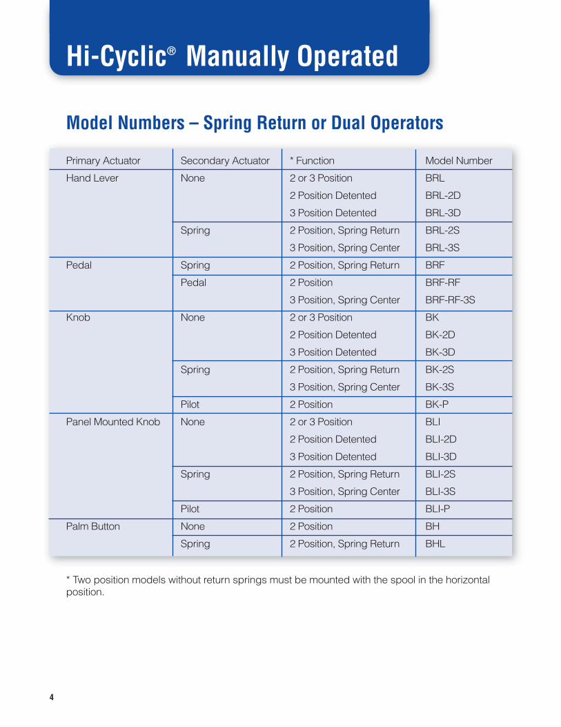
Model Numbers – Spring Return or Dual Operators
Primary Actuator Secondary Actuator * Function Model Number
Hand Lever None 2 or 3 Position BRL
2 Position Detented BRL-2D
3 Position Detented BRL-3D
Spring 2 Position, Spring Return BRL-2S
3 Position, Spring Center BRL-3S
Pedal Spring 2 Position, Spring Return BRF
Pedal 2 Position BRF-RF
3 Position, Spring Center BRF-RF-3S
Knob None 2 or 3 Position BK
2 Position Detented BK-2D
3 Position Detented BK-3D
Spring 2 Position, Spring Return BK-2S
3 Position, Spring Center BK-3S
Pilot 2 Position BK-P
Panel Mounted Knob None 2 or 3 Position BLI
2 Position Detented BLI-2D
3 Position Detented BLI-3D
Spring 2 Position, Spring Return BLI-2S
3 Position, Spring Center BLI-3S
Pilot 2 Position BLI-P
Palm Button None 2 Position BH
Spring 2 Position, Spring Return BHL
* Two position models without return springs must be mounted with the spool in the horizontalposition.

Hi-Cyclic® Manually Operated
How to Order Example
5
This would be a hand lever operated, 4-way, 5-ported, 2-position, spring return valve with 1/4”NPT ports for air service with a Type I spool.
Note: When ordering, always state:
1. Model
2. Port Size
3. Media to be used (air or hydraulic). If special hydraulic fluids are to be used, advise type offluid or specify your O-ring material.
4. Spool type desired.
For Dimensional Drawings, please refer to the CD attached to the back cover.
BRL-2S – 1/4 – AIR – TYPE IModel Port Size Media Spool Type

Hi-Cyclic® Mechanically Operated
6
Body Brass Alloy 360
Seals Buna-N (See options page for other seal options.)
Spool 303 Stainless Steel (See options page for spool functions.)
Port Size See options page for available port sizes.
Temperature Range -20°F to +160°F (With Buna-N seals)
Pressure Rating Pneumatic service - vacuum through 250 PSIHydraulic service - 2000 PSI for 1/8”, 1/4”, 3/8” and 1/2”models (1/4” B, BSL and BB models are rated at 1000 PSI);3000 PSI for 7/16-20 or 9/16-18 SAE models
Flow Pneumatic 1/8” and 1/4” up to 1.00 Cv, 3/8” and 1/2” up to1.13 CvHydraulic up to 16 GPM
SPECIFICATIONS
Mechanically actuated valves are ideal for integration into machine tools, productionmachines, or any type of machine or equipment requiring a compact, high flow valve.Operators include the basic valve with a threaded spool for custom applications in springreturn and non-spring versions, a unique “ball point” operator for actuation via a sliding orrolling cam in almost any plane, a cam roller and a clevis for actuation via mechanical linkage.
Applications include:
• Mechanically controlled machine tool applications
• Operation of pneumatic and hydraulic double acting or single acting cylinders, rotaryactuators, etc.
• Oilfield equipment
• Control valves for agricultural, construction or other types of on/off highway equipment
• Control and sequencing in pneumatic or hydraulic circuits that require mechanical “signals”or “triggers” from the process

7
Hi-Cyclic® Mechanically Operated
Model Numbers
Model Model Number Description
Basic Valve B Can be actuated by any type of moving linkage. Thespool ends are threaded for ease of adapting to yourconnection. Spool ends are provided with strokeadjustment nuts with “micrometer barrel” type threadwhich can be used to restrict spool travel so flowthrough the valve can be adjusted in both directions.
Spring Loaded BSL This is a spring-loaded version of the basic valvedesigned for straight line actuation. It comesstandard with a 10 lb. spring. Two lighter weightsprings and one heavier are available upon request.Spool end adaptors may be used to restrict spooltravel as noted above with the basic valve.
Spring Loaded BB The ball point, spring-loaded valve is used foractuation via a cam. The rolling ball tip provides foroperation via sliding or rolling of a cam in almost anyplane in addition to straight line actuation. It comesstandard with a 10 lb. spring. Two lighter weightsprings and one heavier are available upon request.
* Two position models without return springs must be mounted with the spool in the horizontalposition.
Model Numbers
Primary Actuator Secondary Actuator * Function Model Number
Cam Spring 2 Position, Spring Return BC
Cam 2 Position BC-C
Pilot 2 Position BC-P
Hand Lever 2 Position BC-RL
Clevis None 2 or 3 Position BN
2 Position Detented BN-2D
3 Position Detented BN-3D
Spring 2 Position, Spring Return BN-2S
3 Position, Spring Center BN-3S
* Two position models without return springs must be mounted with the spool in the horizontalposition.
Ball Point

8
Hi-Cyclic® Mechanically Operated
How to Order Example
This would be a Cam Roller Operated, 4-way, 5-ported, 2-position, spring return valve with3/8” NPT ports for air service with a Type I spool.
Note: When ordering, always state:
1. Model
2. Port Size
3. Media to be used (air or hydraulic). If special hydraulic fluids are to be used, advise type offluid or specify your O-ring material.
4. Spool type desired.
For Dimensional Drawings, please refer to the CD attached to the back cover.
BC – 3/8 – AIR – TYPE IModel Port Size Media Spool Type

9
Hi-Cyclic® Direct Solenoid Operated
Body Brass Alloy 360
Seals Buna-N (See options page for other seal options.)
Spool 303 Stainless Steel (See options page for spool functions.)
Port Size See options page for available port sizes.
Temperature Range -20°F to +160°F (With Buna-N seals)
Pressure Rating Pneumatic service - vacuum through 250 PSIHydraulic service - 2000 PSI for 1/4”, 3/8” and 1/2” models;3000 PSI for 7/16-20 or 9/16-18 SAE models
Flow Pneumatic 1/4” up to 1.00 Cv, 3/8” and 1/2” up to 1.13 CvHydraulic up to 16 GPM
Voltages and ElectricalCharacteristics See solenoid options charts on next page.
SPECIFICATIONS
Lexair direct solenoid operated valves feature fast reaction times due to the short stroke andspool-to-body frictionless fit discussed above. Operators are available in AC or DC voltagesand come standard with non-locking manual overrides. All coils are rated for continuous duty.
Applications include:
• Electrically controlled machine tool applications
• Operation of pneumatic and hydraulic double acting or single acting cylinders, rotaryactuators, etc.
• Oilfield equipment
• Control valves for agricultural, construction or other types of on/off highway equipment
• Any pneumatic or hydraulic circuit where positive, fast acting electrical control is needed

10
Model Numbers
Primary Actuator Secondary Actuator * Function Model Number
Solenoid Spring 2 Position, Spring Return B1A
Solenoid 2 Position B2A
3 Position, Spring Center B2A-3S
Solenoid
Voltage Coil Part Number Solenoid Part Number Inrush Amps Holding Amps
120V/60Hz 03-0300 03-0378 2.3 0.470
230V/60Hz 03-0303 03-0379 1.15 0.235
460V/60Hz 03-0306 03-0380 0.57 0.117
110V/50Hz 03-0286 03-0377 2.2 0.450
220V/50Hz 03-0290 03-0376 1.1 0.255
460V/50Hz 03-0294 03-0734 0.55 0.113
6V DC 03-0355 03-0366 0 7.3
12V DC 03-0356 03-0367 0 3.32
24V DC 03-0357 03-0368 0 1.66
* Two position models without return springs must be mounted with the spool in the horizontalposition.
Hi-Cyclic® Direct Solenoid Operated

11
Hi-Cyclic® Direct Solenoid Operated
How to Order Example
This would be a double solenoid, 3-position, spring centered, 4-way, 4-ported valve with 3/8”NPT ports and 120V/60Hz operators for hydraulic service with a Type V spool (supply blockedwith cylinder ports to tank).
Note: When ordering, always state:
1. Model
2. Port Size
3. Media to be used (air or hydraulic). If special hydraulic fluids are to be used, advise type offluid or specify your O-ring material
4. Spool type desired
5. Desired coil type and voltage
NOTE: Solenoid/Pilot operated models are still available for sale as replacementsbut are no longer cataloged items for new applications, consult the factory.
For Dimensional Drawings, please refer to the CD attached to the back cover.
B2A-3S - 3/8 - HYD - TYPE V - 120V/60Hz
Model Port Size Media Spool Type Solenoid Coil Voltage

12
Hi-Cyclic® Pilot Operated
Body Brass Alloy 360
Seals Buna-N (See options page for other seal options.)
Spool 303 Stainless Steel (See options page for spool functions.)
Port Size See options page for available port sizes. Pilot ports are 1/4” NPTfor all air pilot versions and 7/16-20 for all hydraulic pilot versions.
Temperature Range -20°F to +160°F (With Buna-N seals)
Pressure Rating Pneumatic service - vacuum through 250 PSIHydraulic service - 2000 PSI for 1/8”, 1/4”, 3/8” and 1/2” models;3000 PSI for 7/16-20 or 9/16-18 SAE models
Flow Pneumatic 1/8” and 1/4” up to 1.00 Cv, 3/8” and 1/2” up to1.13 CvHydraulic up to 16 GPM
Pilot Pressures Air 35-250 PSIHydraulic 35-2000 PSI
SPECIFICATIONS
Versions are available for actuation via pneumatic or hydraulic pilot signals. The main valvemedia may be either pneumatic or hydraulic with either type of actuation, allowing differentmedia types for control versus pilot sources.
Applications include:
• Pneumatically or hydraulically controlled machine tool applications
• Operation of pneumatic and hydraulic double acting or single acting cylinders, rotaryactuators, etc.
• Oilfield equipment
• Control valves for agricultural, construction or other types of on/off highway equipment
• Control or sequencing in pneumatic or hydraulic circuits that require pilot signals to achieveaction
• Used in hazardous locations where solenoids or other types of operators cannot be used
13
Hi-Cyclic® Pilot Operated
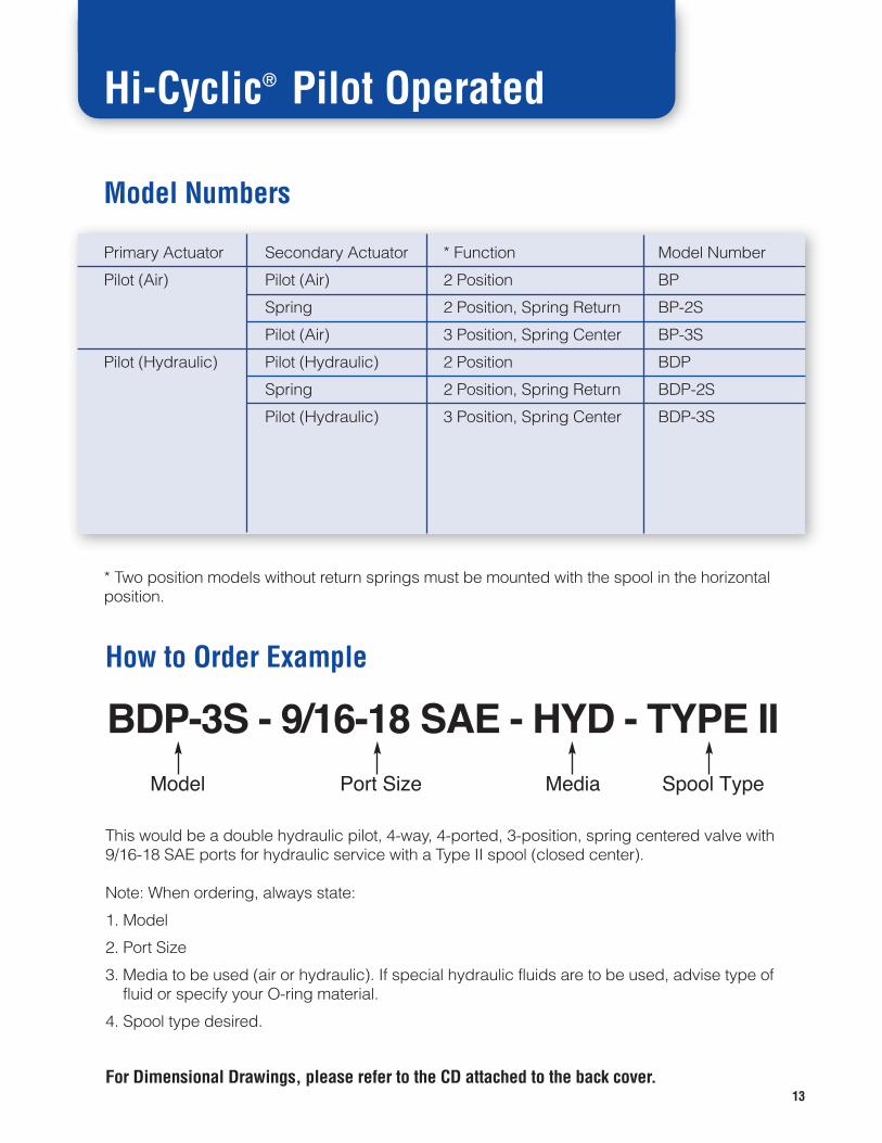
Model Numbers
Primary Actuator Secondary Actuator * Function Model Number
Pilot (Air) Pilot (Air) 2 Position BP
Spring 2 Position, Spring Return BP-2S
Pilot (Air) 3 Position, Spring Center BP-3S
Pilot (Hydraulic) Pilot (Hydraulic) 2 Position BDP
Spring 2 Position, Spring Return BDP-2S
Pilot (Hydraulic) 3 Position, Spring Center BDP-3S
* Two position models without return springs must be mounted with the spool in the horizontalposition.
How to Order Example
This would be a double hydraulic pilot, 4-way, 4-ported, 3-position, spring centered valve with9/16-18 SAE ports for hydraulic service with a Type II spool (closed center).
Note: When ordering, always state:
1. Model
2. Port Size
3. Media to be used (air or hydraulic). If special hydraulic fluids are to be used, advise type offluid or specify your O-ring material.
4. Spool type desired.
For Dimensional Drawings, please refer to the CD attached to the back cover.
BDP-3S - 9/16-18 SAE - HYD - TYPE IIModel Port Size Media Spool Type

14
Hi-Cyclic® Magna-Cycle® Valves
Magna-Cycle® valves are pneumatic 4-way, 2-position directional control models that are airpilot actuated. They contain adjustable permanent magnets in both pilot chambers whichdetent and hold the spool in one of two positions until building pilot pressure exceeds theholding force of the magnet. The adjustment screws allow any pilot pressure between 20 and80 PSI to actuate the valve to the opposite position. The magnetic detent action in the pilotchambers allows automatic control actions to be consistently and reliably repeated. Due tothe fact that they are pneumatically controlled, they are explosion-proof and may be installedin hazardous locations. Operations that may be performed include: continuous reciprocationof a double acting cylinder, sequential operation of two or more cylinders, adjustable or fixedtime delays for cylinder movement, force sensing of cylinder loads, pressure sensing, etc. allwith no mechanical or electrical connections. Models available include internal pilotconnections, external pilot connections and mixed pilots (one internal, one external). Fordetailed operating information and circuit examples, see pages 17-18.
Magna-Cycle® valves are based on the time proven Hi-Cyclic® valve line. They utilize abrass body with a sleeveless spool-to-body design featuring an individually precisionmatched fit, which provides for nearly frictionless operation.
Applications include:
• Operations of any sort requiring continuous reciprocation of a cylinder without the use ofelectrical or mechanical connections, such as to operate a diaphragm pump, shaking of ahopper for compacting or discharging of material, shaking large containers for mixing, etc.
• Sequential operation or sequencing of cylinders
• Cylinder force or pressure sensing operations
• Circuits operating in hostile or hazardous locations where electrical control is impractical ordangerous to use.

Hi-Cyclic® Magna-Cycle® Valves
15
Body Brass Alloy 360
Spool 303 Stainless (See options page for other spool options).
Seals Buna-N
Port Size 1/4” or 3/8” NPT Subbase
Temperature Range -0°F to +160°F (with Buna-N)
Pressure Rating 20 - 80 PSI for MCR and MCE seriesVacuum to 250 PSI for MCS series (pilot pressure 20 - 80PSI)
Flow 1/4” 1.00 Cv, 3/8” 1.13 Cv
SPECIFICATIONS
Model Numbers
NPT Port Size (inches) * Model Number Description
�1/4 MCR-521-1001 Pilot signals received from cylinder portsinternally.
3/8 MCR-531-1001
�1/4 MCE-521-1001 One pilot signal received from cylinderport internally, one received from anexternal source.
3/8 MCE-531-1001
�1/4 MCS-521-1001 Both pilot signals received from anexternal source.
3/8 MCS-531-1001
* Note: Adjusting screw caps which cover magnet detent adjustment screws to discouragetampering by unauthorized personnel are available, simply add a “-P” suffix to the part number.Ex: MCR-531-1001-P would be 3/8” NPT, MCR series with adjusting screw caps factoryinstalled.
�Note: 1/4” models are supplied with exhaust flow controls in the body (see dimensionaldrawings) - 3/8” models require the use of flow controls in the subplate exhaust ports - use twoLexair 10-0076 flow controls.
* All models must be mounted with the spool in the horizontal position.
For Dimensional Drawings, please refer to the CD attached to the back cover.

Hi-Cyclic® Magna-Cycle® Valves
16
Base Model Numbers
NPT Port Size Part Number Description Used with
1/4” 10-0332 Bottom Ports MCR-521-1001
MCE-521-10011/4” 10-0333 Side Ports MCS-521-1001
3/8” 10-0289 Bottom Ports MCR-531-1001
MCE-531-10013/8” 10-1115 Side Ports MCS-531-1001
There are two base sizes available to match the valve body size chosen by valve modelnumber. There are side ported and bottom ported versions available in both body/port sizes.
How to Order1. Choose valve model desired from page 15.
2. Choose base model desired from chart above.
3. Indicate on your order if you would like to have the valve and base assembled. Otherwise,we will ship the two items separately.
For Dimensional Drawings, please refer to the CD attached to the back cover.
Mounting Base Options
17
Hi-Cyclic® Magna-Cycle® Valves
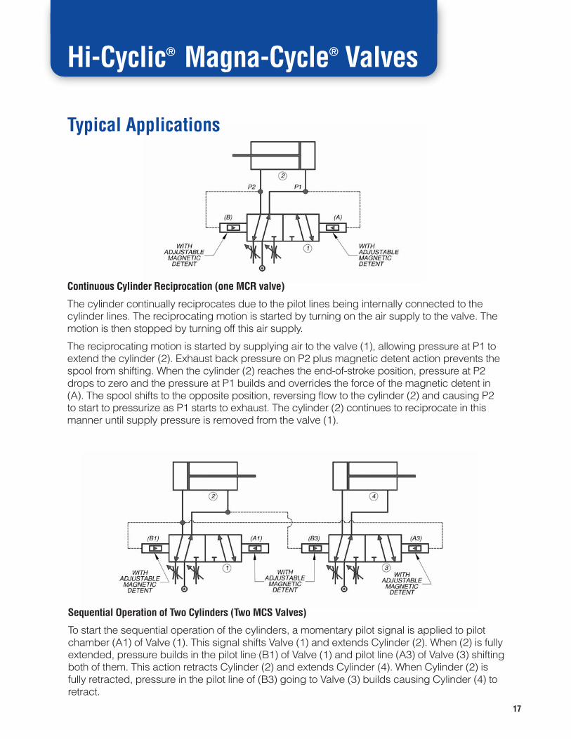
Sequential Operation of Two Cylinders (Two MCS Valves)
To start the sequential operation of the cylinders, a momentary pilot signal is applied to pilotchamber (A1) of Valve (1). This signal shifts Valve (1) and extends Cylinder (2). When (2) is fullyextended, pressure builds in the pilot line (B1) of Valve (1) and pilot line (A3) of Valve (3) shiftingboth of them. This action retracts Cylinder (2) and extends Cylinder (4). When Cylinder (2) isfully retracted, pressure in the pilot line of (B3) going to Valve (3) builds causing Cylinder (4) toretract.
Typical Applications
Continuous Cylinder Reciprocation (one MCR valve)
The cylinder continually reciprocates due to the pilot lines being internally connected to thecylinder lines. The reciprocating motion is started by turning on the air supply to the valve. Themotion is then stopped by turning off this air supply.
The reciprocating motion is started by supplying air to the valve (1), allowing pressure at P1 toextend the cylinder (2). Exhaust back pressure on P2 plus magnetic detent action prevents thespool from shifting. When the cylinder (2) reaches the end-of-stroke position, pressure at P2drops to zero and the pressure at P1 builds and overrides the force of the magnetic detent in(A). The spool shifts to the opposite position, reversing flow to the cylinder (2) and causing P2to start to pressurize as P1 starts to exhaust. The cylinder (2) continues to reciprocate in thismanner until supply pressure is removed from the valve (1).

18
Hi-Cyclic® Magna-Cycle® Valves
Typical Applications
Time Delayed Cylinder Operation(One MCS and one double air piloted valve sized for cylinder operation)
As pressure flows through valve (1), it shifts valve (2) and at the same time is metered into airchamber (6) and actuating chamber (B1) through flow control (4). Once chambers (6) and(B1) are fully pressurized and overcome the magnetic detent setting, valve (1) shifts to theopposite position. This action also shifts valve (2), causing the cylinder (3) to retract and airpressure to build in chambers (7) and (A1) through flow control (5). Once chambers (7) and(A1) are fully pressurized and overcome the magnetic detent setting, valve (1) shifts back, asdoes valve (2), starting the cycle again.
Flow control valves (4) and (5) adjust the time delay. Maximum time delay depends upon thesize of air chambers (6) and (7) plus the adjustability/sensitivity of flow controls (4) and (5). Forthe most accurate time control, it is best to have the Magna-Cycle® valve operate a pilotedvalve as shown. This keeps system pressure fluctuations caused by variations in the workload on the cylinder from affecting the timing cycle.

19
Hi-Cyclic® Options
Porting Options
Spool Function Options
Port Sizes Available in Valve Body
1/8”NPT Pneumatic or hydraulic media (not available in solenoid operated models)1/4”NPT Pneumatic or hydraulic media7/16”-20 SAE-4 Hydraulic media only (pneumatic by special request and pricing)3/8”NPT Pneumatic or hydraulic media1/2”NPT Pneumatic or hydraulic media9/16”-18 SAE-6 Hydraulic media only (pneumatic by special request and pricing)Note: Pilot ports are 1/4” NPT for all air pilot versions and 7/16-20 for all hydraulic pilot versions.
Seal Types
Buna-N or Viton®
Viton® is a registered trademark of the DuPont Corporation.
Spool Diagrams Type Spool Options ANSI Symbol
Type I Two position, positive lap spool usedfor conventional 4-way, 2-positionapplications. Can be used as anormally open or normally closed3-way valve by simply plugging onecylinder port. Use for air andhydraulic service.
This spool type will be furnishedunless otherwise specified.
Type II Three position, closed centerspool with wide lands. All ports areblocked and isolated in the centerposition. Typically used for “position-and-hold” or “inching” circuits (willnot hold position for long periodsof time). Use for air and hydraulicservice.
(See “Note 1” on pg. 22) (See “Note 2” on pg. 22)
Hydraulic
Pneumatic
Hydraulic
Pneumatic

20
Hi-Cyclic® Options
Spool Function Options
Spool Diagrams Type Spool Options ANSI Symbol
Type II-A Three position, closed center spoolwith wide lands that are tapered.All ports are blocked and isolatedin the center position. The taperingof the lands provides a more linearflow versus spool travel andtherefore better speed control.Typically used for “position-and-hold” or “inching” circuits (will nothold position for long periods of time).Use for air and hydraulic service.
Type IV Three position, cylinder portsblocked with cross drilled spool toallow pressure to bleed to tank port.Do not use in a “series” circuit andlimit tank back pressure to 250 PSImaximum. Use for hydraulic serviceonly.
Type V Three position supply blocked withcylinder ports to tank (commonlyreferred to as exhaust open centerin pneumatic terminology). Use forair and hydraulic service.
Type VI Three position, closed center spoolwith narrow lands (minimal lap).Spool movement yields almostimmediate action. Must be usedwith sensing devices that willmechanically or electrically positionthe spool. Use for air and hydraulicservice.
(See “Note 1” on pg. 22) (See “Note 2” on pg. 22)
Hydraulic
Pneumatic
Hydraulic
Pneumatic
Hydraulic
Pneumatic
Hydraulic

21
Spool Function Options
Spool Diagrams Type Spool Options ANSI Symbol
Type VI-A Three position, closed center spoolwith narrow, tapered lands (spoolswith positive or negative lap can besupplied for special applications).The tapered lands help deceleratethe cylinder as the spool approachesthe center position, which assists inreducing shock and systeminstability. May be used with sensingdevices that will mechanically orelectrically position the spool. Usefor hydraulic service only.
Type VII Two position specially machinedspool that allows the valve to be usedas either a 2-way normally open ornormally closed unit. Valves with thisspool function are supplied with a“loose plug” that can be customerinstalled in outlet port “A” or “B” toyield the normally open or normallyclosed function that is desired. Thesemodels may also be used as apressure selector with two differentpressures being piped into thecylinder ports while using the inletport as a common outlet. The thirdtype of function is to be used as apressure diverter with the inletpressure being diverted to one of thetwo outlet ports. Use for hydraulicservice only. Note: Tank port mustbe left open.
Hi-Cyclic® Options
(See “Note 1” on pg. 22) (See “Note 2” on pg. 22)
Pneumatic
Hydraulic 2-way N/C
Hydraulic 2-way N/O
Hydraulic Diverter
Hydraulic Selector
Hydraulic
22
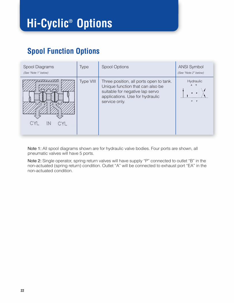
Spool Function Options
Spool Diagrams Type Spool Options ANSI Symbol
Type VIII Three position, all ports open to tank.Unique function that can also besuitable for negative lap servoapplications. Use for hydraulicservice only.
Hi-Cyclic® Options
(See “Note 1” below) (See “Note 2” below)
Hydraulic
Note 1: All spool diagrams shown are for hydraulic valve bodies. Four ports are shown, allpneumatic valves will have 5 ports.
Note 2: Single operator, spring return valves will have supply “P” connected to outlet “B” in thenon-actuated (spring return) condition. Outlet “A” will be connected to exhaust port “EA” in thenon-actuated condition.

Miscellaneous Information
23
NOTE:
Manifold and subplate (except for Magna-Cycle®) mountedvalves are no longer available for new applications but are supplied as
replacements only. Please consult the factory for assistance.
NOTE:
Due to the vast numbers of combinations of operators, spools andport sizes available, please consult the factory for repair kits for various
valves and operators.
Dimensional Drawings

TUBE-O-MATIC® Series: This line features 2-Way operation in a unique pinch valve design thatwas developed for long service life while being used in abrasive/aggressive media applications.Direct air pilot or solenoid pilot versions are available. Port sizes range from 1/4” – 2-1/2” NPT withworking pressures to 150 PSI. Sleeve material options allow a wide range of media and temperaturesto be used.
Hi-Cyclic® Series: Features a complete line of 2, 3 and 4-way valves for pneumatic or hydraulicservice. A wide range of manual, mechanical, pilot (air or oil) and solenoid operators are available.Multiple spool configurations cover any application need. Working pressures to 250 PSI (pneumatic)or 3000 PSI (hydraulic) are standard. Port sizes range from 1/8” – 1/2” NPT with 7/16-20 and 9/16-18SAE available as well. Our Magna-Cycle® models feature built-in, adjustable control functionsavailable in three different models depending upon your application requirements.
Mini 1 Series: These 1/4” NPT pneumatic valves boast a Cv capacity of 1.0 to pack a lot of punchin a small package (basic envelope is 1 inch thick and 2 inches wide). The lineup includes manual,mechanical, solenoid and air pilot versions. Most models are offered in either a three port 3-Way orfive port 4-Way version. Working pressures are from vacuum through 150 PSI and the balanced spooldesign assures that this series can be used as a selector, diverter, in dual pressure service as well asin many other non-standard plumbing applications.
Lexair 2 and 3-Way Poppet valves provide high flow, positive shut-off operation for a variety ofindustrial and process control needs. Constructed of non-corrosive materials, they can be used witha wide range of liquids and gases or vacuum where quick-acting control is required. Workingpressures to 500 PSI are standard, higher pressures are available upon request. Available operatorsinclude, direct pilot, solenoid pilot (with integrated DIN style operators), direct solenoid andmechanical cam operation. Port sizes range from 1/4” – 2” NPT and the 2-Way series features bothnormally closed and normally open models. Many choices of seal materials are available providingfor a wide range of media and temperatures to be used. High ratio pilots are available as standardcatalog items for use in high media pressure/low pilot pressure applications. This catalog alsoincludes: Our bubble-tight, poppet style Check Valves in 1/2" - 2" NPT port sizes with features that arethe same as our 2 and 3-Way Poppet Valve line. Our Shuttle Valve lineup featuring port sizes from 1/4"- 1-1/2" NPT and working pressures to 250 PSI for use with gases or liquids. Our MultifunctionSolenoid Valves for use with gases or liquids up to 150 PSI. These solenoid valves can be used instand-alone applications and also work great as operators for our other valve lines.
2025 Mercer Road | Lexington, KY 40511-1018859-255-5001 | 859-255-6656 Fax | www.lexairinc.com
Catalog LX-325Supercedes LX-135 & LX-300
Revised 12/08
Four different lines–each the best of its kind.It could be the smartest valve decision you have ever made.
Lexair® Valves for Every Application