hg-5h2 hydrograsser safety, operation, parts & …
TRANSCRIPT

Hydrograsser Model HG-5H2 Reinco, Inc. © Manual 00500924 Rev1/07
HG-5H2 HYDROGRASSER
SAFETY, OPERATION, PARTS & SERVICE
MANUAL REINCO INC. TOLL FREE (800) 526-7687 PO BOX 512 PHONE (908) 755-0921 PLAINFIELD, NJ. 07061-0512 FAX (908) 755-6379 http//www.reinco.com e-mail [email protected]
2
Hydrograsser Model HG-5H2 Reinco, Inc. © Manual 00500922
NOTICE Every attempt has been made to make this manual complete, accurate and up-to-date. However, all information contained herein is subject to change due to updates and design modifications. All inquiries concerning this manual should be directed to REINCO INC
CAUTION: The following information is IMPORTANT to the HEALTH and SAFETY of your employees. Please READ, take ACTION and FILE this document for future reference. Ask for additional copies if required.
Study this manual carefully before attempting to operate this machinery.
This safety alert symbol is used to call your attention to instructions concerning your personal safety. Federal law requires you to explain the safety and operating instructions furnished with this machine to all employees before they are allowed to operate the machine. These instructions must be repeated to the employees at the beginning of each season. Be sure to observe and follow these instructions for you and your employee's safety.
This symbol is used to draw attention to those operational and maintenance instructions we consider important to insure long trouble-free operation of this machine.
DISCLAIMER: THESE MATERIALS ARE FOR TRAINING PURPOSES ONLY, AND ARE NOT A SUBSTITUTE FOR OSHA'S OCCUPATIONAL SAFETY AND HEALTH STANDARDS.
Hydrograsser Model HG-5H2 Reinco, Inc. © Manual 00500924 Rev1/07
REINCO MODEL HG-5H2
HYDROGRASSER
FORWARD

Hydrograsser Model HG-5H2 Reinco, Inc. © Manual 00500922
A MESSAGE FROM REINCO
Getting the most out of your new HG-5H2 HYDROGRASSER should be within the reach of an inexperienced operator in a few hours. Machines are shipped from the factory fully operational and ready for work. Some packaging requirements require minimal assembly at the point of delivery. The purpose of this manual is to minimize start up difficulties and acquaint the new owner with recommended operating procedures and techniques. The following pages also include information on parts, service and accessories to help in making your new machine a versatile and profitable investment.
Your new REINCO HYDROGRASSER represents the culmination of over thirty-five years of expertise embodying field feedback, innovative design and manufacturing experience. Functional simplification and avoidance of mechanical complexities have been prime engineering objectives throughout this time. The benefits to be realized will be years of trouble free performance with minimum attention and maintenance.
Every operator and foreman should read this booklet and familiarize themselves with the operational and mechanical aspects described. Some of the following commentary may appear to be obvious, but at the expense of being repetitive or assuming certain basics, this will serve as a guide for both owners and operators not acquainted with seeding and tacking procedures as well as providing instructions on the detailed operation of your new unit.
This manual is provided to ship with new units manufactured at the date of this document's revision. It is also supplied as a reference guide for units of similar construction, manufactured under prior designs. Some parts, options, engines, etc., may not be, or may not have been, available at the time of production of your machine.
Contact REINCO for cost and installation of available upgrades.
All references made to engines, apply to the KOHLER Command Series CH20S engine only.
Owners of equipment with other power plants should consult the appropriate engine manufacturer's literature for applicable detailed information.
We at REINCO welcome this opportunity to be of service to you and wish to express our appreciation for the confidence extended by your selection of REINCO mulching and seeding equipment.
Hydrograsser Model HG-5H2 Reinco, Inc. © Manual 00500924 Rev1/07
WHAT IS HYDROGRASSING
Hydrograssing has emerged as one of the most practical methods of establishing ground cover, particularly on slopes and difficult access areas. Because of the varied slurry capabilities, prepared ground surfaces may be covered in a single pass, thereby reducing capital equipment expenses.
In basic concept, Hydrograssers are mobile slurry generators, which satisfy the needs of professional landscape or reclamation contractors. The Connecticut department of highways researched the concept of hydraulic grassing prior to World War II. Thereafter, developments followed making the technique more practical
The early units combined earth, peat, seed and water to produce slurry, which was then applied to roadsides and slopes from an elevated platform through a boom, and spray nozzle mechanism. This seeding process has evolved to a degree to which the industry is now highly committed.
It is our understanding, that these original units employed a diaphragm mud pump to develop spray pressure with a separate propeller blade mixer installed to agitate the granular solids. Each had its own gasoline engine drive resulting in a cumbersome and maintenance prone arrangement requiring skilled and highly trained operators.
The present day Reinco hydrograsser is very different from the early prototypes. Gone are the multiple engines, the antiquated horizontal agitators and the necessity of having a master mechanic's background for operational reliability. Simplicity, without sacrificing performance, has been REINCO’s prime development concept over the years. This credo has proven its merit since the first hydraulically agitated seeder was built back in 1960.
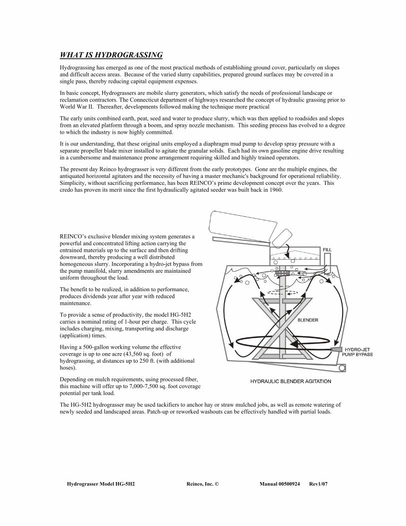
REINCO’s exclusive blender mixing system generates a powerful and concentrated lifting action carrying the entrained materials up to the surface and then drifting downward, thereby producing a well distributed homogeneous slurry. Incorporating a hydro-jet bypass from the pump manifold, slurry amendments are maintained uniform throughout the load.
The benefit to be realized, in addition to performance, produces dividends year after year with reduced maintenance.
To provide a sense of productivity, the model HG-5H2 carries a nominal rating of 1-hour per charge. This cycle includes charging, mixing, transporting and discharge (application) times.
Having a 500-gallon working volume the effective coverage is up to one acre (43,560 sq. foot) of hydrograssing, at distances up to 250 ft. (with additional hoses).
Depending on mulch requirements, using processed fiber, this machine will offer up to 7,000-7,500 sq. foot coverage potential per tank load.
The HG-5H2 hydrograsser may be used tackifiers to anchor hay or straw mulched jobs, as well as remote watering of newly seeded and landscaped areas. Patch-up or reworked washouts can be effectively handled with partial loads.


Hydrograsser Model HG-5H2 Reinco, Inc. © Manual 00500924 Rev1/07
MODEL HG-5H2
HYDROGRASSER
SAFETY

Hydrograsser Model HG-5H2 Reinco, Inc. © Manual 00500922
HYDROGRASSER SAFETY OVERVIEW Personnel responsible for your Hydrograsser training program, maintenance, and operations must read and understand this safety manual and operator's manual. No one should set up, operate or maintain a Hydrograsser until they understand it, its operation and know how to do their job safely. DISCLAIMER: THESE MATERIALS ARE FOR TRAINING PURPOSES ONLY, AND ARE NOT A SUBSTITUTE FOR OSHA'S OCCUPATIONAL SAFETY AND HEALTH STANDARDS.
RECOGNIZE SAFETY INFORMATION This is the safety alert symbol. When you see it in your operations manual, be alert to the potential for personal injury. Follow recommended precautions and safe operating practices.
UNDERSTAND SAFETY WORDS A signal word - DANGER, WARNING, or CAUTION - is used to identify a potential for serious injury. DANGER identifies the most serious hazards. DANGER or WARNING safety signs are located near specific hazards. General precautions are listed on CAUTION safety signs. CAUTION also calls attention to safety messages in this manual and your operations manual.
FOLLOW SAFETY INSTRUCTIONS Carefully read this safety manual and all safety messages in your operations manual and on your Hydrograsser. Keep safety signs in good condition. Replace missing or damaged safety signs. Be sure new equipment components and repair parts include current safety signs and safety guards. Replacement safety signs and guards are available from your Reinco dealer or directly from Reinco.
Learn how to operate the machine and how to use the controls properly. Do not let anyone operate the equipment without instruction. Keep your machine in proper working condition. Unauthorized modifications to the machine may impair the function and/or safety and affect machine life.
If you do not understand any part of this manual and need assistance, contact Reinco.
CONCENTRATE ON YOUR JOB Daydreaming, worrying about other problems or other improper operation of a machine could cripple you for life. Operating a Hydrograsser requires your complete attention. Talking, joking or participating in or watching horseplay could result in physical injury to you . . . and that's not something to joke about. So watch what you are doing and concentrate on your job.
Hydrograsser Model HG-5H2 Reinco, Inc. © Manual 00500924 Rev1/07
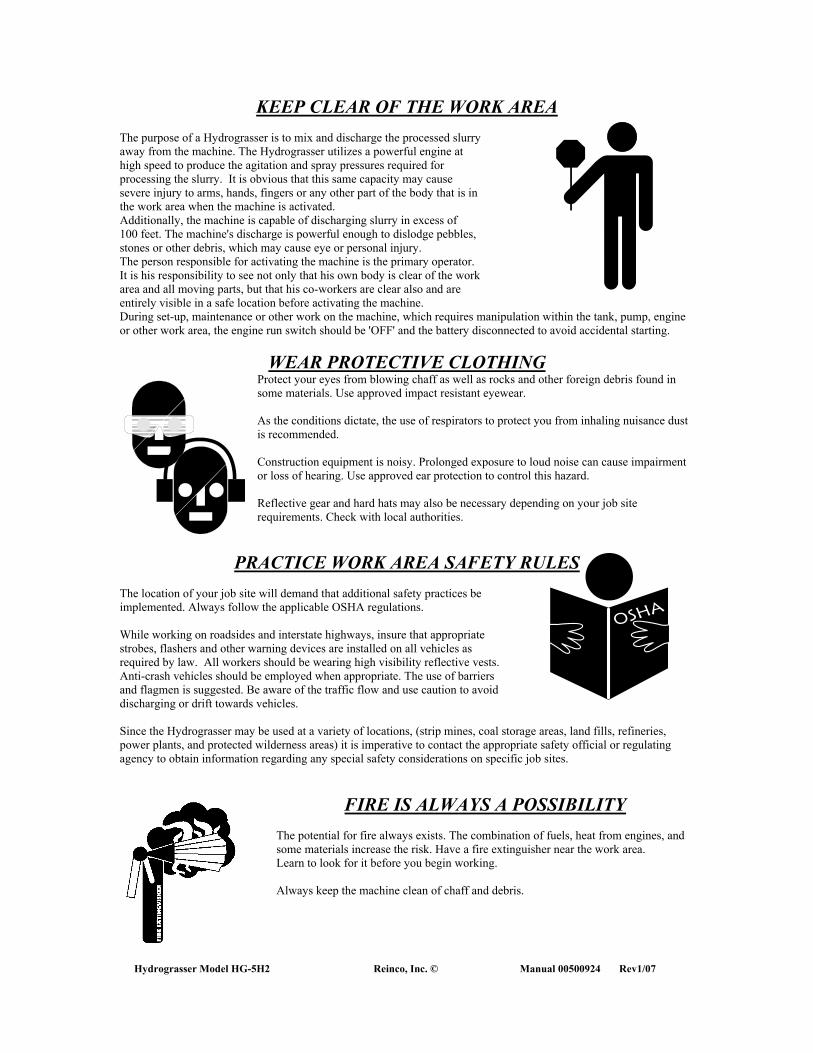
KEEP CLEAR OF THE WORK AREA The purpose of a Hydrograsser is to mix and discharge the processed slurry away from the machine. The Hydrograsser utilizes a powerful engine at high speed to produce the agitation and spray pressures required for processing the slurry. It is obvious that this same capacity may cause severe injury to arms, hands, fingers or any other part of the body that is in the work area when the machine is activated. Additionally, the machine is capable of discharging slurry in excess of 100 feet. The machine's discharge is powerful enough to dislodge pebbles, stones or other debris, which may cause eye or personal injury. The person responsible for activating the machine is the primary operator. It is his responsibility to see not only that his own body is clear of the work area and all moving parts, but that his co-workers are clear also and are entirely visible in a safe location before activating the machine. During set-up, maintenance or other work on the machine, which requires manipulation within the tank, pump, engine or other work area, the engine run switch should be 'OFF' and the battery disconnected to avoid accidental starting.
WEAR PROTECTIVE CLOTHING Protect your eyes from blowing chaff as well as rocks and other foreign debris found in some materials. Use approved impact resistant eyewear. As the conditions dictate, the use of respirators to protect you from inhaling nuisance dust is recommended. Construction equipment is noisy. Prolonged exposure to loud noise can cause impairment or loss of hearing. Use approved ear protection to control this hazard. Reflective gear and hard hats may also be necessary depending on your job site requirements. Check with local authorities.
PRACTICE WORK AREA SAFETY RULES The location of your job site will demand that additional safety practices be implemented. Always follow the applicable OSHA regulations. While working on roadsides and interstate highways, insure that appropriate strobes, flashers and other warning devices are installed on all vehicles as required by law. All workers should be wearing high visibility reflective vests. Anti-crash vehicles should be employed when appropriate. The use of barriers and flagmen is suggested. Be aware of the traffic flow and use caution to avoid discharging or drift towards vehicles. Since the Hydrograsser may be used at a variety of locations, (strip mines, coal storage areas, land fills, refineries, power plants, and protected wilderness areas) it is imperative to contact the appropriate safety official or regulating agency to obtain information regarding any special safety considerations on specific job sites.
FIRE IS ALWAYS A POSSIBILITY
The potential for fire always exists. The combination of fuels, heat from engines, and some materials increase the risk. Have a fire extinguisher near the work area. Learn to look for it before you begin working. Always keep the machine clean of chaff and debris.

Hydrograsser Model HG-5H2 Reinco, Inc. © Manual 00500922
NEATNESS IS IMPORTANT Keep your work area clear of bales or flakes of mulch, twine, scrap and trash that could cause you to stumble. Falling or slipping can result in painful or perhaps even fatal injuries. Put all fuel, tools and other equipment away when you are not using them. Even a screwdriver can be deadly if left on an enclosure of the machine.
CLEAN AS YOU GO Packaging, when removed, should be disposed of immediately in a container away from the machinery. That loose piece of twine or debris around the machine could cause you to fall and cause injury.
MATERIALS HANDLING IS IMPORTANT When cutting and removing packaging from the mulch bale or opening other materials, the handler must make sure that the wrap is not pulled or dropped into the machine. Loose twine can wrap around a shaft and pull an arm or hand into the machine. Twine is capable of cutting through fingers. Knives can be extremely dangerous. Never reach into any rotating area of the machinery. It takes only a fraction of a second to lose fingers. Pay attention to your fingers, debris, and the moving equipment when handling packaging.
VIBRATION IS A WARNING SIGN A rotation unbalance of any sort will become obvious in the form of vibration. Vibration is an important warning, signaling an impending mechanical failure. Instruct all users of your equipment to report unusual vibration at the onset.
PRACTICE SAFE MAINTENANCE Understand the service procedure before doing any work. Keep the work area clean and dry. Never lubricate, service or adjust machine while it is running. Keep hands, feet and clothing away from moving or power driven parts. Disengage all power and operational controls, and relieve pressure. Stop engine and allow machine to cool. Keep all parts in good condition and properly installed. Fix any damage immediately. Replace worn or broken parts. Remove and maintain unit clean of any build-up of grease, oil or debris.
Hydrograsser Model HG-5H2 Reinco, Inc. © Manual 00500924 Rev1/07
HYDRAULIC SYSTEM CONCERNS The HG-5H2 hydrograsser is manufactured with a hydraulically operated blender system. Hydraulic fluid lines are a high-pressure fluid hazard. To prevent serious injury or death, always relieve system pressure before repairing, adjusting, or disconnecting any component of this system. Tighten all connections before applying pressure. Search for leaks with a piece of cardboard. Leaking hoses, fittings or components should be reported to your supervisor immediately.
If an accident occurs, see a doctor immediately. Any fluid injected into the skin must be surgically removed in a few hours or gangrene may result. Doctors unfamiliar with this type of injury should reference a knowledgeable medical source.
HYDRAULIC FEED SYSTEM JAMS
Should the hydraulic system jam and the blender stop rotating, the control valve must be returned to the off (closed position). Before attempting to clear any system jam, turn the engine off. The jammed blender may now be inspected and cleared. Failure to close the valve and shut the machine down may cause the system to immediately resume operation when the obstruction is cleared. This situation could cause severe bodily injury.or death.
TRAILERED UNIT CONCERNS
The machine's frame should be level for towing, as well as for operator safety. The hitch should be located so that the truck bed overhang will not interfere with the machinery. Provide adequate set back from the vehicle chassis frame so that jack knifing, when backing up, will not damage machine. Provide for securing the safety chains. Running lights are standard for over the road travel. They include stop, directional, tail and license plate. Make sure all running lights are working at the start of each day.
The flasher light switch of the truck, when engaged will also activate the directional and taillights mounted in the rear bumper. Whenever emergency signaling is required, use this circuit.
Initially, it is important to check the torque of the wheel lug nuts. These are set at the factory at 90-ft. lbs. Due to relaxation associated with travel; they must be torqued at 25, 75, and 150-mile intervals. Braking systems if supplied must be checked for proper adjustment and operation. Brake adjustments should be made after the first 200 miles (seating) and again at 3000-mile intervals.
Hydrograsser Model HG-5H2 Reinco, Inc. © Manual 00500922
PROPER ENGINE SERVICING IS IMPORTANT DO NOT PERFORM SERVICE ON AN ENGINE IF YOU ARE NOT
QUALIFIED. Use care when refueling all engines, whether gas or diesel units. Fuels and their vapors are extremely flammable and can explode when ignited. Do not fill the fuel tank when engine is hot or running, since spilled fuel could ignite if it comes in contact with hot parts or sparks from the ignition. Do not start the engine near spilled fuel; wipe up spills immediately. Never use gasoline as a cleaning agent. Store fuels in approved containers only. After refueling, remove containers from work area.
Do not add oil when engine is hot or running as oil could vaporize and ignite. Engines are a burn hazard. The crankcase, cylinder head, exhaust system, and other components can get extremely hot from operation.
Engine exhaust gasses contain poisonous carbon monoxide. Never run engine in an enclosed area. Avoid inhaling exhaust fumes.
The electrical systems of engines can be a source of high voltage. Never touch electrical wires or components when engine is running. Never attempt to start the engine by shorting across the starter solenoid. Avoid accidental starts, which could cause injury to you or your fellow workers. Disconnect and ground the spark plug wire.
Refer to the engine manufacturer's operation and safety manuals for more detailed information.
ENGINE SPEED IS IMPORTANT Never tamper with the governor component settings to increase the maximum speed. The components used to build the Hydrograsser are designed to operate at a specific maximum speed. Severe personal injury and damage to the Hydrograsser can result at speeds set above the maximum. A rotation unbalance of any sort will become obvious in the form of vibration. Vibration is an important warning sign of impending mechanical failure. Notify your supervisor of any unusual vibrations or noises at the onset.
DISPOSE OF WASTE PROPERLY Improperly disposing of waste can threaten the environment and ecology. Potentially harmful waste associated with Reinco equipment includes such items as oil, fuel, coolant, filters, batteries, fertilizers, and packaging. Use leak proof containers when draining fluids. Do not use food or beverage containers that may mislead someone into drinking from him or her. Do not pour waste onto the ground, down a drain or into any water source. Inquire on the proper way to recycle or dispose of waste from your local environmental or recycling center, or from your state's Environmental Protection Agency.
����������������������������������������������������������������������������������������������������������������������������������������������������������������������������������������������������������������������������������������������������������������������������������������������������������������������������������������������������
��������������������������������
������������������������������������

Hydrograsser Model HG-5H2 Reinco, Inc. © Manual 00500924 Rev1/07
LOOK THINGS OVER CAREFULLY Before operating your Hydrograsser, look to see if your machine is in proper condition. Is the workspace clean? Is the fuel properly stored? Are all the materials packaging cleaned up? Are the machinery guards and covers all in place? Are all nuts, bolts and screws tight? Do you know where the fire extinguisher is? Do all workers have protective safety gear? Is everything in proper operating condition? If not, report the unsafe condition to your supervisor and be sure the problem is corrected before beginning operation.
KNOW YOUR MACHINE The Hydrograsser has one characteristic in common with most machinery. Do not assume that simply turning off the machine will insure that all moving parts have stopped. The moving machinery can cause serious injury and even death. Be aware that a shaft, which rotates at more than 2000 revolutions per minute, is extremely dangerous.
Before operating this machine be sure to read this entire manual.
1. *Do not operate the unit if unfamiliar with operational and safety procedures on this or any unit.
2. *The force from the discharge can kick up dust, dislodge unsecured items and damage property.
3. *Never discharge the unit towards people. Bodily injury may occur.
4. *Never force any material into the machine.
5. *Never attempt to clear the machinery of debris or make adjustments while the engine is running.
6. *Be sure to keep all body parts and clothing away from moving parts while engine is running.
7. *Do not attempt to mix or discharge rocks, nails, or other debris that may damage the machinery or cause premature wear.
8. *Do not operate machine without required coupling, shaft, or bearing guards installed.
9. *Materials packaging must be removed carefully to prevent being pulled into the machine.
10. *Do not allow fingers to become entangled in the bale twine or packaging.
11. *Do not wear loose clothing that may become entangled with the machinery.
12. *Do not add oil, water or fuel while engine is running or hot.
13. *Do not perform maintenance while unit is running or battery is connected..
14. *Working space must be allowed not only for the machine operator, but also for access to the stacked materials.
15. *Daily, inspect the machinery for signs of wear. Do not operate the machinery until problems have been remedied.
16. *Always make sure fittings are secure and valves are operational and in good order.
17. *The pump impeller is made of cast iron. If a vein breaks, or is clogged with debris an unbalance or vibration will occur. Do not, under any condition, operate the machine when unusual vibration is present.
18. *Check the agitating jet and fittings for wear. The granular nature of materials used will abrade and enlarge the nozzles causing an eventual reduction in mixing and discharge pressures. Rocks and foreign matter found in some materials might clog the nozzles, pump impeller and cause noticeable reduction in pressure, or produce vibration.
19. *Secure the discharge boom and hose(s) before transporting the machine.
IT IS IMPERATIVE THAT COMMON SENSE AND GOOD JUDGMENT BE EMPLOYED WHEN OPERATING THIS MACHINE.

Hydrograsser Model HG-5H2 Reinco, Inc. © Manual 00500922
CHEMICAL REACTIONS With the wide variety of Hydrograssing amendments available, it stands to reason that all may not be compatible.
CERTAIN FERTILIZERS REACT WITH LIME PRODUCING FREE AMMONIA.
Wetting agents may cause foaming. Binders may agglomerate (stick together) because of the minerals in the water. Foaming and aeration are visible conditions that point to material problems. AERATION- this is not a chemical problem, but does affect pump performance. Too much air getting into the water will cause vapor blocks and consequent erratic pumping. The obvious cause is excessive agitation. Simply slow down the engine. Extremely light granular loads or low tank levels contribute to entraining air in the suction line and pump casing. FOAMING- Excessive bubbles and froth occurs when mixing certain products. The potential problem is that the pump may have a reduced efficiency to move liquid because of vapor blockages and the impeller vanes cannot properly pump out. A simple solution is to add corn or vegetable oil to the mix, perhaps a 1/2-pint to 150 gallons of slurry. The oil acts to ‘flat out’ or break the bubbles, improving pumpability. It is also recommended that the materials suppliers be contacted to establish a cause and offer recommendations.
DANGER! CERTAIN AMENDMENTS, WHEN COMBINED WITH OR WITHOUT THE ADDITION OF WATER, HEAT OR THE ELEMENT OF TIME, MAY REACT CAUSING HARMFUL OR DEADLY GASSES! CONSULT YOUR MATERIAL SUPPLIERS REGARDING REACTIVITY INFORMATION
����������������������������������������������������������������������������������������������������������������������������������������������������������������������������������������������������������������������������������������������������������������������������������������������������������������������������������������������������
��������������������������������
������������������������������������
Hydrograsser Model HG-5H2 Reinco, Inc. © Manual 00500924 Rev1/07
MODEL HG-5H2
HYDROGRASSER
OPERATION

Hydrograsser Model HG-5H2 Reinco, Inc. © Manual 00500922
Hydrograsser Model HG-5H2 Reinco, Inc. © Manual 00500924 Rev1/07
MACHINE DESCRIPTION The model HG-5H2 REINCO HYDROGRASSER is a self-contained, multi-purpose seeding machine comprised as follows: A. PUMP/ENGINE combination, consistent with unit capacity and spray range. B. SLURRY TANK sized to contain the rated granular payload in what is termed "working volume". The tank is
engineered to function integral to the mixing scheme. C. MULCH BLENDER, hydraulically actuated mixing assembly is vertically suspended in the tank. D. CIRCULATING MANIFOLD ASSEMBLY, incorporating a steel HYDRO-JET agitating nozzle. Quick- disconnects and mechanically grooved or threaded piping connections allow for simplified maintenance. E. SPRAY SYSTEM including hose, nozzles, and control valve for dispensing the slurry. The optional boom
discharge swivel allows a 360-degree horizontal swing and the boom hose allows vertical movement for controlled placement.
F. FRAME, structural steel base serving as a mount for the foregoing components.
MOUNTING The skid mounted Model HG-5H2 can be secured to any flatbed truck or trailer and is compact enough to be carried on a 10-foot platform body. The unit must be located so that when charged, the weight is evenly distributed on the vehicle. When mounting the unit, a truck of adequate Gross Vehicle Weight (GVW), and proper Cab to Axle (CA) dimension should be used to get the desired handling capability. This information is listed in the respective specification bulletins. Consideration must also be given regarding specific options installed. It is equally important to locate the HYDROGRASSER on the truck correctly, taking into account "DEAD" and "LIVE" load weights to satisfy acceptable axle loading. A front-end loader, a forklift or gantry with lifting chain or sling, can be used to lift and position the machine. The center point of the lift rings welded to the tank, more or less, indicates the empty (dead weight) center of gravity. (Inclusion of the remote hose or hose reel option will offset that center, toward the boarding end of the unit, causing the machine to tilt when raised by crane). Ideally the empty center of gravity should be approximately 3”-6" forward of the vehicle's rear axle when the HYDROGRASSER is in place. When the tank is full (live load) the center of gravity moves forward (toward the cab of the truck). Proper positioning must consider this. Additional space must be provided for any additional options. Consult your truck dealer for specific axle and spring loading information. Chains looped over the ends of the base frame and tensioned with binders, is perhaps the most practical way to temporarily secure the machine to the truck bed while transporting the empty unit only. Once in place, secure with binders or mounting cleats and blocks.
IMPORTANT! INSURE THAT THE MACHINE BASE IS PLACED ON A LEVEL SURFACE BEFORE FASTENING. DO NOT DISTORT THE MACHINE FRAME WHEN BINDING.
FEDERAL GUIDELINES (FEDERAL MOTOR VEHICLE SAFETY STANDARDS) MANDATE STRICT
REQUIREMENTS WHEN MOUNTING MACHINERY ON TRUCK FRAMES FOR OVER THE ROAD USE. INSTALLATION OF THIS HYDROGRASSER REQUIRES A COMPLETED OR ALTERED VEHICLE CERTIFICATION
STICKER ISSUED BY THE INSTALLING DEALER.
TRAILERED UNIT HOOK-UP The machine's frame should be level for towing, as well as operator safety. The hitch should be located so that the truck bed overhang will not interfere with the machinery. Provide adequate set back from the vehicle chassis frame so that jack knifing, when backing up, will not damage machine. Provide for securing the safety chains. A harness connector socket is supplied for installation to the tow vehicle. Make sure all running lights are working at the start of each day. The flasher light switch of the truck, when engaged will also activate the directional and taillights mounted in the rear bumper. Whenever emergency signaling is required, use this circuit. Initially, it is important to check the torque of the wheel lug nuts. These are set at the factory, however, due to relaxation associated with travel, they must be torqued at 25, 75, and 150-mile intervals. Braking systems if supplied must be checked for proper adjustment and operation. Connect the breakaway switch cable to the tow vehicle.
DO NOT ATTEMPT TO TOW MACHINERY UNTIL ALL HOOKUPS ARE COMPLETE AND FUNCTIONING PROPERLY.
DO NOT ATTEMPT TO TOW THE COMPLETELY CHARGED UNIT AT HIGH SPEEDS

Hydrograsser Model HG-5H2 Reinco, Inc. © Manual 00500922
PRE-OPERATION INSPECTION Every machine is tested for performance and checked for quality before shipment. Inspection at the factory includes wet testing for range and system pressure, setting of engine throttle "under load", and inspection of the pump drive coupling and alignment; engine fluid levels and pump seal adjustment. Wet-test readings are recorded. Machines are then drained and prepared for shipment. Cold weather precautions are also taken (see pg39.). Keys for starting the unit are usually included with the operations manual for safe keeping during shipment. Although each machine is packaged for near immediate operation and is tested at the factory prior to shipping, retrace the factory inspection procedures before starting.
Initial pre-starting inspection requires tracing the steps taken at the factory, In addition, rechecking those items as outlined:
ENGINE BREAK IN The BREAK-IN period for the specific engine is noted in the vendor operation manual supplied with this manual. Proper engine break in and maintenance scheduling will result as increased engine life. The engine is equipped with an electronic ignition system. Other than servicing the spark plug, adjustments, timing or ignition maintenance is unnecessary. This non-contact ignition system should provide years of trouble free service if the engine is properly maintained.
ENGINE OPERATING CAUTIONS 1. Turn the fuel tank supply valve to the OFF position while transporting the unit. Failure to shut valve could cause
damage to the engine.
2. Clean chaff from engine daily. Partial engine cowl removal may be required on a periodic basis.
3. The engine is intended to run in a level position. Intermittently, the engine may run at a maximum of 10° angle for not more than 10 minutes.
4. The available horsepower supplied by the engine drops approx. 3% per one thousand feet above sea level. When operating unit at an altitude of 5000 feet or greater, a high altitude carburetor jet must be installed. Contact REINCO or your engine service distributor for details.
Crankcase Oil Level Engine air cleaner assembly Fuel [check engine manual for proper grade]; provide ample fuel for startup. Throttle and choke controls Check battery terminals and connections Inspect tank for debris-remove before starting machine. Check hydraulic system oil level. Check hydraulic system for leaks. Inspect piping and hose connections. Inspect discharge components and connections. Check screws/fasteners for tightness Inspect all bearings, set screws and locking collars. Inspect pump seal lubricator. Inspect all options and accessories supplied.

Hydrograsser Model HG-5H2 Reinco, Inc. © Manual 00500924 Rev1/07
STARTUP Familiarize yourself with this entire manual. Also, read the engine manual.
FILL TANK APPROXIMATELY ONE THIRD FULL WITH WATER FOR YOUR TRIAL RUN. MAKE SURE THE DISCHARGE CONNECTIONS ARE SECURED
AND ALL VALVES ARE IN AN OFF POSITION. After reading the engine manual, you may start the engine. Before starting the unit, be sure it is mounted as described previously. Be sure to make your test run in an open area. Open the fuel tank supply valve. Locate and move choke control to the closed position (cold engine only). Move throttle 1/4 of its travel. Start by turning the ignition key to the right and hold momentarily until the engine starts. After starting, slowly reposition the choke to the fully open position. If vibration or roughness exists, stop engine and check for the cause. Once the engine has warmed up and everything appears in order, set the throttle for maximum speed. Run for a short period of time then reduce the speed to a slow idle, allowing the engine to cool. Turn the engine off. If the machine runs smoothly, proceed to operation section of this manual. If no irregularities are noticed, the unit is mechanically ready for a trial fill. Should problems arise at this point, refer to maintenance section of this manual.
TRIAL RUN The following steps should be followed for the first run to familiarize operators with the HYDROGRASSER: 1. READ THIS MANUAL IN ITS ENTIRETY. 2. Make sure the drain plugs and manifold cap covers are in place and secured. It is worth noting the following with regards to filling: 3. Utilize the fill assembly to prevent siphoning back into the water supply. 4. Never fill through the remote spray or hose reel hoses. 5. Many hydrant systems contain small rocks or pebbles, which may contribute to plugging the machine. 6. Always use a hose end strainer when filling from ponds or streams. 7. Make certain that the spray and blender valves are turned to the off position before starting unit. 8. Check engine fluid levels. Fill as required. 9. Start the engine. Run at moderate idle till warm then rev up to half throttle. 10. Inspect the operation of the HYDRO-JET (item16, page 50) by raising the hatch cover/load tray and
peering through the hatch. Make sure the jet is spewing a solid stream of water. If this is not the case, stop the engine and check for obstructions.
11. Inspect the operation of the BLENDER assembly by opening the control valve. Observe the blender
operating in the tank. The blender should spin freely. If this is not the case, close control valve, stop the engine and check for obstructions.
DANGER! KEEP BODY AND CLOTHING CLEAR OF BLENDER ASSEMBLY WHILE IN MOTION SEVERE INJURY MAY OCCUR!
12. Reduce engine rpm then turn the engine off. 13. Locate the spray valve and the spray nozzles. (Item 23-26, page 50)

Hydrograsser Model HG-5H2 Reinco, Inc. © Manual 00500922
14. Select one of the spray nozzles and install it into the female quick coupling on the end of the spray valve.
There is a sealing gasket in the seat of the quick coupling. Make certain it is in place or the connection will leak.
15. Verify that the spray valve is in the off position and that the spray nozzle is secure. Then restart the
engine. After an adequate idle, bring up the engine throttle. Fully open the spray valve. Articulate the spray to judge the range and pattern of the nozzle. Then vary the throttle to observe how changes in engine RPM effect spray range. Repeat this procedure with the other nozzles supplied.
16. Determine if the HYDROGRASSER is equipped with an optional platform spray boom assembly.
Install the nozzle into the spray boom coupler and test the range and patterns as previously described. 17. Resume filling machine with water. Prepare to add materials to the unit by becoming acquainted with the
BLENDER system (see page 48). 18. Adjust the engine to moderate to fast throttle, and adjust the blender control valve so that the blender is
revolving with maximum speed and power. Adjust the blender speed to keep the water moving at a fast stir. Too fast will cause splash through the hatch opening and operator discomfort.
19. While standing on the spray platform, place a bale of fiber mulch on the load tray. Cut, remove, and
discard the packaging material from the bale of mulch. Be certain not to allow packaging material to fall into tank!
20. Break up the bale through the hatch grate and drop segments into the rotating path of the blender. Most
mulch materials are drawn down and mixed into the slurry quickly. Depending upon mulch materials and slurry amendments, mixing times may be considerably longer.
DANGER! DO NOT STAND ON THE TANK TOP WHILE OPERATING THE MACHINERY. SEVERE INJURY MAY OCCUR!
21. Add a subsequent bale of fiber mulch. Adjust the blender speed as necessary to compensate for the
increasing thickness of the slurry. Two bales should be more than enough to get an idea of the speed and function of the blender system. It is important to be aware of the amount of water in the tank when loading mulch. Since each bale will require approximately 100 gallons of water to properly slurry (Mix Preparation pg.21), care must be taken not to put more mulch into the tank than the water level will allow.
22. Slow down or turn off the blender supply valve to observe the slurry. The tank may now be emptied by
either spraying the load out or by shutting the engine off and then draining the tank by opening the drain cap (item 4, pg.50) located on the sump.
23. A partial fill of clear water can be charged to facilitate cleanup before storing the machine. 24. Remember these important operational procedures when using the HYDROGRASSER: IMPORTANT! BE AWARE OF WATER LEVEL WHEN LOADING MULCH DO NOT ATTEMPT TO LOAD MULCH WITHOUT SUFFICIENT WATER TO SLURRY. IMPORTANT! KEEP BODY AND CLOTHING CLEAR OF BLENDER WHILE IN MOTION AS SEVERE INJURY MAY OCCUR. IMPORTANT! SPRAY VALVES MUST BE FULLY OPEN OR CLOSED. PARTIALLY OPEN VALVES WILL QUICKLY WEAR OUT.
(Although contrary, hose valves may be throttled, as periodic replacement costs of the valve outweighs the cost of another man stationed at the machine to control the engine throttle).

Hydrograsser Model HG-5H2 Reinco, Inc. © Manual 00500924 Rev1/07
MIX PREPARATION The most frequently asked question of the unseasoned operator is: "What to put into the tank? How much coverage can be expected?" Both are redundant since specifications, either formal or self-conceived, determine the amounts to be mixed. Amendments may include seed, innoculant, lime, and fertilizer. It is highly unlikely that all would go in simultaneously because of capacity limitation and/or incompatibility. The REINCO HG-5H2 HYDROGRASSER is rated as follows:
GRANULAR SOLIDS (SEED, FERTILIZER, LIME) 800 lbs.
PROCESSED FIBER MULCH = 200-250 lbs.
REINCO MULCH BINDER PLUS (RMB-plus) = 150lbs.
These ratings are based upon machine performance and averaged product specifications for materials applications.
Granular products will promote wear of the pump impeller as well as the mixing jet and piping components. To extended the service life of these components, it is advisable to source fertilizers with a minimum of fill materials (granulated rock). Liquid fertilizers and liquid limes are available alternatives, however, job specifications should be consulted. Fiber mulches and tackifiers are rated separately from the granular solids capacity, as these amendments require the absorption of water to produce uniformly pumpable slurry. Mulch products and application rates vary significantly. Some mulch products will load at rates as low as 25-30lbs/100 gallons and others as high as 45-50lbs/100 gallons. For the examples here we will consider a 40lb.per 100-gallon average rate.

Hydrograsser Model HG-5H2 Reinco, Inc. © Manual 00500922
HYDROGRASSING
STRAIGHT HYDROGRASSING
Straight Hydrograssing is based on typical highway specifications. This procedure places the seed, fertilizer and water slurry directly onto the prepared seedbed, insuring contact with the soil surface. The application is routinely followed with applications of mulch, either blown straw or hay, or processed fiber mulch. A final application of tackifier slurry fixes the placement of these materials. A seasoned operator can effectively cover an acre with 500 gallons of slurry. This means that the model HG-5H2 may be used to seed one acre (43,560-sq. ft.), with the following sample charge: Amendments Per Batch
Seed @ 150 lbs./Acre (K31, Fescue, Rye mix)=150 lbs. Fertilizer @450 lbs./Acre (10:10:10, 45# N2)=450 lbs.
TOTAL GRANULARS= 700 lbs. In this example the granular solids capacity is not compromised and a single batch is capable of full acre coverage.
STRAIGHT HYDROGRASSING WITH LIME In many areas of the country, and particularly in mine reclamation work, heavy quantities of lime may be specified. Frequently lime must be applied first and then incorporated into the soil before seeding and fertilizing. It is not uncommon to distribute lime at one to two tons to the acre or even more. However, it becomes impractical to apply much larger quantities of lime, via the hydraulic seeding method, due to the abrasiveness of the product. Consult your materials supplier regarding pumpable grades and analysis.
IMPORTANT! USE ONLY FINELY GROUND PULVERIZED LIMESTONE. DO NOT USE COARSE AGRICULTURAL PRODUCT OR HYDRATED LIME.
In this example, let's assume that specifications call for a ton of lime per the acre in addition to the seed and fertilizer in the prior mix. The immediate conclusion is that it is impossible to make a ONE-acre batch because the 2000 lbs. of lime exceeds the HYDROGRASSER'S 800 lbs. granular solids rating. Since 2000/800 = .2.5, calculate a 1/3-acre batch and see if the totals are within the machine's rated capacity.
Amendments Per Batch
Seed @ 150 lbs./Acre x 1/3 (K31, Fescue, Rye mix)=50 lbs. Fertilizer @450 lbs./Acre x 1/3 (10:10:10, 45# N2)=150 lbs.
Lime @ 2000 lbs./Acre x 1/3=660 lbs. TOTAL GRANULARS=860 lbs.
Addition of the seed and fertilizer as granular now exceeds the 800-lb. machine rating. However, by reducing to a 1/4-acre charge, the total granular solids would be 650 lbs., and therefore an acceptable load.

Hydrograsser Model HG-5H2 Reinco, Inc. © Manual 00500924 Rev1/07
HYDROGRASSING WITH PROCESSED FIBER
Commonly referred to as the 'ONE STEP METHOD' this procedure places the ingredients on the prepared seedbed simultaneously. The fiber mulch and tackifier are incorporated into the slurry mix and broadcast in a single application. Ideally suited to small areas where a sterile (weed free) application is preferred, the limitation is that the application will require multiple batches to cover a relatively large area. Fiber, whether paper, wood cellulose, or combinations thereof, are not considered granular solids. It is important to realize, however, that when using fiber mulch, the mulch becomes the limiting factor in the loading equation. Usually 40 pounds of a good fiber requires about 100 gallons of water to produce pumpable slurry. Using this ratio, at a fiber application rate of 1200 pounds/Acre, the coverage per tank load will be approx. 7300 sq. ft. Again, using the previous seed and fertilizer mix ratios the batch would be adjusted to the fiber application rate. Amendments Per Batch
Seed @ 150 lbs./Acre x 1/6 (K31, Fescue, Rye mix) = 25 lbs. Fertilizer @450 lbs./Acre x 1/6 (10:10:10, 45# N2) = 75 lbs.
Fiber @ 1200 lbs./Acre x 1/6 = 200 lbs. RMB-plus binder @ 100 lbs./Acre x 1/6=17 lbs.
Fiber mulch application rate will determine the coverage per tank load. When high mulch requirements are specified, it is realistic to apply the amendments with the initial application and over spray the site to meet mulch requirements. Consecutive applications will reduce the impact of the high water requirements on the seedbed. Lets assume a fiber mulch application rate of 2000 lbs. per acre is specified for a particular site. Using the same proportions of materials, we had previously established that this machine would be capable of a 1/6-acre batch using 1200 lbs. Once the initial application is complete, additional fiber applications are required to meet the specifications. At the mulch to water ratio given the remaining material will require four additional charges excluding the seed and fertilizer. Remember that fiber requires a significant quantity of water to produce pumpable slurry.
HYDROGRASSING WITH FIBER & LIME How would the proportions, in the preceding example, be affected by the additional requirement of 2000 pounds of lime per acre? Since it was determined that the maximum fiber that could be charged would cover one-sixth acre, the corresponding proportion of lime would be 334 pounds. This brings the total granular to 434 pounds, or well below the unit's 800 pound rating. Therefore, the mix quantities do not exceed the machine's capacity and are acceptable.

Hydrograsser Model HG-5H2 Reinco, Inc. © Manual 00500922
HYDROGRASSING WITH BFM (FIBER MATRIX MATERIALS) BONDED FIBER MATRIX PRODUCTS are comprised of a hydroseeding type of mulch, paper, wood, or combinations, with high volumes of 'bonding agents' (Tackifiers). The BFM provides an effective alternative to blanketing and other methods where erosion control methods are critical, and applications are difficult or not easily accessible. BFM's are specified where soil or silt erosion cannot be tolerated. The ‘matrix’ is created by applying the material in a stacking manner, where a high-density interlocking mat is formed, thus controlling the moisture at the seed germination zone. It is preferable to apply the materials with minimal disturbance of the prepared soil texture. Usual applications require that the seed and granular materials are applied as with the 1SMM (Modified One Step Method) to assure seed to soil contact. Effective densities of the matrix mixtures are dependent upon operator capability. Mechanically bonded materials include synthetic fibers materials, with tackifier added for water holding capability. Mechanically bonded materials will require minimal or no curing time, dramatically improving application cycle times. BFM material application rates are usually very high, by comparison to standard hydroseeding applications. Applications of 2000 to 4000 lbs. per acre are usual for critical areas and will vary with erodable water velocity predictions.
CAUTION Certain tackifiers, when used in high volumes, may cause erratic pumping. The pump speed must be slowed to remedy this condition. Consult your material supplier for recommendations.

Hydrograsser Model HG-5H2 Reinco, Inc. © Manual 00500924 Rev1/07
FIBER MULCH LOAD RATE COMPARISONS EQUIP MULCH REQ'D TANK LOADS PER ACRE
WATER VOL. PER ACRE 30LBS/100 35LBS/100 40LBS/100 * 45LBS/100 50LBS/100 1000 16.67 14.29 12.50 11.11 10.00
1200 20.00 17.14 15.00 13.33 12.00
1500 25.00 21.43 18.75 16.67 15.00
1700 28.33 24.29 21.25 18.89 17.00
2000 33.33 28.57 25.00 22.22 20.00
200
3000 60
lbs/
tank
50.00
70 lb
s/ta
nk
42.86
80 lb
s/ta
nk
37.50
90 lb
s/ta
nk
33.33
100
lbs/
tank
30.00
1000 6.67 5.71 5.00 4.44 4.00
1200 8.00 6.86 6.00 5.33 4.80
1500 10.00 8.57 7.50 6.67 6.00
1700 11.33 9.71 8.50 7.56 6.80
2000 13.33 11.43 10.00 8.89 8.00
500
3000
150
lbs/
tank
20.00 17
5 lb
s/ta
nk
17.14
200
lbs/
tank
15.00
225
lbs/
tank
13.33
250
lbs/
tank
12.00
1000 3.00 2.86 2.50 2.22 2.00
1200 3.60 3.43 3.00 2.67 2.40
1500 4.50 4.29 3.75 3.33 3.00
1700 5.10 4.86 4.25 3.78 3.40
2000 6.00 5.71 5.00 4.44 4.00
1000
3000
300
lbs/
tank
9.00
350
lbs/
tank
8.57 40
0 lb
s/ta
nk
7.50
450
lbs/
tank
6.67
500
lbs/
tank
6.00
1000 2.31 2.20 1.92 1.71 1.54
1200 2.77 2.64 2.31 2.05 1.85
1500 3.46 3.30 2.88 2.56 2.31
1700 3.92 3.74 3.27 2.91 2.62
2000 4.62 4.40 3.85 3.42 3.08
1300
3000
390
lbs/
tank
6.92
455
lbs/
tank
6.59
520
lbs/
tank
5.77 58
5 lb
s/ta
nk
5.13
650
lbs/
tank
4.62
1000 2.00 1.90 1.54 1.48 1.33
1200 2.40 2.29 1.85 1.78 1.60
1500 3.00 2.86 2.31 2.22 2.00
1700 3.40 3.24 2.62 2.52 2.27
2000 4.00 3.81 3.08 2.96 2.67
1500
3000
450
lbs/
tank
6.00
525
lbs/
tank
5.71
600
lbs/
tank
4.62
675
lbs/
tank
4.44 75
0 lb
s/ta
nk
4.00
1000 1.50 1.43 1.25 1.11 1.00
1200 1.80 1.71 1.50 1.33 1.20
1500 2.25 2.14 1.88 1.67 1.50
1700 2.55 2.43 2.13 1.89 1.70
2000 3.00 2.86 2.50 2.22 2.00
2000
3000
600
lbs/
tan
4.50
700
lbs/
tank
4.29
800
lbs/
tank
3.75
900
lbs/
tank
3.33
1000
lbs/
tank
3.00
1000 1.00 0.95 0.83 0.74 0.67
1200 1.20 1.14 1.00 0.89 0.80
1500 1.50 1.43 1.25 1.11 1.00
1700 1.70 1.62 1.42 1.26 1.13
2000 2.00 1.90 1.67 1.48 1.33
3000
3000
900
lbs/
tank
3.00
1050
lbs/
tank
2.86
1200
lbs/
tank
2.50
1350
lbs/
tank
2.22
1500
lbs/
tank
2.00

Hydrograsser Model HG-5H2 Reinco, Inc. © Manual 00500922
HAY/STRAW TACKING Your HYDROGRASSER may be used to apply binders or tackifiers to hay or straw mulches uniformly placed with your Reinco Power Mulcher. The tackifier insures that the mulch application will stay in place until germination results. The most common tackifiers are specially formulated products known as hydrophilic colloids. They are quickly hydrated by the agitation produced by the machine mixing combination. Take care to follow the manufacturers instructions when introducing the material into the machine. Tackifier products are extremely slippery and care should be given to avoid spills and slipping. Typical tackifier slurry contains 50-100 pounds of fiber mulch per one-acre batch. The addition of the processed fiber provides two benefits. First, the green dye used to color the mulch, serves as a spotting agent. Second, the discrete fibers of the fiber mulch serve to link the slurry droplets together as they are sprayed over the long fiber mulch mat. The resultant viscous slurry is then applied as an over spray to the previously applied hay or straw mulch. Usual application rates are 300 to 500 gallons to the acre. The preferred application method is to broadcast the slurry at low pressure with large droplets, allowing the tackifier mixture to ‘splat’ across the long fiber strands, cross linking the mulch into a mat. A high-pressure, long-range application will produce smaller droplets, thus demanding higher application rates. Using RMB-plus mulch binder, the following mix is suggested (per acre) for flat areas: Slopes and critical areas, with higher potential incidence for the impact of wind or rainfall, will demand higher tackifier ratios. Consult your materials supplier for recommendations for particular sites.
Amendments Per Batch
WATER= 400-500 gal. RMB-plus tackifier = 80-120 lbs.
FIBER MULCH = 40-100 lbs.
IMPORTANT! DO NOT PUT TACKIFIER IN TANK BEFORE FIBER IS FULLY WETTED.

Hydrograsser Model HG-5H2 Reinco, Inc. © Manual 00500924 Rev1/07
TACKIFIERS
Originally, emulsified asphalt was used predominantly for holding hay or straw mulch in place. Although contractors still use this oil based tackifier, is use is becoming less common due to high cost, environmental concerns, availability problems and the associated cleanup liabilities in congested areas. An emulsion spray system option is available on some Power Mulcher models to spray the ‘tar’ tackifier into the discharged mulch as it is placed. Alternative ‘environmentally friendly’ tackifiers are available in either liquid or powder form, yet both are always applied in a liquid slurry state through a HYDROGRASSER or a similar mixing/spraying apparatus. Hydraulic mulch can be used as a tackifier sprayed onto hay or straw at the recommended rate of 700-850 pounds per acre. Hydraulic mulch applications are water intensive. Tackifiers mixed with hydraulic mulch dramatically reduce material requirements and increase the effectiveness of the application.
TRACER™ TACKIFIER Reinco TRACER™ Tackifier is a powdered, multipurpose, hay and straw tackifier, fiber mulch binder, and temporary soil stabilizer, designed for mixing in a Hydrograsser, Tackifier applicator, or with similar equipment, for use by professional landscape contractors. The formulation includes a Tracing agent, or dye, useful by both contractors and inspectors, in metering application over long fiber mulches. This product is the latest in our tackifier line that spans several decades. It replaces our prior formulations that include: Terra Tack™, Terra Tack™ AR, Terra Tack™ MP, and RMBplus. Reinco TRACER™ Tackifier is packaged in 5-pound (2.27 kg) jars, packed 6 per case and 36 cases per pallet. It is available through Reinco’s network of equipment dealers and landscape supply houses or direct from Reinco, and may be shipped via UPS.
PRODUCT USES
• Hydraulic Seeding • Erosion Control • Storm Water Run-off • Slope Stabilization • Dust Control • Silt Control
• Construction and Development • Roadway vegetation installation • Alternate Daily Cover (ADC) in Landfills • Non traffic path and road surfaces • Agricultural soil displacement protection • Forestry and Logging site remediation
APPLICATION
• Mix and apply Reinco TRACER™ Tackifier with a Hydrograsser, Tackifier applicator, or with similar equipment.

Hydrograsser Model HG-5H2 Reinco, Inc. © Manual 00500922
• Reinco TRACER™ Tackifier may be used alone or in combination with other materials and methods.
• Reinco TRACER™ Tackifier may be applied to the soil surface prior to mulch application for increased soil stabilization.
• End user may, at own risk, modify the recommended application rates based upon design specification and experience.
MIXING INSTRUCTIONS
• For best results, with tank ¼-1/3 full and while agitating, slowly add Reinco TRACER™ Tackifier to a point of greatest agitation to promote even distribution within the water.
• Add any additional ingredients required while completing the tank fill. • Maintain mixing throughout transportation and application. • Clean by flushing tank, lines and hose with clear water.
Tracer is compatible with other materials commonly used in hydraulic plantings.
APPLICATION RATES
• Erosion Control, Hydraulic Seeding Mix and apply Reinco TRACER™ Tackifier at a rate of 5 pounds per acre. Add 1 lb. of Tracer for each 300 lbs of fiber mulch. The application of Reinco TRACER™ Tackifier will enhance the performance of hydraulic mulches.
• Hay and Straw Tacking Mix and apply Reinco TRACER™ Tackifier at a rate of 5 pounds per acre. Mix Reinco TRACER™ Tackifier at a rate of 5 pounds with 500 gallons of water and 40-50 pounds of processed fiber mulch material. Broadcast at low pressure to assure large droplet dispersion.
• Storm Water Run-off Reinco TRACER™ Tackifier may be applied at a rate of 5 pounds per acre to aid in the prevention of sheet erosion and to control sediment runoff.
• Alternate Daily Cover (ADC) Add 1 pound of Tracer to each 5000 sq ft. application of ADC mixture.
• Furrow erosion induced by irrigation Apply 2 pounds of Tracer to the head of each one-acre furrow.

Hydrograsser Model HG-5H2 Reinco, Inc. © Manual 00500924 Rev1/07
PRODUCT NOTES & CAUTIONS
• DO NOT apply directly to any body of water or allow run-off to enter any body of water or drainage system.
• NOT FOR USE with pesticides. • NOT INTENDED for use as a potable water clarifier. • The use of certain fertilizers may enhance the effectiveness of this product. • Colorant will stain paint or newly concreted surfaces. Staining can be minimized by washing
thoroughly with clear water. • Dye intensity will reduce with exposure to light.
SAFETY CAUTIONS
CAUTION!
KEEP OUT OF REACH OF CHILDREN AVOID prolonged contact with skin Do not breathe dust or ingest. KEEP OUT of eyes. If in eyes flush with clean water for 15 minutes and repeat as necessary. If spilled rinse with water until clean. Clothing may be washed in normal fashion. Spilled product may result in a SLIP HAZARD - clean up spills immediately; if wet spill, an absorbent such as vermiculite may be used to aid in clean up. Spilled materials may be recovered and used in the normal manner. DO NOT apply to newly painted or paved surfaces - may cause slippery conditions when used in vehicular traffic areas.
MORE INFORMATION Reinco TRACER™ Tackifier specifications and MSDS is available either
• on line at http://www.reinco.com/ • by Fax or Mail call Reinco
Hydrograsser Model HG-5H2 Reinco, Inc. © Manual 00500922
CHARGING SEQUENCE Pouring amendments into the mix is not arbitrary. Experience and preference will dictate the sequence. Normally charging may start with about a third of a tank of water to utilize the remaining fill time. The procedure outlined under 'trial run’ (pg. 19) should be routinely followed prior to starting the charging sequence. Before starting the unit, make sure all system valves are in the 'off' position. Once started, inspect the operation of the Hydro-jet, and actuate the blender assembly. Inspect the spray discharge and hose(s) before committing to a complete charge. WARNING! DO NOT ATTEMPT TO LOAD OR CHARGE THE UNIT WHILE IN TRANSIT. LOAD ONLY WHEN PARKED ON LEVEL GROUND. Open granular bagged materials by slashing the middle of the bag and lifting on the ends to pour these materials directly into the hatch. Care must be taken to insure that only the contents fall into the tank. Empty bags, as well as scraps and pieces may cause serious plugs. Fiber should be added to the tank as the water fills, to take advantage of the mixing time. It is usually packaged in heat sealed bales or plastic lined paper bags. Place the bale on the hatch lid, cut the packaging from the bale with a razor or knife, around the middle, and then slide the packaging off and away from the bale. Do not to drop the packaging into the slurry. Break up the bale section into the hatch opening allowing the mulch to mix into the rotating path of the blender. Adjust the blender control speed as the material ratio increases, as well as for operator comfort. Also, the engine speed may be adjusted up as the slurry thickens. When RMB-plus binder is used, it must be added after the fiber is fully wetted. Slowly pour the tackifier into the tank directly though the loading hatch. Pouring too quickly will cause the product to ‘ball’ or clump until completely hydrated. If clumping occurs, pour more slowly. The fill may be utilized for ‘wetting’, by placing the hose spray valve with a nozzle into the fill connector and discharging into the tank. The deflector design of the fill fitting will fan the discharge across the slurry surface.
NOTICE! Binder products, when hydrated, are extremely slippery before curing. Wash down and wipe surfaces where product has been unintentionally sprayed or applied. This is especially important while working on or around the machinery.
Seed may be introduced at any time but is often added to the slurry near the end of the charging cycle. ONCE CHARGING IS COMPLETE, check the uniformity of the slurry. When the mixture appears uniform, you are ready to proceed. Seldom are more than a few minutes mixing time required for adequate batching. This mixing often occurs during the transport time to the job site.
SPRAYING Experience and practice will serve to develop a good spraying technique. By following a few simple guidelines, proper coverage can be assured. Novice operators may be trained by mixing a 1/4-acre batch of slurry in the machine. Measure and stake out the area to be covered. Adjust the engine throttle for operator comfort. Starting with the most remote point, spray out 1/2 of the batch in a criss-cross pattern using care to completely cover the staked area. Broadcast the slurry slightly upward to drift onto the prepared site. This method will minimize the effect of the spray on the soil surface. Check the tank slurry level frequently to insure that the operator is not distributing too much or too little. Proceed to over spray the remaining material in the crisscross method as described above. When the area has received full coverage, take note of the color and wetness of the sprayed area. This will serve as a gauge to the operator's eye, for future applications. 1. The area to be covered will depend primarily upon the tank contents and job specifications. 2. (Reference the section on Mix Preparation, pg.21). 3. Stake out or mark the determined area.

Hydrograsser Model HG-5H2 Reinco, Inc. © Manual 00500924 Rev1/07
4. Spray the described area in a crisscross manner, first from left to right then top to bottom. 5. Work the slurry placement from the most distant to the closest, using only half a tank load. 6. Then retrace the first application placement with the remainder. 7. The most remote point should be covered first. Fully open the spray valve and increase engine speed to reach the
far point. Conversely, cut back the engine throttle to reduce the spray range. 8. Control the spray range by adjusting the engine RPM. Throttling the spray valve will cause premature wear on the
valve seals and will require repair or replacement. 9. When the slurry level drops to the point that the pump surges (looses prime) reduce the engine speed to get
maximum pump-out. 10. Complete pump-out serves little purpose. When the pump looses prime, slow the engine down for a while to allow
cooling and then shut off.
REBATCHING After every load there are residuals left in the tank. Some compensation must be made during subsequent recharges due to residual build up. This is particularly true when using fiber mulches. Indications of the effects of this build up include poor agitation, slow mixing, or plugging after the second or third rebatch. The simplest way to avoid residual problems is to cut back on the amount of material to be added by estimating the quantity of material left in the tank after the prior load. During the recharge cycle, when the water level is approximately 1/3 full, start the engine and inspect the operation of the pump bypass stream. Also, open the control valve to actuate the blender. At this point in time the residuals from the preceding load should be disbursed and practically unnoticed in the rolling water. If all does not appear to be in proper working order, stop filling and try to establish why. The small amount of effort expended at this point will save the inconvenience of working out a solution with a full load. (Refer to: TROUBLE SHOOTING, page 34-35). Excessive granulars often result from filler material (inert granulars) remaining from the fertilizer selected. Check inert analysis of product used. Excessive fiber mulch residuals may often indicate a wetting problem. Addition of a surfactant or "wetting agent" may allow the mulch to absorb water faster and create more uniform slurry. If a continual residue buildup occurs, it is simply due to overloading. The logical correction is to increase the water ratio, thus producing a more pumpable mixture. Consult your materials supplier for recommendations. It is worthwhile repeating:
MAKE YOUR INSPECTIONS BEFORE COMMITTING TO A COMPLETE TANK FILL.

Hydrograsser Model HG-5H2 Reinco, Inc. © Manual 00500922
REMOTE SPRAYING On the flat, up to 200 feet of hose may be attached directly. The spray valve is used to control the flow. (Although, contrary to recommended valve use, practicality dictates that periodic replacement of the valve outweighs the expense of another man stationed to control the engine speed.) Remote spraying has limitations. As with routine operation, fluid volume and pressure is controlled by engine RPM. As additional hose lengths are added the frictional pressure drop increases. This means lower pressure at the nozzle and a lesser spray range. If the hose is extended upward, over a rocky outcrop, for example, the additional vertical lift will reduce nozzle pressure, thereby cutting back on effective range. A compromise has to be achieved between flow and pressure to satisfy the requirements allowing this attachment to be fully effective. On tank pump out be sure to close the hose end spray valve while it still contains slurry. This keeps the slurry in a fluid and pumpable state. Recoil the hose without draining. Although heavy, this insures that the contained slurry will stay wet and pumpable. If preferred, the tank may be partially filled with water then pumped through to dilute and clean the hose. The remote spray valve may then be left open to drain the hose.
HOSE REEL OPTION An option for remote spray flexibility is a hose reel. This can be operated from ground level, has the additional advantage of providing power to retract the hose, and a drum providing fixed storage. Up to 100 feet of 1-1/4" two braid water hose can be contained on the reel. Other optional packages are available to suit almost any situation. Collapsible (fire) hose is not normally used on reels because it restricts flow when coiled.
Hydrograsser Model HG-5H2 Reinco, Inc. © Manual 00500924 Rev1/07
REINCO MODEL HG-5H2
HYDROGRASSER
MAINTENANCE AND SERVICE

Hydrograsser Model HG-5H2 Reinco, Inc. © Manual 00500922
SERVICE Due to the simplified construction of REINCO HYDROGRASSERS AND POWER MULCHERS, most routine maintenance can be performed without the services of a skilled mechanic. In the event the unit requires expertise beyond that which is covered in this manual, contact your authorized REINCO servicing dealer. If your REINCO dealer is not an authorized engine dealer, and the problem is engine related, contact an authorized engine service center. Call REINCO or your dealer for the name of your nearest engine service location. The REINCO limited warranty, which follows, does not cover third party warranted components. The engine manufacturer provides their own limited warranty found in the engine section of this manual.
ABOUT WARRANTY The equipment warranty statement is provided as protection to our valued customers, when or if the situation occurs, that a part or parts fail prematurely during normal use and service. The warranty period as provided allows the purchaser to make claim for repair or replacement of the parts deemed defective within that period. The procedure that follows will provide that claims made may be expedited promptly and that settlement will be made fairly and amicably.
WARRANTY PROCEDURE AND FILING 1 ***NOTIFICATION - Promptly notify your dealer or REINCO of defect or failure and confirm in writing.
2 *AUTHORIZATION - Upon receipt of authorization from REINCO, initiate replacement or repair under the terms and conditions of the warranty.
3 *RETURN GOODS - Should part(s) be requested returned for inspection, obtain authorization for return (RGA). Return part(s) to REINCO Inc., freight prepaid. A copy of the return authorization should accompany the shipment.
4 *SUBMIT - Claims submitted for warranty consideration will require copies of notification, replacement part(s), invoice(s), and time record (Work Order). Copies of any additional correspondence with regard to the particular claim should be submitted as well.
REINCO's obligation under the terms of the warranty shall be limited to replacement or credit for the part(s). On request parts must be returned for inspection. Related labor must be considered fair and reasonable regarding work performed. A work order time record will be required to substantiate and validate labor reimbursement requests. Claims submitted which upon review are determined to be the responsibility of third parties will be returned with instruction for forwarding to those parties. Claims submitted for warranty consideration must be forwarded to REINCO for review within 30 days of the date of claim or the claim will be considered invalid and void. Settlement of any claim will require that any prior claims or adjustments be settled.

Hydrograsser Model HG-5H2 Reinco, Inc. © Manual 00500924 Rev1/07
WARRANTY The following warranty statement is provided to illustrate REINCO’s typical Warranty. To the extent that there may be inconsistencies between this statement and that provided by the order Terms and Conditions, the order Terms and Conditions shall apply. REINCO INC. PROVIDES A LIMITED ONE-YEAR WARRANTY ON THE MACHINERY OF ITS OWN MANUFACTURE. REINCO INC. WARRANTS TO ANY BUYER THAT THE MACHINERY SHALL BE FREE OF DEFECTS IN MATERIAL OR WORKMANSHIP DURING NORMAL USE AND SERVICE FOR A PERIOD OF ONE YEAR FROM THE DATE OF SHIPMENT TO THE CONSUMER. THIS WARRANTY IS NOT EXTENDED FOR MACHINES PLACED INTO RENTAL SERVICE. UNDER THIS LIMITED WARRANTY, REINCO INC. SHALL WITHIN ONE WEEK FROM THE DATE OF NOTIFICATION, (1) INITIATE REPLACEMENT OR ACTION FOR REPAIR OF THE PART(S) PROVEN DEFECTIVE IN MATERIAL OR WORKMANSHIP OR, (2) DIRECT THE SERVICING DEALER TO INVESTIGATE, REPORT, AND THEN AUTHORIZE AND PERFORM REPAIR OR, (3) ON DIRECT FACTORY SHIPMENT, INSTRUCT THE USER, UPON VERIFICATION OF FAILURE, TO PERFORM HIS OWN REPAIR WITH PRIOR AGREED UPON BACK CHARGES TO REINCO INC. THE CHOICE OF ALTERNATIVES SHALL REMAIN THE SOLE DECISION OF REINCO INC. THIS WRITTEN WARRANTY IS THE ONLY WARRANTY MADE BY REINCO INC. IMPLIED WARRANTIES OF MERCHANTABILITY OR FITNESS FOR A PARTICULAR PURPOSE, IF ANY, ARE LIMITED TO THE SAME TERM AS THIS WRITTEN WARRANTY. CERTAIN STATES DO NOT ALLOW LIMITATIONS ON HOW LONG AN IMPLIED WARRANTY LAST, SO THE ABOVE LIMITATIONS MAY NOT APPLY. HOWEVER, SOLELY WITH RESPECT TO THE BUYER, THE FOREGOING WARRANTY IS IN LIEU OF ANY AND ALL IMPLIED WARRANTIES INCLUDING, WITHOUT LIMITATION, IMPLIED WARRANTIES OF MERCHANTABILITY AND FITNESS FOR ANY PARTICULAR PURPOSE AND IN LIEU OF ALL OTHER WARRANTIES EXPRESSED OR IMPLIED, AND NO OTHER WARRANTY IS MADE OR AUTHORIZED TO BE MADE. THE USER OR DEALER MUST PROMPTLY, WITHIN THE LIMITED WARRANTY PERIOD, NOTIFY REINCO INC., AND CONFIRM IN WRITING, THE DEFECTS, ALLOWING THE COMPANY TO ANALYZE THE FAILURE AND DETERMINE ITS OBLIGATION UNDER THE WARRANTY. COSTS INCURRED BY THE USER OR DEALER ARE TO BE ABSORBED, UNTIL SETTLEMENT UNDER TERMS OF THIS WARRANTY. THE COMPANY RESERVES THE OPTION AND THE RIGHT TO HAVE ALL DEFECTIVE COMPONENTS RETURNED, TRANSPORTATION PREPAID, FOR INSPECTION. THIS LIMITED WARRANTY DOES NOT COVER UNSATISFACTORY PERFORMANCE OR FAILURE DUE TO MISUSE OR ABUSE OF THE PRODUCT, NOR WILL REINCO INC. BE RESPONSIBLE FOR UNSATISFACTORY PERFORMANCE OR FAILURE DUE TO IMPROPER ADJUSTMENT OR REPAIR OF THE PRODUCT. THE SPECIFICATIONS ARE DESCRIPTIVE AND ARE NOT WARRANTIES. THIS LIMITED WARRANTY DOES NOT COVER EQUIPMENT AND ACCESSORIES MANUFACTURED BY THIRD PARTIES. REINCO INC. SHALL NOT BE RESPONSIBLE FOR CONSEQUENTIAL, SPECIAL, CONTINGENT, INCIDENTAL OR ANY OTHER DAMAGES WHATSOEVER IN CONNECTION WITH REPLACEMENT, REPAIR OR REFUND AS SET FORTH ABOVE. CERTAIN STATES DO NOT ALLOW THE EXCLUSION OR LIMITATION OF INCIDENTAL OR CONSEQUENTIAL DAMAGES, SO THE ABOVE LIMITATION OR EXCLUSION MAY NOT APPLY. THIS WARRANTY GIVES YOU SPECIFIC LEGAL RIGHTS AND YOU MAY ALSO HAVE OTHER RIGHTS IN ACCORDANCE WITH YOUR STATE LAW.

Hydrograsser Model HG-5H2 Reinco, Inc. © Manual 00500922
MAINTENANCE SCHEDULE
After each load, wash down any residual materials spilled or over-sprayed onto the machine. This is easiest accomplished during the water refill between loads.
FIRST FOUR HOURS:
TORQUE ENGINE AND PUMP MOUNTING BOLTS. CHECK PUMP/ENGINE COUPLING ALIGNMENT. TORQUE COUPLING SETSCREWS. INSPECT PUMP SEAL/ LUBRICATOR. CHECK ENGINE CONTROLS. CHECK ENGINE FLUID LEVELS.
EVERY 4 HOURS: INSPECT PUMP SEAL/ LUBRICATOR - ADD GREASE AS REQUIRED. REPEAT FIRST FOUR HOURS INSPECTION
EVERY 20 HOURS: OIL THE ENGINE THROTTLE MECHANISMS. LUBRICATE SPRAY BOOM SWIVEL JOINT. LUBRICATE HOSE REEL SWIVEL JOINT. INSPECT AND CLEAN ENGINE AIR CLEANER. REPEAT THE FIRST 4 HOURS INSPECTION.
EVERY 40 HOURS:
CHECK ENGINE OIL AND BATTERY ELECTROLYTES. CLEAN CHAFF AND DEBRIS FROM ENGINE COOLING FINS.
EVERY 80 HOURS:
TUNE UP ENGINE, CHANGE OIL AND FILTER. REPLACE AIR CLEANER CARTRIDGE. CHECK PUMP IMPELLER CLEARANCE. GREASE PUMP POWER FRAME BEARINGS. GREASE GRINDER SHAFT BEARINGS. INSPECT THE BLENDER HYRAULIC SYSTEM OIL LEVEL. INSPECT HOSES AND FITTINGS FOR LEAKAGE OR WEAR.
DO NOT OVER-GREASE BEARINGS!
A SHOT OR TWO OF GREASE AT 80-100 HR. INTERVALS IS ADEQUATE!
For specific ENGINE maintenance instructions, Please refer to the engine manufacturer's manual.
Please refer to the specific OPTIONS descriptions and corresponding parts pages for maintenance and service
information.
Hydrograsser Model HG-5H2 Reinco, Inc. © Manual 00500924 Rev1/07
MAINTENANCE OVERVIEW The life of your equipment investment relates directly to the care you give it. By following the recommendations below, your new hydrograsser should last many years.
BASIC UNIT
GENERAL: Keep your machine clean. Inspect; drive couplings, engine, oil and air cleaner before and after each use. Remove all dirt and chaff from the engine with a brush. Pay particular attention to the engine air intake-cooling screen.
SAFETY: Perform a daily inspection of the machine from a safety viewpoint. Replace safety decals when worn, faded or damaged.
DRIVE TRAIN
BEARINGS: The most common error committed by the casual operator is over lubrication of bearings. A shot or two of grease (Fiske Lubri-plate 930-AA or equivalent) every 100 hours is adequate. Periodically check locking collar setscrews for tightness.
The drive coupling transmits power to from the driver to the driven shaft. Excessive misalignment of the shafts (axial or angular) will produce vibration. If so, realign coupling as necessary. Check the setscrews and connecting bolts every 100 operating hours for loosening or other abnormality. If a coupling becomes misaligned, contact your servicing dealer. Otherwise, follow this procedure: Determine the direction and degree of misalignment by measuring with a caliper or divider around the periphery of the drive coupling flanges. If the gap is measured on the top of the driver-coupling flange, this indicates that this shaft has shifted. If a gap is measured in the side of the driven flange this indicates that this shaft has shifted.
DRIVE COUPLING:
If misalignment is detected, determine which shaft to adjust [shim as required]. Make the adjustment, then re-measure the two coupling flanges. If the gap is eliminated, tighten all bolts and again check alignment. If coupling is aligned, start engine and check for vibration. If vibration exists contact your servicing dealer or the factory for assistance.
For more information on alignment, see "DRIVE COUPLING ALIGNMENT" pg. 37.
Daily inspection involves checking oil level, air cleaner and removing dirt and chaff from engine cowl. Refer to engine manual for the manufacturers maintenance schedule and further details. ENGINE: A governor setting limits the rpm nominally at 3200. If the max RPM exceeds 3200 readjust this setting.
PUMP: The pump provides both agitation and discharge pressure. Should system pressure or spray range drop off suddenly, the pump impeller may be clogged. If the drop is over a period of time, the pump impeller is worn and requires adjustment or replacement.
PUMP SEAL: Should the mechanical seal fail; the first indication will be dripping slurry from the seal area of the pump. Replacement must be made immediately or the bearings may be ruined.
BLENDER ASSEMBLY:
Daily inspection includes checking hoses and fittings for leakage. Do not operate the blender system with leaking hoses or fittings. Remedy by replacing the failing component completely. The filter gauge is a restriction-controlled device. Replace the service filter at approximately 500 hours operation or when restriction is indicated. The hydraulic pump coupling should be inspected for fatigue. Change system oil at 2500 hours. The system capacity is 12 gallons. Use ISO46 hydraulic fluid only. Dispose of waste oil in approved containers. If the blender stops suddenly, the control valve must be turned to the closed position. Shut down the engine. Remove key from ignition and disconnect battery. Inspect and remove any obstruction. Restart the unit only when ALL obstructions are completely cleared. Should the motor not run or stall continuously under normal operating conditions inspect components for failure. DO NOT ATTEMPT TO REPAIR THE FAILED COMPENENT! Replace the defective component completely.
If the motor or pump should run hot, the system is drawing air or the reservoir level is low. Also assure that the machine is being operated on the level.
DISCHARGE
RANGE: Check engine RPM. If not 3200 reset the governor control. Check the pump impeller clearance. (Reference the section on Pump Adjustment pg. )
BOOM ROTATION:
If the boom swivel becomes hard to turn, the seals may be worn from slurry granulars. Replacement of the swivel joint packing is required.
TRAILER ASSEMBLY
AXLE: Inspect all suspension components for exercise wear at approximately 6,000 miles. Worn spring eye bushings, sagging or broken springs should be replaced. Repack bearings every 12 months or 12,000 miles.
BRAKES: Inspect and service trailer brakes at yearly intervals. Magnets, which are worn unevenly, should be replaced. Inspect drum surfaces and armature contact area for excessive wear or scoring. Test operation before each use. Check adjustment at 200 miles (seating) and each 3000 miles.
BREAKAWAY: Check switch operation routinely.
HITCH: Inspect hitch components for wear. Periodically check hitch mountings bolts for loosening or wear. Replace all worn components.
JACK: Oil tongue jack periodically. Wipe dirt from retracting leg. Inspect locking pin and spring assembly for wear. Replace worn components as necessary.
LIGHTS: Routinely inspect and insure all lights are operational each time the unit is hitched.
TIRES: Check inflation pressure weekly to insure maximum life and tread wear. Check for tire wear frequently.
WHEELS: Retorque wheel bolts at 25, 75, and 150-mile intervals. Inspect for cracks, dents, or distortion at six months or 6,000-mile intervals.
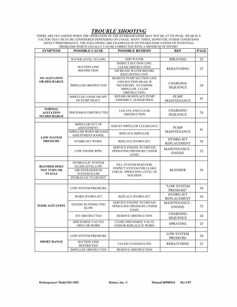
Hydrograsser Model HG-5H2 Reinco, Inc. © Manual 00500924 Rev1/07
TROUBLE SHOOTING THERE ARE OCCASIONS WHEN THE OPERATION OF THE HYDROGRASSER MAY NOT BE AT ITS PEAK. WEAR IS A
FACTOR THAT MUST BE CONSIDERED DEPENDING ON USAGE. MANY TIMES, HOWEVER, OTHER CONDITIONS AFFECT PERFORMANCE. THE FOLLOWING ARE EXAMPLES OF OUTWARD INDICATIONS OF POTENTIAL
PROBLEMS WHICH USUALLY CAN BE CORRECTED WITH A MINIMUM OF EFFORT SYMPTOM POSSIBLE CAUSE POSSIBLE REMEDY REF PAGE
WATER LEVEL TO LOW. ADD WATER. SPRAYING 25
INSPECT SUCTION LINE. CLEAR OBSTRUCTION. SUCTION LINE
RESTRICTION INCREASE WATER BEFORE RESTARTING UNIT.
REBATCHING 25
IMPELLER OBSTRUCTED
REMOVE PUMP SUCTION LINE AND SUCTION HEAD, IF
NECESSARY, TO EXPOSE IMPELLER. CLEAR
OBSTRUCTION.
CHARGING SEQUENCE 24
NO AGITATION OR DISCHARGE
IMPELLER LOOSE OR OFF OF PUMP SHAFT.
REPAIR OR REPLACE PUMP ASSEMBLY AS REQUIRED.
PUMP MAINTENANCE 41
NORMAL
AGITATION NO DISCHARGE
DISCHARGE OBSTRUCTED LOCATE AND CLEAR OBSTRUCTION
CHARGING SEQUENCE 24
IMPELLER OUT OF
ADJUSTMENT. ADJUST IMPELLER CLEARANCE.
IMPELLER WORN BEYOND ADJUSTMENT RANGE. REPLACE IMPELLER.
PUMP MAINTENANCE 41
HYDRO-JET WORN. REPLACE HYDRO-JET. HYDRO-JET REPLACEMENT 36
LOW SYSTEM PRESSURE
LOW ENGINE RPM. SERVICE ENGINE TO OBTAIN
OPERATING PRESSURE UNDER LOAD.
MAINTENANCE -ENGINE 32
HYDRAULIC SYSTEM
FLUID LEVEL LOW AIR ENTRAINED IN
SYSTEM FLUID
BLENDER DOES NOT TURN OR
STALLS HYDRAULIC FLUID HOT
FILL SYSTEM RESEVIOR, INSPECT SYSTEM FOR LEAKS
CHECK OPERATING LEVEL OF MACHINE
BLENDER 36
LOW SYSTEM PRESSURE "LOW SYSTEM PRESSURE" 34
WORN HYDRO-JET REPLACE HYDRO-JET. HYDRO-JET REPLACEMENT 36
ENGINE RUNNING TOO SLOW
SERVICE ENGINE TO OBTAIN OPERATING PRESSURE UNDER
LOAD.
MAINTENANCE -ENGINE 32
JET OBSTRUCTED REMOVE OBSTRUCTION CHARGING SEQUENCE 24
POOR AGITATION
DISCHARGE VALVES OPEN OR WORN
CLOSE DISCHARGE VALVE AND/OR REPLACE IF WORN. SPRAYING 25
LOW SYSTEM PRESSURE LOW SYSTEM PRESSURE 34
SUCTION LINE RESTRICTED CLEAR CLOGGED LINE REBATCHING 25 SHORT RANGE
IMPELLER OBSTRUCTED REMOVE OBSTRUCTION

41
SYMPTOM POSSIBLE CAUSE POSSIBLE REMEDY REF PAGE
OVERLOADING ADJUST MATERIALS
REQUIREMENTS REDUCE MATERIALS ALLOWING
FOR RESIDUALS ADD WETTING AGENT EXCESSIVE RESIDUALS
CONTACT MATERIALS SUPPLIERFOR ASSISTANCE
MATERIAL CONTAMINANTS
CONTACT MATERIALS SUPPLIERFOR ASSISTANCE
REBATCHING
IMPROPER LOADING PROCEDURES
CHARGE MACHINE IN PROPER SEQUENCE CHARGING
25 SYSTEM PLUGGING
LOW SYSTEM PRESSURE LOW SYSTEM PRESSURE 34
AIR ENTRAINMENT SLOW ENGINE SPEED
CHECK SLURRY MATERIALS COMPATABILITY
REBATCHING 25
IMPELLER OBSTRUCTION REMOVE OBSTRUCTION CHARGING SEQUENCE 24
ENGINE / PUMP VIBRATION
MISALIGNMENT CHECK AND ADJUST SHAFT ALIGNMENT
DRIVE COUPLING ALIGNMENT 37
PUMP BEARING FAILURE
OVER GREASING MISALIGNMENT
INSPECT BEARING ASSEMBLIES AND REPLACE IF REQUIRED CHECK SHAFT ALIGNMENT
PUMP LUBRICATION 42
ENGINE RUNNING
ROUGH DIRTY AIR/FUEL FILTERS SERVICE ENGINE CONTACT ENGINE SERVICE CENTER FOR ASSISTANCE

Hydrograsser Model HG-5H2 Reinco, Inc. © Manual 00500924 Rev1/07
BLENDER Daily inspection includes checking the hydraulic system hoses and fittings for leaks. Do not operate the system with leaking hoses or fittings. Remedy by replacing the failing component completely. The filter gauge is a restriction-controlled device. Replace the service filter at approximately 500 hours operation or when restriction is indicated. The hydraulic system coupling(s) should be inspected routinely for fatigue. Change system oil at 2500 hours. The system capacity is 12 gallons. Use ISO- 46 hydraulic fluid only. Dispose of waste oil in approved containers. The blender is supported by two sealed pillow block bearings. Periodically inspect these bearings for wear. Scraping of the blender assembly on the tank bottom would require that the shaft be adjusted providing clearance. Make sure the bearing-locking collar set screws and coupling setscrews are torqued when adjustments are made. Inspect and retorque the blender shaft coupling bolts and set screws. If an adjustment is required, the blender blades should have sufficient clearance to sweep residuals from the tank bottom, without scraping the floor. If the motor or pump should run hot, the system is drawing air or the reservoir level is too low. Assure that the machine is being operated on the level. Excessive tilting of the unit may limit the flow of the hydraulic fluid from the reservoir. Worn or damaged components will contribute to oil heating. Inspect components for wear, and replace as required. DO NOT ATTEMPT TO REBUILD HYDRAULIC COMPONENTS. Replace worn or damaged components
HYDRO-JET REPLACEMENT The HYDRO-JET, or pump bypass nozzle, is located in the tank wall near the rear of the tank. The nozzle is a quick-coupling type flange mounted to the tank-mating flange. The manifold connects via a quick disconnect coupling. The agitator nozzle will eventually wear from slurry granulars. It is important to realize that if the HYDRO-JET nozzle requires replacement, the pump impeller typically will also require adjustment, and visa versa. Replacement of the agitator nozzle is a simple task. Remove the nozzle / flange assembly, apply caulking to the mating flange and install the replacement nozzle assembly. When replacing the agitator nozzle adjust the nozzle angle to maintain a horizontal flow. Fill unit partially with water, start and inspect for leaks and proper agitation.
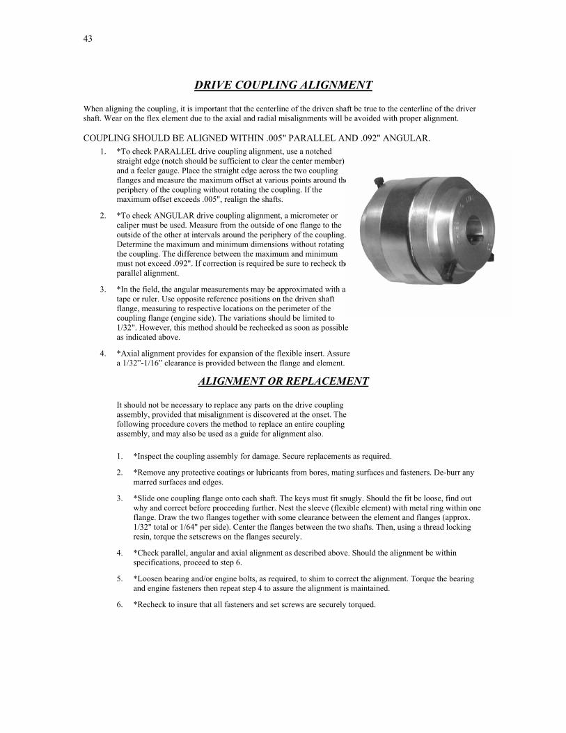
43
DRIVE COUPLING ALIGNMENT When aligning the coupling, it is important that the centerline of the driven shaft be true to the centerline of the driver shaft. Wear on the flex element due to the axial and radial misalignments will be avoided with proper alignment. COUPLING SHOULD BE ALIGNED WITHIN .005" PARALLEL AND .092" ANGULAR.
1. *To check PARALLEL drive coupling alignment, use a notched straight edge (notch should be sufficient to clear the center member) and a feeler gauge. Place the straight edge across the two coupling flanges and measure the maximum offset at various points around the periphery of the coupling without rotating the coupling. If the maximum offset exceeds .005", realign the shafts.
2. *To check ANGULAR drive coupling alignment, a micrometer or caliper must be used. Measure from the outside of one flange to the outside of the other at intervals around the periphery of the coupling. Determine the maximum and minimum dimensions without rotating the coupling. The difference between the maximum and minimum must not exceed .092". If correction is required be sure to recheck the parallel alignment.
3. *In the field, the angular measurements may be approximated with a tape or ruler. Use opposite reference positions on the driven shaft flange, measuring to respective locations on the perimeter of the coupling flange (engine side). The variations should be limited to 1/32". However, this method should be rechecked as soon as possible as indicated above.
4. *Axial alignment provides for expansion of the flexible insert. Assure a 1/32”-1/16” clearance is provided between the flange and element.
ALIGNMENT OR REPLACEMENT It should not be necessary to replace any parts on the drive coupling assembly, provided that misalignment is discovered at the onset. The following procedure covers the method to replace an entire coupling assembly, and may also be used as a guide for alignment also. 1. *Inspect the coupling assembly for damage. Secure replacements as required.
2. *Remove any protective coatings or lubricants from bores, mating surfaces and fasteners. De-burr any marred surfaces and edges.
3. *Slide one coupling flange onto each shaft. The keys must fit snugly. Should the fit be loose, find out why and correct before proceeding further. Nest the sleeve (flexible element) with metal ring within one flange. Draw the two flanges together with some clearance between the element and flanges (approx. 1/32" total or 1/64" per side). Center the flanges between the two shafts. Then, using a thread locking resin, torque the setscrews on the flanges securely.
4. *Check parallel, angular and axial alignment as described above. Should the alignment be within specifications, proceed to step 6.
5. *Loosen bearing and/or engine bolts, as required, to shim to correct the alignment. Torque the bearing and engine fasteners then repeat step 4 to assure the alignment is maintained.
6. *Recheck to insure that all fasteners and set screws are securely torqued.
Hydrograsser Model HG-5H2 Reinco, Inc. © Manual 00500924 Rev1/07
SWIVEL JOINT SERVICE INSTRUCTIONS Repacking the swivel joint assembly is required when the joint seals have become worn from slurry granulars or fatigue causes excessive leaking. Remove the joint from the piping and follow the procedure outlined below: 1. Remove swivel joint service plugs and squirt solvent into cavity to reduce grease. 2. Rotate tailpiece to remove balls from races, collecting the balls on a rag, as they fall from the service port. A
pair of long nosed pliers or pencil magnet may be required to remove any stubborn balls. 3. With the balls removed, the tailpieces will separate from the body section. Remove the worn seal from the
body sections, and the 'O' rings from the tailpiece. Thoroughly clean all surfaces of grease, grit and dirt. 4. Coat all surfaces with a light machine oil and install the new seals. 5. Replace the tailpieces into the body section with a slight twist to assure seating of the new seals. 6. Insert the balls through the service ports, swinging the tailpiece to completely load the races. 7. Replace the service plugs. If binding occurs, back off the plugs slightly. Lubricate the assembly with #1 consistency waterproof grease. Rotate the tailpiece to insure adequate lubrication. DO NOT FORCE GREASE. NOTE: Refer to page 59 for schematic and parts listing.
BALL VALVE SERVICING
The valves used in this application are full flow ball type valves allowing quick on-off control of the slurry flow. Partially opening or closing the valves will quickly cause the ball and or the valve seats to wear from the slurry granulars.
Replacement of the entire valve is recommended.
Repair or replacement of the worn parts is not often economical or effective
45
HOUSEKEEPING None of the ingredients used in the typical Hydrograssing or Tacking mixes are particularly corrosive, but allowing them to cake and collect both inside and out of the machine will contribute to premature deterioration. Make it a practice to hose your unit down with clear water on a daily basis. If a load or portion thereof is still in the tank, it can usually remain overnight or even two, without damage. One of the outstanding practical virtues of HYDRO-JET mixing is the ability to pick up dormant or settled loads relatively easily. However, with the tank empty, and having been given a good wash down, here is the procedure to follow to prepare the inside of the tank and associated piping for work the next day. 1. Fill the tank about 1/3 full. Start the engine; run at a moderate idle. Open the circulation supply valve for a
burst or two, run some of the fill through the spray hose(s), discharging into the tank hatch. 2. If the residual slurry is thin and moving freely, the machine can be shut down with the water remaining for
the night. If the layover is going to extend for a longer period, the weekend, or 3 to 4 days, or during hot weather, the Following additional steps should be taken: 3. Pump out the 1/3 tank load of weak slurry. Often the residuals may be broadcast at the site to prevent waste.
Open the sump fitting to drain the remaining materials. 4. If residuals remain, close all valves and refill as described above. Actuate the control valves and again flush
the lines with intermittent discharges. Then pump out completely. To save time, remove the spray nozzle or hose assembly to get higher flows.
5. Turn off the engine, open the tank drain, hose and wash down the unit inside and out.
WINTERIZING AND STORAGE
When the season is over, properly laying up the machine over the winter months will simplify spring start up. 1. GENERAL: Thoroughly clean and wash down unit both inside and out. Make sure the tank is fully drained.
Disconnect the sump suction hose. 2. PAINTING: Peeling paint or rusty spots should be scraped, primed and painted. 3. ENGINE: Perform the standard 80-hour check on the engine. The air-cooled engine should be fogged to
prevent sticking valves. Refer to the engine manual for cold weather preparation. 4. VALVES: Open all valves. With extreme cold weather conditions, the valves should be set in a 1/2 open
position allowing water to drain from the sealing area. 5. PUMP: Drain pump casing. Then add biodegradable antifreeze to prevent any residual water from freezing. Check and adjust pump impeller clearance as required.
6. COVER: The unit should be stored inside during severe weather conditions. If indoor storage is not available then the entire unit should be tarped and secured under cover in a protected area.

Hydrograsser Model HG-5H2 Reinco, Inc. © Manual 00500924 Rev1/07
REINCO MODEL HG-5H2
HYDROGRASSER
PUMP MAINTENANCE
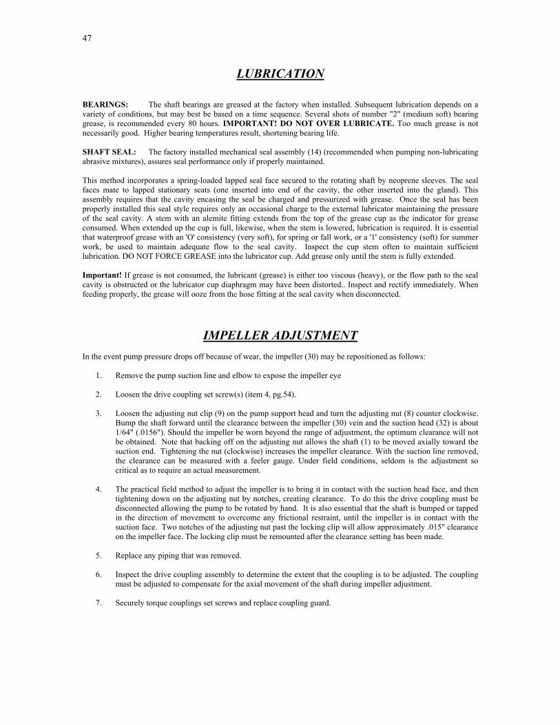
47
LUBRICATION BEARINGS: The shaft bearings are greased at the factory when installed. Subsequent lubrication depends on a variety of conditions, but may best be based on a time sequence. Several shots of number "2" (medium soft) bearing grease, is recommended every 80 hours. IMPORTANT! DO NOT OVER LUBRICATE. Too much grease is not necessarily good. Higher bearing temperatures result, shortening bearing life. SHAFT SEAL: The factory installed mechanical seal assembly (14) (recommended when pumping non-lubricating abrasive mixtures), assures seal performance only if properly maintained. This method incorporates a spring-loaded lapped seal face secured to the rotating shaft by neoprene sleeves. The seal faces mate to lapped stationary seats (one inserted into end of the cavity, the other inserted into the gland). This assembly requires that the cavity encasing the seal be charged and pressurized with grease. Once the seal has been properly installed this seal style requires only an occasional charge to the external lubricator maintaining the pressure of the seal cavity. A stem with an alemite fitting extends from the top of the grease cup as the indicator for grease consumed. When extended up the cup is full, likewise, when the stem is lowered, lubrication is required. It is essential that waterproof grease with an 'O' consistency (very soft), for spring or fall work, or a '1' consistency (soft) for summer work, be used to maintain adequate flow to the seal cavity. Inspect the cup stem often to maintain sufficient lubrication. DO NOT FORCE GREASE into the lubricator cup. Add grease only until the stem is fully extended. Important! If grease is not consumed, the lubricant (grease) is either too viscous (heavy), or the flow path to the seal cavity is obstructed or the lubricator cup diaphragm may have been distorted.. Inspect and rectify immediately. When feeding properly, the grease will ooze from the hose fitting at the seal cavity when disconnected.
IMPELLER ADJUSTMENT
In the event pump pressure drops off because of wear, the impeller (30) may be repositioned as follows: 1. Remove the pump suction line and elbow to expose the impeller eye 2. Loosen the drive coupling set screw(s) (item 4, pg.54). 3. Loosen the adjusting nut clip (9) on the pump support head and turn the adjusting nut (8) counter clockwise.
Bump the shaft forward until the clearance between the impeller (30) vein and the suction head (32) is about 1/64" (.0156"). Should the impeller be worn beyond the range of adjustment, the optimum clearance will not be obtained. Note that backing off on the adjusting nut allows the shaft (1) to be moved axially toward the suction end. Tightening the nut (clockwise) increases the impeller clearance. With the suction line removed, the clearance can be measured with a feeler gauge. Under field conditions, seldom is the adjustment so critical as to require an actual measurement.
4. The practical field method to adjust the impeller is to bring it in contact with the suction head face, and then
tightening down on the adjusting nut by notches, creating clearance. To do this the drive coupling must be disconnected allowing the pump to be rotated by hand. It is also essential that the shaft is bumped or tapped in the direction of movement to overcome any frictional restraint, until the impeller is in contact with the suction face. Two notches of the adjusting nut past the locking clip will allow approximately .015" clearance on the impeller face. The locking clip must be remounted after the clearance setting has been made.
5. Replace any piping that was removed. 6. Inspect the drive coupling assembly to determine the extent that the coupling is to be adjusted. The coupling
must be adjusted to compensate for the axial movement of the shaft during impeller adjustment. 7. Securely torque couplings set screws and replace coupling guard.
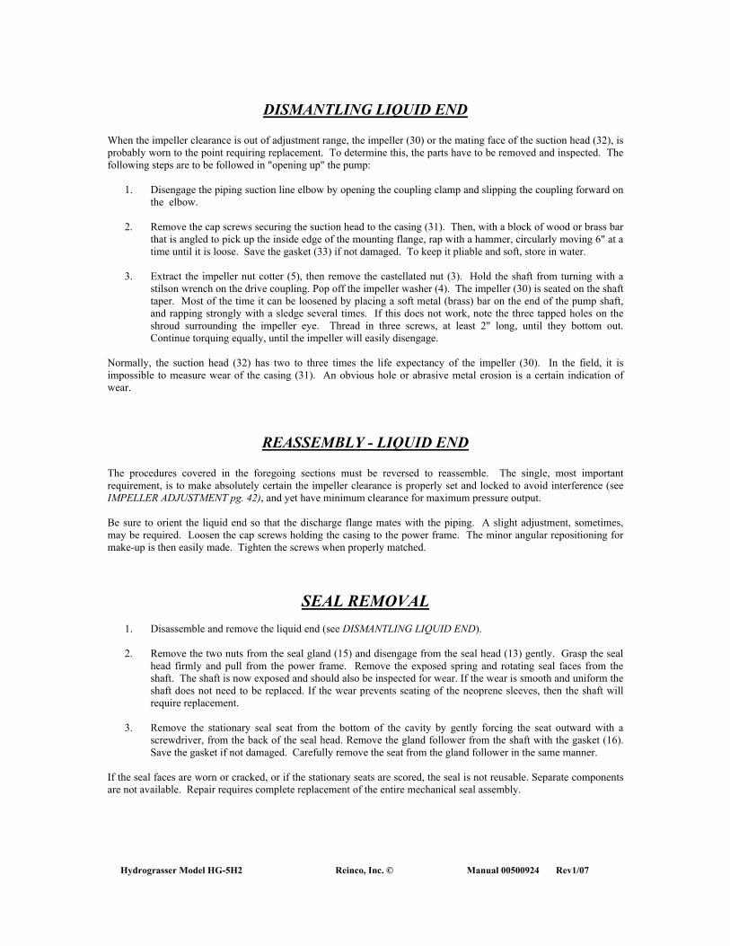
Hydrograsser Model HG-5H2 Reinco, Inc. © Manual 00500924 Rev1/07
DISMANTLING LIQUID END When the impeller clearance is out of adjustment range, the impeller (30) or the mating face of the suction head (32), is probably worn to the point requiring replacement. To determine this, the parts have to be removed and inspected. The following steps are to be followed in "opening up" the pump: 1. Disengage the piping suction line elbow by opening the coupling clamp and slipping the coupling forward on
the elbow. 2. Remove the cap screws securing the suction head to the casing (31). Then, with a block of wood or brass bar
that is angled to pick up the inside edge of the mounting flange, rap with a hammer, circularly moving 6" at a time until it is loose. Save the gasket (33) if not damaged. To keep it pliable and soft, store in water.
3. Extract the impeller nut cotter (5), then remove the castellated nut (3). Hold the shaft from turning with a
stilson wrench on the drive coupling. Pop off the impeller washer (4). The impeller (30) is seated on the shaft taper. Most of the time it can be loosened by placing a soft metal (brass) bar on the end of the pump shaft, and rapping strongly with a sledge several times. If this does not work, note the three tapped holes on the shroud surrounding the impeller eye. Thread in three screws, at least 2" long, until they bottom out. Continue torquing equally, until the impeller will easily disengage.
Normally, the suction head (32) has two to three times the life expectancy of the impeller (30). In the field, it is impossible to measure wear of the casing (31). An obvious hole or abrasive metal erosion is a certain indication of wear.
REASSEMBLY - LIQUID END The procedures covered in the foregoing sections must be reversed to reassemble. The single, most important requirement, is to make absolutely certain the impeller clearance is properly set and locked to avoid interference (see IMPELLER ADJUSTMENT pg. 42), and yet have minimum clearance for maximum pressure output. Be sure to orient the liquid end so that the discharge flange mates with the piping. A slight adjustment, sometimes, may be required. Loosen the cap screws holding the casing to the power frame. The minor angular repositioning for make-up is then easily made. Tighten the screws when properly matched.
SEAL REMOVAL
1. Disassemble and remove the liquid end (see DISMANTLING LIQUID END). 2. Remove the two nuts from the seal gland (15) and disengage from the seal head (13) gently. Grasp the seal
head firmly and pull from the power frame. Remove the exposed spring and rotating seal faces from the shaft. The shaft is now exposed and should also be inspected for wear. If the wear is smooth and uniform the shaft does not need to be replaced. If the wear prevents seating of the neoprene sleeves, then the shaft will require replacement.
3. Remove the stationary seal seat from the bottom of the cavity by gently forcing the seat outward with a
screwdriver, from the back of the seal head. Remove the gland follower from the shaft with the gasket (16). Save the gasket if not damaged. Carefully remove the seat from the gland follower in the same manner.
If the seal faces are worn or cracked, or if the stationary seats are scored, the seal is not reusable. Separate components are not available. Repair requires complete replacement of the entire mechanical seal assembly.
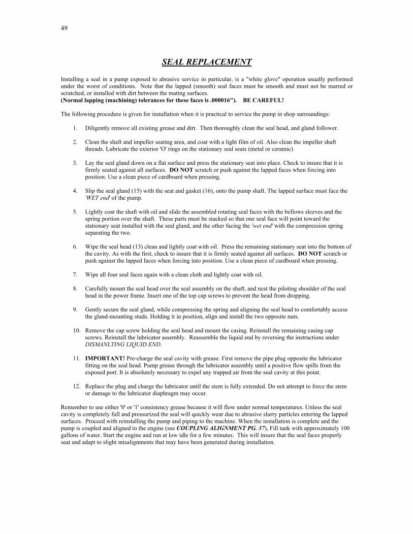
49
SEAL REPLACEMENT Installing a seal in a pump exposed to abrasive service in particular, is a "white glove" operation usually performed under the worst of conditions. Note that the lapped (smooth) seal faces must be smooth and must not be marred or scratched, or installed with dirt between the mating surfaces. (Normal lapping (machining) tolerances for these faces is .000016"). BE CAREFUL! The following procedure is given for installation when it is practical to service the pump in shop surroundings:
1. Diligently remove all existing grease and dirt. Then thoroughly clean the seal head, and gland follower.
2. Clean the shaft and impeller seating area, and coat with a light film of oil. Also clean the impeller shaft threads. Lubricate the exterior 'O' rings on the stationary seal seats (metal or ceramic)
3. Lay the seal gland down on a flat surface and press the stationary seat into place. Check to insure that it is firmly seated against all surfaces. DO NOT scratch or push against the lapped faces when forcing into position. Use a clean piece of cardboard when pressing.
4. Slip the seal gland (15) with the seat and gasket (16), onto the pump shaft. The lapped surface must face the 'WET end' of the pump.
5. Lightly coat the shaft with oil and slide the assembled rotating seal faces with the bellows sleeves and the spring portion over the shaft. These parts must be stacked so that one seal face will point toward the stationary seat installed with the seal gland, and the other facing the 'wet end' with the compression spring separating the two.
6. Wipe the seal head (13) clean and lightly coat with oil. Press the remaining stationary seat into the bottom of the cavity. As with the first, check to insure that it is firmly seated against all surfaces. DO NOT scratch or push against the lapped faces when forcing into position. Use a clean piece of cardboard when pressing.
7. Wipe all four seal faces again with a clean cloth and lightly coat with oil.
8. Carefully mount the seal head over the seal assembly on the shaft, and nest the piloting shoulder of the seal head in the power frame. Insert one of the top cap screws to prevent the head from dropping.
9. Gently secure the seal gland, while compressing the spring and aligning the seal head to comfortably access the gland-mounting studs. Holding it in position, align and install the two opposite nuts.
10. Remove the cap screw holding the seal head and mount the casing. Reinstall the remaining casing cap screws. Reinstall the lubricator assembly. Reassemble the liquid end by reversing the instructions under DISMANLTING LIQUID END.
11. IMPORTANT! Pre-charge the seal cavity with grease. First remove the pipe plug opposite the lubricator
fitting on the seal head. Pump grease through the lubricator assembly until a positive flow spills from the exposed port. It is absolutely necessary to expel any trapped air from the seal cavity at this point.
12. Replace the plug and charge the lubricator until the stem is fully extended. Do not attempt to force the stem or damage to the lubricator diaphragm may occur.
Remember to use either '0' or '1' consistency grease because it will flow under normal temperatures. Unless the seal cavity is completely full and pressurized the seal will quickly wear due to abrasive slurry particles entering the lapped surfaces. Proceed with reinstalling the pump and piping to the machine. When the installation is complete and the pump is coupled and aligned to the engine (see COUPLING ALIGNMENT PG. 37), Fill tank with approximately 100 gallons of water. Start the engine and run at low idle for a few minutes. This will insure that the seal faces properly seat and adapt to slight misalignments that may have been generated during installation.

50
Hydrograsser Model HG-5H2 Reinco, Inc. © Manual 00500924 Rev1/07
BEARING INSPECTION The pump shaft is cradled by two ball bearings that are nested in what is termed the support head. This entire assembly, from the bearing cover to the seal head, is called the Power Frame. To inspect the pump bearings, the pump shaft must be removed from the power frame per the following: 1. Disconnect the suction and discharge pump piping, the drive coupling, and the pump base hold down bolts. 2. Lift the entire pump from the HYDROGRASSER and place on a workbench. Secure the pump power frame
to the workbench. 3. Disassemble and remove the liquid end parts (See DISMANTLING LIQUID END pg.43). 4. Remove the bearing cover (18) and seal head (13) assembly. The adjusting spring (7) should push the cover
off. Place a wooden block on the end of the shaft, rapping with a hammer, to force the shaft and bearings from the power frame. The slinger (10) will slip off as the shaft end reaches the adjusting nut (8).
The bearings may now be easily examined, turned and checked. To remove the bearings, press from the inner race of the bearing to force to the respective end of the shaft.
BEARING INSTALLATION 1. The two bearings (6) are each equipped with a dirt shield on one side. When mounted, the shielded sides
must face the coupling end of the pump shaft. The bearing race should press tightly against the mid-shaft shoulder. If the shaft surface is marred, it must be cleaned, smoothed, and checked for concentricity.
2. Never PRESS a tolerance fit bearing. Instead warm the bearing in an oven to 180 degrees. This will expand
the races so that the bearing may easily slide onto the shaft. Do not exceed the 180-degree temp. so as not to melt out lubricant or damage the bearing ball retainers. It would also be advantageous to cool the shaft at this time, to more easily slip the warmed bearing into position.
3. Mount the wet end (inboard, I.B.) bearing on the pump shaft using the same procedure as with the outboard
bearing. Make sure the bearing shields face the coupling end of the shaft. 4. Apply a number "2" consistency bearing grease to the exposed balls (those opposite the shields), and rotate to
work in. 5. Inspect the felt ring (11) and retaining collars (12) in the bearing cover (18) and the adjusting nut (8). Replace
if necessary. The felt rings should be replaced when bearings are changed. 6. Insert the shaft and bearing assembly with the tapered (impeller mounting) end into the coupling end of the
power frame until the shaft projects from the adjusting nut, then mount the slinger (10) and nudge into position on the shaft. Push the shaft the remaining distance into the frame until the inboard bearing rests against the adjusting nut.
7. Replace the adjusting spring (7) into the coupling end of the frame. While compressing the spring, replace the
bearing cover (18), cover gasket (19), and screws. Now reassemble the pump seal head and liquid end. Adjust the impeller and shaft to mount the casing as described under IMPELLER ADJUSTMENT pg. 42.
8. Install the drive-coupling key, and remount the drive-coupling flange. 9. Grease each bearing fitting, about 1 or two squeezes using a number "2" consistency bearing quality
lubricant. 10. Recheck impeller clearance as described under IMPELLER ADJUSTMENT pg. 42

51

52
Hydrograsser Model HG-5H2 Reinco, Inc. © Manual 00500924 Rev1/07
REINCO MODEL HG-5H2
HYDROGRASSER
PARTS LISTINGS & SCHEMATICS
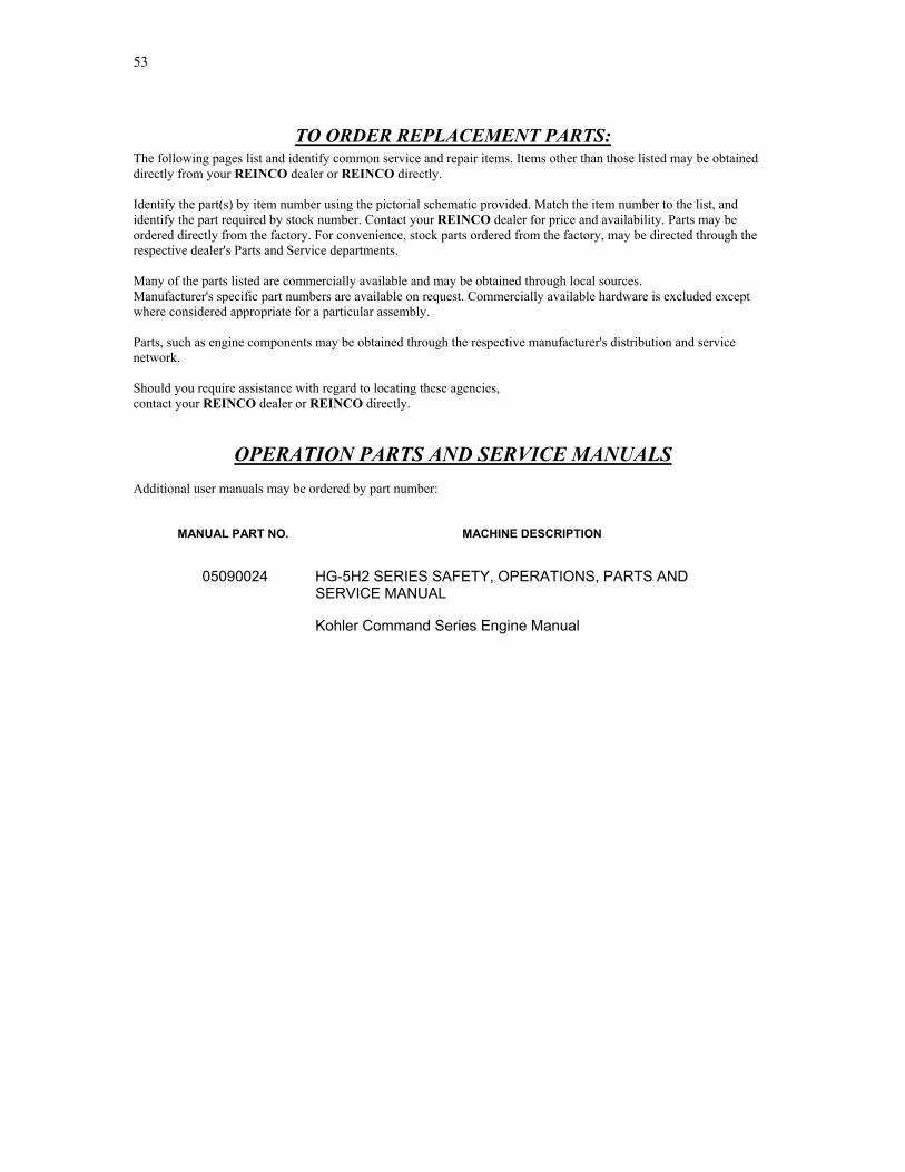
53
TO ORDER REPLACEMENT PARTS: The following pages list and identify common service and repair items. Items other than those listed may be obtained directly from your REINCO dealer or REINCO directly. Identify the part(s) by item number using the pictorial schematic provided. Match the item number to the list, and identify the part required by stock number. Contact your REINCO dealer for price and availability. Parts may be ordered directly from the factory. For convenience, stock parts ordered from the factory, may be directed through the respective dealer's Parts and Service departments. Many of the parts listed are commercially available and may be obtained through local sources. Manufacturer's specific part numbers are available on request. Commercially available hardware is excluded except where considered appropriate for a particular assembly. Parts, such as engine components may be obtained through the respective manufacturer's distribution and service network. Should you require assistance with regard to locating these agencies, contact your REINCO dealer or REINCO directly.
OPERATION PARTS AND SERVICE MANUALS Additional user manuals may be ordered by part number:
MANUAL PART NO. MACHINE DESCRIPTION
05090024 HG-5H2 SERIES SAFETY, OPERATIONS, PARTS AND SERVICE MANUAL
Kohler Command Series Engine Manual

54
Hydrograsser Model HG-5H2 Reinco, Inc. © Manual 00500924 Rev1/07
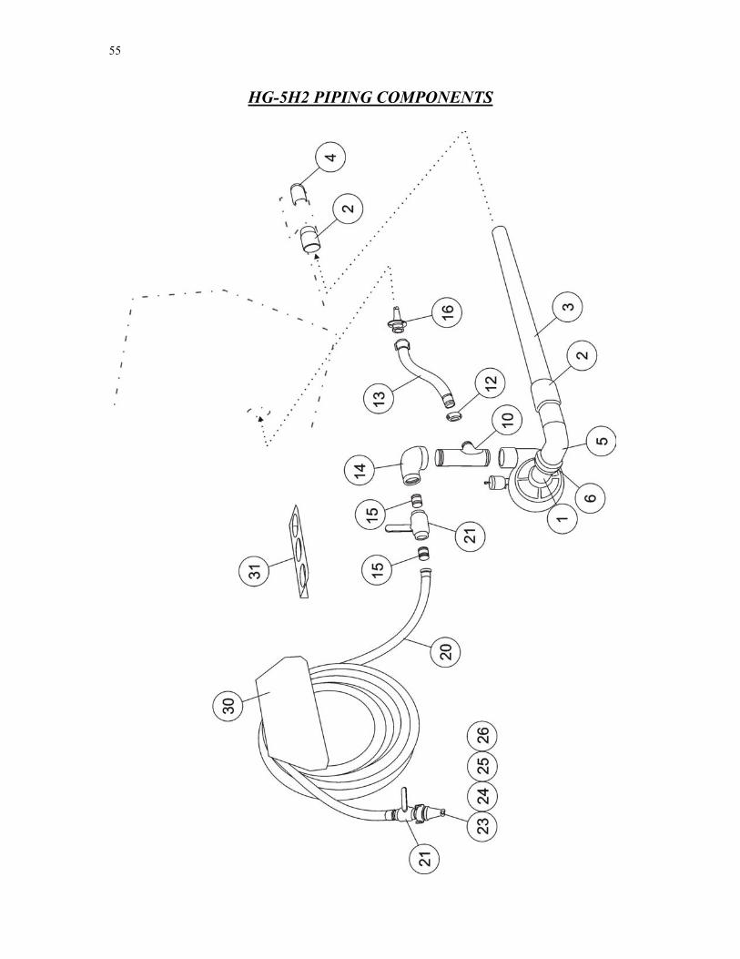
55
HG-5H2 PIPING COMPONENTS

56
Hydrograsser Model HG-5H2 Reinco, Inc. © Manual 00500924 Rev1/07
PIPING COMPONENTS ITEM STOCK NO. DESCRIPTION QTY 1 PI7530.05 SUCTION INTAKE NIPPLE 3” GOE/TOE 1 2 PI2810.40 SLEEVE COUPLING 4” 2 3 PI7740.42 SUCTION LINE ASSEMBLY 4” x 42-1/2” 1 4 CP1005.20 CLEANOUT PLUG 2” 1 5 6 6.1
06789200 PI2312.43 GA7006.43
FABR PUMP INLET ELBOW 4” x 90 REDUCING COUPLING 4” x 3” GASKET ONLY 4” x 3”
1 1 1
10 06788013 PUMP DISCHARGE MANIFOLD 1 12 12.1
PI2310.20 GA7005.20
LINE COUPLING W/ GSKT 2” GASKET ONLY 2”
1
13 13.1 13.2 13.3
06788050 PI2825.20 HO7762.02A HO8002.01
BYPASS HOSE ASSEMBLY 2”x 19-3/4” ”OA HOSE FITTING 2” GRV x HOSE SHANK HOSE FITTING 2” ‘C’ x HOSE SHANK CLAMP 5/8” x 2-1/2” BANDIT
1 1 1 4
14 PI2853.25 ELBOW 2-1/2” x 90 1 15 PI7912.01 NIPPLE 1-1/4” x CLOSE 2 16 05592020 HYDROJET NOZZLE W/ FLANGE 1 20 HO7112.55A 1-1/4”x50FT POLYBRAID HOSE CPLD MxF 1 20.1 GA7001.50 HOSE END GASKET 1-1/4” 21 VA5262.00 BALL VALVE 1-1/4" FULL FLOW BRASS 1 22 PI2821.25A QUICK-DISCONNECT COUPLER 1-1/4" 'B' 1 22.1 GA7001.59 COUPLER GASKET ONLY 1-1/4" 23 NO9940.00 NOZZLE 1-1/4” STRAIGHT STREAM (65 GPM) SS 1 24 NO9940.01 NOZZLE 1-1/4” STRAIGHT STREAM (105 GPM) SS 1 25 NO9941.00 NOZZLE 1-1/4” FAN PATTERN 250 (NARROW) SS 1 26 NO9941.01 NOZZLE 1-1/4” FAN PATTERN 500 (WIDE) SS 1 30 05381050 HOSE HANGER 1 30.1 FA1124.10 3/8"-16 x 1” NC HEX HEAD SREW 2 30.2 FA1241.03 3/8"-16 NC NYLON INSERT NUT 2

57
OPTIONAL SPRAY BOOM ASSEMBLY
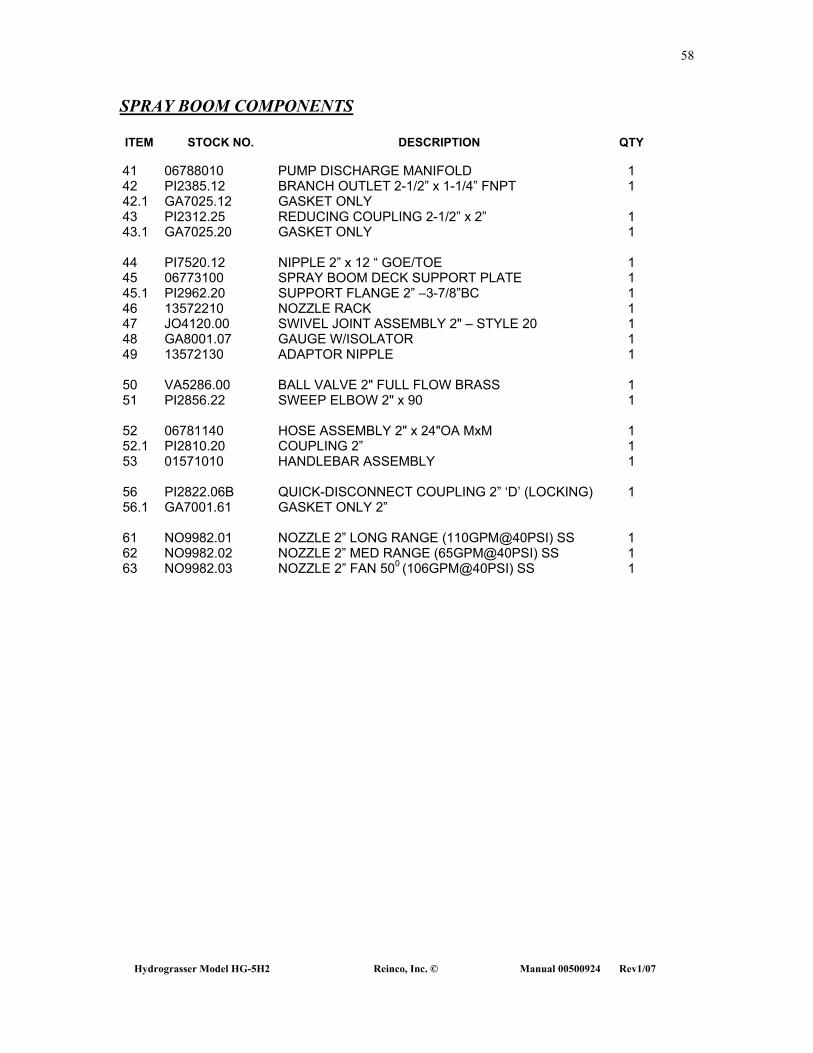
58
Hydrograsser Model HG-5H2 Reinco, Inc. © Manual 00500924 Rev1/07
SPRAY BOOM COMPONENTS
ITEM STOCK NO. DESCRIPTION QTY
41 06788010 PUMP DISCHARGE MANIFOLD 1 42 42.1
PI2385.12 GA7025.12
BRANCH OUTLET 2-1/2” x 1-1/4” FNPT GASKET ONLY
1
43 43.1
PI2312.25 GA7025.20
REDUCING COUPLING 2-1/2” x 2” GASKET ONLY
1 1
44 45
PI7520.12 06773100
NIPPLE 2” x 12 “ GOE/TOE SPRAY BOOM DECK SUPPORT PLATE
1 1
45.1 PI2962.20 SUPPORT FLANGE 2” –3-7/8”BC 1 46 13572210 NOZZLE RACK 1 47 JO4120.00 SWIVEL JOINT ASSEMBLY 2" – STYLE 20 1 48 GA8001.07 GAUGE W/ISOLATOR 1 49 13572130 ADAPTOR NIPPLE 1
50 VA5286.00 BALL VALVE 2" FULL FLOW BRASS 1 51
PI2856.22
SWEEP ELBOW 2" x 90 1
52 52.1
06781140 PI2810.20
HOSE ASSEMBLY 2" x 24"OA MxM COUPLING 2”
1 1
53 01571010 HANDLEBAR ASSEMBLY 1 56 56.1
PI2822.06B GA7001.61
QUICK-DISCONNECT COUPLING 2” ‘D’ (LOCKING) GASKET ONLY 2”
1
61 NO9982.01 NOZZLE 2” LONG RANGE (110GPM@40PSI) SS 1 62 NO9982.02 NOZZLE 2” MED RANGE (65GPM@40PSI) SS 1 63 NO9982.03 NOZZLE 2” FAN 500 (106GPM@40PSI) SS 1
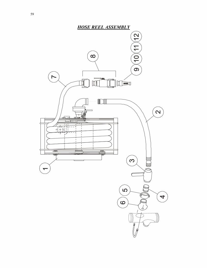
59
HOSE REEL ASSEMBLY

60
Hydrograsser Model HG-5H2 Reinco, Inc. © Manual 00500924 Rev1/07
HOSE REEL COMPONENTS ITEM STOCK NO. DESCRIPTION QTY 1 HR1010.00 HOSE REEL- SPRING REWIND, 1-1/4"x100' Capacity 1 2 06789060 SUPPLY HOSE ASSEMBLY 1-1/2” x 56” OA RH 1 06789060 SUPPLY HOSE ASSEMBLY 1-1/2” x 31” OA LH 1 3 VA5272.00 HOSE REEL SUPPLY VALVE 1-1/2” FULL FLOW 1 4 PI7515.02 NIPPLE 1-1/2” X 1-3/4” GOE/TOE 1 5 PI2310.15 LINE COUPLING 1-1/2” 1 GA7005.15 GASKET ONLY 6 PI2384.15 BRANCH ADAPTOR 2-1/2” X 1-1/2” 1 GA7020.15 GASKET ONLY 7 HO7112.56 1-1/4" x 100' (HARD) NEOPRENE JACKETED HOSE MxF 1 8 VA9912.50 1-1/4" REMOTE SPRAY VALVE ASSEMBLY 1 8.1 PI2821.25A 1-1/4” ‘B’ QUICK-DISCONNECT COUPLER (VALVE END) 1 8.2 VA5262.00 1-1/4” FULL FLOW BALL VALVE 1 8.3 PI2821.22A 1-1/4” ‘F’ QUICK-DISCONNECT ADAPTOR 1 8.4 PI2821.26A 1-1/4” ‘D’ QUICK-DISCONNECT COUPLER (HOSE END) 1 GA7001.59 GASKET ONLY - QUICK-DISCONNECT COUPLER 9 NO9940.00 1-1/4" NOZZLE-SS STRAIGHT STREAM, 65 GPM @ 40PSI 1 10 NO9940.01 1-1/4" NOZZLE-SS STRAIGHT STREAM, 105 GPM @ 40PSI 1 11 NO9941.00 1-1/4" NOZZLE-SS NARROW FAN 250 ANGLE, 50 GPM @ 40PSI 1 12 NO9941.01 1-1/4" NOZZLE-SS WIDE FAN 500 ANGLE, 75 GPM @ 40PSI 1
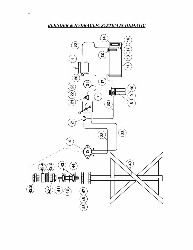
61
BLENDER & HYDRAULIC SYSTEM SCHEMATIC
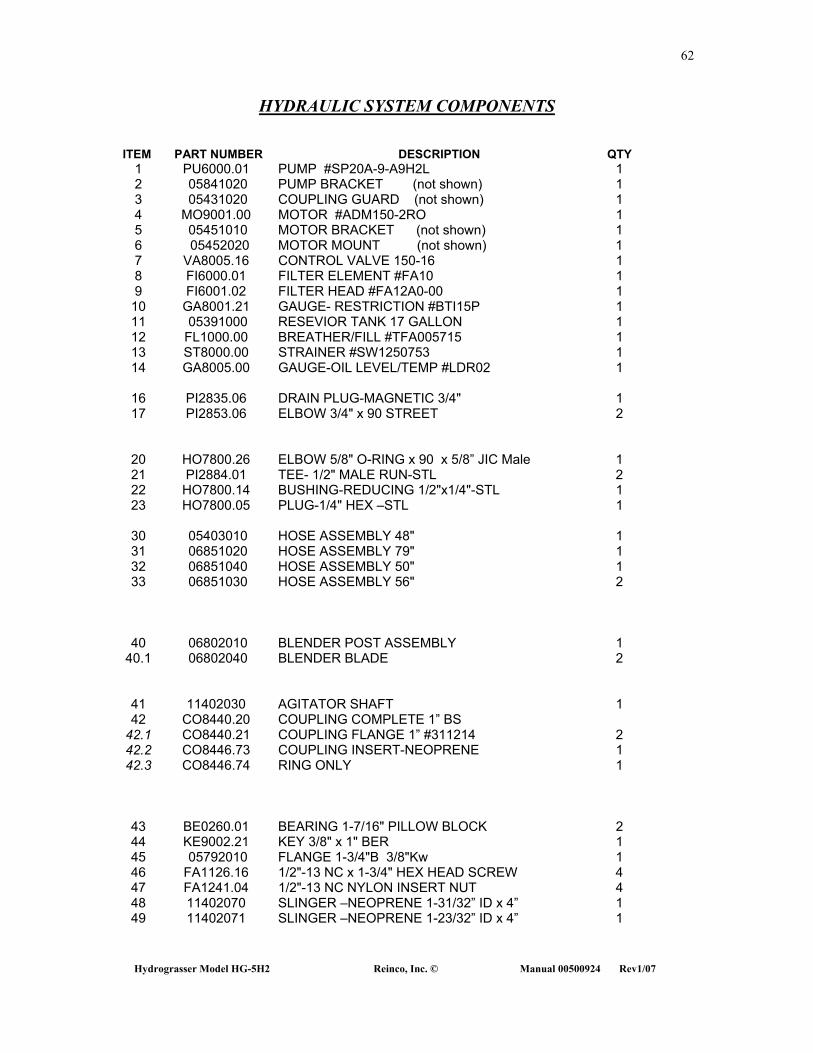
62
Hydrograsser Model HG-5H2 Reinco, Inc. © Manual 00500924 Rev1/07
HYDRAULIC SYSTEM COMPONENTS
ITEM PART NUMBER DESCRIPTION QTY 1 PU6000.01 PUMP #SP20A-9-A9H2L 1 2 05841020 PUMP BRACKET (not shown) 1 3 05431020 COUPLING GUARD (not shown) 1 4 MO9001.00 MOTOR #ADM150-2RO 1 5 05451010 MOTOR BRACKET (not shown) 1 6 05452020 MOTOR MOUNT (not shown) 1 7 VA8005.16 CONTROL VALVE 150-16 1 8 FI6000.01 FILTER ELEMENT #FA10 1 9 FI6001.02 FILTER HEAD #FA12A0-00 1 10 GA8001.21 GAUGE- RESTRICTION #BTI15P 1 11 05391000 RESEVIOR TANK 17 GALLON 1 12 FL1000.00 BREATHER/FILL #TFA005715 1 13 ST8000.00 STRAINER #SW1250753 1 14 GA8005.00 GAUGE-OIL LEVEL/TEMP #LDR02 1
16 PI2835.06 DRAIN PLUG-MAGNETIC 3/4" 1 17 PI2853.06 ELBOW 3/4" x 90 STREET 2
20 HO7800.26 ELBOW 5/8" O-RING x 90 x 5/8” JIC Male 1 21 PI2884.01 TEE- 1/2" MALE RUN-STL 2 22 HO7800.14 BUSHING-REDUCING 1/2"x1/4"-STL 1 23 HO7800.05 PLUG-1/4" HEX –STL 1
30 05403010 HOSE ASSEMBLY 48" 1 31 06851020 HOSE ASSEMBLY 79" 1 32 06851040 HOSE ASSEMBLY 50" 1 33 06851030 HOSE ASSEMBLY 56" 2
40 06802010 BLENDER POST ASSEMBLY 1 40.1 06802040 BLENDER BLADE 2
41 11402030 AGITATOR SHAFT 1 42 CO8440.20 COUPLING COMPLETE 1” BS
42.1 CO8440.21 COUPLING FLANGE 1” #311214 2 42.2 CO8446.73 COUPLING INSERT-NEOPRENE 1 42.3 CO8446.74 RING ONLY 1
43 BE0260.01 BEARING 1-7/16" PILLOW BLOCK 2 44 KE9002.21 KEY 3/8" x 1" BER 1 45 05792010 FLANGE 1-3/4"B 3/8"Kw 1 46 FA1126.16 1/2"-13 NC x 1-3/4" HEX HEAD SCREW 4 47 FA1241.04 1/2"-13 NC NYLON INSERT NUT 4 48 11402070 SLINGER –NEOPRENE 1-31/32” ID x 4” 1 49 11402071 SLINGER –NEOPRENE 1-23/32” ID x 4” 1

63
ENGINE AND PUMP DRIVE
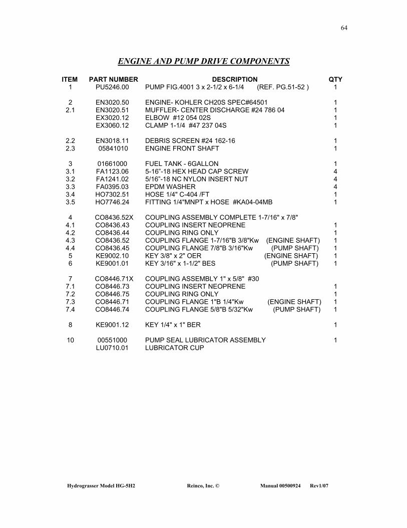
64
Hydrograsser Model HG-5H2 Reinco, Inc. © Manual 00500924 Rev1/07
ENGINE AND PUMP DRIVE COMPONENTS ITEM PART NUMBER DESCRIPTION QTY
1 PU5246.00 PUMP FIG.4001 3 x 2-1/2 x 6-1/4 (REF. PG.51-52 ) 1
2 EN3020.50 ENGINE- KOHLER CH20S SPEC#64501 1 2.1 EN3020.51 MUFFLER- CENTER DISCHARGE #24 786 04 1
EX3020.12 ELBOW #12 054 02S 1 EX3060.12 CLAMP 1-1/4 #47 237 04S 1
2.2 EN3018.11 DEBRIS SCREEN #24 162-16 1 2.3 05841010 ENGINE FRONT SHAFT 1
3 01661000 FUEL TANK - 6GALLON 1
3.1 FA1123.06 5-16”-18 HEX HEAD CAP SCREW 4 3.2 FA1241.02 5/16”-18 NC NYLON INSERT NUT 4 3.3 FA0395.03 EPDM WASHER 4 3.4 HO7302.51 HOSE 1/4" C-404 /FT 1 3.5 HO7746.24 FITTING 1/4"MNPT x HOSE #KA04-04MB 1
4 CO8436.52X COUPLING ASSEMBLY COMPLETE 1-7/16" x 7/8"
4.1 CO8436.43 COUPLING INSERT NEOPRENE 1 4.2 CO8436.44 COUPLING RING ONLY 1 4.3 CO8436.52 COUPLING FLANGE 1-7/16"B 3/8"Kw (ENGINE SHAFT) 1 4.4 CO8436.45 COUPLING FLANGE 7/8"B 3/16"Kw (PUMP SHAFT) 1 5 KE9002.10 KEY 3/8" x 2" OER (ENGINE SHAFT) 1 6 KE9001.01 KEY 3/16" x 1-1/2" BES (PUMP SHAFT) 1
7 CO8446.71X COUPLING ASSEMBLY 1" x 5/8" #30
7.1 CO8446.73 COUPLING INSERT NEOPRENE 1 7.2 CO8446.75 COUPLING RING ONLY 1 7.3 CO8446.71 COUPLING FLANGE 1"B 1/4"Kw (ENGINE SHAFT) 1 7.4 CO8446.74 COUPLING FLANGE 5/8"B 5/32"Kw (PUMP SHAFT) 1
8 KE9001.12 KEY 1/4" x 1" BER 1
10 00551000 PUMP SEAL LUBRICATOR ASSEMBLY 1 LU0710.01 LUBRICATOR CUP
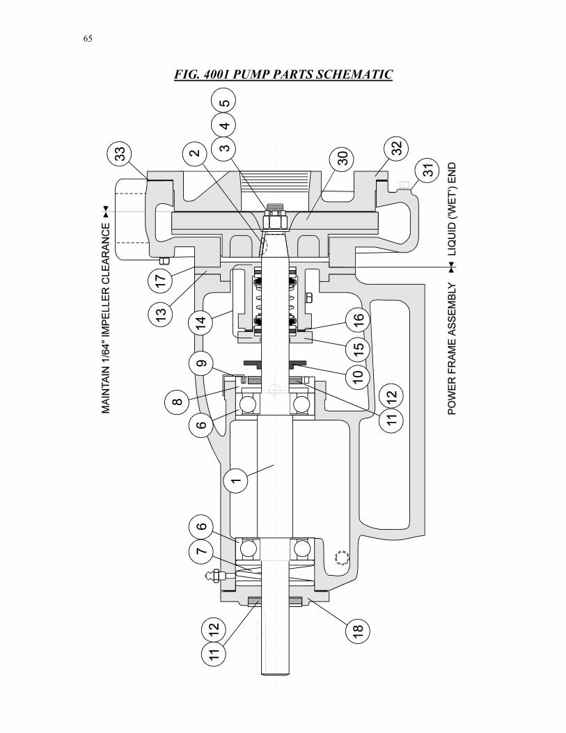
65
FIG. 4001 PUMP PARTS SCHEMATIC
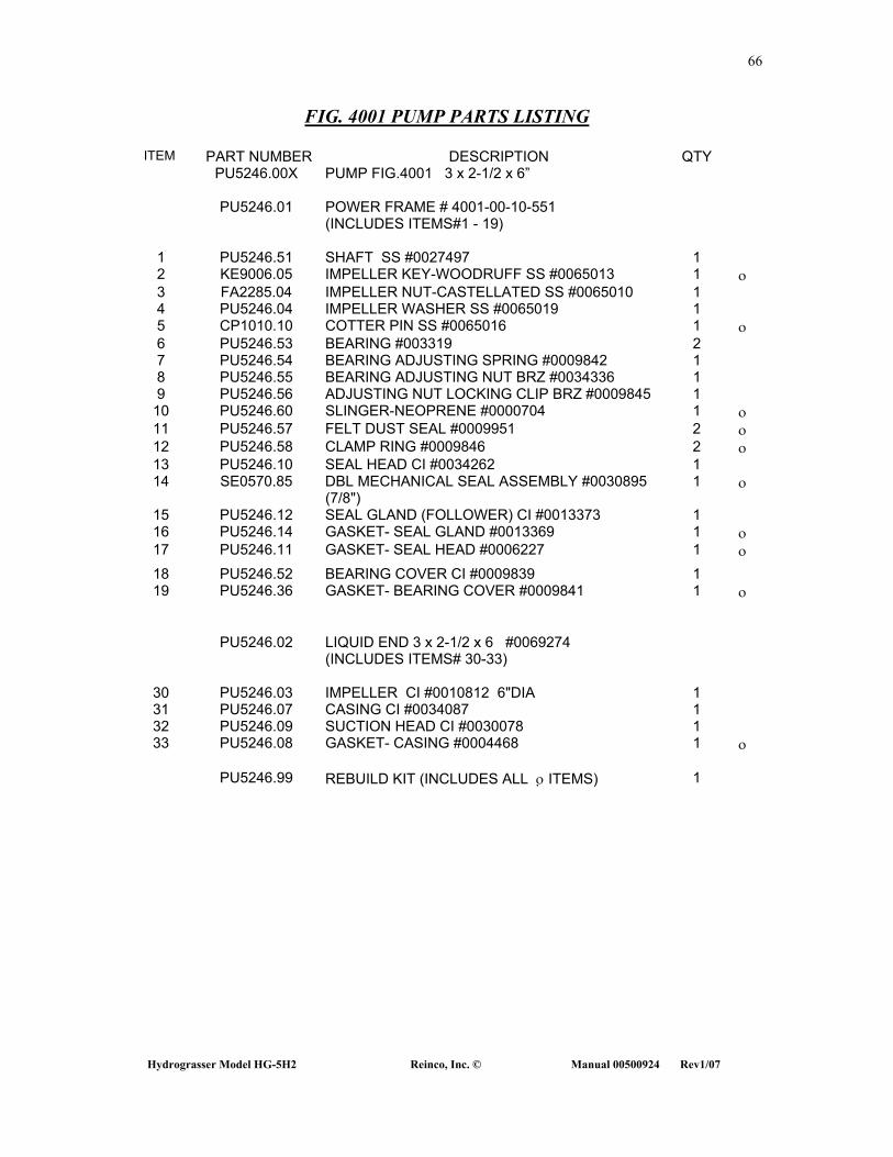
66
Hydrograsser Model HG-5H2 Reinco, Inc. © Manual 00500924 Rev1/07
FIG. 4001 PUMP PARTS LISTING
ITEM PART NUMBER DESCRIPTION QTY PU5246.00X PUMP FIG.4001 3 x 2-1/2 x 6”
PU5246.01 POWER FRAME # 4001-00-10-551
(INCLUDES ITEMS#1 - 19)
1 PU5246.51 SHAFT SS #0027497 1 2 KE9006.05 IMPELLER KEY-WOODRUFF SS #0065013 1 ο 3 FA2285.04 IMPELLER NUT-CASTELLATED SS #0065010 1 4 PU5246.04 IMPELLER WASHER SS #0065019 1 5 CP1010.10 COTTER PIN SS #0065016 1 ο 6 PU5246.53 BEARING #003319 2 7 PU5246.54 BEARING ADJUSTING SPRING #0009842 1 8 PU5246.55 BEARING ADJUSTING NUT BRZ #0034336 1 9 PU5246.56 ADJUSTING NUT LOCKING CLIP BRZ #0009845 1
10 PU5246.60 SLINGER-NEOPRENE #0000704 1 ο 11 PU5246.57 FELT DUST SEAL #0009951 2 ο 12 PU5246.58 CLAMP RING #0009846 2 ο 13 PU5246.10 SEAL HEAD CI #0034262 1 14 SE0570.85 DBL MECHANICAL SEAL ASSEMBLY #0030895
(7/8") 1 ο
15 PU5246.12 SEAL GLAND (FOLLOWER) CI #0013373 1 16 PU5246.14 GASKET- SEAL GLAND #0013369 1 ο 17 PU5246.11 GASKET- SEAL HEAD #0006227 1 ο 18 PU5246.52 BEARING COVER CI #0009839 1 19 PU5246.36 GASKET- BEARING COVER #0009841 1 ο
PU5246.02 LIQUID END 3 x 2-1/2 x 6 #0069274
(INCLUDES ITEMS# 30-33)
30 PU5246.03 IMPELLER CI #0010812 6"DIA 1 31 PU5246.07 CASING CI #0034087 1 32 PU5246.09 SUCTION HEAD CI #0030078 1 33 PU5246.08 GASKET- CASING #0004468 1 ο
PU5246.99 REBUILD KIT (INCLUDES ALL ο ITEMS) 1
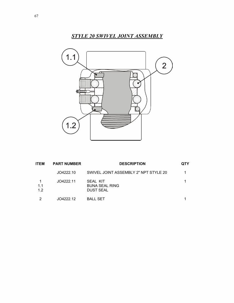
67
STYLE 20 SWIVEL JOINT ASSEMBLY
ITEM PART NUMBER DESCRIPTION QTY JO4222.10 SWIVEL JOINT ASSEMBLY 2" NPT STYLE 20 1 1 JO4222.11 SEAL KIT 1
1.1 BUNA SEAL RING 1.2 DUST SEAL
2 JO4222.12 BALL SET 1

68
Hydrograsser Model HG-5H2 Reinco, Inc. © Manual 00500924 Rev1/07
DECALS AND LABELING
ITEM PART NUMBER DESCRIPTION QTY
1 ID2625.03 APPLIQUE 'REINCO' LOGO 6"x29" 2
2 00171020 DECAL – CHARGING 1 3 00202000 DECAL - LUBRICATION SCHEDULE 1 4 00271000 DECAL - EQUIPMENT TRAINING 1 5 00291000 DECAL - WARNING VIBRATION 1 6 00211020 DECAL - CAUTION STOP MACHINE FOR SERVICING 1 7 00171040 DECAL - DO NOT THROTTLE SPRAY VALVE 1 8 00251000 DECAL - WARNING CONFINED SPACE 1 9 00191000 DECAL - DO NOT OVERGREASE BEARINGS 2
10 00212030 DECAL - WARNING KEEP GUARDS IN PLACE 2 11 00171030 DECAL - MAINTAIN PUMP IMPELLER CLEARANCE 1 12 00231000 DECAL - CAUTION 3200 RPM MAXIMUM 1 13 00192000 DECAL - NOTICE FUEL SHUTOFF 1 14 00181000 DECAL - 'GASOLINE' ONLY 1 15 00183000 DECAL - HYDRAULIC FLUID 1 16 00261000 DECAL - DANGER HYDRAULICS 1 17 00291000 DECAL - WARNING WHEEL TORQUE 2
18 00241000 DECAL - REINCO '800' SALES & SERVICE 2 19 ID2600.11 SERIAL NUMBER NAMEPLATE 1 CO0002.01 REINCO #12-238A W/R ACRYLIC ALKYD ENAMEL EXT CO0131.02 SIGMA 7477F \ TCP ALUMINUM HIGH SOLIDS EPOXY INT

69
TRAILER COMPONENTS
ITEM PART NUMBER DESCRIPTION QTY
1 AX5116.00 BRAKE AXLE ASSEMBLY- #12 (7K) TORFLEX 45DT 12x2 1 HUB & DRUM ASSEMBLY 008-219-4 (INCL υ ITEMS) 2 AX5103.13 GREASE SEAL 010-001-00 NATIONAL #440972 1 υ AX5103.11 BEARING - INNER CONE 031-030—02 #25580 1 υ AX5103.12 RACE - INNER BEARING CUP 031-030-01 #25520 1 υ AX5201.06 BEARING - OUTER CONE 031-029-02 #15123 1 υ AX5201.07 RACE - OUTER BEARING CUP 031-029-01 #15245 1 υ AX5103.06 NUT - SPINDLE 1"-14 006-176-00 1 υ AX5201.31 WASHER - SPINDLE 005-057-00 1 υ AX5201.32 COTTER PIN - 1/8" x 1.75” 0019-002-00 1 υ AX5103.08 CAP 021-001-00 2.45"OD 1 υ
AX5201.33 BRAKE ASSEMBLY - RH KIT 023-181-00 1 AX5201.34 BRAKE ASSEMBLY - LH KIT 023-180-00 1 AX5116.02 CONE NUT 16
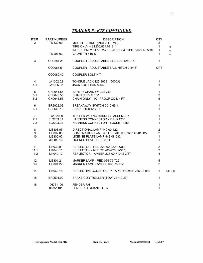
70
Hydrograsser Model HG-5H2 Reinco, Inc. © Manual 00500924 Rev1/07
TRAILER PARTS CONTINUED ITEM PART NUMBER DESCRIPTION QTY
2 TI7530.00 MOUNTED TIRE (INCL σ ITEMS) 2 TIRE ONLY – ST235/85R16 ‘E’ ' 1 σ WHEEL ONLY 017-302-25 8-6.5BC, 4.89PD, 3750LR, 5OS 1 σ TI7203.03 VALVE TR-416-S 1 σ
3 CO9281.21 COUPLER - ADJUSTABLE EYE BDB-1250-15 1 CO9085.51 COUPLER - ADJUSTABLE BALL HITCH 2-5/16” OPT
CO9080.42 COUPLER BOLT KIT
4 JA1002.02 TONGUE JACK 125-80391 (5000#) 1
4.1 JA1005.02 JACK FOOT PAD 82660 1
5 CH0641.56 SAFETY CHAIN W/ CLEVIS' 1 5.1 CH0643.55 CHAIN CLEVIS 1/2" 2 5.2 CH0641.55 CHAIN ONLY - 1/2" PROOF COIL x FT 5
6 BR2022.03 BREAKAWAY SWITCH 2010 65-4 1
6.1 CH0643.10 SNAP HOOK R12978 1
7 05422000 TRAILER WIRING HARNESS ASSEMBLY 1 7.1 EL2203.01 HARNESS CONNECTOR - PLUG 1235 1 7.2 EL2203.02 HARNESS CONNECTOR - SOCKET 1254 1
8 LI3303.05 DIRECTIONAL LAMP 140-00-122 2 9 LI3302.05 COMBINATION LAMP (STOP/TAIL/TURN) 0140-01-122 2 10 LI3305.02 LICENSE PLATE LAMP 448-08-532 1 30284010 LICENSE PLATE BRACKET 1
11 LI4030.01 REFLECTOR - RED 224-00-020 (Oval) 2 11.1 LI4040.11 REFLECTOR - RED 223-00-720 (2-3/8”) 2 11.2 LI4040.12 REFLECTOR – AMBER 223-00-710 (2-3/8”) 4
12 LI3301.21 MARKER LAMP - RED 065-75-722 5 13 LI3301.22 MARKER LAMP - AMBER 065-75-712 2
14 LI4060.18 REFLECTIVE CONSPICUITY TAPE R/S2x18” 235-02-080 1 KIT (4)
15 BR0501.02 BRAKE CONTROLLER (TOW VEHICLE) 1
16 06751100 FENDER RH 1 06751101 FENDER LH (MANIFOLD) 1

71
OPTIONAL TANDEM AXLE COMPONENTS ITEM PART NUMBER DESCRIPTION QTY
1 AX5216.00 BRAKE AXLE ASSEMBLY- #10 (3500#) TORFLEX 2 HUB & DRUM ASSEMBLY 008-250-05 (INCL υ ITEMS) 2 AX5216.13 GREASE SEAL 010-004-00 1 υ AX5216.11 BEARING - INNER CONE 031-033-02 1 υ AX5216.12 RACE - INNER BEARING CUP 031-033-01 1 υ AX5216.09 BEARING - OUTER CONE 031-031-02 1 υ AX5216.10 RACE - OUTER BEARING CUP 031-031-01 1 υ AX5103.06 NUT - SPINDLE 1"-14 006-176-00 1 υ AX5201.31 WASHER - SPINDLE 005-057-00 1 υ AX5201.32 COTTER PIN - 1/8" x 1.75” 0019-002-00 1 υ AX5216.08 CAP 021-003-00 1.99"OD 1 υ
AX5216.33 BRAKE ASSEMBLY - RH KIT 023-026-00 1 AX5216.34 BRAKE ASSEMBLY - LH KIT 023-027-00 1 AX5116.02 CONE NUT 006-080-00 ½-20 16
2 TI7501.00 MOUNTED TIRE (INCL σ ITEMS) 4 TI7201.13 TIRE ONLY – ST225/75R15 ‘D’ 8ply 1 σ AX5101.15 WHEEL ONLY 17-118-25 6-5.5BC 1 σ TI7203.03 VALVE TR-416-S 1 σ
16 06752100 FENDER RH 1 06752101 FENDER LH (MANIFOLD) 1
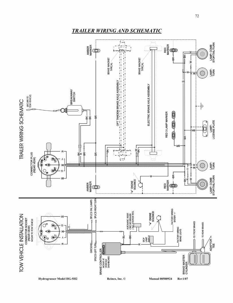
72
Hydrograsser Model HG-5H2 Reinco, Inc. © Manual 00500924 Rev1/07
TRAILER WIRING AND SCHEMATIC

NOTES