hf linear amplifier hl-1000a · pdf filehammond manufacturing company limited ... hf linear...
TRANSCRIPT
HAMMOND MANUFACTURING COMPANY LIMITED394 EDINBURGH RD. GUELPH, ONTARIO N1H 1E5PHONE (519) 822-2960 OR (416) 456-3770 TELEX: 069-56523
HAMMOND MANUFACTURING COMPANY (U.S.) INC.1690 WALDEN AVE., BUFFALO, NEW YORK 14225PHONE (716) 894-5710 TELEX: 91-6452
EFFECTIVE OCTOBER 1980
HAMMONDyVMNUF/OURING,
SERIES
COMMUNICATIONSPRODUCTS DIVISION VERN
YE3KPD
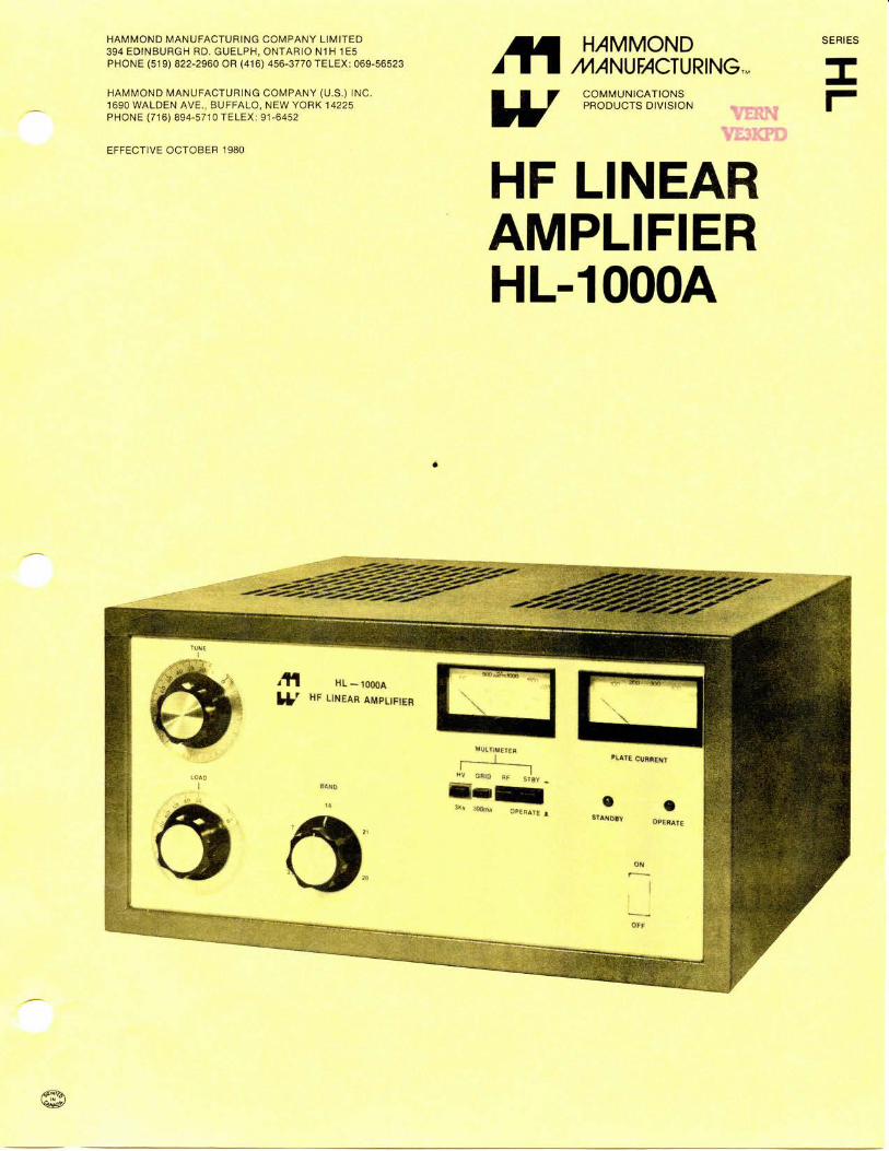
HF LINEARAMPLIFIERHL-1000A
HL-1000A
HF LINEAR AMPLIFIER
HLHF LINEAR AMPLIFIERHL-1000A
H/MMOND/M/NUF/OURING..,
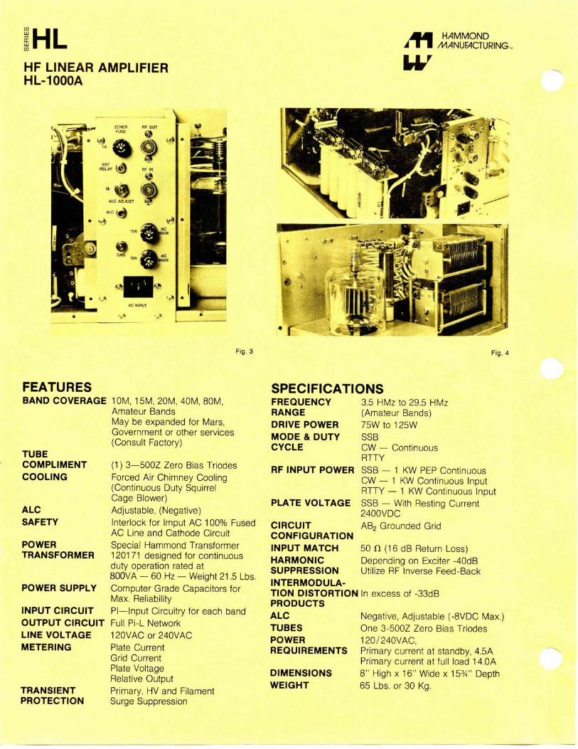
Fig. 3 Fig. 4
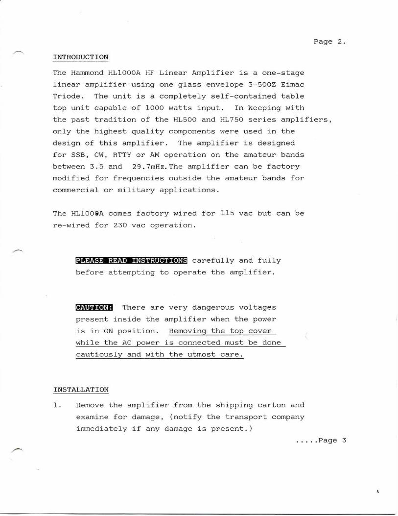
FEATURESBAND COVERAGE 10M, 15M, 20M, 40M, 80M,
Amateur BandsMay be expanded for Mars,Government or other services(Consult Factory)
SPECIFICATIONS
TUBECOMPLIMENTCOOLING
ALCSAFETY
POWERTRANSFORMER
POWER SUPPLY
INPUT CIRCUITOUTPUT CIRCUITLINE VOLTAGEMETERING
TRANSIENTPROTECTION
(1) 3—500Z Zero Bias TriodesForced Air Chimney Cooling(Continuous Duty SquirrelCage Blower)Adjustable, (Negative)Interlock for Imput AC 100% FusedAC Line and Cathode CircuitSpecial Hammond Transformer120171 designed for continuousduty operation rated at800VA — 60 Hz — Weight 21.5 Lbs.Computer Grade Capacitors forMax. ReliabilityPI—Input Circuitry for each bandFull Pi-L Network120VACor240VACPlate CurrentGrid CurrentPlate VoltageRelative OutputPrimary, HV and FilamentSurge Suppression
FREQUENCYRANGEDRIVE POWERMODE & DUTYCYCLE
RF INPUT POWER
PLATE VOLTAGE
3.5 HMz to 29.5 HMz(Amateur Bands)75W to 125WSSBCW — ContinuousRTTYSSB — 1 KW PEP ContinuousCW — 1 KW Continuous InputRTTY — 1 KW Continuous InputSSB — With Resting Current2400VDCAB2 Grounded Grid
50 n (16 dB Return Loss)Depending on Exciter -40dBUtilize RF Inverse Feed-Back
CIRCUITCONFIGURATIONINPUT MATCHHARMONICSUPPRESSIONINTERMODULA-TION DISTORTION In excess of -33dBPRODUCTSALCTUBESPOWERREQUIREMENTS
DIMENSIONSWEIGHT
Negative, Adjustable (-8VDC Max.)One 3-500Z Zero Bias Triodes120/240VAC,Primary current at standby, 4.5APrimary current at full load 14.0A8" High x 16" Wide x 15%" Depth65 Lbs. or 30 Kg.
Page 2
INTRODUCTION
The Hammond HL1000A HF Linear Amplifier is a one-stage
linear amplifier using one glass envelope 3-500Z Eimac
Triode. The unit is a completely self-contained table
top unit capable of 1000 watts input. In keeping with
the past tradition of the HL500 and HL750 series amplifiers,
only the highest quality components were used in the
design of this amplifier. The amplifier is designed
for SSB, CW, RTTY or AM operation on the amateur bands
between 3.5 and 29.7mHz. The amplifier can be factory
modified for frequencies outside the amateur bands for
commercial or military applications.
The HL1008A comes factory wired for 115 vac but can be
re-wired for 230 vac operation.
PLEASE READ INSTRUCTIONS carefully and fully
before attempting to operate the amplifier.
There are very dangerous voltages
present inside the amplifier when the power
is in ON position. Removing the top cover
while the AC power is connected must be done
cautiously and with the utmost care.
INSTALLATION
1. Remove the amplifier from the shipping carton and
examine for damage, (notify the transport company
immediately if any damage is present.)
Page 3

Page 3.
2. Save the carton for future shipment to another location
or storage.
3. The 3-500Z triode tube is shipped separately and
must be installed before operating amplifier in
any way.
4. The following accessories should be included with
your HL1000A amplifier:
(a) Instruction Manual
(b) Warranty Card
(c) Shielded Control Cable
(d) Extra Fuses (Cathode l A) (ABC-15)
OPERATING LOCATION
The amplifier must be located in an open area such that
the flow of air from the top is unrestricted. Location
should be as close as possible to a reliable 115/230
vac AC source to minimize any AC voltage drop.
INSTALLING TUBE (See Figure 4)
1. Remove 4 bolts from bottom of linear cabinet and
carefully slide the inner part of the unit from
the rear of the cabinet.
2. Remove the perforated top cover of the amplifier
giving access to the interior of the RF section
of the amplifier.
3. Put the 3-500Z tube in the socket. Be very careful
not to exert any lateral or twisting pressure on
the glass portion of the tube. The tube is easily
damaged. Fasten the plate lead to the anode connector.
Remove the screw in the top of the anode connector
on top of the tube and flex the parasitic choke
and plate lead until the mounting hole in the plate
is positioned directly above the screw hole in the
anode connector. Insert the screw and hold the
plate lead firmly while tightening the screw.
Page 4-.
Do not, under any circumstances, exert
too great a pressure or twisting, bending motion
in the anode connector or glass portion of the tubes.
Excessive pressure can cause a hair-line fracture
in the tubes' glass envelope, destroying the tube.
The tubes' pins are also particularly delicate,
and can easily break if the tube is not inserted
and removed very carefully.
4. Replace the top shield but leave the outside cabinet
off until the amplifier has been connected and tested.
CABLING
All the following cables must be connected before the
amplifier is operated.
AC POWER CABLE
The HL1000A amplifier comes from the factory wired for
operation from a 120 vac single phase, 60 Hz power source.
The green wire in the power cord is the ground wire and
must be connected to the neutral primary of the plug
that you select for connection into the power line.
The black and white wires must be connected to the other
two pins for the 120 vac operation. The other lead of
the Belden AC cord plugs directly into the rear panel
AC input socket.
Page 5
Page 5
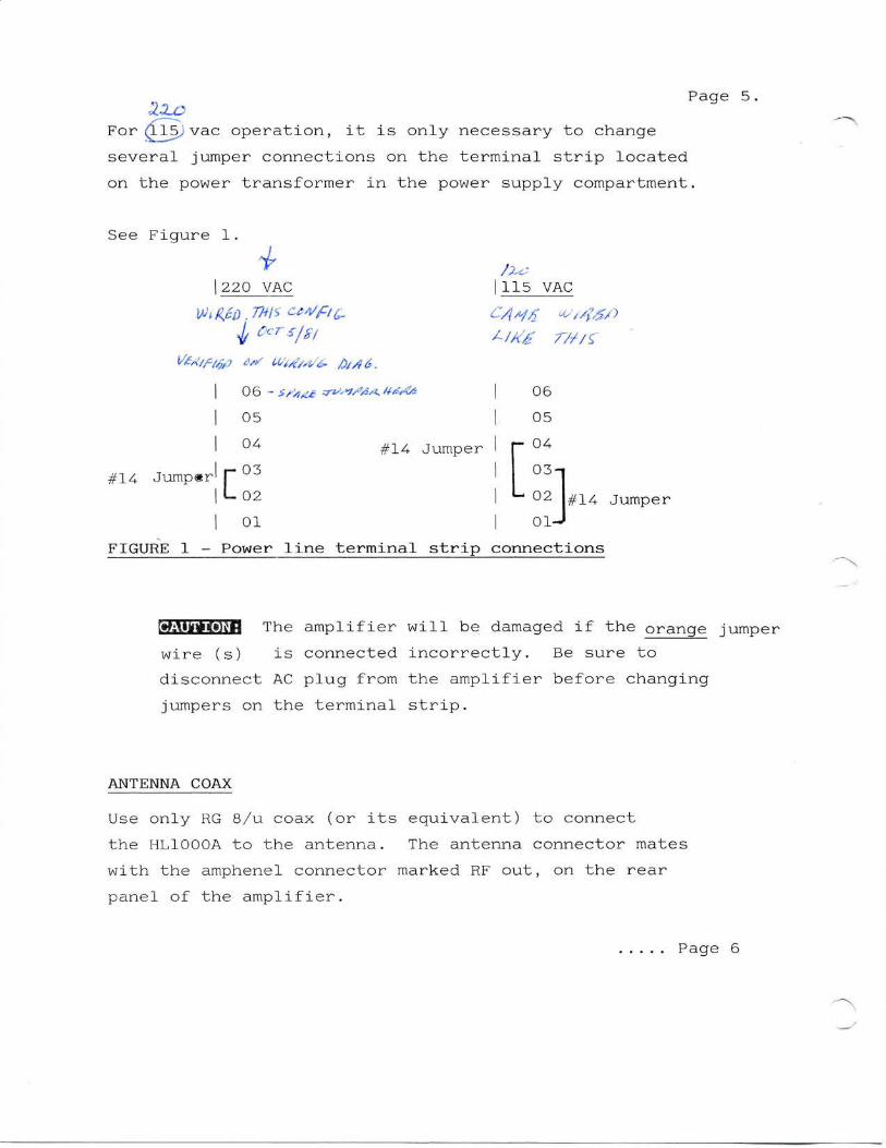
For (115,vac operation, it is only necessary to change
several jumper connections on the terminal strip located
on the power transformer in the power supply compartment.
See Figure 1.
220 VAC
#14 Jumper
THIS
06- i.
05
04
03
02
01
#14 Jumper
115 VAC
06
05
04
03-i
02
01-
#1-4 Jumper
FIGURE 1 - Power line terminal strip connections
The amplifier will be damaged if the orange jumper
wire (s) is connected incorrectly. Be sure to
disconnect AC plug from the amplifier before changing
jumpers on the terminal strip.
ANTENNA COAX
Use only RG 8/u coax (or its equivalent) to connect
the HL1000A to the antenna. The antenna connector mates
with the amphenel connector marked RF out, on the rear
panel of the amplifier.
Page 6
Page 6
Do not operate the amplifier without
a load or into a load with SWR greater than 2:1.
Measure the antennas' SWR with an SWR meter or
in-line Watt-meter and determine that the SWR
is in fact less than 2:1.
With standby/operate switch in the STANDBY position, the
exciter output will pass through the amplifier directly
to the antenna. The amplifier does not have to be off to
accomplish this bypass.
INPUT CABLE
A cable must be connected from the output of your exciter•
to the SO-239 RF input connector on the rear panel of the
amplifier.
ALC (AUTOMATIC LEVEL CONTROL) CABLE
Plug the ALC cable into the phono jack located on the rear
panel (marked ALC) and into the ALC feedback connection
(or equivalent) on the exciter. If the exciter does not
have provision for feedback of ALC voltage from the amplifier,
then simply omit the use of the cable.
ANTENNA RELAY
A control cable should be plugged into the phono socket
marked antenna relay on the rear panel of the amplifier.
This cable connects the keying signal from the exciter to
switch the amplifier to the transmit condition and must
be plugged into the socket or connector marked antenna relay
(or equivalent) on the exciter. The exciter need only supply
a shorting relay contact (during transmit) to key the amplifier.
.....Page 7
Page 7
Do not apply any voltage to the antenna
relay phone jack. The internal relay is activated
by a self-contained power supply.
OPERATING CONTROLS
Refer to Figure 2.
OFF/ON POWER SWITCH
This switch is used for turning the amplifier on and
Off.
*MULTIMETER SWITCH
This 4--positiori pushbutton switch selects the function
of the multimeter as described below.
HV
With the switch in this position, the meter monitors
the amplifiers' plate voltage. The full scale reading
in this position is 3000 VDC. Normal plate voltage
with the amplifier iri the standby position (unkeyed)
is about 2500 VDC for SSB and CW operation. Line voltage
variations will cause corresponding variations in the
plate voltage. (Note: Reading for plate volts is X10<P.
GRID
With the switch in this position, the meter monitors
the amplifiers' grid current. The full scale meter
reading in this position is 150 ma DC. The nominal
grid current during SSB on peaks is approximately 100
ma. Maximum tune-up grid current in SSB or CW single
tone is 14-0 rna marked on the dial as a red bar.
Page 8
Page 8
RF
The meter monitors the output power. It is useful during
tune-ups for verifying resonance on each band.
STANDBY/OPERATE SWITCH
This switch allows the exciter bypass feature, i.e. in
the standby position, the power of the exciter feeds
through the linear and appears at the output connector.
In the operate mode the linear is ready for transmitting.
STANDBY/OPERATE LIGHTS
These pilot lights marked standby and operate indicate
the status of the standby/operate switch. In the standby
.mode the light is red and in the operate mode green.
ZENER FUSE
This .5 amp fast-bio fuse is the cathode fuse. Never
use a higher amperage fuse than the one specified.
TUNE CONTROL
The tune control is a vernier dial connected to an air
variable in the RF section. The disc dial is screened
100 to 0 indicating that maximum capacitance is at 100
and minimum at zero. Approximate settings for the tune
control settings for the amateur bands are given in Figure
3 for your convenience.
LOAD CONTROL
This control matches the amplifiers output network to
the load. Refer to Figure 3 for the approximate initial
settings for the frequency range desired. A load setting
of 100 corresponds to maximum load capacitor mesh and
0 represents minimum capacitor setting.
Page 9
Page 9.
BAND
The band switch selects the applicable input and output
circuits for the HL1000A to operate in any one of the following
bands:
(a)80 meters 3.5 to 4.0 mHz
(b)40 meters 7.0 to 7.3 mHz
(c)20 meters 14.0 to 14.35 mHz
(d)!5 meters 21.0 to 21.45 mHz
(e)10 meters 28.0 to 29.7 mHz
Never move the band switch while the
linear amplifier is keyed or operating.
REAR PANEL CONTROLS
Figure 3.
RF OUT:
Nominal output impedence is 50 ohms. Do not operate this
equipment without a load or into a load where the SWR is
greater that 2:1. Use only RG-8/u coax or its equivalent
to connect to an appropriate antenna or dummy load.
RF IN:
This amphenol type SO-239 connector accepts the drive coax
from an exciter.
ZENER FUSE:
This fuse protects the cathode circuit from over-current.
It is a 1 amp fast-bio type of fuse.
ANT RELAY:
This is a phone jack input that when shorted to ground the
amplifier antenna relay closes.
Page 10
Page 10
ALC ADJUST:
This potentiometer controls the sensitivity of the HL-lOOOA's
ALC cirucit.
ALC:
The ALC feedback (negative) to the exciter is available
to this socket.
AC MAIN:
These are the two fuses for the main 115/230 VAC mains.
They are ABC ceramic type and must not be substituted for
any other types.
GND:
"Shis lug is provided to ground the amplifier. This should
be connected to a good earth ground to minimize radiated
interference or the danger of electrical shock.
AC INPUT:
This is the main input AC socket that accepts a heavy duty
Belden power cord. Note the 3 pin arrangement on the socket
arid the fact that the centre pin is ground. Push the plug
of the power cord when ready for use until it is fully seated
in the socket. No other cord is recommended for use with
this socket.
OPERATION:
Preliminary Settings Settings
(1) Standby/operate switch Standby
(2) On/off switch On
As soon as the ON switch is activated the standby pilot
lamp should light RED and the meter's a soft yellow.
Look into the interior of the linear to make sure that
the uube filaments are lit and that there is a flow
of air £rom the top of the cabinet. This can be done
by putting your hand over each tube from the top to
feel the flow of air. Page 11
Page 11.
The 3-500Z require no warm-up time.
(3) Push HV on the multimeter switch. It should read approximately
24 - 26 indicating a plate voltage of 2400-2600.
(4) Switch multimeter switch to GRID.
(5) Switch "band" switch to desired band.
(6) Pre-set tune and load vernier dials to that referred
to in calibration chart figure Z#
SSB OPERATION:
(7) With exciter adjusted for zero output press the
switch of the exciter causing the HL-1000A and the exciter
to go into the transmit mode.
•(8) The amplifier's plate current meter should register
approximately 90 ma^P
(9) Increase the RF output of the exciter until the amplifier's
grid current is about 110 ma. Adjust the tune control ̂^̂ ^̂ ™ ' --._>
for a minimum plate current reading indicating resonance.
If the load control is set properly, the plate current
will be approximately 400ma. If the plate current is
less than 400 ma, increase the load slightly by moving
the load control to a higher number on the dial. If
the plate current is say more than 420 ma decrease* the
load slightly by moving the load control to a lower*'
number.
Do not forget to re-dip the tune control each time the
load control is changed.
Check that the grid ma reading is approximately 120
- 140 ma, if not, re-adjust the exciter output to give
the required 140 ma - 10% grid current reading.
Page 12.
Page 12.
The tuning, loading and exciter control
adjustments may have to be repeated several times
until the ratio of 140 ma grid to 400 ma plate
current is obtained. Note that the higher the
frequency the more precise these adjustments will
become apparent. Also the lower the frequency,
the broader are these adjustments.
BBMaH The 3-500Z tube should show colour, glowing
a dull cherry red with 400 ma of plate current.
When operated in this manner, the tubes are within
their ratings and can be operated in this way
only if the plate circuit is a resonance (plate
current dipped to a minimum with tune control).
The amplifier should never be operated for any
length of time in an off resonance condition.
(10)Release the PTT switch of the exciter to allow the amplifier
and exciter to go into the unkeyed status. Place the
exciter into the SSB mode and while speaking into a
microphone, adjust the audio gain control for voice
peak plate current readings of around 250ma. The grid
current peaks, should be around 100 ma. Check for proper
drive with a monitor scope if one is available.
CW OPERATION:
Tune amplifier as above --
except that the plate current should be no greater than
400 ma. Grid current will be approximately 120 ma.
AM OPERATION:
Tune and load as above except that:
(a) grid current = 100 ma
(b) plate current to give approximately 500 watts output.
.Page 13
Page 13.
FSK OPERATION:
The HL-1000A is designed to operate the 1 kilowatt input
level continuously and tune adjust as required for 120 ma
grid current and 400 ma of plate current.
ALC ADJUSTMENT:
Drive the amplifier to 400 ma of plate current and then
rotate the ale control until the grid current just begins
to decrease. If the exciter cannot drive the HL-1000A to
400 ma of plate current (single tone) it is not necessary
to adjust or use the ALC control.
WARRANTY:
All goods sold hereunder are warranted to be free from defects
in material and workmanship, for a period of one year from
date of shipment, and this express warranty is in lieu of
and excludes all other warranties whether expressed or implied
by operation of law or otherwise including any warranty
on the merchantability or fitness for a particular purpose.
Defective material may be returned to the seller after inspection
by the seller and upon receipt of definite shipping instructions
by the seller. Goods so returned will be replaced or repaired
without charge, but the seller shall not be liable for loss,
damage or expense directly or indirectly arising from the
use of material or from any other cause, the exclusive remedy
against the seller being to require the replacement or repair
of defective material. Every claim on account of defective
material or workmanship or from any other cause shall be
deemed waived by the purchaser unless made in writing prior
to the expiry date of the warranty......Page 14.
Page 14.
IJMMPH The 3-500Z tube is warranted on a one year
pro-rated basis. Any warranty claims must be
accompanied by the Eimac warranty claim form packaged
with your new tube. All claims must be filed
with the company from which you bought the tubes.
Warranty claims on the amplifier must be accompanied
by proof of purchase and purchase date.
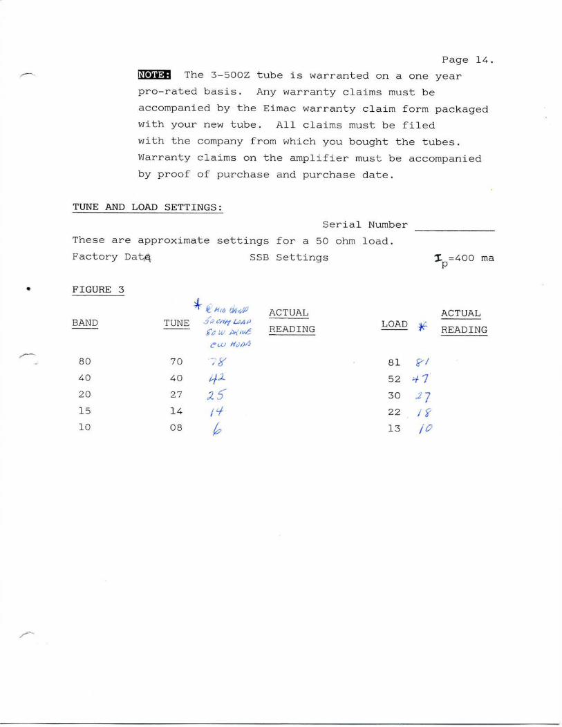
TUNE AND LOAD SETTINGS:
Serial Number
These are approximate settings for a 50 ohm load.
Factory Dat^ SSB Settings
FIGURE 5
BAND
80
40
20
15
10
^f if
TUNE 3°R?£ w
70
40
27
14
08
ACTUAL
READINGLOAD
81
52
30
22
13
T, =400 ma
ACTUAL
READING