hexagonal platy halloysite in an altered tuff bed, komaki city, aichi prefecture, central japan
TRANSCRIPT

Clay Minerals (1986) 21, 401-415
H E X A G O N A L P L A T Y H A L L O Y S I T E IN A N A L T E R E D T U F F BED, K O M A K I CITY, A I C H I
P R E F E C T U R E , C E N T R A L J A P A N
H. N O R O
Department of Earth Sciences, Nagoya University, Chikusa-ku, Nagoya, Japan
(Received 10 December 1985; revised 2 April 1986)
A B S T R A C T: XRD analysis and electron microscopy show that hexagonal platy halloysite is the main component of an altered tuff (Ueno tuff bed) in the Pliocene Seto group, Aichi Prefecture, Central Japan. In the natural state it shows a single basal peak at 10.1 A, which collapses to 7:2 A, by dehydration through a segregate-type interstratification. The (02,11) non-basal band consists of slightly separated peaks which indicates moderate ordering of the crystal structure. The b-dimension is 8.936-8.939 ,~. The stability of the interlayer water is intermediate with respect to halloysites of different morphologies. Between 3.5 and 4% Fe203 is present in the deferrated sample and the calculated chemical formula
2 + 3 + ' (Fe0.0o3)(All.s54Fe0.146)(Sll.995Alo.o05)Os(OH)4 can not explain the anomalously high CEC of 21.9 mEq/100 g. Because the curvature radius and b-dimension of halloysite increase with increase in Fe203 content, the platy morphology is ascribed to replacement of AI 3+ by Fe 3+ in the octahedral sheet. Based on the geological and chemical data, the hexagonal platy halloysite is considered to have been formed from volcanic glass after deposition in a freshwater lake, where conditions were oxidizing and weakly acidic.
HaUoysite occurs in a variety of morphologies and the relationships between the form of halloysite and its occurrence, crystal structure, Fe20 3 content and other mineralogical properties such as dehydration characteristics have been discussed by many authors.
Crystal structure, occurrence and mineralogical properties of long tubular halloysite have been reported by Honjo et al. (1954), Chukhrov & Zvyagin (1969), Parham (1969), Nagasawa & Miyazaki (1976), K o h y a m a et al. (1978), Noro et aL (1981), Churchman & Theng (1984) and Nagasawa & Noro (1985). Occurrence and mineralogical properties of spherical and short tubular halloysites have been discussed by Sudo (1953), Sudo & Yotsumoto (1977), Tazaki (1979) and Churchman & Theng (1984). Other forms of halloysite have also been reported. Kirkman (1977) described squat cylindrical and disk halloysite in rhyolitic tephra of New Zealand. Nagasawa & Karube (1975) reported ribbon-shaped halloysite in altered montmorillonite clay. Tazaki (1979) wrote that various morphologies of halloysite--spherical, walnut-meat-shaped, acicular, crinkly, platy, tubular and square-tube--were observed on the surface of altered plagioclase in volcanic ash,
The occurrence and mineralogical properties of platy or tabular halloysite have also been reported by many authors. Platy halloysite occurs in soil (Kunze & Bradley, 1964), as
Present address: Information and Analysis Office, Geological Survey of Japan 1-1-3, Higashi, Yatabe, Tsukuba, Ibaraki, 305, Japan.
t~ 1986 The Mineralogical Society
402 H. Noro
veins in laterite (de Souza Santos et aL, 1966) and granite (Wilke et al., 1978), on the surface of weathered plagioclase in volcanic ash (Tazaki, 1979), in weathered pyroclastics (Wada & Mizota, 1982), in hydrothermaUy altered acidic volcanic rocks (Nakagawa & Shirozu, 1983) and in ferrallitic soil derived from pyroclastics (Quantin et al., 1984).
The present paper describes the occurrence and mineralogical and chemical charac- teristics of hexagonal platy halloysite from a tuff bed of Pliocene age and also discusses the relationships between the form of halloysite and its Fe203 content.
O C C U R R E N C E
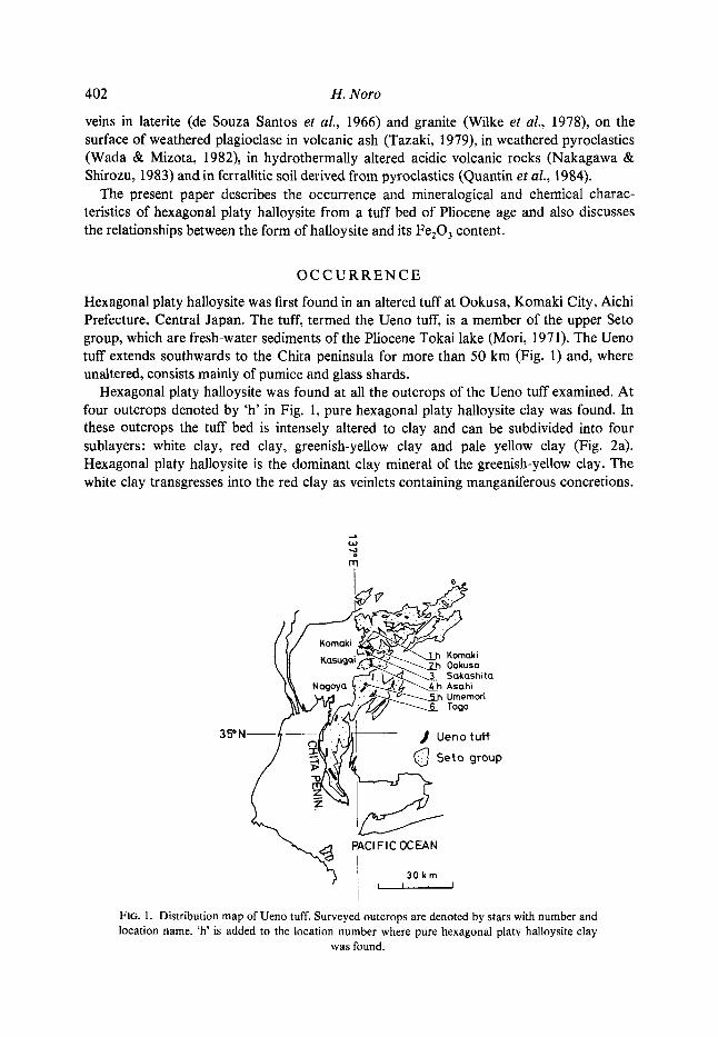
Hexagonal platy halloysite was first found in an altered tuff at Ookusa, Komaki City, Aichi Prefecture, Central Japan. The tuff, termed the Ueno tuff, is a member of the upper Seto group, which are fresh-water sediments of the Pliocene Tokai lake (Mori, 1971). The Ueno tuff extends southwards to the Chita peninsula for more than 50 km (Fig. 1) and, where unaltered, consists mainly of pumice and glass shards.
Hexagonal platy halloysite was found at all the outcrops of the Ueno tuff examined. At four outcrops denoted by 'h' in Fig. 1, pure hexagonal platy halloysite clay was found. In these outcrops the tuff bed is intensely altered to clay and can be subdivided into four sublayers: white clay, red clay, greenish-yellow clay and pale yellow clay (Fig. 2a). Hexagonal platy halloysite is the dominant clay mineral of the greenish-ydlow clay. The white clay transgresses into the red clay as veinlets containing manganiferous concretions.
35=N
wI
~z
,~ Ioya
PACI F IC OCEAN
i 130 k nn I
FIG. 1. Distribution map of Ueno tuff. Surveyed outcrops are denoted by stars with number and location name. 'h' is added to the location number where pure hexagonal platy halloysite clay
was found.

Hexagonal platy halloysite, Japan
%: 10-,..9 >& ~:.b? 0 . r 0 . . 0 . . . . .
�9 " "" ~'& "0 " ' o : 9 : : grovel ". b.'.'.o.'. : :" ~" �9 4~;a-- gibl:~ite " " o" "'O"v" 0 P"" "'~'" o: .o'.." concretion 1 ~ / j - - ~ w h i t e cloy - ~
~ pink clay
~ ~ . ~ red clay Ueno tuff
1.2m
~crearny ! _ __ _ white clay
slit ( a )
.O 9 . . . " ' .o" ....-~-......o...-.... �9 grovel - o . . . . . . . . o - - -
..o: ..o . .. or....9 / t
00000^0~
o o Oo o ~ o\~ O000~OU 0 0 0 ~J 0 0~0~0~ 0 unaltered
00~0~0~0 0 0 0 0 0 0 pum:ce 0 0 0 0 0 0 0 0 0 0 0 00~ 0 O0000~ Ueno tuff
0 0 O00r~ 0 0 0 O00~o0 - 5m 0000 0000
white clay
creamy j white clay _ _
(b)
FIG. 2. (a) Sketch of the outcrop at Ookusa, Komaki City, Aichi Prefecture (location number 2 in Fig. 1). (b) Sketch of the outcrop at Sakashita, Kasugai City, Aichi Prefecture (location
number 3 in Fig. 1).
403
The present surface of the red clay is also whitened. The boundary layer between the white clay and the red clay is pink. The red clay transgresses into the greenish-yellow clay as veinlets and seams containing manganiferous concretions. A thin layer of the creamy white clay lies between the greenish-yellow clay and the underlying silt bed. The boundaries are gradual.
At these outcrops, the Ueno tuff overlies lignite-bearing silt and underlies a gravel bed. The gravel bed and the overlying soil are coloured red and contain gibbsite concretions. The outcrops are located close to the high-level terrace plane. This implies that the gravel bed and the Ueno tuff were exposed to intense weathering during the period of erosion after deposition of the Seto group was complete (~2 Ma ago).
In other outcrops of the Ueno tuff, clays rich in hexagonal platy halloysite were not found (in Fig. 1, these outcrops are denoted by locality numbers only). In an outcrop at Sakashita, Kasugai City (location number 3 in Fig. 1), the Ueno tuff consists of an unaltered pumice sublayer, white clay (pure roll-shaped halloysite) and creamy white clay (roll-shaped halloysite with a small amount of hexagonal platy halloysite) (Fig. 2b). Although the presence of much unaltered pumice shows that alteration was less intense that that of the above four outcrops, weaker iron staining of clay indicates more rigorous leaching of iron. An outcrop at Togo-cho shows the same feature. These two outcrops are located well below the high-level terrace plane, which is why the Ueno tuff at these outcrops was very little affected by weathering compared with the outcrops mentioned above.
E X P E R I M E N T A L
Samples
Channel samples were taken from the Ueno tuff at six outcrops. To avoid possible error in discriminating between halloysite and kaolinite, the dried surface of the exposure was

404 H. Noro
removed and samples were taken from the inner part. From sampling to X-ray examination, special care was taken not to dry the samples.
Sample preparation
Clay andfine sand. After being dispersed in dilute NaOH solution (pH = 10), clay and fine sand fractions were collected by a combination of wet sieving and sedimentation. Excess salt was removed by washing with distilled water and centrifugation. Polished thin-sections of the fine sand were made for examination under an optical microscope. For XRD of the clay fraction, oriented aggregates were prepared on glass slides and kept in a vessel saturated with HEO vapour.
A few grams of the clay fractions were air-dried for chemical analysis and for measurement of CEC.
A drop of clay suspension was placed on a carbon-coated collodion film supported by a copper grid and was air-dried for transmission electron microscopy.
'Whole rock' sample, small stubs of the sample were cut and air-dried for scanning electron microscopy. The surface of the samples were coated with gold using a sputter-coating apparatus.
~ r a y diffraction.
XRD traces were made of oriented mounts equilibrated at relative humidities of 100, 95, 79, 64, 53, 32, 20 and 0%, and heated at 120~ for 24 h, 200~ for 48 h and 560~ for 3 h. Constant humidity air between 95% r.h. and 20% r.h. was produced by circulation of air through water saturated with various salts: KNO 3 for 95% r.h., NH4C1 for 79% r.h., Mg(CH3COO)2 for 64% r.h., Mg(NO3) 2 for 56% r.h., CaC1 z for 32% r.h. and CH3COOK for 20% r.h. During XRD examination, air of constant humidity flowed around the specimen; the humidity was adjusted to the value at which prior drying was done.
Chemical analysis and CEC
The clay fractions were analysed by wet chemical methods after deferration with dithionite-citrate-bicarbonate (DCB) (Jackson, 1956). SiO2 and HEO were determined gravimetrically, TiO 1, A120 ~, Fe203, FeO and MnO by colorimetry, MgO and CaO by the chelate (EDTA) titration method, and NalO and K20 by atomic absorption spectrometry.
Some samples were also analysed by an electron probe microanalyser (JEOL JXA-733). About 20 mg of clay sample was pressed into a translucent pellet and, after coating with carbon, the surface was analysed (Noro et al., 1981). The contribution of unobservable oxides (H20 etc.) to the matrix effect was estimated by the method of Yusa & Tsuzuki (1976).
CECs of deferrated samples were measured by MgC1 z and NH4C1 solutions.
Electron microscopy
Transmission electron micrographs of the clay fractions were taken using a JEOL T7 electron microscope operated at an accelerating voltage of 60 kV. Rock samples were

Hexagonal p[aty halloysite, Japan 405
examined with a JEOL JXA-733 electron probe microanalyser in the scanning electron microscopic mode.
R E S U L T S
X-ray diffraction
Identification of clay minerals. XRD traces of the clay fractions obtained under 100, 56 and 20% r.h. are shown in Fig. 3. Discrimination between halloysite and kaolinite was made using the following criteria for samples which had not been dried prior to examination: (i) a minera! showing a basal reflection at 10 A after equilibration at 100% r.h. and collapsing to 7 A after dehydration is halloysite; (ii) a mineral showing a basal reflection at 7 ,s after equilibration at 100% r.h. is kaolinite; (iii) when the specimen showed two peaks at 10 A and 7 ,/~, it was assumed to contain both halloysite and kaolinite.
At the outcrops where pure hexagonal platy haUoysite was found, the uppermost white clay was identified as pure halloysite, the middle red clay as halloysite with a small amount of kaolinite, the lower greenish-yellow clay as pure halloysite and the lowermost
rhlO0 rh 56 rh 20
10 20 10 20 10 20
28 CuK.~
FIG. 3. X R D traces of clay fractions from the Ueno tuff Ookusa, Komaki City. Samples were equilibrated at 100, 56 and 20% relative humidity. Arrows indicate peaks due to kaolinite.
406 H. Noro
creamy-white clay as pure halloysite. The existence of kaolinite in the red clay was confirmed by kaolinite peaks in the (02,11) band region.
At the outcrops where pure hexagonal platy halloysite clay was not found, the white clay and the creamy-white clay identified as pure halloysite.
Details o f XRD traces o f the hexagonal platy halloysite. The clay mineral in the greenish yellow clay was hexagonal platy halloysite. For detailed XRD study, a sample taken from Ookusa, Komaki city (location number 2 in Fig. 1) was chosen.
Features of the XRD traces are: (i) the clay is composed of pure halloysite and does not show any reflections of mixed-layer kaolin-smectite, (ii) the basal reflections (00/) are broad and symmetrical, (iii) the rate of dehydration is intermediate with respect to halloysites of different morphological forms, (iv) the (02,11) non-basal band exhibits some slightly separated peaks, (v) the b-dimension is larger than that of other halloysites. These features are discussed separately below.
After heating at 560~ for 3 h, no clear peaks remained in the 10-7 A region nor in the 3.5-3.0 A region. This shows that the hexagonal platy halloysite in the present work is not mixed-layer kaolin-smectite, but pure haUoysite (Schultz et al., 1971; Wiewiora, 1971; Yoshimura & Kohyama, 1981).
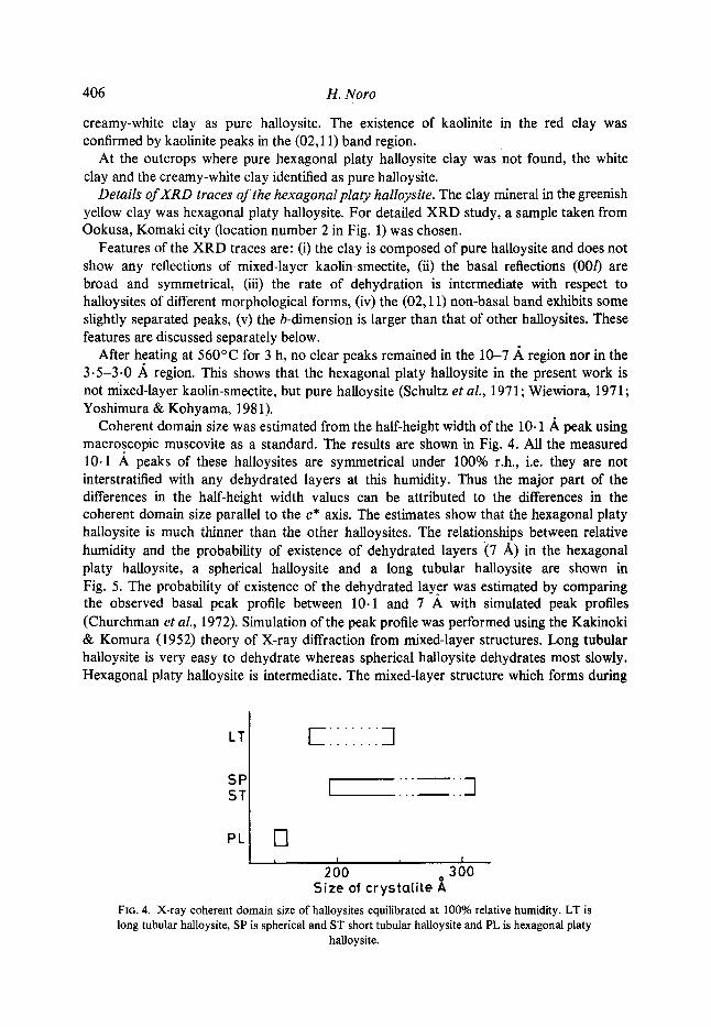
Coherent domain size was estimated from the half-height width of the 10.1 .~ peak using macroscopic muscovite as a standard. The results are shown in Fig. 4. All the measured 10.1 A peaks of these halloysites are symmetrical under 100% r.h., i.e. they are not interstratified with any dehydrated layers at this humidity. Thus the major part of the differences in the half-height width values can be attributed to the differences in the coherent domain size parallel to the c* axis. The estimates show that the hexagonal platy halloysite is much thinner than the other halloysites. The relationships between relative humidity and the probability of existence of dehydrated layers (7 A) in the hexagonal platy haUoysite, a spherical halloysite and a long tubular halloysite are shown in Fig. 5. The probability of existence of the dehydrated layer was estimated by comparing the observed basal peak profile between 10.1 and 7 A with simulated peak profiles (Churchman et al., 1972). Simulation of the peak profile was performed using the Kakinoki & Komura (1952) theory of X-ray diffraction from mixed-layer structures. Long tubular halloysite is very easy to dehydrate whereas spherical halloysite dehydrates most slowly. Hexagonal platy halloysite is intermediate. The mixed-layer structure which forms during
LT
SP ST
EIIIIIII3
I "" - ]
PL
, I , I
200 o 300 Size of crystalite A
FiG. 4. X-ray coherent domain size of haUoysites equilibrated at 100% relative humidity. LT is long tubular halloysite, SP is spherical and ST short tubular halloysite and PL is hexagonal platy
halloysite.

Hexagonal platy halloysite, Japan
~ . 0 O.
o
o
r l O
~0.5 O.
s gl
t t l
I l I I I I 20 35 56 65 79 100
Relative humidity %
FIG. 5. The relationships between relative humidity and the probability of existence of 10 ,~ phase in the hexagonal halloysite (p), the spherical halloysite in an altered tuff of Naegi, Gifu Prefecture (s) and the long tubular halloysite in a weathered granite of Naegi, Gifu Prefecture (1). The values were estimated by a comparison method based on interstratification
theory.
407
dehydration of hexagonal platy halloysite belongs to the partial segregation type. This is the same as for other halloysites (Churchman et al., 1972; Okada & Ossaka, 1983).
In Fig. 6 (02,11) bands of a well-ordered ('well-ordered' compared with other halloysites) roll-shape halloysite (collected at location 3 in Fig. 1), a hexagonal platy halloysite and a poorly-ordered spherical halloysite (Naegi, Gifu Prefecture) are shown.
On the XRD trace of the well-ordered roll-shape halloysite, three sharp and intense peaks can be seen, of which two (marked with arrows) distinctly change position and intensity on drying. This shows that these two peaks belong to hkl (1 4: 0) reflections. Based on the lattice parameters by Chukhrov & Zv.yagin (1966) and Kohyama et al. (1978), these peaks may be indexed as 021 (4.35 A at 100% r.h. and 4.28 ,~ after dehydration) and 112 (4.26 ,~ at 100% r.h. and 3.98 ,/~ after dehydration). Although the parameters of Kohyama et al. well explain the peak positions of the wet-state sample, a small discrepancy between calculated and observed peak position (0.11 A for the 112 reflection) is seen for the dehydrated state. Chukhrov & Zvyagin's parameters better explain the peak positions of the dehydrated sample.
The above results suggest that the structure of the well-ordered roll-shape haUoysite is similar to the two-layer structure of the long tubular haUoysites which have been investigated by Honjo et al. (1954), Chukhrov & Zvyagin (1966) and Kohyama et al. (1978).
The XRD trace of the hexagonal platy halloysite shows more broadened peaks than that of the roll-shape halloysite; however, the 021 and 112 peaks can barely be detected. The structure of the hexagonal platy halloysite may be similar to that of the roll-shape halloysite.
Incomplete separation of the peaks in the (02,11) band of these halloysites indicates poor ordering of the crystal structure. However, a slight peak separation in the (02,11) band of hexagonal platy halloysite shows that the crystal ordering of the hexagonal platy variety is poorer than that of the roll-shape one and superior than that of the spherical one.

408 H. Noro
rhlO0
120~ 2L, h
roll shape hex, platy
J 2O
\J 25 20 25
20 Cu K.,
spherical
0 2
FIG. 6. (02, l 1) bands of a well-ordered roll-shaped halloysite, a hexagonal platy halloysite and a spherical halloysite. Upper:equilibrated at 100% r.h.; lower: heated at 120~ for 24 h. Indices
are based on the data of Chukhrov & Zvyagin (1966) and Kohyama et al. (1978).
The b-dimension values and Fe203 contents after deferration treatment are listed in Table I. The hexagonal platy halloysite has the largest b-dimension. This increases with increase in Fe203 content, although a simple linear relation is not observed.
Chemical composition
Chemical compositions of deferrated clay fractions of the red clay (halloysite with a small amount of kaolinite) and the greenish-yellow clay (hexagonal platy halloysite) are given in Table 2.
The calculated chemical formula of the hexagonal platy haUoysite is
2+ 3+ " (Feo.oo 3) (A11.s54Feo. 146) (S11.995 Alo.o05)O 5(OH)4. Although precise determination of structural iron is better performed by spectroscopic methods (Quantin et al., 1984, Nagasawa & Noro, 1985), the present iron analyses were made by conventional methods after DCB treatment. Thus the Fe203 values in Tables 1 and 2 must be regarded only as estimates of structural iron. However, it is apparent that among the halloysites investigated platy halloysite contains the largest amount of structural iron.
The CEC of the hexagonal platy halloysite is 21.9 mEq/100 g, and those of the white clay (halloysite), the red clay (halloysite with a small amount of kaolinite) and the roll-shaped well-crystallized halloysite (collected at location 3 in Fig. 1) are 2.60, 14.5 and 1.94 mEq/1Q0 g, respectively. Anomalously high CECs of iron-rich platy halloysite have been reported by Kunze & Bradley (1964), Wada & Mizota (1982) and Quantin et al. (1984). Wada & Mizota explained the high CEC of their crumpled lamellar halloysite by assuming the substitution of ferrous iron for aluminium ions in the octahedral sheet. Quantin et al. explained the high CEC by the presence of smectitic layers.

Hexagonal platy halloysite, Japan
TABLE 1. b-dimension values and Fe203 contents after deferration treatment of hal/oysites. The b-dimension values were estimated from the (060) peak positions. Quartz from pegmatite and five-
nine metallic silicon were used as standard,
Crystal form b-dimension Fe203
Hex. platy 8- 939 4.24 Hex. platy 8.937 4.01 Hex, platy 8,938 3.55 Long tubular 8,929 0.79 Long tubular 8-926 0-20 Long tubular 8-920 0-55 Spherical 8,914 2~ 28 Spherical 8.935 2.74 Spherical 8.920 2.38 Spherical 8.914 1-11 Spherical 8.906 0.68 Spherical 8.900 0.71 Spherical 8.938 3.01 Spherical 8.917 0.50 Roll-shape 8.933 2,74 Roll-shape 8.930 i. 58 Short tubular 8,926 2,40 Short tubular 8-926 2- 56
409
TABLE 2. Chemical compositions of DCB- treated clay fractions of the red clay (a) and the greenish yellow clay (b) from the
Ueno tuff at locality number 2 in Fig. 1.
(a) (b)
SiO 2 41.84 43.49 TiO: nd nd AI203 37,04 34.38 Fe203 1-58 4-24 FeO 0.07 0-07 Hz O+ 19.73 17.83
Total 100.26 100.01
In the present investigation, the calculated SiO2/(A1203 + Fe203) molar ratio of 1.99 can not explain the high CEC of the hexagonal platy halloysite. Since X-ray examinat ion eliminated the possibility of mixed-layer kaolin-smectite in the greenish-yellow clay, its high CEC may possibly be at tr ibuted to surface properties.
Morphology
Transmission electron micrographs of the white clay (pure roll-shape halloysite), the red clay (halloysite with a small amount of kaolinite), the greenish-yellow clay (pure hexagonal

410 H. Noro
# ~9
0
Q
"6
,x=
$a
zL t~
"6
t~
"6
"6
e~
E .o
e .
e~
[ .
ez

Hexagonal platy halloysite, Japan 411
U
E O
0
o_
i -
,..< .JD
t ~
i .
o
t -
06

412 H. Noro
platy haUoysite) and the creamy white clay (roll-shape halloysite) are shown in Fig. 7. Halloysite in the white clay (Fig. 7a) and the creamy-white clay (Fig. 7d) is composed of long elfipsoidal or roll-shaped particles and short tubular particles. Particles in the red clay (Fig. 7b) resemble those in the white clay but irregular shaped platy crystals are also seen; these may be kaolinite. The greenish-yellow clay (Fig. 7c) is composed of very thin pseudo-hexagonal platelets. The platelets have curled edges and are <0.3/~m in diameter.
X-ray examination excludes the possibility that these hexagonal plates are kaolinite, mixed-layer kaolin-smectite or gibbsite. The calculated SiO2/(AI203 + Fe203) molar ratio of 1.99 of the greenish-yellow clay also excludes the possibility that these plates are amorphous silica flakes such as those reported by Kirkman (1977). It can be concluded that these hexagonal plates are also halloysite.
Scanning electron micrographs are shown in Fig. 8. In the photographs of the white clay (Fig. 8a) and the red clay (Fig. 8b), particles show the same form as in the TEM photographs. The greenish-yellow clay (Fig. 8c,d) is characterized by 'rose flower'-like aggregates. Monocrystals of the hexagonal platy halloysite may correspond to the petals of the 'flower'. The hexagonal platy halloysite may not be a completely flat plate but a portion of a very large sphere.
Sand fraction
The sand fractions of the tuff were examined under an optical microscope and found to comprise rock fragments, quartz, feldspar, glass, altered biotite, orthopyroxene, amphibole, garnet and opaques.
Altered biotite. In the greenish-yellow clay, biotites were not vermicular and still pleochroic. Biotites in the red clay were vermicular and weakly pleochroic; the partings being filled with hematite. Biotites in the white clay were vermicular and completely replaced by kaolinite.
Glass. Glass fragments in the greenish-yellow clay were transparent and the edges sharp. Those in the red clay were brown and dirty and had rounded edges. The white clay contained a small amount of rounded glass fragments.
Opaques. Opaques in the greenish-yellow clay were goethite and manganese micro- nodules. In the red clay, hematite and manganese micronodules occurred. The white clay did not contain any opaque minerals.
These observations show that during the formation of the red clay and the greenish- yellow clay, iron leaching was not rigorous and the akeration environment was oxidizing. They also indicate that the alteration temperature of the red clay was higher than that of the greenish-yellow clay (Schwertmann et al., 1979).
D I S C U S S I O N
Platy morphology
The most characteristic property of the hexagonal platy halloysite, other than the crystal form, is its large Fe203 content. Kunze & Bradley (1964) and de Souza Santos et al. (1966) reported that their platy halloysites were rich in Fe203 (8-25 and 1-42%, respectively). Thin-plate halloysite from clay veins in a granite of the Bayerischer Wald contained 2.9% Fe203, and only a third of the iron was dithionite-soluble (Wilke et aL,

Hexagonal platy halloysite, Japan 413
1978). Crumpled lamellar halloysite described by Wada & Mizota (1982) contained 12.8% iron oxides after DCB treatment. They concluded that the crumpled lamellar form of halloysite could be attributed to the presence of Fe 3+ in octahedral sites. Nakagawa & Shirozu (1983) reported that in the Omura hydrothermal halloysite deposit, the Fe20 a content of halloysites increased with the amount of platy particles in the samples. Quantin et aL (1984) reported that thin, irregular and sometimes crumpled lamellar halloysite-like clay mineral contained ~7% Fe203.
To demonstrate the semiquantitative relationship between the crystal form of halloysite and the Fe203 content, in Fig. 9 the curvature values (--the reciprocal of radius) are plotted against the Fe203 contents after deferration. Here, 'radius' represents the average value of the shortest radius for spherical, tubular and roll-shape halloysites. The shortest radius of about 50 particles in each sample were measured randomly. The 'radius' of platy halloysites is regarded as infinite, i.e. the curvature is zero. Fig. 9 shows that the curvature of the halloysite crystal decreases with an increase of Fe203 content. So far as the data of this study show, the halloysite crystal approaches the platy form above 3.5-4% Fe20 3.
The ionic radius of Fe a+ in six-fold coordination is 64.5 pm, and that of A13+ is 53 pm. Thus the size of the octahedra in halloysite increases by ~6% when A1 a+ is replaced by Fe 3+. The expansion of the octahedra decreases the mismatch between the octahedral sheet and the tetrahedral sheet, and consequently the crystal may take the platy form above 3.5-4% Fe203.
The b-dimension also increases with the Fe203 content and reaches that of kaolinites (8.935-8.940 ,~) above 3.5-4% Fe203. This tendency is concordant with that of the crystal form.
i
4 0 i
~3 .,..;
~2
1
080 0
o:4 o12 o.'; o.o'8 0.06 Crysta l r 1/).ira
FIG. 9. Fe203 content of halloysites plotted against curvature. Solid circles: hexagonal platy halloysites; open circles: spherical and short tubular halloysites: circles with vertical line: long
tubular halloysites.
Genesis
From details of occurrence and mineralogical observations, the following genesis of various halloysite clays in the tuff bed is deduced. At first, greenish-yellow clay consisting of hexagonal platy halloysite was formed widely over the area. This is an alteration product of pumice soon after its deposition in the Tokai lake in Pliocene times. After deposition of the Seto group was complete, this area was subjected to intense

414 H. Noro
weathering. Under the near-surface oxidizing conditions, the upper part of the pumice bed changed into red clay, which par t ly or entirely replaced the greertish-yellow clay. Under subsurface conditions, on the other hand, the greenish-yellow clay changed into creamy-white clay containing a small amount of platy halloysite. White c lay above the red clay or creamy-white clay formed by recent weathering.
Thus the hexagonal platy halloysite is considered to be a product of lacustrine diagenesis of pumice.
C O N C L U S I O N
The hexagonal platy form of the halloysite which was examined in this s tudy can be at tr ibuted to its high iron content. Ionic substitution of Fe for A1 in octahedral sites increases the curvature radius of halloysite crystals,
The b-dimension of halloysite increases with increase in Fe20 3 content but the relationship between b-dimension and Fe20 3 content is not a simple linear one.
The anomalously high C EC (21.9 mEq/100 g) of the hexagonal platy halloysite can not be explained by its charge deficit due to i somorphous substitution.
Geological da ta indicate that the hexagonal platy halloysite was formed by fresh-water alteration of tuff which occurred in the Pliocene Lake Tokai.
A C K N O W L E D G M E N T
I am greatly indebted to Professor Keinosuke Nagasawa, Shizuoka University, for his helpful suggestions and critical readings of the manuscript. I also express my gratitude to Professor Kanenori Suwa and Dr Kazuhiro Suzuki, Nagoya University for encouragement. I thank anonymous referees for many helpful suggestions and improvements of English usage.
REFERENCES
CHtrrd~ROV F.V. & ZVYAOIN B.B. (1966) Halloysite, a crystallochemically and mineralogically distinct species. Proc. Int. Clay Conf. Jerusalem 1, 11-25.
CHURCHMAN G.J., ALDmDGE L.P. & CARR R.M. (1972) The relationship between the hydrated and dehydrated states of an halloysite. Clays Clay Miner. 20, 241-246.
CHURCHMAN G.J. & THEN6 B.K.G. (1984) Interactions of balloysites with amides: mineralogical factors affecting complex formation. Clay Miner. 19, 16 l-175.
HONJO G., KITAMURA N. & MIHAMA K. (1954) A study of clay minerals by means of single-crystal electron diffraction diagram--the structure of tubular kaolin. Clay Miner. Bull. 2, 133-141.
JACKSON M.L (1956) Soil Chemical Analysis--Advanced Course, p. 72. Published by the author, Dept. of Soil Science, University of Wisconsin, Madison, Wis., USA.
KAKINOKI J. & KOMURA Y. (1952) Intensity of X-ray diffraction by an one-dimensionally disordered crystal (1) General derivation in cases of the "Reichweite" S = 0 and 1. J. Phys. Soc. Japan 7, 30-35.
KIRKMAN J.H. (1977) Possible structure of halloysite disks and cylinders observed in some New Zealand rhyolitic tephras. Clay Miner. 12, 199-216.
KOHYAMA N., FUKUSHIMA K. & FUKAMI A. (1978) Observation of the hydrated form of tubular halioysite by an electron microscope equipped with an environmental cell. Clays Clay Miner. 26, 25-40.
KUNZE G.W. & BRADLEY W.F. (1964) Occurrence of a tabular halloysite in a Texas soil. Clays Clay Miner. 12, 523-527.
Morn S. (1971) The Yadagawa formation of the Seto group in the east of Nagoya city, Aichi Prefecture. J. Geol. Soc. Japan 77, 635-644.
NAGASAWA K. & MIYAZAKI S. (1976) Mineralogical properties of halloysites as related to its genesis. Proc. Int. Clay Conf. Mexico City, 257-265.
Hexagonal p la ty halloysite, Japan 415
NAGASAWA K. & KARUBE K. (1975) Clay mineral formation in a volcanic ash layer in the Seto group, Central Japan. Contributions to Clay Mineralogy--Dedicated to Professor Toshio Sudo, on the occasion of his retirement, 180-184 (in Japanese).
NAGASAWA K. & NORO H. (1985) Mineralogical properties of haUoysites of weathering origin. Proc. Int. Seminar on Laterite, Tokyo, 215-221.
NAKAGAWA M. & SmROZU H. (1984) On halloysites in Omura clay. Nendo Kagaku (J. Clay Sci. Soc. Japan) 23, 92-102 (in Japanese).
NORO H., YAMADA K. & SUZUKI K. (1981) An application of electron probe microanalysis for clay minerals. Kobutsugaku Zasshi (J. Mineral Soc. Japan) 15, 42-54 (in Japanese).
Or.~DA K. & OSSAKA J. (1983) The relation between some properties of halloysites and their sedimentary ages. Nendo Kagaku (J. Clay Sci. Soc. Japan) 23, 149-158 (in Japanese).
PARHAM W.E. (1969) Formation of halloysite from feldspar: Low temperature, artificial weathering versus natural weathering. Clays Clay Miner. 17, 13-22.
QuArcrrN P., HEm3mLON A.J., JANOT C. & SIEFFEI~MAN G. (1984) L"halloysite' blanche riche en fer de Vate (Vanuatu). Hypothese d'un edifice interstratifie halloysite-hisingerite. Clay Miner. 19, 629-643.
SCHULTZ L.G., SHEPArtD A.O., BLACKMOt~ P.D. & STARKEY H.C. (1971) Mixed-layer kaolinite- montmorillonite from the Yucatan Peninsula, Mexico. Clays Clay Miner. 19, 137-150.
SCHWERTMANN U., FITZPATRICK R.W., TAYLOR R.M. & LEWIS D.G. (1979) The influence of aluminum on iron oxides, Part II. Preparation and properties of Al-substituted hematites. Clays Clay Miner. 27, 105-112.
DE SOUZA SANTOS P., DE SOUZA SANTOS H. & BRrNDLEY G.W. (1966) Mineralogical studies of kaolinite-halloysite clays: Part IV. a platy mineral with structural swelling and shrinking characteristics. Am. Miner. 51, 1640-1648.
SUDO T. (1953) Particle shape of a certain clay of hydrated halloysite as revealed by the electron microscopy. Mineral. J. 1, 66-68.
SUDO T. & YOTStn~OTO H. (1977) The formation of halloysite tubes from spherulitic halloysite. Clays Clay Miner. 25, 155-157.
TAZArd K. (1979) Micromorphology of halloysites produced by weathering of plagioclase in volcanic ash. Proc. Int. Clay Conf. Oxford, 415-422.
WADA S. & MIZOTA C. (1982) Iron-rich halloysite (10 ,/~) with crumpled lamellar morphology from Hokkaido, Japan. Clays Clay Miner. 30, 315-317.
WmWIORA A. (1971) A mixed-layer kaolinite-smectite from Lower Silesia, Poland. Clays Clay Miner. 19, 415-416.
WILKE B.-M., SCHWERTMAr~N U. & MURAD E. (1978) An occurrence of polymorphic halloysite in granite saprolite of the Bayerischer Wald, Germany. Clay Miner. 13, 67-77.
YUSA Y. & TSUZUKI Y. (1976) Measurement of H20 in hydrous minerals by electron probe microanalysis. Kobutsugaku Zasshi (J. Mineral Soc. Japan) 12, 101-107 (in Japanese).
YOSHIMURA T. & KOHYAMA N. (1981) Transformation of montmorillonite into halloysite found from H anetsu, Niigata Prefecture. Kobutsugaku Zasshi (J. Mineral Soc. Japan) 15, 210-222 (in Japanese).