henry schein 952 users guide template
TRANSCRIPT

Electrosurgical Generator & High Frequency Desiccator - 50 Watt
User’s Guide

iU s e r ’ s G u i d e • E l e c t r o s u r g i c a l G e n e r a t o r & H i g h F r e q u e n c y D e s i c c a t o r - 5 0 W a t t
USER’S GUIDE570-0582

i i H e n r y S c h e i n I n c

This manual and the equipment it describes are for use only by qualified medical professionals trained in the particular technique and surgical procedure to be performed. It is intended as a guide for using the ElectrosurgicalGenerator & High Frequency Desiccator - 50 Watt only.
Additional technical information is available in the Service Guide.
Equipment Covered in this ManualElectrosurgical Generator & High Frequency Desiccator - 50 Watt: Model No.: 570-0582
For Information CallHenry Schein Inc • 135 Duyrea Road, Melville, NY 11747U.S. Phone 1-800-P-SCHEIN (1-800-772-4346) • Fax 1-800-329-9109 • International Phone +1-631-843-5325 • Fax +1-631-843-5676 • www.henryschein.com
©2017 Henry Schein Inc. All rights reserved. Contents of this publication may not be reproduced without the writtenpermission of Henry Schein Inc.
Henry Schein Part Number: 570-0582 User’s Guide - MC-55-257-001 Rev. 0
CONVENTIONS USED IN THIS GUIDEWARNING:Indicates a potentially hazardous situation which, if not avoided, could result in death or serious injury.
CAUTION:Indicates a hazardous situation which, if not avoided, may result in minor or moderate injury.
NOTICE:Indicates an operating tip, a maintenance suggestion, or a hazard that may result in product damage.
i i iU s e r ’ s G u i d e • E l e c t r o s u r g i c a l G e n e r a t o r & H i g h F r e q u e n c y D e s i c c a t o r - 5 0 W a t t

TABLE OF CONTENTSEquipment Covered in this Manual....................................................................................................iiiFor Information Call ...........................................................................................................................iii
Conventions Used in this Guide...................................................................................................................iii
Introducing the Electrosurgical Generator & High Frequency Desiccator - 50 Watt...............................1-1Key Features .............................................................................................................................................1-2Components and Accessories....................................................................................................................1-3Safety .......................................................................................................................................................1-3Contraindications .....................................................................................................................................1-7Application Specifications.........................................................................................................................1-7
Controls, Indicators, and Receptacles .................................................................................................2-1Front Panel ...............................................................................................................................................2-2
Symbols on the Front Panel ............................................................................................................2-3Front Panel Controls .................................................................................................................................2-4Indicators and Receptacles .......................................................................................................................2-5Rear and Side Panels ................................................................................................................................2-6
Symbols on the Rear and Side Panels..............................................................................................2-6
Getting Started .................................................................................................................................3-1Initial Inspection.......................................................................................................................................3-2Installing the Unit ....................................................................................................................................3-2
Using the Electrosurgical Generator & High Frequency Desiccator - 50 Watt........................................4-1Inspecting the Generator and Accessories ................................................................................................4-2Setup Safety .............................................................................................................................................4-2Setting Up ................................................................................................................................................4-3Preparing for Monopolar Surgery .............................................................................................................4-4
Applying the Patient Return Electrode............................................................................................4-4Preparing for Bipolar Surgery ...................................................................................................................4-5Activation Safety ......................................................................................................................................4-6Activating the Unit ...................................................................................................................................4-7
Monopolar Activation......................................................................................................................4-7Bipolar Activation............................................................................................................................4-7
Maintaining the Electrosurgical Generator & High Frequency Desiccator - 50 Watt..............................5-1Cleaning ...................................................................................................................................................5-2Periodic Inspection ...................................................................................................................................5-2Fuse Replacement ....................................................................................................................................5-2Servicing and Repair.................................................................................................................................5-3
Troubleshooting................................................................................................................................6-1
Repair Policy and Procedures.............................................................................................................7-1Responsibility of the Manufacturer ..........................................................................................................7-2Returning the Generator for Service .........................................................................................................7-2
Step 1 – Obtain a Returned Goods Authorization Number..............................................................7-2Step 2 – Clean the Generator ..........................................................................................................7-2Step 3 – Ship the Generator............................................................................................................7-2
i v H e n r y S c h e i n I n c

Technical Specifications.....................................................................................................................A-1Performance Characteristics .....................................................................................................................A-2
Input Power ....................................................................................................................................A-2Duty Cycle .......................................................................................................................................A-2Dimensions and Weight..................................................................................................................A-2Operating Parameters.....................................................................................................................A-2Transport ........................................................................................................................................A-2Storage ..........................................................................................................................................A-2
Audio Volume .................................................................................................................................A-3Return Electrode Sensing ................................................................................................................A-3Low Frequency (50–60 Hz) Leakage Current ..................................................................................A-3High Frequency (RF) Leakage Current.............................................................................................A-4Operating Conditions ......................................................................................................................A-4
Standards and IEC Classifications .............................................................................................................A-4Class I Equipment (IEC 60601-1) .....................................................................................................A-4Type BF Equipment (IEC 60601-1) / Defibrillator Proof...................................................................A-4Drip Proof (IEC 60601-2-2)..............................................................................................................A-4Electromagnetic Interference..........................................................................................................A-4Electromagnetic Compatibility (IEC 60601-1-2 and IEC 60601-2-2) ...............................................A-4Voltage Transients (Emergency Generator Mains Transfer) ............................................................A-4
EMC Compliance.......................................................................................................................................A-4Output Characteristics ..............................................................................................................................A-8
Maximum Output for Bipolar and Monopolar Modes......................................................................A-8Output Power Curves ...............................................................................................................................A-9
Warranty ..........................................................................................................................................B-1
vU s e r ’ s G u i d e • E l e c t r o s u r g i c a l G e n e r a t o r & H i g h F r e q u e n c y D e s i c c a t o r - 5 0 W a t t

LIST OF FIGURESFigure 2 – 1 Layout of controls, indicators, and receptacles on the front panel ...............................................2-2Figure 2 – 2 Controls for the cut, blend, and coag modes ................................................................................2-4Figure 2 – 3 Controls for the fulguration and bipolar modes and presets.........................................................2-5Figure 2 – 4 Indicators and receptacles ............................................................................................................2-6Figure 2 – 5 Layout of controls and indicators on the rear and side panels ......................................................2-7Figure 4 – 1 Setup procedures..........................................................................................................................4-8Figure A – 1 Output voltage (Vpeak) versus power setting (Monopolar) .........................................................A-9Figure A – 2 Output voltage (Vpeak) versus power setting (Fulgaration) ........................................................A-9Figure A – 3 Output voltage (Vpeak) versus power setting (Bipolar) ...............................................................A-9Figure A – 4 Output voltage (Vpeak) versus power setting (Micro Bipolar) .....................................................A-9Figure A – 5 Output power versus power setting for all modes .....................................................................A-10Figure A – 6 Output power vs impedance for Cut mode.................................................................................A-10Figure A – 7 Output power vs impedance for Blend mode.............................................................................A-11Figure A – 8 Output power versus impedance for Coagulation mode ............................................................A-11Figure A – 9 Output power versus impedance for Fulguration mode ............................................................A-12Figure A – 10 Output power vs impedance for Bipolar mode.........................................................................A-12Figure A – 11 Output power vs impedance for Micro Bipolar mode ...............................................................A-13
v i H e n r y S c h e i n I n c

INTRODUCING THE ELECTROSURGICAL GENERATOR& HIGH FREQUENCY DESICCATOR - 50 WATTThis section includes the following information:
l Key Features
l Components and Accessories
l Safety
l Contraindications
l Application Specifications
CAUTIONSRead all warnings, cautions, and instructions provided with this generator before using.
Read the instructions, warnings, and cautions provided with electrosurgical accessories before using. Specific instruc-tions are not included in this manual.
User’s Guide • Electrosurgical Generator & High Frequency Desiccator - 50 Watt 1 - 1

Henry Schein Inc1 - 2
KEY FEATURESThe Electrosurgical Generator & High Frequency Desiccator - 50 Watt includes the latest technology. This unit offersunsurpassed performance, flexibility, reliability, and convenience.
It includes the following features:
• Cut ModeThe Cut mode gives the surgeon flexibility to cut all types of tissue without losing performance. It generates constant outputpower over a wide range of impedances. Refer to Appendix A, Technical Specifications section of this guide.
• Blend ModeThe Blend mode is a combination of cutting and hemostasis. The Blend mode improves the rate of targeted tissue desiccationwithout increasing the power delivered by the generator.
• Coagulation ModeCoagulation provides precise control of bleeding in localized areas.
• Fulguration ModeFulguration produces a sparking at the skin surface for more shallow tissue destruction. In the Fulguration mode, the use of apatient return electrode is optional.
• Micro Bipolar ModeThe Micro Bipolar Mode provides power for conventional Bipolar output.
• Bipolar ModeThe Standard Bipolar Mode provides precise Bipolar coagulation effects.
• Return electrode sensing and contact quality monitoringThe generator incorporates a return electrode contact quality monitoring system (Bovie NEM™). This system detects the type ofreturn electrode: solid or split. The system also continually monitors the contact quality between the patient and the split returnelectrode. This feature is designed to minimize patient burns at the return electrode site.
NOTICES:The Bovie NEM™ system requires the use of a split return electrode.
Before activation, pad placement and visual verification of the split return electrode (split pad) indicator on the front panel is recommended. After connecting the split pad to the generator andplacing the split pad securely to the patient, give the unit 3 seconds to recognize the split pad. Thesplit pad indicator will illuminate green. If the split pad and cord are attached to the generator without secure contact to the patient, the alarm indicator will illuminate red.
• Four Front Panel Accessory ConnectionsThese connectors accept a monopolar instrument, a bipolar instrument, a return patient grounding pad, and a footswitch. Referto Section 2, Controls, Indicators, and Receptacles to learn more.
• MemoryThe unit automatically powers up to the last activated mode and power settings.
• Isolated RF outputThis minimizes the potential of alternate site burns
• Self diagnosticsThese diagnostics continually monitor the unit to ensure proper performance.

User’s Guide • Electrosurgical Generator & High Frequency Desiccator - 50 Watt 1 - 3
COMPONENTS AND ACCESSORIESTo avoid incompatibility and unsafe operation, we recommend using the following Henry Schein® or Bovie® brand accessories supplied with your generator (Applied Parts*):
SAFETYThe safe and effective use of electrosurgery depends to a large degree on factors solely under the control of the operator. There is no substitute for a properly trained and vigilant medical staff. It is important that they read, understand, and follow the operating instructions supplied with this electrosurgical equipment.
Physicians have used electrosurgical equipment safely in numerous procedures. Before starting any surgical procedure,the surgeon should be familiar with the medical literature, complications, and hazards of using electrosurgery in thatprocedure.
To promote the safe use of the Electrosurgical Generator & High Frequency Desiccator - 50 Watt, this section presents the warnings and cautions that appear throughout this user’s guide. So that you can operate this equipmentwith maximum safety, it is important that you read, understand, and follow the instructions in these warnings andcautions. It is also important that you read, understand, and follow the instructions for use in this user’s guide.
WARNINGS:Hazardous Electrical Output - This equipment is for use only by trained, licensed physicians.
Danger: Fire / Explosion Hazard - Do not use the Electrosurgical Generator & High FrequencyDesiccator - 50 Watt in the presence of flammable anesthetics.
Fire / Explosion Hazard - The following substances will contribute to increased fire and explosion hazards in the operating room: • Flammable substances (such as alcohol based skin prepping agents and tinctures) • Naturally occurring flammable gases which may accumulate in body cavities such as the bowel • Oxygen enriched atmospheres • Oxidizing agents (such as nitrous oxide [N20] atmospheres).The sparking and heating associated with electrosurgery can provide an ignition source. Observe fire precautions at all times. When using electrosurgery in the same room with any of these substances or gases, prevent their accumulation or pooling under surgical drapes, or within the area where electrosurgery is performed.
The use of flammable anesthetics or oxidizing gases such as nitrous oxide (N2O) and oxygenshould be avoided if a surgical procedure is carried out in the region of the thorax or the head,unless these agents are sucked away.
Non-flammable agents should be used for cleaning and disinfection wherever possible.
Flammable agents used for cleaning or disinfecting, or as solvents of adhesives, should beallowed to evaporate before the application if HF surgery. There is a risk of pooling flammablesolutions under the patient or in body depressions such as the umbilicus, and in body cavitiessuch as the vagina. Any fluids pooled in these areas should be mopped up before H.F. surgicalequipment is used. Attention should be called to the danger of ignition of endogenous gases.Some materials, for example cotton, wool and gauze, when saturated with oxygen may be ignitedby sparks produced in Normal Use of the HF surgical equipment.
• (1) Generator & Desiccator - 50 Watt • (1) User’s Guide on CD• (1) Hospital-grade power cord (10ft (3.048m)) • (1) wall mount kit • (2) *reusable grounding cord (9.8ft (3m)) • (5) *disposable split grounding pads• (2) *non-sterile DERM-Elite™ Premium blunt dermal tips • (2) *sterile DERM-Elite™ Premium blunt dermal tips
• (5) *sterile disposable electrode • (1) *3 -button autoclavable handpiece (9.8ft (3m)) • (5) *angled blade f/electrode, sharp disposable • (2) *tip f/electrode, sterile • (5) *dermal tip non-sterile, blunt • (2) *tip f/electrode sterile, blunt • (2) hand pencil sheath plastic, sterile• (2) handpiece sheath

Henry Schein Inc1 - 4
WARNINGS:No modification of this equipment is allowed.
Connect the power cord to a properly polarized and grounded power source with the frequencyand voltage characteristics that match those listed on the back of the unit. Disconnect power cordfrom power source or unplug the power cord from the unit’s power inlet to isolate the internal circuits from the supply mains.
This equipment/system is intended for use by healthcare professionals only. This equipment/sys-tem may cause radio interference or may disrupt the operation of nearby equipment. It may benecessary to take mitigation measures, such as re-orienting or relocating the ME EQUIPMENT orME SYSTEM or shielding the location.
Electric Shock Hazard - Connect the power cord to a properly polarized and grounded powersource with the frequency and voltage characteristics that match those listed on the back of theunit. Do not use power plug adapters.
To avoid risk of electric shock, this equipment must only be connected to a supply mains with protective earth.
Active cord removal during activation could result in a shock to the operator at the generator con-nector plug interface should activation occur by footswitch.
Electric Shock Hazard - Always turn off and unplug the generator before cleaning.
Fire Hazard - Do not use extension cords.
Patient Safety - Use the generator only if the self-test has been completed as described.Otherwise, inaccurate power outputs may result.
Do not use electrosurgical equipment unless properly trained to use it in the specific procedurebeing undertaken. Use by physicians without such training has resulted in serious, unintendedpatient injury, including bowel perforation and unintended, irreversible tissue necrosis.
Failure of the HF SURGICAL EQUIPMENT could result in an unintended increase of output power.
Use the lowest output setting necessary to achieve the desired surgical effect. Use the active elec-trode only for the minimum time necessary in order to lessen the possibility of unintended burninjury. Pediatric applications and/or procedures performed on small anatomic structures may require reduced power settings. The higher the current flow, and the longer the current isapplied, the greater the possibility of unintended thermal damage to tissue, especially during use on small structures.
Avoid using power settings that would exceed the highest maximum voltage that is acceptable foreach accessory. Choose only accessories that will withstand each mode and power setting.
Use of the RF Electrosurgical Generator at minimal power setting to get the expected clinicaleffect and for a normal clinical procedure time will not cause a surface skin temperature under theBovie ESRS or ESRC patient return pads to rise above 41°C when the skin in prepared properlyand the pad is attached properly. However be aware that extended surgical times particularly athigh power will cause a continued temperature rise at the skin and return pad interface due to RFcurrent return to the generator.
The output power selected should be as low as possible for the intended purpose. Certain devicesor accessories may present a safety hazard at low power settings.
Apparent low output or failure of the generator RF to function correctly at the normal operating set-tings may indicate faulty application of the neutral electrode or poor contact in its connections. Inthis case, the application of the neutral electrode and its connections should be checked before selecting a higher output power.
To avoid incompatibility and unsafe operation, use suitable cables, accessories, active and neutralelectrodes, including values for the highest allowed H.F. peak voltage.
Connected accessories need be rated for at least the maximum peak output voltage of the H.F.generator set at the intended output control setting in the intended operating mode.
For surgical procedures where the high frequency current could flow through parts of the bodyhaving a relatively small cross-sectional area, the use of bipolar techniques may be desirable toavoid unwanted coagulation.

WARNINGS:Associated equipment and accessories used must be rated to withstand the combination of theVpeak rating and Crest Factor for all RF modes.
For all Monopolar modes, except Cut mode, any associated equipment and active electrodes mustbe rated to withstand the combination of output voltage, vp-p and crest factor as stated inAppendix A of this manual.
When using Cut mode, associated equipment and active accessories should be selected that havea rated accessory voltage equal to or greater than 1600 Vpeak max.
When using Blend mode, associated equipment and active accessories should be selected thathave a rated accessory voltage equal to or greater than 2100 Vpeak max.
When using Coagulation mode, associated equipment and active accessories should be selectedthat have a rated accessory voltage equal to or greater than 2900 Vpeak max.
When using Fulguration mode, associated equipment and active accessories should be selectedthat have a rated accessory voltage equal to or greater than 6300 Vpeak max.
When using Bipolar mode, associated equipment and active accessories should be selected thathave a rated accessory voltage equal to or greater than 950 Vpeak max.
When using Micro Bipolar mode, associated equipment and active accessories should be selectedthat have a rated accessory voltage equal to or greater than 300 Vpeak max.
Use electrosurgery with caution in the presence of internal or external devices such as pacemak-ers or pulse generators. Interference produced by the use of electrosurgical devices can causedevices such as pacemakers to enter an asynchronous mode or can block the pacemaker effectentirely. Consult the device manufacturer or hospital Cardiology Department for further informationwhen use of electrosurgical appliances is planned for patients with cardiac pacemakers or otherimplantable devices.
If the patient has an Implantable Cardioverter Defibrillator (ICD), contact the ICD manufacturer for instructions before performing an electrosurgical procedure. Electrosurgery may cause multiple activation of ICDs.
The entire area of the neutral electrode should be reliably attached to the patient’s body and asclose to operating field as possible. Refer to NE instructions for use.
The PATIENT should not come into contact with metal parts which are earthed or which have anappreciable capacitance to earth (for example operating table supports, etc.).
In some circumstances, potential exists for alternate site burns at points of skin contact (e.g., between the arm and the side of the body). This occurs when electrosurgical current seeks a path to the patient return electrode that includes the skin-to-skin contact point. Current passing through small skin-to-skin contact points is concentrated and may cause a burn. This is true for grounded, ground referenced, and isolated output generators.
When HF SURGICAL EQUIPMENT and physiological monitoring equipment are used simultane-ously on the same PATIENT, any monitoring electrodes should be placed as far as possible fromthe surgical electrodes. In all cases, monitoring systems incorporating HIGH FREQUENCY currentlimiting devices are recommended.
To reduce the potential for alternate site burns, do one or more of the following: • Avoid skin-to-skin contact points, such as fingers touching leg, when positioning the patient. • Place 5 to 8 cm (2 to 3 in.) of dry gauze between contact points to ensure that contact does not occur. • Position the patient return electrode to provide a direct current route between the surgical site and the return electrode which avoids skin-to-skin contact areas. • In addition, place patient return electrodes according to the manufacturer’s instructions.Potential for alternate site burns increases if the return electrode is compromised. Bovie Medicalrecommends the use of split patient return electrodes and Bovie Medical generators with a contact quality monitoring system.
Do not wrap the accessory cords or patient return electrode cords around metal objects. This may induce currents that could lead to shocks, fires, or injury to the patient or surgical team.
1 - 5User’s Guide • Electrosurgical Generator & High Frequency Desiccator - 50 Watt

WARNINGS:Minor neuromuscular stimulation is possible when arcs between the ACTIVE ELECTRODE andtissue occur. The generator has been designed to minimize the possibility of neuromuscular stimulation.
The PATIENT leads should be positioned in such a way that contact with the PATIENT or otherleads is avoided. Temporarily unused active electrodes should be stored in a location that is isolated from the patient.
Accessories must be connected to the proper receptacle type. In particular, bipolar accessoriesmust be connected to the Bipolar Instrument output jack only. Improper connection may result ininadvertent generator activation.
Some accessories have multiple buttons that can deliver different surgical effects. Verify accessory features and proper mode settings prior to activation.
The output power selected should be as low as possible for the intended purpose. Certain devicesor ACCESSORIES may present an unacceptable RISK at low power settings.
Unless a compatible MONITORING NE is used with a CONTACT QUALITY MONITOR, loss ofsafe contact between the NE and the PATIENT will not result in an auditory alarm.
The generator is equipped with a return electrode sensing and contact quality monitoring system(NEM), which monitors the quality of the patient return electrode connection. When a correctlyfunctioning single plate return electrode is connected to the generator, the NEM verifies the con-nections between the generator and the single return electrode. It DOES NOT verify that a singlereturn electrode is in contact with the patient. When using a split return electrode, the NEM con-firms the total resistance is within the preset safety range. Proper application (such as hydratingthe patient’s skin) and visual inspection of the patient return electrode is required for safe operation. A return electrode is not required for the fulguration mode. The patient plate alarm is notused for this mode. Procedures may be performed without the use of a return electrode.
CAUTIONS:At no time should you touch the active electrode or bipolar forceps. A burn could result.
Do not stack equipment on top of the generator or place the generator on top of electrical equipment. These configurations are unstable and/or do not allow adequate cooling.
Provide as much distance as possible between the electrosurgical generator and other electronicequipment (such as monitors). An activated electrosurgical generator may cause interference with them.
Nonfunction of the generator may cause interruption of surgery. A backup generator should beavailable for use.
Do not turn the activation tone down to an inaudible level. The activation tone alerts the surgicalteam when an accessory is active.
When using a smoke evacuator in conjunction with the electrosurgical generator, place the smokeevacuator a distance from the generator and set the generator volume control at a level thatensures that the activation tones can be heard.
When using Monopolar mode, associated equipment and active accessories should be selectedthat have a voltage rating of 6.3 kVp or greater.
When using Bipolar mode, associated equipment and active accessories should be selected thathave a voltage rating of 1 kVp or greater.
The use of high frequency current can interfere with the function of other electromagnetic equipment.
When high frequency surgical equipment and physiological monitoring equipment are used simultaneously on the same patient, place any monitoring electrodes as far as possible from the surgical electrodes.
Do not use needles as monitoring electrodes during electrosurgical procedures. Inadvertent electrosurgical burns may result.
1 - 6 Henry Schein Inc

To avoid the possibility of a burn to the patient, when using a split pad do not activate the unit ifthe solid pad indicator is illuminated green or the red alarm indicator remains illuminated red. Thiscould indicate improper pad placement or a faulty NEM (contact quality monitor) circuit.
CAUTIONS:To avoid the possibility of an electrosurgical burn to either the patient or the physicians, do not allow the patient to come in contact with a grounded metal object during activation. When activating the unit, do not allow direct skin contact between the patient and the physician.
Remove any loose fitting jewelry from the patient before activation.
Examine all accessories and connections to the electrosurgical generator before use. Ensure thatthe accessories function as intended. Improper connection may result in arcs, sparks, accessorymalfunction, or unintended surgical effects.
Accessories must be connected to the proper receptacle type. In particular, bipolar accessoriesmust be connected to the Bipolar Instrument output jack only. Improper connection may result ininadvertent generator activation.
When not using active accessories, place them in a holster or in a clean, dry, nonconductive, and highly visible area not in contact with the patient. Inadvertent contact with the patient mayresult in burns.
Studies have shown that smoke generated during electrosurgical procedures can be potentiallyharmful to patients and the surgical team. These studies recommend adequately ventilating thesmoke by using a surgical smoke evacuator or other means.1
1. U.S. Department of Health and Human Services. National Institute for Occupational Safety and Health (NIOSH). Control of Smoke from Laser / Electric Surgical Procedures. HAZARD CONTROLS, Publication No. 96-128, September, 1996.
CONTRAINDICATIONSThere are no known contraindications.
NOTICESIf required by local codes, connect the generator to the hospital equalization connector with anequipotential cable.
Do not clean the generator with abrasive cleaning or disinfectant compounds, solvents, or othermaterials that could scratch the panels or damage the generator.
APPLICATION SPECIFICATION
Operating ConditionsRF energy is generated and passed through an interconnecting cable to an accessory where the energy is delivered tocut, coagulate and ablate tissue.Description • The generator is intended to be used for all electrosurgical cut, blend, coagulation, fulguration and bipolar procedures.
Medical Purpose / Indication • Removal and destruction of skin lesions • Electrosurgical cutting, blending, coagulation, fulguration and bipolar procedures of tissue to aid surgeon or physician in performing required procedures.
1 - 7User’s Guide • Electrosurgical Generator & High Frequency Desiccator - 50 Watt

Site Condition
• Clean and protect from infection from start through completion of procedure. • Note the follow Conditions of visibility for use:
Site of use • Site of use: Tissue (ligament, cartilage)
Patient population • Age: newborn to geriatric • Weight: >2.5 kg • Health: no restrictions • Nationality: no restrictions • Patient state: alert, relaxed maybe sedated, possible local anesthesia – Patient should not be User
Intended User Profile • Education: Trained physician, physicians assistance, clinicians - No maximum • Knowledge: - Minimum: o understands electrosurgery and electrosurgical techniques o read and understand supplied “User’s Guide” (accompanying document) o understands hygiene - No maximum • Language understanding: - Languages as specified in the marketing distribution plan • Experience: - Minimum: o Some training on techniques or training under surveillance/supervision o Other: no special experience needed o No maximum • Permissible impairments: - Mild reading vision impairment or corrected vision to 20/20 - impaired by 40 % resulting in 60 % of normal hearing at 500 Hz to 2 kHz
1 - 8 Henry Schein Inc
Ambient luminance range 100 lx to 1,500 lx
Viewing distance 20 cm to 200 cm
Viewing angle normal to the display ± 30˚

2 - 1User’s Guide • Electrosurgical Generator & High Frequency Desiccator - 50 Watt
CONTROLS, INDICATORS, AND RECEPTACLESThis section describes:
● The Front, Rear, and Side Panels
● Controls, Indicators, and Receptacles

FRONT PANELFigure 2 – 1 Layout of controls, indicators, and receptacles on the front panel
2 - 2 Henry Schein Inc

2 - 3User’s Guide • Electrosurgical Generator & High Frequency Desiccator - 50 Watt
SYMBOLS DESCRIPTION
Generator Controls
Cut mode
Blend mode
Coagulation mode
High Frequency Desiccator Controls
Bipolar mode
Micro Bipolar mode
Indicators, Warnings
RF ground referenced to earth
Type BF applied part.
RF Isolated – Patient connections are isolated from earth at high frequency.
Mandatory: Refer to instruction manual / guide
Warning - dangerous voltage
Handpiece Connectors
Monopolar handpiece
Patient return electrode
Footswitch
Fulguration mode
Symbols on the Front PanelThe following table lists descriptions for symbols found on the front panel of the generator.
Bipolar forceps

FRONT PANEL CONTROLSFigure 2 – 2 Controls and indicators for the cut, blend, coag, fulguration, bipolar, and micro bipolar modes
2 - 4 Henry Schein Inc
Power Display (watts)Indicates the power set for theselected mode.
Active IndicatorsIndicates when the power isactivated in Cut or Blend Modeby illuminating in yellow .
Power SwitchFlip toggle up to switchgenerator ON, flip down toswitch power OFF.
Cut, Blend, Coag,Fulguration, Bipolar,Micro Bipolar ModeIndicatorIndicates when mode isselected.*RF ground referenced,only applies to the fulguration mode.
Power Output Control KnobTurn clockwise to increasepower output, counterclock-wise to decrease power output.
Active IndicatorsIndicates when the power is activatedin Coagulation, Fulguration, or BipolarModes by illuminating in blue .

2 - 5User’s Guide • Electrosurgical Generator & High Frequency Desiccator - 50 Watt
INDICATORS AND RECEPTACLESFigure 2 – 3 Indicators and receptacles
Monopolar HandpieceReceptacleAccepts the Aaron A902 3-button handpiece cord.
Patient Plate GroundingReceptacleAccepts the Aaron A1252Creusable grounding cord.
Footswitch ReceptacleAccepts the Aaron A803footswitch cord.
Bipolar Cord ReceptacleAccepts the Aaron A827EU bipolarforceps cord.
Split-Plate Patient Return ElectrodeIndicatorIlluminates green when the systemdetects a split plate is properlyplaced on the patient.
Single Plate Patient Return ElectrodeIndicatorIlluminates green when the systemdetects a single plate.
NOTICE:Solid pad indicator only detects that apad is connected to the unit. The unitdoes not monitor pad placement on thepatient.
Patient Return Electrode (NEM)Alarm IndicatorIlluminates when the systemdetects a patient return el ectrodealarm condition.
NOTICE:A return electrode is not required for the fulguration mode. The patient plate alarm is not used for this mode. Proceduresmay be performed without the use of a return electrode.

2 - 6 Henry Schein Inc
REAR AND SIDE PANELSFigure 2 – 4 Layout of controls and indicators on the rear and side panel
Symbols on the Rear and Side Panels
NOTICE:Please note that infected medical devices must be disposed of as medical/biohazard waste and cannot be included inused electronic equipment disposal/recycling programs. In addition, certain electronic products must be returned directlyto Bovie Medical Corporation. Contact your Henry Schein sales representative for return instructions.
SYMBOLS DESCRIPTION
Power Off
Power On
Non-ionizing Radiation
Volume Control
Danger - Explosion Risk If Used With Flammable Anesthetics.
✱ Do not dispose of this device in the unsorted municipal waste stream.
Read Instructions Before Use
Fuse Symbol (bottom panel, not pictured)
3-1User’s Guide • Electrosurgical Generator & High Frequency Desiccator - 50 Watt
GETTING STARTEDThis section includes the following information:
● Initial Inspection
● Installing the Unit

INITIAL INSPECTIONWhen you first unpack your Electrosurgical Generator & High Frequency Desiccator - 50 Watt, inspect it visually:
• Look for any signs of damage.
• Verify that the shipping package contains all items listed on the packing list.
If the unit or any accessories are damaged, notify Customer Service immediately. Do not use any damaged equipment.
INSTALLING THE UNIT1. Mount the generator on the wall (A837) using the mount and screws included with the accessory kit or optionaltable stand (A813) using the two mounting kit screws that come with the wall mount kit.
CAUTION:The unit is not to be utilized in the horizontal position, as liquids may easily spill into the unit. If mounting on a wall surface, a qualified individual should be consulted to avoid damage to thewall surface.
2. Plug the female end of the supplied power cord into the base of the unit and the male end into a grounded wall receptacle.
WARNING:Connect the power cord to a properly polarized and grounded power source with the frequencyand voltage characteristics that match those listed on the back of the unit.
3-2 Henry Schein Inc

4-1User’s Guide • Electrosurgical Generator & High Frequency Desiccator - 50 Watt
USING THE ELECTROSURGICAL GENERATOR & HIGHFREQUENCY DESICCATOR - 50 WATTThis section contains the following procedures:
l Inspecting the Generator and Accessories
l Setup Safety
l Setting Up
l Preparing for Monopolar Surgery
l Preparing for Bipolar Surgery
l Activation Safety
l Activating the Unit
CAUTIONSRead all warnings, cautions, and instructions provided with this generator before use.
Read the instructions, warnings, and cautions provided with electrosurgical accessories before use. Specific instruc-tions are not included in this manual.

INSPECTING THE GENERATOR AND ACCESSORIESBefore each use of the Generator, verify that the unit and all accessories are in good working order:
• Inspect for damage to the Generator and all its connections.
• Verify that the appropriate accessories and adapters are present.
• Inspect all cords and connectors for signs of wear, damage, and abrasion (e.g. under magnification)
• Verify that no errors occur when you turn on the unit.
SETUP SAFETYWARNINGSHazardous Electrical Output - This equipment is for use only by trained, licensed physicians.
Electric Shock Hazard - Connect the generator power cord to a properly grounded receptacle. Do not use power plugadapters.
Connect the power cord to a properly polarized and grounded power source with the frequency and voltage characteristicsthat match those listed on the back of the unit.
Fire Hazard - Do not use extension cords.
Patient Safety - Use the generator only if the self-test has been completed as described. Otherwise, inaccurate poweroutputs may result.
The instrument receptacles on this generator are designed to accept only one instrument at a time. Do not attempt to con-nect more than one instrument at a time into a given receptacle. Doing so will cause simultaneous activation of the instru-ments.
Failure of the high frequency electrosurgical equipment could result in an unintended increase of output power.
Do not use electrosurgical equipment unless properly trained to use it in the specific procedure being undertaken. Use byphysicians without such training has resulted in serious, unintended patient injury, including bowel perforation and unin-tended, irreversible tissue necrosis.
For surgical procedures where the high frequency current could flow through parts of the body having a relatively smallcross-sectional area, the use of bipolar techniques may be desirable to avoid unwanted coagulation.
If the patient has an Implantable Cardioverter Defibrillator (ICD), contact the ICD manufacturer for instructions before per-forming an electrosurgical procedure. Electrosurgery may cause multiple activation of ICDs.
In some circumstances, potential exists for alternate site burns at points of skin contact (e.g., between the arm and the sideof the body). This occurs when electrosurgical current seeks a path to the patient return electrode that includes the skin-to-skin contact point. Current passing through small skin-to-skin contact points is concentrated and may cause a burn. This istrue for grounded, ground referenced, and isolated output generators.
To reduce the potential for alternate site burns, do one or more of the following: • Avoid skin-to-skin contact points, such as fingers touching leg, when positioning the patient. • Place 5 to 8 cm (2 to 3 in.) of dry gauze between contact points to ensure that contact does not occur. • Position the patient return electrode to provide a direct current route between the surgical site and the return electrode which avoids skin-to-skin contact areas. • In addition, place patient return electrodes according to the manufacturer’s instructions.Potential for alternate site burns increases if the return electrode is compromised.
4-2 Henry Schein Inc

CAUTIONSDo not stack equipment on top of the generator or place the generator on top of electrical equipment. These config-urations are unstable and/or do not allow adequate cooling.
Provide as much distance as possible between the electrosurgical generator and other electronic equipment (such asmonitors). An activated electrosurgical generator may cause interference with them.
Nonfunction of the generator may cause interruption of surgery. A backup generator should be available for use.
Do not turn the activation tone down to an inaudible level. The activation tone alerts the surgical team when anaccessory is active.
When using a smoke evacuator in conjunction with the electrosurgical generator, place the smoke evacuator a dis-tance from the generator and set the generator volume control at a level that ensures that the activation tones canbe heard.
NOTICESIf required by local codes, connect the generator to the hospital equalization connector with an equipotential cable.
Connect the power cord to a wall outlet having the correct voltage. Otherwise product damage may result.
SETTING UP1. If the unit is not already installed refer to Section 3 of this manual for the installation procedure.
2. Turn on the generator by pressing the power switch ON (|) (see figure 4-1, letter A). [Figure 4-1 is located at the end of this Section].Verify the following:• All visual indicators and displays on the front panel illuminate.• Activation tones sound to verify that the speaker is working properly.
3. If the self-test is successful, a tone sounds. Verify the following:• The power display will show the power level for the last used setting.• The mode for the last activated setting is selected.
If the self-test is not successful, an alarm tone sounds. An error code may appear on the power display, in mostcases, the generator is disabled. Note the error code and refer to Section 6, Troubleshooting.
Once the self-test is successful, connect the accessories and set the generator controls. Refer to Preparing for
Monopolar Surgery or Preparing for Bipolar Surgery later in this section.
4-3User’s Guide • Electrosurgical Generator & High Frequency Desiccator - 50 Watt

PREPARING FOR MONOPOLAR SURGERYCut, Blend, and Coagulation modes require a patient return electrode.
NOTICE:A return electrode is not required for the fulguration mode. The patient plate alarm is not used for this mode. Proceduresmay be performed without the use of a return electrode.
Applying the Patient Return ElectrodeRefer to the manufacturer’s instructions for application site and placement procedures. When using metal platepatient return electrodes, use a conductive gel specifically designed for electrosurgery. Select a patient return electrodesite with good blood flow. While a properly applied electrode results in minimal tissue heating beneath the electrode,a good blood flow helps carry heat away from the site.
1. Plug the handpiece into the monopolar output on the lower right of the front of the unit (see figure 4-1, letter B). The plug is designed to fit in only one direction. The three button handpiece is designed to give the doctor com-plete fingertip control of the power settings. The Aaron A902 handpiece is unique: handpieces manufactured byother manufacturers will not function with this unit. Do not use the Aaron A902 handpiece on other brand units.
2. Slide the desired active electrode into the handpiece until it is firmly seated (see figure 4-1, letter C). The handpiece willaccept most standard 3/32” (.24 cm) electrodes.
3. Slide the handpiece from above into the holder on the right side of the unit.
4. Plug the male end of the reusable grounding cord into the Patient Plate receptacle located to the left of themonopolar output (see figure 4-1, letter C). Remove the disposable dispersive electrode from its pouch and attach to thesnap connector on the end of the reusable grounding cord.
NOTICE:A return electrode is not required for the fulguration mode. The patient plate alarm is not used for this mode. Proceduresmay be performed without the use of a return electrode.
5. An optional footswitch may be used with monopolar procedures. If the footswitch is utilized, plug the footswitchcable into the footswitch jack (see figure 4-1, letter E). While using a footswitch the output will be delivered via the hand-piece. The activation button on the handpiece will continue to function while a footswitch is connected to the unit.
6. Choose the Monopolar mode of operation by pressing the desired membrane switch on the front panel (see figure 4-1, letter F). Monopolar modes include Cut, Blend, Coagulation, and Fulguration.
7. Set the output power either by using the dial on the front of the unit (see figure 4-1, letter G) or by the up and down but-tons on the handpiece. When power level adjustment is being made by the handpiece an audible tone will soundto indicate that the power level has been changed. Depressing and holding the up or down buttons will cause thepower settings to change more rapidly for quick adjustment of the output power. Power output is displayed in onewatt increments for Cut, Blend, and Coagulation mode. The maximum power for each of these modes is 50 watts.Fulguration is 40 watts max. Power is displayed in “.1” watt increments below ten watts and in whole numbers fromten to 40 watts.
NOTICE:The output settings cannot be adjusted when the unit is being activated.
8. The unit is now ready to perform surgery. Refer to Activating the Unit later in this section.
4-4 Henry Schein Inc

PREPARING FOR BIPOLAR SURGERY1. Insert the two connectors from the bipolar cable into the bipolar cord receptacles (see figure 4-1, letter H).
2. Connect the desired forcep to the operating end of the bipolar cord.
3. Plug the footswitch cable into the footswitch jack (see figure 4-1, letter E). A footswitch is required to activate the Bipolar mode.
NOTICE:Dispersive electrodes are not utilized during bipolar procedures.
4. Select the Bipolar mode by pressing the membrane switch on the front of the unit (see figure 4-1, letter F).
5. Set the output power by using the dial on the front of the unit (see figure 4-1, letter G). Power is displayed in “.1” wattincrements below ten watts and in whole numbers from ten to 40 watts for Bipolar mode. The Micro Bipolar modeis displayed in one watt increments up to 40 watts.
NOTICE:The output settings cannot be adjusted when the unit is being activated.
6. The unit is now ready to perform surgery. Refer to Activating the Unit later in this section.
4-5User’s Guide • Electrosurgical Generator & High Frequency Desiccator - 50 Watt

ACTIVATION SAFETYWARNINGSDo not wrap the accessory cords or patient return electrode cords around metal objects. This may induce currents that could lead to shocks, fires, or injury to the patient or surgical team.
Danger: Fire / Explosion Hazard - Do not use the Generator in the presence of flammable anesthetics.
Fire / Explosion Hazard - The following substances will contribute to increased fire and explosion hazards inthe operating room: • Flammable substances (such as alcohol based skin prepping agents and tinctures) • Naturally occurring flammable gases that may accumulate in body cavities such as the bowel • Oxygen enriched atmospheres • Oxidizing agents (such as nitrous oxide [N2O] atmospheres)
The sparking and heating associated with electrosurgery can provide an ignition source. Observe fire precautions atall times. When using electrosurgery in the same room with any of these substances or gases, prevent their accumu-lation or pooling under surgical drapes, or within the area where electrosurgery is performed.
This equipment/system is intended for use by healthcare professionals only. This equipment/sys-tem may cause radio interference or may disrupt the operation of nearby equipment. It may benecessary to take mitigation measures, such as re-orienting or relocating the ME EQUIPMENT orME SYSTEM or shielding the location.
Use the lowest output setting necessary to achieve the desired surgical effect. Use the active electrode only for theminimum time necessary in order to lessen the possibility of unintended burn injury. Pediatric applications and/orprocedures performed on small anatomic structures may require reduced power settings. The higher the currentflow, and the longer the current is applied, the greater the possibility of unintended thermal damage to tissue, espe-cially during use on small structures.
Use electrosurgery with caution in the presence of internal or external devices such as pacemakers or pulse genera-tors. Interference produced by the use of electrosurgical devices can cause devices such as pacemakers to enter anasynchronous mode or can block the pacemaker effect entirely. Consult the device manufacturer or hospitalCardiology Department for further information when use of electrosurgical appliances is planned for patients withcardiac pacemakers or other implantable devices.
CAUTIONSThe use of high frequency current can interfere with the function of other electromagnetic equipment.
When high frequency surgical equipment and physiological monitoring equipment are used simultaneously on thesame patient, place any monitoring electrodes as far as possible from the surgical electrodes. Monitoring systemsincorporating high frequency current limiting devices are recommended.
Do not use needles as monitoring electrodes during electrosurgical procedures. Inadvertent electrosurgical burnsmay result.
To avoid the possibility of an electrosurgical burn to either the patient or the physicians, do not allow the patient tocome in contact with a grounded metal object during activation. When activating the unit, do not allow direct skincontact between the patient and the physician.
Remove any loose fitting jewelry from the patient before activation.
Examine all accessories and connections to the electrosurgical generator before use. Ensure that the accessories func-tion as intended. Improper connection may result in arcs, sparks, accessory malfunction, or unintended surgicaleffects.
When not using active accessories, place them in a holster or in a clean, dry, nonconductive, and highly visible areanot in contact with the patient. Inadvertent contact with the patient may result in burns.
Studies have shown that smoke generated during electrosurgical procedures can be potentially harmful to patientsand the surgical team. These studies recommend adequately ventilating the smoke by using a surgical smoke evacu-ator or other means.1
1. U.S. Department of Health and Human Services. National Institute for Occupational Safety and Health (NIOSH). Controlof Smoke from Laser / Electric Surgical Procedures. HAZARD CONTROLS, Publication No. 96-128, September, 1996.
4-6 Henry Schein Inc

ACTIVATING THE UNITMonopolar Activation1. If the unit is not already set up, follow the set up procedure to prepare the unit for operation.
2. Remove the handpiece from the holder. Place the handpiece in the desired position.
3. To activate the unit, depress the activation button on the handpiece or depress the pedal on the footswitch. Whilethe unit is activated, the appropriate audible tone is sounded and one of the activation LEDs will illuminate (see figure 4-1, letter I).
4. When the procedure is completed, turn the unit off.
5. Return the handpiece to the holder on the right side of the unit and remove the electrode. The electrode should bedisposed of after each procedure. If contamination has occurred to the handpiece, the handpiece should be sterilized.
NOTICE:When sterilizing the handpiece follow the manufacturer’s sterilization instructions that accompany the handpiece.
Bipolar Activation1. If the unit is not already set up, follow the set up procedure to prepare the unit for operation.
2. Place the forceps in the desired position.
3. To activate the unit depress the footswitch pedal. While the unit is activated, an audible tone is sounded and theblue activation LED will illuminate (see figure 4-1, letter J).
4. When the procedure is completed, turn the unit off.
5. Remove the forceps from the bipolar cord and sterilize.
NOTICE:When sterilizing the forceps follow the manufactures sterilization instructions that accompany the forceps.
4-7User’s Guide • Electrosurgical Generator & High Frequency Desiccator - 50 Watt

Figure 4 – 1 Setup procedures
4-8 Henry Schein Inc

5-1User’s Guide • Electrosurgical Generator & High Frequency Desiccator - 50
MAINTAINING THE ELECTROSURGICAL GENERATOR& HIGH FREQUENCY DESICCATOR - 50 WATTThis section covers the following topics:
l Cleaning
l Periodic Inspection
l Servicing and Repair
l Fuse Replacement

Henry Schein Inc recommends that you complete periodic inspection and performance testing. Perform inspectionsand performance testing every six months. A qualified biomedical technician should conduct this testing to ensurethat the unit is operating effectively and safely. After the unit has passed the preliminary functional test, it is ready for performance testing. A qualified biomedical engineer who is thoroughly familiar with electrosurgical devicesshould conduct this testing. The testing should include checking all modes of operation for proper function andpower output.
NOTICE:The unit is a programmable electrical medical system (PEMS). The firmware revision level of theunit can be located on a label inside the unit by the responsible Service personnel.
CLEANINGAfter each use, clean the unit.
WARNING:Electric Shock Hazard - Always turn off and unplug the generator before cleaning.
NOTICE:Do not clean the generator with abrasive cleaning or disinfectant compounds, solvents, or othermaterials that could scratch the panels or damage the generator.
1. Turn off the generator, and unplug the power cord from the wall outlet. 2. Thoroughly wipe all surfaces of the generator and power cord with a mild cleaning solution or disinfectant and a damp cloth. Follow the procedures approved by your institution or use a validated infection control procedure. Do not allow fluids to enter the chassis. Do not sterilize the generator.
PERIODIC INSPECTIONEvery six months, visually inspect the generator for signs of wear or damage. In particular, look for any of the following problems:
• Damage to the power cord • Damage to the power cable receptacle • Obvious damage to the unit • Damage to any receptacle • Accumulation of lint or debris in or around the unit
FUSE REPLACEMENTFuses for the unit reside directly below the Power Cable Receptacle on the bottom of the unit.
To replace the fuses, follow this procedure:1. Unplug the power cord from the wall outlet.2. Remove the power cord from the Power Cable Receptacle on the bottom of the unit.3. To release the fuse drawer, insert a small flathead screwdriver into the slot on the drawer below the power cord receptacle. Then, slide the drawer out.4. Remove the two fuses (T1.25AH,250V) and replace them with new fuses with the same values.5. Insert the fuse holder into the Power Cable Receptacle.
NOTICE:If the unit does not display an error and does not power on, check fuses.
5-2 Henry Schein Inc
SERVICING AND REPAIRIt is recommended that all Henry Schein and Bovie® parts be returned to an authorized service center. On request,they will provide circuits diagrams, component part lists, descriptions and instructions to assist service personnel inparts repair. Refer to Service Guide (MC-55-238-002).
For warranty and repair work, please contact Bovie® and obtain a Return Materials Authorization number (RMA).Place the number so that it can be seen on the exterior of the package and ship directly to Bovie®. A return withoutan RMA may not be accepted.
5-3User’s Guide • Electrosurgical Generator & High Frequency Desiccator - 50

5-4 Henry Schein Inc

6-1User’s Guide • Electrosurgical Generator & High Frequency Desiccator - 50 Watt
TROUBLESHOOTINGThis section includes error code descriptions and actions to take to resolve them.

The generator includes automatic self-diagnostics. If the diagnostics detect an error, the system displays an error code,sounds an audible tone, and deactivates the unit output power.
Most error codes result from faults in accessories attached to the unit. The following table lists the error codes,describes the errors, and recommends actions to take to resolve the errors.
All error codes are displayed on the display. If the unit displays any other error code, it requires service. Power offunit and call 727-384-2323.
NOTICE:If the unit does not power on and nothing is displayed in the Bipolar display, check fuses asdescribed in Section 5 of this guide.
SYSTEM FAULT CODE MESSAGESFault messages (F) indicate improper unit setup or faulty accessories.
6-2 Henry Schein Inc
Fault Code Description Recommended Action
F1 Activation on Power-Up Fault
1. If the fault code appears, disconnect all accessories. Turn off, then turn on the generator again.2. If the problem persists, replace the handpiece orfootswitchand repeat the restart.3. If the fault code reappears, record the number andcontact Bovie® customer service at 727-384-2323.
F2 RF Power-Up Button on Power-Up Fault
F3 RF Power Down Button on Power-Up Fault
F4 RF Power Down and UP Buttons Fault
F5 Duty Cycle On Time Fault
F6 Monopolar Handle Not Plugged-In Fault
F7 Bipolar Cable Not Plugged-In Fault
F8 Monopolar and Bipolar CablesSimultaneous Plugged-in Fault

SYSTEM FATAL ERROR MESSAGESError messages (E) indicate internal problems with the unit.
6-3User’s Guide • Electrosurgical Generator & High Frequency Desiccator - 50 Watt
Error Code Description Recommended Action
E0 Multiple Errors
1. Turn the unit off (for Temperature Error, let unit cool for 20 minutes).2. Turn the unit on.3. If the error code reappears, record the number and contact Bovie® customer service at 727-384-2323.
E1 Activation Calibration Error
E2 DC Supply over Voltage Detectionon VDD of Power Generator
E3 Pulse Width Error
E4 DC Supply over Voltage Detectionon +9VDC
E5 Temperature Sense Error- PowerGenerator
E6 DC Supply over Voltage Detectionon +12VDC
E7 DC Voltage Reference over VoltageDetection on +6VDC
E8 NEM Calibration Error
E9 Relay cable is not properly attached

6-4 Henry Schein Inc

7-1User’s Guide • Electrosurgical Generator & High Frequency Desiccator - 50 Watt
REPAIR POLICY AND PROCEDURESRefer to this section for information on:
l The Manufacturer’s Responsibility
l Returning the Generator for Service

RESPONSIBILITY OF THE MANUFACTURERBovie Medical Corporation is responsible for the safety, reliability, and performance of the generator only under thefollowing circumstances:
• The user has followed the installation and setup procedures in this user’s guide. • Persons authorized by Bovie Medical Corporation performed assembly operation, readjustments, modifications, or repairs. • The electrical installation of the relevant room complies with local codes and regulatory requirements, such as IEC and BSI. • Equipment use is in accordance with the Bovie Medical Corporation instructions for use.
For warranty information, refer to Appendix B – Warranty.
RETURNING THE GENERATOR FOR SERVICEBefore you return the generator, call your Bovie Medical Corporation representative for assistance. If instructed tosend the generator to Bovie Medical Corporation, first obtain a Returned Materials Authorization Number. Thenclean the generator and ship it to Bovie Medical Corporation for service.
Step 1 – Obtain a Returned Materials Authorization NumberCall the Bovie Medical Corporation Customer Service Center to obtain a Returned Materials Authorization Number. Have the following information ready when you call:
• Hospital / clinic name / customer number • Telephone number • Department / address, city, state, and zip code • Model number • Serial number / Lot Number • Description of the problem • Type of repair to be done
Step 2 – Clean the GeneratorWARNING:Electric Shock Hazard - Always turn off and unplug the generator before cleaning.
NOTICE:Do not clean the generator with abrasive cleaning or disinfectant compounds, solvents, or othermaterials that could scratch the panels or damage the generator.
A. Turn off the generator, and unplug the power cord from the wall outlet.
B. Thoroughly wipe all surfaces of the generator and power cord with a mild cleaning solution or disinfectant and a damp cloth. Follow the procedures approved by your institution or use a validated infection control procedure. Do not allow fluids to enter the chassis. You cannot sterilize the generator.
Step 3 – Ship the GeneratorA. Attach a tag to the generator that includes the Returned Materials Authorization Number and the information (hospital, phone number, etc.) listed in Step 1 – Obtain a Returned Materials Authorization Number.
B. Be sure the generator is completely dry before you pack it for shipment. Package it in its original shipping container, if available.
C. Ship the generator, prepaid, to the address given to you by the Bovie Medical Corporation Service Center.
7-2 Henry Schein Inc

A-1User’s Guide • Electrosurgical Generator & High Frequency Desiccator - 50 Watt
TECHNICAL SPECIFICATIONSAll specifications are nominal and subject to change without notice. A specification referred to as “typical” is within ± 20% of a stated value at room temperature (25° C / 77° F) and a nominal input power voltage.

PERFORMANCE CHARACTERISTICSInput Power
Duty CycleUnder maximum power settings and rated load conditions (Cut, 50 watt @ 500 ohm load), the generator is suitablefor activation times of 10 seconds on, 30 seconds off for one hour.
The internal temperature of the unit is continuously monitored. If the temperature rises above 750 C, the alarm willsound and output power will be deactivated.
Dimensions and Weight
Operating Parameters
Transport
Storage
A-2 Henry Schein Inc
Ambient temperature range -40˚ to +70˚ C
Relative humidity 10% to 100%, including condensation
Atmospheric pressure 50kPa to 106kPa
100 – 240 VAC
Mains line frequency range (nominal): 50 – 60 Hz
Power consumption: MAX. 1.1 A~
Fuses (two): T 1.25AH 250V 5 x 20mm (Slow Blow)
Width 228 mm (8.98 in.) Depth 105 cm (4.13 in.)
Height 188 mm (7.40 in.) Weight < 2.26 kg (< 5 lbs)
Ambient temperature range 10° to 40° C (50° to 104° F)
Relative humidity 30% to 75%, non-condensing
Atmospheric pressure 70kPa to 106kPa
Warm-up time If transported or stored at temperatures outside the operating temperature range,allow one hour for the generator to reach room temperature before use.
Ambient temperature range 10˚ to 30˚ C (68˚ to 86˚ F)
Relative humidity 10% to 75%, non-condensing
Atmospheric pressure 5 0kPa to 106kPa

Audio VolumeThe audio levels stated below are for activation tones (bipolar, cut and coag) and alarm tones (return electrode andsystem alarms) at a distance of one meter. Alarm tones meet the requirements for IEC 60601-2-2.
Activation Tone
Alarm Tone
Return Electrode SensingThe system presents audible and visible alarms when it senses no return electrode.
NOTICE:A return electrode is not required for the fulguration mode. The patient plate alarm is not used for this mode. Proceduresmay be performed without the use of a return electrode.
Low Frequency (50-60 Hz) Leakage Current
A-3User’s Guide • Electrosurgical Generator & High Frequency Desiccator - 50 Watt
Volume (adjustable) 40 to > 65 dB
Frequency Cut: 610 Hz ± 25 Hz
Blend: 610 Hz ± 25 Hz
Fulguration: 910 Hz ± 25 Hz
Micro Bipolar: 910 Hz ± 25 Hz
Bipolar: 910 Hz ± 25 Hz
Duration Continuous while the generator is activated
Volume (not adjustable) > 65 dB at a distance of one meter
Frequency 2.44 kHz / 490 ms / 1.22 kHz / 490 ms
Single Plate
Trip resistance: 0 Ω to 8 Ω ± 1 ΩContinuous measurement: Once the system establishes the single-plate electrode resistance, an increase of 20 Ω ± 2 Ω in resistance will cause an alarm. When the alarm condition exists, the system deactivates output power.
Split Plate
Trip resistance: 10 Ω ± 1 Ω to 135 Ω ± 2 ΩContinuous measurement: Once the system establishes the split-plate electrode resistance, an increase of (35 ± 5)% in resistance will cause an alarm. When the alarm condition exists, the system deactivates output power.
Enclosure source current, ground open< 500 µA 220 - 240 VAC
< 300 µA 90 - 120 VAC
Source current, patient leads, all outputsNormal polarity, intact ground: < 10 µANormal polarity, ground open: < 50 µAReverse polarity, ground open: < 50 µA
Sink current at high line, all inputs < 50 µA

High Frequency (RF) Leakage Current
Operating ConditionsRF energy is generated and passed through an interconnecting cable to an accessory where the energy is delivered to cut, coagulateand ablate tissue.
STANDARDS AND IEC CLASSIFICATIONSClass I Equipment (IEC 60601-1)Accessible conductive parts cannot become live in the event of a basic insulation failure because of the way in whichthey are connected to the protective earth conductor.
Type BF Equipment (IEC 60601-1) The generator provides a high degree of protection against electric shock, particularly regarding allowableleakage currents. It is type BF equipment. Patient connections are isolated from earth and resist the effectsof defibrillator discharge.
Ingress Protection Rating (EN 60529)This equipment is rated IPX0. It is protected against spillage (EN 60601-2-2), i.e the generator enclosure is constructedso that liquid spillage in normal use does not wet electrical insulation or other components which, when wet, are likelyto affect adversely the safety of the generator.
Electromagnetic InterferenceWhen other equipment is placed on or beneath an activated generator, the unit can be activated without interference.The generator minimizes electromagnetic interference to video equipment used in the operating room.
Electromagnetic Compatibility (IEC 60601-1-2 and IEC 60601-2-2)The generator complies with the appropriate IEC 60601-1-2 and IEC 60601-2-2 specifications regarding electromagnetic compatibility.
Voltage Transients (Emergency Generator Mains Transfer)The generator operates in a safe manner when the transfer is made between line AC and an emergency generator voltage source.
EMC COMPLIANCESpecial precautions should be taken regarding the generator. Medical Electrical Equipment needs special precautionsregarding EMC and needs to be installed and put into service according to the EMC information provided in thismanual.
Understand that only the Accessories supplied with or ordered from Henry Schein should be used with your device.The use of Accessories, transducers, and cables other than those specified, may result in increased Emissions ordecreased Immunity of the generator. The generator and its accessories are not suitable for interconnection with otherequipment.
Portable and mobile RF communications equipment can affect Medical Electrical Equipment. The generator shouldnot be used adjacent to or stacked with other equipment and that if adjacent or stacked use is necessary, the generatorshould be observed to verify normal operation in the configuration in which it will be used.
A-4 Henry Schein Inc
Bipolar RF leakage current < 44 mA rms
Monopolar RF leakage current (additional tolerance) < 150 mA rms

A-5User’s Guide • Electrosurgical Generator & High Frequency Desiccator - 50 Watt
Recommended separation distances between portable and mobile RF communications equipment and the generator.
The generator is intended for use in an electromagnetic environment in which radiated RF disturbancesare controlled. The customer or the user of the generator can help prevent electromagnetic interferenceby maintaining a minimum distance between portable and mobile RF communications equipment (trans-mitters) and the generator as recommended below, according to the maximum output power of the com-munications equipment.
Rated maximum outputpower of transmitter
W
0.01
0.1
1
10
100
separation distance according to frequency of transmitter in metres (m)
150 kHz to 80 MHzd = [ 3.5] P
V1
80 MHz to 800 MHzd = [ 3.5] P
E1
800 MHz to 2.5 GHzd = [ 7 ] P
E10.12 0.12 0.23
0.38 0.38 0.73
1.2 1.2 2.3
3.8 3.8 7.3
12 12 23
For transmitters rated at a maximum output power not listed above, the recommended separation distance d in metres (m) can be estimated using the equation applicable to the frequency of the transmitter, where P is the maximum output power rating of the transmitter in watts (W) according to thetransmitter manufacturer.NOTE 1 At 80 MHz and 800 MHz, the separation distance for the higher frequency range applies.NOTE 2 These guidelines may not apply in all situations. Electromagnetic propagation is affected by absorption and reflection from structures, objects and people.
Guidance and manufacturer’s declaration – electromagnetic emissions
The generator is intended for use in the electromagnetic environment listed below. The customer or theuser of the generator should assure that it is used in such an environment.
Emissions test Compliance Electromagnetic environment - guidance
RF Emissions CISPR 11 Group 1
The generator must emit electromagnetic energy inorder to perform its intended function. Nearbyelectronic equipment may be affected.
The generator is a HF surgical generator whichaccording to EN 60601-2-2 shall be tested as group 1equipment (with the HF output not energised).
RF Emissions CISPR 11 Class A
The generator is suitable for use in all establishmentsother than domestic and those directly connected tothe public low-voltage power supply network that sup-plies buildings used in domestic purposes.
Harmonic emissions IEC 61000-3-2
Class A
Voltage fluctuations/flicker emissionsIEC 61000-3-3
Complies
NOTICE:For the purposes of EN60601-1-2 the generator has an essential performance which is that thereshall be no component failure, change in operating mode or false alarm, the delivered power shallremain within +/-20% of the set power and there shall be no reset or interruption of the HF powerunless this is clearly indicated on the product.

A-6 Henry Schein Inc
Guidance and manufacturer’s declaration – electromagnetic immunity
The generator is intended for use in the electromagnetic environment listed below. The customer or theuser of the generator should assure that it is used in such an environment.
Immunity testIEC 60601test level
Compliance level Electromagnetic environment - guidance
Electrostatic discharge(ESD) IEC 61000-4-2
±6 kV contact±8 kV air
±6 kV contact±8 kV air
Floors should be wood, concreteor ceramic tile. If floors are covered with synthetic material,the relative humidity should be atleast 30%.
Electrical fasttransient/burstIEC 61000-4-4
±2 kV for powersupply lines±1 kV forinput/output lines
±2 kV for powersupply lines±1 kV for input/out-put lines
Mains power quality should be thatof a typical commercial or hospitalenvironment.
Surge IEC 61000-4-5
±1 kV differentialmode±2 kV commonmode
±1 kV differentialmode±2 kV common
Mains power quality should be thatof a typical commercial or hospitalenvironment.
Voltage dips, short interruptions and voltagevariations on power supplyinput linesIEC 61000-4-11
<5 % Ut(>95 % dip in Ut )for 0.5 cycle
40 % Ut(60 % dip in Ut )for 5 cycles
70 % Ut(30 % dip in Ut )for 25 cycles
<5 % Ut(>95 % dip in Ut )for 5 sec
<5 % Ut(>95 % dip in Ut )for 0.5 cycle
40 % Ut(60 % dip in Ut ) for5 cycles
70 % Ut(30 % dip in Ut ) for25 cycles
<5 % Ut(>95 % dip in Ut )for 5 sec
Mains power quality should be thatof a typical commercial or hospitalenvironment. If the user of thegenerator requires continued operation during power mainsinterruptions, it is recommendedthat the generator be poweredfrom an uninterruptible power sup-ply or a battery.
Power frequency (50/60Hz) magnetic fieldIEC 61000-4-8
3 A/m 3 A/m
Power frequency magnetic fieldsshould be at levels characteristicof a typical location in a typicalcommercial or hospital environment.
NOTE Ut is the a.c. mains voltage prior to application of the test level.

A-7User’s Guide • Electrosurgical Generator & High Frequency Desiccator - 50 Watt
Guidance and manufacturer’s declaration – electromagnetic immunity continued...
Immunity testIEC 60601test level
Compliance level Electromagnetic environment - guidance
Conducted RF IEC 61000-4-6
3 Vrms150 kHz to 80MHz
3 Vrms (V1)
Portable and mobile RF communications equipment should be used no closer to any partof the generator, including cables, than the recommended separation distance calculatedfrom the equation applicable to the frequency ofthe transmitter.
Recommended separation distanced = [ 3.5] P
3
Radiated RF IEC 61000-4-3
3 V/m80 MHz to 2.5 GHz
3 V/m (E1)
d = [ 3.5] P3
80 MHz to 800 MHz
d = [ 7 ] P3
800 MHz to 2.5 GHzwhere P is the maximum output power rating ofthe transmitter in watts (W) according to thetransmitter manufacturer and d is the recommended separation distance in metres (m)
Field strengths from fixed RF transmitters, asdetermined by an electromagnetic site survey,ashould be less than the compliance level in eachfrequency range.b
Interference may occur in the vicinity of equipment marked with the following symbol.
NOTE 1 At 80 MHz and 800 MHz, the separation distance for the higher frequency range applies.NOTE 2 These guidelines may not apply in all situations. Electromagnetic propagation is affected by absorption and reflection from structures, objects and people.
a Field strengths from fixed transmitters, such as base stations for radio (cellular/cordless) telephonesand land mobile radios, amateur radio, AM and FM radio broadcast and TV broadcast cannot be predicated theoretically with accuracy. To assess the electromagnetic environment due to fixed RF transmitters, an electromagnetic site survey should be considered. If the measured field strength in thelocation which the generator is used exceeds the applicable RF compliance level above, the generatorshould be observed to verify normal operation. If abnormal performance is observed, additional measures may be necessary, such as reorienting or relocating the generator.
b Over the frequency range 150 kHz to 80 MHz, field strengths should be less than [V3] V/m.

OUTPUT CHARACTERISTICSMaximum Output for Monopolar and Bipolar ModesPower readouts agree with actual power into rated load to within 20% or 5 watts, whichever is greater.
* an indication of a waveform's ability to coagulate bleeders without a cutting effect
A-8 Henry Schein Inc
Mode Output Power Output Frequency Repetition RateOpen CircuitVpeak max
Crest Factor*(@ 800 Ω)
Cut 50 W @ 500 Ω 343 kHz ± 10% N / A 1600V 2.2 ± 20%
Blend 50 W @ 800 Ω 368 kHz ± 10% 46 kHz ± 10% 2100V 3.5 ± 20%
Coagulation 50 W @ 1000 Ω 340 kHz ± 20% 49 kHz ± 10% 2900V 5.2 ± 20%
Fulguration 40 W @ 1000 Ω 410 kHz ± 10% 21 kHz ± 10% 6300V 9.5 ± 20%
Bipolar 40 W @ 200 Ω 368 kHz ± 10% 37 kHz ± 10% 950V 5.5 ± 20%
Micro Bipolar 40 W @ 50 Ω 338 kHz ± 10% N / A 300V 2.6 ± 20%

OUTPUT POWER CURVESFigure A–1 through A–4 illustrates output voltage (Vpeak) versus power setting. Figure A–5 illustrates output power versus power setting for all modes. Figures A–6 through A–11 illustrate specific output power delivered to a range of loadresistances for each mode.
Figure A – 1 Output voltage (Vpeak) versus power setting (Monopolar) Figure A – 2 Output voltage (Vpeak) versus power setting (Fulguration)
Figure A – 3 Output voltage (Vpeak) versus power setting (Bipolar) Figure A – 4 Output voltage (Vpeak) versus power setting (Micro Bipolar)
A-9User’s Guide • Electrosurgical Generator & High Frequency Desiccator - 50 Watt
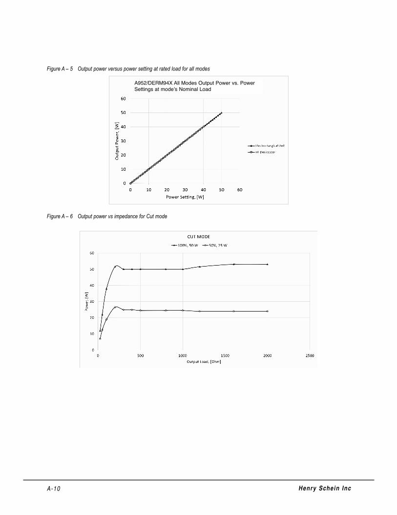
A-10 Henry Schein Inc
Figure A – 5 Output power versus power setting at rated load for all modes
Figure A – 6 Output power vs impedance for Cut mode
A952/DERM94X All Modes Output Power vs. Power Settings at mode’s Nominal Load

Figure A – 7 Output power vs impedance for Blend mode
Figure A – 8 Output power versus impedance for Coagulation modes
A-11User’s Guide • Electrosurgical Generator & High Frequency Desiccator - 50 Watt

Figure A – 9 Output power versus impedance for Fulguration mode
Figure A – 10 Output power vs impedance for Bipolar mode
A-12 Henry Schein Inc

Figure A – 11 Output power vs impedance for Micro Bipolar mode
A-13User’s Guide • Electrosurgical Generator & High Frequency Desiccator - 50 Watt

A-14 Henry Schein Inc

B-1User’s Guide • Electrosurgical Generator & High Frequency Desiccator - 50 Watt
WARRANTYBovie Medical Corporation warrants each product manufactured by it to be free from defects in material and workmanship under normal use and service for the period(s) set forth below.
Bovie Medical Corporation’s obligation under this warranty is limited to the repair or replacement, at its sole option,of any product, or part thereof, which has been returned to it or its Distributor within the applicable time periodshown below after delivery of the product to the original purchaser, and which examination discloses, to BovieMedical Corporation’s satisfaction, that the product is indeed, defective.
This warranty does not apply to any product, or part thereof, which has been repaired or altered outside BovieMedical Corporation’s factory in a way so as, in Bovie Medical Corporation’s judgment, to affect its stability or reliability, or which has been subjected to misuse, neglect, or accident.
The warranty periods for Bovie Medical Corporation products are as follows:
• Electrosurgical Generators: Four years from date of shipment
• Mounting Fixtures (all models): Two years from date of shipment
• Footswitches (all models): One year from date of shipment
• Patient Return Electrodes: Shelf life only as stated on packaging
• Sterile Single Use Accessories: Only as stated on packaging
• Handpiece: Only as stated on packaging

This warranty is in lieu of all other warranties, express or implied, including without limitation, the warranties ofmerchantability and fitness for a particular purpose, and of all other obligations or liabilities on the part of BovieMedical Corporation.
Bovie Medical Corporation neither assumes nor authorizes any other person to assume for it any other liability inconnection with the sale or use of any of Bovie Medical Corporation’s products.
Notwithstanding any other provision herein or in any other document or communication, Bovie MedicalCorporation’s liability with respect to this agreement and products sold hereunder shall be limited to the aggregatepurchase price for the goods sold by Bovie Medical Corporation to the customer.
Bovie Medical Corporation disclaims any liability hereunder or elsewhere in connection with the sale of this product,for indirect or consequential damages.
This warranty and the rights and obligations hereunder shall be construed under and governed by the laws of theState of Florida, USA.
The sole forum for resolving disputes arising under or relating in any way to this warranty is the District Court of theCounty of Pinellas, State of Florida, USA.
Bovie Medical Corporation, its dealers, and representatives reserve the right to make changes in equipment builtand/or sold by them at any time without incurring any obligation to make the same or similar changes on equipmentpreviously built and/or sold by them.
B-2 Henry Schein Inc

MC-55-257-001 Rev. 0
Rev. 2017/03