henry nfpa 285 air barrier assemblies · table 4 – mineral wool with noncombustible and...
TRANSCRIPT

Effective 01/09/2019 Supersedes all previous versions
Henry® NFPA 285 Air Barrier Assemblies The following Henry® air barrier assemblies meet the performance requirements of NFPA 285 as required by the International Building Code® (2003, 2006, 2009, 2012 and 2015 editions). Install NFPA 285 compliant wall assemblies as described in this tech-talk bulletin. Changes or modifications to the construction, and/or materials, may affect the tested assembly fire performance and void NFPA 285 compliance. Install Henry® air barrier assemblies per Henry® installation instructions. Refer to product specific technical data sheet (TDS), guide specification and standard details. Henry® Company regularly expands the NFPA 285 complaint wall assembly offerings. Refer to the Henry® website at www.henry.com for the most up to date version. Table of contents Flow Chart – Quick reference NFPA 285 flow chart
Henry® assemblies
Table 1 – Extruded Polystyrene (XPS) Insulation with noncombustible veneers
Table 2 – Permax® Spray Polyurethane Foam (SPF) with noncombustible veneers
Table 3 – Polyisocyanurate with noncombustible and combustible veneers
Table 4 – Mineral Wool with noncombustible and combustible veneers
Table 5 – Expanded Polystyrene (EPS) with noncombustible veneers
Table 6 – Walls excluding exterior insulation
Third-party assemblies Laminators Inc.
Rmax® ECOBASEci™
TAKTL®v
Disclaimer Henry® Company regularly expands the NFPA 285 complaint wall assembly offerings. It is the user’s responsibility to obtain and to confirm the most recent version. Information contained in this Tech-Talk Bulletin may change without notice.

Tech-talk: Henry® NFPA 285 Assemblies
NFPA 285 Performance Requirements and Code References NFPA 285 is a standard test method for evaluating fire propagation characteristics of exterior noncombustible wall assemblies containing combustible components. NFPA 285 compliance is identified through assembly analysis by accredited testing facilities and Fire Protection Engineers as referenced in AC12 §6.6. This document is based on verified NPFA 285 compliant wall assembly reports, and is intended as a guide for architects, general contractors, building owners, and authorities having jurisdiction in the design and construction of walls requiring NFPA 285 compliance. Product manufacturers do not have the authority to approve and do not approve project specific NFPA 285 compliance. Contact the authority having jurisdiction for final approval.
International Building Code (IBC) sections that trigger NFPA 285
Common exterior wall materials that trigger NFPA 285 compliance Relevant section of the International Building Code Materials Year instated Foam Plastics §2603.5.5 1988 edition Combustible Veneers MCMs & ACMs §1407.10 2000 edition HPLs §1409.10 2009 edition EIFS §1408.2 2009 edition FRPs §2612.5 2009 edition Water-resistive barriers (WRB) §1403.5 2012 edition
Quick reference NFPA 285 flow chart *Refer to International Building Code (IBC) sections that trigger NFPA 285 chart above. **2015 International Building Code: Section 1403.5 Vertical and lateral flame propagation. Exterior walls on buildings of Type I, II, III or IV construction that are greater than 40 feet (12192mm) in height above grade plane and contain a combustible water-resistive barrier shall be tested in accordance with and comply with the acceptance criteria of NFPA 285. For the purposes of this section, fenestration products and flashing of fenestration products shall not be considered part of the water-resistive barrier (WRB). Exceptions: 1. Walls in which the water-resistive barrier is the only combustible component and the exterior wall has a wall covering of brick, concrete, stone, terracotta, stucco or steel with minimum thickness in accordance with Table 1405.2. 2. Walls in which the water-resistive barrier is the only combustible component and the water-resistive barrier has a peak heat release rate of less than 150 kW/M2, a total heat release of less than 20MJ/m2 and an effective heat of combustion of less than 18MJ/kg as determined in accordance with ASTM E 1354 and has a flame spread index of 25 or less and a smoke-developed index of 450 or less as determined in accordance with ASTM E84 or UL 723. The ASTM E1354 test shall be conducted on specimens at the thickness intended for use, in the horizontal orientation and at an incident radiant heat flux of 50 kW/m2.

Tech-talk: Henry® NFPA 285 Assemblies
Table 1. Walls containing Extruded Polystyrene (XPS) insulation and Henry® air barrier membranes
Henry® assembly
Wall component Materials Base wall system Use either 1, 2, 3 or 4
1. Concrete wall 2. Concrete masonry unit (CMU) wall 3. Steel Studs – 20-gauge (min.) 3-5/8 inch (min.) steel studs spaced 24 inches OC (max.) with lateral
bracing every 4 feet vertically or as required by building code a. 5/8 inch thick, Type X, gypsum wallboard on interior
4. Where allowed in Types I, II, III, or IV construction, FRTW (fire retardant treated wood) studs complying with IBC Section 2303.2, min. nominal 2X4 dimension, spaced 24” OC (max.) a. 5/8” (min.) type X Gypsum Wallboard Interior b. Bracing as required by code
Floor line fire-stopping Use either 1, 2 or 3
1. None (base wall systems 1 and 2 only) 2. 4 pcf. mineral wool in each stud cavity at floor lines – attached with Z-clips or equivalent. Safing thickness
must match cavity depth 3. FRTW fire blocking at floor line in accordance with applicable code requirements
Stud cavity insulation Use either 1, 2, 3, 4 or 5 Note: items 2-4 may incorporate a Class A vapor barrier film
1. None 2. Noncombustible insulation per ASTM E136 3. Mineral fiber (board type Class A, ASTM E84 faced or un-faced) 4. Fiberglass (batt type Class A, ASTM E84 faced or un-faced) 5. Henry Permax® SPF - 6 inches (max.) (do not use spray polyurethane foam stud cavity insulation if
incorporating an interior vapor barrier membrane - see optional interior vapor barrier row below) Optional interior vapor barrier Use either 1 or 2
1. None 2. One layer of 6-mil thick (max.) polyethylene film (do not use spray polyurethane foam stud cavity
insulation if incorporating an interior vapor barrier membrane - see note above) Exterior sheathing Use either 1, 2, 3 or 4
1. None (base wall systems 1 and 2 only) 2. 1/2 inch thick, exterior grade gypsum sheathing 3. 5/8 inch thick, Type X, exterior grade gypsum sheathing 4. 1/2 inch thick (min.) FRTW sheathing complying with IBC Section 2303.2 and installed in accordance with
code allowances for Types I, II, III or IV construction Henry® air barrier installed onto exterior sheathing Select from list
1. Air-Bloc® 16MR 2. Air-Bloc® 17MR 3. Air-Bloc® 21FR 4. Air-Bloc® 31MR 5. Air-Bloc® 32MR 6. Air-Bloc® 33MR 7. Blueskin® VP160 8. Blueskin® SA or Blueskin® SA LT 9. FoilSkin® 10. Metal Clad™
Exterior insulation installed onto Henry® air barrier
Extruded Polystyrene Foam Insulation (XPS) - Type IV per ASTM C578 – 3 inches (max.). Where required, XPS may use Blueskin® SA, Blueskin® Butyl Flash flashing tape.
Exterior veneer Use either 1, 2, 3, 4, 5, 6 or 7
1. Brick – Nominal 4 inch thick (min.), clay brick with a 2 inch (max.) air gap between insulation and brick, and standard veneer anchors installed 24 inches (max.) OC
2. Stucco – 3/4 inch thick (min.), exterior cement plaster and lath 3. Stone veneer – 2 inches thick (min.) 4. Cast stone – 1-1/2 inches thick (min.) 5. Terracotta cladding – 1-1/4 inch thick (min.) 6. Concrete Masonry Units (CMU) – 4 inch thick (min.) with a 2 inch (max) air gap between exterior
insulation and CMU 7. Concrete Panels – 2 inches thick (min.) with a 2 inch (max.) air gap between exterior insulation and
concrete panel Special conditions Install header as shown in figure 1, 2 or 3 for window and door openings in walls utilizing XPS insulation. Flashing of window, door and other exterior wall penetrations
Flash window, door and exterior penetrations in accordance with applicable code using asphalt, acrylic or butyl based flashing (Blueskin® SA, Blueskin® Butyl Flash or Air-Bloc® LF) – 12-inches wide (max.).

Tech-talk: Henry® NFPA 285 Assemblies
Figure 1 – Extruded Polystyrene (XPS) Window/door opening detail

Tech-talk: Henry® NFPA 285 Assemblies
Figure 2 – Extruded Polystyrene (XPS) Window/door opening detail

Tech-talk: Henry® NFPA 285 Assemblies
Figure 3 – Extruded Polystyrene (XPS) Window/door opening detail

Tech-talk: Henry® NFPA 285 Assemblies
Table 2.1 Walls containing Henry® Permax® 2.0 or Permax® 1.8 Closed-Cell SPF
Henry® assembly
Wall component Materials Base wall system Use either 1, 2 or 3
1. Concrete wall 2. Concrete masonry unit (CMU) wall 3. Studs – 16-gauge (min.) 6 inch (min.) steel studs spaced 16 inches OC (max.) with lateral bracing every 4
feet vertically or as required by building code a. 5/8 inch thick, Type X, gypsum wallboard on interior
Floor line fire-stopping 4 pcf. mineral wool in each stud cavity at floor lines – attached with Z-clips or equivalent. Safing thickness must match cavity depth
Stud cavity insulation Use either 1, 2 or 3
1. None 2. Fiberglass (batt type Class A, ASTM E84 faced or un-faced) 3. Mineral fiber (Board type Class A, ASTM E84 faced or un-faced)
Exterior sheathing Use either 1, 2 or 3
1. None (base wall systems 1 and 2 only) 2. 1/2 inch thick, exterior grade gypsum sheathing 3. 5/8 inch thick, Type X, exterior grade gypsum sheathing
Henry® exterior insulation installed onto exterior sheathing Select from list
1. Permax® 1.8 – 4 inches thick (max.) 2. Permax® 2.0 – 4 inches thick (max.)
Exterior veneer Use either 1, 2, 3 or 4
1. Brick – Nominal 4 inch thick (min.), clay brick with a 2 inch (max.) air gap between insulation and brick, and standard veneer anchors installed 24 inches (max.) OC
2. Stucco – 3/4 inch thick (min.), exterior cement plaster and lath 3. Stone veneer – 2 inches thick (min.) 4. Terracotta cladding – 1-1/4 inch thick (min.)
Special conditions Frame window and door openings with 16-gauge (min.) steel. Flashing of window, door and other exterior wall penetrations
Flash window, door and exterior penetrations in accordance with applicable code using asphalt, acrylic or butyl based flashing (Blueskin® SA, Blueskin® Butyl Flash or Air-Bloc® LF) – 12-inches wide (max.).
Table 2.2 Walls containing Henry® Permax® 2.0X or Permax® 2.0X Fast Closed-Cell SPF
Henry® assembly
Wall component Materials Base wall system Use either 1, 2 or 3
1. Concrete wall 2. Concrete masonry unit (CMU) wall 3. Steel Studs – 20-gauge (min.) 3-5/8 inch (min.) steel studs spaced 24 inches OC (max.) with lateral
bracing every 4 feet vertically or as required by building code a. 5/8 inch thick, Type X, gypsum wallboard on interior b. See special conditions
Floor line fire-stopping 4 pcf. mineral wool in each stud cavity at floor lines – attached with Z-clips or equivalent. Safing thickness must match cavity depth
Stud cavity insulation Use either 1, 2, 3 or 4
1. None 2. Fiberglass (batt type Class A, ASTM E84 faced or un-faced) 3. Permax® 2.0X SPF 4. Permax® 2.0X Fast Closed-Cell SPF
Exterior sheathing Use either 1, 2 or 3
1. None (base wall systems 1 and 2 only) 2. 1/2 inch thick, exterior grade gypsum sheathing 3. 5/8 inch thick, Type X, exterior grade gypsum sheathing
Henry® exterior insulation installed onto exterior sheathing Select from list
1. Permax® 2.0X – 3 inches thick (max.) 2. Permax® 2.0X Fast Closed-Cell – 3 inches thick (max.)
Exterior veneer Use either 1, 2 or 3
1. Brick – Nominal 4 inch thick (min.), clay brick with a 2 inch (max.) air gap between insulation and brick, and standard veneer anchors installed 24 inches (max.) OC
2. Stucco – 3/4 inch thick (min.), exterior cement plaster and lath 3. Limestone veneer – 2 inches thick (min.)
Special conditions Refer to Permax® 2.0X/2.0X Fast Closed Cell SPF ICC-EX report ESR - 3647

Tech-talk: Henry® NFPA 285 Assemblies
Table 3. Walls containing polyisocyanurate insulation and Henry® air barrier membranes Henry air barriers have been approved for use in NFPA 285 wall assemblies containing polyisocyanurate. Polyisocyanurate may have product specific fire propagation characteristics. Refer to the product specific table as indicated below for more information. Polyisocyanurate insulation tables: Table 3.1 – Atlas® Energy Shield® Pro – 4 inches thick (max.)
Atlas® Energy Shield® Pro2 – 4 inches thick (max.)
Atlas® Rboard® – 4 inches thick (max.)
Table 3.2 – Dow® Thermax™ – 3 inches thick (max) for light claddings
Table 3.3 – Dow® Thermax™ – 4-1/4 inches thick (max) for heavy masonry claddings
Table 3.4 – Johns Manville AP™ Foil Faced Sheathing – 4.5 inches thick (max.)
Table 3.5 – Hunter Xci CG – 3-1/2 inch thick (max.)
Hunter Xci Class A – 3-1/2 inch thick (max.)
Hunter Xci-286 – 3-1/2 inch thick (max.)
Table 3.6 – Hunter Xci-Foil – 3-1/2 inch thick (max.)
Table 3.7 – Hunter Xci-Foil (Class A) – 3.5 inches thick (max.)
Table 3.8.A – Hunter Xci-Ply – 3-1/2 inch thick (max.) – Henry® air barrier installed onto exterior grade sheathing
Table 3.8.B – Hunter Xci-Ply – 3-1/2 inch thick (max.) – Henry® air barrier installed onto Hunter Xci-Ply

Tech-talk: Henry® NFPA 285 Assemblies
Table 3.1 Atlas® Energy Shield® Pro, Atlas® Energy Shield® Pro2 and Atlas® Rboard® – 4 inches thick (max)
Henry® assembly
Wall component Materials Base wall system Use either 1, 2, 3 or 4
1. Concrete wall 2. Concrete masonry unit (CMU) wall 3. Steel Studs – 20-gauge (min.) 3-5/8 inch (min.) steel studs spaced 24 inches OC (max.) with lateral
bracing every 4 feet vertically or as required by building code a. 5/8 inch thick, Type X, gypsum wallboard on interior
4. Where allowed in Types I, II, III, or IV construction, FRTW (fire retardant treated wood) studs complying with IBC Section 2303.2, min. nominal 2X4 dimension, spaced 24” OC (max.) a. 5/8” (min.) type X Gypsum Wallboard Interior b. Bracing as required by code
Floor line fire-stopping Use either 1, 2 or 3
1. None (base wall systems 1 and 2 only) 2. 4 pcf. mineral wool in each stud cavity at floor lines – attached with Z-clips or equivalent. Safing thickness
must match cavity depth 3. FRTW fire blocking at floor line in accordance with applicable code requirement
Stud cavity insulation Use either 1, 2, 3, 4 or 5 Note: items 2-4 may incorporate a Class A vapor barrier film
1. None 2. Noncombustible insulation per ASTM E136 3. Mineral fiber (Board type Class A, ASTM E84 faced or un-faced) 4. Fiberglass (Batt type Class A, ASTM E84 faced or un-faced) 5. Henry® Permax® SPF - 6 inches (max.) - See special conditions (do not use spray polyurethane foam
stud cavity insulation if incorporating an interior vapor barrier membrane - see optional interior vapor barrier row below)
Optional interior vapor barrier Use either 1 or 2
1. None 2. One layer of 6-mil thick (max.) polyethylene film (do not use spray polyurethane foam stud cavity
insulation if incorporating an interior vapor barrier membrane -see note above) Exterior sheathing Use either 1, 2, 3 or 4
1. None (base wall systems 1 and 2 only) 2. 1/2 inch thick, exterior grade gypsum sheathing 3. 5/8 inch thick, Type X, exterior grade gypsum sheathing 4. 1/2 inch thick (min.) FRTW sheathing complying with IBC Section 2303.2 and installed in accordance with
code allowances for Types I, II, III or IV construction Henry® air barrier installed onto exterior sheathing Select from list
1. Air-Bloc® 16MR 2. Air-Bloc® 17MR 3. Air-Bloc® 21FR 4. Air-Bloc® 31MR 5. Air-Bloc® 32MR 6. Air-Bloc® 33MR 7. Blueskin® VP160 8. Blueskin® SA or Blueskin® SA LT 9. FoilSkin® 10. Metal Clad™
Exterior insulation installed onto Henry® air barrier Use either 1, 2 or 3
1. Atlas® Energy Shield® Pro Rigid Insulation – 4 inches thick (max.) 2. Atlas® Energy Shield® Pro2 Rigid Insulation – 4 inches thick (max.) 3. Atlas® Rboard® Rigid Insulation – 4 inches thick (max.)
Exterior veneer Use either 1, 2, 3, 4, 5, 6, 7, 8, 9, 10, 11, 12 or 13
1. Brick – Nominal 4 inch thick (min.), clay brick with a 2 inch (max.) air gap between insulation and brick, and standard veneer anchors installed 24 inches (max.) OC
2. Stucco – 3/4 inch thick (min.), exterior cement plaster and lath 3. Stone veneer – 2 inches thick (min.) 4. Cast stone – 1-1/2 inches thick (min.) 5. Terracotta cladding – 1-1/4 inch thick (min.) 6. Aluminum Composite Material (ACM) – systems that have successfully passed NFPA 285 7. Uninsulated metal panels including steel, copper, or aluminum 8. Fiber cement siding 9. Autoclaved-aerated concrete (AAC) panels – systems that have successfully passed NFPA 285 10. Thin set brick 11. Concrete Masonry Units (CMU) – 4 inch thick CMU (min.), with a 2 inch (max.) air gap between exterior
insulation and CMU 12. Concrete Panels – 2 inch thick (min.) panel, with a 2 inch (max.) air gap between exterior insulation and
concrete panel 13. Insulated Concrete Sandwich Panels – 2 inch thick (min.) outer and inner faces with 2 inch (max.) air gap
between inner face and wall system Special conditions Use 0.03 inch stainless flashing header treatment when polyisocyanurate exterior insulation is installed in
conjunction with spray polyurethane foam cavity insulation. Flashing of window, door and other exterior wall penetrations
Flash window, door and exterior penetrations in accordance with applicable code using asphalt, acrylic or butyl based flashing (Blueskin® SA, Blueskin® Butyl Flash or Air-Bloc® LF) – 12-inches wide (max.).

Tech-talk: Henry® NFPA 285 Assemblies
Table 3.2 Walls containing Dow® Thermax™ – 3 inches thick (max) for light claddings
Henry® assembly
Wall component Materials Base wall system Use either 1, 2, 3 or 4
1. Concrete wall 2. Concrete masonry unit (CMU) wall 3. Steel Studs – 20-gauge (min.) 3-5/8 inch (min.) steel studs spaced 24 inches OC (max.) with lateral
bracing every 4 feet vertically or as required by building code a. 5/8 inch thick, Type X, gypsum wallboard on interior
4. Where allowed in Types I, II, III, or IV construction, FRTW (fire retardant treated wood) studs complying with IBC Section 2303.2, min. nominal 2X4 dimension, spaced 24” OC (max.) a. 5/8” (min.) type X Gypsum Wallboard Interior b. Bracing as required by code
Floor line fire-stopping Use either 1, 2 or 3
1. None (base wall systems 1 and 2 only) 2. 4 pcf. mineral wool in each stud cavity at floor lines – attached with Z-clips or equivalent. Safing thickness
must match cavity depth 3. FRTW fire blocking at floor line in accordance with applicable code requirements
Stud cavity insulation Use either 1, 2 or 3
1. None 2. Fiberglass (batt type Class A, ASTM E84 faced or un-faced) 3. Full stud depth (max.) Dow Styrofoam Spray Polyurethane Foam CM2030, 2045 or 2060 complying with
ESR 2670. Apply to interior side of exterior sheathing Exterior sheathing Use either 1, 2, 3 or 4
1. None (base wall systems 1 and 2 only) 2. 1/2 inch thick, exterior grade gypsum sheathing 3. 5/8 inch thick, Type X, exterior grade gypsum sheathing 4. 1/2 inch thick (min.) FRTW sheathing complying with IBC Section 2303.2 and installed in accordance with
code allowances for Types I, II, III or IV construction Henry® air barrier installed onto exterior sheathing Select from list
1. Air-Bloc® 16MR 2. Air-Bloc® 17MR 3. Air-Bloc® 21FR 4. Air-Bloc® 31MR 5. Air-Bloc® 32MR 6. Air-Bloc® 33MR 7. Blueskin® SA or Blueskin® SA LT 8. Blueskin® VP160 9. Foilskin® 10. Metal Clad™
Exterior insulation installed onto Henry® air barrier
Dow® Thermax™ Insulation – 3 inches thick (max.)
Exterior veneer Use either 1, 2, 3, 4, 5, 6, 7 or 8
1. Cast stone – 3/4 inch thick (min.) bonded using cementitious mortar to a 1/2 inch thick (min.) cement board or gypsum sheathing
2. Metal Composite Material (MCM) – systems that have successfully passed NFPA 285 3. Terracotta cladding – 1-1/4 inch thick (min.) 4. Uninsulated metal panels including steel, copper, or aluminum 5. Fiber cement siding 6. Concrete Panels – 1-1/2 inches thick (min.) with a 2 inch (max.) air gap between exterior insulation and
concrete panels 7. Ceramic tile – 3/8 inch thick (min.) bonded using noncombustible mortar adhesive to a 1/2 inch thick
(min.) cement board or gypsum sheathing 8. Thin set brick – 3/4 inch thick (min.), exterior cement plaster and lath
Special conditions Window headers must incorporate 25 ga. (min.) steel flashing.
Tech-talk: Henry® NFPA 285 Assemblies
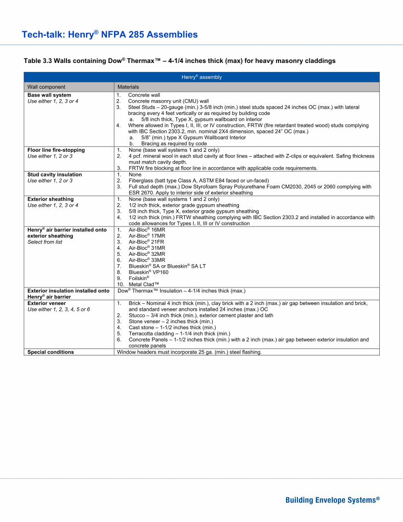
Table 3.3 Walls containing Dow® Thermax™ – 4-1/4 inches thick (max) for heavy masonry claddings
Henry® assembly
Wall component Materials Base wall system Use either 1, 2, 3 or 4
1. Concrete wall 2. Concrete masonry unit (CMU) wall 3. Steel Studs – 20-gauge (min.) 3-5/8 inch (min.) steel studs spaced 24 inches OC (max.) with lateral
bracing every 4 feet vertically or as required by building code a. 5/8 inch thick, Type X, gypsum wallboard on interior
4. Where allowed in Types I, II, III, or IV construction, FRTW (fire retardant treated wood) studs complying with IBC Section 2303.2, min. nominal 2X4 dimension, spaced 24” OC (max.) a. 5/8” (min.) type X Gypsum Wallboard Interior b. Bracing as required by code
Floor line fire-stopping Use either 1, 2 or 3
1. None (base wall systems 1 and 2 only) 2. 4 pcf. mineral wool in each stud cavity at floor lines – attached with Z-clips or equivalent. Safing thickness
must match cavity depth. 3. FRTW fire blocking at floor line in accordance with applicable code requirements.
Stud cavity insulation Use either 1, 2 or 3
1. None 2. Fiberglass (batt type Class A, ASTM E84 faced or un-faced) 3. Full stud depth (max.) Dow Styrofoam Spray Polyurethane Foam CM2030, 2045 or 2060 complying with
ESR 2670. Apply to interior side of exterior sheathing Exterior sheathing Use either 1, 2, 3 or 4
1. None (base wall systems 1 and 2 only) 2. 1/2 inch thick, exterior grade gypsum sheathing 3. 5/8 inch thick, Type X, exterior grade gypsum sheathing 4. 1/2 inch thick (min.) FRTW sheathing complying with IBC Section 2303.2 and installed in accordance with
code allowances for Types I, II, III or IV construction Henry® air barrier installed onto exterior sheathing Select from list
1. Air-Bloc® 16MR 2. Air-Bloc® 17MR 3. Air-Bloc® 21FR 4. Air-Bloc® 31MR 5. Air-Bloc® 32MR 6. Air-Bloc® 33MR 7. Blueskin® SA or Blueskin® SA LT 8. Blueskin® VP160 9. Foilskin® 10. Metal Clad™
Exterior insulation installed onto Henry® air barrier
Dow® Thermax™ Insulation – 4-1/4 inches thick (max.)
Exterior veneer Use either 1, 2, 3, 4, 5 or 6
1. Brick – Nominal 4 inch thick (min.), clay brick with a 2 inch (max.) air gap between insulation and brick, and standard veneer anchors installed 24 inches (max.) OC
2. Stucco – 3/4 inch thick (min.), exterior cement plaster and lath 3. Stone veneer – 2 inches thick (min.) 4. Cast stone – 1-1/2 inches thick (min.) 5. Terracotta cladding – 1-1/4 inch thick (min.) 6. Concrete Panels – 1-1/2 inches thick (min.) with a 2 inch (max.) air gap between exterior insulation and
concrete panels Special conditions Window headers must incorporate 25 ga. (min.) steel flashing.

Tech-talk: Henry® NFPA 285 Assemblies
Table 3.4 Walls containing Johns Manville - AP™ Foil Faced Sheathing – 4-1/2 inches thick (max.)
Henry® assembly
Wall component Materials Base wall system Use either 1, 2, 3 or 4
1. Concrete wall 2. Concrete masonry unit (CMU) wall 3. Steel Studs – 20-gauge (min.) 3-5/8 inch (min.) steel studs spaced 24 inches OC (max.) with lateral
bracing every 4 feet vertically or as required by building code a. 5/8 inch thick, Type X, gypsum wallboard on interior
4. Where allowed in Types I, II, III, or IV construction, FRTW (fire retardant treated wood) studs complying with IBC Section 2303.2, min. nominal 2X4 dimension, spaced 24” OC (max.) a. 5/8” (min.) type X Gypsum Wallboard Interior b. Bracing as required by code
Floor line fire-stopping Use either 1, 2 or 3
1. None (base wall systems 1 and 2 only) 2. 4 pcf. mineral wool in each stud cavity at floor lines – attached with Z-clips or equivalent. Safing thickness
must match cavity depth 3. FRTW fire blocking at floor line in accordance with applicable code requirement
Stud cavity insulation Use either 1, 2, 3, 4 or 5 Note: items 2-4 may incorporate a Class A vapor barrier film
1. None 2. Noncombustible insulation per ASTM E136 3. Mineral fiber (Board type Class A, ASTM E84 faced or un-faced) 4. Fiberglass (Batt type Class A, ASTM E84 faced or un-faced) 5. Henry® Permax® SPF - 6 inches (max.) - See special conditions (do not use spray polyurethane foam
stud cavity insulation if incorporating an interior vapor barrier membrane - see optional interior vapor barrier row below)
Optional interior vapor barrier Use either 1 or 2
1. None 2. One layer of 6-mil thick (max.) polyethylene film (do not use spray polyurethane foam stud cavity
insulation if incorporating an interior vapor barrier membrane -see note above) Exterior sheathing Use either 1, 2 or 3
1. None (base wall systems 1 and 2 only) 2. 1/2 inch thick, exterior grade gypsum sheathing 3. 5/8 inch thick, Type X, exterior grade gypsum sheathing
Henry® air barrier installed onto exterior sheathing Select from list
1. Air-Bloc® 16MR 2. Air-Bloc® 17MR 3. Air-Bloc® 21FR 4. Air-Bloc® 31MR 5. Air-Bloc® 32MR 6. Air-Bloc® 33MR 7. Blueskin® VP160 8. Blueskin® SA or Blueskin® SA LT 9. FoilSkin® 10. Metal Clad™
Exterior insulation installed onto Henry® air barrier
Johns Manville AP™ Foil Faced Sheathing – 4.5 inches thick (max.)
Exterior veneer Use either 1, 2, 3, 4 or 5
1. Brick – Nominal 4 inch thick (min.), clay brick with a 2 inch (max.) air gap between insulation and brick, and standard veneer anchors installed 24 inches (max.) OC
2. Stucco – 3/4 inch thick (min.), exterior cement plaster and lath 3. Stone veneer – 2 inches thick (min.) 4. Cast stone – 1-1/2 inches thick (min.) 5. Terracotta cladding – 1-1/4 inch thick (min.)
Special conditions Use 0.03 inch stainless flashing header treatment when polyisocyanurate exterior insulation is installed in conjunction with spray polyurethane foam cavity insulation.
Flashing of window, door and other exterior wall penetrations
Flash window, door and exterior penetrations in accordance with applicable code using asphalt, acrylic or butyl based flashing (Blueskin® SA, Blueskin® Butyl Flash or Air-Bloc® LF) – 12-inches wide (max.).

Tech-talk: Henry® NFPA 285 Assemblies
Table 3.5 Hunter Xci CG, Hunter Xci Class A and Hunter Xci-286 – 3-1/2 inch thick (max.)
Henry® assembly
Wall component Materials Base wall system Use either 1, 2, 3 or 4
1. Concrete wall 2. Concrete masonry unit (CMU) wall 3. Steel Studs – 25-gauge (min.) 3-5/8 inch (min.) steel studs spaced 24 inches OC (max.) with lateral
bracing every 4 feet vertically or as required by building code a. 5/8 inch thick, Type X, gypsum wallboard on interior
4. Where allowed in Types I, II, III, or IV construction, FRTW (fire retardant treated wood) studs complying with IBC Section 2303.2, min. nominal 2X4 dimension, spaced 24” OC (max.) a. 5/8” (min.) type X Gypsum Wallboard Interior b. Bracing as required by code
Floor line fire-stopping Use either 1, 2 or 3
1. None (base wall systems 1 and 2 only) 2. 4 pcf. mineral wool in each stud cavity at floor lines – attached with Z-clips or equivalent. Safing thickness
must match cavity depth. 3. FRTW fire blocking at floor line in accordance with applicable code requirements.
Stud cavity insulation Use either 1, 2, 3 or 4
1. None 2. Noncombustible insulation (faced or un-faced) per ASTM E136 3. Mineral fiber (board type Class A, faced or un-faced meeting ASTM E84) 4. Fiberglass (batt type Class A, faced or un-faced meeting ASTM E84)
Exterior sheathing Use either 1, 2, 3 or 4
1. None (base wall systems 1 and 2) 2. 1/2 inch thick, exterior grade gypsum sheathing 3. 5/8 inch thick, Type X, exterior grade gypsum sheathing 4. 1/2 inch thick (min.) FRTW sheathing complying with IBC Section 2303.2 and installed in accordance with
code allowances for Types I, II, III or IV construction Henry® air barrier installed onto exterior sheathing Select from list
1. Air-Bloc® 16MR 2. Air-Bloc® 17MR 3. Air-Bloc® 21FR 4. Air-Bloc® 31MR 5. Air-Bloc® 33MR 6. Blueskin® VP160 7. Foilskin® 8. Metal Clad™
Exterior insulation installed onto Henry® air barrier Use either 1, 2 or 3
1. Hunter Xci CG – 3-1/2 inch thick (max.) 2. Hunter Xci Class A – 3-1/2 inch thick (max.) 3. Hunter Xci-286 – 3-1/2 inch thick (max.)
Exterior veneer Use either 1, 2, 3, 4, 5, 6, 7, 8, 9 or 10
1. Brick – Nominal 4 inch thick (min.), clay brick with a 2 inch (max.) air gap between insulation and brick, and standard veneer anchors installed 24 inches (max.) OC
2. Stucco – 3/4 inch thick (min.), exterior cement plaster and lath 3. Stone veneer – 2 inches thick (min.) 4. Cast stone – 1-1/2 inches thick (min.) 5. Terracotta cladding – 1-1/4 inch thick (min.) 6. Metal Composite Material (MCM) – systems that have successfully passed NFPA 285 7. Uninsulated metal panels including steel, copper, or aluminum 8. Fiber cement siding 9. Stone Aluminum Honeycomb Composite Panels – Any system successfully tested by the panel
manufacturer via the NFPA 285 test method 10. Autoclaved-aerated concrete (AAC) panels – systems that have successfully passed NFPA 285
Special conditions Install 25 gauge (min.) steel flashing at window header.

Tech-talk: Henry® NFPA 285 Assemblies
Table 3.6 Hunter Xci-Foil – 3-1/2 inch thick (max.)
Henry® assembly
Wall component Materials Base wall system Use either 1, 2, 3 or 4
1. Concrete wall 2. Concrete masonry unit (CMU) wall 3. Steel Studs – 25-gauge (min.) 3-5/8 inch (min.) steel studs spaced 24 inches OC (max.) with lateral
bracing every 4 feet vertically or as required by building code a. 5/8 inch thick, Type X, gypsum wallboard on interior
4. Where allowed in Types I, II, III, or IV construction, FRTW (fire retardant treated wood) studs complying with IBC Section 2303.2, min. nominal 2X4 dimension, spaced 24” OC (max.) a. 5/8” (min.) type X Gypsum Wallboard Interior b. Bracing as required by code
Floor line fire-stopping Use either 1, 2 or 3
1. None (base wall systems 1 and 2 only) 2. 4 pcf. mineral wool in each stud cavity at floor lines – attached with Z-clips or equivalent. Safing thickness
must match cavity depth. 3. FRTW fire blocking at floor line in accordance with applicable code requirements.
Stud cavity insulation Use either 1, 2, 3 or 4
1. None 2. Noncombustible insulation (faced or un-faced) per ASTM E136 3. Mineral fiber (board type Class A, faced or un-faced meeting ASTM E84) 4. Fiberglass (batt type Class A, faced or un-faced meeting ASTM E84)
Exterior sheathing Use either 1, 2, 3 or 4
1. None (base wall systems 1 and 2) 2. 1/2 inch thick, exterior grade gypsum sheathing 3. 5/8 inch thick, Type X, exterior grade gypsum sheathing 4. 1/2 inch thick (min.) FRTW sheathing complying with IBC Section 2303.2 and installed in accordance with
code allowances for Types I, II, III or IV construction Henry® air barrier installed onto exterior sheathing Select from list
1. Air-Bloc® 16MR 2. Air-Bloc® 17MR 3. Air-Bloc® 21FR 4. Air-Bloc® 31MR 5. Air-Bloc® 33MR 6. Blueskin® VP160 7. Foilskin® 8. Metal Clad™
Exterior insulation installed onto Henry® air barrier
Hunter Xci-Foil – 3-1/2 inch thick (max.)
Exterior veneer Use either 1, 2, 3, 4 or 5
1. Brick – Nominal 4 inch thick (min.), clay brick with a 2 inch (max.) air gap between insulation and brick, and standard veneer anchors installed 24 inches (max.) OC
2. Stucco – 3/4 inch thick (min.), exterior cement plaster and lath 3. Stone veneer – 2 inches thick (min.) 4. Cast stone – 1-1/2 inches thick (min.) 5. Terracotta cladding – 1-1/4 inch thick (min.)
Special conditions Install 25 gauge (min.) steel flashing at window header.

Tech-talk: Henry® NFPA 285 Assemblies
Table 3.7 Hunter Xci-Foil (Class A) – 3.5 inches thick (max.)
Henry® assembly
Wall component Materials Base wall system Use either 1, 2, 3 or 4
1. Concrete wall 2. Concrete masonry unit (CMU) wall 3. Steel Studs – 20-gauge (min.) 3-5/8 inch (min.) steel studs spaced 24 inches OC (max.) with lateral
bracing every 4 feet vertically or as required by building code a. 5/8 inch thick, Type X, gypsum wallboard on interior
4. Where allowed in Types I, II, III, or IV construction, FRTW (fire retardant treated wood) studs complying with IBC Section 2303.2, min. nominal 2X4 dimension, spaced 24” OC (max.) a. 5/8” (min.) type X Gypsum Wallboard Interior b. Bracing as required by code
Floor line fire-stopping Use either 1, 2 or 3
1. None (base wall systems 1 and 2 only) 2. 4 pcf. mineral wool in each stud cavity at floor lines – attached with Z-clips or equivalent. Safing thickness
must match cavity depth 3. FRTW fire blocking at floor line in accordance with applicable code requirement
Stud cavity insulation Use either 1, 2, 3, 4 or 5 Note: items 2-4 may incorporate a Class A vapor barrier film
1. None 2. Noncombustible insulation per ASTM E136 3. Mineral fiber (Board type Class A, ASTM E84 faced or un-faced) 4. Fiberglass (Batt type Class A, ASTM E84 faced or un-faced) 5. Henry® Permax® SPF - 6 inches (max.) - See special conditions (do not use spray polyurethane foam
stud cavity insulation if incorporating an interior vapor barrier membrane - see optional interior vapor barrier row below)
Optional interior vapor barrier Use either 1 or 2
1. None 2. One layer of 6-mil thick (max.) polyethylene film (do not use spray polyurethane foam stud cavity
insulation if incorporating an interior vapor barrier membrane -see note above) Exterior sheathing Use either 1, 2, 3 or 4
1. None (base wall systems 1 and 2 only) 2. 1/2 inch thick, exterior grade gypsum sheathing 3. 5/8 inch thick, Type X, exterior grade gypsum sheathing 4. 1/2 inch thick (min.) FRTW sheathing complying with IBC Section 2303.2 and installed in accordance with
code allowances for Types I, II, III or IV construction Henry® air barrier installed onto exterior sheathing Select from list
1. Air-Bloc® 16MR 2. Air-Bloc® 17MR 3. Air-Bloc® 21FR 4. Air-Bloc® 31MR 5. Air-Bloc® 32MR 6. Air-Bloc® 33MR 7. Blueskin® VP160 8. Blueskin® SA or Blueskin® SA LT 9. FoilSkin® 10. Metal Clad™
Exterior insulation installed onto Henry® air barrier
Hunter Xci-Foil (Class A) – 3.5 inches thick (max.)
Exterior veneer Use either 1, 2, 3, 4, 5, 6, 7, 8, 9, 10, 11, 12 or 13
1. Brick – Nominal 4 inch thick (min.), clay brick with a 2 inch (max.) air gap between insulation and brick, and standard veneer anchors installed 24 inches (max.) OC
2. Stucco – 3/4 inch thick (min.), exterior cement plaster and lath 3. Stone veneer – 2 inches thick (min.) 4. Cast stone – 1-1/2 inches thick (min.) 5. Terracotta cladding – 1-1/4 inch thick (min.) 6. Aluminum Composite Material (ACM) – systems that have successfully passed NFPA 285 7. Uninsulated metal panels including steel, copper, or aluminum 8. Fiber cement siding 9. Autoclaved-aerated concrete (AAC) panels – systems that have successfully passed NFPA 285 10. Thin set brick 11. Concrete Masonry Units (CMU) – 4 inch thick CMU (min.), with a 2 inch (max.) air gap between exterior
insulation and CMU 12. Concrete Panels – 2 inch thick (min.) panel, with a 2 inch (max.) air gap between exterior insulation and
concrete panel 13. Insulated Concrete Sandwich Panels – 2 inch thick (min.) outer and inner faces with 2 inch (max.) air gap
between inner face and wall system Special conditions Use 0.03 inch stainless flashing header treatment when polyisocyanurate exterior insulation is installed in
conjunction with spray polyurethane foam cavity insulation. Flashing of window, door and other exterior wall penetrations
Flash window, door and exterior penetrations in accordance with applicable code using asphalt, acrylic or butyl based flashing (Blueskin® SA, Blueskin® Butyl Flash or Air-Bloc® LF) – 12-inches wide (max.).

Tech-talk: Henry® NFPA 285 Assemblies
Table 3.8.A Hunter Xci-Ply – 3-1/2 inch thick (max.) – Henry® air barrier installed onto exterior grade sheathing
Henry® assembly
Wall component Materials Base wall system Use either 1, 2, 3 or 4
1. Concrete wall 2. Concrete masonry unit (CMU) wall 3. Steel Studs – 25-gauge (min.) 3-5/8 inch (min.) steel studs spaced 24 inches OC (max.) with lateral
bracing every 4 feet vertically or as required by building code a. 5/8 inch thick, Type X, gypsum wallboard on interior
4. Where allowed in Types I, II, III, or IV construction, FRTW (fire retardant treated wood) studs complying with IBC Section 2303.2, min. nominal 2X4 dimension, spaced 24” OC (max.) a. 5/8” (min.) type X Gypsum Wallboard Interior b. Bracing as required by code
Floor line fire-stopping Use either 1, 2 or 3
1. None (base wall systems 1 and 2 only) 2. 4 pcf. mineral wool in each stud cavity at floor lines – attached with Z-clips or equivalent. Safing thickness
must match cavity depth. 3. FRTW fire blocking at floor line in accordance with applicable code requirements.
Stud cavity insulation Use either 1, 2, 3 or 4
1. None 2. Noncombustible insulation (faced or un-faced) per ASTM E136 3. Mineral fiber (board type Class A, faced or un-faced meeting ASTM E84) 4. Fiberglass (batt type Class A, faced or un-faced meeting ASTM E84)
Exterior sheathing Use either 1, 2, 3 or 4
1. None (base wall systems 1 and 2) 2. 1/2 inch thick, exterior grade gypsum sheathing 3. 5/8 inch thick, Type X, exterior grade gypsum sheathing 4. 1/2 inch thick (min.) FRTW sheathing complying with IBC Section 2303.2 and installed in accordance with
code allowances for Types I, II, III or IV construction Henry® air barrier installed onto exterior sheathing Select from list
1. Air-Bloc® 16MR 2. Air-Bloc® 17MR 3. Air-Bloc® 21FR 4. Air-Bloc® 31MR 5. Air-Bloc® 32MR 6. Air-Bloc® 33MR 7. Blueskin® SA or Blueskin® SA LT 8. Blueskin® VP160 9. Foilskin® 10. Metal Clad™
Exterior insulation installed onto Henry® air barrier
Hunter Xci-Ply – 3-1/2 inch thick (max.)
Exterior veneer Use either 1, 2, 3, 4, 5, 6, 7, 8, 9, 10 or 11
1. Brick – Nominal 4 inch thick (min.), clay brick with a 2 inch (max.) air gap between insulation and brick, and standard veneer anchors installed 24 inches (max.) OC
2. Stucco – 3/4 inch thick (min.), exterior cement plaster and lath 3. Stone veneer – 2 inches thick (min.) 4. Cast stone – 1-1/2 inches thick (min.) 5. Terracotta cladding – 1-1/4 inch thick (min.) 6. Metal Composite Material (MCM) – systems that have successfully passed NFPA 285 7. Uninsulated metal panels including steel, copper, or aluminum 8. Fiber cement siding 9. Stone Aluminum Honeycomb Composite Panels – Any system successfully tested by the panel
manufacturer via the NFPA 285 test method 10. Autoclaved-aerated concrete (AAC) panels – systems that have successfully passed NFPA 285 11. Thin set brick
Special conditions Install 25 gauge (min.) steel flashing at window header.

Tech-talk: Henry® NFPA 285 Assemblies
Table 3.8.B Hunter Xci-Ply – 3-1/2 inch thick (max.) Henry® air barrier installed onto Hunter Xci-Ply
Henry® assembly
Wall component Materials Base wall system Use either 1, 2, 3 or 4
1. Concrete wall 2. Concrete masonry unit (CMU) wall 3. Steel Studs – 25-gauge (min.) 3-5/8 inch (min.) steel studs spaced 24 inches OC (max.) with lateral
bracing every 4 feet vertically or as required by building code a. 5/8 inch thick, Type X, gypsum wallboard on interior
4. Where allowed in Types I, II, III, or IV construction, FRTW (fire retardant treated wood) studs complying with IBC Section 2303.2, min. nominal 2X4 dimension, spaced 24” OC (max.) a. 5/8” (min.) type X Gypsum Wallboard Interior b. Bracing as required by code
Floor line fire-stopping Use either 1, 2 or 3
1. None (base wall systems 1 and 2 only) 2. 4 pcf. mineral wool in each stud cavity at floor lines – attached with Z-clips or equivalent. Safing thickness
must match cavity depth. 3. FRTW fire blocking at floor line in accordance with applicable code requirements.
Stud cavity insulation Use either 1, 2, 3 or 4
1. None 2. Noncombustible insulation (faced or un-faced) per ASTM E136 3. Mineral fiber (board type Class A, faced or un-faced meeting ASTM E84) 4. Fiberglass (batt type Class A, faced or un-faced meeting ASTM E84)
Hunter Xci-Ply exterior insulation sheathing
Hunter Xci-Ply – 3-1/2 inch thick (max.)
Henry® air barrier installed onto exterior sheathing Select from list
1. Air-Bloc® 17MR 2. Air-Bloc® 21FR 3. Air-Bloc® 31MR 4. Air-Bloc® 33MR 5. Blueskin® VP160 6. Foilskin® 7. Metal Clad™
Exterior veneer Use either 1, 2, 3, 4, 5, 6, 7, 8, 9, 10 or 11
1. Brick – Nominal 4 inch thick (min.), clay brick with a 2 inch (max.) air gap between insulation and brick, and standard veneer anchors installed 24 inches (max.) OC
2. Stucco – 3/4 inch thick (min.), exterior cement plaster and lath 3. Stone veneer – 2 inches thick (min.) 4. Cast stone – 1-1/2 inches thick (min.) 5. Terracotta cladding – 1-1/4 inch thick (min.) 6. Metal Composite Material (MCM) – systems that have successfully passed NFPA 285 7. Uninsulated metal panels including steel, copper, or aluminum 8. Fiber cement siding 9. Stone Aluminum Honeycomb Composite Panels – Any system successfully tested by the panel
manufacturer via the NFPA 285 test method 10. Autoclaved-aerated concrete (AAC) panels – systems that have successfully passed NFPA 285 11. Thin set brick
Special conditions Install 25 gauge (min.) steel flashing at window header.

Tech-talk: Henry® NFPA 285 Assemblies
Table 4. Walls containing mineral wool insulation and Henry® air barriers
Henry® assembly
Wall component Materials Base wall system Use either 1, 2, 3 or 4
1. Concrete wall 2. Concrete masonry unit (CMU) wall 3. Steel Studs – 20-gauge (min.) 3-5/8 inch (min.) steel studs spaced 24 inches OC (max.) with lateral
bracing every 4 feet vertically or as required by building code a. 5/8 inch thick, Type X, gypsum wallboard on interior
4. Where allowed in Types I, II, III, or IV construction, FRTW (fire retardant treated wood) studs complying with IBC Section 2303.2, min. nominal 2X4 dimension, spaced 24” OC (max.) a. 5/8” (min.) type X Gypsum Wallboard Interior b. Bracing as required by code
Stud cavity insulation Use either 1, 2, 3, 4 or 5 Note: items 2-4 may incorporate a Class A vapor barrier film
1. None 2. Noncombustible insulation per ASTM E136 3. Mineral fiber (Board type Class A, ASTM E84 faced or un-faced) 4. Fiberglass (Batt type Class A, faced or un-faced meeting ASTM E84) 5. Henry Permax® SPF - 6 inches (max.) (do not use spray polyurethane foam stud cavity insulation if
incorporating an interior vapor barrier membrane - see optional interior vapor barrier row below) Optional interior vapor barrier Use either 1 or 2
1. None 2. One layer of 6-mil thick (max.) polyethylene film (do not use spray polyurethane foam stud cavity
insulation if incorporating an interior vapor barrier membrane - see note above) Exterior sheathing Use either 1, 2, 3 or 4
1. None (base wall systems 1 and 2 only) 2. 1/2 inch thick, exterior grade gypsum sheathing 3. 5/8 inch thick, Type X, exterior grade gypsum sheathing 4. 1/2 inch thick (min.) FRTW sheathing complying with IBC Section 2303.2 and installed in accordance with
code allowances for Types I, II, III or IV construction Henry® air barrier installed onto exterior sheathing Select from list
1. Air-Bloc® 16MR 2. Air-Bloc® 17MR 3. Air-Bloc® 21FR 4. Air-Bloc® 31MR 5. Air-Bloc® 32MR 6. Air-Bloc® 33MR 7. Blueskin® VP160 8. Blueskin® SA or Blueskin® SA LT 9. FoilSkin® 10. Metal Clad™
Exterior insulation installed onto Henry® air barrier
Mineral wool insulation as per ASTM C612 and meeting the following conditions: 1. 1-1/2 inch thick minimum 2. Noncombustible via ASTM E136 testing 3. Density range from 4.0 to 9.0 lbs/ft3 4. R-value/inch range from 3.5 to 4.5 5. Mechanically attach mineral wool 6. Completely cover the air barrier membrane with mineral wool
Exterior veneer Use either 1, 2, 3, 4, 5, 6, 7, 8, 9, 10, 11 or 12
1. Brick – Nominal 4 inch thick (min.), clay brick with a 2 inch (max.) air gap between insulation and brick, and standard veneer anchors installed 24 inches (max.) OC
2. Stucco – 3/4 inch thick (min.), exterior cement plaster and lath 3. Stone veneer – 2 inches thick (min.) 4. Cast stone – 1-1/2 inches thick (min.) 5. Terracotta cladding – 1-1/4 inch thick (min.) 6. Aluminum Composite Material (ACM) – systems that have successfully passed NFPA 285 7. Uninsulated metal panels including steel, copper, or aluminum 8. Fiber cement siding 9. Autoclaved-aerated concrete (AAC) panels – systems that have successfully passed NFPA 285 10. Thin set brick 11. Concrete Masonry Units (CMU) – 4 inches thick (min.) with a 2 inch (max) air gap between exterior
insulation and CMU 12. Concrete Panels – 2 inches thick (min.) with a 2 inch (max.) air gap between exterior insulation and
concrete panels Flashing of window, door and other exterior wall penetrations
Flash window, door and exterior penetrations in accordance with applicable code using asphalt, acrylic or butyl based flashing (Blueskin® SA, Blueskin® Butyl Flash or Air-Bloc® LF) – 12-inches wide (max.).

Tech-talk: Henry® NFPA 285 Assemblies
Table 5. Walls containing Expanded Polystyrene (EPS) insulation and Henry® air barrier membranes
Henry® assembly
Wall component Materials Base wall system Use either 1, 2, 3 or 4
1. Concrete wall 2. Concrete masonry unit (CMU) wall 3. Steel Studs – 20-gauge (min.) 3-5/8 inch (min.) steel studs spaced 24 inches OC (max.) with lateral
bracing every 4 feet vertically or as required by building code a. 5/8 inch thick, Type X, gypsum wallboard on interior
4. Where allowed in Types I, II, III, or IV construction, FRTW (fire retardant treated wood) studs complying with IBC Section 2303.2, min. nominal 2X4 dimension, spaced 24” OC (max.) a. 5/8” (min.) type X Gypsum Wallboard Interior b. Bracing as required by code
Floor line fire-stopping Use either 1, 2 or 3
1. None (base wall systems 1 and 2 only) 2. 4 pcf. mineral wool in each stud cavity at floor lines – attached with Z-clips or equivalent. Safing thickness
must match cavity depth 3. FRTW fire blocking at floor line in accordance with applicable code requirements
Stud cavity insulation Use either 1, 2, 3, 4 or 5 Note: items 2-4 may incorporate a Class A vapor barrier film
1. None 2. Noncombustible insulation per ASTM E136 3. Mineral fiber (Board type Class A, ASTM E84 faced or un-faced) 4. Fiberglass (Batt type Class A, ASTM E84 faced or un-faced) 5. Henry Permax® SPF – 6 inch (max.) (do not use spray polyurethane foam stud cavity insulation if
incorporating an interior vapor barrier membrane - see optional interior vapor barrier row below) Optional interior vapor barrier Use either 1 or 2
1. None 2. One layer of 6-mil thick (max.) polyethylene film (do not use spray polyurethane foam stud cavity
insulation if incorporating an interior vapor barrier membrane - see note above) Exterior sheathing Use either 1, 2, 3 or 4
1. None (base wall systems 1 and 2 only) 2. 1/2 inch thick, exterior grade gypsum sheathing 3. 5/8 inch thick, Type X, exterior grade gypsum sheathing 4. 1/2 inch thick (min.) FRTW sheathing complying with IBC Section 2303.2 and installed in accordance with
code allowances for Types I, II, III or IV construction Henry® air barrier installed onto exterior sheathing Select from list
1. Air-Bloc® 16MR 2. Air-Bloc® 17MR 3. Air-Bloc® 21FR 4. Air-Bloc® 31MR 5. Air-Bloc® 33MR 6. Blueskin® VP160 7. Blueskin® SA or Blueskin® SA LT 8. FoilSkin® 9. Metal Clad™
Exterior insulation installed onto Henry® air barrier Use either 1, 2, 3, 4, 5, 6, 7, 8, 9, 10, 11 or 12
1. Atlas ThermalStar® CVT™ 25 – 5.4-inch thick (max.) 2. Atlas ThermalStar® CVT™ 15 – 7.2-inch thick (max.) 3. Atlas ThermalStar® LCi™ 25 – 5.4-inch thick (max.) 4. Atlas ThermalStar® LCi™ 15 – 7.2-inch thick (max.) 5. Atlas ThermalStar® CHROME 15 – 7.2-inch thick (max.) 6. Atlas ThermalStar® CHROME 25 – 5.4-inch thick (max.) 7. AFM Foam Control® EPS Type I – 10.75-inch (max.) 8. AFM Foam Control® EPS Type VIII – 8.25-inch (max.) 9. AFM Foam Control® EPS Type II – 7-inch (max.) 10. AFM Foam Control® EPS Type IX – 5.25-inch (max.) 11. AFM Foam Control® EPS Type XIV – 4-inch (max.) 12. AFM Foam Control® EPS Type XV – 3.25-inch (max.)
Exterior veneer Use either 1, 2, 3, 4 or 5
1. Brick – Nominal 4 inch thick (min.), clay brick with a 2 inch (max.) air gap between insulation and brick, and standard veneer anchors installed 24 inches (max.) OC
2. Stucco – 3/4 inch thick (min.), exterior cement plaster and lath 3. Stone veneer – 2 inches thick (min.) 4. Cast stone – 1-1/2 inches thick (min.) 5. Terracotta cladding – 1-1/4 inch thick (min.)
Special conditions Use header treatment shown in figure 4 for all window and door openings in walls utilizing EPS insulation. Flashing of window, door and other exterior wall penetrations
Flash window, door and exterior penetrations in accordance with applicable code using asphalt, acrylic or butyl based flashing (Blueskin® SA, Blueskin® Butyl Flash or Air-Bloc® LF) – 12-inches wide (max.).

Tech-talk: Henry® NFPA 285 Assemblies
Figure 4 – Expanded Polystyrene (EPS) Window/door opening detail
Source: AFM Technologies
Tech-talk: Henry® NFPA 285 Assemblies
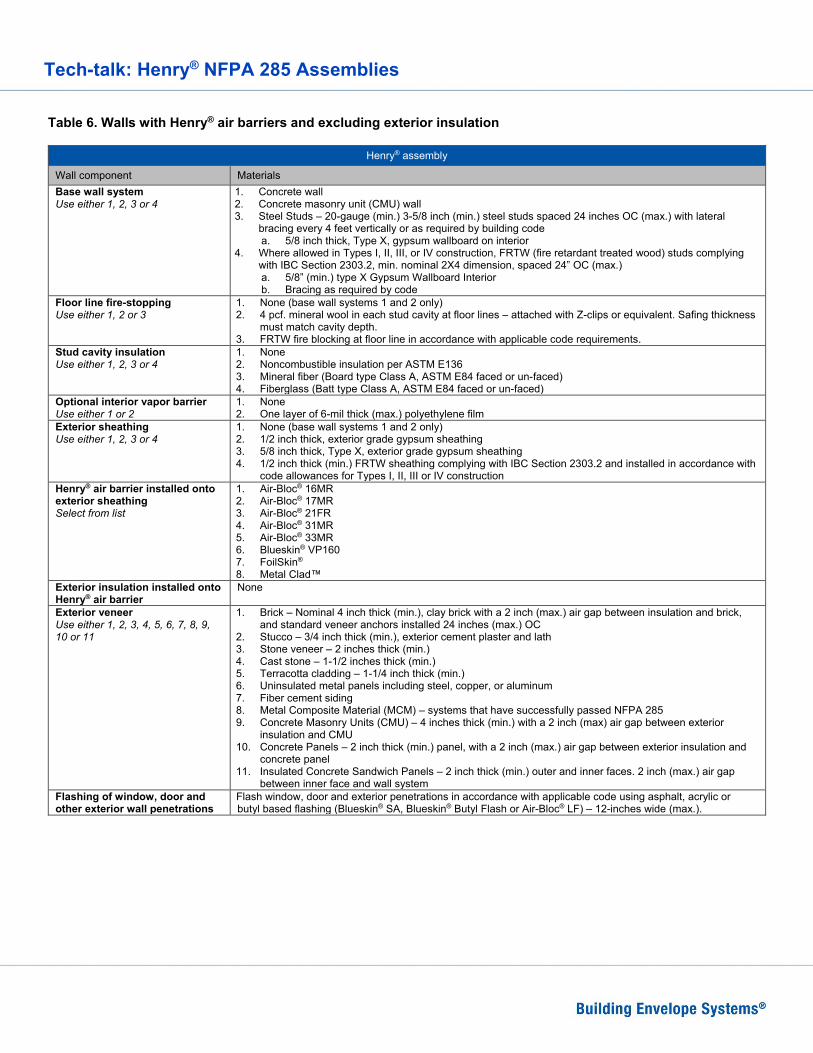
Table 6. Walls with Henry® air barriers and excluding exterior insulation
Henry® assembly
Wall component Materials Base wall system Use either 1, 2, 3 or 4
1. Concrete wall 2. Concrete masonry unit (CMU) wall 3. Steel Studs – 20-gauge (min.) 3-5/8 inch (min.) steel studs spaced 24 inches OC (max.) with lateral
bracing every 4 feet vertically or as required by building code a. 5/8 inch thick, Type X, gypsum wallboard on interior
4. Where allowed in Types I, II, III, or IV construction, FRTW (fire retardant treated wood) studs complying with IBC Section 2303.2, min. nominal 2X4 dimension, spaced 24” OC (max.) a. 5/8” (min.) type X Gypsum Wallboard Interior b. Bracing as required by code
Floor line fire-stopping Use either 1, 2 or 3
1. None (base wall systems 1 and 2 only) 2. 4 pcf. mineral wool in each stud cavity at floor lines – attached with Z-clips or equivalent. Safing thickness
must match cavity depth. 3. FRTW fire blocking at floor line in accordance with applicable code requirements.
Stud cavity insulation Use either 1, 2, 3 or 4
1. None 2. Noncombustible insulation per ASTM E136 3. Mineral fiber (Board type Class A, ASTM E84 faced or un-faced) 4. Fiberglass (Batt type Class A, ASTM E84 faced or un-faced)
Optional interior vapor barrier Use either 1 or 2
1. None 2. One layer of 6-mil thick (max.) polyethylene film
Exterior sheathing Use either 1, 2, 3 or 4
1. None (base wall systems 1 and 2 only) 2. 1/2 inch thick, exterior grade gypsum sheathing 3. 5/8 inch thick, Type X, exterior grade gypsum sheathing 4. 1/2 inch thick (min.) FRTW sheathing complying with IBC Section 2303.2 and installed in accordance with
code allowances for Types I, II, III or IV construction Henry® air barrier installed onto exterior sheathing Select from list
1. Air-Bloc® 16MR 2. Air-Bloc® 17MR 3. Air-Bloc® 21FR 4. Air-Bloc® 31MR 5. Air-Bloc® 33MR 6. Blueskin® VP160 7. FoilSkin® 8. Metal Clad™
Exterior insulation installed onto Henry® air barrier
None
Exterior veneer Use either 1, 2, 3, 4, 5, 6, 7, 8, 9, 10 or 11
1. Brick – Nominal 4 inch thick (min.), clay brick with a 2 inch (max.) air gap between insulation and brick, and standard veneer anchors installed 24 inches (max.) OC
2. Stucco – 3/4 inch thick (min.), exterior cement plaster and lath 3. Stone veneer – 2 inches thick (min.) 4. Cast stone – 1-1/2 inches thick (min.) 5. Terracotta cladding – 1-1/4 inch thick (min.) 6. Uninsulated metal panels including steel, copper, or aluminum 7. Fiber cement siding 8. Metal Composite Material (MCM) – systems that have successfully passed NFPA 285 9. Concrete Masonry Units (CMU) – 4 inches thick (min.) with a 2 inch (max) air gap between exterior
insulation and CMU 10. Concrete Panels – 2 inch thick (min.) panel, with a 2 inch (max.) air gap between exterior insulation and
concrete panel 11. Insulated Concrete Sandwich Panels – 2 inch thick (min.) outer and inner faces. 2 inch (max.) air gap
between inner face and wall system Flashing of window, door and other exterior wall penetrations
Flash window, door and exterior penetrations in accordance with applicable code using asphalt, acrylic or butyl based flashing (Blueskin® SA, Blueskin® Butyl Flash or Air-Bloc® LF) – 12-inches wide (max.).

Tech-talk: Henry® NFPA 285 Assemblies
NFPA 285 Approved Assemblies by Third Party Certification of NFPA 285 test results or extension by engineering analysis provided by listed manufacturer. Henry® did not participate in their testing or certification processes and therefore assumes no responsibility for their results. Contact the product specific manufacturer for more information. Laminators Inc. - Omega-Lite® Dry Seal System The assemblies below are the property of Laminators Inc. For additional information, clarification or installation questions please contact Laminators Inc. at 877-OMEGA77. You may also visit their website at www.laminatorsinc.com.
Henry® assembly
Wall component Materials Base wall system
Steel Studs – 20-gauge (min.) 6 inch (min.) steel studs spaced 16 inches OC (max.) with lateral bracing every 4 feet vertically or as required by building code 1. 5/8 inch thick, Type X, gypsum wallboard on interior
Floor line fire-stopping 4 pcf. mineral wool in each stud cavity at floor lines – attached with Z-clips or equivalent. Safing thickness must match cavity depth
Stud cavity insulation Use either 1 or 2
1. None 2. Any noncombustible insulation (un-faced) per ASTM E136
Exterior sheathing 5/8 inch thick, Type X, exterior grade gypsum sheathing Henry® air barrier installed onto exterior sheathing Select from list
1. Air-Bloc® 31MR (For ext. veneer option 1 or 2 only) 2. Air-Bloc® 33MR (For ext. veneer option 3 only)
Exterior insulation installed onto Henry® air barrier Use either 1 or 2
1. None 2. Mineral wool non-combustible insulation
Exterior veneer Use either 1, 2 or 3
1. Omega-Lite® 1 Piece, Tight-fit Molding System 2. Omega-Lite® Dry Seal System 3. Omega-Lite® Rout & Return System
Flashing of window, door and other exterior wall penetrations
Flash window, door and exterior penetrations in accordance with applicable code using asphalt, acrylic or butyl based flashing (Blueskin® SA, Blueskin® Butyl Flash or Air-Bloc® LF) – 12-inches wide (max.).

Tech-talk: Henry® NFPA 285 Assemblies
Rmax® ECOBASEci™ The assemblies below are the property of Rmax®. For additional information, clarification or installation questions please contact Hunter Panels at 888-746-1114. You may also visit their website at www.rmax.com.
Henry® assembly
Wall component Materials Base wall system Use either 1, 2, 3 or 4
1. Concrete wall 2. Concrete masonry unit (CMU) wall 3. Steel Stud – 20-gauge (min.) 3-5/8” (min.) steel studs spaced 24” OC (max) with lateral bracing every 4
feet vertically or as required by building code. a. 5/8” (min.) type X Gypsum Wallboard Interior
4. Where allowed in Types I, II, III, or IV construction, FRTW (fire retardant treated wood) studs complying with IBC Section 2303.2, min. nominal 2X4 dimension, spaced 24” OC (max.) a. 5/8” (min.) type X Gypsum Wallboard Interior b. Bracing as required by code
Floor line fire-stopping Use either 1, 2 or 3 Note- use 2 with Fire Retardant Treated Wood (FRTW) framing
1. None (base wall systems 1 and 2 only) 2. 4 pcf. mineral wool in each stud cavity at floor lines – attached with Z-clips or equivalent. Safing thickness
must match cavity depth 3. FRTW fire blocking at floor line in accordance with applicable code requirements
Stud cavity insulation Use either 1, 2, 3 or 4
1. None 2. Noncombustible insulation (un-faced) per ASTM E136 3. Mineral fiber (board type Class A, faced or un-faced meeting ASTM E84) 4. Fiberglass (batt type Class A, faced or un-faced meeting ASTM E84)
Exterior sheathing Use either 1, 2, 3 or 4
1. None (base wall systems 1 and 2) 2. 1/2 inch thick (min.) exterior grade gypsum sheathing 3. 5/8 inch thick, Type X, exterior grade gypsum sheathing 4. 1/2 inch thick (min.) FRTW structural panels complying with IBC Section 2303.2 and installed in
accordance with code allowances for Types I, II, III, or IV construction Henry® air barrier installed onto exterior sheathing Select from list
1. Air-Bloc® 17MR 2. Air-Bloc® 21FR 3. Air-Bloc® 31MR 4. Air-Bloc® 32MR 5. Air-Bloc® 33MR 6. Blueskin® SA 7. Blueskin® VP160 8. Foilskin® 9. Metal Clad™
Exterior insulation installed onto Henry® air barrier May be installed with the FRT plywood on exterior side where ECOBASEci™ is installed over exterior sheathing.
RMAX ECOBASEci™, 4-1/2 inch (max.) foam with 5/8 inch (min.) FRT plywood. Installed in accordance with applicable code requirements. Must be applied perpendicular to studs with joints staggered. Fasteners used for securing panels must penetrate through the foam plastic into FRTW studs or steel framing. Design the system to handle the cladding and wind load per the applicable code.
Exterior veneer Use either 1, 2, 3, 4, 5, 6, 7, 8, 9 , 10, 11 or 12
1. Brick – Nominal 4 inch thick (min.), clay brick with a 2 inch (max.) air gap between insulation and brick, and standard veneer anchors installed 24 inches (max.) OC
2. Stucco – Minimum 3/4-inch thick, exterior cement plaster and lath 3. Stone – Minimum 2-inch thick 4. Cast stone – Minimum 1-1/2 inch thick 5. Terracotta cladding – 1-1/4 inch thick (min.) 6. Fiber cement siding 7. Metal Composite Material (MCM) – systems that have successfully passed NFPA 285 8. Aluminum Composite Material (ACM) – systems that have successfully passed NFPA 285 9. Uninsulated metal panels including steel, copper, or aluminum 10. Stone Aluminum Honeycomb Composite Panels – Any system successfully tested by the panel
manufacturer via the NFPA 285 test method 11. Autoclaved-aerated concrete (AAC) panels – systems that have successfully passed NFPA 285 12. Thin set brick
Special conditions Window headers must incorporate 20 ga. (min.) steel flashing to cover air gaps between the exterior sheathing or exterior insulation and the exterior veneer. Flash window, door and exterior penetrations in accordance with applicable code using asphalt, acrylic or butyl based flashing (Blueskin® SA, Blueskin® Butyl Flash or Air-Bloc® LF) – 12-inches wide (max.).

Tech-talk: Henry® NFPA 285 Assemblies
TAKTL® The assemblies below are the property of TAKTL®. For additional information, clarification or installation questions please contact TAKTL® at 412-486-1600. You may also visit their website at www.taktl-llc.com.
Henry® assembly
Wall component Materials Base wall system
Steel Stud – 16-gauge (min.) 3-5/8” (min.) steel studs spaced 24” OC (max.) with lateral bracing every 4 feet vertically or as required by building code a. 5/8” (min.) type X Gypsum Wallboard Interior
Floor line fire-stopping 4 pcf. mineral wool in each stud cavity at floor lines – attached with Z-clips or equivalent. Safing thickness must match cavity depth
Stud cavity insulation None Exterior sheathing 5/8 inch thick, Type X, exterior grade gypsum sheathing Henry® air barrier installed onto exterior sheathing
Air-Bloc® 16MR
Exterior insulation installed onto Henry® air barrier
Roxul® Cavity Rock®, 2 inch (max.) mineral wool. Installed with 3 inch, solid based, insulation impaling pins 24 inches OC (max.) in accordance with applicable code requirements.
Exterior veneer TAKTL® THK Panel – 5/8 inch (max.) thick with Rainscreen Solutions Extr4uded Aluminum brackets and sub-girts and Taktl Extruded Aluminum Panel clips and rails. Install veneer in accordance with TAKTL® NFPA 285 installation requirements.
Special conditions Flash perimeter of window and door openings with 0.080 in. aluminum flashing. Flashing of window, door and other exterior wall penetrations
Flash window, door and exterior penetrations in accordance with applicable code using asphalt, acrylic or butyl based flashing (Blueskin® SA, Blueskin® Butyl Flash or Air-Bloc® LF) – 12-inches wide (max.).