hemodynamics and general principles in valve...
TRANSCRIPT

Hemodynamics and General Principles in Valve DiseaseFederico M Asch MD, FASE
MedStar Heart and Vascular InstituteGeorgetown University
Washington, DC
• I have no financial disclosures related to this presentation

Outline
• Flow• Pressure Gradients• Meaningful Calculations in VHD• Application in Specific conditions
Basic General Concepts
• Flow• Pressure Gradients• Meaningful Calculations in VHD• Application in Specific conditions

Volumetric Flow• Time Velocity Integral (TVI)
– The integrated area under a curve over a period of time.
– Represents the distance (cm) that blood travels with each stroke.
Time
TVI
Velocity
• Cross Sectional Area (CSA)– Mathematically calculated area of a circle.– CSA = r2
– CSA = 0.785 d2
Volumetric Flow
2.1 cm
CSA = (3.14)(1.05)2
CSA = 0.785(2.1)2= 3.46 cm2

• Stroke Volume– The amount of blood pumped out of the heart with each beat.– Calculated as the CSA x TVI
Volumetric Flow
2.1 cm TVIX = Stroke Volume
cm2 X cm = cm3 (cc, ml)
LV Stroke Volume LVOT CSA x TVI LVOT
Cardiac Output = SV x HR/1000Cardiac Index = CO/BSA
SV = (0.785)(LVOT Diameter2) x TVI LVOT
Cardiac Output = SSSSVVV x HR/10

Cardiac Output (C.O.)
• The amount of blood pumped out of the heart every minute (Liters/minute)
• Calculated as the Stroke Volume x Heart Rate• CO = SV (cc/beat) x HR (beats/minute)• cc/minute• Divide by 1000 to convert to Liters/minute
Cardiac Index (C.I.)
• The Cardiac Output (CO) indexed to Body Surface Area (BSA).• Calculated as CO/BSA• Units are L/min/m2

Volumetric Flow
• Pitfalls– Inadequate Doppler / beam alignment.– Inadequate sample volume placement.– Inadequate tracing of TVI.– Not valid with mod-severe aortic stenosis or regurgitation.– Diameter and TVI measurements must be taken from the same
space.– Diameter measurement errors are squared:
• small diam variation = large flow error
Qp/Qs Pulmonic CO/Systemic CO
Qp =RVOT CSA x TVI
Qs = LVOT CSA x TVI

Basic General Concepts
• Flow• Pressure Gradients / PHT• Meaningful Calculations in VHD• Application in Specific conditions
Pressure Gradients

The Bernoulli Equation
P = ½ (v22 – v1
2) +2 v
t s + R( V )
Convective Acceleration
Flow Acceleration
Viscous Friction
The forces of viscous friction in the normal clinical setting are negligible and can be
removed from the equation.
The Bernoulli Equation
P = ½ (v22 – v1
2) +2 v
t s
Convective Acceleration
Flow Acceleration
The forces of flow acceleration in the normal clinical setting are negligible and can be
removed from the equation.

The Bernoulli Equation
P = ½ (v22 – v1
2)
Convective Acceleration
If V1 values are
- <1 m/s V1 can be removed from the equation.
- 1-1.5 acceptable
- > 1.5 cannot use simplified equation
Where:
½ = mass density for blood = 4
V1 = Flow velocity proximal to the valve
V2 = Flow velocity distal to the valve
P = 4 (v22)
The Simplified Bernoulli EquationP = 4 (v2
2)• RV or PA Systolic Pressure
– 4(TR Velocity)2 + RA Estimated Pressure• PA Diastolic Pressure
– 4(End PR Velocity)2 + RA Estimated Pressure• LA Pressure
– Systolic BP – 4(MR Systolic Velocity) 2
• RV Systolic Pressure (if VSD)– Systolic BP – 4(VSD velocity)2

The Modified Bernoulli Equation
• Pitfalls– Large angle 0 (beam not parallel to jet)– Long tubular stenosis– Changes in blood viscosity– V1 > 1.5 m/s
Effect of incident angle on recorded peak velocity
Feigenbaum’s Echocardiography, 6th Ed.

Calculation of PA Pressure
PR
TR
VPR Early VPR End
VTR
PA Diastolic PressureVPR End
2+ RA Pressure
PA Systolic PressureVTR
2+ RA Pressure
Mean GradientAverage of all instantaneous (4 x V2) over the flow period

Apical 3 ch Apical 5 chical 3 ch Apical 5 ch
Gradients in Aortic Stenosis
Pressure Half Time (PHT)Time for peak gradient to decrease to half
Mitral Stenosis:
MVA= 220/PHT
Longer PHT, More Severe MS
CW

Pressure Half Time (PHT)Time for peak gradient to decrease to half
Regurgitation:
Shorter PHT= More severe Regurg
CW
Basic General Concepts
• Flow• Pressure Gradients• Meaningful Calculations in VHD• Application in Specific conditions

Basic General Concepts
• Flow• Pressure Gradients• Meaningful Calculations in VHD
– Regurgitant Volume and Fraction– PISA / EROA– Valve Area – Continuity equation
• Application in Specific conditions
Regurgitant Flow (PISA)
Va = 35 cm/sec
PISA Radius
2)( Va)
Peak Velocity
EROA = Regurgitant Flow / MR Peak VelRegurgitant Volume = (EROA)(TVI)
Regurgitant fraction (PISA) = Regurgitant Volume/ SVLVOT + Regurgitant Volume

Regurgitant Volume
• Regurgitant Volume– The amount of blood (volume) that passes through an incompetent
valve.
SVAO = CSAAO X TVIAO
SVMV = CSAMV X TVIMV
Regurg Vol = Mitral SV - Aortic SV

Regurg Vol = Mitral SV - Aortic SV
SVAO = CSAAO X TVIAO
SVMV = CSAMV X TVIMV
• MV Regurgitant Volume (RV)– SVMV – SVAV
• AV (RV)– SVAV – SVMV
Regurg Fraction (RF) = RV / SV
SVAO = CSAAO X TVIAO
SVMV = CSAMV X TVIMV
• MV Regurgitant Fraction (RV)RVMV – SVMV
• AV RF– RVAV / SVAV

Mitral RegurgitationQuantitative Hemodynamics
120 cc
70 cc50cc
R volume = 120 - 70 = 50 ccR fraction = 50/120 = 42%
Systole Diastole
RV / RF (Doppler)What to measure?
AV annulus DiameterLong Axis View, end systole
Aortic Valve TVI PW at the annulus
MV Annulus Diameter4 chamber view, mid diastole
MV TVI PW at the annulus

Pitfalls of RV/RF
• PW Sample Volume location– Must be at valve annulus
• Diameter Measurements– Error is squared
• Arrhythmias– Measure 5-10 beats and average
• Multivalvular lesions– Invalid with shunt– Invalid with > mild regurgitation of non-measured valve
Proximal Isovelocity Surface Area (PISA)
• Used to assess the severity of Regurgitation• Information Needed
– Zoomed image of Valvular Annulus– Clear Color Doppler Image
• Lower Aliasing Velocity (shift baseline down)– CW of Valvular Regurgitation
• TVI and Peak Velocity

Feigenbaum’s Echocardiography, 6th ed. 2005
Evaluation of MR by PISA method
PISA
• Information Needed – The radius of the aliased region (r)– The aliasing velocity (VA)– The MR Peak Velocity (MRVEL)

Copyright ©2008 American College of Cardiology Foundation. Restrictions may apply.
O'Gara, P. et al. J Am Coll Cardiol Img 2008;1:221-237
Principles of the PISA Method of MR Quantitation
• R= 0.72cm• PISA= 2 x (0.72cm)2 = 3.26 cm2
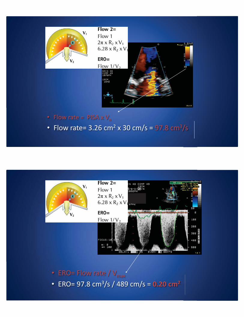
• Flow rate = PISA x Vn
• Flow rate= 3.26 cm2 x 30 cm/s = 97.8 cm3/s
• ERO= Flow rate / Vmax
• ERO= 97.8 cm3/s / 489 cm/s = 0.20 cm2

Regurgitant Flow (PISA)
Regurgitant Volume = EROA X TVI
Continuity Equation
• Conservation of Flow What goes in, must come out.
Flow LVOT = Flow AV

Continuity Equation
• Flow LVOT = Flow AV
• Flow = TVI x CSATVILVOT x CSALVOT = TVIAV x CSAAV
Continuity Equation
TVILVOT x CSALVOT = TVIAV x CSAAV
TVIVILVOT T x CSAALVOT
TVIVIAV
CSAAAAV
TV V =
AVA = CSAAALVOT T x TVIVILVOT
TVIVIVIVIAV

LVOT 1.98 cm LVOT TVI = 28 cm Vmax = 30 cm
AVA = 3.08 x = 2.8 cm228 cm30 cm
Aortic Valve Area (AVA)
Aortic Valve Area (AVA)
LVOT Diameter2.15 cm

Aortic Valve Area (AVA)
• LVOT– TVI – 22.47 cm– Velocity – 93.0 cm/s
• Aortic– TVI – 70.8 cm– Velocity – 2.86 cm/s
Aortic Valve Area (AVA)

Aortic Valve Area (AVA)
• Pitfalls– Accuracy of the LVOT Diameter measurement
• Right View (Parasternal Long Axis)• End systole
– Angle of LVOT Velocity– Perform CW from multiple views, use maximum– Arrythmias (5-10 beats and average)– Confusing MR with Aortic Flow
• MR often has higher velocity• MR extends through IVRT
Summary• Hemodynamics are key for understanding Cardiac physiology• Pitfalls have to be considered and avoided• Calculations have inherent limitations.
• All these considered, Comprehensive Valvular evaluation must include pertinent hemodynamics
