hemodynamic simulator ii -...
TRANSCRIPT

Hemodynamic Simulator II P09026
Preliminary Design Review
10/3/2008
Rochester Institute of Technology

2 Hemodynamic Simulator Preliminary Design Review Friday, October 03, 2008
P09026
Contents Team Ethics & Norms .................................................................................................................................... 3
Project Plan ................................................................................................................................................... 4
Project Summary ....................................................................................................................................... 5
Customer Needs ........................................................................................................................................ 7
Specifications ............................................................................................................................................ 9
2-Quarter Schedule ................................................................................................................................. 11
Work Breakdown Structure .................................................................................................................... 12
Team Roles .............................................................................................................................................. 13
System Level Design .................................................................................................................................... 14
Overall System Architecture ................................................................................................................... 15
Electrical & Mechanical Model ............................................................................................................... 16
Overall System Sketch ............................................................................................................................. 17
Engineering Analysis ................................................................................................................................... 18
LV Pressure Curve generated by Dr. Karl Schwarz .................................................................................. 19
Static Fluids (Level 1) Calculations .......................................................................................................... 20
Dynamic Fluids (Level 2) Calculations as written by Dr. Jeffery Kozak ................................................... 21
Circulatory System Analysis .................................................................................................................... 22
Electrical Model ...................................................................................................................................... 23
Equivalent Electrical Model .................................................................................................................... 24
Graphical User Interface (LabVIEW) ....................................................................................................... 25
Risk Assessment .......................................................................................................................................... 26
Notes ........................................................................................................................................................... 28

3 Hemodynamic Simulator Preliminary Design Review Friday, October 03, 2008
P09026
Team Ethics & Norms
Punctual Conflict Resolution Path
Each team member will be prompt and arrive at the team meetings on time. If an unexpected conflict comes up, the absent team member will notify at least one team-mate prior to the expected absence. An absent team-member should confirm that a team-mate has received their message (in person, voice mail, email, etc).
If a conflict that arrises being personal, design related, team related, or otherwise where the individual does not feel comfortable presenting it to the group, the team leader is to be consulted as the neutral party to assist in resolution of the conflict. If the Team leader is involved in the conflict or for some reason cannot act as a neutral mediator the lead engineer will assist in resolving to conflict. In both cases the conflict is to be resolved ultimatley for the betterment of the team.
Accurate Constructive Criticism
Each team member completes their work accurately and in a way that can be easily checked for accuracy by peers and the faculty guide. All work is fully documented and easy to follow.
As part of the design process all team members will likely engage in brainstorming, problem solving discussion, and critique of ideas. All team members will strive to keep interaction respectful and constructive.
Professional and Ethical Team Trust
Each team member gives credit where credit is due. All work completed includes citations to appropriate literature, or sources of assistance. If a team member has gotten assistance from a publication or individual, then that assistance or guidance is fully documented in the reports prepared. Each team member is honest and trustworthy in their dealings with their peers. Each team member follows the standards in the Students Rights and Responsibilities Handbook found at: http://www.rit.edu/studentaffairs/studentconduct/conductprocess.php#proscribedconduct
Honesty and trust are essential to the team environment. Team members will take all steps nessesary to uphold an aire of openness and integrity in interation between team client and faculty.
Communication Project Issues and Concerns
Each team member is dedicated to ensuring that there is open communication with other members of the group. Including needs and progress as well as setbacks and obstacles they are encountering in the completion of their individual assignments.
If a team member is to be absent, has scheduling conflicts that will not allow the workload requirements to be upheld, or comes across design issues or concerns, these issues are to be openly presented during meeting times so that resources can be redistrubted and solution can be found. This will ensure consistent progress and also shared team responsibility and goals.
Compliance to Customer Needs
Each team member is to make himself or herself aware of the customer's needs, and to give his or her best effort in a attempt to meet the customer's needs
4 Hemodynamic Simulator Preliminary Design Review Friday, October 03, 2008
P09026
Project Plan

5 Hemodynamic Simulator Preliminary Design Review Friday, October 03, 2008
P09026
Project Summary
Project Description
Hemodynamic Flow Simulator is a modular system that replicates the flow and pressure related to the hemodynamic system.
The long term goal of this project is to analyze and redesign some of the features of the module and make it fully compliant to
customer’s needs. The prototype designed by project P08026 team would be utilized in an attempt to achieve a final unit
which is both self contained and aesthetically pleasing. In addition, the module should be able to perform in equally well, in
educational and research applications.
Problem Statement:
The primary objectives of this project are to redesign the pump to its initial requirements, redevelop the data acquisition
software and develop computer control for all system parameters. In addition, the final product must be self contained, and
easy to transport from one classroom to another.
Objectives/Scope:
1. Initially, the pump must be redesigned in order to better replicate the pumping of the heart, which includes appropriate
blood pressure and volume from the heart.
2. The final product must contain a data acquisition system that would monitor blood pressures, volumes, flow rates at
desired locations. In addition, the measured data must be easily accessible to the user.
3. Furthermore, develop a computer system that would allow a user, access to all the parameters of the flow simulator.
Hence, providing the user with a better control of the entire unit.
Deliverables:
• To have a portable, aesthetically appealing, and fully functioning re-modeled blood flow simulator that would
appropriately replicate the operations of the heart (left-ventricle).
• To have a fully remodeled Graphical User Interface that would provide users full control of the unit, and is simple to
operate.
Expected Project Benefits:
• The module would provide faculty members with a tool that may be utilized for instructional purposes.
• This will soon incorporate the testing of the school‘s LVAD prototypes to prove their effects of the circulatory system.
Core Team Members:
• Alexander Baxter
• Joseph Featherall
• Mark Frisicano
• Clarissa Gore
• Liliane Pereira
• Jonathan Peyton
• Gaurav Zirath
06Project # Project Name Project Track Project Family
P09026 Hemodynamic Flow Simulator II Biomedical Engineering
Start Term Team Guide Project Sponsor Doc. Revision
2008-1 Dr. Phillips Dr. Phillips 1.3

6 Hemodynamic Simulator Preliminary Design Review Friday, October 03, 2008
P09026
Assumptions & Constraints:
1. Simulate actual flow rates and pressures as produced by the human heart.
(ie. Match pressure waves in aorta and left ventricle, other properties to be emulated by the system include proper system
resistance and compliance.)
2. Must provide electrically and mechanically safe operation.
3. Must be portable, easy to transport from one class to another.
4. Heart chamber must be easily visible and data must be clearly displayed and recorded for use.
Issues & Risks:
• Redesigning the pump in an attempt to replicate the blood flow of the human heart.
• Developing a GUI that would allow user to fully control the system, including flow rates, and blood volume.

7 Hemodynamic Simulator Preliminary Design Review Friday, October 03, 2008
P09026
Customer Needs
Question/Prompt
Importance (1 is highest)
Customer Statement Interpreted Need Improvement Suggested
Relevent Spec(s)
Basic Functions
10 I need you to develop a new cylinder
design, so that we know where all the parts come from and how to manufacture it.
The module has a unique design with documented
parts and assembly.
Create BOM including where the parts were obtained from
BOM
6 Create a stand for the heart so the
ultrasound probes can be hooked up to the heart while it is in operation.
- Build and design the stand
ES10
5 There must be no bubbles in the heart so
the ultrasound can be read easily. -
Bubbles will disrupt the
ultrasound, so the redesign must eliminate
bubbles
ES20
1 I need to be able to move the module to
another classroom for use. The module is
mobile.
Reduce the size of the
system and its components to
make the system easily portable
ES7 ES8
8 It must be easy to fill and drain the fluid, and
to clean up.
There is a simple method of filling and draining
liquids from the module.
Add valves in the system so it
becomes easier to drain
ES13 ES19
7 I need basic access points and standard connectors to be able to use measurement
tools.
The module has standard
connectors at joints.
Insert more access points so data can be collected at
more locations
Design Sketch
2 The module must be both electronically and
mechanically safe. The module is user safe.
ES12 ES13
9 The module must run for 1 hours
uninterrupted.
The module runs for a minimum of
1 hours. ES14
13 The module must use A/C voltage supply. The module uses
A/C voltage supply.
ES15
11 The module must be quiet enough to use
without a problem in a classroom. The module is
quiet. ES11
12 The fluid used needs to simulate blood. The fluid must simulate blood.
Locate a fluid other than
water to better simulate blood
ES1-ES3

8 Hemodynamic Simulator Preliminary Design Review Friday, October 03, 2008
P09026
4 The pump section should be scalable to be able to represent an adult heart, as well as
that of an infant.
The module is scalable.
ES4
3
The heart must simulate the periodic waveform of the heart, including frequency, dynamic range and duration of pumps, as well as the output of fluid from the heart,
flow rates and volumes.
The pump module simulates the functionality of the heart.
ES6
Measurements and
Controls
2 There must be interfaces to and from the computer that will measure pressures and
flow.
The module has a bidirectional communications link that allows it to be controlled, modified and
monitored via the control system.
There will be more sensors to better
monitor the pressure and flow in various parts of the system
ES16
4 There must be access to the internal flow directly as well as indirectly to measure flow
and pressure.
The module is capable of
invasive and non-invasive
measurements of flow and pressure.
Design Sketch
1 I need it to be easy to use, and have a user
interface on LabView
There is a simple user interface on
Labview to control the module.
Re-create the interface to make it user-friendly and easy to
manipulate
ES16
3 There must be a fail-safe operation as well
as an emergency stop button.
The module has a fail-safe
operation as well as an emergency stop button.
ES12
Aesthetics
1 The module must be visually pleasing to
look at.
The module is aesthletically pleasing.
Make the design look like an engineering prototype,
clean and neat
ES17
2 Reduce the number of hose connections in
the system -
The previous design had to many hose clamps and
connections in the system
ES17
3
The module should be mounted on a board, and be functional lying down or turned
vertically. The end product must be "clearly impressive" to any friends, associates,
family, potential employers, etc.
The module is mounted on a board, and is
robust.
ES7-ES10 ES17

9 Hemodynamic Simulator Preliminary Design Review Friday, October 03, 2008
P09026
Specifications
Engr.
Spec. #
Importa-
nce Source
Specification
(description)
Unit of Measure
Ideal Value Comments/Status
Fluid (Water)
ES1 1
http://www.thermexcel.com/english/ta
bles/eau_atm.htm Volume liters 5
Water will be used
according to
customer request
ES2 1
http://www.thermexcel.com/english/ta
bles/eau_atm.htm Viscosity kg/m.s 0.001003
Room Temperature,
T = 20⁰C
ES3 1
http://www.thermexcel.com/english/ta
bles/eau_atm.htm Density kg/m3 998.29
Room Temperature,
T = 20⁰C
Heart Chamber
ES4 1
http://www.fi.edu/learn/heart/develop
ment/development.html
Normal Heart
Rate
Beats
per
minute
120 -
Infant
70 - Adult
Values used as
reference on
generating Pressure
Curve
ES5 1
http://www.bbc.co.uk/science/humanb
ody/body/factfiles/heart/heartbeat.sht
ml
Max. Heart
Rate Beats
per
minute
220
With variation of +/-
5% - Values used as
reference on
generating Pressure
Curve
ES6 1
http://gaps.anest.ufl.edu/palm/files/for
mulas/13.html
Systemic
Vascular
Resistance MPa·s/
m3
90–120
Normal - Values
used as reference
on generating
Pressure Curve
Physical Dimensions
ES7 1 Cart Size inches
21.5 x
38.5
ES8 1 Height inches 72 Maximum Height
ES9 1
Location of the
heart feet 5
w.r.t the floor (eye
level)
Overall System and Safety
ES10 1
http://www.dangerousdecibels.org/faq.
cfm#16 Noise Level dB 60
Normal
conversation level
ES11 1
Emergency
Stop Button
Response
sec 3 Actuator motion
stops
ES12 2
http://www.grow.arizona.edu/Grow--
GrowResources.php?ResourceId=188 Drainage Time min 5
ES13 1
Functioning
Time hours 8
ES14 1
A/C Voltage
supply volts 120
Available in most
classrooms

10 Hemodynamic Simulator Preliminary Design Review Friday, October 03, 2008
P09026
Specifications (Non-Quantifiable)
Engr.
Spec. #
Import
ance Source
Specification
(description)
Desired
Results
Comments/
Status
ES15 1
Control
Software Lab VIEW
ES16 1
Aesthetic
Benchmar
ked by
previous
project
and
customer
feedback
Aesthetically
Pleasing - Polished,
clean, enclosed,
stainless steel (low
maintenance), only
thing exposed will
the circulatory
system and the
heart chamber
ES17 1 Safety
Ground
Default
System
Like the ones in a
bathroom
Reference Parameters
Fluid (BLOOD)
ES18 1 Cutnell, John & Johnson, Kenneth. Physics,
Fourth Edition. Wiley, 1998: 308. Viscosity N-s/m² 0.0027 At 37°C
ES19 1 Cutnell, John & Johnson, Kenneth. Physics,
Fourth Edition. Wiley, 1998: 308. Density kg/m³ 1060 At 37°C
ES20 1
Taggart, Starr and Cecie Starr. Biology: The
Unity and Diversity of Life. California:
Wadsworth, 1989: 398. Volume liter 5
With variation of +/-
20%
ES21 1
ES22 1
http://www.eie.polyu.edu.hk/~ensmall/
eie448/EIE448/Notes_files/topic2.pdf
Circulatory
System total
length meters 10 8
Propagation Velocities of Blood in Human Body
ES23 1
http://www.eie.polyu.edu.hk/~ensmall/
eie448/EIE448/Notes_files/topic2.pdf Atria m/s 1
ES24 1
http://www.eie.polyu.edu.hk/~ensmall/
eie448/EIE448/Notes_files/topic2.pdf AV Node m/s 0.05
ES25 1
http://www.eie.polyu.edu.hk/~ensmall/
eie448/EIE448/Notes_files/topic2.pdf Purkinje Fibres m/s 3
ES26 1
http://www.eie.polyu.edu.hk/~ensmall/
eie448/EIE448/Notes_files/topic2.pdf Ventricles m/s 0.5

11 Hemodynamic Simulator Preliminary Design Review Friday, October 03, 2008
P09026
2-Quarter Schedule
Fall '08 Winter '08
Week 1
● Become informed on the project basics
● Contact former group members
● Set tenative plans of action
● Reviewed Project with Day and Phillips
● Set design path from newly gained information
●Begin
fabrication/testing/programing of
subsystems
Week 2
●Develop a firm understanding of the individial components design and
purpose and also the system as a whole
● Assign sub groups for design
● Set up meeting with Dr. Schwarz
● Use gained knowledge to refine goals and engineering specs
●Create list of key issues to be fixed in the system
●Define each members role in the group
●Outline project goals
● Assigned personal tasks for the team to complete the deliverables
●Continue
fabrication/testing/programming of
subsystems
Week 3
●Research and reassesment of goals
● Must have atleast one meeting with Schwarz by the end of this week
● Begin meeting in sub groups and laying out the plot for progress for
each subassembly
● Begin finalization of engineering spec within each group
● Report to eachother as a whole to plan for the next weeks progress
●Exteneding and updating of official timeline
●Finalize sub systems
●Final outline of projects due dates
and goals
Week 4
●Further Research
●Preliminary calculations(start design)
● Price and spec out components
● Review prelimary calculations and design specs with Schwarz and
Phillips
● Review as one group info gathered from advisors and alter design route
as needed.
● Continue with prototype design and calculations
●Begin complete system
fabrication/testing/programing
Week 5
●Have Rev 1 of new design with iterative calculations
●Task subsystem analysis to specific teammates
●Continue electrical analysis of analog system
●Begin defining BOM
●Continue complete system
fabrication/testing/programing
Week 6
●Solidfy design of system
●Continue reviews with Kozak and Day
●Pricing components
●Preliminary order
●Have first iteration of calculations of the system as a whole
●Final system fabrication
●Continue testing/programing
Week 7
●Solid modeling and FEA/CFD analysis
●Begin testing with available materials to gain knowledge of the real
dynamics of the system ●Test/Programing
Week 8
●Finalize modeling and software analysis
●Begin print making
●Address any final mechanical
issues
●Optimize programing
Week 9
●Final material acquisition
●Finalize prints ●Optimize controls
Week 10 ●Begin fabrication of components ●Tear down and rebuild
Week 11
●Continue fabrication of components
●Start programing ●Final testing and re-config
12 Hemodynamic Simulator Preliminary Design Review Friday, October 03, 2008
P09026
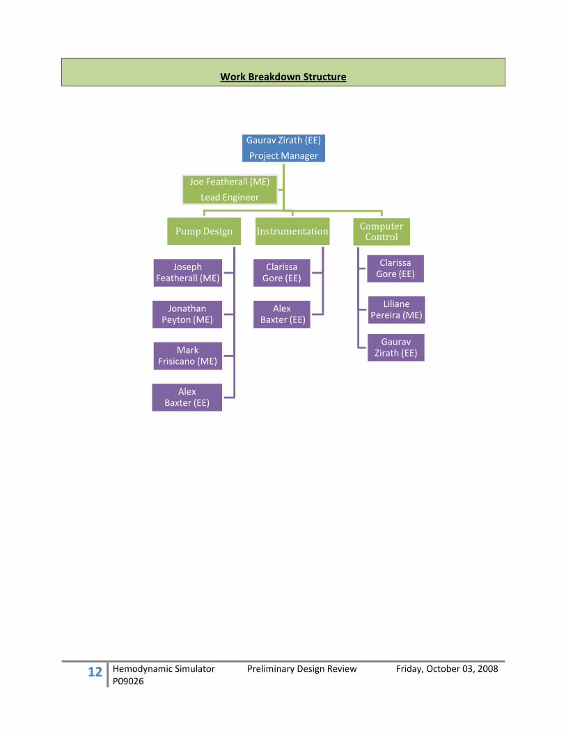
Work Breakdown Structure
Gaurav Zirath (EE)
Project Manager
Pump Design
Joseph Featherall (ME)
Jonathan Peyton (ME)
Mark Frisicano (ME)
Alex Baxter (EE)
Instrumentation
Clarissa Gore (EE)
AlexBaxter (EE)
Computer Control
Gaurav Zirath (EE)
Liliane Pereira (ME)
ClarissaGore (EE)
Joe Featherall (ME)
Lead Engineer

13 Hemodynamic Simulator Preliminary Design Review Friday, October 03, 2008
P09026
Team Roles
Team Member
Field of
Study Pervious experience Role
Lillane Pereira ME •LabVIEW Computer
Control •Biomaterials
•AutoCAD
•Biology
Joseph
Featherall ME •Impact Lead Engineer
Pump Design •Frame Design
•Ceramic Bearing Test
•Suspension
Mark Frisicano ME •Motors Pump Design
•Servo Motor Design
•Test Rigs
Jonathan Peyton ME •Layout and Planning Pump Design
•Design Review
•Organizing Tooling
•Generator Drive
Gaurav Zirath EE •Research and Development Project Manager
Computer
Control •Programming
•Transmission Line Theory
Alex Baxter EE •Drive Control Instrumentation
Pump Design •PLC Programming
•Circuit Theory
Clarissa Gore EE •Analog Circuit Design Instrumentation
Pump Design •Device Characterization
•Technical Writing

14 Hemodynamic Simulator Preliminary Design Review Friday, October 03, 2008
P09026
System Level Design

15 Hemodynamic Simulator Preliminary Design Review Friday, October 03, 2008
P09026
Overall System Architecture
GUIUser interface allows
operator to control the flow rate
ControllerStores the program and controls the movement
of the actuator
ActuatorMovement of the
actuator pumps water throughout the system
Mechanical System
Mock circulatory system
Data Acquisition
Acquires data from the sensors in the system
and feeds it back to GUI
16 Hemodynamic Simulator Preliminary Design Review Friday, October 03, 2008
P09026
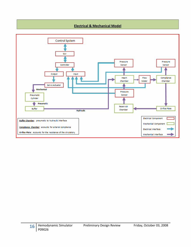
Electrical & Mechanical Model
17 Hemodynamic Simulator Preliminary Design Review Friday, October 03, 2008
P09026
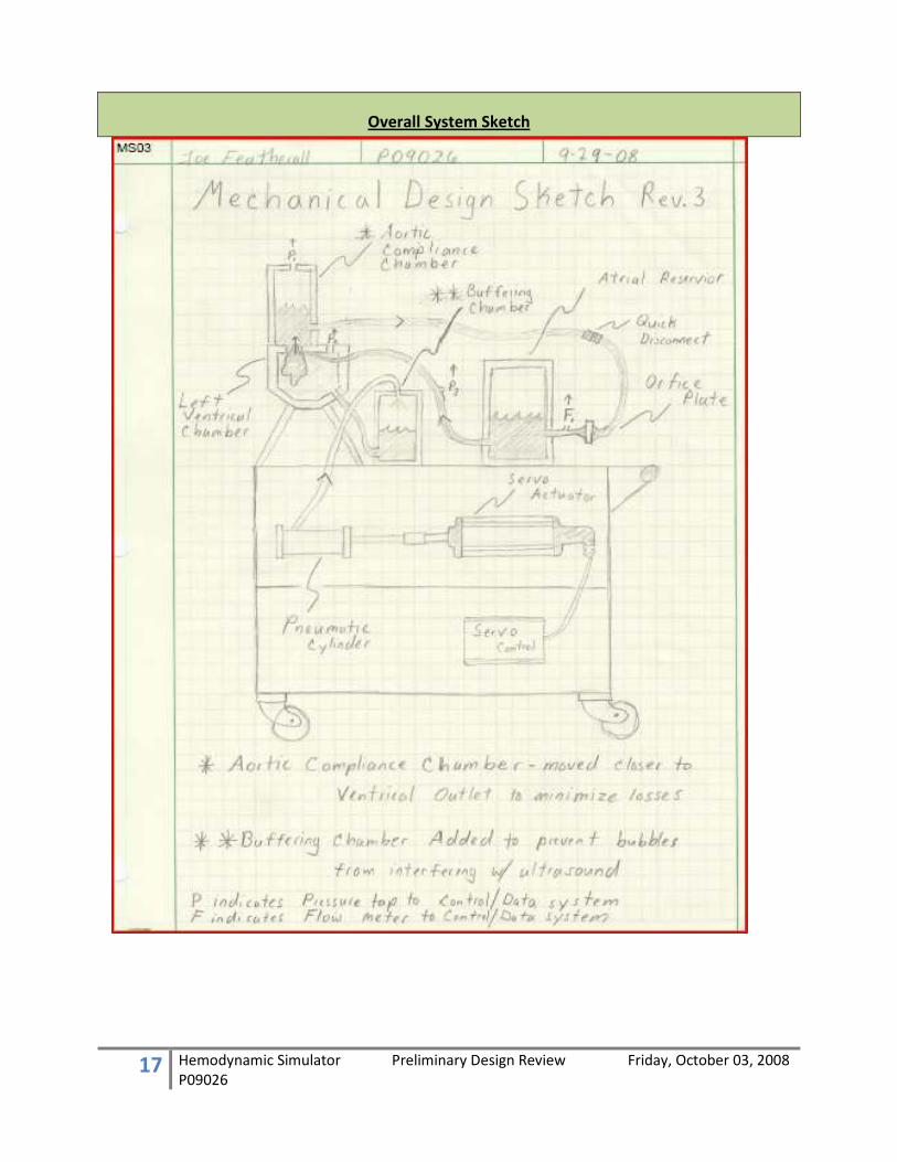
Overall System Sketch

18 Hemodynamic Simulator Preliminary Design Review Friday, October 03, 2008
P09026
Engineering Analysis

19 Hemodynamic Simulator Preliminary Design Review Friday, October 03, 2008
P09026
LV Pressure Curve
generated by Dr. Karl Schwarz

20 Hemodynamic Simulator Preliminary Design Review Friday, October 03, 2008
P09026
Static Fluids (Level 1) Calculations

21 Hemodynamic Simulator Preliminary Design Review Friday, October 03, 2008
P09026
Dynamic Fluids (Level 2) Calculations
as written by Dr. Jeffery Kozak

22 Hemodynamic Simulator Preliminary Design Review Friday, October 03, 2008
P09026
Circulatory System Analysis

23 Hemodynamic Simulator Preliminary Design Review Friday, October 03, 2008
P09026
Electrical Model
Control System
GUI
Controller
Output
Servo Control
Inputs
Pressure Sensor
Pressure Sensor
Pressure Sensor
Flow Meter

24 Hemodynamic Simulator Preliminary Design Review Friday, October 03, 2008
P09026
Equivalent Electrical Model
Hemodynamic Transmission Line Modeling Summary
Research has shown that the hemodynamic system can be modeling by a single two-port transmission
line. Electrical parameters can be matched to analogous mechanical parameters.
• Voltage –Pressure
• Current –Flow
• Capacitance – Compliance
• Electrical Resistance – Mechanical Resistance
Ansoft Designer Analysis
MatLab Analysis
The transfer function of the system was computed using the Fourier Transform and simulated using
Matlab.
� ���� +
�� � = �1 + �
� � + �������
�(�)�(�) + 1� �(�) = (�) �1 + ��� � + ���(�)(�)
�(�) ��� + ��� = (�) ��1 + �
� � + �����
�(�)(�) =
�1 + ��� � + ������ + 1
�
Concerns about the accuracy/usefulness of these modeling techniques:
• Does it model the system we have?
• Are we capable of adding all the necessary components?
• Will we be able to accurately map our mechanical to our electrical parameters?

25 Hemodynamic Simulator Preliminary Design Review Friday, October 03, 2008
P09026
Graphical User Interface (LabVIEW)

26 Hemodynamic Simulator Preliminary Design Review Friday, October 03, 2008
P09026
Risk Assessment
# Category /
Tag Risk Description/Comment Likelihood
(1-5) Severity (1-5)
Risk Priority Number
Mitigation Activity
1 Cost Actuator Cost 2 3 6 6K budget,
2
Design
Actuator creates a negative pressure
Negative pressure created during retraction/filling 2 2 4
Control system or adding relief valve to system
3 Water Column Inertia
During reversing water column will have inertia causing non-idealization 3 4 12
Build factor of safety and flexibility into system
4
Materials
Tank/Tubing Leak Water leaks from the heart, tank, or tubing 2 3 6
Tight fittings, check to make sure all connections are sealed
5 Tank Pressure Tank pressure does not meet the specs 1 3 8
Adjust the tank or water level to adjust the pressure
6 Actuator/Pump Inaccuracies
Actuator does not pump water at the desired rate 2 2 4
Adjust the programming until the desired waveform is reached
7 Measurements Inaccurate measurements
inaccuracy of measurements improperly placed flow meters 1 2 2
Place the sensors where they will record the desired measurements
8
Methods
Assembly error
Connections not tight, tubes not connected to the correct ports 1 3 3
Check all connections before turning on power and testing the simulator
9 LabVIEW errors
Trouble communicating between computer and sensors, not reading desired values 2 3 6
Debug software to ensure desired results
10 Overload Actuator Put to much pressure on the actuator 1 4 4
Review actuator data sheet to make sure we do not use inputs that are too large

27 Hemodynamic Simulator Preliminary Design Review Friday, October 03, 2008
P09026
11 People Water Spill
Caused by user error, loose connections, incorrect filling or draining 1 2 2
User must be careful when filling the tank and assembling the tubing
12 Scheduling Lead time for actuator
Actuator takea long time to receive 3 3 9
Specify and order by week 6
13
Simulations
Losses in System cause inaccuracies
Viscous fluid losses non-idealization 4 4 16
Build factor of safety and flexibility into system
14 Air column resonance
Air may resonate during pulsation 1 2 2
Analyze system for resonance (Helmholtz resonance theory)
28 Hemodynamic Simulator Preliminary Design Review Friday, October 03, 2008
P09026
Notes