helium turbomachinery operating experience from gas turbine power plants
TRANSCRIPT
8112019 Helium Turbomachinery Operating Experience From Gas Turbine Power Plants
httpslidepdfcomreaderfullhelium-turbomachinery-operating-experience-from-gas-turbine-power-plants 135
Helium turbomachinery operating experience from gas turbine power plants
and test facilities
Colin F McDonald
McDonald Thermal Engineering 1730 Castellana Road La Jolla CA 92037 USA
a r t i c l e i n f o
Article history
Received 19 November 2011
Accepted 21 February 2012
Available online 27 March 2012
Keywords
Closed Brayton cycle
Helium gas turbine
Compressor
Turbine
Helium circulator
Test facilities
a b s t r a c t
The closed-cycle gas turbine pioneered and deployed in Europe is not well known in the USA Sincenuclear power plant studies currently being conducted in several countries involve the coupling of a high
temperature gas-cooled nuclear reactor with a helium closed-cycle gas turbine power conversion system
the experience gained from operated helium turbomachinery is the focus of this paper
A study done as early as 1945 foresaw the use of a helium closed-cycle gas turbine coupled with a high
temperature gas-cooled nuclear reactor and some two decades later this was investigated but not
implemented because of lack of technology readiness However the 1047297rst practical use of helium as a gas
turbine working 1047298uid was recognized for cryogenic processes and the 1047297rst two small fossil-1047297red helium
gas turbines to operate were in the USA for air liquefaction and nitrogen production facilities In the 1970rsquos
a larger helium gasturbine plant andhelium test facilities were builtand operated in Germany to establish
technology bases for a projected future high ef 1047297ciency large nuclear gas turbine power plant concept
This review paper covers the experience gained and the lessons learned from the operation of helium
gas turbine plants and related test facilities and puts these into perspective since over three decades
have passed since they were deployed An understanding of the many unexpected events encountered
and how the problems some of them serious were resolved is important to avoid them being replicated
in future helium turbomachines The valuable lessons learned in the past in many cases the hard way
particularly from the operation in Germany of the Oberhausen II 50 MWe helium gas turbine plant andthe technical know-how gained from the formidable HHV helium turbine test facility are viewed as
being germane in the context of current helium turbomachine design work being done for future high
ef 1047297ciency nuclear gas turbine plant concepts
2012 Elsevier Ltd All rights reserved
1 Introduction
While the pioneer closed-cycle gas turbine power plant oper-
ated in Switzerland in 1939 [1] the commercial deployment of this
type of prime-mover was delayed by a decade or so because of the
Second World War and the dif 1047297cult economic times that followed
it The initial success of the closed-cycle gas turbine in the 1950swas its ability to burn low-grade fuels available at the time such as
coal blast furnace gas coke-oven gas heavy oil and peat in its
external heater at modest levels of turbine inlet temperature and
operation in a combined power and heat mode The high grade
sensible heat rejection from the intercooler and precooler offered
ideal cogeneration possibilities and facilitated the use of economic
dry cooling
More than 20 or so plants were built accumulating an operating
time of about 750000 h with some of them in service for over
100000 trouble-free hours An interesting account has been
documented [2] on the construction and operation of closed cycle
gas turbine plants in Europe with emphasis on those using air as
the working 1047298uid in the closed-cycle power conversion system
The performance of early open cycle industrial gas turbines
was modest because of the component technology status in that
era With increasing technology from rapidly developing aeroen-gines being transferred to industrial gas turbines particularly
advancement in turbine inlet temperature as shown on Fig 1
which was generated in 1995 [3] and still considered to be fairly
representative today the early advantages of the externally-1047297red
closed-cycle were eclipsed Gains in turbine inlet temperature
over the years for closed-cycle gas turbines were only incremental
since they were limited by available metallic radiant heater tech-
nology The extrapolation of the closed-cycle gas turbine inlet
temperature trend on Fig 1 beyond 1995 (to say a postulated value
of 1050 C by 2012) did not materialize for fossil-1047297red plants
because of minimal advancements made in ceramic heatE-mail address kmcdona1sanrrcom
Contents lists available at SciVerse ScienceDirect
Applied Thermal Engineering
j o u r n a l h o m e p a g e w w w e l s e v i e r c o m l o c a t e a p t h e r m e n g
1359-4311$ e see front matter 2012 Elsevier Ltd All rights reserved
doi101016japplthermaleng201202041
Applied Thermal Engineering 44 (2012) 108e142
8112019 Helium Turbomachinery Operating Experience From Gas Turbine Power Plants
httpslidepdfcomreaderfullhelium-turbomachinery-operating-experience-from-gas-turbine-power-plants 235
exchanger technology or for nuclear plants since no large VHTR
plants were built although the small 46 MWt AVR nuclear plant in
Germany operated successfully with a helium reactor outlet
temperature of 950 C for many years
By the late 1960rsquos it had become clear that externally-1047297red fossil
gas turbine plants could no longer compete with rapidly improving
simpler higher ef 1047297ciency more compact and lower cost open cycle
gas turbines
The coupling of a high temperature gas-cooled nuclear reactor
with a closed-cycle gas turbine power conversion system usinghelium was 1047297rst suggested by Professor Curt Keller (co-founder of
the closedBrayton cycle gas turbine with Professor Ackeret) in 1945
[1] From the technology standpoint it was clearly ahead of its time
however it did generate interest in the use of helium as an attrac-
tive working 1047298uid and this topic has been studied periodically over
the last six decades The initial deployment of fossil-1047297red helium
gas turbines in the 1960rsquos were for specialized cryogenic processes
However in this time frame it had become clear that the future of
the closed-cycle gas turbine was really tied to its coupling with
a high temperature gas-cooled nuclear reactor A 1047297rst step towards
this ambitious goal was the needed demonstration of a large
helium gas turbine plant The Oberhausen II 50 MW helium gas
turbine plant started in 1974 and was followed by a large helium
turbomachine test facility (HHV) both of these being located inGermany In the ensuing three and a half decades or so work on
nuclear gas turbines has essentially been limited to paper studies
Projecting into the future an advanced modular VHTR demon-
stration plant embodying a helium closed-cycle gas turbine power
conversion system with the potential for an ef 1047297ciency of over 50
percent could perhaps be built and become operational in circa
2025e2030
2 Closed-cycle gas turbine background
21 Fossil- 1047297red plants
At a time when practical gas turbine work was in its infancy
the basic patent for the closed-cycle gas turbine by Ackeret and
Keller (CH 468287) was registered in Bern Switzerland in July
1935 Following his work on airfoil theory [4] much credit is given
to the late Professor Keller for engineering the 1047297rst closed-cycle
gas turbine a 2 MW power plant that was built and run in Zur-
ich in 1939 This pioneering plant has been well documented
previously [1256] and only its major features are highlighted
below
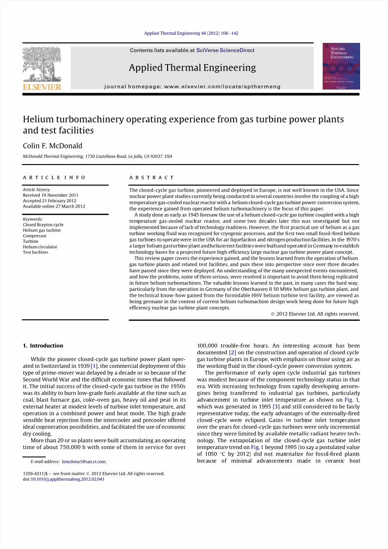
The AK-36 plant shown on Fig 2 was based on a recuperated
cycle with a turbine inlet temperature of 660 C (1220 F) The
compression process was split into three sections with two stagesof intercooling Based on prevailing technology a very large number
of compressor and turbine stages were required With an external
light-oil 1047297red heater the plant demonstrated an ef 1047297ciency of over
30 percent when operating with a turbine inlet temperature of
700 C (1292 F) During the Second World War the plant operated
for about 6000 h providing electrical power for the Escher Wyss
plant facility in Zurich
This 2 Mwe pioneer plant paved the way for closed-cycle gas
turbine deployment in Europe and with air as the working 1047298uid
plants burning a variety of low-grade fuels have been documented
previously [27e9] The 14 MW Oberhausen I closed cycle gas
turbine plant operated in Germany in a combined power and heat
mode between 1960 and 1982 A view of this plant is shown on
Fig 3 and details of the operational problems encountered andhow they were resolved are discussed in a later section The last
closed-cycle gas turbine to operate commercially in Europe with
air as the working 1047298uid was the 17 MW Gelsenkirchen plant [10]
Starting in 1967 this plant was externally 1047297red with blast furnace
gas and around 10 percent light oil With axial 1047298ow turboma-
chinery an ef 1047297ciency of 30 percent was achieved and the reject
heat was used for district heating The plant proved to be very
reliable and ran for almost 100000 h
After this plant entered service it was apparent that the fossil-
1047297red closed-cycle gas turbine could no longer compete with open
cycle gas turbines however one further plant was built In 1972
a combined power and district heating plant was installed in
Vienna [2] Rated at 30 MW the Spittelau plant was the largest
closed-cycle plant using air as the working 1047298
uid Fired with heavy
Nomenclature
ANP aircraft nuclear propulsion
AGR advanced gas cooled reactor
AVR Arbeitsgemeinschaft Versuchsreaktor
BBC Brown Boveri amp Company
CAD computer aided design
CAE computer aided engineering
CFD computational 1047298uid dynamics
CHP combined heat and power
dB decibel
EVO Energieversorgung Oberhausen
FEA 1047297nite element analysis
FSV Fort St Vrain
HTGR power plant
GA general atomics
GHH Gutehoffnungeshutte Sterkrade AG
GT gas turbine
GTeHTR nuclear gas turbine
GTeMHRgas turbine modular helium reactor
GTeVHTR advanced nuclear gas turbine
HP high pressureHHT high temperature helium turbine
HHV high temperature helium test facility
HTGR high temperature gas cooled reactor
HTR high temperature reactor
IHX intermediate heat exchanger
ICR intercooled and recuperated
INL Idaho National Laboratory
ISI inservice inspection
JAEA Japanese Atomic Energy Agency
kW kilowatt
LP low pressure
MHR modular helium reactor
MW megawatt
MPa mega pascal
NGNP next generation nuclear plant
NGT nuclear gas turbine
NGTCC nuclear GT combined cycle
ODS oxide dispersion strengthened alloy
PBMR pebble bed modular reactor
PCS power conversion system
RC recuperated cycle
ST steam turbine
THTR thorium high temperature reactor
TIT turbine inlet temperatureTZM tungsten zirconium molybdenum alloy
VHTR very high temperature reactor
CF McDonald Applied Thermal Engineering 44 (2012) 108e142 109
8112019 Helium Turbomachinery Operating Experience From Gas Turbine Power Plants
httpslidepdfcomreaderfullhelium-turbomachinery-operating-experience-from-gas-turbine-power-plants 335
oil the turbine inlet temperature was 720 C (1328 F) and with
a pressure ratio of 6 two stages of intercooling were used Because
of a variety of technical problems (including excessive rotor
vibration and the failure in quick succession of two blades in the
1047297rst stage of the LP turbine later determined to be due to Karman
vortices originating in the turbine inlet casing) and overriding
political issues this plant was never commissioned for commercial
operation This was a disappointment to engineers who felt at the
time it was the 1047297nest closed-cycle gas turbine ever designed and
built [2]In the 1980rsquos following the introduction of 1047298uidized bed tech-
nology for the combustion of low-grade fuels particularly coal
there was renewed interest in closed-cycle gas turbines A 5 MW
closed-cycle gas turbine burning a low-grade fuel (ie petroleum
coke in an atmospheric 1047298uidized combustor) was built by Garrett
Corporation in the USA in 1985 After evaluating different working
1047298uids [11] air was selected for overall simplicity An overall view of
this plant is shown on Fig 4 With a turbine inlet temperature of
790 C (1454 F) the plant operated well and had low emissions
[12] but was not commercialized because of signi1047297cant advance-
ments being made in the open cycle gas turbine 1047297eld and company
realignments This was the last closed-cycle gas turbine to operate
burning a low-grade fuel and essentially represented the end of an
era spanning 45 years
To the authorrsquos knowledge the last closed-cycle gas turbine
plant to operate was a natural gas-1047297red demonstration facility (as
shown on Fig 5) developed by British Gas at their Coleshill site
near Birmingham in 1995 [13] The closed loop working 1047298uid was
a composition of nitrogen and 2 oxygen The gas 1047298ow in the
circuit was provided by a turbomachine arrangement consisting
of two turbochargers but the rotating assembly did not include
an electrical generator This plant was noteworthy regarding
the use of an advanced heat source exchanger operating at
a temperature several hundred degrees Centigrade higher than inexternally-1047297red European closed-cycle gas turbine plants The
gas-1047297red heater with a thermal rating of about 1000 kWt con-
sisted of a radiant and convective section with headers formed in
a ldquoharprdquo arrangement This tubular heat exchanger was fabricated
from an oxide dispersion strengthened (ODS) alloy [14] A gas
temperature of 1070 C leaving the radiant section was achieved
with this externally 1047297red heater but by means of a bypass
system the gas temperature entering the turbine was reduced to
900 C
This project was intended to lead to a 300 MWe closed-cycle gas
turbine plant using helium as the working 1047298uid with a higher
turbine inlet temperature Due to changes in the organization at the
time testing of the small gas-1047297red facility in the UK did not
advance beyond the initial development phase This demonstration
Fig 1 Gas turbine inlet temperature trends
CF McDonald Applied Thermal Engineering 44 (2012) 108e142110
8112019 Helium Turbomachinery Operating Experience From Gas Turbine Power Plants
httpslidepdfcomreaderfullhelium-turbomachinery-operating-experience-from-gas-turbine-power-plants 435
represented the end of an era of gas-1047297red closed-cycle gas turbine
activities
While valuable experience had been gained in the design
fabrication operation and maintenance of plants with air as the
working 1047298uid [2] the future of this prime-mover was seen to be
with helium and its coupling with a high temperature nuclear heat
source in the 21st century But before this ambitious venture could
be undertaken operating experience was needed with large size
helium turbomachinery in fossil-1047297red plants and in dedicated test
facilities
22 Nuclear gas turbine power plant studies
The Dragon helium cooled reactor was the pioneer HTR plant to
operate and this project took place in the UK between 1959 and
1976 [15] The DragonHTR didnot have a power conversion system
and the reject heat was dissipated in air-blast coolers Follow-on
HTR power plant designs were based on steam cycle power
conversion systems but from the early days of the HTR in the UK
nuclear gas turbine variants were recognized and design concepts
established [16]
From the mid 1960rsquos to about 1980 HTR gas turbine plant
studies in the UK USA and Germany were mainly focused on large
helium turbomachines installed in prestressed concrete reactor
vessels With machines rated between 300 and 1000 MWe the
resultant plant concepts were complex [17] In about 1980 it had
become clear that such concepts would require an extensive
development effort to establish a technically viable nuclear gas
turbine plant to satisfy demanding safety and licensing criteria
and further design innovation was necessary to identify plant
features for improved economics [18] Accordingly there was
a cessation of nuclear gas turbine plant studies in the USA and
Germany and interest reverted to earlier steam cycle HTR plant
concepts
In 1979 a new and innovative modular HTR concept based on
a pebble bed reactor core was proposed by researchers in Germany
Fig 3 Oberhausen I 14 MWe closed-cycle gas turbine utility power plant operated from 1960 to 1982 (Courtesy EVO)
Fig 2 Pioneer AK-36 2 MWe closed-cycle gas turbine with air as the working 1047298uid
operated in Switzerland in 1939 (Courtesy Escher Wyss)
CF McDonald Applied Thermal Engineering 44 (2012) 108e142 111
8112019 Helium Turbomachinery Operating Experience From Gas Turbine Power Plants
httpslidepdfcomreaderfullhelium-turbomachinery-operating-experience-from-gas-turbine-power-plants 535
[1920] Initial studies were focused on steam cycle plant concepts
in which the reactor core and major components were installed in
two separate vertical steel vessels After the Chernobyl accident in
1986 work intensi1047297ed on the modular HTR with emphasis on its
passive decay heat removal and inherent safety features While
a compact direct cycle nuclear gas turbine version of the modular
HTR was 1047297rst suggested in the USA in 1986 [21] it wasa further 1047297ve
years or so before it became accepted based to a large extent on its
potential for very high ef 1047297ciency
Evolution of the nuclear gas turbine power plant concept
spans a period of over six and half decades with intermittent
design studies undertaken by different engineering organizations
in various countries [22] In the last 20 years or so PCS paperstudies have been focused on plant layout arrangements and on
helium turbomachine design with limited sub-component
development [23] in support of various modular nuclear gas
turbine concepts
Up until about 2009 projects in different states of design
de1047297nition were being investigated in several countries and these
are summarized as follows 1) in a joint USARussia project
(GTeMHR) the design of an integrated concept (with all the PCS
components installed in a single pressure vessel) is based on
a direct ICR cycle with a vertically oriented 286 MWe helium tur-
bomachine with a turbine inlet temperature of 850 C [24] 2) the
Japanese GTeHTR300 is a distributed plant concept (the PCS
components being installed in separate pressure vessels) with
a direct recuperated cycle and embodies a horizontal 274 MWe
turbomachine with a turbine inlet temperature of 850 C [25] 3 ) i n
France the ANTARES distributed concept is of the indirect type
using an IHX and with a combined gas and steam turbine PCS has
a power output of 280 MWe with a turbine inlet temperature of
800 C [26] 4) in China a study was undertaken of the HTR e10GT
concept involving the future coupling of a small vertical 22 MWe
helium turbine with the HTR-10 pebble bed reactor it being an
integrated concept with an ICR cycle and a turbine inlet temper-
ature of 750 C [27] and 5) in South Africa design and develop-
ment activities had been underway for several years on a nuclear
gas turbine demonstration plant project (PBMR) involving the
coupling of a helium gas turbine PCS with a pebble bed reactor for
operation in about 2015 For this modular plant a distributedsystem based on an ICR cycle embodied a horizontal 165 MWe
helium turbomachine with a turbine inlet temperature of 900 C
[2829] However in 2009 work on this gas turbine demonstration
plant was terminated and the project redirected to an indirect
steam cycle cogeneration plant concept The cancellation of the
PBMR gas turbine was a disappointment since some had viewed
this demo plant as a benchmark for the eventual commercializa-
tion of modular nuclear gas turbine plants
3 Reasons for choice of helium as the working 1047298uid
Following the initial deployment of European fossil-1047297red gas
turbines with air as the working 1047298uid the demand for plants with
higher powerlevels instigated studies to evaluate other gases in the
Fig 4 Last closed-cycle gas turbine (rated at 5 MWe) burning a low-grade fuel (petroleum coke) in a 1047298uidized bed combustor operated in 1985 (Courtesy Garrett Corporation)
CF McDonald Applied Thermal Engineering 44 (2012) 108e142112
8112019 Helium Turbomachinery Operating Experience From Gas Turbine Power Plants
httpslidepdfcomreaderfullhelium-turbomachinery-operating-experience-from-gas-turbine-power-plants 635
closed power conversion loop Performance analyses and compo-
nent design studies were undertaken for gases that included
helium nitrogen carbon dioxide various gas mixtures and
nitrogen tetroxide For terrestrial power generation considering
the size of the major components namely the turbomachine heat
exchangers casings ducts and the external fossil-1047297red heater itwas generally concluded that for plants rated up to about 30 MWe
air was the favored working 1047298uid from the standpoints of
simplicity conventionality and cost
For the nuclear gas turbine the choice of the working 1047298uid
involved considerations being given from both the reactor coolant
and power conversion system standpoints Studies by engineers
and physicists concluded that helium being neutronically neutral
and chemically inert was compatible with the reactor turboma-
chinery and heat exchangers and acceptable for plants with large
power outputs [30]
The speci1047297c heat of monatomic helium is 1047297ve times that of air
and since the compressor stage temperature rise varies inversely
as speci1047297c heat (for a given limiting blade speed) it follows that
the available temperature rise per stage when operating withhelium will be only one 1047297fth that of air and this of course means
that more stages (for a given pressure ratio) are required for
a helium axial 1047298ow compressor It is fortunate that the optimi-
zation (for maximum ef 1047297ciency) of a highly recuperated and
intercooled Brayton cycle results in a relatively low pressure ratio
(ie 25e30) hence the number of compressor and turbine stages
are fairly comparable with modern industrial open cycle gas
turbines [31]
Substitution of helium for air greatly modi1047297es the turbo-
machine aerodynamic requirements because the high sonic
velocity of helium removes Mach number effects The size of the
machine is essentially dictated by the choice of blade speed there
being an incentive to use the highest possible values commensu-
rate with stress limitations to reduce the number of stages since
the stage loading factor is inversely proportional to the square of
the blade speed In general aerothermal 1047298uid dynamic and
mechanical design methodologies from air-breathing gas turbines
are applicable but the effects that the properties of helium have on
the design of a turbomachine in a high pressure closed-cycle
system are recognized and include the following
- Low molecular weight and high speci1047297c heat results in a large
number of stages (for a given pressure ratio)
- Long slender rotor (rotor dynamic stability concerns)
- Speci1047297c heat 5 times that of air gives high speci1047297c power
- High hub-to-tip ratio blading (in HP compressor)
- Small blade heights (resulting from high pressure system)
- Low aspect ratio blading (large blade chords because of high
bending stress)
- Thicker blade pro1047297les (because of high bending stress)
- Small compressor annulus taper and turbine 1047298are
- High compressor and turbine ef 1047297ciencies
- low Mach number (less than 030)
- high Reynolds numbers (gt5 106
)- clean oxide free blades (in inert helium)
- blade tip clearances minimized (machine not subjected to
severe thermal transients)
The experience gained from helium turbomachines that have
operated in the USA and Germany are covered in the following
sections
4 Pioneer La Fleur helium gas turbine
In 1960 La Fleur Enterprises in Los Angeles initiated work on an
air separation plant that involved the coupling of a closed-cycle gas
turbine with a cryogenic facility Helium was chosen as the closed
cycle working 1047298
uid since the La Fleur process for air liquefaction
Fig 5 Closed-cycle gas turbine demonstration test facility operated in the UK in 1995 with a 1000 kW natural gas- 1047297red heat source (Courtesy British gas)
CF McDonald Applied Thermal Engineering 44 (2012) 108e142 113
8112019 Helium Turbomachinery Operating Experience From Gas Turbine Power Plants
httpslidepdfcomreaderfullhelium-turbomachinery-operating-experience-from-gas-turbine-power-plants 735
required that the working 1047298uid remain gaseous throughout the
system Details of the plant and the axial 1047298ow helium turboma-
chinery have been documented previously [3233] and are only
brie1047298y discussed here This small plant is important in the context
of this paper since it was the 1047297rst fossil-1047297red helium gas turbine
ever to operate
The temperatureeentropy diagram (Fig 6) and the rather
simplistic cycle diagram (Fig 7) are pertinent to understanding
the function of this plant It was not designed to generate
electrical power instead the useful output being ldquobleed heliumrdquo
The major component was the free-running axial 1047298ow helium
turbomachine The rotating assembly consisted of a helium power
turbine compressor and refrigeration turbine mounted on the
same shaft
In the closed Brayton cycle part of the system the helium exiting
the compressor was split with about half of the mass 1047298ow passing
through the hot recuperator and then 1047298owing through the natural
gas-1047297red external heater where the temperature was further
increased before entering the power turbine Exiting the turbine
the helium then 1047298owed through the other side of the recuperator
and after a further reduction in temperature in a precooler entered
the compressor
In the cryogenic part of the cycle the temperature of the other
half of the helium bled from the compressor was reduced in an
aftercooler and then further reduced in the cold recuperator It was
then expanded in a refrigeration turbine and reached the lowest
temperature in the system The cold helium then passes through
a condenser in which the air is lique1047297ed and after passing through
the other side of the cold recuperator enters the compressor
Because the temperature of this bleed helium stream is less than
that coming from the precooler the mixed temperature at the
compressor inlet is cooler thus reducing the compressor workrequired
An overall view of the La Fleur plant is shown on Fig 8 and the
major parameters and features are given on Table 1 From the onset
of the project conservative parameters were selected to ensure
that when constructed the plant would operate reliably and meet
the process requirements since funding available for the project
was limited
With a turbine inlet temperature of 650 C (1202 F) and
a system pressure of 125 MPa (180 psia) a compressor pressure
Fig 6 Temperatureeentropy diagram of La Fleur helium gas turbine plant
Fig 7 Cycle diagram of La Fleur helium gas turbine plant
CF McDonald Applied Thermal Engineering 44 (2012) 108e142114
8112019 Helium Turbomachinery Operating Experience From Gas Turbine Power Plants
httpslidepdfcomreaderfullhelium-turbomachinery-operating-experience-from-gas-turbine-power-plants 835
ratio of 15 was selected With modest stage loading a 16 stage axial
compressor was designed the welded rotor being shown on Fig 9
Fifty percent reaction blading was used throughout The axial
velocity was kept constant and with a low value of pressure ratio
the annulus taper was rather slight The target ef 1047297ciency for the
compressor was83 percent The blades were cast 410 stainless steel
and these were welded to forged discs since this was the lowest
cost type of construction at the timeFor the turbine a tip speed of 305 ms (1000 ftsec) was
conservatively selected the rotational speed being 19500 rpm
While not coupled to a generator to produce electrical power the
size of the constant speed free-running turbine was equivalent to
that in a machine rated in the 1000e2000 kW class A view of the
turbine rotor is given on Fig 10 The material for the investment
cast blades was Haynes 21 and these were welded to a Timken 16-
25-6 disc The turbine ef 1047297ciency goal was 85 percent
The rotor was supported on oil-lubricated bearings To avoid oil
ingress into the helium circuit the oil pump scavenge pump and
the other accessories were separately driven by electric motors As
also experienced in later closed-cycle gas turbine plants oil ingress
into the helium closed loop occurred this being traced to a poor
design of the oil seals Keeping the system leak-tight when
operating with such a low molecular weight gas was a major
challenge and this topic will be discussed later for other helium
systems operating at high pressure and temperature
In this small pioneer plant the worldrsquos 1047297rst helium turbo-
machine operated satisfactorily the major achievement being that
it proved the La Fleur cryogenic process for air liquefaction The
experience gained from this small prototype plant led to the
construction and operation of a larger fossil-1047297red helium closed-cycle gas turbine for a lique1047297ed gas cryogenic plant and this is
discussed in the following section
5 Escher Wyss helium gas turbine plant
Following the successful operation of the pioneer plant La Fleur
Corporation designed and built a cryogenic facility in Phoenix
Arizona in 1966 for the liquefaction of 90 tonsday of nitrogen The
helium turbomachine was developed and built in Zurich by Escher
Wysswho up to that date hadfabricated the majority of the closed-
cycle gas turbine plants in Europe [2] The thermodynamic cycle
(involving splitting the helium 1047298ow at the compressor exit)
resembled the aforementioned pioneer plant with the exception
that the compressor was separated into two sections to facilitate
Fig 8 Overall view of 1047297rst helium gas turbine (Courtesy La Fleur Corp)
CF McDonald Applied Thermal Engineering 44 (2012) 108e142 115
8112019 Helium Turbomachinery Operating Experience From Gas Turbine Power Plants
httpslidepdfcomreaderfullhelium-turbomachinery-operating-experience-from-gas-turbine-power-plants 935
intercooling [634] The major parameters and features of this plant
are summarized on Table 1
With a turbine inlet temperature of 660 C (1220 F) and
a system pressure of 122 MPa (177 psia) a compressor pressure
ratio of 20 was selected A cross-section of the turbomachine is
shown on Fig 11 The LP and HP compressors had 10 and 8 stages
respectively The compressors were designed with a degree of
reaction slightly above 100 percent based on the prevailing view by
Escher Wyss at the time that this had advantages for helium
compressors Since this philosophy was carried over into the next
much larger helium gas turbine (as covered in the following
section) the rationale for this aerothermal design decision is brie1047298y
addressed below
The degree of reaction can essentially be regarded as the ratio of
pressure rise (although accurately de1047297ned as the static enthalpy
rise) in the rotor with the total pressure rise through the combi-
nation of the rotor and stator In early British axial 1047298ow compres-
sors a value of 50 percent was adopted this enabling the same
blade pro1047297le to be used for the rotor and stator In contemporary
air-breathing gas turbines the compressor degree of reaction is not
a major design factor The effect that selected compressor rotor and
stator positioning and geometries have on the degree of reaction is
illustrated in a simple form on Fig 12 In the early years of closed-
cycle gas turbine work Escher Wyss in Switzerland advocateda degree of reaction of 100 percent or higher [35] With such
blading the gas enters and leaves the stage in an axial direction The
basic stage embodies a negative pre-whirl stator ahead of the rotor
With the stator blades acting as a nozzle it was felt that the
resulting acceleration in the stator had the effect of smoothing out
the 1047298ow providing the best possible conditions for the rotor
However such blading with high stagger and lowsolidity has a very
high relative velocity and attendant high Mach number and is not
used in machines with air as the working 1047298uid since the associated
losses would be excessive leading to low overall compressor ef 1047297-
ciency This type of stator-before-rotor high reaction arrangement
was felt to be advantageous for helium axial 1047298ow compressors to
reduce the number of stages since Mach number effects are not
encountered because the sonic velocity of helium is on the order of
three times that of air
Because of the properties of helium (ie low molecular weight
high speci1047297c heat higher adiabatic index etc) a higher number of
compressor and turbinestages for a given pressure ratio are needed
as mentioned previously An axial compressor with just over
a hundred percent reaction as in the Escher Wyss helium gas
turbine that operated in Phoenix has a greater enthalpy rise per
stage for a given tip speed this reducing the number of stages for
a given pressure ratio but the ef 1047297ciency is slightly lower Mini-
mizing the number of stages was important from the rotor dynamic
stability standpoint for the very long rotor assembly associated
Fig 9 La Fleur plant 16 stage compressor (Courtesy La Fleur Corp) Fig 10 La Fleur plant 4 stage helium turbine (Courtesy La Fleur Corp)
Table 1
Salient features of operated helium turbomachinery
Turbomachine Helium closed-cycle gas turbines Test facility Helium circulator
Facility La Fleur
gas turbine
Escher Wyss
gas turbine
Oberhausen 11
power plant
HHV
test loop
FSV HTGR
Country USA USA Germany Germany USA
Year 1962 1966 1974 1981 1976
Application Cryogenic Cryogenic CHP plant Development Nuclear plant
Heat source NG NG Coke oven gas Electrical NuclearPower MW 2 equiv 6 equiv 50 90 4
Cycle Recuperated ICR ICR Customized Steam
Compressor
Type Axial Axial Axial Axial Axial
No stages 16 10LP8HP 10LP15HP 8 1
Inlet press MPa 125 122 105285 45 473
Inlet temp C 21 22 25 820 394
Pressure ratio 15 20 27 113 102
Flow kgsec 73 11 85 212 110
In vol 1047298ow m3sec 35 55 50 107 32
Turbine
Type Axial Axial Axial Axial ST
No stages 4 9 11LP7HP 2 1
Inlet press MPa 18 23 165 50 e
Inlet temp C 650 660 750 850 e
In vol 1047298ow m3sec 30 57 67 98 e
Out vol 1047298ow m3
sec 36 85 120 104 e
Rotation speed rpm 19500 18000 55003000 3000 9550
Shaft type Single Single Twin (geared) Single Single
Generator type None None Conventional Elect motor e
CF McDonald Applied Thermal Engineering 44 (2012) 108e142116
8112019 Helium Turbomachinery Operating Experience From Gas Turbine Power Plants
httpslidepdfcomreaderfullhelium-turbomachinery-operating-experience-from-gas-turbine-power-plants 1035
with this intercooled helium axial compressor of the type shown on
Figs 11 and 13
In the high pressure helium environment a high degree of reaction leads to a rotor blading with longer chords and low aspect
ratio The larger chord length combined with low solidity results in
comparatively few compressor blades Low aspect ratio (de1047297ned as
the ratio of blade height to chord length) results in several effects
including the following 1) high stagger with wider chords results in
a greater overall machine bladed length 2) fewer blades per stage
3) relatively large area of casing and blade surface with adverse
frictional losses tending to give lower ef 1047297ciency and 4) a stiffer
blade section (also with a thicker pro1047297le) with the needed strength
to combat bending stress which can be signi1047297cant in a high pres-
suredensity helium closed-cycle system A way to partially balance
out the bending stress would be by leaning the blades and off-
setting the blade cross-section centre of gravity For the early
helium gas turbine plants a view expressed by Escher Wyss wasthat the use of high reaction blading gave the maximum attainable
head a 1047298atter pressureevolume characteristic and a better surge
margin [36] The merits of increased pressure rise per stage asso-
ciated with high reaction blading has to be put into perspective by
its lower values of ef 1047297ciency [37]
The turbine had 9 stages and a rotational speed of 18000 rpm
While not coupled with a generator the equivalent output of the
free-running turbine was on the order of 6000 kW An overall view
of the long slender rotor is shown on Fig 13 and the turbomachine
assembly being installed in a cylindrical horizontally split casing is
shown on Fig 14 The major 1047298anges had peripheral lip seals to
facilitate welding closure to ensure leak tightness
With an external gas-1047297red heater the plant operated for about
5000 h and the helium gas turbine proved to be mechanically
sound and met its speci1047297ed performance This very specialized
plant proved to be too expensive to operate for the limited market
for cryogenic 1047298uids Anticipated market growth in the late 1960sdid not materialize and while the machinery performed satisfac-
torily the customer Dye Oxygen withdrew the plant from service
As far as the helium gas turbine was concerned the plant repre-
sented a signi1047297cant milestone since the technology generated was
applied to a follow-on helium gas turbine which at this stage was
still to be fossil-1047297red but now with the long-term goal in mind of
paving the way for the eventual operation of a helium closed-cycle
gas turbine power plant with a high temperature nuclear heat
source
6 Oberhausen II helium gas turbine plant at EVO
61 Closed-Cycle gas turbine experience at EVO
With initial operation starting in 1960 the municipal energy
utility (EVO) of the city of Oberhausen in the German industrial
Ruhr area deployed a closed-cycle gas turbine plant Referred to as
Oberhausen I the plant (shown previously on Fig 3) operated in
a combined power and heat mode with an electrical output of
14 MW and the thermal heat rejection of about 20 MW was
supplied to the cityrsquos district heating system The external heater
was initially 1047297red with Bituminous coal and in 1971 a change was
made to use coke-oven gas that had become available While using
air as the working 1047298uid some of the technical dif 1047297culties experi-
enced with this plant are highlighted below simply because if they
were to occur in a future direct cycle nuclear gas turbine plant they
would be very costly and time consuming to resolve as will be
discussed in a following section
Fig 11 Cross-section view of helium gas turbine (Courtesy Escher Wyss)
CF McDonald Applied Thermal Engineering 44 (2012) 108e142 117
8112019 Helium Turbomachinery Operating Experience From Gas Turbine Power Plants
httpslidepdfcomreaderfullhelium-turbomachinery-operating-experience-from-gas-turbine-power-plants 1135
In 1963 after 20000 h of operation a failure in the HP
compressor occurred [10] A rotor blade in the 1047297rst stage failed at
the root and in passing through the compressor caused extensive
damage The failure necessitated replacing the complete HP
compressor rotor assembly From a metallurgical examination of
the broken parts the failure was attributed to a small crevice at the
edge of the blade It was postulated that a corrosive action due to
impurities in the closed-loop working 1047298uid (ie air) in1047298uenced the
propagation of the crevice and blade vibration eventually caused
the failure To prevent a further failure of this kind an electric
polishing procedure was applied to the surface of the blade to
detect any imperfections
In 1967 debris from within the closed circuit caused damage to
the rotor blades and stators of several stages in the LP compressor
In 1973 further damage in the LP compressor due to blade vibration
required blading replacement During these de-blading events the
failed fragments were contained within the machine casings Using
conventional equipment the split casings of this machine were
opened and the failed parts removed by hands-on operations New
parts were then installed and the rotor assembly re-balanced The
problems were resolved and this closed-cycle gas turbine plant
with air as the working 1047298uid then performed well over the years
with high reliability [38]Rotor vibrations are mentioned here because they had caused
problems in three fossil-1047297red closed-cycle gas turbine plants using
air as the working 1047298uid namely1) in the John Brown 12 MW Plant
in Dundee where insurmountable vibration problems occurred [2]
2) multiple blade failures in the Spittelau 30 MW plant [2] and 3)
compressor blade failures in the aforementioned Oberhausen plant
As will be mentioned in a following section a further turbine blade
failure was experienced in a larger plant using helium as the
working 1047298uid
Correcting the subsequent blade failure damage to the turbo-
machine in a fossil-1047297red plant was straightforward however the
implication of such an operation in a future direct cycle nuclear gas
turbine with radioactively contaminated blading would be far more
severe This would likely require complex remote handling equip-ment and a dedicated facility for machine decontamination and
disassembly before hands-on repair could be undertaken
The Oberhausen I plant operated for about 120000 h and was
decommissioned in 1982 In about 1971 an expansion of the utilityrsquos
Fig 12 Impact of compressor blading geometry on degree of reaction (Courtesy
Escher Wyss)
Fig 13 Intercooled axial 1047298
ow helium turbomachine rotating assembly (Courtesy Escher Wyss)
CF McDonald Applied Thermal Engineering 44 (2012) 108e142118
8112019 Helium Turbomachinery Operating Experience From Gas Turbine Power Plants
httpslidepdfcomreaderfullhelium-turbomachinery-operating-experience-from-gas-turbine-power-plants 1235
capacity was needed due to increasing demand A larger fossil-1047297red
closed-cycle cogeneration plant of conventional design and still
retaining the use of air as the working 1047298uid was initially foreseen
but an emerging German development in the nuclear power plant
1047297eld resulted in a different decision being made as discussed
below
62 Relevance of the Oberhausen II helium turbine
Starting in 1972 development work sponsored by the Federal
Republic of Germany within the scope of the 4th Atomic program
was initiated on a high temperature reactor power plant with
a helium gas turbine (HHT) The reference plant design was based
on a large single-shaft intercooled helium turbine rated at
1240 MW A demonstration plant rated at 676 MW was planned
but prior to the construction of this it was necessary to test the
most important components to reduce risk Details of the two
major facilities to accomplish this have been reported previously
[39] and are summarized as follows
The Oberhausen II helium gas turbine plant was designed andbuilt to perform two major functions 1) it had to operate as
a commercial venture to provide electrical power (50 MWe) and
district heating (53 MWt) for the city of Oberhausen and 2) provide
data applicable to the nuclear gas turbine project particularly the
dynamic behavior of the overall plant and the integrity and long-
term operating experience of the major components in a helium
environment especially the turbomachine
The second facility was the HHV an experimental plant for
testing under representative conditions with respect to machine
size operating temperature pressure and mass 1047298ow of a large
helium turbomachine The facility was extensively instrumented to
gatherdata in the following areas rotorcooling system veri1047297cation
thermal insulation integrity 1047298ow characteristics blading ef 1047297ciency
acoustics rotor dynamic stability bearings dynamic and static
seals system leak tightness and metals behavior for the full
spectrum of plant operations including plant startup load change
shutdown upset conditions etc Details of the HHV facility and
testing undertaken are given in a later section
63 Oberhausen II helium gas turbine plant design
The design and construction of the plant was based on joint
efforts between EVO (plant designer and operator) GHH (turbo-
machine recuperator coolers and controls) Sulzer (helium
heater) and the University of Hannover Institute for Turboma-
chinery which contributed to the designwork and monitoring plant
performance
For the future planned nuclear gas turbine plant design values
of the temperature and pressure at the turbine inlet were 850 C
(1562 F) and 60 MPa (870 psia) respectively Attainment of this
temperature in the Oberhausen II plant could not be achieved and
750 C (1382 F) was selected based on tube material stress
considerations in the external coke-oven gas 1047297red heater An
intercooled and recuperated closed cycle was selected and themajor features of the plant are given on Table 1 The salient
parameters are given on the simpli1047297ed cycle diagram (Fig 15)
While rated at 50 MW a maximum system pressure of only
285 MPa (413 psia) was chosen so that the helium volumetric 1047298ow
(hence size of the bladed passages) would correspond to a much
larger helium turbomachine (on the order of 300 MW in fact) This
together with a rotational speed of 5500 rpm for the HP group
would result in representative stress loadings and would permit
a reasonable extrapolation to the machine size planned for the
nuclear demonstration plant
For the intercooled and recuperated cycle a compressor pressure
ratio of 27 was selected The helium mass 1047298ow rate was 85 kgs
(187 lbsec) and the circuit pressure loss was estimated at 104
percent Based on state-of-the-art component ef 1047297
ciencies and
Fig 14 Intercooled helium turbomachine with an equivalent power rating of 6000 kW installed in a split-case steel pressure vessel (Courtesy Escher Wyss)
CF McDonald Applied Thermal Engineering 44 (2012) 108e142 119
8112019 Helium Turbomachinery Operating Experience From Gas Turbine Power Plants
httpslidepdfcomreaderfullhelium-turbomachinery-operating-experience-from-gas-turbine-power-plants 1335
a recuperator effectiveness of 87 percent the projected thermal
ef 1047297ciency was 326 percent gross and 313 percent net
The isometric sketch of the distributed power conversion
system shown on Fig 16 (from Ref [40]) is convenient for
describing the plant layout A decision was made [41] to install the
horizontal turbomachinery in three large steel vessels the group-
ings being as follows 1) LP compressor rotor 2) HP compressor and
HP turbine grouping and 3) LP turbine The 1047297rst two assemblies
were on a single-shaft with a rotational speed of 5500 rpm The
generator with a rotational speed of 3000 rpmis driven from the LP
turbine end The rotors were geared together but with the selected
shafting arrangement only a small amount of power was trans-
mitted through the gearbox This con1047297guration was established
so that the dynamic behavior would be the same as in the large
single-shaft reference nuclear gas turbine plant design concept
The arrangement of the three vessels can be clearly seen on Fig 17
The horizontal tubular recuperator is positioned below the
turbomachinery The tubular precoolers and intercoolers are
installed in vertical steel vessels This type of orientation of the
major components was used in some of the earlier closed-cycle
plants using air as the working 1047298uid
Power regulation was achieved by inventory control as in the
aforementioned Oberhausen I plant which meant that the system
pressure (hence mass 1047298ow) was changed as required To lower the
power output helium was extracted from the loop after the HP
compressor through a control valve into a storage vessel For
a power increase helium was returned from the storage vessel into
the system upstream of the LP compressor without the need for an
additional blower With this arrangement the turbine inlet
temperature and speed remained constant and plant ef 1047297ciency
would be essentially constant down to a very low power level [42]
To achieve rapid load changes a bypass valve was included in the
system in which helium was transferred in a line between the HP
compressor exit end and LP end of the recuperator A very rapid
change from 100 percent load to no-load operation and back was
demonstrated [43]
64 Helium turbomachinery
The major features and parameters for the turbomachine are
given on Table 2 and are summarized as follows A longitudinal
cross-section of the turbomachine is shown on Fig 18 At the left
hand end the LP compressor is installed in a spherical pressure
vessel A high degree of reaction (ie 100 percent) was selected for
this 10 stage axial compressor this practice following the experi-
ence of an earlier discussed helium turbomachine A view showing
the bladed rotor of the LP compressor installed in the pressure
vessel split casing is shown on Fig19 with an appreciation for the
size of the spherical casing being shown on Fig 20 Both the HP
compressor and HP turbine rotors are installed in a common
housing as shown in the turbomachine cross-section (Fig 21) and
Fig 15 Oberhausen II helium gas turbine cycle diagram
Fig 16 Isometric layout of Oberhausen II helium gas turbine power conversion system (Courtesy EVO)
CF McDonald Applied Thermal Engineering 44 (2012) 108e142120
8112019 Helium Turbomachinery Operating Experience From Gas Turbine Power Plants
httpslidepdfcomreaderfullhelium-turbomachinery-operating-experience-from-gas-turbine-power-plants 1435
in the view with the HP rotor assembly positioned above the
horizontal split casing (Fig 22) The 15 stage HP compressor was
again designed with 100 percent reaction blading The HP turbine
has 7 stages and operated with an inlet temperature of 750 C
(1382O F) A cross-section of the 11 stage LP turbine installed in
a separate spherical vessel is shown on Fig 23 The amount of
power transmitted in the gearbox between the HP and LP turbinesis small since at rated output the HP turbine power level is only
slightly more than is needed to drive both compressors
The rotor of the HP group is supported on two oil-lubricated
bearings For the complete rotating assembly the thrust bearing is
located at the warm end of the LP compressor The six turbo-
machine bearing housings were designed such that direct access to
the large oil bearings was possible without having to open the large
casings This was done to reduce maintenance time because the
large split casings have 1047298anges that were welded closed at the
peripheral lip seals to minimize helium leakage
Special attention was given to the design of the cooling system
for the rotor In the case of this plant with a turbine inlet
temperature of 750 C the turbine blades themselves based on the
use of an existing superalloy did not have to be internally cooledbut cooling gas bled from the HP compressor outlet 1047298owed through
the hollow shaft and was used to cool the turbine discs and the
blade root attachments and then returned downstream of the
turbine
In a closed-cycle gas turbine the powerlevel can be regulated by
means of changing the system pressure and careful attention must
be given to the design of the various sealing systems to accom-
modate pressure differentials within the system particularly
during transient operation To simulate what would be needed in
a direct cycle nuclear gas turbine (to prevent 1047297ssion products
coming into contact with the bearing lubricating oil) a system
having a separate chamber for each of the three labyrinth seals was
incorporated in the machine design Outboard of the labyrinth seals
where the shafts penetrate the casings there were two further
seals a 1047298oating ring seal and a shutdown seal to prevent external
helium leakage
65 Helium turbomachine operating experience
Various presentations papers and publications have previously
covered the over 13 year operation of the Oberhausen II helium gas
turbine plant [43e48] The experience gained with the operation
Fig 17 Overall view of Oberhausen II 50 MWe helium gas turbine power plant (Courtesy EVO)
Table 2
Oberhausen II plant helium turbomachinery
Plant design electrical power MW 50
District heating thermal supply MW 535
Plant design ef 1047297ciency at terminals 313
Thermodynamic cycle ICR
Control method Helium inventory
compressor bypass
Rotor arrangement 2 Shaft (geared together)
Helium mass 1047298ow kgsec 85
Overall pressure ratio 27
Generator ef 1047297ciency 98
Design system pressure loss 104Compressor LP HP
Inlet pressure MPa l05 l54
Inlet temperature C 25 25
Vol 1047298ow inletoutlet m3s 5040 4025
Ef 1047297ciency 870 855
Rotational speed rpm 5500 5500
Number of stages 10 15
Blade height inletoutlet mm 10385 7253
Turbine LP HP
Inlet pressure MPa 165 270
Inlet temperature C 582 750
Ef 1047297ciency 900 883
Rotational speed rpm 3000 5500
Number of stages 11 7
Vol 1047298ow inletoutlet m3sec 92120 6792
Blade height inletoutlet mm 200250 150200
CF McDonald Applied Thermal Engineering 44 (2012) 108e142 121
8112019 Helium Turbomachinery Operating Experience From Gas Turbine Power Plants
httpslidepdfcomreaderfullhelium-turbomachinery-operating-experience-from-gas-turbine-power-plants 1535
of the large axial 1047298ow helium turbomachine is summarized asfollows
On the positive side the following were accomplished The rotor
helium buffered bearing labyrinth oil sealing system was one of the
numerous systems that worked well from the onset This was
encouraging since the external leakage of helium contaminated by
1047297ssion products and the ingress of lubricating oil into the closed
helium loop during the projected plant lifetime of 60 years are of
concern to designers of a direct cycle nuclear gas turbine plant (for
a machine with oil bearings) because of the likely long plant
downtime for cleanup and repair
With some modi1047297cations the helium puri1047297cation system
worked well with the purity level within the speci1047297cation The
helium cooling systems worked well to keep the temperatures of
the turbine discs blade root attachments and casings at speci1047297
edlevels Load change by inventory control was done routinely and
the ability to shed 100 percent of the load in a very short period by
means of the bypass valve was demonstrated The integrity of the
co-axial turbine inlet hot gas duct was proven At the end of plant
operation the major turbomachine casings were opened and there
were no signs of corrosion or erosion of the turbine or compressor
blades The coatings applied to mating metallic surfaces were
effective with no evidence of galling or self-welding in the oxygen-
free closed-loop helium environment
Experience from previously operated high temperature helium
cooled nuclear reactor power plants (with Rankine cycle steam
turbine power conversion systems) demonstrated that absolute
helium leak tightness was not attainable This was also true in the
Oberhausen II fossil-1047297red gas turbine plant where during initial
operation the helium leakage was about 45 kg per day Attention
was given to this and helium losses were reduced to the range of
5e10 kg per day principally by seal welding the major 1047298anges This
value can be compared with other closed loop helium systems as
shown below
On the negative side several unexpected problems had a majorimpact on the operation of the plant Following initial running of
the machine at 3000 rpm in preparation to synchronizing the
system the HP casing was opened for inspection revealing
damage to the labyrinth seals this being caused by shifting of
the rotor in the axial direction The labyrinth seals were replaced
and the turbine was 1047297rst synchronized with the grid on November
8 1975
Subsequent vibration problems were encountered and the HP
shaft oscillation became so large that it caused damage to the
bearings and the design value of speed and power could not be
maintained and the plant was shut down This was initially thought
to be due to thermal distortion of the rotor and a large unbalance
Fig 18 Cross-section of Oberhausen II plant helium turbomachinery rotating assembly (Courtesy EVO)
Fig 19 Oberhausen II low pressure helium compressor installed in casing (Courtesy
GHH)
Plant Helium inventory kg Leakage
kgday day
Dragon 180 020e20 010e10
AVR 240 10e30 040e12
Oberhausen II 1400 5e10 035e070
HHV 1250 25e50 020e040
FSV e Excessive leakage
CF McDonald Applied Thermal Engineering 44 (2012) 108e142122
8112019 Helium Turbomachinery Operating Experience From Gas Turbine Power Plants
httpslidepdfcomreaderfullhelium-turbomachinery-operating-experience-from-gas-turbine-power-plants 1635
Modi1047297cations to the rotor were made and the bearings replaced
but now the HP spool design speed of 5500 rpm could not be
achieved Subsequent major design and fabrication changes were
made including decreasing the bearing span by 600 mm (24 in)
giving a shorter stiffer rotor and changing the type of bearings In
restarting the plant the design speed of the HP rotor was achieved
however the power output was only 30 MW compared with the
design value of 50 MW
Fig 20 View of Oberhausen II low pressure helium compressor spherical vessel (Courtesy GHH)
Fig 21 Cross-section of Oberhausen II high pressure rotating group (Courtesy GHH)
CF McDonald Applied Thermal Engineering 44 (2012) 108e142 123
8112019 Helium Turbomachinery Operating Experience From Gas Turbine Power Plants
httpslidepdfcomreaderfullhelium-turbomachinery-operating-experience-from-gas-turbine-power-plants 1735
To gain operational experience it was decided to continue
running the plant at the reduced power rating On February 5 1979
after nearly 11000 h of operation a rotor blade from the second
stage of the HP turbine failed causing damage in the remaining
stages but the high energy fragments were contained within the
thick machine casing Examination of the failed blade revealed the
defect as a crack caused by the forgingprocess on the semi-1047297nishedproduct To prevent such a failure occurring in the future an electric
polishing process applied to the blade surface before inspection
was implemented and improved crack detection methods
introduced
Acoustic loads in a closed-cycle gas turbine represent pressure
1047298uctuations propagating at the speed of sound through the helium
working 1047298uid Pressure 1047298uctuations of importance result from the
aerodynamic effects of high velocity helium impacting and
essentially being intermittently ldquocutrdquo by the blading in the
compressor and turbine Care must be taken in the design of the
plant to ensurethat these 1047298uctuating pressure waves do not induce
vibrations of a magnitude that could result in excitation-induced
fatigue failures in components in the circuit Critical vibrations
occur when resonance exists between the main frequency of
the propagating sound and the natural frequencies of the
components particularly ones that have large surface area to
thickness ratio
Measurements of sound spectrum were taken at four different
locations in the circuit The design level of power of 50 MW was not
achieved but at the 30 MW power output actually realized the
maximum recorded sound power level was 148 dB After plantshutdown there was no evidence of adverse effects on the major
components of noise induced excitation emanating from the axial
1047298ow turbomachinery The integrity of the turbine inlet hot gas duct
and insulation was con1047297rmed
The inability to reach rated power was attributed to shortcom-
ings in the helium turbomachine This included the compressors(s)
and turbine(s) blading failing to attain design values of ef 1047297ciencies
and the bleed helium mass 1047298ows for cooling and sealing being
signi1047297cantly greater than analytically estimated Based on data
taken from the well instrumented plant detailed analyses were
undertaken by specialists [4950] to calculate the losses in the
turbomachine to explain the power output de1047297ciency A summary
of the projected losses and various component ef 1047297ciencies is pre-
sented in a convenient form on Table 3
Fig 22 Oberhausen II high pressure rotor being installed (Courtesy GHH)
CF McDonald Applied Thermal Engineering 44 (2012) 108e142124
8112019 Helium Turbomachinery Operating Experience From Gas Turbine Power Plants
httpslidepdfcomreaderfullhelium-turbomachinery-operating-experience-from-gas-turbine-power-plants 1835
The plant operated for approximately 24000 h and was shut-
down and decommissioned in 1988 when the coke-oven gas supply
for the heater was no longer available A total plant operating time
of about 11500 h had been at the design turbine inlet temperature
of 750 C (1382 F) Turbomachinery related experience gained
from operation of this large helium gas turbine plant was extremely
valuable While many of the functions performed well from the
onset and others worked satisfactorily after modi1047297cations were
made serious unexpected problems were encountered
The achieved electrical power output of only 60 percent of the
design value was initially thought to be due to a grossly excessive
system pressure loss However when the data was carefully eval-uated it was found that 85 percent of the 20 MW power loss was
attributed to turbomachine related problems as delineated on
Table 3
To remedy this power de1047297ciency it was clear that a major re-
design of the turbomachinery would be required While replace-
ment of the gas turbine was not contemplated a study was
undertaken based on data from the plant and new technologies
that had become available since the initial design Based on the
1047297ndings a new turbomachine layout concept was suggested [43]
and a simplistic view of the rotor arrangement is shown on Fig 24
A more conventional single-shaft arrangement was proposed with
the two compressors and turbine having a rotational speed of
5400 rpm A gearbox was still retained to give a generator rota-
tional speed of 3000 rpm Based on prevailing technology at the
time the requirements for such a gearbox would have been moredemanding since the 50 MW from the turbine to the generator
would have to be transmitted through it This would necessitate
a larger system to pump 1047297lter and cool the bearing lubrication oil
To remedy the very large losses in the compressors and turbines
the number of stages would have to be increased In the case of the
compressors the use of lighter aerodynamically loaded higher
ef 1047297ciency stages with 50 percent reaction blading was
recommended
7 High temperature helium test facility (HHV)
71 Background
In the late 1960rsquos with large numbers of orders placed for 1047297rst
generation light water reactor nuclear power plants studies were
initiated for next generation power plants with higher ef 1047297ciency
potential Following the initial operational success of the 1047297rst three
small helium cooled HTR plants (ie Dragon in the UK Peach
Bottom I in the USA and AVR in Germany) studies on larger plants
based on the use of both Rankine steam cycle and helium closed
Brayton cycle power conversion systems were undertaken In the
early 1970rsquos emphasis was placed on nuclear gas turbine plant
designs with larger power output both in the USA (for the
HTGR eGT) and in Europe (for the HHT) Work in the USA was
limited to only paper studies [18] The much larger program in
Germany (with participation by Swiss companies for the turbo-
machine heat exchangers and cooling towers) included a well
planned development testing strategy to support the plant design
Fig 23 Cross-section of Oberhausen II low pressure helium turbine (Courtesy GHH)
Table 3
Oberhausen II helium turbine plant power losses
Componentcause Design
value
Measured Power loss
MW
Compressors
B Flow losses in inlet diffusers
and blades
Low pressure ef 1047297ciency 870 826 13
High pressure ef 1047297ciency 855 779 40
Turbines
B Blade gap and 1047298ow losses
High pressure ef 1047297ciency 883 823 39
B Pro1047297le losses due to Remachined
blades after having detected
damaged blades
Low pressure ef 1047297ciency 900 856 24
BSealing leakage and cooling 1047298ows
in all turbomachines Kgsec
18 75 53
B Circuit pressure losses
(Ducting Hxrsquos etc)
102 128 26
B Miscellaneous heat losses 05
Total power loss 200 MW
Notes (1) Plant designed for electrical power output of 50 MW actual power output
measured 30 MW
(2) Power de1047297ciency of20 MW based on measurements taken and then recalculated
for the rated plant output
(3) 85 of Power loss attributed to helium turbomachinery related issues
CF McDonald Applied Thermal Engineering 44 (2012) 108e142 125
8112019 Helium Turbomachinery Operating Experience From Gas Turbine Power Plants
httpslidepdfcomreaderfullhelium-turbomachinery-operating-experience-from-gas-turbine-power-plants 1935
While the reference HHT plant for eventual commercializationembodied a very large single helium gas turbine rated at 1240 MW
this was to be preceded by a nuclear demonstration plant rated at
676 MW [51] To support the design of this plant technology
generated from the following was planned 1) operational experi-
ence from the aforementioned Oberhausen II 50 MW helium gas
turbine power plant and 2) testing of components in a large high
temperature helium test facility as discussed below
72 Development facilitytesting objectives
An overall view of the HHV test facility sited in Julich in
Germany is shown on Fig 25 and since this has been reported on
previously [52] it will only be brie1047298
y covered in this section Tominimize risk and assure the performance integrity and reliability
of the nuclear demonstration plant some non-nuclear testing of
the major components especially the helium turbomachine was
deemed essential Because of the limitations of a conventional
closed-cycle helium gas turbine power plant particularly the
temperature limitations of existing fossil-1047297red and electrical
heaters a new type of test facility was foreseen
A simpli1047297ed schematic line diagram of the HHV circuit is shown
on Fig 26 The major design parameters are shown on Fig 27
together with the temperatureeentropy diagram which is conve-
nient for describing the unique relationship between the compo-
nents in the closed helium loop Starting at the lowest pressure in
Fig 24 Proposed new concept for Oberhausen II helium gas turbine rotating assembly to remedy problems encountered during operation of the 50 MWe power plant (Courtesy
EVO)
Fig 25 HHV helium turbomachinery test facility (Courtesy BBC)
CF McDonald Applied Thermal Engineering 44 (2012) 108e142126
8112019 Helium Turbomachinery Operating Experience From Gas Turbine Power Plants
httpslidepdfcomreaderfullhelium-turbomachinery-operating-experience-from-gas-turbine-power-plants 2035
the system the helium is compressed (Ae
B) its temperatureincreasing to 850 C (1562 F) before 1047298owing through the test
section (BeC) After being cooled slightly (CeD) the helium is
expanded in the turbine (DeA) down to the compressor inlet
conditions completing the loop There is no power output from the
system and without the need for an external heater the
compression heat is used to raise the helium to the maximum
system temperature in what can be described as a very large heat
pump The required compressor power is 90 MW and to supple-
ment the 45 MW generated by expansion in the turbine external
power is provided by a 45 MW synchronous electrical motor A
cooler is required to remove the compression heat that is contin-
uously put into the closed helium loop and this is done by bleeding
about 5 percent of the mass 1047298ow after the compressor cooling it
and re-introducing it into the circuit close to the turbine inlet In
addition to testing the turbomachine the facility was engineered
with a test section to accommodate other small components (eg
hot gas 1047298ow regulation valves bypass valves insulation con1047297gu-
rations and types of hot gas duct construction) With the highest
temperature in the system being at the compressor exit the facility
had the capability to provide helium at a temperature up to 1000 C
(1832 F) for short periods at the entrance to the test section
While a higher ef 1047297ciency of the planned nuclear demonstration
plant could be projected with a turbine inlet temperature in the
range 950e1000 C (1742e1832 F) this would have necessitated
either turbine blade cooling or the use of a high temperature alloy
such as Titanium Zirconium Molybdenum (TZM) At the time it was
felt that using either of these would have added cost and risk to theprojectso a conventionalnickel-basedalloyas usedin industrialgas
turbines was selected for the 850 C design value of turbine inlet
temperature this negating the needfor actual internal bladecooling
However a complex internal coolingsystemwas neededto keep the
Fig 26 Cycle diagram of HHV test loop (Courtesy BBC)
Fig 27 Salient features of HHV helium turbomachinery (Courtesy BBC)
CF McDonald Applied Thermal Engineering 44 (2012) 108e142 127
8112019 Helium Turbomachinery Operating Experience From Gas Turbine Power Plants
httpslidepdfcomreaderfullhelium-turbomachinery-operating-experience-from-gas-turbine-power-plants 2135
turbine discs and blade root attachments and casings to acceptable
temperatures commensurate with prescribed stress limitations for
thelife of theturbomachine In addition a heliumsupplywas needed
to provide a buffering system for the various labyrinth seals
In a direct Brayton cycle nuclear gas turbine the turbomachine is
installed in the reactor circuit and via the hot gas duct heated
helium is transported directly from the reactor core to the turbine
From the safety licensing and reliability standpoints there are
various seals that must perform perfectly A helium buffered
labyrinth seal system is necessary to prevent bearing lubricating oil
ingress to the closed helium loop Since in the proposed HHT plant
design the drive shaft from the turbine to the generator penetrates
the reactor primary system pressure boundary two shaft seals are
needed one a dynamic seal when the shaft is rotating and a static
seal when the turbomachine is not operating Testing of these seals
in a size and operating conditions representative of the planned
commercial power plant was considered to be a licensing must
The mechanical integrity of the rotating assembly must be
assured there being two major factors necessitating testing the
machine at full speed and temperature and at high pressure
namely 1) loading the blading under representative centrifugal and
gas bending stresses and 2) to monitor vibration and con1047297rm rotor
dynamic stability For the design of the planned commercial planta knowledge of the acoustic emissions by the turbomachine and
propagation in the closed circuit was required Data from the HHV
facility would enable dynamic responses of the major components
(especially the insulation) resulting from excitation by the sound
1047297eld to be calculated
The circuit was instrumented to gather data on the effectiveness
of the hot gas duct insulation thermal expansion devices hot gas
valves helium puri1047297cation system instrumentation and the
adequacy of the coatings applied to mating metallic surfaces to
prevent galling or self-welding Details of the turbomachinery and
the experience gained from the operation of the HHV facility are
covered in the following sections
73 Helium turbomachine
A cross-section of the turbomachine is shown on Fig 28 The
single-shaft rotating assembly consists of 8 compressor stagesand 2
turbine stages and had a weighton the order of 66 tons(60000 kg)
The hub inner and outer diameters are 16 m (525 ft) and 18 m
(59 ft) respectively the blading axial length being 23 m (75 ft)The
span between the oil bearings being 57 m (187 ft) The physical
dimensions of the turbogroup shown on Fig 28 correspond to
a machine rated at about 300 MW The oil bearings operate in
a helium environment and the diameters of the labyrinths and
1047298oating ring shaft seals to prevent oil ingress are representative of
a machine rated at about 600 MW The complexity of the machine
design especially the rotor cooling system sealing system very
large casing and heat insulation have been reported previously
[53e55]
To ensure high structural integrity the rotor was constructed by
welding together the forged compressor and turbine discs The
compressor had 8 stages each having 56 rotor and 72 stator blades
The turbine had 2 stages each having 90 stator and 84 rotor blades
An appreciation for the large size of the rotating assembly can be
seen from Fig 29 The rotor blades have 1047297r-tree attachments
embodying cooling channels Since the temperature and pressure
do not vary very much along the blading in the 1047298ow direction an
intricate rotor and stator cooling system was required Channels in
both the blade roots and the spacers between adjacent blade rows
form an axial geometry for the passage of a cooling helium supplyto keep the temperature of the multiple discs below 400 C
(752 F) The design of this was a challenge since the rotor and
stator blade attachments of both the 8 stage compressor and 2
stage turbine had to be cooled Excessive leakage had to be avoided
since this would have prevented the speci1047297ed compressor
discharge temperature (ie the maximum temperature in the
circuit) from being reached
In the 1970rsquos and early 1980rsquos signi1047297cant studies were carried
out on large helium gas turbines by various organizations [56e62]
In this era there was general agreement that testing of the turbo-
machine in one form or another in non-nuclear facilities be
undertaken to resolve areas of high risk (eg seals bearings cooling
systems rotor dynamic stability compressor surge margin
dynamic response rotor burst protection etc) before installationand operation of a large gas turbine in a nuclear environment
This low risk engineering philosophy which prevailed at the time
in both Germany and the USA emphasized the importance of
Fig 28 Cross-section of HHV helium turbomachinery (Courtesy BBC)
CF McDonald Applied Thermal Engineering 44 (2012) 108e142128
8112019 Helium Turbomachinery Operating Experience From Gas Turbine Power Plants
httpslidepdfcomreaderfullhelium-turbomachinery-operating-experience-from-gas-turbine-power-plants 2235
the HHV test facility as being an important step towards the
eventual deployment of a high ef 1047297ciency nuclear gas turbine power
plant
74 Initial operation of the HHV facility
During commissioning of the plant in 1979 oil ingress into the
helium circuit from the seal system occurred twiceThe 1047297rst ingressof oil between 600 and 1200 kg (1322 and 2644 lb) was due to
a serious operatorerror and the absence of an isolation valve in the
system The oil in the circuit was partly coked and formed thick
deposits on the cold and hot surfaces of the turbomachinery and in
other parts of the closed loop including saturation of the 1047297brous
insulation The fouled metallic surfaces were cleaned mechanically
and chemically by cracking with the addition of hydrogen and
additives The second oil ingress was due to a mechanical defect in
the labyrinth seal system The quantity of oil introduced was small
and it was removed bycracking at a temperature of 600 C (1112 F)
and with the use of additives To obviate further oil ingress inci-
dents the labyrinth seal system was redesigned The buffer and
cooling helium system piping layout was modi1047297ed to positively
eliminate oil ingress due to improper valve operation and toprevent further human error
Pressure and leak detection tests of the HHV test facility at
ambient temperature showed good leak tightness for the turbo-
machine 1047298anged joints and of the main and auxiliary circuits
However at the operating temperature of 850 C (1562 F) large
helium leaks were detected The major 1047298anges had been provi-
sioned with lip seals and the 1047297rst step was to weld the closures A
large leak persisted at the front 1047298ange of the turbomachine This
was diagnosed as being caused by a non-uniform temperature
distribution during initial operation resulting in thermal stresses
creating local gaps This problem was overcome by redesign of the
cooling system with improved gas 1047298ow distribution and 1047298ow rates
to give a more uniform temperature gradient The leakage from the
system was reduced to on the order of 020e
040 percent of the
helium inventory per day this being of the same magnitude as in
other closed helium circuits as discussed in Section 65
It should be mentioned that in addition to the HHV experience
bearing oil ingress into the circuits and system loss of the working
1047298uid in other closed-cycle gas turbine plants have occurred In all of
these fossil-1047297red facilities 1047297xing leaks and removal of oil deposits
were undertaken based on conventional hands-on approaches but
nevertheless such operations were time-consuming However if a new and previously untested helium turbomachine operating in
a direct cycle nuclear gas turbine plant experienced an oil ingress
the rami1047297cations would be severe The likely use of remote
handling equipment to remove the turbomachine from the vessel
machine disassembly (including breaking the welded 1047298ange joints)
and removal of oil from the radioactively contaminated turbo-
machine blade surfaces and system insulation would be time
consuming A diagnosis of the failure would be required before
a spare turbomachine could be installed and this plant downtime
could adversely affect plant availability
75 Experience gained
Afterresolutionof the aforementionedproblems the HHVfacilitywas started in the Spring of 1981 and in an orderly manner was
brought up to full pressure and a temperature of 850 C (1562 F)
During a 60 h run the functioning of the instrumentation control
and safety systems were veri1047297ed During these tests the ability to
stop the turbomachine from full operating conditions to standstill
within 90 s was demonstrated After system depressurization the
plant was then run up again to full operating conditions with no
problems experienced The HHV facility was successfully run for
about 1100 h of which theturbomachineryoperated forabout325 h
at a temperature of 850 C The test facility was extensively instru-
mented and interpretation and analysis of the data recorded gave
positive and favorable results in the following areas
The complex rotor cooling system which was engineered to
assure that the temperature of the discs be kept below 400
C
Fig 29 HHV helium turbomachine rotating assembly (size equivalent to a 300 MWe machine) being installed in a pressure vessel (Courtesy BBC)
CF McDonald Applied Thermal Engineering 44 (2012) 108e142 129
8112019 Helium Turbomachinery Operating Experience From Gas Turbine Power Plants
httpslidepdfcomreaderfullhelium-turbomachinery-operating-experience-from-gas-turbine-power-plants 2335
(752 F) was demonstrated to be effective The measured rotor
coolant 1047298ows (about 3 percent of the mass1047298ow passing through the
machine) were slightly larger than had been estimated and this
resulted in measured turbine disc temperatures lower than pre-
dicted [55]
The dynamic labyrinth shaft seal functioned well at the full
temperature and pressure conditions and met the requirement of
zero oil ingress into the helium circuit The measured rotor oscil-
lation did not have any adverse effect on the shaft sealing system
The static rotor seal (for shutdown conditions) functioned without
any problems
The compressor and turbine blading hadef 1047297ciencies higher than
predicted The structural integrity of the rotor proved to be sound
when operating at 3000 rpm under the maximum temperature and
pressure conditions The stiff rotor shaft had only slight unbalance
and thermal distortion and measured oscillations were in the range
typical of large steam turbines
Sound power spectrum measurements were taken in four
different locations in the circuit These were taken to determine the
spectrum and intensity of the sound generated and propagated by
the turbomachinery and the resultant vibration of internal
components The maximum sound power level in the helium
circuit was160 dB Numerous strain gages were placedin the circuitto determine the in1047298uence of the sound 1047297eld particularly on the
fatigue strength of the turbine inlet hot gas duct In later examining
the internal components there was no evidence of excessive
vibration of the components especially the ducting and the insu-
lation Based on the measurements and calculations it was
concluded that the fatigue strength limit of the components would
not be exceeded during the designed life of the planned commer-
cial nuclear gas turbine power plant
In a direct cycle nuclear gas turbine the hot gas duct used to
transport the helium from the reactor core to the turbineis a critical
component The hot gas duct in the HHV facility performed well
mechanically and con1047297rmed the adequacy of the thermal expan-
sion devices From the thermal standpoint the 1047297ber insulation
performed better than the metallic type
After dismantling the HHV facility there were no signs of
corrosion or erosion of the turbine or compressor blading While
the total number of hours operated was limited the coatings
applied to mating metallic surfaces to prevent galling and frictional
welding in the oxidation-free helium worked well
The helium buffer and cooling system worked well However
problems remained with the puri1047297cation of the buffer helium The
oil separation system consisting of a cyclone separator and a wire
mesh and a down stream 1047297ber 1047297lter needed further improvement
In late 1981 a decision was made to cancel the HHT project and
the HHV facility was shutdown The design and operational expe-
rience gained from the running of this facility would have been
extremely valuable had the nuclear gas turbine power plant
concept moved towards becoming a reality The identi1047297cation of
somewhat inevitable problems to be expected in such a complexturbomachine and their resolution were undertaken in a timely
and cost effective manner in the non-nuclear HHV facility This
should be noted for future nuclear gas turbine endeavors since
remedying such unexpected problems in the case of a new and
untested large helium turbomachine being operated for the 1047297rst
time using nuclear heat could result in very complex repair
Fig 30 Speci1047297
c speed-speci1047297
c diameter array for gas circulators in various gas-cooled nuclear plants
CF McDonald Applied Thermal Engineering 44 (2012) 108e142130
8112019 Helium Turbomachinery Operating Experience From Gas Turbine Power Plants
httpslidepdfcomreaderfullhelium-turbomachinery-operating-experience-from-gas-turbine-power-plants 2435
activities and extended plant downtime and indeed adding risk to
the overall success of the nuclear gas turbine concept
8 Circulators used in gas-cooled reactor plants
Circulators of different types will be needed in future helium
cooled nuclear plants these including the following 1) primary
loop circulator for possible next generation steam cycle power andcogeneration plants 2) for future indirect cycle gas turbine plants
3) shut down cooling circulators forall HTRand VHTR plants and 4)
for various circulators needed in future VHTR high temperature
process heat plant concepts The technology status of operated
helium circulators is brie1047298y addressed as follows
81 Background
It would be remiss not to mention experience gained in the past
with gas circulators and while not gas turbines they are rotating
machines that operate in the primary loop of a helium cooled
reactor With electric motor drives there are basically two types of
compressor rotor con1047297gurations namely radial and axial 1047298ow
machinesIn a single stage form the centrifugal impeller is used for high
stage pressure rise and low volume 1047298ow duties whereas the axial
type covers low pressure rise per stage and high volume 1047298ow The
selection of impeller type is very much related to the working
media type of bearings drive type rotor dynamic characteristics
and installation envelope A wide range of circulators have operated
and a well established technology base exists for both types [63] A
useful portrayal of compressor data in the form of quasi- non-
dimensional parameters (after Balje [64]) showing approximate
boundaries for operation of high ef 1047297ciency axial and radial types is
shown on Fig 30 (from Ref [65])
Both high speed axial and lower speed radial 1047298ow types are
amenable to gas oil and magnetic bearings From the onset of
modularHTR plant studies theuse of active magnetic bearings[6667]offered a solution to eliminate lubricating oil into the reactor circuit
and this tribology technology is attractive for use in submerged
rotating machinery in the next generation of HTR plants [68]
While now dated an appreciation of the main design features of
typical electric motor-driven helium circulators have been reported
previously namely an axial 1047298ow main circulator for a modular
steam cycle HTR plant [69] and a representative radial 1047298ow shut-
down cooling circulator [70]
The operating experience gained from three particular circula-
tors is brie1047298y included below because of their relevance to the
design of helium turbomachinery in future HTR plant variants
82 Axial 1047298ow helium circulator
Since all of the aforementioned predominantly European
helium gas turbines used axial 1047298ow turbomachinery it is of interest
to mention a helium axial 1047298ow circulator that operated in the USA
and to brie1047298y discuss its design parameters and features The
330 MW Fort St Vrain HTGR featured a Rankine cycle power
conversion system Four steam turbine driven helium circulators
were used to transport heat from the reactor core to the steam
generators The complete circulator assemblies were installed
vertically in the prestressed concrete reactor vessel [71e73]
A cross-section of the circulator is shown on Fig 31 with thecompressor rotor and stator visible on the left hand end of the
machine Based on early 1960rsquos technology a decision was made to
use water lubricated bearings and from the overall plant reliability
and availability standpoints this later proved to be a bad choice
Within the vertical circulator assembly there were four 1047298uid
systems namely the helium reactor coolant water lubricant in the
bearings steam for the turbine drive and high pressure water for
the auxiliary Pelton wheel drive During plant transients the pres-
sures and temperatures of these four 1047298uids oscillated considerably
and the response of the control and seal systems proved to be
inadequate and resulted in considerable water ingress from the
bearing cartridge into the reactor helium circuit The considerable
clean up time needed following repeated occurrences of this event
resulted in long periods of plant downtime and this had an adverseeffect on plant availability This together with other technical
Fig 31 Cross section of FSV helium circulator (Courtesy general Atomics)
CF McDonald Applied Thermal Engineering 44 (2012) 108e142 131
8112019 Helium Turbomachinery Operating Experience From Gas Turbine Power Plants
httpslidepdfcomreaderfullhelium-turbomachinery-operating-experience-from-gas-turbine-power-plants 2535
dif 1047297culties eventually contributed to the plant being prematurely
decommissioned
On the positive side in the context of this paper the helium
circulators operated for over 250000 h and exhibited excellent
helium compressor performance good mechanical integrity and
vibration-free operation The rotating assembly showing the axial
1047298ow compressor and steam turbine rotors together with a view of
the machine assembly are given on Fig 32 The helium compressor
consists of a single stage axial rotor followed by an exit guide vane
The machine was designed for axial helium 1047298ow entering and
leaving the stage and this can be seen from the velocity triangles
shown on Fig 33 which also includes the de1047297nition of the various
aerodynamic parameters Major design parameters and features of
this helium circulator are given on Table 4 Related to an earlier
discussion on the degree of reaction for axial 1047298ow compressors the
value for this conventional single stage circulator is 78 percent All
of the major aerothermal and structural loading criteria were
within established boundaries for an axial compressor having high
ef 1047297ciency and a good surge margin
The compressor gas 1047298ow path and blading geometries were
established based on prevailing industrial gas turbine and aero-
engine design practice A low Mach number (025) a high Reynolds
number (3 106) together with a modest stage loading (ie
a temperature rise coef 1047297cient of 044) and an acceptable value of
diffusion factor (042) were some of the factors that contributed to
a helium circulator that had a high ef 1047297ciency and a good pressure
rise- 1047298ow characteristic The large rotor blade chord and thick blade
section for this single stage circulator are necessary to accommo-
date the high bending stress characteristic of operation in a high
pressure environment The solidity and blade camber were opti-
mized for minimum losses
There were essentially two reasons for including this single-
stage axial 1047298ow compressor that operated in a helium cooled
reactor although its overall con1047297guration can be regarded as a 1047297rst
and last of a kind A rotor blade from this circulator as shown onFig 34 was based on a NASA 65 series airfoil which at the time
were one of the best performing cascades for such low Mach
number and high Reynolds number applications Interestingly it
has almost the same blade height aspect ratio and solidity as would
be used in the 1047297rst stage of an LP compressor in a helium turbo-
machine rated on the order of 250 MW
The second point of interest is that the helium mass 1047298ow rate
through the single stage axial compressor (rated at 4 MWe) is
110 kgs compared with 85 kgs through the multistage compressor
in the 50 MWe Oberhausen II helium gas turbine plant However
the volumetric 1047298ow through the Oberhausen axial compressor is
higher than that through the circulator by a factor of 16 this again
pointing out that the Oberhausen II plant was designed for high
volumetric 1047298ow to simulate the much larger size of turboma-chinery that was planned at the time in Germany for use in future
projected nuclear gas turbine power plants
83 High temperature helium circulator
For future helium turbomachines embodying active magnetic
bearings a challenge in their design relates to accommodating
elevated levels of temperature in the vicinity of the electronic
components In this regard it is of interest to note that a small very
high temperature helium axial 1047298ow circulator rated at 20 kW (as
shown on Fig 35) operated for more than 15000 h in an insulation
test facility in Germany more than two decades ago [74] The
signi1047297cance of this machine is that it operated with magnetic
bearings in a high temperature helium test loop with a circulatorgas inlet temperature of 950 C (1742 F) This necessitated the use
of ceramic insulation to ensure that the temperature in the vicinity
of the magnetic bearing electronics did not exceed a temperature of
about 150 C (300 F)
This machine although a very small axial 1047298ow helium blower
performed well and has been brie1047298y mentioned here since it
represents a point of reference for future helium rotating machines
capable operating with magnetic bearings in a very high temper-
ature helium environment
84 Radial 1047298ow AGR nuclear plant gas circulators
The electric motor-driven carbon dioxide circulators rated at
about 5 MW with a total runningtimein excess of 18 million hours
Fig 32 Fort St Vrain HTGR plant helium circulator (Courtesy General Atomics) (a)
Axial 1047298ow helium compressor and steam turbine rotating assembly (b) 4 MW helium
circulator assembly
CF McDonald Applied Thermal Engineering 44 (2012) 108e142132
8112019 Helium Turbomachinery Operating Experience From Gas Turbine Power Plants
httpslidepdfcomreaderfullhelium-turbomachinery-operating-experience-from-gas-turbine-power-plants 2635
in AGR nuclear power plants in the UK have demonstrated veryhigh availability [7576] To a high degree this can be attributed to
the fact that the machines were conservatively designed and proof
tested in a non-nuclear facility at full temperature and power
under conditions that simulated all of the nuclear plant operating
modes The test facility shown on Fig 36 served two functions 1)
design veri1047297cation of the prototype machine and 2) test of all new
and refurbished machines before they were installed in nuclear
plants Engineers currently involved in the design and development
of helium turbomachinery could bene1047297t from this sound testing
protocol to minimize risk in the deployment of helium rotating
machinery in future HTRVHTR plant variants
9 Helium turbomachinery development and testing
91 On-going development activities
The various helium turbomachines discussed in previous
sections operated over a span of about two decades starting in the
early 1960s From about 1990 activities in the nuclear gas turbine
1047297eld have been focused mainly on the design of modular GTeHTR
plant concepts In support of these plant studies many signi1047297cant
helium turbomachine design advancements have been made and
attention given to what development testing would be needed In
the last decade or so limited sub-component development has
been undertaken for helium turbomachines in the 250e300 MWe
size and these are brie1047298y summarized below
In a joint USARussia effort development in support of the
GTe
MHR turbomachine has been undertaken including testing in
the following areas magnetic bearings seals and rotor dynamicsfor the vertical intercooled helium turbomachine rated at 286 MWe
[77e80]
In Japan development activities have been in progress for
several years in support of the 274 MWe helium turbomachine for
the GTeHTR300 plant concept [2581] A detailed discussion on
the aerodynamic design of the axial 1047298ow helium compressor for
this turbomachine has been published in the open literature [82]
While the design methodology used for axial compressor design in
air-breathing industrial and aircraft gas turbines is generally
applicable for a multi-stage helium compressor a decision was
made by JAEA to test a small scale compressor in a helium facility
because of the inherent and unique gas 1047298ow path and type of
blading associated with operation in a high pressure helium
environment The major goal of the test was to validate the designof the 20 stage helium axial 1047298ow compressor for the GTeHTR300
plant
An axial 1047298ow compressor in a closed-cycle helium gas turbine is
characterized by the following 1) a large number stages 2) small
blade heights 3) high hub-to-tip ratio 4) a long annulus with
small taper that tends to deteriorate aerodynamic performance as
a result of end-wall boundary layer length and secondary 1047298ow 5)
low Mach number 6) high Reynolds number and 7) blade tip
clearances that are controlled by the gap necessary in the magnetic
journal and catcher bearings While (as covered in earlier sections)
helium gas turbines have operated there is limited data in the
open literature on the performance of multi-stage axial 1047298ow
compressors operating in a high pressure closed-loop helium
environment
Fig 33 Velocity triangles for axial compressor stage
CF McDonald Applied Thermal Engineering 44 (2012) 108e142 133
8112019 Helium Turbomachinery Operating Experience From Gas Turbine Power Plants
httpslidepdfcomreaderfullhelium-turbomachinery-operating-experience-from-gas-turbine-power-plants 2735
A 13rd scale 4 stage compressor was designed to simulate the
stage interaction the boundary layer growth and repeated stage
1047298ow in an actual compressor The 1047297rst four stages were designed to
be geometrically similar to the corresponding stages in the
GTe
HTR300 compressor Details of the model compressor havebeen discussed previously [81] and are summarized on Table 5
from [83]
A cross-section of the compressor test model is shown on Fig 37
A view of the 4 stage compressor rotor installed in the lower casing
is shown on Fig 38 The test facility (Fig 39) is a closed helium loop
consisting of the compressor model cooler pressure adjustment
valve and a 1047298ow measurement instrument The compressor is
driven by a 3650 kW electrical motor via a step-up gear The rota-
tional speed of 10800 rpm (three times that of the compressor in
the GTeHTR300 plant) was selected to match blade speed and
Mach number in the full size compressor
Details of the planned aerodynamic performance objectives of
the 13rd scale helium compressor test have been published
previously [84] Extensivetesting of the subscale model compressorprovided data to validate the performance of the full size
compressor for the GTeHTR300 power plant The test data and
test-calibrated CFD analyses gave added insight into the effect of
factors that impact performance including blade surface roughness
and Reynolds number
Based on advanced aerodynamic methodology and experi-
mental validation [82] there is now a sound basis for added
con1047297dence that the design goals of 90 percent polytropic ef 1047297ciency
and a design point surge margin of 20 percent are realizable in
a large multistage axial 1047298ow compressor for a future nuclear gas
turbine plant
In a similar manner a design of a one third size single stage
helium axial 1047298ow turbine has been undertaken and a cross
section of the machine is shown on Fig 40 (from Ref [81]) This
Table 4
Major features of axial 1047298ow helium circulator
Helium 1047298ow rate kgsec 110
Inlet temperature C 394
Inlet pressure MPa 473
Pressure rise KPa 965
Volumetric 1047298ow m3sec 32
Compressor type Single stage axial
Compressor drive Steam turbine
Bearing type Water lubricated
Rotational speed rpm 9550
Power MW 40
Rotor tip diameter mm 688
Rotor tip speed msec 344
Number of rotor blades 31
Number of stator blades 33
Blade height mm 114
Hub-to-tip ratio 067
Axial velocity msec 157
Flow coef 1047297cient 055
Temperature rise coef 1047297cient 044
Degree of reaction 078
Mean rotor solidity 128
Rotor aspect ratio 155
Rotor Mach number 025
Rotor diffusion factor 042
Rotor Reynolds number 3106
Speci1047297c speed 335
Speci1047297c diameter 066
Blade root thickness 15
Airfoil type NASA 65
Rotor blade chord mm 94e64
Stator blade chord mm 79
Rotor centrifugal stress MPa 125
Rotor bending stress MPa 30
Circulator(s) operating Hours gt250000
Fig 34 Rotor blade from single stage axial 1047298ow helium circulator (Courtesy General
Atomics)
Fig 35 20 kW axial 1047298ow helium circulator with magnetic bearings operated in 1985 in
an insulation test loop with a gas inlet temperature on 950
C (Courtesy BBC)
CF McDonald Applied Thermal Engineering 44 (2012) 108e142134
8112019 Helium Turbomachinery Operating Experience From Gas Turbine Power Plants
httpslidepdfcomreaderfullhelium-turbomachinery-operating-experience-from-gas-turbine-power-plants 2835
single stage scale model turbine for validity of the full size turbine
has been built and plans made to test the aerodynamic
performance
92 Nuclear gas turbine helium turbomachine testing
In planning for the 1047297rst nuclear gas turbine plant projected to
enter service perhaps in the third decade of the 21st century
a major decision has to be made as to what extent the large helium
turbomachine should be tested prior to operation on nuclear heat
Issues essentially include cost impact on schedule but the over-
riding one is risk Certainly turbomachine component testing will
be undertaken including the compressor (as discussed in the
previous section) and turbine performance seals cooling systems
hot gas valves thermal expansion devices high temperature
insulation rotor fragment containment diagnostic systems
instrumentation helium puri1047297cation system and other areas to
satisfy safety licensing reliability and availability concerns The
major point is really whether a full size or scaled-down turbo-machine be tested early in the project in a non-nuclear facility
To obviate the need for pre-nuclear testing of a large helium
turbomachine a view expressed by some is that advantage can be
taken of formidable technology bases that exist today for large
industrial gas turbines and high performance aeroengines On the
other hand it is the view of some including the author that very
complex power conversion system components especially those
subjected to severe thermal transients donrsquot always perform
exactly as predicted by analysts and designers even using sophis-
ticated computer codes This was exempli1047297ed in the case of the
turbomachine in the aforementioned Oberhausen II helium gas
turbine plant
The need for a helium turbomachine test facility goes beyond
just veri1047297
cation of the prototype machine Each newgas turbine for
commercial modular nuclear reactor plants would have to be proof
tested and validated before being transported to the reactor site
Similarly turbomachines that would be periodically removed from
the plant at say 7 year intervals during the plant operating life of 60
years for scheduled maintenance refurbishment repair or updat-ing would be again proof tested in the facility before re-entering
service
The direction that turbomachine development and testing will
take place for future helium gas turbines needs to be addressed by
the various organizations involved
Fig 36 AGR circulator test facility In the UK (Courtesy Howden)
Table 5
Major design parametersfeatures of model GTeHTR300 axial 1047298ow helium
compressor (Courtesy JAERI)
Scale of GTeHTR300 compressor 13
Helium mass 1047298ow rate (kgsec) 122
Helium volumetric 1047298ow rate (mV s) 87
Inlet temperature C 30
Inlet pressure MPa 0883Compressor pressure ratio at design point 1156
Number of stages 4
Rotational speed rpm 10800
Drive motor power kW 3650
Hub diameter mm 500
Rotor tip diameter (1st4th stage mm) 568566
Hub-to-tip ratio (1st stage) 088
Rotor tip speed (1st stage msec) 321
Number of rotorstator blades (1st stage) 7294
Rotorstator blade height (1st stage mm) 34337
Rotor stator blade c hor d l eng th (1st stage mm) 2620
Rotorstator solidity (1st stage) 119120
Rotorstator aspect ratio (1st stage) 1317
Flow coef 1047297cient 051
Stage loading factor 031
Reynolds number at design point 76 l05
CF McDonald Applied Thermal Engineering 44 (2012) 108e142 135
8112019 Helium Turbomachinery Operating Experience From Gas Turbine Power Plants
httpslidepdfcomreaderfullhelium-turbomachinery-operating-experience-from-gas-turbine-power-plants 2935
10 Helium turbomachinery lessons learned
101 Oberhausen II gas turbine and HHV test facility
It is understandable that 1047297rst-of-a-kind complex turboma-
chinery operating with an inert low molecular weight gas such as
helium will experience unique and unexpected problems In the
operation of the two pioneering large helium turbomachines in
Germany there were many positive1047297ndings which could only have
been achieved by development testing Equally important some
negative situations were identi1047297ed many of which were remedied
In the case of the Oberhausen II helium gas turbine plant some of
the very serious problems encountered were not resolved Inves-
tigations were undertaken to rationalize the problems associated
with the large power de1047297ciency and a data base established to
ensure that the various anomalies identi1047297ed would not occur in
future large helium turbomachines
The experience gained from the operation of the Oberhausen II
helium gas turbine power plant and the HHV test facility have been
discussedin thetextand arepresentedin a summaryformon Table6
Fig 37 Cross-section of 13rd scale helium compressor test model (Courtesy JAEA)
Fig 38 Four stage helium compressor rotor assembly installed in lower casing (Courtesy JAEA)
CF McDonald Applied Thermal Engineering 44 (2012) 108e142136
8112019 Helium Turbomachinery Operating Experience From Gas Turbine Power Plants
httpslidepdfcomreaderfullhelium-turbomachinery-operating-experience-from-gas-turbine-power-plants 3035
102 Impact of 1047297ndings on future helium gas turbine
The long slender rotorcharacteristic of closed-cycle gas turbines
has resulted in shaft dynamic instability which in some cases has
resulted in blade vibration and failure and bearing damage This
remains perhaps the major concern in the design of large
(250e
300 MW) helium turbomachines for future nuclear gas
turbine plants With pressure ratios in the range of about 2e3 in
a helium system a combination of splitting the compressor (to
facilitate intercooling) and having a large number of compressor
and turbine stages results in a long and 1047298exible rotating assembly
andthis is exempli1047297ed by the rotorassembly shown on Fig13 With
multiple bearings (either oil lubricated or magnetic) the rotor
would likely pass through multiple bending critical speeds before
Fig 39 Helium compressor test facility (Courtesy JAEA)
Fig 40 Cross-section of single stage helium turbine test model (Courtesy JAEA)
CF McDonald Applied Thermal Engineering 44 (2012) 108e142 137
8112019 Helium Turbomachinery Operating Experience From Gas Turbine Power Plants
httpslidepdfcomreaderfullhelium-turbomachinery-operating-experience-from-gas-turbine-power-plants 3135
reaching the design speed While very sophisticated computer
codes will be used in the detailed rotor dynamic analyses the real
con1047297rmation of having rotor oscillations within prescribed limits
(to avoid blade bearing and seal damage) will come from actual
testingA point to be made here is that in operated fossil-1047297red closed-
cycle gas turbine plants it was possible to remedy problems asso-
ciated with rotor vibrations and blade failures in a conventional
manner In fact in some situations the casings were opened several
times and modi1047297cations made to facilitate bearing and seal
replacement and rotor re-blading and balancing
An accurate assessment of pressure losses must be made
particularly those associated with the helium entering and leaving
the turbomachine bladed sections Minimizing the system pressure
loss is important since it directly impacts the all important quotient
of turbine expansion ratio to compressor pressure ratio and power
and plant ef 1047297ciency
Based on the operating experience from the 20 or so fossil-1047297red
closed-cycle gas turbine plants using air as the working1047298
uid it was
recognized that future very high pressure helium gas turbines
would pose problems regarding the various seals in the turbo-
machine and obtaining a zero leakage system with such a low
molecular weight gas would be dif 1047297cult and this is discussed
below
When the Oberhausen II gas turbine plant and the HHV facility
operated over 30 years ago oil lubricated bearings were used to
support the heavy rotor assemblies and helium buffered labyrinth
seals were used to prevent oil ingressinto the heliumworking1047298uid
Initial dif 1047297culties encountered in both plants were overcome by
changes made to the seal geometries and for the operating lives of
the helium turbomachines no further oil ingress events were
experienced Twoseals were required where the turbine drive shaft
penetrated the turbomachine casing namely 1) a dynamic laby-
rinth seal and 2) a static seal for shutdown conditions In both
plants these seals functioned without any problems
Labyrinth seals were also required within the helium turbo-
machines to pass the correct helium bleed 1047298ow from the
compressor discharge for cooling of the turbine discs blade root
attachments and casings The fact that the very complex rotor
cooling system in the large helium turbomachine in the HHV test
facility operated well for the test duration of about 350 h with
a turbine inlet temperature of 850 C was encouragingIn the case of the Oberhausen II gas turbine plant analysis of the
test data revealed that the labyrinth seal leakage and excessive
cooling 1047298ows were on the order of four times the design value A
possible reason for this was that damage done to the labyrinth
seals caused excessive clearances when periods of excessive rotor
oscillation and vibration occurred during early operation of the
machine
Clearly 1047298uid dynamic and thermal management of the cooling
system and 1047298ow through the various labyrinth seals will require
extensive analysis design and development testing before the
turbomachine is operated on nuclear heat for the 1047297rst time
In future heliumgas turbine designs (with turbine inlet tempera-
tureslikelyontheorderof950C)the1047298owpathgeometriesofhelium
bledfromthecompressornecessarytocoolpartsoftheturbomachinewillbemorecomplexthanthosetestedto-dateInadditiontoproviding
acooling1047298owtotheturbinebladesanddiscsbladerootattachmentsand
casingsheliummustbetransportedtotheseveralmagneticbearingsto
ensure thatthe temperatureof theirelectronic components doesnot
exceedabout150C
The importance of the points made above is evidenced when
examining the data on Table 3 where a combination of excessive
pressure losses and high bleed 1047298ows contributed to about 40
percent of the power de1047297ciency in the Oberhausen II helium
turbine plant
Retaining overall system leak tightnessin closed heliumsystems
operating at high pressure and temperature has been elusive
including experience from the Fort St Vrain HTGR plant as dis-
cussed in Section 65 New approaches in the design of the plethoraof mechanical joints must be identi1047297ed Experience to-date has
shown that having welded seals on 1047298anges while minimizing
system leakage did not eliminate it
The importance of lessons learned from the operation of the
Oberhausen II helium turbine power plant and the HHV test facility
have primarily been discussed in the context of helium turbo-
machines currently being designed in the 250e300 MWe power
range However the established test data bases could also be
applied to the possible emergence in the future of two helium
cooled reactor concepts namely 1) an advanced VHTR combined
cycle plant concept embodying a smaller helium gas turbine in the
power range of 50e80 MWe [22] and 2) the use of a direct cycle
helium gas turbine PCS in a recently proposed all ceramic fast
nuclear reactor concept [85]
Table 6
Experience gained from Oberhausen II and HHV facility
Oberhausen II 50 MW helium gas turbine power plant
Positive results
e Rotating and static seals worked well
e No ingress of bearing lubricant oil into closed circuit
e Load change by inventory control worked well
e 100 Percent load shed by means of bypass valves demonstrated
e Turbine disc and blade root cooling system con1047297rmed
e Coatings on mating surfaces prevented galling and self-welding
e After 24000 h of operation no evidence of corrosion or erosion
e Coaxial turbine hot gas inlet duct insulation and integrity con1047297rmed
e Monitoring of complete power conversion system for steady state
and transient operation undertaken
Problem areas
e Serious power output de1047297ciency (30 MW compared with design
value of 50 MW)
e Compressor(s) and turbine(s) ef 1047297ciencies several points below predicted
e Higher than estimated system pressure loss
e Rotor dynamic instability and blade vibration
e Bearings damaged and had to be replaced
e Blade failure caused extensive damage in HP turbine but retained
in casing
e Very excessive sealing and cooling 1047298ow rates
e Absolute leak tightness not attainable even with welded 1047298ange lips
HHV test facility
Positive resultse Use of heat pump approach facilitated helium temperature capability
to 1000 C
e Large oompressorturbine rotor system operated at 3000 rpm Complex
turbine disc and blade root cooling system veri1047297ed
e Dynamic and static seals met requirement of zero oxl ingress into circuit
e Structural integrity of rotating assembly veri1047297ed at temperature of 850 C
e Measured rotor oscillations within speci1047297cation
e Compressor and turbine ef 1047297ciencies higher than predicted
e Coatings on mating metallic surfaces prevented galling and self-welding
e Instrumentation control and safety systems veri1047297ed
e Seal 1047298ows within speci1047297cation
e Machine stop from operating speed to shutdown in 90 s demonstrated
e Hot gas duct insulation and thermal expansion devices worked well
e After 1100 h of operation no evidence of corrosionof erosion
Problem areas
e Before commissioning a large oil ingress into the circuit occurred due
to serious operator error and absence of an isolation valve A second oilingress occurred due to a mechanical defect in the labyrinth seal system
These were remedied and no further oil ingress was experienced for the
duration of testing
e Cooling 1047298ows slightly larger than expected but this resulted in actual
disc and blade root temperatures lower than the predicted value of
400 C
e System leak tightness demonstrated when pressurized at ambient
temperature conditions but some leakage occured at 850 C even with
the seal welding of 1047298ange(s) lips
CF McDonald Applied Thermal Engineering 44 (2012) 108e142138
8112019 Helium Turbomachinery Operating Experience From Gas Turbine Power Plants
httpslidepdfcomreaderfullhelium-turbomachinery-operating-experience-from-gas-turbine-power-plants 3235
11 New technologies
It is recognized that in the 3 to 4 decades since the operation of
the helium turbomachines covered in this paper new technologies
have emerged which negate some of the early issues An example of
this is the technology transfer from the design of modern axial 1047298ow
gas turbines (ie industrial aircraft and aeroderivatives) that fully
utilize sophisticated CAE CAD CFD and FEA design software
Air breathing aerodynamic design practice for compressors and
turbines are generally applicable but the properties of helium and
the high system pressure have a signi1047297cant impact on gas 1047298ow
paths and blade geometries With short blade heights high hub-to-
tip ratios long annulus 1047298ow path length (with resultant signi1047297cant
end-wall boundary layer growth and secondary 1047298ow) and blade tip
clearances in some cases controlled by clearances in the magnetic
catcher bearing testing of subscale model compressors and
Fig 41 Gas turbine test facility for aircraft nuclear propulsion involving the coupling of a 32 MWt air-cooled reactor with two modi 1047297ed J-47 turbojet aeroengines each rated at
a thrust of about 3000 kg operated in 1960 (Courtesy INL)
Fig 42 Mobile 350 KWe closed-cycle nuclear gas turbine power plant operated in 1961 (Courtesy US Army)
CF McDonald Applied Thermal Engineering 44 (2012) 108e142 139
8112019 Helium Turbomachinery Operating Experience From Gas Turbine Power Plants
httpslidepdfcomreaderfullhelium-turbomachinery-operating-experience-from-gas-turbine-power-plants 3335
turbines will be needed While most of the operated helium tur-
bomachines discussed in this paper took place 3 or 4 decades ago it
is encouraging that the fairly recent test data and test-calibrated
CFD analysis from a subscale four stage model helium axial 1047298ow
compressor in Japan [80] gave a high degree of con1047297dence that
design goals are realizable for the full size 20 stage compressor in
the 274 MWe GTeHTR300 plant turbomachine
In the future the use of active magnetic bearings will eliminate
the issue of oil ingress however the very heavy rotor weight and
size of the journal and thrust bearings (and catcher bearings) of the
type for helium turbomachines in the 250e300 MWe power range
are way in excess of what have been demonstrated in rotating
machinery For plant designs retaining oil-lubricated bearings well
established dry gas seal technology exists particularly experience
gained from the operation of high pressure natural gas pipe line
compressors
For future nuclear helium gas turbine plants the designer has
freedom regarding meeting different frequency requirements that
exist in some countries These include use of a synchronous
machine (ie designed for 50 or 60 Hz grids) use of a gearbox drive
between the turbine and generator or the use of a frequency
converter which gives the designer an added degree of freedom
regarding the selection of speed for the rotating assemblyCompared with the past very sophisticated electronic control
systems instrumentation and diagnostic systems are available
today
12 Conclusions
In this review paper experience from operated helium turbo-
machines has been compiled based on open literature sources At
this stage in the evolution of HTR and VHTR plant concepts it is not
clear in what role form or time-frame the nuclear gas turbine will
emerge when commercialized By say the middle of the 21st
century all power plants will be operating with signi1047297cantly higher
ef 1047297ciencies to realize improved power generation costs and
reduced emissions In a nuclear gas turbine the helium turbo-machine will be a major contributor towards the achievement of
ef 1047297ciencies higher than 50 percent
While it has been 3 to 4 decades since the Oberhausen II helium
turbine power plant and the HHV high temperature helium turbine
facility operated signi1047297cant lessons were learned and the time and
effort expended to resolve the multiplicity of unexpected technical
problems encountered The remedial repair work was done under
ideal conditions namely that immediate hands-on activities were
possible This would not have been possible if the type of problems
experienced had been encountered in a new and untested helium
turbomachine operated for the 1047297rst time with a nuclear heat
source
While new technologies have emerged that negate many of the
early problems there are some uniquely inherent issues associatedwith for large helium turbines operating in a high pressure and
temperature environment and these include the following 1)
minimizing system leakage with such a low molecular weight gas
2) clearances in labyrinth seals to minimize helium bypass1047298ows 3)
the dynamic stability of long slender rotors 4) minimizing the
turbomachine inlet and outlet pressure losses 5) 1047298ow maldis-
tribution in complex ductturbomachine interfaces 6) integrity
veri1047297cation of the catcher bearings (journal and thrust) after
multiple rotor drops (following loss of the magnetic 1047297eld) during
the plant lifetime 7) assurances that high energy fragments from
a failed turbine disc are contained within the machine casing 8)
turbomachine installation and removal from a steel pressure vessel
and 9) remote handling and cleaning of a machine with turbine
blades contaminated with 1047297
ssion products
The need for a helium turbomachine test facility has been
emphasized to ensure that the integrity performance and reli-
ability of the machine before it operates the 1047297rst time on nuclear
heat Engineers currently involved in the design of helium rotating
machinery for all HTR and VHTR plant variants should take
advantage of the experience gained from the past operation of
helium turbomachinery
13 In closing-GT rsquos operated with nuclear heat
In the context of this paper it is germane to mention that two
gas turbines have actually operated using nuclear heat as brie1047298y
highlighted below
In the late 1950rsquos a program was initiated in the USA for aircraft
nuclear propulsion (ANP) While different concepts were studied
only the direct cycle air-cooled reactor reached the stage of
construction of an experimental reactor [86] A view of the large
nuclear gas turbine facility is given on Fig 41 and shows the air-
cooled and zirconiumehydride moderated reactor rated at
32 MWt coupled with two modi1047297ed J-47 turbojet engines each
rated with a thrust of about 3000 kg In this open cycle system the
high pressure compressor air was directly heated in the reactor
before expansion in the turbine and discharge to the atmosphere in
the exhaust nozzle The facility operated between 1958 and 1961 at
the Idaho reactor testing facility While perhaps possible during the
early years of the US nuclear program it is clear that such a system
would not be acceptable today from safety and environmental
considerations
The 1047297rst and indeed the only coupling of a closed-cycle gas
turbine with a nuclear reactor for power generation was under-
taken to meet the needs of the US Army In the late 1950 rsquos an RampD
program was initiated for a 350 kW trailer-mounted system to be
used in the 1047297eld by military personnel A prototype of the ML-1
plant shown on Fig 42 was 1047297rst operated in 1961 [8788]
It was based on a 33 MW light water moderated pressure tube
reactor with nitrogen as the coolant The closed-cycle gas turbine
power conversion system with nitrogen as the working 1047298uid hada turbine inlet temperature of 649 C (1200 F) and delivered
around 300 kW With changes in the Armyrsquos needs the project was
discontinued in 1965
While the experience gained from the above twounique nuclear
plants is clearly not relevant for future nuclear gas turbine power
plants that could see service in the third decade of the 21st century
these ambitious and innovative nuclear gas turbine pioneering
engineering efforts need to be recognized
Acknowledgements
The author would like to thank the following for helpful discus-
sions advice and for providing valuable comments on the initial
paper draft Prof Dr Hermann Haselbacher Hans Ulrich Frutschi DrXing Yan DrPeter Zenker Professor DavidGordon Wilson Professor
Aristide Massardo Arthur Harris DrFred Starr and DrGuido Bac-
caglini This paper has been enhanced by the inclusion of hardware
photographs and unique sketches and the author is appreciative to
all concerned with credits being duly noted
References
[1] C Keller The Escher Wyss AK Closed-Cycle Gas Turbine Its Actual Develop-ment and Future Prospects Paper Presented at ASME Meeting November 261945
[2] HU Frutschi Closed-Cycle Gas Turbines Operating Experience and FuturePotential ASME Press NY 2005
[3] CF McDonald The Nuclear Gas Turbine-Towards Realization After Half
a Century of Evolution (1995) ASME Paper 95-GT-292
CF McDonald Applied Thermal Engineering 44 (2012) 108e142140
8112019 Helium Turbomachinery Operating Experience From Gas Turbine Power Plants
httpslidepdfcomreaderfullhelium-turbomachinery-operating-experience-from-gas-turbine-power-plants 3435
[4] C Keller The Theory and Performance of Axial Flow Fans McGraw Hill BookCompany Inc NY 1937
[5] J Ackert C Keller Aerodynamic turbine with closed circuit In A Century of Turbines vols 1516 Escher Wyss News 1942e43 5e19
[6] Escher Wyss News Closed-Cycle Gas Turbines for all Fuels Coal Gas Nuclearvol 39 No 1 (1966)
[7] C Keller Closed-cycle gas turbine Escher Wyss-AK development 1945e1950Transactions of ASME (August 1950) 835e850
[8] C Keller Operating Experience and Design Features of Closed-Cycle GasTurbine Power Plants (1956) ASME Paper 56-GTP-15
[9] C Keller HU Frutschi Closed-cycle plants -conventional and nuclear designapplication operation In Sawyerrsquos Gas Turbine Engineering Handbooksecond ed vol 2 Applications (1976) pp 265e283
[10] K Bammert G Groschup Status Report on Closed-Cycle Power Plants in theFederal Republic of Germany (1976) ASME Paper 76-GT-54
[11] JL Mason Monatomic Working Gases versus Air for Closed Brayton Cycles(1985) ASME Paper 85-IGT-50
[12] JL Mason et al 5 MW Closed Cycle Gas Turbine (1984) ASME Paper 84-GT-268
[13] The British Gas Closed-Cycle Demonstrator (1995) British Gas Research ampTechnology Final Year Report
[14] F Starr ODS alloy high temperature heat exchanger prototype developmentPaper Presented at ODS 2010 Materials Workshop UCSD Jacobs Hall La JollaCalifornia Nov17e18 2010
[15] CA Rennie Achievements of the Dragon project Pergamon Press Annals of Nuclear Energy 5 (1978) 305e320
[16] SB Hosegood et al Dragon Project Engineering Studies on the Direct CycleHTR Proceedings of Conference on Nuclear Gas Turbines The British NuclearEnergy Society London April 8e9 1970 pp 161e179
[17] Nuclear Gas Turbines Proceedings of British Nuclear Society Meeting LondonApril 8-9 1972
[18] CF McDonald C Peinado ldquoThe nuclear gas Turbine-A perspective on a long-term advanced technology HTGR plant Optionrdquo ASME Paper 82-GT-289
[19] GH Lohnert et al Technical design features and essential safety-relatedfeatures of the HTR-Module Nuclear Engineering and Design 121 (1990)259e275
[20] H Reutler GH Lohnert The modular high temperature nuclear reactorNuclear Technology 62 (1983) 22e30
[21] CF McDonald Exploitation of the very high temperature capability of theMHTGR to meet National energy needs after the year 2000 IECEC Paper869006
[22] CF McDonald Power conversion system considerations for an advancednuclear gas turbine (GT-VHTR) CHHP demonstration plant concept Interna-tional Journal of Turbo amp Jet Engines 27 (2010) 179e217
[23] N Hee Cheon et al A review of helium gas turbine technology for hightemperature gas cooled reactors Nuclear Engineering and Design 29 (2007)21e30
[24] CB Baxi et al Development of the GT-MHR Turbomachine ASME PaperGT2009e59450[25] X Yan GTHTR300 design and development Nuclear Engineering and Design
222 (2003) 247e262[26] JC Gauthier et al ANTARES the HTRVHTR project of Framatome ANP
Nuclear Engineering and Design 236 (2006) 526e533[27] J Wang et al ldquoDesign features of gas turbine power conversion system for
HTR-10GT paper D05 presented at 2nd Intl Meeting on HTR TechnologyBeijing China September 21e24 2004
[28] A Koster et al ldquoPBMR Design For the Futurerdquo Nuclear engineering andDesign 222 (203) 231e245
[29] S van der Linden Closed cycle nuclear plant rated at 165 MWe and 40 percentef 1047297ciency Gas Turbine World (MarcheApril 2007) 28e32
[30] CF McDonald Large closed-cycle gas turbines Sawyerrsquos gas turbine engi-neering handbook In Selection and Applications vol II (1985) pp 81e38(Chapter 8)
[31] CF McDonald Helium and Combustion Gas Turbine Power ConversionSystems Comparison (1995) ASME Paper 95-GT-263
[32] JK La Fleur Description of an Operating Closed-Cycle Helium Gas Turbine
ASME Paper 63-AHGT-74[33] JK La Fleur The use of turbomachinery in the 1047297eld of cryogenics In
Sawyerrsquos Gas Turbine Engineering Handbook vol II (1976) 296e311[34] W Spillmann The Closed-Cycle Gas Turbine for Non-Conventional Applica-
tions ASME Paper 66-GT-8[35] K Holliger On the in1047298uence of the degree of reaction on the secondary losses
in axial 1047298ow compressors Escher Wyss News 23 (1960)[36] W Gut Comparison of the relative losses and characteristics of axial
compressor stages Escher Wyss News 23 (1959)[37] JH Horlock Axial Flow Compressors Butterworths Scienti1047297c Publications
London 1958 pp 92e93[38] G Deuster Long-term Operating Experience with Oberhausen I Closed-Cycle
Gas Turbine Power Plant (1970) ASME Paper 70-GT-73[39] G Noak Signi1047297cance of the Helium Turbine Power Plant at Oberhausen (EVO)
and the High Temperature Helium Test Facility (HHV) at Julich for theDevelopment of HTR Direct Cycle (HHT) IAEA Publication SM-20026 Vienna1970 189e200
[40] K Bammert G Deuster Layout and Present Status of the Closed-Cycle HeliumTurbine Plant Oberhausen II (1974) ASME Paper 74-GT-132
[41] P Zenker The Oberhausen 50 MW helium turbine plant Combustion 47 (2)(April 1976)
[42] K Bammert et al Operation and Control of the 50 MW Closed Cycle HeliumTurbine Plant Oberhausen (1974) ASME Paper 74-GT-13
[43] P Zenker 10 years operating experience with the Oberhausen II heliumturbo-generator plant VGB Krafswerkstechnik 68 (7) (July 1998) 616e621
[44] K Bammert G Deuster The First Operating Experiences With the OberhausenHelium Turbine Plant Paper Presented at ASME Gas Turbine Conference NewOrleans March 21e25 1976
[45] G Deuster P Zenker Operation of the Oberhausen Helium Turbine Plant
Paper Presented at ASME Gas Turbine Conference London April 1978[46] P Zenker Operating Experience of the Oberhausen Helium Turbine Plant
Paper Presented at ASME Gas Turbine Conference San Diego 1979[47] G Deuster P Zenker Further Operating Experience of the Oberhausen Helium
Turbine Plant Paper Presented at ASME Gas Turbine Conference NewOrleans 1980
[48] P Zenker Past Experience and Future Prospects of Closed-Cycle Gas TurbinesPaper Presented at ASME Gas Turbine Conference London April 18e22 1982
[49] IA Weisbrodt Summary Report on Technical Experiences from HighTemperature Helium Turbine Testing in Germany Report IAEA-TECDOC-899Vienna Nov 1994
[50] F Bentivoglio G Geffraye Validation of the CATHARE Code Against Experi-mental Data from Brayton Cycle Plants Paper C00000228 Proceedings of HTR 2006 Johannesburg October 1e4 2006
[51] E Arndt HHT-Demonstration Plant Paper Presented at European NuclearConference Hamburg May 6 1979
[52] G Hebel HHV-Anlage Erfahrungen bei Bau und Inbetriebnahme Atom-wirtschaft(5) (1982) 258e262
[53] H Haselbacher A Eierman Development of Helium Gas Turbine in NuclearField (1974) ASME Paper 74-GT-123
[54] H Haselbacher The HHT Helium Gas Turbine and HHV Plant Paper A421 5thInternational Fair and Technical Meeting of Nuclear Industry BaselSwitzerland October 3e7 1978
[55] H Haselbacher HJ Sponholz Cooling and Insulating Problems in a HighTemperature Helium Test Facility (1984) ASME Paper 84-GT-253
[56] C Keller D Schmidt The Helium Gas Turbine for Nuclear Power Plants (1967)ASME Paper 67-GT-10
[57] W Endres Large Helium Turbine for Nuclear Power Plants (1970) ASME Paper70-GT-99
[58] JN Hurst Gas turbomachinery for helium cooled reactors in Proceedings of International Conference on Nuclear Gas Turbines British Nuclear SocietyLondon April 8 1970 pp 45e50
[59] K Bammert Nuclear Gas Turbine of Large Output for HHT Plant (1974) ASMEPaper 74-GT-10
[60] CF McDonald The Nuclear Closed-Cycle Gas Turbine (GT-HTGR) e A UtilityPower Plant for the Year 2000 (1979) AIAA Paper 79e0191
[61] CF McDonald MJ Smith Turbomachinery design considerations for the
nuclear HTGR-GT power plant ASME Journal of Engineering for Power 103 (1)(January 1981) 65e77[62] CF McDonald et al Helium Turbomachine Design for GT-MHR Power Plant
(1994) ASME Paper 94-JPGC-NE-12[63] Gas Cooled Reactor Coolant Circulator and Blower Technology (1988) IAEA
Report IWGGCR17[64] OE Balje Turbomachines A Guide to Design Selection and Theory John
Wiley amp Sons NY 1981[65] CF McDonald et al Circulator DesignTechnology Evolution for Gas Cooled
Reactors (1992) ASME Paper 92-GT-79[66] J Donaldson Application of Magnetic Bearings to Helium Circulators for High
Temperature Gas Cooled Reactors (1987) IECEC Paper 879419[67] CF McDonald Active Magnetic Bearings for Rotating Machinery in Closed-
Cycle Power Plant Systems (1989) ASME Paper 89-WANE-5[68] JA Rennie CF McDonald Active Magnetic Bearings for Rotating Machinery
in Future Gas Cooled Reactor Plants Paper Presented at 4th Intl Symposiumon Magnetic Bearings ETH Zurich August 23e26 1994
[69] CF McDonald MK Nichols Helium Circulator Design Considerations forModular High Temperature Gas Cooled Power Plant (1987) ASME Paper 87-
GT-138[70] CF McDonald Shutdown Cooling Helium Circulator Design Considerations
for MHTGR Power Plant (1989) ASME Paper 89-WANE-5[71] J Yampolsky Steam Turbine Driven Circulators for High Temperature Gas
Cooled Reactors Part I Design (1972) ASME Paper 72-WANE-20[72] VJ Barbat Steam Turbine Driven Circulators for High Temperature Gas
Cooled Reactors Part II Development (1972) ASME Paper 72-WANE-21[73] L Cavallaro J Yampolsky Design and development of a steam turbine driven
circulator for high temperature gas cooled reactors Nuclear Engineering andDesign (1974) 135e147
[74] J Henssen et al Facility for fatigue testing of thermal insulation BBC Review72 (6) (1985)
[75] J Donaldson Development of Carbon Dioxide Circulators IAEA ReportIWGGCR17 (1988) pp 47e63
[76] Personal Communication from John Donaldson (April 7 2006)[77] NG Kodochigov et al Development of the GT-MHR Vertical Turbomachine
Design ASME Paper HTR2008-58309[78] CB Baxi et al ldquoRotor Scale Model Tests for Power Conversion Unit of GT-
MHR rdquo ASME Paper HTR 2008e58015
CF McDonald Applied Thermal Engineering 44 (2012) 108e142 141
8112019 Helium Turbomachinery Operating Experience From Gas Turbine Power Plants
httpslidepdfcomreaderfullhelium-turbomachinery-operating-experience-from-gas-turbine-power-plants 3535
[79] NG Kodochibov et al Development of Catcher Bearings for the GT-MHR Turbomachine(Oct 18e20 2010)Proceedings of HTR 2010Paper 025Prague
[80] IV Drumov et al Studies of the Electromagnetic Suspension System for theGT-MHRTurbomachineProceedings of HTR2010Paper041 Oct18e20 (2010)
[81] T Takizuka et al RampD on the power conversion system for the gas turbinehigh temperature reactor Nuclear Engineering and Design 233 (2004)239e346
[82] X Yanet alAerodynamic design model test and CFDanalysisfor a multistageaxialhelium compressor ASME Journal of Turbomachinery 130 (3) (July2008)
[83] S Takada et al The 13rd Scale Aerodynamic Performance Test of Helium
Compressor for GTHTR300 Turbomachine of JAERI (April 20e
23 2003)ICONE11e36368 Tokyo Japan
[84] S Takada et al Program for aerodynamic performance tests of heliumcompressor model of GTHTR300 Transactions of the Atomic Energy Society of
Japan 2 (3) (2003) 291e300[85] RW Schleicher et al EM2 An Innovative Approach to US Energy Security
and Nuclear Waste Disposition Paper Presented at Nuclear Power Interna-tional Conference Orlando Florida December 15 2010
[86] RL Loftness Nuclear Power Plants Norstrand Company Inc NY 1964(Chapter 9 and 11)
[87] SA Varga et al The ML-1 Mobile Nuclear Power Plant (1961) ASME Paper61-SA-43
[88] JA Bailey et al Status of the Army Closed Brayton Cycle Gas Turbine Program(1967) ASME Paper 67-GT-13
CF McDonald Applied Thermal Engineering 44 (2012) 108e142142

8112019 Helium Turbomachinery Operating Experience From Gas Turbine Power Plants
httpslidepdfcomreaderfullhelium-turbomachinery-operating-experience-from-gas-turbine-power-plants 235
exchanger technology or for nuclear plants since no large VHTR
plants were built although the small 46 MWt AVR nuclear plant in
Germany operated successfully with a helium reactor outlet
temperature of 950 C for many years
By the late 1960rsquos it had become clear that externally-1047297red fossil
gas turbine plants could no longer compete with rapidly improving
simpler higher ef 1047297ciency more compact and lower cost open cycle
gas turbines
The coupling of a high temperature gas-cooled nuclear reactor
with a closed-cycle gas turbine power conversion system usinghelium was 1047297rst suggested by Professor Curt Keller (co-founder of
the closedBrayton cycle gas turbine with Professor Ackeret) in 1945
[1] From the technology standpoint it was clearly ahead of its time
however it did generate interest in the use of helium as an attrac-
tive working 1047298uid and this topic has been studied periodically over
the last six decades The initial deployment of fossil-1047297red helium
gas turbines in the 1960rsquos were for specialized cryogenic processes
However in this time frame it had become clear that the future of
the closed-cycle gas turbine was really tied to its coupling with
a high temperature gas-cooled nuclear reactor A 1047297rst step towards
this ambitious goal was the needed demonstration of a large
helium gas turbine plant The Oberhausen II 50 MW helium gas
turbine plant started in 1974 and was followed by a large helium
turbomachine test facility (HHV) both of these being located inGermany In the ensuing three and a half decades or so work on
nuclear gas turbines has essentially been limited to paper studies
Projecting into the future an advanced modular VHTR demon-
stration plant embodying a helium closed-cycle gas turbine power
conversion system with the potential for an ef 1047297ciency of over 50
percent could perhaps be built and become operational in circa
2025e2030
2 Closed-cycle gas turbine background
21 Fossil- 1047297red plants
At a time when practical gas turbine work was in its infancy
the basic patent for the closed-cycle gas turbine by Ackeret and
Keller (CH 468287) was registered in Bern Switzerland in July
1935 Following his work on airfoil theory [4] much credit is given
to the late Professor Keller for engineering the 1047297rst closed-cycle
gas turbine a 2 MW power plant that was built and run in Zur-
ich in 1939 This pioneering plant has been well documented
previously [1256] and only its major features are highlighted
below
The AK-36 plant shown on Fig 2 was based on a recuperated
cycle with a turbine inlet temperature of 660 C (1220 F) The
compression process was split into three sections with two stagesof intercooling Based on prevailing technology a very large number
of compressor and turbine stages were required With an external
light-oil 1047297red heater the plant demonstrated an ef 1047297ciency of over
30 percent when operating with a turbine inlet temperature of
700 C (1292 F) During the Second World War the plant operated
for about 6000 h providing electrical power for the Escher Wyss
plant facility in Zurich
This 2 Mwe pioneer plant paved the way for closed-cycle gas
turbine deployment in Europe and with air as the working 1047298uid
plants burning a variety of low-grade fuels have been documented
previously [27e9] The 14 MW Oberhausen I closed cycle gas
turbine plant operated in Germany in a combined power and heat
mode between 1960 and 1982 A view of this plant is shown on
Fig 3 and details of the operational problems encountered andhow they were resolved are discussed in a later section The last
closed-cycle gas turbine to operate commercially in Europe with
air as the working 1047298uid was the 17 MW Gelsenkirchen plant [10]
Starting in 1967 this plant was externally 1047297red with blast furnace
gas and around 10 percent light oil With axial 1047298ow turboma-
chinery an ef 1047297ciency of 30 percent was achieved and the reject
heat was used for district heating The plant proved to be very
reliable and ran for almost 100000 h
After this plant entered service it was apparent that the fossil-
1047297red closed-cycle gas turbine could no longer compete with open
cycle gas turbines however one further plant was built In 1972
a combined power and district heating plant was installed in
Vienna [2] Rated at 30 MW the Spittelau plant was the largest
closed-cycle plant using air as the working 1047298
uid Fired with heavy
Nomenclature
ANP aircraft nuclear propulsion
AGR advanced gas cooled reactor
AVR Arbeitsgemeinschaft Versuchsreaktor
BBC Brown Boveri amp Company
CAD computer aided design
CAE computer aided engineering
CFD computational 1047298uid dynamics
CHP combined heat and power
dB decibel
EVO Energieversorgung Oberhausen
FEA 1047297nite element analysis
FSV Fort St Vrain
HTGR power plant
GA general atomics
GHH Gutehoffnungeshutte Sterkrade AG
GT gas turbine
GTeHTR nuclear gas turbine
GTeMHRgas turbine modular helium reactor
GTeVHTR advanced nuclear gas turbine
HP high pressureHHT high temperature helium turbine
HHV high temperature helium test facility
HTGR high temperature gas cooled reactor
HTR high temperature reactor
IHX intermediate heat exchanger
ICR intercooled and recuperated
INL Idaho National Laboratory
ISI inservice inspection
JAEA Japanese Atomic Energy Agency
kW kilowatt
LP low pressure
MHR modular helium reactor
MW megawatt
MPa mega pascal
NGNP next generation nuclear plant
NGT nuclear gas turbine
NGTCC nuclear GT combined cycle
ODS oxide dispersion strengthened alloy
PBMR pebble bed modular reactor
PCS power conversion system
RC recuperated cycle
ST steam turbine
THTR thorium high temperature reactor
TIT turbine inlet temperatureTZM tungsten zirconium molybdenum alloy
VHTR very high temperature reactor
CF McDonald Applied Thermal Engineering 44 (2012) 108e142 109
8112019 Helium Turbomachinery Operating Experience From Gas Turbine Power Plants
httpslidepdfcomreaderfullhelium-turbomachinery-operating-experience-from-gas-turbine-power-plants 335
oil the turbine inlet temperature was 720 C (1328 F) and with
a pressure ratio of 6 two stages of intercooling were used Because
of a variety of technical problems (including excessive rotor
vibration and the failure in quick succession of two blades in the
1047297rst stage of the LP turbine later determined to be due to Karman
vortices originating in the turbine inlet casing) and overriding
political issues this plant was never commissioned for commercial
operation This was a disappointment to engineers who felt at the
time it was the 1047297nest closed-cycle gas turbine ever designed and
built [2]In the 1980rsquos following the introduction of 1047298uidized bed tech-
nology for the combustion of low-grade fuels particularly coal
there was renewed interest in closed-cycle gas turbines A 5 MW
closed-cycle gas turbine burning a low-grade fuel (ie petroleum
coke in an atmospheric 1047298uidized combustor) was built by Garrett
Corporation in the USA in 1985 After evaluating different working
1047298uids [11] air was selected for overall simplicity An overall view of
this plant is shown on Fig 4 With a turbine inlet temperature of
790 C (1454 F) the plant operated well and had low emissions
[12] but was not commercialized because of signi1047297cant advance-
ments being made in the open cycle gas turbine 1047297eld and company
realignments This was the last closed-cycle gas turbine to operate
burning a low-grade fuel and essentially represented the end of an
era spanning 45 years
To the authorrsquos knowledge the last closed-cycle gas turbine
plant to operate was a natural gas-1047297red demonstration facility (as
shown on Fig 5) developed by British Gas at their Coleshill site
near Birmingham in 1995 [13] The closed loop working 1047298uid was
a composition of nitrogen and 2 oxygen The gas 1047298ow in the
circuit was provided by a turbomachine arrangement consisting
of two turbochargers but the rotating assembly did not include
an electrical generator This plant was noteworthy regarding
the use of an advanced heat source exchanger operating at
a temperature several hundred degrees Centigrade higher than inexternally-1047297red European closed-cycle gas turbine plants The
gas-1047297red heater with a thermal rating of about 1000 kWt con-
sisted of a radiant and convective section with headers formed in
a ldquoharprdquo arrangement This tubular heat exchanger was fabricated
from an oxide dispersion strengthened (ODS) alloy [14] A gas
temperature of 1070 C leaving the radiant section was achieved
with this externally 1047297red heater but by means of a bypass
system the gas temperature entering the turbine was reduced to
900 C
This project was intended to lead to a 300 MWe closed-cycle gas
turbine plant using helium as the working 1047298uid with a higher
turbine inlet temperature Due to changes in the organization at the
time testing of the small gas-1047297red facility in the UK did not
advance beyond the initial development phase This demonstration
Fig 1 Gas turbine inlet temperature trends
CF McDonald Applied Thermal Engineering 44 (2012) 108e142110
8112019 Helium Turbomachinery Operating Experience From Gas Turbine Power Plants
httpslidepdfcomreaderfullhelium-turbomachinery-operating-experience-from-gas-turbine-power-plants 435
represented the end of an era of gas-1047297red closed-cycle gas turbine
activities
While valuable experience had been gained in the design
fabrication operation and maintenance of plants with air as the
working 1047298uid [2] the future of this prime-mover was seen to be
with helium and its coupling with a high temperature nuclear heat
source in the 21st century But before this ambitious venture could
be undertaken operating experience was needed with large size
helium turbomachinery in fossil-1047297red plants and in dedicated test
facilities
22 Nuclear gas turbine power plant studies
The Dragon helium cooled reactor was the pioneer HTR plant to
operate and this project took place in the UK between 1959 and
1976 [15] The DragonHTR didnot have a power conversion system
and the reject heat was dissipated in air-blast coolers Follow-on
HTR power plant designs were based on steam cycle power
conversion systems but from the early days of the HTR in the UK
nuclear gas turbine variants were recognized and design concepts
established [16]
From the mid 1960rsquos to about 1980 HTR gas turbine plant
studies in the UK USA and Germany were mainly focused on large
helium turbomachines installed in prestressed concrete reactor
vessels With machines rated between 300 and 1000 MWe the
resultant plant concepts were complex [17] In about 1980 it had
become clear that such concepts would require an extensive
development effort to establish a technically viable nuclear gas
turbine plant to satisfy demanding safety and licensing criteria
and further design innovation was necessary to identify plant
features for improved economics [18] Accordingly there was
a cessation of nuclear gas turbine plant studies in the USA and
Germany and interest reverted to earlier steam cycle HTR plant
concepts
In 1979 a new and innovative modular HTR concept based on
a pebble bed reactor core was proposed by researchers in Germany
Fig 3 Oberhausen I 14 MWe closed-cycle gas turbine utility power plant operated from 1960 to 1982 (Courtesy EVO)
Fig 2 Pioneer AK-36 2 MWe closed-cycle gas turbine with air as the working 1047298uid
operated in Switzerland in 1939 (Courtesy Escher Wyss)
CF McDonald Applied Thermal Engineering 44 (2012) 108e142 111
8112019 Helium Turbomachinery Operating Experience From Gas Turbine Power Plants
httpslidepdfcomreaderfullhelium-turbomachinery-operating-experience-from-gas-turbine-power-plants 535
[1920] Initial studies were focused on steam cycle plant concepts
in which the reactor core and major components were installed in
two separate vertical steel vessels After the Chernobyl accident in
1986 work intensi1047297ed on the modular HTR with emphasis on its
passive decay heat removal and inherent safety features While
a compact direct cycle nuclear gas turbine version of the modular
HTR was 1047297rst suggested in the USA in 1986 [21] it wasa further 1047297ve
years or so before it became accepted based to a large extent on its
potential for very high ef 1047297ciency
Evolution of the nuclear gas turbine power plant concept
spans a period of over six and half decades with intermittent
design studies undertaken by different engineering organizations
in various countries [22] In the last 20 years or so PCS paperstudies have been focused on plant layout arrangements and on
helium turbomachine design with limited sub-component
development [23] in support of various modular nuclear gas
turbine concepts
Up until about 2009 projects in different states of design
de1047297nition were being investigated in several countries and these
are summarized as follows 1) in a joint USARussia project
(GTeMHR) the design of an integrated concept (with all the PCS
components installed in a single pressure vessel) is based on
a direct ICR cycle with a vertically oriented 286 MWe helium tur-
bomachine with a turbine inlet temperature of 850 C [24] 2) the
Japanese GTeHTR300 is a distributed plant concept (the PCS
components being installed in separate pressure vessels) with
a direct recuperated cycle and embodies a horizontal 274 MWe
turbomachine with a turbine inlet temperature of 850 C [25] 3 ) i n
France the ANTARES distributed concept is of the indirect type
using an IHX and with a combined gas and steam turbine PCS has
a power output of 280 MWe with a turbine inlet temperature of
800 C [26] 4) in China a study was undertaken of the HTR e10GT
concept involving the future coupling of a small vertical 22 MWe
helium turbine with the HTR-10 pebble bed reactor it being an
integrated concept with an ICR cycle and a turbine inlet temper-
ature of 750 C [27] and 5) in South Africa design and develop-
ment activities had been underway for several years on a nuclear
gas turbine demonstration plant project (PBMR) involving the
coupling of a helium gas turbine PCS with a pebble bed reactor for
operation in about 2015 For this modular plant a distributedsystem based on an ICR cycle embodied a horizontal 165 MWe
helium turbomachine with a turbine inlet temperature of 900 C
[2829] However in 2009 work on this gas turbine demonstration
plant was terminated and the project redirected to an indirect
steam cycle cogeneration plant concept The cancellation of the
PBMR gas turbine was a disappointment since some had viewed
this demo plant as a benchmark for the eventual commercializa-
tion of modular nuclear gas turbine plants
3 Reasons for choice of helium as the working 1047298uid
Following the initial deployment of European fossil-1047297red gas
turbines with air as the working 1047298uid the demand for plants with
higher powerlevels instigated studies to evaluate other gases in the
Fig 4 Last closed-cycle gas turbine (rated at 5 MWe) burning a low-grade fuel (petroleum coke) in a 1047298uidized bed combustor operated in 1985 (Courtesy Garrett Corporation)
CF McDonald Applied Thermal Engineering 44 (2012) 108e142112
8112019 Helium Turbomachinery Operating Experience From Gas Turbine Power Plants
httpslidepdfcomreaderfullhelium-turbomachinery-operating-experience-from-gas-turbine-power-plants 635
closed power conversion loop Performance analyses and compo-
nent design studies were undertaken for gases that included
helium nitrogen carbon dioxide various gas mixtures and
nitrogen tetroxide For terrestrial power generation considering
the size of the major components namely the turbomachine heat
exchangers casings ducts and the external fossil-1047297red heater itwas generally concluded that for plants rated up to about 30 MWe
air was the favored working 1047298uid from the standpoints of
simplicity conventionality and cost
For the nuclear gas turbine the choice of the working 1047298uid
involved considerations being given from both the reactor coolant
and power conversion system standpoints Studies by engineers
and physicists concluded that helium being neutronically neutral
and chemically inert was compatible with the reactor turboma-
chinery and heat exchangers and acceptable for plants with large
power outputs [30]
The speci1047297c heat of monatomic helium is 1047297ve times that of air
and since the compressor stage temperature rise varies inversely
as speci1047297c heat (for a given limiting blade speed) it follows that
the available temperature rise per stage when operating withhelium will be only one 1047297fth that of air and this of course means
that more stages (for a given pressure ratio) are required for
a helium axial 1047298ow compressor It is fortunate that the optimi-
zation (for maximum ef 1047297ciency) of a highly recuperated and
intercooled Brayton cycle results in a relatively low pressure ratio
(ie 25e30) hence the number of compressor and turbine stages
are fairly comparable with modern industrial open cycle gas
turbines [31]
Substitution of helium for air greatly modi1047297es the turbo-
machine aerodynamic requirements because the high sonic
velocity of helium removes Mach number effects The size of the
machine is essentially dictated by the choice of blade speed there
being an incentive to use the highest possible values commensu-
rate with stress limitations to reduce the number of stages since
the stage loading factor is inversely proportional to the square of
the blade speed In general aerothermal 1047298uid dynamic and
mechanical design methodologies from air-breathing gas turbines
are applicable but the effects that the properties of helium have on
the design of a turbomachine in a high pressure closed-cycle
system are recognized and include the following
- Low molecular weight and high speci1047297c heat results in a large
number of stages (for a given pressure ratio)
- Long slender rotor (rotor dynamic stability concerns)
- Speci1047297c heat 5 times that of air gives high speci1047297c power
- High hub-to-tip ratio blading (in HP compressor)
- Small blade heights (resulting from high pressure system)
- Low aspect ratio blading (large blade chords because of high
bending stress)
- Thicker blade pro1047297les (because of high bending stress)
- Small compressor annulus taper and turbine 1047298are
- High compressor and turbine ef 1047297ciencies
- low Mach number (less than 030)
- high Reynolds numbers (gt5 106
)- clean oxide free blades (in inert helium)
- blade tip clearances minimized (machine not subjected to
severe thermal transients)
The experience gained from helium turbomachines that have
operated in the USA and Germany are covered in the following
sections
4 Pioneer La Fleur helium gas turbine
In 1960 La Fleur Enterprises in Los Angeles initiated work on an
air separation plant that involved the coupling of a closed-cycle gas
turbine with a cryogenic facility Helium was chosen as the closed
cycle working 1047298
uid since the La Fleur process for air liquefaction
Fig 5 Closed-cycle gas turbine demonstration test facility operated in the UK in 1995 with a 1000 kW natural gas- 1047297red heat source (Courtesy British gas)
CF McDonald Applied Thermal Engineering 44 (2012) 108e142 113
8112019 Helium Turbomachinery Operating Experience From Gas Turbine Power Plants
httpslidepdfcomreaderfullhelium-turbomachinery-operating-experience-from-gas-turbine-power-plants 735
required that the working 1047298uid remain gaseous throughout the
system Details of the plant and the axial 1047298ow helium turboma-
chinery have been documented previously [3233] and are only
brie1047298y discussed here This small plant is important in the context
of this paper since it was the 1047297rst fossil-1047297red helium gas turbine
ever to operate
The temperatureeentropy diagram (Fig 6) and the rather
simplistic cycle diagram (Fig 7) are pertinent to understanding
the function of this plant It was not designed to generate
electrical power instead the useful output being ldquobleed heliumrdquo
The major component was the free-running axial 1047298ow helium
turbomachine The rotating assembly consisted of a helium power
turbine compressor and refrigeration turbine mounted on the
same shaft
In the closed Brayton cycle part of the system the helium exiting
the compressor was split with about half of the mass 1047298ow passing
through the hot recuperator and then 1047298owing through the natural
gas-1047297red external heater where the temperature was further
increased before entering the power turbine Exiting the turbine
the helium then 1047298owed through the other side of the recuperator
and after a further reduction in temperature in a precooler entered
the compressor
In the cryogenic part of the cycle the temperature of the other
half of the helium bled from the compressor was reduced in an
aftercooler and then further reduced in the cold recuperator It was
then expanded in a refrigeration turbine and reached the lowest
temperature in the system The cold helium then passes through
a condenser in which the air is lique1047297ed and after passing through
the other side of the cold recuperator enters the compressor
Because the temperature of this bleed helium stream is less than
that coming from the precooler the mixed temperature at the
compressor inlet is cooler thus reducing the compressor workrequired
An overall view of the La Fleur plant is shown on Fig 8 and the
major parameters and features are given on Table 1 From the onset
of the project conservative parameters were selected to ensure
that when constructed the plant would operate reliably and meet
the process requirements since funding available for the project
was limited
With a turbine inlet temperature of 650 C (1202 F) and
a system pressure of 125 MPa (180 psia) a compressor pressure
Fig 6 Temperatureeentropy diagram of La Fleur helium gas turbine plant
Fig 7 Cycle diagram of La Fleur helium gas turbine plant
CF McDonald Applied Thermal Engineering 44 (2012) 108e142114
8112019 Helium Turbomachinery Operating Experience From Gas Turbine Power Plants
httpslidepdfcomreaderfullhelium-turbomachinery-operating-experience-from-gas-turbine-power-plants 835
ratio of 15 was selected With modest stage loading a 16 stage axial
compressor was designed the welded rotor being shown on Fig 9
Fifty percent reaction blading was used throughout The axial
velocity was kept constant and with a low value of pressure ratio
the annulus taper was rather slight The target ef 1047297ciency for the
compressor was83 percent The blades were cast 410 stainless steel
and these were welded to forged discs since this was the lowest
cost type of construction at the timeFor the turbine a tip speed of 305 ms (1000 ftsec) was
conservatively selected the rotational speed being 19500 rpm
While not coupled to a generator to produce electrical power the
size of the constant speed free-running turbine was equivalent to
that in a machine rated in the 1000e2000 kW class A view of the
turbine rotor is given on Fig 10 The material for the investment
cast blades was Haynes 21 and these were welded to a Timken 16-
25-6 disc The turbine ef 1047297ciency goal was 85 percent
The rotor was supported on oil-lubricated bearings To avoid oil
ingress into the helium circuit the oil pump scavenge pump and
the other accessories were separately driven by electric motors As
also experienced in later closed-cycle gas turbine plants oil ingress
into the helium closed loop occurred this being traced to a poor
design of the oil seals Keeping the system leak-tight when
operating with such a low molecular weight gas was a major
challenge and this topic will be discussed later for other helium
systems operating at high pressure and temperature
In this small pioneer plant the worldrsquos 1047297rst helium turbo-
machine operated satisfactorily the major achievement being that
it proved the La Fleur cryogenic process for air liquefaction The
experience gained from this small prototype plant led to the
construction and operation of a larger fossil-1047297red helium closed-cycle gas turbine for a lique1047297ed gas cryogenic plant and this is
discussed in the following section
5 Escher Wyss helium gas turbine plant
Following the successful operation of the pioneer plant La Fleur
Corporation designed and built a cryogenic facility in Phoenix
Arizona in 1966 for the liquefaction of 90 tonsday of nitrogen The
helium turbomachine was developed and built in Zurich by Escher
Wysswho up to that date hadfabricated the majority of the closed-
cycle gas turbine plants in Europe [2] The thermodynamic cycle
(involving splitting the helium 1047298ow at the compressor exit)
resembled the aforementioned pioneer plant with the exception
that the compressor was separated into two sections to facilitate
Fig 8 Overall view of 1047297rst helium gas turbine (Courtesy La Fleur Corp)
CF McDonald Applied Thermal Engineering 44 (2012) 108e142 115
8112019 Helium Turbomachinery Operating Experience From Gas Turbine Power Plants
httpslidepdfcomreaderfullhelium-turbomachinery-operating-experience-from-gas-turbine-power-plants 935
intercooling [634] The major parameters and features of this plant
are summarized on Table 1
With a turbine inlet temperature of 660 C (1220 F) and
a system pressure of 122 MPa (177 psia) a compressor pressure
ratio of 20 was selected A cross-section of the turbomachine is
shown on Fig 11 The LP and HP compressors had 10 and 8 stages
respectively The compressors were designed with a degree of
reaction slightly above 100 percent based on the prevailing view by
Escher Wyss at the time that this had advantages for helium
compressors Since this philosophy was carried over into the next
much larger helium gas turbine (as covered in the following
section) the rationale for this aerothermal design decision is brie1047298y
addressed below
The degree of reaction can essentially be regarded as the ratio of
pressure rise (although accurately de1047297ned as the static enthalpy
rise) in the rotor with the total pressure rise through the combi-
nation of the rotor and stator In early British axial 1047298ow compres-
sors a value of 50 percent was adopted this enabling the same
blade pro1047297le to be used for the rotor and stator In contemporary
air-breathing gas turbines the compressor degree of reaction is not
a major design factor The effect that selected compressor rotor and
stator positioning and geometries have on the degree of reaction is
illustrated in a simple form on Fig 12 In the early years of closed-
cycle gas turbine work Escher Wyss in Switzerland advocateda degree of reaction of 100 percent or higher [35] With such
blading the gas enters and leaves the stage in an axial direction The
basic stage embodies a negative pre-whirl stator ahead of the rotor
With the stator blades acting as a nozzle it was felt that the
resulting acceleration in the stator had the effect of smoothing out
the 1047298ow providing the best possible conditions for the rotor
However such blading with high stagger and lowsolidity has a very
high relative velocity and attendant high Mach number and is not
used in machines with air as the working 1047298uid since the associated
losses would be excessive leading to low overall compressor ef 1047297-
ciency This type of stator-before-rotor high reaction arrangement
was felt to be advantageous for helium axial 1047298ow compressors to
reduce the number of stages since Mach number effects are not
encountered because the sonic velocity of helium is on the order of
three times that of air
Because of the properties of helium (ie low molecular weight
high speci1047297c heat higher adiabatic index etc) a higher number of
compressor and turbinestages for a given pressure ratio are needed
as mentioned previously An axial compressor with just over
a hundred percent reaction as in the Escher Wyss helium gas
turbine that operated in Phoenix has a greater enthalpy rise per
stage for a given tip speed this reducing the number of stages for
a given pressure ratio but the ef 1047297ciency is slightly lower Mini-
mizing the number of stages was important from the rotor dynamic
stability standpoint for the very long rotor assembly associated
Fig 9 La Fleur plant 16 stage compressor (Courtesy La Fleur Corp) Fig 10 La Fleur plant 4 stage helium turbine (Courtesy La Fleur Corp)
Table 1
Salient features of operated helium turbomachinery
Turbomachine Helium closed-cycle gas turbines Test facility Helium circulator
Facility La Fleur
gas turbine
Escher Wyss
gas turbine
Oberhausen 11
power plant
HHV
test loop
FSV HTGR
Country USA USA Germany Germany USA
Year 1962 1966 1974 1981 1976
Application Cryogenic Cryogenic CHP plant Development Nuclear plant
Heat source NG NG Coke oven gas Electrical NuclearPower MW 2 equiv 6 equiv 50 90 4
Cycle Recuperated ICR ICR Customized Steam
Compressor
Type Axial Axial Axial Axial Axial
No stages 16 10LP8HP 10LP15HP 8 1
Inlet press MPa 125 122 105285 45 473
Inlet temp C 21 22 25 820 394
Pressure ratio 15 20 27 113 102
Flow kgsec 73 11 85 212 110
In vol 1047298ow m3sec 35 55 50 107 32
Turbine
Type Axial Axial Axial Axial ST
No stages 4 9 11LP7HP 2 1
Inlet press MPa 18 23 165 50 e
Inlet temp C 650 660 750 850 e
In vol 1047298ow m3sec 30 57 67 98 e
Out vol 1047298ow m3
sec 36 85 120 104 e
Rotation speed rpm 19500 18000 55003000 3000 9550
Shaft type Single Single Twin (geared) Single Single
Generator type None None Conventional Elect motor e
CF McDonald Applied Thermal Engineering 44 (2012) 108e142116
8112019 Helium Turbomachinery Operating Experience From Gas Turbine Power Plants
httpslidepdfcomreaderfullhelium-turbomachinery-operating-experience-from-gas-turbine-power-plants 1035
with this intercooled helium axial compressor of the type shown on
Figs 11 and 13
In the high pressure helium environment a high degree of reaction leads to a rotor blading with longer chords and low aspect
ratio The larger chord length combined with low solidity results in
comparatively few compressor blades Low aspect ratio (de1047297ned as
the ratio of blade height to chord length) results in several effects
including the following 1) high stagger with wider chords results in
a greater overall machine bladed length 2) fewer blades per stage
3) relatively large area of casing and blade surface with adverse
frictional losses tending to give lower ef 1047297ciency and 4) a stiffer
blade section (also with a thicker pro1047297le) with the needed strength
to combat bending stress which can be signi1047297cant in a high pres-
suredensity helium closed-cycle system A way to partially balance
out the bending stress would be by leaning the blades and off-
setting the blade cross-section centre of gravity For the early
helium gas turbine plants a view expressed by Escher Wyss wasthat the use of high reaction blading gave the maximum attainable
head a 1047298atter pressureevolume characteristic and a better surge
margin [36] The merits of increased pressure rise per stage asso-
ciated with high reaction blading has to be put into perspective by
its lower values of ef 1047297ciency [37]
The turbine had 9 stages and a rotational speed of 18000 rpm
While not coupled with a generator the equivalent output of the
free-running turbine was on the order of 6000 kW An overall view
of the long slender rotor is shown on Fig 13 and the turbomachine
assembly being installed in a cylindrical horizontally split casing is
shown on Fig 14 The major 1047298anges had peripheral lip seals to
facilitate welding closure to ensure leak tightness
With an external gas-1047297red heater the plant operated for about
5000 h and the helium gas turbine proved to be mechanically
sound and met its speci1047297ed performance This very specialized
plant proved to be too expensive to operate for the limited market
for cryogenic 1047298uids Anticipated market growth in the late 1960sdid not materialize and while the machinery performed satisfac-
torily the customer Dye Oxygen withdrew the plant from service
As far as the helium gas turbine was concerned the plant repre-
sented a signi1047297cant milestone since the technology generated was
applied to a follow-on helium gas turbine which at this stage was
still to be fossil-1047297red but now with the long-term goal in mind of
paving the way for the eventual operation of a helium closed-cycle
gas turbine power plant with a high temperature nuclear heat
source
6 Oberhausen II helium gas turbine plant at EVO
61 Closed-Cycle gas turbine experience at EVO
With initial operation starting in 1960 the municipal energy
utility (EVO) of the city of Oberhausen in the German industrial
Ruhr area deployed a closed-cycle gas turbine plant Referred to as
Oberhausen I the plant (shown previously on Fig 3) operated in
a combined power and heat mode with an electrical output of
14 MW and the thermal heat rejection of about 20 MW was
supplied to the cityrsquos district heating system The external heater
was initially 1047297red with Bituminous coal and in 1971 a change was
made to use coke-oven gas that had become available While using
air as the working 1047298uid some of the technical dif 1047297culties experi-
enced with this plant are highlighted below simply because if they
were to occur in a future direct cycle nuclear gas turbine plant they
would be very costly and time consuming to resolve as will be
discussed in a following section
Fig 11 Cross-section view of helium gas turbine (Courtesy Escher Wyss)
CF McDonald Applied Thermal Engineering 44 (2012) 108e142 117
8112019 Helium Turbomachinery Operating Experience From Gas Turbine Power Plants
httpslidepdfcomreaderfullhelium-turbomachinery-operating-experience-from-gas-turbine-power-plants 1135
In 1963 after 20000 h of operation a failure in the HP
compressor occurred [10] A rotor blade in the 1047297rst stage failed at
the root and in passing through the compressor caused extensive
damage The failure necessitated replacing the complete HP
compressor rotor assembly From a metallurgical examination of
the broken parts the failure was attributed to a small crevice at the
edge of the blade It was postulated that a corrosive action due to
impurities in the closed-loop working 1047298uid (ie air) in1047298uenced the
propagation of the crevice and blade vibration eventually caused
the failure To prevent a further failure of this kind an electric
polishing procedure was applied to the surface of the blade to
detect any imperfections
In 1967 debris from within the closed circuit caused damage to
the rotor blades and stators of several stages in the LP compressor
In 1973 further damage in the LP compressor due to blade vibration
required blading replacement During these de-blading events the
failed fragments were contained within the machine casings Using
conventional equipment the split casings of this machine were
opened and the failed parts removed by hands-on operations New
parts were then installed and the rotor assembly re-balanced The
problems were resolved and this closed-cycle gas turbine plant
with air as the working 1047298uid then performed well over the years
with high reliability [38]Rotor vibrations are mentioned here because they had caused
problems in three fossil-1047297red closed-cycle gas turbine plants using
air as the working 1047298uid namely1) in the John Brown 12 MW Plant
in Dundee where insurmountable vibration problems occurred [2]
2) multiple blade failures in the Spittelau 30 MW plant [2] and 3)
compressor blade failures in the aforementioned Oberhausen plant
As will be mentioned in a following section a further turbine blade
failure was experienced in a larger plant using helium as the
working 1047298uid
Correcting the subsequent blade failure damage to the turbo-
machine in a fossil-1047297red plant was straightforward however the
implication of such an operation in a future direct cycle nuclear gas
turbine with radioactively contaminated blading would be far more
severe This would likely require complex remote handling equip-ment and a dedicated facility for machine decontamination and
disassembly before hands-on repair could be undertaken
The Oberhausen I plant operated for about 120000 h and was
decommissioned in 1982 In about 1971 an expansion of the utilityrsquos
Fig 12 Impact of compressor blading geometry on degree of reaction (Courtesy
Escher Wyss)
Fig 13 Intercooled axial 1047298
ow helium turbomachine rotating assembly (Courtesy Escher Wyss)
CF McDonald Applied Thermal Engineering 44 (2012) 108e142118
8112019 Helium Turbomachinery Operating Experience From Gas Turbine Power Plants
httpslidepdfcomreaderfullhelium-turbomachinery-operating-experience-from-gas-turbine-power-plants 1235
capacity was needed due to increasing demand A larger fossil-1047297red
closed-cycle cogeneration plant of conventional design and still
retaining the use of air as the working 1047298uid was initially foreseen
but an emerging German development in the nuclear power plant
1047297eld resulted in a different decision being made as discussed
below
62 Relevance of the Oberhausen II helium turbine
Starting in 1972 development work sponsored by the Federal
Republic of Germany within the scope of the 4th Atomic program
was initiated on a high temperature reactor power plant with
a helium gas turbine (HHT) The reference plant design was based
on a large single-shaft intercooled helium turbine rated at
1240 MW A demonstration plant rated at 676 MW was planned
but prior to the construction of this it was necessary to test the
most important components to reduce risk Details of the two
major facilities to accomplish this have been reported previously
[39] and are summarized as follows
The Oberhausen II helium gas turbine plant was designed andbuilt to perform two major functions 1) it had to operate as
a commercial venture to provide electrical power (50 MWe) and
district heating (53 MWt) for the city of Oberhausen and 2) provide
data applicable to the nuclear gas turbine project particularly the
dynamic behavior of the overall plant and the integrity and long-
term operating experience of the major components in a helium
environment especially the turbomachine
The second facility was the HHV an experimental plant for
testing under representative conditions with respect to machine
size operating temperature pressure and mass 1047298ow of a large
helium turbomachine The facility was extensively instrumented to
gatherdata in the following areas rotorcooling system veri1047297cation
thermal insulation integrity 1047298ow characteristics blading ef 1047297ciency
acoustics rotor dynamic stability bearings dynamic and static
seals system leak tightness and metals behavior for the full
spectrum of plant operations including plant startup load change
shutdown upset conditions etc Details of the HHV facility and
testing undertaken are given in a later section
63 Oberhausen II helium gas turbine plant design
The design and construction of the plant was based on joint
efforts between EVO (plant designer and operator) GHH (turbo-
machine recuperator coolers and controls) Sulzer (helium
heater) and the University of Hannover Institute for Turboma-
chinery which contributed to the designwork and monitoring plant
performance
For the future planned nuclear gas turbine plant design values
of the temperature and pressure at the turbine inlet were 850 C
(1562 F) and 60 MPa (870 psia) respectively Attainment of this
temperature in the Oberhausen II plant could not be achieved and
750 C (1382 F) was selected based on tube material stress
considerations in the external coke-oven gas 1047297red heater An
intercooled and recuperated closed cycle was selected and themajor features of the plant are given on Table 1 The salient
parameters are given on the simpli1047297ed cycle diagram (Fig 15)
While rated at 50 MW a maximum system pressure of only
285 MPa (413 psia) was chosen so that the helium volumetric 1047298ow
(hence size of the bladed passages) would correspond to a much
larger helium turbomachine (on the order of 300 MW in fact) This
together with a rotational speed of 5500 rpm for the HP group
would result in representative stress loadings and would permit
a reasonable extrapolation to the machine size planned for the
nuclear demonstration plant
For the intercooled and recuperated cycle a compressor pressure
ratio of 27 was selected The helium mass 1047298ow rate was 85 kgs
(187 lbsec) and the circuit pressure loss was estimated at 104
percent Based on state-of-the-art component ef 1047297
ciencies and
Fig 14 Intercooled helium turbomachine with an equivalent power rating of 6000 kW installed in a split-case steel pressure vessel (Courtesy Escher Wyss)
CF McDonald Applied Thermal Engineering 44 (2012) 108e142 119
8112019 Helium Turbomachinery Operating Experience From Gas Turbine Power Plants
httpslidepdfcomreaderfullhelium-turbomachinery-operating-experience-from-gas-turbine-power-plants 1335
a recuperator effectiveness of 87 percent the projected thermal
ef 1047297ciency was 326 percent gross and 313 percent net
The isometric sketch of the distributed power conversion
system shown on Fig 16 (from Ref [40]) is convenient for
describing the plant layout A decision was made [41] to install the
horizontal turbomachinery in three large steel vessels the group-
ings being as follows 1) LP compressor rotor 2) HP compressor and
HP turbine grouping and 3) LP turbine The 1047297rst two assemblies
were on a single-shaft with a rotational speed of 5500 rpm The
generator with a rotational speed of 3000 rpmis driven from the LP
turbine end The rotors were geared together but with the selected
shafting arrangement only a small amount of power was trans-
mitted through the gearbox This con1047297guration was established
so that the dynamic behavior would be the same as in the large
single-shaft reference nuclear gas turbine plant design concept
The arrangement of the three vessels can be clearly seen on Fig 17
The horizontal tubular recuperator is positioned below the
turbomachinery The tubular precoolers and intercoolers are
installed in vertical steel vessels This type of orientation of the
major components was used in some of the earlier closed-cycle
plants using air as the working 1047298uid
Power regulation was achieved by inventory control as in the
aforementioned Oberhausen I plant which meant that the system
pressure (hence mass 1047298ow) was changed as required To lower the
power output helium was extracted from the loop after the HP
compressor through a control valve into a storage vessel For
a power increase helium was returned from the storage vessel into
the system upstream of the LP compressor without the need for an
additional blower With this arrangement the turbine inlet
temperature and speed remained constant and plant ef 1047297ciency
would be essentially constant down to a very low power level [42]
To achieve rapid load changes a bypass valve was included in the
system in which helium was transferred in a line between the HP
compressor exit end and LP end of the recuperator A very rapid
change from 100 percent load to no-load operation and back was
demonstrated [43]
64 Helium turbomachinery
The major features and parameters for the turbomachine are
given on Table 2 and are summarized as follows A longitudinal
cross-section of the turbomachine is shown on Fig 18 At the left
hand end the LP compressor is installed in a spherical pressure
vessel A high degree of reaction (ie 100 percent) was selected for
this 10 stage axial compressor this practice following the experi-
ence of an earlier discussed helium turbomachine A view showing
the bladed rotor of the LP compressor installed in the pressure
vessel split casing is shown on Fig19 with an appreciation for the
size of the spherical casing being shown on Fig 20 Both the HP
compressor and HP turbine rotors are installed in a common
housing as shown in the turbomachine cross-section (Fig 21) and
Fig 15 Oberhausen II helium gas turbine cycle diagram
Fig 16 Isometric layout of Oberhausen II helium gas turbine power conversion system (Courtesy EVO)
CF McDonald Applied Thermal Engineering 44 (2012) 108e142120
8112019 Helium Turbomachinery Operating Experience From Gas Turbine Power Plants
httpslidepdfcomreaderfullhelium-turbomachinery-operating-experience-from-gas-turbine-power-plants 1435
in the view with the HP rotor assembly positioned above the
horizontal split casing (Fig 22) The 15 stage HP compressor was
again designed with 100 percent reaction blading The HP turbine
has 7 stages and operated with an inlet temperature of 750 C
(1382O F) A cross-section of the 11 stage LP turbine installed in
a separate spherical vessel is shown on Fig 23 The amount of
power transmitted in the gearbox between the HP and LP turbinesis small since at rated output the HP turbine power level is only
slightly more than is needed to drive both compressors
The rotor of the HP group is supported on two oil-lubricated
bearings For the complete rotating assembly the thrust bearing is
located at the warm end of the LP compressor The six turbo-
machine bearing housings were designed such that direct access to
the large oil bearings was possible without having to open the large
casings This was done to reduce maintenance time because the
large split casings have 1047298anges that were welded closed at the
peripheral lip seals to minimize helium leakage
Special attention was given to the design of the cooling system
for the rotor In the case of this plant with a turbine inlet
temperature of 750 C the turbine blades themselves based on the
use of an existing superalloy did not have to be internally cooledbut cooling gas bled from the HP compressor outlet 1047298owed through
the hollow shaft and was used to cool the turbine discs and the
blade root attachments and then returned downstream of the
turbine
In a closed-cycle gas turbine the powerlevel can be regulated by
means of changing the system pressure and careful attention must
be given to the design of the various sealing systems to accom-
modate pressure differentials within the system particularly
during transient operation To simulate what would be needed in
a direct cycle nuclear gas turbine (to prevent 1047297ssion products
coming into contact with the bearing lubricating oil) a system
having a separate chamber for each of the three labyrinth seals was
incorporated in the machine design Outboard of the labyrinth seals
where the shafts penetrate the casings there were two further
seals a 1047298oating ring seal and a shutdown seal to prevent external
helium leakage
65 Helium turbomachine operating experience
Various presentations papers and publications have previously
covered the over 13 year operation of the Oberhausen II helium gas
turbine plant [43e48] The experience gained with the operation
Fig 17 Overall view of Oberhausen II 50 MWe helium gas turbine power plant (Courtesy EVO)
Table 2
Oberhausen II plant helium turbomachinery
Plant design electrical power MW 50
District heating thermal supply MW 535
Plant design ef 1047297ciency at terminals 313
Thermodynamic cycle ICR
Control method Helium inventory
compressor bypass
Rotor arrangement 2 Shaft (geared together)
Helium mass 1047298ow kgsec 85
Overall pressure ratio 27
Generator ef 1047297ciency 98
Design system pressure loss 104Compressor LP HP
Inlet pressure MPa l05 l54
Inlet temperature C 25 25
Vol 1047298ow inletoutlet m3s 5040 4025
Ef 1047297ciency 870 855
Rotational speed rpm 5500 5500
Number of stages 10 15
Blade height inletoutlet mm 10385 7253
Turbine LP HP
Inlet pressure MPa 165 270
Inlet temperature C 582 750
Ef 1047297ciency 900 883
Rotational speed rpm 3000 5500
Number of stages 11 7
Vol 1047298ow inletoutlet m3sec 92120 6792
Blade height inletoutlet mm 200250 150200
CF McDonald Applied Thermal Engineering 44 (2012) 108e142 121
8112019 Helium Turbomachinery Operating Experience From Gas Turbine Power Plants
httpslidepdfcomreaderfullhelium-turbomachinery-operating-experience-from-gas-turbine-power-plants 1535
of the large axial 1047298ow helium turbomachine is summarized asfollows
On the positive side the following were accomplished The rotor
helium buffered bearing labyrinth oil sealing system was one of the
numerous systems that worked well from the onset This was
encouraging since the external leakage of helium contaminated by
1047297ssion products and the ingress of lubricating oil into the closed
helium loop during the projected plant lifetime of 60 years are of
concern to designers of a direct cycle nuclear gas turbine plant (for
a machine with oil bearings) because of the likely long plant
downtime for cleanup and repair
With some modi1047297cations the helium puri1047297cation system
worked well with the purity level within the speci1047297cation The
helium cooling systems worked well to keep the temperatures of
the turbine discs blade root attachments and casings at speci1047297
edlevels Load change by inventory control was done routinely and
the ability to shed 100 percent of the load in a very short period by
means of the bypass valve was demonstrated The integrity of the
co-axial turbine inlet hot gas duct was proven At the end of plant
operation the major turbomachine casings were opened and there
were no signs of corrosion or erosion of the turbine or compressor
blades The coatings applied to mating metallic surfaces were
effective with no evidence of galling or self-welding in the oxygen-
free closed-loop helium environment
Experience from previously operated high temperature helium
cooled nuclear reactor power plants (with Rankine cycle steam
turbine power conversion systems) demonstrated that absolute
helium leak tightness was not attainable This was also true in the
Oberhausen II fossil-1047297red gas turbine plant where during initial
operation the helium leakage was about 45 kg per day Attention
was given to this and helium losses were reduced to the range of
5e10 kg per day principally by seal welding the major 1047298anges This
value can be compared with other closed loop helium systems as
shown below
On the negative side several unexpected problems had a majorimpact on the operation of the plant Following initial running of
the machine at 3000 rpm in preparation to synchronizing the
system the HP casing was opened for inspection revealing
damage to the labyrinth seals this being caused by shifting of
the rotor in the axial direction The labyrinth seals were replaced
and the turbine was 1047297rst synchronized with the grid on November
8 1975
Subsequent vibration problems were encountered and the HP
shaft oscillation became so large that it caused damage to the
bearings and the design value of speed and power could not be
maintained and the plant was shut down This was initially thought
to be due to thermal distortion of the rotor and a large unbalance
Fig 18 Cross-section of Oberhausen II plant helium turbomachinery rotating assembly (Courtesy EVO)
Fig 19 Oberhausen II low pressure helium compressor installed in casing (Courtesy
GHH)
Plant Helium inventory kg Leakage
kgday day
Dragon 180 020e20 010e10
AVR 240 10e30 040e12
Oberhausen II 1400 5e10 035e070
HHV 1250 25e50 020e040
FSV e Excessive leakage
CF McDonald Applied Thermal Engineering 44 (2012) 108e142122
8112019 Helium Turbomachinery Operating Experience From Gas Turbine Power Plants
httpslidepdfcomreaderfullhelium-turbomachinery-operating-experience-from-gas-turbine-power-plants 1635
Modi1047297cations to the rotor were made and the bearings replaced
but now the HP spool design speed of 5500 rpm could not be
achieved Subsequent major design and fabrication changes were
made including decreasing the bearing span by 600 mm (24 in)
giving a shorter stiffer rotor and changing the type of bearings In
restarting the plant the design speed of the HP rotor was achieved
however the power output was only 30 MW compared with the
design value of 50 MW
Fig 20 View of Oberhausen II low pressure helium compressor spherical vessel (Courtesy GHH)
Fig 21 Cross-section of Oberhausen II high pressure rotating group (Courtesy GHH)
CF McDonald Applied Thermal Engineering 44 (2012) 108e142 123
8112019 Helium Turbomachinery Operating Experience From Gas Turbine Power Plants
httpslidepdfcomreaderfullhelium-turbomachinery-operating-experience-from-gas-turbine-power-plants 1735
To gain operational experience it was decided to continue
running the plant at the reduced power rating On February 5 1979
after nearly 11000 h of operation a rotor blade from the second
stage of the HP turbine failed causing damage in the remaining
stages but the high energy fragments were contained within the
thick machine casing Examination of the failed blade revealed the
defect as a crack caused by the forgingprocess on the semi-1047297nishedproduct To prevent such a failure occurring in the future an electric
polishing process applied to the blade surface before inspection
was implemented and improved crack detection methods
introduced
Acoustic loads in a closed-cycle gas turbine represent pressure
1047298uctuations propagating at the speed of sound through the helium
working 1047298uid Pressure 1047298uctuations of importance result from the
aerodynamic effects of high velocity helium impacting and
essentially being intermittently ldquocutrdquo by the blading in the
compressor and turbine Care must be taken in the design of the
plant to ensurethat these 1047298uctuating pressure waves do not induce
vibrations of a magnitude that could result in excitation-induced
fatigue failures in components in the circuit Critical vibrations
occur when resonance exists between the main frequency of
the propagating sound and the natural frequencies of the
components particularly ones that have large surface area to
thickness ratio
Measurements of sound spectrum were taken at four different
locations in the circuit The design level of power of 50 MW was not
achieved but at the 30 MW power output actually realized the
maximum recorded sound power level was 148 dB After plantshutdown there was no evidence of adverse effects on the major
components of noise induced excitation emanating from the axial
1047298ow turbomachinery The integrity of the turbine inlet hot gas duct
and insulation was con1047297rmed
The inability to reach rated power was attributed to shortcom-
ings in the helium turbomachine This included the compressors(s)
and turbine(s) blading failing to attain design values of ef 1047297ciencies
and the bleed helium mass 1047298ows for cooling and sealing being
signi1047297cantly greater than analytically estimated Based on data
taken from the well instrumented plant detailed analyses were
undertaken by specialists [4950] to calculate the losses in the
turbomachine to explain the power output de1047297ciency A summary
of the projected losses and various component ef 1047297ciencies is pre-
sented in a convenient form on Table 3
Fig 22 Oberhausen II high pressure rotor being installed (Courtesy GHH)
CF McDonald Applied Thermal Engineering 44 (2012) 108e142124
8112019 Helium Turbomachinery Operating Experience From Gas Turbine Power Plants
httpslidepdfcomreaderfullhelium-turbomachinery-operating-experience-from-gas-turbine-power-plants 1835
The plant operated for approximately 24000 h and was shut-
down and decommissioned in 1988 when the coke-oven gas supply
for the heater was no longer available A total plant operating time
of about 11500 h had been at the design turbine inlet temperature
of 750 C (1382 F) Turbomachinery related experience gained
from operation of this large helium gas turbine plant was extremely
valuable While many of the functions performed well from the
onset and others worked satisfactorily after modi1047297cations were
made serious unexpected problems were encountered
The achieved electrical power output of only 60 percent of the
design value was initially thought to be due to a grossly excessive
system pressure loss However when the data was carefully eval-uated it was found that 85 percent of the 20 MW power loss was
attributed to turbomachine related problems as delineated on
Table 3
To remedy this power de1047297ciency it was clear that a major re-
design of the turbomachinery would be required While replace-
ment of the gas turbine was not contemplated a study was
undertaken based on data from the plant and new technologies
that had become available since the initial design Based on the
1047297ndings a new turbomachine layout concept was suggested [43]
and a simplistic view of the rotor arrangement is shown on Fig 24
A more conventional single-shaft arrangement was proposed with
the two compressors and turbine having a rotational speed of
5400 rpm A gearbox was still retained to give a generator rota-
tional speed of 3000 rpm Based on prevailing technology at the
time the requirements for such a gearbox would have been moredemanding since the 50 MW from the turbine to the generator
would have to be transmitted through it This would necessitate
a larger system to pump 1047297lter and cool the bearing lubrication oil
To remedy the very large losses in the compressors and turbines
the number of stages would have to be increased In the case of the
compressors the use of lighter aerodynamically loaded higher
ef 1047297ciency stages with 50 percent reaction blading was
recommended
7 High temperature helium test facility (HHV)
71 Background
In the late 1960rsquos with large numbers of orders placed for 1047297rst
generation light water reactor nuclear power plants studies were
initiated for next generation power plants with higher ef 1047297ciency
potential Following the initial operational success of the 1047297rst three
small helium cooled HTR plants (ie Dragon in the UK Peach
Bottom I in the USA and AVR in Germany) studies on larger plants
based on the use of both Rankine steam cycle and helium closed
Brayton cycle power conversion systems were undertaken In the
early 1970rsquos emphasis was placed on nuclear gas turbine plant
designs with larger power output both in the USA (for the
HTGR eGT) and in Europe (for the HHT) Work in the USA was
limited to only paper studies [18] The much larger program in
Germany (with participation by Swiss companies for the turbo-
machine heat exchangers and cooling towers) included a well
planned development testing strategy to support the plant design
Fig 23 Cross-section of Oberhausen II low pressure helium turbine (Courtesy GHH)
Table 3
Oberhausen II helium turbine plant power losses
Componentcause Design
value
Measured Power loss
MW
Compressors
B Flow losses in inlet diffusers
and blades
Low pressure ef 1047297ciency 870 826 13
High pressure ef 1047297ciency 855 779 40
Turbines
B Blade gap and 1047298ow losses
High pressure ef 1047297ciency 883 823 39
B Pro1047297le losses due to Remachined
blades after having detected
damaged blades
Low pressure ef 1047297ciency 900 856 24
BSealing leakage and cooling 1047298ows
in all turbomachines Kgsec
18 75 53
B Circuit pressure losses
(Ducting Hxrsquos etc)
102 128 26
B Miscellaneous heat losses 05
Total power loss 200 MW
Notes (1) Plant designed for electrical power output of 50 MW actual power output
measured 30 MW
(2) Power de1047297ciency of20 MW based on measurements taken and then recalculated
for the rated plant output
(3) 85 of Power loss attributed to helium turbomachinery related issues
CF McDonald Applied Thermal Engineering 44 (2012) 108e142 125
8112019 Helium Turbomachinery Operating Experience From Gas Turbine Power Plants
httpslidepdfcomreaderfullhelium-turbomachinery-operating-experience-from-gas-turbine-power-plants 1935
While the reference HHT plant for eventual commercializationembodied a very large single helium gas turbine rated at 1240 MW
this was to be preceded by a nuclear demonstration plant rated at
676 MW [51] To support the design of this plant technology
generated from the following was planned 1) operational experi-
ence from the aforementioned Oberhausen II 50 MW helium gas
turbine power plant and 2) testing of components in a large high
temperature helium test facility as discussed below
72 Development facilitytesting objectives
An overall view of the HHV test facility sited in Julich in
Germany is shown on Fig 25 and since this has been reported on
previously [52] it will only be brie1047298
y covered in this section Tominimize risk and assure the performance integrity and reliability
of the nuclear demonstration plant some non-nuclear testing of
the major components especially the helium turbomachine was
deemed essential Because of the limitations of a conventional
closed-cycle helium gas turbine power plant particularly the
temperature limitations of existing fossil-1047297red and electrical
heaters a new type of test facility was foreseen
A simpli1047297ed schematic line diagram of the HHV circuit is shown
on Fig 26 The major design parameters are shown on Fig 27
together with the temperatureeentropy diagram which is conve-
nient for describing the unique relationship between the compo-
nents in the closed helium loop Starting at the lowest pressure in
Fig 24 Proposed new concept for Oberhausen II helium gas turbine rotating assembly to remedy problems encountered during operation of the 50 MWe power plant (Courtesy
EVO)
Fig 25 HHV helium turbomachinery test facility (Courtesy BBC)
CF McDonald Applied Thermal Engineering 44 (2012) 108e142126
8112019 Helium Turbomachinery Operating Experience From Gas Turbine Power Plants
httpslidepdfcomreaderfullhelium-turbomachinery-operating-experience-from-gas-turbine-power-plants 2035
the system the helium is compressed (Ae
B) its temperatureincreasing to 850 C (1562 F) before 1047298owing through the test
section (BeC) After being cooled slightly (CeD) the helium is
expanded in the turbine (DeA) down to the compressor inlet
conditions completing the loop There is no power output from the
system and without the need for an external heater the
compression heat is used to raise the helium to the maximum
system temperature in what can be described as a very large heat
pump The required compressor power is 90 MW and to supple-
ment the 45 MW generated by expansion in the turbine external
power is provided by a 45 MW synchronous electrical motor A
cooler is required to remove the compression heat that is contin-
uously put into the closed helium loop and this is done by bleeding
about 5 percent of the mass 1047298ow after the compressor cooling it
and re-introducing it into the circuit close to the turbine inlet In
addition to testing the turbomachine the facility was engineered
with a test section to accommodate other small components (eg
hot gas 1047298ow regulation valves bypass valves insulation con1047297gu-
rations and types of hot gas duct construction) With the highest
temperature in the system being at the compressor exit the facility
had the capability to provide helium at a temperature up to 1000 C
(1832 F) for short periods at the entrance to the test section
While a higher ef 1047297ciency of the planned nuclear demonstration
plant could be projected with a turbine inlet temperature in the
range 950e1000 C (1742e1832 F) this would have necessitated
either turbine blade cooling or the use of a high temperature alloy
such as Titanium Zirconium Molybdenum (TZM) At the time it was
felt that using either of these would have added cost and risk to theprojectso a conventionalnickel-basedalloyas usedin industrialgas
turbines was selected for the 850 C design value of turbine inlet
temperature this negating the needfor actual internal bladecooling
However a complex internal coolingsystemwas neededto keep the
Fig 26 Cycle diagram of HHV test loop (Courtesy BBC)
Fig 27 Salient features of HHV helium turbomachinery (Courtesy BBC)
CF McDonald Applied Thermal Engineering 44 (2012) 108e142 127
8112019 Helium Turbomachinery Operating Experience From Gas Turbine Power Plants
httpslidepdfcomreaderfullhelium-turbomachinery-operating-experience-from-gas-turbine-power-plants 2135
turbine discs and blade root attachments and casings to acceptable
temperatures commensurate with prescribed stress limitations for
thelife of theturbomachine In addition a heliumsupplywas needed
to provide a buffering system for the various labyrinth seals
In a direct Brayton cycle nuclear gas turbine the turbomachine is
installed in the reactor circuit and via the hot gas duct heated
helium is transported directly from the reactor core to the turbine
From the safety licensing and reliability standpoints there are
various seals that must perform perfectly A helium buffered
labyrinth seal system is necessary to prevent bearing lubricating oil
ingress to the closed helium loop Since in the proposed HHT plant
design the drive shaft from the turbine to the generator penetrates
the reactor primary system pressure boundary two shaft seals are
needed one a dynamic seal when the shaft is rotating and a static
seal when the turbomachine is not operating Testing of these seals
in a size and operating conditions representative of the planned
commercial power plant was considered to be a licensing must
The mechanical integrity of the rotating assembly must be
assured there being two major factors necessitating testing the
machine at full speed and temperature and at high pressure
namely 1) loading the blading under representative centrifugal and
gas bending stresses and 2) to monitor vibration and con1047297rm rotor
dynamic stability For the design of the planned commercial planta knowledge of the acoustic emissions by the turbomachine and
propagation in the closed circuit was required Data from the HHV
facility would enable dynamic responses of the major components
(especially the insulation) resulting from excitation by the sound
1047297eld to be calculated
The circuit was instrumented to gather data on the effectiveness
of the hot gas duct insulation thermal expansion devices hot gas
valves helium puri1047297cation system instrumentation and the
adequacy of the coatings applied to mating metallic surfaces to
prevent galling or self-welding Details of the turbomachinery and
the experience gained from the operation of the HHV facility are
covered in the following sections
73 Helium turbomachine
A cross-section of the turbomachine is shown on Fig 28 The
single-shaft rotating assembly consists of 8 compressor stagesand 2
turbine stages and had a weighton the order of 66 tons(60000 kg)
The hub inner and outer diameters are 16 m (525 ft) and 18 m
(59 ft) respectively the blading axial length being 23 m (75 ft)The
span between the oil bearings being 57 m (187 ft) The physical
dimensions of the turbogroup shown on Fig 28 correspond to
a machine rated at about 300 MW The oil bearings operate in
a helium environment and the diameters of the labyrinths and
1047298oating ring shaft seals to prevent oil ingress are representative of
a machine rated at about 600 MW The complexity of the machine
design especially the rotor cooling system sealing system very
large casing and heat insulation have been reported previously
[53e55]
To ensure high structural integrity the rotor was constructed by
welding together the forged compressor and turbine discs The
compressor had 8 stages each having 56 rotor and 72 stator blades
The turbine had 2 stages each having 90 stator and 84 rotor blades
An appreciation for the large size of the rotating assembly can be
seen from Fig 29 The rotor blades have 1047297r-tree attachments
embodying cooling channels Since the temperature and pressure
do not vary very much along the blading in the 1047298ow direction an
intricate rotor and stator cooling system was required Channels in
both the blade roots and the spacers between adjacent blade rows
form an axial geometry for the passage of a cooling helium supplyto keep the temperature of the multiple discs below 400 C
(752 F) The design of this was a challenge since the rotor and
stator blade attachments of both the 8 stage compressor and 2
stage turbine had to be cooled Excessive leakage had to be avoided
since this would have prevented the speci1047297ed compressor
discharge temperature (ie the maximum temperature in the
circuit) from being reached
In the 1970rsquos and early 1980rsquos signi1047297cant studies were carried
out on large helium gas turbines by various organizations [56e62]
In this era there was general agreement that testing of the turbo-
machine in one form or another in non-nuclear facilities be
undertaken to resolve areas of high risk (eg seals bearings cooling
systems rotor dynamic stability compressor surge margin
dynamic response rotor burst protection etc) before installationand operation of a large gas turbine in a nuclear environment
This low risk engineering philosophy which prevailed at the time
in both Germany and the USA emphasized the importance of
Fig 28 Cross-section of HHV helium turbomachinery (Courtesy BBC)
CF McDonald Applied Thermal Engineering 44 (2012) 108e142128
8112019 Helium Turbomachinery Operating Experience From Gas Turbine Power Plants
httpslidepdfcomreaderfullhelium-turbomachinery-operating-experience-from-gas-turbine-power-plants 2235
the HHV test facility as being an important step towards the
eventual deployment of a high ef 1047297ciency nuclear gas turbine power
plant
74 Initial operation of the HHV facility
During commissioning of the plant in 1979 oil ingress into the
helium circuit from the seal system occurred twiceThe 1047297rst ingressof oil between 600 and 1200 kg (1322 and 2644 lb) was due to
a serious operatorerror and the absence of an isolation valve in the
system The oil in the circuit was partly coked and formed thick
deposits on the cold and hot surfaces of the turbomachinery and in
other parts of the closed loop including saturation of the 1047297brous
insulation The fouled metallic surfaces were cleaned mechanically
and chemically by cracking with the addition of hydrogen and
additives The second oil ingress was due to a mechanical defect in
the labyrinth seal system The quantity of oil introduced was small
and it was removed bycracking at a temperature of 600 C (1112 F)
and with the use of additives To obviate further oil ingress inci-
dents the labyrinth seal system was redesigned The buffer and
cooling helium system piping layout was modi1047297ed to positively
eliminate oil ingress due to improper valve operation and toprevent further human error
Pressure and leak detection tests of the HHV test facility at
ambient temperature showed good leak tightness for the turbo-
machine 1047298anged joints and of the main and auxiliary circuits
However at the operating temperature of 850 C (1562 F) large
helium leaks were detected The major 1047298anges had been provi-
sioned with lip seals and the 1047297rst step was to weld the closures A
large leak persisted at the front 1047298ange of the turbomachine This
was diagnosed as being caused by a non-uniform temperature
distribution during initial operation resulting in thermal stresses
creating local gaps This problem was overcome by redesign of the
cooling system with improved gas 1047298ow distribution and 1047298ow rates
to give a more uniform temperature gradient The leakage from the
system was reduced to on the order of 020e
040 percent of the
helium inventory per day this being of the same magnitude as in
other closed helium circuits as discussed in Section 65
It should be mentioned that in addition to the HHV experience
bearing oil ingress into the circuits and system loss of the working
1047298uid in other closed-cycle gas turbine plants have occurred In all of
these fossil-1047297red facilities 1047297xing leaks and removal of oil deposits
were undertaken based on conventional hands-on approaches but
nevertheless such operations were time-consuming However if a new and previously untested helium turbomachine operating in
a direct cycle nuclear gas turbine plant experienced an oil ingress
the rami1047297cations would be severe The likely use of remote
handling equipment to remove the turbomachine from the vessel
machine disassembly (including breaking the welded 1047298ange joints)
and removal of oil from the radioactively contaminated turbo-
machine blade surfaces and system insulation would be time
consuming A diagnosis of the failure would be required before
a spare turbomachine could be installed and this plant downtime
could adversely affect plant availability
75 Experience gained
Afterresolutionof the aforementionedproblems the HHVfacilitywas started in the Spring of 1981 and in an orderly manner was
brought up to full pressure and a temperature of 850 C (1562 F)
During a 60 h run the functioning of the instrumentation control
and safety systems were veri1047297ed During these tests the ability to
stop the turbomachine from full operating conditions to standstill
within 90 s was demonstrated After system depressurization the
plant was then run up again to full operating conditions with no
problems experienced The HHV facility was successfully run for
about 1100 h of which theturbomachineryoperated forabout325 h
at a temperature of 850 C The test facility was extensively instru-
mented and interpretation and analysis of the data recorded gave
positive and favorable results in the following areas
The complex rotor cooling system which was engineered to
assure that the temperature of the discs be kept below 400
C
Fig 29 HHV helium turbomachine rotating assembly (size equivalent to a 300 MWe machine) being installed in a pressure vessel (Courtesy BBC)
CF McDonald Applied Thermal Engineering 44 (2012) 108e142 129
8112019 Helium Turbomachinery Operating Experience From Gas Turbine Power Plants
httpslidepdfcomreaderfullhelium-turbomachinery-operating-experience-from-gas-turbine-power-plants 2335
(752 F) was demonstrated to be effective The measured rotor
coolant 1047298ows (about 3 percent of the mass1047298ow passing through the
machine) were slightly larger than had been estimated and this
resulted in measured turbine disc temperatures lower than pre-
dicted [55]
The dynamic labyrinth shaft seal functioned well at the full
temperature and pressure conditions and met the requirement of
zero oil ingress into the helium circuit The measured rotor oscil-
lation did not have any adverse effect on the shaft sealing system
The static rotor seal (for shutdown conditions) functioned without
any problems
The compressor and turbine blading hadef 1047297ciencies higher than
predicted The structural integrity of the rotor proved to be sound
when operating at 3000 rpm under the maximum temperature and
pressure conditions The stiff rotor shaft had only slight unbalance
and thermal distortion and measured oscillations were in the range
typical of large steam turbines
Sound power spectrum measurements were taken in four
different locations in the circuit These were taken to determine the
spectrum and intensity of the sound generated and propagated by
the turbomachinery and the resultant vibration of internal
components The maximum sound power level in the helium
circuit was160 dB Numerous strain gages were placedin the circuitto determine the in1047298uence of the sound 1047297eld particularly on the
fatigue strength of the turbine inlet hot gas duct In later examining
the internal components there was no evidence of excessive
vibration of the components especially the ducting and the insu-
lation Based on the measurements and calculations it was
concluded that the fatigue strength limit of the components would
not be exceeded during the designed life of the planned commer-
cial nuclear gas turbine power plant
In a direct cycle nuclear gas turbine the hot gas duct used to
transport the helium from the reactor core to the turbineis a critical
component The hot gas duct in the HHV facility performed well
mechanically and con1047297rmed the adequacy of the thermal expan-
sion devices From the thermal standpoint the 1047297ber insulation
performed better than the metallic type
After dismantling the HHV facility there were no signs of
corrosion or erosion of the turbine or compressor blading While
the total number of hours operated was limited the coatings
applied to mating metallic surfaces to prevent galling and frictional
welding in the oxidation-free helium worked well
The helium buffer and cooling system worked well However
problems remained with the puri1047297cation of the buffer helium The
oil separation system consisting of a cyclone separator and a wire
mesh and a down stream 1047297ber 1047297lter needed further improvement
In late 1981 a decision was made to cancel the HHT project and
the HHV facility was shutdown The design and operational expe-
rience gained from the running of this facility would have been
extremely valuable had the nuclear gas turbine power plant
concept moved towards becoming a reality The identi1047297cation of
somewhat inevitable problems to be expected in such a complexturbomachine and their resolution were undertaken in a timely
and cost effective manner in the non-nuclear HHV facility This
should be noted for future nuclear gas turbine endeavors since
remedying such unexpected problems in the case of a new and
untested large helium turbomachine being operated for the 1047297rst
time using nuclear heat could result in very complex repair
Fig 30 Speci1047297
c speed-speci1047297
c diameter array for gas circulators in various gas-cooled nuclear plants
CF McDonald Applied Thermal Engineering 44 (2012) 108e142130
8112019 Helium Turbomachinery Operating Experience From Gas Turbine Power Plants
httpslidepdfcomreaderfullhelium-turbomachinery-operating-experience-from-gas-turbine-power-plants 2435
activities and extended plant downtime and indeed adding risk to
the overall success of the nuclear gas turbine concept
8 Circulators used in gas-cooled reactor plants
Circulators of different types will be needed in future helium
cooled nuclear plants these including the following 1) primary
loop circulator for possible next generation steam cycle power andcogeneration plants 2) for future indirect cycle gas turbine plants
3) shut down cooling circulators forall HTRand VHTR plants and 4)
for various circulators needed in future VHTR high temperature
process heat plant concepts The technology status of operated
helium circulators is brie1047298y addressed as follows
81 Background
It would be remiss not to mention experience gained in the past
with gas circulators and while not gas turbines they are rotating
machines that operate in the primary loop of a helium cooled
reactor With electric motor drives there are basically two types of
compressor rotor con1047297gurations namely radial and axial 1047298ow
machinesIn a single stage form the centrifugal impeller is used for high
stage pressure rise and low volume 1047298ow duties whereas the axial
type covers low pressure rise per stage and high volume 1047298ow The
selection of impeller type is very much related to the working
media type of bearings drive type rotor dynamic characteristics
and installation envelope A wide range of circulators have operated
and a well established technology base exists for both types [63] A
useful portrayal of compressor data in the form of quasi- non-
dimensional parameters (after Balje [64]) showing approximate
boundaries for operation of high ef 1047297ciency axial and radial types is
shown on Fig 30 (from Ref [65])
Both high speed axial and lower speed radial 1047298ow types are
amenable to gas oil and magnetic bearings From the onset of
modularHTR plant studies theuse of active magnetic bearings[6667]offered a solution to eliminate lubricating oil into the reactor circuit
and this tribology technology is attractive for use in submerged
rotating machinery in the next generation of HTR plants [68]
While now dated an appreciation of the main design features of
typical electric motor-driven helium circulators have been reported
previously namely an axial 1047298ow main circulator for a modular
steam cycle HTR plant [69] and a representative radial 1047298ow shut-
down cooling circulator [70]
The operating experience gained from three particular circula-
tors is brie1047298y included below because of their relevance to the
design of helium turbomachinery in future HTR plant variants
82 Axial 1047298ow helium circulator
Since all of the aforementioned predominantly European
helium gas turbines used axial 1047298ow turbomachinery it is of interest
to mention a helium axial 1047298ow circulator that operated in the USA
and to brie1047298y discuss its design parameters and features The
330 MW Fort St Vrain HTGR featured a Rankine cycle power
conversion system Four steam turbine driven helium circulators
were used to transport heat from the reactor core to the steam
generators The complete circulator assemblies were installed
vertically in the prestressed concrete reactor vessel [71e73]
A cross-section of the circulator is shown on Fig 31 with thecompressor rotor and stator visible on the left hand end of the
machine Based on early 1960rsquos technology a decision was made to
use water lubricated bearings and from the overall plant reliability
and availability standpoints this later proved to be a bad choice
Within the vertical circulator assembly there were four 1047298uid
systems namely the helium reactor coolant water lubricant in the
bearings steam for the turbine drive and high pressure water for
the auxiliary Pelton wheel drive During plant transients the pres-
sures and temperatures of these four 1047298uids oscillated considerably
and the response of the control and seal systems proved to be
inadequate and resulted in considerable water ingress from the
bearing cartridge into the reactor helium circuit The considerable
clean up time needed following repeated occurrences of this event
resulted in long periods of plant downtime and this had an adverseeffect on plant availability This together with other technical
Fig 31 Cross section of FSV helium circulator (Courtesy general Atomics)
CF McDonald Applied Thermal Engineering 44 (2012) 108e142 131
8112019 Helium Turbomachinery Operating Experience From Gas Turbine Power Plants
httpslidepdfcomreaderfullhelium-turbomachinery-operating-experience-from-gas-turbine-power-plants 2535
dif 1047297culties eventually contributed to the plant being prematurely
decommissioned
On the positive side in the context of this paper the helium
circulators operated for over 250000 h and exhibited excellent
helium compressor performance good mechanical integrity and
vibration-free operation The rotating assembly showing the axial
1047298ow compressor and steam turbine rotors together with a view of
the machine assembly are given on Fig 32 The helium compressor
consists of a single stage axial rotor followed by an exit guide vane
The machine was designed for axial helium 1047298ow entering and
leaving the stage and this can be seen from the velocity triangles
shown on Fig 33 which also includes the de1047297nition of the various
aerodynamic parameters Major design parameters and features of
this helium circulator are given on Table 4 Related to an earlier
discussion on the degree of reaction for axial 1047298ow compressors the
value for this conventional single stage circulator is 78 percent All
of the major aerothermal and structural loading criteria were
within established boundaries for an axial compressor having high
ef 1047297ciency and a good surge margin
The compressor gas 1047298ow path and blading geometries were
established based on prevailing industrial gas turbine and aero-
engine design practice A low Mach number (025) a high Reynolds
number (3 106) together with a modest stage loading (ie
a temperature rise coef 1047297cient of 044) and an acceptable value of
diffusion factor (042) were some of the factors that contributed to
a helium circulator that had a high ef 1047297ciency and a good pressure
rise- 1047298ow characteristic The large rotor blade chord and thick blade
section for this single stage circulator are necessary to accommo-
date the high bending stress characteristic of operation in a high
pressure environment The solidity and blade camber were opti-
mized for minimum losses
There were essentially two reasons for including this single-
stage axial 1047298ow compressor that operated in a helium cooled
reactor although its overall con1047297guration can be regarded as a 1047297rst
and last of a kind A rotor blade from this circulator as shown onFig 34 was based on a NASA 65 series airfoil which at the time
were one of the best performing cascades for such low Mach
number and high Reynolds number applications Interestingly it
has almost the same blade height aspect ratio and solidity as would
be used in the 1047297rst stage of an LP compressor in a helium turbo-
machine rated on the order of 250 MW
The second point of interest is that the helium mass 1047298ow rate
through the single stage axial compressor (rated at 4 MWe) is
110 kgs compared with 85 kgs through the multistage compressor
in the 50 MWe Oberhausen II helium gas turbine plant However
the volumetric 1047298ow through the Oberhausen axial compressor is
higher than that through the circulator by a factor of 16 this again
pointing out that the Oberhausen II plant was designed for high
volumetric 1047298ow to simulate the much larger size of turboma-chinery that was planned at the time in Germany for use in future
projected nuclear gas turbine power plants
83 High temperature helium circulator
For future helium turbomachines embodying active magnetic
bearings a challenge in their design relates to accommodating
elevated levels of temperature in the vicinity of the electronic
components In this regard it is of interest to note that a small very
high temperature helium axial 1047298ow circulator rated at 20 kW (as
shown on Fig 35) operated for more than 15000 h in an insulation
test facility in Germany more than two decades ago [74] The
signi1047297cance of this machine is that it operated with magnetic
bearings in a high temperature helium test loop with a circulatorgas inlet temperature of 950 C (1742 F) This necessitated the use
of ceramic insulation to ensure that the temperature in the vicinity
of the magnetic bearing electronics did not exceed a temperature of
about 150 C (300 F)
This machine although a very small axial 1047298ow helium blower
performed well and has been brie1047298y mentioned here since it
represents a point of reference for future helium rotating machines
capable operating with magnetic bearings in a very high temper-
ature helium environment
84 Radial 1047298ow AGR nuclear plant gas circulators
The electric motor-driven carbon dioxide circulators rated at
about 5 MW with a total runningtimein excess of 18 million hours
Fig 32 Fort St Vrain HTGR plant helium circulator (Courtesy General Atomics) (a)
Axial 1047298ow helium compressor and steam turbine rotating assembly (b) 4 MW helium
circulator assembly
CF McDonald Applied Thermal Engineering 44 (2012) 108e142132
8112019 Helium Turbomachinery Operating Experience From Gas Turbine Power Plants
httpslidepdfcomreaderfullhelium-turbomachinery-operating-experience-from-gas-turbine-power-plants 2635
in AGR nuclear power plants in the UK have demonstrated veryhigh availability [7576] To a high degree this can be attributed to
the fact that the machines were conservatively designed and proof
tested in a non-nuclear facility at full temperature and power
under conditions that simulated all of the nuclear plant operating
modes The test facility shown on Fig 36 served two functions 1)
design veri1047297cation of the prototype machine and 2) test of all new
and refurbished machines before they were installed in nuclear
plants Engineers currently involved in the design and development
of helium turbomachinery could bene1047297t from this sound testing
protocol to minimize risk in the deployment of helium rotating
machinery in future HTRVHTR plant variants
9 Helium turbomachinery development and testing
91 On-going development activities
The various helium turbomachines discussed in previous
sections operated over a span of about two decades starting in the
early 1960s From about 1990 activities in the nuclear gas turbine
1047297eld have been focused mainly on the design of modular GTeHTR
plant concepts In support of these plant studies many signi1047297cant
helium turbomachine design advancements have been made and
attention given to what development testing would be needed In
the last decade or so limited sub-component development has
been undertaken for helium turbomachines in the 250e300 MWe
size and these are brie1047298y summarized below
In a joint USARussia effort development in support of the
GTe
MHR turbomachine has been undertaken including testing in
the following areas magnetic bearings seals and rotor dynamicsfor the vertical intercooled helium turbomachine rated at 286 MWe
[77e80]
In Japan development activities have been in progress for
several years in support of the 274 MWe helium turbomachine for
the GTeHTR300 plant concept [2581] A detailed discussion on
the aerodynamic design of the axial 1047298ow helium compressor for
this turbomachine has been published in the open literature [82]
While the design methodology used for axial compressor design in
air-breathing industrial and aircraft gas turbines is generally
applicable for a multi-stage helium compressor a decision was
made by JAEA to test a small scale compressor in a helium facility
because of the inherent and unique gas 1047298ow path and type of
blading associated with operation in a high pressure helium
environment The major goal of the test was to validate the designof the 20 stage helium axial 1047298ow compressor for the GTeHTR300
plant
An axial 1047298ow compressor in a closed-cycle helium gas turbine is
characterized by the following 1) a large number stages 2) small
blade heights 3) high hub-to-tip ratio 4) a long annulus with
small taper that tends to deteriorate aerodynamic performance as
a result of end-wall boundary layer length and secondary 1047298ow 5)
low Mach number 6) high Reynolds number and 7) blade tip
clearances that are controlled by the gap necessary in the magnetic
journal and catcher bearings While (as covered in earlier sections)
helium gas turbines have operated there is limited data in the
open literature on the performance of multi-stage axial 1047298ow
compressors operating in a high pressure closed-loop helium
environment
Fig 33 Velocity triangles for axial compressor stage
CF McDonald Applied Thermal Engineering 44 (2012) 108e142 133
8112019 Helium Turbomachinery Operating Experience From Gas Turbine Power Plants
httpslidepdfcomreaderfullhelium-turbomachinery-operating-experience-from-gas-turbine-power-plants 2735
A 13rd scale 4 stage compressor was designed to simulate the
stage interaction the boundary layer growth and repeated stage
1047298ow in an actual compressor The 1047297rst four stages were designed to
be geometrically similar to the corresponding stages in the
GTe
HTR300 compressor Details of the model compressor havebeen discussed previously [81] and are summarized on Table 5
from [83]
A cross-section of the compressor test model is shown on Fig 37
A view of the 4 stage compressor rotor installed in the lower casing
is shown on Fig 38 The test facility (Fig 39) is a closed helium loop
consisting of the compressor model cooler pressure adjustment
valve and a 1047298ow measurement instrument The compressor is
driven by a 3650 kW electrical motor via a step-up gear The rota-
tional speed of 10800 rpm (three times that of the compressor in
the GTeHTR300 plant) was selected to match blade speed and
Mach number in the full size compressor
Details of the planned aerodynamic performance objectives of
the 13rd scale helium compressor test have been published
previously [84] Extensivetesting of the subscale model compressorprovided data to validate the performance of the full size
compressor for the GTeHTR300 power plant The test data and
test-calibrated CFD analyses gave added insight into the effect of
factors that impact performance including blade surface roughness
and Reynolds number
Based on advanced aerodynamic methodology and experi-
mental validation [82] there is now a sound basis for added
con1047297dence that the design goals of 90 percent polytropic ef 1047297ciency
and a design point surge margin of 20 percent are realizable in
a large multistage axial 1047298ow compressor for a future nuclear gas
turbine plant
In a similar manner a design of a one third size single stage
helium axial 1047298ow turbine has been undertaken and a cross
section of the machine is shown on Fig 40 (from Ref [81]) This
Table 4
Major features of axial 1047298ow helium circulator
Helium 1047298ow rate kgsec 110
Inlet temperature C 394
Inlet pressure MPa 473
Pressure rise KPa 965
Volumetric 1047298ow m3sec 32
Compressor type Single stage axial
Compressor drive Steam turbine
Bearing type Water lubricated
Rotational speed rpm 9550
Power MW 40
Rotor tip diameter mm 688
Rotor tip speed msec 344
Number of rotor blades 31
Number of stator blades 33
Blade height mm 114
Hub-to-tip ratio 067
Axial velocity msec 157
Flow coef 1047297cient 055
Temperature rise coef 1047297cient 044
Degree of reaction 078
Mean rotor solidity 128
Rotor aspect ratio 155
Rotor Mach number 025
Rotor diffusion factor 042
Rotor Reynolds number 3106
Speci1047297c speed 335
Speci1047297c diameter 066
Blade root thickness 15
Airfoil type NASA 65
Rotor blade chord mm 94e64
Stator blade chord mm 79
Rotor centrifugal stress MPa 125
Rotor bending stress MPa 30
Circulator(s) operating Hours gt250000
Fig 34 Rotor blade from single stage axial 1047298ow helium circulator (Courtesy General
Atomics)
Fig 35 20 kW axial 1047298ow helium circulator with magnetic bearings operated in 1985 in
an insulation test loop with a gas inlet temperature on 950
C (Courtesy BBC)
CF McDonald Applied Thermal Engineering 44 (2012) 108e142134
8112019 Helium Turbomachinery Operating Experience From Gas Turbine Power Plants
httpslidepdfcomreaderfullhelium-turbomachinery-operating-experience-from-gas-turbine-power-plants 2835
single stage scale model turbine for validity of the full size turbine
has been built and plans made to test the aerodynamic
performance
92 Nuclear gas turbine helium turbomachine testing
In planning for the 1047297rst nuclear gas turbine plant projected to
enter service perhaps in the third decade of the 21st century
a major decision has to be made as to what extent the large helium
turbomachine should be tested prior to operation on nuclear heat
Issues essentially include cost impact on schedule but the over-
riding one is risk Certainly turbomachine component testing will
be undertaken including the compressor (as discussed in the
previous section) and turbine performance seals cooling systems
hot gas valves thermal expansion devices high temperature
insulation rotor fragment containment diagnostic systems
instrumentation helium puri1047297cation system and other areas to
satisfy safety licensing reliability and availability concerns The
major point is really whether a full size or scaled-down turbo-machine be tested early in the project in a non-nuclear facility
To obviate the need for pre-nuclear testing of a large helium
turbomachine a view expressed by some is that advantage can be
taken of formidable technology bases that exist today for large
industrial gas turbines and high performance aeroengines On the
other hand it is the view of some including the author that very
complex power conversion system components especially those
subjected to severe thermal transients donrsquot always perform
exactly as predicted by analysts and designers even using sophis-
ticated computer codes This was exempli1047297ed in the case of the
turbomachine in the aforementioned Oberhausen II helium gas
turbine plant
The need for a helium turbomachine test facility goes beyond
just veri1047297
cation of the prototype machine Each newgas turbine for
commercial modular nuclear reactor plants would have to be proof
tested and validated before being transported to the reactor site
Similarly turbomachines that would be periodically removed from
the plant at say 7 year intervals during the plant operating life of 60
years for scheduled maintenance refurbishment repair or updat-ing would be again proof tested in the facility before re-entering
service
The direction that turbomachine development and testing will
take place for future helium gas turbines needs to be addressed by
the various organizations involved
Fig 36 AGR circulator test facility In the UK (Courtesy Howden)
Table 5
Major design parametersfeatures of model GTeHTR300 axial 1047298ow helium
compressor (Courtesy JAERI)
Scale of GTeHTR300 compressor 13
Helium mass 1047298ow rate (kgsec) 122
Helium volumetric 1047298ow rate (mV s) 87
Inlet temperature C 30
Inlet pressure MPa 0883Compressor pressure ratio at design point 1156
Number of stages 4
Rotational speed rpm 10800
Drive motor power kW 3650
Hub diameter mm 500
Rotor tip diameter (1st4th stage mm) 568566
Hub-to-tip ratio (1st stage) 088
Rotor tip speed (1st stage msec) 321
Number of rotorstator blades (1st stage) 7294
Rotorstator blade height (1st stage mm) 34337
Rotor stator blade c hor d l eng th (1st stage mm) 2620
Rotorstator solidity (1st stage) 119120
Rotorstator aspect ratio (1st stage) 1317
Flow coef 1047297cient 051
Stage loading factor 031
Reynolds number at design point 76 l05
CF McDonald Applied Thermal Engineering 44 (2012) 108e142 135
8112019 Helium Turbomachinery Operating Experience From Gas Turbine Power Plants
httpslidepdfcomreaderfullhelium-turbomachinery-operating-experience-from-gas-turbine-power-plants 2935
10 Helium turbomachinery lessons learned
101 Oberhausen II gas turbine and HHV test facility
It is understandable that 1047297rst-of-a-kind complex turboma-
chinery operating with an inert low molecular weight gas such as
helium will experience unique and unexpected problems In the
operation of the two pioneering large helium turbomachines in
Germany there were many positive1047297ndings which could only have
been achieved by development testing Equally important some
negative situations were identi1047297ed many of which were remedied
In the case of the Oberhausen II helium gas turbine plant some of
the very serious problems encountered were not resolved Inves-
tigations were undertaken to rationalize the problems associated
with the large power de1047297ciency and a data base established to
ensure that the various anomalies identi1047297ed would not occur in
future large helium turbomachines
The experience gained from the operation of the Oberhausen II
helium gas turbine power plant and the HHV test facility have been
discussedin thetextand arepresentedin a summaryformon Table6
Fig 37 Cross-section of 13rd scale helium compressor test model (Courtesy JAEA)
Fig 38 Four stage helium compressor rotor assembly installed in lower casing (Courtesy JAEA)
CF McDonald Applied Thermal Engineering 44 (2012) 108e142136
8112019 Helium Turbomachinery Operating Experience From Gas Turbine Power Plants
httpslidepdfcomreaderfullhelium-turbomachinery-operating-experience-from-gas-turbine-power-plants 3035
102 Impact of 1047297ndings on future helium gas turbine
The long slender rotorcharacteristic of closed-cycle gas turbines
has resulted in shaft dynamic instability which in some cases has
resulted in blade vibration and failure and bearing damage This
remains perhaps the major concern in the design of large
(250e
300 MW) helium turbomachines for future nuclear gas
turbine plants With pressure ratios in the range of about 2e3 in
a helium system a combination of splitting the compressor (to
facilitate intercooling) and having a large number of compressor
and turbine stages results in a long and 1047298exible rotating assembly
andthis is exempli1047297ed by the rotorassembly shown on Fig13 With
multiple bearings (either oil lubricated or magnetic) the rotor
would likely pass through multiple bending critical speeds before
Fig 39 Helium compressor test facility (Courtesy JAEA)
Fig 40 Cross-section of single stage helium turbine test model (Courtesy JAEA)
CF McDonald Applied Thermal Engineering 44 (2012) 108e142 137
8112019 Helium Turbomachinery Operating Experience From Gas Turbine Power Plants
httpslidepdfcomreaderfullhelium-turbomachinery-operating-experience-from-gas-turbine-power-plants 3135
reaching the design speed While very sophisticated computer
codes will be used in the detailed rotor dynamic analyses the real
con1047297rmation of having rotor oscillations within prescribed limits
(to avoid blade bearing and seal damage) will come from actual
testingA point to be made here is that in operated fossil-1047297red closed-
cycle gas turbine plants it was possible to remedy problems asso-
ciated with rotor vibrations and blade failures in a conventional
manner In fact in some situations the casings were opened several
times and modi1047297cations made to facilitate bearing and seal
replacement and rotor re-blading and balancing
An accurate assessment of pressure losses must be made
particularly those associated with the helium entering and leaving
the turbomachine bladed sections Minimizing the system pressure
loss is important since it directly impacts the all important quotient
of turbine expansion ratio to compressor pressure ratio and power
and plant ef 1047297ciency
Based on the operating experience from the 20 or so fossil-1047297red
closed-cycle gas turbine plants using air as the working1047298
uid it was
recognized that future very high pressure helium gas turbines
would pose problems regarding the various seals in the turbo-
machine and obtaining a zero leakage system with such a low
molecular weight gas would be dif 1047297cult and this is discussed
below
When the Oberhausen II gas turbine plant and the HHV facility
operated over 30 years ago oil lubricated bearings were used to
support the heavy rotor assemblies and helium buffered labyrinth
seals were used to prevent oil ingressinto the heliumworking1047298uid
Initial dif 1047297culties encountered in both plants were overcome by
changes made to the seal geometries and for the operating lives of
the helium turbomachines no further oil ingress events were
experienced Twoseals were required where the turbine drive shaft
penetrated the turbomachine casing namely 1) a dynamic laby-
rinth seal and 2) a static seal for shutdown conditions In both
plants these seals functioned without any problems
Labyrinth seals were also required within the helium turbo-
machines to pass the correct helium bleed 1047298ow from the
compressor discharge for cooling of the turbine discs blade root
attachments and casings The fact that the very complex rotor
cooling system in the large helium turbomachine in the HHV test
facility operated well for the test duration of about 350 h with
a turbine inlet temperature of 850 C was encouragingIn the case of the Oberhausen II gas turbine plant analysis of the
test data revealed that the labyrinth seal leakage and excessive
cooling 1047298ows were on the order of four times the design value A
possible reason for this was that damage done to the labyrinth
seals caused excessive clearances when periods of excessive rotor
oscillation and vibration occurred during early operation of the
machine
Clearly 1047298uid dynamic and thermal management of the cooling
system and 1047298ow through the various labyrinth seals will require
extensive analysis design and development testing before the
turbomachine is operated on nuclear heat for the 1047297rst time
In future heliumgas turbine designs (with turbine inlet tempera-
tureslikelyontheorderof950C)the1047298owpathgeometriesofhelium
bledfromthecompressornecessarytocoolpartsoftheturbomachinewillbemorecomplexthanthosetestedto-dateInadditiontoproviding
acooling1047298owtotheturbinebladesanddiscsbladerootattachmentsand
casingsheliummustbetransportedtotheseveralmagneticbearingsto
ensure thatthe temperatureof theirelectronic components doesnot
exceedabout150C
The importance of the points made above is evidenced when
examining the data on Table 3 where a combination of excessive
pressure losses and high bleed 1047298ows contributed to about 40
percent of the power de1047297ciency in the Oberhausen II helium
turbine plant
Retaining overall system leak tightnessin closed heliumsystems
operating at high pressure and temperature has been elusive
including experience from the Fort St Vrain HTGR plant as dis-
cussed in Section 65 New approaches in the design of the plethoraof mechanical joints must be identi1047297ed Experience to-date has
shown that having welded seals on 1047298anges while minimizing
system leakage did not eliminate it
The importance of lessons learned from the operation of the
Oberhausen II helium turbine power plant and the HHV test facility
have primarily been discussed in the context of helium turbo-
machines currently being designed in the 250e300 MWe power
range However the established test data bases could also be
applied to the possible emergence in the future of two helium
cooled reactor concepts namely 1) an advanced VHTR combined
cycle plant concept embodying a smaller helium gas turbine in the
power range of 50e80 MWe [22] and 2) the use of a direct cycle
helium gas turbine PCS in a recently proposed all ceramic fast
nuclear reactor concept [85]
Table 6
Experience gained from Oberhausen II and HHV facility
Oberhausen II 50 MW helium gas turbine power plant
Positive results
e Rotating and static seals worked well
e No ingress of bearing lubricant oil into closed circuit
e Load change by inventory control worked well
e 100 Percent load shed by means of bypass valves demonstrated
e Turbine disc and blade root cooling system con1047297rmed
e Coatings on mating surfaces prevented galling and self-welding
e After 24000 h of operation no evidence of corrosion or erosion
e Coaxial turbine hot gas inlet duct insulation and integrity con1047297rmed
e Monitoring of complete power conversion system for steady state
and transient operation undertaken
Problem areas
e Serious power output de1047297ciency (30 MW compared with design
value of 50 MW)
e Compressor(s) and turbine(s) ef 1047297ciencies several points below predicted
e Higher than estimated system pressure loss
e Rotor dynamic instability and blade vibration
e Bearings damaged and had to be replaced
e Blade failure caused extensive damage in HP turbine but retained
in casing
e Very excessive sealing and cooling 1047298ow rates
e Absolute leak tightness not attainable even with welded 1047298ange lips
HHV test facility
Positive resultse Use of heat pump approach facilitated helium temperature capability
to 1000 C
e Large oompressorturbine rotor system operated at 3000 rpm Complex
turbine disc and blade root cooling system veri1047297ed
e Dynamic and static seals met requirement of zero oxl ingress into circuit
e Structural integrity of rotating assembly veri1047297ed at temperature of 850 C
e Measured rotor oscillations within speci1047297cation
e Compressor and turbine ef 1047297ciencies higher than predicted
e Coatings on mating metallic surfaces prevented galling and self-welding
e Instrumentation control and safety systems veri1047297ed
e Seal 1047298ows within speci1047297cation
e Machine stop from operating speed to shutdown in 90 s demonstrated
e Hot gas duct insulation and thermal expansion devices worked well
e After 1100 h of operation no evidence of corrosionof erosion
Problem areas
e Before commissioning a large oil ingress into the circuit occurred due
to serious operator error and absence of an isolation valve A second oilingress occurred due to a mechanical defect in the labyrinth seal system
These were remedied and no further oil ingress was experienced for the
duration of testing
e Cooling 1047298ows slightly larger than expected but this resulted in actual
disc and blade root temperatures lower than the predicted value of
400 C
e System leak tightness demonstrated when pressurized at ambient
temperature conditions but some leakage occured at 850 C even with
the seal welding of 1047298ange(s) lips
CF McDonald Applied Thermal Engineering 44 (2012) 108e142138
8112019 Helium Turbomachinery Operating Experience From Gas Turbine Power Plants
httpslidepdfcomreaderfullhelium-turbomachinery-operating-experience-from-gas-turbine-power-plants 3235
11 New technologies
It is recognized that in the 3 to 4 decades since the operation of
the helium turbomachines covered in this paper new technologies
have emerged which negate some of the early issues An example of
this is the technology transfer from the design of modern axial 1047298ow
gas turbines (ie industrial aircraft and aeroderivatives) that fully
utilize sophisticated CAE CAD CFD and FEA design software
Air breathing aerodynamic design practice for compressors and
turbines are generally applicable but the properties of helium and
the high system pressure have a signi1047297cant impact on gas 1047298ow
paths and blade geometries With short blade heights high hub-to-
tip ratios long annulus 1047298ow path length (with resultant signi1047297cant
end-wall boundary layer growth and secondary 1047298ow) and blade tip
clearances in some cases controlled by clearances in the magnetic
catcher bearing testing of subscale model compressors and
Fig 41 Gas turbine test facility for aircraft nuclear propulsion involving the coupling of a 32 MWt air-cooled reactor with two modi 1047297ed J-47 turbojet aeroengines each rated at
a thrust of about 3000 kg operated in 1960 (Courtesy INL)
Fig 42 Mobile 350 KWe closed-cycle nuclear gas turbine power plant operated in 1961 (Courtesy US Army)
CF McDonald Applied Thermal Engineering 44 (2012) 108e142 139
8112019 Helium Turbomachinery Operating Experience From Gas Turbine Power Plants
httpslidepdfcomreaderfullhelium-turbomachinery-operating-experience-from-gas-turbine-power-plants 3335
turbines will be needed While most of the operated helium tur-
bomachines discussed in this paper took place 3 or 4 decades ago it
is encouraging that the fairly recent test data and test-calibrated
CFD analysis from a subscale four stage model helium axial 1047298ow
compressor in Japan [80] gave a high degree of con1047297dence that
design goals are realizable for the full size 20 stage compressor in
the 274 MWe GTeHTR300 plant turbomachine
In the future the use of active magnetic bearings will eliminate
the issue of oil ingress however the very heavy rotor weight and
size of the journal and thrust bearings (and catcher bearings) of the
type for helium turbomachines in the 250e300 MWe power range
are way in excess of what have been demonstrated in rotating
machinery For plant designs retaining oil-lubricated bearings well
established dry gas seal technology exists particularly experience
gained from the operation of high pressure natural gas pipe line
compressors
For future nuclear helium gas turbine plants the designer has
freedom regarding meeting different frequency requirements that
exist in some countries These include use of a synchronous
machine (ie designed for 50 or 60 Hz grids) use of a gearbox drive
between the turbine and generator or the use of a frequency
converter which gives the designer an added degree of freedom
regarding the selection of speed for the rotating assemblyCompared with the past very sophisticated electronic control
systems instrumentation and diagnostic systems are available
today
12 Conclusions
In this review paper experience from operated helium turbo-
machines has been compiled based on open literature sources At
this stage in the evolution of HTR and VHTR plant concepts it is not
clear in what role form or time-frame the nuclear gas turbine will
emerge when commercialized By say the middle of the 21st
century all power plants will be operating with signi1047297cantly higher
ef 1047297ciencies to realize improved power generation costs and
reduced emissions In a nuclear gas turbine the helium turbo-machine will be a major contributor towards the achievement of
ef 1047297ciencies higher than 50 percent
While it has been 3 to 4 decades since the Oberhausen II helium
turbine power plant and the HHV high temperature helium turbine
facility operated signi1047297cant lessons were learned and the time and
effort expended to resolve the multiplicity of unexpected technical
problems encountered The remedial repair work was done under
ideal conditions namely that immediate hands-on activities were
possible This would not have been possible if the type of problems
experienced had been encountered in a new and untested helium
turbomachine operated for the 1047297rst time with a nuclear heat
source
While new technologies have emerged that negate many of the
early problems there are some uniquely inherent issues associatedwith for large helium turbines operating in a high pressure and
temperature environment and these include the following 1)
minimizing system leakage with such a low molecular weight gas
2) clearances in labyrinth seals to minimize helium bypass1047298ows 3)
the dynamic stability of long slender rotors 4) minimizing the
turbomachine inlet and outlet pressure losses 5) 1047298ow maldis-
tribution in complex ductturbomachine interfaces 6) integrity
veri1047297cation of the catcher bearings (journal and thrust) after
multiple rotor drops (following loss of the magnetic 1047297eld) during
the plant lifetime 7) assurances that high energy fragments from
a failed turbine disc are contained within the machine casing 8)
turbomachine installation and removal from a steel pressure vessel
and 9) remote handling and cleaning of a machine with turbine
blades contaminated with 1047297
ssion products
The need for a helium turbomachine test facility has been
emphasized to ensure that the integrity performance and reli-
ability of the machine before it operates the 1047297rst time on nuclear
heat Engineers currently involved in the design of helium rotating
machinery for all HTR and VHTR plant variants should take
advantage of the experience gained from the past operation of
helium turbomachinery
13 In closing-GT rsquos operated with nuclear heat
In the context of this paper it is germane to mention that two
gas turbines have actually operated using nuclear heat as brie1047298y
highlighted below
In the late 1950rsquos a program was initiated in the USA for aircraft
nuclear propulsion (ANP) While different concepts were studied
only the direct cycle air-cooled reactor reached the stage of
construction of an experimental reactor [86] A view of the large
nuclear gas turbine facility is given on Fig 41 and shows the air-
cooled and zirconiumehydride moderated reactor rated at
32 MWt coupled with two modi1047297ed J-47 turbojet engines each
rated with a thrust of about 3000 kg In this open cycle system the
high pressure compressor air was directly heated in the reactor
before expansion in the turbine and discharge to the atmosphere in
the exhaust nozzle The facility operated between 1958 and 1961 at
the Idaho reactor testing facility While perhaps possible during the
early years of the US nuclear program it is clear that such a system
would not be acceptable today from safety and environmental
considerations
The 1047297rst and indeed the only coupling of a closed-cycle gas
turbine with a nuclear reactor for power generation was under-
taken to meet the needs of the US Army In the late 1950 rsquos an RampD
program was initiated for a 350 kW trailer-mounted system to be
used in the 1047297eld by military personnel A prototype of the ML-1
plant shown on Fig 42 was 1047297rst operated in 1961 [8788]
It was based on a 33 MW light water moderated pressure tube
reactor with nitrogen as the coolant The closed-cycle gas turbine
power conversion system with nitrogen as the working 1047298uid hada turbine inlet temperature of 649 C (1200 F) and delivered
around 300 kW With changes in the Armyrsquos needs the project was
discontinued in 1965
While the experience gained from the above twounique nuclear
plants is clearly not relevant for future nuclear gas turbine power
plants that could see service in the third decade of the 21st century
these ambitious and innovative nuclear gas turbine pioneering
engineering efforts need to be recognized
Acknowledgements
The author would like to thank the following for helpful discus-
sions advice and for providing valuable comments on the initial
paper draft Prof Dr Hermann Haselbacher Hans Ulrich Frutschi DrXing Yan DrPeter Zenker Professor DavidGordon Wilson Professor
Aristide Massardo Arthur Harris DrFred Starr and DrGuido Bac-
caglini This paper has been enhanced by the inclusion of hardware
photographs and unique sketches and the author is appreciative to
all concerned with credits being duly noted
References
[1] C Keller The Escher Wyss AK Closed-Cycle Gas Turbine Its Actual Develop-ment and Future Prospects Paper Presented at ASME Meeting November 261945
[2] HU Frutschi Closed-Cycle Gas Turbines Operating Experience and FuturePotential ASME Press NY 2005
[3] CF McDonald The Nuclear Gas Turbine-Towards Realization After Half
a Century of Evolution (1995) ASME Paper 95-GT-292
CF McDonald Applied Thermal Engineering 44 (2012) 108e142140
8112019 Helium Turbomachinery Operating Experience From Gas Turbine Power Plants
httpslidepdfcomreaderfullhelium-turbomachinery-operating-experience-from-gas-turbine-power-plants 3435
[4] C Keller The Theory and Performance of Axial Flow Fans McGraw Hill BookCompany Inc NY 1937
[5] J Ackert C Keller Aerodynamic turbine with closed circuit In A Century of Turbines vols 1516 Escher Wyss News 1942e43 5e19
[6] Escher Wyss News Closed-Cycle Gas Turbines for all Fuels Coal Gas Nuclearvol 39 No 1 (1966)
[7] C Keller Closed-cycle gas turbine Escher Wyss-AK development 1945e1950Transactions of ASME (August 1950) 835e850
[8] C Keller Operating Experience and Design Features of Closed-Cycle GasTurbine Power Plants (1956) ASME Paper 56-GTP-15
[9] C Keller HU Frutschi Closed-cycle plants -conventional and nuclear designapplication operation In Sawyerrsquos Gas Turbine Engineering Handbooksecond ed vol 2 Applications (1976) pp 265e283
[10] K Bammert G Groschup Status Report on Closed-Cycle Power Plants in theFederal Republic of Germany (1976) ASME Paper 76-GT-54
[11] JL Mason Monatomic Working Gases versus Air for Closed Brayton Cycles(1985) ASME Paper 85-IGT-50
[12] JL Mason et al 5 MW Closed Cycle Gas Turbine (1984) ASME Paper 84-GT-268
[13] The British Gas Closed-Cycle Demonstrator (1995) British Gas Research ampTechnology Final Year Report
[14] F Starr ODS alloy high temperature heat exchanger prototype developmentPaper Presented at ODS 2010 Materials Workshop UCSD Jacobs Hall La JollaCalifornia Nov17e18 2010
[15] CA Rennie Achievements of the Dragon project Pergamon Press Annals of Nuclear Energy 5 (1978) 305e320
[16] SB Hosegood et al Dragon Project Engineering Studies on the Direct CycleHTR Proceedings of Conference on Nuclear Gas Turbines The British NuclearEnergy Society London April 8e9 1970 pp 161e179
[17] Nuclear Gas Turbines Proceedings of British Nuclear Society Meeting LondonApril 8-9 1972
[18] CF McDonald C Peinado ldquoThe nuclear gas Turbine-A perspective on a long-term advanced technology HTGR plant Optionrdquo ASME Paper 82-GT-289
[19] GH Lohnert et al Technical design features and essential safety-relatedfeatures of the HTR-Module Nuclear Engineering and Design 121 (1990)259e275
[20] H Reutler GH Lohnert The modular high temperature nuclear reactorNuclear Technology 62 (1983) 22e30
[21] CF McDonald Exploitation of the very high temperature capability of theMHTGR to meet National energy needs after the year 2000 IECEC Paper869006
[22] CF McDonald Power conversion system considerations for an advancednuclear gas turbine (GT-VHTR) CHHP demonstration plant concept Interna-tional Journal of Turbo amp Jet Engines 27 (2010) 179e217
[23] N Hee Cheon et al A review of helium gas turbine technology for hightemperature gas cooled reactors Nuclear Engineering and Design 29 (2007)21e30
[24] CB Baxi et al Development of the GT-MHR Turbomachine ASME PaperGT2009e59450[25] X Yan GTHTR300 design and development Nuclear Engineering and Design
222 (2003) 247e262[26] JC Gauthier et al ANTARES the HTRVHTR project of Framatome ANP
Nuclear Engineering and Design 236 (2006) 526e533[27] J Wang et al ldquoDesign features of gas turbine power conversion system for
HTR-10GT paper D05 presented at 2nd Intl Meeting on HTR TechnologyBeijing China September 21e24 2004
[28] A Koster et al ldquoPBMR Design For the Futurerdquo Nuclear engineering andDesign 222 (203) 231e245
[29] S van der Linden Closed cycle nuclear plant rated at 165 MWe and 40 percentef 1047297ciency Gas Turbine World (MarcheApril 2007) 28e32
[30] CF McDonald Large closed-cycle gas turbines Sawyerrsquos gas turbine engi-neering handbook In Selection and Applications vol II (1985) pp 81e38(Chapter 8)
[31] CF McDonald Helium and Combustion Gas Turbine Power ConversionSystems Comparison (1995) ASME Paper 95-GT-263
[32] JK La Fleur Description of an Operating Closed-Cycle Helium Gas Turbine
ASME Paper 63-AHGT-74[33] JK La Fleur The use of turbomachinery in the 1047297eld of cryogenics In
Sawyerrsquos Gas Turbine Engineering Handbook vol II (1976) 296e311[34] W Spillmann The Closed-Cycle Gas Turbine for Non-Conventional Applica-
tions ASME Paper 66-GT-8[35] K Holliger On the in1047298uence of the degree of reaction on the secondary losses
in axial 1047298ow compressors Escher Wyss News 23 (1960)[36] W Gut Comparison of the relative losses and characteristics of axial
compressor stages Escher Wyss News 23 (1959)[37] JH Horlock Axial Flow Compressors Butterworths Scienti1047297c Publications
London 1958 pp 92e93[38] G Deuster Long-term Operating Experience with Oberhausen I Closed-Cycle
Gas Turbine Power Plant (1970) ASME Paper 70-GT-73[39] G Noak Signi1047297cance of the Helium Turbine Power Plant at Oberhausen (EVO)
and the High Temperature Helium Test Facility (HHV) at Julich for theDevelopment of HTR Direct Cycle (HHT) IAEA Publication SM-20026 Vienna1970 189e200
[40] K Bammert G Deuster Layout and Present Status of the Closed-Cycle HeliumTurbine Plant Oberhausen II (1974) ASME Paper 74-GT-132
[41] P Zenker The Oberhausen 50 MW helium turbine plant Combustion 47 (2)(April 1976)
[42] K Bammert et al Operation and Control of the 50 MW Closed Cycle HeliumTurbine Plant Oberhausen (1974) ASME Paper 74-GT-13
[43] P Zenker 10 years operating experience with the Oberhausen II heliumturbo-generator plant VGB Krafswerkstechnik 68 (7) (July 1998) 616e621
[44] K Bammert G Deuster The First Operating Experiences With the OberhausenHelium Turbine Plant Paper Presented at ASME Gas Turbine Conference NewOrleans March 21e25 1976
[45] G Deuster P Zenker Operation of the Oberhausen Helium Turbine Plant
Paper Presented at ASME Gas Turbine Conference London April 1978[46] P Zenker Operating Experience of the Oberhausen Helium Turbine Plant
Paper Presented at ASME Gas Turbine Conference San Diego 1979[47] G Deuster P Zenker Further Operating Experience of the Oberhausen Helium
Turbine Plant Paper Presented at ASME Gas Turbine Conference NewOrleans 1980
[48] P Zenker Past Experience and Future Prospects of Closed-Cycle Gas TurbinesPaper Presented at ASME Gas Turbine Conference London April 18e22 1982
[49] IA Weisbrodt Summary Report on Technical Experiences from HighTemperature Helium Turbine Testing in Germany Report IAEA-TECDOC-899Vienna Nov 1994
[50] F Bentivoglio G Geffraye Validation of the CATHARE Code Against Experi-mental Data from Brayton Cycle Plants Paper C00000228 Proceedings of HTR 2006 Johannesburg October 1e4 2006
[51] E Arndt HHT-Demonstration Plant Paper Presented at European NuclearConference Hamburg May 6 1979
[52] G Hebel HHV-Anlage Erfahrungen bei Bau und Inbetriebnahme Atom-wirtschaft(5) (1982) 258e262
[53] H Haselbacher A Eierman Development of Helium Gas Turbine in NuclearField (1974) ASME Paper 74-GT-123
[54] H Haselbacher The HHT Helium Gas Turbine and HHV Plant Paper A421 5thInternational Fair and Technical Meeting of Nuclear Industry BaselSwitzerland October 3e7 1978
[55] H Haselbacher HJ Sponholz Cooling and Insulating Problems in a HighTemperature Helium Test Facility (1984) ASME Paper 84-GT-253
[56] C Keller D Schmidt The Helium Gas Turbine for Nuclear Power Plants (1967)ASME Paper 67-GT-10
[57] W Endres Large Helium Turbine for Nuclear Power Plants (1970) ASME Paper70-GT-99
[58] JN Hurst Gas turbomachinery for helium cooled reactors in Proceedings of International Conference on Nuclear Gas Turbines British Nuclear SocietyLondon April 8 1970 pp 45e50
[59] K Bammert Nuclear Gas Turbine of Large Output for HHT Plant (1974) ASMEPaper 74-GT-10
[60] CF McDonald The Nuclear Closed-Cycle Gas Turbine (GT-HTGR) e A UtilityPower Plant for the Year 2000 (1979) AIAA Paper 79e0191
[61] CF McDonald MJ Smith Turbomachinery design considerations for the
nuclear HTGR-GT power plant ASME Journal of Engineering for Power 103 (1)(January 1981) 65e77[62] CF McDonald et al Helium Turbomachine Design for GT-MHR Power Plant
(1994) ASME Paper 94-JPGC-NE-12[63] Gas Cooled Reactor Coolant Circulator and Blower Technology (1988) IAEA
Report IWGGCR17[64] OE Balje Turbomachines A Guide to Design Selection and Theory John
Wiley amp Sons NY 1981[65] CF McDonald et al Circulator DesignTechnology Evolution for Gas Cooled
Reactors (1992) ASME Paper 92-GT-79[66] J Donaldson Application of Magnetic Bearings to Helium Circulators for High
Temperature Gas Cooled Reactors (1987) IECEC Paper 879419[67] CF McDonald Active Magnetic Bearings for Rotating Machinery in Closed-
Cycle Power Plant Systems (1989) ASME Paper 89-WANE-5[68] JA Rennie CF McDonald Active Magnetic Bearings for Rotating Machinery
in Future Gas Cooled Reactor Plants Paper Presented at 4th Intl Symposiumon Magnetic Bearings ETH Zurich August 23e26 1994
[69] CF McDonald MK Nichols Helium Circulator Design Considerations forModular High Temperature Gas Cooled Power Plant (1987) ASME Paper 87-
GT-138[70] CF McDonald Shutdown Cooling Helium Circulator Design Considerations
for MHTGR Power Plant (1989) ASME Paper 89-WANE-5[71] J Yampolsky Steam Turbine Driven Circulators for High Temperature Gas
Cooled Reactors Part I Design (1972) ASME Paper 72-WANE-20[72] VJ Barbat Steam Turbine Driven Circulators for High Temperature Gas
Cooled Reactors Part II Development (1972) ASME Paper 72-WANE-21[73] L Cavallaro J Yampolsky Design and development of a steam turbine driven
circulator for high temperature gas cooled reactors Nuclear Engineering andDesign (1974) 135e147
[74] J Henssen et al Facility for fatigue testing of thermal insulation BBC Review72 (6) (1985)
[75] J Donaldson Development of Carbon Dioxide Circulators IAEA ReportIWGGCR17 (1988) pp 47e63
[76] Personal Communication from John Donaldson (April 7 2006)[77] NG Kodochigov et al Development of the GT-MHR Vertical Turbomachine
Design ASME Paper HTR2008-58309[78] CB Baxi et al ldquoRotor Scale Model Tests for Power Conversion Unit of GT-
MHR rdquo ASME Paper HTR 2008e58015
CF McDonald Applied Thermal Engineering 44 (2012) 108e142 141
8112019 Helium Turbomachinery Operating Experience From Gas Turbine Power Plants
httpslidepdfcomreaderfullhelium-turbomachinery-operating-experience-from-gas-turbine-power-plants 3535
[79] NG Kodochibov et al Development of Catcher Bearings for the GT-MHR Turbomachine(Oct 18e20 2010)Proceedings of HTR 2010Paper 025Prague
[80] IV Drumov et al Studies of the Electromagnetic Suspension System for theGT-MHRTurbomachineProceedings of HTR2010Paper041 Oct18e20 (2010)
[81] T Takizuka et al RampD on the power conversion system for the gas turbinehigh temperature reactor Nuclear Engineering and Design 233 (2004)239e346
[82] X Yanet alAerodynamic design model test and CFDanalysisfor a multistageaxialhelium compressor ASME Journal of Turbomachinery 130 (3) (July2008)
[83] S Takada et al The 13rd Scale Aerodynamic Performance Test of Helium
Compressor for GTHTR300 Turbomachine of JAERI (April 20e
23 2003)ICONE11e36368 Tokyo Japan
[84] S Takada et al Program for aerodynamic performance tests of heliumcompressor model of GTHTR300 Transactions of the Atomic Energy Society of
Japan 2 (3) (2003) 291e300[85] RW Schleicher et al EM2 An Innovative Approach to US Energy Security
and Nuclear Waste Disposition Paper Presented at Nuclear Power Interna-tional Conference Orlando Florida December 15 2010
[86] RL Loftness Nuclear Power Plants Norstrand Company Inc NY 1964(Chapter 9 and 11)
[87] SA Varga et al The ML-1 Mobile Nuclear Power Plant (1961) ASME Paper61-SA-43
[88] JA Bailey et al Status of the Army Closed Brayton Cycle Gas Turbine Program(1967) ASME Paper 67-GT-13
CF McDonald Applied Thermal Engineering 44 (2012) 108e142142

8112019 Helium Turbomachinery Operating Experience From Gas Turbine Power Plants
httpslidepdfcomreaderfullhelium-turbomachinery-operating-experience-from-gas-turbine-power-plants 335
oil the turbine inlet temperature was 720 C (1328 F) and with
a pressure ratio of 6 two stages of intercooling were used Because
of a variety of technical problems (including excessive rotor
vibration and the failure in quick succession of two blades in the
1047297rst stage of the LP turbine later determined to be due to Karman
vortices originating in the turbine inlet casing) and overriding
political issues this plant was never commissioned for commercial
operation This was a disappointment to engineers who felt at the
time it was the 1047297nest closed-cycle gas turbine ever designed and
built [2]In the 1980rsquos following the introduction of 1047298uidized bed tech-
nology for the combustion of low-grade fuels particularly coal
there was renewed interest in closed-cycle gas turbines A 5 MW
closed-cycle gas turbine burning a low-grade fuel (ie petroleum
coke in an atmospheric 1047298uidized combustor) was built by Garrett
Corporation in the USA in 1985 After evaluating different working
1047298uids [11] air was selected for overall simplicity An overall view of
this plant is shown on Fig 4 With a turbine inlet temperature of
790 C (1454 F) the plant operated well and had low emissions
[12] but was not commercialized because of signi1047297cant advance-
ments being made in the open cycle gas turbine 1047297eld and company
realignments This was the last closed-cycle gas turbine to operate
burning a low-grade fuel and essentially represented the end of an
era spanning 45 years
To the authorrsquos knowledge the last closed-cycle gas turbine
plant to operate was a natural gas-1047297red demonstration facility (as
shown on Fig 5) developed by British Gas at their Coleshill site
near Birmingham in 1995 [13] The closed loop working 1047298uid was
a composition of nitrogen and 2 oxygen The gas 1047298ow in the
circuit was provided by a turbomachine arrangement consisting
of two turbochargers but the rotating assembly did not include
an electrical generator This plant was noteworthy regarding
the use of an advanced heat source exchanger operating at
a temperature several hundred degrees Centigrade higher than inexternally-1047297red European closed-cycle gas turbine plants The
gas-1047297red heater with a thermal rating of about 1000 kWt con-
sisted of a radiant and convective section with headers formed in
a ldquoharprdquo arrangement This tubular heat exchanger was fabricated
from an oxide dispersion strengthened (ODS) alloy [14] A gas
temperature of 1070 C leaving the radiant section was achieved
with this externally 1047297red heater but by means of a bypass
system the gas temperature entering the turbine was reduced to
900 C
This project was intended to lead to a 300 MWe closed-cycle gas
turbine plant using helium as the working 1047298uid with a higher
turbine inlet temperature Due to changes in the organization at the
time testing of the small gas-1047297red facility in the UK did not
advance beyond the initial development phase This demonstration
Fig 1 Gas turbine inlet temperature trends
CF McDonald Applied Thermal Engineering 44 (2012) 108e142110
8112019 Helium Turbomachinery Operating Experience From Gas Turbine Power Plants
httpslidepdfcomreaderfullhelium-turbomachinery-operating-experience-from-gas-turbine-power-plants 435
represented the end of an era of gas-1047297red closed-cycle gas turbine
activities
While valuable experience had been gained in the design
fabrication operation and maintenance of plants with air as the
working 1047298uid [2] the future of this prime-mover was seen to be
with helium and its coupling with a high temperature nuclear heat
source in the 21st century But before this ambitious venture could
be undertaken operating experience was needed with large size
helium turbomachinery in fossil-1047297red plants and in dedicated test
facilities
22 Nuclear gas turbine power plant studies
The Dragon helium cooled reactor was the pioneer HTR plant to
operate and this project took place in the UK between 1959 and
1976 [15] The DragonHTR didnot have a power conversion system
and the reject heat was dissipated in air-blast coolers Follow-on
HTR power plant designs were based on steam cycle power
conversion systems but from the early days of the HTR in the UK
nuclear gas turbine variants were recognized and design concepts
established [16]
From the mid 1960rsquos to about 1980 HTR gas turbine plant
studies in the UK USA and Germany were mainly focused on large
helium turbomachines installed in prestressed concrete reactor
vessels With machines rated between 300 and 1000 MWe the
resultant plant concepts were complex [17] In about 1980 it had
become clear that such concepts would require an extensive
development effort to establish a technically viable nuclear gas
turbine plant to satisfy demanding safety and licensing criteria
and further design innovation was necessary to identify plant
features for improved economics [18] Accordingly there was
a cessation of nuclear gas turbine plant studies in the USA and
Germany and interest reverted to earlier steam cycle HTR plant
concepts
In 1979 a new and innovative modular HTR concept based on
a pebble bed reactor core was proposed by researchers in Germany
Fig 3 Oberhausen I 14 MWe closed-cycle gas turbine utility power plant operated from 1960 to 1982 (Courtesy EVO)
Fig 2 Pioneer AK-36 2 MWe closed-cycle gas turbine with air as the working 1047298uid
operated in Switzerland in 1939 (Courtesy Escher Wyss)
CF McDonald Applied Thermal Engineering 44 (2012) 108e142 111
8112019 Helium Turbomachinery Operating Experience From Gas Turbine Power Plants
httpslidepdfcomreaderfullhelium-turbomachinery-operating-experience-from-gas-turbine-power-plants 535
[1920] Initial studies were focused on steam cycle plant concepts
in which the reactor core and major components were installed in
two separate vertical steel vessels After the Chernobyl accident in
1986 work intensi1047297ed on the modular HTR with emphasis on its
passive decay heat removal and inherent safety features While
a compact direct cycle nuclear gas turbine version of the modular
HTR was 1047297rst suggested in the USA in 1986 [21] it wasa further 1047297ve
years or so before it became accepted based to a large extent on its
potential for very high ef 1047297ciency
Evolution of the nuclear gas turbine power plant concept
spans a period of over six and half decades with intermittent
design studies undertaken by different engineering organizations
in various countries [22] In the last 20 years or so PCS paperstudies have been focused on plant layout arrangements and on
helium turbomachine design with limited sub-component
development [23] in support of various modular nuclear gas
turbine concepts
Up until about 2009 projects in different states of design
de1047297nition were being investigated in several countries and these
are summarized as follows 1) in a joint USARussia project
(GTeMHR) the design of an integrated concept (with all the PCS
components installed in a single pressure vessel) is based on
a direct ICR cycle with a vertically oriented 286 MWe helium tur-
bomachine with a turbine inlet temperature of 850 C [24] 2) the
Japanese GTeHTR300 is a distributed plant concept (the PCS
components being installed in separate pressure vessels) with
a direct recuperated cycle and embodies a horizontal 274 MWe
turbomachine with a turbine inlet temperature of 850 C [25] 3 ) i n
France the ANTARES distributed concept is of the indirect type
using an IHX and with a combined gas and steam turbine PCS has
a power output of 280 MWe with a turbine inlet temperature of
800 C [26] 4) in China a study was undertaken of the HTR e10GT
concept involving the future coupling of a small vertical 22 MWe
helium turbine with the HTR-10 pebble bed reactor it being an
integrated concept with an ICR cycle and a turbine inlet temper-
ature of 750 C [27] and 5) in South Africa design and develop-
ment activities had been underway for several years on a nuclear
gas turbine demonstration plant project (PBMR) involving the
coupling of a helium gas turbine PCS with a pebble bed reactor for
operation in about 2015 For this modular plant a distributedsystem based on an ICR cycle embodied a horizontal 165 MWe
helium turbomachine with a turbine inlet temperature of 900 C
[2829] However in 2009 work on this gas turbine demonstration
plant was terminated and the project redirected to an indirect
steam cycle cogeneration plant concept The cancellation of the
PBMR gas turbine was a disappointment since some had viewed
this demo plant as a benchmark for the eventual commercializa-
tion of modular nuclear gas turbine plants
3 Reasons for choice of helium as the working 1047298uid
Following the initial deployment of European fossil-1047297red gas
turbines with air as the working 1047298uid the demand for plants with
higher powerlevels instigated studies to evaluate other gases in the
Fig 4 Last closed-cycle gas turbine (rated at 5 MWe) burning a low-grade fuel (petroleum coke) in a 1047298uidized bed combustor operated in 1985 (Courtesy Garrett Corporation)
CF McDonald Applied Thermal Engineering 44 (2012) 108e142112
8112019 Helium Turbomachinery Operating Experience From Gas Turbine Power Plants
httpslidepdfcomreaderfullhelium-turbomachinery-operating-experience-from-gas-turbine-power-plants 635
closed power conversion loop Performance analyses and compo-
nent design studies were undertaken for gases that included
helium nitrogen carbon dioxide various gas mixtures and
nitrogen tetroxide For terrestrial power generation considering
the size of the major components namely the turbomachine heat
exchangers casings ducts and the external fossil-1047297red heater itwas generally concluded that for plants rated up to about 30 MWe
air was the favored working 1047298uid from the standpoints of
simplicity conventionality and cost
For the nuclear gas turbine the choice of the working 1047298uid
involved considerations being given from both the reactor coolant
and power conversion system standpoints Studies by engineers
and physicists concluded that helium being neutronically neutral
and chemically inert was compatible with the reactor turboma-
chinery and heat exchangers and acceptable for plants with large
power outputs [30]
The speci1047297c heat of monatomic helium is 1047297ve times that of air
and since the compressor stage temperature rise varies inversely
as speci1047297c heat (for a given limiting blade speed) it follows that
the available temperature rise per stage when operating withhelium will be only one 1047297fth that of air and this of course means
that more stages (for a given pressure ratio) are required for
a helium axial 1047298ow compressor It is fortunate that the optimi-
zation (for maximum ef 1047297ciency) of a highly recuperated and
intercooled Brayton cycle results in a relatively low pressure ratio
(ie 25e30) hence the number of compressor and turbine stages
are fairly comparable with modern industrial open cycle gas
turbines [31]
Substitution of helium for air greatly modi1047297es the turbo-
machine aerodynamic requirements because the high sonic
velocity of helium removes Mach number effects The size of the
machine is essentially dictated by the choice of blade speed there
being an incentive to use the highest possible values commensu-
rate with stress limitations to reduce the number of stages since
the stage loading factor is inversely proportional to the square of
the blade speed In general aerothermal 1047298uid dynamic and
mechanical design methodologies from air-breathing gas turbines
are applicable but the effects that the properties of helium have on
the design of a turbomachine in a high pressure closed-cycle
system are recognized and include the following
- Low molecular weight and high speci1047297c heat results in a large
number of stages (for a given pressure ratio)
- Long slender rotor (rotor dynamic stability concerns)
- Speci1047297c heat 5 times that of air gives high speci1047297c power
- High hub-to-tip ratio blading (in HP compressor)
- Small blade heights (resulting from high pressure system)
- Low aspect ratio blading (large blade chords because of high
bending stress)
- Thicker blade pro1047297les (because of high bending stress)
- Small compressor annulus taper and turbine 1047298are
- High compressor and turbine ef 1047297ciencies
- low Mach number (less than 030)
- high Reynolds numbers (gt5 106
)- clean oxide free blades (in inert helium)
- blade tip clearances minimized (machine not subjected to
severe thermal transients)
The experience gained from helium turbomachines that have
operated in the USA and Germany are covered in the following
sections
4 Pioneer La Fleur helium gas turbine
In 1960 La Fleur Enterprises in Los Angeles initiated work on an
air separation plant that involved the coupling of a closed-cycle gas
turbine with a cryogenic facility Helium was chosen as the closed
cycle working 1047298
uid since the La Fleur process for air liquefaction
Fig 5 Closed-cycle gas turbine demonstration test facility operated in the UK in 1995 with a 1000 kW natural gas- 1047297red heat source (Courtesy British gas)
CF McDonald Applied Thermal Engineering 44 (2012) 108e142 113
8112019 Helium Turbomachinery Operating Experience From Gas Turbine Power Plants
httpslidepdfcomreaderfullhelium-turbomachinery-operating-experience-from-gas-turbine-power-plants 735
required that the working 1047298uid remain gaseous throughout the
system Details of the plant and the axial 1047298ow helium turboma-
chinery have been documented previously [3233] and are only
brie1047298y discussed here This small plant is important in the context
of this paper since it was the 1047297rst fossil-1047297red helium gas turbine
ever to operate
The temperatureeentropy diagram (Fig 6) and the rather
simplistic cycle diagram (Fig 7) are pertinent to understanding
the function of this plant It was not designed to generate
electrical power instead the useful output being ldquobleed heliumrdquo
The major component was the free-running axial 1047298ow helium
turbomachine The rotating assembly consisted of a helium power
turbine compressor and refrigeration turbine mounted on the
same shaft
In the closed Brayton cycle part of the system the helium exiting
the compressor was split with about half of the mass 1047298ow passing
through the hot recuperator and then 1047298owing through the natural
gas-1047297red external heater where the temperature was further
increased before entering the power turbine Exiting the turbine
the helium then 1047298owed through the other side of the recuperator
and after a further reduction in temperature in a precooler entered
the compressor
In the cryogenic part of the cycle the temperature of the other
half of the helium bled from the compressor was reduced in an
aftercooler and then further reduced in the cold recuperator It was
then expanded in a refrigeration turbine and reached the lowest
temperature in the system The cold helium then passes through
a condenser in which the air is lique1047297ed and after passing through
the other side of the cold recuperator enters the compressor
Because the temperature of this bleed helium stream is less than
that coming from the precooler the mixed temperature at the
compressor inlet is cooler thus reducing the compressor workrequired
An overall view of the La Fleur plant is shown on Fig 8 and the
major parameters and features are given on Table 1 From the onset
of the project conservative parameters were selected to ensure
that when constructed the plant would operate reliably and meet
the process requirements since funding available for the project
was limited
With a turbine inlet temperature of 650 C (1202 F) and
a system pressure of 125 MPa (180 psia) a compressor pressure
Fig 6 Temperatureeentropy diagram of La Fleur helium gas turbine plant
Fig 7 Cycle diagram of La Fleur helium gas turbine plant
CF McDonald Applied Thermal Engineering 44 (2012) 108e142114
8112019 Helium Turbomachinery Operating Experience From Gas Turbine Power Plants
httpslidepdfcomreaderfullhelium-turbomachinery-operating-experience-from-gas-turbine-power-plants 835
ratio of 15 was selected With modest stage loading a 16 stage axial
compressor was designed the welded rotor being shown on Fig 9
Fifty percent reaction blading was used throughout The axial
velocity was kept constant and with a low value of pressure ratio
the annulus taper was rather slight The target ef 1047297ciency for the
compressor was83 percent The blades were cast 410 stainless steel
and these were welded to forged discs since this was the lowest
cost type of construction at the timeFor the turbine a tip speed of 305 ms (1000 ftsec) was
conservatively selected the rotational speed being 19500 rpm
While not coupled to a generator to produce electrical power the
size of the constant speed free-running turbine was equivalent to
that in a machine rated in the 1000e2000 kW class A view of the
turbine rotor is given on Fig 10 The material for the investment
cast blades was Haynes 21 and these were welded to a Timken 16-
25-6 disc The turbine ef 1047297ciency goal was 85 percent
The rotor was supported on oil-lubricated bearings To avoid oil
ingress into the helium circuit the oil pump scavenge pump and
the other accessories were separately driven by electric motors As
also experienced in later closed-cycle gas turbine plants oil ingress
into the helium closed loop occurred this being traced to a poor
design of the oil seals Keeping the system leak-tight when
operating with such a low molecular weight gas was a major
challenge and this topic will be discussed later for other helium
systems operating at high pressure and temperature
In this small pioneer plant the worldrsquos 1047297rst helium turbo-
machine operated satisfactorily the major achievement being that
it proved the La Fleur cryogenic process for air liquefaction The
experience gained from this small prototype plant led to the
construction and operation of a larger fossil-1047297red helium closed-cycle gas turbine for a lique1047297ed gas cryogenic plant and this is
discussed in the following section
5 Escher Wyss helium gas turbine plant
Following the successful operation of the pioneer plant La Fleur
Corporation designed and built a cryogenic facility in Phoenix
Arizona in 1966 for the liquefaction of 90 tonsday of nitrogen The
helium turbomachine was developed and built in Zurich by Escher
Wysswho up to that date hadfabricated the majority of the closed-
cycle gas turbine plants in Europe [2] The thermodynamic cycle
(involving splitting the helium 1047298ow at the compressor exit)
resembled the aforementioned pioneer plant with the exception
that the compressor was separated into two sections to facilitate
Fig 8 Overall view of 1047297rst helium gas turbine (Courtesy La Fleur Corp)
CF McDonald Applied Thermal Engineering 44 (2012) 108e142 115
8112019 Helium Turbomachinery Operating Experience From Gas Turbine Power Plants
httpslidepdfcomreaderfullhelium-turbomachinery-operating-experience-from-gas-turbine-power-plants 935
intercooling [634] The major parameters and features of this plant
are summarized on Table 1
With a turbine inlet temperature of 660 C (1220 F) and
a system pressure of 122 MPa (177 psia) a compressor pressure
ratio of 20 was selected A cross-section of the turbomachine is
shown on Fig 11 The LP and HP compressors had 10 and 8 stages
respectively The compressors were designed with a degree of
reaction slightly above 100 percent based on the prevailing view by
Escher Wyss at the time that this had advantages for helium
compressors Since this philosophy was carried over into the next
much larger helium gas turbine (as covered in the following
section) the rationale for this aerothermal design decision is brie1047298y
addressed below
The degree of reaction can essentially be regarded as the ratio of
pressure rise (although accurately de1047297ned as the static enthalpy
rise) in the rotor with the total pressure rise through the combi-
nation of the rotor and stator In early British axial 1047298ow compres-
sors a value of 50 percent was adopted this enabling the same
blade pro1047297le to be used for the rotor and stator In contemporary
air-breathing gas turbines the compressor degree of reaction is not
a major design factor The effect that selected compressor rotor and
stator positioning and geometries have on the degree of reaction is
illustrated in a simple form on Fig 12 In the early years of closed-
cycle gas turbine work Escher Wyss in Switzerland advocateda degree of reaction of 100 percent or higher [35] With such
blading the gas enters and leaves the stage in an axial direction The
basic stage embodies a negative pre-whirl stator ahead of the rotor
With the stator blades acting as a nozzle it was felt that the
resulting acceleration in the stator had the effect of smoothing out
the 1047298ow providing the best possible conditions for the rotor
However such blading with high stagger and lowsolidity has a very
high relative velocity and attendant high Mach number and is not
used in machines with air as the working 1047298uid since the associated
losses would be excessive leading to low overall compressor ef 1047297-
ciency This type of stator-before-rotor high reaction arrangement
was felt to be advantageous for helium axial 1047298ow compressors to
reduce the number of stages since Mach number effects are not
encountered because the sonic velocity of helium is on the order of
three times that of air
Because of the properties of helium (ie low molecular weight
high speci1047297c heat higher adiabatic index etc) a higher number of
compressor and turbinestages for a given pressure ratio are needed
as mentioned previously An axial compressor with just over
a hundred percent reaction as in the Escher Wyss helium gas
turbine that operated in Phoenix has a greater enthalpy rise per
stage for a given tip speed this reducing the number of stages for
a given pressure ratio but the ef 1047297ciency is slightly lower Mini-
mizing the number of stages was important from the rotor dynamic
stability standpoint for the very long rotor assembly associated
Fig 9 La Fleur plant 16 stage compressor (Courtesy La Fleur Corp) Fig 10 La Fleur plant 4 stage helium turbine (Courtesy La Fleur Corp)
Table 1
Salient features of operated helium turbomachinery
Turbomachine Helium closed-cycle gas turbines Test facility Helium circulator
Facility La Fleur
gas turbine
Escher Wyss
gas turbine
Oberhausen 11
power plant
HHV
test loop
FSV HTGR
Country USA USA Germany Germany USA
Year 1962 1966 1974 1981 1976
Application Cryogenic Cryogenic CHP plant Development Nuclear plant
Heat source NG NG Coke oven gas Electrical NuclearPower MW 2 equiv 6 equiv 50 90 4
Cycle Recuperated ICR ICR Customized Steam
Compressor
Type Axial Axial Axial Axial Axial
No stages 16 10LP8HP 10LP15HP 8 1
Inlet press MPa 125 122 105285 45 473
Inlet temp C 21 22 25 820 394
Pressure ratio 15 20 27 113 102
Flow kgsec 73 11 85 212 110
In vol 1047298ow m3sec 35 55 50 107 32
Turbine
Type Axial Axial Axial Axial ST
No stages 4 9 11LP7HP 2 1
Inlet press MPa 18 23 165 50 e
Inlet temp C 650 660 750 850 e
In vol 1047298ow m3sec 30 57 67 98 e
Out vol 1047298ow m3
sec 36 85 120 104 e
Rotation speed rpm 19500 18000 55003000 3000 9550
Shaft type Single Single Twin (geared) Single Single
Generator type None None Conventional Elect motor e
CF McDonald Applied Thermal Engineering 44 (2012) 108e142116
8112019 Helium Turbomachinery Operating Experience From Gas Turbine Power Plants
httpslidepdfcomreaderfullhelium-turbomachinery-operating-experience-from-gas-turbine-power-plants 1035
with this intercooled helium axial compressor of the type shown on
Figs 11 and 13
In the high pressure helium environment a high degree of reaction leads to a rotor blading with longer chords and low aspect
ratio The larger chord length combined with low solidity results in
comparatively few compressor blades Low aspect ratio (de1047297ned as
the ratio of blade height to chord length) results in several effects
including the following 1) high stagger with wider chords results in
a greater overall machine bladed length 2) fewer blades per stage
3) relatively large area of casing and blade surface with adverse
frictional losses tending to give lower ef 1047297ciency and 4) a stiffer
blade section (also with a thicker pro1047297le) with the needed strength
to combat bending stress which can be signi1047297cant in a high pres-
suredensity helium closed-cycle system A way to partially balance
out the bending stress would be by leaning the blades and off-
setting the blade cross-section centre of gravity For the early
helium gas turbine plants a view expressed by Escher Wyss wasthat the use of high reaction blading gave the maximum attainable
head a 1047298atter pressureevolume characteristic and a better surge
margin [36] The merits of increased pressure rise per stage asso-
ciated with high reaction blading has to be put into perspective by
its lower values of ef 1047297ciency [37]
The turbine had 9 stages and a rotational speed of 18000 rpm
While not coupled with a generator the equivalent output of the
free-running turbine was on the order of 6000 kW An overall view
of the long slender rotor is shown on Fig 13 and the turbomachine
assembly being installed in a cylindrical horizontally split casing is
shown on Fig 14 The major 1047298anges had peripheral lip seals to
facilitate welding closure to ensure leak tightness
With an external gas-1047297red heater the plant operated for about
5000 h and the helium gas turbine proved to be mechanically
sound and met its speci1047297ed performance This very specialized
plant proved to be too expensive to operate for the limited market
for cryogenic 1047298uids Anticipated market growth in the late 1960sdid not materialize and while the machinery performed satisfac-
torily the customer Dye Oxygen withdrew the plant from service
As far as the helium gas turbine was concerned the plant repre-
sented a signi1047297cant milestone since the technology generated was
applied to a follow-on helium gas turbine which at this stage was
still to be fossil-1047297red but now with the long-term goal in mind of
paving the way for the eventual operation of a helium closed-cycle
gas turbine power plant with a high temperature nuclear heat
source
6 Oberhausen II helium gas turbine plant at EVO
61 Closed-Cycle gas turbine experience at EVO
With initial operation starting in 1960 the municipal energy
utility (EVO) of the city of Oberhausen in the German industrial
Ruhr area deployed a closed-cycle gas turbine plant Referred to as
Oberhausen I the plant (shown previously on Fig 3) operated in
a combined power and heat mode with an electrical output of
14 MW and the thermal heat rejection of about 20 MW was
supplied to the cityrsquos district heating system The external heater
was initially 1047297red with Bituminous coal and in 1971 a change was
made to use coke-oven gas that had become available While using
air as the working 1047298uid some of the technical dif 1047297culties experi-
enced with this plant are highlighted below simply because if they
were to occur in a future direct cycle nuclear gas turbine plant they
would be very costly and time consuming to resolve as will be
discussed in a following section
Fig 11 Cross-section view of helium gas turbine (Courtesy Escher Wyss)
CF McDonald Applied Thermal Engineering 44 (2012) 108e142 117
8112019 Helium Turbomachinery Operating Experience From Gas Turbine Power Plants
httpslidepdfcomreaderfullhelium-turbomachinery-operating-experience-from-gas-turbine-power-plants 1135
In 1963 after 20000 h of operation a failure in the HP
compressor occurred [10] A rotor blade in the 1047297rst stage failed at
the root and in passing through the compressor caused extensive
damage The failure necessitated replacing the complete HP
compressor rotor assembly From a metallurgical examination of
the broken parts the failure was attributed to a small crevice at the
edge of the blade It was postulated that a corrosive action due to
impurities in the closed-loop working 1047298uid (ie air) in1047298uenced the
propagation of the crevice and blade vibration eventually caused
the failure To prevent a further failure of this kind an electric
polishing procedure was applied to the surface of the blade to
detect any imperfections
In 1967 debris from within the closed circuit caused damage to
the rotor blades and stators of several stages in the LP compressor
In 1973 further damage in the LP compressor due to blade vibration
required blading replacement During these de-blading events the
failed fragments were contained within the machine casings Using
conventional equipment the split casings of this machine were
opened and the failed parts removed by hands-on operations New
parts were then installed and the rotor assembly re-balanced The
problems were resolved and this closed-cycle gas turbine plant
with air as the working 1047298uid then performed well over the years
with high reliability [38]Rotor vibrations are mentioned here because they had caused
problems in three fossil-1047297red closed-cycle gas turbine plants using
air as the working 1047298uid namely1) in the John Brown 12 MW Plant
in Dundee where insurmountable vibration problems occurred [2]
2) multiple blade failures in the Spittelau 30 MW plant [2] and 3)
compressor blade failures in the aforementioned Oberhausen plant
As will be mentioned in a following section a further turbine blade
failure was experienced in a larger plant using helium as the
working 1047298uid
Correcting the subsequent blade failure damage to the turbo-
machine in a fossil-1047297red plant was straightforward however the
implication of such an operation in a future direct cycle nuclear gas
turbine with radioactively contaminated blading would be far more
severe This would likely require complex remote handling equip-ment and a dedicated facility for machine decontamination and
disassembly before hands-on repair could be undertaken
The Oberhausen I plant operated for about 120000 h and was
decommissioned in 1982 In about 1971 an expansion of the utilityrsquos
Fig 12 Impact of compressor blading geometry on degree of reaction (Courtesy
Escher Wyss)
Fig 13 Intercooled axial 1047298
ow helium turbomachine rotating assembly (Courtesy Escher Wyss)
CF McDonald Applied Thermal Engineering 44 (2012) 108e142118
8112019 Helium Turbomachinery Operating Experience From Gas Turbine Power Plants
httpslidepdfcomreaderfullhelium-turbomachinery-operating-experience-from-gas-turbine-power-plants 1235
capacity was needed due to increasing demand A larger fossil-1047297red
closed-cycle cogeneration plant of conventional design and still
retaining the use of air as the working 1047298uid was initially foreseen
but an emerging German development in the nuclear power plant
1047297eld resulted in a different decision being made as discussed
below
62 Relevance of the Oberhausen II helium turbine
Starting in 1972 development work sponsored by the Federal
Republic of Germany within the scope of the 4th Atomic program
was initiated on a high temperature reactor power plant with
a helium gas turbine (HHT) The reference plant design was based
on a large single-shaft intercooled helium turbine rated at
1240 MW A demonstration plant rated at 676 MW was planned
but prior to the construction of this it was necessary to test the
most important components to reduce risk Details of the two
major facilities to accomplish this have been reported previously
[39] and are summarized as follows
The Oberhausen II helium gas turbine plant was designed andbuilt to perform two major functions 1) it had to operate as
a commercial venture to provide electrical power (50 MWe) and
district heating (53 MWt) for the city of Oberhausen and 2) provide
data applicable to the nuclear gas turbine project particularly the
dynamic behavior of the overall plant and the integrity and long-
term operating experience of the major components in a helium
environment especially the turbomachine
The second facility was the HHV an experimental plant for
testing under representative conditions with respect to machine
size operating temperature pressure and mass 1047298ow of a large
helium turbomachine The facility was extensively instrumented to
gatherdata in the following areas rotorcooling system veri1047297cation
thermal insulation integrity 1047298ow characteristics blading ef 1047297ciency
acoustics rotor dynamic stability bearings dynamic and static
seals system leak tightness and metals behavior for the full
spectrum of plant operations including plant startup load change
shutdown upset conditions etc Details of the HHV facility and
testing undertaken are given in a later section
63 Oberhausen II helium gas turbine plant design
The design and construction of the plant was based on joint
efforts between EVO (plant designer and operator) GHH (turbo-
machine recuperator coolers and controls) Sulzer (helium
heater) and the University of Hannover Institute for Turboma-
chinery which contributed to the designwork and monitoring plant
performance
For the future planned nuclear gas turbine plant design values
of the temperature and pressure at the turbine inlet were 850 C
(1562 F) and 60 MPa (870 psia) respectively Attainment of this
temperature in the Oberhausen II plant could not be achieved and
750 C (1382 F) was selected based on tube material stress
considerations in the external coke-oven gas 1047297red heater An
intercooled and recuperated closed cycle was selected and themajor features of the plant are given on Table 1 The salient
parameters are given on the simpli1047297ed cycle diagram (Fig 15)
While rated at 50 MW a maximum system pressure of only
285 MPa (413 psia) was chosen so that the helium volumetric 1047298ow
(hence size of the bladed passages) would correspond to a much
larger helium turbomachine (on the order of 300 MW in fact) This
together with a rotational speed of 5500 rpm for the HP group
would result in representative stress loadings and would permit
a reasonable extrapolation to the machine size planned for the
nuclear demonstration plant
For the intercooled and recuperated cycle a compressor pressure
ratio of 27 was selected The helium mass 1047298ow rate was 85 kgs
(187 lbsec) and the circuit pressure loss was estimated at 104
percent Based on state-of-the-art component ef 1047297
ciencies and
Fig 14 Intercooled helium turbomachine with an equivalent power rating of 6000 kW installed in a split-case steel pressure vessel (Courtesy Escher Wyss)
CF McDonald Applied Thermal Engineering 44 (2012) 108e142 119
8112019 Helium Turbomachinery Operating Experience From Gas Turbine Power Plants
httpslidepdfcomreaderfullhelium-turbomachinery-operating-experience-from-gas-turbine-power-plants 1335
a recuperator effectiveness of 87 percent the projected thermal
ef 1047297ciency was 326 percent gross and 313 percent net
The isometric sketch of the distributed power conversion
system shown on Fig 16 (from Ref [40]) is convenient for
describing the plant layout A decision was made [41] to install the
horizontal turbomachinery in three large steel vessels the group-
ings being as follows 1) LP compressor rotor 2) HP compressor and
HP turbine grouping and 3) LP turbine The 1047297rst two assemblies
were on a single-shaft with a rotational speed of 5500 rpm The
generator with a rotational speed of 3000 rpmis driven from the LP
turbine end The rotors were geared together but with the selected
shafting arrangement only a small amount of power was trans-
mitted through the gearbox This con1047297guration was established
so that the dynamic behavior would be the same as in the large
single-shaft reference nuclear gas turbine plant design concept
The arrangement of the three vessels can be clearly seen on Fig 17
The horizontal tubular recuperator is positioned below the
turbomachinery The tubular precoolers and intercoolers are
installed in vertical steel vessels This type of orientation of the
major components was used in some of the earlier closed-cycle
plants using air as the working 1047298uid
Power regulation was achieved by inventory control as in the
aforementioned Oberhausen I plant which meant that the system
pressure (hence mass 1047298ow) was changed as required To lower the
power output helium was extracted from the loop after the HP
compressor through a control valve into a storage vessel For
a power increase helium was returned from the storage vessel into
the system upstream of the LP compressor without the need for an
additional blower With this arrangement the turbine inlet
temperature and speed remained constant and plant ef 1047297ciency
would be essentially constant down to a very low power level [42]
To achieve rapid load changes a bypass valve was included in the
system in which helium was transferred in a line between the HP
compressor exit end and LP end of the recuperator A very rapid
change from 100 percent load to no-load operation and back was
demonstrated [43]
64 Helium turbomachinery
The major features and parameters for the turbomachine are
given on Table 2 and are summarized as follows A longitudinal
cross-section of the turbomachine is shown on Fig 18 At the left
hand end the LP compressor is installed in a spherical pressure
vessel A high degree of reaction (ie 100 percent) was selected for
this 10 stage axial compressor this practice following the experi-
ence of an earlier discussed helium turbomachine A view showing
the bladed rotor of the LP compressor installed in the pressure
vessel split casing is shown on Fig19 with an appreciation for the
size of the spherical casing being shown on Fig 20 Both the HP
compressor and HP turbine rotors are installed in a common
housing as shown in the turbomachine cross-section (Fig 21) and
Fig 15 Oberhausen II helium gas turbine cycle diagram
Fig 16 Isometric layout of Oberhausen II helium gas turbine power conversion system (Courtesy EVO)
CF McDonald Applied Thermal Engineering 44 (2012) 108e142120
8112019 Helium Turbomachinery Operating Experience From Gas Turbine Power Plants
httpslidepdfcomreaderfullhelium-turbomachinery-operating-experience-from-gas-turbine-power-plants 1435
in the view with the HP rotor assembly positioned above the
horizontal split casing (Fig 22) The 15 stage HP compressor was
again designed with 100 percent reaction blading The HP turbine
has 7 stages and operated with an inlet temperature of 750 C
(1382O F) A cross-section of the 11 stage LP turbine installed in
a separate spherical vessel is shown on Fig 23 The amount of
power transmitted in the gearbox between the HP and LP turbinesis small since at rated output the HP turbine power level is only
slightly more than is needed to drive both compressors
The rotor of the HP group is supported on two oil-lubricated
bearings For the complete rotating assembly the thrust bearing is
located at the warm end of the LP compressor The six turbo-
machine bearing housings were designed such that direct access to
the large oil bearings was possible without having to open the large
casings This was done to reduce maintenance time because the
large split casings have 1047298anges that were welded closed at the
peripheral lip seals to minimize helium leakage
Special attention was given to the design of the cooling system
for the rotor In the case of this plant with a turbine inlet
temperature of 750 C the turbine blades themselves based on the
use of an existing superalloy did not have to be internally cooledbut cooling gas bled from the HP compressor outlet 1047298owed through
the hollow shaft and was used to cool the turbine discs and the
blade root attachments and then returned downstream of the
turbine
In a closed-cycle gas turbine the powerlevel can be regulated by
means of changing the system pressure and careful attention must
be given to the design of the various sealing systems to accom-
modate pressure differentials within the system particularly
during transient operation To simulate what would be needed in
a direct cycle nuclear gas turbine (to prevent 1047297ssion products
coming into contact with the bearing lubricating oil) a system
having a separate chamber for each of the three labyrinth seals was
incorporated in the machine design Outboard of the labyrinth seals
where the shafts penetrate the casings there were two further
seals a 1047298oating ring seal and a shutdown seal to prevent external
helium leakage
65 Helium turbomachine operating experience
Various presentations papers and publications have previously
covered the over 13 year operation of the Oberhausen II helium gas
turbine plant [43e48] The experience gained with the operation
Fig 17 Overall view of Oberhausen II 50 MWe helium gas turbine power plant (Courtesy EVO)
Table 2
Oberhausen II plant helium turbomachinery
Plant design electrical power MW 50
District heating thermal supply MW 535
Plant design ef 1047297ciency at terminals 313
Thermodynamic cycle ICR
Control method Helium inventory
compressor bypass
Rotor arrangement 2 Shaft (geared together)
Helium mass 1047298ow kgsec 85
Overall pressure ratio 27
Generator ef 1047297ciency 98
Design system pressure loss 104Compressor LP HP
Inlet pressure MPa l05 l54
Inlet temperature C 25 25
Vol 1047298ow inletoutlet m3s 5040 4025
Ef 1047297ciency 870 855
Rotational speed rpm 5500 5500
Number of stages 10 15
Blade height inletoutlet mm 10385 7253
Turbine LP HP
Inlet pressure MPa 165 270
Inlet temperature C 582 750
Ef 1047297ciency 900 883
Rotational speed rpm 3000 5500
Number of stages 11 7
Vol 1047298ow inletoutlet m3sec 92120 6792
Blade height inletoutlet mm 200250 150200
CF McDonald Applied Thermal Engineering 44 (2012) 108e142 121
8112019 Helium Turbomachinery Operating Experience From Gas Turbine Power Plants
httpslidepdfcomreaderfullhelium-turbomachinery-operating-experience-from-gas-turbine-power-plants 1535
of the large axial 1047298ow helium turbomachine is summarized asfollows
On the positive side the following were accomplished The rotor
helium buffered bearing labyrinth oil sealing system was one of the
numerous systems that worked well from the onset This was
encouraging since the external leakage of helium contaminated by
1047297ssion products and the ingress of lubricating oil into the closed
helium loop during the projected plant lifetime of 60 years are of
concern to designers of a direct cycle nuclear gas turbine plant (for
a machine with oil bearings) because of the likely long plant
downtime for cleanup and repair
With some modi1047297cations the helium puri1047297cation system
worked well with the purity level within the speci1047297cation The
helium cooling systems worked well to keep the temperatures of
the turbine discs blade root attachments and casings at speci1047297
edlevels Load change by inventory control was done routinely and
the ability to shed 100 percent of the load in a very short period by
means of the bypass valve was demonstrated The integrity of the
co-axial turbine inlet hot gas duct was proven At the end of plant
operation the major turbomachine casings were opened and there
were no signs of corrosion or erosion of the turbine or compressor
blades The coatings applied to mating metallic surfaces were
effective with no evidence of galling or self-welding in the oxygen-
free closed-loop helium environment
Experience from previously operated high temperature helium
cooled nuclear reactor power plants (with Rankine cycle steam
turbine power conversion systems) demonstrated that absolute
helium leak tightness was not attainable This was also true in the
Oberhausen II fossil-1047297red gas turbine plant where during initial
operation the helium leakage was about 45 kg per day Attention
was given to this and helium losses were reduced to the range of
5e10 kg per day principally by seal welding the major 1047298anges This
value can be compared with other closed loop helium systems as
shown below
On the negative side several unexpected problems had a majorimpact on the operation of the plant Following initial running of
the machine at 3000 rpm in preparation to synchronizing the
system the HP casing was opened for inspection revealing
damage to the labyrinth seals this being caused by shifting of
the rotor in the axial direction The labyrinth seals were replaced
and the turbine was 1047297rst synchronized with the grid on November
8 1975
Subsequent vibration problems were encountered and the HP
shaft oscillation became so large that it caused damage to the
bearings and the design value of speed and power could not be
maintained and the plant was shut down This was initially thought
to be due to thermal distortion of the rotor and a large unbalance
Fig 18 Cross-section of Oberhausen II plant helium turbomachinery rotating assembly (Courtesy EVO)
Fig 19 Oberhausen II low pressure helium compressor installed in casing (Courtesy
GHH)
Plant Helium inventory kg Leakage
kgday day
Dragon 180 020e20 010e10
AVR 240 10e30 040e12
Oberhausen II 1400 5e10 035e070
HHV 1250 25e50 020e040
FSV e Excessive leakage
CF McDonald Applied Thermal Engineering 44 (2012) 108e142122
8112019 Helium Turbomachinery Operating Experience From Gas Turbine Power Plants
httpslidepdfcomreaderfullhelium-turbomachinery-operating-experience-from-gas-turbine-power-plants 1635
Modi1047297cations to the rotor were made and the bearings replaced
but now the HP spool design speed of 5500 rpm could not be
achieved Subsequent major design and fabrication changes were
made including decreasing the bearing span by 600 mm (24 in)
giving a shorter stiffer rotor and changing the type of bearings In
restarting the plant the design speed of the HP rotor was achieved
however the power output was only 30 MW compared with the
design value of 50 MW
Fig 20 View of Oberhausen II low pressure helium compressor spherical vessel (Courtesy GHH)
Fig 21 Cross-section of Oberhausen II high pressure rotating group (Courtesy GHH)
CF McDonald Applied Thermal Engineering 44 (2012) 108e142 123
8112019 Helium Turbomachinery Operating Experience From Gas Turbine Power Plants
httpslidepdfcomreaderfullhelium-turbomachinery-operating-experience-from-gas-turbine-power-plants 1735
To gain operational experience it was decided to continue
running the plant at the reduced power rating On February 5 1979
after nearly 11000 h of operation a rotor blade from the second
stage of the HP turbine failed causing damage in the remaining
stages but the high energy fragments were contained within the
thick machine casing Examination of the failed blade revealed the
defect as a crack caused by the forgingprocess on the semi-1047297nishedproduct To prevent such a failure occurring in the future an electric
polishing process applied to the blade surface before inspection
was implemented and improved crack detection methods
introduced
Acoustic loads in a closed-cycle gas turbine represent pressure
1047298uctuations propagating at the speed of sound through the helium
working 1047298uid Pressure 1047298uctuations of importance result from the
aerodynamic effects of high velocity helium impacting and
essentially being intermittently ldquocutrdquo by the blading in the
compressor and turbine Care must be taken in the design of the
plant to ensurethat these 1047298uctuating pressure waves do not induce
vibrations of a magnitude that could result in excitation-induced
fatigue failures in components in the circuit Critical vibrations
occur when resonance exists between the main frequency of
the propagating sound and the natural frequencies of the
components particularly ones that have large surface area to
thickness ratio
Measurements of sound spectrum were taken at four different
locations in the circuit The design level of power of 50 MW was not
achieved but at the 30 MW power output actually realized the
maximum recorded sound power level was 148 dB After plantshutdown there was no evidence of adverse effects on the major
components of noise induced excitation emanating from the axial
1047298ow turbomachinery The integrity of the turbine inlet hot gas duct
and insulation was con1047297rmed
The inability to reach rated power was attributed to shortcom-
ings in the helium turbomachine This included the compressors(s)
and turbine(s) blading failing to attain design values of ef 1047297ciencies
and the bleed helium mass 1047298ows for cooling and sealing being
signi1047297cantly greater than analytically estimated Based on data
taken from the well instrumented plant detailed analyses were
undertaken by specialists [4950] to calculate the losses in the
turbomachine to explain the power output de1047297ciency A summary
of the projected losses and various component ef 1047297ciencies is pre-
sented in a convenient form on Table 3
Fig 22 Oberhausen II high pressure rotor being installed (Courtesy GHH)
CF McDonald Applied Thermal Engineering 44 (2012) 108e142124
8112019 Helium Turbomachinery Operating Experience From Gas Turbine Power Plants
httpslidepdfcomreaderfullhelium-turbomachinery-operating-experience-from-gas-turbine-power-plants 1835
The plant operated for approximately 24000 h and was shut-
down and decommissioned in 1988 when the coke-oven gas supply
for the heater was no longer available A total plant operating time
of about 11500 h had been at the design turbine inlet temperature
of 750 C (1382 F) Turbomachinery related experience gained
from operation of this large helium gas turbine plant was extremely
valuable While many of the functions performed well from the
onset and others worked satisfactorily after modi1047297cations were
made serious unexpected problems were encountered
The achieved electrical power output of only 60 percent of the
design value was initially thought to be due to a grossly excessive
system pressure loss However when the data was carefully eval-uated it was found that 85 percent of the 20 MW power loss was
attributed to turbomachine related problems as delineated on
Table 3
To remedy this power de1047297ciency it was clear that a major re-
design of the turbomachinery would be required While replace-
ment of the gas turbine was not contemplated a study was
undertaken based on data from the plant and new technologies
that had become available since the initial design Based on the
1047297ndings a new turbomachine layout concept was suggested [43]
and a simplistic view of the rotor arrangement is shown on Fig 24
A more conventional single-shaft arrangement was proposed with
the two compressors and turbine having a rotational speed of
5400 rpm A gearbox was still retained to give a generator rota-
tional speed of 3000 rpm Based on prevailing technology at the
time the requirements for such a gearbox would have been moredemanding since the 50 MW from the turbine to the generator
would have to be transmitted through it This would necessitate
a larger system to pump 1047297lter and cool the bearing lubrication oil
To remedy the very large losses in the compressors and turbines
the number of stages would have to be increased In the case of the
compressors the use of lighter aerodynamically loaded higher
ef 1047297ciency stages with 50 percent reaction blading was
recommended
7 High temperature helium test facility (HHV)
71 Background
In the late 1960rsquos with large numbers of orders placed for 1047297rst
generation light water reactor nuclear power plants studies were
initiated for next generation power plants with higher ef 1047297ciency
potential Following the initial operational success of the 1047297rst three
small helium cooled HTR plants (ie Dragon in the UK Peach
Bottom I in the USA and AVR in Germany) studies on larger plants
based on the use of both Rankine steam cycle and helium closed
Brayton cycle power conversion systems were undertaken In the
early 1970rsquos emphasis was placed on nuclear gas turbine plant
designs with larger power output both in the USA (for the
HTGR eGT) and in Europe (for the HHT) Work in the USA was
limited to only paper studies [18] The much larger program in
Germany (with participation by Swiss companies for the turbo-
machine heat exchangers and cooling towers) included a well
planned development testing strategy to support the plant design
Fig 23 Cross-section of Oberhausen II low pressure helium turbine (Courtesy GHH)
Table 3
Oberhausen II helium turbine plant power losses
Componentcause Design
value
Measured Power loss
MW
Compressors
B Flow losses in inlet diffusers
and blades
Low pressure ef 1047297ciency 870 826 13
High pressure ef 1047297ciency 855 779 40
Turbines
B Blade gap and 1047298ow losses
High pressure ef 1047297ciency 883 823 39
B Pro1047297le losses due to Remachined
blades after having detected
damaged blades
Low pressure ef 1047297ciency 900 856 24
BSealing leakage and cooling 1047298ows
in all turbomachines Kgsec
18 75 53
B Circuit pressure losses
(Ducting Hxrsquos etc)
102 128 26
B Miscellaneous heat losses 05
Total power loss 200 MW
Notes (1) Plant designed for electrical power output of 50 MW actual power output
measured 30 MW
(2) Power de1047297ciency of20 MW based on measurements taken and then recalculated
for the rated plant output
(3) 85 of Power loss attributed to helium turbomachinery related issues
CF McDonald Applied Thermal Engineering 44 (2012) 108e142 125
8112019 Helium Turbomachinery Operating Experience From Gas Turbine Power Plants
httpslidepdfcomreaderfullhelium-turbomachinery-operating-experience-from-gas-turbine-power-plants 1935
While the reference HHT plant for eventual commercializationembodied a very large single helium gas turbine rated at 1240 MW
this was to be preceded by a nuclear demonstration plant rated at
676 MW [51] To support the design of this plant technology
generated from the following was planned 1) operational experi-
ence from the aforementioned Oberhausen II 50 MW helium gas
turbine power plant and 2) testing of components in a large high
temperature helium test facility as discussed below
72 Development facilitytesting objectives
An overall view of the HHV test facility sited in Julich in
Germany is shown on Fig 25 and since this has been reported on
previously [52] it will only be brie1047298
y covered in this section Tominimize risk and assure the performance integrity and reliability
of the nuclear demonstration plant some non-nuclear testing of
the major components especially the helium turbomachine was
deemed essential Because of the limitations of a conventional
closed-cycle helium gas turbine power plant particularly the
temperature limitations of existing fossil-1047297red and electrical
heaters a new type of test facility was foreseen
A simpli1047297ed schematic line diagram of the HHV circuit is shown
on Fig 26 The major design parameters are shown on Fig 27
together with the temperatureeentropy diagram which is conve-
nient for describing the unique relationship between the compo-
nents in the closed helium loop Starting at the lowest pressure in
Fig 24 Proposed new concept for Oberhausen II helium gas turbine rotating assembly to remedy problems encountered during operation of the 50 MWe power plant (Courtesy
EVO)
Fig 25 HHV helium turbomachinery test facility (Courtesy BBC)
CF McDonald Applied Thermal Engineering 44 (2012) 108e142126
8112019 Helium Turbomachinery Operating Experience From Gas Turbine Power Plants
httpslidepdfcomreaderfullhelium-turbomachinery-operating-experience-from-gas-turbine-power-plants 2035
the system the helium is compressed (Ae
B) its temperatureincreasing to 850 C (1562 F) before 1047298owing through the test
section (BeC) After being cooled slightly (CeD) the helium is
expanded in the turbine (DeA) down to the compressor inlet
conditions completing the loop There is no power output from the
system and without the need for an external heater the
compression heat is used to raise the helium to the maximum
system temperature in what can be described as a very large heat
pump The required compressor power is 90 MW and to supple-
ment the 45 MW generated by expansion in the turbine external
power is provided by a 45 MW synchronous electrical motor A
cooler is required to remove the compression heat that is contin-
uously put into the closed helium loop and this is done by bleeding
about 5 percent of the mass 1047298ow after the compressor cooling it
and re-introducing it into the circuit close to the turbine inlet In
addition to testing the turbomachine the facility was engineered
with a test section to accommodate other small components (eg
hot gas 1047298ow regulation valves bypass valves insulation con1047297gu-
rations and types of hot gas duct construction) With the highest
temperature in the system being at the compressor exit the facility
had the capability to provide helium at a temperature up to 1000 C
(1832 F) for short periods at the entrance to the test section
While a higher ef 1047297ciency of the planned nuclear demonstration
plant could be projected with a turbine inlet temperature in the
range 950e1000 C (1742e1832 F) this would have necessitated
either turbine blade cooling or the use of a high temperature alloy
such as Titanium Zirconium Molybdenum (TZM) At the time it was
felt that using either of these would have added cost and risk to theprojectso a conventionalnickel-basedalloyas usedin industrialgas
turbines was selected for the 850 C design value of turbine inlet
temperature this negating the needfor actual internal bladecooling
However a complex internal coolingsystemwas neededto keep the
Fig 26 Cycle diagram of HHV test loop (Courtesy BBC)
Fig 27 Salient features of HHV helium turbomachinery (Courtesy BBC)
CF McDonald Applied Thermal Engineering 44 (2012) 108e142 127
8112019 Helium Turbomachinery Operating Experience From Gas Turbine Power Plants
httpslidepdfcomreaderfullhelium-turbomachinery-operating-experience-from-gas-turbine-power-plants 2135
turbine discs and blade root attachments and casings to acceptable
temperatures commensurate with prescribed stress limitations for
thelife of theturbomachine In addition a heliumsupplywas needed
to provide a buffering system for the various labyrinth seals
In a direct Brayton cycle nuclear gas turbine the turbomachine is
installed in the reactor circuit and via the hot gas duct heated
helium is transported directly from the reactor core to the turbine
From the safety licensing and reliability standpoints there are
various seals that must perform perfectly A helium buffered
labyrinth seal system is necessary to prevent bearing lubricating oil
ingress to the closed helium loop Since in the proposed HHT plant
design the drive shaft from the turbine to the generator penetrates
the reactor primary system pressure boundary two shaft seals are
needed one a dynamic seal when the shaft is rotating and a static
seal when the turbomachine is not operating Testing of these seals
in a size and operating conditions representative of the planned
commercial power plant was considered to be a licensing must
The mechanical integrity of the rotating assembly must be
assured there being two major factors necessitating testing the
machine at full speed and temperature and at high pressure
namely 1) loading the blading under representative centrifugal and
gas bending stresses and 2) to monitor vibration and con1047297rm rotor
dynamic stability For the design of the planned commercial planta knowledge of the acoustic emissions by the turbomachine and
propagation in the closed circuit was required Data from the HHV
facility would enable dynamic responses of the major components
(especially the insulation) resulting from excitation by the sound
1047297eld to be calculated
The circuit was instrumented to gather data on the effectiveness
of the hot gas duct insulation thermal expansion devices hot gas
valves helium puri1047297cation system instrumentation and the
adequacy of the coatings applied to mating metallic surfaces to
prevent galling or self-welding Details of the turbomachinery and
the experience gained from the operation of the HHV facility are
covered in the following sections
73 Helium turbomachine
A cross-section of the turbomachine is shown on Fig 28 The
single-shaft rotating assembly consists of 8 compressor stagesand 2
turbine stages and had a weighton the order of 66 tons(60000 kg)
The hub inner and outer diameters are 16 m (525 ft) and 18 m
(59 ft) respectively the blading axial length being 23 m (75 ft)The
span between the oil bearings being 57 m (187 ft) The physical
dimensions of the turbogroup shown on Fig 28 correspond to
a machine rated at about 300 MW The oil bearings operate in
a helium environment and the diameters of the labyrinths and
1047298oating ring shaft seals to prevent oil ingress are representative of
a machine rated at about 600 MW The complexity of the machine
design especially the rotor cooling system sealing system very
large casing and heat insulation have been reported previously
[53e55]
To ensure high structural integrity the rotor was constructed by
welding together the forged compressor and turbine discs The
compressor had 8 stages each having 56 rotor and 72 stator blades
The turbine had 2 stages each having 90 stator and 84 rotor blades
An appreciation for the large size of the rotating assembly can be
seen from Fig 29 The rotor blades have 1047297r-tree attachments
embodying cooling channels Since the temperature and pressure
do not vary very much along the blading in the 1047298ow direction an
intricate rotor and stator cooling system was required Channels in
both the blade roots and the spacers between adjacent blade rows
form an axial geometry for the passage of a cooling helium supplyto keep the temperature of the multiple discs below 400 C
(752 F) The design of this was a challenge since the rotor and
stator blade attachments of both the 8 stage compressor and 2
stage turbine had to be cooled Excessive leakage had to be avoided
since this would have prevented the speci1047297ed compressor
discharge temperature (ie the maximum temperature in the
circuit) from being reached
In the 1970rsquos and early 1980rsquos signi1047297cant studies were carried
out on large helium gas turbines by various organizations [56e62]
In this era there was general agreement that testing of the turbo-
machine in one form or another in non-nuclear facilities be
undertaken to resolve areas of high risk (eg seals bearings cooling
systems rotor dynamic stability compressor surge margin
dynamic response rotor burst protection etc) before installationand operation of a large gas turbine in a nuclear environment
This low risk engineering philosophy which prevailed at the time
in both Germany and the USA emphasized the importance of
Fig 28 Cross-section of HHV helium turbomachinery (Courtesy BBC)
CF McDonald Applied Thermal Engineering 44 (2012) 108e142128
8112019 Helium Turbomachinery Operating Experience From Gas Turbine Power Plants
httpslidepdfcomreaderfullhelium-turbomachinery-operating-experience-from-gas-turbine-power-plants 2235
the HHV test facility as being an important step towards the
eventual deployment of a high ef 1047297ciency nuclear gas turbine power
plant
74 Initial operation of the HHV facility
During commissioning of the plant in 1979 oil ingress into the
helium circuit from the seal system occurred twiceThe 1047297rst ingressof oil between 600 and 1200 kg (1322 and 2644 lb) was due to
a serious operatorerror and the absence of an isolation valve in the
system The oil in the circuit was partly coked and formed thick
deposits on the cold and hot surfaces of the turbomachinery and in
other parts of the closed loop including saturation of the 1047297brous
insulation The fouled metallic surfaces were cleaned mechanically
and chemically by cracking with the addition of hydrogen and
additives The second oil ingress was due to a mechanical defect in
the labyrinth seal system The quantity of oil introduced was small
and it was removed bycracking at a temperature of 600 C (1112 F)
and with the use of additives To obviate further oil ingress inci-
dents the labyrinth seal system was redesigned The buffer and
cooling helium system piping layout was modi1047297ed to positively
eliminate oil ingress due to improper valve operation and toprevent further human error
Pressure and leak detection tests of the HHV test facility at
ambient temperature showed good leak tightness for the turbo-
machine 1047298anged joints and of the main and auxiliary circuits
However at the operating temperature of 850 C (1562 F) large
helium leaks were detected The major 1047298anges had been provi-
sioned with lip seals and the 1047297rst step was to weld the closures A
large leak persisted at the front 1047298ange of the turbomachine This
was diagnosed as being caused by a non-uniform temperature
distribution during initial operation resulting in thermal stresses
creating local gaps This problem was overcome by redesign of the
cooling system with improved gas 1047298ow distribution and 1047298ow rates
to give a more uniform temperature gradient The leakage from the
system was reduced to on the order of 020e
040 percent of the
helium inventory per day this being of the same magnitude as in
other closed helium circuits as discussed in Section 65
It should be mentioned that in addition to the HHV experience
bearing oil ingress into the circuits and system loss of the working
1047298uid in other closed-cycle gas turbine plants have occurred In all of
these fossil-1047297red facilities 1047297xing leaks and removal of oil deposits
were undertaken based on conventional hands-on approaches but
nevertheless such operations were time-consuming However if a new and previously untested helium turbomachine operating in
a direct cycle nuclear gas turbine plant experienced an oil ingress
the rami1047297cations would be severe The likely use of remote
handling equipment to remove the turbomachine from the vessel
machine disassembly (including breaking the welded 1047298ange joints)
and removal of oil from the radioactively contaminated turbo-
machine blade surfaces and system insulation would be time
consuming A diagnosis of the failure would be required before
a spare turbomachine could be installed and this plant downtime
could adversely affect plant availability
75 Experience gained
Afterresolutionof the aforementionedproblems the HHVfacilitywas started in the Spring of 1981 and in an orderly manner was
brought up to full pressure and a temperature of 850 C (1562 F)
During a 60 h run the functioning of the instrumentation control
and safety systems were veri1047297ed During these tests the ability to
stop the turbomachine from full operating conditions to standstill
within 90 s was demonstrated After system depressurization the
plant was then run up again to full operating conditions with no
problems experienced The HHV facility was successfully run for
about 1100 h of which theturbomachineryoperated forabout325 h
at a temperature of 850 C The test facility was extensively instru-
mented and interpretation and analysis of the data recorded gave
positive and favorable results in the following areas
The complex rotor cooling system which was engineered to
assure that the temperature of the discs be kept below 400
C
Fig 29 HHV helium turbomachine rotating assembly (size equivalent to a 300 MWe machine) being installed in a pressure vessel (Courtesy BBC)
CF McDonald Applied Thermal Engineering 44 (2012) 108e142 129
8112019 Helium Turbomachinery Operating Experience From Gas Turbine Power Plants
httpslidepdfcomreaderfullhelium-turbomachinery-operating-experience-from-gas-turbine-power-plants 2335
(752 F) was demonstrated to be effective The measured rotor
coolant 1047298ows (about 3 percent of the mass1047298ow passing through the
machine) were slightly larger than had been estimated and this
resulted in measured turbine disc temperatures lower than pre-
dicted [55]
The dynamic labyrinth shaft seal functioned well at the full
temperature and pressure conditions and met the requirement of
zero oil ingress into the helium circuit The measured rotor oscil-
lation did not have any adverse effect on the shaft sealing system
The static rotor seal (for shutdown conditions) functioned without
any problems
The compressor and turbine blading hadef 1047297ciencies higher than
predicted The structural integrity of the rotor proved to be sound
when operating at 3000 rpm under the maximum temperature and
pressure conditions The stiff rotor shaft had only slight unbalance
and thermal distortion and measured oscillations were in the range
typical of large steam turbines
Sound power spectrum measurements were taken in four
different locations in the circuit These were taken to determine the
spectrum and intensity of the sound generated and propagated by
the turbomachinery and the resultant vibration of internal
components The maximum sound power level in the helium
circuit was160 dB Numerous strain gages were placedin the circuitto determine the in1047298uence of the sound 1047297eld particularly on the
fatigue strength of the turbine inlet hot gas duct In later examining
the internal components there was no evidence of excessive
vibration of the components especially the ducting and the insu-
lation Based on the measurements and calculations it was
concluded that the fatigue strength limit of the components would
not be exceeded during the designed life of the planned commer-
cial nuclear gas turbine power plant
In a direct cycle nuclear gas turbine the hot gas duct used to
transport the helium from the reactor core to the turbineis a critical
component The hot gas duct in the HHV facility performed well
mechanically and con1047297rmed the adequacy of the thermal expan-
sion devices From the thermal standpoint the 1047297ber insulation
performed better than the metallic type
After dismantling the HHV facility there were no signs of
corrosion or erosion of the turbine or compressor blading While
the total number of hours operated was limited the coatings
applied to mating metallic surfaces to prevent galling and frictional
welding in the oxidation-free helium worked well
The helium buffer and cooling system worked well However
problems remained with the puri1047297cation of the buffer helium The
oil separation system consisting of a cyclone separator and a wire
mesh and a down stream 1047297ber 1047297lter needed further improvement
In late 1981 a decision was made to cancel the HHT project and
the HHV facility was shutdown The design and operational expe-
rience gained from the running of this facility would have been
extremely valuable had the nuclear gas turbine power plant
concept moved towards becoming a reality The identi1047297cation of
somewhat inevitable problems to be expected in such a complexturbomachine and their resolution were undertaken in a timely
and cost effective manner in the non-nuclear HHV facility This
should be noted for future nuclear gas turbine endeavors since
remedying such unexpected problems in the case of a new and
untested large helium turbomachine being operated for the 1047297rst
time using nuclear heat could result in very complex repair
Fig 30 Speci1047297
c speed-speci1047297
c diameter array for gas circulators in various gas-cooled nuclear plants
CF McDonald Applied Thermal Engineering 44 (2012) 108e142130
8112019 Helium Turbomachinery Operating Experience From Gas Turbine Power Plants
httpslidepdfcomreaderfullhelium-turbomachinery-operating-experience-from-gas-turbine-power-plants 2435
activities and extended plant downtime and indeed adding risk to
the overall success of the nuclear gas turbine concept
8 Circulators used in gas-cooled reactor plants
Circulators of different types will be needed in future helium
cooled nuclear plants these including the following 1) primary
loop circulator for possible next generation steam cycle power andcogeneration plants 2) for future indirect cycle gas turbine plants
3) shut down cooling circulators forall HTRand VHTR plants and 4)
for various circulators needed in future VHTR high temperature
process heat plant concepts The technology status of operated
helium circulators is brie1047298y addressed as follows
81 Background
It would be remiss not to mention experience gained in the past
with gas circulators and while not gas turbines they are rotating
machines that operate in the primary loop of a helium cooled
reactor With electric motor drives there are basically two types of
compressor rotor con1047297gurations namely radial and axial 1047298ow
machinesIn a single stage form the centrifugal impeller is used for high
stage pressure rise and low volume 1047298ow duties whereas the axial
type covers low pressure rise per stage and high volume 1047298ow The
selection of impeller type is very much related to the working
media type of bearings drive type rotor dynamic characteristics
and installation envelope A wide range of circulators have operated
and a well established technology base exists for both types [63] A
useful portrayal of compressor data in the form of quasi- non-
dimensional parameters (after Balje [64]) showing approximate
boundaries for operation of high ef 1047297ciency axial and radial types is
shown on Fig 30 (from Ref [65])
Both high speed axial and lower speed radial 1047298ow types are
amenable to gas oil and magnetic bearings From the onset of
modularHTR plant studies theuse of active magnetic bearings[6667]offered a solution to eliminate lubricating oil into the reactor circuit
and this tribology technology is attractive for use in submerged
rotating machinery in the next generation of HTR plants [68]
While now dated an appreciation of the main design features of
typical electric motor-driven helium circulators have been reported
previously namely an axial 1047298ow main circulator for a modular
steam cycle HTR plant [69] and a representative radial 1047298ow shut-
down cooling circulator [70]
The operating experience gained from three particular circula-
tors is brie1047298y included below because of their relevance to the
design of helium turbomachinery in future HTR plant variants
82 Axial 1047298ow helium circulator
Since all of the aforementioned predominantly European
helium gas turbines used axial 1047298ow turbomachinery it is of interest
to mention a helium axial 1047298ow circulator that operated in the USA
and to brie1047298y discuss its design parameters and features The
330 MW Fort St Vrain HTGR featured a Rankine cycle power
conversion system Four steam turbine driven helium circulators
were used to transport heat from the reactor core to the steam
generators The complete circulator assemblies were installed
vertically in the prestressed concrete reactor vessel [71e73]
A cross-section of the circulator is shown on Fig 31 with thecompressor rotor and stator visible on the left hand end of the
machine Based on early 1960rsquos technology a decision was made to
use water lubricated bearings and from the overall plant reliability
and availability standpoints this later proved to be a bad choice
Within the vertical circulator assembly there were four 1047298uid
systems namely the helium reactor coolant water lubricant in the
bearings steam for the turbine drive and high pressure water for
the auxiliary Pelton wheel drive During plant transients the pres-
sures and temperatures of these four 1047298uids oscillated considerably
and the response of the control and seal systems proved to be
inadequate and resulted in considerable water ingress from the
bearing cartridge into the reactor helium circuit The considerable
clean up time needed following repeated occurrences of this event
resulted in long periods of plant downtime and this had an adverseeffect on plant availability This together with other technical
Fig 31 Cross section of FSV helium circulator (Courtesy general Atomics)
CF McDonald Applied Thermal Engineering 44 (2012) 108e142 131
8112019 Helium Turbomachinery Operating Experience From Gas Turbine Power Plants
httpslidepdfcomreaderfullhelium-turbomachinery-operating-experience-from-gas-turbine-power-plants 2535
dif 1047297culties eventually contributed to the plant being prematurely
decommissioned
On the positive side in the context of this paper the helium
circulators operated for over 250000 h and exhibited excellent
helium compressor performance good mechanical integrity and
vibration-free operation The rotating assembly showing the axial
1047298ow compressor and steam turbine rotors together with a view of
the machine assembly are given on Fig 32 The helium compressor
consists of a single stage axial rotor followed by an exit guide vane
The machine was designed for axial helium 1047298ow entering and
leaving the stage and this can be seen from the velocity triangles
shown on Fig 33 which also includes the de1047297nition of the various
aerodynamic parameters Major design parameters and features of
this helium circulator are given on Table 4 Related to an earlier
discussion on the degree of reaction for axial 1047298ow compressors the
value for this conventional single stage circulator is 78 percent All
of the major aerothermal and structural loading criteria were
within established boundaries for an axial compressor having high
ef 1047297ciency and a good surge margin
The compressor gas 1047298ow path and blading geometries were
established based on prevailing industrial gas turbine and aero-
engine design practice A low Mach number (025) a high Reynolds
number (3 106) together with a modest stage loading (ie
a temperature rise coef 1047297cient of 044) and an acceptable value of
diffusion factor (042) were some of the factors that contributed to
a helium circulator that had a high ef 1047297ciency and a good pressure
rise- 1047298ow characteristic The large rotor blade chord and thick blade
section for this single stage circulator are necessary to accommo-
date the high bending stress characteristic of operation in a high
pressure environment The solidity and blade camber were opti-
mized for minimum losses
There were essentially two reasons for including this single-
stage axial 1047298ow compressor that operated in a helium cooled
reactor although its overall con1047297guration can be regarded as a 1047297rst
and last of a kind A rotor blade from this circulator as shown onFig 34 was based on a NASA 65 series airfoil which at the time
were one of the best performing cascades for such low Mach
number and high Reynolds number applications Interestingly it
has almost the same blade height aspect ratio and solidity as would
be used in the 1047297rst stage of an LP compressor in a helium turbo-
machine rated on the order of 250 MW
The second point of interest is that the helium mass 1047298ow rate
through the single stage axial compressor (rated at 4 MWe) is
110 kgs compared with 85 kgs through the multistage compressor
in the 50 MWe Oberhausen II helium gas turbine plant However
the volumetric 1047298ow through the Oberhausen axial compressor is
higher than that through the circulator by a factor of 16 this again
pointing out that the Oberhausen II plant was designed for high
volumetric 1047298ow to simulate the much larger size of turboma-chinery that was planned at the time in Germany for use in future
projected nuclear gas turbine power plants
83 High temperature helium circulator
For future helium turbomachines embodying active magnetic
bearings a challenge in their design relates to accommodating
elevated levels of temperature in the vicinity of the electronic
components In this regard it is of interest to note that a small very
high temperature helium axial 1047298ow circulator rated at 20 kW (as
shown on Fig 35) operated for more than 15000 h in an insulation
test facility in Germany more than two decades ago [74] The
signi1047297cance of this machine is that it operated with magnetic
bearings in a high temperature helium test loop with a circulatorgas inlet temperature of 950 C (1742 F) This necessitated the use
of ceramic insulation to ensure that the temperature in the vicinity
of the magnetic bearing electronics did not exceed a temperature of
about 150 C (300 F)
This machine although a very small axial 1047298ow helium blower
performed well and has been brie1047298y mentioned here since it
represents a point of reference for future helium rotating machines
capable operating with magnetic bearings in a very high temper-
ature helium environment
84 Radial 1047298ow AGR nuclear plant gas circulators
The electric motor-driven carbon dioxide circulators rated at
about 5 MW with a total runningtimein excess of 18 million hours
Fig 32 Fort St Vrain HTGR plant helium circulator (Courtesy General Atomics) (a)
Axial 1047298ow helium compressor and steam turbine rotating assembly (b) 4 MW helium
circulator assembly
CF McDonald Applied Thermal Engineering 44 (2012) 108e142132
8112019 Helium Turbomachinery Operating Experience From Gas Turbine Power Plants
httpslidepdfcomreaderfullhelium-turbomachinery-operating-experience-from-gas-turbine-power-plants 2635
in AGR nuclear power plants in the UK have demonstrated veryhigh availability [7576] To a high degree this can be attributed to
the fact that the machines were conservatively designed and proof
tested in a non-nuclear facility at full temperature and power
under conditions that simulated all of the nuclear plant operating
modes The test facility shown on Fig 36 served two functions 1)
design veri1047297cation of the prototype machine and 2) test of all new
and refurbished machines before they were installed in nuclear
plants Engineers currently involved in the design and development
of helium turbomachinery could bene1047297t from this sound testing
protocol to minimize risk in the deployment of helium rotating
machinery in future HTRVHTR plant variants
9 Helium turbomachinery development and testing
91 On-going development activities
The various helium turbomachines discussed in previous
sections operated over a span of about two decades starting in the
early 1960s From about 1990 activities in the nuclear gas turbine
1047297eld have been focused mainly on the design of modular GTeHTR
plant concepts In support of these plant studies many signi1047297cant
helium turbomachine design advancements have been made and
attention given to what development testing would be needed In
the last decade or so limited sub-component development has
been undertaken for helium turbomachines in the 250e300 MWe
size and these are brie1047298y summarized below
In a joint USARussia effort development in support of the
GTe
MHR turbomachine has been undertaken including testing in
the following areas magnetic bearings seals and rotor dynamicsfor the vertical intercooled helium turbomachine rated at 286 MWe
[77e80]
In Japan development activities have been in progress for
several years in support of the 274 MWe helium turbomachine for
the GTeHTR300 plant concept [2581] A detailed discussion on
the aerodynamic design of the axial 1047298ow helium compressor for
this turbomachine has been published in the open literature [82]
While the design methodology used for axial compressor design in
air-breathing industrial and aircraft gas turbines is generally
applicable for a multi-stage helium compressor a decision was
made by JAEA to test a small scale compressor in a helium facility
because of the inherent and unique gas 1047298ow path and type of
blading associated with operation in a high pressure helium
environment The major goal of the test was to validate the designof the 20 stage helium axial 1047298ow compressor for the GTeHTR300
plant
An axial 1047298ow compressor in a closed-cycle helium gas turbine is
characterized by the following 1) a large number stages 2) small
blade heights 3) high hub-to-tip ratio 4) a long annulus with
small taper that tends to deteriorate aerodynamic performance as
a result of end-wall boundary layer length and secondary 1047298ow 5)
low Mach number 6) high Reynolds number and 7) blade tip
clearances that are controlled by the gap necessary in the magnetic
journal and catcher bearings While (as covered in earlier sections)
helium gas turbines have operated there is limited data in the
open literature on the performance of multi-stage axial 1047298ow
compressors operating in a high pressure closed-loop helium
environment
Fig 33 Velocity triangles for axial compressor stage
CF McDonald Applied Thermal Engineering 44 (2012) 108e142 133
8112019 Helium Turbomachinery Operating Experience From Gas Turbine Power Plants
httpslidepdfcomreaderfullhelium-turbomachinery-operating-experience-from-gas-turbine-power-plants 2735
A 13rd scale 4 stage compressor was designed to simulate the
stage interaction the boundary layer growth and repeated stage
1047298ow in an actual compressor The 1047297rst four stages were designed to
be geometrically similar to the corresponding stages in the
GTe
HTR300 compressor Details of the model compressor havebeen discussed previously [81] and are summarized on Table 5
from [83]
A cross-section of the compressor test model is shown on Fig 37
A view of the 4 stage compressor rotor installed in the lower casing
is shown on Fig 38 The test facility (Fig 39) is a closed helium loop
consisting of the compressor model cooler pressure adjustment
valve and a 1047298ow measurement instrument The compressor is
driven by a 3650 kW electrical motor via a step-up gear The rota-
tional speed of 10800 rpm (three times that of the compressor in
the GTeHTR300 plant) was selected to match blade speed and
Mach number in the full size compressor
Details of the planned aerodynamic performance objectives of
the 13rd scale helium compressor test have been published
previously [84] Extensivetesting of the subscale model compressorprovided data to validate the performance of the full size
compressor for the GTeHTR300 power plant The test data and
test-calibrated CFD analyses gave added insight into the effect of
factors that impact performance including blade surface roughness
and Reynolds number
Based on advanced aerodynamic methodology and experi-
mental validation [82] there is now a sound basis for added
con1047297dence that the design goals of 90 percent polytropic ef 1047297ciency
and a design point surge margin of 20 percent are realizable in
a large multistage axial 1047298ow compressor for a future nuclear gas
turbine plant
In a similar manner a design of a one third size single stage
helium axial 1047298ow turbine has been undertaken and a cross
section of the machine is shown on Fig 40 (from Ref [81]) This
Table 4
Major features of axial 1047298ow helium circulator
Helium 1047298ow rate kgsec 110
Inlet temperature C 394
Inlet pressure MPa 473
Pressure rise KPa 965
Volumetric 1047298ow m3sec 32
Compressor type Single stage axial
Compressor drive Steam turbine
Bearing type Water lubricated
Rotational speed rpm 9550
Power MW 40
Rotor tip diameter mm 688
Rotor tip speed msec 344
Number of rotor blades 31
Number of stator blades 33
Blade height mm 114
Hub-to-tip ratio 067
Axial velocity msec 157
Flow coef 1047297cient 055
Temperature rise coef 1047297cient 044
Degree of reaction 078
Mean rotor solidity 128
Rotor aspect ratio 155
Rotor Mach number 025
Rotor diffusion factor 042
Rotor Reynolds number 3106
Speci1047297c speed 335
Speci1047297c diameter 066
Blade root thickness 15
Airfoil type NASA 65
Rotor blade chord mm 94e64
Stator blade chord mm 79
Rotor centrifugal stress MPa 125
Rotor bending stress MPa 30
Circulator(s) operating Hours gt250000
Fig 34 Rotor blade from single stage axial 1047298ow helium circulator (Courtesy General
Atomics)
Fig 35 20 kW axial 1047298ow helium circulator with magnetic bearings operated in 1985 in
an insulation test loop with a gas inlet temperature on 950
C (Courtesy BBC)
CF McDonald Applied Thermal Engineering 44 (2012) 108e142134
8112019 Helium Turbomachinery Operating Experience From Gas Turbine Power Plants
httpslidepdfcomreaderfullhelium-turbomachinery-operating-experience-from-gas-turbine-power-plants 2835
single stage scale model turbine for validity of the full size turbine
has been built and plans made to test the aerodynamic
performance
92 Nuclear gas turbine helium turbomachine testing
In planning for the 1047297rst nuclear gas turbine plant projected to
enter service perhaps in the third decade of the 21st century
a major decision has to be made as to what extent the large helium
turbomachine should be tested prior to operation on nuclear heat
Issues essentially include cost impact on schedule but the over-
riding one is risk Certainly turbomachine component testing will
be undertaken including the compressor (as discussed in the
previous section) and turbine performance seals cooling systems
hot gas valves thermal expansion devices high temperature
insulation rotor fragment containment diagnostic systems
instrumentation helium puri1047297cation system and other areas to
satisfy safety licensing reliability and availability concerns The
major point is really whether a full size or scaled-down turbo-machine be tested early in the project in a non-nuclear facility
To obviate the need for pre-nuclear testing of a large helium
turbomachine a view expressed by some is that advantage can be
taken of formidable technology bases that exist today for large
industrial gas turbines and high performance aeroengines On the
other hand it is the view of some including the author that very
complex power conversion system components especially those
subjected to severe thermal transients donrsquot always perform
exactly as predicted by analysts and designers even using sophis-
ticated computer codes This was exempli1047297ed in the case of the
turbomachine in the aforementioned Oberhausen II helium gas
turbine plant
The need for a helium turbomachine test facility goes beyond
just veri1047297
cation of the prototype machine Each newgas turbine for
commercial modular nuclear reactor plants would have to be proof
tested and validated before being transported to the reactor site
Similarly turbomachines that would be periodically removed from
the plant at say 7 year intervals during the plant operating life of 60
years for scheduled maintenance refurbishment repair or updat-ing would be again proof tested in the facility before re-entering
service
The direction that turbomachine development and testing will
take place for future helium gas turbines needs to be addressed by
the various organizations involved
Fig 36 AGR circulator test facility In the UK (Courtesy Howden)
Table 5
Major design parametersfeatures of model GTeHTR300 axial 1047298ow helium
compressor (Courtesy JAERI)
Scale of GTeHTR300 compressor 13
Helium mass 1047298ow rate (kgsec) 122
Helium volumetric 1047298ow rate (mV s) 87
Inlet temperature C 30
Inlet pressure MPa 0883Compressor pressure ratio at design point 1156
Number of stages 4
Rotational speed rpm 10800
Drive motor power kW 3650
Hub diameter mm 500
Rotor tip diameter (1st4th stage mm) 568566
Hub-to-tip ratio (1st stage) 088
Rotor tip speed (1st stage msec) 321
Number of rotorstator blades (1st stage) 7294
Rotorstator blade height (1st stage mm) 34337
Rotor stator blade c hor d l eng th (1st stage mm) 2620
Rotorstator solidity (1st stage) 119120
Rotorstator aspect ratio (1st stage) 1317
Flow coef 1047297cient 051
Stage loading factor 031
Reynolds number at design point 76 l05
CF McDonald Applied Thermal Engineering 44 (2012) 108e142 135
8112019 Helium Turbomachinery Operating Experience From Gas Turbine Power Plants
httpslidepdfcomreaderfullhelium-turbomachinery-operating-experience-from-gas-turbine-power-plants 2935
10 Helium turbomachinery lessons learned
101 Oberhausen II gas turbine and HHV test facility
It is understandable that 1047297rst-of-a-kind complex turboma-
chinery operating with an inert low molecular weight gas such as
helium will experience unique and unexpected problems In the
operation of the two pioneering large helium turbomachines in
Germany there were many positive1047297ndings which could only have
been achieved by development testing Equally important some
negative situations were identi1047297ed many of which were remedied
In the case of the Oberhausen II helium gas turbine plant some of
the very serious problems encountered were not resolved Inves-
tigations were undertaken to rationalize the problems associated
with the large power de1047297ciency and a data base established to
ensure that the various anomalies identi1047297ed would not occur in
future large helium turbomachines
The experience gained from the operation of the Oberhausen II
helium gas turbine power plant and the HHV test facility have been
discussedin thetextand arepresentedin a summaryformon Table6
Fig 37 Cross-section of 13rd scale helium compressor test model (Courtesy JAEA)
Fig 38 Four stage helium compressor rotor assembly installed in lower casing (Courtesy JAEA)
CF McDonald Applied Thermal Engineering 44 (2012) 108e142136
8112019 Helium Turbomachinery Operating Experience From Gas Turbine Power Plants
httpslidepdfcomreaderfullhelium-turbomachinery-operating-experience-from-gas-turbine-power-plants 3035
102 Impact of 1047297ndings on future helium gas turbine
The long slender rotorcharacteristic of closed-cycle gas turbines
has resulted in shaft dynamic instability which in some cases has
resulted in blade vibration and failure and bearing damage This
remains perhaps the major concern in the design of large
(250e
300 MW) helium turbomachines for future nuclear gas
turbine plants With pressure ratios in the range of about 2e3 in
a helium system a combination of splitting the compressor (to
facilitate intercooling) and having a large number of compressor
and turbine stages results in a long and 1047298exible rotating assembly
andthis is exempli1047297ed by the rotorassembly shown on Fig13 With
multiple bearings (either oil lubricated or magnetic) the rotor
would likely pass through multiple bending critical speeds before
Fig 39 Helium compressor test facility (Courtesy JAEA)
Fig 40 Cross-section of single stage helium turbine test model (Courtesy JAEA)
CF McDonald Applied Thermal Engineering 44 (2012) 108e142 137
8112019 Helium Turbomachinery Operating Experience From Gas Turbine Power Plants
httpslidepdfcomreaderfullhelium-turbomachinery-operating-experience-from-gas-turbine-power-plants 3135
reaching the design speed While very sophisticated computer
codes will be used in the detailed rotor dynamic analyses the real
con1047297rmation of having rotor oscillations within prescribed limits
(to avoid blade bearing and seal damage) will come from actual
testingA point to be made here is that in operated fossil-1047297red closed-
cycle gas turbine plants it was possible to remedy problems asso-
ciated with rotor vibrations and blade failures in a conventional
manner In fact in some situations the casings were opened several
times and modi1047297cations made to facilitate bearing and seal
replacement and rotor re-blading and balancing
An accurate assessment of pressure losses must be made
particularly those associated with the helium entering and leaving
the turbomachine bladed sections Minimizing the system pressure
loss is important since it directly impacts the all important quotient
of turbine expansion ratio to compressor pressure ratio and power
and plant ef 1047297ciency
Based on the operating experience from the 20 or so fossil-1047297red
closed-cycle gas turbine plants using air as the working1047298
uid it was
recognized that future very high pressure helium gas turbines
would pose problems regarding the various seals in the turbo-
machine and obtaining a zero leakage system with such a low
molecular weight gas would be dif 1047297cult and this is discussed
below
When the Oberhausen II gas turbine plant and the HHV facility
operated over 30 years ago oil lubricated bearings were used to
support the heavy rotor assemblies and helium buffered labyrinth
seals were used to prevent oil ingressinto the heliumworking1047298uid
Initial dif 1047297culties encountered in both plants were overcome by
changes made to the seal geometries and for the operating lives of
the helium turbomachines no further oil ingress events were
experienced Twoseals were required where the turbine drive shaft
penetrated the turbomachine casing namely 1) a dynamic laby-
rinth seal and 2) a static seal for shutdown conditions In both
plants these seals functioned without any problems
Labyrinth seals were also required within the helium turbo-
machines to pass the correct helium bleed 1047298ow from the
compressor discharge for cooling of the turbine discs blade root
attachments and casings The fact that the very complex rotor
cooling system in the large helium turbomachine in the HHV test
facility operated well for the test duration of about 350 h with
a turbine inlet temperature of 850 C was encouragingIn the case of the Oberhausen II gas turbine plant analysis of the
test data revealed that the labyrinth seal leakage and excessive
cooling 1047298ows were on the order of four times the design value A
possible reason for this was that damage done to the labyrinth
seals caused excessive clearances when periods of excessive rotor
oscillation and vibration occurred during early operation of the
machine
Clearly 1047298uid dynamic and thermal management of the cooling
system and 1047298ow through the various labyrinth seals will require
extensive analysis design and development testing before the
turbomachine is operated on nuclear heat for the 1047297rst time
In future heliumgas turbine designs (with turbine inlet tempera-
tureslikelyontheorderof950C)the1047298owpathgeometriesofhelium
bledfromthecompressornecessarytocoolpartsoftheturbomachinewillbemorecomplexthanthosetestedto-dateInadditiontoproviding
acooling1047298owtotheturbinebladesanddiscsbladerootattachmentsand
casingsheliummustbetransportedtotheseveralmagneticbearingsto
ensure thatthe temperatureof theirelectronic components doesnot
exceedabout150C
The importance of the points made above is evidenced when
examining the data on Table 3 where a combination of excessive
pressure losses and high bleed 1047298ows contributed to about 40
percent of the power de1047297ciency in the Oberhausen II helium
turbine plant
Retaining overall system leak tightnessin closed heliumsystems
operating at high pressure and temperature has been elusive
including experience from the Fort St Vrain HTGR plant as dis-
cussed in Section 65 New approaches in the design of the plethoraof mechanical joints must be identi1047297ed Experience to-date has
shown that having welded seals on 1047298anges while minimizing
system leakage did not eliminate it
The importance of lessons learned from the operation of the
Oberhausen II helium turbine power plant and the HHV test facility
have primarily been discussed in the context of helium turbo-
machines currently being designed in the 250e300 MWe power
range However the established test data bases could also be
applied to the possible emergence in the future of two helium
cooled reactor concepts namely 1) an advanced VHTR combined
cycle plant concept embodying a smaller helium gas turbine in the
power range of 50e80 MWe [22] and 2) the use of a direct cycle
helium gas turbine PCS in a recently proposed all ceramic fast
nuclear reactor concept [85]
Table 6
Experience gained from Oberhausen II and HHV facility
Oberhausen II 50 MW helium gas turbine power plant
Positive results
e Rotating and static seals worked well
e No ingress of bearing lubricant oil into closed circuit
e Load change by inventory control worked well
e 100 Percent load shed by means of bypass valves demonstrated
e Turbine disc and blade root cooling system con1047297rmed
e Coatings on mating surfaces prevented galling and self-welding
e After 24000 h of operation no evidence of corrosion or erosion
e Coaxial turbine hot gas inlet duct insulation and integrity con1047297rmed
e Monitoring of complete power conversion system for steady state
and transient operation undertaken
Problem areas
e Serious power output de1047297ciency (30 MW compared with design
value of 50 MW)
e Compressor(s) and turbine(s) ef 1047297ciencies several points below predicted
e Higher than estimated system pressure loss
e Rotor dynamic instability and blade vibration
e Bearings damaged and had to be replaced
e Blade failure caused extensive damage in HP turbine but retained
in casing
e Very excessive sealing and cooling 1047298ow rates
e Absolute leak tightness not attainable even with welded 1047298ange lips
HHV test facility
Positive resultse Use of heat pump approach facilitated helium temperature capability
to 1000 C
e Large oompressorturbine rotor system operated at 3000 rpm Complex
turbine disc and blade root cooling system veri1047297ed
e Dynamic and static seals met requirement of zero oxl ingress into circuit
e Structural integrity of rotating assembly veri1047297ed at temperature of 850 C
e Measured rotor oscillations within speci1047297cation
e Compressor and turbine ef 1047297ciencies higher than predicted
e Coatings on mating metallic surfaces prevented galling and self-welding
e Instrumentation control and safety systems veri1047297ed
e Seal 1047298ows within speci1047297cation
e Machine stop from operating speed to shutdown in 90 s demonstrated
e Hot gas duct insulation and thermal expansion devices worked well
e After 1100 h of operation no evidence of corrosionof erosion
Problem areas
e Before commissioning a large oil ingress into the circuit occurred due
to serious operator error and absence of an isolation valve A second oilingress occurred due to a mechanical defect in the labyrinth seal system
These were remedied and no further oil ingress was experienced for the
duration of testing
e Cooling 1047298ows slightly larger than expected but this resulted in actual
disc and blade root temperatures lower than the predicted value of
400 C
e System leak tightness demonstrated when pressurized at ambient
temperature conditions but some leakage occured at 850 C even with
the seal welding of 1047298ange(s) lips
CF McDonald Applied Thermal Engineering 44 (2012) 108e142138
8112019 Helium Turbomachinery Operating Experience From Gas Turbine Power Plants
httpslidepdfcomreaderfullhelium-turbomachinery-operating-experience-from-gas-turbine-power-plants 3235
11 New technologies
It is recognized that in the 3 to 4 decades since the operation of
the helium turbomachines covered in this paper new technologies
have emerged which negate some of the early issues An example of
this is the technology transfer from the design of modern axial 1047298ow
gas turbines (ie industrial aircraft and aeroderivatives) that fully
utilize sophisticated CAE CAD CFD and FEA design software
Air breathing aerodynamic design practice for compressors and
turbines are generally applicable but the properties of helium and
the high system pressure have a signi1047297cant impact on gas 1047298ow
paths and blade geometries With short blade heights high hub-to-
tip ratios long annulus 1047298ow path length (with resultant signi1047297cant
end-wall boundary layer growth and secondary 1047298ow) and blade tip
clearances in some cases controlled by clearances in the magnetic
catcher bearing testing of subscale model compressors and
Fig 41 Gas turbine test facility for aircraft nuclear propulsion involving the coupling of a 32 MWt air-cooled reactor with two modi 1047297ed J-47 turbojet aeroengines each rated at
a thrust of about 3000 kg operated in 1960 (Courtesy INL)
Fig 42 Mobile 350 KWe closed-cycle nuclear gas turbine power plant operated in 1961 (Courtesy US Army)
CF McDonald Applied Thermal Engineering 44 (2012) 108e142 139
8112019 Helium Turbomachinery Operating Experience From Gas Turbine Power Plants
httpslidepdfcomreaderfullhelium-turbomachinery-operating-experience-from-gas-turbine-power-plants 3335
turbines will be needed While most of the operated helium tur-
bomachines discussed in this paper took place 3 or 4 decades ago it
is encouraging that the fairly recent test data and test-calibrated
CFD analysis from a subscale four stage model helium axial 1047298ow
compressor in Japan [80] gave a high degree of con1047297dence that
design goals are realizable for the full size 20 stage compressor in
the 274 MWe GTeHTR300 plant turbomachine
In the future the use of active magnetic bearings will eliminate
the issue of oil ingress however the very heavy rotor weight and
size of the journal and thrust bearings (and catcher bearings) of the
type for helium turbomachines in the 250e300 MWe power range
are way in excess of what have been demonstrated in rotating
machinery For plant designs retaining oil-lubricated bearings well
established dry gas seal technology exists particularly experience
gained from the operation of high pressure natural gas pipe line
compressors
For future nuclear helium gas turbine plants the designer has
freedom regarding meeting different frequency requirements that
exist in some countries These include use of a synchronous
machine (ie designed for 50 or 60 Hz grids) use of a gearbox drive
between the turbine and generator or the use of a frequency
converter which gives the designer an added degree of freedom
regarding the selection of speed for the rotating assemblyCompared with the past very sophisticated electronic control
systems instrumentation and diagnostic systems are available
today
12 Conclusions
In this review paper experience from operated helium turbo-
machines has been compiled based on open literature sources At
this stage in the evolution of HTR and VHTR plant concepts it is not
clear in what role form or time-frame the nuclear gas turbine will
emerge when commercialized By say the middle of the 21st
century all power plants will be operating with signi1047297cantly higher
ef 1047297ciencies to realize improved power generation costs and
reduced emissions In a nuclear gas turbine the helium turbo-machine will be a major contributor towards the achievement of
ef 1047297ciencies higher than 50 percent
While it has been 3 to 4 decades since the Oberhausen II helium
turbine power plant and the HHV high temperature helium turbine
facility operated signi1047297cant lessons were learned and the time and
effort expended to resolve the multiplicity of unexpected technical
problems encountered The remedial repair work was done under
ideal conditions namely that immediate hands-on activities were
possible This would not have been possible if the type of problems
experienced had been encountered in a new and untested helium
turbomachine operated for the 1047297rst time with a nuclear heat
source
While new technologies have emerged that negate many of the
early problems there are some uniquely inherent issues associatedwith for large helium turbines operating in a high pressure and
temperature environment and these include the following 1)
minimizing system leakage with such a low molecular weight gas
2) clearances in labyrinth seals to minimize helium bypass1047298ows 3)
the dynamic stability of long slender rotors 4) minimizing the
turbomachine inlet and outlet pressure losses 5) 1047298ow maldis-
tribution in complex ductturbomachine interfaces 6) integrity
veri1047297cation of the catcher bearings (journal and thrust) after
multiple rotor drops (following loss of the magnetic 1047297eld) during
the plant lifetime 7) assurances that high energy fragments from
a failed turbine disc are contained within the machine casing 8)
turbomachine installation and removal from a steel pressure vessel
and 9) remote handling and cleaning of a machine with turbine
blades contaminated with 1047297
ssion products
The need for a helium turbomachine test facility has been
emphasized to ensure that the integrity performance and reli-
ability of the machine before it operates the 1047297rst time on nuclear
heat Engineers currently involved in the design of helium rotating
machinery for all HTR and VHTR plant variants should take
advantage of the experience gained from the past operation of
helium turbomachinery
13 In closing-GT rsquos operated with nuclear heat
In the context of this paper it is germane to mention that two
gas turbines have actually operated using nuclear heat as brie1047298y
highlighted below
In the late 1950rsquos a program was initiated in the USA for aircraft
nuclear propulsion (ANP) While different concepts were studied
only the direct cycle air-cooled reactor reached the stage of
construction of an experimental reactor [86] A view of the large
nuclear gas turbine facility is given on Fig 41 and shows the air-
cooled and zirconiumehydride moderated reactor rated at
32 MWt coupled with two modi1047297ed J-47 turbojet engines each
rated with a thrust of about 3000 kg In this open cycle system the
high pressure compressor air was directly heated in the reactor
before expansion in the turbine and discharge to the atmosphere in
the exhaust nozzle The facility operated between 1958 and 1961 at
the Idaho reactor testing facility While perhaps possible during the
early years of the US nuclear program it is clear that such a system
would not be acceptable today from safety and environmental
considerations
The 1047297rst and indeed the only coupling of a closed-cycle gas
turbine with a nuclear reactor for power generation was under-
taken to meet the needs of the US Army In the late 1950 rsquos an RampD
program was initiated for a 350 kW trailer-mounted system to be
used in the 1047297eld by military personnel A prototype of the ML-1
plant shown on Fig 42 was 1047297rst operated in 1961 [8788]
It was based on a 33 MW light water moderated pressure tube
reactor with nitrogen as the coolant The closed-cycle gas turbine
power conversion system with nitrogen as the working 1047298uid hada turbine inlet temperature of 649 C (1200 F) and delivered
around 300 kW With changes in the Armyrsquos needs the project was
discontinued in 1965
While the experience gained from the above twounique nuclear
plants is clearly not relevant for future nuclear gas turbine power
plants that could see service in the third decade of the 21st century
these ambitious and innovative nuclear gas turbine pioneering
engineering efforts need to be recognized
Acknowledgements
The author would like to thank the following for helpful discus-
sions advice and for providing valuable comments on the initial
paper draft Prof Dr Hermann Haselbacher Hans Ulrich Frutschi DrXing Yan DrPeter Zenker Professor DavidGordon Wilson Professor
Aristide Massardo Arthur Harris DrFred Starr and DrGuido Bac-
caglini This paper has been enhanced by the inclusion of hardware
photographs and unique sketches and the author is appreciative to
all concerned with credits being duly noted
References
[1] C Keller The Escher Wyss AK Closed-Cycle Gas Turbine Its Actual Develop-ment and Future Prospects Paper Presented at ASME Meeting November 261945
[2] HU Frutschi Closed-Cycle Gas Turbines Operating Experience and FuturePotential ASME Press NY 2005
[3] CF McDonald The Nuclear Gas Turbine-Towards Realization After Half
a Century of Evolution (1995) ASME Paper 95-GT-292
CF McDonald Applied Thermal Engineering 44 (2012) 108e142140
8112019 Helium Turbomachinery Operating Experience From Gas Turbine Power Plants
httpslidepdfcomreaderfullhelium-turbomachinery-operating-experience-from-gas-turbine-power-plants 3435
[4] C Keller The Theory and Performance of Axial Flow Fans McGraw Hill BookCompany Inc NY 1937
[5] J Ackert C Keller Aerodynamic turbine with closed circuit In A Century of Turbines vols 1516 Escher Wyss News 1942e43 5e19
[6] Escher Wyss News Closed-Cycle Gas Turbines for all Fuels Coal Gas Nuclearvol 39 No 1 (1966)
[7] C Keller Closed-cycle gas turbine Escher Wyss-AK development 1945e1950Transactions of ASME (August 1950) 835e850
[8] C Keller Operating Experience and Design Features of Closed-Cycle GasTurbine Power Plants (1956) ASME Paper 56-GTP-15
[9] C Keller HU Frutschi Closed-cycle plants -conventional and nuclear designapplication operation In Sawyerrsquos Gas Turbine Engineering Handbooksecond ed vol 2 Applications (1976) pp 265e283
[10] K Bammert G Groschup Status Report on Closed-Cycle Power Plants in theFederal Republic of Germany (1976) ASME Paper 76-GT-54
[11] JL Mason Monatomic Working Gases versus Air for Closed Brayton Cycles(1985) ASME Paper 85-IGT-50
[12] JL Mason et al 5 MW Closed Cycle Gas Turbine (1984) ASME Paper 84-GT-268
[13] The British Gas Closed-Cycle Demonstrator (1995) British Gas Research ampTechnology Final Year Report
[14] F Starr ODS alloy high temperature heat exchanger prototype developmentPaper Presented at ODS 2010 Materials Workshop UCSD Jacobs Hall La JollaCalifornia Nov17e18 2010
[15] CA Rennie Achievements of the Dragon project Pergamon Press Annals of Nuclear Energy 5 (1978) 305e320
[16] SB Hosegood et al Dragon Project Engineering Studies on the Direct CycleHTR Proceedings of Conference on Nuclear Gas Turbines The British NuclearEnergy Society London April 8e9 1970 pp 161e179
[17] Nuclear Gas Turbines Proceedings of British Nuclear Society Meeting LondonApril 8-9 1972
[18] CF McDonald C Peinado ldquoThe nuclear gas Turbine-A perspective on a long-term advanced technology HTGR plant Optionrdquo ASME Paper 82-GT-289
[19] GH Lohnert et al Technical design features and essential safety-relatedfeatures of the HTR-Module Nuclear Engineering and Design 121 (1990)259e275
[20] H Reutler GH Lohnert The modular high temperature nuclear reactorNuclear Technology 62 (1983) 22e30
[21] CF McDonald Exploitation of the very high temperature capability of theMHTGR to meet National energy needs after the year 2000 IECEC Paper869006
[22] CF McDonald Power conversion system considerations for an advancednuclear gas turbine (GT-VHTR) CHHP demonstration plant concept Interna-tional Journal of Turbo amp Jet Engines 27 (2010) 179e217
[23] N Hee Cheon et al A review of helium gas turbine technology for hightemperature gas cooled reactors Nuclear Engineering and Design 29 (2007)21e30
[24] CB Baxi et al Development of the GT-MHR Turbomachine ASME PaperGT2009e59450[25] X Yan GTHTR300 design and development Nuclear Engineering and Design
222 (2003) 247e262[26] JC Gauthier et al ANTARES the HTRVHTR project of Framatome ANP
Nuclear Engineering and Design 236 (2006) 526e533[27] J Wang et al ldquoDesign features of gas turbine power conversion system for
HTR-10GT paper D05 presented at 2nd Intl Meeting on HTR TechnologyBeijing China September 21e24 2004
[28] A Koster et al ldquoPBMR Design For the Futurerdquo Nuclear engineering andDesign 222 (203) 231e245
[29] S van der Linden Closed cycle nuclear plant rated at 165 MWe and 40 percentef 1047297ciency Gas Turbine World (MarcheApril 2007) 28e32
[30] CF McDonald Large closed-cycle gas turbines Sawyerrsquos gas turbine engi-neering handbook In Selection and Applications vol II (1985) pp 81e38(Chapter 8)
[31] CF McDonald Helium and Combustion Gas Turbine Power ConversionSystems Comparison (1995) ASME Paper 95-GT-263
[32] JK La Fleur Description of an Operating Closed-Cycle Helium Gas Turbine
ASME Paper 63-AHGT-74[33] JK La Fleur The use of turbomachinery in the 1047297eld of cryogenics In
Sawyerrsquos Gas Turbine Engineering Handbook vol II (1976) 296e311[34] W Spillmann The Closed-Cycle Gas Turbine for Non-Conventional Applica-
tions ASME Paper 66-GT-8[35] K Holliger On the in1047298uence of the degree of reaction on the secondary losses
in axial 1047298ow compressors Escher Wyss News 23 (1960)[36] W Gut Comparison of the relative losses and characteristics of axial
compressor stages Escher Wyss News 23 (1959)[37] JH Horlock Axial Flow Compressors Butterworths Scienti1047297c Publications
London 1958 pp 92e93[38] G Deuster Long-term Operating Experience with Oberhausen I Closed-Cycle
Gas Turbine Power Plant (1970) ASME Paper 70-GT-73[39] G Noak Signi1047297cance of the Helium Turbine Power Plant at Oberhausen (EVO)
and the High Temperature Helium Test Facility (HHV) at Julich for theDevelopment of HTR Direct Cycle (HHT) IAEA Publication SM-20026 Vienna1970 189e200
[40] K Bammert G Deuster Layout and Present Status of the Closed-Cycle HeliumTurbine Plant Oberhausen II (1974) ASME Paper 74-GT-132
[41] P Zenker The Oberhausen 50 MW helium turbine plant Combustion 47 (2)(April 1976)
[42] K Bammert et al Operation and Control of the 50 MW Closed Cycle HeliumTurbine Plant Oberhausen (1974) ASME Paper 74-GT-13
[43] P Zenker 10 years operating experience with the Oberhausen II heliumturbo-generator plant VGB Krafswerkstechnik 68 (7) (July 1998) 616e621
[44] K Bammert G Deuster The First Operating Experiences With the OberhausenHelium Turbine Plant Paper Presented at ASME Gas Turbine Conference NewOrleans March 21e25 1976
[45] G Deuster P Zenker Operation of the Oberhausen Helium Turbine Plant
Paper Presented at ASME Gas Turbine Conference London April 1978[46] P Zenker Operating Experience of the Oberhausen Helium Turbine Plant
Paper Presented at ASME Gas Turbine Conference San Diego 1979[47] G Deuster P Zenker Further Operating Experience of the Oberhausen Helium
Turbine Plant Paper Presented at ASME Gas Turbine Conference NewOrleans 1980
[48] P Zenker Past Experience and Future Prospects of Closed-Cycle Gas TurbinesPaper Presented at ASME Gas Turbine Conference London April 18e22 1982
[49] IA Weisbrodt Summary Report on Technical Experiences from HighTemperature Helium Turbine Testing in Germany Report IAEA-TECDOC-899Vienna Nov 1994
[50] F Bentivoglio G Geffraye Validation of the CATHARE Code Against Experi-mental Data from Brayton Cycle Plants Paper C00000228 Proceedings of HTR 2006 Johannesburg October 1e4 2006
[51] E Arndt HHT-Demonstration Plant Paper Presented at European NuclearConference Hamburg May 6 1979
[52] G Hebel HHV-Anlage Erfahrungen bei Bau und Inbetriebnahme Atom-wirtschaft(5) (1982) 258e262
[53] H Haselbacher A Eierman Development of Helium Gas Turbine in NuclearField (1974) ASME Paper 74-GT-123
[54] H Haselbacher The HHT Helium Gas Turbine and HHV Plant Paper A421 5thInternational Fair and Technical Meeting of Nuclear Industry BaselSwitzerland October 3e7 1978
[55] H Haselbacher HJ Sponholz Cooling and Insulating Problems in a HighTemperature Helium Test Facility (1984) ASME Paper 84-GT-253
[56] C Keller D Schmidt The Helium Gas Turbine for Nuclear Power Plants (1967)ASME Paper 67-GT-10
[57] W Endres Large Helium Turbine for Nuclear Power Plants (1970) ASME Paper70-GT-99
[58] JN Hurst Gas turbomachinery for helium cooled reactors in Proceedings of International Conference on Nuclear Gas Turbines British Nuclear SocietyLondon April 8 1970 pp 45e50
[59] K Bammert Nuclear Gas Turbine of Large Output for HHT Plant (1974) ASMEPaper 74-GT-10
[60] CF McDonald The Nuclear Closed-Cycle Gas Turbine (GT-HTGR) e A UtilityPower Plant for the Year 2000 (1979) AIAA Paper 79e0191
[61] CF McDonald MJ Smith Turbomachinery design considerations for the
nuclear HTGR-GT power plant ASME Journal of Engineering for Power 103 (1)(January 1981) 65e77[62] CF McDonald et al Helium Turbomachine Design for GT-MHR Power Plant
(1994) ASME Paper 94-JPGC-NE-12[63] Gas Cooled Reactor Coolant Circulator and Blower Technology (1988) IAEA
Report IWGGCR17[64] OE Balje Turbomachines A Guide to Design Selection and Theory John
Wiley amp Sons NY 1981[65] CF McDonald et al Circulator DesignTechnology Evolution for Gas Cooled
Reactors (1992) ASME Paper 92-GT-79[66] J Donaldson Application of Magnetic Bearings to Helium Circulators for High
Temperature Gas Cooled Reactors (1987) IECEC Paper 879419[67] CF McDonald Active Magnetic Bearings for Rotating Machinery in Closed-
Cycle Power Plant Systems (1989) ASME Paper 89-WANE-5[68] JA Rennie CF McDonald Active Magnetic Bearings for Rotating Machinery
in Future Gas Cooled Reactor Plants Paper Presented at 4th Intl Symposiumon Magnetic Bearings ETH Zurich August 23e26 1994
[69] CF McDonald MK Nichols Helium Circulator Design Considerations forModular High Temperature Gas Cooled Power Plant (1987) ASME Paper 87-
GT-138[70] CF McDonald Shutdown Cooling Helium Circulator Design Considerations
for MHTGR Power Plant (1989) ASME Paper 89-WANE-5[71] J Yampolsky Steam Turbine Driven Circulators for High Temperature Gas
Cooled Reactors Part I Design (1972) ASME Paper 72-WANE-20[72] VJ Barbat Steam Turbine Driven Circulators for High Temperature Gas
Cooled Reactors Part II Development (1972) ASME Paper 72-WANE-21[73] L Cavallaro J Yampolsky Design and development of a steam turbine driven
circulator for high temperature gas cooled reactors Nuclear Engineering andDesign (1974) 135e147
[74] J Henssen et al Facility for fatigue testing of thermal insulation BBC Review72 (6) (1985)
[75] J Donaldson Development of Carbon Dioxide Circulators IAEA ReportIWGGCR17 (1988) pp 47e63
[76] Personal Communication from John Donaldson (April 7 2006)[77] NG Kodochigov et al Development of the GT-MHR Vertical Turbomachine
Design ASME Paper HTR2008-58309[78] CB Baxi et al ldquoRotor Scale Model Tests for Power Conversion Unit of GT-
MHR rdquo ASME Paper HTR 2008e58015
CF McDonald Applied Thermal Engineering 44 (2012) 108e142 141
8112019 Helium Turbomachinery Operating Experience From Gas Turbine Power Plants
httpslidepdfcomreaderfullhelium-turbomachinery-operating-experience-from-gas-turbine-power-plants 3535
[79] NG Kodochibov et al Development of Catcher Bearings for the GT-MHR Turbomachine(Oct 18e20 2010)Proceedings of HTR 2010Paper 025Prague
[80] IV Drumov et al Studies of the Electromagnetic Suspension System for theGT-MHRTurbomachineProceedings of HTR2010Paper041 Oct18e20 (2010)
[81] T Takizuka et al RampD on the power conversion system for the gas turbinehigh temperature reactor Nuclear Engineering and Design 233 (2004)239e346
[82] X Yanet alAerodynamic design model test and CFDanalysisfor a multistageaxialhelium compressor ASME Journal of Turbomachinery 130 (3) (July2008)
[83] S Takada et al The 13rd Scale Aerodynamic Performance Test of Helium
Compressor for GTHTR300 Turbomachine of JAERI (April 20e
23 2003)ICONE11e36368 Tokyo Japan
[84] S Takada et al Program for aerodynamic performance tests of heliumcompressor model of GTHTR300 Transactions of the Atomic Energy Society of
Japan 2 (3) (2003) 291e300[85] RW Schleicher et al EM2 An Innovative Approach to US Energy Security
and Nuclear Waste Disposition Paper Presented at Nuclear Power Interna-tional Conference Orlando Florida December 15 2010
[86] RL Loftness Nuclear Power Plants Norstrand Company Inc NY 1964(Chapter 9 and 11)
[87] SA Varga et al The ML-1 Mobile Nuclear Power Plant (1961) ASME Paper61-SA-43
[88] JA Bailey et al Status of the Army Closed Brayton Cycle Gas Turbine Program(1967) ASME Paper 67-GT-13
CF McDonald Applied Thermal Engineering 44 (2012) 108e142142
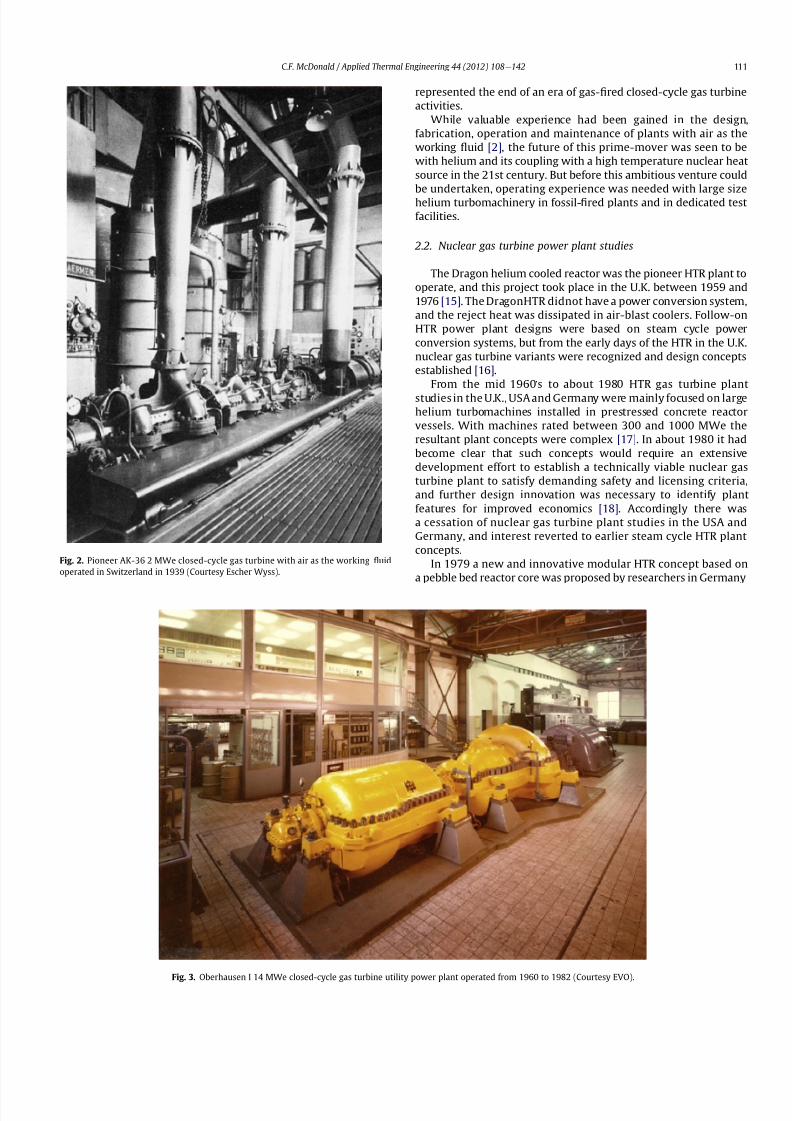
8112019 Helium Turbomachinery Operating Experience From Gas Turbine Power Plants
httpslidepdfcomreaderfullhelium-turbomachinery-operating-experience-from-gas-turbine-power-plants 435
represented the end of an era of gas-1047297red closed-cycle gas turbine
activities
While valuable experience had been gained in the design
fabrication operation and maintenance of plants with air as the
working 1047298uid [2] the future of this prime-mover was seen to be
with helium and its coupling with a high temperature nuclear heat
source in the 21st century But before this ambitious venture could
be undertaken operating experience was needed with large size
helium turbomachinery in fossil-1047297red plants and in dedicated test
facilities
22 Nuclear gas turbine power plant studies
The Dragon helium cooled reactor was the pioneer HTR plant to
operate and this project took place in the UK between 1959 and
1976 [15] The DragonHTR didnot have a power conversion system
and the reject heat was dissipated in air-blast coolers Follow-on
HTR power plant designs were based on steam cycle power
conversion systems but from the early days of the HTR in the UK
nuclear gas turbine variants were recognized and design concepts
established [16]
From the mid 1960rsquos to about 1980 HTR gas turbine plant
studies in the UK USA and Germany were mainly focused on large
helium turbomachines installed in prestressed concrete reactor
vessels With machines rated between 300 and 1000 MWe the
resultant plant concepts were complex [17] In about 1980 it had
become clear that such concepts would require an extensive
development effort to establish a technically viable nuclear gas
turbine plant to satisfy demanding safety and licensing criteria
and further design innovation was necessary to identify plant
features for improved economics [18] Accordingly there was
a cessation of nuclear gas turbine plant studies in the USA and
Germany and interest reverted to earlier steam cycle HTR plant
concepts
In 1979 a new and innovative modular HTR concept based on
a pebble bed reactor core was proposed by researchers in Germany
Fig 3 Oberhausen I 14 MWe closed-cycle gas turbine utility power plant operated from 1960 to 1982 (Courtesy EVO)
Fig 2 Pioneer AK-36 2 MWe closed-cycle gas turbine with air as the working 1047298uid
operated in Switzerland in 1939 (Courtesy Escher Wyss)
CF McDonald Applied Thermal Engineering 44 (2012) 108e142 111
8112019 Helium Turbomachinery Operating Experience From Gas Turbine Power Plants
httpslidepdfcomreaderfullhelium-turbomachinery-operating-experience-from-gas-turbine-power-plants 535
[1920] Initial studies were focused on steam cycle plant concepts
in which the reactor core and major components were installed in
two separate vertical steel vessels After the Chernobyl accident in
1986 work intensi1047297ed on the modular HTR with emphasis on its
passive decay heat removal and inherent safety features While
a compact direct cycle nuclear gas turbine version of the modular
HTR was 1047297rst suggested in the USA in 1986 [21] it wasa further 1047297ve
years or so before it became accepted based to a large extent on its
potential for very high ef 1047297ciency
Evolution of the nuclear gas turbine power plant concept
spans a period of over six and half decades with intermittent
design studies undertaken by different engineering organizations
in various countries [22] In the last 20 years or so PCS paperstudies have been focused on plant layout arrangements and on
helium turbomachine design with limited sub-component
development [23] in support of various modular nuclear gas
turbine concepts
Up until about 2009 projects in different states of design
de1047297nition were being investigated in several countries and these
are summarized as follows 1) in a joint USARussia project
(GTeMHR) the design of an integrated concept (with all the PCS
components installed in a single pressure vessel) is based on
a direct ICR cycle with a vertically oriented 286 MWe helium tur-
bomachine with a turbine inlet temperature of 850 C [24] 2) the
Japanese GTeHTR300 is a distributed plant concept (the PCS
components being installed in separate pressure vessels) with
a direct recuperated cycle and embodies a horizontal 274 MWe
turbomachine with a turbine inlet temperature of 850 C [25] 3 ) i n
France the ANTARES distributed concept is of the indirect type
using an IHX and with a combined gas and steam turbine PCS has
a power output of 280 MWe with a turbine inlet temperature of
800 C [26] 4) in China a study was undertaken of the HTR e10GT
concept involving the future coupling of a small vertical 22 MWe
helium turbine with the HTR-10 pebble bed reactor it being an
integrated concept with an ICR cycle and a turbine inlet temper-
ature of 750 C [27] and 5) in South Africa design and develop-
ment activities had been underway for several years on a nuclear
gas turbine demonstration plant project (PBMR) involving the
coupling of a helium gas turbine PCS with a pebble bed reactor for
operation in about 2015 For this modular plant a distributedsystem based on an ICR cycle embodied a horizontal 165 MWe
helium turbomachine with a turbine inlet temperature of 900 C
[2829] However in 2009 work on this gas turbine demonstration
plant was terminated and the project redirected to an indirect
steam cycle cogeneration plant concept The cancellation of the
PBMR gas turbine was a disappointment since some had viewed
this demo plant as a benchmark for the eventual commercializa-
tion of modular nuclear gas turbine plants
3 Reasons for choice of helium as the working 1047298uid
Following the initial deployment of European fossil-1047297red gas
turbines with air as the working 1047298uid the demand for plants with
higher powerlevels instigated studies to evaluate other gases in the
Fig 4 Last closed-cycle gas turbine (rated at 5 MWe) burning a low-grade fuel (petroleum coke) in a 1047298uidized bed combustor operated in 1985 (Courtesy Garrett Corporation)
CF McDonald Applied Thermal Engineering 44 (2012) 108e142112
8112019 Helium Turbomachinery Operating Experience From Gas Turbine Power Plants
httpslidepdfcomreaderfullhelium-turbomachinery-operating-experience-from-gas-turbine-power-plants 635
closed power conversion loop Performance analyses and compo-
nent design studies were undertaken for gases that included
helium nitrogen carbon dioxide various gas mixtures and
nitrogen tetroxide For terrestrial power generation considering
the size of the major components namely the turbomachine heat
exchangers casings ducts and the external fossil-1047297red heater itwas generally concluded that for plants rated up to about 30 MWe
air was the favored working 1047298uid from the standpoints of
simplicity conventionality and cost
For the nuclear gas turbine the choice of the working 1047298uid
involved considerations being given from both the reactor coolant
and power conversion system standpoints Studies by engineers
and physicists concluded that helium being neutronically neutral
and chemically inert was compatible with the reactor turboma-
chinery and heat exchangers and acceptable for plants with large
power outputs [30]
The speci1047297c heat of monatomic helium is 1047297ve times that of air
and since the compressor stage temperature rise varies inversely
as speci1047297c heat (for a given limiting blade speed) it follows that
the available temperature rise per stage when operating withhelium will be only one 1047297fth that of air and this of course means
that more stages (for a given pressure ratio) are required for
a helium axial 1047298ow compressor It is fortunate that the optimi-
zation (for maximum ef 1047297ciency) of a highly recuperated and
intercooled Brayton cycle results in a relatively low pressure ratio
(ie 25e30) hence the number of compressor and turbine stages
are fairly comparable with modern industrial open cycle gas
turbines [31]
Substitution of helium for air greatly modi1047297es the turbo-
machine aerodynamic requirements because the high sonic
velocity of helium removes Mach number effects The size of the
machine is essentially dictated by the choice of blade speed there
being an incentive to use the highest possible values commensu-
rate with stress limitations to reduce the number of stages since
the stage loading factor is inversely proportional to the square of
the blade speed In general aerothermal 1047298uid dynamic and
mechanical design methodologies from air-breathing gas turbines
are applicable but the effects that the properties of helium have on
the design of a turbomachine in a high pressure closed-cycle
system are recognized and include the following
- Low molecular weight and high speci1047297c heat results in a large
number of stages (for a given pressure ratio)
- Long slender rotor (rotor dynamic stability concerns)
- Speci1047297c heat 5 times that of air gives high speci1047297c power
- High hub-to-tip ratio blading (in HP compressor)
- Small blade heights (resulting from high pressure system)
- Low aspect ratio blading (large blade chords because of high
bending stress)
- Thicker blade pro1047297les (because of high bending stress)
- Small compressor annulus taper and turbine 1047298are
- High compressor and turbine ef 1047297ciencies
- low Mach number (less than 030)
- high Reynolds numbers (gt5 106
)- clean oxide free blades (in inert helium)
- blade tip clearances minimized (machine not subjected to
severe thermal transients)
The experience gained from helium turbomachines that have
operated in the USA and Germany are covered in the following
sections
4 Pioneer La Fleur helium gas turbine
In 1960 La Fleur Enterprises in Los Angeles initiated work on an
air separation plant that involved the coupling of a closed-cycle gas
turbine with a cryogenic facility Helium was chosen as the closed
cycle working 1047298
uid since the La Fleur process for air liquefaction
Fig 5 Closed-cycle gas turbine demonstration test facility operated in the UK in 1995 with a 1000 kW natural gas- 1047297red heat source (Courtesy British gas)
CF McDonald Applied Thermal Engineering 44 (2012) 108e142 113
8112019 Helium Turbomachinery Operating Experience From Gas Turbine Power Plants
httpslidepdfcomreaderfullhelium-turbomachinery-operating-experience-from-gas-turbine-power-plants 735
required that the working 1047298uid remain gaseous throughout the
system Details of the plant and the axial 1047298ow helium turboma-
chinery have been documented previously [3233] and are only
brie1047298y discussed here This small plant is important in the context
of this paper since it was the 1047297rst fossil-1047297red helium gas turbine
ever to operate
The temperatureeentropy diagram (Fig 6) and the rather
simplistic cycle diagram (Fig 7) are pertinent to understanding
the function of this plant It was not designed to generate
electrical power instead the useful output being ldquobleed heliumrdquo
The major component was the free-running axial 1047298ow helium
turbomachine The rotating assembly consisted of a helium power
turbine compressor and refrigeration turbine mounted on the
same shaft
In the closed Brayton cycle part of the system the helium exiting
the compressor was split with about half of the mass 1047298ow passing
through the hot recuperator and then 1047298owing through the natural
gas-1047297red external heater where the temperature was further
increased before entering the power turbine Exiting the turbine
the helium then 1047298owed through the other side of the recuperator
and after a further reduction in temperature in a precooler entered
the compressor
In the cryogenic part of the cycle the temperature of the other
half of the helium bled from the compressor was reduced in an
aftercooler and then further reduced in the cold recuperator It was
then expanded in a refrigeration turbine and reached the lowest
temperature in the system The cold helium then passes through
a condenser in which the air is lique1047297ed and after passing through
the other side of the cold recuperator enters the compressor
Because the temperature of this bleed helium stream is less than
that coming from the precooler the mixed temperature at the
compressor inlet is cooler thus reducing the compressor workrequired
An overall view of the La Fleur plant is shown on Fig 8 and the
major parameters and features are given on Table 1 From the onset
of the project conservative parameters were selected to ensure
that when constructed the plant would operate reliably and meet
the process requirements since funding available for the project
was limited
With a turbine inlet temperature of 650 C (1202 F) and
a system pressure of 125 MPa (180 psia) a compressor pressure
Fig 6 Temperatureeentropy diagram of La Fleur helium gas turbine plant
Fig 7 Cycle diagram of La Fleur helium gas turbine plant
CF McDonald Applied Thermal Engineering 44 (2012) 108e142114
8112019 Helium Turbomachinery Operating Experience From Gas Turbine Power Plants
httpslidepdfcomreaderfullhelium-turbomachinery-operating-experience-from-gas-turbine-power-plants 835
ratio of 15 was selected With modest stage loading a 16 stage axial
compressor was designed the welded rotor being shown on Fig 9
Fifty percent reaction blading was used throughout The axial
velocity was kept constant and with a low value of pressure ratio
the annulus taper was rather slight The target ef 1047297ciency for the
compressor was83 percent The blades were cast 410 stainless steel
and these were welded to forged discs since this was the lowest
cost type of construction at the timeFor the turbine a tip speed of 305 ms (1000 ftsec) was
conservatively selected the rotational speed being 19500 rpm
While not coupled to a generator to produce electrical power the
size of the constant speed free-running turbine was equivalent to
that in a machine rated in the 1000e2000 kW class A view of the
turbine rotor is given on Fig 10 The material for the investment
cast blades was Haynes 21 and these were welded to a Timken 16-
25-6 disc The turbine ef 1047297ciency goal was 85 percent
The rotor was supported on oil-lubricated bearings To avoid oil
ingress into the helium circuit the oil pump scavenge pump and
the other accessories were separately driven by electric motors As
also experienced in later closed-cycle gas turbine plants oil ingress
into the helium closed loop occurred this being traced to a poor
design of the oil seals Keeping the system leak-tight when
operating with such a low molecular weight gas was a major
challenge and this topic will be discussed later for other helium
systems operating at high pressure and temperature
In this small pioneer plant the worldrsquos 1047297rst helium turbo-
machine operated satisfactorily the major achievement being that
it proved the La Fleur cryogenic process for air liquefaction The
experience gained from this small prototype plant led to the
construction and operation of a larger fossil-1047297red helium closed-cycle gas turbine for a lique1047297ed gas cryogenic plant and this is
discussed in the following section
5 Escher Wyss helium gas turbine plant
Following the successful operation of the pioneer plant La Fleur
Corporation designed and built a cryogenic facility in Phoenix
Arizona in 1966 for the liquefaction of 90 tonsday of nitrogen The
helium turbomachine was developed and built in Zurich by Escher
Wysswho up to that date hadfabricated the majority of the closed-
cycle gas turbine plants in Europe [2] The thermodynamic cycle
(involving splitting the helium 1047298ow at the compressor exit)
resembled the aforementioned pioneer plant with the exception
that the compressor was separated into two sections to facilitate
Fig 8 Overall view of 1047297rst helium gas turbine (Courtesy La Fleur Corp)
CF McDonald Applied Thermal Engineering 44 (2012) 108e142 115
8112019 Helium Turbomachinery Operating Experience From Gas Turbine Power Plants
httpslidepdfcomreaderfullhelium-turbomachinery-operating-experience-from-gas-turbine-power-plants 935
intercooling [634] The major parameters and features of this plant
are summarized on Table 1
With a turbine inlet temperature of 660 C (1220 F) and
a system pressure of 122 MPa (177 psia) a compressor pressure
ratio of 20 was selected A cross-section of the turbomachine is
shown on Fig 11 The LP and HP compressors had 10 and 8 stages
respectively The compressors were designed with a degree of
reaction slightly above 100 percent based on the prevailing view by
Escher Wyss at the time that this had advantages for helium
compressors Since this philosophy was carried over into the next
much larger helium gas turbine (as covered in the following
section) the rationale for this aerothermal design decision is brie1047298y
addressed below
The degree of reaction can essentially be regarded as the ratio of
pressure rise (although accurately de1047297ned as the static enthalpy
rise) in the rotor with the total pressure rise through the combi-
nation of the rotor and stator In early British axial 1047298ow compres-
sors a value of 50 percent was adopted this enabling the same
blade pro1047297le to be used for the rotor and stator In contemporary
air-breathing gas turbines the compressor degree of reaction is not
a major design factor The effect that selected compressor rotor and
stator positioning and geometries have on the degree of reaction is
illustrated in a simple form on Fig 12 In the early years of closed-
cycle gas turbine work Escher Wyss in Switzerland advocateda degree of reaction of 100 percent or higher [35] With such
blading the gas enters and leaves the stage in an axial direction The
basic stage embodies a negative pre-whirl stator ahead of the rotor
With the stator blades acting as a nozzle it was felt that the
resulting acceleration in the stator had the effect of smoothing out
the 1047298ow providing the best possible conditions for the rotor
However such blading with high stagger and lowsolidity has a very
high relative velocity and attendant high Mach number and is not
used in machines with air as the working 1047298uid since the associated
losses would be excessive leading to low overall compressor ef 1047297-
ciency This type of stator-before-rotor high reaction arrangement
was felt to be advantageous for helium axial 1047298ow compressors to
reduce the number of stages since Mach number effects are not
encountered because the sonic velocity of helium is on the order of
three times that of air
Because of the properties of helium (ie low molecular weight
high speci1047297c heat higher adiabatic index etc) a higher number of
compressor and turbinestages for a given pressure ratio are needed
as mentioned previously An axial compressor with just over
a hundred percent reaction as in the Escher Wyss helium gas
turbine that operated in Phoenix has a greater enthalpy rise per
stage for a given tip speed this reducing the number of stages for
a given pressure ratio but the ef 1047297ciency is slightly lower Mini-
mizing the number of stages was important from the rotor dynamic
stability standpoint for the very long rotor assembly associated
Fig 9 La Fleur plant 16 stage compressor (Courtesy La Fleur Corp) Fig 10 La Fleur plant 4 stage helium turbine (Courtesy La Fleur Corp)
Table 1
Salient features of operated helium turbomachinery
Turbomachine Helium closed-cycle gas turbines Test facility Helium circulator
Facility La Fleur
gas turbine
Escher Wyss
gas turbine
Oberhausen 11
power plant
HHV
test loop
FSV HTGR
Country USA USA Germany Germany USA
Year 1962 1966 1974 1981 1976
Application Cryogenic Cryogenic CHP plant Development Nuclear plant
Heat source NG NG Coke oven gas Electrical NuclearPower MW 2 equiv 6 equiv 50 90 4
Cycle Recuperated ICR ICR Customized Steam
Compressor
Type Axial Axial Axial Axial Axial
No stages 16 10LP8HP 10LP15HP 8 1
Inlet press MPa 125 122 105285 45 473
Inlet temp C 21 22 25 820 394
Pressure ratio 15 20 27 113 102
Flow kgsec 73 11 85 212 110
In vol 1047298ow m3sec 35 55 50 107 32
Turbine
Type Axial Axial Axial Axial ST
No stages 4 9 11LP7HP 2 1
Inlet press MPa 18 23 165 50 e
Inlet temp C 650 660 750 850 e
In vol 1047298ow m3sec 30 57 67 98 e
Out vol 1047298ow m3
sec 36 85 120 104 e
Rotation speed rpm 19500 18000 55003000 3000 9550
Shaft type Single Single Twin (geared) Single Single
Generator type None None Conventional Elect motor e
CF McDonald Applied Thermal Engineering 44 (2012) 108e142116
8112019 Helium Turbomachinery Operating Experience From Gas Turbine Power Plants
httpslidepdfcomreaderfullhelium-turbomachinery-operating-experience-from-gas-turbine-power-plants 1035
with this intercooled helium axial compressor of the type shown on
Figs 11 and 13
In the high pressure helium environment a high degree of reaction leads to a rotor blading with longer chords and low aspect
ratio The larger chord length combined with low solidity results in
comparatively few compressor blades Low aspect ratio (de1047297ned as
the ratio of blade height to chord length) results in several effects
including the following 1) high stagger with wider chords results in
a greater overall machine bladed length 2) fewer blades per stage
3) relatively large area of casing and blade surface with adverse
frictional losses tending to give lower ef 1047297ciency and 4) a stiffer
blade section (also with a thicker pro1047297le) with the needed strength
to combat bending stress which can be signi1047297cant in a high pres-
suredensity helium closed-cycle system A way to partially balance
out the bending stress would be by leaning the blades and off-
setting the blade cross-section centre of gravity For the early
helium gas turbine plants a view expressed by Escher Wyss wasthat the use of high reaction blading gave the maximum attainable
head a 1047298atter pressureevolume characteristic and a better surge
margin [36] The merits of increased pressure rise per stage asso-
ciated with high reaction blading has to be put into perspective by
its lower values of ef 1047297ciency [37]
The turbine had 9 stages and a rotational speed of 18000 rpm
While not coupled with a generator the equivalent output of the
free-running turbine was on the order of 6000 kW An overall view
of the long slender rotor is shown on Fig 13 and the turbomachine
assembly being installed in a cylindrical horizontally split casing is
shown on Fig 14 The major 1047298anges had peripheral lip seals to
facilitate welding closure to ensure leak tightness
With an external gas-1047297red heater the plant operated for about
5000 h and the helium gas turbine proved to be mechanically
sound and met its speci1047297ed performance This very specialized
plant proved to be too expensive to operate for the limited market
for cryogenic 1047298uids Anticipated market growth in the late 1960sdid not materialize and while the machinery performed satisfac-
torily the customer Dye Oxygen withdrew the plant from service
As far as the helium gas turbine was concerned the plant repre-
sented a signi1047297cant milestone since the technology generated was
applied to a follow-on helium gas turbine which at this stage was
still to be fossil-1047297red but now with the long-term goal in mind of
paving the way for the eventual operation of a helium closed-cycle
gas turbine power plant with a high temperature nuclear heat
source
6 Oberhausen II helium gas turbine plant at EVO
61 Closed-Cycle gas turbine experience at EVO
With initial operation starting in 1960 the municipal energy
utility (EVO) of the city of Oberhausen in the German industrial
Ruhr area deployed a closed-cycle gas turbine plant Referred to as
Oberhausen I the plant (shown previously on Fig 3) operated in
a combined power and heat mode with an electrical output of
14 MW and the thermal heat rejection of about 20 MW was
supplied to the cityrsquos district heating system The external heater
was initially 1047297red with Bituminous coal and in 1971 a change was
made to use coke-oven gas that had become available While using
air as the working 1047298uid some of the technical dif 1047297culties experi-
enced with this plant are highlighted below simply because if they
were to occur in a future direct cycle nuclear gas turbine plant they
would be very costly and time consuming to resolve as will be
discussed in a following section
Fig 11 Cross-section view of helium gas turbine (Courtesy Escher Wyss)
CF McDonald Applied Thermal Engineering 44 (2012) 108e142 117
8112019 Helium Turbomachinery Operating Experience From Gas Turbine Power Plants
httpslidepdfcomreaderfullhelium-turbomachinery-operating-experience-from-gas-turbine-power-plants 1135
In 1963 after 20000 h of operation a failure in the HP
compressor occurred [10] A rotor blade in the 1047297rst stage failed at
the root and in passing through the compressor caused extensive
damage The failure necessitated replacing the complete HP
compressor rotor assembly From a metallurgical examination of
the broken parts the failure was attributed to a small crevice at the
edge of the blade It was postulated that a corrosive action due to
impurities in the closed-loop working 1047298uid (ie air) in1047298uenced the
propagation of the crevice and blade vibration eventually caused
the failure To prevent a further failure of this kind an electric
polishing procedure was applied to the surface of the blade to
detect any imperfections
In 1967 debris from within the closed circuit caused damage to
the rotor blades and stators of several stages in the LP compressor
In 1973 further damage in the LP compressor due to blade vibration
required blading replacement During these de-blading events the
failed fragments were contained within the machine casings Using
conventional equipment the split casings of this machine were
opened and the failed parts removed by hands-on operations New
parts were then installed and the rotor assembly re-balanced The
problems were resolved and this closed-cycle gas turbine plant
with air as the working 1047298uid then performed well over the years
with high reliability [38]Rotor vibrations are mentioned here because they had caused
problems in three fossil-1047297red closed-cycle gas turbine plants using
air as the working 1047298uid namely1) in the John Brown 12 MW Plant
in Dundee where insurmountable vibration problems occurred [2]
2) multiple blade failures in the Spittelau 30 MW plant [2] and 3)
compressor blade failures in the aforementioned Oberhausen plant
As will be mentioned in a following section a further turbine blade
failure was experienced in a larger plant using helium as the
working 1047298uid
Correcting the subsequent blade failure damage to the turbo-
machine in a fossil-1047297red plant was straightforward however the
implication of such an operation in a future direct cycle nuclear gas
turbine with radioactively contaminated blading would be far more
severe This would likely require complex remote handling equip-ment and a dedicated facility for machine decontamination and
disassembly before hands-on repair could be undertaken
The Oberhausen I plant operated for about 120000 h and was
decommissioned in 1982 In about 1971 an expansion of the utilityrsquos
Fig 12 Impact of compressor blading geometry on degree of reaction (Courtesy
Escher Wyss)
Fig 13 Intercooled axial 1047298
ow helium turbomachine rotating assembly (Courtesy Escher Wyss)
CF McDonald Applied Thermal Engineering 44 (2012) 108e142118
8112019 Helium Turbomachinery Operating Experience From Gas Turbine Power Plants
httpslidepdfcomreaderfullhelium-turbomachinery-operating-experience-from-gas-turbine-power-plants 1235
capacity was needed due to increasing demand A larger fossil-1047297red
closed-cycle cogeneration plant of conventional design and still
retaining the use of air as the working 1047298uid was initially foreseen
but an emerging German development in the nuclear power plant
1047297eld resulted in a different decision being made as discussed
below
62 Relevance of the Oberhausen II helium turbine
Starting in 1972 development work sponsored by the Federal
Republic of Germany within the scope of the 4th Atomic program
was initiated on a high temperature reactor power plant with
a helium gas turbine (HHT) The reference plant design was based
on a large single-shaft intercooled helium turbine rated at
1240 MW A demonstration plant rated at 676 MW was planned
but prior to the construction of this it was necessary to test the
most important components to reduce risk Details of the two
major facilities to accomplish this have been reported previously
[39] and are summarized as follows
The Oberhausen II helium gas turbine plant was designed andbuilt to perform two major functions 1) it had to operate as
a commercial venture to provide electrical power (50 MWe) and
district heating (53 MWt) for the city of Oberhausen and 2) provide
data applicable to the nuclear gas turbine project particularly the
dynamic behavior of the overall plant and the integrity and long-
term operating experience of the major components in a helium
environment especially the turbomachine
The second facility was the HHV an experimental plant for
testing under representative conditions with respect to machine
size operating temperature pressure and mass 1047298ow of a large
helium turbomachine The facility was extensively instrumented to
gatherdata in the following areas rotorcooling system veri1047297cation
thermal insulation integrity 1047298ow characteristics blading ef 1047297ciency
acoustics rotor dynamic stability bearings dynamic and static
seals system leak tightness and metals behavior for the full
spectrum of plant operations including plant startup load change
shutdown upset conditions etc Details of the HHV facility and
testing undertaken are given in a later section
63 Oberhausen II helium gas turbine plant design
The design and construction of the plant was based on joint
efforts between EVO (plant designer and operator) GHH (turbo-
machine recuperator coolers and controls) Sulzer (helium
heater) and the University of Hannover Institute for Turboma-
chinery which contributed to the designwork and monitoring plant
performance
For the future planned nuclear gas turbine plant design values
of the temperature and pressure at the turbine inlet were 850 C
(1562 F) and 60 MPa (870 psia) respectively Attainment of this
temperature in the Oberhausen II plant could not be achieved and
750 C (1382 F) was selected based on tube material stress
considerations in the external coke-oven gas 1047297red heater An
intercooled and recuperated closed cycle was selected and themajor features of the plant are given on Table 1 The salient
parameters are given on the simpli1047297ed cycle diagram (Fig 15)
While rated at 50 MW a maximum system pressure of only
285 MPa (413 psia) was chosen so that the helium volumetric 1047298ow
(hence size of the bladed passages) would correspond to a much
larger helium turbomachine (on the order of 300 MW in fact) This
together with a rotational speed of 5500 rpm for the HP group
would result in representative stress loadings and would permit
a reasonable extrapolation to the machine size planned for the
nuclear demonstration plant
For the intercooled and recuperated cycle a compressor pressure
ratio of 27 was selected The helium mass 1047298ow rate was 85 kgs
(187 lbsec) and the circuit pressure loss was estimated at 104
percent Based on state-of-the-art component ef 1047297
ciencies and
Fig 14 Intercooled helium turbomachine with an equivalent power rating of 6000 kW installed in a split-case steel pressure vessel (Courtesy Escher Wyss)
CF McDonald Applied Thermal Engineering 44 (2012) 108e142 119
8112019 Helium Turbomachinery Operating Experience From Gas Turbine Power Plants
httpslidepdfcomreaderfullhelium-turbomachinery-operating-experience-from-gas-turbine-power-plants 1335
a recuperator effectiveness of 87 percent the projected thermal
ef 1047297ciency was 326 percent gross and 313 percent net
The isometric sketch of the distributed power conversion
system shown on Fig 16 (from Ref [40]) is convenient for
describing the plant layout A decision was made [41] to install the
horizontal turbomachinery in three large steel vessels the group-
ings being as follows 1) LP compressor rotor 2) HP compressor and
HP turbine grouping and 3) LP turbine The 1047297rst two assemblies
were on a single-shaft with a rotational speed of 5500 rpm The
generator with a rotational speed of 3000 rpmis driven from the LP
turbine end The rotors were geared together but with the selected
shafting arrangement only a small amount of power was trans-
mitted through the gearbox This con1047297guration was established
so that the dynamic behavior would be the same as in the large
single-shaft reference nuclear gas turbine plant design concept
The arrangement of the three vessels can be clearly seen on Fig 17
The horizontal tubular recuperator is positioned below the
turbomachinery The tubular precoolers and intercoolers are
installed in vertical steel vessels This type of orientation of the
major components was used in some of the earlier closed-cycle
plants using air as the working 1047298uid
Power regulation was achieved by inventory control as in the
aforementioned Oberhausen I plant which meant that the system
pressure (hence mass 1047298ow) was changed as required To lower the
power output helium was extracted from the loop after the HP
compressor through a control valve into a storage vessel For
a power increase helium was returned from the storage vessel into
the system upstream of the LP compressor without the need for an
additional blower With this arrangement the turbine inlet
temperature and speed remained constant and plant ef 1047297ciency
would be essentially constant down to a very low power level [42]
To achieve rapid load changes a bypass valve was included in the
system in which helium was transferred in a line between the HP
compressor exit end and LP end of the recuperator A very rapid
change from 100 percent load to no-load operation and back was
demonstrated [43]
64 Helium turbomachinery
The major features and parameters for the turbomachine are
given on Table 2 and are summarized as follows A longitudinal
cross-section of the turbomachine is shown on Fig 18 At the left
hand end the LP compressor is installed in a spherical pressure
vessel A high degree of reaction (ie 100 percent) was selected for
this 10 stage axial compressor this practice following the experi-
ence of an earlier discussed helium turbomachine A view showing
the bladed rotor of the LP compressor installed in the pressure
vessel split casing is shown on Fig19 with an appreciation for the
size of the spherical casing being shown on Fig 20 Both the HP
compressor and HP turbine rotors are installed in a common
housing as shown in the turbomachine cross-section (Fig 21) and
Fig 15 Oberhausen II helium gas turbine cycle diagram
Fig 16 Isometric layout of Oberhausen II helium gas turbine power conversion system (Courtesy EVO)
CF McDonald Applied Thermal Engineering 44 (2012) 108e142120
8112019 Helium Turbomachinery Operating Experience From Gas Turbine Power Plants
httpslidepdfcomreaderfullhelium-turbomachinery-operating-experience-from-gas-turbine-power-plants 1435
in the view with the HP rotor assembly positioned above the
horizontal split casing (Fig 22) The 15 stage HP compressor was
again designed with 100 percent reaction blading The HP turbine
has 7 stages and operated with an inlet temperature of 750 C
(1382O F) A cross-section of the 11 stage LP turbine installed in
a separate spherical vessel is shown on Fig 23 The amount of
power transmitted in the gearbox between the HP and LP turbinesis small since at rated output the HP turbine power level is only
slightly more than is needed to drive both compressors
The rotor of the HP group is supported on two oil-lubricated
bearings For the complete rotating assembly the thrust bearing is
located at the warm end of the LP compressor The six turbo-
machine bearing housings were designed such that direct access to
the large oil bearings was possible without having to open the large
casings This was done to reduce maintenance time because the
large split casings have 1047298anges that were welded closed at the
peripheral lip seals to minimize helium leakage
Special attention was given to the design of the cooling system
for the rotor In the case of this plant with a turbine inlet
temperature of 750 C the turbine blades themselves based on the
use of an existing superalloy did not have to be internally cooledbut cooling gas bled from the HP compressor outlet 1047298owed through
the hollow shaft and was used to cool the turbine discs and the
blade root attachments and then returned downstream of the
turbine
In a closed-cycle gas turbine the powerlevel can be regulated by
means of changing the system pressure and careful attention must
be given to the design of the various sealing systems to accom-
modate pressure differentials within the system particularly
during transient operation To simulate what would be needed in
a direct cycle nuclear gas turbine (to prevent 1047297ssion products
coming into contact with the bearing lubricating oil) a system
having a separate chamber for each of the three labyrinth seals was
incorporated in the machine design Outboard of the labyrinth seals
where the shafts penetrate the casings there were two further
seals a 1047298oating ring seal and a shutdown seal to prevent external
helium leakage
65 Helium turbomachine operating experience
Various presentations papers and publications have previously
covered the over 13 year operation of the Oberhausen II helium gas
turbine plant [43e48] The experience gained with the operation
Fig 17 Overall view of Oberhausen II 50 MWe helium gas turbine power plant (Courtesy EVO)
Table 2
Oberhausen II plant helium turbomachinery
Plant design electrical power MW 50
District heating thermal supply MW 535
Plant design ef 1047297ciency at terminals 313
Thermodynamic cycle ICR
Control method Helium inventory
compressor bypass
Rotor arrangement 2 Shaft (geared together)
Helium mass 1047298ow kgsec 85
Overall pressure ratio 27
Generator ef 1047297ciency 98
Design system pressure loss 104Compressor LP HP
Inlet pressure MPa l05 l54
Inlet temperature C 25 25
Vol 1047298ow inletoutlet m3s 5040 4025
Ef 1047297ciency 870 855
Rotational speed rpm 5500 5500
Number of stages 10 15
Blade height inletoutlet mm 10385 7253
Turbine LP HP
Inlet pressure MPa 165 270
Inlet temperature C 582 750
Ef 1047297ciency 900 883
Rotational speed rpm 3000 5500
Number of stages 11 7
Vol 1047298ow inletoutlet m3sec 92120 6792
Blade height inletoutlet mm 200250 150200
CF McDonald Applied Thermal Engineering 44 (2012) 108e142 121
8112019 Helium Turbomachinery Operating Experience From Gas Turbine Power Plants
httpslidepdfcomreaderfullhelium-turbomachinery-operating-experience-from-gas-turbine-power-plants 1535
of the large axial 1047298ow helium turbomachine is summarized asfollows
On the positive side the following were accomplished The rotor
helium buffered bearing labyrinth oil sealing system was one of the
numerous systems that worked well from the onset This was
encouraging since the external leakage of helium contaminated by
1047297ssion products and the ingress of lubricating oil into the closed
helium loop during the projected plant lifetime of 60 years are of
concern to designers of a direct cycle nuclear gas turbine plant (for
a machine with oil bearings) because of the likely long plant
downtime for cleanup and repair
With some modi1047297cations the helium puri1047297cation system
worked well with the purity level within the speci1047297cation The
helium cooling systems worked well to keep the temperatures of
the turbine discs blade root attachments and casings at speci1047297
edlevels Load change by inventory control was done routinely and
the ability to shed 100 percent of the load in a very short period by
means of the bypass valve was demonstrated The integrity of the
co-axial turbine inlet hot gas duct was proven At the end of plant
operation the major turbomachine casings were opened and there
were no signs of corrosion or erosion of the turbine or compressor
blades The coatings applied to mating metallic surfaces were
effective with no evidence of galling or self-welding in the oxygen-
free closed-loop helium environment
Experience from previously operated high temperature helium
cooled nuclear reactor power plants (with Rankine cycle steam
turbine power conversion systems) demonstrated that absolute
helium leak tightness was not attainable This was also true in the
Oberhausen II fossil-1047297red gas turbine plant where during initial
operation the helium leakage was about 45 kg per day Attention
was given to this and helium losses were reduced to the range of
5e10 kg per day principally by seal welding the major 1047298anges This
value can be compared with other closed loop helium systems as
shown below
On the negative side several unexpected problems had a majorimpact on the operation of the plant Following initial running of
the machine at 3000 rpm in preparation to synchronizing the
system the HP casing was opened for inspection revealing
damage to the labyrinth seals this being caused by shifting of
the rotor in the axial direction The labyrinth seals were replaced
and the turbine was 1047297rst synchronized with the grid on November
8 1975
Subsequent vibration problems were encountered and the HP
shaft oscillation became so large that it caused damage to the
bearings and the design value of speed and power could not be
maintained and the plant was shut down This was initially thought
to be due to thermal distortion of the rotor and a large unbalance
Fig 18 Cross-section of Oberhausen II plant helium turbomachinery rotating assembly (Courtesy EVO)
Fig 19 Oberhausen II low pressure helium compressor installed in casing (Courtesy
GHH)
Plant Helium inventory kg Leakage
kgday day
Dragon 180 020e20 010e10
AVR 240 10e30 040e12
Oberhausen II 1400 5e10 035e070
HHV 1250 25e50 020e040
FSV e Excessive leakage
CF McDonald Applied Thermal Engineering 44 (2012) 108e142122
8112019 Helium Turbomachinery Operating Experience From Gas Turbine Power Plants
httpslidepdfcomreaderfullhelium-turbomachinery-operating-experience-from-gas-turbine-power-plants 1635
Modi1047297cations to the rotor were made and the bearings replaced
but now the HP spool design speed of 5500 rpm could not be
achieved Subsequent major design and fabrication changes were
made including decreasing the bearing span by 600 mm (24 in)
giving a shorter stiffer rotor and changing the type of bearings In
restarting the plant the design speed of the HP rotor was achieved
however the power output was only 30 MW compared with the
design value of 50 MW
Fig 20 View of Oberhausen II low pressure helium compressor spherical vessel (Courtesy GHH)
Fig 21 Cross-section of Oberhausen II high pressure rotating group (Courtesy GHH)
CF McDonald Applied Thermal Engineering 44 (2012) 108e142 123
8112019 Helium Turbomachinery Operating Experience From Gas Turbine Power Plants
httpslidepdfcomreaderfullhelium-turbomachinery-operating-experience-from-gas-turbine-power-plants 1735
To gain operational experience it was decided to continue
running the plant at the reduced power rating On February 5 1979
after nearly 11000 h of operation a rotor blade from the second
stage of the HP turbine failed causing damage in the remaining
stages but the high energy fragments were contained within the
thick machine casing Examination of the failed blade revealed the
defect as a crack caused by the forgingprocess on the semi-1047297nishedproduct To prevent such a failure occurring in the future an electric
polishing process applied to the blade surface before inspection
was implemented and improved crack detection methods
introduced
Acoustic loads in a closed-cycle gas turbine represent pressure
1047298uctuations propagating at the speed of sound through the helium
working 1047298uid Pressure 1047298uctuations of importance result from the
aerodynamic effects of high velocity helium impacting and
essentially being intermittently ldquocutrdquo by the blading in the
compressor and turbine Care must be taken in the design of the
plant to ensurethat these 1047298uctuating pressure waves do not induce
vibrations of a magnitude that could result in excitation-induced
fatigue failures in components in the circuit Critical vibrations
occur when resonance exists between the main frequency of
the propagating sound and the natural frequencies of the
components particularly ones that have large surface area to
thickness ratio
Measurements of sound spectrum were taken at four different
locations in the circuit The design level of power of 50 MW was not
achieved but at the 30 MW power output actually realized the
maximum recorded sound power level was 148 dB After plantshutdown there was no evidence of adverse effects on the major
components of noise induced excitation emanating from the axial
1047298ow turbomachinery The integrity of the turbine inlet hot gas duct
and insulation was con1047297rmed
The inability to reach rated power was attributed to shortcom-
ings in the helium turbomachine This included the compressors(s)
and turbine(s) blading failing to attain design values of ef 1047297ciencies
and the bleed helium mass 1047298ows for cooling and sealing being
signi1047297cantly greater than analytically estimated Based on data
taken from the well instrumented plant detailed analyses were
undertaken by specialists [4950] to calculate the losses in the
turbomachine to explain the power output de1047297ciency A summary
of the projected losses and various component ef 1047297ciencies is pre-
sented in a convenient form on Table 3
Fig 22 Oberhausen II high pressure rotor being installed (Courtesy GHH)
CF McDonald Applied Thermal Engineering 44 (2012) 108e142124
8112019 Helium Turbomachinery Operating Experience From Gas Turbine Power Plants
httpslidepdfcomreaderfullhelium-turbomachinery-operating-experience-from-gas-turbine-power-plants 1835
The plant operated for approximately 24000 h and was shut-
down and decommissioned in 1988 when the coke-oven gas supply
for the heater was no longer available A total plant operating time
of about 11500 h had been at the design turbine inlet temperature
of 750 C (1382 F) Turbomachinery related experience gained
from operation of this large helium gas turbine plant was extremely
valuable While many of the functions performed well from the
onset and others worked satisfactorily after modi1047297cations were
made serious unexpected problems were encountered
The achieved electrical power output of only 60 percent of the
design value was initially thought to be due to a grossly excessive
system pressure loss However when the data was carefully eval-uated it was found that 85 percent of the 20 MW power loss was
attributed to turbomachine related problems as delineated on
Table 3
To remedy this power de1047297ciency it was clear that a major re-
design of the turbomachinery would be required While replace-
ment of the gas turbine was not contemplated a study was
undertaken based on data from the plant and new technologies
that had become available since the initial design Based on the
1047297ndings a new turbomachine layout concept was suggested [43]
and a simplistic view of the rotor arrangement is shown on Fig 24
A more conventional single-shaft arrangement was proposed with
the two compressors and turbine having a rotational speed of
5400 rpm A gearbox was still retained to give a generator rota-
tional speed of 3000 rpm Based on prevailing technology at the
time the requirements for such a gearbox would have been moredemanding since the 50 MW from the turbine to the generator
would have to be transmitted through it This would necessitate
a larger system to pump 1047297lter and cool the bearing lubrication oil
To remedy the very large losses in the compressors and turbines
the number of stages would have to be increased In the case of the
compressors the use of lighter aerodynamically loaded higher
ef 1047297ciency stages with 50 percent reaction blading was
recommended
7 High temperature helium test facility (HHV)
71 Background
In the late 1960rsquos with large numbers of orders placed for 1047297rst
generation light water reactor nuclear power plants studies were
initiated for next generation power plants with higher ef 1047297ciency
potential Following the initial operational success of the 1047297rst three
small helium cooled HTR plants (ie Dragon in the UK Peach
Bottom I in the USA and AVR in Germany) studies on larger plants
based on the use of both Rankine steam cycle and helium closed
Brayton cycle power conversion systems were undertaken In the
early 1970rsquos emphasis was placed on nuclear gas turbine plant
designs with larger power output both in the USA (for the
HTGR eGT) and in Europe (for the HHT) Work in the USA was
limited to only paper studies [18] The much larger program in
Germany (with participation by Swiss companies for the turbo-
machine heat exchangers and cooling towers) included a well
planned development testing strategy to support the plant design
Fig 23 Cross-section of Oberhausen II low pressure helium turbine (Courtesy GHH)
Table 3
Oberhausen II helium turbine plant power losses
Componentcause Design
value
Measured Power loss
MW
Compressors
B Flow losses in inlet diffusers
and blades
Low pressure ef 1047297ciency 870 826 13
High pressure ef 1047297ciency 855 779 40
Turbines
B Blade gap and 1047298ow losses
High pressure ef 1047297ciency 883 823 39
B Pro1047297le losses due to Remachined
blades after having detected
damaged blades
Low pressure ef 1047297ciency 900 856 24
BSealing leakage and cooling 1047298ows
in all turbomachines Kgsec
18 75 53
B Circuit pressure losses
(Ducting Hxrsquos etc)
102 128 26
B Miscellaneous heat losses 05
Total power loss 200 MW
Notes (1) Plant designed for electrical power output of 50 MW actual power output
measured 30 MW
(2) Power de1047297ciency of20 MW based on measurements taken and then recalculated
for the rated plant output
(3) 85 of Power loss attributed to helium turbomachinery related issues
CF McDonald Applied Thermal Engineering 44 (2012) 108e142 125
8112019 Helium Turbomachinery Operating Experience From Gas Turbine Power Plants
httpslidepdfcomreaderfullhelium-turbomachinery-operating-experience-from-gas-turbine-power-plants 1935
While the reference HHT plant for eventual commercializationembodied a very large single helium gas turbine rated at 1240 MW
this was to be preceded by a nuclear demonstration plant rated at
676 MW [51] To support the design of this plant technology
generated from the following was planned 1) operational experi-
ence from the aforementioned Oberhausen II 50 MW helium gas
turbine power plant and 2) testing of components in a large high
temperature helium test facility as discussed below
72 Development facilitytesting objectives
An overall view of the HHV test facility sited in Julich in
Germany is shown on Fig 25 and since this has been reported on
previously [52] it will only be brie1047298
y covered in this section Tominimize risk and assure the performance integrity and reliability
of the nuclear demonstration plant some non-nuclear testing of
the major components especially the helium turbomachine was
deemed essential Because of the limitations of a conventional
closed-cycle helium gas turbine power plant particularly the
temperature limitations of existing fossil-1047297red and electrical
heaters a new type of test facility was foreseen
A simpli1047297ed schematic line diagram of the HHV circuit is shown
on Fig 26 The major design parameters are shown on Fig 27
together with the temperatureeentropy diagram which is conve-
nient for describing the unique relationship between the compo-
nents in the closed helium loop Starting at the lowest pressure in
Fig 24 Proposed new concept for Oberhausen II helium gas turbine rotating assembly to remedy problems encountered during operation of the 50 MWe power plant (Courtesy
EVO)
Fig 25 HHV helium turbomachinery test facility (Courtesy BBC)
CF McDonald Applied Thermal Engineering 44 (2012) 108e142126
8112019 Helium Turbomachinery Operating Experience From Gas Turbine Power Plants
httpslidepdfcomreaderfullhelium-turbomachinery-operating-experience-from-gas-turbine-power-plants 2035
the system the helium is compressed (Ae
B) its temperatureincreasing to 850 C (1562 F) before 1047298owing through the test
section (BeC) After being cooled slightly (CeD) the helium is
expanded in the turbine (DeA) down to the compressor inlet
conditions completing the loop There is no power output from the
system and without the need for an external heater the
compression heat is used to raise the helium to the maximum
system temperature in what can be described as a very large heat
pump The required compressor power is 90 MW and to supple-
ment the 45 MW generated by expansion in the turbine external
power is provided by a 45 MW synchronous electrical motor A
cooler is required to remove the compression heat that is contin-
uously put into the closed helium loop and this is done by bleeding
about 5 percent of the mass 1047298ow after the compressor cooling it
and re-introducing it into the circuit close to the turbine inlet In
addition to testing the turbomachine the facility was engineered
with a test section to accommodate other small components (eg
hot gas 1047298ow regulation valves bypass valves insulation con1047297gu-
rations and types of hot gas duct construction) With the highest
temperature in the system being at the compressor exit the facility
had the capability to provide helium at a temperature up to 1000 C
(1832 F) for short periods at the entrance to the test section
While a higher ef 1047297ciency of the planned nuclear demonstration
plant could be projected with a turbine inlet temperature in the
range 950e1000 C (1742e1832 F) this would have necessitated
either turbine blade cooling or the use of a high temperature alloy
such as Titanium Zirconium Molybdenum (TZM) At the time it was
felt that using either of these would have added cost and risk to theprojectso a conventionalnickel-basedalloyas usedin industrialgas
turbines was selected for the 850 C design value of turbine inlet
temperature this negating the needfor actual internal bladecooling
However a complex internal coolingsystemwas neededto keep the
Fig 26 Cycle diagram of HHV test loop (Courtesy BBC)
Fig 27 Salient features of HHV helium turbomachinery (Courtesy BBC)
CF McDonald Applied Thermal Engineering 44 (2012) 108e142 127
8112019 Helium Turbomachinery Operating Experience From Gas Turbine Power Plants
httpslidepdfcomreaderfullhelium-turbomachinery-operating-experience-from-gas-turbine-power-plants 2135
turbine discs and blade root attachments and casings to acceptable
temperatures commensurate with prescribed stress limitations for
thelife of theturbomachine In addition a heliumsupplywas needed
to provide a buffering system for the various labyrinth seals
In a direct Brayton cycle nuclear gas turbine the turbomachine is
installed in the reactor circuit and via the hot gas duct heated
helium is transported directly from the reactor core to the turbine
From the safety licensing and reliability standpoints there are
various seals that must perform perfectly A helium buffered
labyrinth seal system is necessary to prevent bearing lubricating oil
ingress to the closed helium loop Since in the proposed HHT plant
design the drive shaft from the turbine to the generator penetrates
the reactor primary system pressure boundary two shaft seals are
needed one a dynamic seal when the shaft is rotating and a static
seal when the turbomachine is not operating Testing of these seals
in a size and operating conditions representative of the planned
commercial power plant was considered to be a licensing must
The mechanical integrity of the rotating assembly must be
assured there being two major factors necessitating testing the
machine at full speed and temperature and at high pressure
namely 1) loading the blading under representative centrifugal and
gas bending stresses and 2) to monitor vibration and con1047297rm rotor
dynamic stability For the design of the planned commercial planta knowledge of the acoustic emissions by the turbomachine and
propagation in the closed circuit was required Data from the HHV
facility would enable dynamic responses of the major components
(especially the insulation) resulting from excitation by the sound
1047297eld to be calculated
The circuit was instrumented to gather data on the effectiveness
of the hot gas duct insulation thermal expansion devices hot gas
valves helium puri1047297cation system instrumentation and the
adequacy of the coatings applied to mating metallic surfaces to
prevent galling or self-welding Details of the turbomachinery and
the experience gained from the operation of the HHV facility are
covered in the following sections
73 Helium turbomachine
A cross-section of the turbomachine is shown on Fig 28 The
single-shaft rotating assembly consists of 8 compressor stagesand 2
turbine stages and had a weighton the order of 66 tons(60000 kg)
The hub inner and outer diameters are 16 m (525 ft) and 18 m
(59 ft) respectively the blading axial length being 23 m (75 ft)The
span between the oil bearings being 57 m (187 ft) The physical
dimensions of the turbogroup shown on Fig 28 correspond to
a machine rated at about 300 MW The oil bearings operate in
a helium environment and the diameters of the labyrinths and
1047298oating ring shaft seals to prevent oil ingress are representative of
a machine rated at about 600 MW The complexity of the machine
design especially the rotor cooling system sealing system very
large casing and heat insulation have been reported previously
[53e55]
To ensure high structural integrity the rotor was constructed by
welding together the forged compressor and turbine discs The
compressor had 8 stages each having 56 rotor and 72 stator blades
The turbine had 2 stages each having 90 stator and 84 rotor blades
An appreciation for the large size of the rotating assembly can be
seen from Fig 29 The rotor blades have 1047297r-tree attachments
embodying cooling channels Since the temperature and pressure
do not vary very much along the blading in the 1047298ow direction an
intricate rotor and stator cooling system was required Channels in
both the blade roots and the spacers between adjacent blade rows
form an axial geometry for the passage of a cooling helium supplyto keep the temperature of the multiple discs below 400 C
(752 F) The design of this was a challenge since the rotor and
stator blade attachments of both the 8 stage compressor and 2
stage turbine had to be cooled Excessive leakage had to be avoided
since this would have prevented the speci1047297ed compressor
discharge temperature (ie the maximum temperature in the
circuit) from being reached
In the 1970rsquos and early 1980rsquos signi1047297cant studies were carried
out on large helium gas turbines by various organizations [56e62]
In this era there was general agreement that testing of the turbo-
machine in one form or another in non-nuclear facilities be
undertaken to resolve areas of high risk (eg seals bearings cooling
systems rotor dynamic stability compressor surge margin
dynamic response rotor burst protection etc) before installationand operation of a large gas turbine in a nuclear environment
This low risk engineering philosophy which prevailed at the time
in both Germany and the USA emphasized the importance of
Fig 28 Cross-section of HHV helium turbomachinery (Courtesy BBC)
CF McDonald Applied Thermal Engineering 44 (2012) 108e142128
8112019 Helium Turbomachinery Operating Experience From Gas Turbine Power Plants
httpslidepdfcomreaderfullhelium-turbomachinery-operating-experience-from-gas-turbine-power-plants 2235
the HHV test facility as being an important step towards the
eventual deployment of a high ef 1047297ciency nuclear gas turbine power
plant
74 Initial operation of the HHV facility
During commissioning of the plant in 1979 oil ingress into the
helium circuit from the seal system occurred twiceThe 1047297rst ingressof oil between 600 and 1200 kg (1322 and 2644 lb) was due to
a serious operatorerror and the absence of an isolation valve in the
system The oil in the circuit was partly coked and formed thick
deposits on the cold and hot surfaces of the turbomachinery and in
other parts of the closed loop including saturation of the 1047297brous
insulation The fouled metallic surfaces were cleaned mechanically
and chemically by cracking with the addition of hydrogen and
additives The second oil ingress was due to a mechanical defect in
the labyrinth seal system The quantity of oil introduced was small
and it was removed bycracking at a temperature of 600 C (1112 F)
and with the use of additives To obviate further oil ingress inci-
dents the labyrinth seal system was redesigned The buffer and
cooling helium system piping layout was modi1047297ed to positively
eliminate oil ingress due to improper valve operation and toprevent further human error
Pressure and leak detection tests of the HHV test facility at
ambient temperature showed good leak tightness for the turbo-
machine 1047298anged joints and of the main and auxiliary circuits
However at the operating temperature of 850 C (1562 F) large
helium leaks were detected The major 1047298anges had been provi-
sioned with lip seals and the 1047297rst step was to weld the closures A
large leak persisted at the front 1047298ange of the turbomachine This
was diagnosed as being caused by a non-uniform temperature
distribution during initial operation resulting in thermal stresses
creating local gaps This problem was overcome by redesign of the
cooling system with improved gas 1047298ow distribution and 1047298ow rates
to give a more uniform temperature gradient The leakage from the
system was reduced to on the order of 020e
040 percent of the
helium inventory per day this being of the same magnitude as in
other closed helium circuits as discussed in Section 65
It should be mentioned that in addition to the HHV experience
bearing oil ingress into the circuits and system loss of the working
1047298uid in other closed-cycle gas turbine plants have occurred In all of
these fossil-1047297red facilities 1047297xing leaks and removal of oil deposits
were undertaken based on conventional hands-on approaches but
nevertheless such operations were time-consuming However if a new and previously untested helium turbomachine operating in
a direct cycle nuclear gas turbine plant experienced an oil ingress
the rami1047297cations would be severe The likely use of remote
handling equipment to remove the turbomachine from the vessel
machine disassembly (including breaking the welded 1047298ange joints)
and removal of oil from the radioactively contaminated turbo-
machine blade surfaces and system insulation would be time
consuming A diagnosis of the failure would be required before
a spare turbomachine could be installed and this plant downtime
could adversely affect plant availability
75 Experience gained
Afterresolutionof the aforementionedproblems the HHVfacilitywas started in the Spring of 1981 and in an orderly manner was
brought up to full pressure and a temperature of 850 C (1562 F)
During a 60 h run the functioning of the instrumentation control
and safety systems were veri1047297ed During these tests the ability to
stop the turbomachine from full operating conditions to standstill
within 90 s was demonstrated After system depressurization the
plant was then run up again to full operating conditions with no
problems experienced The HHV facility was successfully run for
about 1100 h of which theturbomachineryoperated forabout325 h
at a temperature of 850 C The test facility was extensively instru-
mented and interpretation and analysis of the data recorded gave
positive and favorable results in the following areas
The complex rotor cooling system which was engineered to
assure that the temperature of the discs be kept below 400
C
Fig 29 HHV helium turbomachine rotating assembly (size equivalent to a 300 MWe machine) being installed in a pressure vessel (Courtesy BBC)
CF McDonald Applied Thermal Engineering 44 (2012) 108e142 129
8112019 Helium Turbomachinery Operating Experience From Gas Turbine Power Plants
httpslidepdfcomreaderfullhelium-turbomachinery-operating-experience-from-gas-turbine-power-plants 2335
(752 F) was demonstrated to be effective The measured rotor
coolant 1047298ows (about 3 percent of the mass1047298ow passing through the
machine) were slightly larger than had been estimated and this
resulted in measured turbine disc temperatures lower than pre-
dicted [55]
The dynamic labyrinth shaft seal functioned well at the full
temperature and pressure conditions and met the requirement of
zero oil ingress into the helium circuit The measured rotor oscil-
lation did not have any adverse effect on the shaft sealing system
The static rotor seal (for shutdown conditions) functioned without
any problems
The compressor and turbine blading hadef 1047297ciencies higher than
predicted The structural integrity of the rotor proved to be sound
when operating at 3000 rpm under the maximum temperature and
pressure conditions The stiff rotor shaft had only slight unbalance
and thermal distortion and measured oscillations were in the range
typical of large steam turbines
Sound power spectrum measurements were taken in four
different locations in the circuit These were taken to determine the
spectrum and intensity of the sound generated and propagated by
the turbomachinery and the resultant vibration of internal
components The maximum sound power level in the helium
circuit was160 dB Numerous strain gages were placedin the circuitto determine the in1047298uence of the sound 1047297eld particularly on the
fatigue strength of the turbine inlet hot gas duct In later examining
the internal components there was no evidence of excessive
vibration of the components especially the ducting and the insu-
lation Based on the measurements and calculations it was
concluded that the fatigue strength limit of the components would
not be exceeded during the designed life of the planned commer-
cial nuclear gas turbine power plant
In a direct cycle nuclear gas turbine the hot gas duct used to
transport the helium from the reactor core to the turbineis a critical
component The hot gas duct in the HHV facility performed well
mechanically and con1047297rmed the adequacy of the thermal expan-
sion devices From the thermal standpoint the 1047297ber insulation
performed better than the metallic type
After dismantling the HHV facility there were no signs of
corrosion or erosion of the turbine or compressor blading While
the total number of hours operated was limited the coatings
applied to mating metallic surfaces to prevent galling and frictional
welding in the oxidation-free helium worked well
The helium buffer and cooling system worked well However
problems remained with the puri1047297cation of the buffer helium The
oil separation system consisting of a cyclone separator and a wire
mesh and a down stream 1047297ber 1047297lter needed further improvement
In late 1981 a decision was made to cancel the HHT project and
the HHV facility was shutdown The design and operational expe-
rience gained from the running of this facility would have been
extremely valuable had the nuclear gas turbine power plant
concept moved towards becoming a reality The identi1047297cation of
somewhat inevitable problems to be expected in such a complexturbomachine and their resolution were undertaken in a timely
and cost effective manner in the non-nuclear HHV facility This
should be noted for future nuclear gas turbine endeavors since
remedying such unexpected problems in the case of a new and
untested large helium turbomachine being operated for the 1047297rst
time using nuclear heat could result in very complex repair
Fig 30 Speci1047297
c speed-speci1047297
c diameter array for gas circulators in various gas-cooled nuclear plants
CF McDonald Applied Thermal Engineering 44 (2012) 108e142130
8112019 Helium Turbomachinery Operating Experience From Gas Turbine Power Plants
httpslidepdfcomreaderfullhelium-turbomachinery-operating-experience-from-gas-turbine-power-plants 2435
activities and extended plant downtime and indeed adding risk to
the overall success of the nuclear gas turbine concept
8 Circulators used in gas-cooled reactor plants
Circulators of different types will be needed in future helium
cooled nuclear plants these including the following 1) primary
loop circulator for possible next generation steam cycle power andcogeneration plants 2) for future indirect cycle gas turbine plants
3) shut down cooling circulators forall HTRand VHTR plants and 4)
for various circulators needed in future VHTR high temperature
process heat plant concepts The technology status of operated
helium circulators is brie1047298y addressed as follows
81 Background
It would be remiss not to mention experience gained in the past
with gas circulators and while not gas turbines they are rotating
machines that operate in the primary loop of a helium cooled
reactor With electric motor drives there are basically two types of
compressor rotor con1047297gurations namely radial and axial 1047298ow
machinesIn a single stage form the centrifugal impeller is used for high
stage pressure rise and low volume 1047298ow duties whereas the axial
type covers low pressure rise per stage and high volume 1047298ow The
selection of impeller type is very much related to the working
media type of bearings drive type rotor dynamic characteristics
and installation envelope A wide range of circulators have operated
and a well established technology base exists for both types [63] A
useful portrayal of compressor data in the form of quasi- non-
dimensional parameters (after Balje [64]) showing approximate
boundaries for operation of high ef 1047297ciency axial and radial types is
shown on Fig 30 (from Ref [65])
Both high speed axial and lower speed radial 1047298ow types are
amenable to gas oil and magnetic bearings From the onset of
modularHTR plant studies theuse of active magnetic bearings[6667]offered a solution to eliminate lubricating oil into the reactor circuit
and this tribology technology is attractive for use in submerged
rotating machinery in the next generation of HTR plants [68]
While now dated an appreciation of the main design features of
typical electric motor-driven helium circulators have been reported
previously namely an axial 1047298ow main circulator for a modular
steam cycle HTR plant [69] and a representative radial 1047298ow shut-
down cooling circulator [70]
The operating experience gained from three particular circula-
tors is brie1047298y included below because of their relevance to the
design of helium turbomachinery in future HTR plant variants
82 Axial 1047298ow helium circulator
Since all of the aforementioned predominantly European
helium gas turbines used axial 1047298ow turbomachinery it is of interest
to mention a helium axial 1047298ow circulator that operated in the USA
and to brie1047298y discuss its design parameters and features The
330 MW Fort St Vrain HTGR featured a Rankine cycle power
conversion system Four steam turbine driven helium circulators
were used to transport heat from the reactor core to the steam
generators The complete circulator assemblies were installed
vertically in the prestressed concrete reactor vessel [71e73]
A cross-section of the circulator is shown on Fig 31 with thecompressor rotor and stator visible on the left hand end of the
machine Based on early 1960rsquos technology a decision was made to
use water lubricated bearings and from the overall plant reliability
and availability standpoints this later proved to be a bad choice
Within the vertical circulator assembly there were four 1047298uid
systems namely the helium reactor coolant water lubricant in the
bearings steam for the turbine drive and high pressure water for
the auxiliary Pelton wheel drive During plant transients the pres-
sures and temperatures of these four 1047298uids oscillated considerably
and the response of the control and seal systems proved to be
inadequate and resulted in considerable water ingress from the
bearing cartridge into the reactor helium circuit The considerable
clean up time needed following repeated occurrences of this event
resulted in long periods of plant downtime and this had an adverseeffect on plant availability This together with other technical
Fig 31 Cross section of FSV helium circulator (Courtesy general Atomics)
CF McDonald Applied Thermal Engineering 44 (2012) 108e142 131
8112019 Helium Turbomachinery Operating Experience From Gas Turbine Power Plants
httpslidepdfcomreaderfullhelium-turbomachinery-operating-experience-from-gas-turbine-power-plants 2535
dif 1047297culties eventually contributed to the plant being prematurely
decommissioned
On the positive side in the context of this paper the helium
circulators operated for over 250000 h and exhibited excellent
helium compressor performance good mechanical integrity and
vibration-free operation The rotating assembly showing the axial
1047298ow compressor and steam turbine rotors together with a view of
the machine assembly are given on Fig 32 The helium compressor
consists of a single stage axial rotor followed by an exit guide vane
The machine was designed for axial helium 1047298ow entering and
leaving the stage and this can be seen from the velocity triangles
shown on Fig 33 which also includes the de1047297nition of the various
aerodynamic parameters Major design parameters and features of
this helium circulator are given on Table 4 Related to an earlier
discussion on the degree of reaction for axial 1047298ow compressors the
value for this conventional single stage circulator is 78 percent All
of the major aerothermal and structural loading criteria were
within established boundaries for an axial compressor having high
ef 1047297ciency and a good surge margin
The compressor gas 1047298ow path and blading geometries were
established based on prevailing industrial gas turbine and aero-
engine design practice A low Mach number (025) a high Reynolds
number (3 106) together with a modest stage loading (ie
a temperature rise coef 1047297cient of 044) and an acceptable value of
diffusion factor (042) were some of the factors that contributed to
a helium circulator that had a high ef 1047297ciency and a good pressure
rise- 1047298ow characteristic The large rotor blade chord and thick blade
section for this single stage circulator are necessary to accommo-
date the high bending stress characteristic of operation in a high
pressure environment The solidity and blade camber were opti-
mized for minimum losses
There were essentially two reasons for including this single-
stage axial 1047298ow compressor that operated in a helium cooled
reactor although its overall con1047297guration can be regarded as a 1047297rst
and last of a kind A rotor blade from this circulator as shown onFig 34 was based on a NASA 65 series airfoil which at the time
were one of the best performing cascades for such low Mach
number and high Reynolds number applications Interestingly it
has almost the same blade height aspect ratio and solidity as would
be used in the 1047297rst stage of an LP compressor in a helium turbo-
machine rated on the order of 250 MW
The second point of interest is that the helium mass 1047298ow rate
through the single stage axial compressor (rated at 4 MWe) is
110 kgs compared with 85 kgs through the multistage compressor
in the 50 MWe Oberhausen II helium gas turbine plant However
the volumetric 1047298ow through the Oberhausen axial compressor is
higher than that through the circulator by a factor of 16 this again
pointing out that the Oberhausen II plant was designed for high
volumetric 1047298ow to simulate the much larger size of turboma-chinery that was planned at the time in Germany for use in future
projected nuclear gas turbine power plants
83 High temperature helium circulator
For future helium turbomachines embodying active magnetic
bearings a challenge in their design relates to accommodating
elevated levels of temperature in the vicinity of the electronic
components In this regard it is of interest to note that a small very
high temperature helium axial 1047298ow circulator rated at 20 kW (as
shown on Fig 35) operated for more than 15000 h in an insulation
test facility in Germany more than two decades ago [74] The
signi1047297cance of this machine is that it operated with magnetic
bearings in a high temperature helium test loop with a circulatorgas inlet temperature of 950 C (1742 F) This necessitated the use
of ceramic insulation to ensure that the temperature in the vicinity
of the magnetic bearing electronics did not exceed a temperature of
about 150 C (300 F)
This machine although a very small axial 1047298ow helium blower
performed well and has been brie1047298y mentioned here since it
represents a point of reference for future helium rotating machines
capable operating with magnetic bearings in a very high temper-
ature helium environment
84 Radial 1047298ow AGR nuclear plant gas circulators
The electric motor-driven carbon dioxide circulators rated at
about 5 MW with a total runningtimein excess of 18 million hours
Fig 32 Fort St Vrain HTGR plant helium circulator (Courtesy General Atomics) (a)
Axial 1047298ow helium compressor and steam turbine rotating assembly (b) 4 MW helium
circulator assembly
CF McDonald Applied Thermal Engineering 44 (2012) 108e142132
8112019 Helium Turbomachinery Operating Experience From Gas Turbine Power Plants
httpslidepdfcomreaderfullhelium-turbomachinery-operating-experience-from-gas-turbine-power-plants 2635
in AGR nuclear power plants in the UK have demonstrated veryhigh availability [7576] To a high degree this can be attributed to
the fact that the machines were conservatively designed and proof
tested in a non-nuclear facility at full temperature and power
under conditions that simulated all of the nuclear plant operating
modes The test facility shown on Fig 36 served two functions 1)
design veri1047297cation of the prototype machine and 2) test of all new
and refurbished machines before they were installed in nuclear
plants Engineers currently involved in the design and development
of helium turbomachinery could bene1047297t from this sound testing
protocol to minimize risk in the deployment of helium rotating
machinery in future HTRVHTR plant variants
9 Helium turbomachinery development and testing
91 On-going development activities
The various helium turbomachines discussed in previous
sections operated over a span of about two decades starting in the
early 1960s From about 1990 activities in the nuclear gas turbine
1047297eld have been focused mainly on the design of modular GTeHTR
plant concepts In support of these plant studies many signi1047297cant
helium turbomachine design advancements have been made and
attention given to what development testing would be needed In
the last decade or so limited sub-component development has
been undertaken for helium turbomachines in the 250e300 MWe
size and these are brie1047298y summarized below
In a joint USARussia effort development in support of the
GTe
MHR turbomachine has been undertaken including testing in
the following areas magnetic bearings seals and rotor dynamicsfor the vertical intercooled helium turbomachine rated at 286 MWe
[77e80]
In Japan development activities have been in progress for
several years in support of the 274 MWe helium turbomachine for
the GTeHTR300 plant concept [2581] A detailed discussion on
the aerodynamic design of the axial 1047298ow helium compressor for
this turbomachine has been published in the open literature [82]
While the design methodology used for axial compressor design in
air-breathing industrial and aircraft gas turbines is generally
applicable for a multi-stage helium compressor a decision was
made by JAEA to test a small scale compressor in a helium facility
because of the inherent and unique gas 1047298ow path and type of
blading associated with operation in a high pressure helium
environment The major goal of the test was to validate the designof the 20 stage helium axial 1047298ow compressor for the GTeHTR300
plant
An axial 1047298ow compressor in a closed-cycle helium gas turbine is
characterized by the following 1) a large number stages 2) small
blade heights 3) high hub-to-tip ratio 4) a long annulus with
small taper that tends to deteriorate aerodynamic performance as
a result of end-wall boundary layer length and secondary 1047298ow 5)
low Mach number 6) high Reynolds number and 7) blade tip
clearances that are controlled by the gap necessary in the magnetic
journal and catcher bearings While (as covered in earlier sections)
helium gas turbines have operated there is limited data in the
open literature on the performance of multi-stage axial 1047298ow
compressors operating in a high pressure closed-loop helium
environment
Fig 33 Velocity triangles for axial compressor stage
CF McDonald Applied Thermal Engineering 44 (2012) 108e142 133
8112019 Helium Turbomachinery Operating Experience From Gas Turbine Power Plants
httpslidepdfcomreaderfullhelium-turbomachinery-operating-experience-from-gas-turbine-power-plants 2735
A 13rd scale 4 stage compressor was designed to simulate the
stage interaction the boundary layer growth and repeated stage
1047298ow in an actual compressor The 1047297rst four stages were designed to
be geometrically similar to the corresponding stages in the
GTe
HTR300 compressor Details of the model compressor havebeen discussed previously [81] and are summarized on Table 5
from [83]
A cross-section of the compressor test model is shown on Fig 37
A view of the 4 stage compressor rotor installed in the lower casing
is shown on Fig 38 The test facility (Fig 39) is a closed helium loop
consisting of the compressor model cooler pressure adjustment
valve and a 1047298ow measurement instrument The compressor is
driven by a 3650 kW electrical motor via a step-up gear The rota-
tional speed of 10800 rpm (three times that of the compressor in
the GTeHTR300 plant) was selected to match blade speed and
Mach number in the full size compressor
Details of the planned aerodynamic performance objectives of
the 13rd scale helium compressor test have been published
previously [84] Extensivetesting of the subscale model compressorprovided data to validate the performance of the full size
compressor for the GTeHTR300 power plant The test data and
test-calibrated CFD analyses gave added insight into the effect of
factors that impact performance including blade surface roughness
and Reynolds number
Based on advanced aerodynamic methodology and experi-
mental validation [82] there is now a sound basis for added
con1047297dence that the design goals of 90 percent polytropic ef 1047297ciency
and a design point surge margin of 20 percent are realizable in
a large multistage axial 1047298ow compressor for a future nuclear gas
turbine plant
In a similar manner a design of a one third size single stage
helium axial 1047298ow turbine has been undertaken and a cross
section of the machine is shown on Fig 40 (from Ref [81]) This
Table 4
Major features of axial 1047298ow helium circulator
Helium 1047298ow rate kgsec 110
Inlet temperature C 394
Inlet pressure MPa 473
Pressure rise KPa 965
Volumetric 1047298ow m3sec 32
Compressor type Single stage axial
Compressor drive Steam turbine
Bearing type Water lubricated
Rotational speed rpm 9550
Power MW 40
Rotor tip diameter mm 688
Rotor tip speed msec 344
Number of rotor blades 31
Number of stator blades 33
Blade height mm 114
Hub-to-tip ratio 067
Axial velocity msec 157
Flow coef 1047297cient 055
Temperature rise coef 1047297cient 044
Degree of reaction 078
Mean rotor solidity 128
Rotor aspect ratio 155
Rotor Mach number 025
Rotor diffusion factor 042
Rotor Reynolds number 3106
Speci1047297c speed 335
Speci1047297c diameter 066
Blade root thickness 15
Airfoil type NASA 65
Rotor blade chord mm 94e64
Stator blade chord mm 79
Rotor centrifugal stress MPa 125
Rotor bending stress MPa 30
Circulator(s) operating Hours gt250000
Fig 34 Rotor blade from single stage axial 1047298ow helium circulator (Courtesy General
Atomics)
Fig 35 20 kW axial 1047298ow helium circulator with magnetic bearings operated in 1985 in
an insulation test loop with a gas inlet temperature on 950
C (Courtesy BBC)
CF McDonald Applied Thermal Engineering 44 (2012) 108e142134
8112019 Helium Turbomachinery Operating Experience From Gas Turbine Power Plants
httpslidepdfcomreaderfullhelium-turbomachinery-operating-experience-from-gas-turbine-power-plants 2835
single stage scale model turbine for validity of the full size turbine
has been built and plans made to test the aerodynamic
performance
92 Nuclear gas turbine helium turbomachine testing
In planning for the 1047297rst nuclear gas turbine plant projected to
enter service perhaps in the third decade of the 21st century
a major decision has to be made as to what extent the large helium
turbomachine should be tested prior to operation on nuclear heat
Issues essentially include cost impact on schedule but the over-
riding one is risk Certainly turbomachine component testing will
be undertaken including the compressor (as discussed in the
previous section) and turbine performance seals cooling systems
hot gas valves thermal expansion devices high temperature
insulation rotor fragment containment diagnostic systems
instrumentation helium puri1047297cation system and other areas to
satisfy safety licensing reliability and availability concerns The
major point is really whether a full size or scaled-down turbo-machine be tested early in the project in a non-nuclear facility
To obviate the need for pre-nuclear testing of a large helium
turbomachine a view expressed by some is that advantage can be
taken of formidable technology bases that exist today for large
industrial gas turbines and high performance aeroengines On the
other hand it is the view of some including the author that very
complex power conversion system components especially those
subjected to severe thermal transients donrsquot always perform
exactly as predicted by analysts and designers even using sophis-
ticated computer codes This was exempli1047297ed in the case of the
turbomachine in the aforementioned Oberhausen II helium gas
turbine plant
The need for a helium turbomachine test facility goes beyond
just veri1047297
cation of the prototype machine Each newgas turbine for
commercial modular nuclear reactor plants would have to be proof
tested and validated before being transported to the reactor site
Similarly turbomachines that would be periodically removed from
the plant at say 7 year intervals during the plant operating life of 60
years for scheduled maintenance refurbishment repair or updat-ing would be again proof tested in the facility before re-entering
service
The direction that turbomachine development and testing will
take place for future helium gas turbines needs to be addressed by
the various organizations involved
Fig 36 AGR circulator test facility In the UK (Courtesy Howden)
Table 5
Major design parametersfeatures of model GTeHTR300 axial 1047298ow helium
compressor (Courtesy JAERI)
Scale of GTeHTR300 compressor 13
Helium mass 1047298ow rate (kgsec) 122
Helium volumetric 1047298ow rate (mV s) 87
Inlet temperature C 30
Inlet pressure MPa 0883Compressor pressure ratio at design point 1156
Number of stages 4
Rotational speed rpm 10800
Drive motor power kW 3650
Hub diameter mm 500
Rotor tip diameter (1st4th stage mm) 568566
Hub-to-tip ratio (1st stage) 088
Rotor tip speed (1st stage msec) 321
Number of rotorstator blades (1st stage) 7294
Rotorstator blade height (1st stage mm) 34337
Rotor stator blade c hor d l eng th (1st stage mm) 2620
Rotorstator solidity (1st stage) 119120
Rotorstator aspect ratio (1st stage) 1317
Flow coef 1047297cient 051
Stage loading factor 031
Reynolds number at design point 76 l05
CF McDonald Applied Thermal Engineering 44 (2012) 108e142 135
8112019 Helium Turbomachinery Operating Experience From Gas Turbine Power Plants
httpslidepdfcomreaderfullhelium-turbomachinery-operating-experience-from-gas-turbine-power-plants 2935
10 Helium turbomachinery lessons learned
101 Oberhausen II gas turbine and HHV test facility
It is understandable that 1047297rst-of-a-kind complex turboma-
chinery operating with an inert low molecular weight gas such as
helium will experience unique and unexpected problems In the
operation of the two pioneering large helium turbomachines in
Germany there were many positive1047297ndings which could only have
been achieved by development testing Equally important some
negative situations were identi1047297ed many of which were remedied
In the case of the Oberhausen II helium gas turbine plant some of
the very serious problems encountered were not resolved Inves-
tigations were undertaken to rationalize the problems associated
with the large power de1047297ciency and a data base established to
ensure that the various anomalies identi1047297ed would not occur in
future large helium turbomachines
The experience gained from the operation of the Oberhausen II
helium gas turbine power plant and the HHV test facility have been
discussedin thetextand arepresentedin a summaryformon Table6
Fig 37 Cross-section of 13rd scale helium compressor test model (Courtesy JAEA)
Fig 38 Four stage helium compressor rotor assembly installed in lower casing (Courtesy JAEA)
CF McDonald Applied Thermal Engineering 44 (2012) 108e142136
8112019 Helium Turbomachinery Operating Experience From Gas Turbine Power Plants
httpslidepdfcomreaderfullhelium-turbomachinery-operating-experience-from-gas-turbine-power-plants 3035
102 Impact of 1047297ndings on future helium gas turbine
The long slender rotorcharacteristic of closed-cycle gas turbines
has resulted in shaft dynamic instability which in some cases has
resulted in blade vibration and failure and bearing damage This
remains perhaps the major concern in the design of large
(250e
300 MW) helium turbomachines for future nuclear gas
turbine plants With pressure ratios in the range of about 2e3 in
a helium system a combination of splitting the compressor (to
facilitate intercooling) and having a large number of compressor
and turbine stages results in a long and 1047298exible rotating assembly
andthis is exempli1047297ed by the rotorassembly shown on Fig13 With
multiple bearings (either oil lubricated or magnetic) the rotor
would likely pass through multiple bending critical speeds before
Fig 39 Helium compressor test facility (Courtesy JAEA)
Fig 40 Cross-section of single stage helium turbine test model (Courtesy JAEA)
CF McDonald Applied Thermal Engineering 44 (2012) 108e142 137
8112019 Helium Turbomachinery Operating Experience From Gas Turbine Power Plants
httpslidepdfcomreaderfullhelium-turbomachinery-operating-experience-from-gas-turbine-power-plants 3135
reaching the design speed While very sophisticated computer
codes will be used in the detailed rotor dynamic analyses the real
con1047297rmation of having rotor oscillations within prescribed limits
(to avoid blade bearing and seal damage) will come from actual
testingA point to be made here is that in operated fossil-1047297red closed-
cycle gas turbine plants it was possible to remedy problems asso-
ciated with rotor vibrations and blade failures in a conventional
manner In fact in some situations the casings were opened several
times and modi1047297cations made to facilitate bearing and seal
replacement and rotor re-blading and balancing
An accurate assessment of pressure losses must be made
particularly those associated with the helium entering and leaving
the turbomachine bladed sections Minimizing the system pressure
loss is important since it directly impacts the all important quotient
of turbine expansion ratio to compressor pressure ratio and power
and plant ef 1047297ciency
Based on the operating experience from the 20 or so fossil-1047297red
closed-cycle gas turbine plants using air as the working1047298
uid it was
recognized that future very high pressure helium gas turbines
would pose problems regarding the various seals in the turbo-
machine and obtaining a zero leakage system with such a low
molecular weight gas would be dif 1047297cult and this is discussed
below
When the Oberhausen II gas turbine plant and the HHV facility
operated over 30 years ago oil lubricated bearings were used to
support the heavy rotor assemblies and helium buffered labyrinth
seals were used to prevent oil ingressinto the heliumworking1047298uid
Initial dif 1047297culties encountered in both plants were overcome by
changes made to the seal geometries and for the operating lives of
the helium turbomachines no further oil ingress events were
experienced Twoseals were required where the turbine drive shaft
penetrated the turbomachine casing namely 1) a dynamic laby-
rinth seal and 2) a static seal for shutdown conditions In both
plants these seals functioned without any problems
Labyrinth seals were also required within the helium turbo-
machines to pass the correct helium bleed 1047298ow from the
compressor discharge for cooling of the turbine discs blade root
attachments and casings The fact that the very complex rotor
cooling system in the large helium turbomachine in the HHV test
facility operated well for the test duration of about 350 h with
a turbine inlet temperature of 850 C was encouragingIn the case of the Oberhausen II gas turbine plant analysis of the
test data revealed that the labyrinth seal leakage and excessive
cooling 1047298ows were on the order of four times the design value A
possible reason for this was that damage done to the labyrinth
seals caused excessive clearances when periods of excessive rotor
oscillation and vibration occurred during early operation of the
machine
Clearly 1047298uid dynamic and thermal management of the cooling
system and 1047298ow through the various labyrinth seals will require
extensive analysis design and development testing before the
turbomachine is operated on nuclear heat for the 1047297rst time
In future heliumgas turbine designs (with turbine inlet tempera-
tureslikelyontheorderof950C)the1047298owpathgeometriesofhelium
bledfromthecompressornecessarytocoolpartsoftheturbomachinewillbemorecomplexthanthosetestedto-dateInadditiontoproviding
acooling1047298owtotheturbinebladesanddiscsbladerootattachmentsand
casingsheliummustbetransportedtotheseveralmagneticbearingsto
ensure thatthe temperatureof theirelectronic components doesnot
exceedabout150C
The importance of the points made above is evidenced when
examining the data on Table 3 where a combination of excessive
pressure losses and high bleed 1047298ows contributed to about 40
percent of the power de1047297ciency in the Oberhausen II helium
turbine plant
Retaining overall system leak tightnessin closed heliumsystems
operating at high pressure and temperature has been elusive
including experience from the Fort St Vrain HTGR plant as dis-
cussed in Section 65 New approaches in the design of the plethoraof mechanical joints must be identi1047297ed Experience to-date has
shown that having welded seals on 1047298anges while minimizing
system leakage did not eliminate it
The importance of lessons learned from the operation of the
Oberhausen II helium turbine power plant and the HHV test facility
have primarily been discussed in the context of helium turbo-
machines currently being designed in the 250e300 MWe power
range However the established test data bases could also be
applied to the possible emergence in the future of two helium
cooled reactor concepts namely 1) an advanced VHTR combined
cycle plant concept embodying a smaller helium gas turbine in the
power range of 50e80 MWe [22] and 2) the use of a direct cycle
helium gas turbine PCS in a recently proposed all ceramic fast
nuclear reactor concept [85]
Table 6
Experience gained from Oberhausen II and HHV facility
Oberhausen II 50 MW helium gas turbine power plant
Positive results
e Rotating and static seals worked well
e No ingress of bearing lubricant oil into closed circuit
e Load change by inventory control worked well
e 100 Percent load shed by means of bypass valves demonstrated
e Turbine disc and blade root cooling system con1047297rmed
e Coatings on mating surfaces prevented galling and self-welding
e After 24000 h of operation no evidence of corrosion or erosion
e Coaxial turbine hot gas inlet duct insulation and integrity con1047297rmed
e Monitoring of complete power conversion system for steady state
and transient operation undertaken
Problem areas
e Serious power output de1047297ciency (30 MW compared with design
value of 50 MW)
e Compressor(s) and turbine(s) ef 1047297ciencies several points below predicted
e Higher than estimated system pressure loss
e Rotor dynamic instability and blade vibration
e Bearings damaged and had to be replaced
e Blade failure caused extensive damage in HP turbine but retained
in casing
e Very excessive sealing and cooling 1047298ow rates
e Absolute leak tightness not attainable even with welded 1047298ange lips
HHV test facility
Positive resultse Use of heat pump approach facilitated helium temperature capability
to 1000 C
e Large oompressorturbine rotor system operated at 3000 rpm Complex
turbine disc and blade root cooling system veri1047297ed
e Dynamic and static seals met requirement of zero oxl ingress into circuit
e Structural integrity of rotating assembly veri1047297ed at temperature of 850 C
e Measured rotor oscillations within speci1047297cation
e Compressor and turbine ef 1047297ciencies higher than predicted
e Coatings on mating metallic surfaces prevented galling and self-welding
e Instrumentation control and safety systems veri1047297ed
e Seal 1047298ows within speci1047297cation
e Machine stop from operating speed to shutdown in 90 s demonstrated
e Hot gas duct insulation and thermal expansion devices worked well
e After 1100 h of operation no evidence of corrosionof erosion
Problem areas
e Before commissioning a large oil ingress into the circuit occurred due
to serious operator error and absence of an isolation valve A second oilingress occurred due to a mechanical defect in the labyrinth seal system
These were remedied and no further oil ingress was experienced for the
duration of testing
e Cooling 1047298ows slightly larger than expected but this resulted in actual
disc and blade root temperatures lower than the predicted value of
400 C
e System leak tightness demonstrated when pressurized at ambient
temperature conditions but some leakage occured at 850 C even with
the seal welding of 1047298ange(s) lips
CF McDonald Applied Thermal Engineering 44 (2012) 108e142138
8112019 Helium Turbomachinery Operating Experience From Gas Turbine Power Plants
httpslidepdfcomreaderfullhelium-turbomachinery-operating-experience-from-gas-turbine-power-plants 3235
11 New technologies
It is recognized that in the 3 to 4 decades since the operation of
the helium turbomachines covered in this paper new technologies
have emerged which negate some of the early issues An example of
this is the technology transfer from the design of modern axial 1047298ow
gas turbines (ie industrial aircraft and aeroderivatives) that fully
utilize sophisticated CAE CAD CFD and FEA design software
Air breathing aerodynamic design practice for compressors and
turbines are generally applicable but the properties of helium and
the high system pressure have a signi1047297cant impact on gas 1047298ow
paths and blade geometries With short blade heights high hub-to-
tip ratios long annulus 1047298ow path length (with resultant signi1047297cant
end-wall boundary layer growth and secondary 1047298ow) and blade tip
clearances in some cases controlled by clearances in the magnetic
catcher bearing testing of subscale model compressors and
Fig 41 Gas turbine test facility for aircraft nuclear propulsion involving the coupling of a 32 MWt air-cooled reactor with two modi 1047297ed J-47 turbojet aeroengines each rated at
a thrust of about 3000 kg operated in 1960 (Courtesy INL)
Fig 42 Mobile 350 KWe closed-cycle nuclear gas turbine power plant operated in 1961 (Courtesy US Army)
CF McDonald Applied Thermal Engineering 44 (2012) 108e142 139
8112019 Helium Turbomachinery Operating Experience From Gas Turbine Power Plants
httpslidepdfcomreaderfullhelium-turbomachinery-operating-experience-from-gas-turbine-power-plants 3335
turbines will be needed While most of the operated helium tur-
bomachines discussed in this paper took place 3 or 4 decades ago it
is encouraging that the fairly recent test data and test-calibrated
CFD analysis from a subscale four stage model helium axial 1047298ow
compressor in Japan [80] gave a high degree of con1047297dence that
design goals are realizable for the full size 20 stage compressor in
the 274 MWe GTeHTR300 plant turbomachine
In the future the use of active magnetic bearings will eliminate
the issue of oil ingress however the very heavy rotor weight and
size of the journal and thrust bearings (and catcher bearings) of the
type for helium turbomachines in the 250e300 MWe power range
are way in excess of what have been demonstrated in rotating
machinery For plant designs retaining oil-lubricated bearings well
established dry gas seal technology exists particularly experience
gained from the operation of high pressure natural gas pipe line
compressors
For future nuclear helium gas turbine plants the designer has
freedom regarding meeting different frequency requirements that
exist in some countries These include use of a synchronous
machine (ie designed for 50 or 60 Hz grids) use of a gearbox drive
between the turbine and generator or the use of a frequency
converter which gives the designer an added degree of freedom
regarding the selection of speed for the rotating assemblyCompared with the past very sophisticated electronic control
systems instrumentation and diagnostic systems are available
today
12 Conclusions
In this review paper experience from operated helium turbo-
machines has been compiled based on open literature sources At
this stage in the evolution of HTR and VHTR plant concepts it is not
clear in what role form or time-frame the nuclear gas turbine will
emerge when commercialized By say the middle of the 21st
century all power plants will be operating with signi1047297cantly higher
ef 1047297ciencies to realize improved power generation costs and
reduced emissions In a nuclear gas turbine the helium turbo-machine will be a major contributor towards the achievement of
ef 1047297ciencies higher than 50 percent
While it has been 3 to 4 decades since the Oberhausen II helium
turbine power plant and the HHV high temperature helium turbine
facility operated signi1047297cant lessons were learned and the time and
effort expended to resolve the multiplicity of unexpected technical
problems encountered The remedial repair work was done under
ideal conditions namely that immediate hands-on activities were
possible This would not have been possible if the type of problems
experienced had been encountered in a new and untested helium
turbomachine operated for the 1047297rst time with a nuclear heat
source
While new technologies have emerged that negate many of the
early problems there are some uniquely inherent issues associatedwith for large helium turbines operating in a high pressure and
temperature environment and these include the following 1)
minimizing system leakage with such a low molecular weight gas
2) clearances in labyrinth seals to minimize helium bypass1047298ows 3)
the dynamic stability of long slender rotors 4) minimizing the
turbomachine inlet and outlet pressure losses 5) 1047298ow maldis-
tribution in complex ductturbomachine interfaces 6) integrity
veri1047297cation of the catcher bearings (journal and thrust) after
multiple rotor drops (following loss of the magnetic 1047297eld) during
the plant lifetime 7) assurances that high energy fragments from
a failed turbine disc are contained within the machine casing 8)
turbomachine installation and removal from a steel pressure vessel
and 9) remote handling and cleaning of a machine with turbine
blades contaminated with 1047297
ssion products
The need for a helium turbomachine test facility has been
emphasized to ensure that the integrity performance and reli-
ability of the machine before it operates the 1047297rst time on nuclear
heat Engineers currently involved in the design of helium rotating
machinery for all HTR and VHTR plant variants should take
advantage of the experience gained from the past operation of
helium turbomachinery
13 In closing-GT rsquos operated with nuclear heat
In the context of this paper it is germane to mention that two
gas turbines have actually operated using nuclear heat as brie1047298y
highlighted below
In the late 1950rsquos a program was initiated in the USA for aircraft
nuclear propulsion (ANP) While different concepts were studied
only the direct cycle air-cooled reactor reached the stage of
construction of an experimental reactor [86] A view of the large
nuclear gas turbine facility is given on Fig 41 and shows the air-
cooled and zirconiumehydride moderated reactor rated at
32 MWt coupled with two modi1047297ed J-47 turbojet engines each
rated with a thrust of about 3000 kg In this open cycle system the
high pressure compressor air was directly heated in the reactor
before expansion in the turbine and discharge to the atmosphere in
the exhaust nozzle The facility operated between 1958 and 1961 at
the Idaho reactor testing facility While perhaps possible during the
early years of the US nuclear program it is clear that such a system
would not be acceptable today from safety and environmental
considerations
The 1047297rst and indeed the only coupling of a closed-cycle gas
turbine with a nuclear reactor for power generation was under-
taken to meet the needs of the US Army In the late 1950 rsquos an RampD
program was initiated for a 350 kW trailer-mounted system to be
used in the 1047297eld by military personnel A prototype of the ML-1
plant shown on Fig 42 was 1047297rst operated in 1961 [8788]
It was based on a 33 MW light water moderated pressure tube
reactor with nitrogen as the coolant The closed-cycle gas turbine
power conversion system with nitrogen as the working 1047298uid hada turbine inlet temperature of 649 C (1200 F) and delivered
around 300 kW With changes in the Armyrsquos needs the project was
discontinued in 1965
While the experience gained from the above twounique nuclear
plants is clearly not relevant for future nuclear gas turbine power
plants that could see service in the third decade of the 21st century
these ambitious and innovative nuclear gas turbine pioneering
engineering efforts need to be recognized
Acknowledgements
The author would like to thank the following for helpful discus-
sions advice and for providing valuable comments on the initial
paper draft Prof Dr Hermann Haselbacher Hans Ulrich Frutschi DrXing Yan DrPeter Zenker Professor DavidGordon Wilson Professor
Aristide Massardo Arthur Harris DrFred Starr and DrGuido Bac-
caglini This paper has been enhanced by the inclusion of hardware
photographs and unique sketches and the author is appreciative to
all concerned with credits being duly noted
References
[1] C Keller The Escher Wyss AK Closed-Cycle Gas Turbine Its Actual Develop-ment and Future Prospects Paper Presented at ASME Meeting November 261945
[2] HU Frutschi Closed-Cycle Gas Turbines Operating Experience and FuturePotential ASME Press NY 2005
[3] CF McDonald The Nuclear Gas Turbine-Towards Realization After Half
a Century of Evolution (1995) ASME Paper 95-GT-292
CF McDonald Applied Thermal Engineering 44 (2012) 108e142140
8112019 Helium Turbomachinery Operating Experience From Gas Turbine Power Plants
httpslidepdfcomreaderfullhelium-turbomachinery-operating-experience-from-gas-turbine-power-plants 3435
[4] C Keller The Theory and Performance of Axial Flow Fans McGraw Hill BookCompany Inc NY 1937
[5] J Ackert C Keller Aerodynamic turbine with closed circuit In A Century of Turbines vols 1516 Escher Wyss News 1942e43 5e19
[6] Escher Wyss News Closed-Cycle Gas Turbines for all Fuels Coal Gas Nuclearvol 39 No 1 (1966)
[7] C Keller Closed-cycle gas turbine Escher Wyss-AK development 1945e1950Transactions of ASME (August 1950) 835e850
[8] C Keller Operating Experience and Design Features of Closed-Cycle GasTurbine Power Plants (1956) ASME Paper 56-GTP-15
[9] C Keller HU Frutschi Closed-cycle plants -conventional and nuclear designapplication operation In Sawyerrsquos Gas Turbine Engineering Handbooksecond ed vol 2 Applications (1976) pp 265e283
[10] K Bammert G Groschup Status Report on Closed-Cycle Power Plants in theFederal Republic of Germany (1976) ASME Paper 76-GT-54
[11] JL Mason Monatomic Working Gases versus Air for Closed Brayton Cycles(1985) ASME Paper 85-IGT-50
[12] JL Mason et al 5 MW Closed Cycle Gas Turbine (1984) ASME Paper 84-GT-268
[13] The British Gas Closed-Cycle Demonstrator (1995) British Gas Research ampTechnology Final Year Report
[14] F Starr ODS alloy high temperature heat exchanger prototype developmentPaper Presented at ODS 2010 Materials Workshop UCSD Jacobs Hall La JollaCalifornia Nov17e18 2010
[15] CA Rennie Achievements of the Dragon project Pergamon Press Annals of Nuclear Energy 5 (1978) 305e320
[16] SB Hosegood et al Dragon Project Engineering Studies on the Direct CycleHTR Proceedings of Conference on Nuclear Gas Turbines The British NuclearEnergy Society London April 8e9 1970 pp 161e179
[17] Nuclear Gas Turbines Proceedings of British Nuclear Society Meeting LondonApril 8-9 1972
[18] CF McDonald C Peinado ldquoThe nuclear gas Turbine-A perspective on a long-term advanced technology HTGR plant Optionrdquo ASME Paper 82-GT-289
[19] GH Lohnert et al Technical design features and essential safety-relatedfeatures of the HTR-Module Nuclear Engineering and Design 121 (1990)259e275
[20] H Reutler GH Lohnert The modular high temperature nuclear reactorNuclear Technology 62 (1983) 22e30
[21] CF McDonald Exploitation of the very high temperature capability of theMHTGR to meet National energy needs after the year 2000 IECEC Paper869006
[22] CF McDonald Power conversion system considerations for an advancednuclear gas turbine (GT-VHTR) CHHP demonstration plant concept Interna-tional Journal of Turbo amp Jet Engines 27 (2010) 179e217
[23] N Hee Cheon et al A review of helium gas turbine technology for hightemperature gas cooled reactors Nuclear Engineering and Design 29 (2007)21e30
[24] CB Baxi et al Development of the GT-MHR Turbomachine ASME PaperGT2009e59450[25] X Yan GTHTR300 design and development Nuclear Engineering and Design
222 (2003) 247e262[26] JC Gauthier et al ANTARES the HTRVHTR project of Framatome ANP
Nuclear Engineering and Design 236 (2006) 526e533[27] J Wang et al ldquoDesign features of gas turbine power conversion system for
HTR-10GT paper D05 presented at 2nd Intl Meeting on HTR TechnologyBeijing China September 21e24 2004
[28] A Koster et al ldquoPBMR Design For the Futurerdquo Nuclear engineering andDesign 222 (203) 231e245
[29] S van der Linden Closed cycle nuclear plant rated at 165 MWe and 40 percentef 1047297ciency Gas Turbine World (MarcheApril 2007) 28e32
[30] CF McDonald Large closed-cycle gas turbines Sawyerrsquos gas turbine engi-neering handbook In Selection and Applications vol II (1985) pp 81e38(Chapter 8)
[31] CF McDonald Helium and Combustion Gas Turbine Power ConversionSystems Comparison (1995) ASME Paper 95-GT-263
[32] JK La Fleur Description of an Operating Closed-Cycle Helium Gas Turbine
ASME Paper 63-AHGT-74[33] JK La Fleur The use of turbomachinery in the 1047297eld of cryogenics In
Sawyerrsquos Gas Turbine Engineering Handbook vol II (1976) 296e311[34] W Spillmann The Closed-Cycle Gas Turbine for Non-Conventional Applica-
tions ASME Paper 66-GT-8[35] K Holliger On the in1047298uence of the degree of reaction on the secondary losses
in axial 1047298ow compressors Escher Wyss News 23 (1960)[36] W Gut Comparison of the relative losses and characteristics of axial
compressor stages Escher Wyss News 23 (1959)[37] JH Horlock Axial Flow Compressors Butterworths Scienti1047297c Publications
London 1958 pp 92e93[38] G Deuster Long-term Operating Experience with Oberhausen I Closed-Cycle
Gas Turbine Power Plant (1970) ASME Paper 70-GT-73[39] G Noak Signi1047297cance of the Helium Turbine Power Plant at Oberhausen (EVO)
and the High Temperature Helium Test Facility (HHV) at Julich for theDevelopment of HTR Direct Cycle (HHT) IAEA Publication SM-20026 Vienna1970 189e200
[40] K Bammert G Deuster Layout and Present Status of the Closed-Cycle HeliumTurbine Plant Oberhausen II (1974) ASME Paper 74-GT-132
[41] P Zenker The Oberhausen 50 MW helium turbine plant Combustion 47 (2)(April 1976)
[42] K Bammert et al Operation and Control of the 50 MW Closed Cycle HeliumTurbine Plant Oberhausen (1974) ASME Paper 74-GT-13
[43] P Zenker 10 years operating experience with the Oberhausen II heliumturbo-generator plant VGB Krafswerkstechnik 68 (7) (July 1998) 616e621
[44] K Bammert G Deuster The First Operating Experiences With the OberhausenHelium Turbine Plant Paper Presented at ASME Gas Turbine Conference NewOrleans March 21e25 1976
[45] G Deuster P Zenker Operation of the Oberhausen Helium Turbine Plant
Paper Presented at ASME Gas Turbine Conference London April 1978[46] P Zenker Operating Experience of the Oberhausen Helium Turbine Plant
Paper Presented at ASME Gas Turbine Conference San Diego 1979[47] G Deuster P Zenker Further Operating Experience of the Oberhausen Helium
Turbine Plant Paper Presented at ASME Gas Turbine Conference NewOrleans 1980
[48] P Zenker Past Experience and Future Prospects of Closed-Cycle Gas TurbinesPaper Presented at ASME Gas Turbine Conference London April 18e22 1982
[49] IA Weisbrodt Summary Report on Technical Experiences from HighTemperature Helium Turbine Testing in Germany Report IAEA-TECDOC-899Vienna Nov 1994
[50] F Bentivoglio G Geffraye Validation of the CATHARE Code Against Experi-mental Data from Brayton Cycle Plants Paper C00000228 Proceedings of HTR 2006 Johannesburg October 1e4 2006
[51] E Arndt HHT-Demonstration Plant Paper Presented at European NuclearConference Hamburg May 6 1979
[52] G Hebel HHV-Anlage Erfahrungen bei Bau und Inbetriebnahme Atom-wirtschaft(5) (1982) 258e262
[53] H Haselbacher A Eierman Development of Helium Gas Turbine in NuclearField (1974) ASME Paper 74-GT-123
[54] H Haselbacher The HHT Helium Gas Turbine and HHV Plant Paper A421 5thInternational Fair and Technical Meeting of Nuclear Industry BaselSwitzerland October 3e7 1978
[55] H Haselbacher HJ Sponholz Cooling and Insulating Problems in a HighTemperature Helium Test Facility (1984) ASME Paper 84-GT-253
[56] C Keller D Schmidt The Helium Gas Turbine for Nuclear Power Plants (1967)ASME Paper 67-GT-10
[57] W Endres Large Helium Turbine for Nuclear Power Plants (1970) ASME Paper70-GT-99
[58] JN Hurst Gas turbomachinery for helium cooled reactors in Proceedings of International Conference on Nuclear Gas Turbines British Nuclear SocietyLondon April 8 1970 pp 45e50
[59] K Bammert Nuclear Gas Turbine of Large Output for HHT Plant (1974) ASMEPaper 74-GT-10
[60] CF McDonald The Nuclear Closed-Cycle Gas Turbine (GT-HTGR) e A UtilityPower Plant for the Year 2000 (1979) AIAA Paper 79e0191
[61] CF McDonald MJ Smith Turbomachinery design considerations for the
nuclear HTGR-GT power plant ASME Journal of Engineering for Power 103 (1)(January 1981) 65e77[62] CF McDonald et al Helium Turbomachine Design for GT-MHR Power Plant
(1994) ASME Paper 94-JPGC-NE-12[63] Gas Cooled Reactor Coolant Circulator and Blower Technology (1988) IAEA
Report IWGGCR17[64] OE Balje Turbomachines A Guide to Design Selection and Theory John
Wiley amp Sons NY 1981[65] CF McDonald et al Circulator DesignTechnology Evolution for Gas Cooled
Reactors (1992) ASME Paper 92-GT-79[66] J Donaldson Application of Magnetic Bearings to Helium Circulators for High
Temperature Gas Cooled Reactors (1987) IECEC Paper 879419[67] CF McDonald Active Magnetic Bearings for Rotating Machinery in Closed-
Cycle Power Plant Systems (1989) ASME Paper 89-WANE-5[68] JA Rennie CF McDonald Active Magnetic Bearings for Rotating Machinery
in Future Gas Cooled Reactor Plants Paper Presented at 4th Intl Symposiumon Magnetic Bearings ETH Zurich August 23e26 1994
[69] CF McDonald MK Nichols Helium Circulator Design Considerations forModular High Temperature Gas Cooled Power Plant (1987) ASME Paper 87-
GT-138[70] CF McDonald Shutdown Cooling Helium Circulator Design Considerations
for MHTGR Power Plant (1989) ASME Paper 89-WANE-5[71] J Yampolsky Steam Turbine Driven Circulators for High Temperature Gas
Cooled Reactors Part I Design (1972) ASME Paper 72-WANE-20[72] VJ Barbat Steam Turbine Driven Circulators for High Temperature Gas
Cooled Reactors Part II Development (1972) ASME Paper 72-WANE-21[73] L Cavallaro J Yampolsky Design and development of a steam turbine driven
circulator for high temperature gas cooled reactors Nuclear Engineering andDesign (1974) 135e147
[74] J Henssen et al Facility for fatigue testing of thermal insulation BBC Review72 (6) (1985)
[75] J Donaldson Development of Carbon Dioxide Circulators IAEA ReportIWGGCR17 (1988) pp 47e63
[76] Personal Communication from John Donaldson (April 7 2006)[77] NG Kodochigov et al Development of the GT-MHR Vertical Turbomachine
Design ASME Paper HTR2008-58309[78] CB Baxi et al ldquoRotor Scale Model Tests for Power Conversion Unit of GT-
MHR rdquo ASME Paper HTR 2008e58015
CF McDonald Applied Thermal Engineering 44 (2012) 108e142 141
8112019 Helium Turbomachinery Operating Experience From Gas Turbine Power Plants
httpslidepdfcomreaderfullhelium-turbomachinery-operating-experience-from-gas-turbine-power-plants 3535
[79] NG Kodochibov et al Development of Catcher Bearings for the GT-MHR Turbomachine(Oct 18e20 2010)Proceedings of HTR 2010Paper 025Prague
[80] IV Drumov et al Studies of the Electromagnetic Suspension System for theGT-MHRTurbomachineProceedings of HTR2010Paper041 Oct18e20 (2010)
[81] T Takizuka et al RampD on the power conversion system for the gas turbinehigh temperature reactor Nuclear Engineering and Design 233 (2004)239e346
[82] X Yanet alAerodynamic design model test and CFDanalysisfor a multistageaxialhelium compressor ASME Journal of Turbomachinery 130 (3) (July2008)
[83] S Takada et al The 13rd Scale Aerodynamic Performance Test of Helium
Compressor for GTHTR300 Turbomachine of JAERI (April 20e
23 2003)ICONE11e36368 Tokyo Japan
[84] S Takada et al Program for aerodynamic performance tests of heliumcompressor model of GTHTR300 Transactions of the Atomic Energy Society of
Japan 2 (3) (2003) 291e300[85] RW Schleicher et al EM2 An Innovative Approach to US Energy Security
and Nuclear Waste Disposition Paper Presented at Nuclear Power Interna-tional Conference Orlando Florida December 15 2010
[86] RL Loftness Nuclear Power Plants Norstrand Company Inc NY 1964(Chapter 9 and 11)
[87] SA Varga et al The ML-1 Mobile Nuclear Power Plant (1961) ASME Paper61-SA-43
[88] JA Bailey et al Status of the Army Closed Brayton Cycle Gas Turbine Program(1967) ASME Paper 67-GT-13
CF McDonald Applied Thermal Engineering 44 (2012) 108e142142
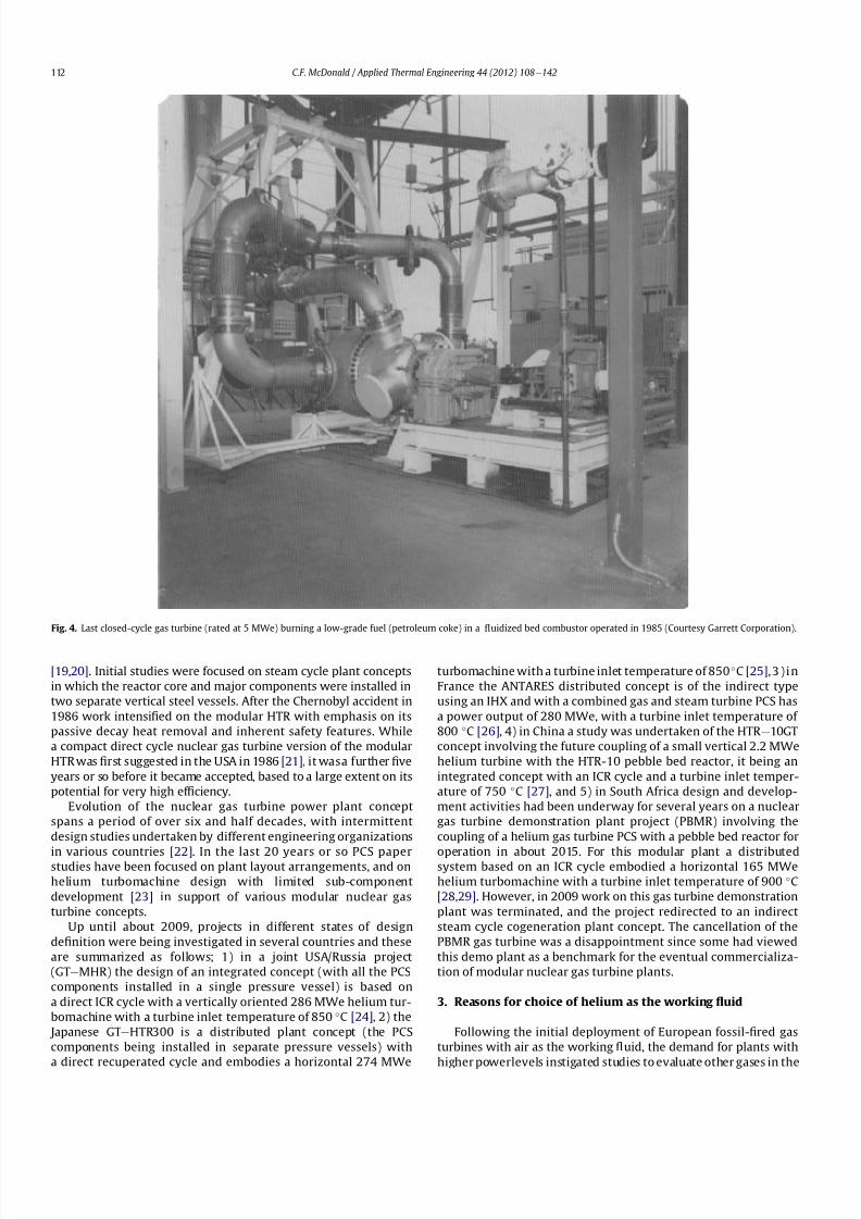
8112019 Helium Turbomachinery Operating Experience From Gas Turbine Power Plants
httpslidepdfcomreaderfullhelium-turbomachinery-operating-experience-from-gas-turbine-power-plants 535
[1920] Initial studies were focused on steam cycle plant concepts
in which the reactor core and major components were installed in
two separate vertical steel vessels After the Chernobyl accident in
1986 work intensi1047297ed on the modular HTR with emphasis on its
passive decay heat removal and inherent safety features While
a compact direct cycle nuclear gas turbine version of the modular
HTR was 1047297rst suggested in the USA in 1986 [21] it wasa further 1047297ve
years or so before it became accepted based to a large extent on its
potential for very high ef 1047297ciency
Evolution of the nuclear gas turbine power plant concept
spans a period of over six and half decades with intermittent
design studies undertaken by different engineering organizations
in various countries [22] In the last 20 years or so PCS paperstudies have been focused on plant layout arrangements and on
helium turbomachine design with limited sub-component
development [23] in support of various modular nuclear gas
turbine concepts
Up until about 2009 projects in different states of design
de1047297nition were being investigated in several countries and these
are summarized as follows 1) in a joint USARussia project
(GTeMHR) the design of an integrated concept (with all the PCS
components installed in a single pressure vessel) is based on
a direct ICR cycle with a vertically oriented 286 MWe helium tur-
bomachine with a turbine inlet temperature of 850 C [24] 2) the
Japanese GTeHTR300 is a distributed plant concept (the PCS
components being installed in separate pressure vessels) with
a direct recuperated cycle and embodies a horizontal 274 MWe
turbomachine with a turbine inlet temperature of 850 C [25] 3 ) i n
France the ANTARES distributed concept is of the indirect type
using an IHX and with a combined gas and steam turbine PCS has
a power output of 280 MWe with a turbine inlet temperature of
800 C [26] 4) in China a study was undertaken of the HTR e10GT
concept involving the future coupling of a small vertical 22 MWe
helium turbine with the HTR-10 pebble bed reactor it being an
integrated concept with an ICR cycle and a turbine inlet temper-
ature of 750 C [27] and 5) in South Africa design and develop-
ment activities had been underway for several years on a nuclear
gas turbine demonstration plant project (PBMR) involving the
coupling of a helium gas turbine PCS with a pebble bed reactor for
operation in about 2015 For this modular plant a distributedsystem based on an ICR cycle embodied a horizontal 165 MWe
helium turbomachine with a turbine inlet temperature of 900 C
[2829] However in 2009 work on this gas turbine demonstration
plant was terminated and the project redirected to an indirect
steam cycle cogeneration plant concept The cancellation of the
PBMR gas turbine was a disappointment since some had viewed
this demo plant as a benchmark for the eventual commercializa-
tion of modular nuclear gas turbine plants
3 Reasons for choice of helium as the working 1047298uid
Following the initial deployment of European fossil-1047297red gas
turbines with air as the working 1047298uid the demand for plants with
higher powerlevels instigated studies to evaluate other gases in the
Fig 4 Last closed-cycle gas turbine (rated at 5 MWe) burning a low-grade fuel (petroleum coke) in a 1047298uidized bed combustor operated in 1985 (Courtesy Garrett Corporation)
CF McDonald Applied Thermal Engineering 44 (2012) 108e142112
8112019 Helium Turbomachinery Operating Experience From Gas Turbine Power Plants
httpslidepdfcomreaderfullhelium-turbomachinery-operating-experience-from-gas-turbine-power-plants 635
closed power conversion loop Performance analyses and compo-
nent design studies were undertaken for gases that included
helium nitrogen carbon dioxide various gas mixtures and
nitrogen tetroxide For terrestrial power generation considering
the size of the major components namely the turbomachine heat
exchangers casings ducts and the external fossil-1047297red heater itwas generally concluded that for plants rated up to about 30 MWe
air was the favored working 1047298uid from the standpoints of
simplicity conventionality and cost
For the nuclear gas turbine the choice of the working 1047298uid
involved considerations being given from both the reactor coolant
and power conversion system standpoints Studies by engineers
and physicists concluded that helium being neutronically neutral
and chemically inert was compatible with the reactor turboma-
chinery and heat exchangers and acceptable for plants with large
power outputs [30]
The speci1047297c heat of monatomic helium is 1047297ve times that of air
and since the compressor stage temperature rise varies inversely
as speci1047297c heat (for a given limiting blade speed) it follows that
the available temperature rise per stage when operating withhelium will be only one 1047297fth that of air and this of course means
that more stages (for a given pressure ratio) are required for
a helium axial 1047298ow compressor It is fortunate that the optimi-
zation (for maximum ef 1047297ciency) of a highly recuperated and
intercooled Brayton cycle results in a relatively low pressure ratio
(ie 25e30) hence the number of compressor and turbine stages
are fairly comparable with modern industrial open cycle gas
turbines [31]
Substitution of helium for air greatly modi1047297es the turbo-
machine aerodynamic requirements because the high sonic
velocity of helium removes Mach number effects The size of the
machine is essentially dictated by the choice of blade speed there
being an incentive to use the highest possible values commensu-
rate with stress limitations to reduce the number of stages since
the stage loading factor is inversely proportional to the square of
the blade speed In general aerothermal 1047298uid dynamic and
mechanical design methodologies from air-breathing gas turbines
are applicable but the effects that the properties of helium have on
the design of a turbomachine in a high pressure closed-cycle
system are recognized and include the following
- Low molecular weight and high speci1047297c heat results in a large
number of stages (for a given pressure ratio)
- Long slender rotor (rotor dynamic stability concerns)
- Speci1047297c heat 5 times that of air gives high speci1047297c power
- High hub-to-tip ratio blading (in HP compressor)
- Small blade heights (resulting from high pressure system)
- Low aspect ratio blading (large blade chords because of high
bending stress)
- Thicker blade pro1047297les (because of high bending stress)
- Small compressor annulus taper and turbine 1047298are
- High compressor and turbine ef 1047297ciencies
- low Mach number (less than 030)
- high Reynolds numbers (gt5 106
)- clean oxide free blades (in inert helium)
- blade tip clearances minimized (machine not subjected to
severe thermal transients)
The experience gained from helium turbomachines that have
operated in the USA and Germany are covered in the following
sections
4 Pioneer La Fleur helium gas turbine
In 1960 La Fleur Enterprises in Los Angeles initiated work on an
air separation plant that involved the coupling of a closed-cycle gas
turbine with a cryogenic facility Helium was chosen as the closed
cycle working 1047298
uid since the La Fleur process for air liquefaction
Fig 5 Closed-cycle gas turbine demonstration test facility operated in the UK in 1995 with a 1000 kW natural gas- 1047297red heat source (Courtesy British gas)
CF McDonald Applied Thermal Engineering 44 (2012) 108e142 113
8112019 Helium Turbomachinery Operating Experience From Gas Turbine Power Plants
httpslidepdfcomreaderfullhelium-turbomachinery-operating-experience-from-gas-turbine-power-plants 735
required that the working 1047298uid remain gaseous throughout the
system Details of the plant and the axial 1047298ow helium turboma-
chinery have been documented previously [3233] and are only
brie1047298y discussed here This small plant is important in the context
of this paper since it was the 1047297rst fossil-1047297red helium gas turbine
ever to operate
The temperatureeentropy diagram (Fig 6) and the rather
simplistic cycle diagram (Fig 7) are pertinent to understanding
the function of this plant It was not designed to generate
electrical power instead the useful output being ldquobleed heliumrdquo
The major component was the free-running axial 1047298ow helium
turbomachine The rotating assembly consisted of a helium power
turbine compressor and refrigeration turbine mounted on the
same shaft
In the closed Brayton cycle part of the system the helium exiting
the compressor was split with about half of the mass 1047298ow passing
through the hot recuperator and then 1047298owing through the natural
gas-1047297red external heater where the temperature was further
increased before entering the power turbine Exiting the turbine
the helium then 1047298owed through the other side of the recuperator
and after a further reduction in temperature in a precooler entered
the compressor
In the cryogenic part of the cycle the temperature of the other
half of the helium bled from the compressor was reduced in an
aftercooler and then further reduced in the cold recuperator It was
then expanded in a refrigeration turbine and reached the lowest
temperature in the system The cold helium then passes through
a condenser in which the air is lique1047297ed and after passing through
the other side of the cold recuperator enters the compressor
Because the temperature of this bleed helium stream is less than
that coming from the precooler the mixed temperature at the
compressor inlet is cooler thus reducing the compressor workrequired
An overall view of the La Fleur plant is shown on Fig 8 and the
major parameters and features are given on Table 1 From the onset
of the project conservative parameters were selected to ensure
that when constructed the plant would operate reliably and meet
the process requirements since funding available for the project
was limited
With a turbine inlet temperature of 650 C (1202 F) and
a system pressure of 125 MPa (180 psia) a compressor pressure
Fig 6 Temperatureeentropy diagram of La Fleur helium gas turbine plant
Fig 7 Cycle diagram of La Fleur helium gas turbine plant
CF McDonald Applied Thermal Engineering 44 (2012) 108e142114
8112019 Helium Turbomachinery Operating Experience From Gas Turbine Power Plants
httpslidepdfcomreaderfullhelium-turbomachinery-operating-experience-from-gas-turbine-power-plants 835
ratio of 15 was selected With modest stage loading a 16 stage axial
compressor was designed the welded rotor being shown on Fig 9
Fifty percent reaction blading was used throughout The axial
velocity was kept constant and with a low value of pressure ratio
the annulus taper was rather slight The target ef 1047297ciency for the
compressor was83 percent The blades were cast 410 stainless steel
and these were welded to forged discs since this was the lowest
cost type of construction at the timeFor the turbine a tip speed of 305 ms (1000 ftsec) was
conservatively selected the rotational speed being 19500 rpm
While not coupled to a generator to produce electrical power the
size of the constant speed free-running turbine was equivalent to
that in a machine rated in the 1000e2000 kW class A view of the
turbine rotor is given on Fig 10 The material for the investment
cast blades was Haynes 21 and these were welded to a Timken 16-
25-6 disc The turbine ef 1047297ciency goal was 85 percent
The rotor was supported on oil-lubricated bearings To avoid oil
ingress into the helium circuit the oil pump scavenge pump and
the other accessories were separately driven by electric motors As
also experienced in later closed-cycle gas turbine plants oil ingress
into the helium closed loop occurred this being traced to a poor
design of the oil seals Keeping the system leak-tight when
operating with such a low molecular weight gas was a major
challenge and this topic will be discussed later for other helium
systems operating at high pressure and temperature
In this small pioneer plant the worldrsquos 1047297rst helium turbo-
machine operated satisfactorily the major achievement being that
it proved the La Fleur cryogenic process for air liquefaction The
experience gained from this small prototype plant led to the
construction and operation of a larger fossil-1047297red helium closed-cycle gas turbine for a lique1047297ed gas cryogenic plant and this is
discussed in the following section
5 Escher Wyss helium gas turbine plant
Following the successful operation of the pioneer plant La Fleur
Corporation designed and built a cryogenic facility in Phoenix
Arizona in 1966 for the liquefaction of 90 tonsday of nitrogen The
helium turbomachine was developed and built in Zurich by Escher
Wysswho up to that date hadfabricated the majority of the closed-
cycle gas turbine plants in Europe [2] The thermodynamic cycle
(involving splitting the helium 1047298ow at the compressor exit)
resembled the aforementioned pioneer plant with the exception
that the compressor was separated into two sections to facilitate
Fig 8 Overall view of 1047297rst helium gas turbine (Courtesy La Fleur Corp)
CF McDonald Applied Thermal Engineering 44 (2012) 108e142 115
8112019 Helium Turbomachinery Operating Experience From Gas Turbine Power Plants
httpslidepdfcomreaderfullhelium-turbomachinery-operating-experience-from-gas-turbine-power-plants 935
intercooling [634] The major parameters and features of this plant
are summarized on Table 1
With a turbine inlet temperature of 660 C (1220 F) and
a system pressure of 122 MPa (177 psia) a compressor pressure
ratio of 20 was selected A cross-section of the turbomachine is
shown on Fig 11 The LP and HP compressors had 10 and 8 stages
respectively The compressors were designed with a degree of
reaction slightly above 100 percent based on the prevailing view by
Escher Wyss at the time that this had advantages for helium
compressors Since this philosophy was carried over into the next
much larger helium gas turbine (as covered in the following
section) the rationale for this aerothermal design decision is brie1047298y
addressed below
The degree of reaction can essentially be regarded as the ratio of
pressure rise (although accurately de1047297ned as the static enthalpy
rise) in the rotor with the total pressure rise through the combi-
nation of the rotor and stator In early British axial 1047298ow compres-
sors a value of 50 percent was adopted this enabling the same
blade pro1047297le to be used for the rotor and stator In contemporary
air-breathing gas turbines the compressor degree of reaction is not
a major design factor The effect that selected compressor rotor and
stator positioning and geometries have on the degree of reaction is
illustrated in a simple form on Fig 12 In the early years of closed-
cycle gas turbine work Escher Wyss in Switzerland advocateda degree of reaction of 100 percent or higher [35] With such
blading the gas enters and leaves the stage in an axial direction The
basic stage embodies a negative pre-whirl stator ahead of the rotor
With the stator blades acting as a nozzle it was felt that the
resulting acceleration in the stator had the effect of smoothing out
the 1047298ow providing the best possible conditions for the rotor
However such blading with high stagger and lowsolidity has a very
high relative velocity and attendant high Mach number and is not
used in machines with air as the working 1047298uid since the associated
losses would be excessive leading to low overall compressor ef 1047297-
ciency This type of stator-before-rotor high reaction arrangement
was felt to be advantageous for helium axial 1047298ow compressors to
reduce the number of stages since Mach number effects are not
encountered because the sonic velocity of helium is on the order of
three times that of air
Because of the properties of helium (ie low molecular weight
high speci1047297c heat higher adiabatic index etc) a higher number of
compressor and turbinestages for a given pressure ratio are needed
as mentioned previously An axial compressor with just over
a hundred percent reaction as in the Escher Wyss helium gas
turbine that operated in Phoenix has a greater enthalpy rise per
stage for a given tip speed this reducing the number of stages for
a given pressure ratio but the ef 1047297ciency is slightly lower Mini-
mizing the number of stages was important from the rotor dynamic
stability standpoint for the very long rotor assembly associated
Fig 9 La Fleur plant 16 stage compressor (Courtesy La Fleur Corp) Fig 10 La Fleur plant 4 stage helium turbine (Courtesy La Fleur Corp)
Table 1
Salient features of operated helium turbomachinery
Turbomachine Helium closed-cycle gas turbines Test facility Helium circulator
Facility La Fleur
gas turbine
Escher Wyss
gas turbine
Oberhausen 11
power plant
HHV
test loop
FSV HTGR
Country USA USA Germany Germany USA
Year 1962 1966 1974 1981 1976
Application Cryogenic Cryogenic CHP plant Development Nuclear plant
Heat source NG NG Coke oven gas Electrical NuclearPower MW 2 equiv 6 equiv 50 90 4
Cycle Recuperated ICR ICR Customized Steam
Compressor
Type Axial Axial Axial Axial Axial
No stages 16 10LP8HP 10LP15HP 8 1
Inlet press MPa 125 122 105285 45 473
Inlet temp C 21 22 25 820 394
Pressure ratio 15 20 27 113 102
Flow kgsec 73 11 85 212 110
In vol 1047298ow m3sec 35 55 50 107 32
Turbine
Type Axial Axial Axial Axial ST
No stages 4 9 11LP7HP 2 1
Inlet press MPa 18 23 165 50 e
Inlet temp C 650 660 750 850 e
In vol 1047298ow m3sec 30 57 67 98 e
Out vol 1047298ow m3
sec 36 85 120 104 e
Rotation speed rpm 19500 18000 55003000 3000 9550
Shaft type Single Single Twin (geared) Single Single
Generator type None None Conventional Elect motor e
CF McDonald Applied Thermal Engineering 44 (2012) 108e142116
8112019 Helium Turbomachinery Operating Experience From Gas Turbine Power Plants
httpslidepdfcomreaderfullhelium-turbomachinery-operating-experience-from-gas-turbine-power-plants 1035
with this intercooled helium axial compressor of the type shown on
Figs 11 and 13
In the high pressure helium environment a high degree of reaction leads to a rotor blading with longer chords and low aspect
ratio The larger chord length combined with low solidity results in
comparatively few compressor blades Low aspect ratio (de1047297ned as
the ratio of blade height to chord length) results in several effects
including the following 1) high stagger with wider chords results in
a greater overall machine bladed length 2) fewer blades per stage
3) relatively large area of casing and blade surface with adverse
frictional losses tending to give lower ef 1047297ciency and 4) a stiffer
blade section (also with a thicker pro1047297le) with the needed strength
to combat bending stress which can be signi1047297cant in a high pres-
suredensity helium closed-cycle system A way to partially balance
out the bending stress would be by leaning the blades and off-
setting the blade cross-section centre of gravity For the early
helium gas turbine plants a view expressed by Escher Wyss wasthat the use of high reaction blading gave the maximum attainable
head a 1047298atter pressureevolume characteristic and a better surge
margin [36] The merits of increased pressure rise per stage asso-
ciated with high reaction blading has to be put into perspective by
its lower values of ef 1047297ciency [37]
The turbine had 9 stages and a rotational speed of 18000 rpm
While not coupled with a generator the equivalent output of the
free-running turbine was on the order of 6000 kW An overall view
of the long slender rotor is shown on Fig 13 and the turbomachine
assembly being installed in a cylindrical horizontally split casing is
shown on Fig 14 The major 1047298anges had peripheral lip seals to
facilitate welding closure to ensure leak tightness
With an external gas-1047297red heater the plant operated for about
5000 h and the helium gas turbine proved to be mechanically
sound and met its speci1047297ed performance This very specialized
plant proved to be too expensive to operate for the limited market
for cryogenic 1047298uids Anticipated market growth in the late 1960sdid not materialize and while the machinery performed satisfac-
torily the customer Dye Oxygen withdrew the plant from service
As far as the helium gas turbine was concerned the plant repre-
sented a signi1047297cant milestone since the technology generated was
applied to a follow-on helium gas turbine which at this stage was
still to be fossil-1047297red but now with the long-term goal in mind of
paving the way for the eventual operation of a helium closed-cycle
gas turbine power plant with a high temperature nuclear heat
source
6 Oberhausen II helium gas turbine plant at EVO
61 Closed-Cycle gas turbine experience at EVO
With initial operation starting in 1960 the municipal energy
utility (EVO) of the city of Oberhausen in the German industrial
Ruhr area deployed a closed-cycle gas turbine plant Referred to as
Oberhausen I the plant (shown previously on Fig 3) operated in
a combined power and heat mode with an electrical output of
14 MW and the thermal heat rejection of about 20 MW was
supplied to the cityrsquos district heating system The external heater
was initially 1047297red with Bituminous coal and in 1971 a change was
made to use coke-oven gas that had become available While using
air as the working 1047298uid some of the technical dif 1047297culties experi-
enced with this plant are highlighted below simply because if they
were to occur in a future direct cycle nuclear gas turbine plant they
would be very costly and time consuming to resolve as will be
discussed in a following section
Fig 11 Cross-section view of helium gas turbine (Courtesy Escher Wyss)
CF McDonald Applied Thermal Engineering 44 (2012) 108e142 117
8112019 Helium Turbomachinery Operating Experience From Gas Turbine Power Plants
httpslidepdfcomreaderfullhelium-turbomachinery-operating-experience-from-gas-turbine-power-plants 1135
In 1963 after 20000 h of operation a failure in the HP
compressor occurred [10] A rotor blade in the 1047297rst stage failed at
the root and in passing through the compressor caused extensive
damage The failure necessitated replacing the complete HP
compressor rotor assembly From a metallurgical examination of
the broken parts the failure was attributed to a small crevice at the
edge of the blade It was postulated that a corrosive action due to
impurities in the closed-loop working 1047298uid (ie air) in1047298uenced the
propagation of the crevice and blade vibration eventually caused
the failure To prevent a further failure of this kind an electric
polishing procedure was applied to the surface of the blade to
detect any imperfections
In 1967 debris from within the closed circuit caused damage to
the rotor blades and stators of several stages in the LP compressor
In 1973 further damage in the LP compressor due to blade vibration
required blading replacement During these de-blading events the
failed fragments were contained within the machine casings Using
conventional equipment the split casings of this machine were
opened and the failed parts removed by hands-on operations New
parts were then installed and the rotor assembly re-balanced The
problems were resolved and this closed-cycle gas turbine plant
with air as the working 1047298uid then performed well over the years
with high reliability [38]Rotor vibrations are mentioned here because they had caused
problems in three fossil-1047297red closed-cycle gas turbine plants using
air as the working 1047298uid namely1) in the John Brown 12 MW Plant
in Dundee where insurmountable vibration problems occurred [2]
2) multiple blade failures in the Spittelau 30 MW plant [2] and 3)
compressor blade failures in the aforementioned Oberhausen plant
As will be mentioned in a following section a further turbine blade
failure was experienced in a larger plant using helium as the
working 1047298uid
Correcting the subsequent blade failure damage to the turbo-
machine in a fossil-1047297red plant was straightforward however the
implication of such an operation in a future direct cycle nuclear gas
turbine with radioactively contaminated blading would be far more
severe This would likely require complex remote handling equip-ment and a dedicated facility for machine decontamination and
disassembly before hands-on repair could be undertaken
The Oberhausen I plant operated for about 120000 h and was
decommissioned in 1982 In about 1971 an expansion of the utilityrsquos
Fig 12 Impact of compressor blading geometry on degree of reaction (Courtesy
Escher Wyss)
Fig 13 Intercooled axial 1047298
ow helium turbomachine rotating assembly (Courtesy Escher Wyss)
CF McDonald Applied Thermal Engineering 44 (2012) 108e142118
8112019 Helium Turbomachinery Operating Experience From Gas Turbine Power Plants
httpslidepdfcomreaderfullhelium-turbomachinery-operating-experience-from-gas-turbine-power-plants 1235
capacity was needed due to increasing demand A larger fossil-1047297red
closed-cycle cogeneration plant of conventional design and still
retaining the use of air as the working 1047298uid was initially foreseen
but an emerging German development in the nuclear power plant
1047297eld resulted in a different decision being made as discussed
below
62 Relevance of the Oberhausen II helium turbine
Starting in 1972 development work sponsored by the Federal
Republic of Germany within the scope of the 4th Atomic program
was initiated on a high temperature reactor power plant with
a helium gas turbine (HHT) The reference plant design was based
on a large single-shaft intercooled helium turbine rated at
1240 MW A demonstration plant rated at 676 MW was planned
but prior to the construction of this it was necessary to test the
most important components to reduce risk Details of the two
major facilities to accomplish this have been reported previously
[39] and are summarized as follows
The Oberhausen II helium gas turbine plant was designed andbuilt to perform two major functions 1) it had to operate as
a commercial venture to provide electrical power (50 MWe) and
district heating (53 MWt) for the city of Oberhausen and 2) provide
data applicable to the nuclear gas turbine project particularly the
dynamic behavior of the overall plant and the integrity and long-
term operating experience of the major components in a helium
environment especially the turbomachine
The second facility was the HHV an experimental plant for
testing under representative conditions with respect to machine
size operating temperature pressure and mass 1047298ow of a large
helium turbomachine The facility was extensively instrumented to
gatherdata in the following areas rotorcooling system veri1047297cation
thermal insulation integrity 1047298ow characteristics blading ef 1047297ciency
acoustics rotor dynamic stability bearings dynamic and static
seals system leak tightness and metals behavior for the full
spectrum of plant operations including plant startup load change
shutdown upset conditions etc Details of the HHV facility and
testing undertaken are given in a later section
63 Oberhausen II helium gas turbine plant design
The design and construction of the plant was based on joint
efforts between EVO (plant designer and operator) GHH (turbo-
machine recuperator coolers and controls) Sulzer (helium
heater) and the University of Hannover Institute for Turboma-
chinery which contributed to the designwork and monitoring plant
performance
For the future planned nuclear gas turbine plant design values
of the temperature and pressure at the turbine inlet were 850 C
(1562 F) and 60 MPa (870 psia) respectively Attainment of this
temperature in the Oberhausen II plant could not be achieved and
750 C (1382 F) was selected based on tube material stress
considerations in the external coke-oven gas 1047297red heater An
intercooled and recuperated closed cycle was selected and themajor features of the plant are given on Table 1 The salient
parameters are given on the simpli1047297ed cycle diagram (Fig 15)
While rated at 50 MW a maximum system pressure of only
285 MPa (413 psia) was chosen so that the helium volumetric 1047298ow
(hence size of the bladed passages) would correspond to a much
larger helium turbomachine (on the order of 300 MW in fact) This
together with a rotational speed of 5500 rpm for the HP group
would result in representative stress loadings and would permit
a reasonable extrapolation to the machine size planned for the
nuclear demonstration plant
For the intercooled and recuperated cycle a compressor pressure
ratio of 27 was selected The helium mass 1047298ow rate was 85 kgs
(187 lbsec) and the circuit pressure loss was estimated at 104
percent Based on state-of-the-art component ef 1047297
ciencies and
Fig 14 Intercooled helium turbomachine with an equivalent power rating of 6000 kW installed in a split-case steel pressure vessel (Courtesy Escher Wyss)
CF McDonald Applied Thermal Engineering 44 (2012) 108e142 119
8112019 Helium Turbomachinery Operating Experience From Gas Turbine Power Plants
httpslidepdfcomreaderfullhelium-turbomachinery-operating-experience-from-gas-turbine-power-plants 1335
a recuperator effectiveness of 87 percent the projected thermal
ef 1047297ciency was 326 percent gross and 313 percent net
The isometric sketch of the distributed power conversion
system shown on Fig 16 (from Ref [40]) is convenient for
describing the plant layout A decision was made [41] to install the
horizontal turbomachinery in three large steel vessels the group-
ings being as follows 1) LP compressor rotor 2) HP compressor and
HP turbine grouping and 3) LP turbine The 1047297rst two assemblies
were on a single-shaft with a rotational speed of 5500 rpm The
generator with a rotational speed of 3000 rpmis driven from the LP
turbine end The rotors were geared together but with the selected
shafting arrangement only a small amount of power was trans-
mitted through the gearbox This con1047297guration was established
so that the dynamic behavior would be the same as in the large
single-shaft reference nuclear gas turbine plant design concept
The arrangement of the three vessels can be clearly seen on Fig 17
The horizontal tubular recuperator is positioned below the
turbomachinery The tubular precoolers and intercoolers are
installed in vertical steel vessels This type of orientation of the
major components was used in some of the earlier closed-cycle
plants using air as the working 1047298uid
Power regulation was achieved by inventory control as in the
aforementioned Oberhausen I plant which meant that the system
pressure (hence mass 1047298ow) was changed as required To lower the
power output helium was extracted from the loop after the HP
compressor through a control valve into a storage vessel For
a power increase helium was returned from the storage vessel into
the system upstream of the LP compressor without the need for an
additional blower With this arrangement the turbine inlet
temperature and speed remained constant and plant ef 1047297ciency
would be essentially constant down to a very low power level [42]
To achieve rapid load changes a bypass valve was included in the
system in which helium was transferred in a line between the HP
compressor exit end and LP end of the recuperator A very rapid
change from 100 percent load to no-load operation and back was
demonstrated [43]
64 Helium turbomachinery
The major features and parameters for the turbomachine are
given on Table 2 and are summarized as follows A longitudinal
cross-section of the turbomachine is shown on Fig 18 At the left
hand end the LP compressor is installed in a spherical pressure
vessel A high degree of reaction (ie 100 percent) was selected for
this 10 stage axial compressor this practice following the experi-
ence of an earlier discussed helium turbomachine A view showing
the bladed rotor of the LP compressor installed in the pressure
vessel split casing is shown on Fig19 with an appreciation for the
size of the spherical casing being shown on Fig 20 Both the HP
compressor and HP turbine rotors are installed in a common
housing as shown in the turbomachine cross-section (Fig 21) and
Fig 15 Oberhausen II helium gas turbine cycle diagram
Fig 16 Isometric layout of Oberhausen II helium gas turbine power conversion system (Courtesy EVO)
CF McDonald Applied Thermal Engineering 44 (2012) 108e142120
8112019 Helium Turbomachinery Operating Experience From Gas Turbine Power Plants
httpslidepdfcomreaderfullhelium-turbomachinery-operating-experience-from-gas-turbine-power-plants 1435
in the view with the HP rotor assembly positioned above the
horizontal split casing (Fig 22) The 15 stage HP compressor was
again designed with 100 percent reaction blading The HP turbine
has 7 stages and operated with an inlet temperature of 750 C
(1382O F) A cross-section of the 11 stage LP turbine installed in
a separate spherical vessel is shown on Fig 23 The amount of
power transmitted in the gearbox between the HP and LP turbinesis small since at rated output the HP turbine power level is only
slightly more than is needed to drive both compressors
The rotor of the HP group is supported on two oil-lubricated
bearings For the complete rotating assembly the thrust bearing is
located at the warm end of the LP compressor The six turbo-
machine bearing housings were designed such that direct access to
the large oil bearings was possible without having to open the large
casings This was done to reduce maintenance time because the
large split casings have 1047298anges that were welded closed at the
peripheral lip seals to minimize helium leakage
Special attention was given to the design of the cooling system
for the rotor In the case of this plant with a turbine inlet
temperature of 750 C the turbine blades themselves based on the
use of an existing superalloy did not have to be internally cooledbut cooling gas bled from the HP compressor outlet 1047298owed through
the hollow shaft and was used to cool the turbine discs and the
blade root attachments and then returned downstream of the
turbine
In a closed-cycle gas turbine the powerlevel can be regulated by
means of changing the system pressure and careful attention must
be given to the design of the various sealing systems to accom-
modate pressure differentials within the system particularly
during transient operation To simulate what would be needed in
a direct cycle nuclear gas turbine (to prevent 1047297ssion products
coming into contact with the bearing lubricating oil) a system
having a separate chamber for each of the three labyrinth seals was
incorporated in the machine design Outboard of the labyrinth seals
where the shafts penetrate the casings there were two further
seals a 1047298oating ring seal and a shutdown seal to prevent external
helium leakage
65 Helium turbomachine operating experience
Various presentations papers and publications have previously
covered the over 13 year operation of the Oberhausen II helium gas
turbine plant [43e48] The experience gained with the operation
Fig 17 Overall view of Oberhausen II 50 MWe helium gas turbine power plant (Courtesy EVO)
Table 2
Oberhausen II plant helium turbomachinery
Plant design electrical power MW 50
District heating thermal supply MW 535
Plant design ef 1047297ciency at terminals 313
Thermodynamic cycle ICR
Control method Helium inventory
compressor bypass
Rotor arrangement 2 Shaft (geared together)
Helium mass 1047298ow kgsec 85
Overall pressure ratio 27
Generator ef 1047297ciency 98
Design system pressure loss 104Compressor LP HP
Inlet pressure MPa l05 l54
Inlet temperature C 25 25
Vol 1047298ow inletoutlet m3s 5040 4025
Ef 1047297ciency 870 855
Rotational speed rpm 5500 5500
Number of stages 10 15
Blade height inletoutlet mm 10385 7253
Turbine LP HP
Inlet pressure MPa 165 270
Inlet temperature C 582 750
Ef 1047297ciency 900 883
Rotational speed rpm 3000 5500
Number of stages 11 7
Vol 1047298ow inletoutlet m3sec 92120 6792
Blade height inletoutlet mm 200250 150200
CF McDonald Applied Thermal Engineering 44 (2012) 108e142 121
8112019 Helium Turbomachinery Operating Experience From Gas Turbine Power Plants
httpslidepdfcomreaderfullhelium-turbomachinery-operating-experience-from-gas-turbine-power-plants 1535
of the large axial 1047298ow helium turbomachine is summarized asfollows
On the positive side the following were accomplished The rotor
helium buffered bearing labyrinth oil sealing system was one of the
numerous systems that worked well from the onset This was
encouraging since the external leakage of helium contaminated by
1047297ssion products and the ingress of lubricating oil into the closed
helium loop during the projected plant lifetime of 60 years are of
concern to designers of a direct cycle nuclear gas turbine plant (for
a machine with oil bearings) because of the likely long plant
downtime for cleanup and repair
With some modi1047297cations the helium puri1047297cation system
worked well with the purity level within the speci1047297cation The
helium cooling systems worked well to keep the temperatures of
the turbine discs blade root attachments and casings at speci1047297
edlevels Load change by inventory control was done routinely and
the ability to shed 100 percent of the load in a very short period by
means of the bypass valve was demonstrated The integrity of the
co-axial turbine inlet hot gas duct was proven At the end of plant
operation the major turbomachine casings were opened and there
were no signs of corrosion or erosion of the turbine or compressor
blades The coatings applied to mating metallic surfaces were
effective with no evidence of galling or self-welding in the oxygen-
free closed-loop helium environment
Experience from previously operated high temperature helium
cooled nuclear reactor power plants (with Rankine cycle steam
turbine power conversion systems) demonstrated that absolute
helium leak tightness was not attainable This was also true in the
Oberhausen II fossil-1047297red gas turbine plant where during initial
operation the helium leakage was about 45 kg per day Attention
was given to this and helium losses were reduced to the range of
5e10 kg per day principally by seal welding the major 1047298anges This
value can be compared with other closed loop helium systems as
shown below
On the negative side several unexpected problems had a majorimpact on the operation of the plant Following initial running of
the machine at 3000 rpm in preparation to synchronizing the
system the HP casing was opened for inspection revealing
damage to the labyrinth seals this being caused by shifting of
the rotor in the axial direction The labyrinth seals were replaced
and the turbine was 1047297rst synchronized with the grid on November
8 1975
Subsequent vibration problems were encountered and the HP
shaft oscillation became so large that it caused damage to the
bearings and the design value of speed and power could not be
maintained and the plant was shut down This was initially thought
to be due to thermal distortion of the rotor and a large unbalance
Fig 18 Cross-section of Oberhausen II plant helium turbomachinery rotating assembly (Courtesy EVO)
Fig 19 Oberhausen II low pressure helium compressor installed in casing (Courtesy
GHH)
Plant Helium inventory kg Leakage
kgday day
Dragon 180 020e20 010e10
AVR 240 10e30 040e12
Oberhausen II 1400 5e10 035e070
HHV 1250 25e50 020e040
FSV e Excessive leakage
CF McDonald Applied Thermal Engineering 44 (2012) 108e142122
8112019 Helium Turbomachinery Operating Experience From Gas Turbine Power Plants
httpslidepdfcomreaderfullhelium-turbomachinery-operating-experience-from-gas-turbine-power-plants 1635
Modi1047297cations to the rotor were made and the bearings replaced
but now the HP spool design speed of 5500 rpm could not be
achieved Subsequent major design and fabrication changes were
made including decreasing the bearing span by 600 mm (24 in)
giving a shorter stiffer rotor and changing the type of bearings In
restarting the plant the design speed of the HP rotor was achieved
however the power output was only 30 MW compared with the
design value of 50 MW
Fig 20 View of Oberhausen II low pressure helium compressor spherical vessel (Courtesy GHH)
Fig 21 Cross-section of Oberhausen II high pressure rotating group (Courtesy GHH)
CF McDonald Applied Thermal Engineering 44 (2012) 108e142 123
8112019 Helium Turbomachinery Operating Experience From Gas Turbine Power Plants
httpslidepdfcomreaderfullhelium-turbomachinery-operating-experience-from-gas-turbine-power-plants 1735
To gain operational experience it was decided to continue
running the plant at the reduced power rating On February 5 1979
after nearly 11000 h of operation a rotor blade from the second
stage of the HP turbine failed causing damage in the remaining
stages but the high energy fragments were contained within the
thick machine casing Examination of the failed blade revealed the
defect as a crack caused by the forgingprocess on the semi-1047297nishedproduct To prevent such a failure occurring in the future an electric
polishing process applied to the blade surface before inspection
was implemented and improved crack detection methods
introduced
Acoustic loads in a closed-cycle gas turbine represent pressure
1047298uctuations propagating at the speed of sound through the helium
working 1047298uid Pressure 1047298uctuations of importance result from the
aerodynamic effects of high velocity helium impacting and
essentially being intermittently ldquocutrdquo by the blading in the
compressor and turbine Care must be taken in the design of the
plant to ensurethat these 1047298uctuating pressure waves do not induce
vibrations of a magnitude that could result in excitation-induced
fatigue failures in components in the circuit Critical vibrations
occur when resonance exists between the main frequency of
the propagating sound and the natural frequencies of the
components particularly ones that have large surface area to
thickness ratio
Measurements of sound spectrum were taken at four different
locations in the circuit The design level of power of 50 MW was not
achieved but at the 30 MW power output actually realized the
maximum recorded sound power level was 148 dB After plantshutdown there was no evidence of adverse effects on the major
components of noise induced excitation emanating from the axial
1047298ow turbomachinery The integrity of the turbine inlet hot gas duct
and insulation was con1047297rmed
The inability to reach rated power was attributed to shortcom-
ings in the helium turbomachine This included the compressors(s)
and turbine(s) blading failing to attain design values of ef 1047297ciencies
and the bleed helium mass 1047298ows for cooling and sealing being
signi1047297cantly greater than analytically estimated Based on data
taken from the well instrumented plant detailed analyses were
undertaken by specialists [4950] to calculate the losses in the
turbomachine to explain the power output de1047297ciency A summary
of the projected losses and various component ef 1047297ciencies is pre-
sented in a convenient form on Table 3
Fig 22 Oberhausen II high pressure rotor being installed (Courtesy GHH)
CF McDonald Applied Thermal Engineering 44 (2012) 108e142124
8112019 Helium Turbomachinery Operating Experience From Gas Turbine Power Plants
httpslidepdfcomreaderfullhelium-turbomachinery-operating-experience-from-gas-turbine-power-plants 1835
The plant operated for approximately 24000 h and was shut-
down and decommissioned in 1988 when the coke-oven gas supply
for the heater was no longer available A total plant operating time
of about 11500 h had been at the design turbine inlet temperature
of 750 C (1382 F) Turbomachinery related experience gained
from operation of this large helium gas turbine plant was extremely
valuable While many of the functions performed well from the
onset and others worked satisfactorily after modi1047297cations were
made serious unexpected problems were encountered
The achieved electrical power output of only 60 percent of the
design value was initially thought to be due to a grossly excessive
system pressure loss However when the data was carefully eval-uated it was found that 85 percent of the 20 MW power loss was
attributed to turbomachine related problems as delineated on
Table 3
To remedy this power de1047297ciency it was clear that a major re-
design of the turbomachinery would be required While replace-
ment of the gas turbine was not contemplated a study was
undertaken based on data from the plant and new technologies
that had become available since the initial design Based on the
1047297ndings a new turbomachine layout concept was suggested [43]
and a simplistic view of the rotor arrangement is shown on Fig 24
A more conventional single-shaft arrangement was proposed with
the two compressors and turbine having a rotational speed of
5400 rpm A gearbox was still retained to give a generator rota-
tional speed of 3000 rpm Based on prevailing technology at the
time the requirements for such a gearbox would have been moredemanding since the 50 MW from the turbine to the generator
would have to be transmitted through it This would necessitate
a larger system to pump 1047297lter and cool the bearing lubrication oil
To remedy the very large losses in the compressors and turbines
the number of stages would have to be increased In the case of the
compressors the use of lighter aerodynamically loaded higher
ef 1047297ciency stages with 50 percent reaction blading was
recommended
7 High temperature helium test facility (HHV)
71 Background
In the late 1960rsquos with large numbers of orders placed for 1047297rst
generation light water reactor nuclear power plants studies were
initiated for next generation power plants with higher ef 1047297ciency
potential Following the initial operational success of the 1047297rst three
small helium cooled HTR plants (ie Dragon in the UK Peach
Bottom I in the USA and AVR in Germany) studies on larger plants
based on the use of both Rankine steam cycle and helium closed
Brayton cycle power conversion systems were undertaken In the
early 1970rsquos emphasis was placed on nuclear gas turbine plant
designs with larger power output both in the USA (for the
HTGR eGT) and in Europe (for the HHT) Work in the USA was
limited to only paper studies [18] The much larger program in
Germany (with participation by Swiss companies for the turbo-
machine heat exchangers and cooling towers) included a well
planned development testing strategy to support the plant design
Fig 23 Cross-section of Oberhausen II low pressure helium turbine (Courtesy GHH)
Table 3
Oberhausen II helium turbine plant power losses
Componentcause Design
value
Measured Power loss
MW
Compressors
B Flow losses in inlet diffusers
and blades
Low pressure ef 1047297ciency 870 826 13
High pressure ef 1047297ciency 855 779 40
Turbines
B Blade gap and 1047298ow losses
High pressure ef 1047297ciency 883 823 39
B Pro1047297le losses due to Remachined
blades after having detected
damaged blades
Low pressure ef 1047297ciency 900 856 24
BSealing leakage and cooling 1047298ows
in all turbomachines Kgsec
18 75 53
B Circuit pressure losses
(Ducting Hxrsquos etc)
102 128 26
B Miscellaneous heat losses 05
Total power loss 200 MW
Notes (1) Plant designed for electrical power output of 50 MW actual power output
measured 30 MW
(2) Power de1047297ciency of20 MW based on measurements taken and then recalculated
for the rated plant output
(3) 85 of Power loss attributed to helium turbomachinery related issues
CF McDonald Applied Thermal Engineering 44 (2012) 108e142 125
8112019 Helium Turbomachinery Operating Experience From Gas Turbine Power Plants
httpslidepdfcomreaderfullhelium-turbomachinery-operating-experience-from-gas-turbine-power-plants 1935
While the reference HHT plant for eventual commercializationembodied a very large single helium gas turbine rated at 1240 MW
this was to be preceded by a nuclear demonstration plant rated at
676 MW [51] To support the design of this plant technology
generated from the following was planned 1) operational experi-
ence from the aforementioned Oberhausen II 50 MW helium gas
turbine power plant and 2) testing of components in a large high
temperature helium test facility as discussed below
72 Development facilitytesting objectives
An overall view of the HHV test facility sited in Julich in
Germany is shown on Fig 25 and since this has been reported on
previously [52] it will only be brie1047298
y covered in this section Tominimize risk and assure the performance integrity and reliability
of the nuclear demonstration plant some non-nuclear testing of
the major components especially the helium turbomachine was
deemed essential Because of the limitations of a conventional
closed-cycle helium gas turbine power plant particularly the
temperature limitations of existing fossil-1047297red and electrical
heaters a new type of test facility was foreseen
A simpli1047297ed schematic line diagram of the HHV circuit is shown
on Fig 26 The major design parameters are shown on Fig 27
together with the temperatureeentropy diagram which is conve-
nient for describing the unique relationship between the compo-
nents in the closed helium loop Starting at the lowest pressure in
Fig 24 Proposed new concept for Oberhausen II helium gas turbine rotating assembly to remedy problems encountered during operation of the 50 MWe power plant (Courtesy
EVO)
Fig 25 HHV helium turbomachinery test facility (Courtesy BBC)
CF McDonald Applied Thermal Engineering 44 (2012) 108e142126
8112019 Helium Turbomachinery Operating Experience From Gas Turbine Power Plants
httpslidepdfcomreaderfullhelium-turbomachinery-operating-experience-from-gas-turbine-power-plants 2035
the system the helium is compressed (Ae
B) its temperatureincreasing to 850 C (1562 F) before 1047298owing through the test
section (BeC) After being cooled slightly (CeD) the helium is
expanded in the turbine (DeA) down to the compressor inlet
conditions completing the loop There is no power output from the
system and without the need for an external heater the
compression heat is used to raise the helium to the maximum
system temperature in what can be described as a very large heat
pump The required compressor power is 90 MW and to supple-
ment the 45 MW generated by expansion in the turbine external
power is provided by a 45 MW synchronous electrical motor A
cooler is required to remove the compression heat that is contin-
uously put into the closed helium loop and this is done by bleeding
about 5 percent of the mass 1047298ow after the compressor cooling it
and re-introducing it into the circuit close to the turbine inlet In
addition to testing the turbomachine the facility was engineered
with a test section to accommodate other small components (eg
hot gas 1047298ow regulation valves bypass valves insulation con1047297gu-
rations and types of hot gas duct construction) With the highest
temperature in the system being at the compressor exit the facility
had the capability to provide helium at a temperature up to 1000 C
(1832 F) for short periods at the entrance to the test section
While a higher ef 1047297ciency of the planned nuclear demonstration
plant could be projected with a turbine inlet temperature in the
range 950e1000 C (1742e1832 F) this would have necessitated
either turbine blade cooling or the use of a high temperature alloy
such as Titanium Zirconium Molybdenum (TZM) At the time it was
felt that using either of these would have added cost and risk to theprojectso a conventionalnickel-basedalloyas usedin industrialgas
turbines was selected for the 850 C design value of turbine inlet
temperature this negating the needfor actual internal bladecooling
However a complex internal coolingsystemwas neededto keep the
Fig 26 Cycle diagram of HHV test loop (Courtesy BBC)
Fig 27 Salient features of HHV helium turbomachinery (Courtesy BBC)
CF McDonald Applied Thermal Engineering 44 (2012) 108e142 127
8112019 Helium Turbomachinery Operating Experience From Gas Turbine Power Plants
httpslidepdfcomreaderfullhelium-turbomachinery-operating-experience-from-gas-turbine-power-plants 2135
turbine discs and blade root attachments and casings to acceptable
temperatures commensurate with prescribed stress limitations for
thelife of theturbomachine In addition a heliumsupplywas needed
to provide a buffering system for the various labyrinth seals
In a direct Brayton cycle nuclear gas turbine the turbomachine is
installed in the reactor circuit and via the hot gas duct heated
helium is transported directly from the reactor core to the turbine
From the safety licensing and reliability standpoints there are
various seals that must perform perfectly A helium buffered
labyrinth seal system is necessary to prevent bearing lubricating oil
ingress to the closed helium loop Since in the proposed HHT plant
design the drive shaft from the turbine to the generator penetrates
the reactor primary system pressure boundary two shaft seals are
needed one a dynamic seal when the shaft is rotating and a static
seal when the turbomachine is not operating Testing of these seals
in a size and operating conditions representative of the planned
commercial power plant was considered to be a licensing must
The mechanical integrity of the rotating assembly must be
assured there being two major factors necessitating testing the
machine at full speed and temperature and at high pressure
namely 1) loading the blading under representative centrifugal and
gas bending stresses and 2) to monitor vibration and con1047297rm rotor
dynamic stability For the design of the planned commercial planta knowledge of the acoustic emissions by the turbomachine and
propagation in the closed circuit was required Data from the HHV
facility would enable dynamic responses of the major components
(especially the insulation) resulting from excitation by the sound
1047297eld to be calculated
The circuit was instrumented to gather data on the effectiveness
of the hot gas duct insulation thermal expansion devices hot gas
valves helium puri1047297cation system instrumentation and the
adequacy of the coatings applied to mating metallic surfaces to
prevent galling or self-welding Details of the turbomachinery and
the experience gained from the operation of the HHV facility are
covered in the following sections
73 Helium turbomachine
A cross-section of the turbomachine is shown on Fig 28 The
single-shaft rotating assembly consists of 8 compressor stagesand 2
turbine stages and had a weighton the order of 66 tons(60000 kg)
The hub inner and outer diameters are 16 m (525 ft) and 18 m
(59 ft) respectively the blading axial length being 23 m (75 ft)The
span between the oil bearings being 57 m (187 ft) The physical
dimensions of the turbogroup shown on Fig 28 correspond to
a machine rated at about 300 MW The oil bearings operate in
a helium environment and the diameters of the labyrinths and
1047298oating ring shaft seals to prevent oil ingress are representative of
a machine rated at about 600 MW The complexity of the machine
design especially the rotor cooling system sealing system very
large casing and heat insulation have been reported previously
[53e55]
To ensure high structural integrity the rotor was constructed by
welding together the forged compressor and turbine discs The
compressor had 8 stages each having 56 rotor and 72 stator blades
The turbine had 2 stages each having 90 stator and 84 rotor blades
An appreciation for the large size of the rotating assembly can be
seen from Fig 29 The rotor blades have 1047297r-tree attachments
embodying cooling channels Since the temperature and pressure
do not vary very much along the blading in the 1047298ow direction an
intricate rotor and stator cooling system was required Channels in
both the blade roots and the spacers between adjacent blade rows
form an axial geometry for the passage of a cooling helium supplyto keep the temperature of the multiple discs below 400 C
(752 F) The design of this was a challenge since the rotor and
stator blade attachments of both the 8 stage compressor and 2
stage turbine had to be cooled Excessive leakage had to be avoided
since this would have prevented the speci1047297ed compressor
discharge temperature (ie the maximum temperature in the
circuit) from being reached
In the 1970rsquos and early 1980rsquos signi1047297cant studies were carried
out on large helium gas turbines by various organizations [56e62]
In this era there was general agreement that testing of the turbo-
machine in one form or another in non-nuclear facilities be
undertaken to resolve areas of high risk (eg seals bearings cooling
systems rotor dynamic stability compressor surge margin
dynamic response rotor burst protection etc) before installationand operation of a large gas turbine in a nuclear environment
This low risk engineering philosophy which prevailed at the time
in both Germany and the USA emphasized the importance of
Fig 28 Cross-section of HHV helium turbomachinery (Courtesy BBC)
CF McDonald Applied Thermal Engineering 44 (2012) 108e142128
8112019 Helium Turbomachinery Operating Experience From Gas Turbine Power Plants
httpslidepdfcomreaderfullhelium-turbomachinery-operating-experience-from-gas-turbine-power-plants 2235
the HHV test facility as being an important step towards the
eventual deployment of a high ef 1047297ciency nuclear gas turbine power
plant
74 Initial operation of the HHV facility
During commissioning of the plant in 1979 oil ingress into the
helium circuit from the seal system occurred twiceThe 1047297rst ingressof oil between 600 and 1200 kg (1322 and 2644 lb) was due to
a serious operatorerror and the absence of an isolation valve in the
system The oil in the circuit was partly coked and formed thick
deposits on the cold and hot surfaces of the turbomachinery and in
other parts of the closed loop including saturation of the 1047297brous
insulation The fouled metallic surfaces were cleaned mechanically
and chemically by cracking with the addition of hydrogen and
additives The second oil ingress was due to a mechanical defect in
the labyrinth seal system The quantity of oil introduced was small
and it was removed bycracking at a temperature of 600 C (1112 F)
and with the use of additives To obviate further oil ingress inci-
dents the labyrinth seal system was redesigned The buffer and
cooling helium system piping layout was modi1047297ed to positively
eliminate oil ingress due to improper valve operation and toprevent further human error
Pressure and leak detection tests of the HHV test facility at
ambient temperature showed good leak tightness for the turbo-
machine 1047298anged joints and of the main and auxiliary circuits
However at the operating temperature of 850 C (1562 F) large
helium leaks were detected The major 1047298anges had been provi-
sioned with lip seals and the 1047297rst step was to weld the closures A
large leak persisted at the front 1047298ange of the turbomachine This
was diagnosed as being caused by a non-uniform temperature
distribution during initial operation resulting in thermal stresses
creating local gaps This problem was overcome by redesign of the
cooling system with improved gas 1047298ow distribution and 1047298ow rates
to give a more uniform temperature gradient The leakage from the
system was reduced to on the order of 020e
040 percent of the
helium inventory per day this being of the same magnitude as in
other closed helium circuits as discussed in Section 65
It should be mentioned that in addition to the HHV experience
bearing oil ingress into the circuits and system loss of the working
1047298uid in other closed-cycle gas turbine plants have occurred In all of
these fossil-1047297red facilities 1047297xing leaks and removal of oil deposits
were undertaken based on conventional hands-on approaches but
nevertheless such operations were time-consuming However if a new and previously untested helium turbomachine operating in
a direct cycle nuclear gas turbine plant experienced an oil ingress
the rami1047297cations would be severe The likely use of remote
handling equipment to remove the turbomachine from the vessel
machine disassembly (including breaking the welded 1047298ange joints)
and removal of oil from the radioactively contaminated turbo-
machine blade surfaces and system insulation would be time
consuming A diagnosis of the failure would be required before
a spare turbomachine could be installed and this plant downtime
could adversely affect plant availability
75 Experience gained
Afterresolutionof the aforementionedproblems the HHVfacilitywas started in the Spring of 1981 and in an orderly manner was
brought up to full pressure and a temperature of 850 C (1562 F)
During a 60 h run the functioning of the instrumentation control
and safety systems were veri1047297ed During these tests the ability to
stop the turbomachine from full operating conditions to standstill
within 90 s was demonstrated After system depressurization the
plant was then run up again to full operating conditions with no
problems experienced The HHV facility was successfully run for
about 1100 h of which theturbomachineryoperated forabout325 h
at a temperature of 850 C The test facility was extensively instru-
mented and interpretation and analysis of the data recorded gave
positive and favorable results in the following areas
The complex rotor cooling system which was engineered to
assure that the temperature of the discs be kept below 400
C
Fig 29 HHV helium turbomachine rotating assembly (size equivalent to a 300 MWe machine) being installed in a pressure vessel (Courtesy BBC)
CF McDonald Applied Thermal Engineering 44 (2012) 108e142 129
8112019 Helium Turbomachinery Operating Experience From Gas Turbine Power Plants
httpslidepdfcomreaderfullhelium-turbomachinery-operating-experience-from-gas-turbine-power-plants 2335
(752 F) was demonstrated to be effective The measured rotor
coolant 1047298ows (about 3 percent of the mass1047298ow passing through the
machine) were slightly larger than had been estimated and this
resulted in measured turbine disc temperatures lower than pre-
dicted [55]
The dynamic labyrinth shaft seal functioned well at the full
temperature and pressure conditions and met the requirement of
zero oil ingress into the helium circuit The measured rotor oscil-
lation did not have any adverse effect on the shaft sealing system
The static rotor seal (for shutdown conditions) functioned without
any problems
The compressor and turbine blading hadef 1047297ciencies higher than
predicted The structural integrity of the rotor proved to be sound
when operating at 3000 rpm under the maximum temperature and
pressure conditions The stiff rotor shaft had only slight unbalance
and thermal distortion and measured oscillations were in the range
typical of large steam turbines
Sound power spectrum measurements were taken in four
different locations in the circuit These were taken to determine the
spectrum and intensity of the sound generated and propagated by
the turbomachinery and the resultant vibration of internal
components The maximum sound power level in the helium
circuit was160 dB Numerous strain gages were placedin the circuitto determine the in1047298uence of the sound 1047297eld particularly on the
fatigue strength of the turbine inlet hot gas duct In later examining
the internal components there was no evidence of excessive
vibration of the components especially the ducting and the insu-
lation Based on the measurements and calculations it was
concluded that the fatigue strength limit of the components would
not be exceeded during the designed life of the planned commer-
cial nuclear gas turbine power plant
In a direct cycle nuclear gas turbine the hot gas duct used to
transport the helium from the reactor core to the turbineis a critical
component The hot gas duct in the HHV facility performed well
mechanically and con1047297rmed the adequacy of the thermal expan-
sion devices From the thermal standpoint the 1047297ber insulation
performed better than the metallic type
After dismantling the HHV facility there were no signs of
corrosion or erosion of the turbine or compressor blading While
the total number of hours operated was limited the coatings
applied to mating metallic surfaces to prevent galling and frictional
welding in the oxidation-free helium worked well
The helium buffer and cooling system worked well However
problems remained with the puri1047297cation of the buffer helium The
oil separation system consisting of a cyclone separator and a wire
mesh and a down stream 1047297ber 1047297lter needed further improvement
In late 1981 a decision was made to cancel the HHT project and
the HHV facility was shutdown The design and operational expe-
rience gained from the running of this facility would have been
extremely valuable had the nuclear gas turbine power plant
concept moved towards becoming a reality The identi1047297cation of
somewhat inevitable problems to be expected in such a complexturbomachine and their resolution were undertaken in a timely
and cost effective manner in the non-nuclear HHV facility This
should be noted for future nuclear gas turbine endeavors since
remedying such unexpected problems in the case of a new and
untested large helium turbomachine being operated for the 1047297rst
time using nuclear heat could result in very complex repair
Fig 30 Speci1047297
c speed-speci1047297
c diameter array for gas circulators in various gas-cooled nuclear plants
CF McDonald Applied Thermal Engineering 44 (2012) 108e142130
8112019 Helium Turbomachinery Operating Experience From Gas Turbine Power Plants
httpslidepdfcomreaderfullhelium-turbomachinery-operating-experience-from-gas-turbine-power-plants 2435
activities and extended plant downtime and indeed adding risk to
the overall success of the nuclear gas turbine concept
8 Circulators used in gas-cooled reactor plants
Circulators of different types will be needed in future helium
cooled nuclear plants these including the following 1) primary
loop circulator for possible next generation steam cycle power andcogeneration plants 2) for future indirect cycle gas turbine plants
3) shut down cooling circulators forall HTRand VHTR plants and 4)
for various circulators needed in future VHTR high temperature
process heat plant concepts The technology status of operated
helium circulators is brie1047298y addressed as follows
81 Background
It would be remiss not to mention experience gained in the past
with gas circulators and while not gas turbines they are rotating
machines that operate in the primary loop of a helium cooled
reactor With electric motor drives there are basically two types of
compressor rotor con1047297gurations namely radial and axial 1047298ow
machinesIn a single stage form the centrifugal impeller is used for high
stage pressure rise and low volume 1047298ow duties whereas the axial
type covers low pressure rise per stage and high volume 1047298ow The
selection of impeller type is very much related to the working
media type of bearings drive type rotor dynamic characteristics
and installation envelope A wide range of circulators have operated
and a well established technology base exists for both types [63] A
useful portrayal of compressor data in the form of quasi- non-
dimensional parameters (after Balje [64]) showing approximate
boundaries for operation of high ef 1047297ciency axial and radial types is
shown on Fig 30 (from Ref [65])
Both high speed axial and lower speed radial 1047298ow types are
amenable to gas oil and magnetic bearings From the onset of
modularHTR plant studies theuse of active magnetic bearings[6667]offered a solution to eliminate lubricating oil into the reactor circuit
and this tribology technology is attractive for use in submerged
rotating machinery in the next generation of HTR plants [68]
While now dated an appreciation of the main design features of
typical electric motor-driven helium circulators have been reported
previously namely an axial 1047298ow main circulator for a modular
steam cycle HTR plant [69] and a representative radial 1047298ow shut-
down cooling circulator [70]
The operating experience gained from three particular circula-
tors is brie1047298y included below because of their relevance to the
design of helium turbomachinery in future HTR plant variants
82 Axial 1047298ow helium circulator
Since all of the aforementioned predominantly European
helium gas turbines used axial 1047298ow turbomachinery it is of interest
to mention a helium axial 1047298ow circulator that operated in the USA
and to brie1047298y discuss its design parameters and features The
330 MW Fort St Vrain HTGR featured a Rankine cycle power
conversion system Four steam turbine driven helium circulators
were used to transport heat from the reactor core to the steam
generators The complete circulator assemblies were installed
vertically in the prestressed concrete reactor vessel [71e73]
A cross-section of the circulator is shown on Fig 31 with thecompressor rotor and stator visible on the left hand end of the
machine Based on early 1960rsquos technology a decision was made to
use water lubricated bearings and from the overall plant reliability
and availability standpoints this later proved to be a bad choice
Within the vertical circulator assembly there were four 1047298uid
systems namely the helium reactor coolant water lubricant in the
bearings steam for the turbine drive and high pressure water for
the auxiliary Pelton wheel drive During plant transients the pres-
sures and temperatures of these four 1047298uids oscillated considerably
and the response of the control and seal systems proved to be
inadequate and resulted in considerable water ingress from the
bearing cartridge into the reactor helium circuit The considerable
clean up time needed following repeated occurrences of this event
resulted in long periods of plant downtime and this had an adverseeffect on plant availability This together with other technical
Fig 31 Cross section of FSV helium circulator (Courtesy general Atomics)
CF McDonald Applied Thermal Engineering 44 (2012) 108e142 131
8112019 Helium Turbomachinery Operating Experience From Gas Turbine Power Plants
httpslidepdfcomreaderfullhelium-turbomachinery-operating-experience-from-gas-turbine-power-plants 2535
dif 1047297culties eventually contributed to the plant being prematurely
decommissioned
On the positive side in the context of this paper the helium
circulators operated for over 250000 h and exhibited excellent
helium compressor performance good mechanical integrity and
vibration-free operation The rotating assembly showing the axial
1047298ow compressor and steam turbine rotors together with a view of
the machine assembly are given on Fig 32 The helium compressor
consists of a single stage axial rotor followed by an exit guide vane
The machine was designed for axial helium 1047298ow entering and
leaving the stage and this can be seen from the velocity triangles
shown on Fig 33 which also includes the de1047297nition of the various
aerodynamic parameters Major design parameters and features of
this helium circulator are given on Table 4 Related to an earlier
discussion on the degree of reaction for axial 1047298ow compressors the
value for this conventional single stage circulator is 78 percent All
of the major aerothermal and structural loading criteria were
within established boundaries for an axial compressor having high
ef 1047297ciency and a good surge margin
The compressor gas 1047298ow path and blading geometries were
established based on prevailing industrial gas turbine and aero-
engine design practice A low Mach number (025) a high Reynolds
number (3 106) together with a modest stage loading (ie
a temperature rise coef 1047297cient of 044) and an acceptable value of
diffusion factor (042) were some of the factors that contributed to
a helium circulator that had a high ef 1047297ciency and a good pressure
rise- 1047298ow characteristic The large rotor blade chord and thick blade
section for this single stage circulator are necessary to accommo-
date the high bending stress characteristic of operation in a high
pressure environment The solidity and blade camber were opti-
mized for minimum losses
There were essentially two reasons for including this single-
stage axial 1047298ow compressor that operated in a helium cooled
reactor although its overall con1047297guration can be regarded as a 1047297rst
and last of a kind A rotor blade from this circulator as shown onFig 34 was based on a NASA 65 series airfoil which at the time
were one of the best performing cascades for such low Mach
number and high Reynolds number applications Interestingly it
has almost the same blade height aspect ratio and solidity as would
be used in the 1047297rst stage of an LP compressor in a helium turbo-
machine rated on the order of 250 MW
The second point of interest is that the helium mass 1047298ow rate
through the single stage axial compressor (rated at 4 MWe) is
110 kgs compared with 85 kgs through the multistage compressor
in the 50 MWe Oberhausen II helium gas turbine plant However
the volumetric 1047298ow through the Oberhausen axial compressor is
higher than that through the circulator by a factor of 16 this again
pointing out that the Oberhausen II plant was designed for high
volumetric 1047298ow to simulate the much larger size of turboma-chinery that was planned at the time in Germany for use in future
projected nuclear gas turbine power plants
83 High temperature helium circulator
For future helium turbomachines embodying active magnetic
bearings a challenge in their design relates to accommodating
elevated levels of temperature in the vicinity of the electronic
components In this regard it is of interest to note that a small very
high temperature helium axial 1047298ow circulator rated at 20 kW (as
shown on Fig 35) operated for more than 15000 h in an insulation
test facility in Germany more than two decades ago [74] The
signi1047297cance of this machine is that it operated with magnetic
bearings in a high temperature helium test loop with a circulatorgas inlet temperature of 950 C (1742 F) This necessitated the use
of ceramic insulation to ensure that the temperature in the vicinity
of the magnetic bearing electronics did not exceed a temperature of
about 150 C (300 F)
This machine although a very small axial 1047298ow helium blower
performed well and has been brie1047298y mentioned here since it
represents a point of reference for future helium rotating machines
capable operating with magnetic bearings in a very high temper-
ature helium environment
84 Radial 1047298ow AGR nuclear plant gas circulators
The electric motor-driven carbon dioxide circulators rated at
about 5 MW with a total runningtimein excess of 18 million hours
Fig 32 Fort St Vrain HTGR plant helium circulator (Courtesy General Atomics) (a)
Axial 1047298ow helium compressor and steam turbine rotating assembly (b) 4 MW helium
circulator assembly
CF McDonald Applied Thermal Engineering 44 (2012) 108e142132
8112019 Helium Turbomachinery Operating Experience From Gas Turbine Power Plants
httpslidepdfcomreaderfullhelium-turbomachinery-operating-experience-from-gas-turbine-power-plants 2635
in AGR nuclear power plants in the UK have demonstrated veryhigh availability [7576] To a high degree this can be attributed to
the fact that the machines were conservatively designed and proof
tested in a non-nuclear facility at full temperature and power
under conditions that simulated all of the nuclear plant operating
modes The test facility shown on Fig 36 served two functions 1)
design veri1047297cation of the prototype machine and 2) test of all new
and refurbished machines before they were installed in nuclear
plants Engineers currently involved in the design and development
of helium turbomachinery could bene1047297t from this sound testing
protocol to minimize risk in the deployment of helium rotating
machinery in future HTRVHTR plant variants
9 Helium turbomachinery development and testing
91 On-going development activities
The various helium turbomachines discussed in previous
sections operated over a span of about two decades starting in the
early 1960s From about 1990 activities in the nuclear gas turbine
1047297eld have been focused mainly on the design of modular GTeHTR
plant concepts In support of these plant studies many signi1047297cant
helium turbomachine design advancements have been made and
attention given to what development testing would be needed In
the last decade or so limited sub-component development has
been undertaken for helium turbomachines in the 250e300 MWe
size and these are brie1047298y summarized below
In a joint USARussia effort development in support of the
GTe
MHR turbomachine has been undertaken including testing in
the following areas magnetic bearings seals and rotor dynamicsfor the vertical intercooled helium turbomachine rated at 286 MWe
[77e80]
In Japan development activities have been in progress for
several years in support of the 274 MWe helium turbomachine for
the GTeHTR300 plant concept [2581] A detailed discussion on
the aerodynamic design of the axial 1047298ow helium compressor for
this turbomachine has been published in the open literature [82]
While the design methodology used for axial compressor design in
air-breathing industrial and aircraft gas turbines is generally
applicable for a multi-stage helium compressor a decision was
made by JAEA to test a small scale compressor in a helium facility
because of the inherent and unique gas 1047298ow path and type of
blading associated with operation in a high pressure helium
environment The major goal of the test was to validate the designof the 20 stage helium axial 1047298ow compressor for the GTeHTR300
plant
An axial 1047298ow compressor in a closed-cycle helium gas turbine is
characterized by the following 1) a large number stages 2) small
blade heights 3) high hub-to-tip ratio 4) a long annulus with
small taper that tends to deteriorate aerodynamic performance as
a result of end-wall boundary layer length and secondary 1047298ow 5)
low Mach number 6) high Reynolds number and 7) blade tip
clearances that are controlled by the gap necessary in the magnetic
journal and catcher bearings While (as covered in earlier sections)
helium gas turbines have operated there is limited data in the
open literature on the performance of multi-stage axial 1047298ow
compressors operating in a high pressure closed-loop helium
environment
Fig 33 Velocity triangles for axial compressor stage
CF McDonald Applied Thermal Engineering 44 (2012) 108e142 133
8112019 Helium Turbomachinery Operating Experience From Gas Turbine Power Plants
httpslidepdfcomreaderfullhelium-turbomachinery-operating-experience-from-gas-turbine-power-plants 2735
A 13rd scale 4 stage compressor was designed to simulate the
stage interaction the boundary layer growth and repeated stage
1047298ow in an actual compressor The 1047297rst four stages were designed to
be geometrically similar to the corresponding stages in the
GTe
HTR300 compressor Details of the model compressor havebeen discussed previously [81] and are summarized on Table 5
from [83]
A cross-section of the compressor test model is shown on Fig 37
A view of the 4 stage compressor rotor installed in the lower casing
is shown on Fig 38 The test facility (Fig 39) is a closed helium loop
consisting of the compressor model cooler pressure adjustment
valve and a 1047298ow measurement instrument The compressor is
driven by a 3650 kW electrical motor via a step-up gear The rota-
tional speed of 10800 rpm (three times that of the compressor in
the GTeHTR300 plant) was selected to match blade speed and
Mach number in the full size compressor
Details of the planned aerodynamic performance objectives of
the 13rd scale helium compressor test have been published
previously [84] Extensivetesting of the subscale model compressorprovided data to validate the performance of the full size
compressor for the GTeHTR300 power plant The test data and
test-calibrated CFD analyses gave added insight into the effect of
factors that impact performance including blade surface roughness
and Reynolds number
Based on advanced aerodynamic methodology and experi-
mental validation [82] there is now a sound basis for added
con1047297dence that the design goals of 90 percent polytropic ef 1047297ciency
and a design point surge margin of 20 percent are realizable in
a large multistage axial 1047298ow compressor for a future nuclear gas
turbine plant
In a similar manner a design of a one third size single stage
helium axial 1047298ow turbine has been undertaken and a cross
section of the machine is shown on Fig 40 (from Ref [81]) This
Table 4
Major features of axial 1047298ow helium circulator
Helium 1047298ow rate kgsec 110
Inlet temperature C 394
Inlet pressure MPa 473
Pressure rise KPa 965
Volumetric 1047298ow m3sec 32
Compressor type Single stage axial
Compressor drive Steam turbine
Bearing type Water lubricated
Rotational speed rpm 9550
Power MW 40
Rotor tip diameter mm 688
Rotor tip speed msec 344
Number of rotor blades 31
Number of stator blades 33
Blade height mm 114
Hub-to-tip ratio 067
Axial velocity msec 157
Flow coef 1047297cient 055
Temperature rise coef 1047297cient 044
Degree of reaction 078
Mean rotor solidity 128
Rotor aspect ratio 155
Rotor Mach number 025
Rotor diffusion factor 042
Rotor Reynolds number 3106
Speci1047297c speed 335
Speci1047297c diameter 066
Blade root thickness 15
Airfoil type NASA 65
Rotor blade chord mm 94e64
Stator blade chord mm 79
Rotor centrifugal stress MPa 125
Rotor bending stress MPa 30
Circulator(s) operating Hours gt250000
Fig 34 Rotor blade from single stage axial 1047298ow helium circulator (Courtesy General
Atomics)
Fig 35 20 kW axial 1047298ow helium circulator with magnetic bearings operated in 1985 in
an insulation test loop with a gas inlet temperature on 950
C (Courtesy BBC)
CF McDonald Applied Thermal Engineering 44 (2012) 108e142134
8112019 Helium Turbomachinery Operating Experience From Gas Turbine Power Plants
httpslidepdfcomreaderfullhelium-turbomachinery-operating-experience-from-gas-turbine-power-plants 2835
single stage scale model turbine for validity of the full size turbine
has been built and plans made to test the aerodynamic
performance
92 Nuclear gas turbine helium turbomachine testing
In planning for the 1047297rst nuclear gas turbine plant projected to
enter service perhaps in the third decade of the 21st century
a major decision has to be made as to what extent the large helium
turbomachine should be tested prior to operation on nuclear heat
Issues essentially include cost impact on schedule but the over-
riding one is risk Certainly turbomachine component testing will
be undertaken including the compressor (as discussed in the
previous section) and turbine performance seals cooling systems
hot gas valves thermal expansion devices high temperature
insulation rotor fragment containment diagnostic systems
instrumentation helium puri1047297cation system and other areas to
satisfy safety licensing reliability and availability concerns The
major point is really whether a full size or scaled-down turbo-machine be tested early in the project in a non-nuclear facility
To obviate the need for pre-nuclear testing of a large helium
turbomachine a view expressed by some is that advantage can be
taken of formidable technology bases that exist today for large
industrial gas turbines and high performance aeroengines On the
other hand it is the view of some including the author that very
complex power conversion system components especially those
subjected to severe thermal transients donrsquot always perform
exactly as predicted by analysts and designers even using sophis-
ticated computer codes This was exempli1047297ed in the case of the
turbomachine in the aforementioned Oberhausen II helium gas
turbine plant
The need for a helium turbomachine test facility goes beyond
just veri1047297
cation of the prototype machine Each newgas turbine for
commercial modular nuclear reactor plants would have to be proof
tested and validated before being transported to the reactor site
Similarly turbomachines that would be periodically removed from
the plant at say 7 year intervals during the plant operating life of 60
years for scheduled maintenance refurbishment repair or updat-ing would be again proof tested in the facility before re-entering
service
The direction that turbomachine development and testing will
take place for future helium gas turbines needs to be addressed by
the various organizations involved
Fig 36 AGR circulator test facility In the UK (Courtesy Howden)
Table 5
Major design parametersfeatures of model GTeHTR300 axial 1047298ow helium
compressor (Courtesy JAERI)
Scale of GTeHTR300 compressor 13
Helium mass 1047298ow rate (kgsec) 122
Helium volumetric 1047298ow rate (mV s) 87
Inlet temperature C 30
Inlet pressure MPa 0883Compressor pressure ratio at design point 1156
Number of stages 4
Rotational speed rpm 10800
Drive motor power kW 3650
Hub diameter mm 500
Rotor tip diameter (1st4th stage mm) 568566
Hub-to-tip ratio (1st stage) 088
Rotor tip speed (1st stage msec) 321
Number of rotorstator blades (1st stage) 7294
Rotorstator blade height (1st stage mm) 34337
Rotor stator blade c hor d l eng th (1st stage mm) 2620
Rotorstator solidity (1st stage) 119120
Rotorstator aspect ratio (1st stage) 1317
Flow coef 1047297cient 051
Stage loading factor 031
Reynolds number at design point 76 l05
CF McDonald Applied Thermal Engineering 44 (2012) 108e142 135
8112019 Helium Turbomachinery Operating Experience From Gas Turbine Power Plants
httpslidepdfcomreaderfullhelium-turbomachinery-operating-experience-from-gas-turbine-power-plants 2935
10 Helium turbomachinery lessons learned
101 Oberhausen II gas turbine and HHV test facility
It is understandable that 1047297rst-of-a-kind complex turboma-
chinery operating with an inert low molecular weight gas such as
helium will experience unique and unexpected problems In the
operation of the two pioneering large helium turbomachines in
Germany there were many positive1047297ndings which could only have
been achieved by development testing Equally important some
negative situations were identi1047297ed many of which were remedied
In the case of the Oberhausen II helium gas turbine plant some of
the very serious problems encountered were not resolved Inves-
tigations were undertaken to rationalize the problems associated
with the large power de1047297ciency and a data base established to
ensure that the various anomalies identi1047297ed would not occur in
future large helium turbomachines
The experience gained from the operation of the Oberhausen II
helium gas turbine power plant and the HHV test facility have been
discussedin thetextand arepresentedin a summaryformon Table6
Fig 37 Cross-section of 13rd scale helium compressor test model (Courtesy JAEA)
Fig 38 Four stage helium compressor rotor assembly installed in lower casing (Courtesy JAEA)
CF McDonald Applied Thermal Engineering 44 (2012) 108e142136
8112019 Helium Turbomachinery Operating Experience From Gas Turbine Power Plants
httpslidepdfcomreaderfullhelium-turbomachinery-operating-experience-from-gas-turbine-power-plants 3035
102 Impact of 1047297ndings on future helium gas turbine
The long slender rotorcharacteristic of closed-cycle gas turbines
has resulted in shaft dynamic instability which in some cases has
resulted in blade vibration and failure and bearing damage This
remains perhaps the major concern in the design of large
(250e
300 MW) helium turbomachines for future nuclear gas
turbine plants With pressure ratios in the range of about 2e3 in
a helium system a combination of splitting the compressor (to
facilitate intercooling) and having a large number of compressor
and turbine stages results in a long and 1047298exible rotating assembly
andthis is exempli1047297ed by the rotorassembly shown on Fig13 With
multiple bearings (either oil lubricated or magnetic) the rotor
would likely pass through multiple bending critical speeds before
Fig 39 Helium compressor test facility (Courtesy JAEA)
Fig 40 Cross-section of single stage helium turbine test model (Courtesy JAEA)
CF McDonald Applied Thermal Engineering 44 (2012) 108e142 137
8112019 Helium Turbomachinery Operating Experience From Gas Turbine Power Plants
httpslidepdfcomreaderfullhelium-turbomachinery-operating-experience-from-gas-turbine-power-plants 3135
reaching the design speed While very sophisticated computer
codes will be used in the detailed rotor dynamic analyses the real
con1047297rmation of having rotor oscillations within prescribed limits
(to avoid blade bearing and seal damage) will come from actual
testingA point to be made here is that in operated fossil-1047297red closed-
cycle gas turbine plants it was possible to remedy problems asso-
ciated with rotor vibrations and blade failures in a conventional
manner In fact in some situations the casings were opened several
times and modi1047297cations made to facilitate bearing and seal
replacement and rotor re-blading and balancing
An accurate assessment of pressure losses must be made
particularly those associated with the helium entering and leaving
the turbomachine bladed sections Minimizing the system pressure
loss is important since it directly impacts the all important quotient
of turbine expansion ratio to compressor pressure ratio and power
and plant ef 1047297ciency
Based on the operating experience from the 20 or so fossil-1047297red
closed-cycle gas turbine plants using air as the working1047298
uid it was
recognized that future very high pressure helium gas turbines
would pose problems regarding the various seals in the turbo-
machine and obtaining a zero leakage system with such a low
molecular weight gas would be dif 1047297cult and this is discussed
below
When the Oberhausen II gas turbine plant and the HHV facility
operated over 30 years ago oil lubricated bearings were used to
support the heavy rotor assemblies and helium buffered labyrinth
seals were used to prevent oil ingressinto the heliumworking1047298uid
Initial dif 1047297culties encountered in both plants were overcome by
changes made to the seal geometries and for the operating lives of
the helium turbomachines no further oil ingress events were
experienced Twoseals were required where the turbine drive shaft
penetrated the turbomachine casing namely 1) a dynamic laby-
rinth seal and 2) a static seal for shutdown conditions In both
plants these seals functioned without any problems
Labyrinth seals were also required within the helium turbo-
machines to pass the correct helium bleed 1047298ow from the
compressor discharge for cooling of the turbine discs blade root
attachments and casings The fact that the very complex rotor
cooling system in the large helium turbomachine in the HHV test
facility operated well for the test duration of about 350 h with
a turbine inlet temperature of 850 C was encouragingIn the case of the Oberhausen II gas turbine plant analysis of the
test data revealed that the labyrinth seal leakage and excessive
cooling 1047298ows were on the order of four times the design value A
possible reason for this was that damage done to the labyrinth
seals caused excessive clearances when periods of excessive rotor
oscillation and vibration occurred during early operation of the
machine
Clearly 1047298uid dynamic and thermal management of the cooling
system and 1047298ow through the various labyrinth seals will require
extensive analysis design and development testing before the
turbomachine is operated on nuclear heat for the 1047297rst time
In future heliumgas turbine designs (with turbine inlet tempera-
tureslikelyontheorderof950C)the1047298owpathgeometriesofhelium
bledfromthecompressornecessarytocoolpartsoftheturbomachinewillbemorecomplexthanthosetestedto-dateInadditiontoproviding
acooling1047298owtotheturbinebladesanddiscsbladerootattachmentsand
casingsheliummustbetransportedtotheseveralmagneticbearingsto
ensure thatthe temperatureof theirelectronic components doesnot
exceedabout150C
The importance of the points made above is evidenced when
examining the data on Table 3 where a combination of excessive
pressure losses and high bleed 1047298ows contributed to about 40
percent of the power de1047297ciency in the Oberhausen II helium
turbine plant
Retaining overall system leak tightnessin closed heliumsystems
operating at high pressure and temperature has been elusive
including experience from the Fort St Vrain HTGR plant as dis-
cussed in Section 65 New approaches in the design of the plethoraof mechanical joints must be identi1047297ed Experience to-date has
shown that having welded seals on 1047298anges while minimizing
system leakage did not eliminate it
The importance of lessons learned from the operation of the
Oberhausen II helium turbine power plant and the HHV test facility
have primarily been discussed in the context of helium turbo-
machines currently being designed in the 250e300 MWe power
range However the established test data bases could also be
applied to the possible emergence in the future of two helium
cooled reactor concepts namely 1) an advanced VHTR combined
cycle plant concept embodying a smaller helium gas turbine in the
power range of 50e80 MWe [22] and 2) the use of a direct cycle
helium gas turbine PCS in a recently proposed all ceramic fast
nuclear reactor concept [85]
Table 6
Experience gained from Oberhausen II and HHV facility
Oberhausen II 50 MW helium gas turbine power plant
Positive results
e Rotating and static seals worked well
e No ingress of bearing lubricant oil into closed circuit
e Load change by inventory control worked well
e 100 Percent load shed by means of bypass valves demonstrated
e Turbine disc and blade root cooling system con1047297rmed
e Coatings on mating surfaces prevented galling and self-welding
e After 24000 h of operation no evidence of corrosion or erosion
e Coaxial turbine hot gas inlet duct insulation and integrity con1047297rmed
e Monitoring of complete power conversion system for steady state
and transient operation undertaken
Problem areas
e Serious power output de1047297ciency (30 MW compared with design
value of 50 MW)
e Compressor(s) and turbine(s) ef 1047297ciencies several points below predicted
e Higher than estimated system pressure loss
e Rotor dynamic instability and blade vibration
e Bearings damaged and had to be replaced
e Blade failure caused extensive damage in HP turbine but retained
in casing
e Very excessive sealing and cooling 1047298ow rates
e Absolute leak tightness not attainable even with welded 1047298ange lips
HHV test facility
Positive resultse Use of heat pump approach facilitated helium temperature capability
to 1000 C
e Large oompressorturbine rotor system operated at 3000 rpm Complex
turbine disc and blade root cooling system veri1047297ed
e Dynamic and static seals met requirement of zero oxl ingress into circuit
e Structural integrity of rotating assembly veri1047297ed at temperature of 850 C
e Measured rotor oscillations within speci1047297cation
e Compressor and turbine ef 1047297ciencies higher than predicted
e Coatings on mating metallic surfaces prevented galling and self-welding
e Instrumentation control and safety systems veri1047297ed
e Seal 1047298ows within speci1047297cation
e Machine stop from operating speed to shutdown in 90 s demonstrated
e Hot gas duct insulation and thermal expansion devices worked well
e After 1100 h of operation no evidence of corrosionof erosion
Problem areas
e Before commissioning a large oil ingress into the circuit occurred due
to serious operator error and absence of an isolation valve A second oilingress occurred due to a mechanical defect in the labyrinth seal system
These were remedied and no further oil ingress was experienced for the
duration of testing
e Cooling 1047298ows slightly larger than expected but this resulted in actual
disc and blade root temperatures lower than the predicted value of
400 C
e System leak tightness demonstrated when pressurized at ambient
temperature conditions but some leakage occured at 850 C even with
the seal welding of 1047298ange(s) lips
CF McDonald Applied Thermal Engineering 44 (2012) 108e142138
8112019 Helium Turbomachinery Operating Experience From Gas Turbine Power Plants
httpslidepdfcomreaderfullhelium-turbomachinery-operating-experience-from-gas-turbine-power-plants 3235
11 New technologies
It is recognized that in the 3 to 4 decades since the operation of
the helium turbomachines covered in this paper new technologies
have emerged which negate some of the early issues An example of
this is the technology transfer from the design of modern axial 1047298ow
gas turbines (ie industrial aircraft and aeroderivatives) that fully
utilize sophisticated CAE CAD CFD and FEA design software
Air breathing aerodynamic design practice for compressors and
turbines are generally applicable but the properties of helium and
the high system pressure have a signi1047297cant impact on gas 1047298ow
paths and blade geometries With short blade heights high hub-to-
tip ratios long annulus 1047298ow path length (with resultant signi1047297cant
end-wall boundary layer growth and secondary 1047298ow) and blade tip
clearances in some cases controlled by clearances in the magnetic
catcher bearing testing of subscale model compressors and
Fig 41 Gas turbine test facility for aircraft nuclear propulsion involving the coupling of a 32 MWt air-cooled reactor with two modi 1047297ed J-47 turbojet aeroengines each rated at
a thrust of about 3000 kg operated in 1960 (Courtesy INL)
Fig 42 Mobile 350 KWe closed-cycle nuclear gas turbine power plant operated in 1961 (Courtesy US Army)
CF McDonald Applied Thermal Engineering 44 (2012) 108e142 139
8112019 Helium Turbomachinery Operating Experience From Gas Turbine Power Plants
httpslidepdfcomreaderfullhelium-turbomachinery-operating-experience-from-gas-turbine-power-plants 3335
turbines will be needed While most of the operated helium tur-
bomachines discussed in this paper took place 3 or 4 decades ago it
is encouraging that the fairly recent test data and test-calibrated
CFD analysis from a subscale four stage model helium axial 1047298ow
compressor in Japan [80] gave a high degree of con1047297dence that
design goals are realizable for the full size 20 stage compressor in
the 274 MWe GTeHTR300 plant turbomachine
In the future the use of active magnetic bearings will eliminate
the issue of oil ingress however the very heavy rotor weight and
size of the journal and thrust bearings (and catcher bearings) of the
type for helium turbomachines in the 250e300 MWe power range
are way in excess of what have been demonstrated in rotating
machinery For plant designs retaining oil-lubricated bearings well
established dry gas seal technology exists particularly experience
gained from the operation of high pressure natural gas pipe line
compressors
For future nuclear helium gas turbine plants the designer has
freedom regarding meeting different frequency requirements that
exist in some countries These include use of a synchronous
machine (ie designed for 50 or 60 Hz grids) use of a gearbox drive
between the turbine and generator or the use of a frequency
converter which gives the designer an added degree of freedom
regarding the selection of speed for the rotating assemblyCompared with the past very sophisticated electronic control
systems instrumentation and diagnostic systems are available
today
12 Conclusions
In this review paper experience from operated helium turbo-
machines has been compiled based on open literature sources At
this stage in the evolution of HTR and VHTR plant concepts it is not
clear in what role form or time-frame the nuclear gas turbine will
emerge when commercialized By say the middle of the 21st
century all power plants will be operating with signi1047297cantly higher
ef 1047297ciencies to realize improved power generation costs and
reduced emissions In a nuclear gas turbine the helium turbo-machine will be a major contributor towards the achievement of
ef 1047297ciencies higher than 50 percent
While it has been 3 to 4 decades since the Oberhausen II helium
turbine power plant and the HHV high temperature helium turbine
facility operated signi1047297cant lessons were learned and the time and
effort expended to resolve the multiplicity of unexpected technical
problems encountered The remedial repair work was done under
ideal conditions namely that immediate hands-on activities were
possible This would not have been possible if the type of problems
experienced had been encountered in a new and untested helium
turbomachine operated for the 1047297rst time with a nuclear heat
source
While new technologies have emerged that negate many of the
early problems there are some uniquely inherent issues associatedwith for large helium turbines operating in a high pressure and
temperature environment and these include the following 1)
minimizing system leakage with such a low molecular weight gas
2) clearances in labyrinth seals to minimize helium bypass1047298ows 3)
the dynamic stability of long slender rotors 4) minimizing the
turbomachine inlet and outlet pressure losses 5) 1047298ow maldis-
tribution in complex ductturbomachine interfaces 6) integrity
veri1047297cation of the catcher bearings (journal and thrust) after
multiple rotor drops (following loss of the magnetic 1047297eld) during
the plant lifetime 7) assurances that high energy fragments from
a failed turbine disc are contained within the machine casing 8)
turbomachine installation and removal from a steel pressure vessel
and 9) remote handling and cleaning of a machine with turbine
blades contaminated with 1047297
ssion products
The need for a helium turbomachine test facility has been
emphasized to ensure that the integrity performance and reli-
ability of the machine before it operates the 1047297rst time on nuclear
heat Engineers currently involved in the design of helium rotating
machinery for all HTR and VHTR plant variants should take
advantage of the experience gained from the past operation of
helium turbomachinery
13 In closing-GT rsquos operated with nuclear heat
In the context of this paper it is germane to mention that two
gas turbines have actually operated using nuclear heat as brie1047298y
highlighted below
In the late 1950rsquos a program was initiated in the USA for aircraft
nuclear propulsion (ANP) While different concepts were studied
only the direct cycle air-cooled reactor reached the stage of
construction of an experimental reactor [86] A view of the large
nuclear gas turbine facility is given on Fig 41 and shows the air-
cooled and zirconiumehydride moderated reactor rated at
32 MWt coupled with two modi1047297ed J-47 turbojet engines each
rated with a thrust of about 3000 kg In this open cycle system the
high pressure compressor air was directly heated in the reactor
before expansion in the turbine and discharge to the atmosphere in
the exhaust nozzle The facility operated between 1958 and 1961 at
the Idaho reactor testing facility While perhaps possible during the
early years of the US nuclear program it is clear that such a system
would not be acceptable today from safety and environmental
considerations
The 1047297rst and indeed the only coupling of a closed-cycle gas
turbine with a nuclear reactor for power generation was under-
taken to meet the needs of the US Army In the late 1950 rsquos an RampD
program was initiated for a 350 kW trailer-mounted system to be
used in the 1047297eld by military personnel A prototype of the ML-1
plant shown on Fig 42 was 1047297rst operated in 1961 [8788]
It was based on a 33 MW light water moderated pressure tube
reactor with nitrogen as the coolant The closed-cycle gas turbine
power conversion system with nitrogen as the working 1047298uid hada turbine inlet temperature of 649 C (1200 F) and delivered
around 300 kW With changes in the Armyrsquos needs the project was
discontinued in 1965
While the experience gained from the above twounique nuclear
plants is clearly not relevant for future nuclear gas turbine power
plants that could see service in the third decade of the 21st century
these ambitious and innovative nuclear gas turbine pioneering
engineering efforts need to be recognized
Acknowledgements
The author would like to thank the following for helpful discus-
sions advice and for providing valuable comments on the initial
paper draft Prof Dr Hermann Haselbacher Hans Ulrich Frutschi DrXing Yan DrPeter Zenker Professor DavidGordon Wilson Professor
Aristide Massardo Arthur Harris DrFred Starr and DrGuido Bac-
caglini This paper has been enhanced by the inclusion of hardware
photographs and unique sketches and the author is appreciative to
all concerned with credits being duly noted
References
[1] C Keller The Escher Wyss AK Closed-Cycle Gas Turbine Its Actual Develop-ment and Future Prospects Paper Presented at ASME Meeting November 261945
[2] HU Frutschi Closed-Cycle Gas Turbines Operating Experience and FuturePotential ASME Press NY 2005
[3] CF McDonald The Nuclear Gas Turbine-Towards Realization After Half
a Century of Evolution (1995) ASME Paper 95-GT-292
CF McDonald Applied Thermal Engineering 44 (2012) 108e142140
8112019 Helium Turbomachinery Operating Experience From Gas Turbine Power Plants
httpslidepdfcomreaderfullhelium-turbomachinery-operating-experience-from-gas-turbine-power-plants 3435
[4] C Keller The Theory and Performance of Axial Flow Fans McGraw Hill BookCompany Inc NY 1937
[5] J Ackert C Keller Aerodynamic turbine with closed circuit In A Century of Turbines vols 1516 Escher Wyss News 1942e43 5e19
[6] Escher Wyss News Closed-Cycle Gas Turbines for all Fuels Coal Gas Nuclearvol 39 No 1 (1966)
[7] C Keller Closed-cycle gas turbine Escher Wyss-AK development 1945e1950Transactions of ASME (August 1950) 835e850
[8] C Keller Operating Experience and Design Features of Closed-Cycle GasTurbine Power Plants (1956) ASME Paper 56-GTP-15
[9] C Keller HU Frutschi Closed-cycle plants -conventional and nuclear designapplication operation In Sawyerrsquos Gas Turbine Engineering Handbooksecond ed vol 2 Applications (1976) pp 265e283
[10] K Bammert G Groschup Status Report on Closed-Cycle Power Plants in theFederal Republic of Germany (1976) ASME Paper 76-GT-54
[11] JL Mason Monatomic Working Gases versus Air for Closed Brayton Cycles(1985) ASME Paper 85-IGT-50
[12] JL Mason et al 5 MW Closed Cycle Gas Turbine (1984) ASME Paper 84-GT-268
[13] The British Gas Closed-Cycle Demonstrator (1995) British Gas Research ampTechnology Final Year Report
[14] F Starr ODS alloy high temperature heat exchanger prototype developmentPaper Presented at ODS 2010 Materials Workshop UCSD Jacobs Hall La JollaCalifornia Nov17e18 2010
[15] CA Rennie Achievements of the Dragon project Pergamon Press Annals of Nuclear Energy 5 (1978) 305e320
[16] SB Hosegood et al Dragon Project Engineering Studies on the Direct CycleHTR Proceedings of Conference on Nuclear Gas Turbines The British NuclearEnergy Society London April 8e9 1970 pp 161e179
[17] Nuclear Gas Turbines Proceedings of British Nuclear Society Meeting LondonApril 8-9 1972
[18] CF McDonald C Peinado ldquoThe nuclear gas Turbine-A perspective on a long-term advanced technology HTGR plant Optionrdquo ASME Paper 82-GT-289
[19] GH Lohnert et al Technical design features and essential safety-relatedfeatures of the HTR-Module Nuclear Engineering and Design 121 (1990)259e275
[20] H Reutler GH Lohnert The modular high temperature nuclear reactorNuclear Technology 62 (1983) 22e30
[21] CF McDonald Exploitation of the very high temperature capability of theMHTGR to meet National energy needs after the year 2000 IECEC Paper869006
[22] CF McDonald Power conversion system considerations for an advancednuclear gas turbine (GT-VHTR) CHHP demonstration plant concept Interna-tional Journal of Turbo amp Jet Engines 27 (2010) 179e217
[23] N Hee Cheon et al A review of helium gas turbine technology for hightemperature gas cooled reactors Nuclear Engineering and Design 29 (2007)21e30
[24] CB Baxi et al Development of the GT-MHR Turbomachine ASME PaperGT2009e59450[25] X Yan GTHTR300 design and development Nuclear Engineering and Design
222 (2003) 247e262[26] JC Gauthier et al ANTARES the HTRVHTR project of Framatome ANP
Nuclear Engineering and Design 236 (2006) 526e533[27] J Wang et al ldquoDesign features of gas turbine power conversion system for
HTR-10GT paper D05 presented at 2nd Intl Meeting on HTR TechnologyBeijing China September 21e24 2004
[28] A Koster et al ldquoPBMR Design For the Futurerdquo Nuclear engineering andDesign 222 (203) 231e245
[29] S van der Linden Closed cycle nuclear plant rated at 165 MWe and 40 percentef 1047297ciency Gas Turbine World (MarcheApril 2007) 28e32
[30] CF McDonald Large closed-cycle gas turbines Sawyerrsquos gas turbine engi-neering handbook In Selection and Applications vol II (1985) pp 81e38(Chapter 8)
[31] CF McDonald Helium and Combustion Gas Turbine Power ConversionSystems Comparison (1995) ASME Paper 95-GT-263
[32] JK La Fleur Description of an Operating Closed-Cycle Helium Gas Turbine
ASME Paper 63-AHGT-74[33] JK La Fleur The use of turbomachinery in the 1047297eld of cryogenics In
Sawyerrsquos Gas Turbine Engineering Handbook vol II (1976) 296e311[34] W Spillmann The Closed-Cycle Gas Turbine for Non-Conventional Applica-
tions ASME Paper 66-GT-8[35] K Holliger On the in1047298uence of the degree of reaction on the secondary losses
in axial 1047298ow compressors Escher Wyss News 23 (1960)[36] W Gut Comparison of the relative losses and characteristics of axial
compressor stages Escher Wyss News 23 (1959)[37] JH Horlock Axial Flow Compressors Butterworths Scienti1047297c Publications
London 1958 pp 92e93[38] G Deuster Long-term Operating Experience with Oberhausen I Closed-Cycle
Gas Turbine Power Plant (1970) ASME Paper 70-GT-73[39] G Noak Signi1047297cance of the Helium Turbine Power Plant at Oberhausen (EVO)
and the High Temperature Helium Test Facility (HHV) at Julich for theDevelopment of HTR Direct Cycle (HHT) IAEA Publication SM-20026 Vienna1970 189e200
[40] K Bammert G Deuster Layout and Present Status of the Closed-Cycle HeliumTurbine Plant Oberhausen II (1974) ASME Paper 74-GT-132
[41] P Zenker The Oberhausen 50 MW helium turbine plant Combustion 47 (2)(April 1976)
[42] K Bammert et al Operation and Control of the 50 MW Closed Cycle HeliumTurbine Plant Oberhausen (1974) ASME Paper 74-GT-13
[43] P Zenker 10 years operating experience with the Oberhausen II heliumturbo-generator plant VGB Krafswerkstechnik 68 (7) (July 1998) 616e621
[44] K Bammert G Deuster The First Operating Experiences With the OberhausenHelium Turbine Plant Paper Presented at ASME Gas Turbine Conference NewOrleans March 21e25 1976
[45] G Deuster P Zenker Operation of the Oberhausen Helium Turbine Plant
Paper Presented at ASME Gas Turbine Conference London April 1978[46] P Zenker Operating Experience of the Oberhausen Helium Turbine Plant
Paper Presented at ASME Gas Turbine Conference San Diego 1979[47] G Deuster P Zenker Further Operating Experience of the Oberhausen Helium
Turbine Plant Paper Presented at ASME Gas Turbine Conference NewOrleans 1980
[48] P Zenker Past Experience and Future Prospects of Closed-Cycle Gas TurbinesPaper Presented at ASME Gas Turbine Conference London April 18e22 1982
[49] IA Weisbrodt Summary Report on Technical Experiences from HighTemperature Helium Turbine Testing in Germany Report IAEA-TECDOC-899Vienna Nov 1994
[50] F Bentivoglio G Geffraye Validation of the CATHARE Code Against Experi-mental Data from Brayton Cycle Plants Paper C00000228 Proceedings of HTR 2006 Johannesburg October 1e4 2006
[51] E Arndt HHT-Demonstration Plant Paper Presented at European NuclearConference Hamburg May 6 1979
[52] G Hebel HHV-Anlage Erfahrungen bei Bau und Inbetriebnahme Atom-wirtschaft(5) (1982) 258e262
[53] H Haselbacher A Eierman Development of Helium Gas Turbine in NuclearField (1974) ASME Paper 74-GT-123
[54] H Haselbacher The HHT Helium Gas Turbine and HHV Plant Paper A421 5thInternational Fair and Technical Meeting of Nuclear Industry BaselSwitzerland October 3e7 1978
[55] H Haselbacher HJ Sponholz Cooling and Insulating Problems in a HighTemperature Helium Test Facility (1984) ASME Paper 84-GT-253
[56] C Keller D Schmidt The Helium Gas Turbine for Nuclear Power Plants (1967)ASME Paper 67-GT-10
[57] W Endres Large Helium Turbine for Nuclear Power Plants (1970) ASME Paper70-GT-99
[58] JN Hurst Gas turbomachinery for helium cooled reactors in Proceedings of International Conference on Nuclear Gas Turbines British Nuclear SocietyLondon April 8 1970 pp 45e50
[59] K Bammert Nuclear Gas Turbine of Large Output for HHT Plant (1974) ASMEPaper 74-GT-10
[60] CF McDonald The Nuclear Closed-Cycle Gas Turbine (GT-HTGR) e A UtilityPower Plant for the Year 2000 (1979) AIAA Paper 79e0191
[61] CF McDonald MJ Smith Turbomachinery design considerations for the
nuclear HTGR-GT power plant ASME Journal of Engineering for Power 103 (1)(January 1981) 65e77[62] CF McDonald et al Helium Turbomachine Design for GT-MHR Power Plant
(1994) ASME Paper 94-JPGC-NE-12[63] Gas Cooled Reactor Coolant Circulator and Blower Technology (1988) IAEA
Report IWGGCR17[64] OE Balje Turbomachines A Guide to Design Selection and Theory John
Wiley amp Sons NY 1981[65] CF McDonald et al Circulator DesignTechnology Evolution for Gas Cooled
Reactors (1992) ASME Paper 92-GT-79[66] J Donaldson Application of Magnetic Bearings to Helium Circulators for High
Temperature Gas Cooled Reactors (1987) IECEC Paper 879419[67] CF McDonald Active Magnetic Bearings for Rotating Machinery in Closed-
Cycle Power Plant Systems (1989) ASME Paper 89-WANE-5[68] JA Rennie CF McDonald Active Magnetic Bearings for Rotating Machinery
in Future Gas Cooled Reactor Plants Paper Presented at 4th Intl Symposiumon Magnetic Bearings ETH Zurich August 23e26 1994
[69] CF McDonald MK Nichols Helium Circulator Design Considerations forModular High Temperature Gas Cooled Power Plant (1987) ASME Paper 87-
GT-138[70] CF McDonald Shutdown Cooling Helium Circulator Design Considerations
for MHTGR Power Plant (1989) ASME Paper 89-WANE-5[71] J Yampolsky Steam Turbine Driven Circulators for High Temperature Gas
Cooled Reactors Part I Design (1972) ASME Paper 72-WANE-20[72] VJ Barbat Steam Turbine Driven Circulators for High Temperature Gas
Cooled Reactors Part II Development (1972) ASME Paper 72-WANE-21[73] L Cavallaro J Yampolsky Design and development of a steam turbine driven
circulator for high temperature gas cooled reactors Nuclear Engineering andDesign (1974) 135e147
[74] J Henssen et al Facility for fatigue testing of thermal insulation BBC Review72 (6) (1985)
[75] J Donaldson Development of Carbon Dioxide Circulators IAEA ReportIWGGCR17 (1988) pp 47e63
[76] Personal Communication from John Donaldson (April 7 2006)[77] NG Kodochigov et al Development of the GT-MHR Vertical Turbomachine
Design ASME Paper HTR2008-58309[78] CB Baxi et al ldquoRotor Scale Model Tests for Power Conversion Unit of GT-
MHR rdquo ASME Paper HTR 2008e58015
CF McDonald Applied Thermal Engineering 44 (2012) 108e142 141
8112019 Helium Turbomachinery Operating Experience From Gas Turbine Power Plants
httpslidepdfcomreaderfullhelium-turbomachinery-operating-experience-from-gas-turbine-power-plants 3535
[79] NG Kodochibov et al Development of Catcher Bearings for the GT-MHR Turbomachine(Oct 18e20 2010)Proceedings of HTR 2010Paper 025Prague
[80] IV Drumov et al Studies of the Electromagnetic Suspension System for theGT-MHRTurbomachineProceedings of HTR2010Paper041 Oct18e20 (2010)
[81] T Takizuka et al RampD on the power conversion system for the gas turbinehigh temperature reactor Nuclear Engineering and Design 233 (2004)239e346
[82] X Yanet alAerodynamic design model test and CFDanalysisfor a multistageaxialhelium compressor ASME Journal of Turbomachinery 130 (3) (July2008)
[83] S Takada et al The 13rd Scale Aerodynamic Performance Test of Helium
Compressor for GTHTR300 Turbomachine of JAERI (April 20e
23 2003)ICONE11e36368 Tokyo Japan
[84] S Takada et al Program for aerodynamic performance tests of heliumcompressor model of GTHTR300 Transactions of the Atomic Energy Society of
Japan 2 (3) (2003) 291e300[85] RW Schleicher et al EM2 An Innovative Approach to US Energy Security
and Nuclear Waste Disposition Paper Presented at Nuclear Power Interna-tional Conference Orlando Florida December 15 2010
[86] RL Loftness Nuclear Power Plants Norstrand Company Inc NY 1964(Chapter 9 and 11)
[87] SA Varga et al The ML-1 Mobile Nuclear Power Plant (1961) ASME Paper61-SA-43
[88] JA Bailey et al Status of the Army Closed Brayton Cycle Gas Turbine Program(1967) ASME Paper 67-GT-13
CF McDonald Applied Thermal Engineering 44 (2012) 108e142142
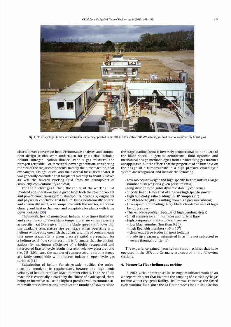
8112019 Helium Turbomachinery Operating Experience From Gas Turbine Power Plants
httpslidepdfcomreaderfullhelium-turbomachinery-operating-experience-from-gas-turbine-power-plants 635
closed power conversion loop Performance analyses and compo-
nent design studies were undertaken for gases that included
helium nitrogen carbon dioxide various gas mixtures and
nitrogen tetroxide For terrestrial power generation considering
the size of the major components namely the turbomachine heat
exchangers casings ducts and the external fossil-1047297red heater itwas generally concluded that for plants rated up to about 30 MWe
air was the favored working 1047298uid from the standpoints of
simplicity conventionality and cost
For the nuclear gas turbine the choice of the working 1047298uid
involved considerations being given from both the reactor coolant
and power conversion system standpoints Studies by engineers
and physicists concluded that helium being neutronically neutral
and chemically inert was compatible with the reactor turboma-
chinery and heat exchangers and acceptable for plants with large
power outputs [30]
The speci1047297c heat of monatomic helium is 1047297ve times that of air
and since the compressor stage temperature rise varies inversely
as speci1047297c heat (for a given limiting blade speed) it follows that
the available temperature rise per stage when operating withhelium will be only one 1047297fth that of air and this of course means
that more stages (for a given pressure ratio) are required for
a helium axial 1047298ow compressor It is fortunate that the optimi-
zation (for maximum ef 1047297ciency) of a highly recuperated and
intercooled Brayton cycle results in a relatively low pressure ratio
(ie 25e30) hence the number of compressor and turbine stages
are fairly comparable with modern industrial open cycle gas
turbines [31]
Substitution of helium for air greatly modi1047297es the turbo-
machine aerodynamic requirements because the high sonic
velocity of helium removes Mach number effects The size of the
machine is essentially dictated by the choice of blade speed there
being an incentive to use the highest possible values commensu-
rate with stress limitations to reduce the number of stages since
the stage loading factor is inversely proportional to the square of
the blade speed In general aerothermal 1047298uid dynamic and
mechanical design methodologies from air-breathing gas turbines
are applicable but the effects that the properties of helium have on
the design of a turbomachine in a high pressure closed-cycle
system are recognized and include the following
- Low molecular weight and high speci1047297c heat results in a large
number of stages (for a given pressure ratio)
- Long slender rotor (rotor dynamic stability concerns)
- Speci1047297c heat 5 times that of air gives high speci1047297c power
- High hub-to-tip ratio blading (in HP compressor)
- Small blade heights (resulting from high pressure system)
- Low aspect ratio blading (large blade chords because of high
bending stress)
- Thicker blade pro1047297les (because of high bending stress)
- Small compressor annulus taper and turbine 1047298are
- High compressor and turbine ef 1047297ciencies
- low Mach number (less than 030)
- high Reynolds numbers (gt5 106
)- clean oxide free blades (in inert helium)
- blade tip clearances minimized (machine not subjected to
severe thermal transients)
The experience gained from helium turbomachines that have
operated in the USA and Germany are covered in the following
sections
4 Pioneer La Fleur helium gas turbine
In 1960 La Fleur Enterprises in Los Angeles initiated work on an
air separation plant that involved the coupling of a closed-cycle gas
turbine with a cryogenic facility Helium was chosen as the closed
cycle working 1047298
uid since the La Fleur process for air liquefaction
Fig 5 Closed-cycle gas turbine demonstration test facility operated in the UK in 1995 with a 1000 kW natural gas- 1047297red heat source (Courtesy British gas)
CF McDonald Applied Thermal Engineering 44 (2012) 108e142 113
8112019 Helium Turbomachinery Operating Experience From Gas Turbine Power Plants
httpslidepdfcomreaderfullhelium-turbomachinery-operating-experience-from-gas-turbine-power-plants 735
required that the working 1047298uid remain gaseous throughout the
system Details of the plant and the axial 1047298ow helium turboma-
chinery have been documented previously [3233] and are only
brie1047298y discussed here This small plant is important in the context
of this paper since it was the 1047297rst fossil-1047297red helium gas turbine
ever to operate
The temperatureeentropy diagram (Fig 6) and the rather
simplistic cycle diagram (Fig 7) are pertinent to understanding
the function of this plant It was not designed to generate
electrical power instead the useful output being ldquobleed heliumrdquo
The major component was the free-running axial 1047298ow helium
turbomachine The rotating assembly consisted of a helium power
turbine compressor and refrigeration turbine mounted on the
same shaft
In the closed Brayton cycle part of the system the helium exiting
the compressor was split with about half of the mass 1047298ow passing
through the hot recuperator and then 1047298owing through the natural
gas-1047297red external heater where the temperature was further
increased before entering the power turbine Exiting the turbine
the helium then 1047298owed through the other side of the recuperator
and after a further reduction in temperature in a precooler entered
the compressor
In the cryogenic part of the cycle the temperature of the other
half of the helium bled from the compressor was reduced in an
aftercooler and then further reduced in the cold recuperator It was
then expanded in a refrigeration turbine and reached the lowest
temperature in the system The cold helium then passes through
a condenser in which the air is lique1047297ed and after passing through
the other side of the cold recuperator enters the compressor
Because the temperature of this bleed helium stream is less than
that coming from the precooler the mixed temperature at the
compressor inlet is cooler thus reducing the compressor workrequired
An overall view of the La Fleur plant is shown on Fig 8 and the
major parameters and features are given on Table 1 From the onset
of the project conservative parameters were selected to ensure
that when constructed the plant would operate reliably and meet
the process requirements since funding available for the project
was limited
With a turbine inlet temperature of 650 C (1202 F) and
a system pressure of 125 MPa (180 psia) a compressor pressure
Fig 6 Temperatureeentropy diagram of La Fleur helium gas turbine plant
Fig 7 Cycle diagram of La Fleur helium gas turbine plant
CF McDonald Applied Thermal Engineering 44 (2012) 108e142114
8112019 Helium Turbomachinery Operating Experience From Gas Turbine Power Plants
httpslidepdfcomreaderfullhelium-turbomachinery-operating-experience-from-gas-turbine-power-plants 835
ratio of 15 was selected With modest stage loading a 16 stage axial
compressor was designed the welded rotor being shown on Fig 9
Fifty percent reaction blading was used throughout The axial
velocity was kept constant and with a low value of pressure ratio
the annulus taper was rather slight The target ef 1047297ciency for the
compressor was83 percent The blades were cast 410 stainless steel
and these were welded to forged discs since this was the lowest
cost type of construction at the timeFor the turbine a tip speed of 305 ms (1000 ftsec) was
conservatively selected the rotational speed being 19500 rpm
While not coupled to a generator to produce electrical power the
size of the constant speed free-running turbine was equivalent to
that in a machine rated in the 1000e2000 kW class A view of the
turbine rotor is given on Fig 10 The material for the investment
cast blades was Haynes 21 and these were welded to a Timken 16-
25-6 disc The turbine ef 1047297ciency goal was 85 percent
The rotor was supported on oil-lubricated bearings To avoid oil
ingress into the helium circuit the oil pump scavenge pump and
the other accessories were separately driven by electric motors As
also experienced in later closed-cycle gas turbine plants oil ingress
into the helium closed loop occurred this being traced to a poor
design of the oil seals Keeping the system leak-tight when
operating with such a low molecular weight gas was a major
challenge and this topic will be discussed later for other helium
systems operating at high pressure and temperature
In this small pioneer plant the worldrsquos 1047297rst helium turbo-
machine operated satisfactorily the major achievement being that
it proved the La Fleur cryogenic process for air liquefaction The
experience gained from this small prototype plant led to the
construction and operation of a larger fossil-1047297red helium closed-cycle gas turbine for a lique1047297ed gas cryogenic plant and this is
discussed in the following section
5 Escher Wyss helium gas turbine plant
Following the successful operation of the pioneer plant La Fleur
Corporation designed and built a cryogenic facility in Phoenix
Arizona in 1966 for the liquefaction of 90 tonsday of nitrogen The
helium turbomachine was developed and built in Zurich by Escher
Wysswho up to that date hadfabricated the majority of the closed-
cycle gas turbine plants in Europe [2] The thermodynamic cycle
(involving splitting the helium 1047298ow at the compressor exit)
resembled the aforementioned pioneer plant with the exception
that the compressor was separated into two sections to facilitate
Fig 8 Overall view of 1047297rst helium gas turbine (Courtesy La Fleur Corp)
CF McDonald Applied Thermal Engineering 44 (2012) 108e142 115
8112019 Helium Turbomachinery Operating Experience From Gas Turbine Power Plants
httpslidepdfcomreaderfullhelium-turbomachinery-operating-experience-from-gas-turbine-power-plants 935
intercooling [634] The major parameters and features of this plant
are summarized on Table 1
With a turbine inlet temperature of 660 C (1220 F) and
a system pressure of 122 MPa (177 psia) a compressor pressure
ratio of 20 was selected A cross-section of the turbomachine is
shown on Fig 11 The LP and HP compressors had 10 and 8 stages
respectively The compressors were designed with a degree of
reaction slightly above 100 percent based on the prevailing view by
Escher Wyss at the time that this had advantages for helium
compressors Since this philosophy was carried over into the next
much larger helium gas turbine (as covered in the following
section) the rationale for this aerothermal design decision is brie1047298y
addressed below
The degree of reaction can essentially be regarded as the ratio of
pressure rise (although accurately de1047297ned as the static enthalpy
rise) in the rotor with the total pressure rise through the combi-
nation of the rotor and stator In early British axial 1047298ow compres-
sors a value of 50 percent was adopted this enabling the same
blade pro1047297le to be used for the rotor and stator In contemporary
air-breathing gas turbines the compressor degree of reaction is not
a major design factor The effect that selected compressor rotor and
stator positioning and geometries have on the degree of reaction is
illustrated in a simple form on Fig 12 In the early years of closed-
cycle gas turbine work Escher Wyss in Switzerland advocateda degree of reaction of 100 percent or higher [35] With such
blading the gas enters and leaves the stage in an axial direction The
basic stage embodies a negative pre-whirl stator ahead of the rotor
With the stator blades acting as a nozzle it was felt that the
resulting acceleration in the stator had the effect of smoothing out
the 1047298ow providing the best possible conditions for the rotor
However such blading with high stagger and lowsolidity has a very
high relative velocity and attendant high Mach number and is not
used in machines with air as the working 1047298uid since the associated
losses would be excessive leading to low overall compressor ef 1047297-
ciency This type of stator-before-rotor high reaction arrangement
was felt to be advantageous for helium axial 1047298ow compressors to
reduce the number of stages since Mach number effects are not
encountered because the sonic velocity of helium is on the order of
three times that of air
Because of the properties of helium (ie low molecular weight
high speci1047297c heat higher adiabatic index etc) a higher number of
compressor and turbinestages for a given pressure ratio are needed
as mentioned previously An axial compressor with just over
a hundred percent reaction as in the Escher Wyss helium gas
turbine that operated in Phoenix has a greater enthalpy rise per
stage for a given tip speed this reducing the number of stages for
a given pressure ratio but the ef 1047297ciency is slightly lower Mini-
mizing the number of stages was important from the rotor dynamic
stability standpoint for the very long rotor assembly associated
Fig 9 La Fleur plant 16 stage compressor (Courtesy La Fleur Corp) Fig 10 La Fleur plant 4 stage helium turbine (Courtesy La Fleur Corp)
Table 1
Salient features of operated helium turbomachinery
Turbomachine Helium closed-cycle gas turbines Test facility Helium circulator
Facility La Fleur
gas turbine
Escher Wyss
gas turbine
Oberhausen 11
power plant
HHV
test loop
FSV HTGR
Country USA USA Germany Germany USA
Year 1962 1966 1974 1981 1976
Application Cryogenic Cryogenic CHP plant Development Nuclear plant
Heat source NG NG Coke oven gas Electrical NuclearPower MW 2 equiv 6 equiv 50 90 4
Cycle Recuperated ICR ICR Customized Steam
Compressor
Type Axial Axial Axial Axial Axial
No stages 16 10LP8HP 10LP15HP 8 1
Inlet press MPa 125 122 105285 45 473
Inlet temp C 21 22 25 820 394
Pressure ratio 15 20 27 113 102
Flow kgsec 73 11 85 212 110
In vol 1047298ow m3sec 35 55 50 107 32
Turbine
Type Axial Axial Axial Axial ST
No stages 4 9 11LP7HP 2 1
Inlet press MPa 18 23 165 50 e
Inlet temp C 650 660 750 850 e
In vol 1047298ow m3sec 30 57 67 98 e
Out vol 1047298ow m3
sec 36 85 120 104 e
Rotation speed rpm 19500 18000 55003000 3000 9550
Shaft type Single Single Twin (geared) Single Single
Generator type None None Conventional Elect motor e
CF McDonald Applied Thermal Engineering 44 (2012) 108e142116
8112019 Helium Turbomachinery Operating Experience From Gas Turbine Power Plants
httpslidepdfcomreaderfullhelium-turbomachinery-operating-experience-from-gas-turbine-power-plants 1035
with this intercooled helium axial compressor of the type shown on
Figs 11 and 13
In the high pressure helium environment a high degree of reaction leads to a rotor blading with longer chords and low aspect
ratio The larger chord length combined with low solidity results in
comparatively few compressor blades Low aspect ratio (de1047297ned as
the ratio of blade height to chord length) results in several effects
including the following 1) high stagger with wider chords results in
a greater overall machine bladed length 2) fewer blades per stage
3) relatively large area of casing and blade surface with adverse
frictional losses tending to give lower ef 1047297ciency and 4) a stiffer
blade section (also with a thicker pro1047297le) with the needed strength
to combat bending stress which can be signi1047297cant in a high pres-
suredensity helium closed-cycle system A way to partially balance
out the bending stress would be by leaning the blades and off-
setting the blade cross-section centre of gravity For the early
helium gas turbine plants a view expressed by Escher Wyss wasthat the use of high reaction blading gave the maximum attainable
head a 1047298atter pressureevolume characteristic and a better surge
margin [36] The merits of increased pressure rise per stage asso-
ciated with high reaction blading has to be put into perspective by
its lower values of ef 1047297ciency [37]
The turbine had 9 stages and a rotational speed of 18000 rpm
While not coupled with a generator the equivalent output of the
free-running turbine was on the order of 6000 kW An overall view
of the long slender rotor is shown on Fig 13 and the turbomachine
assembly being installed in a cylindrical horizontally split casing is
shown on Fig 14 The major 1047298anges had peripheral lip seals to
facilitate welding closure to ensure leak tightness
With an external gas-1047297red heater the plant operated for about
5000 h and the helium gas turbine proved to be mechanically
sound and met its speci1047297ed performance This very specialized
plant proved to be too expensive to operate for the limited market
for cryogenic 1047298uids Anticipated market growth in the late 1960sdid not materialize and while the machinery performed satisfac-
torily the customer Dye Oxygen withdrew the plant from service
As far as the helium gas turbine was concerned the plant repre-
sented a signi1047297cant milestone since the technology generated was
applied to a follow-on helium gas turbine which at this stage was
still to be fossil-1047297red but now with the long-term goal in mind of
paving the way for the eventual operation of a helium closed-cycle
gas turbine power plant with a high temperature nuclear heat
source
6 Oberhausen II helium gas turbine plant at EVO
61 Closed-Cycle gas turbine experience at EVO
With initial operation starting in 1960 the municipal energy
utility (EVO) of the city of Oberhausen in the German industrial
Ruhr area deployed a closed-cycle gas turbine plant Referred to as
Oberhausen I the plant (shown previously on Fig 3) operated in
a combined power and heat mode with an electrical output of
14 MW and the thermal heat rejection of about 20 MW was
supplied to the cityrsquos district heating system The external heater
was initially 1047297red with Bituminous coal and in 1971 a change was
made to use coke-oven gas that had become available While using
air as the working 1047298uid some of the technical dif 1047297culties experi-
enced with this plant are highlighted below simply because if they
were to occur in a future direct cycle nuclear gas turbine plant they
would be very costly and time consuming to resolve as will be
discussed in a following section
Fig 11 Cross-section view of helium gas turbine (Courtesy Escher Wyss)
CF McDonald Applied Thermal Engineering 44 (2012) 108e142 117
8112019 Helium Turbomachinery Operating Experience From Gas Turbine Power Plants
httpslidepdfcomreaderfullhelium-turbomachinery-operating-experience-from-gas-turbine-power-plants 1135
In 1963 after 20000 h of operation a failure in the HP
compressor occurred [10] A rotor blade in the 1047297rst stage failed at
the root and in passing through the compressor caused extensive
damage The failure necessitated replacing the complete HP
compressor rotor assembly From a metallurgical examination of
the broken parts the failure was attributed to a small crevice at the
edge of the blade It was postulated that a corrosive action due to
impurities in the closed-loop working 1047298uid (ie air) in1047298uenced the
propagation of the crevice and blade vibration eventually caused
the failure To prevent a further failure of this kind an electric
polishing procedure was applied to the surface of the blade to
detect any imperfections
In 1967 debris from within the closed circuit caused damage to
the rotor blades and stators of several stages in the LP compressor
In 1973 further damage in the LP compressor due to blade vibration
required blading replacement During these de-blading events the
failed fragments were contained within the machine casings Using
conventional equipment the split casings of this machine were
opened and the failed parts removed by hands-on operations New
parts were then installed and the rotor assembly re-balanced The
problems were resolved and this closed-cycle gas turbine plant
with air as the working 1047298uid then performed well over the years
with high reliability [38]Rotor vibrations are mentioned here because they had caused
problems in three fossil-1047297red closed-cycle gas turbine plants using
air as the working 1047298uid namely1) in the John Brown 12 MW Plant
in Dundee where insurmountable vibration problems occurred [2]
2) multiple blade failures in the Spittelau 30 MW plant [2] and 3)
compressor blade failures in the aforementioned Oberhausen plant
As will be mentioned in a following section a further turbine blade
failure was experienced in a larger plant using helium as the
working 1047298uid
Correcting the subsequent blade failure damage to the turbo-
machine in a fossil-1047297red plant was straightforward however the
implication of such an operation in a future direct cycle nuclear gas
turbine with radioactively contaminated blading would be far more
severe This would likely require complex remote handling equip-ment and a dedicated facility for machine decontamination and
disassembly before hands-on repair could be undertaken
The Oberhausen I plant operated for about 120000 h and was
decommissioned in 1982 In about 1971 an expansion of the utilityrsquos
Fig 12 Impact of compressor blading geometry on degree of reaction (Courtesy
Escher Wyss)
Fig 13 Intercooled axial 1047298
ow helium turbomachine rotating assembly (Courtesy Escher Wyss)
CF McDonald Applied Thermal Engineering 44 (2012) 108e142118
8112019 Helium Turbomachinery Operating Experience From Gas Turbine Power Plants
httpslidepdfcomreaderfullhelium-turbomachinery-operating-experience-from-gas-turbine-power-plants 1235
capacity was needed due to increasing demand A larger fossil-1047297red
closed-cycle cogeneration plant of conventional design and still
retaining the use of air as the working 1047298uid was initially foreseen
but an emerging German development in the nuclear power plant
1047297eld resulted in a different decision being made as discussed
below
62 Relevance of the Oberhausen II helium turbine
Starting in 1972 development work sponsored by the Federal
Republic of Germany within the scope of the 4th Atomic program
was initiated on a high temperature reactor power plant with
a helium gas turbine (HHT) The reference plant design was based
on a large single-shaft intercooled helium turbine rated at
1240 MW A demonstration plant rated at 676 MW was planned
but prior to the construction of this it was necessary to test the
most important components to reduce risk Details of the two
major facilities to accomplish this have been reported previously
[39] and are summarized as follows
The Oberhausen II helium gas turbine plant was designed andbuilt to perform two major functions 1) it had to operate as
a commercial venture to provide electrical power (50 MWe) and
district heating (53 MWt) for the city of Oberhausen and 2) provide
data applicable to the nuclear gas turbine project particularly the
dynamic behavior of the overall plant and the integrity and long-
term operating experience of the major components in a helium
environment especially the turbomachine
The second facility was the HHV an experimental plant for
testing under representative conditions with respect to machine
size operating temperature pressure and mass 1047298ow of a large
helium turbomachine The facility was extensively instrumented to
gatherdata in the following areas rotorcooling system veri1047297cation
thermal insulation integrity 1047298ow characteristics blading ef 1047297ciency
acoustics rotor dynamic stability bearings dynamic and static
seals system leak tightness and metals behavior for the full
spectrum of plant operations including plant startup load change
shutdown upset conditions etc Details of the HHV facility and
testing undertaken are given in a later section
63 Oberhausen II helium gas turbine plant design
The design and construction of the plant was based on joint
efforts between EVO (plant designer and operator) GHH (turbo-
machine recuperator coolers and controls) Sulzer (helium
heater) and the University of Hannover Institute for Turboma-
chinery which contributed to the designwork and monitoring plant
performance
For the future planned nuclear gas turbine plant design values
of the temperature and pressure at the turbine inlet were 850 C
(1562 F) and 60 MPa (870 psia) respectively Attainment of this
temperature in the Oberhausen II plant could not be achieved and
750 C (1382 F) was selected based on tube material stress
considerations in the external coke-oven gas 1047297red heater An
intercooled and recuperated closed cycle was selected and themajor features of the plant are given on Table 1 The salient
parameters are given on the simpli1047297ed cycle diagram (Fig 15)
While rated at 50 MW a maximum system pressure of only
285 MPa (413 psia) was chosen so that the helium volumetric 1047298ow
(hence size of the bladed passages) would correspond to a much
larger helium turbomachine (on the order of 300 MW in fact) This
together with a rotational speed of 5500 rpm for the HP group
would result in representative stress loadings and would permit
a reasonable extrapolation to the machine size planned for the
nuclear demonstration plant
For the intercooled and recuperated cycle a compressor pressure
ratio of 27 was selected The helium mass 1047298ow rate was 85 kgs
(187 lbsec) and the circuit pressure loss was estimated at 104
percent Based on state-of-the-art component ef 1047297
ciencies and
Fig 14 Intercooled helium turbomachine with an equivalent power rating of 6000 kW installed in a split-case steel pressure vessel (Courtesy Escher Wyss)
CF McDonald Applied Thermal Engineering 44 (2012) 108e142 119
8112019 Helium Turbomachinery Operating Experience From Gas Turbine Power Plants
httpslidepdfcomreaderfullhelium-turbomachinery-operating-experience-from-gas-turbine-power-plants 1335
a recuperator effectiveness of 87 percent the projected thermal
ef 1047297ciency was 326 percent gross and 313 percent net
The isometric sketch of the distributed power conversion
system shown on Fig 16 (from Ref [40]) is convenient for
describing the plant layout A decision was made [41] to install the
horizontal turbomachinery in three large steel vessels the group-
ings being as follows 1) LP compressor rotor 2) HP compressor and
HP turbine grouping and 3) LP turbine The 1047297rst two assemblies
were on a single-shaft with a rotational speed of 5500 rpm The
generator with a rotational speed of 3000 rpmis driven from the LP
turbine end The rotors were geared together but with the selected
shafting arrangement only a small amount of power was trans-
mitted through the gearbox This con1047297guration was established
so that the dynamic behavior would be the same as in the large
single-shaft reference nuclear gas turbine plant design concept
The arrangement of the three vessels can be clearly seen on Fig 17
The horizontal tubular recuperator is positioned below the
turbomachinery The tubular precoolers and intercoolers are
installed in vertical steel vessels This type of orientation of the
major components was used in some of the earlier closed-cycle
plants using air as the working 1047298uid
Power regulation was achieved by inventory control as in the
aforementioned Oberhausen I plant which meant that the system
pressure (hence mass 1047298ow) was changed as required To lower the
power output helium was extracted from the loop after the HP
compressor through a control valve into a storage vessel For
a power increase helium was returned from the storage vessel into
the system upstream of the LP compressor without the need for an
additional blower With this arrangement the turbine inlet
temperature and speed remained constant and plant ef 1047297ciency
would be essentially constant down to a very low power level [42]
To achieve rapid load changes a bypass valve was included in the
system in which helium was transferred in a line between the HP
compressor exit end and LP end of the recuperator A very rapid
change from 100 percent load to no-load operation and back was
demonstrated [43]
64 Helium turbomachinery
The major features and parameters for the turbomachine are
given on Table 2 and are summarized as follows A longitudinal
cross-section of the turbomachine is shown on Fig 18 At the left
hand end the LP compressor is installed in a spherical pressure
vessel A high degree of reaction (ie 100 percent) was selected for
this 10 stage axial compressor this practice following the experi-
ence of an earlier discussed helium turbomachine A view showing
the bladed rotor of the LP compressor installed in the pressure
vessel split casing is shown on Fig19 with an appreciation for the
size of the spherical casing being shown on Fig 20 Both the HP
compressor and HP turbine rotors are installed in a common
housing as shown in the turbomachine cross-section (Fig 21) and
Fig 15 Oberhausen II helium gas turbine cycle diagram
Fig 16 Isometric layout of Oberhausen II helium gas turbine power conversion system (Courtesy EVO)
CF McDonald Applied Thermal Engineering 44 (2012) 108e142120
8112019 Helium Turbomachinery Operating Experience From Gas Turbine Power Plants
httpslidepdfcomreaderfullhelium-turbomachinery-operating-experience-from-gas-turbine-power-plants 1435
in the view with the HP rotor assembly positioned above the
horizontal split casing (Fig 22) The 15 stage HP compressor was
again designed with 100 percent reaction blading The HP turbine
has 7 stages and operated with an inlet temperature of 750 C
(1382O F) A cross-section of the 11 stage LP turbine installed in
a separate spherical vessel is shown on Fig 23 The amount of
power transmitted in the gearbox between the HP and LP turbinesis small since at rated output the HP turbine power level is only
slightly more than is needed to drive both compressors
The rotor of the HP group is supported on two oil-lubricated
bearings For the complete rotating assembly the thrust bearing is
located at the warm end of the LP compressor The six turbo-
machine bearing housings were designed such that direct access to
the large oil bearings was possible without having to open the large
casings This was done to reduce maintenance time because the
large split casings have 1047298anges that were welded closed at the
peripheral lip seals to minimize helium leakage
Special attention was given to the design of the cooling system
for the rotor In the case of this plant with a turbine inlet
temperature of 750 C the turbine blades themselves based on the
use of an existing superalloy did not have to be internally cooledbut cooling gas bled from the HP compressor outlet 1047298owed through
the hollow shaft and was used to cool the turbine discs and the
blade root attachments and then returned downstream of the
turbine
In a closed-cycle gas turbine the powerlevel can be regulated by
means of changing the system pressure and careful attention must
be given to the design of the various sealing systems to accom-
modate pressure differentials within the system particularly
during transient operation To simulate what would be needed in
a direct cycle nuclear gas turbine (to prevent 1047297ssion products
coming into contact with the bearing lubricating oil) a system
having a separate chamber for each of the three labyrinth seals was
incorporated in the machine design Outboard of the labyrinth seals
where the shafts penetrate the casings there were two further
seals a 1047298oating ring seal and a shutdown seal to prevent external
helium leakage
65 Helium turbomachine operating experience
Various presentations papers and publications have previously
covered the over 13 year operation of the Oberhausen II helium gas
turbine plant [43e48] The experience gained with the operation
Fig 17 Overall view of Oberhausen II 50 MWe helium gas turbine power plant (Courtesy EVO)
Table 2
Oberhausen II plant helium turbomachinery
Plant design electrical power MW 50
District heating thermal supply MW 535
Plant design ef 1047297ciency at terminals 313
Thermodynamic cycle ICR
Control method Helium inventory
compressor bypass
Rotor arrangement 2 Shaft (geared together)
Helium mass 1047298ow kgsec 85
Overall pressure ratio 27
Generator ef 1047297ciency 98
Design system pressure loss 104Compressor LP HP
Inlet pressure MPa l05 l54
Inlet temperature C 25 25
Vol 1047298ow inletoutlet m3s 5040 4025
Ef 1047297ciency 870 855
Rotational speed rpm 5500 5500
Number of stages 10 15
Blade height inletoutlet mm 10385 7253
Turbine LP HP
Inlet pressure MPa 165 270
Inlet temperature C 582 750
Ef 1047297ciency 900 883
Rotational speed rpm 3000 5500
Number of stages 11 7
Vol 1047298ow inletoutlet m3sec 92120 6792
Blade height inletoutlet mm 200250 150200
CF McDonald Applied Thermal Engineering 44 (2012) 108e142 121
8112019 Helium Turbomachinery Operating Experience From Gas Turbine Power Plants
httpslidepdfcomreaderfullhelium-turbomachinery-operating-experience-from-gas-turbine-power-plants 1535
of the large axial 1047298ow helium turbomachine is summarized asfollows
On the positive side the following were accomplished The rotor
helium buffered bearing labyrinth oil sealing system was one of the
numerous systems that worked well from the onset This was
encouraging since the external leakage of helium contaminated by
1047297ssion products and the ingress of lubricating oil into the closed
helium loop during the projected plant lifetime of 60 years are of
concern to designers of a direct cycle nuclear gas turbine plant (for
a machine with oil bearings) because of the likely long plant
downtime for cleanup and repair
With some modi1047297cations the helium puri1047297cation system
worked well with the purity level within the speci1047297cation The
helium cooling systems worked well to keep the temperatures of
the turbine discs blade root attachments and casings at speci1047297
edlevels Load change by inventory control was done routinely and
the ability to shed 100 percent of the load in a very short period by
means of the bypass valve was demonstrated The integrity of the
co-axial turbine inlet hot gas duct was proven At the end of plant
operation the major turbomachine casings were opened and there
were no signs of corrosion or erosion of the turbine or compressor
blades The coatings applied to mating metallic surfaces were
effective with no evidence of galling or self-welding in the oxygen-
free closed-loop helium environment
Experience from previously operated high temperature helium
cooled nuclear reactor power plants (with Rankine cycle steam
turbine power conversion systems) demonstrated that absolute
helium leak tightness was not attainable This was also true in the
Oberhausen II fossil-1047297red gas turbine plant where during initial
operation the helium leakage was about 45 kg per day Attention
was given to this and helium losses were reduced to the range of
5e10 kg per day principally by seal welding the major 1047298anges This
value can be compared with other closed loop helium systems as
shown below
On the negative side several unexpected problems had a majorimpact on the operation of the plant Following initial running of
the machine at 3000 rpm in preparation to synchronizing the
system the HP casing was opened for inspection revealing
damage to the labyrinth seals this being caused by shifting of
the rotor in the axial direction The labyrinth seals were replaced
and the turbine was 1047297rst synchronized with the grid on November
8 1975
Subsequent vibration problems were encountered and the HP
shaft oscillation became so large that it caused damage to the
bearings and the design value of speed and power could not be
maintained and the plant was shut down This was initially thought
to be due to thermal distortion of the rotor and a large unbalance
Fig 18 Cross-section of Oberhausen II plant helium turbomachinery rotating assembly (Courtesy EVO)
Fig 19 Oberhausen II low pressure helium compressor installed in casing (Courtesy
GHH)
Plant Helium inventory kg Leakage
kgday day
Dragon 180 020e20 010e10
AVR 240 10e30 040e12
Oberhausen II 1400 5e10 035e070
HHV 1250 25e50 020e040
FSV e Excessive leakage
CF McDonald Applied Thermal Engineering 44 (2012) 108e142122
8112019 Helium Turbomachinery Operating Experience From Gas Turbine Power Plants
httpslidepdfcomreaderfullhelium-turbomachinery-operating-experience-from-gas-turbine-power-plants 1635
Modi1047297cations to the rotor were made and the bearings replaced
but now the HP spool design speed of 5500 rpm could not be
achieved Subsequent major design and fabrication changes were
made including decreasing the bearing span by 600 mm (24 in)
giving a shorter stiffer rotor and changing the type of bearings In
restarting the plant the design speed of the HP rotor was achieved
however the power output was only 30 MW compared with the
design value of 50 MW
Fig 20 View of Oberhausen II low pressure helium compressor spherical vessel (Courtesy GHH)
Fig 21 Cross-section of Oberhausen II high pressure rotating group (Courtesy GHH)
CF McDonald Applied Thermal Engineering 44 (2012) 108e142 123
8112019 Helium Turbomachinery Operating Experience From Gas Turbine Power Plants
httpslidepdfcomreaderfullhelium-turbomachinery-operating-experience-from-gas-turbine-power-plants 1735
To gain operational experience it was decided to continue
running the plant at the reduced power rating On February 5 1979
after nearly 11000 h of operation a rotor blade from the second
stage of the HP turbine failed causing damage in the remaining
stages but the high energy fragments were contained within the
thick machine casing Examination of the failed blade revealed the
defect as a crack caused by the forgingprocess on the semi-1047297nishedproduct To prevent such a failure occurring in the future an electric
polishing process applied to the blade surface before inspection
was implemented and improved crack detection methods
introduced
Acoustic loads in a closed-cycle gas turbine represent pressure
1047298uctuations propagating at the speed of sound through the helium
working 1047298uid Pressure 1047298uctuations of importance result from the
aerodynamic effects of high velocity helium impacting and
essentially being intermittently ldquocutrdquo by the blading in the
compressor and turbine Care must be taken in the design of the
plant to ensurethat these 1047298uctuating pressure waves do not induce
vibrations of a magnitude that could result in excitation-induced
fatigue failures in components in the circuit Critical vibrations
occur when resonance exists between the main frequency of
the propagating sound and the natural frequencies of the
components particularly ones that have large surface area to
thickness ratio
Measurements of sound spectrum were taken at four different
locations in the circuit The design level of power of 50 MW was not
achieved but at the 30 MW power output actually realized the
maximum recorded sound power level was 148 dB After plantshutdown there was no evidence of adverse effects on the major
components of noise induced excitation emanating from the axial
1047298ow turbomachinery The integrity of the turbine inlet hot gas duct
and insulation was con1047297rmed
The inability to reach rated power was attributed to shortcom-
ings in the helium turbomachine This included the compressors(s)
and turbine(s) blading failing to attain design values of ef 1047297ciencies
and the bleed helium mass 1047298ows for cooling and sealing being
signi1047297cantly greater than analytically estimated Based on data
taken from the well instrumented plant detailed analyses were
undertaken by specialists [4950] to calculate the losses in the
turbomachine to explain the power output de1047297ciency A summary
of the projected losses and various component ef 1047297ciencies is pre-
sented in a convenient form on Table 3
Fig 22 Oberhausen II high pressure rotor being installed (Courtesy GHH)
CF McDonald Applied Thermal Engineering 44 (2012) 108e142124
8112019 Helium Turbomachinery Operating Experience From Gas Turbine Power Plants
httpslidepdfcomreaderfullhelium-turbomachinery-operating-experience-from-gas-turbine-power-plants 1835
The plant operated for approximately 24000 h and was shut-
down and decommissioned in 1988 when the coke-oven gas supply
for the heater was no longer available A total plant operating time
of about 11500 h had been at the design turbine inlet temperature
of 750 C (1382 F) Turbomachinery related experience gained
from operation of this large helium gas turbine plant was extremely
valuable While many of the functions performed well from the
onset and others worked satisfactorily after modi1047297cations were
made serious unexpected problems were encountered
The achieved electrical power output of only 60 percent of the
design value was initially thought to be due to a grossly excessive
system pressure loss However when the data was carefully eval-uated it was found that 85 percent of the 20 MW power loss was
attributed to turbomachine related problems as delineated on
Table 3
To remedy this power de1047297ciency it was clear that a major re-
design of the turbomachinery would be required While replace-
ment of the gas turbine was not contemplated a study was
undertaken based on data from the plant and new technologies
that had become available since the initial design Based on the
1047297ndings a new turbomachine layout concept was suggested [43]
and a simplistic view of the rotor arrangement is shown on Fig 24
A more conventional single-shaft arrangement was proposed with
the two compressors and turbine having a rotational speed of
5400 rpm A gearbox was still retained to give a generator rota-
tional speed of 3000 rpm Based on prevailing technology at the
time the requirements for such a gearbox would have been moredemanding since the 50 MW from the turbine to the generator
would have to be transmitted through it This would necessitate
a larger system to pump 1047297lter and cool the bearing lubrication oil
To remedy the very large losses in the compressors and turbines
the number of stages would have to be increased In the case of the
compressors the use of lighter aerodynamically loaded higher
ef 1047297ciency stages with 50 percent reaction blading was
recommended
7 High temperature helium test facility (HHV)
71 Background
In the late 1960rsquos with large numbers of orders placed for 1047297rst
generation light water reactor nuclear power plants studies were
initiated for next generation power plants with higher ef 1047297ciency
potential Following the initial operational success of the 1047297rst three
small helium cooled HTR plants (ie Dragon in the UK Peach
Bottom I in the USA and AVR in Germany) studies on larger plants
based on the use of both Rankine steam cycle and helium closed
Brayton cycle power conversion systems were undertaken In the
early 1970rsquos emphasis was placed on nuclear gas turbine plant
designs with larger power output both in the USA (for the
HTGR eGT) and in Europe (for the HHT) Work in the USA was
limited to only paper studies [18] The much larger program in
Germany (with participation by Swiss companies for the turbo-
machine heat exchangers and cooling towers) included a well
planned development testing strategy to support the plant design
Fig 23 Cross-section of Oberhausen II low pressure helium turbine (Courtesy GHH)
Table 3
Oberhausen II helium turbine plant power losses
Componentcause Design
value
Measured Power loss
MW
Compressors
B Flow losses in inlet diffusers
and blades
Low pressure ef 1047297ciency 870 826 13
High pressure ef 1047297ciency 855 779 40
Turbines
B Blade gap and 1047298ow losses
High pressure ef 1047297ciency 883 823 39
B Pro1047297le losses due to Remachined
blades after having detected
damaged blades
Low pressure ef 1047297ciency 900 856 24
BSealing leakage and cooling 1047298ows
in all turbomachines Kgsec
18 75 53
B Circuit pressure losses
(Ducting Hxrsquos etc)
102 128 26
B Miscellaneous heat losses 05
Total power loss 200 MW
Notes (1) Plant designed for electrical power output of 50 MW actual power output
measured 30 MW
(2) Power de1047297ciency of20 MW based on measurements taken and then recalculated
for the rated plant output
(3) 85 of Power loss attributed to helium turbomachinery related issues
CF McDonald Applied Thermal Engineering 44 (2012) 108e142 125
8112019 Helium Turbomachinery Operating Experience From Gas Turbine Power Plants
httpslidepdfcomreaderfullhelium-turbomachinery-operating-experience-from-gas-turbine-power-plants 1935
While the reference HHT plant for eventual commercializationembodied a very large single helium gas turbine rated at 1240 MW
this was to be preceded by a nuclear demonstration plant rated at
676 MW [51] To support the design of this plant technology
generated from the following was planned 1) operational experi-
ence from the aforementioned Oberhausen II 50 MW helium gas
turbine power plant and 2) testing of components in a large high
temperature helium test facility as discussed below
72 Development facilitytesting objectives
An overall view of the HHV test facility sited in Julich in
Germany is shown on Fig 25 and since this has been reported on
previously [52] it will only be brie1047298
y covered in this section Tominimize risk and assure the performance integrity and reliability
of the nuclear demonstration plant some non-nuclear testing of
the major components especially the helium turbomachine was
deemed essential Because of the limitations of a conventional
closed-cycle helium gas turbine power plant particularly the
temperature limitations of existing fossil-1047297red and electrical
heaters a new type of test facility was foreseen
A simpli1047297ed schematic line diagram of the HHV circuit is shown
on Fig 26 The major design parameters are shown on Fig 27
together with the temperatureeentropy diagram which is conve-
nient for describing the unique relationship between the compo-
nents in the closed helium loop Starting at the lowest pressure in
Fig 24 Proposed new concept for Oberhausen II helium gas turbine rotating assembly to remedy problems encountered during operation of the 50 MWe power plant (Courtesy
EVO)
Fig 25 HHV helium turbomachinery test facility (Courtesy BBC)
CF McDonald Applied Thermal Engineering 44 (2012) 108e142126
8112019 Helium Turbomachinery Operating Experience From Gas Turbine Power Plants
httpslidepdfcomreaderfullhelium-turbomachinery-operating-experience-from-gas-turbine-power-plants 2035
the system the helium is compressed (Ae
B) its temperatureincreasing to 850 C (1562 F) before 1047298owing through the test
section (BeC) After being cooled slightly (CeD) the helium is
expanded in the turbine (DeA) down to the compressor inlet
conditions completing the loop There is no power output from the
system and without the need for an external heater the
compression heat is used to raise the helium to the maximum
system temperature in what can be described as a very large heat
pump The required compressor power is 90 MW and to supple-
ment the 45 MW generated by expansion in the turbine external
power is provided by a 45 MW synchronous electrical motor A
cooler is required to remove the compression heat that is contin-
uously put into the closed helium loop and this is done by bleeding
about 5 percent of the mass 1047298ow after the compressor cooling it
and re-introducing it into the circuit close to the turbine inlet In
addition to testing the turbomachine the facility was engineered
with a test section to accommodate other small components (eg
hot gas 1047298ow regulation valves bypass valves insulation con1047297gu-
rations and types of hot gas duct construction) With the highest
temperature in the system being at the compressor exit the facility
had the capability to provide helium at a temperature up to 1000 C
(1832 F) for short periods at the entrance to the test section
While a higher ef 1047297ciency of the planned nuclear demonstration
plant could be projected with a turbine inlet temperature in the
range 950e1000 C (1742e1832 F) this would have necessitated
either turbine blade cooling or the use of a high temperature alloy
such as Titanium Zirconium Molybdenum (TZM) At the time it was
felt that using either of these would have added cost and risk to theprojectso a conventionalnickel-basedalloyas usedin industrialgas
turbines was selected for the 850 C design value of turbine inlet
temperature this negating the needfor actual internal bladecooling
However a complex internal coolingsystemwas neededto keep the
Fig 26 Cycle diagram of HHV test loop (Courtesy BBC)
Fig 27 Salient features of HHV helium turbomachinery (Courtesy BBC)
CF McDonald Applied Thermal Engineering 44 (2012) 108e142 127
8112019 Helium Turbomachinery Operating Experience From Gas Turbine Power Plants
httpslidepdfcomreaderfullhelium-turbomachinery-operating-experience-from-gas-turbine-power-plants 2135
turbine discs and blade root attachments and casings to acceptable
temperatures commensurate with prescribed stress limitations for
thelife of theturbomachine In addition a heliumsupplywas needed
to provide a buffering system for the various labyrinth seals
In a direct Brayton cycle nuclear gas turbine the turbomachine is
installed in the reactor circuit and via the hot gas duct heated
helium is transported directly from the reactor core to the turbine
From the safety licensing and reliability standpoints there are
various seals that must perform perfectly A helium buffered
labyrinth seal system is necessary to prevent bearing lubricating oil
ingress to the closed helium loop Since in the proposed HHT plant
design the drive shaft from the turbine to the generator penetrates
the reactor primary system pressure boundary two shaft seals are
needed one a dynamic seal when the shaft is rotating and a static
seal when the turbomachine is not operating Testing of these seals
in a size and operating conditions representative of the planned
commercial power plant was considered to be a licensing must
The mechanical integrity of the rotating assembly must be
assured there being two major factors necessitating testing the
machine at full speed and temperature and at high pressure
namely 1) loading the blading under representative centrifugal and
gas bending stresses and 2) to monitor vibration and con1047297rm rotor
dynamic stability For the design of the planned commercial planta knowledge of the acoustic emissions by the turbomachine and
propagation in the closed circuit was required Data from the HHV
facility would enable dynamic responses of the major components
(especially the insulation) resulting from excitation by the sound
1047297eld to be calculated
The circuit was instrumented to gather data on the effectiveness
of the hot gas duct insulation thermal expansion devices hot gas
valves helium puri1047297cation system instrumentation and the
adequacy of the coatings applied to mating metallic surfaces to
prevent galling or self-welding Details of the turbomachinery and
the experience gained from the operation of the HHV facility are
covered in the following sections
73 Helium turbomachine
A cross-section of the turbomachine is shown on Fig 28 The
single-shaft rotating assembly consists of 8 compressor stagesand 2
turbine stages and had a weighton the order of 66 tons(60000 kg)
The hub inner and outer diameters are 16 m (525 ft) and 18 m
(59 ft) respectively the blading axial length being 23 m (75 ft)The
span between the oil bearings being 57 m (187 ft) The physical
dimensions of the turbogroup shown on Fig 28 correspond to
a machine rated at about 300 MW The oil bearings operate in
a helium environment and the diameters of the labyrinths and
1047298oating ring shaft seals to prevent oil ingress are representative of
a machine rated at about 600 MW The complexity of the machine
design especially the rotor cooling system sealing system very
large casing and heat insulation have been reported previously
[53e55]
To ensure high structural integrity the rotor was constructed by
welding together the forged compressor and turbine discs The
compressor had 8 stages each having 56 rotor and 72 stator blades
The turbine had 2 stages each having 90 stator and 84 rotor blades
An appreciation for the large size of the rotating assembly can be
seen from Fig 29 The rotor blades have 1047297r-tree attachments
embodying cooling channels Since the temperature and pressure
do not vary very much along the blading in the 1047298ow direction an
intricate rotor and stator cooling system was required Channels in
both the blade roots and the spacers between adjacent blade rows
form an axial geometry for the passage of a cooling helium supplyto keep the temperature of the multiple discs below 400 C
(752 F) The design of this was a challenge since the rotor and
stator blade attachments of both the 8 stage compressor and 2
stage turbine had to be cooled Excessive leakage had to be avoided
since this would have prevented the speci1047297ed compressor
discharge temperature (ie the maximum temperature in the
circuit) from being reached
In the 1970rsquos and early 1980rsquos signi1047297cant studies were carried
out on large helium gas turbines by various organizations [56e62]
In this era there was general agreement that testing of the turbo-
machine in one form or another in non-nuclear facilities be
undertaken to resolve areas of high risk (eg seals bearings cooling
systems rotor dynamic stability compressor surge margin
dynamic response rotor burst protection etc) before installationand operation of a large gas turbine in a nuclear environment
This low risk engineering philosophy which prevailed at the time
in both Germany and the USA emphasized the importance of
Fig 28 Cross-section of HHV helium turbomachinery (Courtesy BBC)
CF McDonald Applied Thermal Engineering 44 (2012) 108e142128
8112019 Helium Turbomachinery Operating Experience From Gas Turbine Power Plants
httpslidepdfcomreaderfullhelium-turbomachinery-operating-experience-from-gas-turbine-power-plants 2235
the HHV test facility as being an important step towards the
eventual deployment of a high ef 1047297ciency nuclear gas turbine power
plant
74 Initial operation of the HHV facility
During commissioning of the plant in 1979 oil ingress into the
helium circuit from the seal system occurred twiceThe 1047297rst ingressof oil between 600 and 1200 kg (1322 and 2644 lb) was due to
a serious operatorerror and the absence of an isolation valve in the
system The oil in the circuit was partly coked and formed thick
deposits on the cold and hot surfaces of the turbomachinery and in
other parts of the closed loop including saturation of the 1047297brous
insulation The fouled metallic surfaces were cleaned mechanically
and chemically by cracking with the addition of hydrogen and
additives The second oil ingress was due to a mechanical defect in
the labyrinth seal system The quantity of oil introduced was small
and it was removed bycracking at a temperature of 600 C (1112 F)
and with the use of additives To obviate further oil ingress inci-
dents the labyrinth seal system was redesigned The buffer and
cooling helium system piping layout was modi1047297ed to positively
eliminate oil ingress due to improper valve operation and toprevent further human error
Pressure and leak detection tests of the HHV test facility at
ambient temperature showed good leak tightness for the turbo-
machine 1047298anged joints and of the main and auxiliary circuits
However at the operating temperature of 850 C (1562 F) large
helium leaks were detected The major 1047298anges had been provi-
sioned with lip seals and the 1047297rst step was to weld the closures A
large leak persisted at the front 1047298ange of the turbomachine This
was diagnosed as being caused by a non-uniform temperature
distribution during initial operation resulting in thermal stresses
creating local gaps This problem was overcome by redesign of the
cooling system with improved gas 1047298ow distribution and 1047298ow rates
to give a more uniform temperature gradient The leakage from the
system was reduced to on the order of 020e
040 percent of the
helium inventory per day this being of the same magnitude as in
other closed helium circuits as discussed in Section 65
It should be mentioned that in addition to the HHV experience
bearing oil ingress into the circuits and system loss of the working
1047298uid in other closed-cycle gas turbine plants have occurred In all of
these fossil-1047297red facilities 1047297xing leaks and removal of oil deposits
were undertaken based on conventional hands-on approaches but
nevertheless such operations were time-consuming However if a new and previously untested helium turbomachine operating in
a direct cycle nuclear gas turbine plant experienced an oil ingress
the rami1047297cations would be severe The likely use of remote
handling equipment to remove the turbomachine from the vessel
machine disassembly (including breaking the welded 1047298ange joints)
and removal of oil from the radioactively contaminated turbo-
machine blade surfaces and system insulation would be time
consuming A diagnosis of the failure would be required before
a spare turbomachine could be installed and this plant downtime
could adversely affect plant availability
75 Experience gained
Afterresolutionof the aforementionedproblems the HHVfacilitywas started in the Spring of 1981 and in an orderly manner was
brought up to full pressure and a temperature of 850 C (1562 F)
During a 60 h run the functioning of the instrumentation control
and safety systems were veri1047297ed During these tests the ability to
stop the turbomachine from full operating conditions to standstill
within 90 s was demonstrated After system depressurization the
plant was then run up again to full operating conditions with no
problems experienced The HHV facility was successfully run for
about 1100 h of which theturbomachineryoperated forabout325 h
at a temperature of 850 C The test facility was extensively instru-
mented and interpretation and analysis of the data recorded gave
positive and favorable results in the following areas
The complex rotor cooling system which was engineered to
assure that the temperature of the discs be kept below 400
C
Fig 29 HHV helium turbomachine rotating assembly (size equivalent to a 300 MWe machine) being installed in a pressure vessel (Courtesy BBC)
CF McDonald Applied Thermal Engineering 44 (2012) 108e142 129
8112019 Helium Turbomachinery Operating Experience From Gas Turbine Power Plants
httpslidepdfcomreaderfullhelium-turbomachinery-operating-experience-from-gas-turbine-power-plants 2335
(752 F) was demonstrated to be effective The measured rotor
coolant 1047298ows (about 3 percent of the mass1047298ow passing through the
machine) were slightly larger than had been estimated and this
resulted in measured turbine disc temperatures lower than pre-
dicted [55]
The dynamic labyrinth shaft seal functioned well at the full
temperature and pressure conditions and met the requirement of
zero oil ingress into the helium circuit The measured rotor oscil-
lation did not have any adverse effect on the shaft sealing system
The static rotor seal (for shutdown conditions) functioned without
any problems
The compressor and turbine blading hadef 1047297ciencies higher than
predicted The structural integrity of the rotor proved to be sound
when operating at 3000 rpm under the maximum temperature and
pressure conditions The stiff rotor shaft had only slight unbalance
and thermal distortion and measured oscillations were in the range
typical of large steam turbines
Sound power spectrum measurements were taken in four
different locations in the circuit These were taken to determine the
spectrum and intensity of the sound generated and propagated by
the turbomachinery and the resultant vibration of internal
components The maximum sound power level in the helium
circuit was160 dB Numerous strain gages were placedin the circuitto determine the in1047298uence of the sound 1047297eld particularly on the
fatigue strength of the turbine inlet hot gas duct In later examining
the internal components there was no evidence of excessive
vibration of the components especially the ducting and the insu-
lation Based on the measurements and calculations it was
concluded that the fatigue strength limit of the components would
not be exceeded during the designed life of the planned commer-
cial nuclear gas turbine power plant
In a direct cycle nuclear gas turbine the hot gas duct used to
transport the helium from the reactor core to the turbineis a critical
component The hot gas duct in the HHV facility performed well
mechanically and con1047297rmed the adequacy of the thermal expan-
sion devices From the thermal standpoint the 1047297ber insulation
performed better than the metallic type
After dismantling the HHV facility there were no signs of
corrosion or erosion of the turbine or compressor blading While
the total number of hours operated was limited the coatings
applied to mating metallic surfaces to prevent galling and frictional
welding in the oxidation-free helium worked well
The helium buffer and cooling system worked well However
problems remained with the puri1047297cation of the buffer helium The
oil separation system consisting of a cyclone separator and a wire
mesh and a down stream 1047297ber 1047297lter needed further improvement
In late 1981 a decision was made to cancel the HHT project and
the HHV facility was shutdown The design and operational expe-
rience gained from the running of this facility would have been
extremely valuable had the nuclear gas turbine power plant
concept moved towards becoming a reality The identi1047297cation of
somewhat inevitable problems to be expected in such a complexturbomachine and their resolution were undertaken in a timely
and cost effective manner in the non-nuclear HHV facility This
should be noted for future nuclear gas turbine endeavors since
remedying such unexpected problems in the case of a new and
untested large helium turbomachine being operated for the 1047297rst
time using nuclear heat could result in very complex repair
Fig 30 Speci1047297
c speed-speci1047297
c diameter array for gas circulators in various gas-cooled nuclear plants
CF McDonald Applied Thermal Engineering 44 (2012) 108e142130
8112019 Helium Turbomachinery Operating Experience From Gas Turbine Power Plants
httpslidepdfcomreaderfullhelium-turbomachinery-operating-experience-from-gas-turbine-power-plants 2435
activities and extended plant downtime and indeed adding risk to
the overall success of the nuclear gas turbine concept
8 Circulators used in gas-cooled reactor plants
Circulators of different types will be needed in future helium
cooled nuclear plants these including the following 1) primary
loop circulator for possible next generation steam cycle power andcogeneration plants 2) for future indirect cycle gas turbine plants
3) shut down cooling circulators forall HTRand VHTR plants and 4)
for various circulators needed in future VHTR high temperature
process heat plant concepts The technology status of operated
helium circulators is brie1047298y addressed as follows
81 Background
It would be remiss not to mention experience gained in the past
with gas circulators and while not gas turbines they are rotating
machines that operate in the primary loop of a helium cooled
reactor With electric motor drives there are basically two types of
compressor rotor con1047297gurations namely radial and axial 1047298ow
machinesIn a single stage form the centrifugal impeller is used for high
stage pressure rise and low volume 1047298ow duties whereas the axial
type covers low pressure rise per stage and high volume 1047298ow The
selection of impeller type is very much related to the working
media type of bearings drive type rotor dynamic characteristics
and installation envelope A wide range of circulators have operated
and a well established technology base exists for both types [63] A
useful portrayal of compressor data in the form of quasi- non-
dimensional parameters (after Balje [64]) showing approximate
boundaries for operation of high ef 1047297ciency axial and radial types is
shown on Fig 30 (from Ref [65])
Both high speed axial and lower speed radial 1047298ow types are
amenable to gas oil and magnetic bearings From the onset of
modularHTR plant studies theuse of active magnetic bearings[6667]offered a solution to eliminate lubricating oil into the reactor circuit
and this tribology technology is attractive for use in submerged
rotating machinery in the next generation of HTR plants [68]
While now dated an appreciation of the main design features of
typical electric motor-driven helium circulators have been reported
previously namely an axial 1047298ow main circulator for a modular
steam cycle HTR plant [69] and a representative radial 1047298ow shut-
down cooling circulator [70]
The operating experience gained from three particular circula-
tors is brie1047298y included below because of their relevance to the
design of helium turbomachinery in future HTR plant variants
82 Axial 1047298ow helium circulator
Since all of the aforementioned predominantly European
helium gas turbines used axial 1047298ow turbomachinery it is of interest
to mention a helium axial 1047298ow circulator that operated in the USA
and to brie1047298y discuss its design parameters and features The
330 MW Fort St Vrain HTGR featured a Rankine cycle power
conversion system Four steam turbine driven helium circulators
were used to transport heat from the reactor core to the steam
generators The complete circulator assemblies were installed
vertically in the prestressed concrete reactor vessel [71e73]
A cross-section of the circulator is shown on Fig 31 with thecompressor rotor and stator visible on the left hand end of the
machine Based on early 1960rsquos technology a decision was made to
use water lubricated bearings and from the overall plant reliability
and availability standpoints this later proved to be a bad choice
Within the vertical circulator assembly there were four 1047298uid
systems namely the helium reactor coolant water lubricant in the
bearings steam for the turbine drive and high pressure water for
the auxiliary Pelton wheel drive During plant transients the pres-
sures and temperatures of these four 1047298uids oscillated considerably
and the response of the control and seal systems proved to be
inadequate and resulted in considerable water ingress from the
bearing cartridge into the reactor helium circuit The considerable
clean up time needed following repeated occurrences of this event
resulted in long periods of plant downtime and this had an adverseeffect on plant availability This together with other technical
Fig 31 Cross section of FSV helium circulator (Courtesy general Atomics)
CF McDonald Applied Thermal Engineering 44 (2012) 108e142 131
8112019 Helium Turbomachinery Operating Experience From Gas Turbine Power Plants
httpslidepdfcomreaderfullhelium-turbomachinery-operating-experience-from-gas-turbine-power-plants 2535
dif 1047297culties eventually contributed to the plant being prematurely
decommissioned
On the positive side in the context of this paper the helium
circulators operated for over 250000 h and exhibited excellent
helium compressor performance good mechanical integrity and
vibration-free operation The rotating assembly showing the axial
1047298ow compressor and steam turbine rotors together with a view of
the machine assembly are given on Fig 32 The helium compressor
consists of a single stage axial rotor followed by an exit guide vane
The machine was designed for axial helium 1047298ow entering and
leaving the stage and this can be seen from the velocity triangles
shown on Fig 33 which also includes the de1047297nition of the various
aerodynamic parameters Major design parameters and features of
this helium circulator are given on Table 4 Related to an earlier
discussion on the degree of reaction for axial 1047298ow compressors the
value for this conventional single stage circulator is 78 percent All
of the major aerothermal and structural loading criteria were
within established boundaries for an axial compressor having high
ef 1047297ciency and a good surge margin
The compressor gas 1047298ow path and blading geometries were
established based on prevailing industrial gas turbine and aero-
engine design practice A low Mach number (025) a high Reynolds
number (3 106) together with a modest stage loading (ie
a temperature rise coef 1047297cient of 044) and an acceptable value of
diffusion factor (042) were some of the factors that contributed to
a helium circulator that had a high ef 1047297ciency and a good pressure
rise- 1047298ow characteristic The large rotor blade chord and thick blade
section for this single stage circulator are necessary to accommo-
date the high bending stress characteristic of operation in a high
pressure environment The solidity and blade camber were opti-
mized for minimum losses
There were essentially two reasons for including this single-
stage axial 1047298ow compressor that operated in a helium cooled
reactor although its overall con1047297guration can be regarded as a 1047297rst
and last of a kind A rotor blade from this circulator as shown onFig 34 was based on a NASA 65 series airfoil which at the time
were one of the best performing cascades for such low Mach
number and high Reynolds number applications Interestingly it
has almost the same blade height aspect ratio and solidity as would
be used in the 1047297rst stage of an LP compressor in a helium turbo-
machine rated on the order of 250 MW
The second point of interest is that the helium mass 1047298ow rate
through the single stage axial compressor (rated at 4 MWe) is
110 kgs compared with 85 kgs through the multistage compressor
in the 50 MWe Oberhausen II helium gas turbine plant However
the volumetric 1047298ow through the Oberhausen axial compressor is
higher than that through the circulator by a factor of 16 this again
pointing out that the Oberhausen II plant was designed for high
volumetric 1047298ow to simulate the much larger size of turboma-chinery that was planned at the time in Germany for use in future
projected nuclear gas turbine power plants
83 High temperature helium circulator
For future helium turbomachines embodying active magnetic
bearings a challenge in their design relates to accommodating
elevated levels of temperature in the vicinity of the electronic
components In this regard it is of interest to note that a small very
high temperature helium axial 1047298ow circulator rated at 20 kW (as
shown on Fig 35) operated for more than 15000 h in an insulation
test facility in Germany more than two decades ago [74] The
signi1047297cance of this machine is that it operated with magnetic
bearings in a high temperature helium test loop with a circulatorgas inlet temperature of 950 C (1742 F) This necessitated the use
of ceramic insulation to ensure that the temperature in the vicinity
of the magnetic bearing electronics did not exceed a temperature of
about 150 C (300 F)
This machine although a very small axial 1047298ow helium blower
performed well and has been brie1047298y mentioned here since it
represents a point of reference for future helium rotating machines
capable operating with magnetic bearings in a very high temper-
ature helium environment
84 Radial 1047298ow AGR nuclear plant gas circulators
The electric motor-driven carbon dioxide circulators rated at
about 5 MW with a total runningtimein excess of 18 million hours
Fig 32 Fort St Vrain HTGR plant helium circulator (Courtesy General Atomics) (a)
Axial 1047298ow helium compressor and steam turbine rotating assembly (b) 4 MW helium
circulator assembly
CF McDonald Applied Thermal Engineering 44 (2012) 108e142132
8112019 Helium Turbomachinery Operating Experience From Gas Turbine Power Plants
httpslidepdfcomreaderfullhelium-turbomachinery-operating-experience-from-gas-turbine-power-plants 2635
in AGR nuclear power plants in the UK have demonstrated veryhigh availability [7576] To a high degree this can be attributed to
the fact that the machines were conservatively designed and proof
tested in a non-nuclear facility at full temperature and power
under conditions that simulated all of the nuclear plant operating
modes The test facility shown on Fig 36 served two functions 1)
design veri1047297cation of the prototype machine and 2) test of all new
and refurbished machines before they were installed in nuclear
plants Engineers currently involved in the design and development
of helium turbomachinery could bene1047297t from this sound testing
protocol to minimize risk in the deployment of helium rotating
machinery in future HTRVHTR plant variants
9 Helium turbomachinery development and testing
91 On-going development activities
The various helium turbomachines discussed in previous
sections operated over a span of about two decades starting in the
early 1960s From about 1990 activities in the nuclear gas turbine
1047297eld have been focused mainly on the design of modular GTeHTR
plant concepts In support of these plant studies many signi1047297cant
helium turbomachine design advancements have been made and
attention given to what development testing would be needed In
the last decade or so limited sub-component development has
been undertaken for helium turbomachines in the 250e300 MWe
size and these are brie1047298y summarized below
In a joint USARussia effort development in support of the
GTe
MHR turbomachine has been undertaken including testing in
the following areas magnetic bearings seals and rotor dynamicsfor the vertical intercooled helium turbomachine rated at 286 MWe
[77e80]
In Japan development activities have been in progress for
several years in support of the 274 MWe helium turbomachine for
the GTeHTR300 plant concept [2581] A detailed discussion on
the aerodynamic design of the axial 1047298ow helium compressor for
this turbomachine has been published in the open literature [82]
While the design methodology used for axial compressor design in
air-breathing industrial and aircraft gas turbines is generally
applicable for a multi-stage helium compressor a decision was
made by JAEA to test a small scale compressor in a helium facility
because of the inherent and unique gas 1047298ow path and type of
blading associated with operation in a high pressure helium
environment The major goal of the test was to validate the designof the 20 stage helium axial 1047298ow compressor for the GTeHTR300
plant
An axial 1047298ow compressor in a closed-cycle helium gas turbine is
characterized by the following 1) a large number stages 2) small
blade heights 3) high hub-to-tip ratio 4) a long annulus with
small taper that tends to deteriorate aerodynamic performance as
a result of end-wall boundary layer length and secondary 1047298ow 5)
low Mach number 6) high Reynolds number and 7) blade tip
clearances that are controlled by the gap necessary in the magnetic
journal and catcher bearings While (as covered in earlier sections)
helium gas turbines have operated there is limited data in the
open literature on the performance of multi-stage axial 1047298ow
compressors operating in a high pressure closed-loop helium
environment
Fig 33 Velocity triangles for axial compressor stage
CF McDonald Applied Thermal Engineering 44 (2012) 108e142 133
8112019 Helium Turbomachinery Operating Experience From Gas Turbine Power Plants
httpslidepdfcomreaderfullhelium-turbomachinery-operating-experience-from-gas-turbine-power-plants 2735
A 13rd scale 4 stage compressor was designed to simulate the
stage interaction the boundary layer growth and repeated stage
1047298ow in an actual compressor The 1047297rst four stages were designed to
be geometrically similar to the corresponding stages in the
GTe
HTR300 compressor Details of the model compressor havebeen discussed previously [81] and are summarized on Table 5
from [83]
A cross-section of the compressor test model is shown on Fig 37
A view of the 4 stage compressor rotor installed in the lower casing
is shown on Fig 38 The test facility (Fig 39) is a closed helium loop
consisting of the compressor model cooler pressure adjustment
valve and a 1047298ow measurement instrument The compressor is
driven by a 3650 kW electrical motor via a step-up gear The rota-
tional speed of 10800 rpm (three times that of the compressor in
the GTeHTR300 plant) was selected to match blade speed and
Mach number in the full size compressor
Details of the planned aerodynamic performance objectives of
the 13rd scale helium compressor test have been published
previously [84] Extensivetesting of the subscale model compressorprovided data to validate the performance of the full size
compressor for the GTeHTR300 power plant The test data and
test-calibrated CFD analyses gave added insight into the effect of
factors that impact performance including blade surface roughness
and Reynolds number
Based on advanced aerodynamic methodology and experi-
mental validation [82] there is now a sound basis for added
con1047297dence that the design goals of 90 percent polytropic ef 1047297ciency
and a design point surge margin of 20 percent are realizable in
a large multistage axial 1047298ow compressor for a future nuclear gas
turbine plant
In a similar manner a design of a one third size single stage
helium axial 1047298ow turbine has been undertaken and a cross
section of the machine is shown on Fig 40 (from Ref [81]) This
Table 4
Major features of axial 1047298ow helium circulator
Helium 1047298ow rate kgsec 110
Inlet temperature C 394
Inlet pressure MPa 473
Pressure rise KPa 965
Volumetric 1047298ow m3sec 32
Compressor type Single stage axial
Compressor drive Steam turbine
Bearing type Water lubricated
Rotational speed rpm 9550
Power MW 40
Rotor tip diameter mm 688
Rotor tip speed msec 344
Number of rotor blades 31
Number of stator blades 33
Blade height mm 114
Hub-to-tip ratio 067
Axial velocity msec 157
Flow coef 1047297cient 055
Temperature rise coef 1047297cient 044
Degree of reaction 078
Mean rotor solidity 128
Rotor aspect ratio 155
Rotor Mach number 025
Rotor diffusion factor 042
Rotor Reynolds number 3106
Speci1047297c speed 335
Speci1047297c diameter 066
Blade root thickness 15
Airfoil type NASA 65
Rotor blade chord mm 94e64
Stator blade chord mm 79
Rotor centrifugal stress MPa 125
Rotor bending stress MPa 30
Circulator(s) operating Hours gt250000
Fig 34 Rotor blade from single stage axial 1047298ow helium circulator (Courtesy General
Atomics)
Fig 35 20 kW axial 1047298ow helium circulator with magnetic bearings operated in 1985 in
an insulation test loop with a gas inlet temperature on 950
C (Courtesy BBC)
CF McDonald Applied Thermal Engineering 44 (2012) 108e142134
8112019 Helium Turbomachinery Operating Experience From Gas Turbine Power Plants
httpslidepdfcomreaderfullhelium-turbomachinery-operating-experience-from-gas-turbine-power-plants 2835
single stage scale model turbine for validity of the full size turbine
has been built and plans made to test the aerodynamic
performance
92 Nuclear gas turbine helium turbomachine testing
In planning for the 1047297rst nuclear gas turbine plant projected to
enter service perhaps in the third decade of the 21st century
a major decision has to be made as to what extent the large helium
turbomachine should be tested prior to operation on nuclear heat
Issues essentially include cost impact on schedule but the over-
riding one is risk Certainly turbomachine component testing will
be undertaken including the compressor (as discussed in the
previous section) and turbine performance seals cooling systems
hot gas valves thermal expansion devices high temperature
insulation rotor fragment containment diagnostic systems
instrumentation helium puri1047297cation system and other areas to
satisfy safety licensing reliability and availability concerns The
major point is really whether a full size or scaled-down turbo-machine be tested early in the project in a non-nuclear facility
To obviate the need for pre-nuclear testing of a large helium
turbomachine a view expressed by some is that advantage can be
taken of formidable technology bases that exist today for large
industrial gas turbines and high performance aeroengines On the
other hand it is the view of some including the author that very
complex power conversion system components especially those
subjected to severe thermal transients donrsquot always perform
exactly as predicted by analysts and designers even using sophis-
ticated computer codes This was exempli1047297ed in the case of the
turbomachine in the aforementioned Oberhausen II helium gas
turbine plant
The need for a helium turbomachine test facility goes beyond
just veri1047297
cation of the prototype machine Each newgas turbine for
commercial modular nuclear reactor plants would have to be proof
tested and validated before being transported to the reactor site
Similarly turbomachines that would be periodically removed from
the plant at say 7 year intervals during the plant operating life of 60
years for scheduled maintenance refurbishment repair or updat-ing would be again proof tested in the facility before re-entering
service
The direction that turbomachine development and testing will
take place for future helium gas turbines needs to be addressed by
the various organizations involved
Fig 36 AGR circulator test facility In the UK (Courtesy Howden)
Table 5
Major design parametersfeatures of model GTeHTR300 axial 1047298ow helium
compressor (Courtesy JAERI)
Scale of GTeHTR300 compressor 13
Helium mass 1047298ow rate (kgsec) 122
Helium volumetric 1047298ow rate (mV s) 87
Inlet temperature C 30
Inlet pressure MPa 0883Compressor pressure ratio at design point 1156
Number of stages 4
Rotational speed rpm 10800
Drive motor power kW 3650
Hub diameter mm 500
Rotor tip diameter (1st4th stage mm) 568566
Hub-to-tip ratio (1st stage) 088
Rotor tip speed (1st stage msec) 321
Number of rotorstator blades (1st stage) 7294
Rotorstator blade height (1st stage mm) 34337
Rotor stator blade c hor d l eng th (1st stage mm) 2620
Rotorstator solidity (1st stage) 119120
Rotorstator aspect ratio (1st stage) 1317
Flow coef 1047297cient 051
Stage loading factor 031
Reynolds number at design point 76 l05
CF McDonald Applied Thermal Engineering 44 (2012) 108e142 135
8112019 Helium Turbomachinery Operating Experience From Gas Turbine Power Plants
httpslidepdfcomreaderfullhelium-turbomachinery-operating-experience-from-gas-turbine-power-plants 2935
10 Helium turbomachinery lessons learned
101 Oberhausen II gas turbine and HHV test facility
It is understandable that 1047297rst-of-a-kind complex turboma-
chinery operating with an inert low molecular weight gas such as
helium will experience unique and unexpected problems In the
operation of the two pioneering large helium turbomachines in
Germany there were many positive1047297ndings which could only have
been achieved by development testing Equally important some
negative situations were identi1047297ed many of which were remedied
In the case of the Oberhausen II helium gas turbine plant some of
the very serious problems encountered were not resolved Inves-
tigations were undertaken to rationalize the problems associated
with the large power de1047297ciency and a data base established to
ensure that the various anomalies identi1047297ed would not occur in
future large helium turbomachines
The experience gained from the operation of the Oberhausen II
helium gas turbine power plant and the HHV test facility have been
discussedin thetextand arepresentedin a summaryformon Table6
Fig 37 Cross-section of 13rd scale helium compressor test model (Courtesy JAEA)
Fig 38 Four stage helium compressor rotor assembly installed in lower casing (Courtesy JAEA)
CF McDonald Applied Thermal Engineering 44 (2012) 108e142136
8112019 Helium Turbomachinery Operating Experience From Gas Turbine Power Plants
httpslidepdfcomreaderfullhelium-turbomachinery-operating-experience-from-gas-turbine-power-plants 3035
102 Impact of 1047297ndings on future helium gas turbine
The long slender rotorcharacteristic of closed-cycle gas turbines
has resulted in shaft dynamic instability which in some cases has
resulted in blade vibration and failure and bearing damage This
remains perhaps the major concern in the design of large
(250e
300 MW) helium turbomachines for future nuclear gas
turbine plants With pressure ratios in the range of about 2e3 in
a helium system a combination of splitting the compressor (to
facilitate intercooling) and having a large number of compressor
and turbine stages results in a long and 1047298exible rotating assembly
andthis is exempli1047297ed by the rotorassembly shown on Fig13 With
multiple bearings (either oil lubricated or magnetic) the rotor
would likely pass through multiple bending critical speeds before
Fig 39 Helium compressor test facility (Courtesy JAEA)
Fig 40 Cross-section of single stage helium turbine test model (Courtesy JAEA)
CF McDonald Applied Thermal Engineering 44 (2012) 108e142 137
8112019 Helium Turbomachinery Operating Experience From Gas Turbine Power Plants
httpslidepdfcomreaderfullhelium-turbomachinery-operating-experience-from-gas-turbine-power-plants 3135
reaching the design speed While very sophisticated computer
codes will be used in the detailed rotor dynamic analyses the real
con1047297rmation of having rotor oscillations within prescribed limits
(to avoid blade bearing and seal damage) will come from actual
testingA point to be made here is that in operated fossil-1047297red closed-
cycle gas turbine plants it was possible to remedy problems asso-
ciated with rotor vibrations and blade failures in a conventional
manner In fact in some situations the casings were opened several
times and modi1047297cations made to facilitate bearing and seal
replacement and rotor re-blading and balancing
An accurate assessment of pressure losses must be made
particularly those associated with the helium entering and leaving
the turbomachine bladed sections Minimizing the system pressure
loss is important since it directly impacts the all important quotient
of turbine expansion ratio to compressor pressure ratio and power
and plant ef 1047297ciency
Based on the operating experience from the 20 or so fossil-1047297red
closed-cycle gas turbine plants using air as the working1047298
uid it was
recognized that future very high pressure helium gas turbines
would pose problems regarding the various seals in the turbo-
machine and obtaining a zero leakage system with such a low
molecular weight gas would be dif 1047297cult and this is discussed
below
When the Oberhausen II gas turbine plant and the HHV facility
operated over 30 years ago oil lubricated bearings were used to
support the heavy rotor assemblies and helium buffered labyrinth
seals were used to prevent oil ingressinto the heliumworking1047298uid
Initial dif 1047297culties encountered in both plants were overcome by
changes made to the seal geometries and for the operating lives of
the helium turbomachines no further oil ingress events were
experienced Twoseals were required where the turbine drive shaft
penetrated the turbomachine casing namely 1) a dynamic laby-
rinth seal and 2) a static seal for shutdown conditions In both
plants these seals functioned without any problems
Labyrinth seals were also required within the helium turbo-
machines to pass the correct helium bleed 1047298ow from the
compressor discharge for cooling of the turbine discs blade root
attachments and casings The fact that the very complex rotor
cooling system in the large helium turbomachine in the HHV test
facility operated well for the test duration of about 350 h with
a turbine inlet temperature of 850 C was encouragingIn the case of the Oberhausen II gas turbine plant analysis of the
test data revealed that the labyrinth seal leakage and excessive
cooling 1047298ows were on the order of four times the design value A
possible reason for this was that damage done to the labyrinth
seals caused excessive clearances when periods of excessive rotor
oscillation and vibration occurred during early operation of the
machine
Clearly 1047298uid dynamic and thermal management of the cooling
system and 1047298ow through the various labyrinth seals will require
extensive analysis design and development testing before the
turbomachine is operated on nuclear heat for the 1047297rst time
In future heliumgas turbine designs (with turbine inlet tempera-
tureslikelyontheorderof950C)the1047298owpathgeometriesofhelium
bledfromthecompressornecessarytocoolpartsoftheturbomachinewillbemorecomplexthanthosetestedto-dateInadditiontoproviding
acooling1047298owtotheturbinebladesanddiscsbladerootattachmentsand
casingsheliummustbetransportedtotheseveralmagneticbearingsto
ensure thatthe temperatureof theirelectronic components doesnot
exceedabout150C
The importance of the points made above is evidenced when
examining the data on Table 3 where a combination of excessive
pressure losses and high bleed 1047298ows contributed to about 40
percent of the power de1047297ciency in the Oberhausen II helium
turbine plant
Retaining overall system leak tightnessin closed heliumsystems
operating at high pressure and temperature has been elusive
including experience from the Fort St Vrain HTGR plant as dis-
cussed in Section 65 New approaches in the design of the plethoraof mechanical joints must be identi1047297ed Experience to-date has
shown that having welded seals on 1047298anges while minimizing
system leakage did not eliminate it
The importance of lessons learned from the operation of the
Oberhausen II helium turbine power plant and the HHV test facility
have primarily been discussed in the context of helium turbo-
machines currently being designed in the 250e300 MWe power
range However the established test data bases could also be
applied to the possible emergence in the future of two helium
cooled reactor concepts namely 1) an advanced VHTR combined
cycle plant concept embodying a smaller helium gas turbine in the
power range of 50e80 MWe [22] and 2) the use of a direct cycle
helium gas turbine PCS in a recently proposed all ceramic fast
nuclear reactor concept [85]
Table 6
Experience gained from Oberhausen II and HHV facility
Oberhausen II 50 MW helium gas turbine power plant
Positive results
e Rotating and static seals worked well
e No ingress of bearing lubricant oil into closed circuit
e Load change by inventory control worked well
e 100 Percent load shed by means of bypass valves demonstrated
e Turbine disc and blade root cooling system con1047297rmed
e Coatings on mating surfaces prevented galling and self-welding
e After 24000 h of operation no evidence of corrosion or erosion
e Coaxial turbine hot gas inlet duct insulation and integrity con1047297rmed
e Monitoring of complete power conversion system for steady state
and transient operation undertaken
Problem areas
e Serious power output de1047297ciency (30 MW compared with design
value of 50 MW)
e Compressor(s) and turbine(s) ef 1047297ciencies several points below predicted
e Higher than estimated system pressure loss
e Rotor dynamic instability and blade vibration
e Bearings damaged and had to be replaced
e Blade failure caused extensive damage in HP turbine but retained
in casing
e Very excessive sealing and cooling 1047298ow rates
e Absolute leak tightness not attainable even with welded 1047298ange lips
HHV test facility
Positive resultse Use of heat pump approach facilitated helium temperature capability
to 1000 C
e Large oompressorturbine rotor system operated at 3000 rpm Complex
turbine disc and blade root cooling system veri1047297ed
e Dynamic and static seals met requirement of zero oxl ingress into circuit
e Structural integrity of rotating assembly veri1047297ed at temperature of 850 C
e Measured rotor oscillations within speci1047297cation
e Compressor and turbine ef 1047297ciencies higher than predicted
e Coatings on mating metallic surfaces prevented galling and self-welding
e Instrumentation control and safety systems veri1047297ed
e Seal 1047298ows within speci1047297cation
e Machine stop from operating speed to shutdown in 90 s demonstrated
e Hot gas duct insulation and thermal expansion devices worked well
e After 1100 h of operation no evidence of corrosionof erosion
Problem areas
e Before commissioning a large oil ingress into the circuit occurred due
to serious operator error and absence of an isolation valve A second oilingress occurred due to a mechanical defect in the labyrinth seal system
These were remedied and no further oil ingress was experienced for the
duration of testing
e Cooling 1047298ows slightly larger than expected but this resulted in actual
disc and blade root temperatures lower than the predicted value of
400 C
e System leak tightness demonstrated when pressurized at ambient
temperature conditions but some leakage occured at 850 C even with
the seal welding of 1047298ange(s) lips
CF McDonald Applied Thermal Engineering 44 (2012) 108e142138
8112019 Helium Turbomachinery Operating Experience From Gas Turbine Power Plants
httpslidepdfcomreaderfullhelium-turbomachinery-operating-experience-from-gas-turbine-power-plants 3235
11 New technologies
It is recognized that in the 3 to 4 decades since the operation of
the helium turbomachines covered in this paper new technologies
have emerged which negate some of the early issues An example of
this is the technology transfer from the design of modern axial 1047298ow
gas turbines (ie industrial aircraft and aeroderivatives) that fully
utilize sophisticated CAE CAD CFD and FEA design software
Air breathing aerodynamic design practice for compressors and
turbines are generally applicable but the properties of helium and
the high system pressure have a signi1047297cant impact on gas 1047298ow
paths and blade geometries With short blade heights high hub-to-
tip ratios long annulus 1047298ow path length (with resultant signi1047297cant
end-wall boundary layer growth and secondary 1047298ow) and blade tip
clearances in some cases controlled by clearances in the magnetic
catcher bearing testing of subscale model compressors and
Fig 41 Gas turbine test facility for aircraft nuclear propulsion involving the coupling of a 32 MWt air-cooled reactor with two modi 1047297ed J-47 turbojet aeroengines each rated at
a thrust of about 3000 kg operated in 1960 (Courtesy INL)
Fig 42 Mobile 350 KWe closed-cycle nuclear gas turbine power plant operated in 1961 (Courtesy US Army)
CF McDonald Applied Thermal Engineering 44 (2012) 108e142 139
8112019 Helium Turbomachinery Operating Experience From Gas Turbine Power Plants
httpslidepdfcomreaderfullhelium-turbomachinery-operating-experience-from-gas-turbine-power-plants 3335
turbines will be needed While most of the operated helium tur-
bomachines discussed in this paper took place 3 or 4 decades ago it
is encouraging that the fairly recent test data and test-calibrated
CFD analysis from a subscale four stage model helium axial 1047298ow
compressor in Japan [80] gave a high degree of con1047297dence that
design goals are realizable for the full size 20 stage compressor in
the 274 MWe GTeHTR300 plant turbomachine
In the future the use of active magnetic bearings will eliminate
the issue of oil ingress however the very heavy rotor weight and
size of the journal and thrust bearings (and catcher bearings) of the
type for helium turbomachines in the 250e300 MWe power range
are way in excess of what have been demonstrated in rotating
machinery For plant designs retaining oil-lubricated bearings well
established dry gas seal technology exists particularly experience
gained from the operation of high pressure natural gas pipe line
compressors
For future nuclear helium gas turbine plants the designer has
freedom regarding meeting different frequency requirements that
exist in some countries These include use of a synchronous
machine (ie designed for 50 or 60 Hz grids) use of a gearbox drive
between the turbine and generator or the use of a frequency
converter which gives the designer an added degree of freedom
regarding the selection of speed for the rotating assemblyCompared with the past very sophisticated electronic control
systems instrumentation and diagnostic systems are available
today
12 Conclusions
In this review paper experience from operated helium turbo-
machines has been compiled based on open literature sources At
this stage in the evolution of HTR and VHTR plant concepts it is not
clear in what role form or time-frame the nuclear gas turbine will
emerge when commercialized By say the middle of the 21st
century all power plants will be operating with signi1047297cantly higher
ef 1047297ciencies to realize improved power generation costs and
reduced emissions In a nuclear gas turbine the helium turbo-machine will be a major contributor towards the achievement of
ef 1047297ciencies higher than 50 percent
While it has been 3 to 4 decades since the Oberhausen II helium
turbine power plant and the HHV high temperature helium turbine
facility operated signi1047297cant lessons were learned and the time and
effort expended to resolve the multiplicity of unexpected technical
problems encountered The remedial repair work was done under
ideal conditions namely that immediate hands-on activities were
possible This would not have been possible if the type of problems
experienced had been encountered in a new and untested helium
turbomachine operated for the 1047297rst time with a nuclear heat
source
While new technologies have emerged that negate many of the
early problems there are some uniquely inherent issues associatedwith for large helium turbines operating in a high pressure and
temperature environment and these include the following 1)
minimizing system leakage with such a low molecular weight gas
2) clearances in labyrinth seals to minimize helium bypass1047298ows 3)
the dynamic stability of long slender rotors 4) minimizing the
turbomachine inlet and outlet pressure losses 5) 1047298ow maldis-
tribution in complex ductturbomachine interfaces 6) integrity
veri1047297cation of the catcher bearings (journal and thrust) after
multiple rotor drops (following loss of the magnetic 1047297eld) during
the plant lifetime 7) assurances that high energy fragments from
a failed turbine disc are contained within the machine casing 8)
turbomachine installation and removal from a steel pressure vessel
and 9) remote handling and cleaning of a machine with turbine
blades contaminated with 1047297
ssion products
The need for a helium turbomachine test facility has been
emphasized to ensure that the integrity performance and reli-
ability of the machine before it operates the 1047297rst time on nuclear
heat Engineers currently involved in the design of helium rotating
machinery for all HTR and VHTR plant variants should take
advantage of the experience gained from the past operation of
helium turbomachinery
13 In closing-GT rsquos operated with nuclear heat
In the context of this paper it is germane to mention that two
gas turbines have actually operated using nuclear heat as brie1047298y
highlighted below
In the late 1950rsquos a program was initiated in the USA for aircraft
nuclear propulsion (ANP) While different concepts were studied
only the direct cycle air-cooled reactor reached the stage of
construction of an experimental reactor [86] A view of the large
nuclear gas turbine facility is given on Fig 41 and shows the air-
cooled and zirconiumehydride moderated reactor rated at
32 MWt coupled with two modi1047297ed J-47 turbojet engines each
rated with a thrust of about 3000 kg In this open cycle system the
high pressure compressor air was directly heated in the reactor
before expansion in the turbine and discharge to the atmosphere in
the exhaust nozzle The facility operated between 1958 and 1961 at
the Idaho reactor testing facility While perhaps possible during the
early years of the US nuclear program it is clear that such a system
would not be acceptable today from safety and environmental
considerations
The 1047297rst and indeed the only coupling of a closed-cycle gas
turbine with a nuclear reactor for power generation was under-
taken to meet the needs of the US Army In the late 1950 rsquos an RampD
program was initiated for a 350 kW trailer-mounted system to be
used in the 1047297eld by military personnel A prototype of the ML-1
plant shown on Fig 42 was 1047297rst operated in 1961 [8788]
It was based on a 33 MW light water moderated pressure tube
reactor with nitrogen as the coolant The closed-cycle gas turbine
power conversion system with nitrogen as the working 1047298uid hada turbine inlet temperature of 649 C (1200 F) and delivered
around 300 kW With changes in the Armyrsquos needs the project was
discontinued in 1965
While the experience gained from the above twounique nuclear
plants is clearly not relevant for future nuclear gas turbine power
plants that could see service in the third decade of the 21st century
these ambitious and innovative nuclear gas turbine pioneering
engineering efforts need to be recognized
Acknowledgements
The author would like to thank the following for helpful discus-
sions advice and for providing valuable comments on the initial
paper draft Prof Dr Hermann Haselbacher Hans Ulrich Frutschi DrXing Yan DrPeter Zenker Professor DavidGordon Wilson Professor
Aristide Massardo Arthur Harris DrFred Starr and DrGuido Bac-
caglini This paper has been enhanced by the inclusion of hardware
photographs and unique sketches and the author is appreciative to
all concerned with credits being duly noted
References
[1] C Keller The Escher Wyss AK Closed-Cycle Gas Turbine Its Actual Develop-ment and Future Prospects Paper Presented at ASME Meeting November 261945
[2] HU Frutschi Closed-Cycle Gas Turbines Operating Experience and FuturePotential ASME Press NY 2005
[3] CF McDonald The Nuclear Gas Turbine-Towards Realization After Half
a Century of Evolution (1995) ASME Paper 95-GT-292
CF McDonald Applied Thermal Engineering 44 (2012) 108e142140
8112019 Helium Turbomachinery Operating Experience From Gas Turbine Power Plants
httpslidepdfcomreaderfullhelium-turbomachinery-operating-experience-from-gas-turbine-power-plants 3435
[4] C Keller The Theory and Performance of Axial Flow Fans McGraw Hill BookCompany Inc NY 1937
[5] J Ackert C Keller Aerodynamic turbine with closed circuit In A Century of Turbines vols 1516 Escher Wyss News 1942e43 5e19
[6] Escher Wyss News Closed-Cycle Gas Turbines for all Fuels Coal Gas Nuclearvol 39 No 1 (1966)
[7] C Keller Closed-cycle gas turbine Escher Wyss-AK development 1945e1950Transactions of ASME (August 1950) 835e850
[8] C Keller Operating Experience and Design Features of Closed-Cycle GasTurbine Power Plants (1956) ASME Paper 56-GTP-15
[9] C Keller HU Frutschi Closed-cycle plants -conventional and nuclear designapplication operation In Sawyerrsquos Gas Turbine Engineering Handbooksecond ed vol 2 Applications (1976) pp 265e283
[10] K Bammert G Groschup Status Report on Closed-Cycle Power Plants in theFederal Republic of Germany (1976) ASME Paper 76-GT-54
[11] JL Mason Monatomic Working Gases versus Air for Closed Brayton Cycles(1985) ASME Paper 85-IGT-50
[12] JL Mason et al 5 MW Closed Cycle Gas Turbine (1984) ASME Paper 84-GT-268
[13] The British Gas Closed-Cycle Demonstrator (1995) British Gas Research ampTechnology Final Year Report
[14] F Starr ODS alloy high temperature heat exchanger prototype developmentPaper Presented at ODS 2010 Materials Workshop UCSD Jacobs Hall La JollaCalifornia Nov17e18 2010
[15] CA Rennie Achievements of the Dragon project Pergamon Press Annals of Nuclear Energy 5 (1978) 305e320
[16] SB Hosegood et al Dragon Project Engineering Studies on the Direct CycleHTR Proceedings of Conference on Nuclear Gas Turbines The British NuclearEnergy Society London April 8e9 1970 pp 161e179
[17] Nuclear Gas Turbines Proceedings of British Nuclear Society Meeting LondonApril 8-9 1972
[18] CF McDonald C Peinado ldquoThe nuclear gas Turbine-A perspective on a long-term advanced technology HTGR plant Optionrdquo ASME Paper 82-GT-289
[19] GH Lohnert et al Technical design features and essential safety-relatedfeatures of the HTR-Module Nuclear Engineering and Design 121 (1990)259e275
[20] H Reutler GH Lohnert The modular high temperature nuclear reactorNuclear Technology 62 (1983) 22e30
[21] CF McDonald Exploitation of the very high temperature capability of theMHTGR to meet National energy needs after the year 2000 IECEC Paper869006
[22] CF McDonald Power conversion system considerations for an advancednuclear gas turbine (GT-VHTR) CHHP demonstration plant concept Interna-tional Journal of Turbo amp Jet Engines 27 (2010) 179e217
[23] N Hee Cheon et al A review of helium gas turbine technology for hightemperature gas cooled reactors Nuclear Engineering and Design 29 (2007)21e30
[24] CB Baxi et al Development of the GT-MHR Turbomachine ASME PaperGT2009e59450[25] X Yan GTHTR300 design and development Nuclear Engineering and Design
222 (2003) 247e262[26] JC Gauthier et al ANTARES the HTRVHTR project of Framatome ANP
Nuclear Engineering and Design 236 (2006) 526e533[27] J Wang et al ldquoDesign features of gas turbine power conversion system for
HTR-10GT paper D05 presented at 2nd Intl Meeting on HTR TechnologyBeijing China September 21e24 2004
[28] A Koster et al ldquoPBMR Design For the Futurerdquo Nuclear engineering andDesign 222 (203) 231e245
[29] S van der Linden Closed cycle nuclear plant rated at 165 MWe and 40 percentef 1047297ciency Gas Turbine World (MarcheApril 2007) 28e32
[30] CF McDonald Large closed-cycle gas turbines Sawyerrsquos gas turbine engi-neering handbook In Selection and Applications vol II (1985) pp 81e38(Chapter 8)
[31] CF McDonald Helium and Combustion Gas Turbine Power ConversionSystems Comparison (1995) ASME Paper 95-GT-263
[32] JK La Fleur Description of an Operating Closed-Cycle Helium Gas Turbine
ASME Paper 63-AHGT-74[33] JK La Fleur The use of turbomachinery in the 1047297eld of cryogenics In
Sawyerrsquos Gas Turbine Engineering Handbook vol II (1976) 296e311[34] W Spillmann The Closed-Cycle Gas Turbine for Non-Conventional Applica-
tions ASME Paper 66-GT-8[35] K Holliger On the in1047298uence of the degree of reaction on the secondary losses
in axial 1047298ow compressors Escher Wyss News 23 (1960)[36] W Gut Comparison of the relative losses and characteristics of axial
compressor stages Escher Wyss News 23 (1959)[37] JH Horlock Axial Flow Compressors Butterworths Scienti1047297c Publications
London 1958 pp 92e93[38] G Deuster Long-term Operating Experience with Oberhausen I Closed-Cycle
Gas Turbine Power Plant (1970) ASME Paper 70-GT-73[39] G Noak Signi1047297cance of the Helium Turbine Power Plant at Oberhausen (EVO)
and the High Temperature Helium Test Facility (HHV) at Julich for theDevelopment of HTR Direct Cycle (HHT) IAEA Publication SM-20026 Vienna1970 189e200
[40] K Bammert G Deuster Layout and Present Status of the Closed-Cycle HeliumTurbine Plant Oberhausen II (1974) ASME Paper 74-GT-132
[41] P Zenker The Oberhausen 50 MW helium turbine plant Combustion 47 (2)(April 1976)
[42] K Bammert et al Operation and Control of the 50 MW Closed Cycle HeliumTurbine Plant Oberhausen (1974) ASME Paper 74-GT-13
[43] P Zenker 10 years operating experience with the Oberhausen II heliumturbo-generator plant VGB Krafswerkstechnik 68 (7) (July 1998) 616e621
[44] K Bammert G Deuster The First Operating Experiences With the OberhausenHelium Turbine Plant Paper Presented at ASME Gas Turbine Conference NewOrleans March 21e25 1976
[45] G Deuster P Zenker Operation of the Oberhausen Helium Turbine Plant
Paper Presented at ASME Gas Turbine Conference London April 1978[46] P Zenker Operating Experience of the Oberhausen Helium Turbine Plant
Paper Presented at ASME Gas Turbine Conference San Diego 1979[47] G Deuster P Zenker Further Operating Experience of the Oberhausen Helium
Turbine Plant Paper Presented at ASME Gas Turbine Conference NewOrleans 1980
[48] P Zenker Past Experience and Future Prospects of Closed-Cycle Gas TurbinesPaper Presented at ASME Gas Turbine Conference London April 18e22 1982
[49] IA Weisbrodt Summary Report on Technical Experiences from HighTemperature Helium Turbine Testing in Germany Report IAEA-TECDOC-899Vienna Nov 1994
[50] F Bentivoglio G Geffraye Validation of the CATHARE Code Against Experi-mental Data from Brayton Cycle Plants Paper C00000228 Proceedings of HTR 2006 Johannesburg October 1e4 2006
[51] E Arndt HHT-Demonstration Plant Paper Presented at European NuclearConference Hamburg May 6 1979
[52] G Hebel HHV-Anlage Erfahrungen bei Bau und Inbetriebnahme Atom-wirtschaft(5) (1982) 258e262
[53] H Haselbacher A Eierman Development of Helium Gas Turbine in NuclearField (1974) ASME Paper 74-GT-123
[54] H Haselbacher The HHT Helium Gas Turbine and HHV Plant Paper A421 5thInternational Fair and Technical Meeting of Nuclear Industry BaselSwitzerland October 3e7 1978
[55] H Haselbacher HJ Sponholz Cooling and Insulating Problems in a HighTemperature Helium Test Facility (1984) ASME Paper 84-GT-253
[56] C Keller D Schmidt The Helium Gas Turbine for Nuclear Power Plants (1967)ASME Paper 67-GT-10
[57] W Endres Large Helium Turbine for Nuclear Power Plants (1970) ASME Paper70-GT-99
[58] JN Hurst Gas turbomachinery for helium cooled reactors in Proceedings of International Conference on Nuclear Gas Turbines British Nuclear SocietyLondon April 8 1970 pp 45e50
[59] K Bammert Nuclear Gas Turbine of Large Output for HHT Plant (1974) ASMEPaper 74-GT-10
[60] CF McDonald The Nuclear Closed-Cycle Gas Turbine (GT-HTGR) e A UtilityPower Plant for the Year 2000 (1979) AIAA Paper 79e0191
[61] CF McDonald MJ Smith Turbomachinery design considerations for the
nuclear HTGR-GT power plant ASME Journal of Engineering for Power 103 (1)(January 1981) 65e77[62] CF McDonald et al Helium Turbomachine Design for GT-MHR Power Plant
(1994) ASME Paper 94-JPGC-NE-12[63] Gas Cooled Reactor Coolant Circulator and Blower Technology (1988) IAEA
Report IWGGCR17[64] OE Balje Turbomachines A Guide to Design Selection and Theory John
Wiley amp Sons NY 1981[65] CF McDonald et al Circulator DesignTechnology Evolution for Gas Cooled
Reactors (1992) ASME Paper 92-GT-79[66] J Donaldson Application of Magnetic Bearings to Helium Circulators for High
Temperature Gas Cooled Reactors (1987) IECEC Paper 879419[67] CF McDonald Active Magnetic Bearings for Rotating Machinery in Closed-
Cycle Power Plant Systems (1989) ASME Paper 89-WANE-5[68] JA Rennie CF McDonald Active Magnetic Bearings for Rotating Machinery
in Future Gas Cooled Reactor Plants Paper Presented at 4th Intl Symposiumon Magnetic Bearings ETH Zurich August 23e26 1994
[69] CF McDonald MK Nichols Helium Circulator Design Considerations forModular High Temperature Gas Cooled Power Plant (1987) ASME Paper 87-
GT-138[70] CF McDonald Shutdown Cooling Helium Circulator Design Considerations
for MHTGR Power Plant (1989) ASME Paper 89-WANE-5[71] J Yampolsky Steam Turbine Driven Circulators for High Temperature Gas
Cooled Reactors Part I Design (1972) ASME Paper 72-WANE-20[72] VJ Barbat Steam Turbine Driven Circulators for High Temperature Gas
Cooled Reactors Part II Development (1972) ASME Paper 72-WANE-21[73] L Cavallaro J Yampolsky Design and development of a steam turbine driven
circulator for high temperature gas cooled reactors Nuclear Engineering andDesign (1974) 135e147
[74] J Henssen et al Facility for fatigue testing of thermal insulation BBC Review72 (6) (1985)
[75] J Donaldson Development of Carbon Dioxide Circulators IAEA ReportIWGGCR17 (1988) pp 47e63
[76] Personal Communication from John Donaldson (April 7 2006)[77] NG Kodochigov et al Development of the GT-MHR Vertical Turbomachine
Design ASME Paper HTR2008-58309[78] CB Baxi et al ldquoRotor Scale Model Tests for Power Conversion Unit of GT-
MHR rdquo ASME Paper HTR 2008e58015
CF McDonald Applied Thermal Engineering 44 (2012) 108e142 141
8112019 Helium Turbomachinery Operating Experience From Gas Turbine Power Plants
httpslidepdfcomreaderfullhelium-turbomachinery-operating-experience-from-gas-turbine-power-plants 3535
[79] NG Kodochibov et al Development of Catcher Bearings for the GT-MHR Turbomachine(Oct 18e20 2010)Proceedings of HTR 2010Paper 025Prague
[80] IV Drumov et al Studies of the Electromagnetic Suspension System for theGT-MHRTurbomachineProceedings of HTR2010Paper041 Oct18e20 (2010)
[81] T Takizuka et al RampD on the power conversion system for the gas turbinehigh temperature reactor Nuclear Engineering and Design 233 (2004)239e346
[82] X Yanet alAerodynamic design model test and CFDanalysisfor a multistageaxialhelium compressor ASME Journal of Turbomachinery 130 (3) (July2008)
[83] S Takada et al The 13rd Scale Aerodynamic Performance Test of Helium
Compressor for GTHTR300 Turbomachine of JAERI (April 20e
23 2003)ICONE11e36368 Tokyo Japan
[84] S Takada et al Program for aerodynamic performance tests of heliumcompressor model of GTHTR300 Transactions of the Atomic Energy Society of
Japan 2 (3) (2003) 291e300[85] RW Schleicher et al EM2 An Innovative Approach to US Energy Security
and Nuclear Waste Disposition Paper Presented at Nuclear Power Interna-tional Conference Orlando Florida December 15 2010
[86] RL Loftness Nuclear Power Plants Norstrand Company Inc NY 1964(Chapter 9 and 11)
[87] SA Varga et al The ML-1 Mobile Nuclear Power Plant (1961) ASME Paper61-SA-43
[88] JA Bailey et al Status of the Army Closed Brayton Cycle Gas Turbine Program(1967) ASME Paper 67-GT-13
CF McDonald Applied Thermal Engineering 44 (2012) 108e142142
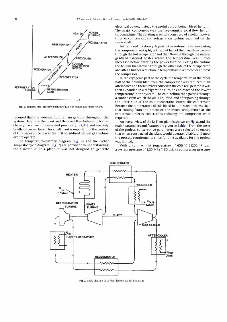
8112019 Helium Turbomachinery Operating Experience From Gas Turbine Power Plants
httpslidepdfcomreaderfullhelium-turbomachinery-operating-experience-from-gas-turbine-power-plants 735
required that the working 1047298uid remain gaseous throughout the
system Details of the plant and the axial 1047298ow helium turboma-
chinery have been documented previously [3233] and are only
brie1047298y discussed here This small plant is important in the context
of this paper since it was the 1047297rst fossil-1047297red helium gas turbine
ever to operate
The temperatureeentropy diagram (Fig 6) and the rather
simplistic cycle diagram (Fig 7) are pertinent to understanding
the function of this plant It was not designed to generate
electrical power instead the useful output being ldquobleed heliumrdquo
The major component was the free-running axial 1047298ow helium
turbomachine The rotating assembly consisted of a helium power
turbine compressor and refrigeration turbine mounted on the
same shaft
In the closed Brayton cycle part of the system the helium exiting
the compressor was split with about half of the mass 1047298ow passing
through the hot recuperator and then 1047298owing through the natural
gas-1047297red external heater where the temperature was further
increased before entering the power turbine Exiting the turbine
the helium then 1047298owed through the other side of the recuperator
and after a further reduction in temperature in a precooler entered
the compressor
In the cryogenic part of the cycle the temperature of the other
half of the helium bled from the compressor was reduced in an
aftercooler and then further reduced in the cold recuperator It was
then expanded in a refrigeration turbine and reached the lowest
temperature in the system The cold helium then passes through
a condenser in which the air is lique1047297ed and after passing through
the other side of the cold recuperator enters the compressor
Because the temperature of this bleed helium stream is less than
that coming from the precooler the mixed temperature at the
compressor inlet is cooler thus reducing the compressor workrequired
An overall view of the La Fleur plant is shown on Fig 8 and the
major parameters and features are given on Table 1 From the onset
of the project conservative parameters were selected to ensure
that when constructed the plant would operate reliably and meet
the process requirements since funding available for the project
was limited
With a turbine inlet temperature of 650 C (1202 F) and
a system pressure of 125 MPa (180 psia) a compressor pressure
Fig 6 Temperatureeentropy diagram of La Fleur helium gas turbine plant
Fig 7 Cycle diagram of La Fleur helium gas turbine plant
CF McDonald Applied Thermal Engineering 44 (2012) 108e142114
8112019 Helium Turbomachinery Operating Experience From Gas Turbine Power Plants
httpslidepdfcomreaderfullhelium-turbomachinery-operating-experience-from-gas-turbine-power-plants 835
ratio of 15 was selected With modest stage loading a 16 stage axial
compressor was designed the welded rotor being shown on Fig 9
Fifty percent reaction blading was used throughout The axial
velocity was kept constant and with a low value of pressure ratio
the annulus taper was rather slight The target ef 1047297ciency for the
compressor was83 percent The blades were cast 410 stainless steel
and these were welded to forged discs since this was the lowest
cost type of construction at the timeFor the turbine a tip speed of 305 ms (1000 ftsec) was
conservatively selected the rotational speed being 19500 rpm
While not coupled to a generator to produce electrical power the
size of the constant speed free-running turbine was equivalent to
that in a machine rated in the 1000e2000 kW class A view of the
turbine rotor is given on Fig 10 The material for the investment
cast blades was Haynes 21 and these were welded to a Timken 16-
25-6 disc The turbine ef 1047297ciency goal was 85 percent
The rotor was supported on oil-lubricated bearings To avoid oil
ingress into the helium circuit the oil pump scavenge pump and
the other accessories were separately driven by electric motors As
also experienced in later closed-cycle gas turbine plants oil ingress
into the helium closed loop occurred this being traced to a poor
design of the oil seals Keeping the system leak-tight when
operating with such a low molecular weight gas was a major
challenge and this topic will be discussed later for other helium
systems operating at high pressure and temperature
In this small pioneer plant the worldrsquos 1047297rst helium turbo-
machine operated satisfactorily the major achievement being that
it proved the La Fleur cryogenic process for air liquefaction The
experience gained from this small prototype plant led to the
construction and operation of a larger fossil-1047297red helium closed-cycle gas turbine for a lique1047297ed gas cryogenic plant and this is
discussed in the following section
5 Escher Wyss helium gas turbine plant
Following the successful operation of the pioneer plant La Fleur
Corporation designed and built a cryogenic facility in Phoenix
Arizona in 1966 for the liquefaction of 90 tonsday of nitrogen The
helium turbomachine was developed and built in Zurich by Escher
Wysswho up to that date hadfabricated the majority of the closed-
cycle gas turbine plants in Europe [2] The thermodynamic cycle
(involving splitting the helium 1047298ow at the compressor exit)
resembled the aforementioned pioneer plant with the exception
that the compressor was separated into two sections to facilitate
Fig 8 Overall view of 1047297rst helium gas turbine (Courtesy La Fleur Corp)
CF McDonald Applied Thermal Engineering 44 (2012) 108e142 115
8112019 Helium Turbomachinery Operating Experience From Gas Turbine Power Plants
httpslidepdfcomreaderfullhelium-turbomachinery-operating-experience-from-gas-turbine-power-plants 935
intercooling [634] The major parameters and features of this plant
are summarized on Table 1
With a turbine inlet temperature of 660 C (1220 F) and
a system pressure of 122 MPa (177 psia) a compressor pressure
ratio of 20 was selected A cross-section of the turbomachine is
shown on Fig 11 The LP and HP compressors had 10 and 8 stages
respectively The compressors were designed with a degree of
reaction slightly above 100 percent based on the prevailing view by
Escher Wyss at the time that this had advantages for helium
compressors Since this philosophy was carried over into the next
much larger helium gas turbine (as covered in the following
section) the rationale for this aerothermal design decision is brie1047298y
addressed below
The degree of reaction can essentially be regarded as the ratio of
pressure rise (although accurately de1047297ned as the static enthalpy
rise) in the rotor with the total pressure rise through the combi-
nation of the rotor and stator In early British axial 1047298ow compres-
sors a value of 50 percent was adopted this enabling the same
blade pro1047297le to be used for the rotor and stator In contemporary
air-breathing gas turbines the compressor degree of reaction is not
a major design factor The effect that selected compressor rotor and
stator positioning and geometries have on the degree of reaction is
illustrated in a simple form on Fig 12 In the early years of closed-
cycle gas turbine work Escher Wyss in Switzerland advocateda degree of reaction of 100 percent or higher [35] With such
blading the gas enters and leaves the stage in an axial direction The
basic stage embodies a negative pre-whirl stator ahead of the rotor
With the stator blades acting as a nozzle it was felt that the
resulting acceleration in the stator had the effect of smoothing out
the 1047298ow providing the best possible conditions for the rotor
However such blading with high stagger and lowsolidity has a very
high relative velocity and attendant high Mach number and is not
used in machines with air as the working 1047298uid since the associated
losses would be excessive leading to low overall compressor ef 1047297-
ciency This type of stator-before-rotor high reaction arrangement
was felt to be advantageous for helium axial 1047298ow compressors to
reduce the number of stages since Mach number effects are not
encountered because the sonic velocity of helium is on the order of
three times that of air
Because of the properties of helium (ie low molecular weight
high speci1047297c heat higher adiabatic index etc) a higher number of
compressor and turbinestages for a given pressure ratio are needed
as mentioned previously An axial compressor with just over
a hundred percent reaction as in the Escher Wyss helium gas
turbine that operated in Phoenix has a greater enthalpy rise per
stage for a given tip speed this reducing the number of stages for
a given pressure ratio but the ef 1047297ciency is slightly lower Mini-
mizing the number of stages was important from the rotor dynamic
stability standpoint for the very long rotor assembly associated
Fig 9 La Fleur plant 16 stage compressor (Courtesy La Fleur Corp) Fig 10 La Fleur plant 4 stage helium turbine (Courtesy La Fleur Corp)
Table 1
Salient features of operated helium turbomachinery
Turbomachine Helium closed-cycle gas turbines Test facility Helium circulator
Facility La Fleur
gas turbine
Escher Wyss
gas turbine
Oberhausen 11
power plant
HHV
test loop
FSV HTGR
Country USA USA Germany Germany USA
Year 1962 1966 1974 1981 1976
Application Cryogenic Cryogenic CHP plant Development Nuclear plant
Heat source NG NG Coke oven gas Electrical NuclearPower MW 2 equiv 6 equiv 50 90 4
Cycle Recuperated ICR ICR Customized Steam
Compressor
Type Axial Axial Axial Axial Axial
No stages 16 10LP8HP 10LP15HP 8 1
Inlet press MPa 125 122 105285 45 473
Inlet temp C 21 22 25 820 394
Pressure ratio 15 20 27 113 102
Flow kgsec 73 11 85 212 110
In vol 1047298ow m3sec 35 55 50 107 32
Turbine
Type Axial Axial Axial Axial ST
No stages 4 9 11LP7HP 2 1
Inlet press MPa 18 23 165 50 e
Inlet temp C 650 660 750 850 e
In vol 1047298ow m3sec 30 57 67 98 e
Out vol 1047298ow m3
sec 36 85 120 104 e
Rotation speed rpm 19500 18000 55003000 3000 9550
Shaft type Single Single Twin (geared) Single Single
Generator type None None Conventional Elect motor e
CF McDonald Applied Thermal Engineering 44 (2012) 108e142116
8112019 Helium Turbomachinery Operating Experience From Gas Turbine Power Plants
httpslidepdfcomreaderfullhelium-turbomachinery-operating-experience-from-gas-turbine-power-plants 1035
with this intercooled helium axial compressor of the type shown on
Figs 11 and 13
In the high pressure helium environment a high degree of reaction leads to a rotor blading with longer chords and low aspect
ratio The larger chord length combined with low solidity results in
comparatively few compressor blades Low aspect ratio (de1047297ned as
the ratio of blade height to chord length) results in several effects
including the following 1) high stagger with wider chords results in
a greater overall machine bladed length 2) fewer blades per stage
3) relatively large area of casing and blade surface with adverse
frictional losses tending to give lower ef 1047297ciency and 4) a stiffer
blade section (also with a thicker pro1047297le) with the needed strength
to combat bending stress which can be signi1047297cant in a high pres-
suredensity helium closed-cycle system A way to partially balance
out the bending stress would be by leaning the blades and off-
setting the blade cross-section centre of gravity For the early
helium gas turbine plants a view expressed by Escher Wyss wasthat the use of high reaction blading gave the maximum attainable
head a 1047298atter pressureevolume characteristic and a better surge
margin [36] The merits of increased pressure rise per stage asso-
ciated with high reaction blading has to be put into perspective by
its lower values of ef 1047297ciency [37]
The turbine had 9 stages and a rotational speed of 18000 rpm
While not coupled with a generator the equivalent output of the
free-running turbine was on the order of 6000 kW An overall view
of the long slender rotor is shown on Fig 13 and the turbomachine
assembly being installed in a cylindrical horizontally split casing is
shown on Fig 14 The major 1047298anges had peripheral lip seals to
facilitate welding closure to ensure leak tightness
With an external gas-1047297red heater the plant operated for about
5000 h and the helium gas turbine proved to be mechanically
sound and met its speci1047297ed performance This very specialized
plant proved to be too expensive to operate for the limited market
for cryogenic 1047298uids Anticipated market growth in the late 1960sdid not materialize and while the machinery performed satisfac-
torily the customer Dye Oxygen withdrew the plant from service
As far as the helium gas turbine was concerned the plant repre-
sented a signi1047297cant milestone since the technology generated was
applied to a follow-on helium gas turbine which at this stage was
still to be fossil-1047297red but now with the long-term goal in mind of
paving the way for the eventual operation of a helium closed-cycle
gas turbine power plant with a high temperature nuclear heat
source
6 Oberhausen II helium gas turbine plant at EVO
61 Closed-Cycle gas turbine experience at EVO
With initial operation starting in 1960 the municipal energy
utility (EVO) of the city of Oberhausen in the German industrial
Ruhr area deployed a closed-cycle gas turbine plant Referred to as
Oberhausen I the plant (shown previously on Fig 3) operated in
a combined power and heat mode with an electrical output of
14 MW and the thermal heat rejection of about 20 MW was
supplied to the cityrsquos district heating system The external heater
was initially 1047297red with Bituminous coal and in 1971 a change was
made to use coke-oven gas that had become available While using
air as the working 1047298uid some of the technical dif 1047297culties experi-
enced with this plant are highlighted below simply because if they
were to occur in a future direct cycle nuclear gas turbine plant they
would be very costly and time consuming to resolve as will be
discussed in a following section
Fig 11 Cross-section view of helium gas turbine (Courtesy Escher Wyss)
CF McDonald Applied Thermal Engineering 44 (2012) 108e142 117
8112019 Helium Turbomachinery Operating Experience From Gas Turbine Power Plants
httpslidepdfcomreaderfullhelium-turbomachinery-operating-experience-from-gas-turbine-power-plants 1135
In 1963 after 20000 h of operation a failure in the HP
compressor occurred [10] A rotor blade in the 1047297rst stage failed at
the root and in passing through the compressor caused extensive
damage The failure necessitated replacing the complete HP
compressor rotor assembly From a metallurgical examination of
the broken parts the failure was attributed to a small crevice at the
edge of the blade It was postulated that a corrosive action due to
impurities in the closed-loop working 1047298uid (ie air) in1047298uenced the
propagation of the crevice and blade vibration eventually caused
the failure To prevent a further failure of this kind an electric
polishing procedure was applied to the surface of the blade to
detect any imperfections
In 1967 debris from within the closed circuit caused damage to
the rotor blades and stators of several stages in the LP compressor
In 1973 further damage in the LP compressor due to blade vibration
required blading replacement During these de-blading events the
failed fragments were contained within the machine casings Using
conventional equipment the split casings of this machine were
opened and the failed parts removed by hands-on operations New
parts were then installed and the rotor assembly re-balanced The
problems were resolved and this closed-cycle gas turbine plant
with air as the working 1047298uid then performed well over the years
with high reliability [38]Rotor vibrations are mentioned here because they had caused
problems in three fossil-1047297red closed-cycle gas turbine plants using
air as the working 1047298uid namely1) in the John Brown 12 MW Plant
in Dundee where insurmountable vibration problems occurred [2]
2) multiple blade failures in the Spittelau 30 MW plant [2] and 3)
compressor blade failures in the aforementioned Oberhausen plant
As will be mentioned in a following section a further turbine blade
failure was experienced in a larger plant using helium as the
working 1047298uid
Correcting the subsequent blade failure damage to the turbo-
machine in a fossil-1047297red plant was straightforward however the
implication of such an operation in a future direct cycle nuclear gas
turbine with radioactively contaminated blading would be far more
severe This would likely require complex remote handling equip-ment and a dedicated facility for machine decontamination and
disassembly before hands-on repair could be undertaken
The Oberhausen I plant operated for about 120000 h and was
decommissioned in 1982 In about 1971 an expansion of the utilityrsquos
Fig 12 Impact of compressor blading geometry on degree of reaction (Courtesy
Escher Wyss)
Fig 13 Intercooled axial 1047298
ow helium turbomachine rotating assembly (Courtesy Escher Wyss)
CF McDonald Applied Thermal Engineering 44 (2012) 108e142118
8112019 Helium Turbomachinery Operating Experience From Gas Turbine Power Plants
httpslidepdfcomreaderfullhelium-turbomachinery-operating-experience-from-gas-turbine-power-plants 1235
capacity was needed due to increasing demand A larger fossil-1047297red
closed-cycle cogeneration plant of conventional design and still
retaining the use of air as the working 1047298uid was initially foreseen
but an emerging German development in the nuclear power plant
1047297eld resulted in a different decision being made as discussed
below
62 Relevance of the Oberhausen II helium turbine
Starting in 1972 development work sponsored by the Federal
Republic of Germany within the scope of the 4th Atomic program
was initiated on a high temperature reactor power plant with
a helium gas turbine (HHT) The reference plant design was based
on a large single-shaft intercooled helium turbine rated at
1240 MW A demonstration plant rated at 676 MW was planned
but prior to the construction of this it was necessary to test the
most important components to reduce risk Details of the two
major facilities to accomplish this have been reported previously
[39] and are summarized as follows
The Oberhausen II helium gas turbine plant was designed andbuilt to perform two major functions 1) it had to operate as
a commercial venture to provide electrical power (50 MWe) and
district heating (53 MWt) for the city of Oberhausen and 2) provide
data applicable to the nuclear gas turbine project particularly the
dynamic behavior of the overall plant and the integrity and long-
term operating experience of the major components in a helium
environment especially the turbomachine
The second facility was the HHV an experimental plant for
testing under representative conditions with respect to machine
size operating temperature pressure and mass 1047298ow of a large
helium turbomachine The facility was extensively instrumented to
gatherdata in the following areas rotorcooling system veri1047297cation
thermal insulation integrity 1047298ow characteristics blading ef 1047297ciency
acoustics rotor dynamic stability bearings dynamic and static
seals system leak tightness and metals behavior for the full
spectrum of plant operations including plant startup load change
shutdown upset conditions etc Details of the HHV facility and
testing undertaken are given in a later section
63 Oberhausen II helium gas turbine plant design
The design and construction of the plant was based on joint
efforts between EVO (plant designer and operator) GHH (turbo-
machine recuperator coolers and controls) Sulzer (helium
heater) and the University of Hannover Institute for Turboma-
chinery which contributed to the designwork and monitoring plant
performance
For the future planned nuclear gas turbine plant design values
of the temperature and pressure at the turbine inlet were 850 C
(1562 F) and 60 MPa (870 psia) respectively Attainment of this
temperature in the Oberhausen II plant could not be achieved and
750 C (1382 F) was selected based on tube material stress
considerations in the external coke-oven gas 1047297red heater An
intercooled and recuperated closed cycle was selected and themajor features of the plant are given on Table 1 The salient
parameters are given on the simpli1047297ed cycle diagram (Fig 15)
While rated at 50 MW a maximum system pressure of only
285 MPa (413 psia) was chosen so that the helium volumetric 1047298ow
(hence size of the bladed passages) would correspond to a much
larger helium turbomachine (on the order of 300 MW in fact) This
together with a rotational speed of 5500 rpm for the HP group
would result in representative stress loadings and would permit
a reasonable extrapolation to the machine size planned for the
nuclear demonstration plant
For the intercooled and recuperated cycle a compressor pressure
ratio of 27 was selected The helium mass 1047298ow rate was 85 kgs
(187 lbsec) and the circuit pressure loss was estimated at 104
percent Based on state-of-the-art component ef 1047297
ciencies and
Fig 14 Intercooled helium turbomachine with an equivalent power rating of 6000 kW installed in a split-case steel pressure vessel (Courtesy Escher Wyss)
CF McDonald Applied Thermal Engineering 44 (2012) 108e142 119
8112019 Helium Turbomachinery Operating Experience From Gas Turbine Power Plants
httpslidepdfcomreaderfullhelium-turbomachinery-operating-experience-from-gas-turbine-power-plants 1335
a recuperator effectiveness of 87 percent the projected thermal
ef 1047297ciency was 326 percent gross and 313 percent net
The isometric sketch of the distributed power conversion
system shown on Fig 16 (from Ref [40]) is convenient for
describing the plant layout A decision was made [41] to install the
horizontal turbomachinery in three large steel vessels the group-
ings being as follows 1) LP compressor rotor 2) HP compressor and
HP turbine grouping and 3) LP turbine The 1047297rst two assemblies
were on a single-shaft with a rotational speed of 5500 rpm The
generator with a rotational speed of 3000 rpmis driven from the LP
turbine end The rotors were geared together but with the selected
shafting arrangement only a small amount of power was trans-
mitted through the gearbox This con1047297guration was established
so that the dynamic behavior would be the same as in the large
single-shaft reference nuclear gas turbine plant design concept
The arrangement of the three vessels can be clearly seen on Fig 17
The horizontal tubular recuperator is positioned below the
turbomachinery The tubular precoolers and intercoolers are
installed in vertical steel vessels This type of orientation of the
major components was used in some of the earlier closed-cycle
plants using air as the working 1047298uid
Power regulation was achieved by inventory control as in the
aforementioned Oberhausen I plant which meant that the system
pressure (hence mass 1047298ow) was changed as required To lower the
power output helium was extracted from the loop after the HP
compressor through a control valve into a storage vessel For
a power increase helium was returned from the storage vessel into
the system upstream of the LP compressor without the need for an
additional blower With this arrangement the turbine inlet
temperature and speed remained constant and plant ef 1047297ciency
would be essentially constant down to a very low power level [42]
To achieve rapid load changes a bypass valve was included in the
system in which helium was transferred in a line between the HP
compressor exit end and LP end of the recuperator A very rapid
change from 100 percent load to no-load operation and back was
demonstrated [43]
64 Helium turbomachinery
The major features and parameters for the turbomachine are
given on Table 2 and are summarized as follows A longitudinal
cross-section of the turbomachine is shown on Fig 18 At the left
hand end the LP compressor is installed in a spherical pressure
vessel A high degree of reaction (ie 100 percent) was selected for
this 10 stage axial compressor this practice following the experi-
ence of an earlier discussed helium turbomachine A view showing
the bladed rotor of the LP compressor installed in the pressure
vessel split casing is shown on Fig19 with an appreciation for the
size of the spherical casing being shown on Fig 20 Both the HP
compressor and HP turbine rotors are installed in a common
housing as shown in the turbomachine cross-section (Fig 21) and
Fig 15 Oberhausen II helium gas turbine cycle diagram
Fig 16 Isometric layout of Oberhausen II helium gas turbine power conversion system (Courtesy EVO)
CF McDonald Applied Thermal Engineering 44 (2012) 108e142120
8112019 Helium Turbomachinery Operating Experience From Gas Turbine Power Plants
httpslidepdfcomreaderfullhelium-turbomachinery-operating-experience-from-gas-turbine-power-plants 1435
in the view with the HP rotor assembly positioned above the
horizontal split casing (Fig 22) The 15 stage HP compressor was
again designed with 100 percent reaction blading The HP turbine
has 7 stages and operated with an inlet temperature of 750 C
(1382O F) A cross-section of the 11 stage LP turbine installed in
a separate spherical vessel is shown on Fig 23 The amount of
power transmitted in the gearbox between the HP and LP turbinesis small since at rated output the HP turbine power level is only
slightly more than is needed to drive both compressors
The rotor of the HP group is supported on two oil-lubricated
bearings For the complete rotating assembly the thrust bearing is
located at the warm end of the LP compressor The six turbo-
machine bearing housings were designed such that direct access to
the large oil bearings was possible without having to open the large
casings This was done to reduce maintenance time because the
large split casings have 1047298anges that were welded closed at the
peripheral lip seals to minimize helium leakage
Special attention was given to the design of the cooling system
for the rotor In the case of this plant with a turbine inlet
temperature of 750 C the turbine blades themselves based on the
use of an existing superalloy did not have to be internally cooledbut cooling gas bled from the HP compressor outlet 1047298owed through
the hollow shaft and was used to cool the turbine discs and the
blade root attachments and then returned downstream of the
turbine
In a closed-cycle gas turbine the powerlevel can be regulated by
means of changing the system pressure and careful attention must
be given to the design of the various sealing systems to accom-
modate pressure differentials within the system particularly
during transient operation To simulate what would be needed in
a direct cycle nuclear gas turbine (to prevent 1047297ssion products
coming into contact with the bearing lubricating oil) a system
having a separate chamber for each of the three labyrinth seals was
incorporated in the machine design Outboard of the labyrinth seals
where the shafts penetrate the casings there were two further
seals a 1047298oating ring seal and a shutdown seal to prevent external
helium leakage
65 Helium turbomachine operating experience
Various presentations papers and publications have previously
covered the over 13 year operation of the Oberhausen II helium gas
turbine plant [43e48] The experience gained with the operation
Fig 17 Overall view of Oberhausen II 50 MWe helium gas turbine power plant (Courtesy EVO)
Table 2
Oberhausen II plant helium turbomachinery
Plant design electrical power MW 50
District heating thermal supply MW 535
Plant design ef 1047297ciency at terminals 313
Thermodynamic cycle ICR
Control method Helium inventory
compressor bypass
Rotor arrangement 2 Shaft (geared together)
Helium mass 1047298ow kgsec 85
Overall pressure ratio 27
Generator ef 1047297ciency 98
Design system pressure loss 104Compressor LP HP
Inlet pressure MPa l05 l54
Inlet temperature C 25 25
Vol 1047298ow inletoutlet m3s 5040 4025
Ef 1047297ciency 870 855
Rotational speed rpm 5500 5500
Number of stages 10 15
Blade height inletoutlet mm 10385 7253
Turbine LP HP
Inlet pressure MPa 165 270
Inlet temperature C 582 750
Ef 1047297ciency 900 883
Rotational speed rpm 3000 5500
Number of stages 11 7
Vol 1047298ow inletoutlet m3sec 92120 6792
Blade height inletoutlet mm 200250 150200
CF McDonald Applied Thermal Engineering 44 (2012) 108e142 121
8112019 Helium Turbomachinery Operating Experience From Gas Turbine Power Plants
httpslidepdfcomreaderfullhelium-turbomachinery-operating-experience-from-gas-turbine-power-plants 1535
of the large axial 1047298ow helium turbomachine is summarized asfollows
On the positive side the following were accomplished The rotor
helium buffered bearing labyrinth oil sealing system was one of the
numerous systems that worked well from the onset This was
encouraging since the external leakage of helium contaminated by
1047297ssion products and the ingress of lubricating oil into the closed
helium loop during the projected plant lifetime of 60 years are of
concern to designers of a direct cycle nuclear gas turbine plant (for
a machine with oil bearings) because of the likely long plant
downtime for cleanup and repair
With some modi1047297cations the helium puri1047297cation system
worked well with the purity level within the speci1047297cation The
helium cooling systems worked well to keep the temperatures of
the turbine discs blade root attachments and casings at speci1047297
edlevels Load change by inventory control was done routinely and
the ability to shed 100 percent of the load in a very short period by
means of the bypass valve was demonstrated The integrity of the
co-axial turbine inlet hot gas duct was proven At the end of plant
operation the major turbomachine casings were opened and there
were no signs of corrosion or erosion of the turbine or compressor
blades The coatings applied to mating metallic surfaces were
effective with no evidence of galling or self-welding in the oxygen-
free closed-loop helium environment
Experience from previously operated high temperature helium
cooled nuclear reactor power plants (with Rankine cycle steam
turbine power conversion systems) demonstrated that absolute
helium leak tightness was not attainable This was also true in the
Oberhausen II fossil-1047297red gas turbine plant where during initial
operation the helium leakage was about 45 kg per day Attention
was given to this and helium losses were reduced to the range of
5e10 kg per day principally by seal welding the major 1047298anges This
value can be compared with other closed loop helium systems as
shown below
On the negative side several unexpected problems had a majorimpact on the operation of the plant Following initial running of
the machine at 3000 rpm in preparation to synchronizing the
system the HP casing was opened for inspection revealing
damage to the labyrinth seals this being caused by shifting of
the rotor in the axial direction The labyrinth seals were replaced
and the turbine was 1047297rst synchronized with the grid on November
8 1975
Subsequent vibration problems were encountered and the HP
shaft oscillation became so large that it caused damage to the
bearings and the design value of speed and power could not be
maintained and the plant was shut down This was initially thought
to be due to thermal distortion of the rotor and a large unbalance
Fig 18 Cross-section of Oberhausen II plant helium turbomachinery rotating assembly (Courtesy EVO)
Fig 19 Oberhausen II low pressure helium compressor installed in casing (Courtesy
GHH)
Plant Helium inventory kg Leakage
kgday day
Dragon 180 020e20 010e10
AVR 240 10e30 040e12
Oberhausen II 1400 5e10 035e070
HHV 1250 25e50 020e040
FSV e Excessive leakage
CF McDonald Applied Thermal Engineering 44 (2012) 108e142122
8112019 Helium Turbomachinery Operating Experience From Gas Turbine Power Plants
httpslidepdfcomreaderfullhelium-turbomachinery-operating-experience-from-gas-turbine-power-plants 1635
Modi1047297cations to the rotor were made and the bearings replaced
but now the HP spool design speed of 5500 rpm could not be
achieved Subsequent major design and fabrication changes were
made including decreasing the bearing span by 600 mm (24 in)
giving a shorter stiffer rotor and changing the type of bearings In
restarting the plant the design speed of the HP rotor was achieved
however the power output was only 30 MW compared with the
design value of 50 MW
Fig 20 View of Oberhausen II low pressure helium compressor spherical vessel (Courtesy GHH)
Fig 21 Cross-section of Oberhausen II high pressure rotating group (Courtesy GHH)
CF McDonald Applied Thermal Engineering 44 (2012) 108e142 123
8112019 Helium Turbomachinery Operating Experience From Gas Turbine Power Plants
httpslidepdfcomreaderfullhelium-turbomachinery-operating-experience-from-gas-turbine-power-plants 1735
To gain operational experience it was decided to continue
running the plant at the reduced power rating On February 5 1979
after nearly 11000 h of operation a rotor blade from the second
stage of the HP turbine failed causing damage in the remaining
stages but the high energy fragments were contained within the
thick machine casing Examination of the failed blade revealed the
defect as a crack caused by the forgingprocess on the semi-1047297nishedproduct To prevent such a failure occurring in the future an electric
polishing process applied to the blade surface before inspection
was implemented and improved crack detection methods
introduced
Acoustic loads in a closed-cycle gas turbine represent pressure
1047298uctuations propagating at the speed of sound through the helium
working 1047298uid Pressure 1047298uctuations of importance result from the
aerodynamic effects of high velocity helium impacting and
essentially being intermittently ldquocutrdquo by the blading in the
compressor and turbine Care must be taken in the design of the
plant to ensurethat these 1047298uctuating pressure waves do not induce
vibrations of a magnitude that could result in excitation-induced
fatigue failures in components in the circuit Critical vibrations
occur when resonance exists between the main frequency of
the propagating sound and the natural frequencies of the
components particularly ones that have large surface area to
thickness ratio
Measurements of sound spectrum were taken at four different
locations in the circuit The design level of power of 50 MW was not
achieved but at the 30 MW power output actually realized the
maximum recorded sound power level was 148 dB After plantshutdown there was no evidence of adverse effects on the major
components of noise induced excitation emanating from the axial
1047298ow turbomachinery The integrity of the turbine inlet hot gas duct
and insulation was con1047297rmed
The inability to reach rated power was attributed to shortcom-
ings in the helium turbomachine This included the compressors(s)
and turbine(s) blading failing to attain design values of ef 1047297ciencies
and the bleed helium mass 1047298ows for cooling and sealing being
signi1047297cantly greater than analytically estimated Based on data
taken from the well instrumented plant detailed analyses were
undertaken by specialists [4950] to calculate the losses in the
turbomachine to explain the power output de1047297ciency A summary
of the projected losses and various component ef 1047297ciencies is pre-
sented in a convenient form on Table 3
Fig 22 Oberhausen II high pressure rotor being installed (Courtesy GHH)
CF McDonald Applied Thermal Engineering 44 (2012) 108e142124
8112019 Helium Turbomachinery Operating Experience From Gas Turbine Power Plants
httpslidepdfcomreaderfullhelium-turbomachinery-operating-experience-from-gas-turbine-power-plants 1835
The plant operated for approximately 24000 h and was shut-
down and decommissioned in 1988 when the coke-oven gas supply
for the heater was no longer available A total plant operating time
of about 11500 h had been at the design turbine inlet temperature
of 750 C (1382 F) Turbomachinery related experience gained
from operation of this large helium gas turbine plant was extremely
valuable While many of the functions performed well from the
onset and others worked satisfactorily after modi1047297cations were
made serious unexpected problems were encountered
The achieved electrical power output of only 60 percent of the
design value was initially thought to be due to a grossly excessive
system pressure loss However when the data was carefully eval-uated it was found that 85 percent of the 20 MW power loss was
attributed to turbomachine related problems as delineated on
Table 3
To remedy this power de1047297ciency it was clear that a major re-
design of the turbomachinery would be required While replace-
ment of the gas turbine was not contemplated a study was
undertaken based on data from the plant and new technologies
that had become available since the initial design Based on the
1047297ndings a new turbomachine layout concept was suggested [43]
and a simplistic view of the rotor arrangement is shown on Fig 24
A more conventional single-shaft arrangement was proposed with
the two compressors and turbine having a rotational speed of
5400 rpm A gearbox was still retained to give a generator rota-
tional speed of 3000 rpm Based on prevailing technology at the
time the requirements for such a gearbox would have been moredemanding since the 50 MW from the turbine to the generator
would have to be transmitted through it This would necessitate
a larger system to pump 1047297lter and cool the bearing lubrication oil
To remedy the very large losses in the compressors and turbines
the number of stages would have to be increased In the case of the
compressors the use of lighter aerodynamically loaded higher
ef 1047297ciency stages with 50 percent reaction blading was
recommended
7 High temperature helium test facility (HHV)
71 Background
In the late 1960rsquos with large numbers of orders placed for 1047297rst
generation light water reactor nuclear power plants studies were
initiated for next generation power plants with higher ef 1047297ciency
potential Following the initial operational success of the 1047297rst three
small helium cooled HTR plants (ie Dragon in the UK Peach
Bottom I in the USA and AVR in Germany) studies on larger plants
based on the use of both Rankine steam cycle and helium closed
Brayton cycle power conversion systems were undertaken In the
early 1970rsquos emphasis was placed on nuclear gas turbine plant
designs with larger power output both in the USA (for the
HTGR eGT) and in Europe (for the HHT) Work in the USA was
limited to only paper studies [18] The much larger program in
Germany (with participation by Swiss companies for the turbo-
machine heat exchangers and cooling towers) included a well
planned development testing strategy to support the plant design
Fig 23 Cross-section of Oberhausen II low pressure helium turbine (Courtesy GHH)
Table 3
Oberhausen II helium turbine plant power losses
Componentcause Design
value
Measured Power loss
MW
Compressors
B Flow losses in inlet diffusers
and blades
Low pressure ef 1047297ciency 870 826 13
High pressure ef 1047297ciency 855 779 40
Turbines
B Blade gap and 1047298ow losses
High pressure ef 1047297ciency 883 823 39
B Pro1047297le losses due to Remachined
blades after having detected
damaged blades
Low pressure ef 1047297ciency 900 856 24
BSealing leakage and cooling 1047298ows
in all turbomachines Kgsec
18 75 53
B Circuit pressure losses
(Ducting Hxrsquos etc)
102 128 26
B Miscellaneous heat losses 05
Total power loss 200 MW
Notes (1) Plant designed for electrical power output of 50 MW actual power output
measured 30 MW
(2) Power de1047297ciency of20 MW based on measurements taken and then recalculated
for the rated plant output
(3) 85 of Power loss attributed to helium turbomachinery related issues
CF McDonald Applied Thermal Engineering 44 (2012) 108e142 125
8112019 Helium Turbomachinery Operating Experience From Gas Turbine Power Plants
httpslidepdfcomreaderfullhelium-turbomachinery-operating-experience-from-gas-turbine-power-plants 1935
While the reference HHT plant for eventual commercializationembodied a very large single helium gas turbine rated at 1240 MW
this was to be preceded by a nuclear demonstration plant rated at
676 MW [51] To support the design of this plant technology
generated from the following was planned 1) operational experi-
ence from the aforementioned Oberhausen II 50 MW helium gas
turbine power plant and 2) testing of components in a large high
temperature helium test facility as discussed below
72 Development facilitytesting objectives
An overall view of the HHV test facility sited in Julich in
Germany is shown on Fig 25 and since this has been reported on
previously [52] it will only be brie1047298
y covered in this section Tominimize risk and assure the performance integrity and reliability
of the nuclear demonstration plant some non-nuclear testing of
the major components especially the helium turbomachine was
deemed essential Because of the limitations of a conventional
closed-cycle helium gas turbine power plant particularly the
temperature limitations of existing fossil-1047297red and electrical
heaters a new type of test facility was foreseen
A simpli1047297ed schematic line diagram of the HHV circuit is shown
on Fig 26 The major design parameters are shown on Fig 27
together with the temperatureeentropy diagram which is conve-
nient for describing the unique relationship between the compo-
nents in the closed helium loop Starting at the lowest pressure in
Fig 24 Proposed new concept for Oberhausen II helium gas turbine rotating assembly to remedy problems encountered during operation of the 50 MWe power plant (Courtesy
EVO)
Fig 25 HHV helium turbomachinery test facility (Courtesy BBC)
CF McDonald Applied Thermal Engineering 44 (2012) 108e142126
8112019 Helium Turbomachinery Operating Experience From Gas Turbine Power Plants
httpslidepdfcomreaderfullhelium-turbomachinery-operating-experience-from-gas-turbine-power-plants 2035
the system the helium is compressed (Ae
B) its temperatureincreasing to 850 C (1562 F) before 1047298owing through the test
section (BeC) After being cooled slightly (CeD) the helium is
expanded in the turbine (DeA) down to the compressor inlet
conditions completing the loop There is no power output from the
system and without the need for an external heater the
compression heat is used to raise the helium to the maximum
system temperature in what can be described as a very large heat
pump The required compressor power is 90 MW and to supple-
ment the 45 MW generated by expansion in the turbine external
power is provided by a 45 MW synchronous electrical motor A
cooler is required to remove the compression heat that is contin-
uously put into the closed helium loop and this is done by bleeding
about 5 percent of the mass 1047298ow after the compressor cooling it
and re-introducing it into the circuit close to the turbine inlet In
addition to testing the turbomachine the facility was engineered
with a test section to accommodate other small components (eg
hot gas 1047298ow regulation valves bypass valves insulation con1047297gu-
rations and types of hot gas duct construction) With the highest
temperature in the system being at the compressor exit the facility
had the capability to provide helium at a temperature up to 1000 C
(1832 F) for short periods at the entrance to the test section
While a higher ef 1047297ciency of the planned nuclear demonstration
plant could be projected with a turbine inlet temperature in the
range 950e1000 C (1742e1832 F) this would have necessitated
either turbine blade cooling or the use of a high temperature alloy
such as Titanium Zirconium Molybdenum (TZM) At the time it was
felt that using either of these would have added cost and risk to theprojectso a conventionalnickel-basedalloyas usedin industrialgas
turbines was selected for the 850 C design value of turbine inlet
temperature this negating the needfor actual internal bladecooling
However a complex internal coolingsystemwas neededto keep the
Fig 26 Cycle diagram of HHV test loop (Courtesy BBC)
Fig 27 Salient features of HHV helium turbomachinery (Courtesy BBC)
CF McDonald Applied Thermal Engineering 44 (2012) 108e142 127
8112019 Helium Turbomachinery Operating Experience From Gas Turbine Power Plants
httpslidepdfcomreaderfullhelium-turbomachinery-operating-experience-from-gas-turbine-power-plants 2135
turbine discs and blade root attachments and casings to acceptable
temperatures commensurate with prescribed stress limitations for
thelife of theturbomachine In addition a heliumsupplywas needed
to provide a buffering system for the various labyrinth seals
In a direct Brayton cycle nuclear gas turbine the turbomachine is
installed in the reactor circuit and via the hot gas duct heated
helium is transported directly from the reactor core to the turbine
From the safety licensing and reliability standpoints there are
various seals that must perform perfectly A helium buffered
labyrinth seal system is necessary to prevent bearing lubricating oil
ingress to the closed helium loop Since in the proposed HHT plant
design the drive shaft from the turbine to the generator penetrates
the reactor primary system pressure boundary two shaft seals are
needed one a dynamic seal when the shaft is rotating and a static
seal when the turbomachine is not operating Testing of these seals
in a size and operating conditions representative of the planned
commercial power plant was considered to be a licensing must
The mechanical integrity of the rotating assembly must be
assured there being two major factors necessitating testing the
machine at full speed and temperature and at high pressure
namely 1) loading the blading under representative centrifugal and
gas bending stresses and 2) to monitor vibration and con1047297rm rotor
dynamic stability For the design of the planned commercial planta knowledge of the acoustic emissions by the turbomachine and
propagation in the closed circuit was required Data from the HHV
facility would enable dynamic responses of the major components
(especially the insulation) resulting from excitation by the sound
1047297eld to be calculated
The circuit was instrumented to gather data on the effectiveness
of the hot gas duct insulation thermal expansion devices hot gas
valves helium puri1047297cation system instrumentation and the
adequacy of the coatings applied to mating metallic surfaces to
prevent galling or self-welding Details of the turbomachinery and
the experience gained from the operation of the HHV facility are
covered in the following sections
73 Helium turbomachine
A cross-section of the turbomachine is shown on Fig 28 The
single-shaft rotating assembly consists of 8 compressor stagesand 2
turbine stages and had a weighton the order of 66 tons(60000 kg)
The hub inner and outer diameters are 16 m (525 ft) and 18 m
(59 ft) respectively the blading axial length being 23 m (75 ft)The
span between the oil bearings being 57 m (187 ft) The physical
dimensions of the turbogroup shown on Fig 28 correspond to
a machine rated at about 300 MW The oil bearings operate in
a helium environment and the diameters of the labyrinths and
1047298oating ring shaft seals to prevent oil ingress are representative of
a machine rated at about 600 MW The complexity of the machine
design especially the rotor cooling system sealing system very
large casing and heat insulation have been reported previously
[53e55]
To ensure high structural integrity the rotor was constructed by
welding together the forged compressor and turbine discs The
compressor had 8 stages each having 56 rotor and 72 stator blades
The turbine had 2 stages each having 90 stator and 84 rotor blades
An appreciation for the large size of the rotating assembly can be
seen from Fig 29 The rotor blades have 1047297r-tree attachments
embodying cooling channels Since the temperature and pressure
do not vary very much along the blading in the 1047298ow direction an
intricate rotor and stator cooling system was required Channels in
both the blade roots and the spacers between adjacent blade rows
form an axial geometry for the passage of a cooling helium supplyto keep the temperature of the multiple discs below 400 C
(752 F) The design of this was a challenge since the rotor and
stator blade attachments of both the 8 stage compressor and 2
stage turbine had to be cooled Excessive leakage had to be avoided
since this would have prevented the speci1047297ed compressor
discharge temperature (ie the maximum temperature in the
circuit) from being reached
In the 1970rsquos and early 1980rsquos signi1047297cant studies were carried
out on large helium gas turbines by various organizations [56e62]
In this era there was general agreement that testing of the turbo-
machine in one form or another in non-nuclear facilities be
undertaken to resolve areas of high risk (eg seals bearings cooling
systems rotor dynamic stability compressor surge margin
dynamic response rotor burst protection etc) before installationand operation of a large gas turbine in a nuclear environment
This low risk engineering philosophy which prevailed at the time
in both Germany and the USA emphasized the importance of
Fig 28 Cross-section of HHV helium turbomachinery (Courtesy BBC)
CF McDonald Applied Thermal Engineering 44 (2012) 108e142128
8112019 Helium Turbomachinery Operating Experience From Gas Turbine Power Plants
httpslidepdfcomreaderfullhelium-turbomachinery-operating-experience-from-gas-turbine-power-plants 2235
the HHV test facility as being an important step towards the
eventual deployment of a high ef 1047297ciency nuclear gas turbine power
plant
74 Initial operation of the HHV facility
During commissioning of the plant in 1979 oil ingress into the
helium circuit from the seal system occurred twiceThe 1047297rst ingressof oil between 600 and 1200 kg (1322 and 2644 lb) was due to
a serious operatorerror and the absence of an isolation valve in the
system The oil in the circuit was partly coked and formed thick
deposits on the cold and hot surfaces of the turbomachinery and in
other parts of the closed loop including saturation of the 1047297brous
insulation The fouled metallic surfaces were cleaned mechanically
and chemically by cracking with the addition of hydrogen and
additives The second oil ingress was due to a mechanical defect in
the labyrinth seal system The quantity of oil introduced was small
and it was removed bycracking at a temperature of 600 C (1112 F)
and with the use of additives To obviate further oil ingress inci-
dents the labyrinth seal system was redesigned The buffer and
cooling helium system piping layout was modi1047297ed to positively
eliminate oil ingress due to improper valve operation and toprevent further human error
Pressure and leak detection tests of the HHV test facility at
ambient temperature showed good leak tightness for the turbo-
machine 1047298anged joints and of the main and auxiliary circuits
However at the operating temperature of 850 C (1562 F) large
helium leaks were detected The major 1047298anges had been provi-
sioned with lip seals and the 1047297rst step was to weld the closures A
large leak persisted at the front 1047298ange of the turbomachine This
was diagnosed as being caused by a non-uniform temperature
distribution during initial operation resulting in thermal stresses
creating local gaps This problem was overcome by redesign of the
cooling system with improved gas 1047298ow distribution and 1047298ow rates
to give a more uniform temperature gradient The leakage from the
system was reduced to on the order of 020e
040 percent of the
helium inventory per day this being of the same magnitude as in
other closed helium circuits as discussed in Section 65
It should be mentioned that in addition to the HHV experience
bearing oil ingress into the circuits and system loss of the working
1047298uid in other closed-cycle gas turbine plants have occurred In all of
these fossil-1047297red facilities 1047297xing leaks and removal of oil deposits
were undertaken based on conventional hands-on approaches but
nevertheless such operations were time-consuming However if a new and previously untested helium turbomachine operating in
a direct cycle nuclear gas turbine plant experienced an oil ingress
the rami1047297cations would be severe The likely use of remote
handling equipment to remove the turbomachine from the vessel
machine disassembly (including breaking the welded 1047298ange joints)
and removal of oil from the radioactively contaminated turbo-
machine blade surfaces and system insulation would be time
consuming A diagnosis of the failure would be required before
a spare turbomachine could be installed and this plant downtime
could adversely affect plant availability
75 Experience gained
Afterresolutionof the aforementionedproblems the HHVfacilitywas started in the Spring of 1981 and in an orderly manner was
brought up to full pressure and a temperature of 850 C (1562 F)
During a 60 h run the functioning of the instrumentation control
and safety systems were veri1047297ed During these tests the ability to
stop the turbomachine from full operating conditions to standstill
within 90 s was demonstrated After system depressurization the
plant was then run up again to full operating conditions with no
problems experienced The HHV facility was successfully run for
about 1100 h of which theturbomachineryoperated forabout325 h
at a temperature of 850 C The test facility was extensively instru-
mented and interpretation and analysis of the data recorded gave
positive and favorable results in the following areas
The complex rotor cooling system which was engineered to
assure that the temperature of the discs be kept below 400
C
Fig 29 HHV helium turbomachine rotating assembly (size equivalent to a 300 MWe machine) being installed in a pressure vessel (Courtesy BBC)
CF McDonald Applied Thermal Engineering 44 (2012) 108e142 129
8112019 Helium Turbomachinery Operating Experience From Gas Turbine Power Plants
httpslidepdfcomreaderfullhelium-turbomachinery-operating-experience-from-gas-turbine-power-plants 2335
(752 F) was demonstrated to be effective The measured rotor
coolant 1047298ows (about 3 percent of the mass1047298ow passing through the
machine) were slightly larger than had been estimated and this
resulted in measured turbine disc temperatures lower than pre-
dicted [55]
The dynamic labyrinth shaft seal functioned well at the full
temperature and pressure conditions and met the requirement of
zero oil ingress into the helium circuit The measured rotor oscil-
lation did not have any adverse effect on the shaft sealing system
The static rotor seal (for shutdown conditions) functioned without
any problems
The compressor and turbine blading hadef 1047297ciencies higher than
predicted The structural integrity of the rotor proved to be sound
when operating at 3000 rpm under the maximum temperature and
pressure conditions The stiff rotor shaft had only slight unbalance
and thermal distortion and measured oscillations were in the range
typical of large steam turbines
Sound power spectrum measurements were taken in four
different locations in the circuit These were taken to determine the
spectrum and intensity of the sound generated and propagated by
the turbomachinery and the resultant vibration of internal
components The maximum sound power level in the helium
circuit was160 dB Numerous strain gages were placedin the circuitto determine the in1047298uence of the sound 1047297eld particularly on the
fatigue strength of the turbine inlet hot gas duct In later examining
the internal components there was no evidence of excessive
vibration of the components especially the ducting and the insu-
lation Based on the measurements and calculations it was
concluded that the fatigue strength limit of the components would
not be exceeded during the designed life of the planned commer-
cial nuclear gas turbine power plant
In a direct cycle nuclear gas turbine the hot gas duct used to
transport the helium from the reactor core to the turbineis a critical
component The hot gas duct in the HHV facility performed well
mechanically and con1047297rmed the adequacy of the thermal expan-
sion devices From the thermal standpoint the 1047297ber insulation
performed better than the metallic type
After dismantling the HHV facility there were no signs of
corrosion or erosion of the turbine or compressor blading While
the total number of hours operated was limited the coatings
applied to mating metallic surfaces to prevent galling and frictional
welding in the oxidation-free helium worked well
The helium buffer and cooling system worked well However
problems remained with the puri1047297cation of the buffer helium The
oil separation system consisting of a cyclone separator and a wire
mesh and a down stream 1047297ber 1047297lter needed further improvement
In late 1981 a decision was made to cancel the HHT project and
the HHV facility was shutdown The design and operational expe-
rience gained from the running of this facility would have been
extremely valuable had the nuclear gas turbine power plant
concept moved towards becoming a reality The identi1047297cation of
somewhat inevitable problems to be expected in such a complexturbomachine and their resolution were undertaken in a timely
and cost effective manner in the non-nuclear HHV facility This
should be noted for future nuclear gas turbine endeavors since
remedying such unexpected problems in the case of a new and
untested large helium turbomachine being operated for the 1047297rst
time using nuclear heat could result in very complex repair
Fig 30 Speci1047297
c speed-speci1047297
c diameter array for gas circulators in various gas-cooled nuclear plants
CF McDonald Applied Thermal Engineering 44 (2012) 108e142130
8112019 Helium Turbomachinery Operating Experience From Gas Turbine Power Plants
httpslidepdfcomreaderfullhelium-turbomachinery-operating-experience-from-gas-turbine-power-plants 2435
activities and extended plant downtime and indeed adding risk to
the overall success of the nuclear gas turbine concept
8 Circulators used in gas-cooled reactor plants
Circulators of different types will be needed in future helium
cooled nuclear plants these including the following 1) primary
loop circulator for possible next generation steam cycle power andcogeneration plants 2) for future indirect cycle gas turbine plants
3) shut down cooling circulators forall HTRand VHTR plants and 4)
for various circulators needed in future VHTR high temperature
process heat plant concepts The technology status of operated
helium circulators is brie1047298y addressed as follows
81 Background
It would be remiss not to mention experience gained in the past
with gas circulators and while not gas turbines they are rotating
machines that operate in the primary loop of a helium cooled
reactor With electric motor drives there are basically two types of
compressor rotor con1047297gurations namely radial and axial 1047298ow
machinesIn a single stage form the centrifugal impeller is used for high
stage pressure rise and low volume 1047298ow duties whereas the axial
type covers low pressure rise per stage and high volume 1047298ow The
selection of impeller type is very much related to the working
media type of bearings drive type rotor dynamic characteristics
and installation envelope A wide range of circulators have operated
and a well established technology base exists for both types [63] A
useful portrayal of compressor data in the form of quasi- non-
dimensional parameters (after Balje [64]) showing approximate
boundaries for operation of high ef 1047297ciency axial and radial types is
shown on Fig 30 (from Ref [65])
Both high speed axial and lower speed radial 1047298ow types are
amenable to gas oil and magnetic bearings From the onset of
modularHTR plant studies theuse of active magnetic bearings[6667]offered a solution to eliminate lubricating oil into the reactor circuit
and this tribology technology is attractive for use in submerged
rotating machinery in the next generation of HTR plants [68]
While now dated an appreciation of the main design features of
typical electric motor-driven helium circulators have been reported
previously namely an axial 1047298ow main circulator for a modular
steam cycle HTR plant [69] and a representative radial 1047298ow shut-
down cooling circulator [70]
The operating experience gained from three particular circula-
tors is brie1047298y included below because of their relevance to the
design of helium turbomachinery in future HTR plant variants
82 Axial 1047298ow helium circulator
Since all of the aforementioned predominantly European
helium gas turbines used axial 1047298ow turbomachinery it is of interest
to mention a helium axial 1047298ow circulator that operated in the USA
and to brie1047298y discuss its design parameters and features The
330 MW Fort St Vrain HTGR featured a Rankine cycle power
conversion system Four steam turbine driven helium circulators
were used to transport heat from the reactor core to the steam
generators The complete circulator assemblies were installed
vertically in the prestressed concrete reactor vessel [71e73]
A cross-section of the circulator is shown on Fig 31 with thecompressor rotor and stator visible on the left hand end of the
machine Based on early 1960rsquos technology a decision was made to
use water lubricated bearings and from the overall plant reliability
and availability standpoints this later proved to be a bad choice
Within the vertical circulator assembly there were four 1047298uid
systems namely the helium reactor coolant water lubricant in the
bearings steam for the turbine drive and high pressure water for
the auxiliary Pelton wheel drive During plant transients the pres-
sures and temperatures of these four 1047298uids oscillated considerably
and the response of the control and seal systems proved to be
inadequate and resulted in considerable water ingress from the
bearing cartridge into the reactor helium circuit The considerable
clean up time needed following repeated occurrences of this event
resulted in long periods of plant downtime and this had an adverseeffect on plant availability This together with other technical
Fig 31 Cross section of FSV helium circulator (Courtesy general Atomics)
CF McDonald Applied Thermal Engineering 44 (2012) 108e142 131
8112019 Helium Turbomachinery Operating Experience From Gas Turbine Power Plants
httpslidepdfcomreaderfullhelium-turbomachinery-operating-experience-from-gas-turbine-power-plants 2535
dif 1047297culties eventually contributed to the plant being prematurely
decommissioned
On the positive side in the context of this paper the helium
circulators operated for over 250000 h and exhibited excellent
helium compressor performance good mechanical integrity and
vibration-free operation The rotating assembly showing the axial
1047298ow compressor and steam turbine rotors together with a view of
the machine assembly are given on Fig 32 The helium compressor
consists of a single stage axial rotor followed by an exit guide vane
The machine was designed for axial helium 1047298ow entering and
leaving the stage and this can be seen from the velocity triangles
shown on Fig 33 which also includes the de1047297nition of the various
aerodynamic parameters Major design parameters and features of
this helium circulator are given on Table 4 Related to an earlier
discussion on the degree of reaction for axial 1047298ow compressors the
value for this conventional single stage circulator is 78 percent All
of the major aerothermal and structural loading criteria were
within established boundaries for an axial compressor having high
ef 1047297ciency and a good surge margin
The compressor gas 1047298ow path and blading geometries were
established based on prevailing industrial gas turbine and aero-
engine design practice A low Mach number (025) a high Reynolds
number (3 106) together with a modest stage loading (ie
a temperature rise coef 1047297cient of 044) and an acceptable value of
diffusion factor (042) were some of the factors that contributed to
a helium circulator that had a high ef 1047297ciency and a good pressure
rise- 1047298ow characteristic The large rotor blade chord and thick blade
section for this single stage circulator are necessary to accommo-
date the high bending stress characteristic of operation in a high
pressure environment The solidity and blade camber were opti-
mized for minimum losses
There were essentially two reasons for including this single-
stage axial 1047298ow compressor that operated in a helium cooled
reactor although its overall con1047297guration can be regarded as a 1047297rst
and last of a kind A rotor blade from this circulator as shown onFig 34 was based on a NASA 65 series airfoil which at the time
were one of the best performing cascades for such low Mach
number and high Reynolds number applications Interestingly it
has almost the same blade height aspect ratio and solidity as would
be used in the 1047297rst stage of an LP compressor in a helium turbo-
machine rated on the order of 250 MW
The second point of interest is that the helium mass 1047298ow rate
through the single stage axial compressor (rated at 4 MWe) is
110 kgs compared with 85 kgs through the multistage compressor
in the 50 MWe Oberhausen II helium gas turbine plant However
the volumetric 1047298ow through the Oberhausen axial compressor is
higher than that through the circulator by a factor of 16 this again
pointing out that the Oberhausen II plant was designed for high
volumetric 1047298ow to simulate the much larger size of turboma-chinery that was planned at the time in Germany for use in future
projected nuclear gas turbine power plants
83 High temperature helium circulator
For future helium turbomachines embodying active magnetic
bearings a challenge in their design relates to accommodating
elevated levels of temperature in the vicinity of the electronic
components In this regard it is of interest to note that a small very
high temperature helium axial 1047298ow circulator rated at 20 kW (as
shown on Fig 35) operated for more than 15000 h in an insulation
test facility in Germany more than two decades ago [74] The
signi1047297cance of this machine is that it operated with magnetic
bearings in a high temperature helium test loop with a circulatorgas inlet temperature of 950 C (1742 F) This necessitated the use
of ceramic insulation to ensure that the temperature in the vicinity
of the magnetic bearing electronics did not exceed a temperature of
about 150 C (300 F)
This machine although a very small axial 1047298ow helium blower
performed well and has been brie1047298y mentioned here since it
represents a point of reference for future helium rotating machines
capable operating with magnetic bearings in a very high temper-
ature helium environment
84 Radial 1047298ow AGR nuclear plant gas circulators
The electric motor-driven carbon dioxide circulators rated at
about 5 MW with a total runningtimein excess of 18 million hours
Fig 32 Fort St Vrain HTGR plant helium circulator (Courtesy General Atomics) (a)
Axial 1047298ow helium compressor and steam turbine rotating assembly (b) 4 MW helium
circulator assembly
CF McDonald Applied Thermal Engineering 44 (2012) 108e142132
8112019 Helium Turbomachinery Operating Experience From Gas Turbine Power Plants
httpslidepdfcomreaderfullhelium-turbomachinery-operating-experience-from-gas-turbine-power-plants 2635
in AGR nuclear power plants in the UK have demonstrated veryhigh availability [7576] To a high degree this can be attributed to
the fact that the machines were conservatively designed and proof
tested in a non-nuclear facility at full temperature and power
under conditions that simulated all of the nuclear plant operating
modes The test facility shown on Fig 36 served two functions 1)
design veri1047297cation of the prototype machine and 2) test of all new
and refurbished machines before they were installed in nuclear
plants Engineers currently involved in the design and development
of helium turbomachinery could bene1047297t from this sound testing
protocol to minimize risk in the deployment of helium rotating
machinery in future HTRVHTR plant variants
9 Helium turbomachinery development and testing
91 On-going development activities
The various helium turbomachines discussed in previous
sections operated over a span of about two decades starting in the
early 1960s From about 1990 activities in the nuclear gas turbine
1047297eld have been focused mainly on the design of modular GTeHTR
plant concepts In support of these plant studies many signi1047297cant
helium turbomachine design advancements have been made and
attention given to what development testing would be needed In
the last decade or so limited sub-component development has
been undertaken for helium turbomachines in the 250e300 MWe
size and these are brie1047298y summarized below
In a joint USARussia effort development in support of the
GTe
MHR turbomachine has been undertaken including testing in
the following areas magnetic bearings seals and rotor dynamicsfor the vertical intercooled helium turbomachine rated at 286 MWe
[77e80]
In Japan development activities have been in progress for
several years in support of the 274 MWe helium turbomachine for
the GTeHTR300 plant concept [2581] A detailed discussion on
the aerodynamic design of the axial 1047298ow helium compressor for
this turbomachine has been published in the open literature [82]
While the design methodology used for axial compressor design in
air-breathing industrial and aircraft gas turbines is generally
applicable for a multi-stage helium compressor a decision was
made by JAEA to test a small scale compressor in a helium facility
because of the inherent and unique gas 1047298ow path and type of
blading associated with operation in a high pressure helium
environment The major goal of the test was to validate the designof the 20 stage helium axial 1047298ow compressor for the GTeHTR300
plant
An axial 1047298ow compressor in a closed-cycle helium gas turbine is
characterized by the following 1) a large number stages 2) small
blade heights 3) high hub-to-tip ratio 4) a long annulus with
small taper that tends to deteriorate aerodynamic performance as
a result of end-wall boundary layer length and secondary 1047298ow 5)
low Mach number 6) high Reynolds number and 7) blade tip
clearances that are controlled by the gap necessary in the magnetic
journal and catcher bearings While (as covered in earlier sections)
helium gas turbines have operated there is limited data in the
open literature on the performance of multi-stage axial 1047298ow
compressors operating in a high pressure closed-loop helium
environment
Fig 33 Velocity triangles for axial compressor stage
CF McDonald Applied Thermal Engineering 44 (2012) 108e142 133
8112019 Helium Turbomachinery Operating Experience From Gas Turbine Power Plants
httpslidepdfcomreaderfullhelium-turbomachinery-operating-experience-from-gas-turbine-power-plants 2735
A 13rd scale 4 stage compressor was designed to simulate the
stage interaction the boundary layer growth and repeated stage
1047298ow in an actual compressor The 1047297rst four stages were designed to
be geometrically similar to the corresponding stages in the
GTe
HTR300 compressor Details of the model compressor havebeen discussed previously [81] and are summarized on Table 5
from [83]
A cross-section of the compressor test model is shown on Fig 37
A view of the 4 stage compressor rotor installed in the lower casing
is shown on Fig 38 The test facility (Fig 39) is a closed helium loop
consisting of the compressor model cooler pressure adjustment
valve and a 1047298ow measurement instrument The compressor is
driven by a 3650 kW electrical motor via a step-up gear The rota-
tional speed of 10800 rpm (three times that of the compressor in
the GTeHTR300 plant) was selected to match blade speed and
Mach number in the full size compressor
Details of the planned aerodynamic performance objectives of
the 13rd scale helium compressor test have been published
previously [84] Extensivetesting of the subscale model compressorprovided data to validate the performance of the full size
compressor for the GTeHTR300 power plant The test data and
test-calibrated CFD analyses gave added insight into the effect of
factors that impact performance including blade surface roughness
and Reynolds number
Based on advanced aerodynamic methodology and experi-
mental validation [82] there is now a sound basis for added
con1047297dence that the design goals of 90 percent polytropic ef 1047297ciency
and a design point surge margin of 20 percent are realizable in
a large multistage axial 1047298ow compressor for a future nuclear gas
turbine plant
In a similar manner a design of a one third size single stage
helium axial 1047298ow turbine has been undertaken and a cross
section of the machine is shown on Fig 40 (from Ref [81]) This
Table 4
Major features of axial 1047298ow helium circulator
Helium 1047298ow rate kgsec 110
Inlet temperature C 394
Inlet pressure MPa 473
Pressure rise KPa 965
Volumetric 1047298ow m3sec 32
Compressor type Single stage axial
Compressor drive Steam turbine
Bearing type Water lubricated
Rotational speed rpm 9550
Power MW 40
Rotor tip diameter mm 688
Rotor tip speed msec 344
Number of rotor blades 31
Number of stator blades 33
Blade height mm 114
Hub-to-tip ratio 067
Axial velocity msec 157
Flow coef 1047297cient 055
Temperature rise coef 1047297cient 044
Degree of reaction 078
Mean rotor solidity 128
Rotor aspect ratio 155
Rotor Mach number 025
Rotor diffusion factor 042
Rotor Reynolds number 3106
Speci1047297c speed 335
Speci1047297c diameter 066
Blade root thickness 15
Airfoil type NASA 65
Rotor blade chord mm 94e64
Stator blade chord mm 79
Rotor centrifugal stress MPa 125
Rotor bending stress MPa 30
Circulator(s) operating Hours gt250000
Fig 34 Rotor blade from single stage axial 1047298ow helium circulator (Courtesy General
Atomics)
Fig 35 20 kW axial 1047298ow helium circulator with magnetic bearings operated in 1985 in
an insulation test loop with a gas inlet temperature on 950
C (Courtesy BBC)
CF McDonald Applied Thermal Engineering 44 (2012) 108e142134
8112019 Helium Turbomachinery Operating Experience From Gas Turbine Power Plants
httpslidepdfcomreaderfullhelium-turbomachinery-operating-experience-from-gas-turbine-power-plants 2835
single stage scale model turbine for validity of the full size turbine
has been built and plans made to test the aerodynamic
performance
92 Nuclear gas turbine helium turbomachine testing
In planning for the 1047297rst nuclear gas turbine plant projected to
enter service perhaps in the third decade of the 21st century
a major decision has to be made as to what extent the large helium
turbomachine should be tested prior to operation on nuclear heat
Issues essentially include cost impact on schedule but the over-
riding one is risk Certainly turbomachine component testing will
be undertaken including the compressor (as discussed in the
previous section) and turbine performance seals cooling systems
hot gas valves thermal expansion devices high temperature
insulation rotor fragment containment diagnostic systems
instrumentation helium puri1047297cation system and other areas to
satisfy safety licensing reliability and availability concerns The
major point is really whether a full size or scaled-down turbo-machine be tested early in the project in a non-nuclear facility
To obviate the need for pre-nuclear testing of a large helium
turbomachine a view expressed by some is that advantage can be
taken of formidable technology bases that exist today for large
industrial gas turbines and high performance aeroengines On the
other hand it is the view of some including the author that very
complex power conversion system components especially those
subjected to severe thermal transients donrsquot always perform
exactly as predicted by analysts and designers even using sophis-
ticated computer codes This was exempli1047297ed in the case of the
turbomachine in the aforementioned Oberhausen II helium gas
turbine plant
The need for a helium turbomachine test facility goes beyond
just veri1047297
cation of the prototype machine Each newgas turbine for
commercial modular nuclear reactor plants would have to be proof
tested and validated before being transported to the reactor site
Similarly turbomachines that would be periodically removed from
the plant at say 7 year intervals during the plant operating life of 60
years for scheduled maintenance refurbishment repair or updat-ing would be again proof tested in the facility before re-entering
service
The direction that turbomachine development and testing will
take place for future helium gas turbines needs to be addressed by
the various organizations involved
Fig 36 AGR circulator test facility In the UK (Courtesy Howden)
Table 5
Major design parametersfeatures of model GTeHTR300 axial 1047298ow helium
compressor (Courtesy JAERI)
Scale of GTeHTR300 compressor 13
Helium mass 1047298ow rate (kgsec) 122
Helium volumetric 1047298ow rate (mV s) 87
Inlet temperature C 30
Inlet pressure MPa 0883Compressor pressure ratio at design point 1156
Number of stages 4
Rotational speed rpm 10800
Drive motor power kW 3650
Hub diameter mm 500
Rotor tip diameter (1st4th stage mm) 568566
Hub-to-tip ratio (1st stage) 088
Rotor tip speed (1st stage msec) 321
Number of rotorstator blades (1st stage) 7294
Rotorstator blade height (1st stage mm) 34337
Rotor stator blade c hor d l eng th (1st stage mm) 2620
Rotorstator solidity (1st stage) 119120
Rotorstator aspect ratio (1st stage) 1317
Flow coef 1047297cient 051
Stage loading factor 031
Reynolds number at design point 76 l05
CF McDonald Applied Thermal Engineering 44 (2012) 108e142 135
8112019 Helium Turbomachinery Operating Experience From Gas Turbine Power Plants
httpslidepdfcomreaderfullhelium-turbomachinery-operating-experience-from-gas-turbine-power-plants 2935
10 Helium turbomachinery lessons learned
101 Oberhausen II gas turbine and HHV test facility
It is understandable that 1047297rst-of-a-kind complex turboma-
chinery operating with an inert low molecular weight gas such as
helium will experience unique and unexpected problems In the
operation of the two pioneering large helium turbomachines in
Germany there were many positive1047297ndings which could only have
been achieved by development testing Equally important some
negative situations were identi1047297ed many of which were remedied
In the case of the Oberhausen II helium gas turbine plant some of
the very serious problems encountered were not resolved Inves-
tigations were undertaken to rationalize the problems associated
with the large power de1047297ciency and a data base established to
ensure that the various anomalies identi1047297ed would not occur in
future large helium turbomachines
The experience gained from the operation of the Oberhausen II
helium gas turbine power plant and the HHV test facility have been
discussedin thetextand arepresentedin a summaryformon Table6
Fig 37 Cross-section of 13rd scale helium compressor test model (Courtesy JAEA)
Fig 38 Four stage helium compressor rotor assembly installed in lower casing (Courtesy JAEA)
CF McDonald Applied Thermal Engineering 44 (2012) 108e142136
8112019 Helium Turbomachinery Operating Experience From Gas Turbine Power Plants
httpslidepdfcomreaderfullhelium-turbomachinery-operating-experience-from-gas-turbine-power-plants 3035
102 Impact of 1047297ndings on future helium gas turbine
The long slender rotorcharacteristic of closed-cycle gas turbines
has resulted in shaft dynamic instability which in some cases has
resulted in blade vibration and failure and bearing damage This
remains perhaps the major concern in the design of large
(250e
300 MW) helium turbomachines for future nuclear gas
turbine plants With pressure ratios in the range of about 2e3 in
a helium system a combination of splitting the compressor (to
facilitate intercooling) and having a large number of compressor
and turbine stages results in a long and 1047298exible rotating assembly
andthis is exempli1047297ed by the rotorassembly shown on Fig13 With
multiple bearings (either oil lubricated or magnetic) the rotor
would likely pass through multiple bending critical speeds before
Fig 39 Helium compressor test facility (Courtesy JAEA)
Fig 40 Cross-section of single stage helium turbine test model (Courtesy JAEA)
CF McDonald Applied Thermal Engineering 44 (2012) 108e142 137
8112019 Helium Turbomachinery Operating Experience From Gas Turbine Power Plants
httpslidepdfcomreaderfullhelium-turbomachinery-operating-experience-from-gas-turbine-power-plants 3135
reaching the design speed While very sophisticated computer
codes will be used in the detailed rotor dynamic analyses the real
con1047297rmation of having rotor oscillations within prescribed limits
(to avoid blade bearing and seal damage) will come from actual
testingA point to be made here is that in operated fossil-1047297red closed-
cycle gas turbine plants it was possible to remedy problems asso-
ciated with rotor vibrations and blade failures in a conventional
manner In fact in some situations the casings were opened several
times and modi1047297cations made to facilitate bearing and seal
replacement and rotor re-blading and balancing
An accurate assessment of pressure losses must be made
particularly those associated with the helium entering and leaving
the turbomachine bladed sections Minimizing the system pressure
loss is important since it directly impacts the all important quotient
of turbine expansion ratio to compressor pressure ratio and power
and plant ef 1047297ciency
Based on the operating experience from the 20 or so fossil-1047297red
closed-cycle gas turbine plants using air as the working1047298
uid it was
recognized that future very high pressure helium gas turbines
would pose problems regarding the various seals in the turbo-
machine and obtaining a zero leakage system with such a low
molecular weight gas would be dif 1047297cult and this is discussed
below
When the Oberhausen II gas turbine plant and the HHV facility
operated over 30 years ago oil lubricated bearings were used to
support the heavy rotor assemblies and helium buffered labyrinth
seals were used to prevent oil ingressinto the heliumworking1047298uid
Initial dif 1047297culties encountered in both plants were overcome by
changes made to the seal geometries and for the operating lives of
the helium turbomachines no further oil ingress events were
experienced Twoseals were required where the turbine drive shaft
penetrated the turbomachine casing namely 1) a dynamic laby-
rinth seal and 2) a static seal for shutdown conditions In both
plants these seals functioned without any problems
Labyrinth seals were also required within the helium turbo-
machines to pass the correct helium bleed 1047298ow from the
compressor discharge for cooling of the turbine discs blade root
attachments and casings The fact that the very complex rotor
cooling system in the large helium turbomachine in the HHV test
facility operated well for the test duration of about 350 h with
a turbine inlet temperature of 850 C was encouragingIn the case of the Oberhausen II gas turbine plant analysis of the
test data revealed that the labyrinth seal leakage and excessive
cooling 1047298ows were on the order of four times the design value A
possible reason for this was that damage done to the labyrinth
seals caused excessive clearances when periods of excessive rotor
oscillation and vibration occurred during early operation of the
machine
Clearly 1047298uid dynamic and thermal management of the cooling
system and 1047298ow through the various labyrinth seals will require
extensive analysis design and development testing before the
turbomachine is operated on nuclear heat for the 1047297rst time
In future heliumgas turbine designs (with turbine inlet tempera-
tureslikelyontheorderof950C)the1047298owpathgeometriesofhelium
bledfromthecompressornecessarytocoolpartsoftheturbomachinewillbemorecomplexthanthosetestedto-dateInadditiontoproviding
acooling1047298owtotheturbinebladesanddiscsbladerootattachmentsand
casingsheliummustbetransportedtotheseveralmagneticbearingsto
ensure thatthe temperatureof theirelectronic components doesnot
exceedabout150C
The importance of the points made above is evidenced when
examining the data on Table 3 where a combination of excessive
pressure losses and high bleed 1047298ows contributed to about 40
percent of the power de1047297ciency in the Oberhausen II helium
turbine plant
Retaining overall system leak tightnessin closed heliumsystems
operating at high pressure and temperature has been elusive
including experience from the Fort St Vrain HTGR plant as dis-
cussed in Section 65 New approaches in the design of the plethoraof mechanical joints must be identi1047297ed Experience to-date has
shown that having welded seals on 1047298anges while minimizing
system leakage did not eliminate it
The importance of lessons learned from the operation of the
Oberhausen II helium turbine power plant and the HHV test facility
have primarily been discussed in the context of helium turbo-
machines currently being designed in the 250e300 MWe power
range However the established test data bases could also be
applied to the possible emergence in the future of two helium
cooled reactor concepts namely 1) an advanced VHTR combined
cycle plant concept embodying a smaller helium gas turbine in the
power range of 50e80 MWe [22] and 2) the use of a direct cycle
helium gas turbine PCS in a recently proposed all ceramic fast
nuclear reactor concept [85]
Table 6
Experience gained from Oberhausen II and HHV facility
Oberhausen II 50 MW helium gas turbine power plant
Positive results
e Rotating and static seals worked well
e No ingress of bearing lubricant oil into closed circuit
e Load change by inventory control worked well
e 100 Percent load shed by means of bypass valves demonstrated
e Turbine disc and blade root cooling system con1047297rmed
e Coatings on mating surfaces prevented galling and self-welding
e After 24000 h of operation no evidence of corrosion or erosion
e Coaxial turbine hot gas inlet duct insulation and integrity con1047297rmed
e Monitoring of complete power conversion system for steady state
and transient operation undertaken
Problem areas
e Serious power output de1047297ciency (30 MW compared with design
value of 50 MW)
e Compressor(s) and turbine(s) ef 1047297ciencies several points below predicted
e Higher than estimated system pressure loss
e Rotor dynamic instability and blade vibration
e Bearings damaged and had to be replaced
e Blade failure caused extensive damage in HP turbine but retained
in casing
e Very excessive sealing and cooling 1047298ow rates
e Absolute leak tightness not attainable even with welded 1047298ange lips
HHV test facility
Positive resultse Use of heat pump approach facilitated helium temperature capability
to 1000 C
e Large oompressorturbine rotor system operated at 3000 rpm Complex
turbine disc and blade root cooling system veri1047297ed
e Dynamic and static seals met requirement of zero oxl ingress into circuit
e Structural integrity of rotating assembly veri1047297ed at temperature of 850 C
e Measured rotor oscillations within speci1047297cation
e Compressor and turbine ef 1047297ciencies higher than predicted
e Coatings on mating metallic surfaces prevented galling and self-welding
e Instrumentation control and safety systems veri1047297ed
e Seal 1047298ows within speci1047297cation
e Machine stop from operating speed to shutdown in 90 s demonstrated
e Hot gas duct insulation and thermal expansion devices worked well
e After 1100 h of operation no evidence of corrosionof erosion
Problem areas
e Before commissioning a large oil ingress into the circuit occurred due
to serious operator error and absence of an isolation valve A second oilingress occurred due to a mechanical defect in the labyrinth seal system
These were remedied and no further oil ingress was experienced for the
duration of testing
e Cooling 1047298ows slightly larger than expected but this resulted in actual
disc and blade root temperatures lower than the predicted value of
400 C
e System leak tightness demonstrated when pressurized at ambient
temperature conditions but some leakage occured at 850 C even with
the seal welding of 1047298ange(s) lips
CF McDonald Applied Thermal Engineering 44 (2012) 108e142138
8112019 Helium Turbomachinery Operating Experience From Gas Turbine Power Plants
httpslidepdfcomreaderfullhelium-turbomachinery-operating-experience-from-gas-turbine-power-plants 3235
11 New technologies
It is recognized that in the 3 to 4 decades since the operation of
the helium turbomachines covered in this paper new technologies
have emerged which negate some of the early issues An example of
this is the technology transfer from the design of modern axial 1047298ow
gas turbines (ie industrial aircraft and aeroderivatives) that fully
utilize sophisticated CAE CAD CFD and FEA design software
Air breathing aerodynamic design practice for compressors and
turbines are generally applicable but the properties of helium and
the high system pressure have a signi1047297cant impact on gas 1047298ow
paths and blade geometries With short blade heights high hub-to-
tip ratios long annulus 1047298ow path length (with resultant signi1047297cant
end-wall boundary layer growth and secondary 1047298ow) and blade tip
clearances in some cases controlled by clearances in the magnetic
catcher bearing testing of subscale model compressors and
Fig 41 Gas turbine test facility for aircraft nuclear propulsion involving the coupling of a 32 MWt air-cooled reactor with two modi 1047297ed J-47 turbojet aeroengines each rated at
a thrust of about 3000 kg operated in 1960 (Courtesy INL)
Fig 42 Mobile 350 KWe closed-cycle nuclear gas turbine power plant operated in 1961 (Courtesy US Army)
CF McDonald Applied Thermal Engineering 44 (2012) 108e142 139
8112019 Helium Turbomachinery Operating Experience From Gas Turbine Power Plants
httpslidepdfcomreaderfullhelium-turbomachinery-operating-experience-from-gas-turbine-power-plants 3335
turbines will be needed While most of the operated helium tur-
bomachines discussed in this paper took place 3 or 4 decades ago it
is encouraging that the fairly recent test data and test-calibrated
CFD analysis from a subscale four stage model helium axial 1047298ow
compressor in Japan [80] gave a high degree of con1047297dence that
design goals are realizable for the full size 20 stage compressor in
the 274 MWe GTeHTR300 plant turbomachine
In the future the use of active magnetic bearings will eliminate
the issue of oil ingress however the very heavy rotor weight and
size of the journal and thrust bearings (and catcher bearings) of the
type for helium turbomachines in the 250e300 MWe power range
are way in excess of what have been demonstrated in rotating
machinery For plant designs retaining oil-lubricated bearings well
established dry gas seal technology exists particularly experience
gained from the operation of high pressure natural gas pipe line
compressors
For future nuclear helium gas turbine plants the designer has
freedom regarding meeting different frequency requirements that
exist in some countries These include use of a synchronous
machine (ie designed for 50 or 60 Hz grids) use of a gearbox drive
between the turbine and generator or the use of a frequency
converter which gives the designer an added degree of freedom
regarding the selection of speed for the rotating assemblyCompared with the past very sophisticated electronic control
systems instrumentation and diagnostic systems are available
today
12 Conclusions
In this review paper experience from operated helium turbo-
machines has been compiled based on open literature sources At
this stage in the evolution of HTR and VHTR plant concepts it is not
clear in what role form or time-frame the nuclear gas turbine will
emerge when commercialized By say the middle of the 21st
century all power plants will be operating with signi1047297cantly higher
ef 1047297ciencies to realize improved power generation costs and
reduced emissions In a nuclear gas turbine the helium turbo-machine will be a major contributor towards the achievement of
ef 1047297ciencies higher than 50 percent
While it has been 3 to 4 decades since the Oberhausen II helium
turbine power plant and the HHV high temperature helium turbine
facility operated signi1047297cant lessons were learned and the time and
effort expended to resolve the multiplicity of unexpected technical
problems encountered The remedial repair work was done under
ideal conditions namely that immediate hands-on activities were
possible This would not have been possible if the type of problems
experienced had been encountered in a new and untested helium
turbomachine operated for the 1047297rst time with a nuclear heat
source
While new technologies have emerged that negate many of the
early problems there are some uniquely inherent issues associatedwith for large helium turbines operating in a high pressure and
temperature environment and these include the following 1)
minimizing system leakage with such a low molecular weight gas
2) clearances in labyrinth seals to minimize helium bypass1047298ows 3)
the dynamic stability of long slender rotors 4) minimizing the
turbomachine inlet and outlet pressure losses 5) 1047298ow maldis-
tribution in complex ductturbomachine interfaces 6) integrity
veri1047297cation of the catcher bearings (journal and thrust) after
multiple rotor drops (following loss of the magnetic 1047297eld) during
the plant lifetime 7) assurances that high energy fragments from
a failed turbine disc are contained within the machine casing 8)
turbomachine installation and removal from a steel pressure vessel
and 9) remote handling and cleaning of a machine with turbine
blades contaminated with 1047297
ssion products
The need for a helium turbomachine test facility has been
emphasized to ensure that the integrity performance and reli-
ability of the machine before it operates the 1047297rst time on nuclear
heat Engineers currently involved in the design of helium rotating
machinery for all HTR and VHTR plant variants should take
advantage of the experience gained from the past operation of
helium turbomachinery
13 In closing-GT rsquos operated with nuclear heat
In the context of this paper it is germane to mention that two
gas turbines have actually operated using nuclear heat as brie1047298y
highlighted below
In the late 1950rsquos a program was initiated in the USA for aircraft
nuclear propulsion (ANP) While different concepts were studied
only the direct cycle air-cooled reactor reached the stage of
construction of an experimental reactor [86] A view of the large
nuclear gas turbine facility is given on Fig 41 and shows the air-
cooled and zirconiumehydride moderated reactor rated at
32 MWt coupled with two modi1047297ed J-47 turbojet engines each
rated with a thrust of about 3000 kg In this open cycle system the
high pressure compressor air was directly heated in the reactor
before expansion in the turbine and discharge to the atmosphere in
the exhaust nozzle The facility operated between 1958 and 1961 at
the Idaho reactor testing facility While perhaps possible during the
early years of the US nuclear program it is clear that such a system
would not be acceptable today from safety and environmental
considerations
The 1047297rst and indeed the only coupling of a closed-cycle gas
turbine with a nuclear reactor for power generation was under-
taken to meet the needs of the US Army In the late 1950 rsquos an RampD
program was initiated for a 350 kW trailer-mounted system to be
used in the 1047297eld by military personnel A prototype of the ML-1
plant shown on Fig 42 was 1047297rst operated in 1961 [8788]
It was based on a 33 MW light water moderated pressure tube
reactor with nitrogen as the coolant The closed-cycle gas turbine
power conversion system with nitrogen as the working 1047298uid hada turbine inlet temperature of 649 C (1200 F) and delivered
around 300 kW With changes in the Armyrsquos needs the project was
discontinued in 1965
While the experience gained from the above twounique nuclear
plants is clearly not relevant for future nuclear gas turbine power
plants that could see service in the third decade of the 21st century
these ambitious and innovative nuclear gas turbine pioneering
engineering efforts need to be recognized
Acknowledgements
The author would like to thank the following for helpful discus-
sions advice and for providing valuable comments on the initial
paper draft Prof Dr Hermann Haselbacher Hans Ulrich Frutschi DrXing Yan DrPeter Zenker Professor DavidGordon Wilson Professor
Aristide Massardo Arthur Harris DrFred Starr and DrGuido Bac-
caglini This paper has been enhanced by the inclusion of hardware
photographs and unique sketches and the author is appreciative to
all concerned with credits being duly noted
References
[1] C Keller The Escher Wyss AK Closed-Cycle Gas Turbine Its Actual Develop-ment and Future Prospects Paper Presented at ASME Meeting November 261945
[2] HU Frutschi Closed-Cycle Gas Turbines Operating Experience and FuturePotential ASME Press NY 2005
[3] CF McDonald The Nuclear Gas Turbine-Towards Realization After Half
a Century of Evolution (1995) ASME Paper 95-GT-292
CF McDonald Applied Thermal Engineering 44 (2012) 108e142140
8112019 Helium Turbomachinery Operating Experience From Gas Turbine Power Plants
httpslidepdfcomreaderfullhelium-turbomachinery-operating-experience-from-gas-turbine-power-plants 3435
[4] C Keller The Theory and Performance of Axial Flow Fans McGraw Hill BookCompany Inc NY 1937
[5] J Ackert C Keller Aerodynamic turbine with closed circuit In A Century of Turbines vols 1516 Escher Wyss News 1942e43 5e19
[6] Escher Wyss News Closed-Cycle Gas Turbines for all Fuels Coal Gas Nuclearvol 39 No 1 (1966)
[7] C Keller Closed-cycle gas turbine Escher Wyss-AK development 1945e1950Transactions of ASME (August 1950) 835e850
[8] C Keller Operating Experience and Design Features of Closed-Cycle GasTurbine Power Plants (1956) ASME Paper 56-GTP-15
[9] C Keller HU Frutschi Closed-cycle plants -conventional and nuclear designapplication operation In Sawyerrsquos Gas Turbine Engineering Handbooksecond ed vol 2 Applications (1976) pp 265e283
[10] K Bammert G Groschup Status Report on Closed-Cycle Power Plants in theFederal Republic of Germany (1976) ASME Paper 76-GT-54
[11] JL Mason Monatomic Working Gases versus Air for Closed Brayton Cycles(1985) ASME Paper 85-IGT-50
[12] JL Mason et al 5 MW Closed Cycle Gas Turbine (1984) ASME Paper 84-GT-268
[13] The British Gas Closed-Cycle Demonstrator (1995) British Gas Research ampTechnology Final Year Report
[14] F Starr ODS alloy high temperature heat exchanger prototype developmentPaper Presented at ODS 2010 Materials Workshop UCSD Jacobs Hall La JollaCalifornia Nov17e18 2010
[15] CA Rennie Achievements of the Dragon project Pergamon Press Annals of Nuclear Energy 5 (1978) 305e320
[16] SB Hosegood et al Dragon Project Engineering Studies on the Direct CycleHTR Proceedings of Conference on Nuclear Gas Turbines The British NuclearEnergy Society London April 8e9 1970 pp 161e179
[17] Nuclear Gas Turbines Proceedings of British Nuclear Society Meeting LondonApril 8-9 1972
[18] CF McDonald C Peinado ldquoThe nuclear gas Turbine-A perspective on a long-term advanced technology HTGR plant Optionrdquo ASME Paper 82-GT-289
[19] GH Lohnert et al Technical design features and essential safety-relatedfeatures of the HTR-Module Nuclear Engineering and Design 121 (1990)259e275
[20] H Reutler GH Lohnert The modular high temperature nuclear reactorNuclear Technology 62 (1983) 22e30
[21] CF McDonald Exploitation of the very high temperature capability of theMHTGR to meet National energy needs after the year 2000 IECEC Paper869006
[22] CF McDonald Power conversion system considerations for an advancednuclear gas turbine (GT-VHTR) CHHP demonstration plant concept Interna-tional Journal of Turbo amp Jet Engines 27 (2010) 179e217
[23] N Hee Cheon et al A review of helium gas turbine technology for hightemperature gas cooled reactors Nuclear Engineering and Design 29 (2007)21e30
[24] CB Baxi et al Development of the GT-MHR Turbomachine ASME PaperGT2009e59450[25] X Yan GTHTR300 design and development Nuclear Engineering and Design
222 (2003) 247e262[26] JC Gauthier et al ANTARES the HTRVHTR project of Framatome ANP
Nuclear Engineering and Design 236 (2006) 526e533[27] J Wang et al ldquoDesign features of gas turbine power conversion system for
HTR-10GT paper D05 presented at 2nd Intl Meeting on HTR TechnologyBeijing China September 21e24 2004
[28] A Koster et al ldquoPBMR Design For the Futurerdquo Nuclear engineering andDesign 222 (203) 231e245
[29] S van der Linden Closed cycle nuclear plant rated at 165 MWe and 40 percentef 1047297ciency Gas Turbine World (MarcheApril 2007) 28e32
[30] CF McDonald Large closed-cycle gas turbines Sawyerrsquos gas turbine engi-neering handbook In Selection and Applications vol II (1985) pp 81e38(Chapter 8)
[31] CF McDonald Helium and Combustion Gas Turbine Power ConversionSystems Comparison (1995) ASME Paper 95-GT-263
[32] JK La Fleur Description of an Operating Closed-Cycle Helium Gas Turbine
ASME Paper 63-AHGT-74[33] JK La Fleur The use of turbomachinery in the 1047297eld of cryogenics In
Sawyerrsquos Gas Turbine Engineering Handbook vol II (1976) 296e311[34] W Spillmann The Closed-Cycle Gas Turbine for Non-Conventional Applica-
tions ASME Paper 66-GT-8[35] K Holliger On the in1047298uence of the degree of reaction on the secondary losses
in axial 1047298ow compressors Escher Wyss News 23 (1960)[36] W Gut Comparison of the relative losses and characteristics of axial
compressor stages Escher Wyss News 23 (1959)[37] JH Horlock Axial Flow Compressors Butterworths Scienti1047297c Publications
London 1958 pp 92e93[38] G Deuster Long-term Operating Experience with Oberhausen I Closed-Cycle
Gas Turbine Power Plant (1970) ASME Paper 70-GT-73[39] G Noak Signi1047297cance of the Helium Turbine Power Plant at Oberhausen (EVO)
and the High Temperature Helium Test Facility (HHV) at Julich for theDevelopment of HTR Direct Cycle (HHT) IAEA Publication SM-20026 Vienna1970 189e200
[40] K Bammert G Deuster Layout and Present Status of the Closed-Cycle HeliumTurbine Plant Oberhausen II (1974) ASME Paper 74-GT-132
[41] P Zenker The Oberhausen 50 MW helium turbine plant Combustion 47 (2)(April 1976)
[42] K Bammert et al Operation and Control of the 50 MW Closed Cycle HeliumTurbine Plant Oberhausen (1974) ASME Paper 74-GT-13
[43] P Zenker 10 years operating experience with the Oberhausen II heliumturbo-generator plant VGB Krafswerkstechnik 68 (7) (July 1998) 616e621
[44] K Bammert G Deuster The First Operating Experiences With the OberhausenHelium Turbine Plant Paper Presented at ASME Gas Turbine Conference NewOrleans March 21e25 1976
[45] G Deuster P Zenker Operation of the Oberhausen Helium Turbine Plant
Paper Presented at ASME Gas Turbine Conference London April 1978[46] P Zenker Operating Experience of the Oberhausen Helium Turbine Plant
Paper Presented at ASME Gas Turbine Conference San Diego 1979[47] G Deuster P Zenker Further Operating Experience of the Oberhausen Helium
Turbine Plant Paper Presented at ASME Gas Turbine Conference NewOrleans 1980
[48] P Zenker Past Experience and Future Prospects of Closed-Cycle Gas TurbinesPaper Presented at ASME Gas Turbine Conference London April 18e22 1982
[49] IA Weisbrodt Summary Report on Technical Experiences from HighTemperature Helium Turbine Testing in Germany Report IAEA-TECDOC-899Vienna Nov 1994
[50] F Bentivoglio G Geffraye Validation of the CATHARE Code Against Experi-mental Data from Brayton Cycle Plants Paper C00000228 Proceedings of HTR 2006 Johannesburg October 1e4 2006
[51] E Arndt HHT-Demonstration Plant Paper Presented at European NuclearConference Hamburg May 6 1979
[52] G Hebel HHV-Anlage Erfahrungen bei Bau und Inbetriebnahme Atom-wirtschaft(5) (1982) 258e262
[53] H Haselbacher A Eierman Development of Helium Gas Turbine in NuclearField (1974) ASME Paper 74-GT-123
[54] H Haselbacher The HHT Helium Gas Turbine and HHV Plant Paper A421 5thInternational Fair and Technical Meeting of Nuclear Industry BaselSwitzerland October 3e7 1978
[55] H Haselbacher HJ Sponholz Cooling and Insulating Problems in a HighTemperature Helium Test Facility (1984) ASME Paper 84-GT-253
[56] C Keller D Schmidt The Helium Gas Turbine for Nuclear Power Plants (1967)ASME Paper 67-GT-10
[57] W Endres Large Helium Turbine for Nuclear Power Plants (1970) ASME Paper70-GT-99
[58] JN Hurst Gas turbomachinery for helium cooled reactors in Proceedings of International Conference on Nuclear Gas Turbines British Nuclear SocietyLondon April 8 1970 pp 45e50
[59] K Bammert Nuclear Gas Turbine of Large Output for HHT Plant (1974) ASMEPaper 74-GT-10
[60] CF McDonald The Nuclear Closed-Cycle Gas Turbine (GT-HTGR) e A UtilityPower Plant for the Year 2000 (1979) AIAA Paper 79e0191
[61] CF McDonald MJ Smith Turbomachinery design considerations for the
nuclear HTGR-GT power plant ASME Journal of Engineering for Power 103 (1)(January 1981) 65e77[62] CF McDonald et al Helium Turbomachine Design for GT-MHR Power Plant
(1994) ASME Paper 94-JPGC-NE-12[63] Gas Cooled Reactor Coolant Circulator and Blower Technology (1988) IAEA
Report IWGGCR17[64] OE Balje Turbomachines A Guide to Design Selection and Theory John
Wiley amp Sons NY 1981[65] CF McDonald et al Circulator DesignTechnology Evolution for Gas Cooled
Reactors (1992) ASME Paper 92-GT-79[66] J Donaldson Application of Magnetic Bearings to Helium Circulators for High
Temperature Gas Cooled Reactors (1987) IECEC Paper 879419[67] CF McDonald Active Magnetic Bearings for Rotating Machinery in Closed-
Cycle Power Plant Systems (1989) ASME Paper 89-WANE-5[68] JA Rennie CF McDonald Active Magnetic Bearings for Rotating Machinery
in Future Gas Cooled Reactor Plants Paper Presented at 4th Intl Symposiumon Magnetic Bearings ETH Zurich August 23e26 1994
[69] CF McDonald MK Nichols Helium Circulator Design Considerations forModular High Temperature Gas Cooled Power Plant (1987) ASME Paper 87-
GT-138[70] CF McDonald Shutdown Cooling Helium Circulator Design Considerations
for MHTGR Power Plant (1989) ASME Paper 89-WANE-5[71] J Yampolsky Steam Turbine Driven Circulators for High Temperature Gas
Cooled Reactors Part I Design (1972) ASME Paper 72-WANE-20[72] VJ Barbat Steam Turbine Driven Circulators for High Temperature Gas
Cooled Reactors Part II Development (1972) ASME Paper 72-WANE-21[73] L Cavallaro J Yampolsky Design and development of a steam turbine driven
circulator for high temperature gas cooled reactors Nuclear Engineering andDesign (1974) 135e147
[74] J Henssen et al Facility for fatigue testing of thermal insulation BBC Review72 (6) (1985)
[75] J Donaldson Development of Carbon Dioxide Circulators IAEA ReportIWGGCR17 (1988) pp 47e63
[76] Personal Communication from John Donaldson (April 7 2006)[77] NG Kodochigov et al Development of the GT-MHR Vertical Turbomachine
Design ASME Paper HTR2008-58309[78] CB Baxi et al ldquoRotor Scale Model Tests for Power Conversion Unit of GT-
MHR rdquo ASME Paper HTR 2008e58015
CF McDonald Applied Thermal Engineering 44 (2012) 108e142 141
8112019 Helium Turbomachinery Operating Experience From Gas Turbine Power Plants
httpslidepdfcomreaderfullhelium-turbomachinery-operating-experience-from-gas-turbine-power-plants 3535
[79] NG Kodochibov et al Development of Catcher Bearings for the GT-MHR Turbomachine(Oct 18e20 2010)Proceedings of HTR 2010Paper 025Prague
[80] IV Drumov et al Studies of the Electromagnetic Suspension System for theGT-MHRTurbomachineProceedings of HTR2010Paper041 Oct18e20 (2010)
[81] T Takizuka et al RampD on the power conversion system for the gas turbinehigh temperature reactor Nuclear Engineering and Design 233 (2004)239e346
[82] X Yanet alAerodynamic design model test and CFDanalysisfor a multistageaxialhelium compressor ASME Journal of Turbomachinery 130 (3) (July2008)
[83] S Takada et al The 13rd Scale Aerodynamic Performance Test of Helium
Compressor for GTHTR300 Turbomachine of JAERI (April 20e
23 2003)ICONE11e36368 Tokyo Japan
[84] S Takada et al Program for aerodynamic performance tests of heliumcompressor model of GTHTR300 Transactions of the Atomic Energy Society of
Japan 2 (3) (2003) 291e300[85] RW Schleicher et al EM2 An Innovative Approach to US Energy Security
and Nuclear Waste Disposition Paper Presented at Nuclear Power Interna-tional Conference Orlando Florida December 15 2010
[86] RL Loftness Nuclear Power Plants Norstrand Company Inc NY 1964(Chapter 9 and 11)
[87] SA Varga et al The ML-1 Mobile Nuclear Power Plant (1961) ASME Paper61-SA-43
[88] JA Bailey et al Status of the Army Closed Brayton Cycle Gas Turbine Program(1967) ASME Paper 67-GT-13
CF McDonald Applied Thermal Engineering 44 (2012) 108e142142
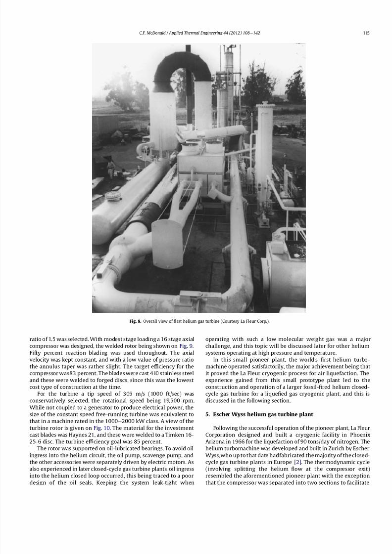
8112019 Helium Turbomachinery Operating Experience From Gas Turbine Power Plants
httpslidepdfcomreaderfullhelium-turbomachinery-operating-experience-from-gas-turbine-power-plants 835
ratio of 15 was selected With modest stage loading a 16 stage axial
compressor was designed the welded rotor being shown on Fig 9
Fifty percent reaction blading was used throughout The axial
velocity was kept constant and with a low value of pressure ratio
the annulus taper was rather slight The target ef 1047297ciency for the
compressor was83 percent The blades were cast 410 stainless steel
and these were welded to forged discs since this was the lowest
cost type of construction at the timeFor the turbine a tip speed of 305 ms (1000 ftsec) was
conservatively selected the rotational speed being 19500 rpm
While not coupled to a generator to produce electrical power the
size of the constant speed free-running turbine was equivalent to
that in a machine rated in the 1000e2000 kW class A view of the
turbine rotor is given on Fig 10 The material for the investment
cast blades was Haynes 21 and these were welded to a Timken 16-
25-6 disc The turbine ef 1047297ciency goal was 85 percent
The rotor was supported on oil-lubricated bearings To avoid oil
ingress into the helium circuit the oil pump scavenge pump and
the other accessories were separately driven by electric motors As
also experienced in later closed-cycle gas turbine plants oil ingress
into the helium closed loop occurred this being traced to a poor
design of the oil seals Keeping the system leak-tight when
operating with such a low molecular weight gas was a major
challenge and this topic will be discussed later for other helium
systems operating at high pressure and temperature
In this small pioneer plant the worldrsquos 1047297rst helium turbo-
machine operated satisfactorily the major achievement being that
it proved the La Fleur cryogenic process for air liquefaction The
experience gained from this small prototype plant led to the
construction and operation of a larger fossil-1047297red helium closed-cycle gas turbine for a lique1047297ed gas cryogenic plant and this is
discussed in the following section
5 Escher Wyss helium gas turbine plant
Following the successful operation of the pioneer plant La Fleur
Corporation designed and built a cryogenic facility in Phoenix
Arizona in 1966 for the liquefaction of 90 tonsday of nitrogen The
helium turbomachine was developed and built in Zurich by Escher
Wysswho up to that date hadfabricated the majority of the closed-
cycle gas turbine plants in Europe [2] The thermodynamic cycle
(involving splitting the helium 1047298ow at the compressor exit)
resembled the aforementioned pioneer plant with the exception
that the compressor was separated into two sections to facilitate
Fig 8 Overall view of 1047297rst helium gas turbine (Courtesy La Fleur Corp)
CF McDonald Applied Thermal Engineering 44 (2012) 108e142 115
8112019 Helium Turbomachinery Operating Experience From Gas Turbine Power Plants
httpslidepdfcomreaderfullhelium-turbomachinery-operating-experience-from-gas-turbine-power-plants 935
intercooling [634] The major parameters and features of this plant
are summarized on Table 1
With a turbine inlet temperature of 660 C (1220 F) and
a system pressure of 122 MPa (177 psia) a compressor pressure
ratio of 20 was selected A cross-section of the turbomachine is
shown on Fig 11 The LP and HP compressors had 10 and 8 stages
respectively The compressors were designed with a degree of
reaction slightly above 100 percent based on the prevailing view by
Escher Wyss at the time that this had advantages for helium
compressors Since this philosophy was carried over into the next
much larger helium gas turbine (as covered in the following
section) the rationale for this aerothermal design decision is brie1047298y
addressed below
The degree of reaction can essentially be regarded as the ratio of
pressure rise (although accurately de1047297ned as the static enthalpy
rise) in the rotor with the total pressure rise through the combi-
nation of the rotor and stator In early British axial 1047298ow compres-
sors a value of 50 percent was adopted this enabling the same
blade pro1047297le to be used for the rotor and stator In contemporary
air-breathing gas turbines the compressor degree of reaction is not
a major design factor The effect that selected compressor rotor and
stator positioning and geometries have on the degree of reaction is
illustrated in a simple form on Fig 12 In the early years of closed-
cycle gas turbine work Escher Wyss in Switzerland advocateda degree of reaction of 100 percent or higher [35] With such
blading the gas enters and leaves the stage in an axial direction The
basic stage embodies a negative pre-whirl stator ahead of the rotor
With the stator blades acting as a nozzle it was felt that the
resulting acceleration in the stator had the effect of smoothing out
the 1047298ow providing the best possible conditions for the rotor
However such blading with high stagger and lowsolidity has a very
high relative velocity and attendant high Mach number and is not
used in machines with air as the working 1047298uid since the associated
losses would be excessive leading to low overall compressor ef 1047297-
ciency This type of stator-before-rotor high reaction arrangement
was felt to be advantageous for helium axial 1047298ow compressors to
reduce the number of stages since Mach number effects are not
encountered because the sonic velocity of helium is on the order of
three times that of air
Because of the properties of helium (ie low molecular weight
high speci1047297c heat higher adiabatic index etc) a higher number of
compressor and turbinestages for a given pressure ratio are needed
as mentioned previously An axial compressor with just over
a hundred percent reaction as in the Escher Wyss helium gas
turbine that operated in Phoenix has a greater enthalpy rise per
stage for a given tip speed this reducing the number of stages for
a given pressure ratio but the ef 1047297ciency is slightly lower Mini-
mizing the number of stages was important from the rotor dynamic
stability standpoint for the very long rotor assembly associated
Fig 9 La Fleur plant 16 stage compressor (Courtesy La Fleur Corp) Fig 10 La Fleur plant 4 stage helium turbine (Courtesy La Fleur Corp)
Table 1
Salient features of operated helium turbomachinery
Turbomachine Helium closed-cycle gas turbines Test facility Helium circulator
Facility La Fleur
gas turbine
Escher Wyss
gas turbine
Oberhausen 11
power plant
HHV
test loop
FSV HTGR
Country USA USA Germany Germany USA
Year 1962 1966 1974 1981 1976
Application Cryogenic Cryogenic CHP plant Development Nuclear plant
Heat source NG NG Coke oven gas Electrical NuclearPower MW 2 equiv 6 equiv 50 90 4
Cycle Recuperated ICR ICR Customized Steam
Compressor
Type Axial Axial Axial Axial Axial
No stages 16 10LP8HP 10LP15HP 8 1
Inlet press MPa 125 122 105285 45 473
Inlet temp C 21 22 25 820 394
Pressure ratio 15 20 27 113 102
Flow kgsec 73 11 85 212 110
In vol 1047298ow m3sec 35 55 50 107 32
Turbine
Type Axial Axial Axial Axial ST
No stages 4 9 11LP7HP 2 1
Inlet press MPa 18 23 165 50 e
Inlet temp C 650 660 750 850 e
In vol 1047298ow m3sec 30 57 67 98 e
Out vol 1047298ow m3
sec 36 85 120 104 e
Rotation speed rpm 19500 18000 55003000 3000 9550
Shaft type Single Single Twin (geared) Single Single
Generator type None None Conventional Elect motor e
CF McDonald Applied Thermal Engineering 44 (2012) 108e142116
8112019 Helium Turbomachinery Operating Experience From Gas Turbine Power Plants
httpslidepdfcomreaderfullhelium-turbomachinery-operating-experience-from-gas-turbine-power-plants 1035
with this intercooled helium axial compressor of the type shown on
Figs 11 and 13
In the high pressure helium environment a high degree of reaction leads to a rotor blading with longer chords and low aspect
ratio The larger chord length combined with low solidity results in
comparatively few compressor blades Low aspect ratio (de1047297ned as
the ratio of blade height to chord length) results in several effects
including the following 1) high stagger with wider chords results in
a greater overall machine bladed length 2) fewer blades per stage
3) relatively large area of casing and blade surface with adverse
frictional losses tending to give lower ef 1047297ciency and 4) a stiffer
blade section (also with a thicker pro1047297le) with the needed strength
to combat bending stress which can be signi1047297cant in a high pres-
suredensity helium closed-cycle system A way to partially balance
out the bending stress would be by leaning the blades and off-
setting the blade cross-section centre of gravity For the early
helium gas turbine plants a view expressed by Escher Wyss wasthat the use of high reaction blading gave the maximum attainable
head a 1047298atter pressureevolume characteristic and a better surge
margin [36] The merits of increased pressure rise per stage asso-
ciated with high reaction blading has to be put into perspective by
its lower values of ef 1047297ciency [37]
The turbine had 9 stages and a rotational speed of 18000 rpm
While not coupled with a generator the equivalent output of the
free-running turbine was on the order of 6000 kW An overall view
of the long slender rotor is shown on Fig 13 and the turbomachine
assembly being installed in a cylindrical horizontally split casing is
shown on Fig 14 The major 1047298anges had peripheral lip seals to
facilitate welding closure to ensure leak tightness
With an external gas-1047297red heater the plant operated for about
5000 h and the helium gas turbine proved to be mechanically
sound and met its speci1047297ed performance This very specialized
plant proved to be too expensive to operate for the limited market
for cryogenic 1047298uids Anticipated market growth in the late 1960sdid not materialize and while the machinery performed satisfac-
torily the customer Dye Oxygen withdrew the plant from service
As far as the helium gas turbine was concerned the plant repre-
sented a signi1047297cant milestone since the technology generated was
applied to a follow-on helium gas turbine which at this stage was
still to be fossil-1047297red but now with the long-term goal in mind of
paving the way for the eventual operation of a helium closed-cycle
gas turbine power plant with a high temperature nuclear heat
source
6 Oberhausen II helium gas turbine plant at EVO
61 Closed-Cycle gas turbine experience at EVO
With initial operation starting in 1960 the municipal energy
utility (EVO) of the city of Oberhausen in the German industrial
Ruhr area deployed a closed-cycle gas turbine plant Referred to as
Oberhausen I the plant (shown previously on Fig 3) operated in
a combined power and heat mode with an electrical output of
14 MW and the thermal heat rejection of about 20 MW was
supplied to the cityrsquos district heating system The external heater
was initially 1047297red with Bituminous coal and in 1971 a change was
made to use coke-oven gas that had become available While using
air as the working 1047298uid some of the technical dif 1047297culties experi-
enced with this plant are highlighted below simply because if they
were to occur in a future direct cycle nuclear gas turbine plant they
would be very costly and time consuming to resolve as will be
discussed in a following section
Fig 11 Cross-section view of helium gas turbine (Courtesy Escher Wyss)
CF McDonald Applied Thermal Engineering 44 (2012) 108e142 117
8112019 Helium Turbomachinery Operating Experience From Gas Turbine Power Plants
httpslidepdfcomreaderfullhelium-turbomachinery-operating-experience-from-gas-turbine-power-plants 1135
In 1963 after 20000 h of operation a failure in the HP
compressor occurred [10] A rotor blade in the 1047297rst stage failed at
the root and in passing through the compressor caused extensive
damage The failure necessitated replacing the complete HP
compressor rotor assembly From a metallurgical examination of
the broken parts the failure was attributed to a small crevice at the
edge of the blade It was postulated that a corrosive action due to
impurities in the closed-loop working 1047298uid (ie air) in1047298uenced the
propagation of the crevice and blade vibration eventually caused
the failure To prevent a further failure of this kind an electric
polishing procedure was applied to the surface of the blade to
detect any imperfections
In 1967 debris from within the closed circuit caused damage to
the rotor blades and stators of several stages in the LP compressor
In 1973 further damage in the LP compressor due to blade vibration
required blading replacement During these de-blading events the
failed fragments were contained within the machine casings Using
conventional equipment the split casings of this machine were
opened and the failed parts removed by hands-on operations New
parts were then installed and the rotor assembly re-balanced The
problems were resolved and this closed-cycle gas turbine plant
with air as the working 1047298uid then performed well over the years
with high reliability [38]Rotor vibrations are mentioned here because they had caused
problems in three fossil-1047297red closed-cycle gas turbine plants using
air as the working 1047298uid namely1) in the John Brown 12 MW Plant
in Dundee where insurmountable vibration problems occurred [2]
2) multiple blade failures in the Spittelau 30 MW plant [2] and 3)
compressor blade failures in the aforementioned Oberhausen plant
As will be mentioned in a following section a further turbine blade
failure was experienced in a larger plant using helium as the
working 1047298uid
Correcting the subsequent blade failure damage to the turbo-
machine in a fossil-1047297red plant was straightforward however the
implication of such an operation in a future direct cycle nuclear gas
turbine with radioactively contaminated blading would be far more
severe This would likely require complex remote handling equip-ment and a dedicated facility for machine decontamination and
disassembly before hands-on repair could be undertaken
The Oberhausen I plant operated for about 120000 h and was
decommissioned in 1982 In about 1971 an expansion of the utilityrsquos
Fig 12 Impact of compressor blading geometry on degree of reaction (Courtesy
Escher Wyss)
Fig 13 Intercooled axial 1047298
ow helium turbomachine rotating assembly (Courtesy Escher Wyss)
CF McDonald Applied Thermal Engineering 44 (2012) 108e142118
8112019 Helium Turbomachinery Operating Experience From Gas Turbine Power Plants
httpslidepdfcomreaderfullhelium-turbomachinery-operating-experience-from-gas-turbine-power-plants 1235
capacity was needed due to increasing demand A larger fossil-1047297red
closed-cycle cogeneration plant of conventional design and still
retaining the use of air as the working 1047298uid was initially foreseen
but an emerging German development in the nuclear power plant
1047297eld resulted in a different decision being made as discussed
below
62 Relevance of the Oberhausen II helium turbine
Starting in 1972 development work sponsored by the Federal
Republic of Germany within the scope of the 4th Atomic program
was initiated on a high temperature reactor power plant with
a helium gas turbine (HHT) The reference plant design was based
on a large single-shaft intercooled helium turbine rated at
1240 MW A demonstration plant rated at 676 MW was planned
but prior to the construction of this it was necessary to test the
most important components to reduce risk Details of the two
major facilities to accomplish this have been reported previously
[39] and are summarized as follows
The Oberhausen II helium gas turbine plant was designed andbuilt to perform two major functions 1) it had to operate as
a commercial venture to provide electrical power (50 MWe) and
district heating (53 MWt) for the city of Oberhausen and 2) provide
data applicable to the nuclear gas turbine project particularly the
dynamic behavior of the overall plant and the integrity and long-
term operating experience of the major components in a helium
environment especially the turbomachine
The second facility was the HHV an experimental plant for
testing under representative conditions with respect to machine
size operating temperature pressure and mass 1047298ow of a large
helium turbomachine The facility was extensively instrumented to
gatherdata in the following areas rotorcooling system veri1047297cation
thermal insulation integrity 1047298ow characteristics blading ef 1047297ciency
acoustics rotor dynamic stability bearings dynamic and static
seals system leak tightness and metals behavior for the full
spectrum of plant operations including plant startup load change
shutdown upset conditions etc Details of the HHV facility and
testing undertaken are given in a later section
63 Oberhausen II helium gas turbine plant design
The design and construction of the plant was based on joint
efforts between EVO (plant designer and operator) GHH (turbo-
machine recuperator coolers and controls) Sulzer (helium
heater) and the University of Hannover Institute for Turboma-
chinery which contributed to the designwork and monitoring plant
performance
For the future planned nuclear gas turbine plant design values
of the temperature and pressure at the turbine inlet were 850 C
(1562 F) and 60 MPa (870 psia) respectively Attainment of this
temperature in the Oberhausen II plant could not be achieved and
750 C (1382 F) was selected based on tube material stress
considerations in the external coke-oven gas 1047297red heater An
intercooled and recuperated closed cycle was selected and themajor features of the plant are given on Table 1 The salient
parameters are given on the simpli1047297ed cycle diagram (Fig 15)
While rated at 50 MW a maximum system pressure of only
285 MPa (413 psia) was chosen so that the helium volumetric 1047298ow
(hence size of the bladed passages) would correspond to a much
larger helium turbomachine (on the order of 300 MW in fact) This
together with a rotational speed of 5500 rpm for the HP group
would result in representative stress loadings and would permit
a reasonable extrapolation to the machine size planned for the
nuclear demonstration plant
For the intercooled and recuperated cycle a compressor pressure
ratio of 27 was selected The helium mass 1047298ow rate was 85 kgs
(187 lbsec) and the circuit pressure loss was estimated at 104
percent Based on state-of-the-art component ef 1047297
ciencies and
Fig 14 Intercooled helium turbomachine with an equivalent power rating of 6000 kW installed in a split-case steel pressure vessel (Courtesy Escher Wyss)
CF McDonald Applied Thermal Engineering 44 (2012) 108e142 119
8112019 Helium Turbomachinery Operating Experience From Gas Turbine Power Plants
httpslidepdfcomreaderfullhelium-turbomachinery-operating-experience-from-gas-turbine-power-plants 1335
a recuperator effectiveness of 87 percent the projected thermal
ef 1047297ciency was 326 percent gross and 313 percent net
The isometric sketch of the distributed power conversion
system shown on Fig 16 (from Ref [40]) is convenient for
describing the plant layout A decision was made [41] to install the
horizontal turbomachinery in three large steel vessels the group-
ings being as follows 1) LP compressor rotor 2) HP compressor and
HP turbine grouping and 3) LP turbine The 1047297rst two assemblies
were on a single-shaft with a rotational speed of 5500 rpm The
generator with a rotational speed of 3000 rpmis driven from the LP
turbine end The rotors were geared together but with the selected
shafting arrangement only a small amount of power was trans-
mitted through the gearbox This con1047297guration was established
so that the dynamic behavior would be the same as in the large
single-shaft reference nuclear gas turbine plant design concept
The arrangement of the three vessels can be clearly seen on Fig 17
The horizontal tubular recuperator is positioned below the
turbomachinery The tubular precoolers and intercoolers are
installed in vertical steel vessels This type of orientation of the
major components was used in some of the earlier closed-cycle
plants using air as the working 1047298uid
Power regulation was achieved by inventory control as in the
aforementioned Oberhausen I plant which meant that the system
pressure (hence mass 1047298ow) was changed as required To lower the
power output helium was extracted from the loop after the HP
compressor through a control valve into a storage vessel For
a power increase helium was returned from the storage vessel into
the system upstream of the LP compressor without the need for an
additional blower With this arrangement the turbine inlet
temperature and speed remained constant and plant ef 1047297ciency
would be essentially constant down to a very low power level [42]
To achieve rapid load changes a bypass valve was included in the
system in which helium was transferred in a line between the HP
compressor exit end and LP end of the recuperator A very rapid
change from 100 percent load to no-load operation and back was
demonstrated [43]
64 Helium turbomachinery
The major features and parameters for the turbomachine are
given on Table 2 and are summarized as follows A longitudinal
cross-section of the turbomachine is shown on Fig 18 At the left
hand end the LP compressor is installed in a spherical pressure
vessel A high degree of reaction (ie 100 percent) was selected for
this 10 stage axial compressor this practice following the experi-
ence of an earlier discussed helium turbomachine A view showing
the bladed rotor of the LP compressor installed in the pressure
vessel split casing is shown on Fig19 with an appreciation for the
size of the spherical casing being shown on Fig 20 Both the HP
compressor and HP turbine rotors are installed in a common
housing as shown in the turbomachine cross-section (Fig 21) and
Fig 15 Oberhausen II helium gas turbine cycle diagram
Fig 16 Isometric layout of Oberhausen II helium gas turbine power conversion system (Courtesy EVO)
CF McDonald Applied Thermal Engineering 44 (2012) 108e142120
8112019 Helium Turbomachinery Operating Experience From Gas Turbine Power Plants
httpslidepdfcomreaderfullhelium-turbomachinery-operating-experience-from-gas-turbine-power-plants 1435
in the view with the HP rotor assembly positioned above the
horizontal split casing (Fig 22) The 15 stage HP compressor was
again designed with 100 percent reaction blading The HP turbine
has 7 stages and operated with an inlet temperature of 750 C
(1382O F) A cross-section of the 11 stage LP turbine installed in
a separate spherical vessel is shown on Fig 23 The amount of
power transmitted in the gearbox between the HP and LP turbinesis small since at rated output the HP turbine power level is only
slightly more than is needed to drive both compressors
The rotor of the HP group is supported on two oil-lubricated
bearings For the complete rotating assembly the thrust bearing is
located at the warm end of the LP compressor The six turbo-
machine bearing housings were designed such that direct access to
the large oil bearings was possible without having to open the large
casings This was done to reduce maintenance time because the
large split casings have 1047298anges that were welded closed at the
peripheral lip seals to minimize helium leakage
Special attention was given to the design of the cooling system
for the rotor In the case of this plant with a turbine inlet
temperature of 750 C the turbine blades themselves based on the
use of an existing superalloy did not have to be internally cooledbut cooling gas bled from the HP compressor outlet 1047298owed through
the hollow shaft and was used to cool the turbine discs and the
blade root attachments and then returned downstream of the
turbine
In a closed-cycle gas turbine the powerlevel can be regulated by
means of changing the system pressure and careful attention must
be given to the design of the various sealing systems to accom-
modate pressure differentials within the system particularly
during transient operation To simulate what would be needed in
a direct cycle nuclear gas turbine (to prevent 1047297ssion products
coming into contact with the bearing lubricating oil) a system
having a separate chamber for each of the three labyrinth seals was
incorporated in the machine design Outboard of the labyrinth seals
where the shafts penetrate the casings there were two further
seals a 1047298oating ring seal and a shutdown seal to prevent external
helium leakage
65 Helium turbomachine operating experience
Various presentations papers and publications have previously
covered the over 13 year operation of the Oberhausen II helium gas
turbine plant [43e48] The experience gained with the operation
Fig 17 Overall view of Oberhausen II 50 MWe helium gas turbine power plant (Courtesy EVO)
Table 2
Oberhausen II plant helium turbomachinery
Plant design electrical power MW 50
District heating thermal supply MW 535
Plant design ef 1047297ciency at terminals 313
Thermodynamic cycle ICR
Control method Helium inventory
compressor bypass
Rotor arrangement 2 Shaft (geared together)
Helium mass 1047298ow kgsec 85
Overall pressure ratio 27
Generator ef 1047297ciency 98
Design system pressure loss 104Compressor LP HP
Inlet pressure MPa l05 l54
Inlet temperature C 25 25
Vol 1047298ow inletoutlet m3s 5040 4025
Ef 1047297ciency 870 855
Rotational speed rpm 5500 5500
Number of stages 10 15
Blade height inletoutlet mm 10385 7253
Turbine LP HP
Inlet pressure MPa 165 270
Inlet temperature C 582 750
Ef 1047297ciency 900 883
Rotational speed rpm 3000 5500
Number of stages 11 7
Vol 1047298ow inletoutlet m3sec 92120 6792
Blade height inletoutlet mm 200250 150200
CF McDonald Applied Thermal Engineering 44 (2012) 108e142 121
8112019 Helium Turbomachinery Operating Experience From Gas Turbine Power Plants
httpslidepdfcomreaderfullhelium-turbomachinery-operating-experience-from-gas-turbine-power-plants 1535
of the large axial 1047298ow helium turbomachine is summarized asfollows
On the positive side the following were accomplished The rotor
helium buffered bearing labyrinth oil sealing system was one of the
numerous systems that worked well from the onset This was
encouraging since the external leakage of helium contaminated by
1047297ssion products and the ingress of lubricating oil into the closed
helium loop during the projected plant lifetime of 60 years are of
concern to designers of a direct cycle nuclear gas turbine plant (for
a machine with oil bearings) because of the likely long plant
downtime for cleanup and repair
With some modi1047297cations the helium puri1047297cation system
worked well with the purity level within the speci1047297cation The
helium cooling systems worked well to keep the temperatures of
the turbine discs blade root attachments and casings at speci1047297
edlevels Load change by inventory control was done routinely and
the ability to shed 100 percent of the load in a very short period by
means of the bypass valve was demonstrated The integrity of the
co-axial turbine inlet hot gas duct was proven At the end of plant
operation the major turbomachine casings were opened and there
were no signs of corrosion or erosion of the turbine or compressor
blades The coatings applied to mating metallic surfaces were
effective with no evidence of galling or self-welding in the oxygen-
free closed-loop helium environment
Experience from previously operated high temperature helium
cooled nuclear reactor power plants (with Rankine cycle steam
turbine power conversion systems) demonstrated that absolute
helium leak tightness was not attainable This was also true in the
Oberhausen II fossil-1047297red gas turbine plant where during initial
operation the helium leakage was about 45 kg per day Attention
was given to this and helium losses were reduced to the range of
5e10 kg per day principally by seal welding the major 1047298anges This
value can be compared with other closed loop helium systems as
shown below
On the negative side several unexpected problems had a majorimpact on the operation of the plant Following initial running of
the machine at 3000 rpm in preparation to synchronizing the
system the HP casing was opened for inspection revealing
damage to the labyrinth seals this being caused by shifting of
the rotor in the axial direction The labyrinth seals were replaced
and the turbine was 1047297rst synchronized with the grid on November
8 1975
Subsequent vibration problems were encountered and the HP
shaft oscillation became so large that it caused damage to the
bearings and the design value of speed and power could not be
maintained and the plant was shut down This was initially thought
to be due to thermal distortion of the rotor and a large unbalance
Fig 18 Cross-section of Oberhausen II plant helium turbomachinery rotating assembly (Courtesy EVO)
Fig 19 Oberhausen II low pressure helium compressor installed in casing (Courtesy
GHH)
Plant Helium inventory kg Leakage
kgday day
Dragon 180 020e20 010e10
AVR 240 10e30 040e12
Oberhausen II 1400 5e10 035e070
HHV 1250 25e50 020e040
FSV e Excessive leakage
CF McDonald Applied Thermal Engineering 44 (2012) 108e142122
8112019 Helium Turbomachinery Operating Experience From Gas Turbine Power Plants
httpslidepdfcomreaderfullhelium-turbomachinery-operating-experience-from-gas-turbine-power-plants 1635
Modi1047297cations to the rotor were made and the bearings replaced
but now the HP spool design speed of 5500 rpm could not be
achieved Subsequent major design and fabrication changes were
made including decreasing the bearing span by 600 mm (24 in)
giving a shorter stiffer rotor and changing the type of bearings In
restarting the plant the design speed of the HP rotor was achieved
however the power output was only 30 MW compared with the
design value of 50 MW
Fig 20 View of Oberhausen II low pressure helium compressor spherical vessel (Courtesy GHH)
Fig 21 Cross-section of Oberhausen II high pressure rotating group (Courtesy GHH)
CF McDonald Applied Thermal Engineering 44 (2012) 108e142 123
8112019 Helium Turbomachinery Operating Experience From Gas Turbine Power Plants
httpslidepdfcomreaderfullhelium-turbomachinery-operating-experience-from-gas-turbine-power-plants 1735
To gain operational experience it was decided to continue
running the plant at the reduced power rating On February 5 1979
after nearly 11000 h of operation a rotor blade from the second
stage of the HP turbine failed causing damage in the remaining
stages but the high energy fragments were contained within the
thick machine casing Examination of the failed blade revealed the
defect as a crack caused by the forgingprocess on the semi-1047297nishedproduct To prevent such a failure occurring in the future an electric
polishing process applied to the blade surface before inspection
was implemented and improved crack detection methods
introduced
Acoustic loads in a closed-cycle gas turbine represent pressure
1047298uctuations propagating at the speed of sound through the helium
working 1047298uid Pressure 1047298uctuations of importance result from the
aerodynamic effects of high velocity helium impacting and
essentially being intermittently ldquocutrdquo by the blading in the
compressor and turbine Care must be taken in the design of the
plant to ensurethat these 1047298uctuating pressure waves do not induce
vibrations of a magnitude that could result in excitation-induced
fatigue failures in components in the circuit Critical vibrations
occur when resonance exists between the main frequency of
the propagating sound and the natural frequencies of the
components particularly ones that have large surface area to
thickness ratio
Measurements of sound spectrum were taken at four different
locations in the circuit The design level of power of 50 MW was not
achieved but at the 30 MW power output actually realized the
maximum recorded sound power level was 148 dB After plantshutdown there was no evidence of adverse effects on the major
components of noise induced excitation emanating from the axial
1047298ow turbomachinery The integrity of the turbine inlet hot gas duct
and insulation was con1047297rmed
The inability to reach rated power was attributed to shortcom-
ings in the helium turbomachine This included the compressors(s)
and turbine(s) blading failing to attain design values of ef 1047297ciencies
and the bleed helium mass 1047298ows for cooling and sealing being
signi1047297cantly greater than analytically estimated Based on data
taken from the well instrumented plant detailed analyses were
undertaken by specialists [4950] to calculate the losses in the
turbomachine to explain the power output de1047297ciency A summary
of the projected losses and various component ef 1047297ciencies is pre-
sented in a convenient form on Table 3
Fig 22 Oberhausen II high pressure rotor being installed (Courtesy GHH)
CF McDonald Applied Thermal Engineering 44 (2012) 108e142124
8112019 Helium Turbomachinery Operating Experience From Gas Turbine Power Plants
httpslidepdfcomreaderfullhelium-turbomachinery-operating-experience-from-gas-turbine-power-plants 1835
The plant operated for approximately 24000 h and was shut-
down and decommissioned in 1988 when the coke-oven gas supply
for the heater was no longer available A total plant operating time
of about 11500 h had been at the design turbine inlet temperature
of 750 C (1382 F) Turbomachinery related experience gained
from operation of this large helium gas turbine plant was extremely
valuable While many of the functions performed well from the
onset and others worked satisfactorily after modi1047297cations were
made serious unexpected problems were encountered
The achieved electrical power output of only 60 percent of the
design value was initially thought to be due to a grossly excessive
system pressure loss However when the data was carefully eval-uated it was found that 85 percent of the 20 MW power loss was
attributed to turbomachine related problems as delineated on
Table 3
To remedy this power de1047297ciency it was clear that a major re-
design of the turbomachinery would be required While replace-
ment of the gas turbine was not contemplated a study was
undertaken based on data from the plant and new technologies
that had become available since the initial design Based on the
1047297ndings a new turbomachine layout concept was suggested [43]
and a simplistic view of the rotor arrangement is shown on Fig 24
A more conventional single-shaft arrangement was proposed with
the two compressors and turbine having a rotational speed of
5400 rpm A gearbox was still retained to give a generator rota-
tional speed of 3000 rpm Based on prevailing technology at the
time the requirements for such a gearbox would have been moredemanding since the 50 MW from the turbine to the generator
would have to be transmitted through it This would necessitate
a larger system to pump 1047297lter and cool the bearing lubrication oil
To remedy the very large losses in the compressors and turbines
the number of stages would have to be increased In the case of the
compressors the use of lighter aerodynamically loaded higher
ef 1047297ciency stages with 50 percent reaction blading was
recommended
7 High temperature helium test facility (HHV)
71 Background
In the late 1960rsquos with large numbers of orders placed for 1047297rst
generation light water reactor nuclear power plants studies were
initiated for next generation power plants with higher ef 1047297ciency
potential Following the initial operational success of the 1047297rst three
small helium cooled HTR plants (ie Dragon in the UK Peach
Bottom I in the USA and AVR in Germany) studies on larger plants
based on the use of both Rankine steam cycle and helium closed
Brayton cycle power conversion systems were undertaken In the
early 1970rsquos emphasis was placed on nuclear gas turbine plant
designs with larger power output both in the USA (for the
HTGR eGT) and in Europe (for the HHT) Work in the USA was
limited to only paper studies [18] The much larger program in
Germany (with participation by Swiss companies for the turbo-
machine heat exchangers and cooling towers) included a well
planned development testing strategy to support the plant design
Fig 23 Cross-section of Oberhausen II low pressure helium turbine (Courtesy GHH)
Table 3
Oberhausen II helium turbine plant power losses
Componentcause Design
value
Measured Power loss
MW
Compressors
B Flow losses in inlet diffusers
and blades
Low pressure ef 1047297ciency 870 826 13
High pressure ef 1047297ciency 855 779 40
Turbines
B Blade gap and 1047298ow losses
High pressure ef 1047297ciency 883 823 39
B Pro1047297le losses due to Remachined
blades after having detected
damaged blades
Low pressure ef 1047297ciency 900 856 24
BSealing leakage and cooling 1047298ows
in all turbomachines Kgsec
18 75 53
B Circuit pressure losses
(Ducting Hxrsquos etc)
102 128 26
B Miscellaneous heat losses 05
Total power loss 200 MW
Notes (1) Plant designed for electrical power output of 50 MW actual power output
measured 30 MW
(2) Power de1047297ciency of20 MW based on measurements taken and then recalculated
for the rated plant output
(3) 85 of Power loss attributed to helium turbomachinery related issues
CF McDonald Applied Thermal Engineering 44 (2012) 108e142 125
8112019 Helium Turbomachinery Operating Experience From Gas Turbine Power Plants
httpslidepdfcomreaderfullhelium-turbomachinery-operating-experience-from-gas-turbine-power-plants 1935
While the reference HHT plant for eventual commercializationembodied a very large single helium gas turbine rated at 1240 MW
this was to be preceded by a nuclear demonstration plant rated at
676 MW [51] To support the design of this plant technology
generated from the following was planned 1) operational experi-
ence from the aforementioned Oberhausen II 50 MW helium gas
turbine power plant and 2) testing of components in a large high
temperature helium test facility as discussed below
72 Development facilitytesting objectives
An overall view of the HHV test facility sited in Julich in
Germany is shown on Fig 25 and since this has been reported on
previously [52] it will only be brie1047298
y covered in this section Tominimize risk and assure the performance integrity and reliability
of the nuclear demonstration plant some non-nuclear testing of
the major components especially the helium turbomachine was
deemed essential Because of the limitations of a conventional
closed-cycle helium gas turbine power plant particularly the
temperature limitations of existing fossil-1047297red and electrical
heaters a new type of test facility was foreseen
A simpli1047297ed schematic line diagram of the HHV circuit is shown
on Fig 26 The major design parameters are shown on Fig 27
together with the temperatureeentropy diagram which is conve-
nient for describing the unique relationship between the compo-
nents in the closed helium loop Starting at the lowest pressure in
Fig 24 Proposed new concept for Oberhausen II helium gas turbine rotating assembly to remedy problems encountered during operation of the 50 MWe power plant (Courtesy
EVO)
Fig 25 HHV helium turbomachinery test facility (Courtesy BBC)
CF McDonald Applied Thermal Engineering 44 (2012) 108e142126
8112019 Helium Turbomachinery Operating Experience From Gas Turbine Power Plants
httpslidepdfcomreaderfullhelium-turbomachinery-operating-experience-from-gas-turbine-power-plants 2035
the system the helium is compressed (Ae
B) its temperatureincreasing to 850 C (1562 F) before 1047298owing through the test
section (BeC) After being cooled slightly (CeD) the helium is
expanded in the turbine (DeA) down to the compressor inlet
conditions completing the loop There is no power output from the
system and without the need for an external heater the
compression heat is used to raise the helium to the maximum
system temperature in what can be described as a very large heat
pump The required compressor power is 90 MW and to supple-
ment the 45 MW generated by expansion in the turbine external
power is provided by a 45 MW synchronous electrical motor A
cooler is required to remove the compression heat that is contin-
uously put into the closed helium loop and this is done by bleeding
about 5 percent of the mass 1047298ow after the compressor cooling it
and re-introducing it into the circuit close to the turbine inlet In
addition to testing the turbomachine the facility was engineered
with a test section to accommodate other small components (eg
hot gas 1047298ow regulation valves bypass valves insulation con1047297gu-
rations and types of hot gas duct construction) With the highest
temperature in the system being at the compressor exit the facility
had the capability to provide helium at a temperature up to 1000 C
(1832 F) for short periods at the entrance to the test section
While a higher ef 1047297ciency of the planned nuclear demonstration
plant could be projected with a turbine inlet temperature in the
range 950e1000 C (1742e1832 F) this would have necessitated
either turbine blade cooling or the use of a high temperature alloy
such as Titanium Zirconium Molybdenum (TZM) At the time it was
felt that using either of these would have added cost and risk to theprojectso a conventionalnickel-basedalloyas usedin industrialgas
turbines was selected for the 850 C design value of turbine inlet
temperature this negating the needfor actual internal bladecooling
However a complex internal coolingsystemwas neededto keep the
Fig 26 Cycle diagram of HHV test loop (Courtesy BBC)
Fig 27 Salient features of HHV helium turbomachinery (Courtesy BBC)
CF McDonald Applied Thermal Engineering 44 (2012) 108e142 127
8112019 Helium Turbomachinery Operating Experience From Gas Turbine Power Plants
httpslidepdfcomreaderfullhelium-turbomachinery-operating-experience-from-gas-turbine-power-plants 2135
turbine discs and blade root attachments and casings to acceptable
temperatures commensurate with prescribed stress limitations for
thelife of theturbomachine In addition a heliumsupplywas needed
to provide a buffering system for the various labyrinth seals
In a direct Brayton cycle nuclear gas turbine the turbomachine is
installed in the reactor circuit and via the hot gas duct heated
helium is transported directly from the reactor core to the turbine
From the safety licensing and reliability standpoints there are
various seals that must perform perfectly A helium buffered
labyrinth seal system is necessary to prevent bearing lubricating oil
ingress to the closed helium loop Since in the proposed HHT plant
design the drive shaft from the turbine to the generator penetrates
the reactor primary system pressure boundary two shaft seals are
needed one a dynamic seal when the shaft is rotating and a static
seal when the turbomachine is not operating Testing of these seals
in a size and operating conditions representative of the planned
commercial power plant was considered to be a licensing must
The mechanical integrity of the rotating assembly must be
assured there being two major factors necessitating testing the
machine at full speed and temperature and at high pressure
namely 1) loading the blading under representative centrifugal and
gas bending stresses and 2) to monitor vibration and con1047297rm rotor
dynamic stability For the design of the planned commercial planta knowledge of the acoustic emissions by the turbomachine and
propagation in the closed circuit was required Data from the HHV
facility would enable dynamic responses of the major components
(especially the insulation) resulting from excitation by the sound
1047297eld to be calculated
The circuit was instrumented to gather data on the effectiveness
of the hot gas duct insulation thermal expansion devices hot gas
valves helium puri1047297cation system instrumentation and the
adequacy of the coatings applied to mating metallic surfaces to
prevent galling or self-welding Details of the turbomachinery and
the experience gained from the operation of the HHV facility are
covered in the following sections
73 Helium turbomachine
A cross-section of the turbomachine is shown on Fig 28 The
single-shaft rotating assembly consists of 8 compressor stagesand 2
turbine stages and had a weighton the order of 66 tons(60000 kg)
The hub inner and outer diameters are 16 m (525 ft) and 18 m
(59 ft) respectively the blading axial length being 23 m (75 ft)The
span between the oil bearings being 57 m (187 ft) The physical
dimensions of the turbogroup shown on Fig 28 correspond to
a machine rated at about 300 MW The oil bearings operate in
a helium environment and the diameters of the labyrinths and
1047298oating ring shaft seals to prevent oil ingress are representative of
a machine rated at about 600 MW The complexity of the machine
design especially the rotor cooling system sealing system very
large casing and heat insulation have been reported previously
[53e55]
To ensure high structural integrity the rotor was constructed by
welding together the forged compressor and turbine discs The
compressor had 8 stages each having 56 rotor and 72 stator blades
The turbine had 2 stages each having 90 stator and 84 rotor blades
An appreciation for the large size of the rotating assembly can be
seen from Fig 29 The rotor blades have 1047297r-tree attachments
embodying cooling channels Since the temperature and pressure
do not vary very much along the blading in the 1047298ow direction an
intricate rotor and stator cooling system was required Channels in
both the blade roots and the spacers between adjacent blade rows
form an axial geometry for the passage of a cooling helium supplyto keep the temperature of the multiple discs below 400 C
(752 F) The design of this was a challenge since the rotor and
stator blade attachments of both the 8 stage compressor and 2
stage turbine had to be cooled Excessive leakage had to be avoided
since this would have prevented the speci1047297ed compressor
discharge temperature (ie the maximum temperature in the
circuit) from being reached
In the 1970rsquos and early 1980rsquos signi1047297cant studies were carried
out on large helium gas turbines by various organizations [56e62]
In this era there was general agreement that testing of the turbo-
machine in one form or another in non-nuclear facilities be
undertaken to resolve areas of high risk (eg seals bearings cooling
systems rotor dynamic stability compressor surge margin
dynamic response rotor burst protection etc) before installationand operation of a large gas turbine in a nuclear environment
This low risk engineering philosophy which prevailed at the time
in both Germany and the USA emphasized the importance of
Fig 28 Cross-section of HHV helium turbomachinery (Courtesy BBC)
CF McDonald Applied Thermal Engineering 44 (2012) 108e142128
8112019 Helium Turbomachinery Operating Experience From Gas Turbine Power Plants
httpslidepdfcomreaderfullhelium-turbomachinery-operating-experience-from-gas-turbine-power-plants 2235
the HHV test facility as being an important step towards the
eventual deployment of a high ef 1047297ciency nuclear gas turbine power
plant
74 Initial operation of the HHV facility
During commissioning of the plant in 1979 oil ingress into the
helium circuit from the seal system occurred twiceThe 1047297rst ingressof oil between 600 and 1200 kg (1322 and 2644 lb) was due to
a serious operatorerror and the absence of an isolation valve in the
system The oil in the circuit was partly coked and formed thick
deposits on the cold and hot surfaces of the turbomachinery and in
other parts of the closed loop including saturation of the 1047297brous
insulation The fouled metallic surfaces were cleaned mechanically
and chemically by cracking with the addition of hydrogen and
additives The second oil ingress was due to a mechanical defect in
the labyrinth seal system The quantity of oil introduced was small
and it was removed bycracking at a temperature of 600 C (1112 F)
and with the use of additives To obviate further oil ingress inci-
dents the labyrinth seal system was redesigned The buffer and
cooling helium system piping layout was modi1047297ed to positively
eliminate oil ingress due to improper valve operation and toprevent further human error
Pressure and leak detection tests of the HHV test facility at
ambient temperature showed good leak tightness for the turbo-
machine 1047298anged joints and of the main and auxiliary circuits
However at the operating temperature of 850 C (1562 F) large
helium leaks were detected The major 1047298anges had been provi-
sioned with lip seals and the 1047297rst step was to weld the closures A
large leak persisted at the front 1047298ange of the turbomachine This
was diagnosed as being caused by a non-uniform temperature
distribution during initial operation resulting in thermal stresses
creating local gaps This problem was overcome by redesign of the
cooling system with improved gas 1047298ow distribution and 1047298ow rates
to give a more uniform temperature gradient The leakage from the
system was reduced to on the order of 020e
040 percent of the
helium inventory per day this being of the same magnitude as in
other closed helium circuits as discussed in Section 65
It should be mentioned that in addition to the HHV experience
bearing oil ingress into the circuits and system loss of the working
1047298uid in other closed-cycle gas turbine plants have occurred In all of
these fossil-1047297red facilities 1047297xing leaks and removal of oil deposits
were undertaken based on conventional hands-on approaches but
nevertheless such operations were time-consuming However if a new and previously untested helium turbomachine operating in
a direct cycle nuclear gas turbine plant experienced an oil ingress
the rami1047297cations would be severe The likely use of remote
handling equipment to remove the turbomachine from the vessel
machine disassembly (including breaking the welded 1047298ange joints)
and removal of oil from the radioactively contaminated turbo-
machine blade surfaces and system insulation would be time
consuming A diagnosis of the failure would be required before
a spare turbomachine could be installed and this plant downtime
could adversely affect plant availability
75 Experience gained
Afterresolutionof the aforementionedproblems the HHVfacilitywas started in the Spring of 1981 and in an orderly manner was
brought up to full pressure and a temperature of 850 C (1562 F)
During a 60 h run the functioning of the instrumentation control
and safety systems were veri1047297ed During these tests the ability to
stop the turbomachine from full operating conditions to standstill
within 90 s was demonstrated After system depressurization the
plant was then run up again to full operating conditions with no
problems experienced The HHV facility was successfully run for
about 1100 h of which theturbomachineryoperated forabout325 h
at a temperature of 850 C The test facility was extensively instru-
mented and interpretation and analysis of the data recorded gave
positive and favorable results in the following areas
The complex rotor cooling system which was engineered to
assure that the temperature of the discs be kept below 400
C
Fig 29 HHV helium turbomachine rotating assembly (size equivalent to a 300 MWe machine) being installed in a pressure vessel (Courtesy BBC)
CF McDonald Applied Thermal Engineering 44 (2012) 108e142 129
8112019 Helium Turbomachinery Operating Experience From Gas Turbine Power Plants
httpslidepdfcomreaderfullhelium-turbomachinery-operating-experience-from-gas-turbine-power-plants 2335
(752 F) was demonstrated to be effective The measured rotor
coolant 1047298ows (about 3 percent of the mass1047298ow passing through the
machine) were slightly larger than had been estimated and this
resulted in measured turbine disc temperatures lower than pre-
dicted [55]
The dynamic labyrinth shaft seal functioned well at the full
temperature and pressure conditions and met the requirement of
zero oil ingress into the helium circuit The measured rotor oscil-
lation did not have any adverse effect on the shaft sealing system
The static rotor seal (for shutdown conditions) functioned without
any problems
The compressor and turbine blading hadef 1047297ciencies higher than
predicted The structural integrity of the rotor proved to be sound
when operating at 3000 rpm under the maximum temperature and
pressure conditions The stiff rotor shaft had only slight unbalance
and thermal distortion and measured oscillations were in the range
typical of large steam turbines
Sound power spectrum measurements were taken in four
different locations in the circuit These were taken to determine the
spectrum and intensity of the sound generated and propagated by
the turbomachinery and the resultant vibration of internal
components The maximum sound power level in the helium
circuit was160 dB Numerous strain gages were placedin the circuitto determine the in1047298uence of the sound 1047297eld particularly on the
fatigue strength of the turbine inlet hot gas duct In later examining
the internal components there was no evidence of excessive
vibration of the components especially the ducting and the insu-
lation Based on the measurements and calculations it was
concluded that the fatigue strength limit of the components would
not be exceeded during the designed life of the planned commer-
cial nuclear gas turbine power plant
In a direct cycle nuclear gas turbine the hot gas duct used to
transport the helium from the reactor core to the turbineis a critical
component The hot gas duct in the HHV facility performed well
mechanically and con1047297rmed the adequacy of the thermal expan-
sion devices From the thermal standpoint the 1047297ber insulation
performed better than the metallic type
After dismantling the HHV facility there were no signs of
corrosion or erosion of the turbine or compressor blading While
the total number of hours operated was limited the coatings
applied to mating metallic surfaces to prevent galling and frictional
welding in the oxidation-free helium worked well
The helium buffer and cooling system worked well However
problems remained with the puri1047297cation of the buffer helium The
oil separation system consisting of a cyclone separator and a wire
mesh and a down stream 1047297ber 1047297lter needed further improvement
In late 1981 a decision was made to cancel the HHT project and
the HHV facility was shutdown The design and operational expe-
rience gained from the running of this facility would have been
extremely valuable had the nuclear gas turbine power plant
concept moved towards becoming a reality The identi1047297cation of
somewhat inevitable problems to be expected in such a complexturbomachine and their resolution were undertaken in a timely
and cost effective manner in the non-nuclear HHV facility This
should be noted for future nuclear gas turbine endeavors since
remedying such unexpected problems in the case of a new and
untested large helium turbomachine being operated for the 1047297rst
time using nuclear heat could result in very complex repair
Fig 30 Speci1047297
c speed-speci1047297
c diameter array for gas circulators in various gas-cooled nuclear plants
CF McDonald Applied Thermal Engineering 44 (2012) 108e142130
8112019 Helium Turbomachinery Operating Experience From Gas Turbine Power Plants
httpslidepdfcomreaderfullhelium-turbomachinery-operating-experience-from-gas-turbine-power-plants 2435
activities and extended plant downtime and indeed adding risk to
the overall success of the nuclear gas turbine concept
8 Circulators used in gas-cooled reactor plants
Circulators of different types will be needed in future helium
cooled nuclear plants these including the following 1) primary
loop circulator for possible next generation steam cycle power andcogeneration plants 2) for future indirect cycle gas turbine plants
3) shut down cooling circulators forall HTRand VHTR plants and 4)
for various circulators needed in future VHTR high temperature
process heat plant concepts The technology status of operated
helium circulators is brie1047298y addressed as follows
81 Background
It would be remiss not to mention experience gained in the past
with gas circulators and while not gas turbines they are rotating
machines that operate in the primary loop of a helium cooled
reactor With electric motor drives there are basically two types of
compressor rotor con1047297gurations namely radial and axial 1047298ow
machinesIn a single stage form the centrifugal impeller is used for high
stage pressure rise and low volume 1047298ow duties whereas the axial
type covers low pressure rise per stage and high volume 1047298ow The
selection of impeller type is very much related to the working
media type of bearings drive type rotor dynamic characteristics
and installation envelope A wide range of circulators have operated
and a well established technology base exists for both types [63] A
useful portrayal of compressor data in the form of quasi- non-
dimensional parameters (after Balje [64]) showing approximate
boundaries for operation of high ef 1047297ciency axial and radial types is
shown on Fig 30 (from Ref [65])
Both high speed axial and lower speed radial 1047298ow types are
amenable to gas oil and magnetic bearings From the onset of
modularHTR plant studies theuse of active magnetic bearings[6667]offered a solution to eliminate lubricating oil into the reactor circuit
and this tribology technology is attractive for use in submerged
rotating machinery in the next generation of HTR plants [68]
While now dated an appreciation of the main design features of
typical electric motor-driven helium circulators have been reported
previously namely an axial 1047298ow main circulator for a modular
steam cycle HTR plant [69] and a representative radial 1047298ow shut-
down cooling circulator [70]
The operating experience gained from three particular circula-
tors is brie1047298y included below because of their relevance to the
design of helium turbomachinery in future HTR plant variants
82 Axial 1047298ow helium circulator
Since all of the aforementioned predominantly European
helium gas turbines used axial 1047298ow turbomachinery it is of interest
to mention a helium axial 1047298ow circulator that operated in the USA
and to brie1047298y discuss its design parameters and features The
330 MW Fort St Vrain HTGR featured a Rankine cycle power
conversion system Four steam turbine driven helium circulators
were used to transport heat from the reactor core to the steam
generators The complete circulator assemblies were installed
vertically in the prestressed concrete reactor vessel [71e73]
A cross-section of the circulator is shown on Fig 31 with thecompressor rotor and stator visible on the left hand end of the
machine Based on early 1960rsquos technology a decision was made to
use water lubricated bearings and from the overall plant reliability
and availability standpoints this later proved to be a bad choice
Within the vertical circulator assembly there were four 1047298uid
systems namely the helium reactor coolant water lubricant in the
bearings steam for the turbine drive and high pressure water for
the auxiliary Pelton wheel drive During plant transients the pres-
sures and temperatures of these four 1047298uids oscillated considerably
and the response of the control and seal systems proved to be
inadequate and resulted in considerable water ingress from the
bearing cartridge into the reactor helium circuit The considerable
clean up time needed following repeated occurrences of this event
resulted in long periods of plant downtime and this had an adverseeffect on plant availability This together with other technical
Fig 31 Cross section of FSV helium circulator (Courtesy general Atomics)
CF McDonald Applied Thermal Engineering 44 (2012) 108e142 131
8112019 Helium Turbomachinery Operating Experience From Gas Turbine Power Plants
httpslidepdfcomreaderfullhelium-turbomachinery-operating-experience-from-gas-turbine-power-plants 2535
dif 1047297culties eventually contributed to the plant being prematurely
decommissioned
On the positive side in the context of this paper the helium
circulators operated for over 250000 h and exhibited excellent
helium compressor performance good mechanical integrity and
vibration-free operation The rotating assembly showing the axial
1047298ow compressor and steam turbine rotors together with a view of
the machine assembly are given on Fig 32 The helium compressor
consists of a single stage axial rotor followed by an exit guide vane
The machine was designed for axial helium 1047298ow entering and
leaving the stage and this can be seen from the velocity triangles
shown on Fig 33 which also includes the de1047297nition of the various
aerodynamic parameters Major design parameters and features of
this helium circulator are given on Table 4 Related to an earlier
discussion on the degree of reaction for axial 1047298ow compressors the
value for this conventional single stage circulator is 78 percent All
of the major aerothermal and structural loading criteria were
within established boundaries for an axial compressor having high
ef 1047297ciency and a good surge margin
The compressor gas 1047298ow path and blading geometries were
established based on prevailing industrial gas turbine and aero-
engine design practice A low Mach number (025) a high Reynolds
number (3 106) together with a modest stage loading (ie
a temperature rise coef 1047297cient of 044) and an acceptable value of
diffusion factor (042) were some of the factors that contributed to
a helium circulator that had a high ef 1047297ciency and a good pressure
rise- 1047298ow characteristic The large rotor blade chord and thick blade
section for this single stage circulator are necessary to accommo-
date the high bending stress characteristic of operation in a high
pressure environment The solidity and blade camber were opti-
mized for minimum losses
There were essentially two reasons for including this single-
stage axial 1047298ow compressor that operated in a helium cooled
reactor although its overall con1047297guration can be regarded as a 1047297rst
and last of a kind A rotor blade from this circulator as shown onFig 34 was based on a NASA 65 series airfoil which at the time
were one of the best performing cascades for such low Mach
number and high Reynolds number applications Interestingly it
has almost the same blade height aspect ratio and solidity as would
be used in the 1047297rst stage of an LP compressor in a helium turbo-
machine rated on the order of 250 MW
The second point of interest is that the helium mass 1047298ow rate
through the single stage axial compressor (rated at 4 MWe) is
110 kgs compared with 85 kgs through the multistage compressor
in the 50 MWe Oberhausen II helium gas turbine plant However
the volumetric 1047298ow through the Oberhausen axial compressor is
higher than that through the circulator by a factor of 16 this again
pointing out that the Oberhausen II plant was designed for high
volumetric 1047298ow to simulate the much larger size of turboma-chinery that was planned at the time in Germany for use in future
projected nuclear gas turbine power plants
83 High temperature helium circulator
For future helium turbomachines embodying active magnetic
bearings a challenge in their design relates to accommodating
elevated levels of temperature in the vicinity of the electronic
components In this regard it is of interest to note that a small very
high temperature helium axial 1047298ow circulator rated at 20 kW (as
shown on Fig 35) operated for more than 15000 h in an insulation
test facility in Germany more than two decades ago [74] The
signi1047297cance of this machine is that it operated with magnetic
bearings in a high temperature helium test loop with a circulatorgas inlet temperature of 950 C (1742 F) This necessitated the use
of ceramic insulation to ensure that the temperature in the vicinity
of the magnetic bearing electronics did not exceed a temperature of
about 150 C (300 F)
This machine although a very small axial 1047298ow helium blower
performed well and has been brie1047298y mentioned here since it
represents a point of reference for future helium rotating machines
capable operating with magnetic bearings in a very high temper-
ature helium environment
84 Radial 1047298ow AGR nuclear plant gas circulators
The electric motor-driven carbon dioxide circulators rated at
about 5 MW with a total runningtimein excess of 18 million hours
Fig 32 Fort St Vrain HTGR plant helium circulator (Courtesy General Atomics) (a)
Axial 1047298ow helium compressor and steam turbine rotating assembly (b) 4 MW helium
circulator assembly
CF McDonald Applied Thermal Engineering 44 (2012) 108e142132
8112019 Helium Turbomachinery Operating Experience From Gas Turbine Power Plants
httpslidepdfcomreaderfullhelium-turbomachinery-operating-experience-from-gas-turbine-power-plants 2635
in AGR nuclear power plants in the UK have demonstrated veryhigh availability [7576] To a high degree this can be attributed to
the fact that the machines were conservatively designed and proof
tested in a non-nuclear facility at full temperature and power
under conditions that simulated all of the nuclear plant operating
modes The test facility shown on Fig 36 served two functions 1)
design veri1047297cation of the prototype machine and 2) test of all new
and refurbished machines before they were installed in nuclear
plants Engineers currently involved in the design and development
of helium turbomachinery could bene1047297t from this sound testing
protocol to minimize risk in the deployment of helium rotating
machinery in future HTRVHTR plant variants
9 Helium turbomachinery development and testing
91 On-going development activities
The various helium turbomachines discussed in previous
sections operated over a span of about two decades starting in the
early 1960s From about 1990 activities in the nuclear gas turbine
1047297eld have been focused mainly on the design of modular GTeHTR
plant concepts In support of these plant studies many signi1047297cant
helium turbomachine design advancements have been made and
attention given to what development testing would be needed In
the last decade or so limited sub-component development has
been undertaken for helium turbomachines in the 250e300 MWe
size and these are brie1047298y summarized below
In a joint USARussia effort development in support of the
GTe
MHR turbomachine has been undertaken including testing in
the following areas magnetic bearings seals and rotor dynamicsfor the vertical intercooled helium turbomachine rated at 286 MWe
[77e80]
In Japan development activities have been in progress for
several years in support of the 274 MWe helium turbomachine for
the GTeHTR300 plant concept [2581] A detailed discussion on
the aerodynamic design of the axial 1047298ow helium compressor for
this turbomachine has been published in the open literature [82]
While the design methodology used for axial compressor design in
air-breathing industrial and aircraft gas turbines is generally
applicable for a multi-stage helium compressor a decision was
made by JAEA to test a small scale compressor in a helium facility
because of the inherent and unique gas 1047298ow path and type of
blading associated with operation in a high pressure helium
environment The major goal of the test was to validate the designof the 20 stage helium axial 1047298ow compressor for the GTeHTR300
plant
An axial 1047298ow compressor in a closed-cycle helium gas turbine is
characterized by the following 1) a large number stages 2) small
blade heights 3) high hub-to-tip ratio 4) a long annulus with
small taper that tends to deteriorate aerodynamic performance as
a result of end-wall boundary layer length and secondary 1047298ow 5)
low Mach number 6) high Reynolds number and 7) blade tip
clearances that are controlled by the gap necessary in the magnetic
journal and catcher bearings While (as covered in earlier sections)
helium gas turbines have operated there is limited data in the
open literature on the performance of multi-stage axial 1047298ow
compressors operating in a high pressure closed-loop helium
environment
Fig 33 Velocity triangles for axial compressor stage
CF McDonald Applied Thermal Engineering 44 (2012) 108e142 133
8112019 Helium Turbomachinery Operating Experience From Gas Turbine Power Plants
httpslidepdfcomreaderfullhelium-turbomachinery-operating-experience-from-gas-turbine-power-plants 2735
A 13rd scale 4 stage compressor was designed to simulate the
stage interaction the boundary layer growth and repeated stage
1047298ow in an actual compressor The 1047297rst four stages were designed to
be geometrically similar to the corresponding stages in the
GTe
HTR300 compressor Details of the model compressor havebeen discussed previously [81] and are summarized on Table 5
from [83]
A cross-section of the compressor test model is shown on Fig 37
A view of the 4 stage compressor rotor installed in the lower casing
is shown on Fig 38 The test facility (Fig 39) is a closed helium loop
consisting of the compressor model cooler pressure adjustment
valve and a 1047298ow measurement instrument The compressor is
driven by a 3650 kW electrical motor via a step-up gear The rota-
tional speed of 10800 rpm (three times that of the compressor in
the GTeHTR300 plant) was selected to match blade speed and
Mach number in the full size compressor
Details of the planned aerodynamic performance objectives of
the 13rd scale helium compressor test have been published
previously [84] Extensivetesting of the subscale model compressorprovided data to validate the performance of the full size
compressor for the GTeHTR300 power plant The test data and
test-calibrated CFD analyses gave added insight into the effect of
factors that impact performance including blade surface roughness
and Reynolds number
Based on advanced aerodynamic methodology and experi-
mental validation [82] there is now a sound basis for added
con1047297dence that the design goals of 90 percent polytropic ef 1047297ciency
and a design point surge margin of 20 percent are realizable in
a large multistage axial 1047298ow compressor for a future nuclear gas
turbine plant
In a similar manner a design of a one third size single stage
helium axial 1047298ow turbine has been undertaken and a cross
section of the machine is shown on Fig 40 (from Ref [81]) This
Table 4
Major features of axial 1047298ow helium circulator
Helium 1047298ow rate kgsec 110
Inlet temperature C 394
Inlet pressure MPa 473
Pressure rise KPa 965
Volumetric 1047298ow m3sec 32
Compressor type Single stage axial
Compressor drive Steam turbine
Bearing type Water lubricated
Rotational speed rpm 9550
Power MW 40
Rotor tip diameter mm 688
Rotor tip speed msec 344
Number of rotor blades 31
Number of stator blades 33
Blade height mm 114
Hub-to-tip ratio 067
Axial velocity msec 157
Flow coef 1047297cient 055
Temperature rise coef 1047297cient 044
Degree of reaction 078
Mean rotor solidity 128
Rotor aspect ratio 155
Rotor Mach number 025
Rotor diffusion factor 042
Rotor Reynolds number 3106
Speci1047297c speed 335
Speci1047297c diameter 066
Blade root thickness 15
Airfoil type NASA 65
Rotor blade chord mm 94e64
Stator blade chord mm 79
Rotor centrifugal stress MPa 125
Rotor bending stress MPa 30
Circulator(s) operating Hours gt250000
Fig 34 Rotor blade from single stage axial 1047298ow helium circulator (Courtesy General
Atomics)
Fig 35 20 kW axial 1047298ow helium circulator with magnetic bearings operated in 1985 in
an insulation test loop with a gas inlet temperature on 950
C (Courtesy BBC)
CF McDonald Applied Thermal Engineering 44 (2012) 108e142134
8112019 Helium Turbomachinery Operating Experience From Gas Turbine Power Plants
httpslidepdfcomreaderfullhelium-turbomachinery-operating-experience-from-gas-turbine-power-plants 2835
single stage scale model turbine for validity of the full size turbine
has been built and plans made to test the aerodynamic
performance
92 Nuclear gas turbine helium turbomachine testing
In planning for the 1047297rst nuclear gas turbine plant projected to
enter service perhaps in the third decade of the 21st century
a major decision has to be made as to what extent the large helium
turbomachine should be tested prior to operation on nuclear heat
Issues essentially include cost impact on schedule but the over-
riding one is risk Certainly turbomachine component testing will
be undertaken including the compressor (as discussed in the
previous section) and turbine performance seals cooling systems
hot gas valves thermal expansion devices high temperature
insulation rotor fragment containment diagnostic systems
instrumentation helium puri1047297cation system and other areas to
satisfy safety licensing reliability and availability concerns The
major point is really whether a full size or scaled-down turbo-machine be tested early in the project in a non-nuclear facility
To obviate the need for pre-nuclear testing of a large helium
turbomachine a view expressed by some is that advantage can be
taken of formidable technology bases that exist today for large
industrial gas turbines and high performance aeroengines On the
other hand it is the view of some including the author that very
complex power conversion system components especially those
subjected to severe thermal transients donrsquot always perform
exactly as predicted by analysts and designers even using sophis-
ticated computer codes This was exempli1047297ed in the case of the
turbomachine in the aforementioned Oberhausen II helium gas
turbine plant
The need for a helium turbomachine test facility goes beyond
just veri1047297
cation of the prototype machine Each newgas turbine for
commercial modular nuclear reactor plants would have to be proof
tested and validated before being transported to the reactor site
Similarly turbomachines that would be periodically removed from
the plant at say 7 year intervals during the plant operating life of 60
years for scheduled maintenance refurbishment repair or updat-ing would be again proof tested in the facility before re-entering
service
The direction that turbomachine development and testing will
take place for future helium gas turbines needs to be addressed by
the various organizations involved
Fig 36 AGR circulator test facility In the UK (Courtesy Howden)
Table 5
Major design parametersfeatures of model GTeHTR300 axial 1047298ow helium
compressor (Courtesy JAERI)
Scale of GTeHTR300 compressor 13
Helium mass 1047298ow rate (kgsec) 122
Helium volumetric 1047298ow rate (mV s) 87
Inlet temperature C 30
Inlet pressure MPa 0883Compressor pressure ratio at design point 1156
Number of stages 4
Rotational speed rpm 10800
Drive motor power kW 3650
Hub diameter mm 500
Rotor tip diameter (1st4th stage mm) 568566
Hub-to-tip ratio (1st stage) 088
Rotor tip speed (1st stage msec) 321
Number of rotorstator blades (1st stage) 7294
Rotorstator blade height (1st stage mm) 34337
Rotor stator blade c hor d l eng th (1st stage mm) 2620
Rotorstator solidity (1st stage) 119120
Rotorstator aspect ratio (1st stage) 1317
Flow coef 1047297cient 051
Stage loading factor 031
Reynolds number at design point 76 l05
CF McDonald Applied Thermal Engineering 44 (2012) 108e142 135
8112019 Helium Turbomachinery Operating Experience From Gas Turbine Power Plants
httpslidepdfcomreaderfullhelium-turbomachinery-operating-experience-from-gas-turbine-power-plants 2935
10 Helium turbomachinery lessons learned
101 Oberhausen II gas turbine and HHV test facility
It is understandable that 1047297rst-of-a-kind complex turboma-
chinery operating with an inert low molecular weight gas such as
helium will experience unique and unexpected problems In the
operation of the two pioneering large helium turbomachines in
Germany there were many positive1047297ndings which could only have
been achieved by development testing Equally important some
negative situations were identi1047297ed many of which were remedied
In the case of the Oberhausen II helium gas turbine plant some of
the very serious problems encountered were not resolved Inves-
tigations were undertaken to rationalize the problems associated
with the large power de1047297ciency and a data base established to
ensure that the various anomalies identi1047297ed would not occur in
future large helium turbomachines
The experience gained from the operation of the Oberhausen II
helium gas turbine power plant and the HHV test facility have been
discussedin thetextand arepresentedin a summaryformon Table6
Fig 37 Cross-section of 13rd scale helium compressor test model (Courtesy JAEA)
Fig 38 Four stage helium compressor rotor assembly installed in lower casing (Courtesy JAEA)
CF McDonald Applied Thermal Engineering 44 (2012) 108e142136
8112019 Helium Turbomachinery Operating Experience From Gas Turbine Power Plants
httpslidepdfcomreaderfullhelium-turbomachinery-operating-experience-from-gas-turbine-power-plants 3035
102 Impact of 1047297ndings on future helium gas turbine
The long slender rotorcharacteristic of closed-cycle gas turbines
has resulted in shaft dynamic instability which in some cases has
resulted in blade vibration and failure and bearing damage This
remains perhaps the major concern in the design of large
(250e
300 MW) helium turbomachines for future nuclear gas
turbine plants With pressure ratios in the range of about 2e3 in
a helium system a combination of splitting the compressor (to
facilitate intercooling) and having a large number of compressor
and turbine stages results in a long and 1047298exible rotating assembly
andthis is exempli1047297ed by the rotorassembly shown on Fig13 With
multiple bearings (either oil lubricated or magnetic) the rotor
would likely pass through multiple bending critical speeds before
Fig 39 Helium compressor test facility (Courtesy JAEA)
Fig 40 Cross-section of single stage helium turbine test model (Courtesy JAEA)
CF McDonald Applied Thermal Engineering 44 (2012) 108e142 137
8112019 Helium Turbomachinery Operating Experience From Gas Turbine Power Plants
httpslidepdfcomreaderfullhelium-turbomachinery-operating-experience-from-gas-turbine-power-plants 3135
reaching the design speed While very sophisticated computer
codes will be used in the detailed rotor dynamic analyses the real
con1047297rmation of having rotor oscillations within prescribed limits
(to avoid blade bearing and seal damage) will come from actual
testingA point to be made here is that in operated fossil-1047297red closed-
cycle gas turbine plants it was possible to remedy problems asso-
ciated with rotor vibrations and blade failures in a conventional
manner In fact in some situations the casings were opened several
times and modi1047297cations made to facilitate bearing and seal
replacement and rotor re-blading and balancing
An accurate assessment of pressure losses must be made
particularly those associated with the helium entering and leaving
the turbomachine bladed sections Minimizing the system pressure
loss is important since it directly impacts the all important quotient
of turbine expansion ratio to compressor pressure ratio and power
and plant ef 1047297ciency
Based on the operating experience from the 20 or so fossil-1047297red
closed-cycle gas turbine plants using air as the working1047298
uid it was
recognized that future very high pressure helium gas turbines
would pose problems regarding the various seals in the turbo-
machine and obtaining a zero leakage system with such a low
molecular weight gas would be dif 1047297cult and this is discussed
below
When the Oberhausen II gas turbine plant and the HHV facility
operated over 30 years ago oil lubricated bearings were used to
support the heavy rotor assemblies and helium buffered labyrinth
seals were used to prevent oil ingressinto the heliumworking1047298uid
Initial dif 1047297culties encountered in both plants were overcome by
changes made to the seal geometries and for the operating lives of
the helium turbomachines no further oil ingress events were
experienced Twoseals were required where the turbine drive shaft
penetrated the turbomachine casing namely 1) a dynamic laby-
rinth seal and 2) a static seal for shutdown conditions In both
plants these seals functioned without any problems
Labyrinth seals were also required within the helium turbo-
machines to pass the correct helium bleed 1047298ow from the
compressor discharge for cooling of the turbine discs blade root
attachments and casings The fact that the very complex rotor
cooling system in the large helium turbomachine in the HHV test
facility operated well for the test duration of about 350 h with
a turbine inlet temperature of 850 C was encouragingIn the case of the Oberhausen II gas turbine plant analysis of the
test data revealed that the labyrinth seal leakage and excessive
cooling 1047298ows were on the order of four times the design value A
possible reason for this was that damage done to the labyrinth
seals caused excessive clearances when periods of excessive rotor
oscillation and vibration occurred during early operation of the
machine
Clearly 1047298uid dynamic and thermal management of the cooling
system and 1047298ow through the various labyrinth seals will require
extensive analysis design and development testing before the
turbomachine is operated on nuclear heat for the 1047297rst time
In future heliumgas turbine designs (with turbine inlet tempera-
tureslikelyontheorderof950C)the1047298owpathgeometriesofhelium
bledfromthecompressornecessarytocoolpartsoftheturbomachinewillbemorecomplexthanthosetestedto-dateInadditiontoproviding
acooling1047298owtotheturbinebladesanddiscsbladerootattachmentsand
casingsheliummustbetransportedtotheseveralmagneticbearingsto
ensure thatthe temperatureof theirelectronic components doesnot
exceedabout150C
The importance of the points made above is evidenced when
examining the data on Table 3 where a combination of excessive
pressure losses and high bleed 1047298ows contributed to about 40
percent of the power de1047297ciency in the Oberhausen II helium
turbine plant
Retaining overall system leak tightnessin closed heliumsystems
operating at high pressure and temperature has been elusive
including experience from the Fort St Vrain HTGR plant as dis-
cussed in Section 65 New approaches in the design of the plethoraof mechanical joints must be identi1047297ed Experience to-date has
shown that having welded seals on 1047298anges while minimizing
system leakage did not eliminate it
The importance of lessons learned from the operation of the
Oberhausen II helium turbine power plant and the HHV test facility
have primarily been discussed in the context of helium turbo-
machines currently being designed in the 250e300 MWe power
range However the established test data bases could also be
applied to the possible emergence in the future of two helium
cooled reactor concepts namely 1) an advanced VHTR combined
cycle plant concept embodying a smaller helium gas turbine in the
power range of 50e80 MWe [22] and 2) the use of a direct cycle
helium gas turbine PCS in a recently proposed all ceramic fast
nuclear reactor concept [85]
Table 6
Experience gained from Oberhausen II and HHV facility
Oberhausen II 50 MW helium gas turbine power plant
Positive results
e Rotating and static seals worked well
e No ingress of bearing lubricant oil into closed circuit
e Load change by inventory control worked well
e 100 Percent load shed by means of bypass valves demonstrated
e Turbine disc and blade root cooling system con1047297rmed
e Coatings on mating surfaces prevented galling and self-welding
e After 24000 h of operation no evidence of corrosion or erosion
e Coaxial turbine hot gas inlet duct insulation and integrity con1047297rmed
e Monitoring of complete power conversion system for steady state
and transient operation undertaken
Problem areas
e Serious power output de1047297ciency (30 MW compared with design
value of 50 MW)
e Compressor(s) and turbine(s) ef 1047297ciencies several points below predicted
e Higher than estimated system pressure loss
e Rotor dynamic instability and blade vibration
e Bearings damaged and had to be replaced
e Blade failure caused extensive damage in HP turbine but retained
in casing
e Very excessive sealing and cooling 1047298ow rates
e Absolute leak tightness not attainable even with welded 1047298ange lips
HHV test facility
Positive resultse Use of heat pump approach facilitated helium temperature capability
to 1000 C
e Large oompressorturbine rotor system operated at 3000 rpm Complex
turbine disc and blade root cooling system veri1047297ed
e Dynamic and static seals met requirement of zero oxl ingress into circuit
e Structural integrity of rotating assembly veri1047297ed at temperature of 850 C
e Measured rotor oscillations within speci1047297cation
e Compressor and turbine ef 1047297ciencies higher than predicted
e Coatings on mating metallic surfaces prevented galling and self-welding
e Instrumentation control and safety systems veri1047297ed
e Seal 1047298ows within speci1047297cation
e Machine stop from operating speed to shutdown in 90 s demonstrated
e Hot gas duct insulation and thermal expansion devices worked well
e After 1100 h of operation no evidence of corrosionof erosion
Problem areas
e Before commissioning a large oil ingress into the circuit occurred due
to serious operator error and absence of an isolation valve A second oilingress occurred due to a mechanical defect in the labyrinth seal system
These were remedied and no further oil ingress was experienced for the
duration of testing
e Cooling 1047298ows slightly larger than expected but this resulted in actual
disc and blade root temperatures lower than the predicted value of
400 C
e System leak tightness demonstrated when pressurized at ambient
temperature conditions but some leakage occured at 850 C even with
the seal welding of 1047298ange(s) lips
CF McDonald Applied Thermal Engineering 44 (2012) 108e142138
8112019 Helium Turbomachinery Operating Experience From Gas Turbine Power Plants
httpslidepdfcomreaderfullhelium-turbomachinery-operating-experience-from-gas-turbine-power-plants 3235
11 New technologies
It is recognized that in the 3 to 4 decades since the operation of
the helium turbomachines covered in this paper new technologies
have emerged which negate some of the early issues An example of
this is the technology transfer from the design of modern axial 1047298ow
gas turbines (ie industrial aircraft and aeroderivatives) that fully
utilize sophisticated CAE CAD CFD and FEA design software
Air breathing aerodynamic design practice for compressors and
turbines are generally applicable but the properties of helium and
the high system pressure have a signi1047297cant impact on gas 1047298ow
paths and blade geometries With short blade heights high hub-to-
tip ratios long annulus 1047298ow path length (with resultant signi1047297cant
end-wall boundary layer growth and secondary 1047298ow) and blade tip
clearances in some cases controlled by clearances in the magnetic
catcher bearing testing of subscale model compressors and
Fig 41 Gas turbine test facility for aircraft nuclear propulsion involving the coupling of a 32 MWt air-cooled reactor with two modi 1047297ed J-47 turbojet aeroengines each rated at
a thrust of about 3000 kg operated in 1960 (Courtesy INL)
Fig 42 Mobile 350 KWe closed-cycle nuclear gas turbine power plant operated in 1961 (Courtesy US Army)
CF McDonald Applied Thermal Engineering 44 (2012) 108e142 139
8112019 Helium Turbomachinery Operating Experience From Gas Turbine Power Plants
httpslidepdfcomreaderfullhelium-turbomachinery-operating-experience-from-gas-turbine-power-plants 3335
turbines will be needed While most of the operated helium tur-
bomachines discussed in this paper took place 3 or 4 decades ago it
is encouraging that the fairly recent test data and test-calibrated
CFD analysis from a subscale four stage model helium axial 1047298ow
compressor in Japan [80] gave a high degree of con1047297dence that
design goals are realizable for the full size 20 stage compressor in
the 274 MWe GTeHTR300 plant turbomachine
In the future the use of active magnetic bearings will eliminate
the issue of oil ingress however the very heavy rotor weight and
size of the journal and thrust bearings (and catcher bearings) of the
type for helium turbomachines in the 250e300 MWe power range
are way in excess of what have been demonstrated in rotating
machinery For plant designs retaining oil-lubricated bearings well
established dry gas seal technology exists particularly experience
gained from the operation of high pressure natural gas pipe line
compressors
For future nuclear helium gas turbine plants the designer has
freedom regarding meeting different frequency requirements that
exist in some countries These include use of a synchronous
machine (ie designed for 50 or 60 Hz grids) use of a gearbox drive
between the turbine and generator or the use of a frequency
converter which gives the designer an added degree of freedom
regarding the selection of speed for the rotating assemblyCompared with the past very sophisticated electronic control
systems instrumentation and diagnostic systems are available
today
12 Conclusions
In this review paper experience from operated helium turbo-
machines has been compiled based on open literature sources At
this stage in the evolution of HTR and VHTR plant concepts it is not
clear in what role form or time-frame the nuclear gas turbine will
emerge when commercialized By say the middle of the 21st
century all power plants will be operating with signi1047297cantly higher
ef 1047297ciencies to realize improved power generation costs and
reduced emissions In a nuclear gas turbine the helium turbo-machine will be a major contributor towards the achievement of
ef 1047297ciencies higher than 50 percent
While it has been 3 to 4 decades since the Oberhausen II helium
turbine power plant and the HHV high temperature helium turbine
facility operated signi1047297cant lessons were learned and the time and
effort expended to resolve the multiplicity of unexpected technical
problems encountered The remedial repair work was done under
ideal conditions namely that immediate hands-on activities were
possible This would not have been possible if the type of problems
experienced had been encountered in a new and untested helium
turbomachine operated for the 1047297rst time with a nuclear heat
source
While new technologies have emerged that negate many of the
early problems there are some uniquely inherent issues associatedwith for large helium turbines operating in a high pressure and
temperature environment and these include the following 1)
minimizing system leakage with such a low molecular weight gas
2) clearances in labyrinth seals to minimize helium bypass1047298ows 3)
the dynamic stability of long slender rotors 4) minimizing the
turbomachine inlet and outlet pressure losses 5) 1047298ow maldis-
tribution in complex ductturbomachine interfaces 6) integrity
veri1047297cation of the catcher bearings (journal and thrust) after
multiple rotor drops (following loss of the magnetic 1047297eld) during
the plant lifetime 7) assurances that high energy fragments from
a failed turbine disc are contained within the machine casing 8)
turbomachine installation and removal from a steel pressure vessel
and 9) remote handling and cleaning of a machine with turbine
blades contaminated with 1047297
ssion products
The need for a helium turbomachine test facility has been
emphasized to ensure that the integrity performance and reli-
ability of the machine before it operates the 1047297rst time on nuclear
heat Engineers currently involved in the design of helium rotating
machinery for all HTR and VHTR plant variants should take
advantage of the experience gained from the past operation of
helium turbomachinery
13 In closing-GT rsquos operated with nuclear heat
In the context of this paper it is germane to mention that two
gas turbines have actually operated using nuclear heat as brie1047298y
highlighted below
In the late 1950rsquos a program was initiated in the USA for aircraft
nuclear propulsion (ANP) While different concepts were studied
only the direct cycle air-cooled reactor reached the stage of
construction of an experimental reactor [86] A view of the large
nuclear gas turbine facility is given on Fig 41 and shows the air-
cooled and zirconiumehydride moderated reactor rated at
32 MWt coupled with two modi1047297ed J-47 turbojet engines each
rated with a thrust of about 3000 kg In this open cycle system the
high pressure compressor air was directly heated in the reactor
before expansion in the turbine and discharge to the atmosphere in
the exhaust nozzle The facility operated between 1958 and 1961 at
the Idaho reactor testing facility While perhaps possible during the
early years of the US nuclear program it is clear that such a system
would not be acceptable today from safety and environmental
considerations
The 1047297rst and indeed the only coupling of a closed-cycle gas
turbine with a nuclear reactor for power generation was under-
taken to meet the needs of the US Army In the late 1950 rsquos an RampD
program was initiated for a 350 kW trailer-mounted system to be
used in the 1047297eld by military personnel A prototype of the ML-1
plant shown on Fig 42 was 1047297rst operated in 1961 [8788]
It was based on a 33 MW light water moderated pressure tube
reactor with nitrogen as the coolant The closed-cycle gas turbine
power conversion system with nitrogen as the working 1047298uid hada turbine inlet temperature of 649 C (1200 F) and delivered
around 300 kW With changes in the Armyrsquos needs the project was
discontinued in 1965
While the experience gained from the above twounique nuclear
plants is clearly not relevant for future nuclear gas turbine power
plants that could see service in the third decade of the 21st century
these ambitious and innovative nuclear gas turbine pioneering
engineering efforts need to be recognized
Acknowledgements
The author would like to thank the following for helpful discus-
sions advice and for providing valuable comments on the initial
paper draft Prof Dr Hermann Haselbacher Hans Ulrich Frutschi DrXing Yan DrPeter Zenker Professor DavidGordon Wilson Professor
Aristide Massardo Arthur Harris DrFred Starr and DrGuido Bac-
caglini This paper has been enhanced by the inclusion of hardware
photographs and unique sketches and the author is appreciative to
all concerned with credits being duly noted
References
[1] C Keller The Escher Wyss AK Closed-Cycle Gas Turbine Its Actual Develop-ment and Future Prospects Paper Presented at ASME Meeting November 261945
[2] HU Frutschi Closed-Cycle Gas Turbines Operating Experience and FuturePotential ASME Press NY 2005
[3] CF McDonald The Nuclear Gas Turbine-Towards Realization After Half
a Century of Evolution (1995) ASME Paper 95-GT-292
CF McDonald Applied Thermal Engineering 44 (2012) 108e142140
8112019 Helium Turbomachinery Operating Experience From Gas Turbine Power Plants
httpslidepdfcomreaderfullhelium-turbomachinery-operating-experience-from-gas-turbine-power-plants 3435
[4] C Keller The Theory and Performance of Axial Flow Fans McGraw Hill BookCompany Inc NY 1937
[5] J Ackert C Keller Aerodynamic turbine with closed circuit In A Century of Turbines vols 1516 Escher Wyss News 1942e43 5e19
[6] Escher Wyss News Closed-Cycle Gas Turbines for all Fuels Coal Gas Nuclearvol 39 No 1 (1966)
[7] C Keller Closed-cycle gas turbine Escher Wyss-AK development 1945e1950Transactions of ASME (August 1950) 835e850
[8] C Keller Operating Experience and Design Features of Closed-Cycle GasTurbine Power Plants (1956) ASME Paper 56-GTP-15
[9] C Keller HU Frutschi Closed-cycle plants -conventional and nuclear designapplication operation In Sawyerrsquos Gas Turbine Engineering Handbooksecond ed vol 2 Applications (1976) pp 265e283
[10] K Bammert G Groschup Status Report on Closed-Cycle Power Plants in theFederal Republic of Germany (1976) ASME Paper 76-GT-54
[11] JL Mason Monatomic Working Gases versus Air for Closed Brayton Cycles(1985) ASME Paper 85-IGT-50
[12] JL Mason et al 5 MW Closed Cycle Gas Turbine (1984) ASME Paper 84-GT-268
[13] The British Gas Closed-Cycle Demonstrator (1995) British Gas Research ampTechnology Final Year Report
[14] F Starr ODS alloy high temperature heat exchanger prototype developmentPaper Presented at ODS 2010 Materials Workshop UCSD Jacobs Hall La JollaCalifornia Nov17e18 2010
[15] CA Rennie Achievements of the Dragon project Pergamon Press Annals of Nuclear Energy 5 (1978) 305e320
[16] SB Hosegood et al Dragon Project Engineering Studies on the Direct CycleHTR Proceedings of Conference on Nuclear Gas Turbines The British NuclearEnergy Society London April 8e9 1970 pp 161e179
[17] Nuclear Gas Turbines Proceedings of British Nuclear Society Meeting LondonApril 8-9 1972
[18] CF McDonald C Peinado ldquoThe nuclear gas Turbine-A perspective on a long-term advanced technology HTGR plant Optionrdquo ASME Paper 82-GT-289
[19] GH Lohnert et al Technical design features and essential safety-relatedfeatures of the HTR-Module Nuclear Engineering and Design 121 (1990)259e275
[20] H Reutler GH Lohnert The modular high temperature nuclear reactorNuclear Technology 62 (1983) 22e30
[21] CF McDonald Exploitation of the very high temperature capability of theMHTGR to meet National energy needs after the year 2000 IECEC Paper869006
[22] CF McDonald Power conversion system considerations for an advancednuclear gas turbine (GT-VHTR) CHHP demonstration plant concept Interna-tional Journal of Turbo amp Jet Engines 27 (2010) 179e217
[23] N Hee Cheon et al A review of helium gas turbine technology for hightemperature gas cooled reactors Nuclear Engineering and Design 29 (2007)21e30
[24] CB Baxi et al Development of the GT-MHR Turbomachine ASME PaperGT2009e59450[25] X Yan GTHTR300 design and development Nuclear Engineering and Design
222 (2003) 247e262[26] JC Gauthier et al ANTARES the HTRVHTR project of Framatome ANP
Nuclear Engineering and Design 236 (2006) 526e533[27] J Wang et al ldquoDesign features of gas turbine power conversion system for
HTR-10GT paper D05 presented at 2nd Intl Meeting on HTR TechnologyBeijing China September 21e24 2004
[28] A Koster et al ldquoPBMR Design For the Futurerdquo Nuclear engineering andDesign 222 (203) 231e245
[29] S van der Linden Closed cycle nuclear plant rated at 165 MWe and 40 percentef 1047297ciency Gas Turbine World (MarcheApril 2007) 28e32
[30] CF McDonald Large closed-cycle gas turbines Sawyerrsquos gas turbine engi-neering handbook In Selection and Applications vol II (1985) pp 81e38(Chapter 8)
[31] CF McDonald Helium and Combustion Gas Turbine Power ConversionSystems Comparison (1995) ASME Paper 95-GT-263
[32] JK La Fleur Description of an Operating Closed-Cycle Helium Gas Turbine
ASME Paper 63-AHGT-74[33] JK La Fleur The use of turbomachinery in the 1047297eld of cryogenics In
Sawyerrsquos Gas Turbine Engineering Handbook vol II (1976) 296e311[34] W Spillmann The Closed-Cycle Gas Turbine for Non-Conventional Applica-
tions ASME Paper 66-GT-8[35] K Holliger On the in1047298uence of the degree of reaction on the secondary losses
in axial 1047298ow compressors Escher Wyss News 23 (1960)[36] W Gut Comparison of the relative losses and characteristics of axial
compressor stages Escher Wyss News 23 (1959)[37] JH Horlock Axial Flow Compressors Butterworths Scienti1047297c Publications
London 1958 pp 92e93[38] G Deuster Long-term Operating Experience with Oberhausen I Closed-Cycle
Gas Turbine Power Plant (1970) ASME Paper 70-GT-73[39] G Noak Signi1047297cance of the Helium Turbine Power Plant at Oberhausen (EVO)
and the High Temperature Helium Test Facility (HHV) at Julich for theDevelopment of HTR Direct Cycle (HHT) IAEA Publication SM-20026 Vienna1970 189e200
[40] K Bammert G Deuster Layout and Present Status of the Closed-Cycle HeliumTurbine Plant Oberhausen II (1974) ASME Paper 74-GT-132
[41] P Zenker The Oberhausen 50 MW helium turbine plant Combustion 47 (2)(April 1976)
[42] K Bammert et al Operation and Control of the 50 MW Closed Cycle HeliumTurbine Plant Oberhausen (1974) ASME Paper 74-GT-13
[43] P Zenker 10 years operating experience with the Oberhausen II heliumturbo-generator plant VGB Krafswerkstechnik 68 (7) (July 1998) 616e621
[44] K Bammert G Deuster The First Operating Experiences With the OberhausenHelium Turbine Plant Paper Presented at ASME Gas Turbine Conference NewOrleans March 21e25 1976
[45] G Deuster P Zenker Operation of the Oberhausen Helium Turbine Plant
Paper Presented at ASME Gas Turbine Conference London April 1978[46] P Zenker Operating Experience of the Oberhausen Helium Turbine Plant
Paper Presented at ASME Gas Turbine Conference San Diego 1979[47] G Deuster P Zenker Further Operating Experience of the Oberhausen Helium
Turbine Plant Paper Presented at ASME Gas Turbine Conference NewOrleans 1980
[48] P Zenker Past Experience and Future Prospects of Closed-Cycle Gas TurbinesPaper Presented at ASME Gas Turbine Conference London April 18e22 1982
[49] IA Weisbrodt Summary Report on Technical Experiences from HighTemperature Helium Turbine Testing in Germany Report IAEA-TECDOC-899Vienna Nov 1994
[50] F Bentivoglio G Geffraye Validation of the CATHARE Code Against Experi-mental Data from Brayton Cycle Plants Paper C00000228 Proceedings of HTR 2006 Johannesburg October 1e4 2006
[51] E Arndt HHT-Demonstration Plant Paper Presented at European NuclearConference Hamburg May 6 1979
[52] G Hebel HHV-Anlage Erfahrungen bei Bau und Inbetriebnahme Atom-wirtschaft(5) (1982) 258e262
[53] H Haselbacher A Eierman Development of Helium Gas Turbine in NuclearField (1974) ASME Paper 74-GT-123
[54] H Haselbacher The HHT Helium Gas Turbine and HHV Plant Paper A421 5thInternational Fair and Technical Meeting of Nuclear Industry BaselSwitzerland October 3e7 1978
[55] H Haselbacher HJ Sponholz Cooling and Insulating Problems in a HighTemperature Helium Test Facility (1984) ASME Paper 84-GT-253
[56] C Keller D Schmidt The Helium Gas Turbine for Nuclear Power Plants (1967)ASME Paper 67-GT-10
[57] W Endres Large Helium Turbine for Nuclear Power Plants (1970) ASME Paper70-GT-99
[58] JN Hurst Gas turbomachinery for helium cooled reactors in Proceedings of International Conference on Nuclear Gas Turbines British Nuclear SocietyLondon April 8 1970 pp 45e50
[59] K Bammert Nuclear Gas Turbine of Large Output for HHT Plant (1974) ASMEPaper 74-GT-10
[60] CF McDonald The Nuclear Closed-Cycle Gas Turbine (GT-HTGR) e A UtilityPower Plant for the Year 2000 (1979) AIAA Paper 79e0191
[61] CF McDonald MJ Smith Turbomachinery design considerations for the
nuclear HTGR-GT power plant ASME Journal of Engineering for Power 103 (1)(January 1981) 65e77[62] CF McDonald et al Helium Turbomachine Design for GT-MHR Power Plant
(1994) ASME Paper 94-JPGC-NE-12[63] Gas Cooled Reactor Coolant Circulator and Blower Technology (1988) IAEA
Report IWGGCR17[64] OE Balje Turbomachines A Guide to Design Selection and Theory John
Wiley amp Sons NY 1981[65] CF McDonald et al Circulator DesignTechnology Evolution for Gas Cooled
Reactors (1992) ASME Paper 92-GT-79[66] J Donaldson Application of Magnetic Bearings to Helium Circulators for High
Temperature Gas Cooled Reactors (1987) IECEC Paper 879419[67] CF McDonald Active Magnetic Bearings for Rotating Machinery in Closed-
Cycle Power Plant Systems (1989) ASME Paper 89-WANE-5[68] JA Rennie CF McDonald Active Magnetic Bearings for Rotating Machinery
in Future Gas Cooled Reactor Plants Paper Presented at 4th Intl Symposiumon Magnetic Bearings ETH Zurich August 23e26 1994
[69] CF McDonald MK Nichols Helium Circulator Design Considerations forModular High Temperature Gas Cooled Power Plant (1987) ASME Paper 87-
GT-138[70] CF McDonald Shutdown Cooling Helium Circulator Design Considerations
for MHTGR Power Plant (1989) ASME Paper 89-WANE-5[71] J Yampolsky Steam Turbine Driven Circulators for High Temperature Gas
Cooled Reactors Part I Design (1972) ASME Paper 72-WANE-20[72] VJ Barbat Steam Turbine Driven Circulators for High Temperature Gas
Cooled Reactors Part II Development (1972) ASME Paper 72-WANE-21[73] L Cavallaro J Yampolsky Design and development of a steam turbine driven
circulator for high temperature gas cooled reactors Nuclear Engineering andDesign (1974) 135e147
[74] J Henssen et al Facility for fatigue testing of thermal insulation BBC Review72 (6) (1985)
[75] J Donaldson Development of Carbon Dioxide Circulators IAEA ReportIWGGCR17 (1988) pp 47e63
[76] Personal Communication from John Donaldson (April 7 2006)[77] NG Kodochigov et al Development of the GT-MHR Vertical Turbomachine
Design ASME Paper HTR2008-58309[78] CB Baxi et al ldquoRotor Scale Model Tests for Power Conversion Unit of GT-
MHR rdquo ASME Paper HTR 2008e58015
CF McDonald Applied Thermal Engineering 44 (2012) 108e142 141
8112019 Helium Turbomachinery Operating Experience From Gas Turbine Power Plants
httpslidepdfcomreaderfullhelium-turbomachinery-operating-experience-from-gas-turbine-power-plants 3535
[79] NG Kodochibov et al Development of Catcher Bearings for the GT-MHR Turbomachine(Oct 18e20 2010)Proceedings of HTR 2010Paper 025Prague
[80] IV Drumov et al Studies of the Electromagnetic Suspension System for theGT-MHRTurbomachineProceedings of HTR2010Paper041 Oct18e20 (2010)
[81] T Takizuka et al RampD on the power conversion system for the gas turbinehigh temperature reactor Nuclear Engineering and Design 233 (2004)239e346
[82] X Yanet alAerodynamic design model test and CFDanalysisfor a multistageaxialhelium compressor ASME Journal of Turbomachinery 130 (3) (July2008)
[83] S Takada et al The 13rd Scale Aerodynamic Performance Test of Helium
Compressor for GTHTR300 Turbomachine of JAERI (April 20e
23 2003)ICONE11e36368 Tokyo Japan
[84] S Takada et al Program for aerodynamic performance tests of heliumcompressor model of GTHTR300 Transactions of the Atomic Energy Society of
Japan 2 (3) (2003) 291e300[85] RW Schleicher et al EM2 An Innovative Approach to US Energy Security
and Nuclear Waste Disposition Paper Presented at Nuclear Power Interna-tional Conference Orlando Florida December 15 2010
[86] RL Loftness Nuclear Power Plants Norstrand Company Inc NY 1964(Chapter 9 and 11)
[87] SA Varga et al The ML-1 Mobile Nuclear Power Plant (1961) ASME Paper61-SA-43
[88] JA Bailey et al Status of the Army Closed Brayton Cycle Gas Turbine Program(1967) ASME Paper 67-GT-13
CF McDonald Applied Thermal Engineering 44 (2012) 108e142142
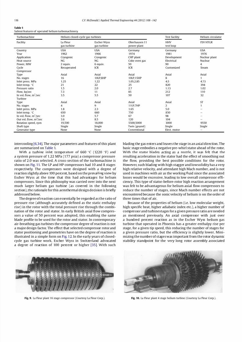
8112019 Helium Turbomachinery Operating Experience From Gas Turbine Power Plants
httpslidepdfcomreaderfullhelium-turbomachinery-operating-experience-from-gas-turbine-power-plants 1035
with this intercooled helium axial compressor of the type shown on
Figs 11 and 13
In the high pressure helium environment a high degree of reaction leads to a rotor blading with longer chords and low aspect
ratio The larger chord length combined with low solidity results in
comparatively few compressor blades Low aspect ratio (de1047297ned as
the ratio of blade height to chord length) results in several effects
including the following 1) high stagger with wider chords results in
a greater overall machine bladed length 2) fewer blades per stage
3) relatively large area of casing and blade surface with adverse
frictional losses tending to give lower ef 1047297ciency and 4) a stiffer
blade section (also with a thicker pro1047297le) with the needed strength
to combat bending stress which can be signi1047297cant in a high pres-
suredensity helium closed-cycle system A way to partially balance
out the bending stress would be by leaning the blades and off-
setting the blade cross-section centre of gravity For the early
helium gas turbine plants a view expressed by Escher Wyss wasthat the use of high reaction blading gave the maximum attainable
head a 1047298atter pressureevolume characteristic and a better surge
margin [36] The merits of increased pressure rise per stage asso-
ciated with high reaction blading has to be put into perspective by
its lower values of ef 1047297ciency [37]
The turbine had 9 stages and a rotational speed of 18000 rpm
While not coupled with a generator the equivalent output of the
free-running turbine was on the order of 6000 kW An overall view
of the long slender rotor is shown on Fig 13 and the turbomachine
assembly being installed in a cylindrical horizontally split casing is
shown on Fig 14 The major 1047298anges had peripheral lip seals to
facilitate welding closure to ensure leak tightness
With an external gas-1047297red heater the plant operated for about
5000 h and the helium gas turbine proved to be mechanically
sound and met its speci1047297ed performance This very specialized
plant proved to be too expensive to operate for the limited market
for cryogenic 1047298uids Anticipated market growth in the late 1960sdid not materialize and while the machinery performed satisfac-
torily the customer Dye Oxygen withdrew the plant from service
As far as the helium gas turbine was concerned the plant repre-
sented a signi1047297cant milestone since the technology generated was
applied to a follow-on helium gas turbine which at this stage was
still to be fossil-1047297red but now with the long-term goal in mind of
paving the way for the eventual operation of a helium closed-cycle
gas turbine power plant with a high temperature nuclear heat
source
6 Oberhausen II helium gas turbine plant at EVO
61 Closed-Cycle gas turbine experience at EVO
With initial operation starting in 1960 the municipal energy
utility (EVO) of the city of Oberhausen in the German industrial
Ruhr area deployed a closed-cycle gas turbine plant Referred to as
Oberhausen I the plant (shown previously on Fig 3) operated in
a combined power and heat mode with an electrical output of
14 MW and the thermal heat rejection of about 20 MW was
supplied to the cityrsquos district heating system The external heater
was initially 1047297red with Bituminous coal and in 1971 a change was
made to use coke-oven gas that had become available While using
air as the working 1047298uid some of the technical dif 1047297culties experi-
enced with this plant are highlighted below simply because if they
were to occur in a future direct cycle nuclear gas turbine plant they
would be very costly and time consuming to resolve as will be
discussed in a following section
Fig 11 Cross-section view of helium gas turbine (Courtesy Escher Wyss)
CF McDonald Applied Thermal Engineering 44 (2012) 108e142 117
8112019 Helium Turbomachinery Operating Experience From Gas Turbine Power Plants
httpslidepdfcomreaderfullhelium-turbomachinery-operating-experience-from-gas-turbine-power-plants 1135
In 1963 after 20000 h of operation a failure in the HP
compressor occurred [10] A rotor blade in the 1047297rst stage failed at
the root and in passing through the compressor caused extensive
damage The failure necessitated replacing the complete HP
compressor rotor assembly From a metallurgical examination of
the broken parts the failure was attributed to a small crevice at the
edge of the blade It was postulated that a corrosive action due to
impurities in the closed-loop working 1047298uid (ie air) in1047298uenced the
propagation of the crevice and blade vibration eventually caused
the failure To prevent a further failure of this kind an electric
polishing procedure was applied to the surface of the blade to
detect any imperfections
In 1967 debris from within the closed circuit caused damage to
the rotor blades and stators of several stages in the LP compressor
In 1973 further damage in the LP compressor due to blade vibration
required blading replacement During these de-blading events the
failed fragments were contained within the machine casings Using
conventional equipment the split casings of this machine were
opened and the failed parts removed by hands-on operations New
parts were then installed and the rotor assembly re-balanced The
problems were resolved and this closed-cycle gas turbine plant
with air as the working 1047298uid then performed well over the years
with high reliability [38]Rotor vibrations are mentioned here because they had caused
problems in three fossil-1047297red closed-cycle gas turbine plants using
air as the working 1047298uid namely1) in the John Brown 12 MW Plant
in Dundee where insurmountable vibration problems occurred [2]
2) multiple blade failures in the Spittelau 30 MW plant [2] and 3)
compressor blade failures in the aforementioned Oberhausen plant
As will be mentioned in a following section a further turbine blade
failure was experienced in a larger plant using helium as the
working 1047298uid
Correcting the subsequent blade failure damage to the turbo-
machine in a fossil-1047297red plant was straightforward however the
implication of such an operation in a future direct cycle nuclear gas
turbine with radioactively contaminated blading would be far more
severe This would likely require complex remote handling equip-ment and a dedicated facility for machine decontamination and
disassembly before hands-on repair could be undertaken
The Oberhausen I plant operated for about 120000 h and was
decommissioned in 1982 In about 1971 an expansion of the utilityrsquos
Fig 12 Impact of compressor blading geometry on degree of reaction (Courtesy
Escher Wyss)
Fig 13 Intercooled axial 1047298
ow helium turbomachine rotating assembly (Courtesy Escher Wyss)
CF McDonald Applied Thermal Engineering 44 (2012) 108e142118
8112019 Helium Turbomachinery Operating Experience From Gas Turbine Power Plants
httpslidepdfcomreaderfullhelium-turbomachinery-operating-experience-from-gas-turbine-power-plants 1235
capacity was needed due to increasing demand A larger fossil-1047297red
closed-cycle cogeneration plant of conventional design and still
retaining the use of air as the working 1047298uid was initially foreseen
but an emerging German development in the nuclear power plant
1047297eld resulted in a different decision being made as discussed
below
62 Relevance of the Oberhausen II helium turbine
Starting in 1972 development work sponsored by the Federal
Republic of Germany within the scope of the 4th Atomic program
was initiated on a high temperature reactor power plant with
a helium gas turbine (HHT) The reference plant design was based
on a large single-shaft intercooled helium turbine rated at
1240 MW A demonstration plant rated at 676 MW was planned
but prior to the construction of this it was necessary to test the
most important components to reduce risk Details of the two
major facilities to accomplish this have been reported previously
[39] and are summarized as follows
The Oberhausen II helium gas turbine plant was designed andbuilt to perform two major functions 1) it had to operate as
a commercial venture to provide electrical power (50 MWe) and
district heating (53 MWt) for the city of Oberhausen and 2) provide
data applicable to the nuclear gas turbine project particularly the
dynamic behavior of the overall plant and the integrity and long-
term operating experience of the major components in a helium
environment especially the turbomachine
The second facility was the HHV an experimental plant for
testing under representative conditions with respect to machine
size operating temperature pressure and mass 1047298ow of a large
helium turbomachine The facility was extensively instrumented to
gatherdata in the following areas rotorcooling system veri1047297cation
thermal insulation integrity 1047298ow characteristics blading ef 1047297ciency
acoustics rotor dynamic stability bearings dynamic and static
seals system leak tightness and metals behavior for the full
spectrum of plant operations including plant startup load change
shutdown upset conditions etc Details of the HHV facility and
testing undertaken are given in a later section
63 Oberhausen II helium gas turbine plant design
The design and construction of the plant was based on joint
efforts between EVO (plant designer and operator) GHH (turbo-
machine recuperator coolers and controls) Sulzer (helium
heater) and the University of Hannover Institute for Turboma-
chinery which contributed to the designwork and monitoring plant
performance
For the future planned nuclear gas turbine plant design values
of the temperature and pressure at the turbine inlet were 850 C
(1562 F) and 60 MPa (870 psia) respectively Attainment of this
temperature in the Oberhausen II plant could not be achieved and
750 C (1382 F) was selected based on tube material stress
considerations in the external coke-oven gas 1047297red heater An
intercooled and recuperated closed cycle was selected and themajor features of the plant are given on Table 1 The salient
parameters are given on the simpli1047297ed cycle diagram (Fig 15)
While rated at 50 MW a maximum system pressure of only
285 MPa (413 psia) was chosen so that the helium volumetric 1047298ow
(hence size of the bladed passages) would correspond to a much
larger helium turbomachine (on the order of 300 MW in fact) This
together with a rotational speed of 5500 rpm for the HP group
would result in representative stress loadings and would permit
a reasonable extrapolation to the machine size planned for the
nuclear demonstration plant
For the intercooled and recuperated cycle a compressor pressure
ratio of 27 was selected The helium mass 1047298ow rate was 85 kgs
(187 lbsec) and the circuit pressure loss was estimated at 104
percent Based on state-of-the-art component ef 1047297
ciencies and
Fig 14 Intercooled helium turbomachine with an equivalent power rating of 6000 kW installed in a split-case steel pressure vessel (Courtesy Escher Wyss)
CF McDonald Applied Thermal Engineering 44 (2012) 108e142 119
8112019 Helium Turbomachinery Operating Experience From Gas Turbine Power Plants
httpslidepdfcomreaderfullhelium-turbomachinery-operating-experience-from-gas-turbine-power-plants 1335
a recuperator effectiveness of 87 percent the projected thermal
ef 1047297ciency was 326 percent gross and 313 percent net
The isometric sketch of the distributed power conversion
system shown on Fig 16 (from Ref [40]) is convenient for
describing the plant layout A decision was made [41] to install the
horizontal turbomachinery in three large steel vessels the group-
ings being as follows 1) LP compressor rotor 2) HP compressor and
HP turbine grouping and 3) LP turbine The 1047297rst two assemblies
were on a single-shaft with a rotational speed of 5500 rpm The
generator with a rotational speed of 3000 rpmis driven from the LP
turbine end The rotors were geared together but with the selected
shafting arrangement only a small amount of power was trans-
mitted through the gearbox This con1047297guration was established
so that the dynamic behavior would be the same as in the large
single-shaft reference nuclear gas turbine plant design concept
The arrangement of the three vessels can be clearly seen on Fig 17
The horizontal tubular recuperator is positioned below the
turbomachinery The tubular precoolers and intercoolers are
installed in vertical steel vessels This type of orientation of the
major components was used in some of the earlier closed-cycle
plants using air as the working 1047298uid
Power regulation was achieved by inventory control as in the
aforementioned Oberhausen I plant which meant that the system
pressure (hence mass 1047298ow) was changed as required To lower the
power output helium was extracted from the loop after the HP
compressor through a control valve into a storage vessel For
a power increase helium was returned from the storage vessel into
the system upstream of the LP compressor without the need for an
additional blower With this arrangement the turbine inlet
temperature and speed remained constant and plant ef 1047297ciency
would be essentially constant down to a very low power level [42]
To achieve rapid load changes a bypass valve was included in the
system in which helium was transferred in a line between the HP
compressor exit end and LP end of the recuperator A very rapid
change from 100 percent load to no-load operation and back was
demonstrated [43]
64 Helium turbomachinery
The major features and parameters for the turbomachine are
given on Table 2 and are summarized as follows A longitudinal
cross-section of the turbomachine is shown on Fig 18 At the left
hand end the LP compressor is installed in a spherical pressure
vessel A high degree of reaction (ie 100 percent) was selected for
this 10 stage axial compressor this practice following the experi-
ence of an earlier discussed helium turbomachine A view showing
the bladed rotor of the LP compressor installed in the pressure
vessel split casing is shown on Fig19 with an appreciation for the
size of the spherical casing being shown on Fig 20 Both the HP
compressor and HP turbine rotors are installed in a common
housing as shown in the turbomachine cross-section (Fig 21) and
Fig 15 Oberhausen II helium gas turbine cycle diagram
Fig 16 Isometric layout of Oberhausen II helium gas turbine power conversion system (Courtesy EVO)
CF McDonald Applied Thermal Engineering 44 (2012) 108e142120
8112019 Helium Turbomachinery Operating Experience From Gas Turbine Power Plants
httpslidepdfcomreaderfullhelium-turbomachinery-operating-experience-from-gas-turbine-power-plants 1435
in the view with the HP rotor assembly positioned above the
horizontal split casing (Fig 22) The 15 stage HP compressor was
again designed with 100 percent reaction blading The HP turbine
has 7 stages and operated with an inlet temperature of 750 C
(1382O F) A cross-section of the 11 stage LP turbine installed in
a separate spherical vessel is shown on Fig 23 The amount of
power transmitted in the gearbox between the HP and LP turbinesis small since at rated output the HP turbine power level is only
slightly more than is needed to drive both compressors
The rotor of the HP group is supported on two oil-lubricated
bearings For the complete rotating assembly the thrust bearing is
located at the warm end of the LP compressor The six turbo-
machine bearing housings were designed such that direct access to
the large oil bearings was possible without having to open the large
casings This was done to reduce maintenance time because the
large split casings have 1047298anges that were welded closed at the
peripheral lip seals to minimize helium leakage
Special attention was given to the design of the cooling system
for the rotor In the case of this plant with a turbine inlet
temperature of 750 C the turbine blades themselves based on the
use of an existing superalloy did not have to be internally cooledbut cooling gas bled from the HP compressor outlet 1047298owed through
the hollow shaft and was used to cool the turbine discs and the
blade root attachments and then returned downstream of the
turbine
In a closed-cycle gas turbine the powerlevel can be regulated by
means of changing the system pressure and careful attention must
be given to the design of the various sealing systems to accom-
modate pressure differentials within the system particularly
during transient operation To simulate what would be needed in
a direct cycle nuclear gas turbine (to prevent 1047297ssion products
coming into contact with the bearing lubricating oil) a system
having a separate chamber for each of the three labyrinth seals was
incorporated in the machine design Outboard of the labyrinth seals
where the shafts penetrate the casings there were two further
seals a 1047298oating ring seal and a shutdown seal to prevent external
helium leakage
65 Helium turbomachine operating experience
Various presentations papers and publications have previously
covered the over 13 year operation of the Oberhausen II helium gas
turbine plant [43e48] The experience gained with the operation
Fig 17 Overall view of Oberhausen II 50 MWe helium gas turbine power plant (Courtesy EVO)
Table 2
Oberhausen II plant helium turbomachinery
Plant design electrical power MW 50
District heating thermal supply MW 535
Plant design ef 1047297ciency at terminals 313
Thermodynamic cycle ICR
Control method Helium inventory
compressor bypass
Rotor arrangement 2 Shaft (geared together)
Helium mass 1047298ow kgsec 85
Overall pressure ratio 27
Generator ef 1047297ciency 98
Design system pressure loss 104Compressor LP HP
Inlet pressure MPa l05 l54
Inlet temperature C 25 25
Vol 1047298ow inletoutlet m3s 5040 4025
Ef 1047297ciency 870 855
Rotational speed rpm 5500 5500
Number of stages 10 15
Blade height inletoutlet mm 10385 7253
Turbine LP HP
Inlet pressure MPa 165 270
Inlet temperature C 582 750
Ef 1047297ciency 900 883
Rotational speed rpm 3000 5500
Number of stages 11 7
Vol 1047298ow inletoutlet m3sec 92120 6792
Blade height inletoutlet mm 200250 150200
CF McDonald Applied Thermal Engineering 44 (2012) 108e142 121
8112019 Helium Turbomachinery Operating Experience From Gas Turbine Power Plants
httpslidepdfcomreaderfullhelium-turbomachinery-operating-experience-from-gas-turbine-power-plants 1535
of the large axial 1047298ow helium turbomachine is summarized asfollows
On the positive side the following were accomplished The rotor
helium buffered bearing labyrinth oil sealing system was one of the
numerous systems that worked well from the onset This was
encouraging since the external leakage of helium contaminated by
1047297ssion products and the ingress of lubricating oil into the closed
helium loop during the projected plant lifetime of 60 years are of
concern to designers of a direct cycle nuclear gas turbine plant (for
a machine with oil bearings) because of the likely long plant
downtime for cleanup and repair
With some modi1047297cations the helium puri1047297cation system
worked well with the purity level within the speci1047297cation The
helium cooling systems worked well to keep the temperatures of
the turbine discs blade root attachments and casings at speci1047297
edlevels Load change by inventory control was done routinely and
the ability to shed 100 percent of the load in a very short period by
means of the bypass valve was demonstrated The integrity of the
co-axial turbine inlet hot gas duct was proven At the end of plant
operation the major turbomachine casings were opened and there
were no signs of corrosion or erosion of the turbine or compressor
blades The coatings applied to mating metallic surfaces were
effective with no evidence of galling or self-welding in the oxygen-
free closed-loop helium environment
Experience from previously operated high temperature helium
cooled nuclear reactor power plants (with Rankine cycle steam
turbine power conversion systems) demonstrated that absolute
helium leak tightness was not attainable This was also true in the
Oberhausen II fossil-1047297red gas turbine plant where during initial
operation the helium leakage was about 45 kg per day Attention
was given to this and helium losses were reduced to the range of
5e10 kg per day principally by seal welding the major 1047298anges This
value can be compared with other closed loop helium systems as
shown below
On the negative side several unexpected problems had a majorimpact on the operation of the plant Following initial running of
the machine at 3000 rpm in preparation to synchronizing the
system the HP casing was opened for inspection revealing
damage to the labyrinth seals this being caused by shifting of
the rotor in the axial direction The labyrinth seals were replaced
and the turbine was 1047297rst synchronized with the grid on November
8 1975
Subsequent vibration problems were encountered and the HP
shaft oscillation became so large that it caused damage to the
bearings and the design value of speed and power could not be
maintained and the plant was shut down This was initially thought
to be due to thermal distortion of the rotor and a large unbalance
Fig 18 Cross-section of Oberhausen II plant helium turbomachinery rotating assembly (Courtesy EVO)
Fig 19 Oberhausen II low pressure helium compressor installed in casing (Courtesy
GHH)
Plant Helium inventory kg Leakage
kgday day
Dragon 180 020e20 010e10
AVR 240 10e30 040e12
Oberhausen II 1400 5e10 035e070
HHV 1250 25e50 020e040
FSV e Excessive leakage
CF McDonald Applied Thermal Engineering 44 (2012) 108e142122
8112019 Helium Turbomachinery Operating Experience From Gas Turbine Power Plants
httpslidepdfcomreaderfullhelium-turbomachinery-operating-experience-from-gas-turbine-power-plants 1635
Modi1047297cations to the rotor were made and the bearings replaced
but now the HP spool design speed of 5500 rpm could not be
achieved Subsequent major design and fabrication changes were
made including decreasing the bearing span by 600 mm (24 in)
giving a shorter stiffer rotor and changing the type of bearings In
restarting the plant the design speed of the HP rotor was achieved
however the power output was only 30 MW compared with the
design value of 50 MW
Fig 20 View of Oberhausen II low pressure helium compressor spherical vessel (Courtesy GHH)
Fig 21 Cross-section of Oberhausen II high pressure rotating group (Courtesy GHH)
CF McDonald Applied Thermal Engineering 44 (2012) 108e142 123
8112019 Helium Turbomachinery Operating Experience From Gas Turbine Power Plants
httpslidepdfcomreaderfullhelium-turbomachinery-operating-experience-from-gas-turbine-power-plants 1735
To gain operational experience it was decided to continue
running the plant at the reduced power rating On February 5 1979
after nearly 11000 h of operation a rotor blade from the second
stage of the HP turbine failed causing damage in the remaining
stages but the high energy fragments were contained within the
thick machine casing Examination of the failed blade revealed the
defect as a crack caused by the forgingprocess on the semi-1047297nishedproduct To prevent such a failure occurring in the future an electric
polishing process applied to the blade surface before inspection
was implemented and improved crack detection methods
introduced
Acoustic loads in a closed-cycle gas turbine represent pressure
1047298uctuations propagating at the speed of sound through the helium
working 1047298uid Pressure 1047298uctuations of importance result from the
aerodynamic effects of high velocity helium impacting and
essentially being intermittently ldquocutrdquo by the blading in the
compressor and turbine Care must be taken in the design of the
plant to ensurethat these 1047298uctuating pressure waves do not induce
vibrations of a magnitude that could result in excitation-induced
fatigue failures in components in the circuit Critical vibrations
occur when resonance exists between the main frequency of
the propagating sound and the natural frequencies of the
components particularly ones that have large surface area to
thickness ratio
Measurements of sound spectrum were taken at four different
locations in the circuit The design level of power of 50 MW was not
achieved but at the 30 MW power output actually realized the
maximum recorded sound power level was 148 dB After plantshutdown there was no evidence of adverse effects on the major
components of noise induced excitation emanating from the axial
1047298ow turbomachinery The integrity of the turbine inlet hot gas duct
and insulation was con1047297rmed
The inability to reach rated power was attributed to shortcom-
ings in the helium turbomachine This included the compressors(s)
and turbine(s) blading failing to attain design values of ef 1047297ciencies
and the bleed helium mass 1047298ows for cooling and sealing being
signi1047297cantly greater than analytically estimated Based on data
taken from the well instrumented plant detailed analyses were
undertaken by specialists [4950] to calculate the losses in the
turbomachine to explain the power output de1047297ciency A summary
of the projected losses and various component ef 1047297ciencies is pre-
sented in a convenient form on Table 3
Fig 22 Oberhausen II high pressure rotor being installed (Courtesy GHH)
CF McDonald Applied Thermal Engineering 44 (2012) 108e142124
8112019 Helium Turbomachinery Operating Experience From Gas Turbine Power Plants
httpslidepdfcomreaderfullhelium-turbomachinery-operating-experience-from-gas-turbine-power-plants 1835
The plant operated for approximately 24000 h and was shut-
down and decommissioned in 1988 when the coke-oven gas supply
for the heater was no longer available A total plant operating time
of about 11500 h had been at the design turbine inlet temperature
of 750 C (1382 F) Turbomachinery related experience gained
from operation of this large helium gas turbine plant was extremely
valuable While many of the functions performed well from the
onset and others worked satisfactorily after modi1047297cations were
made serious unexpected problems were encountered
The achieved electrical power output of only 60 percent of the
design value was initially thought to be due to a grossly excessive
system pressure loss However when the data was carefully eval-uated it was found that 85 percent of the 20 MW power loss was
attributed to turbomachine related problems as delineated on
Table 3
To remedy this power de1047297ciency it was clear that a major re-
design of the turbomachinery would be required While replace-
ment of the gas turbine was not contemplated a study was
undertaken based on data from the plant and new technologies
that had become available since the initial design Based on the
1047297ndings a new turbomachine layout concept was suggested [43]
and a simplistic view of the rotor arrangement is shown on Fig 24
A more conventional single-shaft arrangement was proposed with
the two compressors and turbine having a rotational speed of
5400 rpm A gearbox was still retained to give a generator rota-
tional speed of 3000 rpm Based on prevailing technology at the
time the requirements for such a gearbox would have been moredemanding since the 50 MW from the turbine to the generator
would have to be transmitted through it This would necessitate
a larger system to pump 1047297lter and cool the bearing lubrication oil
To remedy the very large losses in the compressors and turbines
the number of stages would have to be increased In the case of the
compressors the use of lighter aerodynamically loaded higher
ef 1047297ciency stages with 50 percent reaction blading was
recommended
7 High temperature helium test facility (HHV)
71 Background
In the late 1960rsquos with large numbers of orders placed for 1047297rst
generation light water reactor nuclear power plants studies were
initiated for next generation power plants with higher ef 1047297ciency
potential Following the initial operational success of the 1047297rst three
small helium cooled HTR plants (ie Dragon in the UK Peach
Bottom I in the USA and AVR in Germany) studies on larger plants
based on the use of both Rankine steam cycle and helium closed
Brayton cycle power conversion systems were undertaken In the
early 1970rsquos emphasis was placed on nuclear gas turbine plant
designs with larger power output both in the USA (for the
HTGR eGT) and in Europe (for the HHT) Work in the USA was
limited to only paper studies [18] The much larger program in
Germany (with participation by Swiss companies for the turbo-
machine heat exchangers and cooling towers) included a well
planned development testing strategy to support the plant design
Fig 23 Cross-section of Oberhausen II low pressure helium turbine (Courtesy GHH)
Table 3
Oberhausen II helium turbine plant power losses
Componentcause Design
value
Measured Power loss
MW
Compressors
B Flow losses in inlet diffusers
and blades
Low pressure ef 1047297ciency 870 826 13
High pressure ef 1047297ciency 855 779 40
Turbines
B Blade gap and 1047298ow losses
High pressure ef 1047297ciency 883 823 39
B Pro1047297le losses due to Remachined
blades after having detected
damaged blades
Low pressure ef 1047297ciency 900 856 24
BSealing leakage and cooling 1047298ows
in all turbomachines Kgsec
18 75 53
B Circuit pressure losses
(Ducting Hxrsquos etc)
102 128 26
B Miscellaneous heat losses 05
Total power loss 200 MW
Notes (1) Plant designed for electrical power output of 50 MW actual power output
measured 30 MW
(2) Power de1047297ciency of20 MW based on measurements taken and then recalculated
for the rated plant output
(3) 85 of Power loss attributed to helium turbomachinery related issues
CF McDonald Applied Thermal Engineering 44 (2012) 108e142 125
8112019 Helium Turbomachinery Operating Experience From Gas Turbine Power Plants
httpslidepdfcomreaderfullhelium-turbomachinery-operating-experience-from-gas-turbine-power-plants 1935
While the reference HHT plant for eventual commercializationembodied a very large single helium gas turbine rated at 1240 MW
this was to be preceded by a nuclear demonstration plant rated at
676 MW [51] To support the design of this plant technology
generated from the following was planned 1) operational experi-
ence from the aforementioned Oberhausen II 50 MW helium gas
turbine power plant and 2) testing of components in a large high
temperature helium test facility as discussed below
72 Development facilitytesting objectives
An overall view of the HHV test facility sited in Julich in
Germany is shown on Fig 25 and since this has been reported on
previously [52] it will only be brie1047298
y covered in this section Tominimize risk and assure the performance integrity and reliability
of the nuclear demonstration plant some non-nuclear testing of
the major components especially the helium turbomachine was
deemed essential Because of the limitations of a conventional
closed-cycle helium gas turbine power plant particularly the
temperature limitations of existing fossil-1047297red and electrical
heaters a new type of test facility was foreseen
A simpli1047297ed schematic line diagram of the HHV circuit is shown
on Fig 26 The major design parameters are shown on Fig 27
together with the temperatureeentropy diagram which is conve-
nient for describing the unique relationship between the compo-
nents in the closed helium loop Starting at the lowest pressure in
Fig 24 Proposed new concept for Oberhausen II helium gas turbine rotating assembly to remedy problems encountered during operation of the 50 MWe power plant (Courtesy
EVO)
Fig 25 HHV helium turbomachinery test facility (Courtesy BBC)
CF McDonald Applied Thermal Engineering 44 (2012) 108e142126
8112019 Helium Turbomachinery Operating Experience From Gas Turbine Power Plants
httpslidepdfcomreaderfullhelium-turbomachinery-operating-experience-from-gas-turbine-power-plants 2035
the system the helium is compressed (Ae
B) its temperatureincreasing to 850 C (1562 F) before 1047298owing through the test
section (BeC) After being cooled slightly (CeD) the helium is
expanded in the turbine (DeA) down to the compressor inlet
conditions completing the loop There is no power output from the
system and without the need for an external heater the
compression heat is used to raise the helium to the maximum
system temperature in what can be described as a very large heat
pump The required compressor power is 90 MW and to supple-
ment the 45 MW generated by expansion in the turbine external
power is provided by a 45 MW synchronous electrical motor A
cooler is required to remove the compression heat that is contin-
uously put into the closed helium loop and this is done by bleeding
about 5 percent of the mass 1047298ow after the compressor cooling it
and re-introducing it into the circuit close to the turbine inlet In
addition to testing the turbomachine the facility was engineered
with a test section to accommodate other small components (eg
hot gas 1047298ow regulation valves bypass valves insulation con1047297gu-
rations and types of hot gas duct construction) With the highest
temperature in the system being at the compressor exit the facility
had the capability to provide helium at a temperature up to 1000 C
(1832 F) for short periods at the entrance to the test section
While a higher ef 1047297ciency of the planned nuclear demonstration
plant could be projected with a turbine inlet temperature in the
range 950e1000 C (1742e1832 F) this would have necessitated
either turbine blade cooling or the use of a high temperature alloy
such as Titanium Zirconium Molybdenum (TZM) At the time it was
felt that using either of these would have added cost and risk to theprojectso a conventionalnickel-basedalloyas usedin industrialgas
turbines was selected for the 850 C design value of turbine inlet
temperature this negating the needfor actual internal bladecooling
However a complex internal coolingsystemwas neededto keep the
Fig 26 Cycle diagram of HHV test loop (Courtesy BBC)
Fig 27 Salient features of HHV helium turbomachinery (Courtesy BBC)
CF McDonald Applied Thermal Engineering 44 (2012) 108e142 127
8112019 Helium Turbomachinery Operating Experience From Gas Turbine Power Plants
httpslidepdfcomreaderfullhelium-turbomachinery-operating-experience-from-gas-turbine-power-plants 2135
turbine discs and blade root attachments and casings to acceptable
temperatures commensurate with prescribed stress limitations for
thelife of theturbomachine In addition a heliumsupplywas needed
to provide a buffering system for the various labyrinth seals
In a direct Brayton cycle nuclear gas turbine the turbomachine is
installed in the reactor circuit and via the hot gas duct heated
helium is transported directly from the reactor core to the turbine
From the safety licensing and reliability standpoints there are
various seals that must perform perfectly A helium buffered
labyrinth seal system is necessary to prevent bearing lubricating oil
ingress to the closed helium loop Since in the proposed HHT plant
design the drive shaft from the turbine to the generator penetrates
the reactor primary system pressure boundary two shaft seals are
needed one a dynamic seal when the shaft is rotating and a static
seal when the turbomachine is not operating Testing of these seals
in a size and operating conditions representative of the planned
commercial power plant was considered to be a licensing must
The mechanical integrity of the rotating assembly must be
assured there being two major factors necessitating testing the
machine at full speed and temperature and at high pressure
namely 1) loading the blading under representative centrifugal and
gas bending stresses and 2) to monitor vibration and con1047297rm rotor
dynamic stability For the design of the planned commercial planta knowledge of the acoustic emissions by the turbomachine and
propagation in the closed circuit was required Data from the HHV
facility would enable dynamic responses of the major components
(especially the insulation) resulting from excitation by the sound
1047297eld to be calculated
The circuit was instrumented to gather data on the effectiveness
of the hot gas duct insulation thermal expansion devices hot gas
valves helium puri1047297cation system instrumentation and the
adequacy of the coatings applied to mating metallic surfaces to
prevent galling or self-welding Details of the turbomachinery and
the experience gained from the operation of the HHV facility are
covered in the following sections
73 Helium turbomachine
A cross-section of the turbomachine is shown on Fig 28 The
single-shaft rotating assembly consists of 8 compressor stagesand 2
turbine stages and had a weighton the order of 66 tons(60000 kg)
The hub inner and outer diameters are 16 m (525 ft) and 18 m
(59 ft) respectively the blading axial length being 23 m (75 ft)The
span between the oil bearings being 57 m (187 ft) The physical
dimensions of the turbogroup shown on Fig 28 correspond to
a machine rated at about 300 MW The oil bearings operate in
a helium environment and the diameters of the labyrinths and
1047298oating ring shaft seals to prevent oil ingress are representative of
a machine rated at about 600 MW The complexity of the machine
design especially the rotor cooling system sealing system very
large casing and heat insulation have been reported previously
[53e55]
To ensure high structural integrity the rotor was constructed by
welding together the forged compressor and turbine discs The
compressor had 8 stages each having 56 rotor and 72 stator blades
The turbine had 2 stages each having 90 stator and 84 rotor blades
An appreciation for the large size of the rotating assembly can be
seen from Fig 29 The rotor blades have 1047297r-tree attachments
embodying cooling channels Since the temperature and pressure
do not vary very much along the blading in the 1047298ow direction an
intricate rotor and stator cooling system was required Channels in
both the blade roots and the spacers between adjacent blade rows
form an axial geometry for the passage of a cooling helium supplyto keep the temperature of the multiple discs below 400 C
(752 F) The design of this was a challenge since the rotor and
stator blade attachments of both the 8 stage compressor and 2
stage turbine had to be cooled Excessive leakage had to be avoided
since this would have prevented the speci1047297ed compressor
discharge temperature (ie the maximum temperature in the
circuit) from being reached
In the 1970rsquos and early 1980rsquos signi1047297cant studies were carried
out on large helium gas turbines by various organizations [56e62]
In this era there was general agreement that testing of the turbo-
machine in one form or another in non-nuclear facilities be
undertaken to resolve areas of high risk (eg seals bearings cooling
systems rotor dynamic stability compressor surge margin
dynamic response rotor burst protection etc) before installationand operation of a large gas turbine in a nuclear environment
This low risk engineering philosophy which prevailed at the time
in both Germany and the USA emphasized the importance of
Fig 28 Cross-section of HHV helium turbomachinery (Courtesy BBC)
CF McDonald Applied Thermal Engineering 44 (2012) 108e142128
8112019 Helium Turbomachinery Operating Experience From Gas Turbine Power Plants
httpslidepdfcomreaderfullhelium-turbomachinery-operating-experience-from-gas-turbine-power-plants 2235
the HHV test facility as being an important step towards the
eventual deployment of a high ef 1047297ciency nuclear gas turbine power
plant
74 Initial operation of the HHV facility
During commissioning of the plant in 1979 oil ingress into the
helium circuit from the seal system occurred twiceThe 1047297rst ingressof oil between 600 and 1200 kg (1322 and 2644 lb) was due to
a serious operatorerror and the absence of an isolation valve in the
system The oil in the circuit was partly coked and formed thick
deposits on the cold and hot surfaces of the turbomachinery and in
other parts of the closed loop including saturation of the 1047297brous
insulation The fouled metallic surfaces were cleaned mechanically
and chemically by cracking with the addition of hydrogen and
additives The second oil ingress was due to a mechanical defect in
the labyrinth seal system The quantity of oil introduced was small
and it was removed bycracking at a temperature of 600 C (1112 F)
and with the use of additives To obviate further oil ingress inci-
dents the labyrinth seal system was redesigned The buffer and
cooling helium system piping layout was modi1047297ed to positively
eliminate oil ingress due to improper valve operation and toprevent further human error
Pressure and leak detection tests of the HHV test facility at
ambient temperature showed good leak tightness for the turbo-
machine 1047298anged joints and of the main and auxiliary circuits
However at the operating temperature of 850 C (1562 F) large
helium leaks were detected The major 1047298anges had been provi-
sioned with lip seals and the 1047297rst step was to weld the closures A
large leak persisted at the front 1047298ange of the turbomachine This
was diagnosed as being caused by a non-uniform temperature
distribution during initial operation resulting in thermal stresses
creating local gaps This problem was overcome by redesign of the
cooling system with improved gas 1047298ow distribution and 1047298ow rates
to give a more uniform temperature gradient The leakage from the
system was reduced to on the order of 020e
040 percent of the
helium inventory per day this being of the same magnitude as in
other closed helium circuits as discussed in Section 65
It should be mentioned that in addition to the HHV experience
bearing oil ingress into the circuits and system loss of the working
1047298uid in other closed-cycle gas turbine plants have occurred In all of
these fossil-1047297red facilities 1047297xing leaks and removal of oil deposits
were undertaken based on conventional hands-on approaches but
nevertheless such operations were time-consuming However if a new and previously untested helium turbomachine operating in
a direct cycle nuclear gas turbine plant experienced an oil ingress
the rami1047297cations would be severe The likely use of remote
handling equipment to remove the turbomachine from the vessel
machine disassembly (including breaking the welded 1047298ange joints)
and removal of oil from the radioactively contaminated turbo-
machine blade surfaces and system insulation would be time
consuming A diagnosis of the failure would be required before
a spare turbomachine could be installed and this plant downtime
could adversely affect plant availability
75 Experience gained
Afterresolutionof the aforementionedproblems the HHVfacilitywas started in the Spring of 1981 and in an orderly manner was
brought up to full pressure and a temperature of 850 C (1562 F)
During a 60 h run the functioning of the instrumentation control
and safety systems were veri1047297ed During these tests the ability to
stop the turbomachine from full operating conditions to standstill
within 90 s was demonstrated After system depressurization the
plant was then run up again to full operating conditions with no
problems experienced The HHV facility was successfully run for
about 1100 h of which theturbomachineryoperated forabout325 h
at a temperature of 850 C The test facility was extensively instru-
mented and interpretation and analysis of the data recorded gave
positive and favorable results in the following areas
The complex rotor cooling system which was engineered to
assure that the temperature of the discs be kept below 400
C
Fig 29 HHV helium turbomachine rotating assembly (size equivalent to a 300 MWe machine) being installed in a pressure vessel (Courtesy BBC)
CF McDonald Applied Thermal Engineering 44 (2012) 108e142 129
8112019 Helium Turbomachinery Operating Experience From Gas Turbine Power Plants
httpslidepdfcomreaderfullhelium-turbomachinery-operating-experience-from-gas-turbine-power-plants 2335
(752 F) was demonstrated to be effective The measured rotor
coolant 1047298ows (about 3 percent of the mass1047298ow passing through the
machine) were slightly larger than had been estimated and this
resulted in measured turbine disc temperatures lower than pre-
dicted [55]
The dynamic labyrinth shaft seal functioned well at the full
temperature and pressure conditions and met the requirement of
zero oil ingress into the helium circuit The measured rotor oscil-
lation did not have any adverse effect on the shaft sealing system
The static rotor seal (for shutdown conditions) functioned without
any problems
The compressor and turbine blading hadef 1047297ciencies higher than
predicted The structural integrity of the rotor proved to be sound
when operating at 3000 rpm under the maximum temperature and
pressure conditions The stiff rotor shaft had only slight unbalance
and thermal distortion and measured oscillations were in the range
typical of large steam turbines
Sound power spectrum measurements were taken in four
different locations in the circuit These were taken to determine the
spectrum and intensity of the sound generated and propagated by
the turbomachinery and the resultant vibration of internal
components The maximum sound power level in the helium
circuit was160 dB Numerous strain gages were placedin the circuitto determine the in1047298uence of the sound 1047297eld particularly on the
fatigue strength of the turbine inlet hot gas duct In later examining
the internal components there was no evidence of excessive
vibration of the components especially the ducting and the insu-
lation Based on the measurements and calculations it was
concluded that the fatigue strength limit of the components would
not be exceeded during the designed life of the planned commer-
cial nuclear gas turbine power plant
In a direct cycle nuclear gas turbine the hot gas duct used to
transport the helium from the reactor core to the turbineis a critical
component The hot gas duct in the HHV facility performed well
mechanically and con1047297rmed the adequacy of the thermal expan-
sion devices From the thermal standpoint the 1047297ber insulation
performed better than the metallic type
After dismantling the HHV facility there were no signs of
corrosion or erosion of the turbine or compressor blading While
the total number of hours operated was limited the coatings
applied to mating metallic surfaces to prevent galling and frictional
welding in the oxidation-free helium worked well
The helium buffer and cooling system worked well However
problems remained with the puri1047297cation of the buffer helium The
oil separation system consisting of a cyclone separator and a wire
mesh and a down stream 1047297ber 1047297lter needed further improvement
In late 1981 a decision was made to cancel the HHT project and
the HHV facility was shutdown The design and operational expe-
rience gained from the running of this facility would have been
extremely valuable had the nuclear gas turbine power plant
concept moved towards becoming a reality The identi1047297cation of
somewhat inevitable problems to be expected in such a complexturbomachine and their resolution were undertaken in a timely
and cost effective manner in the non-nuclear HHV facility This
should be noted for future nuclear gas turbine endeavors since
remedying such unexpected problems in the case of a new and
untested large helium turbomachine being operated for the 1047297rst
time using nuclear heat could result in very complex repair
Fig 30 Speci1047297
c speed-speci1047297
c diameter array for gas circulators in various gas-cooled nuclear plants
CF McDonald Applied Thermal Engineering 44 (2012) 108e142130
8112019 Helium Turbomachinery Operating Experience From Gas Turbine Power Plants
httpslidepdfcomreaderfullhelium-turbomachinery-operating-experience-from-gas-turbine-power-plants 2435
activities and extended plant downtime and indeed adding risk to
the overall success of the nuclear gas turbine concept
8 Circulators used in gas-cooled reactor plants
Circulators of different types will be needed in future helium
cooled nuclear plants these including the following 1) primary
loop circulator for possible next generation steam cycle power andcogeneration plants 2) for future indirect cycle gas turbine plants
3) shut down cooling circulators forall HTRand VHTR plants and 4)
for various circulators needed in future VHTR high temperature
process heat plant concepts The technology status of operated
helium circulators is brie1047298y addressed as follows
81 Background
It would be remiss not to mention experience gained in the past
with gas circulators and while not gas turbines they are rotating
machines that operate in the primary loop of a helium cooled
reactor With electric motor drives there are basically two types of
compressor rotor con1047297gurations namely radial and axial 1047298ow
machinesIn a single stage form the centrifugal impeller is used for high
stage pressure rise and low volume 1047298ow duties whereas the axial
type covers low pressure rise per stage and high volume 1047298ow The
selection of impeller type is very much related to the working
media type of bearings drive type rotor dynamic characteristics
and installation envelope A wide range of circulators have operated
and a well established technology base exists for both types [63] A
useful portrayal of compressor data in the form of quasi- non-
dimensional parameters (after Balje [64]) showing approximate
boundaries for operation of high ef 1047297ciency axial and radial types is
shown on Fig 30 (from Ref [65])
Both high speed axial and lower speed radial 1047298ow types are
amenable to gas oil and magnetic bearings From the onset of
modularHTR plant studies theuse of active magnetic bearings[6667]offered a solution to eliminate lubricating oil into the reactor circuit
and this tribology technology is attractive for use in submerged
rotating machinery in the next generation of HTR plants [68]
While now dated an appreciation of the main design features of
typical electric motor-driven helium circulators have been reported
previously namely an axial 1047298ow main circulator for a modular
steam cycle HTR plant [69] and a representative radial 1047298ow shut-
down cooling circulator [70]
The operating experience gained from three particular circula-
tors is brie1047298y included below because of their relevance to the
design of helium turbomachinery in future HTR plant variants
82 Axial 1047298ow helium circulator
Since all of the aforementioned predominantly European
helium gas turbines used axial 1047298ow turbomachinery it is of interest
to mention a helium axial 1047298ow circulator that operated in the USA
and to brie1047298y discuss its design parameters and features The
330 MW Fort St Vrain HTGR featured a Rankine cycle power
conversion system Four steam turbine driven helium circulators
were used to transport heat from the reactor core to the steam
generators The complete circulator assemblies were installed
vertically in the prestressed concrete reactor vessel [71e73]
A cross-section of the circulator is shown on Fig 31 with thecompressor rotor and stator visible on the left hand end of the
machine Based on early 1960rsquos technology a decision was made to
use water lubricated bearings and from the overall plant reliability
and availability standpoints this later proved to be a bad choice
Within the vertical circulator assembly there were four 1047298uid
systems namely the helium reactor coolant water lubricant in the
bearings steam for the turbine drive and high pressure water for
the auxiliary Pelton wheel drive During plant transients the pres-
sures and temperatures of these four 1047298uids oscillated considerably
and the response of the control and seal systems proved to be
inadequate and resulted in considerable water ingress from the
bearing cartridge into the reactor helium circuit The considerable
clean up time needed following repeated occurrences of this event
resulted in long periods of plant downtime and this had an adverseeffect on plant availability This together with other technical
Fig 31 Cross section of FSV helium circulator (Courtesy general Atomics)
CF McDonald Applied Thermal Engineering 44 (2012) 108e142 131
8112019 Helium Turbomachinery Operating Experience From Gas Turbine Power Plants
httpslidepdfcomreaderfullhelium-turbomachinery-operating-experience-from-gas-turbine-power-plants 2535
dif 1047297culties eventually contributed to the plant being prematurely
decommissioned
On the positive side in the context of this paper the helium
circulators operated for over 250000 h and exhibited excellent
helium compressor performance good mechanical integrity and
vibration-free operation The rotating assembly showing the axial
1047298ow compressor and steam turbine rotors together with a view of
the machine assembly are given on Fig 32 The helium compressor
consists of a single stage axial rotor followed by an exit guide vane
The machine was designed for axial helium 1047298ow entering and
leaving the stage and this can be seen from the velocity triangles
shown on Fig 33 which also includes the de1047297nition of the various
aerodynamic parameters Major design parameters and features of
this helium circulator are given on Table 4 Related to an earlier
discussion on the degree of reaction for axial 1047298ow compressors the
value for this conventional single stage circulator is 78 percent All
of the major aerothermal and structural loading criteria were
within established boundaries for an axial compressor having high
ef 1047297ciency and a good surge margin
The compressor gas 1047298ow path and blading geometries were
established based on prevailing industrial gas turbine and aero-
engine design practice A low Mach number (025) a high Reynolds
number (3 106) together with a modest stage loading (ie
a temperature rise coef 1047297cient of 044) and an acceptable value of
diffusion factor (042) were some of the factors that contributed to
a helium circulator that had a high ef 1047297ciency and a good pressure
rise- 1047298ow characteristic The large rotor blade chord and thick blade
section for this single stage circulator are necessary to accommo-
date the high bending stress characteristic of operation in a high
pressure environment The solidity and blade camber were opti-
mized for minimum losses
There were essentially two reasons for including this single-
stage axial 1047298ow compressor that operated in a helium cooled
reactor although its overall con1047297guration can be regarded as a 1047297rst
and last of a kind A rotor blade from this circulator as shown onFig 34 was based on a NASA 65 series airfoil which at the time
were one of the best performing cascades for such low Mach
number and high Reynolds number applications Interestingly it
has almost the same blade height aspect ratio and solidity as would
be used in the 1047297rst stage of an LP compressor in a helium turbo-
machine rated on the order of 250 MW
The second point of interest is that the helium mass 1047298ow rate
through the single stage axial compressor (rated at 4 MWe) is
110 kgs compared with 85 kgs through the multistage compressor
in the 50 MWe Oberhausen II helium gas turbine plant However
the volumetric 1047298ow through the Oberhausen axial compressor is
higher than that through the circulator by a factor of 16 this again
pointing out that the Oberhausen II plant was designed for high
volumetric 1047298ow to simulate the much larger size of turboma-chinery that was planned at the time in Germany for use in future
projected nuclear gas turbine power plants
83 High temperature helium circulator
For future helium turbomachines embodying active magnetic
bearings a challenge in their design relates to accommodating
elevated levels of temperature in the vicinity of the electronic
components In this regard it is of interest to note that a small very
high temperature helium axial 1047298ow circulator rated at 20 kW (as
shown on Fig 35) operated for more than 15000 h in an insulation
test facility in Germany more than two decades ago [74] The
signi1047297cance of this machine is that it operated with magnetic
bearings in a high temperature helium test loop with a circulatorgas inlet temperature of 950 C (1742 F) This necessitated the use
of ceramic insulation to ensure that the temperature in the vicinity
of the magnetic bearing electronics did not exceed a temperature of
about 150 C (300 F)
This machine although a very small axial 1047298ow helium blower
performed well and has been brie1047298y mentioned here since it
represents a point of reference for future helium rotating machines
capable operating with magnetic bearings in a very high temper-
ature helium environment
84 Radial 1047298ow AGR nuclear plant gas circulators
The electric motor-driven carbon dioxide circulators rated at
about 5 MW with a total runningtimein excess of 18 million hours
Fig 32 Fort St Vrain HTGR plant helium circulator (Courtesy General Atomics) (a)
Axial 1047298ow helium compressor and steam turbine rotating assembly (b) 4 MW helium
circulator assembly
CF McDonald Applied Thermal Engineering 44 (2012) 108e142132
8112019 Helium Turbomachinery Operating Experience From Gas Turbine Power Plants
httpslidepdfcomreaderfullhelium-turbomachinery-operating-experience-from-gas-turbine-power-plants 2635
in AGR nuclear power plants in the UK have demonstrated veryhigh availability [7576] To a high degree this can be attributed to
the fact that the machines were conservatively designed and proof
tested in a non-nuclear facility at full temperature and power
under conditions that simulated all of the nuclear plant operating
modes The test facility shown on Fig 36 served two functions 1)
design veri1047297cation of the prototype machine and 2) test of all new
and refurbished machines before they were installed in nuclear
plants Engineers currently involved in the design and development
of helium turbomachinery could bene1047297t from this sound testing
protocol to minimize risk in the deployment of helium rotating
machinery in future HTRVHTR plant variants
9 Helium turbomachinery development and testing
91 On-going development activities
The various helium turbomachines discussed in previous
sections operated over a span of about two decades starting in the
early 1960s From about 1990 activities in the nuclear gas turbine
1047297eld have been focused mainly on the design of modular GTeHTR
plant concepts In support of these plant studies many signi1047297cant
helium turbomachine design advancements have been made and
attention given to what development testing would be needed In
the last decade or so limited sub-component development has
been undertaken for helium turbomachines in the 250e300 MWe
size and these are brie1047298y summarized below
In a joint USARussia effort development in support of the
GTe
MHR turbomachine has been undertaken including testing in
the following areas magnetic bearings seals and rotor dynamicsfor the vertical intercooled helium turbomachine rated at 286 MWe
[77e80]
In Japan development activities have been in progress for
several years in support of the 274 MWe helium turbomachine for
the GTeHTR300 plant concept [2581] A detailed discussion on
the aerodynamic design of the axial 1047298ow helium compressor for
this turbomachine has been published in the open literature [82]
While the design methodology used for axial compressor design in
air-breathing industrial and aircraft gas turbines is generally
applicable for a multi-stage helium compressor a decision was
made by JAEA to test a small scale compressor in a helium facility
because of the inherent and unique gas 1047298ow path and type of
blading associated with operation in a high pressure helium
environment The major goal of the test was to validate the designof the 20 stage helium axial 1047298ow compressor for the GTeHTR300
plant
An axial 1047298ow compressor in a closed-cycle helium gas turbine is
characterized by the following 1) a large number stages 2) small
blade heights 3) high hub-to-tip ratio 4) a long annulus with
small taper that tends to deteriorate aerodynamic performance as
a result of end-wall boundary layer length and secondary 1047298ow 5)
low Mach number 6) high Reynolds number and 7) blade tip
clearances that are controlled by the gap necessary in the magnetic
journal and catcher bearings While (as covered in earlier sections)
helium gas turbines have operated there is limited data in the
open literature on the performance of multi-stage axial 1047298ow
compressors operating in a high pressure closed-loop helium
environment
Fig 33 Velocity triangles for axial compressor stage
CF McDonald Applied Thermal Engineering 44 (2012) 108e142 133
8112019 Helium Turbomachinery Operating Experience From Gas Turbine Power Plants
httpslidepdfcomreaderfullhelium-turbomachinery-operating-experience-from-gas-turbine-power-plants 2735
A 13rd scale 4 stage compressor was designed to simulate the
stage interaction the boundary layer growth and repeated stage
1047298ow in an actual compressor The 1047297rst four stages were designed to
be geometrically similar to the corresponding stages in the
GTe
HTR300 compressor Details of the model compressor havebeen discussed previously [81] and are summarized on Table 5
from [83]
A cross-section of the compressor test model is shown on Fig 37
A view of the 4 stage compressor rotor installed in the lower casing
is shown on Fig 38 The test facility (Fig 39) is a closed helium loop
consisting of the compressor model cooler pressure adjustment
valve and a 1047298ow measurement instrument The compressor is
driven by a 3650 kW electrical motor via a step-up gear The rota-
tional speed of 10800 rpm (three times that of the compressor in
the GTeHTR300 plant) was selected to match blade speed and
Mach number in the full size compressor
Details of the planned aerodynamic performance objectives of
the 13rd scale helium compressor test have been published
previously [84] Extensivetesting of the subscale model compressorprovided data to validate the performance of the full size
compressor for the GTeHTR300 power plant The test data and
test-calibrated CFD analyses gave added insight into the effect of
factors that impact performance including blade surface roughness
and Reynolds number
Based on advanced aerodynamic methodology and experi-
mental validation [82] there is now a sound basis for added
con1047297dence that the design goals of 90 percent polytropic ef 1047297ciency
and a design point surge margin of 20 percent are realizable in
a large multistage axial 1047298ow compressor for a future nuclear gas
turbine plant
In a similar manner a design of a one third size single stage
helium axial 1047298ow turbine has been undertaken and a cross
section of the machine is shown on Fig 40 (from Ref [81]) This
Table 4
Major features of axial 1047298ow helium circulator
Helium 1047298ow rate kgsec 110
Inlet temperature C 394
Inlet pressure MPa 473
Pressure rise KPa 965
Volumetric 1047298ow m3sec 32
Compressor type Single stage axial
Compressor drive Steam turbine
Bearing type Water lubricated
Rotational speed rpm 9550
Power MW 40
Rotor tip diameter mm 688
Rotor tip speed msec 344
Number of rotor blades 31
Number of stator blades 33
Blade height mm 114
Hub-to-tip ratio 067
Axial velocity msec 157
Flow coef 1047297cient 055
Temperature rise coef 1047297cient 044
Degree of reaction 078
Mean rotor solidity 128
Rotor aspect ratio 155
Rotor Mach number 025
Rotor diffusion factor 042
Rotor Reynolds number 3106
Speci1047297c speed 335
Speci1047297c diameter 066
Blade root thickness 15
Airfoil type NASA 65
Rotor blade chord mm 94e64
Stator blade chord mm 79
Rotor centrifugal stress MPa 125
Rotor bending stress MPa 30
Circulator(s) operating Hours gt250000
Fig 34 Rotor blade from single stage axial 1047298ow helium circulator (Courtesy General
Atomics)
Fig 35 20 kW axial 1047298ow helium circulator with magnetic bearings operated in 1985 in
an insulation test loop with a gas inlet temperature on 950
C (Courtesy BBC)
CF McDonald Applied Thermal Engineering 44 (2012) 108e142134
8112019 Helium Turbomachinery Operating Experience From Gas Turbine Power Plants
httpslidepdfcomreaderfullhelium-turbomachinery-operating-experience-from-gas-turbine-power-plants 2835
single stage scale model turbine for validity of the full size turbine
has been built and plans made to test the aerodynamic
performance
92 Nuclear gas turbine helium turbomachine testing
In planning for the 1047297rst nuclear gas turbine plant projected to
enter service perhaps in the third decade of the 21st century
a major decision has to be made as to what extent the large helium
turbomachine should be tested prior to operation on nuclear heat
Issues essentially include cost impact on schedule but the over-
riding one is risk Certainly turbomachine component testing will
be undertaken including the compressor (as discussed in the
previous section) and turbine performance seals cooling systems
hot gas valves thermal expansion devices high temperature
insulation rotor fragment containment diagnostic systems
instrumentation helium puri1047297cation system and other areas to
satisfy safety licensing reliability and availability concerns The
major point is really whether a full size or scaled-down turbo-machine be tested early in the project in a non-nuclear facility
To obviate the need for pre-nuclear testing of a large helium
turbomachine a view expressed by some is that advantage can be
taken of formidable technology bases that exist today for large
industrial gas turbines and high performance aeroengines On the
other hand it is the view of some including the author that very
complex power conversion system components especially those
subjected to severe thermal transients donrsquot always perform
exactly as predicted by analysts and designers even using sophis-
ticated computer codes This was exempli1047297ed in the case of the
turbomachine in the aforementioned Oberhausen II helium gas
turbine plant
The need for a helium turbomachine test facility goes beyond
just veri1047297
cation of the prototype machine Each newgas turbine for
commercial modular nuclear reactor plants would have to be proof
tested and validated before being transported to the reactor site
Similarly turbomachines that would be periodically removed from
the plant at say 7 year intervals during the plant operating life of 60
years for scheduled maintenance refurbishment repair or updat-ing would be again proof tested in the facility before re-entering
service
The direction that turbomachine development and testing will
take place for future helium gas turbines needs to be addressed by
the various organizations involved
Fig 36 AGR circulator test facility In the UK (Courtesy Howden)
Table 5
Major design parametersfeatures of model GTeHTR300 axial 1047298ow helium
compressor (Courtesy JAERI)
Scale of GTeHTR300 compressor 13
Helium mass 1047298ow rate (kgsec) 122
Helium volumetric 1047298ow rate (mV s) 87
Inlet temperature C 30
Inlet pressure MPa 0883Compressor pressure ratio at design point 1156
Number of stages 4
Rotational speed rpm 10800
Drive motor power kW 3650
Hub diameter mm 500
Rotor tip diameter (1st4th stage mm) 568566
Hub-to-tip ratio (1st stage) 088
Rotor tip speed (1st stage msec) 321
Number of rotorstator blades (1st stage) 7294
Rotorstator blade height (1st stage mm) 34337
Rotor stator blade c hor d l eng th (1st stage mm) 2620
Rotorstator solidity (1st stage) 119120
Rotorstator aspect ratio (1st stage) 1317
Flow coef 1047297cient 051
Stage loading factor 031
Reynolds number at design point 76 l05
CF McDonald Applied Thermal Engineering 44 (2012) 108e142 135
8112019 Helium Turbomachinery Operating Experience From Gas Turbine Power Plants
httpslidepdfcomreaderfullhelium-turbomachinery-operating-experience-from-gas-turbine-power-plants 2935
10 Helium turbomachinery lessons learned
101 Oberhausen II gas turbine and HHV test facility
It is understandable that 1047297rst-of-a-kind complex turboma-
chinery operating with an inert low molecular weight gas such as
helium will experience unique and unexpected problems In the
operation of the two pioneering large helium turbomachines in
Germany there were many positive1047297ndings which could only have
been achieved by development testing Equally important some
negative situations were identi1047297ed many of which were remedied
In the case of the Oberhausen II helium gas turbine plant some of
the very serious problems encountered were not resolved Inves-
tigations were undertaken to rationalize the problems associated
with the large power de1047297ciency and a data base established to
ensure that the various anomalies identi1047297ed would not occur in
future large helium turbomachines
The experience gained from the operation of the Oberhausen II
helium gas turbine power plant and the HHV test facility have been
discussedin thetextand arepresentedin a summaryformon Table6
Fig 37 Cross-section of 13rd scale helium compressor test model (Courtesy JAEA)
Fig 38 Four stage helium compressor rotor assembly installed in lower casing (Courtesy JAEA)
CF McDonald Applied Thermal Engineering 44 (2012) 108e142136
8112019 Helium Turbomachinery Operating Experience From Gas Turbine Power Plants
httpslidepdfcomreaderfullhelium-turbomachinery-operating-experience-from-gas-turbine-power-plants 3035
102 Impact of 1047297ndings on future helium gas turbine
The long slender rotorcharacteristic of closed-cycle gas turbines
has resulted in shaft dynamic instability which in some cases has
resulted in blade vibration and failure and bearing damage This
remains perhaps the major concern in the design of large
(250e
300 MW) helium turbomachines for future nuclear gas
turbine plants With pressure ratios in the range of about 2e3 in
a helium system a combination of splitting the compressor (to
facilitate intercooling) and having a large number of compressor
and turbine stages results in a long and 1047298exible rotating assembly
andthis is exempli1047297ed by the rotorassembly shown on Fig13 With
multiple bearings (either oil lubricated or magnetic) the rotor
would likely pass through multiple bending critical speeds before
Fig 39 Helium compressor test facility (Courtesy JAEA)
Fig 40 Cross-section of single stage helium turbine test model (Courtesy JAEA)
CF McDonald Applied Thermal Engineering 44 (2012) 108e142 137
8112019 Helium Turbomachinery Operating Experience From Gas Turbine Power Plants
httpslidepdfcomreaderfullhelium-turbomachinery-operating-experience-from-gas-turbine-power-plants 3135
reaching the design speed While very sophisticated computer
codes will be used in the detailed rotor dynamic analyses the real
con1047297rmation of having rotor oscillations within prescribed limits
(to avoid blade bearing and seal damage) will come from actual
testingA point to be made here is that in operated fossil-1047297red closed-
cycle gas turbine plants it was possible to remedy problems asso-
ciated with rotor vibrations and blade failures in a conventional
manner In fact in some situations the casings were opened several
times and modi1047297cations made to facilitate bearing and seal
replacement and rotor re-blading and balancing
An accurate assessment of pressure losses must be made
particularly those associated with the helium entering and leaving
the turbomachine bladed sections Minimizing the system pressure
loss is important since it directly impacts the all important quotient
of turbine expansion ratio to compressor pressure ratio and power
and plant ef 1047297ciency
Based on the operating experience from the 20 or so fossil-1047297red
closed-cycle gas turbine plants using air as the working1047298
uid it was
recognized that future very high pressure helium gas turbines
would pose problems regarding the various seals in the turbo-
machine and obtaining a zero leakage system with such a low
molecular weight gas would be dif 1047297cult and this is discussed
below
When the Oberhausen II gas turbine plant and the HHV facility
operated over 30 years ago oil lubricated bearings were used to
support the heavy rotor assemblies and helium buffered labyrinth
seals were used to prevent oil ingressinto the heliumworking1047298uid
Initial dif 1047297culties encountered in both plants were overcome by
changes made to the seal geometries and for the operating lives of
the helium turbomachines no further oil ingress events were
experienced Twoseals were required where the turbine drive shaft
penetrated the turbomachine casing namely 1) a dynamic laby-
rinth seal and 2) a static seal for shutdown conditions In both
plants these seals functioned without any problems
Labyrinth seals were also required within the helium turbo-
machines to pass the correct helium bleed 1047298ow from the
compressor discharge for cooling of the turbine discs blade root
attachments and casings The fact that the very complex rotor
cooling system in the large helium turbomachine in the HHV test
facility operated well for the test duration of about 350 h with
a turbine inlet temperature of 850 C was encouragingIn the case of the Oberhausen II gas turbine plant analysis of the
test data revealed that the labyrinth seal leakage and excessive
cooling 1047298ows were on the order of four times the design value A
possible reason for this was that damage done to the labyrinth
seals caused excessive clearances when periods of excessive rotor
oscillation and vibration occurred during early operation of the
machine
Clearly 1047298uid dynamic and thermal management of the cooling
system and 1047298ow through the various labyrinth seals will require
extensive analysis design and development testing before the
turbomachine is operated on nuclear heat for the 1047297rst time
In future heliumgas turbine designs (with turbine inlet tempera-
tureslikelyontheorderof950C)the1047298owpathgeometriesofhelium
bledfromthecompressornecessarytocoolpartsoftheturbomachinewillbemorecomplexthanthosetestedto-dateInadditiontoproviding
acooling1047298owtotheturbinebladesanddiscsbladerootattachmentsand
casingsheliummustbetransportedtotheseveralmagneticbearingsto
ensure thatthe temperatureof theirelectronic components doesnot
exceedabout150C
The importance of the points made above is evidenced when
examining the data on Table 3 where a combination of excessive
pressure losses and high bleed 1047298ows contributed to about 40
percent of the power de1047297ciency in the Oberhausen II helium
turbine plant
Retaining overall system leak tightnessin closed heliumsystems
operating at high pressure and temperature has been elusive
including experience from the Fort St Vrain HTGR plant as dis-
cussed in Section 65 New approaches in the design of the plethoraof mechanical joints must be identi1047297ed Experience to-date has
shown that having welded seals on 1047298anges while minimizing
system leakage did not eliminate it
The importance of lessons learned from the operation of the
Oberhausen II helium turbine power plant and the HHV test facility
have primarily been discussed in the context of helium turbo-
machines currently being designed in the 250e300 MWe power
range However the established test data bases could also be
applied to the possible emergence in the future of two helium
cooled reactor concepts namely 1) an advanced VHTR combined
cycle plant concept embodying a smaller helium gas turbine in the
power range of 50e80 MWe [22] and 2) the use of a direct cycle
helium gas turbine PCS in a recently proposed all ceramic fast
nuclear reactor concept [85]
Table 6
Experience gained from Oberhausen II and HHV facility
Oberhausen II 50 MW helium gas turbine power plant
Positive results
e Rotating and static seals worked well
e No ingress of bearing lubricant oil into closed circuit
e Load change by inventory control worked well
e 100 Percent load shed by means of bypass valves demonstrated
e Turbine disc and blade root cooling system con1047297rmed
e Coatings on mating surfaces prevented galling and self-welding
e After 24000 h of operation no evidence of corrosion or erosion
e Coaxial turbine hot gas inlet duct insulation and integrity con1047297rmed
e Monitoring of complete power conversion system for steady state
and transient operation undertaken
Problem areas
e Serious power output de1047297ciency (30 MW compared with design
value of 50 MW)
e Compressor(s) and turbine(s) ef 1047297ciencies several points below predicted
e Higher than estimated system pressure loss
e Rotor dynamic instability and blade vibration
e Bearings damaged and had to be replaced
e Blade failure caused extensive damage in HP turbine but retained
in casing
e Very excessive sealing and cooling 1047298ow rates
e Absolute leak tightness not attainable even with welded 1047298ange lips
HHV test facility
Positive resultse Use of heat pump approach facilitated helium temperature capability
to 1000 C
e Large oompressorturbine rotor system operated at 3000 rpm Complex
turbine disc and blade root cooling system veri1047297ed
e Dynamic and static seals met requirement of zero oxl ingress into circuit
e Structural integrity of rotating assembly veri1047297ed at temperature of 850 C
e Measured rotor oscillations within speci1047297cation
e Compressor and turbine ef 1047297ciencies higher than predicted
e Coatings on mating metallic surfaces prevented galling and self-welding
e Instrumentation control and safety systems veri1047297ed
e Seal 1047298ows within speci1047297cation
e Machine stop from operating speed to shutdown in 90 s demonstrated
e Hot gas duct insulation and thermal expansion devices worked well
e After 1100 h of operation no evidence of corrosionof erosion
Problem areas
e Before commissioning a large oil ingress into the circuit occurred due
to serious operator error and absence of an isolation valve A second oilingress occurred due to a mechanical defect in the labyrinth seal system
These were remedied and no further oil ingress was experienced for the
duration of testing
e Cooling 1047298ows slightly larger than expected but this resulted in actual
disc and blade root temperatures lower than the predicted value of
400 C
e System leak tightness demonstrated when pressurized at ambient
temperature conditions but some leakage occured at 850 C even with
the seal welding of 1047298ange(s) lips
CF McDonald Applied Thermal Engineering 44 (2012) 108e142138
8112019 Helium Turbomachinery Operating Experience From Gas Turbine Power Plants
httpslidepdfcomreaderfullhelium-turbomachinery-operating-experience-from-gas-turbine-power-plants 3235
11 New technologies
It is recognized that in the 3 to 4 decades since the operation of
the helium turbomachines covered in this paper new technologies
have emerged which negate some of the early issues An example of
this is the technology transfer from the design of modern axial 1047298ow
gas turbines (ie industrial aircraft and aeroderivatives) that fully
utilize sophisticated CAE CAD CFD and FEA design software
Air breathing aerodynamic design practice for compressors and
turbines are generally applicable but the properties of helium and
the high system pressure have a signi1047297cant impact on gas 1047298ow
paths and blade geometries With short blade heights high hub-to-
tip ratios long annulus 1047298ow path length (with resultant signi1047297cant
end-wall boundary layer growth and secondary 1047298ow) and blade tip
clearances in some cases controlled by clearances in the magnetic
catcher bearing testing of subscale model compressors and
Fig 41 Gas turbine test facility for aircraft nuclear propulsion involving the coupling of a 32 MWt air-cooled reactor with two modi 1047297ed J-47 turbojet aeroengines each rated at
a thrust of about 3000 kg operated in 1960 (Courtesy INL)
Fig 42 Mobile 350 KWe closed-cycle nuclear gas turbine power plant operated in 1961 (Courtesy US Army)
CF McDonald Applied Thermal Engineering 44 (2012) 108e142 139
8112019 Helium Turbomachinery Operating Experience From Gas Turbine Power Plants
httpslidepdfcomreaderfullhelium-turbomachinery-operating-experience-from-gas-turbine-power-plants 3335
turbines will be needed While most of the operated helium tur-
bomachines discussed in this paper took place 3 or 4 decades ago it
is encouraging that the fairly recent test data and test-calibrated
CFD analysis from a subscale four stage model helium axial 1047298ow
compressor in Japan [80] gave a high degree of con1047297dence that
design goals are realizable for the full size 20 stage compressor in
the 274 MWe GTeHTR300 plant turbomachine
In the future the use of active magnetic bearings will eliminate
the issue of oil ingress however the very heavy rotor weight and
size of the journal and thrust bearings (and catcher bearings) of the
type for helium turbomachines in the 250e300 MWe power range
are way in excess of what have been demonstrated in rotating
machinery For plant designs retaining oil-lubricated bearings well
established dry gas seal technology exists particularly experience
gained from the operation of high pressure natural gas pipe line
compressors
For future nuclear helium gas turbine plants the designer has
freedom regarding meeting different frequency requirements that
exist in some countries These include use of a synchronous
machine (ie designed for 50 or 60 Hz grids) use of a gearbox drive
between the turbine and generator or the use of a frequency
converter which gives the designer an added degree of freedom
regarding the selection of speed for the rotating assemblyCompared with the past very sophisticated electronic control
systems instrumentation and diagnostic systems are available
today
12 Conclusions
In this review paper experience from operated helium turbo-
machines has been compiled based on open literature sources At
this stage in the evolution of HTR and VHTR plant concepts it is not
clear in what role form or time-frame the nuclear gas turbine will
emerge when commercialized By say the middle of the 21st
century all power plants will be operating with signi1047297cantly higher
ef 1047297ciencies to realize improved power generation costs and
reduced emissions In a nuclear gas turbine the helium turbo-machine will be a major contributor towards the achievement of
ef 1047297ciencies higher than 50 percent
While it has been 3 to 4 decades since the Oberhausen II helium
turbine power plant and the HHV high temperature helium turbine
facility operated signi1047297cant lessons were learned and the time and
effort expended to resolve the multiplicity of unexpected technical
problems encountered The remedial repair work was done under
ideal conditions namely that immediate hands-on activities were
possible This would not have been possible if the type of problems
experienced had been encountered in a new and untested helium
turbomachine operated for the 1047297rst time with a nuclear heat
source
While new technologies have emerged that negate many of the
early problems there are some uniquely inherent issues associatedwith for large helium turbines operating in a high pressure and
temperature environment and these include the following 1)
minimizing system leakage with such a low molecular weight gas
2) clearances in labyrinth seals to minimize helium bypass1047298ows 3)
the dynamic stability of long slender rotors 4) minimizing the
turbomachine inlet and outlet pressure losses 5) 1047298ow maldis-
tribution in complex ductturbomachine interfaces 6) integrity
veri1047297cation of the catcher bearings (journal and thrust) after
multiple rotor drops (following loss of the magnetic 1047297eld) during
the plant lifetime 7) assurances that high energy fragments from
a failed turbine disc are contained within the machine casing 8)
turbomachine installation and removal from a steel pressure vessel
and 9) remote handling and cleaning of a machine with turbine
blades contaminated with 1047297
ssion products
The need for a helium turbomachine test facility has been
emphasized to ensure that the integrity performance and reli-
ability of the machine before it operates the 1047297rst time on nuclear
heat Engineers currently involved in the design of helium rotating
machinery for all HTR and VHTR plant variants should take
advantage of the experience gained from the past operation of
helium turbomachinery
13 In closing-GT rsquos operated with nuclear heat
In the context of this paper it is germane to mention that two
gas turbines have actually operated using nuclear heat as brie1047298y
highlighted below
In the late 1950rsquos a program was initiated in the USA for aircraft
nuclear propulsion (ANP) While different concepts were studied
only the direct cycle air-cooled reactor reached the stage of
construction of an experimental reactor [86] A view of the large
nuclear gas turbine facility is given on Fig 41 and shows the air-
cooled and zirconiumehydride moderated reactor rated at
32 MWt coupled with two modi1047297ed J-47 turbojet engines each
rated with a thrust of about 3000 kg In this open cycle system the
high pressure compressor air was directly heated in the reactor
before expansion in the turbine and discharge to the atmosphere in
the exhaust nozzle The facility operated between 1958 and 1961 at
the Idaho reactor testing facility While perhaps possible during the
early years of the US nuclear program it is clear that such a system
would not be acceptable today from safety and environmental
considerations
The 1047297rst and indeed the only coupling of a closed-cycle gas
turbine with a nuclear reactor for power generation was under-
taken to meet the needs of the US Army In the late 1950 rsquos an RampD
program was initiated for a 350 kW trailer-mounted system to be
used in the 1047297eld by military personnel A prototype of the ML-1
plant shown on Fig 42 was 1047297rst operated in 1961 [8788]
It was based on a 33 MW light water moderated pressure tube
reactor with nitrogen as the coolant The closed-cycle gas turbine
power conversion system with nitrogen as the working 1047298uid hada turbine inlet temperature of 649 C (1200 F) and delivered
around 300 kW With changes in the Armyrsquos needs the project was
discontinued in 1965
While the experience gained from the above twounique nuclear
plants is clearly not relevant for future nuclear gas turbine power
plants that could see service in the third decade of the 21st century
these ambitious and innovative nuclear gas turbine pioneering
engineering efforts need to be recognized
Acknowledgements
The author would like to thank the following for helpful discus-
sions advice and for providing valuable comments on the initial
paper draft Prof Dr Hermann Haselbacher Hans Ulrich Frutschi DrXing Yan DrPeter Zenker Professor DavidGordon Wilson Professor
Aristide Massardo Arthur Harris DrFred Starr and DrGuido Bac-
caglini This paper has been enhanced by the inclusion of hardware
photographs and unique sketches and the author is appreciative to
all concerned with credits being duly noted
References
[1] C Keller The Escher Wyss AK Closed-Cycle Gas Turbine Its Actual Develop-ment and Future Prospects Paper Presented at ASME Meeting November 261945
[2] HU Frutschi Closed-Cycle Gas Turbines Operating Experience and FuturePotential ASME Press NY 2005
[3] CF McDonald The Nuclear Gas Turbine-Towards Realization After Half
a Century of Evolution (1995) ASME Paper 95-GT-292
CF McDonald Applied Thermal Engineering 44 (2012) 108e142140
8112019 Helium Turbomachinery Operating Experience From Gas Turbine Power Plants
httpslidepdfcomreaderfullhelium-turbomachinery-operating-experience-from-gas-turbine-power-plants 3435
[4] C Keller The Theory and Performance of Axial Flow Fans McGraw Hill BookCompany Inc NY 1937
[5] J Ackert C Keller Aerodynamic turbine with closed circuit In A Century of Turbines vols 1516 Escher Wyss News 1942e43 5e19
[6] Escher Wyss News Closed-Cycle Gas Turbines for all Fuels Coal Gas Nuclearvol 39 No 1 (1966)
[7] C Keller Closed-cycle gas turbine Escher Wyss-AK development 1945e1950Transactions of ASME (August 1950) 835e850
[8] C Keller Operating Experience and Design Features of Closed-Cycle GasTurbine Power Plants (1956) ASME Paper 56-GTP-15
[9] C Keller HU Frutschi Closed-cycle plants -conventional and nuclear designapplication operation In Sawyerrsquos Gas Turbine Engineering Handbooksecond ed vol 2 Applications (1976) pp 265e283
[10] K Bammert G Groschup Status Report on Closed-Cycle Power Plants in theFederal Republic of Germany (1976) ASME Paper 76-GT-54
[11] JL Mason Monatomic Working Gases versus Air for Closed Brayton Cycles(1985) ASME Paper 85-IGT-50
[12] JL Mason et al 5 MW Closed Cycle Gas Turbine (1984) ASME Paper 84-GT-268
[13] The British Gas Closed-Cycle Demonstrator (1995) British Gas Research ampTechnology Final Year Report
[14] F Starr ODS alloy high temperature heat exchanger prototype developmentPaper Presented at ODS 2010 Materials Workshop UCSD Jacobs Hall La JollaCalifornia Nov17e18 2010
[15] CA Rennie Achievements of the Dragon project Pergamon Press Annals of Nuclear Energy 5 (1978) 305e320
[16] SB Hosegood et al Dragon Project Engineering Studies on the Direct CycleHTR Proceedings of Conference on Nuclear Gas Turbines The British NuclearEnergy Society London April 8e9 1970 pp 161e179
[17] Nuclear Gas Turbines Proceedings of British Nuclear Society Meeting LondonApril 8-9 1972
[18] CF McDonald C Peinado ldquoThe nuclear gas Turbine-A perspective on a long-term advanced technology HTGR plant Optionrdquo ASME Paper 82-GT-289
[19] GH Lohnert et al Technical design features and essential safety-relatedfeatures of the HTR-Module Nuclear Engineering and Design 121 (1990)259e275
[20] H Reutler GH Lohnert The modular high temperature nuclear reactorNuclear Technology 62 (1983) 22e30
[21] CF McDonald Exploitation of the very high temperature capability of theMHTGR to meet National energy needs after the year 2000 IECEC Paper869006
[22] CF McDonald Power conversion system considerations for an advancednuclear gas turbine (GT-VHTR) CHHP demonstration plant concept Interna-tional Journal of Turbo amp Jet Engines 27 (2010) 179e217
[23] N Hee Cheon et al A review of helium gas turbine technology for hightemperature gas cooled reactors Nuclear Engineering and Design 29 (2007)21e30
[24] CB Baxi et al Development of the GT-MHR Turbomachine ASME PaperGT2009e59450[25] X Yan GTHTR300 design and development Nuclear Engineering and Design
222 (2003) 247e262[26] JC Gauthier et al ANTARES the HTRVHTR project of Framatome ANP
Nuclear Engineering and Design 236 (2006) 526e533[27] J Wang et al ldquoDesign features of gas turbine power conversion system for
HTR-10GT paper D05 presented at 2nd Intl Meeting on HTR TechnologyBeijing China September 21e24 2004
[28] A Koster et al ldquoPBMR Design For the Futurerdquo Nuclear engineering andDesign 222 (203) 231e245
[29] S van der Linden Closed cycle nuclear plant rated at 165 MWe and 40 percentef 1047297ciency Gas Turbine World (MarcheApril 2007) 28e32
[30] CF McDonald Large closed-cycle gas turbines Sawyerrsquos gas turbine engi-neering handbook In Selection and Applications vol II (1985) pp 81e38(Chapter 8)
[31] CF McDonald Helium and Combustion Gas Turbine Power ConversionSystems Comparison (1995) ASME Paper 95-GT-263
[32] JK La Fleur Description of an Operating Closed-Cycle Helium Gas Turbine
ASME Paper 63-AHGT-74[33] JK La Fleur The use of turbomachinery in the 1047297eld of cryogenics In
Sawyerrsquos Gas Turbine Engineering Handbook vol II (1976) 296e311[34] W Spillmann The Closed-Cycle Gas Turbine for Non-Conventional Applica-
tions ASME Paper 66-GT-8[35] K Holliger On the in1047298uence of the degree of reaction on the secondary losses
in axial 1047298ow compressors Escher Wyss News 23 (1960)[36] W Gut Comparison of the relative losses and characteristics of axial
compressor stages Escher Wyss News 23 (1959)[37] JH Horlock Axial Flow Compressors Butterworths Scienti1047297c Publications
London 1958 pp 92e93[38] G Deuster Long-term Operating Experience with Oberhausen I Closed-Cycle
Gas Turbine Power Plant (1970) ASME Paper 70-GT-73[39] G Noak Signi1047297cance of the Helium Turbine Power Plant at Oberhausen (EVO)
and the High Temperature Helium Test Facility (HHV) at Julich for theDevelopment of HTR Direct Cycle (HHT) IAEA Publication SM-20026 Vienna1970 189e200
[40] K Bammert G Deuster Layout and Present Status of the Closed-Cycle HeliumTurbine Plant Oberhausen II (1974) ASME Paper 74-GT-132
[41] P Zenker The Oberhausen 50 MW helium turbine plant Combustion 47 (2)(April 1976)
[42] K Bammert et al Operation and Control of the 50 MW Closed Cycle HeliumTurbine Plant Oberhausen (1974) ASME Paper 74-GT-13
[43] P Zenker 10 years operating experience with the Oberhausen II heliumturbo-generator plant VGB Krafswerkstechnik 68 (7) (July 1998) 616e621
[44] K Bammert G Deuster The First Operating Experiences With the OberhausenHelium Turbine Plant Paper Presented at ASME Gas Turbine Conference NewOrleans March 21e25 1976
[45] G Deuster P Zenker Operation of the Oberhausen Helium Turbine Plant
Paper Presented at ASME Gas Turbine Conference London April 1978[46] P Zenker Operating Experience of the Oberhausen Helium Turbine Plant
Paper Presented at ASME Gas Turbine Conference San Diego 1979[47] G Deuster P Zenker Further Operating Experience of the Oberhausen Helium
Turbine Plant Paper Presented at ASME Gas Turbine Conference NewOrleans 1980
[48] P Zenker Past Experience and Future Prospects of Closed-Cycle Gas TurbinesPaper Presented at ASME Gas Turbine Conference London April 18e22 1982
[49] IA Weisbrodt Summary Report on Technical Experiences from HighTemperature Helium Turbine Testing in Germany Report IAEA-TECDOC-899Vienna Nov 1994
[50] F Bentivoglio G Geffraye Validation of the CATHARE Code Against Experi-mental Data from Brayton Cycle Plants Paper C00000228 Proceedings of HTR 2006 Johannesburg October 1e4 2006
[51] E Arndt HHT-Demonstration Plant Paper Presented at European NuclearConference Hamburg May 6 1979
[52] G Hebel HHV-Anlage Erfahrungen bei Bau und Inbetriebnahme Atom-wirtschaft(5) (1982) 258e262
[53] H Haselbacher A Eierman Development of Helium Gas Turbine in NuclearField (1974) ASME Paper 74-GT-123
[54] H Haselbacher The HHT Helium Gas Turbine and HHV Plant Paper A421 5thInternational Fair and Technical Meeting of Nuclear Industry BaselSwitzerland October 3e7 1978
[55] H Haselbacher HJ Sponholz Cooling and Insulating Problems in a HighTemperature Helium Test Facility (1984) ASME Paper 84-GT-253
[56] C Keller D Schmidt The Helium Gas Turbine for Nuclear Power Plants (1967)ASME Paper 67-GT-10
[57] W Endres Large Helium Turbine for Nuclear Power Plants (1970) ASME Paper70-GT-99
[58] JN Hurst Gas turbomachinery for helium cooled reactors in Proceedings of International Conference on Nuclear Gas Turbines British Nuclear SocietyLondon April 8 1970 pp 45e50
[59] K Bammert Nuclear Gas Turbine of Large Output for HHT Plant (1974) ASMEPaper 74-GT-10
[60] CF McDonald The Nuclear Closed-Cycle Gas Turbine (GT-HTGR) e A UtilityPower Plant for the Year 2000 (1979) AIAA Paper 79e0191
[61] CF McDonald MJ Smith Turbomachinery design considerations for the
nuclear HTGR-GT power plant ASME Journal of Engineering for Power 103 (1)(January 1981) 65e77[62] CF McDonald et al Helium Turbomachine Design for GT-MHR Power Plant
(1994) ASME Paper 94-JPGC-NE-12[63] Gas Cooled Reactor Coolant Circulator and Blower Technology (1988) IAEA
Report IWGGCR17[64] OE Balje Turbomachines A Guide to Design Selection and Theory John
Wiley amp Sons NY 1981[65] CF McDonald et al Circulator DesignTechnology Evolution for Gas Cooled
Reactors (1992) ASME Paper 92-GT-79[66] J Donaldson Application of Magnetic Bearings to Helium Circulators for High
Temperature Gas Cooled Reactors (1987) IECEC Paper 879419[67] CF McDonald Active Magnetic Bearings for Rotating Machinery in Closed-
Cycle Power Plant Systems (1989) ASME Paper 89-WANE-5[68] JA Rennie CF McDonald Active Magnetic Bearings for Rotating Machinery
in Future Gas Cooled Reactor Plants Paper Presented at 4th Intl Symposiumon Magnetic Bearings ETH Zurich August 23e26 1994
[69] CF McDonald MK Nichols Helium Circulator Design Considerations forModular High Temperature Gas Cooled Power Plant (1987) ASME Paper 87-
GT-138[70] CF McDonald Shutdown Cooling Helium Circulator Design Considerations
for MHTGR Power Plant (1989) ASME Paper 89-WANE-5[71] J Yampolsky Steam Turbine Driven Circulators for High Temperature Gas
Cooled Reactors Part I Design (1972) ASME Paper 72-WANE-20[72] VJ Barbat Steam Turbine Driven Circulators for High Temperature Gas
Cooled Reactors Part II Development (1972) ASME Paper 72-WANE-21[73] L Cavallaro J Yampolsky Design and development of a steam turbine driven
circulator for high temperature gas cooled reactors Nuclear Engineering andDesign (1974) 135e147
[74] J Henssen et al Facility for fatigue testing of thermal insulation BBC Review72 (6) (1985)
[75] J Donaldson Development of Carbon Dioxide Circulators IAEA ReportIWGGCR17 (1988) pp 47e63
[76] Personal Communication from John Donaldson (April 7 2006)[77] NG Kodochigov et al Development of the GT-MHR Vertical Turbomachine
Design ASME Paper HTR2008-58309[78] CB Baxi et al ldquoRotor Scale Model Tests for Power Conversion Unit of GT-
MHR rdquo ASME Paper HTR 2008e58015
CF McDonald Applied Thermal Engineering 44 (2012) 108e142 141
8112019 Helium Turbomachinery Operating Experience From Gas Turbine Power Plants
httpslidepdfcomreaderfullhelium-turbomachinery-operating-experience-from-gas-turbine-power-plants 3535
[79] NG Kodochibov et al Development of Catcher Bearings for the GT-MHR Turbomachine(Oct 18e20 2010)Proceedings of HTR 2010Paper 025Prague
[80] IV Drumov et al Studies of the Electromagnetic Suspension System for theGT-MHRTurbomachineProceedings of HTR2010Paper041 Oct18e20 (2010)
[81] T Takizuka et al RampD on the power conversion system for the gas turbinehigh temperature reactor Nuclear Engineering and Design 233 (2004)239e346
[82] X Yanet alAerodynamic design model test and CFDanalysisfor a multistageaxialhelium compressor ASME Journal of Turbomachinery 130 (3) (July2008)
[83] S Takada et al The 13rd Scale Aerodynamic Performance Test of Helium
Compressor for GTHTR300 Turbomachine of JAERI (April 20e
23 2003)ICONE11e36368 Tokyo Japan
[84] S Takada et al Program for aerodynamic performance tests of heliumcompressor model of GTHTR300 Transactions of the Atomic Energy Society of
Japan 2 (3) (2003) 291e300[85] RW Schleicher et al EM2 An Innovative Approach to US Energy Security
and Nuclear Waste Disposition Paper Presented at Nuclear Power Interna-tional Conference Orlando Florida December 15 2010
[86] RL Loftness Nuclear Power Plants Norstrand Company Inc NY 1964(Chapter 9 and 11)
[87] SA Varga et al The ML-1 Mobile Nuclear Power Plant (1961) ASME Paper61-SA-43
[88] JA Bailey et al Status of the Army Closed Brayton Cycle Gas Turbine Program(1967) ASME Paper 67-GT-13
CF McDonald Applied Thermal Engineering 44 (2012) 108e142142
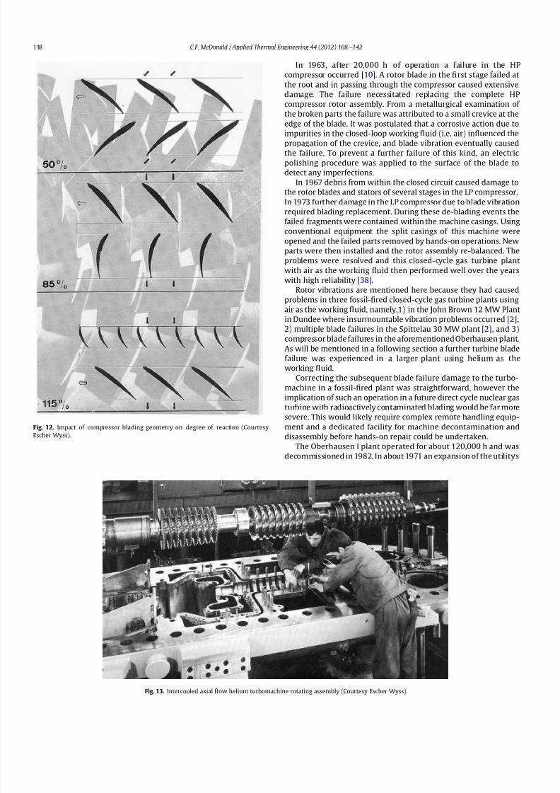
8112019 Helium Turbomachinery Operating Experience From Gas Turbine Power Plants
httpslidepdfcomreaderfullhelium-turbomachinery-operating-experience-from-gas-turbine-power-plants 1135
In 1963 after 20000 h of operation a failure in the HP
compressor occurred [10] A rotor blade in the 1047297rst stage failed at
the root and in passing through the compressor caused extensive
damage The failure necessitated replacing the complete HP
compressor rotor assembly From a metallurgical examination of
the broken parts the failure was attributed to a small crevice at the
edge of the blade It was postulated that a corrosive action due to
impurities in the closed-loop working 1047298uid (ie air) in1047298uenced the
propagation of the crevice and blade vibration eventually caused
the failure To prevent a further failure of this kind an electric
polishing procedure was applied to the surface of the blade to
detect any imperfections
In 1967 debris from within the closed circuit caused damage to
the rotor blades and stators of several stages in the LP compressor
In 1973 further damage in the LP compressor due to blade vibration
required blading replacement During these de-blading events the
failed fragments were contained within the machine casings Using
conventional equipment the split casings of this machine were
opened and the failed parts removed by hands-on operations New
parts were then installed and the rotor assembly re-balanced The
problems were resolved and this closed-cycle gas turbine plant
with air as the working 1047298uid then performed well over the years
with high reliability [38]Rotor vibrations are mentioned here because they had caused
problems in three fossil-1047297red closed-cycle gas turbine plants using
air as the working 1047298uid namely1) in the John Brown 12 MW Plant
in Dundee where insurmountable vibration problems occurred [2]
2) multiple blade failures in the Spittelau 30 MW plant [2] and 3)
compressor blade failures in the aforementioned Oberhausen plant
As will be mentioned in a following section a further turbine blade
failure was experienced in a larger plant using helium as the
working 1047298uid
Correcting the subsequent blade failure damage to the turbo-
machine in a fossil-1047297red plant was straightforward however the
implication of such an operation in a future direct cycle nuclear gas
turbine with radioactively contaminated blading would be far more
severe This would likely require complex remote handling equip-ment and a dedicated facility for machine decontamination and
disassembly before hands-on repair could be undertaken
The Oberhausen I plant operated for about 120000 h and was
decommissioned in 1982 In about 1971 an expansion of the utilityrsquos
Fig 12 Impact of compressor blading geometry on degree of reaction (Courtesy
Escher Wyss)
Fig 13 Intercooled axial 1047298
ow helium turbomachine rotating assembly (Courtesy Escher Wyss)
CF McDonald Applied Thermal Engineering 44 (2012) 108e142118
8112019 Helium Turbomachinery Operating Experience From Gas Turbine Power Plants
httpslidepdfcomreaderfullhelium-turbomachinery-operating-experience-from-gas-turbine-power-plants 1235
capacity was needed due to increasing demand A larger fossil-1047297red
closed-cycle cogeneration plant of conventional design and still
retaining the use of air as the working 1047298uid was initially foreseen
but an emerging German development in the nuclear power plant
1047297eld resulted in a different decision being made as discussed
below
62 Relevance of the Oberhausen II helium turbine
Starting in 1972 development work sponsored by the Federal
Republic of Germany within the scope of the 4th Atomic program
was initiated on a high temperature reactor power plant with
a helium gas turbine (HHT) The reference plant design was based
on a large single-shaft intercooled helium turbine rated at
1240 MW A demonstration plant rated at 676 MW was planned
but prior to the construction of this it was necessary to test the
most important components to reduce risk Details of the two
major facilities to accomplish this have been reported previously
[39] and are summarized as follows
The Oberhausen II helium gas turbine plant was designed andbuilt to perform two major functions 1) it had to operate as
a commercial venture to provide electrical power (50 MWe) and
district heating (53 MWt) for the city of Oberhausen and 2) provide
data applicable to the nuclear gas turbine project particularly the
dynamic behavior of the overall plant and the integrity and long-
term operating experience of the major components in a helium
environment especially the turbomachine
The second facility was the HHV an experimental plant for
testing under representative conditions with respect to machine
size operating temperature pressure and mass 1047298ow of a large
helium turbomachine The facility was extensively instrumented to
gatherdata in the following areas rotorcooling system veri1047297cation
thermal insulation integrity 1047298ow characteristics blading ef 1047297ciency
acoustics rotor dynamic stability bearings dynamic and static
seals system leak tightness and metals behavior for the full
spectrum of plant operations including plant startup load change
shutdown upset conditions etc Details of the HHV facility and
testing undertaken are given in a later section
63 Oberhausen II helium gas turbine plant design
The design and construction of the plant was based on joint
efforts between EVO (plant designer and operator) GHH (turbo-
machine recuperator coolers and controls) Sulzer (helium
heater) and the University of Hannover Institute for Turboma-
chinery which contributed to the designwork and monitoring plant
performance
For the future planned nuclear gas turbine plant design values
of the temperature and pressure at the turbine inlet were 850 C
(1562 F) and 60 MPa (870 psia) respectively Attainment of this
temperature in the Oberhausen II plant could not be achieved and
750 C (1382 F) was selected based on tube material stress
considerations in the external coke-oven gas 1047297red heater An
intercooled and recuperated closed cycle was selected and themajor features of the plant are given on Table 1 The salient
parameters are given on the simpli1047297ed cycle diagram (Fig 15)
While rated at 50 MW a maximum system pressure of only
285 MPa (413 psia) was chosen so that the helium volumetric 1047298ow
(hence size of the bladed passages) would correspond to a much
larger helium turbomachine (on the order of 300 MW in fact) This
together with a rotational speed of 5500 rpm for the HP group
would result in representative stress loadings and would permit
a reasonable extrapolation to the machine size planned for the
nuclear demonstration plant
For the intercooled and recuperated cycle a compressor pressure
ratio of 27 was selected The helium mass 1047298ow rate was 85 kgs
(187 lbsec) and the circuit pressure loss was estimated at 104
percent Based on state-of-the-art component ef 1047297
ciencies and
Fig 14 Intercooled helium turbomachine with an equivalent power rating of 6000 kW installed in a split-case steel pressure vessel (Courtesy Escher Wyss)
CF McDonald Applied Thermal Engineering 44 (2012) 108e142 119
8112019 Helium Turbomachinery Operating Experience From Gas Turbine Power Plants
httpslidepdfcomreaderfullhelium-turbomachinery-operating-experience-from-gas-turbine-power-plants 1335
a recuperator effectiveness of 87 percent the projected thermal
ef 1047297ciency was 326 percent gross and 313 percent net
The isometric sketch of the distributed power conversion
system shown on Fig 16 (from Ref [40]) is convenient for
describing the plant layout A decision was made [41] to install the
horizontal turbomachinery in three large steel vessels the group-
ings being as follows 1) LP compressor rotor 2) HP compressor and
HP turbine grouping and 3) LP turbine The 1047297rst two assemblies
were on a single-shaft with a rotational speed of 5500 rpm The
generator with a rotational speed of 3000 rpmis driven from the LP
turbine end The rotors were geared together but with the selected
shafting arrangement only a small amount of power was trans-
mitted through the gearbox This con1047297guration was established
so that the dynamic behavior would be the same as in the large
single-shaft reference nuclear gas turbine plant design concept
The arrangement of the three vessels can be clearly seen on Fig 17
The horizontal tubular recuperator is positioned below the
turbomachinery The tubular precoolers and intercoolers are
installed in vertical steel vessels This type of orientation of the
major components was used in some of the earlier closed-cycle
plants using air as the working 1047298uid
Power regulation was achieved by inventory control as in the
aforementioned Oberhausen I plant which meant that the system
pressure (hence mass 1047298ow) was changed as required To lower the
power output helium was extracted from the loop after the HP
compressor through a control valve into a storage vessel For
a power increase helium was returned from the storage vessel into
the system upstream of the LP compressor without the need for an
additional blower With this arrangement the turbine inlet
temperature and speed remained constant and plant ef 1047297ciency
would be essentially constant down to a very low power level [42]
To achieve rapid load changes a bypass valve was included in the
system in which helium was transferred in a line between the HP
compressor exit end and LP end of the recuperator A very rapid
change from 100 percent load to no-load operation and back was
demonstrated [43]
64 Helium turbomachinery
The major features and parameters for the turbomachine are
given on Table 2 and are summarized as follows A longitudinal
cross-section of the turbomachine is shown on Fig 18 At the left
hand end the LP compressor is installed in a spherical pressure
vessel A high degree of reaction (ie 100 percent) was selected for
this 10 stage axial compressor this practice following the experi-
ence of an earlier discussed helium turbomachine A view showing
the bladed rotor of the LP compressor installed in the pressure
vessel split casing is shown on Fig19 with an appreciation for the
size of the spherical casing being shown on Fig 20 Both the HP
compressor and HP turbine rotors are installed in a common
housing as shown in the turbomachine cross-section (Fig 21) and
Fig 15 Oberhausen II helium gas turbine cycle diagram
Fig 16 Isometric layout of Oberhausen II helium gas turbine power conversion system (Courtesy EVO)
CF McDonald Applied Thermal Engineering 44 (2012) 108e142120
8112019 Helium Turbomachinery Operating Experience From Gas Turbine Power Plants
httpslidepdfcomreaderfullhelium-turbomachinery-operating-experience-from-gas-turbine-power-plants 1435
in the view with the HP rotor assembly positioned above the
horizontal split casing (Fig 22) The 15 stage HP compressor was
again designed with 100 percent reaction blading The HP turbine
has 7 stages and operated with an inlet temperature of 750 C
(1382O F) A cross-section of the 11 stage LP turbine installed in
a separate spherical vessel is shown on Fig 23 The amount of
power transmitted in the gearbox between the HP and LP turbinesis small since at rated output the HP turbine power level is only
slightly more than is needed to drive both compressors
The rotor of the HP group is supported on two oil-lubricated
bearings For the complete rotating assembly the thrust bearing is
located at the warm end of the LP compressor The six turbo-
machine bearing housings were designed such that direct access to
the large oil bearings was possible without having to open the large
casings This was done to reduce maintenance time because the
large split casings have 1047298anges that were welded closed at the
peripheral lip seals to minimize helium leakage
Special attention was given to the design of the cooling system
for the rotor In the case of this plant with a turbine inlet
temperature of 750 C the turbine blades themselves based on the
use of an existing superalloy did not have to be internally cooledbut cooling gas bled from the HP compressor outlet 1047298owed through
the hollow shaft and was used to cool the turbine discs and the
blade root attachments and then returned downstream of the
turbine
In a closed-cycle gas turbine the powerlevel can be regulated by
means of changing the system pressure and careful attention must
be given to the design of the various sealing systems to accom-
modate pressure differentials within the system particularly
during transient operation To simulate what would be needed in
a direct cycle nuclear gas turbine (to prevent 1047297ssion products
coming into contact with the bearing lubricating oil) a system
having a separate chamber for each of the three labyrinth seals was
incorporated in the machine design Outboard of the labyrinth seals
where the shafts penetrate the casings there were two further
seals a 1047298oating ring seal and a shutdown seal to prevent external
helium leakage
65 Helium turbomachine operating experience
Various presentations papers and publications have previously
covered the over 13 year operation of the Oberhausen II helium gas
turbine plant [43e48] The experience gained with the operation
Fig 17 Overall view of Oberhausen II 50 MWe helium gas turbine power plant (Courtesy EVO)
Table 2
Oberhausen II plant helium turbomachinery
Plant design electrical power MW 50
District heating thermal supply MW 535
Plant design ef 1047297ciency at terminals 313
Thermodynamic cycle ICR
Control method Helium inventory
compressor bypass
Rotor arrangement 2 Shaft (geared together)
Helium mass 1047298ow kgsec 85
Overall pressure ratio 27
Generator ef 1047297ciency 98
Design system pressure loss 104Compressor LP HP
Inlet pressure MPa l05 l54
Inlet temperature C 25 25
Vol 1047298ow inletoutlet m3s 5040 4025
Ef 1047297ciency 870 855
Rotational speed rpm 5500 5500
Number of stages 10 15
Blade height inletoutlet mm 10385 7253
Turbine LP HP
Inlet pressure MPa 165 270
Inlet temperature C 582 750
Ef 1047297ciency 900 883
Rotational speed rpm 3000 5500
Number of stages 11 7
Vol 1047298ow inletoutlet m3sec 92120 6792
Blade height inletoutlet mm 200250 150200
CF McDonald Applied Thermal Engineering 44 (2012) 108e142 121
8112019 Helium Turbomachinery Operating Experience From Gas Turbine Power Plants
httpslidepdfcomreaderfullhelium-turbomachinery-operating-experience-from-gas-turbine-power-plants 1535
of the large axial 1047298ow helium turbomachine is summarized asfollows
On the positive side the following were accomplished The rotor
helium buffered bearing labyrinth oil sealing system was one of the
numerous systems that worked well from the onset This was
encouraging since the external leakage of helium contaminated by
1047297ssion products and the ingress of lubricating oil into the closed
helium loop during the projected plant lifetime of 60 years are of
concern to designers of a direct cycle nuclear gas turbine plant (for
a machine with oil bearings) because of the likely long plant
downtime for cleanup and repair
With some modi1047297cations the helium puri1047297cation system
worked well with the purity level within the speci1047297cation The
helium cooling systems worked well to keep the temperatures of
the turbine discs blade root attachments and casings at speci1047297
edlevels Load change by inventory control was done routinely and
the ability to shed 100 percent of the load in a very short period by
means of the bypass valve was demonstrated The integrity of the
co-axial turbine inlet hot gas duct was proven At the end of plant
operation the major turbomachine casings were opened and there
were no signs of corrosion or erosion of the turbine or compressor
blades The coatings applied to mating metallic surfaces were
effective with no evidence of galling or self-welding in the oxygen-
free closed-loop helium environment
Experience from previously operated high temperature helium
cooled nuclear reactor power plants (with Rankine cycle steam
turbine power conversion systems) demonstrated that absolute
helium leak tightness was not attainable This was also true in the
Oberhausen II fossil-1047297red gas turbine plant where during initial
operation the helium leakage was about 45 kg per day Attention
was given to this and helium losses were reduced to the range of
5e10 kg per day principally by seal welding the major 1047298anges This
value can be compared with other closed loop helium systems as
shown below
On the negative side several unexpected problems had a majorimpact on the operation of the plant Following initial running of
the machine at 3000 rpm in preparation to synchronizing the
system the HP casing was opened for inspection revealing
damage to the labyrinth seals this being caused by shifting of
the rotor in the axial direction The labyrinth seals were replaced
and the turbine was 1047297rst synchronized with the grid on November
8 1975
Subsequent vibration problems were encountered and the HP
shaft oscillation became so large that it caused damage to the
bearings and the design value of speed and power could not be
maintained and the plant was shut down This was initially thought
to be due to thermal distortion of the rotor and a large unbalance
Fig 18 Cross-section of Oberhausen II plant helium turbomachinery rotating assembly (Courtesy EVO)
Fig 19 Oberhausen II low pressure helium compressor installed in casing (Courtesy
GHH)
Plant Helium inventory kg Leakage
kgday day
Dragon 180 020e20 010e10
AVR 240 10e30 040e12
Oberhausen II 1400 5e10 035e070
HHV 1250 25e50 020e040
FSV e Excessive leakage
CF McDonald Applied Thermal Engineering 44 (2012) 108e142122
8112019 Helium Turbomachinery Operating Experience From Gas Turbine Power Plants
httpslidepdfcomreaderfullhelium-turbomachinery-operating-experience-from-gas-turbine-power-plants 1635
Modi1047297cations to the rotor were made and the bearings replaced
but now the HP spool design speed of 5500 rpm could not be
achieved Subsequent major design and fabrication changes were
made including decreasing the bearing span by 600 mm (24 in)
giving a shorter stiffer rotor and changing the type of bearings In
restarting the plant the design speed of the HP rotor was achieved
however the power output was only 30 MW compared with the
design value of 50 MW
Fig 20 View of Oberhausen II low pressure helium compressor spherical vessel (Courtesy GHH)
Fig 21 Cross-section of Oberhausen II high pressure rotating group (Courtesy GHH)
CF McDonald Applied Thermal Engineering 44 (2012) 108e142 123
8112019 Helium Turbomachinery Operating Experience From Gas Turbine Power Plants
httpslidepdfcomreaderfullhelium-turbomachinery-operating-experience-from-gas-turbine-power-plants 1735
To gain operational experience it was decided to continue
running the plant at the reduced power rating On February 5 1979
after nearly 11000 h of operation a rotor blade from the second
stage of the HP turbine failed causing damage in the remaining
stages but the high energy fragments were contained within the
thick machine casing Examination of the failed blade revealed the
defect as a crack caused by the forgingprocess on the semi-1047297nishedproduct To prevent such a failure occurring in the future an electric
polishing process applied to the blade surface before inspection
was implemented and improved crack detection methods
introduced
Acoustic loads in a closed-cycle gas turbine represent pressure
1047298uctuations propagating at the speed of sound through the helium
working 1047298uid Pressure 1047298uctuations of importance result from the
aerodynamic effects of high velocity helium impacting and
essentially being intermittently ldquocutrdquo by the blading in the
compressor and turbine Care must be taken in the design of the
plant to ensurethat these 1047298uctuating pressure waves do not induce
vibrations of a magnitude that could result in excitation-induced
fatigue failures in components in the circuit Critical vibrations
occur when resonance exists between the main frequency of
the propagating sound and the natural frequencies of the
components particularly ones that have large surface area to
thickness ratio
Measurements of sound spectrum were taken at four different
locations in the circuit The design level of power of 50 MW was not
achieved but at the 30 MW power output actually realized the
maximum recorded sound power level was 148 dB After plantshutdown there was no evidence of adverse effects on the major
components of noise induced excitation emanating from the axial
1047298ow turbomachinery The integrity of the turbine inlet hot gas duct
and insulation was con1047297rmed
The inability to reach rated power was attributed to shortcom-
ings in the helium turbomachine This included the compressors(s)
and turbine(s) blading failing to attain design values of ef 1047297ciencies
and the bleed helium mass 1047298ows for cooling and sealing being
signi1047297cantly greater than analytically estimated Based on data
taken from the well instrumented plant detailed analyses were
undertaken by specialists [4950] to calculate the losses in the
turbomachine to explain the power output de1047297ciency A summary
of the projected losses and various component ef 1047297ciencies is pre-
sented in a convenient form on Table 3
Fig 22 Oberhausen II high pressure rotor being installed (Courtesy GHH)
CF McDonald Applied Thermal Engineering 44 (2012) 108e142124
8112019 Helium Turbomachinery Operating Experience From Gas Turbine Power Plants
httpslidepdfcomreaderfullhelium-turbomachinery-operating-experience-from-gas-turbine-power-plants 1835
The plant operated for approximately 24000 h and was shut-
down and decommissioned in 1988 when the coke-oven gas supply
for the heater was no longer available A total plant operating time
of about 11500 h had been at the design turbine inlet temperature
of 750 C (1382 F) Turbomachinery related experience gained
from operation of this large helium gas turbine plant was extremely
valuable While many of the functions performed well from the
onset and others worked satisfactorily after modi1047297cations were
made serious unexpected problems were encountered
The achieved electrical power output of only 60 percent of the
design value was initially thought to be due to a grossly excessive
system pressure loss However when the data was carefully eval-uated it was found that 85 percent of the 20 MW power loss was
attributed to turbomachine related problems as delineated on
Table 3
To remedy this power de1047297ciency it was clear that a major re-
design of the turbomachinery would be required While replace-
ment of the gas turbine was not contemplated a study was
undertaken based on data from the plant and new technologies
that had become available since the initial design Based on the
1047297ndings a new turbomachine layout concept was suggested [43]
and a simplistic view of the rotor arrangement is shown on Fig 24
A more conventional single-shaft arrangement was proposed with
the two compressors and turbine having a rotational speed of
5400 rpm A gearbox was still retained to give a generator rota-
tional speed of 3000 rpm Based on prevailing technology at the
time the requirements for such a gearbox would have been moredemanding since the 50 MW from the turbine to the generator
would have to be transmitted through it This would necessitate
a larger system to pump 1047297lter and cool the bearing lubrication oil
To remedy the very large losses in the compressors and turbines
the number of stages would have to be increased In the case of the
compressors the use of lighter aerodynamically loaded higher
ef 1047297ciency stages with 50 percent reaction blading was
recommended
7 High temperature helium test facility (HHV)
71 Background
In the late 1960rsquos with large numbers of orders placed for 1047297rst
generation light water reactor nuclear power plants studies were
initiated for next generation power plants with higher ef 1047297ciency
potential Following the initial operational success of the 1047297rst three
small helium cooled HTR plants (ie Dragon in the UK Peach
Bottom I in the USA and AVR in Germany) studies on larger plants
based on the use of both Rankine steam cycle and helium closed
Brayton cycle power conversion systems were undertaken In the
early 1970rsquos emphasis was placed on nuclear gas turbine plant
designs with larger power output both in the USA (for the
HTGR eGT) and in Europe (for the HHT) Work in the USA was
limited to only paper studies [18] The much larger program in
Germany (with participation by Swiss companies for the turbo-
machine heat exchangers and cooling towers) included a well
planned development testing strategy to support the plant design
Fig 23 Cross-section of Oberhausen II low pressure helium turbine (Courtesy GHH)
Table 3
Oberhausen II helium turbine plant power losses
Componentcause Design
value
Measured Power loss
MW
Compressors
B Flow losses in inlet diffusers
and blades
Low pressure ef 1047297ciency 870 826 13
High pressure ef 1047297ciency 855 779 40
Turbines
B Blade gap and 1047298ow losses
High pressure ef 1047297ciency 883 823 39
B Pro1047297le losses due to Remachined
blades after having detected
damaged blades
Low pressure ef 1047297ciency 900 856 24
BSealing leakage and cooling 1047298ows
in all turbomachines Kgsec
18 75 53
B Circuit pressure losses
(Ducting Hxrsquos etc)
102 128 26
B Miscellaneous heat losses 05
Total power loss 200 MW
Notes (1) Plant designed for electrical power output of 50 MW actual power output
measured 30 MW
(2) Power de1047297ciency of20 MW based on measurements taken and then recalculated
for the rated plant output
(3) 85 of Power loss attributed to helium turbomachinery related issues
CF McDonald Applied Thermal Engineering 44 (2012) 108e142 125
8112019 Helium Turbomachinery Operating Experience From Gas Turbine Power Plants
httpslidepdfcomreaderfullhelium-turbomachinery-operating-experience-from-gas-turbine-power-plants 1935
While the reference HHT plant for eventual commercializationembodied a very large single helium gas turbine rated at 1240 MW
this was to be preceded by a nuclear demonstration plant rated at
676 MW [51] To support the design of this plant technology
generated from the following was planned 1) operational experi-
ence from the aforementioned Oberhausen II 50 MW helium gas
turbine power plant and 2) testing of components in a large high
temperature helium test facility as discussed below
72 Development facilitytesting objectives
An overall view of the HHV test facility sited in Julich in
Germany is shown on Fig 25 and since this has been reported on
previously [52] it will only be brie1047298
y covered in this section Tominimize risk and assure the performance integrity and reliability
of the nuclear demonstration plant some non-nuclear testing of
the major components especially the helium turbomachine was
deemed essential Because of the limitations of a conventional
closed-cycle helium gas turbine power plant particularly the
temperature limitations of existing fossil-1047297red and electrical
heaters a new type of test facility was foreseen
A simpli1047297ed schematic line diagram of the HHV circuit is shown
on Fig 26 The major design parameters are shown on Fig 27
together with the temperatureeentropy diagram which is conve-
nient for describing the unique relationship between the compo-
nents in the closed helium loop Starting at the lowest pressure in
Fig 24 Proposed new concept for Oberhausen II helium gas turbine rotating assembly to remedy problems encountered during operation of the 50 MWe power plant (Courtesy
EVO)
Fig 25 HHV helium turbomachinery test facility (Courtesy BBC)
CF McDonald Applied Thermal Engineering 44 (2012) 108e142126
8112019 Helium Turbomachinery Operating Experience From Gas Turbine Power Plants
httpslidepdfcomreaderfullhelium-turbomachinery-operating-experience-from-gas-turbine-power-plants 2035
the system the helium is compressed (Ae
B) its temperatureincreasing to 850 C (1562 F) before 1047298owing through the test
section (BeC) After being cooled slightly (CeD) the helium is
expanded in the turbine (DeA) down to the compressor inlet
conditions completing the loop There is no power output from the
system and without the need for an external heater the
compression heat is used to raise the helium to the maximum
system temperature in what can be described as a very large heat
pump The required compressor power is 90 MW and to supple-
ment the 45 MW generated by expansion in the turbine external
power is provided by a 45 MW synchronous electrical motor A
cooler is required to remove the compression heat that is contin-
uously put into the closed helium loop and this is done by bleeding
about 5 percent of the mass 1047298ow after the compressor cooling it
and re-introducing it into the circuit close to the turbine inlet In
addition to testing the turbomachine the facility was engineered
with a test section to accommodate other small components (eg
hot gas 1047298ow regulation valves bypass valves insulation con1047297gu-
rations and types of hot gas duct construction) With the highest
temperature in the system being at the compressor exit the facility
had the capability to provide helium at a temperature up to 1000 C
(1832 F) for short periods at the entrance to the test section
While a higher ef 1047297ciency of the planned nuclear demonstration
plant could be projected with a turbine inlet temperature in the
range 950e1000 C (1742e1832 F) this would have necessitated
either turbine blade cooling or the use of a high temperature alloy
such as Titanium Zirconium Molybdenum (TZM) At the time it was
felt that using either of these would have added cost and risk to theprojectso a conventionalnickel-basedalloyas usedin industrialgas
turbines was selected for the 850 C design value of turbine inlet
temperature this negating the needfor actual internal bladecooling
However a complex internal coolingsystemwas neededto keep the
Fig 26 Cycle diagram of HHV test loop (Courtesy BBC)
Fig 27 Salient features of HHV helium turbomachinery (Courtesy BBC)
CF McDonald Applied Thermal Engineering 44 (2012) 108e142 127
8112019 Helium Turbomachinery Operating Experience From Gas Turbine Power Plants
httpslidepdfcomreaderfullhelium-turbomachinery-operating-experience-from-gas-turbine-power-plants 2135
turbine discs and blade root attachments and casings to acceptable
temperatures commensurate with prescribed stress limitations for
thelife of theturbomachine In addition a heliumsupplywas needed
to provide a buffering system for the various labyrinth seals
In a direct Brayton cycle nuclear gas turbine the turbomachine is
installed in the reactor circuit and via the hot gas duct heated
helium is transported directly from the reactor core to the turbine
From the safety licensing and reliability standpoints there are
various seals that must perform perfectly A helium buffered
labyrinth seal system is necessary to prevent bearing lubricating oil
ingress to the closed helium loop Since in the proposed HHT plant
design the drive shaft from the turbine to the generator penetrates
the reactor primary system pressure boundary two shaft seals are
needed one a dynamic seal when the shaft is rotating and a static
seal when the turbomachine is not operating Testing of these seals
in a size and operating conditions representative of the planned
commercial power plant was considered to be a licensing must
The mechanical integrity of the rotating assembly must be
assured there being two major factors necessitating testing the
machine at full speed and temperature and at high pressure
namely 1) loading the blading under representative centrifugal and
gas bending stresses and 2) to monitor vibration and con1047297rm rotor
dynamic stability For the design of the planned commercial planta knowledge of the acoustic emissions by the turbomachine and
propagation in the closed circuit was required Data from the HHV
facility would enable dynamic responses of the major components
(especially the insulation) resulting from excitation by the sound
1047297eld to be calculated
The circuit was instrumented to gather data on the effectiveness
of the hot gas duct insulation thermal expansion devices hot gas
valves helium puri1047297cation system instrumentation and the
adequacy of the coatings applied to mating metallic surfaces to
prevent galling or self-welding Details of the turbomachinery and
the experience gained from the operation of the HHV facility are
covered in the following sections
73 Helium turbomachine
A cross-section of the turbomachine is shown on Fig 28 The
single-shaft rotating assembly consists of 8 compressor stagesand 2
turbine stages and had a weighton the order of 66 tons(60000 kg)
The hub inner and outer diameters are 16 m (525 ft) and 18 m
(59 ft) respectively the blading axial length being 23 m (75 ft)The
span between the oil bearings being 57 m (187 ft) The physical
dimensions of the turbogroup shown on Fig 28 correspond to
a machine rated at about 300 MW The oil bearings operate in
a helium environment and the diameters of the labyrinths and
1047298oating ring shaft seals to prevent oil ingress are representative of
a machine rated at about 600 MW The complexity of the machine
design especially the rotor cooling system sealing system very
large casing and heat insulation have been reported previously
[53e55]
To ensure high structural integrity the rotor was constructed by
welding together the forged compressor and turbine discs The
compressor had 8 stages each having 56 rotor and 72 stator blades
The turbine had 2 stages each having 90 stator and 84 rotor blades
An appreciation for the large size of the rotating assembly can be
seen from Fig 29 The rotor blades have 1047297r-tree attachments
embodying cooling channels Since the temperature and pressure
do not vary very much along the blading in the 1047298ow direction an
intricate rotor and stator cooling system was required Channels in
both the blade roots and the spacers between adjacent blade rows
form an axial geometry for the passage of a cooling helium supplyto keep the temperature of the multiple discs below 400 C
(752 F) The design of this was a challenge since the rotor and
stator blade attachments of both the 8 stage compressor and 2
stage turbine had to be cooled Excessive leakage had to be avoided
since this would have prevented the speci1047297ed compressor
discharge temperature (ie the maximum temperature in the
circuit) from being reached
In the 1970rsquos and early 1980rsquos signi1047297cant studies were carried
out on large helium gas turbines by various organizations [56e62]
In this era there was general agreement that testing of the turbo-
machine in one form or another in non-nuclear facilities be
undertaken to resolve areas of high risk (eg seals bearings cooling
systems rotor dynamic stability compressor surge margin
dynamic response rotor burst protection etc) before installationand operation of a large gas turbine in a nuclear environment
This low risk engineering philosophy which prevailed at the time
in both Germany and the USA emphasized the importance of
Fig 28 Cross-section of HHV helium turbomachinery (Courtesy BBC)
CF McDonald Applied Thermal Engineering 44 (2012) 108e142128
8112019 Helium Turbomachinery Operating Experience From Gas Turbine Power Plants
httpslidepdfcomreaderfullhelium-turbomachinery-operating-experience-from-gas-turbine-power-plants 2235
the HHV test facility as being an important step towards the
eventual deployment of a high ef 1047297ciency nuclear gas turbine power
plant
74 Initial operation of the HHV facility
During commissioning of the plant in 1979 oil ingress into the
helium circuit from the seal system occurred twiceThe 1047297rst ingressof oil between 600 and 1200 kg (1322 and 2644 lb) was due to
a serious operatorerror and the absence of an isolation valve in the
system The oil in the circuit was partly coked and formed thick
deposits on the cold and hot surfaces of the turbomachinery and in
other parts of the closed loop including saturation of the 1047297brous
insulation The fouled metallic surfaces were cleaned mechanically
and chemically by cracking with the addition of hydrogen and
additives The second oil ingress was due to a mechanical defect in
the labyrinth seal system The quantity of oil introduced was small
and it was removed bycracking at a temperature of 600 C (1112 F)
and with the use of additives To obviate further oil ingress inci-
dents the labyrinth seal system was redesigned The buffer and
cooling helium system piping layout was modi1047297ed to positively
eliminate oil ingress due to improper valve operation and toprevent further human error
Pressure and leak detection tests of the HHV test facility at
ambient temperature showed good leak tightness for the turbo-
machine 1047298anged joints and of the main and auxiliary circuits
However at the operating temperature of 850 C (1562 F) large
helium leaks were detected The major 1047298anges had been provi-
sioned with lip seals and the 1047297rst step was to weld the closures A
large leak persisted at the front 1047298ange of the turbomachine This
was diagnosed as being caused by a non-uniform temperature
distribution during initial operation resulting in thermal stresses
creating local gaps This problem was overcome by redesign of the
cooling system with improved gas 1047298ow distribution and 1047298ow rates
to give a more uniform temperature gradient The leakage from the
system was reduced to on the order of 020e
040 percent of the
helium inventory per day this being of the same magnitude as in
other closed helium circuits as discussed in Section 65
It should be mentioned that in addition to the HHV experience
bearing oil ingress into the circuits and system loss of the working
1047298uid in other closed-cycle gas turbine plants have occurred In all of
these fossil-1047297red facilities 1047297xing leaks and removal of oil deposits
were undertaken based on conventional hands-on approaches but
nevertheless such operations were time-consuming However if a new and previously untested helium turbomachine operating in
a direct cycle nuclear gas turbine plant experienced an oil ingress
the rami1047297cations would be severe The likely use of remote
handling equipment to remove the turbomachine from the vessel
machine disassembly (including breaking the welded 1047298ange joints)
and removal of oil from the radioactively contaminated turbo-
machine blade surfaces and system insulation would be time
consuming A diagnosis of the failure would be required before
a spare turbomachine could be installed and this plant downtime
could adversely affect plant availability
75 Experience gained
Afterresolutionof the aforementionedproblems the HHVfacilitywas started in the Spring of 1981 and in an orderly manner was
brought up to full pressure and a temperature of 850 C (1562 F)
During a 60 h run the functioning of the instrumentation control
and safety systems were veri1047297ed During these tests the ability to
stop the turbomachine from full operating conditions to standstill
within 90 s was demonstrated After system depressurization the
plant was then run up again to full operating conditions with no
problems experienced The HHV facility was successfully run for
about 1100 h of which theturbomachineryoperated forabout325 h
at a temperature of 850 C The test facility was extensively instru-
mented and interpretation and analysis of the data recorded gave
positive and favorable results in the following areas
The complex rotor cooling system which was engineered to
assure that the temperature of the discs be kept below 400
C
Fig 29 HHV helium turbomachine rotating assembly (size equivalent to a 300 MWe machine) being installed in a pressure vessel (Courtesy BBC)
CF McDonald Applied Thermal Engineering 44 (2012) 108e142 129
8112019 Helium Turbomachinery Operating Experience From Gas Turbine Power Plants
httpslidepdfcomreaderfullhelium-turbomachinery-operating-experience-from-gas-turbine-power-plants 2335
(752 F) was demonstrated to be effective The measured rotor
coolant 1047298ows (about 3 percent of the mass1047298ow passing through the
machine) were slightly larger than had been estimated and this
resulted in measured turbine disc temperatures lower than pre-
dicted [55]
The dynamic labyrinth shaft seal functioned well at the full
temperature and pressure conditions and met the requirement of
zero oil ingress into the helium circuit The measured rotor oscil-
lation did not have any adverse effect on the shaft sealing system
The static rotor seal (for shutdown conditions) functioned without
any problems
The compressor and turbine blading hadef 1047297ciencies higher than
predicted The structural integrity of the rotor proved to be sound
when operating at 3000 rpm under the maximum temperature and
pressure conditions The stiff rotor shaft had only slight unbalance
and thermal distortion and measured oscillations were in the range
typical of large steam turbines
Sound power spectrum measurements were taken in four
different locations in the circuit These were taken to determine the
spectrum and intensity of the sound generated and propagated by
the turbomachinery and the resultant vibration of internal
components The maximum sound power level in the helium
circuit was160 dB Numerous strain gages were placedin the circuitto determine the in1047298uence of the sound 1047297eld particularly on the
fatigue strength of the turbine inlet hot gas duct In later examining
the internal components there was no evidence of excessive
vibration of the components especially the ducting and the insu-
lation Based on the measurements and calculations it was
concluded that the fatigue strength limit of the components would
not be exceeded during the designed life of the planned commer-
cial nuclear gas turbine power plant
In a direct cycle nuclear gas turbine the hot gas duct used to
transport the helium from the reactor core to the turbineis a critical
component The hot gas duct in the HHV facility performed well
mechanically and con1047297rmed the adequacy of the thermal expan-
sion devices From the thermal standpoint the 1047297ber insulation
performed better than the metallic type
After dismantling the HHV facility there were no signs of
corrosion or erosion of the turbine or compressor blading While
the total number of hours operated was limited the coatings
applied to mating metallic surfaces to prevent galling and frictional
welding in the oxidation-free helium worked well
The helium buffer and cooling system worked well However
problems remained with the puri1047297cation of the buffer helium The
oil separation system consisting of a cyclone separator and a wire
mesh and a down stream 1047297ber 1047297lter needed further improvement
In late 1981 a decision was made to cancel the HHT project and
the HHV facility was shutdown The design and operational expe-
rience gained from the running of this facility would have been
extremely valuable had the nuclear gas turbine power plant
concept moved towards becoming a reality The identi1047297cation of
somewhat inevitable problems to be expected in such a complexturbomachine and their resolution were undertaken in a timely
and cost effective manner in the non-nuclear HHV facility This
should be noted for future nuclear gas turbine endeavors since
remedying such unexpected problems in the case of a new and
untested large helium turbomachine being operated for the 1047297rst
time using nuclear heat could result in very complex repair
Fig 30 Speci1047297
c speed-speci1047297
c diameter array for gas circulators in various gas-cooled nuclear plants
CF McDonald Applied Thermal Engineering 44 (2012) 108e142130
8112019 Helium Turbomachinery Operating Experience From Gas Turbine Power Plants
httpslidepdfcomreaderfullhelium-turbomachinery-operating-experience-from-gas-turbine-power-plants 2435
activities and extended plant downtime and indeed adding risk to
the overall success of the nuclear gas turbine concept
8 Circulators used in gas-cooled reactor plants
Circulators of different types will be needed in future helium
cooled nuclear plants these including the following 1) primary
loop circulator for possible next generation steam cycle power andcogeneration plants 2) for future indirect cycle gas turbine plants
3) shut down cooling circulators forall HTRand VHTR plants and 4)
for various circulators needed in future VHTR high temperature
process heat plant concepts The technology status of operated
helium circulators is brie1047298y addressed as follows
81 Background
It would be remiss not to mention experience gained in the past
with gas circulators and while not gas turbines they are rotating
machines that operate in the primary loop of a helium cooled
reactor With electric motor drives there are basically two types of
compressor rotor con1047297gurations namely radial and axial 1047298ow
machinesIn a single stage form the centrifugal impeller is used for high
stage pressure rise and low volume 1047298ow duties whereas the axial
type covers low pressure rise per stage and high volume 1047298ow The
selection of impeller type is very much related to the working
media type of bearings drive type rotor dynamic characteristics
and installation envelope A wide range of circulators have operated
and a well established technology base exists for both types [63] A
useful portrayal of compressor data in the form of quasi- non-
dimensional parameters (after Balje [64]) showing approximate
boundaries for operation of high ef 1047297ciency axial and radial types is
shown on Fig 30 (from Ref [65])
Both high speed axial and lower speed radial 1047298ow types are
amenable to gas oil and magnetic bearings From the onset of
modularHTR plant studies theuse of active magnetic bearings[6667]offered a solution to eliminate lubricating oil into the reactor circuit
and this tribology technology is attractive for use in submerged
rotating machinery in the next generation of HTR plants [68]
While now dated an appreciation of the main design features of
typical electric motor-driven helium circulators have been reported
previously namely an axial 1047298ow main circulator for a modular
steam cycle HTR plant [69] and a representative radial 1047298ow shut-
down cooling circulator [70]
The operating experience gained from three particular circula-
tors is brie1047298y included below because of their relevance to the
design of helium turbomachinery in future HTR plant variants
82 Axial 1047298ow helium circulator
Since all of the aforementioned predominantly European
helium gas turbines used axial 1047298ow turbomachinery it is of interest
to mention a helium axial 1047298ow circulator that operated in the USA
and to brie1047298y discuss its design parameters and features The
330 MW Fort St Vrain HTGR featured a Rankine cycle power
conversion system Four steam turbine driven helium circulators
were used to transport heat from the reactor core to the steam
generators The complete circulator assemblies were installed
vertically in the prestressed concrete reactor vessel [71e73]
A cross-section of the circulator is shown on Fig 31 with thecompressor rotor and stator visible on the left hand end of the
machine Based on early 1960rsquos technology a decision was made to
use water lubricated bearings and from the overall plant reliability
and availability standpoints this later proved to be a bad choice
Within the vertical circulator assembly there were four 1047298uid
systems namely the helium reactor coolant water lubricant in the
bearings steam for the turbine drive and high pressure water for
the auxiliary Pelton wheel drive During plant transients the pres-
sures and temperatures of these four 1047298uids oscillated considerably
and the response of the control and seal systems proved to be
inadequate and resulted in considerable water ingress from the
bearing cartridge into the reactor helium circuit The considerable
clean up time needed following repeated occurrences of this event
resulted in long periods of plant downtime and this had an adverseeffect on plant availability This together with other technical
Fig 31 Cross section of FSV helium circulator (Courtesy general Atomics)
CF McDonald Applied Thermal Engineering 44 (2012) 108e142 131
8112019 Helium Turbomachinery Operating Experience From Gas Turbine Power Plants
httpslidepdfcomreaderfullhelium-turbomachinery-operating-experience-from-gas-turbine-power-plants 2535
dif 1047297culties eventually contributed to the plant being prematurely
decommissioned
On the positive side in the context of this paper the helium
circulators operated for over 250000 h and exhibited excellent
helium compressor performance good mechanical integrity and
vibration-free operation The rotating assembly showing the axial
1047298ow compressor and steam turbine rotors together with a view of
the machine assembly are given on Fig 32 The helium compressor
consists of a single stage axial rotor followed by an exit guide vane
The machine was designed for axial helium 1047298ow entering and
leaving the stage and this can be seen from the velocity triangles
shown on Fig 33 which also includes the de1047297nition of the various
aerodynamic parameters Major design parameters and features of
this helium circulator are given on Table 4 Related to an earlier
discussion on the degree of reaction for axial 1047298ow compressors the
value for this conventional single stage circulator is 78 percent All
of the major aerothermal and structural loading criteria were
within established boundaries for an axial compressor having high
ef 1047297ciency and a good surge margin
The compressor gas 1047298ow path and blading geometries were
established based on prevailing industrial gas turbine and aero-
engine design practice A low Mach number (025) a high Reynolds
number (3 106) together with a modest stage loading (ie
a temperature rise coef 1047297cient of 044) and an acceptable value of
diffusion factor (042) were some of the factors that contributed to
a helium circulator that had a high ef 1047297ciency and a good pressure
rise- 1047298ow characteristic The large rotor blade chord and thick blade
section for this single stage circulator are necessary to accommo-
date the high bending stress characteristic of operation in a high
pressure environment The solidity and blade camber were opti-
mized for minimum losses
There were essentially two reasons for including this single-
stage axial 1047298ow compressor that operated in a helium cooled
reactor although its overall con1047297guration can be regarded as a 1047297rst
and last of a kind A rotor blade from this circulator as shown onFig 34 was based on a NASA 65 series airfoil which at the time
were one of the best performing cascades for such low Mach
number and high Reynolds number applications Interestingly it
has almost the same blade height aspect ratio and solidity as would
be used in the 1047297rst stage of an LP compressor in a helium turbo-
machine rated on the order of 250 MW
The second point of interest is that the helium mass 1047298ow rate
through the single stage axial compressor (rated at 4 MWe) is
110 kgs compared with 85 kgs through the multistage compressor
in the 50 MWe Oberhausen II helium gas turbine plant However
the volumetric 1047298ow through the Oberhausen axial compressor is
higher than that through the circulator by a factor of 16 this again
pointing out that the Oberhausen II plant was designed for high
volumetric 1047298ow to simulate the much larger size of turboma-chinery that was planned at the time in Germany for use in future
projected nuclear gas turbine power plants
83 High temperature helium circulator
For future helium turbomachines embodying active magnetic
bearings a challenge in their design relates to accommodating
elevated levels of temperature in the vicinity of the electronic
components In this regard it is of interest to note that a small very
high temperature helium axial 1047298ow circulator rated at 20 kW (as
shown on Fig 35) operated for more than 15000 h in an insulation
test facility in Germany more than two decades ago [74] The
signi1047297cance of this machine is that it operated with magnetic
bearings in a high temperature helium test loop with a circulatorgas inlet temperature of 950 C (1742 F) This necessitated the use
of ceramic insulation to ensure that the temperature in the vicinity
of the magnetic bearing electronics did not exceed a temperature of
about 150 C (300 F)
This machine although a very small axial 1047298ow helium blower
performed well and has been brie1047298y mentioned here since it
represents a point of reference for future helium rotating machines
capable operating with magnetic bearings in a very high temper-
ature helium environment
84 Radial 1047298ow AGR nuclear plant gas circulators
The electric motor-driven carbon dioxide circulators rated at
about 5 MW with a total runningtimein excess of 18 million hours
Fig 32 Fort St Vrain HTGR plant helium circulator (Courtesy General Atomics) (a)
Axial 1047298ow helium compressor and steam turbine rotating assembly (b) 4 MW helium
circulator assembly
CF McDonald Applied Thermal Engineering 44 (2012) 108e142132
8112019 Helium Turbomachinery Operating Experience From Gas Turbine Power Plants
httpslidepdfcomreaderfullhelium-turbomachinery-operating-experience-from-gas-turbine-power-plants 2635
in AGR nuclear power plants in the UK have demonstrated veryhigh availability [7576] To a high degree this can be attributed to
the fact that the machines were conservatively designed and proof
tested in a non-nuclear facility at full temperature and power
under conditions that simulated all of the nuclear plant operating
modes The test facility shown on Fig 36 served two functions 1)
design veri1047297cation of the prototype machine and 2) test of all new
and refurbished machines before they were installed in nuclear
plants Engineers currently involved in the design and development
of helium turbomachinery could bene1047297t from this sound testing
protocol to minimize risk in the deployment of helium rotating
machinery in future HTRVHTR plant variants
9 Helium turbomachinery development and testing
91 On-going development activities
The various helium turbomachines discussed in previous
sections operated over a span of about two decades starting in the
early 1960s From about 1990 activities in the nuclear gas turbine
1047297eld have been focused mainly on the design of modular GTeHTR
plant concepts In support of these plant studies many signi1047297cant
helium turbomachine design advancements have been made and
attention given to what development testing would be needed In
the last decade or so limited sub-component development has
been undertaken for helium turbomachines in the 250e300 MWe
size and these are brie1047298y summarized below
In a joint USARussia effort development in support of the
GTe
MHR turbomachine has been undertaken including testing in
the following areas magnetic bearings seals and rotor dynamicsfor the vertical intercooled helium turbomachine rated at 286 MWe
[77e80]
In Japan development activities have been in progress for
several years in support of the 274 MWe helium turbomachine for
the GTeHTR300 plant concept [2581] A detailed discussion on
the aerodynamic design of the axial 1047298ow helium compressor for
this turbomachine has been published in the open literature [82]
While the design methodology used for axial compressor design in
air-breathing industrial and aircraft gas turbines is generally
applicable for a multi-stage helium compressor a decision was
made by JAEA to test a small scale compressor in a helium facility
because of the inherent and unique gas 1047298ow path and type of
blading associated with operation in a high pressure helium
environment The major goal of the test was to validate the designof the 20 stage helium axial 1047298ow compressor for the GTeHTR300
plant
An axial 1047298ow compressor in a closed-cycle helium gas turbine is
characterized by the following 1) a large number stages 2) small
blade heights 3) high hub-to-tip ratio 4) a long annulus with
small taper that tends to deteriorate aerodynamic performance as
a result of end-wall boundary layer length and secondary 1047298ow 5)
low Mach number 6) high Reynolds number and 7) blade tip
clearances that are controlled by the gap necessary in the magnetic
journal and catcher bearings While (as covered in earlier sections)
helium gas turbines have operated there is limited data in the
open literature on the performance of multi-stage axial 1047298ow
compressors operating in a high pressure closed-loop helium
environment
Fig 33 Velocity triangles for axial compressor stage
CF McDonald Applied Thermal Engineering 44 (2012) 108e142 133
8112019 Helium Turbomachinery Operating Experience From Gas Turbine Power Plants
httpslidepdfcomreaderfullhelium-turbomachinery-operating-experience-from-gas-turbine-power-plants 2735
A 13rd scale 4 stage compressor was designed to simulate the
stage interaction the boundary layer growth and repeated stage
1047298ow in an actual compressor The 1047297rst four stages were designed to
be geometrically similar to the corresponding stages in the
GTe
HTR300 compressor Details of the model compressor havebeen discussed previously [81] and are summarized on Table 5
from [83]
A cross-section of the compressor test model is shown on Fig 37
A view of the 4 stage compressor rotor installed in the lower casing
is shown on Fig 38 The test facility (Fig 39) is a closed helium loop
consisting of the compressor model cooler pressure adjustment
valve and a 1047298ow measurement instrument The compressor is
driven by a 3650 kW electrical motor via a step-up gear The rota-
tional speed of 10800 rpm (three times that of the compressor in
the GTeHTR300 plant) was selected to match blade speed and
Mach number in the full size compressor
Details of the planned aerodynamic performance objectives of
the 13rd scale helium compressor test have been published
previously [84] Extensivetesting of the subscale model compressorprovided data to validate the performance of the full size
compressor for the GTeHTR300 power plant The test data and
test-calibrated CFD analyses gave added insight into the effect of
factors that impact performance including blade surface roughness
and Reynolds number
Based on advanced aerodynamic methodology and experi-
mental validation [82] there is now a sound basis for added
con1047297dence that the design goals of 90 percent polytropic ef 1047297ciency
and a design point surge margin of 20 percent are realizable in
a large multistage axial 1047298ow compressor for a future nuclear gas
turbine plant
In a similar manner a design of a one third size single stage
helium axial 1047298ow turbine has been undertaken and a cross
section of the machine is shown on Fig 40 (from Ref [81]) This
Table 4
Major features of axial 1047298ow helium circulator
Helium 1047298ow rate kgsec 110
Inlet temperature C 394
Inlet pressure MPa 473
Pressure rise KPa 965
Volumetric 1047298ow m3sec 32
Compressor type Single stage axial
Compressor drive Steam turbine
Bearing type Water lubricated
Rotational speed rpm 9550
Power MW 40
Rotor tip diameter mm 688
Rotor tip speed msec 344
Number of rotor blades 31
Number of stator blades 33
Blade height mm 114
Hub-to-tip ratio 067
Axial velocity msec 157
Flow coef 1047297cient 055
Temperature rise coef 1047297cient 044
Degree of reaction 078
Mean rotor solidity 128
Rotor aspect ratio 155
Rotor Mach number 025
Rotor diffusion factor 042
Rotor Reynolds number 3106
Speci1047297c speed 335
Speci1047297c diameter 066
Blade root thickness 15
Airfoil type NASA 65
Rotor blade chord mm 94e64
Stator blade chord mm 79
Rotor centrifugal stress MPa 125
Rotor bending stress MPa 30
Circulator(s) operating Hours gt250000
Fig 34 Rotor blade from single stage axial 1047298ow helium circulator (Courtesy General
Atomics)
Fig 35 20 kW axial 1047298ow helium circulator with magnetic bearings operated in 1985 in
an insulation test loop with a gas inlet temperature on 950
C (Courtesy BBC)
CF McDonald Applied Thermal Engineering 44 (2012) 108e142134
8112019 Helium Turbomachinery Operating Experience From Gas Turbine Power Plants
httpslidepdfcomreaderfullhelium-turbomachinery-operating-experience-from-gas-turbine-power-plants 2835
single stage scale model turbine for validity of the full size turbine
has been built and plans made to test the aerodynamic
performance
92 Nuclear gas turbine helium turbomachine testing
In planning for the 1047297rst nuclear gas turbine plant projected to
enter service perhaps in the third decade of the 21st century
a major decision has to be made as to what extent the large helium
turbomachine should be tested prior to operation on nuclear heat
Issues essentially include cost impact on schedule but the over-
riding one is risk Certainly turbomachine component testing will
be undertaken including the compressor (as discussed in the
previous section) and turbine performance seals cooling systems
hot gas valves thermal expansion devices high temperature
insulation rotor fragment containment diagnostic systems
instrumentation helium puri1047297cation system and other areas to
satisfy safety licensing reliability and availability concerns The
major point is really whether a full size or scaled-down turbo-machine be tested early in the project in a non-nuclear facility
To obviate the need for pre-nuclear testing of a large helium
turbomachine a view expressed by some is that advantage can be
taken of formidable technology bases that exist today for large
industrial gas turbines and high performance aeroengines On the
other hand it is the view of some including the author that very
complex power conversion system components especially those
subjected to severe thermal transients donrsquot always perform
exactly as predicted by analysts and designers even using sophis-
ticated computer codes This was exempli1047297ed in the case of the
turbomachine in the aforementioned Oberhausen II helium gas
turbine plant
The need for a helium turbomachine test facility goes beyond
just veri1047297
cation of the prototype machine Each newgas turbine for
commercial modular nuclear reactor plants would have to be proof
tested and validated before being transported to the reactor site
Similarly turbomachines that would be periodically removed from
the plant at say 7 year intervals during the plant operating life of 60
years for scheduled maintenance refurbishment repair or updat-ing would be again proof tested in the facility before re-entering
service
The direction that turbomachine development and testing will
take place for future helium gas turbines needs to be addressed by
the various organizations involved
Fig 36 AGR circulator test facility In the UK (Courtesy Howden)
Table 5
Major design parametersfeatures of model GTeHTR300 axial 1047298ow helium
compressor (Courtesy JAERI)
Scale of GTeHTR300 compressor 13
Helium mass 1047298ow rate (kgsec) 122
Helium volumetric 1047298ow rate (mV s) 87
Inlet temperature C 30
Inlet pressure MPa 0883Compressor pressure ratio at design point 1156
Number of stages 4
Rotational speed rpm 10800
Drive motor power kW 3650
Hub diameter mm 500
Rotor tip diameter (1st4th stage mm) 568566
Hub-to-tip ratio (1st stage) 088
Rotor tip speed (1st stage msec) 321
Number of rotorstator blades (1st stage) 7294
Rotorstator blade height (1st stage mm) 34337
Rotor stator blade c hor d l eng th (1st stage mm) 2620
Rotorstator solidity (1st stage) 119120
Rotorstator aspect ratio (1st stage) 1317
Flow coef 1047297cient 051
Stage loading factor 031
Reynolds number at design point 76 l05
CF McDonald Applied Thermal Engineering 44 (2012) 108e142 135
8112019 Helium Turbomachinery Operating Experience From Gas Turbine Power Plants
httpslidepdfcomreaderfullhelium-turbomachinery-operating-experience-from-gas-turbine-power-plants 2935
10 Helium turbomachinery lessons learned
101 Oberhausen II gas turbine and HHV test facility
It is understandable that 1047297rst-of-a-kind complex turboma-
chinery operating with an inert low molecular weight gas such as
helium will experience unique and unexpected problems In the
operation of the two pioneering large helium turbomachines in
Germany there were many positive1047297ndings which could only have
been achieved by development testing Equally important some
negative situations were identi1047297ed many of which were remedied
In the case of the Oberhausen II helium gas turbine plant some of
the very serious problems encountered were not resolved Inves-
tigations were undertaken to rationalize the problems associated
with the large power de1047297ciency and a data base established to
ensure that the various anomalies identi1047297ed would not occur in
future large helium turbomachines
The experience gained from the operation of the Oberhausen II
helium gas turbine power plant and the HHV test facility have been
discussedin thetextand arepresentedin a summaryformon Table6
Fig 37 Cross-section of 13rd scale helium compressor test model (Courtesy JAEA)
Fig 38 Four stage helium compressor rotor assembly installed in lower casing (Courtesy JAEA)
CF McDonald Applied Thermal Engineering 44 (2012) 108e142136
8112019 Helium Turbomachinery Operating Experience From Gas Turbine Power Plants
httpslidepdfcomreaderfullhelium-turbomachinery-operating-experience-from-gas-turbine-power-plants 3035
102 Impact of 1047297ndings on future helium gas turbine
The long slender rotorcharacteristic of closed-cycle gas turbines
has resulted in shaft dynamic instability which in some cases has
resulted in blade vibration and failure and bearing damage This
remains perhaps the major concern in the design of large
(250e
300 MW) helium turbomachines for future nuclear gas
turbine plants With pressure ratios in the range of about 2e3 in
a helium system a combination of splitting the compressor (to
facilitate intercooling) and having a large number of compressor
and turbine stages results in a long and 1047298exible rotating assembly
andthis is exempli1047297ed by the rotorassembly shown on Fig13 With
multiple bearings (either oil lubricated or magnetic) the rotor
would likely pass through multiple bending critical speeds before
Fig 39 Helium compressor test facility (Courtesy JAEA)
Fig 40 Cross-section of single stage helium turbine test model (Courtesy JAEA)
CF McDonald Applied Thermal Engineering 44 (2012) 108e142 137
8112019 Helium Turbomachinery Operating Experience From Gas Turbine Power Plants
httpslidepdfcomreaderfullhelium-turbomachinery-operating-experience-from-gas-turbine-power-plants 3135
reaching the design speed While very sophisticated computer
codes will be used in the detailed rotor dynamic analyses the real
con1047297rmation of having rotor oscillations within prescribed limits
(to avoid blade bearing and seal damage) will come from actual
testingA point to be made here is that in operated fossil-1047297red closed-
cycle gas turbine plants it was possible to remedy problems asso-
ciated with rotor vibrations and blade failures in a conventional
manner In fact in some situations the casings were opened several
times and modi1047297cations made to facilitate bearing and seal
replacement and rotor re-blading and balancing
An accurate assessment of pressure losses must be made
particularly those associated with the helium entering and leaving
the turbomachine bladed sections Minimizing the system pressure
loss is important since it directly impacts the all important quotient
of turbine expansion ratio to compressor pressure ratio and power
and plant ef 1047297ciency
Based on the operating experience from the 20 or so fossil-1047297red
closed-cycle gas turbine plants using air as the working1047298
uid it was
recognized that future very high pressure helium gas turbines
would pose problems regarding the various seals in the turbo-
machine and obtaining a zero leakage system with such a low
molecular weight gas would be dif 1047297cult and this is discussed
below
When the Oberhausen II gas turbine plant and the HHV facility
operated over 30 years ago oil lubricated bearings were used to
support the heavy rotor assemblies and helium buffered labyrinth
seals were used to prevent oil ingressinto the heliumworking1047298uid
Initial dif 1047297culties encountered in both plants were overcome by
changes made to the seal geometries and for the operating lives of
the helium turbomachines no further oil ingress events were
experienced Twoseals were required where the turbine drive shaft
penetrated the turbomachine casing namely 1) a dynamic laby-
rinth seal and 2) a static seal for shutdown conditions In both
plants these seals functioned without any problems
Labyrinth seals were also required within the helium turbo-
machines to pass the correct helium bleed 1047298ow from the
compressor discharge for cooling of the turbine discs blade root
attachments and casings The fact that the very complex rotor
cooling system in the large helium turbomachine in the HHV test
facility operated well for the test duration of about 350 h with
a turbine inlet temperature of 850 C was encouragingIn the case of the Oberhausen II gas turbine plant analysis of the
test data revealed that the labyrinth seal leakage and excessive
cooling 1047298ows were on the order of four times the design value A
possible reason for this was that damage done to the labyrinth
seals caused excessive clearances when periods of excessive rotor
oscillation and vibration occurred during early operation of the
machine
Clearly 1047298uid dynamic and thermal management of the cooling
system and 1047298ow through the various labyrinth seals will require
extensive analysis design and development testing before the
turbomachine is operated on nuclear heat for the 1047297rst time
In future heliumgas turbine designs (with turbine inlet tempera-
tureslikelyontheorderof950C)the1047298owpathgeometriesofhelium
bledfromthecompressornecessarytocoolpartsoftheturbomachinewillbemorecomplexthanthosetestedto-dateInadditiontoproviding
acooling1047298owtotheturbinebladesanddiscsbladerootattachmentsand
casingsheliummustbetransportedtotheseveralmagneticbearingsto
ensure thatthe temperatureof theirelectronic components doesnot
exceedabout150C
The importance of the points made above is evidenced when
examining the data on Table 3 where a combination of excessive
pressure losses and high bleed 1047298ows contributed to about 40
percent of the power de1047297ciency in the Oberhausen II helium
turbine plant
Retaining overall system leak tightnessin closed heliumsystems
operating at high pressure and temperature has been elusive
including experience from the Fort St Vrain HTGR plant as dis-
cussed in Section 65 New approaches in the design of the plethoraof mechanical joints must be identi1047297ed Experience to-date has
shown that having welded seals on 1047298anges while minimizing
system leakage did not eliminate it
The importance of lessons learned from the operation of the
Oberhausen II helium turbine power plant and the HHV test facility
have primarily been discussed in the context of helium turbo-
machines currently being designed in the 250e300 MWe power
range However the established test data bases could also be
applied to the possible emergence in the future of two helium
cooled reactor concepts namely 1) an advanced VHTR combined
cycle plant concept embodying a smaller helium gas turbine in the
power range of 50e80 MWe [22] and 2) the use of a direct cycle
helium gas turbine PCS in a recently proposed all ceramic fast
nuclear reactor concept [85]
Table 6
Experience gained from Oberhausen II and HHV facility
Oberhausen II 50 MW helium gas turbine power plant
Positive results
e Rotating and static seals worked well
e No ingress of bearing lubricant oil into closed circuit
e Load change by inventory control worked well
e 100 Percent load shed by means of bypass valves demonstrated
e Turbine disc and blade root cooling system con1047297rmed
e Coatings on mating surfaces prevented galling and self-welding
e After 24000 h of operation no evidence of corrosion or erosion
e Coaxial turbine hot gas inlet duct insulation and integrity con1047297rmed
e Monitoring of complete power conversion system for steady state
and transient operation undertaken
Problem areas
e Serious power output de1047297ciency (30 MW compared with design
value of 50 MW)
e Compressor(s) and turbine(s) ef 1047297ciencies several points below predicted
e Higher than estimated system pressure loss
e Rotor dynamic instability and blade vibration
e Bearings damaged and had to be replaced
e Blade failure caused extensive damage in HP turbine but retained
in casing
e Very excessive sealing and cooling 1047298ow rates
e Absolute leak tightness not attainable even with welded 1047298ange lips
HHV test facility
Positive resultse Use of heat pump approach facilitated helium temperature capability
to 1000 C
e Large oompressorturbine rotor system operated at 3000 rpm Complex
turbine disc and blade root cooling system veri1047297ed
e Dynamic and static seals met requirement of zero oxl ingress into circuit
e Structural integrity of rotating assembly veri1047297ed at temperature of 850 C
e Measured rotor oscillations within speci1047297cation
e Compressor and turbine ef 1047297ciencies higher than predicted
e Coatings on mating metallic surfaces prevented galling and self-welding
e Instrumentation control and safety systems veri1047297ed
e Seal 1047298ows within speci1047297cation
e Machine stop from operating speed to shutdown in 90 s demonstrated
e Hot gas duct insulation and thermal expansion devices worked well
e After 1100 h of operation no evidence of corrosionof erosion
Problem areas
e Before commissioning a large oil ingress into the circuit occurred due
to serious operator error and absence of an isolation valve A second oilingress occurred due to a mechanical defect in the labyrinth seal system
These were remedied and no further oil ingress was experienced for the
duration of testing
e Cooling 1047298ows slightly larger than expected but this resulted in actual
disc and blade root temperatures lower than the predicted value of
400 C
e System leak tightness demonstrated when pressurized at ambient
temperature conditions but some leakage occured at 850 C even with
the seal welding of 1047298ange(s) lips
CF McDonald Applied Thermal Engineering 44 (2012) 108e142138
8112019 Helium Turbomachinery Operating Experience From Gas Turbine Power Plants
httpslidepdfcomreaderfullhelium-turbomachinery-operating-experience-from-gas-turbine-power-plants 3235
11 New technologies
It is recognized that in the 3 to 4 decades since the operation of
the helium turbomachines covered in this paper new technologies
have emerged which negate some of the early issues An example of
this is the technology transfer from the design of modern axial 1047298ow
gas turbines (ie industrial aircraft and aeroderivatives) that fully
utilize sophisticated CAE CAD CFD and FEA design software
Air breathing aerodynamic design practice for compressors and
turbines are generally applicable but the properties of helium and
the high system pressure have a signi1047297cant impact on gas 1047298ow
paths and blade geometries With short blade heights high hub-to-
tip ratios long annulus 1047298ow path length (with resultant signi1047297cant
end-wall boundary layer growth and secondary 1047298ow) and blade tip
clearances in some cases controlled by clearances in the magnetic
catcher bearing testing of subscale model compressors and
Fig 41 Gas turbine test facility for aircraft nuclear propulsion involving the coupling of a 32 MWt air-cooled reactor with two modi 1047297ed J-47 turbojet aeroengines each rated at
a thrust of about 3000 kg operated in 1960 (Courtesy INL)
Fig 42 Mobile 350 KWe closed-cycle nuclear gas turbine power plant operated in 1961 (Courtesy US Army)
CF McDonald Applied Thermal Engineering 44 (2012) 108e142 139
8112019 Helium Turbomachinery Operating Experience From Gas Turbine Power Plants
httpslidepdfcomreaderfullhelium-turbomachinery-operating-experience-from-gas-turbine-power-plants 3335
turbines will be needed While most of the operated helium tur-
bomachines discussed in this paper took place 3 or 4 decades ago it
is encouraging that the fairly recent test data and test-calibrated
CFD analysis from a subscale four stage model helium axial 1047298ow
compressor in Japan [80] gave a high degree of con1047297dence that
design goals are realizable for the full size 20 stage compressor in
the 274 MWe GTeHTR300 plant turbomachine
In the future the use of active magnetic bearings will eliminate
the issue of oil ingress however the very heavy rotor weight and
size of the journal and thrust bearings (and catcher bearings) of the
type for helium turbomachines in the 250e300 MWe power range
are way in excess of what have been demonstrated in rotating
machinery For plant designs retaining oil-lubricated bearings well
established dry gas seal technology exists particularly experience
gained from the operation of high pressure natural gas pipe line
compressors
For future nuclear helium gas turbine plants the designer has
freedom regarding meeting different frequency requirements that
exist in some countries These include use of a synchronous
machine (ie designed for 50 or 60 Hz grids) use of a gearbox drive
between the turbine and generator or the use of a frequency
converter which gives the designer an added degree of freedom
regarding the selection of speed for the rotating assemblyCompared with the past very sophisticated electronic control
systems instrumentation and diagnostic systems are available
today
12 Conclusions
In this review paper experience from operated helium turbo-
machines has been compiled based on open literature sources At
this stage in the evolution of HTR and VHTR plant concepts it is not
clear in what role form or time-frame the nuclear gas turbine will
emerge when commercialized By say the middle of the 21st
century all power plants will be operating with signi1047297cantly higher
ef 1047297ciencies to realize improved power generation costs and
reduced emissions In a nuclear gas turbine the helium turbo-machine will be a major contributor towards the achievement of
ef 1047297ciencies higher than 50 percent
While it has been 3 to 4 decades since the Oberhausen II helium
turbine power plant and the HHV high temperature helium turbine
facility operated signi1047297cant lessons were learned and the time and
effort expended to resolve the multiplicity of unexpected technical
problems encountered The remedial repair work was done under
ideal conditions namely that immediate hands-on activities were
possible This would not have been possible if the type of problems
experienced had been encountered in a new and untested helium
turbomachine operated for the 1047297rst time with a nuclear heat
source
While new technologies have emerged that negate many of the
early problems there are some uniquely inherent issues associatedwith for large helium turbines operating in a high pressure and
temperature environment and these include the following 1)
minimizing system leakage with such a low molecular weight gas
2) clearances in labyrinth seals to minimize helium bypass1047298ows 3)
the dynamic stability of long slender rotors 4) minimizing the
turbomachine inlet and outlet pressure losses 5) 1047298ow maldis-
tribution in complex ductturbomachine interfaces 6) integrity
veri1047297cation of the catcher bearings (journal and thrust) after
multiple rotor drops (following loss of the magnetic 1047297eld) during
the plant lifetime 7) assurances that high energy fragments from
a failed turbine disc are contained within the machine casing 8)
turbomachine installation and removal from a steel pressure vessel
and 9) remote handling and cleaning of a machine with turbine
blades contaminated with 1047297
ssion products
The need for a helium turbomachine test facility has been
emphasized to ensure that the integrity performance and reli-
ability of the machine before it operates the 1047297rst time on nuclear
heat Engineers currently involved in the design of helium rotating
machinery for all HTR and VHTR plant variants should take
advantage of the experience gained from the past operation of
helium turbomachinery
13 In closing-GT rsquos operated with nuclear heat
In the context of this paper it is germane to mention that two
gas turbines have actually operated using nuclear heat as brie1047298y
highlighted below
In the late 1950rsquos a program was initiated in the USA for aircraft
nuclear propulsion (ANP) While different concepts were studied
only the direct cycle air-cooled reactor reached the stage of
construction of an experimental reactor [86] A view of the large
nuclear gas turbine facility is given on Fig 41 and shows the air-
cooled and zirconiumehydride moderated reactor rated at
32 MWt coupled with two modi1047297ed J-47 turbojet engines each
rated with a thrust of about 3000 kg In this open cycle system the
high pressure compressor air was directly heated in the reactor
before expansion in the turbine and discharge to the atmosphere in
the exhaust nozzle The facility operated between 1958 and 1961 at
the Idaho reactor testing facility While perhaps possible during the
early years of the US nuclear program it is clear that such a system
would not be acceptable today from safety and environmental
considerations
The 1047297rst and indeed the only coupling of a closed-cycle gas
turbine with a nuclear reactor for power generation was under-
taken to meet the needs of the US Army In the late 1950 rsquos an RampD
program was initiated for a 350 kW trailer-mounted system to be
used in the 1047297eld by military personnel A prototype of the ML-1
plant shown on Fig 42 was 1047297rst operated in 1961 [8788]
It was based on a 33 MW light water moderated pressure tube
reactor with nitrogen as the coolant The closed-cycle gas turbine
power conversion system with nitrogen as the working 1047298uid hada turbine inlet temperature of 649 C (1200 F) and delivered
around 300 kW With changes in the Armyrsquos needs the project was
discontinued in 1965
While the experience gained from the above twounique nuclear
plants is clearly not relevant for future nuclear gas turbine power
plants that could see service in the third decade of the 21st century
these ambitious and innovative nuclear gas turbine pioneering
engineering efforts need to be recognized
Acknowledgements
The author would like to thank the following for helpful discus-
sions advice and for providing valuable comments on the initial
paper draft Prof Dr Hermann Haselbacher Hans Ulrich Frutschi DrXing Yan DrPeter Zenker Professor DavidGordon Wilson Professor
Aristide Massardo Arthur Harris DrFred Starr and DrGuido Bac-
caglini This paper has been enhanced by the inclusion of hardware
photographs and unique sketches and the author is appreciative to
all concerned with credits being duly noted
References
[1] C Keller The Escher Wyss AK Closed-Cycle Gas Turbine Its Actual Develop-ment and Future Prospects Paper Presented at ASME Meeting November 261945
[2] HU Frutschi Closed-Cycle Gas Turbines Operating Experience and FuturePotential ASME Press NY 2005
[3] CF McDonald The Nuclear Gas Turbine-Towards Realization After Half
a Century of Evolution (1995) ASME Paper 95-GT-292
CF McDonald Applied Thermal Engineering 44 (2012) 108e142140
8112019 Helium Turbomachinery Operating Experience From Gas Turbine Power Plants
httpslidepdfcomreaderfullhelium-turbomachinery-operating-experience-from-gas-turbine-power-plants 3435
[4] C Keller The Theory and Performance of Axial Flow Fans McGraw Hill BookCompany Inc NY 1937
[5] J Ackert C Keller Aerodynamic turbine with closed circuit In A Century of Turbines vols 1516 Escher Wyss News 1942e43 5e19
[6] Escher Wyss News Closed-Cycle Gas Turbines for all Fuels Coal Gas Nuclearvol 39 No 1 (1966)
[7] C Keller Closed-cycle gas turbine Escher Wyss-AK development 1945e1950Transactions of ASME (August 1950) 835e850
[8] C Keller Operating Experience and Design Features of Closed-Cycle GasTurbine Power Plants (1956) ASME Paper 56-GTP-15
[9] C Keller HU Frutschi Closed-cycle plants -conventional and nuclear designapplication operation In Sawyerrsquos Gas Turbine Engineering Handbooksecond ed vol 2 Applications (1976) pp 265e283
[10] K Bammert G Groschup Status Report on Closed-Cycle Power Plants in theFederal Republic of Germany (1976) ASME Paper 76-GT-54
[11] JL Mason Monatomic Working Gases versus Air for Closed Brayton Cycles(1985) ASME Paper 85-IGT-50
[12] JL Mason et al 5 MW Closed Cycle Gas Turbine (1984) ASME Paper 84-GT-268
[13] The British Gas Closed-Cycle Demonstrator (1995) British Gas Research ampTechnology Final Year Report
[14] F Starr ODS alloy high temperature heat exchanger prototype developmentPaper Presented at ODS 2010 Materials Workshop UCSD Jacobs Hall La JollaCalifornia Nov17e18 2010
[15] CA Rennie Achievements of the Dragon project Pergamon Press Annals of Nuclear Energy 5 (1978) 305e320
[16] SB Hosegood et al Dragon Project Engineering Studies on the Direct CycleHTR Proceedings of Conference on Nuclear Gas Turbines The British NuclearEnergy Society London April 8e9 1970 pp 161e179
[17] Nuclear Gas Turbines Proceedings of British Nuclear Society Meeting LondonApril 8-9 1972
[18] CF McDonald C Peinado ldquoThe nuclear gas Turbine-A perspective on a long-term advanced technology HTGR plant Optionrdquo ASME Paper 82-GT-289
[19] GH Lohnert et al Technical design features and essential safety-relatedfeatures of the HTR-Module Nuclear Engineering and Design 121 (1990)259e275
[20] H Reutler GH Lohnert The modular high temperature nuclear reactorNuclear Technology 62 (1983) 22e30
[21] CF McDonald Exploitation of the very high temperature capability of theMHTGR to meet National energy needs after the year 2000 IECEC Paper869006
[22] CF McDonald Power conversion system considerations for an advancednuclear gas turbine (GT-VHTR) CHHP demonstration plant concept Interna-tional Journal of Turbo amp Jet Engines 27 (2010) 179e217
[23] N Hee Cheon et al A review of helium gas turbine technology for hightemperature gas cooled reactors Nuclear Engineering and Design 29 (2007)21e30
[24] CB Baxi et al Development of the GT-MHR Turbomachine ASME PaperGT2009e59450[25] X Yan GTHTR300 design and development Nuclear Engineering and Design
222 (2003) 247e262[26] JC Gauthier et al ANTARES the HTRVHTR project of Framatome ANP
Nuclear Engineering and Design 236 (2006) 526e533[27] J Wang et al ldquoDesign features of gas turbine power conversion system for
HTR-10GT paper D05 presented at 2nd Intl Meeting on HTR TechnologyBeijing China September 21e24 2004
[28] A Koster et al ldquoPBMR Design For the Futurerdquo Nuclear engineering andDesign 222 (203) 231e245
[29] S van der Linden Closed cycle nuclear plant rated at 165 MWe and 40 percentef 1047297ciency Gas Turbine World (MarcheApril 2007) 28e32
[30] CF McDonald Large closed-cycle gas turbines Sawyerrsquos gas turbine engi-neering handbook In Selection and Applications vol II (1985) pp 81e38(Chapter 8)
[31] CF McDonald Helium and Combustion Gas Turbine Power ConversionSystems Comparison (1995) ASME Paper 95-GT-263
[32] JK La Fleur Description of an Operating Closed-Cycle Helium Gas Turbine
ASME Paper 63-AHGT-74[33] JK La Fleur The use of turbomachinery in the 1047297eld of cryogenics In
Sawyerrsquos Gas Turbine Engineering Handbook vol II (1976) 296e311[34] W Spillmann The Closed-Cycle Gas Turbine for Non-Conventional Applica-
tions ASME Paper 66-GT-8[35] K Holliger On the in1047298uence of the degree of reaction on the secondary losses
in axial 1047298ow compressors Escher Wyss News 23 (1960)[36] W Gut Comparison of the relative losses and characteristics of axial
compressor stages Escher Wyss News 23 (1959)[37] JH Horlock Axial Flow Compressors Butterworths Scienti1047297c Publications
London 1958 pp 92e93[38] G Deuster Long-term Operating Experience with Oberhausen I Closed-Cycle
Gas Turbine Power Plant (1970) ASME Paper 70-GT-73[39] G Noak Signi1047297cance of the Helium Turbine Power Plant at Oberhausen (EVO)
and the High Temperature Helium Test Facility (HHV) at Julich for theDevelopment of HTR Direct Cycle (HHT) IAEA Publication SM-20026 Vienna1970 189e200
[40] K Bammert G Deuster Layout and Present Status of the Closed-Cycle HeliumTurbine Plant Oberhausen II (1974) ASME Paper 74-GT-132
[41] P Zenker The Oberhausen 50 MW helium turbine plant Combustion 47 (2)(April 1976)
[42] K Bammert et al Operation and Control of the 50 MW Closed Cycle HeliumTurbine Plant Oberhausen (1974) ASME Paper 74-GT-13
[43] P Zenker 10 years operating experience with the Oberhausen II heliumturbo-generator plant VGB Krafswerkstechnik 68 (7) (July 1998) 616e621
[44] K Bammert G Deuster The First Operating Experiences With the OberhausenHelium Turbine Plant Paper Presented at ASME Gas Turbine Conference NewOrleans March 21e25 1976
[45] G Deuster P Zenker Operation of the Oberhausen Helium Turbine Plant
Paper Presented at ASME Gas Turbine Conference London April 1978[46] P Zenker Operating Experience of the Oberhausen Helium Turbine Plant
Paper Presented at ASME Gas Turbine Conference San Diego 1979[47] G Deuster P Zenker Further Operating Experience of the Oberhausen Helium
Turbine Plant Paper Presented at ASME Gas Turbine Conference NewOrleans 1980
[48] P Zenker Past Experience and Future Prospects of Closed-Cycle Gas TurbinesPaper Presented at ASME Gas Turbine Conference London April 18e22 1982
[49] IA Weisbrodt Summary Report on Technical Experiences from HighTemperature Helium Turbine Testing in Germany Report IAEA-TECDOC-899Vienna Nov 1994
[50] F Bentivoglio G Geffraye Validation of the CATHARE Code Against Experi-mental Data from Brayton Cycle Plants Paper C00000228 Proceedings of HTR 2006 Johannesburg October 1e4 2006
[51] E Arndt HHT-Demonstration Plant Paper Presented at European NuclearConference Hamburg May 6 1979
[52] G Hebel HHV-Anlage Erfahrungen bei Bau und Inbetriebnahme Atom-wirtschaft(5) (1982) 258e262
[53] H Haselbacher A Eierman Development of Helium Gas Turbine in NuclearField (1974) ASME Paper 74-GT-123
[54] H Haselbacher The HHT Helium Gas Turbine and HHV Plant Paper A421 5thInternational Fair and Technical Meeting of Nuclear Industry BaselSwitzerland October 3e7 1978
[55] H Haselbacher HJ Sponholz Cooling and Insulating Problems in a HighTemperature Helium Test Facility (1984) ASME Paper 84-GT-253
[56] C Keller D Schmidt The Helium Gas Turbine for Nuclear Power Plants (1967)ASME Paper 67-GT-10
[57] W Endres Large Helium Turbine for Nuclear Power Plants (1970) ASME Paper70-GT-99
[58] JN Hurst Gas turbomachinery for helium cooled reactors in Proceedings of International Conference on Nuclear Gas Turbines British Nuclear SocietyLondon April 8 1970 pp 45e50
[59] K Bammert Nuclear Gas Turbine of Large Output for HHT Plant (1974) ASMEPaper 74-GT-10
[60] CF McDonald The Nuclear Closed-Cycle Gas Turbine (GT-HTGR) e A UtilityPower Plant for the Year 2000 (1979) AIAA Paper 79e0191
[61] CF McDonald MJ Smith Turbomachinery design considerations for the
nuclear HTGR-GT power plant ASME Journal of Engineering for Power 103 (1)(January 1981) 65e77[62] CF McDonald et al Helium Turbomachine Design for GT-MHR Power Plant
(1994) ASME Paper 94-JPGC-NE-12[63] Gas Cooled Reactor Coolant Circulator and Blower Technology (1988) IAEA
Report IWGGCR17[64] OE Balje Turbomachines A Guide to Design Selection and Theory John
Wiley amp Sons NY 1981[65] CF McDonald et al Circulator DesignTechnology Evolution for Gas Cooled
Reactors (1992) ASME Paper 92-GT-79[66] J Donaldson Application of Magnetic Bearings to Helium Circulators for High
Temperature Gas Cooled Reactors (1987) IECEC Paper 879419[67] CF McDonald Active Magnetic Bearings for Rotating Machinery in Closed-
Cycle Power Plant Systems (1989) ASME Paper 89-WANE-5[68] JA Rennie CF McDonald Active Magnetic Bearings for Rotating Machinery
in Future Gas Cooled Reactor Plants Paper Presented at 4th Intl Symposiumon Magnetic Bearings ETH Zurich August 23e26 1994
[69] CF McDonald MK Nichols Helium Circulator Design Considerations forModular High Temperature Gas Cooled Power Plant (1987) ASME Paper 87-
GT-138[70] CF McDonald Shutdown Cooling Helium Circulator Design Considerations
for MHTGR Power Plant (1989) ASME Paper 89-WANE-5[71] J Yampolsky Steam Turbine Driven Circulators for High Temperature Gas
Cooled Reactors Part I Design (1972) ASME Paper 72-WANE-20[72] VJ Barbat Steam Turbine Driven Circulators for High Temperature Gas
Cooled Reactors Part II Development (1972) ASME Paper 72-WANE-21[73] L Cavallaro J Yampolsky Design and development of a steam turbine driven
circulator for high temperature gas cooled reactors Nuclear Engineering andDesign (1974) 135e147
[74] J Henssen et al Facility for fatigue testing of thermal insulation BBC Review72 (6) (1985)
[75] J Donaldson Development of Carbon Dioxide Circulators IAEA ReportIWGGCR17 (1988) pp 47e63
[76] Personal Communication from John Donaldson (April 7 2006)[77] NG Kodochigov et al Development of the GT-MHR Vertical Turbomachine
Design ASME Paper HTR2008-58309[78] CB Baxi et al ldquoRotor Scale Model Tests for Power Conversion Unit of GT-
MHR rdquo ASME Paper HTR 2008e58015
CF McDonald Applied Thermal Engineering 44 (2012) 108e142 141
8112019 Helium Turbomachinery Operating Experience From Gas Turbine Power Plants
httpslidepdfcomreaderfullhelium-turbomachinery-operating-experience-from-gas-turbine-power-plants 3535
[79] NG Kodochibov et al Development of Catcher Bearings for the GT-MHR Turbomachine(Oct 18e20 2010)Proceedings of HTR 2010Paper 025Prague
[80] IV Drumov et al Studies of the Electromagnetic Suspension System for theGT-MHRTurbomachineProceedings of HTR2010Paper041 Oct18e20 (2010)
[81] T Takizuka et al RampD on the power conversion system for the gas turbinehigh temperature reactor Nuclear Engineering and Design 233 (2004)239e346
[82] X Yanet alAerodynamic design model test and CFDanalysisfor a multistageaxialhelium compressor ASME Journal of Turbomachinery 130 (3) (July2008)
[83] S Takada et al The 13rd Scale Aerodynamic Performance Test of Helium
Compressor for GTHTR300 Turbomachine of JAERI (April 20e
23 2003)ICONE11e36368 Tokyo Japan
[84] S Takada et al Program for aerodynamic performance tests of heliumcompressor model of GTHTR300 Transactions of the Atomic Energy Society of
Japan 2 (3) (2003) 291e300[85] RW Schleicher et al EM2 An Innovative Approach to US Energy Security
and Nuclear Waste Disposition Paper Presented at Nuclear Power Interna-tional Conference Orlando Florida December 15 2010
[86] RL Loftness Nuclear Power Plants Norstrand Company Inc NY 1964(Chapter 9 and 11)
[87] SA Varga et al The ML-1 Mobile Nuclear Power Plant (1961) ASME Paper61-SA-43
[88] JA Bailey et al Status of the Army Closed Brayton Cycle Gas Turbine Program(1967) ASME Paper 67-GT-13
CF McDonald Applied Thermal Engineering 44 (2012) 108e142142
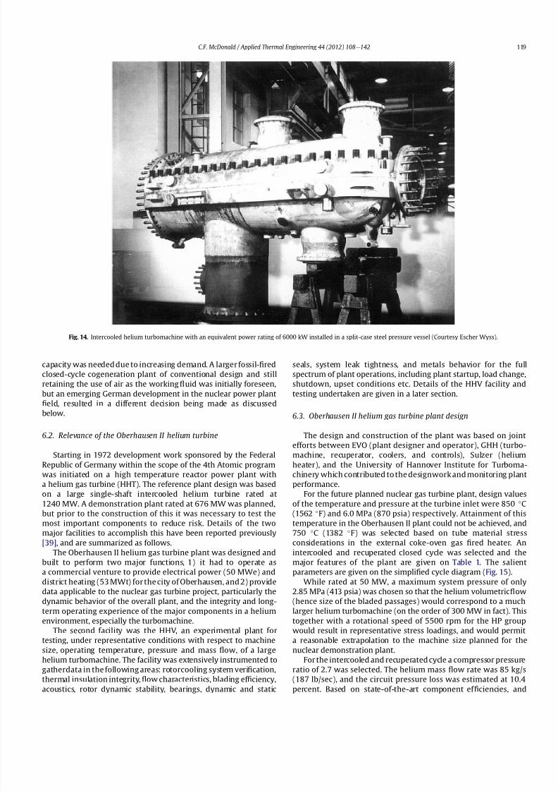
8112019 Helium Turbomachinery Operating Experience From Gas Turbine Power Plants
httpslidepdfcomreaderfullhelium-turbomachinery-operating-experience-from-gas-turbine-power-plants 1235
capacity was needed due to increasing demand A larger fossil-1047297red
closed-cycle cogeneration plant of conventional design and still
retaining the use of air as the working 1047298uid was initially foreseen
but an emerging German development in the nuclear power plant
1047297eld resulted in a different decision being made as discussed
below
62 Relevance of the Oberhausen II helium turbine
Starting in 1972 development work sponsored by the Federal
Republic of Germany within the scope of the 4th Atomic program
was initiated on a high temperature reactor power plant with
a helium gas turbine (HHT) The reference plant design was based
on a large single-shaft intercooled helium turbine rated at
1240 MW A demonstration plant rated at 676 MW was planned
but prior to the construction of this it was necessary to test the
most important components to reduce risk Details of the two
major facilities to accomplish this have been reported previously
[39] and are summarized as follows
The Oberhausen II helium gas turbine plant was designed andbuilt to perform two major functions 1) it had to operate as
a commercial venture to provide electrical power (50 MWe) and
district heating (53 MWt) for the city of Oberhausen and 2) provide
data applicable to the nuclear gas turbine project particularly the
dynamic behavior of the overall plant and the integrity and long-
term operating experience of the major components in a helium
environment especially the turbomachine
The second facility was the HHV an experimental plant for
testing under representative conditions with respect to machine
size operating temperature pressure and mass 1047298ow of a large
helium turbomachine The facility was extensively instrumented to
gatherdata in the following areas rotorcooling system veri1047297cation
thermal insulation integrity 1047298ow characteristics blading ef 1047297ciency
acoustics rotor dynamic stability bearings dynamic and static
seals system leak tightness and metals behavior for the full
spectrum of plant operations including plant startup load change
shutdown upset conditions etc Details of the HHV facility and
testing undertaken are given in a later section
63 Oberhausen II helium gas turbine plant design
The design and construction of the plant was based on joint
efforts between EVO (plant designer and operator) GHH (turbo-
machine recuperator coolers and controls) Sulzer (helium
heater) and the University of Hannover Institute for Turboma-
chinery which contributed to the designwork and monitoring plant
performance
For the future planned nuclear gas turbine plant design values
of the temperature and pressure at the turbine inlet were 850 C
(1562 F) and 60 MPa (870 psia) respectively Attainment of this
temperature in the Oberhausen II plant could not be achieved and
750 C (1382 F) was selected based on tube material stress
considerations in the external coke-oven gas 1047297red heater An
intercooled and recuperated closed cycle was selected and themajor features of the plant are given on Table 1 The salient
parameters are given on the simpli1047297ed cycle diagram (Fig 15)
While rated at 50 MW a maximum system pressure of only
285 MPa (413 psia) was chosen so that the helium volumetric 1047298ow
(hence size of the bladed passages) would correspond to a much
larger helium turbomachine (on the order of 300 MW in fact) This
together with a rotational speed of 5500 rpm for the HP group
would result in representative stress loadings and would permit
a reasonable extrapolation to the machine size planned for the
nuclear demonstration plant
For the intercooled and recuperated cycle a compressor pressure
ratio of 27 was selected The helium mass 1047298ow rate was 85 kgs
(187 lbsec) and the circuit pressure loss was estimated at 104
percent Based on state-of-the-art component ef 1047297
ciencies and
Fig 14 Intercooled helium turbomachine with an equivalent power rating of 6000 kW installed in a split-case steel pressure vessel (Courtesy Escher Wyss)
CF McDonald Applied Thermal Engineering 44 (2012) 108e142 119
8112019 Helium Turbomachinery Operating Experience From Gas Turbine Power Plants
httpslidepdfcomreaderfullhelium-turbomachinery-operating-experience-from-gas-turbine-power-plants 1335
a recuperator effectiveness of 87 percent the projected thermal
ef 1047297ciency was 326 percent gross and 313 percent net
The isometric sketch of the distributed power conversion
system shown on Fig 16 (from Ref [40]) is convenient for
describing the plant layout A decision was made [41] to install the
horizontal turbomachinery in three large steel vessels the group-
ings being as follows 1) LP compressor rotor 2) HP compressor and
HP turbine grouping and 3) LP turbine The 1047297rst two assemblies
were on a single-shaft with a rotational speed of 5500 rpm The
generator with a rotational speed of 3000 rpmis driven from the LP
turbine end The rotors were geared together but with the selected
shafting arrangement only a small amount of power was trans-
mitted through the gearbox This con1047297guration was established
so that the dynamic behavior would be the same as in the large
single-shaft reference nuclear gas turbine plant design concept
The arrangement of the three vessels can be clearly seen on Fig 17
The horizontal tubular recuperator is positioned below the
turbomachinery The tubular precoolers and intercoolers are
installed in vertical steel vessels This type of orientation of the
major components was used in some of the earlier closed-cycle
plants using air as the working 1047298uid
Power regulation was achieved by inventory control as in the
aforementioned Oberhausen I plant which meant that the system
pressure (hence mass 1047298ow) was changed as required To lower the
power output helium was extracted from the loop after the HP
compressor through a control valve into a storage vessel For
a power increase helium was returned from the storage vessel into
the system upstream of the LP compressor without the need for an
additional blower With this arrangement the turbine inlet
temperature and speed remained constant and plant ef 1047297ciency
would be essentially constant down to a very low power level [42]
To achieve rapid load changes a bypass valve was included in the
system in which helium was transferred in a line between the HP
compressor exit end and LP end of the recuperator A very rapid
change from 100 percent load to no-load operation and back was
demonstrated [43]
64 Helium turbomachinery
The major features and parameters for the turbomachine are
given on Table 2 and are summarized as follows A longitudinal
cross-section of the turbomachine is shown on Fig 18 At the left
hand end the LP compressor is installed in a spherical pressure
vessel A high degree of reaction (ie 100 percent) was selected for
this 10 stage axial compressor this practice following the experi-
ence of an earlier discussed helium turbomachine A view showing
the bladed rotor of the LP compressor installed in the pressure
vessel split casing is shown on Fig19 with an appreciation for the
size of the spherical casing being shown on Fig 20 Both the HP
compressor and HP turbine rotors are installed in a common
housing as shown in the turbomachine cross-section (Fig 21) and
Fig 15 Oberhausen II helium gas turbine cycle diagram
Fig 16 Isometric layout of Oberhausen II helium gas turbine power conversion system (Courtesy EVO)
CF McDonald Applied Thermal Engineering 44 (2012) 108e142120
8112019 Helium Turbomachinery Operating Experience From Gas Turbine Power Plants
httpslidepdfcomreaderfullhelium-turbomachinery-operating-experience-from-gas-turbine-power-plants 1435
in the view with the HP rotor assembly positioned above the
horizontal split casing (Fig 22) The 15 stage HP compressor was
again designed with 100 percent reaction blading The HP turbine
has 7 stages and operated with an inlet temperature of 750 C
(1382O F) A cross-section of the 11 stage LP turbine installed in
a separate spherical vessel is shown on Fig 23 The amount of
power transmitted in the gearbox between the HP and LP turbinesis small since at rated output the HP turbine power level is only
slightly more than is needed to drive both compressors
The rotor of the HP group is supported on two oil-lubricated
bearings For the complete rotating assembly the thrust bearing is
located at the warm end of the LP compressor The six turbo-
machine bearing housings were designed such that direct access to
the large oil bearings was possible without having to open the large
casings This was done to reduce maintenance time because the
large split casings have 1047298anges that were welded closed at the
peripheral lip seals to minimize helium leakage
Special attention was given to the design of the cooling system
for the rotor In the case of this plant with a turbine inlet
temperature of 750 C the turbine blades themselves based on the
use of an existing superalloy did not have to be internally cooledbut cooling gas bled from the HP compressor outlet 1047298owed through
the hollow shaft and was used to cool the turbine discs and the
blade root attachments and then returned downstream of the
turbine
In a closed-cycle gas turbine the powerlevel can be regulated by
means of changing the system pressure and careful attention must
be given to the design of the various sealing systems to accom-
modate pressure differentials within the system particularly
during transient operation To simulate what would be needed in
a direct cycle nuclear gas turbine (to prevent 1047297ssion products
coming into contact with the bearing lubricating oil) a system
having a separate chamber for each of the three labyrinth seals was
incorporated in the machine design Outboard of the labyrinth seals
where the shafts penetrate the casings there were two further
seals a 1047298oating ring seal and a shutdown seal to prevent external
helium leakage
65 Helium turbomachine operating experience
Various presentations papers and publications have previously
covered the over 13 year operation of the Oberhausen II helium gas
turbine plant [43e48] The experience gained with the operation
Fig 17 Overall view of Oberhausen II 50 MWe helium gas turbine power plant (Courtesy EVO)
Table 2
Oberhausen II plant helium turbomachinery
Plant design electrical power MW 50
District heating thermal supply MW 535
Plant design ef 1047297ciency at terminals 313
Thermodynamic cycle ICR
Control method Helium inventory
compressor bypass
Rotor arrangement 2 Shaft (geared together)
Helium mass 1047298ow kgsec 85
Overall pressure ratio 27
Generator ef 1047297ciency 98
Design system pressure loss 104Compressor LP HP
Inlet pressure MPa l05 l54
Inlet temperature C 25 25
Vol 1047298ow inletoutlet m3s 5040 4025
Ef 1047297ciency 870 855
Rotational speed rpm 5500 5500
Number of stages 10 15
Blade height inletoutlet mm 10385 7253
Turbine LP HP
Inlet pressure MPa 165 270
Inlet temperature C 582 750
Ef 1047297ciency 900 883
Rotational speed rpm 3000 5500
Number of stages 11 7
Vol 1047298ow inletoutlet m3sec 92120 6792
Blade height inletoutlet mm 200250 150200
CF McDonald Applied Thermal Engineering 44 (2012) 108e142 121
8112019 Helium Turbomachinery Operating Experience From Gas Turbine Power Plants
httpslidepdfcomreaderfullhelium-turbomachinery-operating-experience-from-gas-turbine-power-plants 1535
of the large axial 1047298ow helium turbomachine is summarized asfollows
On the positive side the following were accomplished The rotor
helium buffered bearing labyrinth oil sealing system was one of the
numerous systems that worked well from the onset This was
encouraging since the external leakage of helium contaminated by
1047297ssion products and the ingress of lubricating oil into the closed
helium loop during the projected plant lifetime of 60 years are of
concern to designers of a direct cycle nuclear gas turbine plant (for
a machine with oil bearings) because of the likely long plant
downtime for cleanup and repair
With some modi1047297cations the helium puri1047297cation system
worked well with the purity level within the speci1047297cation The
helium cooling systems worked well to keep the temperatures of
the turbine discs blade root attachments and casings at speci1047297
edlevels Load change by inventory control was done routinely and
the ability to shed 100 percent of the load in a very short period by
means of the bypass valve was demonstrated The integrity of the
co-axial turbine inlet hot gas duct was proven At the end of plant
operation the major turbomachine casings were opened and there
were no signs of corrosion or erosion of the turbine or compressor
blades The coatings applied to mating metallic surfaces were
effective with no evidence of galling or self-welding in the oxygen-
free closed-loop helium environment
Experience from previously operated high temperature helium
cooled nuclear reactor power plants (with Rankine cycle steam
turbine power conversion systems) demonstrated that absolute
helium leak tightness was not attainable This was also true in the
Oberhausen II fossil-1047297red gas turbine plant where during initial
operation the helium leakage was about 45 kg per day Attention
was given to this and helium losses were reduced to the range of
5e10 kg per day principally by seal welding the major 1047298anges This
value can be compared with other closed loop helium systems as
shown below
On the negative side several unexpected problems had a majorimpact on the operation of the plant Following initial running of
the machine at 3000 rpm in preparation to synchronizing the
system the HP casing was opened for inspection revealing
damage to the labyrinth seals this being caused by shifting of
the rotor in the axial direction The labyrinth seals were replaced
and the turbine was 1047297rst synchronized with the grid on November
8 1975
Subsequent vibration problems were encountered and the HP
shaft oscillation became so large that it caused damage to the
bearings and the design value of speed and power could not be
maintained and the plant was shut down This was initially thought
to be due to thermal distortion of the rotor and a large unbalance
Fig 18 Cross-section of Oberhausen II plant helium turbomachinery rotating assembly (Courtesy EVO)
Fig 19 Oberhausen II low pressure helium compressor installed in casing (Courtesy
GHH)
Plant Helium inventory kg Leakage
kgday day
Dragon 180 020e20 010e10
AVR 240 10e30 040e12
Oberhausen II 1400 5e10 035e070
HHV 1250 25e50 020e040
FSV e Excessive leakage
CF McDonald Applied Thermal Engineering 44 (2012) 108e142122
8112019 Helium Turbomachinery Operating Experience From Gas Turbine Power Plants
httpslidepdfcomreaderfullhelium-turbomachinery-operating-experience-from-gas-turbine-power-plants 1635
Modi1047297cations to the rotor were made and the bearings replaced
but now the HP spool design speed of 5500 rpm could not be
achieved Subsequent major design and fabrication changes were
made including decreasing the bearing span by 600 mm (24 in)
giving a shorter stiffer rotor and changing the type of bearings In
restarting the plant the design speed of the HP rotor was achieved
however the power output was only 30 MW compared with the
design value of 50 MW
Fig 20 View of Oberhausen II low pressure helium compressor spherical vessel (Courtesy GHH)
Fig 21 Cross-section of Oberhausen II high pressure rotating group (Courtesy GHH)
CF McDonald Applied Thermal Engineering 44 (2012) 108e142 123
8112019 Helium Turbomachinery Operating Experience From Gas Turbine Power Plants
httpslidepdfcomreaderfullhelium-turbomachinery-operating-experience-from-gas-turbine-power-plants 1735
To gain operational experience it was decided to continue
running the plant at the reduced power rating On February 5 1979
after nearly 11000 h of operation a rotor blade from the second
stage of the HP turbine failed causing damage in the remaining
stages but the high energy fragments were contained within the
thick machine casing Examination of the failed blade revealed the
defect as a crack caused by the forgingprocess on the semi-1047297nishedproduct To prevent such a failure occurring in the future an electric
polishing process applied to the blade surface before inspection
was implemented and improved crack detection methods
introduced
Acoustic loads in a closed-cycle gas turbine represent pressure
1047298uctuations propagating at the speed of sound through the helium
working 1047298uid Pressure 1047298uctuations of importance result from the
aerodynamic effects of high velocity helium impacting and
essentially being intermittently ldquocutrdquo by the blading in the
compressor and turbine Care must be taken in the design of the
plant to ensurethat these 1047298uctuating pressure waves do not induce
vibrations of a magnitude that could result in excitation-induced
fatigue failures in components in the circuit Critical vibrations
occur when resonance exists between the main frequency of
the propagating sound and the natural frequencies of the
components particularly ones that have large surface area to
thickness ratio
Measurements of sound spectrum were taken at four different
locations in the circuit The design level of power of 50 MW was not
achieved but at the 30 MW power output actually realized the
maximum recorded sound power level was 148 dB After plantshutdown there was no evidence of adverse effects on the major
components of noise induced excitation emanating from the axial
1047298ow turbomachinery The integrity of the turbine inlet hot gas duct
and insulation was con1047297rmed
The inability to reach rated power was attributed to shortcom-
ings in the helium turbomachine This included the compressors(s)
and turbine(s) blading failing to attain design values of ef 1047297ciencies
and the bleed helium mass 1047298ows for cooling and sealing being
signi1047297cantly greater than analytically estimated Based on data
taken from the well instrumented plant detailed analyses were
undertaken by specialists [4950] to calculate the losses in the
turbomachine to explain the power output de1047297ciency A summary
of the projected losses and various component ef 1047297ciencies is pre-
sented in a convenient form on Table 3
Fig 22 Oberhausen II high pressure rotor being installed (Courtesy GHH)
CF McDonald Applied Thermal Engineering 44 (2012) 108e142124
8112019 Helium Turbomachinery Operating Experience From Gas Turbine Power Plants
httpslidepdfcomreaderfullhelium-turbomachinery-operating-experience-from-gas-turbine-power-plants 1835
The plant operated for approximately 24000 h and was shut-
down and decommissioned in 1988 when the coke-oven gas supply
for the heater was no longer available A total plant operating time
of about 11500 h had been at the design turbine inlet temperature
of 750 C (1382 F) Turbomachinery related experience gained
from operation of this large helium gas turbine plant was extremely
valuable While many of the functions performed well from the
onset and others worked satisfactorily after modi1047297cations were
made serious unexpected problems were encountered
The achieved electrical power output of only 60 percent of the
design value was initially thought to be due to a grossly excessive
system pressure loss However when the data was carefully eval-uated it was found that 85 percent of the 20 MW power loss was
attributed to turbomachine related problems as delineated on
Table 3
To remedy this power de1047297ciency it was clear that a major re-
design of the turbomachinery would be required While replace-
ment of the gas turbine was not contemplated a study was
undertaken based on data from the plant and new technologies
that had become available since the initial design Based on the
1047297ndings a new turbomachine layout concept was suggested [43]
and a simplistic view of the rotor arrangement is shown on Fig 24
A more conventional single-shaft arrangement was proposed with
the two compressors and turbine having a rotational speed of
5400 rpm A gearbox was still retained to give a generator rota-
tional speed of 3000 rpm Based on prevailing technology at the
time the requirements for such a gearbox would have been moredemanding since the 50 MW from the turbine to the generator
would have to be transmitted through it This would necessitate
a larger system to pump 1047297lter and cool the bearing lubrication oil
To remedy the very large losses in the compressors and turbines
the number of stages would have to be increased In the case of the
compressors the use of lighter aerodynamically loaded higher
ef 1047297ciency stages with 50 percent reaction blading was
recommended
7 High temperature helium test facility (HHV)
71 Background
In the late 1960rsquos with large numbers of orders placed for 1047297rst
generation light water reactor nuclear power plants studies were
initiated for next generation power plants with higher ef 1047297ciency
potential Following the initial operational success of the 1047297rst three
small helium cooled HTR plants (ie Dragon in the UK Peach
Bottom I in the USA and AVR in Germany) studies on larger plants
based on the use of both Rankine steam cycle and helium closed
Brayton cycle power conversion systems were undertaken In the
early 1970rsquos emphasis was placed on nuclear gas turbine plant
designs with larger power output both in the USA (for the
HTGR eGT) and in Europe (for the HHT) Work in the USA was
limited to only paper studies [18] The much larger program in
Germany (with participation by Swiss companies for the turbo-
machine heat exchangers and cooling towers) included a well
planned development testing strategy to support the plant design
Fig 23 Cross-section of Oberhausen II low pressure helium turbine (Courtesy GHH)
Table 3
Oberhausen II helium turbine plant power losses
Componentcause Design
value
Measured Power loss
MW
Compressors
B Flow losses in inlet diffusers
and blades
Low pressure ef 1047297ciency 870 826 13
High pressure ef 1047297ciency 855 779 40
Turbines
B Blade gap and 1047298ow losses
High pressure ef 1047297ciency 883 823 39
B Pro1047297le losses due to Remachined
blades after having detected
damaged blades
Low pressure ef 1047297ciency 900 856 24
BSealing leakage and cooling 1047298ows
in all turbomachines Kgsec
18 75 53
B Circuit pressure losses
(Ducting Hxrsquos etc)
102 128 26
B Miscellaneous heat losses 05
Total power loss 200 MW
Notes (1) Plant designed for electrical power output of 50 MW actual power output
measured 30 MW
(2) Power de1047297ciency of20 MW based on measurements taken and then recalculated
for the rated plant output
(3) 85 of Power loss attributed to helium turbomachinery related issues
CF McDonald Applied Thermal Engineering 44 (2012) 108e142 125
8112019 Helium Turbomachinery Operating Experience From Gas Turbine Power Plants
httpslidepdfcomreaderfullhelium-turbomachinery-operating-experience-from-gas-turbine-power-plants 1935
While the reference HHT plant for eventual commercializationembodied a very large single helium gas turbine rated at 1240 MW
this was to be preceded by a nuclear demonstration plant rated at
676 MW [51] To support the design of this plant technology
generated from the following was planned 1) operational experi-
ence from the aforementioned Oberhausen II 50 MW helium gas
turbine power plant and 2) testing of components in a large high
temperature helium test facility as discussed below
72 Development facilitytesting objectives
An overall view of the HHV test facility sited in Julich in
Germany is shown on Fig 25 and since this has been reported on
previously [52] it will only be brie1047298
y covered in this section Tominimize risk and assure the performance integrity and reliability
of the nuclear demonstration plant some non-nuclear testing of
the major components especially the helium turbomachine was
deemed essential Because of the limitations of a conventional
closed-cycle helium gas turbine power plant particularly the
temperature limitations of existing fossil-1047297red and electrical
heaters a new type of test facility was foreseen
A simpli1047297ed schematic line diagram of the HHV circuit is shown
on Fig 26 The major design parameters are shown on Fig 27
together with the temperatureeentropy diagram which is conve-
nient for describing the unique relationship between the compo-
nents in the closed helium loop Starting at the lowest pressure in
Fig 24 Proposed new concept for Oberhausen II helium gas turbine rotating assembly to remedy problems encountered during operation of the 50 MWe power plant (Courtesy
EVO)
Fig 25 HHV helium turbomachinery test facility (Courtesy BBC)
CF McDonald Applied Thermal Engineering 44 (2012) 108e142126
8112019 Helium Turbomachinery Operating Experience From Gas Turbine Power Plants
httpslidepdfcomreaderfullhelium-turbomachinery-operating-experience-from-gas-turbine-power-plants 2035
the system the helium is compressed (Ae
B) its temperatureincreasing to 850 C (1562 F) before 1047298owing through the test
section (BeC) After being cooled slightly (CeD) the helium is
expanded in the turbine (DeA) down to the compressor inlet
conditions completing the loop There is no power output from the
system and without the need for an external heater the
compression heat is used to raise the helium to the maximum
system temperature in what can be described as a very large heat
pump The required compressor power is 90 MW and to supple-
ment the 45 MW generated by expansion in the turbine external
power is provided by a 45 MW synchronous electrical motor A
cooler is required to remove the compression heat that is contin-
uously put into the closed helium loop and this is done by bleeding
about 5 percent of the mass 1047298ow after the compressor cooling it
and re-introducing it into the circuit close to the turbine inlet In
addition to testing the turbomachine the facility was engineered
with a test section to accommodate other small components (eg
hot gas 1047298ow regulation valves bypass valves insulation con1047297gu-
rations and types of hot gas duct construction) With the highest
temperature in the system being at the compressor exit the facility
had the capability to provide helium at a temperature up to 1000 C
(1832 F) for short periods at the entrance to the test section
While a higher ef 1047297ciency of the planned nuclear demonstration
plant could be projected with a turbine inlet temperature in the
range 950e1000 C (1742e1832 F) this would have necessitated
either turbine blade cooling or the use of a high temperature alloy
such as Titanium Zirconium Molybdenum (TZM) At the time it was
felt that using either of these would have added cost and risk to theprojectso a conventionalnickel-basedalloyas usedin industrialgas
turbines was selected for the 850 C design value of turbine inlet
temperature this negating the needfor actual internal bladecooling
However a complex internal coolingsystemwas neededto keep the
Fig 26 Cycle diagram of HHV test loop (Courtesy BBC)
Fig 27 Salient features of HHV helium turbomachinery (Courtesy BBC)
CF McDonald Applied Thermal Engineering 44 (2012) 108e142 127
8112019 Helium Turbomachinery Operating Experience From Gas Turbine Power Plants
httpslidepdfcomreaderfullhelium-turbomachinery-operating-experience-from-gas-turbine-power-plants 2135
turbine discs and blade root attachments and casings to acceptable
temperatures commensurate with prescribed stress limitations for
thelife of theturbomachine In addition a heliumsupplywas needed
to provide a buffering system for the various labyrinth seals
In a direct Brayton cycle nuclear gas turbine the turbomachine is
installed in the reactor circuit and via the hot gas duct heated
helium is transported directly from the reactor core to the turbine
From the safety licensing and reliability standpoints there are
various seals that must perform perfectly A helium buffered
labyrinth seal system is necessary to prevent bearing lubricating oil
ingress to the closed helium loop Since in the proposed HHT plant
design the drive shaft from the turbine to the generator penetrates
the reactor primary system pressure boundary two shaft seals are
needed one a dynamic seal when the shaft is rotating and a static
seal when the turbomachine is not operating Testing of these seals
in a size and operating conditions representative of the planned
commercial power plant was considered to be a licensing must
The mechanical integrity of the rotating assembly must be
assured there being two major factors necessitating testing the
machine at full speed and temperature and at high pressure
namely 1) loading the blading under representative centrifugal and
gas bending stresses and 2) to monitor vibration and con1047297rm rotor
dynamic stability For the design of the planned commercial planta knowledge of the acoustic emissions by the turbomachine and
propagation in the closed circuit was required Data from the HHV
facility would enable dynamic responses of the major components
(especially the insulation) resulting from excitation by the sound
1047297eld to be calculated
The circuit was instrumented to gather data on the effectiveness
of the hot gas duct insulation thermal expansion devices hot gas
valves helium puri1047297cation system instrumentation and the
adequacy of the coatings applied to mating metallic surfaces to
prevent galling or self-welding Details of the turbomachinery and
the experience gained from the operation of the HHV facility are
covered in the following sections
73 Helium turbomachine
A cross-section of the turbomachine is shown on Fig 28 The
single-shaft rotating assembly consists of 8 compressor stagesand 2
turbine stages and had a weighton the order of 66 tons(60000 kg)
The hub inner and outer diameters are 16 m (525 ft) and 18 m
(59 ft) respectively the blading axial length being 23 m (75 ft)The
span between the oil bearings being 57 m (187 ft) The physical
dimensions of the turbogroup shown on Fig 28 correspond to
a machine rated at about 300 MW The oil bearings operate in
a helium environment and the diameters of the labyrinths and
1047298oating ring shaft seals to prevent oil ingress are representative of
a machine rated at about 600 MW The complexity of the machine
design especially the rotor cooling system sealing system very
large casing and heat insulation have been reported previously
[53e55]
To ensure high structural integrity the rotor was constructed by
welding together the forged compressor and turbine discs The
compressor had 8 stages each having 56 rotor and 72 stator blades
The turbine had 2 stages each having 90 stator and 84 rotor blades
An appreciation for the large size of the rotating assembly can be
seen from Fig 29 The rotor blades have 1047297r-tree attachments
embodying cooling channels Since the temperature and pressure
do not vary very much along the blading in the 1047298ow direction an
intricate rotor and stator cooling system was required Channels in
both the blade roots and the spacers between adjacent blade rows
form an axial geometry for the passage of a cooling helium supplyto keep the temperature of the multiple discs below 400 C
(752 F) The design of this was a challenge since the rotor and
stator blade attachments of both the 8 stage compressor and 2
stage turbine had to be cooled Excessive leakage had to be avoided
since this would have prevented the speci1047297ed compressor
discharge temperature (ie the maximum temperature in the
circuit) from being reached
In the 1970rsquos and early 1980rsquos signi1047297cant studies were carried
out on large helium gas turbines by various organizations [56e62]
In this era there was general agreement that testing of the turbo-
machine in one form or another in non-nuclear facilities be
undertaken to resolve areas of high risk (eg seals bearings cooling
systems rotor dynamic stability compressor surge margin
dynamic response rotor burst protection etc) before installationand operation of a large gas turbine in a nuclear environment
This low risk engineering philosophy which prevailed at the time
in both Germany and the USA emphasized the importance of
Fig 28 Cross-section of HHV helium turbomachinery (Courtesy BBC)
CF McDonald Applied Thermal Engineering 44 (2012) 108e142128
8112019 Helium Turbomachinery Operating Experience From Gas Turbine Power Plants
httpslidepdfcomreaderfullhelium-turbomachinery-operating-experience-from-gas-turbine-power-plants 2235
the HHV test facility as being an important step towards the
eventual deployment of a high ef 1047297ciency nuclear gas turbine power
plant
74 Initial operation of the HHV facility
During commissioning of the plant in 1979 oil ingress into the
helium circuit from the seal system occurred twiceThe 1047297rst ingressof oil between 600 and 1200 kg (1322 and 2644 lb) was due to
a serious operatorerror and the absence of an isolation valve in the
system The oil in the circuit was partly coked and formed thick
deposits on the cold and hot surfaces of the turbomachinery and in
other parts of the closed loop including saturation of the 1047297brous
insulation The fouled metallic surfaces were cleaned mechanically
and chemically by cracking with the addition of hydrogen and
additives The second oil ingress was due to a mechanical defect in
the labyrinth seal system The quantity of oil introduced was small
and it was removed bycracking at a temperature of 600 C (1112 F)
and with the use of additives To obviate further oil ingress inci-
dents the labyrinth seal system was redesigned The buffer and
cooling helium system piping layout was modi1047297ed to positively
eliminate oil ingress due to improper valve operation and toprevent further human error
Pressure and leak detection tests of the HHV test facility at
ambient temperature showed good leak tightness for the turbo-
machine 1047298anged joints and of the main and auxiliary circuits
However at the operating temperature of 850 C (1562 F) large
helium leaks were detected The major 1047298anges had been provi-
sioned with lip seals and the 1047297rst step was to weld the closures A
large leak persisted at the front 1047298ange of the turbomachine This
was diagnosed as being caused by a non-uniform temperature
distribution during initial operation resulting in thermal stresses
creating local gaps This problem was overcome by redesign of the
cooling system with improved gas 1047298ow distribution and 1047298ow rates
to give a more uniform temperature gradient The leakage from the
system was reduced to on the order of 020e
040 percent of the
helium inventory per day this being of the same magnitude as in
other closed helium circuits as discussed in Section 65
It should be mentioned that in addition to the HHV experience
bearing oil ingress into the circuits and system loss of the working
1047298uid in other closed-cycle gas turbine plants have occurred In all of
these fossil-1047297red facilities 1047297xing leaks and removal of oil deposits
were undertaken based on conventional hands-on approaches but
nevertheless such operations were time-consuming However if a new and previously untested helium turbomachine operating in
a direct cycle nuclear gas turbine plant experienced an oil ingress
the rami1047297cations would be severe The likely use of remote
handling equipment to remove the turbomachine from the vessel
machine disassembly (including breaking the welded 1047298ange joints)
and removal of oil from the radioactively contaminated turbo-
machine blade surfaces and system insulation would be time
consuming A diagnosis of the failure would be required before
a spare turbomachine could be installed and this plant downtime
could adversely affect plant availability
75 Experience gained
Afterresolutionof the aforementionedproblems the HHVfacilitywas started in the Spring of 1981 and in an orderly manner was
brought up to full pressure and a temperature of 850 C (1562 F)
During a 60 h run the functioning of the instrumentation control
and safety systems were veri1047297ed During these tests the ability to
stop the turbomachine from full operating conditions to standstill
within 90 s was demonstrated After system depressurization the
plant was then run up again to full operating conditions with no
problems experienced The HHV facility was successfully run for
about 1100 h of which theturbomachineryoperated forabout325 h
at a temperature of 850 C The test facility was extensively instru-
mented and interpretation and analysis of the data recorded gave
positive and favorable results in the following areas
The complex rotor cooling system which was engineered to
assure that the temperature of the discs be kept below 400
C
Fig 29 HHV helium turbomachine rotating assembly (size equivalent to a 300 MWe machine) being installed in a pressure vessel (Courtesy BBC)
CF McDonald Applied Thermal Engineering 44 (2012) 108e142 129
8112019 Helium Turbomachinery Operating Experience From Gas Turbine Power Plants
httpslidepdfcomreaderfullhelium-turbomachinery-operating-experience-from-gas-turbine-power-plants 2335
(752 F) was demonstrated to be effective The measured rotor
coolant 1047298ows (about 3 percent of the mass1047298ow passing through the
machine) were slightly larger than had been estimated and this
resulted in measured turbine disc temperatures lower than pre-
dicted [55]
The dynamic labyrinth shaft seal functioned well at the full
temperature and pressure conditions and met the requirement of
zero oil ingress into the helium circuit The measured rotor oscil-
lation did not have any adverse effect on the shaft sealing system
The static rotor seal (for shutdown conditions) functioned without
any problems
The compressor and turbine blading hadef 1047297ciencies higher than
predicted The structural integrity of the rotor proved to be sound
when operating at 3000 rpm under the maximum temperature and
pressure conditions The stiff rotor shaft had only slight unbalance
and thermal distortion and measured oscillations were in the range
typical of large steam turbines
Sound power spectrum measurements were taken in four
different locations in the circuit These were taken to determine the
spectrum and intensity of the sound generated and propagated by
the turbomachinery and the resultant vibration of internal
components The maximum sound power level in the helium
circuit was160 dB Numerous strain gages were placedin the circuitto determine the in1047298uence of the sound 1047297eld particularly on the
fatigue strength of the turbine inlet hot gas duct In later examining
the internal components there was no evidence of excessive
vibration of the components especially the ducting and the insu-
lation Based on the measurements and calculations it was
concluded that the fatigue strength limit of the components would
not be exceeded during the designed life of the planned commer-
cial nuclear gas turbine power plant
In a direct cycle nuclear gas turbine the hot gas duct used to
transport the helium from the reactor core to the turbineis a critical
component The hot gas duct in the HHV facility performed well
mechanically and con1047297rmed the adequacy of the thermal expan-
sion devices From the thermal standpoint the 1047297ber insulation
performed better than the metallic type
After dismantling the HHV facility there were no signs of
corrosion or erosion of the turbine or compressor blading While
the total number of hours operated was limited the coatings
applied to mating metallic surfaces to prevent galling and frictional
welding in the oxidation-free helium worked well
The helium buffer and cooling system worked well However
problems remained with the puri1047297cation of the buffer helium The
oil separation system consisting of a cyclone separator and a wire
mesh and a down stream 1047297ber 1047297lter needed further improvement
In late 1981 a decision was made to cancel the HHT project and
the HHV facility was shutdown The design and operational expe-
rience gained from the running of this facility would have been
extremely valuable had the nuclear gas turbine power plant
concept moved towards becoming a reality The identi1047297cation of
somewhat inevitable problems to be expected in such a complexturbomachine and their resolution were undertaken in a timely
and cost effective manner in the non-nuclear HHV facility This
should be noted for future nuclear gas turbine endeavors since
remedying such unexpected problems in the case of a new and
untested large helium turbomachine being operated for the 1047297rst
time using nuclear heat could result in very complex repair
Fig 30 Speci1047297
c speed-speci1047297
c diameter array for gas circulators in various gas-cooled nuclear plants
CF McDonald Applied Thermal Engineering 44 (2012) 108e142130
8112019 Helium Turbomachinery Operating Experience From Gas Turbine Power Plants
httpslidepdfcomreaderfullhelium-turbomachinery-operating-experience-from-gas-turbine-power-plants 2435
activities and extended plant downtime and indeed adding risk to
the overall success of the nuclear gas turbine concept
8 Circulators used in gas-cooled reactor plants
Circulators of different types will be needed in future helium
cooled nuclear plants these including the following 1) primary
loop circulator for possible next generation steam cycle power andcogeneration plants 2) for future indirect cycle gas turbine plants
3) shut down cooling circulators forall HTRand VHTR plants and 4)
for various circulators needed in future VHTR high temperature
process heat plant concepts The technology status of operated
helium circulators is brie1047298y addressed as follows
81 Background
It would be remiss not to mention experience gained in the past
with gas circulators and while not gas turbines they are rotating
machines that operate in the primary loop of a helium cooled
reactor With electric motor drives there are basically two types of
compressor rotor con1047297gurations namely radial and axial 1047298ow
machinesIn a single stage form the centrifugal impeller is used for high
stage pressure rise and low volume 1047298ow duties whereas the axial
type covers low pressure rise per stage and high volume 1047298ow The
selection of impeller type is very much related to the working
media type of bearings drive type rotor dynamic characteristics
and installation envelope A wide range of circulators have operated
and a well established technology base exists for both types [63] A
useful portrayal of compressor data in the form of quasi- non-
dimensional parameters (after Balje [64]) showing approximate
boundaries for operation of high ef 1047297ciency axial and radial types is
shown on Fig 30 (from Ref [65])
Both high speed axial and lower speed radial 1047298ow types are
amenable to gas oil and magnetic bearings From the onset of
modularHTR plant studies theuse of active magnetic bearings[6667]offered a solution to eliminate lubricating oil into the reactor circuit
and this tribology technology is attractive for use in submerged
rotating machinery in the next generation of HTR plants [68]
While now dated an appreciation of the main design features of
typical electric motor-driven helium circulators have been reported
previously namely an axial 1047298ow main circulator for a modular
steam cycle HTR plant [69] and a representative radial 1047298ow shut-
down cooling circulator [70]
The operating experience gained from three particular circula-
tors is brie1047298y included below because of their relevance to the
design of helium turbomachinery in future HTR plant variants
82 Axial 1047298ow helium circulator
Since all of the aforementioned predominantly European
helium gas turbines used axial 1047298ow turbomachinery it is of interest
to mention a helium axial 1047298ow circulator that operated in the USA
and to brie1047298y discuss its design parameters and features The
330 MW Fort St Vrain HTGR featured a Rankine cycle power
conversion system Four steam turbine driven helium circulators
were used to transport heat from the reactor core to the steam
generators The complete circulator assemblies were installed
vertically in the prestressed concrete reactor vessel [71e73]
A cross-section of the circulator is shown on Fig 31 with thecompressor rotor and stator visible on the left hand end of the
machine Based on early 1960rsquos technology a decision was made to
use water lubricated bearings and from the overall plant reliability
and availability standpoints this later proved to be a bad choice
Within the vertical circulator assembly there were four 1047298uid
systems namely the helium reactor coolant water lubricant in the
bearings steam for the turbine drive and high pressure water for
the auxiliary Pelton wheel drive During plant transients the pres-
sures and temperatures of these four 1047298uids oscillated considerably
and the response of the control and seal systems proved to be
inadequate and resulted in considerable water ingress from the
bearing cartridge into the reactor helium circuit The considerable
clean up time needed following repeated occurrences of this event
resulted in long periods of plant downtime and this had an adverseeffect on plant availability This together with other technical
Fig 31 Cross section of FSV helium circulator (Courtesy general Atomics)
CF McDonald Applied Thermal Engineering 44 (2012) 108e142 131
8112019 Helium Turbomachinery Operating Experience From Gas Turbine Power Plants
httpslidepdfcomreaderfullhelium-turbomachinery-operating-experience-from-gas-turbine-power-plants 2535
dif 1047297culties eventually contributed to the plant being prematurely
decommissioned
On the positive side in the context of this paper the helium
circulators operated for over 250000 h and exhibited excellent
helium compressor performance good mechanical integrity and
vibration-free operation The rotating assembly showing the axial
1047298ow compressor and steam turbine rotors together with a view of
the machine assembly are given on Fig 32 The helium compressor
consists of a single stage axial rotor followed by an exit guide vane
The machine was designed for axial helium 1047298ow entering and
leaving the stage and this can be seen from the velocity triangles
shown on Fig 33 which also includes the de1047297nition of the various
aerodynamic parameters Major design parameters and features of
this helium circulator are given on Table 4 Related to an earlier
discussion on the degree of reaction for axial 1047298ow compressors the
value for this conventional single stage circulator is 78 percent All
of the major aerothermal and structural loading criteria were
within established boundaries for an axial compressor having high
ef 1047297ciency and a good surge margin
The compressor gas 1047298ow path and blading geometries were
established based on prevailing industrial gas turbine and aero-
engine design practice A low Mach number (025) a high Reynolds
number (3 106) together with a modest stage loading (ie
a temperature rise coef 1047297cient of 044) and an acceptable value of
diffusion factor (042) were some of the factors that contributed to
a helium circulator that had a high ef 1047297ciency and a good pressure
rise- 1047298ow characteristic The large rotor blade chord and thick blade
section for this single stage circulator are necessary to accommo-
date the high bending stress characteristic of operation in a high
pressure environment The solidity and blade camber were opti-
mized for minimum losses
There were essentially two reasons for including this single-
stage axial 1047298ow compressor that operated in a helium cooled
reactor although its overall con1047297guration can be regarded as a 1047297rst
and last of a kind A rotor blade from this circulator as shown onFig 34 was based on a NASA 65 series airfoil which at the time
were one of the best performing cascades for such low Mach
number and high Reynolds number applications Interestingly it
has almost the same blade height aspect ratio and solidity as would
be used in the 1047297rst stage of an LP compressor in a helium turbo-
machine rated on the order of 250 MW
The second point of interest is that the helium mass 1047298ow rate
through the single stage axial compressor (rated at 4 MWe) is
110 kgs compared with 85 kgs through the multistage compressor
in the 50 MWe Oberhausen II helium gas turbine plant However
the volumetric 1047298ow through the Oberhausen axial compressor is
higher than that through the circulator by a factor of 16 this again
pointing out that the Oberhausen II plant was designed for high
volumetric 1047298ow to simulate the much larger size of turboma-chinery that was planned at the time in Germany for use in future
projected nuclear gas turbine power plants
83 High temperature helium circulator
For future helium turbomachines embodying active magnetic
bearings a challenge in their design relates to accommodating
elevated levels of temperature in the vicinity of the electronic
components In this regard it is of interest to note that a small very
high temperature helium axial 1047298ow circulator rated at 20 kW (as
shown on Fig 35) operated for more than 15000 h in an insulation
test facility in Germany more than two decades ago [74] The
signi1047297cance of this machine is that it operated with magnetic
bearings in a high temperature helium test loop with a circulatorgas inlet temperature of 950 C (1742 F) This necessitated the use
of ceramic insulation to ensure that the temperature in the vicinity
of the magnetic bearing electronics did not exceed a temperature of
about 150 C (300 F)
This machine although a very small axial 1047298ow helium blower
performed well and has been brie1047298y mentioned here since it
represents a point of reference for future helium rotating machines
capable operating with magnetic bearings in a very high temper-
ature helium environment
84 Radial 1047298ow AGR nuclear plant gas circulators
The electric motor-driven carbon dioxide circulators rated at
about 5 MW with a total runningtimein excess of 18 million hours
Fig 32 Fort St Vrain HTGR plant helium circulator (Courtesy General Atomics) (a)
Axial 1047298ow helium compressor and steam turbine rotating assembly (b) 4 MW helium
circulator assembly
CF McDonald Applied Thermal Engineering 44 (2012) 108e142132
8112019 Helium Turbomachinery Operating Experience From Gas Turbine Power Plants
httpslidepdfcomreaderfullhelium-turbomachinery-operating-experience-from-gas-turbine-power-plants 2635
in AGR nuclear power plants in the UK have demonstrated veryhigh availability [7576] To a high degree this can be attributed to
the fact that the machines were conservatively designed and proof
tested in a non-nuclear facility at full temperature and power
under conditions that simulated all of the nuclear plant operating
modes The test facility shown on Fig 36 served two functions 1)
design veri1047297cation of the prototype machine and 2) test of all new
and refurbished machines before they were installed in nuclear
plants Engineers currently involved in the design and development
of helium turbomachinery could bene1047297t from this sound testing
protocol to minimize risk in the deployment of helium rotating
machinery in future HTRVHTR plant variants
9 Helium turbomachinery development and testing
91 On-going development activities
The various helium turbomachines discussed in previous
sections operated over a span of about two decades starting in the
early 1960s From about 1990 activities in the nuclear gas turbine
1047297eld have been focused mainly on the design of modular GTeHTR
plant concepts In support of these plant studies many signi1047297cant
helium turbomachine design advancements have been made and
attention given to what development testing would be needed In
the last decade or so limited sub-component development has
been undertaken for helium turbomachines in the 250e300 MWe
size and these are brie1047298y summarized below
In a joint USARussia effort development in support of the
GTe
MHR turbomachine has been undertaken including testing in
the following areas magnetic bearings seals and rotor dynamicsfor the vertical intercooled helium turbomachine rated at 286 MWe
[77e80]
In Japan development activities have been in progress for
several years in support of the 274 MWe helium turbomachine for
the GTeHTR300 plant concept [2581] A detailed discussion on
the aerodynamic design of the axial 1047298ow helium compressor for
this turbomachine has been published in the open literature [82]
While the design methodology used for axial compressor design in
air-breathing industrial and aircraft gas turbines is generally
applicable for a multi-stage helium compressor a decision was
made by JAEA to test a small scale compressor in a helium facility
because of the inherent and unique gas 1047298ow path and type of
blading associated with operation in a high pressure helium
environment The major goal of the test was to validate the designof the 20 stage helium axial 1047298ow compressor for the GTeHTR300
plant
An axial 1047298ow compressor in a closed-cycle helium gas turbine is
characterized by the following 1) a large number stages 2) small
blade heights 3) high hub-to-tip ratio 4) a long annulus with
small taper that tends to deteriorate aerodynamic performance as
a result of end-wall boundary layer length and secondary 1047298ow 5)
low Mach number 6) high Reynolds number and 7) blade tip
clearances that are controlled by the gap necessary in the magnetic
journal and catcher bearings While (as covered in earlier sections)
helium gas turbines have operated there is limited data in the
open literature on the performance of multi-stage axial 1047298ow
compressors operating in a high pressure closed-loop helium
environment
Fig 33 Velocity triangles for axial compressor stage
CF McDonald Applied Thermal Engineering 44 (2012) 108e142 133
8112019 Helium Turbomachinery Operating Experience From Gas Turbine Power Plants
httpslidepdfcomreaderfullhelium-turbomachinery-operating-experience-from-gas-turbine-power-plants 2735
A 13rd scale 4 stage compressor was designed to simulate the
stage interaction the boundary layer growth and repeated stage
1047298ow in an actual compressor The 1047297rst four stages were designed to
be geometrically similar to the corresponding stages in the
GTe
HTR300 compressor Details of the model compressor havebeen discussed previously [81] and are summarized on Table 5
from [83]
A cross-section of the compressor test model is shown on Fig 37
A view of the 4 stage compressor rotor installed in the lower casing
is shown on Fig 38 The test facility (Fig 39) is a closed helium loop
consisting of the compressor model cooler pressure adjustment
valve and a 1047298ow measurement instrument The compressor is
driven by a 3650 kW electrical motor via a step-up gear The rota-
tional speed of 10800 rpm (three times that of the compressor in
the GTeHTR300 plant) was selected to match blade speed and
Mach number in the full size compressor
Details of the planned aerodynamic performance objectives of
the 13rd scale helium compressor test have been published
previously [84] Extensivetesting of the subscale model compressorprovided data to validate the performance of the full size
compressor for the GTeHTR300 power plant The test data and
test-calibrated CFD analyses gave added insight into the effect of
factors that impact performance including blade surface roughness
and Reynolds number
Based on advanced aerodynamic methodology and experi-
mental validation [82] there is now a sound basis for added
con1047297dence that the design goals of 90 percent polytropic ef 1047297ciency
and a design point surge margin of 20 percent are realizable in
a large multistage axial 1047298ow compressor for a future nuclear gas
turbine plant
In a similar manner a design of a one third size single stage
helium axial 1047298ow turbine has been undertaken and a cross
section of the machine is shown on Fig 40 (from Ref [81]) This
Table 4
Major features of axial 1047298ow helium circulator
Helium 1047298ow rate kgsec 110
Inlet temperature C 394
Inlet pressure MPa 473
Pressure rise KPa 965
Volumetric 1047298ow m3sec 32
Compressor type Single stage axial
Compressor drive Steam turbine
Bearing type Water lubricated
Rotational speed rpm 9550
Power MW 40
Rotor tip diameter mm 688
Rotor tip speed msec 344
Number of rotor blades 31
Number of stator blades 33
Blade height mm 114
Hub-to-tip ratio 067
Axial velocity msec 157
Flow coef 1047297cient 055
Temperature rise coef 1047297cient 044
Degree of reaction 078
Mean rotor solidity 128
Rotor aspect ratio 155
Rotor Mach number 025
Rotor diffusion factor 042
Rotor Reynolds number 3106
Speci1047297c speed 335
Speci1047297c diameter 066
Blade root thickness 15
Airfoil type NASA 65
Rotor blade chord mm 94e64
Stator blade chord mm 79
Rotor centrifugal stress MPa 125
Rotor bending stress MPa 30
Circulator(s) operating Hours gt250000
Fig 34 Rotor blade from single stage axial 1047298ow helium circulator (Courtesy General
Atomics)
Fig 35 20 kW axial 1047298ow helium circulator with magnetic bearings operated in 1985 in
an insulation test loop with a gas inlet temperature on 950
C (Courtesy BBC)
CF McDonald Applied Thermal Engineering 44 (2012) 108e142134
8112019 Helium Turbomachinery Operating Experience From Gas Turbine Power Plants
httpslidepdfcomreaderfullhelium-turbomachinery-operating-experience-from-gas-turbine-power-plants 2835
single stage scale model turbine for validity of the full size turbine
has been built and plans made to test the aerodynamic
performance
92 Nuclear gas turbine helium turbomachine testing
In planning for the 1047297rst nuclear gas turbine plant projected to
enter service perhaps in the third decade of the 21st century
a major decision has to be made as to what extent the large helium
turbomachine should be tested prior to operation on nuclear heat
Issues essentially include cost impact on schedule but the over-
riding one is risk Certainly turbomachine component testing will
be undertaken including the compressor (as discussed in the
previous section) and turbine performance seals cooling systems
hot gas valves thermal expansion devices high temperature
insulation rotor fragment containment diagnostic systems
instrumentation helium puri1047297cation system and other areas to
satisfy safety licensing reliability and availability concerns The
major point is really whether a full size or scaled-down turbo-machine be tested early in the project in a non-nuclear facility
To obviate the need for pre-nuclear testing of a large helium
turbomachine a view expressed by some is that advantage can be
taken of formidable technology bases that exist today for large
industrial gas turbines and high performance aeroengines On the
other hand it is the view of some including the author that very
complex power conversion system components especially those
subjected to severe thermal transients donrsquot always perform
exactly as predicted by analysts and designers even using sophis-
ticated computer codes This was exempli1047297ed in the case of the
turbomachine in the aforementioned Oberhausen II helium gas
turbine plant
The need for a helium turbomachine test facility goes beyond
just veri1047297
cation of the prototype machine Each newgas turbine for
commercial modular nuclear reactor plants would have to be proof
tested and validated before being transported to the reactor site
Similarly turbomachines that would be periodically removed from
the plant at say 7 year intervals during the plant operating life of 60
years for scheduled maintenance refurbishment repair or updat-ing would be again proof tested in the facility before re-entering
service
The direction that turbomachine development and testing will
take place for future helium gas turbines needs to be addressed by
the various organizations involved
Fig 36 AGR circulator test facility In the UK (Courtesy Howden)
Table 5
Major design parametersfeatures of model GTeHTR300 axial 1047298ow helium
compressor (Courtesy JAERI)
Scale of GTeHTR300 compressor 13
Helium mass 1047298ow rate (kgsec) 122
Helium volumetric 1047298ow rate (mV s) 87
Inlet temperature C 30
Inlet pressure MPa 0883Compressor pressure ratio at design point 1156
Number of stages 4
Rotational speed rpm 10800
Drive motor power kW 3650
Hub diameter mm 500
Rotor tip diameter (1st4th stage mm) 568566
Hub-to-tip ratio (1st stage) 088
Rotor tip speed (1st stage msec) 321
Number of rotorstator blades (1st stage) 7294
Rotorstator blade height (1st stage mm) 34337
Rotor stator blade c hor d l eng th (1st stage mm) 2620
Rotorstator solidity (1st stage) 119120
Rotorstator aspect ratio (1st stage) 1317
Flow coef 1047297cient 051
Stage loading factor 031
Reynolds number at design point 76 l05
CF McDonald Applied Thermal Engineering 44 (2012) 108e142 135
8112019 Helium Turbomachinery Operating Experience From Gas Turbine Power Plants
httpslidepdfcomreaderfullhelium-turbomachinery-operating-experience-from-gas-turbine-power-plants 2935
10 Helium turbomachinery lessons learned
101 Oberhausen II gas turbine and HHV test facility
It is understandable that 1047297rst-of-a-kind complex turboma-
chinery operating with an inert low molecular weight gas such as
helium will experience unique and unexpected problems In the
operation of the two pioneering large helium turbomachines in
Germany there were many positive1047297ndings which could only have
been achieved by development testing Equally important some
negative situations were identi1047297ed many of which were remedied
In the case of the Oberhausen II helium gas turbine plant some of
the very serious problems encountered were not resolved Inves-
tigations were undertaken to rationalize the problems associated
with the large power de1047297ciency and a data base established to
ensure that the various anomalies identi1047297ed would not occur in
future large helium turbomachines
The experience gained from the operation of the Oberhausen II
helium gas turbine power plant and the HHV test facility have been
discussedin thetextand arepresentedin a summaryformon Table6
Fig 37 Cross-section of 13rd scale helium compressor test model (Courtesy JAEA)
Fig 38 Four stage helium compressor rotor assembly installed in lower casing (Courtesy JAEA)
CF McDonald Applied Thermal Engineering 44 (2012) 108e142136
8112019 Helium Turbomachinery Operating Experience From Gas Turbine Power Plants
httpslidepdfcomreaderfullhelium-turbomachinery-operating-experience-from-gas-turbine-power-plants 3035
102 Impact of 1047297ndings on future helium gas turbine
The long slender rotorcharacteristic of closed-cycle gas turbines
has resulted in shaft dynamic instability which in some cases has
resulted in blade vibration and failure and bearing damage This
remains perhaps the major concern in the design of large
(250e
300 MW) helium turbomachines for future nuclear gas
turbine plants With pressure ratios in the range of about 2e3 in
a helium system a combination of splitting the compressor (to
facilitate intercooling) and having a large number of compressor
and turbine stages results in a long and 1047298exible rotating assembly
andthis is exempli1047297ed by the rotorassembly shown on Fig13 With
multiple bearings (either oil lubricated or magnetic) the rotor
would likely pass through multiple bending critical speeds before
Fig 39 Helium compressor test facility (Courtesy JAEA)
Fig 40 Cross-section of single stage helium turbine test model (Courtesy JAEA)
CF McDonald Applied Thermal Engineering 44 (2012) 108e142 137
8112019 Helium Turbomachinery Operating Experience From Gas Turbine Power Plants
httpslidepdfcomreaderfullhelium-turbomachinery-operating-experience-from-gas-turbine-power-plants 3135
reaching the design speed While very sophisticated computer
codes will be used in the detailed rotor dynamic analyses the real
con1047297rmation of having rotor oscillations within prescribed limits
(to avoid blade bearing and seal damage) will come from actual
testingA point to be made here is that in operated fossil-1047297red closed-
cycle gas turbine plants it was possible to remedy problems asso-
ciated with rotor vibrations and blade failures in a conventional
manner In fact in some situations the casings were opened several
times and modi1047297cations made to facilitate bearing and seal
replacement and rotor re-blading and balancing
An accurate assessment of pressure losses must be made
particularly those associated with the helium entering and leaving
the turbomachine bladed sections Minimizing the system pressure
loss is important since it directly impacts the all important quotient
of turbine expansion ratio to compressor pressure ratio and power
and plant ef 1047297ciency
Based on the operating experience from the 20 or so fossil-1047297red
closed-cycle gas turbine plants using air as the working1047298
uid it was
recognized that future very high pressure helium gas turbines
would pose problems regarding the various seals in the turbo-
machine and obtaining a zero leakage system with such a low
molecular weight gas would be dif 1047297cult and this is discussed
below
When the Oberhausen II gas turbine plant and the HHV facility
operated over 30 years ago oil lubricated bearings were used to
support the heavy rotor assemblies and helium buffered labyrinth
seals were used to prevent oil ingressinto the heliumworking1047298uid
Initial dif 1047297culties encountered in both plants were overcome by
changes made to the seal geometries and for the operating lives of
the helium turbomachines no further oil ingress events were
experienced Twoseals were required where the turbine drive shaft
penetrated the turbomachine casing namely 1) a dynamic laby-
rinth seal and 2) a static seal for shutdown conditions In both
plants these seals functioned without any problems
Labyrinth seals were also required within the helium turbo-
machines to pass the correct helium bleed 1047298ow from the
compressor discharge for cooling of the turbine discs blade root
attachments and casings The fact that the very complex rotor
cooling system in the large helium turbomachine in the HHV test
facility operated well for the test duration of about 350 h with
a turbine inlet temperature of 850 C was encouragingIn the case of the Oberhausen II gas turbine plant analysis of the
test data revealed that the labyrinth seal leakage and excessive
cooling 1047298ows were on the order of four times the design value A
possible reason for this was that damage done to the labyrinth
seals caused excessive clearances when periods of excessive rotor
oscillation and vibration occurred during early operation of the
machine
Clearly 1047298uid dynamic and thermal management of the cooling
system and 1047298ow through the various labyrinth seals will require
extensive analysis design and development testing before the
turbomachine is operated on nuclear heat for the 1047297rst time
In future heliumgas turbine designs (with turbine inlet tempera-
tureslikelyontheorderof950C)the1047298owpathgeometriesofhelium
bledfromthecompressornecessarytocoolpartsoftheturbomachinewillbemorecomplexthanthosetestedto-dateInadditiontoproviding
acooling1047298owtotheturbinebladesanddiscsbladerootattachmentsand
casingsheliummustbetransportedtotheseveralmagneticbearingsto
ensure thatthe temperatureof theirelectronic components doesnot
exceedabout150C
The importance of the points made above is evidenced when
examining the data on Table 3 where a combination of excessive
pressure losses and high bleed 1047298ows contributed to about 40
percent of the power de1047297ciency in the Oberhausen II helium
turbine plant
Retaining overall system leak tightnessin closed heliumsystems
operating at high pressure and temperature has been elusive
including experience from the Fort St Vrain HTGR plant as dis-
cussed in Section 65 New approaches in the design of the plethoraof mechanical joints must be identi1047297ed Experience to-date has
shown that having welded seals on 1047298anges while minimizing
system leakage did not eliminate it
The importance of lessons learned from the operation of the
Oberhausen II helium turbine power plant and the HHV test facility
have primarily been discussed in the context of helium turbo-
machines currently being designed in the 250e300 MWe power
range However the established test data bases could also be
applied to the possible emergence in the future of two helium
cooled reactor concepts namely 1) an advanced VHTR combined
cycle plant concept embodying a smaller helium gas turbine in the
power range of 50e80 MWe [22] and 2) the use of a direct cycle
helium gas turbine PCS in a recently proposed all ceramic fast
nuclear reactor concept [85]
Table 6
Experience gained from Oberhausen II and HHV facility
Oberhausen II 50 MW helium gas turbine power plant
Positive results
e Rotating and static seals worked well
e No ingress of bearing lubricant oil into closed circuit
e Load change by inventory control worked well
e 100 Percent load shed by means of bypass valves demonstrated
e Turbine disc and blade root cooling system con1047297rmed
e Coatings on mating surfaces prevented galling and self-welding
e After 24000 h of operation no evidence of corrosion or erosion
e Coaxial turbine hot gas inlet duct insulation and integrity con1047297rmed
e Monitoring of complete power conversion system for steady state
and transient operation undertaken
Problem areas
e Serious power output de1047297ciency (30 MW compared with design
value of 50 MW)
e Compressor(s) and turbine(s) ef 1047297ciencies several points below predicted
e Higher than estimated system pressure loss
e Rotor dynamic instability and blade vibration
e Bearings damaged and had to be replaced
e Blade failure caused extensive damage in HP turbine but retained
in casing
e Very excessive sealing and cooling 1047298ow rates
e Absolute leak tightness not attainable even with welded 1047298ange lips
HHV test facility
Positive resultse Use of heat pump approach facilitated helium temperature capability
to 1000 C
e Large oompressorturbine rotor system operated at 3000 rpm Complex
turbine disc and blade root cooling system veri1047297ed
e Dynamic and static seals met requirement of zero oxl ingress into circuit
e Structural integrity of rotating assembly veri1047297ed at temperature of 850 C
e Measured rotor oscillations within speci1047297cation
e Compressor and turbine ef 1047297ciencies higher than predicted
e Coatings on mating metallic surfaces prevented galling and self-welding
e Instrumentation control and safety systems veri1047297ed
e Seal 1047298ows within speci1047297cation
e Machine stop from operating speed to shutdown in 90 s demonstrated
e Hot gas duct insulation and thermal expansion devices worked well
e After 1100 h of operation no evidence of corrosionof erosion
Problem areas
e Before commissioning a large oil ingress into the circuit occurred due
to serious operator error and absence of an isolation valve A second oilingress occurred due to a mechanical defect in the labyrinth seal system
These were remedied and no further oil ingress was experienced for the
duration of testing
e Cooling 1047298ows slightly larger than expected but this resulted in actual
disc and blade root temperatures lower than the predicted value of
400 C
e System leak tightness demonstrated when pressurized at ambient
temperature conditions but some leakage occured at 850 C even with
the seal welding of 1047298ange(s) lips
CF McDonald Applied Thermal Engineering 44 (2012) 108e142138
8112019 Helium Turbomachinery Operating Experience From Gas Turbine Power Plants
httpslidepdfcomreaderfullhelium-turbomachinery-operating-experience-from-gas-turbine-power-plants 3235
11 New technologies
It is recognized that in the 3 to 4 decades since the operation of
the helium turbomachines covered in this paper new technologies
have emerged which negate some of the early issues An example of
this is the technology transfer from the design of modern axial 1047298ow
gas turbines (ie industrial aircraft and aeroderivatives) that fully
utilize sophisticated CAE CAD CFD and FEA design software
Air breathing aerodynamic design practice for compressors and
turbines are generally applicable but the properties of helium and
the high system pressure have a signi1047297cant impact on gas 1047298ow
paths and blade geometries With short blade heights high hub-to-
tip ratios long annulus 1047298ow path length (with resultant signi1047297cant
end-wall boundary layer growth and secondary 1047298ow) and blade tip
clearances in some cases controlled by clearances in the magnetic
catcher bearing testing of subscale model compressors and
Fig 41 Gas turbine test facility for aircraft nuclear propulsion involving the coupling of a 32 MWt air-cooled reactor with two modi 1047297ed J-47 turbojet aeroengines each rated at
a thrust of about 3000 kg operated in 1960 (Courtesy INL)
Fig 42 Mobile 350 KWe closed-cycle nuclear gas turbine power plant operated in 1961 (Courtesy US Army)
CF McDonald Applied Thermal Engineering 44 (2012) 108e142 139
8112019 Helium Turbomachinery Operating Experience From Gas Turbine Power Plants
httpslidepdfcomreaderfullhelium-turbomachinery-operating-experience-from-gas-turbine-power-plants 3335
turbines will be needed While most of the operated helium tur-
bomachines discussed in this paper took place 3 or 4 decades ago it
is encouraging that the fairly recent test data and test-calibrated
CFD analysis from a subscale four stage model helium axial 1047298ow
compressor in Japan [80] gave a high degree of con1047297dence that
design goals are realizable for the full size 20 stage compressor in
the 274 MWe GTeHTR300 plant turbomachine
In the future the use of active magnetic bearings will eliminate
the issue of oil ingress however the very heavy rotor weight and
size of the journal and thrust bearings (and catcher bearings) of the
type for helium turbomachines in the 250e300 MWe power range
are way in excess of what have been demonstrated in rotating
machinery For plant designs retaining oil-lubricated bearings well
established dry gas seal technology exists particularly experience
gained from the operation of high pressure natural gas pipe line
compressors
For future nuclear helium gas turbine plants the designer has
freedom regarding meeting different frequency requirements that
exist in some countries These include use of a synchronous
machine (ie designed for 50 or 60 Hz grids) use of a gearbox drive
between the turbine and generator or the use of a frequency
converter which gives the designer an added degree of freedom
regarding the selection of speed for the rotating assemblyCompared with the past very sophisticated electronic control
systems instrumentation and diagnostic systems are available
today
12 Conclusions
In this review paper experience from operated helium turbo-
machines has been compiled based on open literature sources At
this stage in the evolution of HTR and VHTR plant concepts it is not
clear in what role form or time-frame the nuclear gas turbine will
emerge when commercialized By say the middle of the 21st
century all power plants will be operating with signi1047297cantly higher
ef 1047297ciencies to realize improved power generation costs and
reduced emissions In a nuclear gas turbine the helium turbo-machine will be a major contributor towards the achievement of
ef 1047297ciencies higher than 50 percent
While it has been 3 to 4 decades since the Oberhausen II helium
turbine power plant and the HHV high temperature helium turbine
facility operated signi1047297cant lessons were learned and the time and
effort expended to resolve the multiplicity of unexpected technical
problems encountered The remedial repair work was done under
ideal conditions namely that immediate hands-on activities were
possible This would not have been possible if the type of problems
experienced had been encountered in a new and untested helium
turbomachine operated for the 1047297rst time with a nuclear heat
source
While new technologies have emerged that negate many of the
early problems there are some uniquely inherent issues associatedwith for large helium turbines operating in a high pressure and
temperature environment and these include the following 1)
minimizing system leakage with such a low molecular weight gas
2) clearances in labyrinth seals to minimize helium bypass1047298ows 3)
the dynamic stability of long slender rotors 4) minimizing the
turbomachine inlet and outlet pressure losses 5) 1047298ow maldis-
tribution in complex ductturbomachine interfaces 6) integrity
veri1047297cation of the catcher bearings (journal and thrust) after
multiple rotor drops (following loss of the magnetic 1047297eld) during
the plant lifetime 7) assurances that high energy fragments from
a failed turbine disc are contained within the machine casing 8)
turbomachine installation and removal from a steel pressure vessel
and 9) remote handling and cleaning of a machine with turbine
blades contaminated with 1047297
ssion products
The need for a helium turbomachine test facility has been
emphasized to ensure that the integrity performance and reli-
ability of the machine before it operates the 1047297rst time on nuclear
heat Engineers currently involved in the design of helium rotating
machinery for all HTR and VHTR plant variants should take
advantage of the experience gained from the past operation of
helium turbomachinery
13 In closing-GT rsquos operated with nuclear heat
In the context of this paper it is germane to mention that two
gas turbines have actually operated using nuclear heat as brie1047298y
highlighted below
In the late 1950rsquos a program was initiated in the USA for aircraft
nuclear propulsion (ANP) While different concepts were studied
only the direct cycle air-cooled reactor reached the stage of
construction of an experimental reactor [86] A view of the large
nuclear gas turbine facility is given on Fig 41 and shows the air-
cooled and zirconiumehydride moderated reactor rated at
32 MWt coupled with two modi1047297ed J-47 turbojet engines each
rated with a thrust of about 3000 kg In this open cycle system the
high pressure compressor air was directly heated in the reactor
before expansion in the turbine and discharge to the atmosphere in
the exhaust nozzle The facility operated between 1958 and 1961 at
the Idaho reactor testing facility While perhaps possible during the
early years of the US nuclear program it is clear that such a system
would not be acceptable today from safety and environmental
considerations
The 1047297rst and indeed the only coupling of a closed-cycle gas
turbine with a nuclear reactor for power generation was under-
taken to meet the needs of the US Army In the late 1950 rsquos an RampD
program was initiated for a 350 kW trailer-mounted system to be
used in the 1047297eld by military personnel A prototype of the ML-1
plant shown on Fig 42 was 1047297rst operated in 1961 [8788]
It was based on a 33 MW light water moderated pressure tube
reactor with nitrogen as the coolant The closed-cycle gas turbine
power conversion system with nitrogen as the working 1047298uid hada turbine inlet temperature of 649 C (1200 F) and delivered
around 300 kW With changes in the Armyrsquos needs the project was
discontinued in 1965
While the experience gained from the above twounique nuclear
plants is clearly not relevant for future nuclear gas turbine power
plants that could see service in the third decade of the 21st century
these ambitious and innovative nuclear gas turbine pioneering
engineering efforts need to be recognized
Acknowledgements
The author would like to thank the following for helpful discus-
sions advice and for providing valuable comments on the initial
paper draft Prof Dr Hermann Haselbacher Hans Ulrich Frutschi DrXing Yan DrPeter Zenker Professor DavidGordon Wilson Professor
Aristide Massardo Arthur Harris DrFred Starr and DrGuido Bac-
caglini This paper has been enhanced by the inclusion of hardware
photographs and unique sketches and the author is appreciative to
all concerned with credits being duly noted
References
[1] C Keller The Escher Wyss AK Closed-Cycle Gas Turbine Its Actual Develop-ment and Future Prospects Paper Presented at ASME Meeting November 261945
[2] HU Frutschi Closed-Cycle Gas Turbines Operating Experience and FuturePotential ASME Press NY 2005
[3] CF McDonald The Nuclear Gas Turbine-Towards Realization After Half
a Century of Evolution (1995) ASME Paper 95-GT-292
CF McDonald Applied Thermal Engineering 44 (2012) 108e142140
8112019 Helium Turbomachinery Operating Experience From Gas Turbine Power Plants
httpslidepdfcomreaderfullhelium-turbomachinery-operating-experience-from-gas-turbine-power-plants 3435
[4] C Keller The Theory and Performance of Axial Flow Fans McGraw Hill BookCompany Inc NY 1937
[5] J Ackert C Keller Aerodynamic turbine with closed circuit In A Century of Turbines vols 1516 Escher Wyss News 1942e43 5e19
[6] Escher Wyss News Closed-Cycle Gas Turbines for all Fuels Coal Gas Nuclearvol 39 No 1 (1966)
[7] C Keller Closed-cycle gas turbine Escher Wyss-AK development 1945e1950Transactions of ASME (August 1950) 835e850
[8] C Keller Operating Experience and Design Features of Closed-Cycle GasTurbine Power Plants (1956) ASME Paper 56-GTP-15
[9] C Keller HU Frutschi Closed-cycle plants -conventional and nuclear designapplication operation In Sawyerrsquos Gas Turbine Engineering Handbooksecond ed vol 2 Applications (1976) pp 265e283
[10] K Bammert G Groschup Status Report on Closed-Cycle Power Plants in theFederal Republic of Germany (1976) ASME Paper 76-GT-54
[11] JL Mason Monatomic Working Gases versus Air for Closed Brayton Cycles(1985) ASME Paper 85-IGT-50
[12] JL Mason et al 5 MW Closed Cycle Gas Turbine (1984) ASME Paper 84-GT-268
[13] The British Gas Closed-Cycle Demonstrator (1995) British Gas Research ampTechnology Final Year Report
[14] F Starr ODS alloy high temperature heat exchanger prototype developmentPaper Presented at ODS 2010 Materials Workshop UCSD Jacobs Hall La JollaCalifornia Nov17e18 2010
[15] CA Rennie Achievements of the Dragon project Pergamon Press Annals of Nuclear Energy 5 (1978) 305e320
[16] SB Hosegood et al Dragon Project Engineering Studies on the Direct CycleHTR Proceedings of Conference on Nuclear Gas Turbines The British NuclearEnergy Society London April 8e9 1970 pp 161e179
[17] Nuclear Gas Turbines Proceedings of British Nuclear Society Meeting LondonApril 8-9 1972
[18] CF McDonald C Peinado ldquoThe nuclear gas Turbine-A perspective on a long-term advanced technology HTGR plant Optionrdquo ASME Paper 82-GT-289
[19] GH Lohnert et al Technical design features and essential safety-relatedfeatures of the HTR-Module Nuclear Engineering and Design 121 (1990)259e275
[20] H Reutler GH Lohnert The modular high temperature nuclear reactorNuclear Technology 62 (1983) 22e30
[21] CF McDonald Exploitation of the very high temperature capability of theMHTGR to meet National energy needs after the year 2000 IECEC Paper869006
[22] CF McDonald Power conversion system considerations for an advancednuclear gas turbine (GT-VHTR) CHHP demonstration plant concept Interna-tional Journal of Turbo amp Jet Engines 27 (2010) 179e217
[23] N Hee Cheon et al A review of helium gas turbine technology for hightemperature gas cooled reactors Nuclear Engineering and Design 29 (2007)21e30
[24] CB Baxi et al Development of the GT-MHR Turbomachine ASME PaperGT2009e59450[25] X Yan GTHTR300 design and development Nuclear Engineering and Design
222 (2003) 247e262[26] JC Gauthier et al ANTARES the HTRVHTR project of Framatome ANP
Nuclear Engineering and Design 236 (2006) 526e533[27] J Wang et al ldquoDesign features of gas turbine power conversion system for
HTR-10GT paper D05 presented at 2nd Intl Meeting on HTR TechnologyBeijing China September 21e24 2004
[28] A Koster et al ldquoPBMR Design For the Futurerdquo Nuclear engineering andDesign 222 (203) 231e245
[29] S van der Linden Closed cycle nuclear plant rated at 165 MWe and 40 percentef 1047297ciency Gas Turbine World (MarcheApril 2007) 28e32
[30] CF McDonald Large closed-cycle gas turbines Sawyerrsquos gas turbine engi-neering handbook In Selection and Applications vol II (1985) pp 81e38(Chapter 8)
[31] CF McDonald Helium and Combustion Gas Turbine Power ConversionSystems Comparison (1995) ASME Paper 95-GT-263
[32] JK La Fleur Description of an Operating Closed-Cycle Helium Gas Turbine
ASME Paper 63-AHGT-74[33] JK La Fleur The use of turbomachinery in the 1047297eld of cryogenics In
Sawyerrsquos Gas Turbine Engineering Handbook vol II (1976) 296e311[34] W Spillmann The Closed-Cycle Gas Turbine for Non-Conventional Applica-
tions ASME Paper 66-GT-8[35] K Holliger On the in1047298uence of the degree of reaction on the secondary losses
in axial 1047298ow compressors Escher Wyss News 23 (1960)[36] W Gut Comparison of the relative losses and characteristics of axial
compressor stages Escher Wyss News 23 (1959)[37] JH Horlock Axial Flow Compressors Butterworths Scienti1047297c Publications
London 1958 pp 92e93[38] G Deuster Long-term Operating Experience with Oberhausen I Closed-Cycle
Gas Turbine Power Plant (1970) ASME Paper 70-GT-73[39] G Noak Signi1047297cance of the Helium Turbine Power Plant at Oberhausen (EVO)
and the High Temperature Helium Test Facility (HHV) at Julich for theDevelopment of HTR Direct Cycle (HHT) IAEA Publication SM-20026 Vienna1970 189e200
[40] K Bammert G Deuster Layout and Present Status of the Closed-Cycle HeliumTurbine Plant Oberhausen II (1974) ASME Paper 74-GT-132
[41] P Zenker The Oberhausen 50 MW helium turbine plant Combustion 47 (2)(April 1976)
[42] K Bammert et al Operation and Control of the 50 MW Closed Cycle HeliumTurbine Plant Oberhausen (1974) ASME Paper 74-GT-13
[43] P Zenker 10 years operating experience with the Oberhausen II heliumturbo-generator plant VGB Krafswerkstechnik 68 (7) (July 1998) 616e621
[44] K Bammert G Deuster The First Operating Experiences With the OberhausenHelium Turbine Plant Paper Presented at ASME Gas Turbine Conference NewOrleans March 21e25 1976
[45] G Deuster P Zenker Operation of the Oberhausen Helium Turbine Plant
Paper Presented at ASME Gas Turbine Conference London April 1978[46] P Zenker Operating Experience of the Oberhausen Helium Turbine Plant
Paper Presented at ASME Gas Turbine Conference San Diego 1979[47] G Deuster P Zenker Further Operating Experience of the Oberhausen Helium
Turbine Plant Paper Presented at ASME Gas Turbine Conference NewOrleans 1980
[48] P Zenker Past Experience and Future Prospects of Closed-Cycle Gas TurbinesPaper Presented at ASME Gas Turbine Conference London April 18e22 1982
[49] IA Weisbrodt Summary Report on Technical Experiences from HighTemperature Helium Turbine Testing in Germany Report IAEA-TECDOC-899Vienna Nov 1994
[50] F Bentivoglio G Geffraye Validation of the CATHARE Code Against Experi-mental Data from Brayton Cycle Plants Paper C00000228 Proceedings of HTR 2006 Johannesburg October 1e4 2006
[51] E Arndt HHT-Demonstration Plant Paper Presented at European NuclearConference Hamburg May 6 1979
[52] G Hebel HHV-Anlage Erfahrungen bei Bau und Inbetriebnahme Atom-wirtschaft(5) (1982) 258e262
[53] H Haselbacher A Eierman Development of Helium Gas Turbine in NuclearField (1974) ASME Paper 74-GT-123
[54] H Haselbacher The HHT Helium Gas Turbine and HHV Plant Paper A421 5thInternational Fair and Technical Meeting of Nuclear Industry BaselSwitzerland October 3e7 1978
[55] H Haselbacher HJ Sponholz Cooling and Insulating Problems in a HighTemperature Helium Test Facility (1984) ASME Paper 84-GT-253
[56] C Keller D Schmidt The Helium Gas Turbine for Nuclear Power Plants (1967)ASME Paper 67-GT-10
[57] W Endres Large Helium Turbine for Nuclear Power Plants (1970) ASME Paper70-GT-99
[58] JN Hurst Gas turbomachinery for helium cooled reactors in Proceedings of International Conference on Nuclear Gas Turbines British Nuclear SocietyLondon April 8 1970 pp 45e50
[59] K Bammert Nuclear Gas Turbine of Large Output for HHT Plant (1974) ASMEPaper 74-GT-10
[60] CF McDonald The Nuclear Closed-Cycle Gas Turbine (GT-HTGR) e A UtilityPower Plant for the Year 2000 (1979) AIAA Paper 79e0191
[61] CF McDonald MJ Smith Turbomachinery design considerations for the
nuclear HTGR-GT power plant ASME Journal of Engineering for Power 103 (1)(January 1981) 65e77[62] CF McDonald et al Helium Turbomachine Design for GT-MHR Power Plant
(1994) ASME Paper 94-JPGC-NE-12[63] Gas Cooled Reactor Coolant Circulator and Blower Technology (1988) IAEA
Report IWGGCR17[64] OE Balje Turbomachines A Guide to Design Selection and Theory John
Wiley amp Sons NY 1981[65] CF McDonald et al Circulator DesignTechnology Evolution for Gas Cooled
Reactors (1992) ASME Paper 92-GT-79[66] J Donaldson Application of Magnetic Bearings to Helium Circulators for High
Temperature Gas Cooled Reactors (1987) IECEC Paper 879419[67] CF McDonald Active Magnetic Bearings for Rotating Machinery in Closed-
Cycle Power Plant Systems (1989) ASME Paper 89-WANE-5[68] JA Rennie CF McDonald Active Magnetic Bearings for Rotating Machinery
in Future Gas Cooled Reactor Plants Paper Presented at 4th Intl Symposiumon Magnetic Bearings ETH Zurich August 23e26 1994
[69] CF McDonald MK Nichols Helium Circulator Design Considerations forModular High Temperature Gas Cooled Power Plant (1987) ASME Paper 87-
GT-138[70] CF McDonald Shutdown Cooling Helium Circulator Design Considerations
for MHTGR Power Plant (1989) ASME Paper 89-WANE-5[71] J Yampolsky Steam Turbine Driven Circulators for High Temperature Gas
Cooled Reactors Part I Design (1972) ASME Paper 72-WANE-20[72] VJ Barbat Steam Turbine Driven Circulators for High Temperature Gas
Cooled Reactors Part II Development (1972) ASME Paper 72-WANE-21[73] L Cavallaro J Yampolsky Design and development of a steam turbine driven
circulator for high temperature gas cooled reactors Nuclear Engineering andDesign (1974) 135e147
[74] J Henssen et al Facility for fatigue testing of thermal insulation BBC Review72 (6) (1985)
[75] J Donaldson Development of Carbon Dioxide Circulators IAEA ReportIWGGCR17 (1988) pp 47e63
[76] Personal Communication from John Donaldson (April 7 2006)[77] NG Kodochigov et al Development of the GT-MHR Vertical Turbomachine
Design ASME Paper HTR2008-58309[78] CB Baxi et al ldquoRotor Scale Model Tests for Power Conversion Unit of GT-
MHR rdquo ASME Paper HTR 2008e58015
CF McDonald Applied Thermal Engineering 44 (2012) 108e142 141
8112019 Helium Turbomachinery Operating Experience From Gas Turbine Power Plants
httpslidepdfcomreaderfullhelium-turbomachinery-operating-experience-from-gas-turbine-power-plants 3535
[79] NG Kodochibov et al Development of Catcher Bearings for the GT-MHR Turbomachine(Oct 18e20 2010)Proceedings of HTR 2010Paper 025Prague
[80] IV Drumov et al Studies of the Electromagnetic Suspension System for theGT-MHRTurbomachineProceedings of HTR2010Paper041 Oct18e20 (2010)
[81] T Takizuka et al RampD on the power conversion system for the gas turbinehigh temperature reactor Nuclear Engineering and Design 233 (2004)239e346
[82] X Yanet alAerodynamic design model test and CFDanalysisfor a multistageaxialhelium compressor ASME Journal of Turbomachinery 130 (3) (July2008)
[83] S Takada et al The 13rd Scale Aerodynamic Performance Test of Helium
Compressor for GTHTR300 Turbomachine of JAERI (April 20e
23 2003)ICONE11e36368 Tokyo Japan
[84] S Takada et al Program for aerodynamic performance tests of heliumcompressor model of GTHTR300 Transactions of the Atomic Energy Society of
Japan 2 (3) (2003) 291e300[85] RW Schleicher et al EM2 An Innovative Approach to US Energy Security
and Nuclear Waste Disposition Paper Presented at Nuclear Power Interna-tional Conference Orlando Florida December 15 2010
[86] RL Loftness Nuclear Power Plants Norstrand Company Inc NY 1964(Chapter 9 and 11)
[87] SA Varga et al The ML-1 Mobile Nuclear Power Plant (1961) ASME Paper61-SA-43
[88] JA Bailey et al Status of the Army Closed Brayton Cycle Gas Turbine Program(1967) ASME Paper 67-GT-13
CF McDonald Applied Thermal Engineering 44 (2012) 108e142142
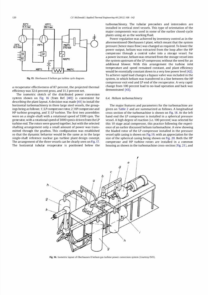
8112019 Helium Turbomachinery Operating Experience From Gas Turbine Power Plants
httpslidepdfcomreaderfullhelium-turbomachinery-operating-experience-from-gas-turbine-power-plants 1435
in the view with the HP rotor assembly positioned above the
horizontal split casing (Fig 22) The 15 stage HP compressor was
again designed with 100 percent reaction blading The HP turbine
has 7 stages and operated with an inlet temperature of 750 C
(1382O F) A cross-section of the 11 stage LP turbine installed in
a separate spherical vessel is shown on Fig 23 The amount of
power transmitted in the gearbox between the HP and LP turbinesis small since at rated output the HP turbine power level is only
slightly more than is needed to drive both compressors
The rotor of the HP group is supported on two oil-lubricated
bearings For the complete rotating assembly the thrust bearing is
located at the warm end of the LP compressor The six turbo-
machine bearing housings were designed such that direct access to
the large oil bearings was possible without having to open the large
casings This was done to reduce maintenance time because the
large split casings have 1047298anges that were welded closed at the
peripheral lip seals to minimize helium leakage
Special attention was given to the design of the cooling system
for the rotor In the case of this plant with a turbine inlet
temperature of 750 C the turbine blades themselves based on the
use of an existing superalloy did not have to be internally cooledbut cooling gas bled from the HP compressor outlet 1047298owed through
the hollow shaft and was used to cool the turbine discs and the
blade root attachments and then returned downstream of the
turbine
In a closed-cycle gas turbine the powerlevel can be regulated by
means of changing the system pressure and careful attention must
be given to the design of the various sealing systems to accom-
modate pressure differentials within the system particularly
during transient operation To simulate what would be needed in
a direct cycle nuclear gas turbine (to prevent 1047297ssion products
coming into contact with the bearing lubricating oil) a system
having a separate chamber for each of the three labyrinth seals was
incorporated in the machine design Outboard of the labyrinth seals
where the shafts penetrate the casings there were two further
seals a 1047298oating ring seal and a shutdown seal to prevent external
helium leakage
65 Helium turbomachine operating experience
Various presentations papers and publications have previously
covered the over 13 year operation of the Oberhausen II helium gas
turbine plant [43e48] The experience gained with the operation
Fig 17 Overall view of Oberhausen II 50 MWe helium gas turbine power plant (Courtesy EVO)
Table 2
Oberhausen II plant helium turbomachinery
Plant design electrical power MW 50
District heating thermal supply MW 535
Plant design ef 1047297ciency at terminals 313
Thermodynamic cycle ICR
Control method Helium inventory
compressor bypass
Rotor arrangement 2 Shaft (geared together)
Helium mass 1047298ow kgsec 85
Overall pressure ratio 27
Generator ef 1047297ciency 98
Design system pressure loss 104Compressor LP HP
Inlet pressure MPa l05 l54
Inlet temperature C 25 25
Vol 1047298ow inletoutlet m3s 5040 4025
Ef 1047297ciency 870 855
Rotational speed rpm 5500 5500
Number of stages 10 15
Blade height inletoutlet mm 10385 7253
Turbine LP HP
Inlet pressure MPa 165 270
Inlet temperature C 582 750
Ef 1047297ciency 900 883
Rotational speed rpm 3000 5500
Number of stages 11 7
Vol 1047298ow inletoutlet m3sec 92120 6792
Blade height inletoutlet mm 200250 150200
CF McDonald Applied Thermal Engineering 44 (2012) 108e142 121
8112019 Helium Turbomachinery Operating Experience From Gas Turbine Power Plants
httpslidepdfcomreaderfullhelium-turbomachinery-operating-experience-from-gas-turbine-power-plants 1535
of the large axial 1047298ow helium turbomachine is summarized asfollows
On the positive side the following were accomplished The rotor
helium buffered bearing labyrinth oil sealing system was one of the
numerous systems that worked well from the onset This was
encouraging since the external leakage of helium contaminated by
1047297ssion products and the ingress of lubricating oil into the closed
helium loop during the projected plant lifetime of 60 years are of
concern to designers of a direct cycle nuclear gas turbine plant (for
a machine with oil bearings) because of the likely long plant
downtime for cleanup and repair
With some modi1047297cations the helium puri1047297cation system
worked well with the purity level within the speci1047297cation The
helium cooling systems worked well to keep the temperatures of
the turbine discs blade root attachments and casings at speci1047297
edlevels Load change by inventory control was done routinely and
the ability to shed 100 percent of the load in a very short period by
means of the bypass valve was demonstrated The integrity of the
co-axial turbine inlet hot gas duct was proven At the end of plant
operation the major turbomachine casings were opened and there
were no signs of corrosion or erosion of the turbine or compressor
blades The coatings applied to mating metallic surfaces were
effective with no evidence of galling or self-welding in the oxygen-
free closed-loop helium environment
Experience from previously operated high temperature helium
cooled nuclear reactor power plants (with Rankine cycle steam
turbine power conversion systems) demonstrated that absolute
helium leak tightness was not attainable This was also true in the
Oberhausen II fossil-1047297red gas turbine plant where during initial
operation the helium leakage was about 45 kg per day Attention
was given to this and helium losses were reduced to the range of
5e10 kg per day principally by seal welding the major 1047298anges This
value can be compared with other closed loop helium systems as
shown below
On the negative side several unexpected problems had a majorimpact on the operation of the plant Following initial running of
the machine at 3000 rpm in preparation to synchronizing the
system the HP casing was opened for inspection revealing
damage to the labyrinth seals this being caused by shifting of
the rotor in the axial direction The labyrinth seals were replaced
and the turbine was 1047297rst synchronized with the grid on November
8 1975
Subsequent vibration problems were encountered and the HP
shaft oscillation became so large that it caused damage to the
bearings and the design value of speed and power could not be
maintained and the plant was shut down This was initially thought
to be due to thermal distortion of the rotor and a large unbalance
Fig 18 Cross-section of Oberhausen II plant helium turbomachinery rotating assembly (Courtesy EVO)
Fig 19 Oberhausen II low pressure helium compressor installed in casing (Courtesy
GHH)
Plant Helium inventory kg Leakage
kgday day
Dragon 180 020e20 010e10
AVR 240 10e30 040e12
Oberhausen II 1400 5e10 035e070
HHV 1250 25e50 020e040
FSV e Excessive leakage
CF McDonald Applied Thermal Engineering 44 (2012) 108e142122
8112019 Helium Turbomachinery Operating Experience From Gas Turbine Power Plants
httpslidepdfcomreaderfullhelium-turbomachinery-operating-experience-from-gas-turbine-power-plants 1635
Modi1047297cations to the rotor were made and the bearings replaced
but now the HP spool design speed of 5500 rpm could not be
achieved Subsequent major design and fabrication changes were
made including decreasing the bearing span by 600 mm (24 in)
giving a shorter stiffer rotor and changing the type of bearings In
restarting the plant the design speed of the HP rotor was achieved
however the power output was only 30 MW compared with the
design value of 50 MW
Fig 20 View of Oberhausen II low pressure helium compressor spherical vessel (Courtesy GHH)
Fig 21 Cross-section of Oberhausen II high pressure rotating group (Courtesy GHH)
CF McDonald Applied Thermal Engineering 44 (2012) 108e142 123
8112019 Helium Turbomachinery Operating Experience From Gas Turbine Power Plants
httpslidepdfcomreaderfullhelium-turbomachinery-operating-experience-from-gas-turbine-power-plants 1735
To gain operational experience it was decided to continue
running the plant at the reduced power rating On February 5 1979
after nearly 11000 h of operation a rotor blade from the second
stage of the HP turbine failed causing damage in the remaining
stages but the high energy fragments were contained within the
thick machine casing Examination of the failed blade revealed the
defect as a crack caused by the forgingprocess on the semi-1047297nishedproduct To prevent such a failure occurring in the future an electric
polishing process applied to the blade surface before inspection
was implemented and improved crack detection methods
introduced
Acoustic loads in a closed-cycle gas turbine represent pressure
1047298uctuations propagating at the speed of sound through the helium
working 1047298uid Pressure 1047298uctuations of importance result from the
aerodynamic effects of high velocity helium impacting and
essentially being intermittently ldquocutrdquo by the blading in the
compressor and turbine Care must be taken in the design of the
plant to ensurethat these 1047298uctuating pressure waves do not induce
vibrations of a magnitude that could result in excitation-induced
fatigue failures in components in the circuit Critical vibrations
occur when resonance exists between the main frequency of
the propagating sound and the natural frequencies of the
components particularly ones that have large surface area to
thickness ratio
Measurements of sound spectrum were taken at four different
locations in the circuit The design level of power of 50 MW was not
achieved but at the 30 MW power output actually realized the
maximum recorded sound power level was 148 dB After plantshutdown there was no evidence of adverse effects on the major
components of noise induced excitation emanating from the axial
1047298ow turbomachinery The integrity of the turbine inlet hot gas duct
and insulation was con1047297rmed
The inability to reach rated power was attributed to shortcom-
ings in the helium turbomachine This included the compressors(s)
and turbine(s) blading failing to attain design values of ef 1047297ciencies
and the bleed helium mass 1047298ows for cooling and sealing being
signi1047297cantly greater than analytically estimated Based on data
taken from the well instrumented plant detailed analyses were
undertaken by specialists [4950] to calculate the losses in the
turbomachine to explain the power output de1047297ciency A summary
of the projected losses and various component ef 1047297ciencies is pre-
sented in a convenient form on Table 3
Fig 22 Oberhausen II high pressure rotor being installed (Courtesy GHH)
CF McDonald Applied Thermal Engineering 44 (2012) 108e142124
8112019 Helium Turbomachinery Operating Experience From Gas Turbine Power Plants
httpslidepdfcomreaderfullhelium-turbomachinery-operating-experience-from-gas-turbine-power-plants 1835
The plant operated for approximately 24000 h and was shut-
down and decommissioned in 1988 when the coke-oven gas supply
for the heater was no longer available A total plant operating time
of about 11500 h had been at the design turbine inlet temperature
of 750 C (1382 F) Turbomachinery related experience gained
from operation of this large helium gas turbine plant was extremely
valuable While many of the functions performed well from the
onset and others worked satisfactorily after modi1047297cations were
made serious unexpected problems were encountered
The achieved electrical power output of only 60 percent of the
design value was initially thought to be due to a grossly excessive
system pressure loss However when the data was carefully eval-uated it was found that 85 percent of the 20 MW power loss was
attributed to turbomachine related problems as delineated on
Table 3
To remedy this power de1047297ciency it was clear that a major re-
design of the turbomachinery would be required While replace-
ment of the gas turbine was not contemplated a study was
undertaken based on data from the plant and new technologies
that had become available since the initial design Based on the
1047297ndings a new turbomachine layout concept was suggested [43]
and a simplistic view of the rotor arrangement is shown on Fig 24
A more conventional single-shaft arrangement was proposed with
the two compressors and turbine having a rotational speed of
5400 rpm A gearbox was still retained to give a generator rota-
tional speed of 3000 rpm Based on prevailing technology at the
time the requirements for such a gearbox would have been moredemanding since the 50 MW from the turbine to the generator
would have to be transmitted through it This would necessitate
a larger system to pump 1047297lter and cool the bearing lubrication oil
To remedy the very large losses in the compressors and turbines
the number of stages would have to be increased In the case of the
compressors the use of lighter aerodynamically loaded higher
ef 1047297ciency stages with 50 percent reaction blading was
recommended
7 High temperature helium test facility (HHV)
71 Background
In the late 1960rsquos with large numbers of orders placed for 1047297rst
generation light water reactor nuclear power plants studies were
initiated for next generation power plants with higher ef 1047297ciency
potential Following the initial operational success of the 1047297rst three
small helium cooled HTR plants (ie Dragon in the UK Peach
Bottom I in the USA and AVR in Germany) studies on larger plants
based on the use of both Rankine steam cycle and helium closed
Brayton cycle power conversion systems were undertaken In the
early 1970rsquos emphasis was placed on nuclear gas turbine plant
designs with larger power output both in the USA (for the
HTGR eGT) and in Europe (for the HHT) Work in the USA was
limited to only paper studies [18] The much larger program in
Germany (with participation by Swiss companies for the turbo-
machine heat exchangers and cooling towers) included a well
planned development testing strategy to support the plant design
Fig 23 Cross-section of Oberhausen II low pressure helium turbine (Courtesy GHH)
Table 3
Oberhausen II helium turbine plant power losses
Componentcause Design
value
Measured Power loss
MW
Compressors
B Flow losses in inlet diffusers
and blades
Low pressure ef 1047297ciency 870 826 13
High pressure ef 1047297ciency 855 779 40
Turbines
B Blade gap and 1047298ow losses
High pressure ef 1047297ciency 883 823 39
B Pro1047297le losses due to Remachined
blades after having detected
damaged blades
Low pressure ef 1047297ciency 900 856 24
BSealing leakage and cooling 1047298ows
in all turbomachines Kgsec
18 75 53
B Circuit pressure losses
(Ducting Hxrsquos etc)
102 128 26
B Miscellaneous heat losses 05
Total power loss 200 MW
Notes (1) Plant designed for electrical power output of 50 MW actual power output
measured 30 MW
(2) Power de1047297ciency of20 MW based on measurements taken and then recalculated
for the rated plant output
(3) 85 of Power loss attributed to helium turbomachinery related issues
CF McDonald Applied Thermal Engineering 44 (2012) 108e142 125
8112019 Helium Turbomachinery Operating Experience From Gas Turbine Power Plants
httpslidepdfcomreaderfullhelium-turbomachinery-operating-experience-from-gas-turbine-power-plants 1935
While the reference HHT plant for eventual commercializationembodied a very large single helium gas turbine rated at 1240 MW
this was to be preceded by a nuclear demonstration plant rated at
676 MW [51] To support the design of this plant technology
generated from the following was planned 1) operational experi-
ence from the aforementioned Oberhausen II 50 MW helium gas
turbine power plant and 2) testing of components in a large high
temperature helium test facility as discussed below
72 Development facilitytesting objectives
An overall view of the HHV test facility sited in Julich in
Germany is shown on Fig 25 and since this has been reported on
previously [52] it will only be brie1047298
y covered in this section Tominimize risk and assure the performance integrity and reliability
of the nuclear demonstration plant some non-nuclear testing of
the major components especially the helium turbomachine was
deemed essential Because of the limitations of a conventional
closed-cycle helium gas turbine power plant particularly the
temperature limitations of existing fossil-1047297red and electrical
heaters a new type of test facility was foreseen
A simpli1047297ed schematic line diagram of the HHV circuit is shown
on Fig 26 The major design parameters are shown on Fig 27
together with the temperatureeentropy diagram which is conve-
nient for describing the unique relationship between the compo-
nents in the closed helium loop Starting at the lowest pressure in
Fig 24 Proposed new concept for Oberhausen II helium gas turbine rotating assembly to remedy problems encountered during operation of the 50 MWe power plant (Courtesy
EVO)
Fig 25 HHV helium turbomachinery test facility (Courtesy BBC)
CF McDonald Applied Thermal Engineering 44 (2012) 108e142126
8112019 Helium Turbomachinery Operating Experience From Gas Turbine Power Plants
httpslidepdfcomreaderfullhelium-turbomachinery-operating-experience-from-gas-turbine-power-plants 2035
the system the helium is compressed (Ae
B) its temperatureincreasing to 850 C (1562 F) before 1047298owing through the test
section (BeC) After being cooled slightly (CeD) the helium is
expanded in the turbine (DeA) down to the compressor inlet
conditions completing the loop There is no power output from the
system and without the need for an external heater the
compression heat is used to raise the helium to the maximum
system temperature in what can be described as a very large heat
pump The required compressor power is 90 MW and to supple-
ment the 45 MW generated by expansion in the turbine external
power is provided by a 45 MW synchronous electrical motor A
cooler is required to remove the compression heat that is contin-
uously put into the closed helium loop and this is done by bleeding
about 5 percent of the mass 1047298ow after the compressor cooling it
and re-introducing it into the circuit close to the turbine inlet In
addition to testing the turbomachine the facility was engineered
with a test section to accommodate other small components (eg
hot gas 1047298ow regulation valves bypass valves insulation con1047297gu-
rations and types of hot gas duct construction) With the highest
temperature in the system being at the compressor exit the facility
had the capability to provide helium at a temperature up to 1000 C
(1832 F) for short periods at the entrance to the test section
While a higher ef 1047297ciency of the planned nuclear demonstration
plant could be projected with a turbine inlet temperature in the
range 950e1000 C (1742e1832 F) this would have necessitated
either turbine blade cooling or the use of a high temperature alloy
such as Titanium Zirconium Molybdenum (TZM) At the time it was
felt that using either of these would have added cost and risk to theprojectso a conventionalnickel-basedalloyas usedin industrialgas
turbines was selected for the 850 C design value of turbine inlet
temperature this negating the needfor actual internal bladecooling
However a complex internal coolingsystemwas neededto keep the
Fig 26 Cycle diagram of HHV test loop (Courtesy BBC)
Fig 27 Salient features of HHV helium turbomachinery (Courtesy BBC)
CF McDonald Applied Thermal Engineering 44 (2012) 108e142 127
8112019 Helium Turbomachinery Operating Experience From Gas Turbine Power Plants
httpslidepdfcomreaderfullhelium-turbomachinery-operating-experience-from-gas-turbine-power-plants 2135
turbine discs and blade root attachments and casings to acceptable
temperatures commensurate with prescribed stress limitations for
thelife of theturbomachine In addition a heliumsupplywas needed
to provide a buffering system for the various labyrinth seals
In a direct Brayton cycle nuclear gas turbine the turbomachine is
installed in the reactor circuit and via the hot gas duct heated
helium is transported directly from the reactor core to the turbine
From the safety licensing and reliability standpoints there are
various seals that must perform perfectly A helium buffered
labyrinth seal system is necessary to prevent bearing lubricating oil
ingress to the closed helium loop Since in the proposed HHT plant
design the drive shaft from the turbine to the generator penetrates
the reactor primary system pressure boundary two shaft seals are
needed one a dynamic seal when the shaft is rotating and a static
seal when the turbomachine is not operating Testing of these seals
in a size and operating conditions representative of the planned
commercial power plant was considered to be a licensing must
The mechanical integrity of the rotating assembly must be
assured there being two major factors necessitating testing the
machine at full speed and temperature and at high pressure
namely 1) loading the blading under representative centrifugal and
gas bending stresses and 2) to monitor vibration and con1047297rm rotor
dynamic stability For the design of the planned commercial planta knowledge of the acoustic emissions by the turbomachine and
propagation in the closed circuit was required Data from the HHV
facility would enable dynamic responses of the major components
(especially the insulation) resulting from excitation by the sound
1047297eld to be calculated
The circuit was instrumented to gather data on the effectiveness
of the hot gas duct insulation thermal expansion devices hot gas
valves helium puri1047297cation system instrumentation and the
adequacy of the coatings applied to mating metallic surfaces to
prevent galling or self-welding Details of the turbomachinery and
the experience gained from the operation of the HHV facility are
covered in the following sections
73 Helium turbomachine
A cross-section of the turbomachine is shown on Fig 28 The
single-shaft rotating assembly consists of 8 compressor stagesand 2
turbine stages and had a weighton the order of 66 tons(60000 kg)
The hub inner and outer diameters are 16 m (525 ft) and 18 m
(59 ft) respectively the blading axial length being 23 m (75 ft)The
span between the oil bearings being 57 m (187 ft) The physical
dimensions of the turbogroup shown on Fig 28 correspond to
a machine rated at about 300 MW The oil bearings operate in
a helium environment and the diameters of the labyrinths and
1047298oating ring shaft seals to prevent oil ingress are representative of
a machine rated at about 600 MW The complexity of the machine
design especially the rotor cooling system sealing system very
large casing and heat insulation have been reported previously
[53e55]
To ensure high structural integrity the rotor was constructed by
welding together the forged compressor and turbine discs The
compressor had 8 stages each having 56 rotor and 72 stator blades
The turbine had 2 stages each having 90 stator and 84 rotor blades
An appreciation for the large size of the rotating assembly can be
seen from Fig 29 The rotor blades have 1047297r-tree attachments
embodying cooling channels Since the temperature and pressure
do not vary very much along the blading in the 1047298ow direction an
intricate rotor and stator cooling system was required Channels in
both the blade roots and the spacers between adjacent blade rows
form an axial geometry for the passage of a cooling helium supplyto keep the temperature of the multiple discs below 400 C
(752 F) The design of this was a challenge since the rotor and
stator blade attachments of both the 8 stage compressor and 2
stage turbine had to be cooled Excessive leakage had to be avoided
since this would have prevented the speci1047297ed compressor
discharge temperature (ie the maximum temperature in the
circuit) from being reached
In the 1970rsquos and early 1980rsquos signi1047297cant studies were carried
out on large helium gas turbines by various organizations [56e62]
In this era there was general agreement that testing of the turbo-
machine in one form or another in non-nuclear facilities be
undertaken to resolve areas of high risk (eg seals bearings cooling
systems rotor dynamic stability compressor surge margin
dynamic response rotor burst protection etc) before installationand operation of a large gas turbine in a nuclear environment
This low risk engineering philosophy which prevailed at the time
in both Germany and the USA emphasized the importance of
Fig 28 Cross-section of HHV helium turbomachinery (Courtesy BBC)
CF McDonald Applied Thermal Engineering 44 (2012) 108e142128
8112019 Helium Turbomachinery Operating Experience From Gas Turbine Power Plants
httpslidepdfcomreaderfullhelium-turbomachinery-operating-experience-from-gas-turbine-power-plants 2235
the HHV test facility as being an important step towards the
eventual deployment of a high ef 1047297ciency nuclear gas turbine power
plant
74 Initial operation of the HHV facility
During commissioning of the plant in 1979 oil ingress into the
helium circuit from the seal system occurred twiceThe 1047297rst ingressof oil between 600 and 1200 kg (1322 and 2644 lb) was due to
a serious operatorerror and the absence of an isolation valve in the
system The oil in the circuit was partly coked and formed thick
deposits on the cold and hot surfaces of the turbomachinery and in
other parts of the closed loop including saturation of the 1047297brous
insulation The fouled metallic surfaces were cleaned mechanically
and chemically by cracking with the addition of hydrogen and
additives The second oil ingress was due to a mechanical defect in
the labyrinth seal system The quantity of oil introduced was small
and it was removed bycracking at a temperature of 600 C (1112 F)
and with the use of additives To obviate further oil ingress inci-
dents the labyrinth seal system was redesigned The buffer and
cooling helium system piping layout was modi1047297ed to positively
eliminate oil ingress due to improper valve operation and toprevent further human error
Pressure and leak detection tests of the HHV test facility at
ambient temperature showed good leak tightness for the turbo-
machine 1047298anged joints and of the main and auxiliary circuits
However at the operating temperature of 850 C (1562 F) large
helium leaks were detected The major 1047298anges had been provi-
sioned with lip seals and the 1047297rst step was to weld the closures A
large leak persisted at the front 1047298ange of the turbomachine This
was diagnosed as being caused by a non-uniform temperature
distribution during initial operation resulting in thermal stresses
creating local gaps This problem was overcome by redesign of the
cooling system with improved gas 1047298ow distribution and 1047298ow rates
to give a more uniform temperature gradient The leakage from the
system was reduced to on the order of 020e
040 percent of the
helium inventory per day this being of the same magnitude as in
other closed helium circuits as discussed in Section 65
It should be mentioned that in addition to the HHV experience
bearing oil ingress into the circuits and system loss of the working
1047298uid in other closed-cycle gas turbine plants have occurred In all of
these fossil-1047297red facilities 1047297xing leaks and removal of oil deposits
were undertaken based on conventional hands-on approaches but
nevertheless such operations were time-consuming However if a new and previously untested helium turbomachine operating in
a direct cycle nuclear gas turbine plant experienced an oil ingress
the rami1047297cations would be severe The likely use of remote
handling equipment to remove the turbomachine from the vessel
machine disassembly (including breaking the welded 1047298ange joints)
and removal of oil from the radioactively contaminated turbo-
machine blade surfaces and system insulation would be time
consuming A diagnosis of the failure would be required before
a spare turbomachine could be installed and this plant downtime
could adversely affect plant availability
75 Experience gained
Afterresolutionof the aforementionedproblems the HHVfacilitywas started in the Spring of 1981 and in an orderly manner was
brought up to full pressure and a temperature of 850 C (1562 F)
During a 60 h run the functioning of the instrumentation control
and safety systems were veri1047297ed During these tests the ability to
stop the turbomachine from full operating conditions to standstill
within 90 s was demonstrated After system depressurization the
plant was then run up again to full operating conditions with no
problems experienced The HHV facility was successfully run for
about 1100 h of which theturbomachineryoperated forabout325 h
at a temperature of 850 C The test facility was extensively instru-
mented and interpretation and analysis of the data recorded gave
positive and favorable results in the following areas
The complex rotor cooling system which was engineered to
assure that the temperature of the discs be kept below 400
C
Fig 29 HHV helium turbomachine rotating assembly (size equivalent to a 300 MWe machine) being installed in a pressure vessel (Courtesy BBC)
CF McDonald Applied Thermal Engineering 44 (2012) 108e142 129
8112019 Helium Turbomachinery Operating Experience From Gas Turbine Power Plants
httpslidepdfcomreaderfullhelium-turbomachinery-operating-experience-from-gas-turbine-power-plants 2335
(752 F) was demonstrated to be effective The measured rotor
coolant 1047298ows (about 3 percent of the mass1047298ow passing through the
machine) were slightly larger than had been estimated and this
resulted in measured turbine disc temperatures lower than pre-
dicted [55]
The dynamic labyrinth shaft seal functioned well at the full
temperature and pressure conditions and met the requirement of
zero oil ingress into the helium circuit The measured rotor oscil-
lation did not have any adverse effect on the shaft sealing system
The static rotor seal (for shutdown conditions) functioned without
any problems
The compressor and turbine blading hadef 1047297ciencies higher than
predicted The structural integrity of the rotor proved to be sound
when operating at 3000 rpm under the maximum temperature and
pressure conditions The stiff rotor shaft had only slight unbalance
and thermal distortion and measured oscillations were in the range
typical of large steam turbines
Sound power spectrum measurements were taken in four
different locations in the circuit These were taken to determine the
spectrum and intensity of the sound generated and propagated by
the turbomachinery and the resultant vibration of internal
components The maximum sound power level in the helium
circuit was160 dB Numerous strain gages were placedin the circuitto determine the in1047298uence of the sound 1047297eld particularly on the
fatigue strength of the turbine inlet hot gas duct In later examining
the internal components there was no evidence of excessive
vibration of the components especially the ducting and the insu-
lation Based on the measurements and calculations it was
concluded that the fatigue strength limit of the components would
not be exceeded during the designed life of the planned commer-
cial nuclear gas turbine power plant
In a direct cycle nuclear gas turbine the hot gas duct used to
transport the helium from the reactor core to the turbineis a critical
component The hot gas duct in the HHV facility performed well
mechanically and con1047297rmed the adequacy of the thermal expan-
sion devices From the thermal standpoint the 1047297ber insulation
performed better than the metallic type
After dismantling the HHV facility there were no signs of
corrosion or erosion of the turbine or compressor blading While
the total number of hours operated was limited the coatings
applied to mating metallic surfaces to prevent galling and frictional
welding in the oxidation-free helium worked well
The helium buffer and cooling system worked well However
problems remained with the puri1047297cation of the buffer helium The
oil separation system consisting of a cyclone separator and a wire
mesh and a down stream 1047297ber 1047297lter needed further improvement
In late 1981 a decision was made to cancel the HHT project and
the HHV facility was shutdown The design and operational expe-
rience gained from the running of this facility would have been
extremely valuable had the nuclear gas turbine power plant
concept moved towards becoming a reality The identi1047297cation of
somewhat inevitable problems to be expected in such a complexturbomachine and their resolution were undertaken in a timely
and cost effective manner in the non-nuclear HHV facility This
should be noted for future nuclear gas turbine endeavors since
remedying such unexpected problems in the case of a new and
untested large helium turbomachine being operated for the 1047297rst
time using nuclear heat could result in very complex repair
Fig 30 Speci1047297
c speed-speci1047297
c diameter array for gas circulators in various gas-cooled nuclear plants
CF McDonald Applied Thermal Engineering 44 (2012) 108e142130
8112019 Helium Turbomachinery Operating Experience From Gas Turbine Power Plants
httpslidepdfcomreaderfullhelium-turbomachinery-operating-experience-from-gas-turbine-power-plants 2435
activities and extended plant downtime and indeed adding risk to
the overall success of the nuclear gas turbine concept
8 Circulators used in gas-cooled reactor plants
Circulators of different types will be needed in future helium
cooled nuclear plants these including the following 1) primary
loop circulator for possible next generation steam cycle power andcogeneration plants 2) for future indirect cycle gas turbine plants
3) shut down cooling circulators forall HTRand VHTR plants and 4)
for various circulators needed in future VHTR high temperature
process heat plant concepts The technology status of operated
helium circulators is brie1047298y addressed as follows
81 Background
It would be remiss not to mention experience gained in the past
with gas circulators and while not gas turbines they are rotating
machines that operate in the primary loop of a helium cooled
reactor With electric motor drives there are basically two types of
compressor rotor con1047297gurations namely radial and axial 1047298ow
machinesIn a single stage form the centrifugal impeller is used for high
stage pressure rise and low volume 1047298ow duties whereas the axial
type covers low pressure rise per stage and high volume 1047298ow The
selection of impeller type is very much related to the working
media type of bearings drive type rotor dynamic characteristics
and installation envelope A wide range of circulators have operated
and a well established technology base exists for both types [63] A
useful portrayal of compressor data in the form of quasi- non-
dimensional parameters (after Balje [64]) showing approximate
boundaries for operation of high ef 1047297ciency axial and radial types is
shown on Fig 30 (from Ref [65])
Both high speed axial and lower speed radial 1047298ow types are
amenable to gas oil and magnetic bearings From the onset of
modularHTR plant studies theuse of active magnetic bearings[6667]offered a solution to eliminate lubricating oil into the reactor circuit
and this tribology technology is attractive for use in submerged
rotating machinery in the next generation of HTR plants [68]
While now dated an appreciation of the main design features of
typical electric motor-driven helium circulators have been reported
previously namely an axial 1047298ow main circulator for a modular
steam cycle HTR plant [69] and a representative radial 1047298ow shut-
down cooling circulator [70]
The operating experience gained from three particular circula-
tors is brie1047298y included below because of their relevance to the
design of helium turbomachinery in future HTR plant variants
82 Axial 1047298ow helium circulator
Since all of the aforementioned predominantly European
helium gas turbines used axial 1047298ow turbomachinery it is of interest
to mention a helium axial 1047298ow circulator that operated in the USA
and to brie1047298y discuss its design parameters and features The
330 MW Fort St Vrain HTGR featured a Rankine cycle power
conversion system Four steam turbine driven helium circulators
were used to transport heat from the reactor core to the steam
generators The complete circulator assemblies were installed
vertically in the prestressed concrete reactor vessel [71e73]
A cross-section of the circulator is shown on Fig 31 with thecompressor rotor and stator visible on the left hand end of the
machine Based on early 1960rsquos technology a decision was made to
use water lubricated bearings and from the overall plant reliability
and availability standpoints this later proved to be a bad choice
Within the vertical circulator assembly there were four 1047298uid
systems namely the helium reactor coolant water lubricant in the
bearings steam for the turbine drive and high pressure water for
the auxiliary Pelton wheel drive During plant transients the pres-
sures and temperatures of these four 1047298uids oscillated considerably
and the response of the control and seal systems proved to be
inadequate and resulted in considerable water ingress from the
bearing cartridge into the reactor helium circuit The considerable
clean up time needed following repeated occurrences of this event
resulted in long periods of plant downtime and this had an adverseeffect on plant availability This together with other technical
Fig 31 Cross section of FSV helium circulator (Courtesy general Atomics)
CF McDonald Applied Thermal Engineering 44 (2012) 108e142 131
8112019 Helium Turbomachinery Operating Experience From Gas Turbine Power Plants
httpslidepdfcomreaderfullhelium-turbomachinery-operating-experience-from-gas-turbine-power-plants 2535
dif 1047297culties eventually contributed to the plant being prematurely
decommissioned
On the positive side in the context of this paper the helium
circulators operated for over 250000 h and exhibited excellent
helium compressor performance good mechanical integrity and
vibration-free operation The rotating assembly showing the axial
1047298ow compressor and steam turbine rotors together with a view of
the machine assembly are given on Fig 32 The helium compressor
consists of a single stage axial rotor followed by an exit guide vane
The machine was designed for axial helium 1047298ow entering and
leaving the stage and this can be seen from the velocity triangles
shown on Fig 33 which also includes the de1047297nition of the various
aerodynamic parameters Major design parameters and features of
this helium circulator are given on Table 4 Related to an earlier
discussion on the degree of reaction for axial 1047298ow compressors the
value for this conventional single stage circulator is 78 percent All
of the major aerothermal and structural loading criteria were
within established boundaries for an axial compressor having high
ef 1047297ciency and a good surge margin
The compressor gas 1047298ow path and blading geometries were
established based on prevailing industrial gas turbine and aero-
engine design practice A low Mach number (025) a high Reynolds
number (3 106) together with a modest stage loading (ie
a temperature rise coef 1047297cient of 044) and an acceptable value of
diffusion factor (042) were some of the factors that contributed to
a helium circulator that had a high ef 1047297ciency and a good pressure
rise- 1047298ow characteristic The large rotor blade chord and thick blade
section for this single stage circulator are necessary to accommo-
date the high bending stress characteristic of operation in a high
pressure environment The solidity and blade camber were opti-
mized for minimum losses
There were essentially two reasons for including this single-
stage axial 1047298ow compressor that operated in a helium cooled
reactor although its overall con1047297guration can be regarded as a 1047297rst
and last of a kind A rotor blade from this circulator as shown onFig 34 was based on a NASA 65 series airfoil which at the time
were one of the best performing cascades for such low Mach
number and high Reynolds number applications Interestingly it
has almost the same blade height aspect ratio and solidity as would
be used in the 1047297rst stage of an LP compressor in a helium turbo-
machine rated on the order of 250 MW
The second point of interest is that the helium mass 1047298ow rate
through the single stage axial compressor (rated at 4 MWe) is
110 kgs compared with 85 kgs through the multistage compressor
in the 50 MWe Oberhausen II helium gas turbine plant However
the volumetric 1047298ow through the Oberhausen axial compressor is
higher than that through the circulator by a factor of 16 this again
pointing out that the Oberhausen II plant was designed for high
volumetric 1047298ow to simulate the much larger size of turboma-chinery that was planned at the time in Germany for use in future
projected nuclear gas turbine power plants
83 High temperature helium circulator
For future helium turbomachines embodying active magnetic
bearings a challenge in their design relates to accommodating
elevated levels of temperature in the vicinity of the electronic
components In this regard it is of interest to note that a small very
high temperature helium axial 1047298ow circulator rated at 20 kW (as
shown on Fig 35) operated for more than 15000 h in an insulation
test facility in Germany more than two decades ago [74] The
signi1047297cance of this machine is that it operated with magnetic
bearings in a high temperature helium test loop with a circulatorgas inlet temperature of 950 C (1742 F) This necessitated the use
of ceramic insulation to ensure that the temperature in the vicinity
of the magnetic bearing electronics did not exceed a temperature of
about 150 C (300 F)
This machine although a very small axial 1047298ow helium blower
performed well and has been brie1047298y mentioned here since it
represents a point of reference for future helium rotating machines
capable operating with magnetic bearings in a very high temper-
ature helium environment
84 Radial 1047298ow AGR nuclear plant gas circulators
The electric motor-driven carbon dioxide circulators rated at
about 5 MW with a total runningtimein excess of 18 million hours
Fig 32 Fort St Vrain HTGR plant helium circulator (Courtesy General Atomics) (a)
Axial 1047298ow helium compressor and steam turbine rotating assembly (b) 4 MW helium
circulator assembly
CF McDonald Applied Thermal Engineering 44 (2012) 108e142132
8112019 Helium Turbomachinery Operating Experience From Gas Turbine Power Plants
httpslidepdfcomreaderfullhelium-turbomachinery-operating-experience-from-gas-turbine-power-plants 2635
in AGR nuclear power plants in the UK have demonstrated veryhigh availability [7576] To a high degree this can be attributed to
the fact that the machines were conservatively designed and proof
tested in a non-nuclear facility at full temperature and power
under conditions that simulated all of the nuclear plant operating
modes The test facility shown on Fig 36 served two functions 1)
design veri1047297cation of the prototype machine and 2) test of all new
and refurbished machines before they were installed in nuclear
plants Engineers currently involved in the design and development
of helium turbomachinery could bene1047297t from this sound testing
protocol to minimize risk in the deployment of helium rotating
machinery in future HTRVHTR plant variants
9 Helium turbomachinery development and testing
91 On-going development activities
The various helium turbomachines discussed in previous
sections operated over a span of about two decades starting in the
early 1960s From about 1990 activities in the nuclear gas turbine
1047297eld have been focused mainly on the design of modular GTeHTR
plant concepts In support of these plant studies many signi1047297cant
helium turbomachine design advancements have been made and
attention given to what development testing would be needed In
the last decade or so limited sub-component development has
been undertaken for helium turbomachines in the 250e300 MWe
size and these are brie1047298y summarized below
In a joint USARussia effort development in support of the
GTe
MHR turbomachine has been undertaken including testing in
the following areas magnetic bearings seals and rotor dynamicsfor the vertical intercooled helium turbomachine rated at 286 MWe
[77e80]
In Japan development activities have been in progress for
several years in support of the 274 MWe helium turbomachine for
the GTeHTR300 plant concept [2581] A detailed discussion on
the aerodynamic design of the axial 1047298ow helium compressor for
this turbomachine has been published in the open literature [82]
While the design methodology used for axial compressor design in
air-breathing industrial and aircraft gas turbines is generally
applicable for a multi-stage helium compressor a decision was
made by JAEA to test a small scale compressor in a helium facility
because of the inherent and unique gas 1047298ow path and type of
blading associated with operation in a high pressure helium
environment The major goal of the test was to validate the designof the 20 stage helium axial 1047298ow compressor for the GTeHTR300
plant
An axial 1047298ow compressor in a closed-cycle helium gas turbine is
characterized by the following 1) a large number stages 2) small
blade heights 3) high hub-to-tip ratio 4) a long annulus with
small taper that tends to deteriorate aerodynamic performance as
a result of end-wall boundary layer length and secondary 1047298ow 5)
low Mach number 6) high Reynolds number and 7) blade tip
clearances that are controlled by the gap necessary in the magnetic
journal and catcher bearings While (as covered in earlier sections)
helium gas turbines have operated there is limited data in the
open literature on the performance of multi-stage axial 1047298ow
compressors operating in a high pressure closed-loop helium
environment
Fig 33 Velocity triangles for axial compressor stage
CF McDonald Applied Thermal Engineering 44 (2012) 108e142 133
8112019 Helium Turbomachinery Operating Experience From Gas Turbine Power Plants
httpslidepdfcomreaderfullhelium-turbomachinery-operating-experience-from-gas-turbine-power-plants 2735
A 13rd scale 4 stage compressor was designed to simulate the
stage interaction the boundary layer growth and repeated stage
1047298ow in an actual compressor The 1047297rst four stages were designed to
be geometrically similar to the corresponding stages in the
GTe
HTR300 compressor Details of the model compressor havebeen discussed previously [81] and are summarized on Table 5
from [83]
A cross-section of the compressor test model is shown on Fig 37
A view of the 4 stage compressor rotor installed in the lower casing
is shown on Fig 38 The test facility (Fig 39) is a closed helium loop
consisting of the compressor model cooler pressure adjustment
valve and a 1047298ow measurement instrument The compressor is
driven by a 3650 kW electrical motor via a step-up gear The rota-
tional speed of 10800 rpm (three times that of the compressor in
the GTeHTR300 plant) was selected to match blade speed and
Mach number in the full size compressor
Details of the planned aerodynamic performance objectives of
the 13rd scale helium compressor test have been published
previously [84] Extensivetesting of the subscale model compressorprovided data to validate the performance of the full size
compressor for the GTeHTR300 power plant The test data and
test-calibrated CFD analyses gave added insight into the effect of
factors that impact performance including blade surface roughness
and Reynolds number
Based on advanced aerodynamic methodology and experi-
mental validation [82] there is now a sound basis for added
con1047297dence that the design goals of 90 percent polytropic ef 1047297ciency
and a design point surge margin of 20 percent are realizable in
a large multistage axial 1047298ow compressor for a future nuclear gas
turbine plant
In a similar manner a design of a one third size single stage
helium axial 1047298ow turbine has been undertaken and a cross
section of the machine is shown on Fig 40 (from Ref [81]) This
Table 4
Major features of axial 1047298ow helium circulator
Helium 1047298ow rate kgsec 110
Inlet temperature C 394
Inlet pressure MPa 473
Pressure rise KPa 965
Volumetric 1047298ow m3sec 32
Compressor type Single stage axial
Compressor drive Steam turbine
Bearing type Water lubricated
Rotational speed rpm 9550
Power MW 40
Rotor tip diameter mm 688
Rotor tip speed msec 344
Number of rotor blades 31
Number of stator blades 33
Blade height mm 114
Hub-to-tip ratio 067
Axial velocity msec 157
Flow coef 1047297cient 055
Temperature rise coef 1047297cient 044
Degree of reaction 078
Mean rotor solidity 128
Rotor aspect ratio 155
Rotor Mach number 025
Rotor diffusion factor 042
Rotor Reynolds number 3106
Speci1047297c speed 335
Speci1047297c diameter 066
Blade root thickness 15
Airfoil type NASA 65
Rotor blade chord mm 94e64
Stator blade chord mm 79
Rotor centrifugal stress MPa 125
Rotor bending stress MPa 30
Circulator(s) operating Hours gt250000
Fig 34 Rotor blade from single stage axial 1047298ow helium circulator (Courtesy General
Atomics)
Fig 35 20 kW axial 1047298ow helium circulator with magnetic bearings operated in 1985 in
an insulation test loop with a gas inlet temperature on 950
C (Courtesy BBC)
CF McDonald Applied Thermal Engineering 44 (2012) 108e142134
8112019 Helium Turbomachinery Operating Experience From Gas Turbine Power Plants
httpslidepdfcomreaderfullhelium-turbomachinery-operating-experience-from-gas-turbine-power-plants 2835
single stage scale model turbine for validity of the full size turbine
has been built and plans made to test the aerodynamic
performance
92 Nuclear gas turbine helium turbomachine testing
In planning for the 1047297rst nuclear gas turbine plant projected to
enter service perhaps in the third decade of the 21st century
a major decision has to be made as to what extent the large helium
turbomachine should be tested prior to operation on nuclear heat
Issues essentially include cost impact on schedule but the over-
riding one is risk Certainly turbomachine component testing will
be undertaken including the compressor (as discussed in the
previous section) and turbine performance seals cooling systems
hot gas valves thermal expansion devices high temperature
insulation rotor fragment containment diagnostic systems
instrumentation helium puri1047297cation system and other areas to
satisfy safety licensing reliability and availability concerns The
major point is really whether a full size or scaled-down turbo-machine be tested early in the project in a non-nuclear facility
To obviate the need for pre-nuclear testing of a large helium
turbomachine a view expressed by some is that advantage can be
taken of formidable technology bases that exist today for large
industrial gas turbines and high performance aeroengines On the
other hand it is the view of some including the author that very
complex power conversion system components especially those
subjected to severe thermal transients donrsquot always perform
exactly as predicted by analysts and designers even using sophis-
ticated computer codes This was exempli1047297ed in the case of the
turbomachine in the aforementioned Oberhausen II helium gas
turbine plant
The need for a helium turbomachine test facility goes beyond
just veri1047297
cation of the prototype machine Each newgas turbine for
commercial modular nuclear reactor plants would have to be proof
tested and validated before being transported to the reactor site
Similarly turbomachines that would be periodically removed from
the plant at say 7 year intervals during the plant operating life of 60
years for scheduled maintenance refurbishment repair or updat-ing would be again proof tested in the facility before re-entering
service
The direction that turbomachine development and testing will
take place for future helium gas turbines needs to be addressed by
the various organizations involved
Fig 36 AGR circulator test facility In the UK (Courtesy Howden)
Table 5
Major design parametersfeatures of model GTeHTR300 axial 1047298ow helium
compressor (Courtesy JAERI)
Scale of GTeHTR300 compressor 13
Helium mass 1047298ow rate (kgsec) 122
Helium volumetric 1047298ow rate (mV s) 87
Inlet temperature C 30
Inlet pressure MPa 0883Compressor pressure ratio at design point 1156
Number of stages 4
Rotational speed rpm 10800
Drive motor power kW 3650
Hub diameter mm 500
Rotor tip diameter (1st4th stage mm) 568566
Hub-to-tip ratio (1st stage) 088
Rotor tip speed (1st stage msec) 321
Number of rotorstator blades (1st stage) 7294
Rotorstator blade height (1st stage mm) 34337
Rotor stator blade c hor d l eng th (1st stage mm) 2620
Rotorstator solidity (1st stage) 119120
Rotorstator aspect ratio (1st stage) 1317
Flow coef 1047297cient 051
Stage loading factor 031
Reynolds number at design point 76 l05
CF McDonald Applied Thermal Engineering 44 (2012) 108e142 135
8112019 Helium Turbomachinery Operating Experience From Gas Turbine Power Plants
httpslidepdfcomreaderfullhelium-turbomachinery-operating-experience-from-gas-turbine-power-plants 2935
10 Helium turbomachinery lessons learned
101 Oberhausen II gas turbine and HHV test facility
It is understandable that 1047297rst-of-a-kind complex turboma-
chinery operating with an inert low molecular weight gas such as
helium will experience unique and unexpected problems In the
operation of the two pioneering large helium turbomachines in
Germany there were many positive1047297ndings which could only have
been achieved by development testing Equally important some
negative situations were identi1047297ed many of which were remedied
In the case of the Oberhausen II helium gas turbine plant some of
the very serious problems encountered were not resolved Inves-
tigations were undertaken to rationalize the problems associated
with the large power de1047297ciency and a data base established to
ensure that the various anomalies identi1047297ed would not occur in
future large helium turbomachines
The experience gained from the operation of the Oberhausen II
helium gas turbine power plant and the HHV test facility have been
discussedin thetextand arepresentedin a summaryformon Table6
Fig 37 Cross-section of 13rd scale helium compressor test model (Courtesy JAEA)
Fig 38 Four stage helium compressor rotor assembly installed in lower casing (Courtesy JAEA)
CF McDonald Applied Thermal Engineering 44 (2012) 108e142136
8112019 Helium Turbomachinery Operating Experience From Gas Turbine Power Plants
httpslidepdfcomreaderfullhelium-turbomachinery-operating-experience-from-gas-turbine-power-plants 3035
102 Impact of 1047297ndings on future helium gas turbine
The long slender rotorcharacteristic of closed-cycle gas turbines
has resulted in shaft dynamic instability which in some cases has
resulted in blade vibration and failure and bearing damage This
remains perhaps the major concern in the design of large
(250e
300 MW) helium turbomachines for future nuclear gas
turbine plants With pressure ratios in the range of about 2e3 in
a helium system a combination of splitting the compressor (to
facilitate intercooling) and having a large number of compressor
and turbine stages results in a long and 1047298exible rotating assembly
andthis is exempli1047297ed by the rotorassembly shown on Fig13 With
multiple bearings (either oil lubricated or magnetic) the rotor
would likely pass through multiple bending critical speeds before
Fig 39 Helium compressor test facility (Courtesy JAEA)
Fig 40 Cross-section of single stage helium turbine test model (Courtesy JAEA)
CF McDonald Applied Thermal Engineering 44 (2012) 108e142 137
8112019 Helium Turbomachinery Operating Experience From Gas Turbine Power Plants
httpslidepdfcomreaderfullhelium-turbomachinery-operating-experience-from-gas-turbine-power-plants 3135
reaching the design speed While very sophisticated computer
codes will be used in the detailed rotor dynamic analyses the real
con1047297rmation of having rotor oscillations within prescribed limits
(to avoid blade bearing and seal damage) will come from actual
testingA point to be made here is that in operated fossil-1047297red closed-
cycle gas turbine plants it was possible to remedy problems asso-
ciated with rotor vibrations and blade failures in a conventional
manner In fact in some situations the casings were opened several
times and modi1047297cations made to facilitate bearing and seal
replacement and rotor re-blading and balancing
An accurate assessment of pressure losses must be made
particularly those associated with the helium entering and leaving
the turbomachine bladed sections Minimizing the system pressure
loss is important since it directly impacts the all important quotient
of turbine expansion ratio to compressor pressure ratio and power
and plant ef 1047297ciency
Based on the operating experience from the 20 or so fossil-1047297red
closed-cycle gas turbine plants using air as the working1047298
uid it was
recognized that future very high pressure helium gas turbines
would pose problems regarding the various seals in the turbo-
machine and obtaining a zero leakage system with such a low
molecular weight gas would be dif 1047297cult and this is discussed
below
When the Oberhausen II gas turbine plant and the HHV facility
operated over 30 years ago oil lubricated bearings were used to
support the heavy rotor assemblies and helium buffered labyrinth
seals were used to prevent oil ingressinto the heliumworking1047298uid
Initial dif 1047297culties encountered in both plants were overcome by
changes made to the seal geometries and for the operating lives of
the helium turbomachines no further oil ingress events were
experienced Twoseals were required where the turbine drive shaft
penetrated the turbomachine casing namely 1) a dynamic laby-
rinth seal and 2) a static seal for shutdown conditions In both
plants these seals functioned without any problems
Labyrinth seals were also required within the helium turbo-
machines to pass the correct helium bleed 1047298ow from the
compressor discharge for cooling of the turbine discs blade root
attachments and casings The fact that the very complex rotor
cooling system in the large helium turbomachine in the HHV test
facility operated well for the test duration of about 350 h with
a turbine inlet temperature of 850 C was encouragingIn the case of the Oberhausen II gas turbine plant analysis of the
test data revealed that the labyrinth seal leakage and excessive
cooling 1047298ows were on the order of four times the design value A
possible reason for this was that damage done to the labyrinth
seals caused excessive clearances when periods of excessive rotor
oscillation and vibration occurred during early operation of the
machine
Clearly 1047298uid dynamic and thermal management of the cooling
system and 1047298ow through the various labyrinth seals will require
extensive analysis design and development testing before the
turbomachine is operated on nuclear heat for the 1047297rst time
In future heliumgas turbine designs (with turbine inlet tempera-
tureslikelyontheorderof950C)the1047298owpathgeometriesofhelium
bledfromthecompressornecessarytocoolpartsoftheturbomachinewillbemorecomplexthanthosetestedto-dateInadditiontoproviding
acooling1047298owtotheturbinebladesanddiscsbladerootattachmentsand
casingsheliummustbetransportedtotheseveralmagneticbearingsto
ensure thatthe temperatureof theirelectronic components doesnot
exceedabout150C
The importance of the points made above is evidenced when
examining the data on Table 3 where a combination of excessive
pressure losses and high bleed 1047298ows contributed to about 40
percent of the power de1047297ciency in the Oberhausen II helium
turbine plant
Retaining overall system leak tightnessin closed heliumsystems
operating at high pressure and temperature has been elusive
including experience from the Fort St Vrain HTGR plant as dis-
cussed in Section 65 New approaches in the design of the plethoraof mechanical joints must be identi1047297ed Experience to-date has
shown that having welded seals on 1047298anges while minimizing
system leakage did not eliminate it
The importance of lessons learned from the operation of the
Oberhausen II helium turbine power plant and the HHV test facility
have primarily been discussed in the context of helium turbo-
machines currently being designed in the 250e300 MWe power
range However the established test data bases could also be
applied to the possible emergence in the future of two helium
cooled reactor concepts namely 1) an advanced VHTR combined
cycle plant concept embodying a smaller helium gas turbine in the
power range of 50e80 MWe [22] and 2) the use of a direct cycle
helium gas turbine PCS in a recently proposed all ceramic fast
nuclear reactor concept [85]
Table 6
Experience gained from Oberhausen II and HHV facility
Oberhausen II 50 MW helium gas turbine power plant
Positive results
e Rotating and static seals worked well
e No ingress of bearing lubricant oil into closed circuit
e Load change by inventory control worked well
e 100 Percent load shed by means of bypass valves demonstrated
e Turbine disc and blade root cooling system con1047297rmed
e Coatings on mating surfaces prevented galling and self-welding
e After 24000 h of operation no evidence of corrosion or erosion
e Coaxial turbine hot gas inlet duct insulation and integrity con1047297rmed
e Monitoring of complete power conversion system for steady state
and transient operation undertaken
Problem areas
e Serious power output de1047297ciency (30 MW compared with design
value of 50 MW)
e Compressor(s) and turbine(s) ef 1047297ciencies several points below predicted
e Higher than estimated system pressure loss
e Rotor dynamic instability and blade vibration
e Bearings damaged and had to be replaced
e Blade failure caused extensive damage in HP turbine but retained
in casing
e Very excessive sealing and cooling 1047298ow rates
e Absolute leak tightness not attainable even with welded 1047298ange lips
HHV test facility
Positive resultse Use of heat pump approach facilitated helium temperature capability
to 1000 C
e Large oompressorturbine rotor system operated at 3000 rpm Complex
turbine disc and blade root cooling system veri1047297ed
e Dynamic and static seals met requirement of zero oxl ingress into circuit
e Structural integrity of rotating assembly veri1047297ed at temperature of 850 C
e Measured rotor oscillations within speci1047297cation
e Compressor and turbine ef 1047297ciencies higher than predicted
e Coatings on mating metallic surfaces prevented galling and self-welding
e Instrumentation control and safety systems veri1047297ed
e Seal 1047298ows within speci1047297cation
e Machine stop from operating speed to shutdown in 90 s demonstrated
e Hot gas duct insulation and thermal expansion devices worked well
e After 1100 h of operation no evidence of corrosionof erosion
Problem areas
e Before commissioning a large oil ingress into the circuit occurred due
to serious operator error and absence of an isolation valve A second oilingress occurred due to a mechanical defect in the labyrinth seal system
These were remedied and no further oil ingress was experienced for the
duration of testing
e Cooling 1047298ows slightly larger than expected but this resulted in actual
disc and blade root temperatures lower than the predicted value of
400 C
e System leak tightness demonstrated when pressurized at ambient
temperature conditions but some leakage occured at 850 C even with
the seal welding of 1047298ange(s) lips
CF McDonald Applied Thermal Engineering 44 (2012) 108e142138
8112019 Helium Turbomachinery Operating Experience From Gas Turbine Power Plants
httpslidepdfcomreaderfullhelium-turbomachinery-operating-experience-from-gas-turbine-power-plants 3235
11 New technologies
It is recognized that in the 3 to 4 decades since the operation of
the helium turbomachines covered in this paper new technologies
have emerged which negate some of the early issues An example of
this is the technology transfer from the design of modern axial 1047298ow
gas turbines (ie industrial aircraft and aeroderivatives) that fully
utilize sophisticated CAE CAD CFD and FEA design software
Air breathing aerodynamic design practice for compressors and
turbines are generally applicable but the properties of helium and
the high system pressure have a signi1047297cant impact on gas 1047298ow
paths and blade geometries With short blade heights high hub-to-
tip ratios long annulus 1047298ow path length (with resultant signi1047297cant
end-wall boundary layer growth and secondary 1047298ow) and blade tip
clearances in some cases controlled by clearances in the magnetic
catcher bearing testing of subscale model compressors and
Fig 41 Gas turbine test facility for aircraft nuclear propulsion involving the coupling of a 32 MWt air-cooled reactor with two modi 1047297ed J-47 turbojet aeroengines each rated at
a thrust of about 3000 kg operated in 1960 (Courtesy INL)
Fig 42 Mobile 350 KWe closed-cycle nuclear gas turbine power plant operated in 1961 (Courtesy US Army)
CF McDonald Applied Thermal Engineering 44 (2012) 108e142 139
8112019 Helium Turbomachinery Operating Experience From Gas Turbine Power Plants
httpslidepdfcomreaderfullhelium-turbomachinery-operating-experience-from-gas-turbine-power-plants 3335
turbines will be needed While most of the operated helium tur-
bomachines discussed in this paper took place 3 or 4 decades ago it
is encouraging that the fairly recent test data and test-calibrated
CFD analysis from a subscale four stage model helium axial 1047298ow
compressor in Japan [80] gave a high degree of con1047297dence that
design goals are realizable for the full size 20 stage compressor in
the 274 MWe GTeHTR300 plant turbomachine
In the future the use of active magnetic bearings will eliminate
the issue of oil ingress however the very heavy rotor weight and
size of the journal and thrust bearings (and catcher bearings) of the
type for helium turbomachines in the 250e300 MWe power range
are way in excess of what have been demonstrated in rotating
machinery For plant designs retaining oil-lubricated bearings well
established dry gas seal technology exists particularly experience
gained from the operation of high pressure natural gas pipe line
compressors
For future nuclear helium gas turbine plants the designer has
freedom regarding meeting different frequency requirements that
exist in some countries These include use of a synchronous
machine (ie designed for 50 or 60 Hz grids) use of a gearbox drive
between the turbine and generator or the use of a frequency
converter which gives the designer an added degree of freedom
regarding the selection of speed for the rotating assemblyCompared with the past very sophisticated electronic control
systems instrumentation and diagnostic systems are available
today
12 Conclusions
In this review paper experience from operated helium turbo-
machines has been compiled based on open literature sources At
this stage in the evolution of HTR and VHTR plant concepts it is not
clear in what role form or time-frame the nuclear gas turbine will
emerge when commercialized By say the middle of the 21st
century all power plants will be operating with signi1047297cantly higher
ef 1047297ciencies to realize improved power generation costs and
reduced emissions In a nuclear gas turbine the helium turbo-machine will be a major contributor towards the achievement of
ef 1047297ciencies higher than 50 percent
While it has been 3 to 4 decades since the Oberhausen II helium
turbine power plant and the HHV high temperature helium turbine
facility operated signi1047297cant lessons were learned and the time and
effort expended to resolve the multiplicity of unexpected technical
problems encountered The remedial repair work was done under
ideal conditions namely that immediate hands-on activities were
possible This would not have been possible if the type of problems
experienced had been encountered in a new and untested helium
turbomachine operated for the 1047297rst time with a nuclear heat
source
While new technologies have emerged that negate many of the
early problems there are some uniquely inherent issues associatedwith for large helium turbines operating in a high pressure and
temperature environment and these include the following 1)
minimizing system leakage with such a low molecular weight gas
2) clearances in labyrinth seals to minimize helium bypass1047298ows 3)
the dynamic stability of long slender rotors 4) minimizing the
turbomachine inlet and outlet pressure losses 5) 1047298ow maldis-
tribution in complex ductturbomachine interfaces 6) integrity
veri1047297cation of the catcher bearings (journal and thrust) after
multiple rotor drops (following loss of the magnetic 1047297eld) during
the plant lifetime 7) assurances that high energy fragments from
a failed turbine disc are contained within the machine casing 8)
turbomachine installation and removal from a steel pressure vessel
and 9) remote handling and cleaning of a machine with turbine
blades contaminated with 1047297
ssion products
The need for a helium turbomachine test facility has been
emphasized to ensure that the integrity performance and reli-
ability of the machine before it operates the 1047297rst time on nuclear
heat Engineers currently involved in the design of helium rotating
machinery for all HTR and VHTR plant variants should take
advantage of the experience gained from the past operation of
helium turbomachinery
13 In closing-GT rsquos operated with nuclear heat
In the context of this paper it is germane to mention that two
gas turbines have actually operated using nuclear heat as brie1047298y
highlighted below
In the late 1950rsquos a program was initiated in the USA for aircraft
nuclear propulsion (ANP) While different concepts were studied
only the direct cycle air-cooled reactor reached the stage of
construction of an experimental reactor [86] A view of the large
nuclear gas turbine facility is given on Fig 41 and shows the air-
cooled and zirconiumehydride moderated reactor rated at
32 MWt coupled with two modi1047297ed J-47 turbojet engines each
rated with a thrust of about 3000 kg In this open cycle system the
high pressure compressor air was directly heated in the reactor
before expansion in the turbine and discharge to the atmosphere in
the exhaust nozzle The facility operated between 1958 and 1961 at
the Idaho reactor testing facility While perhaps possible during the
early years of the US nuclear program it is clear that such a system
would not be acceptable today from safety and environmental
considerations
The 1047297rst and indeed the only coupling of a closed-cycle gas
turbine with a nuclear reactor for power generation was under-
taken to meet the needs of the US Army In the late 1950 rsquos an RampD
program was initiated for a 350 kW trailer-mounted system to be
used in the 1047297eld by military personnel A prototype of the ML-1
plant shown on Fig 42 was 1047297rst operated in 1961 [8788]
It was based on a 33 MW light water moderated pressure tube
reactor with nitrogen as the coolant The closed-cycle gas turbine
power conversion system with nitrogen as the working 1047298uid hada turbine inlet temperature of 649 C (1200 F) and delivered
around 300 kW With changes in the Armyrsquos needs the project was
discontinued in 1965
While the experience gained from the above twounique nuclear
plants is clearly not relevant for future nuclear gas turbine power
plants that could see service in the third decade of the 21st century
these ambitious and innovative nuclear gas turbine pioneering
engineering efforts need to be recognized
Acknowledgements
The author would like to thank the following for helpful discus-
sions advice and for providing valuable comments on the initial
paper draft Prof Dr Hermann Haselbacher Hans Ulrich Frutschi DrXing Yan DrPeter Zenker Professor DavidGordon Wilson Professor
Aristide Massardo Arthur Harris DrFred Starr and DrGuido Bac-
caglini This paper has been enhanced by the inclusion of hardware
photographs and unique sketches and the author is appreciative to
all concerned with credits being duly noted
References
[1] C Keller The Escher Wyss AK Closed-Cycle Gas Turbine Its Actual Develop-ment and Future Prospects Paper Presented at ASME Meeting November 261945
[2] HU Frutschi Closed-Cycle Gas Turbines Operating Experience and FuturePotential ASME Press NY 2005
[3] CF McDonald The Nuclear Gas Turbine-Towards Realization After Half
a Century of Evolution (1995) ASME Paper 95-GT-292
CF McDonald Applied Thermal Engineering 44 (2012) 108e142140
8112019 Helium Turbomachinery Operating Experience From Gas Turbine Power Plants
httpslidepdfcomreaderfullhelium-turbomachinery-operating-experience-from-gas-turbine-power-plants 3435
[4] C Keller The Theory and Performance of Axial Flow Fans McGraw Hill BookCompany Inc NY 1937
[5] J Ackert C Keller Aerodynamic turbine with closed circuit In A Century of Turbines vols 1516 Escher Wyss News 1942e43 5e19
[6] Escher Wyss News Closed-Cycle Gas Turbines for all Fuels Coal Gas Nuclearvol 39 No 1 (1966)
[7] C Keller Closed-cycle gas turbine Escher Wyss-AK development 1945e1950Transactions of ASME (August 1950) 835e850
[8] C Keller Operating Experience and Design Features of Closed-Cycle GasTurbine Power Plants (1956) ASME Paper 56-GTP-15
[9] C Keller HU Frutschi Closed-cycle plants -conventional and nuclear designapplication operation In Sawyerrsquos Gas Turbine Engineering Handbooksecond ed vol 2 Applications (1976) pp 265e283
[10] K Bammert G Groschup Status Report on Closed-Cycle Power Plants in theFederal Republic of Germany (1976) ASME Paper 76-GT-54
[11] JL Mason Monatomic Working Gases versus Air for Closed Brayton Cycles(1985) ASME Paper 85-IGT-50
[12] JL Mason et al 5 MW Closed Cycle Gas Turbine (1984) ASME Paper 84-GT-268
[13] The British Gas Closed-Cycle Demonstrator (1995) British Gas Research ampTechnology Final Year Report
[14] F Starr ODS alloy high temperature heat exchanger prototype developmentPaper Presented at ODS 2010 Materials Workshop UCSD Jacobs Hall La JollaCalifornia Nov17e18 2010
[15] CA Rennie Achievements of the Dragon project Pergamon Press Annals of Nuclear Energy 5 (1978) 305e320
[16] SB Hosegood et al Dragon Project Engineering Studies on the Direct CycleHTR Proceedings of Conference on Nuclear Gas Turbines The British NuclearEnergy Society London April 8e9 1970 pp 161e179
[17] Nuclear Gas Turbines Proceedings of British Nuclear Society Meeting LondonApril 8-9 1972
[18] CF McDonald C Peinado ldquoThe nuclear gas Turbine-A perspective on a long-term advanced technology HTGR plant Optionrdquo ASME Paper 82-GT-289
[19] GH Lohnert et al Technical design features and essential safety-relatedfeatures of the HTR-Module Nuclear Engineering and Design 121 (1990)259e275
[20] H Reutler GH Lohnert The modular high temperature nuclear reactorNuclear Technology 62 (1983) 22e30
[21] CF McDonald Exploitation of the very high temperature capability of theMHTGR to meet National energy needs after the year 2000 IECEC Paper869006
[22] CF McDonald Power conversion system considerations for an advancednuclear gas turbine (GT-VHTR) CHHP demonstration plant concept Interna-tional Journal of Turbo amp Jet Engines 27 (2010) 179e217
[23] N Hee Cheon et al A review of helium gas turbine technology for hightemperature gas cooled reactors Nuclear Engineering and Design 29 (2007)21e30
[24] CB Baxi et al Development of the GT-MHR Turbomachine ASME PaperGT2009e59450[25] X Yan GTHTR300 design and development Nuclear Engineering and Design
222 (2003) 247e262[26] JC Gauthier et al ANTARES the HTRVHTR project of Framatome ANP
Nuclear Engineering and Design 236 (2006) 526e533[27] J Wang et al ldquoDesign features of gas turbine power conversion system for
HTR-10GT paper D05 presented at 2nd Intl Meeting on HTR TechnologyBeijing China September 21e24 2004
[28] A Koster et al ldquoPBMR Design For the Futurerdquo Nuclear engineering andDesign 222 (203) 231e245
[29] S van der Linden Closed cycle nuclear plant rated at 165 MWe and 40 percentef 1047297ciency Gas Turbine World (MarcheApril 2007) 28e32
[30] CF McDonald Large closed-cycle gas turbines Sawyerrsquos gas turbine engi-neering handbook In Selection and Applications vol II (1985) pp 81e38(Chapter 8)
[31] CF McDonald Helium and Combustion Gas Turbine Power ConversionSystems Comparison (1995) ASME Paper 95-GT-263
[32] JK La Fleur Description of an Operating Closed-Cycle Helium Gas Turbine
ASME Paper 63-AHGT-74[33] JK La Fleur The use of turbomachinery in the 1047297eld of cryogenics In
Sawyerrsquos Gas Turbine Engineering Handbook vol II (1976) 296e311[34] W Spillmann The Closed-Cycle Gas Turbine for Non-Conventional Applica-
tions ASME Paper 66-GT-8[35] K Holliger On the in1047298uence of the degree of reaction on the secondary losses
in axial 1047298ow compressors Escher Wyss News 23 (1960)[36] W Gut Comparison of the relative losses and characteristics of axial
compressor stages Escher Wyss News 23 (1959)[37] JH Horlock Axial Flow Compressors Butterworths Scienti1047297c Publications
London 1958 pp 92e93[38] G Deuster Long-term Operating Experience with Oberhausen I Closed-Cycle
Gas Turbine Power Plant (1970) ASME Paper 70-GT-73[39] G Noak Signi1047297cance of the Helium Turbine Power Plant at Oberhausen (EVO)
and the High Temperature Helium Test Facility (HHV) at Julich for theDevelopment of HTR Direct Cycle (HHT) IAEA Publication SM-20026 Vienna1970 189e200
[40] K Bammert G Deuster Layout and Present Status of the Closed-Cycle HeliumTurbine Plant Oberhausen II (1974) ASME Paper 74-GT-132
[41] P Zenker The Oberhausen 50 MW helium turbine plant Combustion 47 (2)(April 1976)
[42] K Bammert et al Operation and Control of the 50 MW Closed Cycle HeliumTurbine Plant Oberhausen (1974) ASME Paper 74-GT-13
[43] P Zenker 10 years operating experience with the Oberhausen II heliumturbo-generator plant VGB Krafswerkstechnik 68 (7) (July 1998) 616e621
[44] K Bammert G Deuster The First Operating Experiences With the OberhausenHelium Turbine Plant Paper Presented at ASME Gas Turbine Conference NewOrleans March 21e25 1976
[45] G Deuster P Zenker Operation of the Oberhausen Helium Turbine Plant
Paper Presented at ASME Gas Turbine Conference London April 1978[46] P Zenker Operating Experience of the Oberhausen Helium Turbine Plant
Paper Presented at ASME Gas Turbine Conference San Diego 1979[47] G Deuster P Zenker Further Operating Experience of the Oberhausen Helium
Turbine Plant Paper Presented at ASME Gas Turbine Conference NewOrleans 1980
[48] P Zenker Past Experience and Future Prospects of Closed-Cycle Gas TurbinesPaper Presented at ASME Gas Turbine Conference London April 18e22 1982
[49] IA Weisbrodt Summary Report on Technical Experiences from HighTemperature Helium Turbine Testing in Germany Report IAEA-TECDOC-899Vienna Nov 1994
[50] F Bentivoglio G Geffraye Validation of the CATHARE Code Against Experi-mental Data from Brayton Cycle Plants Paper C00000228 Proceedings of HTR 2006 Johannesburg October 1e4 2006
[51] E Arndt HHT-Demonstration Plant Paper Presented at European NuclearConference Hamburg May 6 1979
[52] G Hebel HHV-Anlage Erfahrungen bei Bau und Inbetriebnahme Atom-wirtschaft(5) (1982) 258e262
[53] H Haselbacher A Eierman Development of Helium Gas Turbine in NuclearField (1974) ASME Paper 74-GT-123
[54] H Haselbacher The HHT Helium Gas Turbine and HHV Plant Paper A421 5thInternational Fair and Technical Meeting of Nuclear Industry BaselSwitzerland October 3e7 1978
[55] H Haselbacher HJ Sponholz Cooling and Insulating Problems in a HighTemperature Helium Test Facility (1984) ASME Paper 84-GT-253
[56] C Keller D Schmidt The Helium Gas Turbine for Nuclear Power Plants (1967)ASME Paper 67-GT-10
[57] W Endres Large Helium Turbine for Nuclear Power Plants (1970) ASME Paper70-GT-99
[58] JN Hurst Gas turbomachinery for helium cooled reactors in Proceedings of International Conference on Nuclear Gas Turbines British Nuclear SocietyLondon April 8 1970 pp 45e50
[59] K Bammert Nuclear Gas Turbine of Large Output for HHT Plant (1974) ASMEPaper 74-GT-10
[60] CF McDonald The Nuclear Closed-Cycle Gas Turbine (GT-HTGR) e A UtilityPower Plant for the Year 2000 (1979) AIAA Paper 79e0191
[61] CF McDonald MJ Smith Turbomachinery design considerations for the
nuclear HTGR-GT power plant ASME Journal of Engineering for Power 103 (1)(January 1981) 65e77[62] CF McDonald et al Helium Turbomachine Design for GT-MHR Power Plant
(1994) ASME Paper 94-JPGC-NE-12[63] Gas Cooled Reactor Coolant Circulator and Blower Technology (1988) IAEA
Report IWGGCR17[64] OE Balje Turbomachines A Guide to Design Selection and Theory John
Wiley amp Sons NY 1981[65] CF McDonald et al Circulator DesignTechnology Evolution for Gas Cooled
Reactors (1992) ASME Paper 92-GT-79[66] J Donaldson Application of Magnetic Bearings to Helium Circulators for High
Temperature Gas Cooled Reactors (1987) IECEC Paper 879419[67] CF McDonald Active Magnetic Bearings for Rotating Machinery in Closed-
Cycle Power Plant Systems (1989) ASME Paper 89-WANE-5[68] JA Rennie CF McDonald Active Magnetic Bearings for Rotating Machinery
in Future Gas Cooled Reactor Plants Paper Presented at 4th Intl Symposiumon Magnetic Bearings ETH Zurich August 23e26 1994
[69] CF McDonald MK Nichols Helium Circulator Design Considerations forModular High Temperature Gas Cooled Power Plant (1987) ASME Paper 87-
GT-138[70] CF McDonald Shutdown Cooling Helium Circulator Design Considerations
for MHTGR Power Plant (1989) ASME Paper 89-WANE-5[71] J Yampolsky Steam Turbine Driven Circulators for High Temperature Gas
Cooled Reactors Part I Design (1972) ASME Paper 72-WANE-20[72] VJ Barbat Steam Turbine Driven Circulators for High Temperature Gas
Cooled Reactors Part II Development (1972) ASME Paper 72-WANE-21[73] L Cavallaro J Yampolsky Design and development of a steam turbine driven
circulator for high temperature gas cooled reactors Nuclear Engineering andDesign (1974) 135e147
[74] J Henssen et al Facility for fatigue testing of thermal insulation BBC Review72 (6) (1985)
[75] J Donaldson Development of Carbon Dioxide Circulators IAEA ReportIWGGCR17 (1988) pp 47e63
[76] Personal Communication from John Donaldson (April 7 2006)[77] NG Kodochigov et al Development of the GT-MHR Vertical Turbomachine
Design ASME Paper HTR2008-58309[78] CB Baxi et al ldquoRotor Scale Model Tests for Power Conversion Unit of GT-
MHR rdquo ASME Paper HTR 2008e58015
CF McDonald Applied Thermal Engineering 44 (2012) 108e142 141
8112019 Helium Turbomachinery Operating Experience From Gas Turbine Power Plants
httpslidepdfcomreaderfullhelium-turbomachinery-operating-experience-from-gas-turbine-power-plants 3535
[79] NG Kodochibov et al Development of Catcher Bearings for the GT-MHR Turbomachine(Oct 18e20 2010)Proceedings of HTR 2010Paper 025Prague
[80] IV Drumov et al Studies of the Electromagnetic Suspension System for theGT-MHRTurbomachineProceedings of HTR2010Paper041 Oct18e20 (2010)
[81] T Takizuka et al RampD on the power conversion system for the gas turbinehigh temperature reactor Nuclear Engineering and Design 233 (2004)239e346
[82] X Yanet alAerodynamic design model test and CFDanalysisfor a multistageaxialhelium compressor ASME Journal of Turbomachinery 130 (3) (July2008)
[83] S Takada et al The 13rd Scale Aerodynamic Performance Test of Helium
Compressor for GTHTR300 Turbomachine of JAERI (April 20e
23 2003)ICONE11e36368 Tokyo Japan
[84] S Takada et al Program for aerodynamic performance tests of heliumcompressor model of GTHTR300 Transactions of the Atomic Energy Society of
Japan 2 (3) (2003) 291e300[85] RW Schleicher et al EM2 An Innovative Approach to US Energy Security
and Nuclear Waste Disposition Paper Presented at Nuclear Power Interna-tional Conference Orlando Florida December 15 2010
[86] RL Loftness Nuclear Power Plants Norstrand Company Inc NY 1964(Chapter 9 and 11)
[87] SA Varga et al The ML-1 Mobile Nuclear Power Plant (1961) ASME Paper61-SA-43
[88] JA Bailey et al Status of the Army Closed Brayton Cycle Gas Turbine Program(1967) ASME Paper 67-GT-13
CF McDonald Applied Thermal Engineering 44 (2012) 108e142142
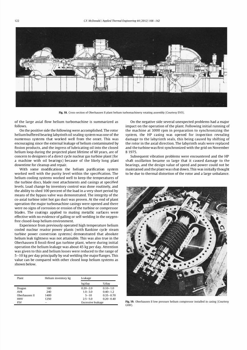
8112019 Helium Turbomachinery Operating Experience From Gas Turbine Power Plants
httpslidepdfcomreaderfullhelium-turbomachinery-operating-experience-from-gas-turbine-power-plants 1535
of the large axial 1047298ow helium turbomachine is summarized asfollows
On the positive side the following were accomplished The rotor
helium buffered bearing labyrinth oil sealing system was one of the
numerous systems that worked well from the onset This was
encouraging since the external leakage of helium contaminated by
1047297ssion products and the ingress of lubricating oil into the closed
helium loop during the projected plant lifetime of 60 years are of
concern to designers of a direct cycle nuclear gas turbine plant (for
a machine with oil bearings) because of the likely long plant
downtime for cleanup and repair
With some modi1047297cations the helium puri1047297cation system
worked well with the purity level within the speci1047297cation The
helium cooling systems worked well to keep the temperatures of
the turbine discs blade root attachments and casings at speci1047297
edlevels Load change by inventory control was done routinely and
the ability to shed 100 percent of the load in a very short period by
means of the bypass valve was demonstrated The integrity of the
co-axial turbine inlet hot gas duct was proven At the end of plant
operation the major turbomachine casings were opened and there
were no signs of corrosion or erosion of the turbine or compressor
blades The coatings applied to mating metallic surfaces were
effective with no evidence of galling or self-welding in the oxygen-
free closed-loop helium environment
Experience from previously operated high temperature helium
cooled nuclear reactor power plants (with Rankine cycle steam
turbine power conversion systems) demonstrated that absolute
helium leak tightness was not attainable This was also true in the
Oberhausen II fossil-1047297red gas turbine plant where during initial
operation the helium leakage was about 45 kg per day Attention
was given to this and helium losses were reduced to the range of
5e10 kg per day principally by seal welding the major 1047298anges This
value can be compared with other closed loop helium systems as
shown below
On the negative side several unexpected problems had a majorimpact on the operation of the plant Following initial running of
the machine at 3000 rpm in preparation to synchronizing the
system the HP casing was opened for inspection revealing
damage to the labyrinth seals this being caused by shifting of
the rotor in the axial direction The labyrinth seals were replaced
and the turbine was 1047297rst synchronized with the grid on November
8 1975
Subsequent vibration problems were encountered and the HP
shaft oscillation became so large that it caused damage to the
bearings and the design value of speed and power could not be
maintained and the plant was shut down This was initially thought
to be due to thermal distortion of the rotor and a large unbalance
Fig 18 Cross-section of Oberhausen II plant helium turbomachinery rotating assembly (Courtesy EVO)
Fig 19 Oberhausen II low pressure helium compressor installed in casing (Courtesy
GHH)
Plant Helium inventory kg Leakage
kgday day
Dragon 180 020e20 010e10
AVR 240 10e30 040e12
Oberhausen II 1400 5e10 035e070
HHV 1250 25e50 020e040
FSV e Excessive leakage
CF McDonald Applied Thermal Engineering 44 (2012) 108e142122
8112019 Helium Turbomachinery Operating Experience From Gas Turbine Power Plants
httpslidepdfcomreaderfullhelium-turbomachinery-operating-experience-from-gas-turbine-power-plants 1635
Modi1047297cations to the rotor were made and the bearings replaced
but now the HP spool design speed of 5500 rpm could not be
achieved Subsequent major design and fabrication changes were
made including decreasing the bearing span by 600 mm (24 in)
giving a shorter stiffer rotor and changing the type of bearings In
restarting the plant the design speed of the HP rotor was achieved
however the power output was only 30 MW compared with the
design value of 50 MW
Fig 20 View of Oberhausen II low pressure helium compressor spherical vessel (Courtesy GHH)
Fig 21 Cross-section of Oberhausen II high pressure rotating group (Courtesy GHH)
CF McDonald Applied Thermal Engineering 44 (2012) 108e142 123
8112019 Helium Turbomachinery Operating Experience From Gas Turbine Power Plants
httpslidepdfcomreaderfullhelium-turbomachinery-operating-experience-from-gas-turbine-power-plants 1735
To gain operational experience it was decided to continue
running the plant at the reduced power rating On February 5 1979
after nearly 11000 h of operation a rotor blade from the second
stage of the HP turbine failed causing damage in the remaining
stages but the high energy fragments were contained within the
thick machine casing Examination of the failed blade revealed the
defect as a crack caused by the forgingprocess on the semi-1047297nishedproduct To prevent such a failure occurring in the future an electric
polishing process applied to the blade surface before inspection
was implemented and improved crack detection methods
introduced
Acoustic loads in a closed-cycle gas turbine represent pressure
1047298uctuations propagating at the speed of sound through the helium
working 1047298uid Pressure 1047298uctuations of importance result from the
aerodynamic effects of high velocity helium impacting and
essentially being intermittently ldquocutrdquo by the blading in the
compressor and turbine Care must be taken in the design of the
plant to ensurethat these 1047298uctuating pressure waves do not induce
vibrations of a magnitude that could result in excitation-induced
fatigue failures in components in the circuit Critical vibrations
occur when resonance exists between the main frequency of
the propagating sound and the natural frequencies of the
components particularly ones that have large surface area to
thickness ratio
Measurements of sound spectrum were taken at four different
locations in the circuit The design level of power of 50 MW was not
achieved but at the 30 MW power output actually realized the
maximum recorded sound power level was 148 dB After plantshutdown there was no evidence of adverse effects on the major
components of noise induced excitation emanating from the axial
1047298ow turbomachinery The integrity of the turbine inlet hot gas duct
and insulation was con1047297rmed
The inability to reach rated power was attributed to shortcom-
ings in the helium turbomachine This included the compressors(s)
and turbine(s) blading failing to attain design values of ef 1047297ciencies
and the bleed helium mass 1047298ows for cooling and sealing being
signi1047297cantly greater than analytically estimated Based on data
taken from the well instrumented plant detailed analyses were
undertaken by specialists [4950] to calculate the losses in the
turbomachine to explain the power output de1047297ciency A summary
of the projected losses and various component ef 1047297ciencies is pre-
sented in a convenient form on Table 3
Fig 22 Oberhausen II high pressure rotor being installed (Courtesy GHH)
CF McDonald Applied Thermal Engineering 44 (2012) 108e142124
8112019 Helium Turbomachinery Operating Experience From Gas Turbine Power Plants
httpslidepdfcomreaderfullhelium-turbomachinery-operating-experience-from-gas-turbine-power-plants 1835
The plant operated for approximately 24000 h and was shut-
down and decommissioned in 1988 when the coke-oven gas supply
for the heater was no longer available A total plant operating time
of about 11500 h had been at the design turbine inlet temperature
of 750 C (1382 F) Turbomachinery related experience gained
from operation of this large helium gas turbine plant was extremely
valuable While many of the functions performed well from the
onset and others worked satisfactorily after modi1047297cations were
made serious unexpected problems were encountered
The achieved electrical power output of only 60 percent of the
design value was initially thought to be due to a grossly excessive
system pressure loss However when the data was carefully eval-uated it was found that 85 percent of the 20 MW power loss was
attributed to turbomachine related problems as delineated on
Table 3
To remedy this power de1047297ciency it was clear that a major re-
design of the turbomachinery would be required While replace-
ment of the gas turbine was not contemplated a study was
undertaken based on data from the plant and new technologies
that had become available since the initial design Based on the
1047297ndings a new turbomachine layout concept was suggested [43]
and a simplistic view of the rotor arrangement is shown on Fig 24
A more conventional single-shaft arrangement was proposed with
the two compressors and turbine having a rotational speed of
5400 rpm A gearbox was still retained to give a generator rota-
tional speed of 3000 rpm Based on prevailing technology at the
time the requirements for such a gearbox would have been moredemanding since the 50 MW from the turbine to the generator
would have to be transmitted through it This would necessitate
a larger system to pump 1047297lter and cool the bearing lubrication oil
To remedy the very large losses in the compressors and turbines
the number of stages would have to be increased In the case of the
compressors the use of lighter aerodynamically loaded higher
ef 1047297ciency stages with 50 percent reaction blading was
recommended
7 High temperature helium test facility (HHV)
71 Background
In the late 1960rsquos with large numbers of orders placed for 1047297rst
generation light water reactor nuclear power plants studies were
initiated for next generation power plants with higher ef 1047297ciency
potential Following the initial operational success of the 1047297rst three
small helium cooled HTR plants (ie Dragon in the UK Peach
Bottom I in the USA and AVR in Germany) studies on larger plants
based on the use of both Rankine steam cycle and helium closed
Brayton cycle power conversion systems were undertaken In the
early 1970rsquos emphasis was placed on nuclear gas turbine plant
designs with larger power output both in the USA (for the
HTGR eGT) and in Europe (for the HHT) Work in the USA was
limited to only paper studies [18] The much larger program in
Germany (with participation by Swiss companies for the turbo-
machine heat exchangers and cooling towers) included a well
planned development testing strategy to support the plant design
Fig 23 Cross-section of Oberhausen II low pressure helium turbine (Courtesy GHH)
Table 3
Oberhausen II helium turbine plant power losses
Componentcause Design
value
Measured Power loss
MW
Compressors
B Flow losses in inlet diffusers
and blades
Low pressure ef 1047297ciency 870 826 13
High pressure ef 1047297ciency 855 779 40
Turbines
B Blade gap and 1047298ow losses
High pressure ef 1047297ciency 883 823 39
B Pro1047297le losses due to Remachined
blades after having detected
damaged blades
Low pressure ef 1047297ciency 900 856 24
BSealing leakage and cooling 1047298ows
in all turbomachines Kgsec
18 75 53
B Circuit pressure losses
(Ducting Hxrsquos etc)
102 128 26
B Miscellaneous heat losses 05
Total power loss 200 MW
Notes (1) Plant designed for electrical power output of 50 MW actual power output
measured 30 MW
(2) Power de1047297ciency of20 MW based on measurements taken and then recalculated
for the rated plant output
(3) 85 of Power loss attributed to helium turbomachinery related issues
CF McDonald Applied Thermal Engineering 44 (2012) 108e142 125
8112019 Helium Turbomachinery Operating Experience From Gas Turbine Power Plants
httpslidepdfcomreaderfullhelium-turbomachinery-operating-experience-from-gas-turbine-power-plants 1935
While the reference HHT plant for eventual commercializationembodied a very large single helium gas turbine rated at 1240 MW
this was to be preceded by a nuclear demonstration plant rated at
676 MW [51] To support the design of this plant technology
generated from the following was planned 1) operational experi-
ence from the aforementioned Oberhausen II 50 MW helium gas
turbine power plant and 2) testing of components in a large high
temperature helium test facility as discussed below
72 Development facilitytesting objectives
An overall view of the HHV test facility sited in Julich in
Germany is shown on Fig 25 and since this has been reported on
previously [52] it will only be brie1047298
y covered in this section Tominimize risk and assure the performance integrity and reliability
of the nuclear demonstration plant some non-nuclear testing of
the major components especially the helium turbomachine was
deemed essential Because of the limitations of a conventional
closed-cycle helium gas turbine power plant particularly the
temperature limitations of existing fossil-1047297red and electrical
heaters a new type of test facility was foreseen
A simpli1047297ed schematic line diagram of the HHV circuit is shown
on Fig 26 The major design parameters are shown on Fig 27
together with the temperatureeentropy diagram which is conve-
nient for describing the unique relationship between the compo-
nents in the closed helium loop Starting at the lowest pressure in
Fig 24 Proposed new concept for Oberhausen II helium gas turbine rotating assembly to remedy problems encountered during operation of the 50 MWe power plant (Courtesy
EVO)
Fig 25 HHV helium turbomachinery test facility (Courtesy BBC)
CF McDonald Applied Thermal Engineering 44 (2012) 108e142126
8112019 Helium Turbomachinery Operating Experience From Gas Turbine Power Plants
httpslidepdfcomreaderfullhelium-turbomachinery-operating-experience-from-gas-turbine-power-plants 2035
the system the helium is compressed (Ae
B) its temperatureincreasing to 850 C (1562 F) before 1047298owing through the test
section (BeC) After being cooled slightly (CeD) the helium is
expanded in the turbine (DeA) down to the compressor inlet
conditions completing the loop There is no power output from the
system and without the need for an external heater the
compression heat is used to raise the helium to the maximum
system temperature in what can be described as a very large heat
pump The required compressor power is 90 MW and to supple-
ment the 45 MW generated by expansion in the turbine external
power is provided by a 45 MW synchronous electrical motor A
cooler is required to remove the compression heat that is contin-
uously put into the closed helium loop and this is done by bleeding
about 5 percent of the mass 1047298ow after the compressor cooling it
and re-introducing it into the circuit close to the turbine inlet In
addition to testing the turbomachine the facility was engineered
with a test section to accommodate other small components (eg
hot gas 1047298ow regulation valves bypass valves insulation con1047297gu-
rations and types of hot gas duct construction) With the highest
temperature in the system being at the compressor exit the facility
had the capability to provide helium at a temperature up to 1000 C
(1832 F) for short periods at the entrance to the test section
While a higher ef 1047297ciency of the planned nuclear demonstration
plant could be projected with a turbine inlet temperature in the
range 950e1000 C (1742e1832 F) this would have necessitated
either turbine blade cooling or the use of a high temperature alloy
such as Titanium Zirconium Molybdenum (TZM) At the time it was
felt that using either of these would have added cost and risk to theprojectso a conventionalnickel-basedalloyas usedin industrialgas
turbines was selected for the 850 C design value of turbine inlet
temperature this negating the needfor actual internal bladecooling
However a complex internal coolingsystemwas neededto keep the
Fig 26 Cycle diagram of HHV test loop (Courtesy BBC)
Fig 27 Salient features of HHV helium turbomachinery (Courtesy BBC)
CF McDonald Applied Thermal Engineering 44 (2012) 108e142 127
8112019 Helium Turbomachinery Operating Experience From Gas Turbine Power Plants
httpslidepdfcomreaderfullhelium-turbomachinery-operating-experience-from-gas-turbine-power-plants 2135
turbine discs and blade root attachments and casings to acceptable
temperatures commensurate with prescribed stress limitations for
thelife of theturbomachine In addition a heliumsupplywas needed
to provide a buffering system for the various labyrinth seals
In a direct Brayton cycle nuclear gas turbine the turbomachine is
installed in the reactor circuit and via the hot gas duct heated
helium is transported directly from the reactor core to the turbine
From the safety licensing and reliability standpoints there are
various seals that must perform perfectly A helium buffered
labyrinth seal system is necessary to prevent bearing lubricating oil
ingress to the closed helium loop Since in the proposed HHT plant
design the drive shaft from the turbine to the generator penetrates
the reactor primary system pressure boundary two shaft seals are
needed one a dynamic seal when the shaft is rotating and a static
seal when the turbomachine is not operating Testing of these seals
in a size and operating conditions representative of the planned
commercial power plant was considered to be a licensing must
The mechanical integrity of the rotating assembly must be
assured there being two major factors necessitating testing the
machine at full speed and temperature and at high pressure
namely 1) loading the blading under representative centrifugal and
gas bending stresses and 2) to monitor vibration and con1047297rm rotor
dynamic stability For the design of the planned commercial planta knowledge of the acoustic emissions by the turbomachine and
propagation in the closed circuit was required Data from the HHV
facility would enable dynamic responses of the major components
(especially the insulation) resulting from excitation by the sound
1047297eld to be calculated
The circuit was instrumented to gather data on the effectiveness
of the hot gas duct insulation thermal expansion devices hot gas
valves helium puri1047297cation system instrumentation and the
adequacy of the coatings applied to mating metallic surfaces to
prevent galling or self-welding Details of the turbomachinery and
the experience gained from the operation of the HHV facility are
covered in the following sections
73 Helium turbomachine
A cross-section of the turbomachine is shown on Fig 28 The
single-shaft rotating assembly consists of 8 compressor stagesand 2
turbine stages and had a weighton the order of 66 tons(60000 kg)
The hub inner and outer diameters are 16 m (525 ft) and 18 m
(59 ft) respectively the blading axial length being 23 m (75 ft)The
span between the oil bearings being 57 m (187 ft) The physical
dimensions of the turbogroup shown on Fig 28 correspond to
a machine rated at about 300 MW The oil bearings operate in
a helium environment and the diameters of the labyrinths and
1047298oating ring shaft seals to prevent oil ingress are representative of
a machine rated at about 600 MW The complexity of the machine
design especially the rotor cooling system sealing system very
large casing and heat insulation have been reported previously
[53e55]
To ensure high structural integrity the rotor was constructed by
welding together the forged compressor and turbine discs The
compressor had 8 stages each having 56 rotor and 72 stator blades
The turbine had 2 stages each having 90 stator and 84 rotor blades
An appreciation for the large size of the rotating assembly can be
seen from Fig 29 The rotor blades have 1047297r-tree attachments
embodying cooling channels Since the temperature and pressure
do not vary very much along the blading in the 1047298ow direction an
intricate rotor and stator cooling system was required Channels in
both the blade roots and the spacers between adjacent blade rows
form an axial geometry for the passage of a cooling helium supplyto keep the temperature of the multiple discs below 400 C
(752 F) The design of this was a challenge since the rotor and
stator blade attachments of both the 8 stage compressor and 2
stage turbine had to be cooled Excessive leakage had to be avoided
since this would have prevented the speci1047297ed compressor
discharge temperature (ie the maximum temperature in the
circuit) from being reached
In the 1970rsquos and early 1980rsquos signi1047297cant studies were carried
out on large helium gas turbines by various organizations [56e62]
In this era there was general agreement that testing of the turbo-
machine in one form or another in non-nuclear facilities be
undertaken to resolve areas of high risk (eg seals bearings cooling
systems rotor dynamic stability compressor surge margin
dynamic response rotor burst protection etc) before installationand operation of a large gas turbine in a nuclear environment
This low risk engineering philosophy which prevailed at the time
in both Germany and the USA emphasized the importance of
Fig 28 Cross-section of HHV helium turbomachinery (Courtesy BBC)
CF McDonald Applied Thermal Engineering 44 (2012) 108e142128
8112019 Helium Turbomachinery Operating Experience From Gas Turbine Power Plants
httpslidepdfcomreaderfullhelium-turbomachinery-operating-experience-from-gas-turbine-power-plants 2235
the HHV test facility as being an important step towards the
eventual deployment of a high ef 1047297ciency nuclear gas turbine power
plant
74 Initial operation of the HHV facility
During commissioning of the plant in 1979 oil ingress into the
helium circuit from the seal system occurred twiceThe 1047297rst ingressof oil between 600 and 1200 kg (1322 and 2644 lb) was due to
a serious operatorerror and the absence of an isolation valve in the
system The oil in the circuit was partly coked and formed thick
deposits on the cold and hot surfaces of the turbomachinery and in
other parts of the closed loop including saturation of the 1047297brous
insulation The fouled metallic surfaces were cleaned mechanically
and chemically by cracking with the addition of hydrogen and
additives The second oil ingress was due to a mechanical defect in
the labyrinth seal system The quantity of oil introduced was small
and it was removed bycracking at a temperature of 600 C (1112 F)
and with the use of additives To obviate further oil ingress inci-
dents the labyrinth seal system was redesigned The buffer and
cooling helium system piping layout was modi1047297ed to positively
eliminate oil ingress due to improper valve operation and toprevent further human error
Pressure and leak detection tests of the HHV test facility at
ambient temperature showed good leak tightness for the turbo-
machine 1047298anged joints and of the main and auxiliary circuits
However at the operating temperature of 850 C (1562 F) large
helium leaks were detected The major 1047298anges had been provi-
sioned with lip seals and the 1047297rst step was to weld the closures A
large leak persisted at the front 1047298ange of the turbomachine This
was diagnosed as being caused by a non-uniform temperature
distribution during initial operation resulting in thermal stresses
creating local gaps This problem was overcome by redesign of the
cooling system with improved gas 1047298ow distribution and 1047298ow rates
to give a more uniform temperature gradient The leakage from the
system was reduced to on the order of 020e
040 percent of the
helium inventory per day this being of the same magnitude as in
other closed helium circuits as discussed in Section 65
It should be mentioned that in addition to the HHV experience
bearing oil ingress into the circuits and system loss of the working
1047298uid in other closed-cycle gas turbine plants have occurred In all of
these fossil-1047297red facilities 1047297xing leaks and removal of oil deposits
were undertaken based on conventional hands-on approaches but
nevertheless such operations were time-consuming However if a new and previously untested helium turbomachine operating in
a direct cycle nuclear gas turbine plant experienced an oil ingress
the rami1047297cations would be severe The likely use of remote
handling equipment to remove the turbomachine from the vessel
machine disassembly (including breaking the welded 1047298ange joints)
and removal of oil from the radioactively contaminated turbo-
machine blade surfaces and system insulation would be time
consuming A diagnosis of the failure would be required before
a spare turbomachine could be installed and this plant downtime
could adversely affect plant availability
75 Experience gained
Afterresolutionof the aforementionedproblems the HHVfacilitywas started in the Spring of 1981 and in an orderly manner was
brought up to full pressure and a temperature of 850 C (1562 F)
During a 60 h run the functioning of the instrumentation control
and safety systems were veri1047297ed During these tests the ability to
stop the turbomachine from full operating conditions to standstill
within 90 s was demonstrated After system depressurization the
plant was then run up again to full operating conditions with no
problems experienced The HHV facility was successfully run for
about 1100 h of which theturbomachineryoperated forabout325 h
at a temperature of 850 C The test facility was extensively instru-
mented and interpretation and analysis of the data recorded gave
positive and favorable results in the following areas
The complex rotor cooling system which was engineered to
assure that the temperature of the discs be kept below 400
C
Fig 29 HHV helium turbomachine rotating assembly (size equivalent to a 300 MWe machine) being installed in a pressure vessel (Courtesy BBC)
CF McDonald Applied Thermal Engineering 44 (2012) 108e142 129
8112019 Helium Turbomachinery Operating Experience From Gas Turbine Power Plants
httpslidepdfcomreaderfullhelium-turbomachinery-operating-experience-from-gas-turbine-power-plants 2335
(752 F) was demonstrated to be effective The measured rotor
coolant 1047298ows (about 3 percent of the mass1047298ow passing through the
machine) were slightly larger than had been estimated and this
resulted in measured turbine disc temperatures lower than pre-
dicted [55]
The dynamic labyrinth shaft seal functioned well at the full
temperature and pressure conditions and met the requirement of
zero oil ingress into the helium circuit The measured rotor oscil-
lation did not have any adverse effect on the shaft sealing system
The static rotor seal (for shutdown conditions) functioned without
any problems
The compressor and turbine blading hadef 1047297ciencies higher than
predicted The structural integrity of the rotor proved to be sound
when operating at 3000 rpm under the maximum temperature and
pressure conditions The stiff rotor shaft had only slight unbalance
and thermal distortion and measured oscillations were in the range
typical of large steam turbines
Sound power spectrum measurements were taken in four
different locations in the circuit These were taken to determine the
spectrum and intensity of the sound generated and propagated by
the turbomachinery and the resultant vibration of internal
components The maximum sound power level in the helium
circuit was160 dB Numerous strain gages were placedin the circuitto determine the in1047298uence of the sound 1047297eld particularly on the
fatigue strength of the turbine inlet hot gas duct In later examining
the internal components there was no evidence of excessive
vibration of the components especially the ducting and the insu-
lation Based on the measurements and calculations it was
concluded that the fatigue strength limit of the components would
not be exceeded during the designed life of the planned commer-
cial nuclear gas turbine power plant
In a direct cycle nuclear gas turbine the hot gas duct used to
transport the helium from the reactor core to the turbineis a critical
component The hot gas duct in the HHV facility performed well
mechanically and con1047297rmed the adequacy of the thermal expan-
sion devices From the thermal standpoint the 1047297ber insulation
performed better than the metallic type
After dismantling the HHV facility there were no signs of
corrosion or erosion of the turbine or compressor blading While
the total number of hours operated was limited the coatings
applied to mating metallic surfaces to prevent galling and frictional
welding in the oxidation-free helium worked well
The helium buffer and cooling system worked well However
problems remained with the puri1047297cation of the buffer helium The
oil separation system consisting of a cyclone separator and a wire
mesh and a down stream 1047297ber 1047297lter needed further improvement
In late 1981 a decision was made to cancel the HHT project and
the HHV facility was shutdown The design and operational expe-
rience gained from the running of this facility would have been
extremely valuable had the nuclear gas turbine power plant
concept moved towards becoming a reality The identi1047297cation of
somewhat inevitable problems to be expected in such a complexturbomachine and their resolution were undertaken in a timely
and cost effective manner in the non-nuclear HHV facility This
should be noted for future nuclear gas turbine endeavors since
remedying such unexpected problems in the case of a new and
untested large helium turbomachine being operated for the 1047297rst
time using nuclear heat could result in very complex repair
Fig 30 Speci1047297
c speed-speci1047297
c diameter array for gas circulators in various gas-cooled nuclear plants
CF McDonald Applied Thermal Engineering 44 (2012) 108e142130
8112019 Helium Turbomachinery Operating Experience From Gas Turbine Power Plants
httpslidepdfcomreaderfullhelium-turbomachinery-operating-experience-from-gas-turbine-power-plants 2435
activities and extended plant downtime and indeed adding risk to
the overall success of the nuclear gas turbine concept
8 Circulators used in gas-cooled reactor plants
Circulators of different types will be needed in future helium
cooled nuclear plants these including the following 1) primary
loop circulator for possible next generation steam cycle power andcogeneration plants 2) for future indirect cycle gas turbine plants
3) shut down cooling circulators forall HTRand VHTR plants and 4)
for various circulators needed in future VHTR high temperature
process heat plant concepts The technology status of operated
helium circulators is brie1047298y addressed as follows
81 Background
It would be remiss not to mention experience gained in the past
with gas circulators and while not gas turbines they are rotating
machines that operate in the primary loop of a helium cooled
reactor With electric motor drives there are basically two types of
compressor rotor con1047297gurations namely radial and axial 1047298ow
machinesIn a single stage form the centrifugal impeller is used for high
stage pressure rise and low volume 1047298ow duties whereas the axial
type covers low pressure rise per stage and high volume 1047298ow The
selection of impeller type is very much related to the working
media type of bearings drive type rotor dynamic characteristics
and installation envelope A wide range of circulators have operated
and a well established technology base exists for both types [63] A
useful portrayal of compressor data in the form of quasi- non-
dimensional parameters (after Balje [64]) showing approximate
boundaries for operation of high ef 1047297ciency axial and radial types is
shown on Fig 30 (from Ref [65])
Both high speed axial and lower speed radial 1047298ow types are
amenable to gas oil and magnetic bearings From the onset of
modularHTR plant studies theuse of active magnetic bearings[6667]offered a solution to eliminate lubricating oil into the reactor circuit
and this tribology technology is attractive for use in submerged
rotating machinery in the next generation of HTR plants [68]
While now dated an appreciation of the main design features of
typical electric motor-driven helium circulators have been reported
previously namely an axial 1047298ow main circulator for a modular
steam cycle HTR plant [69] and a representative radial 1047298ow shut-
down cooling circulator [70]
The operating experience gained from three particular circula-
tors is brie1047298y included below because of their relevance to the
design of helium turbomachinery in future HTR plant variants
82 Axial 1047298ow helium circulator
Since all of the aforementioned predominantly European
helium gas turbines used axial 1047298ow turbomachinery it is of interest
to mention a helium axial 1047298ow circulator that operated in the USA
and to brie1047298y discuss its design parameters and features The
330 MW Fort St Vrain HTGR featured a Rankine cycle power
conversion system Four steam turbine driven helium circulators
were used to transport heat from the reactor core to the steam
generators The complete circulator assemblies were installed
vertically in the prestressed concrete reactor vessel [71e73]
A cross-section of the circulator is shown on Fig 31 with thecompressor rotor and stator visible on the left hand end of the
machine Based on early 1960rsquos technology a decision was made to
use water lubricated bearings and from the overall plant reliability
and availability standpoints this later proved to be a bad choice
Within the vertical circulator assembly there were four 1047298uid
systems namely the helium reactor coolant water lubricant in the
bearings steam for the turbine drive and high pressure water for
the auxiliary Pelton wheel drive During plant transients the pres-
sures and temperatures of these four 1047298uids oscillated considerably
and the response of the control and seal systems proved to be
inadequate and resulted in considerable water ingress from the
bearing cartridge into the reactor helium circuit The considerable
clean up time needed following repeated occurrences of this event
resulted in long periods of plant downtime and this had an adverseeffect on plant availability This together with other technical
Fig 31 Cross section of FSV helium circulator (Courtesy general Atomics)
CF McDonald Applied Thermal Engineering 44 (2012) 108e142 131
8112019 Helium Turbomachinery Operating Experience From Gas Turbine Power Plants
httpslidepdfcomreaderfullhelium-turbomachinery-operating-experience-from-gas-turbine-power-plants 2535
dif 1047297culties eventually contributed to the plant being prematurely
decommissioned
On the positive side in the context of this paper the helium
circulators operated for over 250000 h and exhibited excellent
helium compressor performance good mechanical integrity and
vibration-free operation The rotating assembly showing the axial
1047298ow compressor and steam turbine rotors together with a view of
the machine assembly are given on Fig 32 The helium compressor
consists of a single stage axial rotor followed by an exit guide vane
The machine was designed for axial helium 1047298ow entering and
leaving the stage and this can be seen from the velocity triangles
shown on Fig 33 which also includes the de1047297nition of the various
aerodynamic parameters Major design parameters and features of
this helium circulator are given on Table 4 Related to an earlier
discussion on the degree of reaction for axial 1047298ow compressors the
value for this conventional single stage circulator is 78 percent All
of the major aerothermal and structural loading criteria were
within established boundaries for an axial compressor having high
ef 1047297ciency and a good surge margin
The compressor gas 1047298ow path and blading geometries were
established based on prevailing industrial gas turbine and aero-
engine design practice A low Mach number (025) a high Reynolds
number (3 106) together with a modest stage loading (ie
a temperature rise coef 1047297cient of 044) and an acceptable value of
diffusion factor (042) were some of the factors that contributed to
a helium circulator that had a high ef 1047297ciency and a good pressure
rise- 1047298ow characteristic The large rotor blade chord and thick blade
section for this single stage circulator are necessary to accommo-
date the high bending stress characteristic of operation in a high
pressure environment The solidity and blade camber were opti-
mized for minimum losses
There were essentially two reasons for including this single-
stage axial 1047298ow compressor that operated in a helium cooled
reactor although its overall con1047297guration can be regarded as a 1047297rst
and last of a kind A rotor blade from this circulator as shown onFig 34 was based on a NASA 65 series airfoil which at the time
were one of the best performing cascades for such low Mach
number and high Reynolds number applications Interestingly it
has almost the same blade height aspect ratio and solidity as would
be used in the 1047297rst stage of an LP compressor in a helium turbo-
machine rated on the order of 250 MW
The second point of interest is that the helium mass 1047298ow rate
through the single stage axial compressor (rated at 4 MWe) is
110 kgs compared with 85 kgs through the multistage compressor
in the 50 MWe Oberhausen II helium gas turbine plant However
the volumetric 1047298ow through the Oberhausen axial compressor is
higher than that through the circulator by a factor of 16 this again
pointing out that the Oberhausen II plant was designed for high
volumetric 1047298ow to simulate the much larger size of turboma-chinery that was planned at the time in Germany for use in future
projected nuclear gas turbine power plants
83 High temperature helium circulator
For future helium turbomachines embodying active magnetic
bearings a challenge in their design relates to accommodating
elevated levels of temperature in the vicinity of the electronic
components In this regard it is of interest to note that a small very
high temperature helium axial 1047298ow circulator rated at 20 kW (as
shown on Fig 35) operated for more than 15000 h in an insulation
test facility in Germany more than two decades ago [74] The
signi1047297cance of this machine is that it operated with magnetic
bearings in a high temperature helium test loop with a circulatorgas inlet temperature of 950 C (1742 F) This necessitated the use
of ceramic insulation to ensure that the temperature in the vicinity
of the magnetic bearing electronics did not exceed a temperature of
about 150 C (300 F)
This machine although a very small axial 1047298ow helium blower
performed well and has been brie1047298y mentioned here since it
represents a point of reference for future helium rotating machines
capable operating with magnetic bearings in a very high temper-
ature helium environment
84 Radial 1047298ow AGR nuclear plant gas circulators
The electric motor-driven carbon dioxide circulators rated at
about 5 MW with a total runningtimein excess of 18 million hours
Fig 32 Fort St Vrain HTGR plant helium circulator (Courtesy General Atomics) (a)
Axial 1047298ow helium compressor and steam turbine rotating assembly (b) 4 MW helium
circulator assembly
CF McDonald Applied Thermal Engineering 44 (2012) 108e142132
8112019 Helium Turbomachinery Operating Experience From Gas Turbine Power Plants
httpslidepdfcomreaderfullhelium-turbomachinery-operating-experience-from-gas-turbine-power-plants 2635
in AGR nuclear power plants in the UK have demonstrated veryhigh availability [7576] To a high degree this can be attributed to
the fact that the machines were conservatively designed and proof
tested in a non-nuclear facility at full temperature and power
under conditions that simulated all of the nuclear plant operating
modes The test facility shown on Fig 36 served two functions 1)
design veri1047297cation of the prototype machine and 2) test of all new
and refurbished machines before they were installed in nuclear
plants Engineers currently involved in the design and development
of helium turbomachinery could bene1047297t from this sound testing
protocol to minimize risk in the deployment of helium rotating
machinery in future HTRVHTR plant variants
9 Helium turbomachinery development and testing
91 On-going development activities
The various helium turbomachines discussed in previous
sections operated over a span of about two decades starting in the
early 1960s From about 1990 activities in the nuclear gas turbine
1047297eld have been focused mainly on the design of modular GTeHTR
plant concepts In support of these plant studies many signi1047297cant
helium turbomachine design advancements have been made and
attention given to what development testing would be needed In
the last decade or so limited sub-component development has
been undertaken for helium turbomachines in the 250e300 MWe
size and these are brie1047298y summarized below
In a joint USARussia effort development in support of the
GTe
MHR turbomachine has been undertaken including testing in
the following areas magnetic bearings seals and rotor dynamicsfor the vertical intercooled helium turbomachine rated at 286 MWe
[77e80]
In Japan development activities have been in progress for
several years in support of the 274 MWe helium turbomachine for
the GTeHTR300 plant concept [2581] A detailed discussion on
the aerodynamic design of the axial 1047298ow helium compressor for
this turbomachine has been published in the open literature [82]
While the design methodology used for axial compressor design in
air-breathing industrial and aircraft gas turbines is generally
applicable for a multi-stage helium compressor a decision was
made by JAEA to test a small scale compressor in a helium facility
because of the inherent and unique gas 1047298ow path and type of
blading associated with operation in a high pressure helium
environment The major goal of the test was to validate the designof the 20 stage helium axial 1047298ow compressor for the GTeHTR300
plant
An axial 1047298ow compressor in a closed-cycle helium gas turbine is
characterized by the following 1) a large number stages 2) small
blade heights 3) high hub-to-tip ratio 4) a long annulus with
small taper that tends to deteriorate aerodynamic performance as
a result of end-wall boundary layer length and secondary 1047298ow 5)
low Mach number 6) high Reynolds number and 7) blade tip
clearances that are controlled by the gap necessary in the magnetic
journal and catcher bearings While (as covered in earlier sections)
helium gas turbines have operated there is limited data in the
open literature on the performance of multi-stage axial 1047298ow
compressors operating in a high pressure closed-loop helium
environment
Fig 33 Velocity triangles for axial compressor stage
CF McDonald Applied Thermal Engineering 44 (2012) 108e142 133
8112019 Helium Turbomachinery Operating Experience From Gas Turbine Power Plants
httpslidepdfcomreaderfullhelium-turbomachinery-operating-experience-from-gas-turbine-power-plants 2735
A 13rd scale 4 stage compressor was designed to simulate the
stage interaction the boundary layer growth and repeated stage
1047298ow in an actual compressor The 1047297rst four stages were designed to
be geometrically similar to the corresponding stages in the
GTe
HTR300 compressor Details of the model compressor havebeen discussed previously [81] and are summarized on Table 5
from [83]
A cross-section of the compressor test model is shown on Fig 37
A view of the 4 stage compressor rotor installed in the lower casing
is shown on Fig 38 The test facility (Fig 39) is a closed helium loop
consisting of the compressor model cooler pressure adjustment
valve and a 1047298ow measurement instrument The compressor is
driven by a 3650 kW electrical motor via a step-up gear The rota-
tional speed of 10800 rpm (three times that of the compressor in
the GTeHTR300 plant) was selected to match blade speed and
Mach number in the full size compressor
Details of the planned aerodynamic performance objectives of
the 13rd scale helium compressor test have been published
previously [84] Extensivetesting of the subscale model compressorprovided data to validate the performance of the full size
compressor for the GTeHTR300 power plant The test data and
test-calibrated CFD analyses gave added insight into the effect of
factors that impact performance including blade surface roughness
and Reynolds number
Based on advanced aerodynamic methodology and experi-
mental validation [82] there is now a sound basis for added
con1047297dence that the design goals of 90 percent polytropic ef 1047297ciency
and a design point surge margin of 20 percent are realizable in
a large multistage axial 1047298ow compressor for a future nuclear gas
turbine plant
In a similar manner a design of a one third size single stage
helium axial 1047298ow turbine has been undertaken and a cross
section of the machine is shown on Fig 40 (from Ref [81]) This
Table 4
Major features of axial 1047298ow helium circulator
Helium 1047298ow rate kgsec 110
Inlet temperature C 394
Inlet pressure MPa 473
Pressure rise KPa 965
Volumetric 1047298ow m3sec 32
Compressor type Single stage axial
Compressor drive Steam turbine
Bearing type Water lubricated
Rotational speed rpm 9550
Power MW 40
Rotor tip diameter mm 688
Rotor tip speed msec 344
Number of rotor blades 31
Number of stator blades 33
Blade height mm 114
Hub-to-tip ratio 067
Axial velocity msec 157
Flow coef 1047297cient 055
Temperature rise coef 1047297cient 044
Degree of reaction 078
Mean rotor solidity 128
Rotor aspect ratio 155
Rotor Mach number 025
Rotor diffusion factor 042
Rotor Reynolds number 3106
Speci1047297c speed 335
Speci1047297c diameter 066
Blade root thickness 15
Airfoil type NASA 65
Rotor blade chord mm 94e64
Stator blade chord mm 79
Rotor centrifugal stress MPa 125
Rotor bending stress MPa 30
Circulator(s) operating Hours gt250000
Fig 34 Rotor blade from single stage axial 1047298ow helium circulator (Courtesy General
Atomics)
Fig 35 20 kW axial 1047298ow helium circulator with magnetic bearings operated in 1985 in
an insulation test loop with a gas inlet temperature on 950
C (Courtesy BBC)
CF McDonald Applied Thermal Engineering 44 (2012) 108e142134
8112019 Helium Turbomachinery Operating Experience From Gas Turbine Power Plants
httpslidepdfcomreaderfullhelium-turbomachinery-operating-experience-from-gas-turbine-power-plants 2835
single stage scale model turbine for validity of the full size turbine
has been built and plans made to test the aerodynamic
performance
92 Nuclear gas turbine helium turbomachine testing
In planning for the 1047297rst nuclear gas turbine plant projected to
enter service perhaps in the third decade of the 21st century
a major decision has to be made as to what extent the large helium
turbomachine should be tested prior to operation on nuclear heat
Issues essentially include cost impact on schedule but the over-
riding one is risk Certainly turbomachine component testing will
be undertaken including the compressor (as discussed in the
previous section) and turbine performance seals cooling systems
hot gas valves thermal expansion devices high temperature
insulation rotor fragment containment diagnostic systems
instrumentation helium puri1047297cation system and other areas to
satisfy safety licensing reliability and availability concerns The
major point is really whether a full size or scaled-down turbo-machine be tested early in the project in a non-nuclear facility
To obviate the need for pre-nuclear testing of a large helium
turbomachine a view expressed by some is that advantage can be
taken of formidable technology bases that exist today for large
industrial gas turbines and high performance aeroengines On the
other hand it is the view of some including the author that very
complex power conversion system components especially those
subjected to severe thermal transients donrsquot always perform
exactly as predicted by analysts and designers even using sophis-
ticated computer codes This was exempli1047297ed in the case of the
turbomachine in the aforementioned Oberhausen II helium gas
turbine plant
The need for a helium turbomachine test facility goes beyond
just veri1047297
cation of the prototype machine Each newgas turbine for
commercial modular nuclear reactor plants would have to be proof
tested and validated before being transported to the reactor site
Similarly turbomachines that would be periodically removed from
the plant at say 7 year intervals during the plant operating life of 60
years for scheduled maintenance refurbishment repair or updat-ing would be again proof tested in the facility before re-entering
service
The direction that turbomachine development and testing will
take place for future helium gas turbines needs to be addressed by
the various organizations involved
Fig 36 AGR circulator test facility In the UK (Courtesy Howden)
Table 5
Major design parametersfeatures of model GTeHTR300 axial 1047298ow helium
compressor (Courtesy JAERI)
Scale of GTeHTR300 compressor 13
Helium mass 1047298ow rate (kgsec) 122
Helium volumetric 1047298ow rate (mV s) 87
Inlet temperature C 30
Inlet pressure MPa 0883Compressor pressure ratio at design point 1156
Number of stages 4
Rotational speed rpm 10800
Drive motor power kW 3650
Hub diameter mm 500
Rotor tip diameter (1st4th stage mm) 568566
Hub-to-tip ratio (1st stage) 088
Rotor tip speed (1st stage msec) 321
Number of rotorstator blades (1st stage) 7294
Rotorstator blade height (1st stage mm) 34337
Rotor stator blade c hor d l eng th (1st stage mm) 2620
Rotorstator solidity (1st stage) 119120
Rotorstator aspect ratio (1st stage) 1317
Flow coef 1047297cient 051
Stage loading factor 031
Reynolds number at design point 76 l05
CF McDonald Applied Thermal Engineering 44 (2012) 108e142 135
8112019 Helium Turbomachinery Operating Experience From Gas Turbine Power Plants
httpslidepdfcomreaderfullhelium-turbomachinery-operating-experience-from-gas-turbine-power-plants 2935
10 Helium turbomachinery lessons learned
101 Oberhausen II gas turbine and HHV test facility
It is understandable that 1047297rst-of-a-kind complex turboma-
chinery operating with an inert low molecular weight gas such as
helium will experience unique and unexpected problems In the
operation of the two pioneering large helium turbomachines in
Germany there were many positive1047297ndings which could only have
been achieved by development testing Equally important some
negative situations were identi1047297ed many of which were remedied
In the case of the Oberhausen II helium gas turbine plant some of
the very serious problems encountered were not resolved Inves-
tigations were undertaken to rationalize the problems associated
with the large power de1047297ciency and a data base established to
ensure that the various anomalies identi1047297ed would not occur in
future large helium turbomachines
The experience gained from the operation of the Oberhausen II
helium gas turbine power plant and the HHV test facility have been
discussedin thetextand arepresentedin a summaryformon Table6
Fig 37 Cross-section of 13rd scale helium compressor test model (Courtesy JAEA)
Fig 38 Four stage helium compressor rotor assembly installed in lower casing (Courtesy JAEA)
CF McDonald Applied Thermal Engineering 44 (2012) 108e142136
8112019 Helium Turbomachinery Operating Experience From Gas Turbine Power Plants
httpslidepdfcomreaderfullhelium-turbomachinery-operating-experience-from-gas-turbine-power-plants 3035
102 Impact of 1047297ndings on future helium gas turbine
The long slender rotorcharacteristic of closed-cycle gas turbines
has resulted in shaft dynamic instability which in some cases has
resulted in blade vibration and failure and bearing damage This
remains perhaps the major concern in the design of large
(250e
300 MW) helium turbomachines for future nuclear gas
turbine plants With pressure ratios in the range of about 2e3 in
a helium system a combination of splitting the compressor (to
facilitate intercooling) and having a large number of compressor
and turbine stages results in a long and 1047298exible rotating assembly
andthis is exempli1047297ed by the rotorassembly shown on Fig13 With
multiple bearings (either oil lubricated or magnetic) the rotor
would likely pass through multiple bending critical speeds before
Fig 39 Helium compressor test facility (Courtesy JAEA)
Fig 40 Cross-section of single stage helium turbine test model (Courtesy JAEA)
CF McDonald Applied Thermal Engineering 44 (2012) 108e142 137
8112019 Helium Turbomachinery Operating Experience From Gas Turbine Power Plants
httpslidepdfcomreaderfullhelium-turbomachinery-operating-experience-from-gas-turbine-power-plants 3135
reaching the design speed While very sophisticated computer
codes will be used in the detailed rotor dynamic analyses the real
con1047297rmation of having rotor oscillations within prescribed limits
(to avoid blade bearing and seal damage) will come from actual
testingA point to be made here is that in operated fossil-1047297red closed-
cycle gas turbine plants it was possible to remedy problems asso-
ciated with rotor vibrations and blade failures in a conventional
manner In fact in some situations the casings were opened several
times and modi1047297cations made to facilitate bearing and seal
replacement and rotor re-blading and balancing
An accurate assessment of pressure losses must be made
particularly those associated with the helium entering and leaving
the turbomachine bladed sections Minimizing the system pressure
loss is important since it directly impacts the all important quotient
of turbine expansion ratio to compressor pressure ratio and power
and plant ef 1047297ciency
Based on the operating experience from the 20 or so fossil-1047297red
closed-cycle gas turbine plants using air as the working1047298
uid it was
recognized that future very high pressure helium gas turbines
would pose problems regarding the various seals in the turbo-
machine and obtaining a zero leakage system with such a low
molecular weight gas would be dif 1047297cult and this is discussed
below
When the Oberhausen II gas turbine plant and the HHV facility
operated over 30 years ago oil lubricated bearings were used to
support the heavy rotor assemblies and helium buffered labyrinth
seals were used to prevent oil ingressinto the heliumworking1047298uid
Initial dif 1047297culties encountered in both plants were overcome by
changes made to the seal geometries and for the operating lives of
the helium turbomachines no further oil ingress events were
experienced Twoseals were required where the turbine drive shaft
penetrated the turbomachine casing namely 1) a dynamic laby-
rinth seal and 2) a static seal for shutdown conditions In both
plants these seals functioned without any problems
Labyrinth seals were also required within the helium turbo-
machines to pass the correct helium bleed 1047298ow from the
compressor discharge for cooling of the turbine discs blade root
attachments and casings The fact that the very complex rotor
cooling system in the large helium turbomachine in the HHV test
facility operated well for the test duration of about 350 h with
a turbine inlet temperature of 850 C was encouragingIn the case of the Oberhausen II gas turbine plant analysis of the
test data revealed that the labyrinth seal leakage and excessive
cooling 1047298ows were on the order of four times the design value A
possible reason for this was that damage done to the labyrinth
seals caused excessive clearances when periods of excessive rotor
oscillation and vibration occurred during early operation of the
machine
Clearly 1047298uid dynamic and thermal management of the cooling
system and 1047298ow through the various labyrinth seals will require
extensive analysis design and development testing before the
turbomachine is operated on nuclear heat for the 1047297rst time
In future heliumgas turbine designs (with turbine inlet tempera-
tureslikelyontheorderof950C)the1047298owpathgeometriesofhelium
bledfromthecompressornecessarytocoolpartsoftheturbomachinewillbemorecomplexthanthosetestedto-dateInadditiontoproviding
acooling1047298owtotheturbinebladesanddiscsbladerootattachmentsand
casingsheliummustbetransportedtotheseveralmagneticbearingsto
ensure thatthe temperatureof theirelectronic components doesnot
exceedabout150C
The importance of the points made above is evidenced when
examining the data on Table 3 where a combination of excessive
pressure losses and high bleed 1047298ows contributed to about 40
percent of the power de1047297ciency in the Oberhausen II helium
turbine plant
Retaining overall system leak tightnessin closed heliumsystems
operating at high pressure and temperature has been elusive
including experience from the Fort St Vrain HTGR plant as dis-
cussed in Section 65 New approaches in the design of the plethoraof mechanical joints must be identi1047297ed Experience to-date has
shown that having welded seals on 1047298anges while minimizing
system leakage did not eliminate it
The importance of lessons learned from the operation of the
Oberhausen II helium turbine power plant and the HHV test facility
have primarily been discussed in the context of helium turbo-
machines currently being designed in the 250e300 MWe power
range However the established test data bases could also be
applied to the possible emergence in the future of two helium
cooled reactor concepts namely 1) an advanced VHTR combined
cycle plant concept embodying a smaller helium gas turbine in the
power range of 50e80 MWe [22] and 2) the use of a direct cycle
helium gas turbine PCS in a recently proposed all ceramic fast
nuclear reactor concept [85]
Table 6
Experience gained from Oberhausen II and HHV facility
Oberhausen II 50 MW helium gas turbine power plant
Positive results
e Rotating and static seals worked well
e No ingress of bearing lubricant oil into closed circuit
e Load change by inventory control worked well
e 100 Percent load shed by means of bypass valves demonstrated
e Turbine disc and blade root cooling system con1047297rmed
e Coatings on mating surfaces prevented galling and self-welding
e After 24000 h of operation no evidence of corrosion or erosion
e Coaxial turbine hot gas inlet duct insulation and integrity con1047297rmed
e Monitoring of complete power conversion system for steady state
and transient operation undertaken
Problem areas
e Serious power output de1047297ciency (30 MW compared with design
value of 50 MW)
e Compressor(s) and turbine(s) ef 1047297ciencies several points below predicted
e Higher than estimated system pressure loss
e Rotor dynamic instability and blade vibration
e Bearings damaged and had to be replaced
e Blade failure caused extensive damage in HP turbine but retained
in casing
e Very excessive sealing and cooling 1047298ow rates
e Absolute leak tightness not attainable even with welded 1047298ange lips
HHV test facility
Positive resultse Use of heat pump approach facilitated helium temperature capability
to 1000 C
e Large oompressorturbine rotor system operated at 3000 rpm Complex
turbine disc and blade root cooling system veri1047297ed
e Dynamic and static seals met requirement of zero oxl ingress into circuit
e Structural integrity of rotating assembly veri1047297ed at temperature of 850 C
e Measured rotor oscillations within speci1047297cation
e Compressor and turbine ef 1047297ciencies higher than predicted
e Coatings on mating metallic surfaces prevented galling and self-welding
e Instrumentation control and safety systems veri1047297ed
e Seal 1047298ows within speci1047297cation
e Machine stop from operating speed to shutdown in 90 s demonstrated
e Hot gas duct insulation and thermal expansion devices worked well
e After 1100 h of operation no evidence of corrosionof erosion
Problem areas
e Before commissioning a large oil ingress into the circuit occurred due
to serious operator error and absence of an isolation valve A second oilingress occurred due to a mechanical defect in the labyrinth seal system
These were remedied and no further oil ingress was experienced for the
duration of testing
e Cooling 1047298ows slightly larger than expected but this resulted in actual
disc and blade root temperatures lower than the predicted value of
400 C
e System leak tightness demonstrated when pressurized at ambient
temperature conditions but some leakage occured at 850 C even with
the seal welding of 1047298ange(s) lips
CF McDonald Applied Thermal Engineering 44 (2012) 108e142138
8112019 Helium Turbomachinery Operating Experience From Gas Turbine Power Plants
httpslidepdfcomreaderfullhelium-turbomachinery-operating-experience-from-gas-turbine-power-plants 3235
11 New technologies
It is recognized that in the 3 to 4 decades since the operation of
the helium turbomachines covered in this paper new technologies
have emerged which negate some of the early issues An example of
this is the technology transfer from the design of modern axial 1047298ow
gas turbines (ie industrial aircraft and aeroderivatives) that fully
utilize sophisticated CAE CAD CFD and FEA design software
Air breathing aerodynamic design practice for compressors and
turbines are generally applicable but the properties of helium and
the high system pressure have a signi1047297cant impact on gas 1047298ow
paths and blade geometries With short blade heights high hub-to-
tip ratios long annulus 1047298ow path length (with resultant signi1047297cant
end-wall boundary layer growth and secondary 1047298ow) and blade tip
clearances in some cases controlled by clearances in the magnetic
catcher bearing testing of subscale model compressors and
Fig 41 Gas turbine test facility for aircraft nuclear propulsion involving the coupling of a 32 MWt air-cooled reactor with two modi 1047297ed J-47 turbojet aeroengines each rated at
a thrust of about 3000 kg operated in 1960 (Courtesy INL)
Fig 42 Mobile 350 KWe closed-cycle nuclear gas turbine power plant operated in 1961 (Courtesy US Army)
CF McDonald Applied Thermal Engineering 44 (2012) 108e142 139
8112019 Helium Turbomachinery Operating Experience From Gas Turbine Power Plants
httpslidepdfcomreaderfullhelium-turbomachinery-operating-experience-from-gas-turbine-power-plants 3335
turbines will be needed While most of the operated helium tur-
bomachines discussed in this paper took place 3 or 4 decades ago it
is encouraging that the fairly recent test data and test-calibrated
CFD analysis from a subscale four stage model helium axial 1047298ow
compressor in Japan [80] gave a high degree of con1047297dence that
design goals are realizable for the full size 20 stage compressor in
the 274 MWe GTeHTR300 plant turbomachine
In the future the use of active magnetic bearings will eliminate
the issue of oil ingress however the very heavy rotor weight and
size of the journal and thrust bearings (and catcher bearings) of the
type for helium turbomachines in the 250e300 MWe power range
are way in excess of what have been demonstrated in rotating
machinery For plant designs retaining oil-lubricated bearings well
established dry gas seal technology exists particularly experience
gained from the operation of high pressure natural gas pipe line
compressors
For future nuclear helium gas turbine plants the designer has
freedom regarding meeting different frequency requirements that
exist in some countries These include use of a synchronous
machine (ie designed for 50 or 60 Hz grids) use of a gearbox drive
between the turbine and generator or the use of a frequency
converter which gives the designer an added degree of freedom
regarding the selection of speed for the rotating assemblyCompared with the past very sophisticated electronic control
systems instrumentation and diagnostic systems are available
today
12 Conclusions
In this review paper experience from operated helium turbo-
machines has been compiled based on open literature sources At
this stage in the evolution of HTR and VHTR plant concepts it is not
clear in what role form or time-frame the nuclear gas turbine will
emerge when commercialized By say the middle of the 21st
century all power plants will be operating with signi1047297cantly higher
ef 1047297ciencies to realize improved power generation costs and
reduced emissions In a nuclear gas turbine the helium turbo-machine will be a major contributor towards the achievement of
ef 1047297ciencies higher than 50 percent
While it has been 3 to 4 decades since the Oberhausen II helium
turbine power plant and the HHV high temperature helium turbine
facility operated signi1047297cant lessons were learned and the time and
effort expended to resolve the multiplicity of unexpected technical
problems encountered The remedial repair work was done under
ideal conditions namely that immediate hands-on activities were
possible This would not have been possible if the type of problems
experienced had been encountered in a new and untested helium
turbomachine operated for the 1047297rst time with a nuclear heat
source
While new technologies have emerged that negate many of the
early problems there are some uniquely inherent issues associatedwith for large helium turbines operating in a high pressure and
temperature environment and these include the following 1)
minimizing system leakage with such a low molecular weight gas
2) clearances in labyrinth seals to minimize helium bypass1047298ows 3)
the dynamic stability of long slender rotors 4) minimizing the
turbomachine inlet and outlet pressure losses 5) 1047298ow maldis-
tribution in complex ductturbomachine interfaces 6) integrity
veri1047297cation of the catcher bearings (journal and thrust) after
multiple rotor drops (following loss of the magnetic 1047297eld) during
the plant lifetime 7) assurances that high energy fragments from
a failed turbine disc are contained within the machine casing 8)
turbomachine installation and removal from a steel pressure vessel
and 9) remote handling and cleaning of a machine with turbine
blades contaminated with 1047297
ssion products
The need for a helium turbomachine test facility has been
emphasized to ensure that the integrity performance and reli-
ability of the machine before it operates the 1047297rst time on nuclear
heat Engineers currently involved in the design of helium rotating
machinery for all HTR and VHTR plant variants should take
advantage of the experience gained from the past operation of
helium turbomachinery
13 In closing-GT rsquos operated with nuclear heat
In the context of this paper it is germane to mention that two
gas turbines have actually operated using nuclear heat as brie1047298y
highlighted below
In the late 1950rsquos a program was initiated in the USA for aircraft
nuclear propulsion (ANP) While different concepts were studied
only the direct cycle air-cooled reactor reached the stage of
construction of an experimental reactor [86] A view of the large
nuclear gas turbine facility is given on Fig 41 and shows the air-
cooled and zirconiumehydride moderated reactor rated at
32 MWt coupled with two modi1047297ed J-47 turbojet engines each
rated with a thrust of about 3000 kg In this open cycle system the
high pressure compressor air was directly heated in the reactor
before expansion in the turbine and discharge to the atmosphere in
the exhaust nozzle The facility operated between 1958 and 1961 at
the Idaho reactor testing facility While perhaps possible during the
early years of the US nuclear program it is clear that such a system
would not be acceptable today from safety and environmental
considerations
The 1047297rst and indeed the only coupling of a closed-cycle gas
turbine with a nuclear reactor for power generation was under-
taken to meet the needs of the US Army In the late 1950 rsquos an RampD
program was initiated for a 350 kW trailer-mounted system to be
used in the 1047297eld by military personnel A prototype of the ML-1
plant shown on Fig 42 was 1047297rst operated in 1961 [8788]
It was based on a 33 MW light water moderated pressure tube
reactor with nitrogen as the coolant The closed-cycle gas turbine
power conversion system with nitrogen as the working 1047298uid hada turbine inlet temperature of 649 C (1200 F) and delivered
around 300 kW With changes in the Armyrsquos needs the project was
discontinued in 1965
While the experience gained from the above twounique nuclear
plants is clearly not relevant for future nuclear gas turbine power
plants that could see service in the third decade of the 21st century
these ambitious and innovative nuclear gas turbine pioneering
engineering efforts need to be recognized
Acknowledgements
The author would like to thank the following for helpful discus-
sions advice and for providing valuable comments on the initial
paper draft Prof Dr Hermann Haselbacher Hans Ulrich Frutschi DrXing Yan DrPeter Zenker Professor DavidGordon Wilson Professor
Aristide Massardo Arthur Harris DrFred Starr and DrGuido Bac-
caglini This paper has been enhanced by the inclusion of hardware
photographs and unique sketches and the author is appreciative to
all concerned with credits being duly noted
References
[1] C Keller The Escher Wyss AK Closed-Cycle Gas Turbine Its Actual Develop-ment and Future Prospects Paper Presented at ASME Meeting November 261945
[2] HU Frutschi Closed-Cycle Gas Turbines Operating Experience and FuturePotential ASME Press NY 2005
[3] CF McDonald The Nuclear Gas Turbine-Towards Realization After Half
a Century of Evolution (1995) ASME Paper 95-GT-292
CF McDonald Applied Thermal Engineering 44 (2012) 108e142140
8112019 Helium Turbomachinery Operating Experience From Gas Turbine Power Plants
httpslidepdfcomreaderfullhelium-turbomachinery-operating-experience-from-gas-turbine-power-plants 3435
[4] C Keller The Theory and Performance of Axial Flow Fans McGraw Hill BookCompany Inc NY 1937
[5] J Ackert C Keller Aerodynamic turbine with closed circuit In A Century of Turbines vols 1516 Escher Wyss News 1942e43 5e19
[6] Escher Wyss News Closed-Cycle Gas Turbines for all Fuels Coal Gas Nuclearvol 39 No 1 (1966)
[7] C Keller Closed-cycle gas turbine Escher Wyss-AK development 1945e1950Transactions of ASME (August 1950) 835e850
[8] C Keller Operating Experience and Design Features of Closed-Cycle GasTurbine Power Plants (1956) ASME Paper 56-GTP-15
[9] C Keller HU Frutschi Closed-cycle plants -conventional and nuclear designapplication operation In Sawyerrsquos Gas Turbine Engineering Handbooksecond ed vol 2 Applications (1976) pp 265e283
[10] K Bammert G Groschup Status Report on Closed-Cycle Power Plants in theFederal Republic of Germany (1976) ASME Paper 76-GT-54
[11] JL Mason Monatomic Working Gases versus Air for Closed Brayton Cycles(1985) ASME Paper 85-IGT-50
[12] JL Mason et al 5 MW Closed Cycle Gas Turbine (1984) ASME Paper 84-GT-268
[13] The British Gas Closed-Cycle Demonstrator (1995) British Gas Research ampTechnology Final Year Report
[14] F Starr ODS alloy high temperature heat exchanger prototype developmentPaper Presented at ODS 2010 Materials Workshop UCSD Jacobs Hall La JollaCalifornia Nov17e18 2010
[15] CA Rennie Achievements of the Dragon project Pergamon Press Annals of Nuclear Energy 5 (1978) 305e320
[16] SB Hosegood et al Dragon Project Engineering Studies on the Direct CycleHTR Proceedings of Conference on Nuclear Gas Turbines The British NuclearEnergy Society London April 8e9 1970 pp 161e179
[17] Nuclear Gas Turbines Proceedings of British Nuclear Society Meeting LondonApril 8-9 1972
[18] CF McDonald C Peinado ldquoThe nuclear gas Turbine-A perspective on a long-term advanced technology HTGR plant Optionrdquo ASME Paper 82-GT-289
[19] GH Lohnert et al Technical design features and essential safety-relatedfeatures of the HTR-Module Nuclear Engineering and Design 121 (1990)259e275
[20] H Reutler GH Lohnert The modular high temperature nuclear reactorNuclear Technology 62 (1983) 22e30
[21] CF McDonald Exploitation of the very high temperature capability of theMHTGR to meet National energy needs after the year 2000 IECEC Paper869006
[22] CF McDonald Power conversion system considerations for an advancednuclear gas turbine (GT-VHTR) CHHP demonstration plant concept Interna-tional Journal of Turbo amp Jet Engines 27 (2010) 179e217
[23] N Hee Cheon et al A review of helium gas turbine technology for hightemperature gas cooled reactors Nuclear Engineering and Design 29 (2007)21e30
[24] CB Baxi et al Development of the GT-MHR Turbomachine ASME PaperGT2009e59450[25] X Yan GTHTR300 design and development Nuclear Engineering and Design
222 (2003) 247e262[26] JC Gauthier et al ANTARES the HTRVHTR project of Framatome ANP
Nuclear Engineering and Design 236 (2006) 526e533[27] J Wang et al ldquoDesign features of gas turbine power conversion system for
HTR-10GT paper D05 presented at 2nd Intl Meeting on HTR TechnologyBeijing China September 21e24 2004
[28] A Koster et al ldquoPBMR Design For the Futurerdquo Nuclear engineering andDesign 222 (203) 231e245
[29] S van der Linden Closed cycle nuclear plant rated at 165 MWe and 40 percentef 1047297ciency Gas Turbine World (MarcheApril 2007) 28e32
[30] CF McDonald Large closed-cycle gas turbines Sawyerrsquos gas turbine engi-neering handbook In Selection and Applications vol II (1985) pp 81e38(Chapter 8)
[31] CF McDonald Helium and Combustion Gas Turbine Power ConversionSystems Comparison (1995) ASME Paper 95-GT-263
[32] JK La Fleur Description of an Operating Closed-Cycle Helium Gas Turbine
ASME Paper 63-AHGT-74[33] JK La Fleur The use of turbomachinery in the 1047297eld of cryogenics In
Sawyerrsquos Gas Turbine Engineering Handbook vol II (1976) 296e311[34] W Spillmann The Closed-Cycle Gas Turbine for Non-Conventional Applica-
tions ASME Paper 66-GT-8[35] K Holliger On the in1047298uence of the degree of reaction on the secondary losses
in axial 1047298ow compressors Escher Wyss News 23 (1960)[36] W Gut Comparison of the relative losses and characteristics of axial
compressor stages Escher Wyss News 23 (1959)[37] JH Horlock Axial Flow Compressors Butterworths Scienti1047297c Publications
London 1958 pp 92e93[38] G Deuster Long-term Operating Experience with Oberhausen I Closed-Cycle
Gas Turbine Power Plant (1970) ASME Paper 70-GT-73[39] G Noak Signi1047297cance of the Helium Turbine Power Plant at Oberhausen (EVO)
and the High Temperature Helium Test Facility (HHV) at Julich for theDevelopment of HTR Direct Cycle (HHT) IAEA Publication SM-20026 Vienna1970 189e200
[40] K Bammert G Deuster Layout and Present Status of the Closed-Cycle HeliumTurbine Plant Oberhausen II (1974) ASME Paper 74-GT-132
[41] P Zenker The Oberhausen 50 MW helium turbine plant Combustion 47 (2)(April 1976)
[42] K Bammert et al Operation and Control of the 50 MW Closed Cycle HeliumTurbine Plant Oberhausen (1974) ASME Paper 74-GT-13
[43] P Zenker 10 years operating experience with the Oberhausen II heliumturbo-generator plant VGB Krafswerkstechnik 68 (7) (July 1998) 616e621
[44] K Bammert G Deuster The First Operating Experiences With the OberhausenHelium Turbine Plant Paper Presented at ASME Gas Turbine Conference NewOrleans March 21e25 1976
[45] G Deuster P Zenker Operation of the Oberhausen Helium Turbine Plant
Paper Presented at ASME Gas Turbine Conference London April 1978[46] P Zenker Operating Experience of the Oberhausen Helium Turbine Plant
Paper Presented at ASME Gas Turbine Conference San Diego 1979[47] G Deuster P Zenker Further Operating Experience of the Oberhausen Helium
Turbine Plant Paper Presented at ASME Gas Turbine Conference NewOrleans 1980
[48] P Zenker Past Experience and Future Prospects of Closed-Cycle Gas TurbinesPaper Presented at ASME Gas Turbine Conference London April 18e22 1982
[49] IA Weisbrodt Summary Report on Technical Experiences from HighTemperature Helium Turbine Testing in Germany Report IAEA-TECDOC-899Vienna Nov 1994
[50] F Bentivoglio G Geffraye Validation of the CATHARE Code Against Experi-mental Data from Brayton Cycle Plants Paper C00000228 Proceedings of HTR 2006 Johannesburg October 1e4 2006
[51] E Arndt HHT-Demonstration Plant Paper Presented at European NuclearConference Hamburg May 6 1979
[52] G Hebel HHV-Anlage Erfahrungen bei Bau und Inbetriebnahme Atom-wirtschaft(5) (1982) 258e262
[53] H Haselbacher A Eierman Development of Helium Gas Turbine in NuclearField (1974) ASME Paper 74-GT-123
[54] H Haselbacher The HHT Helium Gas Turbine and HHV Plant Paper A421 5thInternational Fair and Technical Meeting of Nuclear Industry BaselSwitzerland October 3e7 1978
[55] H Haselbacher HJ Sponholz Cooling and Insulating Problems in a HighTemperature Helium Test Facility (1984) ASME Paper 84-GT-253
[56] C Keller D Schmidt The Helium Gas Turbine for Nuclear Power Plants (1967)ASME Paper 67-GT-10
[57] W Endres Large Helium Turbine for Nuclear Power Plants (1970) ASME Paper70-GT-99
[58] JN Hurst Gas turbomachinery for helium cooled reactors in Proceedings of International Conference on Nuclear Gas Turbines British Nuclear SocietyLondon April 8 1970 pp 45e50
[59] K Bammert Nuclear Gas Turbine of Large Output for HHT Plant (1974) ASMEPaper 74-GT-10
[60] CF McDonald The Nuclear Closed-Cycle Gas Turbine (GT-HTGR) e A UtilityPower Plant for the Year 2000 (1979) AIAA Paper 79e0191
[61] CF McDonald MJ Smith Turbomachinery design considerations for the
nuclear HTGR-GT power plant ASME Journal of Engineering for Power 103 (1)(January 1981) 65e77[62] CF McDonald et al Helium Turbomachine Design for GT-MHR Power Plant
(1994) ASME Paper 94-JPGC-NE-12[63] Gas Cooled Reactor Coolant Circulator and Blower Technology (1988) IAEA
Report IWGGCR17[64] OE Balje Turbomachines A Guide to Design Selection and Theory John
Wiley amp Sons NY 1981[65] CF McDonald et al Circulator DesignTechnology Evolution for Gas Cooled
Reactors (1992) ASME Paper 92-GT-79[66] J Donaldson Application of Magnetic Bearings to Helium Circulators for High
Temperature Gas Cooled Reactors (1987) IECEC Paper 879419[67] CF McDonald Active Magnetic Bearings for Rotating Machinery in Closed-
Cycle Power Plant Systems (1989) ASME Paper 89-WANE-5[68] JA Rennie CF McDonald Active Magnetic Bearings for Rotating Machinery
in Future Gas Cooled Reactor Plants Paper Presented at 4th Intl Symposiumon Magnetic Bearings ETH Zurich August 23e26 1994
[69] CF McDonald MK Nichols Helium Circulator Design Considerations forModular High Temperature Gas Cooled Power Plant (1987) ASME Paper 87-
GT-138[70] CF McDonald Shutdown Cooling Helium Circulator Design Considerations
for MHTGR Power Plant (1989) ASME Paper 89-WANE-5[71] J Yampolsky Steam Turbine Driven Circulators for High Temperature Gas
Cooled Reactors Part I Design (1972) ASME Paper 72-WANE-20[72] VJ Barbat Steam Turbine Driven Circulators for High Temperature Gas
Cooled Reactors Part II Development (1972) ASME Paper 72-WANE-21[73] L Cavallaro J Yampolsky Design and development of a steam turbine driven
circulator for high temperature gas cooled reactors Nuclear Engineering andDesign (1974) 135e147
[74] J Henssen et al Facility for fatigue testing of thermal insulation BBC Review72 (6) (1985)
[75] J Donaldson Development of Carbon Dioxide Circulators IAEA ReportIWGGCR17 (1988) pp 47e63
[76] Personal Communication from John Donaldson (April 7 2006)[77] NG Kodochigov et al Development of the GT-MHR Vertical Turbomachine
Design ASME Paper HTR2008-58309[78] CB Baxi et al ldquoRotor Scale Model Tests for Power Conversion Unit of GT-
MHR rdquo ASME Paper HTR 2008e58015
CF McDonald Applied Thermal Engineering 44 (2012) 108e142 141
8112019 Helium Turbomachinery Operating Experience From Gas Turbine Power Plants
httpslidepdfcomreaderfullhelium-turbomachinery-operating-experience-from-gas-turbine-power-plants 3535
[79] NG Kodochibov et al Development of Catcher Bearings for the GT-MHR Turbomachine(Oct 18e20 2010)Proceedings of HTR 2010Paper 025Prague
[80] IV Drumov et al Studies of the Electromagnetic Suspension System for theGT-MHRTurbomachineProceedings of HTR2010Paper041 Oct18e20 (2010)
[81] T Takizuka et al RampD on the power conversion system for the gas turbinehigh temperature reactor Nuclear Engineering and Design 233 (2004)239e346
[82] X Yanet alAerodynamic design model test and CFDanalysisfor a multistageaxialhelium compressor ASME Journal of Turbomachinery 130 (3) (July2008)
[83] S Takada et al The 13rd Scale Aerodynamic Performance Test of Helium
Compressor for GTHTR300 Turbomachine of JAERI (April 20e
23 2003)ICONE11e36368 Tokyo Japan
[84] S Takada et al Program for aerodynamic performance tests of heliumcompressor model of GTHTR300 Transactions of the Atomic Energy Society of
Japan 2 (3) (2003) 291e300[85] RW Schleicher et al EM2 An Innovative Approach to US Energy Security
and Nuclear Waste Disposition Paper Presented at Nuclear Power Interna-tional Conference Orlando Florida December 15 2010
[86] RL Loftness Nuclear Power Plants Norstrand Company Inc NY 1964(Chapter 9 and 11)
[87] SA Varga et al The ML-1 Mobile Nuclear Power Plant (1961) ASME Paper61-SA-43
[88] JA Bailey et al Status of the Army Closed Brayton Cycle Gas Turbine Program(1967) ASME Paper 67-GT-13
CF McDonald Applied Thermal Engineering 44 (2012) 108e142142
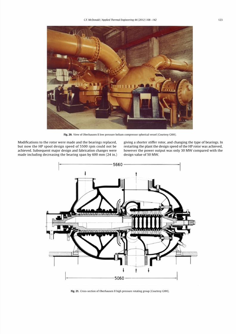
8112019 Helium Turbomachinery Operating Experience From Gas Turbine Power Plants
httpslidepdfcomreaderfullhelium-turbomachinery-operating-experience-from-gas-turbine-power-plants 1635
Modi1047297cations to the rotor were made and the bearings replaced
but now the HP spool design speed of 5500 rpm could not be
achieved Subsequent major design and fabrication changes were
made including decreasing the bearing span by 600 mm (24 in)
giving a shorter stiffer rotor and changing the type of bearings In
restarting the plant the design speed of the HP rotor was achieved
however the power output was only 30 MW compared with the
design value of 50 MW
Fig 20 View of Oberhausen II low pressure helium compressor spherical vessel (Courtesy GHH)
Fig 21 Cross-section of Oberhausen II high pressure rotating group (Courtesy GHH)
CF McDonald Applied Thermal Engineering 44 (2012) 108e142 123
8112019 Helium Turbomachinery Operating Experience From Gas Turbine Power Plants
httpslidepdfcomreaderfullhelium-turbomachinery-operating-experience-from-gas-turbine-power-plants 1735
To gain operational experience it was decided to continue
running the plant at the reduced power rating On February 5 1979
after nearly 11000 h of operation a rotor blade from the second
stage of the HP turbine failed causing damage in the remaining
stages but the high energy fragments were contained within the
thick machine casing Examination of the failed blade revealed the
defect as a crack caused by the forgingprocess on the semi-1047297nishedproduct To prevent such a failure occurring in the future an electric
polishing process applied to the blade surface before inspection
was implemented and improved crack detection methods
introduced
Acoustic loads in a closed-cycle gas turbine represent pressure
1047298uctuations propagating at the speed of sound through the helium
working 1047298uid Pressure 1047298uctuations of importance result from the
aerodynamic effects of high velocity helium impacting and
essentially being intermittently ldquocutrdquo by the blading in the
compressor and turbine Care must be taken in the design of the
plant to ensurethat these 1047298uctuating pressure waves do not induce
vibrations of a magnitude that could result in excitation-induced
fatigue failures in components in the circuit Critical vibrations
occur when resonance exists between the main frequency of
the propagating sound and the natural frequencies of the
components particularly ones that have large surface area to
thickness ratio
Measurements of sound spectrum were taken at four different
locations in the circuit The design level of power of 50 MW was not
achieved but at the 30 MW power output actually realized the
maximum recorded sound power level was 148 dB After plantshutdown there was no evidence of adverse effects on the major
components of noise induced excitation emanating from the axial
1047298ow turbomachinery The integrity of the turbine inlet hot gas duct
and insulation was con1047297rmed
The inability to reach rated power was attributed to shortcom-
ings in the helium turbomachine This included the compressors(s)
and turbine(s) blading failing to attain design values of ef 1047297ciencies
and the bleed helium mass 1047298ows for cooling and sealing being
signi1047297cantly greater than analytically estimated Based on data
taken from the well instrumented plant detailed analyses were
undertaken by specialists [4950] to calculate the losses in the
turbomachine to explain the power output de1047297ciency A summary
of the projected losses and various component ef 1047297ciencies is pre-
sented in a convenient form on Table 3
Fig 22 Oberhausen II high pressure rotor being installed (Courtesy GHH)
CF McDonald Applied Thermal Engineering 44 (2012) 108e142124
8112019 Helium Turbomachinery Operating Experience From Gas Turbine Power Plants
httpslidepdfcomreaderfullhelium-turbomachinery-operating-experience-from-gas-turbine-power-plants 1835
The plant operated for approximately 24000 h and was shut-
down and decommissioned in 1988 when the coke-oven gas supply
for the heater was no longer available A total plant operating time
of about 11500 h had been at the design turbine inlet temperature
of 750 C (1382 F) Turbomachinery related experience gained
from operation of this large helium gas turbine plant was extremely
valuable While many of the functions performed well from the
onset and others worked satisfactorily after modi1047297cations were
made serious unexpected problems were encountered
The achieved electrical power output of only 60 percent of the
design value was initially thought to be due to a grossly excessive
system pressure loss However when the data was carefully eval-uated it was found that 85 percent of the 20 MW power loss was
attributed to turbomachine related problems as delineated on
Table 3
To remedy this power de1047297ciency it was clear that a major re-
design of the turbomachinery would be required While replace-
ment of the gas turbine was not contemplated a study was
undertaken based on data from the plant and new technologies
that had become available since the initial design Based on the
1047297ndings a new turbomachine layout concept was suggested [43]
and a simplistic view of the rotor arrangement is shown on Fig 24
A more conventional single-shaft arrangement was proposed with
the two compressors and turbine having a rotational speed of
5400 rpm A gearbox was still retained to give a generator rota-
tional speed of 3000 rpm Based on prevailing technology at the
time the requirements for such a gearbox would have been moredemanding since the 50 MW from the turbine to the generator
would have to be transmitted through it This would necessitate
a larger system to pump 1047297lter and cool the bearing lubrication oil
To remedy the very large losses in the compressors and turbines
the number of stages would have to be increased In the case of the
compressors the use of lighter aerodynamically loaded higher
ef 1047297ciency stages with 50 percent reaction blading was
recommended
7 High temperature helium test facility (HHV)
71 Background
In the late 1960rsquos with large numbers of orders placed for 1047297rst
generation light water reactor nuclear power plants studies were
initiated for next generation power plants with higher ef 1047297ciency
potential Following the initial operational success of the 1047297rst three
small helium cooled HTR plants (ie Dragon in the UK Peach
Bottom I in the USA and AVR in Germany) studies on larger plants
based on the use of both Rankine steam cycle and helium closed
Brayton cycle power conversion systems were undertaken In the
early 1970rsquos emphasis was placed on nuclear gas turbine plant
designs with larger power output both in the USA (for the
HTGR eGT) and in Europe (for the HHT) Work in the USA was
limited to only paper studies [18] The much larger program in
Germany (with participation by Swiss companies for the turbo-
machine heat exchangers and cooling towers) included a well
planned development testing strategy to support the plant design
Fig 23 Cross-section of Oberhausen II low pressure helium turbine (Courtesy GHH)
Table 3
Oberhausen II helium turbine plant power losses
Componentcause Design
value
Measured Power loss
MW
Compressors
B Flow losses in inlet diffusers
and blades
Low pressure ef 1047297ciency 870 826 13
High pressure ef 1047297ciency 855 779 40
Turbines
B Blade gap and 1047298ow losses
High pressure ef 1047297ciency 883 823 39
B Pro1047297le losses due to Remachined
blades after having detected
damaged blades
Low pressure ef 1047297ciency 900 856 24
BSealing leakage and cooling 1047298ows
in all turbomachines Kgsec
18 75 53
B Circuit pressure losses
(Ducting Hxrsquos etc)
102 128 26
B Miscellaneous heat losses 05
Total power loss 200 MW
Notes (1) Plant designed for electrical power output of 50 MW actual power output
measured 30 MW
(2) Power de1047297ciency of20 MW based on measurements taken and then recalculated
for the rated plant output
(3) 85 of Power loss attributed to helium turbomachinery related issues
CF McDonald Applied Thermal Engineering 44 (2012) 108e142 125
8112019 Helium Turbomachinery Operating Experience From Gas Turbine Power Plants
httpslidepdfcomreaderfullhelium-turbomachinery-operating-experience-from-gas-turbine-power-plants 1935
While the reference HHT plant for eventual commercializationembodied a very large single helium gas turbine rated at 1240 MW
this was to be preceded by a nuclear demonstration plant rated at
676 MW [51] To support the design of this plant technology
generated from the following was planned 1) operational experi-
ence from the aforementioned Oberhausen II 50 MW helium gas
turbine power plant and 2) testing of components in a large high
temperature helium test facility as discussed below
72 Development facilitytesting objectives
An overall view of the HHV test facility sited in Julich in
Germany is shown on Fig 25 and since this has been reported on
previously [52] it will only be brie1047298
y covered in this section Tominimize risk and assure the performance integrity and reliability
of the nuclear demonstration plant some non-nuclear testing of
the major components especially the helium turbomachine was
deemed essential Because of the limitations of a conventional
closed-cycle helium gas turbine power plant particularly the
temperature limitations of existing fossil-1047297red and electrical
heaters a new type of test facility was foreseen
A simpli1047297ed schematic line diagram of the HHV circuit is shown
on Fig 26 The major design parameters are shown on Fig 27
together with the temperatureeentropy diagram which is conve-
nient for describing the unique relationship between the compo-
nents in the closed helium loop Starting at the lowest pressure in
Fig 24 Proposed new concept for Oberhausen II helium gas turbine rotating assembly to remedy problems encountered during operation of the 50 MWe power plant (Courtesy
EVO)
Fig 25 HHV helium turbomachinery test facility (Courtesy BBC)
CF McDonald Applied Thermal Engineering 44 (2012) 108e142126
8112019 Helium Turbomachinery Operating Experience From Gas Turbine Power Plants
httpslidepdfcomreaderfullhelium-turbomachinery-operating-experience-from-gas-turbine-power-plants 2035
the system the helium is compressed (Ae
B) its temperatureincreasing to 850 C (1562 F) before 1047298owing through the test
section (BeC) After being cooled slightly (CeD) the helium is
expanded in the turbine (DeA) down to the compressor inlet
conditions completing the loop There is no power output from the
system and without the need for an external heater the
compression heat is used to raise the helium to the maximum
system temperature in what can be described as a very large heat
pump The required compressor power is 90 MW and to supple-
ment the 45 MW generated by expansion in the turbine external
power is provided by a 45 MW synchronous electrical motor A
cooler is required to remove the compression heat that is contin-
uously put into the closed helium loop and this is done by bleeding
about 5 percent of the mass 1047298ow after the compressor cooling it
and re-introducing it into the circuit close to the turbine inlet In
addition to testing the turbomachine the facility was engineered
with a test section to accommodate other small components (eg
hot gas 1047298ow regulation valves bypass valves insulation con1047297gu-
rations and types of hot gas duct construction) With the highest
temperature in the system being at the compressor exit the facility
had the capability to provide helium at a temperature up to 1000 C
(1832 F) for short periods at the entrance to the test section
While a higher ef 1047297ciency of the planned nuclear demonstration
plant could be projected with a turbine inlet temperature in the
range 950e1000 C (1742e1832 F) this would have necessitated
either turbine blade cooling or the use of a high temperature alloy
such as Titanium Zirconium Molybdenum (TZM) At the time it was
felt that using either of these would have added cost and risk to theprojectso a conventionalnickel-basedalloyas usedin industrialgas
turbines was selected for the 850 C design value of turbine inlet
temperature this negating the needfor actual internal bladecooling
However a complex internal coolingsystemwas neededto keep the
Fig 26 Cycle diagram of HHV test loop (Courtesy BBC)
Fig 27 Salient features of HHV helium turbomachinery (Courtesy BBC)
CF McDonald Applied Thermal Engineering 44 (2012) 108e142 127
8112019 Helium Turbomachinery Operating Experience From Gas Turbine Power Plants
httpslidepdfcomreaderfullhelium-turbomachinery-operating-experience-from-gas-turbine-power-plants 2135
turbine discs and blade root attachments and casings to acceptable
temperatures commensurate with prescribed stress limitations for
thelife of theturbomachine In addition a heliumsupplywas needed
to provide a buffering system for the various labyrinth seals
In a direct Brayton cycle nuclear gas turbine the turbomachine is
installed in the reactor circuit and via the hot gas duct heated
helium is transported directly from the reactor core to the turbine
From the safety licensing and reliability standpoints there are
various seals that must perform perfectly A helium buffered
labyrinth seal system is necessary to prevent bearing lubricating oil
ingress to the closed helium loop Since in the proposed HHT plant
design the drive shaft from the turbine to the generator penetrates
the reactor primary system pressure boundary two shaft seals are
needed one a dynamic seal when the shaft is rotating and a static
seal when the turbomachine is not operating Testing of these seals
in a size and operating conditions representative of the planned
commercial power plant was considered to be a licensing must
The mechanical integrity of the rotating assembly must be
assured there being two major factors necessitating testing the
machine at full speed and temperature and at high pressure
namely 1) loading the blading under representative centrifugal and
gas bending stresses and 2) to monitor vibration and con1047297rm rotor
dynamic stability For the design of the planned commercial planta knowledge of the acoustic emissions by the turbomachine and
propagation in the closed circuit was required Data from the HHV
facility would enable dynamic responses of the major components
(especially the insulation) resulting from excitation by the sound
1047297eld to be calculated
The circuit was instrumented to gather data on the effectiveness
of the hot gas duct insulation thermal expansion devices hot gas
valves helium puri1047297cation system instrumentation and the
adequacy of the coatings applied to mating metallic surfaces to
prevent galling or self-welding Details of the turbomachinery and
the experience gained from the operation of the HHV facility are
covered in the following sections
73 Helium turbomachine
A cross-section of the turbomachine is shown on Fig 28 The
single-shaft rotating assembly consists of 8 compressor stagesand 2
turbine stages and had a weighton the order of 66 tons(60000 kg)
The hub inner and outer diameters are 16 m (525 ft) and 18 m
(59 ft) respectively the blading axial length being 23 m (75 ft)The
span between the oil bearings being 57 m (187 ft) The physical
dimensions of the turbogroup shown on Fig 28 correspond to
a machine rated at about 300 MW The oil bearings operate in
a helium environment and the diameters of the labyrinths and
1047298oating ring shaft seals to prevent oil ingress are representative of
a machine rated at about 600 MW The complexity of the machine
design especially the rotor cooling system sealing system very
large casing and heat insulation have been reported previously
[53e55]
To ensure high structural integrity the rotor was constructed by
welding together the forged compressor and turbine discs The
compressor had 8 stages each having 56 rotor and 72 stator blades
The turbine had 2 stages each having 90 stator and 84 rotor blades
An appreciation for the large size of the rotating assembly can be
seen from Fig 29 The rotor blades have 1047297r-tree attachments
embodying cooling channels Since the temperature and pressure
do not vary very much along the blading in the 1047298ow direction an
intricate rotor and stator cooling system was required Channels in
both the blade roots and the spacers between adjacent blade rows
form an axial geometry for the passage of a cooling helium supplyto keep the temperature of the multiple discs below 400 C
(752 F) The design of this was a challenge since the rotor and
stator blade attachments of both the 8 stage compressor and 2
stage turbine had to be cooled Excessive leakage had to be avoided
since this would have prevented the speci1047297ed compressor
discharge temperature (ie the maximum temperature in the
circuit) from being reached
In the 1970rsquos and early 1980rsquos signi1047297cant studies were carried
out on large helium gas turbines by various organizations [56e62]
In this era there was general agreement that testing of the turbo-
machine in one form or another in non-nuclear facilities be
undertaken to resolve areas of high risk (eg seals bearings cooling
systems rotor dynamic stability compressor surge margin
dynamic response rotor burst protection etc) before installationand operation of a large gas turbine in a nuclear environment
This low risk engineering philosophy which prevailed at the time
in both Germany and the USA emphasized the importance of
Fig 28 Cross-section of HHV helium turbomachinery (Courtesy BBC)
CF McDonald Applied Thermal Engineering 44 (2012) 108e142128
8112019 Helium Turbomachinery Operating Experience From Gas Turbine Power Plants
httpslidepdfcomreaderfullhelium-turbomachinery-operating-experience-from-gas-turbine-power-plants 2235
the HHV test facility as being an important step towards the
eventual deployment of a high ef 1047297ciency nuclear gas turbine power
plant
74 Initial operation of the HHV facility
During commissioning of the plant in 1979 oil ingress into the
helium circuit from the seal system occurred twiceThe 1047297rst ingressof oil between 600 and 1200 kg (1322 and 2644 lb) was due to
a serious operatorerror and the absence of an isolation valve in the
system The oil in the circuit was partly coked and formed thick
deposits on the cold and hot surfaces of the turbomachinery and in
other parts of the closed loop including saturation of the 1047297brous
insulation The fouled metallic surfaces were cleaned mechanically
and chemically by cracking with the addition of hydrogen and
additives The second oil ingress was due to a mechanical defect in
the labyrinth seal system The quantity of oil introduced was small
and it was removed bycracking at a temperature of 600 C (1112 F)
and with the use of additives To obviate further oil ingress inci-
dents the labyrinth seal system was redesigned The buffer and
cooling helium system piping layout was modi1047297ed to positively
eliminate oil ingress due to improper valve operation and toprevent further human error
Pressure and leak detection tests of the HHV test facility at
ambient temperature showed good leak tightness for the turbo-
machine 1047298anged joints and of the main and auxiliary circuits
However at the operating temperature of 850 C (1562 F) large
helium leaks were detected The major 1047298anges had been provi-
sioned with lip seals and the 1047297rst step was to weld the closures A
large leak persisted at the front 1047298ange of the turbomachine This
was diagnosed as being caused by a non-uniform temperature
distribution during initial operation resulting in thermal stresses
creating local gaps This problem was overcome by redesign of the
cooling system with improved gas 1047298ow distribution and 1047298ow rates
to give a more uniform temperature gradient The leakage from the
system was reduced to on the order of 020e
040 percent of the
helium inventory per day this being of the same magnitude as in
other closed helium circuits as discussed in Section 65
It should be mentioned that in addition to the HHV experience
bearing oil ingress into the circuits and system loss of the working
1047298uid in other closed-cycle gas turbine plants have occurred In all of
these fossil-1047297red facilities 1047297xing leaks and removal of oil deposits
were undertaken based on conventional hands-on approaches but
nevertheless such operations were time-consuming However if a new and previously untested helium turbomachine operating in
a direct cycle nuclear gas turbine plant experienced an oil ingress
the rami1047297cations would be severe The likely use of remote
handling equipment to remove the turbomachine from the vessel
machine disassembly (including breaking the welded 1047298ange joints)
and removal of oil from the radioactively contaminated turbo-
machine blade surfaces and system insulation would be time
consuming A diagnosis of the failure would be required before
a spare turbomachine could be installed and this plant downtime
could adversely affect plant availability
75 Experience gained
Afterresolutionof the aforementionedproblems the HHVfacilitywas started in the Spring of 1981 and in an orderly manner was
brought up to full pressure and a temperature of 850 C (1562 F)
During a 60 h run the functioning of the instrumentation control
and safety systems were veri1047297ed During these tests the ability to
stop the turbomachine from full operating conditions to standstill
within 90 s was demonstrated After system depressurization the
plant was then run up again to full operating conditions with no
problems experienced The HHV facility was successfully run for
about 1100 h of which theturbomachineryoperated forabout325 h
at a temperature of 850 C The test facility was extensively instru-
mented and interpretation and analysis of the data recorded gave
positive and favorable results in the following areas
The complex rotor cooling system which was engineered to
assure that the temperature of the discs be kept below 400
C
Fig 29 HHV helium turbomachine rotating assembly (size equivalent to a 300 MWe machine) being installed in a pressure vessel (Courtesy BBC)
CF McDonald Applied Thermal Engineering 44 (2012) 108e142 129
8112019 Helium Turbomachinery Operating Experience From Gas Turbine Power Plants
httpslidepdfcomreaderfullhelium-turbomachinery-operating-experience-from-gas-turbine-power-plants 2335
(752 F) was demonstrated to be effective The measured rotor
coolant 1047298ows (about 3 percent of the mass1047298ow passing through the
machine) were slightly larger than had been estimated and this
resulted in measured turbine disc temperatures lower than pre-
dicted [55]
The dynamic labyrinth shaft seal functioned well at the full
temperature and pressure conditions and met the requirement of
zero oil ingress into the helium circuit The measured rotor oscil-
lation did not have any adverse effect on the shaft sealing system
The static rotor seal (for shutdown conditions) functioned without
any problems
The compressor and turbine blading hadef 1047297ciencies higher than
predicted The structural integrity of the rotor proved to be sound
when operating at 3000 rpm under the maximum temperature and
pressure conditions The stiff rotor shaft had only slight unbalance
and thermal distortion and measured oscillations were in the range
typical of large steam turbines
Sound power spectrum measurements were taken in four
different locations in the circuit These were taken to determine the
spectrum and intensity of the sound generated and propagated by
the turbomachinery and the resultant vibration of internal
components The maximum sound power level in the helium
circuit was160 dB Numerous strain gages were placedin the circuitto determine the in1047298uence of the sound 1047297eld particularly on the
fatigue strength of the turbine inlet hot gas duct In later examining
the internal components there was no evidence of excessive
vibration of the components especially the ducting and the insu-
lation Based on the measurements and calculations it was
concluded that the fatigue strength limit of the components would
not be exceeded during the designed life of the planned commer-
cial nuclear gas turbine power plant
In a direct cycle nuclear gas turbine the hot gas duct used to
transport the helium from the reactor core to the turbineis a critical
component The hot gas duct in the HHV facility performed well
mechanically and con1047297rmed the adequacy of the thermal expan-
sion devices From the thermal standpoint the 1047297ber insulation
performed better than the metallic type
After dismantling the HHV facility there were no signs of
corrosion or erosion of the turbine or compressor blading While
the total number of hours operated was limited the coatings
applied to mating metallic surfaces to prevent galling and frictional
welding in the oxidation-free helium worked well
The helium buffer and cooling system worked well However
problems remained with the puri1047297cation of the buffer helium The
oil separation system consisting of a cyclone separator and a wire
mesh and a down stream 1047297ber 1047297lter needed further improvement
In late 1981 a decision was made to cancel the HHT project and
the HHV facility was shutdown The design and operational expe-
rience gained from the running of this facility would have been
extremely valuable had the nuclear gas turbine power plant
concept moved towards becoming a reality The identi1047297cation of
somewhat inevitable problems to be expected in such a complexturbomachine and their resolution were undertaken in a timely
and cost effective manner in the non-nuclear HHV facility This
should be noted for future nuclear gas turbine endeavors since
remedying such unexpected problems in the case of a new and
untested large helium turbomachine being operated for the 1047297rst
time using nuclear heat could result in very complex repair
Fig 30 Speci1047297
c speed-speci1047297
c diameter array for gas circulators in various gas-cooled nuclear plants
CF McDonald Applied Thermal Engineering 44 (2012) 108e142130
8112019 Helium Turbomachinery Operating Experience From Gas Turbine Power Plants
httpslidepdfcomreaderfullhelium-turbomachinery-operating-experience-from-gas-turbine-power-plants 2435
activities and extended plant downtime and indeed adding risk to
the overall success of the nuclear gas turbine concept
8 Circulators used in gas-cooled reactor plants
Circulators of different types will be needed in future helium
cooled nuclear plants these including the following 1) primary
loop circulator for possible next generation steam cycle power andcogeneration plants 2) for future indirect cycle gas turbine plants
3) shut down cooling circulators forall HTRand VHTR plants and 4)
for various circulators needed in future VHTR high temperature
process heat plant concepts The technology status of operated
helium circulators is brie1047298y addressed as follows
81 Background
It would be remiss not to mention experience gained in the past
with gas circulators and while not gas turbines they are rotating
machines that operate in the primary loop of a helium cooled
reactor With electric motor drives there are basically two types of
compressor rotor con1047297gurations namely radial and axial 1047298ow
machinesIn a single stage form the centrifugal impeller is used for high
stage pressure rise and low volume 1047298ow duties whereas the axial
type covers low pressure rise per stage and high volume 1047298ow The
selection of impeller type is very much related to the working
media type of bearings drive type rotor dynamic characteristics
and installation envelope A wide range of circulators have operated
and a well established technology base exists for both types [63] A
useful portrayal of compressor data in the form of quasi- non-
dimensional parameters (after Balje [64]) showing approximate
boundaries for operation of high ef 1047297ciency axial and radial types is
shown on Fig 30 (from Ref [65])
Both high speed axial and lower speed radial 1047298ow types are
amenable to gas oil and magnetic bearings From the onset of
modularHTR plant studies theuse of active magnetic bearings[6667]offered a solution to eliminate lubricating oil into the reactor circuit
and this tribology technology is attractive for use in submerged
rotating machinery in the next generation of HTR plants [68]
While now dated an appreciation of the main design features of
typical electric motor-driven helium circulators have been reported
previously namely an axial 1047298ow main circulator for a modular
steam cycle HTR plant [69] and a representative radial 1047298ow shut-
down cooling circulator [70]
The operating experience gained from three particular circula-
tors is brie1047298y included below because of their relevance to the
design of helium turbomachinery in future HTR plant variants
82 Axial 1047298ow helium circulator
Since all of the aforementioned predominantly European
helium gas turbines used axial 1047298ow turbomachinery it is of interest
to mention a helium axial 1047298ow circulator that operated in the USA
and to brie1047298y discuss its design parameters and features The
330 MW Fort St Vrain HTGR featured a Rankine cycle power
conversion system Four steam turbine driven helium circulators
were used to transport heat from the reactor core to the steam
generators The complete circulator assemblies were installed
vertically in the prestressed concrete reactor vessel [71e73]
A cross-section of the circulator is shown on Fig 31 with thecompressor rotor and stator visible on the left hand end of the
machine Based on early 1960rsquos technology a decision was made to
use water lubricated bearings and from the overall plant reliability
and availability standpoints this later proved to be a bad choice
Within the vertical circulator assembly there were four 1047298uid
systems namely the helium reactor coolant water lubricant in the
bearings steam for the turbine drive and high pressure water for
the auxiliary Pelton wheel drive During plant transients the pres-
sures and temperatures of these four 1047298uids oscillated considerably
and the response of the control and seal systems proved to be
inadequate and resulted in considerable water ingress from the
bearing cartridge into the reactor helium circuit The considerable
clean up time needed following repeated occurrences of this event
resulted in long periods of plant downtime and this had an adverseeffect on plant availability This together with other technical
Fig 31 Cross section of FSV helium circulator (Courtesy general Atomics)
CF McDonald Applied Thermal Engineering 44 (2012) 108e142 131
8112019 Helium Turbomachinery Operating Experience From Gas Turbine Power Plants
httpslidepdfcomreaderfullhelium-turbomachinery-operating-experience-from-gas-turbine-power-plants 2535
dif 1047297culties eventually contributed to the plant being prematurely
decommissioned
On the positive side in the context of this paper the helium
circulators operated for over 250000 h and exhibited excellent
helium compressor performance good mechanical integrity and
vibration-free operation The rotating assembly showing the axial
1047298ow compressor and steam turbine rotors together with a view of
the machine assembly are given on Fig 32 The helium compressor
consists of a single stage axial rotor followed by an exit guide vane
The machine was designed for axial helium 1047298ow entering and
leaving the stage and this can be seen from the velocity triangles
shown on Fig 33 which also includes the de1047297nition of the various
aerodynamic parameters Major design parameters and features of
this helium circulator are given on Table 4 Related to an earlier
discussion on the degree of reaction for axial 1047298ow compressors the
value for this conventional single stage circulator is 78 percent All
of the major aerothermal and structural loading criteria were
within established boundaries for an axial compressor having high
ef 1047297ciency and a good surge margin
The compressor gas 1047298ow path and blading geometries were
established based on prevailing industrial gas turbine and aero-
engine design practice A low Mach number (025) a high Reynolds
number (3 106) together with a modest stage loading (ie
a temperature rise coef 1047297cient of 044) and an acceptable value of
diffusion factor (042) were some of the factors that contributed to
a helium circulator that had a high ef 1047297ciency and a good pressure
rise- 1047298ow characteristic The large rotor blade chord and thick blade
section for this single stage circulator are necessary to accommo-
date the high bending stress characteristic of operation in a high
pressure environment The solidity and blade camber were opti-
mized for minimum losses
There were essentially two reasons for including this single-
stage axial 1047298ow compressor that operated in a helium cooled
reactor although its overall con1047297guration can be regarded as a 1047297rst
and last of a kind A rotor blade from this circulator as shown onFig 34 was based on a NASA 65 series airfoil which at the time
were one of the best performing cascades for such low Mach
number and high Reynolds number applications Interestingly it
has almost the same blade height aspect ratio and solidity as would
be used in the 1047297rst stage of an LP compressor in a helium turbo-
machine rated on the order of 250 MW
The second point of interest is that the helium mass 1047298ow rate
through the single stage axial compressor (rated at 4 MWe) is
110 kgs compared with 85 kgs through the multistage compressor
in the 50 MWe Oberhausen II helium gas turbine plant However
the volumetric 1047298ow through the Oberhausen axial compressor is
higher than that through the circulator by a factor of 16 this again
pointing out that the Oberhausen II plant was designed for high
volumetric 1047298ow to simulate the much larger size of turboma-chinery that was planned at the time in Germany for use in future
projected nuclear gas turbine power plants
83 High temperature helium circulator
For future helium turbomachines embodying active magnetic
bearings a challenge in their design relates to accommodating
elevated levels of temperature in the vicinity of the electronic
components In this regard it is of interest to note that a small very
high temperature helium axial 1047298ow circulator rated at 20 kW (as
shown on Fig 35) operated for more than 15000 h in an insulation
test facility in Germany more than two decades ago [74] The
signi1047297cance of this machine is that it operated with magnetic
bearings in a high temperature helium test loop with a circulatorgas inlet temperature of 950 C (1742 F) This necessitated the use
of ceramic insulation to ensure that the temperature in the vicinity
of the magnetic bearing electronics did not exceed a temperature of
about 150 C (300 F)
This machine although a very small axial 1047298ow helium blower
performed well and has been brie1047298y mentioned here since it
represents a point of reference for future helium rotating machines
capable operating with magnetic bearings in a very high temper-
ature helium environment
84 Radial 1047298ow AGR nuclear plant gas circulators
The electric motor-driven carbon dioxide circulators rated at
about 5 MW with a total runningtimein excess of 18 million hours
Fig 32 Fort St Vrain HTGR plant helium circulator (Courtesy General Atomics) (a)
Axial 1047298ow helium compressor and steam turbine rotating assembly (b) 4 MW helium
circulator assembly
CF McDonald Applied Thermal Engineering 44 (2012) 108e142132
8112019 Helium Turbomachinery Operating Experience From Gas Turbine Power Plants
httpslidepdfcomreaderfullhelium-turbomachinery-operating-experience-from-gas-turbine-power-plants 2635
in AGR nuclear power plants in the UK have demonstrated veryhigh availability [7576] To a high degree this can be attributed to
the fact that the machines were conservatively designed and proof
tested in a non-nuclear facility at full temperature and power
under conditions that simulated all of the nuclear plant operating
modes The test facility shown on Fig 36 served two functions 1)
design veri1047297cation of the prototype machine and 2) test of all new
and refurbished machines before they were installed in nuclear
plants Engineers currently involved in the design and development
of helium turbomachinery could bene1047297t from this sound testing
protocol to minimize risk in the deployment of helium rotating
machinery in future HTRVHTR plant variants
9 Helium turbomachinery development and testing
91 On-going development activities
The various helium turbomachines discussed in previous
sections operated over a span of about two decades starting in the
early 1960s From about 1990 activities in the nuclear gas turbine
1047297eld have been focused mainly on the design of modular GTeHTR
plant concepts In support of these plant studies many signi1047297cant
helium turbomachine design advancements have been made and
attention given to what development testing would be needed In
the last decade or so limited sub-component development has
been undertaken for helium turbomachines in the 250e300 MWe
size and these are brie1047298y summarized below
In a joint USARussia effort development in support of the
GTe
MHR turbomachine has been undertaken including testing in
the following areas magnetic bearings seals and rotor dynamicsfor the vertical intercooled helium turbomachine rated at 286 MWe
[77e80]
In Japan development activities have been in progress for
several years in support of the 274 MWe helium turbomachine for
the GTeHTR300 plant concept [2581] A detailed discussion on
the aerodynamic design of the axial 1047298ow helium compressor for
this turbomachine has been published in the open literature [82]
While the design methodology used for axial compressor design in
air-breathing industrial and aircraft gas turbines is generally
applicable for a multi-stage helium compressor a decision was
made by JAEA to test a small scale compressor in a helium facility
because of the inherent and unique gas 1047298ow path and type of
blading associated with operation in a high pressure helium
environment The major goal of the test was to validate the designof the 20 stage helium axial 1047298ow compressor for the GTeHTR300
plant
An axial 1047298ow compressor in a closed-cycle helium gas turbine is
characterized by the following 1) a large number stages 2) small
blade heights 3) high hub-to-tip ratio 4) a long annulus with
small taper that tends to deteriorate aerodynamic performance as
a result of end-wall boundary layer length and secondary 1047298ow 5)
low Mach number 6) high Reynolds number and 7) blade tip
clearances that are controlled by the gap necessary in the magnetic
journal and catcher bearings While (as covered in earlier sections)
helium gas turbines have operated there is limited data in the
open literature on the performance of multi-stage axial 1047298ow
compressors operating in a high pressure closed-loop helium
environment
Fig 33 Velocity triangles for axial compressor stage
CF McDonald Applied Thermal Engineering 44 (2012) 108e142 133
8112019 Helium Turbomachinery Operating Experience From Gas Turbine Power Plants
httpslidepdfcomreaderfullhelium-turbomachinery-operating-experience-from-gas-turbine-power-plants 2735
A 13rd scale 4 stage compressor was designed to simulate the
stage interaction the boundary layer growth and repeated stage
1047298ow in an actual compressor The 1047297rst four stages were designed to
be geometrically similar to the corresponding stages in the
GTe
HTR300 compressor Details of the model compressor havebeen discussed previously [81] and are summarized on Table 5
from [83]
A cross-section of the compressor test model is shown on Fig 37
A view of the 4 stage compressor rotor installed in the lower casing
is shown on Fig 38 The test facility (Fig 39) is a closed helium loop
consisting of the compressor model cooler pressure adjustment
valve and a 1047298ow measurement instrument The compressor is
driven by a 3650 kW electrical motor via a step-up gear The rota-
tional speed of 10800 rpm (three times that of the compressor in
the GTeHTR300 plant) was selected to match blade speed and
Mach number in the full size compressor
Details of the planned aerodynamic performance objectives of
the 13rd scale helium compressor test have been published
previously [84] Extensivetesting of the subscale model compressorprovided data to validate the performance of the full size
compressor for the GTeHTR300 power plant The test data and
test-calibrated CFD analyses gave added insight into the effect of
factors that impact performance including blade surface roughness
and Reynolds number
Based on advanced aerodynamic methodology and experi-
mental validation [82] there is now a sound basis for added
con1047297dence that the design goals of 90 percent polytropic ef 1047297ciency
and a design point surge margin of 20 percent are realizable in
a large multistage axial 1047298ow compressor for a future nuclear gas
turbine plant
In a similar manner a design of a one third size single stage
helium axial 1047298ow turbine has been undertaken and a cross
section of the machine is shown on Fig 40 (from Ref [81]) This
Table 4
Major features of axial 1047298ow helium circulator
Helium 1047298ow rate kgsec 110
Inlet temperature C 394
Inlet pressure MPa 473
Pressure rise KPa 965
Volumetric 1047298ow m3sec 32
Compressor type Single stage axial
Compressor drive Steam turbine
Bearing type Water lubricated
Rotational speed rpm 9550
Power MW 40
Rotor tip diameter mm 688
Rotor tip speed msec 344
Number of rotor blades 31
Number of stator blades 33
Blade height mm 114
Hub-to-tip ratio 067
Axial velocity msec 157
Flow coef 1047297cient 055
Temperature rise coef 1047297cient 044
Degree of reaction 078
Mean rotor solidity 128
Rotor aspect ratio 155
Rotor Mach number 025
Rotor diffusion factor 042
Rotor Reynolds number 3106
Speci1047297c speed 335
Speci1047297c diameter 066
Blade root thickness 15
Airfoil type NASA 65
Rotor blade chord mm 94e64
Stator blade chord mm 79
Rotor centrifugal stress MPa 125
Rotor bending stress MPa 30
Circulator(s) operating Hours gt250000
Fig 34 Rotor blade from single stage axial 1047298ow helium circulator (Courtesy General
Atomics)
Fig 35 20 kW axial 1047298ow helium circulator with magnetic bearings operated in 1985 in
an insulation test loop with a gas inlet temperature on 950
C (Courtesy BBC)
CF McDonald Applied Thermal Engineering 44 (2012) 108e142134
8112019 Helium Turbomachinery Operating Experience From Gas Turbine Power Plants
httpslidepdfcomreaderfullhelium-turbomachinery-operating-experience-from-gas-turbine-power-plants 2835
single stage scale model turbine for validity of the full size turbine
has been built and plans made to test the aerodynamic
performance
92 Nuclear gas turbine helium turbomachine testing
In planning for the 1047297rst nuclear gas turbine plant projected to
enter service perhaps in the third decade of the 21st century
a major decision has to be made as to what extent the large helium
turbomachine should be tested prior to operation on nuclear heat
Issues essentially include cost impact on schedule but the over-
riding one is risk Certainly turbomachine component testing will
be undertaken including the compressor (as discussed in the
previous section) and turbine performance seals cooling systems
hot gas valves thermal expansion devices high temperature
insulation rotor fragment containment diagnostic systems
instrumentation helium puri1047297cation system and other areas to
satisfy safety licensing reliability and availability concerns The
major point is really whether a full size or scaled-down turbo-machine be tested early in the project in a non-nuclear facility
To obviate the need for pre-nuclear testing of a large helium
turbomachine a view expressed by some is that advantage can be
taken of formidable technology bases that exist today for large
industrial gas turbines and high performance aeroengines On the
other hand it is the view of some including the author that very
complex power conversion system components especially those
subjected to severe thermal transients donrsquot always perform
exactly as predicted by analysts and designers even using sophis-
ticated computer codes This was exempli1047297ed in the case of the
turbomachine in the aforementioned Oberhausen II helium gas
turbine plant
The need for a helium turbomachine test facility goes beyond
just veri1047297
cation of the prototype machine Each newgas turbine for
commercial modular nuclear reactor plants would have to be proof
tested and validated before being transported to the reactor site
Similarly turbomachines that would be periodically removed from
the plant at say 7 year intervals during the plant operating life of 60
years for scheduled maintenance refurbishment repair or updat-ing would be again proof tested in the facility before re-entering
service
The direction that turbomachine development and testing will
take place for future helium gas turbines needs to be addressed by
the various organizations involved
Fig 36 AGR circulator test facility In the UK (Courtesy Howden)
Table 5
Major design parametersfeatures of model GTeHTR300 axial 1047298ow helium
compressor (Courtesy JAERI)
Scale of GTeHTR300 compressor 13
Helium mass 1047298ow rate (kgsec) 122
Helium volumetric 1047298ow rate (mV s) 87
Inlet temperature C 30
Inlet pressure MPa 0883Compressor pressure ratio at design point 1156
Number of stages 4
Rotational speed rpm 10800
Drive motor power kW 3650
Hub diameter mm 500
Rotor tip diameter (1st4th stage mm) 568566
Hub-to-tip ratio (1st stage) 088
Rotor tip speed (1st stage msec) 321
Number of rotorstator blades (1st stage) 7294
Rotorstator blade height (1st stage mm) 34337
Rotor stator blade c hor d l eng th (1st stage mm) 2620
Rotorstator solidity (1st stage) 119120
Rotorstator aspect ratio (1st stage) 1317
Flow coef 1047297cient 051
Stage loading factor 031
Reynolds number at design point 76 l05
CF McDonald Applied Thermal Engineering 44 (2012) 108e142 135
8112019 Helium Turbomachinery Operating Experience From Gas Turbine Power Plants
httpslidepdfcomreaderfullhelium-turbomachinery-operating-experience-from-gas-turbine-power-plants 2935
10 Helium turbomachinery lessons learned
101 Oberhausen II gas turbine and HHV test facility
It is understandable that 1047297rst-of-a-kind complex turboma-
chinery operating with an inert low molecular weight gas such as
helium will experience unique and unexpected problems In the
operation of the two pioneering large helium turbomachines in
Germany there were many positive1047297ndings which could only have
been achieved by development testing Equally important some
negative situations were identi1047297ed many of which were remedied
In the case of the Oberhausen II helium gas turbine plant some of
the very serious problems encountered were not resolved Inves-
tigations were undertaken to rationalize the problems associated
with the large power de1047297ciency and a data base established to
ensure that the various anomalies identi1047297ed would not occur in
future large helium turbomachines
The experience gained from the operation of the Oberhausen II
helium gas turbine power plant and the HHV test facility have been
discussedin thetextand arepresentedin a summaryformon Table6
Fig 37 Cross-section of 13rd scale helium compressor test model (Courtesy JAEA)
Fig 38 Four stage helium compressor rotor assembly installed in lower casing (Courtesy JAEA)
CF McDonald Applied Thermal Engineering 44 (2012) 108e142136
8112019 Helium Turbomachinery Operating Experience From Gas Turbine Power Plants
httpslidepdfcomreaderfullhelium-turbomachinery-operating-experience-from-gas-turbine-power-plants 3035
102 Impact of 1047297ndings on future helium gas turbine
The long slender rotorcharacteristic of closed-cycle gas turbines
has resulted in shaft dynamic instability which in some cases has
resulted in blade vibration and failure and bearing damage This
remains perhaps the major concern in the design of large
(250e
300 MW) helium turbomachines for future nuclear gas
turbine plants With pressure ratios in the range of about 2e3 in
a helium system a combination of splitting the compressor (to
facilitate intercooling) and having a large number of compressor
and turbine stages results in a long and 1047298exible rotating assembly
andthis is exempli1047297ed by the rotorassembly shown on Fig13 With
multiple bearings (either oil lubricated or magnetic) the rotor
would likely pass through multiple bending critical speeds before
Fig 39 Helium compressor test facility (Courtesy JAEA)
Fig 40 Cross-section of single stage helium turbine test model (Courtesy JAEA)
CF McDonald Applied Thermal Engineering 44 (2012) 108e142 137
8112019 Helium Turbomachinery Operating Experience From Gas Turbine Power Plants
httpslidepdfcomreaderfullhelium-turbomachinery-operating-experience-from-gas-turbine-power-plants 3135
reaching the design speed While very sophisticated computer
codes will be used in the detailed rotor dynamic analyses the real
con1047297rmation of having rotor oscillations within prescribed limits
(to avoid blade bearing and seal damage) will come from actual
testingA point to be made here is that in operated fossil-1047297red closed-
cycle gas turbine plants it was possible to remedy problems asso-
ciated with rotor vibrations and blade failures in a conventional
manner In fact in some situations the casings were opened several
times and modi1047297cations made to facilitate bearing and seal
replacement and rotor re-blading and balancing
An accurate assessment of pressure losses must be made
particularly those associated with the helium entering and leaving
the turbomachine bladed sections Minimizing the system pressure
loss is important since it directly impacts the all important quotient
of turbine expansion ratio to compressor pressure ratio and power
and plant ef 1047297ciency
Based on the operating experience from the 20 or so fossil-1047297red
closed-cycle gas turbine plants using air as the working1047298
uid it was
recognized that future very high pressure helium gas turbines
would pose problems regarding the various seals in the turbo-
machine and obtaining a zero leakage system with such a low
molecular weight gas would be dif 1047297cult and this is discussed
below
When the Oberhausen II gas turbine plant and the HHV facility
operated over 30 years ago oil lubricated bearings were used to
support the heavy rotor assemblies and helium buffered labyrinth
seals were used to prevent oil ingressinto the heliumworking1047298uid
Initial dif 1047297culties encountered in both plants were overcome by
changes made to the seal geometries and for the operating lives of
the helium turbomachines no further oil ingress events were
experienced Twoseals were required where the turbine drive shaft
penetrated the turbomachine casing namely 1) a dynamic laby-
rinth seal and 2) a static seal for shutdown conditions In both
plants these seals functioned without any problems
Labyrinth seals were also required within the helium turbo-
machines to pass the correct helium bleed 1047298ow from the
compressor discharge for cooling of the turbine discs blade root
attachments and casings The fact that the very complex rotor
cooling system in the large helium turbomachine in the HHV test
facility operated well for the test duration of about 350 h with
a turbine inlet temperature of 850 C was encouragingIn the case of the Oberhausen II gas turbine plant analysis of the
test data revealed that the labyrinth seal leakage and excessive
cooling 1047298ows were on the order of four times the design value A
possible reason for this was that damage done to the labyrinth
seals caused excessive clearances when periods of excessive rotor
oscillation and vibration occurred during early operation of the
machine
Clearly 1047298uid dynamic and thermal management of the cooling
system and 1047298ow through the various labyrinth seals will require
extensive analysis design and development testing before the
turbomachine is operated on nuclear heat for the 1047297rst time
In future heliumgas turbine designs (with turbine inlet tempera-
tureslikelyontheorderof950C)the1047298owpathgeometriesofhelium
bledfromthecompressornecessarytocoolpartsoftheturbomachinewillbemorecomplexthanthosetestedto-dateInadditiontoproviding
acooling1047298owtotheturbinebladesanddiscsbladerootattachmentsand
casingsheliummustbetransportedtotheseveralmagneticbearingsto
ensure thatthe temperatureof theirelectronic components doesnot
exceedabout150C
The importance of the points made above is evidenced when
examining the data on Table 3 where a combination of excessive
pressure losses and high bleed 1047298ows contributed to about 40
percent of the power de1047297ciency in the Oberhausen II helium
turbine plant
Retaining overall system leak tightnessin closed heliumsystems
operating at high pressure and temperature has been elusive
including experience from the Fort St Vrain HTGR plant as dis-
cussed in Section 65 New approaches in the design of the plethoraof mechanical joints must be identi1047297ed Experience to-date has
shown that having welded seals on 1047298anges while minimizing
system leakage did not eliminate it
The importance of lessons learned from the operation of the
Oberhausen II helium turbine power plant and the HHV test facility
have primarily been discussed in the context of helium turbo-
machines currently being designed in the 250e300 MWe power
range However the established test data bases could also be
applied to the possible emergence in the future of two helium
cooled reactor concepts namely 1) an advanced VHTR combined
cycle plant concept embodying a smaller helium gas turbine in the
power range of 50e80 MWe [22] and 2) the use of a direct cycle
helium gas turbine PCS in a recently proposed all ceramic fast
nuclear reactor concept [85]
Table 6
Experience gained from Oberhausen II and HHV facility
Oberhausen II 50 MW helium gas turbine power plant
Positive results
e Rotating and static seals worked well
e No ingress of bearing lubricant oil into closed circuit
e Load change by inventory control worked well
e 100 Percent load shed by means of bypass valves demonstrated
e Turbine disc and blade root cooling system con1047297rmed
e Coatings on mating surfaces prevented galling and self-welding
e After 24000 h of operation no evidence of corrosion or erosion
e Coaxial turbine hot gas inlet duct insulation and integrity con1047297rmed
e Monitoring of complete power conversion system for steady state
and transient operation undertaken
Problem areas
e Serious power output de1047297ciency (30 MW compared with design
value of 50 MW)
e Compressor(s) and turbine(s) ef 1047297ciencies several points below predicted
e Higher than estimated system pressure loss
e Rotor dynamic instability and blade vibration
e Bearings damaged and had to be replaced
e Blade failure caused extensive damage in HP turbine but retained
in casing
e Very excessive sealing and cooling 1047298ow rates
e Absolute leak tightness not attainable even with welded 1047298ange lips
HHV test facility
Positive resultse Use of heat pump approach facilitated helium temperature capability
to 1000 C
e Large oompressorturbine rotor system operated at 3000 rpm Complex
turbine disc and blade root cooling system veri1047297ed
e Dynamic and static seals met requirement of zero oxl ingress into circuit
e Structural integrity of rotating assembly veri1047297ed at temperature of 850 C
e Measured rotor oscillations within speci1047297cation
e Compressor and turbine ef 1047297ciencies higher than predicted
e Coatings on mating metallic surfaces prevented galling and self-welding
e Instrumentation control and safety systems veri1047297ed
e Seal 1047298ows within speci1047297cation
e Machine stop from operating speed to shutdown in 90 s demonstrated
e Hot gas duct insulation and thermal expansion devices worked well
e After 1100 h of operation no evidence of corrosionof erosion
Problem areas
e Before commissioning a large oil ingress into the circuit occurred due
to serious operator error and absence of an isolation valve A second oilingress occurred due to a mechanical defect in the labyrinth seal system
These were remedied and no further oil ingress was experienced for the
duration of testing
e Cooling 1047298ows slightly larger than expected but this resulted in actual
disc and blade root temperatures lower than the predicted value of
400 C
e System leak tightness demonstrated when pressurized at ambient
temperature conditions but some leakage occured at 850 C even with
the seal welding of 1047298ange(s) lips
CF McDonald Applied Thermal Engineering 44 (2012) 108e142138
8112019 Helium Turbomachinery Operating Experience From Gas Turbine Power Plants
httpslidepdfcomreaderfullhelium-turbomachinery-operating-experience-from-gas-turbine-power-plants 3235
11 New technologies
It is recognized that in the 3 to 4 decades since the operation of
the helium turbomachines covered in this paper new technologies
have emerged which negate some of the early issues An example of
this is the technology transfer from the design of modern axial 1047298ow
gas turbines (ie industrial aircraft and aeroderivatives) that fully
utilize sophisticated CAE CAD CFD and FEA design software
Air breathing aerodynamic design practice for compressors and
turbines are generally applicable but the properties of helium and
the high system pressure have a signi1047297cant impact on gas 1047298ow
paths and blade geometries With short blade heights high hub-to-
tip ratios long annulus 1047298ow path length (with resultant signi1047297cant
end-wall boundary layer growth and secondary 1047298ow) and blade tip
clearances in some cases controlled by clearances in the magnetic
catcher bearing testing of subscale model compressors and
Fig 41 Gas turbine test facility for aircraft nuclear propulsion involving the coupling of a 32 MWt air-cooled reactor with two modi 1047297ed J-47 turbojet aeroengines each rated at
a thrust of about 3000 kg operated in 1960 (Courtesy INL)
Fig 42 Mobile 350 KWe closed-cycle nuclear gas turbine power plant operated in 1961 (Courtesy US Army)
CF McDonald Applied Thermal Engineering 44 (2012) 108e142 139
8112019 Helium Turbomachinery Operating Experience From Gas Turbine Power Plants
httpslidepdfcomreaderfullhelium-turbomachinery-operating-experience-from-gas-turbine-power-plants 3335
turbines will be needed While most of the operated helium tur-
bomachines discussed in this paper took place 3 or 4 decades ago it
is encouraging that the fairly recent test data and test-calibrated
CFD analysis from a subscale four stage model helium axial 1047298ow
compressor in Japan [80] gave a high degree of con1047297dence that
design goals are realizable for the full size 20 stage compressor in
the 274 MWe GTeHTR300 plant turbomachine
In the future the use of active magnetic bearings will eliminate
the issue of oil ingress however the very heavy rotor weight and
size of the journal and thrust bearings (and catcher bearings) of the
type for helium turbomachines in the 250e300 MWe power range
are way in excess of what have been demonstrated in rotating
machinery For plant designs retaining oil-lubricated bearings well
established dry gas seal technology exists particularly experience
gained from the operation of high pressure natural gas pipe line
compressors
For future nuclear helium gas turbine plants the designer has
freedom regarding meeting different frequency requirements that
exist in some countries These include use of a synchronous
machine (ie designed for 50 or 60 Hz grids) use of a gearbox drive
between the turbine and generator or the use of a frequency
converter which gives the designer an added degree of freedom
regarding the selection of speed for the rotating assemblyCompared with the past very sophisticated electronic control
systems instrumentation and diagnostic systems are available
today
12 Conclusions
In this review paper experience from operated helium turbo-
machines has been compiled based on open literature sources At
this stage in the evolution of HTR and VHTR plant concepts it is not
clear in what role form or time-frame the nuclear gas turbine will
emerge when commercialized By say the middle of the 21st
century all power plants will be operating with signi1047297cantly higher
ef 1047297ciencies to realize improved power generation costs and
reduced emissions In a nuclear gas turbine the helium turbo-machine will be a major contributor towards the achievement of
ef 1047297ciencies higher than 50 percent
While it has been 3 to 4 decades since the Oberhausen II helium
turbine power plant and the HHV high temperature helium turbine
facility operated signi1047297cant lessons were learned and the time and
effort expended to resolve the multiplicity of unexpected technical
problems encountered The remedial repair work was done under
ideal conditions namely that immediate hands-on activities were
possible This would not have been possible if the type of problems
experienced had been encountered in a new and untested helium
turbomachine operated for the 1047297rst time with a nuclear heat
source
While new technologies have emerged that negate many of the
early problems there are some uniquely inherent issues associatedwith for large helium turbines operating in a high pressure and
temperature environment and these include the following 1)
minimizing system leakage with such a low molecular weight gas
2) clearances in labyrinth seals to minimize helium bypass1047298ows 3)
the dynamic stability of long slender rotors 4) minimizing the
turbomachine inlet and outlet pressure losses 5) 1047298ow maldis-
tribution in complex ductturbomachine interfaces 6) integrity
veri1047297cation of the catcher bearings (journal and thrust) after
multiple rotor drops (following loss of the magnetic 1047297eld) during
the plant lifetime 7) assurances that high energy fragments from
a failed turbine disc are contained within the machine casing 8)
turbomachine installation and removal from a steel pressure vessel
and 9) remote handling and cleaning of a machine with turbine
blades contaminated with 1047297
ssion products
The need for a helium turbomachine test facility has been
emphasized to ensure that the integrity performance and reli-
ability of the machine before it operates the 1047297rst time on nuclear
heat Engineers currently involved in the design of helium rotating
machinery for all HTR and VHTR plant variants should take
advantage of the experience gained from the past operation of
helium turbomachinery
13 In closing-GT rsquos operated with nuclear heat
In the context of this paper it is germane to mention that two
gas turbines have actually operated using nuclear heat as brie1047298y
highlighted below
In the late 1950rsquos a program was initiated in the USA for aircraft
nuclear propulsion (ANP) While different concepts were studied
only the direct cycle air-cooled reactor reached the stage of
construction of an experimental reactor [86] A view of the large
nuclear gas turbine facility is given on Fig 41 and shows the air-
cooled and zirconiumehydride moderated reactor rated at
32 MWt coupled with two modi1047297ed J-47 turbojet engines each
rated with a thrust of about 3000 kg In this open cycle system the
high pressure compressor air was directly heated in the reactor
before expansion in the turbine and discharge to the atmosphere in
the exhaust nozzle The facility operated between 1958 and 1961 at
the Idaho reactor testing facility While perhaps possible during the
early years of the US nuclear program it is clear that such a system
would not be acceptable today from safety and environmental
considerations
The 1047297rst and indeed the only coupling of a closed-cycle gas
turbine with a nuclear reactor for power generation was under-
taken to meet the needs of the US Army In the late 1950 rsquos an RampD
program was initiated for a 350 kW trailer-mounted system to be
used in the 1047297eld by military personnel A prototype of the ML-1
plant shown on Fig 42 was 1047297rst operated in 1961 [8788]
It was based on a 33 MW light water moderated pressure tube
reactor with nitrogen as the coolant The closed-cycle gas turbine
power conversion system with nitrogen as the working 1047298uid hada turbine inlet temperature of 649 C (1200 F) and delivered
around 300 kW With changes in the Armyrsquos needs the project was
discontinued in 1965
While the experience gained from the above twounique nuclear
plants is clearly not relevant for future nuclear gas turbine power
plants that could see service in the third decade of the 21st century
these ambitious and innovative nuclear gas turbine pioneering
engineering efforts need to be recognized
Acknowledgements
The author would like to thank the following for helpful discus-
sions advice and for providing valuable comments on the initial
paper draft Prof Dr Hermann Haselbacher Hans Ulrich Frutschi DrXing Yan DrPeter Zenker Professor DavidGordon Wilson Professor
Aristide Massardo Arthur Harris DrFred Starr and DrGuido Bac-
caglini This paper has been enhanced by the inclusion of hardware
photographs and unique sketches and the author is appreciative to
all concerned with credits being duly noted
References
[1] C Keller The Escher Wyss AK Closed-Cycle Gas Turbine Its Actual Develop-ment and Future Prospects Paper Presented at ASME Meeting November 261945
[2] HU Frutschi Closed-Cycle Gas Turbines Operating Experience and FuturePotential ASME Press NY 2005
[3] CF McDonald The Nuclear Gas Turbine-Towards Realization After Half
a Century of Evolution (1995) ASME Paper 95-GT-292
CF McDonald Applied Thermal Engineering 44 (2012) 108e142140
8112019 Helium Turbomachinery Operating Experience From Gas Turbine Power Plants
httpslidepdfcomreaderfullhelium-turbomachinery-operating-experience-from-gas-turbine-power-plants 3435
[4] C Keller The Theory and Performance of Axial Flow Fans McGraw Hill BookCompany Inc NY 1937
[5] J Ackert C Keller Aerodynamic turbine with closed circuit In A Century of Turbines vols 1516 Escher Wyss News 1942e43 5e19
[6] Escher Wyss News Closed-Cycle Gas Turbines for all Fuels Coal Gas Nuclearvol 39 No 1 (1966)
[7] C Keller Closed-cycle gas turbine Escher Wyss-AK development 1945e1950Transactions of ASME (August 1950) 835e850
[8] C Keller Operating Experience and Design Features of Closed-Cycle GasTurbine Power Plants (1956) ASME Paper 56-GTP-15
[9] C Keller HU Frutschi Closed-cycle plants -conventional and nuclear designapplication operation In Sawyerrsquos Gas Turbine Engineering Handbooksecond ed vol 2 Applications (1976) pp 265e283
[10] K Bammert G Groschup Status Report on Closed-Cycle Power Plants in theFederal Republic of Germany (1976) ASME Paper 76-GT-54
[11] JL Mason Monatomic Working Gases versus Air for Closed Brayton Cycles(1985) ASME Paper 85-IGT-50
[12] JL Mason et al 5 MW Closed Cycle Gas Turbine (1984) ASME Paper 84-GT-268
[13] The British Gas Closed-Cycle Demonstrator (1995) British Gas Research ampTechnology Final Year Report
[14] F Starr ODS alloy high temperature heat exchanger prototype developmentPaper Presented at ODS 2010 Materials Workshop UCSD Jacobs Hall La JollaCalifornia Nov17e18 2010
[15] CA Rennie Achievements of the Dragon project Pergamon Press Annals of Nuclear Energy 5 (1978) 305e320
[16] SB Hosegood et al Dragon Project Engineering Studies on the Direct CycleHTR Proceedings of Conference on Nuclear Gas Turbines The British NuclearEnergy Society London April 8e9 1970 pp 161e179
[17] Nuclear Gas Turbines Proceedings of British Nuclear Society Meeting LondonApril 8-9 1972
[18] CF McDonald C Peinado ldquoThe nuclear gas Turbine-A perspective on a long-term advanced technology HTGR plant Optionrdquo ASME Paper 82-GT-289
[19] GH Lohnert et al Technical design features and essential safety-relatedfeatures of the HTR-Module Nuclear Engineering and Design 121 (1990)259e275
[20] H Reutler GH Lohnert The modular high temperature nuclear reactorNuclear Technology 62 (1983) 22e30
[21] CF McDonald Exploitation of the very high temperature capability of theMHTGR to meet National energy needs after the year 2000 IECEC Paper869006
[22] CF McDonald Power conversion system considerations for an advancednuclear gas turbine (GT-VHTR) CHHP demonstration plant concept Interna-tional Journal of Turbo amp Jet Engines 27 (2010) 179e217
[23] N Hee Cheon et al A review of helium gas turbine technology for hightemperature gas cooled reactors Nuclear Engineering and Design 29 (2007)21e30
[24] CB Baxi et al Development of the GT-MHR Turbomachine ASME PaperGT2009e59450[25] X Yan GTHTR300 design and development Nuclear Engineering and Design
222 (2003) 247e262[26] JC Gauthier et al ANTARES the HTRVHTR project of Framatome ANP
Nuclear Engineering and Design 236 (2006) 526e533[27] J Wang et al ldquoDesign features of gas turbine power conversion system for
HTR-10GT paper D05 presented at 2nd Intl Meeting on HTR TechnologyBeijing China September 21e24 2004
[28] A Koster et al ldquoPBMR Design For the Futurerdquo Nuclear engineering andDesign 222 (203) 231e245
[29] S van der Linden Closed cycle nuclear plant rated at 165 MWe and 40 percentef 1047297ciency Gas Turbine World (MarcheApril 2007) 28e32
[30] CF McDonald Large closed-cycle gas turbines Sawyerrsquos gas turbine engi-neering handbook In Selection and Applications vol II (1985) pp 81e38(Chapter 8)
[31] CF McDonald Helium and Combustion Gas Turbine Power ConversionSystems Comparison (1995) ASME Paper 95-GT-263
[32] JK La Fleur Description of an Operating Closed-Cycle Helium Gas Turbine
ASME Paper 63-AHGT-74[33] JK La Fleur The use of turbomachinery in the 1047297eld of cryogenics In
Sawyerrsquos Gas Turbine Engineering Handbook vol II (1976) 296e311[34] W Spillmann The Closed-Cycle Gas Turbine for Non-Conventional Applica-
tions ASME Paper 66-GT-8[35] K Holliger On the in1047298uence of the degree of reaction on the secondary losses
in axial 1047298ow compressors Escher Wyss News 23 (1960)[36] W Gut Comparison of the relative losses and characteristics of axial
compressor stages Escher Wyss News 23 (1959)[37] JH Horlock Axial Flow Compressors Butterworths Scienti1047297c Publications
London 1958 pp 92e93[38] G Deuster Long-term Operating Experience with Oberhausen I Closed-Cycle
Gas Turbine Power Plant (1970) ASME Paper 70-GT-73[39] G Noak Signi1047297cance of the Helium Turbine Power Plant at Oberhausen (EVO)
and the High Temperature Helium Test Facility (HHV) at Julich for theDevelopment of HTR Direct Cycle (HHT) IAEA Publication SM-20026 Vienna1970 189e200
[40] K Bammert G Deuster Layout and Present Status of the Closed-Cycle HeliumTurbine Plant Oberhausen II (1974) ASME Paper 74-GT-132
[41] P Zenker The Oberhausen 50 MW helium turbine plant Combustion 47 (2)(April 1976)
[42] K Bammert et al Operation and Control of the 50 MW Closed Cycle HeliumTurbine Plant Oberhausen (1974) ASME Paper 74-GT-13
[43] P Zenker 10 years operating experience with the Oberhausen II heliumturbo-generator plant VGB Krafswerkstechnik 68 (7) (July 1998) 616e621
[44] K Bammert G Deuster The First Operating Experiences With the OberhausenHelium Turbine Plant Paper Presented at ASME Gas Turbine Conference NewOrleans March 21e25 1976
[45] G Deuster P Zenker Operation of the Oberhausen Helium Turbine Plant
Paper Presented at ASME Gas Turbine Conference London April 1978[46] P Zenker Operating Experience of the Oberhausen Helium Turbine Plant
Paper Presented at ASME Gas Turbine Conference San Diego 1979[47] G Deuster P Zenker Further Operating Experience of the Oberhausen Helium
Turbine Plant Paper Presented at ASME Gas Turbine Conference NewOrleans 1980
[48] P Zenker Past Experience and Future Prospects of Closed-Cycle Gas TurbinesPaper Presented at ASME Gas Turbine Conference London April 18e22 1982
[49] IA Weisbrodt Summary Report on Technical Experiences from HighTemperature Helium Turbine Testing in Germany Report IAEA-TECDOC-899Vienna Nov 1994
[50] F Bentivoglio G Geffraye Validation of the CATHARE Code Against Experi-mental Data from Brayton Cycle Plants Paper C00000228 Proceedings of HTR 2006 Johannesburg October 1e4 2006
[51] E Arndt HHT-Demonstration Plant Paper Presented at European NuclearConference Hamburg May 6 1979
[52] G Hebel HHV-Anlage Erfahrungen bei Bau und Inbetriebnahme Atom-wirtschaft(5) (1982) 258e262
[53] H Haselbacher A Eierman Development of Helium Gas Turbine in NuclearField (1974) ASME Paper 74-GT-123
[54] H Haselbacher The HHT Helium Gas Turbine and HHV Plant Paper A421 5thInternational Fair and Technical Meeting of Nuclear Industry BaselSwitzerland October 3e7 1978
[55] H Haselbacher HJ Sponholz Cooling and Insulating Problems in a HighTemperature Helium Test Facility (1984) ASME Paper 84-GT-253
[56] C Keller D Schmidt The Helium Gas Turbine for Nuclear Power Plants (1967)ASME Paper 67-GT-10
[57] W Endres Large Helium Turbine for Nuclear Power Plants (1970) ASME Paper70-GT-99
[58] JN Hurst Gas turbomachinery for helium cooled reactors in Proceedings of International Conference on Nuclear Gas Turbines British Nuclear SocietyLondon April 8 1970 pp 45e50
[59] K Bammert Nuclear Gas Turbine of Large Output for HHT Plant (1974) ASMEPaper 74-GT-10
[60] CF McDonald The Nuclear Closed-Cycle Gas Turbine (GT-HTGR) e A UtilityPower Plant for the Year 2000 (1979) AIAA Paper 79e0191
[61] CF McDonald MJ Smith Turbomachinery design considerations for the
nuclear HTGR-GT power plant ASME Journal of Engineering for Power 103 (1)(January 1981) 65e77[62] CF McDonald et al Helium Turbomachine Design for GT-MHR Power Plant
(1994) ASME Paper 94-JPGC-NE-12[63] Gas Cooled Reactor Coolant Circulator and Blower Technology (1988) IAEA
Report IWGGCR17[64] OE Balje Turbomachines A Guide to Design Selection and Theory John
Wiley amp Sons NY 1981[65] CF McDonald et al Circulator DesignTechnology Evolution for Gas Cooled
Reactors (1992) ASME Paper 92-GT-79[66] J Donaldson Application of Magnetic Bearings to Helium Circulators for High
Temperature Gas Cooled Reactors (1987) IECEC Paper 879419[67] CF McDonald Active Magnetic Bearings for Rotating Machinery in Closed-
Cycle Power Plant Systems (1989) ASME Paper 89-WANE-5[68] JA Rennie CF McDonald Active Magnetic Bearings for Rotating Machinery
in Future Gas Cooled Reactor Plants Paper Presented at 4th Intl Symposiumon Magnetic Bearings ETH Zurich August 23e26 1994
[69] CF McDonald MK Nichols Helium Circulator Design Considerations forModular High Temperature Gas Cooled Power Plant (1987) ASME Paper 87-
GT-138[70] CF McDonald Shutdown Cooling Helium Circulator Design Considerations
for MHTGR Power Plant (1989) ASME Paper 89-WANE-5[71] J Yampolsky Steam Turbine Driven Circulators for High Temperature Gas
Cooled Reactors Part I Design (1972) ASME Paper 72-WANE-20[72] VJ Barbat Steam Turbine Driven Circulators for High Temperature Gas
Cooled Reactors Part II Development (1972) ASME Paper 72-WANE-21[73] L Cavallaro J Yampolsky Design and development of a steam turbine driven
circulator for high temperature gas cooled reactors Nuclear Engineering andDesign (1974) 135e147
[74] J Henssen et al Facility for fatigue testing of thermal insulation BBC Review72 (6) (1985)
[75] J Donaldson Development of Carbon Dioxide Circulators IAEA ReportIWGGCR17 (1988) pp 47e63
[76] Personal Communication from John Donaldson (April 7 2006)[77] NG Kodochigov et al Development of the GT-MHR Vertical Turbomachine
Design ASME Paper HTR2008-58309[78] CB Baxi et al ldquoRotor Scale Model Tests for Power Conversion Unit of GT-
MHR rdquo ASME Paper HTR 2008e58015
CF McDonald Applied Thermal Engineering 44 (2012) 108e142 141
8112019 Helium Turbomachinery Operating Experience From Gas Turbine Power Plants
httpslidepdfcomreaderfullhelium-turbomachinery-operating-experience-from-gas-turbine-power-plants 3535
[79] NG Kodochibov et al Development of Catcher Bearings for the GT-MHR Turbomachine(Oct 18e20 2010)Proceedings of HTR 2010Paper 025Prague
[80] IV Drumov et al Studies of the Electromagnetic Suspension System for theGT-MHRTurbomachineProceedings of HTR2010Paper041 Oct18e20 (2010)
[81] T Takizuka et al RampD on the power conversion system for the gas turbinehigh temperature reactor Nuclear Engineering and Design 233 (2004)239e346
[82] X Yanet alAerodynamic design model test and CFDanalysisfor a multistageaxialhelium compressor ASME Journal of Turbomachinery 130 (3) (July2008)
[83] S Takada et al The 13rd Scale Aerodynamic Performance Test of Helium
Compressor for GTHTR300 Turbomachine of JAERI (April 20e
23 2003)ICONE11e36368 Tokyo Japan
[84] S Takada et al Program for aerodynamic performance tests of heliumcompressor model of GTHTR300 Transactions of the Atomic Energy Society of
Japan 2 (3) (2003) 291e300[85] RW Schleicher et al EM2 An Innovative Approach to US Energy Security
and Nuclear Waste Disposition Paper Presented at Nuclear Power Interna-tional Conference Orlando Florida December 15 2010
[86] RL Loftness Nuclear Power Plants Norstrand Company Inc NY 1964(Chapter 9 and 11)
[87] SA Varga et al The ML-1 Mobile Nuclear Power Plant (1961) ASME Paper61-SA-43
[88] JA Bailey et al Status of the Army Closed Brayton Cycle Gas Turbine Program(1967) ASME Paper 67-GT-13
CF McDonald Applied Thermal Engineering 44 (2012) 108e142142
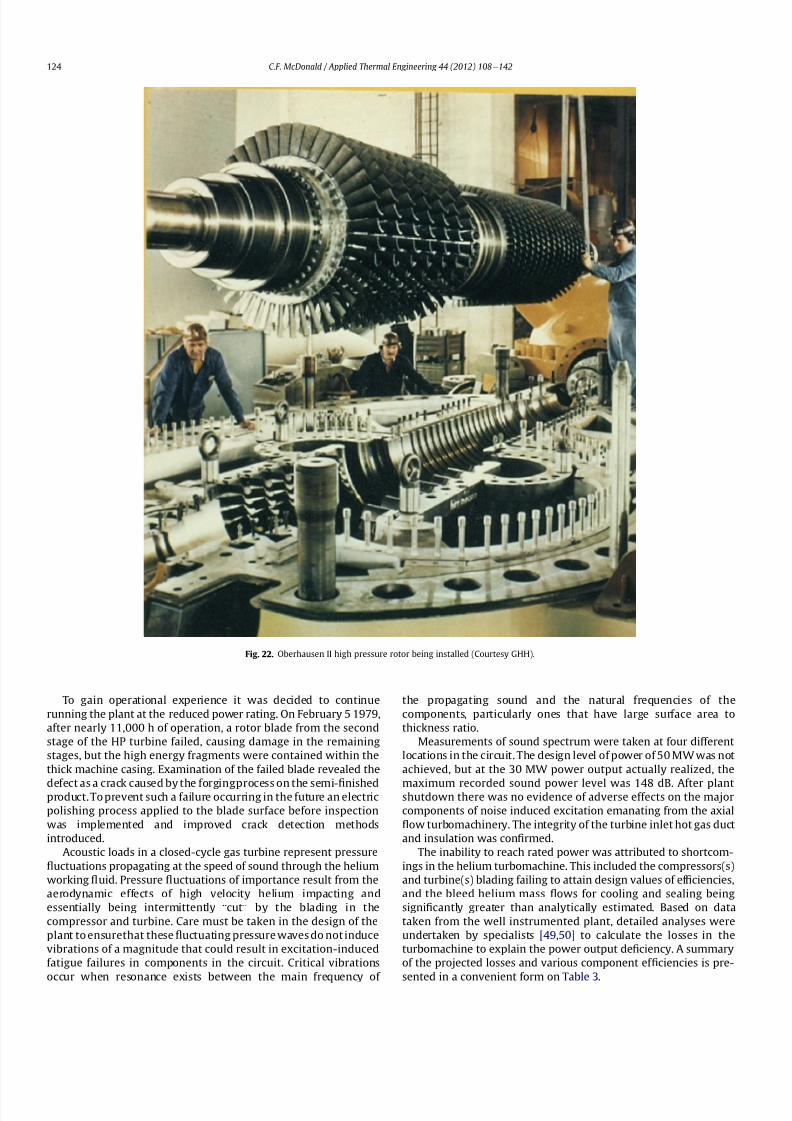
8112019 Helium Turbomachinery Operating Experience From Gas Turbine Power Plants
httpslidepdfcomreaderfullhelium-turbomachinery-operating-experience-from-gas-turbine-power-plants 1735
To gain operational experience it was decided to continue
running the plant at the reduced power rating On February 5 1979
after nearly 11000 h of operation a rotor blade from the second
stage of the HP turbine failed causing damage in the remaining
stages but the high energy fragments were contained within the
thick machine casing Examination of the failed blade revealed the
defect as a crack caused by the forgingprocess on the semi-1047297nishedproduct To prevent such a failure occurring in the future an electric
polishing process applied to the blade surface before inspection
was implemented and improved crack detection methods
introduced
Acoustic loads in a closed-cycle gas turbine represent pressure
1047298uctuations propagating at the speed of sound through the helium
working 1047298uid Pressure 1047298uctuations of importance result from the
aerodynamic effects of high velocity helium impacting and
essentially being intermittently ldquocutrdquo by the blading in the
compressor and turbine Care must be taken in the design of the
plant to ensurethat these 1047298uctuating pressure waves do not induce
vibrations of a magnitude that could result in excitation-induced
fatigue failures in components in the circuit Critical vibrations
occur when resonance exists between the main frequency of
the propagating sound and the natural frequencies of the
components particularly ones that have large surface area to
thickness ratio
Measurements of sound spectrum were taken at four different
locations in the circuit The design level of power of 50 MW was not
achieved but at the 30 MW power output actually realized the
maximum recorded sound power level was 148 dB After plantshutdown there was no evidence of adverse effects on the major
components of noise induced excitation emanating from the axial
1047298ow turbomachinery The integrity of the turbine inlet hot gas duct
and insulation was con1047297rmed
The inability to reach rated power was attributed to shortcom-
ings in the helium turbomachine This included the compressors(s)
and turbine(s) blading failing to attain design values of ef 1047297ciencies
and the bleed helium mass 1047298ows for cooling and sealing being
signi1047297cantly greater than analytically estimated Based on data
taken from the well instrumented plant detailed analyses were
undertaken by specialists [4950] to calculate the losses in the
turbomachine to explain the power output de1047297ciency A summary
of the projected losses and various component ef 1047297ciencies is pre-
sented in a convenient form on Table 3
Fig 22 Oberhausen II high pressure rotor being installed (Courtesy GHH)
CF McDonald Applied Thermal Engineering 44 (2012) 108e142124
8112019 Helium Turbomachinery Operating Experience From Gas Turbine Power Plants
httpslidepdfcomreaderfullhelium-turbomachinery-operating-experience-from-gas-turbine-power-plants 1835
The plant operated for approximately 24000 h and was shut-
down and decommissioned in 1988 when the coke-oven gas supply
for the heater was no longer available A total plant operating time
of about 11500 h had been at the design turbine inlet temperature
of 750 C (1382 F) Turbomachinery related experience gained
from operation of this large helium gas turbine plant was extremely
valuable While many of the functions performed well from the
onset and others worked satisfactorily after modi1047297cations were
made serious unexpected problems were encountered
The achieved electrical power output of only 60 percent of the
design value was initially thought to be due to a grossly excessive
system pressure loss However when the data was carefully eval-uated it was found that 85 percent of the 20 MW power loss was
attributed to turbomachine related problems as delineated on
Table 3
To remedy this power de1047297ciency it was clear that a major re-
design of the turbomachinery would be required While replace-
ment of the gas turbine was not contemplated a study was
undertaken based on data from the plant and new technologies
that had become available since the initial design Based on the
1047297ndings a new turbomachine layout concept was suggested [43]
and a simplistic view of the rotor arrangement is shown on Fig 24
A more conventional single-shaft arrangement was proposed with
the two compressors and turbine having a rotational speed of
5400 rpm A gearbox was still retained to give a generator rota-
tional speed of 3000 rpm Based on prevailing technology at the
time the requirements for such a gearbox would have been moredemanding since the 50 MW from the turbine to the generator
would have to be transmitted through it This would necessitate
a larger system to pump 1047297lter and cool the bearing lubrication oil
To remedy the very large losses in the compressors and turbines
the number of stages would have to be increased In the case of the
compressors the use of lighter aerodynamically loaded higher
ef 1047297ciency stages with 50 percent reaction blading was
recommended
7 High temperature helium test facility (HHV)
71 Background
In the late 1960rsquos with large numbers of orders placed for 1047297rst
generation light water reactor nuclear power plants studies were
initiated for next generation power plants with higher ef 1047297ciency
potential Following the initial operational success of the 1047297rst three
small helium cooled HTR plants (ie Dragon in the UK Peach
Bottom I in the USA and AVR in Germany) studies on larger plants
based on the use of both Rankine steam cycle and helium closed
Brayton cycle power conversion systems were undertaken In the
early 1970rsquos emphasis was placed on nuclear gas turbine plant
designs with larger power output both in the USA (for the
HTGR eGT) and in Europe (for the HHT) Work in the USA was
limited to only paper studies [18] The much larger program in
Germany (with participation by Swiss companies for the turbo-
machine heat exchangers and cooling towers) included a well
planned development testing strategy to support the plant design
Fig 23 Cross-section of Oberhausen II low pressure helium turbine (Courtesy GHH)
Table 3
Oberhausen II helium turbine plant power losses
Componentcause Design
value
Measured Power loss
MW
Compressors
B Flow losses in inlet diffusers
and blades
Low pressure ef 1047297ciency 870 826 13
High pressure ef 1047297ciency 855 779 40
Turbines
B Blade gap and 1047298ow losses
High pressure ef 1047297ciency 883 823 39
B Pro1047297le losses due to Remachined
blades after having detected
damaged blades
Low pressure ef 1047297ciency 900 856 24
BSealing leakage and cooling 1047298ows
in all turbomachines Kgsec
18 75 53
B Circuit pressure losses
(Ducting Hxrsquos etc)
102 128 26
B Miscellaneous heat losses 05
Total power loss 200 MW
Notes (1) Plant designed for electrical power output of 50 MW actual power output
measured 30 MW
(2) Power de1047297ciency of20 MW based on measurements taken and then recalculated
for the rated plant output
(3) 85 of Power loss attributed to helium turbomachinery related issues
CF McDonald Applied Thermal Engineering 44 (2012) 108e142 125
8112019 Helium Turbomachinery Operating Experience From Gas Turbine Power Plants
httpslidepdfcomreaderfullhelium-turbomachinery-operating-experience-from-gas-turbine-power-plants 1935
While the reference HHT plant for eventual commercializationembodied a very large single helium gas turbine rated at 1240 MW
this was to be preceded by a nuclear demonstration plant rated at
676 MW [51] To support the design of this plant technology
generated from the following was planned 1) operational experi-
ence from the aforementioned Oberhausen II 50 MW helium gas
turbine power plant and 2) testing of components in a large high
temperature helium test facility as discussed below
72 Development facilitytesting objectives
An overall view of the HHV test facility sited in Julich in
Germany is shown on Fig 25 and since this has been reported on
previously [52] it will only be brie1047298
y covered in this section Tominimize risk and assure the performance integrity and reliability
of the nuclear demonstration plant some non-nuclear testing of
the major components especially the helium turbomachine was
deemed essential Because of the limitations of a conventional
closed-cycle helium gas turbine power plant particularly the
temperature limitations of existing fossil-1047297red and electrical
heaters a new type of test facility was foreseen
A simpli1047297ed schematic line diagram of the HHV circuit is shown
on Fig 26 The major design parameters are shown on Fig 27
together with the temperatureeentropy diagram which is conve-
nient for describing the unique relationship between the compo-
nents in the closed helium loop Starting at the lowest pressure in
Fig 24 Proposed new concept for Oberhausen II helium gas turbine rotating assembly to remedy problems encountered during operation of the 50 MWe power plant (Courtesy
EVO)
Fig 25 HHV helium turbomachinery test facility (Courtesy BBC)
CF McDonald Applied Thermal Engineering 44 (2012) 108e142126
8112019 Helium Turbomachinery Operating Experience From Gas Turbine Power Plants
httpslidepdfcomreaderfullhelium-turbomachinery-operating-experience-from-gas-turbine-power-plants 2035
the system the helium is compressed (Ae
B) its temperatureincreasing to 850 C (1562 F) before 1047298owing through the test
section (BeC) After being cooled slightly (CeD) the helium is
expanded in the turbine (DeA) down to the compressor inlet
conditions completing the loop There is no power output from the
system and without the need for an external heater the
compression heat is used to raise the helium to the maximum
system temperature in what can be described as a very large heat
pump The required compressor power is 90 MW and to supple-
ment the 45 MW generated by expansion in the turbine external
power is provided by a 45 MW synchronous electrical motor A
cooler is required to remove the compression heat that is contin-
uously put into the closed helium loop and this is done by bleeding
about 5 percent of the mass 1047298ow after the compressor cooling it
and re-introducing it into the circuit close to the turbine inlet In
addition to testing the turbomachine the facility was engineered
with a test section to accommodate other small components (eg
hot gas 1047298ow regulation valves bypass valves insulation con1047297gu-
rations and types of hot gas duct construction) With the highest
temperature in the system being at the compressor exit the facility
had the capability to provide helium at a temperature up to 1000 C
(1832 F) for short periods at the entrance to the test section
While a higher ef 1047297ciency of the planned nuclear demonstration
plant could be projected with a turbine inlet temperature in the
range 950e1000 C (1742e1832 F) this would have necessitated
either turbine blade cooling or the use of a high temperature alloy
such as Titanium Zirconium Molybdenum (TZM) At the time it was
felt that using either of these would have added cost and risk to theprojectso a conventionalnickel-basedalloyas usedin industrialgas
turbines was selected for the 850 C design value of turbine inlet
temperature this negating the needfor actual internal bladecooling
However a complex internal coolingsystemwas neededto keep the
Fig 26 Cycle diagram of HHV test loop (Courtesy BBC)
Fig 27 Salient features of HHV helium turbomachinery (Courtesy BBC)
CF McDonald Applied Thermal Engineering 44 (2012) 108e142 127
8112019 Helium Turbomachinery Operating Experience From Gas Turbine Power Plants
httpslidepdfcomreaderfullhelium-turbomachinery-operating-experience-from-gas-turbine-power-plants 2135
turbine discs and blade root attachments and casings to acceptable
temperatures commensurate with prescribed stress limitations for
thelife of theturbomachine In addition a heliumsupplywas needed
to provide a buffering system for the various labyrinth seals
In a direct Brayton cycle nuclear gas turbine the turbomachine is
installed in the reactor circuit and via the hot gas duct heated
helium is transported directly from the reactor core to the turbine
From the safety licensing and reliability standpoints there are
various seals that must perform perfectly A helium buffered
labyrinth seal system is necessary to prevent bearing lubricating oil
ingress to the closed helium loop Since in the proposed HHT plant
design the drive shaft from the turbine to the generator penetrates
the reactor primary system pressure boundary two shaft seals are
needed one a dynamic seal when the shaft is rotating and a static
seal when the turbomachine is not operating Testing of these seals
in a size and operating conditions representative of the planned
commercial power plant was considered to be a licensing must
The mechanical integrity of the rotating assembly must be
assured there being two major factors necessitating testing the
machine at full speed and temperature and at high pressure
namely 1) loading the blading under representative centrifugal and
gas bending stresses and 2) to monitor vibration and con1047297rm rotor
dynamic stability For the design of the planned commercial planta knowledge of the acoustic emissions by the turbomachine and
propagation in the closed circuit was required Data from the HHV
facility would enable dynamic responses of the major components
(especially the insulation) resulting from excitation by the sound
1047297eld to be calculated
The circuit was instrumented to gather data on the effectiveness
of the hot gas duct insulation thermal expansion devices hot gas
valves helium puri1047297cation system instrumentation and the
adequacy of the coatings applied to mating metallic surfaces to
prevent galling or self-welding Details of the turbomachinery and
the experience gained from the operation of the HHV facility are
covered in the following sections
73 Helium turbomachine
A cross-section of the turbomachine is shown on Fig 28 The
single-shaft rotating assembly consists of 8 compressor stagesand 2
turbine stages and had a weighton the order of 66 tons(60000 kg)
The hub inner and outer diameters are 16 m (525 ft) and 18 m
(59 ft) respectively the blading axial length being 23 m (75 ft)The
span between the oil bearings being 57 m (187 ft) The physical
dimensions of the turbogroup shown on Fig 28 correspond to
a machine rated at about 300 MW The oil bearings operate in
a helium environment and the diameters of the labyrinths and
1047298oating ring shaft seals to prevent oil ingress are representative of
a machine rated at about 600 MW The complexity of the machine
design especially the rotor cooling system sealing system very
large casing and heat insulation have been reported previously
[53e55]
To ensure high structural integrity the rotor was constructed by
welding together the forged compressor and turbine discs The
compressor had 8 stages each having 56 rotor and 72 stator blades
The turbine had 2 stages each having 90 stator and 84 rotor blades
An appreciation for the large size of the rotating assembly can be
seen from Fig 29 The rotor blades have 1047297r-tree attachments
embodying cooling channels Since the temperature and pressure
do not vary very much along the blading in the 1047298ow direction an
intricate rotor and stator cooling system was required Channels in
both the blade roots and the spacers between adjacent blade rows
form an axial geometry for the passage of a cooling helium supplyto keep the temperature of the multiple discs below 400 C
(752 F) The design of this was a challenge since the rotor and
stator blade attachments of both the 8 stage compressor and 2
stage turbine had to be cooled Excessive leakage had to be avoided
since this would have prevented the speci1047297ed compressor
discharge temperature (ie the maximum temperature in the
circuit) from being reached
In the 1970rsquos and early 1980rsquos signi1047297cant studies were carried
out on large helium gas turbines by various organizations [56e62]
In this era there was general agreement that testing of the turbo-
machine in one form or another in non-nuclear facilities be
undertaken to resolve areas of high risk (eg seals bearings cooling
systems rotor dynamic stability compressor surge margin
dynamic response rotor burst protection etc) before installationand operation of a large gas turbine in a nuclear environment
This low risk engineering philosophy which prevailed at the time
in both Germany and the USA emphasized the importance of
Fig 28 Cross-section of HHV helium turbomachinery (Courtesy BBC)
CF McDonald Applied Thermal Engineering 44 (2012) 108e142128
8112019 Helium Turbomachinery Operating Experience From Gas Turbine Power Plants
httpslidepdfcomreaderfullhelium-turbomachinery-operating-experience-from-gas-turbine-power-plants 2235
the HHV test facility as being an important step towards the
eventual deployment of a high ef 1047297ciency nuclear gas turbine power
plant
74 Initial operation of the HHV facility
During commissioning of the plant in 1979 oil ingress into the
helium circuit from the seal system occurred twiceThe 1047297rst ingressof oil between 600 and 1200 kg (1322 and 2644 lb) was due to
a serious operatorerror and the absence of an isolation valve in the
system The oil in the circuit was partly coked and formed thick
deposits on the cold and hot surfaces of the turbomachinery and in
other parts of the closed loop including saturation of the 1047297brous
insulation The fouled metallic surfaces were cleaned mechanically
and chemically by cracking with the addition of hydrogen and
additives The second oil ingress was due to a mechanical defect in
the labyrinth seal system The quantity of oil introduced was small
and it was removed bycracking at a temperature of 600 C (1112 F)
and with the use of additives To obviate further oil ingress inci-
dents the labyrinth seal system was redesigned The buffer and
cooling helium system piping layout was modi1047297ed to positively
eliminate oil ingress due to improper valve operation and toprevent further human error
Pressure and leak detection tests of the HHV test facility at
ambient temperature showed good leak tightness for the turbo-
machine 1047298anged joints and of the main and auxiliary circuits
However at the operating temperature of 850 C (1562 F) large
helium leaks were detected The major 1047298anges had been provi-
sioned with lip seals and the 1047297rst step was to weld the closures A
large leak persisted at the front 1047298ange of the turbomachine This
was diagnosed as being caused by a non-uniform temperature
distribution during initial operation resulting in thermal stresses
creating local gaps This problem was overcome by redesign of the
cooling system with improved gas 1047298ow distribution and 1047298ow rates
to give a more uniform temperature gradient The leakage from the
system was reduced to on the order of 020e
040 percent of the
helium inventory per day this being of the same magnitude as in
other closed helium circuits as discussed in Section 65
It should be mentioned that in addition to the HHV experience
bearing oil ingress into the circuits and system loss of the working
1047298uid in other closed-cycle gas turbine plants have occurred In all of
these fossil-1047297red facilities 1047297xing leaks and removal of oil deposits
were undertaken based on conventional hands-on approaches but
nevertheless such operations were time-consuming However if a new and previously untested helium turbomachine operating in
a direct cycle nuclear gas turbine plant experienced an oil ingress
the rami1047297cations would be severe The likely use of remote
handling equipment to remove the turbomachine from the vessel
machine disassembly (including breaking the welded 1047298ange joints)
and removal of oil from the radioactively contaminated turbo-
machine blade surfaces and system insulation would be time
consuming A diagnosis of the failure would be required before
a spare turbomachine could be installed and this plant downtime
could adversely affect plant availability
75 Experience gained
Afterresolutionof the aforementionedproblems the HHVfacilitywas started in the Spring of 1981 and in an orderly manner was
brought up to full pressure and a temperature of 850 C (1562 F)
During a 60 h run the functioning of the instrumentation control
and safety systems were veri1047297ed During these tests the ability to
stop the turbomachine from full operating conditions to standstill
within 90 s was demonstrated After system depressurization the
plant was then run up again to full operating conditions with no
problems experienced The HHV facility was successfully run for
about 1100 h of which theturbomachineryoperated forabout325 h
at a temperature of 850 C The test facility was extensively instru-
mented and interpretation and analysis of the data recorded gave
positive and favorable results in the following areas
The complex rotor cooling system which was engineered to
assure that the temperature of the discs be kept below 400
C
Fig 29 HHV helium turbomachine rotating assembly (size equivalent to a 300 MWe machine) being installed in a pressure vessel (Courtesy BBC)
CF McDonald Applied Thermal Engineering 44 (2012) 108e142 129
8112019 Helium Turbomachinery Operating Experience From Gas Turbine Power Plants
httpslidepdfcomreaderfullhelium-turbomachinery-operating-experience-from-gas-turbine-power-plants 2335
(752 F) was demonstrated to be effective The measured rotor
coolant 1047298ows (about 3 percent of the mass1047298ow passing through the
machine) were slightly larger than had been estimated and this
resulted in measured turbine disc temperatures lower than pre-
dicted [55]
The dynamic labyrinth shaft seal functioned well at the full
temperature and pressure conditions and met the requirement of
zero oil ingress into the helium circuit The measured rotor oscil-
lation did not have any adverse effect on the shaft sealing system
The static rotor seal (for shutdown conditions) functioned without
any problems
The compressor and turbine blading hadef 1047297ciencies higher than
predicted The structural integrity of the rotor proved to be sound
when operating at 3000 rpm under the maximum temperature and
pressure conditions The stiff rotor shaft had only slight unbalance
and thermal distortion and measured oscillations were in the range
typical of large steam turbines
Sound power spectrum measurements were taken in four
different locations in the circuit These were taken to determine the
spectrum and intensity of the sound generated and propagated by
the turbomachinery and the resultant vibration of internal
components The maximum sound power level in the helium
circuit was160 dB Numerous strain gages were placedin the circuitto determine the in1047298uence of the sound 1047297eld particularly on the
fatigue strength of the turbine inlet hot gas duct In later examining
the internal components there was no evidence of excessive
vibration of the components especially the ducting and the insu-
lation Based on the measurements and calculations it was
concluded that the fatigue strength limit of the components would
not be exceeded during the designed life of the planned commer-
cial nuclear gas turbine power plant
In a direct cycle nuclear gas turbine the hot gas duct used to
transport the helium from the reactor core to the turbineis a critical
component The hot gas duct in the HHV facility performed well
mechanically and con1047297rmed the adequacy of the thermal expan-
sion devices From the thermal standpoint the 1047297ber insulation
performed better than the metallic type
After dismantling the HHV facility there were no signs of
corrosion or erosion of the turbine or compressor blading While
the total number of hours operated was limited the coatings
applied to mating metallic surfaces to prevent galling and frictional
welding in the oxidation-free helium worked well
The helium buffer and cooling system worked well However
problems remained with the puri1047297cation of the buffer helium The
oil separation system consisting of a cyclone separator and a wire
mesh and a down stream 1047297ber 1047297lter needed further improvement
In late 1981 a decision was made to cancel the HHT project and
the HHV facility was shutdown The design and operational expe-
rience gained from the running of this facility would have been
extremely valuable had the nuclear gas turbine power plant
concept moved towards becoming a reality The identi1047297cation of
somewhat inevitable problems to be expected in such a complexturbomachine and their resolution were undertaken in a timely
and cost effective manner in the non-nuclear HHV facility This
should be noted for future nuclear gas turbine endeavors since
remedying such unexpected problems in the case of a new and
untested large helium turbomachine being operated for the 1047297rst
time using nuclear heat could result in very complex repair
Fig 30 Speci1047297
c speed-speci1047297
c diameter array for gas circulators in various gas-cooled nuclear plants
CF McDonald Applied Thermal Engineering 44 (2012) 108e142130
8112019 Helium Turbomachinery Operating Experience From Gas Turbine Power Plants
httpslidepdfcomreaderfullhelium-turbomachinery-operating-experience-from-gas-turbine-power-plants 2435
activities and extended plant downtime and indeed adding risk to
the overall success of the nuclear gas turbine concept
8 Circulators used in gas-cooled reactor plants
Circulators of different types will be needed in future helium
cooled nuclear plants these including the following 1) primary
loop circulator for possible next generation steam cycle power andcogeneration plants 2) for future indirect cycle gas turbine plants
3) shut down cooling circulators forall HTRand VHTR plants and 4)
for various circulators needed in future VHTR high temperature
process heat plant concepts The technology status of operated
helium circulators is brie1047298y addressed as follows
81 Background
It would be remiss not to mention experience gained in the past
with gas circulators and while not gas turbines they are rotating
machines that operate in the primary loop of a helium cooled
reactor With electric motor drives there are basically two types of
compressor rotor con1047297gurations namely radial and axial 1047298ow
machinesIn a single stage form the centrifugal impeller is used for high
stage pressure rise and low volume 1047298ow duties whereas the axial
type covers low pressure rise per stage and high volume 1047298ow The
selection of impeller type is very much related to the working
media type of bearings drive type rotor dynamic characteristics
and installation envelope A wide range of circulators have operated
and a well established technology base exists for both types [63] A
useful portrayal of compressor data in the form of quasi- non-
dimensional parameters (after Balje [64]) showing approximate
boundaries for operation of high ef 1047297ciency axial and radial types is
shown on Fig 30 (from Ref [65])
Both high speed axial and lower speed radial 1047298ow types are
amenable to gas oil and magnetic bearings From the onset of
modularHTR plant studies theuse of active magnetic bearings[6667]offered a solution to eliminate lubricating oil into the reactor circuit
and this tribology technology is attractive for use in submerged
rotating machinery in the next generation of HTR plants [68]
While now dated an appreciation of the main design features of
typical electric motor-driven helium circulators have been reported
previously namely an axial 1047298ow main circulator for a modular
steam cycle HTR plant [69] and a representative radial 1047298ow shut-
down cooling circulator [70]
The operating experience gained from three particular circula-
tors is brie1047298y included below because of their relevance to the
design of helium turbomachinery in future HTR plant variants
82 Axial 1047298ow helium circulator
Since all of the aforementioned predominantly European
helium gas turbines used axial 1047298ow turbomachinery it is of interest
to mention a helium axial 1047298ow circulator that operated in the USA
and to brie1047298y discuss its design parameters and features The
330 MW Fort St Vrain HTGR featured a Rankine cycle power
conversion system Four steam turbine driven helium circulators
were used to transport heat from the reactor core to the steam
generators The complete circulator assemblies were installed
vertically in the prestressed concrete reactor vessel [71e73]
A cross-section of the circulator is shown on Fig 31 with thecompressor rotor and stator visible on the left hand end of the
machine Based on early 1960rsquos technology a decision was made to
use water lubricated bearings and from the overall plant reliability
and availability standpoints this later proved to be a bad choice
Within the vertical circulator assembly there were four 1047298uid
systems namely the helium reactor coolant water lubricant in the
bearings steam for the turbine drive and high pressure water for
the auxiliary Pelton wheel drive During plant transients the pres-
sures and temperatures of these four 1047298uids oscillated considerably
and the response of the control and seal systems proved to be
inadequate and resulted in considerable water ingress from the
bearing cartridge into the reactor helium circuit The considerable
clean up time needed following repeated occurrences of this event
resulted in long periods of plant downtime and this had an adverseeffect on plant availability This together with other technical
Fig 31 Cross section of FSV helium circulator (Courtesy general Atomics)
CF McDonald Applied Thermal Engineering 44 (2012) 108e142 131
8112019 Helium Turbomachinery Operating Experience From Gas Turbine Power Plants
httpslidepdfcomreaderfullhelium-turbomachinery-operating-experience-from-gas-turbine-power-plants 2535
dif 1047297culties eventually contributed to the plant being prematurely
decommissioned
On the positive side in the context of this paper the helium
circulators operated for over 250000 h and exhibited excellent
helium compressor performance good mechanical integrity and
vibration-free operation The rotating assembly showing the axial
1047298ow compressor and steam turbine rotors together with a view of
the machine assembly are given on Fig 32 The helium compressor
consists of a single stage axial rotor followed by an exit guide vane
The machine was designed for axial helium 1047298ow entering and
leaving the stage and this can be seen from the velocity triangles
shown on Fig 33 which also includes the de1047297nition of the various
aerodynamic parameters Major design parameters and features of
this helium circulator are given on Table 4 Related to an earlier
discussion on the degree of reaction for axial 1047298ow compressors the
value for this conventional single stage circulator is 78 percent All
of the major aerothermal and structural loading criteria were
within established boundaries for an axial compressor having high
ef 1047297ciency and a good surge margin
The compressor gas 1047298ow path and blading geometries were
established based on prevailing industrial gas turbine and aero-
engine design practice A low Mach number (025) a high Reynolds
number (3 106) together with a modest stage loading (ie
a temperature rise coef 1047297cient of 044) and an acceptable value of
diffusion factor (042) were some of the factors that contributed to
a helium circulator that had a high ef 1047297ciency and a good pressure
rise- 1047298ow characteristic The large rotor blade chord and thick blade
section for this single stage circulator are necessary to accommo-
date the high bending stress characteristic of operation in a high
pressure environment The solidity and blade camber were opti-
mized for minimum losses
There were essentially two reasons for including this single-
stage axial 1047298ow compressor that operated in a helium cooled
reactor although its overall con1047297guration can be regarded as a 1047297rst
and last of a kind A rotor blade from this circulator as shown onFig 34 was based on a NASA 65 series airfoil which at the time
were one of the best performing cascades for such low Mach
number and high Reynolds number applications Interestingly it
has almost the same blade height aspect ratio and solidity as would
be used in the 1047297rst stage of an LP compressor in a helium turbo-
machine rated on the order of 250 MW
The second point of interest is that the helium mass 1047298ow rate
through the single stage axial compressor (rated at 4 MWe) is
110 kgs compared with 85 kgs through the multistage compressor
in the 50 MWe Oberhausen II helium gas turbine plant However
the volumetric 1047298ow through the Oberhausen axial compressor is
higher than that through the circulator by a factor of 16 this again
pointing out that the Oberhausen II plant was designed for high
volumetric 1047298ow to simulate the much larger size of turboma-chinery that was planned at the time in Germany for use in future
projected nuclear gas turbine power plants
83 High temperature helium circulator
For future helium turbomachines embodying active magnetic
bearings a challenge in their design relates to accommodating
elevated levels of temperature in the vicinity of the electronic
components In this regard it is of interest to note that a small very
high temperature helium axial 1047298ow circulator rated at 20 kW (as
shown on Fig 35) operated for more than 15000 h in an insulation
test facility in Germany more than two decades ago [74] The
signi1047297cance of this machine is that it operated with magnetic
bearings in a high temperature helium test loop with a circulatorgas inlet temperature of 950 C (1742 F) This necessitated the use
of ceramic insulation to ensure that the temperature in the vicinity
of the magnetic bearing electronics did not exceed a temperature of
about 150 C (300 F)
This machine although a very small axial 1047298ow helium blower
performed well and has been brie1047298y mentioned here since it
represents a point of reference for future helium rotating machines
capable operating with magnetic bearings in a very high temper-
ature helium environment
84 Radial 1047298ow AGR nuclear plant gas circulators
The electric motor-driven carbon dioxide circulators rated at
about 5 MW with a total runningtimein excess of 18 million hours
Fig 32 Fort St Vrain HTGR plant helium circulator (Courtesy General Atomics) (a)
Axial 1047298ow helium compressor and steam turbine rotating assembly (b) 4 MW helium
circulator assembly
CF McDonald Applied Thermal Engineering 44 (2012) 108e142132
8112019 Helium Turbomachinery Operating Experience From Gas Turbine Power Plants
httpslidepdfcomreaderfullhelium-turbomachinery-operating-experience-from-gas-turbine-power-plants 2635
in AGR nuclear power plants in the UK have demonstrated veryhigh availability [7576] To a high degree this can be attributed to
the fact that the machines were conservatively designed and proof
tested in a non-nuclear facility at full temperature and power
under conditions that simulated all of the nuclear plant operating
modes The test facility shown on Fig 36 served two functions 1)
design veri1047297cation of the prototype machine and 2) test of all new
and refurbished machines before they were installed in nuclear
plants Engineers currently involved in the design and development
of helium turbomachinery could bene1047297t from this sound testing
protocol to minimize risk in the deployment of helium rotating
machinery in future HTRVHTR plant variants
9 Helium turbomachinery development and testing
91 On-going development activities
The various helium turbomachines discussed in previous
sections operated over a span of about two decades starting in the
early 1960s From about 1990 activities in the nuclear gas turbine
1047297eld have been focused mainly on the design of modular GTeHTR
plant concepts In support of these plant studies many signi1047297cant
helium turbomachine design advancements have been made and
attention given to what development testing would be needed In
the last decade or so limited sub-component development has
been undertaken for helium turbomachines in the 250e300 MWe
size and these are brie1047298y summarized below
In a joint USARussia effort development in support of the
GTe
MHR turbomachine has been undertaken including testing in
the following areas magnetic bearings seals and rotor dynamicsfor the vertical intercooled helium turbomachine rated at 286 MWe
[77e80]
In Japan development activities have been in progress for
several years in support of the 274 MWe helium turbomachine for
the GTeHTR300 plant concept [2581] A detailed discussion on
the aerodynamic design of the axial 1047298ow helium compressor for
this turbomachine has been published in the open literature [82]
While the design methodology used for axial compressor design in
air-breathing industrial and aircraft gas turbines is generally
applicable for a multi-stage helium compressor a decision was
made by JAEA to test a small scale compressor in a helium facility
because of the inherent and unique gas 1047298ow path and type of
blading associated with operation in a high pressure helium
environment The major goal of the test was to validate the designof the 20 stage helium axial 1047298ow compressor for the GTeHTR300
plant
An axial 1047298ow compressor in a closed-cycle helium gas turbine is
characterized by the following 1) a large number stages 2) small
blade heights 3) high hub-to-tip ratio 4) a long annulus with
small taper that tends to deteriorate aerodynamic performance as
a result of end-wall boundary layer length and secondary 1047298ow 5)
low Mach number 6) high Reynolds number and 7) blade tip
clearances that are controlled by the gap necessary in the magnetic
journal and catcher bearings While (as covered in earlier sections)
helium gas turbines have operated there is limited data in the
open literature on the performance of multi-stage axial 1047298ow
compressors operating in a high pressure closed-loop helium
environment
Fig 33 Velocity triangles for axial compressor stage
CF McDonald Applied Thermal Engineering 44 (2012) 108e142 133
8112019 Helium Turbomachinery Operating Experience From Gas Turbine Power Plants
httpslidepdfcomreaderfullhelium-turbomachinery-operating-experience-from-gas-turbine-power-plants 2735
A 13rd scale 4 stage compressor was designed to simulate the
stage interaction the boundary layer growth and repeated stage
1047298ow in an actual compressor The 1047297rst four stages were designed to
be geometrically similar to the corresponding stages in the
GTe
HTR300 compressor Details of the model compressor havebeen discussed previously [81] and are summarized on Table 5
from [83]
A cross-section of the compressor test model is shown on Fig 37
A view of the 4 stage compressor rotor installed in the lower casing
is shown on Fig 38 The test facility (Fig 39) is a closed helium loop
consisting of the compressor model cooler pressure adjustment
valve and a 1047298ow measurement instrument The compressor is
driven by a 3650 kW electrical motor via a step-up gear The rota-
tional speed of 10800 rpm (three times that of the compressor in
the GTeHTR300 plant) was selected to match blade speed and
Mach number in the full size compressor
Details of the planned aerodynamic performance objectives of
the 13rd scale helium compressor test have been published
previously [84] Extensivetesting of the subscale model compressorprovided data to validate the performance of the full size
compressor for the GTeHTR300 power plant The test data and
test-calibrated CFD analyses gave added insight into the effect of
factors that impact performance including blade surface roughness
and Reynolds number
Based on advanced aerodynamic methodology and experi-
mental validation [82] there is now a sound basis for added
con1047297dence that the design goals of 90 percent polytropic ef 1047297ciency
and a design point surge margin of 20 percent are realizable in
a large multistage axial 1047298ow compressor for a future nuclear gas
turbine plant
In a similar manner a design of a one third size single stage
helium axial 1047298ow turbine has been undertaken and a cross
section of the machine is shown on Fig 40 (from Ref [81]) This
Table 4
Major features of axial 1047298ow helium circulator
Helium 1047298ow rate kgsec 110
Inlet temperature C 394
Inlet pressure MPa 473
Pressure rise KPa 965
Volumetric 1047298ow m3sec 32
Compressor type Single stage axial
Compressor drive Steam turbine
Bearing type Water lubricated
Rotational speed rpm 9550
Power MW 40
Rotor tip diameter mm 688
Rotor tip speed msec 344
Number of rotor blades 31
Number of stator blades 33
Blade height mm 114
Hub-to-tip ratio 067
Axial velocity msec 157
Flow coef 1047297cient 055
Temperature rise coef 1047297cient 044
Degree of reaction 078
Mean rotor solidity 128
Rotor aspect ratio 155
Rotor Mach number 025
Rotor diffusion factor 042
Rotor Reynolds number 3106
Speci1047297c speed 335
Speci1047297c diameter 066
Blade root thickness 15
Airfoil type NASA 65
Rotor blade chord mm 94e64
Stator blade chord mm 79
Rotor centrifugal stress MPa 125
Rotor bending stress MPa 30
Circulator(s) operating Hours gt250000
Fig 34 Rotor blade from single stage axial 1047298ow helium circulator (Courtesy General
Atomics)
Fig 35 20 kW axial 1047298ow helium circulator with magnetic bearings operated in 1985 in
an insulation test loop with a gas inlet temperature on 950
C (Courtesy BBC)
CF McDonald Applied Thermal Engineering 44 (2012) 108e142134
8112019 Helium Turbomachinery Operating Experience From Gas Turbine Power Plants
httpslidepdfcomreaderfullhelium-turbomachinery-operating-experience-from-gas-turbine-power-plants 2835
single stage scale model turbine for validity of the full size turbine
has been built and plans made to test the aerodynamic
performance
92 Nuclear gas turbine helium turbomachine testing
In planning for the 1047297rst nuclear gas turbine plant projected to
enter service perhaps in the third decade of the 21st century
a major decision has to be made as to what extent the large helium
turbomachine should be tested prior to operation on nuclear heat
Issues essentially include cost impact on schedule but the over-
riding one is risk Certainly turbomachine component testing will
be undertaken including the compressor (as discussed in the
previous section) and turbine performance seals cooling systems
hot gas valves thermal expansion devices high temperature
insulation rotor fragment containment diagnostic systems
instrumentation helium puri1047297cation system and other areas to
satisfy safety licensing reliability and availability concerns The
major point is really whether a full size or scaled-down turbo-machine be tested early in the project in a non-nuclear facility
To obviate the need for pre-nuclear testing of a large helium
turbomachine a view expressed by some is that advantage can be
taken of formidable technology bases that exist today for large
industrial gas turbines and high performance aeroengines On the
other hand it is the view of some including the author that very
complex power conversion system components especially those
subjected to severe thermal transients donrsquot always perform
exactly as predicted by analysts and designers even using sophis-
ticated computer codes This was exempli1047297ed in the case of the
turbomachine in the aforementioned Oberhausen II helium gas
turbine plant
The need for a helium turbomachine test facility goes beyond
just veri1047297
cation of the prototype machine Each newgas turbine for
commercial modular nuclear reactor plants would have to be proof
tested and validated before being transported to the reactor site
Similarly turbomachines that would be periodically removed from
the plant at say 7 year intervals during the plant operating life of 60
years for scheduled maintenance refurbishment repair or updat-ing would be again proof tested in the facility before re-entering
service
The direction that turbomachine development and testing will
take place for future helium gas turbines needs to be addressed by
the various organizations involved
Fig 36 AGR circulator test facility In the UK (Courtesy Howden)
Table 5
Major design parametersfeatures of model GTeHTR300 axial 1047298ow helium
compressor (Courtesy JAERI)
Scale of GTeHTR300 compressor 13
Helium mass 1047298ow rate (kgsec) 122
Helium volumetric 1047298ow rate (mV s) 87
Inlet temperature C 30
Inlet pressure MPa 0883Compressor pressure ratio at design point 1156
Number of stages 4
Rotational speed rpm 10800
Drive motor power kW 3650
Hub diameter mm 500
Rotor tip diameter (1st4th stage mm) 568566
Hub-to-tip ratio (1st stage) 088
Rotor tip speed (1st stage msec) 321
Number of rotorstator blades (1st stage) 7294
Rotorstator blade height (1st stage mm) 34337
Rotor stator blade c hor d l eng th (1st stage mm) 2620
Rotorstator solidity (1st stage) 119120
Rotorstator aspect ratio (1st stage) 1317
Flow coef 1047297cient 051
Stage loading factor 031
Reynolds number at design point 76 l05
CF McDonald Applied Thermal Engineering 44 (2012) 108e142 135
8112019 Helium Turbomachinery Operating Experience From Gas Turbine Power Plants
httpslidepdfcomreaderfullhelium-turbomachinery-operating-experience-from-gas-turbine-power-plants 2935
10 Helium turbomachinery lessons learned
101 Oberhausen II gas turbine and HHV test facility
It is understandable that 1047297rst-of-a-kind complex turboma-
chinery operating with an inert low molecular weight gas such as
helium will experience unique and unexpected problems In the
operation of the two pioneering large helium turbomachines in
Germany there were many positive1047297ndings which could only have
been achieved by development testing Equally important some
negative situations were identi1047297ed many of which were remedied
In the case of the Oberhausen II helium gas turbine plant some of
the very serious problems encountered were not resolved Inves-
tigations were undertaken to rationalize the problems associated
with the large power de1047297ciency and a data base established to
ensure that the various anomalies identi1047297ed would not occur in
future large helium turbomachines
The experience gained from the operation of the Oberhausen II
helium gas turbine power plant and the HHV test facility have been
discussedin thetextand arepresentedin a summaryformon Table6
Fig 37 Cross-section of 13rd scale helium compressor test model (Courtesy JAEA)
Fig 38 Four stage helium compressor rotor assembly installed in lower casing (Courtesy JAEA)
CF McDonald Applied Thermal Engineering 44 (2012) 108e142136
8112019 Helium Turbomachinery Operating Experience From Gas Turbine Power Plants
httpslidepdfcomreaderfullhelium-turbomachinery-operating-experience-from-gas-turbine-power-plants 3035
102 Impact of 1047297ndings on future helium gas turbine
The long slender rotorcharacteristic of closed-cycle gas turbines
has resulted in shaft dynamic instability which in some cases has
resulted in blade vibration and failure and bearing damage This
remains perhaps the major concern in the design of large
(250e
300 MW) helium turbomachines for future nuclear gas
turbine plants With pressure ratios in the range of about 2e3 in
a helium system a combination of splitting the compressor (to
facilitate intercooling) and having a large number of compressor
and turbine stages results in a long and 1047298exible rotating assembly
andthis is exempli1047297ed by the rotorassembly shown on Fig13 With
multiple bearings (either oil lubricated or magnetic) the rotor
would likely pass through multiple bending critical speeds before
Fig 39 Helium compressor test facility (Courtesy JAEA)
Fig 40 Cross-section of single stage helium turbine test model (Courtesy JAEA)
CF McDonald Applied Thermal Engineering 44 (2012) 108e142 137
8112019 Helium Turbomachinery Operating Experience From Gas Turbine Power Plants
httpslidepdfcomreaderfullhelium-turbomachinery-operating-experience-from-gas-turbine-power-plants 3135
reaching the design speed While very sophisticated computer
codes will be used in the detailed rotor dynamic analyses the real
con1047297rmation of having rotor oscillations within prescribed limits
(to avoid blade bearing and seal damage) will come from actual
testingA point to be made here is that in operated fossil-1047297red closed-
cycle gas turbine plants it was possible to remedy problems asso-
ciated with rotor vibrations and blade failures in a conventional
manner In fact in some situations the casings were opened several
times and modi1047297cations made to facilitate bearing and seal
replacement and rotor re-blading and balancing
An accurate assessment of pressure losses must be made
particularly those associated with the helium entering and leaving
the turbomachine bladed sections Minimizing the system pressure
loss is important since it directly impacts the all important quotient
of turbine expansion ratio to compressor pressure ratio and power
and plant ef 1047297ciency
Based on the operating experience from the 20 or so fossil-1047297red
closed-cycle gas turbine plants using air as the working1047298
uid it was
recognized that future very high pressure helium gas turbines
would pose problems regarding the various seals in the turbo-
machine and obtaining a zero leakage system with such a low
molecular weight gas would be dif 1047297cult and this is discussed
below
When the Oberhausen II gas turbine plant and the HHV facility
operated over 30 years ago oil lubricated bearings were used to
support the heavy rotor assemblies and helium buffered labyrinth
seals were used to prevent oil ingressinto the heliumworking1047298uid
Initial dif 1047297culties encountered in both plants were overcome by
changes made to the seal geometries and for the operating lives of
the helium turbomachines no further oil ingress events were
experienced Twoseals were required where the turbine drive shaft
penetrated the turbomachine casing namely 1) a dynamic laby-
rinth seal and 2) a static seal for shutdown conditions In both
plants these seals functioned without any problems
Labyrinth seals were also required within the helium turbo-
machines to pass the correct helium bleed 1047298ow from the
compressor discharge for cooling of the turbine discs blade root
attachments and casings The fact that the very complex rotor
cooling system in the large helium turbomachine in the HHV test
facility operated well for the test duration of about 350 h with
a turbine inlet temperature of 850 C was encouragingIn the case of the Oberhausen II gas turbine plant analysis of the
test data revealed that the labyrinth seal leakage and excessive
cooling 1047298ows were on the order of four times the design value A
possible reason for this was that damage done to the labyrinth
seals caused excessive clearances when periods of excessive rotor
oscillation and vibration occurred during early operation of the
machine
Clearly 1047298uid dynamic and thermal management of the cooling
system and 1047298ow through the various labyrinth seals will require
extensive analysis design and development testing before the
turbomachine is operated on nuclear heat for the 1047297rst time
In future heliumgas turbine designs (with turbine inlet tempera-
tureslikelyontheorderof950C)the1047298owpathgeometriesofhelium
bledfromthecompressornecessarytocoolpartsoftheturbomachinewillbemorecomplexthanthosetestedto-dateInadditiontoproviding
acooling1047298owtotheturbinebladesanddiscsbladerootattachmentsand
casingsheliummustbetransportedtotheseveralmagneticbearingsto
ensure thatthe temperatureof theirelectronic components doesnot
exceedabout150C
The importance of the points made above is evidenced when
examining the data on Table 3 where a combination of excessive
pressure losses and high bleed 1047298ows contributed to about 40
percent of the power de1047297ciency in the Oberhausen II helium
turbine plant
Retaining overall system leak tightnessin closed heliumsystems
operating at high pressure and temperature has been elusive
including experience from the Fort St Vrain HTGR plant as dis-
cussed in Section 65 New approaches in the design of the plethoraof mechanical joints must be identi1047297ed Experience to-date has
shown that having welded seals on 1047298anges while minimizing
system leakage did not eliminate it
The importance of lessons learned from the operation of the
Oberhausen II helium turbine power plant and the HHV test facility
have primarily been discussed in the context of helium turbo-
machines currently being designed in the 250e300 MWe power
range However the established test data bases could also be
applied to the possible emergence in the future of two helium
cooled reactor concepts namely 1) an advanced VHTR combined
cycle plant concept embodying a smaller helium gas turbine in the
power range of 50e80 MWe [22] and 2) the use of a direct cycle
helium gas turbine PCS in a recently proposed all ceramic fast
nuclear reactor concept [85]
Table 6
Experience gained from Oberhausen II and HHV facility
Oberhausen II 50 MW helium gas turbine power plant
Positive results
e Rotating and static seals worked well
e No ingress of bearing lubricant oil into closed circuit
e Load change by inventory control worked well
e 100 Percent load shed by means of bypass valves demonstrated
e Turbine disc and blade root cooling system con1047297rmed
e Coatings on mating surfaces prevented galling and self-welding
e After 24000 h of operation no evidence of corrosion or erosion
e Coaxial turbine hot gas inlet duct insulation and integrity con1047297rmed
e Monitoring of complete power conversion system for steady state
and transient operation undertaken
Problem areas
e Serious power output de1047297ciency (30 MW compared with design
value of 50 MW)
e Compressor(s) and turbine(s) ef 1047297ciencies several points below predicted
e Higher than estimated system pressure loss
e Rotor dynamic instability and blade vibration
e Bearings damaged and had to be replaced
e Blade failure caused extensive damage in HP turbine but retained
in casing
e Very excessive sealing and cooling 1047298ow rates
e Absolute leak tightness not attainable even with welded 1047298ange lips
HHV test facility
Positive resultse Use of heat pump approach facilitated helium temperature capability
to 1000 C
e Large oompressorturbine rotor system operated at 3000 rpm Complex
turbine disc and blade root cooling system veri1047297ed
e Dynamic and static seals met requirement of zero oxl ingress into circuit
e Structural integrity of rotating assembly veri1047297ed at temperature of 850 C
e Measured rotor oscillations within speci1047297cation
e Compressor and turbine ef 1047297ciencies higher than predicted
e Coatings on mating metallic surfaces prevented galling and self-welding
e Instrumentation control and safety systems veri1047297ed
e Seal 1047298ows within speci1047297cation
e Machine stop from operating speed to shutdown in 90 s demonstrated
e Hot gas duct insulation and thermal expansion devices worked well
e After 1100 h of operation no evidence of corrosionof erosion
Problem areas
e Before commissioning a large oil ingress into the circuit occurred due
to serious operator error and absence of an isolation valve A second oilingress occurred due to a mechanical defect in the labyrinth seal system
These were remedied and no further oil ingress was experienced for the
duration of testing
e Cooling 1047298ows slightly larger than expected but this resulted in actual
disc and blade root temperatures lower than the predicted value of
400 C
e System leak tightness demonstrated when pressurized at ambient
temperature conditions but some leakage occured at 850 C even with
the seal welding of 1047298ange(s) lips
CF McDonald Applied Thermal Engineering 44 (2012) 108e142138
8112019 Helium Turbomachinery Operating Experience From Gas Turbine Power Plants
httpslidepdfcomreaderfullhelium-turbomachinery-operating-experience-from-gas-turbine-power-plants 3235
11 New technologies
It is recognized that in the 3 to 4 decades since the operation of
the helium turbomachines covered in this paper new technologies
have emerged which negate some of the early issues An example of
this is the technology transfer from the design of modern axial 1047298ow
gas turbines (ie industrial aircraft and aeroderivatives) that fully
utilize sophisticated CAE CAD CFD and FEA design software
Air breathing aerodynamic design practice for compressors and
turbines are generally applicable but the properties of helium and
the high system pressure have a signi1047297cant impact on gas 1047298ow
paths and blade geometries With short blade heights high hub-to-
tip ratios long annulus 1047298ow path length (with resultant signi1047297cant
end-wall boundary layer growth and secondary 1047298ow) and blade tip
clearances in some cases controlled by clearances in the magnetic
catcher bearing testing of subscale model compressors and
Fig 41 Gas turbine test facility for aircraft nuclear propulsion involving the coupling of a 32 MWt air-cooled reactor with two modi 1047297ed J-47 turbojet aeroengines each rated at
a thrust of about 3000 kg operated in 1960 (Courtesy INL)
Fig 42 Mobile 350 KWe closed-cycle nuclear gas turbine power plant operated in 1961 (Courtesy US Army)
CF McDonald Applied Thermal Engineering 44 (2012) 108e142 139
8112019 Helium Turbomachinery Operating Experience From Gas Turbine Power Plants
httpslidepdfcomreaderfullhelium-turbomachinery-operating-experience-from-gas-turbine-power-plants 3335
turbines will be needed While most of the operated helium tur-
bomachines discussed in this paper took place 3 or 4 decades ago it
is encouraging that the fairly recent test data and test-calibrated
CFD analysis from a subscale four stage model helium axial 1047298ow
compressor in Japan [80] gave a high degree of con1047297dence that
design goals are realizable for the full size 20 stage compressor in
the 274 MWe GTeHTR300 plant turbomachine
In the future the use of active magnetic bearings will eliminate
the issue of oil ingress however the very heavy rotor weight and
size of the journal and thrust bearings (and catcher bearings) of the
type for helium turbomachines in the 250e300 MWe power range
are way in excess of what have been demonstrated in rotating
machinery For plant designs retaining oil-lubricated bearings well
established dry gas seal technology exists particularly experience
gained from the operation of high pressure natural gas pipe line
compressors
For future nuclear helium gas turbine plants the designer has
freedom regarding meeting different frequency requirements that
exist in some countries These include use of a synchronous
machine (ie designed for 50 or 60 Hz grids) use of a gearbox drive
between the turbine and generator or the use of a frequency
converter which gives the designer an added degree of freedom
regarding the selection of speed for the rotating assemblyCompared with the past very sophisticated electronic control
systems instrumentation and diagnostic systems are available
today
12 Conclusions
In this review paper experience from operated helium turbo-
machines has been compiled based on open literature sources At
this stage in the evolution of HTR and VHTR plant concepts it is not
clear in what role form or time-frame the nuclear gas turbine will
emerge when commercialized By say the middle of the 21st
century all power plants will be operating with signi1047297cantly higher
ef 1047297ciencies to realize improved power generation costs and
reduced emissions In a nuclear gas turbine the helium turbo-machine will be a major contributor towards the achievement of
ef 1047297ciencies higher than 50 percent
While it has been 3 to 4 decades since the Oberhausen II helium
turbine power plant and the HHV high temperature helium turbine
facility operated signi1047297cant lessons were learned and the time and
effort expended to resolve the multiplicity of unexpected technical
problems encountered The remedial repair work was done under
ideal conditions namely that immediate hands-on activities were
possible This would not have been possible if the type of problems
experienced had been encountered in a new and untested helium
turbomachine operated for the 1047297rst time with a nuclear heat
source
While new technologies have emerged that negate many of the
early problems there are some uniquely inherent issues associatedwith for large helium turbines operating in a high pressure and
temperature environment and these include the following 1)
minimizing system leakage with such a low molecular weight gas
2) clearances in labyrinth seals to minimize helium bypass1047298ows 3)
the dynamic stability of long slender rotors 4) minimizing the
turbomachine inlet and outlet pressure losses 5) 1047298ow maldis-
tribution in complex ductturbomachine interfaces 6) integrity
veri1047297cation of the catcher bearings (journal and thrust) after
multiple rotor drops (following loss of the magnetic 1047297eld) during
the plant lifetime 7) assurances that high energy fragments from
a failed turbine disc are contained within the machine casing 8)
turbomachine installation and removal from a steel pressure vessel
and 9) remote handling and cleaning of a machine with turbine
blades contaminated with 1047297
ssion products
The need for a helium turbomachine test facility has been
emphasized to ensure that the integrity performance and reli-
ability of the machine before it operates the 1047297rst time on nuclear
heat Engineers currently involved in the design of helium rotating
machinery for all HTR and VHTR plant variants should take
advantage of the experience gained from the past operation of
helium turbomachinery
13 In closing-GT rsquos operated with nuclear heat
In the context of this paper it is germane to mention that two
gas turbines have actually operated using nuclear heat as brie1047298y
highlighted below
In the late 1950rsquos a program was initiated in the USA for aircraft
nuclear propulsion (ANP) While different concepts were studied
only the direct cycle air-cooled reactor reached the stage of
construction of an experimental reactor [86] A view of the large
nuclear gas turbine facility is given on Fig 41 and shows the air-
cooled and zirconiumehydride moderated reactor rated at
32 MWt coupled with two modi1047297ed J-47 turbojet engines each
rated with a thrust of about 3000 kg In this open cycle system the
high pressure compressor air was directly heated in the reactor
before expansion in the turbine and discharge to the atmosphere in
the exhaust nozzle The facility operated between 1958 and 1961 at
the Idaho reactor testing facility While perhaps possible during the
early years of the US nuclear program it is clear that such a system
would not be acceptable today from safety and environmental
considerations
The 1047297rst and indeed the only coupling of a closed-cycle gas
turbine with a nuclear reactor for power generation was under-
taken to meet the needs of the US Army In the late 1950 rsquos an RampD
program was initiated for a 350 kW trailer-mounted system to be
used in the 1047297eld by military personnel A prototype of the ML-1
plant shown on Fig 42 was 1047297rst operated in 1961 [8788]
It was based on a 33 MW light water moderated pressure tube
reactor with nitrogen as the coolant The closed-cycle gas turbine
power conversion system with nitrogen as the working 1047298uid hada turbine inlet temperature of 649 C (1200 F) and delivered
around 300 kW With changes in the Armyrsquos needs the project was
discontinued in 1965
While the experience gained from the above twounique nuclear
plants is clearly not relevant for future nuclear gas turbine power
plants that could see service in the third decade of the 21st century
these ambitious and innovative nuclear gas turbine pioneering
engineering efforts need to be recognized
Acknowledgements
The author would like to thank the following for helpful discus-
sions advice and for providing valuable comments on the initial
paper draft Prof Dr Hermann Haselbacher Hans Ulrich Frutschi DrXing Yan DrPeter Zenker Professor DavidGordon Wilson Professor
Aristide Massardo Arthur Harris DrFred Starr and DrGuido Bac-
caglini This paper has been enhanced by the inclusion of hardware
photographs and unique sketches and the author is appreciative to
all concerned with credits being duly noted
References
[1] C Keller The Escher Wyss AK Closed-Cycle Gas Turbine Its Actual Develop-ment and Future Prospects Paper Presented at ASME Meeting November 261945
[2] HU Frutschi Closed-Cycle Gas Turbines Operating Experience and FuturePotential ASME Press NY 2005
[3] CF McDonald The Nuclear Gas Turbine-Towards Realization After Half
a Century of Evolution (1995) ASME Paper 95-GT-292
CF McDonald Applied Thermal Engineering 44 (2012) 108e142140
8112019 Helium Turbomachinery Operating Experience From Gas Turbine Power Plants
httpslidepdfcomreaderfullhelium-turbomachinery-operating-experience-from-gas-turbine-power-plants 3435
[4] C Keller The Theory and Performance of Axial Flow Fans McGraw Hill BookCompany Inc NY 1937
[5] J Ackert C Keller Aerodynamic turbine with closed circuit In A Century of Turbines vols 1516 Escher Wyss News 1942e43 5e19
[6] Escher Wyss News Closed-Cycle Gas Turbines for all Fuels Coal Gas Nuclearvol 39 No 1 (1966)
[7] C Keller Closed-cycle gas turbine Escher Wyss-AK development 1945e1950Transactions of ASME (August 1950) 835e850
[8] C Keller Operating Experience and Design Features of Closed-Cycle GasTurbine Power Plants (1956) ASME Paper 56-GTP-15
[9] C Keller HU Frutschi Closed-cycle plants -conventional and nuclear designapplication operation In Sawyerrsquos Gas Turbine Engineering Handbooksecond ed vol 2 Applications (1976) pp 265e283
[10] K Bammert G Groschup Status Report on Closed-Cycle Power Plants in theFederal Republic of Germany (1976) ASME Paper 76-GT-54
[11] JL Mason Monatomic Working Gases versus Air for Closed Brayton Cycles(1985) ASME Paper 85-IGT-50
[12] JL Mason et al 5 MW Closed Cycle Gas Turbine (1984) ASME Paper 84-GT-268
[13] The British Gas Closed-Cycle Demonstrator (1995) British Gas Research ampTechnology Final Year Report
[14] F Starr ODS alloy high temperature heat exchanger prototype developmentPaper Presented at ODS 2010 Materials Workshop UCSD Jacobs Hall La JollaCalifornia Nov17e18 2010
[15] CA Rennie Achievements of the Dragon project Pergamon Press Annals of Nuclear Energy 5 (1978) 305e320
[16] SB Hosegood et al Dragon Project Engineering Studies on the Direct CycleHTR Proceedings of Conference on Nuclear Gas Turbines The British NuclearEnergy Society London April 8e9 1970 pp 161e179
[17] Nuclear Gas Turbines Proceedings of British Nuclear Society Meeting LondonApril 8-9 1972
[18] CF McDonald C Peinado ldquoThe nuclear gas Turbine-A perspective on a long-term advanced technology HTGR plant Optionrdquo ASME Paper 82-GT-289
[19] GH Lohnert et al Technical design features and essential safety-relatedfeatures of the HTR-Module Nuclear Engineering and Design 121 (1990)259e275
[20] H Reutler GH Lohnert The modular high temperature nuclear reactorNuclear Technology 62 (1983) 22e30
[21] CF McDonald Exploitation of the very high temperature capability of theMHTGR to meet National energy needs after the year 2000 IECEC Paper869006
[22] CF McDonald Power conversion system considerations for an advancednuclear gas turbine (GT-VHTR) CHHP demonstration plant concept Interna-tional Journal of Turbo amp Jet Engines 27 (2010) 179e217
[23] N Hee Cheon et al A review of helium gas turbine technology for hightemperature gas cooled reactors Nuclear Engineering and Design 29 (2007)21e30
[24] CB Baxi et al Development of the GT-MHR Turbomachine ASME PaperGT2009e59450[25] X Yan GTHTR300 design and development Nuclear Engineering and Design
222 (2003) 247e262[26] JC Gauthier et al ANTARES the HTRVHTR project of Framatome ANP
Nuclear Engineering and Design 236 (2006) 526e533[27] J Wang et al ldquoDesign features of gas turbine power conversion system for
HTR-10GT paper D05 presented at 2nd Intl Meeting on HTR TechnologyBeijing China September 21e24 2004
[28] A Koster et al ldquoPBMR Design For the Futurerdquo Nuclear engineering andDesign 222 (203) 231e245
[29] S van der Linden Closed cycle nuclear plant rated at 165 MWe and 40 percentef 1047297ciency Gas Turbine World (MarcheApril 2007) 28e32
[30] CF McDonald Large closed-cycle gas turbines Sawyerrsquos gas turbine engi-neering handbook In Selection and Applications vol II (1985) pp 81e38(Chapter 8)
[31] CF McDonald Helium and Combustion Gas Turbine Power ConversionSystems Comparison (1995) ASME Paper 95-GT-263
[32] JK La Fleur Description of an Operating Closed-Cycle Helium Gas Turbine
ASME Paper 63-AHGT-74[33] JK La Fleur The use of turbomachinery in the 1047297eld of cryogenics In
Sawyerrsquos Gas Turbine Engineering Handbook vol II (1976) 296e311[34] W Spillmann The Closed-Cycle Gas Turbine for Non-Conventional Applica-
tions ASME Paper 66-GT-8[35] K Holliger On the in1047298uence of the degree of reaction on the secondary losses
in axial 1047298ow compressors Escher Wyss News 23 (1960)[36] W Gut Comparison of the relative losses and characteristics of axial
compressor stages Escher Wyss News 23 (1959)[37] JH Horlock Axial Flow Compressors Butterworths Scienti1047297c Publications
London 1958 pp 92e93[38] G Deuster Long-term Operating Experience with Oberhausen I Closed-Cycle
Gas Turbine Power Plant (1970) ASME Paper 70-GT-73[39] G Noak Signi1047297cance of the Helium Turbine Power Plant at Oberhausen (EVO)
and the High Temperature Helium Test Facility (HHV) at Julich for theDevelopment of HTR Direct Cycle (HHT) IAEA Publication SM-20026 Vienna1970 189e200
[40] K Bammert G Deuster Layout and Present Status of the Closed-Cycle HeliumTurbine Plant Oberhausen II (1974) ASME Paper 74-GT-132
[41] P Zenker The Oberhausen 50 MW helium turbine plant Combustion 47 (2)(April 1976)
[42] K Bammert et al Operation and Control of the 50 MW Closed Cycle HeliumTurbine Plant Oberhausen (1974) ASME Paper 74-GT-13
[43] P Zenker 10 years operating experience with the Oberhausen II heliumturbo-generator plant VGB Krafswerkstechnik 68 (7) (July 1998) 616e621
[44] K Bammert G Deuster The First Operating Experiences With the OberhausenHelium Turbine Plant Paper Presented at ASME Gas Turbine Conference NewOrleans March 21e25 1976
[45] G Deuster P Zenker Operation of the Oberhausen Helium Turbine Plant
Paper Presented at ASME Gas Turbine Conference London April 1978[46] P Zenker Operating Experience of the Oberhausen Helium Turbine Plant
Paper Presented at ASME Gas Turbine Conference San Diego 1979[47] G Deuster P Zenker Further Operating Experience of the Oberhausen Helium
Turbine Plant Paper Presented at ASME Gas Turbine Conference NewOrleans 1980
[48] P Zenker Past Experience and Future Prospects of Closed-Cycle Gas TurbinesPaper Presented at ASME Gas Turbine Conference London April 18e22 1982
[49] IA Weisbrodt Summary Report on Technical Experiences from HighTemperature Helium Turbine Testing in Germany Report IAEA-TECDOC-899Vienna Nov 1994
[50] F Bentivoglio G Geffraye Validation of the CATHARE Code Against Experi-mental Data from Brayton Cycle Plants Paper C00000228 Proceedings of HTR 2006 Johannesburg October 1e4 2006
[51] E Arndt HHT-Demonstration Plant Paper Presented at European NuclearConference Hamburg May 6 1979
[52] G Hebel HHV-Anlage Erfahrungen bei Bau und Inbetriebnahme Atom-wirtschaft(5) (1982) 258e262
[53] H Haselbacher A Eierman Development of Helium Gas Turbine in NuclearField (1974) ASME Paper 74-GT-123
[54] H Haselbacher The HHT Helium Gas Turbine and HHV Plant Paper A421 5thInternational Fair and Technical Meeting of Nuclear Industry BaselSwitzerland October 3e7 1978
[55] H Haselbacher HJ Sponholz Cooling and Insulating Problems in a HighTemperature Helium Test Facility (1984) ASME Paper 84-GT-253
[56] C Keller D Schmidt The Helium Gas Turbine for Nuclear Power Plants (1967)ASME Paper 67-GT-10
[57] W Endres Large Helium Turbine for Nuclear Power Plants (1970) ASME Paper70-GT-99
[58] JN Hurst Gas turbomachinery for helium cooled reactors in Proceedings of International Conference on Nuclear Gas Turbines British Nuclear SocietyLondon April 8 1970 pp 45e50
[59] K Bammert Nuclear Gas Turbine of Large Output for HHT Plant (1974) ASMEPaper 74-GT-10
[60] CF McDonald The Nuclear Closed-Cycle Gas Turbine (GT-HTGR) e A UtilityPower Plant for the Year 2000 (1979) AIAA Paper 79e0191
[61] CF McDonald MJ Smith Turbomachinery design considerations for the
nuclear HTGR-GT power plant ASME Journal of Engineering for Power 103 (1)(January 1981) 65e77[62] CF McDonald et al Helium Turbomachine Design for GT-MHR Power Plant
(1994) ASME Paper 94-JPGC-NE-12[63] Gas Cooled Reactor Coolant Circulator and Blower Technology (1988) IAEA
Report IWGGCR17[64] OE Balje Turbomachines A Guide to Design Selection and Theory John
Wiley amp Sons NY 1981[65] CF McDonald et al Circulator DesignTechnology Evolution for Gas Cooled
Reactors (1992) ASME Paper 92-GT-79[66] J Donaldson Application of Magnetic Bearings to Helium Circulators for High
Temperature Gas Cooled Reactors (1987) IECEC Paper 879419[67] CF McDonald Active Magnetic Bearings for Rotating Machinery in Closed-
Cycle Power Plant Systems (1989) ASME Paper 89-WANE-5[68] JA Rennie CF McDonald Active Magnetic Bearings for Rotating Machinery
in Future Gas Cooled Reactor Plants Paper Presented at 4th Intl Symposiumon Magnetic Bearings ETH Zurich August 23e26 1994
[69] CF McDonald MK Nichols Helium Circulator Design Considerations forModular High Temperature Gas Cooled Power Plant (1987) ASME Paper 87-
GT-138[70] CF McDonald Shutdown Cooling Helium Circulator Design Considerations
for MHTGR Power Plant (1989) ASME Paper 89-WANE-5[71] J Yampolsky Steam Turbine Driven Circulators for High Temperature Gas
Cooled Reactors Part I Design (1972) ASME Paper 72-WANE-20[72] VJ Barbat Steam Turbine Driven Circulators for High Temperature Gas
Cooled Reactors Part II Development (1972) ASME Paper 72-WANE-21[73] L Cavallaro J Yampolsky Design and development of a steam turbine driven
circulator for high temperature gas cooled reactors Nuclear Engineering andDesign (1974) 135e147
[74] J Henssen et al Facility for fatigue testing of thermal insulation BBC Review72 (6) (1985)
[75] J Donaldson Development of Carbon Dioxide Circulators IAEA ReportIWGGCR17 (1988) pp 47e63
[76] Personal Communication from John Donaldson (April 7 2006)[77] NG Kodochigov et al Development of the GT-MHR Vertical Turbomachine
Design ASME Paper HTR2008-58309[78] CB Baxi et al ldquoRotor Scale Model Tests for Power Conversion Unit of GT-
MHR rdquo ASME Paper HTR 2008e58015
CF McDonald Applied Thermal Engineering 44 (2012) 108e142 141
8112019 Helium Turbomachinery Operating Experience From Gas Turbine Power Plants
httpslidepdfcomreaderfullhelium-turbomachinery-operating-experience-from-gas-turbine-power-plants 3535
[79] NG Kodochibov et al Development of Catcher Bearings for the GT-MHR Turbomachine(Oct 18e20 2010)Proceedings of HTR 2010Paper 025Prague
[80] IV Drumov et al Studies of the Electromagnetic Suspension System for theGT-MHRTurbomachineProceedings of HTR2010Paper041 Oct18e20 (2010)
[81] T Takizuka et al RampD on the power conversion system for the gas turbinehigh temperature reactor Nuclear Engineering and Design 233 (2004)239e346
[82] X Yanet alAerodynamic design model test and CFDanalysisfor a multistageaxialhelium compressor ASME Journal of Turbomachinery 130 (3) (July2008)
[83] S Takada et al The 13rd Scale Aerodynamic Performance Test of Helium
Compressor for GTHTR300 Turbomachine of JAERI (April 20e
23 2003)ICONE11e36368 Tokyo Japan
[84] S Takada et al Program for aerodynamic performance tests of heliumcompressor model of GTHTR300 Transactions of the Atomic Energy Society of
Japan 2 (3) (2003) 291e300[85] RW Schleicher et al EM2 An Innovative Approach to US Energy Security
and Nuclear Waste Disposition Paper Presented at Nuclear Power Interna-tional Conference Orlando Florida December 15 2010
[86] RL Loftness Nuclear Power Plants Norstrand Company Inc NY 1964(Chapter 9 and 11)
[87] SA Varga et al The ML-1 Mobile Nuclear Power Plant (1961) ASME Paper61-SA-43
[88] JA Bailey et al Status of the Army Closed Brayton Cycle Gas Turbine Program(1967) ASME Paper 67-GT-13
CF McDonald Applied Thermal Engineering 44 (2012) 108e142142
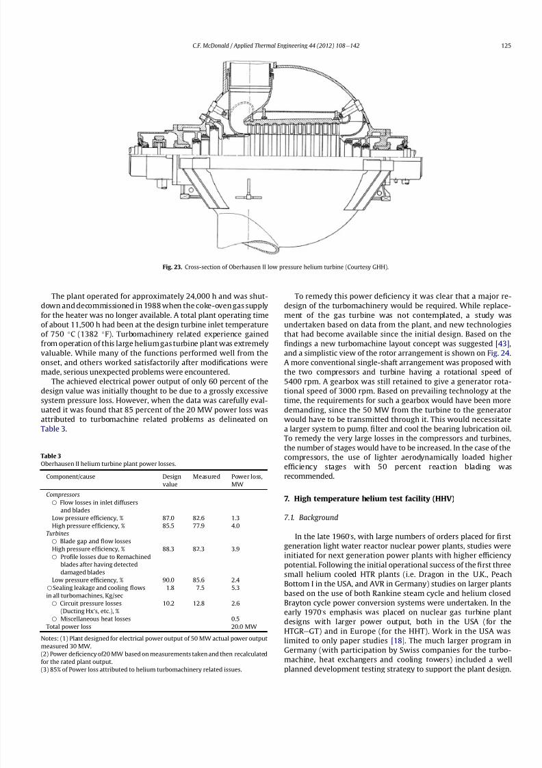
8112019 Helium Turbomachinery Operating Experience From Gas Turbine Power Plants
httpslidepdfcomreaderfullhelium-turbomachinery-operating-experience-from-gas-turbine-power-plants 1835
The plant operated for approximately 24000 h and was shut-
down and decommissioned in 1988 when the coke-oven gas supply
for the heater was no longer available A total plant operating time
of about 11500 h had been at the design turbine inlet temperature
of 750 C (1382 F) Turbomachinery related experience gained
from operation of this large helium gas turbine plant was extremely
valuable While many of the functions performed well from the
onset and others worked satisfactorily after modi1047297cations were
made serious unexpected problems were encountered
The achieved electrical power output of only 60 percent of the
design value was initially thought to be due to a grossly excessive
system pressure loss However when the data was carefully eval-uated it was found that 85 percent of the 20 MW power loss was
attributed to turbomachine related problems as delineated on
Table 3
To remedy this power de1047297ciency it was clear that a major re-
design of the turbomachinery would be required While replace-
ment of the gas turbine was not contemplated a study was
undertaken based on data from the plant and new technologies
that had become available since the initial design Based on the
1047297ndings a new turbomachine layout concept was suggested [43]
and a simplistic view of the rotor arrangement is shown on Fig 24
A more conventional single-shaft arrangement was proposed with
the two compressors and turbine having a rotational speed of
5400 rpm A gearbox was still retained to give a generator rota-
tional speed of 3000 rpm Based on prevailing technology at the
time the requirements for such a gearbox would have been moredemanding since the 50 MW from the turbine to the generator
would have to be transmitted through it This would necessitate
a larger system to pump 1047297lter and cool the bearing lubrication oil
To remedy the very large losses in the compressors and turbines
the number of stages would have to be increased In the case of the
compressors the use of lighter aerodynamically loaded higher
ef 1047297ciency stages with 50 percent reaction blading was
recommended
7 High temperature helium test facility (HHV)
71 Background
In the late 1960rsquos with large numbers of orders placed for 1047297rst
generation light water reactor nuclear power plants studies were
initiated for next generation power plants with higher ef 1047297ciency
potential Following the initial operational success of the 1047297rst three
small helium cooled HTR plants (ie Dragon in the UK Peach
Bottom I in the USA and AVR in Germany) studies on larger plants
based on the use of both Rankine steam cycle and helium closed
Brayton cycle power conversion systems were undertaken In the
early 1970rsquos emphasis was placed on nuclear gas turbine plant
designs with larger power output both in the USA (for the
HTGR eGT) and in Europe (for the HHT) Work in the USA was
limited to only paper studies [18] The much larger program in
Germany (with participation by Swiss companies for the turbo-
machine heat exchangers and cooling towers) included a well
planned development testing strategy to support the plant design
Fig 23 Cross-section of Oberhausen II low pressure helium turbine (Courtesy GHH)
Table 3
Oberhausen II helium turbine plant power losses
Componentcause Design
value
Measured Power loss
MW
Compressors
B Flow losses in inlet diffusers
and blades
Low pressure ef 1047297ciency 870 826 13
High pressure ef 1047297ciency 855 779 40
Turbines
B Blade gap and 1047298ow losses
High pressure ef 1047297ciency 883 823 39
B Pro1047297le losses due to Remachined
blades after having detected
damaged blades
Low pressure ef 1047297ciency 900 856 24
BSealing leakage and cooling 1047298ows
in all turbomachines Kgsec
18 75 53
B Circuit pressure losses
(Ducting Hxrsquos etc)
102 128 26
B Miscellaneous heat losses 05
Total power loss 200 MW
Notes (1) Plant designed for electrical power output of 50 MW actual power output
measured 30 MW
(2) Power de1047297ciency of20 MW based on measurements taken and then recalculated
for the rated plant output
(3) 85 of Power loss attributed to helium turbomachinery related issues
CF McDonald Applied Thermal Engineering 44 (2012) 108e142 125
8112019 Helium Turbomachinery Operating Experience From Gas Turbine Power Plants
httpslidepdfcomreaderfullhelium-turbomachinery-operating-experience-from-gas-turbine-power-plants 1935
While the reference HHT plant for eventual commercializationembodied a very large single helium gas turbine rated at 1240 MW
this was to be preceded by a nuclear demonstration plant rated at
676 MW [51] To support the design of this plant technology
generated from the following was planned 1) operational experi-
ence from the aforementioned Oberhausen II 50 MW helium gas
turbine power plant and 2) testing of components in a large high
temperature helium test facility as discussed below
72 Development facilitytesting objectives
An overall view of the HHV test facility sited in Julich in
Germany is shown on Fig 25 and since this has been reported on
previously [52] it will only be brie1047298
y covered in this section Tominimize risk and assure the performance integrity and reliability
of the nuclear demonstration plant some non-nuclear testing of
the major components especially the helium turbomachine was
deemed essential Because of the limitations of a conventional
closed-cycle helium gas turbine power plant particularly the
temperature limitations of existing fossil-1047297red and electrical
heaters a new type of test facility was foreseen
A simpli1047297ed schematic line diagram of the HHV circuit is shown
on Fig 26 The major design parameters are shown on Fig 27
together with the temperatureeentropy diagram which is conve-
nient for describing the unique relationship between the compo-
nents in the closed helium loop Starting at the lowest pressure in
Fig 24 Proposed new concept for Oberhausen II helium gas turbine rotating assembly to remedy problems encountered during operation of the 50 MWe power plant (Courtesy
EVO)
Fig 25 HHV helium turbomachinery test facility (Courtesy BBC)
CF McDonald Applied Thermal Engineering 44 (2012) 108e142126
8112019 Helium Turbomachinery Operating Experience From Gas Turbine Power Plants
httpslidepdfcomreaderfullhelium-turbomachinery-operating-experience-from-gas-turbine-power-plants 2035
the system the helium is compressed (Ae
B) its temperatureincreasing to 850 C (1562 F) before 1047298owing through the test
section (BeC) After being cooled slightly (CeD) the helium is
expanded in the turbine (DeA) down to the compressor inlet
conditions completing the loop There is no power output from the
system and without the need for an external heater the
compression heat is used to raise the helium to the maximum
system temperature in what can be described as a very large heat
pump The required compressor power is 90 MW and to supple-
ment the 45 MW generated by expansion in the turbine external
power is provided by a 45 MW synchronous electrical motor A
cooler is required to remove the compression heat that is contin-
uously put into the closed helium loop and this is done by bleeding
about 5 percent of the mass 1047298ow after the compressor cooling it
and re-introducing it into the circuit close to the turbine inlet In
addition to testing the turbomachine the facility was engineered
with a test section to accommodate other small components (eg
hot gas 1047298ow regulation valves bypass valves insulation con1047297gu-
rations and types of hot gas duct construction) With the highest
temperature in the system being at the compressor exit the facility
had the capability to provide helium at a temperature up to 1000 C
(1832 F) for short periods at the entrance to the test section
While a higher ef 1047297ciency of the planned nuclear demonstration
plant could be projected with a turbine inlet temperature in the
range 950e1000 C (1742e1832 F) this would have necessitated
either turbine blade cooling or the use of a high temperature alloy
such as Titanium Zirconium Molybdenum (TZM) At the time it was
felt that using either of these would have added cost and risk to theprojectso a conventionalnickel-basedalloyas usedin industrialgas
turbines was selected for the 850 C design value of turbine inlet
temperature this negating the needfor actual internal bladecooling
However a complex internal coolingsystemwas neededto keep the
Fig 26 Cycle diagram of HHV test loop (Courtesy BBC)
Fig 27 Salient features of HHV helium turbomachinery (Courtesy BBC)
CF McDonald Applied Thermal Engineering 44 (2012) 108e142 127
8112019 Helium Turbomachinery Operating Experience From Gas Turbine Power Plants
httpslidepdfcomreaderfullhelium-turbomachinery-operating-experience-from-gas-turbine-power-plants 2135
turbine discs and blade root attachments and casings to acceptable
temperatures commensurate with prescribed stress limitations for
thelife of theturbomachine In addition a heliumsupplywas needed
to provide a buffering system for the various labyrinth seals
In a direct Brayton cycle nuclear gas turbine the turbomachine is
installed in the reactor circuit and via the hot gas duct heated
helium is transported directly from the reactor core to the turbine
From the safety licensing and reliability standpoints there are
various seals that must perform perfectly A helium buffered
labyrinth seal system is necessary to prevent bearing lubricating oil
ingress to the closed helium loop Since in the proposed HHT plant
design the drive shaft from the turbine to the generator penetrates
the reactor primary system pressure boundary two shaft seals are
needed one a dynamic seal when the shaft is rotating and a static
seal when the turbomachine is not operating Testing of these seals
in a size and operating conditions representative of the planned
commercial power plant was considered to be a licensing must
The mechanical integrity of the rotating assembly must be
assured there being two major factors necessitating testing the
machine at full speed and temperature and at high pressure
namely 1) loading the blading under representative centrifugal and
gas bending stresses and 2) to monitor vibration and con1047297rm rotor
dynamic stability For the design of the planned commercial planta knowledge of the acoustic emissions by the turbomachine and
propagation in the closed circuit was required Data from the HHV
facility would enable dynamic responses of the major components
(especially the insulation) resulting from excitation by the sound
1047297eld to be calculated
The circuit was instrumented to gather data on the effectiveness
of the hot gas duct insulation thermal expansion devices hot gas
valves helium puri1047297cation system instrumentation and the
adequacy of the coatings applied to mating metallic surfaces to
prevent galling or self-welding Details of the turbomachinery and
the experience gained from the operation of the HHV facility are
covered in the following sections
73 Helium turbomachine
A cross-section of the turbomachine is shown on Fig 28 The
single-shaft rotating assembly consists of 8 compressor stagesand 2
turbine stages and had a weighton the order of 66 tons(60000 kg)
The hub inner and outer diameters are 16 m (525 ft) and 18 m
(59 ft) respectively the blading axial length being 23 m (75 ft)The
span between the oil bearings being 57 m (187 ft) The physical
dimensions of the turbogroup shown on Fig 28 correspond to
a machine rated at about 300 MW The oil bearings operate in
a helium environment and the diameters of the labyrinths and
1047298oating ring shaft seals to prevent oil ingress are representative of
a machine rated at about 600 MW The complexity of the machine
design especially the rotor cooling system sealing system very
large casing and heat insulation have been reported previously
[53e55]
To ensure high structural integrity the rotor was constructed by
welding together the forged compressor and turbine discs The
compressor had 8 stages each having 56 rotor and 72 stator blades
The turbine had 2 stages each having 90 stator and 84 rotor blades
An appreciation for the large size of the rotating assembly can be
seen from Fig 29 The rotor blades have 1047297r-tree attachments
embodying cooling channels Since the temperature and pressure
do not vary very much along the blading in the 1047298ow direction an
intricate rotor and stator cooling system was required Channels in
both the blade roots and the spacers between adjacent blade rows
form an axial geometry for the passage of a cooling helium supplyto keep the temperature of the multiple discs below 400 C
(752 F) The design of this was a challenge since the rotor and
stator blade attachments of both the 8 stage compressor and 2
stage turbine had to be cooled Excessive leakage had to be avoided
since this would have prevented the speci1047297ed compressor
discharge temperature (ie the maximum temperature in the
circuit) from being reached
In the 1970rsquos and early 1980rsquos signi1047297cant studies were carried
out on large helium gas turbines by various organizations [56e62]
In this era there was general agreement that testing of the turbo-
machine in one form or another in non-nuclear facilities be
undertaken to resolve areas of high risk (eg seals bearings cooling
systems rotor dynamic stability compressor surge margin
dynamic response rotor burst protection etc) before installationand operation of a large gas turbine in a nuclear environment
This low risk engineering philosophy which prevailed at the time
in both Germany and the USA emphasized the importance of
Fig 28 Cross-section of HHV helium turbomachinery (Courtesy BBC)
CF McDonald Applied Thermal Engineering 44 (2012) 108e142128
8112019 Helium Turbomachinery Operating Experience From Gas Turbine Power Plants
httpslidepdfcomreaderfullhelium-turbomachinery-operating-experience-from-gas-turbine-power-plants 2235
the HHV test facility as being an important step towards the
eventual deployment of a high ef 1047297ciency nuclear gas turbine power
plant
74 Initial operation of the HHV facility
During commissioning of the plant in 1979 oil ingress into the
helium circuit from the seal system occurred twiceThe 1047297rst ingressof oil between 600 and 1200 kg (1322 and 2644 lb) was due to
a serious operatorerror and the absence of an isolation valve in the
system The oil in the circuit was partly coked and formed thick
deposits on the cold and hot surfaces of the turbomachinery and in
other parts of the closed loop including saturation of the 1047297brous
insulation The fouled metallic surfaces were cleaned mechanically
and chemically by cracking with the addition of hydrogen and
additives The second oil ingress was due to a mechanical defect in
the labyrinth seal system The quantity of oil introduced was small
and it was removed bycracking at a temperature of 600 C (1112 F)
and with the use of additives To obviate further oil ingress inci-
dents the labyrinth seal system was redesigned The buffer and
cooling helium system piping layout was modi1047297ed to positively
eliminate oil ingress due to improper valve operation and toprevent further human error
Pressure and leak detection tests of the HHV test facility at
ambient temperature showed good leak tightness for the turbo-
machine 1047298anged joints and of the main and auxiliary circuits
However at the operating temperature of 850 C (1562 F) large
helium leaks were detected The major 1047298anges had been provi-
sioned with lip seals and the 1047297rst step was to weld the closures A
large leak persisted at the front 1047298ange of the turbomachine This
was diagnosed as being caused by a non-uniform temperature
distribution during initial operation resulting in thermal stresses
creating local gaps This problem was overcome by redesign of the
cooling system with improved gas 1047298ow distribution and 1047298ow rates
to give a more uniform temperature gradient The leakage from the
system was reduced to on the order of 020e
040 percent of the
helium inventory per day this being of the same magnitude as in
other closed helium circuits as discussed in Section 65
It should be mentioned that in addition to the HHV experience
bearing oil ingress into the circuits and system loss of the working
1047298uid in other closed-cycle gas turbine plants have occurred In all of
these fossil-1047297red facilities 1047297xing leaks and removal of oil deposits
were undertaken based on conventional hands-on approaches but
nevertheless such operations were time-consuming However if a new and previously untested helium turbomachine operating in
a direct cycle nuclear gas turbine plant experienced an oil ingress
the rami1047297cations would be severe The likely use of remote
handling equipment to remove the turbomachine from the vessel
machine disassembly (including breaking the welded 1047298ange joints)
and removal of oil from the radioactively contaminated turbo-
machine blade surfaces and system insulation would be time
consuming A diagnosis of the failure would be required before
a spare turbomachine could be installed and this plant downtime
could adversely affect plant availability
75 Experience gained
Afterresolutionof the aforementionedproblems the HHVfacilitywas started in the Spring of 1981 and in an orderly manner was
brought up to full pressure and a temperature of 850 C (1562 F)
During a 60 h run the functioning of the instrumentation control
and safety systems were veri1047297ed During these tests the ability to
stop the turbomachine from full operating conditions to standstill
within 90 s was demonstrated After system depressurization the
plant was then run up again to full operating conditions with no
problems experienced The HHV facility was successfully run for
about 1100 h of which theturbomachineryoperated forabout325 h
at a temperature of 850 C The test facility was extensively instru-
mented and interpretation and analysis of the data recorded gave
positive and favorable results in the following areas
The complex rotor cooling system which was engineered to
assure that the temperature of the discs be kept below 400
C
Fig 29 HHV helium turbomachine rotating assembly (size equivalent to a 300 MWe machine) being installed in a pressure vessel (Courtesy BBC)
CF McDonald Applied Thermal Engineering 44 (2012) 108e142 129
8112019 Helium Turbomachinery Operating Experience From Gas Turbine Power Plants
httpslidepdfcomreaderfullhelium-turbomachinery-operating-experience-from-gas-turbine-power-plants 2335
(752 F) was demonstrated to be effective The measured rotor
coolant 1047298ows (about 3 percent of the mass1047298ow passing through the
machine) were slightly larger than had been estimated and this
resulted in measured turbine disc temperatures lower than pre-
dicted [55]
The dynamic labyrinth shaft seal functioned well at the full
temperature and pressure conditions and met the requirement of
zero oil ingress into the helium circuit The measured rotor oscil-
lation did not have any adverse effect on the shaft sealing system
The static rotor seal (for shutdown conditions) functioned without
any problems
The compressor and turbine blading hadef 1047297ciencies higher than
predicted The structural integrity of the rotor proved to be sound
when operating at 3000 rpm under the maximum temperature and
pressure conditions The stiff rotor shaft had only slight unbalance
and thermal distortion and measured oscillations were in the range
typical of large steam turbines
Sound power spectrum measurements were taken in four
different locations in the circuit These were taken to determine the
spectrum and intensity of the sound generated and propagated by
the turbomachinery and the resultant vibration of internal
components The maximum sound power level in the helium
circuit was160 dB Numerous strain gages were placedin the circuitto determine the in1047298uence of the sound 1047297eld particularly on the
fatigue strength of the turbine inlet hot gas duct In later examining
the internal components there was no evidence of excessive
vibration of the components especially the ducting and the insu-
lation Based on the measurements and calculations it was
concluded that the fatigue strength limit of the components would
not be exceeded during the designed life of the planned commer-
cial nuclear gas turbine power plant
In a direct cycle nuclear gas turbine the hot gas duct used to
transport the helium from the reactor core to the turbineis a critical
component The hot gas duct in the HHV facility performed well
mechanically and con1047297rmed the adequacy of the thermal expan-
sion devices From the thermal standpoint the 1047297ber insulation
performed better than the metallic type
After dismantling the HHV facility there were no signs of
corrosion or erosion of the turbine or compressor blading While
the total number of hours operated was limited the coatings
applied to mating metallic surfaces to prevent galling and frictional
welding in the oxidation-free helium worked well
The helium buffer and cooling system worked well However
problems remained with the puri1047297cation of the buffer helium The
oil separation system consisting of a cyclone separator and a wire
mesh and a down stream 1047297ber 1047297lter needed further improvement
In late 1981 a decision was made to cancel the HHT project and
the HHV facility was shutdown The design and operational expe-
rience gained from the running of this facility would have been
extremely valuable had the nuclear gas turbine power plant
concept moved towards becoming a reality The identi1047297cation of
somewhat inevitable problems to be expected in such a complexturbomachine and their resolution were undertaken in a timely
and cost effective manner in the non-nuclear HHV facility This
should be noted for future nuclear gas turbine endeavors since
remedying such unexpected problems in the case of a new and
untested large helium turbomachine being operated for the 1047297rst
time using nuclear heat could result in very complex repair
Fig 30 Speci1047297
c speed-speci1047297
c diameter array for gas circulators in various gas-cooled nuclear plants
CF McDonald Applied Thermal Engineering 44 (2012) 108e142130
8112019 Helium Turbomachinery Operating Experience From Gas Turbine Power Plants
httpslidepdfcomreaderfullhelium-turbomachinery-operating-experience-from-gas-turbine-power-plants 2435
activities and extended plant downtime and indeed adding risk to
the overall success of the nuclear gas turbine concept
8 Circulators used in gas-cooled reactor plants
Circulators of different types will be needed in future helium
cooled nuclear plants these including the following 1) primary
loop circulator for possible next generation steam cycle power andcogeneration plants 2) for future indirect cycle gas turbine plants
3) shut down cooling circulators forall HTRand VHTR plants and 4)
for various circulators needed in future VHTR high temperature
process heat plant concepts The technology status of operated
helium circulators is brie1047298y addressed as follows
81 Background
It would be remiss not to mention experience gained in the past
with gas circulators and while not gas turbines they are rotating
machines that operate in the primary loop of a helium cooled
reactor With electric motor drives there are basically two types of
compressor rotor con1047297gurations namely radial and axial 1047298ow
machinesIn a single stage form the centrifugal impeller is used for high
stage pressure rise and low volume 1047298ow duties whereas the axial
type covers low pressure rise per stage and high volume 1047298ow The
selection of impeller type is very much related to the working
media type of bearings drive type rotor dynamic characteristics
and installation envelope A wide range of circulators have operated
and a well established technology base exists for both types [63] A
useful portrayal of compressor data in the form of quasi- non-
dimensional parameters (after Balje [64]) showing approximate
boundaries for operation of high ef 1047297ciency axial and radial types is
shown on Fig 30 (from Ref [65])
Both high speed axial and lower speed radial 1047298ow types are
amenable to gas oil and magnetic bearings From the onset of
modularHTR plant studies theuse of active magnetic bearings[6667]offered a solution to eliminate lubricating oil into the reactor circuit
and this tribology technology is attractive for use in submerged
rotating machinery in the next generation of HTR plants [68]
While now dated an appreciation of the main design features of
typical electric motor-driven helium circulators have been reported
previously namely an axial 1047298ow main circulator for a modular
steam cycle HTR plant [69] and a representative radial 1047298ow shut-
down cooling circulator [70]
The operating experience gained from three particular circula-
tors is brie1047298y included below because of their relevance to the
design of helium turbomachinery in future HTR plant variants
82 Axial 1047298ow helium circulator
Since all of the aforementioned predominantly European
helium gas turbines used axial 1047298ow turbomachinery it is of interest
to mention a helium axial 1047298ow circulator that operated in the USA
and to brie1047298y discuss its design parameters and features The
330 MW Fort St Vrain HTGR featured a Rankine cycle power
conversion system Four steam turbine driven helium circulators
were used to transport heat from the reactor core to the steam
generators The complete circulator assemblies were installed
vertically in the prestressed concrete reactor vessel [71e73]
A cross-section of the circulator is shown on Fig 31 with thecompressor rotor and stator visible on the left hand end of the
machine Based on early 1960rsquos technology a decision was made to
use water lubricated bearings and from the overall plant reliability
and availability standpoints this later proved to be a bad choice
Within the vertical circulator assembly there were four 1047298uid
systems namely the helium reactor coolant water lubricant in the
bearings steam for the turbine drive and high pressure water for
the auxiliary Pelton wheel drive During plant transients the pres-
sures and temperatures of these four 1047298uids oscillated considerably
and the response of the control and seal systems proved to be
inadequate and resulted in considerable water ingress from the
bearing cartridge into the reactor helium circuit The considerable
clean up time needed following repeated occurrences of this event
resulted in long periods of plant downtime and this had an adverseeffect on plant availability This together with other technical
Fig 31 Cross section of FSV helium circulator (Courtesy general Atomics)
CF McDonald Applied Thermal Engineering 44 (2012) 108e142 131
8112019 Helium Turbomachinery Operating Experience From Gas Turbine Power Plants
httpslidepdfcomreaderfullhelium-turbomachinery-operating-experience-from-gas-turbine-power-plants 2535
dif 1047297culties eventually contributed to the plant being prematurely
decommissioned
On the positive side in the context of this paper the helium
circulators operated for over 250000 h and exhibited excellent
helium compressor performance good mechanical integrity and
vibration-free operation The rotating assembly showing the axial
1047298ow compressor and steam turbine rotors together with a view of
the machine assembly are given on Fig 32 The helium compressor
consists of a single stage axial rotor followed by an exit guide vane
The machine was designed for axial helium 1047298ow entering and
leaving the stage and this can be seen from the velocity triangles
shown on Fig 33 which also includes the de1047297nition of the various
aerodynamic parameters Major design parameters and features of
this helium circulator are given on Table 4 Related to an earlier
discussion on the degree of reaction for axial 1047298ow compressors the
value for this conventional single stage circulator is 78 percent All
of the major aerothermal and structural loading criteria were
within established boundaries for an axial compressor having high
ef 1047297ciency and a good surge margin
The compressor gas 1047298ow path and blading geometries were
established based on prevailing industrial gas turbine and aero-
engine design practice A low Mach number (025) a high Reynolds
number (3 106) together with a modest stage loading (ie
a temperature rise coef 1047297cient of 044) and an acceptable value of
diffusion factor (042) were some of the factors that contributed to
a helium circulator that had a high ef 1047297ciency and a good pressure
rise- 1047298ow characteristic The large rotor blade chord and thick blade
section for this single stage circulator are necessary to accommo-
date the high bending stress characteristic of operation in a high
pressure environment The solidity and blade camber were opti-
mized for minimum losses
There were essentially two reasons for including this single-
stage axial 1047298ow compressor that operated in a helium cooled
reactor although its overall con1047297guration can be regarded as a 1047297rst
and last of a kind A rotor blade from this circulator as shown onFig 34 was based on a NASA 65 series airfoil which at the time
were one of the best performing cascades for such low Mach
number and high Reynolds number applications Interestingly it
has almost the same blade height aspect ratio and solidity as would
be used in the 1047297rst stage of an LP compressor in a helium turbo-
machine rated on the order of 250 MW
The second point of interest is that the helium mass 1047298ow rate
through the single stage axial compressor (rated at 4 MWe) is
110 kgs compared with 85 kgs through the multistage compressor
in the 50 MWe Oberhausen II helium gas turbine plant However
the volumetric 1047298ow through the Oberhausen axial compressor is
higher than that through the circulator by a factor of 16 this again
pointing out that the Oberhausen II plant was designed for high
volumetric 1047298ow to simulate the much larger size of turboma-chinery that was planned at the time in Germany for use in future
projected nuclear gas turbine power plants
83 High temperature helium circulator
For future helium turbomachines embodying active magnetic
bearings a challenge in their design relates to accommodating
elevated levels of temperature in the vicinity of the electronic
components In this regard it is of interest to note that a small very
high temperature helium axial 1047298ow circulator rated at 20 kW (as
shown on Fig 35) operated for more than 15000 h in an insulation
test facility in Germany more than two decades ago [74] The
signi1047297cance of this machine is that it operated with magnetic
bearings in a high temperature helium test loop with a circulatorgas inlet temperature of 950 C (1742 F) This necessitated the use
of ceramic insulation to ensure that the temperature in the vicinity
of the magnetic bearing electronics did not exceed a temperature of
about 150 C (300 F)
This machine although a very small axial 1047298ow helium blower
performed well and has been brie1047298y mentioned here since it
represents a point of reference for future helium rotating machines
capable operating with magnetic bearings in a very high temper-
ature helium environment
84 Radial 1047298ow AGR nuclear plant gas circulators
The electric motor-driven carbon dioxide circulators rated at
about 5 MW with a total runningtimein excess of 18 million hours
Fig 32 Fort St Vrain HTGR plant helium circulator (Courtesy General Atomics) (a)
Axial 1047298ow helium compressor and steam turbine rotating assembly (b) 4 MW helium
circulator assembly
CF McDonald Applied Thermal Engineering 44 (2012) 108e142132
8112019 Helium Turbomachinery Operating Experience From Gas Turbine Power Plants
httpslidepdfcomreaderfullhelium-turbomachinery-operating-experience-from-gas-turbine-power-plants 2635
in AGR nuclear power plants in the UK have demonstrated veryhigh availability [7576] To a high degree this can be attributed to
the fact that the machines were conservatively designed and proof
tested in a non-nuclear facility at full temperature and power
under conditions that simulated all of the nuclear plant operating
modes The test facility shown on Fig 36 served two functions 1)
design veri1047297cation of the prototype machine and 2) test of all new
and refurbished machines before they were installed in nuclear
plants Engineers currently involved in the design and development
of helium turbomachinery could bene1047297t from this sound testing
protocol to minimize risk in the deployment of helium rotating
machinery in future HTRVHTR plant variants
9 Helium turbomachinery development and testing
91 On-going development activities
The various helium turbomachines discussed in previous
sections operated over a span of about two decades starting in the
early 1960s From about 1990 activities in the nuclear gas turbine
1047297eld have been focused mainly on the design of modular GTeHTR
plant concepts In support of these plant studies many signi1047297cant
helium turbomachine design advancements have been made and
attention given to what development testing would be needed In
the last decade or so limited sub-component development has
been undertaken for helium turbomachines in the 250e300 MWe
size and these are brie1047298y summarized below
In a joint USARussia effort development in support of the
GTe
MHR turbomachine has been undertaken including testing in
the following areas magnetic bearings seals and rotor dynamicsfor the vertical intercooled helium turbomachine rated at 286 MWe
[77e80]
In Japan development activities have been in progress for
several years in support of the 274 MWe helium turbomachine for
the GTeHTR300 plant concept [2581] A detailed discussion on
the aerodynamic design of the axial 1047298ow helium compressor for
this turbomachine has been published in the open literature [82]
While the design methodology used for axial compressor design in
air-breathing industrial and aircraft gas turbines is generally
applicable for a multi-stage helium compressor a decision was
made by JAEA to test a small scale compressor in a helium facility
because of the inherent and unique gas 1047298ow path and type of
blading associated with operation in a high pressure helium
environment The major goal of the test was to validate the designof the 20 stage helium axial 1047298ow compressor for the GTeHTR300
plant
An axial 1047298ow compressor in a closed-cycle helium gas turbine is
characterized by the following 1) a large number stages 2) small
blade heights 3) high hub-to-tip ratio 4) a long annulus with
small taper that tends to deteriorate aerodynamic performance as
a result of end-wall boundary layer length and secondary 1047298ow 5)
low Mach number 6) high Reynolds number and 7) blade tip
clearances that are controlled by the gap necessary in the magnetic
journal and catcher bearings While (as covered in earlier sections)
helium gas turbines have operated there is limited data in the
open literature on the performance of multi-stage axial 1047298ow
compressors operating in a high pressure closed-loop helium
environment
Fig 33 Velocity triangles for axial compressor stage
CF McDonald Applied Thermal Engineering 44 (2012) 108e142 133
8112019 Helium Turbomachinery Operating Experience From Gas Turbine Power Plants
httpslidepdfcomreaderfullhelium-turbomachinery-operating-experience-from-gas-turbine-power-plants 2735
A 13rd scale 4 stage compressor was designed to simulate the
stage interaction the boundary layer growth and repeated stage
1047298ow in an actual compressor The 1047297rst four stages were designed to
be geometrically similar to the corresponding stages in the
GTe
HTR300 compressor Details of the model compressor havebeen discussed previously [81] and are summarized on Table 5
from [83]
A cross-section of the compressor test model is shown on Fig 37
A view of the 4 stage compressor rotor installed in the lower casing
is shown on Fig 38 The test facility (Fig 39) is a closed helium loop
consisting of the compressor model cooler pressure adjustment
valve and a 1047298ow measurement instrument The compressor is
driven by a 3650 kW electrical motor via a step-up gear The rota-
tional speed of 10800 rpm (three times that of the compressor in
the GTeHTR300 plant) was selected to match blade speed and
Mach number in the full size compressor
Details of the planned aerodynamic performance objectives of
the 13rd scale helium compressor test have been published
previously [84] Extensivetesting of the subscale model compressorprovided data to validate the performance of the full size
compressor for the GTeHTR300 power plant The test data and
test-calibrated CFD analyses gave added insight into the effect of
factors that impact performance including blade surface roughness
and Reynolds number
Based on advanced aerodynamic methodology and experi-
mental validation [82] there is now a sound basis for added
con1047297dence that the design goals of 90 percent polytropic ef 1047297ciency
and a design point surge margin of 20 percent are realizable in
a large multistage axial 1047298ow compressor for a future nuclear gas
turbine plant
In a similar manner a design of a one third size single stage
helium axial 1047298ow turbine has been undertaken and a cross
section of the machine is shown on Fig 40 (from Ref [81]) This
Table 4
Major features of axial 1047298ow helium circulator
Helium 1047298ow rate kgsec 110
Inlet temperature C 394
Inlet pressure MPa 473
Pressure rise KPa 965
Volumetric 1047298ow m3sec 32
Compressor type Single stage axial
Compressor drive Steam turbine
Bearing type Water lubricated
Rotational speed rpm 9550
Power MW 40
Rotor tip diameter mm 688
Rotor tip speed msec 344
Number of rotor blades 31
Number of stator blades 33
Blade height mm 114
Hub-to-tip ratio 067
Axial velocity msec 157
Flow coef 1047297cient 055
Temperature rise coef 1047297cient 044
Degree of reaction 078
Mean rotor solidity 128
Rotor aspect ratio 155
Rotor Mach number 025
Rotor diffusion factor 042
Rotor Reynolds number 3106
Speci1047297c speed 335
Speci1047297c diameter 066
Blade root thickness 15
Airfoil type NASA 65
Rotor blade chord mm 94e64
Stator blade chord mm 79
Rotor centrifugal stress MPa 125
Rotor bending stress MPa 30
Circulator(s) operating Hours gt250000
Fig 34 Rotor blade from single stage axial 1047298ow helium circulator (Courtesy General
Atomics)
Fig 35 20 kW axial 1047298ow helium circulator with magnetic bearings operated in 1985 in
an insulation test loop with a gas inlet temperature on 950
C (Courtesy BBC)
CF McDonald Applied Thermal Engineering 44 (2012) 108e142134
8112019 Helium Turbomachinery Operating Experience From Gas Turbine Power Plants
httpslidepdfcomreaderfullhelium-turbomachinery-operating-experience-from-gas-turbine-power-plants 2835
single stage scale model turbine for validity of the full size turbine
has been built and plans made to test the aerodynamic
performance
92 Nuclear gas turbine helium turbomachine testing
In planning for the 1047297rst nuclear gas turbine plant projected to
enter service perhaps in the third decade of the 21st century
a major decision has to be made as to what extent the large helium
turbomachine should be tested prior to operation on nuclear heat
Issues essentially include cost impact on schedule but the over-
riding one is risk Certainly turbomachine component testing will
be undertaken including the compressor (as discussed in the
previous section) and turbine performance seals cooling systems
hot gas valves thermal expansion devices high temperature
insulation rotor fragment containment diagnostic systems
instrumentation helium puri1047297cation system and other areas to
satisfy safety licensing reliability and availability concerns The
major point is really whether a full size or scaled-down turbo-machine be tested early in the project in a non-nuclear facility
To obviate the need for pre-nuclear testing of a large helium
turbomachine a view expressed by some is that advantage can be
taken of formidable technology bases that exist today for large
industrial gas turbines and high performance aeroengines On the
other hand it is the view of some including the author that very
complex power conversion system components especially those
subjected to severe thermal transients donrsquot always perform
exactly as predicted by analysts and designers even using sophis-
ticated computer codes This was exempli1047297ed in the case of the
turbomachine in the aforementioned Oberhausen II helium gas
turbine plant
The need for a helium turbomachine test facility goes beyond
just veri1047297
cation of the prototype machine Each newgas turbine for
commercial modular nuclear reactor plants would have to be proof
tested and validated before being transported to the reactor site
Similarly turbomachines that would be periodically removed from
the plant at say 7 year intervals during the plant operating life of 60
years for scheduled maintenance refurbishment repair or updat-ing would be again proof tested in the facility before re-entering
service
The direction that turbomachine development and testing will
take place for future helium gas turbines needs to be addressed by
the various organizations involved
Fig 36 AGR circulator test facility In the UK (Courtesy Howden)
Table 5
Major design parametersfeatures of model GTeHTR300 axial 1047298ow helium
compressor (Courtesy JAERI)
Scale of GTeHTR300 compressor 13
Helium mass 1047298ow rate (kgsec) 122
Helium volumetric 1047298ow rate (mV s) 87
Inlet temperature C 30
Inlet pressure MPa 0883Compressor pressure ratio at design point 1156
Number of stages 4
Rotational speed rpm 10800
Drive motor power kW 3650
Hub diameter mm 500
Rotor tip diameter (1st4th stage mm) 568566
Hub-to-tip ratio (1st stage) 088
Rotor tip speed (1st stage msec) 321
Number of rotorstator blades (1st stage) 7294
Rotorstator blade height (1st stage mm) 34337
Rotor stator blade c hor d l eng th (1st stage mm) 2620
Rotorstator solidity (1st stage) 119120
Rotorstator aspect ratio (1st stage) 1317
Flow coef 1047297cient 051
Stage loading factor 031
Reynolds number at design point 76 l05
CF McDonald Applied Thermal Engineering 44 (2012) 108e142 135
8112019 Helium Turbomachinery Operating Experience From Gas Turbine Power Plants
httpslidepdfcomreaderfullhelium-turbomachinery-operating-experience-from-gas-turbine-power-plants 2935
10 Helium turbomachinery lessons learned
101 Oberhausen II gas turbine and HHV test facility
It is understandable that 1047297rst-of-a-kind complex turboma-
chinery operating with an inert low molecular weight gas such as
helium will experience unique and unexpected problems In the
operation of the two pioneering large helium turbomachines in
Germany there were many positive1047297ndings which could only have
been achieved by development testing Equally important some
negative situations were identi1047297ed many of which were remedied
In the case of the Oberhausen II helium gas turbine plant some of
the very serious problems encountered were not resolved Inves-
tigations were undertaken to rationalize the problems associated
with the large power de1047297ciency and a data base established to
ensure that the various anomalies identi1047297ed would not occur in
future large helium turbomachines
The experience gained from the operation of the Oberhausen II
helium gas turbine power plant and the HHV test facility have been
discussedin thetextand arepresentedin a summaryformon Table6
Fig 37 Cross-section of 13rd scale helium compressor test model (Courtesy JAEA)
Fig 38 Four stage helium compressor rotor assembly installed in lower casing (Courtesy JAEA)
CF McDonald Applied Thermal Engineering 44 (2012) 108e142136
8112019 Helium Turbomachinery Operating Experience From Gas Turbine Power Plants
httpslidepdfcomreaderfullhelium-turbomachinery-operating-experience-from-gas-turbine-power-plants 3035
102 Impact of 1047297ndings on future helium gas turbine
The long slender rotorcharacteristic of closed-cycle gas turbines
has resulted in shaft dynamic instability which in some cases has
resulted in blade vibration and failure and bearing damage This
remains perhaps the major concern in the design of large
(250e
300 MW) helium turbomachines for future nuclear gas
turbine plants With pressure ratios in the range of about 2e3 in
a helium system a combination of splitting the compressor (to
facilitate intercooling) and having a large number of compressor
and turbine stages results in a long and 1047298exible rotating assembly
andthis is exempli1047297ed by the rotorassembly shown on Fig13 With
multiple bearings (either oil lubricated or magnetic) the rotor
would likely pass through multiple bending critical speeds before
Fig 39 Helium compressor test facility (Courtesy JAEA)
Fig 40 Cross-section of single stage helium turbine test model (Courtesy JAEA)
CF McDonald Applied Thermal Engineering 44 (2012) 108e142 137
8112019 Helium Turbomachinery Operating Experience From Gas Turbine Power Plants
httpslidepdfcomreaderfullhelium-turbomachinery-operating-experience-from-gas-turbine-power-plants 3135
reaching the design speed While very sophisticated computer
codes will be used in the detailed rotor dynamic analyses the real
con1047297rmation of having rotor oscillations within prescribed limits
(to avoid blade bearing and seal damage) will come from actual
testingA point to be made here is that in operated fossil-1047297red closed-
cycle gas turbine plants it was possible to remedy problems asso-
ciated with rotor vibrations and blade failures in a conventional
manner In fact in some situations the casings were opened several
times and modi1047297cations made to facilitate bearing and seal
replacement and rotor re-blading and balancing
An accurate assessment of pressure losses must be made
particularly those associated with the helium entering and leaving
the turbomachine bladed sections Minimizing the system pressure
loss is important since it directly impacts the all important quotient
of turbine expansion ratio to compressor pressure ratio and power
and plant ef 1047297ciency
Based on the operating experience from the 20 or so fossil-1047297red
closed-cycle gas turbine plants using air as the working1047298
uid it was
recognized that future very high pressure helium gas turbines
would pose problems regarding the various seals in the turbo-
machine and obtaining a zero leakage system with such a low
molecular weight gas would be dif 1047297cult and this is discussed
below
When the Oberhausen II gas turbine plant and the HHV facility
operated over 30 years ago oil lubricated bearings were used to
support the heavy rotor assemblies and helium buffered labyrinth
seals were used to prevent oil ingressinto the heliumworking1047298uid
Initial dif 1047297culties encountered in both plants were overcome by
changes made to the seal geometries and for the operating lives of
the helium turbomachines no further oil ingress events were
experienced Twoseals were required where the turbine drive shaft
penetrated the turbomachine casing namely 1) a dynamic laby-
rinth seal and 2) a static seal for shutdown conditions In both
plants these seals functioned without any problems
Labyrinth seals were also required within the helium turbo-
machines to pass the correct helium bleed 1047298ow from the
compressor discharge for cooling of the turbine discs blade root
attachments and casings The fact that the very complex rotor
cooling system in the large helium turbomachine in the HHV test
facility operated well for the test duration of about 350 h with
a turbine inlet temperature of 850 C was encouragingIn the case of the Oberhausen II gas turbine plant analysis of the
test data revealed that the labyrinth seal leakage and excessive
cooling 1047298ows were on the order of four times the design value A
possible reason for this was that damage done to the labyrinth
seals caused excessive clearances when periods of excessive rotor
oscillation and vibration occurred during early operation of the
machine
Clearly 1047298uid dynamic and thermal management of the cooling
system and 1047298ow through the various labyrinth seals will require
extensive analysis design and development testing before the
turbomachine is operated on nuclear heat for the 1047297rst time
In future heliumgas turbine designs (with turbine inlet tempera-
tureslikelyontheorderof950C)the1047298owpathgeometriesofhelium
bledfromthecompressornecessarytocoolpartsoftheturbomachinewillbemorecomplexthanthosetestedto-dateInadditiontoproviding
acooling1047298owtotheturbinebladesanddiscsbladerootattachmentsand
casingsheliummustbetransportedtotheseveralmagneticbearingsto
ensure thatthe temperatureof theirelectronic components doesnot
exceedabout150C
The importance of the points made above is evidenced when
examining the data on Table 3 where a combination of excessive
pressure losses and high bleed 1047298ows contributed to about 40
percent of the power de1047297ciency in the Oberhausen II helium
turbine plant
Retaining overall system leak tightnessin closed heliumsystems
operating at high pressure and temperature has been elusive
including experience from the Fort St Vrain HTGR plant as dis-
cussed in Section 65 New approaches in the design of the plethoraof mechanical joints must be identi1047297ed Experience to-date has
shown that having welded seals on 1047298anges while minimizing
system leakage did not eliminate it
The importance of lessons learned from the operation of the
Oberhausen II helium turbine power plant and the HHV test facility
have primarily been discussed in the context of helium turbo-
machines currently being designed in the 250e300 MWe power
range However the established test data bases could also be
applied to the possible emergence in the future of two helium
cooled reactor concepts namely 1) an advanced VHTR combined
cycle plant concept embodying a smaller helium gas turbine in the
power range of 50e80 MWe [22] and 2) the use of a direct cycle
helium gas turbine PCS in a recently proposed all ceramic fast
nuclear reactor concept [85]
Table 6
Experience gained from Oberhausen II and HHV facility
Oberhausen II 50 MW helium gas turbine power plant
Positive results
e Rotating and static seals worked well
e No ingress of bearing lubricant oil into closed circuit
e Load change by inventory control worked well
e 100 Percent load shed by means of bypass valves demonstrated
e Turbine disc and blade root cooling system con1047297rmed
e Coatings on mating surfaces prevented galling and self-welding
e After 24000 h of operation no evidence of corrosion or erosion
e Coaxial turbine hot gas inlet duct insulation and integrity con1047297rmed
e Monitoring of complete power conversion system for steady state
and transient operation undertaken
Problem areas
e Serious power output de1047297ciency (30 MW compared with design
value of 50 MW)
e Compressor(s) and turbine(s) ef 1047297ciencies several points below predicted
e Higher than estimated system pressure loss
e Rotor dynamic instability and blade vibration
e Bearings damaged and had to be replaced
e Blade failure caused extensive damage in HP turbine but retained
in casing
e Very excessive sealing and cooling 1047298ow rates
e Absolute leak tightness not attainable even with welded 1047298ange lips
HHV test facility
Positive resultse Use of heat pump approach facilitated helium temperature capability
to 1000 C
e Large oompressorturbine rotor system operated at 3000 rpm Complex
turbine disc and blade root cooling system veri1047297ed
e Dynamic and static seals met requirement of zero oxl ingress into circuit
e Structural integrity of rotating assembly veri1047297ed at temperature of 850 C
e Measured rotor oscillations within speci1047297cation
e Compressor and turbine ef 1047297ciencies higher than predicted
e Coatings on mating metallic surfaces prevented galling and self-welding
e Instrumentation control and safety systems veri1047297ed
e Seal 1047298ows within speci1047297cation
e Machine stop from operating speed to shutdown in 90 s demonstrated
e Hot gas duct insulation and thermal expansion devices worked well
e After 1100 h of operation no evidence of corrosionof erosion
Problem areas
e Before commissioning a large oil ingress into the circuit occurred due
to serious operator error and absence of an isolation valve A second oilingress occurred due to a mechanical defect in the labyrinth seal system
These were remedied and no further oil ingress was experienced for the
duration of testing
e Cooling 1047298ows slightly larger than expected but this resulted in actual
disc and blade root temperatures lower than the predicted value of
400 C
e System leak tightness demonstrated when pressurized at ambient
temperature conditions but some leakage occured at 850 C even with
the seal welding of 1047298ange(s) lips
CF McDonald Applied Thermal Engineering 44 (2012) 108e142138
8112019 Helium Turbomachinery Operating Experience From Gas Turbine Power Plants
httpslidepdfcomreaderfullhelium-turbomachinery-operating-experience-from-gas-turbine-power-plants 3235
11 New technologies
It is recognized that in the 3 to 4 decades since the operation of
the helium turbomachines covered in this paper new technologies
have emerged which negate some of the early issues An example of
this is the technology transfer from the design of modern axial 1047298ow
gas turbines (ie industrial aircraft and aeroderivatives) that fully
utilize sophisticated CAE CAD CFD and FEA design software
Air breathing aerodynamic design practice for compressors and
turbines are generally applicable but the properties of helium and
the high system pressure have a signi1047297cant impact on gas 1047298ow
paths and blade geometries With short blade heights high hub-to-
tip ratios long annulus 1047298ow path length (with resultant signi1047297cant
end-wall boundary layer growth and secondary 1047298ow) and blade tip
clearances in some cases controlled by clearances in the magnetic
catcher bearing testing of subscale model compressors and
Fig 41 Gas turbine test facility for aircraft nuclear propulsion involving the coupling of a 32 MWt air-cooled reactor with two modi 1047297ed J-47 turbojet aeroengines each rated at
a thrust of about 3000 kg operated in 1960 (Courtesy INL)
Fig 42 Mobile 350 KWe closed-cycle nuclear gas turbine power plant operated in 1961 (Courtesy US Army)
CF McDonald Applied Thermal Engineering 44 (2012) 108e142 139
8112019 Helium Turbomachinery Operating Experience From Gas Turbine Power Plants
httpslidepdfcomreaderfullhelium-turbomachinery-operating-experience-from-gas-turbine-power-plants 3335
turbines will be needed While most of the operated helium tur-
bomachines discussed in this paper took place 3 or 4 decades ago it
is encouraging that the fairly recent test data and test-calibrated
CFD analysis from a subscale four stage model helium axial 1047298ow
compressor in Japan [80] gave a high degree of con1047297dence that
design goals are realizable for the full size 20 stage compressor in
the 274 MWe GTeHTR300 plant turbomachine
In the future the use of active magnetic bearings will eliminate
the issue of oil ingress however the very heavy rotor weight and
size of the journal and thrust bearings (and catcher bearings) of the
type for helium turbomachines in the 250e300 MWe power range
are way in excess of what have been demonstrated in rotating
machinery For plant designs retaining oil-lubricated bearings well
established dry gas seal technology exists particularly experience
gained from the operation of high pressure natural gas pipe line
compressors
For future nuclear helium gas turbine plants the designer has
freedom regarding meeting different frequency requirements that
exist in some countries These include use of a synchronous
machine (ie designed for 50 or 60 Hz grids) use of a gearbox drive
between the turbine and generator or the use of a frequency
converter which gives the designer an added degree of freedom
regarding the selection of speed for the rotating assemblyCompared with the past very sophisticated electronic control
systems instrumentation and diagnostic systems are available
today
12 Conclusions
In this review paper experience from operated helium turbo-
machines has been compiled based on open literature sources At
this stage in the evolution of HTR and VHTR plant concepts it is not
clear in what role form or time-frame the nuclear gas turbine will
emerge when commercialized By say the middle of the 21st
century all power plants will be operating with signi1047297cantly higher
ef 1047297ciencies to realize improved power generation costs and
reduced emissions In a nuclear gas turbine the helium turbo-machine will be a major contributor towards the achievement of
ef 1047297ciencies higher than 50 percent
While it has been 3 to 4 decades since the Oberhausen II helium
turbine power plant and the HHV high temperature helium turbine
facility operated signi1047297cant lessons were learned and the time and
effort expended to resolve the multiplicity of unexpected technical
problems encountered The remedial repair work was done under
ideal conditions namely that immediate hands-on activities were
possible This would not have been possible if the type of problems
experienced had been encountered in a new and untested helium
turbomachine operated for the 1047297rst time with a nuclear heat
source
While new technologies have emerged that negate many of the
early problems there are some uniquely inherent issues associatedwith for large helium turbines operating in a high pressure and
temperature environment and these include the following 1)
minimizing system leakage with such a low molecular weight gas
2) clearances in labyrinth seals to minimize helium bypass1047298ows 3)
the dynamic stability of long slender rotors 4) minimizing the
turbomachine inlet and outlet pressure losses 5) 1047298ow maldis-
tribution in complex ductturbomachine interfaces 6) integrity
veri1047297cation of the catcher bearings (journal and thrust) after
multiple rotor drops (following loss of the magnetic 1047297eld) during
the plant lifetime 7) assurances that high energy fragments from
a failed turbine disc are contained within the machine casing 8)
turbomachine installation and removal from a steel pressure vessel
and 9) remote handling and cleaning of a machine with turbine
blades contaminated with 1047297
ssion products
The need for a helium turbomachine test facility has been
emphasized to ensure that the integrity performance and reli-
ability of the machine before it operates the 1047297rst time on nuclear
heat Engineers currently involved in the design of helium rotating
machinery for all HTR and VHTR plant variants should take
advantage of the experience gained from the past operation of
helium turbomachinery
13 In closing-GT rsquos operated with nuclear heat
In the context of this paper it is germane to mention that two
gas turbines have actually operated using nuclear heat as brie1047298y
highlighted below
In the late 1950rsquos a program was initiated in the USA for aircraft
nuclear propulsion (ANP) While different concepts were studied
only the direct cycle air-cooled reactor reached the stage of
construction of an experimental reactor [86] A view of the large
nuclear gas turbine facility is given on Fig 41 and shows the air-
cooled and zirconiumehydride moderated reactor rated at
32 MWt coupled with two modi1047297ed J-47 turbojet engines each
rated with a thrust of about 3000 kg In this open cycle system the
high pressure compressor air was directly heated in the reactor
before expansion in the turbine and discharge to the atmosphere in
the exhaust nozzle The facility operated between 1958 and 1961 at
the Idaho reactor testing facility While perhaps possible during the
early years of the US nuclear program it is clear that such a system
would not be acceptable today from safety and environmental
considerations
The 1047297rst and indeed the only coupling of a closed-cycle gas
turbine with a nuclear reactor for power generation was under-
taken to meet the needs of the US Army In the late 1950 rsquos an RampD
program was initiated for a 350 kW trailer-mounted system to be
used in the 1047297eld by military personnel A prototype of the ML-1
plant shown on Fig 42 was 1047297rst operated in 1961 [8788]
It was based on a 33 MW light water moderated pressure tube
reactor with nitrogen as the coolant The closed-cycle gas turbine
power conversion system with nitrogen as the working 1047298uid hada turbine inlet temperature of 649 C (1200 F) and delivered
around 300 kW With changes in the Armyrsquos needs the project was
discontinued in 1965
While the experience gained from the above twounique nuclear
plants is clearly not relevant for future nuclear gas turbine power
plants that could see service in the third decade of the 21st century
these ambitious and innovative nuclear gas turbine pioneering
engineering efforts need to be recognized
Acknowledgements
The author would like to thank the following for helpful discus-
sions advice and for providing valuable comments on the initial
paper draft Prof Dr Hermann Haselbacher Hans Ulrich Frutschi DrXing Yan DrPeter Zenker Professor DavidGordon Wilson Professor
Aristide Massardo Arthur Harris DrFred Starr and DrGuido Bac-
caglini This paper has been enhanced by the inclusion of hardware
photographs and unique sketches and the author is appreciative to
all concerned with credits being duly noted
References
[1] C Keller The Escher Wyss AK Closed-Cycle Gas Turbine Its Actual Develop-ment and Future Prospects Paper Presented at ASME Meeting November 261945
[2] HU Frutschi Closed-Cycle Gas Turbines Operating Experience and FuturePotential ASME Press NY 2005
[3] CF McDonald The Nuclear Gas Turbine-Towards Realization After Half
a Century of Evolution (1995) ASME Paper 95-GT-292
CF McDonald Applied Thermal Engineering 44 (2012) 108e142140
8112019 Helium Turbomachinery Operating Experience From Gas Turbine Power Plants
httpslidepdfcomreaderfullhelium-turbomachinery-operating-experience-from-gas-turbine-power-plants 3435
[4] C Keller The Theory and Performance of Axial Flow Fans McGraw Hill BookCompany Inc NY 1937
[5] J Ackert C Keller Aerodynamic turbine with closed circuit In A Century of Turbines vols 1516 Escher Wyss News 1942e43 5e19
[6] Escher Wyss News Closed-Cycle Gas Turbines for all Fuels Coal Gas Nuclearvol 39 No 1 (1966)
[7] C Keller Closed-cycle gas turbine Escher Wyss-AK development 1945e1950Transactions of ASME (August 1950) 835e850
[8] C Keller Operating Experience and Design Features of Closed-Cycle GasTurbine Power Plants (1956) ASME Paper 56-GTP-15
[9] C Keller HU Frutschi Closed-cycle plants -conventional and nuclear designapplication operation In Sawyerrsquos Gas Turbine Engineering Handbooksecond ed vol 2 Applications (1976) pp 265e283
[10] K Bammert G Groschup Status Report on Closed-Cycle Power Plants in theFederal Republic of Germany (1976) ASME Paper 76-GT-54
[11] JL Mason Monatomic Working Gases versus Air for Closed Brayton Cycles(1985) ASME Paper 85-IGT-50
[12] JL Mason et al 5 MW Closed Cycle Gas Turbine (1984) ASME Paper 84-GT-268
[13] The British Gas Closed-Cycle Demonstrator (1995) British Gas Research ampTechnology Final Year Report
[14] F Starr ODS alloy high temperature heat exchanger prototype developmentPaper Presented at ODS 2010 Materials Workshop UCSD Jacobs Hall La JollaCalifornia Nov17e18 2010
[15] CA Rennie Achievements of the Dragon project Pergamon Press Annals of Nuclear Energy 5 (1978) 305e320
[16] SB Hosegood et al Dragon Project Engineering Studies on the Direct CycleHTR Proceedings of Conference on Nuclear Gas Turbines The British NuclearEnergy Society London April 8e9 1970 pp 161e179
[17] Nuclear Gas Turbines Proceedings of British Nuclear Society Meeting LondonApril 8-9 1972
[18] CF McDonald C Peinado ldquoThe nuclear gas Turbine-A perspective on a long-term advanced technology HTGR plant Optionrdquo ASME Paper 82-GT-289
[19] GH Lohnert et al Technical design features and essential safety-relatedfeatures of the HTR-Module Nuclear Engineering and Design 121 (1990)259e275
[20] H Reutler GH Lohnert The modular high temperature nuclear reactorNuclear Technology 62 (1983) 22e30
[21] CF McDonald Exploitation of the very high temperature capability of theMHTGR to meet National energy needs after the year 2000 IECEC Paper869006
[22] CF McDonald Power conversion system considerations for an advancednuclear gas turbine (GT-VHTR) CHHP demonstration plant concept Interna-tional Journal of Turbo amp Jet Engines 27 (2010) 179e217
[23] N Hee Cheon et al A review of helium gas turbine technology for hightemperature gas cooled reactors Nuclear Engineering and Design 29 (2007)21e30
[24] CB Baxi et al Development of the GT-MHR Turbomachine ASME PaperGT2009e59450[25] X Yan GTHTR300 design and development Nuclear Engineering and Design
222 (2003) 247e262[26] JC Gauthier et al ANTARES the HTRVHTR project of Framatome ANP
Nuclear Engineering and Design 236 (2006) 526e533[27] J Wang et al ldquoDesign features of gas turbine power conversion system for
HTR-10GT paper D05 presented at 2nd Intl Meeting on HTR TechnologyBeijing China September 21e24 2004
[28] A Koster et al ldquoPBMR Design For the Futurerdquo Nuclear engineering andDesign 222 (203) 231e245
[29] S van der Linden Closed cycle nuclear plant rated at 165 MWe and 40 percentef 1047297ciency Gas Turbine World (MarcheApril 2007) 28e32
[30] CF McDonald Large closed-cycle gas turbines Sawyerrsquos gas turbine engi-neering handbook In Selection and Applications vol II (1985) pp 81e38(Chapter 8)
[31] CF McDonald Helium and Combustion Gas Turbine Power ConversionSystems Comparison (1995) ASME Paper 95-GT-263
[32] JK La Fleur Description of an Operating Closed-Cycle Helium Gas Turbine
ASME Paper 63-AHGT-74[33] JK La Fleur The use of turbomachinery in the 1047297eld of cryogenics In
Sawyerrsquos Gas Turbine Engineering Handbook vol II (1976) 296e311[34] W Spillmann The Closed-Cycle Gas Turbine for Non-Conventional Applica-
tions ASME Paper 66-GT-8[35] K Holliger On the in1047298uence of the degree of reaction on the secondary losses
in axial 1047298ow compressors Escher Wyss News 23 (1960)[36] W Gut Comparison of the relative losses and characteristics of axial
compressor stages Escher Wyss News 23 (1959)[37] JH Horlock Axial Flow Compressors Butterworths Scienti1047297c Publications
London 1958 pp 92e93[38] G Deuster Long-term Operating Experience with Oberhausen I Closed-Cycle
Gas Turbine Power Plant (1970) ASME Paper 70-GT-73[39] G Noak Signi1047297cance of the Helium Turbine Power Plant at Oberhausen (EVO)
and the High Temperature Helium Test Facility (HHV) at Julich for theDevelopment of HTR Direct Cycle (HHT) IAEA Publication SM-20026 Vienna1970 189e200
[40] K Bammert G Deuster Layout and Present Status of the Closed-Cycle HeliumTurbine Plant Oberhausen II (1974) ASME Paper 74-GT-132
[41] P Zenker The Oberhausen 50 MW helium turbine plant Combustion 47 (2)(April 1976)
[42] K Bammert et al Operation and Control of the 50 MW Closed Cycle HeliumTurbine Plant Oberhausen (1974) ASME Paper 74-GT-13
[43] P Zenker 10 years operating experience with the Oberhausen II heliumturbo-generator plant VGB Krafswerkstechnik 68 (7) (July 1998) 616e621
[44] K Bammert G Deuster The First Operating Experiences With the OberhausenHelium Turbine Plant Paper Presented at ASME Gas Turbine Conference NewOrleans March 21e25 1976
[45] G Deuster P Zenker Operation of the Oberhausen Helium Turbine Plant
Paper Presented at ASME Gas Turbine Conference London April 1978[46] P Zenker Operating Experience of the Oberhausen Helium Turbine Plant
Paper Presented at ASME Gas Turbine Conference San Diego 1979[47] G Deuster P Zenker Further Operating Experience of the Oberhausen Helium
Turbine Plant Paper Presented at ASME Gas Turbine Conference NewOrleans 1980
[48] P Zenker Past Experience and Future Prospects of Closed-Cycle Gas TurbinesPaper Presented at ASME Gas Turbine Conference London April 18e22 1982
[49] IA Weisbrodt Summary Report on Technical Experiences from HighTemperature Helium Turbine Testing in Germany Report IAEA-TECDOC-899Vienna Nov 1994
[50] F Bentivoglio G Geffraye Validation of the CATHARE Code Against Experi-mental Data from Brayton Cycle Plants Paper C00000228 Proceedings of HTR 2006 Johannesburg October 1e4 2006
[51] E Arndt HHT-Demonstration Plant Paper Presented at European NuclearConference Hamburg May 6 1979
[52] G Hebel HHV-Anlage Erfahrungen bei Bau und Inbetriebnahme Atom-wirtschaft(5) (1982) 258e262
[53] H Haselbacher A Eierman Development of Helium Gas Turbine in NuclearField (1974) ASME Paper 74-GT-123
[54] H Haselbacher The HHT Helium Gas Turbine and HHV Plant Paper A421 5thInternational Fair and Technical Meeting of Nuclear Industry BaselSwitzerland October 3e7 1978
[55] H Haselbacher HJ Sponholz Cooling and Insulating Problems in a HighTemperature Helium Test Facility (1984) ASME Paper 84-GT-253
[56] C Keller D Schmidt The Helium Gas Turbine for Nuclear Power Plants (1967)ASME Paper 67-GT-10
[57] W Endres Large Helium Turbine for Nuclear Power Plants (1970) ASME Paper70-GT-99
[58] JN Hurst Gas turbomachinery for helium cooled reactors in Proceedings of International Conference on Nuclear Gas Turbines British Nuclear SocietyLondon April 8 1970 pp 45e50
[59] K Bammert Nuclear Gas Turbine of Large Output for HHT Plant (1974) ASMEPaper 74-GT-10
[60] CF McDonald The Nuclear Closed-Cycle Gas Turbine (GT-HTGR) e A UtilityPower Plant for the Year 2000 (1979) AIAA Paper 79e0191
[61] CF McDonald MJ Smith Turbomachinery design considerations for the
nuclear HTGR-GT power plant ASME Journal of Engineering for Power 103 (1)(January 1981) 65e77[62] CF McDonald et al Helium Turbomachine Design for GT-MHR Power Plant
(1994) ASME Paper 94-JPGC-NE-12[63] Gas Cooled Reactor Coolant Circulator and Blower Technology (1988) IAEA
Report IWGGCR17[64] OE Balje Turbomachines A Guide to Design Selection and Theory John
Wiley amp Sons NY 1981[65] CF McDonald et al Circulator DesignTechnology Evolution for Gas Cooled
Reactors (1992) ASME Paper 92-GT-79[66] J Donaldson Application of Magnetic Bearings to Helium Circulators for High
Temperature Gas Cooled Reactors (1987) IECEC Paper 879419[67] CF McDonald Active Magnetic Bearings for Rotating Machinery in Closed-
Cycle Power Plant Systems (1989) ASME Paper 89-WANE-5[68] JA Rennie CF McDonald Active Magnetic Bearings for Rotating Machinery
in Future Gas Cooled Reactor Plants Paper Presented at 4th Intl Symposiumon Magnetic Bearings ETH Zurich August 23e26 1994
[69] CF McDonald MK Nichols Helium Circulator Design Considerations forModular High Temperature Gas Cooled Power Plant (1987) ASME Paper 87-
GT-138[70] CF McDonald Shutdown Cooling Helium Circulator Design Considerations
for MHTGR Power Plant (1989) ASME Paper 89-WANE-5[71] J Yampolsky Steam Turbine Driven Circulators for High Temperature Gas
Cooled Reactors Part I Design (1972) ASME Paper 72-WANE-20[72] VJ Barbat Steam Turbine Driven Circulators for High Temperature Gas
Cooled Reactors Part II Development (1972) ASME Paper 72-WANE-21[73] L Cavallaro J Yampolsky Design and development of a steam turbine driven
circulator for high temperature gas cooled reactors Nuclear Engineering andDesign (1974) 135e147
[74] J Henssen et al Facility for fatigue testing of thermal insulation BBC Review72 (6) (1985)
[75] J Donaldson Development of Carbon Dioxide Circulators IAEA ReportIWGGCR17 (1988) pp 47e63
[76] Personal Communication from John Donaldson (April 7 2006)[77] NG Kodochigov et al Development of the GT-MHR Vertical Turbomachine
Design ASME Paper HTR2008-58309[78] CB Baxi et al ldquoRotor Scale Model Tests for Power Conversion Unit of GT-
MHR rdquo ASME Paper HTR 2008e58015
CF McDonald Applied Thermal Engineering 44 (2012) 108e142 141
8112019 Helium Turbomachinery Operating Experience From Gas Turbine Power Plants
httpslidepdfcomreaderfullhelium-turbomachinery-operating-experience-from-gas-turbine-power-plants 3535
[79] NG Kodochibov et al Development of Catcher Bearings for the GT-MHR Turbomachine(Oct 18e20 2010)Proceedings of HTR 2010Paper 025Prague
[80] IV Drumov et al Studies of the Electromagnetic Suspension System for theGT-MHRTurbomachineProceedings of HTR2010Paper041 Oct18e20 (2010)
[81] T Takizuka et al RampD on the power conversion system for the gas turbinehigh temperature reactor Nuclear Engineering and Design 233 (2004)239e346
[82] X Yanet alAerodynamic design model test and CFDanalysisfor a multistageaxialhelium compressor ASME Journal of Turbomachinery 130 (3) (July2008)
[83] S Takada et al The 13rd Scale Aerodynamic Performance Test of Helium
Compressor for GTHTR300 Turbomachine of JAERI (April 20e
23 2003)ICONE11e36368 Tokyo Japan
[84] S Takada et al Program for aerodynamic performance tests of heliumcompressor model of GTHTR300 Transactions of the Atomic Energy Society of
Japan 2 (3) (2003) 291e300[85] RW Schleicher et al EM2 An Innovative Approach to US Energy Security
and Nuclear Waste Disposition Paper Presented at Nuclear Power Interna-tional Conference Orlando Florida December 15 2010
[86] RL Loftness Nuclear Power Plants Norstrand Company Inc NY 1964(Chapter 9 and 11)
[87] SA Varga et al The ML-1 Mobile Nuclear Power Plant (1961) ASME Paper61-SA-43
[88] JA Bailey et al Status of the Army Closed Brayton Cycle Gas Turbine Program(1967) ASME Paper 67-GT-13
CF McDonald Applied Thermal Engineering 44 (2012) 108e142142
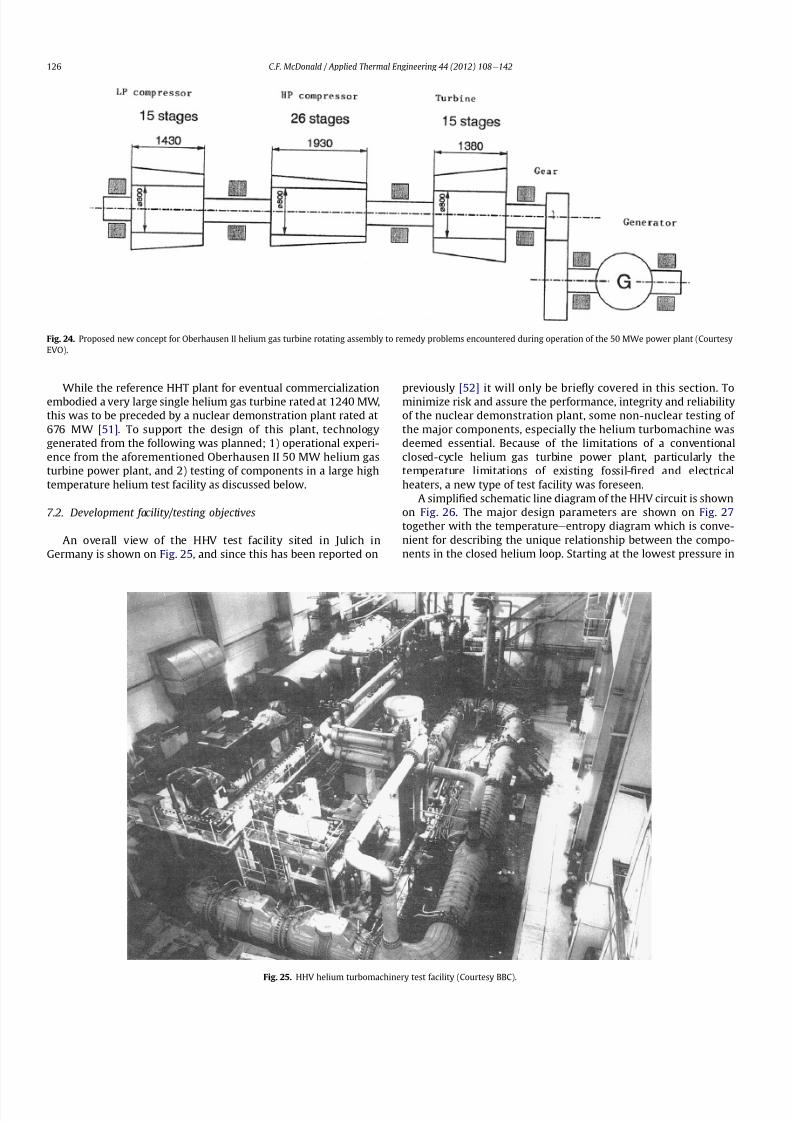
8112019 Helium Turbomachinery Operating Experience From Gas Turbine Power Plants
httpslidepdfcomreaderfullhelium-turbomachinery-operating-experience-from-gas-turbine-power-plants 1935
While the reference HHT plant for eventual commercializationembodied a very large single helium gas turbine rated at 1240 MW
this was to be preceded by a nuclear demonstration plant rated at
676 MW [51] To support the design of this plant technology
generated from the following was planned 1) operational experi-
ence from the aforementioned Oberhausen II 50 MW helium gas
turbine power plant and 2) testing of components in a large high
temperature helium test facility as discussed below
72 Development facilitytesting objectives
An overall view of the HHV test facility sited in Julich in
Germany is shown on Fig 25 and since this has been reported on
previously [52] it will only be brie1047298
y covered in this section Tominimize risk and assure the performance integrity and reliability
of the nuclear demonstration plant some non-nuclear testing of
the major components especially the helium turbomachine was
deemed essential Because of the limitations of a conventional
closed-cycle helium gas turbine power plant particularly the
temperature limitations of existing fossil-1047297red and electrical
heaters a new type of test facility was foreseen
A simpli1047297ed schematic line diagram of the HHV circuit is shown
on Fig 26 The major design parameters are shown on Fig 27
together with the temperatureeentropy diagram which is conve-
nient for describing the unique relationship between the compo-
nents in the closed helium loop Starting at the lowest pressure in
Fig 24 Proposed new concept for Oberhausen II helium gas turbine rotating assembly to remedy problems encountered during operation of the 50 MWe power plant (Courtesy
EVO)
Fig 25 HHV helium turbomachinery test facility (Courtesy BBC)
CF McDonald Applied Thermal Engineering 44 (2012) 108e142126
8112019 Helium Turbomachinery Operating Experience From Gas Turbine Power Plants
httpslidepdfcomreaderfullhelium-turbomachinery-operating-experience-from-gas-turbine-power-plants 2035
the system the helium is compressed (Ae
B) its temperatureincreasing to 850 C (1562 F) before 1047298owing through the test
section (BeC) After being cooled slightly (CeD) the helium is
expanded in the turbine (DeA) down to the compressor inlet
conditions completing the loop There is no power output from the
system and without the need for an external heater the
compression heat is used to raise the helium to the maximum
system temperature in what can be described as a very large heat
pump The required compressor power is 90 MW and to supple-
ment the 45 MW generated by expansion in the turbine external
power is provided by a 45 MW synchronous electrical motor A
cooler is required to remove the compression heat that is contin-
uously put into the closed helium loop and this is done by bleeding
about 5 percent of the mass 1047298ow after the compressor cooling it
and re-introducing it into the circuit close to the turbine inlet In
addition to testing the turbomachine the facility was engineered
with a test section to accommodate other small components (eg
hot gas 1047298ow regulation valves bypass valves insulation con1047297gu-
rations and types of hot gas duct construction) With the highest
temperature in the system being at the compressor exit the facility
had the capability to provide helium at a temperature up to 1000 C
(1832 F) for short periods at the entrance to the test section
While a higher ef 1047297ciency of the planned nuclear demonstration
plant could be projected with a turbine inlet temperature in the
range 950e1000 C (1742e1832 F) this would have necessitated
either turbine blade cooling or the use of a high temperature alloy
such as Titanium Zirconium Molybdenum (TZM) At the time it was
felt that using either of these would have added cost and risk to theprojectso a conventionalnickel-basedalloyas usedin industrialgas
turbines was selected for the 850 C design value of turbine inlet
temperature this negating the needfor actual internal bladecooling
However a complex internal coolingsystemwas neededto keep the
Fig 26 Cycle diagram of HHV test loop (Courtesy BBC)
Fig 27 Salient features of HHV helium turbomachinery (Courtesy BBC)
CF McDonald Applied Thermal Engineering 44 (2012) 108e142 127
8112019 Helium Turbomachinery Operating Experience From Gas Turbine Power Plants
httpslidepdfcomreaderfullhelium-turbomachinery-operating-experience-from-gas-turbine-power-plants 2135
turbine discs and blade root attachments and casings to acceptable
temperatures commensurate with prescribed stress limitations for
thelife of theturbomachine In addition a heliumsupplywas needed
to provide a buffering system for the various labyrinth seals
In a direct Brayton cycle nuclear gas turbine the turbomachine is
installed in the reactor circuit and via the hot gas duct heated
helium is transported directly from the reactor core to the turbine
From the safety licensing and reliability standpoints there are
various seals that must perform perfectly A helium buffered
labyrinth seal system is necessary to prevent bearing lubricating oil
ingress to the closed helium loop Since in the proposed HHT plant
design the drive shaft from the turbine to the generator penetrates
the reactor primary system pressure boundary two shaft seals are
needed one a dynamic seal when the shaft is rotating and a static
seal when the turbomachine is not operating Testing of these seals
in a size and operating conditions representative of the planned
commercial power plant was considered to be a licensing must
The mechanical integrity of the rotating assembly must be
assured there being two major factors necessitating testing the
machine at full speed and temperature and at high pressure
namely 1) loading the blading under representative centrifugal and
gas bending stresses and 2) to monitor vibration and con1047297rm rotor
dynamic stability For the design of the planned commercial planta knowledge of the acoustic emissions by the turbomachine and
propagation in the closed circuit was required Data from the HHV
facility would enable dynamic responses of the major components
(especially the insulation) resulting from excitation by the sound
1047297eld to be calculated
The circuit was instrumented to gather data on the effectiveness
of the hot gas duct insulation thermal expansion devices hot gas
valves helium puri1047297cation system instrumentation and the
adequacy of the coatings applied to mating metallic surfaces to
prevent galling or self-welding Details of the turbomachinery and
the experience gained from the operation of the HHV facility are
covered in the following sections
73 Helium turbomachine
A cross-section of the turbomachine is shown on Fig 28 The
single-shaft rotating assembly consists of 8 compressor stagesand 2
turbine stages and had a weighton the order of 66 tons(60000 kg)
The hub inner and outer diameters are 16 m (525 ft) and 18 m
(59 ft) respectively the blading axial length being 23 m (75 ft)The
span between the oil bearings being 57 m (187 ft) The physical
dimensions of the turbogroup shown on Fig 28 correspond to
a machine rated at about 300 MW The oil bearings operate in
a helium environment and the diameters of the labyrinths and
1047298oating ring shaft seals to prevent oil ingress are representative of
a machine rated at about 600 MW The complexity of the machine
design especially the rotor cooling system sealing system very
large casing and heat insulation have been reported previously
[53e55]
To ensure high structural integrity the rotor was constructed by
welding together the forged compressor and turbine discs The
compressor had 8 stages each having 56 rotor and 72 stator blades
The turbine had 2 stages each having 90 stator and 84 rotor blades
An appreciation for the large size of the rotating assembly can be
seen from Fig 29 The rotor blades have 1047297r-tree attachments
embodying cooling channels Since the temperature and pressure
do not vary very much along the blading in the 1047298ow direction an
intricate rotor and stator cooling system was required Channels in
both the blade roots and the spacers between adjacent blade rows
form an axial geometry for the passage of a cooling helium supplyto keep the temperature of the multiple discs below 400 C
(752 F) The design of this was a challenge since the rotor and
stator blade attachments of both the 8 stage compressor and 2
stage turbine had to be cooled Excessive leakage had to be avoided
since this would have prevented the speci1047297ed compressor
discharge temperature (ie the maximum temperature in the
circuit) from being reached
In the 1970rsquos and early 1980rsquos signi1047297cant studies were carried
out on large helium gas turbines by various organizations [56e62]
In this era there was general agreement that testing of the turbo-
machine in one form or another in non-nuclear facilities be
undertaken to resolve areas of high risk (eg seals bearings cooling
systems rotor dynamic stability compressor surge margin
dynamic response rotor burst protection etc) before installationand operation of a large gas turbine in a nuclear environment
This low risk engineering philosophy which prevailed at the time
in both Germany and the USA emphasized the importance of
Fig 28 Cross-section of HHV helium turbomachinery (Courtesy BBC)
CF McDonald Applied Thermal Engineering 44 (2012) 108e142128
8112019 Helium Turbomachinery Operating Experience From Gas Turbine Power Plants
httpslidepdfcomreaderfullhelium-turbomachinery-operating-experience-from-gas-turbine-power-plants 2235
the HHV test facility as being an important step towards the
eventual deployment of a high ef 1047297ciency nuclear gas turbine power
plant
74 Initial operation of the HHV facility
During commissioning of the plant in 1979 oil ingress into the
helium circuit from the seal system occurred twiceThe 1047297rst ingressof oil between 600 and 1200 kg (1322 and 2644 lb) was due to
a serious operatorerror and the absence of an isolation valve in the
system The oil in the circuit was partly coked and formed thick
deposits on the cold and hot surfaces of the turbomachinery and in
other parts of the closed loop including saturation of the 1047297brous
insulation The fouled metallic surfaces were cleaned mechanically
and chemically by cracking with the addition of hydrogen and
additives The second oil ingress was due to a mechanical defect in
the labyrinth seal system The quantity of oil introduced was small
and it was removed bycracking at a temperature of 600 C (1112 F)
and with the use of additives To obviate further oil ingress inci-
dents the labyrinth seal system was redesigned The buffer and
cooling helium system piping layout was modi1047297ed to positively
eliminate oil ingress due to improper valve operation and toprevent further human error
Pressure and leak detection tests of the HHV test facility at
ambient temperature showed good leak tightness for the turbo-
machine 1047298anged joints and of the main and auxiliary circuits
However at the operating temperature of 850 C (1562 F) large
helium leaks were detected The major 1047298anges had been provi-
sioned with lip seals and the 1047297rst step was to weld the closures A
large leak persisted at the front 1047298ange of the turbomachine This
was diagnosed as being caused by a non-uniform temperature
distribution during initial operation resulting in thermal stresses
creating local gaps This problem was overcome by redesign of the
cooling system with improved gas 1047298ow distribution and 1047298ow rates
to give a more uniform temperature gradient The leakage from the
system was reduced to on the order of 020e
040 percent of the
helium inventory per day this being of the same magnitude as in
other closed helium circuits as discussed in Section 65
It should be mentioned that in addition to the HHV experience
bearing oil ingress into the circuits and system loss of the working
1047298uid in other closed-cycle gas turbine plants have occurred In all of
these fossil-1047297red facilities 1047297xing leaks and removal of oil deposits
were undertaken based on conventional hands-on approaches but
nevertheless such operations were time-consuming However if a new and previously untested helium turbomachine operating in
a direct cycle nuclear gas turbine plant experienced an oil ingress
the rami1047297cations would be severe The likely use of remote
handling equipment to remove the turbomachine from the vessel
machine disassembly (including breaking the welded 1047298ange joints)
and removal of oil from the radioactively contaminated turbo-
machine blade surfaces and system insulation would be time
consuming A diagnosis of the failure would be required before
a spare turbomachine could be installed and this plant downtime
could adversely affect plant availability
75 Experience gained
Afterresolutionof the aforementionedproblems the HHVfacilitywas started in the Spring of 1981 and in an orderly manner was
brought up to full pressure and a temperature of 850 C (1562 F)
During a 60 h run the functioning of the instrumentation control
and safety systems were veri1047297ed During these tests the ability to
stop the turbomachine from full operating conditions to standstill
within 90 s was demonstrated After system depressurization the
plant was then run up again to full operating conditions with no
problems experienced The HHV facility was successfully run for
about 1100 h of which theturbomachineryoperated forabout325 h
at a temperature of 850 C The test facility was extensively instru-
mented and interpretation and analysis of the data recorded gave
positive and favorable results in the following areas
The complex rotor cooling system which was engineered to
assure that the temperature of the discs be kept below 400
C
Fig 29 HHV helium turbomachine rotating assembly (size equivalent to a 300 MWe machine) being installed in a pressure vessel (Courtesy BBC)
CF McDonald Applied Thermal Engineering 44 (2012) 108e142 129
8112019 Helium Turbomachinery Operating Experience From Gas Turbine Power Plants
httpslidepdfcomreaderfullhelium-turbomachinery-operating-experience-from-gas-turbine-power-plants 2335
(752 F) was demonstrated to be effective The measured rotor
coolant 1047298ows (about 3 percent of the mass1047298ow passing through the
machine) were slightly larger than had been estimated and this
resulted in measured turbine disc temperatures lower than pre-
dicted [55]
The dynamic labyrinth shaft seal functioned well at the full
temperature and pressure conditions and met the requirement of
zero oil ingress into the helium circuit The measured rotor oscil-
lation did not have any adverse effect on the shaft sealing system
The static rotor seal (for shutdown conditions) functioned without
any problems
The compressor and turbine blading hadef 1047297ciencies higher than
predicted The structural integrity of the rotor proved to be sound
when operating at 3000 rpm under the maximum temperature and
pressure conditions The stiff rotor shaft had only slight unbalance
and thermal distortion and measured oscillations were in the range
typical of large steam turbines
Sound power spectrum measurements were taken in four
different locations in the circuit These were taken to determine the
spectrum and intensity of the sound generated and propagated by
the turbomachinery and the resultant vibration of internal
components The maximum sound power level in the helium
circuit was160 dB Numerous strain gages were placedin the circuitto determine the in1047298uence of the sound 1047297eld particularly on the
fatigue strength of the turbine inlet hot gas duct In later examining
the internal components there was no evidence of excessive
vibration of the components especially the ducting and the insu-
lation Based on the measurements and calculations it was
concluded that the fatigue strength limit of the components would
not be exceeded during the designed life of the planned commer-
cial nuclear gas turbine power plant
In a direct cycle nuclear gas turbine the hot gas duct used to
transport the helium from the reactor core to the turbineis a critical
component The hot gas duct in the HHV facility performed well
mechanically and con1047297rmed the adequacy of the thermal expan-
sion devices From the thermal standpoint the 1047297ber insulation
performed better than the metallic type
After dismantling the HHV facility there were no signs of
corrosion or erosion of the turbine or compressor blading While
the total number of hours operated was limited the coatings
applied to mating metallic surfaces to prevent galling and frictional
welding in the oxidation-free helium worked well
The helium buffer and cooling system worked well However
problems remained with the puri1047297cation of the buffer helium The
oil separation system consisting of a cyclone separator and a wire
mesh and a down stream 1047297ber 1047297lter needed further improvement
In late 1981 a decision was made to cancel the HHT project and
the HHV facility was shutdown The design and operational expe-
rience gained from the running of this facility would have been
extremely valuable had the nuclear gas turbine power plant
concept moved towards becoming a reality The identi1047297cation of
somewhat inevitable problems to be expected in such a complexturbomachine and their resolution were undertaken in a timely
and cost effective manner in the non-nuclear HHV facility This
should be noted for future nuclear gas turbine endeavors since
remedying such unexpected problems in the case of a new and
untested large helium turbomachine being operated for the 1047297rst
time using nuclear heat could result in very complex repair
Fig 30 Speci1047297
c speed-speci1047297
c diameter array for gas circulators in various gas-cooled nuclear plants
CF McDonald Applied Thermal Engineering 44 (2012) 108e142130
8112019 Helium Turbomachinery Operating Experience From Gas Turbine Power Plants
httpslidepdfcomreaderfullhelium-turbomachinery-operating-experience-from-gas-turbine-power-plants 2435
activities and extended plant downtime and indeed adding risk to
the overall success of the nuclear gas turbine concept
8 Circulators used in gas-cooled reactor plants
Circulators of different types will be needed in future helium
cooled nuclear plants these including the following 1) primary
loop circulator for possible next generation steam cycle power andcogeneration plants 2) for future indirect cycle gas turbine plants
3) shut down cooling circulators forall HTRand VHTR plants and 4)
for various circulators needed in future VHTR high temperature
process heat plant concepts The technology status of operated
helium circulators is brie1047298y addressed as follows
81 Background
It would be remiss not to mention experience gained in the past
with gas circulators and while not gas turbines they are rotating
machines that operate in the primary loop of a helium cooled
reactor With electric motor drives there are basically two types of
compressor rotor con1047297gurations namely radial and axial 1047298ow
machinesIn a single stage form the centrifugal impeller is used for high
stage pressure rise and low volume 1047298ow duties whereas the axial
type covers low pressure rise per stage and high volume 1047298ow The
selection of impeller type is very much related to the working
media type of bearings drive type rotor dynamic characteristics
and installation envelope A wide range of circulators have operated
and a well established technology base exists for both types [63] A
useful portrayal of compressor data in the form of quasi- non-
dimensional parameters (after Balje [64]) showing approximate
boundaries for operation of high ef 1047297ciency axial and radial types is
shown on Fig 30 (from Ref [65])
Both high speed axial and lower speed radial 1047298ow types are
amenable to gas oil and magnetic bearings From the onset of
modularHTR plant studies theuse of active magnetic bearings[6667]offered a solution to eliminate lubricating oil into the reactor circuit
and this tribology technology is attractive for use in submerged
rotating machinery in the next generation of HTR plants [68]
While now dated an appreciation of the main design features of
typical electric motor-driven helium circulators have been reported
previously namely an axial 1047298ow main circulator for a modular
steam cycle HTR plant [69] and a representative radial 1047298ow shut-
down cooling circulator [70]
The operating experience gained from three particular circula-
tors is brie1047298y included below because of their relevance to the
design of helium turbomachinery in future HTR plant variants
82 Axial 1047298ow helium circulator
Since all of the aforementioned predominantly European
helium gas turbines used axial 1047298ow turbomachinery it is of interest
to mention a helium axial 1047298ow circulator that operated in the USA
and to brie1047298y discuss its design parameters and features The
330 MW Fort St Vrain HTGR featured a Rankine cycle power
conversion system Four steam turbine driven helium circulators
were used to transport heat from the reactor core to the steam
generators The complete circulator assemblies were installed
vertically in the prestressed concrete reactor vessel [71e73]
A cross-section of the circulator is shown on Fig 31 with thecompressor rotor and stator visible on the left hand end of the
machine Based on early 1960rsquos technology a decision was made to
use water lubricated bearings and from the overall plant reliability
and availability standpoints this later proved to be a bad choice
Within the vertical circulator assembly there were four 1047298uid
systems namely the helium reactor coolant water lubricant in the
bearings steam for the turbine drive and high pressure water for
the auxiliary Pelton wheel drive During plant transients the pres-
sures and temperatures of these four 1047298uids oscillated considerably
and the response of the control and seal systems proved to be
inadequate and resulted in considerable water ingress from the
bearing cartridge into the reactor helium circuit The considerable
clean up time needed following repeated occurrences of this event
resulted in long periods of plant downtime and this had an adverseeffect on plant availability This together with other technical
Fig 31 Cross section of FSV helium circulator (Courtesy general Atomics)
CF McDonald Applied Thermal Engineering 44 (2012) 108e142 131
8112019 Helium Turbomachinery Operating Experience From Gas Turbine Power Plants
httpslidepdfcomreaderfullhelium-turbomachinery-operating-experience-from-gas-turbine-power-plants 2535
dif 1047297culties eventually contributed to the plant being prematurely
decommissioned
On the positive side in the context of this paper the helium
circulators operated for over 250000 h and exhibited excellent
helium compressor performance good mechanical integrity and
vibration-free operation The rotating assembly showing the axial
1047298ow compressor and steam turbine rotors together with a view of
the machine assembly are given on Fig 32 The helium compressor
consists of a single stage axial rotor followed by an exit guide vane
The machine was designed for axial helium 1047298ow entering and
leaving the stage and this can be seen from the velocity triangles
shown on Fig 33 which also includes the de1047297nition of the various
aerodynamic parameters Major design parameters and features of
this helium circulator are given on Table 4 Related to an earlier
discussion on the degree of reaction for axial 1047298ow compressors the
value for this conventional single stage circulator is 78 percent All
of the major aerothermal and structural loading criteria were
within established boundaries for an axial compressor having high
ef 1047297ciency and a good surge margin
The compressor gas 1047298ow path and blading geometries were
established based on prevailing industrial gas turbine and aero-
engine design practice A low Mach number (025) a high Reynolds
number (3 106) together with a modest stage loading (ie
a temperature rise coef 1047297cient of 044) and an acceptable value of
diffusion factor (042) were some of the factors that contributed to
a helium circulator that had a high ef 1047297ciency and a good pressure
rise- 1047298ow characteristic The large rotor blade chord and thick blade
section for this single stage circulator are necessary to accommo-
date the high bending stress characteristic of operation in a high
pressure environment The solidity and blade camber were opti-
mized for minimum losses
There were essentially two reasons for including this single-
stage axial 1047298ow compressor that operated in a helium cooled
reactor although its overall con1047297guration can be regarded as a 1047297rst
and last of a kind A rotor blade from this circulator as shown onFig 34 was based on a NASA 65 series airfoil which at the time
were one of the best performing cascades for such low Mach
number and high Reynolds number applications Interestingly it
has almost the same blade height aspect ratio and solidity as would
be used in the 1047297rst stage of an LP compressor in a helium turbo-
machine rated on the order of 250 MW
The second point of interest is that the helium mass 1047298ow rate
through the single stage axial compressor (rated at 4 MWe) is
110 kgs compared with 85 kgs through the multistage compressor
in the 50 MWe Oberhausen II helium gas turbine plant However
the volumetric 1047298ow through the Oberhausen axial compressor is
higher than that through the circulator by a factor of 16 this again
pointing out that the Oberhausen II plant was designed for high
volumetric 1047298ow to simulate the much larger size of turboma-chinery that was planned at the time in Germany for use in future
projected nuclear gas turbine power plants
83 High temperature helium circulator
For future helium turbomachines embodying active magnetic
bearings a challenge in their design relates to accommodating
elevated levels of temperature in the vicinity of the electronic
components In this regard it is of interest to note that a small very
high temperature helium axial 1047298ow circulator rated at 20 kW (as
shown on Fig 35) operated for more than 15000 h in an insulation
test facility in Germany more than two decades ago [74] The
signi1047297cance of this machine is that it operated with magnetic
bearings in a high temperature helium test loop with a circulatorgas inlet temperature of 950 C (1742 F) This necessitated the use
of ceramic insulation to ensure that the temperature in the vicinity
of the magnetic bearing electronics did not exceed a temperature of
about 150 C (300 F)
This machine although a very small axial 1047298ow helium blower
performed well and has been brie1047298y mentioned here since it
represents a point of reference for future helium rotating machines
capable operating with magnetic bearings in a very high temper-
ature helium environment
84 Radial 1047298ow AGR nuclear plant gas circulators
The electric motor-driven carbon dioxide circulators rated at
about 5 MW with a total runningtimein excess of 18 million hours
Fig 32 Fort St Vrain HTGR plant helium circulator (Courtesy General Atomics) (a)
Axial 1047298ow helium compressor and steam turbine rotating assembly (b) 4 MW helium
circulator assembly
CF McDonald Applied Thermal Engineering 44 (2012) 108e142132
8112019 Helium Turbomachinery Operating Experience From Gas Turbine Power Plants
httpslidepdfcomreaderfullhelium-turbomachinery-operating-experience-from-gas-turbine-power-plants 2635
in AGR nuclear power plants in the UK have demonstrated veryhigh availability [7576] To a high degree this can be attributed to
the fact that the machines were conservatively designed and proof
tested in a non-nuclear facility at full temperature and power
under conditions that simulated all of the nuclear plant operating
modes The test facility shown on Fig 36 served two functions 1)
design veri1047297cation of the prototype machine and 2) test of all new
and refurbished machines before they were installed in nuclear
plants Engineers currently involved in the design and development
of helium turbomachinery could bene1047297t from this sound testing
protocol to minimize risk in the deployment of helium rotating
machinery in future HTRVHTR plant variants
9 Helium turbomachinery development and testing
91 On-going development activities
The various helium turbomachines discussed in previous
sections operated over a span of about two decades starting in the
early 1960s From about 1990 activities in the nuclear gas turbine
1047297eld have been focused mainly on the design of modular GTeHTR
plant concepts In support of these plant studies many signi1047297cant
helium turbomachine design advancements have been made and
attention given to what development testing would be needed In
the last decade or so limited sub-component development has
been undertaken for helium turbomachines in the 250e300 MWe
size and these are brie1047298y summarized below
In a joint USARussia effort development in support of the
GTe
MHR turbomachine has been undertaken including testing in
the following areas magnetic bearings seals and rotor dynamicsfor the vertical intercooled helium turbomachine rated at 286 MWe
[77e80]
In Japan development activities have been in progress for
several years in support of the 274 MWe helium turbomachine for
the GTeHTR300 plant concept [2581] A detailed discussion on
the aerodynamic design of the axial 1047298ow helium compressor for
this turbomachine has been published in the open literature [82]
While the design methodology used for axial compressor design in
air-breathing industrial and aircraft gas turbines is generally
applicable for a multi-stage helium compressor a decision was
made by JAEA to test a small scale compressor in a helium facility
because of the inherent and unique gas 1047298ow path and type of
blading associated with operation in a high pressure helium
environment The major goal of the test was to validate the designof the 20 stage helium axial 1047298ow compressor for the GTeHTR300
plant
An axial 1047298ow compressor in a closed-cycle helium gas turbine is
characterized by the following 1) a large number stages 2) small
blade heights 3) high hub-to-tip ratio 4) a long annulus with
small taper that tends to deteriorate aerodynamic performance as
a result of end-wall boundary layer length and secondary 1047298ow 5)
low Mach number 6) high Reynolds number and 7) blade tip
clearances that are controlled by the gap necessary in the magnetic
journal and catcher bearings While (as covered in earlier sections)
helium gas turbines have operated there is limited data in the
open literature on the performance of multi-stage axial 1047298ow
compressors operating in a high pressure closed-loop helium
environment
Fig 33 Velocity triangles for axial compressor stage
CF McDonald Applied Thermal Engineering 44 (2012) 108e142 133
8112019 Helium Turbomachinery Operating Experience From Gas Turbine Power Plants
httpslidepdfcomreaderfullhelium-turbomachinery-operating-experience-from-gas-turbine-power-plants 2735
A 13rd scale 4 stage compressor was designed to simulate the
stage interaction the boundary layer growth and repeated stage
1047298ow in an actual compressor The 1047297rst four stages were designed to
be geometrically similar to the corresponding stages in the
GTe
HTR300 compressor Details of the model compressor havebeen discussed previously [81] and are summarized on Table 5
from [83]
A cross-section of the compressor test model is shown on Fig 37
A view of the 4 stage compressor rotor installed in the lower casing
is shown on Fig 38 The test facility (Fig 39) is a closed helium loop
consisting of the compressor model cooler pressure adjustment
valve and a 1047298ow measurement instrument The compressor is
driven by a 3650 kW electrical motor via a step-up gear The rota-
tional speed of 10800 rpm (three times that of the compressor in
the GTeHTR300 plant) was selected to match blade speed and
Mach number in the full size compressor
Details of the planned aerodynamic performance objectives of
the 13rd scale helium compressor test have been published
previously [84] Extensivetesting of the subscale model compressorprovided data to validate the performance of the full size
compressor for the GTeHTR300 power plant The test data and
test-calibrated CFD analyses gave added insight into the effect of
factors that impact performance including blade surface roughness
and Reynolds number
Based on advanced aerodynamic methodology and experi-
mental validation [82] there is now a sound basis for added
con1047297dence that the design goals of 90 percent polytropic ef 1047297ciency
and a design point surge margin of 20 percent are realizable in
a large multistage axial 1047298ow compressor for a future nuclear gas
turbine plant
In a similar manner a design of a one third size single stage
helium axial 1047298ow turbine has been undertaken and a cross
section of the machine is shown on Fig 40 (from Ref [81]) This
Table 4
Major features of axial 1047298ow helium circulator
Helium 1047298ow rate kgsec 110
Inlet temperature C 394
Inlet pressure MPa 473
Pressure rise KPa 965
Volumetric 1047298ow m3sec 32
Compressor type Single stage axial
Compressor drive Steam turbine
Bearing type Water lubricated
Rotational speed rpm 9550
Power MW 40
Rotor tip diameter mm 688
Rotor tip speed msec 344
Number of rotor blades 31
Number of stator blades 33
Blade height mm 114
Hub-to-tip ratio 067
Axial velocity msec 157
Flow coef 1047297cient 055
Temperature rise coef 1047297cient 044
Degree of reaction 078
Mean rotor solidity 128
Rotor aspect ratio 155
Rotor Mach number 025
Rotor diffusion factor 042
Rotor Reynolds number 3106
Speci1047297c speed 335
Speci1047297c diameter 066
Blade root thickness 15
Airfoil type NASA 65
Rotor blade chord mm 94e64
Stator blade chord mm 79
Rotor centrifugal stress MPa 125
Rotor bending stress MPa 30
Circulator(s) operating Hours gt250000
Fig 34 Rotor blade from single stage axial 1047298ow helium circulator (Courtesy General
Atomics)
Fig 35 20 kW axial 1047298ow helium circulator with magnetic bearings operated in 1985 in
an insulation test loop with a gas inlet temperature on 950
C (Courtesy BBC)
CF McDonald Applied Thermal Engineering 44 (2012) 108e142134
8112019 Helium Turbomachinery Operating Experience From Gas Turbine Power Plants
httpslidepdfcomreaderfullhelium-turbomachinery-operating-experience-from-gas-turbine-power-plants 2835
single stage scale model turbine for validity of the full size turbine
has been built and plans made to test the aerodynamic
performance
92 Nuclear gas turbine helium turbomachine testing
In planning for the 1047297rst nuclear gas turbine plant projected to
enter service perhaps in the third decade of the 21st century
a major decision has to be made as to what extent the large helium
turbomachine should be tested prior to operation on nuclear heat
Issues essentially include cost impact on schedule but the over-
riding one is risk Certainly turbomachine component testing will
be undertaken including the compressor (as discussed in the
previous section) and turbine performance seals cooling systems
hot gas valves thermal expansion devices high temperature
insulation rotor fragment containment diagnostic systems
instrumentation helium puri1047297cation system and other areas to
satisfy safety licensing reliability and availability concerns The
major point is really whether a full size or scaled-down turbo-machine be tested early in the project in a non-nuclear facility
To obviate the need for pre-nuclear testing of a large helium
turbomachine a view expressed by some is that advantage can be
taken of formidable technology bases that exist today for large
industrial gas turbines and high performance aeroengines On the
other hand it is the view of some including the author that very
complex power conversion system components especially those
subjected to severe thermal transients donrsquot always perform
exactly as predicted by analysts and designers even using sophis-
ticated computer codes This was exempli1047297ed in the case of the
turbomachine in the aforementioned Oberhausen II helium gas
turbine plant
The need for a helium turbomachine test facility goes beyond
just veri1047297
cation of the prototype machine Each newgas turbine for
commercial modular nuclear reactor plants would have to be proof
tested and validated before being transported to the reactor site
Similarly turbomachines that would be periodically removed from
the plant at say 7 year intervals during the plant operating life of 60
years for scheduled maintenance refurbishment repair or updat-ing would be again proof tested in the facility before re-entering
service
The direction that turbomachine development and testing will
take place for future helium gas turbines needs to be addressed by
the various organizations involved
Fig 36 AGR circulator test facility In the UK (Courtesy Howden)
Table 5
Major design parametersfeatures of model GTeHTR300 axial 1047298ow helium
compressor (Courtesy JAERI)
Scale of GTeHTR300 compressor 13
Helium mass 1047298ow rate (kgsec) 122
Helium volumetric 1047298ow rate (mV s) 87
Inlet temperature C 30
Inlet pressure MPa 0883Compressor pressure ratio at design point 1156
Number of stages 4
Rotational speed rpm 10800
Drive motor power kW 3650
Hub diameter mm 500
Rotor tip diameter (1st4th stage mm) 568566
Hub-to-tip ratio (1st stage) 088
Rotor tip speed (1st stage msec) 321
Number of rotorstator blades (1st stage) 7294
Rotorstator blade height (1st stage mm) 34337
Rotor stator blade c hor d l eng th (1st stage mm) 2620
Rotorstator solidity (1st stage) 119120
Rotorstator aspect ratio (1st stage) 1317
Flow coef 1047297cient 051
Stage loading factor 031
Reynolds number at design point 76 l05
CF McDonald Applied Thermal Engineering 44 (2012) 108e142 135
8112019 Helium Turbomachinery Operating Experience From Gas Turbine Power Plants
httpslidepdfcomreaderfullhelium-turbomachinery-operating-experience-from-gas-turbine-power-plants 2935
10 Helium turbomachinery lessons learned
101 Oberhausen II gas turbine and HHV test facility
It is understandable that 1047297rst-of-a-kind complex turboma-
chinery operating with an inert low molecular weight gas such as
helium will experience unique and unexpected problems In the
operation of the two pioneering large helium turbomachines in
Germany there were many positive1047297ndings which could only have
been achieved by development testing Equally important some
negative situations were identi1047297ed many of which were remedied
In the case of the Oberhausen II helium gas turbine plant some of
the very serious problems encountered were not resolved Inves-
tigations were undertaken to rationalize the problems associated
with the large power de1047297ciency and a data base established to
ensure that the various anomalies identi1047297ed would not occur in
future large helium turbomachines
The experience gained from the operation of the Oberhausen II
helium gas turbine power plant and the HHV test facility have been
discussedin thetextand arepresentedin a summaryformon Table6
Fig 37 Cross-section of 13rd scale helium compressor test model (Courtesy JAEA)
Fig 38 Four stage helium compressor rotor assembly installed in lower casing (Courtesy JAEA)
CF McDonald Applied Thermal Engineering 44 (2012) 108e142136
8112019 Helium Turbomachinery Operating Experience From Gas Turbine Power Plants
httpslidepdfcomreaderfullhelium-turbomachinery-operating-experience-from-gas-turbine-power-plants 3035
102 Impact of 1047297ndings on future helium gas turbine
The long slender rotorcharacteristic of closed-cycle gas turbines
has resulted in shaft dynamic instability which in some cases has
resulted in blade vibration and failure and bearing damage This
remains perhaps the major concern in the design of large
(250e
300 MW) helium turbomachines for future nuclear gas
turbine plants With pressure ratios in the range of about 2e3 in
a helium system a combination of splitting the compressor (to
facilitate intercooling) and having a large number of compressor
and turbine stages results in a long and 1047298exible rotating assembly
andthis is exempli1047297ed by the rotorassembly shown on Fig13 With
multiple bearings (either oil lubricated or magnetic) the rotor
would likely pass through multiple bending critical speeds before
Fig 39 Helium compressor test facility (Courtesy JAEA)
Fig 40 Cross-section of single stage helium turbine test model (Courtesy JAEA)
CF McDonald Applied Thermal Engineering 44 (2012) 108e142 137
8112019 Helium Turbomachinery Operating Experience From Gas Turbine Power Plants
httpslidepdfcomreaderfullhelium-turbomachinery-operating-experience-from-gas-turbine-power-plants 3135
reaching the design speed While very sophisticated computer
codes will be used in the detailed rotor dynamic analyses the real
con1047297rmation of having rotor oscillations within prescribed limits
(to avoid blade bearing and seal damage) will come from actual
testingA point to be made here is that in operated fossil-1047297red closed-
cycle gas turbine plants it was possible to remedy problems asso-
ciated with rotor vibrations and blade failures in a conventional
manner In fact in some situations the casings were opened several
times and modi1047297cations made to facilitate bearing and seal
replacement and rotor re-blading and balancing
An accurate assessment of pressure losses must be made
particularly those associated with the helium entering and leaving
the turbomachine bladed sections Minimizing the system pressure
loss is important since it directly impacts the all important quotient
of turbine expansion ratio to compressor pressure ratio and power
and plant ef 1047297ciency
Based on the operating experience from the 20 or so fossil-1047297red
closed-cycle gas turbine plants using air as the working1047298
uid it was
recognized that future very high pressure helium gas turbines
would pose problems regarding the various seals in the turbo-
machine and obtaining a zero leakage system with such a low
molecular weight gas would be dif 1047297cult and this is discussed
below
When the Oberhausen II gas turbine plant and the HHV facility
operated over 30 years ago oil lubricated bearings were used to
support the heavy rotor assemblies and helium buffered labyrinth
seals were used to prevent oil ingressinto the heliumworking1047298uid
Initial dif 1047297culties encountered in both plants were overcome by
changes made to the seal geometries and for the operating lives of
the helium turbomachines no further oil ingress events were
experienced Twoseals were required where the turbine drive shaft
penetrated the turbomachine casing namely 1) a dynamic laby-
rinth seal and 2) a static seal for shutdown conditions In both
plants these seals functioned without any problems
Labyrinth seals were also required within the helium turbo-
machines to pass the correct helium bleed 1047298ow from the
compressor discharge for cooling of the turbine discs blade root
attachments and casings The fact that the very complex rotor
cooling system in the large helium turbomachine in the HHV test
facility operated well for the test duration of about 350 h with
a turbine inlet temperature of 850 C was encouragingIn the case of the Oberhausen II gas turbine plant analysis of the
test data revealed that the labyrinth seal leakage and excessive
cooling 1047298ows were on the order of four times the design value A
possible reason for this was that damage done to the labyrinth
seals caused excessive clearances when periods of excessive rotor
oscillation and vibration occurred during early operation of the
machine
Clearly 1047298uid dynamic and thermal management of the cooling
system and 1047298ow through the various labyrinth seals will require
extensive analysis design and development testing before the
turbomachine is operated on nuclear heat for the 1047297rst time
In future heliumgas turbine designs (with turbine inlet tempera-
tureslikelyontheorderof950C)the1047298owpathgeometriesofhelium
bledfromthecompressornecessarytocoolpartsoftheturbomachinewillbemorecomplexthanthosetestedto-dateInadditiontoproviding
acooling1047298owtotheturbinebladesanddiscsbladerootattachmentsand
casingsheliummustbetransportedtotheseveralmagneticbearingsto
ensure thatthe temperatureof theirelectronic components doesnot
exceedabout150C
The importance of the points made above is evidenced when
examining the data on Table 3 where a combination of excessive
pressure losses and high bleed 1047298ows contributed to about 40
percent of the power de1047297ciency in the Oberhausen II helium
turbine plant
Retaining overall system leak tightnessin closed heliumsystems
operating at high pressure and temperature has been elusive
including experience from the Fort St Vrain HTGR plant as dis-
cussed in Section 65 New approaches in the design of the plethoraof mechanical joints must be identi1047297ed Experience to-date has
shown that having welded seals on 1047298anges while minimizing
system leakage did not eliminate it
The importance of lessons learned from the operation of the
Oberhausen II helium turbine power plant and the HHV test facility
have primarily been discussed in the context of helium turbo-
machines currently being designed in the 250e300 MWe power
range However the established test data bases could also be
applied to the possible emergence in the future of two helium
cooled reactor concepts namely 1) an advanced VHTR combined
cycle plant concept embodying a smaller helium gas turbine in the
power range of 50e80 MWe [22] and 2) the use of a direct cycle
helium gas turbine PCS in a recently proposed all ceramic fast
nuclear reactor concept [85]
Table 6
Experience gained from Oberhausen II and HHV facility
Oberhausen II 50 MW helium gas turbine power plant
Positive results
e Rotating and static seals worked well
e No ingress of bearing lubricant oil into closed circuit
e Load change by inventory control worked well
e 100 Percent load shed by means of bypass valves demonstrated
e Turbine disc and blade root cooling system con1047297rmed
e Coatings on mating surfaces prevented galling and self-welding
e After 24000 h of operation no evidence of corrosion or erosion
e Coaxial turbine hot gas inlet duct insulation and integrity con1047297rmed
e Monitoring of complete power conversion system for steady state
and transient operation undertaken
Problem areas
e Serious power output de1047297ciency (30 MW compared with design
value of 50 MW)
e Compressor(s) and turbine(s) ef 1047297ciencies several points below predicted
e Higher than estimated system pressure loss
e Rotor dynamic instability and blade vibration
e Bearings damaged and had to be replaced
e Blade failure caused extensive damage in HP turbine but retained
in casing
e Very excessive sealing and cooling 1047298ow rates
e Absolute leak tightness not attainable even with welded 1047298ange lips
HHV test facility
Positive resultse Use of heat pump approach facilitated helium temperature capability
to 1000 C
e Large oompressorturbine rotor system operated at 3000 rpm Complex
turbine disc and blade root cooling system veri1047297ed
e Dynamic and static seals met requirement of zero oxl ingress into circuit
e Structural integrity of rotating assembly veri1047297ed at temperature of 850 C
e Measured rotor oscillations within speci1047297cation
e Compressor and turbine ef 1047297ciencies higher than predicted
e Coatings on mating metallic surfaces prevented galling and self-welding
e Instrumentation control and safety systems veri1047297ed
e Seal 1047298ows within speci1047297cation
e Machine stop from operating speed to shutdown in 90 s demonstrated
e Hot gas duct insulation and thermal expansion devices worked well
e After 1100 h of operation no evidence of corrosionof erosion
Problem areas
e Before commissioning a large oil ingress into the circuit occurred due
to serious operator error and absence of an isolation valve A second oilingress occurred due to a mechanical defect in the labyrinth seal system
These were remedied and no further oil ingress was experienced for the
duration of testing
e Cooling 1047298ows slightly larger than expected but this resulted in actual
disc and blade root temperatures lower than the predicted value of
400 C
e System leak tightness demonstrated when pressurized at ambient
temperature conditions but some leakage occured at 850 C even with
the seal welding of 1047298ange(s) lips
CF McDonald Applied Thermal Engineering 44 (2012) 108e142138
8112019 Helium Turbomachinery Operating Experience From Gas Turbine Power Plants
httpslidepdfcomreaderfullhelium-turbomachinery-operating-experience-from-gas-turbine-power-plants 3235
11 New technologies
It is recognized that in the 3 to 4 decades since the operation of
the helium turbomachines covered in this paper new technologies
have emerged which negate some of the early issues An example of
this is the technology transfer from the design of modern axial 1047298ow
gas turbines (ie industrial aircraft and aeroderivatives) that fully
utilize sophisticated CAE CAD CFD and FEA design software
Air breathing aerodynamic design practice for compressors and
turbines are generally applicable but the properties of helium and
the high system pressure have a signi1047297cant impact on gas 1047298ow
paths and blade geometries With short blade heights high hub-to-
tip ratios long annulus 1047298ow path length (with resultant signi1047297cant
end-wall boundary layer growth and secondary 1047298ow) and blade tip
clearances in some cases controlled by clearances in the magnetic
catcher bearing testing of subscale model compressors and
Fig 41 Gas turbine test facility for aircraft nuclear propulsion involving the coupling of a 32 MWt air-cooled reactor with two modi 1047297ed J-47 turbojet aeroengines each rated at
a thrust of about 3000 kg operated in 1960 (Courtesy INL)
Fig 42 Mobile 350 KWe closed-cycle nuclear gas turbine power plant operated in 1961 (Courtesy US Army)
CF McDonald Applied Thermal Engineering 44 (2012) 108e142 139
8112019 Helium Turbomachinery Operating Experience From Gas Turbine Power Plants
httpslidepdfcomreaderfullhelium-turbomachinery-operating-experience-from-gas-turbine-power-plants 3335
turbines will be needed While most of the operated helium tur-
bomachines discussed in this paper took place 3 or 4 decades ago it
is encouraging that the fairly recent test data and test-calibrated
CFD analysis from a subscale four stage model helium axial 1047298ow
compressor in Japan [80] gave a high degree of con1047297dence that
design goals are realizable for the full size 20 stage compressor in
the 274 MWe GTeHTR300 plant turbomachine
In the future the use of active magnetic bearings will eliminate
the issue of oil ingress however the very heavy rotor weight and
size of the journal and thrust bearings (and catcher bearings) of the
type for helium turbomachines in the 250e300 MWe power range
are way in excess of what have been demonstrated in rotating
machinery For plant designs retaining oil-lubricated bearings well
established dry gas seal technology exists particularly experience
gained from the operation of high pressure natural gas pipe line
compressors
For future nuclear helium gas turbine plants the designer has
freedom regarding meeting different frequency requirements that
exist in some countries These include use of a synchronous
machine (ie designed for 50 or 60 Hz grids) use of a gearbox drive
between the turbine and generator or the use of a frequency
converter which gives the designer an added degree of freedom
regarding the selection of speed for the rotating assemblyCompared with the past very sophisticated electronic control
systems instrumentation and diagnostic systems are available
today
12 Conclusions
In this review paper experience from operated helium turbo-
machines has been compiled based on open literature sources At
this stage in the evolution of HTR and VHTR plant concepts it is not
clear in what role form or time-frame the nuclear gas turbine will
emerge when commercialized By say the middle of the 21st
century all power plants will be operating with signi1047297cantly higher
ef 1047297ciencies to realize improved power generation costs and
reduced emissions In a nuclear gas turbine the helium turbo-machine will be a major contributor towards the achievement of
ef 1047297ciencies higher than 50 percent
While it has been 3 to 4 decades since the Oberhausen II helium
turbine power plant and the HHV high temperature helium turbine
facility operated signi1047297cant lessons were learned and the time and
effort expended to resolve the multiplicity of unexpected technical
problems encountered The remedial repair work was done under
ideal conditions namely that immediate hands-on activities were
possible This would not have been possible if the type of problems
experienced had been encountered in a new and untested helium
turbomachine operated for the 1047297rst time with a nuclear heat
source
While new technologies have emerged that negate many of the
early problems there are some uniquely inherent issues associatedwith for large helium turbines operating in a high pressure and
temperature environment and these include the following 1)
minimizing system leakage with such a low molecular weight gas
2) clearances in labyrinth seals to minimize helium bypass1047298ows 3)
the dynamic stability of long slender rotors 4) minimizing the
turbomachine inlet and outlet pressure losses 5) 1047298ow maldis-
tribution in complex ductturbomachine interfaces 6) integrity
veri1047297cation of the catcher bearings (journal and thrust) after
multiple rotor drops (following loss of the magnetic 1047297eld) during
the plant lifetime 7) assurances that high energy fragments from
a failed turbine disc are contained within the machine casing 8)
turbomachine installation and removal from a steel pressure vessel
and 9) remote handling and cleaning of a machine with turbine
blades contaminated with 1047297
ssion products
The need for a helium turbomachine test facility has been
emphasized to ensure that the integrity performance and reli-
ability of the machine before it operates the 1047297rst time on nuclear
heat Engineers currently involved in the design of helium rotating
machinery for all HTR and VHTR plant variants should take
advantage of the experience gained from the past operation of
helium turbomachinery
13 In closing-GT rsquos operated with nuclear heat
In the context of this paper it is germane to mention that two
gas turbines have actually operated using nuclear heat as brie1047298y
highlighted below
In the late 1950rsquos a program was initiated in the USA for aircraft
nuclear propulsion (ANP) While different concepts were studied
only the direct cycle air-cooled reactor reached the stage of
construction of an experimental reactor [86] A view of the large
nuclear gas turbine facility is given on Fig 41 and shows the air-
cooled and zirconiumehydride moderated reactor rated at
32 MWt coupled with two modi1047297ed J-47 turbojet engines each
rated with a thrust of about 3000 kg In this open cycle system the
high pressure compressor air was directly heated in the reactor
before expansion in the turbine and discharge to the atmosphere in
the exhaust nozzle The facility operated between 1958 and 1961 at
the Idaho reactor testing facility While perhaps possible during the
early years of the US nuclear program it is clear that such a system
would not be acceptable today from safety and environmental
considerations
The 1047297rst and indeed the only coupling of a closed-cycle gas
turbine with a nuclear reactor for power generation was under-
taken to meet the needs of the US Army In the late 1950 rsquos an RampD
program was initiated for a 350 kW trailer-mounted system to be
used in the 1047297eld by military personnel A prototype of the ML-1
plant shown on Fig 42 was 1047297rst operated in 1961 [8788]
It was based on a 33 MW light water moderated pressure tube
reactor with nitrogen as the coolant The closed-cycle gas turbine
power conversion system with nitrogen as the working 1047298uid hada turbine inlet temperature of 649 C (1200 F) and delivered
around 300 kW With changes in the Armyrsquos needs the project was
discontinued in 1965
While the experience gained from the above twounique nuclear
plants is clearly not relevant for future nuclear gas turbine power
plants that could see service in the third decade of the 21st century
these ambitious and innovative nuclear gas turbine pioneering
engineering efforts need to be recognized
Acknowledgements
The author would like to thank the following for helpful discus-
sions advice and for providing valuable comments on the initial
paper draft Prof Dr Hermann Haselbacher Hans Ulrich Frutschi DrXing Yan DrPeter Zenker Professor DavidGordon Wilson Professor
Aristide Massardo Arthur Harris DrFred Starr and DrGuido Bac-
caglini This paper has been enhanced by the inclusion of hardware
photographs and unique sketches and the author is appreciative to
all concerned with credits being duly noted
References
[1] C Keller The Escher Wyss AK Closed-Cycle Gas Turbine Its Actual Develop-ment and Future Prospects Paper Presented at ASME Meeting November 261945
[2] HU Frutschi Closed-Cycle Gas Turbines Operating Experience and FuturePotential ASME Press NY 2005
[3] CF McDonald The Nuclear Gas Turbine-Towards Realization After Half
a Century of Evolution (1995) ASME Paper 95-GT-292
CF McDonald Applied Thermal Engineering 44 (2012) 108e142140
8112019 Helium Turbomachinery Operating Experience From Gas Turbine Power Plants
httpslidepdfcomreaderfullhelium-turbomachinery-operating-experience-from-gas-turbine-power-plants 3435
[4] C Keller The Theory and Performance of Axial Flow Fans McGraw Hill BookCompany Inc NY 1937
[5] J Ackert C Keller Aerodynamic turbine with closed circuit In A Century of Turbines vols 1516 Escher Wyss News 1942e43 5e19
[6] Escher Wyss News Closed-Cycle Gas Turbines for all Fuels Coal Gas Nuclearvol 39 No 1 (1966)
[7] C Keller Closed-cycle gas turbine Escher Wyss-AK development 1945e1950Transactions of ASME (August 1950) 835e850
[8] C Keller Operating Experience and Design Features of Closed-Cycle GasTurbine Power Plants (1956) ASME Paper 56-GTP-15
[9] C Keller HU Frutschi Closed-cycle plants -conventional and nuclear designapplication operation In Sawyerrsquos Gas Turbine Engineering Handbooksecond ed vol 2 Applications (1976) pp 265e283
[10] K Bammert G Groschup Status Report on Closed-Cycle Power Plants in theFederal Republic of Germany (1976) ASME Paper 76-GT-54
[11] JL Mason Monatomic Working Gases versus Air for Closed Brayton Cycles(1985) ASME Paper 85-IGT-50
[12] JL Mason et al 5 MW Closed Cycle Gas Turbine (1984) ASME Paper 84-GT-268
[13] The British Gas Closed-Cycle Demonstrator (1995) British Gas Research ampTechnology Final Year Report
[14] F Starr ODS alloy high temperature heat exchanger prototype developmentPaper Presented at ODS 2010 Materials Workshop UCSD Jacobs Hall La JollaCalifornia Nov17e18 2010
[15] CA Rennie Achievements of the Dragon project Pergamon Press Annals of Nuclear Energy 5 (1978) 305e320
[16] SB Hosegood et al Dragon Project Engineering Studies on the Direct CycleHTR Proceedings of Conference on Nuclear Gas Turbines The British NuclearEnergy Society London April 8e9 1970 pp 161e179
[17] Nuclear Gas Turbines Proceedings of British Nuclear Society Meeting LondonApril 8-9 1972
[18] CF McDonald C Peinado ldquoThe nuclear gas Turbine-A perspective on a long-term advanced technology HTGR plant Optionrdquo ASME Paper 82-GT-289
[19] GH Lohnert et al Technical design features and essential safety-relatedfeatures of the HTR-Module Nuclear Engineering and Design 121 (1990)259e275
[20] H Reutler GH Lohnert The modular high temperature nuclear reactorNuclear Technology 62 (1983) 22e30
[21] CF McDonald Exploitation of the very high temperature capability of theMHTGR to meet National energy needs after the year 2000 IECEC Paper869006
[22] CF McDonald Power conversion system considerations for an advancednuclear gas turbine (GT-VHTR) CHHP demonstration plant concept Interna-tional Journal of Turbo amp Jet Engines 27 (2010) 179e217
[23] N Hee Cheon et al A review of helium gas turbine technology for hightemperature gas cooled reactors Nuclear Engineering and Design 29 (2007)21e30
[24] CB Baxi et al Development of the GT-MHR Turbomachine ASME PaperGT2009e59450[25] X Yan GTHTR300 design and development Nuclear Engineering and Design
222 (2003) 247e262[26] JC Gauthier et al ANTARES the HTRVHTR project of Framatome ANP
Nuclear Engineering and Design 236 (2006) 526e533[27] J Wang et al ldquoDesign features of gas turbine power conversion system for
HTR-10GT paper D05 presented at 2nd Intl Meeting on HTR TechnologyBeijing China September 21e24 2004
[28] A Koster et al ldquoPBMR Design For the Futurerdquo Nuclear engineering andDesign 222 (203) 231e245
[29] S van der Linden Closed cycle nuclear plant rated at 165 MWe and 40 percentef 1047297ciency Gas Turbine World (MarcheApril 2007) 28e32
[30] CF McDonald Large closed-cycle gas turbines Sawyerrsquos gas turbine engi-neering handbook In Selection and Applications vol II (1985) pp 81e38(Chapter 8)
[31] CF McDonald Helium and Combustion Gas Turbine Power ConversionSystems Comparison (1995) ASME Paper 95-GT-263
[32] JK La Fleur Description of an Operating Closed-Cycle Helium Gas Turbine
ASME Paper 63-AHGT-74[33] JK La Fleur The use of turbomachinery in the 1047297eld of cryogenics In
Sawyerrsquos Gas Turbine Engineering Handbook vol II (1976) 296e311[34] W Spillmann The Closed-Cycle Gas Turbine for Non-Conventional Applica-
tions ASME Paper 66-GT-8[35] K Holliger On the in1047298uence of the degree of reaction on the secondary losses
in axial 1047298ow compressors Escher Wyss News 23 (1960)[36] W Gut Comparison of the relative losses and characteristics of axial
compressor stages Escher Wyss News 23 (1959)[37] JH Horlock Axial Flow Compressors Butterworths Scienti1047297c Publications
London 1958 pp 92e93[38] G Deuster Long-term Operating Experience with Oberhausen I Closed-Cycle
Gas Turbine Power Plant (1970) ASME Paper 70-GT-73[39] G Noak Signi1047297cance of the Helium Turbine Power Plant at Oberhausen (EVO)
and the High Temperature Helium Test Facility (HHV) at Julich for theDevelopment of HTR Direct Cycle (HHT) IAEA Publication SM-20026 Vienna1970 189e200
[40] K Bammert G Deuster Layout and Present Status of the Closed-Cycle HeliumTurbine Plant Oberhausen II (1974) ASME Paper 74-GT-132
[41] P Zenker The Oberhausen 50 MW helium turbine plant Combustion 47 (2)(April 1976)
[42] K Bammert et al Operation and Control of the 50 MW Closed Cycle HeliumTurbine Plant Oberhausen (1974) ASME Paper 74-GT-13
[43] P Zenker 10 years operating experience with the Oberhausen II heliumturbo-generator plant VGB Krafswerkstechnik 68 (7) (July 1998) 616e621
[44] K Bammert G Deuster The First Operating Experiences With the OberhausenHelium Turbine Plant Paper Presented at ASME Gas Turbine Conference NewOrleans March 21e25 1976
[45] G Deuster P Zenker Operation of the Oberhausen Helium Turbine Plant
Paper Presented at ASME Gas Turbine Conference London April 1978[46] P Zenker Operating Experience of the Oberhausen Helium Turbine Plant
Paper Presented at ASME Gas Turbine Conference San Diego 1979[47] G Deuster P Zenker Further Operating Experience of the Oberhausen Helium
Turbine Plant Paper Presented at ASME Gas Turbine Conference NewOrleans 1980
[48] P Zenker Past Experience and Future Prospects of Closed-Cycle Gas TurbinesPaper Presented at ASME Gas Turbine Conference London April 18e22 1982
[49] IA Weisbrodt Summary Report on Technical Experiences from HighTemperature Helium Turbine Testing in Germany Report IAEA-TECDOC-899Vienna Nov 1994
[50] F Bentivoglio G Geffraye Validation of the CATHARE Code Against Experi-mental Data from Brayton Cycle Plants Paper C00000228 Proceedings of HTR 2006 Johannesburg October 1e4 2006
[51] E Arndt HHT-Demonstration Plant Paper Presented at European NuclearConference Hamburg May 6 1979
[52] G Hebel HHV-Anlage Erfahrungen bei Bau und Inbetriebnahme Atom-wirtschaft(5) (1982) 258e262
[53] H Haselbacher A Eierman Development of Helium Gas Turbine in NuclearField (1974) ASME Paper 74-GT-123
[54] H Haselbacher The HHT Helium Gas Turbine and HHV Plant Paper A421 5thInternational Fair and Technical Meeting of Nuclear Industry BaselSwitzerland October 3e7 1978
[55] H Haselbacher HJ Sponholz Cooling and Insulating Problems in a HighTemperature Helium Test Facility (1984) ASME Paper 84-GT-253
[56] C Keller D Schmidt The Helium Gas Turbine for Nuclear Power Plants (1967)ASME Paper 67-GT-10
[57] W Endres Large Helium Turbine for Nuclear Power Plants (1970) ASME Paper70-GT-99
[58] JN Hurst Gas turbomachinery for helium cooled reactors in Proceedings of International Conference on Nuclear Gas Turbines British Nuclear SocietyLondon April 8 1970 pp 45e50
[59] K Bammert Nuclear Gas Turbine of Large Output for HHT Plant (1974) ASMEPaper 74-GT-10
[60] CF McDonald The Nuclear Closed-Cycle Gas Turbine (GT-HTGR) e A UtilityPower Plant for the Year 2000 (1979) AIAA Paper 79e0191
[61] CF McDonald MJ Smith Turbomachinery design considerations for the
nuclear HTGR-GT power plant ASME Journal of Engineering for Power 103 (1)(January 1981) 65e77[62] CF McDonald et al Helium Turbomachine Design for GT-MHR Power Plant
(1994) ASME Paper 94-JPGC-NE-12[63] Gas Cooled Reactor Coolant Circulator and Blower Technology (1988) IAEA
Report IWGGCR17[64] OE Balje Turbomachines A Guide to Design Selection and Theory John
Wiley amp Sons NY 1981[65] CF McDonald et al Circulator DesignTechnology Evolution for Gas Cooled
Reactors (1992) ASME Paper 92-GT-79[66] J Donaldson Application of Magnetic Bearings to Helium Circulators for High
Temperature Gas Cooled Reactors (1987) IECEC Paper 879419[67] CF McDonald Active Magnetic Bearings for Rotating Machinery in Closed-
Cycle Power Plant Systems (1989) ASME Paper 89-WANE-5[68] JA Rennie CF McDonald Active Magnetic Bearings for Rotating Machinery
in Future Gas Cooled Reactor Plants Paper Presented at 4th Intl Symposiumon Magnetic Bearings ETH Zurich August 23e26 1994
[69] CF McDonald MK Nichols Helium Circulator Design Considerations forModular High Temperature Gas Cooled Power Plant (1987) ASME Paper 87-
GT-138[70] CF McDonald Shutdown Cooling Helium Circulator Design Considerations
for MHTGR Power Plant (1989) ASME Paper 89-WANE-5[71] J Yampolsky Steam Turbine Driven Circulators for High Temperature Gas
Cooled Reactors Part I Design (1972) ASME Paper 72-WANE-20[72] VJ Barbat Steam Turbine Driven Circulators for High Temperature Gas
Cooled Reactors Part II Development (1972) ASME Paper 72-WANE-21[73] L Cavallaro J Yampolsky Design and development of a steam turbine driven
circulator for high temperature gas cooled reactors Nuclear Engineering andDesign (1974) 135e147
[74] J Henssen et al Facility for fatigue testing of thermal insulation BBC Review72 (6) (1985)
[75] J Donaldson Development of Carbon Dioxide Circulators IAEA ReportIWGGCR17 (1988) pp 47e63
[76] Personal Communication from John Donaldson (April 7 2006)[77] NG Kodochigov et al Development of the GT-MHR Vertical Turbomachine
Design ASME Paper HTR2008-58309[78] CB Baxi et al ldquoRotor Scale Model Tests for Power Conversion Unit of GT-
MHR rdquo ASME Paper HTR 2008e58015
CF McDonald Applied Thermal Engineering 44 (2012) 108e142 141
8112019 Helium Turbomachinery Operating Experience From Gas Turbine Power Plants
httpslidepdfcomreaderfullhelium-turbomachinery-operating-experience-from-gas-turbine-power-plants 3535
[79] NG Kodochibov et al Development of Catcher Bearings for the GT-MHR Turbomachine(Oct 18e20 2010)Proceedings of HTR 2010Paper 025Prague
[80] IV Drumov et al Studies of the Electromagnetic Suspension System for theGT-MHRTurbomachineProceedings of HTR2010Paper041 Oct18e20 (2010)
[81] T Takizuka et al RampD on the power conversion system for the gas turbinehigh temperature reactor Nuclear Engineering and Design 233 (2004)239e346
[82] X Yanet alAerodynamic design model test and CFDanalysisfor a multistageaxialhelium compressor ASME Journal of Turbomachinery 130 (3) (July2008)
[83] S Takada et al The 13rd Scale Aerodynamic Performance Test of Helium
Compressor for GTHTR300 Turbomachine of JAERI (April 20e
23 2003)ICONE11e36368 Tokyo Japan
[84] S Takada et al Program for aerodynamic performance tests of heliumcompressor model of GTHTR300 Transactions of the Atomic Energy Society of
Japan 2 (3) (2003) 291e300[85] RW Schleicher et al EM2 An Innovative Approach to US Energy Security
and Nuclear Waste Disposition Paper Presented at Nuclear Power Interna-tional Conference Orlando Florida December 15 2010
[86] RL Loftness Nuclear Power Plants Norstrand Company Inc NY 1964(Chapter 9 and 11)
[87] SA Varga et al The ML-1 Mobile Nuclear Power Plant (1961) ASME Paper61-SA-43
[88] JA Bailey et al Status of the Army Closed Brayton Cycle Gas Turbine Program(1967) ASME Paper 67-GT-13
CF McDonald Applied Thermal Engineering 44 (2012) 108e142142
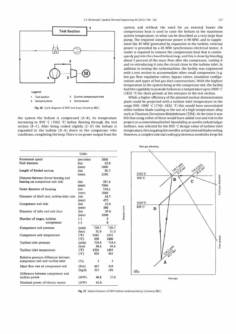
8112019 Helium Turbomachinery Operating Experience From Gas Turbine Power Plants
httpslidepdfcomreaderfullhelium-turbomachinery-operating-experience-from-gas-turbine-power-plants 2035
the system the helium is compressed (Ae
B) its temperatureincreasing to 850 C (1562 F) before 1047298owing through the test
section (BeC) After being cooled slightly (CeD) the helium is
expanded in the turbine (DeA) down to the compressor inlet
conditions completing the loop There is no power output from the
system and without the need for an external heater the
compression heat is used to raise the helium to the maximum
system temperature in what can be described as a very large heat
pump The required compressor power is 90 MW and to supple-
ment the 45 MW generated by expansion in the turbine external
power is provided by a 45 MW synchronous electrical motor A
cooler is required to remove the compression heat that is contin-
uously put into the closed helium loop and this is done by bleeding
about 5 percent of the mass 1047298ow after the compressor cooling it
and re-introducing it into the circuit close to the turbine inlet In
addition to testing the turbomachine the facility was engineered
with a test section to accommodate other small components (eg
hot gas 1047298ow regulation valves bypass valves insulation con1047297gu-
rations and types of hot gas duct construction) With the highest
temperature in the system being at the compressor exit the facility
had the capability to provide helium at a temperature up to 1000 C
(1832 F) for short periods at the entrance to the test section
While a higher ef 1047297ciency of the planned nuclear demonstration
plant could be projected with a turbine inlet temperature in the
range 950e1000 C (1742e1832 F) this would have necessitated
either turbine blade cooling or the use of a high temperature alloy
such as Titanium Zirconium Molybdenum (TZM) At the time it was
felt that using either of these would have added cost and risk to theprojectso a conventionalnickel-basedalloyas usedin industrialgas
turbines was selected for the 850 C design value of turbine inlet
temperature this negating the needfor actual internal bladecooling
However a complex internal coolingsystemwas neededto keep the
Fig 26 Cycle diagram of HHV test loop (Courtesy BBC)
Fig 27 Salient features of HHV helium turbomachinery (Courtesy BBC)
CF McDonald Applied Thermal Engineering 44 (2012) 108e142 127
8112019 Helium Turbomachinery Operating Experience From Gas Turbine Power Plants
httpslidepdfcomreaderfullhelium-turbomachinery-operating-experience-from-gas-turbine-power-plants 2135
turbine discs and blade root attachments and casings to acceptable
temperatures commensurate with prescribed stress limitations for
thelife of theturbomachine In addition a heliumsupplywas needed
to provide a buffering system for the various labyrinth seals
In a direct Brayton cycle nuclear gas turbine the turbomachine is
installed in the reactor circuit and via the hot gas duct heated
helium is transported directly from the reactor core to the turbine
From the safety licensing and reliability standpoints there are
various seals that must perform perfectly A helium buffered
labyrinth seal system is necessary to prevent bearing lubricating oil
ingress to the closed helium loop Since in the proposed HHT plant
design the drive shaft from the turbine to the generator penetrates
the reactor primary system pressure boundary two shaft seals are
needed one a dynamic seal when the shaft is rotating and a static
seal when the turbomachine is not operating Testing of these seals
in a size and operating conditions representative of the planned
commercial power plant was considered to be a licensing must
The mechanical integrity of the rotating assembly must be
assured there being two major factors necessitating testing the
machine at full speed and temperature and at high pressure
namely 1) loading the blading under representative centrifugal and
gas bending stresses and 2) to monitor vibration and con1047297rm rotor
dynamic stability For the design of the planned commercial planta knowledge of the acoustic emissions by the turbomachine and
propagation in the closed circuit was required Data from the HHV
facility would enable dynamic responses of the major components
(especially the insulation) resulting from excitation by the sound
1047297eld to be calculated
The circuit was instrumented to gather data on the effectiveness
of the hot gas duct insulation thermal expansion devices hot gas
valves helium puri1047297cation system instrumentation and the
adequacy of the coatings applied to mating metallic surfaces to
prevent galling or self-welding Details of the turbomachinery and
the experience gained from the operation of the HHV facility are
covered in the following sections
73 Helium turbomachine
A cross-section of the turbomachine is shown on Fig 28 The
single-shaft rotating assembly consists of 8 compressor stagesand 2
turbine stages and had a weighton the order of 66 tons(60000 kg)
The hub inner and outer diameters are 16 m (525 ft) and 18 m
(59 ft) respectively the blading axial length being 23 m (75 ft)The
span between the oil bearings being 57 m (187 ft) The physical
dimensions of the turbogroup shown on Fig 28 correspond to
a machine rated at about 300 MW The oil bearings operate in
a helium environment and the diameters of the labyrinths and
1047298oating ring shaft seals to prevent oil ingress are representative of
a machine rated at about 600 MW The complexity of the machine
design especially the rotor cooling system sealing system very
large casing and heat insulation have been reported previously
[53e55]
To ensure high structural integrity the rotor was constructed by
welding together the forged compressor and turbine discs The
compressor had 8 stages each having 56 rotor and 72 stator blades
The turbine had 2 stages each having 90 stator and 84 rotor blades
An appreciation for the large size of the rotating assembly can be
seen from Fig 29 The rotor blades have 1047297r-tree attachments
embodying cooling channels Since the temperature and pressure
do not vary very much along the blading in the 1047298ow direction an
intricate rotor and stator cooling system was required Channels in
both the blade roots and the spacers between adjacent blade rows
form an axial geometry for the passage of a cooling helium supplyto keep the temperature of the multiple discs below 400 C
(752 F) The design of this was a challenge since the rotor and
stator blade attachments of both the 8 stage compressor and 2
stage turbine had to be cooled Excessive leakage had to be avoided
since this would have prevented the speci1047297ed compressor
discharge temperature (ie the maximum temperature in the
circuit) from being reached
In the 1970rsquos and early 1980rsquos signi1047297cant studies were carried
out on large helium gas turbines by various organizations [56e62]
In this era there was general agreement that testing of the turbo-
machine in one form or another in non-nuclear facilities be
undertaken to resolve areas of high risk (eg seals bearings cooling
systems rotor dynamic stability compressor surge margin
dynamic response rotor burst protection etc) before installationand operation of a large gas turbine in a nuclear environment
This low risk engineering philosophy which prevailed at the time
in both Germany and the USA emphasized the importance of
Fig 28 Cross-section of HHV helium turbomachinery (Courtesy BBC)
CF McDonald Applied Thermal Engineering 44 (2012) 108e142128
8112019 Helium Turbomachinery Operating Experience From Gas Turbine Power Plants
httpslidepdfcomreaderfullhelium-turbomachinery-operating-experience-from-gas-turbine-power-plants 2235
the HHV test facility as being an important step towards the
eventual deployment of a high ef 1047297ciency nuclear gas turbine power
plant
74 Initial operation of the HHV facility
During commissioning of the plant in 1979 oil ingress into the
helium circuit from the seal system occurred twiceThe 1047297rst ingressof oil between 600 and 1200 kg (1322 and 2644 lb) was due to
a serious operatorerror and the absence of an isolation valve in the
system The oil in the circuit was partly coked and formed thick
deposits on the cold and hot surfaces of the turbomachinery and in
other parts of the closed loop including saturation of the 1047297brous
insulation The fouled metallic surfaces were cleaned mechanically
and chemically by cracking with the addition of hydrogen and
additives The second oil ingress was due to a mechanical defect in
the labyrinth seal system The quantity of oil introduced was small
and it was removed bycracking at a temperature of 600 C (1112 F)
and with the use of additives To obviate further oil ingress inci-
dents the labyrinth seal system was redesigned The buffer and
cooling helium system piping layout was modi1047297ed to positively
eliminate oil ingress due to improper valve operation and toprevent further human error
Pressure and leak detection tests of the HHV test facility at
ambient temperature showed good leak tightness for the turbo-
machine 1047298anged joints and of the main and auxiliary circuits
However at the operating temperature of 850 C (1562 F) large
helium leaks were detected The major 1047298anges had been provi-
sioned with lip seals and the 1047297rst step was to weld the closures A
large leak persisted at the front 1047298ange of the turbomachine This
was diagnosed as being caused by a non-uniform temperature
distribution during initial operation resulting in thermal stresses
creating local gaps This problem was overcome by redesign of the
cooling system with improved gas 1047298ow distribution and 1047298ow rates
to give a more uniform temperature gradient The leakage from the
system was reduced to on the order of 020e
040 percent of the
helium inventory per day this being of the same magnitude as in
other closed helium circuits as discussed in Section 65
It should be mentioned that in addition to the HHV experience
bearing oil ingress into the circuits and system loss of the working
1047298uid in other closed-cycle gas turbine plants have occurred In all of
these fossil-1047297red facilities 1047297xing leaks and removal of oil deposits
were undertaken based on conventional hands-on approaches but
nevertheless such operations were time-consuming However if a new and previously untested helium turbomachine operating in
a direct cycle nuclear gas turbine plant experienced an oil ingress
the rami1047297cations would be severe The likely use of remote
handling equipment to remove the turbomachine from the vessel
machine disassembly (including breaking the welded 1047298ange joints)
and removal of oil from the radioactively contaminated turbo-
machine blade surfaces and system insulation would be time
consuming A diagnosis of the failure would be required before
a spare turbomachine could be installed and this plant downtime
could adversely affect plant availability
75 Experience gained
Afterresolutionof the aforementionedproblems the HHVfacilitywas started in the Spring of 1981 and in an orderly manner was
brought up to full pressure and a temperature of 850 C (1562 F)
During a 60 h run the functioning of the instrumentation control
and safety systems were veri1047297ed During these tests the ability to
stop the turbomachine from full operating conditions to standstill
within 90 s was demonstrated After system depressurization the
plant was then run up again to full operating conditions with no
problems experienced The HHV facility was successfully run for
about 1100 h of which theturbomachineryoperated forabout325 h
at a temperature of 850 C The test facility was extensively instru-
mented and interpretation and analysis of the data recorded gave
positive and favorable results in the following areas
The complex rotor cooling system which was engineered to
assure that the temperature of the discs be kept below 400
C
Fig 29 HHV helium turbomachine rotating assembly (size equivalent to a 300 MWe machine) being installed in a pressure vessel (Courtesy BBC)
CF McDonald Applied Thermal Engineering 44 (2012) 108e142 129
8112019 Helium Turbomachinery Operating Experience From Gas Turbine Power Plants
httpslidepdfcomreaderfullhelium-turbomachinery-operating-experience-from-gas-turbine-power-plants 2335
(752 F) was demonstrated to be effective The measured rotor
coolant 1047298ows (about 3 percent of the mass1047298ow passing through the
machine) were slightly larger than had been estimated and this
resulted in measured turbine disc temperatures lower than pre-
dicted [55]
The dynamic labyrinth shaft seal functioned well at the full
temperature and pressure conditions and met the requirement of
zero oil ingress into the helium circuit The measured rotor oscil-
lation did not have any adverse effect on the shaft sealing system
The static rotor seal (for shutdown conditions) functioned without
any problems
The compressor and turbine blading hadef 1047297ciencies higher than
predicted The structural integrity of the rotor proved to be sound
when operating at 3000 rpm under the maximum temperature and
pressure conditions The stiff rotor shaft had only slight unbalance
and thermal distortion and measured oscillations were in the range
typical of large steam turbines
Sound power spectrum measurements were taken in four
different locations in the circuit These were taken to determine the
spectrum and intensity of the sound generated and propagated by
the turbomachinery and the resultant vibration of internal
components The maximum sound power level in the helium
circuit was160 dB Numerous strain gages were placedin the circuitto determine the in1047298uence of the sound 1047297eld particularly on the
fatigue strength of the turbine inlet hot gas duct In later examining
the internal components there was no evidence of excessive
vibration of the components especially the ducting and the insu-
lation Based on the measurements and calculations it was
concluded that the fatigue strength limit of the components would
not be exceeded during the designed life of the planned commer-
cial nuclear gas turbine power plant
In a direct cycle nuclear gas turbine the hot gas duct used to
transport the helium from the reactor core to the turbineis a critical
component The hot gas duct in the HHV facility performed well
mechanically and con1047297rmed the adequacy of the thermal expan-
sion devices From the thermal standpoint the 1047297ber insulation
performed better than the metallic type
After dismantling the HHV facility there were no signs of
corrosion or erosion of the turbine or compressor blading While
the total number of hours operated was limited the coatings
applied to mating metallic surfaces to prevent galling and frictional
welding in the oxidation-free helium worked well
The helium buffer and cooling system worked well However
problems remained with the puri1047297cation of the buffer helium The
oil separation system consisting of a cyclone separator and a wire
mesh and a down stream 1047297ber 1047297lter needed further improvement
In late 1981 a decision was made to cancel the HHT project and
the HHV facility was shutdown The design and operational expe-
rience gained from the running of this facility would have been
extremely valuable had the nuclear gas turbine power plant
concept moved towards becoming a reality The identi1047297cation of
somewhat inevitable problems to be expected in such a complexturbomachine and their resolution were undertaken in a timely
and cost effective manner in the non-nuclear HHV facility This
should be noted for future nuclear gas turbine endeavors since
remedying such unexpected problems in the case of a new and
untested large helium turbomachine being operated for the 1047297rst
time using nuclear heat could result in very complex repair
Fig 30 Speci1047297
c speed-speci1047297
c diameter array for gas circulators in various gas-cooled nuclear plants
CF McDonald Applied Thermal Engineering 44 (2012) 108e142130
8112019 Helium Turbomachinery Operating Experience From Gas Turbine Power Plants
httpslidepdfcomreaderfullhelium-turbomachinery-operating-experience-from-gas-turbine-power-plants 2435
activities and extended plant downtime and indeed adding risk to
the overall success of the nuclear gas turbine concept
8 Circulators used in gas-cooled reactor plants
Circulators of different types will be needed in future helium
cooled nuclear plants these including the following 1) primary
loop circulator for possible next generation steam cycle power andcogeneration plants 2) for future indirect cycle gas turbine plants
3) shut down cooling circulators forall HTRand VHTR plants and 4)
for various circulators needed in future VHTR high temperature
process heat plant concepts The technology status of operated
helium circulators is brie1047298y addressed as follows
81 Background
It would be remiss not to mention experience gained in the past
with gas circulators and while not gas turbines they are rotating
machines that operate in the primary loop of a helium cooled
reactor With electric motor drives there are basically two types of
compressor rotor con1047297gurations namely radial and axial 1047298ow
machinesIn a single stage form the centrifugal impeller is used for high
stage pressure rise and low volume 1047298ow duties whereas the axial
type covers low pressure rise per stage and high volume 1047298ow The
selection of impeller type is very much related to the working
media type of bearings drive type rotor dynamic characteristics
and installation envelope A wide range of circulators have operated
and a well established technology base exists for both types [63] A
useful portrayal of compressor data in the form of quasi- non-
dimensional parameters (after Balje [64]) showing approximate
boundaries for operation of high ef 1047297ciency axial and radial types is
shown on Fig 30 (from Ref [65])
Both high speed axial and lower speed radial 1047298ow types are
amenable to gas oil and magnetic bearings From the onset of
modularHTR plant studies theuse of active magnetic bearings[6667]offered a solution to eliminate lubricating oil into the reactor circuit
and this tribology technology is attractive for use in submerged
rotating machinery in the next generation of HTR plants [68]
While now dated an appreciation of the main design features of
typical electric motor-driven helium circulators have been reported
previously namely an axial 1047298ow main circulator for a modular
steam cycle HTR plant [69] and a representative radial 1047298ow shut-
down cooling circulator [70]
The operating experience gained from three particular circula-
tors is brie1047298y included below because of their relevance to the
design of helium turbomachinery in future HTR plant variants
82 Axial 1047298ow helium circulator
Since all of the aforementioned predominantly European
helium gas turbines used axial 1047298ow turbomachinery it is of interest
to mention a helium axial 1047298ow circulator that operated in the USA
and to brie1047298y discuss its design parameters and features The
330 MW Fort St Vrain HTGR featured a Rankine cycle power
conversion system Four steam turbine driven helium circulators
were used to transport heat from the reactor core to the steam
generators The complete circulator assemblies were installed
vertically in the prestressed concrete reactor vessel [71e73]
A cross-section of the circulator is shown on Fig 31 with thecompressor rotor and stator visible on the left hand end of the
machine Based on early 1960rsquos technology a decision was made to
use water lubricated bearings and from the overall plant reliability
and availability standpoints this later proved to be a bad choice
Within the vertical circulator assembly there were four 1047298uid
systems namely the helium reactor coolant water lubricant in the
bearings steam for the turbine drive and high pressure water for
the auxiliary Pelton wheel drive During plant transients the pres-
sures and temperatures of these four 1047298uids oscillated considerably
and the response of the control and seal systems proved to be
inadequate and resulted in considerable water ingress from the
bearing cartridge into the reactor helium circuit The considerable
clean up time needed following repeated occurrences of this event
resulted in long periods of plant downtime and this had an adverseeffect on plant availability This together with other technical
Fig 31 Cross section of FSV helium circulator (Courtesy general Atomics)
CF McDonald Applied Thermal Engineering 44 (2012) 108e142 131
8112019 Helium Turbomachinery Operating Experience From Gas Turbine Power Plants
httpslidepdfcomreaderfullhelium-turbomachinery-operating-experience-from-gas-turbine-power-plants 2535
dif 1047297culties eventually contributed to the plant being prematurely
decommissioned
On the positive side in the context of this paper the helium
circulators operated for over 250000 h and exhibited excellent
helium compressor performance good mechanical integrity and
vibration-free operation The rotating assembly showing the axial
1047298ow compressor and steam turbine rotors together with a view of
the machine assembly are given on Fig 32 The helium compressor
consists of a single stage axial rotor followed by an exit guide vane
The machine was designed for axial helium 1047298ow entering and
leaving the stage and this can be seen from the velocity triangles
shown on Fig 33 which also includes the de1047297nition of the various
aerodynamic parameters Major design parameters and features of
this helium circulator are given on Table 4 Related to an earlier
discussion on the degree of reaction for axial 1047298ow compressors the
value for this conventional single stage circulator is 78 percent All
of the major aerothermal and structural loading criteria were
within established boundaries for an axial compressor having high
ef 1047297ciency and a good surge margin
The compressor gas 1047298ow path and blading geometries were
established based on prevailing industrial gas turbine and aero-
engine design practice A low Mach number (025) a high Reynolds
number (3 106) together with a modest stage loading (ie
a temperature rise coef 1047297cient of 044) and an acceptable value of
diffusion factor (042) were some of the factors that contributed to
a helium circulator that had a high ef 1047297ciency and a good pressure
rise- 1047298ow characteristic The large rotor blade chord and thick blade
section for this single stage circulator are necessary to accommo-
date the high bending stress characteristic of operation in a high
pressure environment The solidity and blade camber were opti-
mized for minimum losses
There were essentially two reasons for including this single-
stage axial 1047298ow compressor that operated in a helium cooled
reactor although its overall con1047297guration can be regarded as a 1047297rst
and last of a kind A rotor blade from this circulator as shown onFig 34 was based on a NASA 65 series airfoil which at the time
were one of the best performing cascades for such low Mach
number and high Reynolds number applications Interestingly it
has almost the same blade height aspect ratio and solidity as would
be used in the 1047297rst stage of an LP compressor in a helium turbo-
machine rated on the order of 250 MW
The second point of interest is that the helium mass 1047298ow rate
through the single stage axial compressor (rated at 4 MWe) is
110 kgs compared with 85 kgs through the multistage compressor
in the 50 MWe Oberhausen II helium gas turbine plant However
the volumetric 1047298ow through the Oberhausen axial compressor is
higher than that through the circulator by a factor of 16 this again
pointing out that the Oberhausen II plant was designed for high
volumetric 1047298ow to simulate the much larger size of turboma-chinery that was planned at the time in Germany for use in future
projected nuclear gas turbine power plants
83 High temperature helium circulator
For future helium turbomachines embodying active magnetic
bearings a challenge in their design relates to accommodating
elevated levels of temperature in the vicinity of the electronic
components In this regard it is of interest to note that a small very
high temperature helium axial 1047298ow circulator rated at 20 kW (as
shown on Fig 35) operated for more than 15000 h in an insulation
test facility in Germany more than two decades ago [74] The
signi1047297cance of this machine is that it operated with magnetic
bearings in a high temperature helium test loop with a circulatorgas inlet temperature of 950 C (1742 F) This necessitated the use
of ceramic insulation to ensure that the temperature in the vicinity
of the magnetic bearing electronics did not exceed a temperature of
about 150 C (300 F)
This machine although a very small axial 1047298ow helium blower
performed well and has been brie1047298y mentioned here since it
represents a point of reference for future helium rotating machines
capable operating with magnetic bearings in a very high temper-
ature helium environment
84 Radial 1047298ow AGR nuclear plant gas circulators
The electric motor-driven carbon dioxide circulators rated at
about 5 MW with a total runningtimein excess of 18 million hours
Fig 32 Fort St Vrain HTGR plant helium circulator (Courtesy General Atomics) (a)
Axial 1047298ow helium compressor and steam turbine rotating assembly (b) 4 MW helium
circulator assembly
CF McDonald Applied Thermal Engineering 44 (2012) 108e142132
8112019 Helium Turbomachinery Operating Experience From Gas Turbine Power Plants
httpslidepdfcomreaderfullhelium-turbomachinery-operating-experience-from-gas-turbine-power-plants 2635
in AGR nuclear power plants in the UK have demonstrated veryhigh availability [7576] To a high degree this can be attributed to
the fact that the machines were conservatively designed and proof
tested in a non-nuclear facility at full temperature and power
under conditions that simulated all of the nuclear plant operating
modes The test facility shown on Fig 36 served two functions 1)
design veri1047297cation of the prototype machine and 2) test of all new
and refurbished machines before they were installed in nuclear
plants Engineers currently involved in the design and development
of helium turbomachinery could bene1047297t from this sound testing
protocol to minimize risk in the deployment of helium rotating
machinery in future HTRVHTR plant variants
9 Helium turbomachinery development and testing
91 On-going development activities
The various helium turbomachines discussed in previous
sections operated over a span of about two decades starting in the
early 1960s From about 1990 activities in the nuclear gas turbine
1047297eld have been focused mainly on the design of modular GTeHTR
plant concepts In support of these plant studies many signi1047297cant
helium turbomachine design advancements have been made and
attention given to what development testing would be needed In
the last decade or so limited sub-component development has
been undertaken for helium turbomachines in the 250e300 MWe
size and these are brie1047298y summarized below
In a joint USARussia effort development in support of the
GTe
MHR turbomachine has been undertaken including testing in
the following areas magnetic bearings seals and rotor dynamicsfor the vertical intercooled helium turbomachine rated at 286 MWe
[77e80]
In Japan development activities have been in progress for
several years in support of the 274 MWe helium turbomachine for
the GTeHTR300 plant concept [2581] A detailed discussion on
the aerodynamic design of the axial 1047298ow helium compressor for
this turbomachine has been published in the open literature [82]
While the design methodology used for axial compressor design in
air-breathing industrial and aircraft gas turbines is generally
applicable for a multi-stage helium compressor a decision was
made by JAEA to test a small scale compressor in a helium facility
because of the inherent and unique gas 1047298ow path and type of
blading associated with operation in a high pressure helium
environment The major goal of the test was to validate the designof the 20 stage helium axial 1047298ow compressor for the GTeHTR300
plant
An axial 1047298ow compressor in a closed-cycle helium gas turbine is
characterized by the following 1) a large number stages 2) small
blade heights 3) high hub-to-tip ratio 4) a long annulus with
small taper that tends to deteriorate aerodynamic performance as
a result of end-wall boundary layer length and secondary 1047298ow 5)
low Mach number 6) high Reynolds number and 7) blade tip
clearances that are controlled by the gap necessary in the magnetic
journal and catcher bearings While (as covered in earlier sections)
helium gas turbines have operated there is limited data in the
open literature on the performance of multi-stage axial 1047298ow
compressors operating in a high pressure closed-loop helium
environment
Fig 33 Velocity triangles for axial compressor stage
CF McDonald Applied Thermal Engineering 44 (2012) 108e142 133
8112019 Helium Turbomachinery Operating Experience From Gas Turbine Power Plants
httpslidepdfcomreaderfullhelium-turbomachinery-operating-experience-from-gas-turbine-power-plants 2735
A 13rd scale 4 stage compressor was designed to simulate the
stage interaction the boundary layer growth and repeated stage
1047298ow in an actual compressor The 1047297rst four stages were designed to
be geometrically similar to the corresponding stages in the
GTe
HTR300 compressor Details of the model compressor havebeen discussed previously [81] and are summarized on Table 5
from [83]
A cross-section of the compressor test model is shown on Fig 37
A view of the 4 stage compressor rotor installed in the lower casing
is shown on Fig 38 The test facility (Fig 39) is a closed helium loop
consisting of the compressor model cooler pressure adjustment
valve and a 1047298ow measurement instrument The compressor is
driven by a 3650 kW electrical motor via a step-up gear The rota-
tional speed of 10800 rpm (three times that of the compressor in
the GTeHTR300 plant) was selected to match blade speed and
Mach number in the full size compressor
Details of the planned aerodynamic performance objectives of
the 13rd scale helium compressor test have been published
previously [84] Extensivetesting of the subscale model compressorprovided data to validate the performance of the full size
compressor for the GTeHTR300 power plant The test data and
test-calibrated CFD analyses gave added insight into the effect of
factors that impact performance including blade surface roughness
and Reynolds number
Based on advanced aerodynamic methodology and experi-
mental validation [82] there is now a sound basis for added
con1047297dence that the design goals of 90 percent polytropic ef 1047297ciency
and a design point surge margin of 20 percent are realizable in
a large multistage axial 1047298ow compressor for a future nuclear gas
turbine plant
In a similar manner a design of a one third size single stage
helium axial 1047298ow turbine has been undertaken and a cross
section of the machine is shown on Fig 40 (from Ref [81]) This
Table 4
Major features of axial 1047298ow helium circulator
Helium 1047298ow rate kgsec 110
Inlet temperature C 394
Inlet pressure MPa 473
Pressure rise KPa 965
Volumetric 1047298ow m3sec 32
Compressor type Single stage axial
Compressor drive Steam turbine
Bearing type Water lubricated
Rotational speed rpm 9550
Power MW 40
Rotor tip diameter mm 688
Rotor tip speed msec 344
Number of rotor blades 31
Number of stator blades 33
Blade height mm 114
Hub-to-tip ratio 067
Axial velocity msec 157
Flow coef 1047297cient 055
Temperature rise coef 1047297cient 044
Degree of reaction 078
Mean rotor solidity 128
Rotor aspect ratio 155
Rotor Mach number 025
Rotor diffusion factor 042
Rotor Reynolds number 3106
Speci1047297c speed 335
Speci1047297c diameter 066
Blade root thickness 15
Airfoil type NASA 65
Rotor blade chord mm 94e64
Stator blade chord mm 79
Rotor centrifugal stress MPa 125
Rotor bending stress MPa 30
Circulator(s) operating Hours gt250000
Fig 34 Rotor blade from single stage axial 1047298ow helium circulator (Courtesy General
Atomics)
Fig 35 20 kW axial 1047298ow helium circulator with magnetic bearings operated in 1985 in
an insulation test loop with a gas inlet temperature on 950
C (Courtesy BBC)
CF McDonald Applied Thermal Engineering 44 (2012) 108e142134
8112019 Helium Turbomachinery Operating Experience From Gas Turbine Power Plants
httpslidepdfcomreaderfullhelium-turbomachinery-operating-experience-from-gas-turbine-power-plants 2835
single stage scale model turbine for validity of the full size turbine
has been built and plans made to test the aerodynamic
performance
92 Nuclear gas turbine helium turbomachine testing
In planning for the 1047297rst nuclear gas turbine plant projected to
enter service perhaps in the third decade of the 21st century
a major decision has to be made as to what extent the large helium
turbomachine should be tested prior to operation on nuclear heat
Issues essentially include cost impact on schedule but the over-
riding one is risk Certainly turbomachine component testing will
be undertaken including the compressor (as discussed in the
previous section) and turbine performance seals cooling systems
hot gas valves thermal expansion devices high temperature
insulation rotor fragment containment diagnostic systems
instrumentation helium puri1047297cation system and other areas to
satisfy safety licensing reliability and availability concerns The
major point is really whether a full size or scaled-down turbo-machine be tested early in the project in a non-nuclear facility
To obviate the need for pre-nuclear testing of a large helium
turbomachine a view expressed by some is that advantage can be
taken of formidable technology bases that exist today for large
industrial gas turbines and high performance aeroengines On the
other hand it is the view of some including the author that very
complex power conversion system components especially those
subjected to severe thermal transients donrsquot always perform
exactly as predicted by analysts and designers even using sophis-
ticated computer codes This was exempli1047297ed in the case of the
turbomachine in the aforementioned Oberhausen II helium gas
turbine plant
The need for a helium turbomachine test facility goes beyond
just veri1047297
cation of the prototype machine Each newgas turbine for
commercial modular nuclear reactor plants would have to be proof
tested and validated before being transported to the reactor site
Similarly turbomachines that would be periodically removed from
the plant at say 7 year intervals during the plant operating life of 60
years for scheduled maintenance refurbishment repair or updat-ing would be again proof tested in the facility before re-entering
service
The direction that turbomachine development and testing will
take place for future helium gas turbines needs to be addressed by
the various organizations involved
Fig 36 AGR circulator test facility In the UK (Courtesy Howden)
Table 5
Major design parametersfeatures of model GTeHTR300 axial 1047298ow helium
compressor (Courtesy JAERI)
Scale of GTeHTR300 compressor 13
Helium mass 1047298ow rate (kgsec) 122
Helium volumetric 1047298ow rate (mV s) 87
Inlet temperature C 30
Inlet pressure MPa 0883Compressor pressure ratio at design point 1156
Number of stages 4
Rotational speed rpm 10800
Drive motor power kW 3650
Hub diameter mm 500
Rotor tip diameter (1st4th stage mm) 568566
Hub-to-tip ratio (1st stage) 088
Rotor tip speed (1st stage msec) 321
Number of rotorstator blades (1st stage) 7294
Rotorstator blade height (1st stage mm) 34337
Rotor stator blade c hor d l eng th (1st stage mm) 2620
Rotorstator solidity (1st stage) 119120
Rotorstator aspect ratio (1st stage) 1317
Flow coef 1047297cient 051
Stage loading factor 031
Reynolds number at design point 76 l05
CF McDonald Applied Thermal Engineering 44 (2012) 108e142 135
8112019 Helium Turbomachinery Operating Experience From Gas Turbine Power Plants
httpslidepdfcomreaderfullhelium-turbomachinery-operating-experience-from-gas-turbine-power-plants 2935
10 Helium turbomachinery lessons learned
101 Oberhausen II gas turbine and HHV test facility
It is understandable that 1047297rst-of-a-kind complex turboma-
chinery operating with an inert low molecular weight gas such as
helium will experience unique and unexpected problems In the
operation of the two pioneering large helium turbomachines in
Germany there were many positive1047297ndings which could only have
been achieved by development testing Equally important some
negative situations were identi1047297ed many of which were remedied
In the case of the Oberhausen II helium gas turbine plant some of
the very serious problems encountered were not resolved Inves-
tigations were undertaken to rationalize the problems associated
with the large power de1047297ciency and a data base established to
ensure that the various anomalies identi1047297ed would not occur in
future large helium turbomachines
The experience gained from the operation of the Oberhausen II
helium gas turbine power plant and the HHV test facility have been
discussedin thetextand arepresentedin a summaryformon Table6
Fig 37 Cross-section of 13rd scale helium compressor test model (Courtesy JAEA)
Fig 38 Four stage helium compressor rotor assembly installed in lower casing (Courtesy JAEA)
CF McDonald Applied Thermal Engineering 44 (2012) 108e142136
8112019 Helium Turbomachinery Operating Experience From Gas Turbine Power Plants
httpslidepdfcomreaderfullhelium-turbomachinery-operating-experience-from-gas-turbine-power-plants 3035
102 Impact of 1047297ndings on future helium gas turbine
The long slender rotorcharacteristic of closed-cycle gas turbines
has resulted in shaft dynamic instability which in some cases has
resulted in blade vibration and failure and bearing damage This
remains perhaps the major concern in the design of large
(250e
300 MW) helium turbomachines for future nuclear gas
turbine plants With pressure ratios in the range of about 2e3 in
a helium system a combination of splitting the compressor (to
facilitate intercooling) and having a large number of compressor
and turbine stages results in a long and 1047298exible rotating assembly
andthis is exempli1047297ed by the rotorassembly shown on Fig13 With
multiple bearings (either oil lubricated or magnetic) the rotor
would likely pass through multiple bending critical speeds before
Fig 39 Helium compressor test facility (Courtesy JAEA)
Fig 40 Cross-section of single stage helium turbine test model (Courtesy JAEA)
CF McDonald Applied Thermal Engineering 44 (2012) 108e142 137
8112019 Helium Turbomachinery Operating Experience From Gas Turbine Power Plants
httpslidepdfcomreaderfullhelium-turbomachinery-operating-experience-from-gas-turbine-power-plants 3135
reaching the design speed While very sophisticated computer
codes will be used in the detailed rotor dynamic analyses the real
con1047297rmation of having rotor oscillations within prescribed limits
(to avoid blade bearing and seal damage) will come from actual
testingA point to be made here is that in operated fossil-1047297red closed-
cycle gas turbine plants it was possible to remedy problems asso-
ciated with rotor vibrations and blade failures in a conventional
manner In fact in some situations the casings were opened several
times and modi1047297cations made to facilitate bearing and seal
replacement and rotor re-blading and balancing
An accurate assessment of pressure losses must be made
particularly those associated with the helium entering and leaving
the turbomachine bladed sections Minimizing the system pressure
loss is important since it directly impacts the all important quotient
of turbine expansion ratio to compressor pressure ratio and power
and plant ef 1047297ciency
Based on the operating experience from the 20 or so fossil-1047297red
closed-cycle gas turbine plants using air as the working1047298
uid it was
recognized that future very high pressure helium gas turbines
would pose problems regarding the various seals in the turbo-
machine and obtaining a zero leakage system with such a low
molecular weight gas would be dif 1047297cult and this is discussed
below
When the Oberhausen II gas turbine plant and the HHV facility
operated over 30 years ago oil lubricated bearings were used to
support the heavy rotor assemblies and helium buffered labyrinth
seals were used to prevent oil ingressinto the heliumworking1047298uid
Initial dif 1047297culties encountered in both plants were overcome by
changes made to the seal geometries and for the operating lives of
the helium turbomachines no further oil ingress events were
experienced Twoseals were required where the turbine drive shaft
penetrated the turbomachine casing namely 1) a dynamic laby-
rinth seal and 2) a static seal for shutdown conditions In both
plants these seals functioned without any problems
Labyrinth seals were also required within the helium turbo-
machines to pass the correct helium bleed 1047298ow from the
compressor discharge for cooling of the turbine discs blade root
attachments and casings The fact that the very complex rotor
cooling system in the large helium turbomachine in the HHV test
facility operated well for the test duration of about 350 h with
a turbine inlet temperature of 850 C was encouragingIn the case of the Oberhausen II gas turbine plant analysis of the
test data revealed that the labyrinth seal leakage and excessive
cooling 1047298ows were on the order of four times the design value A
possible reason for this was that damage done to the labyrinth
seals caused excessive clearances when periods of excessive rotor
oscillation and vibration occurred during early operation of the
machine
Clearly 1047298uid dynamic and thermal management of the cooling
system and 1047298ow through the various labyrinth seals will require
extensive analysis design and development testing before the
turbomachine is operated on nuclear heat for the 1047297rst time
In future heliumgas turbine designs (with turbine inlet tempera-
tureslikelyontheorderof950C)the1047298owpathgeometriesofhelium
bledfromthecompressornecessarytocoolpartsoftheturbomachinewillbemorecomplexthanthosetestedto-dateInadditiontoproviding
acooling1047298owtotheturbinebladesanddiscsbladerootattachmentsand
casingsheliummustbetransportedtotheseveralmagneticbearingsto
ensure thatthe temperatureof theirelectronic components doesnot
exceedabout150C
The importance of the points made above is evidenced when
examining the data on Table 3 where a combination of excessive
pressure losses and high bleed 1047298ows contributed to about 40
percent of the power de1047297ciency in the Oberhausen II helium
turbine plant
Retaining overall system leak tightnessin closed heliumsystems
operating at high pressure and temperature has been elusive
including experience from the Fort St Vrain HTGR plant as dis-
cussed in Section 65 New approaches in the design of the plethoraof mechanical joints must be identi1047297ed Experience to-date has
shown that having welded seals on 1047298anges while minimizing
system leakage did not eliminate it
The importance of lessons learned from the operation of the
Oberhausen II helium turbine power plant and the HHV test facility
have primarily been discussed in the context of helium turbo-
machines currently being designed in the 250e300 MWe power
range However the established test data bases could also be
applied to the possible emergence in the future of two helium
cooled reactor concepts namely 1) an advanced VHTR combined
cycle plant concept embodying a smaller helium gas turbine in the
power range of 50e80 MWe [22] and 2) the use of a direct cycle
helium gas turbine PCS in a recently proposed all ceramic fast
nuclear reactor concept [85]
Table 6
Experience gained from Oberhausen II and HHV facility
Oberhausen II 50 MW helium gas turbine power plant
Positive results
e Rotating and static seals worked well
e No ingress of bearing lubricant oil into closed circuit
e Load change by inventory control worked well
e 100 Percent load shed by means of bypass valves demonstrated
e Turbine disc and blade root cooling system con1047297rmed
e Coatings on mating surfaces prevented galling and self-welding
e After 24000 h of operation no evidence of corrosion or erosion
e Coaxial turbine hot gas inlet duct insulation and integrity con1047297rmed
e Monitoring of complete power conversion system for steady state
and transient operation undertaken
Problem areas
e Serious power output de1047297ciency (30 MW compared with design
value of 50 MW)
e Compressor(s) and turbine(s) ef 1047297ciencies several points below predicted
e Higher than estimated system pressure loss
e Rotor dynamic instability and blade vibration
e Bearings damaged and had to be replaced
e Blade failure caused extensive damage in HP turbine but retained
in casing
e Very excessive sealing and cooling 1047298ow rates
e Absolute leak tightness not attainable even with welded 1047298ange lips
HHV test facility
Positive resultse Use of heat pump approach facilitated helium temperature capability
to 1000 C
e Large oompressorturbine rotor system operated at 3000 rpm Complex
turbine disc and blade root cooling system veri1047297ed
e Dynamic and static seals met requirement of zero oxl ingress into circuit
e Structural integrity of rotating assembly veri1047297ed at temperature of 850 C
e Measured rotor oscillations within speci1047297cation
e Compressor and turbine ef 1047297ciencies higher than predicted
e Coatings on mating metallic surfaces prevented galling and self-welding
e Instrumentation control and safety systems veri1047297ed
e Seal 1047298ows within speci1047297cation
e Machine stop from operating speed to shutdown in 90 s demonstrated
e Hot gas duct insulation and thermal expansion devices worked well
e After 1100 h of operation no evidence of corrosionof erosion
Problem areas
e Before commissioning a large oil ingress into the circuit occurred due
to serious operator error and absence of an isolation valve A second oilingress occurred due to a mechanical defect in the labyrinth seal system
These were remedied and no further oil ingress was experienced for the
duration of testing
e Cooling 1047298ows slightly larger than expected but this resulted in actual
disc and blade root temperatures lower than the predicted value of
400 C
e System leak tightness demonstrated when pressurized at ambient
temperature conditions but some leakage occured at 850 C even with
the seal welding of 1047298ange(s) lips
CF McDonald Applied Thermal Engineering 44 (2012) 108e142138
8112019 Helium Turbomachinery Operating Experience From Gas Turbine Power Plants
httpslidepdfcomreaderfullhelium-turbomachinery-operating-experience-from-gas-turbine-power-plants 3235
11 New technologies
It is recognized that in the 3 to 4 decades since the operation of
the helium turbomachines covered in this paper new technologies
have emerged which negate some of the early issues An example of
this is the technology transfer from the design of modern axial 1047298ow
gas turbines (ie industrial aircraft and aeroderivatives) that fully
utilize sophisticated CAE CAD CFD and FEA design software
Air breathing aerodynamic design practice for compressors and
turbines are generally applicable but the properties of helium and
the high system pressure have a signi1047297cant impact on gas 1047298ow
paths and blade geometries With short blade heights high hub-to-
tip ratios long annulus 1047298ow path length (with resultant signi1047297cant
end-wall boundary layer growth and secondary 1047298ow) and blade tip
clearances in some cases controlled by clearances in the magnetic
catcher bearing testing of subscale model compressors and
Fig 41 Gas turbine test facility for aircraft nuclear propulsion involving the coupling of a 32 MWt air-cooled reactor with two modi 1047297ed J-47 turbojet aeroengines each rated at
a thrust of about 3000 kg operated in 1960 (Courtesy INL)
Fig 42 Mobile 350 KWe closed-cycle nuclear gas turbine power plant operated in 1961 (Courtesy US Army)
CF McDonald Applied Thermal Engineering 44 (2012) 108e142 139
8112019 Helium Turbomachinery Operating Experience From Gas Turbine Power Plants
httpslidepdfcomreaderfullhelium-turbomachinery-operating-experience-from-gas-turbine-power-plants 3335
turbines will be needed While most of the operated helium tur-
bomachines discussed in this paper took place 3 or 4 decades ago it
is encouraging that the fairly recent test data and test-calibrated
CFD analysis from a subscale four stage model helium axial 1047298ow
compressor in Japan [80] gave a high degree of con1047297dence that
design goals are realizable for the full size 20 stage compressor in
the 274 MWe GTeHTR300 plant turbomachine
In the future the use of active magnetic bearings will eliminate
the issue of oil ingress however the very heavy rotor weight and
size of the journal and thrust bearings (and catcher bearings) of the
type for helium turbomachines in the 250e300 MWe power range
are way in excess of what have been demonstrated in rotating
machinery For plant designs retaining oil-lubricated bearings well
established dry gas seal technology exists particularly experience
gained from the operation of high pressure natural gas pipe line
compressors
For future nuclear helium gas turbine plants the designer has
freedom regarding meeting different frequency requirements that
exist in some countries These include use of a synchronous
machine (ie designed for 50 or 60 Hz grids) use of a gearbox drive
between the turbine and generator or the use of a frequency
converter which gives the designer an added degree of freedom
regarding the selection of speed for the rotating assemblyCompared with the past very sophisticated electronic control
systems instrumentation and diagnostic systems are available
today
12 Conclusions
In this review paper experience from operated helium turbo-
machines has been compiled based on open literature sources At
this stage in the evolution of HTR and VHTR plant concepts it is not
clear in what role form or time-frame the nuclear gas turbine will
emerge when commercialized By say the middle of the 21st
century all power plants will be operating with signi1047297cantly higher
ef 1047297ciencies to realize improved power generation costs and
reduced emissions In a nuclear gas turbine the helium turbo-machine will be a major contributor towards the achievement of
ef 1047297ciencies higher than 50 percent
While it has been 3 to 4 decades since the Oberhausen II helium
turbine power plant and the HHV high temperature helium turbine
facility operated signi1047297cant lessons were learned and the time and
effort expended to resolve the multiplicity of unexpected technical
problems encountered The remedial repair work was done under
ideal conditions namely that immediate hands-on activities were
possible This would not have been possible if the type of problems
experienced had been encountered in a new and untested helium
turbomachine operated for the 1047297rst time with a nuclear heat
source
While new technologies have emerged that negate many of the
early problems there are some uniquely inherent issues associatedwith for large helium turbines operating in a high pressure and
temperature environment and these include the following 1)
minimizing system leakage with such a low molecular weight gas
2) clearances in labyrinth seals to minimize helium bypass1047298ows 3)
the dynamic stability of long slender rotors 4) minimizing the
turbomachine inlet and outlet pressure losses 5) 1047298ow maldis-
tribution in complex ductturbomachine interfaces 6) integrity
veri1047297cation of the catcher bearings (journal and thrust) after
multiple rotor drops (following loss of the magnetic 1047297eld) during
the plant lifetime 7) assurances that high energy fragments from
a failed turbine disc are contained within the machine casing 8)
turbomachine installation and removal from a steel pressure vessel
and 9) remote handling and cleaning of a machine with turbine
blades contaminated with 1047297
ssion products
The need for a helium turbomachine test facility has been
emphasized to ensure that the integrity performance and reli-
ability of the machine before it operates the 1047297rst time on nuclear
heat Engineers currently involved in the design of helium rotating
machinery for all HTR and VHTR plant variants should take
advantage of the experience gained from the past operation of
helium turbomachinery
13 In closing-GT rsquos operated with nuclear heat
In the context of this paper it is germane to mention that two
gas turbines have actually operated using nuclear heat as brie1047298y
highlighted below
In the late 1950rsquos a program was initiated in the USA for aircraft
nuclear propulsion (ANP) While different concepts were studied
only the direct cycle air-cooled reactor reached the stage of
construction of an experimental reactor [86] A view of the large
nuclear gas turbine facility is given on Fig 41 and shows the air-
cooled and zirconiumehydride moderated reactor rated at
32 MWt coupled with two modi1047297ed J-47 turbojet engines each
rated with a thrust of about 3000 kg In this open cycle system the
high pressure compressor air was directly heated in the reactor
before expansion in the turbine and discharge to the atmosphere in
the exhaust nozzle The facility operated between 1958 and 1961 at
the Idaho reactor testing facility While perhaps possible during the
early years of the US nuclear program it is clear that such a system
would not be acceptable today from safety and environmental
considerations
The 1047297rst and indeed the only coupling of a closed-cycle gas
turbine with a nuclear reactor for power generation was under-
taken to meet the needs of the US Army In the late 1950 rsquos an RampD
program was initiated for a 350 kW trailer-mounted system to be
used in the 1047297eld by military personnel A prototype of the ML-1
plant shown on Fig 42 was 1047297rst operated in 1961 [8788]
It was based on a 33 MW light water moderated pressure tube
reactor with nitrogen as the coolant The closed-cycle gas turbine
power conversion system with nitrogen as the working 1047298uid hada turbine inlet temperature of 649 C (1200 F) and delivered
around 300 kW With changes in the Armyrsquos needs the project was
discontinued in 1965
While the experience gained from the above twounique nuclear
plants is clearly not relevant for future nuclear gas turbine power
plants that could see service in the third decade of the 21st century
these ambitious and innovative nuclear gas turbine pioneering
engineering efforts need to be recognized
Acknowledgements
The author would like to thank the following for helpful discus-
sions advice and for providing valuable comments on the initial
paper draft Prof Dr Hermann Haselbacher Hans Ulrich Frutschi DrXing Yan DrPeter Zenker Professor DavidGordon Wilson Professor
Aristide Massardo Arthur Harris DrFred Starr and DrGuido Bac-
caglini This paper has been enhanced by the inclusion of hardware
photographs and unique sketches and the author is appreciative to
all concerned with credits being duly noted
References
[1] C Keller The Escher Wyss AK Closed-Cycle Gas Turbine Its Actual Develop-ment and Future Prospects Paper Presented at ASME Meeting November 261945
[2] HU Frutschi Closed-Cycle Gas Turbines Operating Experience and FuturePotential ASME Press NY 2005
[3] CF McDonald The Nuclear Gas Turbine-Towards Realization After Half
a Century of Evolution (1995) ASME Paper 95-GT-292
CF McDonald Applied Thermal Engineering 44 (2012) 108e142140
8112019 Helium Turbomachinery Operating Experience From Gas Turbine Power Plants
httpslidepdfcomreaderfullhelium-turbomachinery-operating-experience-from-gas-turbine-power-plants 3435
[4] C Keller The Theory and Performance of Axial Flow Fans McGraw Hill BookCompany Inc NY 1937
[5] J Ackert C Keller Aerodynamic turbine with closed circuit In A Century of Turbines vols 1516 Escher Wyss News 1942e43 5e19
[6] Escher Wyss News Closed-Cycle Gas Turbines for all Fuels Coal Gas Nuclearvol 39 No 1 (1966)
[7] C Keller Closed-cycle gas turbine Escher Wyss-AK development 1945e1950Transactions of ASME (August 1950) 835e850
[8] C Keller Operating Experience and Design Features of Closed-Cycle GasTurbine Power Plants (1956) ASME Paper 56-GTP-15
[9] C Keller HU Frutschi Closed-cycle plants -conventional and nuclear designapplication operation In Sawyerrsquos Gas Turbine Engineering Handbooksecond ed vol 2 Applications (1976) pp 265e283
[10] K Bammert G Groschup Status Report on Closed-Cycle Power Plants in theFederal Republic of Germany (1976) ASME Paper 76-GT-54
[11] JL Mason Monatomic Working Gases versus Air for Closed Brayton Cycles(1985) ASME Paper 85-IGT-50
[12] JL Mason et al 5 MW Closed Cycle Gas Turbine (1984) ASME Paper 84-GT-268
[13] The British Gas Closed-Cycle Demonstrator (1995) British Gas Research ampTechnology Final Year Report
[14] F Starr ODS alloy high temperature heat exchanger prototype developmentPaper Presented at ODS 2010 Materials Workshop UCSD Jacobs Hall La JollaCalifornia Nov17e18 2010
[15] CA Rennie Achievements of the Dragon project Pergamon Press Annals of Nuclear Energy 5 (1978) 305e320
[16] SB Hosegood et al Dragon Project Engineering Studies on the Direct CycleHTR Proceedings of Conference on Nuclear Gas Turbines The British NuclearEnergy Society London April 8e9 1970 pp 161e179
[17] Nuclear Gas Turbines Proceedings of British Nuclear Society Meeting LondonApril 8-9 1972
[18] CF McDonald C Peinado ldquoThe nuclear gas Turbine-A perspective on a long-term advanced technology HTGR plant Optionrdquo ASME Paper 82-GT-289
[19] GH Lohnert et al Technical design features and essential safety-relatedfeatures of the HTR-Module Nuclear Engineering and Design 121 (1990)259e275
[20] H Reutler GH Lohnert The modular high temperature nuclear reactorNuclear Technology 62 (1983) 22e30
[21] CF McDonald Exploitation of the very high temperature capability of theMHTGR to meet National energy needs after the year 2000 IECEC Paper869006
[22] CF McDonald Power conversion system considerations for an advancednuclear gas turbine (GT-VHTR) CHHP demonstration plant concept Interna-tional Journal of Turbo amp Jet Engines 27 (2010) 179e217
[23] N Hee Cheon et al A review of helium gas turbine technology for hightemperature gas cooled reactors Nuclear Engineering and Design 29 (2007)21e30
[24] CB Baxi et al Development of the GT-MHR Turbomachine ASME PaperGT2009e59450[25] X Yan GTHTR300 design and development Nuclear Engineering and Design
222 (2003) 247e262[26] JC Gauthier et al ANTARES the HTRVHTR project of Framatome ANP
Nuclear Engineering and Design 236 (2006) 526e533[27] J Wang et al ldquoDesign features of gas turbine power conversion system for
HTR-10GT paper D05 presented at 2nd Intl Meeting on HTR TechnologyBeijing China September 21e24 2004
[28] A Koster et al ldquoPBMR Design For the Futurerdquo Nuclear engineering andDesign 222 (203) 231e245
[29] S van der Linden Closed cycle nuclear plant rated at 165 MWe and 40 percentef 1047297ciency Gas Turbine World (MarcheApril 2007) 28e32
[30] CF McDonald Large closed-cycle gas turbines Sawyerrsquos gas turbine engi-neering handbook In Selection and Applications vol II (1985) pp 81e38(Chapter 8)
[31] CF McDonald Helium and Combustion Gas Turbine Power ConversionSystems Comparison (1995) ASME Paper 95-GT-263
[32] JK La Fleur Description of an Operating Closed-Cycle Helium Gas Turbine
ASME Paper 63-AHGT-74[33] JK La Fleur The use of turbomachinery in the 1047297eld of cryogenics In
Sawyerrsquos Gas Turbine Engineering Handbook vol II (1976) 296e311[34] W Spillmann The Closed-Cycle Gas Turbine for Non-Conventional Applica-
tions ASME Paper 66-GT-8[35] K Holliger On the in1047298uence of the degree of reaction on the secondary losses
in axial 1047298ow compressors Escher Wyss News 23 (1960)[36] W Gut Comparison of the relative losses and characteristics of axial
compressor stages Escher Wyss News 23 (1959)[37] JH Horlock Axial Flow Compressors Butterworths Scienti1047297c Publications
London 1958 pp 92e93[38] G Deuster Long-term Operating Experience with Oberhausen I Closed-Cycle
Gas Turbine Power Plant (1970) ASME Paper 70-GT-73[39] G Noak Signi1047297cance of the Helium Turbine Power Plant at Oberhausen (EVO)
and the High Temperature Helium Test Facility (HHV) at Julich for theDevelopment of HTR Direct Cycle (HHT) IAEA Publication SM-20026 Vienna1970 189e200
[40] K Bammert G Deuster Layout and Present Status of the Closed-Cycle HeliumTurbine Plant Oberhausen II (1974) ASME Paper 74-GT-132
[41] P Zenker The Oberhausen 50 MW helium turbine plant Combustion 47 (2)(April 1976)
[42] K Bammert et al Operation and Control of the 50 MW Closed Cycle HeliumTurbine Plant Oberhausen (1974) ASME Paper 74-GT-13
[43] P Zenker 10 years operating experience with the Oberhausen II heliumturbo-generator plant VGB Krafswerkstechnik 68 (7) (July 1998) 616e621
[44] K Bammert G Deuster The First Operating Experiences With the OberhausenHelium Turbine Plant Paper Presented at ASME Gas Turbine Conference NewOrleans March 21e25 1976
[45] G Deuster P Zenker Operation of the Oberhausen Helium Turbine Plant
Paper Presented at ASME Gas Turbine Conference London April 1978[46] P Zenker Operating Experience of the Oberhausen Helium Turbine Plant
Paper Presented at ASME Gas Turbine Conference San Diego 1979[47] G Deuster P Zenker Further Operating Experience of the Oberhausen Helium
Turbine Plant Paper Presented at ASME Gas Turbine Conference NewOrleans 1980
[48] P Zenker Past Experience and Future Prospects of Closed-Cycle Gas TurbinesPaper Presented at ASME Gas Turbine Conference London April 18e22 1982
[49] IA Weisbrodt Summary Report on Technical Experiences from HighTemperature Helium Turbine Testing in Germany Report IAEA-TECDOC-899Vienna Nov 1994
[50] F Bentivoglio G Geffraye Validation of the CATHARE Code Against Experi-mental Data from Brayton Cycle Plants Paper C00000228 Proceedings of HTR 2006 Johannesburg October 1e4 2006
[51] E Arndt HHT-Demonstration Plant Paper Presented at European NuclearConference Hamburg May 6 1979
[52] G Hebel HHV-Anlage Erfahrungen bei Bau und Inbetriebnahme Atom-wirtschaft(5) (1982) 258e262
[53] H Haselbacher A Eierman Development of Helium Gas Turbine in NuclearField (1974) ASME Paper 74-GT-123
[54] H Haselbacher The HHT Helium Gas Turbine and HHV Plant Paper A421 5thInternational Fair and Technical Meeting of Nuclear Industry BaselSwitzerland October 3e7 1978
[55] H Haselbacher HJ Sponholz Cooling and Insulating Problems in a HighTemperature Helium Test Facility (1984) ASME Paper 84-GT-253
[56] C Keller D Schmidt The Helium Gas Turbine for Nuclear Power Plants (1967)ASME Paper 67-GT-10
[57] W Endres Large Helium Turbine for Nuclear Power Plants (1970) ASME Paper70-GT-99
[58] JN Hurst Gas turbomachinery for helium cooled reactors in Proceedings of International Conference on Nuclear Gas Turbines British Nuclear SocietyLondon April 8 1970 pp 45e50
[59] K Bammert Nuclear Gas Turbine of Large Output for HHT Plant (1974) ASMEPaper 74-GT-10
[60] CF McDonald The Nuclear Closed-Cycle Gas Turbine (GT-HTGR) e A UtilityPower Plant for the Year 2000 (1979) AIAA Paper 79e0191
[61] CF McDonald MJ Smith Turbomachinery design considerations for the
nuclear HTGR-GT power plant ASME Journal of Engineering for Power 103 (1)(January 1981) 65e77[62] CF McDonald et al Helium Turbomachine Design for GT-MHR Power Plant
(1994) ASME Paper 94-JPGC-NE-12[63] Gas Cooled Reactor Coolant Circulator and Blower Technology (1988) IAEA
Report IWGGCR17[64] OE Balje Turbomachines A Guide to Design Selection and Theory John
Wiley amp Sons NY 1981[65] CF McDonald et al Circulator DesignTechnology Evolution for Gas Cooled
Reactors (1992) ASME Paper 92-GT-79[66] J Donaldson Application of Magnetic Bearings to Helium Circulators for High
Temperature Gas Cooled Reactors (1987) IECEC Paper 879419[67] CF McDonald Active Magnetic Bearings for Rotating Machinery in Closed-
Cycle Power Plant Systems (1989) ASME Paper 89-WANE-5[68] JA Rennie CF McDonald Active Magnetic Bearings for Rotating Machinery
in Future Gas Cooled Reactor Plants Paper Presented at 4th Intl Symposiumon Magnetic Bearings ETH Zurich August 23e26 1994
[69] CF McDonald MK Nichols Helium Circulator Design Considerations forModular High Temperature Gas Cooled Power Plant (1987) ASME Paper 87-
GT-138[70] CF McDonald Shutdown Cooling Helium Circulator Design Considerations
for MHTGR Power Plant (1989) ASME Paper 89-WANE-5[71] J Yampolsky Steam Turbine Driven Circulators for High Temperature Gas
Cooled Reactors Part I Design (1972) ASME Paper 72-WANE-20[72] VJ Barbat Steam Turbine Driven Circulators for High Temperature Gas
Cooled Reactors Part II Development (1972) ASME Paper 72-WANE-21[73] L Cavallaro J Yampolsky Design and development of a steam turbine driven
circulator for high temperature gas cooled reactors Nuclear Engineering andDesign (1974) 135e147
[74] J Henssen et al Facility for fatigue testing of thermal insulation BBC Review72 (6) (1985)
[75] J Donaldson Development of Carbon Dioxide Circulators IAEA ReportIWGGCR17 (1988) pp 47e63
[76] Personal Communication from John Donaldson (April 7 2006)[77] NG Kodochigov et al Development of the GT-MHR Vertical Turbomachine
Design ASME Paper HTR2008-58309[78] CB Baxi et al ldquoRotor Scale Model Tests for Power Conversion Unit of GT-
MHR rdquo ASME Paper HTR 2008e58015
CF McDonald Applied Thermal Engineering 44 (2012) 108e142 141
8112019 Helium Turbomachinery Operating Experience From Gas Turbine Power Plants
httpslidepdfcomreaderfullhelium-turbomachinery-operating-experience-from-gas-turbine-power-plants 3535
[79] NG Kodochibov et al Development of Catcher Bearings for the GT-MHR Turbomachine(Oct 18e20 2010)Proceedings of HTR 2010Paper 025Prague
[80] IV Drumov et al Studies of the Electromagnetic Suspension System for theGT-MHRTurbomachineProceedings of HTR2010Paper041 Oct18e20 (2010)
[81] T Takizuka et al RampD on the power conversion system for the gas turbinehigh temperature reactor Nuclear Engineering and Design 233 (2004)239e346
[82] X Yanet alAerodynamic design model test and CFDanalysisfor a multistageaxialhelium compressor ASME Journal of Turbomachinery 130 (3) (July2008)
[83] S Takada et al The 13rd Scale Aerodynamic Performance Test of Helium
Compressor for GTHTR300 Turbomachine of JAERI (April 20e
23 2003)ICONE11e36368 Tokyo Japan
[84] S Takada et al Program for aerodynamic performance tests of heliumcompressor model of GTHTR300 Transactions of the Atomic Energy Society of
Japan 2 (3) (2003) 291e300[85] RW Schleicher et al EM2 An Innovative Approach to US Energy Security
and Nuclear Waste Disposition Paper Presented at Nuclear Power Interna-tional Conference Orlando Florida December 15 2010
[86] RL Loftness Nuclear Power Plants Norstrand Company Inc NY 1964(Chapter 9 and 11)
[87] SA Varga et al The ML-1 Mobile Nuclear Power Plant (1961) ASME Paper61-SA-43
[88] JA Bailey et al Status of the Army Closed Brayton Cycle Gas Turbine Program(1967) ASME Paper 67-GT-13
CF McDonald Applied Thermal Engineering 44 (2012) 108e142142
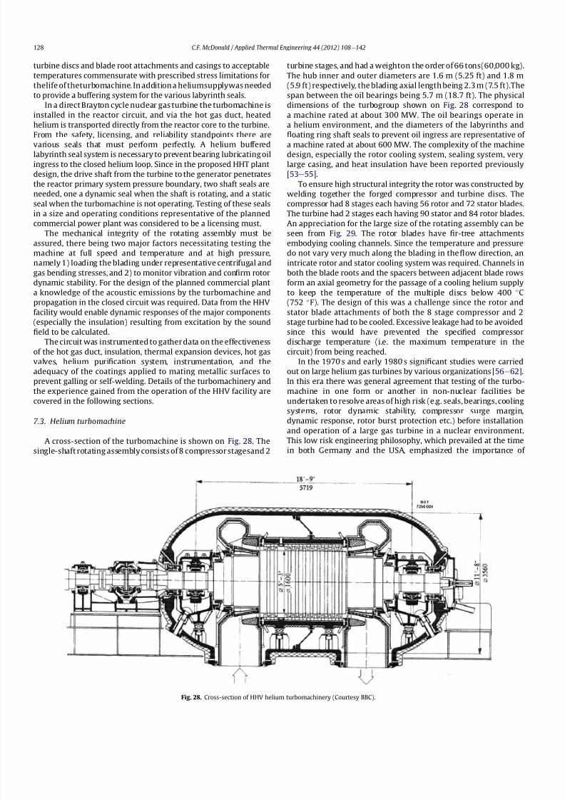
8112019 Helium Turbomachinery Operating Experience From Gas Turbine Power Plants
httpslidepdfcomreaderfullhelium-turbomachinery-operating-experience-from-gas-turbine-power-plants 2135
turbine discs and blade root attachments and casings to acceptable
temperatures commensurate with prescribed stress limitations for
thelife of theturbomachine In addition a heliumsupplywas needed
to provide a buffering system for the various labyrinth seals
In a direct Brayton cycle nuclear gas turbine the turbomachine is
installed in the reactor circuit and via the hot gas duct heated
helium is transported directly from the reactor core to the turbine
From the safety licensing and reliability standpoints there are
various seals that must perform perfectly A helium buffered
labyrinth seal system is necessary to prevent bearing lubricating oil
ingress to the closed helium loop Since in the proposed HHT plant
design the drive shaft from the turbine to the generator penetrates
the reactor primary system pressure boundary two shaft seals are
needed one a dynamic seal when the shaft is rotating and a static
seal when the turbomachine is not operating Testing of these seals
in a size and operating conditions representative of the planned
commercial power plant was considered to be a licensing must
The mechanical integrity of the rotating assembly must be
assured there being two major factors necessitating testing the
machine at full speed and temperature and at high pressure
namely 1) loading the blading under representative centrifugal and
gas bending stresses and 2) to monitor vibration and con1047297rm rotor
dynamic stability For the design of the planned commercial planta knowledge of the acoustic emissions by the turbomachine and
propagation in the closed circuit was required Data from the HHV
facility would enable dynamic responses of the major components
(especially the insulation) resulting from excitation by the sound
1047297eld to be calculated
The circuit was instrumented to gather data on the effectiveness
of the hot gas duct insulation thermal expansion devices hot gas
valves helium puri1047297cation system instrumentation and the
adequacy of the coatings applied to mating metallic surfaces to
prevent galling or self-welding Details of the turbomachinery and
the experience gained from the operation of the HHV facility are
covered in the following sections
73 Helium turbomachine
A cross-section of the turbomachine is shown on Fig 28 The
single-shaft rotating assembly consists of 8 compressor stagesand 2
turbine stages and had a weighton the order of 66 tons(60000 kg)
The hub inner and outer diameters are 16 m (525 ft) and 18 m
(59 ft) respectively the blading axial length being 23 m (75 ft)The
span between the oil bearings being 57 m (187 ft) The physical
dimensions of the turbogroup shown on Fig 28 correspond to
a machine rated at about 300 MW The oil bearings operate in
a helium environment and the diameters of the labyrinths and
1047298oating ring shaft seals to prevent oil ingress are representative of
a machine rated at about 600 MW The complexity of the machine
design especially the rotor cooling system sealing system very
large casing and heat insulation have been reported previously
[53e55]
To ensure high structural integrity the rotor was constructed by
welding together the forged compressor and turbine discs The
compressor had 8 stages each having 56 rotor and 72 stator blades
The turbine had 2 stages each having 90 stator and 84 rotor blades
An appreciation for the large size of the rotating assembly can be
seen from Fig 29 The rotor blades have 1047297r-tree attachments
embodying cooling channels Since the temperature and pressure
do not vary very much along the blading in the 1047298ow direction an
intricate rotor and stator cooling system was required Channels in
both the blade roots and the spacers between adjacent blade rows
form an axial geometry for the passage of a cooling helium supplyto keep the temperature of the multiple discs below 400 C
(752 F) The design of this was a challenge since the rotor and
stator blade attachments of both the 8 stage compressor and 2
stage turbine had to be cooled Excessive leakage had to be avoided
since this would have prevented the speci1047297ed compressor
discharge temperature (ie the maximum temperature in the
circuit) from being reached
In the 1970rsquos and early 1980rsquos signi1047297cant studies were carried
out on large helium gas turbines by various organizations [56e62]
In this era there was general agreement that testing of the turbo-
machine in one form or another in non-nuclear facilities be
undertaken to resolve areas of high risk (eg seals bearings cooling
systems rotor dynamic stability compressor surge margin
dynamic response rotor burst protection etc) before installationand operation of a large gas turbine in a nuclear environment
This low risk engineering philosophy which prevailed at the time
in both Germany and the USA emphasized the importance of
Fig 28 Cross-section of HHV helium turbomachinery (Courtesy BBC)
CF McDonald Applied Thermal Engineering 44 (2012) 108e142128
8112019 Helium Turbomachinery Operating Experience From Gas Turbine Power Plants
httpslidepdfcomreaderfullhelium-turbomachinery-operating-experience-from-gas-turbine-power-plants 2235
the HHV test facility as being an important step towards the
eventual deployment of a high ef 1047297ciency nuclear gas turbine power
plant
74 Initial operation of the HHV facility
During commissioning of the plant in 1979 oil ingress into the
helium circuit from the seal system occurred twiceThe 1047297rst ingressof oil between 600 and 1200 kg (1322 and 2644 lb) was due to
a serious operatorerror and the absence of an isolation valve in the
system The oil in the circuit was partly coked and formed thick
deposits on the cold and hot surfaces of the turbomachinery and in
other parts of the closed loop including saturation of the 1047297brous
insulation The fouled metallic surfaces were cleaned mechanically
and chemically by cracking with the addition of hydrogen and
additives The second oil ingress was due to a mechanical defect in
the labyrinth seal system The quantity of oil introduced was small
and it was removed bycracking at a temperature of 600 C (1112 F)
and with the use of additives To obviate further oil ingress inci-
dents the labyrinth seal system was redesigned The buffer and
cooling helium system piping layout was modi1047297ed to positively
eliminate oil ingress due to improper valve operation and toprevent further human error
Pressure and leak detection tests of the HHV test facility at
ambient temperature showed good leak tightness for the turbo-
machine 1047298anged joints and of the main and auxiliary circuits
However at the operating temperature of 850 C (1562 F) large
helium leaks were detected The major 1047298anges had been provi-
sioned with lip seals and the 1047297rst step was to weld the closures A
large leak persisted at the front 1047298ange of the turbomachine This
was diagnosed as being caused by a non-uniform temperature
distribution during initial operation resulting in thermal stresses
creating local gaps This problem was overcome by redesign of the
cooling system with improved gas 1047298ow distribution and 1047298ow rates
to give a more uniform temperature gradient The leakage from the
system was reduced to on the order of 020e
040 percent of the
helium inventory per day this being of the same magnitude as in
other closed helium circuits as discussed in Section 65
It should be mentioned that in addition to the HHV experience
bearing oil ingress into the circuits and system loss of the working
1047298uid in other closed-cycle gas turbine plants have occurred In all of
these fossil-1047297red facilities 1047297xing leaks and removal of oil deposits
were undertaken based on conventional hands-on approaches but
nevertheless such operations were time-consuming However if a new and previously untested helium turbomachine operating in
a direct cycle nuclear gas turbine plant experienced an oil ingress
the rami1047297cations would be severe The likely use of remote
handling equipment to remove the turbomachine from the vessel
machine disassembly (including breaking the welded 1047298ange joints)
and removal of oil from the radioactively contaminated turbo-
machine blade surfaces and system insulation would be time
consuming A diagnosis of the failure would be required before
a spare turbomachine could be installed and this plant downtime
could adversely affect plant availability
75 Experience gained
Afterresolutionof the aforementionedproblems the HHVfacilitywas started in the Spring of 1981 and in an orderly manner was
brought up to full pressure and a temperature of 850 C (1562 F)
During a 60 h run the functioning of the instrumentation control
and safety systems were veri1047297ed During these tests the ability to
stop the turbomachine from full operating conditions to standstill
within 90 s was demonstrated After system depressurization the
plant was then run up again to full operating conditions with no
problems experienced The HHV facility was successfully run for
about 1100 h of which theturbomachineryoperated forabout325 h
at a temperature of 850 C The test facility was extensively instru-
mented and interpretation and analysis of the data recorded gave
positive and favorable results in the following areas
The complex rotor cooling system which was engineered to
assure that the temperature of the discs be kept below 400
C
Fig 29 HHV helium turbomachine rotating assembly (size equivalent to a 300 MWe machine) being installed in a pressure vessel (Courtesy BBC)
CF McDonald Applied Thermal Engineering 44 (2012) 108e142 129
8112019 Helium Turbomachinery Operating Experience From Gas Turbine Power Plants
httpslidepdfcomreaderfullhelium-turbomachinery-operating-experience-from-gas-turbine-power-plants 2335
(752 F) was demonstrated to be effective The measured rotor
coolant 1047298ows (about 3 percent of the mass1047298ow passing through the
machine) were slightly larger than had been estimated and this
resulted in measured turbine disc temperatures lower than pre-
dicted [55]
The dynamic labyrinth shaft seal functioned well at the full
temperature and pressure conditions and met the requirement of
zero oil ingress into the helium circuit The measured rotor oscil-
lation did not have any adverse effect on the shaft sealing system
The static rotor seal (for shutdown conditions) functioned without
any problems
The compressor and turbine blading hadef 1047297ciencies higher than
predicted The structural integrity of the rotor proved to be sound
when operating at 3000 rpm under the maximum temperature and
pressure conditions The stiff rotor shaft had only slight unbalance
and thermal distortion and measured oscillations were in the range
typical of large steam turbines
Sound power spectrum measurements were taken in four
different locations in the circuit These were taken to determine the
spectrum and intensity of the sound generated and propagated by
the turbomachinery and the resultant vibration of internal
components The maximum sound power level in the helium
circuit was160 dB Numerous strain gages were placedin the circuitto determine the in1047298uence of the sound 1047297eld particularly on the
fatigue strength of the turbine inlet hot gas duct In later examining
the internal components there was no evidence of excessive
vibration of the components especially the ducting and the insu-
lation Based on the measurements and calculations it was
concluded that the fatigue strength limit of the components would
not be exceeded during the designed life of the planned commer-
cial nuclear gas turbine power plant
In a direct cycle nuclear gas turbine the hot gas duct used to
transport the helium from the reactor core to the turbineis a critical
component The hot gas duct in the HHV facility performed well
mechanically and con1047297rmed the adequacy of the thermal expan-
sion devices From the thermal standpoint the 1047297ber insulation
performed better than the metallic type
After dismantling the HHV facility there were no signs of
corrosion or erosion of the turbine or compressor blading While
the total number of hours operated was limited the coatings
applied to mating metallic surfaces to prevent galling and frictional
welding in the oxidation-free helium worked well
The helium buffer and cooling system worked well However
problems remained with the puri1047297cation of the buffer helium The
oil separation system consisting of a cyclone separator and a wire
mesh and a down stream 1047297ber 1047297lter needed further improvement
In late 1981 a decision was made to cancel the HHT project and
the HHV facility was shutdown The design and operational expe-
rience gained from the running of this facility would have been
extremely valuable had the nuclear gas turbine power plant
concept moved towards becoming a reality The identi1047297cation of
somewhat inevitable problems to be expected in such a complexturbomachine and their resolution were undertaken in a timely
and cost effective manner in the non-nuclear HHV facility This
should be noted for future nuclear gas turbine endeavors since
remedying such unexpected problems in the case of a new and
untested large helium turbomachine being operated for the 1047297rst
time using nuclear heat could result in very complex repair
Fig 30 Speci1047297
c speed-speci1047297
c diameter array for gas circulators in various gas-cooled nuclear plants
CF McDonald Applied Thermal Engineering 44 (2012) 108e142130
8112019 Helium Turbomachinery Operating Experience From Gas Turbine Power Plants
httpslidepdfcomreaderfullhelium-turbomachinery-operating-experience-from-gas-turbine-power-plants 2435
activities and extended plant downtime and indeed adding risk to
the overall success of the nuclear gas turbine concept
8 Circulators used in gas-cooled reactor plants
Circulators of different types will be needed in future helium
cooled nuclear plants these including the following 1) primary
loop circulator for possible next generation steam cycle power andcogeneration plants 2) for future indirect cycle gas turbine plants
3) shut down cooling circulators forall HTRand VHTR plants and 4)
for various circulators needed in future VHTR high temperature
process heat plant concepts The technology status of operated
helium circulators is brie1047298y addressed as follows
81 Background
It would be remiss not to mention experience gained in the past
with gas circulators and while not gas turbines they are rotating
machines that operate in the primary loop of a helium cooled
reactor With electric motor drives there are basically two types of
compressor rotor con1047297gurations namely radial and axial 1047298ow
machinesIn a single stage form the centrifugal impeller is used for high
stage pressure rise and low volume 1047298ow duties whereas the axial
type covers low pressure rise per stage and high volume 1047298ow The
selection of impeller type is very much related to the working
media type of bearings drive type rotor dynamic characteristics
and installation envelope A wide range of circulators have operated
and a well established technology base exists for both types [63] A
useful portrayal of compressor data in the form of quasi- non-
dimensional parameters (after Balje [64]) showing approximate
boundaries for operation of high ef 1047297ciency axial and radial types is
shown on Fig 30 (from Ref [65])
Both high speed axial and lower speed radial 1047298ow types are
amenable to gas oil and magnetic bearings From the onset of
modularHTR plant studies theuse of active magnetic bearings[6667]offered a solution to eliminate lubricating oil into the reactor circuit
and this tribology technology is attractive for use in submerged
rotating machinery in the next generation of HTR plants [68]
While now dated an appreciation of the main design features of
typical electric motor-driven helium circulators have been reported
previously namely an axial 1047298ow main circulator for a modular
steam cycle HTR plant [69] and a representative radial 1047298ow shut-
down cooling circulator [70]
The operating experience gained from three particular circula-
tors is brie1047298y included below because of their relevance to the
design of helium turbomachinery in future HTR plant variants
82 Axial 1047298ow helium circulator
Since all of the aforementioned predominantly European
helium gas turbines used axial 1047298ow turbomachinery it is of interest
to mention a helium axial 1047298ow circulator that operated in the USA
and to brie1047298y discuss its design parameters and features The
330 MW Fort St Vrain HTGR featured a Rankine cycle power
conversion system Four steam turbine driven helium circulators
were used to transport heat from the reactor core to the steam
generators The complete circulator assemblies were installed
vertically in the prestressed concrete reactor vessel [71e73]
A cross-section of the circulator is shown on Fig 31 with thecompressor rotor and stator visible on the left hand end of the
machine Based on early 1960rsquos technology a decision was made to
use water lubricated bearings and from the overall plant reliability
and availability standpoints this later proved to be a bad choice
Within the vertical circulator assembly there were four 1047298uid
systems namely the helium reactor coolant water lubricant in the
bearings steam for the turbine drive and high pressure water for
the auxiliary Pelton wheel drive During plant transients the pres-
sures and temperatures of these four 1047298uids oscillated considerably
and the response of the control and seal systems proved to be
inadequate and resulted in considerable water ingress from the
bearing cartridge into the reactor helium circuit The considerable
clean up time needed following repeated occurrences of this event
resulted in long periods of plant downtime and this had an adverseeffect on plant availability This together with other technical
Fig 31 Cross section of FSV helium circulator (Courtesy general Atomics)
CF McDonald Applied Thermal Engineering 44 (2012) 108e142 131
8112019 Helium Turbomachinery Operating Experience From Gas Turbine Power Plants
httpslidepdfcomreaderfullhelium-turbomachinery-operating-experience-from-gas-turbine-power-plants 2535
dif 1047297culties eventually contributed to the plant being prematurely
decommissioned
On the positive side in the context of this paper the helium
circulators operated for over 250000 h and exhibited excellent
helium compressor performance good mechanical integrity and
vibration-free operation The rotating assembly showing the axial
1047298ow compressor and steam turbine rotors together with a view of
the machine assembly are given on Fig 32 The helium compressor
consists of a single stage axial rotor followed by an exit guide vane
The machine was designed for axial helium 1047298ow entering and
leaving the stage and this can be seen from the velocity triangles
shown on Fig 33 which also includes the de1047297nition of the various
aerodynamic parameters Major design parameters and features of
this helium circulator are given on Table 4 Related to an earlier
discussion on the degree of reaction for axial 1047298ow compressors the
value for this conventional single stage circulator is 78 percent All
of the major aerothermal and structural loading criteria were
within established boundaries for an axial compressor having high
ef 1047297ciency and a good surge margin
The compressor gas 1047298ow path and blading geometries were
established based on prevailing industrial gas turbine and aero-
engine design practice A low Mach number (025) a high Reynolds
number (3 106) together with a modest stage loading (ie
a temperature rise coef 1047297cient of 044) and an acceptable value of
diffusion factor (042) were some of the factors that contributed to
a helium circulator that had a high ef 1047297ciency and a good pressure
rise- 1047298ow characteristic The large rotor blade chord and thick blade
section for this single stage circulator are necessary to accommo-
date the high bending stress characteristic of operation in a high
pressure environment The solidity and blade camber were opti-
mized for minimum losses
There were essentially two reasons for including this single-
stage axial 1047298ow compressor that operated in a helium cooled
reactor although its overall con1047297guration can be regarded as a 1047297rst
and last of a kind A rotor blade from this circulator as shown onFig 34 was based on a NASA 65 series airfoil which at the time
were one of the best performing cascades for such low Mach
number and high Reynolds number applications Interestingly it
has almost the same blade height aspect ratio and solidity as would
be used in the 1047297rst stage of an LP compressor in a helium turbo-
machine rated on the order of 250 MW
The second point of interest is that the helium mass 1047298ow rate
through the single stage axial compressor (rated at 4 MWe) is
110 kgs compared with 85 kgs through the multistage compressor
in the 50 MWe Oberhausen II helium gas turbine plant However
the volumetric 1047298ow through the Oberhausen axial compressor is
higher than that through the circulator by a factor of 16 this again
pointing out that the Oberhausen II plant was designed for high
volumetric 1047298ow to simulate the much larger size of turboma-chinery that was planned at the time in Germany for use in future
projected nuclear gas turbine power plants
83 High temperature helium circulator
For future helium turbomachines embodying active magnetic
bearings a challenge in their design relates to accommodating
elevated levels of temperature in the vicinity of the electronic
components In this regard it is of interest to note that a small very
high temperature helium axial 1047298ow circulator rated at 20 kW (as
shown on Fig 35) operated for more than 15000 h in an insulation
test facility in Germany more than two decades ago [74] The
signi1047297cance of this machine is that it operated with magnetic
bearings in a high temperature helium test loop with a circulatorgas inlet temperature of 950 C (1742 F) This necessitated the use
of ceramic insulation to ensure that the temperature in the vicinity
of the magnetic bearing electronics did not exceed a temperature of
about 150 C (300 F)
This machine although a very small axial 1047298ow helium blower
performed well and has been brie1047298y mentioned here since it
represents a point of reference for future helium rotating machines
capable operating with magnetic bearings in a very high temper-
ature helium environment
84 Radial 1047298ow AGR nuclear plant gas circulators
The electric motor-driven carbon dioxide circulators rated at
about 5 MW with a total runningtimein excess of 18 million hours
Fig 32 Fort St Vrain HTGR plant helium circulator (Courtesy General Atomics) (a)
Axial 1047298ow helium compressor and steam turbine rotating assembly (b) 4 MW helium
circulator assembly
CF McDonald Applied Thermal Engineering 44 (2012) 108e142132
8112019 Helium Turbomachinery Operating Experience From Gas Turbine Power Plants
httpslidepdfcomreaderfullhelium-turbomachinery-operating-experience-from-gas-turbine-power-plants 2635
in AGR nuclear power plants in the UK have demonstrated veryhigh availability [7576] To a high degree this can be attributed to
the fact that the machines were conservatively designed and proof
tested in a non-nuclear facility at full temperature and power
under conditions that simulated all of the nuclear plant operating
modes The test facility shown on Fig 36 served two functions 1)
design veri1047297cation of the prototype machine and 2) test of all new
and refurbished machines before they were installed in nuclear
plants Engineers currently involved in the design and development
of helium turbomachinery could bene1047297t from this sound testing
protocol to minimize risk in the deployment of helium rotating
machinery in future HTRVHTR plant variants
9 Helium turbomachinery development and testing
91 On-going development activities
The various helium turbomachines discussed in previous
sections operated over a span of about two decades starting in the
early 1960s From about 1990 activities in the nuclear gas turbine
1047297eld have been focused mainly on the design of modular GTeHTR
plant concepts In support of these plant studies many signi1047297cant
helium turbomachine design advancements have been made and
attention given to what development testing would be needed In
the last decade or so limited sub-component development has
been undertaken for helium turbomachines in the 250e300 MWe
size and these are brie1047298y summarized below
In a joint USARussia effort development in support of the
GTe
MHR turbomachine has been undertaken including testing in
the following areas magnetic bearings seals and rotor dynamicsfor the vertical intercooled helium turbomachine rated at 286 MWe
[77e80]
In Japan development activities have been in progress for
several years in support of the 274 MWe helium turbomachine for
the GTeHTR300 plant concept [2581] A detailed discussion on
the aerodynamic design of the axial 1047298ow helium compressor for
this turbomachine has been published in the open literature [82]
While the design methodology used for axial compressor design in
air-breathing industrial and aircraft gas turbines is generally
applicable for a multi-stage helium compressor a decision was
made by JAEA to test a small scale compressor in a helium facility
because of the inherent and unique gas 1047298ow path and type of
blading associated with operation in a high pressure helium
environment The major goal of the test was to validate the designof the 20 stage helium axial 1047298ow compressor for the GTeHTR300
plant
An axial 1047298ow compressor in a closed-cycle helium gas turbine is
characterized by the following 1) a large number stages 2) small
blade heights 3) high hub-to-tip ratio 4) a long annulus with
small taper that tends to deteriorate aerodynamic performance as
a result of end-wall boundary layer length and secondary 1047298ow 5)
low Mach number 6) high Reynolds number and 7) blade tip
clearances that are controlled by the gap necessary in the magnetic
journal and catcher bearings While (as covered in earlier sections)
helium gas turbines have operated there is limited data in the
open literature on the performance of multi-stage axial 1047298ow
compressors operating in a high pressure closed-loop helium
environment
Fig 33 Velocity triangles for axial compressor stage
CF McDonald Applied Thermal Engineering 44 (2012) 108e142 133
8112019 Helium Turbomachinery Operating Experience From Gas Turbine Power Plants
httpslidepdfcomreaderfullhelium-turbomachinery-operating-experience-from-gas-turbine-power-plants 2735
A 13rd scale 4 stage compressor was designed to simulate the
stage interaction the boundary layer growth and repeated stage
1047298ow in an actual compressor The 1047297rst four stages were designed to
be geometrically similar to the corresponding stages in the
GTe
HTR300 compressor Details of the model compressor havebeen discussed previously [81] and are summarized on Table 5
from [83]
A cross-section of the compressor test model is shown on Fig 37
A view of the 4 stage compressor rotor installed in the lower casing
is shown on Fig 38 The test facility (Fig 39) is a closed helium loop
consisting of the compressor model cooler pressure adjustment
valve and a 1047298ow measurement instrument The compressor is
driven by a 3650 kW electrical motor via a step-up gear The rota-
tional speed of 10800 rpm (three times that of the compressor in
the GTeHTR300 plant) was selected to match blade speed and
Mach number in the full size compressor
Details of the planned aerodynamic performance objectives of
the 13rd scale helium compressor test have been published
previously [84] Extensivetesting of the subscale model compressorprovided data to validate the performance of the full size
compressor for the GTeHTR300 power plant The test data and
test-calibrated CFD analyses gave added insight into the effect of
factors that impact performance including blade surface roughness
and Reynolds number
Based on advanced aerodynamic methodology and experi-
mental validation [82] there is now a sound basis for added
con1047297dence that the design goals of 90 percent polytropic ef 1047297ciency
and a design point surge margin of 20 percent are realizable in
a large multistage axial 1047298ow compressor for a future nuclear gas
turbine plant
In a similar manner a design of a one third size single stage
helium axial 1047298ow turbine has been undertaken and a cross
section of the machine is shown on Fig 40 (from Ref [81]) This
Table 4
Major features of axial 1047298ow helium circulator
Helium 1047298ow rate kgsec 110
Inlet temperature C 394
Inlet pressure MPa 473
Pressure rise KPa 965
Volumetric 1047298ow m3sec 32
Compressor type Single stage axial
Compressor drive Steam turbine
Bearing type Water lubricated
Rotational speed rpm 9550
Power MW 40
Rotor tip diameter mm 688
Rotor tip speed msec 344
Number of rotor blades 31
Number of stator blades 33
Blade height mm 114
Hub-to-tip ratio 067
Axial velocity msec 157
Flow coef 1047297cient 055
Temperature rise coef 1047297cient 044
Degree of reaction 078
Mean rotor solidity 128
Rotor aspect ratio 155
Rotor Mach number 025
Rotor diffusion factor 042
Rotor Reynolds number 3106
Speci1047297c speed 335
Speci1047297c diameter 066
Blade root thickness 15
Airfoil type NASA 65
Rotor blade chord mm 94e64
Stator blade chord mm 79
Rotor centrifugal stress MPa 125
Rotor bending stress MPa 30
Circulator(s) operating Hours gt250000
Fig 34 Rotor blade from single stage axial 1047298ow helium circulator (Courtesy General
Atomics)
Fig 35 20 kW axial 1047298ow helium circulator with magnetic bearings operated in 1985 in
an insulation test loop with a gas inlet temperature on 950
C (Courtesy BBC)
CF McDonald Applied Thermal Engineering 44 (2012) 108e142134
8112019 Helium Turbomachinery Operating Experience From Gas Turbine Power Plants
httpslidepdfcomreaderfullhelium-turbomachinery-operating-experience-from-gas-turbine-power-plants 2835
single stage scale model turbine for validity of the full size turbine
has been built and plans made to test the aerodynamic
performance
92 Nuclear gas turbine helium turbomachine testing
In planning for the 1047297rst nuclear gas turbine plant projected to
enter service perhaps in the third decade of the 21st century
a major decision has to be made as to what extent the large helium
turbomachine should be tested prior to operation on nuclear heat
Issues essentially include cost impact on schedule but the over-
riding one is risk Certainly turbomachine component testing will
be undertaken including the compressor (as discussed in the
previous section) and turbine performance seals cooling systems
hot gas valves thermal expansion devices high temperature
insulation rotor fragment containment diagnostic systems
instrumentation helium puri1047297cation system and other areas to
satisfy safety licensing reliability and availability concerns The
major point is really whether a full size or scaled-down turbo-machine be tested early in the project in a non-nuclear facility
To obviate the need for pre-nuclear testing of a large helium
turbomachine a view expressed by some is that advantage can be
taken of formidable technology bases that exist today for large
industrial gas turbines and high performance aeroengines On the
other hand it is the view of some including the author that very
complex power conversion system components especially those
subjected to severe thermal transients donrsquot always perform
exactly as predicted by analysts and designers even using sophis-
ticated computer codes This was exempli1047297ed in the case of the
turbomachine in the aforementioned Oberhausen II helium gas
turbine plant
The need for a helium turbomachine test facility goes beyond
just veri1047297
cation of the prototype machine Each newgas turbine for
commercial modular nuclear reactor plants would have to be proof
tested and validated before being transported to the reactor site
Similarly turbomachines that would be periodically removed from
the plant at say 7 year intervals during the plant operating life of 60
years for scheduled maintenance refurbishment repair or updat-ing would be again proof tested in the facility before re-entering
service
The direction that turbomachine development and testing will
take place for future helium gas turbines needs to be addressed by
the various organizations involved
Fig 36 AGR circulator test facility In the UK (Courtesy Howden)
Table 5
Major design parametersfeatures of model GTeHTR300 axial 1047298ow helium
compressor (Courtesy JAERI)
Scale of GTeHTR300 compressor 13
Helium mass 1047298ow rate (kgsec) 122
Helium volumetric 1047298ow rate (mV s) 87
Inlet temperature C 30
Inlet pressure MPa 0883Compressor pressure ratio at design point 1156
Number of stages 4
Rotational speed rpm 10800
Drive motor power kW 3650
Hub diameter mm 500
Rotor tip diameter (1st4th stage mm) 568566
Hub-to-tip ratio (1st stage) 088
Rotor tip speed (1st stage msec) 321
Number of rotorstator blades (1st stage) 7294
Rotorstator blade height (1st stage mm) 34337
Rotor stator blade c hor d l eng th (1st stage mm) 2620
Rotorstator solidity (1st stage) 119120
Rotorstator aspect ratio (1st stage) 1317
Flow coef 1047297cient 051
Stage loading factor 031
Reynolds number at design point 76 l05
CF McDonald Applied Thermal Engineering 44 (2012) 108e142 135
8112019 Helium Turbomachinery Operating Experience From Gas Turbine Power Plants
httpslidepdfcomreaderfullhelium-turbomachinery-operating-experience-from-gas-turbine-power-plants 2935
10 Helium turbomachinery lessons learned
101 Oberhausen II gas turbine and HHV test facility
It is understandable that 1047297rst-of-a-kind complex turboma-
chinery operating with an inert low molecular weight gas such as
helium will experience unique and unexpected problems In the
operation of the two pioneering large helium turbomachines in
Germany there were many positive1047297ndings which could only have
been achieved by development testing Equally important some
negative situations were identi1047297ed many of which were remedied
In the case of the Oberhausen II helium gas turbine plant some of
the very serious problems encountered were not resolved Inves-
tigations were undertaken to rationalize the problems associated
with the large power de1047297ciency and a data base established to
ensure that the various anomalies identi1047297ed would not occur in
future large helium turbomachines
The experience gained from the operation of the Oberhausen II
helium gas turbine power plant and the HHV test facility have been
discussedin thetextand arepresentedin a summaryformon Table6
Fig 37 Cross-section of 13rd scale helium compressor test model (Courtesy JAEA)
Fig 38 Four stage helium compressor rotor assembly installed in lower casing (Courtesy JAEA)
CF McDonald Applied Thermal Engineering 44 (2012) 108e142136
8112019 Helium Turbomachinery Operating Experience From Gas Turbine Power Plants
httpslidepdfcomreaderfullhelium-turbomachinery-operating-experience-from-gas-turbine-power-plants 3035
102 Impact of 1047297ndings on future helium gas turbine
The long slender rotorcharacteristic of closed-cycle gas turbines
has resulted in shaft dynamic instability which in some cases has
resulted in blade vibration and failure and bearing damage This
remains perhaps the major concern in the design of large
(250e
300 MW) helium turbomachines for future nuclear gas
turbine plants With pressure ratios in the range of about 2e3 in
a helium system a combination of splitting the compressor (to
facilitate intercooling) and having a large number of compressor
and turbine stages results in a long and 1047298exible rotating assembly
andthis is exempli1047297ed by the rotorassembly shown on Fig13 With
multiple bearings (either oil lubricated or magnetic) the rotor
would likely pass through multiple bending critical speeds before
Fig 39 Helium compressor test facility (Courtesy JAEA)
Fig 40 Cross-section of single stage helium turbine test model (Courtesy JAEA)
CF McDonald Applied Thermal Engineering 44 (2012) 108e142 137
8112019 Helium Turbomachinery Operating Experience From Gas Turbine Power Plants
httpslidepdfcomreaderfullhelium-turbomachinery-operating-experience-from-gas-turbine-power-plants 3135
reaching the design speed While very sophisticated computer
codes will be used in the detailed rotor dynamic analyses the real
con1047297rmation of having rotor oscillations within prescribed limits
(to avoid blade bearing and seal damage) will come from actual
testingA point to be made here is that in operated fossil-1047297red closed-
cycle gas turbine plants it was possible to remedy problems asso-
ciated with rotor vibrations and blade failures in a conventional
manner In fact in some situations the casings were opened several
times and modi1047297cations made to facilitate bearing and seal
replacement and rotor re-blading and balancing
An accurate assessment of pressure losses must be made
particularly those associated with the helium entering and leaving
the turbomachine bladed sections Minimizing the system pressure
loss is important since it directly impacts the all important quotient
of turbine expansion ratio to compressor pressure ratio and power
and plant ef 1047297ciency
Based on the operating experience from the 20 or so fossil-1047297red
closed-cycle gas turbine plants using air as the working1047298
uid it was
recognized that future very high pressure helium gas turbines
would pose problems regarding the various seals in the turbo-
machine and obtaining a zero leakage system with such a low
molecular weight gas would be dif 1047297cult and this is discussed
below
When the Oberhausen II gas turbine plant and the HHV facility
operated over 30 years ago oil lubricated bearings were used to
support the heavy rotor assemblies and helium buffered labyrinth
seals were used to prevent oil ingressinto the heliumworking1047298uid
Initial dif 1047297culties encountered in both plants were overcome by
changes made to the seal geometries and for the operating lives of
the helium turbomachines no further oil ingress events were
experienced Twoseals were required where the turbine drive shaft
penetrated the turbomachine casing namely 1) a dynamic laby-
rinth seal and 2) a static seal for shutdown conditions In both
plants these seals functioned without any problems
Labyrinth seals were also required within the helium turbo-
machines to pass the correct helium bleed 1047298ow from the
compressor discharge for cooling of the turbine discs blade root
attachments and casings The fact that the very complex rotor
cooling system in the large helium turbomachine in the HHV test
facility operated well for the test duration of about 350 h with
a turbine inlet temperature of 850 C was encouragingIn the case of the Oberhausen II gas turbine plant analysis of the
test data revealed that the labyrinth seal leakage and excessive
cooling 1047298ows were on the order of four times the design value A
possible reason for this was that damage done to the labyrinth
seals caused excessive clearances when periods of excessive rotor
oscillation and vibration occurred during early operation of the
machine
Clearly 1047298uid dynamic and thermal management of the cooling
system and 1047298ow through the various labyrinth seals will require
extensive analysis design and development testing before the
turbomachine is operated on nuclear heat for the 1047297rst time
In future heliumgas turbine designs (with turbine inlet tempera-
tureslikelyontheorderof950C)the1047298owpathgeometriesofhelium
bledfromthecompressornecessarytocoolpartsoftheturbomachinewillbemorecomplexthanthosetestedto-dateInadditiontoproviding
acooling1047298owtotheturbinebladesanddiscsbladerootattachmentsand
casingsheliummustbetransportedtotheseveralmagneticbearingsto
ensure thatthe temperatureof theirelectronic components doesnot
exceedabout150C
The importance of the points made above is evidenced when
examining the data on Table 3 where a combination of excessive
pressure losses and high bleed 1047298ows contributed to about 40
percent of the power de1047297ciency in the Oberhausen II helium
turbine plant
Retaining overall system leak tightnessin closed heliumsystems
operating at high pressure and temperature has been elusive
including experience from the Fort St Vrain HTGR plant as dis-
cussed in Section 65 New approaches in the design of the plethoraof mechanical joints must be identi1047297ed Experience to-date has
shown that having welded seals on 1047298anges while minimizing
system leakage did not eliminate it
The importance of lessons learned from the operation of the
Oberhausen II helium turbine power plant and the HHV test facility
have primarily been discussed in the context of helium turbo-
machines currently being designed in the 250e300 MWe power
range However the established test data bases could also be
applied to the possible emergence in the future of two helium
cooled reactor concepts namely 1) an advanced VHTR combined
cycle plant concept embodying a smaller helium gas turbine in the
power range of 50e80 MWe [22] and 2) the use of a direct cycle
helium gas turbine PCS in a recently proposed all ceramic fast
nuclear reactor concept [85]
Table 6
Experience gained from Oberhausen II and HHV facility
Oberhausen II 50 MW helium gas turbine power plant
Positive results
e Rotating and static seals worked well
e No ingress of bearing lubricant oil into closed circuit
e Load change by inventory control worked well
e 100 Percent load shed by means of bypass valves demonstrated
e Turbine disc and blade root cooling system con1047297rmed
e Coatings on mating surfaces prevented galling and self-welding
e After 24000 h of operation no evidence of corrosion or erosion
e Coaxial turbine hot gas inlet duct insulation and integrity con1047297rmed
e Monitoring of complete power conversion system for steady state
and transient operation undertaken
Problem areas
e Serious power output de1047297ciency (30 MW compared with design
value of 50 MW)
e Compressor(s) and turbine(s) ef 1047297ciencies several points below predicted
e Higher than estimated system pressure loss
e Rotor dynamic instability and blade vibration
e Bearings damaged and had to be replaced
e Blade failure caused extensive damage in HP turbine but retained
in casing
e Very excessive sealing and cooling 1047298ow rates
e Absolute leak tightness not attainable even with welded 1047298ange lips
HHV test facility
Positive resultse Use of heat pump approach facilitated helium temperature capability
to 1000 C
e Large oompressorturbine rotor system operated at 3000 rpm Complex
turbine disc and blade root cooling system veri1047297ed
e Dynamic and static seals met requirement of zero oxl ingress into circuit
e Structural integrity of rotating assembly veri1047297ed at temperature of 850 C
e Measured rotor oscillations within speci1047297cation
e Compressor and turbine ef 1047297ciencies higher than predicted
e Coatings on mating metallic surfaces prevented galling and self-welding
e Instrumentation control and safety systems veri1047297ed
e Seal 1047298ows within speci1047297cation
e Machine stop from operating speed to shutdown in 90 s demonstrated
e Hot gas duct insulation and thermal expansion devices worked well
e After 1100 h of operation no evidence of corrosionof erosion
Problem areas
e Before commissioning a large oil ingress into the circuit occurred due
to serious operator error and absence of an isolation valve A second oilingress occurred due to a mechanical defect in the labyrinth seal system
These were remedied and no further oil ingress was experienced for the
duration of testing
e Cooling 1047298ows slightly larger than expected but this resulted in actual
disc and blade root temperatures lower than the predicted value of
400 C
e System leak tightness demonstrated when pressurized at ambient
temperature conditions but some leakage occured at 850 C even with
the seal welding of 1047298ange(s) lips
CF McDonald Applied Thermal Engineering 44 (2012) 108e142138
8112019 Helium Turbomachinery Operating Experience From Gas Turbine Power Plants
httpslidepdfcomreaderfullhelium-turbomachinery-operating-experience-from-gas-turbine-power-plants 3235
11 New technologies
It is recognized that in the 3 to 4 decades since the operation of
the helium turbomachines covered in this paper new technologies
have emerged which negate some of the early issues An example of
this is the technology transfer from the design of modern axial 1047298ow
gas turbines (ie industrial aircraft and aeroderivatives) that fully
utilize sophisticated CAE CAD CFD and FEA design software
Air breathing aerodynamic design practice for compressors and
turbines are generally applicable but the properties of helium and
the high system pressure have a signi1047297cant impact on gas 1047298ow
paths and blade geometries With short blade heights high hub-to-
tip ratios long annulus 1047298ow path length (with resultant signi1047297cant
end-wall boundary layer growth and secondary 1047298ow) and blade tip
clearances in some cases controlled by clearances in the magnetic
catcher bearing testing of subscale model compressors and
Fig 41 Gas turbine test facility for aircraft nuclear propulsion involving the coupling of a 32 MWt air-cooled reactor with two modi 1047297ed J-47 turbojet aeroengines each rated at
a thrust of about 3000 kg operated in 1960 (Courtesy INL)
Fig 42 Mobile 350 KWe closed-cycle nuclear gas turbine power plant operated in 1961 (Courtesy US Army)
CF McDonald Applied Thermal Engineering 44 (2012) 108e142 139
8112019 Helium Turbomachinery Operating Experience From Gas Turbine Power Plants
httpslidepdfcomreaderfullhelium-turbomachinery-operating-experience-from-gas-turbine-power-plants 3335
turbines will be needed While most of the operated helium tur-
bomachines discussed in this paper took place 3 or 4 decades ago it
is encouraging that the fairly recent test data and test-calibrated
CFD analysis from a subscale four stage model helium axial 1047298ow
compressor in Japan [80] gave a high degree of con1047297dence that
design goals are realizable for the full size 20 stage compressor in
the 274 MWe GTeHTR300 plant turbomachine
In the future the use of active magnetic bearings will eliminate
the issue of oil ingress however the very heavy rotor weight and
size of the journal and thrust bearings (and catcher bearings) of the
type for helium turbomachines in the 250e300 MWe power range
are way in excess of what have been demonstrated in rotating
machinery For plant designs retaining oil-lubricated bearings well
established dry gas seal technology exists particularly experience
gained from the operation of high pressure natural gas pipe line
compressors
For future nuclear helium gas turbine plants the designer has
freedom regarding meeting different frequency requirements that
exist in some countries These include use of a synchronous
machine (ie designed for 50 or 60 Hz grids) use of a gearbox drive
between the turbine and generator or the use of a frequency
converter which gives the designer an added degree of freedom
regarding the selection of speed for the rotating assemblyCompared with the past very sophisticated electronic control
systems instrumentation and diagnostic systems are available
today
12 Conclusions
In this review paper experience from operated helium turbo-
machines has been compiled based on open literature sources At
this stage in the evolution of HTR and VHTR plant concepts it is not
clear in what role form or time-frame the nuclear gas turbine will
emerge when commercialized By say the middle of the 21st
century all power plants will be operating with signi1047297cantly higher
ef 1047297ciencies to realize improved power generation costs and
reduced emissions In a nuclear gas turbine the helium turbo-machine will be a major contributor towards the achievement of
ef 1047297ciencies higher than 50 percent
While it has been 3 to 4 decades since the Oberhausen II helium
turbine power plant and the HHV high temperature helium turbine
facility operated signi1047297cant lessons were learned and the time and
effort expended to resolve the multiplicity of unexpected technical
problems encountered The remedial repair work was done under
ideal conditions namely that immediate hands-on activities were
possible This would not have been possible if the type of problems
experienced had been encountered in a new and untested helium
turbomachine operated for the 1047297rst time with a nuclear heat
source
While new technologies have emerged that negate many of the
early problems there are some uniquely inherent issues associatedwith for large helium turbines operating in a high pressure and
temperature environment and these include the following 1)
minimizing system leakage with such a low molecular weight gas
2) clearances in labyrinth seals to minimize helium bypass1047298ows 3)
the dynamic stability of long slender rotors 4) minimizing the
turbomachine inlet and outlet pressure losses 5) 1047298ow maldis-
tribution in complex ductturbomachine interfaces 6) integrity
veri1047297cation of the catcher bearings (journal and thrust) after
multiple rotor drops (following loss of the magnetic 1047297eld) during
the plant lifetime 7) assurances that high energy fragments from
a failed turbine disc are contained within the machine casing 8)
turbomachine installation and removal from a steel pressure vessel
and 9) remote handling and cleaning of a machine with turbine
blades contaminated with 1047297
ssion products
The need for a helium turbomachine test facility has been
emphasized to ensure that the integrity performance and reli-
ability of the machine before it operates the 1047297rst time on nuclear
heat Engineers currently involved in the design of helium rotating
machinery for all HTR and VHTR plant variants should take
advantage of the experience gained from the past operation of
helium turbomachinery
13 In closing-GT rsquos operated with nuclear heat
In the context of this paper it is germane to mention that two
gas turbines have actually operated using nuclear heat as brie1047298y
highlighted below
In the late 1950rsquos a program was initiated in the USA for aircraft
nuclear propulsion (ANP) While different concepts were studied
only the direct cycle air-cooled reactor reached the stage of
construction of an experimental reactor [86] A view of the large
nuclear gas turbine facility is given on Fig 41 and shows the air-
cooled and zirconiumehydride moderated reactor rated at
32 MWt coupled with two modi1047297ed J-47 turbojet engines each
rated with a thrust of about 3000 kg In this open cycle system the
high pressure compressor air was directly heated in the reactor
before expansion in the turbine and discharge to the atmosphere in
the exhaust nozzle The facility operated between 1958 and 1961 at
the Idaho reactor testing facility While perhaps possible during the
early years of the US nuclear program it is clear that such a system
would not be acceptable today from safety and environmental
considerations
The 1047297rst and indeed the only coupling of a closed-cycle gas
turbine with a nuclear reactor for power generation was under-
taken to meet the needs of the US Army In the late 1950 rsquos an RampD
program was initiated for a 350 kW trailer-mounted system to be
used in the 1047297eld by military personnel A prototype of the ML-1
plant shown on Fig 42 was 1047297rst operated in 1961 [8788]
It was based on a 33 MW light water moderated pressure tube
reactor with nitrogen as the coolant The closed-cycle gas turbine
power conversion system with nitrogen as the working 1047298uid hada turbine inlet temperature of 649 C (1200 F) and delivered
around 300 kW With changes in the Armyrsquos needs the project was
discontinued in 1965
While the experience gained from the above twounique nuclear
plants is clearly not relevant for future nuclear gas turbine power
plants that could see service in the third decade of the 21st century
these ambitious and innovative nuclear gas turbine pioneering
engineering efforts need to be recognized
Acknowledgements
The author would like to thank the following for helpful discus-
sions advice and for providing valuable comments on the initial
paper draft Prof Dr Hermann Haselbacher Hans Ulrich Frutschi DrXing Yan DrPeter Zenker Professor DavidGordon Wilson Professor
Aristide Massardo Arthur Harris DrFred Starr and DrGuido Bac-
caglini This paper has been enhanced by the inclusion of hardware
photographs and unique sketches and the author is appreciative to
all concerned with credits being duly noted
References
[1] C Keller The Escher Wyss AK Closed-Cycle Gas Turbine Its Actual Develop-ment and Future Prospects Paper Presented at ASME Meeting November 261945
[2] HU Frutschi Closed-Cycle Gas Turbines Operating Experience and FuturePotential ASME Press NY 2005
[3] CF McDonald The Nuclear Gas Turbine-Towards Realization After Half
a Century of Evolution (1995) ASME Paper 95-GT-292
CF McDonald Applied Thermal Engineering 44 (2012) 108e142140
8112019 Helium Turbomachinery Operating Experience From Gas Turbine Power Plants
httpslidepdfcomreaderfullhelium-turbomachinery-operating-experience-from-gas-turbine-power-plants 3435
[4] C Keller The Theory and Performance of Axial Flow Fans McGraw Hill BookCompany Inc NY 1937
[5] J Ackert C Keller Aerodynamic turbine with closed circuit In A Century of Turbines vols 1516 Escher Wyss News 1942e43 5e19
[6] Escher Wyss News Closed-Cycle Gas Turbines for all Fuels Coal Gas Nuclearvol 39 No 1 (1966)
[7] C Keller Closed-cycle gas turbine Escher Wyss-AK development 1945e1950Transactions of ASME (August 1950) 835e850
[8] C Keller Operating Experience and Design Features of Closed-Cycle GasTurbine Power Plants (1956) ASME Paper 56-GTP-15
[9] C Keller HU Frutschi Closed-cycle plants -conventional and nuclear designapplication operation In Sawyerrsquos Gas Turbine Engineering Handbooksecond ed vol 2 Applications (1976) pp 265e283
[10] K Bammert G Groschup Status Report on Closed-Cycle Power Plants in theFederal Republic of Germany (1976) ASME Paper 76-GT-54
[11] JL Mason Monatomic Working Gases versus Air for Closed Brayton Cycles(1985) ASME Paper 85-IGT-50
[12] JL Mason et al 5 MW Closed Cycle Gas Turbine (1984) ASME Paper 84-GT-268
[13] The British Gas Closed-Cycle Demonstrator (1995) British Gas Research ampTechnology Final Year Report
[14] F Starr ODS alloy high temperature heat exchanger prototype developmentPaper Presented at ODS 2010 Materials Workshop UCSD Jacobs Hall La JollaCalifornia Nov17e18 2010
[15] CA Rennie Achievements of the Dragon project Pergamon Press Annals of Nuclear Energy 5 (1978) 305e320
[16] SB Hosegood et al Dragon Project Engineering Studies on the Direct CycleHTR Proceedings of Conference on Nuclear Gas Turbines The British NuclearEnergy Society London April 8e9 1970 pp 161e179
[17] Nuclear Gas Turbines Proceedings of British Nuclear Society Meeting LondonApril 8-9 1972
[18] CF McDonald C Peinado ldquoThe nuclear gas Turbine-A perspective on a long-term advanced technology HTGR plant Optionrdquo ASME Paper 82-GT-289
[19] GH Lohnert et al Technical design features and essential safety-relatedfeatures of the HTR-Module Nuclear Engineering and Design 121 (1990)259e275
[20] H Reutler GH Lohnert The modular high temperature nuclear reactorNuclear Technology 62 (1983) 22e30
[21] CF McDonald Exploitation of the very high temperature capability of theMHTGR to meet National energy needs after the year 2000 IECEC Paper869006
[22] CF McDonald Power conversion system considerations for an advancednuclear gas turbine (GT-VHTR) CHHP demonstration plant concept Interna-tional Journal of Turbo amp Jet Engines 27 (2010) 179e217
[23] N Hee Cheon et al A review of helium gas turbine technology for hightemperature gas cooled reactors Nuclear Engineering and Design 29 (2007)21e30
[24] CB Baxi et al Development of the GT-MHR Turbomachine ASME PaperGT2009e59450[25] X Yan GTHTR300 design and development Nuclear Engineering and Design
222 (2003) 247e262[26] JC Gauthier et al ANTARES the HTRVHTR project of Framatome ANP
Nuclear Engineering and Design 236 (2006) 526e533[27] J Wang et al ldquoDesign features of gas turbine power conversion system for
HTR-10GT paper D05 presented at 2nd Intl Meeting on HTR TechnologyBeijing China September 21e24 2004
[28] A Koster et al ldquoPBMR Design For the Futurerdquo Nuclear engineering andDesign 222 (203) 231e245
[29] S van der Linden Closed cycle nuclear plant rated at 165 MWe and 40 percentef 1047297ciency Gas Turbine World (MarcheApril 2007) 28e32
[30] CF McDonald Large closed-cycle gas turbines Sawyerrsquos gas turbine engi-neering handbook In Selection and Applications vol II (1985) pp 81e38(Chapter 8)
[31] CF McDonald Helium and Combustion Gas Turbine Power ConversionSystems Comparison (1995) ASME Paper 95-GT-263
[32] JK La Fleur Description of an Operating Closed-Cycle Helium Gas Turbine
ASME Paper 63-AHGT-74[33] JK La Fleur The use of turbomachinery in the 1047297eld of cryogenics In
Sawyerrsquos Gas Turbine Engineering Handbook vol II (1976) 296e311[34] W Spillmann The Closed-Cycle Gas Turbine for Non-Conventional Applica-
tions ASME Paper 66-GT-8[35] K Holliger On the in1047298uence of the degree of reaction on the secondary losses
in axial 1047298ow compressors Escher Wyss News 23 (1960)[36] W Gut Comparison of the relative losses and characteristics of axial
compressor stages Escher Wyss News 23 (1959)[37] JH Horlock Axial Flow Compressors Butterworths Scienti1047297c Publications
London 1958 pp 92e93[38] G Deuster Long-term Operating Experience with Oberhausen I Closed-Cycle
Gas Turbine Power Plant (1970) ASME Paper 70-GT-73[39] G Noak Signi1047297cance of the Helium Turbine Power Plant at Oberhausen (EVO)
and the High Temperature Helium Test Facility (HHV) at Julich for theDevelopment of HTR Direct Cycle (HHT) IAEA Publication SM-20026 Vienna1970 189e200
[40] K Bammert G Deuster Layout and Present Status of the Closed-Cycle HeliumTurbine Plant Oberhausen II (1974) ASME Paper 74-GT-132
[41] P Zenker The Oberhausen 50 MW helium turbine plant Combustion 47 (2)(April 1976)
[42] K Bammert et al Operation and Control of the 50 MW Closed Cycle HeliumTurbine Plant Oberhausen (1974) ASME Paper 74-GT-13
[43] P Zenker 10 years operating experience with the Oberhausen II heliumturbo-generator plant VGB Krafswerkstechnik 68 (7) (July 1998) 616e621
[44] K Bammert G Deuster The First Operating Experiences With the OberhausenHelium Turbine Plant Paper Presented at ASME Gas Turbine Conference NewOrleans March 21e25 1976
[45] G Deuster P Zenker Operation of the Oberhausen Helium Turbine Plant
Paper Presented at ASME Gas Turbine Conference London April 1978[46] P Zenker Operating Experience of the Oberhausen Helium Turbine Plant
Paper Presented at ASME Gas Turbine Conference San Diego 1979[47] G Deuster P Zenker Further Operating Experience of the Oberhausen Helium
Turbine Plant Paper Presented at ASME Gas Turbine Conference NewOrleans 1980
[48] P Zenker Past Experience and Future Prospects of Closed-Cycle Gas TurbinesPaper Presented at ASME Gas Turbine Conference London April 18e22 1982
[49] IA Weisbrodt Summary Report on Technical Experiences from HighTemperature Helium Turbine Testing in Germany Report IAEA-TECDOC-899Vienna Nov 1994
[50] F Bentivoglio G Geffraye Validation of the CATHARE Code Against Experi-mental Data from Brayton Cycle Plants Paper C00000228 Proceedings of HTR 2006 Johannesburg October 1e4 2006
[51] E Arndt HHT-Demonstration Plant Paper Presented at European NuclearConference Hamburg May 6 1979
[52] G Hebel HHV-Anlage Erfahrungen bei Bau und Inbetriebnahme Atom-wirtschaft(5) (1982) 258e262
[53] H Haselbacher A Eierman Development of Helium Gas Turbine in NuclearField (1974) ASME Paper 74-GT-123
[54] H Haselbacher The HHT Helium Gas Turbine and HHV Plant Paper A421 5thInternational Fair and Technical Meeting of Nuclear Industry BaselSwitzerland October 3e7 1978
[55] H Haselbacher HJ Sponholz Cooling and Insulating Problems in a HighTemperature Helium Test Facility (1984) ASME Paper 84-GT-253
[56] C Keller D Schmidt The Helium Gas Turbine for Nuclear Power Plants (1967)ASME Paper 67-GT-10
[57] W Endres Large Helium Turbine for Nuclear Power Plants (1970) ASME Paper70-GT-99
[58] JN Hurst Gas turbomachinery for helium cooled reactors in Proceedings of International Conference on Nuclear Gas Turbines British Nuclear SocietyLondon April 8 1970 pp 45e50
[59] K Bammert Nuclear Gas Turbine of Large Output for HHT Plant (1974) ASMEPaper 74-GT-10
[60] CF McDonald The Nuclear Closed-Cycle Gas Turbine (GT-HTGR) e A UtilityPower Plant for the Year 2000 (1979) AIAA Paper 79e0191
[61] CF McDonald MJ Smith Turbomachinery design considerations for the
nuclear HTGR-GT power plant ASME Journal of Engineering for Power 103 (1)(January 1981) 65e77[62] CF McDonald et al Helium Turbomachine Design for GT-MHR Power Plant
(1994) ASME Paper 94-JPGC-NE-12[63] Gas Cooled Reactor Coolant Circulator and Blower Technology (1988) IAEA
Report IWGGCR17[64] OE Balje Turbomachines A Guide to Design Selection and Theory John
Wiley amp Sons NY 1981[65] CF McDonald et al Circulator DesignTechnology Evolution for Gas Cooled
Reactors (1992) ASME Paper 92-GT-79[66] J Donaldson Application of Magnetic Bearings to Helium Circulators for High
Temperature Gas Cooled Reactors (1987) IECEC Paper 879419[67] CF McDonald Active Magnetic Bearings for Rotating Machinery in Closed-
Cycle Power Plant Systems (1989) ASME Paper 89-WANE-5[68] JA Rennie CF McDonald Active Magnetic Bearings for Rotating Machinery
in Future Gas Cooled Reactor Plants Paper Presented at 4th Intl Symposiumon Magnetic Bearings ETH Zurich August 23e26 1994
[69] CF McDonald MK Nichols Helium Circulator Design Considerations forModular High Temperature Gas Cooled Power Plant (1987) ASME Paper 87-
GT-138[70] CF McDonald Shutdown Cooling Helium Circulator Design Considerations
for MHTGR Power Plant (1989) ASME Paper 89-WANE-5[71] J Yampolsky Steam Turbine Driven Circulators for High Temperature Gas
Cooled Reactors Part I Design (1972) ASME Paper 72-WANE-20[72] VJ Barbat Steam Turbine Driven Circulators for High Temperature Gas
Cooled Reactors Part II Development (1972) ASME Paper 72-WANE-21[73] L Cavallaro J Yampolsky Design and development of a steam turbine driven
circulator for high temperature gas cooled reactors Nuclear Engineering andDesign (1974) 135e147
[74] J Henssen et al Facility for fatigue testing of thermal insulation BBC Review72 (6) (1985)
[75] J Donaldson Development of Carbon Dioxide Circulators IAEA ReportIWGGCR17 (1988) pp 47e63
[76] Personal Communication from John Donaldson (April 7 2006)[77] NG Kodochigov et al Development of the GT-MHR Vertical Turbomachine
Design ASME Paper HTR2008-58309[78] CB Baxi et al ldquoRotor Scale Model Tests for Power Conversion Unit of GT-
MHR rdquo ASME Paper HTR 2008e58015
CF McDonald Applied Thermal Engineering 44 (2012) 108e142 141
8112019 Helium Turbomachinery Operating Experience From Gas Turbine Power Plants
httpslidepdfcomreaderfullhelium-turbomachinery-operating-experience-from-gas-turbine-power-plants 3535
[79] NG Kodochibov et al Development of Catcher Bearings for the GT-MHR Turbomachine(Oct 18e20 2010)Proceedings of HTR 2010Paper 025Prague
[80] IV Drumov et al Studies of the Electromagnetic Suspension System for theGT-MHRTurbomachineProceedings of HTR2010Paper041 Oct18e20 (2010)
[81] T Takizuka et al RampD on the power conversion system for the gas turbinehigh temperature reactor Nuclear Engineering and Design 233 (2004)239e346
[82] X Yanet alAerodynamic design model test and CFDanalysisfor a multistageaxialhelium compressor ASME Journal of Turbomachinery 130 (3) (July2008)
[83] S Takada et al The 13rd Scale Aerodynamic Performance Test of Helium
Compressor for GTHTR300 Turbomachine of JAERI (April 20e
23 2003)ICONE11e36368 Tokyo Japan
[84] S Takada et al Program for aerodynamic performance tests of heliumcompressor model of GTHTR300 Transactions of the Atomic Energy Society of
Japan 2 (3) (2003) 291e300[85] RW Schleicher et al EM2 An Innovative Approach to US Energy Security
and Nuclear Waste Disposition Paper Presented at Nuclear Power Interna-tional Conference Orlando Florida December 15 2010
[86] RL Loftness Nuclear Power Plants Norstrand Company Inc NY 1964(Chapter 9 and 11)
[87] SA Varga et al The ML-1 Mobile Nuclear Power Plant (1961) ASME Paper61-SA-43
[88] JA Bailey et al Status of the Army Closed Brayton Cycle Gas Turbine Program(1967) ASME Paper 67-GT-13
CF McDonald Applied Thermal Engineering 44 (2012) 108e142142
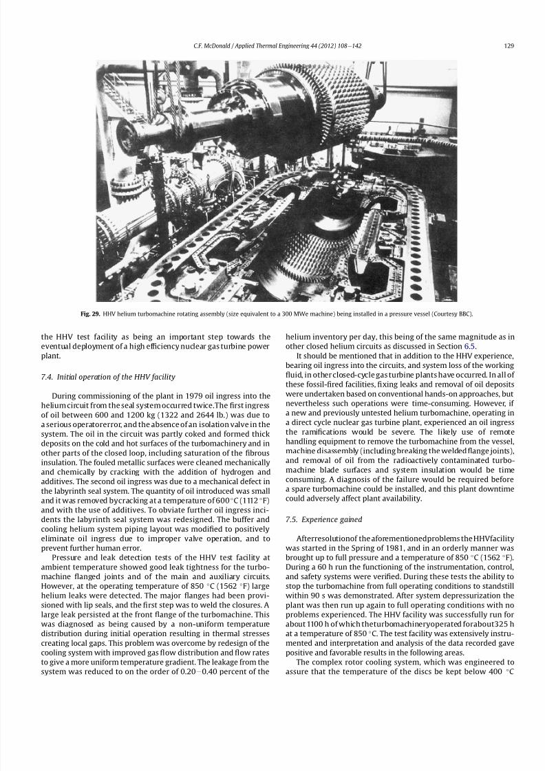
8112019 Helium Turbomachinery Operating Experience From Gas Turbine Power Plants
httpslidepdfcomreaderfullhelium-turbomachinery-operating-experience-from-gas-turbine-power-plants 2235
the HHV test facility as being an important step towards the
eventual deployment of a high ef 1047297ciency nuclear gas turbine power
plant
74 Initial operation of the HHV facility
During commissioning of the plant in 1979 oil ingress into the
helium circuit from the seal system occurred twiceThe 1047297rst ingressof oil between 600 and 1200 kg (1322 and 2644 lb) was due to
a serious operatorerror and the absence of an isolation valve in the
system The oil in the circuit was partly coked and formed thick
deposits on the cold and hot surfaces of the turbomachinery and in
other parts of the closed loop including saturation of the 1047297brous
insulation The fouled metallic surfaces were cleaned mechanically
and chemically by cracking with the addition of hydrogen and
additives The second oil ingress was due to a mechanical defect in
the labyrinth seal system The quantity of oil introduced was small
and it was removed bycracking at a temperature of 600 C (1112 F)
and with the use of additives To obviate further oil ingress inci-
dents the labyrinth seal system was redesigned The buffer and
cooling helium system piping layout was modi1047297ed to positively
eliminate oil ingress due to improper valve operation and toprevent further human error
Pressure and leak detection tests of the HHV test facility at
ambient temperature showed good leak tightness for the turbo-
machine 1047298anged joints and of the main and auxiliary circuits
However at the operating temperature of 850 C (1562 F) large
helium leaks were detected The major 1047298anges had been provi-
sioned with lip seals and the 1047297rst step was to weld the closures A
large leak persisted at the front 1047298ange of the turbomachine This
was diagnosed as being caused by a non-uniform temperature
distribution during initial operation resulting in thermal stresses
creating local gaps This problem was overcome by redesign of the
cooling system with improved gas 1047298ow distribution and 1047298ow rates
to give a more uniform temperature gradient The leakage from the
system was reduced to on the order of 020e
040 percent of the
helium inventory per day this being of the same magnitude as in
other closed helium circuits as discussed in Section 65
It should be mentioned that in addition to the HHV experience
bearing oil ingress into the circuits and system loss of the working
1047298uid in other closed-cycle gas turbine plants have occurred In all of
these fossil-1047297red facilities 1047297xing leaks and removal of oil deposits
were undertaken based on conventional hands-on approaches but
nevertheless such operations were time-consuming However if a new and previously untested helium turbomachine operating in
a direct cycle nuclear gas turbine plant experienced an oil ingress
the rami1047297cations would be severe The likely use of remote
handling equipment to remove the turbomachine from the vessel
machine disassembly (including breaking the welded 1047298ange joints)
and removal of oil from the radioactively contaminated turbo-
machine blade surfaces and system insulation would be time
consuming A diagnosis of the failure would be required before
a spare turbomachine could be installed and this plant downtime
could adversely affect plant availability
75 Experience gained
Afterresolutionof the aforementionedproblems the HHVfacilitywas started in the Spring of 1981 and in an orderly manner was
brought up to full pressure and a temperature of 850 C (1562 F)
During a 60 h run the functioning of the instrumentation control
and safety systems were veri1047297ed During these tests the ability to
stop the turbomachine from full operating conditions to standstill
within 90 s was demonstrated After system depressurization the
plant was then run up again to full operating conditions with no
problems experienced The HHV facility was successfully run for
about 1100 h of which theturbomachineryoperated forabout325 h
at a temperature of 850 C The test facility was extensively instru-
mented and interpretation and analysis of the data recorded gave
positive and favorable results in the following areas
The complex rotor cooling system which was engineered to
assure that the temperature of the discs be kept below 400
C
Fig 29 HHV helium turbomachine rotating assembly (size equivalent to a 300 MWe machine) being installed in a pressure vessel (Courtesy BBC)
CF McDonald Applied Thermal Engineering 44 (2012) 108e142 129
8112019 Helium Turbomachinery Operating Experience From Gas Turbine Power Plants
httpslidepdfcomreaderfullhelium-turbomachinery-operating-experience-from-gas-turbine-power-plants 2335
(752 F) was demonstrated to be effective The measured rotor
coolant 1047298ows (about 3 percent of the mass1047298ow passing through the
machine) were slightly larger than had been estimated and this
resulted in measured turbine disc temperatures lower than pre-
dicted [55]
The dynamic labyrinth shaft seal functioned well at the full
temperature and pressure conditions and met the requirement of
zero oil ingress into the helium circuit The measured rotor oscil-
lation did not have any adverse effect on the shaft sealing system
The static rotor seal (for shutdown conditions) functioned without
any problems
The compressor and turbine blading hadef 1047297ciencies higher than
predicted The structural integrity of the rotor proved to be sound
when operating at 3000 rpm under the maximum temperature and
pressure conditions The stiff rotor shaft had only slight unbalance
and thermal distortion and measured oscillations were in the range
typical of large steam turbines
Sound power spectrum measurements were taken in four
different locations in the circuit These were taken to determine the
spectrum and intensity of the sound generated and propagated by
the turbomachinery and the resultant vibration of internal
components The maximum sound power level in the helium
circuit was160 dB Numerous strain gages were placedin the circuitto determine the in1047298uence of the sound 1047297eld particularly on the
fatigue strength of the turbine inlet hot gas duct In later examining
the internal components there was no evidence of excessive
vibration of the components especially the ducting and the insu-
lation Based on the measurements and calculations it was
concluded that the fatigue strength limit of the components would
not be exceeded during the designed life of the planned commer-
cial nuclear gas turbine power plant
In a direct cycle nuclear gas turbine the hot gas duct used to
transport the helium from the reactor core to the turbineis a critical
component The hot gas duct in the HHV facility performed well
mechanically and con1047297rmed the adequacy of the thermal expan-
sion devices From the thermal standpoint the 1047297ber insulation
performed better than the metallic type
After dismantling the HHV facility there were no signs of
corrosion or erosion of the turbine or compressor blading While
the total number of hours operated was limited the coatings
applied to mating metallic surfaces to prevent galling and frictional
welding in the oxidation-free helium worked well
The helium buffer and cooling system worked well However
problems remained with the puri1047297cation of the buffer helium The
oil separation system consisting of a cyclone separator and a wire
mesh and a down stream 1047297ber 1047297lter needed further improvement
In late 1981 a decision was made to cancel the HHT project and
the HHV facility was shutdown The design and operational expe-
rience gained from the running of this facility would have been
extremely valuable had the nuclear gas turbine power plant
concept moved towards becoming a reality The identi1047297cation of
somewhat inevitable problems to be expected in such a complexturbomachine and their resolution were undertaken in a timely
and cost effective manner in the non-nuclear HHV facility This
should be noted for future nuclear gas turbine endeavors since
remedying such unexpected problems in the case of a new and
untested large helium turbomachine being operated for the 1047297rst
time using nuclear heat could result in very complex repair
Fig 30 Speci1047297
c speed-speci1047297
c diameter array for gas circulators in various gas-cooled nuclear plants
CF McDonald Applied Thermal Engineering 44 (2012) 108e142130
8112019 Helium Turbomachinery Operating Experience From Gas Turbine Power Plants
httpslidepdfcomreaderfullhelium-turbomachinery-operating-experience-from-gas-turbine-power-plants 2435
activities and extended plant downtime and indeed adding risk to
the overall success of the nuclear gas turbine concept
8 Circulators used in gas-cooled reactor plants
Circulators of different types will be needed in future helium
cooled nuclear plants these including the following 1) primary
loop circulator for possible next generation steam cycle power andcogeneration plants 2) for future indirect cycle gas turbine plants
3) shut down cooling circulators forall HTRand VHTR plants and 4)
for various circulators needed in future VHTR high temperature
process heat plant concepts The technology status of operated
helium circulators is brie1047298y addressed as follows
81 Background
It would be remiss not to mention experience gained in the past
with gas circulators and while not gas turbines they are rotating
machines that operate in the primary loop of a helium cooled
reactor With electric motor drives there are basically two types of
compressor rotor con1047297gurations namely radial and axial 1047298ow
machinesIn a single stage form the centrifugal impeller is used for high
stage pressure rise and low volume 1047298ow duties whereas the axial
type covers low pressure rise per stage and high volume 1047298ow The
selection of impeller type is very much related to the working
media type of bearings drive type rotor dynamic characteristics
and installation envelope A wide range of circulators have operated
and a well established technology base exists for both types [63] A
useful portrayal of compressor data in the form of quasi- non-
dimensional parameters (after Balje [64]) showing approximate
boundaries for operation of high ef 1047297ciency axial and radial types is
shown on Fig 30 (from Ref [65])
Both high speed axial and lower speed radial 1047298ow types are
amenable to gas oil and magnetic bearings From the onset of
modularHTR plant studies theuse of active magnetic bearings[6667]offered a solution to eliminate lubricating oil into the reactor circuit
and this tribology technology is attractive for use in submerged
rotating machinery in the next generation of HTR plants [68]
While now dated an appreciation of the main design features of
typical electric motor-driven helium circulators have been reported
previously namely an axial 1047298ow main circulator for a modular
steam cycle HTR plant [69] and a representative radial 1047298ow shut-
down cooling circulator [70]
The operating experience gained from three particular circula-
tors is brie1047298y included below because of their relevance to the
design of helium turbomachinery in future HTR plant variants
82 Axial 1047298ow helium circulator
Since all of the aforementioned predominantly European
helium gas turbines used axial 1047298ow turbomachinery it is of interest
to mention a helium axial 1047298ow circulator that operated in the USA
and to brie1047298y discuss its design parameters and features The
330 MW Fort St Vrain HTGR featured a Rankine cycle power
conversion system Four steam turbine driven helium circulators
were used to transport heat from the reactor core to the steam
generators The complete circulator assemblies were installed
vertically in the prestressed concrete reactor vessel [71e73]
A cross-section of the circulator is shown on Fig 31 with thecompressor rotor and stator visible on the left hand end of the
machine Based on early 1960rsquos technology a decision was made to
use water lubricated bearings and from the overall plant reliability
and availability standpoints this later proved to be a bad choice
Within the vertical circulator assembly there were four 1047298uid
systems namely the helium reactor coolant water lubricant in the
bearings steam for the turbine drive and high pressure water for
the auxiliary Pelton wheel drive During plant transients the pres-
sures and temperatures of these four 1047298uids oscillated considerably
and the response of the control and seal systems proved to be
inadequate and resulted in considerable water ingress from the
bearing cartridge into the reactor helium circuit The considerable
clean up time needed following repeated occurrences of this event
resulted in long periods of plant downtime and this had an adverseeffect on plant availability This together with other technical
Fig 31 Cross section of FSV helium circulator (Courtesy general Atomics)
CF McDonald Applied Thermal Engineering 44 (2012) 108e142 131
8112019 Helium Turbomachinery Operating Experience From Gas Turbine Power Plants
httpslidepdfcomreaderfullhelium-turbomachinery-operating-experience-from-gas-turbine-power-plants 2535
dif 1047297culties eventually contributed to the plant being prematurely
decommissioned
On the positive side in the context of this paper the helium
circulators operated for over 250000 h and exhibited excellent
helium compressor performance good mechanical integrity and
vibration-free operation The rotating assembly showing the axial
1047298ow compressor and steam turbine rotors together with a view of
the machine assembly are given on Fig 32 The helium compressor
consists of a single stage axial rotor followed by an exit guide vane
The machine was designed for axial helium 1047298ow entering and
leaving the stage and this can be seen from the velocity triangles
shown on Fig 33 which also includes the de1047297nition of the various
aerodynamic parameters Major design parameters and features of
this helium circulator are given on Table 4 Related to an earlier
discussion on the degree of reaction for axial 1047298ow compressors the
value for this conventional single stage circulator is 78 percent All
of the major aerothermal and structural loading criteria were
within established boundaries for an axial compressor having high
ef 1047297ciency and a good surge margin
The compressor gas 1047298ow path and blading geometries were
established based on prevailing industrial gas turbine and aero-
engine design practice A low Mach number (025) a high Reynolds
number (3 106) together with a modest stage loading (ie
a temperature rise coef 1047297cient of 044) and an acceptable value of
diffusion factor (042) were some of the factors that contributed to
a helium circulator that had a high ef 1047297ciency and a good pressure
rise- 1047298ow characteristic The large rotor blade chord and thick blade
section for this single stage circulator are necessary to accommo-
date the high bending stress characteristic of operation in a high
pressure environment The solidity and blade camber were opti-
mized for minimum losses
There were essentially two reasons for including this single-
stage axial 1047298ow compressor that operated in a helium cooled
reactor although its overall con1047297guration can be regarded as a 1047297rst
and last of a kind A rotor blade from this circulator as shown onFig 34 was based on a NASA 65 series airfoil which at the time
were one of the best performing cascades for such low Mach
number and high Reynolds number applications Interestingly it
has almost the same blade height aspect ratio and solidity as would
be used in the 1047297rst stage of an LP compressor in a helium turbo-
machine rated on the order of 250 MW
The second point of interest is that the helium mass 1047298ow rate
through the single stage axial compressor (rated at 4 MWe) is
110 kgs compared with 85 kgs through the multistage compressor
in the 50 MWe Oberhausen II helium gas turbine plant However
the volumetric 1047298ow through the Oberhausen axial compressor is
higher than that through the circulator by a factor of 16 this again
pointing out that the Oberhausen II plant was designed for high
volumetric 1047298ow to simulate the much larger size of turboma-chinery that was planned at the time in Germany for use in future
projected nuclear gas turbine power plants
83 High temperature helium circulator
For future helium turbomachines embodying active magnetic
bearings a challenge in their design relates to accommodating
elevated levels of temperature in the vicinity of the electronic
components In this regard it is of interest to note that a small very
high temperature helium axial 1047298ow circulator rated at 20 kW (as
shown on Fig 35) operated for more than 15000 h in an insulation
test facility in Germany more than two decades ago [74] The
signi1047297cance of this machine is that it operated with magnetic
bearings in a high temperature helium test loop with a circulatorgas inlet temperature of 950 C (1742 F) This necessitated the use
of ceramic insulation to ensure that the temperature in the vicinity
of the magnetic bearing electronics did not exceed a temperature of
about 150 C (300 F)
This machine although a very small axial 1047298ow helium blower
performed well and has been brie1047298y mentioned here since it
represents a point of reference for future helium rotating machines
capable operating with magnetic bearings in a very high temper-
ature helium environment
84 Radial 1047298ow AGR nuclear plant gas circulators
The electric motor-driven carbon dioxide circulators rated at
about 5 MW with a total runningtimein excess of 18 million hours
Fig 32 Fort St Vrain HTGR plant helium circulator (Courtesy General Atomics) (a)
Axial 1047298ow helium compressor and steam turbine rotating assembly (b) 4 MW helium
circulator assembly
CF McDonald Applied Thermal Engineering 44 (2012) 108e142132
8112019 Helium Turbomachinery Operating Experience From Gas Turbine Power Plants
httpslidepdfcomreaderfullhelium-turbomachinery-operating-experience-from-gas-turbine-power-plants 2635
in AGR nuclear power plants in the UK have demonstrated veryhigh availability [7576] To a high degree this can be attributed to
the fact that the machines were conservatively designed and proof
tested in a non-nuclear facility at full temperature and power
under conditions that simulated all of the nuclear plant operating
modes The test facility shown on Fig 36 served two functions 1)
design veri1047297cation of the prototype machine and 2) test of all new
and refurbished machines before they were installed in nuclear
plants Engineers currently involved in the design and development
of helium turbomachinery could bene1047297t from this sound testing
protocol to minimize risk in the deployment of helium rotating
machinery in future HTRVHTR plant variants
9 Helium turbomachinery development and testing
91 On-going development activities
The various helium turbomachines discussed in previous
sections operated over a span of about two decades starting in the
early 1960s From about 1990 activities in the nuclear gas turbine
1047297eld have been focused mainly on the design of modular GTeHTR
plant concepts In support of these plant studies many signi1047297cant
helium turbomachine design advancements have been made and
attention given to what development testing would be needed In
the last decade or so limited sub-component development has
been undertaken for helium turbomachines in the 250e300 MWe
size and these are brie1047298y summarized below
In a joint USARussia effort development in support of the
GTe
MHR turbomachine has been undertaken including testing in
the following areas magnetic bearings seals and rotor dynamicsfor the vertical intercooled helium turbomachine rated at 286 MWe
[77e80]
In Japan development activities have been in progress for
several years in support of the 274 MWe helium turbomachine for
the GTeHTR300 plant concept [2581] A detailed discussion on
the aerodynamic design of the axial 1047298ow helium compressor for
this turbomachine has been published in the open literature [82]
While the design methodology used for axial compressor design in
air-breathing industrial and aircraft gas turbines is generally
applicable for a multi-stage helium compressor a decision was
made by JAEA to test a small scale compressor in a helium facility
because of the inherent and unique gas 1047298ow path and type of
blading associated with operation in a high pressure helium
environment The major goal of the test was to validate the designof the 20 stage helium axial 1047298ow compressor for the GTeHTR300
plant
An axial 1047298ow compressor in a closed-cycle helium gas turbine is
characterized by the following 1) a large number stages 2) small
blade heights 3) high hub-to-tip ratio 4) a long annulus with
small taper that tends to deteriorate aerodynamic performance as
a result of end-wall boundary layer length and secondary 1047298ow 5)
low Mach number 6) high Reynolds number and 7) blade tip
clearances that are controlled by the gap necessary in the magnetic
journal and catcher bearings While (as covered in earlier sections)
helium gas turbines have operated there is limited data in the
open literature on the performance of multi-stage axial 1047298ow
compressors operating in a high pressure closed-loop helium
environment
Fig 33 Velocity triangles for axial compressor stage
CF McDonald Applied Thermal Engineering 44 (2012) 108e142 133
8112019 Helium Turbomachinery Operating Experience From Gas Turbine Power Plants
httpslidepdfcomreaderfullhelium-turbomachinery-operating-experience-from-gas-turbine-power-plants 2735
A 13rd scale 4 stage compressor was designed to simulate the
stage interaction the boundary layer growth and repeated stage
1047298ow in an actual compressor The 1047297rst four stages were designed to
be geometrically similar to the corresponding stages in the
GTe
HTR300 compressor Details of the model compressor havebeen discussed previously [81] and are summarized on Table 5
from [83]
A cross-section of the compressor test model is shown on Fig 37
A view of the 4 stage compressor rotor installed in the lower casing
is shown on Fig 38 The test facility (Fig 39) is a closed helium loop
consisting of the compressor model cooler pressure adjustment
valve and a 1047298ow measurement instrument The compressor is
driven by a 3650 kW electrical motor via a step-up gear The rota-
tional speed of 10800 rpm (three times that of the compressor in
the GTeHTR300 plant) was selected to match blade speed and
Mach number in the full size compressor
Details of the planned aerodynamic performance objectives of
the 13rd scale helium compressor test have been published
previously [84] Extensivetesting of the subscale model compressorprovided data to validate the performance of the full size
compressor for the GTeHTR300 power plant The test data and
test-calibrated CFD analyses gave added insight into the effect of
factors that impact performance including blade surface roughness
and Reynolds number
Based on advanced aerodynamic methodology and experi-
mental validation [82] there is now a sound basis for added
con1047297dence that the design goals of 90 percent polytropic ef 1047297ciency
and a design point surge margin of 20 percent are realizable in
a large multistage axial 1047298ow compressor for a future nuclear gas
turbine plant
In a similar manner a design of a one third size single stage
helium axial 1047298ow turbine has been undertaken and a cross
section of the machine is shown on Fig 40 (from Ref [81]) This
Table 4
Major features of axial 1047298ow helium circulator
Helium 1047298ow rate kgsec 110
Inlet temperature C 394
Inlet pressure MPa 473
Pressure rise KPa 965
Volumetric 1047298ow m3sec 32
Compressor type Single stage axial
Compressor drive Steam turbine
Bearing type Water lubricated
Rotational speed rpm 9550
Power MW 40
Rotor tip diameter mm 688
Rotor tip speed msec 344
Number of rotor blades 31
Number of stator blades 33
Blade height mm 114
Hub-to-tip ratio 067
Axial velocity msec 157
Flow coef 1047297cient 055
Temperature rise coef 1047297cient 044
Degree of reaction 078
Mean rotor solidity 128
Rotor aspect ratio 155
Rotor Mach number 025
Rotor diffusion factor 042
Rotor Reynolds number 3106
Speci1047297c speed 335
Speci1047297c diameter 066
Blade root thickness 15
Airfoil type NASA 65
Rotor blade chord mm 94e64
Stator blade chord mm 79
Rotor centrifugal stress MPa 125
Rotor bending stress MPa 30
Circulator(s) operating Hours gt250000
Fig 34 Rotor blade from single stage axial 1047298ow helium circulator (Courtesy General
Atomics)
Fig 35 20 kW axial 1047298ow helium circulator with magnetic bearings operated in 1985 in
an insulation test loop with a gas inlet temperature on 950
C (Courtesy BBC)
CF McDonald Applied Thermal Engineering 44 (2012) 108e142134
8112019 Helium Turbomachinery Operating Experience From Gas Turbine Power Plants
httpslidepdfcomreaderfullhelium-turbomachinery-operating-experience-from-gas-turbine-power-plants 2835
single stage scale model turbine for validity of the full size turbine
has been built and plans made to test the aerodynamic
performance
92 Nuclear gas turbine helium turbomachine testing
In planning for the 1047297rst nuclear gas turbine plant projected to
enter service perhaps in the third decade of the 21st century
a major decision has to be made as to what extent the large helium
turbomachine should be tested prior to operation on nuclear heat
Issues essentially include cost impact on schedule but the over-
riding one is risk Certainly turbomachine component testing will
be undertaken including the compressor (as discussed in the
previous section) and turbine performance seals cooling systems
hot gas valves thermal expansion devices high temperature
insulation rotor fragment containment diagnostic systems
instrumentation helium puri1047297cation system and other areas to
satisfy safety licensing reliability and availability concerns The
major point is really whether a full size or scaled-down turbo-machine be tested early in the project in a non-nuclear facility
To obviate the need for pre-nuclear testing of a large helium
turbomachine a view expressed by some is that advantage can be
taken of formidable technology bases that exist today for large
industrial gas turbines and high performance aeroengines On the
other hand it is the view of some including the author that very
complex power conversion system components especially those
subjected to severe thermal transients donrsquot always perform
exactly as predicted by analysts and designers even using sophis-
ticated computer codes This was exempli1047297ed in the case of the
turbomachine in the aforementioned Oberhausen II helium gas
turbine plant
The need for a helium turbomachine test facility goes beyond
just veri1047297
cation of the prototype machine Each newgas turbine for
commercial modular nuclear reactor plants would have to be proof
tested and validated before being transported to the reactor site
Similarly turbomachines that would be periodically removed from
the plant at say 7 year intervals during the plant operating life of 60
years for scheduled maintenance refurbishment repair or updat-ing would be again proof tested in the facility before re-entering
service
The direction that turbomachine development and testing will
take place for future helium gas turbines needs to be addressed by
the various organizations involved
Fig 36 AGR circulator test facility In the UK (Courtesy Howden)
Table 5
Major design parametersfeatures of model GTeHTR300 axial 1047298ow helium
compressor (Courtesy JAERI)
Scale of GTeHTR300 compressor 13
Helium mass 1047298ow rate (kgsec) 122
Helium volumetric 1047298ow rate (mV s) 87
Inlet temperature C 30
Inlet pressure MPa 0883Compressor pressure ratio at design point 1156
Number of stages 4
Rotational speed rpm 10800
Drive motor power kW 3650
Hub diameter mm 500
Rotor tip diameter (1st4th stage mm) 568566
Hub-to-tip ratio (1st stage) 088
Rotor tip speed (1st stage msec) 321
Number of rotorstator blades (1st stage) 7294
Rotorstator blade height (1st stage mm) 34337
Rotor stator blade c hor d l eng th (1st stage mm) 2620
Rotorstator solidity (1st stage) 119120
Rotorstator aspect ratio (1st stage) 1317
Flow coef 1047297cient 051
Stage loading factor 031
Reynolds number at design point 76 l05
CF McDonald Applied Thermal Engineering 44 (2012) 108e142 135
8112019 Helium Turbomachinery Operating Experience From Gas Turbine Power Plants
httpslidepdfcomreaderfullhelium-turbomachinery-operating-experience-from-gas-turbine-power-plants 2935
10 Helium turbomachinery lessons learned
101 Oberhausen II gas turbine and HHV test facility
It is understandable that 1047297rst-of-a-kind complex turboma-
chinery operating with an inert low molecular weight gas such as
helium will experience unique and unexpected problems In the
operation of the two pioneering large helium turbomachines in
Germany there were many positive1047297ndings which could only have
been achieved by development testing Equally important some
negative situations were identi1047297ed many of which were remedied
In the case of the Oberhausen II helium gas turbine plant some of
the very serious problems encountered were not resolved Inves-
tigations were undertaken to rationalize the problems associated
with the large power de1047297ciency and a data base established to
ensure that the various anomalies identi1047297ed would not occur in
future large helium turbomachines
The experience gained from the operation of the Oberhausen II
helium gas turbine power plant and the HHV test facility have been
discussedin thetextand arepresentedin a summaryformon Table6
Fig 37 Cross-section of 13rd scale helium compressor test model (Courtesy JAEA)
Fig 38 Four stage helium compressor rotor assembly installed in lower casing (Courtesy JAEA)
CF McDonald Applied Thermal Engineering 44 (2012) 108e142136
8112019 Helium Turbomachinery Operating Experience From Gas Turbine Power Plants
httpslidepdfcomreaderfullhelium-turbomachinery-operating-experience-from-gas-turbine-power-plants 3035
102 Impact of 1047297ndings on future helium gas turbine
The long slender rotorcharacteristic of closed-cycle gas turbines
has resulted in shaft dynamic instability which in some cases has
resulted in blade vibration and failure and bearing damage This
remains perhaps the major concern in the design of large
(250e
300 MW) helium turbomachines for future nuclear gas
turbine plants With pressure ratios in the range of about 2e3 in
a helium system a combination of splitting the compressor (to
facilitate intercooling) and having a large number of compressor
and turbine stages results in a long and 1047298exible rotating assembly
andthis is exempli1047297ed by the rotorassembly shown on Fig13 With
multiple bearings (either oil lubricated or magnetic) the rotor
would likely pass through multiple bending critical speeds before
Fig 39 Helium compressor test facility (Courtesy JAEA)
Fig 40 Cross-section of single stage helium turbine test model (Courtesy JAEA)
CF McDonald Applied Thermal Engineering 44 (2012) 108e142 137
8112019 Helium Turbomachinery Operating Experience From Gas Turbine Power Plants
httpslidepdfcomreaderfullhelium-turbomachinery-operating-experience-from-gas-turbine-power-plants 3135
reaching the design speed While very sophisticated computer
codes will be used in the detailed rotor dynamic analyses the real
con1047297rmation of having rotor oscillations within prescribed limits
(to avoid blade bearing and seal damage) will come from actual
testingA point to be made here is that in operated fossil-1047297red closed-
cycle gas turbine plants it was possible to remedy problems asso-
ciated with rotor vibrations and blade failures in a conventional
manner In fact in some situations the casings were opened several
times and modi1047297cations made to facilitate bearing and seal
replacement and rotor re-blading and balancing
An accurate assessment of pressure losses must be made
particularly those associated with the helium entering and leaving
the turbomachine bladed sections Minimizing the system pressure
loss is important since it directly impacts the all important quotient
of turbine expansion ratio to compressor pressure ratio and power
and plant ef 1047297ciency
Based on the operating experience from the 20 or so fossil-1047297red
closed-cycle gas turbine plants using air as the working1047298
uid it was
recognized that future very high pressure helium gas turbines
would pose problems regarding the various seals in the turbo-
machine and obtaining a zero leakage system with such a low
molecular weight gas would be dif 1047297cult and this is discussed
below
When the Oberhausen II gas turbine plant and the HHV facility
operated over 30 years ago oil lubricated bearings were used to
support the heavy rotor assemblies and helium buffered labyrinth
seals were used to prevent oil ingressinto the heliumworking1047298uid
Initial dif 1047297culties encountered in both plants were overcome by
changes made to the seal geometries and for the operating lives of
the helium turbomachines no further oil ingress events were
experienced Twoseals were required where the turbine drive shaft
penetrated the turbomachine casing namely 1) a dynamic laby-
rinth seal and 2) a static seal for shutdown conditions In both
plants these seals functioned without any problems
Labyrinth seals were also required within the helium turbo-
machines to pass the correct helium bleed 1047298ow from the
compressor discharge for cooling of the turbine discs blade root
attachments and casings The fact that the very complex rotor
cooling system in the large helium turbomachine in the HHV test
facility operated well for the test duration of about 350 h with
a turbine inlet temperature of 850 C was encouragingIn the case of the Oberhausen II gas turbine plant analysis of the
test data revealed that the labyrinth seal leakage and excessive
cooling 1047298ows were on the order of four times the design value A
possible reason for this was that damage done to the labyrinth
seals caused excessive clearances when periods of excessive rotor
oscillation and vibration occurred during early operation of the
machine
Clearly 1047298uid dynamic and thermal management of the cooling
system and 1047298ow through the various labyrinth seals will require
extensive analysis design and development testing before the
turbomachine is operated on nuclear heat for the 1047297rst time
In future heliumgas turbine designs (with turbine inlet tempera-
tureslikelyontheorderof950C)the1047298owpathgeometriesofhelium
bledfromthecompressornecessarytocoolpartsoftheturbomachinewillbemorecomplexthanthosetestedto-dateInadditiontoproviding
acooling1047298owtotheturbinebladesanddiscsbladerootattachmentsand
casingsheliummustbetransportedtotheseveralmagneticbearingsto
ensure thatthe temperatureof theirelectronic components doesnot
exceedabout150C
The importance of the points made above is evidenced when
examining the data on Table 3 where a combination of excessive
pressure losses and high bleed 1047298ows contributed to about 40
percent of the power de1047297ciency in the Oberhausen II helium
turbine plant
Retaining overall system leak tightnessin closed heliumsystems
operating at high pressure and temperature has been elusive
including experience from the Fort St Vrain HTGR plant as dis-
cussed in Section 65 New approaches in the design of the plethoraof mechanical joints must be identi1047297ed Experience to-date has
shown that having welded seals on 1047298anges while minimizing
system leakage did not eliminate it
The importance of lessons learned from the operation of the
Oberhausen II helium turbine power plant and the HHV test facility
have primarily been discussed in the context of helium turbo-
machines currently being designed in the 250e300 MWe power
range However the established test data bases could also be
applied to the possible emergence in the future of two helium
cooled reactor concepts namely 1) an advanced VHTR combined
cycle plant concept embodying a smaller helium gas turbine in the
power range of 50e80 MWe [22] and 2) the use of a direct cycle
helium gas turbine PCS in a recently proposed all ceramic fast
nuclear reactor concept [85]
Table 6
Experience gained from Oberhausen II and HHV facility
Oberhausen II 50 MW helium gas turbine power plant
Positive results
e Rotating and static seals worked well
e No ingress of bearing lubricant oil into closed circuit
e Load change by inventory control worked well
e 100 Percent load shed by means of bypass valves demonstrated
e Turbine disc and blade root cooling system con1047297rmed
e Coatings on mating surfaces prevented galling and self-welding
e After 24000 h of operation no evidence of corrosion or erosion
e Coaxial turbine hot gas inlet duct insulation and integrity con1047297rmed
e Monitoring of complete power conversion system for steady state
and transient operation undertaken
Problem areas
e Serious power output de1047297ciency (30 MW compared with design
value of 50 MW)
e Compressor(s) and turbine(s) ef 1047297ciencies several points below predicted
e Higher than estimated system pressure loss
e Rotor dynamic instability and blade vibration
e Bearings damaged and had to be replaced
e Blade failure caused extensive damage in HP turbine but retained
in casing
e Very excessive sealing and cooling 1047298ow rates
e Absolute leak tightness not attainable even with welded 1047298ange lips
HHV test facility
Positive resultse Use of heat pump approach facilitated helium temperature capability
to 1000 C
e Large oompressorturbine rotor system operated at 3000 rpm Complex
turbine disc and blade root cooling system veri1047297ed
e Dynamic and static seals met requirement of zero oxl ingress into circuit
e Structural integrity of rotating assembly veri1047297ed at temperature of 850 C
e Measured rotor oscillations within speci1047297cation
e Compressor and turbine ef 1047297ciencies higher than predicted
e Coatings on mating metallic surfaces prevented galling and self-welding
e Instrumentation control and safety systems veri1047297ed
e Seal 1047298ows within speci1047297cation
e Machine stop from operating speed to shutdown in 90 s demonstrated
e Hot gas duct insulation and thermal expansion devices worked well
e After 1100 h of operation no evidence of corrosionof erosion
Problem areas
e Before commissioning a large oil ingress into the circuit occurred due
to serious operator error and absence of an isolation valve A second oilingress occurred due to a mechanical defect in the labyrinth seal system
These were remedied and no further oil ingress was experienced for the
duration of testing
e Cooling 1047298ows slightly larger than expected but this resulted in actual
disc and blade root temperatures lower than the predicted value of
400 C
e System leak tightness demonstrated when pressurized at ambient
temperature conditions but some leakage occured at 850 C even with
the seal welding of 1047298ange(s) lips
CF McDonald Applied Thermal Engineering 44 (2012) 108e142138
8112019 Helium Turbomachinery Operating Experience From Gas Turbine Power Plants
httpslidepdfcomreaderfullhelium-turbomachinery-operating-experience-from-gas-turbine-power-plants 3235
11 New technologies
It is recognized that in the 3 to 4 decades since the operation of
the helium turbomachines covered in this paper new technologies
have emerged which negate some of the early issues An example of
this is the technology transfer from the design of modern axial 1047298ow
gas turbines (ie industrial aircraft and aeroderivatives) that fully
utilize sophisticated CAE CAD CFD and FEA design software
Air breathing aerodynamic design practice for compressors and
turbines are generally applicable but the properties of helium and
the high system pressure have a signi1047297cant impact on gas 1047298ow
paths and blade geometries With short blade heights high hub-to-
tip ratios long annulus 1047298ow path length (with resultant signi1047297cant
end-wall boundary layer growth and secondary 1047298ow) and blade tip
clearances in some cases controlled by clearances in the magnetic
catcher bearing testing of subscale model compressors and
Fig 41 Gas turbine test facility for aircraft nuclear propulsion involving the coupling of a 32 MWt air-cooled reactor with two modi 1047297ed J-47 turbojet aeroengines each rated at
a thrust of about 3000 kg operated in 1960 (Courtesy INL)
Fig 42 Mobile 350 KWe closed-cycle nuclear gas turbine power plant operated in 1961 (Courtesy US Army)
CF McDonald Applied Thermal Engineering 44 (2012) 108e142 139
8112019 Helium Turbomachinery Operating Experience From Gas Turbine Power Plants
httpslidepdfcomreaderfullhelium-turbomachinery-operating-experience-from-gas-turbine-power-plants 3335
turbines will be needed While most of the operated helium tur-
bomachines discussed in this paper took place 3 or 4 decades ago it
is encouraging that the fairly recent test data and test-calibrated
CFD analysis from a subscale four stage model helium axial 1047298ow
compressor in Japan [80] gave a high degree of con1047297dence that
design goals are realizable for the full size 20 stage compressor in
the 274 MWe GTeHTR300 plant turbomachine
In the future the use of active magnetic bearings will eliminate
the issue of oil ingress however the very heavy rotor weight and
size of the journal and thrust bearings (and catcher bearings) of the
type for helium turbomachines in the 250e300 MWe power range
are way in excess of what have been demonstrated in rotating
machinery For plant designs retaining oil-lubricated bearings well
established dry gas seal technology exists particularly experience
gained from the operation of high pressure natural gas pipe line
compressors
For future nuclear helium gas turbine plants the designer has
freedom regarding meeting different frequency requirements that
exist in some countries These include use of a synchronous
machine (ie designed for 50 or 60 Hz grids) use of a gearbox drive
between the turbine and generator or the use of a frequency
converter which gives the designer an added degree of freedom
regarding the selection of speed for the rotating assemblyCompared with the past very sophisticated electronic control
systems instrumentation and diagnostic systems are available
today
12 Conclusions
In this review paper experience from operated helium turbo-
machines has been compiled based on open literature sources At
this stage in the evolution of HTR and VHTR plant concepts it is not
clear in what role form or time-frame the nuclear gas turbine will
emerge when commercialized By say the middle of the 21st
century all power plants will be operating with signi1047297cantly higher
ef 1047297ciencies to realize improved power generation costs and
reduced emissions In a nuclear gas turbine the helium turbo-machine will be a major contributor towards the achievement of
ef 1047297ciencies higher than 50 percent
While it has been 3 to 4 decades since the Oberhausen II helium
turbine power plant and the HHV high temperature helium turbine
facility operated signi1047297cant lessons were learned and the time and
effort expended to resolve the multiplicity of unexpected technical
problems encountered The remedial repair work was done under
ideal conditions namely that immediate hands-on activities were
possible This would not have been possible if the type of problems
experienced had been encountered in a new and untested helium
turbomachine operated for the 1047297rst time with a nuclear heat
source
While new technologies have emerged that negate many of the
early problems there are some uniquely inherent issues associatedwith for large helium turbines operating in a high pressure and
temperature environment and these include the following 1)
minimizing system leakage with such a low molecular weight gas
2) clearances in labyrinth seals to minimize helium bypass1047298ows 3)
the dynamic stability of long slender rotors 4) minimizing the
turbomachine inlet and outlet pressure losses 5) 1047298ow maldis-
tribution in complex ductturbomachine interfaces 6) integrity
veri1047297cation of the catcher bearings (journal and thrust) after
multiple rotor drops (following loss of the magnetic 1047297eld) during
the plant lifetime 7) assurances that high energy fragments from
a failed turbine disc are contained within the machine casing 8)
turbomachine installation and removal from a steel pressure vessel
and 9) remote handling and cleaning of a machine with turbine
blades contaminated with 1047297
ssion products
The need for a helium turbomachine test facility has been
emphasized to ensure that the integrity performance and reli-
ability of the machine before it operates the 1047297rst time on nuclear
heat Engineers currently involved in the design of helium rotating
machinery for all HTR and VHTR plant variants should take
advantage of the experience gained from the past operation of
helium turbomachinery
13 In closing-GT rsquos operated with nuclear heat
In the context of this paper it is germane to mention that two
gas turbines have actually operated using nuclear heat as brie1047298y
highlighted below
In the late 1950rsquos a program was initiated in the USA for aircraft
nuclear propulsion (ANP) While different concepts were studied
only the direct cycle air-cooled reactor reached the stage of
construction of an experimental reactor [86] A view of the large
nuclear gas turbine facility is given on Fig 41 and shows the air-
cooled and zirconiumehydride moderated reactor rated at
32 MWt coupled with two modi1047297ed J-47 turbojet engines each
rated with a thrust of about 3000 kg In this open cycle system the
high pressure compressor air was directly heated in the reactor
before expansion in the turbine and discharge to the atmosphere in
the exhaust nozzle The facility operated between 1958 and 1961 at
the Idaho reactor testing facility While perhaps possible during the
early years of the US nuclear program it is clear that such a system
would not be acceptable today from safety and environmental
considerations
The 1047297rst and indeed the only coupling of a closed-cycle gas
turbine with a nuclear reactor for power generation was under-
taken to meet the needs of the US Army In the late 1950 rsquos an RampD
program was initiated for a 350 kW trailer-mounted system to be
used in the 1047297eld by military personnel A prototype of the ML-1
plant shown on Fig 42 was 1047297rst operated in 1961 [8788]
It was based on a 33 MW light water moderated pressure tube
reactor with nitrogen as the coolant The closed-cycle gas turbine
power conversion system with nitrogen as the working 1047298uid hada turbine inlet temperature of 649 C (1200 F) and delivered
around 300 kW With changes in the Armyrsquos needs the project was
discontinued in 1965
While the experience gained from the above twounique nuclear
plants is clearly not relevant for future nuclear gas turbine power
plants that could see service in the third decade of the 21st century
these ambitious and innovative nuclear gas turbine pioneering
engineering efforts need to be recognized
Acknowledgements
The author would like to thank the following for helpful discus-
sions advice and for providing valuable comments on the initial
paper draft Prof Dr Hermann Haselbacher Hans Ulrich Frutschi DrXing Yan DrPeter Zenker Professor DavidGordon Wilson Professor
Aristide Massardo Arthur Harris DrFred Starr and DrGuido Bac-
caglini This paper has been enhanced by the inclusion of hardware
photographs and unique sketches and the author is appreciative to
all concerned with credits being duly noted
References
[1] C Keller The Escher Wyss AK Closed-Cycle Gas Turbine Its Actual Develop-ment and Future Prospects Paper Presented at ASME Meeting November 261945
[2] HU Frutschi Closed-Cycle Gas Turbines Operating Experience and FuturePotential ASME Press NY 2005
[3] CF McDonald The Nuclear Gas Turbine-Towards Realization After Half
a Century of Evolution (1995) ASME Paper 95-GT-292
CF McDonald Applied Thermal Engineering 44 (2012) 108e142140
8112019 Helium Turbomachinery Operating Experience From Gas Turbine Power Plants
httpslidepdfcomreaderfullhelium-turbomachinery-operating-experience-from-gas-turbine-power-plants 3435
[4] C Keller The Theory and Performance of Axial Flow Fans McGraw Hill BookCompany Inc NY 1937
[5] J Ackert C Keller Aerodynamic turbine with closed circuit In A Century of Turbines vols 1516 Escher Wyss News 1942e43 5e19
[6] Escher Wyss News Closed-Cycle Gas Turbines for all Fuels Coal Gas Nuclearvol 39 No 1 (1966)
[7] C Keller Closed-cycle gas turbine Escher Wyss-AK development 1945e1950Transactions of ASME (August 1950) 835e850
[8] C Keller Operating Experience and Design Features of Closed-Cycle GasTurbine Power Plants (1956) ASME Paper 56-GTP-15
[9] C Keller HU Frutschi Closed-cycle plants -conventional and nuclear designapplication operation In Sawyerrsquos Gas Turbine Engineering Handbooksecond ed vol 2 Applications (1976) pp 265e283
[10] K Bammert G Groschup Status Report on Closed-Cycle Power Plants in theFederal Republic of Germany (1976) ASME Paper 76-GT-54
[11] JL Mason Monatomic Working Gases versus Air for Closed Brayton Cycles(1985) ASME Paper 85-IGT-50
[12] JL Mason et al 5 MW Closed Cycle Gas Turbine (1984) ASME Paper 84-GT-268
[13] The British Gas Closed-Cycle Demonstrator (1995) British Gas Research ampTechnology Final Year Report
[14] F Starr ODS alloy high temperature heat exchanger prototype developmentPaper Presented at ODS 2010 Materials Workshop UCSD Jacobs Hall La JollaCalifornia Nov17e18 2010
[15] CA Rennie Achievements of the Dragon project Pergamon Press Annals of Nuclear Energy 5 (1978) 305e320
[16] SB Hosegood et al Dragon Project Engineering Studies on the Direct CycleHTR Proceedings of Conference on Nuclear Gas Turbines The British NuclearEnergy Society London April 8e9 1970 pp 161e179
[17] Nuclear Gas Turbines Proceedings of British Nuclear Society Meeting LondonApril 8-9 1972
[18] CF McDonald C Peinado ldquoThe nuclear gas Turbine-A perspective on a long-term advanced technology HTGR plant Optionrdquo ASME Paper 82-GT-289
[19] GH Lohnert et al Technical design features and essential safety-relatedfeatures of the HTR-Module Nuclear Engineering and Design 121 (1990)259e275
[20] H Reutler GH Lohnert The modular high temperature nuclear reactorNuclear Technology 62 (1983) 22e30
[21] CF McDonald Exploitation of the very high temperature capability of theMHTGR to meet National energy needs after the year 2000 IECEC Paper869006
[22] CF McDonald Power conversion system considerations for an advancednuclear gas turbine (GT-VHTR) CHHP demonstration plant concept Interna-tional Journal of Turbo amp Jet Engines 27 (2010) 179e217
[23] N Hee Cheon et al A review of helium gas turbine technology for hightemperature gas cooled reactors Nuclear Engineering and Design 29 (2007)21e30
[24] CB Baxi et al Development of the GT-MHR Turbomachine ASME PaperGT2009e59450[25] X Yan GTHTR300 design and development Nuclear Engineering and Design
222 (2003) 247e262[26] JC Gauthier et al ANTARES the HTRVHTR project of Framatome ANP
Nuclear Engineering and Design 236 (2006) 526e533[27] J Wang et al ldquoDesign features of gas turbine power conversion system for
HTR-10GT paper D05 presented at 2nd Intl Meeting on HTR TechnologyBeijing China September 21e24 2004
[28] A Koster et al ldquoPBMR Design For the Futurerdquo Nuclear engineering andDesign 222 (203) 231e245
[29] S van der Linden Closed cycle nuclear plant rated at 165 MWe and 40 percentef 1047297ciency Gas Turbine World (MarcheApril 2007) 28e32
[30] CF McDonald Large closed-cycle gas turbines Sawyerrsquos gas turbine engi-neering handbook In Selection and Applications vol II (1985) pp 81e38(Chapter 8)
[31] CF McDonald Helium and Combustion Gas Turbine Power ConversionSystems Comparison (1995) ASME Paper 95-GT-263
[32] JK La Fleur Description of an Operating Closed-Cycle Helium Gas Turbine
ASME Paper 63-AHGT-74[33] JK La Fleur The use of turbomachinery in the 1047297eld of cryogenics In
Sawyerrsquos Gas Turbine Engineering Handbook vol II (1976) 296e311[34] W Spillmann The Closed-Cycle Gas Turbine for Non-Conventional Applica-
tions ASME Paper 66-GT-8[35] K Holliger On the in1047298uence of the degree of reaction on the secondary losses
in axial 1047298ow compressors Escher Wyss News 23 (1960)[36] W Gut Comparison of the relative losses and characteristics of axial
compressor stages Escher Wyss News 23 (1959)[37] JH Horlock Axial Flow Compressors Butterworths Scienti1047297c Publications
London 1958 pp 92e93[38] G Deuster Long-term Operating Experience with Oberhausen I Closed-Cycle
Gas Turbine Power Plant (1970) ASME Paper 70-GT-73[39] G Noak Signi1047297cance of the Helium Turbine Power Plant at Oberhausen (EVO)
and the High Temperature Helium Test Facility (HHV) at Julich for theDevelopment of HTR Direct Cycle (HHT) IAEA Publication SM-20026 Vienna1970 189e200
[40] K Bammert G Deuster Layout and Present Status of the Closed-Cycle HeliumTurbine Plant Oberhausen II (1974) ASME Paper 74-GT-132
[41] P Zenker The Oberhausen 50 MW helium turbine plant Combustion 47 (2)(April 1976)
[42] K Bammert et al Operation and Control of the 50 MW Closed Cycle HeliumTurbine Plant Oberhausen (1974) ASME Paper 74-GT-13
[43] P Zenker 10 years operating experience with the Oberhausen II heliumturbo-generator plant VGB Krafswerkstechnik 68 (7) (July 1998) 616e621
[44] K Bammert G Deuster The First Operating Experiences With the OberhausenHelium Turbine Plant Paper Presented at ASME Gas Turbine Conference NewOrleans March 21e25 1976
[45] G Deuster P Zenker Operation of the Oberhausen Helium Turbine Plant
Paper Presented at ASME Gas Turbine Conference London April 1978[46] P Zenker Operating Experience of the Oberhausen Helium Turbine Plant
Paper Presented at ASME Gas Turbine Conference San Diego 1979[47] G Deuster P Zenker Further Operating Experience of the Oberhausen Helium
Turbine Plant Paper Presented at ASME Gas Turbine Conference NewOrleans 1980
[48] P Zenker Past Experience and Future Prospects of Closed-Cycle Gas TurbinesPaper Presented at ASME Gas Turbine Conference London April 18e22 1982
[49] IA Weisbrodt Summary Report on Technical Experiences from HighTemperature Helium Turbine Testing in Germany Report IAEA-TECDOC-899Vienna Nov 1994
[50] F Bentivoglio G Geffraye Validation of the CATHARE Code Against Experi-mental Data from Brayton Cycle Plants Paper C00000228 Proceedings of HTR 2006 Johannesburg October 1e4 2006
[51] E Arndt HHT-Demonstration Plant Paper Presented at European NuclearConference Hamburg May 6 1979
[52] G Hebel HHV-Anlage Erfahrungen bei Bau und Inbetriebnahme Atom-wirtschaft(5) (1982) 258e262
[53] H Haselbacher A Eierman Development of Helium Gas Turbine in NuclearField (1974) ASME Paper 74-GT-123
[54] H Haselbacher The HHT Helium Gas Turbine and HHV Plant Paper A421 5thInternational Fair and Technical Meeting of Nuclear Industry BaselSwitzerland October 3e7 1978
[55] H Haselbacher HJ Sponholz Cooling and Insulating Problems in a HighTemperature Helium Test Facility (1984) ASME Paper 84-GT-253
[56] C Keller D Schmidt The Helium Gas Turbine for Nuclear Power Plants (1967)ASME Paper 67-GT-10
[57] W Endres Large Helium Turbine for Nuclear Power Plants (1970) ASME Paper70-GT-99
[58] JN Hurst Gas turbomachinery for helium cooled reactors in Proceedings of International Conference on Nuclear Gas Turbines British Nuclear SocietyLondon April 8 1970 pp 45e50
[59] K Bammert Nuclear Gas Turbine of Large Output for HHT Plant (1974) ASMEPaper 74-GT-10
[60] CF McDonald The Nuclear Closed-Cycle Gas Turbine (GT-HTGR) e A UtilityPower Plant for the Year 2000 (1979) AIAA Paper 79e0191
[61] CF McDonald MJ Smith Turbomachinery design considerations for the
nuclear HTGR-GT power plant ASME Journal of Engineering for Power 103 (1)(January 1981) 65e77[62] CF McDonald et al Helium Turbomachine Design for GT-MHR Power Plant
(1994) ASME Paper 94-JPGC-NE-12[63] Gas Cooled Reactor Coolant Circulator and Blower Technology (1988) IAEA
Report IWGGCR17[64] OE Balje Turbomachines A Guide to Design Selection and Theory John
Wiley amp Sons NY 1981[65] CF McDonald et al Circulator DesignTechnology Evolution for Gas Cooled
Reactors (1992) ASME Paper 92-GT-79[66] J Donaldson Application of Magnetic Bearings to Helium Circulators for High
Temperature Gas Cooled Reactors (1987) IECEC Paper 879419[67] CF McDonald Active Magnetic Bearings for Rotating Machinery in Closed-
Cycle Power Plant Systems (1989) ASME Paper 89-WANE-5[68] JA Rennie CF McDonald Active Magnetic Bearings for Rotating Machinery
in Future Gas Cooled Reactor Plants Paper Presented at 4th Intl Symposiumon Magnetic Bearings ETH Zurich August 23e26 1994
[69] CF McDonald MK Nichols Helium Circulator Design Considerations forModular High Temperature Gas Cooled Power Plant (1987) ASME Paper 87-
GT-138[70] CF McDonald Shutdown Cooling Helium Circulator Design Considerations
for MHTGR Power Plant (1989) ASME Paper 89-WANE-5[71] J Yampolsky Steam Turbine Driven Circulators for High Temperature Gas
Cooled Reactors Part I Design (1972) ASME Paper 72-WANE-20[72] VJ Barbat Steam Turbine Driven Circulators for High Temperature Gas
Cooled Reactors Part II Development (1972) ASME Paper 72-WANE-21[73] L Cavallaro J Yampolsky Design and development of a steam turbine driven
circulator for high temperature gas cooled reactors Nuclear Engineering andDesign (1974) 135e147
[74] J Henssen et al Facility for fatigue testing of thermal insulation BBC Review72 (6) (1985)
[75] J Donaldson Development of Carbon Dioxide Circulators IAEA ReportIWGGCR17 (1988) pp 47e63
[76] Personal Communication from John Donaldson (April 7 2006)[77] NG Kodochigov et al Development of the GT-MHR Vertical Turbomachine
Design ASME Paper HTR2008-58309[78] CB Baxi et al ldquoRotor Scale Model Tests for Power Conversion Unit of GT-
MHR rdquo ASME Paper HTR 2008e58015
CF McDonald Applied Thermal Engineering 44 (2012) 108e142 141
8112019 Helium Turbomachinery Operating Experience From Gas Turbine Power Plants
httpslidepdfcomreaderfullhelium-turbomachinery-operating-experience-from-gas-turbine-power-plants 3535
[79] NG Kodochibov et al Development of Catcher Bearings for the GT-MHR Turbomachine(Oct 18e20 2010)Proceedings of HTR 2010Paper 025Prague
[80] IV Drumov et al Studies of the Electromagnetic Suspension System for theGT-MHRTurbomachineProceedings of HTR2010Paper041 Oct18e20 (2010)
[81] T Takizuka et al RampD on the power conversion system for the gas turbinehigh temperature reactor Nuclear Engineering and Design 233 (2004)239e346
[82] X Yanet alAerodynamic design model test and CFDanalysisfor a multistageaxialhelium compressor ASME Journal of Turbomachinery 130 (3) (July2008)
[83] S Takada et al The 13rd Scale Aerodynamic Performance Test of Helium
Compressor for GTHTR300 Turbomachine of JAERI (April 20e
23 2003)ICONE11e36368 Tokyo Japan
[84] S Takada et al Program for aerodynamic performance tests of heliumcompressor model of GTHTR300 Transactions of the Atomic Energy Society of
Japan 2 (3) (2003) 291e300[85] RW Schleicher et al EM2 An Innovative Approach to US Energy Security
and Nuclear Waste Disposition Paper Presented at Nuclear Power Interna-tional Conference Orlando Florida December 15 2010
[86] RL Loftness Nuclear Power Plants Norstrand Company Inc NY 1964(Chapter 9 and 11)
[87] SA Varga et al The ML-1 Mobile Nuclear Power Plant (1961) ASME Paper61-SA-43
[88] JA Bailey et al Status of the Army Closed Brayton Cycle Gas Turbine Program(1967) ASME Paper 67-GT-13
CF McDonald Applied Thermal Engineering 44 (2012) 108e142142
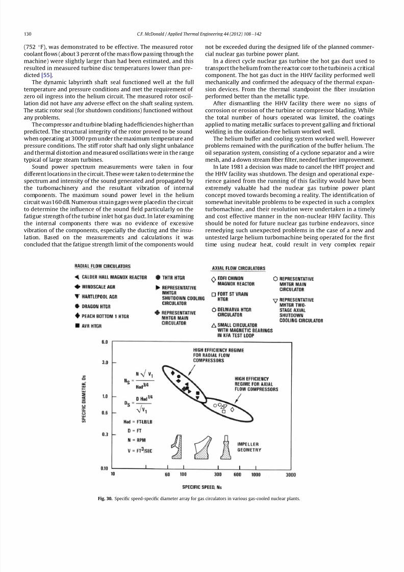
8112019 Helium Turbomachinery Operating Experience From Gas Turbine Power Plants
httpslidepdfcomreaderfullhelium-turbomachinery-operating-experience-from-gas-turbine-power-plants 2335
(752 F) was demonstrated to be effective The measured rotor
coolant 1047298ows (about 3 percent of the mass1047298ow passing through the
machine) were slightly larger than had been estimated and this
resulted in measured turbine disc temperatures lower than pre-
dicted [55]
The dynamic labyrinth shaft seal functioned well at the full
temperature and pressure conditions and met the requirement of
zero oil ingress into the helium circuit The measured rotor oscil-
lation did not have any adverse effect on the shaft sealing system
The static rotor seal (for shutdown conditions) functioned without
any problems
The compressor and turbine blading hadef 1047297ciencies higher than
predicted The structural integrity of the rotor proved to be sound
when operating at 3000 rpm under the maximum temperature and
pressure conditions The stiff rotor shaft had only slight unbalance
and thermal distortion and measured oscillations were in the range
typical of large steam turbines
Sound power spectrum measurements were taken in four
different locations in the circuit These were taken to determine the
spectrum and intensity of the sound generated and propagated by
the turbomachinery and the resultant vibration of internal
components The maximum sound power level in the helium
circuit was160 dB Numerous strain gages were placedin the circuitto determine the in1047298uence of the sound 1047297eld particularly on the
fatigue strength of the turbine inlet hot gas duct In later examining
the internal components there was no evidence of excessive
vibration of the components especially the ducting and the insu-
lation Based on the measurements and calculations it was
concluded that the fatigue strength limit of the components would
not be exceeded during the designed life of the planned commer-
cial nuclear gas turbine power plant
In a direct cycle nuclear gas turbine the hot gas duct used to
transport the helium from the reactor core to the turbineis a critical
component The hot gas duct in the HHV facility performed well
mechanically and con1047297rmed the adequacy of the thermal expan-
sion devices From the thermal standpoint the 1047297ber insulation
performed better than the metallic type
After dismantling the HHV facility there were no signs of
corrosion or erosion of the turbine or compressor blading While
the total number of hours operated was limited the coatings
applied to mating metallic surfaces to prevent galling and frictional
welding in the oxidation-free helium worked well
The helium buffer and cooling system worked well However
problems remained with the puri1047297cation of the buffer helium The
oil separation system consisting of a cyclone separator and a wire
mesh and a down stream 1047297ber 1047297lter needed further improvement
In late 1981 a decision was made to cancel the HHT project and
the HHV facility was shutdown The design and operational expe-
rience gained from the running of this facility would have been
extremely valuable had the nuclear gas turbine power plant
concept moved towards becoming a reality The identi1047297cation of
somewhat inevitable problems to be expected in such a complexturbomachine and their resolution were undertaken in a timely
and cost effective manner in the non-nuclear HHV facility This
should be noted for future nuclear gas turbine endeavors since
remedying such unexpected problems in the case of a new and
untested large helium turbomachine being operated for the 1047297rst
time using nuclear heat could result in very complex repair
Fig 30 Speci1047297
c speed-speci1047297
c diameter array for gas circulators in various gas-cooled nuclear plants
CF McDonald Applied Thermal Engineering 44 (2012) 108e142130
8112019 Helium Turbomachinery Operating Experience From Gas Turbine Power Plants
httpslidepdfcomreaderfullhelium-turbomachinery-operating-experience-from-gas-turbine-power-plants 2435
activities and extended plant downtime and indeed adding risk to
the overall success of the nuclear gas turbine concept
8 Circulators used in gas-cooled reactor plants
Circulators of different types will be needed in future helium
cooled nuclear plants these including the following 1) primary
loop circulator for possible next generation steam cycle power andcogeneration plants 2) for future indirect cycle gas turbine plants
3) shut down cooling circulators forall HTRand VHTR plants and 4)
for various circulators needed in future VHTR high temperature
process heat plant concepts The technology status of operated
helium circulators is brie1047298y addressed as follows
81 Background
It would be remiss not to mention experience gained in the past
with gas circulators and while not gas turbines they are rotating
machines that operate in the primary loop of a helium cooled
reactor With electric motor drives there are basically two types of
compressor rotor con1047297gurations namely radial and axial 1047298ow
machinesIn a single stage form the centrifugal impeller is used for high
stage pressure rise and low volume 1047298ow duties whereas the axial
type covers low pressure rise per stage and high volume 1047298ow The
selection of impeller type is very much related to the working
media type of bearings drive type rotor dynamic characteristics
and installation envelope A wide range of circulators have operated
and a well established technology base exists for both types [63] A
useful portrayal of compressor data in the form of quasi- non-
dimensional parameters (after Balje [64]) showing approximate
boundaries for operation of high ef 1047297ciency axial and radial types is
shown on Fig 30 (from Ref [65])
Both high speed axial and lower speed radial 1047298ow types are
amenable to gas oil and magnetic bearings From the onset of
modularHTR plant studies theuse of active magnetic bearings[6667]offered a solution to eliminate lubricating oil into the reactor circuit
and this tribology technology is attractive for use in submerged
rotating machinery in the next generation of HTR plants [68]
While now dated an appreciation of the main design features of
typical electric motor-driven helium circulators have been reported
previously namely an axial 1047298ow main circulator for a modular
steam cycle HTR plant [69] and a representative radial 1047298ow shut-
down cooling circulator [70]
The operating experience gained from three particular circula-
tors is brie1047298y included below because of their relevance to the
design of helium turbomachinery in future HTR plant variants
82 Axial 1047298ow helium circulator
Since all of the aforementioned predominantly European
helium gas turbines used axial 1047298ow turbomachinery it is of interest
to mention a helium axial 1047298ow circulator that operated in the USA
and to brie1047298y discuss its design parameters and features The
330 MW Fort St Vrain HTGR featured a Rankine cycle power
conversion system Four steam turbine driven helium circulators
were used to transport heat from the reactor core to the steam
generators The complete circulator assemblies were installed
vertically in the prestressed concrete reactor vessel [71e73]
A cross-section of the circulator is shown on Fig 31 with thecompressor rotor and stator visible on the left hand end of the
machine Based on early 1960rsquos technology a decision was made to
use water lubricated bearings and from the overall plant reliability
and availability standpoints this later proved to be a bad choice
Within the vertical circulator assembly there were four 1047298uid
systems namely the helium reactor coolant water lubricant in the
bearings steam for the turbine drive and high pressure water for
the auxiliary Pelton wheel drive During plant transients the pres-
sures and temperatures of these four 1047298uids oscillated considerably
and the response of the control and seal systems proved to be
inadequate and resulted in considerable water ingress from the
bearing cartridge into the reactor helium circuit The considerable
clean up time needed following repeated occurrences of this event
resulted in long periods of plant downtime and this had an adverseeffect on plant availability This together with other technical
Fig 31 Cross section of FSV helium circulator (Courtesy general Atomics)
CF McDonald Applied Thermal Engineering 44 (2012) 108e142 131
8112019 Helium Turbomachinery Operating Experience From Gas Turbine Power Plants
httpslidepdfcomreaderfullhelium-turbomachinery-operating-experience-from-gas-turbine-power-plants 2535
dif 1047297culties eventually contributed to the plant being prematurely
decommissioned
On the positive side in the context of this paper the helium
circulators operated for over 250000 h and exhibited excellent
helium compressor performance good mechanical integrity and
vibration-free operation The rotating assembly showing the axial
1047298ow compressor and steam turbine rotors together with a view of
the machine assembly are given on Fig 32 The helium compressor
consists of a single stage axial rotor followed by an exit guide vane
The machine was designed for axial helium 1047298ow entering and
leaving the stage and this can be seen from the velocity triangles
shown on Fig 33 which also includes the de1047297nition of the various
aerodynamic parameters Major design parameters and features of
this helium circulator are given on Table 4 Related to an earlier
discussion on the degree of reaction for axial 1047298ow compressors the
value for this conventional single stage circulator is 78 percent All
of the major aerothermal and structural loading criteria were
within established boundaries for an axial compressor having high
ef 1047297ciency and a good surge margin
The compressor gas 1047298ow path and blading geometries were
established based on prevailing industrial gas turbine and aero-
engine design practice A low Mach number (025) a high Reynolds
number (3 106) together with a modest stage loading (ie
a temperature rise coef 1047297cient of 044) and an acceptable value of
diffusion factor (042) were some of the factors that contributed to
a helium circulator that had a high ef 1047297ciency and a good pressure
rise- 1047298ow characteristic The large rotor blade chord and thick blade
section for this single stage circulator are necessary to accommo-
date the high bending stress characteristic of operation in a high
pressure environment The solidity and blade camber were opti-
mized for minimum losses
There were essentially two reasons for including this single-
stage axial 1047298ow compressor that operated in a helium cooled
reactor although its overall con1047297guration can be regarded as a 1047297rst
and last of a kind A rotor blade from this circulator as shown onFig 34 was based on a NASA 65 series airfoil which at the time
were one of the best performing cascades for such low Mach
number and high Reynolds number applications Interestingly it
has almost the same blade height aspect ratio and solidity as would
be used in the 1047297rst stage of an LP compressor in a helium turbo-
machine rated on the order of 250 MW
The second point of interest is that the helium mass 1047298ow rate
through the single stage axial compressor (rated at 4 MWe) is
110 kgs compared with 85 kgs through the multistage compressor
in the 50 MWe Oberhausen II helium gas turbine plant However
the volumetric 1047298ow through the Oberhausen axial compressor is
higher than that through the circulator by a factor of 16 this again
pointing out that the Oberhausen II plant was designed for high
volumetric 1047298ow to simulate the much larger size of turboma-chinery that was planned at the time in Germany for use in future
projected nuclear gas turbine power plants
83 High temperature helium circulator
For future helium turbomachines embodying active magnetic
bearings a challenge in their design relates to accommodating
elevated levels of temperature in the vicinity of the electronic
components In this regard it is of interest to note that a small very
high temperature helium axial 1047298ow circulator rated at 20 kW (as
shown on Fig 35) operated for more than 15000 h in an insulation
test facility in Germany more than two decades ago [74] The
signi1047297cance of this machine is that it operated with magnetic
bearings in a high temperature helium test loop with a circulatorgas inlet temperature of 950 C (1742 F) This necessitated the use
of ceramic insulation to ensure that the temperature in the vicinity
of the magnetic bearing electronics did not exceed a temperature of
about 150 C (300 F)
This machine although a very small axial 1047298ow helium blower
performed well and has been brie1047298y mentioned here since it
represents a point of reference for future helium rotating machines
capable operating with magnetic bearings in a very high temper-
ature helium environment
84 Radial 1047298ow AGR nuclear plant gas circulators
The electric motor-driven carbon dioxide circulators rated at
about 5 MW with a total runningtimein excess of 18 million hours
Fig 32 Fort St Vrain HTGR plant helium circulator (Courtesy General Atomics) (a)
Axial 1047298ow helium compressor and steam turbine rotating assembly (b) 4 MW helium
circulator assembly
CF McDonald Applied Thermal Engineering 44 (2012) 108e142132
8112019 Helium Turbomachinery Operating Experience From Gas Turbine Power Plants
httpslidepdfcomreaderfullhelium-turbomachinery-operating-experience-from-gas-turbine-power-plants 2635
in AGR nuclear power plants in the UK have demonstrated veryhigh availability [7576] To a high degree this can be attributed to
the fact that the machines were conservatively designed and proof
tested in a non-nuclear facility at full temperature and power
under conditions that simulated all of the nuclear plant operating
modes The test facility shown on Fig 36 served two functions 1)
design veri1047297cation of the prototype machine and 2) test of all new
and refurbished machines before they were installed in nuclear
plants Engineers currently involved in the design and development
of helium turbomachinery could bene1047297t from this sound testing
protocol to minimize risk in the deployment of helium rotating
machinery in future HTRVHTR plant variants
9 Helium turbomachinery development and testing
91 On-going development activities
The various helium turbomachines discussed in previous
sections operated over a span of about two decades starting in the
early 1960s From about 1990 activities in the nuclear gas turbine
1047297eld have been focused mainly on the design of modular GTeHTR
plant concepts In support of these plant studies many signi1047297cant
helium turbomachine design advancements have been made and
attention given to what development testing would be needed In
the last decade or so limited sub-component development has
been undertaken for helium turbomachines in the 250e300 MWe
size and these are brie1047298y summarized below
In a joint USARussia effort development in support of the
GTe
MHR turbomachine has been undertaken including testing in
the following areas magnetic bearings seals and rotor dynamicsfor the vertical intercooled helium turbomachine rated at 286 MWe
[77e80]
In Japan development activities have been in progress for
several years in support of the 274 MWe helium turbomachine for
the GTeHTR300 plant concept [2581] A detailed discussion on
the aerodynamic design of the axial 1047298ow helium compressor for
this turbomachine has been published in the open literature [82]
While the design methodology used for axial compressor design in
air-breathing industrial and aircraft gas turbines is generally
applicable for a multi-stage helium compressor a decision was
made by JAEA to test a small scale compressor in a helium facility
because of the inherent and unique gas 1047298ow path and type of
blading associated with operation in a high pressure helium
environment The major goal of the test was to validate the designof the 20 stage helium axial 1047298ow compressor for the GTeHTR300
plant
An axial 1047298ow compressor in a closed-cycle helium gas turbine is
characterized by the following 1) a large number stages 2) small
blade heights 3) high hub-to-tip ratio 4) a long annulus with
small taper that tends to deteriorate aerodynamic performance as
a result of end-wall boundary layer length and secondary 1047298ow 5)
low Mach number 6) high Reynolds number and 7) blade tip
clearances that are controlled by the gap necessary in the magnetic
journal and catcher bearings While (as covered in earlier sections)
helium gas turbines have operated there is limited data in the
open literature on the performance of multi-stage axial 1047298ow
compressors operating in a high pressure closed-loop helium
environment
Fig 33 Velocity triangles for axial compressor stage
CF McDonald Applied Thermal Engineering 44 (2012) 108e142 133
8112019 Helium Turbomachinery Operating Experience From Gas Turbine Power Plants
httpslidepdfcomreaderfullhelium-turbomachinery-operating-experience-from-gas-turbine-power-plants 2735
A 13rd scale 4 stage compressor was designed to simulate the
stage interaction the boundary layer growth and repeated stage
1047298ow in an actual compressor The 1047297rst four stages were designed to
be geometrically similar to the corresponding stages in the
GTe
HTR300 compressor Details of the model compressor havebeen discussed previously [81] and are summarized on Table 5
from [83]
A cross-section of the compressor test model is shown on Fig 37
A view of the 4 stage compressor rotor installed in the lower casing
is shown on Fig 38 The test facility (Fig 39) is a closed helium loop
consisting of the compressor model cooler pressure adjustment
valve and a 1047298ow measurement instrument The compressor is
driven by a 3650 kW electrical motor via a step-up gear The rota-
tional speed of 10800 rpm (three times that of the compressor in
the GTeHTR300 plant) was selected to match blade speed and
Mach number in the full size compressor
Details of the planned aerodynamic performance objectives of
the 13rd scale helium compressor test have been published
previously [84] Extensivetesting of the subscale model compressorprovided data to validate the performance of the full size
compressor for the GTeHTR300 power plant The test data and
test-calibrated CFD analyses gave added insight into the effect of
factors that impact performance including blade surface roughness
and Reynolds number
Based on advanced aerodynamic methodology and experi-
mental validation [82] there is now a sound basis for added
con1047297dence that the design goals of 90 percent polytropic ef 1047297ciency
and a design point surge margin of 20 percent are realizable in
a large multistage axial 1047298ow compressor for a future nuclear gas
turbine plant
In a similar manner a design of a one third size single stage
helium axial 1047298ow turbine has been undertaken and a cross
section of the machine is shown on Fig 40 (from Ref [81]) This
Table 4
Major features of axial 1047298ow helium circulator
Helium 1047298ow rate kgsec 110
Inlet temperature C 394
Inlet pressure MPa 473
Pressure rise KPa 965
Volumetric 1047298ow m3sec 32
Compressor type Single stage axial
Compressor drive Steam turbine
Bearing type Water lubricated
Rotational speed rpm 9550
Power MW 40
Rotor tip diameter mm 688
Rotor tip speed msec 344
Number of rotor blades 31
Number of stator blades 33
Blade height mm 114
Hub-to-tip ratio 067
Axial velocity msec 157
Flow coef 1047297cient 055
Temperature rise coef 1047297cient 044
Degree of reaction 078
Mean rotor solidity 128
Rotor aspect ratio 155
Rotor Mach number 025
Rotor diffusion factor 042
Rotor Reynolds number 3106
Speci1047297c speed 335
Speci1047297c diameter 066
Blade root thickness 15
Airfoil type NASA 65
Rotor blade chord mm 94e64
Stator blade chord mm 79
Rotor centrifugal stress MPa 125
Rotor bending stress MPa 30
Circulator(s) operating Hours gt250000
Fig 34 Rotor blade from single stage axial 1047298ow helium circulator (Courtesy General
Atomics)
Fig 35 20 kW axial 1047298ow helium circulator with magnetic bearings operated in 1985 in
an insulation test loop with a gas inlet temperature on 950
C (Courtesy BBC)
CF McDonald Applied Thermal Engineering 44 (2012) 108e142134
8112019 Helium Turbomachinery Operating Experience From Gas Turbine Power Plants
httpslidepdfcomreaderfullhelium-turbomachinery-operating-experience-from-gas-turbine-power-plants 2835
single stage scale model turbine for validity of the full size turbine
has been built and plans made to test the aerodynamic
performance
92 Nuclear gas turbine helium turbomachine testing
In planning for the 1047297rst nuclear gas turbine plant projected to
enter service perhaps in the third decade of the 21st century
a major decision has to be made as to what extent the large helium
turbomachine should be tested prior to operation on nuclear heat
Issues essentially include cost impact on schedule but the over-
riding one is risk Certainly turbomachine component testing will
be undertaken including the compressor (as discussed in the
previous section) and turbine performance seals cooling systems
hot gas valves thermal expansion devices high temperature
insulation rotor fragment containment diagnostic systems
instrumentation helium puri1047297cation system and other areas to
satisfy safety licensing reliability and availability concerns The
major point is really whether a full size or scaled-down turbo-machine be tested early in the project in a non-nuclear facility
To obviate the need for pre-nuclear testing of a large helium
turbomachine a view expressed by some is that advantage can be
taken of formidable technology bases that exist today for large
industrial gas turbines and high performance aeroengines On the
other hand it is the view of some including the author that very
complex power conversion system components especially those
subjected to severe thermal transients donrsquot always perform
exactly as predicted by analysts and designers even using sophis-
ticated computer codes This was exempli1047297ed in the case of the
turbomachine in the aforementioned Oberhausen II helium gas
turbine plant
The need for a helium turbomachine test facility goes beyond
just veri1047297
cation of the prototype machine Each newgas turbine for
commercial modular nuclear reactor plants would have to be proof
tested and validated before being transported to the reactor site
Similarly turbomachines that would be periodically removed from
the plant at say 7 year intervals during the plant operating life of 60
years for scheduled maintenance refurbishment repair or updat-ing would be again proof tested in the facility before re-entering
service
The direction that turbomachine development and testing will
take place for future helium gas turbines needs to be addressed by
the various organizations involved
Fig 36 AGR circulator test facility In the UK (Courtesy Howden)
Table 5
Major design parametersfeatures of model GTeHTR300 axial 1047298ow helium
compressor (Courtesy JAERI)
Scale of GTeHTR300 compressor 13
Helium mass 1047298ow rate (kgsec) 122
Helium volumetric 1047298ow rate (mV s) 87
Inlet temperature C 30
Inlet pressure MPa 0883Compressor pressure ratio at design point 1156
Number of stages 4
Rotational speed rpm 10800
Drive motor power kW 3650
Hub diameter mm 500
Rotor tip diameter (1st4th stage mm) 568566
Hub-to-tip ratio (1st stage) 088
Rotor tip speed (1st stage msec) 321
Number of rotorstator blades (1st stage) 7294
Rotorstator blade height (1st stage mm) 34337
Rotor stator blade c hor d l eng th (1st stage mm) 2620
Rotorstator solidity (1st stage) 119120
Rotorstator aspect ratio (1st stage) 1317
Flow coef 1047297cient 051
Stage loading factor 031
Reynolds number at design point 76 l05
CF McDonald Applied Thermal Engineering 44 (2012) 108e142 135
8112019 Helium Turbomachinery Operating Experience From Gas Turbine Power Plants
httpslidepdfcomreaderfullhelium-turbomachinery-operating-experience-from-gas-turbine-power-plants 2935
10 Helium turbomachinery lessons learned
101 Oberhausen II gas turbine and HHV test facility
It is understandable that 1047297rst-of-a-kind complex turboma-
chinery operating with an inert low molecular weight gas such as
helium will experience unique and unexpected problems In the
operation of the two pioneering large helium turbomachines in
Germany there were many positive1047297ndings which could only have
been achieved by development testing Equally important some
negative situations were identi1047297ed many of which were remedied
In the case of the Oberhausen II helium gas turbine plant some of
the very serious problems encountered were not resolved Inves-
tigations were undertaken to rationalize the problems associated
with the large power de1047297ciency and a data base established to
ensure that the various anomalies identi1047297ed would not occur in
future large helium turbomachines
The experience gained from the operation of the Oberhausen II
helium gas turbine power plant and the HHV test facility have been
discussedin thetextand arepresentedin a summaryformon Table6
Fig 37 Cross-section of 13rd scale helium compressor test model (Courtesy JAEA)
Fig 38 Four stage helium compressor rotor assembly installed in lower casing (Courtesy JAEA)
CF McDonald Applied Thermal Engineering 44 (2012) 108e142136
8112019 Helium Turbomachinery Operating Experience From Gas Turbine Power Plants
httpslidepdfcomreaderfullhelium-turbomachinery-operating-experience-from-gas-turbine-power-plants 3035
102 Impact of 1047297ndings on future helium gas turbine
The long slender rotorcharacteristic of closed-cycle gas turbines
has resulted in shaft dynamic instability which in some cases has
resulted in blade vibration and failure and bearing damage This
remains perhaps the major concern in the design of large
(250e
300 MW) helium turbomachines for future nuclear gas
turbine plants With pressure ratios in the range of about 2e3 in
a helium system a combination of splitting the compressor (to
facilitate intercooling) and having a large number of compressor
and turbine stages results in a long and 1047298exible rotating assembly
andthis is exempli1047297ed by the rotorassembly shown on Fig13 With
multiple bearings (either oil lubricated or magnetic) the rotor
would likely pass through multiple bending critical speeds before
Fig 39 Helium compressor test facility (Courtesy JAEA)
Fig 40 Cross-section of single stage helium turbine test model (Courtesy JAEA)
CF McDonald Applied Thermal Engineering 44 (2012) 108e142 137
8112019 Helium Turbomachinery Operating Experience From Gas Turbine Power Plants
httpslidepdfcomreaderfullhelium-turbomachinery-operating-experience-from-gas-turbine-power-plants 3135
reaching the design speed While very sophisticated computer
codes will be used in the detailed rotor dynamic analyses the real
con1047297rmation of having rotor oscillations within prescribed limits
(to avoid blade bearing and seal damage) will come from actual
testingA point to be made here is that in operated fossil-1047297red closed-
cycle gas turbine plants it was possible to remedy problems asso-
ciated with rotor vibrations and blade failures in a conventional
manner In fact in some situations the casings were opened several
times and modi1047297cations made to facilitate bearing and seal
replacement and rotor re-blading and balancing
An accurate assessment of pressure losses must be made
particularly those associated with the helium entering and leaving
the turbomachine bladed sections Minimizing the system pressure
loss is important since it directly impacts the all important quotient
of turbine expansion ratio to compressor pressure ratio and power
and plant ef 1047297ciency
Based on the operating experience from the 20 or so fossil-1047297red
closed-cycle gas turbine plants using air as the working1047298
uid it was
recognized that future very high pressure helium gas turbines
would pose problems regarding the various seals in the turbo-
machine and obtaining a zero leakage system with such a low
molecular weight gas would be dif 1047297cult and this is discussed
below
When the Oberhausen II gas turbine plant and the HHV facility
operated over 30 years ago oil lubricated bearings were used to
support the heavy rotor assemblies and helium buffered labyrinth
seals were used to prevent oil ingressinto the heliumworking1047298uid
Initial dif 1047297culties encountered in both plants were overcome by
changes made to the seal geometries and for the operating lives of
the helium turbomachines no further oil ingress events were
experienced Twoseals were required where the turbine drive shaft
penetrated the turbomachine casing namely 1) a dynamic laby-
rinth seal and 2) a static seal for shutdown conditions In both
plants these seals functioned without any problems
Labyrinth seals were also required within the helium turbo-
machines to pass the correct helium bleed 1047298ow from the
compressor discharge for cooling of the turbine discs blade root
attachments and casings The fact that the very complex rotor
cooling system in the large helium turbomachine in the HHV test
facility operated well for the test duration of about 350 h with
a turbine inlet temperature of 850 C was encouragingIn the case of the Oberhausen II gas turbine plant analysis of the
test data revealed that the labyrinth seal leakage and excessive
cooling 1047298ows were on the order of four times the design value A
possible reason for this was that damage done to the labyrinth
seals caused excessive clearances when periods of excessive rotor
oscillation and vibration occurred during early operation of the
machine
Clearly 1047298uid dynamic and thermal management of the cooling
system and 1047298ow through the various labyrinth seals will require
extensive analysis design and development testing before the
turbomachine is operated on nuclear heat for the 1047297rst time
In future heliumgas turbine designs (with turbine inlet tempera-
tureslikelyontheorderof950C)the1047298owpathgeometriesofhelium
bledfromthecompressornecessarytocoolpartsoftheturbomachinewillbemorecomplexthanthosetestedto-dateInadditiontoproviding
acooling1047298owtotheturbinebladesanddiscsbladerootattachmentsand
casingsheliummustbetransportedtotheseveralmagneticbearingsto
ensure thatthe temperatureof theirelectronic components doesnot
exceedabout150C
The importance of the points made above is evidenced when
examining the data on Table 3 where a combination of excessive
pressure losses and high bleed 1047298ows contributed to about 40
percent of the power de1047297ciency in the Oberhausen II helium
turbine plant
Retaining overall system leak tightnessin closed heliumsystems
operating at high pressure and temperature has been elusive
including experience from the Fort St Vrain HTGR plant as dis-
cussed in Section 65 New approaches in the design of the plethoraof mechanical joints must be identi1047297ed Experience to-date has
shown that having welded seals on 1047298anges while minimizing
system leakage did not eliminate it
The importance of lessons learned from the operation of the
Oberhausen II helium turbine power plant and the HHV test facility
have primarily been discussed in the context of helium turbo-
machines currently being designed in the 250e300 MWe power
range However the established test data bases could also be
applied to the possible emergence in the future of two helium
cooled reactor concepts namely 1) an advanced VHTR combined
cycle plant concept embodying a smaller helium gas turbine in the
power range of 50e80 MWe [22] and 2) the use of a direct cycle
helium gas turbine PCS in a recently proposed all ceramic fast
nuclear reactor concept [85]
Table 6
Experience gained from Oberhausen II and HHV facility
Oberhausen II 50 MW helium gas turbine power plant
Positive results
e Rotating and static seals worked well
e No ingress of bearing lubricant oil into closed circuit
e Load change by inventory control worked well
e 100 Percent load shed by means of bypass valves demonstrated
e Turbine disc and blade root cooling system con1047297rmed
e Coatings on mating surfaces prevented galling and self-welding
e After 24000 h of operation no evidence of corrosion or erosion
e Coaxial turbine hot gas inlet duct insulation and integrity con1047297rmed
e Monitoring of complete power conversion system for steady state
and transient operation undertaken
Problem areas
e Serious power output de1047297ciency (30 MW compared with design
value of 50 MW)
e Compressor(s) and turbine(s) ef 1047297ciencies several points below predicted
e Higher than estimated system pressure loss
e Rotor dynamic instability and blade vibration
e Bearings damaged and had to be replaced
e Blade failure caused extensive damage in HP turbine but retained
in casing
e Very excessive sealing and cooling 1047298ow rates
e Absolute leak tightness not attainable even with welded 1047298ange lips
HHV test facility
Positive resultse Use of heat pump approach facilitated helium temperature capability
to 1000 C
e Large oompressorturbine rotor system operated at 3000 rpm Complex
turbine disc and blade root cooling system veri1047297ed
e Dynamic and static seals met requirement of zero oxl ingress into circuit
e Structural integrity of rotating assembly veri1047297ed at temperature of 850 C
e Measured rotor oscillations within speci1047297cation
e Compressor and turbine ef 1047297ciencies higher than predicted
e Coatings on mating metallic surfaces prevented galling and self-welding
e Instrumentation control and safety systems veri1047297ed
e Seal 1047298ows within speci1047297cation
e Machine stop from operating speed to shutdown in 90 s demonstrated
e Hot gas duct insulation and thermal expansion devices worked well
e After 1100 h of operation no evidence of corrosionof erosion
Problem areas
e Before commissioning a large oil ingress into the circuit occurred due
to serious operator error and absence of an isolation valve A second oilingress occurred due to a mechanical defect in the labyrinth seal system
These were remedied and no further oil ingress was experienced for the
duration of testing
e Cooling 1047298ows slightly larger than expected but this resulted in actual
disc and blade root temperatures lower than the predicted value of
400 C
e System leak tightness demonstrated when pressurized at ambient
temperature conditions but some leakage occured at 850 C even with
the seal welding of 1047298ange(s) lips
CF McDonald Applied Thermal Engineering 44 (2012) 108e142138
8112019 Helium Turbomachinery Operating Experience From Gas Turbine Power Plants
httpslidepdfcomreaderfullhelium-turbomachinery-operating-experience-from-gas-turbine-power-plants 3235
11 New technologies
It is recognized that in the 3 to 4 decades since the operation of
the helium turbomachines covered in this paper new technologies
have emerged which negate some of the early issues An example of
this is the technology transfer from the design of modern axial 1047298ow
gas turbines (ie industrial aircraft and aeroderivatives) that fully
utilize sophisticated CAE CAD CFD and FEA design software
Air breathing aerodynamic design practice for compressors and
turbines are generally applicable but the properties of helium and
the high system pressure have a signi1047297cant impact on gas 1047298ow
paths and blade geometries With short blade heights high hub-to-
tip ratios long annulus 1047298ow path length (with resultant signi1047297cant
end-wall boundary layer growth and secondary 1047298ow) and blade tip
clearances in some cases controlled by clearances in the magnetic
catcher bearing testing of subscale model compressors and
Fig 41 Gas turbine test facility for aircraft nuclear propulsion involving the coupling of a 32 MWt air-cooled reactor with two modi 1047297ed J-47 turbojet aeroengines each rated at
a thrust of about 3000 kg operated in 1960 (Courtesy INL)
Fig 42 Mobile 350 KWe closed-cycle nuclear gas turbine power plant operated in 1961 (Courtesy US Army)
CF McDonald Applied Thermal Engineering 44 (2012) 108e142 139
8112019 Helium Turbomachinery Operating Experience From Gas Turbine Power Plants
httpslidepdfcomreaderfullhelium-turbomachinery-operating-experience-from-gas-turbine-power-plants 3335
turbines will be needed While most of the operated helium tur-
bomachines discussed in this paper took place 3 or 4 decades ago it
is encouraging that the fairly recent test data and test-calibrated
CFD analysis from a subscale four stage model helium axial 1047298ow
compressor in Japan [80] gave a high degree of con1047297dence that
design goals are realizable for the full size 20 stage compressor in
the 274 MWe GTeHTR300 plant turbomachine
In the future the use of active magnetic bearings will eliminate
the issue of oil ingress however the very heavy rotor weight and
size of the journal and thrust bearings (and catcher bearings) of the
type for helium turbomachines in the 250e300 MWe power range
are way in excess of what have been demonstrated in rotating
machinery For plant designs retaining oil-lubricated bearings well
established dry gas seal technology exists particularly experience
gained from the operation of high pressure natural gas pipe line
compressors
For future nuclear helium gas turbine plants the designer has
freedom regarding meeting different frequency requirements that
exist in some countries These include use of a synchronous
machine (ie designed for 50 or 60 Hz grids) use of a gearbox drive
between the turbine and generator or the use of a frequency
converter which gives the designer an added degree of freedom
regarding the selection of speed for the rotating assemblyCompared with the past very sophisticated electronic control
systems instrumentation and diagnostic systems are available
today
12 Conclusions
In this review paper experience from operated helium turbo-
machines has been compiled based on open literature sources At
this stage in the evolution of HTR and VHTR plant concepts it is not
clear in what role form or time-frame the nuclear gas turbine will
emerge when commercialized By say the middle of the 21st
century all power plants will be operating with signi1047297cantly higher
ef 1047297ciencies to realize improved power generation costs and
reduced emissions In a nuclear gas turbine the helium turbo-machine will be a major contributor towards the achievement of
ef 1047297ciencies higher than 50 percent
While it has been 3 to 4 decades since the Oberhausen II helium
turbine power plant and the HHV high temperature helium turbine
facility operated signi1047297cant lessons were learned and the time and
effort expended to resolve the multiplicity of unexpected technical
problems encountered The remedial repair work was done under
ideal conditions namely that immediate hands-on activities were
possible This would not have been possible if the type of problems
experienced had been encountered in a new and untested helium
turbomachine operated for the 1047297rst time with a nuclear heat
source
While new technologies have emerged that negate many of the
early problems there are some uniquely inherent issues associatedwith for large helium turbines operating in a high pressure and
temperature environment and these include the following 1)
minimizing system leakage with such a low molecular weight gas
2) clearances in labyrinth seals to minimize helium bypass1047298ows 3)
the dynamic stability of long slender rotors 4) minimizing the
turbomachine inlet and outlet pressure losses 5) 1047298ow maldis-
tribution in complex ductturbomachine interfaces 6) integrity
veri1047297cation of the catcher bearings (journal and thrust) after
multiple rotor drops (following loss of the magnetic 1047297eld) during
the plant lifetime 7) assurances that high energy fragments from
a failed turbine disc are contained within the machine casing 8)
turbomachine installation and removal from a steel pressure vessel
and 9) remote handling and cleaning of a machine with turbine
blades contaminated with 1047297
ssion products
The need for a helium turbomachine test facility has been
emphasized to ensure that the integrity performance and reli-
ability of the machine before it operates the 1047297rst time on nuclear
heat Engineers currently involved in the design of helium rotating
machinery for all HTR and VHTR plant variants should take
advantage of the experience gained from the past operation of
helium turbomachinery
13 In closing-GT rsquos operated with nuclear heat
In the context of this paper it is germane to mention that two
gas turbines have actually operated using nuclear heat as brie1047298y
highlighted below
In the late 1950rsquos a program was initiated in the USA for aircraft
nuclear propulsion (ANP) While different concepts were studied
only the direct cycle air-cooled reactor reached the stage of
construction of an experimental reactor [86] A view of the large
nuclear gas turbine facility is given on Fig 41 and shows the air-
cooled and zirconiumehydride moderated reactor rated at
32 MWt coupled with two modi1047297ed J-47 turbojet engines each
rated with a thrust of about 3000 kg In this open cycle system the
high pressure compressor air was directly heated in the reactor
before expansion in the turbine and discharge to the atmosphere in
the exhaust nozzle The facility operated between 1958 and 1961 at
the Idaho reactor testing facility While perhaps possible during the
early years of the US nuclear program it is clear that such a system
would not be acceptable today from safety and environmental
considerations
The 1047297rst and indeed the only coupling of a closed-cycle gas
turbine with a nuclear reactor for power generation was under-
taken to meet the needs of the US Army In the late 1950 rsquos an RampD
program was initiated for a 350 kW trailer-mounted system to be
used in the 1047297eld by military personnel A prototype of the ML-1
plant shown on Fig 42 was 1047297rst operated in 1961 [8788]
It was based on a 33 MW light water moderated pressure tube
reactor with nitrogen as the coolant The closed-cycle gas turbine
power conversion system with nitrogen as the working 1047298uid hada turbine inlet temperature of 649 C (1200 F) and delivered
around 300 kW With changes in the Armyrsquos needs the project was
discontinued in 1965
While the experience gained from the above twounique nuclear
plants is clearly not relevant for future nuclear gas turbine power
plants that could see service in the third decade of the 21st century
these ambitious and innovative nuclear gas turbine pioneering
engineering efforts need to be recognized
Acknowledgements
The author would like to thank the following for helpful discus-
sions advice and for providing valuable comments on the initial
paper draft Prof Dr Hermann Haselbacher Hans Ulrich Frutschi DrXing Yan DrPeter Zenker Professor DavidGordon Wilson Professor
Aristide Massardo Arthur Harris DrFred Starr and DrGuido Bac-
caglini This paper has been enhanced by the inclusion of hardware
photographs and unique sketches and the author is appreciative to
all concerned with credits being duly noted
References
[1] C Keller The Escher Wyss AK Closed-Cycle Gas Turbine Its Actual Develop-ment and Future Prospects Paper Presented at ASME Meeting November 261945
[2] HU Frutschi Closed-Cycle Gas Turbines Operating Experience and FuturePotential ASME Press NY 2005
[3] CF McDonald The Nuclear Gas Turbine-Towards Realization After Half
a Century of Evolution (1995) ASME Paper 95-GT-292
CF McDonald Applied Thermal Engineering 44 (2012) 108e142140
8112019 Helium Turbomachinery Operating Experience From Gas Turbine Power Plants
httpslidepdfcomreaderfullhelium-turbomachinery-operating-experience-from-gas-turbine-power-plants 3435
[4] C Keller The Theory and Performance of Axial Flow Fans McGraw Hill BookCompany Inc NY 1937
[5] J Ackert C Keller Aerodynamic turbine with closed circuit In A Century of Turbines vols 1516 Escher Wyss News 1942e43 5e19
[6] Escher Wyss News Closed-Cycle Gas Turbines for all Fuels Coal Gas Nuclearvol 39 No 1 (1966)
[7] C Keller Closed-cycle gas turbine Escher Wyss-AK development 1945e1950Transactions of ASME (August 1950) 835e850
[8] C Keller Operating Experience and Design Features of Closed-Cycle GasTurbine Power Plants (1956) ASME Paper 56-GTP-15
[9] C Keller HU Frutschi Closed-cycle plants -conventional and nuclear designapplication operation In Sawyerrsquos Gas Turbine Engineering Handbooksecond ed vol 2 Applications (1976) pp 265e283
[10] K Bammert G Groschup Status Report on Closed-Cycle Power Plants in theFederal Republic of Germany (1976) ASME Paper 76-GT-54
[11] JL Mason Monatomic Working Gases versus Air for Closed Brayton Cycles(1985) ASME Paper 85-IGT-50
[12] JL Mason et al 5 MW Closed Cycle Gas Turbine (1984) ASME Paper 84-GT-268
[13] The British Gas Closed-Cycle Demonstrator (1995) British Gas Research ampTechnology Final Year Report
[14] F Starr ODS alloy high temperature heat exchanger prototype developmentPaper Presented at ODS 2010 Materials Workshop UCSD Jacobs Hall La JollaCalifornia Nov17e18 2010
[15] CA Rennie Achievements of the Dragon project Pergamon Press Annals of Nuclear Energy 5 (1978) 305e320
[16] SB Hosegood et al Dragon Project Engineering Studies on the Direct CycleHTR Proceedings of Conference on Nuclear Gas Turbines The British NuclearEnergy Society London April 8e9 1970 pp 161e179
[17] Nuclear Gas Turbines Proceedings of British Nuclear Society Meeting LondonApril 8-9 1972
[18] CF McDonald C Peinado ldquoThe nuclear gas Turbine-A perspective on a long-term advanced technology HTGR plant Optionrdquo ASME Paper 82-GT-289
[19] GH Lohnert et al Technical design features and essential safety-relatedfeatures of the HTR-Module Nuclear Engineering and Design 121 (1990)259e275
[20] H Reutler GH Lohnert The modular high temperature nuclear reactorNuclear Technology 62 (1983) 22e30
[21] CF McDonald Exploitation of the very high temperature capability of theMHTGR to meet National energy needs after the year 2000 IECEC Paper869006
[22] CF McDonald Power conversion system considerations for an advancednuclear gas turbine (GT-VHTR) CHHP demonstration plant concept Interna-tional Journal of Turbo amp Jet Engines 27 (2010) 179e217
[23] N Hee Cheon et al A review of helium gas turbine technology for hightemperature gas cooled reactors Nuclear Engineering and Design 29 (2007)21e30
[24] CB Baxi et al Development of the GT-MHR Turbomachine ASME PaperGT2009e59450[25] X Yan GTHTR300 design and development Nuclear Engineering and Design
222 (2003) 247e262[26] JC Gauthier et al ANTARES the HTRVHTR project of Framatome ANP
Nuclear Engineering and Design 236 (2006) 526e533[27] J Wang et al ldquoDesign features of gas turbine power conversion system for
HTR-10GT paper D05 presented at 2nd Intl Meeting on HTR TechnologyBeijing China September 21e24 2004
[28] A Koster et al ldquoPBMR Design For the Futurerdquo Nuclear engineering andDesign 222 (203) 231e245
[29] S van der Linden Closed cycle nuclear plant rated at 165 MWe and 40 percentef 1047297ciency Gas Turbine World (MarcheApril 2007) 28e32
[30] CF McDonald Large closed-cycle gas turbines Sawyerrsquos gas turbine engi-neering handbook In Selection and Applications vol II (1985) pp 81e38(Chapter 8)
[31] CF McDonald Helium and Combustion Gas Turbine Power ConversionSystems Comparison (1995) ASME Paper 95-GT-263
[32] JK La Fleur Description of an Operating Closed-Cycle Helium Gas Turbine
ASME Paper 63-AHGT-74[33] JK La Fleur The use of turbomachinery in the 1047297eld of cryogenics In
Sawyerrsquos Gas Turbine Engineering Handbook vol II (1976) 296e311[34] W Spillmann The Closed-Cycle Gas Turbine for Non-Conventional Applica-
tions ASME Paper 66-GT-8[35] K Holliger On the in1047298uence of the degree of reaction on the secondary losses
in axial 1047298ow compressors Escher Wyss News 23 (1960)[36] W Gut Comparison of the relative losses and characteristics of axial
compressor stages Escher Wyss News 23 (1959)[37] JH Horlock Axial Flow Compressors Butterworths Scienti1047297c Publications
London 1958 pp 92e93[38] G Deuster Long-term Operating Experience with Oberhausen I Closed-Cycle
Gas Turbine Power Plant (1970) ASME Paper 70-GT-73[39] G Noak Signi1047297cance of the Helium Turbine Power Plant at Oberhausen (EVO)
and the High Temperature Helium Test Facility (HHV) at Julich for theDevelopment of HTR Direct Cycle (HHT) IAEA Publication SM-20026 Vienna1970 189e200
[40] K Bammert G Deuster Layout and Present Status of the Closed-Cycle HeliumTurbine Plant Oberhausen II (1974) ASME Paper 74-GT-132
[41] P Zenker The Oberhausen 50 MW helium turbine plant Combustion 47 (2)(April 1976)
[42] K Bammert et al Operation and Control of the 50 MW Closed Cycle HeliumTurbine Plant Oberhausen (1974) ASME Paper 74-GT-13
[43] P Zenker 10 years operating experience with the Oberhausen II heliumturbo-generator plant VGB Krafswerkstechnik 68 (7) (July 1998) 616e621
[44] K Bammert G Deuster The First Operating Experiences With the OberhausenHelium Turbine Plant Paper Presented at ASME Gas Turbine Conference NewOrleans March 21e25 1976
[45] G Deuster P Zenker Operation of the Oberhausen Helium Turbine Plant
Paper Presented at ASME Gas Turbine Conference London April 1978[46] P Zenker Operating Experience of the Oberhausen Helium Turbine Plant
Paper Presented at ASME Gas Turbine Conference San Diego 1979[47] G Deuster P Zenker Further Operating Experience of the Oberhausen Helium
Turbine Plant Paper Presented at ASME Gas Turbine Conference NewOrleans 1980
[48] P Zenker Past Experience and Future Prospects of Closed-Cycle Gas TurbinesPaper Presented at ASME Gas Turbine Conference London April 18e22 1982
[49] IA Weisbrodt Summary Report on Technical Experiences from HighTemperature Helium Turbine Testing in Germany Report IAEA-TECDOC-899Vienna Nov 1994
[50] F Bentivoglio G Geffraye Validation of the CATHARE Code Against Experi-mental Data from Brayton Cycle Plants Paper C00000228 Proceedings of HTR 2006 Johannesburg October 1e4 2006
[51] E Arndt HHT-Demonstration Plant Paper Presented at European NuclearConference Hamburg May 6 1979
[52] G Hebel HHV-Anlage Erfahrungen bei Bau und Inbetriebnahme Atom-wirtschaft(5) (1982) 258e262
[53] H Haselbacher A Eierman Development of Helium Gas Turbine in NuclearField (1974) ASME Paper 74-GT-123
[54] H Haselbacher The HHT Helium Gas Turbine and HHV Plant Paper A421 5thInternational Fair and Technical Meeting of Nuclear Industry BaselSwitzerland October 3e7 1978
[55] H Haselbacher HJ Sponholz Cooling and Insulating Problems in a HighTemperature Helium Test Facility (1984) ASME Paper 84-GT-253
[56] C Keller D Schmidt The Helium Gas Turbine for Nuclear Power Plants (1967)ASME Paper 67-GT-10
[57] W Endres Large Helium Turbine for Nuclear Power Plants (1970) ASME Paper70-GT-99
[58] JN Hurst Gas turbomachinery for helium cooled reactors in Proceedings of International Conference on Nuclear Gas Turbines British Nuclear SocietyLondon April 8 1970 pp 45e50
[59] K Bammert Nuclear Gas Turbine of Large Output for HHT Plant (1974) ASMEPaper 74-GT-10
[60] CF McDonald The Nuclear Closed-Cycle Gas Turbine (GT-HTGR) e A UtilityPower Plant for the Year 2000 (1979) AIAA Paper 79e0191
[61] CF McDonald MJ Smith Turbomachinery design considerations for the
nuclear HTGR-GT power plant ASME Journal of Engineering for Power 103 (1)(January 1981) 65e77[62] CF McDonald et al Helium Turbomachine Design for GT-MHR Power Plant
(1994) ASME Paper 94-JPGC-NE-12[63] Gas Cooled Reactor Coolant Circulator and Blower Technology (1988) IAEA
Report IWGGCR17[64] OE Balje Turbomachines A Guide to Design Selection and Theory John
Wiley amp Sons NY 1981[65] CF McDonald et al Circulator DesignTechnology Evolution for Gas Cooled
Reactors (1992) ASME Paper 92-GT-79[66] J Donaldson Application of Magnetic Bearings to Helium Circulators for High
Temperature Gas Cooled Reactors (1987) IECEC Paper 879419[67] CF McDonald Active Magnetic Bearings for Rotating Machinery in Closed-
Cycle Power Plant Systems (1989) ASME Paper 89-WANE-5[68] JA Rennie CF McDonald Active Magnetic Bearings for Rotating Machinery
in Future Gas Cooled Reactor Plants Paper Presented at 4th Intl Symposiumon Magnetic Bearings ETH Zurich August 23e26 1994
[69] CF McDonald MK Nichols Helium Circulator Design Considerations forModular High Temperature Gas Cooled Power Plant (1987) ASME Paper 87-
GT-138[70] CF McDonald Shutdown Cooling Helium Circulator Design Considerations
for MHTGR Power Plant (1989) ASME Paper 89-WANE-5[71] J Yampolsky Steam Turbine Driven Circulators for High Temperature Gas
Cooled Reactors Part I Design (1972) ASME Paper 72-WANE-20[72] VJ Barbat Steam Turbine Driven Circulators for High Temperature Gas
Cooled Reactors Part II Development (1972) ASME Paper 72-WANE-21[73] L Cavallaro J Yampolsky Design and development of a steam turbine driven
circulator for high temperature gas cooled reactors Nuclear Engineering andDesign (1974) 135e147
[74] J Henssen et al Facility for fatigue testing of thermal insulation BBC Review72 (6) (1985)
[75] J Donaldson Development of Carbon Dioxide Circulators IAEA ReportIWGGCR17 (1988) pp 47e63
[76] Personal Communication from John Donaldson (April 7 2006)[77] NG Kodochigov et al Development of the GT-MHR Vertical Turbomachine
Design ASME Paper HTR2008-58309[78] CB Baxi et al ldquoRotor Scale Model Tests for Power Conversion Unit of GT-
MHR rdquo ASME Paper HTR 2008e58015
CF McDonald Applied Thermal Engineering 44 (2012) 108e142 141
8112019 Helium Turbomachinery Operating Experience From Gas Turbine Power Plants
httpslidepdfcomreaderfullhelium-turbomachinery-operating-experience-from-gas-turbine-power-plants 3535
[79] NG Kodochibov et al Development of Catcher Bearings for the GT-MHR Turbomachine(Oct 18e20 2010)Proceedings of HTR 2010Paper 025Prague
[80] IV Drumov et al Studies of the Electromagnetic Suspension System for theGT-MHRTurbomachineProceedings of HTR2010Paper041 Oct18e20 (2010)
[81] T Takizuka et al RampD on the power conversion system for the gas turbinehigh temperature reactor Nuclear Engineering and Design 233 (2004)239e346
[82] X Yanet alAerodynamic design model test and CFDanalysisfor a multistageaxialhelium compressor ASME Journal of Turbomachinery 130 (3) (July2008)
[83] S Takada et al The 13rd Scale Aerodynamic Performance Test of Helium
Compressor for GTHTR300 Turbomachine of JAERI (April 20e
23 2003)ICONE11e36368 Tokyo Japan
[84] S Takada et al Program for aerodynamic performance tests of heliumcompressor model of GTHTR300 Transactions of the Atomic Energy Society of
Japan 2 (3) (2003) 291e300[85] RW Schleicher et al EM2 An Innovative Approach to US Energy Security
and Nuclear Waste Disposition Paper Presented at Nuclear Power Interna-tional Conference Orlando Florida December 15 2010
[86] RL Loftness Nuclear Power Plants Norstrand Company Inc NY 1964(Chapter 9 and 11)
[87] SA Varga et al The ML-1 Mobile Nuclear Power Plant (1961) ASME Paper61-SA-43
[88] JA Bailey et al Status of the Army Closed Brayton Cycle Gas Turbine Program(1967) ASME Paper 67-GT-13
CF McDonald Applied Thermal Engineering 44 (2012) 108e142142
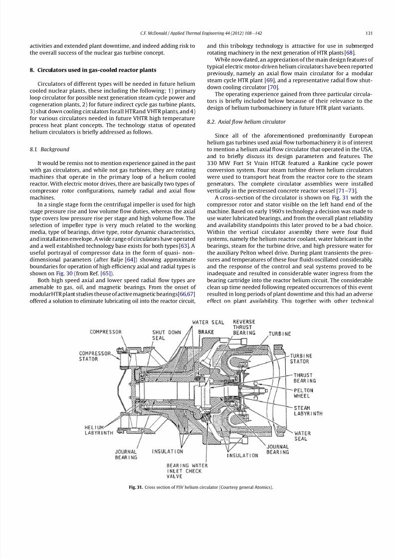
8112019 Helium Turbomachinery Operating Experience From Gas Turbine Power Plants
httpslidepdfcomreaderfullhelium-turbomachinery-operating-experience-from-gas-turbine-power-plants 2435
activities and extended plant downtime and indeed adding risk to
the overall success of the nuclear gas turbine concept
8 Circulators used in gas-cooled reactor plants
Circulators of different types will be needed in future helium
cooled nuclear plants these including the following 1) primary
loop circulator for possible next generation steam cycle power andcogeneration plants 2) for future indirect cycle gas turbine plants
3) shut down cooling circulators forall HTRand VHTR plants and 4)
for various circulators needed in future VHTR high temperature
process heat plant concepts The technology status of operated
helium circulators is brie1047298y addressed as follows
81 Background
It would be remiss not to mention experience gained in the past
with gas circulators and while not gas turbines they are rotating
machines that operate in the primary loop of a helium cooled
reactor With electric motor drives there are basically two types of
compressor rotor con1047297gurations namely radial and axial 1047298ow
machinesIn a single stage form the centrifugal impeller is used for high
stage pressure rise and low volume 1047298ow duties whereas the axial
type covers low pressure rise per stage and high volume 1047298ow The
selection of impeller type is very much related to the working
media type of bearings drive type rotor dynamic characteristics
and installation envelope A wide range of circulators have operated
and a well established technology base exists for both types [63] A
useful portrayal of compressor data in the form of quasi- non-
dimensional parameters (after Balje [64]) showing approximate
boundaries for operation of high ef 1047297ciency axial and radial types is
shown on Fig 30 (from Ref [65])
Both high speed axial and lower speed radial 1047298ow types are
amenable to gas oil and magnetic bearings From the onset of
modularHTR plant studies theuse of active magnetic bearings[6667]offered a solution to eliminate lubricating oil into the reactor circuit
and this tribology technology is attractive for use in submerged
rotating machinery in the next generation of HTR plants [68]
While now dated an appreciation of the main design features of
typical electric motor-driven helium circulators have been reported
previously namely an axial 1047298ow main circulator for a modular
steam cycle HTR plant [69] and a representative radial 1047298ow shut-
down cooling circulator [70]
The operating experience gained from three particular circula-
tors is brie1047298y included below because of their relevance to the
design of helium turbomachinery in future HTR plant variants
82 Axial 1047298ow helium circulator
Since all of the aforementioned predominantly European
helium gas turbines used axial 1047298ow turbomachinery it is of interest
to mention a helium axial 1047298ow circulator that operated in the USA
and to brie1047298y discuss its design parameters and features The
330 MW Fort St Vrain HTGR featured a Rankine cycle power
conversion system Four steam turbine driven helium circulators
were used to transport heat from the reactor core to the steam
generators The complete circulator assemblies were installed
vertically in the prestressed concrete reactor vessel [71e73]
A cross-section of the circulator is shown on Fig 31 with thecompressor rotor and stator visible on the left hand end of the
machine Based on early 1960rsquos technology a decision was made to
use water lubricated bearings and from the overall plant reliability
and availability standpoints this later proved to be a bad choice
Within the vertical circulator assembly there were four 1047298uid
systems namely the helium reactor coolant water lubricant in the
bearings steam for the turbine drive and high pressure water for
the auxiliary Pelton wheel drive During plant transients the pres-
sures and temperatures of these four 1047298uids oscillated considerably
and the response of the control and seal systems proved to be
inadequate and resulted in considerable water ingress from the
bearing cartridge into the reactor helium circuit The considerable
clean up time needed following repeated occurrences of this event
resulted in long periods of plant downtime and this had an adverseeffect on plant availability This together with other technical
Fig 31 Cross section of FSV helium circulator (Courtesy general Atomics)
CF McDonald Applied Thermal Engineering 44 (2012) 108e142 131
8112019 Helium Turbomachinery Operating Experience From Gas Turbine Power Plants
httpslidepdfcomreaderfullhelium-turbomachinery-operating-experience-from-gas-turbine-power-plants 2535
dif 1047297culties eventually contributed to the plant being prematurely
decommissioned
On the positive side in the context of this paper the helium
circulators operated for over 250000 h and exhibited excellent
helium compressor performance good mechanical integrity and
vibration-free operation The rotating assembly showing the axial
1047298ow compressor and steam turbine rotors together with a view of
the machine assembly are given on Fig 32 The helium compressor
consists of a single stage axial rotor followed by an exit guide vane
The machine was designed for axial helium 1047298ow entering and
leaving the stage and this can be seen from the velocity triangles
shown on Fig 33 which also includes the de1047297nition of the various
aerodynamic parameters Major design parameters and features of
this helium circulator are given on Table 4 Related to an earlier
discussion on the degree of reaction for axial 1047298ow compressors the
value for this conventional single stage circulator is 78 percent All
of the major aerothermal and structural loading criteria were
within established boundaries for an axial compressor having high
ef 1047297ciency and a good surge margin
The compressor gas 1047298ow path and blading geometries were
established based on prevailing industrial gas turbine and aero-
engine design practice A low Mach number (025) a high Reynolds
number (3 106) together with a modest stage loading (ie
a temperature rise coef 1047297cient of 044) and an acceptable value of
diffusion factor (042) were some of the factors that contributed to
a helium circulator that had a high ef 1047297ciency and a good pressure
rise- 1047298ow characteristic The large rotor blade chord and thick blade
section for this single stage circulator are necessary to accommo-
date the high bending stress characteristic of operation in a high
pressure environment The solidity and blade camber were opti-
mized for minimum losses
There were essentially two reasons for including this single-
stage axial 1047298ow compressor that operated in a helium cooled
reactor although its overall con1047297guration can be regarded as a 1047297rst
and last of a kind A rotor blade from this circulator as shown onFig 34 was based on a NASA 65 series airfoil which at the time
were one of the best performing cascades for such low Mach
number and high Reynolds number applications Interestingly it
has almost the same blade height aspect ratio and solidity as would
be used in the 1047297rst stage of an LP compressor in a helium turbo-
machine rated on the order of 250 MW
The second point of interest is that the helium mass 1047298ow rate
through the single stage axial compressor (rated at 4 MWe) is
110 kgs compared with 85 kgs through the multistage compressor
in the 50 MWe Oberhausen II helium gas turbine plant However
the volumetric 1047298ow through the Oberhausen axial compressor is
higher than that through the circulator by a factor of 16 this again
pointing out that the Oberhausen II plant was designed for high
volumetric 1047298ow to simulate the much larger size of turboma-chinery that was planned at the time in Germany for use in future
projected nuclear gas turbine power plants
83 High temperature helium circulator
For future helium turbomachines embodying active magnetic
bearings a challenge in their design relates to accommodating
elevated levels of temperature in the vicinity of the electronic
components In this regard it is of interest to note that a small very
high temperature helium axial 1047298ow circulator rated at 20 kW (as
shown on Fig 35) operated for more than 15000 h in an insulation
test facility in Germany more than two decades ago [74] The
signi1047297cance of this machine is that it operated with magnetic
bearings in a high temperature helium test loop with a circulatorgas inlet temperature of 950 C (1742 F) This necessitated the use
of ceramic insulation to ensure that the temperature in the vicinity
of the magnetic bearing electronics did not exceed a temperature of
about 150 C (300 F)
This machine although a very small axial 1047298ow helium blower
performed well and has been brie1047298y mentioned here since it
represents a point of reference for future helium rotating machines
capable operating with magnetic bearings in a very high temper-
ature helium environment
84 Radial 1047298ow AGR nuclear plant gas circulators
The electric motor-driven carbon dioxide circulators rated at
about 5 MW with a total runningtimein excess of 18 million hours
Fig 32 Fort St Vrain HTGR plant helium circulator (Courtesy General Atomics) (a)
Axial 1047298ow helium compressor and steam turbine rotating assembly (b) 4 MW helium
circulator assembly
CF McDonald Applied Thermal Engineering 44 (2012) 108e142132
8112019 Helium Turbomachinery Operating Experience From Gas Turbine Power Plants
httpslidepdfcomreaderfullhelium-turbomachinery-operating-experience-from-gas-turbine-power-plants 2635
in AGR nuclear power plants in the UK have demonstrated veryhigh availability [7576] To a high degree this can be attributed to
the fact that the machines were conservatively designed and proof
tested in a non-nuclear facility at full temperature and power
under conditions that simulated all of the nuclear plant operating
modes The test facility shown on Fig 36 served two functions 1)
design veri1047297cation of the prototype machine and 2) test of all new
and refurbished machines before they were installed in nuclear
plants Engineers currently involved in the design and development
of helium turbomachinery could bene1047297t from this sound testing
protocol to minimize risk in the deployment of helium rotating
machinery in future HTRVHTR plant variants
9 Helium turbomachinery development and testing
91 On-going development activities
The various helium turbomachines discussed in previous
sections operated over a span of about two decades starting in the
early 1960s From about 1990 activities in the nuclear gas turbine
1047297eld have been focused mainly on the design of modular GTeHTR
plant concepts In support of these plant studies many signi1047297cant
helium turbomachine design advancements have been made and
attention given to what development testing would be needed In
the last decade or so limited sub-component development has
been undertaken for helium turbomachines in the 250e300 MWe
size and these are brie1047298y summarized below
In a joint USARussia effort development in support of the
GTe
MHR turbomachine has been undertaken including testing in
the following areas magnetic bearings seals and rotor dynamicsfor the vertical intercooled helium turbomachine rated at 286 MWe
[77e80]
In Japan development activities have been in progress for
several years in support of the 274 MWe helium turbomachine for
the GTeHTR300 plant concept [2581] A detailed discussion on
the aerodynamic design of the axial 1047298ow helium compressor for
this turbomachine has been published in the open literature [82]
While the design methodology used for axial compressor design in
air-breathing industrial and aircraft gas turbines is generally
applicable for a multi-stage helium compressor a decision was
made by JAEA to test a small scale compressor in a helium facility
because of the inherent and unique gas 1047298ow path and type of
blading associated with operation in a high pressure helium
environment The major goal of the test was to validate the designof the 20 stage helium axial 1047298ow compressor for the GTeHTR300
plant
An axial 1047298ow compressor in a closed-cycle helium gas turbine is
characterized by the following 1) a large number stages 2) small
blade heights 3) high hub-to-tip ratio 4) a long annulus with
small taper that tends to deteriorate aerodynamic performance as
a result of end-wall boundary layer length and secondary 1047298ow 5)
low Mach number 6) high Reynolds number and 7) blade tip
clearances that are controlled by the gap necessary in the magnetic
journal and catcher bearings While (as covered in earlier sections)
helium gas turbines have operated there is limited data in the
open literature on the performance of multi-stage axial 1047298ow
compressors operating in a high pressure closed-loop helium
environment
Fig 33 Velocity triangles for axial compressor stage
CF McDonald Applied Thermal Engineering 44 (2012) 108e142 133
8112019 Helium Turbomachinery Operating Experience From Gas Turbine Power Plants
httpslidepdfcomreaderfullhelium-turbomachinery-operating-experience-from-gas-turbine-power-plants 2735
A 13rd scale 4 stage compressor was designed to simulate the
stage interaction the boundary layer growth and repeated stage
1047298ow in an actual compressor The 1047297rst four stages were designed to
be geometrically similar to the corresponding stages in the
GTe
HTR300 compressor Details of the model compressor havebeen discussed previously [81] and are summarized on Table 5
from [83]
A cross-section of the compressor test model is shown on Fig 37
A view of the 4 stage compressor rotor installed in the lower casing
is shown on Fig 38 The test facility (Fig 39) is a closed helium loop
consisting of the compressor model cooler pressure adjustment
valve and a 1047298ow measurement instrument The compressor is
driven by a 3650 kW electrical motor via a step-up gear The rota-
tional speed of 10800 rpm (three times that of the compressor in
the GTeHTR300 plant) was selected to match blade speed and
Mach number in the full size compressor
Details of the planned aerodynamic performance objectives of
the 13rd scale helium compressor test have been published
previously [84] Extensivetesting of the subscale model compressorprovided data to validate the performance of the full size
compressor for the GTeHTR300 power plant The test data and
test-calibrated CFD analyses gave added insight into the effect of
factors that impact performance including blade surface roughness
and Reynolds number
Based on advanced aerodynamic methodology and experi-
mental validation [82] there is now a sound basis for added
con1047297dence that the design goals of 90 percent polytropic ef 1047297ciency
and a design point surge margin of 20 percent are realizable in
a large multistage axial 1047298ow compressor for a future nuclear gas
turbine plant
In a similar manner a design of a one third size single stage
helium axial 1047298ow turbine has been undertaken and a cross
section of the machine is shown on Fig 40 (from Ref [81]) This
Table 4
Major features of axial 1047298ow helium circulator
Helium 1047298ow rate kgsec 110
Inlet temperature C 394
Inlet pressure MPa 473
Pressure rise KPa 965
Volumetric 1047298ow m3sec 32
Compressor type Single stage axial
Compressor drive Steam turbine
Bearing type Water lubricated
Rotational speed rpm 9550
Power MW 40
Rotor tip diameter mm 688
Rotor tip speed msec 344
Number of rotor blades 31
Number of stator blades 33
Blade height mm 114
Hub-to-tip ratio 067
Axial velocity msec 157
Flow coef 1047297cient 055
Temperature rise coef 1047297cient 044
Degree of reaction 078
Mean rotor solidity 128
Rotor aspect ratio 155
Rotor Mach number 025
Rotor diffusion factor 042
Rotor Reynolds number 3106
Speci1047297c speed 335
Speci1047297c diameter 066
Blade root thickness 15
Airfoil type NASA 65
Rotor blade chord mm 94e64
Stator blade chord mm 79
Rotor centrifugal stress MPa 125
Rotor bending stress MPa 30
Circulator(s) operating Hours gt250000
Fig 34 Rotor blade from single stage axial 1047298ow helium circulator (Courtesy General
Atomics)
Fig 35 20 kW axial 1047298ow helium circulator with magnetic bearings operated in 1985 in
an insulation test loop with a gas inlet temperature on 950
C (Courtesy BBC)
CF McDonald Applied Thermal Engineering 44 (2012) 108e142134
8112019 Helium Turbomachinery Operating Experience From Gas Turbine Power Plants
httpslidepdfcomreaderfullhelium-turbomachinery-operating-experience-from-gas-turbine-power-plants 2835
single stage scale model turbine for validity of the full size turbine
has been built and plans made to test the aerodynamic
performance
92 Nuclear gas turbine helium turbomachine testing
In planning for the 1047297rst nuclear gas turbine plant projected to
enter service perhaps in the third decade of the 21st century
a major decision has to be made as to what extent the large helium
turbomachine should be tested prior to operation on nuclear heat
Issues essentially include cost impact on schedule but the over-
riding one is risk Certainly turbomachine component testing will
be undertaken including the compressor (as discussed in the
previous section) and turbine performance seals cooling systems
hot gas valves thermal expansion devices high temperature
insulation rotor fragment containment diagnostic systems
instrumentation helium puri1047297cation system and other areas to
satisfy safety licensing reliability and availability concerns The
major point is really whether a full size or scaled-down turbo-machine be tested early in the project in a non-nuclear facility
To obviate the need for pre-nuclear testing of a large helium
turbomachine a view expressed by some is that advantage can be
taken of formidable technology bases that exist today for large
industrial gas turbines and high performance aeroengines On the
other hand it is the view of some including the author that very
complex power conversion system components especially those
subjected to severe thermal transients donrsquot always perform
exactly as predicted by analysts and designers even using sophis-
ticated computer codes This was exempli1047297ed in the case of the
turbomachine in the aforementioned Oberhausen II helium gas
turbine plant
The need for a helium turbomachine test facility goes beyond
just veri1047297
cation of the prototype machine Each newgas turbine for
commercial modular nuclear reactor plants would have to be proof
tested and validated before being transported to the reactor site
Similarly turbomachines that would be periodically removed from
the plant at say 7 year intervals during the plant operating life of 60
years for scheduled maintenance refurbishment repair or updat-ing would be again proof tested in the facility before re-entering
service
The direction that turbomachine development and testing will
take place for future helium gas turbines needs to be addressed by
the various organizations involved
Fig 36 AGR circulator test facility In the UK (Courtesy Howden)
Table 5
Major design parametersfeatures of model GTeHTR300 axial 1047298ow helium
compressor (Courtesy JAERI)
Scale of GTeHTR300 compressor 13
Helium mass 1047298ow rate (kgsec) 122
Helium volumetric 1047298ow rate (mV s) 87
Inlet temperature C 30
Inlet pressure MPa 0883Compressor pressure ratio at design point 1156
Number of stages 4
Rotational speed rpm 10800
Drive motor power kW 3650
Hub diameter mm 500
Rotor tip diameter (1st4th stage mm) 568566
Hub-to-tip ratio (1st stage) 088
Rotor tip speed (1st stage msec) 321
Number of rotorstator blades (1st stage) 7294
Rotorstator blade height (1st stage mm) 34337
Rotor stator blade c hor d l eng th (1st stage mm) 2620
Rotorstator solidity (1st stage) 119120
Rotorstator aspect ratio (1st stage) 1317
Flow coef 1047297cient 051
Stage loading factor 031
Reynolds number at design point 76 l05
CF McDonald Applied Thermal Engineering 44 (2012) 108e142 135
8112019 Helium Turbomachinery Operating Experience From Gas Turbine Power Plants
httpslidepdfcomreaderfullhelium-turbomachinery-operating-experience-from-gas-turbine-power-plants 2935
10 Helium turbomachinery lessons learned
101 Oberhausen II gas turbine and HHV test facility
It is understandable that 1047297rst-of-a-kind complex turboma-
chinery operating with an inert low molecular weight gas such as
helium will experience unique and unexpected problems In the
operation of the two pioneering large helium turbomachines in
Germany there were many positive1047297ndings which could only have
been achieved by development testing Equally important some
negative situations were identi1047297ed many of which were remedied
In the case of the Oberhausen II helium gas turbine plant some of
the very serious problems encountered were not resolved Inves-
tigations were undertaken to rationalize the problems associated
with the large power de1047297ciency and a data base established to
ensure that the various anomalies identi1047297ed would not occur in
future large helium turbomachines
The experience gained from the operation of the Oberhausen II
helium gas turbine power plant and the HHV test facility have been
discussedin thetextand arepresentedin a summaryformon Table6
Fig 37 Cross-section of 13rd scale helium compressor test model (Courtesy JAEA)
Fig 38 Four stage helium compressor rotor assembly installed in lower casing (Courtesy JAEA)
CF McDonald Applied Thermal Engineering 44 (2012) 108e142136
8112019 Helium Turbomachinery Operating Experience From Gas Turbine Power Plants
httpslidepdfcomreaderfullhelium-turbomachinery-operating-experience-from-gas-turbine-power-plants 3035
102 Impact of 1047297ndings on future helium gas turbine
The long slender rotorcharacteristic of closed-cycle gas turbines
has resulted in shaft dynamic instability which in some cases has
resulted in blade vibration and failure and bearing damage This
remains perhaps the major concern in the design of large
(250e
300 MW) helium turbomachines for future nuclear gas
turbine plants With pressure ratios in the range of about 2e3 in
a helium system a combination of splitting the compressor (to
facilitate intercooling) and having a large number of compressor
and turbine stages results in a long and 1047298exible rotating assembly
andthis is exempli1047297ed by the rotorassembly shown on Fig13 With
multiple bearings (either oil lubricated or magnetic) the rotor
would likely pass through multiple bending critical speeds before
Fig 39 Helium compressor test facility (Courtesy JAEA)
Fig 40 Cross-section of single stage helium turbine test model (Courtesy JAEA)
CF McDonald Applied Thermal Engineering 44 (2012) 108e142 137
8112019 Helium Turbomachinery Operating Experience From Gas Turbine Power Plants
httpslidepdfcomreaderfullhelium-turbomachinery-operating-experience-from-gas-turbine-power-plants 3135
reaching the design speed While very sophisticated computer
codes will be used in the detailed rotor dynamic analyses the real
con1047297rmation of having rotor oscillations within prescribed limits
(to avoid blade bearing and seal damage) will come from actual
testingA point to be made here is that in operated fossil-1047297red closed-
cycle gas turbine plants it was possible to remedy problems asso-
ciated with rotor vibrations and blade failures in a conventional
manner In fact in some situations the casings were opened several
times and modi1047297cations made to facilitate bearing and seal
replacement and rotor re-blading and balancing
An accurate assessment of pressure losses must be made
particularly those associated with the helium entering and leaving
the turbomachine bladed sections Minimizing the system pressure
loss is important since it directly impacts the all important quotient
of turbine expansion ratio to compressor pressure ratio and power
and plant ef 1047297ciency
Based on the operating experience from the 20 or so fossil-1047297red
closed-cycle gas turbine plants using air as the working1047298
uid it was
recognized that future very high pressure helium gas turbines
would pose problems regarding the various seals in the turbo-
machine and obtaining a zero leakage system with such a low
molecular weight gas would be dif 1047297cult and this is discussed
below
When the Oberhausen II gas turbine plant and the HHV facility
operated over 30 years ago oil lubricated bearings were used to
support the heavy rotor assemblies and helium buffered labyrinth
seals were used to prevent oil ingressinto the heliumworking1047298uid
Initial dif 1047297culties encountered in both plants were overcome by
changes made to the seal geometries and for the operating lives of
the helium turbomachines no further oil ingress events were
experienced Twoseals were required where the turbine drive shaft
penetrated the turbomachine casing namely 1) a dynamic laby-
rinth seal and 2) a static seal for shutdown conditions In both
plants these seals functioned without any problems
Labyrinth seals were also required within the helium turbo-
machines to pass the correct helium bleed 1047298ow from the
compressor discharge for cooling of the turbine discs blade root
attachments and casings The fact that the very complex rotor
cooling system in the large helium turbomachine in the HHV test
facility operated well for the test duration of about 350 h with
a turbine inlet temperature of 850 C was encouragingIn the case of the Oberhausen II gas turbine plant analysis of the
test data revealed that the labyrinth seal leakage and excessive
cooling 1047298ows were on the order of four times the design value A
possible reason for this was that damage done to the labyrinth
seals caused excessive clearances when periods of excessive rotor
oscillation and vibration occurred during early operation of the
machine
Clearly 1047298uid dynamic and thermal management of the cooling
system and 1047298ow through the various labyrinth seals will require
extensive analysis design and development testing before the
turbomachine is operated on nuclear heat for the 1047297rst time
In future heliumgas turbine designs (with turbine inlet tempera-
tureslikelyontheorderof950C)the1047298owpathgeometriesofhelium
bledfromthecompressornecessarytocoolpartsoftheturbomachinewillbemorecomplexthanthosetestedto-dateInadditiontoproviding
acooling1047298owtotheturbinebladesanddiscsbladerootattachmentsand
casingsheliummustbetransportedtotheseveralmagneticbearingsto
ensure thatthe temperatureof theirelectronic components doesnot
exceedabout150C
The importance of the points made above is evidenced when
examining the data on Table 3 where a combination of excessive
pressure losses and high bleed 1047298ows contributed to about 40
percent of the power de1047297ciency in the Oberhausen II helium
turbine plant
Retaining overall system leak tightnessin closed heliumsystems
operating at high pressure and temperature has been elusive
including experience from the Fort St Vrain HTGR plant as dis-
cussed in Section 65 New approaches in the design of the plethoraof mechanical joints must be identi1047297ed Experience to-date has
shown that having welded seals on 1047298anges while minimizing
system leakage did not eliminate it
The importance of lessons learned from the operation of the
Oberhausen II helium turbine power plant and the HHV test facility
have primarily been discussed in the context of helium turbo-
machines currently being designed in the 250e300 MWe power
range However the established test data bases could also be
applied to the possible emergence in the future of two helium
cooled reactor concepts namely 1) an advanced VHTR combined
cycle plant concept embodying a smaller helium gas turbine in the
power range of 50e80 MWe [22] and 2) the use of a direct cycle
helium gas turbine PCS in a recently proposed all ceramic fast
nuclear reactor concept [85]
Table 6
Experience gained from Oberhausen II and HHV facility
Oberhausen II 50 MW helium gas turbine power plant
Positive results
e Rotating and static seals worked well
e No ingress of bearing lubricant oil into closed circuit
e Load change by inventory control worked well
e 100 Percent load shed by means of bypass valves demonstrated
e Turbine disc and blade root cooling system con1047297rmed
e Coatings on mating surfaces prevented galling and self-welding
e After 24000 h of operation no evidence of corrosion or erosion
e Coaxial turbine hot gas inlet duct insulation and integrity con1047297rmed
e Monitoring of complete power conversion system for steady state
and transient operation undertaken
Problem areas
e Serious power output de1047297ciency (30 MW compared with design
value of 50 MW)
e Compressor(s) and turbine(s) ef 1047297ciencies several points below predicted
e Higher than estimated system pressure loss
e Rotor dynamic instability and blade vibration
e Bearings damaged and had to be replaced
e Blade failure caused extensive damage in HP turbine but retained
in casing
e Very excessive sealing and cooling 1047298ow rates
e Absolute leak tightness not attainable even with welded 1047298ange lips
HHV test facility
Positive resultse Use of heat pump approach facilitated helium temperature capability
to 1000 C
e Large oompressorturbine rotor system operated at 3000 rpm Complex
turbine disc and blade root cooling system veri1047297ed
e Dynamic and static seals met requirement of zero oxl ingress into circuit
e Structural integrity of rotating assembly veri1047297ed at temperature of 850 C
e Measured rotor oscillations within speci1047297cation
e Compressor and turbine ef 1047297ciencies higher than predicted
e Coatings on mating metallic surfaces prevented galling and self-welding
e Instrumentation control and safety systems veri1047297ed
e Seal 1047298ows within speci1047297cation
e Machine stop from operating speed to shutdown in 90 s demonstrated
e Hot gas duct insulation and thermal expansion devices worked well
e After 1100 h of operation no evidence of corrosionof erosion
Problem areas
e Before commissioning a large oil ingress into the circuit occurred due
to serious operator error and absence of an isolation valve A second oilingress occurred due to a mechanical defect in the labyrinth seal system
These were remedied and no further oil ingress was experienced for the
duration of testing
e Cooling 1047298ows slightly larger than expected but this resulted in actual
disc and blade root temperatures lower than the predicted value of
400 C
e System leak tightness demonstrated when pressurized at ambient
temperature conditions but some leakage occured at 850 C even with
the seal welding of 1047298ange(s) lips
CF McDonald Applied Thermal Engineering 44 (2012) 108e142138
8112019 Helium Turbomachinery Operating Experience From Gas Turbine Power Plants
httpslidepdfcomreaderfullhelium-turbomachinery-operating-experience-from-gas-turbine-power-plants 3235
11 New technologies
It is recognized that in the 3 to 4 decades since the operation of
the helium turbomachines covered in this paper new technologies
have emerged which negate some of the early issues An example of
this is the technology transfer from the design of modern axial 1047298ow
gas turbines (ie industrial aircraft and aeroderivatives) that fully
utilize sophisticated CAE CAD CFD and FEA design software
Air breathing aerodynamic design practice for compressors and
turbines are generally applicable but the properties of helium and
the high system pressure have a signi1047297cant impact on gas 1047298ow
paths and blade geometries With short blade heights high hub-to-
tip ratios long annulus 1047298ow path length (with resultant signi1047297cant
end-wall boundary layer growth and secondary 1047298ow) and blade tip
clearances in some cases controlled by clearances in the magnetic
catcher bearing testing of subscale model compressors and
Fig 41 Gas turbine test facility for aircraft nuclear propulsion involving the coupling of a 32 MWt air-cooled reactor with two modi 1047297ed J-47 turbojet aeroengines each rated at
a thrust of about 3000 kg operated in 1960 (Courtesy INL)
Fig 42 Mobile 350 KWe closed-cycle nuclear gas turbine power plant operated in 1961 (Courtesy US Army)
CF McDonald Applied Thermal Engineering 44 (2012) 108e142 139
8112019 Helium Turbomachinery Operating Experience From Gas Turbine Power Plants
httpslidepdfcomreaderfullhelium-turbomachinery-operating-experience-from-gas-turbine-power-plants 3335
turbines will be needed While most of the operated helium tur-
bomachines discussed in this paper took place 3 or 4 decades ago it
is encouraging that the fairly recent test data and test-calibrated
CFD analysis from a subscale four stage model helium axial 1047298ow
compressor in Japan [80] gave a high degree of con1047297dence that
design goals are realizable for the full size 20 stage compressor in
the 274 MWe GTeHTR300 plant turbomachine
In the future the use of active magnetic bearings will eliminate
the issue of oil ingress however the very heavy rotor weight and
size of the journal and thrust bearings (and catcher bearings) of the
type for helium turbomachines in the 250e300 MWe power range
are way in excess of what have been demonstrated in rotating
machinery For plant designs retaining oil-lubricated bearings well
established dry gas seal technology exists particularly experience
gained from the operation of high pressure natural gas pipe line
compressors
For future nuclear helium gas turbine plants the designer has
freedom regarding meeting different frequency requirements that
exist in some countries These include use of a synchronous
machine (ie designed for 50 or 60 Hz grids) use of a gearbox drive
between the turbine and generator or the use of a frequency
converter which gives the designer an added degree of freedom
regarding the selection of speed for the rotating assemblyCompared with the past very sophisticated electronic control
systems instrumentation and diagnostic systems are available
today
12 Conclusions
In this review paper experience from operated helium turbo-
machines has been compiled based on open literature sources At
this stage in the evolution of HTR and VHTR plant concepts it is not
clear in what role form or time-frame the nuclear gas turbine will
emerge when commercialized By say the middle of the 21st
century all power plants will be operating with signi1047297cantly higher
ef 1047297ciencies to realize improved power generation costs and
reduced emissions In a nuclear gas turbine the helium turbo-machine will be a major contributor towards the achievement of
ef 1047297ciencies higher than 50 percent
While it has been 3 to 4 decades since the Oberhausen II helium
turbine power plant and the HHV high temperature helium turbine
facility operated signi1047297cant lessons were learned and the time and
effort expended to resolve the multiplicity of unexpected technical
problems encountered The remedial repair work was done under
ideal conditions namely that immediate hands-on activities were
possible This would not have been possible if the type of problems
experienced had been encountered in a new and untested helium
turbomachine operated for the 1047297rst time with a nuclear heat
source
While new technologies have emerged that negate many of the
early problems there are some uniquely inherent issues associatedwith for large helium turbines operating in a high pressure and
temperature environment and these include the following 1)
minimizing system leakage with such a low molecular weight gas
2) clearances in labyrinth seals to minimize helium bypass1047298ows 3)
the dynamic stability of long slender rotors 4) minimizing the
turbomachine inlet and outlet pressure losses 5) 1047298ow maldis-
tribution in complex ductturbomachine interfaces 6) integrity
veri1047297cation of the catcher bearings (journal and thrust) after
multiple rotor drops (following loss of the magnetic 1047297eld) during
the plant lifetime 7) assurances that high energy fragments from
a failed turbine disc are contained within the machine casing 8)
turbomachine installation and removal from a steel pressure vessel
and 9) remote handling and cleaning of a machine with turbine
blades contaminated with 1047297
ssion products
The need for a helium turbomachine test facility has been
emphasized to ensure that the integrity performance and reli-
ability of the machine before it operates the 1047297rst time on nuclear
heat Engineers currently involved in the design of helium rotating
machinery for all HTR and VHTR plant variants should take
advantage of the experience gained from the past operation of
helium turbomachinery
13 In closing-GT rsquos operated with nuclear heat
In the context of this paper it is germane to mention that two
gas turbines have actually operated using nuclear heat as brie1047298y
highlighted below
In the late 1950rsquos a program was initiated in the USA for aircraft
nuclear propulsion (ANP) While different concepts were studied
only the direct cycle air-cooled reactor reached the stage of
construction of an experimental reactor [86] A view of the large
nuclear gas turbine facility is given on Fig 41 and shows the air-
cooled and zirconiumehydride moderated reactor rated at
32 MWt coupled with two modi1047297ed J-47 turbojet engines each
rated with a thrust of about 3000 kg In this open cycle system the
high pressure compressor air was directly heated in the reactor
before expansion in the turbine and discharge to the atmosphere in
the exhaust nozzle The facility operated between 1958 and 1961 at
the Idaho reactor testing facility While perhaps possible during the
early years of the US nuclear program it is clear that such a system
would not be acceptable today from safety and environmental
considerations
The 1047297rst and indeed the only coupling of a closed-cycle gas
turbine with a nuclear reactor for power generation was under-
taken to meet the needs of the US Army In the late 1950 rsquos an RampD
program was initiated for a 350 kW trailer-mounted system to be
used in the 1047297eld by military personnel A prototype of the ML-1
plant shown on Fig 42 was 1047297rst operated in 1961 [8788]
It was based on a 33 MW light water moderated pressure tube
reactor with nitrogen as the coolant The closed-cycle gas turbine
power conversion system with nitrogen as the working 1047298uid hada turbine inlet temperature of 649 C (1200 F) and delivered
around 300 kW With changes in the Armyrsquos needs the project was
discontinued in 1965
While the experience gained from the above twounique nuclear
plants is clearly not relevant for future nuclear gas turbine power
plants that could see service in the third decade of the 21st century
these ambitious and innovative nuclear gas turbine pioneering
engineering efforts need to be recognized
Acknowledgements
The author would like to thank the following for helpful discus-
sions advice and for providing valuable comments on the initial
paper draft Prof Dr Hermann Haselbacher Hans Ulrich Frutschi DrXing Yan DrPeter Zenker Professor DavidGordon Wilson Professor
Aristide Massardo Arthur Harris DrFred Starr and DrGuido Bac-
caglini This paper has been enhanced by the inclusion of hardware
photographs and unique sketches and the author is appreciative to
all concerned with credits being duly noted
References
[1] C Keller The Escher Wyss AK Closed-Cycle Gas Turbine Its Actual Develop-ment and Future Prospects Paper Presented at ASME Meeting November 261945
[2] HU Frutschi Closed-Cycle Gas Turbines Operating Experience and FuturePotential ASME Press NY 2005
[3] CF McDonald The Nuclear Gas Turbine-Towards Realization After Half
a Century of Evolution (1995) ASME Paper 95-GT-292
CF McDonald Applied Thermal Engineering 44 (2012) 108e142140
8112019 Helium Turbomachinery Operating Experience From Gas Turbine Power Plants
httpslidepdfcomreaderfullhelium-turbomachinery-operating-experience-from-gas-turbine-power-plants 3435
[4] C Keller The Theory and Performance of Axial Flow Fans McGraw Hill BookCompany Inc NY 1937
[5] J Ackert C Keller Aerodynamic turbine with closed circuit In A Century of Turbines vols 1516 Escher Wyss News 1942e43 5e19
[6] Escher Wyss News Closed-Cycle Gas Turbines for all Fuels Coal Gas Nuclearvol 39 No 1 (1966)
[7] C Keller Closed-cycle gas turbine Escher Wyss-AK development 1945e1950Transactions of ASME (August 1950) 835e850
[8] C Keller Operating Experience and Design Features of Closed-Cycle GasTurbine Power Plants (1956) ASME Paper 56-GTP-15
[9] C Keller HU Frutschi Closed-cycle plants -conventional and nuclear designapplication operation In Sawyerrsquos Gas Turbine Engineering Handbooksecond ed vol 2 Applications (1976) pp 265e283
[10] K Bammert G Groschup Status Report on Closed-Cycle Power Plants in theFederal Republic of Germany (1976) ASME Paper 76-GT-54
[11] JL Mason Monatomic Working Gases versus Air for Closed Brayton Cycles(1985) ASME Paper 85-IGT-50
[12] JL Mason et al 5 MW Closed Cycle Gas Turbine (1984) ASME Paper 84-GT-268
[13] The British Gas Closed-Cycle Demonstrator (1995) British Gas Research ampTechnology Final Year Report
[14] F Starr ODS alloy high temperature heat exchanger prototype developmentPaper Presented at ODS 2010 Materials Workshop UCSD Jacobs Hall La JollaCalifornia Nov17e18 2010
[15] CA Rennie Achievements of the Dragon project Pergamon Press Annals of Nuclear Energy 5 (1978) 305e320
[16] SB Hosegood et al Dragon Project Engineering Studies on the Direct CycleHTR Proceedings of Conference on Nuclear Gas Turbines The British NuclearEnergy Society London April 8e9 1970 pp 161e179
[17] Nuclear Gas Turbines Proceedings of British Nuclear Society Meeting LondonApril 8-9 1972
[18] CF McDonald C Peinado ldquoThe nuclear gas Turbine-A perspective on a long-term advanced technology HTGR plant Optionrdquo ASME Paper 82-GT-289
[19] GH Lohnert et al Technical design features and essential safety-relatedfeatures of the HTR-Module Nuclear Engineering and Design 121 (1990)259e275
[20] H Reutler GH Lohnert The modular high temperature nuclear reactorNuclear Technology 62 (1983) 22e30
[21] CF McDonald Exploitation of the very high temperature capability of theMHTGR to meet National energy needs after the year 2000 IECEC Paper869006
[22] CF McDonald Power conversion system considerations for an advancednuclear gas turbine (GT-VHTR) CHHP demonstration plant concept Interna-tional Journal of Turbo amp Jet Engines 27 (2010) 179e217
[23] N Hee Cheon et al A review of helium gas turbine technology for hightemperature gas cooled reactors Nuclear Engineering and Design 29 (2007)21e30
[24] CB Baxi et al Development of the GT-MHR Turbomachine ASME PaperGT2009e59450[25] X Yan GTHTR300 design and development Nuclear Engineering and Design
222 (2003) 247e262[26] JC Gauthier et al ANTARES the HTRVHTR project of Framatome ANP
Nuclear Engineering and Design 236 (2006) 526e533[27] J Wang et al ldquoDesign features of gas turbine power conversion system for
HTR-10GT paper D05 presented at 2nd Intl Meeting on HTR TechnologyBeijing China September 21e24 2004
[28] A Koster et al ldquoPBMR Design For the Futurerdquo Nuclear engineering andDesign 222 (203) 231e245
[29] S van der Linden Closed cycle nuclear plant rated at 165 MWe and 40 percentef 1047297ciency Gas Turbine World (MarcheApril 2007) 28e32
[30] CF McDonald Large closed-cycle gas turbines Sawyerrsquos gas turbine engi-neering handbook In Selection and Applications vol II (1985) pp 81e38(Chapter 8)
[31] CF McDonald Helium and Combustion Gas Turbine Power ConversionSystems Comparison (1995) ASME Paper 95-GT-263
[32] JK La Fleur Description of an Operating Closed-Cycle Helium Gas Turbine
ASME Paper 63-AHGT-74[33] JK La Fleur The use of turbomachinery in the 1047297eld of cryogenics In
Sawyerrsquos Gas Turbine Engineering Handbook vol II (1976) 296e311[34] W Spillmann The Closed-Cycle Gas Turbine for Non-Conventional Applica-
tions ASME Paper 66-GT-8[35] K Holliger On the in1047298uence of the degree of reaction on the secondary losses
in axial 1047298ow compressors Escher Wyss News 23 (1960)[36] W Gut Comparison of the relative losses and characteristics of axial
compressor stages Escher Wyss News 23 (1959)[37] JH Horlock Axial Flow Compressors Butterworths Scienti1047297c Publications
London 1958 pp 92e93[38] G Deuster Long-term Operating Experience with Oberhausen I Closed-Cycle
Gas Turbine Power Plant (1970) ASME Paper 70-GT-73[39] G Noak Signi1047297cance of the Helium Turbine Power Plant at Oberhausen (EVO)
and the High Temperature Helium Test Facility (HHV) at Julich for theDevelopment of HTR Direct Cycle (HHT) IAEA Publication SM-20026 Vienna1970 189e200
[40] K Bammert G Deuster Layout and Present Status of the Closed-Cycle HeliumTurbine Plant Oberhausen II (1974) ASME Paper 74-GT-132
[41] P Zenker The Oberhausen 50 MW helium turbine plant Combustion 47 (2)(April 1976)
[42] K Bammert et al Operation and Control of the 50 MW Closed Cycle HeliumTurbine Plant Oberhausen (1974) ASME Paper 74-GT-13
[43] P Zenker 10 years operating experience with the Oberhausen II heliumturbo-generator plant VGB Krafswerkstechnik 68 (7) (July 1998) 616e621
[44] K Bammert G Deuster The First Operating Experiences With the OberhausenHelium Turbine Plant Paper Presented at ASME Gas Turbine Conference NewOrleans March 21e25 1976
[45] G Deuster P Zenker Operation of the Oberhausen Helium Turbine Plant
Paper Presented at ASME Gas Turbine Conference London April 1978[46] P Zenker Operating Experience of the Oberhausen Helium Turbine Plant
Paper Presented at ASME Gas Turbine Conference San Diego 1979[47] G Deuster P Zenker Further Operating Experience of the Oberhausen Helium
Turbine Plant Paper Presented at ASME Gas Turbine Conference NewOrleans 1980
[48] P Zenker Past Experience and Future Prospects of Closed-Cycle Gas TurbinesPaper Presented at ASME Gas Turbine Conference London April 18e22 1982
[49] IA Weisbrodt Summary Report on Technical Experiences from HighTemperature Helium Turbine Testing in Germany Report IAEA-TECDOC-899Vienna Nov 1994
[50] F Bentivoglio G Geffraye Validation of the CATHARE Code Against Experi-mental Data from Brayton Cycle Plants Paper C00000228 Proceedings of HTR 2006 Johannesburg October 1e4 2006
[51] E Arndt HHT-Demonstration Plant Paper Presented at European NuclearConference Hamburg May 6 1979
[52] G Hebel HHV-Anlage Erfahrungen bei Bau und Inbetriebnahme Atom-wirtschaft(5) (1982) 258e262
[53] H Haselbacher A Eierman Development of Helium Gas Turbine in NuclearField (1974) ASME Paper 74-GT-123
[54] H Haselbacher The HHT Helium Gas Turbine and HHV Plant Paper A421 5thInternational Fair and Technical Meeting of Nuclear Industry BaselSwitzerland October 3e7 1978
[55] H Haselbacher HJ Sponholz Cooling and Insulating Problems in a HighTemperature Helium Test Facility (1984) ASME Paper 84-GT-253
[56] C Keller D Schmidt The Helium Gas Turbine for Nuclear Power Plants (1967)ASME Paper 67-GT-10
[57] W Endres Large Helium Turbine for Nuclear Power Plants (1970) ASME Paper70-GT-99
[58] JN Hurst Gas turbomachinery for helium cooled reactors in Proceedings of International Conference on Nuclear Gas Turbines British Nuclear SocietyLondon April 8 1970 pp 45e50
[59] K Bammert Nuclear Gas Turbine of Large Output for HHT Plant (1974) ASMEPaper 74-GT-10
[60] CF McDonald The Nuclear Closed-Cycle Gas Turbine (GT-HTGR) e A UtilityPower Plant for the Year 2000 (1979) AIAA Paper 79e0191
[61] CF McDonald MJ Smith Turbomachinery design considerations for the
nuclear HTGR-GT power plant ASME Journal of Engineering for Power 103 (1)(January 1981) 65e77[62] CF McDonald et al Helium Turbomachine Design for GT-MHR Power Plant
(1994) ASME Paper 94-JPGC-NE-12[63] Gas Cooled Reactor Coolant Circulator and Blower Technology (1988) IAEA
Report IWGGCR17[64] OE Balje Turbomachines A Guide to Design Selection and Theory John
Wiley amp Sons NY 1981[65] CF McDonald et al Circulator DesignTechnology Evolution for Gas Cooled
Reactors (1992) ASME Paper 92-GT-79[66] J Donaldson Application of Magnetic Bearings to Helium Circulators for High
Temperature Gas Cooled Reactors (1987) IECEC Paper 879419[67] CF McDonald Active Magnetic Bearings for Rotating Machinery in Closed-
Cycle Power Plant Systems (1989) ASME Paper 89-WANE-5[68] JA Rennie CF McDonald Active Magnetic Bearings for Rotating Machinery
in Future Gas Cooled Reactor Plants Paper Presented at 4th Intl Symposiumon Magnetic Bearings ETH Zurich August 23e26 1994
[69] CF McDonald MK Nichols Helium Circulator Design Considerations forModular High Temperature Gas Cooled Power Plant (1987) ASME Paper 87-
GT-138[70] CF McDonald Shutdown Cooling Helium Circulator Design Considerations
for MHTGR Power Plant (1989) ASME Paper 89-WANE-5[71] J Yampolsky Steam Turbine Driven Circulators for High Temperature Gas
Cooled Reactors Part I Design (1972) ASME Paper 72-WANE-20[72] VJ Barbat Steam Turbine Driven Circulators for High Temperature Gas
Cooled Reactors Part II Development (1972) ASME Paper 72-WANE-21[73] L Cavallaro J Yampolsky Design and development of a steam turbine driven
circulator for high temperature gas cooled reactors Nuclear Engineering andDesign (1974) 135e147
[74] J Henssen et al Facility for fatigue testing of thermal insulation BBC Review72 (6) (1985)
[75] J Donaldson Development of Carbon Dioxide Circulators IAEA ReportIWGGCR17 (1988) pp 47e63
[76] Personal Communication from John Donaldson (April 7 2006)[77] NG Kodochigov et al Development of the GT-MHR Vertical Turbomachine
Design ASME Paper HTR2008-58309[78] CB Baxi et al ldquoRotor Scale Model Tests for Power Conversion Unit of GT-
MHR rdquo ASME Paper HTR 2008e58015
CF McDonald Applied Thermal Engineering 44 (2012) 108e142 141
8112019 Helium Turbomachinery Operating Experience From Gas Turbine Power Plants
httpslidepdfcomreaderfullhelium-turbomachinery-operating-experience-from-gas-turbine-power-plants 3535
[79] NG Kodochibov et al Development of Catcher Bearings for the GT-MHR Turbomachine(Oct 18e20 2010)Proceedings of HTR 2010Paper 025Prague
[80] IV Drumov et al Studies of the Electromagnetic Suspension System for theGT-MHRTurbomachineProceedings of HTR2010Paper041 Oct18e20 (2010)
[81] T Takizuka et al RampD on the power conversion system for the gas turbinehigh temperature reactor Nuclear Engineering and Design 233 (2004)239e346
[82] X Yanet alAerodynamic design model test and CFDanalysisfor a multistageaxialhelium compressor ASME Journal of Turbomachinery 130 (3) (July2008)
[83] S Takada et al The 13rd Scale Aerodynamic Performance Test of Helium
Compressor for GTHTR300 Turbomachine of JAERI (April 20e
23 2003)ICONE11e36368 Tokyo Japan
[84] S Takada et al Program for aerodynamic performance tests of heliumcompressor model of GTHTR300 Transactions of the Atomic Energy Society of
Japan 2 (3) (2003) 291e300[85] RW Schleicher et al EM2 An Innovative Approach to US Energy Security
and Nuclear Waste Disposition Paper Presented at Nuclear Power Interna-tional Conference Orlando Florida December 15 2010
[86] RL Loftness Nuclear Power Plants Norstrand Company Inc NY 1964(Chapter 9 and 11)
[87] SA Varga et al The ML-1 Mobile Nuclear Power Plant (1961) ASME Paper61-SA-43
[88] JA Bailey et al Status of the Army Closed Brayton Cycle Gas Turbine Program(1967) ASME Paper 67-GT-13
CF McDonald Applied Thermal Engineering 44 (2012) 108e142142
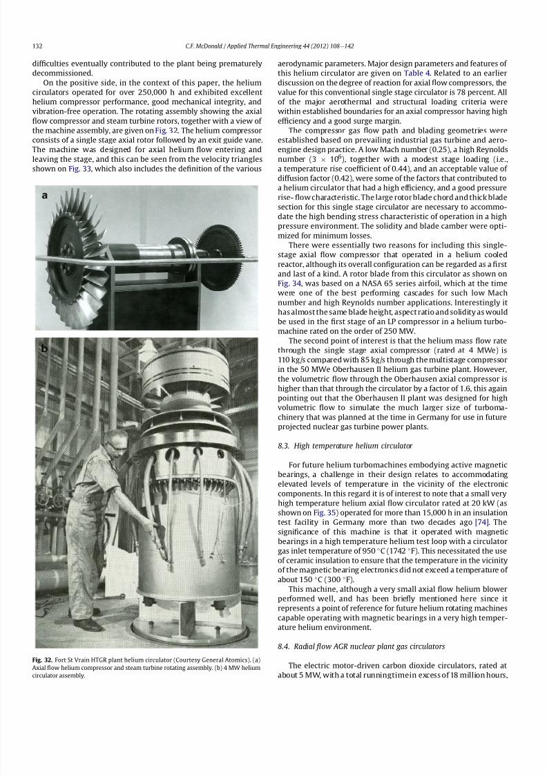
8112019 Helium Turbomachinery Operating Experience From Gas Turbine Power Plants
httpslidepdfcomreaderfullhelium-turbomachinery-operating-experience-from-gas-turbine-power-plants 2535
dif 1047297culties eventually contributed to the plant being prematurely
decommissioned
On the positive side in the context of this paper the helium
circulators operated for over 250000 h and exhibited excellent
helium compressor performance good mechanical integrity and
vibration-free operation The rotating assembly showing the axial
1047298ow compressor and steam turbine rotors together with a view of
the machine assembly are given on Fig 32 The helium compressor
consists of a single stage axial rotor followed by an exit guide vane
The machine was designed for axial helium 1047298ow entering and
leaving the stage and this can be seen from the velocity triangles
shown on Fig 33 which also includes the de1047297nition of the various
aerodynamic parameters Major design parameters and features of
this helium circulator are given on Table 4 Related to an earlier
discussion on the degree of reaction for axial 1047298ow compressors the
value for this conventional single stage circulator is 78 percent All
of the major aerothermal and structural loading criteria were
within established boundaries for an axial compressor having high
ef 1047297ciency and a good surge margin
The compressor gas 1047298ow path and blading geometries were
established based on prevailing industrial gas turbine and aero-
engine design practice A low Mach number (025) a high Reynolds
number (3 106) together with a modest stage loading (ie
a temperature rise coef 1047297cient of 044) and an acceptable value of
diffusion factor (042) were some of the factors that contributed to
a helium circulator that had a high ef 1047297ciency and a good pressure
rise- 1047298ow characteristic The large rotor blade chord and thick blade
section for this single stage circulator are necessary to accommo-
date the high bending stress characteristic of operation in a high
pressure environment The solidity and blade camber were opti-
mized for minimum losses
There were essentially two reasons for including this single-
stage axial 1047298ow compressor that operated in a helium cooled
reactor although its overall con1047297guration can be regarded as a 1047297rst
and last of a kind A rotor blade from this circulator as shown onFig 34 was based on a NASA 65 series airfoil which at the time
were one of the best performing cascades for such low Mach
number and high Reynolds number applications Interestingly it
has almost the same blade height aspect ratio and solidity as would
be used in the 1047297rst stage of an LP compressor in a helium turbo-
machine rated on the order of 250 MW
The second point of interest is that the helium mass 1047298ow rate
through the single stage axial compressor (rated at 4 MWe) is
110 kgs compared with 85 kgs through the multistage compressor
in the 50 MWe Oberhausen II helium gas turbine plant However
the volumetric 1047298ow through the Oberhausen axial compressor is
higher than that through the circulator by a factor of 16 this again
pointing out that the Oberhausen II plant was designed for high
volumetric 1047298ow to simulate the much larger size of turboma-chinery that was planned at the time in Germany for use in future
projected nuclear gas turbine power plants
83 High temperature helium circulator
For future helium turbomachines embodying active magnetic
bearings a challenge in their design relates to accommodating
elevated levels of temperature in the vicinity of the electronic
components In this regard it is of interest to note that a small very
high temperature helium axial 1047298ow circulator rated at 20 kW (as
shown on Fig 35) operated for more than 15000 h in an insulation
test facility in Germany more than two decades ago [74] The
signi1047297cance of this machine is that it operated with magnetic
bearings in a high temperature helium test loop with a circulatorgas inlet temperature of 950 C (1742 F) This necessitated the use
of ceramic insulation to ensure that the temperature in the vicinity
of the magnetic bearing electronics did not exceed a temperature of
about 150 C (300 F)
This machine although a very small axial 1047298ow helium blower
performed well and has been brie1047298y mentioned here since it
represents a point of reference for future helium rotating machines
capable operating with magnetic bearings in a very high temper-
ature helium environment
84 Radial 1047298ow AGR nuclear plant gas circulators
The electric motor-driven carbon dioxide circulators rated at
about 5 MW with a total runningtimein excess of 18 million hours
Fig 32 Fort St Vrain HTGR plant helium circulator (Courtesy General Atomics) (a)
Axial 1047298ow helium compressor and steam turbine rotating assembly (b) 4 MW helium
circulator assembly
CF McDonald Applied Thermal Engineering 44 (2012) 108e142132
8112019 Helium Turbomachinery Operating Experience From Gas Turbine Power Plants
httpslidepdfcomreaderfullhelium-turbomachinery-operating-experience-from-gas-turbine-power-plants 2635
in AGR nuclear power plants in the UK have demonstrated veryhigh availability [7576] To a high degree this can be attributed to
the fact that the machines were conservatively designed and proof
tested in a non-nuclear facility at full temperature and power
under conditions that simulated all of the nuclear plant operating
modes The test facility shown on Fig 36 served two functions 1)
design veri1047297cation of the prototype machine and 2) test of all new
and refurbished machines before they were installed in nuclear
plants Engineers currently involved in the design and development
of helium turbomachinery could bene1047297t from this sound testing
protocol to minimize risk in the deployment of helium rotating
machinery in future HTRVHTR plant variants
9 Helium turbomachinery development and testing
91 On-going development activities
The various helium turbomachines discussed in previous
sections operated over a span of about two decades starting in the
early 1960s From about 1990 activities in the nuclear gas turbine
1047297eld have been focused mainly on the design of modular GTeHTR
plant concepts In support of these plant studies many signi1047297cant
helium turbomachine design advancements have been made and
attention given to what development testing would be needed In
the last decade or so limited sub-component development has
been undertaken for helium turbomachines in the 250e300 MWe
size and these are brie1047298y summarized below
In a joint USARussia effort development in support of the
GTe
MHR turbomachine has been undertaken including testing in
the following areas magnetic bearings seals and rotor dynamicsfor the vertical intercooled helium turbomachine rated at 286 MWe
[77e80]
In Japan development activities have been in progress for
several years in support of the 274 MWe helium turbomachine for
the GTeHTR300 plant concept [2581] A detailed discussion on
the aerodynamic design of the axial 1047298ow helium compressor for
this turbomachine has been published in the open literature [82]
While the design methodology used for axial compressor design in
air-breathing industrial and aircraft gas turbines is generally
applicable for a multi-stage helium compressor a decision was
made by JAEA to test a small scale compressor in a helium facility
because of the inherent and unique gas 1047298ow path and type of
blading associated with operation in a high pressure helium
environment The major goal of the test was to validate the designof the 20 stage helium axial 1047298ow compressor for the GTeHTR300
plant
An axial 1047298ow compressor in a closed-cycle helium gas turbine is
characterized by the following 1) a large number stages 2) small
blade heights 3) high hub-to-tip ratio 4) a long annulus with
small taper that tends to deteriorate aerodynamic performance as
a result of end-wall boundary layer length and secondary 1047298ow 5)
low Mach number 6) high Reynolds number and 7) blade tip
clearances that are controlled by the gap necessary in the magnetic
journal and catcher bearings While (as covered in earlier sections)
helium gas turbines have operated there is limited data in the
open literature on the performance of multi-stage axial 1047298ow
compressors operating in a high pressure closed-loop helium
environment
Fig 33 Velocity triangles for axial compressor stage
CF McDonald Applied Thermal Engineering 44 (2012) 108e142 133
8112019 Helium Turbomachinery Operating Experience From Gas Turbine Power Plants
httpslidepdfcomreaderfullhelium-turbomachinery-operating-experience-from-gas-turbine-power-plants 2735
A 13rd scale 4 stage compressor was designed to simulate the
stage interaction the boundary layer growth and repeated stage
1047298ow in an actual compressor The 1047297rst four stages were designed to
be geometrically similar to the corresponding stages in the
GTe
HTR300 compressor Details of the model compressor havebeen discussed previously [81] and are summarized on Table 5
from [83]
A cross-section of the compressor test model is shown on Fig 37
A view of the 4 stage compressor rotor installed in the lower casing
is shown on Fig 38 The test facility (Fig 39) is a closed helium loop
consisting of the compressor model cooler pressure adjustment
valve and a 1047298ow measurement instrument The compressor is
driven by a 3650 kW electrical motor via a step-up gear The rota-
tional speed of 10800 rpm (three times that of the compressor in
the GTeHTR300 plant) was selected to match blade speed and
Mach number in the full size compressor
Details of the planned aerodynamic performance objectives of
the 13rd scale helium compressor test have been published
previously [84] Extensivetesting of the subscale model compressorprovided data to validate the performance of the full size
compressor for the GTeHTR300 power plant The test data and
test-calibrated CFD analyses gave added insight into the effect of
factors that impact performance including blade surface roughness
and Reynolds number
Based on advanced aerodynamic methodology and experi-
mental validation [82] there is now a sound basis for added
con1047297dence that the design goals of 90 percent polytropic ef 1047297ciency
and a design point surge margin of 20 percent are realizable in
a large multistage axial 1047298ow compressor for a future nuclear gas
turbine plant
In a similar manner a design of a one third size single stage
helium axial 1047298ow turbine has been undertaken and a cross
section of the machine is shown on Fig 40 (from Ref [81]) This
Table 4
Major features of axial 1047298ow helium circulator
Helium 1047298ow rate kgsec 110
Inlet temperature C 394
Inlet pressure MPa 473
Pressure rise KPa 965
Volumetric 1047298ow m3sec 32
Compressor type Single stage axial
Compressor drive Steam turbine
Bearing type Water lubricated
Rotational speed rpm 9550
Power MW 40
Rotor tip diameter mm 688
Rotor tip speed msec 344
Number of rotor blades 31
Number of stator blades 33
Blade height mm 114
Hub-to-tip ratio 067
Axial velocity msec 157
Flow coef 1047297cient 055
Temperature rise coef 1047297cient 044
Degree of reaction 078
Mean rotor solidity 128
Rotor aspect ratio 155
Rotor Mach number 025
Rotor diffusion factor 042
Rotor Reynolds number 3106
Speci1047297c speed 335
Speci1047297c diameter 066
Blade root thickness 15
Airfoil type NASA 65
Rotor blade chord mm 94e64
Stator blade chord mm 79
Rotor centrifugal stress MPa 125
Rotor bending stress MPa 30
Circulator(s) operating Hours gt250000
Fig 34 Rotor blade from single stage axial 1047298ow helium circulator (Courtesy General
Atomics)
Fig 35 20 kW axial 1047298ow helium circulator with magnetic bearings operated in 1985 in
an insulation test loop with a gas inlet temperature on 950
C (Courtesy BBC)
CF McDonald Applied Thermal Engineering 44 (2012) 108e142134
8112019 Helium Turbomachinery Operating Experience From Gas Turbine Power Plants
httpslidepdfcomreaderfullhelium-turbomachinery-operating-experience-from-gas-turbine-power-plants 2835
single stage scale model turbine for validity of the full size turbine
has been built and plans made to test the aerodynamic
performance
92 Nuclear gas turbine helium turbomachine testing
In planning for the 1047297rst nuclear gas turbine plant projected to
enter service perhaps in the third decade of the 21st century
a major decision has to be made as to what extent the large helium
turbomachine should be tested prior to operation on nuclear heat
Issues essentially include cost impact on schedule but the over-
riding one is risk Certainly turbomachine component testing will
be undertaken including the compressor (as discussed in the
previous section) and turbine performance seals cooling systems
hot gas valves thermal expansion devices high temperature
insulation rotor fragment containment diagnostic systems
instrumentation helium puri1047297cation system and other areas to
satisfy safety licensing reliability and availability concerns The
major point is really whether a full size or scaled-down turbo-machine be tested early in the project in a non-nuclear facility
To obviate the need for pre-nuclear testing of a large helium
turbomachine a view expressed by some is that advantage can be
taken of formidable technology bases that exist today for large
industrial gas turbines and high performance aeroengines On the
other hand it is the view of some including the author that very
complex power conversion system components especially those
subjected to severe thermal transients donrsquot always perform
exactly as predicted by analysts and designers even using sophis-
ticated computer codes This was exempli1047297ed in the case of the
turbomachine in the aforementioned Oberhausen II helium gas
turbine plant
The need for a helium turbomachine test facility goes beyond
just veri1047297
cation of the prototype machine Each newgas turbine for
commercial modular nuclear reactor plants would have to be proof
tested and validated before being transported to the reactor site
Similarly turbomachines that would be periodically removed from
the plant at say 7 year intervals during the plant operating life of 60
years for scheduled maintenance refurbishment repair or updat-ing would be again proof tested in the facility before re-entering
service
The direction that turbomachine development and testing will
take place for future helium gas turbines needs to be addressed by
the various organizations involved
Fig 36 AGR circulator test facility In the UK (Courtesy Howden)
Table 5
Major design parametersfeatures of model GTeHTR300 axial 1047298ow helium
compressor (Courtesy JAERI)
Scale of GTeHTR300 compressor 13
Helium mass 1047298ow rate (kgsec) 122
Helium volumetric 1047298ow rate (mV s) 87
Inlet temperature C 30
Inlet pressure MPa 0883Compressor pressure ratio at design point 1156
Number of stages 4
Rotational speed rpm 10800
Drive motor power kW 3650
Hub diameter mm 500
Rotor tip diameter (1st4th stage mm) 568566
Hub-to-tip ratio (1st stage) 088
Rotor tip speed (1st stage msec) 321
Number of rotorstator blades (1st stage) 7294
Rotorstator blade height (1st stage mm) 34337
Rotor stator blade c hor d l eng th (1st stage mm) 2620
Rotorstator solidity (1st stage) 119120
Rotorstator aspect ratio (1st stage) 1317
Flow coef 1047297cient 051
Stage loading factor 031
Reynolds number at design point 76 l05
CF McDonald Applied Thermal Engineering 44 (2012) 108e142 135
8112019 Helium Turbomachinery Operating Experience From Gas Turbine Power Plants
httpslidepdfcomreaderfullhelium-turbomachinery-operating-experience-from-gas-turbine-power-plants 2935
10 Helium turbomachinery lessons learned
101 Oberhausen II gas turbine and HHV test facility
It is understandable that 1047297rst-of-a-kind complex turboma-
chinery operating with an inert low molecular weight gas such as
helium will experience unique and unexpected problems In the
operation of the two pioneering large helium turbomachines in
Germany there were many positive1047297ndings which could only have
been achieved by development testing Equally important some
negative situations were identi1047297ed many of which were remedied
In the case of the Oberhausen II helium gas turbine plant some of
the very serious problems encountered were not resolved Inves-
tigations were undertaken to rationalize the problems associated
with the large power de1047297ciency and a data base established to
ensure that the various anomalies identi1047297ed would not occur in
future large helium turbomachines
The experience gained from the operation of the Oberhausen II
helium gas turbine power plant and the HHV test facility have been
discussedin thetextand arepresentedin a summaryformon Table6
Fig 37 Cross-section of 13rd scale helium compressor test model (Courtesy JAEA)
Fig 38 Four stage helium compressor rotor assembly installed in lower casing (Courtesy JAEA)
CF McDonald Applied Thermal Engineering 44 (2012) 108e142136
8112019 Helium Turbomachinery Operating Experience From Gas Turbine Power Plants
httpslidepdfcomreaderfullhelium-turbomachinery-operating-experience-from-gas-turbine-power-plants 3035
102 Impact of 1047297ndings on future helium gas turbine
The long slender rotorcharacteristic of closed-cycle gas turbines
has resulted in shaft dynamic instability which in some cases has
resulted in blade vibration and failure and bearing damage This
remains perhaps the major concern in the design of large
(250e
300 MW) helium turbomachines for future nuclear gas
turbine plants With pressure ratios in the range of about 2e3 in
a helium system a combination of splitting the compressor (to
facilitate intercooling) and having a large number of compressor
and turbine stages results in a long and 1047298exible rotating assembly
andthis is exempli1047297ed by the rotorassembly shown on Fig13 With
multiple bearings (either oil lubricated or magnetic) the rotor
would likely pass through multiple bending critical speeds before
Fig 39 Helium compressor test facility (Courtesy JAEA)
Fig 40 Cross-section of single stage helium turbine test model (Courtesy JAEA)
CF McDonald Applied Thermal Engineering 44 (2012) 108e142 137
8112019 Helium Turbomachinery Operating Experience From Gas Turbine Power Plants
httpslidepdfcomreaderfullhelium-turbomachinery-operating-experience-from-gas-turbine-power-plants 3135
reaching the design speed While very sophisticated computer
codes will be used in the detailed rotor dynamic analyses the real
con1047297rmation of having rotor oscillations within prescribed limits
(to avoid blade bearing and seal damage) will come from actual
testingA point to be made here is that in operated fossil-1047297red closed-
cycle gas turbine plants it was possible to remedy problems asso-
ciated with rotor vibrations and blade failures in a conventional
manner In fact in some situations the casings were opened several
times and modi1047297cations made to facilitate bearing and seal
replacement and rotor re-blading and balancing
An accurate assessment of pressure losses must be made
particularly those associated with the helium entering and leaving
the turbomachine bladed sections Minimizing the system pressure
loss is important since it directly impacts the all important quotient
of turbine expansion ratio to compressor pressure ratio and power
and plant ef 1047297ciency
Based on the operating experience from the 20 or so fossil-1047297red
closed-cycle gas turbine plants using air as the working1047298
uid it was
recognized that future very high pressure helium gas turbines
would pose problems regarding the various seals in the turbo-
machine and obtaining a zero leakage system with such a low
molecular weight gas would be dif 1047297cult and this is discussed
below
When the Oberhausen II gas turbine plant and the HHV facility
operated over 30 years ago oil lubricated bearings were used to
support the heavy rotor assemblies and helium buffered labyrinth
seals were used to prevent oil ingressinto the heliumworking1047298uid
Initial dif 1047297culties encountered in both plants were overcome by
changes made to the seal geometries and for the operating lives of
the helium turbomachines no further oil ingress events were
experienced Twoseals were required where the turbine drive shaft
penetrated the turbomachine casing namely 1) a dynamic laby-
rinth seal and 2) a static seal for shutdown conditions In both
plants these seals functioned without any problems
Labyrinth seals were also required within the helium turbo-
machines to pass the correct helium bleed 1047298ow from the
compressor discharge for cooling of the turbine discs blade root
attachments and casings The fact that the very complex rotor
cooling system in the large helium turbomachine in the HHV test
facility operated well for the test duration of about 350 h with
a turbine inlet temperature of 850 C was encouragingIn the case of the Oberhausen II gas turbine plant analysis of the
test data revealed that the labyrinth seal leakage and excessive
cooling 1047298ows were on the order of four times the design value A
possible reason for this was that damage done to the labyrinth
seals caused excessive clearances when periods of excessive rotor
oscillation and vibration occurred during early operation of the
machine
Clearly 1047298uid dynamic and thermal management of the cooling
system and 1047298ow through the various labyrinth seals will require
extensive analysis design and development testing before the
turbomachine is operated on nuclear heat for the 1047297rst time
In future heliumgas turbine designs (with turbine inlet tempera-
tureslikelyontheorderof950C)the1047298owpathgeometriesofhelium
bledfromthecompressornecessarytocoolpartsoftheturbomachinewillbemorecomplexthanthosetestedto-dateInadditiontoproviding
acooling1047298owtotheturbinebladesanddiscsbladerootattachmentsand
casingsheliummustbetransportedtotheseveralmagneticbearingsto
ensure thatthe temperatureof theirelectronic components doesnot
exceedabout150C
The importance of the points made above is evidenced when
examining the data on Table 3 where a combination of excessive
pressure losses and high bleed 1047298ows contributed to about 40
percent of the power de1047297ciency in the Oberhausen II helium
turbine plant
Retaining overall system leak tightnessin closed heliumsystems
operating at high pressure and temperature has been elusive
including experience from the Fort St Vrain HTGR plant as dis-
cussed in Section 65 New approaches in the design of the plethoraof mechanical joints must be identi1047297ed Experience to-date has
shown that having welded seals on 1047298anges while minimizing
system leakage did not eliminate it
The importance of lessons learned from the operation of the
Oberhausen II helium turbine power plant and the HHV test facility
have primarily been discussed in the context of helium turbo-
machines currently being designed in the 250e300 MWe power
range However the established test data bases could also be
applied to the possible emergence in the future of two helium
cooled reactor concepts namely 1) an advanced VHTR combined
cycle plant concept embodying a smaller helium gas turbine in the
power range of 50e80 MWe [22] and 2) the use of a direct cycle
helium gas turbine PCS in a recently proposed all ceramic fast
nuclear reactor concept [85]
Table 6
Experience gained from Oberhausen II and HHV facility
Oberhausen II 50 MW helium gas turbine power plant
Positive results
e Rotating and static seals worked well
e No ingress of bearing lubricant oil into closed circuit
e Load change by inventory control worked well
e 100 Percent load shed by means of bypass valves demonstrated
e Turbine disc and blade root cooling system con1047297rmed
e Coatings on mating surfaces prevented galling and self-welding
e After 24000 h of operation no evidence of corrosion or erosion
e Coaxial turbine hot gas inlet duct insulation and integrity con1047297rmed
e Monitoring of complete power conversion system for steady state
and transient operation undertaken
Problem areas
e Serious power output de1047297ciency (30 MW compared with design
value of 50 MW)
e Compressor(s) and turbine(s) ef 1047297ciencies several points below predicted
e Higher than estimated system pressure loss
e Rotor dynamic instability and blade vibration
e Bearings damaged and had to be replaced
e Blade failure caused extensive damage in HP turbine but retained
in casing
e Very excessive sealing and cooling 1047298ow rates
e Absolute leak tightness not attainable even with welded 1047298ange lips
HHV test facility
Positive resultse Use of heat pump approach facilitated helium temperature capability
to 1000 C
e Large oompressorturbine rotor system operated at 3000 rpm Complex
turbine disc and blade root cooling system veri1047297ed
e Dynamic and static seals met requirement of zero oxl ingress into circuit
e Structural integrity of rotating assembly veri1047297ed at temperature of 850 C
e Measured rotor oscillations within speci1047297cation
e Compressor and turbine ef 1047297ciencies higher than predicted
e Coatings on mating metallic surfaces prevented galling and self-welding
e Instrumentation control and safety systems veri1047297ed
e Seal 1047298ows within speci1047297cation
e Machine stop from operating speed to shutdown in 90 s demonstrated
e Hot gas duct insulation and thermal expansion devices worked well
e After 1100 h of operation no evidence of corrosionof erosion
Problem areas
e Before commissioning a large oil ingress into the circuit occurred due
to serious operator error and absence of an isolation valve A second oilingress occurred due to a mechanical defect in the labyrinth seal system
These were remedied and no further oil ingress was experienced for the
duration of testing
e Cooling 1047298ows slightly larger than expected but this resulted in actual
disc and blade root temperatures lower than the predicted value of
400 C
e System leak tightness demonstrated when pressurized at ambient
temperature conditions but some leakage occured at 850 C even with
the seal welding of 1047298ange(s) lips
CF McDonald Applied Thermal Engineering 44 (2012) 108e142138
8112019 Helium Turbomachinery Operating Experience From Gas Turbine Power Plants
httpslidepdfcomreaderfullhelium-turbomachinery-operating-experience-from-gas-turbine-power-plants 3235
11 New technologies
It is recognized that in the 3 to 4 decades since the operation of
the helium turbomachines covered in this paper new technologies
have emerged which negate some of the early issues An example of
this is the technology transfer from the design of modern axial 1047298ow
gas turbines (ie industrial aircraft and aeroderivatives) that fully
utilize sophisticated CAE CAD CFD and FEA design software
Air breathing aerodynamic design practice for compressors and
turbines are generally applicable but the properties of helium and
the high system pressure have a signi1047297cant impact on gas 1047298ow
paths and blade geometries With short blade heights high hub-to-
tip ratios long annulus 1047298ow path length (with resultant signi1047297cant
end-wall boundary layer growth and secondary 1047298ow) and blade tip
clearances in some cases controlled by clearances in the magnetic
catcher bearing testing of subscale model compressors and
Fig 41 Gas turbine test facility for aircraft nuclear propulsion involving the coupling of a 32 MWt air-cooled reactor with two modi 1047297ed J-47 turbojet aeroengines each rated at
a thrust of about 3000 kg operated in 1960 (Courtesy INL)
Fig 42 Mobile 350 KWe closed-cycle nuclear gas turbine power plant operated in 1961 (Courtesy US Army)
CF McDonald Applied Thermal Engineering 44 (2012) 108e142 139
8112019 Helium Turbomachinery Operating Experience From Gas Turbine Power Plants
httpslidepdfcomreaderfullhelium-turbomachinery-operating-experience-from-gas-turbine-power-plants 3335
turbines will be needed While most of the operated helium tur-
bomachines discussed in this paper took place 3 or 4 decades ago it
is encouraging that the fairly recent test data and test-calibrated
CFD analysis from a subscale four stage model helium axial 1047298ow
compressor in Japan [80] gave a high degree of con1047297dence that
design goals are realizable for the full size 20 stage compressor in
the 274 MWe GTeHTR300 plant turbomachine
In the future the use of active magnetic bearings will eliminate
the issue of oil ingress however the very heavy rotor weight and
size of the journal and thrust bearings (and catcher bearings) of the
type for helium turbomachines in the 250e300 MWe power range
are way in excess of what have been demonstrated in rotating
machinery For plant designs retaining oil-lubricated bearings well
established dry gas seal technology exists particularly experience
gained from the operation of high pressure natural gas pipe line
compressors
For future nuclear helium gas turbine plants the designer has
freedom regarding meeting different frequency requirements that
exist in some countries These include use of a synchronous
machine (ie designed for 50 or 60 Hz grids) use of a gearbox drive
between the turbine and generator or the use of a frequency
converter which gives the designer an added degree of freedom
regarding the selection of speed for the rotating assemblyCompared with the past very sophisticated electronic control
systems instrumentation and diagnostic systems are available
today
12 Conclusions
In this review paper experience from operated helium turbo-
machines has been compiled based on open literature sources At
this stage in the evolution of HTR and VHTR plant concepts it is not
clear in what role form or time-frame the nuclear gas turbine will
emerge when commercialized By say the middle of the 21st
century all power plants will be operating with signi1047297cantly higher
ef 1047297ciencies to realize improved power generation costs and
reduced emissions In a nuclear gas turbine the helium turbo-machine will be a major contributor towards the achievement of
ef 1047297ciencies higher than 50 percent
While it has been 3 to 4 decades since the Oberhausen II helium
turbine power plant and the HHV high temperature helium turbine
facility operated signi1047297cant lessons were learned and the time and
effort expended to resolve the multiplicity of unexpected technical
problems encountered The remedial repair work was done under
ideal conditions namely that immediate hands-on activities were
possible This would not have been possible if the type of problems
experienced had been encountered in a new and untested helium
turbomachine operated for the 1047297rst time with a nuclear heat
source
While new technologies have emerged that negate many of the
early problems there are some uniquely inherent issues associatedwith for large helium turbines operating in a high pressure and
temperature environment and these include the following 1)
minimizing system leakage with such a low molecular weight gas
2) clearances in labyrinth seals to minimize helium bypass1047298ows 3)
the dynamic stability of long slender rotors 4) minimizing the
turbomachine inlet and outlet pressure losses 5) 1047298ow maldis-
tribution in complex ductturbomachine interfaces 6) integrity
veri1047297cation of the catcher bearings (journal and thrust) after
multiple rotor drops (following loss of the magnetic 1047297eld) during
the plant lifetime 7) assurances that high energy fragments from
a failed turbine disc are contained within the machine casing 8)
turbomachine installation and removal from a steel pressure vessel
and 9) remote handling and cleaning of a machine with turbine
blades contaminated with 1047297
ssion products
The need for a helium turbomachine test facility has been
emphasized to ensure that the integrity performance and reli-
ability of the machine before it operates the 1047297rst time on nuclear
heat Engineers currently involved in the design of helium rotating
machinery for all HTR and VHTR plant variants should take
advantage of the experience gained from the past operation of
helium turbomachinery
13 In closing-GT rsquos operated with nuclear heat
In the context of this paper it is germane to mention that two
gas turbines have actually operated using nuclear heat as brie1047298y
highlighted below
In the late 1950rsquos a program was initiated in the USA for aircraft
nuclear propulsion (ANP) While different concepts were studied
only the direct cycle air-cooled reactor reached the stage of
construction of an experimental reactor [86] A view of the large
nuclear gas turbine facility is given on Fig 41 and shows the air-
cooled and zirconiumehydride moderated reactor rated at
32 MWt coupled with two modi1047297ed J-47 turbojet engines each
rated with a thrust of about 3000 kg In this open cycle system the
high pressure compressor air was directly heated in the reactor
before expansion in the turbine and discharge to the atmosphere in
the exhaust nozzle The facility operated between 1958 and 1961 at
the Idaho reactor testing facility While perhaps possible during the
early years of the US nuclear program it is clear that such a system
would not be acceptable today from safety and environmental
considerations
The 1047297rst and indeed the only coupling of a closed-cycle gas
turbine with a nuclear reactor for power generation was under-
taken to meet the needs of the US Army In the late 1950 rsquos an RampD
program was initiated for a 350 kW trailer-mounted system to be
used in the 1047297eld by military personnel A prototype of the ML-1
plant shown on Fig 42 was 1047297rst operated in 1961 [8788]
It was based on a 33 MW light water moderated pressure tube
reactor with nitrogen as the coolant The closed-cycle gas turbine
power conversion system with nitrogen as the working 1047298uid hada turbine inlet temperature of 649 C (1200 F) and delivered
around 300 kW With changes in the Armyrsquos needs the project was
discontinued in 1965
While the experience gained from the above twounique nuclear
plants is clearly not relevant for future nuclear gas turbine power
plants that could see service in the third decade of the 21st century
these ambitious and innovative nuclear gas turbine pioneering
engineering efforts need to be recognized
Acknowledgements
The author would like to thank the following for helpful discus-
sions advice and for providing valuable comments on the initial
paper draft Prof Dr Hermann Haselbacher Hans Ulrich Frutschi DrXing Yan DrPeter Zenker Professor DavidGordon Wilson Professor
Aristide Massardo Arthur Harris DrFred Starr and DrGuido Bac-
caglini This paper has been enhanced by the inclusion of hardware
photographs and unique sketches and the author is appreciative to
all concerned with credits being duly noted
References
[1] C Keller The Escher Wyss AK Closed-Cycle Gas Turbine Its Actual Develop-ment and Future Prospects Paper Presented at ASME Meeting November 261945
[2] HU Frutschi Closed-Cycle Gas Turbines Operating Experience and FuturePotential ASME Press NY 2005
[3] CF McDonald The Nuclear Gas Turbine-Towards Realization After Half
a Century of Evolution (1995) ASME Paper 95-GT-292
CF McDonald Applied Thermal Engineering 44 (2012) 108e142140
8112019 Helium Turbomachinery Operating Experience From Gas Turbine Power Plants
httpslidepdfcomreaderfullhelium-turbomachinery-operating-experience-from-gas-turbine-power-plants 3435
[4] C Keller The Theory and Performance of Axial Flow Fans McGraw Hill BookCompany Inc NY 1937
[5] J Ackert C Keller Aerodynamic turbine with closed circuit In A Century of Turbines vols 1516 Escher Wyss News 1942e43 5e19
[6] Escher Wyss News Closed-Cycle Gas Turbines for all Fuels Coal Gas Nuclearvol 39 No 1 (1966)
[7] C Keller Closed-cycle gas turbine Escher Wyss-AK development 1945e1950Transactions of ASME (August 1950) 835e850
[8] C Keller Operating Experience and Design Features of Closed-Cycle GasTurbine Power Plants (1956) ASME Paper 56-GTP-15
[9] C Keller HU Frutschi Closed-cycle plants -conventional and nuclear designapplication operation In Sawyerrsquos Gas Turbine Engineering Handbooksecond ed vol 2 Applications (1976) pp 265e283
[10] K Bammert G Groschup Status Report on Closed-Cycle Power Plants in theFederal Republic of Germany (1976) ASME Paper 76-GT-54
[11] JL Mason Monatomic Working Gases versus Air for Closed Brayton Cycles(1985) ASME Paper 85-IGT-50
[12] JL Mason et al 5 MW Closed Cycle Gas Turbine (1984) ASME Paper 84-GT-268
[13] The British Gas Closed-Cycle Demonstrator (1995) British Gas Research ampTechnology Final Year Report
[14] F Starr ODS alloy high temperature heat exchanger prototype developmentPaper Presented at ODS 2010 Materials Workshop UCSD Jacobs Hall La JollaCalifornia Nov17e18 2010
[15] CA Rennie Achievements of the Dragon project Pergamon Press Annals of Nuclear Energy 5 (1978) 305e320
[16] SB Hosegood et al Dragon Project Engineering Studies on the Direct CycleHTR Proceedings of Conference on Nuclear Gas Turbines The British NuclearEnergy Society London April 8e9 1970 pp 161e179
[17] Nuclear Gas Turbines Proceedings of British Nuclear Society Meeting LondonApril 8-9 1972
[18] CF McDonald C Peinado ldquoThe nuclear gas Turbine-A perspective on a long-term advanced technology HTGR plant Optionrdquo ASME Paper 82-GT-289
[19] GH Lohnert et al Technical design features and essential safety-relatedfeatures of the HTR-Module Nuclear Engineering and Design 121 (1990)259e275
[20] H Reutler GH Lohnert The modular high temperature nuclear reactorNuclear Technology 62 (1983) 22e30
[21] CF McDonald Exploitation of the very high temperature capability of theMHTGR to meet National energy needs after the year 2000 IECEC Paper869006
[22] CF McDonald Power conversion system considerations for an advancednuclear gas turbine (GT-VHTR) CHHP demonstration plant concept Interna-tional Journal of Turbo amp Jet Engines 27 (2010) 179e217
[23] N Hee Cheon et al A review of helium gas turbine technology for hightemperature gas cooled reactors Nuclear Engineering and Design 29 (2007)21e30
[24] CB Baxi et al Development of the GT-MHR Turbomachine ASME PaperGT2009e59450[25] X Yan GTHTR300 design and development Nuclear Engineering and Design
222 (2003) 247e262[26] JC Gauthier et al ANTARES the HTRVHTR project of Framatome ANP
Nuclear Engineering and Design 236 (2006) 526e533[27] J Wang et al ldquoDesign features of gas turbine power conversion system for
HTR-10GT paper D05 presented at 2nd Intl Meeting on HTR TechnologyBeijing China September 21e24 2004
[28] A Koster et al ldquoPBMR Design For the Futurerdquo Nuclear engineering andDesign 222 (203) 231e245
[29] S van der Linden Closed cycle nuclear plant rated at 165 MWe and 40 percentef 1047297ciency Gas Turbine World (MarcheApril 2007) 28e32
[30] CF McDonald Large closed-cycle gas turbines Sawyerrsquos gas turbine engi-neering handbook In Selection and Applications vol II (1985) pp 81e38(Chapter 8)
[31] CF McDonald Helium and Combustion Gas Turbine Power ConversionSystems Comparison (1995) ASME Paper 95-GT-263
[32] JK La Fleur Description of an Operating Closed-Cycle Helium Gas Turbine
ASME Paper 63-AHGT-74[33] JK La Fleur The use of turbomachinery in the 1047297eld of cryogenics In
Sawyerrsquos Gas Turbine Engineering Handbook vol II (1976) 296e311[34] W Spillmann The Closed-Cycle Gas Turbine for Non-Conventional Applica-
tions ASME Paper 66-GT-8[35] K Holliger On the in1047298uence of the degree of reaction on the secondary losses
in axial 1047298ow compressors Escher Wyss News 23 (1960)[36] W Gut Comparison of the relative losses and characteristics of axial
compressor stages Escher Wyss News 23 (1959)[37] JH Horlock Axial Flow Compressors Butterworths Scienti1047297c Publications
London 1958 pp 92e93[38] G Deuster Long-term Operating Experience with Oberhausen I Closed-Cycle
Gas Turbine Power Plant (1970) ASME Paper 70-GT-73[39] G Noak Signi1047297cance of the Helium Turbine Power Plant at Oberhausen (EVO)
and the High Temperature Helium Test Facility (HHV) at Julich for theDevelopment of HTR Direct Cycle (HHT) IAEA Publication SM-20026 Vienna1970 189e200
[40] K Bammert G Deuster Layout and Present Status of the Closed-Cycle HeliumTurbine Plant Oberhausen II (1974) ASME Paper 74-GT-132
[41] P Zenker The Oberhausen 50 MW helium turbine plant Combustion 47 (2)(April 1976)
[42] K Bammert et al Operation and Control of the 50 MW Closed Cycle HeliumTurbine Plant Oberhausen (1974) ASME Paper 74-GT-13
[43] P Zenker 10 years operating experience with the Oberhausen II heliumturbo-generator plant VGB Krafswerkstechnik 68 (7) (July 1998) 616e621
[44] K Bammert G Deuster The First Operating Experiences With the OberhausenHelium Turbine Plant Paper Presented at ASME Gas Turbine Conference NewOrleans March 21e25 1976
[45] G Deuster P Zenker Operation of the Oberhausen Helium Turbine Plant
Paper Presented at ASME Gas Turbine Conference London April 1978[46] P Zenker Operating Experience of the Oberhausen Helium Turbine Plant
Paper Presented at ASME Gas Turbine Conference San Diego 1979[47] G Deuster P Zenker Further Operating Experience of the Oberhausen Helium
Turbine Plant Paper Presented at ASME Gas Turbine Conference NewOrleans 1980
[48] P Zenker Past Experience and Future Prospects of Closed-Cycle Gas TurbinesPaper Presented at ASME Gas Turbine Conference London April 18e22 1982
[49] IA Weisbrodt Summary Report on Technical Experiences from HighTemperature Helium Turbine Testing in Germany Report IAEA-TECDOC-899Vienna Nov 1994
[50] F Bentivoglio G Geffraye Validation of the CATHARE Code Against Experi-mental Data from Brayton Cycle Plants Paper C00000228 Proceedings of HTR 2006 Johannesburg October 1e4 2006
[51] E Arndt HHT-Demonstration Plant Paper Presented at European NuclearConference Hamburg May 6 1979
[52] G Hebel HHV-Anlage Erfahrungen bei Bau und Inbetriebnahme Atom-wirtschaft(5) (1982) 258e262
[53] H Haselbacher A Eierman Development of Helium Gas Turbine in NuclearField (1974) ASME Paper 74-GT-123
[54] H Haselbacher The HHT Helium Gas Turbine and HHV Plant Paper A421 5thInternational Fair and Technical Meeting of Nuclear Industry BaselSwitzerland October 3e7 1978
[55] H Haselbacher HJ Sponholz Cooling and Insulating Problems in a HighTemperature Helium Test Facility (1984) ASME Paper 84-GT-253
[56] C Keller D Schmidt The Helium Gas Turbine for Nuclear Power Plants (1967)ASME Paper 67-GT-10
[57] W Endres Large Helium Turbine for Nuclear Power Plants (1970) ASME Paper70-GT-99
[58] JN Hurst Gas turbomachinery for helium cooled reactors in Proceedings of International Conference on Nuclear Gas Turbines British Nuclear SocietyLondon April 8 1970 pp 45e50
[59] K Bammert Nuclear Gas Turbine of Large Output for HHT Plant (1974) ASMEPaper 74-GT-10
[60] CF McDonald The Nuclear Closed-Cycle Gas Turbine (GT-HTGR) e A UtilityPower Plant for the Year 2000 (1979) AIAA Paper 79e0191
[61] CF McDonald MJ Smith Turbomachinery design considerations for the
nuclear HTGR-GT power plant ASME Journal of Engineering for Power 103 (1)(January 1981) 65e77[62] CF McDonald et al Helium Turbomachine Design for GT-MHR Power Plant
(1994) ASME Paper 94-JPGC-NE-12[63] Gas Cooled Reactor Coolant Circulator and Blower Technology (1988) IAEA
Report IWGGCR17[64] OE Balje Turbomachines A Guide to Design Selection and Theory John
Wiley amp Sons NY 1981[65] CF McDonald et al Circulator DesignTechnology Evolution for Gas Cooled
Reactors (1992) ASME Paper 92-GT-79[66] J Donaldson Application of Magnetic Bearings to Helium Circulators for High
Temperature Gas Cooled Reactors (1987) IECEC Paper 879419[67] CF McDonald Active Magnetic Bearings for Rotating Machinery in Closed-
Cycle Power Plant Systems (1989) ASME Paper 89-WANE-5[68] JA Rennie CF McDonald Active Magnetic Bearings for Rotating Machinery
in Future Gas Cooled Reactor Plants Paper Presented at 4th Intl Symposiumon Magnetic Bearings ETH Zurich August 23e26 1994
[69] CF McDonald MK Nichols Helium Circulator Design Considerations forModular High Temperature Gas Cooled Power Plant (1987) ASME Paper 87-
GT-138[70] CF McDonald Shutdown Cooling Helium Circulator Design Considerations
for MHTGR Power Plant (1989) ASME Paper 89-WANE-5[71] J Yampolsky Steam Turbine Driven Circulators for High Temperature Gas
Cooled Reactors Part I Design (1972) ASME Paper 72-WANE-20[72] VJ Barbat Steam Turbine Driven Circulators for High Temperature Gas
Cooled Reactors Part II Development (1972) ASME Paper 72-WANE-21[73] L Cavallaro J Yampolsky Design and development of a steam turbine driven
circulator for high temperature gas cooled reactors Nuclear Engineering andDesign (1974) 135e147
[74] J Henssen et al Facility for fatigue testing of thermal insulation BBC Review72 (6) (1985)
[75] J Donaldson Development of Carbon Dioxide Circulators IAEA ReportIWGGCR17 (1988) pp 47e63
[76] Personal Communication from John Donaldson (April 7 2006)[77] NG Kodochigov et al Development of the GT-MHR Vertical Turbomachine
Design ASME Paper HTR2008-58309[78] CB Baxi et al ldquoRotor Scale Model Tests for Power Conversion Unit of GT-
MHR rdquo ASME Paper HTR 2008e58015
CF McDonald Applied Thermal Engineering 44 (2012) 108e142 141
8112019 Helium Turbomachinery Operating Experience From Gas Turbine Power Plants
httpslidepdfcomreaderfullhelium-turbomachinery-operating-experience-from-gas-turbine-power-plants 3535
[79] NG Kodochibov et al Development of Catcher Bearings for the GT-MHR Turbomachine(Oct 18e20 2010)Proceedings of HTR 2010Paper 025Prague
[80] IV Drumov et al Studies of the Electromagnetic Suspension System for theGT-MHRTurbomachineProceedings of HTR2010Paper041 Oct18e20 (2010)
[81] T Takizuka et al RampD on the power conversion system for the gas turbinehigh temperature reactor Nuclear Engineering and Design 233 (2004)239e346
[82] X Yanet alAerodynamic design model test and CFDanalysisfor a multistageaxialhelium compressor ASME Journal of Turbomachinery 130 (3) (July2008)
[83] S Takada et al The 13rd Scale Aerodynamic Performance Test of Helium
Compressor for GTHTR300 Turbomachine of JAERI (April 20e
23 2003)ICONE11e36368 Tokyo Japan
[84] S Takada et al Program for aerodynamic performance tests of heliumcompressor model of GTHTR300 Transactions of the Atomic Energy Society of
Japan 2 (3) (2003) 291e300[85] RW Schleicher et al EM2 An Innovative Approach to US Energy Security
and Nuclear Waste Disposition Paper Presented at Nuclear Power Interna-tional Conference Orlando Florida December 15 2010
[86] RL Loftness Nuclear Power Plants Norstrand Company Inc NY 1964(Chapter 9 and 11)
[87] SA Varga et al The ML-1 Mobile Nuclear Power Plant (1961) ASME Paper61-SA-43
[88] JA Bailey et al Status of the Army Closed Brayton Cycle Gas Turbine Program(1967) ASME Paper 67-GT-13
CF McDonald Applied Thermal Engineering 44 (2012) 108e142142
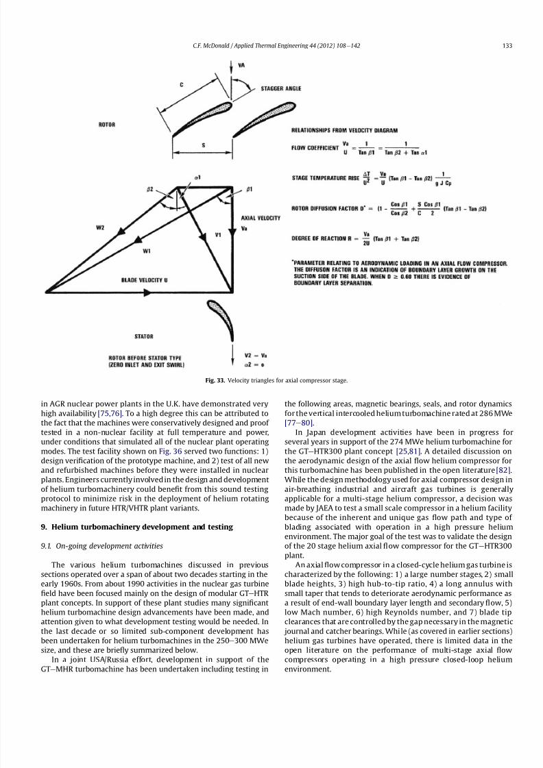
8112019 Helium Turbomachinery Operating Experience From Gas Turbine Power Plants
httpslidepdfcomreaderfullhelium-turbomachinery-operating-experience-from-gas-turbine-power-plants 2635
in AGR nuclear power plants in the UK have demonstrated veryhigh availability [7576] To a high degree this can be attributed to
the fact that the machines were conservatively designed and proof
tested in a non-nuclear facility at full temperature and power
under conditions that simulated all of the nuclear plant operating
modes The test facility shown on Fig 36 served two functions 1)
design veri1047297cation of the prototype machine and 2) test of all new
and refurbished machines before they were installed in nuclear
plants Engineers currently involved in the design and development
of helium turbomachinery could bene1047297t from this sound testing
protocol to minimize risk in the deployment of helium rotating
machinery in future HTRVHTR plant variants
9 Helium turbomachinery development and testing
91 On-going development activities
The various helium turbomachines discussed in previous
sections operated over a span of about two decades starting in the
early 1960s From about 1990 activities in the nuclear gas turbine
1047297eld have been focused mainly on the design of modular GTeHTR
plant concepts In support of these plant studies many signi1047297cant
helium turbomachine design advancements have been made and
attention given to what development testing would be needed In
the last decade or so limited sub-component development has
been undertaken for helium turbomachines in the 250e300 MWe
size and these are brie1047298y summarized below
In a joint USARussia effort development in support of the
GTe
MHR turbomachine has been undertaken including testing in
the following areas magnetic bearings seals and rotor dynamicsfor the vertical intercooled helium turbomachine rated at 286 MWe
[77e80]
In Japan development activities have been in progress for
several years in support of the 274 MWe helium turbomachine for
the GTeHTR300 plant concept [2581] A detailed discussion on
the aerodynamic design of the axial 1047298ow helium compressor for
this turbomachine has been published in the open literature [82]
While the design methodology used for axial compressor design in
air-breathing industrial and aircraft gas turbines is generally
applicable for a multi-stage helium compressor a decision was
made by JAEA to test a small scale compressor in a helium facility
because of the inherent and unique gas 1047298ow path and type of
blading associated with operation in a high pressure helium
environment The major goal of the test was to validate the designof the 20 stage helium axial 1047298ow compressor for the GTeHTR300
plant
An axial 1047298ow compressor in a closed-cycle helium gas turbine is
characterized by the following 1) a large number stages 2) small
blade heights 3) high hub-to-tip ratio 4) a long annulus with
small taper that tends to deteriorate aerodynamic performance as
a result of end-wall boundary layer length and secondary 1047298ow 5)
low Mach number 6) high Reynolds number and 7) blade tip
clearances that are controlled by the gap necessary in the magnetic
journal and catcher bearings While (as covered in earlier sections)
helium gas turbines have operated there is limited data in the
open literature on the performance of multi-stage axial 1047298ow
compressors operating in a high pressure closed-loop helium
environment
Fig 33 Velocity triangles for axial compressor stage
CF McDonald Applied Thermal Engineering 44 (2012) 108e142 133
8112019 Helium Turbomachinery Operating Experience From Gas Turbine Power Plants
httpslidepdfcomreaderfullhelium-turbomachinery-operating-experience-from-gas-turbine-power-plants 2735
A 13rd scale 4 stage compressor was designed to simulate the
stage interaction the boundary layer growth and repeated stage
1047298ow in an actual compressor The 1047297rst four stages were designed to
be geometrically similar to the corresponding stages in the
GTe
HTR300 compressor Details of the model compressor havebeen discussed previously [81] and are summarized on Table 5
from [83]
A cross-section of the compressor test model is shown on Fig 37
A view of the 4 stage compressor rotor installed in the lower casing
is shown on Fig 38 The test facility (Fig 39) is a closed helium loop
consisting of the compressor model cooler pressure adjustment
valve and a 1047298ow measurement instrument The compressor is
driven by a 3650 kW electrical motor via a step-up gear The rota-
tional speed of 10800 rpm (three times that of the compressor in
the GTeHTR300 plant) was selected to match blade speed and
Mach number in the full size compressor
Details of the planned aerodynamic performance objectives of
the 13rd scale helium compressor test have been published
previously [84] Extensivetesting of the subscale model compressorprovided data to validate the performance of the full size
compressor for the GTeHTR300 power plant The test data and
test-calibrated CFD analyses gave added insight into the effect of
factors that impact performance including blade surface roughness
and Reynolds number
Based on advanced aerodynamic methodology and experi-
mental validation [82] there is now a sound basis for added
con1047297dence that the design goals of 90 percent polytropic ef 1047297ciency
and a design point surge margin of 20 percent are realizable in
a large multistage axial 1047298ow compressor for a future nuclear gas
turbine plant
In a similar manner a design of a one third size single stage
helium axial 1047298ow turbine has been undertaken and a cross
section of the machine is shown on Fig 40 (from Ref [81]) This
Table 4
Major features of axial 1047298ow helium circulator
Helium 1047298ow rate kgsec 110
Inlet temperature C 394
Inlet pressure MPa 473
Pressure rise KPa 965
Volumetric 1047298ow m3sec 32
Compressor type Single stage axial
Compressor drive Steam turbine
Bearing type Water lubricated
Rotational speed rpm 9550
Power MW 40
Rotor tip diameter mm 688
Rotor tip speed msec 344
Number of rotor blades 31
Number of stator blades 33
Blade height mm 114
Hub-to-tip ratio 067
Axial velocity msec 157
Flow coef 1047297cient 055
Temperature rise coef 1047297cient 044
Degree of reaction 078
Mean rotor solidity 128
Rotor aspect ratio 155
Rotor Mach number 025
Rotor diffusion factor 042
Rotor Reynolds number 3106
Speci1047297c speed 335
Speci1047297c diameter 066
Blade root thickness 15
Airfoil type NASA 65
Rotor blade chord mm 94e64
Stator blade chord mm 79
Rotor centrifugal stress MPa 125
Rotor bending stress MPa 30
Circulator(s) operating Hours gt250000
Fig 34 Rotor blade from single stage axial 1047298ow helium circulator (Courtesy General
Atomics)
Fig 35 20 kW axial 1047298ow helium circulator with magnetic bearings operated in 1985 in
an insulation test loop with a gas inlet temperature on 950
C (Courtesy BBC)
CF McDonald Applied Thermal Engineering 44 (2012) 108e142134
8112019 Helium Turbomachinery Operating Experience From Gas Turbine Power Plants
httpslidepdfcomreaderfullhelium-turbomachinery-operating-experience-from-gas-turbine-power-plants 2835
single stage scale model turbine for validity of the full size turbine
has been built and plans made to test the aerodynamic
performance
92 Nuclear gas turbine helium turbomachine testing
In planning for the 1047297rst nuclear gas turbine plant projected to
enter service perhaps in the third decade of the 21st century
a major decision has to be made as to what extent the large helium
turbomachine should be tested prior to operation on nuclear heat
Issues essentially include cost impact on schedule but the over-
riding one is risk Certainly turbomachine component testing will
be undertaken including the compressor (as discussed in the
previous section) and turbine performance seals cooling systems
hot gas valves thermal expansion devices high temperature
insulation rotor fragment containment diagnostic systems
instrumentation helium puri1047297cation system and other areas to
satisfy safety licensing reliability and availability concerns The
major point is really whether a full size or scaled-down turbo-machine be tested early in the project in a non-nuclear facility
To obviate the need for pre-nuclear testing of a large helium
turbomachine a view expressed by some is that advantage can be
taken of formidable technology bases that exist today for large
industrial gas turbines and high performance aeroengines On the
other hand it is the view of some including the author that very
complex power conversion system components especially those
subjected to severe thermal transients donrsquot always perform
exactly as predicted by analysts and designers even using sophis-
ticated computer codes This was exempli1047297ed in the case of the
turbomachine in the aforementioned Oberhausen II helium gas
turbine plant
The need for a helium turbomachine test facility goes beyond
just veri1047297
cation of the prototype machine Each newgas turbine for
commercial modular nuclear reactor plants would have to be proof
tested and validated before being transported to the reactor site
Similarly turbomachines that would be periodically removed from
the plant at say 7 year intervals during the plant operating life of 60
years for scheduled maintenance refurbishment repair or updat-ing would be again proof tested in the facility before re-entering
service
The direction that turbomachine development and testing will
take place for future helium gas turbines needs to be addressed by
the various organizations involved
Fig 36 AGR circulator test facility In the UK (Courtesy Howden)
Table 5
Major design parametersfeatures of model GTeHTR300 axial 1047298ow helium
compressor (Courtesy JAERI)
Scale of GTeHTR300 compressor 13
Helium mass 1047298ow rate (kgsec) 122
Helium volumetric 1047298ow rate (mV s) 87
Inlet temperature C 30
Inlet pressure MPa 0883Compressor pressure ratio at design point 1156
Number of stages 4
Rotational speed rpm 10800
Drive motor power kW 3650
Hub diameter mm 500
Rotor tip diameter (1st4th stage mm) 568566
Hub-to-tip ratio (1st stage) 088
Rotor tip speed (1st stage msec) 321
Number of rotorstator blades (1st stage) 7294
Rotorstator blade height (1st stage mm) 34337
Rotor stator blade c hor d l eng th (1st stage mm) 2620
Rotorstator solidity (1st stage) 119120
Rotorstator aspect ratio (1st stage) 1317
Flow coef 1047297cient 051
Stage loading factor 031
Reynolds number at design point 76 l05
CF McDonald Applied Thermal Engineering 44 (2012) 108e142 135
8112019 Helium Turbomachinery Operating Experience From Gas Turbine Power Plants
httpslidepdfcomreaderfullhelium-turbomachinery-operating-experience-from-gas-turbine-power-plants 2935
10 Helium turbomachinery lessons learned
101 Oberhausen II gas turbine and HHV test facility
It is understandable that 1047297rst-of-a-kind complex turboma-
chinery operating with an inert low molecular weight gas such as
helium will experience unique and unexpected problems In the
operation of the two pioneering large helium turbomachines in
Germany there were many positive1047297ndings which could only have
been achieved by development testing Equally important some
negative situations were identi1047297ed many of which were remedied
In the case of the Oberhausen II helium gas turbine plant some of
the very serious problems encountered were not resolved Inves-
tigations were undertaken to rationalize the problems associated
with the large power de1047297ciency and a data base established to
ensure that the various anomalies identi1047297ed would not occur in
future large helium turbomachines
The experience gained from the operation of the Oberhausen II
helium gas turbine power plant and the HHV test facility have been
discussedin thetextand arepresentedin a summaryformon Table6
Fig 37 Cross-section of 13rd scale helium compressor test model (Courtesy JAEA)
Fig 38 Four stage helium compressor rotor assembly installed in lower casing (Courtesy JAEA)
CF McDonald Applied Thermal Engineering 44 (2012) 108e142136
8112019 Helium Turbomachinery Operating Experience From Gas Turbine Power Plants
httpslidepdfcomreaderfullhelium-turbomachinery-operating-experience-from-gas-turbine-power-plants 3035
102 Impact of 1047297ndings on future helium gas turbine
The long slender rotorcharacteristic of closed-cycle gas turbines
has resulted in shaft dynamic instability which in some cases has
resulted in blade vibration and failure and bearing damage This
remains perhaps the major concern in the design of large
(250e
300 MW) helium turbomachines for future nuclear gas
turbine plants With pressure ratios in the range of about 2e3 in
a helium system a combination of splitting the compressor (to
facilitate intercooling) and having a large number of compressor
and turbine stages results in a long and 1047298exible rotating assembly
andthis is exempli1047297ed by the rotorassembly shown on Fig13 With
multiple bearings (either oil lubricated or magnetic) the rotor
would likely pass through multiple bending critical speeds before
Fig 39 Helium compressor test facility (Courtesy JAEA)
Fig 40 Cross-section of single stage helium turbine test model (Courtesy JAEA)
CF McDonald Applied Thermal Engineering 44 (2012) 108e142 137
8112019 Helium Turbomachinery Operating Experience From Gas Turbine Power Plants
httpslidepdfcomreaderfullhelium-turbomachinery-operating-experience-from-gas-turbine-power-plants 3135
reaching the design speed While very sophisticated computer
codes will be used in the detailed rotor dynamic analyses the real
con1047297rmation of having rotor oscillations within prescribed limits
(to avoid blade bearing and seal damage) will come from actual
testingA point to be made here is that in operated fossil-1047297red closed-
cycle gas turbine plants it was possible to remedy problems asso-
ciated with rotor vibrations and blade failures in a conventional
manner In fact in some situations the casings were opened several
times and modi1047297cations made to facilitate bearing and seal
replacement and rotor re-blading and balancing
An accurate assessment of pressure losses must be made
particularly those associated with the helium entering and leaving
the turbomachine bladed sections Minimizing the system pressure
loss is important since it directly impacts the all important quotient
of turbine expansion ratio to compressor pressure ratio and power
and plant ef 1047297ciency
Based on the operating experience from the 20 or so fossil-1047297red
closed-cycle gas turbine plants using air as the working1047298
uid it was
recognized that future very high pressure helium gas turbines
would pose problems regarding the various seals in the turbo-
machine and obtaining a zero leakage system with such a low
molecular weight gas would be dif 1047297cult and this is discussed
below
When the Oberhausen II gas turbine plant and the HHV facility
operated over 30 years ago oil lubricated bearings were used to
support the heavy rotor assemblies and helium buffered labyrinth
seals were used to prevent oil ingressinto the heliumworking1047298uid
Initial dif 1047297culties encountered in both plants were overcome by
changes made to the seal geometries and for the operating lives of
the helium turbomachines no further oil ingress events were
experienced Twoseals were required where the turbine drive shaft
penetrated the turbomachine casing namely 1) a dynamic laby-
rinth seal and 2) a static seal for shutdown conditions In both
plants these seals functioned without any problems
Labyrinth seals were also required within the helium turbo-
machines to pass the correct helium bleed 1047298ow from the
compressor discharge for cooling of the turbine discs blade root
attachments and casings The fact that the very complex rotor
cooling system in the large helium turbomachine in the HHV test
facility operated well for the test duration of about 350 h with
a turbine inlet temperature of 850 C was encouragingIn the case of the Oberhausen II gas turbine plant analysis of the
test data revealed that the labyrinth seal leakage and excessive
cooling 1047298ows were on the order of four times the design value A
possible reason for this was that damage done to the labyrinth
seals caused excessive clearances when periods of excessive rotor
oscillation and vibration occurred during early operation of the
machine
Clearly 1047298uid dynamic and thermal management of the cooling
system and 1047298ow through the various labyrinth seals will require
extensive analysis design and development testing before the
turbomachine is operated on nuclear heat for the 1047297rst time
In future heliumgas turbine designs (with turbine inlet tempera-
tureslikelyontheorderof950C)the1047298owpathgeometriesofhelium
bledfromthecompressornecessarytocoolpartsoftheturbomachinewillbemorecomplexthanthosetestedto-dateInadditiontoproviding
acooling1047298owtotheturbinebladesanddiscsbladerootattachmentsand
casingsheliummustbetransportedtotheseveralmagneticbearingsto
ensure thatthe temperatureof theirelectronic components doesnot
exceedabout150C
The importance of the points made above is evidenced when
examining the data on Table 3 where a combination of excessive
pressure losses and high bleed 1047298ows contributed to about 40
percent of the power de1047297ciency in the Oberhausen II helium
turbine plant
Retaining overall system leak tightnessin closed heliumsystems
operating at high pressure and temperature has been elusive
including experience from the Fort St Vrain HTGR plant as dis-
cussed in Section 65 New approaches in the design of the plethoraof mechanical joints must be identi1047297ed Experience to-date has
shown that having welded seals on 1047298anges while minimizing
system leakage did not eliminate it
The importance of lessons learned from the operation of the
Oberhausen II helium turbine power plant and the HHV test facility
have primarily been discussed in the context of helium turbo-
machines currently being designed in the 250e300 MWe power
range However the established test data bases could also be
applied to the possible emergence in the future of two helium
cooled reactor concepts namely 1) an advanced VHTR combined
cycle plant concept embodying a smaller helium gas turbine in the
power range of 50e80 MWe [22] and 2) the use of a direct cycle
helium gas turbine PCS in a recently proposed all ceramic fast
nuclear reactor concept [85]
Table 6
Experience gained from Oberhausen II and HHV facility
Oberhausen II 50 MW helium gas turbine power plant
Positive results
e Rotating and static seals worked well
e No ingress of bearing lubricant oil into closed circuit
e Load change by inventory control worked well
e 100 Percent load shed by means of bypass valves demonstrated
e Turbine disc and blade root cooling system con1047297rmed
e Coatings on mating surfaces prevented galling and self-welding
e After 24000 h of operation no evidence of corrosion or erosion
e Coaxial turbine hot gas inlet duct insulation and integrity con1047297rmed
e Monitoring of complete power conversion system for steady state
and transient operation undertaken
Problem areas
e Serious power output de1047297ciency (30 MW compared with design
value of 50 MW)
e Compressor(s) and turbine(s) ef 1047297ciencies several points below predicted
e Higher than estimated system pressure loss
e Rotor dynamic instability and blade vibration
e Bearings damaged and had to be replaced
e Blade failure caused extensive damage in HP turbine but retained
in casing
e Very excessive sealing and cooling 1047298ow rates
e Absolute leak tightness not attainable even with welded 1047298ange lips
HHV test facility
Positive resultse Use of heat pump approach facilitated helium temperature capability
to 1000 C
e Large oompressorturbine rotor system operated at 3000 rpm Complex
turbine disc and blade root cooling system veri1047297ed
e Dynamic and static seals met requirement of zero oxl ingress into circuit
e Structural integrity of rotating assembly veri1047297ed at temperature of 850 C
e Measured rotor oscillations within speci1047297cation
e Compressor and turbine ef 1047297ciencies higher than predicted
e Coatings on mating metallic surfaces prevented galling and self-welding
e Instrumentation control and safety systems veri1047297ed
e Seal 1047298ows within speci1047297cation
e Machine stop from operating speed to shutdown in 90 s demonstrated
e Hot gas duct insulation and thermal expansion devices worked well
e After 1100 h of operation no evidence of corrosionof erosion
Problem areas
e Before commissioning a large oil ingress into the circuit occurred due
to serious operator error and absence of an isolation valve A second oilingress occurred due to a mechanical defect in the labyrinth seal system
These were remedied and no further oil ingress was experienced for the
duration of testing
e Cooling 1047298ows slightly larger than expected but this resulted in actual
disc and blade root temperatures lower than the predicted value of
400 C
e System leak tightness demonstrated when pressurized at ambient
temperature conditions but some leakage occured at 850 C even with
the seal welding of 1047298ange(s) lips
CF McDonald Applied Thermal Engineering 44 (2012) 108e142138
8112019 Helium Turbomachinery Operating Experience From Gas Turbine Power Plants
httpslidepdfcomreaderfullhelium-turbomachinery-operating-experience-from-gas-turbine-power-plants 3235
11 New technologies
It is recognized that in the 3 to 4 decades since the operation of
the helium turbomachines covered in this paper new technologies
have emerged which negate some of the early issues An example of
this is the technology transfer from the design of modern axial 1047298ow
gas turbines (ie industrial aircraft and aeroderivatives) that fully
utilize sophisticated CAE CAD CFD and FEA design software
Air breathing aerodynamic design practice for compressors and
turbines are generally applicable but the properties of helium and
the high system pressure have a signi1047297cant impact on gas 1047298ow
paths and blade geometries With short blade heights high hub-to-
tip ratios long annulus 1047298ow path length (with resultant signi1047297cant
end-wall boundary layer growth and secondary 1047298ow) and blade tip
clearances in some cases controlled by clearances in the magnetic
catcher bearing testing of subscale model compressors and
Fig 41 Gas turbine test facility for aircraft nuclear propulsion involving the coupling of a 32 MWt air-cooled reactor with two modi 1047297ed J-47 turbojet aeroengines each rated at
a thrust of about 3000 kg operated in 1960 (Courtesy INL)
Fig 42 Mobile 350 KWe closed-cycle nuclear gas turbine power plant operated in 1961 (Courtesy US Army)
CF McDonald Applied Thermal Engineering 44 (2012) 108e142 139
8112019 Helium Turbomachinery Operating Experience From Gas Turbine Power Plants
httpslidepdfcomreaderfullhelium-turbomachinery-operating-experience-from-gas-turbine-power-plants 3335
turbines will be needed While most of the operated helium tur-
bomachines discussed in this paper took place 3 or 4 decades ago it
is encouraging that the fairly recent test data and test-calibrated
CFD analysis from a subscale four stage model helium axial 1047298ow
compressor in Japan [80] gave a high degree of con1047297dence that
design goals are realizable for the full size 20 stage compressor in
the 274 MWe GTeHTR300 plant turbomachine
In the future the use of active magnetic bearings will eliminate
the issue of oil ingress however the very heavy rotor weight and
size of the journal and thrust bearings (and catcher bearings) of the
type for helium turbomachines in the 250e300 MWe power range
are way in excess of what have been demonstrated in rotating
machinery For plant designs retaining oil-lubricated bearings well
established dry gas seal technology exists particularly experience
gained from the operation of high pressure natural gas pipe line
compressors
For future nuclear helium gas turbine plants the designer has
freedom regarding meeting different frequency requirements that
exist in some countries These include use of a synchronous
machine (ie designed for 50 or 60 Hz grids) use of a gearbox drive
between the turbine and generator or the use of a frequency
converter which gives the designer an added degree of freedom
regarding the selection of speed for the rotating assemblyCompared with the past very sophisticated electronic control
systems instrumentation and diagnostic systems are available
today
12 Conclusions
In this review paper experience from operated helium turbo-
machines has been compiled based on open literature sources At
this stage in the evolution of HTR and VHTR plant concepts it is not
clear in what role form or time-frame the nuclear gas turbine will
emerge when commercialized By say the middle of the 21st
century all power plants will be operating with signi1047297cantly higher
ef 1047297ciencies to realize improved power generation costs and
reduced emissions In a nuclear gas turbine the helium turbo-machine will be a major contributor towards the achievement of
ef 1047297ciencies higher than 50 percent
While it has been 3 to 4 decades since the Oberhausen II helium
turbine power plant and the HHV high temperature helium turbine
facility operated signi1047297cant lessons were learned and the time and
effort expended to resolve the multiplicity of unexpected technical
problems encountered The remedial repair work was done under
ideal conditions namely that immediate hands-on activities were
possible This would not have been possible if the type of problems
experienced had been encountered in a new and untested helium
turbomachine operated for the 1047297rst time with a nuclear heat
source
While new technologies have emerged that negate many of the
early problems there are some uniquely inherent issues associatedwith for large helium turbines operating in a high pressure and
temperature environment and these include the following 1)
minimizing system leakage with such a low molecular weight gas
2) clearances in labyrinth seals to minimize helium bypass1047298ows 3)
the dynamic stability of long slender rotors 4) minimizing the
turbomachine inlet and outlet pressure losses 5) 1047298ow maldis-
tribution in complex ductturbomachine interfaces 6) integrity
veri1047297cation of the catcher bearings (journal and thrust) after
multiple rotor drops (following loss of the magnetic 1047297eld) during
the plant lifetime 7) assurances that high energy fragments from
a failed turbine disc are contained within the machine casing 8)
turbomachine installation and removal from a steel pressure vessel
and 9) remote handling and cleaning of a machine with turbine
blades contaminated with 1047297
ssion products
The need for a helium turbomachine test facility has been
emphasized to ensure that the integrity performance and reli-
ability of the machine before it operates the 1047297rst time on nuclear
heat Engineers currently involved in the design of helium rotating
machinery for all HTR and VHTR plant variants should take
advantage of the experience gained from the past operation of
helium turbomachinery
13 In closing-GT rsquos operated with nuclear heat
In the context of this paper it is germane to mention that two
gas turbines have actually operated using nuclear heat as brie1047298y
highlighted below
In the late 1950rsquos a program was initiated in the USA for aircraft
nuclear propulsion (ANP) While different concepts were studied
only the direct cycle air-cooled reactor reached the stage of
construction of an experimental reactor [86] A view of the large
nuclear gas turbine facility is given on Fig 41 and shows the air-
cooled and zirconiumehydride moderated reactor rated at
32 MWt coupled with two modi1047297ed J-47 turbojet engines each
rated with a thrust of about 3000 kg In this open cycle system the
high pressure compressor air was directly heated in the reactor
before expansion in the turbine and discharge to the atmosphere in
the exhaust nozzle The facility operated between 1958 and 1961 at
the Idaho reactor testing facility While perhaps possible during the
early years of the US nuclear program it is clear that such a system
would not be acceptable today from safety and environmental
considerations
The 1047297rst and indeed the only coupling of a closed-cycle gas
turbine with a nuclear reactor for power generation was under-
taken to meet the needs of the US Army In the late 1950 rsquos an RampD
program was initiated for a 350 kW trailer-mounted system to be
used in the 1047297eld by military personnel A prototype of the ML-1
plant shown on Fig 42 was 1047297rst operated in 1961 [8788]
It was based on a 33 MW light water moderated pressure tube
reactor with nitrogen as the coolant The closed-cycle gas turbine
power conversion system with nitrogen as the working 1047298uid hada turbine inlet temperature of 649 C (1200 F) and delivered
around 300 kW With changes in the Armyrsquos needs the project was
discontinued in 1965
While the experience gained from the above twounique nuclear
plants is clearly not relevant for future nuclear gas turbine power
plants that could see service in the third decade of the 21st century
these ambitious and innovative nuclear gas turbine pioneering
engineering efforts need to be recognized
Acknowledgements
The author would like to thank the following for helpful discus-
sions advice and for providing valuable comments on the initial
paper draft Prof Dr Hermann Haselbacher Hans Ulrich Frutschi DrXing Yan DrPeter Zenker Professor DavidGordon Wilson Professor
Aristide Massardo Arthur Harris DrFred Starr and DrGuido Bac-
caglini This paper has been enhanced by the inclusion of hardware
photographs and unique sketches and the author is appreciative to
all concerned with credits being duly noted
References
[1] C Keller The Escher Wyss AK Closed-Cycle Gas Turbine Its Actual Develop-ment and Future Prospects Paper Presented at ASME Meeting November 261945
[2] HU Frutschi Closed-Cycle Gas Turbines Operating Experience and FuturePotential ASME Press NY 2005
[3] CF McDonald The Nuclear Gas Turbine-Towards Realization After Half
a Century of Evolution (1995) ASME Paper 95-GT-292
CF McDonald Applied Thermal Engineering 44 (2012) 108e142140
8112019 Helium Turbomachinery Operating Experience From Gas Turbine Power Plants
httpslidepdfcomreaderfullhelium-turbomachinery-operating-experience-from-gas-turbine-power-plants 3435
[4] C Keller The Theory and Performance of Axial Flow Fans McGraw Hill BookCompany Inc NY 1937
[5] J Ackert C Keller Aerodynamic turbine with closed circuit In A Century of Turbines vols 1516 Escher Wyss News 1942e43 5e19
[6] Escher Wyss News Closed-Cycle Gas Turbines for all Fuels Coal Gas Nuclearvol 39 No 1 (1966)
[7] C Keller Closed-cycle gas turbine Escher Wyss-AK development 1945e1950Transactions of ASME (August 1950) 835e850
[8] C Keller Operating Experience and Design Features of Closed-Cycle GasTurbine Power Plants (1956) ASME Paper 56-GTP-15
[9] C Keller HU Frutschi Closed-cycle plants -conventional and nuclear designapplication operation In Sawyerrsquos Gas Turbine Engineering Handbooksecond ed vol 2 Applications (1976) pp 265e283
[10] K Bammert G Groschup Status Report on Closed-Cycle Power Plants in theFederal Republic of Germany (1976) ASME Paper 76-GT-54
[11] JL Mason Monatomic Working Gases versus Air for Closed Brayton Cycles(1985) ASME Paper 85-IGT-50
[12] JL Mason et al 5 MW Closed Cycle Gas Turbine (1984) ASME Paper 84-GT-268
[13] The British Gas Closed-Cycle Demonstrator (1995) British Gas Research ampTechnology Final Year Report
[14] F Starr ODS alloy high temperature heat exchanger prototype developmentPaper Presented at ODS 2010 Materials Workshop UCSD Jacobs Hall La JollaCalifornia Nov17e18 2010
[15] CA Rennie Achievements of the Dragon project Pergamon Press Annals of Nuclear Energy 5 (1978) 305e320
[16] SB Hosegood et al Dragon Project Engineering Studies on the Direct CycleHTR Proceedings of Conference on Nuclear Gas Turbines The British NuclearEnergy Society London April 8e9 1970 pp 161e179
[17] Nuclear Gas Turbines Proceedings of British Nuclear Society Meeting LondonApril 8-9 1972
[18] CF McDonald C Peinado ldquoThe nuclear gas Turbine-A perspective on a long-term advanced technology HTGR plant Optionrdquo ASME Paper 82-GT-289
[19] GH Lohnert et al Technical design features and essential safety-relatedfeatures of the HTR-Module Nuclear Engineering and Design 121 (1990)259e275
[20] H Reutler GH Lohnert The modular high temperature nuclear reactorNuclear Technology 62 (1983) 22e30
[21] CF McDonald Exploitation of the very high temperature capability of theMHTGR to meet National energy needs after the year 2000 IECEC Paper869006
[22] CF McDonald Power conversion system considerations for an advancednuclear gas turbine (GT-VHTR) CHHP demonstration plant concept Interna-tional Journal of Turbo amp Jet Engines 27 (2010) 179e217
[23] N Hee Cheon et al A review of helium gas turbine technology for hightemperature gas cooled reactors Nuclear Engineering and Design 29 (2007)21e30
[24] CB Baxi et al Development of the GT-MHR Turbomachine ASME PaperGT2009e59450[25] X Yan GTHTR300 design and development Nuclear Engineering and Design
222 (2003) 247e262[26] JC Gauthier et al ANTARES the HTRVHTR project of Framatome ANP
Nuclear Engineering and Design 236 (2006) 526e533[27] J Wang et al ldquoDesign features of gas turbine power conversion system for
HTR-10GT paper D05 presented at 2nd Intl Meeting on HTR TechnologyBeijing China September 21e24 2004
[28] A Koster et al ldquoPBMR Design For the Futurerdquo Nuclear engineering andDesign 222 (203) 231e245
[29] S van der Linden Closed cycle nuclear plant rated at 165 MWe and 40 percentef 1047297ciency Gas Turbine World (MarcheApril 2007) 28e32
[30] CF McDonald Large closed-cycle gas turbines Sawyerrsquos gas turbine engi-neering handbook In Selection and Applications vol II (1985) pp 81e38(Chapter 8)
[31] CF McDonald Helium and Combustion Gas Turbine Power ConversionSystems Comparison (1995) ASME Paper 95-GT-263
[32] JK La Fleur Description of an Operating Closed-Cycle Helium Gas Turbine
ASME Paper 63-AHGT-74[33] JK La Fleur The use of turbomachinery in the 1047297eld of cryogenics In
Sawyerrsquos Gas Turbine Engineering Handbook vol II (1976) 296e311[34] W Spillmann The Closed-Cycle Gas Turbine for Non-Conventional Applica-
tions ASME Paper 66-GT-8[35] K Holliger On the in1047298uence of the degree of reaction on the secondary losses
in axial 1047298ow compressors Escher Wyss News 23 (1960)[36] W Gut Comparison of the relative losses and characteristics of axial
compressor stages Escher Wyss News 23 (1959)[37] JH Horlock Axial Flow Compressors Butterworths Scienti1047297c Publications
London 1958 pp 92e93[38] G Deuster Long-term Operating Experience with Oberhausen I Closed-Cycle
Gas Turbine Power Plant (1970) ASME Paper 70-GT-73[39] G Noak Signi1047297cance of the Helium Turbine Power Plant at Oberhausen (EVO)
and the High Temperature Helium Test Facility (HHV) at Julich for theDevelopment of HTR Direct Cycle (HHT) IAEA Publication SM-20026 Vienna1970 189e200
[40] K Bammert G Deuster Layout and Present Status of the Closed-Cycle HeliumTurbine Plant Oberhausen II (1974) ASME Paper 74-GT-132
[41] P Zenker The Oberhausen 50 MW helium turbine plant Combustion 47 (2)(April 1976)
[42] K Bammert et al Operation and Control of the 50 MW Closed Cycle HeliumTurbine Plant Oberhausen (1974) ASME Paper 74-GT-13
[43] P Zenker 10 years operating experience with the Oberhausen II heliumturbo-generator plant VGB Krafswerkstechnik 68 (7) (July 1998) 616e621
[44] K Bammert G Deuster The First Operating Experiences With the OberhausenHelium Turbine Plant Paper Presented at ASME Gas Turbine Conference NewOrleans March 21e25 1976
[45] G Deuster P Zenker Operation of the Oberhausen Helium Turbine Plant
Paper Presented at ASME Gas Turbine Conference London April 1978[46] P Zenker Operating Experience of the Oberhausen Helium Turbine Plant
Paper Presented at ASME Gas Turbine Conference San Diego 1979[47] G Deuster P Zenker Further Operating Experience of the Oberhausen Helium
Turbine Plant Paper Presented at ASME Gas Turbine Conference NewOrleans 1980
[48] P Zenker Past Experience and Future Prospects of Closed-Cycle Gas TurbinesPaper Presented at ASME Gas Turbine Conference London April 18e22 1982
[49] IA Weisbrodt Summary Report on Technical Experiences from HighTemperature Helium Turbine Testing in Germany Report IAEA-TECDOC-899Vienna Nov 1994
[50] F Bentivoglio G Geffraye Validation of the CATHARE Code Against Experi-mental Data from Brayton Cycle Plants Paper C00000228 Proceedings of HTR 2006 Johannesburg October 1e4 2006
[51] E Arndt HHT-Demonstration Plant Paper Presented at European NuclearConference Hamburg May 6 1979
[52] G Hebel HHV-Anlage Erfahrungen bei Bau und Inbetriebnahme Atom-wirtschaft(5) (1982) 258e262
[53] H Haselbacher A Eierman Development of Helium Gas Turbine in NuclearField (1974) ASME Paper 74-GT-123
[54] H Haselbacher The HHT Helium Gas Turbine and HHV Plant Paper A421 5thInternational Fair and Technical Meeting of Nuclear Industry BaselSwitzerland October 3e7 1978
[55] H Haselbacher HJ Sponholz Cooling and Insulating Problems in a HighTemperature Helium Test Facility (1984) ASME Paper 84-GT-253
[56] C Keller D Schmidt The Helium Gas Turbine for Nuclear Power Plants (1967)ASME Paper 67-GT-10
[57] W Endres Large Helium Turbine for Nuclear Power Plants (1970) ASME Paper70-GT-99
[58] JN Hurst Gas turbomachinery for helium cooled reactors in Proceedings of International Conference on Nuclear Gas Turbines British Nuclear SocietyLondon April 8 1970 pp 45e50
[59] K Bammert Nuclear Gas Turbine of Large Output for HHT Plant (1974) ASMEPaper 74-GT-10
[60] CF McDonald The Nuclear Closed-Cycle Gas Turbine (GT-HTGR) e A UtilityPower Plant for the Year 2000 (1979) AIAA Paper 79e0191
[61] CF McDonald MJ Smith Turbomachinery design considerations for the
nuclear HTGR-GT power plant ASME Journal of Engineering for Power 103 (1)(January 1981) 65e77[62] CF McDonald et al Helium Turbomachine Design for GT-MHR Power Plant
(1994) ASME Paper 94-JPGC-NE-12[63] Gas Cooled Reactor Coolant Circulator and Blower Technology (1988) IAEA
Report IWGGCR17[64] OE Balje Turbomachines A Guide to Design Selection and Theory John
Wiley amp Sons NY 1981[65] CF McDonald et al Circulator DesignTechnology Evolution for Gas Cooled
Reactors (1992) ASME Paper 92-GT-79[66] J Donaldson Application of Magnetic Bearings to Helium Circulators for High
Temperature Gas Cooled Reactors (1987) IECEC Paper 879419[67] CF McDonald Active Magnetic Bearings for Rotating Machinery in Closed-
Cycle Power Plant Systems (1989) ASME Paper 89-WANE-5[68] JA Rennie CF McDonald Active Magnetic Bearings for Rotating Machinery
in Future Gas Cooled Reactor Plants Paper Presented at 4th Intl Symposiumon Magnetic Bearings ETH Zurich August 23e26 1994
[69] CF McDonald MK Nichols Helium Circulator Design Considerations forModular High Temperature Gas Cooled Power Plant (1987) ASME Paper 87-
GT-138[70] CF McDonald Shutdown Cooling Helium Circulator Design Considerations
for MHTGR Power Plant (1989) ASME Paper 89-WANE-5[71] J Yampolsky Steam Turbine Driven Circulators for High Temperature Gas
Cooled Reactors Part I Design (1972) ASME Paper 72-WANE-20[72] VJ Barbat Steam Turbine Driven Circulators for High Temperature Gas
Cooled Reactors Part II Development (1972) ASME Paper 72-WANE-21[73] L Cavallaro J Yampolsky Design and development of a steam turbine driven
circulator for high temperature gas cooled reactors Nuclear Engineering andDesign (1974) 135e147
[74] J Henssen et al Facility for fatigue testing of thermal insulation BBC Review72 (6) (1985)
[75] J Donaldson Development of Carbon Dioxide Circulators IAEA ReportIWGGCR17 (1988) pp 47e63
[76] Personal Communication from John Donaldson (April 7 2006)[77] NG Kodochigov et al Development of the GT-MHR Vertical Turbomachine
Design ASME Paper HTR2008-58309[78] CB Baxi et al ldquoRotor Scale Model Tests for Power Conversion Unit of GT-
MHR rdquo ASME Paper HTR 2008e58015
CF McDonald Applied Thermal Engineering 44 (2012) 108e142 141
8112019 Helium Turbomachinery Operating Experience From Gas Turbine Power Plants
httpslidepdfcomreaderfullhelium-turbomachinery-operating-experience-from-gas-turbine-power-plants 3535
[79] NG Kodochibov et al Development of Catcher Bearings for the GT-MHR Turbomachine(Oct 18e20 2010)Proceedings of HTR 2010Paper 025Prague
[80] IV Drumov et al Studies of the Electromagnetic Suspension System for theGT-MHRTurbomachineProceedings of HTR2010Paper041 Oct18e20 (2010)
[81] T Takizuka et al RampD on the power conversion system for the gas turbinehigh temperature reactor Nuclear Engineering and Design 233 (2004)239e346
[82] X Yanet alAerodynamic design model test and CFDanalysisfor a multistageaxialhelium compressor ASME Journal of Turbomachinery 130 (3) (July2008)
[83] S Takada et al The 13rd Scale Aerodynamic Performance Test of Helium
Compressor for GTHTR300 Turbomachine of JAERI (April 20e
23 2003)ICONE11e36368 Tokyo Japan
[84] S Takada et al Program for aerodynamic performance tests of heliumcompressor model of GTHTR300 Transactions of the Atomic Energy Society of
Japan 2 (3) (2003) 291e300[85] RW Schleicher et al EM2 An Innovative Approach to US Energy Security
and Nuclear Waste Disposition Paper Presented at Nuclear Power Interna-tional Conference Orlando Florida December 15 2010
[86] RL Loftness Nuclear Power Plants Norstrand Company Inc NY 1964(Chapter 9 and 11)
[87] SA Varga et al The ML-1 Mobile Nuclear Power Plant (1961) ASME Paper61-SA-43
[88] JA Bailey et al Status of the Army Closed Brayton Cycle Gas Turbine Program(1967) ASME Paper 67-GT-13
CF McDonald Applied Thermal Engineering 44 (2012) 108e142142
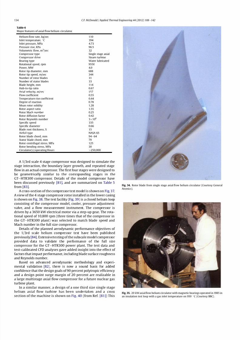
8112019 Helium Turbomachinery Operating Experience From Gas Turbine Power Plants
httpslidepdfcomreaderfullhelium-turbomachinery-operating-experience-from-gas-turbine-power-plants 2735
A 13rd scale 4 stage compressor was designed to simulate the
stage interaction the boundary layer growth and repeated stage
1047298ow in an actual compressor The 1047297rst four stages were designed to
be geometrically similar to the corresponding stages in the
GTe
HTR300 compressor Details of the model compressor havebeen discussed previously [81] and are summarized on Table 5
from [83]
A cross-section of the compressor test model is shown on Fig 37
A view of the 4 stage compressor rotor installed in the lower casing
is shown on Fig 38 The test facility (Fig 39) is a closed helium loop
consisting of the compressor model cooler pressure adjustment
valve and a 1047298ow measurement instrument The compressor is
driven by a 3650 kW electrical motor via a step-up gear The rota-
tional speed of 10800 rpm (three times that of the compressor in
the GTeHTR300 plant) was selected to match blade speed and
Mach number in the full size compressor
Details of the planned aerodynamic performance objectives of
the 13rd scale helium compressor test have been published
previously [84] Extensivetesting of the subscale model compressorprovided data to validate the performance of the full size
compressor for the GTeHTR300 power plant The test data and
test-calibrated CFD analyses gave added insight into the effect of
factors that impact performance including blade surface roughness
and Reynolds number
Based on advanced aerodynamic methodology and experi-
mental validation [82] there is now a sound basis for added
con1047297dence that the design goals of 90 percent polytropic ef 1047297ciency
and a design point surge margin of 20 percent are realizable in
a large multistage axial 1047298ow compressor for a future nuclear gas
turbine plant
In a similar manner a design of a one third size single stage
helium axial 1047298ow turbine has been undertaken and a cross
section of the machine is shown on Fig 40 (from Ref [81]) This
Table 4
Major features of axial 1047298ow helium circulator
Helium 1047298ow rate kgsec 110
Inlet temperature C 394
Inlet pressure MPa 473
Pressure rise KPa 965
Volumetric 1047298ow m3sec 32
Compressor type Single stage axial
Compressor drive Steam turbine
Bearing type Water lubricated
Rotational speed rpm 9550
Power MW 40
Rotor tip diameter mm 688
Rotor tip speed msec 344
Number of rotor blades 31
Number of stator blades 33
Blade height mm 114
Hub-to-tip ratio 067
Axial velocity msec 157
Flow coef 1047297cient 055
Temperature rise coef 1047297cient 044
Degree of reaction 078
Mean rotor solidity 128
Rotor aspect ratio 155
Rotor Mach number 025
Rotor diffusion factor 042
Rotor Reynolds number 3106
Speci1047297c speed 335
Speci1047297c diameter 066
Blade root thickness 15
Airfoil type NASA 65
Rotor blade chord mm 94e64
Stator blade chord mm 79
Rotor centrifugal stress MPa 125
Rotor bending stress MPa 30
Circulator(s) operating Hours gt250000
Fig 34 Rotor blade from single stage axial 1047298ow helium circulator (Courtesy General
Atomics)
Fig 35 20 kW axial 1047298ow helium circulator with magnetic bearings operated in 1985 in
an insulation test loop with a gas inlet temperature on 950
C (Courtesy BBC)
CF McDonald Applied Thermal Engineering 44 (2012) 108e142134
8112019 Helium Turbomachinery Operating Experience From Gas Turbine Power Plants
httpslidepdfcomreaderfullhelium-turbomachinery-operating-experience-from-gas-turbine-power-plants 2835
single stage scale model turbine for validity of the full size turbine
has been built and plans made to test the aerodynamic
performance
92 Nuclear gas turbine helium turbomachine testing
In planning for the 1047297rst nuclear gas turbine plant projected to
enter service perhaps in the third decade of the 21st century
a major decision has to be made as to what extent the large helium
turbomachine should be tested prior to operation on nuclear heat
Issues essentially include cost impact on schedule but the over-
riding one is risk Certainly turbomachine component testing will
be undertaken including the compressor (as discussed in the
previous section) and turbine performance seals cooling systems
hot gas valves thermal expansion devices high temperature
insulation rotor fragment containment diagnostic systems
instrumentation helium puri1047297cation system and other areas to
satisfy safety licensing reliability and availability concerns The
major point is really whether a full size or scaled-down turbo-machine be tested early in the project in a non-nuclear facility
To obviate the need for pre-nuclear testing of a large helium
turbomachine a view expressed by some is that advantage can be
taken of formidable technology bases that exist today for large
industrial gas turbines and high performance aeroengines On the
other hand it is the view of some including the author that very
complex power conversion system components especially those
subjected to severe thermal transients donrsquot always perform
exactly as predicted by analysts and designers even using sophis-
ticated computer codes This was exempli1047297ed in the case of the
turbomachine in the aforementioned Oberhausen II helium gas
turbine plant
The need for a helium turbomachine test facility goes beyond
just veri1047297
cation of the prototype machine Each newgas turbine for
commercial modular nuclear reactor plants would have to be proof
tested and validated before being transported to the reactor site
Similarly turbomachines that would be periodically removed from
the plant at say 7 year intervals during the plant operating life of 60
years for scheduled maintenance refurbishment repair or updat-ing would be again proof tested in the facility before re-entering
service
The direction that turbomachine development and testing will
take place for future helium gas turbines needs to be addressed by
the various organizations involved
Fig 36 AGR circulator test facility In the UK (Courtesy Howden)
Table 5
Major design parametersfeatures of model GTeHTR300 axial 1047298ow helium
compressor (Courtesy JAERI)
Scale of GTeHTR300 compressor 13
Helium mass 1047298ow rate (kgsec) 122
Helium volumetric 1047298ow rate (mV s) 87
Inlet temperature C 30
Inlet pressure MPa 0883Compressor pressure ratio at design point 1156
Number of stages 4
Rotational speed rpm 10800
Drive motor power kW 3650
Hub diameter mm 500
Rotor tip diameter (1st4th stage mm) 568566
Hub-to-tip ratio (1st stage) 088
Rotor tip speed (1st stage msec) 321
Number of rotorstator blades (1st stage) 7294
Rotorstator blade height (1st stage mm) 34337
Rotor stator blade c hor d l eng th (1st stage mm) 2620
Rotorstator solidity (1st stage) 119120
Rotorstator aspect ratio (1st stage) 1317
Flow coef 1047297cient 051
Stage loading factor 031
Reynolds number at design point 76 l05
CF McDonald Applied Thermal Engineering 44 (2012) 108e142 135
8112019 Helium Turbomachinery Operating Experience From Gas Turbine Power Plants
httpslidepdfcomreaderfullhelium-turbomachinery-operating-experience-from-gas-turbine-power-plants 2935
10 Helium turbomachinery lessons learned
101 Oberhausen II gas turbine and HHV test facility
It is understandable that 1047297rst-of-a-kind complex turboma-
chinery operating with an inert low molecular weight gas such as
helium will experience unique and unexpected problems In the
operation of the two pioneering large helium turbomachines in
Germany there were many positive1047297ndings which could only have
been achieved by development testing Equally important some
negative situations were identi1047297ed many of which were remedied
In the case of the Oberhausen II helium gas turbine plant some of
the very serious problems encountered were not resolved Inves-
tigations were undertaken to rationalize the problems associated
with the large power de1047297ciency and a data base established to
ensure that the various anomalies identi1047297ed would not occur in
future large helium turbomachines
The experience gained from the operation of the Oberhausen II
helium gas turbine power plant and the HHV test facility have been
discussedin thetextand arepresentedin a summaryformon Table6
Fig 37 Cross-section of 13rd scale helium compressor test model (Courtesy JAEA)
Fig 38 Four stage helium compressor rotor assembly installed in lower casing (Courtesy JAEA)
CF McDonald Applied Thermal Engineering 44 (2012) 108e142136
8112019 Helium Turbomachinery Operating Experience From Gas Turbine Power Plants
httpslidepdfcomreaderfullhelium-turbomachinery-operating-experience-from-gas-turbine-power-plants 3035
102 Impact of 1047297ndings on future helium gas turbine
The long slender rotorcharacteristic of closed-cycle gas turbines
has resulted in shaft dynamic instability which in some cases has
resulted in blade vibration and failure and bearing damage This
remains perhaps the major concern in the design of large
(250e
300 MW) helium turbomachines for future nuclear gas
turbine plants With pressure ratios in the range of about 2e3 in
a helium system a combination of splitting the compressor (to
facilitate intercooling) and having a large number of compressor
and turbine stages results in a long and 1047298exible rotating assembly
andthis is exempli1047297ed by the rotorassembly shown on Fig13 With
multiple bearings (either oil lubricated or magnetic) the rotor
would likely pass through multiple bending critical speeds before
Fig 39 Helium compressor test facility (Courtesy JAEA)
Fig 40 Cross-section of single stage helium turbine test model (Courtesy JAEA)
CF McDonald Applied Thermal Engineering 44 (2012) 108e142 137
8112019 Helium Turbomachinery Operating Experience From Gas Turbine Power Plants
httpslidepdfcomreaderfullhelium-turbomachinery-operating-experience-from-gas-turbine-power-plants 3135
reaching the design speed While very sophisticated computer
codes will be used in the detailed rotor dynamic analyses the real
con1047297rmation of having rotor oscillations within prescribed limits
(to avoid blade bearing and seal damage) will come from actual
testingA point to be made here is that in operated fossil-1047297red closed-
cycle gas turbine plants it was possible to remedy problems asso-
ciated with rotor vibrations and blade failures in a conventional
manner In fact in some situations the casings were opened several
times and modi1047297cations made to facilitate bearing and seal
replacement and rotor re-blading and balancing
An accurate assessment of pressure losses must be made
particularly those associated with the helium entering and leaving
the turbomachine bladed sections Minimizing the system pressure
loss is important since it directly impacts the all important quotient
of turbine expansion ratio to compressor pressure ratio and power
and plant ef 1047297ciency
Based on the operating experience from the 20 or so fossil-1047297red
closed-cycle gas turbine plants using air as the working1047298
uid it was
recognized that future very high pressure helium gas turbines
would pose problems regarding the various seals in the turbo-
machine and obtaining a zero leakage system with such a low
molecular weight gas would be dif 1047297cult and this is discussed
below
When the Oberhausen II gas turbine plant and the HHV facility
operated over 30 years ago oil lubricated bearings were used to
support the heavy rotor assemblies and helium buffered labyrinth
seals were used to prevent oil ingressinto the heliumworking1047298uid
Initial dif 1047297culties encountered in both plants were overcome by
changes made to the seal geometries and for the operating lives of
the helium turbomachines no further oil ingress events were
experienced Twoseals were required where the turbine drive shaft
penetrated the turbomachine casing namely 1) a dynamic laby-
rinth seal and 2) a static seal for shutdown conditions In both
plants these seals functioned without any problems
Labyrinth seals were also required within the helium turbo-
machines to pass the correct helium bleed 1047298ow from the
compressor discharge for cooling of the turbine discs blade root
attachments and casings The fact that the very complex rotor
cooling system in the large helium turbomachine in the HHV test
facility operated well for the test duration of about 350 h with
a turbine inlet temperature of 850 C was encouragingIn the case of the Oberhausen II gas turbine plant analysis of the
test data revealed that the labyrinth seal leakage and excessive
cooling 1047298ows were on the order of four times the design value A
possible reason for this was that damage done to the labyrinth
seals caused excessive clearances when periods of excessive rotor
oscillation and vibration occurred during early operation of the
machine
Clearly 1047298uid dynamic and thermal management of the cooling
system and 1047298ow through the various labyrinth seals will require
extensive analysis design and development testing before the
turbomachine is operated on nuclear heat for the 1047297rst time
In future heliumgas turbine designs (with turbine inlet tempera-
tureslikelyontheorderof950C)the1047298owpathgeometriesofhelium
bledfromthecompressornecessarytocoolpartsoftheturbomachinewillbemorecomplexthanthosetestedto-dateInadditiontoproviding
acooling1047298owtotheturbinebladesanddiscsbladerootattachmentsand
casingsheliummustbetransportedtotheseveralmagneticbearingsto
ensure thatthe temperatureof theirelectronic components doesnot
exceedabout150C
The importance of the points made above is evidenced when
examining the data on Table 3 where a combination of excessive
pressure losses and high bleed 1047298ows contributed to about 40
percent of the power de1047297ciency in the Oberhausen II helium
turbine plant
Retaining overall system leak tightnessin closed heliumsystems
operating at high pressure and temperature has been elusive
including experience from the Fort St Vrain HTGR plant as dis-
cussed in Section 65 New approaches in the design of the plethoraof mechanical joints must be identi1047297ed Experience to-date has
shown that having welded seals on 1047298anges while minimizing
system leakage did not eliminate it
The importance of lessons learned from the operation of the
Oberhausen II helium turbine power plant and the HHV test facility
have primarily been discussed in the context of helium turbo-
machines currently being designed in the 250e300 MWe power
range However the established test data bases could also be
applied to the possible emergence in the future of two helium
cooled reactor concepts namely 1) an advanced VHTR combined
cycle plant concept embodying a smaller helium gas turbine in the
power range of 50e80 MWe [22] and 2) the use of a direct cycle
helium gas turbine PCS in a recently proposed all ceramic fast
nuclear reactor concept [85]
Table 6
Experience gained from Oberhausen II and HHV facility
Oberhausen II 50 MW helium gas turbine power plant
Positive results
e Rotating and static seals worked well
e No ingress of bearing lubricant oil into closed circuit
e Load change by inventory control worked well
e 100 Percent load shed by means of bypass valves demonstrated
e Turbine disc and blade root cooling system con1047297rmed
e Coatings on mating surfaces prevented galling and self-welding
e After 24000 h of operation no evidence of corrosion or erosion
e Coaxial turbine hot gas inlet duct insulation and integrity con1047297rmed
e Monitoring of complete power conversion system for steady state
and transient operation undertaken
Problem areas
e Serious power output de1047297ciency (30 MW compared with design
value of 50 MW)
e Compressor(s) and turbine(s) ef 1047297ciencies several points below predicted
e Higher than estimated system pressure loss
e Rotor dynamic instability and blade vibration
e Bearings damaged and had to be replaced
e Blade failure caused extensive damage in HP turbine but retained
in casing
e Very excessive sealing and cooling 1047298ow rates
e Absolute leak tightness not attainable even with welded 1047298ange lips
HHV test facility
Positive resultse Use of heat pump approach facilitated helium temperature capability
to 1000 C
e Large oompressorturbine rotor system operated at 3000 rpm Complex
turbine disc and blade root cooling system veri1047297ed
e Dynamic and static seals met requirement of zero oxl ingress into circuit
e Structural integrity of rotating assembly veri1047297ed at temperature of 850 C
e Measured rotor oscillations within speci1047297cation
e Compressor and turbine ef 1047297ciencies higher than predicted
e Coatings on mating metallic surfaces prevented galling and self-welding
e Instrumentation control and safety systems veri1047297ed
e Seal 1047298ows within speci1047297cation
e Machine stop from operating speed to shutdown in 90 s demonstrated
e Hot gas duct insulation and thermal expansion devices worked well
e After 1100 h of operation no evidence of corrosionof erosion
Problem areas
e Before commissioning a large oil ingress into the circuit occurred due
to serious operator error and absence of an isolation valve A second oilingress occurred due to a mechanical defect in the labyrinth seal system
These were remedied and no further oil ingress was experienced for the
duration of testing
e Cooling 1047298ows slightly larger than expected but this resulted in actual
disc and blade root temperatures lower than the predicted value of
400 C
e System leak tightness demonstrated when pressurized at ambient
temperature conditions but some leakage occured at 850 C even with
the seal welding of 1047298ange(s) lips
CF McDonald Applied Thermal Engineering 44 (2012) 108e142138
8112019 Helium Turbomachinery Operating Experience From Gas Turbine Power Plants
httpslidepdfcomreaderfullhelium-turbomachinery-operating-experience-from-gas-turbine-power-plants 3235
11 New technologies
It is recognized that in the 3 to 4 decades since the operation of
the helium turbomachines covered in this paper new technologies
have emerged which negate some of the early issues An example of
this is the technology transfer from the design of modern axial 1047298ow
gas turbines (ie industrial aircraft and aeroderivatives) that fully
utilize sophisticated CAE CAD CFD and FEA design software
Air breathing aerodynamic design practice for compressors and
turbines are generally applicable but the properties of helium and
the high system pressure have a signi1047297cant impact on gas 1047298ow
paths and blade geometries With short blade heights high hub-to-
tip ratios long annulus 1047298ow path length (with resultant signi1047297cant
end-wall boundary layer growth and secondary 1047298ow) and blade tip
clearances in some cases controlled by clearances in the magnetic
catcher bearing testing of subscale model compressors and
Fig 41 Gas turbine test facility for aircraft nuclear propulsion involving the coupling of a 32 MWt air-cooled reactor with two modi 1047297ed J-47 turbojet aeroengines each rated at
a thrust of about 3000 kg operated in 1960 (Courtesy INL)
Fig 42 Mobile 350 KWe closed-cycle nuclear gas turbine power plant operated in 1961 (Courtesy US Army)
CF McDonald Applied Thermal Engineering 44 (2012) 108e142 139
8112019 Helium Turbomachinery Operating Experience From Gas Turbine Power Plants
httpslidepdfcomreaderfullhelium-turbomachinery-operating-experience-from-gas-turbine-power-plants 3335
turbines will be needed While most of the operated helium tur-
bomachines discussed in this paper took place 3 or 4 decades ago it
is encouraging that the fairly recent test data and test-calibrated
CFD analysis from a subscale four stage model helium axial 1047298ow
compressor in Japan [80] gave a high degree of con1047297dence that
design goals are realizable for the full size 20 stage compressor in
the 274 MWe GTeHTR300 plant turbomachine
In the future the use of active magnetic bearings will eliminate
the issue of oil ingress however the very heavy rotor weight and
size of the journal and thrust bearings (and catcher bearings) of the
type for helium turbomachines in the 250e300 MWe power range
are way in excess of what have been demonstrated in rotating
machinery For plant designs retaining oil-lubricated bearings well
established dry gas seal technology exists particularly experience
gained from the operation of high pressure natural gas pipe line
compressors
For future nuclear helium gas turbine plants the designer has
freedom regarding meeting different frequency requirements that
exist in some countries These include use of a synchronous
machine (ie designed for 50 or 60 Hz grids) use of a gearbox drive
between the turbine and generator or the use of a frequency
converter which gives the designer an added degree of freedom
regarding the selection of speed for the rotating assemblyCompared with the past very sophisticated electronic control
systems instrumentation and diagnostic systems are available
today
12 Conclusions
In this review paper experience from operated helium turbo-
machines has been compiled based on open literature sources At
this stage in the evolution of HTR and VHTR plant concepts it is not
clear in what role form or time-frame the nuclear gas turbine will
emerge when commercialized By say the middle of the 21st
century all power plants will be operating with signi1047297cantly higher
ef 1047297ciencies to realize improved power generation costs and
reduced emissions In a nuclear gas turbine the helium turbo-machine will be a major contributor towards the achievement of
ef 1047297ciencies higher than 50 percent
While it has been 3 to 4 decades since the Oberhausen II helium
turbine power plant and the HHV high temperature helium turbine
facility operated signi1047297cant lessons were learned and the time and
effort expended to resolve the multiplicity of unexpected technical
problems encountered The remedial repair work was done under
ideal conditions namely that immediate hands-on activities were
possible This would not have been possible if the type of problems
experienced had been encountered in a new and untested helium
turbomachine operated for the 1047297rst time with a nuclear heat
source
While new technologies have emerged that negate many of the
early problems there are some uniquely inherent issues associatedwith for large helium turbines operating in a high pressure and
temperature environment and these include the following 1)
minimizing system leakage with such a low molecular weight gas
2) clearances in labyrinth seals to minimize helium bypass1047298ows 3)
the dynamic stability of long slender rotors 4) minimizing the
turbomachine inlet and outlet pressure losses 5) 1047298ow maldis-
tribution in complex ductturbomachine interfaces 6) integrity
veri1047297cation of the catcher bearings (journal and thrust) after
multiple rotor drops (following loss of the magnetic 1047297eld) during
the plant lifetime 7) assurances that high energy fragments from
a failed turbine disc are contained within the machine casing 8)
turbomachine installation and removal from a steel pressure vessel
and 9) remote handling and cleaning of a machine with turbine
blades contaminated with 1047297
ssion products
The need for a helium turbomachine test facility has been
emphasized to ensure that the integrity performance and reli-
ability of the machine before it operates the 1047297rst time on nuclear
heat Engineers currently involved in the design of helium rotating
machinery for all HTR and VHTR plant variants should take
advantage of the experience gained from the past operation of
helium turbomachinery
13 In closing-GT rsquos operated with nuclear heat
In the context of this paper it is germane to mention that two
gas turbines have actually operated using nuclear heat as brie1047298y
highlighted below
In the late 1950rsquos a program was initiated in the USA for aircraft
nuclear propulsion (ANP) While different concepts were studied
only the direct cycle air-cooled reactor reached the stage of
construction of an experimental reactor [86] A view of the large
nuclear gas turbine facility is given on Fig 41 and shows the air-
cooled and zirconiumehydride moderated reactor rated at
32 MWt coupled with two modi1047297ed J-47 turbojet engines each
rated with a thrust of about 3000 kg In this open cycle system the
high pressure compressor air was directly heated in the reactor
before expansion in the turbine and discharge to the atmosphere in
the exhaust nozzle The facility operated between 1958 and 1961 at
the Idaho reactor testing facility While perhaps possible during the
early years of the US nuclear program it is clear that such a system
would not be acceptable today from safety and environmental
considerations
The 1047297rst and indeed the only coupling of a closed-cycle gas
turbine with a nuclear reactor for power generation was under-
taken to meet the needs of the US Army In the late 1950 rsquos an RampD
program was initiated for a 350 kW trailer-mounted system to be
used in the 1047297eld by military personnel A prototype of the ML-1
plant shown on Fig 42 was 1047297rst operated in 1961 [8788]
It was based on a 33 MW light water moderated pressure tube
reactor with nitrogen as the coolant The closed-cycle gas turbine
power conversion system with nitrogen as the working 1047298uid hada turbine inlet temperature of 649 C (1200 F) and delivered
around 300 kW With changes in the Armyrsquos needs the project was
discontinued in 1965
While the experience gained from the above twounique nuclear
plants is clearly not relevant for future nuclear gas turbine power
plants that could see service in the third decade of the 21st century
these ambitious and innovative nuclear gas turbine pioneering
engineering efforts need to be recognized
Acknowledgements
The author would like to thank the following for helpful discus-
sions advice and for providing valuable comments on the initial
paper draft Prof Dr Hermann Haselbacher Hans Ulrich Frutschi DrXing Yan DrPeter Zenker Professor DavidGordon Wilson Professor
Aristide Massardo Arthur Harris DrFred Starr and DrGuido Bac-
caglini This paper has been enhanced by the inclusion of hardware
photographs and unique sketches and the author is appreciative to
all concerned with credits being duly noted
References
[1] C Keller The Escher Wyss AK Closed-Cycle Gas Turbine Its Actual Develop-ment and Future Prospects Paper Presented at ASME Meeting November 261945
[2] HU Frutschi Closed-Cycle Gas Turbines Operating Experience and FuturePotential ASME Press NY 2005
[3] CF McDonald The Nuclear Gas Turbine-Towards Realization After Half
a Century of Evolution (1995) ASME Paper 95-GT-292
CF McDonald Applied Thermal Engineering 44 (2012) 108e142140
8112019 Helium Turbomachinery Operating Experience From Gas Turbine Power Plants
httpslidepdfcomreaderfullhelium-turbomachinery-operating-experience-from-gas-turbine-power-plants 3435
[4] C Keller The Theory and Performance of Axial Flow Fans McGraw Hill BookCompany Inc NY 1937
[5] J Ackert C Keller Aerodynamic turbine with closed circuit In A Century of Turbines vols 1516 Escher Wyss News 1942e43 5e19
[6] Escher Wyss News Closed-Cycle Gas Turbines for all Fuels Coal Gas Nuclearvol 39 No 1 (1966)
[7] C Keller Closed-cycle gas turbine Escher Wyss-AK development 1945e1950Transactions of ASME (August 1950) 835e850
[8] C Keller Operating Experience and Design Features of Closed-Cycle GasTurbine Power Plants (1956) ASME Paper 56-GTP-15
[9] C Keller HU Frutschi Closed-cycle plants -conventional and nuclear designapplication operation In Sawyerrsquos Gas Turbine Engineering Handbooksecond ed vol 2 Applications (1976) pp 265e283
[10] K Bammert G Groschup Status Report on Closed-Cycle Power Plants in theFederal Republic of Germany (1976) ASME Paper 76-GT-54
[11] JL Mason Monatomic Working Gases versus Air for Closed Brayton Cycles(1985) ASME Paper 85-IGT-50
[12] JL Mason et al 5 MW Closed Cycle Gas Turbine (1984) ASME Paper 84-GT-268
[13] The British Gas Closed-Cycle Demonstrator (1995) British Gas Research ampTechnology Final Year Report
[14] F Starr ODS alloy high temperature heat exchanger prototype developmentPaper Presented at ODS 2010 Materials Workshop UCSD Jacobs Hall La JollaCalifornia Nov17e18 2010
[15] CA Rennie Achievements of the Dragon project Pergamon Press Annals of Nuclear Energy 5 (1978) 305e320
[16] SB Hosegood et al Dragon Project Engineering Studies on the Direct CycleHTR Proceedings of Conference on Nuclear Gas Turbines The British NuclearEnergy Society London April 8e9 1970 pp 161e179
[17] Nuclear Gas Turbines Proceedings of British Nuclear Society Meeting LondonApril 8-9 1972
[18] CF McDonald C Peinado ldquoThe nuclear gas Turbine-A perspective on a long-term advanced technology HTGR plant Optionrdquo ASME Paper 82-GT-289
[19] GH Lohnert et al Technical design features and essential safety-relatedfeatures of the HTR-Module Nuclear Engineering and Design 121 (1990)259e275
[20] H Reutler GH Lohnert The modular high temperature nuclear reactorNuclear Technology 62 (1983) 22e30
[21] CF McDonald Exploitation of the very high temperature capability of theMHTGR to meet National energy needs after the year 2000 IECEC Paper869006
[22] CF McDonald Power conversion system considerations for an advancednuclear gas turbine (GT-VHTR) CHHP demonstration plant concept Interna-tional Journal of Turbo amp Jet Engines 27 (2010) 179e217
[23] N Hee Cheon et al A review of helium gas turbine technology for hightemperature gas cooled reactors Nuclear Engineering and Design 29 (2007)21e30
[24] CB Baxi et al Development of the GT-MHR Turbomachine ASME PaperGT2009e59450[25] X Yan GTHTR300 design and development Nuclear Engineering and Design
222 (2003) 247e262[26] JC Gauthier et al ANTARES the HTRVHTR project of Framatome ANP
Nuclear Engineering and Design 236 (2006) 526e533[27] J Wang et al ldquoDesign features of gas turbine power conversion system for
HTR-10GT paper D05 presented at 2nd Intl Meeting on HTR TechnologyBeijing China September 21e24 2004
[28] A Koster et al ldquoPBMR Design For the Futurerdquo Nuclear engineering andDesign 222 (203) 231e245
[29] S van der Linden Closed cycle nuclear plant rated at 165 MWe and 40 percentef 1047297ciency Gas Turbine World (MarcheApril 2007) 28e32
[30] CF McDonald Large closed-cycle gas turbines Sawyerrsquos gas turbine engi-neering handbook In Selection and Applications vol II (1985) pp 81e38(Chapter 8)
[31] CF McDonald Helium and Combustion Gas Turbine Power ConversionSystems Comparison (1995) ASME Paper 95-GT-263
[32] JK La Fleur Description of an Operating Closed-Cycle Helium Gas Turbine
ASME Paper 63-AHGT-74[33] JK La Fleur The use of turbomachinery in the 1047297eld of cryogenics In
Sawyerrsquos Gas Turbine Engineering Handbook vol II (1976) 296e311[34] W Spillmann The Closed-Cycle Gas Turbine for Non-Conventional Applica-
tions ASME Paper 66-GT-8[35] K Holliger On the in1047298uence of the degree of reaction on the secondary losses
in axial 1047298ow compressors Escher Wyss News 23 (1960)[36] W Gut Comparison of the relative losses and characteristics of axial
compressor stages Escher Wyss News 23 (1959)[37] JH Horlock Axial Flow Compressors Butterworths Scienti1047297c Publications
London 1958 pp 92e93[38] G Deuster Long-term Operating Experience with Oberhausen I Closed-Cycle
Gas Turbine Power Plant (1970) ASME Paper 70-GT-73[39] G Noak Signi1047297cance of the Helium Turbine Power Plant at Oberhausen (EVO)
and the High Temperature Helium Test Facility (HHV) at Julich for theDevelopment of HTR Direct Cycle (HHT) IAEA Publication SM-20026 Vienna1970 189e200
[40] K Bammert G Deuster Layout and Present Status of the Closed-Cycle HeliumTurbine Plant Oberhausen II (1974) ASME Paper 74-GT-132
[41] P Zenker The Oberhausen 50 MW helium turbine plant Combustion 47 (2)(April 1976)
[42] K Bammert et al Operation and Control of the 50 MW Closed Cycle HeliumTurbine Plant Oberhausen (1974) ASME Paper 74-GT-13
[43] P Zenker 10 years operating experience with the Oberhausen II heliumturbo-generator plant VGB Krafswerkstechnik 68 (7) (July 1998) 616e621
[44] K Bammert G Deuster The First Operating Experiences With the OberhausenHelium Turbine Plant Paper Presented at ASME Gas Turbine Conference NewOrleans March 21e25 1976
[45] G Deuster P Zenker Operation of the Oberhausen Helium Turbine Plant
Paper Presented at ASME Gas Turbine Conference London April 1978[46] P Zenker Operating Experience of the Oberhausen Helium Turbine Plant
Paper Presented at ASME Gas Turbine Conference San Diego 1979[47] G Deuster P Zenker Further Operating Experience of the Oberhausen Helium
Turbine Plant Paper Presented at ASME Gas Turbine Conference NewOrleans 1980
[48] P Zenker Past Experience and Future Prospects of Closed-Cycle Gas TurbinesPaper Presented at ASME Gas Turbine Conference London April 18e22 1982
[49] IA Weisbrodt Summary Report on Technical Experiences from HighTemperature Helium Turbine Testing in Germany Report IAEA-TECDOC-899Vienna Nov 1994
[50] F Bentivoglio G Geffraye Validation of the CATHARE Code Against Experi-mental Data from Brayton Cycle Plants Paper C00000228 Proceedings of HTR 2006 Johannesburg October 1e4 2006
[51] E Arndt HHT-Demonstration Plant Paper Presented at European NuclearConference Hamburg May 6 1979
[52] G Hebel HHV-Anlage Erfahrungen bei Bau und Inbetriebnahme Atom-wirtschaft(5) (1982) 258e262
[53] H Haselbacher A Eierman Development of Helium Gas Turbine in NuclearField (1974) ASME Paper 74-GT-123
[54] H Haselbacher The HHT Helium Gas Turbine and HHV Plant Paper A421 5thInternational Fair and Technical Meeting of Nuclear Industry BaselSwitzerland October 3e7 1978
[55] H Haselbacher HJ Sponholz Cooling and Insulating Problems in a HighTemperature Helium Test Facility (1984) ASME Paper 84-GT-253
[56] C Keller D Schmidt The Helium Gas Turbine for Nuclear Power Plants (1967)ASME Paper 67-GT-10
[57] W Endres Large Helium Turbine for Nuclear Power Plants (1970) ASME Paper70-GT-99
[58] JN Hurst Gas turbomachinery for helium cooled reactors in Proceedings of International Conference on Nuclear Gas Turbines British Nuclear SocietyLondon April 8 1970 pp 45e50
[59] K Bammert Nuclear Gas Turbine of Large Output for HHT Plant (1974) ASMEPaper 74-GT-10
[60] CF McDonald The Nuclear Closed-Cycle Gas Turbine (GT-HTGR) e A UtilityPower Plant for the Year 2000 (1979) AIAA Paper 79e0191
[61] CF McDonald MJ Smith Turbomachinery design considerations for the
nuclear HTGR-GT power plant ASME Journal of Engineering for Power 103 (1)(January 1981) 65e77[62] CF McDonald et al Helium Turbomachine Design for GT-MHR Power Plant
(1994) ASME Paper 94-JPGC-NE-12[63] Gas Cooled Reactor Coolant Circulator and Blower Technology (1988) IAEA
Report IWGGCR17[64] OE Balje Turbomachines A Guide to Design Selection and Theory John
Wiley amp Sons NY 1981[65] CF McDonald et al Circulator DesignTechnology Evolution for Gas Cooled
Reactors (1992) ASME Paper 92-GT-79[66] J Donaldson Application of Magnetic Bearings to Helium Circulators for High
Temperature Gas Cooled Reactors (1987) IECEC Paper 879419[67] CF McDonald Active Magnetic Bearings for Rotating Machinery in Closed-
Cycle Power Plant Systems (1989) ASME Paper 89-WANE-5[68] JA Rennie CF McDonald Active Magnetic Bearings for Rotating Machinery
in Future Gas Cooled Reactor Plants Paper Presented at 4th Intl Symposiumon Magnetic Bearings ETH Zurich August 23e26 1994
[69] CF McDonald MK Nichols Helium Circulator Design Considerations forModular High Temperature Gas Cooled Power Plant (1987) ASME Paper 87-
GT-138[70] CF McDonald Shutdown Cooling Helium Circulator Design Considerations
for MHTGR Power Plant (1989) ASME Paper 89-WANE-5[71] J Yampolsky Steam Turbine Driven Circulators for High Temperature Gas
Cooled Reactors Part I Design (1972) ASME Paper 72-WANE-20[72] VJ Barbat Steam Turbine Driven Circulators for High Temperature Gas
Cooled Reactors Part II Development (1972) ASME Paper 72-WANE-21[73] L Cavallaro J Yampolsky Design and development of a steam turbine driven
circulator for high temperature gas cooled reactors Nuclear Engineering andDesign (1974) 135e147
[74] J Henssen et al Facility for fatigue testing of thermal insulation BBC Review72 (6) (1985)
[75] J Donaldson Development of Carbon Dioxide Circulators IAEA ReportIWGGCR17 (1988) pp 47e63
[76] Personal Communication from John Donaldson (April 7 2006)[77] NG Kodochigov et al Development of the GT-MHR Vertical Turbomachine
Design ASME Paper HTR2008-58309[78] CB Baxi et al ldquoRotor Scale Model Tests for Power Conversion Unit of GT-
MHR rdquo ASME Paper HTR 2008e58015
CF McDonald Applied Thermal Engineering 44 (2012) 108e142 141
8112019 Helium Turbomachinery Operating Experience From Gas Turbine Power Plants
httpslidepdfcomreaderfullhelium-turbomachinery-operating-experience-from-gas-turbine-power-plants 3535
[79] NG Kodochibov et al Development of Catcher Bearings for the GT-MHR Turbomachine(Oct 18e20 2010)Proceedings of HTR 2010Paper 025Prague
[80] IV Drumov et al Studies of the Electromagnetic Suspension System for theGT-MHRTurbomachineProceedings of HTR2010Paper041 Oct18e20 (2010)
[81] T Takizuka et al RampD on the power conversion system for the gas turbinehigh temperature reactor Nuclear Engineering and Design 233 (2004)239e346
[82] X Yanet alAerodynamic design model test and CFDanalysisfor a multistageaxialhelium compressor ASME Journal of Turbomachinery 130 (3) (July2008)
[83] S Takada et al The 13rd Scale Aerodynamic Performance Test of Helium
Compressor for GTHTR300 Turbomachine of JAERI (April 20e
23 2003)ICONE11e36368 Tokyo Japan
[84] S Takada et al Program for aerodynamic performance tests of heliumcompressor model of GTHTR300 Transactions of the Atomic Energy Society of
Japan 2 (3) (2003) 291e300[85] RW Schleicher et al EM2 An Innovative Approach to US Energy Security
and Nuclear Waste Disposition Paper Presented at Nuclear Power Interna-tional Conference Orlando Florida December 15 2010
[86] RL Loftness Nuclear Power Plants Norstrand Company Inc NY 1964(Chapter 9 and 11)
[87] SA Varga et al The ML-1 Mobile Nuclear Power Plant (1961) ASME Paper61-SA-43
[88] JA Bailey et al Status of the Army Closed Brayton Cycle Gas Turbine Program(1967) ASME Paper 67-GT-13
CF McDonald Applied Thermal Engineering 44 (2012) 108e142142
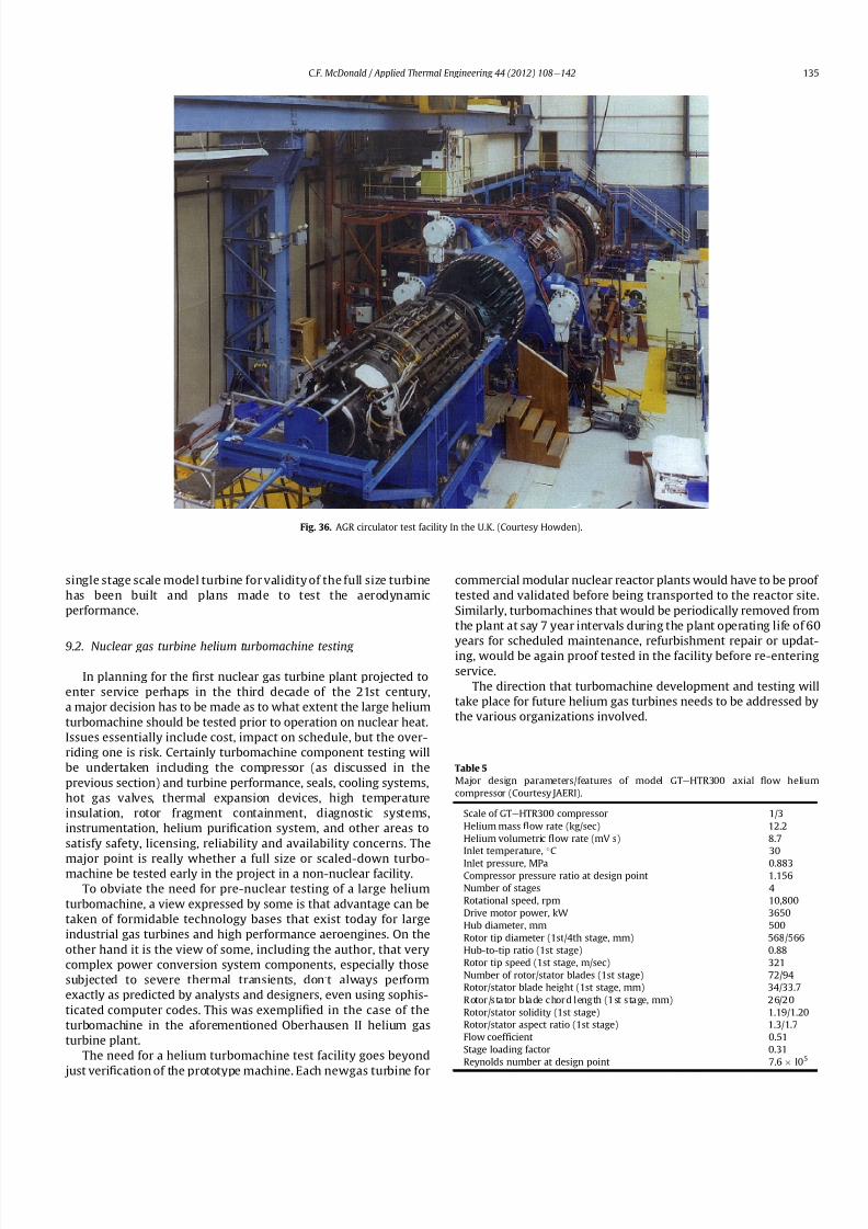
8112019 Helium Turbomachinery Operating Experience From Gas Turbine Power Plants
httpslidepdfcomreaderfullhelium-turbomachinery-operating-experience-from-gas-turbine-power-plants 2835
single stage scale model turbine for validity of the full size turbine
has been built and plans made to test the aerodynamic
performance
92 Nuclear gas turbine helium turbomachine testing
In planning for the 1047297rst nuclear gas turbine plant projected to
enter service perhaps in the third decade of the 21st century
a major decision has to be made as to what extent the large helium
turbomachine should be tested prior to operation on nuclear heat
Issues essentially include cost impact on schedule but the over-
riding one is risk Certainly turbomachine component testing will
be undertaken including the compressor (as discussed in the
previous section) and turbine performance seals cooling systems
hot gas valves thermal expansion devices high temperature
insulation rotor fragment containment diagnostic systems
instrumentation helium puri1047297cation system and other areas to
satisfy safety licensing reliability and availability concerns The
major point is really whether a full size or scaled-down turbo-machine be tested early in the project in a non-nuclear facility
To obviate the need for pre-nuclear testing of a large helium
turbomachine a view expressed by some is that advantage can be
taken of formidable technology bases that exist today for large
industrial gas turbines and high performance aeroengines On the
other hand it is the view of some including the author that very
complex power conversion system components especially those
subjected to severe thermal transients donrsquot always perform
exactly as predicted by analysts and designers even using sophis-
ticated computer codes This was exempli1047297ed in the case of the
turbomachine in the aforementioned Oberhausen II helium gas
turbine plant
The need for a helium turbomachine test facility goes beyond
just veri1047297
cation of the prototype machine Each newgas turbine for
commercial modular nuclear reactor plants would have to be proof
tested and validated before being transported to the reactor site
Similarly turbomachines that would be periodically removed from
the plant at say 7 year intervals during the plant operating life of 60
years for scheduled maintenance refurbishment repair or updat-ing would be again proof tested in the facility before re-entering
service
The direction that turbomachine development and testing will
take place for future helium gas turbines needs to be addressed by
the various organizations involved
Fig 36 AGR circulator test facility In the UK (Courtesy Howden)
Table 5
Major design parametersfeatures of model GTeHTR300 axial 1047298ow helium
compressor (Courtesy JAERI)
Scale of GTeHTR300 compressor 13
Helium mass 1047298ow rate (kgsec) 122
Helium volumetric 1047298ow rate (mV s) 87
Inlet temperature C 30
Inlet pressure MPa 0883Compressor pressure ratio at design point 1156
Number of stages 4
Rotational speed rpm 10800
Drive motor power kW 3650
Hub diameter mm 500
Rotor tip diameter (1st4th stage mm) 568566
Hub-to-tip ratio (1st stage) 088
Rotor tip speed (1st stage msec) 321
Number of rotorstator blades (1st stage) 7294
Rotorstator blade height (1st stage mm) 34337
Rotor stator blade c hor d l eng th (1st stage mm) 2620
Rotorstator solidity (1st stage) 119120
Rotorstator aspect ratio (1st stage) 1317
Flow coef 1047297cient 051
Stage loading factor 031
Reynolds number at design point 76 l05
CF McDonald Applied Thermal Engineering 44 (2012) 108e142 135
8112019 Helium Turbomachinery Operating Experience From Gas Turbine Power Plants
httpslidepdfcomreaderfullhelium-turbomachinery-operating-experience-from-gas-turbine-power-plants 2935
10 Helium turbomachinery lessons learned
101 Oberhausen II gas turbine and HHV test facility
It is understandable that 1047297rst-of-a-kind complex turboma-
chinery operating with an inert low molecular weight gas such as
helium will experience unique and unexpected problems In the
operation of the two pioneering large helium turbomachines in
Germany there were many positive1047297ndings which could only have
been achieved by development testing Equally important some
negative situations were identi1047297ed many of which were remedied
In the case of the Oberhausen II helium gas turbine plant some of
the very serious problems encountered were not resolved Inves-
tigations were undertaken to rationalize the problems associated
with the large power de1047297ciency and a data base established to
ensure that the various anomalies identi1047297ed would not occur in
future large helium turbomachines
The experience gained from the operation of the Oberhausen II
helium gas turbine power plant and the HHV test facility have been
discussedin thetextand arepresentedin a summaryformon Table6
Fig 37 Cross-section of 13rd scale helium compressor test model (Courtesy JAEA)
Fig 38 Four stage helium compressor rotor assembly installed in lower casing (Courtesy JAEA)
CF McDonald Applied Thermal Engineering 44 (2012) 108e142136
8112019 Helium Turbomachinery Operating Experience From Gas Turbine Power Plants
httpslidepdfcomreaderfullhelium-turbomachinery-operating-experience-from-gas-turbine-power-plants 3035
102 Impact of 1047297ndings on future helium gas turbine
The long slender rotorcharacteristic of closed-cycle gas turbines
has resulted in shaft dynamic instability which in some cases has
resulted in blade vibration and failure and bearing damage This
remains perhaps the major concern in the design of large
(250e
300 MW) helium turbomachines for future nuclear gas
turbine plants With pressure ratios in the range of about 2e3 in
a helium system a combination of splitting the compressor (to
facilitate intercooling) and having a large number of compressor
and turbine stages results in a long and 1047298exible rotating assembly
andthis is exempli1047297ed by the rotorassembly shown on Fig13 With
multiple bearings (either oil lubricated or magnetic) the rotor
would likely pass through multiple bending critical speeds before
Fig 39 Helium compressor test facility (Courtesy JAEA)
Fig 40 Cross-section of single stage helium turbine test model (Courtesy JAEA)
CF McDonald Applied Thermal Engineering 44 (2012) 108e142 137
8112019 Helium Turbomachinery Operating Experience From Gas Turbine Power Plants
httpslidepdfcomreaderfullhelium-turbomachinery-operating-experience-from-gas-turbine-power-plants 3135
reaching the design speed While very sophisticated computer
codes will be used in the detailed rotor dynamic analyses the real
con1047297rmation of having rotor oscillations within prescribed limits
(to avoid blade bearing and seal damage) will come from actual
testingA point to be made here is that in operated fossil-1047297red closed-
cycle gas turbine plants it was possible to remedy problems asso-
ciated with rotor vibrations and blade failures in a conventional
manner In fact in some situations the casings were opened several
times and modi1047297cations made to facilitate bearing and seal
replacement and rotor re-blading and balancing
An accurate assessment of pressure losses must be made
particularly those associated with the helium entering and leaving
the turbomachine bladed sections Minimizing the system pressure
loss is important since it directly impacts the all important quotient
of turbine expansion ratio to compressor pressure ratio and power
and plant ef 1047297ciency
Based on the operating experience from the 20 or so fossil-1047297red
closed-cycle gas turbine plants using air as the working1047298
uid it was
recognized that future very high pressure helium gas turbines
would pose problems regarding the various seals in the turbo-
machine and obtaining a zero leakage system with such a low
molecular weight gas would be dif 1047297cult and this is discussed
below
When the Oberhausen II gas turbine plant and the HHV facility
operated over 30 years ago oil lubricated bearings were used to
support the heavy rotor assemblies and helium buffered labyrinth
seals were used to prevent oil ingressinto the heliumworking1047298uid
Initial dif 1047297culties encountered in both plants were overcome by
changes made to the seal geometries and for the operating lives of
the helium turbomachines no further oil ingress events were
experienced Twoseals were required where the turbine drive shaft
penetrated the turbomachine casing namely 1) a dynamic laby-
rinth seal and 2) a static seal for shutdown conditions In both
plants these seals functioned without any problems
Labyrinth seals were also required within the helium turbo-
machines to pass the correct helium bleed 1047298ow from the
compressor discharge for cooling of the turbine discs blade root
attachments and casings The fact that the very complex rotor
cooling system in the large helium turbomachine in the HHV test
facility operated well for the test duration of about 350 h with
a turbine inlet temperature of 850 C was encouragingIn the case of the Oberhausen II gas turbine plant analysis of the
test data revealed that the labyrinth seal leakage and excessive
cooling 1047298ows were on the order of four times the design value A
possible reason for this was that damage done to the labyrinth
seals caused excessive clearances when periods of excessive rotor
oscillation and vibration occurred during early operation of the
machine
Clearly 1047298uid dynamic and thermal management of the cooling
system and 1047298ow through the various labyrinth seals will require
extensive analysis design and development testing before the
turbomachine is operated on nuclear heat for the 1047297rst time
In future heliumgas turbine designs (with turbine inlet tempera-
tureslikelyontheorderof950C)the1047298owpathgeometriesofhelium
bledfromthecompressornecessarytocoolpartsoftheturbomachinewillbemorecomplexthanthosetestedto-dateInadditiontoproviding
acooling1047298owtotheturbinebladesanddiscsbladerootattachmentsand
casingsheliummustbetransportedtotheseveralmagneticbearingsto
ensure thatthe temperatureof theirelectronic components doesnot
exceedabout150C
The importance of the points made above is evidenced when
examining the data on Table 3 where a combination of excessive
pressure losses and high bleed 1047298ows contributed to about 40
percent of the power de1047297ciency in the Oberhausen II helium
turbine plant
Retaining overall system leak tightnessin closed heliumsystems
operating at high pressure and temperature has been elusive
including experience from the Fort St Vrain HTGR plant as dis-
cussed in Section 65 New approaches in the design of the plethoraof mechanical joints must be identi1047297ed Experience to-date has
shown that having welded seals on 1047298anges while minimizing
system leakage did not eliminate it
The importance of lessons learned from the operation of the
Oberhausen II helium turbine power plant and the HHV test facility
have primarily been discussed in the context of helium turbo-
machines currently being designed in the 250e300 MWe power
range However the established test data bases could also be
applied to the possible emergence in the future of two helium
cooled reactor concepts namely 1) an advanced VHTR combined
cycle plant concept embodying a smaller helium gas turbine in the
power range of 50e80 MWe [22] and 2) the use of a direct cycle
helium gas turbine PCS in a recently proposed all ceramic fast
nuclear reactor concept [85]
Table 6
Experience gained from Oberhausen II and HHV facility
Oberhausen II 50 MW helium gas turbine power plant
Positive results
e Rotating and static seals worked well
e No ingress of bearing lubricant oil into closed circuit
e Load change by inventory control worked well
e 100 Percent load shed by means of bypass valves demonstrated
e Turbine disc and blade root cooling system con1047297rmed
e Coatings on mating surfaces prevented galling and self-welding
e After 24000 h of operation no evidence of corrosion or erosion
e Coaxial turbine hot gas inlet duct insulation and integrity con1047297rmed
e Monitoring of complete power conversion system for steady state
and transient operation undertaken
Problem areas
e Serious power output de1047297ciency (30 MW compared with design
value of 50 MW)
e Compressor(s) and turbine(s) ef 1047297ciencies several points below predicted
e Higher than estimated system pressure loss
e Rotor dynamic instability and blade vibration
e Bearings damaged and had to be replaced
e Blade failure caused extensive damage in HP turbine but retained
in casing
e Very excessive sealing and cooling 1047298ow rates
e Absolute leak tightness not attainable even with welded 1047298ange lips
HHV test facility
Positive resultse Use of heat pump approach facilitated helium temperature capability
to 1000 C
e Large oompressorturbine rotor system operated at 3000 rpm Complex
turbine disc and blade root cooling system veri1047297ed
e Dynamic and static seals met requirement of zero oxl ingress into circuit
e Structural integrity of rotating assembly veri1047297ed at temperature of 850 C
e Measured rotor oscillations within speci1047297cation
e Compressor and turbine ef 1047297ciencies higher than predicted
e Coatings on mating metallic surfaces prevented galling and self-welding
e Instrumentation control and safety systems veri1047297ed
e Seal 1047298ows within speci1047297cation
e Machine stop from operating speed to shutdown in 90 s demonstrated
e Hot gas duct insulation and thermal expansion devices worked well
e After 1100 h of operation no evidence of corrosionof erosion
Problem areas
e Before commissioning a large oil ingress into the circuit occurred due
to serious operator error and absence of an isolation valve A second oilingress occurred due to a mechanical defect in the labyrinth seal system
These were remedied and no further oil ingress was experienced for the
duration of testing
e Cooling 1047298ows slightly larger than expected but this resulted in actual
disc and blade root temperatures lower than the predicted value of
400 C
e System leak tightness demonstrated when pressurized at ambient
temperature conditions but some leakage occured at 850 C even with
the seal welding of 1047298ange(s) lips
CF McDonald Applied Thermal Engineering 44 (2012) 108e142138
8112019 Helium Turbomachinery Operating Experience From Gas Turbine Power Plants
httpslidepdfcomreaderfullhelium-turbomachinery-operating-experience-from-gas-turbine-power-plants 3235
11 New technologies
It is recognized that in the 3 to 4 decades since the operation of
the helium turbomachines covered in this paper new technologies
have emerged which negate some of the early issues An example of
this is the technology transfer from the design of modern axial 1047298ow
gas turbines (ie industrial aircraft and aeroderivatives) that fully
utilize sophisticated CAE CAD CFD and FEA design software
Air breathing aerodynamic design practice for compressors and
turbines are generally applicable but the properties of helium and
the high system pressure have a signi1047297cant impact on gas 1047298ow
paths and blade geometries With short blade heights high hub-to-
tip ratios long annulus 1047298ow path length (with resultant signi1047297cant
end-wall boundary layer growth and secondary 1047298ow) and blade tip
clearances in some cases controlled by clearances in the magnetic
catcher bearing testing of subscale model compressors and
Fig 41 Gas turbine test facility for aircraft nuclear propulsion involving the coupling of a 32 MWt air-cooled reactor with two modi 1047297ed J-47 turbojet aeroengines each rated at
a thrust of about 3000 kg operated in 1960 (Courtesy INL)
Fig 42 Mobile 350 KWe closed-cycle nuclear gas turbine power plant operated in 1961 (Courtesy US Army)
CF McDonald Applied Thermal Engineering 44 (2012) 108e142 139
8112019 Helium Turbomachinery Operating Experience From Gas Turbine Power Plants
httpslidepdfcomreaderfullhelium-turbomachinery-operating-experience-from-gas-turbine-power-plants 3335
turbines will be needed While most of the operated helium tur-
bomachines discussed in this paper took place 3 or 4 decades ago it
is encouraging that the fairly recent test data and test-calibrated
CFD analysis from a subscale four stage model helium axial 1047298ow
compressor in Japan [80] gave a high degree of con1047297dence that
design goals are realizable for the full size 20 stage compressor in
the 274 MWe GTeHTR300 plant turbomachine
In the future the use of active magnetic bearings will eliminate
the issue of oil ingress however the very heavy rotor weight and
size of the journal and thrust bearings (and catcher bearings) of the
type for helium turbomachines in the 250e300 MWe power range
are way in excess of what have been demonstrated in rotating
machinery For plant designs retaining oil-lubricated bearings well
established dry gas seal technology exists particularly experience
gained from the operation of high pressure natural gas pipe line
compressors
For future nuclear helium gas turbine plants the designer has
freedom regarding meeting different frequency requirements that
exist in some countries These include use of a synchronous
machine (ie designed for 50 or 60 Hz grids) use of a gearbox drive
between the turbine and generator or the use of a frequency
converter which gives the designer an added degree of freedom
regarding the selection of speed for the rotating assemblyCompared with the past very sophisticated electronic control
systems instrumentation and diagnostic systems are available
today
12 Conclusions
In this review paper experience from operated helium turbo-
machines has been compiled based on open literature sources At
this stage in the evolution of HTR and VHTR plant concepts it is not
clear in what role form or time-frame the nuclear gas turbine will
emerge when commercialized By say the middle of the 21st
century all power plants will be operating with signi1047297cantly higher
ef 1047297ciencies to realize improved power generation costs and
reduced emissions In a nuclear gas turbine the helium turbo-machine will be a major contributor towards the achievement of
ef 1047297ciencies higher than 50 percent
While it has been 3 to 4 decades since the Oberhausen II helium
turbine power plant and the HHV high temperature helium turbine
facility operated signi1047297cant lessons were learned and the time and
effort expended to resolve the multiplicity of unexpected technical
problems encountered The remedial repair work was done under
ideal conditions namely that immediate hands-on activities were
possible This would not have been possible if the type of problems
experienced had been encountered in a new and untested helium
turbomachine operated for the 1047297rst time with a nuclear heat
source
While new technologies have emerged that negate many of the
early problems there are some uniquely inherent issues associatedwith for large helium turbines operating in a high pressure and
temperature environment and these include the following 1)
minimizing system leakage with such a low molecular weight gas
2) clearances in labyrinth seals to minimize helium bypass1047298ows 3)
the dynamic stability of long slender rotors 4) minimizing the
turbomachine inlet and outlet pressure losses 5) 1047298ow maldis-
tribution in complex ductturbomachine interfaces 6) integrity
veri1047297cation of the catcher bearings (journal and thrust) after
multiple rotor drops (following loss of the magnetic 1047297eld) during
the plant lifetime 7) assurances that high energy fragments from
a failed turbine disc are contained within the machine casing 8)
turbomachine installation and removal from a steel pressure vessel
and 9) remote handling and cleaning of a machine with turbine
blades contaminated with 1047297
ssion products
The need for a helium turbomachine test facility has been
emphasized to ensure that the integrity performance and reli-
ability of the machine before it operates the 1047297rst time on nuclear
heat Engineers currently involved in the design of helium rotating
machinery for all HTR and VHTR plant variants should take
advantage of the experience gained from the past operation of
helium turbomachinery
13 In closing-GT rsquos operated with nuclear heat
In the context of this paper it is germane to mention that two
gas turbines have actually operated using nuclear heat as brie1047298y
highlighted below
In the late 1950rsquos a program was initiated in the USA for aircraft
nuclear propulsion (ANP) While different concepts were studied
only the direct cycle air-cooled reactor reached the stage of
construction of an experimental reactor [86] A view of the large
nuclear gas turbine facility is given on Fig 41 and shows the air-
cooled and zirconiumehydride moderated reactor rated at
32 MWt coupled with two modi1047297ed J-47 turbojet engines each
rated with a thrust of about 3000 kg In this open cycle system the
high pressure compressor air was directly heated in the reactor
before expansion in the turbine and discharge to the atmosphere in
the exhaust nozzle The facility operated between 1958 and 1961 at
the Idaho reactor testing facility While perhaps possible during the
early years of the US nuclear program it is clear that such a system
would not be acceptable today from safety and environmental
considerations
The 1047297rst and indeed the only coupling of a closed-cycle gas
turbine with a nuclear reactor for power generation was under-
taken to meet the needs of the US Army In the late 1950 rsquos an RampD
program was initiated for a 350 kW trailer-mounted system to be
used in the 1047297eld by military personnel A prototype of the ML-1
plant shown on Fig 42 was 1047297rst operated in 1961 [8788]
It was based on a 33 MW light water moderated pressure tube
reactor with nitrogen as the coolant The closed-cycle gas turbine
power conversion system with nitrogen as the working 1047298uid hada turbine inlet temperature of 649 C (1200 F) and delivered
around 300 kW With changes in the Armyrsquos needs the project was
discontinued in 1965
While the experience gained from the above twounique nuclear
plants is clearly not relevant for future nuclear gas turbine power
plants that could see service in the third decade of the 21st century
these ambitious and innovative nuclear gas turbine pioneering
engineering efforts need to be recognized
Acknowledgements
The author would like to thank the following for helpful discus-
sions advice and for providing valuable comments on the initial
paper draft Prof Dr Hermann Haselbacher Hans Ulrich Frutschi DrXing Yan DrPeter Zenker Professor DavidGordon Wilson Professor
Aristide Massardo Arthur Harris DrFred Starr and DrGuido Bac-
caglini This paper has been enhanced by the inclusion of hardware
photographs and unique sketches and the author is appreciative to
all concerned with credits being duly noted
References
[1] C Keller The Escher Wyss AK Closed-Cycle Gas Turbine Its Actual Develop-ment and Future Prospects Paper Presented at ASME Meeting November 261945
[2] HU Frutschi Closed-Cycle Gas Turbines Operating Experience and FuturePotential ASME Press NY 2005
[3] CF McDonald The Nuclear Gas Turbine-Towards Realization After Half
a Century of Evolution (1995) ASME Paper 95-GT-292
CF McDonald Applied Thermal Engineering 44 (2012) 108e142140
8112019 Helium Turbomachinery Operating Experience From Gas Turbine Power Plants
httpslidepdfcomreaderfullhelium-turbomachinery-operating-experience-from-gas-turbine-power-plants 3435
[4] C Keller The Theory and Performance of Axial Flow Fans McGraw Hill BookCompany Inc NY 1937
[5] J Ackert C Keller Aerodynamic turbine with closed circuit In A Century of Turbines vols 1516 Escher Wyss News 1942e43 5e19
[6] Escher Wyss News Closed-Cycle Gas Turbines for all Fuels Coal Gas Nuclearvol 39 No 1 (1966)
[7] C Keller Closed-cycle gas turbine Escher Wyss-AK development 1945e1950Transactions of ASME (August 1950) 835e850
[8] C Keller Operating Experience and Design Features of Closed-Cycle GasTurbine Power Plants (1956) ASME Paper 56-GTP-15
[9] C Keller HU Frutschi Closed-cycle plants -conventional and nuclear designapplication operation In Sawyerrsquos Gas Turbine Engineering Handbooksecond ed vol 2 Applications (1976) pp 265e283
[10] K Bammert G Groschup Status Report on Closed-Cycle Power Plants in theFederal Republic of Germany (1976) ASME Paper 76-GT-54
[11] JL Mason Monatomic Working Gases versus Air for Closed Brayton Cycles(1985) ASME Paper 85-IGT-50
[12] JL Mason et al 5 MW Closed Cycle Gas Turbine (1984) ASME Paper 84-GT-268
[13] The British Gas Closed-Cycle Demonstrator (1995) British Gas Research ampTechnology Final Year Report
[14] F Starr ODS alloy high temperature heat exchanger prototype developmentPaper Presented at ODS 2010 Materials Workshop UCSD Jacobs Hall La JollaCalifornia Nov17e18 2010
[15] CA Rennie Achievements of the Dragon project Pergamon Press Annals of Nuclear Energy 5 (1978) 305e320
[16] SB Hosegood et al Dragon Project Engineering Studies on the Direct CycleHTR Proceedings of Conference on Nuclear Gas Turbines The British NuclearEnergy Society London April 8e9 1970 pp 161e179
[17] Nuclear Gas Turbines Proceedings of British Nuclear Society Meeting LondonApril 8-9 1972
[18] CF McDonald C Peinado ldquoThe nuclear gas Turbine-A perspective on a long-term advanced technology HTGR plant Optionrdquo ASME Paper 82-GT-289
[19] GH Lohnert et al Technical design features and essential safety-relatedfeatures of the HTR-Module Nuclear Engineering and Design 121 (1990)259e275
[20] H Reutler GH Lohnert The modular high temperature nuclear reactorNuclear Technology 62 (1983) 22e30
[21] CF McDonald Exploitation of the very high temperature capability of theMHTGR to meet National energy needs after the year 2000 IECEC Paper869006
[22] CF McDonald Power conversion system considerations for an advancednuclear gas turbine (GT-VHTR) CHHP demonstration plant concept Interna-tional Journal of Turbo amp Jet Engines 27 (2010) 179e217
[23] N Hee Cheon et al A review of helium gas turbine technology for hightemperature gas cooled reactors Nuclear Engineering and Design 29 (2007)21e30
[24] CB Baxi et al Development of the GT-MHR Turbomachine ASME PaperGT2009e59450[25] X Yan GTHTR300 design and development Nuclear Engineering and Design
222 (2003) 247e262[26] JC Gauthier et al ANTARES the HTRVHTR project of Framatome ANP
Nuclear Engineering and Design 236 (2006) 526e533[27] J Wang et al ldquoDesign features of gas turbine power conversion system for
HTR-10GT paper D05 presented at 2nd Intl Meeting on HTR TechnologyBeijing China September 21e24 2004
[28] A Koster et al ldquoPBMR Design For the Futurerdquo Nuclear engineering andDesign 222 (203) 231e245
[29] S van der Linden Closed cycle nuclear plant rated at 165 MWe and 40 percentef 1047297ciency Gas Turbine World (MarcheApril 2007) 28e32
[30] CF McDonald Large closed-cycle gas turbines Sawyerrsquos gas turbine engi-neering handbook In Selection and Applications vol II (1985) pp 81e38(Chapter 8)
[31] CF McDonald Helium and Combustion Gas Turbine Power ConversionSystems Comparison (1995) ASME Paper 95-GT-263
[32] JK La Fleur Description of an Operating Closed-Cycle Helium Gas Turbine
ASME Paper 63-AHGT-74[33] JK La Fleur The use of turbomachinery in the 1047297eld of cryogenics In
Sawyerrsquos Gas Turbine Engineering Handbook vol II (1976) 296e311[34] W Spillmann The Closed-Cycle Gas Turbine for Non-Conventional Applica-
tions ASME Paper 66-GT-8[35] K Holliger On the in1047298uence of the degree of reaction on the secondary losses
in axial 1047298ow compressors Escher Wyss News 23 (1960)[36] W Gut Comparison of the relative losses and characteristics of axial
compressor stages Escher Wyss News 23 (1959)[37] JH Horlock Axial Flow Compressors Butterworths Scienti1047297c Publications
London 1958 pp 92e93[38] G Deuster Long-term Operating Experience with Oberhausen I Closed-Cycle
Gas Turbine Power Plant (1970) ASME Paper 70-GT-73[39] G Noak Signi1047297cance of the Helium Turbine Power Plant at Oberhausen (EVO)
and the High Temperature Helium Test Facility (HHV) at Julich for theDevelopment of HTR Direct Cycle (HHT) IAEA Publication SM-20026 Vienna1970 189e200
[40] K Bammert G Deuster Layout and Present Status of the Closed-Cycle HeliumTurbine Plant Oberhausen II (1974) ASME Paper 74-GT-132
[41] P Zenker The Oberhausen 50 MW helium turbine plant Combustion 47 (2)(April 1976)
[42] K Bammert et al Operation and Control of the 50 MW Closed Cycle HeliumTurbine Plant Oberhausen (1974) ASME Paper 74-GT-13
[43] P Zenker 10 years operating experience with the Oberhausen II heliumturbo-generator plant VGB Krafswerkstechnik 68 (7) (July 1998) 616e621
[44] K Bammert G Deuster The First Operating Experiences With the OberhausenHelium Turbine Plant Paper Presented at ASME Gas Turbine Conference NewOrleans March 21e25 1976
[45] G Deuster P Zenker Operation of the Oberhausen Helium Turbine Plant
Paper Presented at ASME Gas Turbine Conference London April 1978[46] P Zenker Operating Experience of the Oberhausen Helium Turbine Plant
Paper Presented at ASME Gas Turbine Conference San Diego 1979[47] G Deuster P Zenker Further Operating Experience of the Oberhausen Helium
Turbine Plant Paper Presented at ASME Gas Turbine Conference NewOrleans 1980
[48] P Zenker Past Experience and Future Prospects of Closed-Cycle Gas TurbinesPaper Presented at ASME Gas Turbine Conference London April 18e22 1982
[49] IA Weisbrodt Summary Report on Technical Experiences from HighTemperature Helium Turbine Testing in Germany Report IAEA-TECDOC-899Vienna Nov 1994
[50] F Bentivoglio G Geffraye Validation of the CATHARE Code Against Experi-mental Data from Brayton Cycle Plants Paper C00000228 Proceedings of HTR 2006 Johannesburg October 1e4 2006
[51] E Arndt HHT-Demonstration Plant Paper Presented at European NuclearConference Hamburg May 6 1979
[52] G Hebel HHV-Anlage Erfahrungen bei Bau und Inbetriebnahme Atom-wirtschaft(5) (1982) 258e262
[53] H Haselbacher A Eierman Development of Helium Gas Turbine in NuclearField (1974) ASME Paper 74-GT-123
[54] H Haselbacher The HHT Helium Gas Turbine and HHV Plant Paper A421 5thInternational Fair and Technical Meeting of Nuclear Industry BaselSwitzerland October 3e7 1978
[55] H Haselbacher HJ Sponholz Cooling and Insulating Problems in a HighTemperature Helium Test Facility (1984) ASME Paper 84-GT-253
[56] C Keller D Schmidt The Helium Gas Turbine for Nuclear Power Plants (1967)ASME Paper 67-GT-10
[57] W Endres Large Helium Turbine for Nuclear Power Plants (1970) ASME Paper70-GT-99
[58] JN Hurst Gas turbomachinery for helium cooled reactors in Proceedings of International Conference on Nuclear Gas Turbines British Nuclear SocietyLondon April 8 1970 pp 45e50
[59] K Bammert Nuclear Gas Turbine of Large Output for HHT Plant (1974) ASMEPaper 74-GT-10
[60] CF McDonald The Nuclear Closed-Cycle Gas Turbine (GT-HTGR) e A UtilityPower Plant for the Year 2000 (1979) AIAA Paper 79e0191
[61] CF McDonald MJ Smith Turbomachinery design considerations for the
nuclear HTGR-GT power plant ASME Journal of Engineering for Power 103 (1)(January 1981) 65e77[62] CF McDonald et al Helium Turbomachine Design for GT-MHR Power Plant
(1994) ASME Paper 94-JPGC-NE-12[63] Gas Cooled Reactor Coolant Circulator and Blower Technology (1988) IAEA
Report IWGGCR17[64] OE Balje Turbomachines A Guide to Design Selection and Theory John
Wiley amp Sons NY 1981[65] CF McDonald et al Circulator DesignTechnology Evolution for Gas Cooled
Reactors (1992) ASME Paper 92-GT-79[66] J Donaldson Application of Magnetic Bearings to Helium Circulators for High
Temperature Gas Cooled Reactors (1987) IECEC Paper 879419[67] CF McDonald Active Magnetic Bearings for Rotating Machinery in Closed-
Cycle Power Plant Systems (1989) ASME Paper 89-WANE-5[68] JA Rennie CF McDonald Active Magnetic Bearings for Rotating Machinery
in Future Gas Cooled Reactor Plants Paper Presented at 4th Intl Symposiumon Magnetic Bearings ETH Zurich August 23e26 1994
[69] CF McDonald MK Nichols Helium Circulator Design Considerations forModular High Temperature Gas Cooled Power Plant (1987) ASME Paper 87-
GT-138[70] CF McDonald Shutdown Cooling Helium Circulator Design Considerations
for MHTGR Power Plant (1989) ASME Paper 89-WANE-5[71] J Yampolsky Steam Turbine Driven Circulators for High Temperature Gas
Cooled Reactors Part I Design (1972) ASME Paper 72-WANE-20[72] VJ Barbat Steam Turbine Driven Circulators for High Temperature Gas
Cooled Reactors Part II Development (1972) ASME Paper 72-WANE-21[73] L Cavallaro J Yampolsky Design and development of a steam turbine driven
circulator for high temperature gas cooled reactors Nuclear Engineering andDesign (1974) 135e147
[74] J Henssen et al Facility for fatigue testing of thermal insulation BBC Review72 (6) (1985)
[75] J Donaldson Development of Carbon Dioxide Circulators IAEA ReportIWGGCR17 (1988) pp 47e63
[76] Personal Communication from John Donaldson (April 7 2006)[77] NG Kodochigov et al Development of the GT-MHR Vertical Turbomachine
Design ASME Paper HTR2008-58309[78] CB Baxi et al ldquoRotor Scale Model Tests for Power Conversion Unit of GT-
MHR rdquo ASME Paper HTR 2008e58015
CF McDonald Applied Thermal Engineering 44 (2012) 108e142 141
8112019 Helium Turbomachinery Operating Experience From Gas Turbine Power Plants
httpslidepdfcomreaderfullhelium-turbomachinery-operating-experience-from-gas-turbine-power-plants 3535
[79] NG Kodochibov et al Development of Catcher Bearings for the GT-MHR Turbomachine(Oct 18e20 2010)Proceedings of HTR 2010Paper 025Prague
[80] IV Drumov et al Studies of the Electromagnetic Suspension System for theGT-MHRTurbomachineProceedings of HTR2010Paper041 Oct18e20 (2010)
[81] T Takizuka et al RampD on the power conversion system for the gas turbinehigh temperature reactor Nuclear Engineering and Design 233 (2004)239e346
[82] X Yanet alAerodynamic design model test and CFDanalysisfor a multistageaxialhelium compressor ASME Journal of Turbomachinery 130 (3) (July2008)
[83] S Takada et al The 13rd Scale Aerodynamic Performance Test of Helium
Compressor for GTHTR300 Turbomachine of JAERI (April 20e
23 2003)ICONE11e36368 Tokyo Japan
[84] S Takada et al Program for aerodynamic performance tests of heliumcompressor model of GTHTR300 Transactions of the Atomic Energy Society of
Japan 2 (3) (2003) 291e300[85] RW Schleicher et al EM2 An Innovative Approach to US Energy Security
and Nuclear Waste Disposition Paper Presented at Nuclear Power Interna-tional Conference Orlando Florida December 15 2010
[86] RL Loftness Nuclear Power Plants Norstrand Company Inc NY 1964(Chapter 9 and 11)
[87] SA Varga et al The ML-1 Mobile Nuclear Power Plant (1961) ASME Paper61-SA-43
[88] JA Bailey et al Status of the Army Closed Brayton Cycle Gas Turbine Program(1967) ASME Paper 67-GT-13
CF McDonald Applied Thermal Engineering 44 (2012) 108e142142
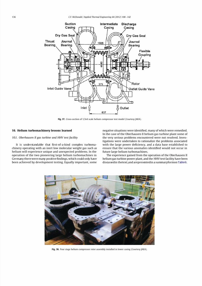
8112019 Helium Turbomachinery Operating Experience From Gas Turbine Power Plants
httpslidepdfcomreaderfullhelium-turbomachinery-operating-experience-from-gas-turbine-power-plants 2935
10 Helium turbomachinery lessons learned
101 Oberhausen II gas turbine and HHV test facility
It is understandable that 1047297rst-of-a-kind complex turboma-
chinery operating with an inert low molecular weight gas such as
helium will experience unique and unexpected problems In the
operation of the two pioneering large helium turbomachines in
Germany there were many positive1047297ndings which could only have
been achieved by development testing Equally important some
negative situations were identi1047297ed many of which were remedied
In the case of the Oberhausen II helium gas turbine plant some of
the very serious problems encountered were not resolved Inves-
tigations were undertaken to rationalize the problems associated
with the large power de1047297ciency and a data base established to
ensure that the various anomalies identi1047297ed would not occur in
future large helium turbomachines
The experience gained from the operation of the Oberhausen II
helium gas turbine power plant and the HHV test facility have been
discussedin thetextand arepresentedin a summaryformon Table6
Fig 37 Cross-section of 13rd scale helium compressor test model (Courtesy JAEA)
Fig 38 Four stage helium compressor rotor assembly installed in lower casing (Courtesy JAEA)
CF McDonald Applied Thermal Engineering 44 (2012) 108e142136
8112019 Helium Turbomachinery Operating Experience From Gas Turbine Power Plants
httpslidepdfcomreaderfullhelium-turbomachinery-operating-experience-from-gas-turbine-power-plants 3035
102 Impact of 1047297ndings on future helium gas turbine
The long slender rotorcharacteristic of closed-cycle gas turbines
has resulted in shaft dynamic instability which in some cases has
resulted in blade vibration and failure and bearing damage This
remains perhaps the major concern in the design of large
(250e
300 MW) helium turbomachines for future nuclear gas
turbine plants With pressure ratios in the range of about 2e3 in
a helium system a combination of splitting the compressor (to
facilitate intercooling) and having a large number of compressor
and turbine stages results in a long and 1047298exible rotating assembly
andthis is exempli1047297ed by the rotorassembly shown on Fig13 With
multiple bearings (either oil lubricated or magnetic) the rotor
would likely pass through multiple bending critical speeds before
Fig 39 Helium compressor test facility (Courtesy JAEA)
Fig 40 Cross-section of single stage helium turbine test model (Courtesy JAEA)
CF McDonald Applied Thermal Engineering 44 (2012) 108e142 137
8112019 Helium Turbomachinery Operating Experience From Gas Turbine Power Plants
httpslidepdfcomreaderfullhelium-turbomachinery-operating-experience-from-gas-turbine-power-plants 3135
reaching the design speed While very sophisticated computer
codes will be used in the detailed rotor dynamic analyses the real
con1047297rmation of having rotor oscillations within prescribed limits
(to avoid blade bearing and seal damage) will come from actual
testingA point to be made here is that in operated fossil-1047297red closed-
cycle gas turbine plants it was possible to remedy problems asso-
ciated with rotor vibrations and blade failures in a conventional
manner In fact in some situations the casings were opened several
times and modi1047297cations made to facilitate bearing and seal
replacement and rotor re-blading and balancing
An accurate assessment of pressure losses must be made
particularly those associated with the helium entering and leaving
the turbomachine bladed sections Minimizing the system pressure
loss is important since it directly impacts the all important quotient
of turbine expansion ratio to compressor pressure ratio and power
and plant ef 1047297ciency
Based on the operating experience from the 20 or so fossil-1047297red
closed-cycle gas turbine plants using air as the working1047298
uid it was
recognized that future very high pressure helium gas turbines
would pose problems regarding the various seals in the turbo-
machine and obtaining a zero leakage system with such a low
molecular weight gas would be dif 1047297cult and this is discussed
below
When the Oberhausen II gas turbine plant and the HHV facility
operated over 30 years ago oil lubricated bearings were used to
support the heavy rotor assemblies and helium buffered labyrinth
seals were used to prevent oil ingressinto the heliumworking1047298uid
Initial dif 1047297culties encountered in both plants were overcome by
changes made to the seal geometries and for the operating lives of
the helium turbomachines no further oil ingress events were
experienced Twoseals were required where the turbine drive shaft
penetrated the turbomachine casing namely 1) a dynamic laby-
rinth seal and 2) a static seal for shutdown conditions In both
plants these seals functioned without any problems
Labyrinth seals were also required within the helium turbo-
machines to pass the correct helium bleed 1047298ow from the
compressor discharge for cooling of the turbine discs blade root
attachments and casings The fact that the very complex rotor
cooling system in the large helium turbomachine in the HHV test
facility operated well for the test duration of about 350 h with
a turbine inlet temperature of 850 C was encouragingIn the case of the Oberhausen II gas turbine plant analysis of the
test data revealed that the labyrinth seal leakage and excessive
cooling 1047298ows were on the order of four times the design value A
possible reason for this was that damage done to the labyrinth
seals caused excessive clearances when periods of excessive rotor
oscillation and vibration occurred during early operation of the
machine
Clearly 1047298uid dynamic and thermal management of the cooling
system and 1047298ow through the various labyrinth seals will require
extensive analysis design and development testing before the
turbomachine is operated on nuclear heat for the 1047297rst time
In future heliumgas turbine designs (with turbine inlet tempera-
tureslikelyontheorderof950C)the1047298owpathgeometriesofhelium
bledfromthecompressornecessarytocoolpartsoftheturbomachinewillbemorecomplexthanthosetestedto-dateInadditiontoproviding
acooling1047298owtotheturbinebladesanddiscsbladerootattachmentsand
casingsheliummustbetransportedtotheseveralmagneticbearingsto
ensure thatthe temperatureof theirelectronic components doesnot
exceedabout150C
The importance of the points made above is evidenced when
examining the data on Table 3 where a combination of excessive
pressure losses and high bleed 1047298ows contributed to about 40
percent of the power de1047297ciency in the Oberhausen II helium
turbine plant
Retaining overall system leak tightnessin closed heliumsystems
operating at high pressure and temperature has been elusive
including experience from the Fort St Vrain HTGR plant as dis-
cussed in Section 65 New approaches in the design of the plethoraof mechanical joints must be identi1047297ed Experience to-date has
shown that having welded seals on 1047298anges while minimizing
system leakage did not eliminate it
The importance of lessons learned from the operation of the
Oberhausen II helium turbine power plant and the HHV test facility
have primarily been discussed in the context of helium turbo-
machines currently being designed in the 250e300 MWe power
range However the established test data bases could also be
applied to the possible emergence in the future of two helium
cooled reactor concepts namely 1) an advanced VHTR combined
cycle plant concept embodying a smaller helium gas turbine in the
power range of 50e80 MWe [22] and 2) the use of a direct cycle
helium gas turbine PCS in a recently proposed all ceramic fast
nuclear reactor concept [85]
Table 6
Experience gained from Oberhausen II and HHV facility
Oberhausen II 50 MW helium gas turbine power plant
Positive results
e Rotating and static seals worked well
e No ingress of bearing lubricant oil into closed circuit
e Load change by inventory control worked well
e 100 Percent load shed by means of bypass valves demonstrated
e Turbine disc and blade root cooling system con1047297rmed
e Coatings on mating surfaces prevented galling and self-welding
e After 24000 h of operation no evidence of corrosion or erosion
e Coaxial turbine hot gas inlet duct insulation and integrity con1047297rmed
e Monitoring of complete power conversion system for steady state
and transient operation undertaken
Problem areas
e Serious power output de1047297ciency (30 MW compared with design
value of 50 MW)
e Compressor(s) and turbine(s) ef 1047297ciencies several points below predicted
e Higher than estimated system pressure loss
e Rotor dynamic instability and blade vibration
e Bearings damaged and had to be replaced
e Blade failure caused extensive damage in HP turbine but retained
in casing
e Very excessive sealing and cooling 1047298ow rates
e Absolute leak tightness not attainable even with welded 1047298ange lips
HHV test facility
Positive resultse Use of heat pump approach facilitated helium temperature capability
to 1000 C
e Large oompressorturbine rotor system operated at 3000 rpm Complex
turbine disc and blade root cooling system veri1047297ed
e Dynamic and static seals met requirement of zero oxl ingress into circuit
e Structural integrity of rotating assembly veri1047297ed at temperature of 850 C
e Measured rotor oscillations within speci1047297cation
e Compressor and turbine ef 1047297ciencies higher than predicted
e Coatings on mating metallic surfaces prevented galling and self-welding
e Instrumentation control and safety systems veri1047297ed
e Seal 1047298ows within speci1047297cation
e Machine stop from operating speed to shutdown in 90 s demonstrated
e Hot gas duct insulation and thermal expansion devices worked well
e After 1100 h of operation no evidence of corrosionof erosion
Problem areas
e Before commissioning a large oil ingress into the circuit occurred due
to serious operator error and absence of an isolation valve A second oilingress occurred due to a mechanical defect in the labyrinth seal system
These were remedied and no further oil ingress was experienced for the
duration of testing
e Cooling 1047298ows slightly larger than expected but this resulted in actual
disc and blade root temperatures lower than the predicted value of
400 C
e System leak tightness demonstrated when pressurized at ambient
temperature conditions but some leakage occured at 850 C even with
the seal welding of 1047298ange(s) lips
CF McDonald Applied Thermal Engineering 44 (2012) 108e142138
8112019 Helium Turbomachinery Operating Experience From Gas Turbine Power Plants
httpslidepdfcomreaderfullhelium-turbomachinery-operating-experience-from-gas-turbine-power-plants 3235
11 New technologies
It is recognized that in the 3 to 4 decades since the operation of
the helium turbomachines covered in this paper new technologies
have emerged which negate some of the early issues An example of
this is the technology transfer from the design of modern axial 1047298ow
gas turbines (ie industrial aircraft and aeroderivatives) that fully
utilize sophisticated CAE CAD CFD and FEA design software
Air breathing aerodynamic design practice for compressors and
turbines are generally applicable but the properties of helium and
the high system pressure have a signi1047297cant impact on gas 1047298ow
paths and blade geometries With short blade heights high hub-to-
tip ratios long annulus 1047298ow path length (with resultant signi1047297cant
end-wall boundary layer growth and secondary 1047298ow) and blade tip
clearances in some cases controlled by clearances in the magnetic
catcher bearing testing of subscale model compressors and
Fig 41 Gas turbine test facility for aircraft nuclear propulsion involving the coupling of a 32 MWt air-cooled reactor with two modi 1047297ed J-47 turbojet aeroengines each rated at
a thrust of about 3000 kg operated in 1960 (Courtesy INL)
Fig 42 Mobile 350 KWe closed-cycle nuclear gas turbine power plant operated in 1961 (Courtesy US Army)
CF McDonald Applied Thermal Engineering 44 (2012) 108e142 139
8112019 Helium Turbomachinery Operating Experience From Gas Turbine Power Plants
httpslidepdfcomreaderfullhelium-turbomachinery-operating-experience-from-gas-turbine-power-plants 3335
turbines will be needed While most of the operated helium tur-
bomachines discussed in this paper took place 3 or 4 decades ago it
is encouraging that the fairly recent test data and test-calibrated
CFD analysis from a subscale four stage model helium axial 1047298ow
compressor in Japan [80] gave a high degree of con1047297dence that
design goals are realizable for the full size 20 stage compressor in
the 274 MWe GTeHTR300 plant turbomachine
In the future the use of active magnetic bearings will eliminate
the issue of oil ingress however the very heavy rotor weight and
size of the journal and thrust bearings (and catcher bearings) of the
type for helium turbomachines in the 250e300 MWe power range
are way in excess of what have been demonstrated in rotating
machinery For plant designs retaining oil-lubricated bearings well
established dry gas seal technology exists particularly experience
gained from the operation of high pressure natural gas pipe line
compressors
For future nuclear helium gas turbine plants the designer has
freedom regarding meeting different frequency requirements that
exist in some countries These include use of a synchronous
machine (ie designed for 50 or 60 Hz grids) use of a gearbox drive
between the turbine and generator or the use of a frequency
converter which gives the designer an added degree of freedom
regarding the selection of speed for the rotating assemblyCompared with the past very sophisticated electronic control
systems instrumentation and diagnostic systems are available
today
12 Conclusions
In this review paper experience from operated helium turbo-
machines has been compiled based on open literature sources At
this stage in the evolution of HTR and VHTR plant concepts it is not
clear in what role form or time-frame the nuclear gas turbine will
emerge when commercialized By say the middle of the 21st
century all power plants will be operating with signi1047297cantly higher
ef 1047297ciencies to realize improved power generation costs and
reduced emissions In a nuclear gas turbine the helium turbo-machine will be a major contributor towards the achievement of
ef 1047297ciencies higher than 50 percent
While it has been 3 to 4 decades since the Oberhausen II helium
turbine power plant and the HHV high temperature helium turbine
facility operated signi1047297cant lessons were learned and the time and
effort expended to resolve the multiplicity of unexpected technical
problems encountered The remedial repair work was done under
ideal conditions namely that immediate hands-on activities were
possible This would not have been possible if the type of problems
experienced had been encountered in a new and untested helium
turbomachine operated for the 1047297rst time with a nuclear heat
source
While new technologies have emerged that negate many of the
early problems there are some uniquely inherent issues associatedwith for large helium turbines operating in a high pressure and
temperature environment and these include the following 1)
minimizing system leakage with such a low molecular weight gas
2) clearances in labyrinth seals to minimize helium bypass1047298ows 3)
the dynamic stability of long slender rotors 4) minimizing the
turbomachine inlet and outlet pressure losses 5) 1047298ow maldis-
tribution in complex ductturbomachine interfaces 6) integrity
veri1047297cation of the catcher bearings (journal and thrust) after
multiple rotor drops (following loss of the magnetic 1047297eld) during
the plant lifetime 7) assurances that high energy fragments from
a failed turbine disc are contained within the machine casing 8)
turbomachine installation and removal from a steel pressure vessel
and 9) remote handling and cleaning of a machine with turbine
blades contaminated with 1047297
ssion products
The need for a helium turbomachine test facility has been
emphasized to ensure that the integrity performance and reli-
ability of the machine before it operates the 1047297rst time on nuclear
heat Engineers currently involved in the design of helium rotating
machinery for all HTR and VHTR plant variants should take
advantage of the experience gained from the past operation of
helium turbomachinery
13 In closing-GT rsquos operated with nuclear heat
In the context of this paper it is germane to mention that two
gas turbines have actually operated using nuclear heat as brie1047298y
highlighted below
In the late 1950rsquos a program was initiated in the USA for aircraft
nuclear propulsion (ANP) While different concepts were studied
only the direct cycle air-cooled reactor reached the stage of
construction of an experimental reactor [86] A view of the large
nuclear gas turbine facility is given on Fig 41 and shows the air-
cooled and zirconiumehydride moderated reactor rated at
32 MWt coupled with two modi1047297ed J-47 turbojet engines each
rated with a thrust of about 3000 kg In this open cycle system the
high pressure compressor air was directly heated in the reactor
before expansion in the turbine and discharge to the atmosphere in
the exhaust nozzle The facility operated between 1958 and 1961 at
the Idaho reactor testing facility While perhaps possible during the
early years of the US nuclear program it is clear that such a system
would not be acceptable today from safety and environmental
considerations
The 1047297rst and indeed the only coupling of a closed-cycle gas
turbine with a nuclear reactor for power generation was under-
taken to meet the needs of the US Army In the late 1950 rsquos an RampD
program was initiated for a 350 kW trailer-mounted system to be
used in the 1047297eld by military personnel A prototype of the ML-1
plant shown on Fig 42 was 1047297rst operated in 1961 [8788]
It was based on a 33 MW light water moderated pressure tube
reactor with nitrogen as the coolant The closed-cycle gas turbine
power conversion system with nitrogen as the working 1047298uid hada turbine inlet temperature of 649 C (1200 F) and delivered
around 300 kW With changes in the Armyrsquos needs the project was
discontinued in 1965
While the experience gained from the above twounique nuclear
plants is clearly not relevant for future nuclear gas turbine power
plants that could see service in the third decade of the 21st century
these ambitious and innovative nuclear gas turbine pioneering
engineering efforts need to be recognized
Acknowledgements
The author would like to thank the following for helpful discus-
sions advice and for providing valuable comments on the initial
paper draft Prof Dr Hermann Haselbacher Hans Ulrich Frutschi DrXing Yan DrPeter Zenker Professor DavidGordon Wilson Professor
Aristide Massardo Arthur Harris DrFred Starr and DrGuido Bac-
caglini This paper has been enhanced by the inclusion of hardware
photographs and unique sketches and the author is appreciative to
all concerned with credits being duly noted
References
[1] C Keller The Escher Wyss AK Closed-Cycle Gas Turbine Its Actual Develop-ment and Future Prospects Paper Presented at ASME Meeting November 261945
[2] HU Frutschi Closed-Cycle Gas Turbines Operating Experience and FuturePotential ASME Press NY 2005
[3] CF McDonald The Nuclear Gas Turbine-Towards Realization After Half
a Century of Evolution (1995) ASME Paper 95-GT-292
CF McDonald Applied Thermal Engineering 44 (2012) 108e142140
8112019 Helium Turbomachinery Operating Experience From Gas Turbine Power Plants
httpslidepdfcomreaderfullhelium-turbomachinery-operating-experience-from-gas-turbine-power-plants 3435
[4] C Keller The Theory and Performance of Axial Flow Fans McGraw Hill BookCompany Inc NY 1937
[5] J Ackert C Keller Aerodynamic turbine with closed circuit In A Century of Turbines vols 1516 Escher Wyss News 1942e43 5e19
[6] Escher Wyss News Closed-Cycle Gas Turbines for all Fuels Coal Gas Nuclearvol 39 No 1 (1966)
[7] C Keller Closed-cycle gas turbine Escher Wyss-AK development 1945e1950Transactions of ASME (August 1950) 835e850
[8] C Keller Operating Experience and Design Features of Closed-Cycle GasTurbine Power Plants (1956) ASME Paper 56-GTP-15
[9] C Keller HU Frutschi Closed-cycle plants -conventional and nuclear designapplication operation In Sawyerrsquos Gas Turbine Engineering Handbooksecond ed vol 2 Applications (1976) pp 265e283
[10] K Bammert G Groschup Status Report on Closed-Cycle Power Plants in theFederal Republic of Germany (1976) ASME Paper 76-GT-54
[11] JL Mason Monatomic Working Gases versus Air for Closed Brayton Cycles(1985) ASME Paper 85-IGT-50
[12] JL Mason et al 5 MW Closed Cycle Gas Turbine (1984) ASME Paper 84-GT-268
[13] The British Gas Closed-Cycle Demonstrator (1995) British Gas Research ampTechnology Final Year Report
[14] F Starr ODS alloy high temperature heat exchanger prototype developmentPaper Presented at ODS 2010 Materials Workshop UCSD Jacobs Hall La JollaCalifornia Nov17e18 2010
[15] CA Rennie Achievements of the Dragon project Pergamon Press Annals of Nuclear Energy 5 (1978) 305e320
[16] SB Hosegood et al Dragon Project Engineering Studies on the Direct CycleHTR Proceedings of Conference on Nuclear Gas Turbines The British NuclearEnergy Society London April 8e9 1970 pp 161e179
[17] Nuclear Gas Turbines Proceedings of British Nuclear Society Meeting LondonApril 8-9 1972
[18] CF McDonald C Peinado ldquoThe nuclear gas Turbine-A perspective on a long-term advanced technology HTGR plant Optionrdquo ASME Paper 82-GT-289
[19] GH Lohnert et al Technical design features and essential safety-relatedfeatures of the HTR-Module Nuclear Engineering and Design 121 (1990)259e275
[20] H Reutler GH Lohnert The modular high temperature nuclear reactorNuclear Technology 62 (1983) 22e30
[21] CF McDonald Exploitation of the very high temperature capability of theMHTGR to meet National energy needs after the year 2000 IECEC Paper869006
[22] CF McDonald Power conversion system considerations for an advancednuclear gas turbine (GT-VHTR) CHHP demonstration plant concept Interna-tional Journal of Turbo amp Jet Engines 27 (2010) 179e217
[23] N Hee Cheon et al A review of helium gas turbine technology for hightemperature gas cooled reactors Nuclear Engineering and Design 29 (2007)21e30
[24] CB Baxi et al Development of the GT-MHR Turbomachine ASME PaperGT2009e59450[25] X Yan GTHTR300 design and development Nuclear Engineering and Design
222 (2003) 247e262[26] JC Gauthier et al ANTARES the HTRVHTR project of Framatome ANP
Nuclear Engineering and Design 236 (2006) 526e533[27] J Wang et al ldquoDesign features of gas turbine power conversion system for
HTR-10GT paper D05 presented at 2nd Intl Meeting on HTR TechnologyBeijing China September 21e24 2004
[28] A Koster et al ldquoPBMR Design For the Futurerdquo Nuclear engineering andDesign 222 (203) 231e245
[29] S van der Linden Closed cycle nuclear plant rated at 165 MWe and 40 percentef 1047297ciency Gas Turbine World (MarcheApril 2007) 28e32
[30] CF McDonald Large closed-cycle gas turbines Sawyerrsquos gas turbine engi-neering handbook In Selection and Applications vol II (1985) pp 81e38(Chapter 8)
[31] CF McDonald Helium and Combustion Gas Turbine Power ConversionSystems Comparison (1995) ASME Paper 95-GT-263
[32] JK La Fleur Description of an Operating Closed-Cycle Helium Gas Turbine
ASME Paper 63-AHGT-74[33] JK La Fleur The use of turbomachinery in the 1047297eld of cryogenics In
Sawyerrsquos Gas Turbine Engineering Handbook vol II (1976) 296e311[34] W Spillmann The Closed-Cycle Gas Turbine for Non-Conventional Applica-
tions ASME Paper 66-GT-8[35] K Holliger On the in1047298uence of the degree of reaction on the secondary losses
in axial 1047298ow compressors Escher Wyss News 23 (1960)[36] W Gut Comparison of the relative losses and characteristics of axial
compressor stages Escher Wyss News 23 (1959)[37] JH Horlock Axial Flow Compressors Butterworths Scienti1047297c Publications
London 1958 pp 92e93[38] G Deuster Long-term Operating Experience with Oberhausen I Closed-Cycle
Gas Turbine Power Plant (1970) ASME Paper 70-GT-73[39] G Noak Signi1047297cance of the Helium Turbine Power Plant at Oberhausen (EVO)
and the High Temperature Helium Test Facility (HHV) at Julich for theDevelopment of HTR Direct Cycle (HHT) IAEA Publication SM-20026 Vienna1970 189e200
[40] K Bammert G Deuster Layout and Present Status of the Closed-Cycle HeliumTurbine Plant Oberhausen II (1974) ASME Paper 74-GT-132
[41] P Zenker The Oberhausen 50 MW helium turbine plant Combustion 47 (2)(April 1976)
[42] K Bammert et al Operation and Control of the 50 MW Closed Cycle HeliumTurbine Plant Oberhausen (1974) ASME Paper 74-GT-13
[43] P Zenker 10 years operating experience with the Oberhausen II heliumturbo-generator plant VGB Krafswerkstechnik 68 (7) (July 1998) 616e621
[44] K Bammert G Deuster The First Operating Experiences With the OberhausenHelium Turbine Plant Paper Presented at ASME Gas Turbine Conference NewOrleans March 21e25 1976
[45] G Deuster P Zenker Operation of the Oberhausen Helium Turbine Plant
Paper Presented at ASME Gas Turbine Conference London April 1978[46] P Zenker Operating Experience of the Oberhausen Helium Turbine Plant
Paper Presented at ASME Gas Turbine Conference San Diego 1979[47] G Deuster P Zenker Further Operating Experience of the Oberhausen Helium
Turbine Plant Paper Presented at ASME Gas Turbine Conference NewOrleans 1980
[48] P Zenker Past Experience and Future Prospects of Closed-Cycle Gas TurbinesPaper Presented at ASME Gas Turbine Conference London April 18e22 1982
[49] IA Weisbrodt Summary Report on Technical Experiences from HighTemperature Helium Turbine Testing in Germany Report IAEA-TECDOC-899Vienna Nov 1994
[50] F Bentivoglio G Geffraye Validation of the CATHARE Code Against Experi-mental Data from Brayton Cycle Plants Paper C00000228 Proceedings of HTR 2006 Johannesburg October 1e4 2006
[51] E Arndt HHT-Demonstration Plant Paper Presented at European NuclearConference Hamburg May 6 1979
[52] G Hebel HHV-Anlage Erfahrungen bei Bau und Inbetriebnahme Atom-wirtschaft(5) (1982) 258e262
[53] H Haselbacher A Eierman Development of Helium Gas Turbine in NuclearField (1974) ASME Paper 74-GT-123
[54] H Haselbacher The HHT Helium Gas Turbine and HHV Plant Paper A421 5thInternational Fair and Technical Meeting of Nuclear Industry BaselSwitzerland October 3e7 1978
[55] H Haselbacher HJ Sponholz Cooling and Insulating Problems in a HighTemperature Helium Test Facility (1984) ASME Paper 84-GT-253
[56] C Keller D Schmidt The Helium Gas Turbine for Nuclear Power Plants (1967)ASME Paper 67-GT-10
[57] W Endres Large Helium Turbine for Nuclear Power Plants (1970) ASME Paper70-GT-99
[58] JN Hurst Gas turbomachinery for helium cooled reactors in Proceedings of International Conference on Nuclear Gas Turbines British Nuclear SocietyLondon April 8 1970 pp 45e50
[59] K Bammert Nuclear Gas Turbine of Large Output for HHT Plant (1974) ASMEPaper 74-GT-10
[60] CF McDonald The Nuclear Closed-Cycle Gas Turbine (GT-HTGR) e A UtilityPower Plant for the Year 2000 (1979) AIAA Paper 79e0191
[61] CF McDonald MJ Smith Turbomachinery design considerations for the
nuclear HTGR-GT power plant ASME Journal of Engineering for Power 103 (1)(January 1981) 65e77[62] CF McDonald et al Helium Turbomachine Design for GT-MHR Power Plant
(1994) ASME Paper 94-JPGC-NE-12[63] Gas Cooled Reactor Coolant Circulator and Blower Technology (1988) IAEA
Report IWGGCR17[64] OE Balje Turbomachines A Guide to Design Selection and Theory John
Wiley amp Sons NY 1981[65] CF McDonald et al Circulator DesignTechnology Evolution for Gas Cooled
Reactors (1992) ASME Paper 92-GT-79[66] J Donaldson Application of Magnetic Bearings to Helium Circulators for High
Temperature Gas Cooled Reactors (1987) IECEC Paper 879419[67] CF McDonald Active Magnetic Bearings for Rotating Machinery in Closed-
Cycle Power Plant Systems (1989) ASME Paper 89-WANE-5[68] JA Rennie CF McDonald Active Magnetic Bearings for Rotating Machinery
in Future Gas Cooled Reactor Plants Paper Presented at 4th Intl Symposiumon Magnetic Bearings ETH Zurich August 23e26 1994
[69] CF McDonald MK Nichols Helium Circulator Design Considerations forModular High Temperature Gas Cooled Power Plant (1987) ASME Paper 87-
GT-138[70] CF McDonald Shutdown Cooling Helium Circulator Design Considerations
for MHTGR Power Plant (1989) ASME Paper 89-WANE-5[71] J Yampolsky Steam Turbine Driven Circulators for High Temperature Gas
Cooled Reactors Part I Design (1972) ASME Paper 72-WANE-20[72] VJ Barbat Steam Turbine Driven Circulators for High Temperature Gas
Cooled Reactors Part II Development (1972) ASME Paper 72-WANE-21[73] L Cavallaro J Yampolsky Design and development of a steam turbine driven
circulator for high temperature gas cooled reactors Nuclear Engineering andDesign (1974) 135e147
[74] J Henssen et al Facility for fatigue testing of thermal insulation BBC Review72 (6) (1985)
[75] J Donaldson Development of Carbon Dioxide Circulators IAEA ReportIWGGCR17 (1988) pp 47e63
[76] Personal Communication from John Donaldson (April 7 2006)[77] NG Kodochigov et al Development of the GT-MHR Vertical Turbomachine
Design ASME Paper HTR2008-58309[78] CB Baxi et al ldquoRotor Scale Model Tests for Power Conversion Unit of GT-
MHR rdquo ASME Paper HTR 2008e58015
CF McDonald Applied Thermal Engineering 44 (2012) 108e142 141
8112019 Helium Turbomachinery Operating Experience From Gas Turbine Power Plants
httpslidepdfcomreaderfullhelium-turbomachinery-operating-experience-from-gas-turbine-power-plants 3535
[79] NG Kodochibov et al Development of Catcher Bearings for the GT-MHR Turbomachine(Oct 18e20 2010)Proceedings of HTR 2010Paper 025Prague
[80] IV Drumov et al Studies of the Electromagnetic Suspension System for theGT-MHRTurbomachineProceedings of HTR2010Paper041 Oct18e20 (2010)
[81] T Takizuka et al RampD on the power conversion system for the gas turbinehigh temperature reactor Nuclear Engineering and Design 233 (2004)239e346
[82] X Yanet alAerodynamic design model test and CFDanalysisfor a multistageaxialhelium compressor ASME Journal of Turbomachinery 130 (3) (July2008)
[83] S Takada et al The 13rd Scale Aerodynamic Performance Test of Helium
Compressor for GTHTR300 Turbomachine of JAERI (April 20e
23 2003)ICONE11e36368 Tokyo Japan
[84] S Takada et al Program for aerodynamic performance tests of heliumcompressor model of GTHTR300 Transactions of the Atomic Energy Society of
Japan 2 (3) (2003) 291e300[85] RW Schleicher et al EM2 An Innovative Approach to US Energy Security
and Nuclear Waste Disposition Paper Presented at Nuclear Power Interna-tional Conference Orlando Florida December 15 2010
[86] RL Loftness Nuclear Power Plants Norstrand Company Inc NY 1964(Chapter 9 and 11)
[87] SA Varga et al The ML-1 Mobile Nuclear Power Plant (1961) ASME Paper61-SA-43
[88] JA Bailey et al Status of the Army Closed Brayton Cycle Gas Turbine Program(1967) ASME Paper 67-GT-13
CF McDonald Applied Thermal Engineering 44 (2012) 108e142142
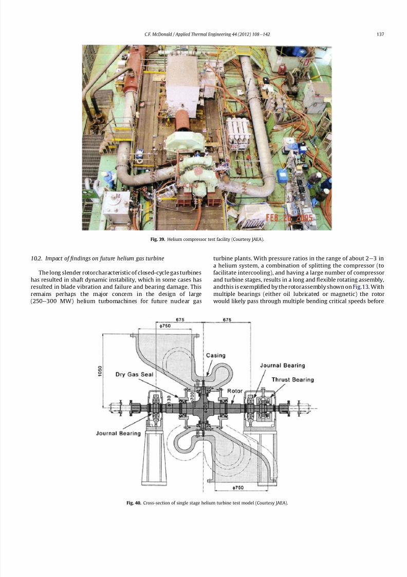
8112019 Helium Turbomachinery Operating Experience From Gas Turbine Power Plants
httpslidepdfcomreaderfullhelium-turbomachinery-operating-experience-from-gas-turbine-power-plants 3035
102 Impact of 1047297ndings on future helium gas turbine
The long slender rotorcharacteristic of closed-cycle gas turbines
has resulted in shaft dynamic instability which in some cases has
resulted in blade vibration and failure and bearing damage This
remains perhaps the major concern in the design of large
(250e
300 MW) helium turbomachines for future nuclear gas
turbine plants With pressure ratios in the range of about 2e3 in
a helium system a combination of splitting the compressor (to
facilitate intercooling) and having a large number of compressor
and turbine stages results in a long and 1047298exible rotating assembly
andthis is exempli1047297ed by the rotorassembly shown on Fig13 With
multiple bearings (either oil lubricated or magnetic) the rotor
would likely pass through multiple bending critical speeds before
Fig 39 Helium compressor test facility (Courtesy JAEA)
Fig 40 Cross-section of single stage helium turbine test model (Courtesy JAEA)
CF McDonald Applied Thermal Engineering 44 (2012) 108e142 137
8112019 Helium Turbomachinery Operating Experience From Gas Turbine Power Plants
httpslidepdfcomreaderfullhelium-turbomachinery-operating-experience-from-gas-turbine-power-plants 3135
reaching the design speed While very sophisticated computer
codes will be used in the detailed rotor dynamic analyses the real
con1047297rmation of having rotor oscillations within prescribed limits
(to avoid blade bearing and seal damage) will come from actual
testingA point to be made here is that in operated fossil-1047297red closed-
cycle gas turbine plants it was possible to remedy problems asso-
ciated with rotor vibrations and blade failures in a conventional
manner In fact in some situations the casings were opened several
times and modi1047297cations made to facilitate bearing and seal
replacement and rotor re-blading and balancing
An accurate assessment of pressure losses must be made
particularly those associated with the helium entering and leaving
the turbomachine bladed sections Minimizing the system pressure
loss is important since it directly impacts the all important quotient
of turbine expansion ratio to compressor pressure ratio and power
and plant ef 1047297ciency
Based on the operating experience from the 20 or so fossil-1047297red
closed-cycle gas turbine plants using air as the working1047298
uid it was
recognized that future very high pressure helium gas turbines
would pose problems regarding the various seals in the turbo-
machine and obtaining a zero leakage system with such a low
molecular weight gas would be dif 1047297cult and this is discussed
below
When the Oberhausen II gas turbine plant and the HHV facility
operated over 30 years ago oil lubricated bearings were used to
support the heavy rotor assemblies and helium buffered labyrinth
seals were used to prevent oil ingressinto the heliumworking1047298uid
Initial dif 1047297culties encountered in both plants were overcome by
changes made to the seal geometries and for the operating lives of
the helium turbomachines no further oil ingress events were
experienced Twoseals were required where the turbine drive shaft
penetrated the turbomachine casing namely 1) a dynamic laby-
rinth seal and 2) a static seal for shutdown conditions In both
plants these seals functioned without any problems
Labyrinth seals were also required within the helium turbo-
machines to pass the correct helium bleed 1047298ow from the
compressor discharge for cooling of the turbine discs blade root
attachments and casings The fact that the very complex rotor
cooling system in the large helium turbomachine in the HHV test
facility operated well for the test duration of about 350 h with
a turbine inlet temperature of 850 C was encouragingIn the case of the Oberhausen II gas turbine plant analysis of the
test data revealed that the labyrinth seal leakage and excessive
cooling 1047298ows were on the order of four times the design value A
possible reason for this was that damage done to the labyrinth
seals caused excessive clearances when periods of excessive rotor
oscillation and vibration occurred during early operation of the
machine
Clearly 1047298uid dynamic and thermal management of the cooling
system and 1047298ow through the various labyrinth seals will require
extensive analysis design and development testing before the
turbomachine is operated on nuclear heat for the 1047297rst time
In future heliumgas turbine designs (with turbine inlet tempera-
tureslikelyontheorderof950C)the1047298owpathgeometriesofhelium
bledfromthecompressornecessarytocoolpartsoftheturbomachinewillbemorecomplexthanthosetestedto-dateInadditiontoproviding
acooling1047298owtotheturbinebladesanddiscsbladerootattachmentsand
casingsheliummustbetransportedtotheseveralmagneticbearingsto
ensure thatthe temperatureof theirelectronic components doesnot
exceedabout150C
The importance of the points made above is evidenced when
examining the data on Table 3 where a combination of excessive
pressure losses and high bleed 1047298ows contributed to about 40
percent of the power de1047297ciency in the Oberhausen II helium
turbine plant
Retaining overall system leak tightnessin closed heliumsystems
operating at high pressure and temperature has been elusive
including experience from the Fort St Vrain HTGR plant as dis-
cussed in Section 65 New approaches in the design of the plethoraof mechanical joints must be identi1047297ed Experience to-date has
shown that having welded seals on 1047298anges while minimizing
system leakage did not eliminate it
The importance of lessons learned from the operation of the
Oberhausen II helium turbine power plant and the HHV test facility
have primarily been discussed in the context of helium turbo-
machines currently being designed in the 250e300 MWe power
range However the established test data bases could also be
applied to the possible emergence in the future of two helium
cooled reactor concepts namely 1) an advanced VHTR combined
cycle plant concept embodying a smaller helium gas turbine in the
power range of 50e80 MWe [22] and 2) the use of a direct cycle
helium gas turbine PCS in a recently proposed all ceramic fast
nuclear reactor concept [85]
Table 6
Experience gained from Oberhausen II and HHV facility
Oberhausen II 50 MW helium gas turbine power plant
Positive results
e Rotating and static seals worked well
e No ingress of bearing lubricant oil into closed circuit
e Load change by inventory control worked well
e 100 Percent load shed by means of bypass valves demonstrated
e Turbine disc and blade root cooling system con1047297rmed
e Coatings on mating surfaces prevented galling and self-welding
e After 24000 h of operation no evidence of corrosion or erosion
e Coaxial turbine hot gas inlet duct insulation and integrity con1047297rmed
e Monitoring of complete power conversion system for steady state
and transient operation undertaken
Problem areas
e Serious power output de1047297ciency (30 MW compared with design
value of 50 MW)
e Compressor(s) and turbine(s) ef 1047297ciencies several points below predicted
e Higher than estimated system pressure loss
e Rotor dynamic instability and blade vibration
e Bearings damaged and had to be replaced
e Blade failure caused extensive damage in HP turbine but retained
in casing
e Very excessive sealing and cooling 1047298ow rates
e Absolute leak tightness not attainable even with welded 1047298ange lips
HHV test facility
Positive resultse Use of heat pump approach facilitated helium temperature capability
to 1000 C
e Large oompressorturbine rotor system operated at 3000 rpm Complex
turbine disc and blade root cooling system veri1047297ed
e Dynamic and static seals met requirement of zero oxl ingress into circuit
e Structural integrity of rotating assembly veri1047297ed at temperature of 850 C
e Measured rotor oscillations within speci1047297cation
e Compressor and turbine ef 1047297ciencies higher than predicted
e Coatings on mating metallic surfaces prevented galling and self-welding
e Instrumentation control and safety systems veri1047297ed
e Seal 1047298ows within speci1047297cation
e Machine stop from operating speed to shutdown in 90 s demonstrated
e Hot gas duct insulation and thermal expansion devices worked well
e After 1100 h of operation no evidence of corrosionof erosion
Problem areas
e Before commissioning a large oil ingress into the circuit occurred due
to serious operator error and absence of an isolation valve A second oilingress occurred due to a mechanical defect in the labyrinth seal system
These were remedied and no further oil ingress was experienced for the
duration of testing
e Cooling 1047298ows slightly larger than expected but this resulted in actual
disc and blade root temperatures lower than the predicted value of
400 C
e System leak tightness demonstrated when pressurized at ambient
temperature conditions but some leakage occured at 850 C even with
the seal welding of 1047298ange(s) lips
CF McDonald Applied Thermal Engineering 44 (2012) 108e142138
8112019 Helium Turbomachinery Operating Experience From Gas Turbine Power Plants
httpslidepdfcomreaderfullhelium-turbomachinery-operating-experience-from-gas-turbine-power-plants 3235
11 New technologies
It is recognized that in the 3 to 4 decades since the operation of
the helium turbomachines covered in this paper new technologies
have emerged which negate some of the early issues An example of
this is the technology transfer from the design of modern axial 1047298ow
gas turbines (ie industrial aircraft and aeroderivatives) that fully
utilize sophisticated CAE CAD CFD and FEA design software
Air breathing aerodynamic design practice for compressors and
turbines are generally applicable but the properties of helium and
the high system pressure have a signi1047297cant impact on gas 1047298ow
paths and blade geometries With short blade heights high hub-to-
tip ratios long annulus 1047298ow path length (with resultant signi1047297cant
end-wall boundary layer growth and secondary 1047298ow) and blade tip
clearances in some cases controlled by clearances in the magnetic
catcher bearing testing of subscale model compressors and
Fig 41 Gas turbine test facility for aircraft nuclear propulsion involving the coupling of a 32 MWt air-cooled reactor with two modi 1047297ed J-47 turbojet aeroengines each rated at
a thrust of about 3000 kg operated in 1960 (Courtesy INL)
Fig 42 Mobile 350 KWe closed-cycle nuclear gas turbine power plant operated in 1961 (Courtesy US Army)
CF McDonald Applied Thermal Engineering 44 (2012) 108e142 139
8112019 Helium Turbomachinery Operating Experience From Gas Turbine Power Plants
httpslidepdfcomreaderfullhelium-turbomachinery-operating-experience-from-gas-turbine-power-plants 3335
turbines will be needed While most of the operated helium tur-
bomachines discussed in this paper took place 3 or 4 decades ago it
is encouraging that the fairly recent test data and test-calibrated
CFD analysis from a subscale four stage model helium axial 1047298ow
compressor in Japan [80] gave a high degree of con1047297dence that
design goals are realizable for the full size 20 stage compressor in
the 274 MWe GTeHTR300 plant turbomachine
In the future the use of active magnetic bearings will eliminate
the issue of oil ingress however the very heavy rotor weight and
size of the journal and thrust bearings (and catcher bearings) of the
type for helium turbomachines in the 250e300 MWe power range
are way in excess of what have been demonstrated in rotating
machinery For plant designs retaining oil-lubricated bearings well
established dry gas seal technology exists particularly experience
gained from the operation of high pressure natural gas pipe line
compressors
For future nuclear helium gas turbine plants the designer has
freedom regarding meeting different frequency requirements that
exist in some countries These include use of a synchronous
machine (ie designed for 50 or 60 Hz grids) use of a gearbox drive
between the turbine and generator or the use of a frequency
converter which gives the designer an added degree of freedom
regarding the selection of speed for the rotating assemblyCompared with the past very sophisticated electronic control
systems instrumentation and diagnostic systems are available
today
12 Conclusions
In this review paper experience from operated helium turbo-
machines has been compiled based on open literature sources At
this stage in the evolution of HTR and VHTR plant concepts it is not
clear in what role form or time-frame the nuclear gas turbine will
emerge when commercialized By say the middle of the 21st
century all power plants will be operating with signi1047297cantly higher
ef 1047297ciencies to realize improved power generation costs and
reduced emissions In a nuclear gas turbine the helium turbo-machine will be a major contributor towards the achievement of
ef 1047297ciencies higher than 50 percent
While it has been 3 to 4 decades since the Oberhausen II helium
turbine power plant and the HHV high temperature helium turbine
facility operated signi1047297cant lessons were learned and the time and
effort expended to resolve the multiplicity of unexpected technical
problems encountered The remedial repair work was done under
ideal conditions namely that immediate hands-on activities were
possible This would not have been possible if the type of problems
experienced had been encountered in a new and untested helium
turbomachine operated for the 1047297rst time with a nuclear heat
source
While new technologies have emerged that negate many of the
early problems there are some uniquely inherent issues associatedwith for large helium turbines operating in a high pressure and
temperature environment and these include the following 1)
minimizing system leakage with such a low molecular weight gas
2) clearances in labyrinth seals to minimize helium bypass1047298ows 3)
the dynamic stability of long slender rotors 4) minimizing the
turbomachine inlet and outlet pressure losses 5) 1047298ow maldis-
tribution in complex ductturbomachine interfaces 6) integrity
veri1047297cation of the catcher bearings (journal and thrust) after
multiple rotor drops (following loss of the magnetic 1047297eld) during
the plant lifetime 7) assurances that high energy fragments from
a failed turbine disc are contained within the machine casing 8)
turbomachine installation and removal from a steel pressure vessel
and 9) remote handling and cleaning of a machine with turbine
blades contaminated with 1047297
ssion products
The need for a helium turbomachine test facility has been
emphasized to ensure that the integrity performance and reli-
ability of the machine before it operates the 1047297rst time on nuclear
heat Engineers currently involved in the design of helium rotating
machinery for all HTR and VHTR plant variants should take
advantage of the experience gained from the past operation of
helium turbomachinery
13 In closing-GT rsquos operated with nuclear heat
In the context of this paper it is germane to mention that two
gas turbines have actually operated using nuclear heat as brie1047298y
highlighted below
In the late 1950rsquos a program was initiated in the USA for aircraft
nuclear propulsion (ANP) While different concepts were studied
only the direct cycle air-cooled reactor reached the stage of
construction of an experimental reactor [86] A view of the large
nuclear gas turbine facility is given on Fig 41 and shows the air-
cooled and zirconiumehydride moderated reactor rated at
32 MWt coupled with two modi1047297ed J-47 turbojet engines each
rated with a thrust of about 3000 kg In this open cycle system the
high pressure compressor air was directly heated in the reactor
before expansion in the turbine and discharge to the atmosphere in
the exhaust nozzle The facility operated between 1958 and 1961 at
the Idaho reactor testing facility While perhaps possible during the
early years of the US nuclear program it is clear that such a system
would not be acceptable today from safety and environmental
considerations
The 1047297rst and indeed the only coupling of a closed-cycle gas
turbine with a nuclear reactor for power generation was under-
taken to meet the needs of the US Army In the late 1950 rsquos an RampD
program was initiated for a 350 kW trailer-mounted system to be
used in the 1047297eld by military personnel A prototype of the ML-1
plant shown on Fig 42 was 1047297rst operated in 1961 [8788]
It was based on a 33 MW light water moderated pressure tube
reactor with nitrogen as the coolant The closed-cycle gas turbine
power conversion system with nitrogen as the working 1047298uid hada turbine inlet temperature of 649 C (1200 F) and delivered
around 300 kW With changes in the Armyrsquos needs the project was
discontinued in 1965
While the experience gained from the above twounique nuclear
plants is clearly not relevant for future nuclear gas turbine power
plants that could see service in the third decade of the 21st century
these ambitious and innovative nuclear gas turbine pioneering
engineering efforts need to be recognized
Acknowledgements
The author would like to thank the following for helpful discus-
sions advice and for providing valuable comments on the initial
paper draft Prof Dr Hermann Haselbacher Hans Ulrich Frutschi DrXing Yan DrPeter Zenker Professor DavidGordon Wilson Professor
Aristide Massardo Arthur Harris DrFred Starr and DrGuido Bac-
caglini This paper has been enhanced by the inclusion of hardware
photographs and unique sketches and the author is appreciative to
all concerned with credits being duly noted
References
[1] C Keller The Escher Wyss AK Closed-Cycle Gas Turbine Its Actual Develop-ment and Future Prospects Paper Presented at ASME Meeting November 261945
[2] HU Frutschi Closed-Cycle Gas Turbines Operating Experience and FuturePotential ASME Press NY 2005
[3] CF McDonald The Nuclear Gas Turbine-Towards Realization After Half
a Century of Evolution (1995) ASME Paper 95-GT-292
CF McDonald Applied Thermal Engineering 44 (2012) 108e142140
8112019 Helium Turbomachinery Operating Experience From Gas Turbine Power Plants
httpslidepdfcomreaderfullhelium-turbomachinery-operating-experience-from-gas-turbine-power-plants 3435
[4] C Keller The Theory and Performance of Axial Flow Fans McGraw Hill BookCompany Inc NY 1937
[5] J Ackert C Keller Aerodynamic turbine with closed circuit In A Century of Turbines vols 1516 Escher Wyss News 1942e43 5e19
[6] Escher Wyss News Closed-Cycle Gas Turbines for all Fuels Coal Gas Nuclearvol 39 No 1 (1966)
[7] C Keller Closed-cycle gas turbine Escher Wyss-AK development 1945e1950Transactions of ASME (August 1950) 835e850
[8] C Keller Operating Experience and Design Features of Closed-Cycle GasTurbine Power Plants (1956) ASME Paper 56-GTP-15
[9] C Keller HU Frutschi Closed-cycle plants -conventional and nuclear designapplication operation In Sawyerrsquos Gas Turbine Engineering Handbooksecond ed vol 2 Applications (1976) pp 265e283
[10] K Bammert G Groschup Status Report on Closed-Cycle Power Plants in theFederal Republic of Germany (1976) ASME Paper 76-GT-54
[11] JL Mason Monatomic Working Gases versus Air for Closed Brayton Cycles(1985) ASME Paper 85-IGT-50
[12] JL Mason et al 5 MW Closed Cycle Gas Turbine (1984) ASME Paper 84-GT-268
[13] The British Gas Closed-Cycle Demonstrator (1995) British Gas Research ampTechnology Final Year Report
[14] F Starr ODS alloy high temperature heat exchanger prototype developmentPaper Presented at ODS 2010 Materials Workshop UCSD Jacobs Hall La JollaCalifornia Nov17e18 2010
[15] CA Rennie Achievements of the Dragon project Pergamon Press Annals of Nuclear Energy 5 (1978) 305e320
[16] SB Hosegood et al Dragon Project Engineering Studies on the Direct CycleHTR Proceedings of Conference on Nuclear Gas Turbines The British NuclearEnergy Society London April 8e9 1970 pp 161e179
[17] Nuclear Gas Turbines Proceedings of British Nuclear Society Meeting LondonApril 8-9 1972
[18] CF McDonald C Peinado ldquoThe nuclear gas Turbine-A perspective on a long-term advanced technology HTGR plant Optionrdquo ASME Paper 82-GT-289
[19] GH Lohnert et al Technical design features and essential safety-relatedfeatures of the HTR-Module Nuclear Engineering and Design 121 (1990)259e275
[20] H Reutler GH Lohnert The modular high temperature nuclear reactorNuclear Technology 62 (1983) 22e30
[21] CF McDonald Exploitation of the very high temperature capability of theMHTGR to meet National energy needs after the year 2000 IECEC Paper869006
[22] CF McDonald Power conversion system considerations for an advancednuclear gas turbine (GT-VHTR) CHHP demonstration plant concept Interna-tional Journal of Turbo amp Jet Engines 27 (2010) 179e217
[23] N Hee Cheon et al A review of helium gas turbine technology for hightemperature gas cooled reactors Nuclear Engineering and Design 29 (2007)21e30
[24] CB Baxi et al Development of the GT-MHR Turbomachine ASME PaperGT2009e59450[25] X Yan GTHTR300 design and development Nuclear Engineering and Design
222 (2003) 247e262[26] JC Gauthier et al ANTARES the HTRVHTR project of Framatome ANP
Nuclear Engineering and Design 236 (2006) 526e533[27] J Wang et al ldquoDesign features of gas turbine power conversion system for
HTR-10GT paper D05 presented at 2nd Intl Meeting on HTR TechnologyBeijing China September 21e24 2004
[28] A Koster et al ldquoPBMR Design For the Futurerdquo Nuclear engineering andDesign 222 (203) 231e245
[29] S van der Linden Closed cycle nuclear plant rated at 165 MWe and 40 percentef 1047297ciency Gas Turbine World (MarcheApril 2007) 28e32
[30] CF McDonald Large closed-cycle gas turbines Sawyerrsquos gas turbine engi-neering handbook In Selection and Applications vol II (1985) pp 81e38(Chapter 8)
[31] CF McDonald Helium and Combustion Gas Turbine Power ConversionSystems Comparison (1995) ASME Paper 95-GT-263
[32] JK La Fleur Description of an Operating Closed-Cycle Helium Gas Turbine
ASME Paper 63-AHGT-74[33] JK La Fleur The use of turbomachinery in the 1047297eld of cryogenics In
Sawyerrsquos Gas Turbine Engineering Handbook vol II (1976) 296e311[34] W Spillmann The Closed-Cycle Gas Turbine for Non-Conventional Applica-
tions ASME Paper 66-GT-8[35] K Holliger On the in1047298uence of the degree of reaction on the secondary losses
in axial 1047298ow compressors Escher Wyss News 23 (1960)[36] W Gut Comparison of the relative losses and characteristics of axial
compressor stages Escher Wyss News 23 (1959)[37] JH Horlock Axial Flow Compressors Butterworths Scienti1047297c Publications
London 1958 pp 92e93[38] G Deuster Long-term Operating Experience with Oberhausen I Closed-Cycle
Gas Turbine Power Plant (1970) ASME Paper 70-GT-73[39] G Noak Signi1047297cance of the Helium Turbine Power Plant at Oberhausen (EVO)
and the High Temperature Helium Test Facility (HHV) at Julich for theDevelopment of HTR Direct Cycle (HHT) IAEA Publication SM-20026 Vienna1970 189e200
[40] K Bammert G Deuster Layout and Present Status of the Closed-Cycle HeliumTurbine Plant Oberhausen II (1974) ASME Paper 74-GT-132
[41] P Zenker The Oberhausen 50 MW helium turbine plant Combustion 47 (2)(April 1976)
[42] K Bammert et al Operation and Control of the 50 MW Closed Cycle HeliumTurbine Plant Oberhausen (1974) ASME Paper 74-GT-13
[43] P Zenker 10 years operating experience with the Oberhausen II heliumturbo-generator plant VGB Krafswerkstechnik 68 (7) (July 1998) 616e621
[44] K Bammert G Deuster The First Operating Experiences With the OberhausenHelium Turbine Plant Paper Presented at ASME Gas Turbine Conference NewOrleans March 21e25 1976
[45] G Deuster P Zenker Operation of the Oberhausen Helium Turbine Plant
Paper Presented at ASME Gas Turbine Conference London April 1978[46] P Zenker Operating Experience of the Oberhausen Helium Turbine Plant
Paper Presented at ASME Gas Turbine Conference San Diego 1979[47] G Deuster P Zenker Further Operating Experience of the Oberhausen Helium
Turbine Plant Paper Presented at ASME Gas Turbine Conference NewOrleans 1980
[48] P Zenker Past Experience and Future Prospects of Closed-Cycle Gas TurbinesPaper Presented at ASME Gas Turbine Conference London April 18e22 1982
[49] IA Weisbrodt Summary Report on Technical Experiences from HighTemperature Helium Turbine Testing in Germany Report IAEA-TECDOC-899Vienna Nov 1994
[50] F Bentivoglio G Geffraye Validation of the CATHARE Code Against Experi-mental Data from Brayton Cycle Plants Paper C00000228 Proceedings of HTR 2006 Johannesburg October 1e4 2006
[51] E Arndt HHT-Demonstration Plant Paper Presented at European NuclearConference Hamburg May 6 1979
[52] G Hebel HHV-Anlage Erfahrungen bei Bau und Inbetriebnahme Atom-wirtschaft(5) (1982) 258e262
[53] H Haselbacher A Eierman Development of Helium Gas Turbine in NuclearField (1974) ASME Paper 74-GT-123
[54] H Haselbacher The HHT Helium Gas Turbine and HHV Plant Paper A421 5thInternational Fair and Technical Meeting of Nuclear Industry BaselSwitzerland October 3e7 1978
[55] H Haselbacher HJ Sponholz Cooling and Insulating Problems in a HighTemperature Helium Test Facility (1984) ASME Paper 84-GT-253
[56] C Keller D Schmidt The Helium Gas Turbine for Nuclear Power Plants (1967)ASME Paper 67-GT-10
[57] W Endres Large Helium Turbine for Nuclear Power Plants (1970) ASME Paper70-GT-99
[58] JN Hurst Gas turbomachinery for helium cooled reactors in Proceedings of International Conference on Nuclear Gas Turbines British Nuclear SocietyLondon April 8 1970 pp 45e50
[59] K Bammert Nuclear Gas Turbine of Large Output for HHT Plant (1974) ASMEPaper 74-GT-10
[60] CF McDonald The Nuclear Closed-Cycle Gas Turbine (GT-HTGR) e A UtilityPower Plant for the Year 2000 (1979) AIAA Paper 79e0191
[61] CF McDonald MJ Smith Turbomachinery design considerations for the
nuclear HTGR-GT power plant ASME Journal of Engineering for Power 103 (1)(January 1981) 65e77[62] CF McDonald et al Helium Turbomachine Design for GT-MHR Power Plant
(1994) ASME Paper 94-JPGC-NE-12[63] Gas Cooled Reactor Coolant Circulator and Blower Technology (1988) IAEA
Report IWGGCR17[64] OE Balje Turbomachines A Guide to Design Selection and Theory John
Wiley amp Sons NY 1981[65] CF McDonald et al Circulator DesignTechnology Evolution for Gas Cooled
Reactors (1992) ASME Paper 92-GT-79[66] J Donaldson Application of Magnetic Bearings to Helium Circulators for High
Temperature Gas Cooled Reactors (1987) IECEC Paper 879419[67] CF McDonald Active Magnetic Bearings for Rotating Machinery in Closed-
Cycle Power Plant Systems (1989) ASME Paper 89-WANE-5[68] JA Rennie CF McDonald Active Magnetic Bearings for Rotating Machinery
in Future Gas Cooled Reactor Plants Paper Presented at 4th Intl Symposiumon Magnetic Bearings ETH Zurich August 23e26 1994
[69] CF McDonald MK Nichols Helium Circulator Design Considerations forModular High Temperature Gas Cooled Power Plant (1987) ASME Paper 87-
GT-138[70] CF McDonald Shutdown Cooling Helium Circulator Design Considerations
for MHTGR Power Plant (1989) ASME Paper 89-WANE-5[71] J Yampolsky Steam Turbine Driven Circulators for High Temperature Gas
Cooled Reactors Part I Design (1972) ASME Paper 72-WANE-20[72] VJ Barbat Steam Turbine Driven Circulators for High Temperature Gas
Cooled Reactors Part II Development (1972) ASME Paper 72-WANE-21[73] L Cavallaro J Yampolsky Design and development of a steam turbine driven
circulator for high temperature gas cooled reactors Nuclear Engineering andDesign (1974) 135e147
[74] J Henssen et al Facility for fatigue testing of thermal insulation BBC Review72 (6) (1985)
[75] J Donaldson Development of Carbon Dioxide Circulators IAEA ReportIWGGCR17 (1988) pp 47e63
[76] Personal Communication from John Donaldson (April 7 2006)[77] NG Kodochigov et al Development of the GT-MHR Vertical Turbomachine
Design ASME Paper HTR2008-58309[78] CB Baxi et al ldquoRotor Scale Model Tests for Power Conversion Unit of GT-
MHR rdquo ASME Paper HTR 2008e58015
CF McDonald Applied Thermal Engineering 44 (2012) 108e142 141
8112019 Helium Turbomachinery Operating Experience From Gas Turbine Power Plants
httpslidepdfcomreaderfullhelium-turbomachinery-operating-experience-from-gas-turbine-power-plants 3535
[79] NG Kodochibov et al Development of Catcher Bearings for the GT-MHR Turbomachine(Oct 18e20 2010)Proceedings of HTR 2010Paper 025Prague
[80] IV Drumov et al Studies of the Electromagnetic Suspension System for theGT-MHRTurbomachineProceedings of HTR2010Paper041 Oct18e20 (2010)
[81] T Takizuka et al RampD on the power conversion system for the gas turbinehigh temperature reactor Nuclear Engineering and Design 233 (2004)239e346
[82] X Yanet alAerodynamic design model test and CFDanalysisfor a multistageaxialhelium compressor ASME Journal of Turbomachinery 130 (3) (July2008)
[83] S Takada et al The 13rd Scale Aerodynamic Performance Test of Helium
Compressor for GTHTR300 Turbomachine of JAERI (April 20e
23 2003)ICONE11e36368 Tokyo Japan
[84] S Takada et al Program for aerodynamic performance tests of heliumcompressor model of GTHTR300 Transactions of the Atomic Energy Society of
Japan 2 (3) (2003) 291e300[85] RW Schleicher et al EM2 An Innovative Approach to US Energy Security
and Nuclear Waste Disposition Paper Presented at Nuclear Power Interna-tional Conference Orlando Florida December 15 2010
[86] RL Loftness Nuclear Power Plants Norstrand Company Inc NY 1964(Chapter 9 and 11)
[87] SA Varga et al The ML-1 Mobile Nuclear Power Plant (1961) ASME Paper61-SA-43
[88] JA Bailey et al Status of the Army Closed Brayton Cycle Gas Turbine Program(1967) ASME Paper 67-GT-13
CF McDonald Applied Thermal Engineering 44 (2012) 108e142142
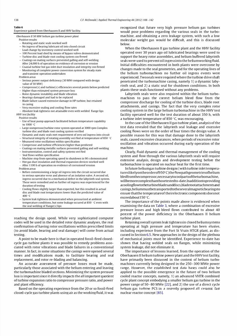
8112019 Helium Turbomachinery Operating Experience From Gas Turbine Power Plants
httpslidepdfcomreaderfullhelium-turbomachinery-operating-experience-from-gas-turbine-power-plants 3135
reaching the design speed While very sophisticated computer
codes will be used in the detailed rotor dynamic analyses the real
con1047297rmation of having rotor oscillations within prescribed limits
(to avoid blade bearing and seal damage) will come from actual
testingA point to be made here is that in operated fossil-1047297red closed-
cycle gas turbine plants it was possible to remedy problems asso-
ciated with rotor vibrations and blade failures in a conventional
manner In fact in some situations the casings were opened several
times and modi1047297cations made to facilitate bearing and seal
replacement and rotor re-blading and balancing
An accurate assessment of pressure losses must be made
particularly those associated with the helium entering and leaving
the turbomachine bladed sections Minimizing the system pressure
loss is important since it directly impacts the all important quotient
of turbine expansion ratio to compressor pressure ratio and power
and plant ef 1047297ciency
Based on the operating experience from the 20 or so fossil-1047297red
closed-cycle gas turbine plants using air as the working1047298
uid it was
recognized that future very high pressure helium gas turbines
would pose problems regarding the various seals in the turbo-
machine and obtaining a zero leakage system with such a low
molecular weight gas would be dif 1047297cult and this is discussed
below
When the Oberhausen II gas turbine plant and the HHV facility
operated over 30 years ago oil lubricated bearings were used to
support the heavy rotor assemblies and helium buffered labyrinth
seals were used to prevent oil ingressinto the heliumworking1047298uid
Initial dif 1047297culties encountered in both plants were overcome by
changes made to the seal geometries and for the operating lives of
the helium turbomachines no further oil ingress events were
experienced Twoseals were required where the turbine drive shaft
penetrated the turbomachine casing namely 1) a dynamic laby-
rinth seal and 2) a static seal for shutdown conditions In both
plants these seals functioned without any problems
Labyrinth seals were also required within the helium turbo-
machines to pass the correct helium bleed 1047298ow from the
compressor discharge for cooling of the turbine discs blade root
attachments and casings The fact that the very complex rotor
cooling system in the large helium turbomachine in the HHV test
facility operated well for the test duration of about 350 h with
a turbine inlet temperature of 850 C was encouragingIn the case of the Oberhausen II gas turbine plant analysis of the
test data revealed that the labyrinth seal leakage and excessive
cooling 1047298ows were on the order of four times the design value A
possible reason for this was that damage done to the labyrinth
seals caused excessive clearances when periods of excessive rotor
oscillation and vibration occurred during early operation of the
machine
Clearly 1047298uid dynamic and thermal management of the cooling
system and 1047298ow through the various labyrinth seals will require
extensive analysis design and development testing before the
turbomachine is operated on nuclear heat for the 1047297rst time
In future heliumgas turbine designs (with turbine inlet tempera-
tureslikelyontheorderof950C)the1047298owpathgeometriesofhelium
bledfromthecompressornecessarytocoolpartsoftheturbomachinewillbemorecomplexthanthosetestedto-dateInadditiontoproviding
acooling1047298owtotheturbinebladesanddiscsbladerootattachmentsand
casingsheliummustbetransportedtotheseveralmagneticbearingsto
ensure thatthe temperatureof theirelectronic components doesnot
exceedabout150C
The importance of the points made above is evidenced when
examining the data on Table 3 where a combination of excessive
pressure losses and high bleed 1047298ows contributed to about 40
percent of the power de1047297ciency in the Oberhausen II helium
turbine plant
Retaining overall system leak tightnessin closed heliumsystems
operating at high pressure and temperature has been elusive
including experience from the Fort St Vrain HTGR plant as dis-
cussed in Section 65 New approaches in the design of the plethoraof mechanical joints must be identi1047297ed Experience to-date has
shown that having welded seals on 1047298anges while minimizing
system leakage did not eliminate it
The importance of lessons learned from the operation of the
Oberhausen II helium turbine power plant and the HHV test facility
have primarily been discussed in the context of helium turbo-
machines currently being designed in the 250e300 MWe power
range However the established test data bases could also be
applied to the possible emergence in the future of two helium
cooled reactor concepts namely 1) an advanced VHTR combined
cycle plant concept embodying a smaller helium gas turbine in the
power range of 50e80 MWe [22] and 2) the use of a direct cycle
helium gas turbine PCS in a recently proposed all ceramic fast
nuclear reactor concept [85]
Table 6
Experience gained from Oberhausen II and HHV facility
Oberhausen II 50 MW helium gas turbine power plant
Positive results
e Rotating and static seals worked well
e No ingress of bearing lubricant oil into closed circuit
e Load change by inventory control worked well
e 100 Percent load shed by means of bypass valves demonstrated
e Turbine disc and blade root cooling system con1047297rmed
e Coatings on mating surfaces prevented galling and self-welding
e After 24000 h of operation no evidence of corrosion or erosion
e Coaxial turbine hot gas inlet duct insulation and integrity con1047297rmed
e Monitoring of complete power conversion system for steady state
and transient operation undertaken
Problem areas
e Serious power output de1047297ciency (30 MW compared with design
value of 50 MW)
e Compressor(s) and turbine(s) ef 1047297ciencies several points below predicted
e Higher than estimated system pressure loss
e Rotor dynamic instability and blade vibration
e Bearings damaged and had to be replaced
e Blade failure caused extensive damage in HP turbine but retained
in casing
e Very excessive sealing and cooling 1047298ow rates
e Absolute leak tightness not attainable even with welded 1047298ange lips
HHV test facility
Positive resultse Use of heat pump approach facilitated helium temperature capability
to 1000 C
e Large oompressorturbine rotor system operated at 3000 rpm Complex
turbine disc and blade root cooling system veri1047297ed
e Dynamic and static seals met requirement of zero oxl ingress into circuit
e Structural integrity of rotating assembly veri1047297ed at temperature of 850 C
e Measured rotor oscillations within speci1047297cation
e Compressor and turbine ef 1047297ciencies higher than predicted
e Coatings on mating metallic surfaces prevented galling and self-welding
e Instrumentation control and safety systems veri1047297ed
e Seal 1047298ows within speci1047297cation
e Machine stop from operating speed to shutdown in 90 s demonstrated
e Hot gas duct insulation and thermal expansion devices worked well
e After 1100 h of operation no evidence of corrosionof erosion
Problem areas
e Before commissioning a large oil ingress into the circuit occurred due
to serious operator error and absence of an isolation valve A second oilingress occurred due to a mechanical defect in the labyrinth seal system
These were remedied and no further oil ingress was experienced for the
duration of testing
e Cooling 1047298ows slightly larger than expected but this resulted in actual
disc and blade root temperatures lower than the predicted value of
400 C
e System leak tightness demonstrated when pressurized at ambient
temperature conditions but some leakage occured at 850 C even with
the seal welding of 1047298ange(s) lips
CF McDonald Applied Thermal Engineering 44 (2012) 108e142138
8112019 Helium Turbomachinery Operating Experience From Gas Turbine Power Plants
httpslidepdfcomreaderfullhelium-turbomachinery-operating-experience-from-gas-turbine-power-plants 3235
11 New technologies
It is recognized that in the 3 to 4 decades since the operation of
the helium turbomachines covered in this paper new technologies
have emerged which negate some of the early issues An example of
this is the technology transfer from the design of modern axial 1047298ow
gas turbines (ie industrial aircraft and aeroderivatives) that fully
utilize sophisticated CAE CAD CFD and FEA design software
Air breathing aerodynamic design practice for compressors and
turbines are generally applicable but the properties of helium and
the high system pressure have a signi1047297cant impact on gas 1047298ow
paths and blade geometries With short blade heights high hub-to-
tip ratios long annulus 1047298ow path length (with resultant signi1047297cant
end-wall boundary layer growth and secondary 1047298ow) and blade tip
clearances in some cases controlled by clearances in the magnetic
catcher bearing testing of subscale model compressors and
Fig 41 Gas turbine test facility for aircraft nuclear propulsion involving the coupling of a 32 MWt air-cooled reactor with two modi 1047297ed J-47 turbojet aeroengines each rated at
a thrust of about 3000 kg operated in 1960 (Courtesy INL)
Fig 42 Mobile 350 KWe closed-cycle nuclear gas turbine power plant operated in 1961 (Courtesy US Army)
CF McDonald Applied Thermal Engineering 44 (2012) 108e142 139
8112019 Helium Turbomachinery Operating Experience From Gas Turbine Power Plants
httpslidepdfcomreaderfullhelium-turbomachinery-operating-experience-from-gas-turbine-power-plants 3335
turbines will be needed While most of the operated helium tur-
bomachines discussed in this paper took place 3 or 4 decades ago it
is encouraging that the fairly recent test data and test-calibrated
CFD analysis from a subscale four stage model helium axial 1047298ow
compressor in Japan [80] gave a high degree of con1047297dence that
design goals are realizable for the full size 20 stage compressor in
the 274 MWe GTeHTR300 plant turbomachine
In the future the use of active magnetic bearings will eliminate
the issue of oil ingress however the very heavy rotor weight and
size of the journal and thrust bearings (and catcher bearings) of the
type for helium turbomachines in the 250e300 MWe power range
are way in excess of what have been demonstrated in rotating
machinery For plant designs retaining oil-lubricated bearings well
established dry gas seal technology exists particularly experience
gained from the operation of high pressure natural gas pipe line
compressors
For future nuclear helium gas turbine plants the designer has
freedom regarding meeting different frequency requirements that
exist in some countries These include use of a synchronous
machine (ie designed for 50 or 60 Hz grids) use of a gearbox drive
between the turbine and generator or the use of a frequency
converter which gives the designer an added degree of freedom
regarding the selection of speed for the rotating assemblyCompared with the past very sophisticated electronic control
systems instrumentation and diagnostic systems are available
today
12 Conclusions
In this review paper experience from operated helium turbo-
machines has been compiled based on open literature sources At
this stage in the evolution of HTR and VHTR plant concepts it is not
clear in what role form or time-frame the nuclear gas turbine will
emerge when commercialized By say the middle of the 21st
century all power plants will be operating with signi1047297cantly higher
ef 1047297ciencies to realize improved power generation costs and
reduced emissions In a nuclear gas turbine the helium turbo-machine will be a major contributor towards the achievement of
ef 1047297ciencies higher than 50 percent
While it has been 3 to 4 decades since the Oberhausen II helium
turbine power plant and the HHV high temperature helium turbine
facility operated signi1047297cant lessons were learned and the time and
effort expended to resolve the multiplicity of unexpected technical
problems encountered The remedial repair work was done under
ideal conditions namely that immediate hands-on activities were
possible This would not have been possible if the type of problems
experienced had been encountered in a new and untested helium
turbomachine operated for the 1047297rst time with a nuclear heat
source
While new technologies have emerged that negate many of the
early problems there are some uniquely inherent issues associatedwith for large helium turbines operating in a high pressure and
temperature environment and these include the following 1)
minimizing system leakage with such a low molecular weight gas
2) clearances in labyrinth seals to minimize helium bypass1047298ows 3)
the dynamic stability of long slender rotors 4) minimizing the
turbomachine inlet and outlet pressure losses 5) 1047298ow maldis-
tribution in complex ductturbomachine interfaces 6) integrity
veri1047297cation of the catcher bearings (journal and thrust) after
multiple rotor drops (following loss of the magnetic 1047297eld) during
the plant lifetime 7) assurances that high energy fragments from
a failed turbine disc are contained within the machine casing 8)
turbomachine installation and removal from a steel pressure vessel
and 9) remote handling and cleaning of a machine with turbine
blades contaminated with 1047297
ssion products
The need for a helium turbomachine test facility has been
emphasized to ensure that the integrity performance and reli-
ability of the machine before it operates the 1047297rst time on nuclear
heat Engineers currently involved in the design of helium rotating
machinery for all HTR and VHTR plant variants should take
advantage of the experience gained from the past operation of
helium turbomachinery
13 In closing-GT rsquos operated with nuclear heat
In the context of this paper it is germane to mention that two
gas turbines have actually operated using nuclear heat as brie1047298y
highlighted below
In the late 1950rsquos a program was initiated in the USA for aircraft
nuclear propulsion (ANP) While different concepts were studied
only the direct cycle air-cooled reactor reached the stage of
construction of an experimental reactor [86] A view of the large
nuclear gas turbine facility is given on Fig 41 and shows the air-
cooled and zirconiumehydride moderated reactor rated at
32 MWt coupled with two modi1047297ed J-47 turbojet engines each
rated with a thrust of about 3000 kg In this open cycle system the
high pressure compressor air was directly heated in the reactor
before expansion in the turbine and discharge to the atmosphere in
the exhaust nozzle The facility operated between 1958 and 1961 at
the Idaho reactor testing facility While perhaps possible during the
early years of the US nuclear program it is clear that such a system
would not be acceptable today from safety and environmental
considerations
The 1047297rst and indeed the only coupling of a closed-cycle gas
turbine with a nuclear reactor for power generation was under-
taken to meet the needs of the US Army In the late 1950 rsquos an RampD
program was initiated for a 350 kW trailer-mounted system to be
used in the 1047297eld by military personnel A prototype of the ML-1
plant shown on Fig 42 was 1047297rst operated in 1961 [8788]
It was based on a 33 MW light water moderated pressure tube
reactor with nitrogen as the coolant The closed-cycle gas turbine
power conversion system with nitrogen as the working 1047298uid hada turbine inlet temperature of 649 C (1200 F) and delivered
around 300 kW With changes in the Armyrsquos needs the project was
discontinued in 1965
While the experience gained from the above twounique nuclear
plants is clearly not relevant for future nuclear gas turbine power
plants that could see service in the third decade of the 21st century
these ambitious and innovative nuclear gas turbine pioneering
engineering efforts need to be recognized
Acknowledgements
The author would like to thank the following for helpful discus-
sions advice and for providing valuable comments on the initial
paper draft Prof Dr Hermann Haselbacher Hans Ulrich Frutschi DrXing Yan DrPeter Zenker Professor DavidGordon Wilson Professor
Aristide Massardo Arthur Harris DrFred Starr and DrGuido Bac-
caglini This paper has been enhanced by the inclusion of hardware
photographs and unique sketches and the author is appreciative to
all concerned with credits being duly noted
References
[1] C Keller The Escher Wyss AK Closed-Cycle Gas Turbine Its Actual Develop-ment and Future Prospects Paper Presented at ASME Meeting November 261945
[2] HU Frutschi Closed-Cycle Gas Turbines Operating Experience and FuturePotential ASME Press NY 2005
[3] CF McDonald The Nuclear Gas Turbine-Towards Realization After Half
a Century of Evolution (1995) ASME Paper 95-GT-292
CF McDonald Applied Thermal Engineering 44 (2012) 108e142140
8112019 Helium Turbomachinery Operating Experience From Gas Turbine Power Plants
httpslidepdfcomreaderfullhelium-turbomachinery-operating-experience-from-gas-turbine-power-plants 3435
[4] C Keller The Theory and Performance of Axial Flow Fans McGraw Hill BookCompany Inc NY 1937
[5] J Ackert C Keller Aerodynamic turbine with closed circuit In A Century of Turbines vols 1516 Escher Wyss News 1942e43 5e19
[6] Escher Wyss News Closed-Cycle Gas Turbines for all Fuels Coal Gas Nuclearvol 39 No 1 (1966)
[7] C Keller Closed-cycle gas turbine Escher Wyss-AK development 1945e1950Transactions of ASME (August 1950) 835e850
[8] C Keller Operating Experience and Design Features of Closed-Cycle GasTurbine Power Plants (1956) ASME Paper 56-GTP-15
[9] C Keller HU Frutschi Closed-cycle plants -conventional and nuclear designapplication operation In Sawyerrsquos Gas Turbine Engineering Handbooksecond ed vol 2 Applications (1976) pp 265e283
[10] K Bammert G Groschup Status Report on Closed-Cycle Power Plants in theFederal Republic of Germany (1976) ASME Paper 76-GT-54
[11] JL Mason Monatomic Working Gases versus Air for Closed Brayton Cycles(1985) ASME Paper 85-IGT-50
[12] JL Mason et al 5 MW Closed Cycle Gas Turbine (1984) ASME Paper 84-GT-268
[13] The British Gas Closed-Cycle Demonstrator (1995) British Gas Research ampTechnology Final Year Report
[14] F Starr ODS alloy high temperature heat exchanger prototype developmentPaper Presented at ODS 2010 Materials Workshop UCSD Jacobs Hall La JollaCalifornia Nov17e18 2010
[15] CA Rennie Achievements of the Dragon project Pergamon Press Annals of Nuclear Energy 5 (1978) 305e320
[16] SB Hosegood et al Dragon Project Engineering Studies on the Direct CycleHTR Proceedings of Conference on Nuclear Gas Turbines The British NuclearEnergy Society London April 8e9 1970 pp 161e179
[17] Nuclear Gas Turbines Proceedings of British Nuclear Society Meeting LondonApril 8-9 1972
[18] CF McDonald C Peinado ldquoThe nuclear gas Turbine-A perspective on a long-term advanced technology HTGR plant Optionrdquo ASME Paper 82-GT-289
[19] GH Lohnert et al Technical design features and essential safety-relatedfeatures of the HTR-Module Nuclear Engineering and Design 121 (1990)259e275
[20] H Reutler GH Lohnert The modular high temperature nuclear reactorNuclear Technology 62 (1983) 22e30
[21] CF McDonald Exploitation of the very high temperature capability of theMHTGR to meet National energy needs after the year 2000 IECEC Paper869006
[22] CF McDonald Power conversion system considerations for an advancednuclear gas turbine (GT-VHTR) CHHP demonstration plant concept Interna-tional Journal of Turbo amp Jet Engines 27 (2010) 179e217
[23] N Hee Cheon et al A review of helium gas turbine technology for hightemperature gas cooled reactors Nuclear Engineering and Design 29 (2007)21e30
[24] CB Baxi et al Development of the GT-MHR Turbomachine ASME PaperGT2009e59450[25] X Yan GTHTR300 design and development Nuclear Engineering and Design
222 (2003) 247e262[26] JC Gauthier et al ANTARES the HTRVHTR project of Framatome ANP
Nuclear Engineering and Design 236 (2006) 526e533[27] J Wang et al ldquoDesign features of gas turbine power conversion system for
HTR-10GT paper D05 presented at 2nd Intl Meeting on HTR TechnologyBeijing China September 21e24 2004
[28] A Koster et al ldquoPBMR Design For the Futurerdquo Nuclear engineering andDesign 222 (203) 231e245
[29] S van der Linden Closed cycle nuclear plant rated at 165 MWe and 40 percentef 1047297ciency Gas Turbine World (MarcheApril 2007) 28e32
[30] CF McDonald Large closed-cycle gas turbines Sawyerrsquos gas turbine engi-neering handbook In Selection and Applications vol II (1985) pp 81e38(Chapter 8)
[31] CF McDonald Helium and Combustion Gas Turbine Power ConversionSystems Comparison (1995) ASME Paper 95-GT-263
[32] JK La Fleur Description of an Operating Closed-Cycle Helium Gas Turbine
ASME Paper 63-AHGT-74[33] JK La Fleur The use of turbomachinery in the 1047297eld of cryogenics In
Sawyerrsquos Gas Turbine Engineering Handbook vol II (1976) 296e311[34] W Spillmann The Closed-Cycle Gas Turbine for Non-Conventional Applica-
tions ASME Paper 66-GT-8[35] K Holliger On the in1047298uence of the degree of reaction on the secondary losses
in axial 1047298ow compressors Escher Wyss News 23 (1960)[36] W Gut Comparison of the relative losses and characteristics of axial
compressor stages Escher Wyss News 23 (1959)[37] JH Horlock Axial Flow Compressors Butterworths Scienti1047297c Publications
London 1958 pp 92e93[38] G Deuster Long-term Operating Experience with Oberhausen I Closed-Cycle
Gas Turbine Power Plant (1970) ASME Paper 70-GT-73[39] G Noak Signi1047297cance of the Helium Turbine Power Plant at Oberhausen (EVO)
and the High Temperature Helium Test Facility (HHV) at Julich for theDevelopment of HTR Direct Cycle (HHT) IAEA Publication SM-20026 Vienna1970 189e200
[40] K Bammert G Deuster Layout and Present Status of the Closed-Cycle HeliumTurbine Plant Oberhausen II (1974) ASME Paper 74-GT-132
[41] P Zenker The Oberhausen 50 MW helium turbine plant Combustion 47 (2)(April 1976)
[42] K Bammert et al Operation and Control of the 50 MW Closed Cycle HeliumTurbine Plant Oberhausen (1974) ASME Paper 74-GT-13
[43] P Zenker 10 years operating experience with the Oberhausen II heliumturbo-generator plant VGB Krafswerkstechnik 68 (7) (July 1998) 616e621
[44] K Bammert G Deuster The First Operating Experiences With the OberhausenHelium Turbine Plant Paper Presented at ASME Gas Turbine Conference NewOrleans March 21e25 1976
[45] G Deuster P Zenker Operation of the Oberhausen Helium Turbine Plant
Paper Presented at ASME Gas Turbine Conference London April 1978[46] P Zenker Operating Experience of the Oberhausen Helium Turbine Plant
Paper Presented at ASME Gas Turbine Conference San Diego 1979[47] G Deuster P Zenker Further Operating Experience of the Oberhausen Helium
Turbine Plant Paper Presented at ASME Gas Turbine Conference NewOrleans 1980
[48] P Zenker Past Experience and Future Prospects of Closed-Cycle Gas TurbinesPaper Presented at ASME Gas Turbine Conference London April 18e22 1982
[49] IA Weisbrodt Summary Report on Technical Experiences from HighTemperature Helium Turbine Testing in Germany Report IAEA-TECDOC-899Vienna Nov 1994
[50] F Bentivoglio G Geffraye Validation of the CATHARE Code Against Experi-mental Data from Brayton Cycle Plants Paper C00000228 Proceedings of HTR 2006 Johannesburg October 1e4 2006
[51] E Arndt HHT-Demonstration Plant Paper Presented at European NuclearConference Hamburg May 6 1979
[52] G Hebel HHV-Anlage Erfahrungen bei Bau und Inbetriebnahme Atom-wirtschaft(5) (1982) 258e262
[53] H Haselbacher A Eierman Development of Helium Gas Turbine in NuclearField (1974) ASME Paper 74-GT-123
[54] H Haselbacher The HHT Helium Gas Turbine and HHV Plant Paper A421 5thInternational Fair and Technical Meeting of Nuclear Industry BaselSwitzerland October 3e7 1978
[55] H Haselbacher HJ Sponholz Cooling and Insulating Problems in a HighTemperature Helium Test Facility (1984) ASME Paper 84-GT-253
[56] C Keller D Schmidt The Helium Gas Turbine for Nuclear Power Plants (1967)ASME Paper 67-GT-10
[57] W Endres Large Helium Turbine for Nuclear Power Plants (1970) ASME Paper70-GT-99
[58] JN Hurst Gas turbomachinery for helium cooled reactors in Proceedings of International Conference on Nuclear Gas Turbines British Nuclear SocietyLondon April 8 1970 pp 45e50
[59] K Bammert Nuclear Gas Turbine of Large Output for HHT Plant (1974) ASMEPaper 74-GT-10
[60] CF McDonald The Nuclear Closed-Cycle Gas Turbine (GT-HTGR) e A UtilityPower Plant for the Year 2000 (1979) AIAA Paper 79e0191
[61] CF McDonald MJ Smith Turbomachinery design considerations for the
nuclear HTGR-GT power plant ASME Journal of Engineering for Power 103 (1)(January 1981) 65e77[62] CF McDonald et al Helium Turbomachine Design for GT-MHR Power Plant
(1994) ASME Paper 94-JPGC-NE-12[63] Gas Cooled Reactor Coolant Circulator and Blower Technology (1988) IAEA
Report IWGGCR17[64] OE Balje Turbomachines A Guide to Design Selection and Theory John
Wiley amp Sons NY 1981[65] CF McDonald et al Circulator DesignTechnology Evolution for Gas Cooled
Reactors (1992) ASME Paper 92-GT-79[66] J Donaldson Application of Magnetic Bearings to Helium Circulators for High
Temperature Gas Cooled Reactors (1987) IECEC Paper 879419[67] CF McDonald Active Magnetic Bearings for Rotating Machinery in Closed-
Cycle Power Plant Systems (1989) ASME Paper 89-WANE-5[68] JA Rennie CF McDonald Active Magnetic Bearings for Rotating Machinery
in Future Gas Cooled Reactor Plants Paper Presented at 4th Intl Symposiumon Magnetic Bearings ETH Zurich August 23e26 1994
[69] CF McDonald MK Nichols Helium Circulator Design Considerations forModular High Temperature Gas Cooled Power Plant (1987) ASME Paper 87-
GT-138[70] CF McDonald Shutdown Cooling Helium Circulator Design Considerations
for MHTGR Power Plant (1989) ASME Paper 89-WANE-5[71] J Yampolsky Steam Turbine Driven Circulators for High Temperature Gas
Cooled Reactors Part I Design (1972) ASME Paper 72-WANE-20[72] VJ Barbat Steam Turbine Driven Circulators for High Temperature Gas
Cooled Reactors Part II Development (1972) ASME Paper 72-WANE-21[73] L Cavallaro J Yampolsky Design and development of a steam turbine driven
circulator for high temperature gas cooled reactors Nuclear Engineering andDesign (1974) 135e147
[74] J Henssen et al Facility for fatigue testing of thermal insulation BBC Review72 (6) (1985)
[75] J Donaldson Development of Carbon Dioxide Circulators IAEA ReportIWGGCR17 (1988) pp 47e63
[76] Personal Communication from John Donaldson (April 7 2006)[77] NG Kodochigov et al Development of the GT-MHR Vertical Turbomachine
Design ASME Paper HTR2008-58309[78] CB Baxi et al ldquoRotor Scale Model Tests for Power Conversion Unit of GT-
MHR rdquo ASME Paper HTR 2008e58015
CF McDonald Applied Thermal Engineering 44 (2012) 108e142 141
8112019 Helium Turbomachinery Operating Experience From Gas Turbine Power Plants
httpslidepdfcomreaderfullhelium-turbomachinery-operating-experience-from-gas-turbine-power-plants 3535
[79] NG Kodochibov et al Development of Catcher Bearings for the GT-MHR Turbomachine(Oct 18e20 2010)Proceedings of HTR 2010Paper 025Prague
[80] IV Drumov et al Studies of the Electromagnetic Suspension System for theGT-MHRTurbomachineProceedings of HTR2010Paper041 Oct18e20 (2010)
[81] T Takizuka et al RampD on the power conversion system for the gas turbinehigh temperature reactor Nuclear Engineering and Design 233 (2004)239e346
[82] X Yanet alAerodynamic design model test and CFDanalysisfor a multistageaxialhelium compressor ASME Journal of Turbomachinery 130 (3) (July2008)
[83] S Takada et al The 13rd Scale Aerodynamic Performance Test of Helium
Compressor for GTHTR300 Turbomachine of JAERI (April 20e
23 2003)ICONE11e36368 Tokyo Japan
[84] S Takada et al Program for aerodynamic performance tests of heliumcompressor model of GTHTR300 Transactions of the Atomic Energy Society of
Japan 2 (3) (2003) 291e300[85] RW Schleicher et al EM2 An Innovative Approach to US Energy Security
and Nuclear Waste Disposition Paper Presented at Nuclear Power Interna-tional Conference Orlando Florida December 15 2010
[86] RL Loftness Nuclear Power Plants Norstrand Company Inc NY 1964(Chapter 9 and 11)
[87] SA Varga et al The ML-1 Mobile Nuclear Power Plant (1961) ASME Paper61-SA-43
[88] JA Bailey et al Status of the Army Closed Brayton Cycle Gas Turbine Program(1967) ASME Paper 67-GT-13
CF McDonald Applied Thermal Engineering 44 (2012) 108e142142
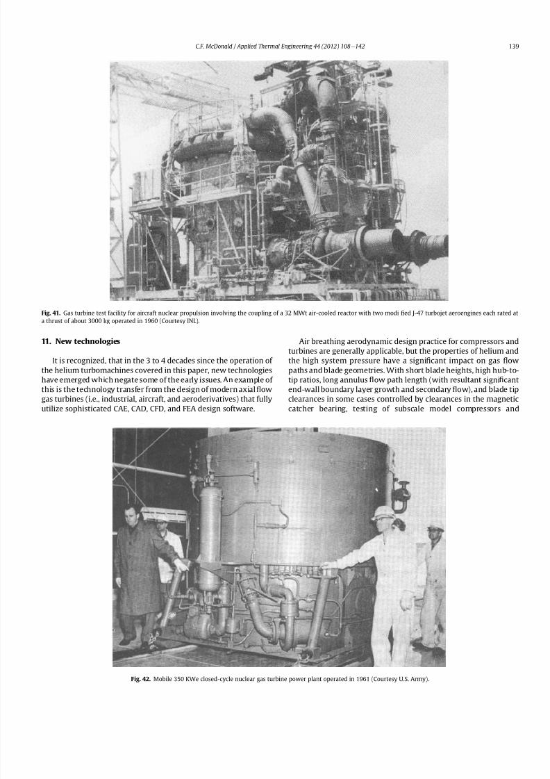
8112019 Helium Turbomachinery Operating Experience From Gas Turbine Power Plants
httpslidepdfcomreaderfullhelium-turbomachinery-operating-experience-from-gas-turbine-power-plants 3235
11 New technologies
It is recognized that in the 3 to 4 decades since the operation of
the helium turbomachines covered in this paper new technologies
have emerged which negate some of the early issues An example of
this is the technology transfer from the design of modern axial 1047298ow
gas turbines (ie industrial aircraft and aeroderivatives) that fully
utilize sophisticated CAE CAD CFD and FEA design software
Air breathing aerodynamic design practice for compressors and
turbines are generally applicable but the properties of helium and
the high system pressure have a signi1047297cant impact on gas 1047298ow
paths and blade geometries With short blade heights high hub-to-
tip ratios long annulus 1047298ow path length (with resultant signi1047297cant
end-wall boundary layer growth and secondary 1047298ow) and blade tip
clearances in some cases controlled by clearances in the magnetic
catcher bearing testing of subscale model compressors and
Fig 41 Gas turbine test facility for aircraft nuclear propulsion involving the coupling of a 32 MWt air-cooled reactor with two modi 1047297ed J-47 turbojet aeroengines each rated at
a thrust of about 3000 kg operated in 1960 (Courtesy INL)
Fig 42 Mobile 350 KWe closed-cycle nuclear gas turbine power plant operated in 1961 (Courtesy US Army)
CF McDonald Applied Thermal Engineering 44 (2012) 108e142 139
8112019 Helium Turbomachinery Operating Experience From Gas Turbine Power Plants
httpslidepdfcomreaderfullhelium-turbomachinery-operating-experience-from-gas-turbine-power-plants 3335
turbines will be needed While most of the operated helium tur-
bomachines discussed in this paper took place 3 or 4 decades ago it
is encouraging that the fairly recent test data and test-calibrated
CFD analysis from a subscale four stage model helium axial 1047298ow
compressor in Japan [80] gave a high degree of con1047297dence that
design goals are realizable for the full size 20 stage compressor in
the 274 MWe GTeHTR300 plant turbomachine
In the future the use of active magnetic bearings will eliminate
the issue of oil ingress however the very heavy rotor weight and
size of the journal and thrust bearings (and catcher bearings) of the
type for helium turbomachines in the 250e300 MWe power range
are way in excess of what have been demonstrated in rotating
machinery For plant designs retaining oil-lubricated bearings well
established dry gas seal technology exists particularly experience
gained from the operation of high pressure natural gas pipe line
compressors
For future nuclear helium gas turbine plants the designer has
freedom regarding meeting different frequency requirements that
exist in some countries These include use of a synchronous
machine (ie designed for 50 or 60 Hz grids) use of a gearbox drive
between the turbine and generator or the use of a frequency
converter which gives the designer an added degree of freedom
regarding the selection of speed for the rotating assemblyCompared with the past very sophisticated electronic control
systems instrumentation and diagnostic systems are available
today
12 Conclusions
In this review paper experience from operated helium turbo-
machines has been compiled based on open literature sources At
this stage in the evolution of HTR and VHTR plant concepts it is not
clear in what role form or time-frame the nuclear gas turbine will
emerge when commercialized By say the middle of the 21st
century all power plants will be operating with signi1047297cantly higher
ef 1047297ciencies to realize improved power generation costs and
reduced emissions In a nuclear gas turbine the helium turbo-machine will be a major contributor towards the achievement of
ef 1047297ciencies higher than 50 percent
While it has been 3 to 4 decades since the Oberhausen II helium
turbine power plant and the HHV high temperature helium turbine
facility operated signi1047297cant lessons were learned and the time and
effort expended to resolve the multiplicity of unexpected technical
problems encountered The remedial repair work was done under
ideal conditions namely that immediate hands-on activities were
possible This would not have been possible if the type of problems
experienced had been encountered in a new and untested helium
turbomachine operated for the 1047297rst time with a nuclear heat
source
While new technologies have emerged that negate many of the
early problems there are some uniquely inherent issues associatedwith for large helium turbines operating in a high pressure and
temperature environment and these include the following 1)
minimizing system leakage with such a low molecular weight gas
2) clearances in labyrinth seals to minimize helium bypass1047298ows 3)
the dynamic stability of long slender rotors 4) minimizing the
turbomachine inlet and outlet pressure losses 5) 1047298ow maldis-
tribution in complex ductturbomachine interfaces 6) integrity
veri1047297cation of the catcher bearings (journal and thrust) after
multiple rotor drops (following loss of the magnetic 1047297eld) during
the plant lifetime 7) assurances that high energy fragments from
a failed turbine disc are contained within the machine casing 8)
turbomachine installation and removal from a steel pressure vessel
and 9) remote handling and cleaning of a machine with turbine
blades contaminated with 1047297
ssion products
The need for a helium turbomachine test facility has been
emphasized to ensure that the integrity performance and reli-
ability of the machine before it operates the 1047297rst time on nuclear
heat Engineers currently involved in the design of helium rotating
machinery for all HTR and VHTR plant variants should take
advantage of the experience gained from the past operation of
helium turbomachinery
13 In closing-GT rsquos operated with nuclear heat
In the context of this paper it is germane to mention that two
gas turbines have actually operated using nuclear heat as brie1047298y
highlighted below
In the late 1950rsquos a program was initiated in the USA for aircraft
nuclear propulsion (ANP) While different concepts were studied
only the direct cycle air-cooled reactor reached the stage of
construction of an experimental reactor [86] A view of the large
nuclear gas turbine facility is given on Fig 41 and shows the air-
cooled and zirconiumehydride moderated reactor rated at
32 MWt coupled with two modi1047297ed J-47 turbojet engines each
rated with a thrust of about 3000 kg In this open cycle system the
high pressure compressor air was directly heated in the reactor
before expansion in the turbine and discharge to the atmosphere in
the exhaust nozzle The facility operated between 1958 and 1961 at
the Idaho reactor testing facility While perhaps possible during the
early years of the US nuclear program it is clear that such a system
would not be acceptable today from safety and environmental
considerations
The 1047297rst and indeed the only coupling of a closed-cycle gas
turbine with a nuclear reactor for power generation was under-
taken to meet the needs of the US Army In the late 1950 rsquos an RampD
program was initiated for a 350 kW trailer-mounted system to be
used in the 1047297eld by military personnel A prototype of the ML-1
plant shown on Fig 42 was 1047297rst operated in 1961 [8788]
It was based on a 33 MW light water moderated pressure tube
reactor with nitrogen as the coolant The closed-cycle gas turbine
power conversion system with nitrogen as the working 1047298uid hada turbine inlet temperature of 649 C (1200 F) and delivered
around 300 kW With changes in the Armyrsquos needs the project was
discontinued in 1965
While the experience gained from the above twounique nuclear
plants is clearly not relevant for future nuclear gas turbine power
plants that could see service in the third decade of the 21st century
these ambitious and innovative nuclear gas turbine pioneering
engineering efforts need to be recognized
Acknowledgements
The author would like to thank the following for helpful discus-
sions advice and for providing valuable comments on the initial
paper draft Prof Dr Hermann Haselbacher Hans Ulrich Frutschi DrXing Yan DrPeter Zenker Professor DavidGordon Wilson Professor
Aristide Massardo Arthur Harris DrFred Starr and DrGuido Bac-
caglini This paper has been enhanced by the inclusion of hardware
photographs and unique sketches and the author is appreciative to
all concerned with credits being duly noted
References
[1] C Keller The Escher Wyss AK Closed-Cycle Gas Turbine Its Actual Develop-ment and Future Prospects Paper Presented at ASME Meeting November 261945
[2] HU Frutschi Closed-Cycle Gas Turbines Operating Experience and FuturePotential ASME Press NY 2005
[3] CF McDonald The Nuclear Gas Turbine-Towards Realization After Half
a Century of Evolution (1995) ASME Paper 95-GT-292
CF McDonald Applied Thermal Engineering 44 (2012) 108e142140
8112019 Helium Turbomachinery Operating Experience From Gas Turbine Power Plants
httpslidepdfcomreaderfullhelium-turbomachinery-operating-experience-from-gas-turbine-power-plants 3435
[4] C Keller The Theory and Performance of Axial Flow Fans McGraw Hill BookCompany Inc NY 1937
[5] J Ackert C Keller Aerodynamic turbine with closed circuit In A Century of Turbines vols 1516 Escher Wyss News 1942e43 5e19
[6] Escher Wyss News Closed-Cycle Gas Turbines for all Fuels Coal Gas Nuclearvol 39 No 1 (1966)
[7] C Keller Closed-cycle gas turbine Escher Wyss-AK development 1945e1950Transactions of ASME (August 1950) 835e850
[8] C Keller Operating Experience and Design Features of Closed-Cycle GasTurbine Power Plants (1956) ASME Paper 56-GTP-15
[9] C Keller HU Frutschi Closed-cycle plants -conventional and nuclear designapplication operation In Sawyerrsquos Gas Turbine Engineering Handbooksecond ed vol 2 Applications (1976) pp 265e283
[10] K Bammert G Groschup Status Report on Closed-Cycle Power Plants in theFederal Republic of Germany (1976) ASME Paper 76-GT-54
[11] JL Mason Monatomic Working Gases versus Air for Closed Brayton Cycles(1985) ASME Paper 85-IGT-50
[12] JL Mason et al 5 MW Closed Cycle Gas Turbine (1984) ASME Paper 84-GT-268
[13] The British Gas Closed-Cycle Demonstrator (1995) British Gas Research ampTechnology Final Year Report
[14] F Starr ODS alloy high temperature heat exchanger prototype developmentPaper Presented at ODS 2010 Materials Workshop UCSD Jacobs Hall La JollaCalifornia Nov17e18 2010
[15] CA Rennie Achievements of the Dragon project Pergamon Press Annals of Nuclear Energy 5 (1978) 305e320
[16] SB Hosegood et al Dragon Project Engineering Studies on the Direct CycleHTR Proceedings of Conference on Nuclear Gas Turbines The British NuclearEnergy Society London April 8e9 1970 pp 161e179
[17] Nuclear Gas Turbines Proceedings of British Nuclear Society Meeting LondonApril 8-9 1972
[18] CF McDonald C Peinado ldquoThe nuclear gas Turbine-A perspective on a long-term advanced technology HTGR plant Optionrdquo ASME Paper 82-GT-289
[19] GH Lohnert et al Technical design features and essential safety-relatedfeatures of the HTR-Module Nuclear Engineering and Design 121 (1990)259e275
[20] H Reutler GH Lohnert The modular high temperature nuclear reactorNuclear Technology 62 (1983) 22e30
[21] CF McDonald Exploitation of the very high temperature capability of theMHTGR to meet National energy needs after the year 2000 IECEC Paper869006
[22] CF McDonald Power conversion system considerations for an advancednuclear gas turbine (GT-VHTR) CHHP demonstration plant concept Interna-tional Journal of Turbo amp Jet Engines 27 (2010) 179e217
[23] N Hee Cheon et al A review of helium gas turbine technology for hightemperature gas cooled reactors Nuclear Engineering and Design 29 (2007)21e30
[24] CB Baxi et al Development of the GT-MHR Turbomachine ASME PaperGT2009e59450[25] X Yan GTHTR300 design and development Nuclear Engineering and Design
222 (2003) 247e262[26] JC Gauthier et al ANTARES the HTRVHTR project of Framatome ANP
Nuclear Engineering and Design 236 (2006) 526e533[27] J Wang et al ldquoDesign features of gas turbine power conversion system for
HTR-10GT paper D05 presented at 2nd Intl Meeting on HTR TechnologyBeijing China September 21e24 2004
[28] A Koster et al ldquoPBMR Design For the Futurerdquo Nuclear engineering andDesign 222 (203) 231e245
[29] S van der Linden Closed cycle nuclear plant rated at 165 MWe and 40 percentef 1047297ciency Gas Turbine World (MarcheApril 2007) 28e32
[30] CF McDonald Large closed-cycle gas turbines Sawyerrsquos gas turbine engi-neering handbook In Selection and Applications vol II (1985) pp 81e38(Chapter 8)
[31] CF McDonald Helium and Combustion Gas Turbine Power ConversionSystems Comparison (1995) ASME Paper 95-GT-263
[32] JK La Fleur Description of an Operating Closed-Cycle Helium Gas Turbine
ASME Paper 63-AHGT-74[33] JK La Fleur The use of turbomachinery in the 1047297eld of cryogenics In
Sawyerrsquos Gas Turbine Engineering Handbook vol II (1976) 296e311[34] W Spillmann The Closed-Cycle Gas Turbine for Non-Conventional Applica-
tions ASME Paper 66-GT-8[35] K Holliger On the in1047298uence of the degree of reaction on the secondary losses
in axial 1047298ow compressors Escher Wyss News 23 (1960)[36] W Gut Comparison of the relative losses and characteristics of axial
compressor stages Escher Wyss News 23 (1959)[37] JH Horlock Axial Flow Compressors Butterworths Scienti1047297c Publications
London 1958 pp 92e93[38] G Deuster Long-term Operating Experience with Oberhausen I Closed-Cycle
Gas Turbine Power Plant (1970) ASME Paper 70-GT-73[39] G Noak Signi1047297cance of the Helium Turbine Power Plant at Oberhausen (EVO)
and the High Temperature Helium Test Facility (HHV) at Julich for theDevelopment of HTR Direct Cycle (HHT) IAEA Publication SM-20026 Vienna1970 189e200
[40] K Bammert G Deuster Layout and Present Status of the Closed-Cycle HeliumTurbine Plant Oberhausen II (1974) ASME Paper 74-GT-132
[41] P Zenker The Oberhausen 50 MW helium turbine plant Combustion 47 (2)(April 1976)
[42] K Bammert et al Operation and Control of the 50 MW Closed Cycle HeliumTurbine Plant Oberhausen (1974) ASME Paper 74-GT-13
[43] P Zenker 10 years operating experience with the Oberhausen II heliumturbo-generator plant VGB Krafswerkstechnik 68 (7) (July 1998) 616e621
[44] K Bammert G Deuster The First Operating Experiences With the OberhausenHelium Turbine Plant Paper Presented at ASME Gas Turbine Conference NewOrleans March 21e25 1976
[45] G Deuster P Zenker Operation of the Oberhausen Helium Turbine Plant
Paper Presented at ASME Gas Turbine Conference London April 1978[46] P Zenker Operating Experience of the Oberhausen Helium Turbine Plant
Paper Presented at ASME Gas Turbine Conference San Diego 1979[47] G Deuster P Zenker Further Operating Experience of the Oberhausen Helium
Turbine Plant Paper Presented at ASME Gas Turbine Conference NewOrleans 1980
[48] P Zenker Past Experience and Future Prospects of Closed-Cycle Gas TurbinesPaper Presented at ASME Gas Turbine Conference London April 18e22 1982
[49] IA Weisbrodt Summary Report on Technical Experiences from HighTemperature Helium Turbine Testing in Germany Report IAEA-TECDOC-899Vienna Nov 1994
[50] F Bentivoglio G Geffraye Validation of the CATHARE Code Against Experi-mental Data from Brayton Cycle Plants Paper C00000228 Proceedings of HTR 2006 Johannesburg October 1e4 2006
[51] E Arndt HHT-Demonstration Plant Paper Presented at European NuclearConference Hamburg May 6 1979
[52] G Hebel HHV-Anlage Erfahrungen bei Bau und Inbetriebnahme Atom-wirtschaft(5) (1982) 258e262
[53] H Haselbacher A Eierman Development of Helium Gas Turbine in NuclearField (1974) ASME Paper 74-GT-123
[54] H Haselbacher The HHT Helium Gas Turbine and HHV Plant Paper A421 5thInternational Fair and Technical Meeting of Nuclear Industry BaselSwitzerland October 3e7 1978
[55] H Haselbacher HJ Sponholz Cooling and Insulating Problems in a HighTemperature Helium Test Facility (1984) ASME Paper 84-GT-253
[56] C Keller D Schmidt The Helium Gas Turbine for Nuclear Power Plants (1967)ASME Paper 67-GT-10
[57] W Endres Large Helium Turbine for Nuclear Power Plants (1970) ASME Paper70-GT-99
[58] JN Hurst Gas turbomachinery for helium cooled reactors in Proceedings of International Conference on Nuclear Gas Turbines British Nuclear SocietyLondon April 8 1970 pp 45e50
[59] K Bammert Nuclear Gas Turbine of Large Output for HHT Plant (1974) ASMEPaper 74-GT-10
[60] CF McDonald The Nuclear Closed-Cycle Gas Turbine (GT-HTGR) e A UtilityPower Plant for the Year 2000 (1979) AIAA Paper 79e0191
[61] CF McDonald MJ Smith Turbomachinery design considerations for the
nuclear HTGR-GT power plant ASME Journal of Engineering for Power 103 (1)(January 1981) 65e77[62] CF McDonald et al Helium Turbomachine Design for GT-MHR Power Plant
(1994) ASME Paper 94-JPGC-NE-12[63] Gas Cooled Reactor Coolant Circulator and Blower Technology (1988) IAEA
Report IWGGCR17[64] OE Balje Turbomachines A Guide to Design Selection and Theory John
Wiley amp Sons NY 1981[65] CF McDonald et al Circulator DesignTechnology Evolution for Gas Cooled
Reactors (1992) ASME Paper 92-GT-79[66] J Donaldson Application of Magnetic Bearings to Helium Circulators for High
Temperature Gas Cooled Reactors (1987) IECEC Paper 879419[67] CF McDonald Active Magnetic Bearings for Rotating Machinery in Closed-
Cycle Power Plant Systems (1989) ASME Paper 89-WANE-5[68] JA Rennie CF McDonald Active Magnetic Bearings for Rotating Machinery
in Future Gas Cooled Reactor Plants Paper Presented at 4th Intl Symposiumon Magnetic Bearings ETH Zurich August 23e26 1994
[69] CF McDonald MK Nichols Helium Circulator Design Considerations forModular High Temperature Gas Cooled Power Plant (1987) ASME Paper 87-
GT-138[70] CF McDonald Shutdown Cooling Helium Circulator Design Considerations
for MHTGR Power Plant (1989) ASME Paper 89-WANE-5[71] J Yampolsky Steam Turbine Driven Circulators for High Temperature Gas
Cooled Reactors Part I Design (1972) ASME Paper 72-WANE-20[72] VJ Barbat Steam Turbine Driven Circulators for High Temperature Gas
Cooled Reactors Part II Development (1972) ASME Paper 72-WANE-21[73] L Cavallaro J Yampolsky Design and development of a steam turbine driven
circulator for high temperature gas cooled reactors Nuclear Engineering andDesign (1974) 135e147
[74] J Henssen et al Facility for fatigue testing of thermal insulation BBC Review72 (6) (1985)
[75] J Donaldson Development of Carbon Dioxide Circulators IAEA ReportIWGGCR17 (1988) pp 47e63
[76] Personal Communication from John Donaldson (April 7 2006)[77] NG Kodochigov et al Development of the GT-MHR Vertical Turbomachine
Design ASME Paper HTR2008-58309[78] CB Baxi et al ldquoRotor Scale Model Tests for Power Conversion Unit of GT-
MHR rdquo ASME Paper HTR 2008e58015
CF McDonald Applied Thermal Engineering 44 (2012) 108e142 141
8112019 Helium Turbomachinery Operating Experience From Gas Turbine Power Plants
httpslidepdfcomreaderfullhelium-turbomachinery-operating-experience-from-gas-turbine-power-plants 3535
[79] NG Kodochibov et al Development of Catcher Bearings for the GT-MHR Turbomachine(Oct 18e20 2010)Proceedings of HTR 2010Paper 025Prague
[80] IV Drumov et al Studies of the Electromagnetic Suspension System for theGT-MHRTurbomachineProceedings of HTR2010Paper041 Oct18e20 (2010)
[81] T Takizuka et al RampD on the power conversion system for the gas turbinehigh temperature reactor Nuclear Engineering and Design 233 (2004)239e346
[82] X Yanet alAerodynamic design model test and CFDanalysisfor a multistageaxialhelium compressor ASME Journal of Turbomachinery 130 (3) (July2008)
[83] S Takada et al The 13rd Scale Aerodynamic Performance Test of Helium
Compressor for GTHTR300 Turbomachine of JAERI (April 20e
23 2003)ICONE11e36368 Tokyo Japan
[84] S Takada et al Program for aerodynamic performance tests of heliumcompressor model of GTHTR300 Transactions of the Atomic Energy Society of
Japan 2 (3) (2003) 291e300[85] RW Schleicher et al EM2 An Innovative Approach to US Energy Security
and Nuclear Waste Disposition Paper Presented at Nuclear Power Interna-tional Conference Orlando Florida December 15 2010
[86] RL Loftness Nuclear Power Plants Norstrand Company Inc NY 1964(Chapter 9 and 11)
[87] SA Varga et al The ML-1 Mobile Nuclear Power Plant (1961) ASME Paper61-SA-43
[88] JA Bailey et al Status of the Army Closed Brayton Cycle Gas Turbine Program(1967) ASME Paper 67-GT-13
CF McDonald Applied Thermal Engineering 44 (2012) 108e142142
8112019 Helium Turbomachinery Operating Experience From Gas Turbine Power Plants
httpslidepdfcomreaderfullhelium-turbomachinery-operating-experience-from-gas-turbine-power-plants 3435
[4] C Keller The Theory and Performance of Axial Flow Fans McGraw Hill BookCompany Inc NY 1937
[5] J Ackert C Keller Aerodynamic turbine with closed circuit In A Century of Turbines vols 1516 Escher Wyss News 1942e43 5e19
[6] Escher Wyss News Closed-Cycle Gas Turbines for all Fuels Coal Gas Nuclearvol 39 No 1 (1966)
[7] C Keller Closed-cycle gas turbine Escher Wyss-AK development 1945e1950Transactions of ASME (August 1950) 835e850
[8] C Keller Operating Experience and Design Features of Closed-Cycle GasTurbine Power Plants (1956) ASME Paper 56-GTP-15
[9] C Keller HU Frutschi Closed-cycle plants -conventional and nuclear designapplication operation In Sawyerrsquos Gas Turbine Engineering Handbooksecond ed vol 2 Applications (1976) pp 265e283
[10] K Bammert G Groschup Status Report on Closed-Cycle Power Plants in theFederal Republic of Germany (1976) ASME Paper 76-GT-54
[11] JL Mason Monatomic Working Gases versus Air for Closed Brayton Cycles(1985) ASME Paper 85-IGT-50
[12] JL Mason et al 5 MW Closed Cycle Gas Turbine (1984) ASME Paper 84-GT-268
[13] The British Gas Closed-Cycle Demonstrator (1995) British Gas Research ampTechnology Final Year Report
[14] F Starr ODS alloy high temperature heat exchanger prototype developmentPaper Presented at ODS 2010 Materials Workshop UCSD Jacobs Hall La JollaCalifornia Nov17e18 2010
[15] CA Rennie Achievements of the Dragon project Pergamon Press Annals of Nuclear Energy 5 (1978) 305e320
[16] SB Hosegood et al Dragon Project Engineering Studies on the Direct CycleHTR Proceedings of Conference on Nuclear Gas Turbines The British NuclearEnergy Society London April 8e9 1970 pp 161e179
[17] Nuclear Gas Turbines Proceedings of British Nuclear Society Meeting LondonApril 8-9 1972
[18] CF McDonald C Peinado ldquoThe nuclear gas Turbine-A perspective on a long-term advanced technology HTGR plant Optionrdquo ASME Paper 82-GT-289
[19] GH Lohnert et al Technical design features and essential safety-relatedfeatures of the HTR-Module Nuclear Engineering and Design 121 (1990)259e275
[20] H Reutler GH Lohnert The modular high temperature nuclear reactorNuclear Technology 62 (1983) 22e30
[21] CF McDonald Exploitation of the very high temperature capability of theMHTGR to meet National energy needs after the year 2000 IECEC Paper869006
[22] CF McDonald Power conversion system considerations for an advancednuclear gas turbine (GT-VHTR) CHHP demonstration plant concept Interna-tional Journal of Turbo amp Jet Engines 27 (2010) 179e217
[23] N Hee Cheon et al A review of helium gas turbine technology for hightemperature gas cooled reactors Nuclear Engineering and Design 29 (2007)21e30
[24] CB Baxi et al Development of the GT-MHR Turbomachine ASME PaperGT2009e59450[25] X Yan GTHTR300 design and development Nuclear Engineering and Design
222 (2003) 247e262[26] JC Gauthier et al ANTARES the HTRVHTR project of Framatome ANP
Nuclear Engineering and Design 236 (2006) 526e533[27] J Wang et al ldquoDesign features of gas turbine power conversion system for
HTR-10GT paper D05 presented at 2nd Intl Meeting on HTR TechnologyBeijing China September 21e24 2004
[28] A Koster et al ldquoPBMR Design For the Futurerdquo Nuclear engineering andDesign 222 (203) 231e245
[29] S van der Linden Closed cycle nuclear plant rated at 165 MWe and 40 percentef 1047297ciency Gas Turbine World (MarcheApril 2007) 28e32
[30] CF McDonald Large closed-cycle gas turbines Sawyerrsquos gas turbine engi-neering handbook In Selection and Applications vol II (1985) pp 81e38(Chapter 8)
[31] CF McDonald Helium and Combustion Gas Turbine Power ConversionSystems Comparison (1995) ASME Paper 95-GT-263
[32] JK La Fleur Description of an Operating Closed-Cycle Helium Gas Turbine
ASME Paper 63-AHGT-74[33] JK La Fleur The use of turbomachinery in the 1047297eld of cryogenics In
Sawyerrsquos Gas Turbine Engineering Handbook vol II (1976) 296e311[34] W Spillmann The Closed-Cycle Gas Turbine for Non-Conventional Applica-
tions ASME Paper 66-GT-8[35] K Holliger On the in1047298uence of the degree of reaction on the secondary losses
in axial 1047298ow compressors Escher Wyss News 23 (1960)[36] W Gut Comparison of the relative losses and characteristics of axial
compressor stages Escher Wyss News 23 (1959)[37] JH Horlock Axial Flow Compressors Butterworths Scienti1047297c Publications
London 1958 pp 92e93[38] G Deuster Long-term Operating Experience with Oberhausen I Closed-Cycle
Gas Turbine Power Plant (1970) ASME Paper 70-GT-73[39] G Noak Signi1047297cance of the Helium Turbine Power Plant at Oberhausen (EVO)
and the High Temperature Helium Test Facility (HHV) at Julich for theDevelopment of HTR Direct Cycle (HHT) IAEA Publication SM-20026 Vienna1970 189e200
[40] K Bammert G Deuster Layout and Present Status of the Closed-Cycle HeliumTurbine Plant Oberhausen II (1974) ASME Paper 74-GT-132
[41] P Zenker The Oberhausen 50 MW helium turbine plant Combustion 47 (2)(April 1976)
[42] K Bammert et al Operation and Control of the 50 MW Closed Cycle HeliumTurbine Plant Oberhausen (1974) ASME Paper 74-GT-13
[43] P Zenker 10 years operating experience with the Oberhausen II heliumturbo-generator plant VGB Krafswerkstechnik 68 (7) (July 1998) 616e621
[44] K Bammert G Deuster The First Operating Experiences With the OberhausenHelium Turbine Plant Paper Presented at ASME Gas Turbine Conference NewOrleans March 21e25 1976
[45] G Deuster P Zenker Operation of the Oberhausen Helium Turbine Plant
Paper Presented at ASME Gas Turbine Conference London April 1978[46] P Zenker Operating Experience of the Oberhausen Helium Turbine Plant
Paper Presented at ASME Gas Turbine Conference San Diego 1979[47] G Deuster P Zenker Further Operating Experience of the Oberhausen Helium
Turbine Plant Paper Presented at ASME Gas Turbine Conference NewOrleans 1980
[48] P Zenker Past Experience and Future Prospects of Closed-Cycle Gas TurbinesPaper Presented at ASME Gas Turbine Conference London April 18e22 1982
[49] IA Weisbrodt Summary Report on Technical Experiences from HighTemperature Helium Turbine Testing in Germany Report IAEA-TECDOC-899Vienna Nov 1994
[50] F Bentivoglio G Geffraye Validation of the CATHARE Code Against Experi-mental Data from Brayton Cycle Plants Paper C00000228 Proceedings of HTR 2006 Johannesburg October 1e4 2006
[51] E Arndt HHT-Demonstration Plant Paper Presented at European NuclearConference Hamburg May 6 1979
[52] G Hebel HHV-Anlage Erfahrungen bei Bau und Inbetriebnahme Atom-wirtschaft(5) (1982) 258e262
[53] H Haselbacher A Eierman Development of Helium Gas Turbine in NuclearField (1974) ASME Paper 74-GT-123
[54] H Haselbacher The HHT Helium Gas Turbine and HHV Plant Paper A421 5thInternational Fair and Technical Meeting of Nuclear Industry BaselSwitzerland October 3e7 1978
[55] H Haselbacher HJ Sponholz Cooling and Insulating Problems in a HighTemperature Helium Test Facility (1984) ASME Paper 84-GT-253
[56] C Keller D Schmidt The Helium Gas Turbine for Nuclear Power Plants (1967)ASME Paper 67-GT-10
[57] W Endres Large Helium Turbine for Nuclear Power Plants (1970) ASME Paper70-GT-99
[58] JN Hurst Gas turbomachinery for helium cooled reactors in Proceedings of International Conference on Nuclear Gas Turbines British Nuclear SocietyLondon April 8 1970 pp 45e50
[59] K Bammert Nuclear Gas Turbine of Large Output for HHT Plant (1974) ASMEPaper 74-GT-10
[60] CF McDonald The Nuclear Closed-Cycle Gas Turbine (GT-HTGR) e A UtilityPower Plant for the Year 2000 (1979) AIAA Paper 79e0191
[61] CF McDonald MJ Smith Turbomachinery design considerations for the
nuclear HTGR-GT power plant ASME Journal of Engineering for Power 103 (1)(January 1981) 65e77[62] CF McDonald et al Helium Turbomachine Design for GT-MHR Power Plant
(1994) ASME Paper 94-JPGC-NE-12[63] Gas Cooled Reactor Coolant Circulator and Blower Technology (1988) IAEA
Report IWGGCR17[64] OE Balje Turbomachines A Guide to Design Selection and Theory John
Wiley amp Sons NY 1981[65] CF McDonald et al Circulator DesignTechnology Evolution for Gas Cooled
Reactors (1992) ASME Paper 92-GT-79[66] J Donaldson Application of Magnetic Bearings to Helium Circulators for High
Temperature Gas Cooled Reactors (1987) IECEC Paper 879419[67] CF McDonald Active Magnetic Bearings for Rotating Machinery in Closed-
Cycle Power Plant Systems (1989) ASME Paper 89-WANE-5[68] JA Rennie CF McDonald Active Magnetic Bearings for Rotating Machinery
in Future Gas Cooled Reactor Plants Paper Presented at 4th Intl Symposiumon Magnetic Bearings ETH Zurich August 23e26 1994
[69] CF McDonald MK Nichols Helium Circulator Design Considerations forModular High Temperature Gas Cooled Power Plant (1987) ASME Paper 87-
GT-138[70] CF McDonald Shutdown Cooling Helium Circulator Design Considerations
for MHTGR Power Plant (1989) ASME Paper 89-WANE-5[71] J Yampolsky Steam Turbine Driven Circulators for High Temperature Gas
Cooled Reactors Part I Design (1972) ASME Paper 72-WANE-20[72] VJ Barbat Steam Turbine Driven Circulators for High Temperature Gas
Cooled Reactors Part II Development (1972) ASME Paper 72-WANE-21[73] L Cavallaro J Yampolsky Design and development of a steam turbine driven
circulator for high temperature gas cooled reactors Nuclear Engineering andDesign (1974) 135e147
[74] J Henssen et al Facility for fatigue testing of thermal insulation BBC Review72 (6) (1985)
[75] J Donaldson Development of Carbon Dioxide Circulators IAEA ReportIWGGCR17 (1988) pp 47e63
[76] Personal Communication from John Donaldson (April 7 2006)[77] NG Kodochigov et al Development of the GT-MHR Vertical Turbomachine
Design ASME Paper HTR2008-58309[78] CB Baxi et al ldquoRotor Scale Model Tests for Power Conversion Unit of GT-
MHR rdquo ASME Paper HTR 2008e58015
CF McDonald Applied Thermal Engineering 44 (2012) 108e142 141
8112019 Helium Turbomachinery Operating Experience From Gas Turbine Power Plants
httpslidepdfcomreaderfullhelium-turbomachinery-operating-experience-from-gas-turbine-power-plants 3535
[79] NG Kodochibov et al Development of Catcher Bearings for the GT-MHR Turbomachine(Oct 18e20 2010)Proceedings of HTR 2010Paper 025Prague
[80] IV Drumov et al Studies of the Electromagnetic Suspension System for theGT-MHRTurbomachineProceedings of HTR2010Paper041 Oct18e20 (2010)
[81] T Takizuka et al RampD on the power conversion system for the gas turbinehigh temperature reactor Nuclear Engineering and Design 233 (2004)239e346
[82] X Yanet alAerodynamic design model test and CFDanalysisfor a multistageaxialhelium compressor ASME Journal of Turbomachinery 130 (3) (July2008)
[83] S Takada et al The 13rd Scale Aerodynamic Performance Test of Helium
Compressor for GTHTR300 Turbomachine of JAERI (April 20e
23 2003)ICONE11e36368 Tokyo Japan
[84] S Takada et al Program for aerodynamic performance tests of heliumcompressor model of GTHTR300 Transactions of the Atomic Energy Society of
Japan 2 (3) (2003) 291e300[85] RW Schleicher et al EM2 An Innovative Approach to US Energy Security
and Nuclear Waste Disposition Paper Presented at Nuclear Power Interna-tional Conference Orlando Florida December 15 2010
[86] RL Loftness Nuclear Power Plants Norstrand Company Inc NY 1964(Chapter 9 and 11)
[87] SA Varga et al The ML-1 Mobile Nuclear Power Plant (1961) ASME Paper61-SA-43
[88] JA Bailey et al Status of the Army Closed Brayton Cycle Gas Turbine Program(1967) ASME Paper 67-GT-13
CF McDonald Applied Thermal Engineering 44 (2012) 108e142142