helium leak detection...a p a s s i o n f o r p e r f e c t i o n 2 vacuum helium leak detector...
TRANSCRIPT

A P A S S I O N F O R P E R F E C T I O N
Helium Leak Detection
Presented by:
Terry Rogelstad
A P A S S I O N F O R P E R F E C T I O N
■ 2
VACUUM
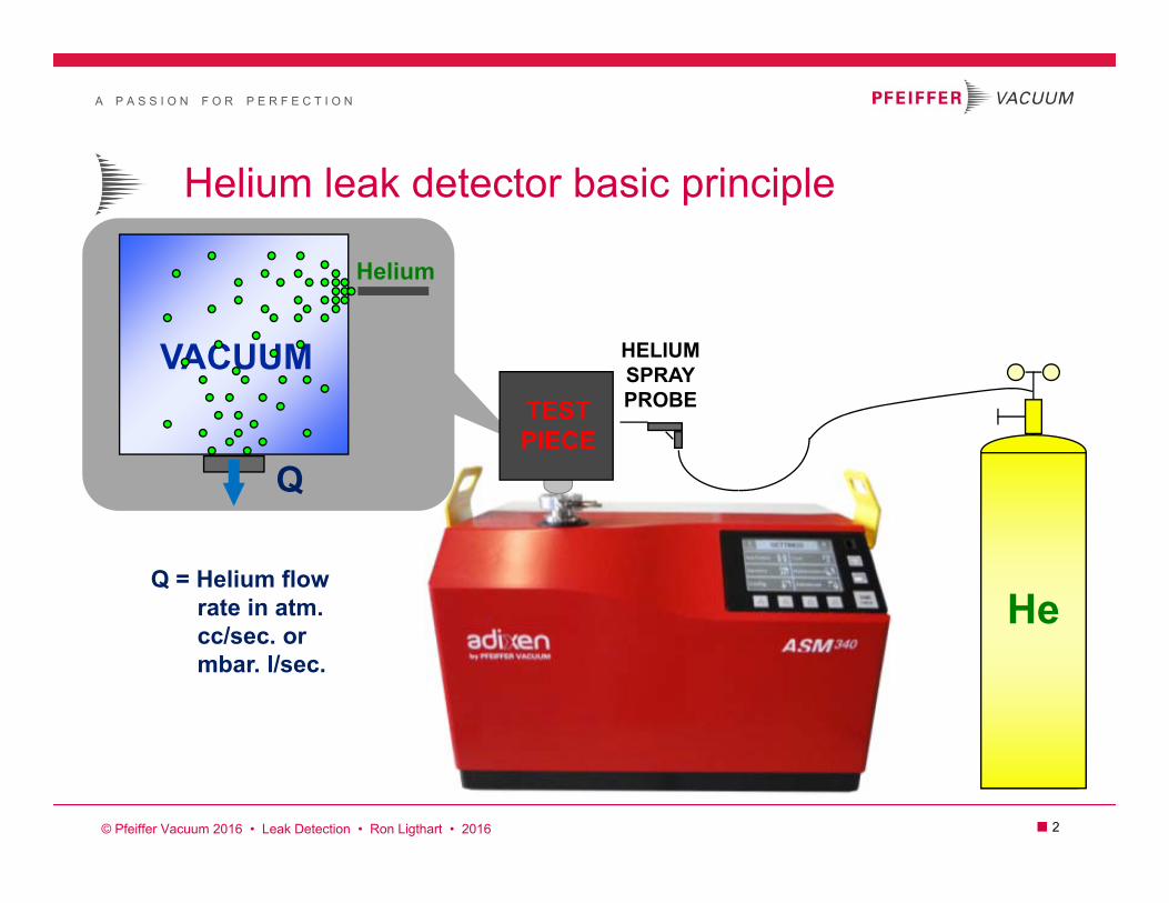
Helium leak detector basic principle
Helium
Q
Q = Helium flowrate in atm.cc/sec. ormbar. l/sec.
He
HELIUMSPRAYPROBETEST
PIECE
© Pfeiffer Vacuum 2016 • Leak Detection • Ron Ligthart • 2016
A P A S S I O N F O R P E R F E C T I O N
■ 3
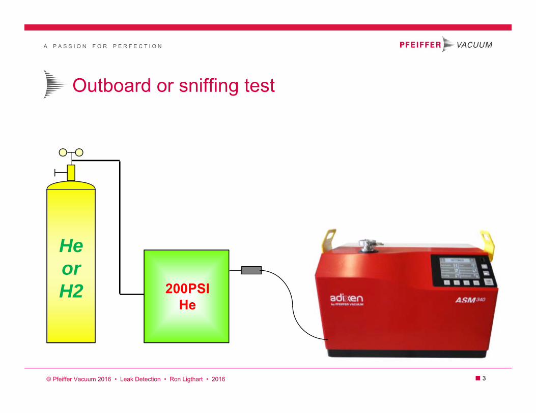
Outboard or sniffing test
HeorH2 200PSI
He
© Pfeiffer Vacuum 2016 • Leak Detection • Ron Ligthart • 2016

A P A S S I O N F O R P E R F E C T I O N
■ 4
Few examples of Helium Leak Detection today
AutomotiveAirbags
Gas tanksCompressors
Fuel railsShock absorbers
ABS valvesRadiators
Wheel rimsManifoldsSensors
Oil coolersFuel cells
55 gallon drums
AerospaceEngines
Antennas Watches
AircraftHydraulic components
gyroswings
missiles
Food packaging
MedicalPacemakerCatheters
Blood FiltersSealed Packaging
SemiconductorMass flow controllers
Integrated circuits Vacuum systems
Gas linesGas cabinets
Quartz displays
ElectricalLampsTubes
TransformersPower plants
Circuit breakers
© Pfeiffer Vacuum 2010 • Leak Detection • Ron Ligthart • 2016
A P A S S I O N F O R P E R F E C T I O N
■ 5
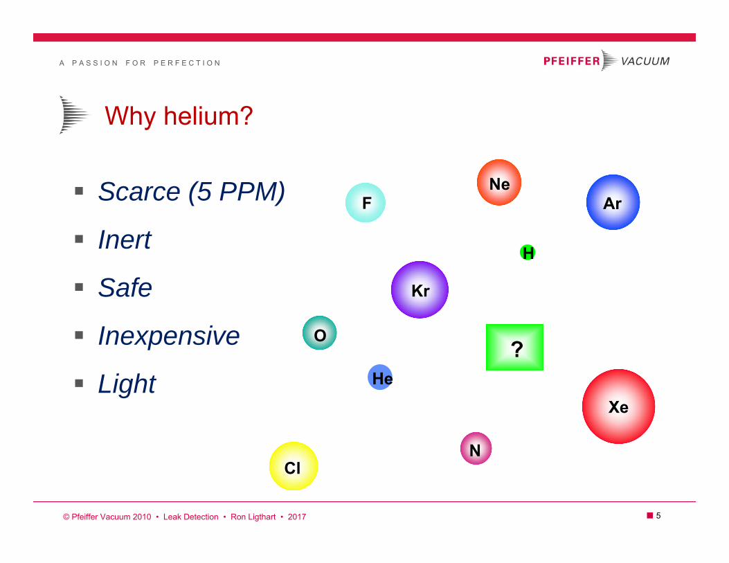
Why helium?
Scarce (5 PPM)
Inert
Safe
Inexpensive
Light?
He
N
O
FNe
Cl
Ar
Kr
Xe
H
© Pfeiffer Vacuum 2010 • Leak Detection • Ron Ligthart • 2017

A P A S S I O N F O R P E R F E C T I O N
■ 6
Helium versus Hydrogen leak test gas
HeliumAmbient concentration: 5ppm
Inert: non-toxic, non-flammable High energy: Fast diffusion
Cannot be created via processNon-replenishable resource
Cost: $$$$Increasing cost rate: $$$
BLM surplus runs out ~2018Supply: intermitting issues
Hydrogen 95/5 (N2/H2)Ambient concentration: .5ppm
Non-toxic, non-flammable @95/5 Higher energy: Faster diffusion
Can be created via processReplenishable resource
Cost: $Increasing cost rate: $
Supply: No issuesMixing 95/5 onsite: ~1 cent cubic/ft.
© Pfeiffer Vacuum • Product Manager • Ron Ligthart • 2016

A P A S S I O N F O R P E R F E C T I O N
■ 7
Why helium/hydrogen leak detector?
High Sensitivity
Wide Range
Reliable
Quantitative
Dynamic Testing
Nondestructive
No “ghost” readings
© Pfeiffer Vacuum 2016 • Leak Detection • Ron Ligthart • 2016

A P A S S I O N F O R P E R F E C T I O N
■ 8
Various leak rate relationships
waterrunning1 mm
10mbar l/s
waterdripping100 µm
10E-1mbar l/s
watertight
30 µm
10E-3mbar l/s
Bacteriatight
10 µm
10E-5mbar l/s
Virustight3 µm
10E-7mbar l/s
“technically“tight
0.1 µm
10E-12mbar l/s
“gas“tight
0.8 µm
10E-9mbar l/s
µm = microns mm = millimeters mbar l/s = leak rate Note: Test conditions such as pressure will impact correlations
© Pfeiffer Vacuum 2016 • Leak Detection • Ron Ligthart • 2016
A P A S S I O N F O R P E R F E C T I O N
■ 9
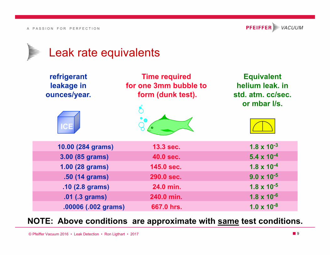
Leak rate equivalents
refrigerantleakage in
ounces/year.
Time requiredfor one 3mm bubble to
form (dunk test).
Equivalenthelium leak. in
std. atm. cc/sec.or mbar l/s.
10.00 (284 grams)3.00 (85 grams)1.00 (28 grams)
.50 (14 grams).10 (2.8 grams).01 (.3 grams).00006 (.002 grams)
13.3 sec.40.0 sec.
145.0 sec.290.0 sec.24.0 min.
240.0 min.667.0 hrs.
1.8 x 10⁻³
5.4 x 10⁻⁴
1.8 x 10⁻⁴
9.0 x 10⁻⁵
1.8 x 10⁻⁵
1.8 x 10⁻⁶
1.0 x 10⁻⁸
NOTE: Above conditions are approximate with same test conditions.
ICE
© Pfeiffer Vacuum 2016 • Leak Detection • Ron Ligthart • 2017
A P A S S I O N F O R P E R F E C T I O N
■ 10
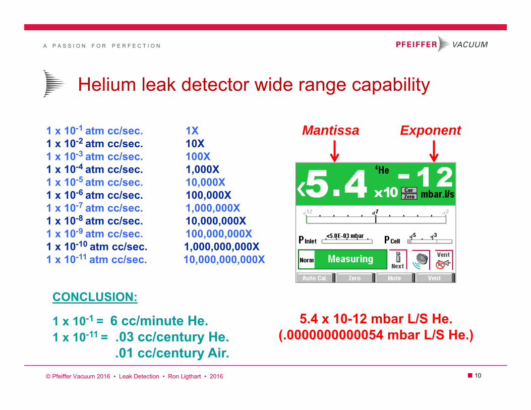
Helium leak detector wide range capability
1 x 10⁻¹ atm cc/sec. 1X1 x 10-2 atm cc/sec. 10X1 x 10-3 atm cc/sec. 100X1 x 10-4 atm cc/sec. 1,000X1 x 10-5 atm cc/sec. 10,000X1 x 10-6 atm cc/sec. 100,000X1 x 10-7 atm cc/sec. 1,000,000X1 x 10-8 atm cc/sec. 10,000,000X1 x 10-9 atm cc/sec. 100,000,000X1 x 10-10 atm cc/sec. 1,000,000,000X1 x 10-11 atm cc/sec. 10,000,000,000X
CONCLUSION:
1 x 10-1 = 6 cc/minute He.1 x 10-11 = .03 cc/century He.
.01 cc/century Air. © Pfeiffer Vacuum 2016 • Leak Detection • Ron Ligthart • 2016
Mantissa Exponent
5.4 x 10⁻¹² mbar L/S He.(.0000000000054 mbar L/S He.)
A P A S S I O N F O R P E R F E C T I O N
■ 11
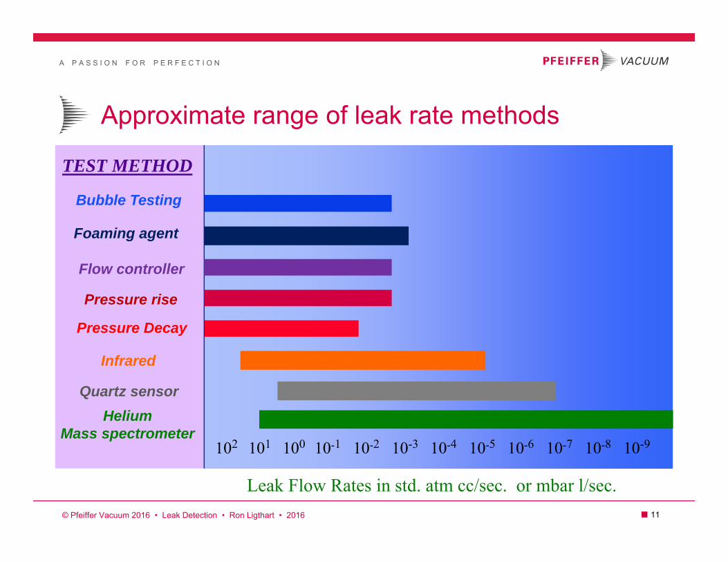
Approximate range of leak rate methods
TEST METHOD
Bubble Testing
Pressure Decay
Helium Mass spectrometer
102 101 100 10-1 10-2 10-4 10-5 10-6 10-7 10-8
Leak Flow Rates in std. atm cc/sec. or mbar l/sec.
10-910-3
© Pfeiffer Vacuum 2016 • Leak Detection • Ron Ligthart • 2016
Foaming agent
Pressure rise
Flow controller
Infrared
Quartz sensor

A P A S S I O N F O R P E R F E C T I O N
■ 12
Leak rate units of measurement & conditions Leak rate units of measurement and conditions can severely
alter the real leak rate value.
=
Atm. cc/sec. He (drive force of leak at exhaust side x volume per unit time of helium)
1X10⁻⁸?Air?
Helium?Leak Rate?Pressure?
What?
Cc/second?Cc/minute?Cc/hour?Cc/day? ?Atm?
Torr?Mbar?
Pascal?InchHg?
PSI?
?5 PSIA?100 PSIG?
5 BAR?200 mbar?1000 Torr?
ASK:What gas?
What pressure?What unit of time?
What unit of pressure?
Additional details:What temperature?
What gas concentration?
© Pfeiffer Vacuum 2016 • Leak Detection • Ron Ligthart • 2016
A P A S S I O N F O R P E R F E C T I O N
■ 13
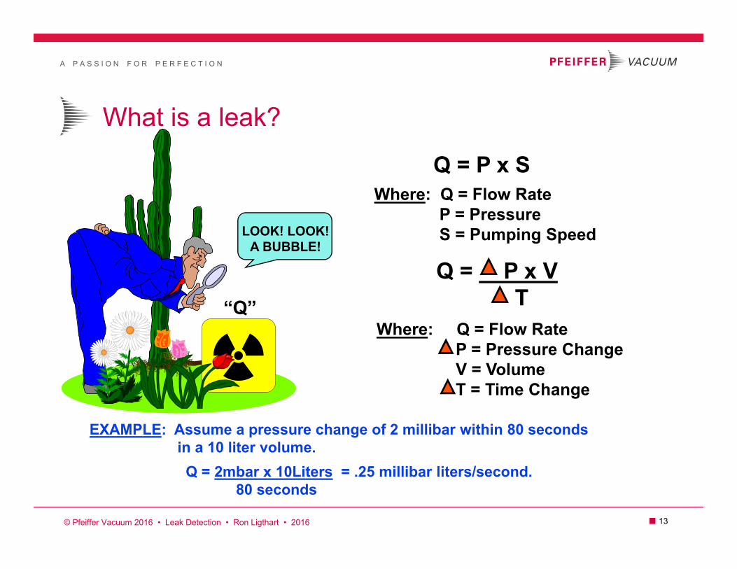
What is a leak?
Q = P x SWhere: Q = Flow Rate
P = PressureS = Pumping Speed
Q = P x VT
Where: Q = Flow RateP = Pressure ChangeV = VolumeT = Time Change
EXAMPLE: Assume a pressure change of 2 millibar within 80 secondsin a 10 liter volume.Q = 2mbar x 10Liters = .25 millibar liters/second.
80 seconds
LOOK! LOOK!A BUBBLE!
“Q”
© Pfeiffer Vacuum 2016 • Leak Detection • Ron Ligthart • 2016

A P A S S I O N F O R P E R F E C T I O N
■ 14
What is a leak?
Literal definition“…to enter or escape through an opening usually by a fault or
mistake.”
Everything leaks!It is a matter of degree or “How much?”
Modern leak detectors are extremely effectiveDetects leakage of molecules of tracer gas (< 0.0029 cc/year)
- Set test standard to leaks of practical concern -
A P A S S I O N F O R P E R F E C T I O N
■ 15
Determining Leak Rate Specifications
Typical Considerations What type of leakage will damage the product
Inflow of contaminant
Outflow of contents Vacuum requirement of process
How much material flow can be permitted
How long must the product last – “shelf life”
Competitors specification
Customer requirements
A P A S S I O N F O R P E R F E C T I O N
■ 16
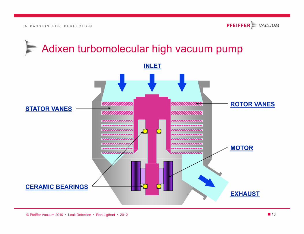
Adixen turbomolecular high vacuum pump
ROTOR VANES
EXHAUST
STATOR VANES
CERAMIC BEARINGS
MOTOR
INLET
© Pfeiffer Vacuum 2010 • Leak Detection • Ron Ligthart • 2012

A P A S S I O N F O R P E R F E C T I O N
■ 17
Adixen Molecular Drag Pump (MDP)
IMPELLER
MOTOR
UPPER CERAMICBEARING
LOWER CERAMICBEARING
ROTOR
EXHAUST INTERSTAGE PORT
Robust “Holweck” design.
Low 27,000 RPM.
Mounted in any orientation.
100% field serviceable.
MTBF of 50,000 hrs.
Interstage pumping.(two HLD test ports)
Rugged single monoblock machining.
Superior compression ratio1,000,000,000 for N220,000 for He.
Full pump protection:air inrushes,thermal,movement.
© Pfeiffer Vacuum 2010 • Leak Detection • Ron Ligthart • 2012

A P A S S I O N F O R P E R F E C T I O N
■ 18
Adixen hybrid turbomolecular drag pump
TURBO STAGES
DRAG STAGES
EXHAUST
CERAMIC BEARINGS
MOTOR
ROTOR
© Pfeiffer Vacuum 2010 • Leak Detection • Ron Ligthart • 2012

A P A S S I O N F O R P E R F E C T I O N
■ 19
Counter-Flow Testing
Tracer gas (helium) flows past turbo exhaust
Helium molecules “migrate” back through turbo
Tolerable pressure at turbo exhaust is very high
Spec tube protected from heavier molecules
SpecTube
Gas Flow
Helium MoleculeFlow
Helium Gas
15 Torr
10-5 Torr
Exhaust
RP

A P A S S I O N F O R P E R F E C T I O N
■ 20
ACP28 mechanical dry pump
ROOTS TECHNOLOGY
FRICTIONLESSVACUUM
DISPLACEMENT SINGLE PHASELOW VOLTAGE
5 STAGECOMPRESSION
AIRCOOLED
16 CFM displacementFirst PM @ 22,000 hours
© Pfeiffer Vacuum 2016 • Leak Detection • Ron Ligthart • 2016
A P A S S I O N F O R P E R F E C T I O N
■ 21
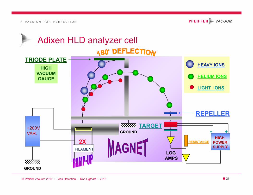
Adixen HLD analyzer cell
+200VVAR.
FILAMENT
GROUND
TRIODE PLATEHEAVY IONS
HELIUM IONS
LIGHT IONS
REPELLER
HIGHPOWERSUPPLY
LOGAMPS
- +TARGET
RESISTANCE
HIGHVACUUMGAUGE
GROUND
2X
© Pfeiffer Vacuum 2016 • Leak Detection • Ron Ligthart • 2016

A P A S S I O N F O R P E R F E C T I O N
■ 22
Adixen helium calibrated leaks
HELIUM CALIBRATED Type FE 14 N
values Atm cm3/s +- 10%HeAtm cm3/s +- 10%Air
Date Temperature
8.4x10⁻⁸
3.1x10⁻⁸
2763
20 CTemperature Coeff. 3%/degree C. 2% loss/year
A L C A T E L
Nov. 23- 1996
150 cc volume / 8.4x10⁻⁸ atm. cc/sec. He = 1,785,714,286 seconds57 years
8.4x10⁻⁸ atm cc/sec. He - 2% loss = 8.2x10⁻⁸ atm cc/sec. He
HELIUM TO AIR CONVERSION IN MOLECULAR FLOWQhe = Qair Mair = Qair 29 = 2.7 8.4x10⁻⁸ atm. cc/sec. He = 3.1x10⁻⁸ atm. cc/sec. air
Mhe 4 2.7
© Pfeiffer Vacuum 2016 • Leak Detection • Ron Ligthart • 2016

A P A S S I O N F O R P E R F E C T I O N
■ 23
Pyrex Helium Calibrated Leak
Glass pyrex tube
Helium under pressure
Constant Helium permeation takes place until helium supply is depleted
Valve should always be open when in storage (permeation lives on).
Should glass break within. Your in trouble ($$$) and hide the evidence.
Helium pressure is directly proportional to helium permeation through glass pyrex.
Heliumrecharge
portHe
HeHe
He
© Pfeiffer Vacuum 2010 • Leak Detection • Ron Ligthart • 2016

A P A S S I O N F O R P E R F E C T I O N
■ 24
Integrated large vacuum chamber leak testing
Helium Helium
© Pfeiffer Vacuum 2016 • Leak Detection • Ron Ligthart • 2016
Leak detector in test cycle
A P A S S I O N F O R P E R F E C T I O N
■ 25
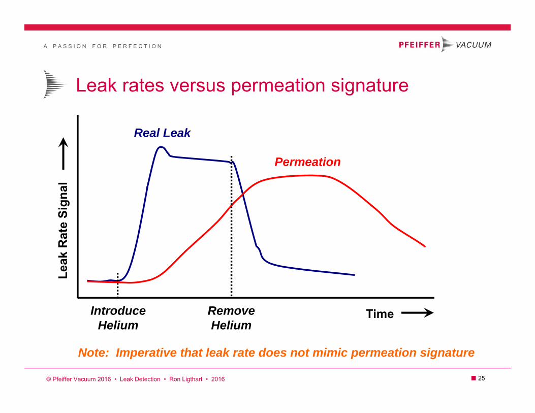
Leak rates versus permeation signature
Real Leak
Permeation
IntroduceHelium
RemoveHelium
Time
Leak
Rat
e Si
gnal
Note: Imperative that leak rate does not mimic permeation signature
© Pfeiffer Vacuum 2016 • Leak Detection • Ron Ligthart • 2016
A P A S S I O N F O R P E R F E C T I O N
■ 26
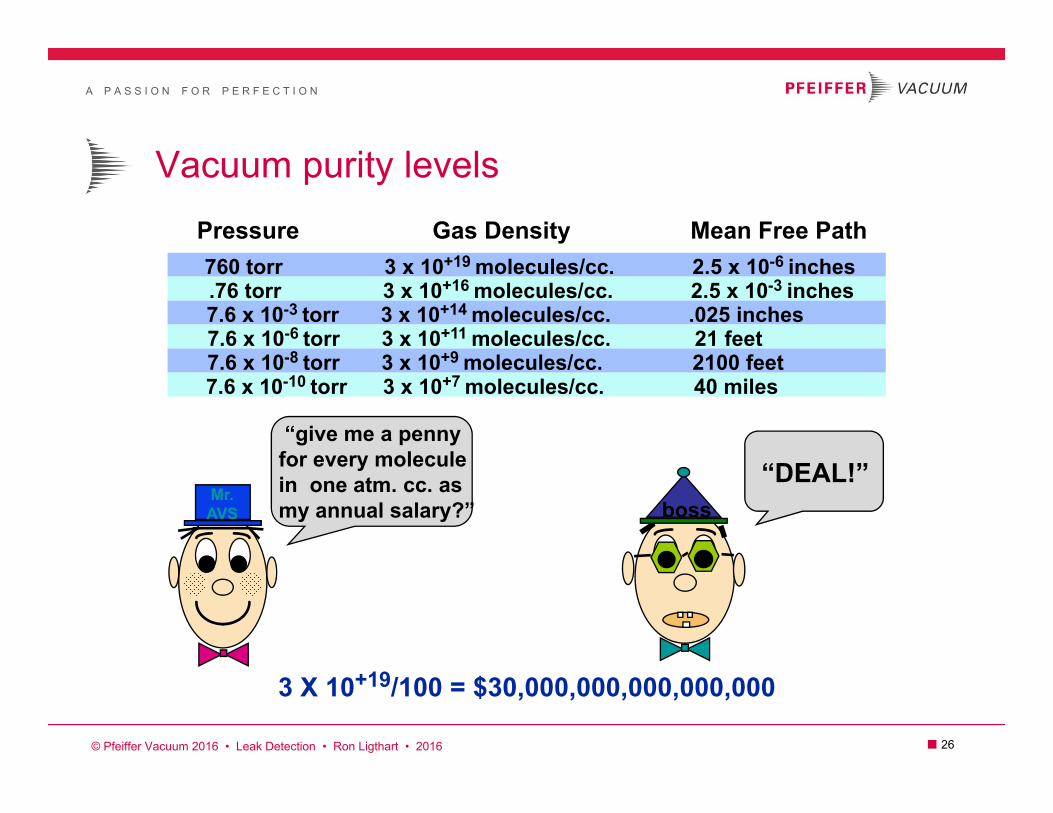
Vacuum purity levelsPressure Gas Density Mean Free Path760 torr 3 x 10+19 molecules/cc. 2.5 x 10⁻⁶ inches .76 torr 3 x 10+16 molecules/cc. 2.5 x 10⁻³ inches 7.6 x 10⁻³ torr 3 x 10+14 molecules/cc. .025 inches 7.6 x 10⁻⁶ torr 3 x 10+11 molecules/cc. 21 feet 7.6 x 10⁻⁸ torr 3 x 10+9 molecules/cc. 2100 feet7.6 x 10-10 torr 3 x 10+7 molecules/cc. 40 miles
“give me a pennyfor every moleculein one atm. cc. asmy annual salary?” boss
“DEAL!”
3 X 10+19/100 = $30,000,000,000,000,000
Mr.AVS
© Pfeiffer Vacuum 2016 • Leak Detection • Ron Ligthart • 2016
A P A S S I O N F O R P E R F E C T I O N
■ 27
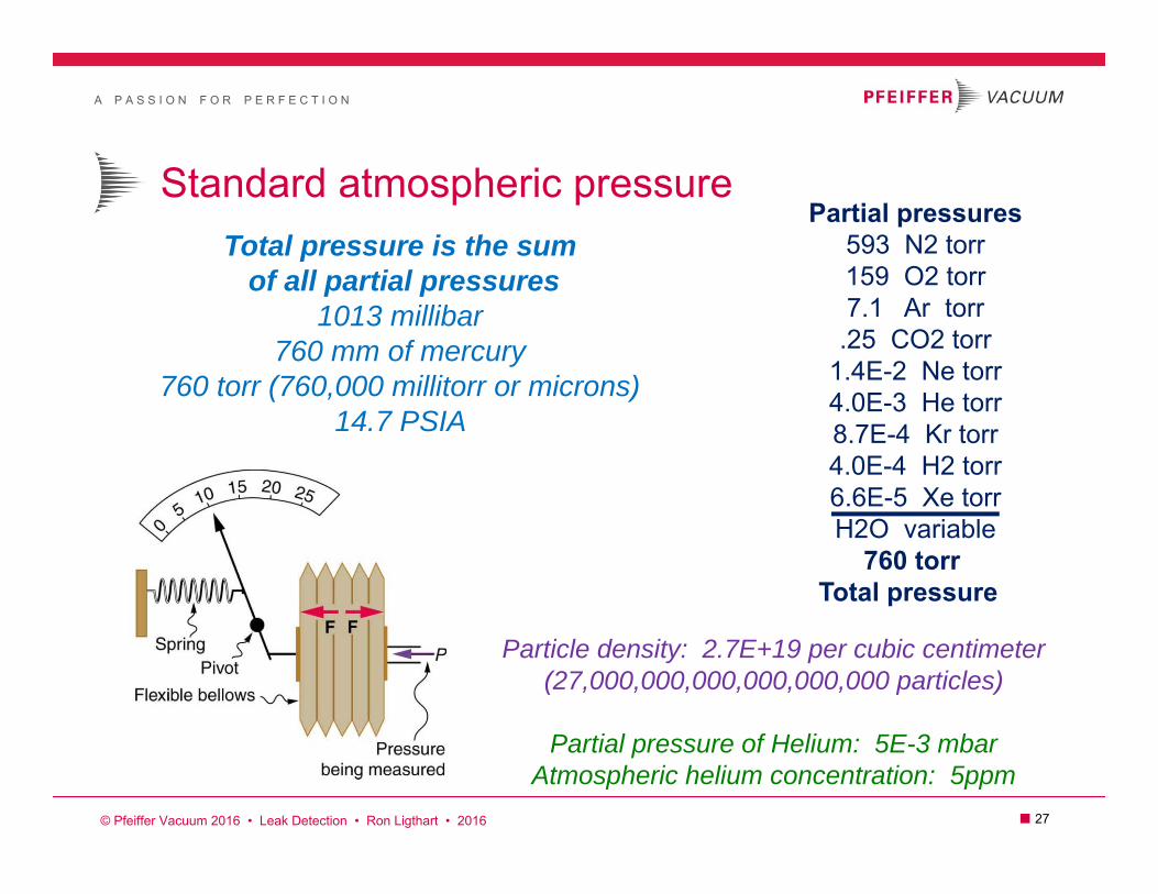
Standard atmospheric pressureTotal pressure is the sum
of all partial pressures1013 millibar
760 mm of mercury760 torr (760,000 millitorr or microns)
14.7 PSIA
Particle density: 2.7E+19 per cubic centimeter(27,000,000,000,000,000,000 particles)
Partial pressure of Helium: 5E-3 mbarAtmospheric helium concentration: 5ppm
Partial pressures593 N2 torr159 O2 torr7.1 Ar torr.25 CO2 torr
1.4E-2 Ne torr4.0E-3 He torr8.7E-4 Kr torr4.0E-4 H2 torr6.6E-5 Xe torrH2O variable
760 torrTotal pressure
© Pfeiffer Vacuum 2016 • Leak Detection • Ron Ligthart • 2016

A P A S S I O N F O R P E R F E C T I O N
■ 28
Vacuum measurements reality
PRESSURE % VACUUM
14.7 PSI = 760 Torr13.5 PSI = 700 Torr11.6 PSI = 600 Torr
9.7 PSI = 500 Torr7.7 PSI = 400 Torr 5.8 PSI = 300 Torr3.9 PSI = 200 Torr1.9 PSI = 100 Torr
.2 PSI = 10 Torr.02 PSI = 1 Torr = 1000 Millitorr
.002 PSI = .1 Torr = 100 Millitorr .0002 PSI = .01 Torr = 10 Millitorr
.00002 PSI = .001 Torr = 1 Millitorr
0% 8%
21% 34%47%59%74%87%99%
99.9%99.99%
99.999%99.9999%
© Pfeiffer Vacuum 2016 • Leak Detection • Ron Ligthart • 2016
A P A S S I O N F O R P E R F E C T I O N
■ 29
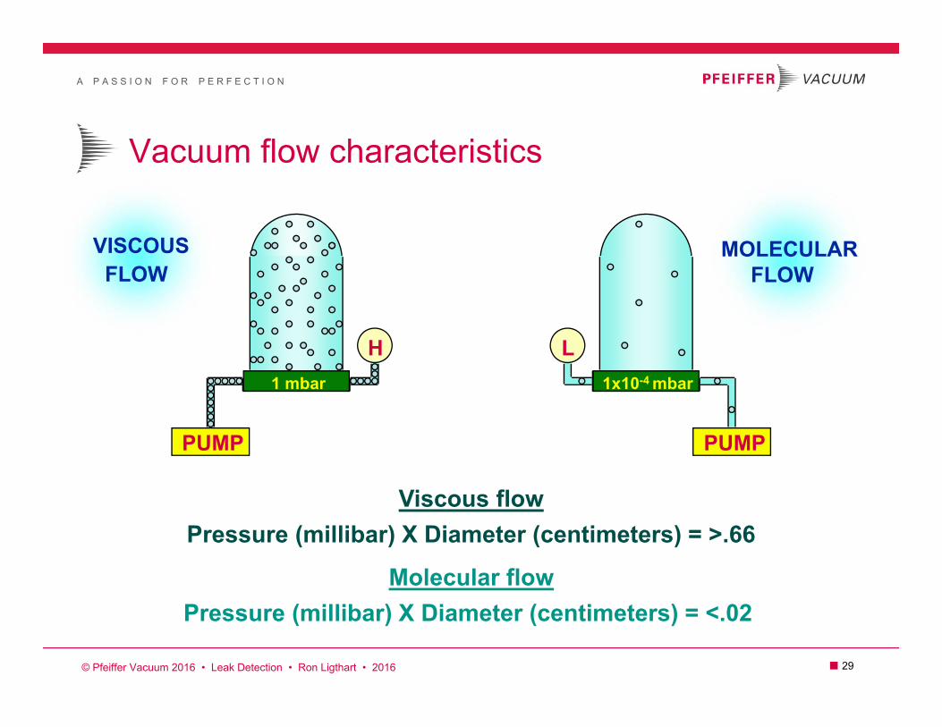
Vacuum flow characteristics
PUMP PUMP
H L
VISCOUSFLOW
MOLECULARFLOW
Viscous flowPressure (millibar) X Diameter (centimeters) = >.66
Molecular flowPressure (millibar) X Diameter (centimeters) = <.02
1x10⁻⁴ mbar1 mbar
© Pfeiffer Vacuum 2016 • Leak Detection • Ron Ligthart • 2016

A P A S S I O N F O R P E R F E C T I O N
■ 30
Gas Flow
ViscousL/d < 0.01Rough Vacuum760 T to 1 TLR > 10-5 sccs
Transitional0.01 < L/d < 0.5 Medium Vacuum1 T to 10-3 T
MolecularL/d > 0.5High/Ultrahigh Vacuum< 10-3 TLR < 10-5 sccs
L
d

A P A S S I O N F O R P E R F E C T I O N
■ 31
In molecular flowConductance is the ability of an opening to allow a volume of gas
to pass through in a given amount of time. Most helium leak test applicationsunder vacuum are in molecular flow where conductance plays a
vital role for performance testing.
Simplified formula for air at 20 degrees C.
Cair = 12.1 x D3 / L
Where: C = liters/secondD & L = centimeters (Diameter & Length) Example: Assume a 3’ (91.4 cm.) tube length
with a ID of 1/4” (.64 cm)
C = 12.1 x .643 / 91.4 > C = whopping .034 l/s air
For Helium : C = 2.7 x .034 > C = .092 l/s. He.
For other gases than air Correction Factor
Cgas = CF x Cair
N21.0
O2.95
H23.8
Kr.59
AR.85
He2.7
CF Correction Factors for other gases
© Pfeiffer Vacuum 2016 • Leak Detection • Ron Ligthart • 2016

A P A S S I O N F O R P E R F E C T I O N
■ 32
In Series & More RealityConductance in series is where the total conductance is less
than the smallest of the conductances in series.
Series Conductance
1/Ctotal = 1/C1 + 1/C2
50 litervacuum chamber
“VS”Example 1: Assume C1 = 100 l/s.
And C2 = 50 l/s.Ctotal = 33.33 l/s.
More Conductance Reality
VS = C x SC + S
Example 2: C = Conductance of a 3’ bellow with 1/4” ID for Helium in molecular flow = .092 l/s.S = HLD He. inlet pumping speed @ 4.4 l/s.VS = He. pumping @ chamber= .09 l/s.
HLD Response time = 9.3 minutes.Example 3: If conductance of bellow “C” was 28 l/s. He.
(1 meter NW40)VS = He. pumping @ chamber = 3.8 l/s.HLD Response time = 13 seconds.
C
S
VS = pumping speed @ chamberC = conductance of bellowS = pumping speed of leak detector
C1 C2 = C total
This image cannot currently be displayed.
© Pfeiffer Vacuum 2016 • Leak Detection • Ron Ligthart • 2016

A P A S S I O N F O R P E R F E C T I O N
■ 33
adixen
adixen
ASM 142
2.0
Inboard or vacuum test
He
SPRAYPROBE
Spray heliumstarting at the
top of testitem.
© Pfeiffer Vacuum 2010 • Leak Detection • Ron Ligthart • 2012
A P A S S I O N F O R P E R F E C T I O N
■ 34
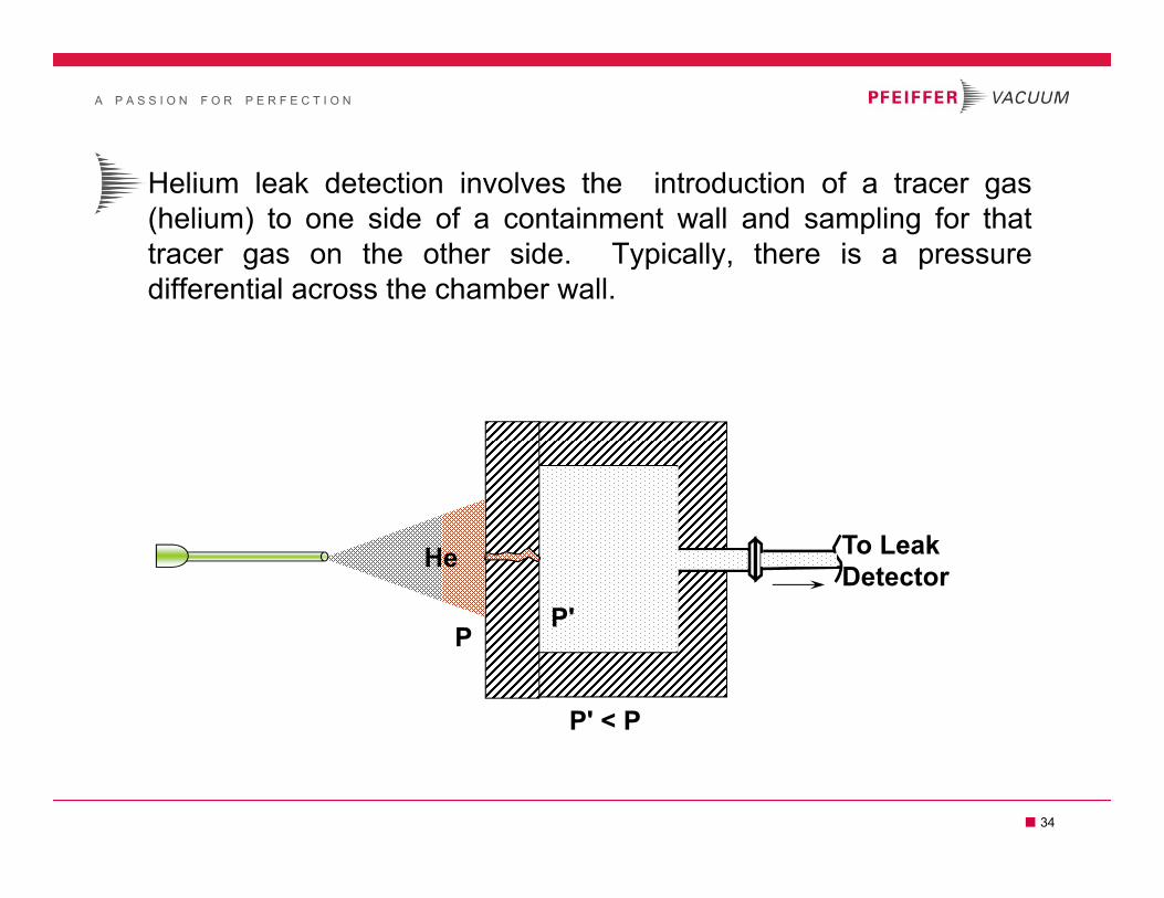
Helium leak detection involves the introduction of a tracer gas(helium) to one side of a containment wall and sampling for thattracer gas on the other side. Typically, there is a pressuredifferential across the chamber wall.
He To Leak Detector
P
P' < P
P'

A P A S S I O N F O R P E R F E C T I O N
■ 35
So What?
A helium leak detector does not detect leaks…
It detects helium
Helium signal, response time, & test results dependant on…
Test conditions, method & technique

A P A S S I O N F O R P E R F E C T I O N
■ 36
Outboard or sniffing test
He200PSI
He
Sniff heliumstarting at the
bottom oftest item.
LIMITATIONSNatural helium background of 5ppm.
Non global test (not cumulative)Operator dependent
adixen
adixen
ASM 142
2.0
© Pfeiffer Vacuum 2010 • Leak Detection • Ron Ligthart • 2012

A P A S S I O N F O R P E R F E C T I O N
■ 37
Sniffing basics & reality
TEST ITEMUNDER POSITIVE
HELIUM PRESSURE
Not avacuumcleaner
Noliquids
Filter stone
Conductancelimiter
Flow rate @ 1 cc/sec.
Adixen sniffing response and clean-up time isa function of tube length (.2 seconds/meter).
CRITICAL: Minimize helium concentration within working environment.
Angle probe tip along surfaces to assure flowrate and avoid clogging of any kind.
For maximum sensitivity probe speed shouldnot exceed 1 inch per second.
Helium5 ppm
Start at bottom of testitem and move yourway up.
© Pfeiffer Vacuum 2010 • Leak Detection • Ron Ligthart • 2016
A P A S S I O N F O R P E R F E C T I O N
■ 38
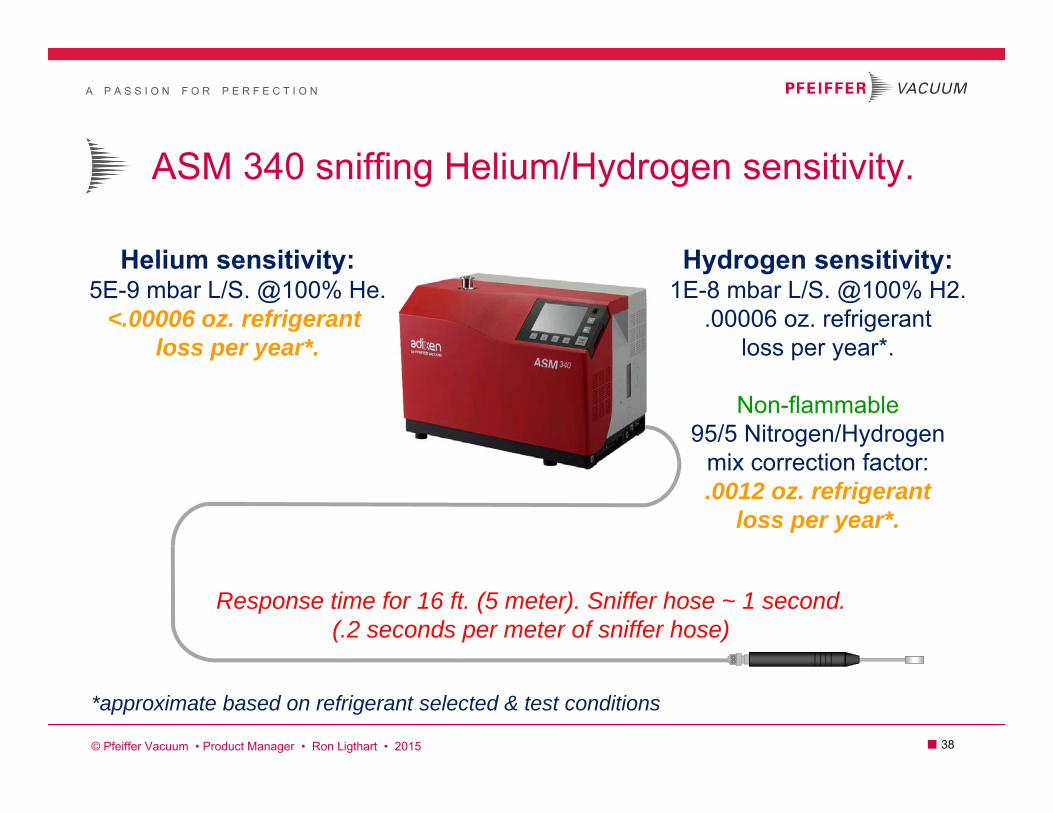
ASM 340 sniffing Helium/Hydrogen sensitivity.
Helium sensitivity:5E-9 mbar L/S. @100% He.
<.00006 oz. refrigerant loss per year*.
Hydrogen sensitivity:1E-8 mbar L/S. @100% H2.
.00006 oz. refrigerantloss per year*.
Non-flammable95/5 Nitrogen/Hydrogen
mix correction factor:.0012 oz. refrigerant
loss per year*.
*approximate based on refrigerant selected & test conditions
Response time for 16 ft. (5 meter). Sniffer hose ~ 1 second.(.2 seconds per meter of sniffer hose)
© Pfeiffer Vacuum • Product Manager • Ron Ligthart • 2015

A P A S S I O N F O R P E R F E C T I O N
■ 39
Sniffing helium leak test example – step one
Helium
Test itemevacuation pump
Test item vent
Evacuationvalve
Heliumchargevalve
Vacuum
PressureCoil is evacuated andback-filled with helium
Note: coil is pressurized with nitrogenfor gross pressure decay test first. Helium vent must go outside
or reclaim system!
01
© Pfeiffer Vacuum 2010 • Leak Detection • Ron Ligthart • 2016

A P A S S I O N F O R P E R F E C T I O N
■ 40
Helium/Hydrogen outboard sniffer leak test Coil under test gas pressure
operator
ASM340Outboard sniffing mode
Helium or Hydrogentest gas
Standardor
Smart Probe
© Pfeiffer Vacuum • Product Manager • Ron Ligthart • 2016

A P A S S I O N F O R P E R F E C T I O N
■ 41
Average molecular velocityAverage molecular velocity at room temperature (20 C).
HeliumAir
HydrogenHeliumAirNitrogenOxygenArgon
1.75 x 10³ meters/sec. = 6,299 KPH = 3,915 MPH1.24 x 103 meters/sec. = 4,882 KPH = 2,997 MPH4.64 x 102 meters/sec. = 1,670 KPH = 1,038 MPH4.71 x 102 meters/sec. = 1,696 KPH = 1,054 MPH4.40 x 102 meters/sec. = 1,583 KPH = 984 MPH3.94 x 102 meters/sec. = 1,418 KPH = 881 MPH
Va = 8RT/ M = 1.455 x 10² T/M
WHERE: Va = Average velocity in meters/sec.R = Gas constant.M = Molecular weight in grams.T = Absolute temperature in Kelvin.
© Pfeiffer Vacuum 2010 • Leak Detection • Ron Ligthart • 2017

A P A S S I O N F O R P E R F E C T I O N
■ 42
Helium concentration impact
Helium leak test concentration is directly proportional to leak rate test results that can aid economic cost by means of helium dilution.
Example: Leak rate criteria = 1 x 10⁻⁶ atm. cc/sec. He.using 100% helium.
1 x 10-6 x 100% = 1 x 10⁻⁶ atm. cc/sec. He.
Example: Leak rate criteria = 1 x 10⁻⁶ atm. cc/sec. He.using 10% helium mix.
1 x 10-6 x 10% = 1 x 10⁻⁷ atm. cc/sec. He.
Example: Leak rate criteria = 1 x 10⁻⁶ atm. cc/sec. He.using 1% helium mix.
1 x 10-6 x 1% = 1 x 10⁻⁸ atm. cc/sec. He. Increasing test pressurecan bring back lost helium
sensitivity with helium dilution
1
2
3!
© Pfeiffer Vacuum 2010 • Leak Detection • Ron Ligthart • 2017

A P A S S I O N F O R P E R F E C T I O N
■ 43
Optimal spectrometer location
A CB
ROOTSBLOWER
ROTARY VANEMECHANICAL PUMP
OR DRY PUMP
HELIUMLEAK DETECTOR
© Pfeiffer Vacuum 2010 • Leak Detection • Ron Ligthart • 2017
Is it A or B or C?

A P A S S I O N F O R P E R F E C T I O N
■ 44
Subfab Leak Testing
*Not to scale
HeliumSpray gun
Exhaust at ~atmosphere
“Sniffing mode”
© Pfeiffer Vacuum 2010 • Leak Detection • Ron Ligthart • 2017
Helium spray

A P A S S I O N F O R P E R F E C T I O N
■ 45
Optimal spectrometer location?
A CB
ROTARY VANE WET ORDRY MECHANICAL PUMP
HELIUMLEAK DETECTOR
OPEN VALVE CLOSED VALVE
TURBO OR HYBRIDTURBODRAG PUMP
© Pfeiffer Vacuum 2010 • Leak Detection • Ron Ligthart • 2017
A P A S S I O N F O R P E R F E C T I O N
■ 46
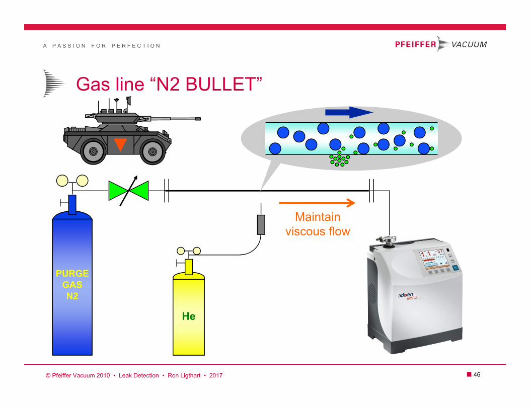
Gas line “N2 BULLET”
PURGEGASN2
He
Maintainviscous flow
© Pfeiffer Vacuum 2010 • Leak Detection • Ron Ligthart • 2017
A P A S S I O N F O R P E R F E C T I O N
■ 47
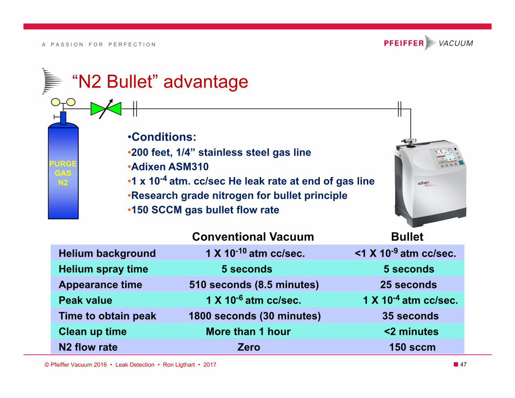
“N2 Bullet” advantage
Conventional Vacuum BulletHelium background 1 X 10⁻¹⁰ atm cc/sec. <1 X 10⁻⁹ atm cc/sec.Helium spray time 5 seconds 5 seconds Appearance time 510 seconds (8.5 minutes) 25 seconds Peak value 1 X 10⁻⁶ atm cc/sec. 1 X 10⁻⁴ atm cc/sec. Time to obtain peak 1800 seconds (30 minutes) 35 seconds Clean up time More than 1 hour <2 minutes N2 flow rate Zero 150 sccm
•Conditions:•200 feet, 1/4” stainless steel gas line•Adixen ASM310•1 x 10⁻⁴ atm. cc/sec He leak rate at end of gas line•Research grade nitrogen for bullet principle•150 SCCM gas bullet flow rate
PURGEGASN2
© Pfeiffer Vacuum 2016 • Leak Detection • Ron Ligthart • 2017

A P A S S I O N F O R P E R F E C T I O N
■ 48
Reality of vacuum grease
Properly maintained vacuum seals don’t need grease—that is, really good technicians don’t need it.
Vacuum grease is a lubricant and retains helium.
Use only hydrocarbon or fomblin/krytox grease if needed.
If used, use enough for “glaze” but NO GOOPS!
Quick fix and long term consequences
© Pfeiffer Vacuum 2016 • Leak Detection • Ron Ligthart • 2018
???
A P A S S I O N F O R P E R F E C T I O N
■ 49
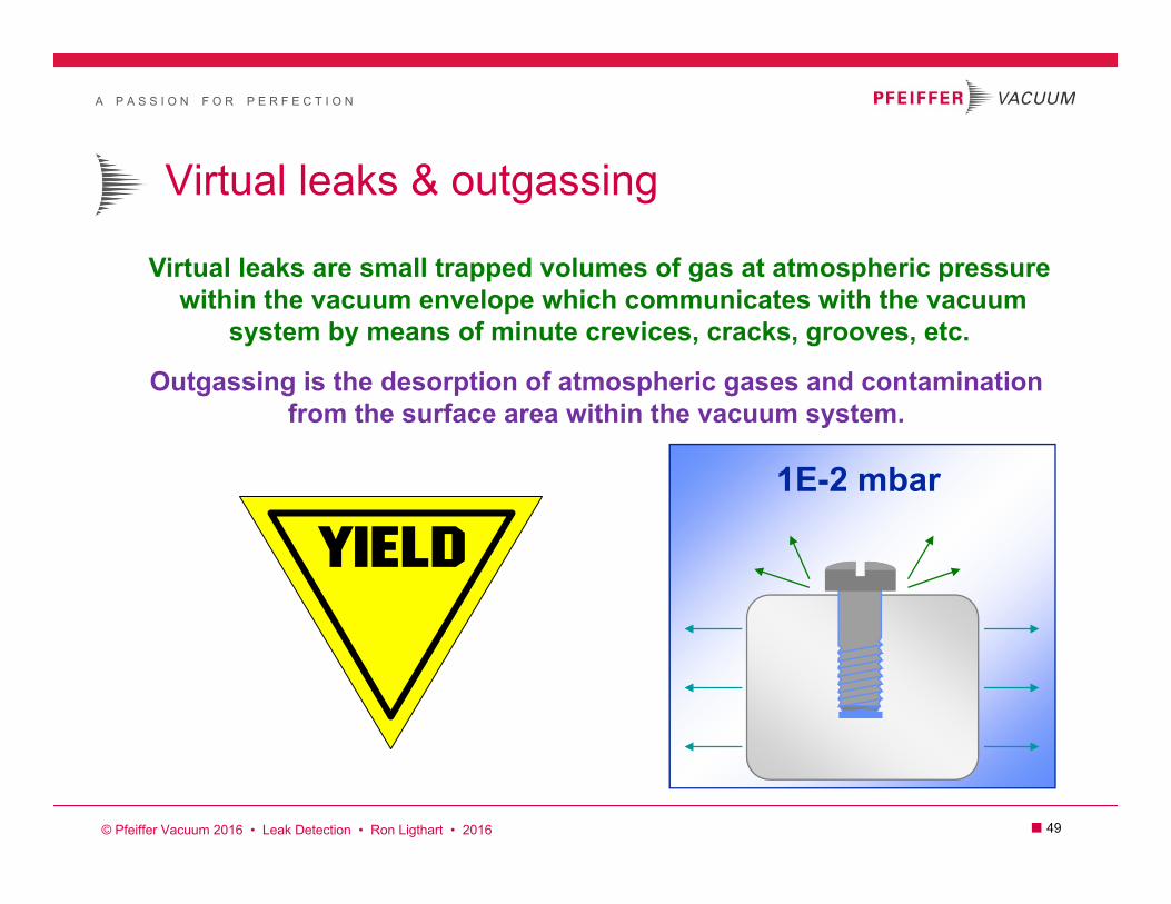
1E-2 mbar
Virtual leaks are small trapped volumes of gas at atmospheric pressurewithin the vacuum envelope which communicates with the vacuum
system by means of minute crevices, cracks, grooves, etc.
Outgassing is the desorption of atmospheric gases and contamination from the surface area within the vacuum system.
Virtual leaks & outgassing
© Pfeiffer Vacuum 2016 • Leak Detection • Ron Ligthart • 2016

A P A S S I O N F O R P E R F E C T I O N
■ 50
vacuum
solution
vacuum
“o” ring
Virtual leaks
vacuum
Top view with solution
Virtual leaks are small trapped volumes of gaswithin the vacuum envelope that can also “burp”
Virtual leaks within “O” rings
© Pfeiffer Vacuum 2016 • Leak Detection • Ron Ligthart • 2016
A P A S S I O N F O R P E R F E C T I O N
■ 51
Outgassing
Properties of Outgassing The rate of outgassing generally diminishes over time
The rate of outgassing increases with temperature
Sources include water vapor, synthetics, residual solvents, and contamination (finger prints)
The release of gases and vapor from the chamber walls and other materials inside a vacuum system

A P A S S I O N F O R P E R F E C T I O N
■ 52
What be happening here?
© Pfeiffer Vacuum 2016 • Leak Detection • Ron Ligthart • 2016
A P A S S I O N F O R P E R F E C T I O N
■ 53
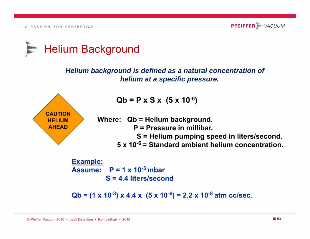
Helium Background
Helium background is defined as a natural concentration ofhelium at a specific pressure.
Qb = P x S x (5 x 10⁻⁶)
Where: Qb = Helium background.P = Pressure in millibar.S = Helium pumping speed in liters/second.
5 x 10-6 = Standard ambient helium concentration.
Example:Assume: P = 1 x 10⁻³ mbar
S = 4.4 liters/second
Qb = (1 x 10-3) x 4.4 x (5 x 10-6) = 2.2 x 10⁻⁸ atm cc/sec.
CAUTIONHELIUMAHEAD
© Pfeiffer Vacuum 2016 • Leak Detection • Ron Ligthart • 2016

A P A S S I O N F O R P E R F E C T I O N
■ 54
Response time
Response time is defined as the time to reach 63% of the signal.
T = VS
Where: T = Time in seconds.V = Volume in liters.S = Helium pumping speed in liters/second.
Example 1: V = 50 liters. T = 50 = 250 seconds S = .2 liters/sec. .2 (4.2 minutes)
Example 2: V = 50 liters. T = 50 = 11.4 secondsS = 4.4 liters/sec. 4.4
12
3
6
921
4578
1011
© Pfeiffer Vacuum 2010 • Leak Detection • Ron Ligthart • 2017
A P A S S I O N F O R P E R F E C T I O N
■ 55
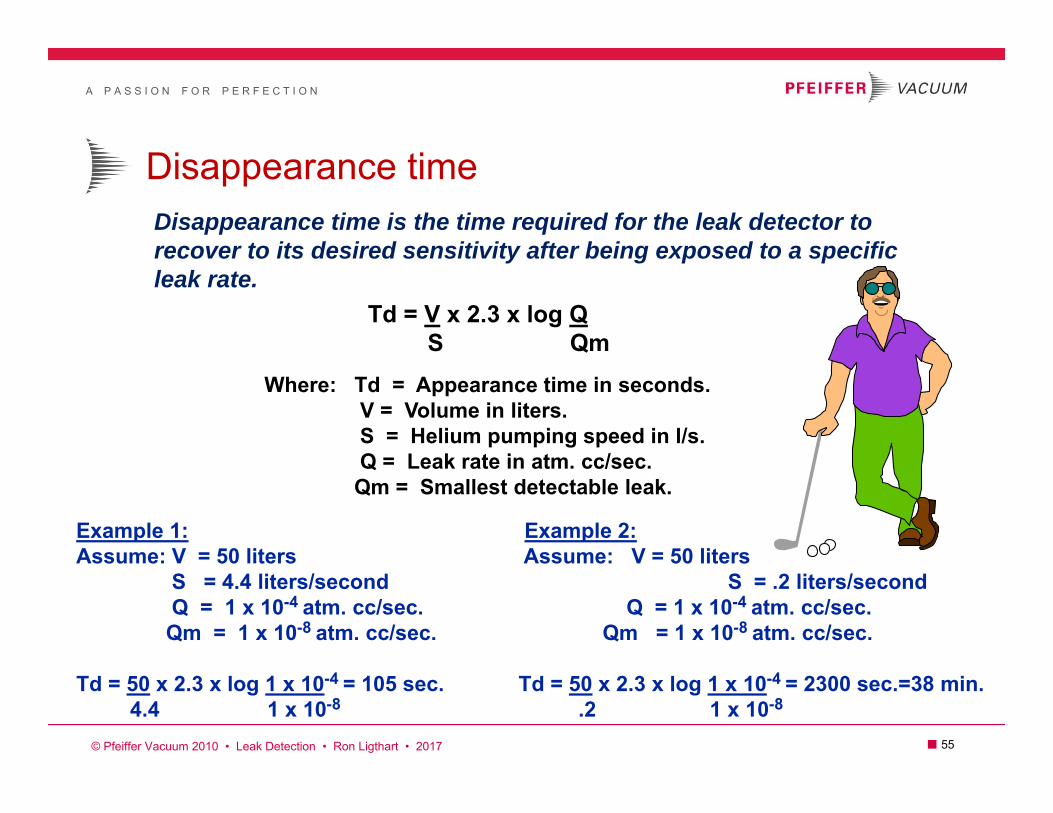
Disappearance timeDisappearance time is the time required for the leak detector to recover to its desired sensitivity after being exposed to a specificleak rate.
Td = V x 2.3 x log QS Qm
Where: Td = Appearance time in seconds.V = Volume in liters.S = Helium pumping speed in l/s. Q = Leak rate in atm. cc/sec.Qm = Smallest detectable leak.
Example 1: Example 2:Assume: V = 50 liters Assume: V = 50 liters
S = 4.4 liters/second S = .2 liters/secondQ = 1 x 10⁻⁴ atm. cc/sec. Q = 1 x 10⁻⁴ atm. cc/sec.Qm = 1 x 10⁻⁸ atm. cc/sec. Qm = 1 x 10⁻⁸ atm. cc/sec.
Td = 50 x 2.3 x log 1 x 10-4 = 105 sec. Td = 50 x 2.3 x log 1 x 10-4 = 2300 sec.=38 min.4.4 1 x 10⁻⁸ .2 1 x 10⁻⁸
© Pfeiffer Vacuum 2010 • Leak Detection • Ron Ligthart • 2017

A P A S S I O N F O R P E R F E C T I O N
■ 56
Parallel operation (split flow)
15
Sb
Sa
VacuumChamber
Qt
adixen
adixen
ASM 142
2.0
Qb = Sb x Qt (Sb + Sa)
Where: Qb = Helium detector reading in atm. cc/sec.Sb = Detector helium pumping speed in liters/sec.Sa = Helium pumping speed in liters/sec. of auxilary pump.Qt = Helium leak rate to be detected.
Example:Assume: Sb = .6 liters/sec.
Sa = 2.5 liters/sec.Qt = 1 x 10⁻⁸ atm. cc/sec. He.Qb = .6 x (1 x 10-8)
.6 + 2.5
Qb = 2 x 10⁻⁹ atm cc/sec. He.
© Pfeiffer Vacuum 2010 • Leak Detection • Ron Ligthart • 2012
A P A S S I O N F O R P E R F E C T I O N
■ 57
adixen
adixen
ASM 142
2.0
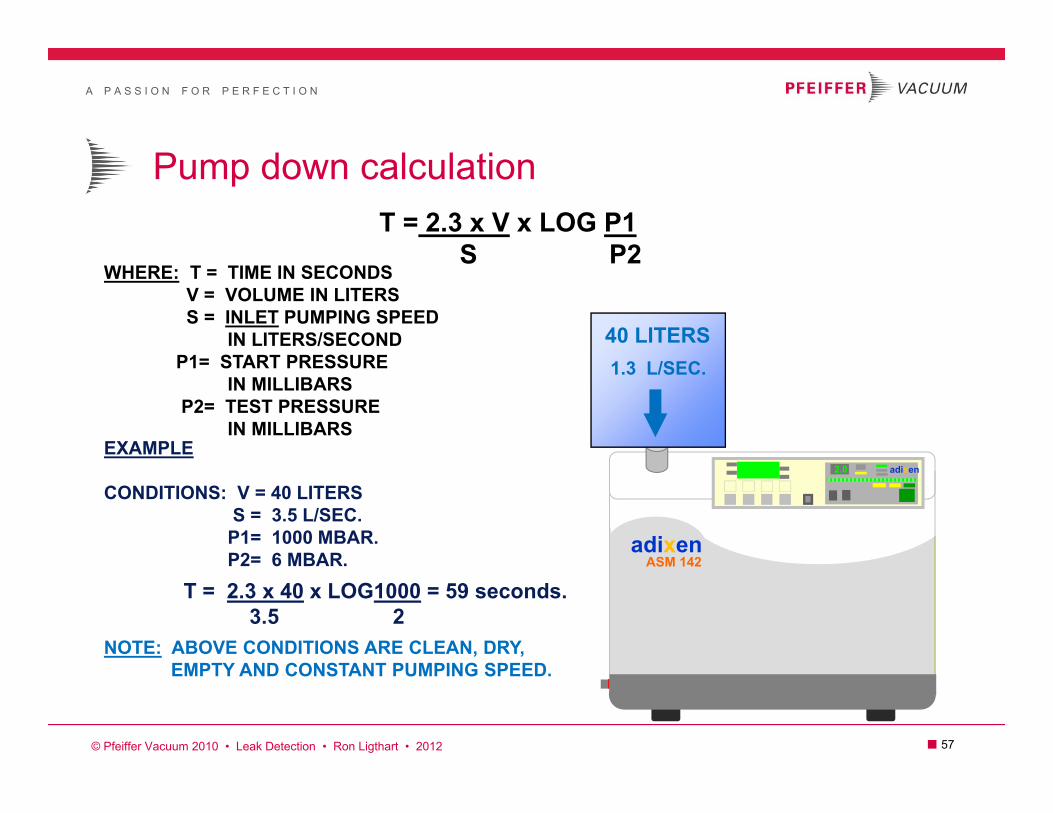
Pump down calculationT = 2.3 x V x LOG P1
S P2WHERE: T = TIME IN SECONDS
V = VOLUME IN LITERSS = INLET PUMPING SPEED
IN LITERS/SECONDP1= START PRESSURE
IN MILLIBARSP2= TEST PRESSURE
IN MILLIBARSEXAMPLE
CONDITIONS: V = 40 LITERSS = 3.5 L/SEC.
P1= 1000 MBAR.P2= 6 MBAR.
T = 2.3 x 40 x LOG1000 = 59 seconds.3.5 2
NOTE: ABOVE CONDITIONS ARE CLEAN, DRY,EMPTY AND CONSTANT PUMPING SPEED.
40 LITERS1.3 L/SEC.
© Pfeiffer Vacuum 2010 • Leak Detection • Ron Ligthart • 2012

A P A S S I O N F O R P E R F E C T I O N
■ 58
Viscous flow leak
Viscous flow leak is when the gas molecules are entrained by frictionto produce laminar flow as is encountered particularly in gross leaks.A cylindrical type leak in this regime can be expressed by the “Poiseuille’s” equation.
“Poiseuille’s”
QDnL
P1P2
= Leak rate in atm. cc/sec.= Leak Diameter in cm. = Gas viscosity in bar sec.= Length of leak in cm.= Test pressure on one side of leak (bar).= Test pressure on other side of leak (bar).
EXAMPLE: Assume a leak diameter of .005 millimeters with a length of 2 millimeters.Internal test pressure of 100PSI (6.8 bar) helium with surroundingambient pressure using the sniffing principle.
Q = .00054 (7.82 - 12) = 1.2 x 10⁻³ atm. cc/sec. helium. 256 (1.93 x 10⁻¹⁰) .2
“Q”
Q = D4 (P12 - P22)256nL
© Pfeiffer Vacuum 2010 • Leak Detection • Ron Ligthart • 2012

A P A S S I O N F O R P E R F E C T I O N
■ 59
Molecular flow leaksMolecular flow leak is when independent gas molecules no longerinteract with one another within the diameter of the leak due tothe mean free path. A cylindrical type leak in this regime can beexpressed with the “Knudsen” equation.
“Knudsen”
Q = 1 2 RT D3 (P1 - P2)6 M L
QRTM
= Leak rate in atm. cc/sec.= Ideal gas constant.= Absolute temperature.= Molecular weight of gas.
DLP1P2
= Diameter of leak in cm.= Length of leak in cm.= Test pressure on one side of leak (bar). = Test pressure on other side of leak (bar).
EXAMPLE: Assume a leak of .001 millimeters with a length of 2 millimetersTest item is under vacuum with helium being sprayed surrounding test item at atmosphere in a 20 C ambient environment.
Q = 1 2 (8.32 x 10⁷) (293) (.0001)3 (1 - 0) = 1.63 x 10⁻⁷ atm. cc/sec. helium. 6 4 .2
© Pfeiffer Vacuum 2010 • Leak Detection • Ron Ligthart • 2012

A P A S S I O N F O R P E R F E C T I O N
■ 60
Fine leak rate realityTheoretical hole diameter calculation in molecular flow regime
D = 6 M L 1 Q .33
2 RT P1- P2CONDITIONS
1E-11 atm cc/sec. He leak rate.2 cm. wall thickness20 C ambient temperatureInboard He spray test
D = 6 4 (.2)(1)(1E-11) .33
2 (8.32E7)(293)
D = .0000045 cm. = .045 microns
Size (microns) .0001 .001 .01 .1 1 10 100 1,000 10,000Pollens
Skin cellsLints
Tobacco smokeHousehold dust
Industrial dustAcid fumesGas molecules
Finger printsAlcohol residue
1 meter=
1,000,000 microns
1E-11 1E-9 1E-7Theoretical leak rate values:
© Pfeiffer Vacuum 2010 • Leak Detection • Ron Ligthart • 2012

A P A S S I O N F O R P E R F E C T I O N
■ 61
How it works…1. Prior to Test: Measure and record raw signal (background)
2. Actual Test: Measure actual leak + background
3. Display: Actual test measurement – raw signal = Actual Leak
Helium Background Suppression (Zeroing)
CautionDo not “zero” signal while applying helium to test object
Signal(sccs)
Time (s)
Raw Signal
Activate ZERO Measured Value
Actual Leak + Raw Signal
Displayed Value(Measured Value – Raw Signal)
ZEROReference
RawSignal
Actual Leak
A P A S S I O N F O R P E R F E C T I O N
■ 62
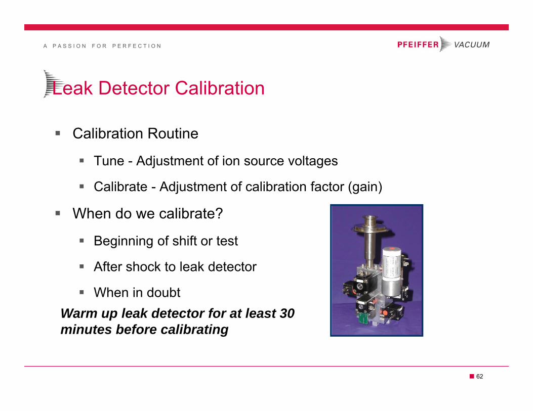
Calibration Routine
Tune - Adjustment of ion source voltages
Calibrate - Adjustment of calibration factor (gain)
When do we calibrate?
Beginning of shift or test
After shock to leak detector
When in doubt
Leak Detector Calibration
Warm up leak detector for at least 30 minutes before calibrating
A P A S S I O N F O R P E R F E C T I O N
■ 63
Avoid Misidentifying Leak Location
Begin testing area with highest probability of leakage first
Seals, fixtures, recently maintained components, etc.
In still air, test from the top of the system down
‘Dead-Stick’ testing for accurate leak location
In high Air flow environments…
Use a wind barrier while fine testing
Isolate (“bag”) components being tested
Large Chamber Testing
A P A S S I O N F O R P E R F E C T I O N
■ 64
Helium leak detection Contact
Terry Rogelstad - Leak Detection InstructorTEL: 585-248-3208
Main contact numbers
© Pfeiffer Vacuum 2010 • Leak Detection • Ron Ligthart • 2018