heliport design 2
TRANSCRIPT

8/10/2019 Heliport Design 2
http://slidepdf.com/reader/full/heliport-design-2 1/6

8/10/2019 Heliport Design 2
http://slidepdf.com/reader/full/heliport-design-2 2/6
Attachment 2
Interim Helicopter Point-in-Space Visual Segment Criteria
1.2 Touchdown and Liftoff Area (TLOF)
A load bearing, generally paved area, normally centered in the FATO, on whichthe helicopter lands or takes off. The TLOF is frequently called a helipad orhelideck. This area was called the "FATO" in previous publications.

8/10/2019 Heliport Design 2
http://slidepdf.com/reader/full/heliport-design-2 3/6
Attachment 2
Interim Helicopter Point-in-Space Visual Segment Criteria
2.0 VISUAL SEGMENT. (MAP WITHIN 10,500 FEET OF HELIPORT)
The purpose of the visual segment on a PinS approach procedure to a landingarea within 10,500 feet of the MAP is to provide a measure of obstructionprotection/identification along the track from the MAP to the heliport. Thesegment is based on the premise that the pilot will maintain level flight at MDAuntil the helicopter is in the position to initiate a 6° (OPTIMUM) descent to thehelipoint. Identify this point as an ATD fix from the MAP. The course from theMAP to the heliport must be within 30° of the final approach course.
2.1 Area.
2.1.1 Length.
The area considered for obstacle identification begins at the MAP earliestposition and extends to the end of the FATO or 50 feet beyond the helipoint,whichever is farther. The MINIMUM distance from MAP to helipoint is 2,600 feet.
2.1.2 Width.
2.1.2.1 Visual segment course continuation of final course. Construct lines (c-e, d-f)from the corners of the MAP fix error box closest to the heliport to the farthestcorners of the FATO. See Figure 1A.
Final Course
Figure 1A
Straight Visual Segment
MAP
Not to scale for emphasis.
Corner of fix
Corner of fixFarthest corner
≥50'
Helipoint
FATO
VSRL
a
b
c
d
e ef
f
zoom view
2.1.2.2 Visual segment course deviating up to 30° from final course. Connect the turnside earliest corner (b) of the MAP fix error box to the farthest correspondingcorner (e) of the FATO. Connect the non-turn side corner (d) of the fix error boxclosest to the heliport to the farthest FATO corner (f). See figure 1B.

8/10/2019 Heliport Design 2
http://slidepdf.com/reader/full/heliport-design-2 4/6
Attachment 2
Interim Helicopter Point-in-Space Visual Segment Criteria
Figure 1B
Visual Segment With Turn at MAP
Scale exaggerated for emphasis.
Earliest corner on turnside of fix error box
MAP ≥50'
HelipointFATO
Final Course
≤30°
VSRL
a
b
c
d
e
f
e
f
2.2 Visual Segment Descent Angle (VSDA).
The VSDA is a developer specified angle extending from the a point 5 feetdirectly above the helipoint to the MDA. The VSDA must cross MDA betweenthe helipoint and the MAP. MAXIMUM VSDA is 7.5°, OPTIMUM is 6.0°, and theMINIMUM is 4.5°. VSDA’s greater than 7.5° requires Flight Standards Serviceapproval considering specific helicopter equipment and capabilities, pilot training,and demonstrated capability.
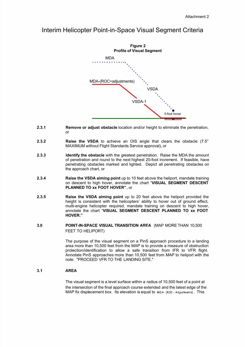
2.3 Visual Segment OIS.
The VSRL is a line perpendicular to the visual track, located 50 feet from thehelipoint or at the leading edge of the FATO, whichever is farther. The OISbegins as a level surface at helipoint elevation. At the VSRL, it extends upwardin the direction of the MAP at a 1° less than the specified VSDA to the point itreaches an altitude equal to MDA minus ROC and adjustments. When the MAPis beyond this point, the OIS becomes a level surface to the plotted position ofthe MAP. Obstacles are measured shortest distance to the VSRL. Obstaclesshould not penetrate the OIS. When obstacles penetrate the OIS, take one ofthe following actions in the listed sequence.
8/10/2019 Heliport Design 2
http://slidepdf.com/reader/full/heliport-design-2 5/6
Attachment 2
Interim Helicopter Point-in-Space Visual Segment Criteria
5-foot hover
MDA
MDA-(ROC+adjustments)
VSDA
VSDA-1
Figure 2
Profile of Visual Segment
2.3.1 Remove or adjust obstacle location and/or height to eliminate the penetration,or
2.3.2 Raise the VSDA to achieve an OIS angle that clears the obstacle (7.5°MAXIMUM without Flight Standards Service approval), or
2.3.3 Identify the obstacle with the greatest penetration. Raise the MDA the amountof penetration and round to the next highest 20-foot increment. If feasible, havepenetrating obstacles marked and lighted. Depict all penetrating obstacles onthe approach chart, or
2.3.4 Raise the VSDA aiming point up to 10 feet above the heliport, mandate training
on descent to high hover, annotate the chart “VISUAL SEGMENT DESCENTPLANNED TO xx FOOT HOVER”, or
2.3.5 Raise the VSDA aiming point up to 20 feet above the heliport provided theheight is consistent with the helicopters’ ability to hover out of ground effect,multi-engine helicopter required, mandate training on descent to high hover,annotate the chart “VISUAL SEGMENT DESCENT PLANNED TO xx FOOTHOVER.”
3.0 POINT-IN-SPACE VISUAL TRANSITION AREA (MAP MORE THAN 10,500
FEET TO HELIPORT)
The purpose of the visual segment on a PinS approach procedure to a landingarea more than 10,500 feet from the MAP is to provide a measure of obstructionprotection/identification to allow a safe transition from IFR to VFR flight.
Annotate PinS approaches more than 10,500 feet from MAP to heliport with thenote: "PROCEED VFR TO THE LANDING SITE."
3.1 AREA
The visual segment is a level surface within a radius of 10,500 feet of a point at
the intersection of the final approach course extended and the latest edge of theMAP fix displacement box. Its elevation is equal to ( )MDA ROC Adjustments− + . This

8/10/2019 Heliport Design 2
http://slidepdf.com/reader/full/heliport-design-2 6/6