height adjustable workbench
TRANSCRIPT
HEIGHT ADJUSTABLEWORKBENCH
Model 94214ASSEMBLY AND OpERATING INSTRUCTIONS
Visit our website at: http://www.harborfreight.com
Read this material before using this product. Failure to do so can result in serious injury.
SAVE THIS MANUAL.Copyright© 2006 by Harbor Freight Tools®. All rights reserved. No portion of this manual or any
artwork contained herein may be reproduced in any shape or form without the express written
consent of Harbor Freight Tools. Diagrams within this manual may not be drawn proportionally.
Due to continuing improvements, actual product may differ slightly from the product described
herein. Tools required for assembly and service may not be included.
For technical questions and replacement parts, please call 1-800-444-3353.Revised Manual 09l

SKU 94214 For technical questions, please call 1-800-444-3353. Page 2
DESCRIpTION31” H at Lowest Position to 42” H Maximum with Foldable Frame27-5/8” L x 12” W, Split Sections Marked with Grid 44” Squared, Protractor 0-180 Degrees
Angled with Spring Push Button Release, 45 and 90 Degree
Yellow Laminated Particle Board
Square Clamps (Qty.4)- Plastic Wide Clamps (Qty. 4)
175 Lbs.29.70 Lbs.
ITEM
SpECIFICATIONS
SAVE THIS MANUAL
You will need the manual for the safety warnings and precautions, assembly instructions, operating and maintenance procedures, parts list and diagram. Keep your invoice with this manual. Write the invoice number on the inside of the front cover. Keep the manual and invoice in a safe and dry place for future reference.
SAFETY WARNINGS AND pRECAUTIONS
1. KEEp WORK AREA CLEAN. Cluttered areas invite injuries.
2. OBSERVE WORK AREA CONDITIONS. Keep work area well lit.
3. DO NOT ALLOW CHILDREN IN THE WORK AREA.
4. CHECK FOR DAMAGED pARTS. Before using any product, any part that appears damaged should be carefully checked to determine that it will perform its intended function. Check for any broken or damaged parts and any other conditions that may affect its operation. Replace or repair damaged or worn parts immediately.
5. USE SAFETY EqUIpMENT. WEAR ANSI AppROVED SAFETY IMpACT EYE GOGGLES WHEN ASSEMBLING THIS pRODUCT OR WHEN USING MACHINERY WITH THIS pRODUCT.
6. REpLACEMENT pARTS AND ACCESSORIES. When servicing, use only identical replacement parts. Use of any other parts will void the warranty.
7. ALWAYS CHECK HARDWARE AND ASSEMBLED pARTS AFTER ASSEMBLING. All connections should be tight and hardware tightened.
8. DO NOT OVERREACH. Keep proper footing and balance at all times when assembling this product.
9. STAY ALERT. Watch what you are doing at all times. Use common sense. Do not assemble this product when you are tired or distracted from the job at hand.
Adjustable Workbench
Table Size
Board Features
Table Top Materials
Table Clamps
Weight Capacity
Net Weight
SKU 94214 For technical questions, please call 1-800-444-3353. Page 3
10. USE THE CORRECT pRODUCT FOR YOUR AppLICATION. The correct equip- ment will do the job better and safer at the rate for which it is designed. Do not
use small equipment, tools, or attachments to do the work of larger industrial equip-
ment, tools, or attachments. Do not use this product for a purpose for which it was not
intended.
11. USE BREATHING pROTECTION for mouth and nose during all jobs that cause dust, chips, fumes or sparks.
12. pROTECT YOUR HEARING when doing work causing a lot of noise. Use ear plugs if necessary. (not included).
13. USE HEAVY DUTY GLOVES when working with tools and equipment.
14. NEVER ALLOW INExpERIENCED pERSONNEL TO WORK with your equipment and tools without instructions and/or supervision.
Warning: The warnings, cautions, and instructions discussed in this instruction manual cannot cover all possible conditions and situations that may occur. It must be understood by the operator that common sense and caution are factors which cannot be built into this product, but must be supplied by the operator.
UNpACKING
When unpacking this product check to make sure that all parts are included as shown in the parts list. If any parts are missing or broken, please call Harbor Freight Tools at the number below.
ASSEMBLY INSTRUCTIONS
NOTE: All parts that follow refer to the parts listed on Page 11 of this manual.
.
SKU 94214 For technical questions, please call 1-800-444-3353. Page 4
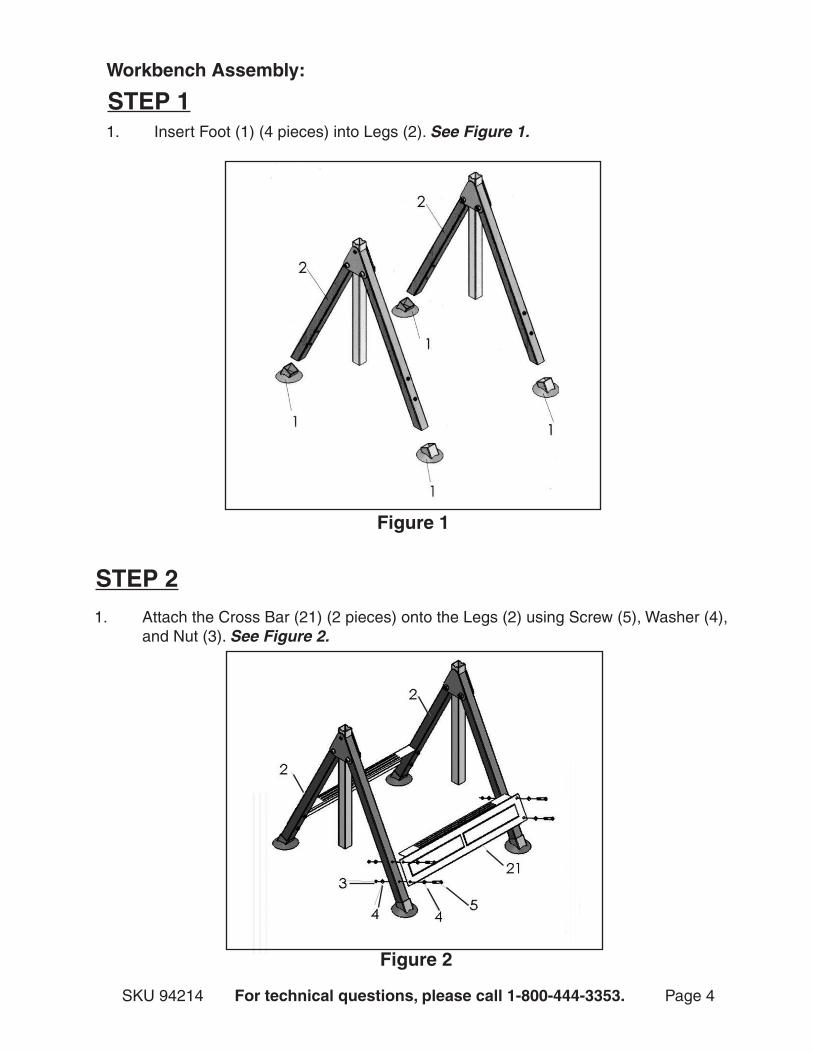
Workbench Assembly:
1. Insert Foot (1) (4 pieces) into Legs (2). See Figure 1.
STEp 1
STEp 2
1. Attach the Cross Bar (21) (2 pieces) onto the Legs (2) using Screw (5), Washer (4), and Nut (3). See Figure 2.
Figure 1
Figure 2
SKU 94214 For technical questions, please call 1-800-444-3353. Page 5
Figure 3
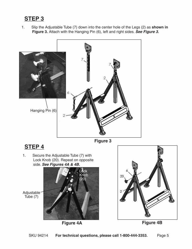
1. Slip the Adjustable Tube (7) down into the center hole of the Legs (2) as shown in Figure 3. Attach with the Hanging Pin (6), left and right sides. See Figure 3.
STEp 3
1. Secure the Adjustable Tube (7) with Lock Knob (20). Repeat on opposite side. See Figures 4A & 4B.
STEp 4
Figure 4A
Lock Knob (20)
Figure 4B
Adjustable Tube (7)
Hanging Pin (6)
SKU 94214 For technical questions, please call 1-800-444-3353. Page 6
Figure 5
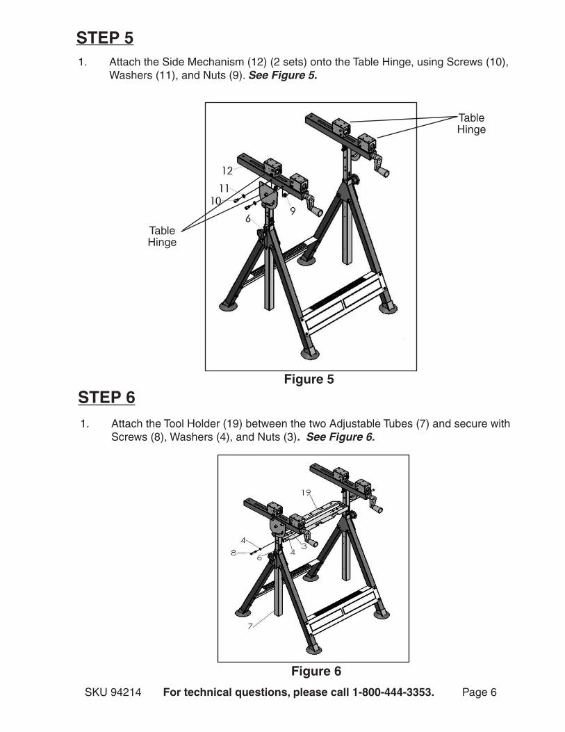
1. Attach the Side Mechanism (12) (2 sets) onto the Table Hinge, using Screws (10), Washers (11), and Nuts (9). See Figure 5.
STEp 5
STEp 6
Table Hinge
1. Attach the Tool Holder (19) between the two Adjustable Tubes (7) and secure with Screws (8), Washers (4), and Nuts (3). See Figure 6.
Figure 6
Table Hinge
SKU 94214 For technical questions, please call 1-800-444-3353. Page 7
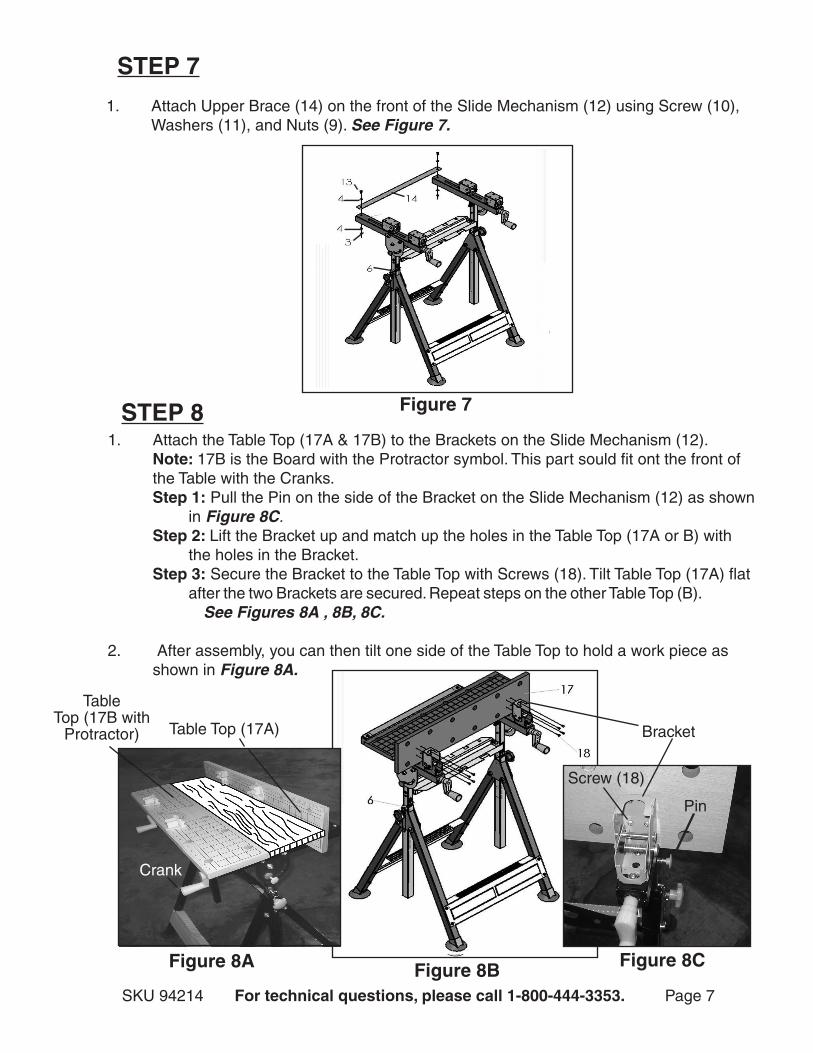
1. Attach the Table Top (17A & 17B) to the Brackets on the Slide Mechanism (12). Note: 17B is the Board with the Protractor symbol. This part sould fit ont the front of the Table with the Cranks.
Step 1: Pull the Pin on the side of the Bracket on the Slide Mechanism (12) as shown in Figure 8C.
Step 2: Lift the Bracket up and match up the holes in the Table Top (17A or B) with the holes in the Bracket.
Step 3: Secure the Bracket to the Table Top with Screws (18). Tilt Table Top (17A) flat after the two Brackets are secured. Repeat steps on the other Table Top (B). See Figures 8A , 8B, 8C.
2. After assembly, you can then tilt one side of the Table Top to hold a work piece as shown in Figure 8A.
STEp 7
Figure 8B
1. Attach Upper Brace (14) on the front of the Slide Mechanism (12) using Screw (10), Washers (11), and Nuts (9). See Figure 7.
Figure 7STEp 8
Figure 8C
Pin
Bracket
Screw (18)
Figure 8A
Table Top (17A)
Table Top (17B with
Protractor)
Crank
SKU 94214 For technical questions, please call 1-800-444-3353. Page 8
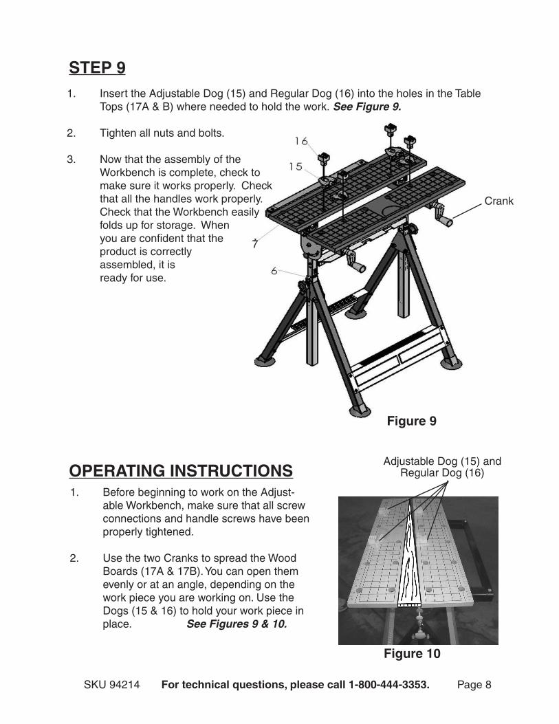
STEp 91. Insert the Adjustable Dog (15) and Regular Dog (16) into the holes in the Table
Tops (17A & B) where needed to hold the work. See Figure 9.
2. Tighten all nuts and bolts.
3. Now that the assembly of the Workbench is complete, check to make sure it works properly. Check that all the handles work properly. Check that the Workbench easily folds up for storage. When you are confident that the product is correctly assembled, it is ready for use.
Figure 9
7
Figure 10
OpERATING INSTRUCTIONS1. Before beginning to work on the Adjust-
able Workbench, make sure that all screw connections and handle screws have been properly tightened.
2. Use the two Cranks to spread the Wood Boards (17A & 17B). You can open them evenly or at an angle, depending on the work piece you are working on. Use the Dogs (15 & 16) to hold your work piece in place. See Figures 9 & 10.
Adjustable Dog (15) and Regular Dog (16)
Crank
SKU 94214 For technical questions, please call 1-800-444-3353. Page 9
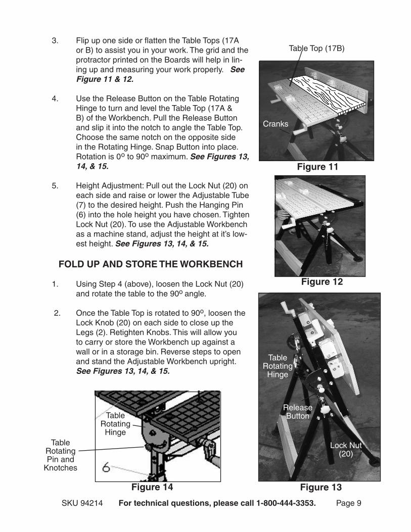
3. Flip up one side or flatten the Table Tops (17A or B) to assist you in your work. The grid and the protractor printed on the Boards will help in lin-ing up and measuring your work properly. See Figure 11 & 12.
4. Use the Release Button on the Table Rotating Hinge to turn and level the Table Top (17A & B) of the Workbench. Pull the Release Button and slip it into the notch to angle the Table Top. Choose the same notch on the opposite side in the Rotating Hinge. Snap Button into place. Rotation is 0o to 90o maximum. See Figures 13, 14, & 15.
5. Height Adjustment: Pull out the Lock Nut (20) on each side and raise or lower the Adjustable Tube (7) to the desired height. Push the Hanging Pin (6) into the hole height you have chosen. Tighten Lock Nut (20). To use the Adjustable Workbench as a machine stand, adjust the height at it’s low-est height. See Figures 13, 14, & 15.
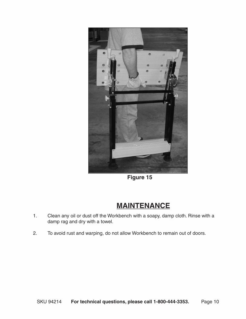
FOLD Up AND STORE THE WORKBENCH
1. Using Step 4 (above), loosen the Lock Nut (20) and rotate the table to the 90o angle.
2. Once the Table Top is rotated to 90o, loosen the Lock Knob (20) on each side to close up the Legs (2). Retighten Knobs. This will allow you to carry or store the Workbench up against a wall or in a storage bin. Reverse steps to open and stand the Adjustable Workbench upright. See Figures 13, 14, & 15.
Figure 12
Table Rotating Hinge
Table Rotating Pin and
Knotches
Figure 14
Figure 11
Table Top (17B)
Cranks
Figure 13
Release Button
Table Rotating Hinge
Lock Nut (20)
SKU 94214 For technical questions, please call 1-800-444-3353. Page 10
Figure 15
MAINTENANCE1. Clean any oil or dust off the Workbench with a soapy, damp cloth. Rinse with a
damp rag and dry with a towel.
2. To avoid rust and warping, do not allow Workbench to remain out of doors.
SKU 94214 For technical questions, please call 1-800-444-3353. Page 11
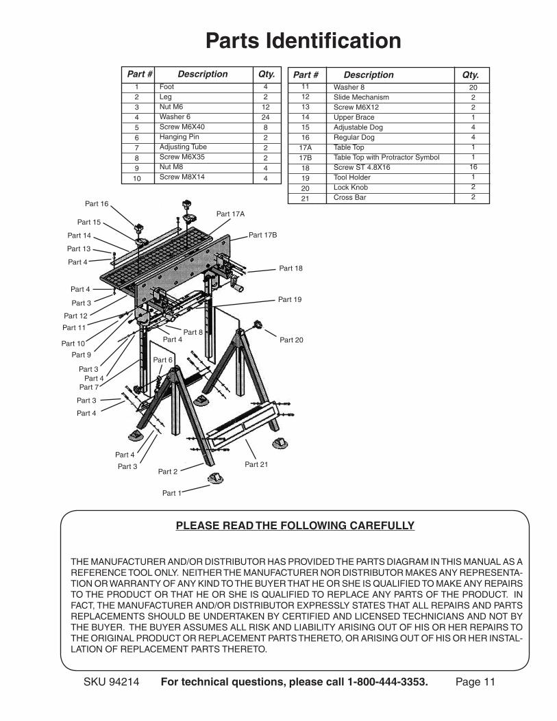
THE MANUFACTURER AND/OR DISTRIBUTOR HAS PROVIDED THE PARTS DIAGRAM IN THIS MANUAL AS A REFERENCE TOOL ONLY. NEITHER THE MANUFACTURER NOR DISTRIBUTOR MAKES ANY REPRESENTA-TION OR WARRANTY OF ANY KIND TO THE BUYER THAT HE OR SHE IS QUALIFIED TO MAKE ANY REPAIRS TO THE PRODUCT OR THAT HE OR SHE IS QUALIFIED TO REPLACE ANY PARTS OF THE PRODUCT. IN FACT, THE MANUFACTURER AND/OR DISTRIBUTOR EXPRESSLY STATES THAT ALL REPAIRS AND PARTS REPLACEMENTS SHOULD BE UNDERTAKEN BY CERTIFIED AND LICENSED TECHNICIANS AND NOT BY THE BUYER. THE BUYER ASSUMES ALL RISK AND LIABILITY ARISING OUT OF HIS OR HER REPAIRS TO THE ORIGINAL PRODUCT OR REPLACEMENT PARTS THERETO, OR ARISING OUT OF HIS OR HER INSTAL-LATION OF REPLACEMENT PARTS THERETO.
pLEASE READ THE FOLLOWING CAREFULLY
parts Identification
Part 21
Part 1
Part # Description Qty.Foot LegNut M6Washer 6Screw M6X40Hanging PinAdjusting TubeScrew M6X35Nut M8Screw M8X14
12345678910
421224822244
Washer 8Slide Mechanism Screw M6X12Upper BraceAdjustable DogRegular DogTable TopTable Top with Protractor SymbolScrew ST 4.8X16Tool Holder Lock KnobCross Bar
111213141516
17A17B18192021
20221441116122
Part # Description Qty.
Part 2Part 3
Part 4
Part 4
Part 3
Part 4
Part 20
Part 6
Part 19
Part 18
Part 17A Part 16
Part 15
Part 8Part 4
Part 9
Part 10
Part 11
Part 12
Part 3
Part 3
Part 4
Part 4
Part 13
Part 14
Part 7
Part 17B