heidenhain | tnc 640 | user’s manual for cycle programming...
TRANSCRIPT

TNC 640User’s manual for
cycle programming
NC Software
340590-06
340591-06
340595-06
English (en)
9/2015


Fundamentals

Fundamentals About this Manual
4 HEIDENHAIN | TNC 640 | User’s manual for cycle programming | 9/2015
About this Manual
The symbols used in this manual are described below.
This symbol indicates that important information
about the function described must be considered.
WARNING This symbol indicates a possibly
dangerous situation that may cause light injuries if
not avoided.
This symbol indicates that there is one or more
of the following risks when using the described
function:
Danger to workpiece
Danger to fixtures
Danger to tool
Danger to machine
Danger to operator
This symbol indicates that the described function
must be adapted by the machine tool builder. The
function described may therefore vary depending on
the machine.
This symbol indicates that you can find detailed
information about a function in another manual.
Would you like any changes, or have you found any
errors?
We are continuously striving to improve our documentation for you.
Please help us by sending your requests to the following e-mail
address: [email protected].

TNC model, software and features
HEIDENHAIN | TNC 640 | User’s manual for cycle programming | 9/2015 5
TNC model, software and features
This manual describes functions and features provided by TNCs as
of the following NC software numbers.
TNC model NC software number
TNC 640 340590-06
TNC 640 E 340591-06
TNC 640 Programming Station 340595-06
The suffix E indicates the export version of the TNC. The export
version of the TNC has the following limitations:
Simultaneous linear movement in up to 4 axes
The machine tool builder adapts the usable features of the TNC to
his machine by setting machine parameters. Some of the functions
described in this manual may therefore not be among the features
provided by the TNC on your machine tool.
TNC functions that may not be available on your machine include:
Tool measurement with the TT
Please contact your machine tool builder to become familiar with
the features of your machine.
Many machine manufacturers, as well as HEIDENHAIN, offer
programming courses for the TNCs. We recommend these courses
as an effective way of improving your programming skill and
sharing information and ideas with other TNC users.
User's Manual:
All TNC functions that have no connection with
cycles are described in the User's Manual of the TNC
640. Please contact HEIDENHAIN if you require a
copy of this User's Manual.
ID of User's Manual for conversational programming:
892903-xx.
ID of User’s Manual for DIN/ISO programming:
892909-xx.

Fundamentals TNC model, software and features
6 HEIDENHAIN | TNC 640 | User’s manual for cycle programming | 9/2015
Software options
The TNC 640 features various software options that can be enabled by your machine tool builder. Each option is to
be enabled separately and contains the following respective functions:
Additional Axis (options 0 to 7)
Additional axis Additional control loops 1 to 8
Advanced Function Set 1 (option 8)
Expanded functions Group 1 Machining with rotary tables
Cylindrical contours as if in two axes
Feed rate in distance per minute
Coordinate transformations:
Tilting the working plane
Interpolation:
Circle in 3 axes with tilted working plane (spatial arc)
Advanced Function Set 2 (option 9)
Expanded functions Group 2 3-D machining:
Motion control with minimum jerk
3-D tool compensation through surface normal vectors
Using the electronic handwheel to change the angle of the swivel
head during program run without affecting the position of the tool
point. (TCPM = Tool Center Point Management)
Keeping the tool normal to the contour
Tool radius compensation perpendicular to traversing direction and
tool direction
Interpolation:
Linear in 5 axes (subject to export permit)
HEIDENHAIN DNC (option 18)
Communication with external PC applications over COM component
Display Step (option 23)
Display step Input resolution:
Linear axes down to 0.01 µm
Rotary axes to 0.00001°
Dynamic Collision Monitoring – DCM (option 40)
Dynamic Collision Monitoring The machine manufacturer defines objects to be monitored
Warning in Manual operation
Program interrupt in Automatic operation
Includes monitoring of 5-axis movements

TNC model, software and features
HEIDENHAIN | TNC 640 | User’s manual for cycle programming | 9/2015 7
DXF Converter (option 42)
DXF converter Supported DXF format: AC1009 (AutoCAD R12)
Adoption of contours and point patterns
Simple and convenient specification of reference points
Select graphical features of contour sections from conversational
programs
Adaptive Feed Control – AFC (option 45)
Adaptive Feed Control Recording the actual spindle power by means of a teach-in cut
Defining the limits of automatic feed rate control
Fully automatic feed control during program run
KinematicsOpt (option 48)
Optimizing the machine
kinematicsBackup/restore active kinematics
Test active kinematics
Optimize active kinematics
Mill-Turning (option 50)
Milling and turning modes Functions:
Switching between Milling/Turning mode of operation
Constant surface speed
Tool-tip radius compensation
Turning cycles
Extended Tool Management (option 93)
Extended tool management Python-based
Advanced Spindle Interpolation (option number 96)
Interpolating spindle Interpolation turning:
Cycle 880: Gear hobbing
Cycle 291: Interpolation turning, coupling
Cycle 292: Interpolation turning, contour finishing
Spindle Synchronism (option 131)
Spindle synchronization Synchronization of milling spindle and turning spindle
Remote Desktop Manager (option 133)
Remote operation of external
computer unitsWindows on a separate computer unit
Incorporated in the TNC interface
Synchronizing Functions (option 135)
Synchronization functions Real Time Coupling – RTC:
Coupling of axes

Fundamentals TNC model, software and features
8 HEIDENHAIN | TNC 640 | User’s manual for cycle programming | 9/2015
Visual Setup Control – VSC (option number 136)
Camera-based monitoring of the
setup situationRecord the setup situation with a HEIDENHAIN camera system
Visual comparison of planned and actual status in the workspace
Cross Talk Compensation – CTC (option number 141)
Compensation of axis couplings Determination of dynamically caused position deviation through axis
acceleration
Compensation of the TCP (Tool Center Point)
Position Adaptive Control – PAC (option 142)
Adaptive position control Changing of the control parameters depending on the position of
the axes in the working space
Changing of the control parameters depending on the speed or
acceleration of an axis
Load Adaptive Control – LAC (option 143)
Adaptive load control Automatic determination of workpiece weight and frictional forces
Changing of control parameters depending on the actual mass of
the workpiece
Active Chatter Control – ACC (option number 145)
Active chatter control Fully automatic function for chatter control during machining
Active Vibration Damping – AVD (option number 146)
Active vibration damping Damping of machine oscillations to improve the workpiece surface

TNC model, software and features
HEIDENHAIN | TNC 640 | User’s manual for cycle programming | 9/2015 9
Feature Content Level (upgrade functions)
Along with software options, significant further improvements
of the TNC software are managed via the Feature Content Level
upgrade functions. Functions subject to the FCL are not available
simply by updating the software on your TNC.
All upgrade functions are available to you without
surcharge when you receive a new machine.
Upgrade functions are identified in the manual with FCL n, where nindicates the sequential number of the feature content level.
You can purchase a code number in order to permanently enable
the FCL functions. For more information, contact your machine tool
builder or HEIDENHAIN.
Intended place of operation
The TNC complies with the limits for a Class A device in
accordance with the specifications in EN 55022, and is intended for
use primarily in industrially-zoned areas.
Legal information
This product uses open source software. Further information is
available on the control under
Programming and Editing operating mode
MOD function
LICENSE INFO softkey

Fundamentals Optional parameters
10 HEIDENHAIN | TNC 640 | User’s manual for cycle programming | 9/2015
Optional parameters
The comprehensive cycle package is continuously further
developed by HEIDENHAIN. Every new software version thus
may also introduce new Q parameters for cycles. These new Q
parameters are optional parameters, some of which have not been
available in previous software versions. Within a cycle, they are
always provided at the end of the cycle definition. You will find an
overview of the optional Q parameters that have been added with
this software version in the "New and changed cycle functions of
software 34059x-05" section. You can choose whether to define
optional Q parameters or delete them with the NO ENT key. You
can also adopt the default value. If you have accidentally deleted an
optional Q parameter or if you would like to extend cycles in your
existing programs after a software update, you can include optional
Q parameters in cycles when needed. The following steps describe
how this is done:
To insert optional Q parameters in existing programs:
Call the cycle definition
Press the right arrow key until the new Q parameters are
displayed
Apply the default value or enter a value
To transfer the new Q parameter, exit the menu by pressing
the right arrow key once again or by pressing END
If you do not wish to apply the new Q parameter, press the
NO ENT key
Compatibility
The majority of part programs created on older HEIDENHAIN
contouring controls (TNC 150 B and higher) can be executed with
this new software version of the TNC 640. Even if new, optional
parameters ("Optional parameters") have been added to existing
cycles, you can normally continue running your programs as usual.
This is achieved by using the stored default value. The other way
round, if a program created with a new software version is to be
run on an older control, you can delete the respective optional
Q parameters from the cycle definition with the NO ENT key.
In this way you can ensure that the program will be downward
compatible. If NC blocks contain invalid elements, the TNC will
mark them as ERROR blocks when the file is opened.

New cycle functions of software
HEIDENHAIN | TNC 640 | User’s manual for cycle programming | 9/2015 11
New cycle functions of software 34059x-04
The character set of the fixed cycle 225 Engraving was
expanded by more characters and the diameter sign see
"ENGRAVING (Cycle 225, DIN/ISO: G225)", page 309
New machining cycle 275 Trochoidal milling see "TROCHOIDAL
SLOT (Cycle 275, DIN ISO G275)", page 219
New machining cycle 233 Face milling see "FACE MILLING
(Cycle 233, DIN/ISO: G233)", page 174
In Cycle 205 Universal Pecking you can now use parameter
Q208 to define a feed rate for retraction see "Cycle parameters",
page 94
In the thread milling cycles 26x an approaching feed rate was
introduced see "Cycle parameters", page 121
The parameter Q305 NUMBER IN TABLE was added to Cycle
404 see "Cycle parameters", page 472
In the drilling cycles 200, 203 and 205 the parameter Q395
DEPTH REFERENCE was introduced in order to evaluate the T
ANGLE see "Cycle parameters", page 94
Cycle 241 SINGLE-LIP DEEP HOLE DRILLING was expanded
by several input parameters see "SINGLE-LIP DEEP-HOLE
DRILLING (Cycle 241, DIN/ISO: G241)", page 99
The probing cycle 4 MEASURING IN 3-D was introduced see
"MEASURING IN 3-D (Cycle 4)", page 583
Fundamentals New and changed cycle functions of software
12 HEIDENHAIN | TNC 640 | User’s manual for cycle programming | 9/2015
New and changed cycle functions of
software 34059x-05
New Cycle 880 GEAR HOBBING (software option 50), see
"GEAR HOBBING (Cycle 880, DIN/ISO: G880)", page 435
New Cycle 292 CONTOUR FINISHING TURNING
INTERPOLATION (software option 96), see "CONTOUR
TURNING INTERPOLATION (Cycle 292, DIN/ISO: G292,
software option 96)", page 294
New Cycle 291 COUPLING TURNING INTERPOLATION
(software option 96), see "COUPLING INTERPOLATION
TURNING (cycle 291, DIN/ISO: G291, software option 96)",
page 303
New Load Adaptive Control (LAC) cycle for the load-dependent
adaptation of control parameters (software option 143), see
"ASCERTAIN THE LOAD (Cycle 239, DIN/ISO: G239, software
option 143)", page 318
Cycle 270: CONTOUR TRAIN DATA was added to the cycle
package (software option 19), see "CONTOUR TRAIN DATA
(Cycle 270, DIN/ISO: G270)", page 218
Cycle 39 CYLINDER SURFACE (software option 1) Contour was
added to the cycle package, see "CYLINDER SURFACE (Cycle
39, DIN/ISO: G139, software option 1)", page 240
The character set of the fixed cycle 225 Engraving was
expanded by the CE, ß and @ characters and the system time,
see "ENGRAVING (Cycle 225, DIN/ISO: G225)", page 309
Cycles 252 to 254 were expanded by the optional parameter
Q439, see "Cycle parameters", page 150
Cycle 22 was expanded by the optional parameters Q401 and
Q404, see "ROUGHING (Cycle 22, DIN/ISO: G122)", page 207
Cycles 841, 842, 851 and 852 were expanded by the plunging
feed rate Q488, see "Cycle parameters", page 382
Cycle 484 was expanded by the optional parameter Q536, see
"Calibrating the wireless TT 449 (Cycle 484, DIN/ISO: G484,
DIN/ISO: G484)", page 657
Eccentric turning with Cycle 800 is possible with option 50, see
"ADAPT ROTARY COORDINATE SYSTEM(Cycle 800, DIN/ISO:
G800)", page 332

New and changed cycle functions of software
HEIDENHAIN | TNC 640 | User’s manual for cycle programming | 9/2015 13
New and changed cycle functions of
software 34059x-06
New cycle 258 POLYGON STUD see "CIRCULAR STUD (cycle
258, DIN/ISO: G258)", page 169
New cycles 600 and 601 for Visual Setup Control (software
option 136), see "Camera-based monitoring of the setup
situation VSC (option number136)", page 596
Cycle 291 COUPLING TURNING INTERPOLATION (software
option 96), was expanded by parameter Q561, see "COUPLING
INTERPOLATION TURNING (cycle 291, DIN/ISO: G291,
software option 96)", page 303
Cycles 421, 422 and 427 were expanded by the parameters
Q498 and Q531, see "MEASURE HOLE (Cycle 421, DIN/ISO:
G421)", page 545
In cycle 247: SET DATUM, the datum point can be selected
from the preset table, see "DATUM SETTING (Cycle 247, DIN/
ISO: G247)", page 269
In the cycles 200 and 203 the behavior of the dwell time was
adjusted, see "UNIVERSAL DRILLING (Cycle 203, DIN/ISO:
G203)", page 86
Cycle 205 performs deburring on the coordinate surface,
see "UNIVERSAL PECKING (Cycle 205, DIN/ISO: G205)",
page 92
In SL cycles, M110 is now accounted for compensated inner
arcs if activated during machining see "SL Cycles", page 196
Fundamentals New and changed cycle functions of software
14 HEIDENHAIN | TNC 640 | User’s manual for cycle programming | 9/2015

HEIDENHAIN | TNC 640 | User’s manual for cycle programming | 9/2015 15
Contents
1 Fundamentals / Overviews............................................................................................................51
2 Using Fixed Cycles......................................................................................................................... 55
3 Fixed Cycles: Drilling......................................................................................................................75
4 Fixed Cycles: Tapping / Thread Milling...................................................................................... 105
5 Fixed Cycles: Pocket Milling / Stud Milling / Slot Milling........................................................141
6 Fixed Cycles: Pattern Definitions................................................................................................ 185
7 Fixed Cycles: Contour Pocket......................................................................................................195
8 Fixed Cycles: Cylindrical Surface................................................................................................ 229
9 Fixed Cycles: Contour Pocket with Contour Formula...............................................................247
10 Cycles: Coordinate Transformations........................................................................................... 261
11 Cycles: Special Functions............................................................................................................ 285
12 Cycles: Turning..............................................................................................................................325
13 Using Touch Probe Cycles........................................................................................................... 447
14 Touch Probe Cycles: Automatic Measurement of Workpiece Misalignment.......................... 457
15 Touch Probe Cycles: Automatic Datum Setting........................................................................ 479
16 Touch Probe Cycles: Automatic Workpiece Inspection.............................................................533
17 Touch Probe Cycles: Special Functions......................................................................................579
18 Visual Setup Control VSC (software option 136)..................................................................... 595
19 Touch Probe Cycles: Automatic Kinematics Measurement......................................................617
20 Touch Probe Cycles: Automatic Tool Measurement..................................................................649
21 Tables of Cycles............................................................................................................................ 665

Contents
16 HEIDENHAIN | TNC 640 | User’s manual for cycle programming | 9/2015

HEIDENHAIN | TNC 640 | User’s manual for cycle programming | 9/2015 17
1 Fundamentals / Overviews............................................................................................................51
1.1 Introduction............................................................................................................................................52
1.2 Available Cycle Groups.........................................................................................................................53
Overview of fixed cycles........................................................................................................................ 53
Overview of touch probe cycles.............................................................................................................54

Contents
18 HEIDENHAIN | TNC 640 | User’s manual for cycle programming | 9/2015
2 Using Fixed Cycles......................................................................................................................... 55
2.1 Working with fixed cycles....................................................................................................................56
Machine-specific cycles...........................................................................................................................56
Defining a cycle using soft keys.............................................................................................................57
Defining a cycle using the GOTO function............................................................................................. 57
Calling a cycle......................................................................................................................................... 58
2.2 Program defaults for cycles................................................................................................................. 60
Overview................................................................................................................................................. 60
Entering GLOBAL DEF............................................................................................................................60
Using GLOBAL DEF information............................................................................................................ 61
Global data valid everywhere..................................................................................................................62
Global data for drilling operations........................................................................................................... 62
Global data for milling operations with pocket cycles 25x..................................................................... 62
Global data for milling operations with contour cycles...........................................................................63
Global data for positioning behavior....................................................................................................... 63
Global data for probing functions........................................................................................................... 63
2.3 PATTERN DEF pattern definition......................................................................................................... 64
Application............................................................................................................................................... 64
Entering PATTERN DEF.......................................................................................................................... 65
Using PATTERN DEF...............................................................................................................................65
Defining individual machining positions.................................................................................................. 66
Defining a single row..............................................................................................................................66
Defining a single pattern.........................................................................................................................67
Defining individual frames.......................................................................................................................68
Defining a full circle................................................................................................................................ 69
Defining a pitch circle............................................................................................................................. 70
2.4 Point tables............................................................................................................................................ 71
Application............................................................................................................................................... 71
Creating a point table............................................................................................................................. 71
Hiding single points from the machining process.................................................................................. 72
Selecting a point table in the program................................................................................................... 72
Calling a cycle in connection with point tables...................................................................................... 73

HEIDENHAIN | TNC 640 | User’s manual for cycle programming | 9/2015 19
3 Fixed Cycles: Drilling......................................................................................................................75
3.1 Fundamentals........................................................................................................................................ 76
Overview................................................................................................................................................. 76
3.2 CENTERING (Cycle 240, DIN/ISO: G240)............................................................................................ 77
Cycle run................................................................................................................................................. 77
Please note while programming:............................................................................................................77
Cycle parameters.................................................................................................................................... 78
3.3 DRILLING (Cycle 200)............................................................................................................................79
Cycle run................................................................................................................................................. 79
Please note while programming:............................................................................................................79
Cycle parameters.................................................................................................................................... 80
3.4 REAMING (Cycle 201, DIN/ISO: G201)................................................................................................ 81
Cycle run................................................................................................................................................. 81
Please note while programming:............................................................................................................81
Cycle parameters.................................................................................................................................... 82
3.5 BORING (Cycle 202, DIN/ISO: G202)...................................................................................................83
Cycle run................................................................................................................................................. 83
Please note while programming:............................................................................................................84
Cycle parameters.................................................................................................................................... 85
3.6 UNIVERSAL DRILLING (Cycle 203, DIN/ISO: G203)...........................................................................86
Cycle run................................................................................................................................................. 86
Please note while programming:............................................................................................................86
Cycle parameters.................................................................................................................................... 87
3.7 BACK BORING (Cycle 204, DIN/ISO: G204)........................................................................................89
Cycle run................................................................................................................................................. 89
Please note while programming:............................................................................................................90
Cycle parameters.................................................................................................................................... 91
3.8 UNIVERSAL PECKING (Cycle 205, DIN/ISO: G205)........................................................................... 92
Cycle run................................................................................................................................................. 92
Please note while programming:............................................................................................................93
Cycle parameters.................................................................................................................................... 94

Contents
20 HEIDENHAIN | TNC 640 | User’s manual for cycle programming | 9/2015
3.9 BORE MILLING (Cycle 208).................................................................................................................. 96
Cycle run................................................................................................................................................. 96
Please note while programming:............................................................................................................97
Cycle parameters.................................................................................................................................... 98
3.10 SINGLE-LIP DEEP-HOLE DRILLING (Cycle 241, DIN/ISO: G241)....................................................... 99
Cycle run................................................................................................................................................. 99
Please note while programming:............................................................................................................99
Cycle parameters.................................................................................................................................. 100
3.11 Programming Examples..................................................................................................................... 102
Example: Drilling cycles........................................................................................................................ 102
Example: Using drilling cycles in connection with PATTERN DEF........................................................103

HEIDENHAIN | TNC 640 | User’s manual for cycle programming | 9/2015 21
4 Fixed Cycles: Tapping / Thread Milling...................................................................................... 105
4.1 Fundamentals...................................................................................................................................... 106
Overview............................................................................................................................................... 106
4.2 TAPPING with a floating tap holder (Cycle 206, DIN/ISO: G206)...................................................107
Cycle run............................................................................................................................................... 107
Please note while programming:..........................................................................................................108
Cycle parameters.................................................................................................................................. 109
4.3 RIGID TAPPING without a floating tap holder (Cycle 207, DIN/ISO: G207)................................... 110
Cycle run............................................................................................................................................... 110
Please note while programming:..........................................................................................................111
Cycle parameters.................................................................................................................................. 112
Retracting after a program interruption................................................................................................ 112
4.4 TAPPING WITH CHIP BREAKING (Cycle 209, DIN/ISO: G209)........................................................ 113
Cycle run............................................................................................................................................... 113
Please note while programming:..........................................................................................................114
Cycle parameters.................................................................................................................................. 115
4.5 Fundamentals of Thread Milling....................................................................................................... 117
Prerequisites..........................................................................................................................................117
4.6 THREAD MILLING (Cycle 262, DIN/ISO: G262).................................................................................119
Cycle run............................................................................................................................................... 119
Please note while programming:..........................................................................................................120
Cycle parameters.................................................................................................................................. 121
4.7 THREAD MILLING/COUNTERSINKING (Cycle 263, DIN/ISO:G263)................................................122
Cycle run............................................................................................................................................... 122
Please note while programming:..........................................................................................................123
Cycle parameters.................................................................................................................................. 124
4.8 THREAD DRILLING/MILLING (Cycle 264, DIN/ISO: G264).............................................................. 126
Cycle run............................................................................................................................................... 126
Please note while programming:..........................................................................................................127
Cycle parameters.................................................................................................................................. 128

Contents
22 HEIDENHAIN | TNC 640 | User’s manual for cycle programming | 9/2015
4.9 HELICAL THREAD DRILLING/MILLING (Cycle 265, DIN/ISO: G265)...............................................130
Cycle run............................................................................................................................................... 130
Please note while programming:..........................................................................................................131
Cycle parameters.................................................................................................................................. 132
4.10 OUTSIDE THREAD MILLING (Cycle 267, DIN/ISO: G267)................................................................ 134
Cycle run............................................................................................................................................... 134
Please note while programming:..........................................................................................................135
Cycle parameters.................................................................................................................................. 136
4.11 Programming Examples..................................................................................................................... 138
Example: Thread milling........................................................................................................................138

HEIDENHAIN | TNC 640 | User’s manual for cycle programming | 9/2015 23
5 Fixed Cycles: Pocket Milling / Stud Milling / Slot Milling........................................................141
5.1 Fundamentals...................................................................................................................................... 142
Overview............................................................................................................................................... 142
5.2 RECTANGULAR POCKET (Cycle 251, DIN/ISO: G251)..................................................................... 143
Cycle run............................................................................................................................................... 143
Please note while programming:..........................................................................................................144
Cycle parameters.................................................................................................................................. 145
5.3 CIRCULAR POCKET (Cycle 252, DIN/ISO: G252)..............................................................................147
Cycle run............................................................................................................................................... 147
Please note while programming:..........................................................................................................149
Cycle parameters.................................................................................................................................. 150
5.4 SLOT MILLING (Cycle 253, DIN/ISO: G253)......................................................................................152
Cycle run............................................................................................................................................... 152
Please note while programming:..........................................................................................................153
Cycle parameters.................................................................................................................................. 154
5.5 CIRCULAR SLOT (Cycle 254, DIN/ISO: G254)...................................................................................156
Cycle run............................................................................................................................................... 156
Please note while programming:..........................................................................................................157
Cycle parameters.................................................................................................................................. 158
5.6 RECTANGULAR STUD (Cycle 256, DIN/ISO: G256)......................................................................... 161
Cycle run............................................................................................................................................... 161
Please note while programming:..........................................................................................................162
Cycle parameters.................................................................................................................................. 163
5.7 CIRCULAR STUD (Cycle 257, DIN/ISO: G257)...................................................................................165
Cycle run............................................................................................................................................... 165
Please note while programming:..........................................................................................................166
Cycle parameters.................................................................................................................................. 167
5.8 CIRCULAR STUD (cycle 258, DIN/ISO: G258)...................................................................................169
Cycle run............................................................................................................................................... 169
Please note while programming:..........................................................................................................170
Cycle parameters.................................................................................................................................. 171

Contents
24 HEIDENHAIN | TNC 640 | User’s manual for cycle programming | 9/2015
5.9 FACE MILLING (Cycle 233, DIN/ISO: G233)...................................................................................... 174
Cycle run............................................................................................................................................... 174
Please note while programming:..........................................................................................................178
Cycle parameters.................................................................................................................................. 179
5.10 Programming Examples..................................................................................................................... 182
Example: Milling pockets, studs and slots........................................................................................... 182

HEIDENHAIN | TNC 640 | User’s manual for cycle programming | 9/2015 25
6 Fixed Cycles: Pattern Definitions................................................................................................ 185
6.1 Fundamentals...................................................................................................................................... 186
Overview............................................................................................................................................... 186
6.2 POLAR PATTERN (Cycle 220, DIN/ISO: G220).................................................................................. 187
Cycle run............................................................................................................................................... 187
Please note while programming:..........................................................................................................187
Cycle parameters.................................................................................................................................. 188
6.3 LINEAR PATTERN (Cycle 221, DIN/ISO: G221)................................................................................. 190
Cycle run............................................................................................................................................... 190
Please note while programming:..........................................................................................................190
Cycle parameters.................................................................................................................................. 191
6.4 Programming Examples..................................................................................................................... 192
Example: Polar hole patterns................................................................................................................ 192
Contents
26 HEIDENHAIN | TNC 640 | User’s manual for cycle programming | 9/2015
7 Fixed Cycles: Contour Pocket......................................................................................................195
7.1 SL Cycles..............................................................................................................................................196
Fundamentals........................................................................................................................................ 196
Overview............................................................................................................................................... 197
7.2 CONTOUR (Cycle 14, DIN/ISO: G37).................................................................................................198
Please note while programming:..........................................................................................................198
Cycle parameters.................................................................................................................................. 198
7.3 Superimposed contours..................................................................................................................... 199
Fundamentals........................................................................................................................................ 199
Subprograms: overlapping pockets....................................................................................................... 199
Area of inclusion................................................................................................................................... 200
Area of exclusion.................................................................................................................................. 201
Area of intersection.............................................................................................................................. 202
7.4 CONTOUR DATA (Cycle 20, DIN/ISO: G120).....................................................................................203
Please note while programming:..........................................................................................................203
Cycle parameters.................................................................................................................................. 204
7.5 PILOT DRILLING (Cycle 21, DIN/ISO: G121)..................................................................................... 205
Cycle run............................................................................................................................................... 205
Please note while programming:..........................................................................................................206
Cycle parameters.................................................................................................................................. 206
7.6 ROUGHING (Cycle 22, DIN/ISO: G122)............................................................................................. 207
Cycle run............................................................................................................................................... 207
Please note while programming:..........................................................................................................208
Cycle parameters.................................................................................................................................. 209
7.7 FLOOR FINISHING (Cycle 23, DIN/ISO: G123)..................................................................................211
Cycle run............................................................................................................................................... 211
Please note while programming:..........................................................................................................212
Cycle parameters.................................................................................................................................. 212
7.8 SIDE FINISHING (Cycle 24, DIN/ISO: G124)..................................................................................... 213
Cycle run............................................................................................................................................... 213
Please note while programming:..........................................................................................................214
Cycle parameters.................................................................................................................................. 215

HEIDENHAIN | TNC 640 | User’s manual for cycle programming | 9/2015 27
7.9 CONTOUR TRAIN (Cycle 25, DIN/ISO: G125)...................................................................................216
Cycle run............................................................................................................................................... 216
Please note while programming:..........................................................................................................216
Cycle parameters.................................................................................................................................. 217
7.10 CONTOUR TRAIN DATA (Cycle 270, DIN/ISO: G270).......................................................................218
Please note while programming:..........................................................................................................218
Cycle parameters.................................................................................................................................. 218
7.11 TROCHOIDAL SLOT (Cycle 275, DIN ISO G275)............................................................................... 219
Cycle run............................................................................................................................................... 219
Please note while programming:..........................................................................................................220
Cycle parameters.................................................................................................................................. 221
7.12 Programming Examples..................................................................................................................... 223
Example: Roughing-out and fine-roughing a pocket............................................................................. 223
Example: Pilot drilling, roughing-out and finishing overlapping contours..............................................225
Example: Contour train......................................................................................................................... 227

Contents
28 HEIDENHAIN | TNC 640 | User’s manual for cycle programming | 9/2015
8 Fixed Cycles: Cylindrical Surface................................................................................................ 229
8.1 Fundamentals...................................................................................................................................... 230
Overview of cylindrical surface cycles..................................................................................................230
8.2 CYLINDER SURFACE (Cycle 27, DIN/ISO: G127, software option 1)............................................... 231
Cycle run............................................................................................................................................... 231
Please note while programming:..........................................................................................................232
Cycle parameters.................................................................................................................................. 233
8.3 CYLINDER SURFACE Slot milling (Cycle 28, DIN/ISO: G128, software option 1)......................... 234
Cycle run............................................................................................................................................... 234
Please note while programming:..........................................................................................................235
Cycle parameters.................................................................................................................................. 236
8.4 CYLINDER SURFACE Ridge milling (Cycle 29, DIN/ISO: G129, software option 1).......................237
Cycle run............................................................................................................................................... 237
Please note while programming:..........................................................................................................238
Cycle parameters.................................................................................................................................. 239
8.5 CYLINDER SURFACE (Cycle 39, DIN/ISO: G139, software option 1)..............................................240
Cycle run............................................................................................................................................... 240
Please note while programming:..........................................................................................................241
Cycle parameters.................................................................................................................................. 242
8.6 Programming Examples..................................................................................................................... 243
Example: Cylinder surface with Cycle 27............................................................................................. 243
Example: Cylinder surface with Cycle 28............................................................................................. 245

HEIDENHAIN | TNC 640 | User’s manual for cycle programming | 9/2015 29
9 Fixed Cycles: Contour Pocket with Contour Formula...............................................................247
9.1 SL cycles with complex contour formula.........................................................................................248
Fundamentals........................................................................................................................................ 248
Selecting a program with contour definitions.......................................................................................250
Defining contour descriptions............................................................................................................... 250
Entering a complex contour formula.................................................................................................... 251
Superimposed contours........................................................................................................................ 252
Contour machining with SL Cycles.......................................................................................................254
Example: Roughing and finishing superimposed contours with the contour formula...........................255
9.2 SL cycles with simple contour formula............................................................................................258
Fundamentals........................................................................................................................................ 258
Entering a simple contour formula....................................................................................................... 260
Contour machining with SL Cycles.......................................................................................................260

Contents
30 HEIDENHAIN | TNC 640 | User’s manual for cycle programming | 9/2015
10 Cycles: Coordinate Transformations........................................................................................... 261
10.1 Fundamentals...................................................................................................................................... 262
Overview............................................................................................................................................... 262
Effect of coordinate transformations.................................................................................................... 262
10.2 DATUM SHIFT (Cycle 7, DIN/ISO: G54)............................................................................................. 263
Effect..................................................................................................................................................... 263
Cycle parameters.................................................................................................................................. 263
10.3 DATUM SHIFT with datum tables (Cycle 7, DIN/ISO: G53)............................................................. 264
Effect..................................................................................................................................................... 264
Please note while programming:..........................................................................................................265
Cycle parameters.................................................................................................................................. 265
Selecting a datum table in the part program........................................................................................266
Edit the datum table in the Programming mode of operation..............................................................266
Configuring the datum table................................................................................................................. 268
To exit a datum table............................................................................................................................ 268
Status displays...................................................................................................................................... 268
10.4 DATUM SETTING (Cycle 247, DIN/ISO: G247)..................................................................................269
Effect..................................................................................................................................................... 269
Please note before programming:........................................................................................................ 269
Cycle parameters.................................................................................................................................. 269
Status displays...................................................................................................................................... 269
10.5 MIRRORING (Cycle 8, DIN/ISO: G28)................................................................................................ 270
Effect..................................................................................................................................................... 270
Please note while programming:..........................................................................................................271
Cycle parameters.................................................................................................................................. 271
10.6 ROTATION (Cycle 10, DIN/ISO: G73)................................................................................................. 272
Effect..................................................................................................................................................... 272
Please note while programming:..........................................................................................................273
Cycle parameters.................................................................................................................................. 273
10.7 SCALING (Cycle 11, DIN/ISO: G72.................................................................................................... 274
Effect..................................................................................................................................................... 274
Cycle parameters.................................................................................................................................. 274

HEIDENHAIN | TNC 640 | User’s manual for cycle programming | 9/2015 31
10.8 AXIS-SPECIFIC SCALING (Cycle 26)..................................................................................................275
Effect..................................................................................................................................................... 275
Please note while programming:..........................................................................................................275
Cycle parameters.................................................................................................................................. 276
10.9 WORKING PLANE (Cycle 19, DIN/ISO: G80, software option 1).....................................................277
Effect..................................................................................................................................................... 277
Please note while programming:..........................................................................................................278
Cycle parameters.................................................................................................................................. 278
Resetting............................................................................................................................................... 279
Positioning the axes of rotation............................................................................................................ 279
Position display in the tilted system.....................................................................................................280
Workspace monitoring.......................................................................................................................... 280
Positioning in a tilted coordinate system..............................................................................................281
Combining coordinate transformation cycles........................................................................................281
Procedure for working with Cycle 19 WORKING PLANE..................................................................... 282
10.10 Programming Examples..................................................................................................................... 283
Example: Coordinate transformation cycles......................................................................................... 283

Contents
32 HEIDENHAIN | TNC 640 | User’s manual for cycle programming | 9/2015
11 Cycles: Special Functions............................................................................................................ 285
11.1 Fundamentals...................................................................................................................................... 286
Overview............................................................................................................................................... 286
11.2 DWELL TIME (Cycle 9, DIN/ISO: G04)...............................................................................................287
Function................................................................................................................................................. 287
Cycle parameters.................................................................................................................................. 287
11.3 PROGRAM CALL (Cycle 12, DIN/ISO: G39).......................................................................................288
Cycle function........................................................................................................................................288
Please note while programming:..........................................................................................................288
Cycle parameters.................................................................................................................................. 289
11.4 SPINDLE ORIENTATION (Cycle 13, DIN/ISO: G36)...........................................................................290
Cycle function........................................................................................................................................290
Please note while programming:..........................................................................................................290
Cycle parameters.................................................................................................................................. 290
11.5 TOLERANCE (Cycle 32, DIN/ISO: G62)..............................................................................................291
Cycle function........................................................................................................................................291
Influences of the geometry definition in the CAM system..................................................................291
Please note while programming:..........................................................................................................292
Cycle parameters.................................................................................................................................. 293
11.6 CONTOUR TURNING INTERPOLATION (Cycle 292, DIN/ISO: G292, software option 96)............ 294
Cycle run............................................................................................................................................... 294
Please note while programming:..........................................................................................................296
Cycle parameters.................................................................................................................................. 298
Machining variants.................................................................................................................................299
Defining the tool................................................................................................................................... 301
11.7 COUPLING INTERPOLATION TURNING (cycle 291, DIN/ISO: G291, software option 96)............ 303
Cycle run............................................................................................................................................... 303
Please note while programming:..........................................................................................................303
Cycle parameters.................................................................................................................................. 305
Defining the tool................................................................................................................................... 306

HEIDENHAIN | TNC 640 | User’s manual for cycle programming | 9/2015 33
11.8 ENGRAVING (Cycle 225, DIN/ISO: G225)..........................................................................................309
Cycle run............................................................................................................................................... 309
Please note while programming:..........................................................................................................309
Cycle parameters.................................................................................................................................. 310
Allowed engraving characters............................................................................................................... 311
Characters that cannot be printed........................................................................................................ 311
Engraving system variables...................................................................................................................312
11.9 FACE MILLING (Cycle 232, DIN/ISO: G232)...................................................................................... 313
Cycle run............................................................................................................................................... 313
Please note while programming:..........................................................................................................315
Cycle parameters.................................................................................................................................. 316
11.10 ASCERTAIN THE LOAD (Cycle 239, DIN/ISO: G239, software option 143).................................... 318
Cycle run............................................................................................................................................... 318
Please note while programming:..........................................................................................................319
Cycle parameters.................................................................................................................................. 319
11.11 Programming examples..................................................................................................................... 320
Example: Interpolation Turning Cycle 291.............................................................................................320
Example: Interpolation Turning Cycle 292.............................................................................................322

Contents
34 HEIDENHAIN | TNC 640 | User’s manual for cycle programming | 9/2015
12 Cycles: Turning..............................................................................................................................325
12.1 Turning Cycles (software option 50)..................................................................................................326
Overview............................................................................................................................................... 326
Working with turning cycles................................................................................................................. 329
Blank form update (FUNCTION TURNDATA)........................................................................................ 330
12.2 ADAPT ROTARY COORDINATE SYSTEM (Cycle 800, DIN/ISO: G800)............................................ 332
Application............................................................................................................................................. 332
Effect..................................................................................................................................................... 335
Please note while programming:..........................................................................................................335
Cycle parameters.................................................................................................................................. 336
12.3 RESET ROTARY COORDINATE SYSTEM (Cycle 801, DIN/ISO: G801)............................................. 338
Please note while programming:..........................................................................................................338
Effect..................................................................................................................................................... 338
Cycle parameters.................................................................................................................................. 338
12.4 Fundamentals of Turning Cycles....................................................................................................... 339
12.5 TURN SHOULDER LONGITUDINAL (Cycle 811, DIN/ISO: G811).....................................................340
Application............................................................................................................................................. 340
Roughing cycle run................................................................................................................................340
Finishing cycle run................................................................................................................................ 341
Please note while programming:..........................................................................................................341
Cycle parameters.................................................................................................................................. 342
12.6 TURN SHOULDER LONGITUDINAL EXTENDED (Cycle 812, DIN/ISO: G812)................................343
Application............................................................................................................................................. 343
Roughing cycle run................................................................................................................................343
Finishing cycle run................................................................................................................................ 344
Please note while programming:..........................................................................................................344
Cycle parameters.................................................................................................................................. 345
12.7 TURN, LONGITUDINAL PLUNGE (Cycle 813, DIN/ISO: G813)........................................................ 347
Application............................................................................................................................................. 347
Roughing cycle run................................................................................................................................347
Finishing cycle run................................................................................................................................ 348
Please note while programming:..........................................................................................................348
Cycle parameters.................................................................................................................................. 349
HEIDENHAIN | TNC 640 | User’s manual for cycle programming | 9/2015 35
12.8 TURN, LONGITUDINAL PLUNGE EXTENDED (Cycle 814, DIN/ISO: G814)....................................350
Application............................................................................................................................................. 350
Roughing cycle run................................................................................................................................350
Finishing cycle run................................................................................................................................ 351
Please note while programming:..........................................................................................................351
Cycle parameters.................................................................................................................................. 352
12.9 TURN CONTOUR LONGITUDINAL (Cycle 810, DIN/ISO: G810)...................................................... 354
Application............................................................................................................................................. 354
Roughing cycle run................................................................................................................................354
Finishing cycle run................................................................................................................................ 355
Please note while programming:..........................................................................................................355
Cycle parameters.................................................................................................................................. 356
12.10TURN CONTOUR-PARALLEL (Cycle 815, DIN/ISO: G815)............................................................... 358
Application............................................................................................................................................. 358
Roughing cycle run................................................................................................................................358
Finishing cycle run................................................................................................................................ 359
Please note while programming:..........................................................................................................359
Cycle parameters.................................................................................................................................. 360
12.11 TURN SHOULDER FACE (Cycle 821, DIN/ISO: G821)...................................................................... 362
Application............................................................................................................................................. 362
Roughing cycle run................................................................................................................................362
Finishing cycle run................................................................................................................................ 363
Please note while programming:..........................................................................................................363
Cycle parameters.................................................................................................................................. 364
12.12TURN SHOULDER FACE EXTENDED (Cycle 822, DIN/ISO: G822)..................................................365
Application............................................................................................................................................. 365
Roughing cycle run................................................................................................................................365
Finishing cycle run................................................................................................................................ 366
Please note while programming:..........................................................................................................366
Cycle parameters.................................................................................................................................. 367
Contents
36 HEIDENHAIN | TNC 640 | User’s manual for cycle programming | 9/2015
12.13TURN, TRANSVERSE PLUNGE (Cycle 823, DIN/ISO: G823)........................................................... 369
Application............................................................................................................................................. 369
Roughing cycle run................................................................................................................................369
Finishing cycle run................................................................................................................................ 370
Please note while programming:..........................................................................................................370
Cycle parameters.................................................................................................................................. 371
12.14TURN, TRANSVERSE PLUNGE EXTENDED (Cycle 824, DIN/ISO: G824).......................................372
Application............................................................................................................................................. 372
Roughing cycle run................................................................................................................................372
Finishing cycle run................................................................................................................................ 373
Please note while programming:..........................................................................................................373
Cycle parameters.................................................................................................................................. 374
12.15TURN CONTOUR FACE (Cycle 820, DIN/ISO: G820)........................................................................376
Application............................................................................................................................................. 376
Roughing cycle run................................................................................................................................376
Finishing cycle run................................................................................................................................ 377
Please note while programming:..........................................................................................................377
Cycle parameters.................................................................................................................................. 378
12.16SIMPLE RADIAL RECESSING (Cycle 841, DIN/ISO: G841).............................................................. 380
Application............................................................................................................................................. 380
Roughing cycle run................................................................................................................................380
Finishing cycle run................................................................................................................................ 381
Please note while programming:..........................................................................................................381
Cycle parameters.................................................................................................................................. 382
12.17RADIAL RECESSING EXTENDED (Cycle 842, DIN/ISO: G842)........................................................ 383
Application............................................................................................................................................. 383
Roughing cycle run................................................................................................................................383
Finishing cycle run................................................................................................................................ 384
Please note while programming:..........................................................................................................384
Cycle parameters.................................................................................................................................. 385

HEIDENHAIN | TNC 640 | User’s manual for cycle programming | 9/2015 37
12.18RECESSING CONTOUR RADIAL (Cycle 840, DIN/ISO: G840)......................................................... 388
Application............................................................................................................................................. 388
Roughing cycle run................................................................................................................................388
Finishing cycle run................................................................................................................................ 389
Please note while programming:..........................................................................................................389
Cycle parameters.................................................................................................................................. 390
12.19SIMPLE AXIAL RECESSING (Cycle 851, DIN/ISO: G851)................................................................ 392
Application............................................................................................................................................. 392
Roughing cycle run................................................................................................................................392
Finishing cycle run................................................................................................................................ 393
Please note while programming:..........................................................................................................393
Cycle parameters.................................................................................................................................. 394
12.20AXIAL RECESSING EXTENDED (Cycle 852, DIN/ISO: G852).......................................................... 395
Application............................................................................................................................................. 395
Roughing cycle run................................................................................................................................395
Finishing cycle run................................................................................................................................ 396
Please note while programming:..........................................................................................................396
Cycle parameters.................................................................................................................................. 397
12.21AXIAL RECESSING (Cycle 850, DIN/ISO: G850)...............................................................................400
Application............................................................................................................................................. 400
Roughing cycle run................................................................................................................................400
Finishing cycle run................................................................................................................................ 401
Please note while programming:..........................................................................................................401
Cycle parameters.................................................................................................................................. 402
12.22RADIAL RECESSING (Cycle 861, DIN/ISO: G861)............................................................................ 404
Application............................................................................................................................................. 404
Roughing cycle run................................................................................................................................404
Finishing cycle run................................................................................................................................ 405
Please note while programming:..........................................................................................................405
Cycle parameters.................................................................................................................................. 406
Contents
38 HEIDENHAIN | TNC 640 | User’s manual for cycle programming | 9/2015
12.23RADIAL RECESSING EXTENDED (Cycle 862, DIN/ISO: G862)........................................................ 407
Application............................................................................................................................................. 407
Roughing cycle run................................................................................................................................407
Finishing cycle run................................................................................................................................ 408
Please note while programming:..........................................................................................................408
Cycle parameters.................................................................................................................................. 409
12.24RECESSING CONTOUR RADIAL (Cycle 860, DIN/ISO: G860)......................................................... 411
Application............................................................................................................................................. 411
Roughing cycle run................................................................................................................................411
Finishing cycle run................................................................................................................................ 412
Please note while programming:..........................................................................................................412
Cycle parameters.................................................................................................................................. 413
12.25AXIAL RECESSING (Cycle 871, DIN/ISO: G871)...............................................................................415
Application............................................................................................................................................. 415
Roughing cycle run................................................................................................................................415
Finishing cycle run................................................................................................................................ 415
Please note while programming:..........................................................................................................416
Cycle parameters.................................................................................................................................. 416
12.26AXIAL RECESSING EXTENDED (Cycle 872, DIN/ISO: G872).......................................................... 417
Application............................................................................................................................................. 417
Roughing cycle run................................................................................................................................417
Finishing cycle run................................................................................................................................ 418
Please note while programming:..........................................................................................................418
Cycle parameters.................................................................................................................................. 419
12.27AXIAL RECESSING (Cycle 870, DIN/ISO: G870)...............................................................................421
Application............................................................................................................................................. 421
Roughing cycle run................................................................................................................................421
Finishing cycle run................................................................................................................................ 422
Please note while programming:..........................................................................................................422
Cycle parameters.................................................................................................................................. 423

HEIDENHAIN | TNC 640 | User’s manual for cycle programming | 9/2015 39
12.28THREAD LONGITUDINAL (Cycle 831, DIN/ISO: G831).................................................................... 424
Application............................................................................................................................................. 424
Cycle run............................................................................................................................................... 424
Please note while programming:..........................................................................................................425
Cycle parameters.................................................................................................................................. 426
12.29THREAD EXTENDED (Cycle 832, DIN/ISO: G832)............................................................................ 427
Application............................................................................................................................................. 427
Cycle run............................................................................................................................................... 427
Please note while programming:..........................................................................................................428
Cycle parameters.................................................................................................................................. 429
12.30CONTOUR-PARALLEL THREAD (Cycle 830, DIN/ISO: G830)...........................................................431
Application............................................................................................................................................. 431
Cycle run............................................................................................................................................... 431
Please note while programming:..........................................................................................................432
Cycle parameters.................................................................................................................................. 433
12.31GEAR HOBBING (Cycle 880, DIN/ISO: G880)................................................................................... 435
Cycle run............................................................................................................................................... 435
Please note while programming:..........................................................................................................436
Cycle parameters.................................................................................................................................. 437
Direction of rotation depending on the machining side (Q550)............................................................439
12.32CHECK UNBALANCE (Cycle 892, DIN/ISO: G892)........................................................................... 440
Application............................................................................................................................................. 440
Please note while programming:..........................................................................................................441
Cycle parameters.................................................................................................................................. 442
12.33Example program................................................................................................................................443
Example: Shoulder with recess............................................................................................................ 443
Example: Gear hobbing.........................................................................................................................445

Contents
40 HEIDENHAIN | TNC 640 | User’s manual for cycle programming | 9/2015
13 Using Touch Probe Cycles........................................................................................................... 447
13.1 General information about touch probe cycles............................................................................... 448
Method of function............................................................................................................................... 448
Consideration of a basic rotation in the Manual Operation mode........................................................448
Touch probe cycles in the Manual Operation and Electronic Handwheel operating modes................. 448
Touch probe cycles for automatic operation.........................................................................................449
13.2 Before You Start Working with Touch Probe Cycles....................................................................... 451
Maximum traverse to touch point: DIST in touch probe table..............................................................451
Set-up clearance to touch point: SET_UP in touch probe table............................................................451
Orient the infrared touch probe to the programmed probe direction: TRACK in touch probe table...... 451
Touch trigger probe, probing feed rate: F in touch probe table............................................................ 452
Touch trigger probe, rapid traverse for positioning: FMAX................................................................... 452
Touch trigger probe, rapid traverse for positioning: F_PREPOS in touch probe table........................... 452
Multiple measurements........................................................................................................................ 453
Confidence interval of multiple measurements....................................................................................453
Executing touch probe cycles............................................................................................................... 454
13.3 Touch probe table............................................................................................................................... 455
General information...............................................................................................................................455
Editing touch probe tables....................................................................................................................455
Touch probe data...................................................................................................................................456
HEIDENHAIN | TNC 640 | User’s manual for cycle programming | 9/2015 41
14 Touch Probe Cycles: Automatic Measurement of Workpiece Misalignment.......................... 457
14.1 Fundamentals...................................................................................................................................... 458
Overview............................................................................................................................................... 458
Characteristics common to all touch probe cycles for measuring workpiece misalignment.................459
14.2 BASIC ROTATION (Cycle 400, DIN/ISO: G400)................................................................................. 460
Cycle run............................................................................................................................................... 460
Please note while programming:..........................................................................................................460
Cycle parameters.................................................................................................................................. 461
14.3 BASIC ROTATION over two holes (Cycle 401, DIN/ISO: G401)....................................................... 463
Cycle run............................................................................................................................................... 463
Please note while programming:..........................................................................................................463
Cycle parameters.................................................................................................................................. 464
14.4 BASIC ROTATION over two studs (Cycle 402, DIN/ISO: G402).......................................................466
Cycle run............................................................................................................................................... 466
Please note while programming:..........................................................................................................466
Cycle parameters.................................................................................................................................. 467
14.5 BASIC ROTATION compensation via rotary axis (Cycle 403, DIN/ISO: G403)............................... 469
Cycle run............................................................................................................................................... 469
Please note while programming:..........................................................................................................469
Cycle parameters.................................................................................................................................. 470
14.6 SET BASIC ROTATION (Cycle 404, DIN/ISO: G404)......................................................................... 472
Cycle run............................................................................................................................................... 472
Cycle parameters.................................................................................................................................. 472
14.7 Compensating workpiece misalignment by rotating the C axis (Cycle 405, DIN/ISO: G405)...... 473
Cycle run............................................................................................................................................... 473
Please note while programming:..........................................................................................................474
Cycle parameters.................................................................................................................................. 475
14.8 Example: Determining a basic rotation from two holes.................................................................477
Contents
42 HEIDENHAIN | TNC 640 | User’s manual for cycle programming | 9/2015
15 Touch Probe Cycles: Automatic Datum Setting........................................................................ 479
15.1 Fundamentals...................................................................................................................................... 480
Overview............................................................................................................................................... 480
Characteristics common to all touch probe cycles for datum setting...................................................482
15.2 DATUM SLOT CENTER (Cycle 408, DIN/ISO: G408).........................................................................484
Cycle run............................................................................................................................................... 484
Please note while programming:..........................................................................................................485
Cycle parameters.................................................................................................................................. 486
15.3 DATUM RIDGE CENTER (Cycle 409, DIN/ISO: G409).......................................................................488
Cycle run............................................................................................................................................... 488
Please note while programming:..........................................................................................................488
Cycle parameters.................................................................................................................................. 489
15.4 DATUM FROM INSIDE OF RECTANGLE (Cycle 410, DIN/ISO: G410).............................................. 491
Cycle run............................................................................................................................................... 491
Please note while programming:..........................................................................................................492
Cycle parameters.................................................................................................................................. 493
15.5 DATUM FROM OUTSIDE OF RECTANGLE (Cycle 411, DIN/ISO: G411).......................................... 495
Cycle run............................................................................................................................................... 495
Please note while programming:..........................................................................................................495
Cycle parameters.................................................................................................................................. 496
15.6 DATUM FROM INSIDE OF CIRCLE (Cycle 412, DIN/ISO: G412)...................................................... 498
Cycle run............................................................................................................................................... 498
Please note while programming:..........................................................................................................499
Cycle parameters.................................................................................................................................. 500
15.7 DATUM FROM OUTSIDE OF CIRCLE (Cycle 413, DIN/ISO: G413).................................................. 503
Cycle run............................................................................................................................................... 503
Please note while programming:..........................................................................................................503
Cycle parameters.................................................................................................................................. 504
15.8 DATUM FROM OUTSIDE OF CORNER (Cycle 414, DIN/ISO: G414)................................................507
Cycle run............................................................................................................................................... 507
Please note while programming:..........................................................................................................508
Cycle parameters.................................................................................................................................. 509

HEIDENHAIN | TNC 640 | User’s manual for cycle programming | 9/2015 43
15.9 DATUM FROM INSIDE OF CORNER (Cycle 415, DIN/ISO: G415)....................................................512
Cycle run............................................................................................................................................... 512
Please note while programming:..........................................................................................................513
Cycle parameters.................................................................................................................................. 514
15.10DATUM CIRCLE CENTER (Cycle 416, DIN/ISO: G416)..................................................................... 516
Cycle run............................................................................................................................................... 516
Please note while programming:..........................................................................................................517
Cycle parameters.................................................................................................................................. 518
15.11 DATUM IN TOUCH PROBE AXIS (Cycle 417, DIN/ISO: G417)..........................................................520
Cycle run............................................................................................................................................... 520
Please note while programming:..........................................................................................................520
Cycle parameters.................................................................................................................................. 521
15.12DATUM AT CENTER OF 4 HOLES (Cycle 418, DIN/ISO: G418)........................................................522
Cycle run............................................................................................................................................... 522
Please note while programming:..........................................................................................................523
Cycle parameters.................................................................................................................................. 524
15.13DATUM IN ONE AXIS (Cycle 419, DIN/ISO: G419)...........................................................................526
Cycle run............................................................................................................................................... 526
Please note while programming:..........................................................................................................526
Cycle parameters.................................................................................................................................. 527
15.14Example: Datum setting in center of a circular segment and on top surface of workpiece.........529
15.15Example: Datum setting on top surface of workpiece and in center of a bolt hole circle............530

Contents
44 HEIDENHAIN | TNC 640 | User’s manual for cycle programming | 9/2015
16 Touch Probe Cycles: Automatic Workpiece Inspection.............................................................533
16.1 Fundamentals...................................................................................................................................... 534
Overview............................................................................................................................................... 534
Recording the results of measurement................................................................................................535
Measurement results in Q parameters................................................................................................ 537
Classification of results.........................................................................................................................537
Tolerance monitoring.............................................................................................................................537
Tool monitoring......................................................................................................................................538
Reference system for measurement results........................................................................................ 539
16.2 DATUM PLANE (Cycle 0, DIN/ISO: G55)...........................................................................................540
Cycle run............................................................................................................................................... 540
Please note while programming:..........................................................................................................540
Cycle parameters.................................................................................................................................. 540
16.3 POLAR DATUM PLANE (Cycle 1)....................................................................................................... 541
Cycle run............................................................................................................................................... 541
Please note while programming:..........................................................................................................541
Cycle parameters.................................................................................................................................. 541
16.4 MEASURE ANGLE (Cycle 420, DIN/ISO: G420)................................................................................542
Cycle run............................................................................................................................................... 542
Please note while programming:..........................................................................................................542
Cycle parameters.................................................................................................................................. 543
16.5 MEASURE HOLE (Cycle 421, DIN/ISO: G421)...................................................................................545
Cycle run............................................................................................................................................... 545
Please note while programming:..........................................................................................................546
Cycle parameters.................................................................................................................................. 547
16.6 MEASURE HOLE OUTSIDE (Cycle 422, DIN/ISO: G422)..................................................................550
Cycle run............................................................................................................................................... 550
Please note while programming:..........................................................................................................551
Cycle parameters.................................................................................................................................. 552
16.7 MEASURE RECTANGLE INSIDE (Cycle 423, DIN/ISO: G423).......................................................... 555
Cycle run............................................................................................................................................... 555
Please note while programming:..........................................................................................................555
Cycle parameters.................................................................................................................................. 556

HEIDENHAIN | TNC 640 | User’s manual for cycle programming | 9/2015 45
16.8 MEASURE RECTANGLE OUTSIDE (Cycle 424, DIN/ISO: G424)...................................................... 558
Cycle run............................................................................................................................................... 558
Please note while programming:..........................................................................................................558
Cycle parameters.................................................................................................................................. 559
16.9 MEASURE INSIDE WIDTH (Cycle 425, DIN/ISO: G425)................................................................... 561
Cycle run............................................................................................................................................... 561
Please note while programming:..........................................................................................................561
Cycle parameters.................................................................................................................................. 562
16.10MEASURE RIDGE WIDTH (Cycle 426, DIN/ISO: G426).................................................................... 564
Cycle run............................................................................................................................................... 564
Please note while programming:..........................................................................................................564
Cycle parameters.................................................................................................................................. 565
16.11 MEASURE COORDINATE (Cycle 427, DIN/ISO: G427)......................................................................567
Cycle run............................................................................................................................................... 567
Please note while programming:..........................................................................................................567
Cycle parameters.................................................................................................................................. 568
16.12MEASURE BOLT HOLE CIRCLE (Cycle 430, DIN/ISO: G430)........................................................... 570
Cycle run............................................................................................................................................... 570
Please note while programming:..........................................................................................................571
Cycle parameters.................................................................................................................................. 571
16.13MEASURE PLANE (Cycle 431, DIN/ISO: G431)................................................................................ 573
Cycle run............................................................................................................................................... 573
Please note while programming:..........................................................................................................574
Cycle parameters.................................................................................................................................. 574
16.14Programming Examples..................................................................................................................... 576
Example: Measuring and reworking a rectangular stud....................................................................... 576
Example: Measuring a rectangular pocket and recording the results...................................................578

Contents
46 HEIDENHAIN | TNC 640 | User’s manual for cycle programming | 9/2015
17 Touch Probe Cycles: Special Functions......................................................................................579
17.1 Fundamentals...................................................................................................................................... 580
Overview............................................................................................................................................... 580
17.2 MEASURE (Cycle 3)............................................................................................................................ 581
Cycle run............................................................................................................................................... 581
Please note while programming:..........................................................................................................581
Cycle parameters.................................................................................................................................. 582
17.3 MEASURING IN 3-D (Cycle 4)............................................................................................................583
Cycle run............................................................................................................................................... 583
Please note while programming:..........................................................................................................583
Cycle parameters.................................................................................................................................. 584
17.4 Calibrating a touch trigger probe......................................................................................................585
17.5 Displaying calibration values............................................................................................................. 586
17.6 CALIBRATE TS (Cycle 460, DIN/ISO: G460)......................................................................................587
17.7 CALIBRATE TS LENGTH (Cycle 461, DIN/ISO: G461)...................................................................... 589
17.8 CALIBRATE TS RADIUS INSIDE (Cycle 462, DIN/ISO: G462).......................................................... 591
17.9 CALIBRATE TS RADIUS OUTSIDE (Cycle 463, DIN/ISO: G463)...................................................... 593
HEIDENHAIN | TNC 640 | User’s manual for cycle programming | 9/2015 47
18 Visual Setup Control VSC (software option 136)..................................................................... 595
18.1 Camera-based monitoring of the setup situation VSC (option number136)................................ 596
Fundamentals........................................................................................................................................ 596
Produce live image................................................................................................................................598
Manage monitoring data.......................................................................................................................599
Overview............................................................................................................................................... 601
Results of the image evaluation........................................................................................................... 602
Configuration......................................................................................................................................... 602
Defining the monitoring area................................................................................................................ 604
Possible queries.................................................................................................................................... 605
18.2 Workspace Global (Cycle 600)........................................................................................................... 606
Application............................................................................................................................................. 606
Creating reference images....................................................................................................................606
Monitoring phase.................................................................................................................................. 609
Please note while programming:..........................................................................................................609
Cycle parameters.................................................................................................................................. 610
18.3 Workspace Local (Cycle 601)..............................................................................................................611
Application............................................................................................................................................. 611
Creating reference images....................................................................................................................611
Monitoring phase.................................................................................................................................. 614
Please note while programming:..........................................................................................................614
Cycle parameters.................................................................................................................................. 615
Contents
48 HEIDENHAIN | TNC 640 | User’s manual for cycle programming | 9/2015
19 Touch Probe Cycles: Automatic Kinematics Measurement......................................................617
19.1 Kinematics Measurement with TS Touch Probes (KinematicsOpt option)................................... 618
Fundamentals........................................................................................................................................ 618
Overview............................................................................................................................................... 619
19.2 Prerequisites.........................................................................................................................................620
Please note while programming:..........................................................................................................620
19.3 SAVE KINEMATICS (Cycle 450, DIN/ISO: G450, option)..................................................................621
Cycle run............................................................................................................................................... 621
Please note while programming:..........................................................................................................621
Cycle parameters.................................................................................................................................. 622
Logging function....................................................................................................................................622
Notes on data management................................................................................................................. 623
19.4 MEASURE KINEMATICS (Cycle 451, DIN/ISO: G451, option)......................................................... 624
Cycle run............................................................................................................................................... 624
Positioning direction.............................................................................................................................. 626
Machines with Hirth-coupled axes........................................................................................................627
Choice of number of measuring points................................................................................................628
Choice of the calibration sphere position on the machine table.......................................................... 629
Notes on the accuracy..........................................................................................................................629
Notes on various calibration methods.................................................................................................. 630
Backlash.................................................................................................................................................631
Please note while programming:..........................................................................................................632
Cycle parameters.................................................................................................................................. 633
Various modes (Q406).......................................................................................................................... 636
Logging function....................................................................................................................................637
19.5 PRESET COMPENSATION (Cycle 452, DIN/ISO: G452, option)...................................................... 638
Cycle run............................................................................................................................................... 638
Please note while programming:..........................................................................................................640
Cycle parameters.................................................................................................................................. 641
Adjustment of interchangeable heads.................................................................................................. 643
Drift compensation................................................................................................................................645
Logging function....................................................................................................................................647
HEIDENHAIN | TNC 640 | User’s manual for cycle programming | 9/2015 49
20 Touch Probe Cycles: Automatic Tool Measurement..................................................................649
20.1 Fundamentals...................................................................................................................................... 650
Overview............................................................................................................................................... 650
Differences between Cycles 31 to 33 and Cycles 481 to 483............................................................. 651
Setting machine parameters................................................................................................................. 652
Entries in the tool table TOOL.T...........................................................................................................654
20.2 Calibrate the TT (Cycle 30 or 480, DIN/ISO: G480 Option 17)........................................................ 656
Cycle run............................................................................................................................................... 656
Please note while programming:..........................................................................................................656
Cycle parameters.................................................................................................................................. 656
20.3 Calibrating the wireless TT 449 (Cycle 484, DIN/ISO: G484, DIN/ISO: G484)................................657
Fundamentals........................................................................................................................................ 657
Cycle run............................................................................................................................................... 657
Please note while programming:..........................................................................................................658
Cycle parameters.................................................................................................................................. 658
20.4 Measuring tool length (Cycle 31 or 481, DIN/ISO: G481)............................................................... 659
Cycle run............................................................................................................................................... 659
Please note while programming:..........................................................................................................660
Cycle parameters.................................................................................................................................. 660
20.5 Measuring tool radius (Cycle 32 or 482, DIN/ISO: G482)................................................................661
Cycle run............................................................................................................................................... 661
Please note while programming:..........................................................................................................661
Cycle parameters.................................................................................................................................. 662
20.6 Measuring tool length and radius (Cycle 33 or 483, DIN/ISO: G483).............................................663
Cycle run............................................................................................................................................... 663
Please note while programming:..........................................................................................................663
Cycle parameters.................................................................................................................................. 664

Contents
50 HEIDENHAIN | TNC 640 | User’s manual for cycle programming | 9/2015
21 Tables of Cycles............................................................................................................................ 665
21.1 Overview.............................................................................................................................................. 666
Fixed cycles...........................................................................................................................................666
Turning cycles........................................................................................................................................668
Touch probe cycles................................................................................................................................669

1Fundamentals /
Overviews

Fundamentals / Overviews 1.1 Introduction
1
52 HEIDENHAIN | TNC 640 | User’s manual for cycle programming | 9/2015
1.1 Introduction
Frequently recurring machining cycles that comprise several
working steps are stored in the TNC memory as standard cycles.
Coordinate transformations and several special functions are also
available as cycles. Most cycles use Q parameters as transfer
parameters.
Danger of collision!
Cycles sometimes execute extensive operations. For
safety reasons, you should run a graphical program
test before machining.
If you use indirect parameter assignments in cycles
with numbers greater than 200 (e.g. Q210 = Q1), any
change in the assigned parameter (e.g. Q1) will have
no effect after the cycle definition. Define the cycle
parameter (e.g. Q210) directly in such cases.
If you define a feed-rate parameter for fixed cycles
greater than 200, then instead of entering a
numerical value you can use soft keys to assign the
feed rate defined in the TOOL CALL block (FAUTOsoft key). You can also use the feed-rate alternatives
FMAX (rapid traverse), FZ (feed per tooth) and FU(feed per rev), depending on the respective cycle and
the function of the feed-rate parameter.
Note that, after a cycle definition, a change of the
FAUTO feed rate has no effect, because internally the
TNC assigns the feed rate from the TOOL CALL block
when processing the cycle definition.
If you want to delete a block that is part of a cycle,
the TNC asks you whether you want to delete the
whole cycle.

Available Cycle Groups 1.2
1
HEIDENHAIN | TNC 640 | User’s manual for cycle programming | 9/2015 53
1.2 Available Cycle Groups
Overview of fixed cycles
The soft-key row shows the available groups of
cycles
Soft key Cycle group Page
Cycles for pecking, reaming, boring and counterboring 76
Cycles for tapping, thread cutting and thread milling 106
Cycles for milling pockets, studs and slots and for face milling 142
Coordinate transformation cycles which enable datum shift, rotation, mirror
image, enlarging and reducing for various contours
262
Subcontour List (SL) cycles, which allow the machining of contours
consisting of several overlapping subcontours, as well as cycles for cylinder
surface machining and for trochoidal milling
230
Cycles for producing point patterns, such as circular or linear hole patterns 186
Cycles for turning and gear hobbing 326
Special cycles such as dwell time, program call, oriented spindle stop,
engraving, tolerance, interpolation turning , ascertaining the load
286
If required, switch to machine-specific fixed
cycles. These fixed cycles can be integrated by
your machine tool builder.
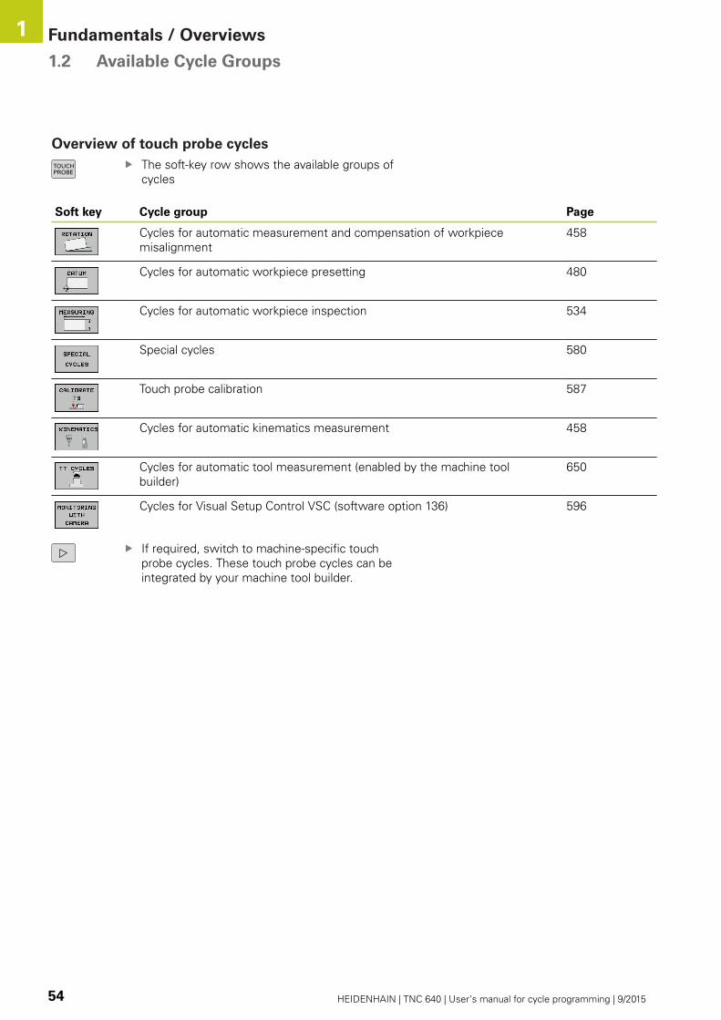
Fundamentals / Overviews 1.2 Available Cycle Groups
1
54 HEIDENHAIN | TNC 640 | User’s manual for cycle programming | 9/2015
Overview of touch probe cycles
The soft-key row shows the available groups of
cycles
Soft key Cycle group Page
Cycles for automatic measurement and compensation of workpiece
misalignment
458
Cycles for automatic workpiece presetting 480
Cycles for automatic workpiece inspection 534
Special cycles 580
Touch probe calibration 587
Cycles for automatic kinematics measurement 458
Cycles for automatic tool measurement (enabled by the machine tool
builder)
650
Cycles for Visual Setup Control VSC (software option 136) 596
If required, switch to machine-specific touch
probe cycles. These touch probe cycles can be
integrated by your machine tool builder.
2Using Fixed Cycles
Using Fixed Cycles 2.1 Working with fixed cycles
2
56 HEIDENHAIN | TNC 640 | User’s manual for cycle programming | 9/2015
2.1 Working with fixed cycles
Machine-specific cycles
In addition to the HEIDENHAIN cycles, many machine tool builders
offer their own cycles in the TNC. These cycles are available in a
separate cycle-number range:
Cycles 300 to 399
Machine-specific cycles that are to be defined through the
CYCLE DEF key
Cycles 500 to 599
Machine-specific touch probe cycles that are to be defined
through the TOUCH PROBE key
Refer to your machine manual for a description of the
specific function.
Sometimes machine-specific cycles use transfer parameters that
HEIDENHAIN already uses in standard cycles. For parallel use of
DEF active cycles (cycles that the TNC is automatically running
during cycle definition) and CALL active cycles (cycles that you
need to call up to run).
Further Information: Calling a cycle, page 58
Adhere to the following procedure in order to avoid problems
regarding the overwriting of transfer parameters that are used
more than once:
As a rule, always program DEF-active cycles before CALL-active
cycles
If you do want to program a DEF-active cycle between the
definition and call of a CALL-active cycle, do it only if there is no
common use of specific transfer parameters
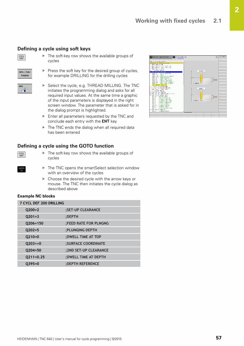
Working with fixed cycles 2.1
2
HEIDENHAIN | TNC 640 | User’s manual for cycle programming | 9/2015 57
Defining a cycle using soft keys
The soft-key row shows the available groups of
cycles
Press the soft key for the desired group of cycles,
for example DRILLING for the drilling cycles
Select the cycle, e.g. THREAD MILLING. The TNC
initiates the programming dialog and asks for all
required input values. At the same time a graphic
of the input parameters is displayed in the right
screen window. The parameter that is asked for in
the dialog prompt is highlighted.
Enter all parameters requested by the TNC and
conclude each entry with the ENT key
The TNC ends the dialog when all required data
has been entered
Defining a cycle using the GOTO function
The soft-key row shows the available groups of
cycles
The TNC opens the smartSelect selection window
with an overview of the cycles
Choose the desired cycle with the arrow keys or
mouse. The TNC then initiates the cycle dialog as
described above
Example NC blocks
7 CYCL DEF 200 DRILLING
Q200=2 ;SET-UP CLEARANCE
Q201=3 ;DEPTH
Q206=150 ;FEED RATE FOR PLNGNG
Q202=5 ;PLUNGING DEPTH
Q210=0 ;DWELL TIME AT TOP
Q203=+0 ;SURFACE COORDINATE
Q204=50 ;2ND SET-UP CLEARANCE
Q211=0.25 ;DWELL TIME AT DEPTH
Q395=0 ;DEPTH REFERENCE

Using Fixed Cycles 2.1 Working with fixed cycles
2
58 HEIDENHAIN | TNC 640 | User’s manual for cycle programming | 9/2015
Calling a cycle
Prerequisites
The following data must always be programmed
before a cycle call:
BLK FORM for graphic display (needed only for
test graphics)
Tool call
Direction of spindle rotation (M functions M3/M4)
Cycle definition (CYCL DEF)
For some cycles, additional prerequisites must be
observed. They are detailed in the descriptions for
each cycle.
The following cycles become effective automatically as soon as
they are defined in the part program. These cycles cannot and
must not be called:
Cycle 220 for point patterns on circles and Cycle 221 for point
patterns on lines
SL Cycle 14 CONTOUR GEOMETRY
SL Cycle 20 CONTOUR DATA
Cycle 32 TOLERANCE
Coordinate transformation cycles
Cycle 9 DWELL TIME
All touch probe cycles
You can call all other cycles with the functions described as follows.
Calling a cycle with CYCL CALL
The CYCL CALL function calls the most recently defined fixed
cycle once. The starting point of the cycle is the position that was
programmed last before the CYCL CALL block.
To program the cycle call, press the CYCL CALLkey
Press the CYCL CALL M soft key to enter a cycle
call
If necessary, enter the miscellaneous function M
(for example M3 to switch the spindle on), or end
the dialog by pressing the END key
Calling a cycle with CYCL CALL PAT
The CYCL CALL PAT function calls the most recently defined
machining cycle at all positions that you defined in a PATTERN DEF
pattern definition or in a points table.
Further Information: PATTERN DEF pattern definition, page 64
Further Information: Point tables, page 71
Working with fixed cycles 2.1
2
HEIDENHAIN | TNC 640 | User’s manual for cycle programming | 9/2015 59
Calling a cycle with CYCL CALL POS
The CYCL CALL POS function calls the most recently defined fixed
cycle once. The starting point of the cycle is the position that you
defined in the CYCL CALL POS block.
Using positioning logic the TNC moves to the position defined in
the CYCL CALL POS block.
If the tool’s current position in the tool axis is greater than the
top surface of the workpiece (Q203), the TNC moves the tool to
the programmed position first in the machining plane and then
in the tool axis.
If the tool’s current position in the tool axis is below the top
surface of the workpiece (Q203), the TNC moves the tool to
the programmed position first in the tool axis to the clearance
height and then in the working plane to the programmed
position.
Three coordinate axes must always be programmed
in the CYCL CALL POS block. With the coordinate
in the tool axis you can easily change the starting
position. It serves as an additional datum shift.
The feed rate most recently defined in the CYCLCALL POS block applies only to traverse to the start
position programmed in this block.
As a rule, the TNC moves without radius
compensation (R0) to the position defined in the
CYCL CALL POS block.
If you use CYCL CALL POS to call a cycle in which
a start position is defined (for example Cycle 212),
then the position defined in the cycle serves as an
additional shift of the position defined in the CYCLCALL POS block. You should therefore always define
the start position to be set in the cycle as 0.
Cycle call with M99/M89
The M99 function, which is active only in the block in which it
is programmed, calls the last defined fixed cycle once. You can
program M99 at the end of a positioning block. The TNC moves to
this position and then calls the last defined fixed cycle.
If the TNC is to run the cycle automatically after every positioning
block, program the first cycle call with M89.
To cancel the effect of M89, program:
M99 in the positioning block in which you move to the last
starting point, or
Use CYCL DEF to define a new fixed cycle

Using Fixed Cycles 2.2 Program defaults for cycles
2
60 HEIDENHAIN | TNC 640 | User’s manual for cycle programming | 9/2015
2.2 Program defaults for cycles
Overview
All Cycles 20 to 25, as well as all of those with numbers 200 or
higher, always use identical cycle parameters, such as the set-up
clearance Q200, which you must enter for each cycle definition.
The GLOBAL DEF function gives you the possibility of defining
these cycle parameters at the beginning of the program, so that
they are effective globally for all machining cycles used in the
program. In the respective machining cycle you then simply link to
the value defined at the beginning of the program.
The following GLOBAL DEF functions are available:
Soft key Machining patterns Page
GLOBAL DEF COMMON
Definition of generally valid cycle
parameters
62
GLOBAL DEF DRILLING
Definition of specific drilling cycle
parameters
62
GLOBAL DEF POCKET MILLING
Definition of specific pocket-milling
cycle parameters
62
GLOBAL DEF CONTOUR MILLING
Definition of specific contour milling
cycle parameters
63
GLOBAL DEF POSITIONING
Definition of the positioning behavior
for CYCL CALL PAT
63
GLOBAL DEF PROBING
Definition of specific touch probe
cycle parameters
63
Entering GLOBAL DEF
Select the Programming mode of operation
Press the special functions key
Select the functions for program defaults
Select GLOBAL DEF functions
Select desired GLOBAL DEF function, e.g.
GLOBAL DEF GENERALEnter the required definitions, and confirm each
entry with the key ENT

Program defaults for cycles 2.2
2
HEIDENHAIN | TNC 640 | User’s manual for cycle programming | 9/2015 61
Using GLOBAL DEF information
If you have entered the corresponding GLOBAL DEF functions at
the beginning of the program, then you can link to these globally
valid values when defining any fixed cycle.
Proceed as follows:
Select the Programming and Editing operating
mode
Select fixed cycles
Select the desired group of cycles, for example:
drilling cycles
Select the desired cycle, e.g. DRILLINGThe TNC displays the SET STANDARD VALUES soft
key, if there is a global parameter for it
Press the SET STANDARD VALUES soft key. The
TNC enters the word PREDEF (predefined) in the
cycle definition. You have now created a link to the
corresponding GLOBAL DEF parameter that you
defined at the beginning of the program
Danger of collision!
Please note that later changes to the program
settings affect the entire machining program, and
can therefore change the machining procedure
significantly.
If you enter a fixed value in a fixed cycle, then this
value will not be changed by the GLOBAL DEFfunctions.

Using Fixed Cycles 2.2 Program defaults for cycles
2
62 HEIDENHAIN | TNC 640 | User’s manual for cycle programming | 9/2015
Global data valid everywhere
Set-up clearance: Distance between tool tip and workpiece
surface for automated approach of the cycle start position in the
tool axis
2nd set-up clearance: Position to which the TNC positions the
tool at the end of a machining step. The next machining position
is approached at this height in the machining plane
F positioning: Feed rate at which the TNC traverses the tool
within a cycle
F retraction: Feed rate at which the TNC retracts the tool
The parameters are valid for all fixed cycles with
numbers greater than 2xx.
Global data for drilling operations
Retraction rate for chip breaking: Value by which the TNC
retracts the tool during chip breaking
Dwell time at depth: Time in seconds that the tool remains at
the hole bottom
Dwell time at top: Time in seconds that the tool remains at the
set-up clearance
The parameters apply to the drilling, tapping and
thread milling cycles 200 to 209, 240, 241 and 262 to
267.
Global data for milling operations with pocket
cycles 25x
Overlap factor: The tool radius multiplied by the overlap factor
equals the lateral stepover
Climb or up-cut: Select the type of milling
Plunging type: Plunge into the material helically, in a
reciprocating motion, or vertically
The parameters apply to milling cycles 251 to 257.
Program defaults for cycles 2.2
2
HEIDENHAIN | TNC 640 | User’s manual for cycle programming | 9/2015 63
Global data for milling operations with contour
cycles
Set-up clearance: Distance between tool face and workpiece
surface for automated approach of the cycle start position in the
tool axis
Clearance height: Absolute height at which the tool cannot
collide with the workpiece (for intermediate positioning and
retraction at the end of the cycle)
Overlap factor: The tool radius multiplied by the overlap factor
equals the lateral stepover
Climb or up-cut: Select the type of milling
The parameters apply to SL cycles 20, 22, 23, 24 and
25.
Global data for positioning behavior
Positioning behavior: Retraction in the tool axis at the end of
the machining step: Return to the 2nd set-up clearance or to the
position at the beginning of the unit
The parameters apply to each fixed cycle that you call
with the CYCL CALL PAT function.
Global data for probing functions
Set-up clearance: Distance between stylus and workpiece
surface for automated approach of the probing position
Clearance height: The coordinate in the touch probe axis to
which the TNC traverses the touch probe between measuring
points, if the Move to clearance height option is activated
Move to clearance height: Select whether the TNC moves
the touch probe to the set-up clearance or clearance height
between the measuring points
Applies to all Touch Probe Cycles 4xx.

Using Fixed Cycles 2.3 PATTERN DEF pattern definition
2
64 HEIDENHAIN | TNC 640 | User’s manual for cycle programming | 9/2015
2.3 PATTERN DEF pattern definition
Application
You use the PATTERN DEF function to easily define regular
machining patterns, which you can call with the CYCL CALL PATfunction. As with the cycle definitions, support graphics that
illustrate the respective input parameter are also available for
pattern definitions.
PATTERN DEF is to be used only in connection with
the tool axis Z.
The following machining patterns are available:
Soft key Machining patterns Page
POINT
Definition of up to any 9
machining positions
66
ROW
Definition of a single row,
straight or rotated
66
PATTERN
Definition of a single pattern,
straight, rotated or distorted
67
FRAME
Definition of a single frame,
straight, rotated or distorted
68
CIRCLE
Definition of a full circle
69
PITCH CIRCLE
Definition of a pitch circle
70

PATTERN DEF pattern definition 2.3
2
HEIDENHAIN | TNC 640 | User’s manual for cycle programming | 9/2015 65
Entering PATTERN DEF
Select the Programming mode of operation
Press the special functions key
Select the functions for contour and point
machining
Open a PATTERN DEF block
Select the desired machining pattern, e.g. a single
row
Enter the required definitions, and confirm each
entry with the ENT key
Using PATTERN DEF
As soon as you have entered a pattern definition, you can call it
with the CYCL CALL PAT function.
Further Information: Calling a cycle, page 58
The TNC then performs the most recently defined machining cycle
on the machining pattern you defined.
A machining pattern remains active until you define
a new one, or select a point table with the SELPATTERN function.
You can use the mid-program startup function
to select any point at which you want to start or
continue machining.
More information: User’s Manual for conversational
programming
The TNC retracts the tool to the clearance height
between the starting points. Depending on which
is greater, the TNC uses either the spindle axis
coordinate from the cycle call or the value from cycle
parameter Q204 as the clearance height.

Using Fixed Cycles 2.3 PATTERN DEF pattern definition
2
66 HEIDENHAIN | TNC 640 | User’s manual for cycle programming | 9/2015
Defining individual machining positions
You can enter up to 9 machining positions. Confirm
each entry with the ENT key.
If you have defined a workpiece surface in Z not
equal to 0, then this value is effective in addition to
the workpiece surface Q203 that you defined in the
machining cycle.
X coord. of machining position (absolute): Enter X
coordinate
Y coord. of machining position (absolute): Enter Y
coordinate
Coordinate of workpiece surface (absolute): Enter
Z coordinate at which machining is to begin
NC blocks
10 L Z+100 R0 FMAX
11 PATTERN DEF POS1 (X+25 Y+33.5 Z+0) POS2 (X+50 Y+75 Z+0)
Defining a single row
If you have defined a workpiece surface in Z not
equal to 0, then this value is effective in addition to
the workpiece surface Q203 that you defined in the
machining cycle.
Starting point in X (absolute): Coordinate of the
starting point of the row in the X axis
Starting point in Y (absolute): Coordinate of the
starting point of the row in the Y axis
Spacing of machining positions (incremental):Distance between the machining positions. You can
enter a positive or negative value
Number of repetitions: Total number of machining
operations
Rot. position of entire pattern (absolute):Angle of rotation around the entered starting
point. Reference axis: Reference axis of the active
machining plane (e.g. X for tool axis Z). You can
enter a positive or negative value
Coordinate of workpiece surface (absolute): Enter
Z coordinate at which machining is to begin
NC blocks
10 L Z+100 R0 FMAX
11 PATTERN DEF ROW1 (X+25 Y+33.5 D+8 NUM5 ROT+0 Z+0)

PATTERN DEF pattern definition 2.3
2
HEIDENHAIN | TNC 640 | User’s manual for cycle programming | 9/2015 67
Defining a single pattern
If you have defined a workpiece surface in Z not
equal to 0, then this value is effective in addition to
the workpiece surface Q203 that you defined in the
machining cycle.
The Rotary pos. ref. ax. and Rotary pos. minorax. parameters are added to a previously performed
rotated position of the entire pattern.
Starting point in X (absolute): Coordinate of the
starting point of the pattern in the X axis
Starting point in Y (absolute): Coordinate of the
starting point of the pattern in the Y axis
Spacing of machining positions X (incremental):Distance between the machining positions in the X
direction. You can enter a positive or negative value
Spacing of machining positions Y (incremental):Distance between the machining positions in the Y
direction. You can enter a positive or negative value
Number of columns: Total number of columns in
the pattern
Number of rows: Total number of lines in the
pattern
Rot. position of entire pattern (absolute): Angle
of rotation by which the entire pattern is rotated
around the entered starting point. Reference axis:
Reference axis of the active machining plane (e.g. X
for tool axis Z). You can enter a positive or negative
value
Rotary pos. ref. ax.: Angle of rotation around which
only the reference axis of the machining plane is
distorted with respect to the entered starting point.
You can enter a positive or negative value.
Rotary pos. minor ax.: Angle of rotation around
which only the minor axis of the machining plane is
distorted with respect to the entered starting point.
You can enter a positive or negative value.
Coordinate of workpiece surface (absolute): Enter
Z coordinate at which machining is to begin
NC blocks
10 L Z+100 R0 FMAX
11 PATTERN DEF PAT1 (X+25 Y+33.5DX+8 DY+10 NUMX5 NUMY4 ROT+0ROTX+0 ROTY+0 Z+0)
Using Fixed Cycles 2.3 PATTERN DEF pattern definition
2
68 HEIDENHAIN | TNC 640 | User’s manual for cycle programming | 9/2015
Defining individual frames
If you have defined a workpiece surface in Z not
equal to 0, then this value is effective in addition to
the workpiece surface Q203 that you defined in the
machining cycle.
The Rotary pos. ref. ax. and Rotary pos. minorax. parameters are added to a previously performed
rotated position of the entire pattern.
Starting point in X (absolute): Coordinate of the
starting point of the frame in the X axis
Starting point in Y (absolute): Coordinate of the
starting point of the frame in the Y axis
Spacing of machining positions X (incremental):Distance between the machining positions in the X
direction. You can enter a positive or negative value
Spacing of machining positions Y (incremental):Distance between the machining positions in the Y
direction. You can enter a positive or negative value
Number of columns: Total number of columns in
the pattern
Number of lines: Total number of rows in the
pattern
Rot. position of entire pattern (absolute): Angle
of rotation by which the entire pattern is rotated
around the entered starting point. Reference axis:
Reference axis of the active machining plane (e.g. X
for tool axis Z). You can enter a positive or negative
value
Rotary pos. ref. ax.: Angle of rotation around which
only the reference axis of the machining plane is
distorted with respect to the entered starting point.
You can enter a positive or negative value
Rotary pos. minor ax.: Angle of rotation around
which only the minor axis of the machining plane is
distorted with respect to the entered starting point.
You can enter a positive or negative value.
Coordinate of workpiece surface (absolute): Enter
Z coordinate at which machining is to begin
NC blocks
10 L Z+100 R0 FMAX
11 PATTERN DEF FRAME1 (X+25 Y+33.5 DX+8 DY+10 NUMX5NUMY4 ROT+0 ROTX+0 ROTY+0 Z+0)
PATTERN DEF pattern definition 2.3
2
HEIDENHAIN | TNC 640 | User’s manual for cycle programming | 9/2015 69
Defining a full circle
If you have defined a workpiece surface in Z not
equal to 0, then this value is effective in addition to
the workpiece surface Q203 that you defined in the
machining cycle.
Bolt-hole circle center X (absolute): Coordinate of
the circle center in the X axis
Bolt-hole circle center Y (absolute): Coordinate of
the circle center in the Y axis
Bolt-hole circle diameter: Diameter of the bolt-
hole circle
Starting angle: Polar angle of the first machining
position. Reference axis: Reference axis of the
active machining plane (e.g. X for tool axis Z). You
can enter a positive or negative value
Number of repetitions: Total number of machining
positions on the circle
Coordinate of workpiece surface (absolute): Enter
Z coordinate at which machining is to begin
NC blocks
10 L Z+100 R0 FMAX
11 PATTERN DEF CIRC1 (X+25 Y+33 D80 START+45 NUM8 Z+0)
Using Fixed Cycles 2.3 PATTERN DEF pattern definition
2
70 HEIDENHAIN | TNC 640 | User’s manual for cycle programming | 9/2015
Defining a pitch circle
If you have defined a workpiece surface in Z not
equal to 0, then this value is effective in addition to
the workpiece surface Q203 that you defined in the
machining cycle.
Bolt-hole circle center X (absolute): Coordinate of
the circle center in the X axis
Bolt-hole circle center Y (absolute): Coordinate of
the circle center in the Y axis
Bolt-hole circle diameter: Diameter of the bolt-
hole circle
Starting angle: Polar angle of the first machining
position. Reference axis: Major axis of the active
machining plane (e.g. X for tool axis Z). You can
enter a positive or negative value
Stepping angle/end angle: Incremental polar angle
between two machining positions. You can enter a
positive or negative value As an alternative you can
enter the end angle (switch via soft key).
Number of repetitions: Total number of machining
positions on the circle
Coordinate of workpiece surface (absolute): Enter
Z coordinate at which machining is to begin
NC blocks
10 L Z+100 R0 FMAX
11 PATTERN DEF PITCHCIRC1 (X+25 Y+33 D80 START+45 STEP30NUM8 Z+0)

Point tables 2.4
2
HEIDENHAIN | TNC 640 | User’s manual for cycle programming | 9/2015 71
2.4 Point tables
Application
You should create a point table whenever you want to run a cycle,
or several cycles in sequence, on an irregular point pattern.
If you are using drilling cycles, the coordinates of the working
plane in the point table represent the hole centers. If you are
using milling cycles, the coordinates of the working plane in
the point table represent the starting-point coordinates of the
respective cycle (e.g. center-point coordinates of a circular pocket).
Coordinates in the spindle axis correspond to the coordinate of the
workpiece surface.
Creating a point table
Select the Programming mode of operation
Call the file manager: Press the PGM MGT key.
FILE NAME?Enter the name and file type of the point table and
confirm your entry with the ENT key.
Select the unit of measure: Press the MM or INCHsoft key. The TNC changes to the program blocks
window and displays an empty point table.
With the INSERT LINE soft key, insert new
lines and enter the coordinates of the desired
machining position.
Repeat the process until all desired coordinates have been entered.
The name of the point table must begin with a letter.
Use the soft keys X OFF/ON, Y OFF/ON, Z OFF/ON(second soft-key row) to specify which coordinates
you want to enter in the point table.
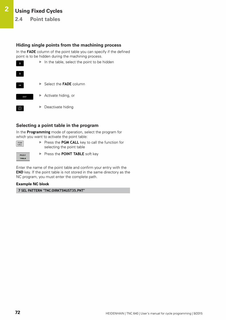
Using Fixed Cycles 2.4 Point tables
2
72 HEIDENHAIN | TNC 640 | User’s manual for cycle programming | 9/2015
Hiding single points from the machining process
In the FADE column of the point table you can specify if the defined
point is to be hidden during the machining process.
In the table, select the point to be hidden
Select the FADE column
Activate hiding, or
NOENT
Deactivate hiding
Selecting a point table in the program
In the Programming mode of operation, select the program for
which you want to activate the point table:
Press the PGM CALL key to call the function for
selecting the point table
Press the POINT TABLE soft key
Enter the name of the point table and confirm your entry with the
END key. If the point table is not stored in the same directory as the
NC program, you must enter the complete path.
Example NC block
7 SEL PATTERN "TNC:DIRKT5NUST35.PNT"

Point tables 2.4
2
HEIDENHAIN | TNC 640 | User’s manual for cycle programming | 9/2015 73
Calling a cycle in connection with point tables
With CYCL CALL PAT the TNC runs the point table
that you last defined (even if you defined the point
table in a program that was nested with CALL PGM).
If you want the TNC to call the last defined fixed cycle at the points
defined in a point table, then program the cycle call with CYCLECALL PAT:
To program the cycle call, press the CYCL CALLkey
Press the CYCL CALL PAT soft key to call a point
table
Enter the feed rate at which the TNC is to move
from point to point (if you make no entry the TNC
will move at the last programmed feed rate; FMAXis not valid)
If required, enter a miscellaneous function M, then
confirm with the END key
The TNC retracts the tool to the clearance height between the
starting points. Depending on which is greater, the TNC uses either
the spindle axis coordinate from the cycle call or the value from
cycle parameter Q204 as the clearance height.
If you want to move at reduced feed rate when pre-positioning in
the spindle axis, use the miscellaneous function M103.
Effect of the point table with SL cycles and Cycle 12
The TNC interprets the points as an additional datum shift.
Effect of the point table with Cycles 200 to 208 and 262 to 267
The TNC interprets the points of the working plane as coordinates
of the hole centers. If you want to use the coordinate defined in
the point table for the spindle axis as the starting point coordinate,
you must define the workpiece surface coordinate (Q203) as 0.
Effect of the point table with Cycles 251 to 254
The TNC interprets the points of the working plane as coordinates
of the cycle starting point. If you want to use the coordinate
defined in the point table for the spindle axis as the starting point
coordinate, you must define the workpiece surface coordinate
(Q203) as 0.


3Fixed Cycles:
Drilling
Fixed Cycles: Drilling 3.1 Fundamentals
3
76 HEIDENHAIN | TNC 640 | User’s manual for cycle programming | 9/2015
3.1 Fundamentals
Overview
The TNC offers the following cycles for all types of drilling
operations:
Soft key Cycle Page
240 CENTERING
With automatic pre-positioning, 2nd
set-up clearance, optional entry of the
centering diameter or centering depth
77
200 DRILLING
With automatic pre-positioning, 2nd
set-up clearance
79
201 REAMING
With automatic pre-positioning, 2nd
set-up clearance
81
202 BORING
With automatic pre-positioning, 2nd
set-up clearance
83
203 UNIVERSAL DRILLING
With automatic pre-positioning, 2nd
set-up clearance, chip breaking, and
decrementing
86
204 BACK BORING
With automatic pre-positioning, 2nd
set-up clearance
89
205 UNIVERSAL PECKING
With automatic pre-positioning, 2nd
set-up clearance, chip breaking, and
advanced stop distance
92
208 BORE MILLING
With automatic pre-positioning, 2nd
set-up clearance
96
241 SINGLE-LIP D.H.DRLNG
With automatic pre-positioning to
deepened starting point, shaft speed
and coolant definition
99

CENTERING (Cycle 240) 3.2
3
HEIDENHAIN | TNC 640 | User’s manual for cycle programming | 9/2015 77
3.2 CENTERING (Cycle 240, DIN/ISO:
G240)
Cycle run
1 The TNC positions the tool in the tool axis at rapid traverse
FMAX to set-up clearance above the workpiece surface.
2 The tool is centered at the programmed feed rate F to the
programmed centering diameter or centering depth.
3 If defined, the tool remains at the centering depth.
4 Finally, the tool path is retraced to setup clearance or—if
programmed—to the 2nd setup clearance at rapid traverse
FMAX.
Please note while programming:
Program a positioning block for the starting point
(hole center) in the working plane with radius
compensation R0.
The algebraic sign for the cycle parameter Q344(diameter) or Q201 (depth) determines the working
direction. If you program the diameter or depth = 0,
the cycle will not be executed.
Danger of collision!
Use the machine parameter displayDepthErr to
define whether, if a positive depth is entered, the
TNC should output an error message (on) or not (off).
Keep in mind that the TNC reverses the calculation
for pre-positioning when a positive diameter or
depth is entered. This means that the tool moves
at rapid traverse in the tool axis to set-up clearance
below the workpiece surface!

Fixed Cycles: Drilling 3.2 CENTERING (Cycle 240)
3
78 HEIDENHAIN | TNC 640 | User’s manual for cycle programming | 9/2015
Cycle parameters
Set-up clearance Q200 (incremental): Distance
between tool tip and workpiece surface. Enter a
positive value. Input range 0 to 99999.9999
Select depth/diameter (0/1) Q343: Select whether
centering is based on the entered diameter or
depth. If the TNC is to center based on the entered
diameter, the point angle of the tool must be
defined in the T ANGLE column of the tool table
TOOL.T.
0: Centering based on the entered depth
1: Centering based on the entered diameter
Depth Q201 (incremental): Distance between
workpiece surface and centering bottom (tip
of centering taper). Only effective if Q343=0 is
defined. Input range -99999.9999 to 99999.9999
Diameter (algebraic sign) Q344: Centering
diameter. Only effective if Q343=1 is defined. Input
range -99999.9999 to 99999.9999
Feed rate for plunging Q206: Traversing speed of
the tool during centering in mm/min. Input range: 0
to 99999.999; alternatively FAUTO, FUDwell time at depth Q211: Time in seconds that
the tool remains at the hole bottom. Input range 0 to
3600.0000
Coordinate of workpiece surface Q203 (absolute):
Coordinate of the workpiece surface. Input range
-99999.9999 to 99999.9999
2nd set-up clearance Q204 (incremental):
Coordinate in the spindle axis at which no collision
between tool and workpiece (fixtures) can occur.
Input range 0 to 99999.9999
NC blocks
10 L Z+100 R0 FMAX
11 CYCL DEF 240 CENTERING
Q200=2 ;SET-UP CLEARANCE
Q343=1 ;SELECT DIA./DEPTH
Q201=+0 ;DEPTH
Q344=-9 ;DIAMETER
Q206=250 ;FEED RATE FORPLNGNG
Q211=0.1 ;DWELL TIME AT DEPTH
Q203=+20 ;SURFACE COORDINATE
Q204=100 ;2ND SET-UPCLEARANCE
12 L X+30 Y+20 R0 FMAX M3 M99
13 L X+80 Y+50 R0 FMAX M99

DRILLING (Cycle 200) 3.3
3
HEIDENHAIN | TNC 640 | User’s manual for cycle programming | 9/2015 79
3.3 DRILLING (Cycle 200)
Cycle run
1 The TNC positions the tool in the tool axis at rapid traverse
FMAX to set-up clearance above the workpiece surface.
2 The tool drills to the first plunging depth at the programmed
feed rate F.
3 The TNC returns the tool at FMAX to the set-up clearance,
dwells there (if a dwell time was entered), and then moves at
FMAX to the set-up clearance above the first plunging depth.
4 The tool then drills deeper by the plunging depth at the
programmed feed rate F.
5 The TNC repeats this process (2 to 4) until the programmed
total hole depth is reached.
6 Finally, the tool path is retraced to setup clearance from the
hole bottom or—if programmed—to the 2nd setup clearance at
FMAX.
Please note while programming:
Program a positioning block for the starting point
(hole center) in the working plane with radius
compensation R0.
The algebraic sign for the cycle parameter DEPTH
determines the working direction. If you program
DEPTH=0, the cycle will not be executed.
Danger of collision!
Use the machine parameter displayDepthErr to
define whether, if a positive depth is entered, the
TNC should output an error message (on) or not (off).
Keep in mind that the TNC reverses the calculation
for pre-positioning when a positive depth is
entered. This means that the tool moves at rapid
traverse in the tool axis to set-up clearance below
the workpiece surface!
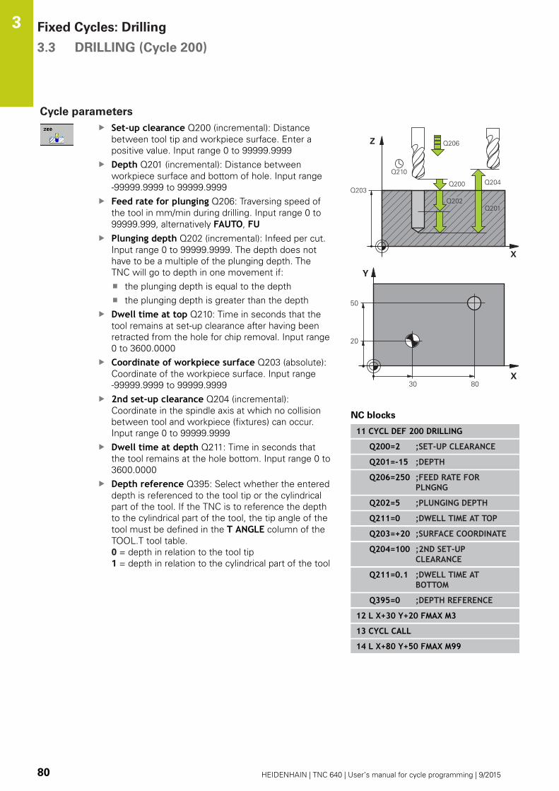
Fixed Cycles: Drilling 3.3 DRILLING (Cycle 200)
3
80 HEIDENHAIN | TNC 640 | User’s manual for cycle programming | 9/2015
Cycle parameters
Set-up clearance Q200 (incremental): Distance
between tool tip and workpiece surface. Enter a
positive value. Input range 0 to 99999.9999
Depth Q201 (incremental): Distance between
workpiece surface and bottom of hole. Input range
-99999.9999 to 99999.9999
Feed rate for plunging Q206: Traversing speed of
the tool in mm/min during drilling. Input range 0 to
99999.999, alternatively FAUTO, FUPlunging depth Q202 (incremental): Infeed per cut.
Input range 0 to 99999.9999. The depth does not
have to be a multiple of the plunging depth. The
TNC will go to depth in one movement if:
the plunging depth is equal to the depth
the plunging depth is greater than the depth
Dwell time at top Q210: Time in seconds that the
tool remains at set-up clearance after having been
retracted from the hole for chip removal. Input range
0 to 3600.0000
Coordinate of workpiece surface Q203 (absolute):
Coordinate of the workpiece surface. Input range
-99999.9999 to 99999.9999
2nd set-up clearance Q204 (incremental):
Coordinate in the spindle axis at which no collision
between tool and workpiece (fixtures) can occur.
Input range 0 to 99999.9999
Dwell time at depth Q211: Time in seconds that
the tool remains at the hole bottom. Input range 0 to
3600.0000
Depth reference Q395: Select whether the entered
depth is referenced to the tool tip or the cylindrical
part of the tool. If the TNC is to reference the depth
to the cylindrical part of the tool, the tip angle of the
tool must be defined in the T ANGLE column of the
TOOL.T tool table.
0 = depth in relation to the tool tip
1 = depth in relation to the cylindrical part of the tool
NC blocks
11 CYCL DEF 200 DRILLING
Q200=2 ;SET-UP CLEARANCE
Q201=-15 ;DEPTH
Q206=250 ;FEED RATE FORPLNGNG
Q202=5 ;PLUNGING DEPTH
Q211=0 ;DWELL TIME AT TOP
Q203=+20 ;SURFACE COORDINATE
Q204=100 ;2ND SET-UPCLEARANCE
Q211=0.1 ;DWELL TIME ATBOTTOM
Q395=0 ;DEPTH REFERENCE
12 L X+30 Y+20 FMAX M3
13 CYCL CALL
14 L X+80 Y+50 FMAX M99

REAMING (Cycle 201) 3.4
3
HEIDENHAIN | TNC 640 | User’s manual for cycle programming | 9/2015 81
3.4 REAMING (Cycle 201, DIN/ISO: G201)
Cycle run
1 The TNC positions the tool in the tool axis at rapid traverse
FMAX to the entered set-up clearance above the workpiece
surface.
2 The tool reams to the entered depth at the programmed feed
rate F.
3 If programmed, the tool remains at the hole bottom for the
entered dwell time.
4 The tool then retracts to set-up clearance at the feed rate F, and
from there—if programmed—to the 2nd set-up clearance in
FMAX.
Please note while programming:
Program a positioning block for the starting point
(hole center) in the working plane with radius
compensation R0.
The algebraic sign for the cycle parameter DEPTH
determines the working direction. If you program
DEPTH=0, the cycle will not be executed.
Danger of collision!
Use the machine parameter displayDepthErr to
define whether, if a positive depth is entered, the
TNC should output an error message (on) or not (off).
Keep in mind that the TNC reverses the calculation
for pre-positioning when a positive depth is
entered. This means that the tool moves at rapid
traverse in the tool axis to set-up clearance below
the workpiece surface!
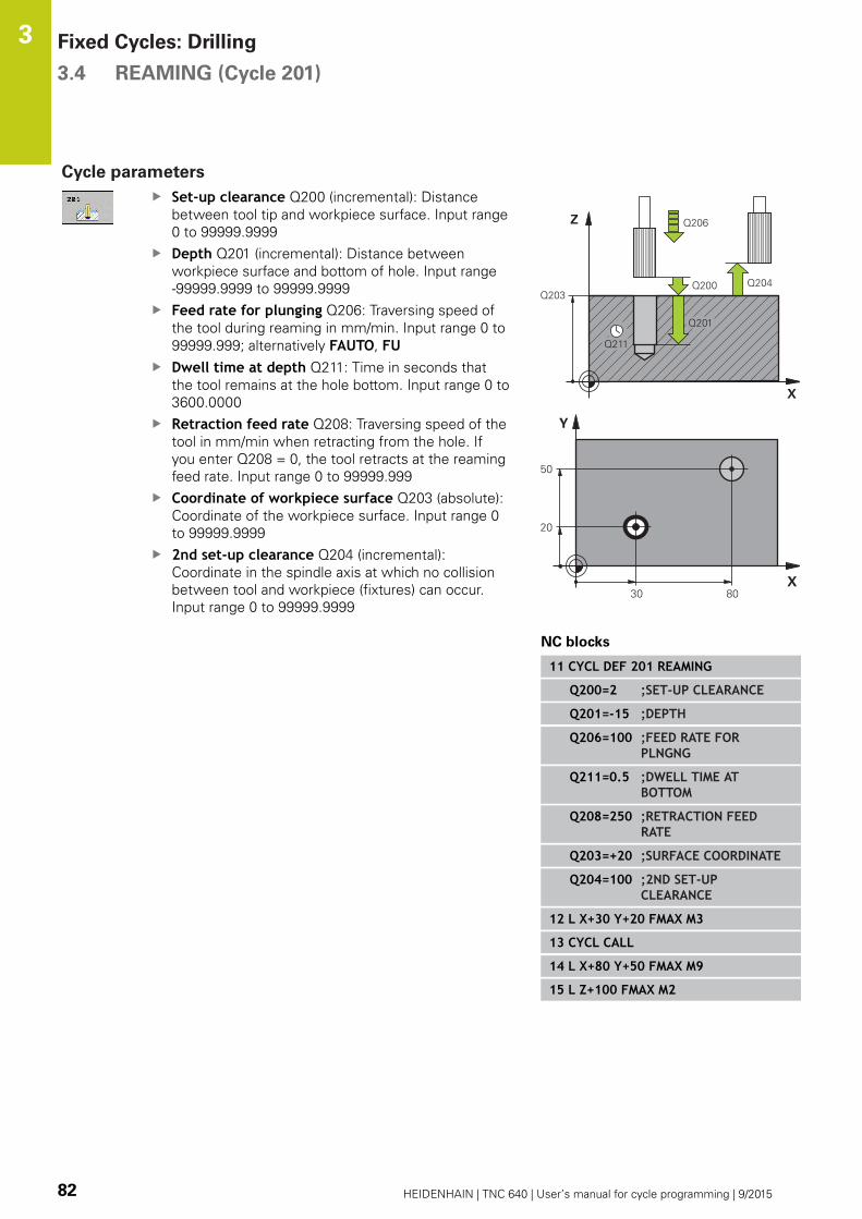
Fixed Cycles: Drilling 3.4 REAMING (Cycle 201)
3
82 HEIDENHAIN | TNC 640 | User’s manual for cycle programming | 9/2015
Cycle parameters
Set-up clearance Q200 (incremental): Distance
between tool tip and workpiece surface. Input range
0 to 99999.9999
Depth Q201 (incremental): Distance between
workpiece surface and bottom of hole. Input range
-99999.9999 to 99999.9999
Feed rate for plunging Q206: Traversing speed of
the tool during reaming in mm/min. Input range 0 to
99999.999; alternatively FAUTO, FUDwell time at depth Q211: Time in seconds that
the tool remains at the hole bottom. Input range 0 to
3600.0000
Retraction feed rate Q208: Traversing speed of the
tool in mm/min when retracting from the hole. If
you enter Q208 = 0, the tool retracts at the reaming
feed rate. Input range 0 to 99999.999
Coordinate of workpiece surface Q203 (absolute):
Coordinate of the workpiece surface. Input range 0
to 99999.9999
2nd set-up clearance Q204 (incremental):
Coordinate in the spindle axis at which no collision
between tool and workpiece (fixtures) can occur.
Input range 0 to 99999.9999
NC blocks
11 CYCL DEF 201 REAMING
Q200=2 ;SET-UP CLEARANCE
Q201=-15 ;DEPTH
Q206=100 ;FEED RATE FORPLNGNG
Q211=0.5 ;DWELL TIME ATBOTTOM
Q208=250 ;RETRACTION FEEDRATE
Q203=+20 ;SURFACE COORDINATE
Q204=100 ;2ND SET-UPCLEARANCE
12 L X+30 Y+20 FMAX M3
13 CYCL CALL
14 L X+80 Y+50 FMAX M9
15 L Z+100 FMAX M2
BORING (Cycle 202) 3.5
3
HEIDENHAIN | TNC 640 | User’s manual for cycle programming | 9/2015 83
3.5 BORING (Cycle 202, DIN/ISO: G202)
Cycle run
1 The TNC positions the tool in the tool axis at rapid traverse
FMAX to set-up clearance above the workpiece surface.
2 The tool drills to the programmed depth at the feed rate for
plunging.
3 If programmed, the tool remains at the hole bottom for the
entered dwell time with active spindle rotation for cutting free.
4 The TNC then orients the spindle to the position that is defined
in parameter Q336.
5 If retraction is selected, the tool retracts in the programmed
direction by 0.2 mm (fixed value).
6 The tool then retracts to set-up clearance at the retraction rate,
and from there—if programmed—to the 2nd set-up clearance at
FMAX. If Q214=0 the tool point remains on the wall of the hole.
7 The TNC finally positions the tool back at the center of the hole.

Fixed Cycles: Drilling 3.5 BORING (Cycle 202)
3
84 HEIDENHAIN | TNC 640 | User’s manual for cycle programming | 9/2015
Please note while programming:
Machine and TNC must be specially prepared by the
machine tool builder for use of this cycle.
This cycle is effective only for machines with servo-
controlled spindle.
Program a positioning block for the starting point
(hole center) in the working plane with radius
compensation R0.
The algebraic sign for the cycle parameter DEPTH
determines the working direction. If you program
DEPTH=0, the cycle will not be executed.
After machining, the TNC positions the tool back at
the starting point of the machining plane. This way,
you can continue positioning incrementally.
If the functions M7 or M8 were active before calling
the cycle, the TNC will reconstruct this previous
state at the end of the cycle.
Danger of collision!
Use the machine parameter displayDepthErr to
define whether, if a positive depth is entered, the
TNC should output an error message (on) or not (off).
Keep in mind that the TNC reverses the calculation
for pre-positioning when a positive depth is
entered. This means that the tool moves at rapid
traverse in the tool axis to set-up clearance below
the workpiece surface!
Select a disengaging direction in which the tool
moves away from the edge of the hole.
Check the position of the tool tip when you program
a spindle orientation to the angle that you enter in
Q336 (for example, in the Positioning with ManualData Input mode of operation). Set the angle so that
the tool tip is parallel to a coordinate axis.
During retraction the TNC automatically takes an
active rotation of the coordinate system into account.

BORING (Cycle 202) 3.5
3
HEIDENHAIN | TNC 640 | User’s manual for cycle programming | 9/2015 85
Cycle parameters
Set-up clearance Q200 (incremental): Distance
between tool tip and workpiece surface. Input range
0 to 99999.9999
Depth Q201 (incremental): Distance between
workpiece surface and bottom of hole. Input range
-99999.9999 to 99999.9999
Feed rate for plunging Q206: Traversing speed of
the tool during boring at mm/min. Input range 0 to
99999.999; alternatively FAUTO, FUDwell time at depth Q211: Time in seconds that
the tool remains at the hole bottom. Input range 0 to
3600.0000
Retraction feed rate Q208: Traversing speed of the
tool in mm/min when retracting from the hole. If
you enter Q208 = 0, the tool retracts at feed rate for
plunging. Input range 0 to 99999.999, alternatively
FMAX, FAUTOCoordinate of workpiece surface Q203 (absolute):
Coordinate of the workpiece surface. Input range
-99999.9999 to 99999.9999
2nd set-up clearance Q204 (incremental):
Coordinate in the spindle axis at which no collision
between tool and workpiece (fixtures) can occur.
Input range 0 to 99999.999
Disengaging direction (0/1/2/3/4) Q214:
Determine the direction in which the TNC retracts
the
tool on the hole bottom (after spindle orientation)
0: Do not retract the tool
1: Retract the tool in minus direction of the principle
axis
2: Retract the tool in minus direction of the minor
axis
3: Retract the tool in plus direction of the principle
axis
4: Retract the tool in plus direction of the minor axis
Angle for spindle orientation Q336 (absolute):
Angle at which the TNC positions the tool before
retracting it. Input range -360.000 to 360.000
10 L Z+100 R0 FMAX
11 CYCL DEF 202 BORING
Q200=2 ;SET-UP CLEARANCE
Q201=-15 ;DEPTH
Q206=100 ;FEED RATE FORPLNGNG
Q211=0.5 ;DWELL TIME ATBOTTOM
Q208=250 ;RETRACTION FEEDRATE
Q203=+20 ;SURFACE COORDINATE
Q204=100 ;2ND SET-UPCLEARANCE
Q214=1 ;DISENGAGING DIRECTN
Q336=0 ;ANGLE OF SPINDLE
12 L X+30 Y+20 FMAX M3
13 CYCL CALL
14 L X+80 Y+50 FMAX M99
Fixed Cycles: Drilling 3.6 UNIVERSAL DRILLING (Cycle 203)
3
86 HEIDENHAIN | TNC 640 | User’s manual for cycle programming | 9/2015
3.6 UNIVERSAL DRILLING (Cycle 203,
DIN/ISO: G203)
Cycle run
1 The TNC positions the tool in the tool axis at rapid traverse
FMAX to the entered set-up clearance above the workpiece
surface.
2 The tool drills to the first plunging depth at the entered feed rate
F.
3 If you have programmed chip breaking, the tool then retracts
by the entered retraction value. If you are working without chip
breaking, the tool retracts at the retraction feed rate to the set-
up clearance, remains there—if programmed—for the entered
dwell time, and advances again at FMAX to the set-up clearance
above the first PLUNGING DEPTH.
4 The tool then advances with another infeed at the programmed
feed rate. If programmed, the plunging depth is decreased after
each infeed by the decrement.
5 The TNC repeats this process (2 to 4) until the programmed
total hole depth is reached.
6 The tool remains at the hole bottom—if programmed—for
the entered dwell time to cut free, and then retracts to set-up
clearance at the retraction feed rate. If programmed, the tool
moves to the 2nd set-up clearance at FMAX.
Please note while programming:
Program a positioning block for the starting point
(hole center) in the working plane with radius
compensation R0.
The algebraic sign for the cycle parameter DEPTH
determines the working direction. If you program
DEPTH=0, the cycle will not be executed.
Danger of collision!
Use the machine parameter displayDepthErr to
define whether, if a positive depth is entered, the
TNC should output an error message (on) or not (off).
Keep in mind that the TNC reverses the calculation
for pre-positioning when a positive depth is
entered. This means that the tool moves at rapid
traverse in the tool axis to set-up clearance below
the workpiece surface!

UNIVERSAL DRILLING (Cycle 203) 3.6
3
HEIDENHAIN | TNC 640 | User’s manual for cycle programming | 9/2015 87
Cycle parameters
Set-up clearance Q200 (incremental): Distance
between tool tip and workpiece surface. Input range
0 to 99999.9999
Depth Q201 (incremental): Distance between
workpiece surface and bottom of hole. Input range
-99999.9999 to 99999.9999
Feed rate for plunging Q206: Traversing speed of
the tool during drilling in mm/min. Input range 0 to
99999.999; alternatively FAUTO, FUPlunging depth Q202 (incremental): Infeed per cut.
Input range 0 to 99999.9999. The depth does not
have to be a multiple of the plunging depth. The
TNC will go to depth in one movement if:
the plunging depth is equal to the depth
the plunging depth is greater than the depth and
no chip breaking is defined
Dwell time at top Q210: Time in seconds that the
tool remains at set-up clearance after having been
retracted from the hole for chip removal. Input range
0 to 3600.0000
Coordinate of workpiece surface Q203 (absolute):
Coordinate of the workpiece surface. Input range
-99999.9999 to 99999.9999
2nd set-up clearance Q204 (incremental):
Coordinate in the spindle axis at which no collision
between tool and workpiece (fixtures) can occur.
Input range 0 to 99999.9999
Decrement Q212 (incremental): Value by which the
TNC decreases the plunging depth Q202 after each
infeed. Input range 0 to 99999.9999
No. Breaks before retracting Q213: Number of
chip breaks after which the TNC is to withdraw
the tool from the hole for chip removal. For chip
breaking, the TNC retracts the tool each time by the
value in Q256. Input range 0 to 99999
Minimum plunging depth Q205 (incremental): If
you have entered a decrement, the TNC limits the
plunging depth to the value entered with Q205.
Input range 0 to 99999.9999
NC blocks
11 CYCL DEF 203 UNIVERSAL DRILLING
Q200=2 ;SET-UP CLEARANCE
Q201=-20 ;DEPTH
Q206=150 ;FEED RATE FORPLNGNG
Q202=5 ;PLUNGING DEPTH
Q211=0 ;DWELL TIME AT TOP
Q203=+20 ;SURFACE COORDINATE
Q204=50 ;2ND SET-UPCLEARANCE
Q212=0.2 ;DECREMENT
Q213=3 ;CHIP BREAKING
Q205=3 ;MIN. PLUNGING DEPTH
Q211=0.25 ;DWELL TIME ATBOTTOM
Q208=500 ;RETRACTION FEEDRATE
Q256=0.2 ;DIST. FOR CHIP BRKNG
Q395=0 ;DEPTH REFERENCE
Fixed Cycles: Drilling 3.6 UNIVERSAL DRILLING (Cycle 203)
3
88 HEIDENHAIN | TNC 640 | User’s manual for cycle programming | 9/2015
Dwell time at depth Q211: Time in seconds that
the tool remains at the hole bottom. Input range 0 to
3600.0000
Feed rate for retraction Q208: Traversing speed of
the tool in mm/min when retracting from the hole.
If you enter Q208 = 0, the TNC retracts the tool at
the feed rate Q206. Input range 0 to 99999.999,
alternatively FMAX, FAUTORetraction rate for chip breaking Q256
(incremental): Value by which the TNC retracts
the tool during chip breaking. Input range 0.000 to
99999.999
Depth reference Q395: Select whether the entered
depth is referenced to the tool tip or the cylindrical
part of the tool. If the TNC is to reference the depth
to the cylindrical part of the tool, the tip angle of the
tool must be defined in the T ANGLE column of the
TOOL.T tool table.
0 = depth in relation to the tool tip
1 = depth in relation to the cylindrical part of the tool

BACK BORING (Cycle 204) 3.7
3
HEIDENHAIN | TNC 640 | User’s manual for cycle programming | 9/2015 89
3.7 BACK BORING (Cycle 204, DIN/ISO:
G204)
Cycle run
This cycle allows holes to be bored from the underside of the
workpiece.
1 The TNC positions the tool in the tool axis at rapid traverse
FMAX to set-up clearance above the workpiece surface.
2 The TNC then orients the spindle to the 0° position with an
oriented spindle stop and displaces the tool by the off-center
distance.
3 The tool is then plunged into the already bored hole at the
feed rate for pre-positioning until the tooth has reached set-up
clearance on the underside of the workpiece.
4 The TNC then centers the tool again over the bore hole,
switches on the spindle and the coolant and moves at the feed
rate for boring to the depth of bore.
5 If a dwell time is entered, the tool will pause at the top of the
bore hole and will then be retracted from the hole again. The
TNC carries out another oriented spindle stop and the tool is
once again displaced by the off-center distance.
6 The tool then retracts to set-up clearance at the feed rate for
pre-positioning, and from there—if programmed—to the 2nd
set-up clearance at FMAX.
7 The TNC finally positions the tool back at the center of the hole.
Fixed Cycles: Drilling 3.7 BACK BORING (Cycle 204)
3
90 HEIDENHAIN | TNC 640 | User’s manual for cycle programming | 9/2015
Please note while programming:
Machine and TNC must be specially prepared by the
machine tool builder for use of this cycle.
This cycle is effective only for machines with servo-
controlled spindle.
Special boring bars for upward cutting are required
for this cycle.
Program a positioning block for the starting point
(hole center) in the working plane with radius
compensation R0.
After machining, the TNC positions the tool back at
the starting point of the machining plane. This way,
you can continue positioning incrementally.
The algebraic sign for the cycle parameter depth
determines the working direction. Note: A positive
sign bores in the direction of the positive spindle
axis.
The entered tool length is the total length to the
underside of the boring bar and not just to the tooth.
When calculating the starting point for boring, the
TNC considers the tooth length of the boring bar and
the thickness of the material.
If the functions M7 or M8 were active before calling
the cycle, the TNC will reconstruct this previous
state at the end of the cycle.
Danger of collision!
Check the position of the tool tip when you program
a spindle orientation to the angle that you enter in
Q336 (for example, in the Positioning with ManualData Input mode of operation). Set the angle so that
the tool tip is parallel to a coordinate axis. Select a
disengaging direction in which the tool moves away
from the edge of the hole.
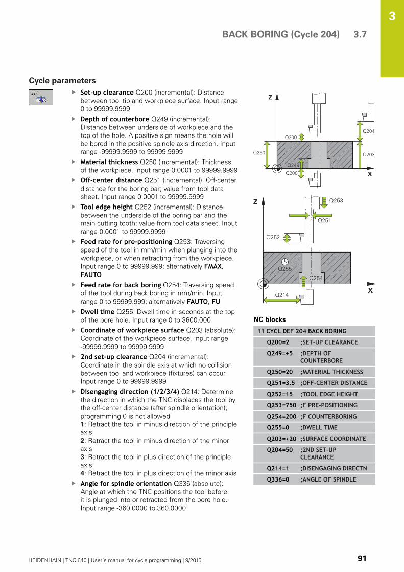
BACK BORING (Cycle 204) 3.7
3
HEIDENHAIN | TNC 640 | User’s manual for cycle programming | 9/2015 91
Cycle parameters
Set-up clearance Q200 (incremental): Distance
between tool tip and workpiece surface. Input range
0 to 99999.9999
Depth of counterbore Q249 (incremental):
Distance between underside of workpiece and the
top of the hole. A positive sign means the hole will
be bored in the positive spindle axis direction. Input
range -99999.9999 to 99999.9999
Material thickness Q250 (incremental): Thickness
of the workpiece. Input range 0.0001 to 99999.9999
Off-center distance Q251 (incremental): Off-center
distance for the boring bar; value from tool data
sheet. Input range 0.0001 to 99999.9999
Tool edge height Q252 (incremental): Distance
between the underside of the boring bar and the
main cutting tooth; value from tool data sheet. Input
range 0.0001 to 99999.9999
Feed rate for pre-positioning Q253: Traversing
speed of the tool in mm/min when plunging into the
workpiece, or when retracting from the workpiece.
Input range 0 to 99999.999; alternatively FMAX,
FAUTOFeed rate for back boring Q254: Traversing speed
of the tool during back boring in mm/min. Input
range 0 to 99999.999; alternatively FAUTO, FUDwell time Q255: Dwell time in seconds at the top
of the bore hole. Input range 0 to 3600.000
Coordinate of workpiece surface Q203 (absolute):
Coordinate of the workpiece surface. Input range
-99999.9999 to 99999.9999
2nd set-up clearance Q204 (incremental):
Coordinate in the spindle axis at which no collision
between tool and workpiece (fixtures) can occur.
Input range 0 to 99999.9999
Disengaging direction (1/2/3/4) Q214: Determine
the direction in which the TNC displaces the tool by
the off-center distance (after spindle orientation);
programming 0 is not allowed
1: Retract the tool in minus direction of the principle
axis
2: Retract the tool in minus direction of the minor
axis
3: Retract the tool in plus direction of the principle
axis
4: Retract the tool in plus direction of the minor axis
Angle for spindle orientation Q336 (absolute):
Angle at which the TNC positions the tool before
it is plunged into or retracted from the bore hole.
Input range -360.0000 to 360.0000
NC blocks
11 CYCL DEF 204 BACK BORING
Q200=2 ;SET-UP CLEARANCE
Q249=+5 ;DEPTH OFCOUNTERBORE
Q250=20 ;MATERIAL THICKNESS
Q251=3.5 ;OFF-CENTER DISTANCE
Q252=15 ;TOOL EDGE HEIGHT
Q253=750 ;F PRE-POSITIONING
Q254=200 ;F COUNTERBORING
Q255=0 ;DWELL TIME
Q203=+20 ;SURFACE COORDINATE
Q204=50 ;2ND SET-UPCLEARANCE
Q214=1 ;DISENGAGING DIRECTN
Q336=0 ;ANGLE OF SPINDLE
Fixed Cycles: Drilling 3.8 UNIVERSAL PECKING (Cycle 205)
3
92 HEIDENHAIN | TNC 640 | User’s manual for cycle programming | 9/2015
3.8 UNIVERSAL PECKING (Cycle 205,
DIN/ISO: G205)
Cycle run
1 The TNC positions the tool in the tool axis at rapid traverse
FMAX to the entered set-up clearance above the workpiece
surface.
2 If you enter a deepened starting point, the TNC move at the
defined positioning feed rate to the set-up clearance above the
deepened starting point.
3 The tool drills to the first plunging depth at the entered feed rate
F.
4 If you have programmed chip breaking, the tool then retracts
by the entered retraction value. If you are working without
chip breaking, the tool is moved at rapid traverse to the set-up
clearance, and then at FMAX to the entered starting position
above the first plunging depth.
5 The tool then advances with another infeed at the programmed
feed rate. If programmed, the plunging depth is decreased after
each infeed by the decrement.
6 The TNC repeats this process (2 to 4) until the programmed
total hole depth is reached.
7 The tool remains at the hole bottom—if programmed—for
the entered dwell time to cut free, and then retracts to set-up
clearance at the retraction feed rate. If programmed, the tool
moves to the 2nd set-up clearance at FMAX.

UNIVERSAL PECKING (Cycle 205) 3.8
3
HEIDENHAIN | TNC 640 | User’s manual for cycle programming | 9/2015 93
Please note while programming:
Program a positioning block for the starting point
(hole center) in the working plane with radius
compensation R0.
The algebraic sign for the cycle parameter DEPTH
determines the working direction. If you program
DEPTH=0, the cycle will not be executed.
If you enter different advance stop distances for
Q258 and Q259, the TNC will change the advance
stop distances between the first and last plunging
depths at the same rate.
If you use Q379 to enter a deepened starting
point, the TNC merely changes the starting point
of the infeed movement. The TNC does not change
retracting movements; the are referenced to the
coordinate of the workpiece surface.
Danger of collision!
Use the machine parameter displayDepthErr to
define whether, if a positive depth is entered, the
TNC should output an error message (on) or not (off).
Keep in mind that the TNC reverses the calculation
for pre-positioning when a positive depth is
entered. This means that the tool moves at rapid
traverse in the tool axis to set-up clearance below
the workpiece surface!

Fixed Cycles: Drilling 3.8 UNIVERSAL PECKING (Cycle 205)
3
94 HEIDENHAIN | TNC 640 | User’s manual for cycle programming | 9/2015
Cycle parameters
Set-up clearance Q200 (incremental): Distance
between tool tip and workpiece surface. Input range
0 to 99999.9999
Depth Q201 (incremental): Distance between
workpiece surface and bottom of hole (tip of drill
taper). Input range -99999.9999 to 99999.9999
Feed rate for plunging Q206: Traversing speed of
the tool during drilling in mm/min. Input range 0 to
99999.999; alternatively FAUTO, FUPlunging depth Q202 (incremental): Infeed per cut.
Input range 0 to 99999.9999. The depth does not
have to be a multiple of the plunging depth. The
TNC will go to depth in one movement if:
the plunging depth is equal to the depth
the plunging depth is greater than the depth
Coordinate of workpiece surface Q203 (absolute):
Coordinate of the workpiece surface. Input range
-99999.9999 to 99999.9999
2nd set-up clearance Q204 (incremental):
Coordinate in the spindle axis at which no collision
between tool and workpiece (fixtures) can occur.
Input range 0 to 99999.9999
Decrement Q212 (incremental): Value by which
the TNC decreases the plunging depth Q202. Input
range 0 to 99999.9999
Minimum plunging depth Q205 (incremental): If
you have entered a decrement, the TNC limits the
plunging depth to the value entered with Q205.
Input range 0 to 99999.9999
Upper advanced stop distance Q258 (incremental):
Set-up clearance for rapid traverse positioning
when the TNC moves the tool again to the current
plunging depth after retraction from the hole;
value for the first plunging depth. Input range 0 to
99999.9999
Lower advanced stop distance Q259 (incremental):
Set-up clearance for rapid traverse positioning
when the TNC moves the tool again to the current
plunging depth after retraction from the hole;
value for the last plunging depth. Input range 0 to
99999.9999
Infeed depth for chip breaking Q257
(incremental): Depth at which the TNC carries out
chip breaking. No chip breaking if 0 is entered. Input
range 0 to 99999.9999
Retraction rate for chip breaking Q256
(incremental): Value by which the TNC retracts
the tool during chip breaking. Input range 0.000 to
99999.999
Dwell time at depth Q211: Time in seconds that
the tool remains at the hole bottom. Input range 0 to
3600.0000
NC blocks
11 CYCL DEF 205 UNIVERSAL PECKING
Q200=2 ;SET-UP CLEARANCE
Q201=-80 ;DEPTH
Q206=150 ;FEED RATE FORPLNGNG
Q202=15 ;PLUNGING DEPTH
Q203=+100;SURFACE COORDINATE
Q204=50 ;2ND SET-UPCLEARANCE
Q212=0.5 ;DECREMENT
Q205=3 ;MIN. PLUNGING DEPTH
Q258=0.5 ;UPPER ADV. STOPDIST.
Q259=1 ;LOWER ADV. STOPDIST.
Q257=5 ;DEPTH FOR CHIPBRKNG
Q256=0.2 ;DIST. FOR CHIP BRKNG
Q211=0.25 ;DWELL TIME ATBOTTOM
Q379=7.5 ;START POINT
Q253=750 ;F PRE-POSITIONING
Q208=9999;RETRACTION FEEDRATE
Q395=0 ;DEPTH REFERENCE
UNIVERSAL PECKING (Cycle 205) 3.8
3
HEIDENHAIN | TNC 640 | User’s manual for cycle programming | 9/2015 95
Deepened starting point Q379 (incremental with
respect to the workpiece surface): Starting position
for actual drilling operation. The TNC moves at the
feed rate for pre-positioning from the set-up
clearance above the workpiece surface to the set-up
clearance above the deepened starting point. Input
range 0 to 99999.9999
Feed rate for pre-positioning Q253: Defines the
traversing speed of the tool when returning to
the plunging depth after having retracted for chip
breaking (Q256). This feed rate is also effective
when the tool is positioned to a deepened starting
point (Q379 not equal to 0). Entry in mm/min. Input
range 0 to 99999.9999 alternatively FMAX, FAUTOFeed rate for retraction Q208: Traversing speed
of the tool in mm/min when retracting after the
machining operation. If you enter Q208 = 0, the
TNC retracts the tool at the feed rate Q206. Input
range 0 to 99999.9999, alternatively FMAX,FAUTODepth reference Q395: Select whether the entered
depth is referenced to the tool tip or the cylindrical
part of the tool. If the TNC is to reference the depth
to the cylindrical part of the tool, the tip angle of the
tool must be defined in the T ANGLE column of the
TOOL.T tool table.
0 = depth in relation to the tool tip
1 = depth in relation to the cylindrical part of the tool
Fixed Cycles: Drilling 3.9 BORE MILLING (Cycle 208)
3
96 HEIDENHAIN | TNC 640 | User’s manual for cycle programming | 9/2015
3.9 BORE MILLING (Cycle 208)
Cycle run
1 The TNC positions the tool in the tool axis at rapid traverse
FMAX to the programmed set-up clearance above the workpiece
surface and then moves the tool to the bore hole circumference
on a rounded arc (if enough space is available).
2 The tool mills in a helix from the current position to the first
plunging depth at the programmed feed rate F.
3 When the drilling depth is reached, the TNC once again
traverses a full circle to remove the material remaining after the
initial plunge.
4 The TNC then positions the tool at the center of the hole again.
5 Finally the TNC returns to the setup clearance at FMAX. If
programmed, the tool moves to the 2nd set-up clearance at
FMAX.
BORE MILLING (Cycle 208) 3.9
3
HEIDENHAIN | TNC 640 | User’s manual for cycle programming | 9/2015 97
Please note while programming:
Program a positioning block for the starting point
(hole center) in the working plane with radius
compensation R0.
The algebraic sign for the cycle parameter DEPTH
determines the working direction. If you program
DEPTH=0, the cycle will not be executed.
If you have entered the bore hole diameter to be
the same as the tool diameter, the TNC will bore
directly to the entered depth without any helical
interpolation.
An active mirror function does not influence the type
of milling defined in the cycle.
Note that if the infeed distance is too large, the tool
or the workpiece may be damaged.
To prevent the infeeds from being too large, enter
the maximum plunge angle of the tool in the ANGLEcolumn of the tool table. The TNC then automatically
calculates the max. infeed permitted and changes
your entered value accordingly.
Danger of collision!
Use the machine parameter displayDepthErr to
define whether, if a positive depth is entered, the
TNC should output an error message (on) or not (off).
Keep in mind that the TNC reverses the calculation
for pre-positioning when a positive depth is
entered. This means that the tool moves at rapid
traverse in the tool axis to set-up clearance below
the workpiece surface!

Fixed Cycles: Drilling 3.9 BORE MILLING (Cycle 208)
3
98 HEIDENHAIN | TNC 640 | User’s manual for cycle programming | 9/2015
Cycle parameters
Set-up clearance Q200 (incremental): Distance
between tool lower edge and workpiece surface.
Input range 0 to 99999.9999
Depth Q201 (incremental): Distance between
workpiece surface and bottom of hole. Input range
-99999.9999 to 99999.9999
Feed rate for plunging Q206: Traversing speed
of the tool in mm/min during helical drilling. Input
range 0 to 99999.999, alternatively FAUTO, FU, FZInfeed per helix Q334 (incremental): Depth of the
tool plunge with each helix (=360°). Input range 0 to
99999.9999
Coordinate of workpiece surface Q203 (absolute):
Coordinate of the workpiece surface. Input range
-99999.9999 to 99999.9999
2nd set-up clearance Q204 (incremental):
Coordinate in the spindle axis at which no collision
between tool and workpiece (fixtures) can occur.
Input range 0 to 99999.9999
Nominal diameter Q335 (absolute value): Bore-hole
diameter. If you have entered the nominal diameter
to be the same as the tool diameter, the TNC will
bore directly to the entered depth without any
helical interpolation. Input range 0 to 99999.9999
Roughing diameter Q342 (absolute): As soon as
you enter a value greater than 0 in Q342, the TNC
no longer checks the ratio between the nominal
diameter and the tool diameter. This allows you
to rough-mill holes whose diameter is more than
twice as large as the tool diameter. Input range 0 to
99999.9999
Climb or up-cut Q351: Type of milling operation
with M3
+1 = Climb
–1 = Up-cut
NC blocks
12 CYCL DEF 208 BORE MILLING
Q200=2 ;SET-UP CLEARANCE
Q201=-80 ;DEPTH
Q206=150 ;FEED RATE FORPLNGNG
Q334=1.5 ;PLUNGING DEPTH
Q203=+100;SURFACE COORDINATE
Q204=50 ;2ND SET-UPCLEARANCE
Q335=25 ;NOMINAL DIAMETER
Q342=0 ;ROUGHING DIAMETER
Q351=+1 ;CLIMB OR UP-CUT
SINGLE-LIP DEEP-HOLE DRILLING (Cycle 241) 3.10
3
HEIDENHAIN | TNC 640 | User’s manual for cycle programming | 9/2015 99
3.10 SINGLE-LIP DEEP-HOLE DRILLING
(Cycle 241, DIN/ISO: G241)
Cycle run
1 The TNC positions the tool in the tool axis at rapid traverse
FMAX to the entered set-up clearance above the workpiece
surface.
2 Then the TNC moves the tool at the defined positioning feed
rate to the set-up clearance above the deepened starting point
and activates the drilling speed (M3) and the coolant. The TNC
executes the approach motion with the direction of rotation
defined in the cycle, with clockwise, counterclockwise or
stationary spindle.
3 The tool drills to the hole depth at the feed rate F, or to the
plunging depth if a smaller infeed value has been entered. The
plunging depth is decreased after each infeed by the decrement.
If you have entered a dwell depth, the TNC reduces the feed
rate by the feed rate factor after the dwell depth has been
reached.
4 If programmed, the tool remains at the hole bottom for chip
breaking.
5 The TNC repeats this process (3 to 4) until the programmed
total hole depth is reached.
6 After the TNC has reached the hole depth, the TNC switches off
the coolant and resets the drilling speed to the value defined for
retraction.
7 The tool is retracted to the set-up clearance at the retraction
feed rate. If programmed, the tool moves to the 2nd set-up
clearance at FMAX.
Please note while programming:
Program a positioning block for the starting point
(hole center) in the working plane with radius
compensation R0.
The algebraic sign for the cycle parameter DEPTH
determines the working direction. If you program
DEPTH=0, the cycle will not be executed.
Danger of collision!
Use the machine parameter displayDepthErr to
define whether, if a positive depth is entered, the
TNC should output an error message (on) or not (off).
Keep in mind that the TNC reverses the calculation
for pre-positioning when a positive depth is
entered. This means that the tool moves at rapid
traverse in the tool axis to set-up clearance below
the workpiece surface!
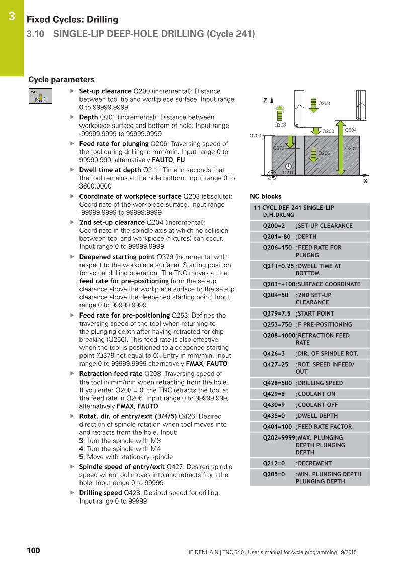
Fixed Cycles: Drilling 3.10 SINGLE-LIP DEEP-HOLE DRILLING (Cycle 241)
3
100 HEIDENHAIN | TNC 640 | User’s manual for cycle programming | 9/2015
Cycle parameters
Set-up clearance Q200 (incremental): Distance
between tool tip and workpiece surface. Input range
0 to 99999.9999
Depth Q201 (incremental): Distance between
workpiece surface and bottom of hole. Input range
-99999.9999 to 99999.9999
Feed rate for plunging Q206: Traversing speed of
the tool during drilling in mm/min. Input range 0 to
99999.999; alternatively FAUTO, FUDwell time at depth Q211: Time in seconds that
the tool remains at the hole bottom. Input range 0 to
3600.0000
Coordinate of workpiece surface Q203 (absolute):
Coordinate of the workpiece surface. Input range
-99999.9999 to 99999.9999
2nd set-up clearance Q204 (incremental):
Coordinate in the spindle axis at which no collision
between tool and workpiece (fixtures) can occur.
Input range 0 to 99999.9999
Deepened starting point Q379 (incremental with
respect to the workpiece surface): Starting position
for actual drilling operation. The TNC moves at the
feed rate for pre-positioning from the set-up
clearance above the workpiece surface to the set-up
clearance above the deepened starting point. Input
range 0 to 99999.9999
Feed rate for pre-positioning Q253: Defines the
traversing speed of the tool when returning to
the plunging depth after having retracted for chip
breaking (Q256). This feed rate is also effective
when the tool is positioned to a deepened starting
point (Q379 not equal to 0). Entry in mm/min. Input
range 0 to 99999.9999 alternatively FMAX, FAUTORetraction feed rate Q208: Traversing speed of
the tool in mm/min when retracting from the hole.
If you enter Q208 = 0, the TNC retracts the tool at
the feed rate in Q206. Input range 0 to 99999.999,
alternatively FMAX, FAUTORotat. dir. of entry/exit (3/4/5) Q426: Desired
direction of spindle rotation when tool moves into
and retracts from the hole. Input:
3: Turn the spindle with M3
4: Turn the spindle with M4
5: Move with stationary spindle
Spindle speed of entry/exit Q427: Desired spindle
speed when tool moves into and retracts from the
hole. Input range 0 to 99999
Drilling speed Q428: Desired speed for drilling.
Input range 0 to 99999
NC blocks
11 CYCL DEF 241 SINGLE-LIPD.H.DRLNG
Q200=2 ;SET-UP CLEARANCE
Q201=-80 ;DEPTH
Q206=150 ;FEED RATE FORPLNGNG
Q211=0.25 ;DWELL TIME ATBOTTOM
Q203=+100;SURFACE COORDINATE
Q204=50 ;2ND SET-UPCLEARANCE
Q379=7.5 ;START POINT
Q253=750 ;F PRE-POSITIONING
Q208=1000;RETRACTION FEEDRATE
Q426=3 ;DIR. OF SPINDLE ROT.
Q427=25 ;ROT. SPEED INFEED/OUT
Q428=500 ;DRILLING SPEED
Q429=8 ;COOLANT ON
Q430=9 ;COOLANT OFF
Q435=0 ;DWELL DEPTH
Q401=100 ;FEED RATE FACTOR
Q202=9999;MAX. PLUNGINGDEPTH PLUNGINGDEPTH
Q212=0 ;DECREMENT
Q205=0 ;MIN. PLUNGING DEPTHPLUNGING DEPTH
SINGLE-LIP DEEP-HOLE DRILLING (Cycle 241) 3.10
3
HEIDENHAIN | TNC 640 | User’s manual for cycle programming | 9/2015 101
M function for coolant on? Q429: M function for
switching on the coolant. The TNC switches the
coolant on if the tool is in the hole at the deepened
starting point. Input range 0 to 999
M function for coolant off? Q430: M function for
switching off the coolant. The TNC switches the
coolant off if the tool is at the hole depth. Input
range 0 to 999
Dwell depth Q435 (incremental): Coordinate in
the spindle axis at which the tool is to dwell. If
0 is entered, the function is not active (standard
setting). Application: During machining of through-
holes some tools require a short dwell time before
exiting the bottom of the hole in order to transport
the chips to the top. Define a value smaller than the
hole depth Q201; input range 0 to 99999.9999.
Feed rate factor Q401: Factor by which the TNC
reduces the feed rate after the dwell depth has
been reached. Input range 0 to 100
Plunging depth Q202 (incremental): Infeed per cut.
The depth does not have to be a multiple of the
plunging depth. Input range 0 to 99999.9999
Decrement Q212 (incremental): Value by which the
TNC decreases the plunging depth Q202 after each
infeed. Input range 0 to 99999.9999
Minimum plunging depth Q205 (incremental): If
you have entered a decrement, the TNC limits the
plunging depth to the value entered with Q205.
Input range 0 to 99999.9999
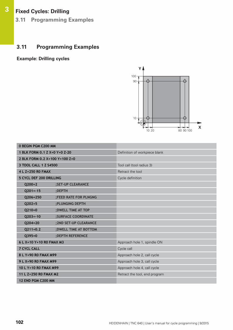
Fixed Cycles: Drilling 3.11 Programming Examples
3
102 HEIDENHAIN | TNC 640 | User’s manual for cycle programming | 9/2015
3.11 Programming Examples
Example: Drilling cycles
0 BEGIN PGM C200 MM
1 BLK FORM 0.1 Z X+0 Y+0 Z-20 Definition of workpiece blank
2 BLK FORM 0.2 X+100 Y+100 Z+0
3 TOOL CALL 1 Z S4500 Tool call (tool radius 3)
4 L Z+250 R0 FMAX Retract the tool
5 CYCL DEF 200 DRILLING Cycle definition
Q200=2 ;SET-UP CLEARANCE
Q201=-15 ;DEPTH
Q206=250 ;FEED RATE FOR PLNGNG
Q202=5 ;PLUNGING DEPTH
Q210=0 ;DWELL TIME AT TOP
Q203=-10 ;SURFACE COORDINATE
Q204=20 ;2ND SET-UP CLEARANCE
Q211=0.2 ;DWELL TIME AT BOTTOM
Q395=0 ;DEPTH REFERENCE
6 L X+10 Y+10 R0 FMAX M3 Approach hole 1, spindle ON
7 CYCL CALL Cycle call
8 L Y+90 R0 FMAX M99 Approach hole 2, call cycle
9 L X+90 R0 FMAX M99 Approach hole 3, call cycle
10 L Y+10 R0 FMAX M99 Approach hole 4, call cycle
11 L Z+250 R0 FMAX M2 Retract the tool, end program
12 END PGM C200 MM
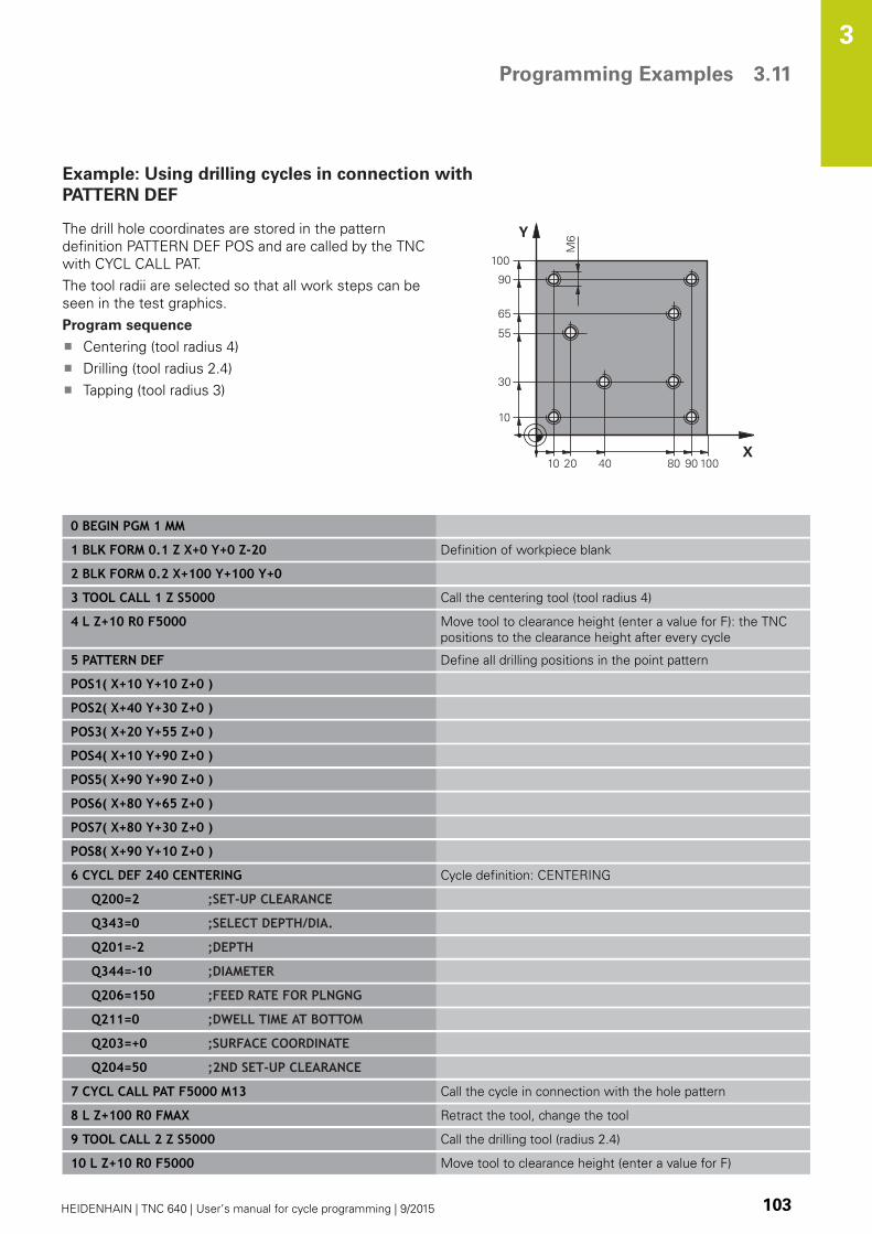
Programming Examples 3.11
3
HEIDENHAIN | TNC 640 | User’s manual for cycle programming | 9/2015 103
Example: Using drilling cycles in connection with
PATTERN DEF
The drill hole coordinates are stored in the pattern
definition PATTERN DEF POS and are called by the TNC
with CYCL CALL PAT.
The tool radii are selected so that all work steps can be
seen in the test graphics.
Program sequence
Centering (tool radius 4)
Drilling (tool radius 2.4)
Tapping (tool radius 3)
0 BEGIN PGM 1 MM
1 BLK FORM 0.1 Z X+0 Y+0 Z-20 Definition of workpiece blank
2 BLK FORM 0.2 X+100 Y+100 Y+0
3 TOOL CALL 1 Z S5000 Call the centering tool (tool radius 4)
4 L Z+10 R0 F5000 Move tool to clearance height (enter a value for F): the TNC
positions to the clearance height after every cycle
5 PATTERN DEF Define all drilling positions in the point pattern
POS1( X+10 Y+10 Z+0 )
POS2( X+40 Y+30 Z+0 )
POS3( X+20 Y+55 Z+0 )
POS4( X+10 Y+90 Z+0 )
POS5( X+90 Y+90 Z+0 )
POS6( X+80 Y+65 Z+0 )
POS7( X+80 Y+30 Z+0 )
POS8( X+90 Y+10 Z+0 )
6 CYCL DEF 240 CENTERING Cycle definition: CENTERING
Q200=2 ;SET-UP CLEARANCE
Q343=0 ;SELECT DEPTH/DIA.
Q201=-2 ;DEPTH
Q344=-10 ;DIAMETER
Q206=150 ;FEED RATE FOR PLNGNG
Q211=0 ;DWELL TIME AT BOTTOM
Q203=+0 ;SURFACE COORDINATE
Q204=50 ;2ND SET-UP CLEARANCE
7 CYCL CALL PAT F5000 M13 Call the cycle in connection with the hole pattern
8 L Z+100 R0 FMAX Retract the tool, change the tool
9 TOOL CALL 2 Z S5000 Call the drilling tool (radius 2.4)
10 L Z+10 R0 F5000 Move tool to clearance height (enter a value for F)

Fixed Cycles: Drilling 3.11 Programming Examples
3
104 HEIDENHAIN | TNC 640 | User’s manual for cycle programming | 9/2015
11 CYCL DEF 200 DRILLING Cycle definition: drilling
Q200=2 ;SET-UP CLEARANCE
Q201=-25 ;DEPTH
Q206=150 ;FEED RATE FOR PLNGNG
Q202=5 ;PLUNGING DEPTH
Q211=0 ;DWELL TIME AT TOP
Q203=+0 ;SURFACE COORDINATE
Q204=50 ;2ND SET-UP CLEARANCE
Q211=0.2 ;DWELL TIME AT BOTTOM
Q395=0 ;DEPTH REFERENCE
12 CYCL CALL PAT F5000 M13 Call the cycle in connection with the hole pattern
13 L Z+100 R0 FMAX Retract the tool
14 TOOL CALL 3 Z S200 Call the tapping tool (radius 3)
15 L Z+50 R0 FMAX Move tool to clearance height
16 CYCL DEF 206 TAPPING NEW Cycle definition for tapping
Q200=2 ;SET-UP CLEARANCE
Q201=-25 ;THREAD DEPTH
Q206=150 ;FEED RATE FOR PLNGNG
Q211=0 ;DWELL TIME AT BOTTOM
Q203=+0 ;SURFACE COORDINATE
Q204=50 ;2ND SET-UP CLEARANCE
17 CYCL CALL PAT F5000 M13 Call the cycle in connection with the hole pattern
18 L Z+100 R0 FMAX M2 Retract the tool, end program
19 END PGM 1 MM

4Fixed Cycles:
Tapping / ThreadMilling

Fixed Cycles: Tapping / Thread Milling 4.1 Fundamentals
4
106 HEIDENHAIN | TNC 640 | User’s manual for cycle programming | 9/2015
4.1 Fundamentals
Overview
The TNC offers the following cycles for all types of threading
operations:
Soft key Cycle Page
206 TAPPING NEW
With a floating tap holder,
with automatic prepositioning,
2nd Set-up clearance
107
207 TAPPING NEW
Without a floating tap holder, with
automatic pre-positioning, 2nd set-up
clearance
110
209 TAPPING WITH CHIP BREAKING
Without a floating tap holder, with
automatic pre-positioning, 2nd set-up
clearance, chip breaking
113
262 THREAD MILLING
Cycle for milling a thread in pre-drilled
material
119
263 THREAD MILLING/
COUNTERSINKING
Cycle for milling a thread in pre-drilled
material and machining a countersunk
chamfer
122
264 THREAD DRILLING/MILLING
Cycle for drilling into solid material
with subsequent milling of the thread
with a tool
126
265 HELICAL THREAD DRILLING/
MILLING
Cycle for milling the thread into solid
material
130
267 OUTSIDE THREAD MILLING
Cycle for milling an external thread
and machining a countersunk chamfer
134

TAPPING with a floating tap holder (Cycle 206) 4.2
4
HEIDENHAIN | TNC 640 | User’s manual for cycle programming | 9/2015 107
4.2 TAPPING with a floating tap holder
(Cycle 206, DIN/ISO: G206)
Cycle run
1 The TNC positions the tool in the tool axis at rapid traverse
FMAX to the entered set-up clearance above the workpiece
surface.
2 The tool drills to the total hole depth in one movement.
3 Once the tool has reached the total hole depth, the direction of
spindle rotation is reversed and the tool is retracted to the set-
up clearance at the end of the dwell time. If programmed, the
tool moves to the 2nd set-up clearance at FMAX.
4 At the set-up clearance, the direction of spindle rotation
reverses once again.

Fixed Cycles: Tapping / Thread Milling 4.2 TAPPING with a floating tap holder (Cycle 206)
4
108 HEIDENHAIN | TNC 640 | User’s manual for cycle programming | 9/2015
Please note while programming:
Program a positioning block for the starting point
(hole center) in the working plane with radius
compensation R0.
The algebraic sign for the cycle parameter DEPTH
determines the working direction. If you program
DEPTH=0, the cycle will not be executed.
A floating tap holder is required for tapping. It must
compensate the tolerances between feed rate and
spindle speed during the tapping process.
When a cycle is being run, the spindle speed override
knob is disabled. The feed-rate override knob is active
only within a limited range, which is defined by the
machine tool builder (refer to your machine manual).
For tapping right-hand threads activate the spindle
with M3, for left-hand threads use M4.
If you enter the thread pitch of the tap in the Pitchcolumn of the tool table, the TNC compares the
thread pitch from the tool table with the thread
pitch defined in the cycle. The TNC displays an error
message if the values do not match. In Cycle 206 the
TNC uses the programmed rotational speed and the
feed rate defined in the cycle to calculate the thread
pitch.
Danger of collision!
Use the machine parameter displayDepthErr to
define whether, if a positive depth is entered, the
TNC should output an error message (on) or not (off).
Keep in mind that the TNC reverses the calculation
for pre-positioning when a positive depth is
entered. This means that the tool moves at rapid
traverse in the tool axis to set-up clearance below
the workpiece surface!

TAPPING with a floating tap holder (Cycle 206) 4.2
4
HEIDENHAIN | TNC 640 | User’s manual for cycle programming | 9/2015 109
Cycle parameters
Set-up clearance Q200 (incremental): Distance
between tool tip and workpiece surface. Input range
0 to 99999.9999
Guide value: 4x pitch.
Thread depth Q201 (incremental): Distance
between workpiece surface and root of thread.
Input range -99999.9999 to 99999.9999
Feed rate F Q206: Traversing speed of the tool
during tapping. Input range 0 to 99999.999
alternatively FAUTODwell time at bottom Q211: Enter a value between
0 and 0.5 seconds to avoid wedging of the tool
during retraction. Input range 0 to 3600.0000
Coordinate of workpiece surface Q203 (absolute):
Coordinate of the workpiece surface. Input range
-99999.9999 to 99999.9999
2nd set-up clearance Q204 (incremental):
Coordinate in the spindle axis at which no collision
between tool and workpiece (fixtures) can occur.
Input range 0 to 99999.9999
NC blocks
25 CYCL DEF 206 TAPPING NEW
Q200=2 ;SET-UP CLEARANCE
Q201=-20 ;THREAD DEPTH
Q206=150 ;FEED RATE FORPLNGNG
Q211=0.25 ;DWELL TIME ATBOTTOM
Q203=+25 ;SURFACE COORDINATE
Q204=50 ;2ND SET-UPCLEARANCE
The feed rate is calculated as follows: F = S x p
F: Feed rate (mm/min)
S: Spindle speed (rpm)
p: Thread pitch (mm)
Retracting after a program interruption
If you interrupt program run during tapping with the machine stop
button, the TNC will display a soft key with which you can retract
the tool.
Fixed Cycles: Tapping / Thread Milling 4.3 RIGID TAPPING without a floating tap holder (Cycle 207)
4
110 HEIDENHAIN | TNC 640 | User’s manual for cycle programming | 9/2015
4.3 RIGID TAPPING without a floating
tap holder (Cycle 207, DIN/
ISO: G207)
Cycle run
The TNC cuts the thread without a floating tap holder in one or
more passes.
1 The TNC positions the tool in the tool axis at rapid traverse
FMAX to the entered set-up clearance above the workpiece
surface.
2 The tool drills to the total hole depth in one movement.
3 It then reverses the direction of spindle rotation again and the
tool is retracted to the setup clearance. If you have entered a
2nd set-up clearance the TNC will move the tool with FMAXtowards it.
4 The TNC stops the spindle turning at set-up clearance.

RIGID TAPPING without a floating tap holder (Cycle 207) 4.3
4
HEIDENHAIN | TNC 640 | User’s manual for cycle programming | 9/2015 111
Please note while programming:
Machine and TNC must be specially prepared by the
machine tool builder for use of this cycle.
This cycle is effective only for machines with servo-
controlled spindle.
Program a positioning block for the starting point
(hole center) in the working plane with radius
compensation R0.
The algebraic sign for the cycle parameter DEPTH
determines the working direction. If you program
DEPTH=0, the cycle will not be executed.
The TNC calculates the feed rate from the spindle
speed. If the feed-rate override is used during
tapping, the TNC automatically adjusts the feed rate.
The feed-rate override knob is disabled.
At the end of the cycle the spindle comes to a stop.
Before the next operation, restart the spindle with
M3 (or M4).
If you enter the thread pitch of the tap in the Pitchcolumn of the tool table, the TNC compares the
thread pitch from the tool table with the thread
pitch defined in the cycle. The TNC displays an error
message if the values do not match.
Danger of collision!
Use the machine parameter displayDepthErr to
define whether, if a positive depth is entered, the
TNC should output an error message (on) or not (off).
Keep in mind that the TNC reverses the calculation
for pre-positioning when a positive depth is
entered. This means that the tool moves at rapid
traverse in the tool axis to set-up clearance below
the workpiece surface!

Fixed Cycles: Tapping / Thread Milling 4.3 RIGID TAPPING without a floating tap holder (Cycle 207)
4
112 HEIDENHAIN | TNC 640 | User’s manual for cycle programming | 9/2015
Cycle parameters
Set-up clearance Q200 (incremental): Distance
between tool tip and workpiece surface. Input range
0 to 99999.9999
Thread depth Q201 (incremental): Distance
between workpiece surface and root of thread.
Input range -99999.9999 to 99999.9999
Thread pitch Q239: Pitch of the thread. The
algebraic sign differentiates between right-hand and
left-hand threads:
+ = right-hand thread
–= left-hand thread
Input range -99.9999 to 99.9999
Coordinate of workpiece surface Q203 (absolute):
Coordinate of the workpiece surface. Input range
-99999.9999 to 99999.9999
2nd set-up clearance Q204 (incremental):
Coordinate in the spindle axis at which no collision
between tool and workpiece (fixtures) can occur.
Input range 0 to 99999.9999
NC blocks
26 CYCL DEF 207 RIGID TAPPING NEW
Q200=2 ;SET-UP CLEARANCE
Q201=-20 ;THREAD DEPTH
Q239=+1 ;THREAD PITCH
Q203=+25 ;SURFACE COORDINATE
Q204=50 ;2ND SET-UPCLEARANCE
Retracting after a program interruption
Retracting in the Manual Operation mode
You can interrupt the thread cutting process by pressing the NC
Stop key. A soft key for retracting the tool from the thread is
displayed in the soft-key row below the screen. When you press
this soft key and the NC Start key, the tool retracts from the
hole and returns to the starting point of machining. The spindle
is stopped automatically and the TNC displays a message.
Retracting in the Program Run, Single Block or Full Sequence
mode
You can interrupt the thread cutting process by pressing the
NC Stop key. The TNC displays the MANUAL TRAVERSE soft
key. After you pressed the MANUAL TRAVERSE soft key, you
can retract the tool from the active spindle axis. To resume
machining after the interruption, press the RESTORE POSITIONsoft key and NC Start. The TNC moves the tool back to the
position it had assumed before the NC Stop key was pressed.
When retracting the tool you can move it in the
positive and negative tool axis directions. Please
keep this in mind during retraction—danger of
collision!

TAPPING WITH CHIP BREAKING (Cycle 209, DIN/ISO: G209) 4.4
4
HEIDENHAIN | TNC 640 | User’s manual for cycle programming | 9/2015 113
4.4 TAPPING WITH CHIP BREAKING
(Cycle 209, DIN/ISO: G209)
Cycle run
The TNC machines the thread in several passes until it reaches the
programmed depth. You can define in a parameter whether the tool
is to be retracted completely from the hole for chip breaking.
1 The TNC positions the tool in the tool axis at rapid traverse
FMAX to the programmed set-up clearance above the workpiece
surface. There it carries out an oriented spindle stop.
2 The tool moves to the programmed infeed depth, reverses the
direction of spindle rotation and retracts by a specific distance
or completely for chip release, depending on the definition. If
you have defined a factor for increasing the spindle speed, the
TNC retracts from the hole at the corresponding speed.
3 It then reverses the direction of spindle rotation again and
advances to the next infeed depth.
4 The TNC repeats this process (2 to 3) until the programmed
thread depth is reached.
5 The tool is then retracted to set-up clearance. If programmed,
the tool moves to the 2nd set-up clearance at FMAX.
6 The TNC stops the spindle turning at set-up clearance.

Fixed Cycles: Tapping / Thread Milling 4.4 TAPPING WITH CHIP BREAKING (Cycle 209, DIN/ISO: G209)
4
114 HEIDENHAIN | TNC 640 | User’s manual for cycle programming | 9/2015
Please note while programming:
Machine and TNC must be specially prepared by the
machine tool builder for use of this cycle.
This cycle is effective only for machines with servo-
controlled spindle.
Program a positioning block for the starting point
(hole center) in the working plane with radius
compensation R0.
The algebraic sign for the cycle parameter "thread
depth" determines the working direction.
The TNC calculates the feed rate from the spindle
speed. If the feed-rate override is used during
tapping, the TNC automatically adjusts the feed rate.
The feed-rate override knob is disabled.
If you defined an rpm factor for fast retraction in
cycle parameter Q403, the TNC limits the speed to
the maximum speed of the active gear range.
At the end of the cycle the spindle comes to a stop.
Before the next operation, restart the spindle with
M3 (or M4).
If you enter the thread pitch of the tap in the Pitchcolumn of the tool table, the TNC compares the
thread pitch from the tool table with the thread
pitch defined in the cycle. The TNC displays an error
message if the values do not match.
Danger of collision!
Use the machine parameter displayDepthErr to
define whether, if a positive depth is entered, the
TNC should output an error message (on) or not (off).
Keep in mind that the TNC reverses the calculation
for pre-positioning when a positive depth is
entered. This means that the tool moves at rapid
traverse in the tool axis to set-up clearance below
the workpiece surface!

TAPPING WITH CHIP BREAKING (Cycle 209, DIN/ISO: G209) 4.4
4
HEIDENHAIN | TNC 640 | User’s manual for cycle programming | 9/2015 115
Cycle parameters
Set-up clearance Q200 (incremental): Distance
between tool tip and workpiece surface. Input range
0 to 99999.9999
Thread depth Q201 (incremental): Distance
between workpiece surface and root of thread.
Input range -99999.9999 to 99999.9999
Thread pitch Q239: Pitch of the thread. The
algebraic sign differentiates between right-hand and
left-hand threads:
+ = right-hand thread
–= left-hand thread
Input range -99.9999 to 99.9999
Coordinate of workpiece surface Q203 (absolute):
Coordinate of the workpiece surface. Input range
-99999.9999 to 99999.9999
2nd set-up clearance Q204 (incremental):
Coordinate in the spindle axis at which no collision
between tool and workpiece (fixtures) can occur.
Input range 0 to 99999.9999
Infeed depth for chip breaking Q257
(incremental): Depth at which the TNC carries out
chip breaking. No chip breaking if 0 is entered. Input
range 0 to 99999.9999
Retraction rate for chip breaking Q256: The
TNC multiplies the pitch Q239 by the programmed
value and retracts the tool by the calculated value
during chip breaking. If you enter Q256 = 0, the
TNC retracts the tool completely from the hole (to
the set-up clearance) for chip breaking. Input range
0.000 to 99999.999
Angle for spindle orientation Q336 (absolute):
Angle at which the TNC positions the tool before
machining the thread. This allows you to regroove
the thread, if required. Input range -360.0000 to
360.0000
RPM factor for retraction Q403: Factor by
which the TNC increases the spindle speed—
and therefore also the retraction feed rate—when
retracting from the drill hole. Input range 0.0001 to
10. Maximum increase to maximum speed of the
active gear range.
NC blocks
26 CYCL DEF 209 TAPPING W/ CHIPBRKG
Q200=2 ;SET-UP CLEARANCE
Q201=-20 ;DEPTH
Q239=+1 ;THREAD PITCH
Q203=+25 ;SURFACE COORDINATE
Q204=50 ;2ND SET-UPCLEARANCE
Q257=5 ;DEPTH FOR CHIPBRKNG
Q256=+1 ;DIST. FOR CHIP BRKNG
Q336=50 ;ANGLE OF SPINDLE
Q403=1.5 ;RPM FACTOR

Fixed Cycles: Tapping / Thread Milling 4.4 TAPPING WITH CHIP BREAKING (Cycle 209, DIN/ISO: G209)
4
116 HEIDENHAIN | TNC 640 | User’s manual for cycle programming | 9/2015
Retracting after a program interruption
Retracting in the Manual Operation mode
You can interrupt the thread cutting process by pressing the NC
Stop key. A soft key for retracting the tool from the thread is
displayed in the soft-key row below the screen. When you press
this soft key and the NC Start key, the tool retracts from the
hole and returns to the starting point of machining. The spindle
is stopped automatically and the TNC displays a message.
Retracting in the Program Run, Single Block or Full Sequence
mode
You can interrupt the thread cutting process by pressing the
NC Stop key. The TNC displays the MANUAL TRAVERSE soft
key. After you pressed the MANUAL TRAVERSE soft key, you
can retract the tool from the active spindle axis. To resume
machining after the interruption, press the RESTORE POSITIONsoft key and NC Start. The TNC moves the tool back to the
position it had assumed before the NC Stop key was pressed.
When retracting the tool you can move it in the
positive and negative tool axis directions. Please
keep this in mind during retraction—danger of
collision!
Fundamentals of Thread Milling 4.5
4
HEIDENHAIN | TNC 640 | User’s manual for cycle programming | 9/2015 117
4.5 Fundamentals of Thread Milling
Prerequisites
Your machine tool should feature internal spindle cooling
(cooling lubricant at least 30 bars, compressed air supply at
least 6 bars).
Thread milling usually leads to distortions of the thread profile.
To correct this effect, you need tool-specific compensation
values which are given in the tool catalog or are available from
the tool manufacturer. You program the compensation with the
delta value for the tool radius DR in the TOOL CALL.
The Cycles 262, 263, 264 and 267 can only be used with
rightward rotating tools. For Cycle 265 you can use rightward
and leftward rotating tools.
The working direction is determined by the following input
parameters: Algebraic sign Q239 (+ = right-hand thread / – =
left-hand thread) and milling method Q351 (+1 = climb / –1 =
up-cut). The table below illustrates the interrelation between the
individual input parameters for rightward rotating tools.
Internal thread Pitch Climb/
Up-cut
Work direction
Right-handed + +1(RL) Z+
Left-handed – –1(RR) Z+
Right-handed + –1(RR) Z–
Left-handed – +1(RL) Z–
External
thread
Pitch Climb/
Up-cut
Work direction
Right-handed + +1(RL) Z–
Left-handed – –1(RR) Z–
Right-handed + –1(RR) Z+
Left-handed – +1(RL) Z+
The TNC references the programmed feed rate
during thread milling to the tool cutting edge. Since
the TNC, however, always displays the feed rate
relative to the path of the tool tip, the displayed value
does not match the programmed value.
The machining direction of the thread changes if you
execute a thread milling cycle in connection with
Cycle 8 MIRROR IMAGE in only one axis.
Fixed Cycles: Tapping / Thread Milling 4.5 Fundamentals of Thread Milling
4
118 HEIDENHAIN | TNC 640 | User’s manual for cycle programming | 9/2015
Danger of collision!
Always program the same algebraic sign for the
infeeds: Cycles comprise several sequences of
operation that are independent of each other.
The order of precedence according to which the
work direction is determined is described with the
individual cycles. For example, if you only want to
repeat the countersinking process of a cycle, enter 0
for the thread depth. The work direction will then be
determined from the countersinking depth.
Procedure in case of a tool break
If a tool break occurs during thread cutting, stop
program run, change to the Positioning with MDI
operating mode and move the tool on a linear path to
the hole center. You can then retract the tool in the
infeed axis and replace it.
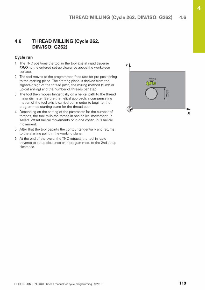
THREAD MILLING (Cycle 262, DIN/ISO: G262) 4.6
4
HEIDENHAIN | TNC 640 | User’s manual for cycle programming | 9/2015 119
4.6 THREAD MILLING (Cycle 262,
DIN/ISO: G262)
Cycle run
1 The TNC positions the tool in the tool axis at rapid traverse
FMAX to the entered set-up clearance above the workpiece
surface.
2 The tool moves at the programmed feed rate for pre-positioning
to the starting plane. The starting plane is derived from the
algebraic sign of the thread pitch, the milling method (climb or
up-cut milling) and the number of threads per step.
3 The tool then moves tangentially on a helical path to the thread
major diameter. Before the helical approach, a compensating
motion of the tool axis is carried out in order to begin at the
programmed starting plane for the thread path.
4 Depending on the setting of the parameter for the number of
threads, the tool mills the thread in one helical movement, in
several offset helical movements or in one continuous helical
movement.
5 After that the tool departs the contour tangentially and returns
to the starting point in the working plane.
6 At the end of the cycle, the TNC retracts the tool in rapid
traverse to setup clearance or, if programmed, to the 2nd setup
clearance.
Fixed Cycles: Tapping / Thread Milling 4.6 THREAD MILLING (Cycle 262, DIN/ISO: G262)
4
120 HEIDENHAIN | TNC 640 | User’s manual for cycle programming | 9/2015
Please note while programming:
Program a positioning block for the starting point
(hole center) in the working plane with radius
compensation R0.
The algebraic sign for the cycle parameter "thread
depth" determines the working direction.
If you program the thread DEPTH = 0, the cycle will
not be executed.
The nominal thread diameter is approached in a semi-
circle from the center. A pre-positioning movement
to the side is carried out if the pitch of the tool
diameter is four times smaller than the nominal
thread diameter.
Note that the TNC makes a compensation
movement in the tool axis before the approach
movement. The length of the compensation
movement is at most half of the thread pitch. Ensure
sufficient space in the hole!
If you change the thread depth, the TNC
automatically changes the starting point for the
helical movement.
Danger of collision!
Use the machine parameter displayDepthErr to
define whether, if a positive depth is entered, the
TNC should output an error message (on) or not (off).
Keep in mind that the TNC reverses the calculation
for pre-positioning when a positive depth is
entered. This means that the tool moves at rapid
traverse in the tool axis to set-up clearance below
the workpiece surface!

THREAD MILLING (Cycle 262, DIN/ISO: G262) 4.6
4
HEIDENHAIN | TNC 640 | User’s manual for cycle programming | 9/2015 121
Cycle parameters
Nominal diameter Q335: Nominal thread diameter.
Input range 0 to 99999.9999
Thread pitch Q239: Pitch of the thread. The
algebraic sign differentiates between right-hand and
left-hand threads:
+ = right-hand thread
–= left-hand thread
Input range -99.9999 to 99.9999
Thread depth Q201 (incremental): Distance
between workpiece surface and root of thread.
Input range -99999.9999 to 99999.9999
Threads per step Q355: Number of thread starts by
which the tool is displaced:
0 = one helix on the thread depth
1 = continuous helix on the complete thread length
>1 = several helix paths with approach and
departure, between these the TNC sets the tool by
Q355 x pitch. Input range 0 to 99999
Feed rate for pre-positioning Q253: Traversing
speed of the tool when moving in and out of the
workpiece, in mm/min. Input range 0 to 99999.9999
alternatively FMAX, FAUTOClimb or up-cut Q351: Type of milling operation
with M3
+1 = Climb
–1 = Up-cut (If you enter 0, climb milling is used for
machining)
Set-up clearance Q200 (incremental): Distance
between tool tip and workpiece surface. Input range
0 to 99999.9999
Coordinate of workpiece surface Q203 (absolute):
Coordinate of the workpiece surface. Input range
-99999.9999 to 99999.9999
2nd set-up clearance Q204 (incremental):
Coordinate in the spindle axis at which no collision
between tool and workpiece (fixtures) can occur.
Input range 0 to 99999.9999
Feed rate for milling Q207: Traversing speed of
the tool in mm/min while milling. Input range 0 to
99999.999 alternatively FAUTOFeed rate for approaching Q206: Traversing
speed of the tool in mm/min while approaching.
If the thread diameters are small, you can reduce
the danger of tool breakage by using a reduced
approaching feed rate. Input range 0 to 99999.999
alternatively FAUTO
NC blocks
25 CYCL DEF 262 THREAD MILLING
Q335=10 ;NOMINAL DIAMETER
Q239=+1.5 ;THREAD PITCH
Q201=-20 ;THREAD DEPTH
Q355=0 ;THREADS PER STEP
Q253=750 ;F PRE-POSITIONING
Q351=+1 ;CLIMB OR UP-CUT
Q200=2 ;SET-UP CLEARANCE
Q203=+30 ;SURFACE COORDINATE
Q204=50 ;2ND SET-UPCLEARANCE
Q207=500 ;FEED RATE FORMILLING
Q512=0 ;FEED RATE FORAPPROACHING

Fixed Cycles: Tapping / Thread Milling 4.7 THREAD MILLING/COUNTERSINKING (Cycle 263, DIN/ISO:G263)
4
122 HEIDENHAIN | TNC 640 | User’s manual for cycle programming | 9/2015
4.7 THREAD MILLING/
COUNTERSINKING (Cycle 263, DIN/
ISO:G263)
Cycle run
1 The TNC positions the tool in the tool axis at rapid traverse
FMAX to the entered set-up clearance above the workpiece
surface.
Countersinking
2 The tool moves at the feed rate for pre-positioning to the
countersinking depth minus the set-up clearance, and then at
the feed rate for countersinking to the countersinking depth.
3 If a safety clearance to the side has been entered, the TNC
immediately positions the tool at the feed rate for pre-
positioning to the countersinking depth.
4 Then, depending on the available space, the TNC makes a
tangential approach to the core diameter, either tangentially
from the center or with a pre-positioning move to the side, and
follows a circular path.
Countersinking at front
5 The tool moves at the feed rate for pre-positioning to the sinking
depth at front.
6 The TNC positions the tool without compensation from the
center on a semicircle to the offset at front, and then follows a
circular path at the feed rate for countersinking.
7 The tool then moves in a semicircle to the hole center.
Thread milling
8 The TNC moves the tool at the programmed feed rate for pre-
positioning to the starting plane for the thread. The starting
plane is determined from the thread pitch and the type of
milling (climb or up-cut).
9 Then the tool moves tangentially on a helical path to the thread
diameter and mills the thread with a 360° helical motion.
10 After that the tool departs the contour tangentially and returns
to the starting point in the working plane.
11 At the end of the cycle, the TNC retracts the tool in rapid
traverse to setup clearance or, if programmed, to the 2nd setup
clearance.

THREAD MILLING/COUNTERSINKING (Cycle 263, DIN/ISO:G263) 4.7
4
HEIDENHAIN | TNC 640 | User’s manual for cycle programming | 9/2015 123
Please note while programming:
Program a positioning block for the starting point
(hole center) in the working plane with radius
compensation R0.
The algebraic sign of the cycle parameters depth
of thread, countersinking depth or sinking depth at
front determines the working direction. The working
direction is defined in the following sequence:
1. Thread depth
2. Countersinking depth
3. Depth at front
If you program a depth parameter to be 0, the TNC
does not execute that step.
If you want to countersink at front, define the
countersinking depth as 0.
Program the thread depth as a value smaller than the
countersinking depth by at least one-third the thread
pitch.
Danger of collision!
Use the machine parameter displayDepthErr to
define whether, if a positive depth is entered, the
TNC should output an error message (on) or not (off).
Keep in mind that the TNC reverses the calculation
for pre-positioning when a positive depth is
entered. This means that the tool moves at rapid
traverse in the tool axis to set-up clearance below
the workpiece surface!
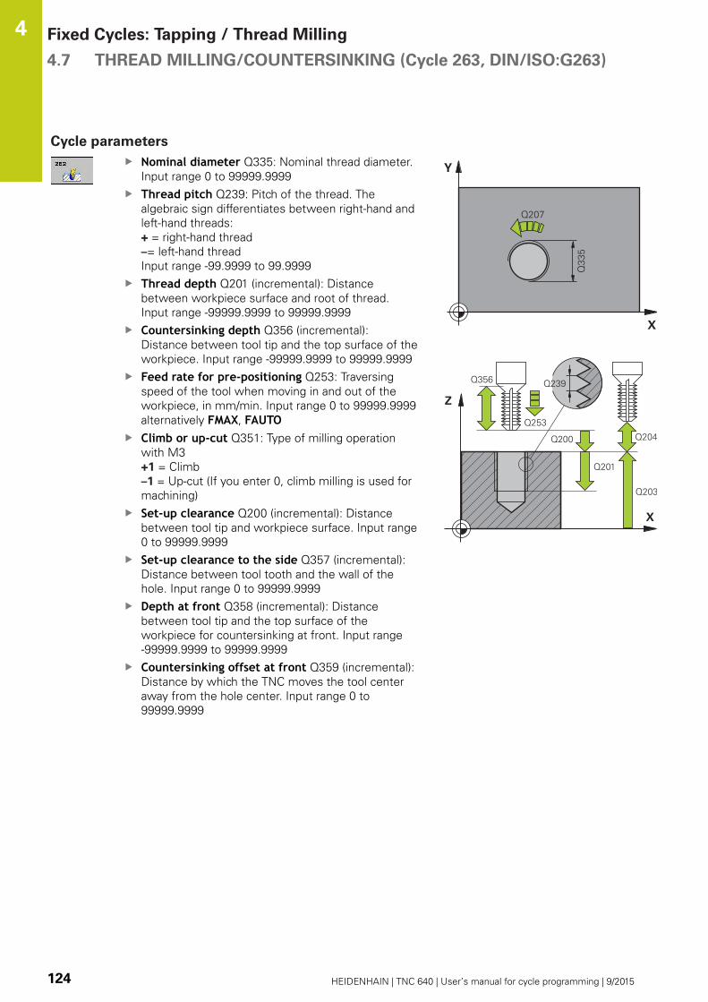
Fixed Cycles: Tapping / Thread Milling 4.7 THREAD MILLING/COUNTERSINKING (Cycle 263, DIN/ISO:G263)
4
124 HEIDENHAIN | TNC 640 | User’s manual for cycle programming | 9/2015
Cycle parameters
Nominal diameter Q335: Nominal thread diameter.
Input range 0 to 99999.9999
Thread pitch Q239: Pitch of the thread. The
algebraic sign differentiates between right-hand and
left-hand threads:
+ = right-hand thread
–= left-hand thread
Input range -99.9999 to 99.9999
Thread depth Q201 (incremental): Distance
between workpiece surface and root of thread.
Input range -99999.9999 to 99999.9999
Countersinking depth Q356 (incremental):
Distance between tool tip and the top surface of the
workpiece. Input range -99999.9999 to 99999.9999
Feed rate for pre-positioning Q253: Traversing
speed of the tool when moving in and out of the
workpiece, in mm/min. Input range 0 to 99999.9999
alternatively FMAX, FAUTOClimb or up-cut Q351: Type of milling operation
with M3
+1 = Climb
–1 = Up-cut (If you enter 0, climb milling is used for
machining)
Set-up clearance Q200 (incremental): Distance
between tool tip and workpiece surface. Input range
0 to 99999.9999
Set-up clearance to the side Q357 (incremental):
Distance between tool tooth and the wall of the
hole. Input range 0 to 99999.9999
Depth at front Q358 (incremental): Distance
between tool tip and the top surface of the
workpiece for countersinking at front. Input range
-99999.9999 to 99999.9999
Countersinking offset at front Q359 (incremental):
Distance by which the TNC moves the tool center
away from the hole center. Input range 0 to
99999.9999

THREAD MILLING/COUNTERSINKING (Cycle 263, DIN/ISO:G263) 4.7
4
HEIDENHAIN | TNC 640 | User’s manual for cycle programming | 9/2015 125
Coordinate of workpiece surface Q203 (absolute):
Coordinate of the workpiece surface. Input range
-99999.9999 to 99999.9999
2nd set-up clearance Q204 (incremental):
Coordinate in the spindle axis at which no collision
between tool and workpiece (fixtures) can occur.
Input range 0 to 99999.9999
Feed rate for countersinking Q254: Traversing
speed of the tool during countersinking in mm/min.
Input range 0 to 99999.9999 alternatively FAUTO,
FUFeed rate for milling Q207: Traversing speed of
the tool in mm/min while milling. Input range 0 to
99999.999 alternatively FAUTOFeed rate for approaching Q206: Traversing
speed of the tool in mm/min while approaching.
If the thread diameters are small, you can reduce
the danger of tool breakage by using a reduced
approaching feed rate. Input range 0 to 99999.999
alternatively FAUTO
NC blocks
25 CYCL DEF 263 THREAD MLLNG/CNTSNKG
Q335=10 ;NOMINAL DIAMETER
Q239=+1.5 ;THREAD PITCH
Q201=-16 ;THREAD DEPTH
Q356=-20 ;COUNTERSINKINGDEPTH
Q253=750 ;F PRE-POSITIONING
Q351=+1 ;CLIMB OR UP-CUT
Q200=2 ;SET-UP CLEARANCE
Q357=0.2 ;CLEARANCE TO SIDE
Q358=+0 ;DEPTH AT FRONT
Q359=+0 ;OFFSET AT FRONT
Q203=+30 ;SURFACE COORDINATE
Q204=50 ;2ND SET-UPCLEARANCE
Q254=150 ;F COUNTERBORING
Q207=500 ;FEED RATE FORMILLING
Q512=0 ;FEED RATE FORAPPROACHING

Fixed Cycles: Tapping / Thread Milling 4.8 THREAD DRILLING/MILLING (Cycle 264, DIN/ISO: G264)
4
126 HEIDENHAIN | TNC 640 | User’s manual for cycle programming | 9/2015
4.8 THREAD DRILLING/MILLING (Cycle
264, DIN/ISO: G264)
Cycle run
1 The TNC positions the tool in the tool axis at rapid traverse
FMAX to the entered set-up clearance above the workpiece
surface.
Drilling
2 The tool drills to the first plunging depth at the programmed
feed rate for plunging.
3 If you have programmed chip breaking, the tool then retracts
by the entered retraction value. If you are working without
chip breaking, the tool is moved at rapid traverse to the set-up
clearance, and then at FMAX to the entered starting position
above the first plunging depth.
4 The tool then advances with another infeed at the programmed
feed rate.
5 The TNC repeats this process (2 to 4) until the programmed
total hole depth is reached.
Countersinking at front
6 The tool moves at the feed rate for pre-positioning to the sinking
depth at front.
7 The TNC positions the tool without compensation from the
center on a semicircle to the offset at front, and then follows a
circular path at the feed rate for countersinking.
8 The tool then moves in a semicircle to the hole center.
Thread milling
9 The TNC moves the tool at the programmed feed rate for pre-
positioning to the starting plane for the thread. The starting
plane is determined from the thread pitch and the type of
milling (climb or up-cut).
10 Then the tool moves tangentially on a helical path to the thread
diameter and mills the thread with a 360° helical motion.
11 After that the tool departs the contour tangentially and returns
to the starting point in the working plane.
12 At the end of the cycle, the TNC retracts the tool in rapid
traverse to setup clearance or, if programmed, to the 2nd setup
clearance.

THREAD DRILLING/MILLING (Cycle 264, DIN/ISO: G264) 4.8
4
HEIDENHAIN | TNC 640 | User’s manual for cycle programming | 9/2015 127
Please note while programming:
Program a positioning block for the starting point
(hole center) in the working plane with radius
compensation R0.
The algebraic sign of the cycle parameters depth
of thread, countersinking depth or sinking depth at
front determines the working direction. The working
direction is defined in the following sequence:
1. Thread depth
2. Countersinking depth
3. Depth at front
If you program a depth parameter to be 0, the TNC
does not execute that step.
Program the thread depth as a value smaller than the
total hole depth by at least one-third the thread pitch.
Danger of collision!
Use the machine parameter displayDepthErr to
define whether, if a positive depth is entered, the
TNC should output an error message (on) or not (off).
Keep in mind that the TNC reverses the calculation
for pre-positioning when a positive depth is
entered. This means that the tool moves at rapid
traverse in the tool axis to set-up clearance below
the workpiece surface!

Fixed Cycles: Tapping / Thread Milling 4.8 THREAD DRILLING/MILLING (Cycle 264, DIN/ISO: G264)
4
128 HEIDENHAIN | TNC 640 | User’s manual for cycle programming | 9/2015
Cycle parameters
Nominal diameter Q335: Nominal thread diameter.
Input range 0 to 99999.9999
Thread pitch Q239: Pitch of the thread. The
algebraic sign differentiates between right-hand and
left-hand threads:
+ = right-hand thread
–= left-hand thread
Input range -99.9999 to 99.9999
Thread depth Q201 (incremental): Distance
between workpiece surface and root of thread.
Input range -99999.9999 to 99999.9999
Total hole depth Q356 (incremental): Distance
between workpiece surface and bottom of hole.
Input range -99999.9999 to 99999.9999
Feed rate for pre-positioning Q253: Traversing
speed of the tool when moving in and out of the
workpiece, in mm/min. Input range 0 to 99999.9999
alternatively FMAX, FAUTOClimb or up-cut Q351: Type of milling operation
with M3
+1 = Climb
–1 = Up-cut (If you enter 0, climb milling is used for
machining)
Plunging depth Q202 (incremental): Infeed per cut.
The depth does not have to be a multiple of the
plunging depth. Input range 0 to 99999.9999
The TNC will go to depth in one movement if:
the plunging depth is equal to the depth
the plunging depth is greater than the depth
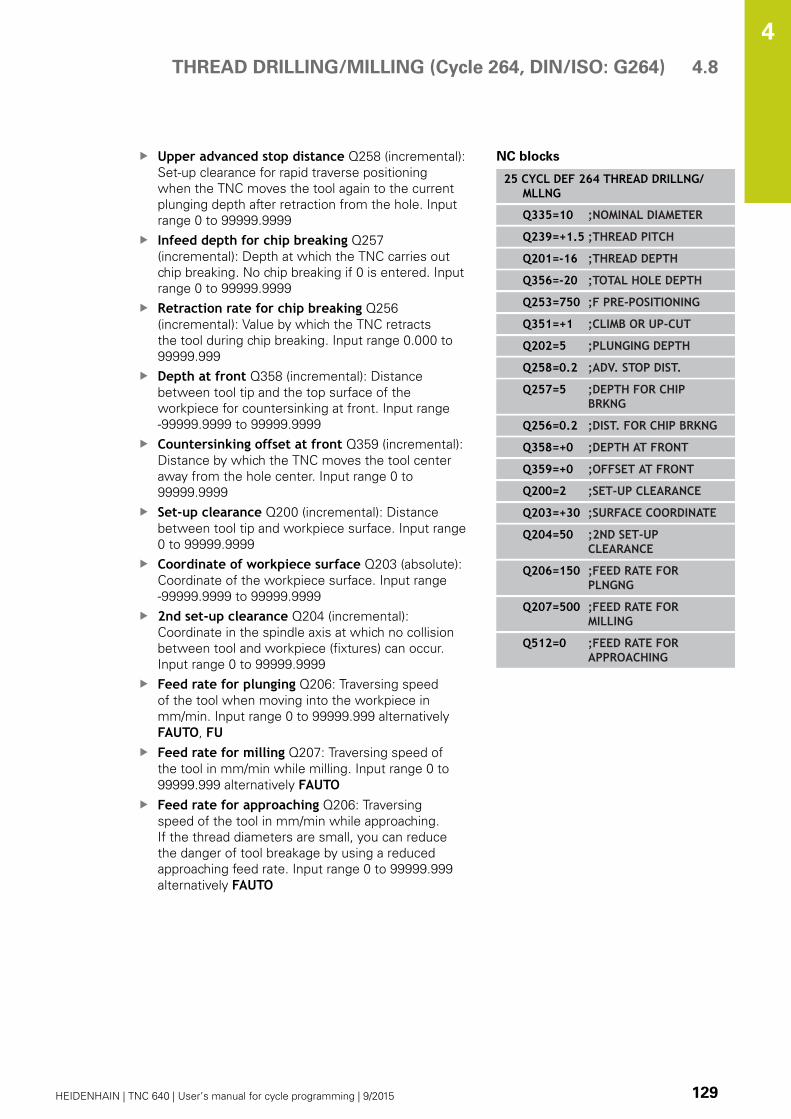
THREAD DRILLING/MILLING (Cycle 264, DIN/ISO: G264) 4.8
4
HEIDENHAIN | TNC 640 | User’s manual for cycle programming | 9/2015 129
Upper advanced stop distance Q258 (incremental):
Set-up clearance for rapid traverse positioning
when the TNC moves the tool again to the current
plunging depth after retraction from the hole. Input
range 0 to 99999.9999
Infeed depth for chip breaking Q257
(incremental): Depth at which the TNC carries out
chip breaking. No chip breaking if 0 is entered. Input
range 0 to 99999.9999
Retraction rate for chip breaking Q256
(incremental): Value by which the TNC retracts
the tool during chip breaking. Input range 0.000 to
99999.999
Depth at front Q358 (incremental): Distance
between tool tip and the top surface of the
workpiece for countersinking at front. Input range
-99999.9999 to 99999.9999
Countersinking offset at front Q359 (incremental):
Distance by which the TNC moves the tool center
away from the hole center. Input range 0 to
99999.9999
Set-up clearance Q200 (incremental): Distance
between tool tip and workpiece surface. Input range
0 to 99999.9999
Coordinate of workpiece surface Q203 (absolute):
Coordinate of the workpiece surface. Input range
-99999.9999 to 99999.9999
2nd set-up clearance Q204 (incremental):
Coordinate in the spindle axis at which no collision
between tool and workpiece (fixtures) can occur.
Input range 0 to 99999.9999
Feed rate for plunging Q206: Traversing speed
of the tool when moving into the workpiece in
mm/min. Input range 0 to 99999.999 alternatively
FAUTO, FUFeed rate for milling Q207: Traversing speed of
the tool in mm/min while milling. Input range 0 to
99999.999 alternatively FAUTOFeed rate for approaching Q206: Traversing
speed of the tool in mm/min while approaching.
If the thread diameters are small, you can reduce
the danger of tool breakage by using a reduced
approaching feed rate. Input range 0 to 99999.999
alternatively FAUTO
NC blocks
25 CYCL DEF 264 THREAD DRILLNG/MLLNG
Q335=10 ;NOMINAL DIAMETER
Q239=+1.5 ;THREAD PITCH
Q201=-16 ;THREAD DEPTH
Q356=-20 ;TOTAL HOLE DEPTH
Q253=750 ;F PRE-POSITIONING
Q351=+1 ;CLIMB OR UP-CUT
Q202=5 ;PLUNGING DEPTH
Q258=0.2 ;ADV. STOP DIST.
Q257=5 ;DEPTH FOR CHIPBRKNG
Q256=0.2 ;DIST. FOR CHIP BRKNG
Q358=+0 ;DEPTH AT FRONT
Q359=+0 ;OFFSET AT FRONT
Q200=2 ;SET-UP CLEARANCE
Q203=+30 ;SURFACE COORDINATE
Q204=50 ;2ND SET-UPCLEARANCE
Q206=150 ;FEED RATE FORPLNGNG
Q207=500 ;FEED RATE FORMILLING
Q512=0 ;FEED RATE FORAPPROACHING
Fixed Cycles: Tapping / Thread Milling 4.9 HELICAL THREAD DRILLING/MILLING (Cycle 265, DIN/ISO: G265)
4
130 HEIDENHAIN | TNC 640 | User’s manual for cycle programming | 9/2015
4.9 HELICAL THREAD DRILLING/
MILLING (Cycle 265, DIN/ISO: G265)
Cycle run
1 The TNC positions the tool in the tool axis at rapid traverse
FMAX to the entered set-up clearance above the workpiece
surface.
Countersinking at front
2 If countersinking occurs before thread milling, the tool moves
at the feed rate for countersinking to the sinking depth at front.
If countersinking occurs after thread milling, the TNC moves
the tool to the countersinking depth at the feed rate for pre-
positioning.
3 The TNC positions the tool without compensation from the
center on a semicircle to the offset at front, and then follows a
circular path at the feed rate for countersinking.
4 The tool then moves in a semicircle to the hole center.
Thread milling
5 The tool moves at the programmed feed rate for pre-positioning
to the starting plane for the thread.
6 The tool then approaches the thread diameter tangentially in a
helical movement.
7 The tool moves on a continuous helical downward path until it
reaches the thread depth.
8 After that the tool departs the contour tangentially and returns
to the starting point in the working plane.
9 At the end of the cycle, the TNC retracts the tool in rapid
traverse to setup clearance or, if programmed, to the 2nd setup
clearance.
HELICAL THREAD DRILLING/MILLING (Cycle 265, DIN/ISO: G265) 4.9
4
HEIDENHAIN | TNC 640 | User’s manual for cycle programming | 9/2015 131
Please note while programming:
Program a positioning block for the starting point
(hole center) in the working plane with radius
compensation R0.
The algebraic sign of the cycle parameters depth
of thread or sinking depth at front determines the
working direction. The working direction is defined in
the following sequence:
1. Thread depth
2. Depth at front
If you program a depth parameter to be 0, the TNC
does not execute that step.
If you change the thread depth, the TNC
automatically changes the starting point for the
helical movement.
The type of milling (up-cut/climb) is determined by
the thread (right-hand/left-hand) and the direction of
tool rotation, since it is only possible to work in the
direction of the tool.
Danger of collision!
Use the machine parameter displayDepthErr to
define whether, if a positive depth is entered, the
TNC should output an error message (on) or not (off).
Keep in mind that the TNC reverses the calculation
for pre-positioning when a positive depth is
entered. This means that the tool moves at rapid
traverse in the tool axis to set-up clearance below
the workpiece surface!

Fixed Cycles: Tapping / Thread Milling 4.9 HELICAL THREAD DRILLING/MILLING (Cycle 265, DIN/ISO: G265)
4
132 HEIDENHAIN | TNC 640 | User’s manual for cycle programming | 9/2015
Cycle parameters
Nominal diameter Q335: Nominal thread diameter.
Input range 0 to 99999.9999
Thread pitch Q239: Pitch of the thread. The
algebraic sign differentiates between right-hand and
left-hand threads:
+ = right-hand thread
–= left-hand thread
Input range -99.9999 to 99.9999
Thread depth Q201 (incremental): Distance
between workpiece surface and root of thread.
Input range -99999.9999 to 99999.9999
Feed rate for pre-positioning Q253: Traversing
speed of the tool when moving in and out of the
workpiece, in mm/min. Input range 0 to 99999.9999
alternatively FMAX, FAUTODepth at front Q358 (incremental): Distance
between tool tip and the top surface of the
workpiece for countersinking at front. Input range
-99999.9999 to 99999.9999
Countersinking offset at front Q359 (incremental):
Distance by which the TNC moves the tool center
away from the hole center. Input range 0 to
99999.9999
Countersinking Q360: Running the chamfer
0 = before thread milling
1 = after thread milling
Set-up clearance Q200 (incremental): Distance
between tool tip and workpiece surface. Input range
0 to 99999.9999
Coordinate of workpiece surface Q203 (absolute):
Coordinate of the workpiece surface. Input range
-99999.9999 to 99999.9999

HELICAL THREAD DRILLING/MILLING (Cycle 265, DIN/ISO: G265) 4.9
4
HEIDENHAIN | TNC 640 | User’s manual for cycle programming | 9/2015 133
2nd set-up clearance Q204 (incremental):
Coordinate in the spindle axis at which no collision
between tool and workpiece (fixtures) can occur.
Input range 0 to 99999.9999
Feed rate for countersinking Q254: Traversing
speed of the tool during countersinking in mm/min.
Input range 0 to 99999.9999 alternatively FAUTO,
FUFeed rate for milling Q207: Traversing speed of
the tool in mm/min while milling. Input range 0 to
99999.999 alternatively FAUTO
NC blocks
25 CYCL DEF 265 HEL. THREAD DRLG/MLG
Q335=10 ;NOMINAL DIAMETER
Q239=+1.5 ;THREAD PITCH
Q201=-16 ;THREAD DEPTH
Q253=750 ;F PRE-POSITIONING
Q358=+0 ;DEPTH AT FRONT
Q359=+0 ;OFFSET AT FRONT
Q360=0 ;COUNTERSINKING
Q200=2 ;SET-UP CLEARANCE
Q203=+30 ;SURFACE COORDINATE
Q204=50 ;2ND SET-UPCLEARANCE
Q254=150 ;F COUNTERBORING
Q207=500 ;FEED RATE FORMILLING

Fixed Cycles: Tapping / Thread Milling 4.10 OUTSIDE THREAD MILLING (Cycle 267, DIN/ISO: G267)
4
134 HEIDENHAIN | TNC 640 | User’s manual for cycle programming | 9/2015
4.10 OUTSIDE THREAD MILLING (Cycle
267, DIN/ISO: G267)
Cycle run
1 The TNC positions the tool in the tool axis at rapid traverse
FMAX to the entered set-up clearance above the workpiece
surface.
Countersinking at front
2 The TNC moves on the reference axis of the working plane from
the center of the stud to the starting point for countersinking
at front. The position of the starting point is determined by the
thread radius, tool radius and pitch.
3 The tool moves at the feed rate for pre-positioning to the sinking
depth at front.
4 The TNC positions the tool without compensation from the
center on a semicircle to the offset at front, and then follows a
circular path at the feed rate for countersinking.
5 The tool then moves in a semicircle to the starting point.
Thread milling
6 The TNC positions the tool to the starting point if there has
been no previous countersinking at front. Starting point for
thread milling = starting point for countersinking at front.
7 The tool moves at the programmed feed rate for pre-positioning
to the starting plane. The starting plane is derived from the
algebraic sign of the thread pitch, the milling method (climb or
up-cut milling) and the number of threads per step.
8 The tool then approaches the thread diameter tangentially in a
helical movement.
9 Depending on the setting of the parameter for the number of
threads, the tool mills the thread in one helical movement, in
several offset helical movements or in one continuous helical
movement.
10 After that the tool departs the contour tangentially and returns
to the starting point in the working plane.
11 At the end of the cycle, the TNC retracts the tool in rapid
traverse to setup clearance or, if programmed, to the 2nd setup
clearance.

OUTSIDE THREAD MILLING (Cycle 267, DIN/ISO: G267) 4.10
4
HEIDENHAIN | TNC 640 | User’s manual for cycle programming | 9/2015 135
Please note while programming:
Program a positioning block for the starting point
(stud center) in the working plane with radius
compensation R0.
The offset required before countersinking at the front
should be determined ahead of time. You must enter
the value from the center of the stud to the center of
the tool (uncorrected value).
The algebraic sign of the cycle parameters depth
of thread or sinking depth at front determines the
working direction. The working direction is defined in
the following sequence:
1. Thread depth
2. Depth at front
If you program a depth parameter to be 0, the TNC
does not execute that step.
The algebraic sign for the cycle parameter "thread
depth" determines the working direction.
Danger of collision!
Use the machine parameter displayDepthErr to
define whether, if a positive depth is entered, the
TNC should output an error message (on) or not (off).
Keep in mind that the TNC reverses the calculation
for pre-positioning when a positive depth is
entered. This means that the tool moves at rapid
traverse in the tool axis to set-up clearance below
the workpiece surface!
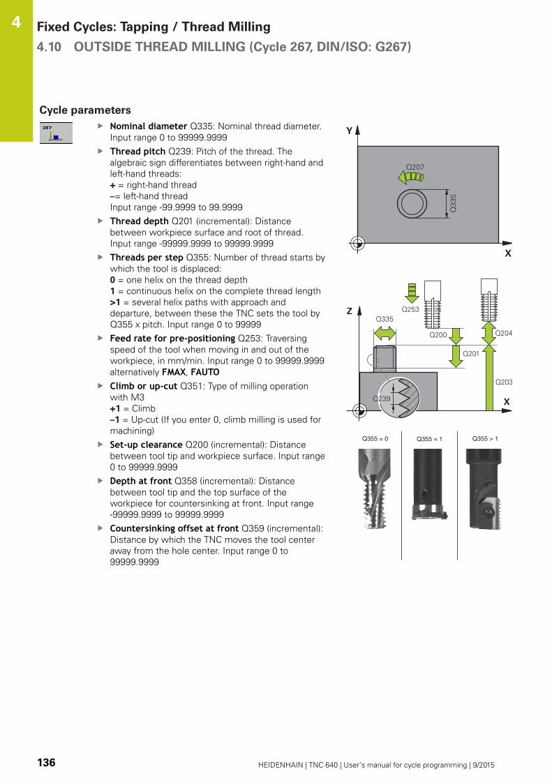
Fixed Cycles: Tapping / Thread Milling 4.10 OUTSIDE THREAD MILLING (Cycle 267, DIN/ISO: G267)
4
136 HEIDENHAIN | TNC 640 | User’s manual for cycle programming | 9/2015
Cycle parameters
Nominal diameter Q335: Nominal thread diameter.
Input range 0 to 99999.9999
Thread pitch Q239: Pitch of the thread. The
algebraic sign differentiates between right-hand and
left-hand threads:
+ = right-hand thread
–= left-hand thread
Input range -99.9999 to 99.9999
Thread depth Q201 (incremental): Distance
between workpiece surface and root of thread.
Input range -99999.9999 to 99999.9999
Threads per step Q355: Number of thread starts by
which the tool is displaced:
0 = one helix on the thread depth
1 = continuous helix on the complete thread length
>1 = several helix paths with approach and
departure, between these the TNC sets the tool by
Q355 x pitch. Input range 0 to 99999
Feed rate for pre-positioning Q253: Traversing
speed of the tool when moving in and out of the
workpiece, in mm/min. Input range 0 to 99999.9999
alternatively FMAX, FAUTOClimb or up-cut Q351: Type of milling operation
with M3
+1 = Climb
–1 = Up-cut (If you enter 0, climb milling is used for
machining)
Set-up clearance Q200 (incremental): Distance
between tool tip and workpiece surface. Input range
0 to 99999.9999
Depth at front Q358 (incremental): Distance
between tool tip and the top surface of the
workpiece for countersinking at front. Input range
-99999.9999 to 99999.9999
Countersinking offset at front Q359 (incremental):
Distance by which the TNC moves the tool center
away from the hole center. Input range 0 to
99999.9999
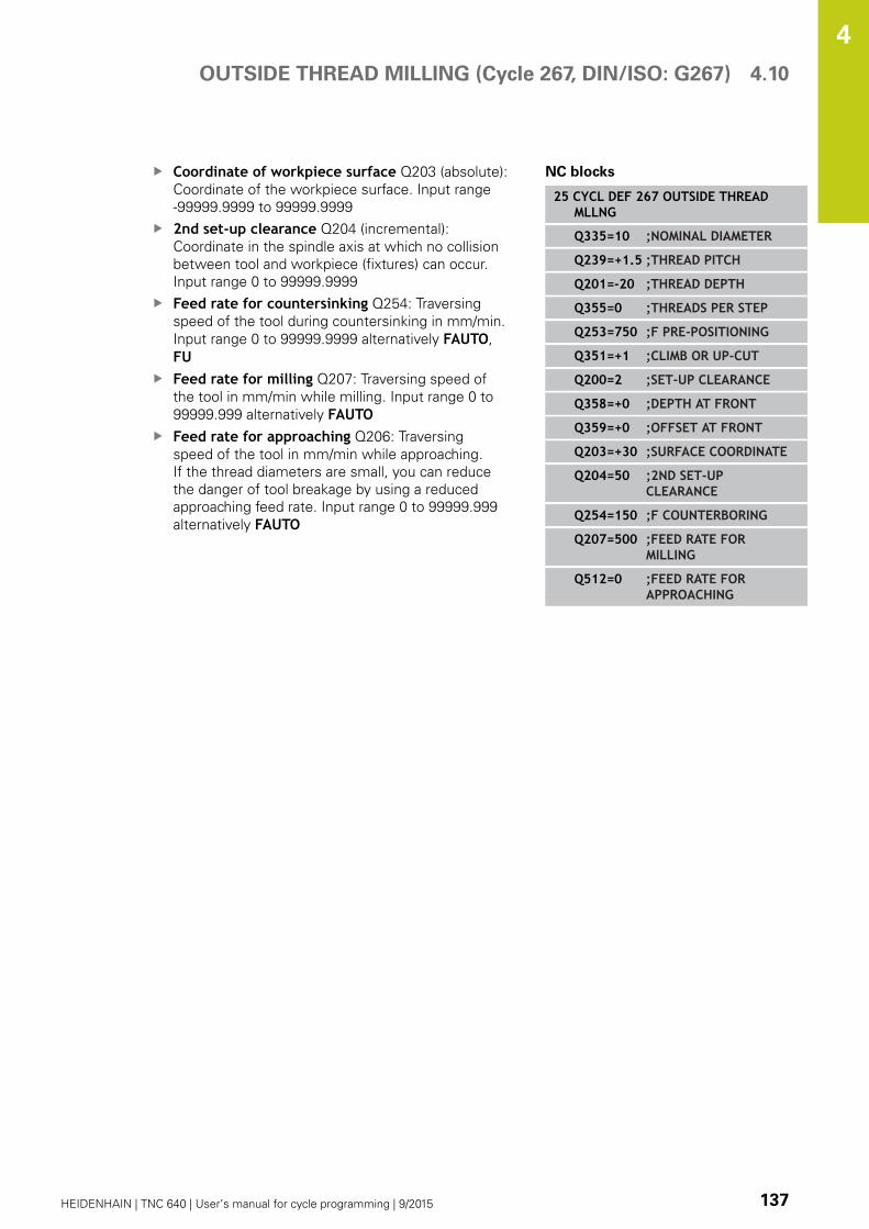
OUTSIDE THREAD MILLING (Cycle 267, DIN/ISO: G267) 4.10
4
HEIDENHAIN | TNC 640 | User’s manual for cycle programming | 9/2015 137
Coordinate of workpiece surface Q203 (absolute):
Coordinate of the workpiece surface. Input range
-99999.9999 to 99999.9999
2nd set-up clearance Q204 (incremental):
Coordinate in the spindle axis at which no collision
between tool and workpiece (fixtures) can occur.
Input range 0 to 99999.9999
Feed rate for countersinking Q254: Traversing
speed of the tool during countersinking in mm/min.
Input range 0 to 99999.9999 alternatively FAUTO,
FUFeed rate for milling Q207: Traversing speed of
the tool in mm/min while milling. Input range 0 to
99999.999 alternatively FAUTOFeed rate for approaching Q206: Traversing
speed of the tool in mm/min while approaching.
If the thread diameters are small, you can reduce
the danger of tool breakage by using a reduced
approaching feed rate. Input range 0 to 99999.999
alternatively FAUTO
NC blocks
25 CYCL DEF 267 OUTSIDE THREADMLLNG
Q335=10 ;NOMINAL DIAMETER
Q239=+1.5 ;THREAD PITCH
Q201=-20 ;THREAD DEPTH
Q355=0 ;THREADS PER STEP
Q253=750 ;F PRE-POSITIONING
Q351=+1 ;CLIMB OR UP-CUT
Q200=2 ;SET-UP CLEARANCE
Q358=+0 ;DEPTH AT FRONT
Q359=+0 ;OFFSET AT FRONT
Q203=+30 ;SURFACE COORDINATE
Q204=50 ;2ND SET-UPCLEARANCE
Q254=150 ;F COUNTERBORING
Q207=500 ;FEED RATE FORMILLING
Q512=0 ;FEED RATE FORAPPROACHING

Fixed Cycles: Tapping / Thread Milling 4.11 Programming Examples
4
138 HEIDENHAIN | TNC 640 | User’s manual for cycle programming | 9/2015
4.11 Programming Examples
Example: Thread milling
The drill hole coordinates are stored in the point table
TAB1.PNT and are called by the TNC with CYCL CALLPAT.
The tool radii are selected so that all work steps can be
seen in the test graphics.
Program sequence
Centering
Drilling
Tapping
0 BEGIN PGM 1 MM
1 BLK FORM 0.1 Z X+0 Y+0 Z-20 Definition of workpiece blank
2 BLK FORM 0.2 X+100 Y+100 Y+0
3 TOOL CALL 1 Z S5000 Call tool: centering drill
4 L Z+10 R0 F5000 Move tool to clearance height (enter a value for F): the TNC
positions to the clearance height after every cycle
5 SEL PATTERN "TAB1" Definition of point table
6 CYCL DEF 240 CENTERING Cycle definition: CENTERING
Q200=2 ;SET-UP CLEARANCE
Q343=1 ;SELECT DIA./DEPTH
Q201=-3.5 ;DEPTH
Q344=-7 ;DIAMETER
Q206=150 ;FEED RATE FOR PLNGNG
Q11=0 ;DWELL TIME AT DEPTH
Q203=+0 ;SURFACE COORDINATE 0 must be entered here, effective as defined in point table
Q204=0 ;2ND SET-UP CLEARANCE 0 must be entered here, effective as defined in point table
10 CYCL CALL PAT F5000 M3 Cycle call in connection with point table TAB1.PNT, feed rate
between the points: 5000 mm/min
11 L Z+100 R0 FMAX M6 Retract the tool, change the tool
12 TOOL CALL 2 Z S5000 Call tool: drill
13 L Z+10 R0 F5000 Move tool to clearance height (enter a value for F)
14 CYCL DEF 200 DRILLING Cycle definition: drilling
Q200=2 ;SET-UP CLEARANCE
Q201=-25 ;DEPTH
Q206=150 ;FEED RATE FOR PLNGNG
Q202=5 ;PLUNGING DEPTH
Q210=0 ;DWELL TIME AT TOP
Q203=+0 ;SURFACE COORDINATE 0 must be entered here, effective as defined in point table

Programming Examples 4.11
4
HEIDENHAIN | TNC 640 | User’s manual for cycle programming | 9/2015 139
Q204=0 ;2ND SET-UP CLEARANCE 0 must be entered here, effective as defined in point table
Q211=0.2 ;DWELL TIME AT DEPTH
Q395=0 ;DEPTH REFERENCE
15 CYCL CALL PAT F5000 M3 Cycle call in connection with point table TAB1.PNT
16 L Z+100 R0 FMAX M6 Retract the tool, change the tool
17 TOOL CALL 3 Z S200 Call tool: tap
18 L Z+50 R0 FMAX Move tool to clearance height
19 CYCL DEF 206 TAPPING Cycle definition for tapping
Q200=2 ;SET-UP CLEARANCE
Q201=-25 ;DEPTH OF THREAD
Q206=150 ;FEED RATE FOR PLNGNG
Q211=0 ;DWELL TIME AT DEPTH
Q203=+0 ;SURFACE COORDINATE 0 must be entered here, effective as defined in point table
Q204=0 ;2ND SET-UP CLEARANCE 0 must be entered here, effective as defined in point table
20 CYCL CALL PAT F5000 M3 Cycle call in connection with point table TAB1.PNT
21 L Z+100 R0 FMAX M2 Retract the tool, end program
22 END PGM 1 MM
Point table TAB1.PNT
TAB1. PNT MM
NR X Y Z
0 +10 +10 +0
1 +40 +30 +0
2 +90 +10 +0
3 +80 +30 +0
4 +80 +65 +0
5 +90 +90 +0
6 +10 +90 +0
7 +20 +55 +0
[END]


5Fixed Cycles:
Pocket Milling /Stud Milling / Slot
Milling

Fixed Cycles: Pocket Milling / Stud Milling / Slot Milling 5.1 Fundamentals
5
142 HEIDENHAIN | TNC 640 | User’s manual for cycle programming | 9/2015
5.1 Fundamentals
Overview
The TNC offers the following cycles for machining pockets, studs
and slots:
Soft key Cycle Page
251 RECTANGULAR POCKET
Roughing/finishing cycle
with selection of machining
operation and helical plunging
143
252 CIRCULAR POCKET
Roughing/finishing cycle
with selection of machining
operation and helical plunging
147
253 SLOT MILLING
Roughing/finishing cycle
with selection of machining
operation and reciprocal
plunging
152
254 CIRCULAR SLOT
Roughing/finishing cycle
with selection of machining
operation and reciprocal
plunging
156
256 RECTANGULAR STUD
Roughing/finishing cycle with
stepover, if multiple passes
are required
161
257 CIRCULAR STUD
Roughing/finishing cycle with
stepover, if multiple passes
are required
165
233 FACE MILLING
Machining the face with up to
3 limits
174

RECTANGULAR POCKET (Cycle 251) 5.2
5
HEIDENHAIN | TNC 640 | User’s manual for cycle programming | 9/2015 143
5.2 RECTANGULAR POCKET (Cycle 251,
DIN/ISO: G251)
Cycle run
Use Cycle 251 RECTANGULAR POCKET to completely machine
rectangular pockets. Depending on the cycle parameters, the
following machining alternatives are available:
Complete machining: Roughing, floor finishing, side finishing
Only roughing
Only floor finishing and side finishing
Only floor finishing
Only side finishing
Roughing
1 The tool plunges the workpiece at the pocket center and
advances to the first plunging depth. Specify the plunging
strategy with parameter Q366.
2 The TNC roughs out the pocket from the inside out, taking the
overlap factor (parameter Q370) and the finishing allowance
(parameters Q368 and Q369) into account.
3 At the end of the roughing operation, the TNC moves the tool
tangentially away from the pocket wall, then moves by the set-
up clearance above the current plunging depth and returns from
there at rapid traverse to the pocket center.
4 This process is repeated until the programmed pocket depth is
reached.
Finishing
5 If finishing allowances are defined, the tool plunges the
workpiece at the pocket center and moves to the plunging
depth for finishing. The TNC first finishes the pocket walls, in
multiple infeeds if so specified. The pocket wall is approached
tangentially.
6 Then the TNC finishes the floor of the pocket from the inside
out. The pocket floor is approached tangentially.

Fixed Cycles: Pocket Milling / Stud Milling / Slot Milling 5.2 RECTANGULAR POCKET (Cycle 251)
5
144 HEIDENHAIN | TNC 640 | User’s manual for cycle programming | 9/2015
Please note while programming:
With an inactive tool table you must always plunge
vertically (Q366=0) because you cannot define a
plunging angle.
Pre-position the tool in the machining plane to the
starting position with radius compensation R0. Note
parameter Q367 (position).
The TNC automatically pre-positions the tool in the
tool axis. Note the 2nd set-up clearance Q204.
The algebraic sign for the cycle parameter DEPTH
determines the working direction. If you program
DEPTH=0, the cycle will not be executed.
At the end of the cycle, the TNC returns the tool to
the starting position.
At the end of a roughing operation, the TNC
positions the tool back to the pocket center at rapid
traverse. The tool is above the current pecking depth
by the set-up clearance. Enter the set-up clearance
so that the tool cannot jam because of chips.
The TNC outputs an error message during helical
plunging if the internally calculated diameter of the
helix is smaller than twice the tool diameter. If you
are using a center-cut tool, you can switch off this
monitoring function via the suppressPlungeErrmachine parameter.
The TNC reduces the infeed depth to the LCUTS tool
length defined in the tool table if the tool length is
shorter than the Q202 infeed depth programmed in
the cycle.
Danger of collision!
Use the machine parameter displayDepthErr to
define whether, if a positive depth is entered, the
TNC should output an error message (on) or not (off).
Keep in mind that the TNC reverses the calculation
for pre-positioning when a positive depth is
entered. This means that the tool moves at rapid
traverse in the tool axis to set-up clearance below
the workpiece surface!
If you call the cycle with machining operation 2 (only
finishing), then the TNC positions the tool in the
center of the pocket at rapid traverse to the first
plunging depth.

RECTANGULAR POCKET (Cycle 251) 5.2
5
HEIDENHAIN | TNC 640 | User’s manual for cycle programming | 9/2015 145
Cycle parameters
Machining operation (0/1/2) Q215: Define
machining operation:
0: Roughing and finishing
1: Only roughing
2: Only finishing
Side finishing and floor finishing are only machined
when the specific allowance (Q368, Q369) is
defined
1st side length Q218 (incremental): Pocket length,
parallel to the reference axis of the working plane.
Input range 0 to 99999.9999
2nd side length Q219 (incremental): Pocket length,
parallel to the minor axis of the working plane. Input
range 0 to 99999.9999
Corner radius Q220: Radius of the pocket corner. If
you have entered 0 here, the TNC assumes that the
corner radius is equal to the tool radius. Input range
0 to 99999.9999
Finishing allowance for side Q368 (incremental):
Finishing allowance in the working plane. Input
range 0 to 99999.9999
Angle of rotation Q224 (absolute): Angle by which
the entire machining is rotated. The center of
rotation is the position at which the tool is located
when the cycle is called. Input range -360.0000 to
360.0000
Pocket position Q367: Position of the pocket in
reference to the position of the tool when the cycle
is called:
0: Tool position = pocket center
1: Tool position = left corner below
2: Tool position = right corner below
3: Tool position = right corner top
4: Tool position = left top corner top
Feed rate for milling Q207: Traversing speed of
the tool in mm/min while milling. Input range 0 to
99999.999 alternatively FAUTO, FU, FZClimb or up-cut Q351: Type of milling operation
with M3
+1 = climb
–1 = up-cut
PREDEF: The TNC uses the value from the GLOBAL
DEF block (If you enter 0, climb milling is used for
machining)
Depth Q201 (incremental): Distance between
workpiece surface and bottom of pocket. Input
range -99999.9999 to 99999.9999
Plunging depth Q202 (incremental): Infeed per
cut. Enter a value greater than 0. Input range 0 to
99999.9999

Fixed Cycles: Pocket Milling / Stud Milling / Slot Milling 5.2 RECTANGULAR POCKET (Cycle 251)
5
146 HEIDENHAIN | TNC 640 | User’s manual for cycle programming | 9/2015
Finishing allowance for floor Q369 (incremental
value): Finishing allowance in the tool axis. Input
range 0 to 99999.9999
Feed rate for plunging Q206: Traversing speed of
the tool while moving to depth in mm/min. Input
range 0 to 99999.999; alternatively FAUTO, FU, FZInfeed for finishing Q338 (incremental): Infeed per
cut. Q338=0: Finishing in one infeed. Input range 0
to 99999.9999
Set-up clearance Q200 (incremental): Distance
between tool tip and workpiece surface. Input range
0 to 99999.9999; alternatively PREDEFCoordinate of workpiece surface Q203 (absolute):
Coordinate of the workpiece surface. Input range
-99999.9999 to 99999.9999
2nd set-up clearance Q204 (incremental):
Coordinate in the spindle axis at which no collision
between tool and workpiece (fixtures) can occur.
Input range 0 to 99999.9999; alternatively PREDEFPath overlap factor Q370: Q370 x tool radius
= stepover factor k. Input range: 0.1 to 1.414
alternatively PREDEFPlunging strategy Q366: Type of plunging strategy:
0: vertical plunging. The TNC plunges
perpendicularly, regardless of the plunging angle
ANGLE defined in the tool table
1: helical plunging. In the tool table, the plunging
angle ANGLE for the active tool must be defined as
not equal to 0. Otherwise, the TNC generates an
error message
2: reciprocal plunging. In the tool table, the plunging
angle ANGLE for the active tool must be defined as
not equal to 0. Otherwise, the TNC generates an
error message. The reciprocation length depends
on the plunging angle. As a minimum value the TNC
uses twice the tool diameter
PREDEF: The TNC uses the value from the GLOBAL
DEF block
Feed rate for finishing Q385: Traversing speed of
the tool during side and floor finishing in mm/min.
Input range 0 to 99999.999; alternatively FAUTO,
FU, FZ
NC blocks
8 CYCL DEF 251 RECTANGULARPOCKET
Q215=0 ;MACHININGOPERATION
Q218=80 ;FIRST SIDE LENGTH
Q219=60 ;2ND SIDE LENGTH
Q220=5 ;CORNER RADIUS
Q368=0.2 ;ALLOWANCE FOR SIDE
Q224=+0 ;ANGLE OF ROTATION
Q367=0 ;POCKET POSITION
Q207=500 ;FEED RATE FORMILLING
Q351=+1 ;CLIMB OR UP-CUT
Q201=-20 ;DEPTH
Q202=5 ;PLUNGING DEPTH
Q369=0.1 ;ALLOWANCE FORFLOOR
Q206=150 ;FEED RATE FORPLNGNG
Q338=5 ;INFEED FOR FINISHING
Q200=2 ;SET-UP CLEARANCE
Q203=+0 ;SURFACE COORDINATE
Q204=50 ;2ND SET-UPCLEARANCE
Q370=1 ;TOOL PATH OVERLAP
Q366=1 ;PLUNGE
Q385=500 ;FINISHING FEED RATE
9 L X+50 Y+50 R0 FMAX M3 M99

CIRCULAR POCKET (Cycle 252, DIN/ISO: G252) 5.3
5
HEIDENHAIN | TNC 640 | User’s manual for cycle programming | 9/2015 147
5.3 CIRCULAR POCKET (Cycle 252, DIN/
ISO: G252)
Cycle run
Use Cycle 252 CIRCULAR POCKET to machine circular pockets.
Depending on the cycle parameters, the following machining
alternatives are available:
Complete machining: Roughing, floor finishing, side finishing
Only roughing
Only floor finishing and side finishing
Only floor finishing
Only side finishing
Roughing
1 The TNC first moves the tool at rapid traverse to the set-up
clearance Q200 above the workpiece.
2 The tool plunges to the first plunging depth at the pocket center.
Specify the plunging strategy with parameter Q366.
3 The TNC roughs out the pocket from the inside out, taking the
overlap factor (Parameter Q370) and the finishing allowance
(Parameters Q368 and Q369) into account.
4 At the end of a roughing operation, the TNC moves the tool
tangentially away from the pocket wall by the set-up clearance
Q200 in the working plane, then retracts the tool by Q200 at
rapid traverse and returns it from there at rapid traverse to the
pocket center.
5 Steps 2 to 4 are repeated until the programmed pocket depth is
reached, taking the finishing allowance Q369 into account.
6 If only roughing is programmed (Q215=1), the tool moves away
from the pocket wall tangentially by the set-up clearance Q200,
then retracts at rapid traverse to the 2nd set-up clearance Q200
in the tool axis and returns at rapid traverse to the pocket center.

Fixed Cycles: Pocket Milling / Stud Milling / Slot Milling 5.3 CIRCULAR POCKET (Cycle 252, DIN/ISO: G252)
5
148 HEIDENHAIN | TNC 640 | User’s manual for cycle programming | 9/2015
Finishing
1 Inasmuch as finishing allowances are defined, the TNC then
finishes the pocket walls, in multiple infeeds if so specified.
2 The TNC positions the tool in the tool axis in front of the
pocket wall, taking the finishing allowance Q368 and the set-up
clearance Q200 into account.
3 The TNC clears the pocket from the inside out until the diameter
Q223 is reached.
4 Then the TNC again positions the tool in the tool axis in front
of the pocket wall, taking the finishing allowance Q368 and the
set-up clearance Q200 into account, and repeats the finishing
process of the pocket wall at the next depth.
5 The TNC repeats this process until the programmed diameter is
reached.
6 After machining to the diameter Q223, the TNC retracts the
tool tangentially by the finishing allowance Q368 plus the set-
up clearance Q200 in the working plane, then retracts at rapid
traverse to the set-up clearance Q200 in the tool axis and
returns to the pocket center.
7 Next, the TNC moves the tool in the tool axis to the depth Q201
and finishes the floor of the pocket from the inside out. The
pocket floor is approached tangentially.
8 The TNC repeats this process until the depth Q201 plus Q369 is
reached.
9 Finally, the tool moves away from the pocket wall tangentially
by the set-up clearance Q200, then retracts at rapid traverse to
the set-up clearance Q200 in the tool axis and returns at rapid
traverse to the pocket center.

CIRCULAR POCKET (Cycle 252, DIN/ISO: G252) 5.3
5
HEIDENHAIN | TNC 640 | User’s manual for cycle programming | 9/2015 149
Please note while programming:
With an inactive tool table you must always plunge
vertically (Q366=0) because you cannot define a
plunging angle.
Pre-position the tool in the machining plane to
the starting position (circle center) with radius
compensation R0.
The TNC automatically pre-positions the tool in the
tool axis. Note the 2nd set-up clearance Q204.
The algebraic sign for the cycle parameter DEPTH
determines the working direction. If you program
DEPTH=0, the cycle will not be executed.
At the end of the cycle, the TNC returns the tool to
the starting position.
At the end of a roughing operation, the TNC
positions the tool back to the pocket center at rapid
traverse. The tool is above the current pecking depth
by the set-up clearance. Enter the set-up clearance
so that the tool cannot jam because of chips.
The TNC outputs an error message during helical
plunging if the internally calculated diameter of the
helix is smaller than twice the tool diameter. If you
are using a center-cut tool, you can switch off this
monitoring function via the suppressPlungeErrmachine parameter.
The TNC reduces the infeed depth to the LCUTS tool
length defined in the tool table if the tool length is
shorter than the Q202 infeed depth programmed in
the cycle.
Danger of collision!
Use the machine parameter displayDepthErr to
define whether, if a positive depth is entered, the
TNC should output an error message (on) or not (off).
Keep in mind that the TNC reverses the calculation
for pre-positioning when a positive depth is
entered. This means that the tool moves at rapid
traverse in the tool axis to set-up clearance below
the workpiece surface!
If you call the cycle with machining operation 2 (only
finishing), then the TNC positions the tool in the
center of the pocket at rapid traverse to the first
plunging depth.

Fixed Cycles: Pocket Milling / Stud Milling / Slot Milling 5.3 CIRCULAR POCKET (Cycle 252, DIN/ISO: G252)
5
150 HEIDENHAIN | TNC 640 | User’s manual for cycle programming | 9/2015
Cycle parameters
Machining operation (0/1/2) Q215: Define
machining operation:
0: Roughing and finishing
1: Only roughing
2: Only finishing
Side finishing and floor finishing are only machined
when the specific allowance (Q368, Q369) is
defined
Circle diameter Q223: Diameter of the finished
pocket. Input range 0 to 99999.9999
Finishing allowance for side Q368 (incremental):
Finishing allowance in the working plane. Input
range 0 to 99999.9999
Feed rate for milling Q207: Traversing speed of
the tool in mm/min while milling. Input range 0 to
99999.999 alternatively FAUTO, FU, FZClimb or up-cut Q351: Type of milling operation
with M3
+1 = climb
–1 = up-cut
PREDEF: The TNC uses the value from the GLOBAL
DEF block (If you enter 0, climb milling is used for
machining)
Depth Q201 (incremental): Distance between
workpiece surface and bottom of pocket. Input
range -99999.9999 to 99999.9999
Plunging depth Q202 (incremental): Infeed per
cut. Enter a value greater than 0. Input range 0 to
99999.9999
Finishing allowance for floor Q369 (incremental
value): Finishing allowance in the tool axis. Input
range 0 to 99999.9999
Feed rate for plunging Q206: Traversing speed of
the tool while moving to depth in mm/min. Input
range 0 to 99999.999; alternatively FAUTO, FU, FZ

CIRCULAR POCKET (Cycle 252, DIN/ISO: G252) 5.3
5
HEIDENHAIN | TNC 640 | User’s manual for cycle programming | 9/2015 151
Infeed for finishing Q338 (incremental): Infeed per
cut. Q338=0: Finishing in one infeed. Input range 0
to 99999.9999
Set-up clearance Q200 (incremental): Distance
between tool tip and workpiece surface. Input range
0 to 99999.9999; alternatively PREDEFCoordinate of workpiece surface Q203 (absolute):
Coordinate of the workpiece surface. Input range
-99999.9999 to 99999.9999
2nd set-up clearance Q204 (incremental):
Coordinate in the spindle axis at which no collision
between tool and workpiece (fixtures) can occur.
Input range 0 to 99999.9999; alternatively PREDEFPath overlap factor Q370: Q370 x tool radius
= stepover factor k. Input range: 0.1 to 1.9999;
alternatively PREDEFPlunging strategy Q366: Type of plunging strategy:
0 = vertical plunging. In the tool table, the
plunging angle ANGLE for the active tool must
be defined as 0 or 90. The TNC will otherwise
display an error message.
1 = helical plunging. In the tool table, the
plunging angle ANGLE for the active tool must
be defined as not equal to 0. The TNC will
otherwise display an error message.
Alternative: PREDEFFeed rate for finishing Q385: Traversing speed of
the tool during side and floor finishing in mm/min.
Input range 0 to 99999.999; alternatively FAUTO,
FU, FZFeed rate reference (0...3) Q439: Define a
reference for the programmed feed rate:
0: The feed rate refers to the center point path of
the tool
1: The feed rate refers to the tool cutting edge only
during side finishing; otherwise, it refers to the
center point path
2: The feed rate refers to the tool cutting edge
during side and floor finishing; otherwise, it refers
to the center point path
3: The feed rate always refers to the tool cutting
edge
NC blocks
8 CYCL DEF 252 CIRCULAR POCKET
Q215=0 ;MACHININGOPERATION
Q223=60 ;CIRCLE DIAMETER
Q368=0.2 ;ALLOWANCE FOR SIDE
Q207=500 ;FEED RATE FORMILLING
Q351=+1 ;CLIMB OR UP-CUT
Q201=-20 ;DEPTH
Q202=5 ;PLUNGING DEPTH
Q369=0.1 ;ALLOWANCE FORFLOOR
Q206=150 ;FEED RATE FORPLNGNG
Q338=5 ;INFEED FOR FINISHING
Q200=2 ;SET-UP CLEARANCE
Q203=+0 ;SURFACE COORDINATE
Q204=50 ;2ND SET-UPCLEARANCE
Q370=1 ;TOOL PATH OVERLAP
Q366=1 ;PLUNGE
Q385=500 ;FINISHING FEED RATE
Q439=3 ;FEED RATE REFERENCE
9 L X+50 Y+50 R0 FMAX M3 M99

Fixed Cycles: Pocket Milling / Stud Milling / Slot Milling 5.4 SLOT MILLING (Cycle 253, DIN/ISO: G253)
5
152 HEIDENHAIN | TNC 640 | User’s manual for cycle programming | 9/2015
5.4 SLOT MILLING (Cycle 253, DIN/ISO:
G253)
Cycle run
Use Cycle 253 to completely machine a slot. Depending on the
cycle parameters, the following machining alternatives are available:
Complete machining: Roughing and finishing (floor and side
finishing)
Only roughing
Only finishing (floor and side finishing)
Only floor finishing
Only side finishing
Roughing
1 Starting from the left slot arc center, the tool moves in a
reciprocating motion at the plunging angle defined in the tool
table to the first infeed depth. Specify the plunging strategy
with parameter Q366.
2 The TNC roughs out the slot from the inside out, taking the
finishing allowances (parameters Q368 and Q369) into account.
3 This process is repeated until the programmed slot depth is
reached.
Finishing
4 Inasmuch as finishing allowances are defined, the TNC then
finishes the slot walls, in multiple infeeds if so specified. The
slot side is approached tangentially in the left slot arc.
5 Then the TNC finishes the floor of the slot from the inside out.
SLOT MILLING (Cycle 253, DIN/ISO: G253) 5.4
5
HEIDENHAIN | TNC 640 | User’s manual for cycle programming | 9/2015 153
Please note while programming:
With an inactive tool table you must always plunge
vertically (Q366=0) because you cannot define a
plunging angle.
Pre-position the tool in the machining plane to the
starting position with radius compensation R0. Note
parameter Q367 (position).
The TNC automatically pre-positions the tool in the
tool axis. Note the 2nd set-up clearance Q204.
At the end of the cycle the TNC merely moves the
tool in working plane back to the center of the slot;
in the other working plane axis the TNC does not do
any positioning. If you define a slot position not equal
to 0, then the TNC only positions the tool in the tool
axis to the 2nd set-up clearance. Prior to a new cycle
call, move the tool back to the starting position or
program always absolute traverse motions after the
cycle call.
The algebraic sign for the cycle parameter DEPTH
determines the working direction. If you program
DEPTH=0, the cycle will not be executed.
If the slot width is greater than twice the tool
diameter, the TNC roughs the slot correspondingly
from the inside out. You can therefore mill any slots
with small tools, too.
The TNC reduces the infeed depth to the LCUTS tool
length defined in the tool table if the tool length is
shorter than the Q202 infeed depth programmed in
the cycle.
Danger of collision!
Use the machine parameter displayDepthErr to
define whether, if a positive depth is entered, the
TNC should output an error message (on) or not (off).
Keep in mind that the TNC reverses the calculation
for pre-positioning when a positive depth is
entered. This means that the tool moves at rapid
traverse in the tool axis to set-up clearance below
the workpiece surface!
If you call the cycle with machining operation 2 (only
finishing), then the TNC positions the tool to the first
plunging depth at rapid traverse!

Fixed Cycles: Pocket Milling / Stud Milling / Slot Milling 5.4 SLOT MILLING (Cycle 253, DIN/ISO: G253)
5
154 HEIDENHAIN | TNC 640 | User’s manual for cycle programming | 9/2015
Cycle parameters
Machining operation (0/1/2) Q215: Define
machining operation:
0: Roughing and finishing
1: Only roughing
2: Only finishing
Side finishing and floor finishing are only machined
when the specific allowance (Q368, Q369) is
defined
Slot length Q218 (value parallel to the reference
axis of the working plane): Enter the length of the
slot. Input range 0 to 99999.9999
Slot width Q219 (value parallel to the secondary
axis of the working plane): Enter the slot width.
If you enter a slot width that equals the tool
diameter, the TNC will carry out the roughing
process only (slot milling). Maximum slot width for
roughing: Twice the tool diameter. Input range 0 to
99999.9999
Finishing allowance for side Q368 (incremental):
Finishing allowance in the working plane. Input
range 0 to 99999.9999
Angle of rotation Q374 (absolute): Angle by which
the entire slot is rotated. The center of rotation is
the position at which the tool is located when the
cycle is called. Input range -360.000 to 360.000
Slot position (0/1/2/3/4) Q367: Position of the slot
in reference to the position of the tool when the
cycle is called:
0: Tool position = slot center
1: Tool position = left end of slot
2: Tool position = center of left slot arc
3: Tool position = center of right slot arc
4: Tool position = right end of slot
Feed rate for milling Q207: Traversing speed of
the tool in mm/min while milling. Input range 0 to
99999.999 alternatively FAUTO, FU, FZClimb or up-cut Q351: Type of milling operation
with M3
+1 = climb
–1 = up-cut
PREDEF: The TNC uses the value from the GLOBAL
DEF block (If you enter 0, climb milling is used for
machining)
Depth Q201 (incremental): Distance between
workpiece surface and bottom of slot. Input range
-99999.9999 to 99999.9999
Plunging depth Q202 (incremental): Infeed per
cut. Enter a value greater than 0. Input range 0 to
99999.9999

SLOT MILLING (Cycle 253, DIN/ISO: G253) 5.4
5
HEIDENHAIN | TNC 640 | User’s manual for cycle programming | 9/2015 155
Finishing allowance for floor Q369 (incremental
value): Finishing allowance in the tool axis. Input
range 0 to 99999.9999
Feed rate for plunging Q206: Traversing speed of
the tool while moving to depth in mm/min. Input
range 0 to 99999.999; alternatively FAUTO, FU, FZInfeed for finishing Q338 (incremental): Infeed per
cut. Q338=0: Finishing in one infeed. Input range 0
to 99999.9999
Set-up clearance Q200 (incremental): Distance
between tool tip and workpiece surface. Input range
0 to 99999.9999; alternatively PREDEFCoordinate of workpiece surface Q203 (absolute):
Coordinate of the workpiece surface. Input range
-99999.9999 to 99999.9999
2nd set-up clearance Q204 (incremental):
Coordinate in the spindle axis at which no collision
between tool and workpiece (fixtures) can occur.
Input range 0 to 99999.9999; alternatively PREDEFPlunging strategy Q366: Type of plunging strategy:
0 = vertical plunging. The plunging angle
(ANGLE) in the tool table is not evaluated.
1, 2 = reciprocating plunge. In the tool table,
the plunging angle ANGLE for the active tool
must be defined as not equal to 0. The TNC will
otherwise display an error message.
Alternative: PREDEFFeed rate for finishing Q385: Traversing speed of
the tool during side and floor finishing in mm/min.
Input range 0 to 99999.999; alternatively FAUTO,
FU, FZFeed rate reference (0...3) Q439: Define a
reference for the programmed feed rate:
0: The feed rate refers to the center point path of
the tool
1: The feed rate refers to the tool cutting edge only
during side finishing; otherwise, it refers to the
center point path
2: The feed rate refers to the tool cutting edge
during side and floor finishing; otherwise, it refers
to the center point path
3: The feed rate always refers to the tool cutting
edge
NC blocks
8 CYCL DEF 253 SLOT MILLING
Q215=0 ;MACHININGOPERATION
Q218=80 ;SLOT LENGTH
Q219=12 ;SLOT WIDTH
Q368=0.2 ;ALLOWANCE FOR SIDE
Q374=+0 ;ANGLE OF ROTATION
Q367=0 ;SLOT POSITION
Q207=500 ;FEED RATE FORMILLING
Q351=+1 ;CLIMB OR UP-CUT
Q201=-20 ;DEPTH
Q202=5 ;PLUNGING DEPTH
Q369=0.1 ;ALLOWANCE FORFLOOR
Q206=150 ;FEED RATE FORPLNGNG
Q338=5 ;INFEED FOR FINISHING
Q200=2 ;SET-UP CLEARANCE
Q203=+0 ;SURFACE COORDINATE
Q204=50 ;2ND SET-UPCLEARANCE
Q366=1 ;PLUNGE
Q385=500 ;FINISHING FEED RATE
Q439=0 ;FEED RATE REFERENCE
9 L X+50 Y+50 R0 FMAX M3 M99
Fixed Cycles: Pocket Milling / Stud Milling / Slot Milling 5.5 CIRCULAR SLOT (Cycle 254, DIN/ISO: G254)
5
156 HEIDENHAIN | TNC 640 | User’s manual for cycle programming | 9/2015
5.5 CIRCULAR SLOT (Cycle 254, DIN/ISO:
G254)
Cycle run
Use Cycle 254 to completely machine a circular slot. Depending
on the cycle parameters, the following machining alternatives are
available:
Complete machining: Roughing, floor finishing, side finishing
Only roughing
Only floor finishing and side finishing
Only floor finishing
Only side finishing
Roughing
1 The tool moves in a reciprocating motion in the slot center at
the plunging angle defined in the tool table to the first infeed
depth. Specify the plunging strategy with parameter Q366.
2 The TNC roughs out the slot from the inside out, taking the
finishing allowances (parameter Q368) into account.
3 The TNC retracts the tool by the set-up clearance Q200. If the
slot width matches the cutter diameter, the TNC retracts the
tool from the slot after each infeed.
4 This process is repeated until the programmed slot depth is
reached.
Finishing
5 Inasmuch as finishing allowances are defined, the TNC then
finishes the slot walls, in multiple infeeds if so specified. The
slot side is approached tangentially.
6 Then the TNC finishes the floor of the slot from the inside out.
CIRCULAR SLOT (Cycle 254, DIN/ISO: G254) 5.5
5
HEIDENHAIN | TNC 640 | User’s manual for cycle programming | 9/2015 157
Please note while programming:
With an inactive tool table you must always plunge
vertically (Q366=0) because you cannot define a
plunging angle.
Pre-position the tool in the machining plane to the
starting position with radius compensation R0. Note
parameter Q367 (position).
The TNC automatically pre-positions the tool in the
tool axis. Note the 2nd set-up clearance Q204.
At the end of the cycle the TNC returns the tool to
the starting point (center of the pitch circle) in the
working plane. Exception: if you define a slot position
not equal to 0, then the TNC only positions the tool
in the tool axis to the 2nd set-up clearance. In these
cases, always program absolute traverse movements
after the cycle call.
The algebraic sign for the cycle parameter DEPTH
determines the working direction. If you program
DEPTH=0, the cycle will not be executed.
If the slot width is greater than twice the tool
diameter, the TNC roughs the slot correspondingly
from the inside out. You can therefore mill any slots
with small tools, too.
The slot position 0 is not allowed if you use Cycle
254 Circular Slot in combination with Cycle 221.
The TNC reduces the infeed depth to the LCUTS tool
length defined in the tool table if the tool length is
shorter than the Q202 infeed depth programmed in
the cycle.
Danger of collision!
Use the machine parameter displayDepthErr to
define whether, if a positive depth is entered, the
TNC should output an error message (on) or not (off).
Keep in mind that the TNC reverses the calculation
for pre-positioning when a positive depth is
entered. This means that the tool moves at rapid
traverse in the tool axis to set-up clearance below
the workpiece surface!
If you call the cycle with machining operation 2 (only
finishing), then the TNC positions the tool to the first
plunging depth at rapid traverse!

Fixed Cycles: Pocket Milling / Stud Milling / Slot Milling 5.5 CIRCULAR SLOT (Cycle 254, DIN/ISO: G254)
5
158 HEIDENHAIN | TNC 640 | User’s manual for cycle programming | 9/2015
Cycle parameters
Machining operation (0/1/2) Q215: Define
machining operation:
0: Roughing and finishing
1: Only roughing
2: Only finishing
Side finishing and floor finishing are only machined
when the specific allowance (Q368, Q369) is
defined
Slot width Q219 (value parallel to the secondary
axis of the working plane): Enter the slot width.
If you enter a slot width that equals the tool
diameter, the TNC will carry out the roughing
process only (slot milling). Maximum slot width for
roughing: Twice the tool diameter. Input range 0 to
99999.9999
Finishing allowance for side Q368 (incremental):
Finishing allowance in the working plane. Input
range 0 to 99999.9999
Pitch circle diameter Q375: Enter the diameter of
the pitch circle. Input range 0 to 99999.9999
Reference for slot position (0/1/2/3) Q367:
Position of the slot in reference to the position of
the tool when the cycle is called:
0: Tool position is not taken into account. The slot
position is determined from the entered pitch circle
center and the starting angle
1: Tool position = center of left slot arc. Starting
angle Q376 refers to this position. The entered pitch
circle center is not taken into account
2: Tool position = center of centerline. Starting angle
Q376 refers to this position. The entered pitch circle
center is not taken into account
3: Tool position = center of right slot arc. Starting
angle Q376 refers to this position. The entered pitch
circle center is not taken into account.
Center in 1st axis Q216 (absolute): Center of the
pitch circle in the reference axis of the working
plane. Only effective if Q367 = 0. Input range
-99999.9999 to 99999.9999
Center in 2nd axis Q217 (absolute): Center of the
pitch circle in the minor axis of the working plane.
Only effective if Q367 = 0. Input range -99999.9999
to 99999.9999
Starting angle Q376 (absolute): Enter the polar
angle of the starting point. Input range -360.000 to
360.000
Angular length Q248 (incremental): Enter the
angular length of the slot. Input range 0 to 360.000
Stepping angle Q378 (incremental): Angle by which
the entire slot is rotated. The center of rotation is at
the center of the pitch circle. Input range -360.000
to 360.000
Number of repetitions Q377: Number of machining
operations on a pitch circle. Input range 1 to 99999

CIRCULAR SLOT (Cycle 254, DIN/ISO: G254) 5.5
5
HEIDENHAIN | TNC 640 | User’s manual for cycle programming | 9/2015 159
Feed rate for milling Q207: Traversing speed of
the tool in mm/min while milling. Input range 0 to
99999.999 alternatively FAUTO, FU, FZClimb or up-cut Q351: Type of milling operation
with M3
+1 = climb
–1 = up-cut
PREDEF: The TNC uses the value from the GLOBAL
DEF block (If you enter 0, climb milling is used for
machining)
Depth Q201 (incremental): Distance between
workpiece surface and bottom of slot. Input range
-99999.9999 to 99999.9999
Plunging depth Q202 (incremental): Infeed per
cut. Enter a value greater than 0. Input range 0 to
99999.9999
Finishing allowance for floor Q369 (incremental
value): Finishing allowance in the tool axis. Input
range 0 to 99999.9999
Feed rate for plunging Q206: Traversing speed of
the tool while moving to depth in mm/min. Input
range 0 to 99999.999; alternatively FAUTO, FU, FZInfeed for finishing Q338 (incremental): Infeed per
cut. Q338=0: Finishing in one infeed. Input range 0
to 99999.9999
Set-up clearance Q200 (incremental): Distance
between tool tip and workpiece surface. Input range
0 to 99999.9999
Coordinate of workpiece surface Q203 (absolute):
Coordinate of the workpiece surface. Input range
-99999.9999 to 99999.9999
2nd set-up clearance Q204 (incremental):
Coordinate in the spindle axis at which no collision
between tool and workpiece (fixtures) can occur.
Input range 0 to 99999.9999
NC blocks
8 CYCL DEF 254 CIRCULAR SLOT
Q215=0 ;MACHININGOPERATION
Q219=12 ;SLOT WIDTH
Q368=0.2 ;ALLOWANCE FOR SIDE
Q375=80 ;PITCH CIRCLE DIA.
Q367=0 ;REF. SLOT POSITION
Q216=+50 ;CENTER IN 1ST AXIS
Q217=+50 ;CENTER IN 2ND AXIS
Q376=+45 ;STARTING ANGLE
Q248=90 ;ANGULAR LENGTH
Q378=0 ;STEPPING ANGLE
Q377=1 ;NR OF REPETITIONS
Q207=500 ;FEED RATE FORMILLING
Q351=+1 ;CLIMB OR UP-CUT
Q201=-20 ;DEPTH
Q202=5 ;PLUNGING DEPTH
Q369=0.1 ;ALLOWANCE FORFLOOR
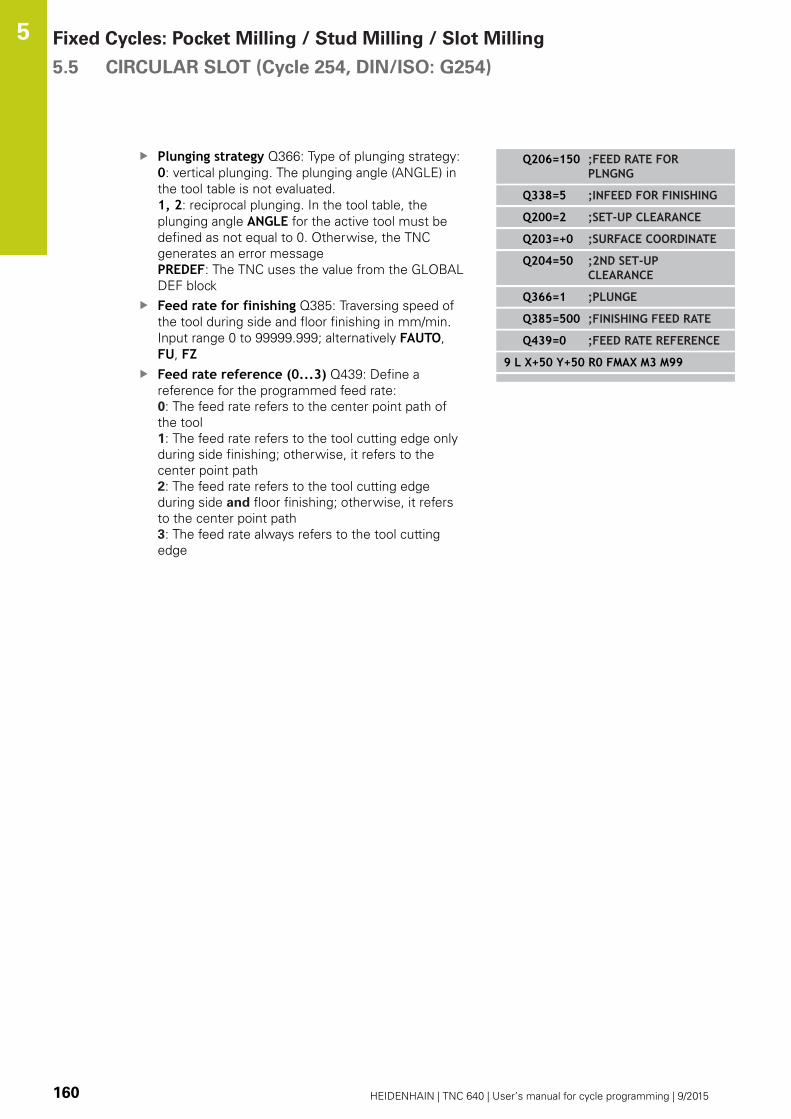
Fixed Cycles: Pocket Milling / Stud Milling / Slot Milling 5.5 CIRCULAR SLOT (Cycle 254, DIN/ISO: G254)
5
160 HEIDENHAIN | TNC 640 | User’s manual for cycle programming | 9/2015
Plunging strategy Q366: Type of plunging strategy:
0: vertical plunging. The plunging angle (ANGLE) in
the tool table is not evaluated.
1, 2: reciprocal plunging. In the tool table, the
plunging angle ANGLE for the active tool must be
defined as not equal to 0. Otherwise, the TNC
generates an error message
PREDEF: The TNC uses the value from the GLOBAL
DEF block
Feed rate for finishing Q385: Traversing speed of
the tool during side and floor finishing in mm/min.
Input range 0 to 99999.999; alternatively FAUTO,
FU, FZFeed rate reference (0...3) Q439: Define a
reference for the programmed feed rate:
0: The feed rate refers to the center point path of
the tool
1: The feed rate refers to the tool cutting edge only
during side finishing; otherwise, it refers to the
center point path
2: The feed rate refers to the tool cutting edge
during side and floor finishing; otherwise, it refers
to the center point path
3: The feed rate always refers to the tool cutting
edge
Q206=150 ;FEED RATE FORPLNGNG
Q338=5 ;INFEED FOR FINISHING
Q200=2 ;SET-UP CLEARANCE
Q203=+0 ;SURFACE COORDINATE
Q204=50 ;2ND SET-UPCLEARANCE
Q366=1 ;PLUNGE
Q385=500 ;FINISHING FEED RATE
Q439=0 ;FEED RATE REFERENCE
9 L X+50 Y+50 R0 FMAX M3 M99
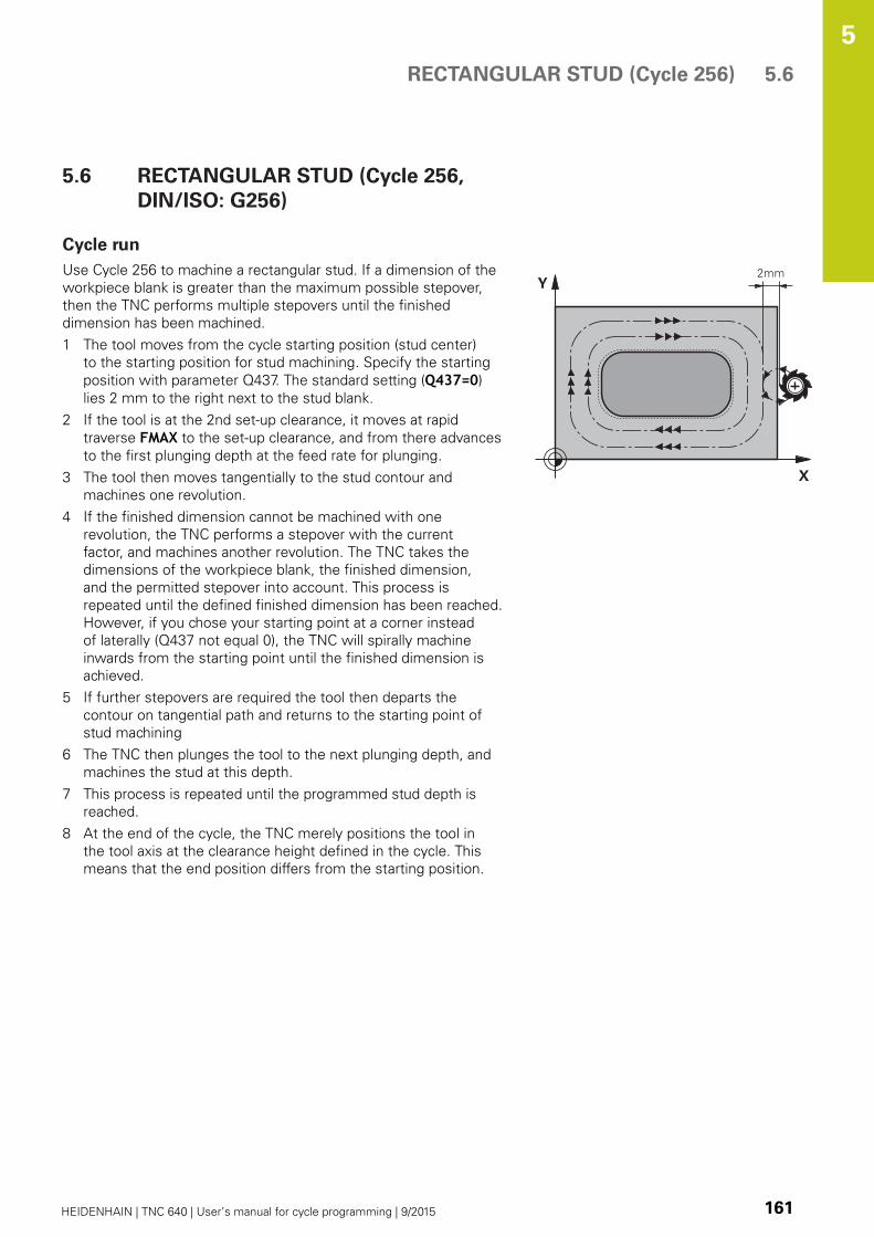
RECTANGULAR STUD (Cycle 256) 5.6
5
HEIDENHAIN | TNC 640 | User’s manual for cycle programming | 9/2015 161
5.6 RECTANGULAR STUD (Cycle 256,
DIN/ISO: G256)
Cycle run
Use Cycle 256 to machine a rectangular stud. If a dimension of the
workpiece blank is greater than the maximum possible stepover,
then the TNC performs multiple stepovers until the finished
dimension has been machined.
1 The tool moves from the cycle starting position (stud center)
to the starting position for stud machining. Specify the starting
position with parameter Q437. The standard setting (Q437=0)
lies 2 mm to the right next to the stud blank.
2 If the tool is at the 2nd set-up clearance, it moves at rapid
traverse FMAX to the set-up clearance, and from there advances
to the first plunging depth at the feed rate for plunging.
3 The tool then moves tangentially to the stud contour and
machines one revolution.
4 If the finished dimension cannot be machined with one
revolution, the TNC performs a stepover with the current
factor, and machines another revolution. The TNC takes the
dimensions of the workpiece blank, the finished dimension,
and the permitted stepover into account. This process is
repeated until the defined finished dimension has been reached.
However, if you chose your starting point at a corner instead
of laterally (Q437 not equal 0), the TNC will spirally machine
inwards from the starting point until the finished dimension is
achieved.
5 If further stepovers are required the tool then departs the
contour on tangential path and returns to the starting point of
stud machining
6 The TNC then plunges the tool to the next plunging depth, and
machines the stud at this depth.
7 This process is repeated until the programmed stud depth is
reached.
8 At the end of the cycle, the TNC merely positions the tool in
the tool axis at the clearance height defined in the cycle. This
means that the end position differs from the starting position.
Fixed Cycles: Pocket Milling / Stud Milling / Slot Milling 5.6 RECTANGULAR STUD (Cycle 256)
5
162 HEIDENHAIN | TNC 640 | User’s manual for cycle programming | 9/2015
Please note while programming:
Pre-position the tool in the machining plane to the
starting position with radius compensation R0. Note
parameter Q367 (position).
The TNC automatically pre-positions the tool in the
tool axis. Note the 2nd set-up clearance Q204.
The algebraic sign for the cycle parameter DEPTH
determines the working direction. If you program
DEPTH=0, the cycle will not be executed.
The TNC reduces the infeed depth to the LCUTS tool
length defined in the tool table if the tool length is
shorter than the Q202 infeed depth programmed in
the cycle.
Danger of collision!
Use the machine parameter displayDepthErr to
define whether, if a positive depth is entered, the
TNC should output an error message (on) or not (off).
Keep in mind that the TNC reverses the calculation
for pre-positioning when a positive depth is
entered. This means that the tool moves at rapid
traverse in the tool axis to set-up clearance below
the workpiece surface!
Depending on the approach position Q439, leave
enough room next to the stud for the approach
motion. At least tool diameter + 2 mm.
At the end, the TNC positions the tool back to the
set-up clearance, or to the 2nd set-up clearance if
one was programmed. The end position of the tool
after the cycle differs from the starting position!
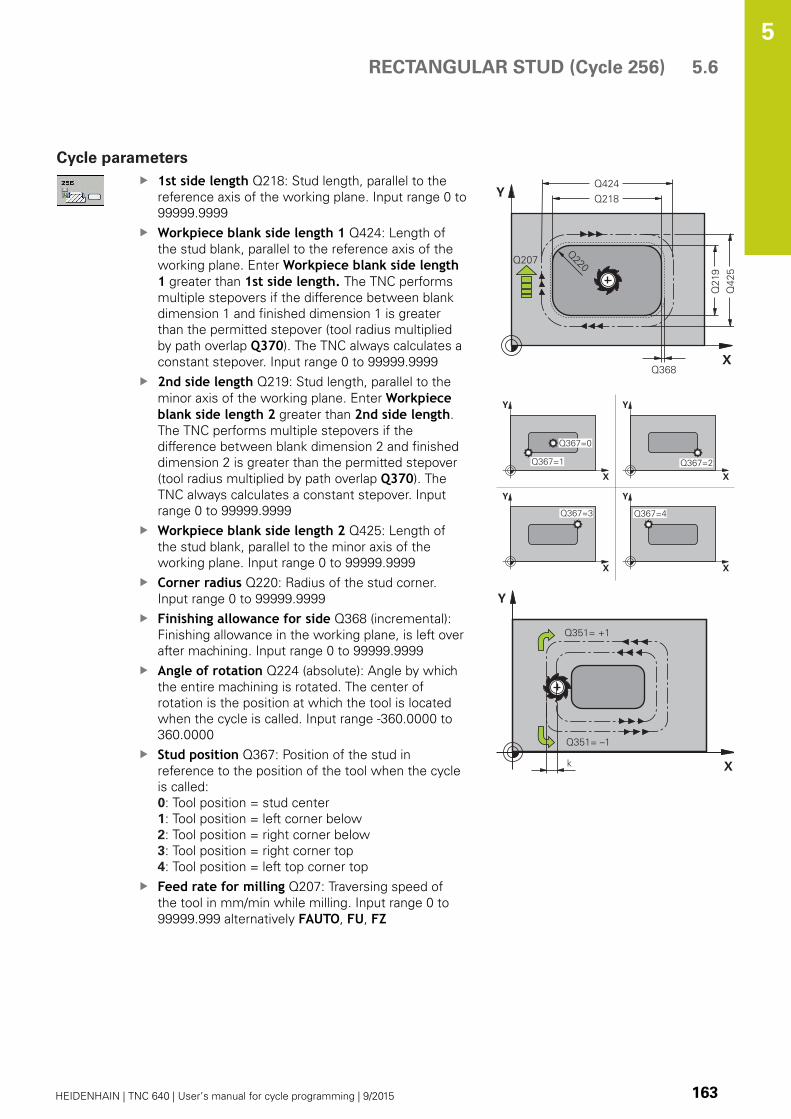
RECTANGULAR STUD (Cycle 256) 5.6
5
HEIDENHAIN | TNC 640 | User’s manual for cycle programming | 9/2015 163
Cycle parameters
1st side length Q218: Stud length, parallel to the
reference axis of the working plane. Input range 0 to
99999.9999
Workpiece blank side length 1 Q424: Length of
the stud blank, parallel to the reference axis of the
working plane. Enter Workpiece blank side length1 greater than 1st side length. The TNC performs
multiple stepovers if the difference between blank
dimension 1 and finished dimension 1 is greater
than the permitted stepover (tool radius multiplied
by path overlap Q370). The TNC always calculates a
constant stepover. Input range 0 to 99999.9999
2nd side length Q219: Stud length, parallel to the
minor axis of the working plane. Enter Workpieceblank side length 2 greater than 2nd side length.
The TNC performs multiple stepovers if the
difference between blank dimension 2 and finished
dimension 2 is greater than the permitted stepover
(tool radius multiplied by path overlap Q370). The
TNC always calculates a constant stepover. Input
range 0 to 99999.9999
Workpiece blank side length 2 Q425: Length of
the stud blank, parallel to the minor axis of the
working plane. Input range 0 to 99999.9999
Corner radius Q220: Radius of the stud corner.
Input range 0 to 99999.9999
Finishing allowance for side Q368 (incremental):
Finishing allowance in the working plane, is left over
after machining. Input range 0 to 99999.9999
Angle of rotation Q224 (absolute): Angle by which
the entire machining is rotated. The center of
rotation is the position at which the tool is located
when the cycle is called. Input range -360.0000 to
360.0000
Stud position Q367: Position of the stud in
reference to the position of the tool when the cycle
is called:
0: Tool position = stud center
1: Tool position = left corner below
2: Tool position = right corner below
3: Tool position = right corner top
4: Tool position = left top corner top
Feed rate for milling Q207: Traversing speed of
the tool in mm/min while milling. Input range 0 to
99999.999 alternatively FAUTO, FU, FZ

Fixed Cycles: Pocket Milling / Stud Milling / Slot Milling 5.6 RECTANGULAR STUD (Cycle 256)
5
164 HEIDENHAIN | TNC 640 | User’s manual for cycle programming | 9/2015
Climb or up-cut Q351: Type of milling operation
with M3
+1 = climb
–1 = up-cut
PREDEF: The TNC uses the value from the GLOBAL
DEF block (If you enter 0, climb milling is used for
machining)
Depth Q201 (incremental): Distance between
workpiece surface and bottom of stud. Input range
-99999.9999 to 99999.9999
Plunging depth Q202 (incremental): Infeed per
cut. Enter a value greater than 0. Input range 0 to
99999.9999
Feed rate for plunging Q206: Traversing speed of
the tool while moving to depth in mm/min. Input
range 0 to 99999.999; alternatively FMAX, FAUTO,
FU, FZSet-up clearance Q200 (incremental): Distance
between tool tip and workpiece surface. Input range
0 to 99999.9999; alternatively PREDEFCoordinate of workpiece surface Q203 (absolute):
Coordinate of the workpiece surface. Input range
-99999.9999 to 99999.9999
2nd set-up clearance Q204 (incremental):
Coordinate in the spindle axis at which no collision
between tool and workpiece (fixtures) can occur.
Input range 0 to 99999.9999; alternatively PREDEFPath overlap factor Q370: Q370 x tool radius
= stepover factor k. Input range: 0.1 to 1.9999;
alternatively PREDEFApproach position (0...4) Q437: Define the
approach strategy of the tool:
0: Right of the stud (default setting)
1: left corner below
2: right corner below
3: right corner top
4: left corner top. If approach marks on the stud
surface are caused by the setting Q437=0, specify
another approach position.
NC blocks
8 CYCL DEF 256 RECTANGULAR STUD
Q218=60 ;FIRST SIDE LENGTH
Q424=74 ;WORKPC. BLANK SIDE1
Q219=40 ;2ND SIDE LENGTH
Q425=60 ;WORKPC. BLANK SIDE2
Q220=5 ;CORNER RADIUS
Q368=0.2 ;ALLOWANCE FOR SIDE
Q224=+0 ;ANGLE OF ROTATION
Q367=0 ;STUD POSITION
Q207=500 ;FEED RATE FORMILLING
Q351=+1 ;CLIMB OR UP-CUT
Q201=-20 ;DEPTH
Q202=5 ;PLUNGING DEPTH
Q206=150 ;FEED RATE FORPLNGNG
Q200=2 ;SET-UP CLEARANCE
Q203=+0 ;SURFACE COORDINATE
Q204=50 ;2ND SET-UPCLEARANCE
Q370=1 ;TOOL PATH OVERLAP
Q437=0 ;APPROACH POSITION
9 L X+50 Y+50 R0 FMAX M3 M99

CIRCULAR STUD (Cycle 257, DIN/ISO: G257) 5.7
5
HEIDENHAIN | TNC 640 | User’s manual for cycle programming | 9/2015 165
5.7 CIRCULAR STUD (Cycle 257, DIN/ISO:
G257)
Cycle run
Use Cycle 257 to machine a circular stud. The TNC mills the circular
stud with a helical infeed motion starting from the workpiece blank
diameter.
1 If the tool is below the 2nd set-up clearance, the TNC retracts
the tool to the 2nd set-up clearance.
2 The tool moves from the stud center to the starting position for
stud machining. With the polar angle you specify the starting
position with respect to the stud center using parameter Q376.
3 The TNC moves the tool at rapid traverse FMAX to the set-up
clearance Q200, and from there advances to the first plunging
depth at the feed rate for plunging.
4 The TNC then machines the circular stud with a helical infeed
motion, taking the overlap factor into account.
5 The TNC retracts the tool from the contour by 2 mm on a
tangential path.
6 If more than one plunging movement is required, the tool
repeats the plunging movement at the point next to the
departure movement.
7 This process is repeated until the programmed stud depth is
reached.
8 At the end of the cycle, the tool departs on a tangential path and
then retracts in the tool axis to the 2nd set-up clearance defined
in the cycle.
Fixed Cycles: Pocket Milling / Stud Milling / Slot Milling 5.7 CIRCULAR STUD (Cycle 257, DIN/ISO: G257)
5
166 HEIDENHAIN | TNC 640 | User’s manual for cycle programming | 9/2015
Please note while programming:
Pre-position the tool in the machining plane to
the starting position (stud center) with radius
compensation R0.
The TNC automatically pre-positions the tool in the
tool axis. Note the 2nd set-up clearance Q204.
The algebraic sign for the cycle parameter DEPTH
determines the working direction. If you program
DEPTH=0, the cycle will not be executed.
At the end of the cycle, the TNC returns the tool to
the starting position.
The TNC reduces the infeed depth to the LCUTS tool
length defined in the tool table if the tool length is
shorter than the Q202 infeed depth programmed in
the cycle.
Danger of collision!
Use the machine parameter displayDepthErr to
define whether, if a positive depth is entered, the
TNC should output an error message (on) or not (off).
Keep in mind that the TNC reverses the calculation
for pre-positioning when a positive depth is
entered. This means that the tool moves at rapid
traverse in the tool axis to set-up clearance below
the workpiece surface!
The TNC performs an approach motion in this cycle!
Depending on the starting angle Q376, the following
amount of space must be left next to the stud: At
least tool diameter + 2 mm. Danger of collision!
At the end, the TNC positions the tool back to the
set-up clearance, or to the 2nd set-up clearance if
one was programmed. The end position of the tool
after the cycle differs from the starting position!
Enter a starting angle between 0° and 360° in
parameter Q376 in order to determine the exact
starting position. If you use the default value -1 the
TNC automatically calculates the most favorable
starting position. These may vary

CIRCULAR STUD (Cycle 257, DIN/ISO: G257) 5.7
5
HEIDENHAIN | TNC 640 | User’s manual for cycle programming | 9/2015 167
Cycle parameters
Finished part diameter Q223: Diameter of
the completely machined stud. Input range 0 to
99999.9999
Workpiece blank diameter Q222: Diameter of
the workpiece blank. Enter the workpiece blank
diameter greater than the finished diameter. The
TNC performs multiple stepovers if the difference
between the workpiece blank diameter and finished
diameter is greater than the permitted stepover (tool
radius multiplied by path overlap Q370). The TNC
always calculates a constant stepover. Input range 0
to 99999.9999
Finishing allowance for side Q368 (incremental):
Finishing allowance in the working plane. Input
range 0 to 99999.9999
Feed rate for milling Q207: Traversing speed of
the tool in mm/min while milling. Input range 0 to
99999.999 alternatively FAUTO, FU, FZClimb or up-cut Q351: Type of milling operation
with M3
+1 = climb
–1 = up-cut
PREDEF: The TNC uses the value from the GLOBAL
DEF block (If you enter 0, climb milling is used for
machining)
Depth Q201 (incremental): Distance between
workpiece surface and bottom of stud. Input range
-99999.9999 to 99999.9999
Plunging depth Q202 (incremental): Infeed per
cut. Enter a value greater than 0. Input range 0 to
99999.9999
Feed rate for plunging Q206: Traversing speed of
the tool while moving to depth in mm/min. Input
range 0 to 99999.999; alternatively FMAX, FAUTO,
FU, FZSet-up clearance Q200 (incremental): Distance
between tool tip and workpiece surface. Input range
0 to 99999.9999; alternatively PREDEF
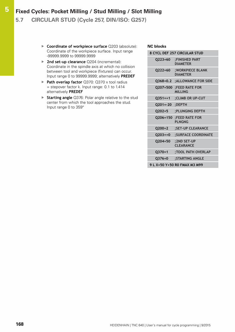
Fixed Cycles: Pocket Milling / Stud Milling / Slot Milling 5.7 CIRCULAR STUD (Cycle 257, DIN/ISO: G257)
5
168 HEIDENHAIN | TNC 640 | User’s manual for cycle programming | 9/2015
Coordinate of workpiece surface Q203 (absolute):
Coordinate of the workpiece surface. Input range
-99999.9999 to 99999.9999
2nd set-up clearance Q204 (incremental):
Coordinate in the spindle axis at which no collision
between tool and workpiece (fixtures) can occur.
Input range 0 to 99999.9999; alternatively PREDEFPath overlap factor Q370: Q370 x tool radius
= stepover factor k. Input range: 0.1 to 1.414
alternatively PREDEFStarting angle Q376: Polar angle relative to the stud
center from which the tool approaches the stud.
Input range 0 to 359°
NC blocks
8 CYCL DEF 257 CIRCULAR STUD
Q223=60 ;FINISHED PARTDIAMETER
Q222=60 ;WORKPIECE BLANKDIAMETER
Q368=0.2 ;ALLOWANCE FOR SIDE
Q207=500 ;FEED RATE FORMILLING
Q351=+1 ;CLIMB OR UP-CUT
Q201=-20 ;DEPTH
Q202=5 ;PLUNGING DEPTH
Q206=150 ;FEED RATE FORPLNGNG
Q200=2 ;SET-UP CLEARANCE
Q203=+0 ;SURFACE COORDINATE
Q204=50 ;2ND SET-UPCLEARANCE
Q370=1 ;TOOL PATH OVERLAP
Q376=0 ;STARTING ANGLE
9 L X+50 Y+50 R0 FMAX M3 M99

CIRCULAR STUD (cycle 258, DIN/ISO: G258) 5.8
5
HEIDENHAIN | TNC 640 | User’s manual for cycle programming | 9/2015 169
5.8 CIRCULAR STUD (cycle 258, DIN/ISO:
G258)
Cycle run
With the cycle POLYGON STUD you can create an even polygon by
machining the contour outside. The milling operation is carried out
on a spiral path, based on the diameter of the workpiece blank.
1 If, at the beginning of machining, the work piece is positioned
below the 2nd set-up clearance, the TNC will retract the tool
back to the 2nd setup clearance.
2 Starting from the center of the stud the TNC moves the tool
to the starting point of the stud machining. The starting point
depends, among others, on the diameter of the workpiece blank
and the angle of rotation of the stud. The angle of rotation is
determined with parameter Q224.
3 The tool moves at rapid traverse FMAX to the setup clearance
Q200 and from there with the feed rate for plunging to the first
plunging depth.
4 Then the TNC creates the polygon stud in a spiral-shaped pass,
taking into account the path overlap
5 The TNC moves the tool on a tangential path from the outside
to the inside
6 The tool will be lifted in the direction of the spindle axis to the
2nd setup clearance in one rapid movement
7 If several plunging depths are required, the TNC will position the
tool back to the starting point of the stud milling process.
8 This process is repeated until the programmed stud depth is
reached.
9 At the end of the cycle first a departing motion is performed.
Then the TNC will move the tool on the tool axis to the 2nd
setup clearance.

Fixed Cycles: Pocket Milling / Stud Milling / Slot Milling 5.8 CIRCULAR STUD (cycle 258, DIN/ISO: G258)
5
170 HEIDENHAIN | TNC 640 | User’s manual for cycle programming | 9/2015
Please note while programming:
Before the start of the cycle you will have to
preposition the tool on the machining plane. In order
to do so, move the tool with radius compensation R0to the center of the stud.
The TNC automatically pre-positions the tool in the
tool axis. Note the 2nd set-up clearance Q204.
The algebraic sign for the cycle parameter DEPTH
determines the working direction. If you program
DEPTH=0, the cycle will not be executed.
The TNC reduces the infeed depth to the LCUTS tool
length defined in the tool table if the tool length is
shorter than the Q202 infeed depth programmed in
the cycle.
Danger of collision!
Use the machine parameter displayDepthErr to
define whether, if a positive depth is entered, the
TNC should output an error message (on) or not (off).
Keep in mind that the TNC reverses the calculation
for pre-positioning when a positive depth is
entered. This means that the tool moves at rapid
traverse in the tool axis to set-up clearance below
the workpiece surface!
The TNC performs an approaching motion in this
cycle! Depending on the rotary position Q224, the
following amount of space must be left next to
the stud: At least tool diameter + 2mm. Danger of
collision!
At the end, the TNC positions the tool back to the
set-up clearance, or to the 2nd set-up clearance if
one was programmed. The end position of the tool
after the cycle differs from the starting position!

CIRCULAR STUD (cycle 258, DIN/ISO: G258) 5.8
5
HEIDENHAIN | TNC 640 | User’s manual for cycle programming | 9/2015 171
Cycle parameters
Reference circuit Q573: Definition of whether the
dimensioning shall reference to the inscribed circle
or to the perimeter:
0= dimensioning refers to the inscribed circle
1= dimensioning refers to the perimeter
Reference circuit diameter Q571: Definition of
the diameter of the reference circuit. Specify in
parameter Q573 whether the diameter references
to the inscribed circle or the perimeter. Input range:
0 to 99999.9999
Workpiece blank diameter Q222: Definition of the
diameter of the workpiece blank. The workpiece
blank diameter must be greater than the finished
diameter. The TNC performs multiple stepovers
if the difference between the workpiece blank
diameter and reference circuit diameter is greater
than the permitted stepover (tool radius multiplied
by path overlap Q370). The TNC always calculates a
constant stepover. Input range 0 to 99999.9999
Number of corners Q572: Enter the number of
corners of the polygon. The TNC will always equally
divide the corners on the stud. Input range 3 to 30
Angle of rotation Q224: Specify which angle is
used to machine the first corner of the polygon.
Input range: -360° to +360°

Fixed Cycles: Pocket Milling / Stud Milling / Slot Milling 5.8 CIRCULAR STUD (cycle 258, DIN/ISO: G258)
5
172 HEIDENHAIN | TNC 640 | User’s manual for cycle programming | 9/2015
Radius/Chamfer Q220: Enter the value for the input
form radius or chamfer. When entering a positive
value between 0 and +99999.9999 the TNC creates
a polygon with round corners. The radius refers
to the value you entered. If you enter a negative
value between 0 and -99999.9999 all corners of the
contour are chamfered and the value entered refers
to the length of the chamfer.
Finishing allowance for side Q368 (incremental):
Finishing allowance in the working plane. Input
range 0 to 99999.9999
Feed rate for milling Q207: Traversing speed of
the tool in mm/min while milling. Input range 0 to
99999.999 alternatively FAUTO, FU, FZClimb or up-cut Q351: Type of milling operation
with M3
+1 = climb
–1 = up-cut
PREDEF: The TNC uses the value from the GLOBAL
DEF block (If you enter 0, climb milling is used for
machining)
Depth Q201 (incremental): Distance between
workpiece surface and bottom of stud. Input range
-99999.9999 to 99999.9999
Plunging depth Q202 (incremental): Infeed per
cut. Enter a value greater than 0. Input range 0 to
99999.9999
Feed rate for plunging Q206: Traversing speed of
the tool while moving to depth in mm/min. Input
range 0 to 99999.999; alternatively FMAX, FAUTO,
FU, FZ
NC blocks
8 CYCL DEF 258 POLYGON STUDS
Q573=1 ;REFERENCE CIRCUIT
Q571=50 ;REFERENCE CIRCUITDIA.
Q222=120 ;WORKPIECE BLANKDIA.
Q572=10 ;NUMBER OF CORNERS
Q224=40 ;ANGLE OF ROTATION
Q220=2 ;RADIUS/CHAMFER
Q368=0 ;FINISHINGALLOWANCE FOR SIDE
Q207=3000;FEED RATE FORMILLING
Q351=1 ;MILLING TYPE
Q201=-18 ;DEPTH
Q202=10 ;PLUNGING DEPTH
Q206=150 ;FEED RATE FORPLUNGING
Q200=2 ;SETUP CLEARANCE
Q203=+0 ;SURFACE COORDINATE
Q204=50 ;2ND SETUPCLEARANCE
Q370=1 ;TOOL PATH OVERLAP
CIRCULAR STUD (cycle 258, DIN/ISO: G258) 5.8
5
HEIDENHAIN | TNC 640 | User’s manual for cycle programming | 9/2015 173
Set-up clearance Q200 (incremental): Distance
between tool tip and workpiece surface. Input range
0 to 99999.9999; alternatively PREDEFCoordinate of workpiece surface Q203 (absolute):
Coordinate of the workpiece surface. Input range
-99999.9999 to 99999.9999
2nd set-up clearance Q204 (incremental):
Coordinate in the spindle axis at which no collision
between tool and workpiece (fixtures) can occur.
Input range 0 to 99999.9999; alternatively PREDEFPath overlap factor Q370: Q370 x tool radius
= stepover factor k. Input range: 0.1 to 1.414
alternatively PREDEFMachining operation (0/1/2) Q215: Define
machining operation:
0: Roughing and finishing
1: Only roughing
2: Only finishing
Side finishing and floor finishing are only machined
when the specific allowance (Q368, Q369) is
defined
Finishing allowance for floor Q369 (incremental
value): Finishing allowance in the tool axis. Input
range 0 to 99999.9999
Infeed for finishing Q338 (incremental): Infeed per
cut. Q338=0: Finishing in one infeed. Input range 0
to 99999.9999
Feed rate for finishing Q385: Traversing speed of
the tool during side and floor finishing in mm/min.
Input range 0 to 99999.999; alternatively FAUTO,
FU, FZ
Q215=0 ;MACHININGOPERATION
Q369=0 ;ALLOWANCE OF THEFLOOR
Q338=0 ;INFEED FOR FINISHING
Q385=500 ;FINISHING FEED RATE
9 L X+50 Y+50 R0 FMAX M3 M99
Fixed Cycles: Pocket Milling / Stud Milling / Slot Milling 5.9 FACE MILLING (Cycle 233)
5
174 HEIDENHAIN | TNC 640 | User’s manual for cycle programming | 9/2015
5.9 FACE MILLING (Cycle 233, DIN/ISO:
G233)
Cycle run
Cycle 233 is used to face mill a level surface in multiple infeeds
while taking the finishing allowance into account. You can also
define side walls in the cycle, which are then taken into account
when machining the level surface. The cycle offers you various
machining strategies:
Strategy Q389=0: Meander machining, stepover outside the
surface being machined
Strategy Q389=1: Meander machining, stepover at the edge of
the surface being machined
Strategy Q389=2: The surface is machined line by line with
overtravel; stepover when retracting at rapid traverse
Strategy Q389=3: The surface is machined line by line without
overtravel; stepover when retracting at rapid traverse
Strategy Q389=4: Helical machining from the outside toward
the inside
1 From the current position, the TNC positions the tool at rapid
traverse FMAX to the starting point 1 in the working plane: The
starting point in the working plane is offset from the edge of
the workpiece by the tool radius and the safety clearance to the
side.
2 The TNC then positions the tool at rapid traverse FMAX to the
set-up clearance in the spindle axis.
3 The tool then moves in the tool axis at the feed rate for milling
Q207 to the first plunging depth calculated by the TNC.
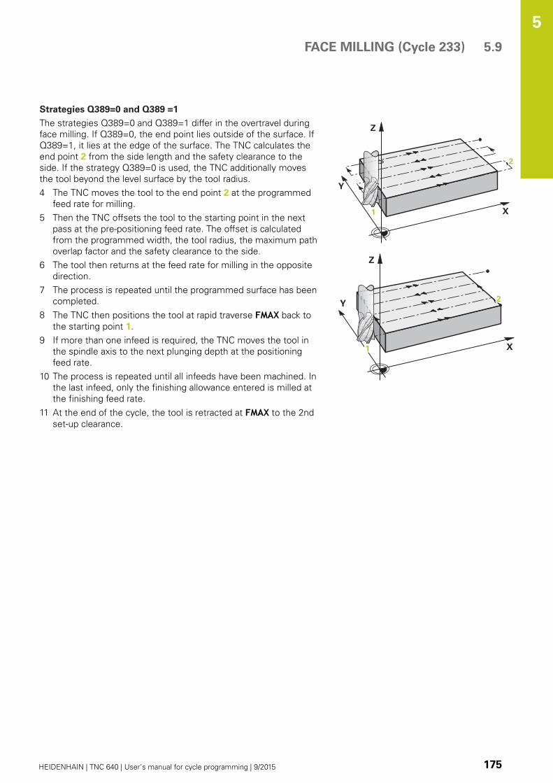
FACE MILLING (Cycle 233) 5.9
5
HEIDENHAIN | TNC 640 | User’s manual for cycle programming | 9/2015 175
Strategies Q389=0 and Q389 =1
The strategies Q389=0 and Q389=1 differ in the overtravel during
face milling. If Q389=0, the end point lies outside of the surface. If
Q389=1, it lies at the edge of the surface. The TNC calculates the
end point 2 from the side length and the safety clearance to the
side. If the strategy Q389=0 is used, the TNC additionally moves
the tool beyond the level surface by the tool radius.
4 The TNC moves the tool to the end point 2 at the programmed
feed rate for milling.
5 Then the TNC offsets the tool to the starting point in the next
pass at the pre-positioning feed rate. The offset is calculated
from the programmed width, the tool radius, the maximum path
overlap factor and the safety clearance to the side.
6 The tool then returns at the feed rate for milling in the opposite
direction.
7 The process is repeated until the programmed surface has been
completed.
8 The TNC then positions the tool at rapid traverse FMAX back to
the starting point 1.
9 If more than one infeed is required, the TNC moves the tool in
the spindle axis to the next plunging depth at the positioning
feed rate.
10 The process is repeated until all infeeds have been machined. In
the last infeed, only the finishing allowance entered is milled at
the finishing feed rate.
11 At the end of the cycle, the tool is retracted at FMAX to the 2nd
set-up clearance.

Fixed Cycles: Pocket Milling / Stud Milling / Slot Milling 5.9 FACE MILLING (Cycle 233)
5
176 HEIDENHAIN | TNC 640 | User’s manual for cycle programming | 9/2015
Strategies Q389=2 and Q389 =3
The strategies Q389=2 and Q389=3 differ in the overtravel during
face milling. If Q389=2, the end point lies outside of the surface. If
Q389=3, it lies at the edge of the surface. The TNC calculates the
end point 2 from the side length and the safety clearance to the
side. If the strategy Q389=2 is used, the TNC additionally moves
the tool beyond the level surface by the tool radius.
4 The tool subsequently advances to the end point 2 at the
programmed feed rate for milling.
5 The TNC positions the tool in the spindle axis to the set-up
clearance over the current infeed depth, and then moves at
FMAX directly back to the starting point in the next line. The
TNC calculates the offset from the programmed width, the
tool radius, the maximum path overlap factor and the safety
clearance to the side.
6 The tool then returns to the current infeed depth and moves in
the direction of the next end point 2.
7 The multipass process is repeated until the programmed
surface has been completed. At the end of the last path, the
TNC positions the tool at rapid traverse FMAX back to the
starting point 1.
8 If more than one infeed is required, the TNC moves the tool in
the spindle axis to the next plunging depth at the positioning
feed rate.
9 The process is repeated until all infeeds have been machined. In
the last infeed, only the finishing allowance entered is milled at
the finishing feed rate.
10 At the end of the cycle, the tool is retracted at FMAX to the 2nd
set-up clearance.

FACE MILLING (Cycle 233) 5.9
5
HEIDENHAIN | TNC 640 | User’s manual for cycle programming | 9/2015 177
Strategy Q389=4
4 The tool subsequently approaches the starting point of the
milling path on a tangential arc at the programmed feed ratefor milling.
5 The TNC machines the level surface at the feed rate for
milling from the outside toward the inside with ever-shorter
milling paths. The constant stepover results in the tool being
continuously engaged.
6 The process is repeated until the programmed surface has been
completed. At the end of the last path, the TNC positions the
tool at rapid traverse FMAX back to the starting point 1.
7 If more than one infeed is required, the TNC moves the tool in
the spindle axis to the next plunging depth at the positioning
feed rate.
8 The process is repeated until all infeeds have been machined. In
the last infeed, only the finishing allowance entered is milled at
the finishing feed rate.
9 At the end of the cycle, the tool is retracted at FMAX to the 2ndset-up clearance.
Limits
The limits enable you to set limits to the machining of the level
surface so that, for example, side walls or shoulders are considered
during machining. A side wall that is defined by a limit is machined
to the finished dimension resulting from the starting point or the
side lengths of the level surface. During roughing the TNC takes
the allowance for the side into account, whereas during finishing
the allowance is used for pre-positioning the tool.

Fixed Cycles: Pocket Milling / Stud Milling / Slot Milling 5.9 FACE MILLING (Cycle 233)
5
178 HEIDENHAIN | TNC 640 | User’s manual for cycle programming | 9/2015
Please note while programming:
Pre-position the tool in the machining plane to the
starting position with radius compensation R0. Keep
in mind the machining direction.
The TNC automatically pre-positions the tool in the
tool axis. Note the 2nd set-up clearance Q204.
Enter the 2nd set-up clearance in Q204 so that no
collision with the workpiece or the fixtures can occur.
If the starting point in the 3rd axis Q227 and the
end point in the 3rd axis Q386 are entered as equal
values, the TNC does not run the cycle (depth = 0
has been programmed).
Danger of collision!
Use the machine parameter displayDepthErr to
define whether, if a positive depth is entered, the
TNC should output an error message (on) or not (off).
Keep in mind that the TNC reverses the calculation
for pre-positioning if starting point < end point is
entered. This means that the tool moves at rapid
traverse in the tool axis to set-up clearance below
the workpiece surface!

FACE MILLING (Cycle 233) 5.9
5
HEIDENHAIN | TNC 640 | User’s manual for cycle programming | 9/2015 179
Cycle parameters
Machining operation (0/1/2) Q215: Define
machining operation:
0: Roughing and finishing
1: Only roughing
2: Only finishing
Side finishing and floor finishing are only machined
when the specific allowance (Q368, Q369) is
defined
Milling strategy (0 to 4) Q389: Determine how the
TNC should machine the surface:
0: Meander machining, stepover at the positioning
feed rate outside the surface to be machined
1: Meander machining, stepover at the feed rate for
milling at the edge of the surface to be machined
2: Line-by-line machining, retraction and stepover at
the positioning feed rate outside the surface to be
machined
3: Line-by-line machining, retraction and stepover at
the positioning feed rate at the edge of the surface
to be machined
4: Helical machining, uniform infeed from the
outside toward the inside
Milling direction Q350: Axis in the machining plane
that defines the machining direction:
1: Reference axis = machining direction
2: Minor axis = machining direction
1st side length Q218 (incremental): Length of the
surface to be multipass-milled in the reference axis
of the working plane, referenced to the starting
point in the 1st axis. Input range 0 to 99999.9999
2nd side length Q219 (incremental value): Length
of the surface to be machined in the minor axis of
the working plane. Use the algebraic sign to specify
the direction of the first stepover in reference to
the starting point in the 2nd axis. Input range
-99999.9999 to 99999.9999
Q21
9
Q357
Q227
Q347Q348 Q349
= 0
= -1 = +1
= -2 = +2

Fixed Cycles: Pocket Milling / Stud Milling / Slot Milling 5.9 FACE MILLING (Cycle 233)
5
180 HEIDENHAIN | TNC 640 | User’s manual for cycle programming | 9/2015
Starting point in 3rd axis Q227 (absolute):
Coordinate of the workpiece surface used to
calculate the infeeds. Input range -99999.9999 to
99999.9999
End point in 3rd axis Q386 (absolute): Coordinate
in the spindle axis to which the surface is to be face
milled. Input range -99999.9999 to 99999.9999
Allowance for floor Q369 (incremental):
Distance used for the last infeed. Input range 0 to
99999.9999
Plunging depth Q202 (incremental): Infeed per
cut. Enter a value greater than 0. Input range 0 to
99999.9999
Path overlap factor Q370: Maximum stepover
factor k. The TNC calculates the actual stepover
from the second side length (Q219) and the tool
radius so that a constant stepover is used for
machining. Input range: 0.1 bis 1.9999.
Feed rate for milling Q207: Traversing speed of
the tool in mm/min while milling. Input range 0 to
99999.999 alternatively FAUTO, FU, FZFeed rate for finishing Q385: Traversing speed of
the tool in mm/min, while milling the last infeed.
Input range 0 to 99999.9999; alternatively FAUTO,
FU, FZFeed rate for pre-positioning Q253: Traversing
speed of the tool in mm/min when approaching
the starting position and when moving to the next
pass. If you are moving the tool transversely to
the material (Q389=1), the TNC moves the tool
at the feed rate for milling Q207. Input range 0 to
99999.9999, alternatively FMAX, FAUTOClearance to side Q357 (incremental): Safety
clearance to the side of the workpiece when
the tool approaches the first plunging depth,
and distance at which the stepover occurs if the
machining strategy Q389=0 or Q389=2 is used.
Input range 0 to 99999.9999
Set-up clearance Q200 (incremental): Distance
between tool tip and workpiece surface. Input range
0 to 99999.9999; alternatively PREDEF
NC blocks
8 CYCL DEF 233 FACE MILLING
Q215=0 ;MACHININGOPERATION
Q389=2 ;MILLING STRATEGY
Q350=1 ;MILLING DIRECTION
Q218=120 ;1ST SIDE LENGTH
Q219=80 ;2ND SIDE LENGTH
Q227=0 ;STARTNG PNT 3RDAXIS
Q386=-6 ;END POINT 3RD AXIS
Q369=0.2 ;ALLOWANCE FORFLOOR
Q202=3 ;MAX. PLUNGINGDEPTH
Q370=1 ;TOOL PATH OVERLAP
Q207=500 ;FEED RATE FORMILLING
Q385=500 ;FINISHING FEED RATE
Q253=750 ;F PRE-POSITIONING
Q357=2 ;CLEARANCE TO SIDE
Q200=2 ;SET-UP CLEARANCE
Q204=50 ;2ND SET-UPCLEARANCE
Q347=0 ;1ST LIMIT
Q348=0 ;2ND LIMIT
Q349=0 ;3RD LIMIT
Q220=2 ;CORNER RADIUS
Q368=0 ;ALLOWANCE FOR SIDE
Q338=0 ;INFEED FOR FINISHING
9 L X+0 Y+0 R0 FMAX M3 M99

FACE MILLING (Cycle 233) 5.9
5
HEIDENHAIN | TNC 640 | User’s manual for cycle programming | 9/2015 181
2nd set-up clearance Q204 (incremental):
Coordinate in the spindle axis at which no collision
between tool and workpiece (fixtures) can occur.
Input range 0 to 99999.9999; alternatively PREDEF1st limit Q347:Select the workpiece side on
which the level surface is limited by a side wall
(not possible for helical machining). Depending on
the position of the side wall, the TNC limits the
machining of the level surface to the respective
coordinate of the starting point or to the side length:
(not possible for helical machining):
Input 0: No limit
Input -1: Limit in the negative reference axis
Input +1: Limit in the positive reference axis
Input -2: Limit in the negative minor axis
Input +2: Limit in the positive minor axis
2nd limit Q348: See parameter 1st limit Q347
3rd limit Q349: See parameter 1st limit Q347
Corner radius Q220: Radius for corner at limits
(Q347 to Q349). Input range 0 to 99999.9999
Finishing allowance for side Q368 (incremental):
Finishing allowance in the working plane. Input
range 0 to 99999.9999
Infeed for finishing Q338 (incremental): Infeed per
cut. Q338=0: Finishing in one infeed. Input range 0
to 99999.9999

Fixed Cycles: Pocket Milling / Stud Milling / Slot Milling 5.10 Programming Examples
5
182 HEIDENHAIN | TNC 640 | User’s manual for cycle programming | 9/2015
5.10 Programming Examples
Example: Milling pockets, studs and slots
0 BEGINN PGM C210 MM
1 BLK FORM 0.1 Z X+0 Y+0 Z-40 Definition of workpiece blank
2 BLK FORM 0.2 X+100 Y+100 Z+0
3 TOOL CALL 1 Z S3500 Call the tool for roughing/finishing
4 L Z+250 R0 FMAX Retract the tool
5 CYCL DEF 256 RECTANGULAR STUD Define cycle for machining the contour outside
Q218=90 ;FIRST SIDE LENGTH
Q424=100 ;WORKPC. BLANK SIDE 1
Q219=80 ;2ND SIDE LENGTH
Q425=100 ;WORKPC. BLANK SIDE 2
Q220=0 ;CORNER RADIUS
Q368=0 ;ALLOWANCE FOR SIDE
Q224=0 ;ANGLE OF ROTATION
Q367=0 ;STUD POSITION
Q207=250 ;FEED RATE FOR MILLING
Q351=+1 ;CLIMB OR UP-CUT
Q201=-30 ;DEPTH
Q202=5 ;PLUNGING DEPTH
Q206=250 ;FEED RATE FOR PLNGNG
Q200=2 ;SET-UP CLEARANCE
Q203=+0 ;SURFACE COORDINATE
Q204=20 ;2ND SET-UP CLEARANCE
Q370=1 ;TOOL PATH OVERLAP
Q437=0 ;APPROACH POSITION
6 L X+50 Y+50 R0 M3 M99 Call cycle for machining the contour outside
7 CYCL DEF 252 CIRCULAR POCKET Define CIRCULAR POCKET MILLING cycle
Q215=0 ;MACHINING OPERATION
Q223=50 ;CIRCLE DIAMETER
Q368=0.2 ;ALLOWANCE FOR SIDE
Q207=500 ;FEED RATE FOR MILLING
Programming Examples 5.10
5
HEIDENHAIN | TNC 640 | User’s manual for cycle programming | 9/2015 183
Q351=+1 ;CLIMB OR UP-CUT
Q201=-30 ;DEPTH
Q202=5 ;PLUNGING DEPTH
Q369=0.1 ;ALLOWANCE FOR FLOOR
Q206=150 ;FEED RATE FOR PLNGNG
Q338=5 ;INFEED FOR FINISHING
Q200=2 ;SET-UP CLEARANCE
Q203=+0 ;SURFACE COORDINATE
Q204=50 ;2ND SET-UP CLEARANCE
Q370=1 ;TOOL PATH OVERLAP
Q366=1 ;PLUNGE
Q385=750 ;FINISHING FEED RATE
8 L X+50 Y+50 R0 FMAX M99 Call CIRCULAR POCKET MILLING cycle
9 L Z+250 R0 FMAX M6 Tool change
10 TOLL CALL 2 Z S5000 Call tool: slotting mill
11 CYCL DEF 254 CIRCULAR SLOT Define SLOT cycle
Q215=0 ;MACHINING OPERATION
Q219=8 ;SLOT WIDTH
Q368=0.2 ;ALLOWANCE FOR SIDE
Q375=70 ;PITCH CIRCLE DIA.
Q367=0 ;REF. SLOT POSITION No pre-positioning in X/Y required
Q216=+50 ;CENTER IN 1ST AXIS
Q217=+50 ;CENTER IN 2ND AXIS
Q376=+45 ;STARTING ANGLE
Q248=90 ;ANGULAR LENGTH
Q378=180 ;STEPPING ANGLE Starting point for second slot
Q377=2 ;NR OF REPETITIONS
Q207=500 ;FEED RATE FOR MILLING
Q351=+1 ;CLIMB OR UP-CUT
Q201=-20 ;DEPTH
Q202=5 ;PLUNGING DEPTH
Q369=0.1 ;ALLOWANCE FOR FLOOR
Q206=150 ;FEED RATE FOR PLNGNG
Q338=5 ;INFEED FOR FINISHING
Q200=2 ;SET-UP CLEARANCE
Q203=+0 ;SURFACE COORDINATE
Q204=50 ;2ND SET-UP CLEARANCE
Q366=1 ;PLUNGE
12 CYCL CALL FMAX M3 Call SLOT cycle
13 L Z+250 R0 FMAX M2 Retract in the tool axis, end program
14 END PGM C210 MM

6Fixed Cycles:
Pattern Definitions

Fixed Cycles: Pattern Definitions 6.1 Fundamentals
6
186 HEIDENHAIN | TNC 640 | User’s manual for cycle programming | 9/2015
6.1 Fundamentals
Overview
The TNC provides two cycles for machining point patterns directly:
Soft key Cycle Page
220 POLAR PATTERN 187
221 CARTESIAN PATTERN 190
You can combine Cycle 220 and Cycle 221 with the following fixed
cycles:
If you have to machine irregular point patterns, use
CYCL CALL PAT (see "Point tables", page 71) to
develop point tables.
More regular point patterns are available with the
PATTERN DEF function (see "PATTERN DEF pattern
definition", page 64).
Cycle 200 DRILLING
Cycle 201 REAMING
Cycle 202 BORING
Cycle 203 UNIVERSAL DRILLING
Cycle 204 BACK BORING
Cycle 205 UNIVERSAL PECKING
Cycle 206 TAPPING NEW with a floating tap holder
Cycle 207 RIGID TAPPING without a floating tap holder NEW
Cycle 208 BORE MILLING
Cycle 209 TAPPING WITH CHIP BREAKING
Cycle 240 CENTERING
Cycle 251 RECTANGULAR POCKET
Cycle 252 CIRCULAR POCKET MILLING
Cycle 253 SLOT MILLING
Cycle 254 CIRCULAR SLOT (can only be combined with Cycle
221)
Cycle 256 RECTANGULAR STUD
Cycle 257 CIRCULAR STUD
Cycle 262 THREAD MILLING
Cycle 263 THREAD MILLING/COUNTERSINKING
Cycle 264 THREAD DRILLING/MILLING
Cycle 265 HELICAL THREAD DRILLING/MILLING
Cycle 267 OUTSIDE THREAD MILLING

POLAR PATTERN (Cycle 220) 6.2
6
HEIDENHAIN | TNC 640 | User’s manual for cycle programming | 9/2015 187
6.2 POLAR PATTERN (Cycle 220, DIN/
ISO: G220)
Cycle run
1 At rapid traverse, the TNC moves the tool from its current
position to the starting point for the first machining operation.
Sequence:
Move to the 2nd set-up clearance (spindle axis)
Approach the starting point in the spindle axis.
Move to the set-up clearance above the workpiece surface
(spindle axis).
2 From this position, the TNC executes the last defined fixed
cycle.
3 The tool then approaches on a straight line or circular arc the
starting point for the next machining operation. The tool stops at
the set-up clearance (or the 2nd set-up clearance).
4 This process (1 to 3) is repeated until all machining operations
have been executed.
Please note while programming:
Cycle 220 is DEF active, which means that Cycle 220
automatically calls the last defined fixed cycle.
If you combine Cycle 220 with one of the fixed
cycles 200 to 209 and 251 to 267, the set-up
clearance, workpiece surface and 2nd set-up
clearance from Cycle 220 will be effective for the
selected fixed cycle.
If you run this cycle in the Single Block mode of
operation, the control stops between the individual
points of a point pattern.
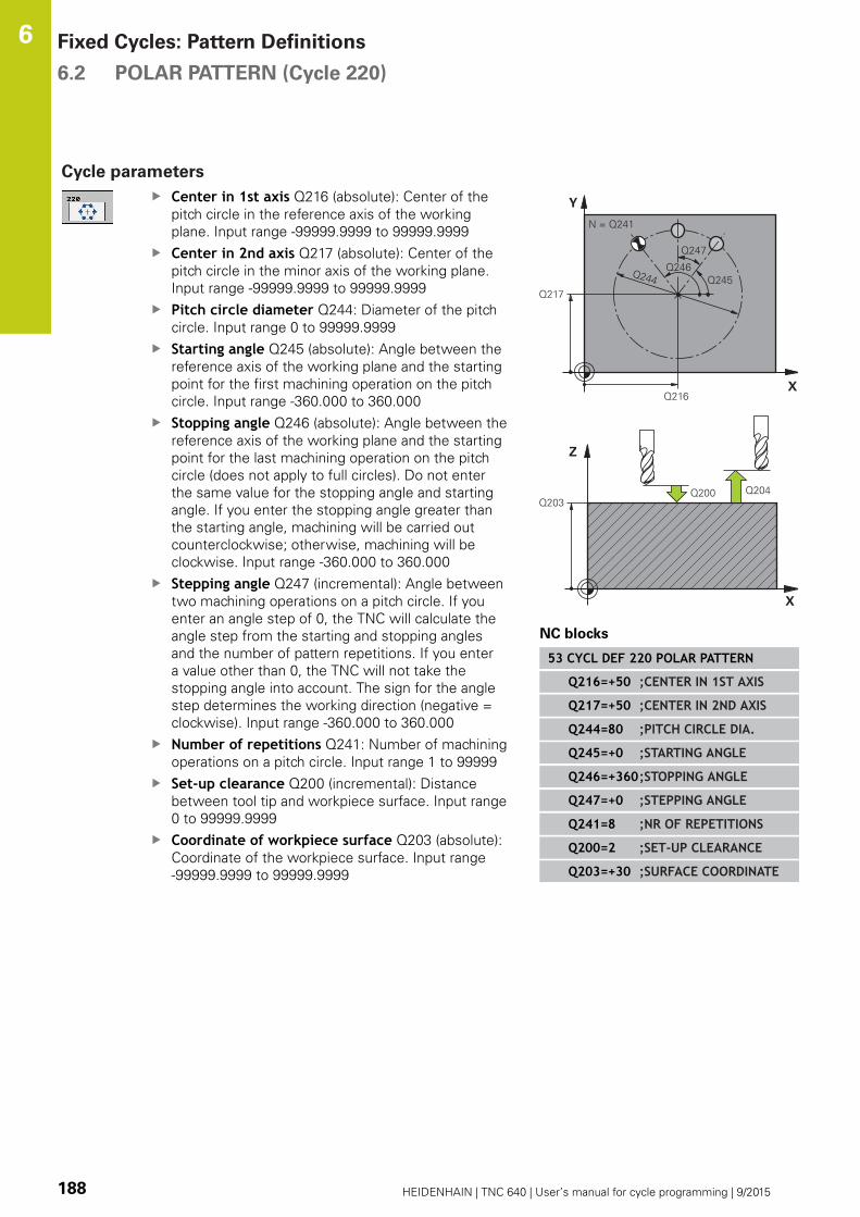
Fixed Cycles: Pattern Definitions 6.2 POLAR PATTERN (Cycle 220)
6
188 HEIDENHAIN | TNC 640 | User’s manual for cycle programming | 9/2015
Cycle parameters
Center in 1st axis Q216 (absolute): Center of the
pitch circle in the reference axis of the working
plane. Input range -99999.9999 to 99999.9999
Center in 2nd axis Q217 (absolute): Center of the
pitch circle in the minor axis of the working plane.
Input range -99999.9999 to 99999.9999
Pitch circle diameter Q244: Diameter of the pitch
circle. Input range 0 to 99999.9999
Starting angle Q245 (absolute): Angle between the
reference axis of the working plane and the starting
point for the first machining operation on the pitch
circle. Input range -360.000 to 360.000
Stopping angle Q246 (absolute): Angle between the
reference axis of the working plane and the starting
point for the last machining operation on the pitch
circle (does not apply to full circles). Do not enter
the same value for the stopping angle and starting
angle. If you enter the stopping angle greater than
the starting angle, machining will be carried out
counterclockwise; otherwise, machining will be
clockwise. Input range -360.000 to 360.000
Stepping angle Q247 (incremental): Angle between
two machining operations on a pitch circle. If you
enter an angle step of 0, the TNC will calculate the
angle step from the starting and stopping angles
and the number of pattern repetitions. If you enter
a value other than 0, the TNC will not take the
stopping angle into account. The sign for the angle
step determines the working direction (negative =
clockwise). Input range -360.000 to 360.000
Number of repetitions Q241: Number of machining
operations on a pitch circle. Input range 1 to 99999
Set-up clearance Q200 (incremental): Distance
between tool tip and workpiece surface. Input range
0 to 99999.9999
Coordinate of workpiece surface Q203 (absolute):
Coordinate of the workpiece surface. Input range
-99999.9999 to 99999.9999
NC blocks
53 CYCL DEF 220 POLAR PATTERN
Q216=+50 ;CENTER IN 1ST AXIS
Q217=+50 ;CENTER IN 2ND AXIS
Q244=80 ;PITCH CIRCLE DIA.
Q245=+0 ;STARTING ANGLE
Q246=+360;STOPPING ANGLE
Q247=+0 ;STEPPING ANGLE
Q241=8 ;NR OF REPETITIONS
Q200=2 ;SET-UP CLEARANCE
Q203=+30 ;SURFACE COORDINATE

POLAR PATTERN (Cycle 220) 6.2
6
HEIDENHAIN | TNC 640 | User’s manual for cycle programming | 9/2015 189
2nd set-up clearance Q204 (incremental):
Coordinate in the spindle axis at which no collision
between tool and workpiece (fixtures) can occur.
Input range 0 to 99999.9999
Traversing to clearance height Q301: Definition of
how the touch probe is to move between machining
operations:
0: Move at set-up clearance between machining
operations
1: Move at 2nd set-up clearance between machining
operations
Type of traverse? Line=0/Arc=1 Q365: Definition
of the path function with which the tool moves
between machining operations:
0: Move in a straight line between machining
operations
1: Move in a circular arc on the pitch circle diameter
between machining operations
Q204=50 ;2ND SET-UPCLEARANCE
Q301=1 ;MOVE TO CLEARANCE
Q365=0 ;TYPE OF TRAVERSE
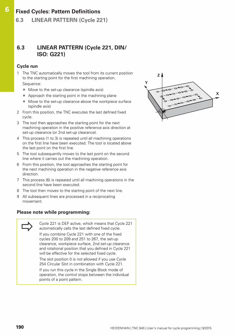
Fixed Cycles: Pattern Definitions 6.3 LINEAR PATTERN (Cycle 221)
6
190 HEIDENHAIN | TNC 640 | User’s manual for cycle programming | 9/2015
6.3 LINEAR PATTERN (Cycle 221, DIN/
ISO: G221)
Cycle run
1 The TNC automatically moves the tool from its current position
to the starting point for the first machining operation.
Sequence:
Move to the set-up clearance (spindle axis)
Approach the starting point in the machining plane
Move to the set-up clearance above the workpiece surface
(spindle axis)
2 From this position, the TNC executes the last defined fixed
cycle.
3 The tool then approaches the starting point for the next
machining operation in the positive reference axis direction at
set-up clearance (or 2nd set-up clearance).
4 This process (1 to 3) is repeated until all machining operations
on the first line have been executed. The tool is located above
the last point on the first line.
5 The tool subsequently moves to the last point on the second
line where it carries out the machining operation.
6 From this position, the tool approaches the starting point for
the next machining operation in the negative reference axis
direction.
7 This process (6) is repeated until all machining operations in the
second line have been executed.
8 The tool then moves to the starting point of the next line.
9 All subsequent lines are processed in a reciprocating
movement.
Please note while programming:
Cycle 221 is DEF active, which means that Cycle 221
automatically calls the last defined fixed cycle.
If you combine Cycle 221 with one of the fixed
cycles 200 to 209 and 251 to 267, the set-up
clearance, workpiece surface, 2nd set-up clearance
and rotational position that you defined in Cycle 221
will be effective for the selected fixed cycle.
The slot position 0 is not allowed if you use Cycle
254 Circular Slot in combination with Cycle 221.
If you run this cycle in the Single Block mode of
operation, the control stops between the individual
points of a point pattern.
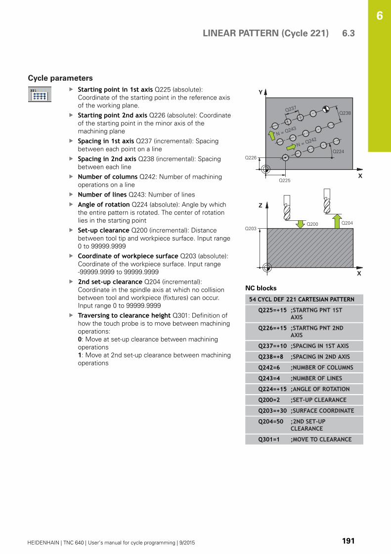
LINEAR PATTERN (Cycle 221) 6.3
6
HEIDENHAIN | TNC 640 | User’s manual for cycle programming | 9/2015 191
Cycle parameters
Starting point in 1st axis Q225 (absolute):
Coordinate of the starting point in the reference axis
of the working plane.
Starting point 2nd axis Q226 (absolute): Coordinate
of the starting point in the minor axis of the
machining plane
Spacing in 1st axis Q237 (incremental): Spacing
between each point on a line
Spacing in 2nd axis Q238 (incremental): Spacing
between each line
Number of columns Q242: Number of machining
operations on a line
Number of lines Q243: Number of lines
Angle of rotation Q224 (absolute): Angle by which
the entire pattern is rotated. The center of rotation
lies in the starting point
Set-up clearance Q200 (incremental): Distance
between tool tip and workpiece surface. Input range
0 to 99999.9999
Coordinate of workpiece surface Q203 (absolute):
Coordinate of the workpiece surface. Input range
-99999.9999 to 99999.9999
2nd set-up clearance Q204 (incremental):
Coordinate in the spindle axis at which no collision
between tool and workpiece (fixtures) can occur.
Input range 0 to 99999.9999
Traversing to clearance height Q301: Definition of
how the touch probe is to move between machining
operations:
0: Move at set-up clearance between machining
operations
1: Move at 2nd set-up clearance between machining
operations
NC blocks
54 CYCL DEF 221 CARTESIAN PATTERN
Q225=+15 ;STARTNG PNT 1STAXIS
Q226=+15 ;STARTNG PNT 2NDAXIS
Q237=+10 ;SPACING IN 1ST AXIS
Q238=+8 ;SPACING IN 2ND AXIS
Q242=6 ;NUMBER OF COLUMNS
Q243=4 ;NUMBER OF LINES
Q224=+15 ;ANGLE OF ROTATION
Q200=2 ;SET-UP CLEARANCE
Q203=+30 ;SURFACE COORDINATE
Q204=50 ;2ND SET-UPCLEARANCE
Q301=1 ;MOVE TO CLEARANCE

Fixed Cycles: Pattern Definitions 6.4 Programming Examples
6
192 HEIDENHAIN | TNC 640 | User’s manual for cycle programming | 9/2015
6.4 Programming Examples
Example: Polar hole patterns
0 BEGIN PGM HOLEPAT MM
1 BLK FORM 0.1 Z X+0 Y+0 Z-40 Definition of workpiece blank
2 BLK FORM 0.2 Y+100 Y+100 Z+0
3 TOOL CALL 1 Z S3500 Tool call
4 L Z+250 R0 FMAX M3 Retract the tool
5 CYCL DEF 200 DRILLING Cycle definition: drilling
Q200=2 ;SET-UP CLEARANCE
Q201=-15 ;DEPTH
Q206=250 ;FEED RATE FOR PLNGNG
Q202=4 ;PLUNGING DEPTH
Q211=0 ;DWELL TIME AT TOP
Q203=+0 ;SURFACE COORDINATE
Q204=0 ;2ND SET-UP CLEARANCE
Q211=0.25 ;DWELL TIME AT BOTTOM
6 CYCL DEF 220 POLAR PATTERN Define cycle for polar pattern 1, CYCL 200 is called
automatically; Q200, Q203 and Q204 are effective as
defined in Cycle 220.
Q216=+30 ;CENTER IN 1ST AXIS
Q217=+70 ;CENTER IN 2ND AXIS
Q244=50 ;PITCH CIRCLE DIA.
Q245=+0 ;STARTING ANGLE
Q246=+360 ;STOPPING ANGLE
Q247=+0 ;STEPPING ANGLE
Q241=10 ;NR OF REPETITIONS
Q200=2 ;SET-UP CLEARANCE
Q203=+0 ;SURFACE COORDINATE
Q204=100 ;2ND SET-UP CLEARANCE

Programming Examples 6.4
6
HEIDENHAIN | TNC 640 | User’s manual for cycle programming | 9/2015 193
Q301=1 ;MOVE TO CLEARANCE
Q365=0 ;TYPE OF TRAVERSE
7 CYCL DEF 220 POLAR PATTERN Define cycle for polar pattern 2, CYCL 200 is called
automatically; Q200, Q203 and Q204 are effective as
defined in Cycle 220.
Q216=+90 ;CENTER IN 1ST AXIS
Q217=+25 ;CENTER IN 2ND AXIS
Q244=70 ;PITCH CIRCLE DIA.
Q245=+90 ;STARTING ANGLE
Q246=+360 ;STOPPING ANGLE
Q247=+30 ;STEPPING ANGLE
Q241=5 ;NR OF REPETITIONS
Q200=2 ;SET-UP CLEARANCE
Q203=+0 ;SURFACE COORDINATE
Q204=100 ;2ND SET-UP CLEARANCE
Q301=1 ;MOVE TO CLEARANCE
Q365=0 ;TYPE OF TRAVERSE
8 L Z+250 R0 FMAX M2 Retract in the tool axis, end program
9 END PGM HOLEPAT MM


7Fixed Cycles:
Contour Pocket
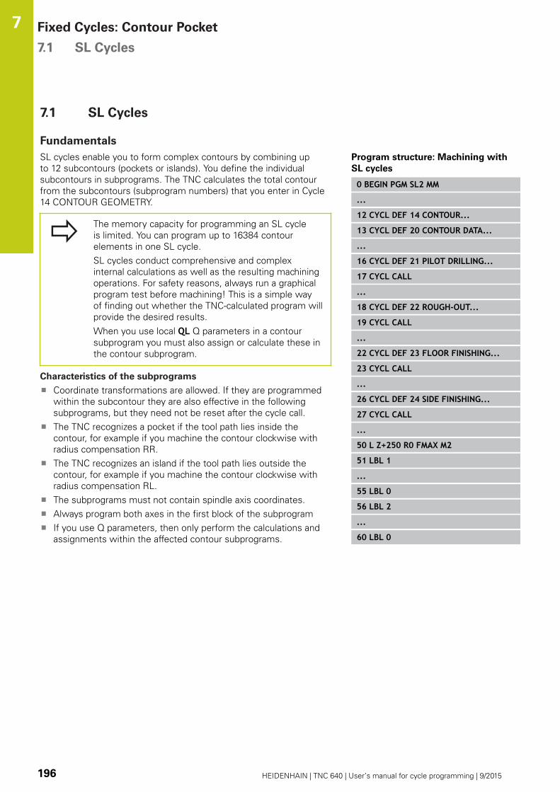
Fixed Cycles: Contour Pocket 7.1 SL Cycles
7
196 HEIDENHAIN | TNC 640 | User’s manual for cycle programming | 9/2015
7.1 SL Cycles
Fundamentals
SL cycles enable you to form complex contours by combining up
to 12 subcontours (pockets or islands). You define the individual
subcontours in subprograms. The TNC calculates the total contour
from the subcontours (subprogram numbers) that you enter in Cycle
14 CONTOUR GEOMETRY.
The memory capacity for programming an SL cycle
is limited. You can program up to 16384 contour
elements in one SL cycle.
SL cycles conduct comprehensive and complex
internal calculations as well as the resulting machining
operations. For safety reasons, always run a graphical
program test before machining! This is a simple way
of finding out whether the TNC-calculated program will
provide the desired results.
When you use local QL Q parameters in a contour
subprogram you must also assign or calculate these in
the contour subprogram.
Characteristics of the subprograms
Coordinate transformations are allowed. If they are programmed
within the subcontour they are also effective in the following
subprograms, but they need not be reset after the cycle call.
The TNC recognizes a pocket if the tool path lies inside the
contour, for example if you machine the contour clockwise with
radius compensation RR.
The TNC recognizes an island if the tool path lies outside the
contour, for example if you machine the contour clockwise with
radius compensation RL.
The subprograms must not contain spindle axis coordinates.
Always program both axes in the first block of the subprogram
If you use Q parameters, then only perform the calculations and
assignments within the affected contour subprograms.
Program structure: Machining with
SL cycles
0 BEGIN PGM SL2 MM
...
12 CYCL DEF 14 CONTOUR...
13 CYCL DEF 20 CONTOUR DATA...
...
16 CYCL DEF 21 PILOT DRILLING...
17 CYCL CALL
...
18 CYCL DEF 22 ROUGH-OUT...
19 CYCL CALL
...
22 CYCL DEF 23 FLOOR FINISHING...
23 CYCL CALL
...
26 CYCL DEF 24 SIDE FINISHING...
27 CYCL CALL
...
50 L Z+250 R0 FMAX M2
51 LBL 1
...
55 LBL 0
56 LBL 2
...
60 LBL 0

SL Cycles 7.1
7
HEIDENHAIN | TNC 640 | User’s manual for cycle programming | 9/2015 197
Characteristics of the fixed cycles
The TNC automatically positions the tool to the set-up clearance
before each cycle–position the tool to a safe position before the
cycle call.
Each level of infeed depth is milled without interruptions since the
cutter traverses around islands instead of over them.
The radius of "inside corners" can be programmed—the tool
keeps moving to prevent surface blemishes at inside corners (this
applies to the outermost pass in the Rough-out and Side Finishing
cycles).
The contour is approached in a tangential arc for side finishing.
For floor finishing, the tool again approaches the workpiece on a
tangential arc (for spindle axis Z, for example, the arc may be in
the Z/X plane).
The contour is machined throughout in either climb or up-cut
milling.
The machining data (such as milling depth, finishing allowance and
set-up clearance) are entered as CONTOUR DATA in Cycle 20.
...
99 END PGM SL2 MM
Overview
Soft key Cycle Page
14 CONTOUR GEOMETRY (essential) 198
20 CONTOUR DATA (essential) 203
21 PILOT DRILLING (optional) 205
22 ROUGH-OUT (essential) 207
23 FLOOR FINISHING (optional) 211
24 SIDE FINISHING (optional) 213
Enhanced cycles:
Soft key Cycle Page
25 CONTOUR TRAIN 216
270 CONTOUR TRAIN DATA 218
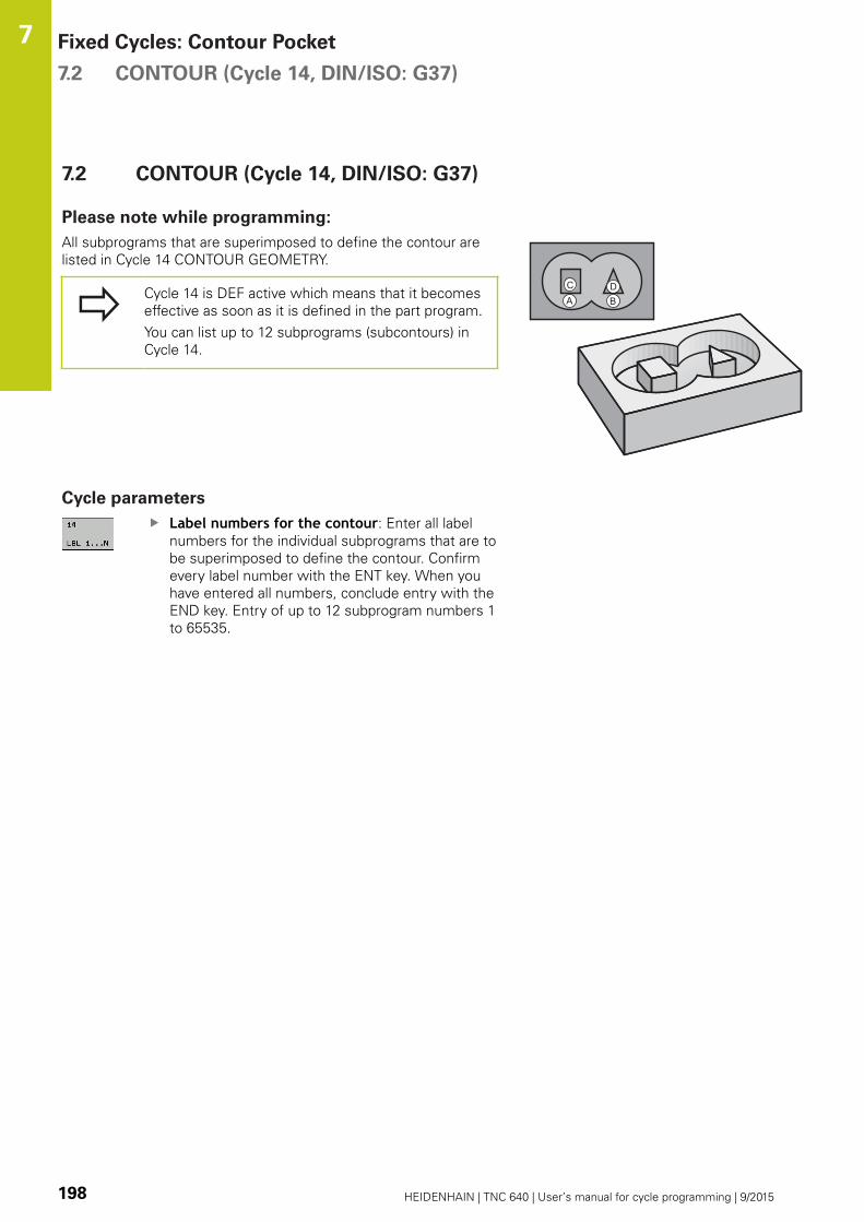
Fixed Cycles: Contour Pocket 7.2 CONTOUR (Cycle 14, DIN/ISO: G37)
7
198 HEIDENHAIN | TNC 640 | User’s manual for cycle programming | 9/2015
7.2 CONTOUR (Cycle 14, DIN/ISO: G37)
Please note while programming:
All subprograms that are superimposed to define the contour are
listed in Cycle 14 CONTOUR GEOMETRY.
Cycle 14 is DEF active which means that it becomes
effective as soon as it is defined in the part program.
You can list up to 12 subprograms (subcontours) in
Cycle 14.
Cycle parameters
Label numbers for the contour: Enter all label
numbers for the individual subprograms that are to
be superimposed to define the contour. Confirm
every label number with the ENT key. When you
have entered all numbers, conclude entry with the
END key. Entry of up to 12 subprogram numbers 1
to 65535.
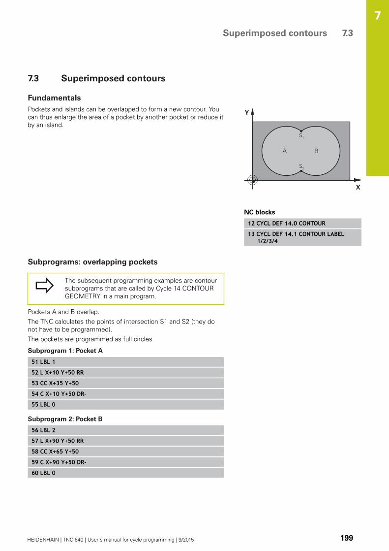
Superimposed contours 7.3
7
HEIDENHAIN | TNC 640 | User’s manual for cycle programming | 9/2015 199
7.3 Superimposed contours
Fundamentals
Pockets and islands can be overlapped to form a new contour. You
can thus enlarge the area of a pocket by another pocket or reduce it
by an island.
NC blocks
12 CYCL DEF 14.0 CONTOUR
13 CYCL DEF 14.1 CONTOUR LABEL1/2/3/4
Subprograms: overlapping pockets
The subsequent programming examples are contour
subprograms that are called by Cycle 14 CONTOUR
GEOMETRY in a main program.
Pockets A and B overlap.
The TNC calculates the points of intersection S1 and S2 (they do
not have to be programmed).
The pockets are programmed as full circles.
Subprogram 1: Pocket A
51 LBL 1
52 L X+10 Y+50 RR
53 CC X+35 Y+50
54 C X+10 Y+50 DR-
55 LBL 0
Subprogram 2: Pocket B
56 LBL 2
57 L X+90 Y+50 RR
58 CC X+65 Y+50
59 C X+90 Y+50 DR-
60 LBL 0

Fixed Cycles: Contour Pocket 7.3 Superimposed contours
7
200 HEIDENHAIN | TNC 640 | User’s manual for cycle programming | 9/2015
Area of inclusion
Both surfaces A and B are to be machined, including the
overlapping area:
The surfaces A and B must be pockets.
The first pocket (in Cycle 14) must start outside the second
pocket.
Surface A:
51 LBL 1
52 L X+10 Y+50 RR
53 CC X+35 Y+50
54 C X+10 Y+50 DR-
55 LBL 0
Surface B:
56 LBL 2
57 L X+90 Y+50 RR
58 CC X+65 Y+50
59 C X+90 Y+50 DR-
60 LBL 0

Superimposed contours 7.3
7
HEIDENHAIN | TNC 640 | User’s manual for cycle programming | 9/2015 201
Area of exclusion
Surface A is to be machined without the portion overlapped by B:
Surface A must be a pocket and B an island.
A must start outside of B.
B must start inside of A.
Surface A:
51 LBL 1
52 L X+10 Y+50 RR
53 CC X+35 Y+50
54 C X+10 Y+50 DR-
55 LBL 0
Surface B:
56 LBL 2
57 L X+40 Y+50 RL
58 CC X+65 Y+50
59 C X+40 Y+50 DR-
60 LBL 0

Fixed Cycles: Contour Pocket 7.3 Superimposed contours
7
202 HEIDENHAIN | TNC 640 | User’s manual for cycle programming | 9/2015
Area of intersection
Only the area where A and B overlap is to be machined. (The areas
covered by A or B alone are to be left unmachined.)
A and B must be pockets.
A must start inside of B.
Surface A:
51 LBL 1
52 L X+60 Y+50 RR
53 CC X+35 Y+50
54 C X+60 Y+50 DR-
55 LBL 0
Surface B:
56 LBL 2
57 L X+90 Y+50 RR
58 CC X+65 Y+50
59 C X+90 Y+50 DR-
60 LBL 0
CONTOUR DATA (Cycle 20, DIN/ISO: G120) 7.4
7
HEIDENHAIN | TNC 640 | User’s manual for cycle programming | 9/2015 203
7.4 CONTOUR DATA (Cycle 20, DIN/ISO:
G120)
Please note while programming:
Machining data for the subprograms describing the subcontours
are entered in Cycle 20.
Cycle 20 is DEF active, which means that it becomes
effective as soon as it is defined in the part program.
The machining data entered in Cycle 20 are valid for
Cycles 21 to 24.
The algebraic sign for the cycle parameter DEPTH
determines the working direction. If you program
DEPTH = 0, the TNC performs the cycle at the depth
0.
If you are using the SL cycles in Q parameter
programs, the cycle parameters Q1 to Q20 cannot be
used as program parameters.
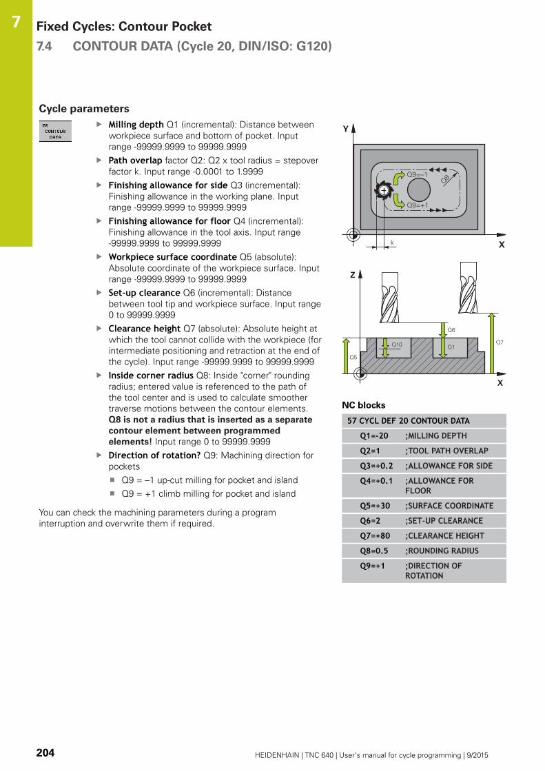
Fixed Cycles: Contour Pocket 7.4 CONTOUR DATA (Cycle 20, DIN/ISO: G120)
7
204 HEIDENHAIN | TNC 640 | User’s manual for cycle programming | 9/2015
Cycle parameters
Milling depth Q1 (incremental): Distance between
workpiece surface and bottom of pocket. Input
range -99999.9999 to 99999.9999
Path overlap factor Q2: Q2 x tool radius = stepover
factor k. Input range -0.0001 to 1.9999
Finishing allowance for side Q3 (incremental):
Finishing allowance in the working plane. Input
range -99999.9999 to 99999.9999
Finishing allowance for floor Q4 (incremental):
Finishing allowance in the tool axis. Input range
-99999.9999 to 99999.9999
Workpiece surface coordinate Q5 (absolute):
Absolute coordinate of the workpiece surface. Input
range -99999.9999 to 99999.9999
Set-up clearance Q6 (incremental): Distance
between tool tip and workpiece surface. Input range
0 to 99999.9999
Clearance height Q7 (absolute): Absolute height at
which the tool cannot collide with the workpiece (for
intermediate positioning and retraction at the end of
the cycle). Input range -99999.9999 to 99999.9999
Inside corner radius Q8: Inside "corner" rounding
radius; entered value is referenced to the path of
the tool center and is used to calculate smoother
traverse motions between the contour elements.
Q8 is not a radius that is inserted as a separate
contour element between programmed
elements! Input range 0 to 99999.9999
Direction of rotation? Q9: Machining direction for
pockets
Q9 = –1 up-cut milling for pocket and island
Q9 = +1 climb milling for pocket and island
You can check the machining parameters during a program
interruption and overwrite them if required.
NC blocks
57 CYCL DEF 20 CONTOUR DATA
Q1=-20 ;MILLING DEPTH
Q2=1 ;TOOL PATH OVERLAP
Q3=+0.2 ;ALLOWANCE FOR SIDE
Q4=+0.1 ;ALLOWANCE FORFLOOR
Q5=+30 ;SURFACE COORDINATE
Q6=2 ;SET-UP CLEARANCE
Q7=+80 ;CLEARANCE HEIGHT
Q8=0.5 ;ROUNDING RADIUS
Q9=+1 ;DIRECTION OFROTATION

PILOT DRILLING (Cycle 21, DIN/ISO: G121) 7.5
7
HEIDENHAIN | TNC 640 | User’s manual for cycle programming | 9/2015 205
7.5 PILOT DRILLING (Cycle 21, DIN/ISO:
G121)
Cycle run
Use Cycle 21 PILOT DRILLING if you will subsequently rough out
the contour with a tool other than a center-cut end mill (ISO 1641).
This cycle drills a hole in the area that is to be roughed out with a
cycle such as Cycle 22. Cycle 21 takes the allowance for side and
the allowance for floor as well as the radius of the rough-out tool
into account for the cutter infeed points. The cutter infeed points
also serve as starting points for roughing.
Before calling Cycle 21 you need to program two further cycles:
Cycle 14 CONTOUR GEOMETRY or SEL CONTOUR—needed
by Cycle 21 PILOT DRILLING in order to determine the drilling
position in the plane
Cycle 20 CONTOUR DATA—needed by Cycle 21 PILOT
DRILLING in order to determine parameters such as hole depth
and set-up clearance
Cycle run:
1 The TNC first positions the tool in the plane (the position
results from the contour you have defined with Cycle 14 or SEL
CONTOUR, and from the rough-out tool data).
2 The tool then moves at rapid traverse FMAX to the set-up
clearance. (Define the set-up clearance in Cycle 20 CONTOUR
DATA).
3 The tool drills from the current position to the first plunging
depth at the programmed feed rate F.
4 Then the tool retracts at rapid traverse FMAX to the starting
position and advances again to the first plunging depth minus
the advanced stop distance t.
5 The advanced stop distance is automatically calculated by the
control:
At a total hole depth up to 30 mm: t = 0.6 mm
At a total hole depth exceeding 30 mm: t = hole depth / 50
Maximum advanced stop distance: 7 mm
6 The tool then advances with another infeed at the programmed
feed rate F.
7 The TNC repeats this process (1 to 4) until the programmed
total hole depth is reached. The finishing allowance for floor is
taken into account.
8 Finally, the tool retracts in the tool axis to the clearance
height or to the position last programmed before the cycle.
This depends on the parameter ConfigDatum, CfgGeoCycle,
posAfterContPocket.
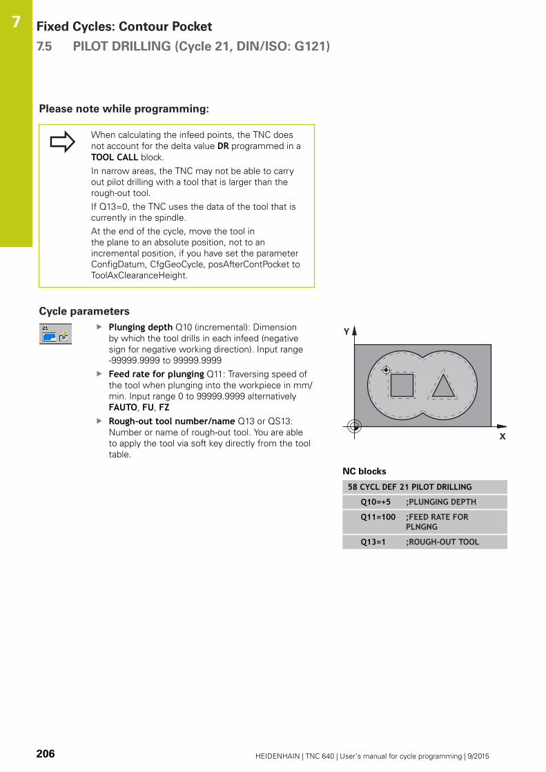
Fixed Cycles: Contour Pocket 7.5 PILOT DRILLING (Cycle 21, DIN/ISO: G121)
7
206 HEIDENHAIN | TNC 640 | User’s manual for cycle programming | 9/2015
Please note while programming:
When calculating the infeed points, the TNC does
not account for the delta value DR programmed in a
TOOL CALL block.
In narrow areas, the TNC may not be able to carry
out pilot drilling with a tool that is larger than the
rough-out tool.
If Q13=0, the TNC uses the data of the tool that is
currently in the spindle.
At the end of the cycle, move the tool in
the plane to an absolute position, not to an
incremental position, if you have set the parameter
ConfigDatum, CfgGeoCycle, posAfterContPocket to
ToolAxClearanceHeight.
Cycle parameters
Plunging depth Q10 (incremental): Dimension
by which the tool drills in each infeed (negative
sign for negative working direction). Input range
-99999.9999 to 99999.9999
Feed rate for plunging Q11: Traversing speed of
the tool when plunging into the workpiece in mm/
min. Input range 0 to 99999.9999 alternatively
FAUTO, FU, FZRough-out tool number/name Q13 or QS13:
Number or name of rough-out tool. You are able
to apply the tool via soft key directly from the tool
table.
NC blocks
58 CYCL DEF 21 PILOT DRILLING
Q10=+5 ;PLUNGING DEPTH
Q11=100 ;FEED RATE FORPLNGNG
Q13=1 ;ROUGH-OUT TOOL
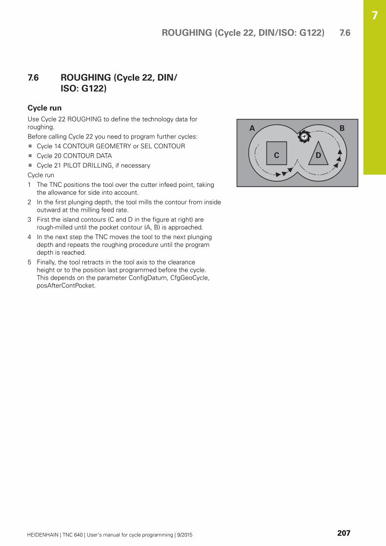
ROUGHING (Cycle 22, DIN/ISO: G122) 7.6
7
HEIDENHAIN | TNC 640 | User’s manual for cycle programming | 9/2015 207
7.6 ROUGHING (Cycle 22, DIN/
ISO: G122)
Cycle run
Use Cycle 22 ROUGHING to define the technology data for
roughing.
Before calling Cycle 22 you need to program further cycles:
Cycle 14 CONTOUR GEOMETRY or SEL CONTOUR
Cycle 20 CONTOUR DATA
Cycle 21 PILOT DRILLING, if necessary
Cycle run
1 The TNC positions the tool over the cutter infeed point, taking
the allowance for side into account.
2 In the first plunging depth, the tool mills the contour from inside
outward at the milling feed rate.
3 First the island contours (C and D in the figure at right) are
rough-milled until the pocket contour (A, B) is approached.
4 In the next step the TNC moves the tool to the next plunging
depth and repeats the roughing procedure until the program
depth is reached.
5 Finally, the tool retracts in the tool axis to the clearance
height or to the position last programmed before the cycle.
This depends on the parameter ConfigDatum, CfgGeoCycle,
posAfterContPocket.
Fixed Cycles: Contour Pocket 7.6 ROUGHING (Cycle 22, DIN/ISO: G122)
7
208 HEIDENHAIN | TNC 640 | User’s manual for cycle programming | 9/2015
Please note while programming:
This cycle requires a center-cut end mill (ISO 1641) or
pilot drilling with Cycle 21.
You define the plunging behavior of Cycle 22 with
parameter Q19 and with the tool table in the ANGLEand LCUTS columns:
If Q19=0 is defined, the TNC always plunges
perpendicularly, even if a plunge angle (ANGLE) is
defined for the active tool.
If you define the ANGLE=90°, the TNC plunges
perpendicularly. The reciprocation feed rate Q19 is
used as plunging feed rate.
If the reciprocation feed rate Q19 is defined in
Cycle 22 and ANGLE is defined between 0.1 and
89.999 in the tool table, the TNC plunges helically
at the defined ANGLE.
If the reciprocation feed is defined in Cycle 22 and
no ANGLE is in the tool table, the TNC displays an
error message.
If geometrical conditions do not allow helical
plunging (slot), the TNC tries a reciprocating
plunge. The reciprocation length is calculated
from LCUTS and ANGLE (reciprocation length =
LCUTS / tan ANGLE).
If you clear out an acute inside corner and use an
overlap factor greater than 1, some material might
be left over. Check especially the innermost path in
the test run graphic and, if necessary, change the
overlap factor slightly. This allows another distribution
of cuts, which often provides the desired results.
During fine roughing the TNC does not take a
defined wear value DR of the coarse roughing tool
into account.
If M110 is activated during operation, the feed rate
of compensated circular arcs within will be reduced
accordingly.
Danger of collision!
After executing an SL cycle you must program
the first traverse motion in the working plane
with both coordinate data, e.g. L X+80 Y+0 R0 FMAX. At the end of the cycle, move the
tool in the plane to an absolute position, not to an
incremental position, if you have set the parameter
ConfigDatum, CfgGeoCycle, posAfterContPocket to
ToolAxClearanceHeight.

ROUGHING (Cycle 22, DIN/ISO: G122) 7.6
7
HEIDENHAIN | TNC 640 | User’s manual for cycle programming | 9/2015 209
Cycle parameters
Plunging depth Q10 (incremental): Infeed per cut.
Input range -99999.9999 to 99999.9999
Feed rate for plunging Q11: Traversing speed
of the tool in the spindle axis. Input range 0 to
99999.9999, alternatively FAUTO, FU, FZFeed rate for milling Q12: Traversing speed of
the tool in the working plane. Input range 0 to
99999.9999, alternatively FAUTO, FU, FZCoarse roughing tool Q18 or QS18: Number or
name of the tool with which the TNC has already
coarse-roughed the contour. You are able to apply
the coarse roughing tool via soft key directly from
the tool table. In addition, the tool name can be
entered via the soft key TOOL NAME. The TNC
automatically inserts the closing quotation mark
when you exit the input field. If there was no coarse
roughing, enter "0"; if you enter a number or a
name, the TNC will only rough-out the portion that
could not be machined with the coarse roughing
tool. If the portion that is to be roughed cannot be
approached from the side, the TNC will mill in a
reciprocating plunge-cut; for this purpose you must
enter the tool length LCUTS in the tool table TOOL.T
and define the maximum plunging ANGLE of the
tool. Input range 0 to 99999 if a number is entered;
maximum 16 characters if a name is entered.
Reciprocation feed rate Q19: Traversing speed of
the tool in mm/min during reciprocating plunge cut.
Input range 0 to 99999.9999; alternatively FAUTO,
FU, FZRetraction feed rate Q208: Traversing speed of
the tool in mm/min when retracting after machining.
If you enter Q208 = 0, the TNC retracts the tool at
the feed rate in Q12. Input range 0 to 99999.9999,
alternatively FMAX,FAUTO
NC blocks
59 CYCL DEF 22 ROUGH-OUT
Q10=+5 ;PLUNGING DEPTH
Q11=100 ;FEED RATE FORPLNGNG
Q12=750 ;FEED RATE FORMILLING
Q18=1 ;COARSE ROUGHINGTOOL
Q19=150 ;RECIPROCATION FEEDRATE
Q208=9999;RETRACTION FEEDRATE
Q401=80 ;FEED RATE REDUCTION
Q404=0 ;FINE ROUGHSTRATEGY
Fixed Cycles: Contour Pocket 7.6 ROUGHING (Cycle 22, DIN/ISO: G122)
7
210 HEIDENHAIN | TNC 640 | User’s manual for cycle programming | 9/2015
Feed rate factor in % Q401: Percentage factor by
which the TNC reduces the machining feed rate
(Q12) as soon as the tool moves within the material
over its entire circumference during roughing. If you
use the feed rate reduction, then you can define
the feed rate for roughing so large that there are
optimum cutting conditions with the path overlap
(Q2) specified in Cycle 20. The TNC then reduces
the feed rate as per your definition at transitions
and narrow places, so the machining time should be
reduced in total. Input range 0.0001 to 100.0000
Fine rough strategy Q404: Specify the fine
roughing behavior of the TNC if the radius of the
fine roughing tool is greater than half the diameter
of the rough-out tool:
Q404=0:
The TNC moves the tool between the areas to be
fine roughed at the current depth along the contour
Q404=1:
The TNC retracts the tool to the set-up clearance
between the areas to be fine roughed and then
moves to the starting point for the next area to be
roughed out.

FLOOR FINISHING (Cycle 23, DIN/ISO: G123) 7.7
7
HEIDENHAIN | TNC 640 | User’s manual for cycle programming | 9/2015 211
7.7 FLOOR FINISHING (Cycle 23,
DIN/ISO: G123)
Cycle run
With Cycle 23 FLOOR FINISHING, you can clear the finishing
allowance for floor that is programmed in Cycle 20. The tool
approaches the machining plane smoothly (on a vertically tangential
arc) if there is sufficient room. If there is not enough room, the TNC
moves the tool to depth vertically. The tool then clears the finishing
allowance remaining from rough-out.
Before calling Cycle 23 you need to program further cycles:
Cycle 14 CONTOUR GEOMETRY or SEL CONTOUR
Cycle 20 CONTOUR DATA
Cycle 21 PILOT DRILLING, if necessary
Cycle 22 ROUGHING, if necessary
Cycle run
1 The TNC positions the tool to the clearance height at rapid
traverse FMAX.
2 The tool then moves in the tool axis at the feed rate Q11.
3 The tool approaches the machining plane smoothly (on a
vertically tangential arc) if there is sufficient room. If there is not
enough room, the TNC moves the tool to depth vertically.
4 The tool clears the finishing allowance remaining from rough-
out.
5 Finally, the tool retracts in the tool axis to the clearance
height or to the position last programmed before the cycle.
This depends on the parameter ConfigDatum, CfgGeoCycle,
posAfterContPocket.
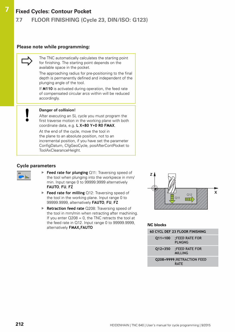
Fixed Cycles: Contour Pocket 7.7 FLOOR FINISHING (Cycle 23, DIN/ISO: G123)
7
212 HEIDENHAIN | TNC 640 | User’s manual for cycle programming | 9/2015
Please note while programming:
The TNC automatically calculates the starting point
for finishing. The starting point depends on the
available space in the pocket.
The approaching radius for pre-positioning to the final
depth is permanently defined and independent of the
plunging angle of the tool.
If M110 is activated during operation, the feed rate
of compensated circular arcs within will be reduced
accordingly.
Danger of collision!
After executing an SL cycle you must program the
first traverse motion in the working plane with both
coordinate data, e.g. L X+80 Y+0 R0 FMAX.
At the end of the cycle, move the tool in
the plane to an absolute position, not to an
incremental position, if you have set the parameter
ConfigDatum, CfgGeoCycle, posAfterContPocket to
ToolAxClearanceHeight.
Cycle parameters
Feed rate for plunging Q11: Traversing speed of
the tool when plunging into the workpiece in mm/
min. Input range 0 to 99999.9999 alternatively
FAUTO, FU, FZFeed rate for milling Q12: Traversing speed of
the tool in the working plane. Input range 0 to
99999.9999, alternatively FAUTO, FU, FZRetraction feed rate Q208: Traversing speed of
the tool in mm/min when retracting after machining.
If you enter Q208 = 0, the TNC retracts the tool at
the feed rate in Q12. Input range 0 to 99999.9999,
alternatively FMAX,FAUTONC blocks
60 CYCL DEF 23 FLOOR FINISHING
Q11=100 ;FEED RATE FORPLNGNG
Q12=350 ;FEED RATE FORMILLING
Q208=9999;RETRACTION FEEDRATE

SIDE FINISHING (Cycle 24, DIN/ISO: G124) 7.8
7
HEIDENHAIN | TNC 640 | User’s manual for cycle programming | 9/2015 213
7.8 SIDE FINISHING (Cycle 24, DIN/ISO:
G124)
Cycle run
With Cycle 24 SIDE FINISHING, you can clear the finishing
allowance for side that is programmed in Cycle 20. You can run this
cycle in climb or up-cut milling.
Before calling Cycle 24 you need to program further cycles:
Cycle 14 CONTOUR GEOMETRY or SEL CONTOUR
Cycle 20 CONTOUR DATA
Cycle 21 PILOT DRILLING, if necessary
Cycle 22 ROUGHING, if necessary
Cycle run
1 The TNC positions the tool above the workpiece surface to the
starting point for the approach position. This position in the
plane results from a tangential arc on which the TNC moves the
tool when approaching the contour.
2 The tool then advances to the first plunging depth at the feed
rate for plunging.
3 The contour is approached on a tangential arc until the entire
contour is completed. Each subcontour is finished separately.
4 Finally, the tool retracts in the tool axis to the clearance
height or to the position last programmed before the cycle.
This depends on the parameter ConfigDatum, CfgGeoCycle,
posAfterContPocket.
Fixed Cycles: Contour Pocket 7.8 SIDE FINISHING (Cycle 24, DIN/ISO: G124)
7
214 HEIDENHAIN | TNC 640 | User’s manual for cycle programming | 9/2015
Please note while programming:
The sum of allowance for side (Q14) and the radius
of the finish mill must be smaller than the sum of
allowance for side (Q3, Cycle 20) and the radius of
the rough mill.
If no allowance has been defined in Cycle 20, the
control issues the error message "Tool radius too
large".
The allowance for side Q14 is left over after finishing.
Therefore, it must be smaller than the allowance in
Cycle 20.
This calculation also holds if you run Cycle 24 without
having roughed out with Cycle 22; in this case, enter
"0" for the radius of the rough mill.
You can use Cycle 24 also for contour milling. Then
you must:
define the contour to be milled as a single island
(without pocket limit), and
enter the finishing allowance (Q3) in Cycle 20
to be greater than the sum of the finishing
allowance Q14 + radius of the tool being used.
The TNC automatically calculates the starting point
for finishing. The starting point depends on the
available space in the pocket and the allowance
programmed in Cycle 20.
The starting point calculated by the TNC also
depends on the machining sequence. If you select
the finishing cycle with the GOTO key and then start
the program, the starting point can be at a different
location from where it would be if you execute the
program in the defined sequence.
If M110 is activated during operation, the feed rate
of compensated circular arcs within will be reduced
accordingly.
Danger of collision!
After executing an SL cycle you must program the
first traverse motion in the working plane with both
coordinate data, e.g. L X+80 Y+0 R0 FMAX.
At the end of the cycle, move the tool in
the plane to an absolute position, not to an
incremental position, if you have set the parameter
ConfigDatum, CfgGeoCycle, posAfterContPocket to
ToolAxClearanceHeight.

SIDE FINISHING (Cycle 24, DIN/ISO: G124) 7.8
7
HEIDENHAIN | TNC 640 | User’s manual for cycle programming | 9/2015 215
Cycle parameters
Direction of rotation Q9: Machining direction:
+1: Rotation counterclockwise
–1: Rotation clockwise
Plunging depth Q10 (incremental): Infeed per cut.
Input range -99999.9999 to 99999.9999
Feed rate for plunging Q11: Traversing speed of
the tool when plunging into the workpiece in mm/
min. Input range 0 to 99999.9999 alternatively
FAUTO, FU, FZFeed rate for milling Q12: Traversing speed of
the tool in the working plane. Input range 0 to
99999.9999, alternatively FAUTO, FU, FZFinishing allowance for side Q14 (incremental):
The allowance for side Q14 is left over after
finishing. (This allowance must be smaller than the
allowance in Cycle 20.) Input range -99999.9999 to
99999.9999
NC blocks
61 CYCL DEF 24 SIDE FINISHING
Q9=+1 ;DIRECTION OFROTATION
Q10=+5 ;PLUNGING DEPTH
Q11=100 ;FEED RATE FORPLNGNG
Q12=350 ;FEED RATE FORMILLING
Q14=+0 ;ALLOWANCE FOR SIDE

Fixed Cycles: Contour Pocket 7.9 CONTOUR TRAIN (Cycle 25, DIN/ISO: G125)
7
216 HEIDENHAIN | TNC 640 | User’s manual for cycle programming | 9/2015
7.9 CONTOUR TRAIN (Cycle 25, DIN/ISO:
G125)
Cycle run
In conjunction with Cycle 14 CONTOUR GEOMETRY, this cycle
facilitates the machining of open and closed contours.
Cycle 25 CONTOUR TRAIN offers considerable advantages over
machining a contour using positioning blocks:
The TNC monitors the operation to prevent undercuts and
surface blemishes. It is recommended that you run a graphic
simulation of the contour before execution.
If the radius of the selected tool is too large, the corners of the
contour may have to be reworked.
The contour can be machined throughout by up-cut or by climb
milling. The type of milling even remains effective when the
contours are mirrored.
The tool can traverse back and forth for milling in several
infeeds: This results in faster machining.
Allowance values can be entered in order to perform repeated
rough-milling and finish-milling operations.
Please note while programming:
The algebraic sign for the cycle parameter DEPTH
determines the working direction. If you program
DEPTH=0, the cycle will not be executed.
The TNC takes only the first label of Cycle 14
CONTOUR GEOMETRY into account.
The sub program allows no APPR- or DEP motions.
When you use local QL Q parameters in a contour
subprogram you must also assign or calculate these
in the contour subprogram.
The memory capacity for programming an SL cycle
is limited. You can program up to 16384 contour
elements in one SL cycle.
Cycle 20 CONTOUR DATA is not required.
If M110 is activated during operation, the feed rate
of compensated circular arcs within will be reduced
accordingly.
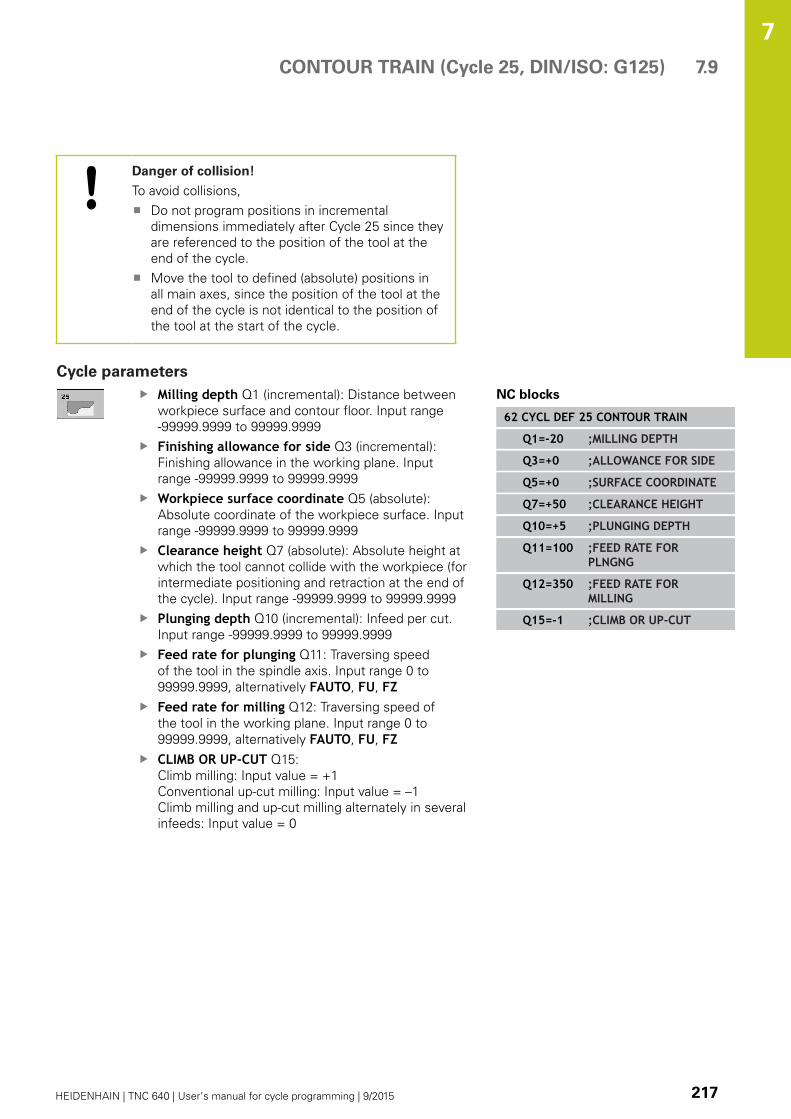
CONTOUR TRAIN (Cycle 25, DIN/ISO: G125) 7.9
7
HEIDENHAIN | TNC 640 | User’s manual for cycle programming | 9/2015 217
Danger of collision!
To avoid collisions,
Do not program positions in incremental
dimensions immediately after Cycle 25 since they
are referenced to the position of the tool at the
end of the cycle.
Move the tool to defined (absolute) positions in
all main axes, since the position of the tool at the
end of the cycle is not identical to the position of
the tool at the start of the cycle.
Cycle parameters
Milling depth Q1 (incremental): Distance between
workpiece surface and contour floor. Input range
-99999.9999 to 99999.9999
Finishing allowance for side Q3 (incremental):
Finishing allowance in the working plane. Input
range -99999.9999 to 99999.9999
Workpiece surface coordinate Q5 (absolute):
Absolute coordinate of the workpiece surface. Input
range -99999.9999 to 99999.9999
Clearance height Q7 (absolute): Absolute height at
which the tool cannot collide with the workpiece (for
intermediate positioning and retraction at the end of
the cycle). Input range -99999.9999 to 99999.9999
Plunging depth Q10 (incremental): Infeed per cut.
Input range -99999.9999 to 99999.9999
Feed rate for plunging Q11: Traversing speed
of the tool in the spindle axis. Input range 0 to
99999.9999, alternatively FAUTO, FU, FZFeed rate for milling Q12: Traversing speed of
the tool in the working plane. Input range 0 to
99999.9999, alternatively FAUTO, FU, FZCLIMB OR UP-CUT Q15:
Climb milling: Input value = +1
Conventional up-cut milling: Input value = –1
Climb milling and up-cut milling alternately in several
infeeds: Input value = 0
NC blocks
62 CYCL DEF 25 CONTOUR TRAIN
Q1=-20 ;MILLING DEPTH
Q3=+0 ;ALLOWANCE FOR SIDE
Q5=+0 ;SURFACE COORDINATE
Q7=+50 ;CLEARANCE HEIGHT
Q10=+5 ;PLUNGING DEPTH
Q11=100 ;FEED RATE FORPLNGNG
Q12=350 ;FEED RATE FORMILLING
Q15=-1 ;CLIMB OR UP-CUT

Fixed Cycles: Contour Pocket 7.10 CONTOUR TRAIN DATA (Cycle 270, DIN/ISO: G270)
7
218 HEIDENHAIN | TNC 640 | User’s manual for cycle programming | 9/2015
7.10 CONTOUR TRAIN DATA (Cycle 270,
DIN/ISO: G270)
Please note while programming:
You can use this cycle to specify various properties of Cycle 25
CONTOUR TRAIN.
Cycle 270 is DEF active, which means that it
becomes effective as soon as it is defined in the part
program.
If Cycle 270 is used, do not define any radius
compensation in the contour subprogram.
Define Cycle 270 before Cycle 25.
Cycle parameters
Type of approach/departure (1/2/3) Q390:
Definition of the type of approach and departure:
Q390=1:
Approach the contour tangentially on a circular path
Q390=2:
Approach the contour tangentially on a straight line
Q390=3:
Approach the contour at a right angle
Radius compensation (0=R0/1=RL/2=RR) Q391:
Definition of the radius compensation:
Q391=0:
Machine the defined contour without radius
compensation
Q391=1:
Machine the defined contour with radius
compensation RL
Q391=2:
Machine the defined contour with radius
compensation RR
Approach/departure radius Q392: Only in effect
if tangential approach on a circular path is selected
(Q390=1). Radius of the approach/departure arc.
Input range 0 to 99999.9999
Center angle Q393: Only in effect if tangential
approach on a circular path is selected (Q390=1).
Angular length of the approach arc. Input range 0 to
99999.9999
Distance to auxiliary point Q394: Only in effect if
tangential approach on a straight line or right-angle
approach is selected (Q390=2 or Q390=3). Distance
to the auxiliary point from which the TNC is to
approach the contour. Input range 0 to 99999.9999
NC blocks
62 CYCL DEF 270 CONTOUR TRAINDATA
Q390=1 ;TYPE OF APPROACH
Q391=1 ;RADIUSCOMPENSATION
Q392=3 ;RADIUS
Q393=+45 ;CENTER ANGLE
Q394=+2 ;DISTANCE

TROCHOIDAL SLOT (Cycle 275, DIN ISO G275) 7.11
7
HEIDENHAIN | TNC 640 | User’s manual for cycle programming | 9/2015 219
7.11 TROCHOIDAL SLOT (Cycle 275, DIN
ISO G275)
Cycle run
In conjunction with Cycle 14 CONTOUR GEOMETRY, this cycle
facilitates the complete machining of open and closed slots or
contour slots using trochoidal milling.
With trochoidal milling, large cutting depths and high cutting speeds
are possible because the equally distributed cutting conditions
prevent wear-increasing influences on the tool. When tool inserts are
used the entire cutting length is exploited to increase the attainable
chip volume per tooth. Moreover, trochoidal milling is easy on the
machine mechanics. Enormous amounts of time can also be saved
by combining this milling method with the integrated adaptive feed
control AFC software option (see User's Manual on conversational
programming).
Depending on the cycle parameters you select, the following
machining alternatives are available:
Complete machining: Roughing, side finishing
Only roughing
Only side finishing
Roughing with closed slots
The contour description of a closed slot must always start with a
straight-line block (L block).
1 Following the positioning logic, the tool moves to the starting
point of the contour description and moves in a reciprocating
motion at the plunging angle defined in the tool table to the first
plunging depth. Specify the plunging strategy with parameter
Q366.
2 The TNC roughs the slot in circular motions to the contour end
point. During the circular motion the TNC moves the tool in
machining direction by an infeed you can define (Q436). Define
climb or up-cut of the circular motion in parameter Q351.
3 At the contour end point, the TNC moves the tool to clearance
height and returns to the starting point of the contour description.
4 This process is repeated until the programmed slot depth is
reached.
Finishing with closed slots
5 Inasmuch as a finishing allowance is defined, the TNC finishes
the slot walls, in multiple infeeds if so specified. Starting from
the defined starting point, the TNC approaches the slot wall
tangentially. Climb or up-cut are taken into consideration.
Program structure: Machining with
SL cycles
0 BEGIN PGM CYC275 MM
...
12 CYCL DEF 14.0 CONTOUR
13 CYCL DEF 14.1 CONTOUR LABEL 10
14 CYCL DEF 275 TROCHOIDAL SLOT...
15 CYCL CALL M3
...
50 L Z+250 R0 FMAX M2
51 LBL 10
...
55 LBL 0
...
99 END PGM CYC275 MM

Fixed Cycles: Contour Pocket 7.11 TROCHOIDAL SLOT (Cycle 275, DIN ISO G275)
7
220 HEIDENHAIN | TNC 640 | User’s manual for cycle programming | 9/2015
Roughing with open slots
The contour description of an open slot must always start with an
approach block (APPR).
1 Following the positioning logic, the tool moves to the starting
point of the machining operation as defined by the parameters
in the APPR block and positions there perpendicular to the first
plunging depth.
2 The TNC roughs the slot in circular motions to the contour end
point. During the circular motion the TNC moves the tool in
machining direction by an infeed you can define (Q436). Define
climb or up-cut of the circular motion in parameter Q351.
3 At the contour end point, the TNC moves the tool to clearance
height and returns to the starting point of the contour description.
4 This process is repeated until the programmed slot depth is
reached.
Finishing with open slots
5 Inasmuch as a finishing allowance is defined, the TNC finishes
the slot walls, in multiple infeeds if so specified. Starting from the
defined starting point of the APPR block, the TNC approaches the
slot wall. Climb or up-cut are taken into consideration.
Please note while programming:
The algebraic sign for the cycle parameter DEPTH
determines the working direction. If you program
DEPTH=0, the cycle will not be executed.
When using Cycle 275 TROCHOIDAL SLOT, you
can define only one contour subprogram in Cycle 14
CONTOUR GEOMETRY.
Define the center line of the slot with all available
path functions in the contour subprogram.
The memory capacity for programming an SL cycle
is limited. You can program up to 16384 contour
elements in one SL cycle.
The TNC does not need Cycle 20 CONTOUR DATA in
conjunction with Cycle 275.
The starting point of a closed slot must not be
located in a contour corner.
Danger of collision!
To avoid collisions,
Do not program positions in incremental
dimensions immediately after Cycle 275 since
they are referenced to the position of the tool at
the end of the cycle.
Move the tool to defined (absolute) positions in all
principal axes, since the position of the tool at the
end of the cycle is not identical to the position of
the tool at the start of the cycle.

TROCHOIDAL SLOT (Cycle 275, DIN ISO G275) 7.11
7
HEIDENHAIN | TNC 640 | User’s manual for cycle programming | 9/2015 221
Cycle parameters
Machining operation (0/1/2) Q215: Define
machining operation:
0: Roughing and finishing
1: Only roughing
2: Only finishing
Side finishing and floor finishing are only machined
when the specific allowance (Q368, Q369) is
defined
Slot width Q219 (value parallel to the secondary
axis of the working plane): Enter the slot width.
If you enter a slot width that equals the tool
diameter, the TNC will carry out the roughing
process only (slot milling). Maximum slot width for
roughing: Twice the tool diameter. Input range 0 to
99999.9999
Finishing allowance for side Q368 (incremental):
Finishing allowance in the working plane. Input
range 0 to 99999.9999
Infeed per rev. Q436 absolute: Value by which the
TNC moves the tool in the machining direction per
revolution. Input range 0 to 99999.9999
Feed rate for milling Q207: Traversing speed of
the tool in mm/min while milling. Input range 0 to
99999.999 alternatively FAUTO, FU, FZFeed rate for milling Q12: Traversing speed of
the tool in the working plane. Input range 0 to
99999.9999, alternatively FAUTO, FU, FZClimb or up-cut Q351: Type of milling operation
with M3
+1 = climb
–1 = up-cut
PREDEF: The TNC uses the value from the GLOBAL
DEF block (If you enter 0, climb milling is used for
machining)
Depth Q201 (incremental): Distance between
workpiece surface and bottom of slot. Input range
-99999.9999 to 99999.9999
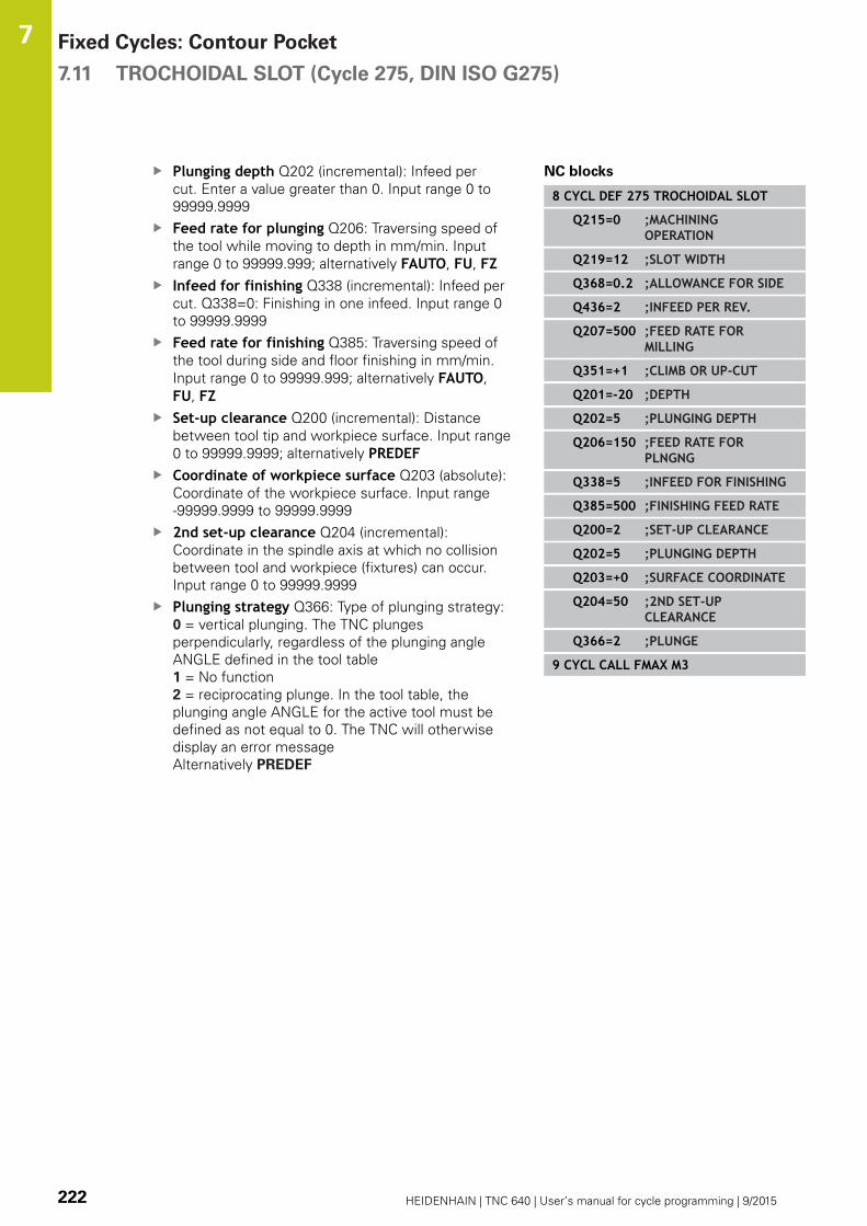
Fixed Cycles: Contour Pocket 7.11 TROCHOIDAL SLOT (Cycle 275, DIN ISO G275)
7
222 HEIDENHAIN | TNC 640 | User’s manual for cycle programming | 9/2015
Plunging depth Q202 (incremental): Infeed per
cut. Enter a value greater than 0. Input range 0 to
99999.9999
Feed rate for plunging Q206: Traversing speed of
the tool while moving to depth in mm/min. Input
range 0 to 99999.999; alternatively FAUTO, FU, FZInfeed for finishing Q338 (incremental): Infeed per
cut. Q338=0: Finishing in one infeed. Input range 0
to 99999.9999
Feed rate for finishing Q385: Traversing speed of
the tool during side and floor finishing in mm/min.
Input range 0 to 99999.999; alternatively FAUTO,
FU, FZSet-up clearance Q200 (incremental): Distance
between tool tip and workpiece surface. Input range
0 to 99999.9999; alternatively PREDEFCoordinate of workpiece surface Q203 (absolute):
Coordinate of the workpiece surface. Input range
-99999.9999 to 99999.9999
2nd set-up clearance Q204 (incremental):
Coordinate in the spindle axis at which no collision
between tool and workpiece (fixtures) can occur.
Input range 0 to 99999.9999
Plunging strategy Q366: Type of plunging strategy:
0 = vertical plunging. The TNC plunges
perpendicularly, regardless of the plunging angle
ANGLE defined in the tool table
1 = No function
2 = reciprocating plunge. In the tool table, the
plunging angle ANGLE for the active tool must be
defined as not equal to 0. The TNC will otherwise
display an error message
Alternatively PREDEF
NC blocks
8 CYCL DEF 275 TROCHOIDAL SLOT
Q215=0 ;MACHININGOPERATION
Q219=12 ;SLOT WIDTH
Q368=0.2 ;ALLOWANCE FOR SIDE
Q436=2 ;INFEED PER REV.
Q207=500 ;FEED RATE FORMILLING
Q351=+1 ;CLIMB OR UP-CUT
Q201=-20 ;DEPTH
Q202=5 ;PLUNGING DEPTH
Q206=150 ;FEED RATE FORPLNGNG
Q338=5 ;INFEED FOR FINISHING
Q385=500 ;FINISHING FEED RATE
Q200=2 ;SET-UP CLEARANCE
Q202=5 ;PLUNGING DEPTH
Q203=+0 ;SURFACE COORDINATE
Q204=50 ;2ND SET-UPCLEARANCE
Q366=2 ;PLUNGE
9 CYCL CALL FMAX M3

Programming Examples 7.12
7
HEIDENHAIN | TNC 640 | User’s manual for cycle programming | 9/2015 223
7.12 Programming Examples
Example: Roughing-out and fine-roughing a pocket
0 BEGIN PGM C20 MM
1 BLK FORM 0.1 Z X-10 Y-10 Z-40
2 BLK FORM 0.2 X+100 Y+100 Z+0 Definition of workpiece blank
3 TOOL CALL 1 Z S2500 Tool call: coarse roughing tool, diameter 30
4 L Z+250 R0 FMAX Retract the tool
5 CYCL DEF 14.0 CONTOUR GEOMETRY Define contour subprogram
6 CYCL DEF 14.1 CONTOUR LABEL 1
7 CYCL DEF 20 CONTOUR DATA Define general machining parameters
Q1=-20 ;MILLING DEPTH
Q2=1 ;TOOL PATH OVERLAP
Q3=+0 ;ALLOWANCE FOR SIDE
Q4=+0 ;ALLOWANCE FOR FLOOR
Q5=+0 ;SURFACE COORDINATE
Q6=2 ;SET-UP CLEARANCE
Q7=+100 ;CLEARANCE HEIGHT
Q8=0.1 ;ROUNDING RADIUS
Q9=-1 ;DIRECTION
8 CYCL DEF 22 ROUGH-OUT Cycle definition: Coarse roughing
Q10=5 ;PLUNGING DEPTH
Q11=100 ;FEED RATE FOR PLNGNG
Q12=350 ;FEED RATE FOR ROUGH-OUT
Q18=0 ;COARSE ROUGHING TOOL
Q19=150 ;RECIPROCATION FEED RATE
Q208=30000 ;RETRACTION FEED RATE
9 CYCL CALL M3 Cycle call: Coarse roughing
10 L Z+250 R0 FMAX M6 Tool change

Fixed Cycles: Contour Pocket 7.12 Programming Examples
7
224 HEIDENHAIN | TNC 640 | User’s manual for cycle programming | 9/2015
11 TOOL CALL 2 Z S3000 Tool call: fine roughing tool, diameter 15
12 CYCL DEF 22 ROUGH-OUT Define the fine roughing cycle
Q10=5 ;PLUNGING DEPTH
Q11=100 ;FEED RATE FOR PLNGNG
Q12=350 ;FEED RATE FOR ROUGH-OUT
Q18=1 ;COARSE ROUGHING TOOL
Q19=150 ;RECIPROCATION FEED RATE
Q208=30000 ;RETRACTION FEED RATE
13 CYCL CALL M3 Cycle call: Fine roughing
14 L Z+250 R0 FMAX M2 Retract in the tool axis, end program
15 LBL 1 Contour subprogram
16 L X+0 Y+30 RR
17 FC DR- R30 CCX+30 CCY+30
18 FL AN+60 PDX+30 PDY+30 D10
19 FSELECT 3
20 FPOL X+30 Y+30
21 FC DR- R20 CCPR+55 CCPA+60
22 FSELECT 2
23 FL AN-120 PDX+30 PDY+30 D10
24 FSELECT 3
25 FC X+0 DR- R30 CCX+30 CCY+30
26 FSELECT 2
27 LBL 0
28 END PGM C20 MM

Programming Examples 7.12
7
HEIDENHAIN | TNC 640 | User’s manual for cycle programming | 9/2015 225
Example: Pilot drilling, roughing-out and finishing
overlapping contours
0 BEGIN PGM C21 MM
1 BLK FORM 0.1 Z X+0 Y+0 Z-40 Definition of workpiece blank
2 BLK FORM 0.2 X+100 Y+100 Z+0
3 TOOL CALL 1 Z S2500 Tool call: Drill, diameter 12
4 L Z+250 R0 FMAX Retract the tool
5 CYCL DEF 14.0 CONTOUR GEOMETRY Define contour subprogram
6 CYCL DEF 14.1 CONTOUR LABEL 1 /2 /3 /4
7 CYCL DEF 20 CONTOUR DATA Define general machining parameters
Q1=-20 ;MILLING DEPTH
Q2=1 ;TOOL PATH OVERLAP
Q3=+0.5 ;ALLOWANCE FOR SIDE
Q4=+0.5 ;ALLOWANCE FOR FLOOR
Q5=+0 ;SURFACE COORDINATE
Q6=2 ;SET-UP CLEARANCE
Q7=+100 ;CLEARANCE HEIGHT
Q8=0.1 ;ROUNDING RADIUS
Q9=-1 ;DIRECTION
8 CYCL DEF 21 PILOT DRILLING Cycle definition: Pilot drilling
Q10=5 ;PLUNGING DEPTH
Q11=250 ;FEED RATE FOR PLNGNG
Q13=2 ;ROUGH-OUT TOOL
9 CYCL CALL M3 Cycle call: Pilot drilling
10 L +250 R0 FMAX M6 Tool change
11 TOOL CALL 2 Z S3000 Call the tool for roughing/finishing, diameter 12
12 CYCL DEF 22 ROUGH-OUT Cycle definition: Rough-out
Q10=5 ;PLUNGING DEPTH
Q11=100 ;FEED RATE FOR PLNGNG
Q12=350 ;FEED RATE FOR ROUGH-OUT

Fixed Cycles: Contour Pocket 7.12 Programming Examples
7
226 HEIDENHAIN | TNC 640 | User’s manual for cycle programming | 9/2015
Q18=0 ;COARSE ROUGHING TOOL
Q19=150 ;RECIPROCATION FEED RATE
Q208=30000 ;RETRACTION FEED RATE
13 CYCL CALL M3 Cycle call: Rough-out
14 CYCL DEF 23 FLOOR FINISHING Cycle definition: Floor finishing
Q11=100 ;FEED RATE FOR PLNGNG
Q12=200 ;FEED RATE FOR MILLING
Q208=30000 ;RETRACTION FEED RATE
15 CYCL CALL Cycle call: Floor finishing
16 CYCL DEF 24 SIDE FINISHING Cycle definition: Side finishing
Q9=+1 ;DIRECTION OF ROTATION
Q10=5 ;PLUNGING DEPTH
Q11=100 ;FEED RATE FOR PLNGNG
Q12=400 ;FEED RATE FOR MILLING
Q14=+0 ;ALLOWANCE FOR SIDE
17 CYCL CALL Cycle call: Side finishing
18 L Z+250 R0 FMAX M2 Retract the tool, end program
19 LBL 1 Contour subprogram 1: left pocket
20 CC X+35 Y+50
21 L X+10 Y+50 RR
22 C X+10 DR-
23 LBL 0
24 LBL 2 Contour subprogram 2: right pocket
25 CC X+65 Y+50
26 L X+90 Y+50 RR
27 C X+90 DR-
28 LBL 0
29 LBL 3 Contour subprogram 3: square left island
30 L X+27 Y+50 RL
31 L Y+58
32 L X+43
33 L Y+42
34 L X+27
35 LBL 0
36 LBL 4 Contour subprogram 4: triangular right island
37 L X+65 Y+42 RL
38 L X+57
39 L X+65 Y+58
40 L X+73 Y+42
41 LBL 0
42 END PGM C21 MM

Programming Examples 7.12
7
HEIDENHAIN | TNC 640 | User’s manual for cycle programming | 9/2015 227
Example: Contour train
0 BEGIN PGM C25 MM
1 BLK FORM 0.1 Z X+0 Y+0 Z-40 Definition of workpiece blank
2 BLK FORM 0.2 X+100 Y+100 Z+0
3 TOOL CALL 1 Z S2000 Tool call: Diameter 20
4 L Z+250 R0 FMAX Retract the tool
5 CYCL DEF 14.0 CONTOUR GEOMETRY Define contour subprogram
6 CYCL DEF 14.1 CONTOUR LABEL 1
7 CYCL DEF 25 CONTOUR TRAIN Define machining parameters
Q1=-20 ;MILLING DEPTH
Q3=+0 ;ALLOWANCE FOR SIDE
Q5=+0 ;SURFACE COORDINATE
Q7=+250 ;CLEARANCE HEIGHT
Q10=5 ;PLUNGING DEPTH
Q11=100 ;FEED RATE FOR PLNGNG
Q12=200 ;FEED RATE FOR MILLING
Q15=+1 ;CLIMB OR UP-CUT
8 CYCL CALL M3 Cycle call
9 L Z+250 R0 FMAX M2 Retract the tool, end program
10 LBL 1 Contour subprogram
11 L X+0 Y+15 RL
12 L X+5 Y+20
13 CT X+5 Y+75
14 L Y+95
15 RND R7.5
16 L X+50
17 RND R7.5
18 L X+100 Y+80
19 LBL 0
20 END PGM C25 MM


8Fixed Cycles:
Cylindrical Surface

Fixed Cycles: Cylindrical Surface 8.1 Fundamentals
8
230 HEIDENHAIN | TNC 640 | User’s manual for cycle programming | 9/2015
8.1 Fundamentals
Overview of cylindrical surface cycles
Soft key Cycle Page
27 CYLINDER SURFACE 231
28 CYLINDER SURFACE
slot milling
234
29 CYLINDER SURFACE
ridge milling
237
39 CYLINDER SURFACE
Contour
240

CYLINDER SURFACE (Cycle 27, DIN/ISO: G127, software option 1) 8.2
8
HEIDENHAIN | TNC 640 | User’s manual for cycle programming | 9/2015 231
8.2 CYLINDER SURFACE (Cycle 27,
DIN/ISO: G127, software option 1)
Cycle run
This cycle enables you to program a contour in two dimensions and
then roll it onto a cylindrical surface for 3-D machining. Use Cycle
28 if you want to mill guideways on the cylinder.
The contour is described in a subprogram identified in Cycle 14
CONTOUR GEOMETRY.
In the subprogram you always describe the contour with the
coordinates X and Y, regardless of which rotary axes exist on your
machine. This means that the contour description is independent
of your machine configuration. The path functions L, CHF, CR, RNDand CT are available.
The dimensions for the rotary axis (X coordinates) can be entered
as desired either in degrees or in mm (or inches). Specify this with
Q17 in the cycle definition.
1 The TNC positions the tool over the cutter infeed point, taking
the allowance for side into account.
2 At the first plunging depth, the tool mills along the programmed
contour at the milling feed rate Q12.
3 At the end of the contour, the TNC returns the tool to the set-up
clearance and returns to the point of penetration.
4 Steps 1 to 3 are repeated until the programmed milling depth
Q1 is reached.
5 Then the tool moves to the set-up clearance.
Y (Z)
X (C)
Fixed Cycles: Cylindrical Surface 8.2 CYLINDER SURFACE (Cycle 27, DIN/ISO: G127, software option 1)
8
232 HEIDENHAIN | TNC 640 | User’s manual for cycle programming | 9/2015
Please note while programming:
The machine and TNC must be prepared for cylinder
surface interpolation by the machine tool builder.
Refer to your machine manual.
In the first NC block of the contour program, always
program both cylinder surface coordinates.
The memory capacity for programming an SL cycle
is limited. You can program up to 16384 contour
elements in one SL cycle.
The algebraic sign for the cycle parameter DEPTH
determines the working direction. If you program
DEPTH=0, the cycle will not be executed.
This cycle requires a center-cut end mill (ISO 1641).
The cylinder must be set up centered on the rotary
table. Set the reference point to the center of the
rotary table.
The spindle axis must be perpendicular to the rotary
table axis when the cycle is called. If this is not
the case, the TNC will generate an error message.
Switching of the kinematics may be required.
This cycle can also be used in a tilted working plane.
The set-up clearance must be greater than the tool
radius.
The machining time can increase if the contour
consists of many non-tangential contour elements.
When you use local QL Q parameters in a contour
subprogram you must also assign or calculate these
in the contour subprogram.

CYLINDER SURFACE (Cycle 27, DIN/ISO: G127, software option 1) 8.2
8
HEIDENHAIN | TNC 640 | User’s manual for cycle programming | 9/2015 233
Cycle parameters
Milling depth Q1 (incremental): Distance between
the cylindrical surface and the floor of the contour.
Input range -99999.9999 to 99999.9999
Finishing allowance for side Q3 (incremental):
Finishing allowance in the plane of the unrolled
cylindrical surface. This allowance is effective in the
direction of the radius compensation. Input range
-99999.9999 to 99999.9999
Set-up clearance Q6 (incremental): Distance
between the tool tip and the cylinder surface. Input
range 0 to 99999.9999
Plunging depth Q10 (incremental): Infeed per cut.
Input range -99999.9999 to 99999.9999
Feed rate for plunging Q11: Traversing speed
of the tool in the spindle axis. Input range 0 to
99999.9999, alternatively FAUTO, FU, FZFeed rate for milling Q12: Traversing speed of
the tool in the working plane. Input range 0 to
99999.9999, alternatively FAUTO, FU, FZCylinder radius Q16: Radius of the cylinder on
which the contour is to be machined. Input range 0
to 99999.9999
Dimension type? deg=0 MM/INCH=1 Q17: The
coordinates for the rotary axis of the subprogram
are given either in degrees (0) or in mm/inches (1).
NC blocks
63 CYCL DEF 27 CYLINDER SURFACE
Q1=-8 ;MILLING DEPTH
Q3=+0 ;ALLOWANCE FOR SIDE
Q6=+0 ;SET-UP CLEARANCE
Q10=+3 ;PLUNGING DEPTH
Q11=100 ;FEED RATE FORPLNGNG
Q12=350 ;FEED RATE FORMILLING
Q16=25 ;RADIUS
Q17=0 ;DIMENSION TYPE

Fixed Cycles: Cylindrical Surface 8.3 CYLINDER SURFACE Slot milling (Cycle 28, DIN/ISO: G128, software
option 1)
8
234 HEIDENHAIN | TNC 640 | User’s manual for cycle programming | 9/2015
8.3 CYLINDER SURFACE Slot milling
(Cycle 28, DIN/ISO: G128, software
option 1)
Cycle run
With this cycle you can program a guide notch in two dimensions
and then transfer it onto a cylindrical surface. Unlike Cycle 27,
this cycle enables the TNC to adjust the tool so that, with radius
compensation active, the walls of the slot are nearly parallel. You
can machine exactly parallel walls by using a tool that is exactly as
wide as the slot.
The smaller the tool is with respect to the slot width, the larger the
distortion in circular arcs and oblique line segments. To minimize
this process-related distortion, you can define the parameter
Q21. This parameter specifies the tolerance with which the TNC
machines a slot as similar as possible to a slot machined with a tool
of the same width as the slot.
Program the midpoint path of the contour together with the tool
radius compensation. With the radius compensation you specify
whether the TNC cuts the slot with climb milling or up-cut milling.
1 The TNC positions the tool over the cutter infeed point.
2 The TNC moves the tool to the first plunging depth. The
tool approaches the workpiece on a tangential path or on a
straight line at the milling feed rate Q12. The approaching
behavior depends on the parameter ConfigDatum CfgGeoCycle
apprDepCylWall.
3 At the first plunging depth, the tool mills along the programmed
slot wall at the milling feed rate Q12 while respecting the
finishing allowance for the side.
4 At the end of the contour, the TNC moves the tool to the
opposite wall and returns to the infeed point.
5 Steps 2 to 3 are repeated until the programmed milling depth
Q1 is reached.
6 If you have defined the tolerance in Q21, the TNC then
remachines the slot walls to be as parallel as possible.
7 Finally, the tool retracts in the tool axis to the clearance
height or to the position last programmed before the cycle.
This depends on the parameter ConfigDatum, CfgGeoCycle,
posAfterContPocket.
Y (Z)
X (C)
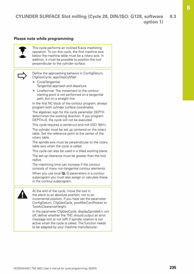
CYLINDER SURFACE Slot milling (Cycle 28, DIN/ISO: G128, software
option 1)
8.3
8
HEIDENHAIN | TNC 640 | User’s manual for cycle programming | 9/2015 235
Please note while programming:
This cycle performs an inclined 5-axis machining
operation. To run this cycle, the first machine axis
below the machine table must be a rotary axis. In
addition, it must be possible to position the tool
perpendicular to the cylinder surface.
Define the approaching behavior in ConfigDatum,
CfgGeoCycle, apprDepCylWall
CircleTangential:
Tangential approach and departure
LineNormal: The movement to the contour
starting point is not performed on a tangential
path, but on a straight line
In the first NC block of the contour program, always
program both cylinder surface coordinates.
The algebraic sign for the cycle parameter DEPTH
determines the working direction. If you program
DEPTH=0, the cycle will not be executed.
This cycle requires a center-cut end mill (ISO 1641).
The cylinder must be set up centered on the rotary
table. Set the reference point to the center of the
rotary table.
The spindle axis must be perpendicular to the rotary
table axis when the cycle is called.
This cycle can also be used in a tilted working plane.
The set-up clearance must be greater than the tool
radius.
The machining time can increase if the contour
consists of many non-tangential contour elements.
When you use local QL Q parameters in a contour
subprogram you must also assign or calculate these
in the contour subprogram.
At the end of the cycle, move the tool in
the plane to an absolute position, not to an
incremental position, if you have set the parameter
ConfigDatum, CfgGeoCycle, posAfterContPocket to
ToolAxClearanceHeight.
In the parameter CfgGeoCycle, displaySpindleErr, on/
off, define whether the TNC should output an error
message (on) or not (off) if spindle rotation is not
active when the cycle is called. The function needs
to be adapted by your machine manufacturer.
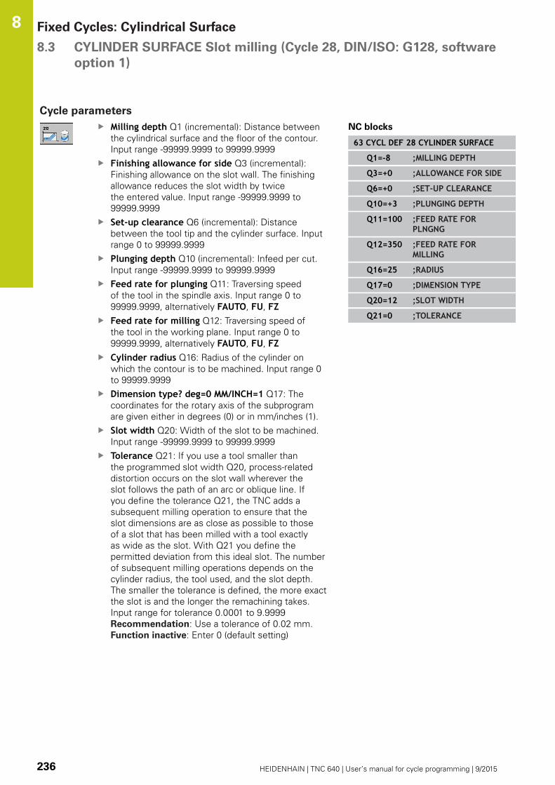
Fixed Cycles: Cylindrical Surface 8.3 CYLINDER SURFACE Slot milling (Cycle 28, DIN/ISO: G128, software
option 1)
8
236 HEIDENHAIN | TNC 640 | User’s manual for cycle programming | 9/2015
Cycle parameters
Milling depth Q1 (incremental): Distance between
the cylindrical surface and the floor of the contour.
Input range -99999.9999 to 99999.9999
Finishing allowance for side Q3 (incremental):
Finishing allowance on the slot wall. The finishing
allowance reduces the slot width by twice
the entered value. Input range -99999.9999 to
99999.9999
Set-up clearance Q6 (incremental): Distance
between the tool tip and the cylinder surface. Input
range 0 to 99999.9999
Plunging depth Q10 (incremental): Infeed per cut.
Input range -99999.9999 to 99999.9999
Feed rate for plunging Q11: Traversing speed
of the tool in the spindle axis. Input range 0 to
99999.9999, alternatively FAUTO, FU, FZFeed rate for milling Q12: Traversing speed of
the tool in the working plane. Input range 0 to
99999.9999, alternatively FAUTO, FU, FZCylinder radius Q16: Radius of the cylinder on
which the contour is to be machined. Input range 0
to 99999.9999
Dimension type? deg=0 MM/INCH=1 Q17: The
coordinates for the rotary axis of the subprogram
are given either in degrees (0) or in mm/inches (1).
Slot width Q20: Width of the slot to be machined.
Input range -99999.9999 to 99999.9999
Tolerance Q21: If you use a tool smaller than
the programmed slot width Q20, process-related
distortion occurs on the slot wall wherever the
slot follows the path of an arc or oblique line. If
you define the tolerance Q21, the TNC adds a
subsequent milling operation to ensure that the
slot dimensions are as close as possible to those
of a slot that has been milled with a tool exactly
as wide as the slot. With Q21 you define the
permitted deviation from this ideal slot. The number
of subsequent milling operations depends on the
cylinder radius, the tool used, and the slot depth.
The smaller the tolerance is defined, the more exact
the slot is and the longer the remachining takes.
Input range for tolerance 0.0001 to 9.9999
Recommendation: Use a tolerance of 0.02 mm.
Function inactive: Enter 0 (default setting)
NC blocks
63 CYCL DEF 28 CYLINDER SURFACE
Q1=-8 ;MILLING DEPTH
Q3=+0 ;ALLOWANCE FOR SIDE
Q6=+0 ;SET-UP CLEARANCE
Q10=+3 ;PLUNGING DEPTH
Q11=100 ;FEED RATE FORPLNGNG
Q12=350 ;FEED RATE FORMILLING
Q16=25 ;RADIUS
Q17=0 ;DIMENSION TYPE
Q20=12 ;SLOT WIDTH
Q21=0 ;TOLERANCE

CYLINDER SURFACE Ridge milling (Cycle 29, DIN/ISO: G129,
software option 1)
8.4
8
HEIDENHAIN | TNC 640 | User’s manual for cycle programming | 9/2015 237
8.4 CYLINDER SURFACE Ridge milling
(Cycle 29, DIN/ISO: G129, software
option 1)
Cycle run
This cycle enables you to program a ridge in two dimensions and
then transfer it onto a cylindrical surface. With this cycle the TNC
adjusts the tool so that, with radius compensation active, the walls
of the slot are always parallel. Program the midpoint path of the
ridge together with the tool radius compensation. With the radius
compensation you specify whether the TNC cuts the ridge with
climb milling or up-cut milling.
At the ends of the ridge the TNC always adds a semicircle whose
radius is half the ridge width.
1 The TNC positions the tool over the starting point of machining.
The TNC calculates the starting point from the ridge width and
the tool diameter. It is located next to the first point defined in
the contour subprogram, offset by half the ridge width and the
tool diameter. The radius compensation determines whether
machining begins from the left (1, RL = climb milling) or the
right of the ridge (2, RR = up-cut milling).
2 After the TNC has positioned to the first plunging depth, the tool
moves on a circular arc at the milling feed rate Q12 tangentially
to the ridge wall. If so programmed, it will leave metal for the
finishing allowance.
3 At the first plunging depth, the tool mills along the programmed
ridge wall at the milling feed rate Q12 until the stud is
completed.
4 The tool then departs the ridge wall on a tangential path and
returns to the starting point of machining.
5 Steps 2 to 4 are repeated until the programmed milling depth
Q1 is reached.
6 Finally, the tool retracts in the tool axis to the clearance height
or to the position last programmed before the cycle.
Y (Z)
X (C)

Fixed Cycles: Cylindrical Surface 8.4 CYLINDER SURFACE Ridge milling (Cycle 29, DIN/ISO: G129,
software option 1)
8
238 HEIDENHAIN | TNC 640 | User’s manual for cycle programming | 9/2015
Please note while programming:
This cycle performs an inclined 5-axis machining
operation. To run this cycle, the first machine axis
below the machine table must be a rotary axis. In
addition, it must be possible to position the tool
perpendicular to the cylinder surface.
In the first NC block of the contour program, always
program both cylinder surface coordinates.
The algebraic sign for the cycle parameter DEPTH
determines the working direction. If you program
DEPTH=0, the cycle will not be executed.
This cycle requires a center-cut end mill (ISO 1641).
The cylinder must be set up centered on the rotary
table. Set the reference point to the center of the
rotary table.
The spindle axis must be perpendicular to the rotary
table axis when the cycle is called. If this is not
the case, the TNC will generate an error message.
Switching of the kinematics may be required.
The set-up clearance must be greater than the tool
radius.
When you use local QL Q parameters in a contour
subprogram you must also assign or calculate these
in the contour subprogram.
In the parameter CfgGeoCycle, displaySpindleErr, on/
off, define whether the TNC should output an error
message (on) or not (off) if spindle rotation is not
active when the cycle is called. The function needs
to be adapted by your machine manufacturer.

CYLINDER SURFACE Ridge milling (Cycle 29, DIN/ISO: G129,
software option 1)
8.4
8
HEIDENHAIN | TNC 640 | User’s manual for cycle programming | 9/2015 239
Cycle parameters
Milling depth Q1 (incremental): Distance between
the cylindrical surface and the floor of the contour.
Input range -99999.9999 to 99999.9999
Finishing allowance for side Q3 (incremental):
Finishing allowance on the ridge wall. The finishing
allowance increases the ridge width by twice
the entered value. Input range -99999.9999 to
99999.9999
Set-up clearance Q6 (incremental): Distance
between the tool tip and the cylinder surface. Input
range 0 to 99999.9999
Plunging depth Q10 (incremental): Infeed per cut.
Input range -99999.9999 to 99999.9999
Feed rate for plunging Q11: Traversing speed
of the tool in the spindle axis. Input range 0 to
99999.9999, alternatively FAUTO, FU, FZFeed rate for milling Q12: Traversing speed of
the tool in the working plane. Input range 0 to
99999.9999, alternatively FAUTO, FU, FZCylinder radius Q16: Radius of the cylinder on
which the contour is to be machined. Input range 0
to 99999.9999
Dimension type? deg=0 MM/INCH=1 Q17: The
coordinates for the rotary axis of the subprogram
are given either in degrees (0) or in mm/inches (1).
Ridge width Q20: Width of the ridge to be
machined. Input range -99999.9999 to 99999.9999
NC blocks
63 CYCL DEF 29 CYLINDER SURFACERIDGE
Q1=-8 ;MILLING DEPTH
Q3=+0 ;ALLOWANCE FOR SIDE
Q6=+0 ;SET-UP CLEARANCE
Q10=+3 ;PLUNGING DEPTH
Q11=100 ;FEED RATE FORPLNGNG
Q12=350 ;FEED RATE FORMILLING
Q16=25 ;RADIUS
Q17=0 ;DIMENSION TYPE
Q20=12 ;RIDGE WIDTH

Fixed Cycles: Cylindrical Surface 8.5 CYLINDER SURFACE (Cycle 39, DIN/ISO: G139, software option 1)
8
240 HEIDENHAIN | TNC 640 | User’s manual for cycle programming | 9/2015
8.5 CYLINDER SURFACE (Cycle 39,
DIN/ISO: G139, software option 1)
Cycle run
This cycle enables you to machine a contour on a cylindrical
surface. The contour to be machined is programmed on the
unrolled surface of the cylinder. With this cycle the TNC adjusts the
tool so that, with radius compensation active, the wall of the open
contour is always parallel to the cylinder axis.
The contour is described in a subprogram identified in Cycle 14
CONTOUR GEOMETRY.
In the subprogram you always describe the contour with the
coordinates X and Y, regardless of which rotary axes exist on your
machine. This means that the contour description is independent
of your machine configuration. The path functions L, CHF, CR, RNDand CT are available.
Unlike Cycles 28 and 29, in the contour subprogram you define the
actual contour to be machined.
1 The TNC positions the tool over the starting point of machining.
The TNC locates the starting point next to the first point defined
in the contour subprogram, offset by the tool diameter.
2 The TNC then moves the tool to the first plunging depth.
The tool approaches the workpiece on a tangential path or
on a straight line at the milling feed rate Q12. A finishing
allowance programmed for the side is taken into account. (The
approaching behavior depends on the parameter ConfigDatum,
CfgGeoCycle, apprDepCylWall.)
3 At the first plunging depth, the tool mills along the programmed
contour at the milling feed rate Q12 until the contour train is
completed.
4 The tool then departs the ridge wall on a tangential path and
returns to the starting point of machining.
5 Steps 2 to 4 are repeated until the programmed milling depth
Q1 is reached.
6 Finally, the tool retracts in the tool axis to the clearance
height or to the position last programmed before the cycle
(depending on the parameter ConfigDatum, CfgGeoCycle,
posAfterContPocket).

CYLINDER SURFACE (Cycle 39, DIN/ISO: G139, software option 1) 8.5
8
HEIDENHAIN | TNC 640 | User’s manual for cycle programming | 9/2015 241
Please note while programming:
This cycle performs an inclined 5-axis machining
operation. To run this cycle, the first machine axis
below the machine table must be a rotary axis. In
addition, it must be possible to position the tool
perpendicular to the cylinder surface.
In the first NC block of the contour program, always
program both cylinder surface coordinates.
The algebraic sign for the cycle parameter DEPTH
determines the working direction. If you program
DEPTH=0, the cycle will not be executed.
Ensure that the tool has enough space laterally for
contour approach and departure.
The cylinder must be set up centered on the rotary
table. Set the reference point to the center of the
rotary table.
The spindle axis must be perpendicular to the rotary
table axis when the cycle is called.
The set-up clearance must be greater than the tool
radius.
The machining time can increase if the contour
consists of many non-tangential contour elements.
When you use local QL Q parameters in a contour
subprogram you must also assign or calculate these
in the contour subprogram.
Define the approaching behavior in ConfigDatum,
CfgGeoCycle, apprDepCylWall
CircleTangential:
Tangential approach and departure
LineNormal: The movement to the contour
starting point is not performed on a tangential
path, but on a straight line
Danger of collision!
In the parameter CfgGeoCycle, displaySpindleErr, on/
off, define whether the TNC should output an error
message (on) or not (off) if spindle rotation is not
active when the cycle is called. The function needs
to be adapted by your machine manufacturer.

Fixed Cycles: Cylindrical Surface 8.5 CYLINDER SURFACE (Cycle 39, DIN/ISO: G139, software option 1)
8
242 HEIDENHAIN | TNC 640 | User’s manual for cycle programming | 9/2015
Cycle parameters
Milling depth Q1 (incremental): Distance between
the cylindrical surface and the floor of the contour.
Input range -99999.9999 to 99999.9999
Finishing allowance for side Q3 (incremental):
Finishing allowance in the plane of the unrolled
cylindrical surface. This allowance is effective in the
direction of the radius compensation. Input range
-99999.9999 to 99999.9999
Set-up clearance Q6 (incremental): Distance
between the tool tip and the cylinder surface. Input
range 0 to 99999.9999
Plunging depth Q10 (incremental): Infeed per cut.
Input range -99999.9999 to 99999.9999
Feed rate for plunging Q11: Traversing speed
of the tool in the spindle axis. Input range 0 to
99999.9999, alternatively FAUTO, FU, FZFeed rate for milling Q12: Traversing speed of
the tool in the working plane. Input range 0 to
99999.9999, alternatively FAUTO, FU, FZCylinder radius Q16: Radius of the cylinder on
which the contour is to be machined. Input range 0
to 99999.9999
Dimension type? deg=0 MM/INCH=1 Q17: The
coordinates for the rotary axis of the subprogram
are given either in degrees (0) or in mm/inches (1).
NC blocks
63 CYCL DEF 39 CYL. SURFACECONTOUR
Q1=-8 ;MILLING DEPTH
Q3=+0 ;ALLOWANCE FOR SIDE
Q6=+0 ;SET-UP CLEARANCE
Q10=+3 ;PLUNGING DEPTH
Q11=100 ;FEED RATE FORPLNGNG
Q12=350 ;FEED RATE FORMILLING
Q16=25 ;RADIUS
Q17=0 ;DIMENSION TYPE
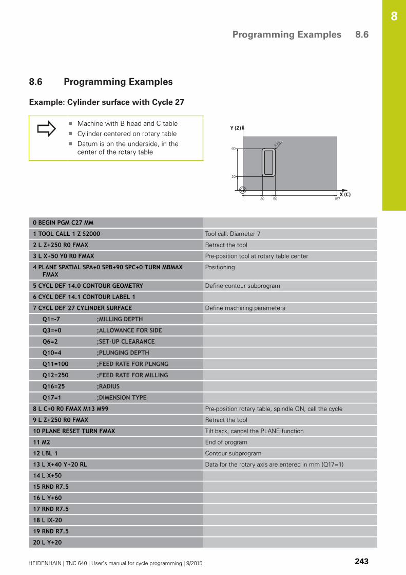
Programming Examples 8.6
8
HEIDENHAIN | TNC 640 | User’s manual for cycle programming | 9/2015 243
8.6 Programming Examples
Example: Cylinder surface with Cycle 27
Machine with B head and C table
Cylinder centered on rotary table
Datum is on the underside, in the
center of the rotary table
Y (Z)
X (C)
0 BEGIN PGM C27 MM
1 TOOL CALL 1 Z S2000 Tool call: Diameter 7
2 L Z+250 R0 FMAX Retract the tool
3 L X+50 Y0 R0 FMAX Pre-position tool at rotary table center
4 PLANE SPATIAL SPA+0 SPB+90 SPC+0 TURN MBMAXFMAX
Positioning
5 CYCL DEF 14.0 CONTOUR GEOMETRY Define contour subprogram
6 CYCL DEF 14.1 CONTOUR LABEL 1
7 CYCL DEF 27 CYLINDER SURFACE Define machining parameters
Q1=-7 ;MILLING DEPTH
Q3=+0 ;ALLOWANCE FOR SIDE
Q6=2 ;SET-UP CLEARANCE
Q10=4 ;PLUNGING DEPTH
Q11=100 ;FEED RATE FOR PLNGNG
Q12=250 ;FEED RATE FOR MILLING
Q16=25 ;RADIUS
Q17=1 ;DIMENSION TYPE
8 L C+0 R0 FMAX M13 M99 Pre-position rotary table, spindle ON, call the cycle
9 L Z+250 R0 FMAX Retract the tool
10 PLANE RESET TURN FMAX Tilt back, cancel the PLANE function
11 M2 End of program
12 LBL 1 Contour subprogram
13 L X+40 Y+20 RL Data for the rotary axis are entered in mm (Q17=1)
14 L X+50
15 RND R7.5
16 L Y+60
17 RND R7.5
18 L IX-20
19 RND R7.5
20 L Y+20
Fixed Cycles: Cylindrical Surface 8.6 Programming Examples
8
244 HEIDENHAIN | TNC 640 | User’s manual for cycle programming | 9/2015
21 RND R7.5
22 L X+40 Y+20
23 LBL 0
24 END PGM C27 MM

Programming Examples 8.6
8
HEIDENHAIN | TNC 640 | User’s manual for cycle programming | 9/2015 245
Example: Cylinder surface with Cycle 28
Cylinder centered on rotary table
Machine with B head and C table
Datum at center of rotary table
Description of the midpoint path in the
contour subprogram
Y (Z)
X (C)
0 BEGIN PGM C28 MM
1 TOOL CALL 1 Z S2000 Tool call, tool axis Z, diameter 7
2 L Z+250 R0 FMAX Retract the tool
3 L X+50 Y+0 R0 FMAX Position tool at rotary table center
4 PLANE SPATIAL SPA+0 SPB+90 SPC+0 TURN FMAX Tilting
5 CYCL DEF 14.0 CONTOUR GEOMETRY Define contour subprogram
6 CYCL DEF 14.1 CONTOUR LABEL 1
7 CYCL DEF 28 CYLINDER SURFACE Define machining parameters
Q1=-7 ;MILLING DEPTH
Q3=+0 ;ALLOWANCE FOR SIDE
Q6=2 ;SET-UP CLEARANCE
Q10=-4 ;PLUNGING DEPTH
Q11=100 ;FEED RATE FOR PLNGNG
Q12=250 ;FEED RATE FOR MILLING
Q16=25 ;RADIUS
Q17=1 ;DIMENSION TYPE
Q20=10 ;SLOT WIDTH
Q21=0.02 ;TOLERANCE Remachining active
8 L C+0 R0 FMAX M3 M99 Pre-position rotary table, spindle ON, call the cycle
9 L Z+250 R0 FMAX Retract the tool
10 PLANE RESET TURN FMAX Tilt back, cancel the PLANE function
11 M2 End of program
12 LBL 1 Contour subprogram, description of the midpoint path
13 L X+60 Y+0 RL Data for the rotary axis are entered in mm (Q17=1)
14 L Y-35
15 L X+40 Y-52.5
16 L Y-70
17 LBL 0
18 END PGM C28 MM

9Fixed Cycles:
Contour Pocketwith Contour
Formula

Fixed Cycles: Contour Pocket with Contour Formula 9.1 SL cycles with complex contour formula
9
248 HEIDENHAIN | TNC 640 | User’s manual for cycle programming | 9/2015
9.1 SL cycles with complex contour
formula
Fundamentals
SL cycles and the complex contour formula enable you to form
complex contours by combining subcontours (pockets or islands).
You define the individual subcontours (geometry data) as separate
programs. In this way, any subcontour can be used any number of
times. The TNC calculates the complete contour from the selected
subcontours, which you link together through a contour formula.
The memory capacity for programming an SL cycle
(all contour description programs) is limited to 128
contours. The number of possible contour elements
depends on the type of contour (inside or outside
contour) and the number of contour descriptions. You
can program up to 16384 elements.
The SL cycles with contour formula presuppose a
structured program layout and enable you to save
frequently used contours in individual programs. Using
the contour formula, you can connect the subcontours
to a complete contour and define whether it applies to
a pocket or island.
In its present form, the "SL cycles with contour
formula" function requires input from several areas in
the TNC’s user interface. This function is to serve as a
basis for further development.
Program structure: Machining with
SL cycles and complex contour
formula
0 BEGIN PGM CONTOUR MM
...
5 SEL CONTOUR "MODEL"
6 CYCL DEF 20 CONTOUR DATA...
8 CYCL DEF 22 ROUGH-OUT...
9 CYCL CALL
...
12 CYCL DEF 23 FLOOR FINISHING...
13 CYCL CALL
...
16 CYCL DEF 24 SIDE FINISHING...
17 CYCL CALL
63 L Z+250 R0 FMAX M2
64 END PGM CONTOUR MM
SL cycles with complex contour formula 9.1
9
HEIDENHAIN | TNC 640 | User’s manual for cycle programming | 9/2015 249
Properties of the subcontours
By default, the TNC assumes that the contour is a pocket. Do not
program a radius compensation.
The TNC ignores feed rates F and miscellaneous functions M.
Coordinate transformations are allowed. If they are programmed
within the subcontour they are also effective in the following
subprograms, but they need not be reset after the cycle call.
Although the subprograms can contain coordinates in the spindle
axis, such coordinates are ignored.
The working plane is defined in the first coordinate block of the
subprogram.
You can define subcontours with various depths as needed
Characteristics of the fixed cycles
The TNC automatically positions the tool to the set-up clearance
before a cycle.
Each level of infeed depth is milled without interruptions since the
cutter traverses around islands instead of over them.
The radius of "inside corners" can be programmed—the tool
keeps moving to prevent surface blemishes at inside corners (this
applies to the outermost pass in the Rough-out and Side Finishing
cycles).
The contour is approached in a tangential arc for side finishing.
For floor finishing, the tool again approaches the workpiece on a
tangential arc (for spindle axis Z, for example, the arc may be in
the Z/X plane).
The contour is machined throughout in either climb or up-cut
milling.
The machining data (such as milling depth, finishing allowance and
set-up clearance) are entered as CONTOUR DATA in Cycle 20.
Program structure: Calculation of the
subcontours with contour formula
0 BEGIN PGM MODEL MM
1 DECLARE CONTOUR QC1 = "CIRCLE1"
2 DECLARE CONTOUR QC2 ="CIRCLEXY" DEPTH15
3 DECLARE CONTOUR QC3 ="TRIANGLE" DEPTH10
4 DECLARE CONTOUR QC4 = "SQUARE"DEPTH5
5 QC10 = ( QC1 | QC3 | QC4 ) \ QC2
6 END PGM MODEL MM
0 BEGIN PGM CIRCLE 1 MM
1 CC X+75 Y+50
2 LP PR+45 PA+0
3 CP IPA+360 DR+
4 END PGM CIRCLE 1 MM
0 BEGIN PGM CIRCLE31XY MM
...
...

Fixed Cycles: Contour Pocket with Contour Formula 9.1 SL cycles with complex contour formula
9
250 HEIDENHAIN | TNC 640 | User’s manual for cycle programming | 9/2015
Selecting a program with contour definitions
With the SEL CONTOUR function you select a program with contour
definitions, from which the TNC takes the contour descriptions:
Show the soft-key row with special functions
Select the menu for functions for contour and
point machining
Press the SEL CONTOUR soft key
Enter the full name of the program with the
contour definition and confirm with the END key
Program a SEL CONTOUR block before the SL
cycles. Cycle 14 CONTOUR GEOMETRY is no longer
necessary if you use SEL CONTOUR.
Defining contour descriptions
With the DECLARE CONTOUR function you enter in a program
the path for programs from which the TNC draws the contour
descriptions. In addition, you can select a separate depth for this
contour description (FCL 2 function):
Show the soft-key row with special functions
Select the menu for functions for contour and
point machining
Press the DECLARE CONTOUR soft key
Enter the number for the contour designator QC,
and confirm with the ENT key
Enter the full name of the program with the
contour description and confirm with the END key,
or if desired,
Define a separate depth for the selected contour
With the entered contour designators QC you can
include the various contours in the contour formula.
If you program separate depths for contours, then
you must assign a depth to all subcontours (assign
the depth 0 if necessary).

SL cycles with complex contour formula 9.1
9
HEIDENHAIN | TNC 640 | User’s manual for cycle programming | 9/2015 251
Entering a complex contour formula
You can use soft keys to interlink various contours in a
mathematical formula.
Show the soft-key row with special functions
Select the menu for functions for contour and
point machining
Press the CONTOUR FORMULA soft key. The TNC
then displays the following soft keys:
Soft key Mathematical function
cut with
e.g. QC10 = QC1 & QC5
joined with
e.g. QC25 = QC7 | QC18
joined with, but without cut
e.g. QC12 = QC5 ^ QC25
without
e.g. QC25 = QC1 \ QC2
Parenthesis open
e.g. QC12 = QC1 * (QC2 + QC3)
Parenthesis closed
e.g. QC12 = QC1 * (QC2 + QC3)
Define single contour
e.g. QC12 = QC1

Fixed Cycles: Contour Pocket with Contour Formula 9.1 SL cycles with complex contour formula
9
252 HEIDENHAIN | TNC 640 | User’s manual for cycle programming | 9/2015
Superimposed contours
By default, the TNC considers a programmed contour to be a
pocket. With the functions of the contour formula, you can convert
a contour from a pocket to an island.
Pockets and islands can be overlapped to form a new contour. You
can thus enlarge the area of a pocket by another pocket or reduce it
by an island.
Subprograms: overlapping pockets
The following programming examples are contour
description programs that are defined in a contour
definition program. The contour definition program
is called through the SEL CONTOUR function in the
actual main program.
Pockets A and B overlap.
The TNC calculates the points of intersection S1 and S2 (they do
not have to be programmed).
The pockets are programmed as full circles.
Contour description program 1: pocket A
0 BEGIN PGM POCKET_A MM
1 L X+10 Y+50 R0
2 CC X+35 Y+50
3 C X+10 Y+50 DR-
4 END PGM POCKET_A MM
Contour description program 2: pocket B
0 BEGIN PGM POCKET_B MM
1 L X+90 Y+50 R0
2 CC X+65 Y+50
3 C X+90 Y+50 DR-
4 END PGM POCKET_B MM
SL cycles with complex contour formula 9.1
9
HEIDENHAIN | TNC 640 | User’s manual for cycle programming | 9/2015 253
Area of inclusion
Both areas A and B are to be machined, including the overlapping
area:
The areas A and B must be entered in separate programs
without radius compensation.
In the contour formula, the areas A and B are processed with
the "joined with" function.
Contour definition program:
50 ...
51 ...
52 DECLARE CONTOUR QC1 = "POCKET_A.H"
53 DECLARE CONTOUR QC2 = "POCKET_B.H"
54 QC10 = QC1 | QC2
55 ...
56 ...
Area of exclusion
Area A is to be machined without the portion overlapped by B:
The areas A and B must be entered in separate programs
without radius compensation.
In the contour formula, the area B is subtracted from the area A
with the without function.
Contour definition program:
50 ...
51 ...
52 DECLARE CONTOUR QC1 = "POCKET_A.H"
53 DECLARE CONTOUR QC2 = "POCKET_B.H"
54 QC10 = QC1 \ QC2
55 ...
56 ...

Fixed Cycles: Contour Pocket with Contour Formula 9.1 SL cycles with complex contour formula
9
254 HEIDENHAIN | TNC 640 | User’s manual for cycle programming | 9/2015
Area of intersection
Only the area where A and B overlap is to be machined. (The areas
covered by A or B alone are to be left unmachined.)
The areas A and B must be entered in separate programs
without radius compensation.
In the contour formula, the areas A and B are processed with
the "intersection with" function.
Contour definition program:
50 ...
51 ...
52 DECLARE CONTOUR QC1 = "POCKET_A.H"
53 DECLARE CONTOUR QC2 = "POCKET_B.H"
54 QC10 = QC1 & QC2
55 ...
56 ...
Contour machining with SL Cycles
The complete contour is machined with the SL
Cycles 20 to 24 (see "Overview", page 197).

SL cycles with complex contour formula 9.1
9
HEIDENHAIN | TNC 640 | User’s manual for cycle programming | 9/2015 255
Example: Roughing and finishing superimposed
contours with the contour formula
0 BEGIN PGM CONTOUR MM
1 BLK FORM 0.1 Z X+0 Y+0 Z-40 Definition of workpiece blank
2 BLK FORM 0.2 X+100 Y+100 Z+0
3 TOOL DEF 1 L+0 R+2.5 Tool definition of roughing cutter
4 TOOL DEF 2 L+0 R+3 Tool definition of finishing cutter
5 TOOL CALL 1 Z S2500 Tool call of roughing cutter
6 L Z+250 R0 FMAX Retract the tool
7 SEL CONTOUR "MODEL" Specify contour definition program
8 CYCL DEF 20 CONTOUR DATA Define general machining parameters
Q1=-20 ;MILLING DEPTH
Q2=1 ;TOOL PATH OVERLAP
Q3=+0.5 ;ALLOWANCE FOR SIDE
Q4=+0.5 ;ALLOWANCE FOR FLOOR
Q5=+0 ;SURFACE COORDINATE
Q6=2 ;SET-UP CLEARANCE
Q7=+100 ;CLEARANCE HEIGHT
Q8=0.1 ;ROUNDING RADIUS
Q9=-1 ;DIRECTION

Fixed Cycles: Contour Pocket with Contour Formula 9.1 SL cycles with complex contour formula
9
256 HEIDENHAIN | TNC 640 | User’s manual for cycle programming | 9/2015
9 CYCL DEF 22 ROUGH-OUT Cycle definition: Rough-out
Q10=5 ;PLUNGING DEPTH
Q11=100 ;FEED RATE FOR PLNGNG
Q12=350 ;FEED RATE FOR MILLING
Q18=0 ;COARSE ROUGHING TOOL
Q19=150 ;RECIPROCATION FEED RATE
Q401=100 ;FEED RATE FACTOR
Q404=0 ;FINE ROUGH STRATEGY
10 CYCL CALL M3 Cycle call: Rough-out
11 TOOL CALL 2 Z S5000 Tool call of finishing cutter
12 CYCL DEF 23 FLOOR FINISHING Cycle definition: Floor finishing
Q11=100 ;FEED RATE FOR PLNGNG
Q12=200 ;FEED RATE FOR MILLING
13 CYCL CALL M3 Cycle call: Floor finishing
14 CYCL DEF 24 SIDE FINISHING Cycle definition: Side finishing
Q9=+1 ;DIRECTION OF ROTATION
Q10=5 ;PLUNGING DEPTH
Q11=100 ;FEED RATE FOR PLNGNG
Q12=400 ;FEED RATE FOR MILLING
Q14=+0 ;ALLOWANCE FOR SIDE
15 CYCL CALL M3 Cycle call: Side finishing
16 L Z+250 R0 FMAX M2 Retract in the tool axis, end program
17 END PGM CONTOUR MM
Contour definition program with contour formula:
0 BEGIN PGM MODEL MM Contour definition program
1 DECLARE CONTOUR QC1 = "CIRCLE1" Definition of the contour designator for the program
"CIRCLE1"
2 FN 0: Q1 =+35 Assignment of values for parameters used in PGM
"CIRCLE31XY"
3 FN 0: Q2 =+50
4 FN 0: Q3 =+25
5 DECLARE CONTOUR QC2 = "CIRCLE31XY" Definition of the contour designator for the program
"CIRCLE31XY"
6 DECLARE CONTOUR QC3 = "TRIANGLE" Definition of the contour designator for the program
"TRIANGLE"
7 DECLARE CONTOUR QC4 = "SQUARE" Definition of the contour designator for the program
"SQUARE"
8 QC10 = ( QC 1 | QC 2 ) \ QC 3 \ QC 4 Contour formula
9 END PGM MODEL MM
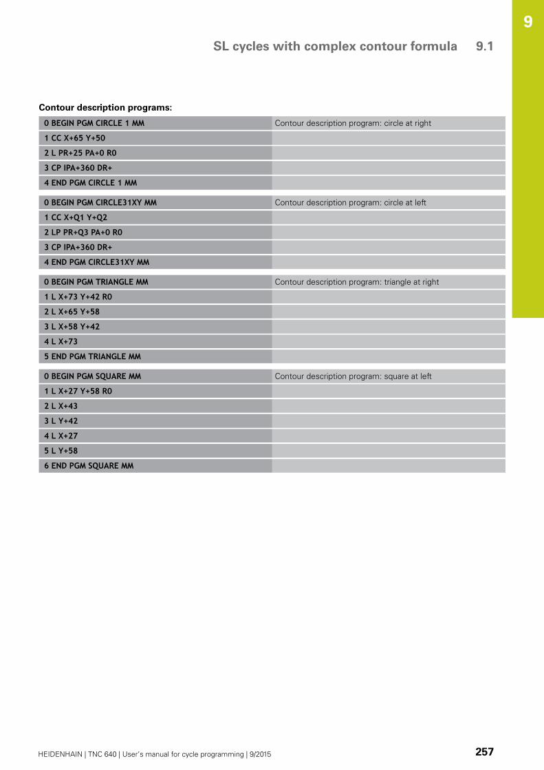
SL cycles with complex contour formula 9.1
9
HEIDENHAIN | TNC 640 | User’s manual for cycle programming | 9/2015 257
Contour description programs:
0 BEGIN PGM CIRCLE 1 MM Contour description program: circle at right
1 CC X+65 Y+50
2 L PR+25 PA+0 R0
3 CP IPA+360 DR+
4 END PGM CIRCLE 1 MM
0 BEGIN PGM CIRCLE31XY MM Contour description program: circle at left
1 CC X+Q1 Y+Q2
2 LP PR+Q3 PA+0 R0
3 CP IPA+360 DR+
4 END PGM CIRCLE31XY MM
0 BEGIN PGM TRIANGLE MM Contour description program: triangle at right
1 L X+73 Y+42 R0
2 L X+65 Y+58
3 L X+58 Y+42
4 L X+73
5 END PGM TRIANGLE MM
0 BEGIN PGM SQUARE MM Contour description program: square at left
1 L X+27 Y+58 R0
2 L X+43
3 L Y+42
4 L X+27
5 L Y+58
6 END PGM SQUARE MM

Fixed Cycles: Contour Pocket with Contour Formula 9.2 SL cycles with simple contour formula
9
258 HEIDENHAIN | TNC 640 | User’s manual for cycle programming | 9/2015
9.2 SL cycles with simple contour
formula
Fundamentals
SL cycles and the simple contour formula enable you to form
contours by combining up to 9 subcontours (pockets or islands) in
a simple manner. You define the individual subcontours (geometry
data) as separate programs. In this way, any subcontour can be
used any number of times. The TNC calculates the contour from the
selected subcontours.
The memory capacity for programming an SL cycle
(all contour description programs) is limited to 128
contours. The number of possible contour elements
depends on the type of contour (inside or outside
contour) and the number of contour descriptions. You
can program up to 16384 elements.
Program structure: Machining with
SL cycles and complex contour
formula
0 BEGIN PGM CONTDEF MM
...
5 CONTOUR DEF P1= "POCK1.H" I2= "ISLE2.H" DEPTH5 I3 "ISLE3.H"DEPTH7.5
6 CYCL DEF 20 CONTOUR DATA...
8 CYCL DEF 22 ROUGH-OUT...
9 CYCL CALL
...
12 CYCL DEF 23 FLOOR FINISHING...
13 CYCL CALL
...
16 CYCL DEF 24 SIDE FINISHING...
17 CYCL CALL
63 L Z+250 R0 FMAX M2
64 END PGM CONTDEF MM
SL cycles with simple contour formula 9.2
9
HEIDENHAIN | TNC 640 | User’s manual for cycle programming | 9/2015 259
Properties of the subcontours
Do not program a radius compensation.
The TNC ignores feed rates F and miscellaneous functions M.
Coordinate transformations are allowed. If they are programmed
within the subcontour they are also effective in the following
subprograms, but they need not be reset after the cycle call.
Although the subprograms can contain coordinates in the
spindle axis, such coordinates are ignored.
The working plane is defined in the first coordinate block of the
subprogram.
Characteristics of the fixed cycles
The TNC automatically positions the tool to the set-up clearance
before a cycle.
Each level of infeed depth is milled without interruptions since
the cutter traverses around islands instead of over them.
The radius of "inside corners" can be programmed—the tool
keeps moving to prevent surface blemishes at inside corners
(this applies to the outermost pass in the Rough-out and Side
Finishing cycles).
The contour is approached in a tangential arc for side finishing.
For floor finishing, the tool again approaches the workpiece on a
tangential arc (for spindle axis Z, for example, the arc may be in
the Z/X plane).
The contour is machined throughout in either climb or up-cut
milling.
The machining data (such as milling depth, finishing allowance and
set-up clearance) are entered as CONTOUR DATA in Cycle 20.

Fixed Cycles: Contour Pocket with Contour Formula 9.2 SL cycles with simple contour formula
9
260 HEIDENHAIN | TNC 640 | User’s manual for cycle programming | 9/2015
Entering a simple contour formula
You can use soft keys to interlink various contours in a
mathematical formula.
Show the soft-key row with special functions
Select the menu for functions for contour and
point machining
Press the CONTOUR DEF soft key. The TNC opens
the dialog for entering the contour formula
Enter the name of the first subcontour. The first
subcontour must always be the deepest pocket.
Confirm with the ENT key
Specify via soft key whether the next subcontour
is a pocket or an island. Confirm with the ENT key
Enter the name of the second subcontour.
Confirm with the ENT key
If needed, enter the depth of the second
subcontour. Confirm with the ENT key
Carry on with the dialog as described above until
you have entered all subcontours.
Always start the list of subcontours with the deepest
pocket!
If the contour is defined as an island, the TNC
interprets the entered depth as the island height. The
entered value (without an algebraic sign) then refers
to the workpiece top surface!
If the depth is entered as 0, then for pockets the
depth defined in the Cycle 20 is effective. Islands
then rise up to the workpiece top surface!
Contour machining with SL Cycles
The complete contour is machined with the SL
Cycles 20 to 24 (see "Overview", page 197).

10Cycles: Coordinate
Transformations

Cycles: Coordinate Transformations 10.1 Fundamentals
10
262 HEIDENHAIN | TNC 640 | User’s manual for cycle programming | 9/2015
10.1 Fundamentals
Overview
Once a contour has been programmed, you can position it on the
workpiece at various locations and in different sizes through the
use of coordinate transformations. The TNC provides the following
coordinate transformation cycles:
Soft key Cycle Page
7 DATUM
For shifting contours directly
within the program or from
datum tables
263
247 DATUM SETTING
Datum setting during program
run
269
8 MIRRORING
Mirroring contours
270
10 ROTATION
Rotating contours in the
working plane
272
11 SCALING FACTOR
Increasing or reducing the size
of contours
274
26 AXIS-SPECIFIC SCALING
Increasing or reducing the size
of contours with axis-specific
scaling
275
19 WORKING PLANE
Machining in tilted coordinate
system on machines with
swivel heads and/or rotary
tables
277
Effect of coordinate transformations
Beginning of effect: A coordinate transformation becomes effective
as soon as it is defined—it is not called separately. It remains in
effect until it is changed or canceled.
To cancel coordinate transformations:
Define cycles for basic behavior with a new value, such as
scaling factor 1.0
Execute a miscellaneous function M2, M30, or an END PGM
block (depending on machine parameter clearMode).
Select a new program

DATUM SHIFT (Cycle 7) 10.2
10
HEIDENHAIN | TNC 640 | User’s manual for cycle programming | 9/2015 263
10.2 DATUM SHIFT (Cycle 7, DIN/ISO:
G54)
Effect
A DATUM SHIFT allows machining operations to be repeated at
various locations on the workpiece.
When the DATUM SHIFT cycle is defined, all coordinate data is
based on the new datum. The TNC displays the datum shift in each
axis in the additional status display. Input of rotary axes is also
permitted.
Resetting
Program a datum shift to the coordinates X=0, Y=0 etc. directly
with a cycle definition.
Call a datum shift to the coordinates X=0; Y=0 etc. from a
datum table.
Cycle parameters
Datum shift: Enter the coordinates of the new
datum. Absolute values are referenced to the
manually set workpiece datum. Incremental values
are always referenced to the datum which was last
valid—this can be a datum which has already been
shifted. Input range: Up to six NC axes, each from
–99999.9999 to 99999.9999
NC blocks
13 CYCL DEF 7.0 DATUM
14 CYCL DEF 7.1 X+60
15 CYCL DEF 7.2 Y+40
16 CYCL DEF 7.3 Z-5

Cycles: Coordinate Transformations 10.3 DATUM SHIFT with datum tables (Cycle 7)
10
264 HEIDENHAIN | TNC 640 | User’s manual for cycle programming | 9/2015
10.3 DATUM SHIFT with datum tables
(Cycle 7, DIN/ISO: G53)
Effect
Datum tables are used for:
Frequently recurring machining sequences at various locations
on the workpiece
Frequent use of the same datum shift
Within a program, you can either program datum points directly in
the cycle definition or call them from a datum table.
Resetting
Call a datum shift to the coordinates X=0; Y=0 etc. from a
datum table.
Execute a datum shift to the coordinates X=0, Y=0 etc. directly
with a cycle definition
Status displays
In the additional status display, the following data from the datum
table are shown:
Name and path of the active datum table
Active datum number
Comment from the DOC column of the active datum number

DATUM SHIFT with datum tables (Cycle 7) 10.3
10
HEIDENHAIN | TNC 640 | User’s manual for cycle programming | 9/2015 265
Please note while programming:
Danger of collision!
Datums from a datum table are always and
exclusively referenced to the current datum (preset).
If you are using datum shifts with datum tables, then
use the SEL TABLE function to activate the desired
datum table from the NC program.
If you work without SEL TABLE, then you must
activate the desired datum table before the test
run or the program run. (This applies also to the
programming graphics).
Use the file management to select the desired
table for a test run in the Test Run operating
mode: The table receives the status S
Use the file management in the Program Run,Single Block and Program Run, Full Sequenceoperating modes to select the desired table for
program run: The table receives the status M
The coordinate values from datum tables are only
effective with absolute coordinate values.
New lines can only be inserted at the end of the
table.
If you create datum tables, the file name has to start
with a letter.
Cycle parameters
Datum shift: Enter the number of the datum from
the datum table or a Q parameter. If you enter a Q
parameter, the TNC activates the datum number
entered in the Q parameter. Input range: 0 to 9999
NC blocks
77 CYCL DEF 7.0 DATUM SHIFT
78 CYCL DEF 7.1 #5

Cycles: Coordinate Transformations 10.3 DATUM SHIFT with datum tables (Cycle 7)
10
266 HEIDENHAIN | TNC 640 | User’s manual for cycle programming | 9/2015
Selecting a datum table in the part program
With the SEL TABLE function you select the table from which the
TNC takes the datums:
Select the functions for program call: Press the
PGM CALL key
Press the DATUM TABLE soft key
Select the complete path name of the datum table
or the file with the SELECT soft key and confirm
your entry with the END key
Program a SEL TABLE block before Cycle 7 Datum
Shift.
A datum table selected with SEL TABLE remains
active until you select another datum table with SELTABLE or through PGM MGT.
Edit the datum table in the Programming mode of
operation
After you have changed a value in a datum table, you
must save the change with the ENT key. Otherwise
the change might not be included during program
run.
Select the datum table in the Programming mode of operation
Call the file manager: Press the PGM MGT key
Display the datum tables: Press the SELECT TYPEand SHOW .D soft keys
Select the desired table or enter a new file name.
Edit the file The functions displayed in the soft-key
row for editing include:

DATUM SHIFT with datum tables (Cycle 7) 10.3
10
HEIDENHAIN | TNC 640 | User’s manual for cycle programming | 9/2015 267
Soft key Function
Select beginning of table
Select end of table
Go to the previous page
Go to next page
Insert line (only possible at the end of table)
Delete line
Find
Go to beginning of line
Go to end of line
Copy the current value
Insert the copied value
Add the entered number of lines (datums) to
the end of the table
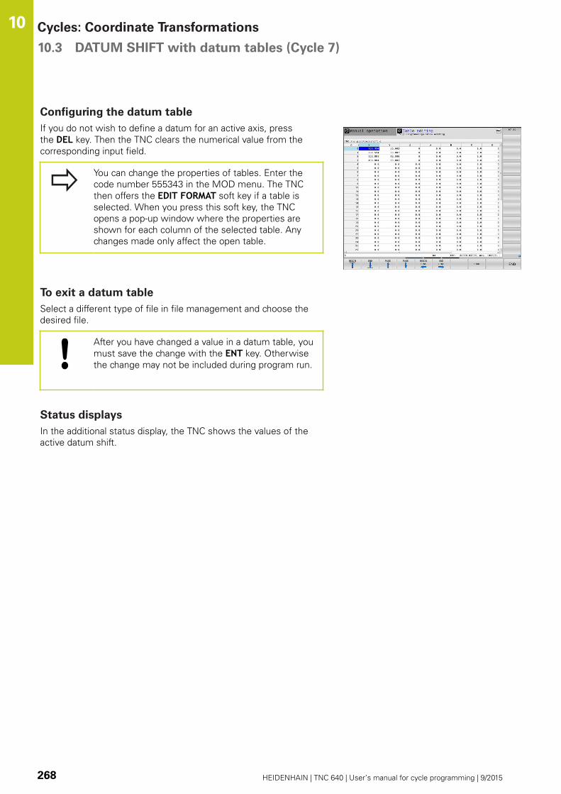
Cycles: Coordinate Transformations 10.3 DATUM SHIFT with datum tables (Cycle 7)
10
268 HEIDENHAIN | TNC 640 | User’s manual for cycle programming | 9/2015
Configuring the datum table
If you do not wish to define a datum for an active axis, press
the DEL key. Then the TNC clears the numerical value from the
corresponding input field.
You can change the properties of tables. Enter the
code number 555343 in the MOD menu. The TNC
then offers the EDIT FORMAT soft key if a table is
selected. When you press this soft key, the TNC
opens a pop-up window where the properties are
shown for each column of the selected table. Any
changes made only affect the open table.
To exit a datum table
Select a different type of file in file management and choose the
desired file.
After you have changed a value in a datum table, you
must save the change with the ENT key. Otherwise
the change may not be included during program run.
Status displays
In the additional status display, the TNC shows the values of the
active datum shift.

DATUM SETTING (Cycle 247) 10.4
10
HEIDENHAIN | TNC 640 | User’s manual for cycle programming | 9/2015 269
10.4 DATUM SETTING (Cycle 247, DIN/
ISO: G247)
Effect
With the DATUM SETTING cycle you can activate as the new
datum a preset defined in a preset table.
After a DATUM SETTING cycle definition, all of the coordinate
inputs and datum shifts (absolute and incremental) are referenced
to the new preset.
Status display
In the status display the TNC shows the active preset number
behind the datum symbol.
Please note before programming:
When activating a datum from the preset table,
the TNC resets the datum shift, mirroring, rotation,
scaling factor and axis-specific scaling factor.
If you activate preset number 0 (line 0), then you
activate the datum that you last set in the ManualOperation or El. Handwheel operating mode.
Cycle 247 is not functional in Test Run mode.
Cycle parameters
Number for datum?: Enter the number of the
desired datum from the preset table. Optionally you
can use the soft key SELECT and select the desired
datum from the preset table. Input range 0 to 65535
NC blocks
13 CYCL DEF 247 DATUM SETTING
Q339=4 ;DATUM NUMBER
Status displays
In the additional status display (POS. DISP. STATUS) the TNC shows
the active preset number behind the datum dialog.

Cycles: Coordinate Transformations 10.5 MIRRORING (Cycle 8)
10
270 HEIDENHAIN | TNC 640 | User’s manual for cycle programming | 9/2015
10.5 MIRRORING (Cycle 8, DIN/ISO: G28)
Effect
The TNC can machine the mirror image of a contour in the working
plane.
The mirroring cycle becomes effective as soon as it is defined in
the program. It is also effective in the Positioning with MDI mode
of operation. The active mirrored axes are shown in the additional
status display.
If you mirror only one axis, the machining direction of the tool is
reversed (except in SL cycles).
If you mirror two axes, the machining direction remains the
same.
The result of the mirroring depends on the location of the datum:
If the datum lies on the contour to be mirrored, the element
simply flips over.
If the datum lies outside the contour to be mirrored, the
element also “jumps” to another location.
Resetting
Program the MIRROR IMAGE cycle once again with NO ENT.

MIRRORING (Cycle 8) 10.5
10
HEIDENHAIN | TNC 640 | User’s manual for cycle programming | 9/2015 271
Please note while programming:
If you work in a tilted system with Cycle 8 the
following procedure is recommended:
First program the tilting movement and then call
Cycle 8 MIRRORING!
Cycle parameters
Mirrored axis?: Enter the axis to be mirrored. You
can mirror all axes except for the spindle axis—
including rotary axes—with the exception of the
spindle axis and its associated auxiliary axis. You can
enter up to three axes. Input range: Up to three NC
axes X, Y, Z, U, V, W, A, B, C
NC blocks
79 CYCL DEF 8.0 MIRROR IMAGE
80 CYCL DEF 8.1 X Y Z

Cycles: Coordinate Transformations 10.6 ROTATION (Cycle 10, DIN/ISO: G73)
10
272 HEIDENHAIN | TNC 640 | User’s manual for cycle programming | 9/2015
10.6 ROTATION (Cycle 10, DIN/ISO: G73)
Effect
The TNC can rotate the coordinate system about the active datum
in the working plane within a program.
The ROTATION cycle becomes effective as soon as it is defined in
the program. It is also effective in the Positioning with MDI mode
of operation. The active rotation angle is shown in the additional
status display.
Reference axis for the rotation angle:
X/Y plane: X axis
Y/Z plane: Y axis
Z/X plane: Z axis
Resetting
Program the ROTATION cycle once again with a rotation angle of
0°.
ROTATION (Cycle 10, DIN/ISO: G73) 10.6
10
HEIDENHAIN | TNC 640 | User’s manual for cycle programming | 9/2015 273
Please note while programming:
An active radius compensation is canceled
by defining Cycle 10 and must therefore be
reprogrammed, if necessary.
After defining Cycle 10, you must move both axes of
the working plane to activate rotation for all axes.
Cycle parameters
Rotation: Enter the rotation angle in degrees (°).
Input range –360.000° to +360.000° (absolute or
incremental)
NC blocks
12 CALL LBL 1
13 CYCL DEF 7.0 DATUM SHIFT
14 CYCL DEF 7.1 X+60
15 CYCL DEF 7.2 Y+40
16 CYCL DEF 10.0 ROTATION
17 CYCL DEF 10.1 ROT+35
18 CALL LBL 1
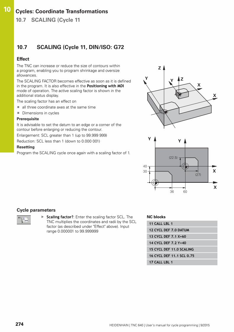
Cycles: Coordinate Transformations 10.7 SCALING (Cycle 11
10
274 HEIDENHAIN | TNC 640 | User’s manual for cycle programming | 9/2015
10.7 SCALING (Cycle 11, DIN/ISO: G72
Effect
The TNC can increase or reduce the size of contours within
a program, enabling you to program shrinkage and oversize
allowances.
The SCALING FACTOR becomes effective as soon as it is defined
in the program. It is also effective in the Positioning with MDImode of operation. The active scaling factor is shown in the
additional status display.
The scaling factor has an effect on
all three coordinate axes at the same time
Dimensions in cycles
Prerequisite
It is advisable to set the datum to an edge or a corner of the
contour before enlarging or reducing the contour.
Enlargement: SCL greater than 1 (up to 99.999 999)
Reduction: SCL less than 1 (down to 0.000 001)
Resetting
Program the SCALING cycle once again with a scaling factor of 1.
Cycle parameters
Scaling factor?: Enter the scaling factor SCL. The
TNC multiplies the coordinates and radii by the SCL
factor (as described under "Effect" above). Input
range 0.000001 to 99.999999
NC blocks
11 CALL LBL 1
12 CYCL DEF 7.0 DATUM
13 CYCL DEF 7.1 X+60
14 CYCL DEF 7.2 Y+40
15 CYCL DEF 11.0 SCALING
16 CYCL DEF 11.1 SCL 0.75
17 CALL LBL 1

AXIS-SPECIFIC SCALING (Cycle 26) 10.8
10
HEIDENHAIN | TNC 640 | User’s manual for cycle programming | 9/2015 275
10.8 AXIS-SPECIFIC SCALING (Cycle 26)
Effect
With Cycle 26 you can account for shrinkage and oversize factors
for each axis.
The SCALING FACTOR becomes effective as soon as it is defined
in the program. It is also effective in the Positioning with MDImode of operation. The active scaling factor is shown in the
additional status display.
Resetting
Program the SCALING cycle once again with a scaling factor of 1
for the same axis.
Please note while programming:
Coordinate axes sharing coordinates for arcs must be
enlarged or reduced by the same factor.
You can program each coordinate axis with its own
axis-specific scaling factor.
In addition, you can enter the coordinates of a center
for all scaling factors.
The size of the contour is enlarged or reduced with
reference to the center, and not necessarily (as in
Cycle 11 SCALING) with reference to the active
datum.

Cycles: Coordinate Transformations 10.8 AXIS-SPECIFIC SCALING (Cycle 26)
10
276 HEIDENHAIN | TNC 640 | User’s manual for cycle programming | 9/2015
Cycle parameters
Axis and scaling factor: Select the coordinate axis/
axes by soft key and enter the factor(s) involved
in enlarging or reducing. Input range 0.000001 to
99.999999
Center coordinates: Enter the center of the axis-
specific enlargement or reduction. Input range
-99999.9999 to 99999.9999
NC blocks
25 CALL LBL 1
26 CYCL DEF 26.0 AXIS-SPECIFICSCALING
27 CYCL DEF 26.1 X 1.4 Y 0.6 CCX+15CCY+20
28 CALL LBL 1

WORKING PLANE (Cycle 19, DIN/ISO: G80, software option 1) 10.9
10
HEIDENHAIN | TNC 640 | User’s manual for cycle programming | 9/2015 277
10.9 WORKING PLANE (Cycle 19, DIN/ISO:
G80, software option 1)
Effect
In Cycle 19 you define the position of the working plane—i.e. the
position of the tool axis referenced to the machine coordinate
system—by entering tilt angles. There are two ways to determine
the position of the working plane:
Enter the position of the rotary axes directly.
Describe the position of the working plane using up to 3
rotations (spatial angle) of the fixed machine coordinate
system. The required spatial angle can be calculated by cutting
a perpendicular line through the tilted working plane and
considering it from the axis around which you wish to tilt. With
two spatial angles, every tool position in space can be defined
exactly.
Note that the position of the tilted coordinate
system, and therefore also all movements in the
tilted system, are dependent on your description of
the tilted plane.
If you program the position of the working plane via spatial angles,
the TNC will calculate the required angle positions of the tilted axes
automatically and will store these in the parameters Q120 (A axis)
to Q122 (C axis). If two solutions are possible, the TNC will choose
the shorter path from the zero position of the rotary axes.
The axes are always rotated in the same sequence for calculating
the tilt of the plane: The TNC first rotates the A axis, then the B
axis, and finally the C axis.
Cycle 19 becomes effective as soon as it is defined in the
program. As soon as you move an axis in the tilted system, the
compensation for this specific axis is activated. You must move all
axes to activate compensation for all axes.
If you set the function Tilting program run to Active in the
Manual Operation mode, the angular value entered in this menu is
overwritten by Cycle 19 WORKING PLANE.

Cycles: Coordinate Transformations 10.9 WORKING PLANE (Cycle 19, DIN/ISO: G80, software option 1)
10
278 HEIDENHAIN | TNC 640 | User’s manual for cycle programming | 9/2015
Please note while programming:
The functions for tilting the working plane are
interfaced to the TNC and the machine tool by the
machine tool builder. With some swivel heads and
tilting tables, the machine tool builder determines
whether the entered angles are interpreted as
coordinates of the rotary axes or as angular
components of a tilted plane.
Refer to your machine manual.
Because nonprogrammed rotary axis values are
interpreted as unchanged, you should always define
all three spatial angles, even if one or more angles
are at zero.
The working plane is always tilted around the active
datum.
If you use Cycle 19 when M120 is active, the TNC
automatically rescinds the radius compensation,
which also rescinds the M120 function.
Cycle parameters
Rotary axis and tilt angle?: Enter the axes of
rotation together with the associated tilt angles.
The rotary axes A, B and C are programmed using
soft keys. Input range -360.000 to 360.000
If the TNC automatically positions the rotary axes, you can enter
the following parameters:
Feed rate? F=: Traverse speed of the rotary axis
during automatic positioning. Input range: 0 to
99999.999
Set-up clearance? (incremental value): The TNC
positions the tilting head so that the position
that results from the extension of the tool by the
set-up clearance does not change relative to the
workpiece. Input range: 0 to 99999.9999

WORKING PLANE (Cycle 19, DIN/ISO: G80, software option 1) 10.9
10
HEIDENHAIN | TNC 640 | User’s manual for cycle programming | 9/2015 279
Resetting
To cancel the tilt angle, redefine the WORKING PLANE cycle and
enter an angular value of 0° for all axes of rotation. You must then
program the WORKING PLANE cycle once again and respond to
the dialog question with the NO ENT key to disable the function.
Positioning the axes of rotation
The machine tool builder determines whether Cycle
19 positions the axes of rotation automatically or
whether they must be positioned manually in the
program. Refer to your machine manual.
Manual positioning of rotary axes
If the rotary axes are not positioned automatically in Cycle 19, you
must position them in a separate L block after the cycle definition.
If you use axis angles, you can define the axis values right in the L
block. If you use spatial angles, then use the Q parameters Q120(A-axis value), Q121 (B-axis value) and Q122 (C-axis value), which
are described by Cycle 19.
For manual positioning, always use the rotary axis
positions stored in Q parameters Q120 to Q122.
Avoid using functions, such as M94 (modulo rotary
axes), in order to avoid discrepancies between
the actual and nominal positions of rotary axes in
multiple definitions.
Example NC blocks:
10 L Z+100 R0 FMAX
11 L X+25 Y+10 R0 FMAX
12 CYCL DEF 19.0 WORKING PLANE Define the spatial angle for calculation of the compensation
13 CYCL DEF 19.1 A+0 B+45 C+0
14 L A+Q120 C+Q122 R0 F1000 Position the rotary axes by using values calculated by Cycle
19
15 L Z+80 R0 FMAX Activate compensation for the spindle axis
16 L X-8.5 Y-10 R0 FMAX Activate compensation for the working plane
Cycles: Coordinate Transformations 10.9 WORKING PLANE (Cycle 19, DIN/ISO: G80, software option 1)
10
280 HEIDENHAIN | TNC 640 | User’s manual for cycle programming | 9/2015
Automatic positioning of rotary axes
If the rotary axes are positioned automatically in Cycle 19:
The TNC can position only controlled axes
In order for the tilted axes to be positioned, you must enter a
feed rate and a set-up clearance in addition to the tilting angles,
during cycle definition.
Use only preset tools (the full tool length must be defined).
The position of the tool tip as referenced to the workpiece
surface remains nearly unchanged after tilting
The TNC performs the tilt at the last programmed feed rate.
The maximum feed rate that can be reached depends on the
complexity of the swivel head or tilting table.
Example NC blocks:
10 L Z+100 R0 FMAX
11 L X+25 Y+10 R0 FMAX
12 CYCL DEF 19.0 WORKING PLANE Define the angle for calculation of the compensation
13 CYCL DEF 19.1 A+0 B+45 C+0 F5000 SETUP50 Also define the feed rate and the clearance
14 L Z+80 R0 FMAX Activate compensation for the spindle axis
15 L X-8.5 Y-10 R0 FMAX Activate compensation for the working plane
Position display in the tilted system
On activation of Cycle 19, the displayed positions (ACTL and
NOML) and the datum indicated in the additional status display are
referenced to the tilted coordinate system. The positions displayed
immediately after cycle definition might not be the same as the
coordinates of the last programmed position before Cycle 19.
Workspace monitoring
The TNC monitors only those axes in the tilted coordinate system
that are moved. If necessary, the TNC outputs an error message.

WORKING PLANE (Cycle 19, DIN/ISO: G80, software option 1) 10.9
10
HEIDENHAIN | TNC 640 | User’s manual for cycle programming | 9/2015 281
Positioning in a tilted coordinate system
With the miscellaneous function M130 you can move the tool,
while the coordinate system is tilted, to positions that are
referenced to the non-tilted coordinate system.
Positioning movements with straight lines that are referenced to
the machine coordinate system (blocks with M91 or M92) can also
be executed in a tilted working plane. Constraints:
Positioning is without length compensation.
Positioning is without machine geometry compensation.
Tool radius compensation is not permitted.
Combining coordinate transformation cycles
When combining coordinate transformation cycles, always make
sure the working plane is swiveled around the active datum. You
can program a datum shift before activating Cycle 19. In this case,
you are shifting the machine-based coordinate system.
If you program a datum shift after having activated Cycle 19, you
are shifting the tilted coordinate system.
Important: When resetting the cycles, use the reverse sequence
used for defining them:
1. Activate the datum shift
2. Activate tilting function
3. Activate rotation
...
Workpiece machining
...
1. Reset the rotation
2. Reset the tilting function
3. Reset the datum shift

Cycles: Coordinate Transformations 10.9 WORKING PLANE (Cycle 19, DIN/ISO: G80, software option 1)
10
282 HEIDENHAIN | TNC 640 | User’s manual for cycle programming | 9/2015
Procedure for working with Cycle 19 WORKING
PLANE
1 Write the program
Define the tool (not required if TOOL.T is active), and enter the
full tool length.
Call the tool.
Retract the tool in the tool axis to a position where there is
no danger of collision with the workpiece or clamping devices
during tilting.
If required, position the rotary axis or axes with an L block
to the appropriate angular value(s) (depending on a machine
parameter).
Activate datum shift if required.
Define Cycle 19 WORKING PLANE; enter the angular values for
the tilt axes
Traverse all principal axes (X, Y, Z) to activate compensation.
Write the program as if the machining process were to be
executed in a non-tilted plane.
If required, define Cycle 19 WORKING PLANE with other
angular values to execute machining in a different axis position.
In this case, it is not necessary to reset Cycle 19. You can define
the new angular values directly.
Reset Cycle 19 WORKING PLANE; program 0° for all tilt axes.
Disable the WORKING PLANE function; redefine Cycle 19 and
answer the dialog question with NO ENT.Reset datum shift if required.
Position the tilt axes to the 0° position if required.
2 Clamp the workpiece
3 Datum setting
Manually by touch-off
Controlled with a HEIDENHAIN 3-D touch probe (see the Touch
Probe Cycles User's Manual, chapter 2).
Automatically with a HEIDENHAIN 3-D touch probe (see the
Touch Probe Cycles User's Manual, chapter 3).
4 Start the part program in the operating mode Program Run,
Full Sequence
5 Manual Operation mode
Use the 3-D ROT soft key to set the TILT WORKING PLANE
function to INACTIVE. Enter an angular value of 0° for each rotary
axis in the menu.
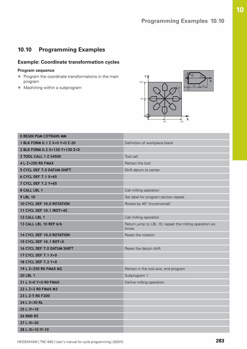
Programming Examples 10.10
10
HEIDENHAIN | TNC 640 | User’s manual for cycle programming | 9/2015 283
10.10 Programming Examples
Example: Coordinate transformation cycles
Program sequence
Program the coordinate transformations in the main
program
Machining within a subprogram
0 BEGIN PGM COTRANS MM
1 BLK FORM 0.1 Z X+0 Y+0 Z-20 Definition of workpiece blank
2 BLK FORM 0.2 X+130 Y+130 Z+0
3 TOOL CALL 1 Z S4500 Tool call
4 L Z+250 R0 FMAX Retract the tool
5 CYCL DEF 7.0 DATUM SHIFT Shift datum to center
6 CYCL DEF 7.1 X+65
7 CYCL DEF 7.2 Y+65
8 CALL LBL 1 Call milling operation
9 LBL 10 Set label for program section repeat
10 CYCL DEF 10.0 ROTATION Rotate by 45° (incremental)
11 CYCL DEF 10.1 IROT+45
12 CALL LBL 1 Call milling operation
13 CALL LBL 10 REP 6/6 Return jump to LBL 10; repeat the milling operation six
times
14 CYCL DEF 10.0 ROTATION Reset the rotation
15 CYCL DEF 10.1 ROT+0
16 CYCL DEF 7.0 DATUM SHIFT Reset the datum shift
17 CYCL DEF 7.1 X+0
18 CYCL DEF 7.2 Y+0
19 L Z+250 R0 FMAX M2 Retract in the tool axis, end program
20 LBL 1 Subprogram 1
21 L X+0 Y+0 R0 FMAX Define milling operation
22 L Z+2 R0 FMAX M3
23 L Z-5 R0 F200
24 L X+30 RL
25 L IY+10
26 RND R5
27 L IX+20
28 L IX+10 IY-10

Cycles: Coordinate Transformations 10.10 Programming Examples
10
284 HEIDENHAIN | TNC 640 | User’s manual for cycle programming | 9/2015
29 RND R5
30 L IX-10 IY-10
31 L IX-20
32 L IY+10
33 L X+0 Y+0 R0 F5000
34 L Z+20 R0 FMAX
35 LBL 0
36 END PGM COTRANS MM

11Cycles: Special
Functions
Cycles: Special Functions 11.1 Fundamentals
11
286 HEIDENHAIN | TNC 640 | User’s manual for cycle programming | 9/2015
11.1 Fundamentals
Overview
The TNC provides the following cycles for the following special
purposes:
Soft key Cycle Page
9 DWELL TIME 287
12 PROGRAM CALL 288
13 SPINDLE ORIENTATION 290
32 TOLERANCE 291
225 ENGRAVING of texts 309
291 COUPLING TURNING
INTERPOLATION
303
292 CONTOUR TURNING
INTERPOLATION
294
232 FACE MILLING 313
239 ASCERTAIN THE LOAD 318

DWELL TIME (Cycle 9) 11.2
11
HEIDENHAIN | TNC 640 | User’s manual for cycle programming | 9/2015 287
11.2 DWELL TIME (Cycle 9, DIN/ISO: G04)
Function
This causes the execution of the next block within a running program
to be delayed by the programmed DWELL TIME. A dwell time can be
used for such purposes as chip breaking.
The cycle becomes effective as soon as it is defined in the program.
Modal conditions such as spindle rotation are not affected.
NC blocks
89 CYCL DEF 9.0 DWELL TIME
90 CYCL DEF 9.1 DWELL 1.5
Cycle parameters
Dwell time in seconds: Enter the dwell time in
seconds. Input range: 0 to 3600 s (1 hour) in steps
of 0.001 seconds

Cycles: Special Functions 11.3 PROGRAM CALL (Cycle 12)
11
288 HEIDENHAIN | TNC 640 | User’s manual for cycle programming | 9/2015
11.3 PROGRAM CALL (Cycle 12, DIN/ISO:
G39)
Cycle function
Routines that you have programmed (such as special drilling cycles
or geometrical modules) can be written as main programs. These
can then be called like fixed cycles.
Please note while programming:
The program you are calling must be stored in the
internal memory of your TNC.
If the program you are defining to be a cycle is
located in the same directory as the program you
are calling it from, you need only enter the program
name.
If the program you are defining to be a cycle is not
located in the same directory as the program you are
calling it from, you must enter the complete path, for
example TNC:\KLAR35\FK1\50.H.
If you want to define a DIN/ISO program to be a
cycle, enter the file type .I behind the program name.
As a rule, Q parameters are globally effective when
called with Cycle 12. So please note that changes
to Q parameters in the called program can also
influence the calling program.

PROGRAM CALL (Cycle 12) 11.3
11
HEIDENHAIN | TNC 640 | User’s manual for cycle programming | 9/2015 289
Cycle parameters
Program name: Enter the name of the program
you want to call and, if necessary, the directory it is
located in or
Activate the file select dialog with the SELECT soft
key and select the program to be called
Call the program with:
CYCL CALL (separate block) or
M99 (blockwise) or
M89 (executed after every positioning block)
Designate program 50 as a cycle and
call it with M99
55 CYCL DEF 12.0 PGM CALL
56 CYCL DEF 12.1 PGM TNC:\KLAR35\FK1\50.H
57 L X+20 Y+50 FMAX M99

Cycles: Special Functions 11.4 SPINDLE ORIENTATION (Cycle 13)
11
290 HEIDENHAIN | TNC 640 | User’s manual for cycle programming | 9/2015
11.4 SPINDLE ORIENTATION (Cycle 13,
DIN/ISO: G36)
Cycle function
Machine and TNC must be specially prepared by the
machine tool builder for use of this cycle.
The TNC can control the machine tool spindle and rotate it to a given
angular position.
Oriented spindle stops are required for
Tool changing systems with a defined tool change position
Orientation of the transmitter/receiver window of HEIDENHAIN 3-
D touch probes with infrared transmission
The angle of orientation defined in the cycle is positioned to by
entering M19 or M20 (depending on the machine).
If you program M19 or M20 without having defined Cycle 13, the
TNC positions the machine tool spindle at an angle that has been set
by the machine tool builder.
More information: machine tool manual.
NC blocks
93 CYCL DEF 13.0 ORIENTATION
94 CYCL DEF 13.1 ANGLE 180
Please note while programming:
Cycle 13 is used internally for Cycles 202, 204 and
209. Please note that, if required, you must program
Cycle 13 again in your NC program after one of the
machining cycles mentioned above.
Cycle parameters
Angle of orientation: Enter the angle referenced
to the reference axis of the working plane. Input
range: 0.0000° to 360.0000°

TOLERANCE (Cycle 32, DIN/ISO: G62) 11.5
11
HEIDENHAIN | TNC 640 | User’s manual for cycle programming | 9/2015 291
11.5 TOLERANCE (Cycle 32, DIN/ISO: G62)
Cycle function
Machine and TNC must be specially prepared by the
machine tool builder for use of this cycle.
With the entries in Cycle 32 you can influence the result of
HSC machining with respect to accuracy, surface definition and
speed, inasmuch as the TNC has been adapted to the machine’s
characteristics.
The TNC automatically smoothens the contour between two path
elements (whether compensated or not). The tool has constant
contact with the workpiece surface and therefore reduces wear on
the machine tool. The tolerance defined in the cycle also affects the
traverse paths on circular arcs.
If necessary, the TNC automatically reduces the programmed feed
rate so that the program can be machined at the fastest possible
speed without short pauses for computing time. Even if the TNC
does not move with reduced speed, it will always comply with
the tolerance that you have defined. The larger you define the
tolerance, the faster the TNC can move the axes.
Smoothing the contour results in a certain amount of deviation
from the contour. The size of this contour error (tolerance value)
is set in a machine parameter by the machine manufacturer. With
CYCLE 32 you can change the pre-set tolerance value and select
different filter settings, provided that your machine tool builder has
implemented these features.
Influences of the geometry definition in the CAM
system
The most important factor of influence in offline NC program
creation is the chord error S defined in the CAM system.
The maximum point spacing of NC programs generated in a
postprocessor (PP) is defined through the chord error. If the chord
error is less than or equal to the tolerance value T defined in Cycle
32, then the TNC can smooth the contour points unless any special
machine settings limit the programmed feed rate.
You will achieve optimal smoothing if in Cycle 32 you choose a
tolerance value between 110-% and 200-% of the CAM chord error.
Cycles: Special Functions 11.5 TOLERANCE (Cycle 32, DIN/ISO: G62)
11
292 HEIDENHAIN | TNC 640 | User’s manual for cycle programming | 9/2015
Please note while programming:
With very small tolerance values the machine cannot
cut the contour without jerking. These jerking
movements are not caused by poor processing
power in the TNC, but by the fact that, in order to
machine the contour element transitions very exactly,
the TNC might have to drastically reduce the speed.
Cycle 32 is DEF active which means that it becomes
effective as soon as it is defined in the part program.
The TNC resets Cycle 32 if you
Redefine it and confirm the dialog question for
the tolerance value with NO ENT.
Select a new program with the PGM MGT key.
After you have reset Cycle 32, the TNC reactivates
the tolerance that was predefined by machine
parameter.
In a program with millimeters set as unit of measure,
the TNC interprets the entered tolerance value in
millimeters. In an inch program it interprets it as
inches.
If you transfer a program with Cycle 32 that contains
only the cycle parameter Tolerance value T, the TNC
inserts the two remaining parameters with the value
0 if required.
As the tolerance value increases, the diameter of
circular movements usually decreases, except if HSC
filters are active on your machine (settings made by
the machine tool builder).
If Cycle 32 is active, the TNC shows the parameters
defined for Cycle 32 on the CYC tab of the additional
status display.

TOLERANCE (Cycle 32, DIN/ISO: G62) 11.5
11
HEIDENHAIN | TNC 640 | User’s manual for cycle programming | 9/2015 293
Cycle parameters
Tolerance value T: Permissible contour deviation in
mm (or inches with inch programming). Input range
0 to 99999.9999
HSC MODE, Finishing=0, Roughing=1: Activate
filter:
Input value 0: Milling with increased contour
accuracy. The TNC uses internally defined
finishing filter settings
Input value 1: Milling at an increased feed rate.
The TNC uses internally defined roughing filter
settings
Tolerance for rotary axes TA: Permissible position
error of rotary axes in degrees when M128 is active
(FUNCTION TCPM). The TNC always reduces the
feed rate in such a way that—if more than one
axis is traversed—the slowest axis moves at its
maximum feed rate. Rotary axes are usually much
slower than linear axes. You can significantly reduce
the machining time for programs for more than
one axis by entering a large tolerance value (e.g.
10°), since the TNC does not always have to move
the rotary axis to the given nominal position. The
contour will not be damaged by entering a rotary
axis tolerance value. Only the position of the rotary
axis with respect to the workpiece surface will
change. Input range 0 to 179.9999
NC blocks
95 CYCL DEF 32.0 TOLERANCE
96 CYCL DEF 32.1 T0.05
97 CYCL DEF 32.2 HSC-MODE:1 TA5
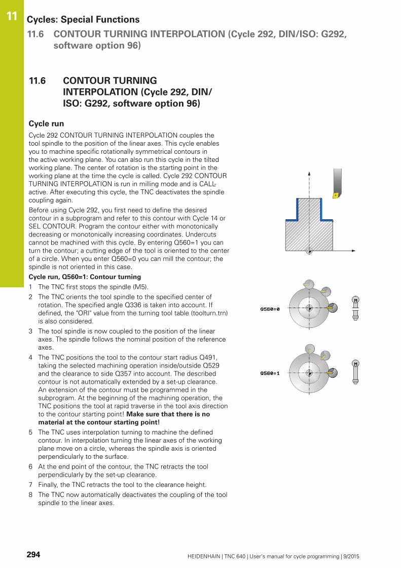
Cycles: Special Functions 11.6 CONTOUR TURNING INTERPOLATION (Cycle 292, DIN/ISO: G292,
software option 96)
11
294 HEIDENHAIN | TNC 640 | User’s manual for cycle programming | 9/2015
11.6 CONTOUR TURNING
INTERPOLATION (Cycle 292, DIN/
ISO: G292, software option 96)
Cycle run
Cycle 292 CONTOUR TURNING INTERPOLATION couples the
tool spindle to the position of the linear axes. This cycle enables
you to machine specific rotationally symmetrical contours in
the active working plane. You can also run this cycle in the tilted
working plane. The center of rotation is the starting point in the
working plane at the time the cycle is called. Cycle 292 CONTOUR
TURNING INTERPOLATION is run in milling mode and is CALL-
active. After executing this cycle, the TNC deactivates the spindle
coupling again.
Before using Cycle 292, you first need to define the desired
contour in a subprogram and refer to this contour with Cycle 14 or
SEL CONTOUR. Program the contour either with monotonically
decreasing or monotonically increasing coordinates. Undercuts
cannot be machined with this cycle. By entering Q560=1 you can
turn the contour; a cutting edge of the tool is oriented to the center
of a circle. When you enter Q560=0 you can mill the contour; the
spindle is not oriented in this case.
Cycle run, Q560=1: Contour turning
1 The TNC first stops the spindle (M5).
2 The TNC orients the tool spindle to the specified center of
rotation. The specified angle Q336 is taken into account. If
defined, the "ORI" value from the turning tool table (toolturn.trn)
is also considered.
3 The tool spindle is now coupled to the position of the linear
axes. The spindle follows the nominal position of the reference
axes.
4 The TNC positions the tool to the contour start radius Q491,
taking the selected machining operation inside/outside Q529
and the clearance to side Q357 into account. The described
contour is not automatically extended by a set-up clearance.
An extension of the contour must be programmed in the
subprogram. At the beginning of the machining operation, the
TNC positions the tool at rapid traverse in the tool axis direction
to the contour starting point! Make sure that there is no
material at the contour starting point!
5 The TNC uses interpolation turning to machine the defined
contour. In interpolation turning the linear axes of the working
plane move on a circle, whereas the spindle axis is oriented
perpendicularly to the surface.
6 At the end point of the contour, the TNC retracts the tool
perpendicularly by the set-up clearance.
7 Finally, the TNC retracts the tool to the clearance height.
8 The TNC now automatically deactivates the coupling of the tool
spindle to the linear axes.

CONTOUR TURNING INTERPOLATION (Cycle 292, DIN/ISO: G292,
software option 96)
11.6
11
HEIDENHAIN | TNC 640 | User’s manual for cycle programming | 9/2015 295
Cycle run, Q560=0: Contour milling
1 The M3/M4 function programmed before the cycle call remains
in effect.
2 No spindle stop and no spindle orientation are performed. Q336
is not taken into account.
3 The TNC positions the tool to the contour start radius Q491,
taking the selected machining operation inside/outside Q529
and the clearance to side Q357 into account. The described
contour is not automatically extended by a set-up clearance.
An extension of the contour must be programmed in the
subprogram. At the beginning of the machining operation, the
TNC positions the tool at rapid traverse in the tool axis direction
to the contour starting point! Make sure that there is no
material at the contour starting point!
4 The TNC machines the defined contour with the spindle rotating
(M3/M4). In the process, the reference axes of the working
plane move on a circle; the TNC does not orient the tool spindle.
5 At the end point of the contour, the TNC retracts the tool
perpendicularly by the set-up clearance.
6 Finally, the TNC retracts the tool to the clearance height.

Cycles: Special Functions 11.6 CONTOUR TURNING INTERPOLATION (Cycle 292, DIN/ISO: G292,
software option 96)
11
296 HEIDENHAIN | TNC 640 | User’s manual for cycle programming | 9/2015
Please note while programming:
A programming example is provided at the end of this chapter, see
page 322.
Program the contour either with monotonically
decreasing or monotonically increasing coordinates.
When programming, remember to use only positive
radius values.
Program the turning contour without tool radius
compensation (RR/RL) and without APPR or DEP
movements.
When programming, remember that neither the
spindle center nor the indexable insert must be
moved into the center of the turning contour.
Program outside contours with a radius greater than
0.
Program inside contours with a radius greater than
the tool radius.
Roughing operations with multiple passes are not
possible in this cycle.
Before cycle call, define a large tolerance with Cycle
32 for your machine to attain high contour speeds.
Program Cycle 32 with HSC filter=1.
For inside machining, the TNC checks whether the
active tool radius is smaller than half the contour
start diameter Q491 plus the clearance to side Q357.
If the check shows that the tool is too large, the
program is aborted.
If Cycle 8 MIRRORING is active, the TNC does not
execute the interpolation turning cycle.
If Cycle 26 SCALING FACTOR is active and the
scaling factor in an axis is not equal to 1, the TNC
does not execute the interpolation turning cycle.

CONTOUR TURNING INTERPOLATION (Cycle 292, DIN/ISO: G292,
software option 96)
11.6
11
HEIDENHAIN | TNC 640 | User’s manual for cycle programming | 9/2015 297
The described contour is not automatically extended
by a set-up clearance. An extension of the contour
must be programmed in the subprogram. At the
beginning of the machining operation, the TNC
positions the tool at rapid traverse in the tool axis
direction to the contour starting point! Make sure
that there is no material at the contour starting
point!
The center of the turning contour is the starting point
in the working plane at the time the cycle is called.
This cycle is effective only for machines with servo-
controlled spindle.
Software option 96 must be enabled.
If Q560=1 the TNC does not check whether
the spindle is rotating when the cycle is run.
(Independent of CfgGeoCycle – displaySpindleError)
Your TNC might monitor the tool to ensure that no
positioning movements at feed rate are performed
while spindle rotation is off. Contact the machine tool
builder for further information.

Cycles: Special Functions 11.6 CONTOUR TURNING INTERPOLATION (Cycle 292, DIN/ISO: G292,
software option 96)
11
298 HEIDENHAIN | TNC 640 | User’s manual for cycle programming | 9/2015
Cycle parameters
Spindle coupling (0, 1) Q560: Define whether the
spindle is to be coupled.
0: Spindle coupling off (contour milling)
1: Spindle coupling on (contour turning)
Angle of spindle Q336: The TNC orients the tool to
this angle before starting the machining operation. If
you work with a milling tool, enter the angle in such
a way that a tooth is turned towards the center of
rotation. If you work with a turning tool and defined
the value "ORI" in the turning tool (toolturn.trn), then
this value will also be accounted for when orienting
the spindle. Input range 0.000 to 360.000
Change tool direction (3, 4) Q546: Direction of
spindle rotation of the active tool:
3: Right-turning tool (M3)
4: Left-turning tool (M4)
Machining operation (+1, 0) Q529: Define whether
to perform inside or outside machining:
+1: Inside machining
0: Outside machining
Surface oversize Q221: Allowance in the working
plane. Input range 0 to 99.9999
Infeed Q441 (mm/rev): Amount that the tool
advances with each revolution. Input range 0.001 to
99.999
Feed rate Q449 (mm/min): Feed rate with respect
to the contour starting point Q491. Input range 0.1
to 99999.9. The feed rate of the tool's center point
path is adjusted according to the tool radius and the
machining operation Q529. From these parameters,
the TNC determines the programmed cutting speed
at the diameter of the contour starting point.
Q529=1: The feed rate of the tool center point path
is reduced for inside machining
Q529=0: The feed rate of the tool center point path
is increased for outside machining
Contour start radius Q491 (absolute value): Radius
of the contour starting point (e.g. X coordinate, with
tool axis Z). Input range 0.9999 to 99999.9999
Clearance to side Q357 (incremental): Clearance
between the side of the tool and the workpiece
when approaching for the first plunging depth Input
range 0 to 99999.9
Clearance height Q445 (absolute): Absolute height
at which the tool cannot collide with the workpiece.
The tool retracts to this position at the end of the
cycle. Input range -99999.9999 to 99999.9999
NC blocks
63 CYCL DEF 292 CONTOURTURNING INTERPOLATION
Q560=1 ;SPINDLE COUPLING
Q336=0 ;ANGLE OF SPINDLE
Q546=3 ;CHANGE TOOLDIRECTN.
Q529=0 ;MACHININGOPERATION
Q221=0 ;SURFACE OVERSIZE
Q441=0.5 ;INFEED
Q449=2000;FEED RATE
Q491=0 ;CONTOUR START DIA.
Q357=2 ;CLEARANCE TO SIDE
Q445=50 ;CLEARANCE HEIGHT

CONTOUR TURNING INTERPOLATION (Cycle 292, DIN/ISO: G292,
software option 96)
11.6
11
HEIDENHAIN | TNC 640 | User’s manual for cycle programming | 9/2015 299
Machining variants
Before using Cycle 292, you first need to define the desired turning
contour in a subprogram and refer to this contour with Cycle 14 or
SEL CONTOUR. Describe the turning contour on the cross section
of a rotationally symmetrical body. Depending on the tool axis, use
the following coordinates to define the turning contour:
Tool axis used Axial coordinate Radial coordinate
Z Z X
X X Y
Y Y Z
Example: If you are using the tool axis Z, program the turning
contour in the axial direction in Z and the radius of the contour in X.
You can use this cycle for inside and outside machining. The
following information illustrates some of the notes given in the
"Please note while programming" section. You can also find a
programming example in "Example: Interpolation Turning Cycle
292", page 322
Inside machining
The center of rotation is the position of the tool in the
working plane at the time the cycle is called 1
After the cycle is started, neither the indexable
insert nor the spindle center must be moved into
the center of rotation! Keep this in mind when
describing the contour! 2
The described contour is not automatically extended
by a set-up clearance. An extension of the contour
must be programmed in the subprogram. At the
beginning of the machining operation, the TNC
positions the tool at rapid traverse in the tool axis
direction to the contour starting point! Make sure
that there is no material at the contour starting
point!
When programming an inside contour, please also
remember:
– Program either monotonically increasing radial and
axial coordinates, e.g. 1-5
– Or program monotonically decreasing radial and
axial coordinates, e.g. 5-1
– Program inside contours with a radius greater than
the tool radius.
1
3
4 5
2
Z
X
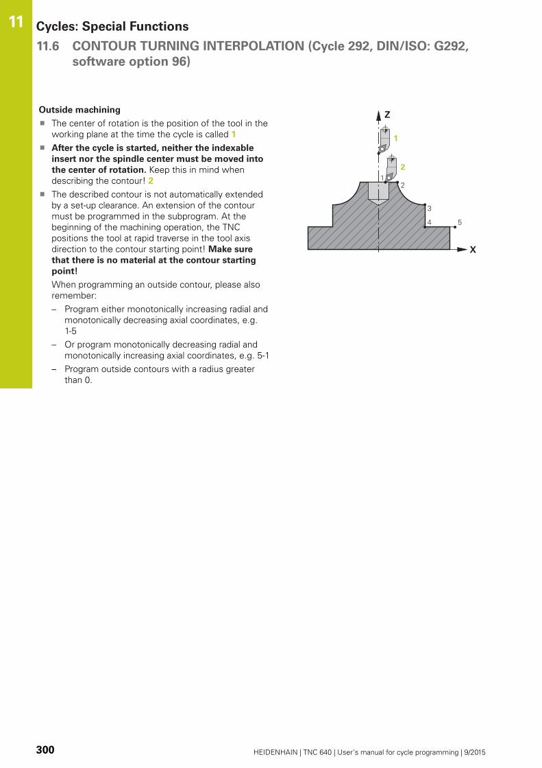
Cycles: Special Functions 11.6 CONTOUR TURNING INTERPOLATION (Cycle 292, DIN/ISO: G292,
software option 96)
11
300 HEIDENHAIN | TNC 640 | User’s manual for cycle programming | 9/2015
Outside machining
The center of rotation is the position of the tool in the
working plane at the time the cycle is called 1
After the cycle is started, neither the indexable
insert nor the spindle center must be moved into
the center of rotation. Keep this in mind when
describing the contour! 2
The described contour is not automatically extended
by a set-up clearance. An extension of the contour
must be programmed in the subprogram. At the
beginning of the machining operation, the TNC
positions the tool at rapid traverse in the tool axis
direction to the contour starting point! Make sure
that there is no material at the contour starting
point!
When programming an outside contour, please also
remember:
– Program either monotonically increasing radial and
monotonically decreasing axial coordinates, e.g.
1-5
– Or program monotonically decreasing radial and
monotonically increasing axial coordinates, e.g. 5-1
– Program outside contours with a radius greater
than 0.
Z
X
12
3
4 5

CONTOUR TURNING INTERPOLATION (Cycle 292, DIN/ISO: G292,
software option 96)
11.6
11
HEIDENHAIN | TNC 640 | User’s manual for cycle programming | 9/2015 301
Defining the tool
Overview
Depending on the setting of the parameter Q560, you can mill
(Q560=0) or turn (Q560=1) the contour. For each of the two
machining modes, there are different possibilities to define the tool
in the tool table. This section describes the different possibilities:
Spindle coupling off, Q560=0
Milling: Define the milling cutter in the tool table as usual by
entering the length, radius, toroid cutter radius, etc.
Spindle coupling on, Q560=1
Turning: The geometry data of the turning tool are converted to
the data of a milling cutter. You now have the following three
possibilities:
Define a turning tool in the tool table (tool.t) as a milling tool
Define a milling tool in the tool table (tool.t) as a milling tool (for
subsequent use as a turning tool)
Define a turning tool in the turning tool table (toolturn.trn)
These three possibilities of defining the tool are described in more
detail below:
Define a turning tool in the tool table (tool.t) as a milling
tool
If you are working without option 50, define the turning tool
in the tool table (tool.t) as a milling cutter. In this case, the
following data from the tool table are taken into account
(including delta values): Length (L), radius (R) and toroid cutter
radius (R2). Orient the turning tool to the spindle center and
enter this spindle orientation angle in the parameter Q336 of
the cycle. For outside machining, the spindle orientation Q336 is
used; for inside machining, the spindle orientation is calculated
from Q336+180.
The tool holder is not monitored! If the rotation
diameter resulting from the tool holder is greater
than that from the cutting edge, the machine
operator must take this into account for inside
machining.
Define a milling tool in the tool table (tool.t) as a milling
tool (for subsequent use as a turning tool)
You can use a milling cutter for interpolation turning. In this
case, the following data from the tool table are taken into
account (including delta values): Length (L), radius (R) and toroid
cutter radius (R2). Orient a cutting edge of the milling cutter to
the spindle center and enter this angle in the parameter Q336.
For outside machining, the spindle orientation Q336 is used;
for inside machining, the spindle orientation is calculated from
Q336+180.
Define a turning tool in the turning tool table (toolturn.trn)
If you are working with option 50, you can define the turning
tool in the turning tool table (toolturn.trn). In this case, the
spindle is oriented to the center of rotation by taking tool-
specific data into account, such as the machining operation
(TO in the turning tool table), the orientation angle (ORI in the
turning tool table) and the parameter Q336.

Cycles: Special Functions 11.6 CONTOUR TURNING INTERPOLATION (Cycle 292, DIN/ISO: G292,
software option 96)
11
302 HEIDENHAIN | TNC 640 | User’s manual for cycle programming | 9/2015
The spindle orientation is calculated as follows:
Machining TO Spindle orientation
Interpolation turning, outside 1 ORI + Q336
Interpolation turning, inside 7 ORI + Q336 + 180
Interpolation turning, outside 7 ORI + Q336 + 180
Interpolation turning, inside 1 ORI + Q336
Interpolation turning, outside 8,9 ORI + Q336
Interpolation turning, inside 8,9 ORI + Q336
You can use the following tool types for interpolation
turning:
TYPE: ROUGH, with the machining directions TO: 1 or 7
TYPE: FINISH, with the machining directions TO: 1 or 7
TYPE: BUTTON, with the machining directions TO: 1 or 7
For inside machining, the TNC checks whether
the active tool radius is smaller than half the
contour start diameter Q491 plus the clearance to
side Q357. If the check shows that the tool is too
large, the program is aborted.
The following tool types cannot be used for
interpolation turning: (error message "Function
not possible with this tool type" is displayed)
TYPE: ROUGH, with the machining directions
TO: 2 to 6
TYPE: FINISH, with the machining directions
TO: 2 to 6
TYPE: BUTTON, with the machining directions
TO: 2 to 6
TYPE: RECESS
TYPE: RECTURN
TYPE: THREAD
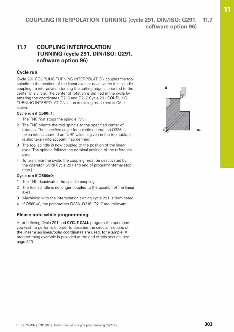
COUPLING INTERPOLATION TURNING (cycle 291, DIN/ISO: G291,
software option 96)
11.7
11
HEIDENHAIN | TNC 640 | User’s manual for cycle programming | 9/2015 303
11.7 COUPLING INTERPOLATION
TURNING (cycle 291, DIN/ISO: G291,
software option 96)
Cycle run
Cycle 291 COUPLING TURNING INTERPOLATION couples the tool
spindle to the position of the linear axes or deactivates this spindle
coupling. In interpolation turning the cutting edge is oriented to the
center of a circle. The center of rotation is defined in the cycle by
entering the coordinates Q216 and Q217. Cycle 291 COUPLING
TURNING INTERPOLATION is run in milling mode and is CALL-
active.
Cycle run if Q560=1:
1 The TNC first stops the spindle (M5).
2 The TNC orients the tool spindle to the specified center of
rotation. The specified angle for spindle orientation Q336 is
taken into account. If an "ORI" value is given in the tool table, it
is also taken into account if so defined.
3 The tool spindle is now coupled to the position of the linear
axes. The spindle follows the nominal position of the reference
axes.
4 To terminate the cycle, the coupling must be deactivated by
the operator. (With Cycle 291 and end of program/internal stop
resp.)
Cycle run if Q560=0:
1 The TNC deactivates the spindle coupling.
2 The tool spindle is no longer coupled to the position of the linear
axes.
3 Machining with the interpolation turning cycle 291 is terminated.
4 If Q560=0, the parameters Q336, Q216, Q217 are irrelevant.
Please note while programming:
After defining Cycle 291 and CYCLE CALL program the operation
you wish to perform. In order to describe the circular motions of
the linear axes linear/polar coordinates are used, for example. A
programming example is provided at the end of this section, see
page 320.
Cycles: Special Functions 11.7 COUPLING INTERPOLATION TURNING (cycle 291, DIN/ISO: G291,
software option 96)
11
304 HEIDENHAIN | TNC 640 | User’s manual for cycle programming | 9/2015
Cycle 291 is CALL-active.
Programming of M3/M4 is not required. In order to
describe the circular motions of the linear axes, you
can use CC and C coordinates, for example.
If you specify the turning tool in the turning tool
table (toolturn.trn), we recommend to work with
parameter Q561=1. This way, you convert the data
of the turning tool into the data of the milling tool,
thus greatly facilitating your programming effort.
For programming Q561=1 you can work with a
radius compensation RR or RL. (However, if you
are programming parameter Q561=0, you will have
to do without a radius compensation RR or RL for
the description of your contour. In addition, while
programming you have to make sure that the motion
of the center of the tool TCP is programmed without
spindle coupling. This kind of programming is much
more complex!)
If you programmed parameter Q561=1, you must
program the following in order to complete the
operation of interpolation turning:
R0, overrides radius compensation
Cycle 291 with parameters Q560=0 and Q561=0,
overrides spindle coupling
CYCLE CALL, for calling up Cycle 291
TOOL CALL overrides the conversion of
parameter Q561
When programming, remember that neither the
spindle center nor the indexable insert must be
moved into the center of the turning contour.
Program outside contours with a radius greater than
0.
Program inside contours with a radius greater than
the tool radius.
This cycle can also be used in a tilted working plane.
Before cycle call, define a large tolerance with Cycle
32 for your machine to attain high contour speeds.
Program Cycle 32 with HSC filter=1.
If Cycle 8 MIRRORING is active, the TNC does not
execute the interpolation turning cycle.
If Cycle 26 SCALING FACTOR is active and the
scaling factor in an axis is not equal to 1, the TNC
does not execute the interpolation turning cycle.
This cycle is effective only for machines with servo-
controlled spindle.
Your TNC might monitor the tool to ensure that no
positioning movements at feed rate are performed
while spindle rotation is off. Contact the machine tool
builder for further information.
Software option 96 must be enabled.
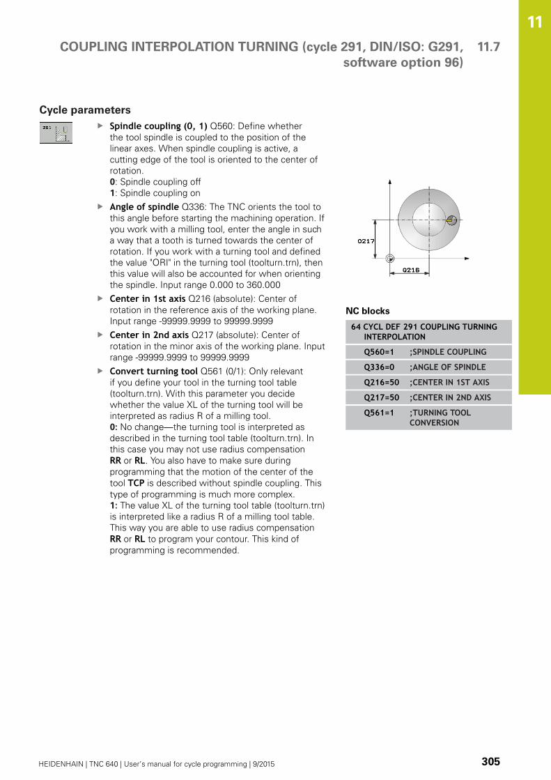
COUPLING INTERPOLATION TURNING (cycle 291, DIN/ISO: G291,
software option 96)
11.7
11
HEIDENHAIN | TNC 640 | User’s manual for cycle programming | 9/2015 305
Cycle parameters
Spindle coupling (0, 1) Q560: Define whether
the tool spindle is coupled to the position of the
linear axes. When spindle coupling is active, a
cutting edge of the tool is oriented to the center of
rotation.
0: Spindle coupling off
1: Spindle coupling on
Angle of spindle Q336: The TNC orients the tool to
this angle before starting the machining operation. If
you work with a milling tool, enter the angle in such
a way that a tooth is turned towards the center of
rotation. If you work with a turning tool and defined
the value "ORI" in the turning tool (toolturn.trn), then
this value will also be accounted for when orienting
the spindle. Input range 0.000 to 360.000
Center in 1st axis Q216 (absolute): Center of
rotation in the reference axis of the working plane.
Input range -99999.9999 to 99999.9999
Center in 2nd axis Q217 (absolute): Center of
rotation in the minor axis of the working plane. Input
range -99999.9999 to 99999.9999
Convert turning tool Q561 (0/1): Only relevant
if you define your tool in the turning tool table
(toolturn.trn). With this parameter you decide
whether the value XL of the turning tool will be
interpreted as radius R of a milling tool.
0: No change—the turning tool is interpreted as
described in the turning tool table (toolturn.trn). In
this case you may not use radius compensation
RR or RL. You also have to make sure during
programming that the motion of the center of the
tool TCP is described without spindle coupling. This
type of programming is much more complex.
1: The value XL of the turning tool table (toolturn.trn)
is interpreted like a radius R of a milling tool table.
This way you are able to use radius compensation
RR or RL to program your contour. This kind of
programming is recommended.
NC blocks
64 CYCL DEF 291 COUPLING TURNINGINTERPOLATION
Q560=1 ;SPINDLE COUPLING
Q336=0 ;ANGLE OF SPINDLE
Q216=50 ;CENTER IN 1ST AXIS
Q217=50 ;CENTER IN 2ND AXIS
Q561=1 ;TURNING TOOLCONVERSION

Cycles: Special Functions 11.7 COUPLING INTERPOLATION TURNING (cycle 291, DIN/ISO: G291,
software option 96)
11
306 HEIDENHAIN | TNC 640 | User’s manual for cycle programming | 9/2015
Defining the tool
Overview
Depending on the setting of the parameter Q560, you can activate
(Q560=1) or deactivate (Q560=0) the COUPLING TURNING
INTERPOLATION cycle.
Spindle coupling off, Q560=0
The tool spindle is not coupled to the position of the linear axes.
Q560=0: Deactivate the COUPLING TURNINGINTERPOLATION cycle!
Spindle coupling on, Q560=1
A turning operation is executed with the tool spindle coupled to
the position of the linear axes. If you set the parameter Q560 to 1,
there are different possibilities to define the tool in the tool table.
This section describes the different possibilities:
Define a turning tool in the tool table (tool.t) as a milling tool
Define a milling tool in the tool table (tool.t) as a milling tool (for
subsequent use as a turning tool)
Define a turning tool in the turning tool table (toolturn.trn)
These three possibilities of defining the tool are described in more
detail below:
Define a turning tool in the tool table (tool.t) as a milling
tool
If you are working without option 50, define the turning tool
in the tool table (tool.t) as a milling cutter. In this case, the
following data from the tool table are taken into account
(including delta values): Length (L), radius (R) and toroid cutter
radius (R2). The geometry data of the turning tool are converted
to the data of a milling cutter. Orient the turning tool to the
spindle center and enter this spindle orientation angle in the
parameter Q336 of the cycle. For outside machining, the spindle
orientation Q336 is used; for inside machining, the spindle
orientation is calculated from Q336+180.
The tool holder is not monitored! If the rotation
diameter resulting from the tool holder is greater
than that from the cutting edge, the machine
operator must take this into account for inside
machining.
Define a milling tool in the tool table (tool.t) as a milling
tool (for subsequent use as a turning tool)
You can use a milling cutter for interpolation turning. In this
case, the following data from the tool table are taken into
account (including delta values): Length (L), radius (R) and toroid
cutter radius (R2). Orient a cutting edge of the milling cutter to
the spindle center and enter this angle in the parameter Q336.
For outside machining, the spindle orientation Q336 is used;
for inside machining, the spindle orientation is calculated from
Q336+180.

COUPLING INTERPOLATION TURNING (cycle 291, DIN/ISO: G291,
software option 96)
11.7
11
HEIDENHAIN | TNC 640 | User’s manual for cycle programming | 9/2015 307
Define a turning tool in the turning tool table (toolturn.trn)
If you are working with option 50, you can define the turning
tool in the turning tool table (toolturn.trn). In this case, the
spindle is oriented to the center of rotation by taking tool-
specific data into account, such as the machining operation
(TO in the turning tool table), the orientation angle (ORI in the
turning tool table), and the parameters Q336 and Q561.
If you specify the turning tool in the turning tool
table (toolturn.trn), we recommend to work with
parameter Q561=1. This way, you convert the
data of the turning tool into the data of the milling
tool, thus greatly facilitating your programming
effort. For programming Q561=1 you can work
with a radius compensation RR or RL. (However,
if you are programming parameter Q561=0, you
will have to do without a radius compensation
RR or RL for the description of your contour. In
addition, while programming you have to make
sure that the motion of the center of the tool TCPis programmed without spindle coupling. This
kind of programming is much more complex!)
If you programmed parameter Q561=1, you must
program the following in order to complete the
operation of interpolation turning:
R0, overrides radius compensation
Cycle 291 with parameters Q560=0 and
Q561=0, overrides spindle coupling
CYCLE CALL, for calling up Cycle 291
TOOL CALL overrides the conversion of
parameter Q561
If you programmed parameter Q561=1, you may
only use the following types of tools:
TYPE: ROUGH, FINISH, BUTTON with the
machining directions TO: 1 or 8, XL>=0
TYPE: ROUGH, FINISH, BUTTON with the
machining directions TO: 7, XL<=0
The spindle orientation is calculated as follows:
Machining TO Spindle orientation
Interpolation turning, outside 1 ORI + Q336
Interpolation turning, inside 7 ORI + Q336 + 180
Interpolation turning, outside 7 ORI + Q336 + 180
Interpolation turning, inside 1 ORI + Q336
Interpolation turning, outside 8 ORI + Q336
Interpolation turning, inside 8 ORI + Q336

Cycles: Special Functions 11.7 COUPLING INTERPOLATION TURNING (cycle 291, DIN/ISO: G291,
software option 96)
11
308 HEIDENHAIN | TNC 640 | User’s manual for cycle programming | 9/2015
You can use the following tool types for interpolation
turning:
TYPE: ROUGH, with the machining directions TO: 1, 7, 8
TYPE: FINISH, with the machining directions TO: 1, 7, 8
TYPE: BUTTON, with the machining directions TO: 1, 7, 8
The following tool types cannot be used for
interpolation turning: (error message "Function
not possible with this tool type" is displayed)
TYPE: ROUGH, with the machining directions
TO: 2 to 6
TYPE: FINISH, with the machining directions
TO: 2 to 6
TYPE: BUTTON, with the machining directions
TO: 2 to 6
TYPE: RECESS
TYPE: RECTURN
TYPE: THREAD
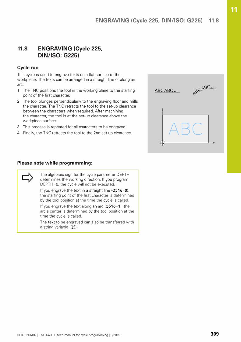
ENGRAVING (Cycle 225, DIN/ISO: G225) 11.8
11
HEIDENHAIN | TNC 640 | User’s manual for cycle programming | 9/2015 309
11.8 ENGRAVING (Cycle 225,
DIN/ISO: G225)
Cycle run
This cycle is used to engrave texts on a flat surface of the
workpiece. The texts can be arranged in a straight line or along an
arc.
1 The TNC positions the tool in the working plane to the starting
point of the first character.
2 The tool plunges perpendicularly to the engraving floor and mills
the character. The TNC retracts the tool to the set-up clearance
between the characters when required. After machining
the character, the tool is at the set-up clearance above the
workpiece surface.
3 This process is repeated for all characters to be engraved.
4 Finally, the TNC retracts the tool to the 2nd set-up clearance.
Please note while programming:
The algebraic sign for the cycle parameter DEPTH
determines the working direction. If you program
DEPTH=0, the cycle will not be executed.
If you engrave the text in a straight line (Q516=0),
the starting point of the first character is determined
by the tool position at the time the cycle is called.
If you engrave the text along an arc (Q516=1), the
arc's center is determined by the tool position at the
time the cycle is called.
The text to be engraved can also be transferred with
a string variable (QS).

Cycles: Special Functions 11.8 ENGRAVING (Cycle 225, DIN/ISO: G225)
11
310 HEIDENHAIN | TNC 640 | User’s manual for cycle programming | 9/2015
Cycle parameters
Engraving text QS500: Text to be engraved inside
quotation marks. Assignment of a string variable
through the Q key of the numerical keypad. The Q
key on the ASCI keyboard represents normal text
input. Allowed entry characters: see "Engraving
system variables", page 312
Character height Q513 (absolute): Height of the
characters to be engraved in mm. Input range 0 to
99999.9999
Space factor Q514: The font used is a proportional
font. Each character has its own width, which
is engraved correspondingly by the TNC if you
program Q514 = 0. If Q514 is not equal to 0, the
TNC scales the space between the characters. Input
range 0 to 9.9999
Font Q515: Currently without function
Text in a straight line/on arc (0/1) Q516:
Engrave text in a straight line: Input = 0
Engrave text on an arc: Input = 1
Angle of rotation Q374: Center angle if the text is
to be arranged on an arc. Engraving angle if the text
is arranged in a straight line. Input range -360.0000
to +360.0000°
Radius of text on an arc Q517 (absolute): Radius
of the arc in mm on which the TNC is to arrange the
text. Input range 0 to 99999.9999
Feed rate for milling Q207: Traversing speed of
the tool in mm/min while milling. Input range 0 to
99999.999 alternatively FAUTO, FU, FZDepth Q201 (incremental value): Distance between
workpiece surface and engraving floor
Feed rate for plunging Q206: Traversing speed
of the tool when moving into the workpiece in
mm/min. Input range 0 to 99999.999 alternatively
FAUTO, FUSet-up clearance Q200 (incremental): Distance
between tool tip and workpiece surface. Input range
0 to 99999.9999; alternatively PREDEFCoordinate of workpiece surface Q203 (absolute):
Coordinate of the workpiece surface. Input range
-99999.9999 to 99999.9999
2nd set-up clearance Q204 (incremental):
Coordinate in the spindle axis at which no collision
between tool and workpiece (fixtures) can occur.
Input range 0 to 99999.9999; alternatively PREDEF
NC blocks
62 CYCL DEF 225 ENGRAVING
QS500="A" ;ENGRAVING TEXT
Q513=10 ;CHARACTER HEIGHT
Q514=0 ;SPACE FACTOR
Q515=0 ;FONT
Q516=0 ;TEXT LAYOUT
Q374=0 ;ANGLE OF ROTATION
Q517=0 ;CIRCLE RADIUS
Q207=750 ;FEED RATE FORMILLING
Q201=-0.5 ;DEPTH
Q206=150 ;FEED RATE FORPLNGNG
Q200=2 ;SET-UP CLEARANCE
Q203=+20 ;SURFACE COORDINATE
Q204=50 ;2ND SET-UPCLEARANCE

ENGRAVING (Cycle 225, DIN/ISO: G225) 11.8
11
HEIDENHAIN | TNC 640 | User’s manual for cycle programming | 9/2015 311
Allowed engraving characters
The following special characters are allowed in addition to
lowercase letters, uppercase letters and numbers:
! # $ % & ‘ ( ) * + , - . / : ; < = > ? @ [ \ ] _ ß CE
The TNC uses the special characters % and \for special functions. These characters must be
indicated twice in the text to be engraved (e.g. %%) if
you want to engrave them.
When engraving German umlauts, ß, ø, @ or the CE character,
enter the character % before the character to be engraved:
Algebraic sign Input
ä %ae
ö %oe
ü %ue
Ä %AE
Ö %OE
Ü %UE
ß %ss
ø %D
@ %at
CE %CE
Characters that cannot be printed
Apart from text, you can also define certain non-printable
characters for formatting purposes. Enter the special character \before the non-printable characters.
The following formatting possibilities are available:
Character Input
Line break \n
Horizontal tab
(the tab width is permanently set to 8
characters)
\t
Vertical tab
(the tab width is permanently set to one
line)
\v

Cycles: Special Functions 11.8 ENGRAVING (Cycle 225, DIN/ISO: G225)
11
312 HEIDENHAIN | TNC 640 | User’s manual for cycle programming | 9/2015
Engraving system variables
In addition to the standard characters, you can engrave the
contents of certain system variables. Enter % before the system
variable.
You can also engrave the current date or time. Enter %time<x>.
<x> defines the format, e.g. 08 for DD.MM.YYYY. (Identical to the
function SYSSTR ID332, see the User's Manual for Conversational
Programming, "Q parameter programming" chapter, "Copying
system data to a string" section)
Keep in mind that you must enter a leading 0 when
entering the date formats 1 to 9, e.g. time08.
Character Input
DD.MM.YYYY hh:mm:ss %time00
D.MM.YYYY h:mm:ss %time01
D.MM.YYYY h:mm %time02
D.MM.YY h:mm %time03
YYYY-MM-DD hh:mm:ss %time04
YYYY-MM-DD hh:mm %time05
YYYY-MM-DD h:mm %time06
YY-MM-DD h:mm %time07
DD.MM.YYYY %time08
D.MM.YYYY %time09
D.MM.YY %time10
YYYY-MM-DD %time11
YY-MM-DD %time12
hh:mm:ss %time13
h:mm:ss %time14
h:mm %time15
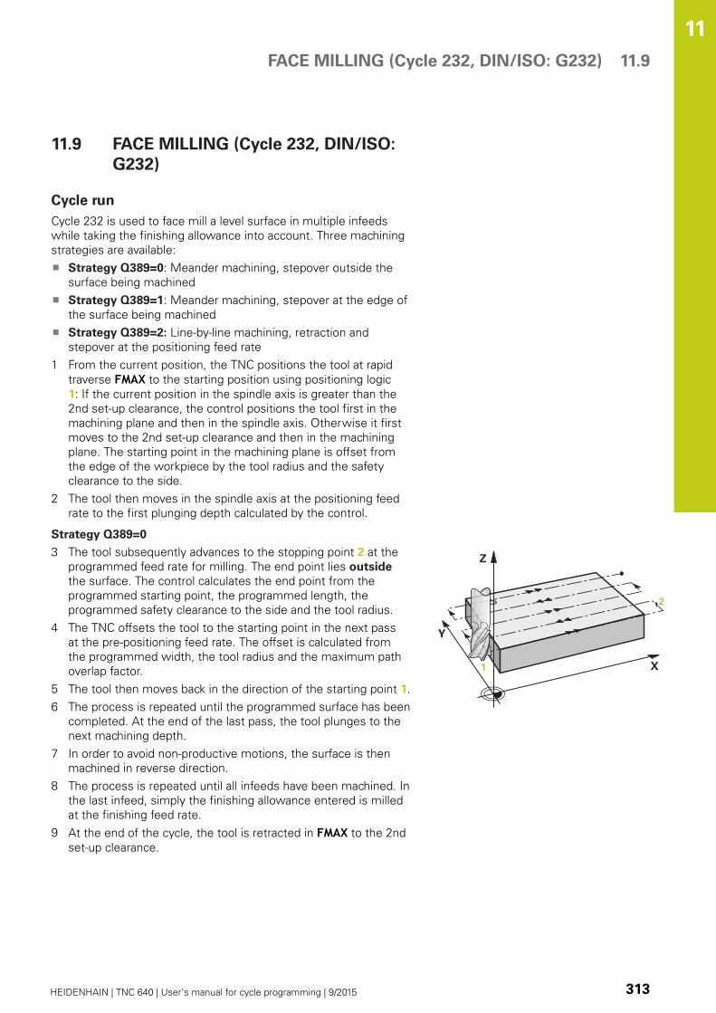
FACE MILLING (Cycle 232, DIN/ISO: G232) 11.9
11
HEIDENHAIN | TNC 640 | User’s manual for cycle programming | 9/2015 313
11.9 FACE MILLING (Cycle 232, DIN/ISO:
G232)
Cycle run
Cycle 232 is used to face mill a level surface in multiple infeeds
while taking the finishing allowance into account. Three machining
strategies are available:
Strategy Q389=0: Meander machining, stepover outside the
surface being machined
Strategy Q389=1: Meander machining, stepover at the edge of
the surface being machined
Strategy Q389=2: Line-by-line machining, retraction and
stepover at the positioning feed rate
1 From the current position, the TNC positions the tool at rapid
traverse FMAX to the starting position using positioning logic
1: If the current position in the spindle axis is greater than the
2nd set-up clearance, the control positions the tool first in the
machining plane and then in the spindle axis. Otherwise it first
moves to the 2nd set-up clearance and then in the machining
plane. The starting point in the machining plane is offset from
the edge of the workpiece by the tool radius and the safety
clearance to the side.
2 The tool then moves in the spindle axis at the positioning feed
rate to the first plunging depth calculated by the control.
Strategy Q389=0
3 The tool subsequently advances to the stopping point 2 at the
programmed feed rate for milling. The end point lies outside
the surface. The control calculates the end point from the
programmed starting point, the programmed length, the
programmed safety clearance to the side and the tool radius.
4 The TNC offsets the tool to the starting point in the next pass
at the pre-positioning feed rate. The offset is calculated from
the programmed width, the tool radius and the maximum path
overlap factor.
5 The tool then moves back in the direction of the starting point 1.
6 The process is repeated until the programmed surface has been
completed. At the end of the last pass, the tool plunges to the
next machining depth.
7 In order to avoid non-productive motions, the surface is then
machined in reverse direction.
8 The process is repeated until all infeeds have been machined. In
the last infeed, simply the finishing allowance entered is milled
at the finishing feed rate.
9 At the end of the cycle, the tool is retracted in FMAX to the 2nd
set-up clearance.

Cycles: Special Functions 11.9 FACE MILLING (Cycle 232, DIN/ISO: G232)
11
314 HEIDENHAIN | TNC 640 | User’s manual for cycle programming | 9/2015
Strategy Q389=1
3 The tool subsequently advances to the end point 2 at the
programmed feed rate for milling. The end point lies at the
edge of the surface. The TNC calculates the end point from the
programmed starting point, the programmed length and the tool
radius.
4 The TNC offsets the tool to the starting point in the next pass
at the pre-positioning feed rate. The offset is calculated from
the programmed width, the tool radius and the maximum path
overlap factor.
5 The tool then moves back in the direction of the starting point
1. The motion to the next line again occurs at the edge of the
workpiece.
6 The process is repeated until the programmed surface has been
completed. At the end of the last pass, the tool plunges to the
next machining depth.
7 In order to avoid non-productive motions, the surface is then
machined in reverse direction.
8 The process is repeated until all infeeds have been machined. In
the last infeed, simply the finishing allowance entered is milled
at the finishing feed rate.
9 At the end of the cycle, the tool is retracted in FMAX to the 2nd
set-up clearance.
Strategy Q389=2
3 The tool subsequently advances to the stopping point 2 at the
programmed feed rate for milling. The end point lies outside
the surface. The control calculates the end point from the
programmed starting point, the programmed length, the
programmed safety clearance to the side and the tool radius.
4 The TNC positions the tool in the spindle axis to the set-up
clearance over the current infeed depth, and then moves at the
pre-positioning feed rate directly back to the starting point in the
next line. The TNC calculates the offset from the programmed
width, the tool radius and the maximum path overlap factor.
5 The tool then returns to the current infeed depth and moves in
the direction of the next end point 2.
6 The multipass process is repeated until the programmed
surface has been completed. At the end of the last pass, the
tool plunges to the next machining depth.
7 In order to avoid non-productive motions, the surface is then
machined in reverse direction.
8 The process is repeated until all infeeds have been machined. In
the last infeed, simply the finishing allowance entered is milled
at the finishing feed rate.
9 At the end of the cycle, the tool is retracted in FMAX to the 2nd
set-up clearance.
FACE MILLING (Cycle 232, DIN/ISO: G232) 11.9
11
HEIDENHAIN | TNC 640 | User’s manual for cycle programming | 9/2015 315
Please note while programming:
Enter the 2nd set-up clearance in Q204 so that no
collision with the workpiece or the fixtures can occur.
If the starting point in the 3rd axis Q227 and the
end point in the 3rd axis Q386 are entered as equal
values, the TNC does not run the cycle (depth = 0
has been programmed).
Program Q227 greater than Q386. Otherwise, the
TNC will display an error message.
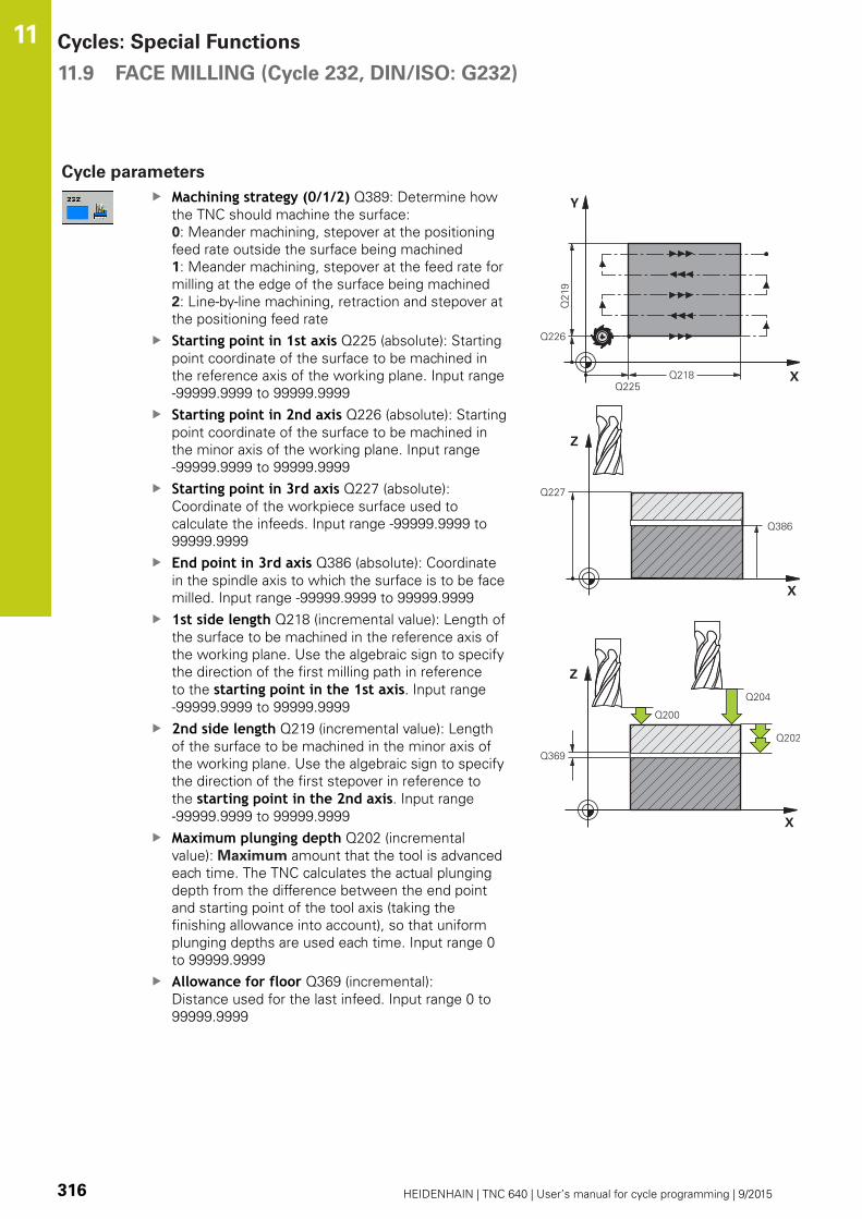
Cycles: Special Functions 11.9 FACE MILLING (Cycle 232, DIN/ISO: G232)
11
316 HEIDENHAIN | TNC 640 | User’s manual for cycle programming | 9/2015
Cycle parameters
Machining strategy (0/1/2) Q389: Determine how
the TNC should machine the surface:
0: Meander machining, stepover at the positioning
feed rate outside the surface being machined
1: Meander machining, stepover at the feed rate for
milling at the edge of the surface being machined
2: Line-by-line machining, retraction and stepover at
the positioning feed rate
Starting point in 1st axis Q225 (absolute): Starting
point coordinate of the surface to be machined in
the reference axis of the working plane. Input range
-99999.9999 to 99999.9999
Starting point in 2nd axis Q226 (absolute): Starting
point coordinate of the surface to be machined in
the minor axis of the working plane. Input range
-99999.9999 to 99999.9999
Starting point in 3rd axis Q227 (absolute):
Coordinate of the workpiece surface used to
calculate the infeeds. Input range -99999.9999 to
99999.9999
End point in 3rd axis Q386 (absolute): Coordinate
in the spindle axis to which the surface is to be face
milled. Input range -99999.9999 to 99999.9999
1st side length Q218 (incremental value): Length of
the surface to be machined in the reference axis of
the working plane. Use the algebraic sign to specify
the direction of the first milling path in reference
to the starting point in the 1st axis. Input range
-99999.9999 to 99999.9999
2nd side length Q219 (incremental value): Length
of the surface to be machined in the minor axis of
the working plane. Use the algebraic sign to specify
the direction of the first stepover in reference to
the starting point in the 2nd axis. Input range
-99999.9999 to 99999.9999
Maximum plunging depth Q202 (incremental
value): Maximum amount that the tool is advanced
each time. The TNC calculates the actual plunging
depth from the difference between the end point
and starting point of the tool axis (taking the
finishing allowance into account), so that uniform
plunging depths are used each time. Input range 0
to 99999.9999
Allowance for floor Q369 (incremental):
Distance used for the last infeed. Input range 0 to
99999.9999

FACE MILLING (Cycle 232, DIN/ISO: G232) 11.9
11
HEIDENHAIN | TNC 640 | User’s manual for cycle programming | 9/2015 317
Max. path overlap factor Q370: Maximum
stepover factor k. The TNC calculates the actual
stepover from the second side length (Q219) and
the tool radius so that a constant stepover is used
for machining. If you have entered a radius R2
in the tool table (e.g. tooth radius when using a
face-milling cutter), the TNC reduces the stepover
accordingly. Input range 0.1 to 1.9999
Feed rate for milling Q207: Traversing speed of
the tool in mm/min while milling. Input range 0 to
99999.999 alternatively FAUTO, FU, FZFeed rate for finishing Q385: Traversing speed of
the tool in mm/min, while milling the last infeed.
Input range 0 to 99999.9999; alternatively FAUTO,
FU, FZFeed rate for pre-positioning Q253: Traversing
speed of the tool in mm/min when approaching
the starting position and when moving to the next
pass. If you are moving the tool transversely to
the material (Q389=1), the TNC moves the tool
at the feed rate for milling Q207. Input range 0 to
99999.9999, alternatively FMAX, FAUTOSet-up clearance Q200 (incremental): Distance
between tool tip and the starting position in the
tool axis. If you are milling with machining strategy
Q389=2, the TNC moves the tool at the set-up
clearance over the current plunging depth to the
starting point of the next pass. Input range 0 to
99999.9999
Clearance to side Q357 (incremental): Safety
clearance to the side of the workpiece when
the tool approaches the first plunging depth,
and distance at which the stepover occurs if the
machining strategy Q389=0 or Q389=2 is used.
Input range 0 to 99999.9999
2nd set-up clearance Q204 (incremental):
Coordinate in the spindle axis at which no collision
between tool and workpiece (fixtures) can occur.
Input range 0 to 99999.9999; alternatively PREDEF
NC blocks
71 CYCL DEF 232 FACE MILLING
Q389=2 ;STRATEGY
Q225=+10 ;STARTNG PNT 1STAXIS
Q226=+12 ;STARTNG PNT 2NDAXIS
Q227=+2.5 ;STARTNG PNT 3RDAXIS
Q386=-3 ;END POINT 3RD AXIS
Q218=150 ;FIRST SIDE LENGTH
Q219=75 ;2ND SIDE LENGTH
Q202=2 ;MAX. PLUNGINGDEPTH
Q369=0.5 ;ALLOWANCE FORFLOOR
Q370=1 ;MAX. TOOL PATHOVERLAP
Q207=500 ;FEED RATE FORMILLING
Q385=800 ;FINISHING FEED RATE
Q253=2000;F PRE-POSITIONING
Q200=2 ;SET-UP CLEARANCE
Q357=2 ;CLEARANCE TO SIDE
Q204=2 ;2ND SET-UPCLEARANCE
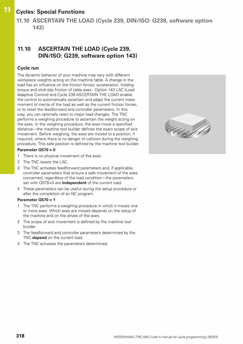
Cycles: Special Functions 11.10 ASCERTAIN THE LOAD (Cycle 239, DIN/ISO: G239, software option
143)
11
318 HEIDENHAIN | TNC 640 | User’s manual for cycle programming | 9/2015
11.10 ASCERTAIN THE LOAD (Cycle 239,
DIN/ISO: G239, software option 143)
Cycle run
The dynamic behavior of your machine may vary with different
workpiece weights acting on the machine table. A change in the
load has an influence on the friction forces, acceleration, holding
torque and stick-slip friction of table axes. Option 143 LAC (Load
Adaptive Control) and Cycle 239 ASCERTAIN THE LOAD enable
the control to automatically ascertain and adapt the current mass
moment of inertia of the load as well as the current friction forces,
or to reset the feedforward and controller parameters. In this
way, you can optimally react to major load changes. The TNC
performs a weighing procedure to ascertain the weight acting on
the axes. In the weighing procedure, the axes move a specified
distance—the machine tool builder defines the exact scope of axis
movement. Before weighing, the axes are moved to a position, if
required, where there is no danger of collision during the weighing
procedure. This safe position is defined by the machine tool builder.
Parameter Q570 = 0
1 There is no physical movement of the axes.
2 The TNC resets the LAC.
3 The TNC activates feedforward parameters and, if applicable,
controller parameters that ensure a safe movement of the axes
concerned, regardless of the load condition—the parameters
set with Q570=0 are independent of the current load.
4 These parameters can be useful during the setup procedure or
after the completion of an NC program.
Parameter Q570 = 1
1 The TNC performs a weighing procedure in which it moves one
or more axes. Which axes are moved depends on the setup of
the machine and on the drives of the axes.
2 The scope of axis movement is defined by the machine tool
builder.
3 The feedforward and controller parameters determined by the
TNC depend on the current load.
4 The TNC activates the parameters determined.

ASCERTAIN THE LOAD (Cycle 239, DIN/ISO: G239, software option
143)
11.10
11
HEIDENHAIN | TNC 640 | User’s manual for cycle programming | 9/2015 319
Please note while programming:
Cycle 239 becomes effective immediately after
definition.
If you are using the mid-program startup function and
the TNC skips Cycle 239 in the block scan, the TNC
will ignore this cycle—no weighing procedure will be
performed.
The machine must be prepared by the machine tool
builder for this cycle.
Cycle 239 can only be used with option 143 LAC
(Load Adaptive Control).
This cycle may lead to extensive motion in one or
more axes!
The TNC moves the axes at rapid traverse.
Set the potentiometer for feed-rate and rapid-
traverse override to at least 50 % to ensure a correct
ascertainment of the load.
Before cycle start, the TNC might move to a safe
position; this position is defined by the machine tool
builder!
Before using this cycle, contact your machine
tool builder for details on the type and scope of
movements performed in Cycle 239!
Cycle parameters
ASCERTAIN THE LOAD Q570: Define whether
the TNC is to perform the LAC (Load Adaptive
Control) weighing procedure or reset the last
determined load-dependent feedforward and
controller parameters:
0: Reset LAC; the values last set by the TNC are
reset; the TNC uses load-independent feedforward
and controller parameters
1: Perform the weighing procedure; the TNC
moves the axes to determine the feedforward
and controller parameters with respect to the
current load; the determined values are activated
immediately
NC blocks
62 CYCL DEF 239 ASCERTAIN THELOAD
Q570=+0 ;ASCERTAIN THE LOAD

Cycles: Special Functions 11.11 Programming examples
11
320 HEIDENHAIN | TNC 640 | User’s manual for cycle programming | 9/2015
11.11 Programming examples
Example: Interpolation Turning Cycle 291
Cycle 291 COUPLING TURNING INTERPOLATION
is used in the following program. This programming
example illustrates the machining of an axial recess and a
radial recess.
Program sequence
Turning tool as defined in toolturn.trn: tool No 10:
TO:1, ORI:0, TYPE:ROUGH, tool for axial recesses
Turning tool as defined in toolturn.trn: tool No 11:
TO:8, ORI:0, TYPE:ROUGH, tool for radial recesses
Program sequence
Tool call: tool for axial recess
Start of interpolation turning: Description and call of
Cycle 291; Q560=1
End of interpolation turning: Description and call of
Cycle 291; Q560=0
Tool call: Recessing tool for radial recess
Start of interpolation turning: Description and call of
Cycle 291; Q560=1
End of interpolation turning: Description and call of
Cycle 291; Q560=0
By converting parameter Q561,
the turning tool is displayed in the
simulation graphic as a milling tool.
5
60
6
30
18
22
11
18
0 BEGIN PGM 1 MM
1 BLK FORM CYLINDER Z R15 L60 Definition of workpiece blank: Cylinder
2 TOOL CALL 10 Tool call: tool for axial recess
3 CC X+0 Y+0
4 LP PR+30 PA+0 R0 FMAX Retract the tool
5 CYCL DEF 291 COUPLG. TURNG. INTERP. Activate interpolation turning
Q560=+1 ;SPINDLE COUPLING
Q336=+0 ;ANGLE OF SPINDLE
Q216=+0 ;CENTER IN 1ST AXIS
Q217=+0 ;CENTER IN 2ND AXIS
Q561=+1 ;TURNING TOOL CONVERSION
6 CYCL CALL Call the cycle
7 LP PR+9 PA+0 RR FMAX Position the tool in the working plane
8 L Z+10 FMAX
9 L Z+0.2 F2000 Position the tool in the spindle axis
10 LBL 1 Recessing on face, infeed: 0.2 mm, depth: 6 mm
11 CP IPA+360 IZ-0.2 DR+ F10000
12 CALL LBL 1 REP 30

Programming examples 11.11
11
HEIDENHAIN | TNC 640 | User’s manual for cycle programming | 9/2015 321
13 LBL 2 Retract from recess, step: 0.4 mm
14 CP IPA+360 IZ+0.4 DR+
15 CALL LBL 2 REP15
16 L Z+200 R0 FMAX Retract to clearance height, deactivate radius compensation
17 CYCL DEF 291 COUPLG. TURNG. INTERP. Terminate interpolation turning
Q560=+0 ;SPINDLE COUPLING
Q336=+0 ;ANGLE OF SPINDLE
Q216=+0 ;CENTER IN 1ST AXIS
Q217=+0 ;CENTER IN 2ND AXIS
Q561=+0 ;TURNING TOOL CONVERSION
18 CYCL CALL Call the cycle
19 TOOL CALL 11 Tool call: tool for radial recess
20 CC X+0 Y+0
21 LP PR+25 PA+0 R0 FMAX Retract the tool
22 CYCL DEF 291 COUPLG. TURNG. INTERP. Activate interpolation turning
Q560=+1 ;SPINDLE COUPLING
Q336=+0 ;ANGLE OF SPINDLE
Q216=+0 ;CENTER IN 1ST AXIS
Q217=+0 ;CENTER IN 2ND AXIS
Q561=+1 ;TURNING TOOL CONVERSION
23 CYCL CALL Call the cycle
24 LP PR+15.2 PA+0 RR FMAX Position the tool in the working plane
25 L Z+10 FMAX
26 L Z-11 F7000 Position the tool in the spindle axis
27 LBL 3 Recessing on lateral surface, infeed: 0.2 mm, depth: 6 mm
28 CC X+0.1 Y+0
29 CP IPA+180 DR+ F10000
30 CC X-0.1 Y+0
31 CP IPA+180 DR+
32 CALL LBL 3 REP15
33 LBL 4 Retract from recess, step: 0.4 mm
34 CC X-0.2 Y+0
35 CP IPA+180 DR+
36 CC X+0.2 Y+0
37 CP IPA+180 DR+
38 CALL LBL 4 REP8
39 LP PR+50 FMAX
40 L Z+200 R0 FMAX Retract to clearance height, deactivate radius compensation
41 CYCL DEF 291 COUPLG. TURNG. INTERP. Terminate interpolation turning
Q560=+0 ;SPINDLE COUPLING
Q336=+0 ;ANGLE OF SPINDLE
Q216=+0 ;CENTER IN 1ST AXIS

Cycles: Special Functions 11.11 Programming examples
11
322 HEIDENHAIN | TNC 640 | User’s manual for cycle programming | 9/2015
Q217=+0 ;CENTER IN 2ND AXIS
Q561=+0 ;TURNING TOOL CONVERSION
42 CYCL CALL Call the cycle
43 TOOL CALL 11 Repeated TOOL CALL in order to override the conversion of
parameter Q561
44 M30
45 END PGM 1 MM
Example: Interpolation Turning Cycle 292
Cycle 292 CONTOUR TURNING INTERPOLATION
is used in the following program. This programming
example illustrates the machining of an outside contour
with the milling spindle rotating.
Program sequence
Tool call: Milling cutter D20
Cycle 32 Tolerance
Reference to the contour with Cycle 14
Cycle 292 Contour turning interpolation
40
57
15
50
30
38
0 BEGIN PGM 2 MM
1 BLK FORM CYLINDER Z R25 L40 Definition of workpiece blank: Cylinder
2 TOOL CALL "D20" Z S111 Tool call: End mill D20
3 CYCL DEF 32.0 TOLERANCE Use Cycle 32 to define the tolerance
4 CYCL DEF 32.1 T0.05
5 CYCL DEF 32.2 HSC-MODE:1
6 CYCL DEF 14.0 CONTOUR Use Cycle 14 to refer to the contour in LBL1
7 CYCL DEF 14.1 CONTOUR LABEL1
8 CYCL DEF 292 CONTOUR. TURNG. INTRP. Define Cycle 292
Q560=+1 ;SPINDLE COUPLING
Q336=+0 ;ANGLE OF SPINDLE
Q546=+3 ;CHANGE TOOL DIRECTN.
Q529=+0 ;MACHINING OPERATION
Q221=+0 ;SURFACE OVERSIZE
Q441=+1 ;INFEED
Q449=+15000 ;FEED RATE
Q491=+15 ;CONTOUR START RADIUS
Q357=+2 ;CLEARANCE TO SIDE
Q445=+50 ;CLEARANCE HEIGHT
9 L Z+50 R0 FMAX M3 Pre-position in the tool axis, spindle on
10 L X+0 Y+0 R0 FMAX M99 Pre-position in the working plane to the center of rotation,
call the cycle
11 LBL 1 LBL1 contains the contour

Programming examples 11.11
11
HEIDENHAIN | TNC 640 | User’s manual for cycle programming | 9/2015 323
12 L Z+2 X+15
13 L Z-5
14 L Z-7 X+19
15 RND R3
16 L Z-15
17 RND R2
18 L X+27
19 LBL 0
20 M30 End of program
21 END PGM 2 MM

12Cycles: Turning
Cycles: Turning 12.1 Turning Cycles (software option 50)
12
326 HEIDENHAIN | TNC 640 | User’s manual for cycle programming | 9/2015
12.1 Turning Cycles (software option 50)
Overview
Defining turning cycles:
The soft-key row shows the available groups of cycles
Select the menu for cycle group TURNING
Select cycle group, e.g. cycles for longitudinal turning
Select cycle, e.g. TURN SHOULDER, LONGITUDINAL
The TNC offers the following cycles for turning operations:
Soft key Cycle group Cycle Page
Special cycles
ADAPT ROTARY COORDINATE SYSTEM(Cycle 800, DIN/
ISO: G800)
332
RESET ROTARY COORDINATE SYSTEM (Cycle 801, DIN/
ISO: G801)
338
GEAR HOBBING (Cycle 880, DIN/ISO: G880) 435
CHECK UNBALANCE (Cycle 892, DIN/ISO: G892) 440
Cycles for longitudinal
turning
339
TURN SHOULDER LONGITUDINAL (Cycle 811, DIN/ISO:
G811)
340
TURN SHOULDER LONGITUDINAL EXTENDED (Cycle
812, DIN/ISO: G812)
343
TURN, LONGITUDINAL PLUNGE (Cycle 813, DIN/ISO:
G813)
347
TURN, LONGITUDINAL PLUNGE EXTENDED (Cycle 814,
DIN/ISO: G814)
350
TURN CONTOUR LONGITUDINAL (Cycle 810, DIN/ISO:
G810)
354
TURN CONTOUR-PARALLEL (Cycle 815, DIN/ISO: G815) 358

Turning Cycles (software option 50) 12.1
12
HEIDENHAIN | TNC 640 | User’s manual for cycle programming | 9/2015 327
Soft key Cycle group Cycle Page
Cycles for transverse
turning
339
TURN SHOULDER FACE (Cycle 821, DIN/ISO: G821) 362
TURN SHOULDER FACE EXTENDED (Cycle 822, DIN/
ISO: G822)
365
TURN, TRANSVERSE PLUNGE (Cycle 823, DIN/ISO:
G823)
369
TURN, TRANSVERSE PLUNGE EXTENDED (Cycle 824,
DIN/ISO: G824)
372
TURN CONTOUR FACE (Cycle 820, DIN/ISO: G820) 376
TURN CONTOUR-PARALLEL (Cycle 815, DIN/ISO: G815) 358
Cycles for recessing
SIMPLE RADIAL RECESSING (Cycle 841, DIN/ISO: G841) 380
RADIAL RECESSING EXTENDED(Cycle 842, DIN/ISO:
G842)
383
RECESSING CONTOUR RADIAL(Cycle 840, DIN/ISO:
G840)
388
SIMPLE AXIAL RECESSING (Cycle 851, DIN/ISO: G851) 392
AXIAL RECESSING EXTENDED(Cycle 852, DIN/ISO:
G852)
395
AXIAL RECESSING(Cycle 850, DIN/ISO: G850) 400

Cycles: Turning 12.1 Turning Cycles (software option 50)
12
328 HEIDENHAIN | TNC 640 | User’s manual for cycle programming | 9/2015
Soft key Cycle group Cycle Page
Cycles for recessing
RADIAL RECESSING (Cycle 861, DIN/ISO: G861) 404
RADIAL RECESSING EXTENDED(Cycle 862, DIN/ISO:
G862)
407
RECESSING CONTOUR RADIAL(Cycle 860, DIN/ISO:
G860)
411
AXIAL RECESSING (Cycle 871, DIN/ISO: G871) 415
AXIAL RECESSING EXTENDED(Cycle 872, DIN/ISO:
G872)
417
AXIAL RECESSING(Cycle 870, DIN/ISO: G870) 421
Cycles for thread
turning
THREAD LONGITUDINAL (Cycle 831, DIN/ISO: G831) 424
THREAD EXTENDED (Cycle 832, DIN/ISO: G832) 427
CONTOUR-PARALLEL THREAD (Cycle 830, DIN/ISO:
G830)
431
Turning Cycles (software option 50) 12.1
12
HEIDENHAIN | TNC 640 | User’s manual for cycle programming | 9/2015 329
Working with turning cycles
You can only use turning cycles in Turning mode
FUNCTION MODE TURN.
In turning cycles the TNC takes into account the cutting geometry
(TO, RS, P-ANGLE, T-ANGLE) of the tool so that damage to the
defined contour elements is prevented. The TNC outputs a warning
if complete machining of the contour with the active tool is not
possible.
You can use the turning cycles both for inside and outside
machining. Depending upon the specific cycle, the TNC detects
the machining position (inside/outside machining) via the starting
position or tool position when the cycle is called. In some cycles
you can also enter the machining position directly in the cycle.
After modifying the machining position, check the tool position and
rotation direction.
If you program M136 before a cycle, the TNC interprets feed rate
values in the cycle in mm/rev., and without M136 in mm/min.
If turning cycles are executed during inclined machining (M144), the
angles of the tool to the contour change. The TNC automatically
takes these modifications into account and thus also monitors the
machining in inclined state to prevent contour damage.
Some cycles machine contours that you have written in a
subprogram. You program these contours with plain-language
path functions or FK functions. Before calling the cycle you must
program the cycle 14 CONTOUR to define the subprogram number.
You must call turning cycles 880 and 81x - 87x with CYCL CALL or
M99. Before calling a cycle, be sure to program:
Turning mode FUNCTION MODE TURNTool call TOOL CALLDirection of rotation of turning spindle, e.g. M303Selection of speed/cutting speed FUNCTION TURNDATA SPINIf you use feed rate per revolution mm/rev., M136Tool positioning to suitable starting point e.g. L X+130 Y+0 R0FMAXAdaptation of coordinate system and align tool CYCL DEF 800ADAPT ROTARY COORDINATE SYSTEM

Cycles: Turning 12.1 Turning Cycles (software option 50)
12
330 HEIDENHAIN | TNC 640 | User’s manual for cycle programming | 9/2015
Blank form update (FUNCTION TURNDATA)
During turning operations workpieces must often be machined
with several tools. Often a contour element cannot be completely
finished because the tool form does not permit this (e.g. with
a back cut). In this case, single sub-areas have to be reworked
with other tools. The TNC detects the already machined areas
with the blank form update and adapts all approach and departure
paths to the specific, current machining situation. With the shorter
machining paths, traverses in the air are avoided to significantly
reduce machining time.
To activate the blank form update, program the TURNDATA BLANKfunction and link to a program or subprogram with a workpiece
blank specification. The workpiece blank defined in TURNDATABLANK determines the area to be machined with the blank form
update. TURNDATA BLANK OFF deactivates blank form update.
The TNC optimizes machining areas and approach
motions with blank form update. The TNC takes into
account the specific tracked workpiece blank for
approach and departure paths. If parts of the finished
part extend beyond the workpiece blank, this may
damage the workpiece and tool.
Blank form update is only possible with cycle
machining in turning mode (FUNCTION MODE TURN).
You must define a closed contour as the workpiece
blank for the blank form update (start position = end
position). The workpiece blank corresponds to the
cross-section of a rotationally symmetrical body.

Turning Cycles (software option 50) 12.1
12
HEIDENHAIN | TNC 640 | User’s manual for cycle programming | 9/2015 331
The TNC has various options for defining the blank:
Soft key Workpiece blank definition
Deactivate blank form update TURNDATABLANK OFF: No input
Workpiece blank definition in a program: Enter
name of the file
Workpiece blank definition in a program: Enter
the string parameter with the program name
Workpiece blank definition in a subprogram:
Enter the number of the subprogram
Workpiece blank definition in a subprogram:
Enter the name of the subprogram
Workpiece blank definition in a subprogram:
Enter the string parameter with the
subprogram name
Activate blank form update and define workpiece blank:
Show the soft-key row with special functions
Select the menu for TURNING PROGRAMFUNCTIONS
Select BASIC FUNCTIONS
Select the function for blank form update
NC syntax
11 FUNCTION TURNDATABLANK LBL 20

Cycles: Turning 12.2 ADAPT ROTARY COORDINATE SYSTEM
(Cycle 800, DIN/ISO: G800)
12
332 HEIDENHAIN | TNC 640 | User’s manual for cycle programming | 9/2015
12.2 ADAPT ROTARY COORDINATE
SYSTEM
(Cycle 800, DIN/ISO: G800)
Application
This function must be adapted to the TNC by your
machine manufacturer. Refer to your machine
manual.
You need to position the tool appropriately with respect to the
turning spindle, in order to be able to perform a turning operation.
You can use Cycle 800 ADAPT ROTARY COORDINATE SYSTEM for
this.
The angle of incidence between the tool and the turning spindle is
important for turning operations, for example, in order to machine
contours with undercuts. Cycle 800 provides various possibilities
for aligning the coordinate system for an inclined machining
operation:
If you have already positioned the tilting axis for an inclined
machining operation, you can use Cycle 800 to align the
coordinate system relative to the position of the tilting axes
(Q530=0).
Cycle 800 uses the angle of incidence Q531 to calculate the
required tilting axis angle. Depending on the strategy selected in
parameter INCLINED MACHINING Q530, the TNC positions the
tilting axis with (Q530=1) or without compensating movement
(Q530=2).
Cycle 800 uses the angle of incidence Q531 to calculate the
required tilting axis angle, but does not perform any movements
for positioning the tilting axis (Q530=3). You need to position the
tilting axis to the calculated values Q120 (A axis), Q121 (B axis)
and Q122 (C axis) after the cycle.
If you change the position of a tilting axis, you
need to run Cycle 800 again to align the coordinate
system.

ADAPT ROTARY COORDINATE SYSTEM
(Cycle 800, DIN/ISO: G800)
12.2
12
HEIDENHAIN | TNC 640 | User’s manual for cycle programming | 9/2015 333
If the axis of the milling spindle and the axis of the turning spindle
are aligned parallel to each other, you can use PRECESSION ANGLEQ497 to define any desired rotation of the coordinate system
around the spindle axis (Z axis). This may be necessary if you have
to bring the tool into a specific position due to space restrictions or
if you want to improve your ability to observe a machining process.
If the axis of the turning spindle is not aligned parallel to the axis
of the milling spindle, only two precession angles are useful for
machining. The TNC selects the angle that is closest to the input
value Q497.
Cycle 800 positions the milling spindle such that the cutting edge
is aligned relative to the turning contour. You can also use the
mirrored tool (REVERSE TOOL Q498), thereby moving the position
of the milling spindle by 180°. In this way you can use a tool for
both inside and outside machining. Position the cutting edge at the
center of the turning spindle using a positioning block, such as L Y+0 R0 FMAX.
Cycles: Turning 12.2 ADAPT ROTARY COORDINATE SYSTEM
(Cycle 800, DIN/ISO: G800)
12
334 HEIDENHAIN | TNC 640 | User’s manual for cycle programming | 9/2015
Eccentric turning
Sometimes it is not possible to clamp a workpiece such that the
axis of rotation is aligned with the axis of the turning spindle (e.g.
if large or rotationally non-symmetrical workpieces are being used).
The Q535 eccentric turning function in Cycle 800 enables you to
perform turning operations in such cases as well.
During eccentric turning more than one linear axis is coupled to
the turning spindle. The TNC compensates the eccentricity by
performing circular compensating movements with the coupled
linear axes.
This feature must be enabled and adapted by the
machine tool builder. Refer to your machine manual.
High rotational speeds and large eccentricity require high feed
rates of the linear axes to ensure that they move synchronously. If
these feed rates are not maintained, the contour will be damaged.
The TNC therefore generates an error message if 80 % of a
maximum axis speed or acceleration is exceeded. If this occurs,
reduce the rotational speed.
Do not couple or decouple axes when the turning
spindle is rotating. The TNC performs compensating
movements during coupling and decoupling. Check
for possible collisions.
Turn a test cut before the actual machining operation
to ensure that the required speeds can be attained.
The linear axis positions resulting from the
compensation are displayed by the TNC only in the
ACTUAL value position display.
The rotation of the workpiece creates centrifugal
forces that can cause vibration (resonance),
depending on the unbalance. This vibration has
a negative effect on the machining process and
reduces the tool life. High centrifugal forces can
damage the machine or push the workpiece out of
the fixture.
Danger of collision!
Collision monitoring (DCM) is not active during
eccentric turning. The TNC displays a corresponding
warning during eccentric turning.
ADAPT ROTARY COORDINATE SYSTEM
(Cycle 800, DIN/ISO: G800)
12.2
12
HEIDENHAIN | TNC 640 | User’s manual for cycle programming | 9/2015 335
Effect
With Cycle 800 ADAPT ROTARY COORDINATE SYSTEM, the
TNC aligns the workpiece coordinate system and orients the tool
correspondingly. Cycle 800 is effective until it is reset by Cycle 801,
or until Cycle 800 is defined again. Some cycle functions of Cycle
800 are additionally reset by other factors:
The mirroring of the tool data (Q498 REVERSE TOOL) is reset by
a TOOL CALL.
The ECCENTRIC TURNING Q535 function is reset at the end of
the program or due to cancelation of the program (internal stop).
Please note while programming:
The Cycle 800 ADAPT ROTARY COORDINATE
SYSTEM is machine-dependent. Refer to your
machine manual.
Software option 50 must be enabled
The tool must be clamped and measured in the
correct position.
You can only mirror the tool data (Q498 REVERSETOOL) when a turning tool is selected.
Check the orientation of the tool before machining.
Cycle 800 limits the maximum spindle speed during
eccentric turning. Therefore, program Cycle 801 to
reset Cycle 800, and reset the speed limitation with
FUNCTION TURNDATA SPIN SMAX.
If you use the settings 1: MOVE, 2: TURN
and 3: STAY in the parameter Q530 INCLINEDMACHINING, the TNC activates the function M144(see also User's Manual for Inclined Turning).

Cycles: Turning 12.2 ADAPT ROTARY COORDINATE SYSTEM
(Cycle 800, DIN/ISO: G800)
12
336 HEIDENHAIN | TNC 640 | User’s manual for cycle programming | 9/2015
Cycle parameters
PRECESSION ANGLE Q497: Angle to which the
TNC aligns the tool. Input range 0 to 359.9999
REVERSE TOOL Q498: mirror tool for inside/
outside machining. Input range 0 and 1.
Inclined machining Q530: Position the tilting axes
for inclined machining:
0: The position of the tilting axis (axis must have
been positioned before) remains unchanged
1: Position the tilting axis automatically, thereby
orienting the tool tip (MOVE). The relative
position between the tool and workpiece remains
unchanged. The TNC performs a compensating
movement with the linear axes
2: Position the tilting axis automatically without
orienting the tool tip (TURN)
3: Do not position the tilting axis. Position
the tilting axes in a subsequent and separate
positioning block (STAY). The TNC stores the
position values in the parameters Q120 (A axis),
Q121 (B axis) and Q122 (C axis).
Angle of incidence Q531: Angle of incidence for
aligning the tool. Input range: -180° to +180°
Feed rate for positioning Q532: Traverse speed
of the tilting axis during automatic positioning.
Input range 0.001 to 99999.999
Preferred direction Q533: Selection of alternate
possibilities of inclination. The angle of incidence
you have defined is used by the TNC to calculate
the appropriate positioning of the tilting axes
present on the machine. In general there are
always two possible solutions. Using parameter
Q533, configure which of the solution options the
TNC should apply:
0: Choose option with shortest way
-1: Choose option with negative direction
+1: Choose option with positive direction
-2: Choose option with negative direction at a
range of between -90° and -180°
+2: Choose option with positive direction at a
range of between +90° and +180°
ADAPT ROTARY COORDINATE SYSTEM
(Cycle 800, DIN/ISO: G800)
12.2
12
HEIDENHAIN | TNC 640 | User’s manual for cycle programming | 9/2015 337
Eccentric turning Q535: Couple the axes for the
eccentric turning operation:
0: Deactivate axis couplings
1: Activate axis couplings The center of rotation is
located at the active preset
2: Activate axis couplings. The center of rotation is
located at the active datum
3: Do not change axis couplings.
Eccentric turning without stop Q536: Interrupt
program run before the axes are coupled:
0: Stop before the axes are coupled again. In
stopped condition, the TNC opens a window
in which the amount of eccentricity and the
maximum deflection of the individual axes are
displayed. Then press NC start to continue
machining or press the CANCEL soft key to cancel
machining
1: Axes are coupled without stopping beforehand
Cycles: Turning 12.3 RESET ROTARY COORDINATE SYSTEM
(Cycle 801, DIN/ISO: G801)
12
338 HEIDENHAIN | TNC 640 | User’s manual for cycle programming | 9/2015
12.3 RESET ROTARY COORDINATE
SYSTEM
(Cycle 801, DIN/ISO: G801)
Please note while programming:
The Cycle 801 RESET ROTARY COORDINATE
SYSTEM is machine-dependent. Refer to your
machine manual.
With Cycle 801 RESET ROTARY COORDINATE
SYSTEM you can reset the settings you have made
with Cycle 800 ADAPT ROTARY COORDINATE
SYSTEM.
Cycle 800 limits the maximum spindle speed during
eccentric turning. Therefore, program Cycle 801 to
reset Cycle 800, and reset the speed limitation with
FUNCTION TURNDATA SPIN SMAX.
Effect
Cycle 801 resets the following settings you have programmed with
Cycle 800:
Precession angle Q497
Reverse tool Q498
If you have executed the eccentric turning function with Cycle 800,
the cycle limits the maximum spindle speed. To reset this, program
FUNCTION TURNDATA SPIN SMAX in addition to Cycle 801.
Cycle 801 does not orient the tool to the starting
position. If a tool was oriented with Cycle 800, it
remains in this position also after resetting.
Cycle parameters
Cycle 801 does not have a cycle parameter. Finish
the cycle input with the "END" key.

Fundamentals of Turning Cycles 12.4
12
HEIDENHAIN | TNC 640 | User’s manual for cycle programming | 9/2015 339
12.4 Fundamentals of Turning Cycles
The pre-positioning of the tool decisively affects the workspace
of the cycle and thus the machining time. During roughing, the
starting point for cycles corresponds to the tool position when a
cycle is called. When calculating the area to be machined, the TNC
takes into account the starting point and the end point defined in
the cycle or contour defined in the cycle. If the starting point lies in
the area to be machined the TNC positions the tool beforehand in
some cycles to set-up clearance.
The turning direction with 81x cycles is longitudinal to the rotary
axis and lateral to the rotary axis with 82x cycles. The motions are
contour-parallel in cycle 815.
The cycles can be used for inside and outside machining. The TNC
takes the information for this from the position of the tool or the
definition in the cycle (see "Working with turning cycles", page 329).
In cycles with freely defined contours (Cycles 810, 820 and 815),
the programming direction of the contour determines the direction
of machining.
In cycles for turning you can specify the machining strategies of
roughing, finishing or complete machining.
Caution: Danger to the workpiece and tool!
The turning cycles position the tool automatically
to the starting point during finishing. The approach
strategy is influenced by the position of the tool
when the cycle is called. The decisive factor is
whether the tool is located inside or outside an
envelope contour when the cycle is called. The
envelope contour is the programmed contour,
enlarged by the set-up clearance.
If the tool is within the envelope contour, the cycle
positions the tool at the defined feed rate directly
to the starting position. This can cause contour
damage. Position the tool at a sufficient distance
from the starting point to prevent the possibility of
contour damage.
If the tool is outside the envelope contour,
positioning to the envelope contour is performed
at rapid traverse, and at the programmed feed rate
within the envelope contour.

Cycles: Turning 12.5 TURN SHOULDER LONGITUDINAL
(Cycle 811, DIN/ISO: G811)
12
340 HEIDENHAIN | TNC 640 | User’s manual for cycle programming | 9/2015
12.5 TURN SHOULDER LONGITUDINAL
(Cycle 811, DIN/ISO: G811)
Application
This cycle enables you to carry out longitudinal turning of right-
angled shoulders.
You can use the cycle either for roughing, finishing or complete
machining. Turning is run paraxially with roughing.
The cycle can be used for inside and outside machining. If the tool
is outside the contour to be machined when the cycle is called, the
cycle runs outside machining. If the tool is inside the contour to be
machined, the cycle runs inside machining.
Roughing cycle run
The cycle processes the area from the tool position to the end
point defined in the cycle.
1 The TNC runs a paraxial infeed motion at rapid traverse. The
infeed value is calculated by the TNC with Q463 MAX. CUTTINGDEPTH.
2 The TNC cuts the area between the starting position and the
end point in longitudinal direction at the defined feed rate Q478.
3 The TNC returns the tool at the defined feed rate by one infeed
value.
4 The TNC positions the tool back at rapid traverse to the
beginning of cut.
5 The TNC repeats this process (1 to 4) until the final contour is
completed.
6 The TNC positions the tool back at rapid traverse to the cycle
starting point.

TURN SHOULDER LONGITUDINAL
(Cycle 811, DIN/ISO: G811)
12.5
12
HEIDENHAIN | TNC 640 | User’s manual for cycle programming | 9/2015 341
Finishing cycle run
1 The TNC traverses the tool in the Z coordinate by the set-up
clearance Q460. The movement is performed at rapid traverse.
2 The TNC runs the paraxial infeed motion at rapid traverse.
3 The TNC finishes the finished part contour at the defined feed
rate Q505.
4 The TNC returns the tool to set-up clearance at the defined feed
rate.
5 The TNC positions the tool back at rapid traverse to the cycle
starting point.
Please note while programming:
Program a positioning block to the starting position
with radius compensation R0 before the cycle call.
The tool position at cycle call defines the size of the
area to be machined (cycle starting point).
Also refer to the fundamentals of turning cycles (see
page 339).

Cycles: Turning 12.5 TURN SHOULDER LONGITUDINAL
(Cycle 811, DIN/ISO: G811)
12
342 HEIDENHAIN | TNC 640 | User’s manual for cycle programming | 9/2015
Cycle parameters
Machining operation Q215: Define machining
operation:
0: Roughing and finishing
1: Only roughing
2: Only finishing to finished dimension
3: Only finishing to oversize
Set-up clearance Q460 (incremental): Distance for
retraction and pre-positioning.
Diameter at end of contour Q493: X coordinate of
the contour end point (diameter value)
Contour end in Z Q494: Z coordinate of the contour
end point
Maximum cutting depth Q463: Maximum infeed
(radius value) in radial direction. The infeed is divided
evenly to avoid abrasive cuts. Input range 0.001 to
999.999
Roughing feed rate Q478: Feed rate during
roughing. If M136 has been programmed, the
value is interpreted by the TNC in millimeters per
revolution, without M136 in millimeters per minute.
Oversize in diameter Q483 (incremental): Diameter
oversize for the defined contour
Oversize in Z Q484 (incremental): Oversize for the
defined contour in axial direction
Finishing feed rate Q505: Feed rate during
finishing. If M136 has been programmed, the
value is interpreted by the TNC in millimeters per
revolution, without M136 in millimeters per minute.
Contour smoothing Q506:
0: After each cut along the contour (within the
infeed range)
1: Contour smoothing after the last cut (complete
contour); retract below 45°
2: No contour smoothing; retract below 45°
Q460
Ø Q493
Q494 Q463
Ø Q483
Q484
NC blocks
11 CYCL DEF 811 TURN SHOULDERLONG.
Q215=+0 ;MACHININGOPERATION
Q460=+2 ;SAFETY CLEARANCE
Q493=+50 ;DIAMETER AT END OFCONTOUR
Q494=-55 ;CONTOUR END IN Z
Q463=+3 ;MAX. CUTTING DEPTH
Q478=+0.3 ;ROUGHING FEED RATE
Q483=+0.4 ;OVERSIZE FORDIAMETER
Q484=+0.2 ;OVERSIZE IN Z
Q505=+0.2 ;FINISHING FEED RATE
Q506=+0 ;CONTOUR SMOOTHING
12 L X+75 Y+0 Z+2 FMAX M303
13 CYCL CALL

TURN SHOULDER LONGITUDINAL EXTENDED
(Cycle 812, DIN/ISO: G812)
12.6
12
HEIDENHAIN | TNC 640 | User’s manual for cycle programming | 9/2015 343
12.6 TURN SHOULDER LONGITUDINAL
EXTENDED
(Cycle 812, DIN/ISO: G812)
Application
This cycle enables you to run longitudinal turning of shoulders.
Expanded scope of function:
You can insert a chamfer or curve at the contour start and
contour end.
In the cycle you can define angles for the face and
circumferential surfaces
You can insert a radius in the contour edge
You can use the cycle either for roughing, finishing or complete
machining. Turning is run paraxially with roughing.
The cycle can be used for inside and outside machining. If the start
diameter Q491 is larger than the end diameter Q493, the cycle
runs outside machining. If the start diameter Q491 is less than the
end diameter Q493, the cycle runs inside machining.
Roughing cycle run
The TNC uses the tool position as cycle starting point when a cycle
is called. If the starting point is within the area to be machined,
the TNC positions the tool in the X coordinate and then in the Z
coordinate to set-up clearance and begins the cycle there.
1 The TNC runs a paraxial infeed motion at rapid traverse. The
infeed value is calculated by the TNC with Q463 MAX. CUTTINGDEPTH.
2 The TNC cuts the area between the starting position and the
end point in longitudinal direction at the defined feed rate Q478.
3 The TNC returns the tool at the defined feed rate by one infeed
value.
4 The TNC positions the tool back at rapid traverse to the
beginning of cut.
5 The TNC repeats this process (1 to 4) until the final contour is
completed.
6 The TNC positions the tool back at rapid traverse to the cycle
starting point.

Cycles: Turning 12.6 TURN SHOULDER LONGITUDINAL EXTENDED
(Cycle 812, DIN/ISO: G812)
12
344 HEIDENHAIN | TNC 640 | User’s manual for cycle programming | 9/2015
Finishing cycle run
If the starting point lies in the area to be machined, the TNC
positions the tool beforehand to set-up clearance in the Z
coordinate.
1 The TNC runs the paraxial infeed motion at rapid traverse.
2 The TNC finishes the finished part contour (contour starting
point to contour end point) at the defined feed rate Q505.
3 The TNC returns the tool to set-up clearance at the defined feed
rate.
4 The TNC positions the tool back at rapid traverse to the cycle
starting point.
Please note while programming:
Program a positioning block to a safe position with
radius compensation R0 before the cycle call.
The tool position at cycle call (cycle starting point)
affects the area to be machined.
Also refer to the fundamentals of turning cycles (see
page 339).

TURN SHOULDER LONGITUDINAL EXTENDED
(Cycle 812, DIN/ISO: G812)
12.6
12
HEIDENHAIN | TNC 640 | User’s manual for cycle programming | 9/2015 345
Cycle parameters
Machining operation Q215: Define machining
operation:
0: Roughing and finishing
1: Only roughing
2: Only finishing to finished dimension
3: Only finishing to oversize
Set-up clearance Q460 (incremental): Distance for
retraction and pre-positioning.
Diameter at contour start Q491: X coordinate of
the contour starting point (diameter value)
Contour start in Z Q492: Z coordinate of the
contour starting point
Diameter at end of contour Q493: X coordinate of
the contour end point (diameter value)
Contour end in Z Q494: Z coordinate of the contour
end point
Angle of circumferential surface Q495: Angle
between the circumferential surface and the rotary
axis
Ø Q491
Ø Q483
Q484
Q463
Q460
Q493
Ø Q493
Q494

Cycles: Turning 12.6 TURN SHOULDER LONGITUDINAL EXTENDED
(Cycle 812, DIN/ISO: G812)
12
346 HEIDENHAIN | TNC 640 | User’s manual for cycle programming | 9/2015
Type of starting element Q501: Define the type of
element at the start of the contour (circumferential
surface):
0: No additional element
1: Element is a chamfer
2: Element is a radius
Size of starting element Q502: Size of the starting
element (chamfer section)
Radius of contour edge Q500: Radius of the inside
contour edge. If no radius is specified, the radius of
the cutting insert is generated.
Angle of face Q496: Angle between the face and
the rotary axis
Type of end element Q503: Define the type of
element at the end of the contour (face):
0: No additional element
1: Element is a chamfer
2: Element is a radius
Size of end element Q504: Size of the end element
(chamfer section)
Maximum cutting depth Q463: Maximum infeed
(radius value) in radial direction. The infeed is divided
evenly to avoid abrasive cuts. Input range 0.001 to
999.999
Roughing feed rate Q478: Feed rate during
roughing. If M136 has been programmed, the
value is interpreted by the TNC in millimeters per
revolution, without M136 in millimeters per minute.
Oversize in diameter Q483 (incremental): Diameter
oversize for the defined contour
Oversize in Z Q484 (incremental): Oversize for the
defined contour in axial direction
Finishing feed rate Q505: Feed rate during
finishing. If M136 has been programmed, the
value is interpreted by the TNC in millimeters per
revolution, without M136 in millimeters per minute.
Contour smoothing Q506:
0: After each cut along the contour (within the
infeed range)
1: Contour smoothing after the last cut (complete
contour); retract below 45°
2: No contour smoothing; retract below 45°
NC blocks
11 CYCL DEF 812 TURN SHOULDERLONG. EXTENDED.
Q215=+0 ;MACHININGOPERATION
Q460=+2 ;SAFETY CLEARANCE
Q491=+75 ;DIAMETER ATCONTOUR START
Q492=+0 ;CONTOUR START IN Z
Q493=+50 ;DIAMETER AT END OFCONTOUR
Q494=-55 ;CONTOUR END IN Z
Q495=+5 ;ANGLE OF CIRCUM.SURFACE
Q501=+1 ;TYPE OF STARTINGELEMENT
Q502=+0.5 ;SIZE OF STARTINGELEMENT
Q500=+1.5 ;RADIUS OF CONTOUREDGE
Q496=+0 ;ANGLE OF FACE
Q503=+1 ;TYPE OF ENDELEMENT
Q504=+0.5 ;SIZE OF END ELEMENT
Q463=+3 ;MAX. CUTTING DEPTH
Q478=+0.3 ;ROUGHING FEED RATE
Q483=+0.4 ;OVERSIZE FORDIAMETER
Q484=+0.2 ;OVERSIZE IN Z
Q505=+0.2 ;FINISHING FEED RATE
Q506=+0 ;CONTOUR SMOOTHING
12 L X+75 Y+0 Z+2 FMAX M303
13 CYCL CALL

TURN, LONGITUDINAL PLUNGE
(Cycle 813, DIN/ISO: G813)
12.7
12
HEIDENHAIN | TNC 640 | User’s manual for cycle programming | 9/2015 347
12.7 TURN, LONGITUDINAL PLUNGE
(Cycle 813, DIN/ISO: G813)
Application
This cycle enables you to run longitudinal turning of shoulders with
plunge elements (undercuts).
You can use the cycle either for roughing, finishing or complete
machining. Turning is run paraxially with roughing.
The cycle can be used for inside and outside machining. If the start
diameter Q491 is larger than the end diameter Q493, the cycle
runs outside machining. If the start diameter Q491 is less than the
end diameter Q493, the cycle runs inside machining.
Roughing cycle run
The TNC uses the tool position as cycle starting point when a
cycle is called. If the Z coordinate of the starting point is less than
Q492 CONTOUR START IN Z, the TNC positions the tool in the Z
coordinate to set-up clearance and begins the cycle there.
In undercutting the TNC runs the infeed with feed rate Q478. The
return movements are then each at set-up clearance.
1 The TNC runs a paraxial infeed motion at rapid traverse. The
infeed value is calculated by the TNC with Q463 MAX. CUTTINGDEPTH.
2 The TNC cuts the area between the starting position and the
end point in longitudinal direction at the defined feed rate Q478.
3 The TNC returns the tool at the defined feed rate by one infeed
value.
4 The TNC positions the tool back at rapid traverse to the
beginning of cut.
5 The TNC repeats this process (1 to 4) until the final contour is
completed.
6 The TNC positions the tool back at rapid traverse to the cycle
starting point.

Cycles: Turning 12.7 TURN, LONGITUDINAL PLUNGE
(Cycle 813, DIN/ISO: G813)
12
348 HEIDENHAIN | TNC 640 | User’s manual for cycle programming | 9/2015
Finishing cycle run
1 The TNC runs the infeed motion at rapid traverse.
2 The TNC finishes the finished part contour (contour starting
point to contour end point) at the defined feed rate Q505.
3 The TNC returns the tool to set-up clearance at the defined feed
rate.
4 The TNC positions the tool back at rapid traverse to the cycle
starting point.
Please note while programming:
Program a positioning block to a safe position with
radius compensation R0 before the cycle call.
The tool position at cycle call (cycle starting point)
affects the area to be machined.
The TNC takes the cutting geometry of the tool into
account to prevent damage to contour elements.
If complete machining with the active tool is not
possible, a warning is output by the TNC.
Also refer to the fundamentals of turning cycles (see
page 339).
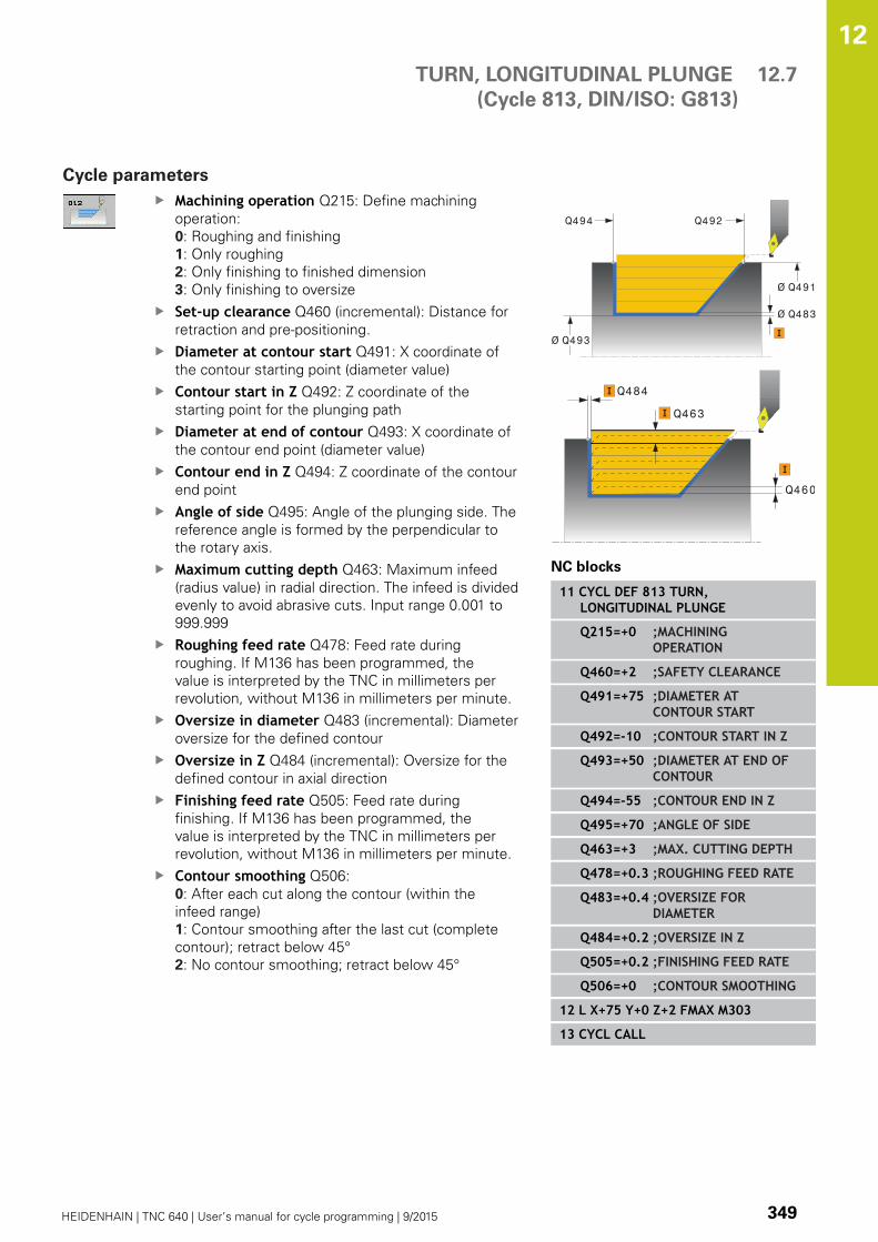
TURN, LONGITUDINAL PLUNGE
(Cycle 813, DIN/ISO: G813)
12.7
12
HEIDENHAIN | TNC 640 | User’s manual for cycle programming | 9/2015 349
Cycle parameters
Machining operation Q215: Define machining
operation:
0: Roughing and finishing
1: Only roughing
2: Only finishing to finished dimension
3: Only finishing to oversize
Set-up clearance Q460 (incremental): Distance for
retraction and pre-positioning.
Diameter at contour start Q491: X coordinate of
the contour starting point (diameter value)
Contour start in Z Q492: Z coordinate of the
starting point for the plunging path
Diameter at end of contour Q493: X coordinate of
the contour end point (diameter value)
Contour end in Z Q494: Z coordinate of the contour
end point
Angle of side Q495: Angle of the plunging side. The
reference angle is formed by the perpendicular to
the rotary axis.
Maximum cutting depth Q463: Maximum infeed
(radius value) in radial direction. The infeed is divided
evenly to avoid abrasive cuts. Input range 0.001 to
999.999
Roughing feed rate Q478: Feed rate during
roughing. If M136 has been programmed, the
value is interpreted by the TNC in millimeters per
revolution, without M136 in millimeters per minute.
Oversize in diameter Q483 (incremental): Diameter
oversize for the defined contour
Oversize in Z Q484 (incremental): Oversize for the
defined contour in axial direction
Finishing feed rate Q505: Feed rate during
finishing. If M136 has been programmed, the
value is interpreted by the TNC in millimeters per
revolution, without M136 in millimeters per minute.
Contour smoothing Q506:
0: After each cut along the contour (within the
infeed range)
1: Contour smoothing after the last cut (complete
contour); retract below 45°
2: No contour smoothing; retract below 45°
Ø Q493
Ø Q491
Ø Q483
Q494 Q492
Q460
Q463
Q484
NC blocks
11 CYCL DEF 813 TURN,LONGITUDINAL PLUNGE
Q215=+0 ;MACHININGOPERATION
Q460=+2 ;SAFETY CLEARANCE
Q491=+75 ;DIAMETER ATCONTOUR START
Q492=-10 ;CONTOUR START IN Z
Q493=+50 ;DIAMETER AT END OFCONTOUR
Q494=-55 ;CONTOUR END IN Z
Q495=+70 ;ANGLE OF SIDE
Q463=+3 ;MAX. CUTTING DEPTH
Q478=+0.3 ;ROUGHING FEED RATE
Q483=+0.4 ;OVERSIZE FORDIAMETER
Q484=+0.2 ;OVERSIZE IN Z
Q505=+0.2 ;FINISHING FEED RATE
Q506=+0 ;CONTOUR SMOOTHING
12 L X+75 Y+0 Z+2 FMAX M303
13 CYCL CALL

Cycles: Turning 12.8 TURN, LONGITUDINAL PLUNGE EXTENDED
(Cycle 814, DIN/ISO: G814)
12
350 HEIDENHAIN | TNC 640 | User’s manual for cycle programming | 9/2015
12.8 TURN, LONGITUDINAL PLUNGE
EXTENDED
(Cycle 814, DIN/ISO: G814)
Application
This cycle enables you to run longitudinal turning of shoulders with
plunge elements (undercuts). Expanded scope of function:
You can insert a chamfer or curve at the contour start and
contour end.
In the cycle you can define an angle for the face and a radius for
the contour edge
You can use the cycle either for roughing, finishing or complete
machining. Turning is run paraxially with roughing.
The cycle can be used for inside and outside machining. If the start
diameter Q491 is larger than the end diameter Q493, the cycle
runs outside machining. If the start diameter Q491 is less than the
end diameter Q493, the cycle runs inside machining.
Roughing cycle run
The TNC uses the tool position as cycle starting point when a
cycle is called. If the Z coordinate of the starting point is less than
Q492 CONTOUR START IN Z, the TNC positions the tool in the Z
coordinate to set-up clearance and begins the cycle there.
In undercutting the TNC runs the infeed with feed rate Q478. The
return movements are then each at set-up clearance.
1 The TNC runs a paraxial infeed motion at rapid traverse. The
infeed value is calculated by the TNC with Q463 MAX. CUTTINGDEPTH.
2 The TNC cuts the area between the starting position and the
end point in longitudinal direction at the defined feed rate Q478.
3 The TNC returns the tool at the defined feed rate by one infeed
value.
4 The TNC positions the tool back at rapid traverse to the
beginning of cut.
5 The TNC repeats this process (1 to 4) until the final contour is
completed.
6 The TNC positions the tool back at rapid traverse to the cycle
starting point.
TURN, LONGITUDINAL PLUNGE EXTENDED
(Cycle 814, DIN/ISO: G814)
12.8
12
HEIDENHAIN | TNC 640 | User’s manual for cycle programming | 9/2015 351
Finishing cycle run
1 The TNC runs the infeed motion at rapid traverse.
2 The TNC finishes the finished part contour (contour starting
point to contour end point) at the defined feed rate Q505.
3 The TNC returns the tool to set-up clearance at the defined feed
rate.
4 The TNC positions the tool back at rapid traverse to the cycle
starting point.
Please note while programming:
Program a positioning block to a safe position with
radius compensation R0 before the cycle call.
The tool position at cycle call (cycle starting point)
affects the area to be machined.
The TNC takes the cutting geometry of the tool into
account to prevent damage to contour elements.
If complete machining with the active tool is not
possible, a warning is output by the TNC.
Also refer to the fundamentals of turning cycles (see
page 339).

Cycles: Turning 12.8 TURN, LONGITUDINAL PLUNGE EXTENDED
(Cycle 814, DIN/ISO: G814)
12
352 HEIDENHAIN | TNC 640 | User’s manual for cycle programming | 9/2015
Cycle parameters
Machining operation Q215: Define machining
operation:
0: Roughing and finishing
1: Only roughing
2: Only finishing to finished dimension
3: Only finishing to oversize
Set-up clearance Q460 (incremental): Distance for
retraction and pre-positioning.
Diameter at contour start Q491: X coordinate of
the contour starting point (diameter value)
Contour start in Z Q492: Z coordinate of the
starting point for the plunging path
Diameter at end of contour Q493: X coordinate of
the contour end point (diameter value)
Contour end in Z Q494: Z coordinate of the contour
end point
Angle of side Q495: Angle of the plunging side. The
reference angle is formed by the perpendicular to
the rotary axis.
Q460
Q463
Q484
Ø Q493
Ø Q491
Ø Q483
Q494 Q492
TURN, LONGITUDINAL PLUNGE EXTENDED
(Cycle 814, DIN/ISO: G814)
12.8
12
HEIDENHAIN | TNC 640 | User’s manual for cycle programming | 9/2015 353
Type of starting element Q501: Define the type of
element at the start of the contour (circumferential
surface):
0: No additional element
1: Element is a chamfer
2: Element is a radius
Size of starting element Q502: Size of the starting
element (chamfer section)
Radius of contour edge Q500: Radius of the inside
contour edge. If no radius is specified, the radius of
the cutting insert is generated.
Angle of face Q496: Angle between the face and
the rotary axis
Type of end element Q503: Define the type of
element at the end of the contour (face):
0: No additional element
1: Element is a chamfer
2: Element is a radius
Size of end element Q504: Size of the end element
(chamfer section)
Maximum cutting depth Q463: Maximum infeed
(radius value) in radial direction. The infeed is divided
evenly to avoid abrasive cuts. Input range 0.001 to
999.999
Roughing feed rate Q478: Feed rate during
roughing. If M136 has been programmed, the
value is interpreted by the TNC in millimeters per
revolution, without M136 in millimeters per minute.
Oversize in diameter Q483 (incremental): Diameter
oversize for the defined contour
Oversize in Z Q484 (incremental): Oversize for the
defined contour in axial direction
Finishing feed rate Q505: Feed rate during
finishing. If M136 has been programmed, the
value is interpreted by the TNC in millimeters per
revolution, without M136 in millimeters per minute.
Contour smoothing Q506:
0: After each cut along the contour (within the
infeed range)
1: Contour smoothing after the last cut (complete
contour); retract below 45°
2: No contour smoothing; retract below 45°
NC blocks
11 CYCL DEF 814 TURN,LONGITUDINAL PLUNGE EXT.
Q215=+0 ;MACHININGOPERATION
Q460=+2 ;SAFETY CLEARANCE
Q491=+75 ;DIAMETER ATCONTOUR START
Q492=-10 ;CONTOUR START IN Z
Q493=+50 ;DIAMETER AT END OFCONTOUR
Q494=-55 ;CONTOUR END IN Z
Q495=+70 ;ANGLE OF SIDE
Q501=+1 ;TYPE OF STARTINGELEMENT
Q502=+0.5 ;SIZE OF STARTINGELEMENT
Q500=+1.5 ;RADIUS OF CONTOUREDGE
Q496=+0 ;ANGLE OF FACE
Q503=+1 ;TYPE OF ENDELEMENT
Q504=+0.5 ;SIZE OF END ELEMENT
Q463=+3 ;MAX. CUTTING DEPTH
Q478=+0.3 ;ROUGHING FEED RATE
Q483=+0.4 ;OVERSIZE FORDIAMETER
Q484=+0.2 ;OVERSIZE IN Z
Q505=+0.2 ;FINISHING FEED RATE
Q506=+0 ;CONTOUR SMOOTHING
12 L X+75 Y+0 Z+2 FMAX M303
13 CYCL CALL

Cycles: Turning 12.9 TURN CONTOUR LONGITUDINAL
(Cycle 810, DIN/ISO: G810)
12
354 HEIDENHAIN | TNC 640 | User’s manual for cycle programming | 9/2015
12.9 TURN CONTOUR LONGITUDINAL
(Cycle 810, DIN/ISO: G810)
Application
This cycle enables you to run longitudinal turning of workpieces
with any turning contours. The contour description is in a
subprogram.
You can use the cycle either for roughing, finishing or complete
machining. Turning is run paraxially with roughing.
The cycle can be used for inside and outside machining. If the
starting point of the contour is larger than the end point of the
contour, the cycle runs outside machining. If the contour starting
point is less than the end point, the cycle runs inside machining.
Roughing cycle run
The TNC uses the tool position as cycle starting point when a
cycle is called. If the Z coordinate of the starting point is less than
the contour starting point, the TNC positions the tool in the Z
coordinate to set-up clearance and begins the cycle there.
1 The TNC runs a paraxial infeed motion at rapid traverse. The
infeed value is calculated by the TNC with Q463 MAX. CUTTINGDEPTH.
2 The TNC machines the area between the starting position and
the end point in longitudinal direction. The longitudinal cut is run
paraxially with the defined feed rate Q478.
3 The TNC returns the tool at the defined feed rate by one infeed
value.
4 The TNC positions the tool back at rapid traverse to the
beginning of cut.
5 The TNC repeats this process (1 to 4) until the final contour is
completed.
6 The TNC positions the tool back at rapid traverse to the cycle
starting point.
TURN CONTOUR LONGITUDINAL
(Cycle 810, DIN/ISO: G810)
12.9
12
HEIDENHAIN | TNC 640 | User’s manual for cycle programming | 9/2015 355
Finishing cycle run
If the Z coordinate of the starting point is less than the contour
starting point, the TNC positions the tool in the Z coordinate to set-
up clearance and begins the cycle there.
1 The TNC runs the infeed motion at rapid traverse.
2 The TNC finishes the finished part contour (contour starting
point to contour end point) at the defined feed rate Q505.
3 The TNC returns the tool to set-up clearance at the defined feed
rate.
4 The TNC positions the tool back at rapid traverse to the cycle
starting point.
Please note while programming:
The cutting limit defines the contour range to be
machined. The approach and departure paths can
exceed the cutting limits.
The tool position before the cycle call influences the
execution of the cutting limit. The TNC 640 machines
the area to the right or to the left of the cutting
limit, depending on which side the tool has been
positioned before the cycle is called.
Program a positioning block to a safe position with
radius compensation R0 before the cycle call.
The tool position at cycle call (cycle starting point)
affects the area to be machined.
The TNC takes the cutting geometry of the tool into
account to prevent damage to contour elements.
If complete machining with the active tool is not
possible, a warning is output by the TNC.
Before calling the cycle you must program the cycle
14 CONTOUR to define the subprogram number.
Also refer to the fundamentals of turning cycles (see
page 339).
When you use local QL Q parameters in a contour
subprogram you must also assign or calculate these
in the contour subprogram.

Cycles: Turning 12.9 TURN CONTOUR LONGITUDINAL
(Cycle 810, DIN/ISO: G810)
12
356 HEIDENHAIN | TNC 640 | User’s manual for cycle programming | 9/2015
Cycle parameters
Machining operation Q215: Define machining
operation:
0: Roughing and finishing
1: Only roughing
2: Only finishing to finished dimension
3: Only finishing to oversize
Set-up clearance Q460 (incremental): Distance for
retraction and pre-positioning.
Reverse contour Q499: Define the machining
direction of the contour:
0: Contour machined in the programmed direction
1: Contour machined in reverse direction to the
programmed direction
Maximum cutting depth Q463: Maximum infeed
(radius value) in radial direction. The infeed is divided
evenly to avoid abrasive cuts. Input range 0.001 to
999.999
Roughing feed rate Q478: Feed rate during
roughing. If M136 has been programmed, the
value is interpreted by the TNC in millimeters per
revolution, without M136 in millimeters per minute.
Oversize in diameter Q483 (incremental): Diameter
oversize for the defined contour
Q460
Q463
Q484
Ø Q483
Q482

TURN CONTOUR LONGITUDINAL
(Cycle 810, DIN/ISO: G810)
12.9
12
HEIDENHAIN | TNC 640 | User’s manual for cycle programming | 9/2015 357
Oversize in Z Q484 (incremental): Oversize for the
defined contour in axial direction
Finishing feed rate Q505: Feed rate during
finishing. If M136 has been programmed, the
value is interpreted by the TNC in millimeters per
revolution, without M136 in millimeters per minute.
Plunging Q487: Permit machining of plunging
elements:
0: Do not machine plunging elements
1: Machine plunging elements
Feed rate for plunging Q488: Feed rate for
machining of plunging elements. This input value
is optional. If it is not programmed, the feed rate
defined for turning is effective.
Cutting limit Q479: Activate cutting limit:
0: No cutting limit active
1: Cutting limit (Q480/Q482)
Limit value for diameter Q480: X value for contour
limitation (diameter value)
Limit value Z Q482: Z value for contour limitation
Contour smoothing Q506:
0: After each cut along the contour (within the
infeed range)
1: Contour smoothing after the last cut (complete
contour); retract below 45°
2: No contour smoothing; retract below 45°
NC blocks
9 CYCL DEF 14.0 CONTOUR
10 CYCL DEF 14.1 CONTOUR LABEL2
11 CYCL DEF 810 TURN CONTOURLONG.
Q215=+0 ;MACHININGOPERATION
Q460=+2 ;SAFETY CLEARANCE
Q499=+0 ;REVERSE CONTOUR
Q463=+3 ;MAX. CUTTING DEPTH
Q478=+0.3 ;ROUGHING FEED RATE
Q483=+0.4 ;OVERSIZE FORDIAMETER
Q484=+0.2 ;OVERSIZE IN Z
Q505=+0.2 ;FINISHING FEED RATE
Q487=+1 ;PLUNGE
Q488=+0 ;PLUNGING FEED RATE
Q479=+0 ;CUTTING LIMIT
Q480=+0 ;LIMIT VALUE FORDIAMETER
Q482=+0 ;LIMIT VALUE IN Z
Q506=+0 ;CONTOUR SMOOTHING
12 L X+75 Y+0 Z+2 FMAX M303
13 CYCL CALL
14 M30
15 LBL 2
16 L X+60 Z+0
17 L Z-10
18 RND R5
19 L X+40 Z-35
20 RND R5
21 L X+50 Z-40
22 L Z-55
23 CC X+60 Z-55
24 C X+60 Z-60
25 L X+100
26 LBL 0

Cycles: Turning 12.10 TURN CONTOUR-PARALLEL
(Cycle 815, DIN/ISO: G815)
12
358 HEIDENHAIN | TNC 640 | User’s manual for cycle programming | 9/2015
12.10 TURN CONTOUR-PARALLEL
(Cycle 815, DIN/ISO: G815)
Application
This cycle enables you to machine workpieces with any turning
contours. The contour description is in a subprogram.
You can use the cycle either for roughing, finishing or complete
machining. Turning with roughing is contour-parallel.
The cycle can be used for inside and outside machining. If the
starting point of the contour is larger than the end point of the
contour, the cycle runs outside machining. If the contour starting
point is less than the end point, the cycle runs inside machining.
Roughing cycle run
The TNC uses the tool position as cycle starting point when a
cycle is called. If the Z coordinate of the starting point is less than
the contour starting point, the TNC positions the tool in the Z
coordinate to set-up clearance and begins the cycle there.
1 The TNC runs a paraxial infeed motion at rapid traverse. The
infeed value is calculated by the TNC with Q463 MAX. CUTTINGDEPTH.
2 The TNC machines the area between the starting position and
end point. The cut is run contour-parallel with the defined feed
rate Q478.
3 The TNC returns the tool at the defined feed rate back to the
starting position in the X coordinate.
4 The TNC positions the tool back at rapid traverse to the
beginning of cut.
5 The TNC repeats this process (1 to 4) until the final contour is
completed.
6 The TNC positions the tool back at rapid traverse to the cycle
starting point.

TURN CONTOUR-PARALLEL
(Cycle 815, DIN/ISO: G815)
12.10
12
HEIDENHAIN | TNC 640 | User’s manual for cycle programming | 9/2015 359
Finishing cycle run
If the Z coordinate of the starting point is less than the contour
starting point, the TNC positions the tool in the Z coordinate to set-
up clearance and begins the cycle there.
1 The TNC runs the infeed motion at rapid traverse.
2 The TNC finishes the finished part contour (contour starting
point to contour end point) at the defined feed rate Q505.
3 The TNC returns the tool to set-up clearance at the defined feed
rate.
4 The TNC positions the tool back at rapid traverse to the cycle
starting point.
Please note while programming:
Program a positioning block to a safe position with
radius compensation R0 before the cycle call.
The tool position at cycle call (cycle starting point)
affects the area to be machined.
The TNC takes the cutting geometry of the tool into
account to prevent damage to contour elements.
If complete machining with the active tool is not
possible, a warning is output by the TNC.
Before calling the cycle you must program the cycle
14 CONTOUR to define the subprogram number.
Also refer to the fundamentals of turning cycles (see
page 339).
When you use local QL Q parameters in a contour
subprogram you must also assign or calculate these
in the contour subprogram.
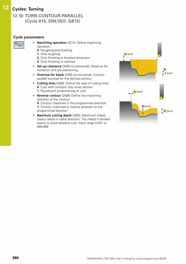
Cycles: Turning 12.10 TURN CONTOUR-PARALLEL
(Cycle 815, DIN/ISO: G815)
12
360 HEIDENHAIN | TNC 640 | User’s manual for cycle programming | 9/2015
Cycle parameters
Machining operation Q215: Define machining
operation:
0: Roughing and finishing
1: Only roughing
2: Only finishing to finished dimension
3: Only finishing to oversize
Set-up clearance Q460 (incremental): Distance for
retraction and pre-positioning.
Oversize for blank Q485 (incremental): Contour-
parallel oversize for the defined contour
Cutting lines Q486: Define the type of cutting lines:
0: Cuts with constant chip cross section
1: Equidistant proportioning of cuts
Reverse contour Q499: Define the machining
direction of the contour:
0: Contour machined in the programmed direction
1: Contour machined in reverse direction to the
programmed direction
Maximum cutting depth Q463: Maximum infeed
(radius value) in radial direction. The infeed is divided
evenly to avoid abrasive cuts. Input range 0.001 to
999.999
Q460
Ø Q483
Q458
Q463
Q484

TURN CONTOUR-PARALLEL
(Cycle 815, DIN/ISO: G815)
12.10
12
HEIDENHAIN | TNC 640 | User’s manual for cycle programming | 9/2015 361
Roughing feed rate Q478: Feed rate during
roughing. If M136 has been programmed, the
value is interpreted by the TNC in millimeters per
revolution, without M136 in millimeters per minute.
Oversize in diameter Q483 (incremental): Diameter
oversize for the defined contour
Oversize in Z Q484 (incremental): Oversize for the
defined contour in axial direction
Finishing feed rate Q505: Feed rate during
finishing. If M136 has been programmed, the
value is interpreted by the TNC in millimeters per
revolution, without M136 in millimeters per minute.
NC blocks
9 CYCL DEF 14.0 CONTOUR
10 CYCL DEF 14.1 CONTOUR LABEL2
11 CYCL DEF 815 TURN CONTOUR-PARALLEL
Q215=+0 ;MACHININGOPERATION
Q460=+2 ;SAFETY CLEARANCE
Q485=+5 ;OVERSIZE ON BLANK
Q486=+0 ;CUTTING LINES
Q499=+0 ;REVERSE CONTOUR
Q463=+3 ;MAX. CUTTING DEPTH
Q483=+0.4 ;OVERSIZE FORDIAMETER
Q484=+0.2 ;OVERSIZE IN Z
Q505=+0.2 ;FINISHING FEED RATE
12 L X+75 Y+0 Z+2 FMAX M303
13 CYCL CALL
14 M30
15 LBL 2
16 L X+60 Z+0
17 L Z-10
18 RND R5
19 L X+40 Z-35
20 RND R5
21 L X+50 Z-40
22 L Z-55
23 CC X+60 Z-55
24 C X+60 Z-60
25 L X+100
26 LBL 0

Cycles: Turning 12.11 TURN SHOULDER FACE
(Cycle 821, DIN/ISO: G821)
12
362 HEIDENHAIN | TNC 640 | User’s manual for cycle programming | 9/2015
12.11 TURN SHOULDER FACE
(Cycle 821, DIN/ISO: G821)
Application
This cycle enables you to face turn right-angled shoulders.
You can use the cycle either for roughing, finishing or complete
machining. Turning is run paraxially with roughing.
The cycle can be used for inside and outside machining. If the tool
is outside the contour to be machined when the cycle is called, the
cycle runs outside machining. If the tool is inside the contour to be
machined, the cycle runs inside machining.
Roughing cycle run
The cycle processes the area from the cycle starting point to the
end point defined in the cycle.
1 The TNC runs a paraxial infeed motion at rapid traverse. The
infeed value is calculated by the TNC with Q463 MAX. CUTTINGDEPTH.
2 The TNC cuts the area between the starting position and the
end point in traverse direction at the defined feed rate Q478.
3 The TNC returns the tool at the defined feed rate by one infeed
value.
4 The TNC positions the tool back at rapid traverse to the
beginning of cut.
5 The TNC repeats this process (1 to 4) until the final contour is
completed.
6 The TNC positions the tool back at rapid traverse to the cycle
starting point.

TURN SHOULDER FACE
(Cycle 821, DIN/ISO: G821)
12.11
12
HEIDENHAIN | TNC 640 | User’s manual for cycle programming | 9/2015 363
Finishing cycle run
1 The TNC traverses the tool in the Z coordinate by the set-up
clearance Q460. The movement is performed at rapid traverse.
2 The TNC runs the paraxial infeed motion at rapid traverse.
3 The TNC finishes the finished part contour at the defined feed
rate Q505.
4 The TNC returns the tool to set-up clearance at the defined feed
rate.
5 The TNC positions the tool back at rapid traverse to the cycle
starting point.
Please note while programming:
Program a positioning block to the starting position
with radius compensation R0 before the cycle call.
The tool position at cycle call (cycle starting point)
affects the area to be machined.
Also refer to the fundamentals of turning cycles (see
page 339).
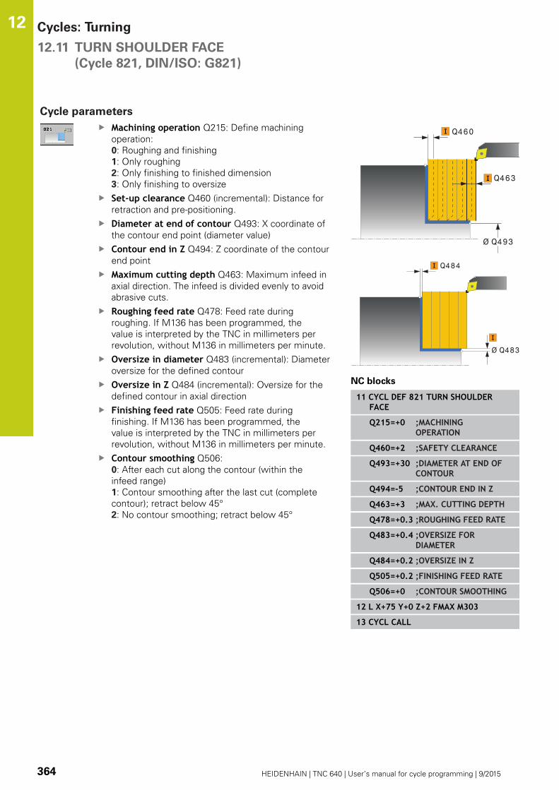
Cycles: Turning 12.11 TURN SHOULDER FACE
(Cycle 821, DIN/ISO: G821)
12
364 HEIDENHAIN | TNC 640 | User’s manual for cycle programming | 9/2015
Cycle parameters
Machining operation Q215: Define machining
operation:
0: Roughing and finishing
1: Only roughing
2: Only finishing to finished dimension
3: Only finishing to oversize
Set-up clearance Q460 (incremental): Distance for
retraction and pre-positioning.
Diameter at end of contour Q493: X coordinate of
the contour end point (diameter value)
Contour end in Z Q494: Z coordinate of the contour
end point
Maximum cutting depth Q463: Maximum infeed in
axial direction. The infeed is divided evenly to avoid
abrasive cuts.
Roughing feed rate Q478: Feed rate during
roughing. If M136 has been programmed, the
value is interpreted by the TNC in millimeters per
revolution, without M136 in millimeters per minute.
Oversize in diameter Q483 (incremental): Diameter
oversize for the defined contour
Oversize in Z Q484 (incremental): Oversize for the
defined contour in axial direction
Finishing feed rate Q505: Feed rate during
finishing. If M136 has been programmed, the
value is interpreted by the TNC in millimeters per
revolution, without M136 in millimeters per minute.
Contour smoothing Q506:
0: After each cut along the contour (within the
infeed range)
1: Contour smoothing after the last cut (complete
contour); retract below 45°
2: No contour smoothing; retract below 45°
Q460
Ø Q493
Q463
Ø Q483
Q484
NC blocks
11 CYCL DEF 821 TURN SHOULDERFACE
Q215=+0 ;MACHININGOPERATION
Q460=+2 ;SAFETY CLEARANCE
Q493=+30 ;DIAMETER AT END OFCONTOUR
Q494=-5 ;CONTOUR END IN Z
Q463=+3 ;MAX. CUTTING DEPTH
Q478=+0.3 ;ROUGHING FEED RATE
Q483=+0.4 ;OVERSIZE FORDIAMETER
Q484=+0.2 ;OVERSIZE IN Z
Q505=+0.2 ;FINISHING FEED RATE
Q506=+0 ;CONTOUR SMOOTHING
12 L X+75 Y+0 Z+2 FMAX M303
13 CYCL CALL

TURN SHOULDER FACE EXTENDED
(Cycle 822, DIN/ISO: G822)
12.12
12
HEIDENHAIN | TNC 640 | User’s manual for cycle programming | 9/2015 365
12.12 TURN SHOULDER FACE EXTENDED
(Cycle 822, DIN/ISO: G822)
Application
This cycle enables you to face turn shoulders. Expanded scope of
function:
You can insert a chamfer or curve at the contour start and
contour end.
In the cycle you can define angles for the face and
circumferential surfaces
You can insert a radius in the contour edge
You can use the cycle either for roughing, finishing or complete
machining. Turning is run paraxially with roughing.
The cycle can be used for inside and outside machining. If the start
diameter Q491 is larger than the end diameter Q493, the cycle
runs outside machining. If the start diameter Q491 is less than the
end diameter Q493, the cycle runs inside machining.
Roughing cycle run
The TNC uses the tool position as cycle starting point when a cycle
is called. If the starting point is within the area to be machined,
the TNC positions the tool in the Z coordinate and then in the X
coordinate to set-up clearance and begins the cycle there.
1 The TNC runs a paraxial infeed motion at rapid traverse. The
infeed value is calculated by the TNC with Q463 MAX. CUTTINGDEPTH.
2 The TNC cuts the area between the starting position and the
end point in traverse direction at the defined feed rate Q478.
3 The TNC returns the tool at the defined feed rate by one infeed
value.
4 The TNC positions the tool back at rapid traverse to the
beginning of cut.
5 The TNC repeats this process (1 to 4) until the final contour is
completed.
6 The TNC positions the tool back at rapid traverse to the cycle
starting point.

Cycles: Turning 12.12 TURN SHOULDER FACE EXTENDED
(Cycle 822, DIN/ISO: G822)
12
366 HEIDENHAIN | TNC 640 | User’s manual for cycle programming | 9/2015
Finishing cycle run
1 The TNC runs the paraxial infeed motion at rapid traverse.
2 The TNC finishes the finished part contour (contour starting
point to contour end point) at the defined feed rate Q505.
3 The TNC returns the tool to set-up clearance at the defined feed
rate.
4 The TNC positions the tool back at rapid traverse to the cycle
starting point.
Please note while programming:
Program a positioning block to the starting position
with radius compensation R0 before the cycle call.
The tool position at cycle call (cycle starting point)
affects the area to be machined.
Also refer to the fundamentals of turning cycles (see
page 339).

TURN SHOULDER FACE EXTENDED
(Cycle 822, DIN/ISO: G822)
12.12
12
HEIDENHAIN | TNC 640 | User’s manual for cycle programming | 9/2015 367
Cycle parameters
Machining operation Q215: Define machining
operation:
0: Roughing and finishing
1: Only roughing
2: Only finishing to finished dimension
3: Only finishing to oversize
Set-up clearance Q460 (incremental): Distance for
retraction and pre-positioning.
Diameter at contour start Q491: X coordinate of
the contour starting point (diameter value)
Contour start in Z Q492: Z coordinate of the
contour starting point
Diameter at end of contour Q493: X coordinate of
the contour end point (diameter value)
Contour end in Z Q494: Z coordinate of the contour
end point
Angle of face Q495: Angle between the face and
the rotary axis
Type of starting element Q501: Define the type of
element at the start of the contour (circumferential
surface):
0: No additional element
1: Element is a chamfer
2: Element is a radius
Q460
Ø Q491
Q494
Ø Q493
Q463
Ø Q483
Q484
Q492
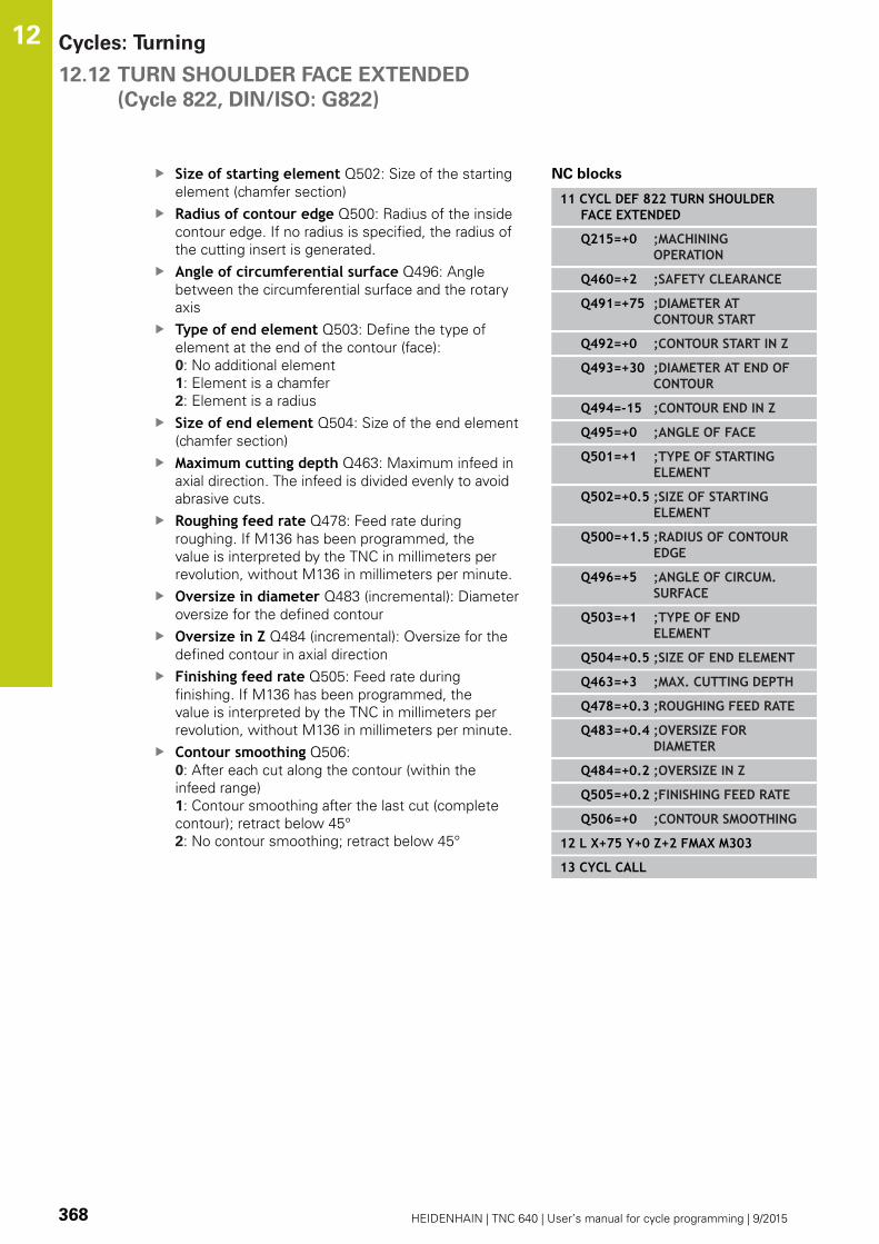
Cycles: Turning 12.12 TURN SHOULDER FACE EXTENDED
(Cycle 822, DIN/ISO: G822)
12
368 HEIDENHAIN | TNC 640 | User’s manual for cycle programming | 9/2015
Size of starting element Q502: Size of the starting
element (chamfer section)
Radius of contour edge Q500: Radius of the inside
contour edge. If no radius is specified, the radius of
the cutting insert is generated.
Angle of circumferential surface Q496: Angle
between the circumferential surface and the rotary
axis
Type of end element Q503: Define the type of
element at the end of the contour (face):
0: No additional element
1: Element is a chamfer
2: Element is a radius
Size of end element Q504: Size of the end element
(chamfer section)
Maximum cutting depth Q463: Maximum infeed in
axial direction. The infeed is divided evenly to avoid
abrasive cuts.
Roughing feed rate Q478: Feed rate during
roughing. If M136 has been programmed, the
value is interpreted by the TNC in millimeters per
revolution, without M136 in millimeters per minute.
Oversize in diameter Q483 (incremental): Diameter
oversize for the defined contour
Oversize in Z Q484 (incremental): Oversize for the
defined contour in axial direction
Finishing feed rate Q505: Feed rate during
finishing. If M136 has been programmed, the
value is interpreted by the TNC in millimeters per
revolution, without M136 in millimeters per minute.
Contour smoothing Q506:
0: After each cut along the contour (within the
infeed range)
1: Contour smoothing after the last cut (complete
contour); retract below 45°
2: No contour smoothing; retract below 45°
NC blocks
11 CYCL DEF 822 TURN SHOULDERFACE EXTENDED
Q215=+0 ;MACHININGOPERATION
Q460=+2 ;SAFETY CLEARANCE
Q491=+75 ;DIAMETER ATCONTOUR START
Q492=+0 ;CONTOUR START IN Z
Q493=+30 ;DIAMETER AT END OFCONTOUR
Q494=-15 ;CONTOUR END IN Z
Q495=+0 ;ANGLE OF FACE
Q501=+1 ;TYPE OF STARTINGELEMENT
Q502=+0.5 ;SIZE OF STARTINGELEMENT
Q500=+1.5 ;RADIUS OF CONTOUREDGE
Q496=+5 ;ANGLE OF CIRCUM.SURFACE
Q503=+1 ;TYPE OF ENDELEMENT
Q504=+0.5 ;SIZE OF END ELEMENT
Q463=+3 ;MAX. CUTTING DEPTH
Q478=+0.3 ;ROUGHING FEED RATE
Q483=+0.4 ;OVERSIZE FORDIAMETER
Q484=+0.2 ;OVERSIZE IN Z
Q505=+0.2 ;FINISHING FEED RATE
Q506=+0 ;CONTOUR SMOOTHING
12 L X+75 Y+0 Z+2 FMAX M303
13 CYCL CALL
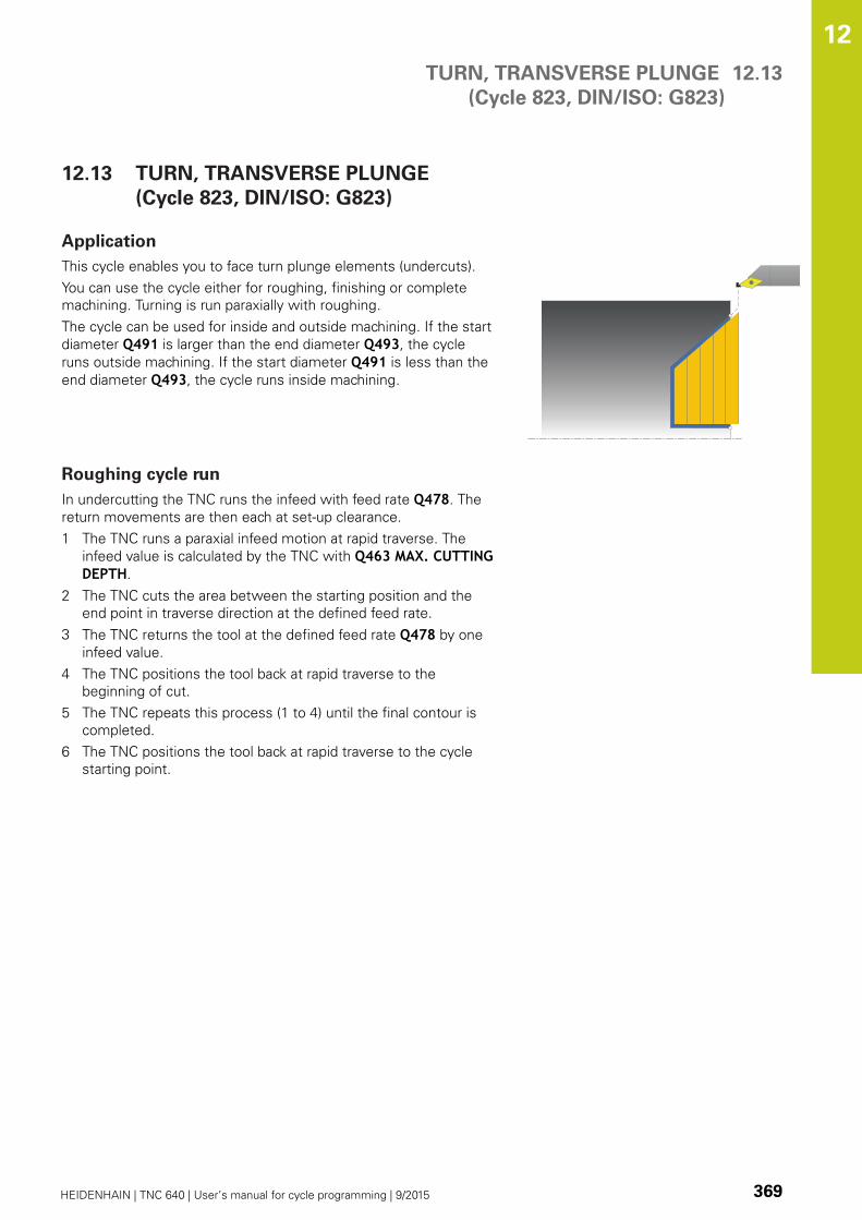
TURN, TRANSVERSE PLUNGE
(Cycle 823, DIN/ISO: G823)
12.13
12
HEIDENHAIN | TNC 640 | User’s manual for cycle programming | 9/2015 369
12.13 TURN, TRANSVERSE PLUNGE
(Cycle 823, DIN/ISO: G823)
Application
This cycle enables you to face turn plunge elements (undercuts).
You can use the cycle either for roughing, finishing or complete
machining. Turning is run paraxially with roughing.
The cycle can be used for inside and outside machining. If the start
diameter Q491 is larger than the end diameter Q493, the cycle
runs outside machining. If the start diameter Q491 is less than the
end diameter Q493, the cycle runs inside machining.
Roughing cycle run
In undercutting the TNC runs the infeed with feed rate Q478. The
return movements are then each at set-up clearance.
1 The TNC runs a paraxial infeed motion at rapid traverse. The
infeed value is calculated by the TNC with Q463 MAX. CUTTINGDEPTH.
2 The TNC cuts the area between the starting position and the
end point in traverse direction at the defined feed rate.
3 The TNC returns the tool at the defined feed rate Q478 by one
infeed value.
4 The TNC positions the tool back at rapid traverse to the
beginning of cut.
5 The TNC repeats this process (1 to 4) until the final contour is
completed.
6 The TNC positions the tool back at rapid traverse to the cycle
starting point.
Cycles: Turning 12.13 TURN, TRANSVERSE PLUNGE
(Cycle 823, DIN/ISO: G823)
12
370 HEIDENHAIN | TNC 640 | User’s manual for cycle programming | 9/2015
Finishing cycle run
The TNC uses the tool position as cycle starting point when a
cycle is called. If the Z coordinate of the starting point is less than
the contour starting point, the TNC positions the tool in the Z
coordinate to set-up clearance and begins the cycle there.
1 The TNC runs the infeed motion at rapid traverse.
2 The TNC finishes the finished part contour (contour starting
point to contour end point) at the defined feed rate Q505.
3 The TNC returns the tool to set-up clearance at the defined feed
rate.
4 The TNC positions the tool back at rapid traverse to the cycle
starting point.
Please note while programming:
Program a positioning block to a safe position with
radius compensation R0 before the cycle call.
The tool position at cycle call (cycle starting point)
affects the area to be machined.
The TNC takes the cutting geometry of the tool into
account to prevent damage to contour elements.
If complete machining with the active tool is not
possible, a warning is output by the TNC.
Also refer to the fundamentals of turning cycles (see
page 339).

TURN, TRANSVERSE PLUNGE
(Cycle 823, DIN/ISO: G823)
12.13
12
HEIDENHAIN | TNC 640 | User’s manual for cycle programming | 9/2015 371
Cycle parameters
Machining operation Q215: Define machining
operation:
0: Roughing and finishing
1: Only roughing
2: Only finishing to finished dimension
3: Only finishing to oversize
Set-up clearance Q460 (incremental): Distance for
retraction and pre-positioning.
Diameter at contour start Q491: X coordinate of
the contour starting point (diameter value)
Contour start in Z Q492: Z coordinate of the
starting point for the plunging path
Diameter at end of contour Q493: X coordinate of
the contour end point (diameter value)
Contour end in Z Q494: Z coordinate of the contour
end point
Angle of side Q495: Angle of the plunging side. The
reference angle is formed by the parallel line to the
rotary axis
Maximum cutting depth Q463: Maximum infeed in
axial direction. The infeed is divided evenly to avoid
abrasive cuts.
Roughing feed rate Q478: Feed rate during
roughing. If M136 has been programmed, the
value is interpreted by the TNC in millimeters per
revolution, without M136 in millimeters per minute.
Oversize in diameter Q483 (incremental): Diameter
oversize for the defined contour
Oversize in Z Q484 (incremental): Oversize for the
defined contour in axial direction
Finishing feed rate Q505: Feed rate during
finishing. If M136 has been programmed, the
value is interpreted by the TNC in millimeters per
revolution, without M136 in millimeters per minute.
Contour smoothing Q506:
0: After each cut along the contour (within the
infeed range)
1: Contour smoothing after the last cut (complete
contour); retract below 45°
2: No contour smoothing; retract below 45°
Q460
Ø Q493
Q494
Q463
Ø Q491
Q492
Q484
Ø Q483
NC blocks
11 CYCL DEF 823 TURN, TRANSVERSEPLUNGE
Q215=+0 ;MACHININGOPERATION
Q460=+2 ;SAFETY CLEARANCE
Q491=+75 ;DIAMETER ATCONTOUR START
Q492=+0 ;CONTOUR START IN Z
Q493=+20 ;DIAMETER AT END OFCONTOUR
Q494=-5 ;CONTOUR END IN Z
Q495=+60 ;ANGLE OF SIDE
Q463=+3 ;MAX. CUTTING DEPTH
Q478=+0.3 ;ROUGHING FEED RATE
Q483=+0.4 ;OVERSIZE FORDIAMETER
Q484=+0.2 ;OVERSIZE IN Z
Q505=+0.2 ;FINISHING FEED RATE
Q506=+0 ;CONTOUR SMOOTHING
12 L X+75 Y+0 Z+2 FMAX M303
13 CYCL CALL

Cycles: Turning 12.14 TURN, TRANSVERSE PLUNGE EXTENDED
(Cycle 824, DIN/ISO: G824)
12
372 HEIDENHAIN | TNC 640 | User’s manual for cycle programming | 9/2015
12.14 TURN, TRANSVERSE PLUNGE
EXTENDED
(Cycle 824, DIN/ISO: G824)
Application
This cycle enables you to face turn plunge elements (undercuts).
Expanded scope of function:
You can insert a chamfer or curve at the contour start and
contour end.
In the cycle you can define an angle for the face and a radius for
the contour edge
You can use the cycle either for roughing, finishing or complete
machining. Turning is run paraxially with roughing.
The cycle can be used for inside and outside machining. If the start
diameter Q491 is larger than the end diameter Q493, the cycle
runs outside machining. If the start diameter Q491 is less than the
end diameter Q493, the cycle runs inside machining.
Roughing cycle run
In undercutting the TNC runs the infeed with feed rate Q478. The
return movements are then each at set-up clearance.
1 The TNC runs a paraxial infeed motion at rapid traverse. The
infeed value is calculated by the TNC with Q463 MAX. CUTTINGDEPTH.
2 The TNC cuts the area between the starting position and the
end point in traverse direction at the defined feed rate.
3 The TNC returns the tool at the defined feed rate Q478 by one
infeed value.
4 The TNC positions the tool back at rapid traverse to the
beginning of cut.
5 The TNC repeats this process (1 to 4) until the final contour is
completed.
6 The TNC positions the tool back at rapid traverse to the cycle
starting point.

TURN, TRANSVERSE PLUNGE EXTENDED
(Cycle 824, DIN/ISO: G824)
12.14
12
HEIDENHAIN | TNC 640 | User’s manual for cycle programming | 9/2015 373
Finishing cycle run
The TNC uses the tool position as cycle starting point when a
cycle is called. If the Z coordinate of the starting point is less than
the contour starting point, the TNC positions the tool in the Z
coordinate to set-up clearance and begins the cycle there.
1 The TNC runs the infeed motion at rapid traverse.
2 The TNC finishes the finished part contour (contour starting
point to contour end point) at the defined feed rate Q505.
3 The TNC returns the tool to set-up clearance at the defined feed
rate.
4 The TNC positions the tool back at rapid traverse to the cycle
starting point.
Please note while programming:
Program a positioning block to a safe position with
radius compensation R0 before the cycle call.
The tool position at cycle call (cycle starting point)
affects the area to be machined.
The TNC takes the cutting geometry of the tool into
account to prevent damage to contour elements.
If complete machining with the active tool is not
possible, a warning is output by the TNC.
Also refer to the fundamentals of turning cycles (see
page 339).

Cycles: Turning 12.14 TURN, TRANSVERSE PLUNGE EXTENDED
(Cycle 824, DIN/ISO: G824)
12
374 HEIDENHAIN | TNC 640 | User’s manual for cycle programming | 9/2015
Cycle parameters
Machining operation Q215: Define machining
operation:
0: Roughing and finishing
1: Only roughing
2: Only finishing to finished dimension
3: Only finishing to oversize
Set-up clearance Q460 (incremental): Distance for
retraction and pre-positioning.
Diameter at contour start Q491: X coordinate of
the starting point for the plunging path (diameter
value)
Contour start in Z Q492: Z coordinate of the
starting point for the plunging path
Diameter at end of contour Q493: X coordinate of
the contour end point (diameter value)
Contour end in Z Q494: Z coordinate of the contour
end point
Angle of side Q495: Angle of the plunging side. The
reference angle is formed by the parallel line to the
rotary axis
Type of starting element Q501: Define the type of
element at the start of the contour (circumferential
surface):
0: No additional element
1: Element is a chamfer
2: Element is a radius
Q460
Ø Q493
Q494
Q463
Ø Q491
Q492
Q484
Ø Q483

TURN, TRANSVERSE PLUNGE EXTENDED
(Cycle 824, DIN/ISO: G824)
12.14
12
HEIDENHAIN | TNC 640 | User’s manual for cycle programming | 9/2015 375
Size of starting element Q502: Size of the starting
element (chamfer section)
Radius of contour edge Q500: Radius of the inside
contour edge. If no radius is specified, the radius of
the cutting insert is generated.
Type of end element Q503: Define the type of
element at the end of the contour (face):
0: No additional element
1: Element is a chamfer
2: Element is a radius
Size of end element Q504: Size of the end element
(chamfer section)
Maximum cutting depth Q463: Maximum infeed in
axial direction. The infeed is divided evenly to avoid
abrasive cuts.
Roughing feed rate Q478: Feed rate during
roughing. If M136 has been programmed, the
value is interpreted by the TNC in millimeters per
revolution, without M136 in millimeters per minute.
Oversize in diameter Q483 (incremental): Diameter
oversize for the defined contour
Oversize in Z Q484 (incremental): Oversize for the
defined contour in axial direction
Finishing feed rate Q505: Feed rate during
finishing. If M136 has been programmed, the
value is interpreted by the TNC in millimeters per
revolution, without M136 in millimeters per minute.
Contour smoothing Q506:
0: After each cut along the contour (within the
infeed range)
1: Contour smoothing after the last cut (complete
contour); retract below 45°
2: No contour smoothing; retract below 45°
NC blocks
11 CYCL DEF 824 TURN, TRANSVERSEPLUNGE EXT.
Q215=+0 ;MACHININGOPERATION
Q460=+2 ;SAFETY CLEARANCE
Q491=+75 ;DIAMETER ATCONTOUR START
Q492=+0 ;CONTOUR START IN Z
Q493=+20 ;DIAMETER AT END OFCONTOUR
Q494=-10 ;CONTOUR END IN Z
Q495=+70 ;ANGLE OF SIDE
Q501=+1 ;TYPE OF STARTINGELEMENT
Q502=+0.5 ;SIZE OF STARTINGELEMENT
Q500=+1.5 ;RADIUS OF CONTOUREDGE
Q496=+0 ;ANGLE OF FACE
Q503=+1 ;TYPE OF ENDELEMENT
Q504=+0.5 ;SIZE OF END ELEMENT
Q463=+3 ;MAX. CUTTING DEPTH
Q478=+0.3 ;ROUGHING FEED RATE
Q483=+0.4 ;OVERSIZE FORDIAMETER
Q484=+0.2 ;OVERSIZE IN Z
Q505=+0.2 ;FINISHING FEED RATE
Q506=+0 ;CONTOUR SMOOTHING
12 L X+75 Y+0 Z+2 FMAX M303
13 CYCL CALL

Cycles: Turning 12.15 TURN CONTOUR FACE
(Cycle 820, DIN/ISO: G820)
12
376 HEIDENHAIN | TNC 640 | User’s manual for cycle programming | 9/2015
12.15 TURN CONTOUR FACE
(Cycle 820, DIN/ISO: G820)
Application
This cycle enables you to face turn workpieces with any turning
contours. The contour description is in a subprogram.
You can use the cycle either for roughing, finishing or complete
machining. Turning is run paraxially with roughing.
The cycle can be used for inside and outside machining. If the
starting point of the contour is larger than the end point of the
contour, the cycle runs outside machining. If the contour starting
point is less than the end point, the cycle runs inside machining.
Roughing cycle run
The TNC uses the tool position as cycle starting point when a
cycle is called. If the Z coordinate of the starting point is less than
the contour starting point, the TNC positions the tool in the Z
coordinate to the contour starting point and begins the cycle there.
1 The TNC runs a paraxial infeed motion at rapid traverse. The
infeed value is calculated by the TNC with Q463 MAX. CUTTINGDEPTH.
2 The TNC machines the area between the starting position and
the end point in traverse direction. The transverse cut is run
paraxially with the defined feed rate Q478.
3 The TNC returns the tool at the defined feed rate by one infeed
value.
4 The TNC positions the tool back at rapid traverse to the
beginning of cut.
5 The TNC repeats this process (1 to 4) until the final contour is
completed.
6 The TNC positions the tool back at rapid traverse to the cycle
starting point.

TURN CONTOUR FACE
(Cycle 820, DIN/ISO: G820)
12.15
12
HEIDENHAIN | TNC 640 | User’s manual for cycle programming | 9/2015 377
Finishing cycle run
If the Z coordinate of the starting point is less than the contour
starting point, the TNC positions the tool in the Z coordinate to set-
up clearance and begins the cycle there.
1 The TNC runs the infeed motion at rapid traverse.
2 The TNC finishes the finished part contour (contour starting
point to contour end point) at the defined feed rate Q505.
3 The TNC returns the tool to set-up clearance at the defined feed
rate.
4 The TNC positions the tool back at rapid traverse to the cycle
starting point.
Please note while programming:
The cutting limit defines the contour range to be
machined. The approach and departure paths can
exceed the cutting limits.
The tool position before the cycle call influences the
execution of the cutting limit. The TNC 640 machines
the area to the right or to the left of the cutting
limit, depending on which side the tool has been
positioned before the cycle is called.
Program a positioning block to a safe position with
radius compensation R0 before the cycle call.
The tool position at cycle call (cycle starting point)
affects the area to be machined.
The TNC takes the cutting geometry of the tool into
account to prevent damage to contour elements.
If complete machining with the active tool is not
possible, a warning is output by the TNC.
Before calling the cycle you must program the cycle
14 CONTOUR to define the subprogram number.
Also refer to the fundamentals of turning cycles (see
page 339).
When you use local QL Q parameters in a contour
subprogram you must also assign or calculate these
in the contour subprogram.

Cycles: Turning 12.15 TURN CONTOUR FACE
(Cycle 820, DIN/ISO: G820)
12
378 HEIDENHAIN | TNC 640 | User’s manual for cycle programming | 9/2015
Cycle parameters
Machining operation Q215: Define machining
operation:
0: Roughing and finishing
1: Only roughing
2: Only finishing to finished dimension
3: Only finishing to oversize
Set-up clearance Q460 (incremental): Distance for
retraction and pre-positioning.
Reverse contour Q499: Define the machining
direction of the contour:
0: Contour machined in the programmed direction
1: Contour machined in reverse direction to the
programmed direction
Maximum cutting depth Q463: Maximum infeed in
axial direction. The infeed is divided evenly to avoid
abrasive cuts.
Roughing feed rate Q478: Feed rate during
roughing. If M136 has been programmed, the
value is interpreted by the TNC in millimeters per
revolution, without M136 in millimeters per minute.
Oversize in diameter Q483 (incremental): Diameter
oversize for the defined contour
Q460
Q463
Ø Q483
Q484
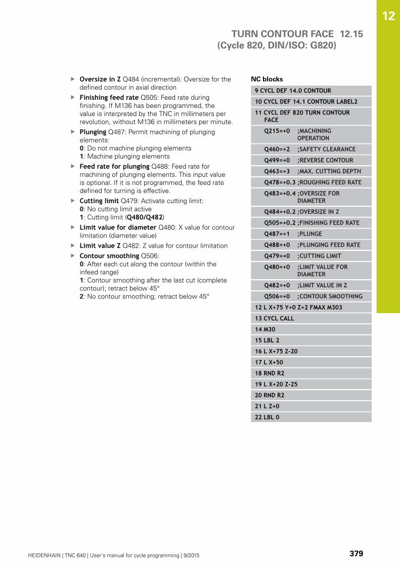
TURN CONTOUR FACE
(Cycle 820, DIN/ISO: G820)
12.15
12
HEIDENHAIN | TNC 640 | User’s manual for cycle programming | 9/2015 379
Oversize in Z Q484 (incremental): Oversize for the
defined contour in axial direction
Finishing feed rate Q505: Feed rate during
finishing. If M136 has been programmed, the
value is interpreted by the TNC in millimeters per
revolution, without M136 in millimeters per minute.
Plunging Q487: Permit machining of plunging
elements:
0: Do not machine plunging elements
1: Machine plunging elements
Feed rate for plunging Q488: Feed rate for
machining of plunging elements. This input value
is optional. If it is not programmed, the feed rate
defined for turning is effective.
Cutting limit Q479: Activate cutting limit:
0: No cutting limit active
1: Cutting limit (Q480/Q482)
Limit value for diameter Q480: X value for contour
limitation (diameter value)
Limit value Z Q482: Z value for contour limitation
Contour smoothing Q506:
0: After each cut along the contour (within the
infeed range)
1: Contour smoothing after the last cut (complete
contour); retract below 45°
2: No contour smoothing; retract below 45°
NC blocks
9 CYCL DEF 14.0 CONTOUR
10 CYCL DEF 14.1 CONTOUR LABEL2
11 CYCL DEF 820 TURN CONTOURFACE
Q215=+0 ;MACHININGOPERATION
Q460=+2 ;SAFETY CLEARANCE
Q499=+0 ;REVERSE CONTOUR
Q463=+3 ;MAX. CUTTING DEPTH
Q478=+0.3 ;ROUGHING FEED RATE
Q483=+0.4 ;OVERSIZE FORDIAMETER
Q484=+0.2 ;OVERSIZE IN Z
Q505=+0.2 ;FINISHING FEED RATE
Q487=+1 ;PLUNGE
Q488=+0 ;PLUNGING FEED RATE
Q479=+0 ;CUTTING LIMIT
Q480=+0 ;LIMIT VALUE FORDIAMETER
Q482=+0 ;LIMIT VALUE IN Z
Q506=+0 ;CONTOUR SMOOTHING
12 L X+75 Y+0 Z+2 FMAX M303
13 CYCL CALL
14 M30
15 LBL 2
16 L X+75 Z-20
17 L X+50
18 RND R2
19 L X+20 Z-25
20 RND R2
21 L Z+0
22 LBL 0

Cycles: Turning 12.16 SIMPLE RADIAL RECESSING
(Cycle 841, DIN/ISO: G841)
12
380 HEIDENHAIN | TNC 640 | User’s manual for cycle programming | 9/2015
12.16 SIMPLE RADIAL RECESSING
(Cycle 841, DIN/ISO: G841)
Application
This cycle enables you to recess right-angled slots in longitudinal
direction. With recess turning, a recessing traverse to plunging
depth and then a roughing traverse is alternatively machined. The
machining process thus requires a minimum of retraction and
infeed movements.
You can use the cycle either for roughing, finishing or complete
machining. Turning is run paraxially with roughing.
The cycle can be used for inside and outside machining. If the tool
is outside the contour to be machined when the cycle is called, the
cycle runs outside machining. If the tool is inside the contour to be
machined, the cycle runs inside machining.
Roughing cycle run
The TNC uses the tool position as cycle starting point when a cycle
is called. The cycle processes only the area from the cycle starting
point to the end point defined in the cycle.
1 From the cycle starting point, the TNC recesses until the first
plunging depth.
2 The TNC cuts the area between the starting position and the
end point in longitudinal direction at the defined feed rate Q478.
3 If the input parameter Q488 is defined in the cycle, plunging
elements are machined at the programmed feed rate for
plunging.
4 If only one machining direction Q507=1 was specified in
the cycle, the TNC retracts the tool by the set-up clearance,
positions the tool back at rapid traverse and approaches the
contour again with the defined feed rate. With machining
direction Q507=0, infeed is on both sides.
5 The tool recesses to the next plunging depth.
6 The TNC repeats this process (2 to 4) until the slot depth is
reached.
7 The TNC returns the tool to set-up clearance and machines a
recessing traverse on both side walls.
8 The TNC positions the tool back at rapid traverse to the cycle
starting point.

SIMPLE RADIAL RECESSING
(Cycle 841, DIN/ISO: G841)
12.16
12
HEIDENHAIN | TNC 640 | User’s manual for cycle programming | 9/2015 381
Finishing cycle run
1 The TNC positions the tool at rapid traverse to the first slot side.
2 The TNC finishes the side wall of the slot at the defined feed
rate Q505.
3 The TNC finishes the slot floor at the defined feed rate.
4 The TNC returns the tool at rapid traverse.
5 The TNC positions the tool at rapid traverse to the second slot
side.
6 The TNC finishes the side wall of the slot at the defined feed
rate Q505.
7 The TNC positions the tool back at rapid traverse to the cycle
starting point.
Please note while programming:
Program a positioning block to the starting position
with radius compensation R0 before the cycle call.
The tool position at cycle call defines the size of the
area to be machined (cycle starting point).
From the second infeed, the TNC reduces each
further cutting traverse by 0.1 mm. This reduces
lateral pressure on the tool. If the offset width Q508was input into the cycle, the TNC reduces the cutting
traverse by this value. After clearance roughing, the
remaining material is removed with a single cut. The
TNC generates an error message if the lateral offset
exceeds 80 % of the effective cutting width (effective
cutting width = cutting width –2*cutting radius).

Cycles: Turning 12.16 SIMPLE RADIAL RECESSING
(Cycle 841, DIN/ISO: G841)
12
382 HEIDENHAIN | TNC 640 | User’s manual for cycle programming | 9/2015
Cycle parameters
Machining operation Q215: Define machining
operation:
0: Roughing and finishing
1: Only roughing
2: Only finishing to finished dimension
3: Only finishing to oversize
Set-up clearance Q460: Reserved, currently
without function
Diameter at end of contour Q493: X coordinate of
the contour end point (diameter value)
Contour end in Z Q494: Z coordinate of the contour
end point
Roughing feed rate Q478: Feed rate during
roughing. If M136 has been programmed, the
value is interpreted by the TNC in millimeters per
revolution, without M136 in millimeters per minute.
Oversize in diameter Q483 (incremental): Diameter
oversize for the defined contour
Oversize in Z Q484 (incremental): Oversize for the
defined contour in axial direction
Finishing feed rate Q505: Feed rate during
finishing. If M136 has been programmed, the
value is interpreted by the TNC in millimeters per
revolution, without M136 in millimeters per minute.
Maximum cutting depth Q463: Maximum infeed
(radius value) in radial direction. The infeed is divided
evenly to avoid abrasive cuts. Input range 0.001 to
999.999
Machining direction Q507: Cutting direction:
0: bidirectional (in both directions)
1: unidirectional (in contour direction)
Offset width Q508: Reduction of cutting length.
After clearance roughing, the remaining material
is removed with a single cut. If required, the TNC
limits the programmed offset width.
Turning depth compensation Q509: Depending
on factors such as workpiece material or feed rate,
the tool tip is displaced during a turning operation.
You can correct the resulting infeed error with the
turning depth compensation factor.
Feed rate for plunging Q488: Feed rate for
machining of plunging elements. This input value
is optional. If it is not programmed, the feed rate
defined for turning is effective.
Q460
Ø Q493
Q494 Q463
Ø Q483
Q484
NC blocks
11 CYCL DEF 841 RECESS TURNG.SIMPLE R.
Q215=+0 ;MACHININGOPERATION
Q460=+2 ;SAFETY CLEARANCE
Q493=+50 ;DIAMETER AT END OFCONTOUR
Q494=-50 ;CONTOUR END IN Z
Q478=+0.3 ;ROUGHING FEED RATE
Q483=+0.4 ;OVERSIZE FORDIAMETER
Q484=+0.2 ;OVERSIZE IN Z
Q505=+0.2 ;FINISHING FEED RATE
Q463=+2 ;MAX. CUTTING DEPTH
Q507=+0 ;MACHINING DIRECTION
Q508=+0 ;OFFSET WIDTH
Q509=+0 ;DEPTH COMPENSATION
Q488=+0 ;PLUNGING FEED RATE
12 L X+75 Y+0 Z-25 FMAX M303
13 CYCL CALL
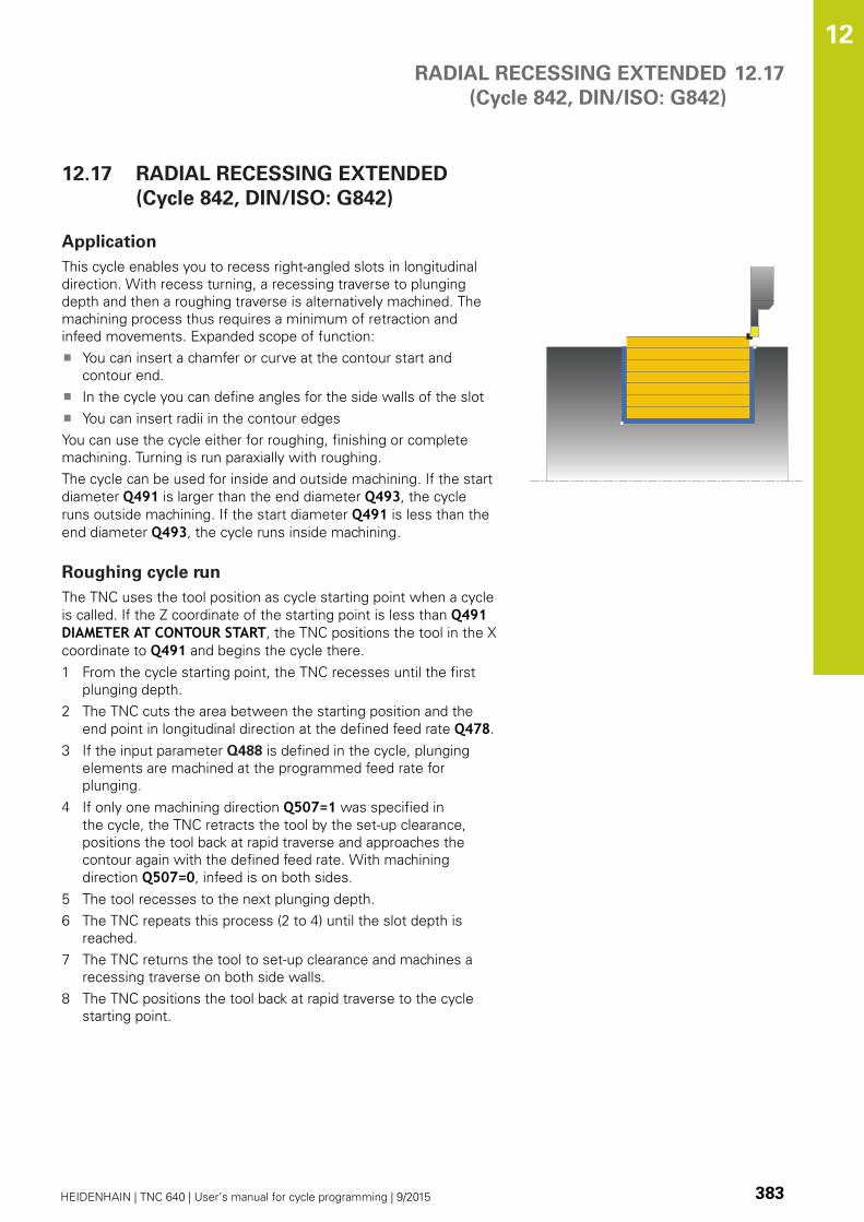
RADIAL RECESSING EXTENDED
(Cycle 842, DIN/ISO: G842)
12.17
12
HEIDENHAIN | TNC 640 | User’s manual for cycle programming | 9/2015 383
12.17 RADIAL RECESSING EXTENDED
(Cycle 842, DIN/ISO: G842)
Application
This cycle enables you to recess right-angled slots in longitudinal
direction. With recess turning, a recessing traverse to plunging
depth and then a roughing traverse is alternatively machined. The
machining process thus requires a minimum of retraction and
infeed movements. Expanded scope of function:
You can insert a chamfer or curve at the contour start and
contour end.
In the cycle you can define angles for the side walls of the slot
You can insert radii in the contour edges
You can use the cycle either for roughing, finishing or complete
machining. Turning is run paraxially with roughing.
The cycle can be used for inside and outside machining. If the start
diameter Q491 is larger than the end diameter Q493, the cycle
runs outside machining. If the start diameter Q491 is less than the
end diameter Q493, the cycle runs inside machining.
Roughing cycle run
The TNC uses the tool position as cycle starting point when a cycle
is called. If the Z coordinate of the starting point is less than Q491DIAMETER AT CONTOUR START, the TNC positions the tool in the X
coordinate to Q491 and begins the cycle there.
1 From the cycle starting point, the TNC recesses until the first
plunging depth.
2 The TNC cuts the area between the starting position and the
end point in longitudinal direction at the defined feed rate Q478.
3 If the input parameter Q488 is defined in the cycle, plunging
elements are machined at the programmed feed rate for
plunging.
4 If only one machining direction Q507=1 was specified in
the cycle, the TNC retracts the tool by the set-up clearance,
positions the tool back at rapid traverse and approaches the
contour again with the defined feed rate. With machining
direction Q507=0, infeed is on both sides.
5 The tool recesses to the next plunging depth.
6 The TNC repeats this process (2 to 4) until the slot depth is
reached.
7 The TNC returns the tool to set-up clearance and machines a
recessing traverse on both side walls.
8 The TNC positions the tool back at rapid traverse to the cycle
starting point.

Cycles: Turning 12.17 RADIAL RECESSING EXTENDED
(Cycle 842, DIN/ISO: G842)
12
384 HEIDENHAIN | TNC 640 | User’s manual for cycle programming | 9/2015
Finishing cycle run
The TNC uses the tool position as cycle starting point when a cycle
is called. If the Z coordinate of the starting point is less than Q491DIAMETER AT CONTOUR START, the TNC positions the tool in the X
coordinate to Q491 and begins the cycle there.
1 The TNC positions the tool at rapid traverse to the first slot side.
2 The TNC finishes the side wall of the slot at the defined feed
rate Q505.
3 The TNC finishes the slot floor at the defined feed rate. If a
radius for contour edges Q500 was specified, the TNC finishes
the complete slot in one pass.
4 The TNC returns the tool at rapid traverse.
5 The TNC positions the tool at rapid traverse to the second slot
side.
6 The TNC finishes the side wall of the slot at the defined feed
rate Q505.
7 The TNC positions the tool back at rapid traverse to the cycle
starting point.
Please note while programming:
Program a positioning block to the starting position
with radius compensation R0 before the cycle call.
The tool position at cycle call defines the size of the
area to be machined (cycle starting point).
From the second infeed, the TNC reduces each
further cutting traverse by 0.1 mm. This reduces
lateral pressure on the tool. If the offset width Q508was input into the cycle, the TNC reduces the cutting
traverse by this value. After clearance roughing, the
remaining material is removed with a single cut. The
TNC generates an error message if the lateral offset
exceeds 80 % of the effective cutting width (effective
cutting width = cutting width –2*cutting radius).
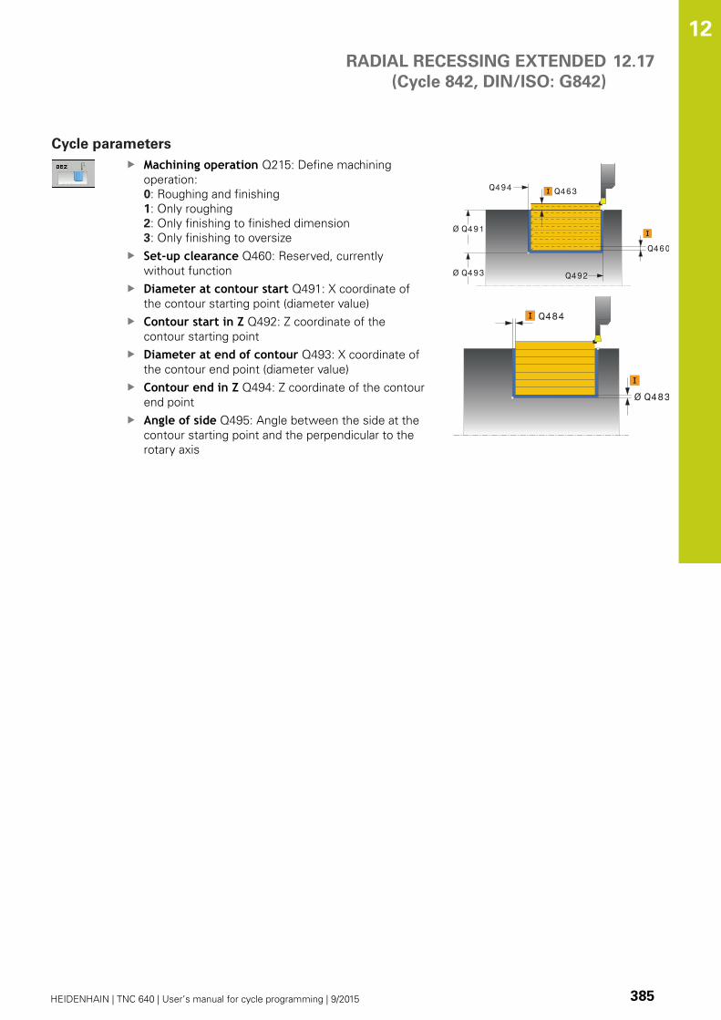
RADIAL RECESSING EXTENDED
(Cycle 842, DIN/ISO: G842)
12.17
12
HEIDENHAIN | TNC 640 | User’s manual for cycle programming | 9/2015 385
Cycle parameters
Machining operation Q215: Define machining
operation:
0: Roughing and finishing
1: Only roughing
2: Only finishing to finished dimension
3: Only finishing to oversize
Set-up clearance Q460: Reserved, currently
without function
Diameter at contour start Q491: X coordinate of
the contour starting point (diameter value)
Contour start in Z Q492: Z coordinate of the
contour starting point
Diameter at end of contour Q493: X coordinate of
the contour end point (diameter value)
Contour end in Z Q494: Z coordinate of the contour
end point
Angle of side Q495: Angle between the side at the
contour starting point and the perpendicular to the
rotary axis
Q460
Ø Q493
Ø Q491
Q492
Q494 Q463
Ø Q483
Q484
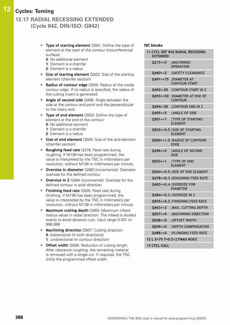
Cycles: Turning 12.17 RADIAL RECESSING EXTENDED
(Cycle 842, DIN/ISO: G842)
12
386 HEIDENHAIN | TNC 640 | User’s manual for cycle programming | 9/2015
Type of starting element Q501: Define the type of
element at the start of the contour (circumferential
surface):
0: No additional element
1: Element is a chamfer
2: Element is a radius
Size of starting element Q502: Size of the starting
element (chamfer section)
Radius of contour edge Q500: Radius of the inside
contour edge. If no radius is specified, the radius of
the cutting insert is generated.
Angle of second side Q496: Angle between the
side at the contour end point and the perpendicular
to the rotary axis
Type of end element Q503: Define the type of
element at the end of the contour:
0: No additional element
1: Element is a chamfer
2: Element is a radius
Size of end element Q504: Size of the end element
(chamfer section)
Roughing feed rate Q478: Feed rate during
roughing. If M136 has been programmed, the
value is interpreted by the TNC in millimeters per
revolution, without M136 in millimeters per minute.
Oversize in diameter Q483 (incremental): Diameter
oversize for the defined contour
Oversize in Z Q484 (incremental): Oversize for the
defined contour in axial direction
Finishing feed rate Q505: Feed rate during
finishing. If M136 has been programmed, the
value is interpreted by the TNC in millimeters per
revolution, without M136 in millimeters per minute.
Maximum cutting depth Q463: Maximum infeed
(radius value) in radial direction. The infeed is divided
evenly to avoid abrasive cuts. Input range 0.001 to
999.999
Machining direction Q507: Cutting direction:
0: bidirectional (in both directions)
1: unidirectional (in contour direction)
Offset width Q508: Reduction of cutting length.
After clearance roughing, the remaining material
is removed with a single cut. If required, the TNC
limits the programmed offset width.
NC blocks
11 CYCL DEF 842 RADIAL RECESSINGEXTENDED
Q215=+0 ;MACHININGOPERATION
Q460=+2 ;SAFETY CLEARANCE
Q491=+75 ;DIAMETER ATCONTOUR START
Q492=-20 ;CONTOUR START IN Z
Q493=+50 ;DIAMETER AT END OFCONTOUR
Q494=-50 ;CONTOUR END IN Z
Q495=+5 ;ANGLE OF SIDE
Q501=+1 ;TYPE OF STARTINGELEMENT
Q502=+0.5 ;SIZE OF STARTINGELEMENT
Q500=+1.5 ;RADIUS OF CONTOUREDGE
Q496=+5 ;ANGLE OF SECONDSIDE
Q503=+1 ;TYPE OF ENDELEMENT
Q504=+0.5 ;SIZE OF END ELEMENT
Q478=+0.3 ;ROUGHING FEED RATE
Q483=+0.4 ;OVERSIZE FORDIAMETER
Q484=+0.2 ;OVERSIZE IN Z
Q505=+0.2 ;FINISHING FEED RATE
Q463=+2 ;MAX. CUTTING DEPTH
Q507=+0 ;MACHINING DIRECTION
Q508=+0 ;OFFSET WIDTH
Q509=+0 ;DEPTH COMPENSATION
Q488=+0 ;PLUNGING FEED RATE
12 L X+75 Y+0 Z+2 FMAX M303
13 CYCL CALL

RADIAL RECESSING EXTENDED
(Cycle 842, DIN/ISO: G842)
12.17
12
HEIDENHAIN | TNC 640 | User’s manual for cycle programming | 9/2015 387
Turning depth compensation Q509: Depending
on factors such as workpiece material or feed rate,
the tool tip is displaced during a turning operation.
You can correct the resulting infeed error with the
turning depth compensation factor.
Feed rate for plunging Q488: Feed rate for
machining of plunging elements. This input value
is optional. If it is not programmed, the feed rate
defined for turning is effective.

Cycles: Turning 12.18 RECESSING CONTOUR RADIAL
(Cycle 840, DIN/ISO: G840)
12
388 HEIDENHAIN | TNC 640 | User’s manual for cycle programming | 9/2015
12.18 RECESSING CONTOUR RADIAL
(Cycle 840, DIN/ISO: G840)
Application
This cycle enables you to recess right-angled slots of any form in
longitudinal direction. With recess turning, a recessing traverse
to plunging depth and then a roughing traverse is alternatively
machined.
You can use the cycle either for roughing, finishing or complete
machining. Turning is run paraxially with roughing.
The cycle can be used for inside and outside machining. If the
starting point of the contour is larger than the end point of the
contour, the cycle runs outside machining. If the contour starting
point is less than the end point, the cycle runs inside machining.
Roughing cycle run
The TNC uses the tool position as cycle starting point when a
cycle is called. If the X coordinate of the starting point is less than
the contour starting point, the TNC positions the tool in the X
coordinate to the contour starting point and begins the cycle there.
1 The TNC positions the tool at rapid traverse in the Z coordinate
(first cut-in position).
2 The TNC recesses until the first plunging depth.
3 The TNC cuts the area between the starting position and the
end point in longitudinal direction at the defined feed rate Q478.
4 If the input parameter Q488 is defined in the cycle, plunging
elements are machined at the programmed feed rate for
plunging.
5 If only one machining direction Q507=1 was specified in
the cycle, the TNC retracts the tool by the set-up clearance,
positions the tool back at rapid traverse and approaches the
contour again with the defined feed rate. With machining
direction Q507=0, infeed is on both sides. .
6 The tool recesses to the next plunging depth.
7 The TNC repeats this process (2 to 4) until the slot depth is
reached.
8 The TNC returns the tool to set-up clearance and machines a
recessing traverse on both side walls.
9 The TNC positions the tool back at rapid traverse to the cycle
starting point.

RECESSING CONTOUR RADIAL
(Cycle 840, DIN/ISO: G840)
12.18
12
HEIDENHAIN | TNC 640 | User’s manual for cycle programming | 9/2015 389
Finishing cycle run
1 The TNC positions the tool at rapid traverse to the first slot side.
2 The TNC finishes the side walls of the slot at the defined feed
rate Q505.
3 The TNC finishes the slot floor at the defined feed rate.
4 The TNC positions the tool back at rapid traverse to the cycle
starting point.
Please note while programming:
The cutting limit defines the contour range to be
machined. The approach and departure paths can
exceed the cutting limits.
The tool position before the cycle call influences the
execution of the cutting limit. The TNC 640 machines
the area to the right or to the left of the cutting
limit, depending on which side the tool has been
positioned before the cycle is called.
Program a positioning block to the starting position
with radius compensation R0 before the cycle call.
The tool position at cycle call defines the size of the
area to be machined (cycle starting point).
Before calling the cycle you must program the cycle
14 CONTOUR to define the subprogram number.
When you use local QL Q parameters in a contour
subprogram you must also assign or calculate these
in the contour subprogram.
From the second infeed, the TNC reduces each
further cutting traverse by 0.1 mm. This reduces
lateral pressure on the tool. If the offset width Q508was input into the cycle, the TNC reduces the cutting
traverse by this value. After clearance roughing, the
remaining material is removed with a single cut. The
TNC generates an error message if the lateral offset
exceeds 80 % of the effective cutting width (effective
cutting width = cutting width –2*cutting radius).

Cycles: Turning 12.18 RECESSING CONTOUR RADIAL
(Cycle 840, DIN/ISO: G840)
12
390 HEIDENHAIN | TNC 640 | User’s manual for cycle programming | 9/2015
Cycle parameters
Machining operation Q215: Define machining
operation:
0: Roughing and finishing
1: Only roughing
2: Only finishing to finished dimension
3: Only finishing to oversize
Set-up clearance Q460: Reserved, currently
without function
Roughing feed rate Q478: Feed rate during
roughing. If M136 has been programmed, the
value is interpreted by the TNC in millimeters per
revolution, without M136 in millimeters per minute.
Feed rate for plunging Q488: Feed rate for
machining of plunging elements. This input value
is optional. If it is not programmed, the feed rate
defined for turning is effective.
Oversize in diameter Q483 (incremental): Diameter
oversize for the defined contour
Oversize in Z Q484 (incremental): Oversize for the
defined contour in axial direction
Q460
Q484
Ø Q483
Q463

RECESSING CONTOUR RADIAL
(Cycle 840, DIN/ISO: G840)
12.18
12
HEIDENHAIN | TNC 640 | User’s manual for cycle programming | 9/2015 391
Finishing feed rate Q505: Feed rate during
finishing. If M136 has been programmed, the
value is interpreted by the TNC in millimeters per
revolution, without M136 in millimeters per minute.
Cutting limit Q479: Activate cutting limit:
0: No cutting limit active
1: Cutting limit (Q480/Q482)
Limit value for diameter Q480: X value for contour
limitation (diameter value)
Limit value Z Q482: Z value for contour limitation
Maximum cutting depth Q463: Maximum infeed
(radius value) in radial direction. The infeed is divided
evenly to avoid abrasive cuts. Input range 0.001 to
999.999
Machining direction Q507: Cutting direction:
0: bidirectional (in both directions)
1: unidirectional (in contour direction)
Offset width Q508: Reduction of cutting length.
After clearance roughing, the remaining material
is removed with a single cut. If required, the TNC
limits the programmed offset width.
Turning depth compensation Q509: Depending
on factors such as workpiece material or feed rate,
the tool tip is displaced during a turning operation.
You can correct the resulting infeed error with the
turning depth compensation factor.
Reverse contour Q499: Machining direction:
0: Machining in contour direction
1: Machining opposite the contour direction
NC blocks
9 CYCL DEF 14.0 CONTOUR
10 CYCL DEF 14.1 CONTOUR LABEL2
11 CYCL DEF 840 RECESS TURNG. RAD
Q215=+0 ;MACHININGOPERATION
Q460=+2 ;SAFETY CLEARANCE
Q478=+0.3 ;ROUGHING FEED RATE
Q488=+0 ;PLUNGING FEED RATE
Q483=+0.4 ;OVERSIZE FORDIAMETER
Q484=+0.2 ;OVERSIZE IN Z
Q505=+0.2 ;FINISHING FEED RATE
Q479=+0 ;CUTTING LIMIT
Q480=+0 ;LIMIT VALUE FORDIAMETER
Q482=+0 ;LIMIT VALUE IN Z
Q463=+2 ;MAX. CUTTING DEPTH
Q507=+0 ;MACHINING DIRECTION
Q508=+0 ;OFFSET WIDTH
Q509=+0 ;DEPTH COMPENSATION
Q499=+0 ;REVERSE CONTOUR
12 L X+75 Y+0 Z+2 FMAX M303
13 CYCL CALL
14 M30
15 LBL 2
16 L X+60 Z-10
17 L X+40 Z-15
18 RND R3
19 CR X+40 Z-35 R+30 DR+
18 RND R3
20 L X+60 Z-40
21 LBL 0
Cycles: Turning 12.19 SIMPLE AXIAL RECESSING
(Cycle 851, DIN/ISO: G851)
12
392 HEIDENHAIN | TNC 640 | User’s manual for cycle programming | 9/2015
12.19 SIMPLE AXIAL RECESSING
(Cycle 851, DIN/ISO: G851)
Application
This cycle enables you to recess right-angled slots in traverse
direction. With recess turning, a recessing traverse to plunging
depth and then a roughing traverse is alternatively machined. The
machining process thus requires a minimum of retraction and
infeed movements.
You can use the cycle either for roughing, finishing or complete
machining. Turning is run paraxially with roughing.
The cycle can be used for inside and outside machining. If the tool
is outside the contour to be machined when the cycle is called, the
cycle runs outside machining. If the tool is inside the contour to be
machined, the cycle runs inside machining.
Roughing cycle run
The TNC uses the tool position as cycle starting point when a cycle
is called. The cycle processes the area from the cycle starting point
to the end point defined in the cycle.
1 From the cycle starting point, the TNC recesses until the first
plunging depth.
2 The TNC cuts the area between the starting position and the
end point in traverse direction at the defined feed rate Q478.
3 If the input parameter Q488 is defined in the cycle, plunging
elements are machined at the programmed feed rate for
plunging.
4 If only one machining direction Q507=1 was specified in
the cycle, the TNC retracts the tool by the set-up clearance,
positions the tool back at rapid traverse and approaches the
contour again with the defined feed rate. With machining
direction Q507=0, infeed is on both sides.
5 The tool recesses to the next plunging depth.
6 The TNC repeats this process (2 to 4) until the slot depth is
reached.
7 The TNC returns the tool to set-up clearance and machines a
recessing traverse on both side walls.
8 The TNC positions the tool back at rapid traverse to the cycle
starting point.

SIMPLE AXIAL RECESSING
(Cycle 851, DIN/ISO: G851)
12.19
12
HEIDENHAIN | TNC 640 | User’s manual for cycle programming | 9/2015 393
Finishing cycle run
1 The TNC positions the tool at rapid traverse to the first slot side.
2 The TNC finishes the side wall of the slot at the defined feed
rate Q505.
3 The TNC finishes the slot floor at the defined feed rate.
4 The TNC returns the tool at rapid traverse.
5 The TNC positions the tool at rapid traverse to the second slot
side.
6 The TNC finishes the side wall of the slot at the defined feed
rate Q505.
7 The TNC positions the tool back at rapid traverse to the cycle
starting point.
Please note while programming:
Program a positioning block to the starting position
with radius compensation R0 before the cycle call.
The tool position at cycle call defines the size of the
area to be machined (cycle starting point).
From the second infeed, the TNC reduces each
further cutting traverse by 0.1 mm. This reduces
lateral pressure on the tool. If the offset width Q508was input into the cycle, the TNC reduces the cutting
traverse by this value. After clearance roughing, the
remaining material is removed with a single cut. The
TNC generates an error message if the lateral offset
exceeds 80 % of the effective cutting width (effective
cutting width = cutting width –2*cutting radius).

Cycles: Turning 12.19 SIMPLE AXIAL RECESSING
(Cycle 851, DIN/ISO: G851)
12
394 HEIDENHAIN | TNC 640 | User’s manual for cycle programming | 9/2015
Cycle parameters
Machining operation Q215: Define machining
operation:
0: Roughing and finishing
1: Only roughing
2: Only finishing to finished dimension
3: Only finishing to oversize
Set-up clearance Q460: Reserved, currently
without function
Diameter at end of contour Q493: X coordinate of
the contour end point (diameter value)
Contour end in Z Q494: Z coordinate of the contour
end point
Roughing feed rate Q478: Feed rate during
roughing. If M136 has been programmed, the
value is interpreted by the TNC in millimeters per
revolution, without M136 in millimeters per minute.
Oversize in diameter Q483 (incremental): Diameter
oversize for the defined contour
Oversize in Z Q484 (incremental): Oversize for the
defined contour in axial direction
Finishing feed rate Q505: Feed rate during
finishing. If M136 has been programmed, the
value is interpreted by the TNC in millimeters per
revolution, without M136 in millimeters per minute.
Maximum cutting depth Q463: Maximum infeed
(radius value) in radial direction. The infeed is divided
evenly to avoid abrasive cuts. Input range 0.001 to
999.999
Machining direction Q507: Cutting direction:
0: bidirectional (in both directions)
1: unidirectional (in contour direction)
Offset width Q508: Reduction of cutting length.
After clearance roughing, the remaining material
is removed with a single cut. If required, the TNC
limits the programmed offset width.
Turning depth compensation Q509: Depending
on factors such as workpiece material or feed rate,
the tool tip is displaced during a turning operation.
You can correct the resulting infeed error with the
turning depth compensation factor.
Feed rate for plunging Q488: Feed rate for
machining of plunging elements. This input value
is optional. If it is not programmed, the feed rate
defined for turning is effective.
Q460
Ø Q493Q494
Ø Q483
Q484
NC blocks
11 CYCL DEF 851 RECESS TURNG,SIMPLE AXIAL
Q215=+0 ;MACHININGOPERATION
Q460=+2 ;SAFETY CLEARANCE
Q493=+50 ;DIAMETER AT END OFCONTOUR
Q494=-10 ;CONTOUR END IN Z
Q478=+0.3 ;ROUGHING FEED RATE
Q483=+0.4 ;OVERSIZE FORDIAMETER
Q484=+0.2 ;OVERSIZE IN Z
Q505=+0.2 ;FINISHING FEED RATE
Q463=+2 ;MAX. CUTTING DEPTH
Q507=+0 ;MACHINING DIRECTION
Q508=+0 ;OFFSET WIDTH
Q509=+0 ;DEPTH COMPENSATION
Q488=+0 ;PLUNGING FEED RATE
12 L X+65 Y+0 Z+2 FMAX M303
13 CYCL CALL

AXIAL RECESSING EXTENDED
(Cycle 852, DIN/ISO: G852)
12.20
12
HEIDENHAIN | TNC 640 | User’s manual for cycle programming | 9/2015 395
12.20 AXIAL RECESSING EXTENDED
(Cycle 852, DIN/ISO: G852)
Application
This cycle enables you to recess right-angled slots in traverse
direction. With recess turning, a recessing traverse to plunging
depth and then a roughing traverse is alternatively machined. The
machining process thus requires a minimum of retraction and
infeed movements. Expanded scope of function:
You can insert a chamfer or curve at the contour start and
contour end.
In the cycle you can define angles for the side walls of the slot
You can insert radii in the contour edges
You can use the cycle either for roughing, finishing or complete
machining. Turning is run paraxially with roughing.
The cycle can be used for inside and outside machining. If the start
diameter Q491 is larger than the end diameter Q493, the cycle
runs outside machining. If the start diameter Q491 is less than the
end diameter Q493, the cycle runs inside machining.
Roughing cycle run
The TNC uses the tool position as cycle starting point when a
cycle is called. If the Z coordinate of the starting point is less than
Q492 CONTOUR START IN Z, the TNC positions the tool in the Z
coordinate to Q492 and begins the cycle there.
1 From the cycle starting point, the TNC recesses until the first
plunging depth.
2 The TNC cuts the area between the starting position and the
end point in traverse direction at the defined feed rate Q478.
3 If the input parameter Q488 is defined in the cycle, plunging
elements are machined at the programmed feed rate for
plunging.
4 If only one machining direction Q507=1 was specified in
the cycle, the TNC retracts the tool by the set-up clearance,
positions the tool back at rapid traverse and approaches the
contour again with the defined feed rate. With machining
direction Q507=0, infeed is on both sides.
5 The tool recesses to the next plunging depth.
6 The TNC repeats this process (2 to 4) until the slot depth is
reached.
7 The TNC returns the tool to set-up clearance and machines a
recessing traverse on both side walls.
8 The TNC positions the tool back at rapid traverse to the cycle
starting point.
Cycles: Turning 12.20 AXIAL RECESSING EXTENDED
(Cycle 852, DIN/ISO: G852)
12
396 HEIDENHAIN | TNC 640 | User’s manual for cycle programming | 9/2015
Finishing cycle run
The TNC uses the tool position as cycle starting point when a
cycle is called. If the Z coordinate of the starting point is less than
Q492 CONTOUR START IN Z, the TNC positions the tool in the Z
coordinate to Q492 and begins the cycle there.
1 The TNC positions the tool at rapid traverse to the first slot side.
2 The TNC finishes the side wall of the slot at the defined feed
rate Q505.
3 The TNC finishes the slot floor at the defined feed rate. If a
radius for contour edges Q500 was specified, the TNC finishes
the complete slot in one pass.
4 The TNC returns the tool at rapid traverse.
5 The TNC positions the tool at rapid traverse to the second slot
side.
6 The TNC finishes the side wall of the slot at the defined feed
rate Q505.
7 The TNC positions the tool back at rapid traverse to the cycle
starting point.
Please note while programming:
Program a positioning block to the starting position
with radius compensation R0 before the cycle call.
The tool position at cycle call defines the size of the
area to be machined (cycle starting point).
From the second infeed, the TNC reduces each
further cutting traverse by 0.1 mm. This reduces
lateral pressure on the tool. If the offset width Q508was input into the cycle, the TNC reduces the cutting
traverse by this value. After clearance roughing, the
remaining material is removed with a single cut. The
TNC generates an error message if the lateral offset
exceeds 80 % of the effective cutting width (effective
cutting width = cutting width –2*cutting radius).
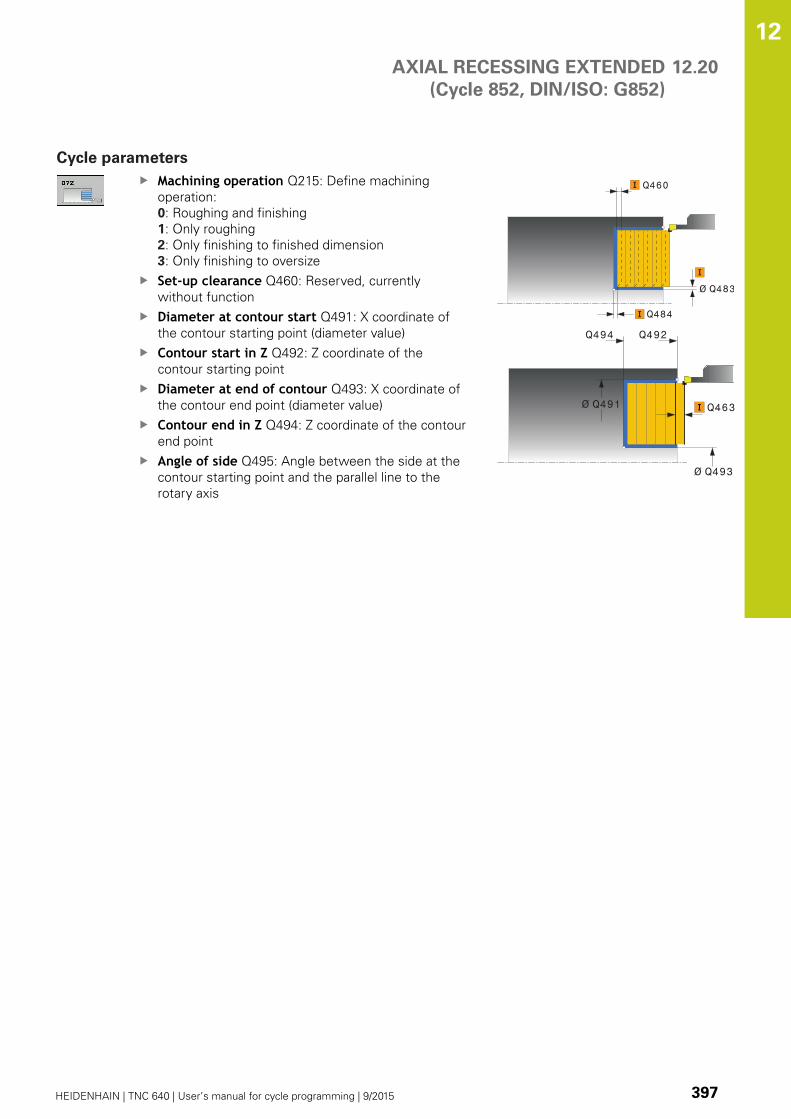
AXIAL RECESSING EXTENDED
(Cycle 852, DIN/ISO: G852)
12.20
12
HEIDENHAIN | TNC 640 | User’s manual for cycle programming | 9/2015 397
Cycle parameters
Machining operation Q215: Define machining
operation:
0: Roughing and finishing
1: Only roughing
2: Only finishing to finished dimension
3: Only finishing to oversize
Set-up clearance Q460: Reserved, currently
without function
Diameter at contour start Q491: X coordinate of
the contour starting point (diameter value)
Contour start in Z Q492: Z coordinate of the
contour starting point
Diameter at end of contour Q493: X coordinate of
the contour end point (diameter value)
Contour end in Z Q494: Z coordinate of the contour
end point
Angle of side Q495: Angle between the side at the
contour starting point and the parallel line to the
rotary axis
Ø Q483
Q484
Q460
Ø Q491
Q492
Ø Q493
Q494
Q463
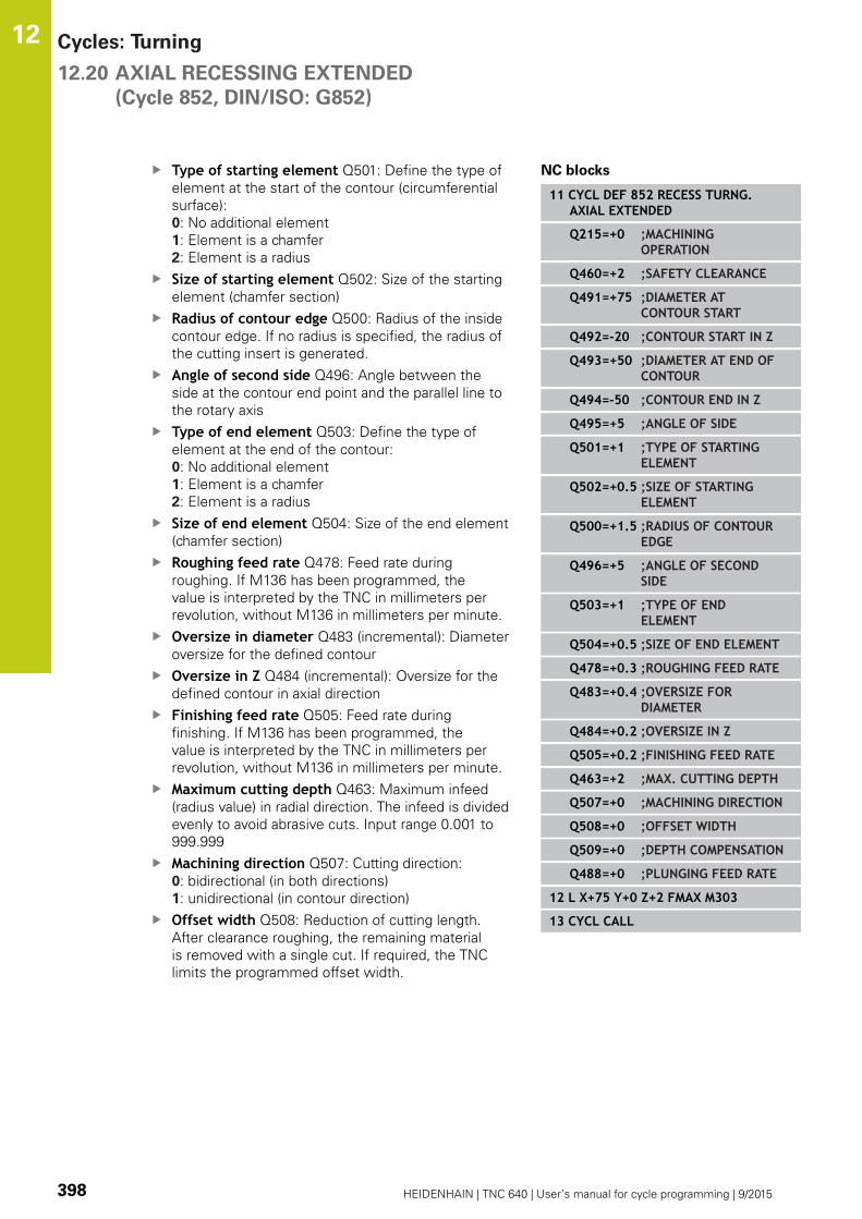
Cycles: Turning 12.20 AXIAL RECESSING EXTENDED
(Cycle 852, DIN/ISO: G852)
12
398 HEIDENHAIN | TNC 640 | User’s manual for cycle programming | 9/2015
Type of starting element Q501: Define the type of
element at the start of the contour (circumferential
surface):
0: No additional element
1: Element is a chamfer
2: Element is a radius
Size of starting element Q502: Size of the starting
element (chamfer section)
Radius of contour edge Q500: Radius of the inside
contour edge. If no radius is specified, the radius of
the cutting insert is generated.
Angle of second side Q496: Angle between the
side at the contour end point and the parallel line to
the rotary axis
Type of end element Q503: Define the type of
element at the end of the contour:
0: No additional element
1: Element is a chamfer
2: Element is a radius
Size of end element Q504: Size of the end element
(chamfer section)
Roughing feed rate Q478: Feed rate during
roughing. If M136 has been programmed, the
value is interpreted by the TNC in millimeters per
revolution, without M136 in millimeters per minute.
Oversize in diameter Q483 (incremental): Diameter
oversize for the defined contour
Oversize in Z Q484 (incremental): Oversize for the
defined contour in axial direction
Finishing feed rate Q505: Feed rate during
finishing. If M136 has been programmed, the
value is interpreted by the TNC in millimeters per
revolution, without M136 in millimeters per minute.
Maximum cutting depth Q463: Maximum infeed
(radius value) in radial direction. The infeed is divided
evenly to avoid abrasive cuts. Input range 0.001 to
999.999
Machining direction Q507: Cutting direction:
0: bidirectional (in both directions)
1: unidirectional (in contour direction)
Offset width Q508: Reduction of cutting length.
After clearance roughing, the remaining material
is removed with a single cut. If required, the TNC
limits the programmed offset width.
NC blocks
11 CYCL DEF 852 RECESS TURNG.AXIAL EXTENDED
Q215=+0 ;MACHININGOPERATION
Q460=+2 ;SAFETY CLEARANCE
Q491=+75 ;DIAMETER ATCONTOUR START
Q492=-20 ;CONTOUR START IN Z
Q493=+50 ;DIAMETER AT END OFCONTOUR
Q494=-50 ;CONTOUR END IN Z
Q495=+5 ;ANGLE OF SIDE
Q501=+1 ;TYPE OF STARTINGELEMENT
Q502=+0.5 ;SIZE OF STARTINGELEMENT
Q500=+1.5 ;RADIUS OF CONTOUREDGE
Q496=+5 ;ANGLE OF SECONDSIDE
Q503=+1 ;TYPE OF ENDELEMENT
Q504=+0.5 ;SIZE OF END ELEMENT
Q478=+0.3 ;ROUGHING FEED RATE
Q483=+0.4 ;OVERSIZE FORDIAMETER
Q484=+0.2 ;OVERSIZE IN Z
Q505=+0.2 ;FINISHING FEED RATE
Q463=+2 ;MAX. CUTTING DEPTH
Q507=+0 ;MACHINING DIRECTION
Q508=+0 ;OFFSET WIDTH
Q509=+0 ;DEPTH COMPENSATION
Q488=+0 ;PLUNGING FEED RATE
12 L X+75 Y+0 Z+2 FMAX M303
13 CYCL CALL

AXIAL RECESSING EXTENDED
(Cycle 852, DIN/ISO: G852)
12.20
12
HEIDENHAIN | TNC 640 | User’s manual for cycle programming | 9/2015 399
Turning depth compensation Q509: Depending
on factors such as workpiece material or feed rate,
the tool tip is displaced during a turning operation.
You can correct the resulting infeed error with the
turning depth compensation factor.
Feed rate for plunging Q488: Feed rate for
machining of plunging elements. This input value
is optional. If it is not programmed, the feed rate
defined for turning is effective.

Cycles: Turning 12.21 AXIAL RECESSING
(Cycle 850, DIN/ISO: G850)
12
400 HEIDENHAIN | TNC 640 | User’s manual for cycle programming | 9/2015
12.21 AXIAL RECESSING
(Cycle 850, DIN/ISO: G850)
Application
This cycle enables you to recess right-angled slots of any form in
longitudinal direction. With recess turning, a recessing traverse
to plunging depth and then a roughing traverse is alternatively
machined.
You can use the cycle either for roughing, finishing or complete
machining. Turning is run paraxially with roughing.
The cycle can be used for inside and outside machining. If the
starting point of the contour is larger than the end point of the
contour, the cycle runs outside machining. If the contour starting
point is less than the end point, the cycle runs inside machining.
Roughing cycle run
The TNC uses the tool position as cycle starting point when a
cycle is called. If the Z coordinate of the starting point is less than
the contour starting point, the TNC positions the tool in the Z
coordinate to the contour starting point and begins the cycle there.
1 The TNC positions the tool at rapid traverse in the X coordinate
(first cut-in position).
2 The TNC recesses until the first plunging depth.
3 The TNC cuts the area between the starting position and the
end point in traverse direction at the defined feed rate Q478.
4 If the input parameter Q488 is defined in the cycle, plunging
elements are machined at the programmed feed rate for
plunging.
5 If only one machining direction Q507=1 was specified in
the cycle, the TNC retracts the tool by the set-up clearance,
positions the tool back at rapid traverse and approaches the
contour again with the defined feed rate. With machining
direction Q507=0, infeed is on both sides. .
6 The tool recesses to the next plunging depth.
7 The TNC repeats this process (2 to 4) until the slot depth is
reached.
8 The TNC returns the tool to set-up clearance and machines a
recessing traverse on both side walls.
9 The TNC positions the tool back at rapid traverse to the cycle
starting point.

AXIAL RECESSING
(Cycle 850, DIN/ISO: G850)
12.21
12
HEIDENHAIN | TNC 640 | User’s manual for cycle programming | 9/2015 401
Finishing cycle run
The TNC uses the tool position as cycle starting point when a cycle
is called.
1 The TNC positions the tool at rapid traverse to the first slot side.
2 The TNC finishes the side walls of the slot at the defined feed
rate Q505.
3 The TNC finishes the slot floor at the defined feed rate.
4 The TNC positions the tool back at rapid traverse to the cycle
starting point.
Please note while programming:
Program a positioning block to the starting position
with radius compensation R0 before the cycle call.
The tool position at cycle call defines the size of the
area to be machined (cycle starting point).
Before calling the cycle you must program the cycle
14 CONTOUR to define the subprogram number.
When you use local QL Q parameters in a contour
subprogram you must also assign or calculate these
in the contour subprogram.
From the second infeed, the TNC reduces each
further cutting traverse by 0.1 mm. This reduces
lateral pressure on the tool. If the offset width Q508was input into the cycle, the TNC reduces the cutting
traverse by this value. After clearance roughing, the
remaining material is removed with a single cut. The
TNC generates an error message if the lateral offset
exceeds 80 % of the effective cutting width (effective
cutting width = cutting width –2*cutting radius).
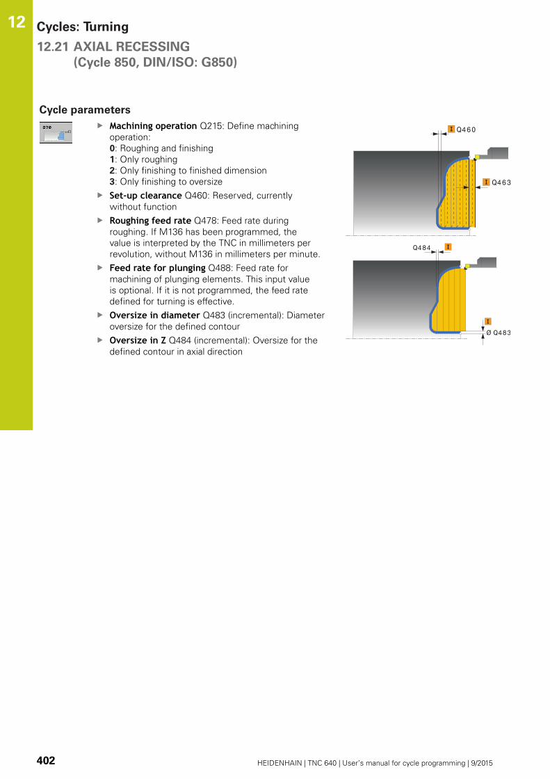
Cycles: Turning 12.21 AXIAL RECESSING
(Cycle 850, DIN/ISO: G850)
12
402 HEIDENHAIN | TNC 640 | User’s manual for cycle programming | 9/2015
Cycle parameters
Machining operation Q215: Define machining
operation:
0: Roughing and finishing
1: Only roughing
2: Only finishing to finished dimension
3: Only finishing to oversize
Set-up clearance Q460: Reserved, currently
without function
Roughing feed rate Q478: Feed rate during
roughing. If M136 has been programmed, the
value is interpreted by the TNC in millimeters per
revolution, without M136 in millimeters per minute.
Feed rate for plunging Q488: Feed rate for
machining of plunging elements. This input value
is optional. If it is not programmed, the feed rate
defined for turning is effective.
Oversize in diameter Q483 (incremental): Diameter
oversize for the defined contour
Oversize in Z Q484 (incremental): Oversize for the
defined contour in axial direction
Q460
Q463
Ø Q483
Q484

AXIAL RECESSING
(Cycle 850, DIN/ISO: G850)
12.21
12
HEIDENHAIN | TNC 640 | User’s manual for cycle programming | 9/2015 403
Finishing feed rate Q505: Feed rate during
finishing. If M136 has been programmed, the
value is interpreted by the TNC in millimeters per
revolution, without M136 in millimeters per minute.
Cutting limit Q479: Activate cutting limit:
0: No cutting limit active
1: Cutting limit (Q480/Q482)
Limit value for diameter Q480: X value for contour
limitation (diameter value)
Limit value Z Q482: Z value for contour limitation
Maximum cutting depth Q463: Maximum infeed
(radius value) in radial direction. The infeed is divided
evenly to avoid abrasive cuts. Input range 0.001 to
999.999
Machining direction Q507: Cutting direction:
0: bidirectional (in both directions)
1: unidirectional (in contour direction)
Offset width Q508: Reduction of cutting length.
After clearance roughing, the remaining material
is removed with a single cut. If required, the TNC
limits the programmed offset width.
Turning depth compensation Q509: Depending
on factors such as workpiece material or feed rate,
the tool tip is displaced during a turning operation.
You can correct the resulting infeed error with the
turning depth compensation factor.
Reverse contour Q499: Machining direction:
0: Machining in contour direction
1: Machining opposite the contour direction
NC blocks
9 CYCL DEF 14.0 CONTOUR
10 CYCL DEF 14.1 CONTOUR LABEL2
11 CYCL DEF 850 RECESS TURNG.AXIAL
Q215=+0 ;MACHININGOPERATION
Q460=+2 ;SAFETY CLEARANCE
Q478=+0.3 ;ROUGHING FEED RATE
Q483=+0.4 ;OVERSIZE FORDIAMETER
Q484=+0.2 ;OVERSIZE IN Z
Q505=+0.2 ;FINISHING FEED RATE
Q479=+0 ;CUTTING LIMIT
Q480=+0 ;LIMIT VALUE FORDIAMETER
Q482=+0 ;LIMIT VALUE IN Z
Q463=+2 ;MAX. CUTTING DEPTH
Q507=+0 ;MACHINING DIRECTION
Q508=+0 ;OFFSET WIDTH
Q509=+0 ;DEPTH COMPENSATION
Q499=+0 ;REVERSE CONTOUR
12 L X+75 Y+0 Z+2 FMAX M303
13 CYCL CALL
14 M30
15 LBL 2
16 L X+60 Z+0
17 L Z-10
18 RND R5
19 L X+40 Z-15
20 L Z+0
21 LBL 0

Cycles: Turning 12.22 RADIAL RECESSING
(Cycle 861, DIN/ISO: G861)
12
404 HEIDENHAIN | TNC 640 | User’s manual for cycle programming | 9/2015
12.22 RADIAL RECESSING
(Cycle 861, DIN/ISO: G861)
Application
This cycle enables you to radially cut in right-angled slots.
You can use the cycle either for roughing, finishing or complete
machining. Turning is run paraxially with roughing.
The cycle can be used for inside and outside machining. If the tool
is outside the contour to be machined when the cycle is called, the
cycle runs outside machining. If the tool is inside the contour to be
machined, the cycle runs inside machining.
Roughing cycle run
The cycle processes only the area from the cycle starting point to
the end point defined in the cycle.
1 The TNC runs a paraxial infeed motion at rapid traverse (lateral
infeed = 0.8 cutting width).
2 The TNC cuts the area between the starting position and the
end point in axial direction at the defined feed rate Q478.
3 The TNC positions the tool back at rapid traverse to the
beginning of cut.
4 The TNC repeats this process (1 to 3) until the slot width is
reached.
5 The TNC positions the tool back at rapid traverse to the cycle
starting point.

RADIAL RECESSING
(Cycle 861, DIN/ISO: G861)
12.22
12
HEIDENHAIN | TNC 640 | User’s manual for cycle programming | 9/2015 405
Finishing cycle run
1 The TNC positions the tool at rapid traverse to the first slot side.
2 The TNC finishes the side wall of the slot at the defined feed
rate Q505.
3 The TNC finishes half the slot width at the defined feed rate.
4 The TNC returns the tool at rapid traverse.
5 The TNC positions the tool at rapid traverse to the second slot
side.
6 The TNC finishes the side wall of the slot at the defined feed
rate Q505.
7 The TNC finishes half the slot width at the defined feed rate.
8 The TNC positions the tool back at rapid traverse to the cycle
starting point.
Please note while programming:
Program a positioning block to the starting position
with radius compensation R0 before the cycle call.
The tool position at cycle call defines the size of the
area to be machined (cycle starting point).

Cycles: Turning 12.22 RADIAL RECESSING
(Cycle 861, DIN/ISO: G861)
12
406 HEIDENHAIN | TNC 640 | User’s manual for cycle programming | 9/2015
Cycle parameters
Machining operation Q215: Define machining
operation:
0: Roughing and finishing
1: Only roughing
2: Only finishing to finished dimension
3: Only finishing to oversize
Set-up clearance Q460: Reserved, currently
without function
Diameter at end of contour Q493: X coordinate of
the contour end point (diameter value)
Contour end in Z Q494: Z coordinate of the contour
end point
Roughing feed rate Q478: Feed rate during
roughing. If M136 has been programmed, the
value is interpreted by the TNC in millimeters per
revolution, without M136 in millimeters per minute.
Oversize in diameter Q483 (incremental): Diameter
oversize for the defined contour
Oversize in Z Q484 (incremental): Oversize for the
defined contour in axial direction
Finishing feed rate Q505: Feed rate during
finishing. If M136 has been programmed, the
value is interpreted by the TNC in millimeters per
revolution, without M136 in millimeters per minute.
Limit to depth Q463: Max. recess depth per cut
Ø Q460
Ø Q493
Q494Q463
Ø Q483
Q484
NC blocks
11 CYCL DEF 861 RADIAL RECESSING
Q215=+0 ;MACHININGOPERATION
Q460=+2 ;SAFETY CLEARANCE
Q493=+50 ;DIAMETER AT END OFCONTOUR
Q494=-50 ;CONTOUR END IN Z
Q478=+0.3 ;ROUGHING FEED RATE
Q483=+0.4 ;OVERSIZE FORDIAMETER
Q484=+0.2 ;OVERSIZE IN Z
Q505=+0.2 ;FINISHING FEED RATE
Q463=+0 ;LIMIT TO DEPTH
12 L X+75 Y+0 Z-25 FMAX M303
13 CYCL CALL

RADIAL RECESSING EXTENDED
(Cycle 862, DIN/ISO: G862)
12.23
12
HEIDENHAIN | TNC 640 | User’s manual for cycle programming | 9/2015 407
12.23 RADIAL RECESSING EXTENDED
(Cycle 862, DIN/ISO: G862)
Application
This cycle enables you to radially cut in slots. Expanded scope of
function:
You can insert a chamfer or curve at the contour start and
contour end.
In the cycle you can define angles for the side walls of the slot
You can insert radii in the contour edges
You can use the cycle either for roughing, finishing or complete
machining. Turning is run paraxially with roughing.
The cycle can be used for inside and outside machining. If the start
diameter Q491 is larger than the end diameter Q493, the cycle
runs outside machining. If the start diameter Q491 is less than the
end diameter Q493, the cycle runs inside machining.
Roughing cycle run
1 The TNC runs a paraxial infeed motion at rapid traverse (lateral
infeed = 0.8 cutting width).
2 The TNC cuts the area between the starting position and the
end point in axial direction at the defined feed rate Q478.
3 The TNC positions the tool back at rapid traverse to the
beginning of cut.
4 The TNC repeats this process (1 to 3) until the slot width is
reached.
5 The TNC positions the tool back at rapid traverse to the cycle
starting point.
Cycles: Turning 12.23 RADIAL RECESSING EXTENDED
(Cycle 862, DIN/ISO: G862)
12
408 HEIDENHAIN | TNC 640 | User’s manual for cycle programming | 9/2015
Finishing cycle run
1 The TNC positions the tool at rapid traverse to the first slot side.
2 The TNC finishes the side wall of the slot at the defined feed
rate Q505.
3 The TNC finishes half the slot width at the defined feed rate.
4 The TNC returns the tool at rapid traverse.
5 The TNC positions the tool at rapid traverse to the second slot
side.
6 The TNC finishes the side wall of the slot at the defined feed
rate Q505.
7 The TNC finishes half the slot width at the defined feed rate.
8 The TNC positions the tool back at rapid traverse to the cycle
starting point.
Please note while programming:
Program a positioning block to the starting position
with radius compensation R0 before the cycle call.
The tool position at cycle call defines the size of the
area to be machined (cycle starting point).

RADIAL RECESSING EXTENDED
(Cycle 862, DIN/ISO: G862)
12.23
12
HEIDENHAIN | TNC 640 | User’s manual for cycle programming | 9/2015 409
Cycle parameters
Machining operation Q215: Define machining
operation:
0: Roughing and finishing
1: Only roughing
2: Only finishing to finished dimension
3: Only finishing to oversize
Set-up clearance Q460: Reserved, currently
without function
Diameter at contour start Q491: X coordinate of
the contour starting point (diameter value)
Contour start in Z Q492: Z coordinate of the
contour starting point
Diameter at end of contour Q493: X coordinate of
the contour end point (diameter value)
Contour end in Z Q494: Z coordinate of the contour
end point
Angle of side Q495: Angle between the side at the
contour starting point and the perpendicular to the
rotary axis
Q463
Ø Q460
Ø Q493
Q494
Q492

Cycles: Turning 12.23 RADIAL RECESSING EXTENDED
(Cycle 862, DIN/ISO: G862)
12
410 HEIDENHAIN | TNC 640 | User’s manual for cycle programming | 9/2015
Type of starting element Q501: Define the type of
element at the start of the contour (circumferential
surface):
0: No additional element
1: Element is a chamfer
2: Element is a radius
Size of starting element Q502: Size of the starting
element (chamfer section)
Radius of contour edge Q500: Radius of the inside
contour edge. If no radius is specified, the radius of
the cutting insert is generated.
Angle of second side Q496: Angle between the
side at the contour end point and the perpendicular
to the rotary axis
Type of end element Q503: Define the type of
element at the end of the contour:
0: No additional element
1: Element is a chamfer
2: Element is a radius
Size of end element Q504: Size of the end element
(chamfer section)
Roughing feed rate Q478: Feed rate during
roughing. If M136 has been programmed, the
value is interpreted by the TNC in millimeters per
revolution, without M136 in millimeters per minute.
Oversize in diameter Q483 (incremental): Diameter
oversize for the defined contour
Oversize in Z Q484 (incremental): Oversize for the
defined contour in axial direction
Finishing feed rate Q505: Feed rate during
finishing. If M136 has been programmed, the
value is interpreted by the TNC in millimeters per
revolution, without M136 in millimeters per minute.
Limit to depth Q463: Max. recess depth per cut
Ø Q483
Q484
NC blocks
11 CYCL DEF 862 RADIAL RECESSINGEXTENDED
Q215=+0 ;MACHININGOPERATION
Q460=+2 ;SAFETY CLEARANCE
Q491=+75 ;DIAMETER ATCONTOUR START
Q492=-20 ;CONTOUR START IN Z
Q493=+50 ;DIAMETER AT END OFCONTOUR
Q494=-50 ;CONTOUR END IN Z
Q495=+5 ;ANGLE OF SIDE
Q501=+1 ;TYPE OF STARTINGELEMENT
Q502=+0.5 ;SIZE OF STARTINGELEMENT
Q500=+1.5 ;RADIUS OF CONTOUREDGE
Q496=+5 ;ANGLE OF SECONDSIDE
Q503=+1 ;TYPE OF ENDELEMENT
Q504=+0.5 ;SIZE OF END ELEMENT
Q478=+0.3 ;ROUGHING FEED RATE
Q483=+0.4 ;OVERSIZE FORDIAMETER
Q484=+0.2 ;OVERSIZE IN Z
Q505=+0.2 ;FINISHING FEED RATE
Q463=+0 ;LIMIT TO DEPTH
12 L X+75 Y+0 Z+2 FMAX M303
13 CYCL CALL
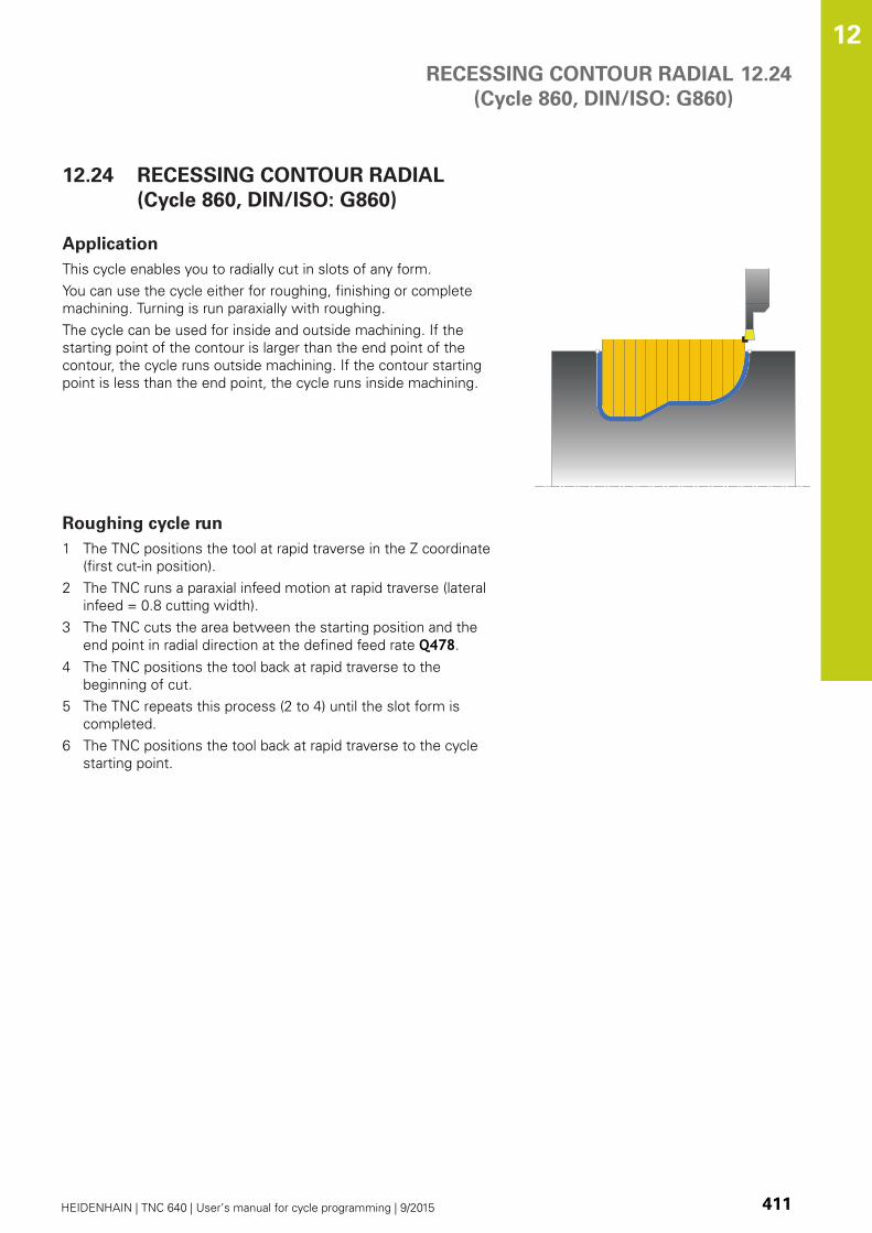
RECESSING CONTOUR RADIAL
(Cycle 860, DIN/ISO: G860)
12.24
12
HEIDENHAIN | TNC 640 | User’s manual for cycle programming | 9/2015 411
12.24 RECESSING CONTOUR RADIAL
(Cycle 860, DIN/ISO: G860)
Application
This cycle enables you to radially cut in slots of any form.
You can use the cycle either for roughing, finishing or complete
machining. Turning is run paraxially with roughing.
The cycle can be used for inside and outside machining. If the
starting point of the contour is larger than the end point of the
contour, the cycle runs outside machining. If the contour starting
point is less than the end point, the cycle runs inside machining.
Roughing cycle run
1 The TNC positions the tool at rapid traverse in the Z coordinate
(first cut-in position).
2 The TNC runs a paraxial infeed motion at rapid traverse (lateral
infeed = 0.8 cutting width).
3 The TNC cuts the area between the starting position and the
end point in radial direction at the defined feed rate Q478.
4 The TNC positions the tool back at rapid traverse to the
beginning of cut.
5 The TNC repeats this process (2 to 4) until the slot form is
completed.
6 The TNC positions the tool back at rapid traverse to the cycle
starting point.
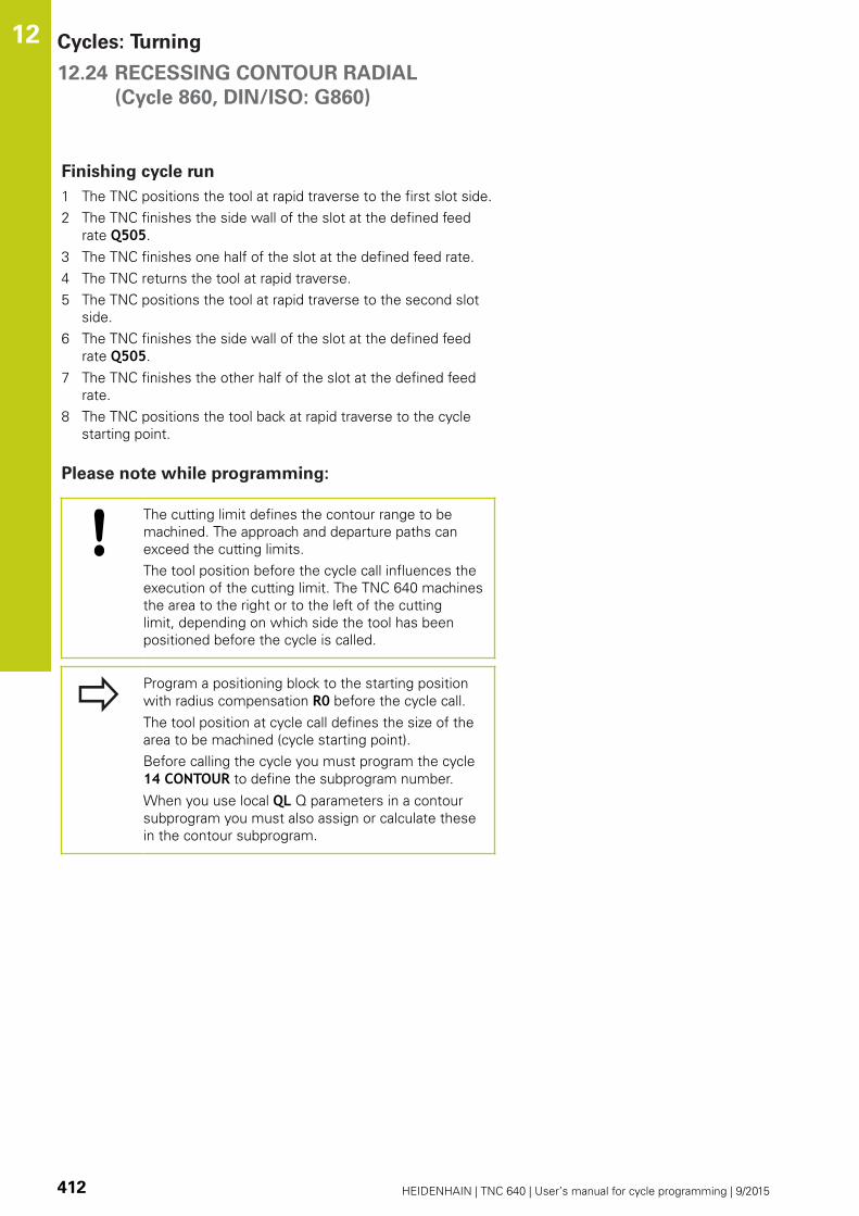
Cycles: Turning 12.24 RECESSING CONTOUR RADIAL
(Cycle 860, DIN/ISO: G860)
12
412 HEIDENHAIN | TNC 640 | User’s manual for cycle programming | 9/2015
Finishing cycle run
1 The TNC positions the tool at rapid traverse to the first slot side.
2 The TNC finishes the side wall of the slot at the defined feed
rate Q505.
3 The TNC finishes one half of the slot at the defined feed rate.
4 The TNC returns the tool at rapid traverse.
5 The TNC positions the tool at rapid traverse to the second slot
side.
6 The TNC finishes the side wall of the slot at the defined feed
rate Q505.
7 The TNC finishes the other half of the slot at the defined feed
rate.
8 The TNC positions the tool back at rapid traverse to the cycle
starting point.
Please note while programming:
The cutting limit defines the contour range to be
machined. The approach and departure paths can
exceed the cutting limits.
The tool position before the cycle call influences the
execution of the cutting limit. The TNC 640 machines
the area to the right or to the left of the cutting
limit, depending on which side the tool has been
positioned before the cycle is called.
Program a positioning block to the starting position
with radius compensation R0 before the cycle call.
The tool position at cycle call defines the size of the
area to be machined (cycle starting point).
Before calling the cycle you must program the cycle
14 CONTOUR to define the subprogram number.
When you use local QL Q parameters in a contour
subprogram you must also assign or calculate these
in the contour subprogram.

RECESSING CONTOUR RADIAL
(Cycle 860, DIN/ISO: G860)
12.24
12
HEIDENHAIN | TNC 640 | User’s manual for cycle programming | 9/2015 413
Cycle parameters
Machining operation Q215: Define machining
operation:
0: Roughing and finishing
1: Only roughing
2: Only finishing to finished dimension
3: Only finishing to oversize
Set-up clearance Q460: Reserved, currently
without function
Roughing feed rate Q478: Feed rate during
roughing. If M136 has been programmed, the
value is interpreted by the TNC in millimeters per
revolution, without M136 in millimeters per minute.
Oversize in diameter Q483 (incremental): Diameter
oversize for the defined contour
Oversize in Z Q484 (incremental): Oversize for the
defined contour in axial direction
Ø Q460
Q463
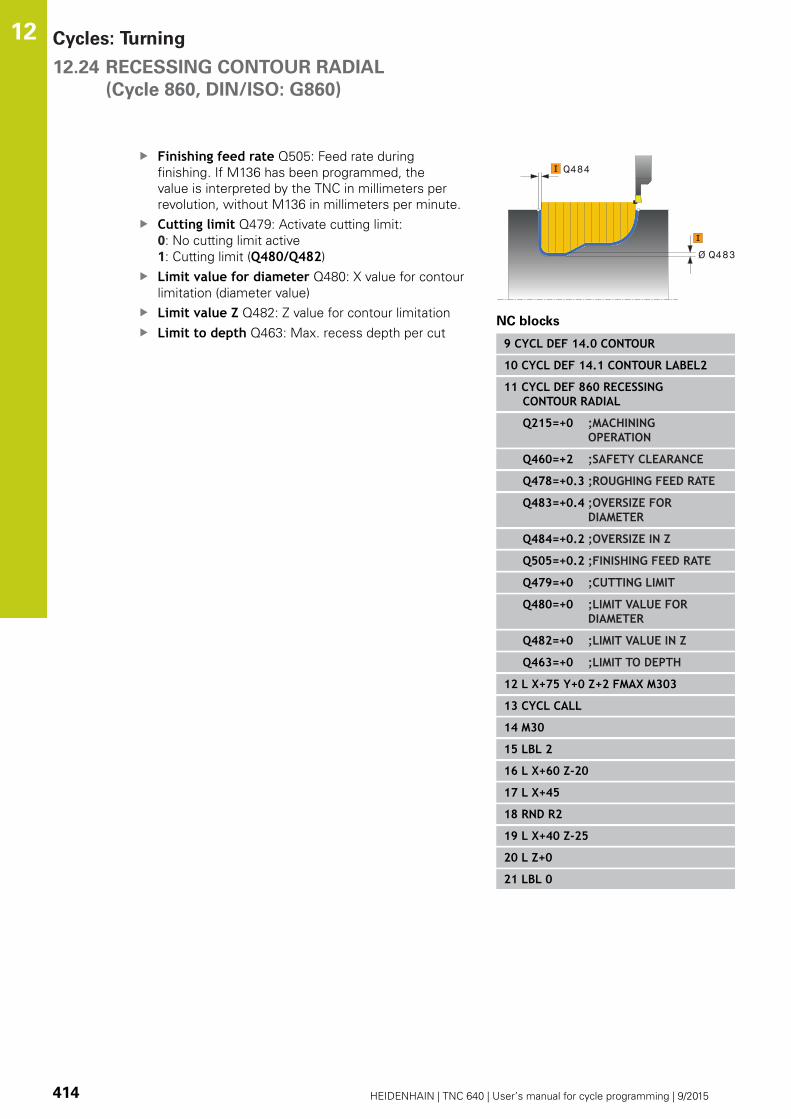
Cycles: Turning 12.24 RECESSING CONTOUR RADIAL
(Cycle 860, DIN/ISO: G860)
12
414 HEIDENHAIN | TNC 640 | User’s manual for cycle programming | 9/2015
Finishing feed rate Q505: Feed rate during
finishing. If M136 has been programmed, the
value is interpreted by the TNC in millimeters per
revolution, without M136 in millimeters per minute.
Cutting limit Q479: Activate cutting limit:
0: No cutting limit active
1: Cutting limit (Q480/Q482)
Limit value for diameter Q480: X value for contour
limitation (diameter value)
Limit value Z Q482: Z value for contour limitation
Limit to depth Q463: Max. recess depth per cut
Ø Q483
Q484
NC blocks
9 CYCL DEF 14.0 CONTOUR
10 CYCL DEF 14.1 CONTOUR LABEL2
11 CYCL DEF 860 RECESSINGCONTOUR RADIAL
Q215=+0 ;MACHININGOPERATION
Q460=+2 ;SAFETY CLEARANCE
Q478=+0.3 ;ROUGHING FEED RATE
Q483=+0.4 ;OVERSIZE FORDIAMETER
Q484=+0.2 ;OVERSIZE IN Z
Q505=+0.2 ;FINISHING FEED RATE
Q479=+0 ;CUTTING LIMIT
Q480=+0 ;LIMIT VALUE FORDIAMETER
Q482=+0 ;LIMIT VALUE IN Z
Q463=+0 ;LIMIT TO DEPTH
12 L X+75 Y+0 Z+2 FMAX M303
13 CYCL CALL
14 M30
15 LBL 2
16 L X+60 Z-20
17 L X+45
18 RND R2
19 L X+40 Z-25
20 L Z+0
21 LBL 0

AXIAL RECESSING
(Cycle 871, DIN/ISO: G871)
12.25
12
HEIDENHAIN | TNC 640 | User’s manual for cycle programming | 9/2015 415
12.25 AXIAL RECESSING
(Cycle 871, DIN/ISO: G871)
Application
This cycle enables you to axially cut in right-angled slots (face
recessing).
You can use the cycle either for roughing, finishing or complete
machining. Turning is run paraxially with roughing.
Roughing cycle run
The TNC uses the tool position as cycle starting point when a cycle
is called. The cycle processes only the area from the cycle starting
point to the end point defined in the cycle.
1 The TNC runs a paraxial infeed motion at rapid traverse (lateral
infeed = 0.8 cutting width).
2 The TNC cuts the area between the starting position and the
end point in radial direction at the defined feed rate Q478.
3 The TNC positions the tool back at rapid traverse to the
beginning of cut.
4 The TNC repeats this process (1 to 3) until the slot width is
reached.
5 The TNC positions the tool back at rapid traverse to the cycle
starting point.
Finishing cycle run
1 The TNC positions the tool at rapid traverse to the first slot side.
2 The TNC finishes the side wall of the slot at the defined feed
rate Q505.
3 The TNC finishes half the slot width at the defined feed rate.
4 The TNC returns the tool at rapid traverse.
5 The TNC positions the tool at rapid traverse to the second slot
side.
6 The TNC finishes the side wall of the slot at the defined feed
rate Q505.
7 The TNC finishes half the slot width at the defined feed rate.
8 The TNC positions the tool back at rapid traverse to the cycle
starting point.

Cycles: Turning 12.25 AXIAL RECESSING
(Cycle 871, DIN/ISO: G871)
12
416 HEIDENHAIN | TNC 640 | User’s manual for cycle programming | 9/2015
Please note while programming:
Program a positioning block to the starting position
with radius compensation R0 before the cycle call.
The tool position at cycle call defines the size of the
area to be machined (cycle starting point).
Cycle parameters
Machining operation Q215: Define machining
operation:
0: Roughing and finishing
1: Only roughing
2: Only finishing to finished dimension
3: Only finishing to oversize
Set-up clearance Q460: Reserved, currently
without function
Diameter at end of contour Q493: X coordinate of
the contour end point (diameter value)
Contour end in Z Q494: Z coordinate of the contour
end point
Roughing feed rate Q478: Feed rate during
roughing. If M136 has been programmed, the
value is interpreted by the TNC in millimeters per
revolution, without M136 in millimeters per minute.
Oversize in diameter Q483 (incremental): Diameter
oversize for the defined contour
Oversize in Z Q484 (incremental): Oversize for the
defined contour in axial direction
Finishing feed rate Q505: Feed rate during
finishing. If M136 has been programmed, the
value is interpreted by the TNC in millimeters per
revolution, without M136 in millimeters per minute.
Limit to depth Q463: Max. recess depth per cut
Q460
Ø Q493
Q494
Q463
Ø Q483
Q484
NC blocks
11 CYCL DEF 871 AXIAL RECESSING
Q215=+0 ;MACHININGOPERATION
Q460=+2 ;SAFETY CLEARANCE
Q493=+50 ;DIAMETER AT END OFCONTOUR
Q494=-10 ;CONTOUR END IN Z
Q478=+0.3 ;ROUGHING FEED RATE
Q483=+0.4 ;OVERSIZE FORDIAMETER
Q484=+0.2 ;OVERSIZE IN Z
Q505=+0.2 ;FINISHING FEED RATE
Q463=+0 ;LIMIT TO DEPTH
12 L X+65 Y+0 Z+2 FMAX M303
13 CYCL CALL
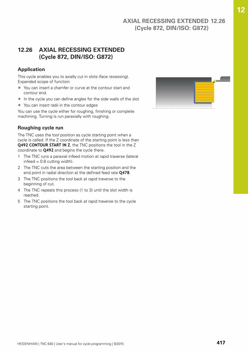
AXIAL RECESSING EXTENDED
(Cycle 872, DIN/ISO: G872)
12.26
12
HEIDENHAIN | TNC 640 | User’s manual for cycle programming | 9/2015 417
12.26 AXIAL RECESSING EXTENDED
(Cycle 872, DIN/ISO: G872)
Application
This cycle enables you to axially cut in slots (face recessing).
Expanded scope of function:
You can insert a chamfer or curve at the contour start and
contour end.
In the cycle you can define angles for the side walls of the slot
You can insert radii in the contour edges
You can use the cycle either for roughing, finishing or complete
machining. Turning is run paraxially with roughing.
Roughing cycle run
The TNC uses the tool position as cycle starting point when a
cycle is called. If the Z coordinate of the starting point is less than
Q492 CONTOUR START IN Z, the TNC positions the tool in the Z
coordinate to Q492 and begins the cycle there.
1 The TNC runs a paraxial infeed motion at rapid traverse (lateral
infeed = 0.8 cutting width).
2 The TNC cuts the area between the starting position and the
end point in radial direction at the defined feed rate Q478.
3 The TNC positions the tool back at rapid traverse to the
beginning of cut.
4 The TNC repeats this process (1 to 3) until the slot width is
reached.
5 The TNC positions the tool back at rapid traverse to the cycle
starting point.

Cycles: Turning 12.26 AXIAL RECESSING EXTENDED
(Cycle 872, DIN/ISO: G872)
12
418 HEIDENHAIN | TNC 640 | User’s manual for cycle programming | 9/2015
Finishing cycle run
The TNC uses the tool position as cycle starting point when a
cycle is called. If the Z coordinate of the starting point is less than
Q492 CONTOUR START IN Z, the TNC positions the tool in the Z
coordinate to Q492 and begins the cycle there.
1 The TNC positions the tool at rapid traverse to the first slot side.
2 The TNC finishes the side wall of the slot at the defined feed
rate Q505.
3 The TNC returns the tool at rapid traverse.
4 The TNC positions the tool at rapid traverse to the second slot
side.
5 The TNC finishes the side wall of the slot at the defined feed
rate Q505.
6 The TNC finishes one half of the slot at the defined feed rate.
7 The TNC positions the tool at rapid traverse to the first side.
8 The TNC finishes the other half of the slot at the defined feed
rate.
9 The TNC positions the tool back at rapid traverse to the cycle
starting point.
Please note while programming:
Program a positioning block to the starting position
with radius compensation R0 before the cycle call.
The tool position at cycle call defines the size of the
area to be machined (cycle starting point).

AXIAL RECESSING EXTENDED
(Cycle 872, DIN/ISO: G872)
12.26
12
HEIDENHAIN | TNC 640 | User’s manual for cycle programming | 9/2015 419
Cycle parameters
Machining operation Q215: Define machining
operation:
0: Roughing and finishing
1: Only roughing
2: Only finishing to finished dimension
3: Only finishing to oversize
Set-up clearance Q460: Reserved, currently
without function
Diameter at contour start Q491: X coordinate of
the contour starting point (diameter value)
Contour start in Z Q492: Z coordinate of the
contour starting point
Diameter at end of contour Q493: X coordinate of
the contour end point (diameter value)
Contour end in Z Q494: Z coordinate of the contour
end point
Angle of side Q495: Angle between the side at the
contour starting point and the parallel line to the
rotary axis
Type of starting element Q501: Define the type of
element at the start of the contour (circumferential
surface):
0: No additional element
1: Element is a chamfer
2: Element is a radius
Size of starting element Q502: Size of the starting
element (chamfer section)
Radius of contour edge Q500: Radius of the inside
contour edge. If no radius is specified, the radius of
the cutting insert is generated.
Angle of second side Q496: Angle between the
side at the contour end point and the parallel line to
the rotary axis
Type of end element Q503: Define the type of
element at the end of the contour:
0: No additional element
1: Element is a chamfer
2: Element is a radius
Q460 Ø Q493
Q494
Q463
Q492
Ø Q483
Q484
NC blocks
11 CYCL DEF 871 AXIAL RECESSINGEXTENDED
Q215=+0 ;MACHININGOPERATION
Q460=+2 ;SAFETY CLEARANCE
Q491=+75 ;DIAMETER ATCONTOUR START
Q492=-20 ;CONTOUR START IN Z
Q493=+50 ;DIAMETER AT END OFCONTOUR
Q494=-50 ;CONTOUR END IN Z
Q495=+5 ;ANGLE OF SIDE
Q501=+1 ;TYPE OF STARTINGELEMENT
Q502=+0.5 ;SIZE OF STARTINGELEMENT

Cycles: Turning 12.26 AXIAL RECESSING EXTENDED
(Cycle 872, DIN/ISO: G872)
12
420 HEIDENHAIN | TNC 640 | User’s manual for cycle programming | 9/2015
Size of end element Q504: Size of the end element
(chamfer section)
Roughing feed rate Q478: Feed rate during
roughing. If M136 has been programmed, the
value is interpreted by the TNC in millimeters per
revolution, without M136 in millimeters per minute.
Oversize in diameter Q483 (incremental): Diameter
oversize for the defined contour
Oversize in Z Q484 (incremental): Oversize for the
defined contour in axial direction
Finishing feed rate Q505: Feed rate during
finishing. If M136 has been programmed, the
value is interpreted by the TNC in millimeters per
revolution, without M136 in millimeters per minute.
Limit to depth Q463: Max. recess depth per cut
Q500=+1.5 ;RADIUS OF CONTOUREDGE
Q496=+5 ;ANGLE OF SECONDSIDE
Q503=+1 ;TYPE OF ENDELEMENT
Q504=+0.5 ;SIZE OF END ELEMENT
Q478=+0.3 ;ROUGHING FEED RATE
Q483=+0.4 ;OVERSIZE FORDIAMETER
Q484=+0.2 ;OVERSIZE IN Z
Q505=+0.2 ;FINISHING FEED RATE
Q463=+0 ;LIMIT TO DEPTH
12 L X+75 Y+0 Z+2 FMAX M303
13 CYCL CALL

AXIAL RECESSING
(Cycle 870, DIN/ISO: G870)
12.27
12
HEIDENHAIN | TNC 640 | User’s manual for cycle programming | 9/2015 421
12.27 AXIAL RECESSING
(Cycle 870, DIN/ISO: G870)
Application
This cycle enables you to axially cut in slots of any form (face
recessing).
You can use the cycle either for roughing, finishing or complete
machining. Turning is run paraxially with roughing.
Roughing cycle run
The TNC uses the tool position as cycle starting point when a
cycle is called. If the Z coordinate of the starting point is less than
the contour starting point, the TNC positions the tool in the Z
coordinate to the contour starting point and begins the cycle there.
1 The TNC positions the tool at rapid traverse in the X coordinate
(first cut-in position).
2 The TNC runs a paraxial infeed motion at rapid traverse (lateral
infeed = 0.8 cutting width).
3 The TNC cuts the area between the starting position and the
end point in axial direction at the defined feed rate Q478.
4 The TNC positions the tool back at rapid traverse to the
beginning of cut.
5 The TNC repeats this process (2 to 4) until the slot form is
completed.
6 The TNC positions the tool back at rapid traverse to the cycle
starting point.
Cycles: Turning 12.27 AXIAL RECESSING
(Cycle 870, DIN/ISO: G870)
12
422 HEIDENHAIN | TNC 640 | User’s manual for cycle programming | 9/2015
Finishing cycle run
The TNC uses the tool position as cycle starting point when a cycle
is called.
1 The TNC positions the tool at rapid traverse to the first slot side.
2 The TNC finishes the side wall of the slot at the defined feed
rate Q505.
3 The TNC finishes one half of the slot at the defined feed rate.
4 The TNC returns the tool at rapid traverse.
5 The TNC positions the tool at rapid traverse to the second slot
side.
6 The TNC finishes the side wall of the slot at the defined feed
rate Q505.
7 The TNC finishes the other half of the slot at the defined feed
rate.
8 The TNC positions the tool back at rapid traverse to the cycle
starting point.
Please note while programming:
The cutting limit defines the contour range to be
machined. The approach and departure paths can
exceed the cutting limits.
The tool position before the cycle call influences the
execution of the cutting limit. The TNC 640 machines
the area to the right or to the left of the cutting
limit, depending on which side the tool has been
positioned before the cycle is called.
Program a positioning block to the starting position
with radius compensation R0 before the cycle call.
The tool position at cycle call defines the size of the
area to be machined (cycle starting point).
Before calling the cycle you must program the cycle
14 CONTOUR to define the subprogram number.
When you use local QL Q parameters in a contour
subprogram you must also assign or calculate these
in the contour subprogram.

AXIAL RECESSING
(Cycle 870, DIN/ISO: G870)
12.27
12
HEIDENHAIN | TNC 640 | User’s manual for cycle programming | 9/2015 423
Cycle parameters
Machining operation Q215: Define machining
operation:
0: Roughing and finishing
1: Only roughing
2: Only finishing to finished dimension
3: Only finishing to oversize
Set-up clearance Q460: Reserved, currently
without function
Roughing feed rate Q478: Feed rate during
roughing. If M136 has been programmed, the
value is interpreted by the TNC in millimeters per
revolution, without M136 in millimeters per minute.
Oversize in diameter Q483 (incremental): Diameter
oversize for the defined contour
Oversize in Z Q484 (incremental): Oversize for the
defined contour in axial direction
Finishing feed rate Q505: Feed rate during
finishing. If M136 has been programmed, the
value is interpreted by the TNC in millimeters per
revolution, without M136 in millimeters per minute.
Cutting limit Q479: Activate cutting limit:
0: No cutting limit active
1: Cutting limit (Q480/Q482)
Limit value for diameter Q480: X value for contour
limitation (diameter value)
Limit value Z Q482: Z value for contour limitation
Limit to depth Q463: Max. recess depth per cut
Q460
Ø Q483
Q484
Q463
NC blocks
9 CYCL DEF 14.0 CONTOUR
10 CYCL DEF 14.1 CONTOUR LABEL2
11 CYCL DEF 870 AXIAL RECESSING
Q215=+0 ;MACHININGOPERATION
Q460=+2 ;SAFETY CLEARANCE
Q478=+0.3 ;ROUGHING FEED RATE
Q483=+0.4 ;OVERSIZE FORDIAMETER
Q484=+0.2 ;OVERSIZE IN Z
Q505=+0.2 ;FINISHING FEED RATE
Q479=+0 ;CUTTING LIMIT
Q480=+0 ;LIMIT VALUE FORDIAMETER
Q482=+0 ;LIMIT VALUE IN Z
Q463=+0 ;LIMIT TO DEPTH
12 L X+75 Y+0 Z+2 FMAX M303
13 CYCL CALL
14 M30
15 LBL 2
16 L X+60 Z+0
17 L Z-10
18 RND R5
19 L X+40 Z-15
20 L Z+0
21 LBL 0

Cycles: Turning 12.28 THREAD LONGITUDINAL
(Cycle 831, DIN/ISO: G831)
12
424 HEIDENHAIN | TNC 640 | User’s manual for cycle programming | 9/2015
12.28 THREAD LONGITUDINAL
(Cycle 831, DIN/ISO: G831)
Application
This cycle enables you to run longitudinal turning of threads.
You can process single threads or multi-threads with the cycle.
If you do not enter a thread depth, the cycle uses thread depth in
accordance with the ISO1502 standard.
The cycle can be used for inside and outside machining.
Cycle run
The TNC uses the tool position as cycle starting point when a cycle
is called.
1 The TNC positions the tool in rapid traverse at set-up clearance
in front of the thread and runs an infeed motion.
2 The TNC runs a paraxial longitudinal cut. Here the TNC
synchronizes feed rate and speed so that the defined pitch is
machined.
3 The TNC retracts the tool at rapid traverse by the set-up
clearance.
4 The TNC positions the tool back at rapid traverse to the
beginning of cut.
5 The TNC runs an infeed motion. The infeeds are run according
to the angle of infeed Q467.
6 The TNC repeats the process (2 to 5) until the thread depth is
completed.
7 The TNC runs the number of air cuts as defined in Q476.
8 The TNC repeats the process (2 to 7) according to the number
of traverses Q475.
9 The TNC positions the tool back at rapid traverse to the cycle
starting point.

THREAD LONGITUDINAL
(Cycle 831, DIN/ISO: G831)
12.28
12
HEIDENHAIN | TNC 640 | User’s manual for cycle programming | 9/2015 425
Please note while programming:
Program a positioning block to the starting position
with radius compensation R0 before the cycle call.
The TNC uses the set-up clearance Q460 as
approach path. The approach path must be long
enough for the feed axes to be accelerated to the
required velocity.
The TNC uses the thread pitch as overrun path. The
overrun path must be long enough to decelerate the
feed axes.
Parameters are available for approach and overrun in
Cycle 832 THREAD EXTENDED.
When the TNC runs a thread cut, the feed-rate
override knob is disabled. The spindle speed override
knob is active only within a limited range, which is
defined by the machine tool builder (refer to your
machine manual).
With some machine types the turning tool is not
clamped in the milling spindle but in a separate
holder adjacent to the spindle. The turning tool
cannot be rotated through 180° in such cases to
machine internal and external threads with only one
tool for example. If with such a machine you wish
to use an external tool for inside machining, you can
execute machining in the negative diameter range
(-X) and reverse the direction of workpiece rotation.
Note that with pre-positioning in the negative
diameter range, the TNC reverses the effect of the
parameter G471 Thread position (external thread is
then 1 and internal thread 0).
The retraction motion is directly to the starting
position. Always position the tool so that the TNC
can approach the starting point at the end of the
cycle without collisions.

Cycles: Turning 12.28 THREAD LONGITUDINAL
(Cycle 831, DIN/ISO: G831)
12
426 HEIDENHAIN | TNC 640 | User’s manual for cycle programming | 9/2015
Cycle parameters
Thread position Q471: Define the position of the
thread:
0: External thread
1: Internal thread
Set-up clearance Q460: Set-up clearance in radial
and axial direction. In axial direction, the set-up
clearance is used for acceleration (approach path) to
the synchronized feed rate.
Thread diameter Q491: Define the nominal
diameter of the thread.
Thread pitch Q472: Pitch of the thread.
Depth of thread Q473 (incremental): Depth of the
thread. If you enter 0, the depth is assumed for a
metric thread based on the pitch.
Contour start in Z Q492: Z coordinate of the
starting point
Contour end in Z Q494: Z coordinate of the end
point including the runout of the thread Q474.
Runout of thread Q474 (incremental): Length of the
path on which, at the end of the thread, the tool is
lifted from the current plunging depth to the thread
diameter Q460.
Maximum cutting depth Q463: Maximum plunging
depth in radial direction relative to the radius.
Angle of infeed Q467: Angle for the infeed Q463.
The reference angle is formed by the perpendicular
to the rotary axis.
Type of infeed Q468: Define the type of infeed:
0: Constant chip cross section (infeed lessens with
depth)
1: Constant plunging depth
Starting angle Q470: Angle of the turning spindle at
which the thread start is to be made.
Number of starts Q475: Number of thread starts
Number of air cuts Q476: Number of air cuts
without infeed at finished thread depth
Q460
Q472
Q473
=0 ISO 1502
Q492Q494
Ø Q491
Q467
Q463
NC blocks
11 CYCL DEF 831 LONGITUDINALTHREAD
Q471=+0 ;THREAD POSITION
Q460=+5 ;SET-UP CLEARANCE
Q491=+75 ;THREAD DIAMETER
Q472=+2 ;THREAD PITCH
Q473=+0 ;THREAD DEPTH
Q492=+0 ;CONTOUR START IN Z
Q494=-15 ;CONTOUR END IN Z
Q474=+0 ;RUNOUT OF THREAD
Q463=+0.5 ;MAX. CUTTING DEPTH
Q467=+30 ;ANGLE OF INFEED
Q468=+0 ;TYPE OF INFEED
Q470=+0 ;START ANGLE
Q475=+30 ;NUMBER OF STARTS
Q476=+30 ;NO. OF AIR CUTS
12 L X+80 Y+0 Z+2 FMAX M303
13 CYCL CALL

THREAD EXTENDED (Cycle 832, DIN/ISO: G832) 12.29
12
HEIDENHAIN | TNC 640 | User’s manual for cycle programming | 9/2015 427
12.29 THREAD EXTENDED (Cycle 832, DIN/
ISO: G832)
Application
This cycle enables you to run both face turning and longitudinal
turning of threads or tapered threads. Expanded scope of function:
Selection of longitudinal thread or face thread.
The parameters for dimension type of taper, taper angle and
contour starting point X enable the definition of various tapered
threads.
The parameters for approach path and overrun path define a
path in which feed axes can be accelerated or decelerated.
You can process single threads or multi-threads with the cycle.
If you do not enter a thread depth in the cycle, the cycle uses a
standardized thread depth.
The cycle can be used for inside and outside machining.
Cycle run
The TNC uses the tool position as cycle starting point when a cycle
is called.
1 The TNC positions the tool in rapid traverse at set-up clearance
in front of the thread and runs an infeed motion.
2 The TNC runs a longitudinal cut. Here the TNC synchronizes
feed rate and speed so that the defined pitch is machined.
3 The TNC retracts the tool at rapid traverse by the set-up
clearance.
4 The TNC positions the tool back at rapid traverse to the
beginning of cut.
5 The TNC runs an infeed motion. The infeeds are run according
to the angle of infeed Q467.
6 The TNC repeats the process (2 to 5) until the thread depth is
completed.
7 The TNC runs the number of air cuts as defined in Q476.
8 The TNC repeats the process (2 to 7) according to the number
of traverses Q475.
9 The TNC positions the tool back at rapid traverse to the cycle
starting point.
Cycles: Turning 12.29 THREAD EXTENDED (Cycle 832, DIN/ISO: G832)
12
428 HEIDENHAIN | TNC 640 | User’s manual for cycle programming | 9/2015
Please note while programming:
Program a positioning block to a safe position with
radius compensation R0 before the cycle call.
The approach path (Q465) must be long enough
for the feed axes to be accelerated to the required
velocity.
The overrun path (Q466) must be long enough to
decelerate the feed axes.
When the TNC runs a thread cut, the feed-rate
override knob is disabled. The spindle speed override
knob is active only within a limited range, which is
defined by the machine tool builder (refer to your
machine manual).
With some machine types the turning tool is not
clamped in the milling spindle but in a separate
holder adjacent to the spindle. The turning tool
cannot be rotated through 180° in such cases to
machine internal and external threads with only one
tool for example. If with such a machine you wish
to use an external tool for inside machining, you can
execute machining in the negative diameter range
(-X) and reverse the direction of workpiece rotation.
Note that with pre-positioning in the negative
diameter range, the TNC reverses the effect of the
parameter G471 Thread position (external thread is
then 1 and internal thread 0).
The retraction motion is directly to the starting
position. Always position the tool so that the TNC
can approach the starting point at the end of the
cycle without collisions.

THREAD EXTENDED (Cycle 832, DIN/ISO: G832) 12.29
12
HEIDENHAIN | TNC 640 | User’s manual for cycle programming | 9/2015 429
Cycle parameters
Thread position Q471: Define the position of the
thread:
0: External thread
1: Internal thread
Thread orientationQ461: Define the direction of
the thread pitch:
0: Longitudinal (parallel to the rotary axis)
1: Lateral (perpendicular to the rotary axis)
Set-up clearance Q460: Set-up clearance
perpendicular to thread pitch.
Thread pitch Q472: Pitch of the thread.
Depth of thread Q473 (incremental): Depth of the
thread. If you enter 0, the depth is assumed for a
metric thread based on the pitch.
Dimension type of taper Q464: Define the type of
dimension for the taper contour:
0: Via starting point and end point
1: Via end point, start-X and taper angle
2: Via end point, start-Z and taper angle
3: Via starting point, end-X and taper angle
4: Via starting point, end-Z and taper angle
Diameter at contour start Q491: X coordinate of
the contour starting point (diameter value)
Contour start in Z Q492: Z coordinate of the
starting point
Diameter at end of contour Q493: X coordinate of
the end point (diameter value)
Contour end in Z Q494: Z coordinate of the end
point
Taper angle Q469: Taper angle of contour
Runout of thread Q474 (incremental): Length of the
path on which, at the end of the thread, the tool is
lifted from the current plunging depth to the thread
diameter Q460.
Approach path Q465 (incremental): Length of the
path in pitch direction on which the feed axes are
accelerated to the required velocity. The approach
path is outside of the defined thread contour.
Overrun path Q466: Length of the path in pitch
direction on which the feed axes are decelerated.
The overrun path is within the defined thread
contour.
Maximum cutting depth Q463: Maximum plunging
depth perpendicular to the thread pitch
Q460
Q472
Q473
=0 ISO 1502
NC blocks
11 CYCL DEF 832 THREAD EXTENDED
Q471=+0 ;THREAD POSITION
Q461=+0 ;THREAD ORIENTATION
Q460=+2 ;SET-UP CLEARANCE
Q472=+2 ;THREAD PITCH
Q473=+0 ;THREAD DEPTH
Q464=+0 ;DIMENSION TYPE FORTAPER
Q491=+100;DIAMETER ATCONTOUR START
Q492=+0 ;CONTOUR START IN Z
Q493=+110;DIAMETER AT END OFCONTOUR
Q494=-35 ;CONTOUR END IN Z
Q469=+0 ;TAPER ANGLE
Q474=+0 ;RUNOUT OF THREAD
Q465=+4 ;APPROACH PATH
Q466=+4 ;OVERRUN PATH
Q463=+0.5 ;MAX. CUTTING DEPTH
Q467=+30 ;ANGLE OF INFEED
Q468=+0 ;TYPE OF INFEED
Q470=+0 ;START ANGLE
Q475=+30 ;NUMBER OF STARTS
Q476=+30 ;NO. OF AIR CUTS
12 L X+80 Y+0 Z+2 FMAX M303
13 CYCL CALL
Cycles: Turning 12.29 THREAD EXTENDED (Cycle 832, DIN/ISO: G832)
12
430 HEIDENHAIN | TNC 640 | User’s manual for cycle programming | 9/2015
Angle of infeed Q467: Angle for the infeed Q463.
The reference angle is formed by the parallel line to
the thread pitch.
Type of infeed Q468: Define the type of infeed:
0: Constant chip cross section (infeed lessens with
depth)
1: Constant plunging depth
Starting angle Q470: Angle of the turning spindle at
which the thread start is to be made.
Number of starts Q475: Number of thread starts
Number of air cuts Q476: Number of air cuts
without infeed at finished thread depth
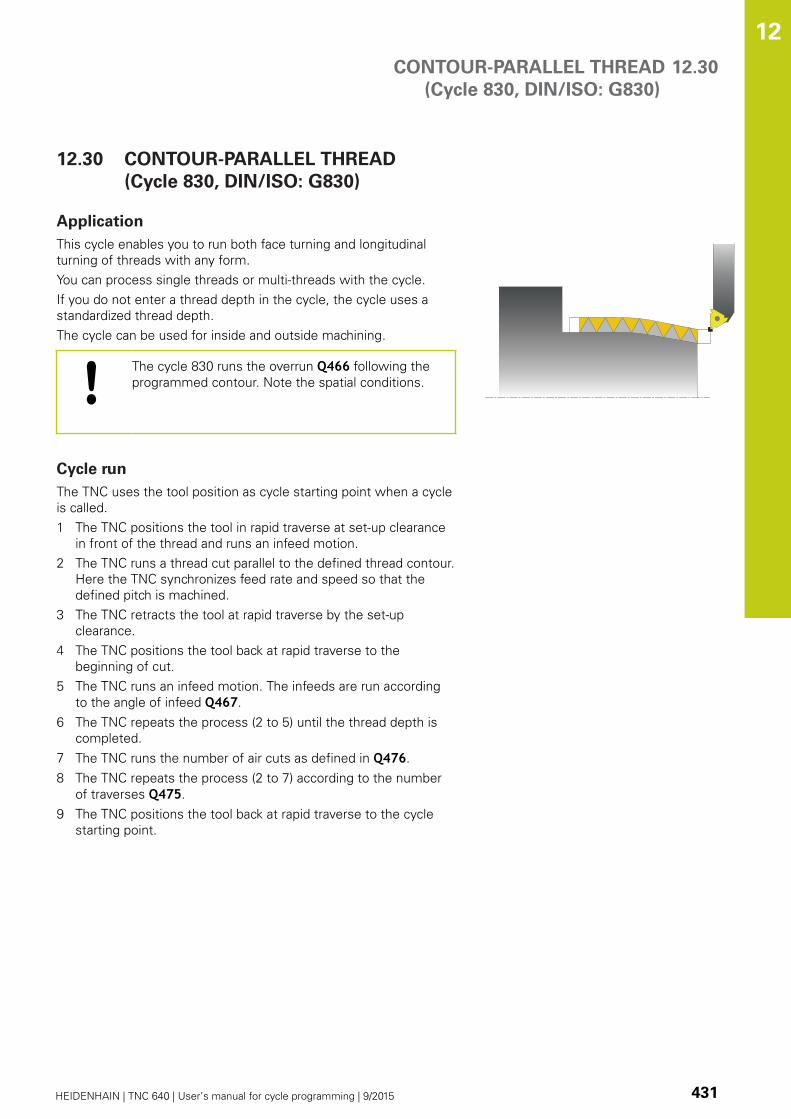
CONTOUR-PARALLEL THREAD
(Cycle 830, DIN/ISO: G830)
12.30
12
HEIDENHAIN | TNC 640 | User’s manual for cycle programming | 9/2015 431
12.30 CONTOUR-PARALLEL THREAD
(Cycle 830, DIN/ISO: G830)
Application
This cycle enables you to run both face turning and longitudinal
turning of threads with any form.
You can process single threads or multi-threads with the cycle.
If you do not enter a thread depth in the cycle, the cycle uses a
standardized thread depth.
The cycle can be used for inside and outside machining.
The cycle 830 runs the overrun Q466 following the
programmed contour. Note the spatial conditions.
Cycle run
The TNC uses the tool position as cycle starting point when a cycle
is called.
1 The TNC positions the tool in rapid traverse at set-up clearance
in front of the thread and runs an infeed motion.
2 The TNC runs a thread cut parallel to the defined thread contour.
Here the TNC synchronizes feed rate and speed so that the
defined pitch is machined.
3 The TNC retracts the tool at rapid traverse by the set-up
clearance.
4 The TNC positions the tool back at rapid traverse to the
beginning of cut.
5 The TNC runs an infeed motion. The infeeds are run according
to the angle of infeed Q467.
6 The TNC repeats the process (2 to 5) until the thread depth is
completed.
7 The TNC runs the number of air cuts as defined in Q476.
8 The TNC repeats the process (2 to 7) according to the number
of traverses Q475.
9 The TNC positions the tool back at rapid traverse to the cycle
starting point.

Cycles: Turning 12.30 CONTOUR-PARALLEL THREAD
(Cycle 830, DIN/ISO: G830)
12
432 HEIDENHAIN | TNC 640 | User’s manual for cycle programming | 9/2015
Please note while programming:
Program a positioning block to the starting position
with radius compensation R0 before the cycle call.
The approach path (Q465) must be long enough
for the feed axes to be accelerated to the required
velocity.
The overrun path (Q466) must be long enough to
decelerate the feed axes.
Both the approach and overrun take place outside the
defined contour.
When the TNC runs a thread cut, the feed-rate
override knob is disabled. The spindle speed override
knob is active only within a limited range, which is
defined by the machine tool builder (refer to your
machine manual).
Before calling the cycle you must program the cycle
14 CONTOUR to define the subprogram number.
When you use local QL Q parameters in a contour
subprogram you must also assign or calculate these
in the contour subprogram.
With some machine types the turning tool is not
clamped in the milling spindle but in a separate
holder adjacent to the spindle. The turning tool
cannot be rotated through 180° in such cases to
machine internal and external threads with only one
tool for example. If with such a machine you wish
to use an external tool for inside machining, you can
execute machining in the negative diameter range
(-X) and reverse the direction of workpiece rotation.
Note that with pre-positioning in the negative
diameter range, the TNC reverses the effect of the
parameter G471 Thread position (external thread is
then 1 and internal thread 0).
The retraction motion is directly to the starting
position. Always position the tool so that the TNC
can approach the starting point at the end of the
cycle without collisions.

CONTOUR-PARALLEL THREAD
(Cycle 830, DIN/ISO: G830)
12.30
12
HEIDENHAIN | TNC 640 | User’s manual for cycle programming | 9/2015 433
Cycle parameters
Thread position Q471: Define the position of the
thread:
0: External thread
1: Internal thread
Thread orientationQ461: Define the direction of
the thread pitch:
0: Longitudinal (parallel to the rotary axis)
1: Lateral (perpendicular to the rotary axis)
Set-up clearance Q460: Set-up clearance
perpendicular to thread pitch.
Thread pitch Q472: Pitch of the thread.
Depth of thread Q473 (incremental): Depth of the
thread. If you enter 0, the depth is assumed for a
metric thread based on the pitch.
Runout of thread Q474 (incremental): Length of the
path on which, at the end of the thread, the tool is
lifted from the current plunging depth to the thread
diameter Q460.
Q460
Q472
Q473
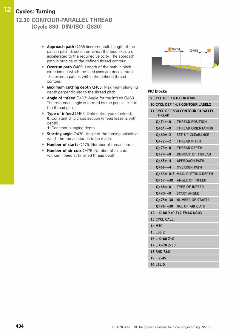
Cycles: Turning 12.30 CONTOUR-PARALLEL THREAD
(Cycle 830, DIN/ISO: G830)
12
434 HEIDENHAIN | TNC 640 | User’s manual for cycle programming | 9/2015
Approach path Q465 (incremental): Length of the
path in pitch direction on which the feed axes are
accelerated to the required velocity. The approach
path is outside of the defined thread contour.
Overrun path Q466: Length of the path in pitch
direction on which the feed axes are decelerated.
The overrun path is within the defined thread
contour.
Maximum cutting depth Q463: Maximum plunging
depth perpendicular to the thread pitch
Angle of infeed Q467: Angle for the infeed Q463.
The reference angle is formed by the parallel line to
the thread pitch.
Type of infeed Q468: Define the type of infeed:
0: Constant chip cross section (infeed lessens with
depth)
1: Constant plunging depth
Starting angle Q470: Angle of the turning spindle at
which the thread start is to be made.
Number of starts Q475: Number of thread starts
Number of air cuts Q476: Number of air cuts
without infeed at finished thread depth
Q465Q474
NC blocks
9 CYCL DEF 14.0 CONTOUR
10 CYCL DEF 14.1 CONTOUR LABEL2
11 CYCL DEF 830 CONTOUR-PARALLELTHREAD
Q471=+0 ;THREAD POSITION
Q461=+0 ;THREAD ORIENTATION
Q460=+2 ;SET-UP CLEARANCE
Q472=+2 ;THREAD PITCH
Q473=+0 ;THREAD DEPTH
Q474=+0 ;RUNOUT OF THREAD
Q465=+4 ;APPROACH PATH
Q466=+4 ;OVERRUN PATH
Q463=+0.5 ;MAX. CUTTING DEPTH
Q467=+30 ;ANGLE OF INFEED
Q468=+0 ;TYPE OF INFEED
Q470=+0 ;START ANGLE
Q475=+30 ;NUMBER OF STARTS
Q476=+30 ;NO. OF AIR CUTS
12 L X+80 Y+0 Z+2 FMAX M303
13 CYCL CALL
14 M30
15 LBL 2
16 L X+60 Z+0
17 L X+70 Z-30
18 RND R60
19 L Z-45
20 LBL 0

GEAR HOBBING (Cycle 880, DIN/ISO: G880) 12.31
12
HEIDENHAIN | TNC 640 | User’s manual for cycle programming | 9/2015 435
12.31 GEAR HOBBING (Cycle 880, DIN/ISO:
G880)
Cycle run
With Cycle 880 Gear Hobbing you can machine external cylindrical
gears or helical gears with any angles. In the cycle you first define
the gear and then the tool with which the gear is to be machined.
You can select the machining strategy and the machining side in
the cycle. The machining process for gear hobbing is performed
with a synchronized rotary motion of the tool spindle and rotary
table. In addition, the gear hob moves along the workpiece in axial
direction.
While Cycle 880 Gear Hobbing is active, the coordinate system
might be rotated. It is therefore essential to program Cycle 801
RESET ROTARY COORDINATE SYSTEM and M145 at the end of
the cycle.
Cycle run:
1 The TNC positions the tool in the tool axis to clearance height
Q260 at the feed rate FMAX. If the value of the current tool
location in the tool axis is greater than Q260, the tool is not
moved.
2 Before tilting the working plane, the TNC positions the tool in X
to a safe coordinate at the feed rate FMAX. If the tool is already
located at a coordinate in the working plane that is greater than
the calculated coordinate, the tool is not moved.
3 The TNC then tilts the working plane at the feed rate Q253;
M144 is internally active in the cycle.
4 The TNC positions the tool at the feed rate FMAX to the starting
point in the working plane.
5 The TNC then moves the tool in the tool axis at the feed rate
Q253 to the set-up clearance Q460.
6 The TNC moves the hob in the longitudinal direction at the
programmed feed rate Q478 (for roughing) or Q505 (for
finishing) along the workpiece into which the teeth are to be
cut. The area to be machined is limited by the starting point in Z
Q551+Q460 and the end point in Z Q552+Q460.
7 When the tool reaches the end point, it is retracted at the feed
rate Q253 and returns to the starting point.
8 The TNC repeats the steps 5 to 7 until the defined gear is
completed.
9 Finally, the TNC retracts the tool to the clearance height Q260 at
the feed rate FMAX.
10 The machining operation ends in the tilted system.
11 Now you need to move the tool to a safe height and reset the
tilting of the working plane.
12 Then you must program Cycle 801 RESET ROTARY
COORDINATE SYSTEM and M145.
Cycles: Turning 12.31 GEAR HOBBING (Cycle 880, DIN/ISO: G880)
12
436 HEIDENHAIN | TNC 640 | User’s manual for cycle programming | 9/2015
Please note while programming:
The values entered for module, number of teeth and
outside diameter are monitored. If these values are
not consistent, an error message is displayed. It is
also possible to make entries for only 2 of these 3
parameters. In this case, enter the value 0 for either
the module or the number of teeth or the outside
diameter. The TNC then calculates the missing value.
Program FUNCTION TURNDATA SPIN VCONST:OFF.
If you program FUNCTION TURNDATA SPIN
VCONST:OFF S15, the spindle speed of the tool is
calculated as follows: Q541 x S. With Q541=238 and
S=15, this would result in a tool spindle speed of
3570 rpm.
Define the tool as a milling cutter in the tool table.
To avoid exceeding the maximum permissible spindle
speed of the tool, you can enter a limitation. (Entry in
the "Nmax" column of the tool table "tool.t".)
Before starting the cycle, program the direction of
rotation of the workpiece (M303/M304).
Before cycle call, set the datum to the center of
rotation.
Cycle 880 Gear Hobbing is run in turning mode and is
CALL-active.
Software option 50 must be enabled
Danger of collision!
Pre-position the tool so that it is already on the
desired machining side Q550. On this machining
side, move the tool to a safe position where there is
no danger of collision with the workpiece (clamping
devices) during tilting.
Please note that the starting point in Z and the end
point in Z are extended by the set-up clearance
Q460! Clamp the workpiece in such a way that there
is no danger of collision between the tool and the
clamping devices!
If you program M136 before the cycle, the TNC
interprets feed rate values in the cycle in mm/rev.,
and if you are not using M136, in mm/min!
After Cycle 880 GEAR HOBBING remember to call
Cycle 801 and M145 in order to reset the coordinate
system.
If you abort a program during machining, you must
reset the coordinate system with Cycle 801 and
call M145 before you start machining again!
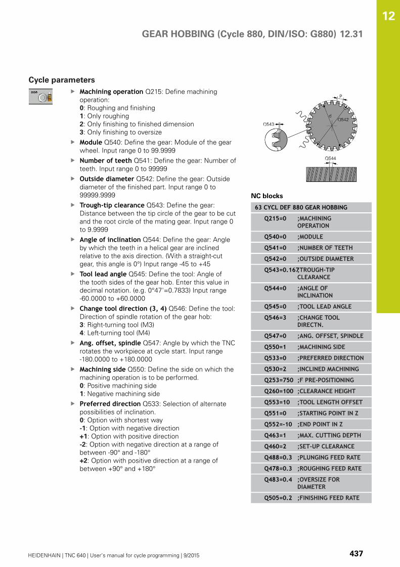
GEAR HOBBING (Cycle 880, DIN/ISO: G880) 12.31
12
HEIDENHAIN | TNC 640 | User’s manual for cycle programming | 9/2015 437
Cycle parameters
Machining operation Q215: Define machining
operation:
0: Roughing and finishing
1: Only roughing
2: Only finishing to finished dimension
3: Only finishing to oversize
Module Q540: Define the gear: Module of the gear
wheel. Input range 0 to 99.9999
Number of teeth Q541: Define the gear: Number of
teeth. Input range 0 to 99999
Outside diameter Q542: Define the gear: Outside
diameter of the finished part. Input range 0 to
99999.9999
Trough-tip clearance Q543: Define the gear:
Distance between the tip circle of the gear to be cut
and the root circle of the mating gear. Input range 0
to 9.9999
Angle of inclination Q544: Define the gear: Angle
by which the teeth in a helical gear are inclined
relative to the axis direction. (With a straight-cut
gear, this angle is 0°) Input range -45 to +45
Tool lead angle Q545: Define the tool: Angle of
the tooth sides of the gear hob. Enter this value in
decimal notation. (e.g. 0°47'=0.7833) Input range
-60.0000 to +60.0000
Change tool direction (3, 4) Q546: Define the tool:
Direction of spindle rotation of the gear hob:
3: Right-turning tool (M3)
4: Left-turning tool (M4)
Ang. offset, spindle Q547: Angle by which the TNC
rotates the workpiece at cycle start. Input range
-180.0000 to +180.0000
Machining side Q550: Define the side on which the
machining operation is to be performed.
0: Positive machining side
1: Negative machining side
Preferred direction Q533: Selection of alternate
possibilities of inclination.
0: Option with shortest way
-1: Option with negative direction
+1: Option with positive direction
-2: Option with negative direction at a range of
between -90° and -180°
+2: Option with positive direction at a range of
between +90° and +180°
NC blocks
63 CYCL DEF 880 GEAR HOBBING
Q215=0 ;MACHININGOPERATION
Q540=0 ;MODULE
Q541=0 ;NUMBER OF TEETH
Q542=0 ;OUTSIDE DIAMETER
Q543=0.167;TROUGH-TIPCLEARANCE
Q544=0 ;ANGLE OFINCLINATION
Q545=0 ;TOOL LEAD ANGLE
Q546=3 ;CHANGE TOOLDIRECTN.
Q547=0 ;ANG. OFFSET, SPINDLE
Q550=1 ;MACHINING SIDE
Q533=0 ;PREFERRED DIRECTION
Q530=2 ;INCLINED MACHINING
Q253=750 ;F PRE-POSITIONING
Q260=100 ;CLEARANCE HEIGHT
Q553=10 ;TOOL LENGTH OFFSET
Q551=0 ;STARTING POINT IN Z
Q552=-10 ;END POINT IN Z
Q463=1 ;MAX. CUTTING DEPTH
Q460=2 ;SET-UP CLEARANCE
Q488=0.3 ;PLUNGING FEED RATE
Q478=0.3 ;ROUGHING FEED RATE
Q483=0.4 ;OVERSIZE FORDIAMETER
Q505=0.2 ;FINISHING FEED RATE

Cycles: Turning 12.31 GEAR HOBBING (Cycle 880, DIN/ISO: G880)
12
438 HEIDENHAIN | TNC 640 | User’s manual for cycle programming | 9/2015
Inclined machining Q530: Position the tilting axes
for inclined machining:
1: Position the tilting axis automatically, thereby
orienting the tool tip (MOVE). The relative
position between the tool and workpiece remains
unchanged. The TNC performs a compensating
movement with the linear axes
2: Position the tilting axis automatically without
orienting the tool tip (TURN).
Feed rate for pre-positioning Q253: Traversing
speed of the tool when tilting and pre-positioning,
and when positioning the tool axis between the
individual infeeds. Entry in mm/min. Input range 0 to
99999.9999 alternatively FMAX, FAUTO, PREDEF
Tool length offset Q553: Define which section of
the gear hob is to be used. As gear hobbing causes
wear to the hob teeth, the tool can be offset in the
longitudinal direction to evenly apply the load over
the entire length of the tool. In parameter Q553 you
enter an incremental distance by which the tool is to
be moved in the longitudinal direction. Input range 0
to 99.9999
Starting point in Z Q551: Starting point in Z for gear
hobbing. Input range -99999.9999 to 99999.9999
End point in Z Q552: End point in Z for gear
hobbing. Input range -99999.9999 to 99999.9999
Maximum cutting depth Q463: Maximum infeed
(radius value) in radial direction. The infeed is divided
evenly to avoid abrasive cuts. Input range 0.001 to
999.999
Set-up clearance Q460 (incremental): Distance
for retraction and pre-positioning.Input range 0 to
999.999
Feed rate for plunging Q488: Feed rate for tool
infeed. Input range 0 to 99999.999
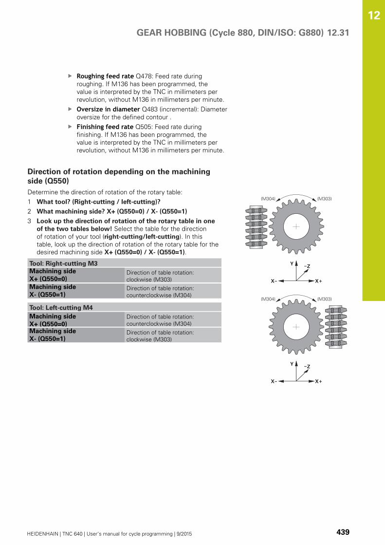
GEAR HOBBING (Cycle 880, DIN/ISO: G880) 12.31
12
HEIDENHAIN | TNC 640 | User’s manual for cycle programming | 9/2015 439
Roughing feed rate Q478: Feed rate during
roughing. If M136 has been programmed, the
value is interpreted by the TNC in millimeters per
revolution, without M136 in millimeters per minute.
Oversize in diameter Q483 (incremental): Diameter
oversize for the defined contour .
Finishing feed rate Q505: Feed rate during
finishing. If M136 has been programmed, the
value is interpreted by the TNC in millimeters per
revolution, without M136 in millimeters per minute.
Direction of rotation depending on the machining
side (Q550)
Determine the direction of rotation of the rotary table:
1 What tool? (Right-cutting / left-cutting)?
2 What machining side? X+ (Q550=0) / X- (Q550=1)
3 Look up the direction of rotation of the rotary table in one
of the two tables below! Select the table for the direction
of rotation of your tool (right-cutting/left-cutting). In this
table, look up the direction of rotation of the rotary table for the
desired machining side X+ (Q550=0) / X- (Q550=1).
Tool: Right-cutting M3
Machining side
X+ (Q550=0)Direction of table rotation:
clockwise (M303)
Machining side
X- (Q550=1)Direction of table rotation:
counterclockwise (M304)
Tool: Left-cutting M4
Machining side
X+ (Q550=0)
Direction of table rotation:
counterclockwise (M304)
Machining side
X- (Q550=1)Direction of table rotation:
clockwise (M303)
(M303)(M304)
(M303)(M304)

Cycles: Turning 12.32 CHECK UNBALANCE (Cycle 892, DIN/ISO: G892)
12
440 HEIDENHAIN | TNC 640 | User’s manual for cycle programming | 9/2015
12.32 CHECK UNBALANCE (Cycle 892, DIN/
ISO: G892)
Application
When turning a nonsymmetrical workpiece, such as a pump
body, an unbalance may occur. This may cause a high load on the
machine, depending on the rotational speed, mass and shape of
the workpiece. With Cycle 892 CHECK UNBALANCE the TNC
checks the unbalance of the turning spindle. This cycle uses two
parameters. Q450 describes the maximum unbalance and Q451
the maximum speed. If the maximum unbalance is exceeded, an
error message is displayed and the program is aborted. When
the maximum unbalance is not exceeded, the TNC executes the
program without interruptions. This function protects the machine
mechanics. It enables you to take action if excessive unbalance is
detected.

CHECK UNBALANCE (Cycle 892, DIN/ISO: G892) 12.32
12
HEIDENHAIN | TNC 640 | User’s manual for cycle programming | 9/2015 441
Please note while programming:
Check the unbalance whenever you clamp a new
workpiece. If required, use balancing weights to
compensate any imbalance.
The removal of material during machining will change
the mass distribution within the workpiece. This
may also have an influence on workpiece unbalance.
Therefore, unbalance checks should also be carried
out between machining steps.
Keep in mind the mass and unbalance of the
workpiece when choosing the speed. Do not
use high speeds with heavy workpieces or high
unbalance loads.
Software option 50 must be enabled
This function is executed in turning mode.
FUNCTION MODE TURN must be active, otherwise
the TNC generates an error message.
Your machine tool builder configures Cycle 892.
Your machine tool builder defines the function of
Cycle 892.
The turning spindle rotates during the unbalance
check.
This function can also be run on machines with more
than one turning spindle. Contact the machine tool
builder for further information.
You need to check the applicability of the control's
internal unbalance functionality for each of your
machine types. If the unbalance amplitude of the
turning spindle has very little effect on the adjoining
axes, it might not be possible to calculate useful
unbalance values from the determined results. In
this case, you will have to use a system with external
sensors for unbalance monitoring.
If Cycle 892 CHECK UNBALANCE has aborted a
program, it is recommended to use the manual
MEASURE UNBALANCE cycle. With this cycle, the
TNC determines the unbalance and calculates the
mass and position of a balancing weight. For more
information on the manual MEASURE UNBALANCE
cycle, refer to the User's Manual for Conversational
Programming.

Cycles: Turning 12.32 CHECK UNBALANCE (Cycle 892, DIN/ISO: G892)
12
442 HEIDENHAIN | TNC 640 | User’s manual for cycle programming | 9/2015
Cycle parameters
Maximum runout Q450: (mm) Specifies the
maximum amplitude of a sinusoidal unbalance
signal. The signal results from the following error of
the measuring axis and from the spindle revolutions.
Speed Q451: (rpm) The unbalance check starts at a
low rotational speed (e.g. 50 rpm). It is automatically
increased by specified increments (e.g. 25 rpm) until
the defined maximum speed is reached. Spindle
override is not effective.
NC blocks
63 CYCL DEF 892 CHECK UNBALANCE
Q450=0 ;MAXIMUM RUNOUT
Q451=50 ;SPEED
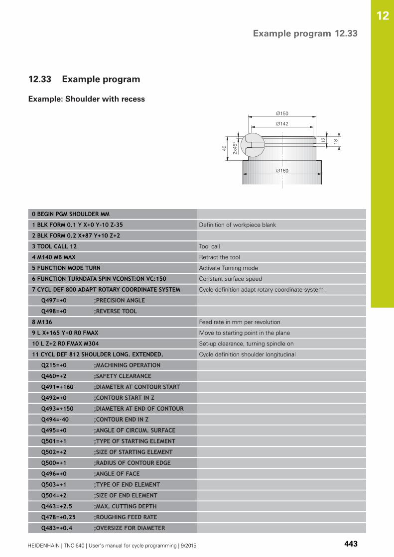
Example program 12.33
12
HEIDENHAIN | TNC 640 | User’s manual for cycle programming | 9/2015 443
12.33 Example program
Example: Shoulder with recess
0 BEGIN PGM SHOULDER MM
1 BLK FORM 0.1 Y X+0 Y-10 Z-35 Definition of workpiece blank
2 BLK FORM 0.2 X+87 Y+10 Z+2
3 TOOL CALL 12 Tool call
4 M140 MB MAX Retract the tool
5 FUNCTION MODE TURN Activate Turning mode
6 FUNCTION TURNDATA SPIN VCONST:ON VC:150 Constant surface speed
7 CYCL DEF 800 ADAPT ROTARY COORDINATE SYSTEM Cycle definition adapt rotary coordinate system
Q497=+0 ;PRECISION ANGLE
Q498=+0 ;REVERSE TOOL
8 M136 Feed rate in mm per revolution
9 L X+165 Y+0 R0 FMAX Move to starting point in the plane
10 L Z+2 R0 FMAX M304 Set-up clearance, turning spindle on
11 CYCL DEF 812 SHOULDER LONG. EXTENDED. Cycle definition shoulder longitudinal
Q215=+0 ;MACHINING OPERATION
Q460=+2 ;SAFETY CLEARANCE
Q491=+160 ;DIAMETER AT CONTOUR START
Q492=+0 ;CONTOUR START IN Z
Q493=+150 ;DIAMETER AT END OF CONTOUR
Q494=-40 ;CONTOUR END IN Z
Q495=+0 ;ANGLE OF CIRCUM. SURFACE
Q501=+1 ;TYPE OF STARTING ELEMENT
Q502=+2 ;SIZE OF STARTING ELEMENT
Q500=+1 ;RADIUS OF CONTOUR EDGE
Q496=+0 ;ANGLE OF FACE
Q503=+1 ;TYPE OF END ELEMENT
Q504=+2 ;SIZE OF END ELEMENT
Q463=+2.5 ;MAX. CUTTING DEPTH
Q478=+0.25 ;ROUGHING FEED RATE
Q483=+0.4 ;OVERSIZE FOR DIAMETER
Cycles: Turning 12.33 Example program
12
444 HEIDENHAIN | TNC 640 | User’s manual for cycle programming | 9/2015
Q484=+0.2 ;OVERSIZE IN Z
Q505=+0.2 ;FINISHING FEED RATE
Q506=+0 ;CONTOUR SMOOTHING
12 CYCL CALL M8 Cycle call
13 M305 Turning spindle off
14 TOOL CALL 15 Tool call
15 M140 MB MAX Retract the tool
16 FUNCTION TURNDATA SPIN VCONST:ON VC:100 Constant cutting speed
17 CYCL DEF 800 ADAPT ROTARY COORDINATE SYSTEM Cycle definition adapt rotary coordinate system
Q497=+0 ;PRECISION ANGLE
Q498=+0 ;REVERSE TOOL
18 L X+165 Y+0 R0 FMAX Move to starting point in the plane
19 L Z+2 R0 FMAX M304 Set-up clearance, turning spindle on
20 CYCL DEF 862 RADIAL RECESSING EXTENDED Cycle definition recess
Q215=+0 ;MACHINING OPERATION
Q460=+2 ;SAFETY CLEARANCE
Q491=+150 ;DIAMETER AT CONTOUR START
Q492=-12 ;CONTOUR START IN Z
Q493=+142 ;DIAMETER AT END OF CONTOUR
Q494=-18 ;CONTOUR END IN Z
Q495=+0 ;ANGLE OF SIDE
Q501=+1 ;TYPE OF STARTING ELEMENT
Q502=+1 ;SIZE OF STARTING ELEMENT
Q500=+0 ;RADIUS OF CONTOUR EDGE
Q496=+0 ;ANGLE OF SECOND SIDE
Q503=+1 ;TYPE OF END ELEMENT
Q504=+1 ;SIZE OF END ELEMENT
Q478=+0.3 ;ROUGHING FEED RATE
Q483=+0.4 ;OVERSIZE FOR DIAMETER
Q484=+0.2 ;OVERSIZE IN Z
Q505=+0.15 ;FINISHING FEED RATE
Q463=+0 ;LIMIT TO DEPTH
21 CYCL CALL M8 Cycle call
22 M305 Turning spindle off
23 M137 Feed rate in mm per minute
24 M140 MB MAX Retract the tool
25 FUNCTION MODE MILL Activate Milling mode
26 M30 End of program
27 END PGM SHOULDER MM

Example program 12.33
12
HEIDENHAIN | TNC 640 | User’s manual for cycle programming | 9/2015 445
Example: Gear hobbing
Cycle 880 GEAR HOBBING is used in the following
program. This programming example illustrates the
machining of a helical gear, with Module=2.1.
Program sequence
Tool call: Gear hob
Start turning mode
Approach safe position
Call the cycle
Reset the coordinate system with Cycle 801 and
M145
0 BEGIN PGM 5 MM
1 BLK FORM CYLINDER Z R42 L150 Definition of workpiece blank: Cylinder
2 FUNCTION MODE MILL Activate milling mode
3 TOOL CALL "GEAR_HOB_D75" Call the tool
4 FUNCTION MODE TURN Activate turning mode
5 CYCL DEF 801 RESET ROTARY COORDINATE SYSTEM Reset the coordinate system
6 M145 Deactivate M144 if still active
7 FUNCTION TURNDATA SPIN VCONST:OFF S50 Constant surface speed OFF
8 M140 MB MAX Retract the tool
9 L A+0 R0 FMAX Set the rotary axis to 0
10 L X+250 Y-250 R0 FMAX Pre-position the tool in the working plane on the side on
which machining will be performed
11 Z+20 R0 FMAX Pre-position the tool in the spindle axis
12 L M136 Feed rate in mm/rev
13 CYCL DEF 880 GEAR HOBBING Activate interpolation turning
Q215=+0 ;MACHINING OPERATION
Q540=+2.1 ;MODULE
Q541=+0 ;NUMBER OF TEETH
Q542=+69.3 ;OUTSIDE DIAMETER
Q543=+0.1666 ;TROUGH-TIP CLEARANCE
Q544=-5 ;ANGLE OF INCLINATION
Q545=+1.6833 ;TOOL LEAD ANGLE
Q546=+3 ;CHANGE TOOL DIRECTN.
Q550=+0 ;MACHINING SIDE
Q533=+0 ;PREFERRED DIRECTION
Q530=+2 ;INCLINED MACHINING
Q253=+2000 ;F PRE-POSITIONING
Q260=+20 ;CLEARANCE HEIGHT
Q553=+10 ;TOOL LENGTH OFFSET
Q551=+0 ;STARTING POINT IN Z
Q552=-10 ;END POINT IN Z
Q463=+1 ;MAX. CUTTING DEPTH
Cycles: Turning 12.33 Example program
12
446 HEIDENHAIN | TNC 640 | User’s manual for cycle programming | 9/2015
Q488=+1 ;PLUNGING FEED RATE
Q478=+2 ;ROUGHING FEED RATE
Q483=+0.4 ;OVERSIZE FOR DIAMETER
Q505=+1 ;FINISHING FEED RATE
14 CYCL CALL M303 Call the cycle, spindle on
15 CYCL DEF 801 RESET ROTARY COORDINATE SYSTEM Reset the coordinate system
16 M145 Deactivate the active M144 in the cycle
17 FUNCTION MODE MILL Activate milling mode
18 M140 MB MAX Retract the tool in the tool axis
19 L A+0 C+0 R0 FMAX Reset the rotation
20 M30 END of program
21 END PGM 5 MM

13Using Touch Probe
Cycles
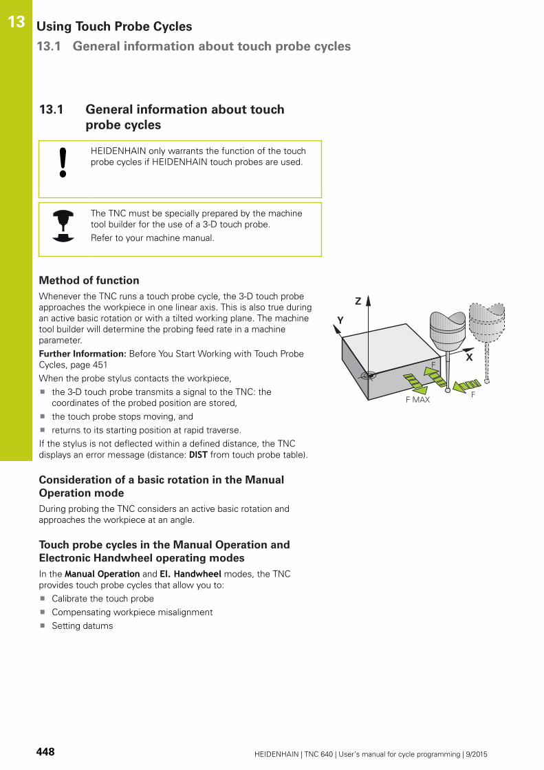
Using Touch Probe Cycles 13.1 General information about touch probe cycles
13
448 HEIDENHAIN | TNC 640 | User’s manual for cycle programming | 9/2015
13.1 General information about touch
probe cycles
HEIDENHAIN only warrants the function of the touch
probe cycles if HEIDENHAIN touch probes are used.
The TNC must be specially prepared by the machine
tool builder for the use of a 3-D touch probe.
Refer to your machine manual.
Method of function
Whenever the TNC runs a touch probe cycle, the 3-D touch probe
approaches the workpiece in one linear axis. This is also true during
an active basic rotation or with a tilted working plane. The machine
tool builder will determine the probing feed rate in a machine
parameter.
Further Information: Before You Start Working with Touch Probe
Cycles, page 451
When the probe stylus contacts the workpiece,
the 3-D touch probe transmits a signal to the TNC: the
coordinates of the probed position are stored,
the touch probe stops moving, and
returns to its starting position at rapid traverse.
If the stylus is not deflected within a defined distance, the TNC
displays an error message (distance: DIST from touch probe table).
Consideration of a basic rotation in the Manual
Operation mode
During probing the TNC considers an active basic rotation and
approaches the workpiece at an angle.
Touch probe cycles in the Manual Operation and
Electronic Handwheel operating modes
In the Manual Operation and El. Handwheel modes, the TNC
provides touch probe cycles that allow you to:
Calibrate the touch probe
Compensating workpiece misalignment
Setting datums
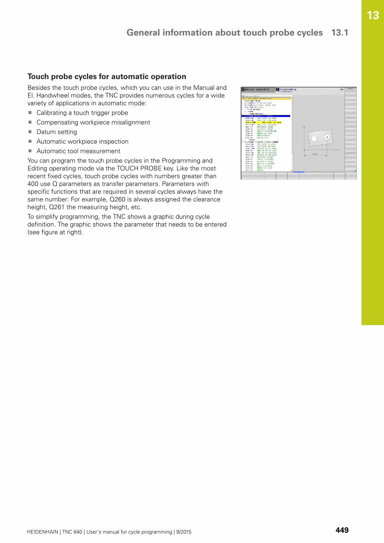
General information about touch probe cycles 13.1
13
HEIDENHAIN | TNC 640 | User’s manual for cycle programming | 9/2015 449
Touch probe cycles for automatic operation
Besides the touch probe cycles, which you can use in the Manual and
El. Handwheel modes, the TNC provides numerous cycles for a wide
variety of applications in automatic mode:
Calibrating a touch trigger probe
Compensating workpiece misalignment
Datum setting
Automatic workpiece inspection
Automatic tool measurement
You can program the touch probe cycles in the Programming and
Editing operating mode via the TOUCH PROBE key. Like the most
recent fixed cycles, touch probe cycles with numbers greater than
400 use Q parameters as transfer parameters. Parameters with
specific functions that are required in several cycles always have the
same number: For example, Q260 is always assigned the clearance
height, Q261 the measuring height, etc.
To simplify programming, the TNC shows a graphic during cycle
definition. The graphic shows the parameter that needs to be entered
(see figure at right).

Using Touch Probe Cycles 13.1 General information about touch probe cycles
13
450 HEIDENHAIN | TNC 640 | User’s manual for cycle programming | 9/2015
Defining the touch probe cycle in the Programming and Editing
mode of operation
The soft-key row shows all available touch probe
functions divided into groups.
Select the desired probe cycle group, for
example datum setting. Cycles for automatic tool
measurement are available only if your machine has
been prepared for them.
Select a cycle, e.g. datum setting at pocket center.
The TNC initiates the programming dialog and asks
for all required input values. At the same time a
graphic of the input parameters is displayed in the
right screen window. The parameter that is asked
for in the dialog prompt is highlighted.
Enter all parameters requested by the TNC and
conclude each entry with the ENT key.
The TNC ends the dialog when all required data has
been entered
Soft key Group of measuring cycles Page
Cycles for automatic measurement
and compensation of workpiece
misalignment
458
Cycles for automatic workpiece
presetting
480
Cycles for automatic workpiece
inspection
534
Special cycles 580
Calibrate TS 580
Kinematics 619
Cycles for automatic tool
measurement (enabled by the machine
tool builder)
650
Visual Setup Control (Option 136 VSC) 596
NC blocks
5 TCH PROBE 410 DATUM INSIDERECTAN.
Q321=+50 ;CENTER IN 1ST AXIS
Q322=+50 ;CENTER IN 2ND AXIS
Q323=60 ;FIRST SIDE LENGTH
Q324=20 ;2ND SIDE LENGTH
Q261=-5 ;MEASURING HEIGHT
Q320=0 ;SET-UP CLEARANCE
Q260=+20 ;CLEARANCE HEIGHT
Q301=0 ;MOVE TO CLEARANCE
Q305=10 ;NO. IN TABLE
Q331=+0 ;DATUM
Q332=+0 ;DATUM
Q303=+1 ;MEAS. VALUETRANSFER
Q381=1 ;PROBE IN TS AXIS
Q382=+85 ;1ST CO. FOR TS AXIS
Q383=+50 ;2ND CO. FOR TS AXIS
Q384=+0 ;3RD CO. FOR TS AXIS
Q333=+0 ;DATUM
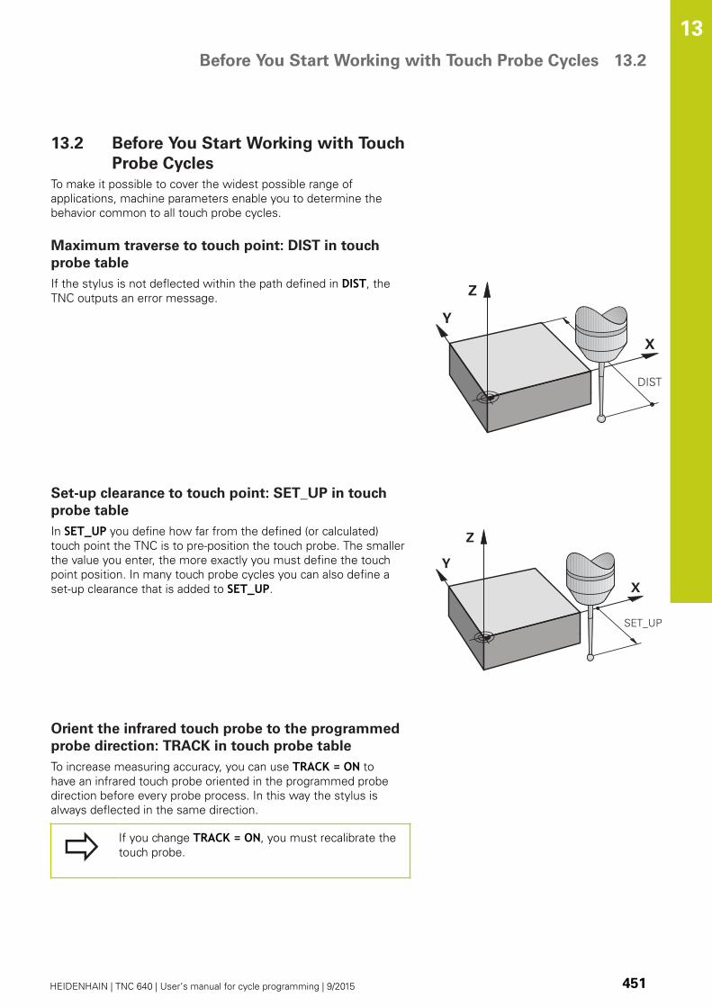
Before You Start Working with Touch Probe Cycles 13.2
13
HEIDENHAIN | TNC 640 | User’s manual for cycle programming | 9/2015 451
13.2 Before You Start Working with Touch
Probe Cycles
To make it possible to cover the widest possible range of
applications, machine parameters enable you to determine the
behavior common to all touch probe cycles.
Maximum traverse to touch point: DIST in touch
probe table
If the stylus is not deflected within the path defined in DIST, the
TNC outputs an error message.
Set-up clearance to touch point: SET_UP in touch
probe table
In SET_UP you define how far from the defined (or calculated)
touch point the TNC is to pre-position the touch probe. The smaller
the value you enter, the more exactly you must define the touch
point position. In many touch probe cycles you can also define a
set-up clearance that is added to SET_UP.
Orient the infrared touch probe to the programmed
probe direction: TRACK in touch probe table
To increase measuring accuracy, you can use TRACK = ON to
have an infrared touch probe oriented in the programmed probe
direction before every probe process. In this way the stylus is
always deflected in the same direction.
If you change TRACK = ON, you must recalibrate the
touch probe.
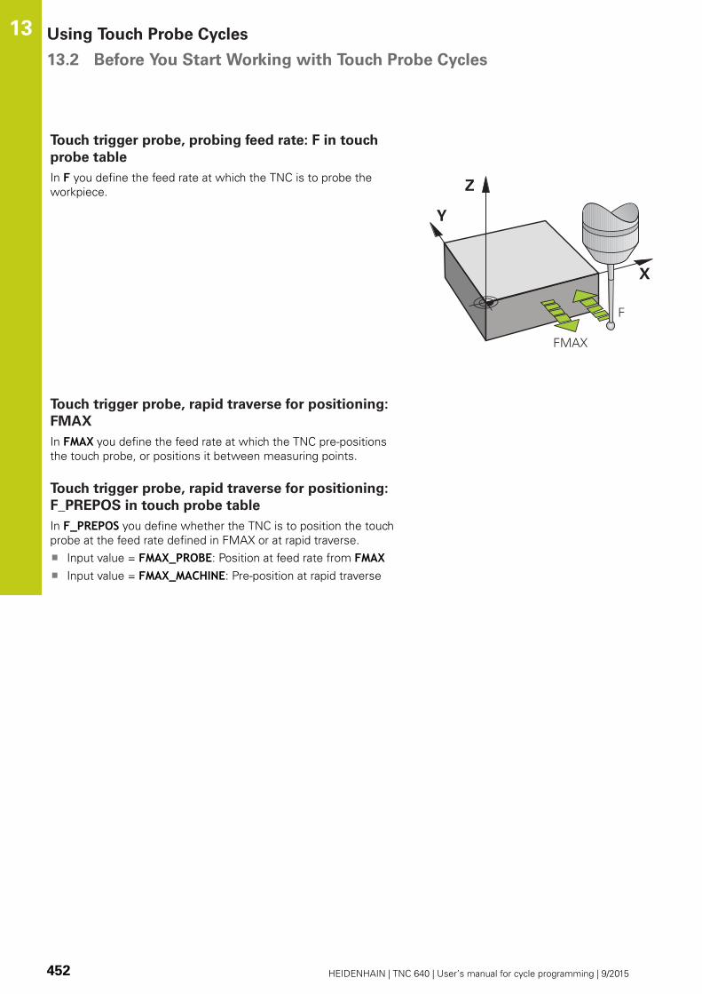
Using Touch Probe Cycles 13.2 Before You Start Working with Touch Probe Cycles
13
452 HEIDENHAIN | TNC 640 | User’s manual for cycle programming | 9/2015
Touch trigger probe, probing feed rate: F in touch
probe table
In F you define the feed rate at which the TNC is to probe the
workpiece.
Touch trigger probe, rapid traverse for positioning:
FMAX
In FMAX you define the feed rate at which the TNC pre-positions
the touch probe, or positions it between measuring points.
Touch trigger probe, rapid traverse for positioning:
F_PREPOS in touch probe table
In F_PREPOS you define whether the TNC is to position the touch
probe at the feed rate defined in FMAX or at rapid traverse.
Input value = FMAX_PROBE: Position at feed rate from FMAXInput value = FMAX_MACHINE: Pre-position at rapid traverse

Before You Start Working with Touch Probe Cycles 13.2
13
HEIDENHAIN | TNC 640 | User’s manual for cycle programming | 9/2015 453
Multiple measurements
To increase measuring certainty, the TNC can run each probing
process up to three times in sequence. Define the number
of measurements in machine parameter ProbeSettings >
Configuration of probe behavior > Automatic mode: Multiplemeasurements with probe function. If the measured position
values differ too greatly, the TNC outputs an error message
(the limit value is defined in Confidence interval of multiplemeasurements). With multiple measurement it is possible to
detect random errors, e.g. from contamination.
If the measured values lie within the confidence interval, the TNC
saves the mean value of the measured positions.
Confidence interval of multiple measurements
When you perform a multiple measurement, you store the
value that the measured values may vary in ProbeSettings >
Configuration of probe behavior > Automatic mode: Confidenceinterval of multiple measurements. If the difference in the
measured values exceeds the value defined by you, the TNC
outputs an error message.

Using Touch Probe Cycles 13.2 Before You Start Working with Touch Probe Cycles
13
454 HEIDENHAIN | TNC 640 | User’s manual for cycle programming | 9/2015
Executing touch probe cycles
All touch probe cycles are DEF active. This means that the TNC
runs the cycle automatically as soon as the TNC executes the cycle
definition in the program run.
Danger of collision!
When running touch probe cycles, no cycles must
be active for coordinate transformation (Cycle
7 DATUM, Cycle 8 MIRROR IMAGE, Cycle 10
ROTATION, Cycles 11 SCALING and 26 AXIS-
SPECIFIC SCALING).
You can also run the Touch Probe Cycles 408 to 419
during an active basic rotation. Make sure, however,
that the basic rotation angle does not change when
you use Cycle 7 DATUM SHIFT with datum tables
after the measuring cycle.
Touch probe cycles with a number greater than 400 position the
touch probe according to a positioning logic:
If the current coordinate of the south pole of the stylus is less
than the coordinate of the clearance height (defined in the
cycle), the TNC retracts the touch probe in the probe axis to the
clearance height and then positions it in the working plane to
the first starting position.
If the current coordinate of the stylus south pole is greater
than the coordinate of the clearance height, then the TNC first
positions the touch probe to the first probe point in the working
plane, and then in the touch-probe axis directly to the measuring
height.
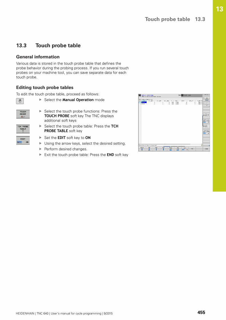
Touch probe table 13.3
13
HEIDENHAIN | TNC 640 | User’s manual for cycle programming | 9/2015 455
13.3 Touch probe table
General information
Various data is stored in the touch probe table that defines the
probe behavior during the probing process. If you run several touch
probes on your machine tool, you can save separate data for each
touch probe.
Editing touch probe tables
To edit the touch probe table, proceed as follows:
Select the Manual Operation mode
Select the touch probe functions: Press the
TOUCH PROBE soft key The TNC displays
additional soft keys
Select the touch probe table: Press the TCHPROBE TABLE soft key
Set the EDIT soft key to ONUsing the arrow keys, select the desired setting.
Perform desired changes.
Exit the touch probe table: Press the END soft key

Using Touch Probe Cycles 13.3 Touch probe table
13
456 HEIDENHAIN | TNC 640 | User’s manual for cycle programming | 9/2015
Touch probe data
Abbr. Inputs Dialog
NO Number of the touch probe: Enter this number in the tool
table (column: TP_NO) under the appropriate tool number
–
TYPE Selection of the touch probe used Selection of touch probe?
CAL_OF1 Offset of the touch probe axis to the spindle axis for the
reference axis
TS center misalignmt. ref. axis?[mm]
CAL_OF2 Offset of the touch probe axis to the spindle axis for the
minor axis
TS center misalignmt. aux. axis?[mm]
CAL_ANG The TNC orients the touch probe to the orientation angle
before calibration or probing (if orientation is possible)
Spindle angle for calibration?
F Feed rate at which the TNC is to probe the workpiece Probing feed rate? [mm/min]
FMAX Feed rate at which the touch probe pre-positions, or is
positioned between the measuring points
Rapid traverse in probing cycle?[mm/min]
DIST If the stylus is not deflected within the defined path, the
TNC outputs an error message
Maximum measuring path? [mm]
SET_UP In SET_UP you define how far from the defined (or
calculated) touch point the TNC is to pre-position the
touch probe. The smaller the value you enter, the more
exactly you must define the touch point position. In many
touch probe cycles you can also define a set-up clearance
that is added to the SET_UP machine parameter.
Set-up clearance? [mm]
F_PREPOS Defining speed with pre-positioning:
Pre-positioning with speed from FMAX: FMAX_PROBEPre-positioning with machine rapid traverse:
FMAX_MACHINE
Pre-positioning at rap. traverse?ENT/NO ENT
TRACK To increase measuring accuracy, you can use TRACK= ON to have an infrared touch probe oriented in the
programmed probe direction before every probe process.
In this way the stylus is always deflected in the same
direction:
ON: Perform spindle tracking
OFF: Do not perform spindle tracking
Orient touch probe cycles?Yes=ENT, No=NOENT
14Touch Probe
Cycles: AutomaticMeasurementof Workpiece
Misalignment

Touch Probe Cycles: Automatic Measurement of Workpiece Misalignment 14.1 Fundamentals
14
458 HEIDENHAIN | TNC 640 | User’s manual for cycle programming | 9/2015
14.1 Fundamentals
Overview
When running touch probe cycles, Cycle 8 MIRROR
IMAGE, Cycle 11 SCALING and Cycle 26 AXIS-
SPECIFIC SCALING must not be active.
HEIDENHAIN only warrants the function of the touch
probe cycles if HEIDENHAIN touch probes are used.
The TNC must be specially prepared by the machine
tool builder for the use of a 3-D touch probe.
Refer to your machine manual.
The TNC provides five cycles that enable you to measure and
compensate workpiece misalignment. In addition, you can reset a
basic rotation with Cycle 404:
Soft key Cycle Page
400 BASIC ROTATION
Automatic measurement using two
points. Compensation via basic
rotation.
460
401 ROT OF 2 HOLES
Automatic measurement using
two holes. Compensation via basic
rotation.
463
402 ROT OF 2 STUDS
Automatic measurement using
two studs. Compensation via basic
rotation.
466
403 ROT IN ROTARY AXIS
Automatic measurement using two
points. Compensation by turning the
table.
469
405 ROT IN C AXIS
Automatic alignment of an angular
offset between a hole center and the
positive Y axis. Compensation via
table rotation.
473
404 SET BASIC ROTATION
Setting any basic rotation.
472
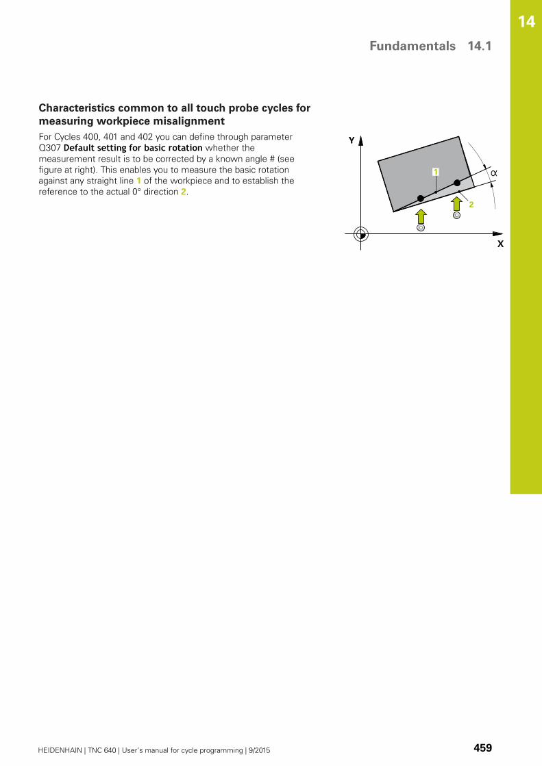
Fundamentals 14.1
14
HEIDENHAIN | TNC 640 | User’s manual for cycle programming | 9/2015 459
Characteristics common to all touch probe cycles for
measuring workpiece misalignment
For Cycles 400, 401 and 402 you can define through parameter
Q307 Default setting for basic rotation whether the
measurement result is to be corrected by a known angle # (see
figure at right). This enables you to measure the basic rotation
against any straight line 1 of the workpiece and to establish the
reference to the actual 0° direction 2.

Touch Probe Cycles: Automatic Measurement of Workpiece Misalignment 14.2 BASIC ROTATION (Cycle 400, DIN/ISO: G400)
14
460 HEIDENHAIN | TNC 640 | User’s manual for cycle programming | 9/2015
14.2 BASIC ROTATION (Cycle 400,
DIN/ISO: G400)
Cycle run
Touch probe cycle 400 determines a workpiece misalignment by
measuring two points, which must lie on a straight surface. With
the basic rotation function the TNC compensates the measured
value.
1 Following the positioning logic, the TNC positions the touch
probe at rapid traverse (value from FMAX column) (see
"Executing touch probe cycles", page 454) to the programmed
touch point 1. The TNC offsets the touch probe by the safety
clearance in the direction opposite to the defined traverse
direction.
2 Then the touch probe moves to the entered measuring height
and runs the first probing process at the probing feed rate
(column F).
3 Then the touch probe moves to the next starting position 2 and
probes the second position.
4 The TNC returns the touch probe to the clearance height and
performs the basic rotation.
Please note while programming:
Before a cycle definition you must have programmed
a tool call to define the touch probe axis.
The TNC will reset an active basic rotation at the
beginning of the cycle.

BASIC ROTATION (Cycle 400, DIN/ISO: G400) 14.2
14
HEIDENHAIN | TNC 640 | User’s manual for cycle programming | 9/2015 461
Cycle parameters
1st meas. point 1st axis Q263 (absolute):
Coordinate of the first touch point in the reference
axis of the working plane. Input range -99999.9999
to 99999.9999
1st meas. point 2nd axis Q264 (absolute):
Coordinate of the first touch point in the minor axis
of the working plane. Input range -99999.9999 to
99999.9999
2nd meas. point 1st axis Q265 (absolute):
Coordinate of the second touch point in the
reference axis of the working plane. Input range
-99999.9999 to 99999.9999
2nd meas. point 2nd axis Q266 (absolute):
Coordinate of the second touch point in the minor
axis of the working plane. Input range -99999.9999
to 99999.9999
Measuring axis Q272: Axis in the working plane in
which the measurement is to be made:
1: Principal axis = measuring axis
2: Secondary axis = measuring axis
Traverse direction 1 Q267: Direction in which the
probe is to approach the workpiece:
-1: Negative Traverse direction
+1: Positive traverse direction
Measuring height in the touch probe axis Q261
(absolute): Coordinate of the ball tip center (=
touch point) in the touch probe axis in which
the measurement is to be made. Input range
-99999.9999 to 99999.9999
Set-up clearance Q320 (incremental): Additional
distance between measuring point and ball tip.
Q320 is added to SET_UP (touch probe table). Input
range 0 to 99999.9999
Clearance height Q260 (absolute): Coordinate in
the touch probe axis at which no collision between
touch probe and workpiece (fixtures) can occur.
Input range -99999.9999 to 99999.9999
NC blocks
5 TCH PROBE 400 BASIC ROTATION
Q263=+10 ;1ST POINT 1ST AXIS
Q264=+3.5 ;1ST POINT 2ND AXIS
Q265=+25 ;2ND POINT 1ST AXIS
Q266=+2 ;2ND POINT 2ND AXIS
Q272=2 ;MEASURING AXIS
Q267=+1 ;TRAVERSE DIRECTION
Q261=-5 ;MEASURING HEIGHT
Q320=0 ;SET-UP CLEARANCE
Q260=+20 ;CLEARANCE HEIGHT
Q301=0 ;MOVE TO CLEARANCE
Q307=0 ;PRESET ROT. ANGLE
Q305=0 ;NO. IN TABLE
Touch Probe Cycles: Automatic Measurement of Workpiece Misalignment 14.2 BASIC ROTATION (Cycle 400, DIN/ISO: G400)
14
462 HEIDENHAIN | TNC 640 | User’s manual for cycle programming | 9/2015
Traversing to clearance height Q301: definition
of how the touch probe is to move between the
measuring points:
0: Move at measuring height between measuring
points
1: Move at clearance height between measuring
points
Preset value for rotation angle Q307 (absolute):
If the misalignment is to be measured against a
straight line other than the reference axis, enter
the angle of this reference line. The TNC will
then calculate the difference between the value
measured and the angle of the reference line for the
basic rotation. Input range -360.000 to 360.000
Preset number in table Q305: Enter the preset
number in the table in which the TNC is to save the
determined basic rotation. If you enter Q305=0,
the TNC automatically places the determined basic
rotation in the ROT menu of the Manual Operation
mode. Input range 0 to 99999
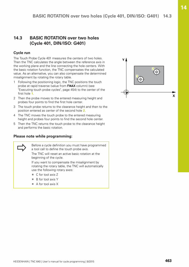
BASIC ROTATION over two holes (Cycle 401, DIN/ISO: G401) 14.3
14
HEIDENHAIN | TNC 640 | User’s manual for cycle programming | 9/2015 463
14.3 BASIC ROTATION over two holes
(Cycle 401, DIN/ISO: G401)
Cycle run
The Touch Probe Cycle 401 measures the centers of two holes.
Then the TNC calculates the angle between the reference axis in
the working plane and the line connecting the hole centers. With
the basic rotation function, the TNC compensates the calculated
value. As an alternative, you can also compensate the determined
misalignment by rotating the rotary table.
1 Following the positioning logic, the TNC positions the touch
probe at rapid traverse (value from FMAX column) (see
"Executing touch probe cycles", page 454) to the center of the
first hole 1.
2 Then the probe moves to the entered measuring height and
probes four points to find the first hole center.
3 The touch probe returns to the clearance height and then to the
position entered as center of the second hole 2.
4 The TNC moves the touch probe to the entered measuring
height and probes four points to find the second hole center.
5 Then the TNC returns the touch probe to the clearance height
and performs the basic rotation.
Please note while programming:
Before a cycle definition you must have programmed
a tool call to define the touch probe axis.
The TNC will reset an active basic rotation at the
beginning of the cycle.
If you want to compensate the misalignment by
rotating the rotary table, the TNC will automatically
use the following rotary axes:
C for tool axis Z
B for tool axis Y
A for tool axis X
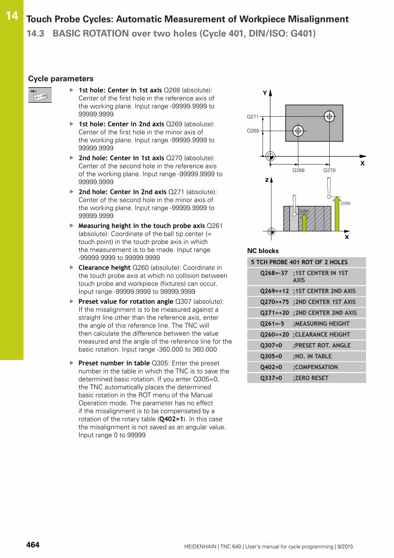
Touch Probe Cycles: Automatic Measurement of Workpiece Misalignment 14.3 BASIC ROTATION over two holes (Cycle 401, DIN/ISO: G401)
14
464 HEIDENHAIN | TNC 640 | User’s manual for cycle programming | 9/2015
Cycle parameters
1st hole: Center in 1st axis Q268 (absolute):
Center of the first hole in the reference axis of
the working plane. Input range -99999.9999 to
99999.9999
1st hole: Center in 2nd axis Q269 (absolute):
Center of the first hole in the minor axis of
the working plane. Input range -99999.9999 to
99999.9999
2nd hole: Center in 1st axis Q270 (absolute):
Center of the second hole in the reference axis
of the working plane. Input range -99999.9999 to
99999.9999
2nd hole: Center in 2nd axis Q271 (absolute):
Center of the second hole in the minor axis of
the working plane. Input range -99999.9999 to
99999.9999
Measuring height in the touch probe axis Q261
(absolute): Coordinate of the ball tip center (=
touch point) in the touch probe axis in which
the measurement is to be made. Input range
-99999.9999 to 99999.9999
Clearance height Q260 (absolute): Coordinate in
the touch probe axis at which no collision between
touch probe and workpiece (fixtures) can occur.
Input range -99999.9999 to 99999.9999
Preset value for rotation angle Q307 (absolute):
If the misalignment is to be measured against a
straight line other than the reference axis, enter
the angle of this reference line. The TNC will
then calculate the difference between the value
measured and the angle of the reference line for the
basic rotation. Input range -360.000 to 360.000
Preset number in table Q305: Enter the preset
number in the table in which the TNC is to save the
determined basic rotation. If you enter Q305=0,
the TNC automatically places the determined
basic rotation in the ROT menu of the Manual
Operation mode. The parameter has no effect
if the misalignment is to be compensated by a
rotation of the rotary table (Q402=1). In this case
the misalignment is not saved as an angular value.
Input range 0 to 99999
NC blocks
5 TCH PROBE 401 ROT OF 2 HOLES
Q268=-37 ;1ST CENTER IN 1STAXIS
Q269=+12 ;1ST CENTER 2ND AXIS
Q270=+75 ;2ND CENTER 1ST AXIS
Q271=+20 ;2ND CENTER 2ND AXIS
Q261=-5 ;MEASURING HEIGHT
Q260=+20 ;CLEARANCE HEIGHT
Q307=0 ;PRESET ROT. ANGLE
Q305=0 ;NO. IN TABLE
Q402=0 ;COMPENSATION
Q337=0 ;ZERO RESET

BASIC ROTATION over two holes (Cycle 401, DIN/ISO: G401) 14.3
14
HEIDENHAIN | TNC 640 | User’s manual for cycle programming | 9/2015 465
Compensation Q402: Define whether the TNC
should set the measured misalignment as basic
rotation or should align via rotating the rotary table:
0: Set basic rotation
1: Rotate the rotary table
If you specify rotating the rotary table, the TNC
does not save the measured misalignment, even if
you have defined a table row in parameter Q305.
Set to zero after alignment Q337: Define whether
the TNC should set the angle of the aligned rotary
axis to 0 in the preset table or in the datum table
after the alignment:
0: Do not set the angle of the rotary axis to 0 in the
table after alignment
1: Set the angle of the rotary axis to 0 in the table
after alignment. The TNC sets the display to 0 only if
you have defined Q402=1.

Touch Probe Cycles: Automatic Measurement of Workpiece Misalignment 14.4 BASIC ROTATION over two studs (Cycle 402, DIN/ISO: G402)
14
466 HEIDENHAIN | TNC 640 | User’s manual for cycle programming | 9/2015
14.4 BASIC ROTATION over two studs
(Cycle 402, DIN/ISO: G402)
Cycle run
The Touch Probe Cycle 402 measures the centers of two studs.
Then the TNC calculates the angle between the reference axis in
the working plane and the line connecting the two stud centers.
With the basic rotation function, the TNC compensates the
calculated value. As an alternative, you can also compensate the
determined misalignment by rotating the rotary table.
1 Following the positioning logic, the TNC positions the touch
probe at rapid traverse (value from FMAX column) (see
"Executing touch probe cycles", page 454) to touch point 1 of
the first stud.
2 Then the probe moves to the entered measuring height 1 and
probes four points to find the center of the first stud. The touch
probe moves on a circular arc between the touch points, each of
which is offset by 90°.
3 The touch probe returns to the clearance height and then
positions the probe to starting point 5 of the second stud.
4 The probe moves to the entered measuring height 2 and
probes four points to find the center of the second stud.
5 Then the TNC returns the touch probe to the clearance height
and performs the basic rotation.
Please note while programming:
Before a cycle definition you must have programmed
a tool call to define the touch probe axis.
The TNC will reset an active basic rotation at the
beginning of the cycle.
If you want to compensate the misalignment by
rotating the rotary table, the TNC will automatically
use the following rotary axes:
C for tool axis Z
B for tool axis Y
A for tool axis X

BASIC ROTATION over two studs (Cycle 402, DIN/ISO: G402) 14.4
14
HEIDENHAIN | TNC 640 | User’s manual for cycle programming | 9/2015 467
Cycle parameters
1st stud: Center in 1st axis Q268 (absolute):
Center of the first stud in the reference axis of
the working plane. Input range -99999.9999 to
99999.9999
1st stud: Center in 2nd axis Q269 (absolute):
Center of the first stud in the minor axis of
the working plane. Input range -99999.9999 to
99999.9999
Diameter of stud 1 Q313: Approximate diameter
of the 1st stud. Enter a value that is more likely
to be too large than too small. Input range 0 to
99999.9999
Measuring height 1 in the probe axis Q261
(absolute): Coordinate of the ball tip center (=
touch point in the touch probe axis) at which stud
1 is to be measured. Input range -99999.9999 to
99999.9999
2nd stud: Center in 1st axis Q270 (absolute):
Center of the second stud in the reference axis
of the working plane. Input range -99999.9999 to
99999.9999
2nd stud: Center in 2nd axis Q271 (absolute):
Center of the second stud in the minor axis of
the working plane. Input range -99999.9999 to
99999.9999
Diameter of stud 2 Q314: Approximate diameter
of the 2nd stud. Enter a value that is more likely
to be too large than too small. Input range 0 to
99999.9999
Measuring height of stud 2 in the probe axisQ315 (absolute): Coordinate of the ball tip center (=
touch point in the touch probe axis) at which stud
2 is to be measured. Input range -99999.9999 to
99999.9999
Set-up clearance Q320 (incremental): Additional
distance between measuring point and ball tip.
Q320 is added to SET_UP (touch probe table). Input
range 0 to 99999.9999
Clearance height Q260 (absolute): Coordinate in
the touch probe axis at which no collision between
touch probe and workpiece (fixtures) can occur.
Input range -99999.9999 to 99999.9999
Traversing to clearance height Q301: definition
of how the touch probe is to move between the
measuring points:
0: Move at measuring height between measuring
points
1: Move at clearance height between measuring
points
NC blocks
5 TCH PROBE 402 ROT OF 2 STUDS
Q268=-37 ;1ST CENTER IN 1STAXIS
Q269=+12 ;1ST CENTER 2ND AXIS
Q313=60 ;DIAMETER OF STUD 1
Q261=-5 ;MEASURING HEIGHT 1
Q270=+75 ;2ND CENTER 1ST AXIS
Q271=+20 ;2ND CENTER 2ND AXIS
Q314=60 ;DIAMETER OF STUD 2
Q315=-5 ;MEASURING HEIGHT 2
Q320=0 ;SET-UP CLEARANCE
Q260=+20 ;CLEARANCE HEIGHT
Q301=0 ;MOVE TO CLEARANCE
Q307=0 ;PRESET ROT. ANGLE
Q305=0 ;NO. IN TABLE
Q402=0 ;COMPENSATION
Q337=0 ;ZERO RESET

Touch Probe Cycles: Automatic Measurement of Workpiece Misalignment 14.4 BASIC ROTATION over two studs (Cycle 402, DIN/ISO: G402)
14
468 HEIDENHAIN | TNC 640 | User’s manual for cycle programming | 9/2015
Preset value for rotation angle Q307 (absolute):
If the misalignment is to be measured against a
straight line other than the reference axis, enter
the angle of this reference line. The TNC will
then calculate the difference between the value
measured and the angle of the reference line for the
basic rotation. Input range -360.000 to 360.000
Preset number in table Q305: Enter the preset
number in the table in which the TNC is to save the
determined basic rotation. If you enter Q305=0,
the TNC automatically places the determined
basic rotation in the ROT menu of the Manual
Operation mode. The parameter has no effect
if the misalignment is to be compensated by a
rotation of the rotary table (Q402=1). In this case
the misalignment is not saved as an angular value.
Input range 0 to 99999
Compensation Q402: Define whether the TNC
should set the measured misalignment as basic
rotation or should align via rotating the rotary table:
0: Set basic rotation
1: Rotate the rotary table
If you specify rotating the rotary table, the TNC
does not save the measured misalignment, even if
you have defined a table row in parameter Q305.
Set to zero after alignment Q337: Define whether
the TNC should set the angle of the aligned rotary
axis to 0 in the preset table or in the datum table
after the alignment:
0: Do not set the angle of the rotary axis to 0 in the
table after alignment
1: Set the angle of the rotary axis to 0 in the table
after alignment. The TNC sets the display to 0 only if
you have defined Q402=1.

BASIC ROTATION compensation via rotary axis (Cycle 403, DIN/
ISO: G403)
14.5
14
HEIDENHAIN | TNC 640 | User’s manual for cycle programming | 9/2015 469
14.5 BASIC ROTATION compensation
via rotary axis (Cycle 403, DIN/
ISO: G403)
Cycle run
Touch probe cycle 403 determines a workpiece misalignment by
measuring two points, which must lie on a straight line. The TNC
compensates the determined misalignment by rotating the A, B or
C axis. The workpiece can be clamped in any position on the rotary
table.
1 Following the positioning logic, the TNC positions the touch
probe at rapid traverse (value from FMAX column) (see
"Executing touch probe cycles", page 454) to the programmed
touch point 1. The TNC offsets the touch probe by the safety
clearance in the direction opposite to the defined traverse
direction.
2 Then the touch probe moves to the entered measuring height
and runs the first probing process at the probing feed rate
(column F).
3 Then the touch probe moves to the next starting position 2 and
probes the second position.
4 The TNC returns the touch probe to the clearance height and
rotates the rotary axis, which was defined in the cycle, by the
measured value. Optionally you can specify whether the TNC is
to set the determined rotation angle to 0 in the preset table or
in the datum table.
Please note while programming:
Danger of collision!
Ensure that the clearance height is sufficiently
large so that no collisions can occur during the final
positioning of the rotary axis.
If you enter 0 in parameter Q312 Axis forcompensating movement, the cycle automatically
determines the rotary axis to be aligned
(recommended setting). Depending on the sequence
of the probing points, an angle with the actual
direction is determined. The measured angle goes
from the first to the second probing point. If you
select the A, B or C axis as compensation axis in
parameter Q312, the cycle determines the angle,
regardless of the sequence of the probing points.
The calculated angle lies in the range from –90°
to +90°. After alignment, check the position of the
rotary axis.
Before a cycle definition you must have programmed
a tool call to define the touch probe axis.
The TNC stores the measured angle in parameter
Q150.

Touch Probe Cycles: Automatic Measurement of Workpiece Misalignment 14.5 BASIC ROTATION compensation via rotary axis (Cycle 403, DIN/
ISO: G403)
14
470 HEIDENHAIN | TNC 640 | User’s manual for cycle programming | 9/2015
Cycle parameters
1st meas. point 1st axis Q263 (absolute):
Coordinate of the first touch point in the reference
axis of the working plane. Input range -99999.9999
to 99999.9999
1st meas. point 2nd axis Q264 (absolute):
Coordinate of the first touch point in the minor axis
of the working plane. Input range -99999.9999 to
99999.9999
2nd meas. point 1st axis Q265 (absolute):
Coordinate of the second touch point in the
reference axis of the working plane. Input range
-99999.9999 to 99999.9999
2nd meas. point 2nd axis Q266 (absolute):
Coordinate of the second touch point in the minor
axis of the working plane. Input range -99999.9999
to 99999.9999
Measuring axis (1...3: 1 = principal axis) Q272:
Axis in which the measurement is to be made:
1: Principal axis = measuring axis
2: Secondary axis = measuring axis
3: Touch probe axis = measuring axis
Traverse direction 1 Q267: Direction in which the
probe is to approach the workpiece:
-1: Negative Traverse direction
+1: Positive traverse direction
Measuring height in the touch probe axis Q261
(absolute): Coordinate of the ball tip center (=
touch point) in the touch probe axis in which
the measurement is to be made. Input range
-99999.9999 to 99999.9999
Set-up clearance Q320 (incremental): Additional
distance between measuring point and ball tip.
Q320 is added to SET_UP (touch probe table). Input
range 0 to 99999.9999
Clearance height Q260 (absolute): Coordinate in
the touch probe axis at which no collision between
touch probe and workpiece (fixtures) can occur.
Input range -99999.9999 to 99999.9999
NC blocks
5 TCH PROBE 403 ROT IN ROTARY AXIS
Q263=+0 ;1ST POINT 1ST AXIS
Q264=+0 ;1ST POINT 2ND AXIS
Q265=+20 ;2ND POINT 1ST AXIS
Q266=+30 ;2ND POINT 2ND AXIS
Q272=1 ;MEASURING AXIS
Q267=-1 ;TRAVERSE DIRECTION
Q261=-5 ;MEASURING HEIGHT
Q320=0 ;SET-UP CLEARANCE
Q260=+20 ;CLEARANCE HEIGHT
Q301=0 ;MOVE TO CLEARANCE

BASIC ROTATION compensation via rotary axis (Cycle 403, DIN/
ISO: G403)
14.5
14
HEIDENHAIN | TNC 640 | User’s manual for cycle programming | 9/2015 471
Traversing to clearance height Q301: definition
of how the touch probe is to move between the
measuring points:
0: Move at measuring height between measuring
points
1: Move at clearance height between measuring
points
Axis for compensation movement Q312:
Assignment of the rotary axis in which the TNC is to
compensate the measured misalignment:
0: Automatic mode – the TNC uses the active
kinematics to determine the rotary axis to be
aligned. In automatic mode the first rotary table
axis (as viewed from the workpiece) is used as
compensation axis. Recommended setting.
4: Compensate misalignment with rotary axis A
5: Compensate misalignment with rotary axis B
6: Compensate misalignment with rotary axis C
Set to zero after alignment Q337: Define whether
the TNC should set the angle of the aligned rotary
axis to 0 in the preset table or in the datum table
after the alignment:
0: Do not set the angle of the rotary axis to 0 in the
table after alignment
1: Set the angle of the rotary axis to 0 in the table
after alignment
Number in table Q305: Enter the number in the
preset table/datum table in which the TNC is to set
the rotary axis to zero. Only effective if Q337 is set
to 1. Input range 0 to 99999
Measured value transfer (0, 1) Q303: Specify if
the determined basic rotation is to be saved in the
datum table or in the preset table:
0: Write the measured basic rotation as datum shift
active datum table. The reference system is the
active workpiece coordinate system
1: Write the measured basic rotation into the
preset table. The reference system is the machine
coordinate system (REF system).
Reference angle? (0=ref. axis) Q380: Angle with
which the TNC is to align the probed straight line.
Only effective if rotary axis = automatic mode is
selected, or rotary axis = C is selected (Q312 = 0 or
6). Input range -360.000 to 360.000
Q312=0 ;COMPENSATION AXIS
Q337=0 ;ZERO RESET
Q305=1 ;NO. IN TABLE
Q303=+1 ;MEAS. VALUETRANSFER
Q380=+90 ;REFERENCE ANGLE

Touch Probe Cycles: Automatic Measurement of Workpiece Misalignment 14.6 SET BASIC ROTATION (Cycle 404, DIN/ISO: G404)
14
472 HEIDENHAIN | TNC 640 | User’s manual for cycle programming | 9/2015
14.6 SET BASIC ROTATION (Cycle 404,
DIN/ISO: G404)
Cycle run
With Touch Probe Cycle 404, during program run you can
automatically set any basic rotation or save it to the preset table. You
can also use Cycle 404 if you want to reset an active basic rotation.
NC blocks
5 TCH PROBE 404 BASIC ROTATION
Q307=+0 ;PRESET ROTATIONANG.
Q305=-1 ;NO. IN TABLE
Cycle parameters
Preset value for rotation angle: Angular value at
which the basic rotation is to be set. Input range
-360.000 to 360.000
Preset number in table Q305: Enter the preset
number in the table in which the TNC is to save
the determined basic rotation. Input range -1 to
99999. If you enter Q305=0 or Q305=1, the TNC
additionally saves the determined basic rotation
in the basic rotation menu (PROBING ROT) of the
Manual Operation mode.
-1 = Overwrite and activate the active preset
0 = Copy the active preset to preset line 0, write
the basic rotation to preset line 0 and activate
preset 0
>1 = Save the basic rotation to the specified
preset. The preset is not activated.
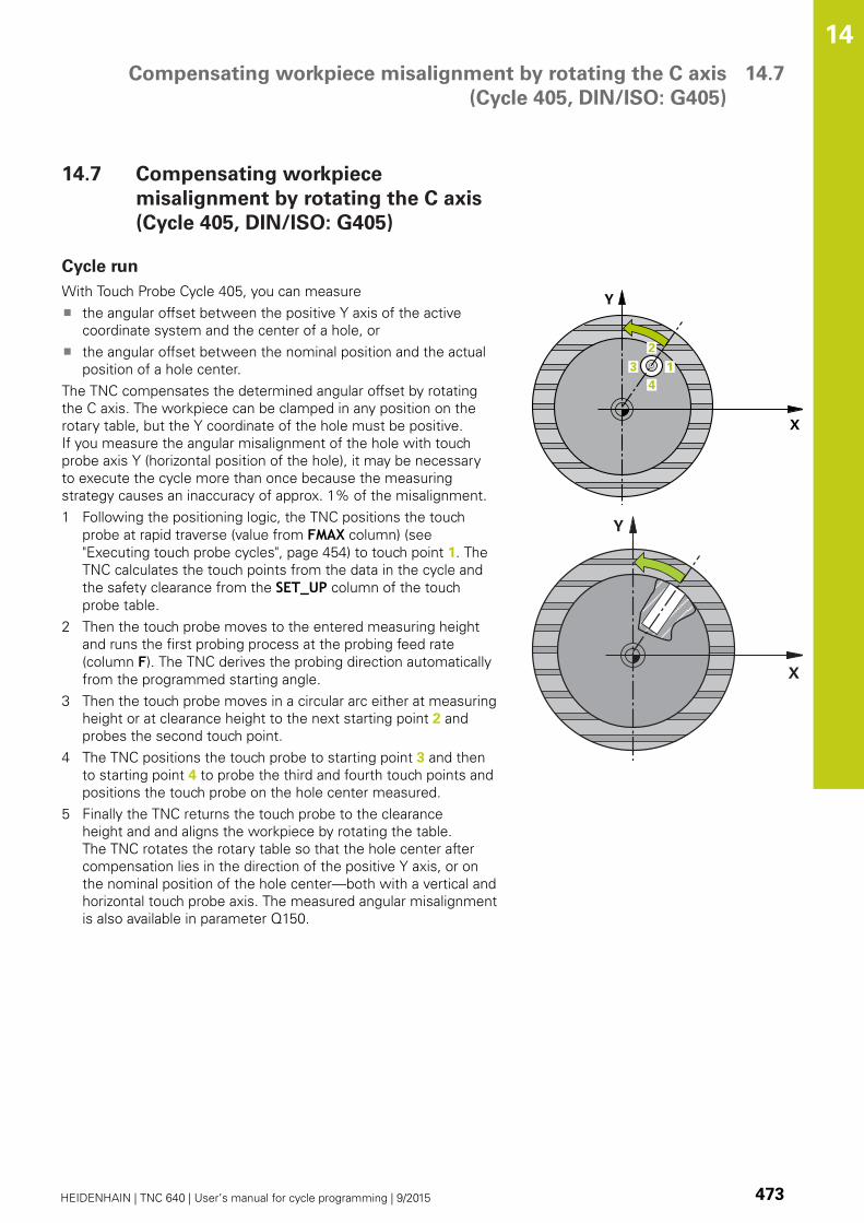
Compensating workpiece misalignment by rotating the C axis
(Cycle 405, DIN/ISO: G405)
14.7
14
HEIDENHAIN | TNC 640 | User’s manual for cycle programming | 9/2015 473
14.7 Compensating workpiece
misalignment by rotating the C axis
(Cycle 405, DIN/ISO: G405)
Cycle run
With Touch Probe Cycle 405, you can measure
the angular offset between the positive Y axis of the active
coordinate system and the center of a hole, or
the angular offset between the nominal position and the actual
position of a hole center.
The TNC compensates the determined angular offset by rotating
the C axis. The workpiece can be clamped in any position on the
rotary table, but the Y coordinate of the hole must be positive.
If you measure the angular misalignment of the hole with touch
probe axis Y (horizontal position of the hole), it may be necessary
to execute the cycle more than once because the measuring
strategy causes an inaccuracy of approx. 1% of the misalignment.
1 Following the positioning logic, the TNC positions the touch
probe at rapid traverse (value from FMAX column) (see
"Executing touch probe cycles", page 454) to touch point 1. The
TNC calculates the touch points from the data in the cycle and
the safety clearance from the SET_UP column of the touch
probe table.
2 Then the touch probe moves to the entered measuring height
and runs the first probing process at the probing feed rate
(column F). The TNC derives the probing direction automatically
from the programmed starting angle.
3 Then the touch probe moves in a circular arc either at measuring
height or at clearance height to the next starting point 2 and
probes the second touch point.
4 The TNC positions the touch probe to starting point 3 and then
to starting point 4 to probe the third and fourth touch points and
positions the touch probe on the hole center measured.
5 Finally the TNC returns the touch probe to the clearance
height and and aligns the workpiece by rotating the table.
The TNC rotates the rotary table so that the hole center after
compensation lies in the direction of the positive Y axis, or on
the nominal position of the hole center—both with a vertical and
horizontal touch probe axis. The measured angular misalignment
is also available in parameter Q150.
Touch Probe Cycles: Automatic Measurement of Workpiece Misalignment 14.7 Compensating workpiece misalignment by rotating the C axis
(Cycle 405, DIN/ISO: G405)
14
474 HEIDENHAIN | TNC 640 | User’s manual for cycle programming | 9/2015
Please note while programming:
Danger of collision!
To prevent a collision between the touch probe and
the workpiece, enter a low estimate for the nominal
diameter of the pocket (or hole).
If the dimensions of the pocket and the safety
clearance do not permit pre-positioning in the
proximity of the touch points, the TNC always starts
probing from the center of the pocket. In this case
the touch probe does not return to the clearance
height between the four measuring points.
Before a cycle definition you must have programmed
a tool call to define the touch probe axis.
The smaller the angle, the less accurately the TNC
can calculate the circle center. Minimum input value:
5°.
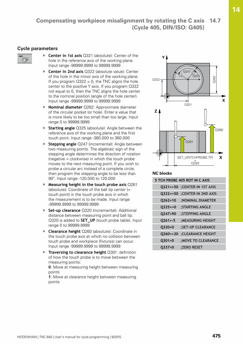
Compensating workpiece misalignment by rotating the C axis
(Cycle 405, DIN/ISO: G405)
14.7
14
HEIDENHAIN | TNC 640 | User’s manual for cycle programming | 9/2015 475
Cycle parameters
Center in 1st axis Q321 (absolute): Center of the
hole in the reference axis of the working plane.
Input range -99999.9999 to 99999.9999
Center in 2nd axis Q322 (absolute value): Center
of the hole in the minor axis of the working plane.
If you program Q322 = 0, the TNC aligns the hole
center to the positive Y axis. If you program Q322
not equal to 0, then the TNC aligns the hole center
to the nominal position (angle of the hole center).
Input range -99999.9999 to 99999.9999
Nominal diameter Q262: Approximate diameter
of the circular pocket (or hole). Enter a value that
is more likely to be too small than too large. Input
range 0 to 99999.9999
Starting angle Q325 (absolute): Angle between the
reference axis of the working plane and the first
touch point. Input range -360.000 to 360.000
Stepping angle Q247 (incremental): Angle between
two measuring points. The algebraic sign of the
stepping angle determines the direction of rotation
(negative = clockwise) in which the touch probe
moves to the next measuring point. If you wish to
probe a circular arc instead of a complete circle,
then program the stepping angle to be less than
90°. Input range -120.000 to 120.000
Measuring height in the touch probe axis Q261
(absolute): Coordinate of the ball tip center (=
touch point) in the touch probe axis in which
the measurement is to be made. Input range
-99999.9999 to 99999.9999
Set-up clearance Q320 (incremental): Additional
distance between measuring point and ball tip.
Q320 is added to SET_UP (touch probe table). Input
range 0 to 99999.9999
Clearance height Q260 (absolute): Coordinate in
the touch probe axis at which no collision between
touch probe and workpiece (fixtures) can occur.
Input range -99999.9999 to 99999.9999
Traversing to clearance height Q301: definition
of how the touch probe is to move between the
measuring points:
0: Move at measuring height between measuring
points
1: Move at clearance height between measuring
points
NC blocks
5 TCH PROBE 405 ROT IN C AXIS
Q321=+50 ;CENTER IN 1ST AXIS
Q322=+50 ;CENTER IN 2ND AXIS
Q262=10 ;NOMINAL DIAMETER
Q325=+0 ;STARTING ANGLE
Q247=90 ;STEPPING ANGLE
Q261=-5 ;MEASURING HEIGHT
Q320=0 ;SET-UP CLEARANCE
Q260=+20 ;CLEARANCE HEIGHT
Q301=0 ;MOVE TO CLEARANCE
Q337=0 ;ZERO RESET

Touch Probe Cycles: Automatic Measurement of Workpiece Misalignment 14.7 Compensating workpiece misalignment by rotating the C axis
(Cycle 405, DIN/ISO: G405)
14
476 HEIDENHAIN | TNC 640 | User’s manual for cycle programming | 9/2015
Set to zero after alignment Q337: definition of
whether the TNC should set the display of the C-
axis to zero, or write the angular misalignment in
column C of the datum table:
0: Set the display of the C-axis to zero
>0: Write the measured angular misalignment
with correct algebraic signs in the datum table.
Line number = value of Q337. If a C-axis shift is
registered in the datum table, the TNC adds the
measured angular misalignment.
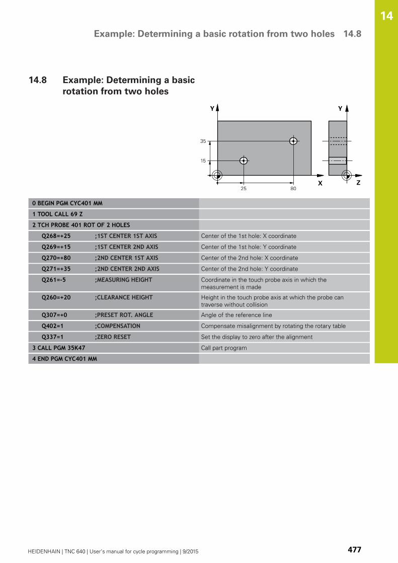
Example: Determining a basic rotation from two holes 14.8
14
HEIDENHAIN | TNC 640 | User’s manual for cycle programming | 9/2015 477
14.8 Example: Determining a basic
rotation from two holes
0 BEGIN PGM CYC401 MM
1 TOOL CALL 69 Z
2 TCH PROBE 401 ROT OF 2 HOLES
Q268=+25 ;1ST CENTER 1ST AXIS Center of the 1st hole: X coordinate
Q269=+15 ;1ST CENTER 2ND AXIS Center of the 1st hole: Y coordinate
Q270=+80 ;2ND CENTER 1ST AXIS Center of the 2nd hole: X coordinate
Q271=+35 ;2ND CENTER 2ND AXIS Center of the 2nd hole: Y coordinate
Q261=-5 ;MEASURING HEIGHT Coordinate in the touch probe axis in which the
measurement is made
Q260=+20 ;CLEARANCE HEIGHT Height in the touch probe axis at which the probe can
traverse without collision
Q307=+0 ;PRESET ROT. ANGLE Angle of the reference line
Q402=1 ;COMPENSATION Compensate misalignment by rotating the rotary table
Q337=1 ;ZERO RESET Set the display to zero after the alignment
3 CALL PGM 35K47 Call part program
4 END PGM CYC401 MM


15Touch Probe
Cycles: AutomaticDatum Setting

Touch Probe Cycles: Automatic Datum Setting 15.1 Fundamentals
15
480 HEIDENHAIN | TNC 640 | User’s manual for cycle programming | 9/2015
15.1 Fundamentals
Overview
When running touch probe cycles, Cycle 8 MIRROR
IMAGE, Cycle 11 SCALING and Cycle 26 AXIS-
SPECIFIC SCALING must not be active.
HEIDENHAIN only warrants the function of the touch
probe cycles if HEIDENHAIN touch probes are used.
The TNC must be specially prepared by the machine
tool builder for the use of a 3-D touch probe.
Refer to your machine manual.
The TNC offers twelve cycles for automatically finding reference
points and handling them as follows:
Setting the determined values directly as display values
Entering the determined values in the preset table
Entering the determined values in a datum table

Fundamentals 15.1
15
HEIDENHAIN | TNC 640 | User’s manual for cycle programming | 9/2015 481
Soft key Cycle Page
408 SLOT CENTER REF PT.
Measuring the inside width of a slot,
and defining the slot center as datum
484
409 RIDGE CENTER REF PT.
Measuring the outside width of a
ridge, and defining the ridge center as
datum
488
410 DATUM INSIDE RECTANGLE
Measuring the inside length and
width of a rectangle, and defining the
center as datum
491
411 DATUM OUTSIDE RECTANGLE
Measuring the outside length and
width of a rectangle, and defining the
center as datum
495
412 DATUM INSIDE CIRCLE
Measuring any four points on the
inside of a circle, and defining the
center as datum
498
413 DATUM OUTSIDE CIRCLE
Measuring any four points on the
outside of a circle, and defining the
center as datum
503
414 DATUM OUTSIDE CORNER
Measuring two lines from the
outside of the angle, and defining the
intersection as datum
507
415 DATUM INSIDE CORNER
Measuring two lines from within the
angle, and defining the intersection
as datum
512
416 DATUM CIRCLE CENTER
(2nd soft-key level) Measuring any
three holes on a bolt hole circle, and
defining the bolt-hole center as datum
516
417 DATUM IN TS AXIS
(2nd soft-key level) Measuring any
position in the touch probe axis and
defining it as datum
520
418 DATUM FROM 4 HOLES
(2nd soft-key level) Measuring 4
holes crosswise and defining the
intersection of the lines between
them as datum
522
419 DATUM IN ONE AXIS
(2nd soft-key row) Measuring any
position in any axis and defining it as
datum
526

Touch Probe Cycles: Automatic Datum Setting 15.1 Fundamentals
15
482 HEIDENHAIN | TNC 640 | User’s manual for cycle programming | 9/2015
Characteristics common to all touch probe cycles for
datum setting
You can also run the Touch Probe Cycles 408 to 419
during an active rotation (basic rotation or Cycle 10).
Datum point and touch probe axis
From the touch probe axis that you have defined in the measuring
program the TNC determines the working plane for the datum.
Active touch probe axis Datum setting in
Z X and Y
Y Z and X
X Y and Z
Saving the calculated datum
In all cycles for datum setting you can use the input parameters
Q303 and Q305 to define how the TNC is to save the calculated
datum:
Q305 = 0, Q303 = any value: The TNC sets the calculated
datum in the display. The new datum is active immediately. At
the same time, the TNC saves the datum set in the display by
the cycle in line 0 of the preset table.
Q305 not equal to 0, Q303 = –1
Fundamentals 15.1
15
HEIDENHAIN | TNC 640 | User’s manual for cycle programming | 9/2015 483
This combination can only occur if you
read in programs containing Cycles 410 to 418
created on a TNC 4xx
read in programs containing Cycles 410 to 418
created with an older software version on an iTNC
530
did not specifically define the measured-value
transfer with parameter Q303 when defining the
cycle.
In these cases the TNC outputs an error message,
since the complete handling of REF-referenced
datum tables has changed. You must define a
measured-value transfer yourself with parameter
Q303.
Q305 not equal to 0, Q303 = 0 The TNC writes the calculated
reference point in the active datum table. The reference
system is the active workpiece coordinate system. The value of
parameter Q305 determines the datum number. Activate the
datum with Cycle 7 in the part program.
Q305 not equal to 0, Q303 = 1 The TNC writes the calculated
reference point in the preset table. The reference system is
the machine coordinate system (REF coordinates). The value of
parameter Q305 determines the preset number. Activate the
preset with Cycle 247 in the part program.
Measurement results in Q parameters
The TNC saves the measurement results of the respective touch
probe cycle in the globally effective Q parameters Q150 to Q160.
You can use these parameters in your program. Note the table of
result parameters listed with every cycle description.

Touch Probe Cycles: Automatic Datum Setting 15.2 DATUM SLOT CENTER (Cycle 408, DIN/ISO: G408)
15
484 HEIDENHAIN | TNC 640 | User’s manual for cycle programming | 9/2015
15.2 DATUM SLOT CENTER (Cycle 408,
DIN/ISO: G408)
Cycle run
Touch Probe Cycle 408 finds the center of a slot and defines its
center as datum. If desired, the TNC can also enter the coordinates
into a datum table or the preset table.
1 Following the positioning logic, the TNC positions the touch
probe at rapid traverse (value from FMAX column) (see
"Executing touch probe cycles", page 454) to touch point 1. The
TNC calculates the touch points from the data in the cycle and
the safety clearance from the SET_UP column of the touch
probe table.
2 Then the touch probe moves to the entered measuring height
and runs the first probing process at the probing feed rate
(column F).
3 Then the touch probe moves either paraxially at measuring
height or at clearance height to the next starting point 2 and
probes the second touch point.
4 Finally the TNC returns the touch probe to the clearance height
and processes the determined datum depending on the cycle
parameters Q303 and Q305 (see "Characteristics common to all
touch probe cycles for datum setting", page 482) and saves the
actual values in the Q parameters listed below.
5 If desired, the TNC subsequently measures the datum in the
touch probe axis in a separate probing.
Parameter number Meaning
Q166 Actual value of measured slot width
Q157 Actual value of the centerline

DATUM SLOT CENTER (Cycle 408, DIN/ISO: G408) 15.2
15
HEIDENHAIN | TNC 640 | User’s manual for cycle programming | 9/2015 485
Please note while programming:
Danger of collision!
To prevent a collision between touch probe and
workpiece, enter a low estimate for the slot width.
If the slot width and the safety clearance do not
permit pre-positioning in the proximity of the touch
points, the TNC always starts probing from the
center of the slot. In this case the touch probe does
not return to the clearance height between the two
measuring points.
Before a cycle definition you must have programmed
a tool call to define the touch probe axis.
If you set a datum (Q303 = 0) with the touch probe
cycle and also use probe in TS axis (Q381 = 1), then
no coordinate transformation must be active.
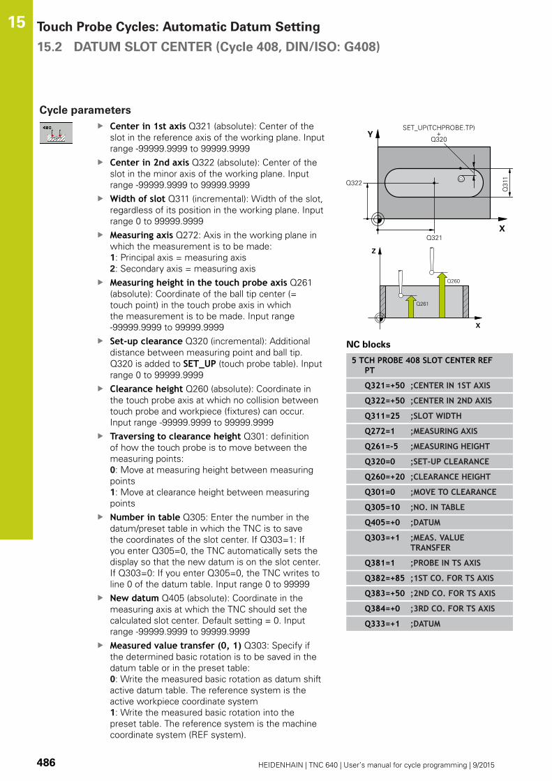
Touch Probe Cycles: Automatic Datum Setting 15.2 DATUM SLOT CENTER (Cycle 408, DIN/ISO: G408)
15
486 HEIDENHAIN | TNC 640 | User’s manual for cycle programming | 9/2015
Cycle parameters
Center in 1st axis Q321 (absolute): Center of the
slot in the reference axis of the working plane. Input
range -99999.9999 to 99999.9999
Center in 2nd axis Q322 (absolute): Center of the
slot in the minor axis of the working plane. Input
range -99999.9999 to 99999.9999
Width of slot Q311 (incremental): Width of the slot,
regardless of its position in the working plane. Input
range 0 to 99999.9999
Measuring axis Q272: Axis in the working plane in
which the measurement is to be made:
1: Principal axis = measuring axis
2: Secondary axis = measuring axis
Measuring height in the touch probe axis Q261
(absolute): Coordinate of the ball tip center (=
touch point) in the touch probe axis in which
the measurement is to be made. Input range
-99999.9999 to 99999.9999
Set-up clearance Q320 (incremental): Additional
distance between measuring point and ball tip.
Q320 is added to SET_UP (touch probe table). Input
range 0 to 99999.9999
Clearance height Q260 (absolute): Coordinate in
the touch probe axis at which no collision between
touch probe and workpiece (fixtures) can occur.
Input range -99999.9999 to 99999.9999
Traversing to clearance height Q301: definition
of how the touch probe is to move between the
measuring points:
0: Move at measuring height between measuring
points
1: Move at clearance height between measuring
points
Number in table Q305: Enter the number in the
datum/preset table in which the TNC is to save
the coordinates of the slot center. If Q303=1: If
you enter Q305=0, the TNC automatically sets the
display so that the new datum is on the slot center.
If Q303=0: If you enter Q305=0, the TNC writes to
line 0 of the datum table. Input range 0 to 99999
New datum Q405 (absolute): Coordinate in the
measuring axis at which the TNC should set the
calculated slot center. Default setting = 0. Input
range -99999.9999 to 99999.9999
Measured value transfer (0, 1) Q303: Specify if
the determined basic rotation is to be saved in the
datum table or in the preset table:
0: Write the measured basic rotation as datum shift
active datum table. The reference system is the
active workpiece coordinate system
1: Write the measured basic rotation into the
preset table. The reference system is the machine
coordinate system (REF system).
NC blocks
5 TCH PROBE 408 SLOT CENTER REFPT
Q321=+50 ;CENTER IN 1ST AXIS
Q322=+50 ;CENTER IN 2ND AXIS
Q311=25 ;SLOT WIDTH
Q272=1 ;MEASURING AXIS
Q261=-5 ;MEASURING HEIGHT
Q320=0 ;SET-UP CLEARANCE
Q260=+20 ;CLEARANCE HEIGHT
Q301=0 ;MOVE TO CLEARANCE
Q305=10 ;NO. IN TABLE
Q405=+0 ;DATUM
Q303=+1 ;MEAS. VALUETRANSFER
Q381=1 ;PROBE IN TS AXIS
Q382=+85 ;1ST CO. FOR TS AXIS
Q383=+50 ;2ND CO. FOR TS AXIS
Q384=+0 ;3RD CO. FOR TS AXIS
Q333=+1 ;DATUM

DATUM SLOT CENTER (Cycle 408, DIN/ISO: G408) 15.2
15
HEIDENHAIN | TNC 640 | User’s manual for cycle programming | 9/2015 487
Probe in TS axis Q381: Specify whether the TNC
should also set the datum in the touch probe axis:
0: Do not set the datum in the touch probe axis
1: Set the datum in the touch probe axis
Probe TS axis: Coord. 1st axis Q382 (absolute):
Coordinate of the probe point in the reference axis
of the working plane at which point the datum is
to be set in the touch probe axis. Only effective if
Q381 = 1st input range -99999.9999 to 99999.9999
Probe TS axis: Coord. 2nd axis Q383 (absolute):
Coordinate of the probe point in the minor axis of
the working plane at which point the datum is to be
set in the touch probe axis. Only effective if Q381 =
1. Input range -99999.9999 to 99999.9999
Probe TS axis: Coord. 3rd axis Q384 (absolute):
Coordinate of the probe point in the touch probe
axis, at which point the datum is to be set in the
touch probe axis. Only effective if Q381 = 1. Input
range -99999.9999 to 99999.9999
New datum in TS axis Q333 (absolute): Coordinate
in the touch probe axis at which the TNC should
set the datum. Default setting = 0. Input range
-99999.9999 to 99999.9999

Touch Probe Cycles: Automatic Datum Setting 15.3 DATUM RIDGE CENTER (Cycle 409, DIN/ISO: G409)
15
488 HEIDENHAIN | TNC 640 | User’s manual for cycle programming | 9/2015
15.3 DATUM RIDGE CENTER (Cycle 409,
DIN/ISO: G409)
Cycle run
Touch Probe Cycle 409 finds the center of a ridge and defines its
center as datum. If desired, the TNC can also enter the coordinates
into a datum table or the preset table.
1 Following the positioning logic, the TNC positions the touch
probe at rapid traverse (value from FMAX column) (see
"Executing touch probe cycles", page 454) to touch point 1. The
TNC calculates the touch points from the data in the cycle and
the safety clearance from the SET_UP column of the touch
probe table.
2 Then the touch probe moves to the entered measuring height
and runs the first probing process at the probing feed rate
(column F).
3 Then the touch probe moves at clearance height to the next
touch point 2 and probes the second touch point.
4 Finally the TNC returns the touch probe to the clearance height
and processes the determined datum depending on the cycle
parameters Q303 and Q305 (see "Characteristics common to all
touch probe cycles for datum setting", page 482) and saves the
actual values in the Q parameters listed below.
5 If desired, the TNC subsequently measures the datum in the
touch probe axis in a separate probing.
Parameter number Meaning
Q166 Actual value of measured ridge width
Q157 Actual value of the centerline
Please note while programming:
Danger of collision!
To prevent a collision between touch probe and
workpiece, enter a high estimate for the ridge width.
Before a cycle definition you must have programmed
a tool call to define the touch probe axis.
If you set a datum (Q303 = 0) with the touch probe
cycle and also use probe in TS axis (Q381 = 1), then
no coordinate transformation must be active.

DATUM RIDGE CENTER (Cycle 409, DIN/ISO: G409) 15.3
15
HEIDENHAIN | TNC 640 | User’s manual for cycle programming | 9/2015 489
Cycle parameters
Center in 1st axis Q321 (absolute): Center of the
ridge in the reference axis of the working plane.
Input range -99999.9999 to 99999.9999
Center in 2nd axis Q322 (absolute): Center of the
ridge in the minor axis of the working plane. Input
range -99999.9999 to 99999.9999
Width of ridge Q311 (incremental): Width of the
ridge, regardless of its position in the working plane.
Input range 0 to 99999.9999
Measuring axis Q272: Axis in the working plane in
which the measurement is to be made:
1: Principal axis = measuring axis
2: Secondary axis = measuring axis
Measuring height in the touch probe axis Q261
(absolute): Coordinate of the ball tip center (=
touch point) in the touch probe axis in which
the measurement is to be made. Input range
-99999.9999 to 99999.9999
Set-up clearance Q320 (incremental): Additional
distance between measuring point and ball tip.
Q320 is added to SET_UP (touch probe table). Input
range 0 to 99999.9999
Clearance height Q260 (absolute): Coordinate in
the touch probe axis at which no collision between
touch probe and workpiece (fixtures) can occur.
Input range -99999.9999 to 99999.9999
Number in table Q305: Enter the number in the
datum/preset table in which the TNC is to save
the coordinates of the ridge center. If Q303=1: If
you enter Q305=0, the TNC automatically sets the
display so that the new datum is on the ridge center.
If Q303=0: If you enter Q305=0, the TNC writes to
line 0 of the datum table. Input range 0 to 99999
New datum Q405 (absolute): Coordinate in the
measuring axis at which the TNC should set the
calculated ridge center. Default setting = 0 input
range -99999.9999 to 99999.9999
Measured value transfer (0, 1) Q303: Specify if
the determined basic rotation is to be saved in the
datum table or in the preset table:
0: Write the measured basic rotation as datum shift
active datum table. The reference system is the
active workpiece coordinate system
1: Write the measured basic rotation into the
preset table. The reference system is the machine
coordinate system (REF system).
Probe in TS axis Q381: Specify whether the TNC
should also set the datum in the touch probe axis:
0: Do not set the datum in the touch probe axis
1: Set the datum in the touch probe axis
NC blocks
5 TCH PROBE 409 SLOT CENTER RIDGE
Q321=+50 ;CENTER IN 1ST AXIS
Q322=+50 ;CENTER IN 2ND AXIS
Q311=25 ;SLOT WIDTH
Q272=1 ;MEASURING AXIS
Q261=-5 ;MEASURING HEIGHT
Q320=0 ;SET-UP CLEARANCE
Q260=+20 ;CLEARANCE HEIGHT
Q305=10 ;NO. IN TABLE
Q405=+0 ;DATUM
Q303=+1 ;MEAS. VALUETRANSFER
Q381=1 ;PROBE IN TS AXIS
Q382=+85 ;1ST CO. FOR TS AXIS
Q383=+50 ;2ND CO. FOR TS AXIS
Q384=+0 ;3RD CO. FOR TS AXIS
Q333=+1 ;DATUM

Touch Probe Cycles: Automatic Datum Setting 15.3 DATUM RIDGE CENTER (Cycle 409, DIN/ISO: G409)
15
490 HEIDENHAIN | TNC 640 | User’s manual for cycle programming | 9/2015
Probe TS axis: Coord. 1st axis Q382 (absolute):
Coordinate of the probe point in the reference axis
of the working plane at which point the datum is
to be set in the touch probe axis. Only effective if
Q381 = 1st input range -99999.9999 to 99999.9999
Probe TS axis: Coord. 2nd axis Q383 (absolute):
Coordinate of the probe point in the minor axis of
the working plane at which point the datum is to be
set in the touch probe axis. Only effective if Q381 =
1. Input range -99999.9999 to 99999.9999
Probe TS axis: Coord. 3rd axis Q384 (absolute):
Coordinate of the probe point in the touch probe
axis, at which point the datum is to be set in the
touch probe axis. Only effective if Q381 = 1. Input
range -99999.9999 to 99999.9999
New datum in TS axis Q333 (absolute): Coordinate
in the touch probe axis at which the TNC should
set the datum. Default setting = 0. Input range
-99999.9999 to 99999.9999

DATUM FROM INSIDE OF RECTANGLE (Cycle 410, DIN/ISO: G410) 15.4
15
HEIDENHAIN | TNC 640 | User’s manual for cycle programming | 9/2015 491
15.4 DATUM FROM INSIDE OF
RECTANGLE (Cycle 410, DIN/
ISO: G410)
Cycle run
Touch Probe Cycle 410 finds the center of a rectangular pocket and
defines its center as datum. If desired, the TNC can also enter the
coordinates into a datum table or the preset table.
1 Following the positioning logic, the TNC positions the touch
probe at rapid traverse (value from FMAX column) (see
"Executing touch probe cycles", page 454) to touch point 1. The
TNC calculates the touch points from the data in the cycle and
the safety clearance from the SET_UP column of the touch
probe table.
2 Then the touch probe moves to the entered measuring height
and runs the first probing process at the probing feed rate
(column F).
3 Then the touch probe moves either paraxially at measuring
height or at clearance height to the next starting point 2 and
probes the second touch point.
4 The TNC positions the probe to starting point 3 and then to
starting point 4 to probe the third and fourth touch points.
5 Finally the TNC returns the touch probe to the clearance height
and processes the determined datum depending on the cycle
parameters Q303 and Q305 (see "Characteristics common to all
touch probe cycles for datum setting", page 482).
6 If desired, the TNC subsequently measures the datum in the
touch probe axis in a separate probing and saves the actual
values in the following Q parameters.
Parameter number Meaning
Q151 Actual value of center in reference axis
Q152 Actual value of center in minor axis
Q154 Actual value of length in the reference
axis
Q155 Actual value of length in the minor axis

Touch Probe Cycles: Automatic Datum Setting 15.4 DATUM FROM INSIDE OF RECTANGLE (Cycle 410, DIN/ISO: G410)
15
492 HEIDENHAIN | TNC 640 | User’s manual for cycle programming | 9/2015
Please note while programming:
Danger of collision!
To prevent a collision between touch probe and
workpiece, enter low estimates for the lengths of
the first and second sides.
If the dimensions of the pocket and the safety
clearance do not permit pre-positioning in the
proximity of the touch points, the TNC always starts
probing from the center of the pocket. In this case
the touch probe does not return to the clearance
height between the four measuring points.
Before a cycle definition you must have programmed
a tool call to define the touch probe axis.
If you set a datum (Q303 = 0) with the touch probe
cycle and also use probe in TS axis (Q381 = 1), then
no coordinate transformation must be active.
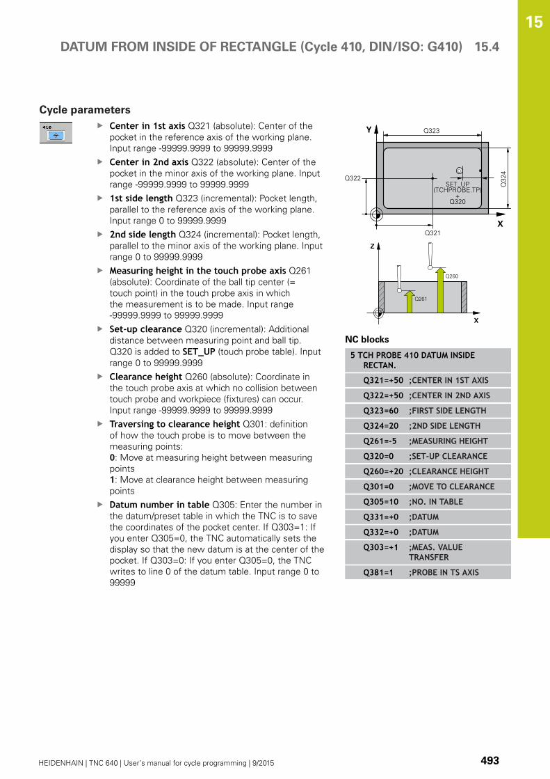
DATUM FROM INSIDE OF RECTANGLE (Cycle 410, DIN/ISO: G410) 15.4
15
HEIDENHAIN | TNC 640 | User’s manual for cycle programming | 9/2015 493
Cycle parameters
Center in 1st axis Q321 (absolute): Center of the
pocket in the reference axis of the working plane.
Input range -99999.9999 to 99999.9999
Center in 2nd axis Q322 (absolute): Center of the
pocket in the minor axis of the working plane. Input
range -99999.9999 to 99999.9999
1st side length Q323 (incremental): Pocket length,
parallel to the reference axis of the working plane.
Input range 0 to 99999.9999
2nd side length Q324 (incremental): Pocket length,
parallel to the minor axis of the working plane. Input
range 0 to 99999.9999
Measuring height in the touch probe axis Q261
(absolute): Coordinate of the ball tip center (=
touch point) in the touch probe axis in which
the measurement is to be made. Input range
-99999.9999 to 99999.9999
Set-up clearance Q320 (incremental): Additional
distance between measuring point and ball tip.
Q320 is added to SET_UP (touch probe table). Input
range 0 to 99999.9999
Clearance height Q260 (absolute): Coordinate in
the touch probe axis at which no collision between
touch probe and workpiece (fixtures) can occur.
Input range -99999.9999 to 99999.9999
Traversing to clearance height Q301: definition
of how the touch probe is to move between the
measuring points:
0: Move at measuring height between measuring
points
1: Move at clearance height between measuring
points
Datum number in table Q305: Enter the number in
the datum/preset table in which the TNC is to save
the coordinates of the pocket center. If Q303=1: If
you enter Q305=0, the TNC automatically sets the
display so that the new datum is at the center of the
pocket. If Q303=0: If you enter Q305=0, the TNC
writes to line 0 of the datum table. Input range 0 to
99999
NC blocks
5 TCH PROBE 410 DATUM INSIDERECTAN.
Q321=+50 ;CENTER IN 1ST AXIS
Q322=+50 ;CENTER IN 2ND AXIS
Q323=60 ;FIRST SIDE LENGTH
Q324=20 ;2ND SIDE LENGTH
Q261=-5 ;MEASURING HEIGHT
Q320=0 ;SET-UP CLEARANCE
Q260=+20 ;CLEARANCE HEIGHT
Q301=0 ;MOVE TO CLEARANCE
Q305=10 ;NO. IN TABLE
Q331=+0 ;DATUM
Q332=+0 ;DATUM
Q303=+1 ;MEAS. VALUETRANSFER
Q381=1 ;PROBE IN TS AXIS

Touch Probe Cycles: Automatic Datum Setting 15.4 DATUM FROM INSIDE OF RECTANGLE (Cycle 410, DIN/ISO: G410)
15
494 HEIDENHAIN | TNC 640 | User’s manual for cycle programming | 9/2015
New datum for reference axis Q331 (absolute):
Coordinate in the reference axis at which the TNC
should set the pocket center. Default setting = 0.
Input range -99999.9999 to 99999.9999
New datum for minor axis Q332 (absolute):
Coordinate in the minor axis at which the TNC
should set the pocket center. Default setting = 0
input range -99999.9999 to 99999.9999
Measured-value transfer (0, 1) Q303: Specify
whether the determined datum is to be saved in the
datum table or in the preset table:
-1: Do not use! Is entered by the TNC when old
programs are read in (see "Characteristics common
to all touch probe cycles for datum setting",
page 482)
0: Write the measured datum into the active datum
table. The reference system is the active workpiece
coordinate system
1: Write the measured datum into the preset table.
The reference system is the machine coordinate
system (REF system).
Probe in TS axis Q381: Specify whether the TNC
should also set the datum in the touch probe axis:
0: Do not set the datum in the touch probe axis
1: Set the datum in the touch probe axis
Probe TS axis: Coord. 1st axis Q382 (absolute):
Coordinate of the probe point in the reference axis
of the working plane at which point the datum is
to be set in the touch probe axis. Only effective if
Q381 = 1st input range -99999.9999 to 99999.9999
Probe TS axis: Coord. 2nd axis Q383 (absolute):
Coordinate of the probe point in the minor axis of
the working plane at which point the datum is to be
set in the touch probe axis. Only effective if Q381 =
1. Input range -99999.9999 to 99999.9999
Probe TS axis: Coord. 3rd axis Q384 (absolute):
Coordinate of the probe point in the touch probe
axis, at which point the datum is to be set in the
touch probe axis. Only effective if Q381 = 1. Input
range -99999.9999 to 99999.9999
New datum Q333 (absolute): Coordinate at which
the TNC should set the datum. Default setting = 0
input range -99999.9999 to 99999.9999
Q382=+85 ;1ST CO. FOR TS AXIS
Q383=+50 ;2ND CO. FOR TS AXIS
Q384=+0 ;3RD CO. FOR TS AXIS
Q333=+1 ;DATUM

DATUM FROM OUTSIDE OF RECTANGLE (Cycle 411, DIN/ISO: G411) 15.5
15
HEIDENHAIN | TNC 640 | User’s manual for cycle programming | 9/2015 495
15.5 DATUM FROM OUTSIDE OF
RECTANGLE (Cycle 411, DIN/
ISO: G411)
Cycle run
Touch Probe Cycle 411 finds the center of a rectangular stud and
defines its center as datum. If desired, the TNC can also enter the
coordinates into a datum table or the preset table.
1 Following the positioning logic, the TNC positions the touch
probe at rapid traverse (value from FMAX column) (see
"Executing touch probe cycles", page 454) to touch point 1. The
TNC calculates the touch points from the data in the cycle and
the safety clearance from the SET_UP column of the touch
probe table.
2 Then the touch probe moves to the entered measuring height
and runs the first probing process at the probing feed rate
(column F).
3 Then the touch probe moves either paraxially at measuring
height or at clearance height to the next starting point 2 and
probes the second touch point.
4 The TNC positions the probe to starting point 3 and then to
starting point 4 to probe the third and fourth touch points.
5 Finally the TNC returns the touch probe to the clearance height
and processes the determined datum depending on the cycle
parameters Q303 and Q305 (see "Characteristics common to all
touch probe cycles for datum setting", page 482).
6 If desired, the TNC subsequently measures the datum in the
touch probe axis in a separate probing and saves the actual
values in the following Q parameters.
Parameter number Meaning
Q151 Actual value of center in reference axis
Q152 Actual value of center in minor axis
Q154 Actual value of length in the reference
axis
Q155 Actual value of length in the minor axis
Please note while programming:
Danger of collision!
To prevent a collision between touch probe and
workpiece, enter high estimates for the lengths of
the 1st and 2nd sides.
Before a cycle definition you must have programmed
a tool call to define the touch probe axis.
If you set a datum (Q303 = 0) with the touch probe
cycle and also use probe in TS axis (Q381 = 1), then
no coordinate transformation must be active.

Touch Probe Cycles: Automatic Datum Setting 15.5 DATUM FROM OUTSIDE OF RECTANGLE (Cycle 411, DIN/ISO: G411)
15
496 HEIDENHAIN | TNC 640 | User’s manual for cycle programming | 9/2015
Cycle parameters
Center in 1st axis Q321 (absolute): Center of the
stud in the reference axis of the working plane.
Input range -99999.9999 to 99999.9999
Center in 2nd axis Q322 (absolute): Center of the
stud in the minor axis of the working plane. Input
range -99999.9999 to 99999.9999
1st side length Q323 (incremental): Stud length,
parallel to the reference axis of the working plane
Input range 0 to 99999.9999
2nd side length Q324 (incremental): Stud length,
parallel to the minor axis of the working plane. Input
range 0 to 99999.9999
Measuring height in the touch probe axis Q261
(absolute): Coordinate of the ball tip center (=
touch point) in the touch probe axis in which
the measurement is to be made. Input range
-99999.9999 to 99999.9999
Set-up clearance Q320 (incremental): Additional
distance between measuring point and ball tip.
Q320 is added to SET_UP (touch probe table). Input
range 0 to 99999.9999
Clearance height Q260 (absolute): Coordinate in
the touch probe axis at which no collision between
touch probe and workpiece (fixtures) can occur.
Input range -99999.9999 to 99999.9999
Traversing to clearance height Q301: definition
of how the touch probe is to move between the
measuring points:
0: Move at measuring height between measuring
points
1: Move at clearance height between measuring
points
Datum number in table Q305: Enter the number in
the datum/preset table in which the TNC is to save
the coordinates of the stud center. If Q303=1: If
you enter Q305=0, the TNC automatically sets the
display so that the new datum is on the stud center.
If Q303=0: If you enter Q305=0, the TNC writes to
line 0 of the datum table. Input range 0 to 99999
New datum for minor axis Q332 (absolute):
Coordinate in the minor axis at which the TNC
should set the stud center. Default setting = 0 input
range -99999.9999 to 99999.9999
NC blocks
5 TCH PROBE 411 DATUM OUTS.RECTAN.
Q321=+50 ;CENTER IN 1ST AXIS
Q322=+50 ;CENTER IN 2ND AXIS
Q323=60 ;FIRST SIDE LENGTH
Q324=20 ;2ND SIDE LENGTH
Q261=-5 ;MEASURING HEIGHT
Q320=0 ;SET-UP CLEARANCE
Q260=+20 ;CLEARANCE HEIGHT
Q301=0 ;MOVE TO CLEARANCE
Q305=0 ;NO. IN TABLE
Q331=+0 ;DATUM
Q332=+0 ;DATUM
Q303=+1 ;MEAS. VALUETRANSFER
Q381=1 ;PROBE IN TS AXIS

DATUM FROM OUTSIDE OF RECTANGLE (Cycle 411, DIN/ISO: G411) 15.5
15
HEIDENHAIN | TNC 640 | User’s manual for cycle programming | 9/2015 497
Measured-value transfer (0, 1) Q303: Specify
whether the determined datum is to be saved in the
datum table or in the preset table:
-1: Do not use! Is entered by the TNC when old
programs are read in (see "Characteristics common
to all touch probe cycles for datum setting",
page 482)
0: Write the measured datum into the active datum
table. The reference system is the active workpiece
coordinate system
1: Write the measured datum into the preset table.
The reference system is the machine coordinate
system (REF system).
Probe in TS axis Q381: Specify whether the TNC
should also set the datum in the touch probe axis:
0: Do not set the datum in the touch probe axis
1: Set the datum in the touch probe axis
Probe TS axis: Coord. 1st axis Q382 (absolute):
Coordinate of the probe point in the reference axis
of the working plane at which point the datum is
to be set in the touch probe axis. Only effective if
Q381 = 1st input range -99999.9999 to 99999.9999
Probe TS axis: Coord. 2nd axis Q383 (absolute):
Coordinate of the probe point in the minor axis of
the working plane at which point the datum is to be
set in the touch probe axis. Only effective if Q381 =
1. Input range -99999.9999 to 99999.9999
Probe TS axis: Coord. 3rd axis Q384 (absolute):
Coordinate of the probe point in the touch probe
axis, at which point the datum is to be set in the
touch probe axis. Only effective if Q381 = 1. Input
range -99999.9999 to 99999.9999
New datum in TS axis Q333 (absolute): Coordinate
in the touch probe axis at which the TNC should
set the datum. Default setting = 0. Input range
-99999.9999 to 99999.9999
Q382=+85 ;1ST CO. FOR TS AXIS
Q383=+50 ;2ND CO. FOR TS AXIS
Q384=+0 ;3RD CO. FOR TS AXIS
Q333=+1 ;DATUM
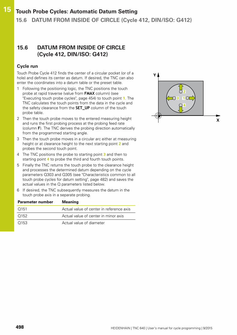
Touch Probe Cycles: Automatic Datum Setting 15.6 DATUM FROM INSIDE OF CIRCLE (Cycle 412, DIN/ISO: G412)
15
498 HEIDENHAIN | TNC 640 | User’s manual for cycle programming | 9/2015
15.6 DATUM FROM INSIDE OF CIRCLE
(Cycle 412, DIN/ISO: G412)
Cycle run
Touch Probe Cycle 412 finds the center of a circular pocket (or of a
hole) and defines its center as datum. If desired, the TNC can also
enter the coordinates into a datum table or the preset table.
1 Following the positioning logic, the TNC positions the touch
probe at rapid traverse (value from FMAX column) (see
"Executing touch probe cycles", page 454) to touch point 1. The
TNC calculates the touch points from the data in the cycle and
the safety clearance from the SET_UP column of the touch
probe table.
2 Then the touch probe moves to the entered measuring height
and runs the first probing process at the probing feed rate
(column F). The TNC derives the probing direction automatically
from the programmed starting angle.
3 Then the touch probe moves in a circular arc either at measuring
height or at clearance height to the next starting point 2 and
probes the second touch point.
4 The TNC positions the probe to starting point 3 and then to
starting point 4 to probe the third and fourth touch points.
5 Finally the TNC returns the touch probe to the clearance height
and processes the determined datum depending on the cycle
parameters Q303 and Q305 (see "Characteristics common to all
touch probe cycles for datum setting", page 482) and saves the
actual values in the Q parameters listed below.
6 If desired, the TNC subsequently measures the datum in the
touch probe axis in a separate probing.
Parameter number Meaning
Q151 Actual value of center in reference axis
Q152 Actual value of center in minor axis
Q153 Actual value of diameter

DATUM FROM INSIDE OF CIRCLE (Cycle 412, DIN/ISO: G412) 15.6
15
HEIDENHAIN | TNC 640 | User’s manual for cycle programming | 9/2015 499
Please note while programming:
Danger of collision!
To prevent a collision between the touch probe and
the workpiece, enter a low estimate for the nominal
diameter of the pocket (or hole).
If the dimensions of the pocket and the safety
clearance do not permit pre-positioning in the
proximity of the touch points, the TNC always starts
probing from the center of the pocket. In this case
the touch probe does not return to the clearance
height between the four measuring points.
The smaller the angle increment Q247, the less
accurately the TNC can calculate the datum.
Minimum input value: 5°.
Before a cycle definition you must have programmed
a tool call to define the touch probe axis.
If you set a datum (Q303 = 0) with the touch probe
cycle and also use probe in TS axis (Q381 = 1), then
no coordinate transformation must be active.

Touch Probe Cycles: Automatic Datum Setting 15.6 DATUM FROM INSIDE OF CIRCLE (Cycle 412, DIN/ISO: G412)
15
500 HEIDENHAIN | TNC 640 | User’s manual for cycle programming | 9/2015
Cycle parameters
Center in 1st axis Q321 (absolute): Center of the
pocket in the reference axis of the working plane.
Input range -99999.9999 to 99999.9999
Center in 2nd axis Q322 (absolute): Center of the
pocket in the minor axis of the working plane. If
you program Q322 = 0, the TNC aligns the hole
center to the positive Y axis. If you program Q322
not equal to 0, then the TNC aligns the hole center
to the nominal position. Input range -99999.9999 to
99999.9999
Nominal diameter Q262: Approximate diameter
of the circular pocket (or hole). Enter a value that
is more likely to be too small than too large. Input
range 0 to 99999.9999
Starting angle Q325 (absolute): Angle between the
reference axis of the working plane and the first
touch point. Input range -360.000 to 360.000
Stepping angle Q247 (incremental): Angle between
two measuring points. The algebraic sign of the
stepping angle determines the direction of rotation
(negative = clockwise) in which the touch probe
moves to the next measuring point. If you wish to
probe a circular arc instead of a complete circle,
then program the stepping angle to be less than
90°. Input range -120.000 to 120.000
Measuring height in the touch probe axis Q261
(absolute): Coordinate of the ball tip center (=
touch point) in the touch probe axis in which
the measurement is to be made. Input range
-99999.9999 to 99999.9999
Set-up clearance Q320 (incremental): Additional
distance between measuring point and ball tip.
Q320 is added to SET_UP (touch probe table). Input
range 0 to 99999.9999
Clearance height Q260 (absolute): Coordinate in
the touch probe axis at which no collision between
touch probe and workpiece (fixtures) can occur.
Input range -99999.9999 to 99999.9999
Traversing to clearance height Q301: definition
of how the touch probe is to move between the
measuring points:
0: Move at measuring height between measuring
points
1: Move at clearance height between measuring
points
Datum number in table Q305: Enter the number in
the datum/preset table in which the TNC is to save
the coordinates of the pocket center. If Q303=1: If
you enter Q305=0, the TNC automatically sets the
display so that the new datum is at the center of the
pocket. If Q303=0: If you enter Q305=0, the TNC
writes to line 0 of the datum table. Input range 0 to
99999
NC blocks
5 TCH PROBE 412 DATUM INSIDECIRCLE
Q321=+50 ;CENTER IN 1ST AXIS
Q322=+50 ;CENTER IN 2ND AXIS
Q262=75 ;NOMINAL DIAMETER
Q325=+0 ;STARTING ANGLE
Q247=+60 ;STEPPING ANGLE
Q261=-5 ;MEASURING HEIGHT
Q320=0 ;SET-UP CLEARANCE
Q260=+20 ;CLEARANCE HEIGHT
Q301=0 ;MOVE TO CLEARANCE
Q305=12 ;NO. IN TABLE
Q331=+0 ;DATUM
Q332=+0 ;DATUM
Q303=+1 ;MEAS. VALUETRANSFER
Q381=1 ;PROBE IN TS AXIS
Q382=+85 ;1ST CO. FOR TS AXIS
Q383=+50 ;2ND CO. FOR TS AXIS
Q384=+0 ;3RD CO. FOR TS AXIS
Q333=+1 ;DATUM
Q423=4 ;NO. OF PROBE POINTS
Q365=1 ;TYPE OF TRAVERSE

DATUM FROM INSIDE OF CIRCLE (Cycle 412, DIN/ISO: G412) 15.6
15
HEIDENHAIN | TNC 640 | User’s manual for cycle programming | 9/2015 501
New datum for reference axis Q331 (absolute):
Coordinate in the reference axis at which the TNC
should set the pocket center. Default setting = 0.
Input range -99999.9999 to 99999.9999
New datum for minor axis Q332 (absolute):
Coordinate in the minor axis at which the TNC
should set the pocket center. Default setting = 0
input range -99999.9999 to 99999.9999
Measured-value transfer (0, 1) Q303: Specify
whether the determined datum is to be saved in the
datum table or in the preset table:
-1: Do not use! Is entered by the TNC when old
programs are read in (see "Characteristics common
to all touch probe cycles for datum setting",
page 482)
0: Write the measured datum into the active datum
table. The reference system is the active workpiece
coordinate system
1: Write the measured datum into the preset table.
The reference system is the machine coordinate
system (REF system).
Probe in TS axis Q381: Specify whether the TNC
should also set the datum in the touch probe axis:
0: Do not set the datum in the touch probe axis
1: Set the datum in the touch probe axis
Probe TS axis: Coord. 1st axis Q382 (absolute):
Coordinate of the probe point in the reference axis
of the working plane at which point the datum is
to be set in the touch probe axis. Only effective if
Q381 = 1st input range -99999.9999 to 99999.9999
Probe TS axis: Coord. 2nd axis Q383 (absolute):
Coordinate of the probe point in the minor axis of
the working plane at which point the datum is to be
set in the touch probe axis. Only effective if Q381 =
1. Input range -99999.9999 to 99999.9999
Probe TS axis: Coord. 3rd axis Q384 (absolute):
Coordinate of the probe point in the touch probe
axis, at which point the datum is to be set in the
touch probe axis. Only effective if Q381 = 1. Input
range -99999.9999 to 99999.9999

Touch Probe Cycles: Automatic Datum Setting 15.6 DATUM FROM INSIDE OF CIRCLE (Cycle 412, DIN/ISO: G412)
15
502 HEIDENHAIN | TNC 640 | User’s manual for cycle programming | 9/2015
New datum in TS axis Q333 (absolute): Coordinate
in the touch probe axis at which the TNC should
set the datum. Default setting = 0. Input range
-99999.9999 to 99999.9999
No. of measuring points (4/3) Q423: Specify
whether the TNC should measure the stud with 4 or
3 probing points:
4: Use 4 measuring points (default setting)
3: Use 3 measuring points
Type of traverse? Line=0/Arc=1 Q365: Definition
of the path function with which the tool is to move
between the measuring points if "traverse to
clearance height" (Q301=1) is active:
0: Move in a straight line between machining
operations
1: Move in a circular arc on the pitch circle diameter
between machining operations

DATUM FROM OUTSIDE OF CIRCLE (Cycle 413, DIN/ISO: G413) 15.7
15
HEIDENHAIN | TNC 640 | User’s manual for cycle programming | 9/2015 503
15.7 DATUM FROM OUTSIDE OF CIRCLE
(Cycle 413, DIN/ISO: G413)
Cycle run
Touch Probe Cycle 413 finds the center of a circular stud and
defines it as datum. If desired, the TNC can also enter the
coordinates into a datum table or the preset table.
1 Following the positioning logic, the TNC positions the touch
probe at rapid traverse (value from FMAX column) (see
"Executing touch probe cycles", page 454) to touch point 1. The
TNC calculates the touch points from the data in the cycle and
the safety clearance from the SET_UP column of the touch
probe table.
2 Then the touch probe moves to the entered measuring height
and runs the first probing process at the probing feed rate
(column F). The TNC derives the probing direction automatically
from the programmed starting angle.
3 Then the touch probe moves in a circular arc either at measuring
height or at clearance height to the next starting point 2 and
probes the second touch point.
4 The TNC positions the probe to starting point 3 and then to
starting point 4 to probe the third and fourth touch points.
5 Finally the TNC returns the touch probe to the clearance height
and processes the determined datum depending on the cycle
parameters Q303 and Q305 (see "Characteristics common to all
touch probe cycles for datum setting", page 482) and saves the
actual values in the Q parameters listed below.
6 If desired, the TNC subsequently measures the datum in the
touch probe axis in a separate probing.
Parameter number Meaning
Q151 Actual value of center in reference axis
Q152 Actual value of center in minor axis
Q153 Actual value of diameter
Please note while programming:
Danger of collision!
To prevent a collision between touch probe and
workpiece, enter a high estimate for the nominal
diameter of the stud.
Before a cycle definition you must have programmed
a tool call to define the touch probe axis.
The smaller the angle increment Q247, the less
accurately the TNC can calculate the datum.
Minimum input value: 5°.
If you set a datum (Q303 = 0) with the touch probe
cycle and also use probe in TS axis (Q381 = 1), then
no coordinate transformation must be active.
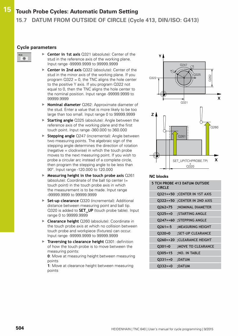
Touch Probe Cycles: Automatic Datum Setting 15.7 DATUM FROM OUTSIDE OF CIRCLE (Cycle 413, DIN/ISO: G413)
15
504 HEIDENHAIN | TNC 640 | User’s manual for cycle programming | 9/2015
Cycle parameters
Center in 1st axis Q321 (absolute): Center of the
stud in the reference axis of the working plane.
Input range -99999.9999 to 99999.9999
Center in 2nd axis Q322 (absolute): Center of the
stud in the minor axis of the working plane. If you
program Q322 = 0, the TNC aligns the hole center
to the positive Y axis. If you program Q322 not
equal to 0, then the TNC aligns the hole center to
the nominal position. Input range -99999.9999 to
99999.9999
Nominal diameter Q262: Approximate diameter of
the stud. Enter a value that is more likely to be too
large than too small. Input range 0 to 99999.9999
Starting angle Q325 (absolute): Angle between the
reference axis of the working plane and the first
touch point. Input range -360.000 to 360.000
Stepping angle Q247 (incremental): Angle between
two measuring points. The algebraic sign of the
stepping angle determines the direction of rotation
(negative = clockwise) in which the touch probe
moves to the next measuring point. If you wish to
probe a circular arc instead of a complete circle,
then program the stepping angle to be less than
90°. Input range -120.000 to 120.000
Measuring height in the touch probe axis Q261
(absolute): Coordinate of the ball tip center (=
touch point) in the touch probe axis in which
the measurement is to be made. Input range
-99999.9999 to 99999.9999
Set-up clearance Q320 (incremental): Additional
distance between measuring point and ball tip.
Q320 is added to SET_UP (touch probe table). Input
range 0 to 99999.9999
Clearance height Q260 (absolute): Coordinate in
the touch probe axis at which no collision between
touch probe and workpiece (fixtures) can occur.
Input range -99999.9999 to 99999.9999
Traversing to clearance height Q301: definition
of how the touch probe is to move between the
measuring points:
0: Move at measuring height between measuring
points
1: Move at clearance height between measuring
points
NC blocks
5 TCH PROBE 413 DATUM OUTSIDECIRCLE
Q321=+50 ;CENTER IN 1ST AXIS
Q322=+50 ;CENTER IN 2ND AXIS
Q262=75 ;NOMINAL DIAMETER
Q325=+0 ;STARTING ANGLE
Q247=+60 ;STEPPING ANGLE
Q261=-5 ;MEASURING HEIGHT
Q320=0 ;SET-UP CLEARANCE
Q260=+20 ;CLEARANCE HEIGHT
Q301=0 ;MOVE TO CLEARANCE
Q305=15 ;NO. IN TABLE
Q331=+0 ;DATUM
Q332=+0 ;DATUM

DATUM FROM OUTSIDE OF CIRCLE (Cycle 413, DIN/ISO: G413) 15.7
15
HEIDENHAIN | TNC 640 | User’s manual for cycle programming | 9/2015 505
Datum number in table Q305: Enter the number in
the datum/preset table in which the TNC is to save
the coordinates of the stud center. If Q303=1: If
you enter Q305=0, the TNC automatically sets the
display so that the new datum is on the stud center.
If Q303=0: If you enter Q305=0, the TNC writes to
line 0 of the datum table. Input range 0 to 99999
New datum for reference axis Q331 (absolute):
Coordinate in the reference axis at which the TNC
should set the stud center. Default setting = 0 input
range -99999.9999 to 99999.9999
New datum for minor axis Q332 (absolute):
Coordinate in the minor axis at which the TNC
should set the stud center. Default setting = 0 input
range -99999.9999 to 99999.9999
Measured-value transfer (0, 1) Q303: Specify
whether the determined datum is to be saved in the
datum table or in the preset table:
-1: Do not use! Is entered by the TNC when old
programs are read in (see "Characteristics common
to all touch probe cycles for datum setting",
page 482)
0: Write the measured datum into the active datum
table. The reference system is the active workpiece
coordinate system
1: Write the measured datum into the preset table.
The reference system is the machine coordinate
system (REF system).
Probe in TS axis Q381: Specify whether the TNC
should also set the datum in the touch probe axis:
0: Do not set the datum in the touch probe axis
1: Set the datum in the touch probe axis
Probe TS axis: Coord. 1st axis Q382 (absolute):
Coordinate of the probe point in the reference axis
of the working plane at which point the datum is
to be set in the touch probe axis. Only effective if
Q381 = 1st input range -99999.9999 to 99999.9999
Probe TS axis: Coord. 2nd axis Q383 (absolute):
Coordinate of the probe point in the minor axis of
the working plane at which point the datum is to be
set in the touch probe axis. Only effective if Q381 =
1. Input range -99999.9999 to 99999.9999
Q303=+1 ;MEAS. VALUETRANSFER
Q381=1 ;PROBE IN TS AXIS
Q382=+85 ;1ST CO. FOR TS AXIS
Q383=+50 ;2ND CO. FOR TS AXIS
Q384=+0 ;3RD CO. FOR TS AXIS
Q333=+1 ;DATUM
Q423=4 ;NO. OF PROBE POINTS
Q365=1 ;TYPE OF TRAVERSE

Touch Probe Cycles: Automatic Datum Setting 15.7 DATUM FROM OUTSIDE OF CIRCLE (Cycle 413, DIN/ISO: G413)
15
506 HEIDENHAIN | TNC 640 | User’s manual for cycle programming | 9/2015
Probe TS axis: Coord. 3rd axis Q384 (absolute):
Coordinate of the probe point in the touch probe
axis, at which point the datum is to be set in the
touch probe axis. Only effective if Q381 = 1. Input
range -99999.9999 to 99999.9999
New datum in TS axis Q333 (absolute): Coordinate
in the touch probe axis at which the TNC should
set the datum. Default setting = 0. Input range
-99999.9999 to 99999.9999
No. of measuring points (4/3) Q423: Specify
whether the TNC should measure the stud with 4 or
3 probing points:
4: Use 4 measuring points (default setting)
3: Use 3 measuring points
Type of traverse? Line=0/Arc=1 Q365: Definition
of the path function with which the tool is to move
between the measuring points if "traverse to
clearance height" (Q301=1) is active:
0: Move in a straight line between machining
operations
1: Move in a circular arc on the pitch circle diameter
between machining operations

DATUM FROM OUTSIDE OF CORNER (Cycle 414, DIN/ISO: G414) 15.8
15
HEIDENHAIN | TNC 640 | User’s manual for cycle programming | 9/2015 507
15.8 DATUM FROM OUTSIDE OF CORNER
(Cycle 414, DIN/ISO: G414)
Cycle run
Touch Probe Cycle 414 finds the intersection of two lines and
defines it as the datum. If desired, the TNC can also enter the
intersection into a datum table or preset table.
1 Following the positioning logic, the TNC positions the touch
probe at rapid traverse (value from FMAX column) (see
"Executing touch probe cycles", page 454) to touch point 1 (see
figure at upper right). The TNC offsets the touch probe by the
safety clearance in the direction opposite to the respective
traverse direction.
2 Then the touch probe moves to the entered measuring height
and runs the first probing process at the probing feed rate
(column F). The TNC derives the probing direction automatically
from the programmed 3rd measuring point.
1 Then the touch probe moves to the next starting position 2 and
from there probes the second position.
2 The TNC positions the probe to starting point 3 and then to
starting point 4 to probe the third and fourth touch points.
3 Finally the TNC returns the touch probe to the clearance height
and processes the determined datum depending on the cycle
parameters Q303 and Q305 (see "Characteristics common to all
touch probe cycles for datum setting", page 482) and saves the
coordinates of the determined corner in the Q parameters listed
below.
4 If desired, the TNC subsequently measures the datum in the
touch probe axis in a separate probing.
Parameter number Meaning
Q151 Actual value of corner in reference axis
Q152 Actual value of corner in minor axis

Touch Probe Cycles: Automatic Datum Setting 15.8 DATUM FROM OUTSIDE OF CORNER (Cycle 414, DIN/ISO: G414)
15
508 HEIDENHAIN | TNC 640 | User’s manual for cycle programming | 9/2015
Please note while programming:
Danger of collision!
If you set a datum (Q303 = 0) with the touch probe
cycle and also use probe in TS axis (Q381 = 1), then
no coordinate transformation must be active.
Before a cycle definition you must have programmed
a tool call to define the touch probe axis.
The TNC always measures the first line in the
direction of the minor axis of the working plane.
By defining the positions of the measuring points
1 and 3 you also determine the corner at which the
TNC sets the datum (see figure at right and table
below).
Corner X coordinate Y coordinate
A Point 1 greater than point
3
Point 1 less than point 3
B Point 1 less than point 3 Point 1 less than point 3
C Point 1 less than point 3 Point 1 greater than point 3
D Point 1 greater than point
3
Point 1 greater than point 3

DATUM FROM OUTSIDE OF CORNER (Cycle 414, DIN/ISO: G414) 15.8
15
HEIDENHAIN | TNC 640 | User’s manual for cycle programming | 9/2015 509
Cycle parameters
1st meas. point 1st axis Q263 (absolute):
Coordinate of the first touch point in the reference
axis of the working plane. Input range -99999.9999
to 99999.9999
1st meas. point 2nd axis Q264 (absolute):
Coordinate of the first touch point in the minor axis
of the working plane. Input range -99999.9999 to
99999.9999
Spacing in 1st axis Q326 (incremental): Distance
between the first and second measuring points in
the reference axis of the working plane. Input range
0 to 99999.9999
3rd meas. point 1st axis Q296 (absolute):
Coordinate of the third touch point in the reference
axis of the working plane. Input range -99999.9999
to 99999.9999
3rd meas. point 2nd axis Q297 (absolute):
Coordinate of the third touch point in the minor axis
of the working plane. Input range -99999.9999 to
99999.9999
Spacing in 2nd axis Q327 (incremental): Distance
between third and fourth measuring points in the
minor axis of the working plane. Input range 0 to
99999.9999
Measuring height in the touch probe axis Q261
(absolute): Coordinate of the ball tip center (=
touch point) in the touch probe axis in which
the measurement is to be made. Input range
-99999.9999 to 99999.9999
Set-up clearance Q320 (incremental): Additional
distance between measuring point and ball tip.
Q320 is added to SET_UP (touch probe table). Input
range 0 to 99999.9999
Clearance height Q260 (absolute): Coordinate in
the touch probe axis at which no collision between
touch probe and workpiece (fixtures) can occur.
Input range -99999.9999 to 99999.9999
Traversing to clearance height Q301: definition
of how the touch probe is to move between the
measuring points:
0: Move at measuring height between measuring
points
1: Move at clearance height between measuring
points
NC blocks
5 TCH PROBE 414 DATUM INSIDECORNER
Q263=+37 ;1ST POINT 1ST AXIS
Q264=+7 ;1ST POINT 2ND AXIS
Q326=50 ;SPACING IN 1ST AXIS
Q296=+95 ;3RD POINT 1ST AXIS
Q297=+25 ;3RD POINT 2ND AXIS
Q327=45 ;SPACING IN 2ND AXIS
Q261=-5 ;MEASURING HEIGHT
Q320=0 ;SET-UP CLEARANCE
Q260=+20 ;CLEARANCE HEIGHT
Q301=0 ;MOVE TO CLEARANCE
Q304=0 ;BASIC ROTATION
Q305=7 ;NO. IN TABLE
Q331=+0 ;DATUM

Touch Probe Cycles: Automatic Datum Setting 15.8 DATUM FROM OUTSIDE OF CORNER (Cycle 414, DIN/ISO: G414)
15
510 HEIDENHAIN | TNC 640 | User’s manual for cycle programming | 9/2015
Execute basic rotation Q304: Definition of
whether the TNC should compensate workpiece
misalignment with a basic rotation:
0: Do not execute basic rotation
1: Execute basic rotation
Datum number in table Q305: Enter the datum
number in the datum or preset table in which
the TNC is to save the coordinates of the corner.
If Q303=1: If you enter Q305=0, the TNC
automatically sets the display so that the new
datum is on the corner. If Q303=0: If you enter
Q305=0, the TNC writes to line 0 of the datum
table. Input range 0 to 99999
New datum for reference axis Q331 (absolute):
Coordinate in the reference axis at which the TNC
should set the corner. Default setting = 0 input
range -99999.9999 to 99999.9999
New datum for minor axis Q332 (absolute):
Coordinate in the minor axis at which the TNC
should set the calculated corner. Default setting = 0
input range -99999.9999 to 99999.9999
Measured-value transfer (0, 1) Q303: Specify
whether the determined datum is to be saved in the
datum table or in the preset table:
-1: Do not use! Is entered by the TNC when old
programs are read in (see "Characteristics common
to all touch probe cycles for datum setting",
page 482)
0: Write the measured datum into the active datum
table. The reference system is the active workpiece
coordinate system
1: Write the measured datum into the preset table.
The reference system is the machine coordinate
system (REF system).
Probe in TS axis Q381: Specify whether the TNC
should also set the datum in the touch probe axis:
0: Do not set the datum in the touch probe axis
1: Set the datum in the touch probe axis
Probe TS axis: Coord. 1st axis Q382 (absolute):
Coordinate of the probe point in the reference axis
of the working plane at which point the datum is
to be set in the touch probe axis. Only effective if
Q381 = 1st input range -99999.9999 to 99999.9999
Q332=+0 ;DATUM
Q303=+1 ;MEAS. VALUETRANSFER
Q381=1 ;PROBE IN TS AXIS
Q382=+85 ;1ST CO. FOR TS AXIS
Q383=+50 ;2ND CO. FOR TS AXIS
Q384=+0 ;3RD CO. FOR TS AXIS
Q333=+1 ;DATUM
DATUM FROM OUTSIDE OF CORNER (Cycle 414, DIN/ISO: G414) 15.8
15
HEIDENHAIN | TNC 640 | User’s manual for cycle programming | 9/2015 511
Probe TS axis: Coord. 2nd axis Q383 (absolute):
Coordinate of the probe point in the minor axis of
the working plane at which point the datum is to be
set in the touch probe axis. Only effective if Q381 =
1. Input range -99999.9999 to 99999.9999
Probe TS axis: Coord. 3rd axis Q384 (absolute):
Coordinate of the probe point in the touch probe
axis, at which point the datum is to be set in the
touch probe axis. Only effective if Q381 = 1. Input
range -99999.9999 to 99999.9999
New datum in TS axis Q333 (absolute): Coordinate
in the touch probe axis at which the TNC should
set the datum. Default setting = 0. Input range
-99999.9999 to 99999.9999

Touch Probe Cycles: Automatic Datum Setting 15.9 DATUM FROM INSIDE OF CORNER (Cycle 415, DIN/ISO: G415)
15
512 HEIDENHAIN | TNC 640 | User’s manual for cycle programming | 9/2015
15.9 DATUM FROM INSIDE OF CORNER
(Cycle 415, DIN/ISO: G415)
Cycle run
Touch Probe Cycle 415 finds the intersection of two lines and
defines it as the datum. If desired, the TNC can also enter the
intersection into a datum table or preset table.
1 Following the positioning logic, the TNC positions the touch
probe at rapid traverse (value from FMAX column) (see
"Executing touch probe cycles", page 454) to touch point 1 (see
figure at upper right) that you have defined in the cycle. The
TNC offsets the touch probe by the safety clearance in the
direction opposite to the respective traverse direction.
2 Then the touch probe moves to the entered measuring height
and runs the first probing process at the probing feed rate
(column F). The probing direction is derived from the number by
which you identify the corner.
1 Then the touch probe moves to the next starting position 2 and
from there probes the second position.
2 The TNC positions the probe to starting point 3 and then to
starting point 4 to probe the third and fourth touch points.
3 Finally the TNC returns the touch probe to the clearance height
and processes the determined datum depending on the cycle
parameters Q303 and Q305 (see "Characteristics common to all
touch probe cycles for datum setting", page 482) and saves the
coordinates of the determined corner in the Q parameters listed
below.
4 If desired, the TNC subsequently measures the datum in the
touch probe axis in a separate probing.
Parameter number Meaning
Q151 Actual value of corner in reference axis
Q152 Actual value of corner in minor axis

DATUM FROM INSIDE OF CORNER (Cycle 415, DIN/ISO: G415) 15.9
15
HEIDENHAIN | TNC 640 | User’s manual for cycle programming | 9/2015 513
Please note while programming:
Danger of collision!
If you set a datum (Q303 = 0) with the touch probe
cycle and also use probe in TS axis (Q381 = 1), then
no coordinate transformation must be active.
Before a cycle definition you must have programmed
a tool call to define the touch probe axis.
The TNC always measures the first line in the
direction of the minor axis of the working plane.

Touch Probe Cycles: Automatic Datum Setting 15.9 DATUM FROM INSIDE OF CORNER (Cycle 415, DIN/ISO: G415)
15
514 HEIDENHAIN | TNC 640 | User’s manual for cycle programming | 9/2015
Cycle parameters
1st meas. point 1st axis Q263 (absolute):
Coordinate of the first touch point in the reference
axis of the working plane. Input range -99999.9999
to 99999.9999
1st meas. point 2nd axis Q264 (absolute):
Coordinate of the first touch point in the minor axis
of the working plane. Input range -99999.9999 to
99999.9999
Spacing in 1st axis Q326 (incremental): Distance
between the first and second measuring points in
the reference axis of the working plane. Input range
0 to 99999.9999
Spacing in 2nd axis Q327 (incremental): Distance
between third and fourth measuring points in the
minor axis of the working plane. Input range 0 to
99999.9999
Corner Q308: Number identifying the corner which
the TNC is to set as datum. Input range 1 to 4
Measuring height in the touch probe axis Q261
(absolute): Coordinate of the ball tip center (=
touch point) in the touch probe axis in which
the measurement is to be made. Input range
-99999.9999 to 99999.9999
Set-up clearance Q320 (incremental): Additional
distance between measuring point and ball tip.
Q320 is added to SET_UP (touch probe table). Input
range 0 to 99999.9999
Clearance height Q260 (absolute): Coordinate in
the touch probe axis at which no collision between
touch probe and workpiece (fixtures) can occur.
Input range -99999.9999 to 99999.9999
Traversing to clearance height Q301: definition
of how the touch probe is to move between the
measuring points:
0: Move at measuring height between measuring
points
1: Move at clearance height between measuring
points
Execute basic rotation Q304: Definition of
whether the TNC should compensate workpiece
misalignment with a basic rotation:
0: Do not execute basic rotation
1: Execute basic rotation
Datum number in table Q305: Enter the datum
number in the datum or preset table in which
the TNC is to save the coordinates of the corner.
If Q303=1: If you enter Q305=0, the TNC
automatically sets the display so that the new
datum is on the corner. If Q303=0: If you enter
Q305=0, the TNC writes to line 0 of the datum
table. Input range 0 to 99999
NC blocks
5 TCH PROBE 415 DATUM OUTSIDECORNER
Q263=+37 ;1ST POINT 1ST AXIS
Q264=+7 ;1ST POINT 2ND AXIS
Q326=50 ;SPACING IN 1ST AXIS
Q296=+95 ;3RD POINT 1ST AXIS
Q297=+25 ;3RD POINT 2ND AXIS
Q327=45 ;SPACING IN 2ND AXIS
Q261=-5 ;MEASURING HEIGHT
Q320=0 ;SET-UP CLEARANCE
Q260=+20 ;CLEARANCE HEIGHT
Q301=0 ;MOVE TO CLEARANCE
Q304=0 ;BASIC ROTATION
Q305=7 ;NO. IN TABLE
Q331=+0 ;DATUM
Q332=+0 ;DATUM
Q303=+1 ;MEAS. VALUETRANSFER
Q381=1 ;PROBE IN TS AXIS
Q382=+85 ;1ST CO. FOR TS AXIS
Q383=+50 ;2ND CO. FOR TS AXIS
Q384=+0 ;3RD CO. FOR TS AXIS
Q333=+1 ;DATUM

DATUM FROM INSIDE OF CORNER (Cycle 415, DIN/ISO: G415) 15.9
15
HEIDENHAIN | TNC 640 | User’s manual for cycle programming | 9/2015 515
New datum for reference axis Q331 (absolute):
Coordinate in the reference axis at which the TNC
should set the corner. Default setting = 0 input
range -99999.9999 to 99999.9999
New datum for minor axis Q332 (absolute):
Coordinate in the minor axis at which the TNC
should set the calculated corner. Default setting = 0
input range -99999.9999 to 99999.9999
Measured-value transfer (0, 1) Q303: Specify
whether the determined datum is to be saved in the
datum table or in the preset table:
-1: Do not use! Is entered by the TNC when old
programs are read in (see "Characteristics common
to all touch probe cycles for datum setting",
page 482)
0: Write the measured datum into the active datum
table. The reference system is the active workpiece
coordinate system
1: Write the measured datum into the preset table.
The reference system is the machine coordinate
system (REF system).
Probe in TS axis Q381: Specify whether the TNC
should also set the datum in the touch probe axis:
0: Do not set the datum in the touch probe axis
1: Set the datum in the touch probe axis
Probe TS axis: Coord. 1st axis Q382 (absolute):
Coordinate of the probe point in the reference axis
of the working plane at which point the datum is
to be set in the touch probe axis. Only effective if
Q381 = 1st input range -99999.9999 to 99999.9999
Probe TS axis: Coord. 2nd axis Q383 (absolute):
Coordinate of the probe point in the minor axis of
the working plane at which point the datum is to be
set in the touch probe axis. Only effective if Q381 =
1. Input range -99999.9999 to 99999.9999
Probe TS axis: Coord. 3rd axis Q384 (absolute):
Coordinate of the probe point in the touch probe
axis, at which point the datum is to be set in the
touch probe axis. Only effective if Q381 = 1. Input
range -99999.9999 to 99999.9999
New datum in TS axis Q333 (absolute): Coordinate
in the touch probe axis at which the TNC should
set the datum. Default setting = 0. Input range
-99999.9999 to 99999.9999

Touch Probe Cycles: Automatic Datum Setting 15.10 DATUM CIRCLE CENTER (Cycle 416, DIN/ISO: G416)
15
516 HEIDENHAIN | TNC 640 | User’s manual for cycle programming | 9/2015
15.10 DATUM CIRCLE CENTER (Cycle 416,
DIN/ISO: G416)
Cycle run
Touch Probe Cycle 416 finds the center of a bolt hole circle and
defines its center as datum. If desired, the TNC can also enter the
coordinates into a datum table or the preset table.
1 Following the positioning logic, the TNC positions the touch
probe at rapid traverse (value from FMAX column) (see
"Executing touch probe cycles", page 454) to the center of the
first hole 1.
2 Then the probe moves to the entered measuring height and
probes four points to find the first hole center.
3 The touch probe returns to the clearance height and then to the
position entered as center of the second hole 2.
4 The TNC moves the touch probe to the entered measuring
height and probes four points to find the second hole center.
5 The touch probe returns to the clearance height and then to the
position entered as center of the third hole 3.
6 The TNC moves the touch probe to the entered measuring
height and probes four points to find the third hole center.
7 Finally the TNC returns the touch probe to the clearance height
and processes the determined datum depending on the cycle
parameters Q303 and Q305 (see "Characteristics common to all
touch probe cycles for datum setting", page 482) and saves the
actual values in the Q parameters listed below.
8 If desired, the TNC subsequently measures the datum in the
touch probe axis in a separate probing.
Parameter number Meaning
Q151 Actual value of center in reference axis
Q152 Actual value of center in minor axis
Q153 Actual value of bolt hole circle
diameter

DATUM CIRCLE CENTER (Cycle 416, DIN/ISO: G416) 15.10
15
HEIDENHAIN | TNC 640 | User’s manual for cycle programming | 9/2015 517
Please note while programming:
Danger of collision!
If you set a datum (Q303 = 0) with the touch probe
cycle and also use probe in TS axis (Q381 = 1), then
no coordinate transformation must be active.
Before a cycle definition you must have programmed
a tool call to define the touch probe axis.

Touch Probe Cycles: Automatic Datum Setting 15.10 DATUM CIRCLE CENTER (Cycle 416, DIN/ISO: G416)
15
518 HEIDENHAIN | TNC 640 | User’s manual for cycle programming | 9/2015
Cycle parameters
Center in 1st axis Q273 (absolute): Bolt hole circle
center (nominal value) in the reference axis of
the working plane. Input range -99999.9999 to
99999.9999
Center in 2nd axis Q274 (absolute): Bolt hole
circle center (nominal value) in the minor axis of
the working plane. Input range -99999.9999 to
99999.9999
Nominal diameter Q262: Enter the approximate
bolt hole circle diameter. The smaller the hole
diameter, the more exact the nominal diameter
must be. Input range 0 to 99999.9999
Angle of 1st hole Q291 (absolute): Polar coordinate
angle of the first hole center in the working plane.
Input range -360.0000 to 360.0000
Angle of 2nd hole Q292 (absolute): Polar coordinate
angle of the second hole center in the working
plane. Input range -360.0000 to 360.0000
Angle of 3rd hole Q293 (absolute): Polar coordinate
angle of the third hole center in the working plane.
Input range -360.0000 to 360.0000
Measuring height in the touch probe axis Q261
(absolute): Coordinate of the ball tip center (=
touch point) in the touch probe axis in which
the measurement is to be made. Input range
-99999.9999 to 99999.9999
Clearance height Q260 (absolute): Coordinate in
the touch probe axis at which no collision between
touch probe and workpiece (fixtures) can occur.
Input range -99999.9999 to 99999.9999
Datum number in table Q305: Enter the number
in the datum or preset table in which the TNC
is to save the coordinates of the bolt-hole circle
center. If Q303=1: If you enter Q305=0, the TNC
automatically sets the display so that the new
datum is on the bolt-hole circle center. If Q303=0: If
you enter Q305=0, the TNC writes to line 0 of the
datum table. Input range 0 to 99999
New datum for reference axis Q331 (absolute):
Coordinate in the reference axis at which the TNC
should set the bolt-hole center. Default setting = 0
input range -99999.9999 to 99999.9999
New datum for minor axis Q332 (absolute):
Coordinate in the minor axis at which the TNC
should set the bolt-hole center. Default setting = 0
input range -99999.9999 to 99999.9999
NC blocks
5 TCH PROBE 416 DATUM CIRCLECENTER
Q273=+50 ;CENTER IN 1ST AXIS
Q274=+50 ;CENTER IN 2ND AXIS
Q262=90 ;NOMINAL DIAMETER
Q291=+34 ;ANGLE OF 1ST HOLE
Q292=+70 ;ANGLE OF 2ND HOLE
Q293=+210;ANGLE OF 3RD HOLE
Q261=-5 ;MEASURING HEIGHT
Q260=+20 ;CLEARANCE HEIGHT
Q305=12 ;NO. IN TABLE
Q331=+0 ;DATUM
Q332=+0 ;DATUM
Q303=+1 ;MEAS. VALUETRANSFER
Q381=1 ;PROBE IN TS AXIS
Q382=+85 ;1ST CO. FOR TS AXIS
Q383=+50 ;2ND CO. FOR TS AXIS

DATUM CIRCLE CENTER (Cycle 416, DIN/ISO: G416) 15.10
15
HEIDENHAIN | TNC 640 | User’s manual for cycle programming | 9/2015 519
Measured-value transfer (0, 1) Q303: Specify
whether the determined datum is to be saved in the
datum table or in the preset table:
-1: Do not use! Is entered by the TNC when old
programs are read in (see "Characteristics common
to all touch probe cycles for datum setting",
page 482)
0: Write the measured datum into the active datum
table. The reference system is the active workpiece
coordinate system
1: Write the measured datum into the preset table.
The reference system is the machine coordinate
system (REF system).
Probe in TS axis Q381: Specify whether the TNC
should also set the datum in the touch probe axis:
0: Do not set the datum in the touch probe axis
1: Set the datum in the touch probe axis
Probe TS axis: Coord. 1st axis Q382 (absolute):
Coordinate of the probe point in the reference axis
of the working plane at which point the datum is
to be set in the touch probe axis. Only effective if
Q381 = 1st input range -99999.9999 to 99999.9999
Probe TS axis: Coord. 2nd axis Q383 (absolute):
Coordinate of the probe point in the minor axis of
the working plane at which point the datum is to be
set in the touch probe axis. Only effective if Q381 =
1. Input range -99999.9999 to 99999.9999
Probe TS axis: Coord. 3rd axis Q384 (absolute):
Coordinate of the probe point in the touch probe
axis, at which point the datum is to be set in the
touch probe axis. Only effective if Q381 = 1. Input
range -99999.9999 to 99999.9999
New datum in TS axis Q333 (absolute): Coordinate
in the touch probe axis at which the TNC should
set the datum. Default setting = 0. Input range
-99999.9999 to 99999.9999
Set-up clearance Q320 (incremental): Additional
distance between measuring point and ball tip.
Q320 is added to SET_UP (touch probe table), and
is only effective when the datum is probed in the
touch probe axis. Input range 0 to 99999.9999
Q384=+0 ;3RD CO. FOR TS AXIS
Q333=+1 ;DATUM
Q320=0 ;SET-UP CLEARANCE

Touch Probe Cycles: Automatic Datum Setting 15.11 DATUM IN TOUCH PROBE AXIS (Cycle 417, DIN/ISO: G417)
15
520 HEIDENHAIN | TNC 640 | User’s manual for cycle programming | 9/2015
15.11 DATUM IN TOUCH PROBE AXIS
(Cycle 417, DIN/ISO: G417)
Cycle run
Touch Probe Cycle 417 measures any coordinate in the touch probe
axis and defines it as datum. If desired, the TNC can also enter the
measured coordinate in a datum table or preset table.
1 Following the positioning logic, the TNC positions the touch
probe at rapid traverse (value from FMAX column) (see
"Executing touch probe cycles", page 454) to the programmed
touch point 1. The TNC offsets the touch probe by the safety
clearance in the positive direction of the touch probe axis.
2 Then the touch probe moves in its own axis to the coordinate
entered as starting point 1 and measures the actual position
with a simple probing movement.
3 Finally the TNC returns the touch probe to the clearance height
and processes the determined datum depending on the cycle
parameters Q303 and Q305 (see "Characteristics common to all
touch probe cycles for datum setting", page 482) and saves the
actual value in the Q parameters listed below.
Parameter number Meaning
Q160 Actual value of measured point
Please note while programming:
Danger of collision!
If you set a datum (Q303 = 0) with the touch probe
cycle and also use probe in TS axis (Q381 = 1), then
no coordinate transformation must be active.
Before a cycle definition you must have programmed
a tool call to define the touch probe axis.
The TNC then sets the datum in this axis.

DATUM IN TOUCH PROBE AXIS (Cycle 417, DIN/ISO: G417) 15.11
15
HEIDENHAIN | TNC 640 | User’s manual for cycle programming | 9/2015 521
Cycle parameters
1st meas. point 1st axis Q263 (absolute):
Coordinate of the first touch point in the reference
axis of the working plane. Input range -99999.9999
to 99999.9999
1st meas. point 2nd axis Q264 (absolute):
Coordinate of the first touch point in the minor axis
of the working plane. Input range -99999.9999 to
99999.9999
1st meas. point 3rd axis Q294 (absolute):
Coordinate of the first touch point in the touch probe
axis. Input range -99999.9999 to 99999.9999
Set-up clearance Q320 (incremental): Additional
distance between measuring point and ball tip.
Q320 is added to SET_UP (touch probe table). Input
range 0 to 99999.9999
Clearance height Q260 (absolute): Coordinate in
the touch probe axis at which no collision between
touch probe and workpiece (fixtures) can occur.
Input range -99999.9999 to 99999.9999
Datum number in table Q305: Enter the number
in the datum or preset table in which the TNC is
to save the coordinate. If Q303=1: If you enter
Q305=0, the TNC automatically sets the display
so that the new datum is on the probed surface. If
Q303=0: If you enter Q305=0, the TNC writes to
line 0 of the datum table. Input range 0 to 99999
New datum Q333 (absolute): Coordinate at which
the TNC should set the datum. Default setting = 0
input range -99999.9999 to 99999.9999
Measured-value transfer (0, 1) Q303: Specify
whether the determined datum is to be saved in the
datum table or in the preset table:
-1: Do not use! Is entered by the TNC when old
programs are read in (see "Characteristics common
to all touch probe cycles for datum setting",
page 482)
0: Write the measured datum into the active datum
table. The reference system is the active workpiece
coordinate system
1: Write the measured datum into the preset table.
The reference system is the machine coordinate
system (REF system).
NC blocks
5 TCH PROBE 417 DATUM IN TS AXIS
Q263=+25 ;1ST POINT 1ST AXIS
Q264=+25 ;1ST POINT 2ND AXIS
Q294=+25 ;1ST POINT 3RD AXIS
Q320=0 ;SET-UP CLEARANCE
Q260=+50 ;CLEARANCE HEIGHT
Q305=0 ;NO. IN TABLE
Q333=+0 ;DATUM
Q303=+1 ;MEAS. VALUETRANSFER

Touch Probe Cycles: Automatic Datum Setting 15.12 DATUM AT CENTER OF 4 HOLES (Cycle 418, DIN/ISO: G418)
15
522 HEIDENHAIN | TNC 640 | User’s manual for cycle programming | 9/2015
15.12 DATUM AT CENTER OF 4 HOLES
(Cycle 418, DIN/ISO: G418)
Cycle run
Touch Probe Cycle 418 calculates the intersection of the lines
connecting opposite holes and sets the datum at the intersection.
If desired, the TNC can also enter the intersection into a datum
table or preset table.
1 Following the positioning logic, the TNC positions the touch
probe at rapid traverse (value from FMAX column) (see
"Executing touch probe cycles", page 454) to the center of the
first hole 1.
2 Then the probe moves to the entered measuring height and
probes four points to find the first hole center.
3 The touch probe returns to the clearance height and then to the
position entered as center of the second hole 2.
4 The TNC moves the touch probe to the entered measuring
height and probes four points to find the second hole center.
5 The TNC repeats steps 3 and 4 for holes 3 and 4.
6 Finally the TNC returns the touch probe to the clearance height
and processes the determined datum depending on the cycle
parameters Q303 and Q305 (see "Characteristics common to
all touch probe cycles for datum setting", page 482). The TNC
calculates the datum as the intersection of the lines connecting
the centers of holes 1/3 and 2/4 and saves the actual values in
the Q parameters listed below.
7 If desired, the TNC subsequently measures the datum in the
touch probe axis in a separate probing.
Parameter number Meaning
Q151 Actual value of intersection point in
reference axis
Q152 Actual value of intersection point in
minor axis

DATUM AT CENTER OF 4 HOLES (Cycle 418, DIN/ISO: G418) 15.12
15
HEIDENHAIN | TNC 640 | User’s manual for cycle programming | 9/2015 523
Please note while programming:
Danger of collision!
If you set a datum (Q303 = 0) with the touch probe
cycle and also use probe in TS axis (Q381 = 1), then
no coordinate transformation must be active.
Before a cycle definition you must have programmed
a tool call to define the touch probe axis.

Touch Probe Cycles: Automatic Datum Setting 15.12 DATUM AT CENTER OF 4 HOLES (Cycle 418, DIN/ISO: G418)
15
524 HEIDENHAIN | TNC 640 | User’s manual for cycle programming | 9/2015
Cycle parameters
1st hole: Center in 1st axis Q268 (absolute):
Center of the first hole in the reference axis of
the working plane. Input range -99999.9999 to
99999.9999
1st hole: Center in 2nd axis Q269 (absolute):
Center of the first hole in the minor axis of
the working plane. Input range -99999.9999 to
99999.9999
2nd hole: Center in 1st axis Q270 (absolute):
Center of the second hole in the reference axis
of the working plane. Input range -99999.9999 to
99999.9999
2nd hole: Center in 2nd axis Q271 (absolute):
Center of the second hole in the minor axis of
the working plane. Input range -99999.9999 to
99999.9999
3rd center in 1st axis Q316 (absolute): center of
the 3rd hole in the reference axis of the working
plane. Input range -99999.9999 to 99999.9999
3rd center in 2nd axis Q317 (absolute): center of
the 3rd hole in the minor axis of the working plane.
Input range -99999.9999 to 99999.9999
4th center in 1st axis Q318 (absolute): center of
the 4th hole in the reference axis of the working
plane. Input range -99999.9999 to 99999.9999
4th center in 2nd axis Q319 (absolute): center of
the 4th hole in the minor axis of the working plane.
Input range -99999.9999 to 99999.9999
Measuring height in the touch probe axis Q261
(absolute): Coordinate of the ball tip center (=
touch point) in the touch probe axis in which
the measurement is to be made. Input range
-99999.9999 to 99999.9999
Clearance height Q260 (absolute): Coordinate in
the touch probe axis at which no collision between
touch probe and workpiece (fixtures) can occur.
Input range -99999.9999 to 99999.9999
Datum number in table Q305: Enter the number
in the datum or preset table in which the TNC is
to save the coordinates of the line intersection.
If Q303=1: If you enter Q305=0, the TNC
automatically sets the display so that the new
datum is at the intersection of the connecting lines.
If Q303=0: If you enter Q305=0, the TNC writes to
line 0 of the datum table. Input range 0 to 99999
New datum for reference axis Q331 (absolute):
Coordinate in the reference axis at which the
TNC should set the calculated intersection of the
connecting lines. Default setting = 0 input range
-99999.9999 to 99999.9999
NC blocks
5 TCH PROBE 418 DATUM FROM 4HOLES
Q268=+20 ;1ST CENTER 1ST AXIS
Q269=+25 ;1ST CENTER 2ND AXIS
Q270=+150;2ND CENTER 1ST AXIS
Q271=+25 ;2ND CENTER 2ND AXIS
Q316=+150;3RD CENTER 1ST AXIS
Q317=+85 ;3RD CENTER 2ND AXIS
Q318=+22 ;4TH CENTER 1ST AXIS
Q319=+80 ;4TH CENTER 2ND AXIS
Q261=-5 ;MEASURING HEIGHT
Q260=+10 ;CLEARANCE HEIGHT
Q305=12 ;NO. IN TABLE
Q331=+0 ;DATUM
Q332=+0 ;DATUM
Q303=+1 ;MEAS. VALUETRANSFER
Q381=1 ;PROBE IN TS AXIS
Q382=+85 ;1ST CO. FOR TS AXIS
Q383=+50 ;2ND CO. FOR TS AXIS
Q384=+0 ;3RD CO. FOR TS AXIS
Q333=+0 ;DATUM

DATUM AT CENTER OF 4 HOLES (Cycle 418, DIN/ISO: G418) 15.12
15
HEIDENHAIN | TNC 640 | User’s manual for cycle programming | 9/2015 525
New datum for minor axis Q332 (absolute):
Coordinate in the minor axis at which the TNC
should set the calculated intersection of the
connecting lines. Default setting = 0 input range
-99999.9999 to 99999.9999
Measured-value transfer (0, 1) Q303: Specify
whether the determined datum is to be saved in the
datum table or in the preset table:
-1: Do not use! Is entered by the TNC when old
programs are read in (see "Characteristics common
to all touch probe cycles for datum setting",
page 482)
0: Write the measured datum into the active datum
table. The reference system is the active workpiece
coordinate system
1: Write the measured datum into the preset table.
The reference system is the machine coordinate
system (REF system).
Probe in TS axis Q381: Specify whether the TNC
should also set the datum in the touch probe axis:
0: Do not set the datum in the touch probe axis
1: Set the datum in the touch probe axis
Probe TS axis: Coord. 1st axis Q382 (absolute):
Coordinate of the probe point in the reference axis
of the working plane at which point the datum is
to be set in the touch probe axis. Only effective if
Q381 = 1st input range -99999.9999 to 99999.9999
Probe TS axis: Coord. 2nd axis Q383 (absolute):
Coordinate of the probe point in the minor axis of
the working plane at which point the datum is to be
set in the touch probe axis. Only effective if Q381 =
1. Input range -99999.9999 to 99999.9999
Probe TS axis: Coord. 3rd axis Q384 (absolute):
Coordinate of the probe point in the touch probe
axis, at which point the datum is to be set in the
touch probe axis. Only effective if Q381 = 1. Input
range -99999.9999 to 99999.9999
New datum in TS axis Q333 (absolute): Coordinate
in the touch probe axis at which the TNC should
set the datum. Default setting = 0. Input range
-99999.9999 to 99999.9999
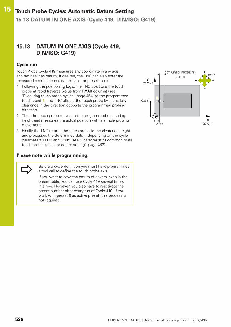
Touch Probe Cycles: Automatic Datum Setting 15.13 DATUM IN ONE AXIS (Cycle 419, DIN/ISO: G419)
15
526 HEIDENHAIN | TNC 640 | User’s manual for cycle programming | 9/2015
15.13 DATUM IN ONE AXIS (Cycle 419,
DIN/ISO: G419)
Cycle run
Touch Probe Cycle 419 measures any coordinate in any axis
and defines it as datum. If desired, the TNC can also enter the
measured coordinate in a datum table or preset table.
1 Following the positioning logic, the TNC positions the touch
probe at rapid traverse (value from FMAX column) (see
"Executing touch probe cycles", page 454) to the programmed
touch point 1. The TNC offsets the touch probe by the safety
clearance in the direction opposite the programmed probing
direction.
2 Then the touch probe moves to the programmed measuring
height and measures the actual position with a simple probing
movement.
3 Finally the TNC returns the touch probe to the clearance height
and processes the determined datum depending on the cycle
parameters Q303 and Q305 (see "Characteristics common to all
touch probe cycles for datum setting", page 482).
Please note while programming:
Before a cycle definition you must have programmed
a tool call to define the touch probe axis.
If you want to save the datum of several axes in the
preset table, you can use Cycle 419 several times
in a row. However, you also have to reactivate the
preset number after every run of Cycle 419. If you
work with preset 0 as active preset, this process is
not required.

DATUM IN ONE AXIS (Cycle 419, DIN/ISO: G419) 15.13
15
HEIDENHAIN | TNC 640 | User’s manual for cycle programming | 9/2015 527
Cycle parameters
1st meas. point 1st axis Q263 (absolute):
Coordinate of the first touch point in the reference
axis of the working plane. Input range -99999.9999
to 99999.9999
1st meas. point 2nd axis Q264 (absolute):
Coordinate of the first touch point in the minor axis
of the working plane. Input range -99999.9999 to
99999.9999
Measuring height in the touch probe axis Q261
(absolute): Coordinate of the ball tip center (=
touch point) in the touch probe axis in which
the measurement is to be made. Input range
-99999.9999 to 99999.9999
Set-up clearance Q320 (incremental): Additional
distance between measuring point and ball tip.
Q320 is added to SET_UP (touch probe table). Input
range 0 to 99999.9999
Clearance height Q260 (absolute): Coordinate in
the touch probe axis at which no collision between
touch probe and workpiece (fixtures) can occur.
Input range -99999.9999 to 99999.9999
Measuring axis (1...3: 1 = principal axis) Q272:
Axis in which the measurement is to be made:
1: Principal axis = measuring axis
2: Secondary axis = measuring axis
3: Touch probe axis = measuring axis
Axis assignment
Active touch probe
axis: Q272= 3
Corresponding
reference axis:
Q272= 1
Corresponding
minor axis: Q272=
2
Z X Y
Y Z X
X Y Z
NC blocks
5 TCH PROBE 419 DATUM IN ONE AXIS
Q263=+25 ;1ST POINT 1ST AXIS
Q264=+25 ;1ST POINT 2ND AXIS
Q261=+25 ;MEASURING HEIGHT
Q320=0 ;SET-UP CLEARANCE
Q260=+50 ;CLEARANCE HEIGHT
Q272=+1 ;MEASURING AXIS
Q267=+1 ;TRAVERSE DIRECTION
Q305=0 ;NO. IN TABLE
Q333=+0 ;DATUM
Q303=+1 ;MEAS. VALUETRANSFER

Touch Probe Cycles: Automatic Datum Setting 15.13 DATUM IN ONE AXIS (Cycle 419, DIN/ISO: G419)
15
528 HEIDENHAIN | TNC 640 | User’s manual for cycle programming | 9/2015
Traverse direction 1 Q267: Direction in which the
probe is to approach the workpiece:
-1: Negative Traverse direction
+1: Positive traverse direction
Datum number in table Q305: Enter the number
in the datum or preset table in which the TNC is
to save the coordinate. If Q303=1: If you enter
Q305=0, the TNC automatically sets the display
so that the new datum is on the probed surface. If
Q303=0: If you enter Q305=0, the TNC writes to
line 0 of the datum table. Input range 0 to 99999
New datum Q333 (absolute): Coordinate at which
the TNC should set the datum. Default setting = 0
input range -99999.9999 to 99999.9999
Measured-value transfer (0, 1) Q303: Specify
whether the determined datum is to be saved in the
datum table or in the preset table:
-1: Do not use! Is entered by the TNC when old
programs are read in (see "Characteristics common
to all touch probe cycles for datum setting",
page 482)
0: Write the measured datum into the active datum
table. The reference system is the active workpiece
coordinate system
1: Write the measured datum into the preset table.
The reference system is the machine coordinate
system (REF system).

Example: Datum setting in center of a circular segment and on top
surface of workpiece
15.14
15
HEIDENHAIN | TNC 640 | User’s manual for cycle programming | 9/2015 529
15.14 Example: Datum setting in center
of a circular segment and on top
surface of workpiece
0 BEGIN PGM CYC413 MM
1 TOOL CALL 69 Z Call tool 0 to define the touch probe axis
2 TCH PROBE 413 DATUM OUTSIDE CIRCLE
Q321=+25 ;CENTER 1ST AXIS Center of circle: X coordinate
Q322=+25 ;CENTER 2ND AXIS Center of circle: Y coordinate
Q262=30 ;NOMINAL DIAMETER Circle diameter
Q325=+90 ;STARTING ANGLE Polar coordinate angle for 1st touch point
Q247=+45 ;STEPPING ANGLE Stepping angle for calculating the starting points 2 to 4
Q261=-5 ;MEASURING HEIGHT Coordinate in the touch probe axis in which the
measurement is made
Q320=2 ;SET-UP CLEARANCE Safety clearance in addition to SET_UP column
Q260=+10 ;CLEARANCE HEIGHT Height in the touch probe axis at which the probe can
traverse without collision
Q301=0 ;MOVE TO CLEARANCE Do not move to clearance height between measuring points
Q305=0 ;NO. IN TABLE Set display
Q331=+0 ;DATUM Set the display in X to 0
Q332=+10 ;DATUM Set the display in Y to 10
Q303=+0 ;MEAS. VALUE TRANSFER Without function, since display is to be set
Q381=1 ;PROBE IN TS AXIS Also set datum in the touch probe axis
Q382=+25 ;1ST CO. FOR TS AXIS X coordinate of touch point
Q383=+25 ;2ND CO. FOR TS AXIS Y coordinate of touch point
Q384=+25 ;3RD CO. FOR TS AXIS Z coordinate of touch point
Q333=+0 ;DATUM Set the display in Z to 0
Q423=4 ;NO. OF PROBE POINTS Measure circle with 4 probes
Q365=0 ;TYPE OF TRAVERSE Move on circular path between measuring points
3 CALL PGM 35K47 Call part program
4 END PGM CYC413 MM
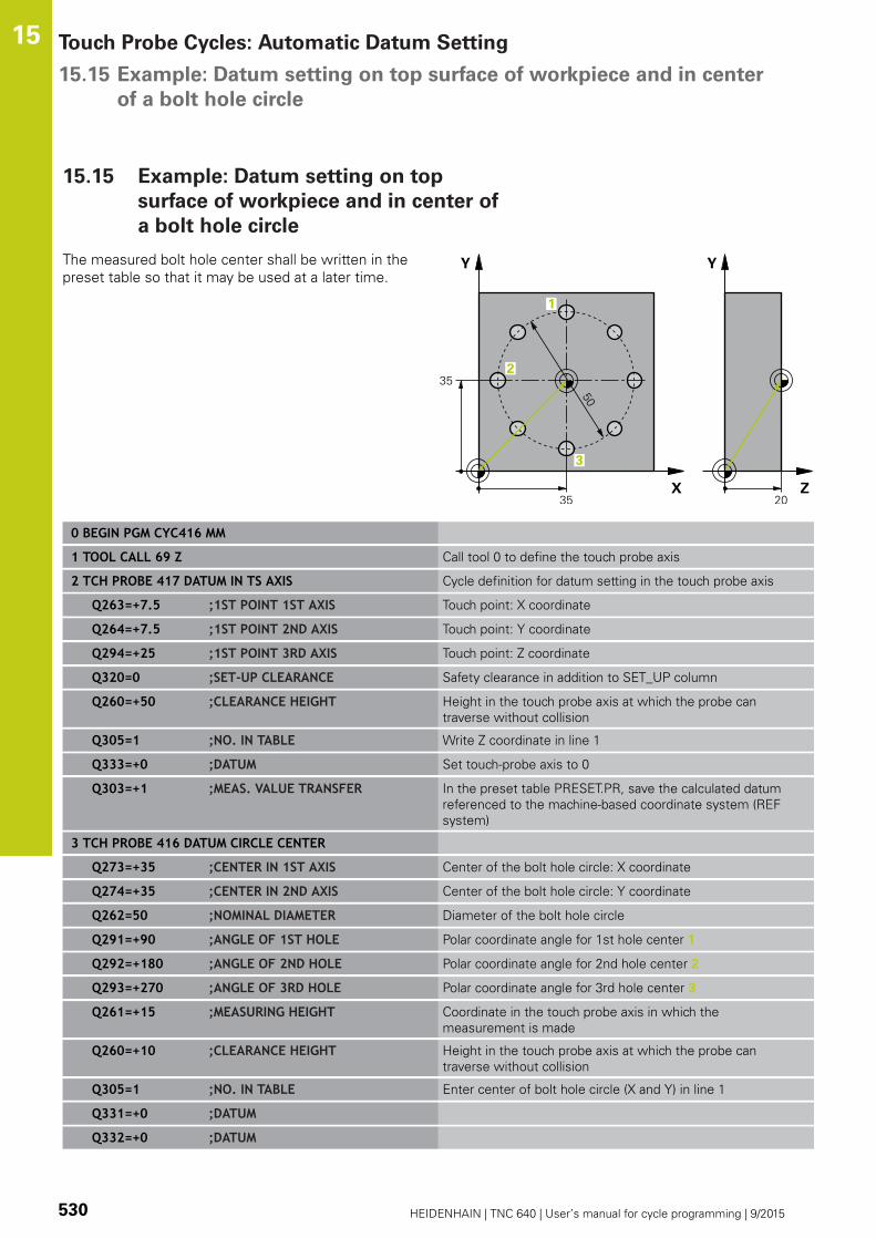
Touch Probe Cycles: Automatic Datum Setting 15.15 Example: Datum setting on top surface of workpiece and in center
of a bolt hole circle
15
530 HEIDENHAIN | TNC 640 | User’s manual for cycle programming | 9/2015
15.15 Example: Datum setting on top
surface of workpiece and in center of
a bolt hole circle
The measured bolt hole center shall be written in the
preset table so that it may be used at a later time.
0 BEGIN PGM CYC416 MM
1 TOOL CALL 69 Z Call tool 0 to define the touch probe axis
2 TCH PROBE 417 DATUM IN TS AXIS Cycle definition for datum setting in the touch probe axis
Q263=+7.5 ;1ST POINT 1ST AXIS Touch point: X coordinate
Q264=+7.5 ;1ST POINT 2ND AXIS Touch point: Y coordinate
Q294=+25 ;1ST POINT 3RD AXIS Touch point: Z coordinate
Q320=0 ;SET-UP CLEARANCE Safety clearance in addition to SET_UP column
Q260=+50 ;CLEARANCE HEIGHT Height in the touch probe axis at which the probe can
traverse without collision
Q305=1 ;NO. IN TABLE Write Z coordinate in line 1
Q333=+0 ;DATUM Set touch-probe axis to 0
Q303=+1 ;MEAS. VALUE TRANSFER In the preset table PRESET.PR, save the calculated datum
referenced to the machine-based coordinate system (REF
system)
3 TCH PROBE 416 DATUM CIRCLE CENTER
Q273=+35 ;CENTER IN 1ST AXIS Center of the bolt hole circle: X coordinate
Q274=+35 ;CENTER IN 2ND AXIS Center of the bolt hole circle: Y coordinate
Q262=50 ;NOMINAL DIAMETER Diameter of the bolt hole circle
Q291=+90 ;ANGLE OF 1ST HOLE Polar coordinate angle for 1st hole center 1
Q292=+180 ;ANGLE OF 2ND HOLE Polar coordinate angle for 2nd hole center 2
Q293=+270 ;ANGLE OF 3RD HOLE Polar coordinate angle for 3rd hole center 3
Q261=+15 ;MEASURING HEIGHT Coordinate in the touch probe axis in which the
measurement is made
Q260=+10 ;CLEARANCE HEIGHT Height in the touch probe axis at which the probe can
traverse without collision
Q305=1 ;NO. IN TABLE Enter center of bolt hole circle (X and Y) in line 1
Q331=+0 ;DATUM
Q332=+0 ;DATUM
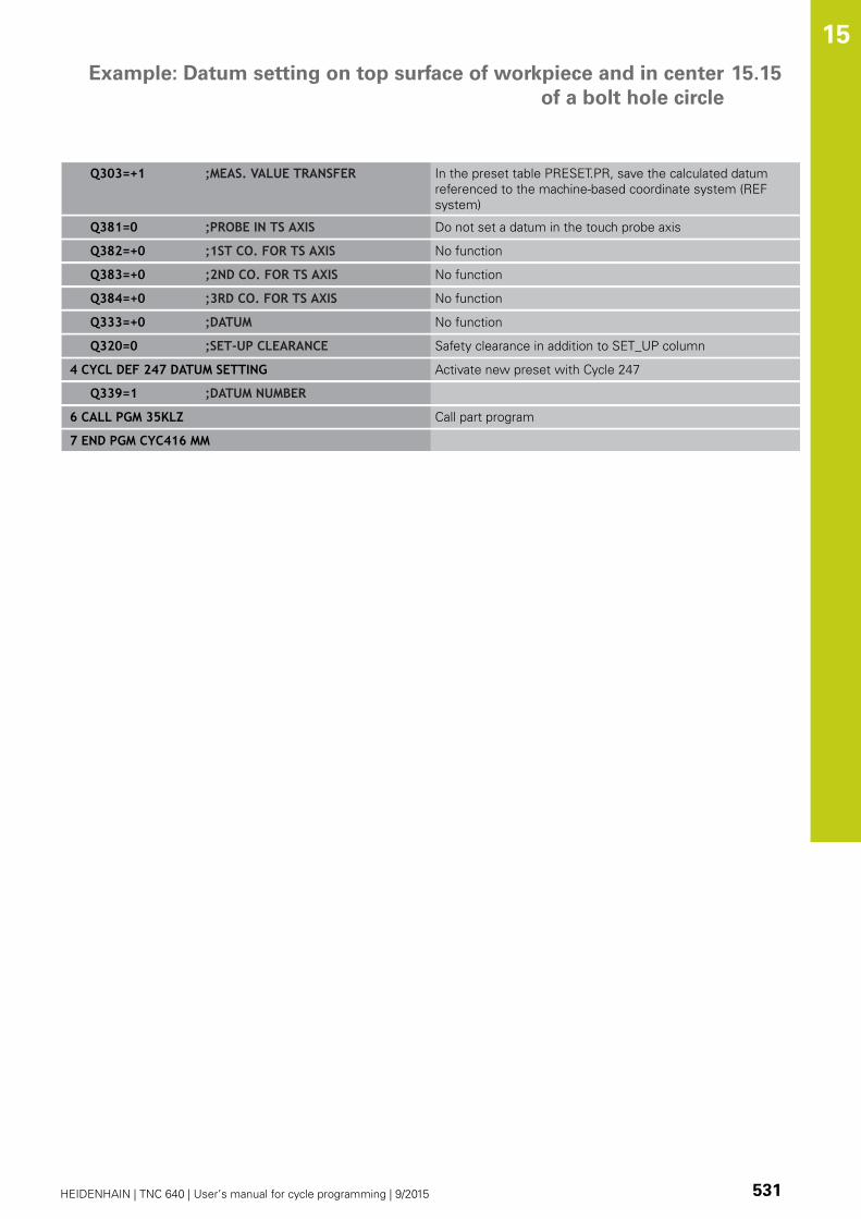
Example: Datum setting on top surface of workpiece and in center
of a bolt hole circle
15.15
15
HEIDENHAIN | TNC 640 | User’s manual for cycle programming | 9/2015 531
Q303=+1 ;MEAS. VALUE TRANSFER In the preset table PRESET.PR, save the calculated datum
referenced to the machine-based coordinate system (REF
system)
Q381=0 ;PROBE IN TS AXIS Do not set a datum in the touch probe axis
Q382=+0 ;1ST CO. FOR TS AXIS No function
Q383=+0 ;2ND CO. FOR TS AXIS No function
Q384=+0 ;3RD CO. FOR TS AXIS No function
Q333=+0 ;DATUM No function
Q320=0 ;SET-UP CLEARANCE Safety clearance in addition to SET_UP column
4 CYCL DEF 247 DATUM SETTING Activate new preset with Cycle 247
Q339=1 ;DATUM NUMBER
6 CALL PGM 35KLZ Call part program
7 END PGM CYC416 MM


16Touch Probe
Cycles: AutomaticWorkpieceInspection
Touch Probe Cycles: Automatic Workpiece Inspection 16.1 Fundamentals
16
534 HEIDENHAIN | TNC 640 | User’s manual for cycle programming | 9/2015
16.1 Fundamentals
Overview
When running touch probe cycles, Cycle 8 MIRROR
IMAGE, Cycle 11 SCALING and Cycle 26 AXIS-
SPECIFIC SCALING must not be active.
HEIDENHAIN only warrants the function of the touch
probe cycles if HEIDENHAIN touch probes are used.
The TNC must be specially prepared by the machine
tool builder for the use of a 3-D touch probe.
Refer to your machine manual.
The TNC offers twelve cycles for measuring workpieces
automatically.
Soft key Cycle Page
0 REFERENCE PLANE
Measuring a coordinate in a
selectable axis
540
1 POLAR DATUM PLANE
Measuring a point in a probing
direction
541
420 MEASURE ANGLE
Measuring an angle in the working
plane
542
421 MEASURE HOLE
Measuring the position and diameter
of a hole
545
422 MEASURE CIRCLE OUTSIDE
Measuring the position and diameter
of a circular stud
550
423 MEASURE RECTANGLE INSIDE
Measuring the position, length and
width of a rectangular pocket
555
424 MEASURE RECTANGLE
OUTSIDE
Measuring the position, length and
width of a rectangular stud
558
425 MEASURE INSIDE WIDTH
(2nd soft-key level) Measuring slot
width
561
426 MEASURE RIDGE WIDTH
(2nd soft-key row) Measuring the
width of a ridge
564

Fundamentals 16.1
16
HEIDENHAIN | TNC 640 | User’s manual for cycle programming | 9/2015 535
Soft key Cycle Page
427 MEASURE COORDINATE
(2nd soft-key row) Measuring any
coordinate in a selectable axis
567
430 MEASURE BOLT HOLE CIRCLE
(2nd soft-key row) Measuring position
and diameter of a bolt hole circle
570
431 MEASURE PLANE
(2nd soft-key row) Measuring the A
and B axis angles of a plane
573
Recording the results of measurement
For all cycles in which you automatically measure workpieces (with
the exception of Cycles 0 and 1), you can have the TNC record
the measurement results. In the respective probing cycle you can
define if the TNC is to
Save the measuring log to a file
Interrupt program run and display the measuring log on the
screen
Create no measuring log
If you want to save the measuring log to a file the TNC, by default,
saves the data as an ASCII file. The TNC will save the file in the
directory that also contains the associated NC program.
Use the HEIDENHAIN data transfer software
TNCRemo if you wish to output the measuring log
over the data interface.

Touch Probe Cycles: Automatic Workpiece Inspection 16.1 Fundamentals
16
536 HEIDENHAIN | TNC 640 | User’s manual for cycle programming | 9/2015
Example: Measuring log for touch probe cycle 421:
Measuring log for Probing Cycle 421 Hole Measuring
Date: 30-06-2005
Time: 6:55:04
Measuring program: TNC:\GEH35712\CHECK1.H
Nominal values:
Center in reference axis: 50.0000
Center in minor axis: 65.0000
Diameter: 12.0000
Given limit values:
Maximum limit for center in reference axis: 50.1000
Minimum limit for center in reference axis: 49.9000
Maximum limit for center in minor axis: 65.1000
Minimum limit for center in minor axis: 64.9000
Maximum dimension for hole: 12.0450
Minimum dimension for hole: 12.0000
Actual values:
Center in reference axis: 50.0810
Center in minor axis: 64.9530
Diameter: 12.0259
Deviations:
Center in reference axis: 0.0810
Center in minor axis: -0.0470
Diameter: 0.0259
Further measuring results: Measuring
height:
-5.0000
End of measuring log
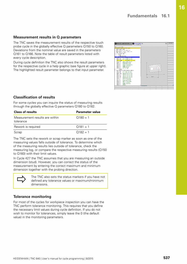
Fundamentals 16.1
16
HEIDENHAIN | TNC 640 | User’s manual for cycle programming | 9/2015 537
Measurement results in Q parameters
The TNC saves the measurement results of the respective touch
probe cycle in the globally effective Q parameters Q150 to Q160.
Deviations from the nominal value are saved in the parameters
Q161 to Q166. Note the table of result parameters listed with
every cycle description.
During cycle definition the TNC also shows the result parameters
for the respective cycle in a help graphic (see figure at upper right).
The highlighted result parameter belongs to that input parameter.
Classification of results
For some cycles you can inquire the status of measuring results
through the globally effective Q parameters Q180 to Q182.
Class of results Parameter value
Measurement results are within
tolerance
Q180 = 1
Rework is required Q181 = 1
Scrap Q182 = 1
The TNC sets the rework or scrap marker as soon as one of the
measuring values falls outside of tolerance. To determine which
of the measuring results lies outside of tolerance, check the
measuring log, or compare the respective measuring results (Q150
to Q160) with their limit values.
In Cycle 427 the TNC assumes that you are measuring an outside
dimension (stud). However, you can correct the status of the
measurement by entering the correct maximum and minimum
dimension together with the probing direction.
The TNC also sets the status markers if you have not
defined any tolerance values or maximum/minimum
dimensions.
Tolerance monitoring
For most of the cycles for workpiece inspection you can have the
TNC perform tolerance monitoring. This requires that you define
the necessary limit values during cycle definition. If you do not
wish to monitor for tolerances, simply leave the 0 (the default
value) in the monitoring parameters.

Touch Probe Cycles: Automatic Workpiece Inspection 16.1 Fundamentals
16
538 HEIDENHAIN | TNC 640 | User’s manual for cycle programming | 9/2015
Tool monitoring
For some cycles for workpiece inspection you can have the TNC
perform tool monitoring. The TNC then monitors whether
The tool radius should be compensated because of the
deviations from the nominal value (values in Q16x).
The deviations from the nominal value (values in Q16x) are
greater than the tool breakage tolerance.
Tool compensation
This function works only:
If the tool table is active.
If tool monitoring is switched on in the cycle
(enter a tool name or Q330 unequal to 0). Select
the tool name input by soft key. The TNC no
longer displays the right single quotation mark.
If you perform several compensation measurements,
the TNC adds the respective measured deviation to
the value stored in the tool table.
Milling tool: If you reference parameter Q330 to a milling tool,
the appropriate values are compensated in the following way: the
TNC basically always compensates the tool radius in column DR of
the tool table, even if the measured deviation is within the stated
tolerance. You can inquire whether re-working is necessary via
parameter Q181 in the NC program (Q181=1: must be reworked).
Turning tool: (applies to cycles 421, 422, 427 only) If you reference
parameter Q330 to a turning tool, the appropriate values in row
DZL and DXL, respectively, are compensated. The TNC monitors
the breakage tolerance which is defined in column LBREAK. You
can inquire whether re-working is necessary via parameter Q181 in
the NC program (Q181=1: must be reworked).
Fundamentals 16.1
16
HEIDENHAIN | TNC 640 | User’s manual for cycle programming | 9/2015 539
Tool breakage monitoring
This function works only:
If the tool table is active.
If tool monitoring is switched on in the cycle
(enter Q330 not equal to 0).
If the breakage tolerance RBREAK for the tool
number entered in the table is greater than 0 (see
also the User's Manual, section 5.2 "Tool Data").
The TNC will output an error message and stop program run if the
measured deviation is greater than the breakage tolerance of the
tool. At the same time the tool will be deactivated in the tool table
(column TL = L).
Reference system for measurement results
The TNC transfers all the measurement results to the result
parameters and the log file in the active coordinate system, or
as the case may be, the shifted and/or rotated/tilted coordinate
system.

Touch Probe Cycles: Automatic Workpiece Inspection 16.2 DATUM PLANE (Cycle 0, DIN/ISO: G55)
16
540 HEIDENHAIN | TNC 640 | User’s manual for cycle programming | 9/2015
16.2 DATUM PLANE (Cycle 0, DIN/ISO:
G55)
Cycle run
1 The touch probe moves at rapid traverse (value from FMAXcolumn) to the starting position 1 programmed in the cycle.
2 Then the touch probe runs the probing process at the probing
feed rate (column F). The probing direction is defined in the
cycle.
3 After the TNC has saved the position, the probe retracts to
the starting point and saves the measured coordinate in a
Q parameter. The TNC also stores the coordinates of the
touch probe position at the time of the triggering signal in the
parameters Q115 to Q119. For the values in these parameters
the TNC does not account for the stylus length and radius.
Please note while programming:
Danger of collision!
Pre-position the touch probe in order to avoid a
collision when the programmed pre-positioning point
is approached.
Cycle parameters
Parameter number for result: Enter the number
of the Q parameter to which you want to assign the
coordinate. Input range 0 to 1999
Probing axis/Probing direction: Enter the probing
axis with the axis selection keys or ASCII keyboard
and the algebraic sign for the probing direction.
Confirm your entry with the ENT key. Input range:
All NC axes
Nominal position value: Use the axis selection
keys or the ASCII keyboard to enter all coordinates
of the nominal pre-positioning point values for
the touch probe. Input range -99999.9999 to
99999.9999
To conclude the input, press the ENT key.
NC blocks
67 TCH PROBE 0.0 REF. PLANE Q5 X-
68 TCH PROBE 0.1 X+5 Y+0 Z-5

POLAR DATUM PLANE (Cycle 1) 16.3
16
HEIDENHAIN | TNC 640 | User’s manual for cycle programming | 9/2015 541
16.3 POLAR DATUM PLANE (Cycle 1)
Cycle run
Touch Probe Cycle 1 measures any position on the workpiece in
any direction.
1 The touch probe moves at rapid traverse (value from FMAXcolumn) to the starting position 1 programmed in the cycle.
2 Then the touch probe runs the probing process at the
probing feed rate (column F). During probing the TNC moves
simultaneously in two axes (depending on the probing angle).
The probing direction is defined by the polar angle entered in
the cycle.
3 After the TNC has saved the position, the probe returns to the
starting point. The TNC also stores the coordinates of the touch
probe position at the time of the triggering signal in parameters
Q115 to Q119.
Please note while programming:
Danger of collision!
Pre-position the touch probe in order to avoid a
collision when the programmed pre-positioning point
is approached.
The probing axis defined in the cycle specifies the
probing plane:
Probing axis X: X/Y plane
Probing axis Y: Y/Z plane
Probing axis Z: Z/X plane
Cycle parameters
Probing axis: Enter the probing axis with the axis
selection keys or ASCII keyboard. Confirm your
entry with the ENT key. Input range: X, Y or ZProbing angle: Angle, measured from the probing
axis, at which the touch probe is to move. Input
range -180.0000 to 180.0000
Nominal position value: Use the axis selection
keys or the ASCII keyboard to enter all coordinates
of the nominal pre-positioning point values for
the touch probe. Input range -99999.9999 to
99999.9999
To conclude the input, press the ENT key.
NC blocks
67 TCH PROBE 1.0 POLAR REFERENCEPLANE
68 TCH PROBE 1.1 X ANGLE: +30
69 TCH PROBE 1.2 X+5 Y+0 Z-5

Touch Probe Cycles: Automatic Workpiece Inspection 16.4 MEASURE ANGLE (Cycle 420, DIN/ISO: G420)
16
542 HEIDENHAIN | TNC 640 | User’s manual for cycle programming | 9/2015
16.4 MEASURE ANGLE (Cycle 420,
DIN/ISO: G420)
Cycle run
Touch Probe Cycle 420 measures the angle that any straight
surface on the workpiece describes with respect to the reference
axis of the working plane.
1 Following the positioning logic, the TNC positions the touch
probe at rapid traverse (value from FMAX column) (see
"Executing touch probe cycles", page 454) to the programmed
touch point 1. The TNC offsets the touch probe by the safety
clearance in the direction opposite to the defined traverse
direction.
2 Then the touch probe moves to the entered measuring height
and runs the first probing process at the probing feed rate
(column F).
3 Then the touch probe moves to the next starting position 2 and
from there probes the second position.
4 The TNC returns the touch probe to the clearance height and
saves the measured angle in the following Q parameter:
Parameter number Meaning
Q150 The measured angle is referenced to
the reference axis of the machining
plane.
Please note while programming:
Before a cycle definition you must have programmed
a tool call to define the touch probe axis.
If touch probe axis = measuring axis, set Q263equal to Q265 if the angle about the A axis is to be
measured; set Q263 not equal to Q265 if the angle is
to be measured about the B axis.

MEASURE ANGLE (Cycle 420, DIN/ISO: G420) 16.4
16
HEIDENHAIN | TNC 640 | User’s manual for cycle programming | 9/2015 543
Cycle parameters
1st meas. point 1st axis Q263 (absolute):
Coordinate of the first touch point in the reference
axis of the working plane. Input range -99999.9999
to 99999.9999
1st meas. point 2nd axis Q264 (absolute):
Coordinate of the first touch point in the minor axis
of the working plane. Input range -99999.9999 to
99999.9999
2nd meas. point 1st axis Q265 (absolute):
Coordinate of the second touch point in the
reference axis of the working plane. Input range
-99999.9999 to 99999.9999
2nd meas. point 2nd axis Q266 (absolute):
Coordinate of the second touch point in the minor
axis of the working plane. Input range -99999.9999
to 99999.9999
Measuring axis Q272: Axis in which the
measurement is to be made:
1: Reference axis = measuring axis
2: Minor axis = measuring axis
3: Touch probe axis = measuring axis
Traverse direction 1 Q267: Direction in which the
probe is to approach the workpiece:
-1: Negative traverse direction
+1: Positive traverse direction
Measuring height in the touch probe axis Q261
(absolute): Coordinate of the ball tip center (=
touch point) in the touch probe axis in which
the measurement is to be made. Input range
-99999.9999 to 99999.9999
Set-up clearance Q320 (incremental): Additional
distance between measuring point and ball tip.
Q320 is added to SET_UP (touch probe table). Input
range 0 to 99999.9999
Clearance height Q260 (absolute): Coordinate in
the touch probe axis at which no collision between
touch probe and workpiece (fixtures) can occur.
Input range -99999.9999 to 99999.9999
Traversing to clearance height Q301: Definition
of how the touch probe is to move between the
measuring points:
0: Move at measuring height between measuring
points
1: Move at clearance height between measuring
points
NC blocks
5 TCH PROBE 420 MEASURE ANGLE
Q263=+10 ;1ST POINT 1ST AXIS
Q264=+10 ;1ST POINT 2ND AXIS
Q265=+15 ;2ND POINT 1ST AXIS
Q266=+95 ;2ND POINT 2ND AXIS
Q272=1 ;MEASURING AXIS
Q267=-1 ;TRAVERSE DIRECTION
Q261=-5 ;MEASURING HEIGHT
Q320=0 ;SET-UP CLEARANCE
Q260=+10 ;CLEARANCE HEIGHT
Q301=1 ;MOVE TO CLEARANCE
Q281=1 ;MEASURING LOG
Touch Probe Cycles: Automatic Workpiece Inspection 16.4 MEASURE ANGLE (Cycle 420, DIN/ISO: G420)
16
544 HEIDENHAIN | TNC 640 | User’s manual for cycle programming | 9/2015
Measuring log Q281: Define whether the TNC
should create a measuring log:
0: Do not create a measuring log
1: Create a measuring log: The TNC saves the log
file TCHPR420.TXT as standard in the directory
TNC:\.
2: Interrupt program run and output measuring log
to the TNC screen. Resume program run with NC
Start.
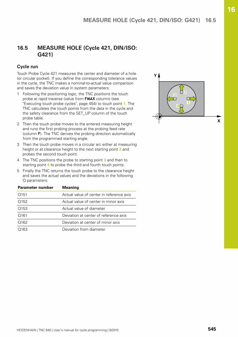
MEASURE HOLE (Cycle 421, DIN/ISO: G421) 16.5
16
HEIDENHAIN | TNC 640 | User’s manual for cycle programming | 9/2015 545
16.5 MEASURE HOLE (Cycle 421, DIN/ISO:
G421)
Cycle run
Touch Probe Cycle 421 measures the center and diameter of a hole
(or circular pocket). If you define the corresponding tolerance values
in the cycle, the TNC makes a nominal-to-actual value comparison
and saves the deviation value in system parameters.
1 Following the positioning logic, the TNC positions the touch
probe at rapid traverse (value from FMAX column) (see
"Executing touch probe cycles", page 454) to touch point 1. The
TNC calculates the touch points from the data in the cycle and
the safety clearance from the SET_UP column of the touch
probe table.
2 Then the touch probe moves to the entered measuring height
and runs the first probing process at the probing feed rate
(column F). The TNC derives the probing direction automatically
from the programmed starting angle.
3 Then the touch probe moves in a circular arc either at measuring
height or at clearance height to the next starting point 2 and
probes the second touch point.
4 The TNC positions the probe to starting point 3 and then to
starting point 4 to probe the third and fourth touch points.
5 Finally the TNC returns the touch probe to the clearance height
and saves the actual values and the deviations in the following
Q parameters:
Parameter number Meaning
Q151 Actual value of center in reference axis
Q152 Actual value of center in minor axis
Q153 Actual value of diameter
Q161 Deviation at center of reference axis
Q162 Deviation at center of minor axis
Q163 Deviation from diameter

Touch Probe Cycles: Automatic Workpiece Inspection 16.5 MEASURE HOLE (Cycle 421, DIN/ISO: G421)
16
546 HEIDENHAIN | TNC 640 | User’s manual for cycle programming | 9/2015
Please note while programming:
Before a cycle definition you must have programmed
a tool call to define the touch probe axis.
The smaller the angle, the less accurately the TNC
can calculate the hole dimensions. Minimum input
value: 5°
If you reference parameter Q330 to a turning tool,
the following applies:
– Parameters Q498 and Q531 have to be described
– The information of the parameters Q498, Q531,
for example from Cycle 800, has to match this
information
– If the TNC compensates the turning tool,
the appropriate values in line DZL and DXL,
respectively, are compensated.
– The TNC monitors the breakage tolerance which
is defined in column LBREAK
If you reference parameter Q330 to a milling tool, the
information of the parameters Q498 and Q531 has
no effect

MEASURE HOLE (Cycle 421, DIN/ISO: G421) 16.5
16
HEIDENHAIN | TNC 640 | User’s manual for cycle programming | 9/2015 547
Cycle parameters
Center in 1st axis Q273 (absolute): Center of the
hole in the reference axis of the working plane.
Input range -99999.9999 to 99999.9999
Center in 2nd axis Q274 (absolute value): Center
of the hole in the minor axis of the working plane.
Input range -99999.9999 to 99999.9999
Nominal diameter Q262: Enter the diameter of the
hole. Input range 0 to 99999.9999
Starting angle Q325 (absolute): Angle between the
reference axis of the working plane and the first
touch point. Input range -360.000 to 360.000
Stepping angle Q247 (incremental): Angle between
two measuring points. The algebraic sign of the
stepping angle determines the direction of rotation
(negative = clockwise) in which the touch probe
moves to the next measuring point. If you wish to
probe a circular arc instead of a complete circle,
then program the stepping angle to be less than
90°. Input range -120.000 to 120.000
Measuring height in the touch probe axis Q261
(absolute): Coordinate of the ball tip center (=
touch point) in the touch probe axis in which
the measurement is to be made. Input range
-99999.9999 to 99999.9999
Set-up clearance Q320 (incremental): Additional
distance between measuring point and ball tip.
Q320 is added to SET_UP (touch probe table). Input
range 0 to 99999.9999
Clearance height Q260 (absolute): Coordinate in
the touch probe axis at which no collision between
touch probe and workpiece (fixtures) can occur.
Input range -99999.9999 to 99999.9999
Traversing to clearance height Q301: definition
of how the touch probe is to move between the
measuring points:
0: Move at measuring height between measuring
points
1: Move at clearance height between measuring
points
Maximum limit of size for hole Q275: Maximum
permissible diameter for the hole (circular pocket).
Input range 0 to 99999.9999
Minimum limit of size for hole Q276: Minimum
permissible diameter for the hole (circular pocket).
Input range 0 to 99999.9999
Tolerance for center 1st axis Q279: Permissible
position deviation in the reference axis of the
working plane. Input range 0 to 99999.9999
Tolerance for center 2nd axis Q280: Permissible
position deviation in the minor axis of the working
plane. Input range 0 to 99999.9999
NC blocks
5 TCH PROBE 421 MEASURE HOLE
Q273=+50 ;CENTER IN 1ST AXIS
Q274=+50 ;CENTER IN 2ND AXIS
Q262=75 ;NOMINAL DIAMETER
Q325=+0 ;STARTING ANGLE
Q247=+60 ;STEPPING ANGLE
Q261=-5 ;MEASURING HEIGHT
Q320=0 ;SET-UP CLEARANCE
Q260=+20 ;CLEARANCE HEIGHT
Q301=1 ;MOVE TO CLEARANCE
Q275=75.12;MAXIMUM DIMENSION
Q276=74.95;MINIMUM DIMENSION
Q279=0.1 ;TOLERANCE 1STCENTER
Q280=0.1 ;TOLERANCE 2NDCENTER
Q281=1 ;MEASURING LOG
Q309=0 ;PGM STOP IF ERROR
Q330=0 ;TOOL
Q423=4 ;NO. OF PROBE POINTS
Q365=1 ;TYPE OF TRAVERSE
Q498=0 ;REVERSE TOOL
Q531=0 ;INCLINED ANGLE

Touch Probe Cycles: Automatic Workpiece Inspection 16.5 MEASURE HOLE (Cycle 421, DIN/ISO: G421)
16
548 HEIDENHAIN | TNC 640 | User’s manual for cycle programming | 9/2015
Measuring log Q281: Definition of whether TNC
should create a measuring log:
0: Create no measuring log
1: Create measuring log: The TNC will save the log
file TCHPR421.TXT by default in the directory that
also contains the associated NC program.
2: Interrupt the program run and display the
measuring log on the TNC screen. Resume program
run with NC Start.
PGM stop if tolerance error Q309: Definition of
whether in the event of a violation of tolerance
limits the TNC is to interrupt program run and output
an error message:
0: Do not interrupt program run, do not output an
error message
1: Interrupt program run and output an error
message
Tool for monitoring Q330: Definition of
whether the TNC is to monitor the tool (see
"Tool monitoring", page 538). Enter 0 to 32767.9,
optionally the tool name with up to 16 characters
0: Monitoring not active
>0: Number or name of the tool the TNC used to
perform the operation with. You are able to apply a
tool via soft key directly from the tool table.
No. of measuring points (4/3) Q423: Specify
whether the TNC should measure the stud with 4 or
3 probing points:
4: Use 4 measuring points (default setting)
3: Use 3 measuring points
Type of traverse? Line=0/Arc=1 Q365: Definition
of the path function with which the tool is to move
between the measuring points if "traverse to
clearance height" (Q301=1) is active:
0: Move in a straight line between machining
operations
1: Move in a circular arc on the pitch circle diameter
between machining operations

MEASURE HOLE (Cycle 421, DIN/ISO: G421) 16.5
16
HEIDENHAIN | TNC 640 | User’s manual for cycle programming | 9/2015 549
Reverse tool (0=no/1=yes)? Q498: Only relevant
if you have entered a turning tool in parameter
Q330 before. For proper monitoring of the turning
tool, the TNC requires the exact working condition.
Therefore, enter the following:
1: Turning tool is mirrored (rotated by 180°) e.g. by
Cycle 800 and parameter Reverse the tool Q498=1
0: Turning tool matches the description of the
turning tool table toolturn.trn, no modifications,
e.g. via Cycle 800 and parameter Reverse the toolQ498=0
Angle of incidence? Q531: Only relevant if you have
entered a turning tool in parameter Q330 before.
Enter the angle of incidence between the turning
tool and the work piece during machining, e.g. from
Cycle 800 parameter Angle of incidence? Q531.
Input range: -180° to +180°

Touch Probe Cycles: Automatic Workpiece Inspection 16.6 MEASURE HOLE OUTSIDE (Cycle 422, DIN/ISO: G422)
16
550 HEIDENHAIN | TNC 640 | User’s manual for cycle programming | 9/2015
16.6 MEASURE HOLE OUTSIDE
(Cycle 422, DIN/ISO: G422)
Cycle run
Touch Probe Cycle 422 measures the center and diameter of a
circular stud. If you define the corresponding tolerance values in
the cycle, the TNC makes a nominal-to-actual value comparison and
saves the deviation value in system parameters.
1 Following the positioning logic, the TNC positions the touch
probe at rapid traverse (value from FMAX column) (see
"Executing touch probe cycles", page 454) to touch point 1. The
TNC calculates the touch points from the data in the cycle and
the safety clearance from the SET_UP column of the touch
probe table.
2 Then the touch probe moves to the entered measuring height
and runs the first probing process at the probing feed rate
(column F). The TNC derives the probing direction automatically
from the programmed starting angle.
3 Then the touch probe moves in a circular arc either at measuring
height or at clearance height to the next starting point 2 and
probes the second touch point.
4 The TNC positions the probe to starting point 3 and then to
starting point 4 to probe the third and fourth touch points.
5 Finally the TNC returns the touch probe to the clearance height
and saves the actual values and the deviations in the following
Q parameters:
Parameter number Meaning
Q151 Actual value of center in reference axis
Q152 Actual value of center in minor axis
Q153 Actual value of diameter
Q161 Deviation at center of reference axis
Q162 Deviation at center of minor axis
Q163 Deviation from diameter
MEASURE HOLE OUTSIDE (Cycle 422, DIN/ISO: G422) 16.6
16
HEIDENHAIN | TNC 640 | User’s manual for cycle programming | 9/2015 551
Please note while programming:
Before a cycle definition you must have programmed
a tool call to define the touch probe axis.
The smaller the angle, the less accurately the TNC
can calculate the dimensions of the stud. Minimum
input value: 5°
If you reference parameter Q330 to a turning tool,
the following applies:
– Parameters Q498 and Q531 have to be described
– The information of the parameters Q498, Q531,
for example from Cycle 800, has to match this
information
– If the TNC compensates the turning tool,
the appropriate values in line DZL and DXL,
respectively, are compensated.
– The TNC monitors the breakage tolerance which
is defined in column LBREAK
If you reference parameter Q330 to a milling tool, the
information of the parameters Q498 and Q531 has
no effect

Touch Probe Cycles: Automatic Workpiece Inspection 16.6 MEASURE HOLE OUTSIDE (Cycle 422, DIN/ISO: G422)
16
552 HEIDENHAIN | TNC 640 | User’s manual for cycle programming | 9/2015
Cycle parameters
Center in 1st axis Q273 (absolute): Center of the
stud in the reference axis of the working plane.
Input range -99999.9999 to 99999.9999
Center in 2nd axis Q274 (absolute): Center of the
stud in the minor axis of the working plane. Input
range -99999.9999 to 99999.9999
Nominal diameter Q262: Enter the diameter of the
stud. Input range 0 to 99999.9999
Starting angle Q325 (absolute): Angle between the
reference axis of the working plane and the first
touch point. Input range -360.0000 to 360.0000
Stepping angle Q247 (incremental): Angle between
two measuring points. The algebraic sign of the
stepping angle determines the direction of rotation
(negative = clockwise). If you wish to probe a
circular arc instead of a complete circle, then
program the stepping angle to be less than 90°.
Input range -120.0000 to 120.0000
Measuring height in the touch probe axis Q261
(absolute): Coordinate of the ball tip center (=
touch point) in the touch probe axis in which
the measurement is to be made. Input range
-99999.9999 to 99999.9999
Set-up clearance Q320 (incremental): Additional
distance between measuring point and ball tip.
Q320 is added to SET_UP (touch probe table). Input
range 0 to 99999.9999
Clearance height Q260 (absolute): Coordinate in
the touch probe axis at which no collision between
touch probe and workpiece (fixtures) can occur.
Input range -99999.9999 to 99999.9999
Traversing to clearance height Q301: Definition
of how the touch probe is to move between the
measuring points:
0: Move at measuring height between measuring
points
1: Move at clearance height between measuring
points
Maximum limit of size for stud Q277: Maximum
permissible diameter for the stud. Input range 0 to
99999.9999
Minimum limit of size for the stud Q278:
Minimum permissible diameter for the stud. Input
range 0 to 99999.9999
NC blocks
5 TCH PROBE 422 MEAS. CIRCLEOUTSIDE
Q273=+50 ;CENTER IN 1ST AXIS
Q274=+50 ;CENTER IN 2ND AXIS
Q262=75 ;NOMINAL DIAMETER
Q325=+90 ;STARTING ANGLE
Q247=+30 ;STEPPING ANGLE
Q261=-5 ;MEASURING HEIGHT
Q320=0 ;SET-UP CLEARANCE
Q260=+10 ;CLEARANCE HEIGHT
Q301=0 ;MOVE TO CLEARANCE
Q275=35.15;MAXIMUM DIMENSION
Q276=34.9 ;MINIMUM DIMENSION
Q279=0.05 ;TOLERANCE 1STCENTER

MEASURE HOLE OUTSIDE (Cycle 422, DIN/ISO: G422) 16.6
16
HEIDENHAIN | TNC 640 | User’s manual for cycle programming | 9/2015 553
Tolerance for center 1st axis Q279: Permissible
position deviation in the reference axis of the
working plane. Input range 0 to 99999.9999
Tolerance for center 2nd axis Q280: Permissible
position deviation in the minor axis of the working
plane. Input range 0 to 99999.9999
Measuring log Q281: Define whether the TNC
should create a measuring log:
0: Do not create a measuring log
1: Create a measuring log: The TNC saves the log
file TCHPR422.TXT as standard in the directory
TNC:\.
2: Interrupt program run and output measuring log
to the TNC screen. Resume program run with NC
Start.
PGM stop if tolerance error Q309: Definition of
whether in the event of a violation of tolerance
limits the TNC is to interrupt program run and output
an error message:
0: Do not interrupt program run, do not output an
error message
1: Interrupt program run and output an error
message
Tool for monitoring Q330: Definition of whether
the TNC is to monitor the tool (see "Tool
monitoring", page 538). Input range 0 to 32767.9,
alternatively tool name with up to 16 characters
0: Monitoring inactive
> 0: Tool number in the tool table TOOL.T
No. of measuring points (4/3) Q423: Specify
whether the TNC should measure the stud with 4 or
3 probing points:
4: Use 4 measuring points (default setting)
3: Use 3 measuring points
Type of traverse? Line=0/Arc=1 Q365: Definition
of the path function with which the tool is to move
between the measuring points if "traverse to
clearance height" (Q301=1) is active:
0: Move in a straight line between machining
operations
1: Move in a circular arc on the pitch circle diameter
between machining operations
Q280=0.05 ;TOLERANCE 2NDCENTER
Q281=1 ;MEASURING LOG
Q309=0 ;PGM STOP IF ERROR
Q330=0 ;TOOL
Q423=4 ;NO. OF PROBE POINTS
Q365=1 ;TYPE OF TRAVERSE
Q498=0 ;REVERSE TOOL
Q531=0 ;INCLINED ANGLE
Touch Probe Cycles: Automatic Workpiece Inspection 16.6 MEASURE HOLE OUTSIDE (Cycle 422, DIN/ISO: G422)
16
554 HEIDENHAIN | TNC 640 | User’s manual for cycle programming | 9/2015
Reverse tool (0=no/1=yes)? Q498: Only relevant
if you have entered a turning tool in parameter
Q330 before. For proper monitoring of the turning
tool, the TNC requires the exact working condition.
Therefore, enter the following:
1: Turning tool is mirrored (rotated by 180°) e.g. by
Cycle 800 and parameter Reverse the tool Q498=1
0: Turning tool matches the description of the
turning tool table toolturn.trn, no modifications,
e.g. via Cycle 800 and parameter Reverse the toolQ498=0
Angle of incidence? Q531: Only relevant if you have
entered a turning tool in parameter Q330 before.
Enter the angle of incidence between the turning
tool and the work piece during machining, e.g. from
Cycle 800 parameter Angle of incidence? Q531.
Input range: -180° to +180°

MEASURE RECTANGLE INSIDE (Cycle 423, DIN/ISO: G423) 16.7
16
HEIDENHAIN | TNC 640 | User’s manual for cycle programming | 9/2015 555
16.7 MEASURE RECTANGLE INSIDE
(Cycle 423, DIN/ISO: G423)
Cycle run
Touch Probe Cycle 423 finds the center, length and width of a
rectangular pocket. If you define the corresponding tolerance
values in the cycle, the TNC makes a nominal-to-actual value
comparison and saves the deviation value in system parameters.
1 Following the positioning logic, the TNC positions the touch
probe at rapid traverse (value from FMAX column) (see
"Executing touch probe cycles", page 454) to touch point 1. The
TNC calculates the touch points from the data in the cycle and
the safety clearance from the SET_UP column of the touch
probe table.
2 Then the touch probe moves to the entered measuring height
and runs the first probing process at the probing feed rate
(column F).
3 Then the touch probe moves either paraxially at measuring
height or at clearance height to the next starting point 2 and
probes the second touch point.
4 The TNC positions the probe to starting point 3 and then to
starting point 4 to probe the third and fourth touch points.
5 Finally the TNC returns the touch probe to the clearance height
and saves the actual values and the deviations in the following
Q parameters:
Parameter number Meaning
Q151 Actual value of center in reference axis
Q152 Actual value of center in minor axis
Q154 Actual value of length in the reference
axis
Q155 Actual value of length in the minor axis
Q161 Deviation at center of reference axis
Q162 Deviation at center of minor axis
Q164 Deviation of side length in reference
axis
Q165 Deviation of side length in minor axis
Please note while programming:
Before a cycle definition you must have programmed
a tool call to define the touch probe axis.
If the dimensions of the pocket and the safety
clearance do not permit pre-positioning in the
proximity of the touch points, the TNC always starts
probing from the center of the pocket. In this case
the touch probe does not return to the clearance
height between the four measuring points.

Touch Probe Cycles: Automatic Workpiece Inspection 16.7 MEASURE RECTANGLE INSIDE (Cycle 423, DIN/ISO: G423)
16
556 HEIDENHAIN | TNC 640 | User’s manual for cycle programming | 9/2015
Cycle parameters
Center in 1st axis Q273 (absolute): Center of the
pocket in the reference axis of the working plane.
Input range -99999.9999 to 99999.9999
Center in 2nd axis Q274 (absolute): Center of the
pocket in the minor axis of the working plane. Input
range -99999.9999 to 99999.9999
1st side length Q282: Pocket length, parallel to the
reference axis of the working plane. Input range 0 to
99999.9999
2nd side length Q283: Pocket length, parallel to the
minor axis of the working plane. Input range 0 to
99999.9999
Measuring height in the touch probe axis Q261
(absolute): Coordinate of the ball tip center (=
touch point) in the touch probe axis in which
the measurement is to be made. Input range
-99999.9999 to 99999.9999
Set-up clearance Q320 (incremental): Additional
distance between measuring point and ball tip.
Q320 is added to SET_UP (touch probe table). Input
range 0 to 99999.9999
Clearance height Q260 (absolute): Coordinate in
the touch probe axis at which no collision between
touch probe and workpiece (fixtures) can occur.
Input range -99999.9999 to 99999.9999
Traversing to clearance height Q301: Definition
of how the touch probe is to move between the
measuring points:
0: Move at measuring height between measuring
points
1: Move at clearance height between measuring
points
Max. size limit 1st side length Q284: Maximum
permissible length of the pocket. Input range 0 to
99999.9999
Min. size limit 1st side length Q285: Minimum
permissible length of the pocket. Input range 0 to
99999.9999
Max. size limit 2nd side length Q286: Maximum
permissible width of the pocket. Input range 0 to
99999.9999
Min. size limit 2nd side length Q287: Minimum
permissible width of the pocket. Input range 0 to
99999.9999
Tolerance for center 1st axis Q279: Permissible
position deviation in the reference axis of the
working plane. Input range 0 to 99999.9999
Tolerance for center 2nd axis Q280: Permissible
position deviation in the minor axis of the working
plane. Input range 0 to 99999.9999
NC blocks
5 TCH PROBE 423 MEAS. RECTAN.INSIDE
Q273=+50 ;CENTER IN 1ST AXIS
Q274=+50 ;CENTER IN 2ND AXIS
Q282=80 ;FIRST SIDE LENGTH
Q283=60 ;2ND SIDE LENGTH
Q261=-5 ;MEASURING HEIGHT
Q320=0 ;SET-UP CLEARANCE
Q260=+10 ;CLEARANCE HEIGHT
Q301=1 ;MOVE TO CLEARANCE
Q284=0 ;MAX. LIMIT 1ST SIDE
Q285=0 ;MIN. LIMIT 1ST SIDE
Q286=0 ;MAX. LIMIT 2ND SIDE
Q287=0 ;MIN. LIMIT 2ND SIDE
Q279=0 ;TOLERANCE 1STCENTER
Q280=0 ;TOLERANCE 2NDCENTER
Q281=1 ;MEASURING LOG
Q309=0 ;PGM STOP IF ERROR
Q330=0 ;TOOL

MEASURE RECTANGLE INSIDE (Cycle 423, DIN/ISO: G423) 16.7
16
HEIDENHAIN | TNC 640 | User’s manual for cycle programming | 9/2015 557
Measuring log Q281: Define whether the TNC
should create a measuring log:
0: Do not create a measuring log
1: Create a measuring log: The TNC saves the log
file TCHPR423.TXT as standard in the directory
TNC:\.
2: Interrupt program run and output measuring log
to the TNC screen. Resume program run with NC
Start.
PGM stop if tolerance error Q309: Definition of
whether in the event of a violation of tolerance
limits the TNC is to interrupt program run and output
an error message:
0: Do not interrupt program run, do not output an
error message
1: Interrupt program run and output an error
message
Tool for monitoring Q330: Definition of whether
the TNC is to monitor the tool (see "Tool
monitoring", page 538). Input range 0 to 32767.9,
alternatively tool name with up to 16 characters
0: Monitoring inactive
> 0: Tool number in the tool table TOOL.T

Touch Probe Cycles: Automatic Workpiece Inspection 16.8 MEASURE RECTANGLE OUTSIDE (Cycle 424, DIN/ISO: G424)
16
558 HEIDENHAIN | TNC 640 | User’s manual for cycle programming | 9/2015
16.8 MEASURE RECTANGLE OUTSIDE
(Cycle 424, DIN/ISO: G424)
Cycle run
Touch Probe Cycle 424 finds the center, length and width of a
rectangular stud. If you define the corresponding tolerance values
in the cycle, the TNC makes a nominal-to-actual value comparison
and saves the deviation value in system parameters.
1 Following the positioning logic, the TNC positions the touch
probe at rapid traverse (value from FMAX column) (see
"Executing touch probe cycles", page 454) to touch point 1. The
TNC calculates the touch points from the data in the cycle and
the safety clearance from the SET_UP column of the touch
probe table.
2 Then the touch probe moves to the entered measuring height
and runs the first probing process at the probing feed rate
(column F).
3 Then the touch probe moves either paraxially at measuring
height or at clearance height to the next starting point 2 and
probes the second touch point.
4 The TNC positions the probe to starting point 3 and then to
starting point 4 to probe the third and fourth touch points.
5 Finally the TNC returns the touch probe to the clearance height
and saves the actual values and the deviations in the following
Q parameters:
Parameter number Meaning
Q151 Actual value of center in reference axis
Q152 Actual value of center in minor axis
Q154 Actual value of length in the reference
axis
Q155 Actual value of length in the minor axis
Q161 Deviation at center of reference axis
Q162 Deviation at center of minor axis
Q164 Deviation of side length in reference
axis
Q165 Deviation of side length in minor axis
Please note while programming:
Before a cycle definition you must have programmed
a tool call to define the touch probe axis.

MEASURE RECTANGLE OUTSIDE (Cycle 424, DIN/ISO: G424) 16.8
16
HEIDENHAIN | TNC 640 | User’s manual for cycle programming | 9/2015 559
Cycle parameters
Center in 1st axis Q273 (absolute): Center of the
stud in the reference axis of the working plane.
Input range -99999.9999 to 99999.9999
Center in 2nd axis Q274 (absolute): Center of the
stud in the minor axis of the working plane. Input
range -99999.9999 to 99999.9999
1st side length Q282: Stud length, parallel to the
reference axis of the working plane. Input range 0 to
99999.9999
2nd side length Q283: Stud length, parallel to the
minor axis of the working plane. Input range 0 to
99999.9999
Measuring height in the touch probe axis Q261
(absolute): Coordinate of the ball tip center (=
touch point) in the touch probe axis in which
the measurement is to be made. Input range
-99999.9999 to 99999.9999
Set-up clearance Q320 (incremental): Additional
distance between measuring point and ball tip.
Q320 is added to SET_UP (touch probe table). Input
range 0 to 99999.9999
Clearance height Q260 (absolute): Coordinate in
the touch probe axis at which no collision between
touch probe and workpiece (fixtures) can occur.
Input range -99999.9999 to 99999.9999
Traversing to clearance height Q301: Definition
of how the touch probe is to move between the
measuring points:
0: Move at measuring height between measuring
points
1: Move at clearance height between measuring
points
Max. size limit 1st side length Q284: Maximum
permissible length of the stud. Input range 0 to
99999.9999
Min. size limit 1st side length Q285: Minimum
permissible length of the stud. Input range 0 to
99999.9999
Max. size limit 2nd side length Q286: Maximum
permissible width of the stud. Input range 0 to
99999.9999
Min. size limit 2nd side length Q287: Minimum
permissible width of the stud. Input range 0 to
99999.9999
NC blocks
5 TCH PROBE 424 MEAS. RECTAN.OUTS.
Q273=+50 ;CENTER IN 1ST AXIS
Q274=+50 ;CENTER IN 2ND AXIS
Q282=75 ;FIRST SIDE LENGTH
Q283=35 ;2ND SIDE LENGTH
Q261=-5 ;MEASURING HEIGHT
Q320=0 ;SET-UP CLEARANCE
Q260=+20 ;CLEARANCE HEIGHT
Q301=0 ;MOVE TO CLEARANCE
Q284=75.1 ;MAX. LIMIT 1ST SIDE
Q285=74.9 ;MIN. LIMIT 1ST SIDE
Q286=35 ;MAX. LIMIT 2ND SIDE
Q287=34.95;MIN. LIMIT 2ND SIDE

Touch Probe Cycles: Automatic Workpiece Inspection 16.8 MEASURE RECTANGLE OUTSIDE (Cycle 424, DIN/ISO: G424)
16
560 HEIDENHAIN | TNC 640 | User’s manual for cycle programming | 9/2015
Tolerance for center 1st axis Q279: Permissible
position deviation in the reference axis of the
working plane. Input range 0 to 99999.9999
Tolerance for center 2nd axis Q280: Permissible
position deviation in the minor axis of the working
plane. Input range 0 to 99999.9999
Measuring log Q281: Define whether the TNC
should create a measuring log:
0: Do not create a measuring log
1: Create a measuring log: The TNC saves the log
file TCHPR424.TXT as standard in the directory
TNC:\.
2: Interrupt program run and output measuring log
to the TNC screen. Resume program run with NC
Start.
PGM stop if tolerance error Q309: Definition of
whether in the event of a violation of tolerance
limits the TNC is to interrupt program run and output
an error message:
0: Do not interrupt program run, do not output an
error message
1: Interrupt program run and output an error
message
Tool for monitoring Q330: Definition of whether
the TNC is to monitor the tool (see "Tool
monitoring", page 538). Input range 0 to 32767.9,
alternatively tool name with maximum of 16
characters
0: Monitoring inactive
> 0: Tool number in the tool table TOOL.T
Q279=0.1 ;TOLERANCE 1STCENTER
Q280=0.1 ;TOLERANCE 2NDCENTER
Q281=1 ;MEASURING LOG
Q309=0 ;PGM STOP IF ERROR
Q330=0 ;TOOL

MEASURE INSIDE WIDTH (Cycle 425, DIN/ISO: G425) 16.9
16
HEIDENHAIN | TNC 640 | User’s manual for cycle programming | 9/2015 561
16.9 MEASURE INSIDE WIDTH (Cycle 425,
DIN/ISO: G425)
Cycle run
Touch Probe Cycle 425 measures the position and width of a slot
(or pocket). If you define the corresponding tolerance values in the
cycle, the TNC makes a nominal-to-actual value comparison and
saves the deviation value in a system parameter.
1 Following the positioning logic, the TNC positions the touch
probe at rapid traverse (value from FMAX column) (see
"Executing touch probe cycles", page 454) to touch point 1. The
TNC calculates the touch points from the data in the cycle and
the safety clearance from the SET_UP column of the touch
probe table.
2 Then the touch probe moves to the entered measuring height
and runs the first probing process at the probing feed rate
(column F). 1. The first probing is always in the positive direction
of the programmed axis.
3 If you enter an offset for the second measurement, the TNC
then moves the touch probe (if required, at clearance height)
to the next starting point 2 and probes the second touch point.
If the nominal length is large, the TNC moves the touch probe
to the second touch point at rapid traverse. If you do not enter
an offset, the TNC measures the width in the exact opposite
direction.
4 Finally the TNC returns the touch probe to the clearance height
and saves the actual values and the deviation value in the
following Q parameters:
Parameter number Meaning
Q156 Actual value of measured length
Q157 Actual value of the centerline
Q166 Deviation of the measured length
Please note while programming:
Before a cycle definition you must have programmed
a tool call to define the touch probe axis.
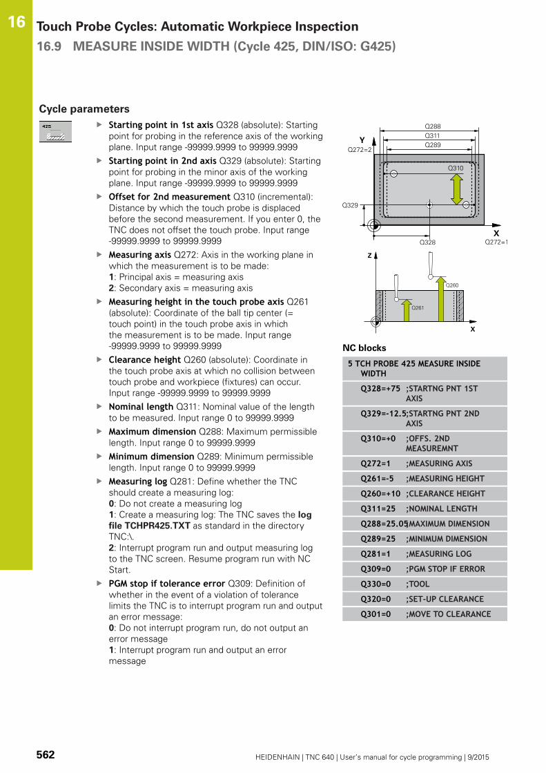
Touch Probe Cycles: Automatic Workpiece Inspection 16.9 MEASURE INSIDE WIDTH (Cycle 425, DIN/ISO: G425)
16
562 HEIDENHAIN | TNC 640 | User’s manual for cycle programming | 9/2015
Cycle parameters
Starting point in 1st axis Q328 (absolute): Starting
point for probing in the reference axis of the working
plane. Input range -99999.9999 to 99999.9999
Starting point in 2nd axis Q329 (absolute): Starting
point for probing in the minor axis of the working
plane. Input range -99999.9999 to 99999.9999
Offset for 2nd measurement Q310 (incremental):
Distance by which the touch probe is displaced
before the second measurement. If you enter 0, the
TNC does not offset the touch probe. Input range
-99999.9999 to 99999.9999
Measuring axis Q272: Axis in the working plane in
which the measurement is to be made:
1: Principal axis = measuring axis
2: Secondary axis = measuring axis
Measuring height in the touch probe axis Q261
(absolute): Coordinate of the ball tip center (=
touch point) in the touch probe axis in which
the measurement is to be made. Input range
-99999.9999 to 99999.9999
Clearance height Q260 (absolute): Coordinate in
the touch probe axis at which no collision between
touch probe and workpiece (fixtures) can occur.
Input range -99999.9999 to 99999.9999
Nominal length Q311: Nominal value of the length
to be measured. Input range 0 to 99999.9999
Maximum dimension Q288: Maximum permissible
length. Input range 0 to 99999.9999
Minimum dimension Q289: Minimum permissible
length. Input range 0 to 99999.9999
Measuring log Q281: Define whether the TNC
should create a measuring log:
0: Do not create a measuring log
1: Create a measuring log: The TNC saves the log
file TCHPR425.TXT as standard in the directory
TNC:\.
2: Interrupt program run and output measuring log
to the TNC screen. Resume program run with NC
Start.
PGM stop if tolerance error Q309: Definition of
whether in the event of a violation of tolerance
limits the TNC is to interrupt program run and output
an error message:
0: Do not interrupt program run, do not output an
error message
1: Interrupt program run and output an error
message
NC blocks
5 TCH PROBE 425 MEASURE INSIDEWIDTH
Q328=+75 ;STARTNG PNT 1STAXIS
Q329=-12.5;STARTNG PNT 2NDAXIS
Q310=+0 ;OFFS. 2NDMEASUREMNT
Q272=1 ;MEASURING AXIS
Q261=-5 ;MEASURING HEIGHT
Q260=+10 ;CLEARANCE HEIGHT
Q311=25 ;NOMINAL LENGTH
Q288=25.05;MAXIMUM DIMENSION
Q289=25 ;MINIMUM DIMENSION
Q281=1 ;MEASURING LOG
Q309=0 ;PGM STOP IF ERROR
Q330=0 ;TOOL
Q320=0 ;SET-UP CLEARANCE
Q301=0 ;MOVE TO CLEARANCE

MEASURE INSIDE WIDTH (Cycle 425, DIN/ISO: G425) 16.9
16
HEIDENHAIN | TNC 640 | User’s manual for cycle programming | 9/2015 563
Tool for monitoring Q330: Definition of
whether the TNC is to monitor the tool (see
"Tool monitoring", page 538). Enter 0 to 32767.9,
optionally the tool name with up to 16 characters
0: Monitoring not active
>0: Number or name of the tool the TNC used to
perform the operation with. You are able to apply a
tool via soft key directly from the tool table.
Set-up clearance Q320 (incremental): Additional
distance between measuring point and ball tip.
Q320 is added to SET_UP (touch probe table), and
is only effective when the datum is probed in the
touch probe axis. Input range 0 to 99999.9999
Traversing to clearance height Q301: definition
of how the touch probe is to move between the
measuring points:
0: Move at measuring height between measuring
points
1: Move at clearance height between measuring
points

Touch Probe Cycles: Automatic Workpiece Inspection 16.10 MEASURE RIDGE WIDTH (Cycle 426, DIN/ISO: G426)
16
564 HEIDENHAIN | TNC 640 | User’s manual for cycle programming | 9/2015
16.10 MEASURE RIDGE WIDTH (Cycle 426,
DIN/ISO: G426)
Cycle run
Touch Probe Cycle 426 measures the position and width of a ridge.
If you define the corresponding tolerance values in the cycle, the
TNC makes a nominal-to-actual value comparison and saves the
deviation value in system parameters.
1 Following the positioning logic, the TNC positions the touch
probe at rapid traverse (value from FMAX column) (see
"Executing touch probe cycles", page 454) to touch point 1. The
TNC calculates the touch points from the data in the cycle and
the safety clearance from the SET_UP column of the touch
probe table.
2 Then the touch probe moves to the entered measuring height
and runs the first probing process at the probing feed rate
(column F). 1. The first probing is always in the negative
direction of the programmed axis.
3 Then the touch probe moves at clearance height to the next
starting position and probes the second touch point.
4 Finally the TNC returns the touch probe to the clearance height
and saves the actual values and the deviation value in the
following Q parameters:
Parameter number Meaning
Q156 Actual value of measured length
Q157 Actual value of the centerline
Q166 Deviation of the measured length
Please note while programming:
Before a cycle definition you must have programmed
a tool call to define the touch probe axis.

MEASURE RIDGE WIDTH (Cycle 426, DIN/ISO: G426) 16.10
16
HEIDENHAIN | TNC 640 | User’s manual for cycle programming | 9/2015 565
Cycle parameters
1st meas. point 1st axis Q263 (absolute):
Coordinate of the first touch point in the reference
axis of the working plane. Input range -99999.9999
to 99999.9999
1st meas. point 2nd axis Q264 (absolute):
Coordinate of the first touch point in the minor axis
of the working plane. Input range -99999.9999 to
99999.9999
2nd meas. point 1st axis Q265 (absolute):
Coordinate of the second touch point in the
reference axis of the working plane. Input range
-99999.9999 to 99999.9999
2nd meas. point 2nd axis Q266 (absolute):
Coordinate of the second touch point in the minor
axis of the working plane. Input range -99999.9999
to 99999.9999
Measuring axis Q272: Axis in the working plane in
which the measurement is to be made:
1: Reference axis = measuring axis
2: Minor axis = measuring axis
Measuring height in the touch probe axis Q261
(absolute): Coordinate of the ball tip center (=
touch point) in the touch probe axis in which
the measurement is to be made. Input range
-99999.9999 to 99999.9999
Set-up clearance Q320 (incremental): Additional
distance between measuring point and ball tip.
Q320 is added to SET_UP (touch probe table). Input
range 0 to 99999.9999
Clearance height Q260 (absolute): Coordinate in
the touch probe axis at which no collision between
touch probe and workpiece (fixtures) can occur.
Input range -99999.9999 to 99999.9999
Nominal length Q311: Nominal value of the length
to be measured. Input range 0 to 99999.9999
Maximum dimension Q288: Maximum permissible
length. Input range 0 to 99999.9999
Minimum dimension Q289: Minimum permissible
length. Input range 0 to 99999.9999
Measuring log Q281: Define whether the TNC
should create a measuring log:
0: Do not create a measuring log
1: Create a measuring log: The TNC saves the log
file TCHPR426.TXT as standard in the directory
TNC:\.
2: Interrupt program run and output measuring log
to the TNC screen. Resume program run with NC
Start.
NC blocks
5 TCH PROBE 426 MEASURE RIDGEWIDTH
Q263=+50 ;1ST POINT 1ST AXIS
Q264=+25 ;1ST POINT 2ND AXIS
Q265=+50 ;2ND POINT 1ST AXIS
Q266=+85 ;2ND POINT 2ND AXIS
Q272=2 ;MEASURING AXIS
Q261=-5 ;MEASURING HEIGHT
Q320=0 ;SET-UP CLEARANCE
Q260=+20 ;CLEARANCE HEIGHT
Q311=45 ;NOMINAL LENGTH
Q288=45 ;MAXIMUM DIMENSION
Q289=44.95;MINIMUM DIMENSION
Q281=1 ;MEASURING LOG
Q309=0 ;PGM STOP IF ERROR
Q330=0 ;TOOL
Touch Probe Cycles: Automatic Workpiece Inspection 16.10 MEASURE RIDGE WIDTH (Cycle 426, DIN/ISO: G426)
16
566 HEIDENHAIN | TNC 640 | User’s manual for cycle programming | 9/2015
PGM stop if tolerance error Q309: Definition of
whether in the event of a violation of tolerance
limits the TNC is to interrupt program run and output
an error message:
0: Do not interrupt program run, do not output an
error message
1: Interrupt program run and output an error
message
Tool for monitoring Q330: Definition of whether
the TNC is to monitor the tool (see "Tool
monitoring", page 538). Input range 0 to 32767.9,
alternatively tool name with up to 16 characters
0: Monitoring inactive
> 0: Tool number in the tool table TOOL.T

MEASURE COORDINATE (Cycle 427, DIN/ISO: G427) 16.11
16
HEIDENHAIN | TNC 640 | User’s manual for cycle programming | 9/2015 567
16.11 MEASURE COORDINATE (Cycle 427,
DIN/ISO: G427)
Cycle run
Touch Probe Cycle 427 finds a coordinate in a selectable axis
and saves the value in a system parameter. If you define the
corresponding tolerance values in the cycle, the TNC makes a
nominal-to-actual value comparison and saves the deviation value in
system parameters.
1 Following the positioning logic, the TNC positions the touch
probe at rapid traverse (value from FMAX column) (see
"Executing touch probe cycles", page 454) to touch point 1.
The TNC offsets the touch probe by the safety clearance in the
direction opposite to the defined traverse direction.
2 Then the TNC positions the touch probe to the entered touch
point 1 in the working plane and measures the actual value in
the selected axis.
3 Finally the TNC returns the touch probe to the clearance
height and saves the measured coordinate in the following Q
parameter.
Parameter number Meaning
Q160 Measured coordinate
Please note while programming:
Before a cycle definition you must have programmed
a tool call to define the touch probe axis.
If an axis of the active working plane is defined
as measuring axis (Q272 = 1 or 2), the TNC
compensates the tool radius. From the defined
traversing direction (Q267) the TNC determines the
direction of compensation.
If the touch probe axis is defined as measuring axis
(Q272 = 3), the TNC compensates the tool length.
If you reference parameter Q330 to a turning tool,
the following applies:
– Parameters Q498 and Q531 have to be described
– The information of the parameters Q498, Q531,
for example from Cycle 800, has to match this
information
– If the TNC compensates the turning tool,
the appropriate values in line DZL and DXL,
respectively, are compensated.
– The TNC monitors the breakage tolerance which
is defined in column LBREAK
If you reference parameter Q330 to a milling tool, the
information of the parameters Q498 and Q531 has
no effect

Touch Probe Cycles: Automatic Workpiece Inspection 16.11 MEASURE COORDINATE (Cycle 427, DIN/ISO: G427)
16
568 HEIDENHAIN | TNC 640 | User’s manual for cycle programming | 9/2015
Cycle parameters
1st meas. point 1st axis Q263 (absolute):
Coordinate of the first touch point in the reference
axis of the working plane. Input range -99999.9999
to 99999.9999
1st meas. point 2nd axis Q264 (absolute):
Coordinate of the first touch point in the minor axis
of the working plane. Input range -99999.9999 to
99999.9999
Measuring height in the touch probe axis Q261
(absolute): Coordinate of the ball tip center (=
touch point) in the touch probe axis in which
the measurement is to be made. Input range
-99999.9999 to 99999.9999
Set-up clearance Q320 (incremental): Additional
distance between measuring point and ball tip.
Q320 is added to SET_UP (touch probe table). Input
range 0 to 99999.9999
Measuring axis (1 to 3: 1 = Reference axis) Q272:
Axis in which the measurement is to be made:
1: Reference axis = measuring axis
2: Minor axis = measuring axis
3: Touch probe axis = measuring axis
Traverse direction 1 Q267: Direction in which the
probe is to approach the workpiece:
-1: Negative traverse direction
+1: Positive traverse direction
Clearance height Q260 (absolute): Coordinate in
the touch probe axis at which no collision between
touch probe and workpiece (fixtures) can occur.
Input range -99999.9999 to 99999.9999
Measuring log Q281: Define whether the TNC
should create a measuring log:
0: Do not create a measuring log
1: Create a measuring log: The TNC saves the log
file TCHPR427.TXT as standard in the directory
TNC:\.
2: Interrupt program run and output measuring log
to the TNC screen. Resume program run with NC
Start.
NC blocks
5 TCH PROBE 427 MEASURECOORDINATE
Q263=+35 ;1ST POINT 1ST AXIS
Q264=+45 ;1ST POINT 2ND AXIS
Q261=+5 ;MEASURING HEIGHT
Q320=0 ;SET-UP CLEARANCE
Q272=3 ;MEASURING AXIS
Q267=-1 ;TRAVERSE DIRECTION
Q260=+20 ;CLEARANCE HEIGHT
Q281=1 ;MEASURING LOG
Q288=5.1 ;MAXIMUM DIMENSION
Q289=4.95 ;MINIMUM DIMENSION

MEASURE COORDINATE (Cycle 427, DIN/ISO: G427) 16.11
16
HEIDENHAIN | TNC 640 | User’s manual for cycle programming | 9/2015 569
Maximum limit of size Q288: Maximum
permissible measured value. Input range 0 to
99999.9999
Minimum limit of size Q289: Minimum permissible
measured value. Input range 0 to 99999.9999
PGM stop if tolerance error Q309: Definition of
whether in the event of a violation of tolerance
limits the TNC is to interrupt program run and output
an error message:
0: Do not interrupt program run, do not output an
error message
1: Interrupt program run and output an error
message
Tool for monitoring Q330: Definition of whether
the TNC is to monitor the tool (see "Tool
monitoring", page 538). Input range 0 to 32767.9,
alternatively tool name with up to 16 characters
0: Monitoring inactive
> 0: Tool number in the tool table TOOL.T
Reverse tool (0=no/1=yes)? Q498: Only relevant
if you have entered a turning tool in parameter
Q330 before. For proper monitoring of the turning
tool, the TNC requires the exact working condition.
Therefore, enter the following:
1: Turning tool is mirrored (rotated by 180°) e.g. by
Cycle 800 and parameter Reverse the tool Q498=1
0: Turning tool matches the description of the
turning tool table toolturn.trn, no modifications,
e.g. via Cycle 800 and parameter Reverse the toolQ498=0
Angle of incidence? Q531: Only relevant if you have
entered a turning tool in parameter Q330 before.
Enter the angle of incidence between the turning
tool and the work piece during machining, e.g. from
Cycle 800 parameter Angle of incidence? Q531.
Input range: -180° to +180°
Q309=0 ;PGM STOP IF ERROR
Q330=0 ;TOOL
Q498=0 ;REVERSE TOOL
Q531=0 ;INCLINED ANGLE
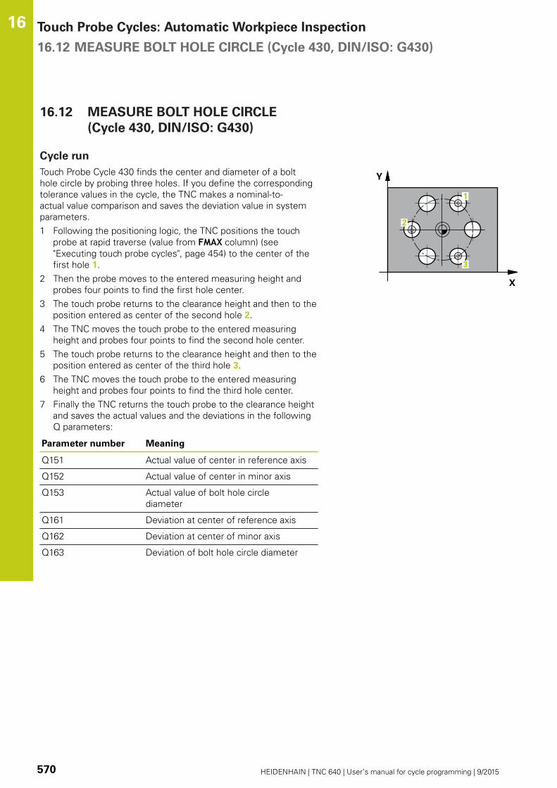
Touch Probe Cycles: Automatic Workpiece Inspection 16.12 MEASURE BOLT HOLE CIRCLE (Cycle 430, DIN/ISO: G430)
16
570 HEIDENHAIN | TNC 640 | User’s manual for cycle programming | 9/2015
16.12 MEASURE BOLT HOLE CIRCLE
(Cycle 430, DIN/ISO: G430)
Cycle run
Touch Probe Cycle 430 finds the center and diameter of a bolt
hole circle by probing three holes. If you define the corresponding
tolerance values in the cycle, the TNC makes a nominal-to-
actual value comparison and saves the deviation value in system
parameters.
1 Following the positioning logic, the TNC positions the touch
probe at rapid traverse (value from FMAX column) (see
"Executing touch probe cycles", page 454) to the center of the
first hole 1.
2 Then the probe moves to the entered measuring height and
probes four points to find the first hole center.
3 The touch probe returns to the clearance height and then to the
position entered as center of the second hole 2.
4 The TNC moves the touch probe to the entered measuring
height and probes four points to find the second hole center.
5 The touch probe returns to the clearance height and then to the
position entered as center of the third hole 3.
6 The TNC moves the touch probe to the entered measuring
height and probes four points to find the third hole center.
7 Finally the TNC returns the touch probe to the clearance height
and saves the actual values and the deviations in the following
Q parameters:
Parameter number Meaning
Q151 Actual value of center in reference axis
Q152 Actual value of center in minor axis
Q153 Actual value of bolt hole circle
diameter
Q161 Deviation at center of reference axis
Q162 Deviation at center of minor axis
Q163 Deviation of bolt hole circle diameter

MEASURE BOLT HOLE CIRCLE (Cycle 430, DIN/ISO: G430) 16.12
16
HEIDENHAIN | TNC 640 | User’s manual for cycle programming | 9/2015 571
Please note while programming:
Before a cycle definition you must have programmed
a tool call to define the touch probe axis.
Cycle 430 only monitors for tool breakage; there is
no automatic tool compensation.
Cycle parameters
Center in 1st axis Q273 (absolute): Bolt hole circle
center (nominal value) in the reference axis of
the working plane. Input range -99999.9999 to
99999.9999
Center in 2nd axis Q274 (absolute): Bolt hole
circle center (nominal value) in the minor axis of
the working plane. Input range -99999.9999 to
99999.9999
Nominal diameter Q262: Enter the bolt hole circle
diameter. Input range 0 to 99999.9999
Angle of 1st hole Q291 (absolute): Polar coordinate
angle of the first hole center in the working plane.
Input range -360.0000 to 360.0000
Angle of 2nd hole Q292 (absolute): Polar coordinate
angle of the second hole center in the working
plane. Input range -360.0000 to 360.0000
Angle of 3rd hole Q293 (absolute): Polar coordinate
angle of the third hole center in the working plane.
Input range -360.0000 to 360.0000
Measuring height in the touch probe axis Q261
(absolute): Coordinate of the ball tip center (=
touch point) in the touch probe axis in which
the measurement is to be made. Input range
-99999.9999 to 99999.9999
Clearance height Q260 (absolute): Coordinate in
the touch probe axis at which no collision between
touch probe and workpiece (fixtures) can occur.
Input range -99999.9999 to 99999.9999
Maximum limit of size Q288: Maximum
permissible diameter of bolt hole circle. Input range
0 to 99999.9999
Minimum limit of size Q289: Minimum permissible
diameter of bolt hole circle. Input range 0 to
99999.9999
Tolerance for center 1st axis Q279: Permissible
position deviation in the reference axis of the
working plane. Input range 0 to 99999.9999
NC blocks
5 TCH PROBE 430 MEAS. BOLT HOLECIRC
Q273=+50 ;CENTER IN 1ST AXIS
Q274=+50 ;CENTER IN 2ND AXIS
Q262=80 ;NOMINAL DIAMETER
Q291=+0 ;ANGLE OF 1ST HOLE
Q292=+90 ;ANGLE OF 2ND HOLE
Q293=+180;ANGLE OF 3RD HOLE
Q261=-5 ;MEASURING HEIGHT
Q260=+10 ;CLEARANCE HEIGHT
Q288=80.1 ;MAXIMUM DIMENSION
Q289=79.9 ;MINIMUM DIMENSION
Q279=0.15 ;TOLERANCE 1STCENTER

Touch Probe Cycles: Automatic Workpiece Inspection 16.12 MEASURE BOLT HOLE CIRCLE (Cycle 430, DIN/ISO: G430)
16
572 HEIDENHAIN | TNC 640 | User’s manual for cycle programming | 9/2015
Tolerance for center 2nd axis Q280: Permissible
position deviation in the minor axis of the working
plane. Input range 0 to 99999.9999
Measuring log Q281: Define whether the TNC
should create a measuring log:
0: Do not create a measuring log
1: Create a measuring log: The TNC saves the log
file TCHPR430.TXT as standard in the directory
TNC:\.
2: Interrupt program run and output measuring log
to the TNC screen. Resume program run with NC
Start.
PGM stop if tolerance error Q309: Definition of
whether in the event of a violation of tolerance
limits the TNC is to interrupt program run and output
an error message:
0: Do not interrupt program run, do not output an
error message
1: Interrupt program run and output an error
message
Tool for monitoring Q330: Definition of whether
the TNC is to monitor for tool breakage (see "Tool
monitoring", page 538). Input range 0 to 32767.9,
alternatively tool name with up to 16 characters.
0: Monitoring inactive
> 0: Tool number in the tool table TOOL.T
Q280=0.15 ;TOLERANCE 2NDCENTER
Q281=1 ;MEASURING LOG
Q309=0 ;PGM STOP IF ERROR
Q330=0 ;TOOL

MEASURE PLANE (Cycle 431, DIN/ISO: G431) 16.13
16
HEIDENHAIN | TNC 640 | User’s manual for cycle programming | 9/2015 573
16.13 MEASURE PLANE (Cycle 431, DIN/
ISO: G431)
Cycle run
Touch Probe Cycle 431 finds the angle of a plane by measuring
three points. It saves the measured values in system parameters.
1 Following the positioning logic, the TNC positions the touch
probe at rapid traverse (value from FMAX column) (see
"Executing touch probe cycles", page 454) to the programmed
touch point 1 and measures the first point of the plane. The TNC
offsets the touch probe by the safety clearance in the direction
opposite to the direction of probing.
2 The touch probe returns to the clearance height and then moves
in the working plane to starting point 2 and measures the actual
value of the second touch point of the plane.
3 The touch probe returns to the clearance height and then moves
in the working plane to starting point 3 and measures the actual
value of the third touch point of the plane.
4 Finally the TNC returns the touch probe to the clearance
height and saves the measured angle values in the following Q
parameters:
Parameter number Meaning
Q158 Projection angle of the A axis
Q159 Projection angle of the B axis
Q170 Spatial angle A
Q171 Spatial angle B
Q172 Spatial angle C
Q173 to Q175 Measured values in the touch probe
axis (first to third measurement)

Touch Probe Cycles: Automatic Workpiece Inspection 16.13 MEASURE PLANE (Cycle 431, DIN/ISO: G431)
16
574 HEIDENHAIN | TNC 640 | User’s manual for cycle programming | 9/2015
Please note while programming:
Before a cycle definition you must have programmed
a tool call to define the touch probe axis.
For the TNC to be able to calculate the angular
values, the three measuring points must not be
positioned on one straight line.
The spatial angles that are needed for tilting the
working plane are saved in parameters Q170 – Q172.
With the first two measuring points you also specify
the direction of the reference axis when tilting the
working plane.
The third measuring point determines the direction
of the tool axis. Define the third measuring point in
the direction of the positive Y axis to ensure that the
position of the tool axis in a clockwise coordinate
system is correct.
Cycle parameters
1st meas. point 1st axis Q263 (absolute):
Coordinate of the first touch point in the reference
axis of the working plane. Input range -99999.9999
to 99999.9999
1st meas. point 2nd axis Q264 (absolute):
Coordinate of the first touch point in the minor axis
of the working plane. Input range -99999.9999 to
99999.9999
1st meas. point 3rd axis Q294 (absolute):
Coordinate of the first touch point in the touch probe
axis. Input range -99999.9999 to 99999.9999
2nd meas. point 1st axis Q265 (absolute):
Coordinate of the second touch point in the
reference axis of the working plane. Input range
-99999.9999 to 99999.9999
2nd meas. point 2nd axis Q266 (absolute):
Coordinate of the second touch point in the minor
axis of the working plane. Input range -99999.9999
to 99999.9999
2nd meas. point 3rd axis Q295 (absolute):
Coordinate of the second touch point in the touch
probe axis. Input range -99999.9999 to 99999.9999

MEASURE PLANE (Cycle 431, DIN/ISO: G431) 16.13
16
HEIDENHAIN | TNC 640 | User’s manual for cycle programming | 9/2015 575
3rd meas. point 1st axis Q296 (absolute):
Coordinate of the third touch point in the reference
axis of the working plane. Input range -99999.9999
to 99999.9999
3rd meas. point 2nd axis Q297 (absolute):
Coordinate of the third touch point in the minor axis
of the working plane. Input range -99999.9999 to
99999.9999
3rd meas. point 3rd axis Q298 (absolute):
Coordinate of the third touch point in the touch
probe axis. Input range -99999.9999 to 99999.9999
Set-up clearance Q320 (incremental): Additional
distance between measuring point and ball tip.
Q320 is added to SET_UP (touch probe table). Input
range 0 to 99999.9999
Clearance height Q260 (absolute): Coordinate in
the touch probe axis at which no collision between
touch probe and workpiece (fixtures) can occur.
Input range -99999.9999 to 99999.9999
Measuring log Q281: Define whether the TNC
should create a measuring log:
0: Do not create a measuring log
1: Create a measuring log: The TNC saves the log
file TCHPR431.TXT as standard in the directory
TNC:\.
2: Interrupt program run and output measuring log
to the TNC screen. Resume program run with NC
Start.
NC blocks
5 TCH PROBE 431 MEASURE PLANE
Q263=+20 ;1ST POINT 1ST AXIS
Q264=+20 ;1ST POINT 2ND AXIS
Q294=-10 ;1ST POINT 3RD AXIS
Q265=+50 ;2ND POINT 1ST AXIS
Q266=+80 ;2ND POINT 2ND AXIS
Q295=+0 ;2ND POINT 3RD AXIS
Q296=+90 ;3RD POINT 1ST AXIS
Q297=+35 ;3RD POINT 2ND AXIS
Q298=+12 ;3RD POINT 3RD AXIS
Q320=0 ;SET-UP CLEARANCE
Q260=+5 ;CLEARANCE HEIGHT
Q281=1 ;MEASURING LOG

Touch Probe Cycles: Automatic Workpiece Inspection 16.14 Programming Examples
16
576 HEIDENHAIN | TNC 640 | User’s manual for cycle programming | 9/2015
16.14 Programming Examples
Example: Measuring and reworking a rectangular
stud
Program sequence
Roughing with 0.5 mm finishing allowance
Measuring
Rectangular stud finishing in accordance with the
measured values
0 BEGIN PGM BEAMS MM
1 TOOL CALL 69 Z Tool call for roughing
2 L Z+100 R0 FMAX Retract the tool
3 FN 0: Q1 = +81 Length of rectangle in X (roughing dimension)
4 FN 0: Q2 = +61 Length of rectangle in Y (roughing dimension)
5 CALL LBL 1 Call subprogram for machining
6 L Z+100 R0 FMAX Retract the tool, change the tool
7 TOOL CALL 99 Z Call the touch probe
8 TCH PROBE 424 MEAS. RECTAN. OUTS. Measure the rough-milled rectangle
Q273=+50 ;CENTER IN 1ST AXIS
Q274=+50 ;CENTER IN 2ND AXIS
Q282=80 ;FIRST SIDE LENGTH Nominal length in X (final dimension)
Q283=60 ;2ND SIDE LENGTH Nominal length in Y (final dimension)
Q261=-5 ;MEASURING HEIGHT
Q320=0 ;SET-UP CLEARANCE
Q260=+30 ;CLEARANCE HEIGHT
Q301=0 ;MOVE TO CLEARANCE
Q284=0 ;MAX. LIMIT 1ST SIDE Input values for tolerance checking not required
Q285=0 ;MIN. LIMIT 1ST SIDE
Q286=0 ;MAX. LIMIT 2ND SIDE
Q287=0 ;MIN. LIMIT 2ND SIDE
Q279=0 ;TOLERANCE 1ST CENTER
Q280=0 ;TOLERANCE 2ND CENTER
Q281=0 ;MEASURING LOG No measuring log transmission
Q309=0 ;PGM STOP IF ERROR Do not output an error message
Q330=0 ;TOOL NO. No tool monitoring
9 FN 2: Q1 = +Q1 - +Q164 Calculate length in X including the measured deviation
10 FN 2: Q2 = +Q2 - +Q165 Calculate length in Y including the measured deviation
11 L Z+100 R0 FMAX Retract the touch probe, change the tool

Programming Examples 16.14
16
HEIDENHAIN | TNC 640 | User’s manual for cycle programming | 9/2015 577
12 TOOL CALL 1 Z S5000 Tool call for finishing
13 CALL LBL 1 Call subprogram for machining
14 L Z+100 R0 FMAX M2 Retract in the tool axis, end program
15 LBL 1 Subprogram with fixed cycle for rectangular stud
16 CYCL DEF 213 STUD FINISHING
Q200=20 ;SET-UP CLEARANCE
Q201=-10 ;DEPTH
Q206=150 ;FEED RATE FOR PLNGNG
Q202=5 ;PLUNGING DEPTH
Q207=500 ;FEED RATE FOR MILLING
Q203=+10 ;SURFACE COORDINATE
Q204=20 ;2ND SET-UP CLEARANCE
Q216=+50 ;CENTER IN 1ST AXIS
Q217=+50 ;CENTER IN 2ND AXIS
Q218=Q1 ;FIRST SIDE LENGTH Length in X variable for roughing and finishing
Q219=Q2 ;SECOND SIDE LENGTH Length in Y variable for roughing and finishing
Q220=0 ;CORNER RADIUS
Q221=0 ;ALLOWANCE IN 1ST AXS
17 CYCL CALL M3 Cycle call
18 LBL 0 End of subprogram
19 END PGM BEAMS MM
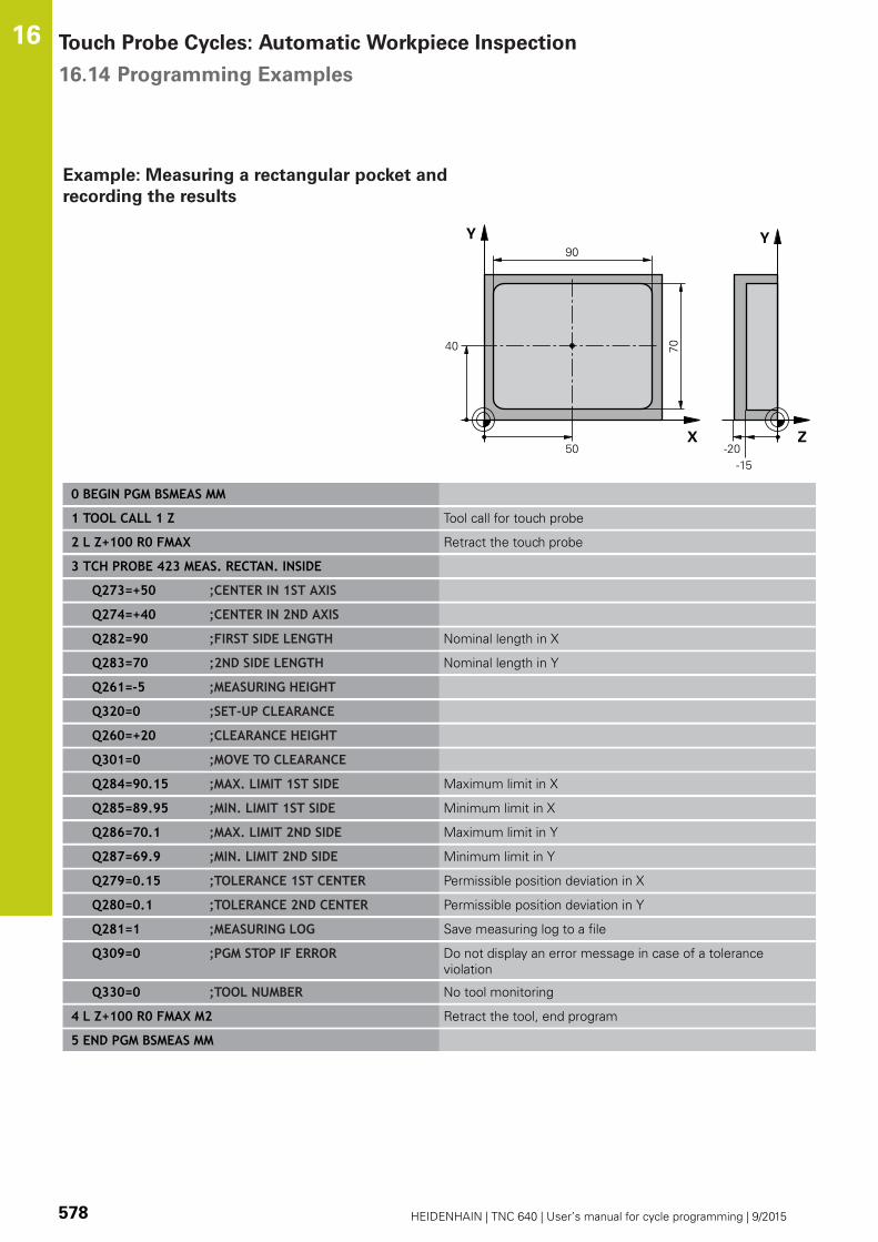
Touch Probe Cycles: Automatic Workpiece Inspection 16.14 Programming Examples
16
578 HEIDENHAIN | TNC 640 | User’s manual for cycle programming | 9/2015
Example: Measuring a rectangular pocket and
recording the results
0 BEGIN PGM BSMEAS MM
1 TOOL CALL 1 Z Tool call for touch probe
2 L Z+100 R0 FMAX Retract the touch probe
3 TCH PROBE 423 MEAS. RECTAN. INSIDE
Q273=+50 ;CENTER IN 1ST AXIS
Q274=+40 ;CENTER IN 2ND AXIS
Q282=90 ;FIRST SIDE LENGTH Nominal length in X
Q283=70 ;2ND SIDE LENGTH Nominal length in Y
Q261=-5 ;MEASURING HEIGHT
Q320=0 ;SET-UP CLEARANCE
Q260=+20 ;CLEARANCE HEIGHT
Q301=0 ;MOVE TO CLEARANCE
Q284=90.15 ;MAX. LIMIT 1ST SIDE Maximum limit in X
Q285=89.95 ;MIN. LIMIT 1ST SIDE Minimum limit in X
Q286=70.1 ;MAX. LIMIT 2ND SIDE Maximum limit in Y
Q287=69.9 ;MIN. LIMIT 2ND SIDE Minimum limit in Y
Q279=0.15 ;TOLERANCE 1ST CENTER Permissible position deviation in X
Q280=0.1 ;TOLERANCE 2ND CENTER Permissible position deviation in Y
Q281=1 ;MEASURING LOG Save measuring log to a file
Q309=0 ;PGM STOP IF ERROR Do not display an error message in case of a tolerance
violation
Q330=0 ;TOOL NUMBER No tool monitoring
4 L Z+100 R0 FMAX M2 Retract the tool, end program
5 END PGM BSMEAS MM

17Touch Probe
Cycles: SpecialFunctions

Touch Probe Cycles: Special Functions 17.1 Fundamentals
17
580 HEIDENHAIN | TNC 640 | User’s manual for cycle programming | 9/2015
17.1 Fundamentals
Overview
When running touch probe cycles, Cycle 8 MIRROR
IMAGE, Cycle 11 SCALING and Cycle 26 AXIS-
SPECIFIC SCALING must not be active.
HEIDENHAIN grants a warranty for the function of
the touch probe cycles only if HEIDENHAIN touch
probes are used.
The TNC must be specially prepared by the machine
tool builder for the use of a 3-D touch probe.
The TNC provides a cycle for the following special purpose:
Soft key Cycle Page
3 MEASURING
Cycle for defining OEM cycles
581

MEASURE (Cycle 3) 17.2
17
HEIDENHAIN | TNC 640 | User’s manual for cycle programming | 9/2015 581
17.2 MEASURE (Cycle 3)
Cycle run
Touch Probe Cycle 3 measures any position on the workpiece
in a selectable direction. Unlike other measuring cycles, Cycle 3
enables you to enter the measuring range SET UP and feed rate
F directly. Also, the touch probe retracts by a definable value after
determining the measured value MB.
1 The touch probe moves from the current position at the entered
feed rate in the defined probing direction. The probing direction
must be defined in the cycle as a polar angle.
2 After the TNC has saved the position, the touch probe stops.
The TNC saves the X, Y, Z coordinates of the probe-tip center in
three successive Q parameters. The TNC does not conduct any
length or radius compensations. You define the number of the
first result parameter in the cycle.
3 Finally, the TNC moves the touch probe back by that value
against the probing direction that you defined in the parameter
MB.
Please note while programming:
The exact behavior of Touch Probe Cycle 3 is
defined by your machine tool builder or a software
manufacturer who uses it within specific touch probe
cycles.
The DIST (maximum traverse to touch point) and F(probing feed rate) data from the touch-probe table,
which are effective in other measuring cycles, do not
apply in Touch Probe Cycle 3.
Remember that the TNC always writes to four
successive Q-parameters.
If the TNC was not able to determine a valid touch
point, the program is run without error message. In
this case the TNC assigns the value –1 to the 4th
result parameter so that you can deal with the error
yourself.
The TNC retracts the touch probe by no more than
the retraction distance MB and does not pass the
starting point of the measurement. This rules out any
collision during retraction.
With function FN17: SYSWRITE ID 990 NR 6 you can
set whether the cycle runs through the probe input
X12 or X13.

Touch Probe Cycles: Special Functions 17.2 MEASURE (Cycle 3)
17
582 HEIDENHAIN | TNC 640 | User’s manual for cycle programming | 9/2015
Cycle parameters
Parameter number for result: Enter the number
of the Q parameter to which you want the TNC
to assign the first measured coordinate (X). The
values Y and Z are in the immediately following Q
parameters. Input range: 0 to 1999
Probing axis: Enter the axis in whose direction the
probe is to move and confirm with the ENT key.
Input range: X, Y or Z
Probing angle: Angle, measured from the defined
probing axis in which the touch probe is to move.
Confirm with ENT. Input range –180.0000 to
180.0000
Maximum measuring range: Enter the maximum
distance from the starting point by which the touch
probe is to move. Confirm with ENT. Input range
-99999.9999 to 99999.9999
Feed rate for measurement: Enter the measuring
feed rate in mm/min. Input range 0 to 3000.000
Maximum retraction distance: Traverse path in the
direction opposite the probing direction, after the
stylus was deflected. The TNC returns the touch
probe to a point no farther than the starting point,
so that there can be no collision. Input range 0 to
99999.9999
Reference system? (0=ACTUAL/1=REF): Define
whether the probing direction and measuring result
should reference the current coordinate system
(ACTUAL, can be shifted or rotated) or the machine
coordinate system (REF):
0: Probe in the current system and save the
measuring result to the ACTUAL system
1: Probe in the fixed machine REF system and save
the measuring result to the REF system.
Error mode (0=OFF/1=ON): Specify whether the
TNC is to issue an error message if the stylus is
deflected at cycle start. If mode 1 is selected, the
TNC saves the value -1 in the 4th result parameter
and continues the cycle:
0: Error message output
1: No error message output
NC blocks
4 TCH PROBE 3.0 MEASURING
5 TCH PROBE 3.1 Q1
6 TCH PROBE 3.2 X ANGLE: +15
7 TCH PROBE 3.3 DIST +10 F100 MB1REFERENCE SYSTEM:0
8 TCH PROBE 3.4 ERRORMODE1

MEASURING IN 3-D (Cycle 4) 17.3
17
HEIDENHAIN | TNC 640 | User’s manual for cycle programming | 9/2015 583
17.3 MEASURING IN 3-D (Cycle 4)
Cycle run
Cycle 4 is an auxiliary cycle that can be used for
probing with any touch probe (TS, TT or TL). The TNC
does not provide a cycle for calibrating the TS touch
probe in any probing direction.
Touch probe cycle 4 measures any position on the workpiece in
the probing direction defined by a vector. Unlike other measuring
cycles, Cycle 4 enables you to enter the measuring distance and
feed rate directly. Also, the touch probe retracts by a definable
value after determining the measured value.
1 The TNC moves from the current position at the entered
feed rate in the defined probing direction. Define the probing
direction in the cycle by using a vector (delta values in X, Y and
Z).
2 After the TNC has saved the position, the TNC stops the
probing motion. The TNC saves the X, Y, Z coordinates of the
probing position in three successive Q parameters. You define
the number of the first parameter in the cycle. If you are using
a TS touch probe, the probe result is corrected by the calibrated
center offset.
3 Finally, the TNC performs a positioning movement in the
direction opposite to the direction of probing. You define the
traverse path in parameter MB—the touch probe is moved to a
point no farther than the starting point.
Please note while programming:
The TNC retracts the touch probe by no more than
the retraction distance MB and does not pass the
starting point of the measurement. This rules out any
collision during retraction.
Ensure during pre-positioning that the TNC moves
the probe-tip center without compensation to the
defined position!
Remember that the TNC always writes to four
successive Q parameters. If the TNC was not able
to determine a valid touch point, the 4th result
parameter will have the value –1.

Touch Probe Cycles: Special Functions 17.3 MEASURING IN 3-D (Cycle 4)
17
584 HEIDENHAIN | TNC 640 | User’s manual for cycle programming | 9/2015
Cycle parameters
Parameter number for result: Enter the number
of the Q parameter to which you want the TNC
to assign the first measured coordinate (X). The
values Y and Z are in the immediately following Q
parameters. Input range: 0 to 1999
Relative measuring path in X: X component of the
direction vector defining the direction in which the
touch probe is to move. Input range -99999.9999 to
99999.9999
Relative measuring path in Y: Y component of the
direction vector defining the direction in which the
touch probe is to move. Input range -99999.9999 to
99999.9999
Relative measuring path in Z: Z component of the
direction vector defining the direction in which the
touch probe is to move. Input range -99999.9999 to
99999.9999
Maximum measuring path: Enter the maximum
distance from the starting point by which the touch
probe may move along the direction vector. Input
range -99999.9999 to 99999.9999
Feed rate for measurement: Enter the measuring
feed rate in mm/min. Input range 0 to 3000.000
Maximum retraction distance: Traverse path in the
direction opposite the probing direction, after the
stylus was deflected. Input range 0 to 99999.9999
Reference system? (0=ACTUAL/1=REF): Define
whether the probing result should be saved in the
input coordinate system (ACTUAL) or referenced to
the machine-table coordinate system (REF):
0: Save the measured result in the ACTUAL system
1: Save the measured result in the REF system
NC blocks
4 TCH PROBE 4.0 MEASURING IN 3-D
5 TCH PROBE 4.1 Q1
6 TCH PROBE 4.2 IX-0.5 IY-1 IZ-1
7 TCH PROBE 4.3 DIST+45 F100 MB50REFERENCE SYSTEM:0

Calibrating a touch trigger probe 17.4
17
HEIDENHAIN | TNC 640 | User’s manual for cycle programming | 9/2015 585
17.4 Calibrating a touch trigger probe
In order to precisely specify the actual trigger point of a 3-D touch
probe, you must calibrate the touch probe, otherwise the TNC
cannot provide precise measuring results.
Always calibrate a touch probe in the following cases:
Commissioning
Stylus breakage
Stylus exchange
Change in the probe feed rate
Irregularities caused, for example, when the
machine heats up
Change of active tool axis
The TNC assumes the calibration values for the
active probe system directly after the calibration
process. The updated tool data become effective
immediately, and a new tool call is not necessary.
During calibration, the TNC finds the "effective" length of the stylus
and the "effective" radius of the ball tip. To calibrate the 3-D touch
probe, clamp a ring gauge or a stud of known height and known
radius to the machine table.
The TNC provides calibration cycles for calibrating the length and
the radius:
Press the TOUCH PROBE soft key
Display the calibration cycles: Press CALIBRATE
TS
Select the calibration cycle
Calibration cycles of the TNC
Soft key Function Page
Calibrating the length 589
Measure the radius and the center
offset using a calibration ring
591
Measure the radius and the center
offset using a stud or a calibration
pin
593
Measure the radius and the center
offset using a calibration sphere
587

Touch Probe Cycles: Special Functions 17.5 Displaying calibration values
17
586 HEIDENHAIN | TNC 640 | User’s manual for cycle programming | 9/2015
17.5 Displaying calibration values
The TNC saves the effective length and effective radius of the
touch probe in the tool table. The TNC saves the ball-tip center
offset of the touch probe in the touch-probe table in the CAL_OF1(principal axis) and CAL_OF2 (secondary axis) columns. You can
display the values on the screen by pressing the TOUCH PROBE
TABLE soft key.
A measuring log is created automatically during calibration. The
log file is named TCHPRAUTO.html. This file is stored in the same
location as the original file. The measuring log can be displayed in
the browser on the control. If a program uses more than one cycle
to calibrate the touch probe, TCHPRAUTO.html will contain all the
measuring logs. When running a touch probe cycle in the Manual
Operation mode, the TNC saves the measuring log under the name
TCHPRMAN.html. This file is stored in the folder TNC: \ *.
Please make sure the correct tool number is active
when you use the touch probe system. Regardless
of whether you want to use a touch probe cycle in
automatic mode or Manual operation mode.
For more information, see Chapter Touch probe table

CALIBRATE TS (Cycle 460, DIN/ISO: G460) 17.6
17
HEIDENHAIN | TNC 640 | User’s manual for cycle programming | 9/2015 587
17.6 CALIBRATE TS (Cycle 460, DIN/ISO:
G460)
With Cycle 460 you can calibrate a triggering 3-D touch probe
automatically on an exact calibration sphere. You can do radius
calibration alone, or radius and length calibration.
A measuring log is created automatically during calibration. The
log file is named TCHPRAUTO.html. This file is stored in the same
location as the original file. The measuring log can be displayed in
the browser on the control. If a program uses more than one cycle
to calibrate the touch probe, TCHPRAUTO.html will contain all the
measuring logs.
1 Clamp the calibration sphere and check for potential collisions.
2 In the touch probe axis, position the touch probe over the
calibration sphere, and in the working plane, approximately over
the sphere center.
3 The first movement in the cycle is in the negative direction of
the touch probe axis.
4 Then the cycle determines the exact center of the sphere in the
touch probe axis.
Please note while programming:
HEIDENHAIN only warrants the function of the touch
probe cycles if HEIDENHAIN touch probes are used.
The effective length of the touch probe is always
referenced to the tool datum. The machine tool
builder usually defines the spindle tip as the tool
datum.
Before a cycle definition you must have programmed
a tool call to define the touch probe axis.
Pre-position the touch probe in the program so that
it is located approximately above the center of the
calibration sphere.
A measuring log is created automatically during
calibration. The log file is named TCHPRAUTO.html.

Touch Probe Cycles: Special Functions 17.6 CALIBRATE TS (Cycle 460, DIN/ISO: G460)
17
588 HEIDENHAIN | TNC 640 | User’s manual for cycle programming | 9/2015
Exact calibration sphere radius Q407: Enter the
exact radius of the calibration sphere used. Input
range 0.0001 to 99.9999
Set-up clearance Q320 (incremental): Additional
distance between measuring point and ball tip.
Q320 is added to SET_UP in the touch probe table.
Input range 0 to 99999.9999
Traversing to clearance height Q301: Definition
of how the touch probe is to move between the
measuring points:
0: Move at measuring height between measuring
points
1: Move at clearance height between measuring
points
Number of probe points in the plane (4/3) Q423:
Number of measuring points on the diameter. Input
range 0 to 8
Reference angle Q380 (absolute): Reference
angle (basic rotation) for measuring the measuring
points in the active workpiece coordinate system.
Defining a reference angle can considerably enlarge
the measuring range of an axis. Input range 0 to
360.0000
Calibrate length (0/1) Q433: Define whether the
TNC should also calibrate the touch probe length
after radius calibration:
0: Do not calibrate touch probe length
1: Calibrate touch probe length
Datum for length Q434 (absolute): Coordinate of
the calibration sphere center. The definition is only
required if length calibration is to be carried out.
Input range -99999.9999 to 99999.9999
NC blocks
5 TCH PROBE 460 CALIBRATE TS
Q407=12.5 ;SPHERE RADIUS
Q320=0 ;SET-UP CLEARANCE
Q301=1 ;MOVE TO CLEARANCE
Q423=4 ;NO. OF PROBE POINTS
Q380=+0 ;REFERENCE ANGLE
Q433=0 ;CALIBRATE LENGTH
Q434=-2.5 ;DATUM
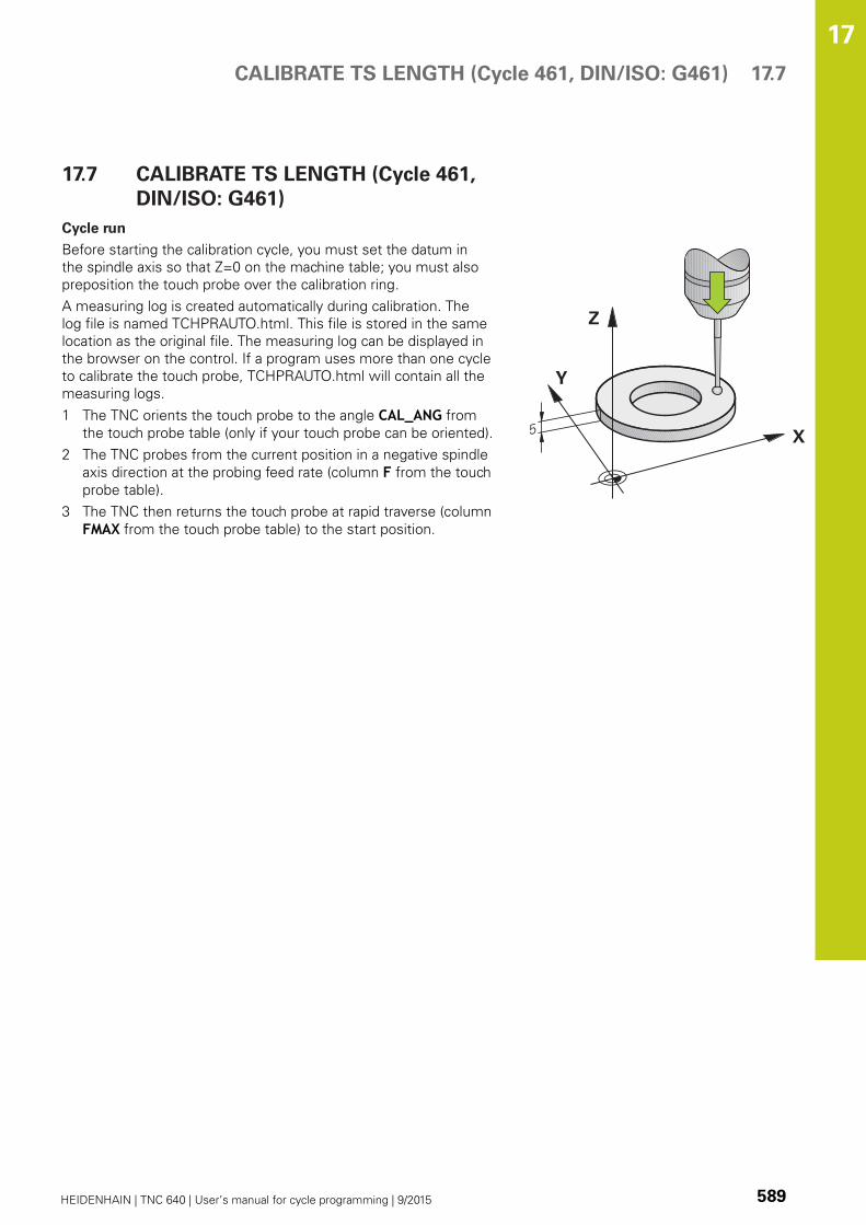
CALIBRATE TS LENGTH (Cycle 461, DIN/ISO: G461) 17.7
17
HEIDENHAIN | TNC 640 | User’s manual for cycle programming | 9/2015 589
17.7 CALIBRATE TS LENGTH (Cycle 461,
DIN/ISO: G461)
Cycle run
Before starting the calibration cycle, you must set the datum in
the spindle axis so that Z=0 on the machine table; you must also
preposition the touch probe over the calibration ring.
A measuring log is created automatically during calibration. The
log file is named TCHPRAUTO.html. This file is stored in the same
location as the original file. The measuring log can be displayed in
the browser on the control. If a program uses more than one cycle
to calibrate the touch probe, TCHPRAUTO.html will contain all the
measuring logs.
1 The TNC orients the touch probe to the angle CAL_ANG from
the touch probe table (only if your touch probe can be oriented).
2 The TNC probes from the current position in a negative spindle
axis direction at the probing feed rate (column F from the touch
probe table).
3 The TNC then returns the touch probe at rapid traverse (column
FMAX from the touch probe table) to the start position.

Touch Probe Cycles: Special Functions 17.7 CALIBRATE TS LENGTH (Cycle 461, DIN/ISO: G461)
17
590 HEIDENHAIN | TNC 640 | User’s manual for cycle programming | 9/2015
Please note while programming:
HEIDENHAIN only warrants the function of the touch
probe cycles if HEIDENHAIN touch probes are used.
The effective length of the touch probe is always
referenced to the tool datum. The machine tool
builder usually defines the spindle tip as the tool
datum.
Before a cycle definition you must have programmed
a tool call to define the touch probe axis.
A measuring log is created automatically during
calibration. The log file is named TCHPRAUTO.html.
Datum Q434 (absolute): Datum for the length (e.g.
height of the ring gauge). Input range -99999.9999
to 99999.9999
NC blocks
5 TCH PROBE 461 CALIBRATE TSLENGTH
Q434=+5 ;DATUM
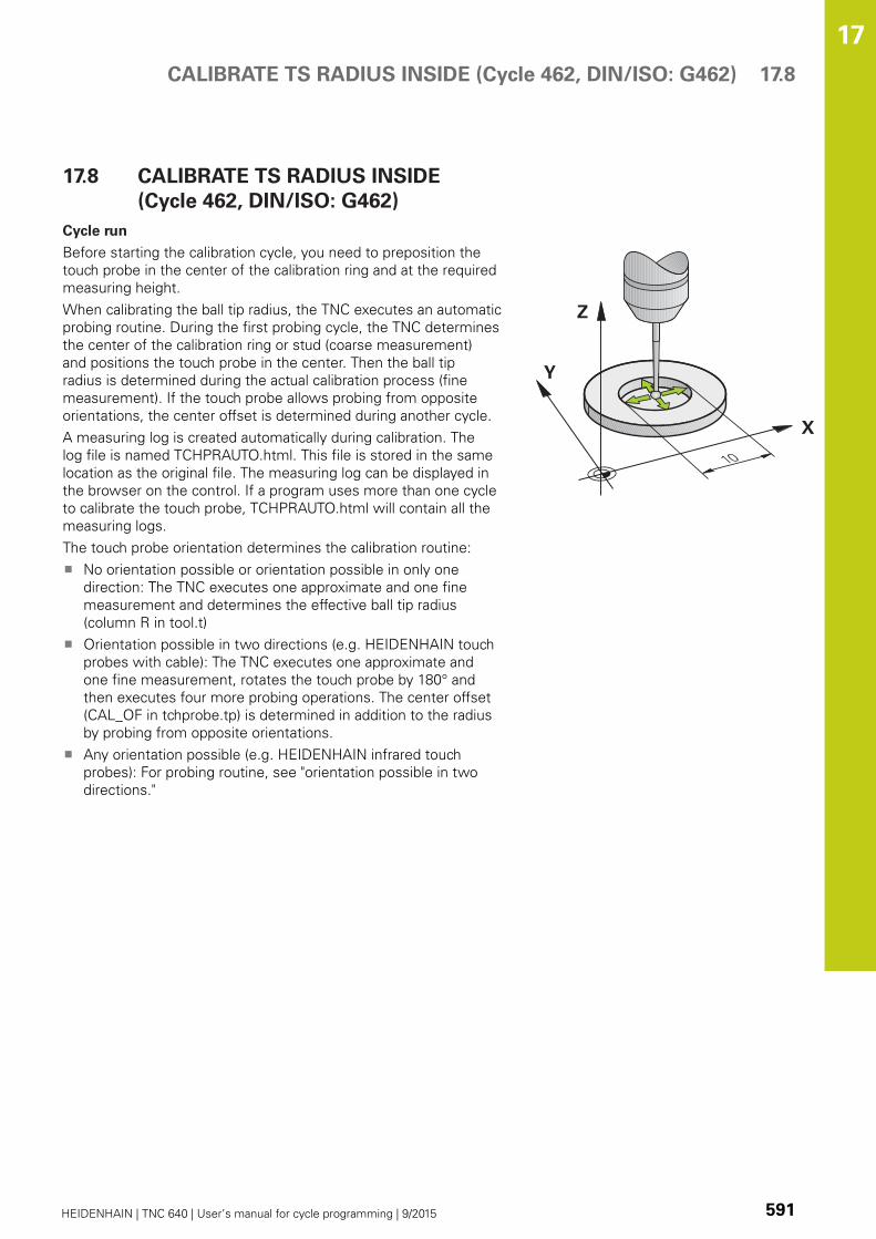
CALIBRATE TS RADIUS INSIDE (Cycle 462, DIN/ISO: G462) 17.8
17
HEIDENHAIN | TNC 640 | User’s manual for cycle programming | 9/2015 591
17.8 CALIBRATE TS RADIUS INSIDE
(Cycle 462, DIN/ISO: G462)
Cycle run
Before starting the calibration cycle, you need to preposition the
touch probe in the center of the calibration ring and at the required
measuring height.
When calibrating the ball tip radius, the TNC executes an automatic
probing routine. During the first probing cycle, the TNC determines
the center of the calibration ring or stud (coarse measurement)
and positions the touch probe in the center. Then the ball tip
radius is determined during the actual calibration process (fine
measurement). If the touch probe allows probing from opposite
orientations, the center offset is determined during another cycle.
A measuring log is created automatically during calibration. The
log file is named TCHPRAUTO.html. This file is stored in the same
location as the original file. The measuring log can be displayed in
the browser on the control. If a program uses more than one cycle
to calibrate the touch probe, TCHPRAUTO.html will contain all the
measuring logs.
The touch probe orientation determines the calibration routine:
No orientation possible or orientation possible in only one
direction: The TNC executes one approximate and one fine
measurement and determines the effective ball tip radius
(column R in tool.t)
Orientation possible in two directions (e.g. HEIDENHAIN touch
probes with cable): The TNC executes one approximate and
one fine measurement, rotates the touch probe by 180° and
then executes four more probing operations. The center offset
(CAL_OF in tchprobe.tp) is determined in addition to the radius
by probing from opposite orientations.
Any orientation possible (e.g. HEIDENHAIN infrared touch
probes): For probing routine, see "orientation possible in two
directions."
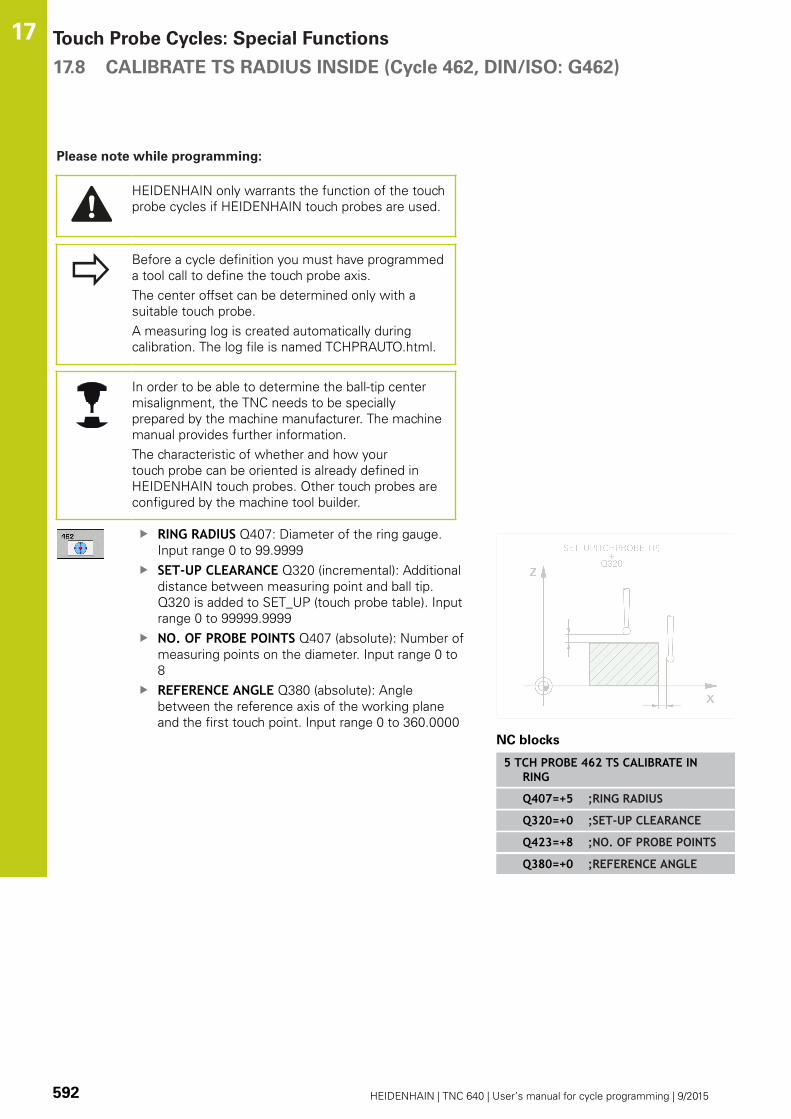
Touch Probe Cycles: Special Functions 17.8 CALIBRATE TS RADIUS INSIDE (Cycle 462, DIN/ISO: G462)
17
592 HEIDENHAIN | TNC 640 | User’s manual for cycle programming | 9/2015
Please note while programming:
HEIDENHAIN only warrants the function of the touch
probe cycles if HEIDENHAIN touch probes are used.
Before a cycle definition you must have programmed
a tool call to define the touch probe axis.
The center offset can be determined only with a
suitable touch probe.
A measuring log is created automatically during
calibration. The log file is named TCHPRAUTO.html.
In order to be able to determine the ball-tip center
misalignment, the TNC needs to be specially
prepared by the machine manufacturer. The machine
manual provides further information.
The characteristic of whether and how your
touch probe can be oriented is already defined in
HEIDENHAIN touch probes. Other touch probes are
configured by the machine tool builder.
RING RADIUS Q407: Diameter of the ring gauge.
Input range 0 to 99.9999
SET-UP CLEARANCE Q320 (incremental): Additional
distance between measuring point and ball tip.
Q320 is added to SET_UP (touch probe table). Input
range 0 to 99999.9999
NO. OF PROBE POINTS Q407 (absolute): Number of
measuring points on the diameter. Input range 0 to
8
REFERENCE ANGLE Q380 (absolute): Angle
between the reference axis of the working plane
and the first touch point. Input range 0 to 360.0000
NC blocks
5 TCH PROBE 462 TS CALIBRATE INRING
Q407=+5 ;RING RADIUS
Q320=+0 ;SET-UP CLEARANCE
Q423=+8 ;NO. OF PROBE POINTS
Q380=+0 ;REFERENCE ANGLE

CALIBRATE TS RADIUS OUTSIDE (Cycle 463, DIN/ISO: G463) 17.9
17
HEIDENHAIN | TNC 640 | User’s manual for cycle programming | 9/2015 593
17.9 CALIBRATE TS RADIUS OUTSIDE
(Cycle 463, DIN/ISO: G463)
Cycle run
Before starting the calibration cycle, you need to preposition the
touch probe above the center of the calibration pin. Position the
touch probe in the touch probe axis by approximately the set-up
clearance (value from touch probe table + value from cycle) above
the calibration pin.
When calibrating the ball tip radius, the TNC executes an automatic
probing routine. During the first probing cycle, the TNC determines
the center of the calibration ring or stud (coarse measurement)
and positions the touch probe in the center. Then the ball tip
radius is determined during the actual calibration process (fine
measurement). If the touch probe allows probing from opposite
orientations, the center offset is determined during another cycle.
A measuring log is created automatically during calibration. The
log file is named TCHPRAUTO.html. This file is stored in the same
location as the original file. The measuring log can be displayed in
the browser on the control. If a program uses more than one cycle
to calibrate the touch probe, TCHPRAUTO.html will contain all the
measuring logs.
The touch probe orientation determines the calibration routine:
No orientation possible or orientation possible in only one
direction: The TNC executes one approximate and one fine
measurement and determines the effective ball tip radius
(column R in tool.t)
Orientation possible in two directions (e.g. HEIDENHAIN touch
probes with cable): The TNC executes one approximate and
one fine measurement, rotates the touch probe by 180° and
then executes four more probing operations. The center offset
(CAL_OF in tchprobe.tp) is determined in addition to the radius
by probing from opposite orientations.
Any orientation possible (e.g. HEIDENHAIN infrared touch
probes): For probing routine, see "orientation possible in two
directions."

Touch Probe Cycles: Special Functions 17.9 CALIBRATE TS RADIUS OUTSIDE (Cycle 463, DIN/ISO: G463)
17
594 HEIDENHAIN | TNC 640 | User’s manual for cycle programming | 9/2015
Please note while programming:
HEIDENHAIN only warrants the function of the touch
probe cycles if HEIDENHAIN touch probes are used.
Before a cycle definition you must have programmed
a tool call to define the touch probe axis.
The center offset can be determined only with a
suitable touch probe.
A measuring log is created automatically during
calibration. The log file is named TCHPRAUTO.html.
In order to be able to determine the ball-tip center
misalignment, the TNC needs to be specially
prepared by the machine manufacturer. The machine
manual provides further information.
The characteristic of whether and how your
touch probe can be oriented is already defined in
HEIDENHAIN touch probes. Other touch probes are
configured by the machine tool builder.
STUD RADIUS Q407: Diameter of the ring gauge.
Input range 0 to 99.9999
SET-UP CLEARANCE Q320 (incremental): Additional
distance between measuring point and ball tip.
Q320 is added to SET_UP (touch probe table). Input
range 0 to 99999.9999
MOVE TO CLEARANCE Q301: Definition of how the
touch probe is to move between the measuring
points:
0: Move at measuring height between measuring
points
1: Move at clearance height between measuring
points
NO. OF PROBE POINTS Q407 (absolute): Number of
measuring points on the diameter. Input range 0 to
8
REFERENCE ANGLE Q380 (absolute): Angle
between the reference axis of the working plane
and the first touch point. Input range 0 to 360.0000
NC blocks
5 TCH PROBE 463 TS CALIBRATE ONSTUD
Q407=+5 ;STUD RADIUS
Q320=+0 ;SET-UP CLEARANCE
Q301=+1 ;MOVE TO CLEARANCE
Q423=+8 ;NO. OF PROBE POINTS
Q380=+0 ;REFERENCE ANGLE

18Visual SetupControl VSC
(software option136)
Visual Setup Control VSC (software option 136) 18.1 Camera-based monitoring of the setup situation VSC (option
number136)
18
596 HEIDENHAIN | TNC 640 | User’s manual for cycle programming | 9/2015
18.1 Camera-based monitoring of
the setup situation VSC (option
number136)
Fundamentals
In order to use the Visual Setup Control you require the following
components:
Software: Option 136 Visual Setup Control (VSC)
Hardware: Camera system of HEIDENHAIN
Application
Camera-based checking of the setup situation (option number
136 Visual Setup Control) allows you to monitor the current setup
situation before and during processing, and to compare this with
a safe target status. After setup, simple cycles for automatic
monitoring are available.
Reference images of the current working space are recorded in
the camera system. With cycles 600 GLOBAL WORKING SPACE or
601 LOCAL WORKING SPACE, the TNC produces an image of the
working space and compares the image with previously prepared
reference images. These cycles can highlight irregularities in the
working space. The operator decides if the NC program should be
suspended or continued in the event of a fault.
Using VSC offers the following advantages:
The control can recognize elements (e.g.tools or chucking
equipment) located in the working space after the start of the
program
If you would always like to clamp a workpiece in the same
position (e.g. hole top right), the control can check the clamping
situation
For documentation purposes you can produce an image of
the current working space (e.g.of a rarely-needed clamping
situation)
Terms
The following terms are used in connection with VSC:
Term Explanation
Reference image Saved image, highlighted as a reference.
A reference image shows a situation in
the working space that you regard as
safe. Therefore only create reference
images showing safe, non-hazardous
situations.
Mid-value image The control creates a mid-value image
taking into account all reference images.
The control compares new images
with the mid-value image as part of
evaluation.
Camera-based monitoring of the setup situation VSC (option
number136)
18.1
18
HEIDENHAIN | TNC 640 | User’s manual for cycle programming | 9/2015 597
Term Explanation
Error If you take a picture that shows a
poor situation (e.g.workpiece wrongly
clamped), you can create what is known
as an error image.
It is not advisable to highlight an error
image as a reference image.
Monitoring area Denotes an area that you highlight
with the mouse. When evaluating
new images, the control only refers
to this area. Parts of images outside
the monitoring area have no effect on
the results of the monitoring process.
Several monitoring areas can be defined.
Monitoring areas are not linked to
images.
Error Area on an image containing a deviation
form the desired position. Errors always
relate to the image to which they were
saved (error image) or to the last image
evaluated.
Monitoring phase No further reference images are
produced in the monitoring phase.
You can use the cycle for automatic
monitoring of your working space. In this
phase, the control only issues a warning
if it finds a deviation when comparing
images.

Visual Setup Control VSC (software option 136) 18.1 Camera-based monitoring of the setup situation VSC (option
number136)
18
598 HEIDENHAIN | TNC 640 | User’s manual for cycle programming | 9/2015
Produce live image
In the Manual operation mode, you can display and save the
current camera view as a live image.
The control only uses the picture taken here for automatic
monitoring of the setup situation. Images produced in this menu
may be used for documentation and traceability. For example, you
could record the current setup situation. The control saves the
image produced as a .png file in TNC:\system\visontool\live_view.
The name of the saved image is made up of the date and time it
was created.
Procedure
Proceed as follows to save the camera’s live image:
Press the CAMERA soft key
Press the LIVE IMAGE soft key: The TNC shows
you the current camera view
Press the SAVE IMAGE soft key: Create a live
image from the current camera view
Options in Live Image mode
The control provides the following options:
Soft key Function
Increase camera brightness
The settings made here only affect Live Image
mode, and and have no influence on pictures
taken in automatic mode.
Reduce camera brightness
The settings made here only affect Live Image
mode, and and have no influence on pictures
taken in automatic mode.
Go back to the previous screen

Camera-based monitoring of the setup situation VSC (option
number136)
18.1
18
HEIDENHAIN | TNC 640 | User’s manual for cycle programming | 9/2015 599
Manage monitoring data
In the Manual operation mode you can manage images from
cycles 600 and 601.
Proceed as follows to enter the monitoring data:
Press the CAMERA soft key
Press the MONITORING DATA MANAGEMENT soft
key: The control shows a list of the NC programs
monitored
Press the OPEN soft key: The control shows a list
of monitoring points
Edit the desired data
Select data
You can select the marked interfaces 1 with the mouse. These
interfaces make it easier to search and show results in a
manageable way.
All images: Display all images for this monitoring file
Reference images: Only display reference images
Images with error: Display all images where you have
highlighted an error

Visual Setup Control VSC (software option 136) 18.1 Camera-based monitoring of the setup situation VSC (option
number136)
18
600 HEIDENHAIN | TNC 640 | User’s manual for cycle programming | 9/2015
Features of the monitoring data management
Soft key Function
Mark selected image as a reference image
Please note: A reference image shows a situation
in the working space that you regard as safe.
All reference images are used as part of the
evaluation process. If you add or remove an image
as a reference image, this has an effect on the
results of image evaluation.
Delete image currently selected
Carry out automatic image evaluation
The control carries out an image evaluation
according to the reference images and the
monitoring areas.
Change monitoring area or highlight an error
Further Information: Configuration, page
Go back to the previous screen
If you change the configuration, the control carries
out an image evaluation.

Camera-based monitoring of the setup situation VSC (option
number136)
18.1
18
HEIDENHAIN | TNC 640 | User’s manual for cycle programming | 9/2015 601
Overview
The TNC provides two cycles you can use for visual setup control in
the Programming mode of operation:
The soft-key row shows all available touch probe
functions divided into groups.
Chose soft key MONITORING WITH CAMERA
Soft key Cycle Page
600 GLOBAL WORKING SPACE 606
601 LOCAL WORKING SPACE 611
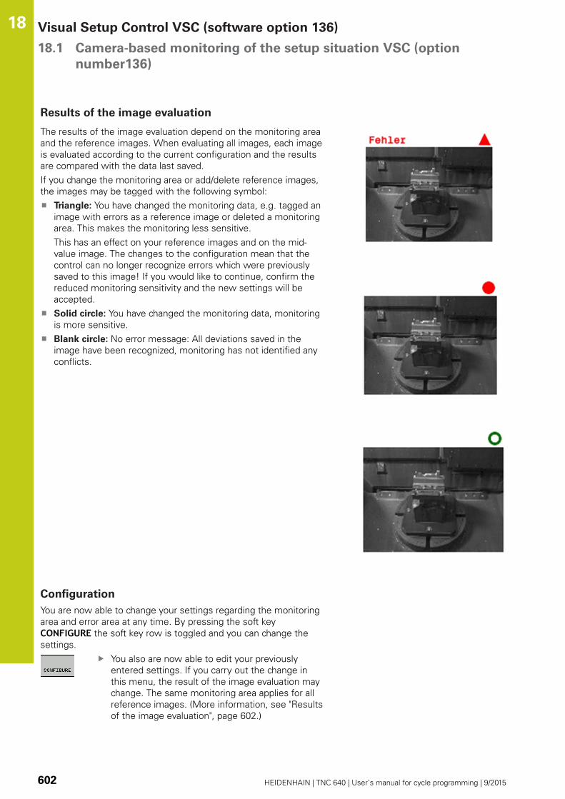
Visual Setup Control VSC (software option 136) 18.1 Camera-based monitoring of the setup situation VSC (option
number136)
18
602 HEIDENHAIN | TNC 640 | User’s manual for cycle programming | 9/2015
Results of the image evaluation
The results of the image evaluation depend on the monitoring area
and the reference images. When evaluating all images, each image
is evaluated according to the current configuration and the results
are compared with the data last saved.
If you change the monitoring area or add/delete reference images,
the images may be tagged with the following symbol:
Triangle: You have changed the monitoring data, e.g. tagged an
image with errors as a reference image or deleted a monitoring
area. This makes the monitoring less sensitive.
This has an effect on your reference images and on the mid-
value image. The changes to the configuration mean that the
control can no longer recognize errors which were previously
saved to this image! If you would like to continue, confirm the
reduced monitoring sensitivity and the new settings will be
accepted.
Solid circle: You have changed the monitoring data, monitoring
is more sensitive.
Blank circle: No error message: All deviations saved in the
image have been recognized, monitoring has not identified any
conflicts.
Configuration
You are now able to change your settings regarding the monitoring
area and error area at any time. By pressing the soft key
CONFIGURE the soft key row is toggled and you can change the
settings.
You also are now able to edit your previously
entered settings. If you carry out the change in
this menu, the result of the image evaluation may
change. The same monitoring area applies for all
reference images. (More information, see "Results
of the image evaluation", page 602.)

Camera-based monitoring of the setup situation VSC (option
number136)
18.1
18
HEIDENHAIN | TNC 640 | User’s manual for cycle programming | 9/2015 603
You are able to click on the image and draw
up a rectangular frame. This way you define
the monitoring area. (More information, see
"Fundamentals", page 596.) If you define
monitoring areas in a setting that is always
exposed or in which differences in contrast are
to be expected, false alerts will be displayed. If
you draw a new monitoring area or change or
delete an already drawn up monitoring area, this
will affect the result of the image evaluation. Due
to the changed settings the TNC must check
whether these changes may have an impact on
the previously generated images.
You are able to click on the image and draw
up a rectangular frame. This way you define
a new area with errors. The area is marked
red. It is recommended to mark only errors
that may reoccur exactly at this spot. It is not
advisable to mark areas that are contaminated
with chips or drilling fluid. The errors need to
be reproducible in the exact same way. (More
information, see "Fundamentals", page 596.) If
you define monitoring areas in a setting that is
always exposed or in which differences in contrast
are to be expected, false alerts will be displayed.
If you draw a new area with errors or change or
delete an already drawn up area of errors, this
will affect the result of the image evaluation. Due
to the changed settings the TNC must check
whether these changes may have an impact on
the previously generated images. You can also
draw several areas with errors. It is not advisable
to draw errors onto reference images.
The TNC checks whether and how the new
settings affect the new image: (More information,
see "Results of the image evaluation", page 602)
The TNC checks whether and how the new
settings affect the new image: (More information,
see "Results of the image evaluation", page 602)
Save current image and return to previous
screen. If you changed the configuration, the
TNC will perform an image evaluation. (More
information, see "Results of the image evaluation",
page 602.)
You discard all changes and return to the
previously displayed screen.
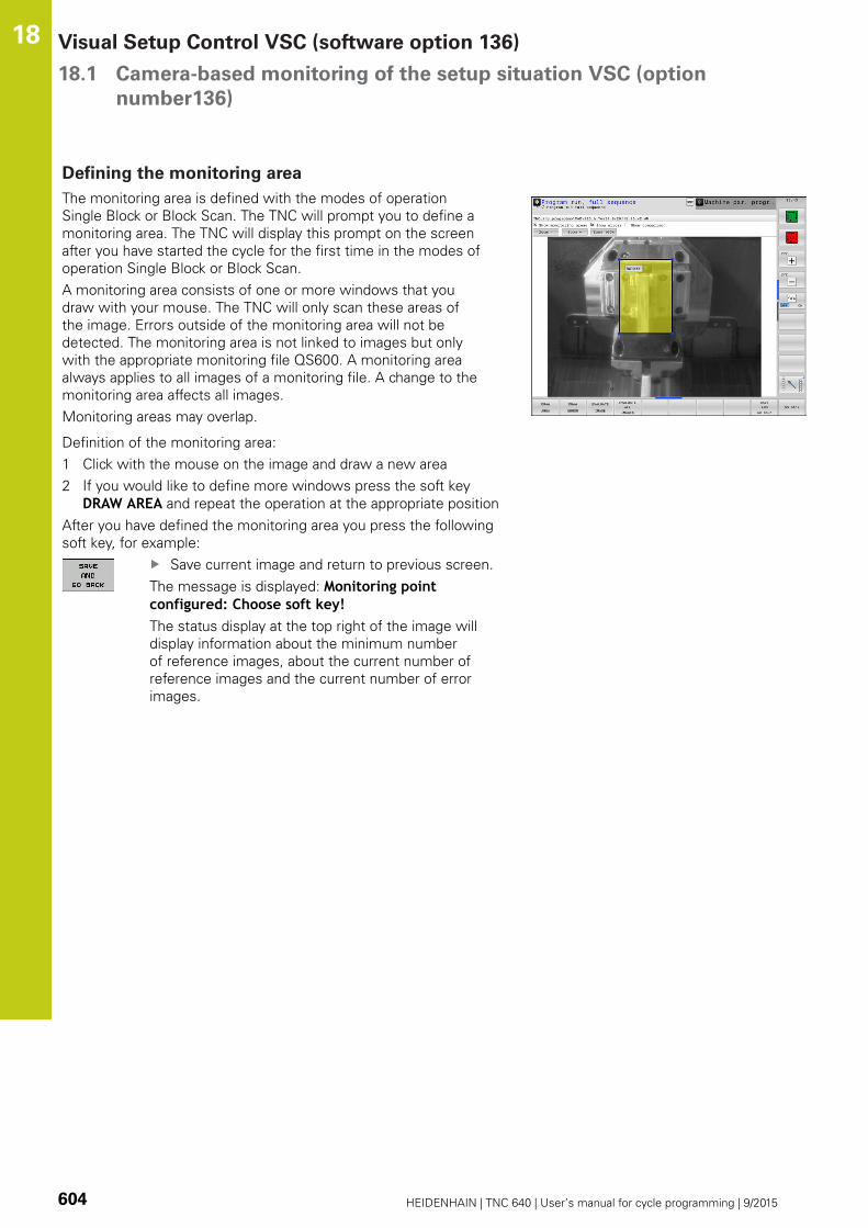
Visual Setup Control VSC (software option 136) 18.1 Camera-based monitoring of the setup situation VSC (option
number136)
18
604 HEIDENHAIN | TNC 640 | User’s manual for cycle programming | 9/2015
Defining the monitoring area
The monitoring area is defined with the modes of operation
Single Block or Block Scan. The TNC will prompt you to define a
monitoring area. The TNC will display this prompt on the screen
after you have started the cycle for the first time in the modes of
operation Single Block or Block Scan.
A monitoring area consists of one or more windows that you
draw with your mouse. The TNC will only scan these areas of
the image. Errors outside of the monitoring area will not be
detected. The monitoring area is not linked to images but only
with the appropriate monitoring file QS600. A monitoring area
always applies to all images of a monitoring file. A change to the
monitoring area affects all images.
Monitoring areas may overlap.
Definition of the monitoring area:
1 Click with the mouse on the image and draw a new area
2 If you would like to define more windows press the soft key
DRAW AREA and repeat the operation at the appropriate position
After you have defined the monitoring area you press the following
soft key, for example:
Save current image and return to previous screen.
The message is displayed: Monitoring pointconfigured: Choose soft key!The status display at the top right of the image will
display information about the minimum number
of reference images, about the current number of
reference images and the current number of error
images.

Camera-based monitoring of the setup situation VSC (option
number136)
18.1
18
HEIDENHAIN | TNC 640 | User’s manual for cycle programming | 9/2015 605
Possible queries
The cycles of the workspace monitoring enter a value in parameter
Q601.
The following values are possible:
Q601 = 1: No error
Q601 = 2: Error
Q601 = 3: You have yet not defined a monitoring area or you did
not save enough reference images
Q601 = 10: Internal error (no signal, faulty camera, etc.)
You can use parameter Q601 for internal queries.
More information about If-Then Decisions with Q
parameter functions are found in the user manuals of
the 'TNC 640, section 9.6
Here, a possible programming example for a query:
0 BEGIN PGM 5 MM
1 BLK FORM CYLINDER Z R42 L150 Blank form Cylinder
2 FUNCTION MODE MILL Activate milling mode
3 TCH PROBE 601 WORKSPACE LOCAL Define Cycle 600
QS600 = OS ;MONITORING POINT
Q309=+0 ;PGM STOP IF ERROR
Q613 = +0 ;KEEP CAMERA LID OPEN
Q617 = 10 ;REFERENCE IMAGES
4 FN 9: IF Q601 EQU 1 GOTO LBL 20 If parameter Q601 = 1, then jump to LBL 20
5 FN 9: IF Q601 EQU 2 GOTO LBL 21 If parameter Q601 = 2, then jump to LBL 21
6 FN 9: IF Q601 EQU 3 GOTO LBL 22 If parameter Q601 = 3, then jump to LBL 22
7 FN 9: IF Q601 EQU 10 GOTO LBL 23 If parameter Q601 = 10, then jump to LBL 23
8 TOOL CALL "GEAR_HOB_D75" Call the tool
9 L X+... Y+... R0 FMAX Program the machining
...
...
...
57 LBL 21 Definition LBL 21
58 STOP Program stop, the operator can check the condition of the
workspace
59 LBL 0
60 END PGM 5MM

Visual Setup Control VSC (software option 136) 18.2 Workspace Global (Cycle 600)
18
606 HEIDENHAIN | TNC 640 | User’s manual for cycle programming | 9/2015
18.2 Workspace Global (Cycle 600)
Application
With Cycle 600, Workspace Global, you monitor the workspace
of your tooling machine. The TNC will generate an image of the
current workspace from a position determined by your machine
tool builder. Then, the TNC will match the image with previously
generated reference images and enforce a program stop, if
required. You can program this cycle to suit a particular application
and specify one or several monitoring areas. Cycle 600 is valid
once specified and must not be called up. Before you work with
the visual setup control you must create reference images (more
information, see "Creating reference images", page 606) and
define a monitoring area (more information, see "Monitoring
phase", page 609).
Creating reference images
The TNC will start generating reference images as soon as you run
the cycle for the first time in the program modes Single Block or
Block Scan.
The following cycle process applies as long as the TNC still requires
reference images to be saved. Specify the number of reference
images with parameter Q617.
Cycle run
1 The camera will be mounted by the machine tool builder onto
the main spindle.
2 The TNC automatically opens the camera lid.
3 The TNC will generate an image of the current condition and
display it on the screen.
4 During the first run of this cycle a message is displayed at the
bottom of the screen "Monitoring point not configured: Drawareas!"
5 Define the monitoring area. (More information, see "Defining
the monitoring area", page 604)
6 You can decide whether the current image should be saved as
a reference image or an error image, but you can also change
the monitoring area. (More information, see "Configuration",
page 602).
7 Press the soft key. BACK.
8 To complete the operation the TNC will close the camera lid.
9 Press the NC start and run your program as usual.
After you have defined the monitoring area, you can press in
addition of the soft key: BACK you can also choose the following
soft keys:

Workspace Global (Cycle 600) 18.2
18
HEIDENHAIN | TNC 640 | User’s manual for cycle programming | 9/2015 607
The TNC will save the current image and return
to the program run screen. If you changed the
configuration, the TNC will perform an image
evaluation. (More information, "Results of the
image evaluation")
The status display at the top right displays the
word "Reference". You have marked the current
image as the reference image. Because a
reference image can never be an error image at
the same time, the soft key ERROR IMAGE is gray.
(More information, see "Fundamentals", page 596)
The status display at the top right displays the
word "Error". You have marked the current image
as the error image. Because an error image can
never be a reference image at the same time, the
soft key ERROR IMAGE is gray. (More information,
see "Fundamentals", page 596)
The soft key row changes. You are now able to
change your previously entered settings with
respect to the monitoring area and the sensitivity.
If you carry out the change in this menu, this may
impact all of your images. (More information, see
"Configuration", page 602)
The TNC will save the current image and return
to the program run screen. If you changed the
configuration, the TNC will perform an image
evaluation. (More information, "Results of the
image evaluation")
As soon as the TNC generated at least one reference
image, images will be evaluated and errors displayed.
If no errors are detected the following message is
displayed: Too few reference images: Choose nextaction with soft key!. This message will no longer
be displayed if the number of reference images
defined in parameter Q617 has been reached.
The TNC will generate mean image taking into
account all reference images. New images are
compared during evaluation with the mean image
taking into account variance. Only after all reference
images are available the cycle will no longer stop
because of too few reference images.

Visual Setup Control VSC (software option 136) 18.2 Workspace Global (Cycle 600)
18
608 HEIDENHAIN | TNC 640 | User’s manual for cycle programming | 9/2015
Defining the monitoring area
The monitoring area is defined with the modes of operation
Single Block or Block Scan. The TNC will prompt you to define a
monitoring area. The TNC will display this prompt on the screen
after you have started the cycle for the first time in the modes of
operation Single Block or Block Scan.
A monitoring area consists of one or more windows that you
draw with your mouse. The TNC will only scan these areas of
the image. Errors outside of the monitoring area will not be
detected. The monitoring area is not linked to images but only
with the appropriate monitoring file QS600. A monitoring area
always applies to all images of a monitoring file. A change to the
monitoring area affects all images.
Monitoring areas may overlap.
Definition of the monitoring area:
1 Click with the mouse on the image and draw a new area
2 If you would like to define more windows press the soft key
DRAW AREA and repeat the operation at the appropriate position
After you have defined the monitoring area you press the following
soft key, for example:
Save current image and return to previous screen.
The message is displayed: Monitoring pointconfigured: Choose soft key!The status display at the top right of the image will
display information about the minimum number
of reference images, about the current number of
reference images and the current number of error
images.
Workspace Global (Cycle 600) 18.2
18
HEIDENHAIN | TNC 640 | User’s manual for cycle programming | 9/2015 609
Monitoring phase
Cycle run: Monitoring phase
1 The camera will be mounted by the machine tool builder onto
the main spindle. The main spindle moves to a position defined
by the machine tool builder.
2 After the TNC has reached this position, it will automatically
open the camera lid.
3 The TNC will generate an image of the current condition.
4 Then it will match the image against the mean value and
the variance image (more information, see "Fundamentals",
page 596).
5 Depending on whether the TNC detected a so-called
"Error" (deviation), it may now enforce a program stop (more
information, see "Fundamentals", page 596). If parameter
Q309=1 is set, the TNC will display the image on the screen
upon detecting an error. If parameter Q309=0 is set, no image
will be displayed on the screen and the program will not be
stopped.
6 To complete the operation the TNC will close the camera lid.
Please note while programming:
In addition to the attribute Reference image, you can
also assign the attribute Error image to your images.
This assignment may impact the image evaluation.
Remember the following:
A reference image may never be an error image at
the same time.
If you change the monitoring area, this has an impact
on all images.
Ideally, you define the monitoring area only once
at the beginning and then make no or only little
changes to it.
The number of reference images will affect the
accuracy of the image evaluation. A high number
of reference images improves the quality of the
evaluation.
Specify a sensible number of reference images in
parameter Q617. (target value: 10 images).
You can also create more reference images than
you have specified in Q617..
Your machine must be prepared for the workspace
monitoring!
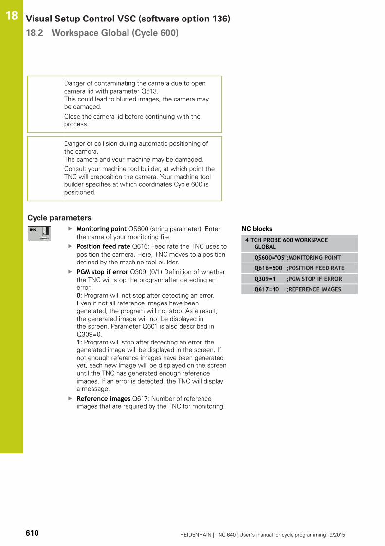
Visual Setup Control VSC (software option 136) 18.2 Workspace Global (Cycle 600)
18
610 HEIDENHAIN | TNC 640 | User’s manual for cycle programming | 9/2015
Danger of contaminating the camera due to open
camera lid with parameter Q613.
This could lead to blurred images, the camera may
be damaged.
Close the camera lid before continuing with the
process.
Danger of collision during automatic positioning of
the camera.
The camera and your machine may be damaged.
Consult your machine tool builder, at which point the
TNC will preposition the camera. Your machine tool
builder specifies at which coordinates Cycle 600 is
positioned.
Cycle parameters
Monitoring point QS600 (string parameter): Enter
the name of your monitoring file
Position feed rate Q616: Feed rate the TNC uses to
position the camera. Here, TNC moves to a position
defined by the machine tool builder.
PGM stop if error Q309: (0/1) Definition of whether
the TNC will stop the program after detecting an
error.
0: Program will not stop after detecting an error.
Even if not all reference images have been
generated, the program will not stop. As a result,
the generated image will not be displayed in
the screen. Parameter Q601 is also described in
Q309=0.
1: Program will stop after detecting an error, the
generated image will be displayed in the screen. If
not enough reference images have been generated
yet, each new image will be displayed on the screen
until the TNC has generated enough reference
images. If an error is detected, the TNC will display
a message.
Reference images Q617: Number of reference
images that are required by the TNC for monitoring.
NC blocks
4 TCH PROBE 600 WORKSPACEGLOBAL
QS600="OS";MONITORING POINT
Q616=500 ;POSITION FEED RATE
Q309=1 ;PGM STOP IF ERROR
Q617=10 ;REFERENCE IMAGES

Workspace Local (Cycle 601) 18.3
18
HEIDENHAIN | TNC 640 | User’s manual for cycle programming | 9/2015 611
18.3 Workspace Local (Cycle 601)
Application
With Cycle 601, Workspace Local, you monitor the workspace
of your tooling machine. The TNC will generate an image of the
current workspace from the position of the spindle at the point in
time of the cycle call. Then, the TNC will match the image against
previously generated reference images and enforce a program
stop, if required. You can program this cycle to suit a particular
application and specify one or several monitoring areas. Cycle 601
is valid once specified and must not be called up. Before you work
with the visual setup control you must create reference images
(more information, see "Creating reference images", page 611)
and define a monitoring area (more information, see "Monitoring
phase", page 614).
Creating reference images
The TNC will start generating reference images as soon as you run
the cycle for the first time in the program modes Single Block or
Block Scan.
The following cycle process applies as long as the TNC still requires
reference images to be saved. Specify the number of reference
images with parameter Q617.
Cycle run
1 The camera will be mounted by the machine tool builder onto
the main spindle.
2 The TNC automatically opens the camera lid.
3 The TNC will generate an image of the current condition and
display it on the screen.
4 During the first run of this cycle a message is displayed at the
bottom of the screen "Monitoring point not configured: Drawareas!"
5 Define the monitoring area. (More information, see "Defining
the monitoring area", page 604)
6 You can decide whether the current image should be saved as
a reference image or an error image, but you can also change
the monitoring area. (More information, see "Configuration",
page 602).
7 Press the soft key. BACK.
8 To complete the operation the TNC will close the camera lid.
9 Press the NC start and run your program as usual.
After you have defined the monitoring area, you can press in
addition of the soft key: BACK you can also choose the following
soft keys:

Visual Setup Control VSC (software option 136) 18.3 Workspace Local (Cycle 601)
18
612 HEIDENHAIN | TNC 640 | User’s manual for cycle programming | 9/2015
The TNC will save the current image and return
to the program run screen. If you changed the
configuration, the TNC will perform an image
evaluation. (More information, "Results of the
image evaluation")
The status display at the top right displays the
word "Reference". You have marked the current
image as the reference image. Because a
reference image can never be an error image at
the same time, the soft key ERROR IMAGE is gray.
(More information, see "Fundamentals", page 596)
The status display at the top right displays the
word "Error". You have marked the current image
as the error image. Because an error image can
never be a reference image at the same time, the
soft key ERROR IMAGE is gray. (More information,
see "Fundamentals", page 596)
The soft key row changes. You are now able to
change your previously entered settings with
respect to the monitoring area and the sensitivity.
If you carry out the change in this menu, this may
impact all of your images. (More information, see
"Configuration", page 602)
The TNC will save the current image and return
to the program run screen. If you changed the
configuration, the TNC will perform an image
evaluation. (More information, "Results of the
image evaluation")
As soon as the TNC generated at least one reference
image, images will be evaluated and errors displayed.
If no errors are detected the following message is
displayed: Too few reference images: Choose nextaction with soft key!. This message will no longer
be displayed if the number of reference images
defined in parameter Q617 has been reached.
The TNC will generate mean image taking into
account all reference images. New images are
compared during evaluation with the mean image
taking into account variance. Only after all reference
images are available the cycle will no longer stop
because of too few reference images.

Workspace Local (Cycle 601) 18.3
18
HEIDENHAIN | TNC 640 | User’s manual for cycle programming | 9/2015 613
Defining the monitoring area
The monitoring area is defined with the modes of operation
Single Block or Block Scan. The TNC will prompt you to define a
monitoring area. The TNC will display this prompt on the screen
after you have started the cycle for the first time in the modes of
operation Single Block or Block Scan.
A monitoring area consists of one or more windows that you
draw with your mouse. The TNC will only scan these areas of
the image. Errors outside of the monitoring area will not be
detected. The monitoring area is not linked to images but only
with the appropriate monitoring file QS600. A monitoring area
always applies to all images of a monitoring file. A change to the
monitoring area affects all images.
Monitoring areas may overlap.
Definition of the monitoring area:
1 Click with the mouse on the image and draw a new area
2 If you would like to define more windows press the soft key
DRAW AREA and repeat the operation at the appropriate position
After you have defined the monitoring area you press the following
soft key, for example:
Save current image and return to previous screen.
The message is displayed: Monitoring pointconfigured: Choose soft key!The status display at the top right of the image will
display information about the minimum number
of reference images, about the current number of
reference images and the current number of error
images.

Visual Setup Control VSC (software option 136) 18.3 Workspace Local (Cycle 601)
18
614 HEIDENHAIN | TNC 640 | User’s manual for cycle programming | 9/2015
Monitoring phase
The monitoring phase starts as soon as the TNC has generated
enough reference images.
Cycle run: Monitoring phase
1 The camera will be mounted by the machine tool builder onto
the main spindle.
2 The TNC automatically opens the camera lid.
3 The TNC will generate an image of the current condition.
4 Then it will match the image against the mean value and
the variance image (more information, see "Fundamentals",
page 596)
5 Depending on whether the TNC detected a so-called
"error" (deviation), it may now enforce a program stop (more
information, "Results of the image evaluation") If parameter
Q309=1 is set, the TNC will display the image on the screen
upon detecting an error. If parameter Q309=0 is set, no image
will be displayed on the screen and the program will not be
stopped.
6 Depending on parameter Q613, the TNC either leaves the
camera lid open or closes it.
Please note while programming:
In addition to the attribute Reference image, you can
also assign the attribute Error image to your images.
This assignment may impact the image evaluation.
Remember the following:
A reference image may never be an error image at
the same time.
If you change the monitoring area, this has an impact
on all images.
Ideally, you define the monitoring area only once
at the beginning and then make no or only little
changes to it.
The number of reference images will affect the
accuracy of the image evaluation. A high number
of reference images improves the quality of the
evaluation.
Specify a sensible number of reference images in
parameter Q617. (target value: 10 images)
You can also create more reference images than
you have specified in Q617.
Your machine must be prepared for the workspace
monitoring!

Workspace Local (Cycle 601) 18.3
18
HEIDENHAIN | TNC 640 | User’s manual for cycle programming | 9/2015 615
Danger of contaminating the camera due to open
camera lid with parameter Q613.
This could lead to blurred images, the camera may
be damaged.
Close the camera lid before continuing with the
process!
Cycle parameters
Monitoring point QS600 (string parameter): Enter
the name of your monitoring file
PGM stop if error Q309: (0/1) Definition of whether
the TNC will stop the program after detecting an
error.
0: Program will not stop after detecting an error.
Even if not all reference images have been
generated, the program will not stop. As a result,
the generated image will not be displayed in
the screen. Parameter Q601 is also described in
Q309=0.
1: Program will stop after detecting an error, the
generated image will be displayed in the screen. If
not enough reference images have been generated
yet, each new image will be displayed on the screen
until the TNC has generated enough reference
images. If an error is detected, the TNC will display
a message.
Keep camera open Q613: (0/1) Definition of
whether the TNC should close the camera lid after
monitoring
0: The TNC closes the camera lid after running Cycle
601.
1: The TNC keeps camera lid open after running
Cycle 601. This function is only recommended if
you would like to generate yet another image of
the workspace in a different position after the first
cycle call of Cycle 601. In order to so, program the
new position on a straight line block and then call
up Cycle 601 with a new monitoring point. Program
Q613=0 before continuing with the process!
Reference images Q617: Number of reference
images that are required by the TNC for monitoring.
NC blocks
4 TCH PROBE 601 WORKSPACE LOCAL
QS600="OS";MONITORING POINT
Q309=+1 ;PGM STOP IF ERROR
Q613=0 ;KEEP CAMERA OPEN
Q617=10 ;REFERENCE IMAGES


19Touch Probe
Cycles: AutomaticKinematics
Measurement

Touch Probe Cycles: Automatic Kinematics Measurement 19.1 Kinematics Measurement with TS Touch Probes (KinematicsOpt
option)
19
618 HEIDENHAIN | TNC 640 | User’s manual for cycle programming | 9/2015
19.1 Kinematics Measurement with TS
Touch Probes (KinematicsOpt option)
Fundamentals
Accuracy requirements are becoming increasingly stringent,
particularly in the area of 5-axis machining. Complex parts need to
be manufactured with precision and reproducible accuracy even
over long periods.
Some of the reasons for inaccuracy in multi-axis machining are
deviations between the kinematic model saved in the control
(see 1 in the figure at right), and the kinematic conditions actually
existing on the machine (see 2 in the figure at right). When the
rotary axes are positioned, these deviations cause inaccuracy of
the workpiece (see 3 in the figure at right). It is therefore necessary
for the model to approach reality as closely as possible.
The TNC function KinematicsOpt is an important component
that helps you to really fulfill these complex requirements: a 3-D
touch probe cycle measures the rotary axes on your machine fully
automatically, regardless of whether they are in the form of tables
or spindle heads. A calibration sphere is fixed at any position on
the machine table, and measured with a resolution that you define.
During cycle definition you simply define for each rotary axis the
area that you want to measure.
From the measured values, the TNC calculates the static tilting
accuracy. The software minimizes the positioning error arising
from the tilting movements and, at the end of the measurement
process, automatically saves the machine geometry in the
respective machine constants of the kinematic table.

Kinematics Measurement with TS Touch Probes (KinematicsOpt
option)
19.1
19
HEIDENHAIN | TNC 640 | User’s manual for cycle programming | 9/2015 619
Overview
The TNC offers cycles that enable you to automatically save, check
and optimize the machine kinematics:
Soft key Cycle Page
450 SAVE KINEMATICS
Automatically saving and restoring
kinematic configurations
621
451 MEASURE KINEMATICS
Automatically checking or optimizing
the machine kinematics
624
452 PRESET COMPENSATION
Automatically checking or optimizing
the machine kinematics
638
Touch Probe Cycles: Automatic Kinematics Measurement 19.2 Prerequisites
19
620 HEIDENHAIN | TNC 640 | User’s manual for cycle programming | 9/2015
19.2 Prerequisites
The following are prerequisites for using the KinematicsOpt option:
The software options 48 (KinematicsOpt), 8 (Software option 1)
and 17 (Touch Probe function) must be enabled.
The 3-D touch probe used for the measurement must be
calibrated.
The cycles can only be carried out with the tool axis Z.
A calibration sphere with an exactly known radius and sufficient
rigidity must be attached to any position on the machine table.
HEIDENHAIN recommends using the calibration spheres
KKH 250 (ID number 655475-01) or KKH 100 (ID number
655475-02), which have particularly high rigidity and are
designed especially for machine calibration. Please contact
HEIDENHAIN if you have any questions in this regard.
The kinematics description of the machine must be complete
and correct. The transformation values must be entered with an
accuracy of approx. 1 mm.
The complete machine geometry must have been measured (by
the machine tool builder during commissioning).
The machine tool builder must have saved the machine
parameters for CfgKinematicsOpt in the configuration data.
maxModification specifies the tolerance limit from which the
TNC should indicate if the modifications to kinematic data are
above this limit value. maxDevCalBall specifies how large the
measured calibration sphere radius should be from the cycle
parameters entered. mStrobeRotAxPos defines an M function
specified by the machine tool builder for positioning the rotary
axes.
Please note while programming:
HEIDENHAIN only gives warranty for the function of
the probing cycles if HEIDENHAIN touch probes are
used.
If an M function has been defined in machine
parameter mStrobeRotAxPos, you have to position
the rotary axes to 0° (ACTUAL system) before
starting one of the KinematicsOpt cycles (except for
450).
If machine parameters were changed through the
KinematicsOpt cycles, the control must be restarted.
Otherwise the changes could be lost in certain
circumstances.
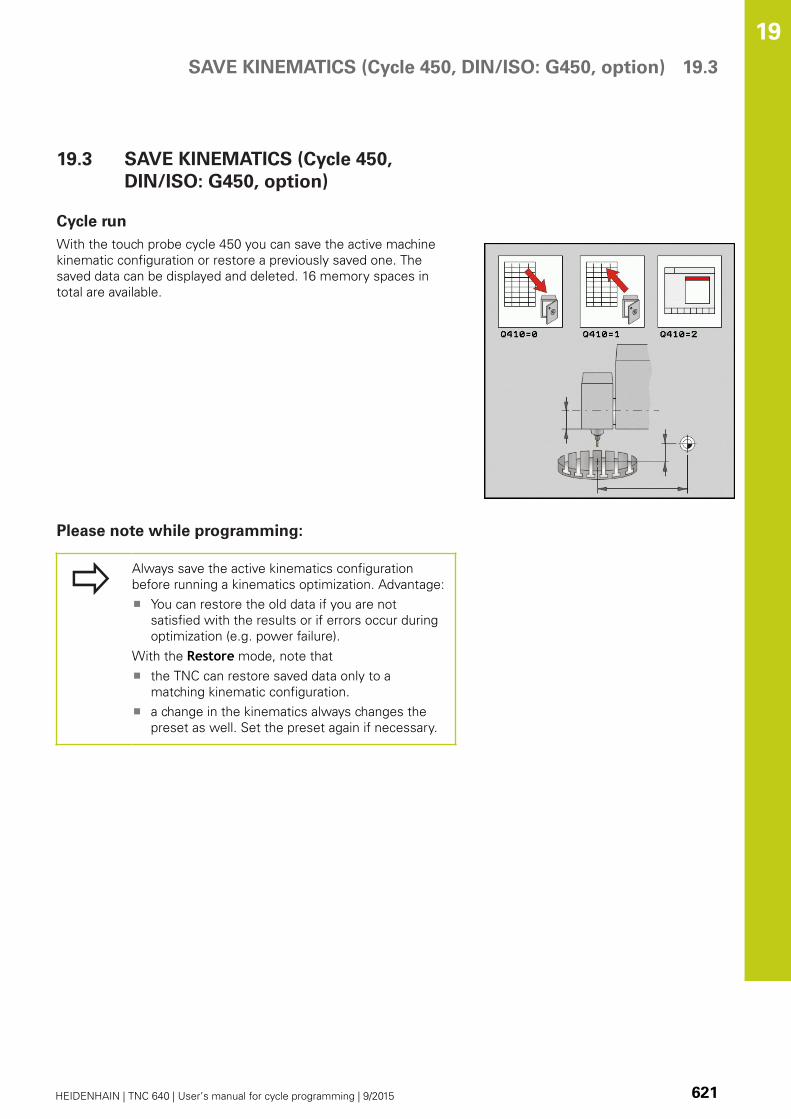
SAVE KINEMATICS (Cycle 450, DIN/ISO: G450, option) 19.3
19
HEIDENHAIN | TNC 640 | User’s manual for cycle programming | 9/2015 621
19.3 SAVE KINEMATICS (Cycle 450,
DIN/ISO: G450, option)
Cycle run
With the touch probe cycle 450 you can save the active machine
kinematic configuration or restore a previously saved one. The
saved data can be displayed and deleted. 16 memory spaces in
total are available.
Please note while programming:
Always save the active kinematics configuration
before running a kinematics optimization. Advantage:
You can restore the old data if you are not
satisfied with the results or if errors occur during
optimization (e.g. power failure).
With the Restore mode, note that
the TNC can restore saved data only to a
matching kinematic configuration.
a change in the kinematics always changes the
preset as well. Set the preset again if necessary.
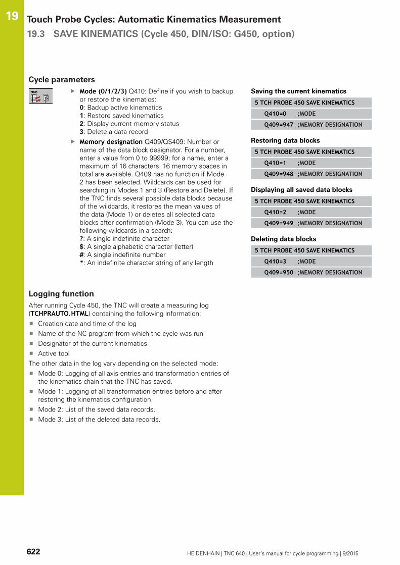
Touch Probe Cycles: Automatic Kinematics Measurement 19.3 SAVE KINEMATICS (Cycle 450, DIN/ISO: G450, option)
19
622 HEIDENHAIN | TNC 640 | User’s manual for cycle programming | 9/2015
Cycle parameters
Mode (0/1/2/3) Q410: Define if you wish to backup
or restore the kinematics:
0: Backup active kinematics
1: Restore saved kinematics
2: Display current memory status
3: Delete a data record
Memory designation Q409/QS409: Number or
name of the data block designator. For a number,
enter a value from 0 to 99999; for a name, enter a
maximum of 16 characters. 16 memory spaces in
total are available. Q409 has no function if Mode
2 has been selected. Wildcards can be used for
searching in Modes 1 and 3 (Restore and Delete). If
the TNC finds several possible data blocks because
of the wildcards, it restores the mean values of
the data (Mode 1) or deletes all selected data
blocks after confirmation (Mode 3). You can use the
following wildcards in a search:
?: A single indefinite character
$: A single alphabetic character (letter)
#: A single indefinite number
*: An indefinite character string of any length
Saving the current kinematics
5 TCH PROBE 450 SAVE KINEMATICS
Q410=0 ;MODE
Q409=947 ;MEMORY DESIGNATION
Restoring data blocks
5 TCH PROBE 450 SAVE KINEMATICS
Q410=1 ;MODE
Q409=948 ;MEMORY DESIGNATION
Displaying all saved data blocks
5 TCH PROBE 450 SAVE KINEMATICS
Q410=2 ;MODE
Q409=949 ;MEMORY DESIGNATION
Deleting data blocks
5 TCH PROBE 450 SAVE KINEMATICS
Q410=3 ;MODE
Q409=950 ;MEMORY DESIGNATION
Logging function
After running Cycle 450, the TNC will create a measuring log
(TCHPRAUTO.HTML) containing the following information:
Creation date and time of the log
Name of the NC program from which the cycle was run
Designator of the current kinematics
Active tool
The other data in the log vary depending on the selected mode:
Mode 0: Logging of all axis entries and transformation entries of
the kinematics chain that the TNC has saved.
Mode 1: Logging of all transformation entries before and after
restoring the kinematics configuration.
Mode 2: List of the saved data records.
Mode 3: List of the deleted data records.

SAVE KINEMATICS (Cycle 450, DIN/ISO: G450, option) 19.3
19
HEIDENHAIN | TNC 640 | User’s manual for cycle programming | 9/2015 623
Notes on data management
The TNC stores the saved data in the file TNC:\table\DATA450.KD.
This file can be backed up on an external PC with TNCREMO, for
example. If the file is deleted, the stored data are removed, too.
If the data in the file are changed manually, the data records can
become corrupted so that they cannot be used anymore.
If the TNC:\table\DATA450.KD file does not exist,
it is generated automatically when Cycle 450 is
executed.
Make sure that you delete empty files with the name
TNC:\table\DATA450.KD, if any, before starting Cycle
450. If there is an empty storage table (TNC:\table\DATA450.KD) that does not contain any lines yet,
an error message will be displayed upon starting to
run Cycle 450. In this case, delete the empty storage
table and call the cycle again.
Do not change stored data manually.
Make a backup of the TNC:\table\DATA450.KD file
so that you can restore the file, if necessary (e.g. if
the data medium is damaged).
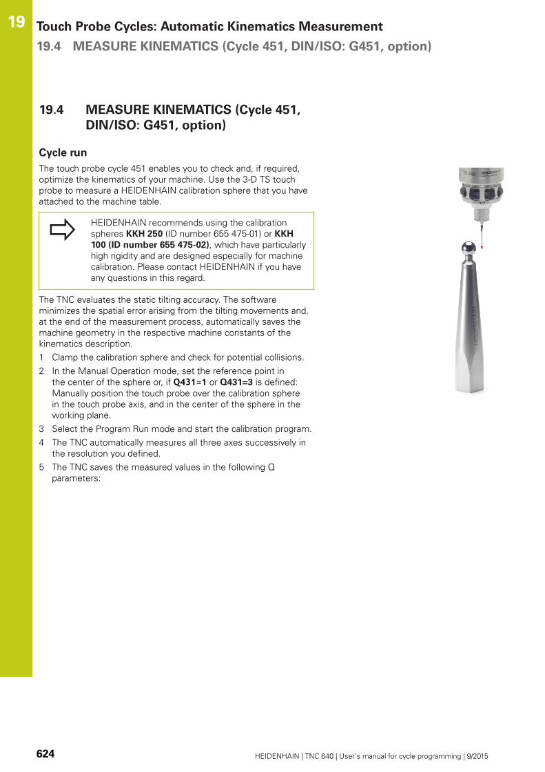
Touch Probe Cycles: Automatic Kinematics Measurement 19.4 MEASURE KINEMATICS (Cycle 451, DIN/ISO: G451, option)
19
624 HEIDENHAIN | TNC 640 | User’s manual for cycle programming | 9/2015
19.4 MEASURE KINEMATICS (Cycle 451,
DIN/ISO: G451, option)
Cycle run
The touch probe cycle 451 enables you to check and, if required,
optimize the kinematics of your machine. Use the 3-D TS touch
probe to measure a HEIDENHAIN calibration sphere that you have
attached to the machine table.
HEIDENHAIN recommends using the calibration
spheres KKH 250 (ID number 655 475-01) or KKH
100 (ID number 655 475-02), which have particularly
high rigidity and are designed especially for machine
calibration. Please contact HEIDENHAIN if you have
any questions in this regard.
The TNC evaluates the static tilting accuracy. The software
minimizes the spatial error arising from the tilting movements and,
at the end of the measurement process, automatically saves the
machine geometry in the respective machine constants of the
kinematics description.
1 Clamp the calibration sphere and check for potential collisions.
2 In the Manual Operation mode, set the reference point in
the center of the sphere or, if Q431=1 or Q431=3 is defined:
Manually position the touch probe over the calibration sphere
in the touch probe axis, and in the center of the sphere in the
working plane.
3 Select the Program Run mode and start the calibration program.
4 The TNC automatically measures all three axes successively in
the resolution you defined.
5 The TNC saves the measured values in the following Q
parameters:

MEASURE KINEMATICS (Cycle 451, DIN/ISO: G451, option) 19.4
19
HEIDENHAIN | TNC 640 | User’s manual for cycle programming | 9/2015 625
Parameter
number
Meaning
Q141 Standard deviation measured in the A axis
(–1 if axis was not measured)
Q142 Standard deviation measured in the B axis
(–1 if axis was not measured)
Q143 Standard deviation measured in the C axis
(–1 if axis was not measured)
Q144 Optimized standard deviation in the A axis
(–1 if axis was not optimized)
Q145 Optimized standard deviation in the B axis
(–1 if axis was not optimized)
Q146 Optimized standard deviation in the C axis
(–1 if axis was not optimized)
Q147 Offset error in X direction, for manual
transfer to the corresponding machine
parameter
Q148 Offset error in Y direction, for manual
transfer to the corresponding machine
parameter
Q149 Offset error in Z direction, for manual
transfer to the corresponding machine
parameter

Touch Probe Cycles: Automatic Kinematics Measurement 19.4 MEASURE KINEMATICS (Cycle 451, DIN/ISO: G451, option)
19
626 HEIDENHAIN | TNC 640 | User’s manual for cycle programming | 9/2015
Positioning direction
The positioning direction of the rotary axis to be measured is
determined from the start angle and the end angle that you define
in the cycle. A reference measurement is automatically performed
at 0°.
Specify the start and end angles to ensure that the same position
is not measured twice. A duplicated point measurement (e.g.
measuring positions +90° and –270°) is not advisable, but it does
not cause an error message.
Example: Start angle = +90°, end angle = –90°
Start angle = +90°
End angle = –90°
No. of measuring points = 4
Stepping angle resulting from the calculation = (–90 – +90) /
(4 – 1) = –60°
Measuring point 1 = +90°
Measuring point 2 = +30°
Measuring point 3 = –30°
Measuring point 4 = –90°
Example: start angle = +90°, end angle = +270°
Start angle = +90°
End angle = +270°
No. of measuring points = 4
Stepping angle resulting from the calculation = (270 – 90) / (4
– 1) = +60°
Measuring point 1 = +90°
Measuring point 2 = +150°
Measuring point 3 = +210°
Measuring point 4 = +270°

MEASURE KINEMATICS (Cycle 451, DIN/ISO: G451, option) 19.4
19
HEIDENHAIN | TNC 640 | User’s manual for cycle programming | 9/2015 627
Machines with Hirth-coupled axes
Danger of collision!
In order to be positioned, the axis must move out of
the Hirth grid. So remember to leave a large enough
safety clearance to prevent any risk of collision
between the touch probe and calibration sphere.
Also ensure that there is enough space to reach the
safety clearance (software limit switch).
Define a retraction height Q408 greater than 0 if
software option 2 (M128, FUNCTION TCPM) is not
available.
If necessary, the TNC rounds the calculated
measuring positions so that they fit into the Hirth grid
(depending on the start angle, end angle and number
of measuring points).
Depending on the machine configuration, the TNC
cannot position the rotary axes automatically. If this
is the case, you need a special M function from the
machine tool builder enabling the TNC to move the
rotary axes. The machine tool builder must have
entered the number of the M function in machine
parameter mStrobeRotAxPos for this purpose.
The measuring positions are calculated from the start angle, end
angle and number of measurements for the respective axis and
from the Hirth grid.
Example calculation of measuring positions for an A axis:
Start angle Q411 = –30
End angle Q412 = +90
Number of measuring points Q414 = 4
Hirth grid = 3°
Calculated stepping angle = ( Q412 – Q411 ) / ( Q414 – 1 )
Calculated stepping angle = = ( 90 – –30 ) / ( 4 – 1 ) = 120 / 3 = 40
Measuring position 1 = Q411 + 0 * stepping angle = -30° --> -30°
Measuring position 2 = Q411 + 1 * stepping angle = +10° --> 9°
Measuring position 3 = Q411 + 2 * stepping angle = +50° --> 51°
Measuring position 4 = Q411 + 3 * stepping angle = +90° --> 90°

Touch Probe Cycles: Automatic Kinematics Measurement 19.4 MEASURE KINEMATICS (Cycle 451, DIN/ISO: G451, option)
19
628 HEIDENHAIN | TNC 640 | User’s manual for cycle programming | 9/2015
Choice of number of measuring points
To save time you can make a rough optimization with a small
number of measuring points (1 or 2), for example during
commissioning.
You then make a fine optimization with a medium number of
measuring points (recommended value = approx. 4). Higher
numbers of measuring points do not usually improve the results.
Ideally, you should distribute the measuring points evenly over the
tilting range of the axis.
This is why you should measure an axis with a tilting range of 0°
to 360° at three measuring points, namely at 90°, 180° and 270°.
Thus, define a starting angle of 90° and an end angle of 270°.
If you want to check the accuracy accordingly, you can also enter a
higher number of measuring points in the Check mode.
If a measuring point has been defined at 0°, it will
be ignored because the reference measurement is
always done at 0°.

MEASURE KINEMATICS (Cycle 451, DIN/ISO: G451, option) 19.4
19
HEIDENHAIN | TNC 640 | User’s manual for cycle programming | 9/2015 629
Choice of the calibration sphere position on the
machine table
In principle, you can fix the calibration sphere to any accessible
position on the machine table and also on fixtures or workpieces.
The following factors should positively influence the result of
measurement:
On machine with rotary tables/tilting tables: Clamp the
calibrating ball as far as possible away from the center of
rotation.
On machines with very large traverse paths: Clamp the
calibration sphere as closely as possible to the position intended
for subsequent machining.
Notes on the accuracy
The geometrical and positioning errors of the machine influence
the measured values and therefore also the optimization of a rotary
axis. For this reason there will always be a certain amount of error.
If there were no geometrical and positioning errors, any values
measured by the cycle at any point on the machine at a certain
time would be exactly reproducible. The greater the geometrical
and positioning errors are, the greater is the dispersion of
measured results when you perform measurements at different
positions.
The dispersion of results recorded by the TNC in the measuring log
is a measure of the machine's static tilting accuracy. However, the
measuring circle radius and the number and position of measuring
points have to be included in the evaluation of accuracy. One
measuring point alone is not enough to calculate dispersion. For
only one point, the result of the calculation is the spatial error of
that measuring point.
If several rotary axes are moved simultaneously, their error values
are combined. In the worst case they are added together.
If your machine is equipped with a controlled
spindle, you should activate the angle tracking in the
touch probe table (TRACK column). This generally
increases the accuracy of measurements with a 3-D
touch probe.
If required, deactivate the lock on the rotary axes
for the duration of the calibration. Otherwise it may
falsify the results of measurement. The machine tool
manual provides further information.

Touch Probe Cycles: Automatic Kinematics Measurement 19.4 MEASURE KINEMATICS (Cycle 451, DIN/ISO: G451, option)
19
630 HEIDENHAIN | TNC 640 | User’s manual for cycle programming | 9/2015
Notes on various calibration methods
Rough optimization during commissioning after entering
approximate dimensions.
Number of measuring points between 1 and 2
Angular step of the rotary axes: Approx. 90°
Fine optimization over the entire range of traverse
Number of measuring points between 3 and 6
The start and end angles should cover the largest possible
traverse range of the rotary axes.
Position the calibration sphere on the machine table so that
on rotary table axes there is a large measuring circle, or so
that on swivel head axes the measurement can be made at
a representative position (e.g. in the center of the traverse
range).
Optimization of a specific rotary axis position
Number of measuring points between 2 and 3
The measurements are made near the rotary axis angle at
which the workpiece is to be machined.
Position the calibration sphere on the machine table for
calibration at the position subsequently intended for
machining.
Inspecting the machine accuracy
Number of measuring points between 4 and 8
The start and end angles should cover the largest possible
traverse range of the rotary axes.
Determination of the rotary axis backlash
Number of measuring points between 8 and 12
The start and end angles should cover the largest possible
traverse range of the rotary axes.

MEASURE KINEMATICS (Cycle 451, DIN/ISO: G451, option) 19.4
19
HEIDENHAIN | TNC 640 | User’s manual for cycle programming | 9/2015 631
Backlash
Backlash is a small amount of play between the rotary or angle
encoder and the table that occurs when the traverse direction is
reversed. If the rotary axes have backlash outside of the control
loop, for example because the angle measurement is made with
the motor encoder, this can result in significant error during tilting.
With input parameter Q432 you can activate backlash
measurement. Enter an angle that the TNC uses as traversing
angle. The cycle will then carry out two measurements per rotary
axis. If you take over the angle value 0, the TNC will not measure
any backlash.
The TNC does not perform an automatic backlash
compensation.
If the measuring circle radius is < 1 mm, the TNC
does not calculate the backlash. The larger the
measuring circle radius, the more accurately the TNC
can determine the rotary axis backlash (see "Logging
function", page 637).
Backlash measurement is not possible if an M
function for positioning the rotary axes is set in
machine parameter mStrobeRotAxPos or if the axis is
a Hirth axis.

Touch Probe Cycles: Automatic Kinematics Measurement 19.4 MEASURE KINEMATICS (Cycle 451, DIN/ISO: G451, option)
19
632 HEIDENHAIN | TNC 640 | User’s manual for cycle programming | 9/2015
Please note while programming:
Note that all functions for tilting in the working
plane are reset. M128 and FUNCTION TCPM are
deactivated.
Position the calibration sphere on the machine
table so that there can be no collisions during the
measuring process.
Before defining the cycle you must set the
datum in the center of the calibration sphere and
activate it, or you define the input parameter Q431
correspondingly to 1 or 3.
If machine parameter mStrobeRotAxPos is defined
as not equal –1 (M function positions the rotary axis),
then only start a measurement when all rotary axes
are at 0°.
For the positioning feed rate when moving to the
probing height in the touch probe axis, the TNC uses
the value from cycle parameter Q253 or the FMAX
value, whichever is smaller. The TNC always moves
the rotary axes at positioning feed rate Q253, while
the probe monitoring is inactive.
If the kinematic data attained in the Optimize
mode are greater than the permissible limit
(maxModification), the TNC shows a warning. Then
you have to confirm acceptance of the attained value
by pressing NC start.
Note that a change in the kinematics always changes
the preset as well. After an optimization, reset the
preset.
In every probing process the TNC first measures
the radius of the calibration sphere. If the measured
sphere radius differs from the entered sphere radius
by more than you have defined in machine parameter
maxDevCalBall the TNC shows an error message
and ends the measurement.
If you interrupt the cycle during the measurement,
the kinematic data might no longer be in the original
condition. Save the active kinematic configuration
before an optimization with Cycle 450, so that in
case of an emergency the most recently active
kinematic configuration can be restored.
Programming in inches: The TNC always records the
log data and results of measurement in millimeters.
The TNC ignores cycle definition data that applies to
inactive axes.

MEASURE KINEMATICS (Cycle 451, DIN/ISO: G451, option) 19.4
19
HEIDENHAIN | TNC 640 | User’s manual for cycle programming | 9/2015 633
Cycle parameters
Mode (0=Check/1=Measure) Q406: Specify
whether the TNC should check or optimize the
active kinematics:
0: Check active kinematics. The TNC measures
the kinematics in the rotary axes you have defined,
but it does not make any changes to it. The
TNC displays the results of measurement in a
measurement log.
1: Optimize active kinematics. The TNC measures
the kinematics in the rotary axes you have defined
and optimizes the position of the rotary axes of
the active kinematics.
Exact calibration sphere radius Q407: Enter the
exact radius of the calibration sphere used. Input
range 0.0001 to 99.9999
Set-up clearance Q320 (incremental): Additional
distance between measuring point and ball tip.
Q320 is added to SET_UP in the touch probe table.
Input range 0 to 99999.9999; alternatively PREDEFRetraction height Q408 (absolute): Input range
0.0001 to 99999.9999
Input 0:
Do not move to any retraction height. The TNC
moves to the next measuring position in the axis
to be measured. Not allowed for Hirth axes! The
TNC moves to the first measuring position in the
sequence A, then B, then C.
Input >0:
Retraction height in the untilted workpiece
coordinate system to which the TNC positions
before a rotary axis positioning in the spindle
axis. Also, the TNC moves the touch probe in the
working plane to the datum. Probe monitoring is
not active in this mode. Define the positioning
velocity in parameter Q253.
Feed rate for pre-positioning Q253: Traversing
speed of the tool in mm/min during positioning.
Input range 0.0001 to 99999.9999; alternatively
FMAX, FAUTO, PREDEF
Saving and checking the kinematics
4 TOOL CALL "TCH PROBE" Z
5 TCH PROBE 450 SAVE KINEMATICS
Q410=0 ;MODE
Q409=5 ;MEMORY DESIGNATION
6 TCH PROBE 451 MEASUREKINEMATICS
Q406=0 ;MODE
Q407=12.5 ;SPHERE RADIUS
Q320=0 ;SET-UP CLEARANCE
Q408=0 ;RETR. HEIGHT
Q253=750 ;F PRE-POSITIONING
Q380=0 ;REFERENCE ANGLE
Q411=-90 ;START ANGLE A AXIS
Q412=+90 ;END ANGLE A AXIS
Q413=0 ;INCID. ANGLE A AXIS
Q414=0 ;MEAS. POINTS A AXIS
Q415=-90 ;START ANGLE B AXIS
Q416=+90 ;END ANGLE B AXIS
Q417=0 ;INCID. ANGLE B AXIS
Q418=2 ;MEAS. POINTS B AXIS
Q419=-90 ;START ANGLE C AXIS
Q420=+90 ;END ANGLE C AXIS
Q421=0 ;INCID. ANGLE C AXIS
Q422=2 ;MEAS. POINTS C AXIS
Q423=4 ;NO. OF PROBE POINTS
Q431=0 ;PRESET
Q432=0 ;BACKLASH, ANG.RANGE
Touch Probe Cycles: Automatic Kinematics Measurement 19.4 MEASURE KINEMATICS (Cycle 451, DIN/ISO: G451, option)
19
634 HEIDENHAIN | TNC 640 | User’s manual for cycle programming | 9/2015
Reference angle Q380 (absolute): Reference
angle (basic rotation) for measuring the measuring
points in the active workpiece coordinate system.
Defining a reference angle can considerably enlarge
the measuring range of an axis. Input range 0 to
360.0000
Start angle A axis Q411 (absolute): Starting angle in
the A axis at which the first measurement is to be
made. Input range -359.999 to 359.999
End angle A axis Q412 (absolute): Ending angle in
the A axis at which the last measurement is to be
made. Input range -359.999 to 359.999
Angle of incid. A axis Q413: Angle of incidence in
the A axis at which the other rotary axes are to be
measured. Input range -359.999 to 359.999
Number meas. points A axis Q414: Number of
probe measurements with which the TNC is to
measure the A axis. If the input value = 0, the TNC
does not measure the respective axis. Input range 0
to 12
Start angle B axis Q415 (absolute): Starting angle in
the B axis at which the first measurement is to be
made. Input range -359.999 to 359.999
End angle B axis Q416 (absolute): Ending angle in
the B axis at which the last measurement is to be
made. Input range -359.999 to 359.999
Angle of incid. in B axis Q417: Angle of incidence
in the B axis at which the other rotary axes are to be
measured. Input range -359.999 to 359.999
Number meas. points B axis Q418: Number of
probe measurements with which the TNC is to
measure the B axis. If the input value = 0, the TNC
does not measure the respective axis. Input range 0
to 12
Start angle C axis Q419 (absolute): Starting angle in
the C axis at which the first measurement is to be
made. Input range -359.999 to 359.999
End angle C axis Q420 (absolute): Ending angle in
the C axis at which the last measurement is to be
made. Input range -359.999 to 359.999
Angle of incid. in C axis Q421: Angle of incidence
in the C axis at which the other rotary axes are to be
measured. Input range -359.999 to 359.999
Number meas. points C axis Q422: Number of
probe measurements with which the TNC is to
measure the C axis. Input range 0 to 12. If the input
value = 0, the TNC does not measure the respective
axis.
MEASURE KINEMATICS (Cycle 451, DIN/ISO: G451, option) 19.4
19
HEIDENHAIN | TNC 640 | User’s manual for cycle programming | 9/2015 635
Number meas. points (3-8) Q423: Number of
probe measurements with which the TNC is to
measure the calibration sphere in the plane. Input
range 3 to 8. Less measuring points increase speed
and more measuring points increase measurement
precision.
Preset (0/1/2/3) Q431: Define whether the TNC
automatically sets the active preset (datum) into the
center of the sphere:
0: Do not set the preset automatically into the
center of the sphere: Preset manually before cycle
start
1: Automatically preset into the center of the sphere
before measurement: Manually preposition the
touch probe above the calibration sphere before the
cycle start
2: Automatically preset into the center of the sphere
after measurement: Preset manually before cycle
start
3: Preset before and after measurement into the
center of the sphere: Preposition the touch probe
manually above the calibration sphere before cycle
start
Backlash, angle range Q432: Here you define
the angle value to be used as traverse for the
measurement of the rotary axis. The traversing
angle must be significantly larger than the actual
backlash of the rotary axes. If input value = 0, the
TNC does not measure the backlash. Input range
-3.0000 to +3.0000
If you have activated "Preset" before the calibration
(Q431 = 1/3), then move the touch probe by the safety
clearance (Q320 + SET_UP) to a position approximately
above the center of the calibration sphere before the
start of the cycle.

Touch Probe Cycles: Automatic Kinematics Measurement 19.4 MEASURE KINEMATICS (Cycle 451, DIN/ISO: G451, option)
19
636 HEIDENHAIN | TNC 640 | User’s manual for cycle programming | 9/2015
Various modes (Q406)
Test mode Q406 = 0
The TNC measures the rotary axes in the positions defined and
calculates the static accuracy of the tilting transformation.
The TNC records the results of a possible position optimization
but does not make any adjustments.
Position Optimization mode Q406 = 1
The TNC measures the rotary axes in the positions defined and
calculates the static accuracy of the tilting transformation.
During this, the TNC tries to change the position of the rotary axis
in the kinematics model in order to achieve higher accuracy.
The machine data is adjusted automatically.
Position optimization of the rotary
axes with preceding, automatic
datum setting and measurement of
the rotary axis backlash
1 TOOL CALL "TCH PROBE" Z
2 TCH PROBE 451 MEASUREKINEMATICS
Q406=1 ;MODE
Q407=12.5 ;SPHERE RADIUS
Q320=0 ;SET-UP CLEARANCE
Q408=0 ;RETR. HEIGHT
Q253=750 ;F PRE-POSITIONING
Q380=0 ;REFERENCE ANGLE
Q411=-90 ;START ANGLE A AXIS
Q412=+90 ;END ANGLE A AXIS
Q413=0 ;INCID. ANGLE A AXIS
Q414=0 ;MEAS. POINTS A AXIS
Q415=-90 ;START ANGLE B AXIS
Q416=+90 ;END ANGLE B AXIS
Q417=0 ;INCID. ANGLE B AXIS
Q418=0 ;MEAS. POINTS B AXIS
Q419=+90 ;START ANGLE C AXIS
Q420=+270;END ANGLE C AXIS
Q421=0 ;INCID. ANGLE C AXIS
Q422=3 ;MEAS. POINTS C AXIS
Q423=3 ;NO. OF PROBE POINTS
Q431=1 ;PRESET
Q432=0.5 ;BACKLASH, ANG.RANGE

MEASURE KINEMATICS (Cycle 451, DIN/ISO: G451, option) 19.4
19
HEIDENHAIN | TNC 640 | User’s manual for cycle programming | 9/2015 637
Logging function
After running Cycle 451, the TNC creates a measuring log
(TCHPR451.TXT) containing the following information:
Creation date and time of the log
Path of the NC program from which the cycle was run
Mode used (0=Check/1=Optimize position/2=Optimize pose)
Active kinematic number
Entered calibration sphere radius
For each measured rotary axis:
Starting angle
End angle
Angle of incidence
Number of measuring points
Dispersion (standard deviation)
Maximum error
Angular error
Averaged backlash
Averaged positioning error
Measuring circle radius
Compensation values in all axes (preset shift)
Measurement uncertainty of rotary axes

Touch Probe Cycles: Automatic Kinematics Measurement 19.5 PRESET COMPENSATION (Cycle 452, DIN/ISO: G452, option)
19
638 HEIDENHAIN | TNC 640 | User’s manual for cycle programming | 9/2015
19.5 PRESET COMPENSATION (Cycle 452,
DIN/ISO: G452, option)
Cycle run
Touch probe cycle 452 optimizes the kinematic transformation
chain of your machine (see "MEASURE KINEMATICS (Cycle 451,
DIN/ISO: G451, option)", page 624). Then the TNC corrects the
workpiece coordinate system in the kinematics model in such a
way that the current preset is in the center of the calibration sphere
after optimization.
This cycle enables you, for example, to adjust different
interchangeable heads so that the workpiece preset applies for all
heads.
1 Clamp the calibration sphere
2 Measure the complete reference head with Cycle 451, and use
Cycle 451 to finally set the preset in the center of the sphere.
3 Insert the second head.
4 Use Cycle 452 to measure the interchangeable head up to the
point where the head is changed.
5 Use Cycle 452 to adjust other interchangeable heads to the
reference head.
If it is possible to leave the calibration sphere clamped to the
machine table during machining, you can compensate for machine
drift, for example. This procedure is also possible on a machine
without rotary axes.
1 Clamp the calibration sphere and check for potential collisions.
2 Define the preset in the calibration sphere.
3 Set the preset on the workpiece, and start machining the
workpiece.
4 Use Cycle 452 for preset compensation at regular intervals. The
TNC measures the drift of the axes involved and compensates it
in the kinematics description.
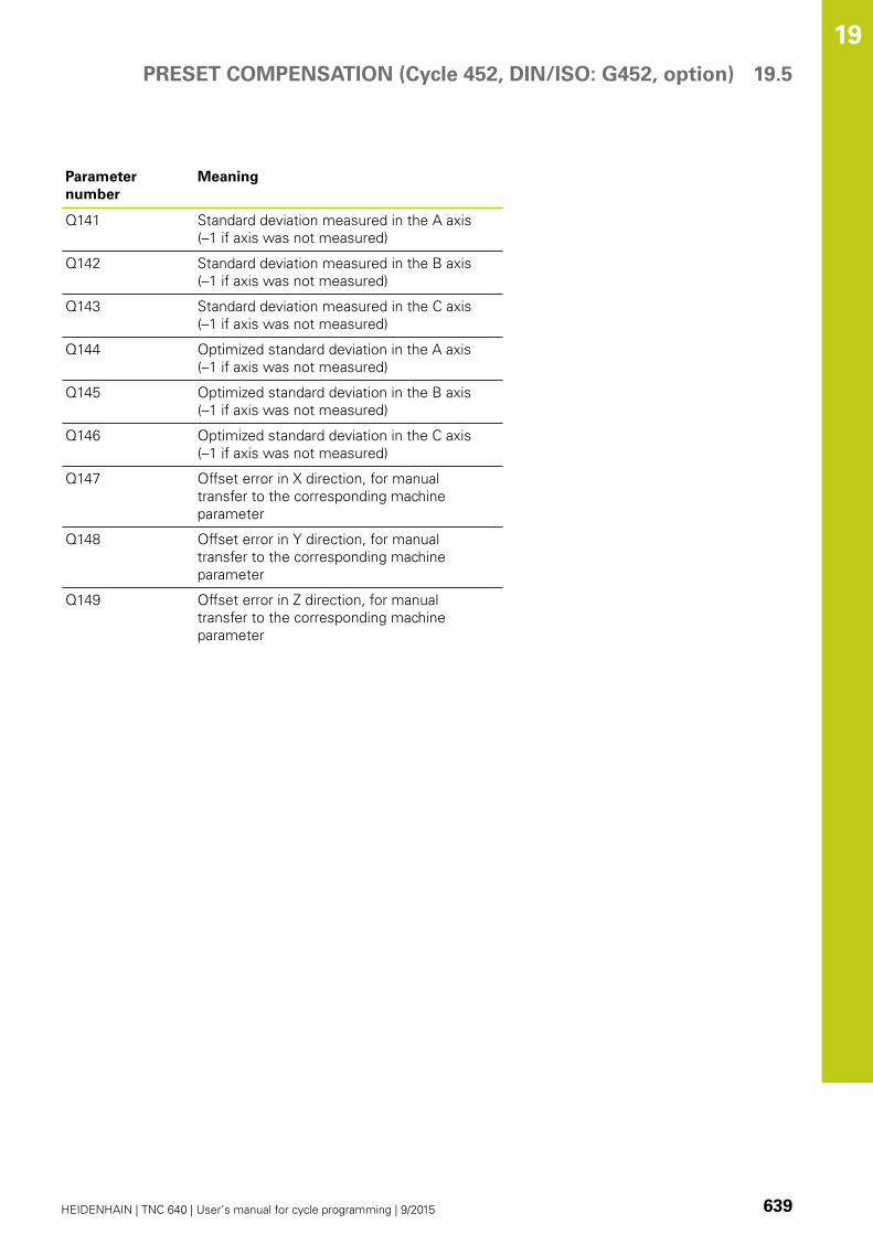
PRESET COMPENSATION (Cycle 452, DIN/ISO: G452, option) 19.5
19
HEIDENHAIN | TNC 640 | User’s manual for cycle programming | 9/2015 639
Parameter
number
Meaning
Q141 Standard deviation measured in the A axis
(–1 if axis was not measured)
Q142 Standard deviation measured in the B axis
(–1 if axis was not measured)
Q143 Standard deviation measured in the C axis
(–1 if axis was not measured)
Q144 Optimized standard deviation in the A axis
(–1 if axis was not measured)
Q145 Optimized standard deviation in the B axis
(–1 if axis was not measured)
Q146 Optimized standard deviation in the C axis
(–1 if axis was not measured)
Q147 Offset error in X direction, for manual
transfer to the corresponding machine
parameter
Q148 Offset error in Y direction, for manual
transfer to the corresponding machine
parameter
Q149 Offset error in Z direction, for manual
transfer to the corresponding machine
parameter

Touch Probe Cycles: Automatic Kinematics Measurement 19.5 PRESET COMPENSATION (Cycle 452, DIN/ISO: G452, option)
19
640 HEIDENHAIN | TNC 640 | User’s manual for cycle programming | 9/2015
Please note while programming:
In order to be able to perform a preset
compensation, the kinematics must be specially
prepared. The machine manual provides further
information.
Note that all functions for tilting in the working
plane are reset. M128 and FUNCTION TCPM are
deactivated.
Position the calibration sphere on the machine
table so that there can be no collisions during the
measuring process.
Before defining the cycle you must set the datum in
the center of the calibration sphere and activate it.
For rotary axes without separate position encoders,
select the measuring points in such a way that you
have to traverse a distance of 1° to the limit switch.
The TNC needs this distance for internal backlash
compensation.
For the positioning feed rate when moving to the
probing height in the touch probe axis, the TNC uses
the value from cycle parameter Q253 or the FMAX
value, whichever is smaller. The TNC always moves
the rotary axes at positioning feed rate Q253, while
the probe monitoring is inactive.
If the kinematic data are greater than the permissible
limit (maxModification), the TNC shows a warning.
Then you have to confirm acceptance of the attained
value by pressing NC start.
Note that a change in the kinematics always changes
the preset as well. After an optimization, reset the
preset.
In every probing process the TNC first measures
the radius of the calibration sphere. If the measured
sphere radius differs from the entered sphere radius
by more than you have defined in machine parameter
maxDevCalBall the TNC shows an error message
and ends the measurement.
If you interrupt the cycle during the measurement,
the kinematic data might no longer be in the original
condition. Save the active kinematic configuration
before an optimization with Cycle 450, so that in
case of a failure the most recently active kinematic
configuration can be restored.
Programming in inches: The TNC always records the
log data and results of measurement in millimeters.

PRESET COMPENSATION (Cycle 452, DIN/ISO: G452, option) 19.5
19
HEIDENHAIN | TNC 640 | User’s manual for cycle programming | 9/2015 641
Cycle parameters
Exact calibration sphere radius Q407: Enter the
exact radius of the calibration sphere used. Input
range 0.0001 to 99.9999
Set-up clearance Q320 (incremental): Additional
distance between measuring point and ball
tip. Q320 is added to SET_UP. Input range 0 to
99999.9999; alternatively PREDEFRetraction height Q408 (absolute): Input range
0.0001 to 99999.9999
Input 0:
Do not move to any retraction height. The TNC
moves to the next measuring position in the axis
to be measured. Not allowed for Hirth axes! The
TNC moves to the first measuring position in the
sequence A, then B, then C.
Input >0:
Retraction height in the untilted workpiece
coordinate system to which the TNC positions
before a rotary axis positioning in the spindle
axis. Also, the TNC moves the touch probe in the
working plane to the datum. Probe monitoring is
not active in this mode. Define the positioning
velocity in parameter Q253.
Feed rate for pre-positioning Q253: Traversing
speed of the tool in mm/min during positioning.
Input range 0.0001 to 99999.9999; alternatively
FMAX, FAUTO, PREDEFReference angle Q380 (absolute): Reference
angle (basic rotation) for measuring the measuring
points in the active workpiece coordinate system.
Defining a reference angle can considerably enlarge
the measuring range of an axis. Input range 0 to
360.0000
Start angle A axis Q411 (absolute): Starting angle in
the A axis at which the first measurement is to be
made. Input range -359.999 to 359.999
End angle A axis Q412 (absolute): Ending angle in
the A axis at which the last measurement is to be
made. Input range -359.999 to 359.999
Angle of incid. A axis Q413: Angle of incidence in
the A axis at which the other rotary axes are to be
measured. Input range -359.999 to 359.999
Number meas. points A axis Q414: Number of
probe measurements with which the TNC is to
measure the A axis. If the input value = 0, the TNC
does not measure the respective axis. Input range 0
to 12
Start angle B axis Q415 (absolute): Starting angle in
the B axis at which the first measurement is to be
made. Input range -359.999 to 359.999
End angle B axis Q416 (absolute): Ending angle in
the B axis at which the last measurement is to be
made. Input range -359.999 to 359.999
Calibration program
4 TOOL CALL "TCH PROBE" Z
5 TCH PROBE 450 SAVE KINEMATICS
Q410=0 ;MODE
Q409=5 ;MEMORY DESIGNATION
6 TCH PROBE 452 PRESETCOMPENSATION
Q407=12.5 ;SPHERE RADIUS
Q320=0 ;SET-UP CLEARANCE
Q408=0 ;RETR. HEIGHT
Q253=750 ;F PRE-POSITIONING
Q380=0 ;REFERENCE ANGLE
Q411=-90 ;START ANGLE A AXIS
Q412=+90 ;END ANGLE A AXIS
Q413=0 ;INCID. ANGLE A AXIS
Q414=0 ;MEAS. POINTS A AXIS
Q415=-90 ;START ANGLE B AXIS
Q416=+90 ;END ANGLE B AXIS
Q417=0 ;INCID. ANGLE B AXIS
Q418=2 ;MEAS. POINTS B AXIS
Q419=-90 ;START ANGLE C AXIS
Q420=+90 ;END ANGLE C AXIS
Q421=0 ;INCID. ANGLE C AXIS
Q422=2 ;MEAS. POINTS C AXIS
Q423=4 ;NO. OF PROBE POINTS
Q432=0 ;BACKLASH, ANG.RANGE

Touch Probe Cycles: Automatic Kinematics Measurement 19.5 PRESET COMPENSATION (Cycle 452, DIN/ISO: G452, option)
19
642 HEIDENHAIN | TNC 640 | User’s manual for cycle programming | 9/2015
Angle of incid. in B axis Q417: Angle of incidence
in the B axis at which the other rotary axes are to be
measured. Input range -359.999 to 359.999
Number meas. points B axis Q418: Number of
probe measurements with which the TNC is to
measure the B axis. If the input value = 0, the TNC
does not measure the respective axis. Input range 0
to 12
Start angle C axis Q419 (absolute): Starting angle in
the C axis at which the first measurement is to be
made. Input range -359.999 to 359.999
End angle C axis Q420 (absolute): Ending angle in
the C axis at which the last measurement is to be
made. Input range -359.999 to 359.999
Angle of incid. in C axis Q421: Angle of incidence
in the C axis at which the other rotary axes are to be
measured. Input range -359.999 to 359.999
Number meas. points C axis Q422: Number of
probe measurements with which the TNC is to
measure the C axis. If the input value = 0, the TNC
does not measure the respective axis. Input range 0
to 12
No. of measuring points Q423: Specify the
number of probing points to be used by the TNC for
measuring the calibration sphere in the plane. Input
range: 3 to 8 measurements
Backlash, angle range Q432: Here you define
the angle value to be used as traverse for the
measurement of the rotary axis. The traversing
angle must be significantly larger than the actual
backlash of the rotary axes. If input value = 0, the
TNC does not measure the backlash. Input range
-3.0000 to +3.0000

PRESET COMPENSATION (Cycle 452, DIN/ISO: G452, option) 19.5
19
HEIDENHAIN | TNC 640 | User’s manual for cycle programming | 9/2015 643
Adjustment of interchangeable heads
The goal of this procedure is for the workpiece preset to remain
unchanged after changing rotary axes (head exchange).
In the following example, a fork head is adjusted to the A and C axes.
The A axis is changed, whereas the C axis continues being a part of
the basic configuration.
Insert the interchangeable head that will be used as a reference
head.
Clamp the calibration sphere
Insert the touch probe
Use Cycle 451 to measure the complete kinematics, including the
reference head.
Set the preset (using Q431 = 2 or 3 in Cycle 451) after measuring
the reference head
Measuring a reference head
1 TOOL CALL "TCH PROBE" Z
2 TCH PROBE 451 MEASUREKINEMATICS
Q406=1 ;MODE
Q407=12.5 ;SPHERE RADIUS
Q320=0 ;SET-UP CLEARANCE
Q408=0 ;RETR. HEIGHT
Q253=2000;F PRE-POSITIONING
Q380=+45 ;REFERENCE ANGLE
Q411=-90 ;START ANGLE A AXIS
Q412=+90 ;END ANGLE A AXIS
Q413=45 ;INCID. ANGLE A AXIS
Q414=4 ;MEAS. POINTS A AXIS
Q415=-90 ;START ANGLE B AXIS
Q416=+90 ;END ANGLE B AXIS
Q417=0 ;INCID. ANGLE B AXIS
Q418=2 ;MEAS. POINTS B AXIS
Q419=+90 ;START ANGLE C AXIS
Q420=+270;END ANGLE C AXIS
Q421=0 ;INCID. ANGLE C AXIS
Q422=3 ;MEAS. POINTS C AXIS
Q423=4 ;NO. OF PROBE POINTS
Q431=3 ;PRESET
Q432=0 ;BACKLASH, ANG.RANGE

Touch Probe Cycles: Automatic Kinematics Measurement 19.5 PRESET COMPENSATION (Cycle 452, DIN/ISO: G452, option)
19
644 HEIDENHAIN | TNC 640 | User’s manual for cycle programming | 9/2015
Insert the second interchangeable head
Insert the touch probe
Measure the interchangeable head with Cycle 452
Measure only the axes that have actually been changed (in this
example: only the A axis; the C axis is hidden with Q422)
The preset and the position of the calibration sphere must not be
changed during the complete process
All other interchangeable heads can be adjusted in the same way
The head change function can vary depending on the
individual machine tool. Refer to your machine manual.
Adjusting an interchangeable head
4 TOOL CALL "TCH PROBE" Z
4 TCH PROBE 452 PRESETCOMPENSATION
Q407=12.5 ;SPHERE RADIUS
Q320=0 ;SET-UP CLEARANCE
Q408=0 ;RETR. HEIGHT
Q253=2000;F PRE-POSITIONING
Q380=+45 ;REFERENCE ANGLE
Q411=-90 ;START ANGLE A AXIS
Q412=+90 ;END ANGLE A AXIS
Q413=45 ;INCID. ANGLE A AXIS
Q414=4 ;MEAS. POINTS A AXIS
Q415=-90 ;START ANGLE B AXIS
Q416=+90 ;END ANGLE B AXIS
Q417=0 ;INCID. ANGLE B AXIS
Q418=2 ;MEAS. POINTS B AXIS
Q419=+90 ;START ANGLE C AXIS
Q420=+270;END ANGLE C AXIS
Q421=0 ;INCID. ANGLE C AXIS
Q422=0 ;MEAS. POINTS C AXIS
Q423=4 ;NO. OF PROBE POINTS
Q432=0 ;BACKLASH, ANG.RANGE

PRESET COMPENSATION (Cycle 452, DIN/ISO: G452, option) 19.5
19
HEIDENHAIN | TNC 640 | User’s manual for cycle programming | 9/2015 645
Drift compensation
During machining various machine components are subject to drift
due to varying ambient conditions. If the drift remains sufficiently
constant over the range of traverse, and if the calibration sphere
can be left on the machine table during machining, the drift can be
measured and compensated with Cycle 452.
Clamp the calibration sphere
Insert the touch probe
Measure the complete kinematics with Cycle 451 before starting
the machining process
Set the preset (using Q432 = 2 or 3 in Cycle 451) after measuring
the kinematics.
Then set the presets on your workpieces and start the machining
process
Reference measurement for drift
compensation
1 TOOL CALL "TCH PROBE" Z
2 CYCL DEF 247 DATUM SETTING
Q339=1 ;DATUM NUMBER
3 TCH PROBE 451 MEASUREKINEMATICS
Q406=1 ;MODE
Q407=12.5 ;SPHERE RADIUS
Q320=0 ;SET-UP CLEARANCE
Q408=0 ;RETR. HEIGHT
Q253=750 ;F PRE-POSITIONING
Q380=+45 ;REFERENCE ANGLE
Q411=+90 ;START ANGLE A AXIS
Q412=+270;END ANGLE A AXIS
Q413=45 ;INCID. ANGLE A AXIS
Q414=4 ;MEAS. POINTS A AXIS
Q415=-90 ;START ANGLE B AXIS
Q416=+90 ;END ANGLE B AXIS
Q417=0 ;INCID. ANGLE B AXIS
Q418=2 ;MEAS. POINTS B AXIS
Q419=+90 ;START ANGLE C AXIS
Q420=+270;END ANGLE C AXIS
Q421=0 ;INCID. ANGLE C AXIS
Q422=3 ;MEAS. POINTS C AXIS
Q423=4 ;NO. OF PROBE POINTS
Q431=3 ;PRESET
Q432=0 ;BACKLASH, ANG.RANGE
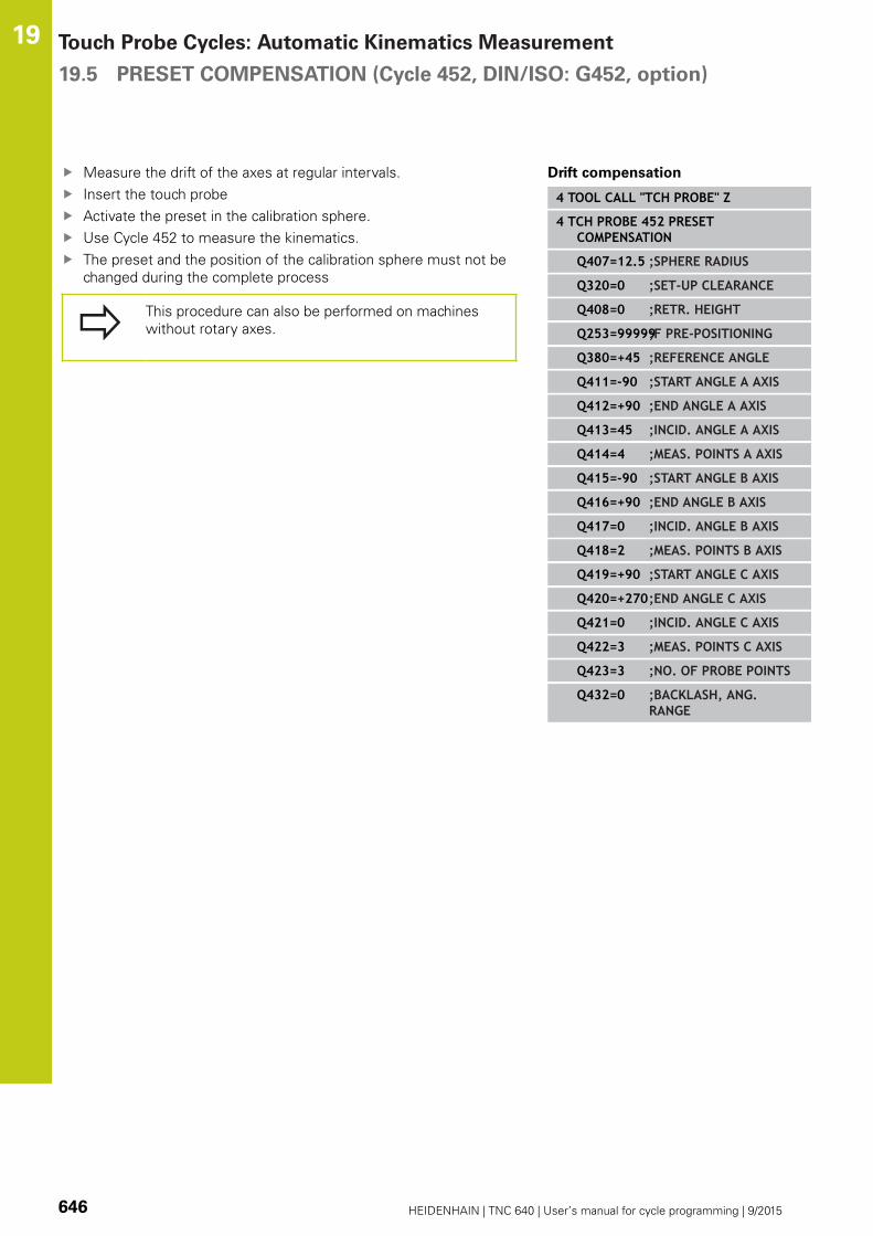
Touch Probe Cycles: Automatic Kinematics Measurement 19.5 PRESET COMPENSATION (Cycle 452, DIN/ISO: G452, option)
19
646 HEIDENHAIN | TNC 640 | User’s manual for cycle programming | 9/2015
Measure the drift of the axes at regular intervals.
Insert the touch probe
Activate the preset in the calibration sphere.
Use Cycle 452 to measure the kinematics.
The preset and the position of the calibration sphere must not be
changed during the complete process
This procedure can also be performed on machines
without rotary axes.
Drift compensation
4 TOOL CALL "TCH PROBE" Z
4 TCH PROBE 452 PRESETCOMPENSATION
Q407=12.5 ;SPHERE RADIUS
Q320=0 ;SET-UP CLEARANCE
Q408=0 ;RETR. HEIGHT
Q253=99999;F PRE-POSITIONING
Q380=+45 ;REFERENCE ANGLE
Q411=-90 ;START ANGLE A AXIS
Q412=+90 ;END ANGLE A AXIS
Q413=45 ;INCID. ANGLE A AXIS
Q414=4 ;MEAS. POINTS A AXIS
Q415=-90 ;START ANGLE B AXIS
Q416=+90 ;END ANGLE B AXIS
Q417=0 ;INCID. ANGLE B AXIS
Q418=2 ;MEAS. POINTS B AXIS
Q419=+90 ;START ANGLE C AXIS
Q420=+270;END ANGLE C AXIS
Q421=0 ;INCID. ANGLE C AXIS
Q422=3 ;MEAS. POINTS C AXIS
Q423=3 ;NO. OF PROBE POINTS
Q432=0 ;BACKLASH, ANG.RANGE

PRESET COMPENSATION (Cycle 452, DIN/ISO: G452, option) 19.5
19
HEIDENHAIN | TNC 640 | User’s manual for cycle programming | 9/2015 647
Logging function
After running Cycle 452, the TNC creates a measuring log
(TCHPR452.TXT) containing the following information:
Creation date and time of the log
Path of the NC program from which the cycle was run
Active kinematic number
Entered calibration sphere radius
For each measured rotary axis:
Starting angle
End angle
Angle of incidence
Number of measuring points
Dispersion (standard deviation)
Maximum error
Angular error
Averaged backlash
Averaged positioning error
Measuring circle radius
Compensation values in all axes (preset shift)
Measurement uncertainty of rotary axes
Notes on log data
(see "Logging function", page 637)

20Touch Probe
Cycles: AutomaticTool Measurement
Touch Probe Cycles: Automatic Tool Measurement 20.1 Fundamentals
20
650 HEIDENHAIN | TNC 640 | User’s manual for cycle programming | 9/2015
20.1 Fundamentals
Overview
When running touch probe cycles, Cycle 8 MIRROR
IMAGE, Cycle 11 SCALING and Cycle 26 AXIS-
SPECIFIC SCALING must not be active.
HEIDENHAIN only gives warranty for the function of
the probing cycles if HEIDENHAIN touch probes are
used.
The TNC and the machine tool must be set up by the
machine tool builder for use of the TT touch probe.
Some cycles and functions may not be provided on
your machine tool. Refer to your machine manual.
The touch probe cycles are available only with the
Touch Probe Functions software option (option
number 17). If you are using a HEIDENHAIN touch
probe, this option is available automatically.
In conjunction with the TNC's tool measurement cycles, the tool
touch probe enables you to measure tools automatically. The
compensation values for tool length and radius can be stored in
the central tool file TOOL.T and are accounted for at the end of the
touch probe cycle. The following types of tool measurement are
provided:
Tool measurement while the tool is at standstill
Tool measurement while the tool is rotating
Measurement of individual teeth

Fundamentals 20.1
20
HEIDENHAIN | TNC 640 | User’s manual for cycle programming | 9/2015 651
You can program the cycles for tool measurement in the
Programming mode of operation using the TOUCH PROBE key. The
following cycles are available:
New format Old format Cycle Page
Calibrating the TT, Cycles 30 and 480 656
Calibrating the wireless TT 449, Cycle 484 657
Measuring the tool length, Cycles 31 and 481 659
Measuring the tool radius, Cycles 32 and 482 661
Measuring the tool length and radius, Cycles 33 and
483
663
The measuring cycles can be used only when the
central tool file TOOL.T is active.
Before working with the measuring cycles, you must
first enter all the required data into the central tool
file and call the tool to be measured with TOOLCALL.
Differences between Cycles 31 to 33 and Cycles 481
to 483
The features and the operating sequences are absolutely identical.
There are only two differences between Cycles 31 to 33 and Cycles
481 to 483:
Cycles 481 to 483 are also available in controls for ISO
programming under G481 to G483.
Instead of a selectable parameter for the status of the
measurement, the new cycles use the fixed parameter Q199.
Touch Probe Cycles: Automatic Tool Measurement 20.1 Fundamentals
20
652 HEIDENHAIN | TNC 640 | User’s manual for cycle programming | 9/2015
Setting machine parameters
Before you start working with the measuring
cycles, check all machine parameters defined
in ProbeSettings > CfgToolMeasurement and
CfgTTRoundStylus.
The TNC uses the feed rate for probing defined in
probingFeed when measuring a tool at standstill.
When measuring a rotating tool, the TNC automatically calculates
the spindle speed and feed rate for probing.
The spindle speed is calculated as follows:
n = maxPeriphSpeedMeas / ( r • 0.0063) where
n: Spindle speed [rpm]
maxPeriphSpeedMeas: Maximum permissible cutting speed in
m/min
r: Active tool radius in mm
The feed rate for probing is calculated from:
v = measuring tolerance • n with
v: Feed rate for probing in mm/min
Measuring tolerance Measuring tolerance [mm], depending
on maxPeriphSpeedMeasn: Shaft speed [rpm]

Fundamentals 20.1
20
HEIDENHAIN | TNC 640 | User’s manual for cycle programming | 9/2015 653
probingFeedCalc determines the calculation of the probing feed
rate:
probingFeedCalc = ConstantTolerance:
The measuring tolerance remains constant regardless of the tool
radius. With very large tools, however, the feed rate for probing
is reduced to zero. The smaller you set the maximum permissible
rotational speed (maxPeriphSpeedMeas) and the permissible
tolerance (measureTolerance1), the sooner you will encounter this
effect.
probingFeedCalc = VariableTolerance:
The measuring tolerance is adjusted relative to the size of the tool
radius. This ensures a sufficient feed rate for probing even with
large tool radii. The TNC adjusts the measuring tolerance according
to the following table:
Tool radius Measuring tolerance
Up to 30 mm measureTolerance1
30 to 60 mm 2 • measureTolerance1
60 to 90 mm 3 • measureTolerance1
90 to 120 mm 4 • measureTolerance1
probingFeedCalc = ConstantFeed:
The feed rate for probing remains constant; the error of
measurement, however, rises linearly with the increase in tool
radius:
Measuring tolerance = r • measureTolerance1/ 5 mm, where
r: Active tool radius in mm
measureTolerance1: Maximum permissible error of
measurement
Touch Probe Cycles: Automatic Tool Measurement 20.1 Fundamentals
20
654 HEIDENHAIN | TNC 640 | User’s manual for cycle programming | 9/2015
Entries in the tool table TOOL.T
Abbr. Inputs Dialog
CUT Number of teeth (20 teeth maximum) Number of teeth?
LTOL Permissible deviation from tool length L for wear
detection. If the entered value is exceeded, the TNC locks
the tool (status L). Input range: 0 to 0.9999 mm
Wear tolerance: length?
RTOL Permissible deviation from tool radius R for wear
detection. If the entered value is exceeded, the TNC locks
the tool (status L). Input range: 0 to 0.9999 mm
Wear tolerance: radius?
R2TOL Permissible deviation from tool radius R2 for wear
detection. If the entered value is exceeded, the TNC locks
the tool (status L). Input range: 0 to 0.9999 mm
Wear tolerance: Radius 2?
DIRECT. Cutting direction of the tool for measuring the tool during
rotation
Cutting direction (M3 = –)?
R_OFFS Tool length measurement: Tool offset between stylus
center and tool center. Default setting: No value entered
(offset = tool radius)
Tool offset: radius?
L_OFFS Tool radius measurement: tool offset in addition to
offsetToolAxis between upper surface of stylus and
lower surface of tool. Default: 0
Tool offset: length?
LBREAK Permissible deviation from tool length L for breakage
detection. If the entered value is exceeded, the TNC locks
the tool (status L). Input range: 0 to 0.9999 mm
Breakage tolerance: length?
RBREAK Permissible deviation from tool radius R for breakage
detection. If the entered value is exceeded, the TNC locks
the tool (status L). Input range: 0 to 0.9999 mm
Breakage tolerance: radius?

Fundamentals 20.1
20
HEIDENHAIN | TNC 640 | User’s manual for cycle programming | 9/2015 655
Input examples for common tool types
Tool type CUT TT:R_OFFS TT:L_OFFS
Drill – (no function) 0 (no offset required
because tool tip is to be
measured)
End mill with diameter
of < 19 mm
4 (4 teeth) 0 (no offset required
because tool diameter is
smaller than the contact
plate diameter of the TT)
0 (no additional offset
required during radius
measurement. Offset from
offsetToolAxis is used)
End mill with diameter
of > 19 mm
4 (4 teeth) R (offset required because
tool diameter is larger than
the contact plate diameter
of the TT)
0 (no additional offset
required during radius
measurement. Offset from
offsetToolAxis is used)
Radius cutter with a
diameter of 10 mm, for
example
4 (4 teeth) 0 (no offset required
because the south pole of
the ball is to be measured)
5 (always define the tool
radius as the offset so
that the diameter is not
measured in the radius)

Touch Probe Cycles: Automatic Tool Measurement 20.2 Calibrate the TT (Cycle 480,)
20
656 HEIDENHAIN | TNC 640 | User’s manual for cycle programming | 9/2015
20.2 Calibrate the TT (Cycle 30 or 480,
DIN/ISO: G480 Option 17)
Cycle run
The TT is calibrated with the measuring cycle TCH PROBE 30 or
TCH PROBE 480 (see "Differences between Cycles 31 to 33 and
Cycles 481 to 483", page 651). The calibration process is automatic.
The TNC also measures the center misalignment of the calibrating
tool automatically by rotating the spindle by 180° after the first half
of the calibration cycle.
The calibrating tool must be a precisely cylindrical part, for example
a cylinder pin. The resulting calibration values are stored in the
TNC memory and are accounted for during subsequent tool
measurements.
Please note while programming:
The functioning of the calibration cycle is dependent
on machine parameter CfgToolMeasurement. Refer
to your machine tool manual.
Before calibrating the touch probe, you must enter
the exact length and radius of the calibrating tool into
the tool table TOOL.T.
The position of the TT within the machine working
space must be defined by setting the Machine
Parameters centerPos > [0] to [2].If you change the setting of any of the Machine
Parameters centerPos > [0] to [2], you must
recalibrate.
Cycle parameters
Clearance height: Enter the position in the spindle
axis at which there is no danger of collision with
the workpiece or fixtures. The clearance height is
referenced to the active workpiece datum. If you
enter such a small clearance height that the tool
tip would lie below the level of the probe contact,
the TNC automatically positions the tool above
the level of the probe contact (safety zone from
safetyDistStylus). Input range -99999.9999 to
99999.9999
NC blocks in old format
6 TOOL CALL 1 Z
7 TCH PROBE 30.0 CALIBRATE TT
8 TCH PROBE 30.1 HEIGHT: +90
NC blocks in new format
6 TOOL CALL 1 Z
7 TCH PROBE 480 CALIBRATE TT
Q260=+100;CLEARANCE HEIGHT

Calibrating the wireless TT 449 (Cycle 484, DIN/ISO: G484) 20.3
20
HEIDENHAIN | TNC 640 | User’s manual for cycle programming | 9/2015 657
20.3 Calibrating the wireless TT 449 (Cycle
484, DIN/ISO: G484, DIN/ISO: G484)
Fundamentals
With Cycle 484, you can calibrate your tool touch probe, e.g the
wireless infrared TT 449 tool touch probe. The calibration process
is either fully automatic or semi-automatic, depending on the
parameter setting.
Semi-automatic—stop before running: A dialog asks you to
manually move the tool over the TT
Fully automatic—no stop before running: Before using Cycle
484 you must move the tool over the TT
Cycle run
To calibrate the tool touch probe, program the measuring cycle TCH
PROBE 484. In the input parameter Q536, you can specify whether
you want to run the cycle semi-automatically or fully automatically.
Semi-automatic—stop before running
Insert the calibrating tool
Define and start the calibration cycle
The TNC interrupts the calibration cycle
The TNC opens a dialog in a new window
The dialog asks you to manually position the calibrating tool
above the center of the touch probe. Ensure that the calibrating
tool is located above the measuring surface of the probe contact
Fully automatic—no stop before running
Insert the calibrating tool
Position the calibrating tool above the center of the touch probe.
Ensure that the calibrating tool is located above the measuring
surface of the probe contact
Define and start the calibration cycle
The calibration cycle is executed without stopping. The
calibration process starts from the current position of the tool.
Calibrating tool:
The calibrating tool must be a precisely cylindrical part, for example
a cylinder pin. Enter the exact length and radius of the calibrating
tool into the tool table TOOL.T. At the end of the calibration
process, the TNC stores the calibration values and takes them into
account during subsequent tool measurement. The calibrating tool
should have a diameter of more than 15 mm and protrude approx.
50 mm from the chuck.

Touch Probe Cycles: Automatic Tool Measurement 20.3 Calibrating the wireless TT 449 (Cycle 484, DIN/ISO: G484)
20
658 HEIDENHAIN | TNC 640 | User’s manual for cycle programming | 9/2015
Please note while programming:
Danger of collision!
To avoid collisions, the tool must be pre-positioned
before the cycle call if Q536 is set to 1!
In the calibration process, the TNC also measures
the center misalignment of the calibrating tool by
rotating the spindle by 180° after the first half of the
calibration cycle.
The functioning of the calibration cycle is dependent
on machine parameter CfgToolMeasurement. Refer
to your machine manual.
The calibrating tool should have a diameter of
more than 15 mm and protrude approx. 50 mm
from the chuck. When using a cylinder pin of
these dimensions, the resulting deformation will
only be 0.1 µm per 1 N of probing force. The use
of a calibrating tool of too small a diameter and/
or protruding too far from the chuck may cause
significant inaccuracies.
Before calibrating the touch probe, you must enter
the exact length and radius of the calibrating tool into
the tool table TOOL.T.
The TT needs to be recalibrated if you change its
position on the table.
Cycle parameters
Stop before running Q536: Specify whether to stop before cycle
start or run the cycle automatically without stopping:
0: Stop before running. A dialog asks you to manually position
the tool above the tool touch probe. After moving the tool to the
approximate position above the tool touch probe, press NC start to
continue the calibration process or press the CANCEL soft key to
cancel the calibration process
1: No stop before running. The TNC starts the calibration process
from the current position. Before running Cycle 484, you must
position the tool above the tool touch probe.
NC blocks
6 TOOL CALL 1 Z
7 TCH PROBE 484 CALIBRATE TT
Q536=+0 ;STOP BEFORERUNNING

Measuring tool length (Cycle 481) 20.4
20
HEIDENHAIN | TNC 640 | User’s manual for cycle programming | 9/2015 659
20.4 Measuring tool length (Cycle 31 or
481, DIN/ISO: G481)
Cycle run
In order to measure the tool length program the measurement
cycles TCH PROBE 31 or TCH PROBE 481 (see "Differences
between Cycles 31 to 33 and Cycles 481 to 483"). Via input
parameters you can measure the length of a tool by three
methods:
If the tool diameter is larger than the diameter of the measuring
surface of the TT, you measure the tool while it is rotating.
If the tool diameter is smaller than the diameter of the
measuring surface of the TT, or if you are measuring the length
of a drill or spherical cutter, you measure the tool while it is at
standstill.
If the tool diameter is larger than the diameter of the measuring
surface of the TT, you measure the individual teeth of the tool
while it is at standstill.
Cycle for measuring a tool during rotation
The control determines the longest tooth of a rotating tool by
positioning the tool to be measured at an offset to the center of the
touch probe and then moving it toward the measuring surface of
the TT until it contacts the surface. The offset is programmed in the
tool table under Tool offset: Radius (TT: R_OFFS).
Cycle for measuring a tool during standstill (e.g. for drills)
The control positions the tool to be measured over the center of
the measuring surface. It then moves the non-rotating tool toward
the measuring surface of the TT until it touches the surface. To
activate this function, enter zero for the tool offset: Radius (TT:R_OFFS) in the tool table.
Cycle for measuring individual teeth
The TNC pre-positions the tool to be measured to a position at
the side of the touch probe head. The distance from the tip of
the tool to the upper edge of the touch probe head is defined
in offsetToolAxis. You can enter an additional offset with tool
offset: Length (TT: L_OFFS) in the tool table. The TNC probes
the tool radially during rotation to determine the starting angle for
measuring the individual teeth. It then measures the length of each
tooth by changing the corresponding angle of spindle orientation.
To activate this function, program TCH PROBE 31 = 1 for CUTTER
MEASUREMENT.

Touch Probe Cycles: Automatic Tool Measurement 20.4 Measuring tool length (Cycle 481)
20
660 HEIDENHAIN | TNC 640 | User’s manual for cycle programming | 9/2015
Please note while programming:
Before measuring a tool for the first time, enter the
following data on the tool into the tool table TOOL.T:
the approximate radius, the approximate length, the
number of teeth, and the cutting direction.
You can run an individual tooth measurement of tools
with up to 20 teeth.
Cycle parameters
Measure tool=0 / Check tool=1: Select whether
the tool is to be measured for the first time or
whether a tool that has already been measured is to
be inspected. If the tool is being measured for the
first time, the TNC overwrites the tool length L in
the central tool file TOOL.T by the delta value DL =
0. If you wish to inspect a tool, the TNC compares
the measured length with the tool length L that is
stored in TOOL.T. It then calculates the positive or
negative deviation from the stored value and enters
it into TOOL.T as the delta value DL. The deviation
can also be used for Q-parameter Q115. If the delta
value is greater than the permissible tool length
tolerance for wear or break detection, the TNC will
lock the tool (status L in TOOL.T).
Parameter number for result ?: Parameter
number in which the TNC saves the status of the
measurement result:
0.0: Tool is within tolerance
1.0: Tool is worn (LTOL exceeded)
2.0: Tool is broken (LBREAK exceeded).
If you do not wish to use the result of measurement
within the program, answer the dialog prompt with
NO ENT.
Clearance height: Enter the position in the spindle
axis at which there is no danger of collision with
the workpiece or fixtures. The clearance height is
referenced to the active workpiece datum. If you
enter such a small clearance height that the tool
tip would lie below the level of the probe contact,
the TNC automatically positions the tool above
the level of the probe contact (safety zone from
safetyDistStylus). Input range -99999.9999 to
99999.9999
Cutter measurement? 0=No / 1=Yes: Choose
whether the control is to measure the individual
teeth (maximum of 20 teeth)
Measuring a rotating tool for the first
time; old format
6 TOOL CALL 12 Z
7 TCH PROBE 31.0 TOOL LENGTH
8 TCH PROBE 31.1 CHECK: 0
9 TCH PROBE 31.2 HEIGHT: +120
10 TCH PROBE 31.3 PROBING THETEETH: 0
Inspecting a tool and measuring the
individual teeth and saving the status
in Q5; old format
6 TOOL CALL 12 Z
7 TCH PROBE 31.0 TOOL LENGTH
8 TCH PROBE 31.1 CHECK: 1 Q5
9 TCH PROBE 31.2 HEIGHT: +120
10 TCH PROBE 31.3 PROBING THETEETH:1
NC blocks in new format
6 TOOL CALL 12 Z
7 TCH PROBE 481 TOOL LENGTH
Q340=1 ;CHECK
Q260=+100;CLEARANCE HEIGHT
Q341=1 ;PROBING THE TEETH
Measuring tool radius (Cycle 482) 20.5
20
HEIDENHAIN | TNC 640 | User’s manual for cycle programming | 9/2015 661
20.5 Measuring tool radius (Cycle 32 or
482, DIN/ISO: G482)
Cycle run
To measure the tool radius, program the measuring cycle TCH
PROBE 32 or TCH PROBE 482 (see "Differences between Cycles
31 to 33 and Cycles 481 to 483", page 651). Select via input
parameters by which of two methods the radius of a tool is to be
measured:
Measuring the tool while it is rotating
Measuring the tool while it is rotating and subsequently
measuring the individual teeth.
The TNC pre-positions the tool to be measured to a position at
the side of the touch probe head. The distance from the tip of the
milling tool to the upper edge of the touch probe head is defined in
offsetToolAxis. The TNC probes the tool radially while it is rotating.
If you have programmed a subsequent measurement of individual
teeth, the control measures the radius of each tooth with the aid of
oriented spindle stops.
Please note while programming:
Before measuring a tool for the first time, enter the
following data on the tool into the tool table TOOL.T:
the approximate radius, the approximate length, the
number of teeth, and the cutting direction.
Cylindrical tools with diamond surfaces can be
measured with stationary spindle. To do so, define
in the tool table the number of teeth CUT as 0 and
adjust machine parameter CfgToolMeasurement.Refer to your machine manual.

Touch Probe Cycles: Automatic Tool Measurement 20.5 Measuring tool radius (Cycle 482)
20
662 HEIDENHAIN | TNC 640 | User’s manual for cycle programming | 9/2015
Cycle parameters
Measure tool=0 / Check tool=1: Select whether
the tool is to be measured for the first time or
whether a tool that has already been measured is to
be inspected. If the tool is being measured for the
first time, the TNC overwrites the tool radius R in
the central tool file TOOL.T by the delta value DR =
0. If you wish to inspect a tool, the TNC compares
the measured radius with the tool radius R that is
stored in TOOL.T. It then calculates the positive or
negative deviation from the stored value and enters
it into TOOL.T as the delta value DR. The deviation
can also be used for Q-parameter Q116. If the delta
value is greater than the permissible tool radius
tolerance for wear or break detection, the TNC will
lock the tool (status L in TOOL.T).
Parameter number for result ?: Parameter
number in which the TNC saves the status of the
measurement result:
0.0: Tool is within tolerance
1.0: Tool is worn (RTOL exceeded)
2.0: Tool is broken (RBREAK exceeded).
If you do not wish to use the result of measurement
within the program, answer the dialog prompt with
NO ENT.
Clearance height: Enter the position in the spindle
axis at which there is no danger of collision with
the workpiece or fixtures. The clearance height is
referenced to the active workpiece datum. If you
enter such a small clearance height that the tool
tip would lie below the level of the probe contact,
the TNC automatically positions the tool above
the level of the probe contact (safety zone from
safetyDistStylus). Input range -99999.9999 to
99999.9999
Cutter measurement? 0=No / 1=Yes: Choose
whether the control is also to measure the individual
teeth (maximum of 20 teeth)
Measuring a rotating tool for the first
time; old format
6 TOOL CALL 12 Z
7 TCH PROBE 32.0 TOOL RADIUS
8 TCH PROBE 32.1 CHECK: 0
9 TCH PROBE 32.2 HEIGHT: +120
10 TCH PROBE 32.3 PROBING THETEETH: 0
Inspecting a tool and measuring the
individual teeth and saving the status
in Q5; old format
6 TOOL CALL 12 Z
7 TCH PROBE 32.0 TOOL RADIUS
8 TCH PROBE 32.1 CHECK: 1 Q5
9 TCH PROBE 32.2 HEIGHT: +120
10 TCH PROBE 32.3 PROBING THETEETH: 1
NC blocks in new format
6 TOOL CALL 12 Z
7 TCH PROBE 482 TOOL RADIUS
Q340=1 ;CHECK
Q260=+100;CLEARANCE HEIGHT
Q341=1 ;PROBING THE TEETH

Measuring tool length and radius (Cycle 483) 20.6
20
HEIDENHAIN | TNC 640 | User’s manual for cycle programming | 9/2015 663
20.6 Measuring tool length and radius
(Cycle 33 or 483, DIN/ISO: G483)
Cycle run
To measure both the length and radius of a tool, program
the measuring cycle TCH PROBE 33 or TCH PROBE 483
(see "Differences between Cycles 31 to 33 and Cycles 481 to
483", page 651). This cycle is particularly suitable for the first
measurement of tools, as it saves time when compared with
individual measurement of length and radius. Via input parameters
you can select the desired type of measurement:
Measuring the tool while it is rotating
Measuring the tool while it is rotating and subsequently
measuring the individual teeth.
The TNC measures the tool in a fixed programmed sequence. First
it measures the tool radius, then the tool length. The sequence of
measurement is the same as for Cycles 31 and 32 as well as .
Please note while programming:
Before measuring a tool for the first time, enter the
following data on the tool into the tool table TOOL.T:
the approximate radius, the approximate length, the
number of teeth, and the cutting direction.
Cylindrical tools with diamond surfaces can be
measured with stationary spindle. To do so, define
in the tool table the number of teeth CUT as 0 and
adjust machine parameter CfgToolMeasurement.Refer to your machine manual.

Touch Probe Cycles: Automatic Tool Measurement 20.6 Measuring tool length and radius (Cycle 483)
20
664 HEIDENHAIN | TNC 640 | User’s manual for cycle programming | 9/2015
Cycle parameters
Measure tool=0 / Check tool=1: Select whether
the tool is to be measured for the first time or
whether a tool that has already been measured
is to be inspected. If the tool is being measured
for the first time, the TNC overwrites the tool
radius R and the tool length L in the central tool file
TOOL.T by the delta values DR = 0 and DL = 0. If
you wish to inspect a tool, the TNC compares the
measured data with the tool data stored in TOOL.T.
The TNC calculates the deviations and enters them
as positive or negative delta values DR and DL in
TOOL.T. The deviations are also available in the Q
parameters Q115 and Q116. If the delta values are
greater than the permissible tool tolerances for wear
or break detection, the TNC will lock the tool (status
L in TOOL.T).
Parameter number for result ?: Parameter
number in which the TNC saves the status of the
measurement result:
0.0: Tool is within tolerance
1.0: Tool is worn (LTOL and/or RTOL exceeded)
2,0: Tool is broken (LBREAK and/or RBREAKexceeded).
If you do not wish to use the result of measurement
within the program, answer the dialog prompt with
NO ENT.
Clearance height: Enter the position in the spindle
axis at which there is no danger of collision with
the workpiece or fixtures. The clearance height is
referenced to the active workpiece datum. If you
enter such a small clearance height that the tool
tip would lie below the level of the probe contact,
the TNC automatically positions the tool above
the level of the probe contact (safety zone from
safetyDistStylus). Input range -99999.9999 to
99999.9999
Cutter measurement? 0=No / 1=Yes: Choose
whether the control is also to measure the individual
teeth (maximum of 20 teeth)
Measuring a rotating tool for the first
time; old format
6 TOOL CALL 12 Z
7 TCH PROBE 33.0 MEASURE TOOL
8 TCH PROBE 33.1 CHECK: 0
9 TCH PROBE 33.2 HEIGHT: +120
10 TCH PROBE 33.3 PROBING THETEETH: 0
Inspecting a tool and measuring the
individual teeth and saving the status
in Q5; old format
6 TOOL CALL 12 Z
7 TCH PROBE 33.0 MEASURE TOOL
8 TCH PROBE 33.1 CHECK: 1 Q5
9 TCH PROBE 33.2 HEIGHT: +120
10 TCH PROBE 33.3 PROBING THETEETH: 1
NC blocks in new format
6 TOOL CALL 12 Z
7 TCH PROBE 483 MEASURE TOOL
Q340=1 ;CHECK
Q260=+100;CLEARANCE HEIGHT
Q341=1 ;PROBING THE TEETH
21Tables of Cycles
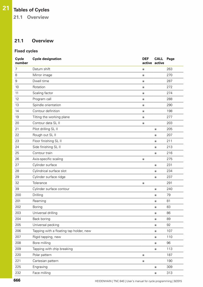
Tables of Cycles 21.1 Overview
21
666 HEIDENHAIN | TNC 640 | User’s manual for cycle programming | 9/2015
21.1 Overview
Fixed cycles
Cycle
number
Cycle designation DEF
active
CALL
active
Page
7 Datum shift ■ 263
8 Mirror image ■ 270
9 Dwell time ■ 287
10 Rotation ■ 272
11 Scaling factor ■ 274
12 Program call ■ 288
13 Spindle orientation ■ 290
14 Contour definition ■ 198
19 Tilting the working plane ■ 277
20 Contour data SL II ■ 203
21 Pilot drilling SL II ■ 205
22 Rough out SL II ■ 207
23 Floor finishing SL II ■ 211
24 Side finishing SL II ■ 213
25 Contour train ■ 216
26 Axis-specific scaling ■ 275
27 Cylinder surface ■ 231
28 Cylindrical surface slot ■ 234
29 Cylinder surface ridge ■ 237
32 Tolerance ■ 291
39 Cylinder surface contour ■ 240
200 Drilling ■ 79
201 Reaming ■ 81
202 Boring ■ 83
203 Universal drilling ■ 86
204 Back boring ■ 89
205 Universal pecking ■ 92
206 Tapping with a floating tap holder, new ■ 107
207 Rigid tapping, new ■ 110
208 Bore milling ■ 96
209 Tapping with chip breaking ■ 113
220 Polar pattern ■ 187
221 Cartesian pattern ■ 190
225 Engraving ■ 309
232 Face milling ■ 313

Overview 21.1
21
HEIDENHAIN | TNC 640 | User’s manual for cycle programming | 9/2015 667
Cycle
number
Cycle designation DEF
active
CALL
active
Page
233 Face milling (selectable milling direction, consider the side walls) ■ 174
239 Ascertain the load ■ 318
240 Centering ■ 77
241 Single-lip deep-hole drilling ■ 99
247 Datum setting ■ 269
251 Rectangular pocket (complete machining) ■ 143
252 Circular pocket (complete machining) ■ 147
253 Slot milling ■ 152
254 Circular slot ■ 156
256 Rectangular stud (complete machining) ■ 161
257 Circular stud (complete machining) ■ 165
258 Polygon stud ■ 169
262 Thread milling ■ 119
263 Thread milling/countersinking ■ 122
264 Thread drilling/milling ■ 126
265 Helical thread drilling/milling ■ 130
267 Outside thread milling ■ 134
270 Contour train data ■ 218
275 Trochoidal slot ■ 219
291 Coupling turning interpolation ■ 294
292 Contour turning interpolation ■ 303
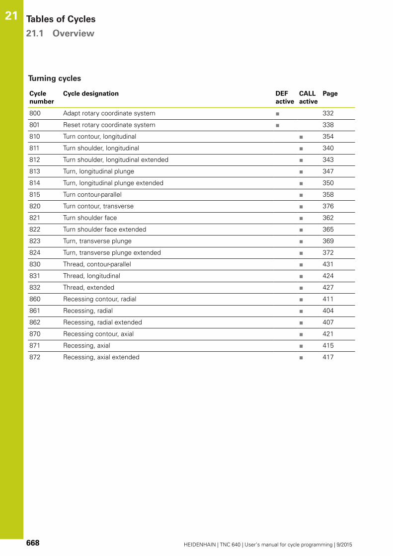
Tables of Cycles 21.1 Overview
21
668 HEIDENHAIN | TNC 640 | User’s manual for cycle programming | 9/2015
Turning cycles
Cycle
number
Cycle designation DEF
active
CALL
active
Page
800 Adapt rotary coordinate system ■ 332
801 Reset rotary coordinate system ■ 338
810 Turn contour, longitudinal ■ 354
811 Turn shoulder, longitudinal ■ 340
812 Turn shoulder, longitudinal extended ■ 343
813 Turn, longitudinal plunge ■ 347
814 Turn, longitudinal plunge extended ■ 350
815 Turn contour-parallel ■ 358
820 Turn contour, transverse ■ 376
821 Turn shoulder face ■ 362
822 Turn shoulder face extended ■ 365
823 Turn, transverse plunge ■ 369
824 Turn, transverse plunge extended ■ 372
830 Thread, contour-parallel ■ 431
831 Thread, longitudinal ■ 424
832 Thread, extended ■ 427
860 Recessing contour, radial ■ 411
861 Recessing, radial ■ 404
862 Recessing, radial extended ■ 407
870 Recessing contour, axial ■ 421
871 Recessing, axial ■ 415
872 Recessing, axial extended ■ 417

Overview 21.1
21
HEIDENHAIN | TNC 640 | User’s manual for cycle programming | 9/2015 669
Touch probe cycles
Cycle
number
Cycle designation DEF
active
CALL
active
Page
0 Reference plane ■ 540
1 Polar datum ■ 541
3 Measuring ■ 581
4 Measuring in 3-D ■ 583
30 Calibrate the TT ■ 656
31 Measure/Inspect the tool length ■ 659
32 Measure/inspect the tool radius ■ 661
33 Measure/Inspect the tool length and the tool radius ■ 663
400 Basic rotation using two points ■ 460
401 Basic rotation over two holes ■ 463
402 Basic rotation over two studs ■ 466
403 Compensate misalignment with rotary axis ■ 469
404 Set basic rotation ■ 472
405 Compensate misalignment with the C axis ■ 473
408 Reference point at slot center (FCL 3 function) ■ 484
409 Reference point at ridge center (FCL 3 function) ■ 488
410 Datum from inside of rectangle ■ 491
411 Datum from outside of rectangle ■ 495
412 Datum from inside of circle (hole) ■ 498
413 Datum from outside of circle (stud) ■ 503
414 Datum from outside of corner ■ 507
415 Datum from inside of corner ■ 512
416 Datum from circle center ■ 516
417 Datum in touch probe axis ■ 520
418 Datum at center between four holes ■ 522
419 Datum in any one axis ■ 526
420 Workpiece—measure angle ■ 542
421 Workpiece—measure hole (center and diameter of hole) ■ 545
422 Workpiece—measure circle from outside (diameter of circular stud) ■ 550
423 Workpiece—measure rectangle from inside ■ 555
424 Workpiece—measure rectangle from outside ■ 558
425 Workpiece—measure inside width (slot) ■ 561
426 Workpiece—measure outside width (ridge) ■ 564
427 Workpiece—measure in any selectable axis ■ 567
430 Workpiece—measure bolt hole circle ■ 570
431 Workpiece—measure plane ■ 570

Tables of Cycles 21.1 Overview
21
670 HEIDENHAIN | TNC 640 | User’s manual for cycle programming | 9/2015
Cycle
number
Cycle designation DEF
active
CALL
active
Page
450 KinematicsOpt: Save kinematics (option) ■ 621
451 KinematicsOpt: Measure kinematics (option) ■ 624
452 KinematicsOpt: Preset compensation ■ 618
460 Calibrate the touch probe ■ 587
461 Calibrate touch probe length ■ 589
462 Calibrate touch probe inside radius ■ 591
463 Calibrate touch probe outside radius ■ 593
480 Calibrate the TT ■ 656
481 Measure/Inspect the tool length ■ 659
482 Measure/Inspect the tool radius ■ 661
483 Measure/Inspect the tool length and the tool radius ■ 663
484 Calibrate TT ■ 657
600 Global workspace ■ 606
601 Local workspace ■ 611

HEIDENHAIN | TNC 640 | User’s manual for cycle programming | 9/2015 671
Index
3
3D Touch Probes...................... 448
3-D touch probes....................... 52
A
Adapt rotary coordinate
system..................................... 332
Automatic datum setting.......... 480
At center of 4 holes............... 522
Center of a bolt hole circle..... 516
Center of a circular pocket
(hole)...................................... 498
Center of a circular stud......... 503
Center of a rectangular
pocket.................................... 491
Center of a rectangular stud... 495
In any axis.............................. 526
Inside of corner...................... 512
In the touch probe axis........... 520
Outside of corner................... 507
Ridge center.......................... 488
Slot center............................. 484
Automatic tool measurement... 654
Axis-specific scaling................. 275
B
Back boring................................ 89
Basic rotation
Measure during program run.. 458
Blank form update.................... 330
Bolt hole circle......................... 187
Bore milling................................ 96
Boring......................................... 83
C
Centering................................... 77
Circular pocket
Roughing+finishing................ 147
Circular point patterns.............. 187
Circular slot
Roughing+finishing................ 156
Circular stud..................... 165, 169
Classification of results............ 537
Compensating workpiece
misalignment............................ 458
By measuring two points on a
straight line............................ 460
Over two circular studs.......... 466
Over two holes...................... 463
Via rotary axis................ 469, 473
Confidence interval.................. 453
Consideration of basic rotation. 448
Contour cycles......................... 196
Contour train.................... 216, 218
CONTOUR TURNING
INTERPOLATION..................... 294
Coordinate transformation........ 262
COUPLING INTERPOLATION
TURNING................................. 303
Cycle.......................................... 56
Calling...................................... 58
Define...................................... 57
Cycles and point tables.............. 73
Cylinder surface
Machine contour............ 231, 240
Ridge machining..................... 237
Slot machining........................ 234
D
Datum shift.............................. 263
In the program....................... 263
With datum tables................. 264
Drilling............................ 79, 86, 92
Drilling Cycles............................ 76
Dwell time................................ 287
E
Engraving................................. 309
F
Face milling.............................. 313
FCL function................................ 9
Feature Content Level.................. 9
Floor finishing........................... 211
FUNCTION TURNDATA............ 330
Fundamentals of Thread
Milling...................................... 117
G
GEAR HOBBING.............. 435, 440
H
Helical thread drilling/milling..... 130
I
Inside thread milling................. 119
K
Kinematic measurement
Accuracy................................. 629
Backlash................................. 631
Calibration methods.... 630, 643,
645
Hirth coupling......................... 627
Logging function..... 622, 637, 647
Measuring point selection.... 623,
628
Measuring position selection. 629
Prerequisites.......................... 620
Kinematics measurement........ 618
Kinematics Measurement
Measure kinematics....... 624, 638
Kinematics measurement
Save kinematics..................... 621
KinematicsOpt.......................... 618
L
Linear point patterns................ 190
M
Machine parameters for 3D touch
probe........................................ 451
Machining pattern...................... 64
Measure angle......................... 542
Measure angle of a plane......... 573
Measure any coordinate........... 567
Measure bolt hole circle........... 570
Measure hole........................... 545
Measure hole inside................. 545
Measure hole outside.............. 550
Measure kinematics................. 624
Preset compensation............. 638
Measurement parameters........ 537
Measurement results in Q
parameters............................... 537
Measure rectangular pocket..... 558
Measure rectangular stud........ 555
Measure the plane angle.......... 573
Measure the slot width............ 561
Measure the width of a
ridge................................. 564, 564
Measuring slot width............... 561
Measuring the width of a ridge 564
Mirroring................................... 270
Multiple measurements........... 453
O
Outside thread milling.............. 134
P
Pattern definition........................ 64
Peck drilling.......................... 92, 99
Point patterns........................... 186
Overview................................ 186
Point tables................................ 71
Positioning logic....................... 454
Probing feed rate..................... 452
Program call............................. 288
Via cycle................................. 288
R
Reaming..................................... 81
Recording measurement results....
535
Rectangular pocket
Roughing+finishing................ 143
Rectangular stud...................... 161
Reference images.................... 596
Reset rotary coordinate
system..................................... 338
Rotation.................................... 272
Roughing:See SL Cycles,
Roughing.................................. 207
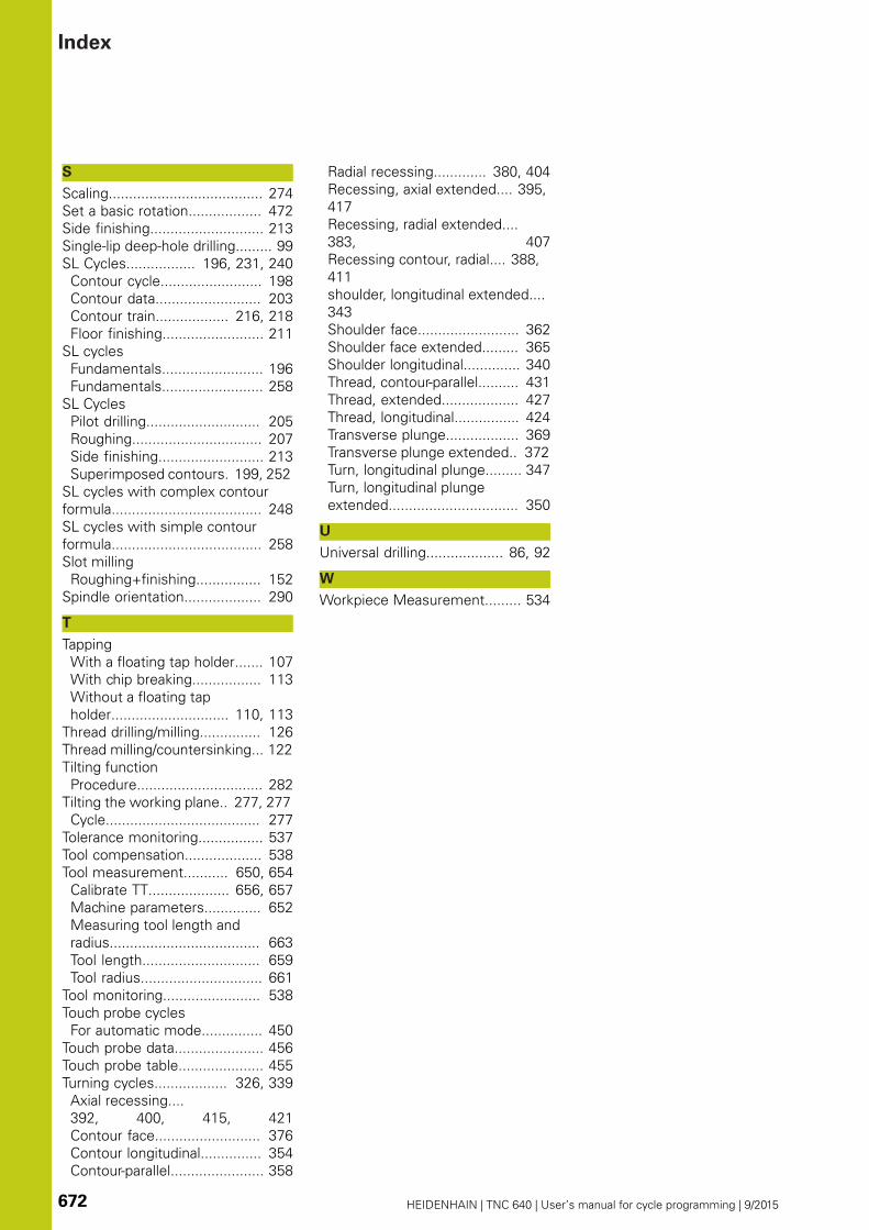
Index
672 HEIDENHAIN | TNC 640 | User’s manual for cycle programming | 9/2015
S
Scaling...................................... 274
Set a basic rotation.................. 472
Side finishing............................ 213
Single-lip deep-hole drilling......... 99
SL Cycles................. 196, 231, 240
Contour cycle......................... 198
Contour data.......................... 203
Contour train.................. 216, 218
Floor finishing......................... 211
SL cycles
Fundamentals......................... 196
Fundamentals......................... 258
SL Cycles
Pilot drilling............................ 205
Roughing................................ 207
Side finishing.......................... 213
Superimposed contours. 199, 252
SL cycles with complex contour
formula..................................... 248
SL cycles with simple contour
formula..................................... 258
Slot milling
Roughing+finishing................ 152
Spindle orientation................... 290
T
Tapping
With a floating tap holder....... 107
With chip breaking................. 113
Without a floating tap
holder............................. 110, 113
Thread drilling/milling............... 126
Thread milling/countersinking... 122
Tilting function
Procedure............................... 282
Tilting the working plane.. 277, 277
Cycle...................................... 277
Tolerance monitoring................ 537
Tool compensation................... 538
Tool measurement........... 650, 654
Calibrate TT.................... 656, 657
Machine parameters.............. 652
Measuring tool length and
radius..................................... 663
Tool length............................. 659
Tool radius.............................. 661
Tool monitoring........................ 538
Touch probe cycles
For automatic mode............... 450
Touch probe data...................... 456
Touch probe table..................... 455
Turning cycles.................. 326, 339
Axial recessing....
392, 400, 415, 421
Contour face.......................... 376
Contour longitudinal............... 354
Contour-parallel....................... 358
Radial recessing............. 380, 404
Recessing, axial extended.... 395,
417
Recessing, radial extended....
383, 407
Recessing contour, radial.... 388,
411
shoulder, longitudinal extended....
343
Shoulder face......................... 362
Shoulder face extended......... 365
Shoulder longitudinal.............. 340
Thread, contour-parallel.......... 431
Thread, extended................... 427
Thread, longitudinal................ 424
Transverse plunge.................. 369
Transverse plunge extended.. 372
Turn, longitudinal plunge......... 347
Turn, longitudinal plunge
extended................................ 350
U
Universal drilling................... 86, 92
W
Workpiece Measurement......... 534

Touch probes from HEIDENHAINhelp you reduce non-productive time and improve the dimensional accuracy of the finished workpieces.
Workpiece touch probesTS 220 Signal transmission by cableTS 440, TS 444 Infrared transmission TS 640, TS 740 Infrared transmission
• Workpiece alignment• Setting datums• Workpiece measurement
Tool touch probesTT 140 Signal transmission by cableTT 449 Infrared transmissionTL Contact-free laser systems
• Tool measurement• Wear monitoring• Tool breakage detection
����������������������������������������������������������� ���� ���������������� ����������� ��������� �����������������������������
��������������� � ���������������������������� � �������������
��������������������� ������������������� ������� � �������������
��������������������� ������������������ ����������� � �������������
������������������� ���������������� ����������� � �������������
���������������� ����������������������������� � ������������
������������������������ �����������������
����������������
*I_892905-24*892905-24 · Ver04 · SW06 · 10/2015 · Printed in Germany · H