heavy duty rotator system instruction manual
TRANSCRIPT

HDR-300AHeavy Duty Rotator System
Instruction Manual

TABLE OF CONTENTSPageCHAPTER 1 - INSTALLATION AND OPERATION .........................................................1-1Section I. Components of the HDR-300/A Rotator System ..................................................1-1Gear Motor Assembly..............................................................................…........................... l-1Control Console.......................................................................................…............................1-1Tower Compatibility ..............................................................................…........................... 1-2Antenna Compatibility............................................................................…............................1-2Section II. Specifications ........................................................................................................1-3Section III. Pre-Installation Instructions................................................................................. l-4Pre-Installation Check...........................................................................….............................1-4Section IV Voltage Conversion.............................................................................................. l-9Section V Calibration and Installation Procedures..............................................................1-12Calibration........................................................................................…................................1-12Installation........................................................................................…................................1-12Section VI. Operations and Maintenance.............................................................................1-15Operations .......................................................................................….................................1-15Use the Digital Readout System......................................................…................................1-16Maintenance .....................................................................................…................................1-16
CHAPTER 2 - TROUBLESHOOTING AND SERVICE INFORMATION.......................... 2-1Section 1. Troubleshooting .................................................................................................... 2-1Section II. Voltage and Resistance Measurements..................................................................2-5
Voltage and Resistance Charts............................................................................................2-5Section III. How to Get Factory Service................................................................................ 2-6
Service Information ........................................................................................................... 2-6CHAPTER 3 - HDR-300/A PARTS LIST AND SCHEMATICS.......................................... 3-1

LIST OF ILLUSTRATIONSFigure Page
1 Control Console Rear Panel ...................................................................................1-42 Socket Contact Application ....................................................................................1-53 Control Cable Connector Attachments...................................................................1-74 Control Cable - Rotator Wiring Guide................................................................... l-8
Detail A-Actuator Shown in the "000" Position ................................................1-85 Solenoid and Potentiometer Wiring Guide.............................................................1-96 Wiring for 115 VAC .............................................................................................1-107 Wiring for 230 VAC ............................................................................................. 1-118 HDR-300/A Rotator Mounting Hardware............................................................1-139 Top View of HDR-300/A and Tower Mounting Plate for
Hy-Gain Crank-Up Towers HG-54HD and HG-70HD.................................... 1-1410 Typical Installation of Rotator Mounted Below Plate .......................................... 1-1411 Gear Motor Assembly with Cover ......................................................................... 3-412 Output Gear and Shaft Assembly........................................................................... 3-413 Gear Motor Assembly - Side View ........................................................................ 3-514 Gear Motor Assembly - Top View ......................................................................... 3-515 Gear Motor Schematic............................................................................................3-616 Steel and Fiber Gears.............................................................................................. 3-617 Exterior View - Control Console............................................................................ 3-718 Interior View of Control Console........................................................................... 3-719 Schematic Main P.C. Board .................................................................................... 3-820 Main P .C. Board...................................................................................................... 3-821 Components and Wiring of Main PC. Board ........................................................ 3-922 Schematic of Display PC. Board ......................................................................... 3-1023 Display P.C. Board ................................................................................................ 3-1024 Components of Display PC. Board - PN 871166-1 ........................................... 3-1125 Rear Mounted Components - Front Panel of Control Console ........................... 3-11
PLEASE RECORD THE FOLLOWING INFORMATION FOR YOUR RECORDS:
Date of Purchase:_______________________________________________
Purchased From:________________________________________________
Price Paid:____________________________________________________
Serial Number (on Gear Motor):___________________________________
CHAPTER 1INSTALLATION AND OPERATION
Section I. Components of the HDR-300/A Rotator System
General DescriptionGear Motor Assembly
The HDR 300/A Rotator is a compact, high torqueantenna rotator that can be used for positioninglarge antenna systems. The gear train isconstructed of heavy steel-spur gears for maximumstrength and reliability. To provide for quiet,vibration free operation, a fiber drive gear from themotor is used. An aluminum housing reducesweight and helps prevent corrosion. The gears arelubricated with a low temperature grease that isstable from -60°F to 280°F The HDR-300/A alsofeatures a new 17-4 PH stainless steel heattreatedoutput shaft for increased corrosion resistance andincreased wear resistance.
Azimuth indication is provided by a 3-turn, 1000ohm wire wound potentiometer that is geared tothe rotator output shaft. An analog output is ob-tained by a varying DC voltage as the rotator isturned. Because a 3-turn potentiometer is used,the amount of over-travel can be as great as 180°without damage to the potentiometer. However,the over-travel is limited to approximately 20° bythe limit switches. This gives a maximum travelof 400°. Ferrite beads have been added to thewires on the potentiometer to reduce susceptabil-ity to high-power RF
General Description
The gear train is driven by a 1/10 HP permanentmagnet split capacitor motor. The motor is sup-plied with 24 VAC, 50/60 Hz, single phase powerthrough one of two limit switches. Gear motorstall torque at 70°F typically exceeds 5000inch/pounds. Full load torque exceeds 2300inch/pounds. The motor contains a thermal over-load circuit breaker which will not allow the mo-tor to operate if it is too hot. The breaker willautomatically reset after the motor cools down.This usually takes 5 to 15 minutes dependingupon ambient temperature. The gear motor willoperate reliably from -30°F to +120°F
The HDR-300/A Rotator has a low voltage sole-noid brake/clutch assembly. This assembly is in-stalled on the motor shaft and prevents geardamage by slipping when the braking torque orbrake-holding torque exceeds 7500 inch/pounds.This value may drop if the clutch is allowed toslip several times. The braking torque and brake-holding torque will always be greater than 5000inch/pounds unless the rotator system is subjectedto misuse, neglect or incorrect wiring.
Control ConsoleThe Control Console actually consists of twoseparate systems. The first system supplies 24VAC to the motor. The second system supplies 5VDC to the azimuth potentiometer and receivesthe analog signal from the potentiometer which isconverted into seven segment LED's digital formand displayed on the front panel.
The 24 VAC transformer comes wired for 115VAC, although it can be easily rewired for 230VAC operation. Power is supplied to the rotationcontrol switch through the brake control switch.Before the antenna can be turned the brake mustbe in the "FREE" position. This also permits theoperator to allow the antenna to coast to a stopbefore locking the brake. This will prevent thebrake/clutch assembly from slipping under hightorque conditions. The brake switch has a re-minder light to tell you that the antenna is free torotate.

When the power switch is turned on, 5 VDC issupplied to the potentiometer in the rotator. As therotator is turned from 0° to 360°, output voltagefrom the potentiometer is varied from .833 to2.500 VDC. This analog voltage is compared to areference voltage and finally converted into adigital format for display purposes. The displaysystem is capable of displaying -99° to +999°,although the limit switches on the rotator limit therotation from -20° to +380°. Potentiometers areavailable through the back plate for zero and gaincalibration.
A new main PC Board, P/N 871165-2, and asmall adjustment to the position of the 3-turn po-tentiometer allows the HDR-300/A to operate as aNorth-centered or South-centered antenna rotator.
Tower CompatibilityThe HDR-300/A is a large, heavy-duty antennarotator; therefore it is meant to be installed intowers capable of withstanding near the maxi-mum wind loading capacity of this rotator, whichis 25 square feet (2.3 sq. meters). The HDR300/Amay be installed in smaller and mediumdutytower structures, but the installation will be moredifficult and in some cases will degrade theoperation of some features of the tower.
We recommend that you install this rotator in atower that is rated for at least 15 square feet ofwind area. For towers with wind loading capaci-ties of less than 15 square feet, either the T2X"Tailtwister" or Ham IV may be installed easilyand operated safely.
This new main PC Board has (4) four trim potsand one 2 position slide switch. The two new trimpots affect how the rotator switches from 359degrees to 000 degrees while in the Northcenteredmode of operation. The slide switch selects eitherNorth-center or the original South-centeroperation. Choose whether you wish to use therotator in North or South-centered operation. Ifyou want South-centered operation, place theswitch in the right (open) position. If you wantNorth-centered operation, place the switch in theleft (closed) position.
Antenna CompatibilityAs stated earlier, the HDR-300/A is a large,heavy-duty antenna rotator, and as such, shouldbe used primarily in systems that require this ca-pacity. For antenna systems that exhibit less than15 square feet of wind area, the HDR-300/A isNOT required. The Ham IV may be used to turnwind areas up to 15 square feet and the T2X"Tailtwister" may be used to turn wind areas up to20 square feet.
Alternatively, do not exceed the maximum windarea capacity of this rotator (25 square feet).Also, the wind area ratings of antennas withboom lengths longer than 30 feet are not valid touse when selecting a rotator. Long-boom yagi orlogperiodic antennas require more braking andturning torque than shorter antennas with thesame wind area.
NOTE: The maximum antenna area of 25 squarefeet is only valid if no antenna boom is more than30 feet long and all elements are less than 50 feetlong.
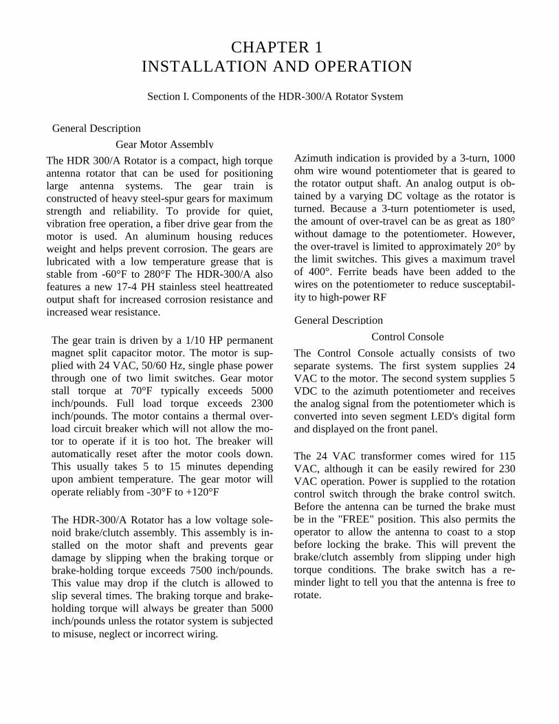
Section II. Specifications
Control Cable Requirements:Recommended
Length of Run Minimum for Maximum Torque
0-100 Feet: two #18 and six #22 AWG two #16 and six #18 AWGBertek 6308-18 or Belden Belden 94058448
100-200 Feet: two #16 and six #18 Belden seven #14 Belden 86289405
200-300 Feet: seven #14 Belden 8628 I twelve #14 Belden 8629
CAUTION:Before purchase of the control cable is made, considerationshould be taken to the wire size and O.D. of the cable incomparison to the connectors being used.

Belden 9495 (3-#14 AWG) and Belden 8489 (4-#18 AWG) can be used in place of Belden 8628.Also, Belden 8620 (4-#16 AWG) and 3-#12hook-up wire can be used in place of Belden8629.
Use the Effective Moment rating of the anten-nas to determine compatibility.
The three large wires are used on pins 1, 2, and3. The four smaller wires are used on pins 4, 8,9, and 10. The maximum resistance in the threelarge wires should not exceed 0.5 ohms each.
Section III. Pre-Installation Instructions
Pre-Installation CheckIt is required that a preliminary operational checkbe made on the rotator system prior to actual in-stallation. First, check each item against the PartsList. If any of these items are missing ordamaged, follow the instructions on our warrantylabel.
Next, set up the control unit and the rotator as-sembly for an operational check using thefollowing procedure:
STEP l: Determine if you wish to operate thisunit on 115 VAC or 230 VAC. TheHDR-300/A comes prewired for 115VAC, but can be easily modified for230 VAC operation. If 230 VACoperation is desired, go to Section IVbefore returning to Step 2.
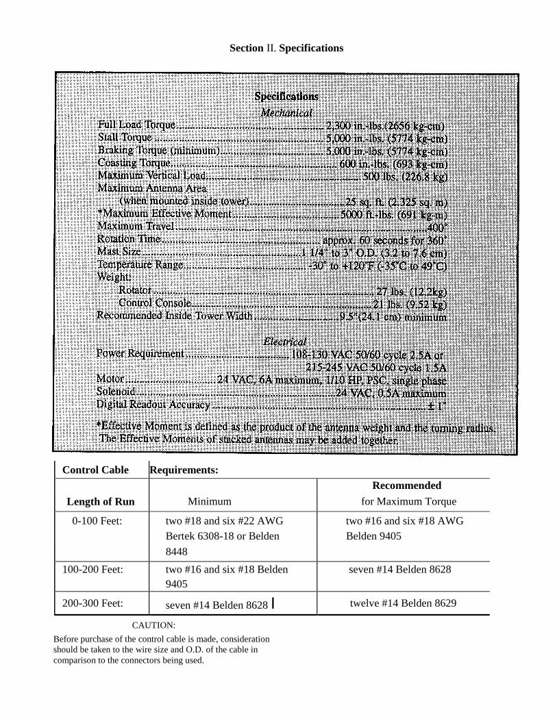
Figure 1Control Console Rear Panel

STEP 2: Referring to Figure 1, Control ConsoleRear Panel, install a 2.5A fuse (1.5Afor 230 VAC) and a 12A fuse in theappropriate fuse holders.
STEP 3: With the Control Console setting on asuitable workbench, plug the powercord into the appropriate wall socket.
STEP 4: Turn the power switch on. The switchlight should come on and stay lit untilturned off. The LED digital readoutshould also come on. You will noticethat the digits will change for asecond or two until the system hasstabilized. Once stabilized, the displayshould read between "-85" and "-99"or "---". All of these are under-rangeindicators showing that the controlcable has not been plugged in. Theover-range indicator is "EEE". Thiswill occasionally appear duringstabilization, but should not stay onunless there is a wiring mistake. Turnthe power switch off.
Moisten the sheath with isopropyl al-cohol. Align the contact with the backof the cavity and insert it straight intothe appropriate cavity until bottomed.Remove the sheath from the front ofthe recetpacle and use on the othercontacts.
Repeat for each contact. pull backlightly on each conductor to be sureeach contact is locked in each cavity.Once locked in place, the contacts mayonly be safely removed with an extrac-tion tool. This tool consists of a tubewith an OD of 0.129 and an ID of0.115. When inserted over the contactfrom the front side, this tool compres-ses the locking tabs, permitting easyremoval.
STEP 6: Plug the 8 pin connector into the rotatorreceptacle.
STEP 5: Measure out the control cable requiredfor your installation. (See Specifica-tions.) Stretch the cable out to its fulllength when testing. Strip the wires onboth ends as shown in Figure 2.Attach one end to the 10 pinconnector and the other end to the 8
Attach the other wire ends to the AMPsocket contacts, Figure 2. The maxi-mum wire size that should be usedwith these is 14 AWG, with a maxi-mum insulation diameter of 0.135inch. Crimp and solder these socketcontacts securely to each wire.
Before inserting a socket contact intothe receptacle, install the AMP sealprotector (sheath) (PN 650294) in thesocket portion of the contact as shownin Figure 2.
Figure 2Socket Contact Application
STEP 7: Plug the 10 pin connector into the con-trol console. Turn on the control con-sole power switch. The digital readoutshould show a heading between -10and 010 degrees. If it doesn't, refer toChapter 2, Section I, Troubleshootingguide. Final calibration will take placein Section V
STEP 8: Set the rotator so that the cover is facingyou. Move the brake switch on thecontrol console to the "FREE" posi-tion. The switch should light up, indi-cating that the antenna is free to turn.You should also hear the solenoid re-lease the brake and the solenoid willmake a humming noise which is nor-mal.
STEP 9: Set the rotator so that the output shaft isfacing you. Move the rotate switch onthe control console to the right.
NOTE: The brake must be in the "FREE" positionbefore the rotate switch will operate.
The output shaft should rotate clockwise. If not,refer to Chapter 2, Troubleshooting. Move the ro-tate switch back to the center position. The outputshaft should coast to a stop.Move the rotate switch to the left. The outputshaft should rotate counterclockwise.
North-Center Calibration:
Place the gearmotor assembly ( P/N 871159) onyour bench, and attach your control cable to boththe control unit and the gearmotor unit. Turn onthe control unit and rotate the gearmotor fullyCCW If South-centered, the display should readapprox. -15 degrees.
If North-centered, the display should read approx.165 degrees. If not, adjust the ZERO pot for thisvalue. Once you have the correct display, rotatethe gearmotor fully CW. If South-centered, thedisplay should read approx. 375 degrees. IfNorth-centered, the display should read approx.195 degrees. If not, adjust the GAIN pot for thisvalue. If you are using South-centered operation,this completes the adjustments on the bench.
If you are using North-centered operation, rotateCCW until you reach a display of `000'. As yourotate further CCW the display should change to`359','358', etc. You can expect some ambiguitynear the switchover from `359' to `000'. Try ro-tating both directions near this point, and watchthe display. If there is a large jump (e.g. from`355' to `002') or an overlap (e.g. from `359' to `-007'), you will need to adjust the two lower potsmarked "-01/3XX" and "3XX". Rotate to where "-O1" is displayed. If "-O1" can not be obtained,rotate to the closest positive heading (e.g. "00" or"O1"). This may require quick reflexes on thebrake switch. Adjust the new pot marked "-01/3XX" until "-O1" is replaced by "3XX", where"X" may be any digit. Adjust the new pot marked"3XX", so that "359" is displayed.
You may now rotate plus and minus a few de-grees to check the operation of the 359/000switchover. You may notice that the operation isslightly different between CW and CCW (hyster-esis). Occasionally you will see either "360" or "-O1". This is normal! This completes the benchadjustments for North-centered operation.
Leave your gearmotor at the center of rotation,and install it within your tower.

Figure 3Control Cable Connector Attachments

DETAIL AActuator Shown in the "000" position.
Figure 4Control Cable-Rotator Wiring Guide
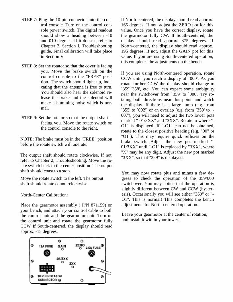
Figure 5Solenoid and Potentiometer Wiring Guide
Section IV Voltage ConversionCAUTION:
Dangerous and lethal voltage exist insidethis unit. Remove the power cord from thesocket before servicing this unit.
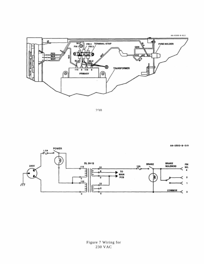
To convert the voltage of this unit, follow theprocedure below and Figure 5 for 115 VAC, orFigure 6 for 230 VAC.
Refer to Figure 1 and install the fuse indicated forthe voltage that will be used.
Replace the power cord's plug with the appropri-ate one for the power system requirements in yourarea.
Arrange the three white wires indicated with Aand B to the configuration shown for the desiredvoltage.
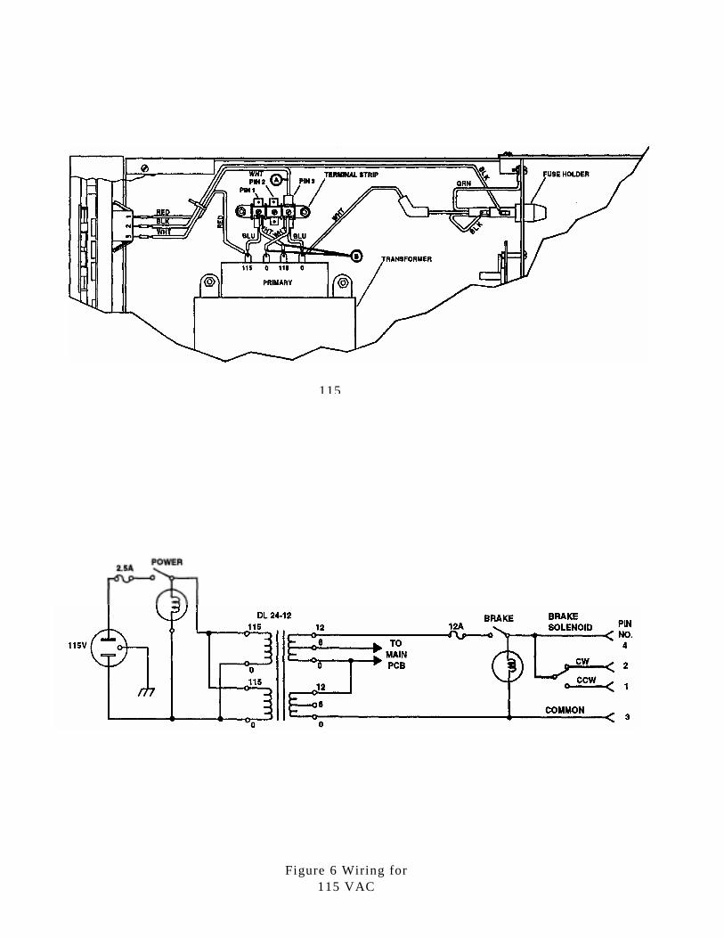
115
Figure 6 Wiring for115 VAC
AA-0300-9-011
230
Figure 7 Wiring for230 VAC
Section V Calibration and Installation Procedures
Calibration InstallationThe HDR-300/A is shipped from the factorywith two calibration steps completed. The 3-turnpotentiometer is matched to the rotator assemblyand the digital display is calibrated to zero.
It these items are replaced or become un-calibrated, refer to Chapter 2, Section III forcalibration procedures.
Only one calibration step should normally haveto be performed. This is a gain adjustment to thedigital voltmeter incorporated into the displaycircuitry. This adjustment can be made eitherwith the rotator installed or on the bench. Thebest method is to adjust it on the bench first, thencheck it again on the tower!Set the rotator on the bench with the output shaftparallel to the bench top. Assemble the mastclamps and platform as shown in Figure 7. Insertthe key into the keyway in the platform, andslide the mast clamp assembly onto the outputshaft. This may unbalance the rotator, so youmay wish to tip it back on the plastic housing.Turn on the control console and turn the rotatorso the display reads "00". Line up the mastclamp assembly on a distant object, so that afterturning the rotator through 360°, the mast clampassembly is again lined up on the same object.Turn the rotator clockwise until this alignment isobtained. Using a small screwdriver, adjust thegain potentiometer so that the display reads"360", See Figure 1.
Remove the mast clamp assembly from the out-put shaft. At this time, coat the platform holewith heavy grease to prevent corrosion. If yourrotator mounting plate is not permanentlyattached to the tower, it should be removed atthis time. Assemble the rotator to the rotatormounting plate. (For Hy-Gain towers see Figures7 and 8.) The rotator requires four (4) mountingholes, each 3/8 inch in diameter, four (4) inchesapart on a 5.656 inch (5 21/32") diameter circle.Refer to the template for mounting hole locationson the mounting plate which is furnished in thismanual. For small towers, the mounting holesmust be arranged on the mounting plate so thatthe output shaft is centered within the tower antthat the gear housing doesn't interfere with atower leg or bracing.
Turn the rotator back to "000" to check the align-ment again. If "360" cannot be obtained by ad-justing the gain potentiometer, refer to Chapter 2,Troubleshooting. Turn the rotator bothcounterclockwise and clockwise until each limitswitch is found. The counterclockwise limitswitch should be between -10 and -25 degrees.The clockwise limit switch should be between370 and 385 degrees. Return the rotator to "000".
If everything checks out, the HDR-300/A is nowready for installation.

Figure 8HDR-300 Rotator Mounting Hardware
Item ItemNo. Description No. Description10 Platform Plate 20 Nut, hex, 5/16", stainless steel11 Platform 21 Flatwasher, 5/16", stainless steel12 Mast Clamp 22 Lockwasher, split, 3/8", stainless steel13 Key, 1/4 sq. x 15/8", plated 23 Lockwasher, split, 5/16", stainless steel14 Bolt, hex head, 3/8"-16 x 3 1/2", stainless steel 24 Flatwasher, 3/8", stainless steel16 Bolt, hex head, 5/16"-18 x 1", stainless steel 68 Screw, pan head, #10-24 x 6"17 Bolt, hex head, 5/16"-18 x 1 1/2", stainless steel 69 Screw, pan head, #10-24 x 13/4"18 Setscrew Allen, 1/4"-20 x 3/8", stainless steel 70 Screw, pan head, #10-24 x 3/8", stainless steel19 Nut, 3/8"-16, stainless steel 71 Flatwasher, #10
72 Receptacle, 8 pin

Figure 9Top View of HDR-300/A and Tower Mounting Plate for
Hy-Gain Crank-Up Towers HG-54HD and HG-70HD
Figure 10Typical Installation of Rotator Mounted Below Plate

For towers that must be climbed for installation,follow these instructions:
Make sure that the rotator will match the holesin your mounting plate per previous informa-tion. Under NO circumstances should therotator be lifted by the mast clamp assembly.The rotator may be pulled up the tower byfirst attaching the mounting plate to therotator. The rope can ben be attached tomounting plate. Another method is to secure a5/16"-18 eyebolt into one of the mountingholes and attach the rope to it for lifting. Arope cradle may also be used. Once the rotatoris mounted securely within the tower, the mastclamp assembly can be installed and thecontrol cable taped to the tower.
Tighten the setscrew into the platform. Lowerthe mast into the mast clamp. Tighten the four(4) 3/8 inch bolts so that the mast is heldsecurely. Center the mast above the output shaftand tighten the four (4) 5/16 inch bolts on theplatform. The antenna should be oriented so thatit is pointing north when the readout shows"000".
Route the control cable down the tower usingappropriate strain relief. Route the control cableto the control console and plug it in. Using thesame calibration steps as before, line the antennaup with a distant object. Rotate the antenna untilthe antenna is again lined up with the sameobject. Check the digital readout and adjust ifnecessary.
CAUTION:
If using a crank-up tower, do notcompletely nest the tower with the HDR-300/A installed. Because of the shape ofthe gear box, a portion of the rotatorextends out of the tower.
Section VI. Operations and Maintenance
OperationsThe HDR-300/A brake release feature isdesigned to decrease the effects of torsionalforces caused by rapid deceleration and instantstopping of large antennas and beams. Byreleasing the rotate switch slightly before thepoint of intended antenna position, letting theunit coast to a full stop, then locking the brake,the torque on both the tower and rotator is heldto a minimum. This will prolong the life of yourrotator system and will maintain the maximum
CAUTION:
Although operation of the HDR-300/A atits rated capacity of 25 square feet instrong winds (50 mph plus) is not recom-mended, it is possible as long as certainprecautions are taken.
Always allow the antenna to coast to a stopbefore locking the brake.
NOTE: When the rotator is not in use, the brakeswitch should be set in the "lock" position. Thebrake switch incorporates a light to remind youthat the antenna is free to turn.
The brake switch must be in the "FREE"position before the rotator will turn.
2
3
Always keep the brake locked when therotator is not being turned.
Avoid rotating near the ends of rotation. Donot depend on the limit switches to stoprotation of a large antenna in strong winds.
These precautions should also be followed whenrotating medium size antenna (7 to 15 squarefeet) in light winds. When followed, the life ofthe rotator system will be prolonged.

Use the Digital Readout System
The HDR-300/A incorporates a very accuratedigital display of azimuth bearing information.This display will always indicate the exact direc-tion of the antenna once calibrated. A readout of"000" degrees indicates that the antenna is point-ing due North. A readout of "090" indicates East,"180" indicates South, "270" indicates West, and"360" indicates North again.
Because of the type of digital readout systemused, overtravel in the clockwise direction isindicated by 360 to 385 which would correspondthe 000 to 025 degrees. Overtravel in thecounterclockwise direction is indicated by nega-tive numbers such as -01 to 125 degrees.
The HDR-300/A has numerous features toprevent water entry. The output shaft uses a spe-cial V -shaped )-ring to prevent water entry atthis point. The mast clamp assembly uses analuminum plate to keep the platform fromdamaging the O-ring and to prevent water fromrunning through the mast clamp assembly.
Also, a new plastic housing is provided to keepthe motor, capacitor, limit switches, and poten-tiometer dry. A drain hole is provided toeliminate condensation water. Periodically checkthe O-ring and the plastic housing to insuremoisture resistance.
During normal rotation, the display will incre-ment in steps of approximately 4 degrees. This isbecause the rotation is faster than the displaysystem. Once the rotator is allowed to coast, theincrements will be in steps of 1 degree. Theconversion rate of the digital display system is 4Hz. This prevents a rapid flickering of thedisplay during rotation.
The digital display system also incorporates twofilters that eliminate both 50/60 Hz and RFmodulation of the display.
Maintenance
Rotator Assembly: The gears are lubricated witha special low temperature grease that is stablefrom -60°F to +280°R After three to five years ofservice, the gears should be checked to insureadequate lubricant. This grease can be obtainedthrough Hy-Gains's Customer Service Depart-ment for a nominal charge.
The output shaft of the rotator is stainless steel toprevent corrosion; however, after many years ofservice, some rusting may occur in the platformhole. You should coat this hole with greasebefore installation to prevent corrosion.
CHAPTER 2TROUBLESHOOTING AND SERVICE
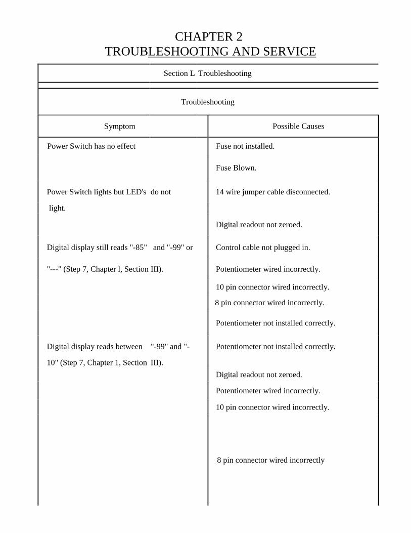
Section L Troubleshooting
Troubleshooting
Symptom Possible Causes
Power Switch has no effect Fuse not installed.
Fuse Blown.
Power Switch lights but LED's do not 14 wire jumper cable disconnected.
light.
Digital readout not zeroed.
Digital display still reads "-85" and "-99" or Control cable not plugged in.
"---" (Step 7, Chapter l, Section III). Potentiometer wired incorrectly.
10 pin connector wired incorrectly.
8 pin connector wired incorrectly.
Potentiometer not installed correctly.
Digital display reads between "-99" and "- Potentiometer not installed correctly.
10" (Step 7, Chapter 1, Section III).Digital readout not zeroed.
Potentiometer wired incorrectly.
10 pin connector wired incorrectly.
8 pin connector wired incorrectly

Troubleshooting Continued
Symptom Possible Causes
Digital display reacis greater than "10" (Step Pontentiometer not installed correctly.7, Chapter 1, Section III).
Digital readout not zeroed.
Potentiometer wired incorrectly.
10 pin connector wired incorrectly.
8 pin connector wired incorrectly
Brake switch has no effect when switched to Solenoid wired incorrectly.
"FREE" position.10 pin connector wired incorrectly.
8 pin connector wired incorrectly.
Control cable not plugged in.
12 Amp fuse not installed.
Brake solenoid buzzes but doesn't release Too much voltage drop in control cable.
brake.
Use a heavier cable.
Rotate switch has no effect. Brake still in lock position.
Control cable not plugged in.
10 pin connector wired incorrectly.
8 pin connector wired incorrectly.
Limit switch stuck.
End of rotation - Switch direction.
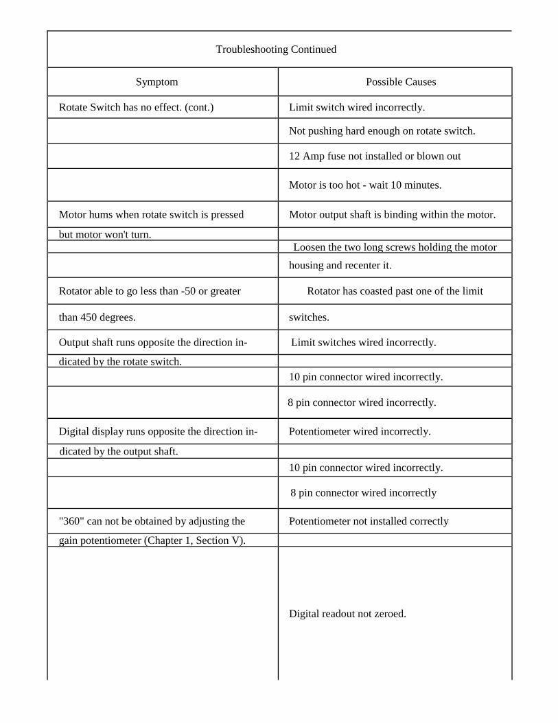
Troubleshooting Continued
Symptom Possible Causes
Rotate Switch has no effect. (cont.) Limit switch wired incorrectly.
Not pushing hard enough on rotate switch.
12 Amp fuse not installed or blown out
Motor is too hot - wait 10 minutes.
Motor hums when rotate switch is pressed Motor output shaft is binding within the motor.
but motor won't turn.Loosen the two long screws holding the motor
housing and recenter it.
Rotator able to go less than -50 or greater Rotator has coasted past one of the limit
than 450 degrees. switches.
Output shaft runs opposite the direction in- Limit switches wired incorrectly.
dicated by the rotate switch.10 pin connector wired incorrectly.
8 pin connector wired incorrectly.
Digital display runs opposite the direction in- Potentiometer wired incorrectly.
dicated by the output shaft.10 pin connector wired incorrectly.
8 pin connector wired incorrectly
"360" can not be obtained by adjusting the Potentiometer not installed correctly
gain potentiometer (Chapter 1, Section V).
Digital readout not zeroed.

Troubleshooting Continued
Symptom Possible Causes
Digital readout is changing more than t 1 High winds causing antenna to rock.degree with brake switch locked.
High RF field near control cable.
Brake system failed.
250 gF capacitor not working.
Digital readout is changing more than t5 Extremely high winds causing antenna to rock.
degrees with brake switch locked.Brake system failed.
Very high RF field near control cable.
250 j.tF capacitor not working.
Rotator able to go less than -25 degrees Limit switches) broken.
and/or greater than 385 degrees.Limit switch actuator loose or misadjusted.
Gain control not calibrated.
Digital readout not zeroed.
Rotator will turn with no load but will not Mast is binding in tower.
turn a large antenna.Control cable is too small.
Winds are too strong.
Antenna is too large.
Thrust bearing is not used.

Section II. Voltage and Resistance Measurements
Voltage and Resistance Charts
Control Unit, 10 pin socket:
Between Pin Numbers Voltage or 1hleranceResistance
1-3 (with rotate switch to the right) 24 VAC f 10%
2-3 (with rotate switch to the left) 24 VAC t 10%
4-3 (with brake "Free") 24 VAC ± 10%
8-10 +5 VDC t %
9-10 180KL2 t 20%
10-chassis zero ohms
Rotator Unit, 8 Pin Socket:
Between Pins ResistanceExcluding Control Cable
1-3 1.0 ohm
2-3 1.0 ohm
1-2 2.0 ohms
3-4 32 ohms
5-7 1000 ohms
6-7 150-550 ohms
5-6 450-850 ohms
Section III. How to Get Factory Service/Calibration
Service Information
Do not ship equipment to the manufacturer with-out prior authorization. We prefer to send specialshipping labels which will avoid the delay of anunexpected shipment.
If time is extremely important, wire or call forapproval and we will rush labels to you. When ashipment is expected, even the time of sendingthe labels is less than that lost when an unex-pected shipment is received.
It is very important that the shipment be wellpacked and fully insured. Damage claims must besettled between you and the carrier and willgreatly delay any returns. Proper packing nor-mally avoids this trouble.
NOTE: we will not ship by means of a carrier thatwill not fully insure the shipment. Some carriershave a $200.00 limit. The exception to this iswhen there is no other means (APO-FPO-etc.) ofshipment than parcel post, then we will ship bythis means with your written agreement that youassume any loss over that which the carrier willinsure. C.O.D. shipments cannot be made toAPO-FPO addresses.
All replacement parts orders must be prepaid orC.O.D. only. Replacement part price quotes willbe furnished on request for those who desire pre-paid shipment or cannot accept C.O.D. shipments.
Calibration
ALL SHIPMENTS MUST BE SENT TO USPREPAID. We do not accept collect shipments.All returns should be made in our standard car-tons only - so save our carton when unpacking theunit. When a shipment is returned, it will behandled in one of three ways:
1. Where all service is in warranty, the ship-ment will be returned prepaid by a carrier ofour choice. Warranty claims must be accom-panied by a copy of the bill-of-sale.
2. If there are any charges not covered by war-ranty, we will hold the shipment and adviseyou of costs, which you can then send.
3. Or, upon your written authorization, wewill ship C.O.D. for any charges notcovered by warranty, then the carrier willcollect these charges and the transportationcosts on arrival. Unclaimed or refusedC.O.D. shipments will not be reshippeduntil payment of service and transportationcharges is received. Shipment will then bemade collect for reshipment transportationcharges.
Most replacement parts do not need adjustment orcalibration. The two exceptions are the 3-turn po-tentiometer and the main P .C. board.
To Recalibrate The Pot Within The GearmotorAssembly:Place the gearmotor assembly (P/N 871159) onyour bench, and remove the black plastic cover.Attach your control cable to both the control unitand the gearmotor unit. Place a voltmeter across.pins 9 and 10 (A digital VOM is best to use). Turnon the control unit and rotate the gearmotor to it'scenter of rotation. (Watch the plastic limit switchactuator while turning the rotator) With thegearmotor at the mechanical center of rotation,loosen the screws which hold the pot assembly tothe gearmotor. It is easier to remove one screw,then pivot this assembly so that the plastic gearsunmesh. When loose enough so that the pot'splastic gear turns freely, adjust the position of thisgear until the voltmeter reads 3.07 volts. Carefullyre-mesh the plastic gears and tighten the twoscrews. The voltmeter should read within therange of 3.05 to 3.10. If not, repeat thisadjustment.

Rotate the gearmotor CCW until the limit-switchactuator is approximately 1/8" from the limit-switch arm, and has not opened the circuit. Theactuator should "point" to the pivot-post of thelimit switch arm. (The voltage should read ap-prox. 2.25 volts) Adjust the "Zero" potentiometerso that the digital display reads "000". Mark thisposition with a pen or pencil on the gearmotor.Rotate the gearmotor a full revolution CW untilyour mark is reached again. (The voltage shouldread approx. 3.89 volts) Adjust the "Gain" potuntil "360" is shown on the digital display. Therotator is now calibrated for South-centered op-eration.
To calibrate for North-centered operation, adjustthe slide switch to the left (closed) position. Ro-tate CCW to where "-O1" is displayed. If "-O1"can not be obtained, rotate to the closest positiveheading (e.g. "00" or "01"). This may requirequick reflexes on the brake switch. Adjust thenew pot directly under the "Gain" pot until "-O1"is replaced by "3XX", where "X" may be anydigit. Adjust the new pot centered between the"Zero" and "Gain" pots and two inches lower, sothat "359" is displayed. You may now rotate plusand minus a few degrees to check the operation ofthe 359/000 switchover. You may notice that theoperation is slightly different between CW andCCW (hysteresis). Occasionally you will seeeither "360" or "-O1". This is normal!
New PCB 871165-2
Switch South-Centerright (open)
North-Centerleft closed
Voltage at Center of Rotation 3.07 3.07Voltage at full CCW 2.25 2.25Voltage at full CW 3.89 3.89
Service Information
If you are encounter technical problems and needassistance, you should contact Hy-Gain CustomerService Department.
All requests, inquires, warranty claims, orfor ordering replacement parts, contact:
Hy-Gain
308 Industrial Park Road Starkville,Mississippi 39759 USA Phone: 662-323-9538

CHAPTER 3HDR-300/A PARTS LIST AND SCHEMATICS
PARTSNOTE: Item numbers may not necessarily be in numerical order.
ItemNo. Part No. Description Qty1 870511 Gear Motor Assembly..............................................................................12 250117 Gear, 1T2-32038..................................................................................13 470643 Cover, black plastic..............................................................................14 (Not Used)5 722958 Potentiometer, 3-turn (1 K ohm) .........................................................16 *740200-2 Gear Motor, VW47..............................................................................164 500350 Screw, panhead, #4-40 x 5/8"..............................................................465 559612 Nut, hex, #4-40....................................................................................466 561166 Flatwasher, #6......................................................................................467 569613 Lockwasher, internal, #4......................................................................468 500346 Screw, pan head, #10-24 x 6"..............................................................269 500347 Screw, pan head, #10-24 x 13/4 ".......................................................270 500348 Screw, pan head, #10-24 x 3/8" ..........................................................771 561165 Flatwasher, #10..................................................................................1172 650290 Connector, AMP 208677-1..................................................................1
650291 Contact, AMP 66602-1........................................................................7450581 Wire seal foryin contact, AMP 207565-2.................................................. 1
871161 Parts Pack, Fuses .....................................................................................17 710043 Fuse, 1.5A/3AG slo-blow....................................................................28 710044 Fuse, 2.5A/3AG slo-blow....................................................................29 710045 Fuse, 12A/3AG slo-blow.....................................................................2
871532 Parts Pack Box, HDR-300.......................................................................110, 170429 Platform Plate ......................................................................................111 375917 Platform................................................................................................112 375918 Clamp, mast .........................................................................................2
870512 Parts Pack, AMP Plug..............................................................................1652292 AMP plug, 208678-1...........................................................................1650293 AMP socket, 66601-1..........................................................................8650294 AMP sheath, 208338-1........................................................................3
871533 Parts Pack, Hardware...............................................................................113 385928 Key, plated, 1/4" sq. x 15/8 "..............................................................114 500155 Bolt, hex head, 3/8"-16 x 3 1/2", stainless steel .................................415 (Not Used)16 505842 Bolt, hex head, 5/16"-18 x 1", stainless steel ...................................... 417 509712 Bolt, hex head, 5/16"-18 x 1 1/2", stainless steel ...............................418 536395 Setscrew, Allen, 1/4"-20 x 3/8" ss, with nyloc patch .......................... 219 555694 Nut, hex, 3/8"-16 stainless steel .......................................................... 420 555747 Nut, hex, 5/16"-18 stainless steel ........................................................421 560024 Flatwasher, medium, 5/16", stainless steel .......................................... 422 561016 Lockwasher, split, 3/8", stainless steel ................................................ 4

HDR-300/A PARTS LIST (cont.)ItemNo. Part No. Description Qty23 564792 Lockwasher, split, 5/16", stainless steel .............................................. 824 567180 Flatwasher, 3/8", stainless steel...........................................................425 640024 Plug, 10 pin..........................................................................................126 (Not Used)27 871869 Control Console Assembly ......................................................................128 51845039 Screw, Philips, #4-40 x 3/8".............................................................. 229 250105 Spacer, hex head, #8-32 x 3/8"............................................................430 179808 Cover, console......................................................................................131 451623 Strain Relief .....................................................................……………132 460293 Front Panel...........................................................................................133 350834-1 Back Plate ............................................................................................134 450375 Front Panel Label.................................................................................135 506460 Screw, Rround head, #10-24 x 3/4" ....................................................436 506650 Screw, round head, #6-32 x 1/2...........................................................437 506665 Screw, round head, #6-32 x 1/4" .........................................................238 506800 Screw, round head, #8-32 x 3/4" .........................................................639 509234 Screw, round head, #8-32 x 1/2" .........................................................640 511577 Screw, Type A, pan head, #6 x 5/16" ..................................................441 556970 Nut, hex, #10-24..................................................................................442 556990 Nut, hex,#8-32 ...................................................................................1243 557000 Nut, hex, #6-32....................................................................................244 557010 Nut, hex, #4-40....................................................................................245 567125 Lockwasher, internal, #10.................................................................. 446 567135 Lockwasher, internal,#8.......................................................................847 600221 Power Cord ..........................................................................................148 640026 10 Pin Receptacle ................................................................................149 660020 Terminal Strip ......................................................................................150 700088 Power Switch .......................................................................................151 700092 Brake Switch............................................................................…………….152 700089 Rotate Switch.......................................................................................153 710044 Fuse, 2.5A/3AG slo-blow....................................................................154 710045 Fuse, 12A/3AG slo-blow.....................................................................155 718105 Fuse holder, 3AG.................................................................................256 52158025 Capacitor, disc, ceramic, .lpf..............................................................257 730063 Transformer, 24 VAC...........................................................................158 870994 Jumper Cable Assembly ......................................................................159 871165-2 Main PC. Board Assembly
(Refer to Figures 18, 19, & 20)...........................................................160 871166-1 Display PC. Board Assembly
(Refer to Figures 21, 22, and 23) ........................................................161 871275 Bezel and Lens Assembly....................................................................162 871870 Main Chassis w/feet.............................................................................163 04890 Cable Tie 4" .........................................................................................664 59000111 Screw, M4-.7 x 10, pan head, Philips .................................................465 51845039 Screw, #4-40 x 3/8" pan head............................................................ 2
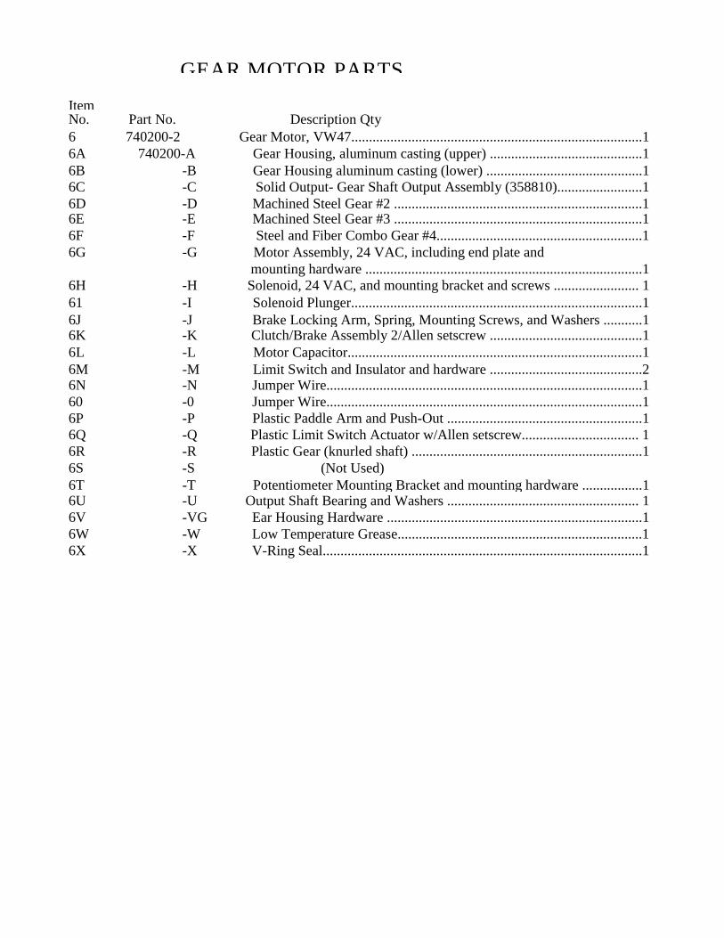
GEAR MOTOR PARTSItemNo. Part No. Description Qty6 740200-2 Gear Motor, VW47..................................................................................16A 740200-A Gear Housing, aluminum casting (upper) ...........................................16B -B Gear Housing aluminum casting (lower) ............................................16C -C Solid Output- Gear Shaft Output Assembly (358810)........................16D -D Machined Steel Gear #2 ......................................................................16E -E Machined Steel Gear #3 ......................................................................16F -F Steel and Fiber Combo Gear #4..........................................................16G -G Motor Assembly, 24 VAC, including end plate and
mounting hardware ..............................................................................16H -H Solenoid, 24 VAC, and mounting bracket and screws ........................ 161 -I Solenoid Plunger..................................................................................16J -J Brake Locking Arm, Spring, Mounting Screws, and Washers ...........16K -K Clutch/Brake Assembly 2/Allen setscrew ...........................................16L -L Motor Capacitor...................................................................................16M -M Limit Switch and Insulator and hardware ...........................................26N -N Jumper Wire.........................................................................................160 -0 Jumper Wire.........................................................................................16P -P Plastic Paddle Arm and Push-Out .......................................................16Q -Q Plastic Limit Switch Actuator w/Allen setscrew................................. 16R -R Plastic Gear (knurled shaft) .................................................................16S -S (Not Used)6T -T Potentiometer Mounting Bracket and mounting hardware .................16U -U Output Shaft Bearing and Washers ...................................................... 16V -VG Ear Housing Hardware ........................................................................16W -W Low Temperature Grease.....................................................................16X -X V-Ring Seal..........................................................................................1
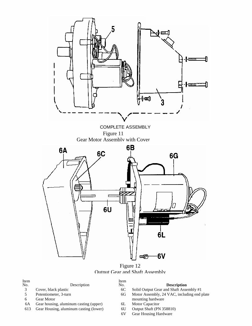
COMPLETE ASSEMBLYFigure 11
Gear Motor Assembly with Cover
Figure 12Output Gear and Shaft Assembly
Item ItemNo. Description No. Description
3 Cover, black plastic 6C Solid Output Gear and Shaft Assembly #15 Potentiometer, 3-turn 6G Motor Assembly, 24 VAC, including end plate6 Gear Motor mounting hardware6A Gear housing, aluminum casting (upper) 6L Motor Capacitor613 Gear Housing, aluminum casting (lower) 6U Output Shaft (PN 358810)
6V Gear Housing Hardware

Figure 13Gear Motor Assembly-Side
Figure 14Gear Motor Assembly-Top View
Item ItemNo. Description No. Description
5 Potentiometer, 3-turn (1K ohm) 6L Motor Capacitor6 Gear Motor 6M Limit Switch and Insulator and Hardware6G Motor Assembly, 24 VAC, including end plate and 6N Jumper Wire
mounting hardware 60 Jumper W iere6H Solenoid, 24 VAC, and mounting bracket and screws 6P Plastic Paddle Arm and Push-Out61 Solenoid Plunger 6Q Plastic Limit Switch Actuator w/Allen setscrew6J Brake Locking Ann, Spring, Mounting Screws 6R Plastic Gear (knurled shaft)
and Washers 6T Potentiometer Mounting Bracket and mounting hardware6K Clutch/Brake Assembly w/Allen setscrew 6V Gear Housng Hardware
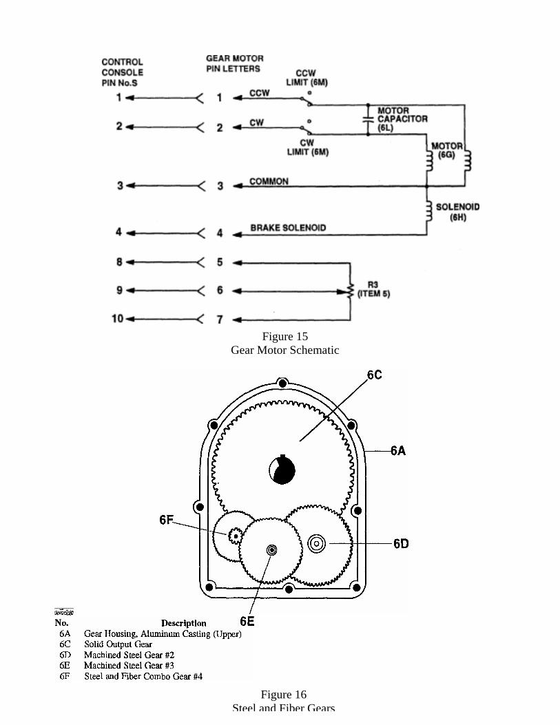
Figure 15Gear Motor Schematic
Figure 16Steel and Fiber Gears

Figure 18Interior View of Control Console

Figure 19Schematic Main P .C. Board
Figure 20Main PC. Board

Main P .C. Board - PN 871165-2Parts List for Main P.C. Board (871165-2)
PartDesignator Part Number DescriptionC101 and C102 52158025 Capacitor, dis c, ceramic, .1 pF, 25VCl and C2 722463 Capacitor, electrolytic, l000pF, 16VDCC3 and C4 52158025 Capacitor, disc, ceramic, .1pF, 25VC5 51821016 Capacitor, electrolytic, 220pFC6 722465 Capacitor, .22 pF 12VDC, disc,R1 54046100 Resistor, 100K, 1/4W 1%R2 54045110 Resistor, 11 K, 1/4W 1 %R3 52154269 Resistor, 3.3K, 1/4W 1%R4 722469 Resistor, 150K, 1/4W 1 %R5 722975 Resistor, 42.2K, 1/4W 1 %R6 52154195 Resistor, 3.9M, 1/4W, 1%R7 54044576 Resistor, 5.76K, 1/4W 1 %R8 54046237 Resistor, 237K, 1/4W, 1 %R9 54044681 Resistor, 6.81K, 1/4W 1%RIO 54044953 Resistor, 9.53K, 1/4W 1%VRl 722467 Variable Resistor, 50KVR2 723441 Variable Resistor, 1 KVR3 723421 Variable Resistor, 2.5KVR4 722468 Variable Resistor, IOKD1-D4 58678000 Diode, IN5817, low voltage turn onU1 760098 A/D IC CA3161EU2 760099 Driver IC, CA 3161EU3 and U4 760097 LM348AT 5.0U5 53284000 LM393S1 70000 Switch, 2-positionF1 710076 Fuse, 1 amp, 3AG, Fast acting
NOTE: All designators correspond with Figures
Components and Wiring of Main PC.
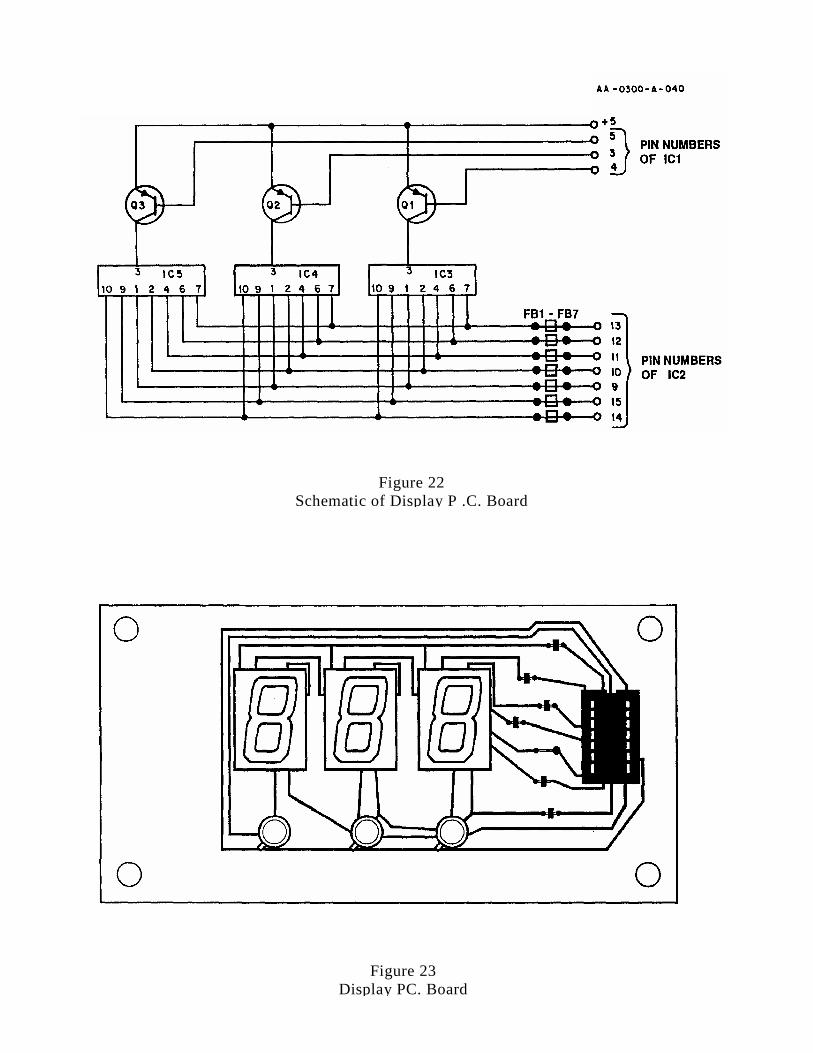
Figure 22Schematic of Display P .C. Board
Figure 23Display PC. Board

Figure 24
IteNo. Description
40 Screw, Type A, pan head, #6x 5/16" 50 Power Switch51 Brake Switch52 Rotate switch60 Display PC. Board Assembly Figure 25
Rear Mounted Components-Front Panel of Control Console