heavy-duty rod ends and spherical bearings · 2 heavy-duty rod ends and spherical bearings from...
TRANSCRIPT
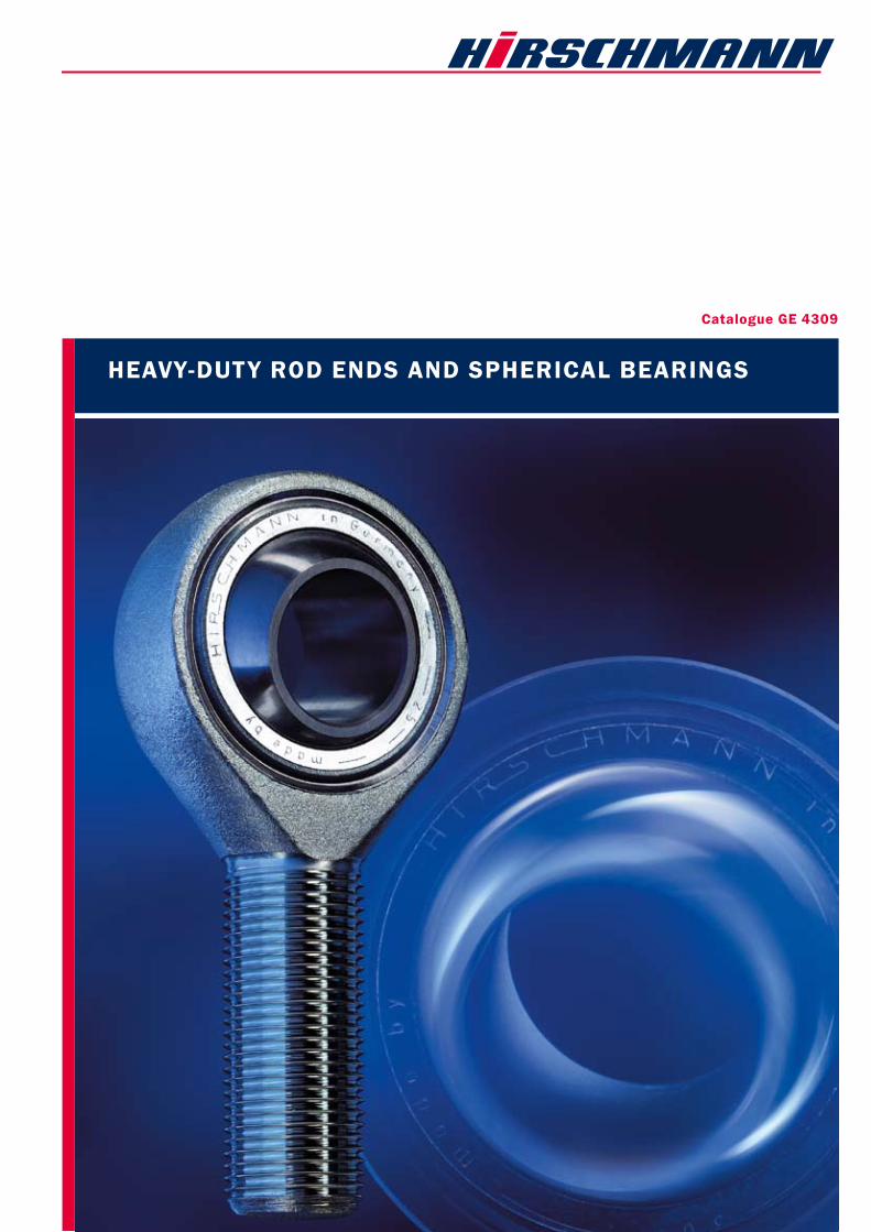
Catalogue GE 4309
HEAVy-DUTy ROD EnDs AnD sPHERICAl bEARInGs

2
Heavy-duty Rod ends and spherical bearings from HIRsCHmAnn
mm A million times proved
mm In sizes 2 up to 50 mm
mm Acc. to DIN ISO 122404 (DIN 648K)
and Cetop
mm Maintenance free or Relubricatable
mm Hard cromed or stainless steel, sealed
mm Specials to customer requirements
Rod ends and spherical bearings
standard products
3
C O n T E n T s :Introduction
HIRSCHMANN GmbH
mm Selection 5
mm Technical notes 6–7
mm Checking bearing size 8–9
mm Determining bearing size 10
mm Calculation examples 11
mm Rod ends
heavy-duty relubricatable design 12–13
mm Rod ends
heavy-duty maintenance-free design 14–15
mm Rod ends heavy-duty,
relubricatable and maintenance-free
as per CETOP-Norm 16–17
mm Spherical bearings heavy-duty,
relubricatable and maintenance-free 18–19
mm Spherical bearings heavy-duty,
relubricatable and maintenance-free
without steel outer ring 20
mm Sealed rod ends
and spherical bearings 21
mm Threaded bolts for rod ends
and spherical bearings 22
mm Applications and
typical installations 23
mm Form sheets for an inquiry 24-25
mm Advice and sales 26–27
HIRSCHMANN's rod ends and spherical bearings are bearing elements which can be used for many applications, and are of the plain bearing type. They have proved their worth in millions of instances as a design element for trans-mitting power between members lying at various angles, both statically and dynamically. The mounting dimensions of these bearing elements have been fixed in DIN ISO 12240-4 (648 K). This catalogue reflects the current state of develop-ment and manufacture, and the information contained in it supersedes earlier publications. We reserve the right to make modifications in the course of product development. Reprints and excerpts require our express permission.
standard products:For all the standard products shown in this catalogue, many variations are possible. Details are given in the text below the tables of dimensions, e.g. hard-chromed or rustproof inner ring or outer part, reduced bearing slackness etc.
specials: In addition to our standard products, we make specials to customer requirements or to drawing. Examples of our spe-cials are shown on the rear cover of the catalogue.
Warranty: All the information contained in this catalogue is the result of years of experience in the manufacture and use of rod ends and spherical bearings. Nevertheless, unknown para-meters and practical conditions of use can considerably re-duce the validity of these general statements, so that the user must conduct practical tests. The multitude of applica-tions for rod ends and spherical bearings mean that we can-not accept any liability for the correctness of our recommen-dations in individual instances.
Quality according to En 9100All HIRSCHMANN GMBH rod ends and spherical bearings are produced using the latest and most reliable production methods, and are subject to quality assurance measures as per EN 9100 (air and space industry) both during production and in the product stage.
Advisory service and sales: Our staff and the sales engineers at our agencies and dealers in Germany and abroad, all of whom have their own stocks, would be pleased to assist you at any time.
4
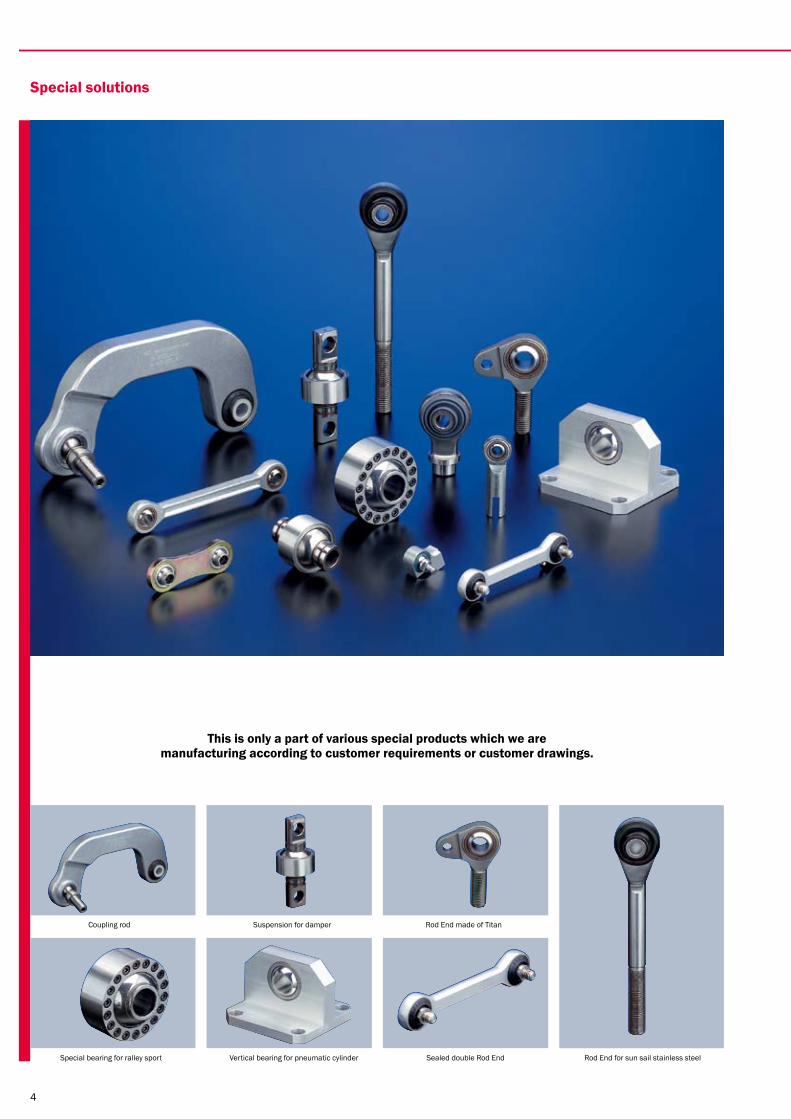
special solutions
This is only a part of various special products which we are manufacturing according to customer requirements or customer drawings.
Coupling rod Suspension for damper Rod End made of Titan
Special bearing for ralley sport Vertical bearing for pneumatic cylinder Sealed double Rod End Rod End for sun sail stainless steel
5
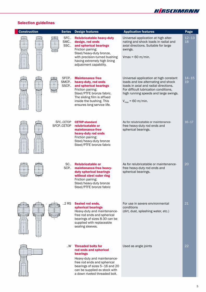
SFC.. Relubricatable heavy-duty Universal application at high alter- 12–13 SMC.. design, rod ends nating and shock loads in radial and 18 SSC.. and spherical bearings axial directions. Suitable for large Friction pairing: swings. Steel/heavy-duty bronze, with precision-turned bushing Vmax = 60 m/min. having extremely high lining adjustment capability.
SFCP.. maintenance free Universal application at high constant 14–15 SMCP.. heavy-duty, rod ends loads and low alternating and shock 19 SSCP.. and spherical bearings loads in axial and radial directions. Friction pairing: For difficult lubrication conditions, Steel/PTFE bronze fabric. high running speeds and large swings. The sliding film is affixed inside the bushing. This Vmax = 60 m/min. ensures long service life.
SFC..CETOP CETOP-standard As for relubricatable or maintenance- 16–17 SFCP..CETOP relubricatable or free heavy-duty rod ends and maintenance-free spherical bearings. heavy-duty rod ends Friction pairing: Steel/heavy-duty bronze Steel/PTFE bronze fabric
SC.. Relubricatable or As for relubricatable or maintenance- 20 SCP.. maintenance-free heavy- free heavy-duty rod ends and duty spherical bearings spherical bearings. without steel outer ring Friction pairing: Steel/heavy-duty bronze Steel/PTFE bronze fabric
..2 RS sealed rod ends, For use in severe environmental 21 spherical bearings conditions Heavy-duty and maintenance- (dirt, dust, splashing water, etc.) free rod ends and spherical bearings of sizes 8-30 can be supplied with replaceable sealing sleeves.
..W Threaded bolts for Used as angle joints 22 rod ends and spherical bearings Heavy-duty and maintenance-
free rod ends and spherical bearings of sizes 5–16 and 20 can be supplied ex stock with a down riveted threaded bolt.
selection guidelines
Construction series Design features Application features Page

Technical notes
bearing slackness:Bearing slackness or bearing clearance is the dimension by which the inner ring can be moved within the bushings in a radial or axial direction when not installed and unlubricated. Rod ends and spherical bearings are manufactured with dif-fering bearing slackness, as shown in the following charts, depending on the friction pairing and the size of the bearing. When mounting bearings, please note that the slackness can be reduced to null if necessary, due to possible diffe-rences in tolerance (bearing diameter to housing bore ho-le).The test load is 100 N.
Bearing slackness in lubricated design (at room temperature)
Radial slackness in µm
Size C2 Normal C3 min max min max min max 2– 4 – – 10 30 – – 5– 8 5 10 10 30 30 60 10–14 10 20 20 40 40 80 16–20 15 25 30 50 50 100 22–30 20 30 40 60 60 120 35–50 40 60 60 90 90 150
Fig. 1
Bearing slackness in maintenance-free design (at room temperature) Radial slackness in µm Size C2 Normal C3 min max min max min max 2– 4 – – 2 4 – – 5–30 – – 5 10 10 20 35–50 – – 10 20 20 40
Fig. 2
The axial slackness is 2 to 3 times the radial slackness un-der the same test load (measured at room temperature).
selection of bearing slackness: lubricated design If there are no special reasons for a reduced bearing slackness according to C2, the “Normal” radial slacckness must be selected as it offers the best lubricating grease dis-tribution with a high bearing contact area.All rod ends and spherical bearings are supplied with “Nor-mal” radial slackness unless otherwise ordered.maintenance-free designThese bearings are remarkable for their low bearing slack-ness and a high contact area ratio. Unless otherwise orde-red, the maintenance-free rod ends are supplied with “Nor-mal” radial slackness. If the overall friction movement should be kept low when se-veral rod ends or spherical bearings are used, bearings with a radial slackness in accordance with C3 should be used al-so.
6
Consideration of the environment: It is recommendable to apply a stainless or sealed type when using it in a humid environment.Accordingly to the individual customer’s requirements, the bearings are delivered in the following special designs:stainless and acid-proof high temperature-proof low temperature-proof etc.
lubrication:All relubricatable rod ends and bearings are supplied un-greased. We recommend lubrication with an anticorrosive Li-thium-based pressure-resistant grease or a Lithium-complex metal soap (multipurpose antifriction bearing grease) for the temperature range of –20° C to +125° C. For temperatures above 125° C a high temperature grease must be used and for temperatures below –20° C a low temperature grease must be used.
Initial lubrication and relubrication, lubrication intervals Under severe conditions and at high load, a temperature check is recommended shortly after commissioning. If a temperature rise of 25° C occurs after a running-in time of approx. 1 hour of operation, immediate lubrication is ne-cessary. A periodical relubrication is necessary in any event. Rod ends and spherical bearings under alternate load from both sides require shorter intervals between lubrication than rod ends and spherical bearings under load from one side only. The lubrication intervals depend on the individual circumstances and on the surrounding conditions. The following guideline values apply for the minimum lubricating periods:With load from one direction
With load from alternating directions
t = lubricating period in hours of operation.Gh = duration of use in hours of operation
(see page 9).Lubricating more often does not have any advantages, fur-thermore it can damage the hydrodynamic balance on the sliding surface.If the lubricating periods are not observed, the service life can decrease. The rod ends with female thread are equipped from size 5 upwards with funnel-type lubricating nipples to DIN 3405, those with thread from size 6 upwards. We can supply other lubricating nipples on request. During the running-in time of the maintenance-free types on-ly a small part of the PTFE is transferred from the sliding foil to the inner ring. Hereby a smoothing effect arises. This reduces the friction and leads to the longer du-rability. A greasy or oily film prevents this smoothing effect. Thus, we recommend using these elements without lubrication.
t = Gh 30
t = Gh 130

7
Operating temperature:All designs can be used without restriction in a temperature range from –30° C to +120° C. Increasing the operating temperature reduces the bearing power and, thus, the ser-vice life. Operation at high temperature of relubricatable rod ends and spherical bearings depends to a very great extent on whether the high-temperature lubricating grease used offers sufficient lubricity at high operating temperatures. These de-signs could be used in the short term under low load and with suitable lubrication at temperatures up to +250° C. The maintenance-free bearings can be used in a temperatu-re range from –50° C to +150° C (mind the decrease or the increase of bearing slackness). Sealed rod ends and spherical bearings can be used at tem-peratures from –20° C to +120° C (sealing sleeves of Perbunan). For higher temperatures up to +250° C sealing sleeves can be specially made from fluorelastomer rubber (Viton®).
moment of friction m:The moment of friction for rod ends and spherical bearings can be calculated using the following equation:
M = moment of friction [Nm]µ = friction coefficient of sliding surface P = dynamically equivalent bearing load [N]K = inner ring diameter [mm]
Guideline values for the friction coefficient µ
Friction coefficient µ Bearing type min max lubricated 0,08 0,15 maintenance-free 0,03 0,10
Fig. 3
The low friction coefficients apply for high loads (p = 80–100 N/mm2) at low running speeds (v = 5–10 m/min). The high friction coefficients are for low loads (p = 5–10 N/mm2) at high running speeds (v = 30–60 m/min).p = specific surface pressure [N/mm2]v = running speed in the lining [m/min]
Viton® is a registrered trademark of Du Pont Performance Elastomers.
bearing capacities: The dynamic bearing capacity C:The dynamic bearing capacity C is a characteristic value for the calculation of the service life of rod ends and spherical bearings under dynamic load, i.e. having to perform tilting, swinging or pivoting movements under load. The dynamic bearing capacity C is based on the values given in the table for the specific surface pressure kc:
Type of bearing Specific surface pressure kc
[N/mm2] lubricated 50 maintenance-free 150
Fig. 4
The static bearing capacity Co:The static bearing capacity Co represents the maximum per-missible load at which no permanent deformation of the li-ning or the outer part occurs. In the case of the spherical bearing, the surrounding components must be so designed that they prevent any deformation of the bearing.In the case of rod ends, Co corresponds to the permissible load based on the weakest cross-section which results form the yield point of the outer material, with a safety factor of 1,2.The ultimate load is at least 1.5 the permissible Co load.
The axial load-bearing capacity:The axial load-bearing capacity of the rod ends and the spherical bearings is limited by the axial fixing of the bu-shing (flanged) in the outer part. In the case of spherical bearings without steel outer ring (ty-pes SC.. and SCP..), it must be ensured that the axial bu-shing support can absorb the forces given in the table (Fig. 5) both statically and dynamically. The maximum permissible axial load is calculated on the ba-sis of the values given in the table.
Heavy-duty and Permissible axial load maintenance-free dynamic static series Fa perm. [N] Fa perm. [N] SFC/SMC/SSC.. SFRC/SMRC/SSRC.. 0,06 · Co 0,3 · Co SFXC/SMXC/SC.. 0,04 · Co 0,2 · Co
Fig. 5
M = 5 · 10-4 · µ · P · K

8
Checking bearing size:To check a bearing size with regard to its static and dynamic load-bearing capacity, the bearing must be investigated to the following criteria: Constant dynamic load Variable dynamic load Static loadThe equivalent bearing loads are calculated from Fr and Fa.Dynamic load:The inner ring carries out a swinging or pivoting movement in relation to the bushing.
Fig. 6
Constant dynamic load:The dynamically equivalent bearing load P for rod ends and spherical bearings with constant dynamic loads is calcula-ted as follows:
[N]
It is necessary that: Fa % Fa, perm. Fa, perm. as per table (Fig. 5)
The axial factor Y is taken from the following table (Fig. 7). Intermediate values can be interpolated linearly.
Load- Fa 0,1 0,2 0,3 0,4 0,5 > 0,5 relation Fr Axial- Y 0,8 1 1,5 2,5 3 not factor suitable
Fig. 7
Using the calculated value for P, the load ratio fc = C__P is
formed and compared with the values in the table (Fig. 8). The bearing is overloaded if a value below the limit value is obtained.P is also required for calculation of the service life.
Type of bearing fc = C__P (lower limit)
lubricated 0,5 maintenance-free 1,0
Fig. 8Variable dynamic load: For rod ends and spherical bearings with variable radial dy-namic load, the mean dymanic bearing load Fm from the in-dividual load steps F1, F2 ... Fn and the corresponding time components q1, q2 ... qn, for instance for three load steps, are calculated as follows: (Fig. 9)
[N]
The dynamic bearing load is:
[N]
If there is also a constant axial load acting, P is calculated as follows:
[N]
Fig. 9
In addition Fmax must be checked for static safety.
[N]
For Pperm. see “Permission load”. static load:The inner ring is stationary in relation to the bushing.
Fig. 10
For rod ends and spherical bearings with static load, the sta-tically equivalent bearing load Po is calculated as follows: [N]
[N] It is necessary that: Fa, perm. as per table (Fig. 5) The axial factor Y is taken from the table (Fig. 7).Po must be % Pperm.. See “Permissible load” for Pperm.
Permissible load Pperm.: Rod Spherical ends: bearings:
Pperm. = permissible load [N]Co = static bearing capacity [N]b2 = temperature factor from table (Fig. 12) b4 = load factor from table (Fig. 11)
P = Fr + Y · Fa
Fm = F21 · q1 + F2
2 · q2 + F23 · q3
_____________________________
QEFFFFFFFFFFFF
P = Fm
P = Fm + Y · Fa
Load
F [N
]
Fmax % Pperm.
Po = Fr + Y · Fa
Fa % Fa perm.
Pperm. = Co · b2 · b4 Pperm. = Co · b2
Time components

9
Fig. 11The values written in brackets are valid for rod ends with male threads and lubricating nipples or lubrication holes.
It is necessary that: or
service life:The service life of a rod end or spherical bearing is a func-tion of several factors, some of which are difficult to determi-ne. A precise calculation is therefore not possible. The calcu-lation method following, which has been proved correct in many test stand trials, gives a relatively accurate result for the service life. Influences as shocks, vibrations, soiling etc. are not taken into consideration. This calculation is based on a total abrasion of the linings of 0.3% of the diameter of the inner ring. The coefficient of the sliding friction of the li-nings increases of about 0.25.
Gh = b1 · b2 · b3 · 107 · C__PK · b · f ---
Gh = service life [h] C = dynamic bearing capacity [N] P = dynamic equivalent bearing load [N] K = inner ring diameter [mm] b = swing angle ^ 1 [degrees] (by pivoting movements b = 180°)
f = swing frequency [rpm] b1 = load direction factor (Fig. 12) b2 = temperature factor (Fig. 12) b3 = material factor (Fig. 13)
Operating- Load direction Temperature factor factors factor b1 b2
Load direction Temperature [° C] Bearing type single alternat. 80 100 150 200 250 direction direction lubricated 1 2,5 1 1 1 0,8 0,5 maintenance- 1 0,3 1 1 0,8 0,5 0,3 free
Fig. 12
Very low loads or running speeds result in a relatively high arithmetic service life. In practice, with a longer service life, environmental influences can acquire importance and lead to an error in the results.
If the required service life is not obtained, repeat this calcu-lation with next bearing size up.
Checking of linings for overheating:Permissible running speed: The permissible running speed is largely a function of the surface exerted, the friction pairing, the lubrication and coo-ling if applicable. The heat building up in the bearing is pro-portional to the product of surface pressure and running speed. When checking the bearing size, therefore the p · v value must be determined and compared with the permis-sible value (Fig. 14). The bearing running speed must also be checked.
To avoid overheating, the following is necessary:
hNNN____
mm2 · nmn____
min
i
[m/min]
p = surface pressure = kc · P__C [N/mm2]
kc = specific surface pressure (Fig. 4) [N/mm2] v = mean running speed =
1,745 · 10-5 · K · b · f [m/min]
Guideline values for the permissible p · v -value
(p · v)perm. perm. running speed
Bearing type N____mm2 · m____
min vperm. [m/min]
swing pivot lubricated 30 15 60 maintenance- 80 60 free
Fig. 14
Type of load
invariable
pulsating
variable
time
time
time
P % Pperm. Po % Pperm.
Material factor b3 –– –– –– Maintenance-free bearing ––––––– Lubricated bearing
Load ratio C__P Fig. 13
Mat
eria
l fac
tor
b3
p · v % (p · v)perm.
v % vperm.

10
Determining of the bearing size
lubricated design
Dynamically equivalent bearing load P [N] Fig. 15maintenance-free design
Dynamically equivalent bearing load P [N] Fig. 16
The insertion of the relative service life Gh as auxiliary quan-tity enables a correlation between the relative service life and the dynamically equivalent bearing load to be represen-ted graphically.
The following equation applies for the relative service life:Gh = Gh · b · f
b1 · b2
Gh = relative service life [h] Gh = required service life [h] b = swing angle [degrees] f = swing frequency [min-1] b1 = load direction factor (Fig. 12) b2 = temperature factor (Fig. 12)
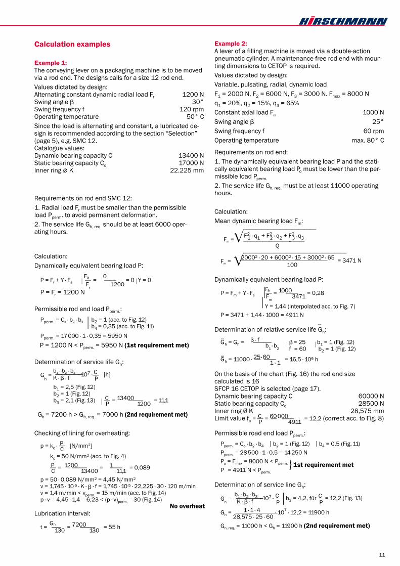
Example:A rod end with male thread is required for the following ope-rating conditions: Alternating dynamic load Fr 1200 N Swing angle b 30° Swing frequency f 120 rpm Operating temperature 50° C Required service life Gh 7000 h
Since the load is alternating, a lubricated design is recom-mended, as set forth in the “Selection” section (page 5). Thus, Fig. 12 gives b1 = 2.5 and b2 = 1.
Dynamically equivalent bearing load:P = Fr = 1200 N
Relative service life:
_Gh = Gh ·
nb · fn______b1 · b2
= 7000 · 30__2,
· 120_____5 · 1 = 10,08 · 106 h
The intersection in Fig. 15 with P = 1200 N and _Gh = 10,08 ·
106 h results in the bearing size 12. Thus, SMC 12 is cho-sen.
Checking the rod end SMC 12 with regard to the permissible load Pperm. and the service life
_Gh, and checking the lining
for overheating and determination of the lubricating inter-vals is conducted as shown in Example 1, page 11.
The example given in Fig. 16 is the result of the 2nd calcula-tion example on page 11.
Rela
tive
serv
ice
live
Gh [
h]Re
lativ
e se
rvic
e liv
e G
h [h]
lower limit values
lower limit values
Bearing sizes
Bearing sizes
11
Calculation examples
Example 1:The conveying lever on a packaging machine is to be moved via a rod end. The designs calls for a size 12 rod end.Values dictated by design: Alternating constant dynamic radial load Fr 1200 N Swing angle b 30° Swing frequency f 120 rpm Operating temperature 50° CSince the load is alternating and constant, a lubricated de-sign is recommended according to the section “Selection” (page 5), e.g. SMC 12. Catalogue values: Dynamic bearing capacity C 13400 N Static bearing capacity Co 17000 N Inner ring ; K 22.225 mm
Requirements on rod end SMC 12:1. Radial load Fr must be smaller than the permissible load Pperm. to avoid permanent deformation.2. The service life Gh, req. should be at least 6000 oper- ating hours.
Calculation:Dynamically equivalent bearing load P:
P = Fr + Y · Fa j Fa__F
r = 000____
1200 = 0 j Y = 0
P = Fr = 1200 N
Permissible rod end load Pperm.: Pperm. = Co · b2 · b4 j b2 = 1 (acc. to Fig. 12)
b4 = 0,35 (acc. to Fig. 11) Pperm. = 17000 · 1 · 0,35 = 5950 N P = 1200 N < Pperm. = 5950 N (1st requirement met)
Determination of service life Gh:
Gh = b1 · b2 · b3 · 107 · C__
P [h] K · b · f
b1 = 2,5 (Fig. 12) b2 = 1 (Fig. 12) b3 = 2,1 (Fig. 13) j
C__P
= 13400_____
1200 = 11,1
Gh = 7200 h > Gh, req. = 7000 h (2nd requirement met)
Checking of lining for overheating:
p = kc · P__C [N/mm2]
p = kc = 50 N/mm2 (acc. to Fig. 4)
p = P__C = 1200_____
13400 = 111____11,1 = 0,089
p = 50 · 0,089 N/mm2 = 4,45 N/mm2
v = 1,745 · 10-5 · K · b · f = 1,745 · 10-5 · 22,225 · 30 · 120 m/min v = 1,4 m/min < vperm. = 15 m/min (acc. to Fig. 14) p · v = 4,45 · 1,4 = 6,23 < (p · v)perm. = 30 (Fig. 14)
no overheatLubrication interval:
t = Gh___130 = 7200_____
130 = 55 h
Example 2:A lever of a filling machine is moved via a double-action pneumatic cylinder. A maintenance-free rod end with moun-ting dimensions to CETOP is required.Values dictated by design:Variable, pulsating, radial, dynamic loadF1 = 2000 N, F2 = 6000 N, F3 = 3000 N. Fmax = 8000 Nq1 = 20%, q2 = 15%, q3 = 65%Constant axial load Fa 1000 NSwing angle b 25°Swing frequency f 60 rpmOperating temperature max. 80° C
Requirements on rod end:1. The dynamically equivalent bearing load P and the stati-cally equivalent bearing load Po must be lower than the per-missible load Pperm.
2. The service life Gh, req. must be at least 11000 operating hours.
Calculation:Mean dynamic bearing load Fm:
EFFFFFFFFFFFF Fm = F21 · q1 + F2
2 · q2 + F23 · q3
__________________________________________
Q
EFFFFFFFFFFFFFFFFF Fm = 20002 · 20 + 60002 · 15 + 30002 · 65 = 3471 N
_________________________________________________________
100
Dynamically equivalent bearing load P:
P = Fm + Y · Fa jj� Fa__Fm
= 1000____3471 = 0,28
Y = 1,44 (interpolated acc. to Fig. 7)
P = 3471 + 1,44 · 1000 = 4911 N
Determination of relative service life Gh:
G_
h = Gh = b · f______b1 · b2
j ��b
= 25 j b1 = 1 (Fig. 12)
f = 60 b2 = 1 (Fig. 12)
G_
h = 11000 · 25__ · 60____1 · 1 = 16,5 · 106 h
On the basis of the chart (Fig. 16) the rod end size calculated is 16SFCP 16 CETOP is selected (page 17).Dynamic bearing capacity C 60000 NStatic bearing capacity Co 28500 NInner ring Ø K 28,575 mmLimit value fc = C__
P = 60__000____4911 = 12,2 (correct acc. to Fig. 8)
Permissible road end load Pperm.: Pperm. = Co · b2 · b4 j b2 = 1 (Fig. 12) j b4 = 0,5 (Fig. 11) Pperm. = 28 500 · 1 · 0,5 = 14250 N Po = Fmax = 8000 N < Pperm.
o 1st requirement met P = 4911 N < Pperm.
Determination of service line Gh:
Gh = b1 · b2 · b3 · 107 · C__
P j b3 = 4,2, für C__
P = 12,2 (Fig. 13) K · b · f
Gh = 1 · 1 · 4 28,575 · 25 · 60
· 107 · 12,2 = 11900 h
Gh, req. = 11000 h < Gh = 11900 h (2nd requirement met)

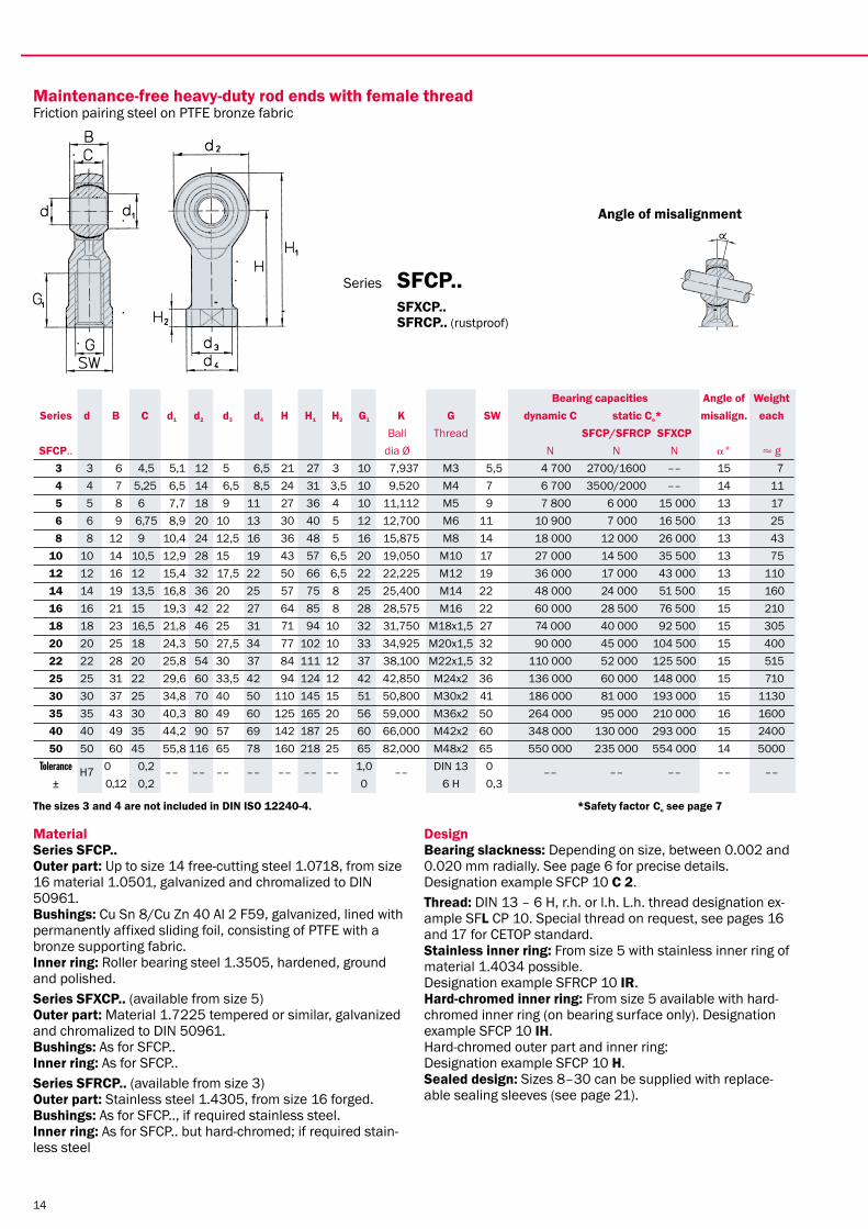
Relubricatable heavy-duty rod ends with female threadFriction pairing steel on heavy-duty bronze
Angle of misalignment
Series sFC.. sFxC.. sFRC.. (rustproof)
12
material series sFC.. Outer part: Up to size 14 free-cutting steel 1.0718, from size 16 material 1.0501, galvanized and chromalized to DIN 50961. bushings: Cu Sn 8/Cu Zn 40 Al 2 F59, 2.0550.31. Inner ring: Roller bearing steel 1.3505, hardened, ground and polished.series sFxC.. (available from size 5) Outer part: Material 1.7225 tempered or similar, galvanized and chromalized to DIN 50961. bushings: As for SFC.. Inner ring: As for SFC..series sFRC.. (available from size 3) Outer part: Stainless steel 1.4305, from size 16, forged. bushings: As for SFC.. Inner ring: As for SFC.. but hard-chromed; if required stain-less steel.
Designbearing slackness: Depending on size, between 0.01 and 0.09 mm radially. With reduced or increased slackness see page 6. Designation example SFC 10 C 2. Thread: DIN 13 – 6 H, r.h. or l.h. L.h. thread designation ex-ample SFl C 10. Special threads on request, see pages 16 and 17 for CETOP standard. lubricating nipple: Size 5–50 funnel-type DIN 3405, form D. stainless inner ring: From size 5 with stainless inner ring of material 1.4034 possible. Designation example SFRC 10 IR. Hard-chromed inner ring: From size 5 with hard-chromed in-ner ring (on bearing surface only). Designation example SFC 10 IH. Hard-chromed outer part and inner ring: Designation example SFC 10 H. sealed design: Sizes 8–30 can be supplied with replace-ab-le sealing sleeves (see page 21).
bearing capacities Angle of Weight series d b C d1 d2 d3 d4 H H1 H2 G1 K G sW dynamic C static Co* misalign. each Ball Thread sFC/sFRC sFxC sFC.. dia Ø N N N a° P g 2 2 4,8 3,6 3,6 9 3,8 4,5 16 20,5 2,5 7 6,000 M2 4 900 1900 –– 16 3 3 3 6 4,5 5,1 12 5 6,5 21 27 3 10 7,937 M3 5,5 1 500 3600/2200 –– 15 7 4 4 7 5,25 6,5 14 6 8,5 24 31 3,5 12 9,520 M4 7 2 260 4500/2700 –– 14 11 5 5 8 6 7,7 18 9 11 27 36 4 10 11,112 M5 9 3 250 6 000 15 000 13 18 6 6 9 6,75 8,9 20 10 13 30 40 5 12 12,700 M6 11 4 300 7 000 16 500 13 27 8 8 12 9 10,4 24 12,5 16 36 48 5 16 15,875 M8 14 7 200 12 000 26 000 13 46 10 10 14 10,5 12,9 28 15 19 43 57 6,5 20 19,050 M10 17 10 000 14 500 35 500 13 78 12 12 16 12 15,4 32 17,5 22 50 66 6,5 22 22,225 M12 19 13 400 17 000 43 000 13 115 14 14 19 13,5 16,8 36 20 25 57 75 8 25 25,400 M14 22 17 000 24 000 51 500 15 170 16 16 21 15 19,3 42 22 27 64 85 8 28 28,575 M16 22 21 600 28 500 76 500 15 230 18 18 23 16,5 21,8 46 25 31 71 94 10 32 31,750 M18x1,5 27 26 000 40 000 92 500 15 320 20 20 25 18 24,3 50 27,5 34 77 102 10 33 34,925 M20x1,5 32 31 500 45 000 104 500 15 420 22 22 28 20 25,8 54 30 37 84 111 12 37 38,100 M22x1,5 32 38 000 52 000 125 500 15 540 25 25 31 22 29,6 60 33,5 42 94 124 12 42 42,850 M24x2 36 47 500 60 000 148 000 15 750 30 30 37 25 34,8 70 40 50 110 145 15 51 50,800 M30x2 41 64 000 81 000 193 000 15 1130 35 35 43 30 40,3 80 49 60 125 165 20 56 59,000 M36x2 50 90 000 95 000 210 000 16 1600 40 40 49 35 44,2 90 57 69 142 187 25 60 66,000 M42x2 60 120 000 130 000 293 000 15 2400 50 50 60 45 55,8 116 65 78 160 218 25 65 82,000 M48x2 65 190 000 235 000 554 000 14 5000 Tolerance H7 0 0,2 –– –– –– –– –– –– –– 1,0 –– DIN 13 0 –– –– –– –– –– ± 0,12 0,2 0 6 H 0,3
The sizes 2, 3 and 4 are not included in DIn IsO 12240-4. *safety factor Co see page 7

13
Relubricatable heavy-duty rod ends with male threadFriction pairing steel on heavy-duty bronze
Angle of misalignment
Series smC.. smxC.. smRC.. (rustproof)
material series smC.. Outer part: Up to size 14 free-cutting steel 1.0718, from size 16 material 1.0501 galvanized and chromalized to DIN 50961. bushings: Cu Sn 8/Cu Zn 40 Al 2 F59, 2.0550.31. Inner ring: Roller bearing steel 1.3505, hardened, ground and polished.series smxC.. (available from size 5) Outer part: Material 1.7225 tempered or similar, galvanized and chromalized to DIN 50961. bushings: As for SMC.. Inner ring: As for SMC..series smRC.. (available form size 3) Outer part: Stainless steel 1.4305, from size 16 forged. bushings: as for SMC.. Inner ring: as for SMC.. but hard-chromed, if required stain-less steel.
Designbearing slackness: Depending on size between 0.01 and 0.09 mm radially. With reduced or increased slackness see page 6. Designation example SMC 10 C 2. Thread: DIN 13 – 6 g, r.h. or l.h. L.h. thread designation ex-ample SMl C 10. Special threads on request. lubricating nipple: Size 6–50 funnel-type DIN 3405, form D. stainless inner ring: From size 5 stainless steel inner ring of material 1.4034 possible. Designation example SMRC 10 IR. Hard-chromed inner ring: From size 5 available with hard-chromed inner ring (on bearing surface only). Designation example SMC 10 IH. Hard-chromed outer part and inner ring: Designation example SMC 10 H. sealed design: Sizes 8–30 can be supplied with replace-able sealing sleeves (see page 21).
bearing capacities Angle of Weight series d b C d1 d2 H H1 G1 K G dynamic C static Co* misalign. each Ball Thread smC/smRC smxC smC.. dia x N N N a° P g 2 2 4,8 3,65 3,6 9 18 22,5 9 6,000 M2 900 400 –– 16 2 3 3 6,5 4,55 5,1 12 27 33 15 7,937 M3 1 500 1200/700 –– 15 5 4 4 7,5 5,25 6,5 14 30 37 18 9,520 M4 2 260 2000/1200 –– 14 9 5 5 8,5 6,55 7,7 18 33 42 20 11,112 M5 3 250 3 000 7 500 13 14 6 6 9,5 6,75 8,9 20 36 46 22 12,700 M6 4 300 4 000 10 500 13 21 8 8 12,5 9,55 10,4 24 42 54 25 15,875 M8 7 200 8 000 19 500 13 34 10 10 14,2 10,55 12,9 28 48 62 29 19,050 M10 10 000 13 000 30 500 13 58 12 12 16,2 12,25 15,4 32 54 70 33 22,225 M12 13 400 17 000 43 000 13 92 14 14 19,2 13,55 16,8 36 60 78 36 25,400 M14 17 000 24 000 51 500 15 135 16 16 21,2 15,25 19,3 42 66 87 40 28,575 M16 21 600 28 500 76 500 15 205 18 18 23,5 16,55 21,8 46 72 95 44 31,750 M18x1,5 26 000 38 000 92 500 15 285 20 20 25,5 18,55 24,3 50 78 103 47 34,925 M20x1,5 31 500 42 000 104 500 15 370 22 22 28,5 20,55 25,8 54 84 111 51 38,100 M22x1,5 38 000 52 000 125 500 15 475 25 25 31,5 22,55 29,6 60 94 124 57 42,850 M24x2,5 47 500 60 000 148 000 15 650 30 30 37,5 25,55 34,8 70 110 145 66 50,800 M30x2,5 64 000 81 000 193 000 15 1070 35 35 43,2 30,25 40,3 80 140 180 85 59,000 M36x2,2 90 000 95 000 210 000 16 1600 40 40 49,2 35,25 44,2 90 150 195 90 66,000 M42x2,2 120 000 130 000 293 000 15 2300 50 50 60,2 45,25 55,8 116 185 243 105 82,000 M48x2,2 190 000 235 000 554 000 14 4800 Tolerance H7 0,55 0,2 –– –– –– –– 1,0 –– DIN 13 –– –– –– –– –– ± 0,12 0,2 0,5 6 g
The sizes 3 und 4 are not included in DIn IsO 12240-4. *safety factor Co see page 7
14
material series sFCP.. Outer part: Up to size 14 free-cutting steel 1.0718, from size 16 material 1.0501, galvanized and chromalized to DIN 50961. bushings: Cu Sn 8/Cu Zn 40 Al 2 F59, galvanized, lined with permanently affixed sliding foil, consisting of PTFE with a bronze supporting fabric. Inner ring: Roller bearing steel 1.3505, hardened, ground and polished.series sFxCP.. (available from size 5) Outer part: Material 1.7225 tempered or similar, galvanized and chromalized to DIN 50961. bushings: As for SFCP.. Inner ring: As for SFCP..series sFRCP.. (available from size 3) Outer part: Stainless steel 1.4305, from size 16 forged. bushings: As for SFCP.., if required stainless steel. Inner ring: As for SFCP.. but hard-chromed; if required stain-less steel
Designbearing slackness: Depending on size, between 0.002 and 0.020 mm radially. See page 6 for precise details. Designation example SFCP 10 C 2.Thread: DIN 13 – 6 H, r.h. or l.h. L.h. thread designation ex-ample SFl CP 10. Special thread on request, see pages 16 and 17 for CETOP standard. stainless inner ring: From size 5 with stainless inner ring of material 1.4034 possible. Designation example SFRCP 10 IR. Hard-chromed inner ring: From size 5 available with hard-chromed inner ring (on bearing surface only). Designation example SFCP 10 IH. Hard-chromed outer part and inner ring: Designation example SFCP 10 H. sealed design: Sizes 8–30 can be supplied with replace-able sealing sleeves (see page 21).
bearing capacities Angle of Weight series d b C d1 d2 d3 d4 H H1 H2 G1 K G sW dynamic C static Co* misalign. each Ball Thread sFCP/sFRCP sFxCP sFCP.. dia Ø N N N a° P g 3 3 6 4,5 5,1 12 5 6,5 21 27 3 10 7,937 M3 5,5 4 700 2700/1600 –– 15 7 4 4 7 5,25 6,5 14 6,5 8,5 24 31 3,5 10 9,520 M4 7 6 700 3500/2000 –– 14 11 5 5 8 6 7,7 18 9 11 27 36 4 10 11,112 M5 9 7 800 6 000 15 000 13 17 6 6 9 6,75 8,9 20 10 13 30 40 5 12 12,700 M6 11 10 900 7 000 16 500 13 25 8 8 12 9 10,4 24 12,5 16 36 48 5 16 15,875 M8 14 18 000 12 000 26 000 13 43 10 10 14 10,5 12,9 28 15 19 43 57 6,5 20 19,050 M10 17 27 000 14 500 35 500 13 75 12 12 16 12 15,4 32 17,5 22 50 66 6,5 22 22,225 M12 19 36 000 17 000 43 000 13 110 14 14 19 13,5 16,8 36 20 25 57 75 8 25 25,400 M14 22 48 000 24 000 51 500 15 160 16 16 21 15 19,3 42 22 27 64 85 8 28 28,575 M16 22 60 000 28 500 76 500 15 210 18 18 23 16,5 21,8 46 25 31 71 94 10 32 31,750 M18x1,5 27 74 000 40 000 92 500 15 305 20 20 25 18 24,3 50 27,5 34 77 102 10 33 34,925 M20x1,5 32 90 000 45 000 104 500 15 400 22 22 28 20 25,8 54 30 37 84 111 12 37 38,100 M22x1,5 32 110 000 52 000 125 500 15 515 25 25 31 22 29,6 60 33,5 42 94 124 12 42 42,850 M24x2 36 136 000 60 000 148 000 15 710 30 30 37 25 34,8 70 40 50 110 145 15 51 50,800 M30x2 41 186 000 81 000 193 000 15 1130 35 35 43 30 40,3 80 49 60 125 165 20 56 59,000 M36x2 50 264 000 95 000 210 000 16 1600 40 40 49 35 44,2 90 57 69 142 187 25 60 66,000 M42x2 60 348 000 130 000 293 000 15 2400 50 50 60 45 55,8 116 65 78 160 218 25 65 82,000 M48x2 65 550 000 235 000 554 000 14 5000 Tolerance H7 0,55 0,2 –– –– –– –– –– –– –– 1,0 –– DIN 13 0 –– –– –– –– –– ± 0,12 0,2 0 6 H 0,3
The sizes 3 and 4 are not included in DIn IsO 12240-4. *safety factor Co see page 7
maintenance-free heavy-duty rod ends with female threadFriction pairing steel on PTFE bronze fabric
Angle of misalignment
Series sFCP.. sFxCP.. sFRCP.. (rustproof)

15
materialseries smCP.. Outer part: Up to size 14 free-cutting steel 1.0718, from size 16 material 1.0501, galvanized and chromalized to DIN 50961. bushings: Cu Sn 8/Cu Zn 40 Al 2 F59 galvanized, lined with permanently affixed sliding foil, consisting of PTFE with a bronze supporting fabric. Inner ring: Roller bearing steel 1.3505, hardened, ground and polished.series smxCP.. (available from size 5) Outer part: Material 1.7225 tempered or similar, galvanized and chromalized to DIN 50961. bushings: As for SMCP.. Inner ring: As for SMCP..series smRCP.. (available from size 3) Outer part: Stainless steel 1.4305, from size 16 forged. bushings: As for SMCP.., if required stainless steel. Inner ring: As for SMCP.. but hard-chromed; if required stain-less steel.
Designbearing slackness: Depending on size, between 0.002 and 0.020 mm radially. See page 6 for precise details. Designation example SMCP 10 C 2.Thread: DIN 13 – 6 g, r.h. or l.h. L.h. designation example SMlCP 10. Special thread on request. stainless inner ring: From size 5 with stainless steel inner ring of material 1.4034 possible. Designation example SMRCP 10 IR. Hard-chromed inner ring: From size 5 available with hard-chromed inner ring (on bearing surface only). Designation example SMCP 10 IH. Hard-chromed outer part and inner ring: Designation example SMCP 10 H. sealed design: Sizes 8–30 can be supplied with replace-able sealing sleeves (see page 21).
bearing capacities Angle of Weight series d b C d1 d2 H H1 G1 K G dynamic C static Co* misalign. each Ball Thread smCP/smRCP smxCP smCP.. dia Ø N N N a° P g 3 3 6 4,55 5,1 12 27 33 15 7,937 M3 4 700 900/500 –– 15 5 4 4 7 5,25 6,5 14 30 37 18 9,520 M4 6 700 1500/900 –– 14 9 5 5 8 6 7,7 18 33 42 20 11,112 M5 7 800 3 000 7 500 13 13 6 6 9 6,75 8,9 20 36 46 22 12,700 M6 10 900 4 000 10 500 13 18 8 8 12 9 10,4 24 42 54 25 15,875 M8 18 000 8 000 19 500 13 30 10 10 14 10,5 12,9 28 48 62 29 19,050 M10 27 000 13 000 30 500 13 55 12 12 16 12 15,4 32 54 70 33 22,225 M12 36 000 17 000 43 000 13 85 14 14 19 13,5 16,8 36 60 78 36 25,400 M14 48 000 24 000 51 500 15 125 16 16 21 15 19,3 42 66 87 40 28,575 M16 60 000 28 500 76 500 15 190 18 18 23 16,5 21,8 46 72 95 44 31,750 M18x1,5 74 000 40 000 92 500 15 265 20 20 25 18 24,3 50 78 103 47 34,925 M20x1,5 90 000 45 000 104 500 15 350 22 22 28 20 25,8 54 84 111 51 38,100 M22x1,5 110 000 52 000 125 500 15 450 25 25 31 22 29,6 60 94 124 57 42,850 M24x2 136 000 60 000 148 000 15 610 30 30 37 25 34,8 70 110 145 66 50,800 M30x2 186 000 81 000 193 000 15 1090 35 35 43 30 40,3 80 140 180 85 59,000 M36x2 264 000 95 000 210 000 16 1600 40 40 49 35 44,2 90 150 195 90 66,000 M42x2 348 000 130 000 293 000 15 2300 50 50 60 45 55,8 116 185 243 105 82,000 M48x2 550 000 235 000 554 000 14 4800 Tolerance H7 0, 0,2 –– –– –– –– 1,0 –– DIN 13 –– –– –– –– –– ± 0,12 0,2 0 6g
The sizes 3 and 4 are not included in DIn IsO 12240-4. *safety factor Co see page 7
maintenance-free heavy-duty rod ends with male threadFriction pairing steel on PTFE bronze fabric
Angle of misalignment
Series smCP.. smxCP.. smRCP.. ( rustproof)

16
material series sFC...CETOP Outer part: Up to size 14 free-cutting steel 1.0718, from size 16 material 1.0501, galvanized and chromalized to DIN 50961. bushings: Cu Sn 8/Cu Zn 40 Al 2 F59, 2.0550.31. Inner ring: Roller bearing steel 1.3505, hardened, ground and polished.series sFxC...CETOP Outer part: Material 1.7225 tempered or similar, galvanized and chromalized to DIN 50961. bushings: As for SFC.. Inner ring: As for SFC..series sFRC...CETOP Outer part: Stainless steel 1.4305, from size 16 forged. bushings: As for SFC.. Inner ring: As for SFC.. but hard-chromed; if required stain-less steel.
Designbearing slackness: Depending on size, between 0.002 and 0.090 mm radially. With reduced or increased slackness see page 6. Designation example SFC 10 C 2 CETOP. Thread: DIN 13 – 6 H, r.h. or l.h. L.h. thread designation ex-ample SFl C 10 CETOP. lubricating nipple: Sizes 5–50 funnel-type DIN 3405, form D. stainless inner ring: From size 5 stainless steel inner ring of material 1.4034 possible. Designation example SFRC 10 IR CETOP. Hard-chromed inner ring: From size 5 available with hard-chromed inner ring (on bearing surface only). Designation example SFC 10 IH CETOP. Hard-chromed outer part and inner ring: Designation example SFC 10 H CETOP. sealed design: Sizes 8–30 can be supplied with replace-able sealing sleeves (see page 21).
bearing capacities Angle of Weight series d b C d1 d2 d3 d4 H H1 H2 G1 K G sW dynamic C static Co** misalign. each Ball Thread sFC/sFRC sFxC sFC.. dia. Ø N N N a° P g
5 5 8 6 7,7 18 9 11 27 36 4 10 11,112 M4 9 3 250 6 000 15 000 13 17 * 6* * 8* 10 10 14 10,5 12,9 28 15 19 43 57 6,5 20 19,050 M10x1,25 17 10 000 14 500 35 500 13 75 12 12 16 12 15,4 32 17,5 22 50 66 6,5 22 22,225 M12x1,25 19 13 400 17 000 43 000 13 110 16 16 21 15 19,3 42 22 27 64 85 8 28 28,575 M16x1,5 22 21 600 28 500 76 500 15 210
*20* *25* 30 30 37 25 34,8 70 40 50 110 145 15 51 50,800 M27x2 41 64 000 81 000 193 000 15 1130 *35* *40* *50* Tolerance H7 0 0,2 –– –– –– –– –– –– –– 1,0 –– DIN 13 0 –– –– –– –– –– ± 0,12 0,2 0 6 H 0,3
*sizes 6, 8, 20, 25 and 35 to 50 correspond to the rod ends on page 12. **safety factor Co see page 7
Relubricatable heavy-duty rod ends for pneumatic cylindersFriction pairing steel on heavy duty bronze - Mounting dimensions: CETOP
Angle of misalignment
Series sFC...CETOP

17
bearing capacities Angle of Weight series d b C d1 d2 d3 d4 H H1 H2 G1 K G sW dynamic C static Co** misalign. each Ball Thread sFCP/sFRCP sFxCP sFCP.. dia Ø N N N a° P g
5 5 8 6 7,7 18 9 11 27 36 4 10 11,112 M4 9 7 800 6 000 15 000 13 17 * 6* * 8* 10 10 14 10,5 12,9 28 15 19 43 57 6,5 20 19,050 M10x1,25 17 27 000 14 500 35 500 13 75 12 12 16 12 15,4 32 17,5 22 50 66 6,5 22 22,225 M12x1,25 19 36 000 17 000 43 000 13 110 16 16 21 15 19,3 42 22 27 64 85 8 28 28,575 M16x1,5 22 60 000 28 500 76 500 15 210
*20* *25* 30 30 37 25 34,8 70 40 50 110 145 15 51 50,800 M27x2 41 186 000 81 000 193 000 15 1130 *35* *40* *50* Tolerance H7 0,55 0,2 –– –– –– –– –– –– –– 1,0 –– DIN 13 0 –– –– –– –– –– ± 0,12 0,2 0 6 H 0,3
*sizes 6, 8, 20, 25 and 35 to 50 correspond to the rod ends on page 14. **safety factor Co see page 7
material series sFCP...CETOP Outer part: Up to size 14 free-cutting steel 1.0718, from size 16 material 1.0501, galvanized and chromalized to DIN 50961. bushings: Cu Sn 8/Cu Zn 40 Al 2 F59, galvanized, lined with permanently affixed sliding foil, consisting of PTFE with a bronze supporting fabric. Inner ring: Roller bearing steel 1.3505, hardened, ground and polished.series sFxCP...CETOP Outer part: Material 1.7225 tempered or similar, galvanized and chromalized to DIN 50961. bushings: As for SFCP.. Inner ring: As for SFCP..series sFRCP...CETOP Outer part: Stainless steel 1.4305, from size 16 forged. bushings: As for SFCP.., if required stainless steel. Inner ring: As for SFCP.. but hard-chromed; if required stain-less steel.Design
bearing slackness: Depending on size, between 0.002 and 0.020 mm radially. See page 6 for precise details. Designation example SFC 10 C 2 CETOP. Thread: DIN 13 – 6 H r.h. or l.h. L.h. thread designation ex-ample SFl CP 10 CETOP. stainless inner ring: From size 5 with stainless steel inner ring of material 1.4034 possible. Designation example SFRCP 10 IR CETOP. Hard-chromed inner ring: From size 5 available with hard-chromed inner ring (on bearing surface only). Designation example SFCP 10 IH CETOP. Hard-chromed outer part and inner ring: Designation example SFCP 10 H CETOP. sealed design: Sizes 8–30 can be supplied with replace-able sealing sleeves (see page 21).
maintenance-free heavy-duty rod ends for pneumatic cylindersFriction pairing steel on PTFE bronze fabric Mounting dimensions: CETOP
Angle of misalignment
Series sFCP...CETOP

18
material series ssC.. Outer part: Free-cutting steel 1.0718, browned. bushings: Cu Sn 8/Cu Zn 40 Al 2 F59. Inner ring: Roller bearing steel 100 Cr 6, material 1.3505, hardened, ground and polished.series ssRC.. (available from size 5) Outer part: Stainless steel, material 1.4305. bushings: As for SSC.. Inner ring: As for SSC.. but hard-chromed, if required stain-less steel.
Designbearing slackness: Depending on size, between 0.01 and 0.09 mm radially. With reduced or increased slackness see page 6. Designation example SSC 10 C 2. lubrication: Through an annular lubrication groove on the outer ring. stainless inner ring: From size 5 stainless steel inner ring of material 1.4034 possible. Designation example SSRC 10 IR. Hard-chromed inner ring: From size 5 available with hard-chromed inner ring. Designation example SSC 10 IH. sealed design: Sizes 8–30 can be supplied with replace-able sealing sleeves (see page 21).
bearing capacities Angle of- Weight series d D b C d1 K dynamic C static Co* misalign. each Ball ssC.. dia x N N a° P g 2 2 9 4,8 3,6 3,6 6,000 900 2 450 16 3 3 3 12 6 4,5 5,2 7,937 1 500 4 200 15 4 4 4 14 7 5,25 6,4 9,520 2 260 5 900 14 6 5 5 16 8 6 7,7 11,112 3 250 19 000 13 9 6 6 18 9 6,75 8,9 12,700 4 300 25 000 13 13 8 8 22 12 9 10,4 15,875 7 200 41 000 13 24 10 10 26 14 10,5 12,9 19,050 10 000 58 000 13 40 12 12 30 16 12 15,4 22,225 13 400 78 000 13 80 14 14 34 19 13,5 16,8 25,400 17 000 100 000 15 110 16 16 38 21 15 19,3 28,575 21 600 125 000 15 130 18 18 42 23 16,5 21,8 31,750 26 000 155 000 15 170 20 20 46 25 18 24,3 34,925 31 500 186 000 15 230 22 22 50 28 20 25,8 38,100 38 000 228 000 15 280 25 25 56 31 22 29,6 42,850 47 500 284 000 15 390 30 30 66 37 25 34,8 50,800 64 000 384 000 15 610 35 35 78 43 30 40,3 59,000 90 000 510 000 16 850 40 40 87 49 35 44,2 66,000 120 000 675 000 15 1420 50 50 108 60 45 55,8 82,000 190 000 1 100 000 14 2630 Tolerance H7 h6** 0 0 –– –– –– –– –– –– ± 0,12 0,2**recommended housing hole m 7, see page 6 *security factor Co see page 7
sizes 2, 3, 4 will be delivered without oil groove.
Relubricatable heavy-duty spherical bearingsFriction pairing steel on heavy-duty bronze
Angle of misalignment
Series ssC.. SSRC.. (rustproof)

19
material series ssCP.. Outer part: Free-cutting steel 1.0718, browned. bushings: Cu Sn 8/Cu Zn 40 Al 2 F59 galvanized, lined with permanently affixed sliding foil, consisting of PTFE with a bronze supporting fabric. Inner ring: Roller bearing steel 100 Cr 6, material 1.3505, hardened, ground and polished.series ssRCP.. (available from size 5) Outer part: Stainless steel, material 1.4305. bushings: As for SSCP.., if required stainless steel. Inner ring: As for SSCP.. but hard-chromed, if required stain-less steel.
Designbearing slackness: Depending on size, between 0.002 and 0.020 mm radially. See page 6 for precise details. Designation example SSCP 10 C 2. stainless inner ring: From size 5 stainless steel inner ring of material 1.4034 possible. Designation example SSCP 10 IR. Hard-chromed inner ring: From size 5 available with hard-chromed inner ring. Designation example SSCP 10 IH. sealed design: Sizes 8–30 can be supplied with replace- able sealing sleeves (see page 21).
bearing capacities Angle of Weight series d D b C d1 K dynamic C static Co* misalign. each Ball ssCP.. dia x N N a° P g 2 5 3 3 12 6 4,5 5,2 7,937 4 700 7 300 15 4 4 4 14 7 5,25 6,4 9,520 6 700 11 000 14 6 5 5 16 8 6 7,7 11,112 7 800 15 000 13 9 6 6 18 9 6,75 8,9 12,700 10 900 21 000 13 12 8 8 22 12 9 10,4 15,875 18 000 36 000 13 20 10 10 26 14 10,5 12,9 19,050 27 000 53 000 13 35 12 12 30 16 12 15,4 22,225 36 000 71 000 13 75 14 14 34 19 13,5 16,8 25,400 48 000 93 000 15 105 16 16 38 21 15 19,3 28,575 60 000 116 000 15 120 18 18 42 23 16,5 21,8 31,750 74 000 143 000 15 160 20 20 46 25 18 24,3 34,925 90 000 173 000 15 220 22 22 50 28 20 25,8 38,100 110 000 212 000 15 260 25 25 56 31 22 29,6 42,850 136 000 263 000 15 370 30 30 66 37 25 34,8 50,800 186 000 358 000 15 580 35 35 78 43 30 40,3 59,000 264 000 500 000 16 850 40 40 87 49 35 44,2 66,000 348 000 660 000 15 1420 50 50 108 60 45 55,8 82,000 550 000 1 000 000 14 2630 Tolerance H7 h6** 0, 0 –– –– –– –– –– –– ± 0,12 0,2
**recommended housing hole m 7, see page 6 *security factor Co see page 7sizes 2, 3, 4 will be delivered without oil groove.
maintenance-free heavy-duty spherical bearingsFriction pairing steel on PTFE bronze fabric
Angle of misalignment
Series ssCP.. ssRCP.. (rustproof)

20
material series sC.. Outer part/bushing: Cu Sn 8. Inner ring: Roller bearing steel 100 Cr 6, material 1.3505, hardened, ground and polished.series sCP.. Outer part/bushing: Stainless steel material 1.4305. Lined and covered with sliding foil of PTFE with bronze sup-porting fabric. Inner ring: As for SC..
Designbearing slackness: In the case of SC.. between 0.010 and 0.090 mm depending on the size. In the case of SCP.. bet-ween 0.005 and 0.010 mm depending on the size. See pa-ge 6 for precise details. Slackness C3 not possible. stainless inner ring: Available with stainless steel inner ring of material 1.4034. Designation example SC 10 IR. Hard-chromed inner ring: Available with hard-chromed inner ring. Designation example SC 10 IH.
bearing cap. Angle of Weight series d D1 b C d1 K relubricatable maintenance-free misalign. each Ball dynamic C static Co* dynamic C static Co* dia x N N N N a° P g 2 3 4 5 5 13 8 6 7,7 11,112 3 250 15 300 7 800 12 000 13 9 6 6 16 9 6,75 8,9 12,700 4 300 20 000 10 900 17 000 13 10 8 8 19 12 9 10,4 15,875 7 200 33 000 18 000 29 000 13 15 10 10 22 14 10,5 12,9 19,050 10 000 46 000 27 000 42 000 13 25 12 12 26 16 12 15,4 22,225 13 400 63 000 36 000 57 000 13 55 14 14 29 19 13,5 16,8 25,400 17 000 80 000 48 000 75 000 15 70 16 16 32 21 15 19,3 28,575 21600 100 000 60 000 93 000 15 85 18 18 35 23 16,5 21,8 31,750 26 000 124 000 74 000 115 000 15 100 20 20 40 25 18 24,3 34,925 31 500 150 000 90 000 138 000 15 160 22 22 42 28 20 25,8 38,100 38 000 182 000 110 000 170 000 15 180 25 25 47 31 22 29,6 42,850 47 500 227 000 136 000 210 000 15 250 30 30 55 37 25 34,8 50,800 64 000 307 000 186 000 286 000 15 390 35 40 Sizes 2–4 and 35–50 are not available as spherical bearings. 50 Tolerance H7 h6** 0 0 –– –– –– –– –– –– –– ± 0,12 0,2**recommended housing hole m 7, see page 6. *security factor Co see page 7
Heavy-duty spherical bearingsFriction pairing steel on heavy-duty bronze Steel on PTFE bronze fabric relubricatable maintenance-free
Series sC.. Series sCP..

21
material sealing sleeve: Butadiene acrylnitrile copolymer Viton®. Oil and ozone resistant, temperature resistant from –25° to +250° C. slip ring: Brass. bore bushing: Stainless steel, material 1.4305. Viton® is a registered trademark of DuPont Performance Elastomers.
Design The relubricatable and maintenance-free rod ends and spherical bearings of sizes 8 to 30 can be provided with re-placeable sealing sleeves to protect the bearing from coarse dirt, dust and splashing water. The elastic sealing sleeve is pulled on the outside over the specially extended and grooved bushing, and on the inside over a slip ring. Designation example SFC 10.2 Rs.
sealed rod ends and spherical bearings
SSC/SSCP..2 RS
Series 2 Rs.. SFC/SFCP..2 RS SMC/SMCP..2 RS,
series d do A1 A2 b1 b2 Angle of misa. ..Rs a° 2 3 4 5 6 8 8 6 10,5 18,5 19 18,5 10 10 10 8 12,5 21,5 21 20 10 12 12 10 14,5 25,5 23 22,5 10 14 14 12 16,5 29,5 26 24,5 12 16 16 14 19 32,5 28 27 12 18 18 16 21 35,5 30 29 12 20 20 18 23 39 32 31 12 22 22 20 25,5 42,5 35 34 12 25 25 22 29 46,5 38 37 12 30 30 25 33,5 55 44 43 12 35 40 Sizes 2–6 and 35–50 are not available in sealed design. 50
Tolerance –– H7 –– –– 0 –– –– ± 0,2

22
material Stainless steel, material 1.4305, hexagon bare. Other materials such as 1.7225 browned. Special dimensi-ons on request.
DesignAll series of rod ends and spherical bearings, except the sealed ..2 RS design, can be fitted with threaded bolts and used as angle joints. The bolt is pressed and riveted into the inner ring. Designation example SF C 10 W.
Weight series b l1 l2 l3 A m sW each (only bolts) ..W P g 2 3 4 5 5 9 5 11 8 M 5 7 4 6 6 10 5,5 13 10 M 6 7 5 8 8 13 6,5 17 13 M 8 11 16 10 10 15 7 21 17 M 10 11 26 12 12 17 7,5 25 20 M 12 14 43 14 14 20 8,5 29 22 M 14 14 67 16 16 22 9,5 33 24 M 16 17 100 18 20 20 26 12 45 35 M 20 22 200 22 25 30 35 Sizes 2-4 and 18, 22-50 are not made in series. 40 50 Tolerance m6 –– 0,1 0,3 0 DlN13 –– ± 0,1 0,3 1,0 6g
Threaded bolts for rod ends and spherical bearings
Series ..W The lubricating nipple is on the reverse
23
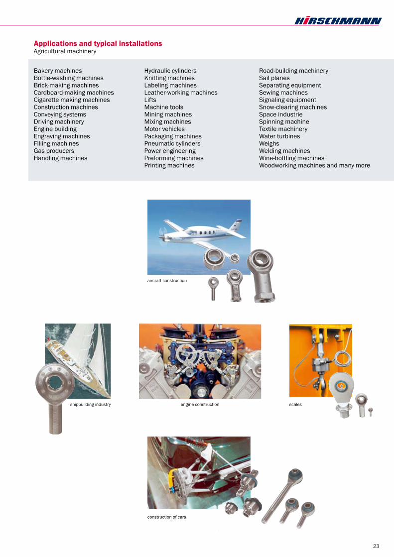
Applications and typical installationsAgricultural machinery
Bakery machines Bottle-washing machines Brick-making machines Cardboard-making machines Cigarette making machines Construction machines Conveying systems Driving machinery Engine building Engraving machines Filling machines Gas producers Handling machines
Hydraulic cylinders Knitting machines Labeling machines Leather-working machines Lifts Machine tools Mining machines Mixing machines Motor vehicles Packaging machines Pneumatic cylinders Power engineering Preforming machines Printing machines
Road-building machinery Sail planes Separating equipment Sewing machines Signaling equipment Snow-clearing machinesSpace industrie Spinning machine Textile machinery Water turbines Weighs Welding machines Wine-bottling machines Woodworking machines and many more
aircraft construction
shipbuilding industry
construction of cars
scalesengine construction

24
α?:?__________
α
Form A
α α
Form B
Tick where applicable
To complete: Company: _________________ Contact: ___________________ Tel.: _____________

25
centre distance =________mm
(outer ring)
(inner ring)
α
centre distance =_______mmAdjustable range = +/-_______mm
identification left hand thread
left
hand
thre
ad tube with cross hole;
alternative hexagon SW
(Rod End SM.. 2x)Material Rod End: _________
Nut M______ DIN439(flat)Material:__________
centre distance =_______mm
left
hand
thre
ad
Adjustable range = +/-_______mm
(Rod End SF.. 2x)Material Rod End: _________
Nut M______ DIN439(flat)Material:__________
Thread bar
To complete: Company: _________________ Contact: ___________________ Tel.: _____________
Material outer part : _____________ Form A :
Form B :Material Inner ring : ______________Material outer ring : _______________maintenance free : yes noAngle of misalignment α : ____
Material outer part : _____________ tube : Ø.............
hexagon : SW .............Material Inner ring : _____________Material outer ring : ______________maintenance free : yes nosealed :Angle of misalignment α : ____
Quantity : _____
Quantity : _____
Quantity : _____
Material thread bar: _______________Material Inner ring : ______________Material outer ring : _______________maintenance free : yes nosealed :Angle of misalignment α : ____
Tick where applicable

26
Advice and sales
Through our dealers with their own stock, in:
AUsTRAliA R. R. Fisher & Co. Ltd., P.O.Box 754, Caringbah, N.S.W. 1495, Fon: (02) 9540-4533, Fax.: (02) 9540-4079, Telex: Steep AA 14459, [email protected]
AUsTRIA Haberkorn Ulmer GmbH, Modecenterstrasse 7, A-1030 Wien, Fon: 01-74 074-0, Telefax: 01-74 074-13 89, [email protected]
bElGIEn/lUxEmbURG RAMAEKERS Transmissions s.a., Smallandlaan 21, 2660 Hoboken (Antwerpen), Fon: 03-8210404, Fax: 03-8210400, [email protected]
DEnmARK Herstad + Piper A/S, Jernholmen 48c, DK-2650 Hvidovre, Fon: +45 (36) 7740 00, Fax: +45 (36) 777740, [email protected]
FInlAnD KNORRING OY AB, P.O. Box 20, FIN-0038 Helsinki, Fon: 09-5 60 41, Fax: 09-5 65 24 63, [email protected]
GREAT bRITAIn MANTEK MANUFACTURING LTD., Holder Road, Aldershot Hampshire GU12 4RH Fon: 0 12 52-34 33 35, Fax: 0 12 52-34 35 70, [email protected]
IsRAEl Power Transmission Ltd., 12a Barzilay St., POB 2009, Tel Aviv, Fon: 03-6154 49, Telefax: 03-5 6018 54, [email protected]
nEW ZEAlAnD R. R. Fisher & Co., Ltd., 13 Spring Street, P.O.Box 23-293, Papatoetoe, Auckland, Fon: 09-278 40 59, Fax: 09-279 82 86, [email protected]
nETHERlAnDs Kimman Technische Handelsmaatschappij B.V., Boelewerf 10–12, 2987 VD Ridderkerk-Bolnes, Fon: 0180-46 46 88, Fax: 0180-46 59 38, [email protected]
nORWAy Merko AS, P.O. Box 63, Va Kasveiens, 1378 Nesbru, Fon: 47-667780 95, Fax: 47-667780 93, [email protected]
sWEDEn Jens S. Transmissioner AB, Box 903, Koppargatan 9, 60119 Norrköping, Fon: 011-19 80 00, Fax: 011-19 80 50,
UsA HIRSCHMANN ENGINEERING USA, INC., 1760 Britannia Drive Unit #1, Elgin, Illinois 60123, Fon: (847) 468-9700, Fax: (847) 468-9701 [email protected]

27
Advice and sales
Through our dealers with their own stock, in:
bERlIn Weber Industrietechnik Berlin GmbH & Co. KG, Motzener Str. 19, 12277 Berlin, Telefon: (0 30) 72 39 04-0, Telefax: (0 30) 72 39 04 99, [email protected]
DUIsbURG INDUNORM Bewegungstechnik GmbH, Postfach 29 02 27, 47262 Duisburg, Telefon: (02 03) 76 91-0, Telefax: (02 03) 76912 91, [email protected]
GIEssEn HIRSCHMANN-Verkaufsbüro Michael Schmidt, Pfingstweg 4, 35305 Grünberg Telefon: (0 64 00) 95 83 31, Telefax: (0 64 00) 95 83 32, [email protected]
HAmbURG John & Molt GmbH, Norm-, Sonder- und Gelenkantriebe Biedenkamp 5e, 21509 Glinde, Telefon: (0 40) 7148 80-0, Telefax: (0 40) 7148 80-50, [email protected]
HAnnOVER Heusinger + Salmon Mangelsdorf GmbH, Robert-Hesse-Str. 11, 30827 Garbsen, Telefon: (0511) 279 98-0, Telefax: (0511) 279 98 49, [email protected]
HERFORD MAT Maschinen- und Antriebstechnik Handelsgesellschaft mbH, Lockhauser Str. 227, 32052 Herford, Telefon: (0 52 21) 76 50 50, Telefax: (0 52 21) 76 50 40 [email protected]
sTUTTGART Ingenieurbüro Voskamp, Im Rosenhain 16, 71563 Affalterbach bei Stuttgart, Telefon: (07144) 37123, Telefax: (07144) 3 4417
mÜnCHEn HIRSCHMANN-Verkaufsbüro Franz Protschka, Dompfaffenweg 9a, 82538 Geretsried, Telefon: (0 8171) 8973, Telefax: (0 8171) 38 76 28, [email protected]

PRODUCT OVERVIEW
HigH-duty Rod-ends and spHeRical BeaRings
for sinking and Wire edM
HIRSCHMANN GMBH · KIRCHENTANNENSTRASSE 9 · D-78737 FLUORN-WINZELNFON +49 (0 )74 02 183-0 · FAX +49 (0 )74 02 18310 · www.hirschmanngmbh.com · [email protected]
stainless steel RotaRy indexing taBles and a-axes for Wire and sinking edM
spannsystemFixtuRing systeMModular Zero-point Fixturing system
Representatives, consultants and distributors in:
Australia · Austria Belgium · Brazil · Bulgaria Canada · China · Croatia
Czech Republic Denmark
Finland · France Great Britain
Hong Kong · Hungary India · Indonesia · Israel · Italy
Japan · Korea · Malaysia Netherlands · Norway · New Zealand
Philippines · Poland · Portugal Singapore · Slovakia · Slovenia Spain · Sweden · Switzerland
Taiwan · Thailand · Turkey USA
Please ask for our catalogues.
AXIAL SHAFT SEALS
FixtuRing systeM FlExIblE AUTOmATIOnfor machine tools