heating technical data - termo shop · 2013-08-08 · • daikin altherma low temperature split •...
TRANSCRIPT
Heating
Technical DataDaikin Altherma low temperature split
EEDEN12-725
EHVH-C


• Heating • Daikin Altherma low temperature split 1
• • Daikin Altherma low temperature split • EHVH-C
TABLE OF CONTENTSEHVH-C
1 Features . . . . . . . . . . . . . . . . . . . . . . . . . . . . . . . . . . . . . . . . . . . . . . . . . . . . . . . . . . . . . 2
2 Specifications . . . . . . . . . . . . . . . . . . . . . . . . . . . . . . . . . . . . . . . . . . . . . . . . . . . . . . . 3
Technical Specifications . . . . . . . . . . . . . . . . . . . . . . . . . . . . . . . . . . . . . . . . . . . . . 3
Electrical Specifications . . . . . . . . . . . . . . . . . . . . . . . . . . . . . . . . . . . . . . . . . . . . . . 4
3 Electrical data . . . . . . . . . . . . . . . . . . . . . . . . . . . . . . . . . . . . . . . . . . . . . . . . . . . . . . . 5
Electrical Data . . . . . . . . . . . . . . . . . . . . . . . . . . . . . . . . . . . . . . . . . . . . . . . . . . . . . . . . 5
4 Combination table . . . . . . . . . . . . . . . . . . . . . . . . . . . . . . . . . . . . . . . . . . . . . . . . . . 6
Combination Table . . . . . . . . . . . . . . . . . . . . . . . . . . . . . . . . . . . . . . . . . . . . . . . . . . . 6
5 Capacity tables . . . . . . . . . . . . . . . . . . . . . . . . . . . . . . . . . . . . . . . . . . . . . . . . . . . . . 7
Domestic Hot Water performance . . . . . . . . . . . . . . . . . . . . . . . . . . . . . . . . . . . 7
6 Dimensional drawings . . . . . . . . . . . . . . . . . . . . . . . . . . . . . . . . . . . . . . . . . . . . 10
Dimensional Drawings . . . . . . . . . . . . . . . . . . . . . . . . . . . . . . . . . . . . . . . . . . . . . . 10
7 Piping diagrams . . . . . . . . . . . . . . . . . . . . . . . . . . . . . . . . . . . . . . . . . . . . . . . . . . . 11
Piping Diagrams . . . . . . . . . . . . . . . . . . . . . . . . . . . . . . . . . . . . . . . . . . . . . . . . . . . . 11
8 Wiring diagrams . . . . . . . . . . . . . . . . . . . . . . . . . . . . . . . . . . . . . . . . . . . . . . . . . . . 12
Wiring Diagrams - Single Phase . . . . . . . . . . . . . . . . . . . . . . . . . . . . . . . . . . . 12
9 External connection diagrams . . . . . . . . . . . . . . . . . . . . . . . . . . . . . . . . . . . 16
External Connection Diagrams . . . . . . . . . . . . . . . . . . . . . . . . . . . . . . . . . . . . . . 16
10 Installation . . . . . . . . . . . . . . . . . . . . . . . . . . . . . . . . . . . . . . . . . . . . . . . . . . . . . . . . . . 17
Installation Method . . . . . . . . . . . . . . . . . . . . . . . . . . . . . . . . . . . . . . . . . . . . . . . . . . 17
11 Operation range . . . . . . . . . . . . . . . . . . . . . . . . . . . . . . . . . . . . . . . . . . . . . . . . . . . 18
Operation Range . . . . . . . . . . . . . . . . . . . . . . . . . . . . . . . . . . . . . . . . . . . . . . . . . . . . 18
12 Hydraulic performance. . . . . . . . . . . . . . . . . . . . . . . . . . . . . . . . . . . . . . . . . . . . 19
Static Pressure Drop Unit . . . . . . . . . . . . . . . . . . . . . . . . . . . . . . . . . . . . . . . . . . . 19

• Daikin Altherma low temperature split • EHVH-C
11
2
1 Features
ting H-C kin Alth
Hea EHV Dai • Integrated indoor unit: all-in-one floor standing unit including the domestic hot water tank• Energy efficient heating only system based on air to water heat pump technology
• Perfect fit for new built as well as for low energy houses
• Best seasonal efficiencies, providing the highest savings on running costs
• Flexible configuration with respect to heat emitters
• Heating • Daikin Altherma low temperature split

• Daikin Altherma low temperature split • EHVH-C
12
3
2 Specifications
2-1 Technical Specifications EHVH04S18C3V EHVH08S18C3V EHVH08S26C9W EHVH16S18C3V EHVH16S26C9W
Power input Nom. kW 0.075 0.190
Casing Colour White
Material Precoated sheet metal
Dimensions Unit Height mm 1,732
Width mm 600
Depth mm 728
Packed unit Height mm 1,922
Width mm 690
Depth mm 818
Weight Unit kg 115 116 126 120 129
Packed unit kg 128 129 139 133 142
Packing Material Wood / Carton / PE wrapping foil
Wood / Carton / PE wrapping foil
Wood / Carton / PE wrapping foil
Wood / Carton / PE wrapping foil
Wood / Carton / PE wrapping foil
Weight kg 12
Tank Water volume l 180 260 180 260
Material Stainless steel (EN 1.4521)
Maximum water temperature ºC 65
Maximum water pressure bar 10
Insulation Material EPS
Heat loss kWh/24h
1.4 (1) 1.9 (1) 1.4 (1) 1.9 (1)
Heat exchanger Quantity 1 -
Material Stainless steel (EH 1 4521)
Surface m² 1.9
Internal coil volume l 8.9
Pump Type DC motor
Nr of speeds Inverter controlled
Power input W 46 160
3-way valve Coefficient of flow (kV)
Space heating m³/h 1.600
Domestic hot water tank
m³/h 1.600
Expansion vessel Volume l 10
Max. water pressure bar 3
Pre pressure bar 1
Operation range Heating Ambient Min. ºC -25 -25 (13)
Max. ºC 25 35 (13)
Water side
Min. ºC 15 (5)
Max. ºC 55 (5)
Domestic hot water Ambient Min. ºCDB -25 -20
Max. ºCDB 35
Water side
Min. ºC 25
Max. ºC 60
Water side Heat exchanger
Type Brazed plate
Quantity 1
Water volume l 0.9 1.3 1.0
Water flow rate Min. l/min 5 11
Heating Max. l/min 25 34 50
Refrigerant circuit Gas side diameter mm 15.9
Liquid side diameter mm 6.35 9.52
Sound power level Nom. dBA 42 (2) 47 (2)
Sound pressure level Nom. dBA 28 33
Water filter Diameter perforations mm 1
Material copper - brass - stainless steel
• Heating • Daikin Altherma low temperature split

3
12
• Daikin Altherma low temperature split • EHVH-C
2 Specifications
Notes
(1) Heatloss according to EN12897
(2) DB/WB 7ºC/6ºC - LWC 35ºC (DT=5ºC)
(3) The sound pressure level is measured via a microphone at a 1m distance from the unit. It is a relative value, depending on the distance and acoustic environment.
(4) The sound pressure level mentioned is valid for pump medium speed - 0 ESP / medium speed - nominal flow / high speed - nominal flow
(5) 15ºC-25ºC: BUH only, no heat pump operation = during commisioning
(6) Including piping + PHE + back-up heater; excluding expansion vessel
(7) Value mentioned is connection after ball valves, Connection at unit is G1-1/4 FEMALE
(8) See separate drawing for operation range
(9) For *RLQ* outdoor units \>55ºC BUH only, no heatpump operation
(10) For *RHQ* outdoor units \>50ºC BUH only, no heatpump operation
(11) Minimum flow is mentioned for heat pump operation. To allow backup heater to operate safety a higher minimum flow is required. For *3V models 12 l/min
(12) Minimum flow is mentioned for heat pump operation. To allow backup heater to operate safety a higher minimum flow is required. For *9W models 15 l/min
(13) Refer to operation range for detail for differences between *RHQ* and *RLQ* models
(14) PED unit category: Art3§3: excluded from scope of PED due to article 1, item 3.6 of 97/23/EC
(15) For more details on current & voltage range, refer to the installation manual.
Water circuit Piping connections diameter inch G 1"1/4 (female)
Safety valve bar 3
Manometer Yes
Drain valve / fill valve Yes
Shut off valve Yes
Air purge valve Yes
Total water volume l 4.4 (6) 4.8 (6) 5.8 (6) 4.5 (6) 5.5 (6)
Safety devices Item 01 Thermal cutout (on indoor unit): 90-95ºC
PED Category Art3§3 Category I Art3§3
Most critical part Name - Plate heat exchanger -
Ps*V Bar*l - 51.0 (0.000) -
Water circuit - Domestic hot water side
Piping connections Cold water in / Hot water out
inch G 1" FEMALE
Recirculation connection
inch G 1/2" FEMALE
2-2 Electrical Specifications EHVH04S18C3V EHVH08S18C3V EHVH08S26C9W EHVH16S18C3V EHVH16S26C9W
Power supply Voltage range Min. % 10
Max. % 10
Wiring connections Communication cable
Quantity 3
Remark 2.5 mm²
Electric meter Quantity 2
Preferential kWh rate power supply
Quantity Power: 2
Domestic hot water pump
Quantity 2
Remark Minimum 0.75 mm² (2A inrush, 1A continuous)
For connection with R6T
Quantity 2
Remark Minimum 0.75 mm²
For connection with A3P
Remark Select diameter & type according to national & local regulations / Voltage: 230V / Max.current: 100mA / Min. 0.75mm²
For connection with M2S
Quantity 3G
Remark Select diameter & type according to national & local regulations / Voltage: 230V / Max.current: 100mA / Min. 0.75mm²
For connection with bottom plate heater
Quantity 2
Remark Select diameter and type according to national and local regulations
For connection with user interface
Quantity 2
Remark 0,75 mm² till 1,25 mm² (max length 500m)
For connection with optional FWXV* (demand input and output)
Quantity 4
Remark 100 mA, minimum 0.75 mm²
Notes For more details on current & voltage range, refer to the installation manual.
2-1 Technical Specifications EHVH04S18C3V EHVH08S18C3V EHVH08S26C9W EHVH16S18C3V EHVH16S26C9W
• Heating • Daikin Altherma low temperature split 4

• Daikin Altherma low temperature split • EHVH-C
13
5
3 Electrical data
3 - 1 Electrical Data
∼ ∼ ∼ ∼ ∼ ∼
∼ ∼ ∼ ∼ ∼ ∼ ∼ ∼ ∼
∼∼∼
∼∼∼
• Heating • Daikin Altherma low temperature split

3
14
• Daikin Altherma low temperature split • EHVH-C
4 Combination table
4 - 1 Combination Table
∼∼∼∼∼
∼∼∼∼∼
• Heating • Daikin Altherma low temperature split 6

• Daikin Altherma low temperature split • EHVH-C
15
7
5 Capacity tables
5 - 1 Domestic Hot Water performance
• Heating • Daikin Altherma low temperature split

3
15
• Daikin Altherma low temperature split • EHVH-C
5 Capacity tables
5 - 1 Domestic Hot Water performance
• Heating • Daikin Altherma low temperature split 8

• Daikin Altherma low temperature split • EHVH-C
15
9
5 Capacity tables
5 - 1 Domestic Hot Water performance
• Heating • Daikin Altherma low temperature split

3
16
• Daikin Altherma low temperature split • EHVH-C
6 Dimensional drawings
6 - 1 Dimensional Drawings
″″
″″
″
″″
″″
″
• Heating • Daikin Altherma low temperature split 10

• Daikin Altherma low temperature split • EHVH-C
17
11
7 Piping diagrams
7 - 1 Piping Diagrams
• Heating • Daikin Altherma low temperature split

3
18
• Daikin Altherma low temperature split • EHVH-C
8 Wiring diagrams
8 - 1 Wiring Diagrams - Single Phase
∼∼∼∼
∼
• Heating • Daikin Altherma low temperature split 12

• Daikin Altherma low temperature split • EHVH-C
18
13
8 Wiring diagrams
8 - 1 Wiring Diagrams - Single Phase
∼
∼
∼
∼
∼ ∼ ∼ ∼ ∼
∼∼∼
• Heating • Daikin Altherma low temperature split

3
18
• Daikin Altherma low temperature split • EHVH-C
8 Wiring diagrams
8 - 1 Wiring Diagrams - Single Phase
• Heating • Daikin Altherma low temperature split 14

• Daikin Altherma low temperature split • EHVH-C
18
15
8 Wiring diagrams
8 - 1 Wiring Diagrams - Single Phase
∼
• Heating • Daikin Altherma low temperature split

3
19
• Daikin Altherma low temperature split • EHVH-C
9 External connection diagrams
9 - 1 External Connection Diagrams
• Heating • Daikin Altherma low temperature split 16

• Daikin Altherma low temperature split • EHVH-C
110
17
10 Installation
10 - 1 Installation Method
• Heating • Daikin Altherma low temperature split
3
111
• Daikin Altherma low temperature split • EHVH-C
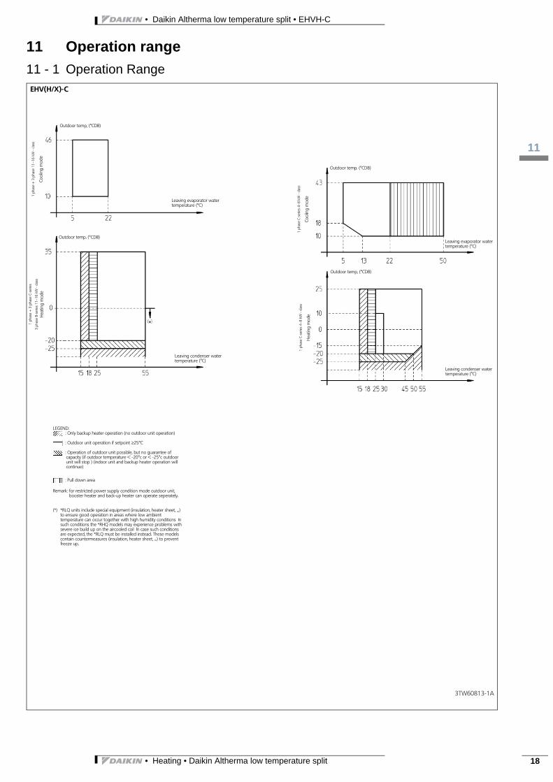
11 Operation range
11 - 1 Operation Range
≥
∼∼
∼∼
• Heating • Daikin Altherma low temperature split 18

• Daikin Altherma low temperature split • EHVH-C
112
19
12 Hydraulic performance
12 - 1 Static Pressure Drop Unit
• Heating • Daikin Altherma low temperature split

3
112
• Daikin Altherma low temperature split • EHVH-C
12 Hydraulic performance
12 - 1 Static Pressure Drop Unit
• Heating • Daikin Altherma low temperature split 20

Daikin’s unique position as a manufacturer of airconditioning equipment, compressors and refriger-ants has led to its close involvement in environmen-tal issues. For several years Daikin has had theintention to become a leader in the provision ofproducts that have limited impact on the environ-ment. This challenge demands the eco design anddevelopment of a wide range of products and an en-ergy management system, resulting in energy con-servation and a reduction of waste.
These products are not within the scope ofthe Eurovent certification program
EE
DE
N1
2-7
25
•
11/
12
• C
opy
righ
t Dai
kin
The
pre
sent
pu
blic
atio
n s
up
erse
des
EE
DE
N1
1-72
5
The present leaflet is drawn up by way of information only and does notconstitute an offer binding upon Daikin Europe N.V.. Daikin Europe N.V.has compiled the content of this leaflet to the best of its knowledge. Noexpress or implied warranty is given for the completeness, accuracy, re-liability or fitness for particular purpose of its content and the productsand services presented therein. Specifications are subject to changewithout prior notice. Daikin Europe N.V. explicitly rejects any liability forany direct or indirect damage, in the broadest sense, arising from or re-lated to the use and/or interpretation of this leaflet. All content is copy-righted by Daikin Europe N.V.
BARCODE Daikin products are distributed by:
Naamloze Vennootschap - Zandvoordestraat 300, B-8400 Oostende - Belgium - www.daikin.eu - BE 0412 120 336 - RPR Oostende