heat pumps and pinch technology
TRANSCRIPT

Heat Recovery Systems & CliP Vol. 10, No. 4, pp. 387-398, 1990 0890-4332/90 $3.00 + .00 Printed in Great Britain Pergamon Press pie
HEAT PUMPS AND PINCH TECHNOLOGY
R. BENSTEAD and F.W. SHARMAN Electricity Council Research Centre, Capenhurst, Chester CHI 6ES, U.K.
(Received 1 April 1989)
Almraet--This paper describes the use made of process integration at the Electricity Council Research Centre at Capenhurst and how it has been extended to cover electric heat pumps for energy recovery. The grand composite curve for the process is the basis of the method, together with models of heat pump thermodynamic cycles and work fluid properties which are needed for reliable capital cost estimates. These various components are combined with the more usual methods of process integration in a computer program in Prolo8 and Fortran on a UNIX graphics workstation.
INTRODUCTION
The Electricity Council Research Centre has for many years developed heat pump systems for industrial application [1, 2] usually based around an isolated or dominant unit operation. The need to enable electricity supply industry staff and customers to identify correctly placed heat pumps in more complex plants led to the undertaking of a study into the role of heat pumps in process integration.
From the very earliest work on pinch technology it was recognized that heat pumps should only be placed across the pinch [3], but very little work on expanding this simple observation had been carried out by any group with experience of industrial heat pump design.
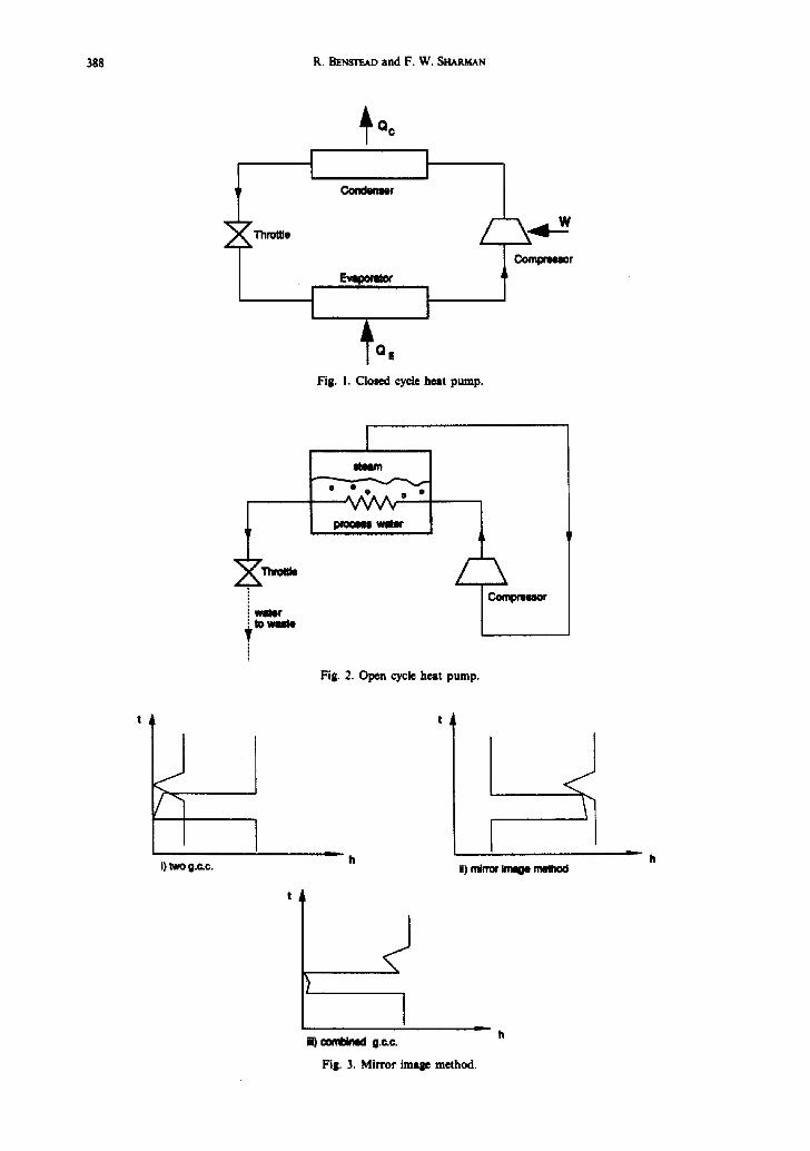
The heat pumps discussed in this paper are of the electrically driven vapour compression type, which work on the principle that a liquid boils at a higher temperature if its pressure is increased. The cycle is illustrated in Fig. 1. A low pressure liquid passes into the evaporator, where it takes in heat causing the liquid to boil at a low temperature. The low pressure vapour is passed to the compressor where it is compressed by the application of work to a higher pressure. The resulting high pressure vapour flows to the condenser where it condenses, giving up its latent heat at a high temperature, before being expanded back to a low pressure liquid.
In some industrial processes, especially evaporation, a variation can be made (Fig. 2). Here the process fluid becomes part of the heat pump system. A vapour, usually steam, is evaporated from the process by the application of heat. This vapour is taken off and compressed, by the application of work in a compressor, and the high pressure vapour is then condensed within the heating surfaces of the process, giving out heat, so causing more evaporation to take place. This type of heat pump is called an open cycle, to distinguish it from the closed cycle described above where the same fluid circulates around a closed loop.
T H E G R A N D C O M P O S I T E C U R V E
A combined grand composite curve (g.c.c.) for two sets of processes can be obtained graphically by taking the grand composite curve of the first set of processes and a mirror image, reflected in the vertical axis, placed to the left of the first curve, and sliding the image horizontally until it just touches the g.c.c, of the first set of processes. The horizontal distance between the two curves is the g.c.c, of the combined set, and the pinch temperature is the point where the two curves just touch. Note that this need not be the pinch of either of the two processes, Fig. 3.
This method can be used to fit any set of processes together and is particularly powerful where the temperature range of a process is variable, for example by varying the operating pressure of an evaporator.
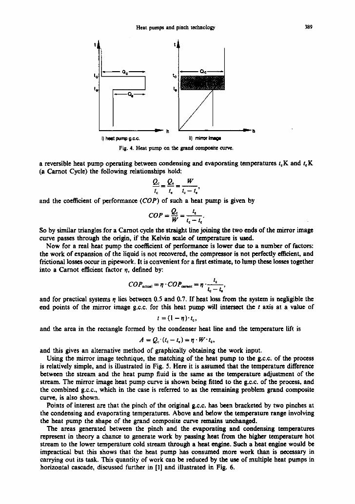
The grand composite curve of a heat pump is illustrated together with its mirror image in Fig. 4. The shape of the curve is governed by the laws of thermodynamics, which show that for
387
388 R. BE~T~AD and F. W. StixtMAN
L 7Thn~e
~Qc Cofl~tNIt@r
I
Fig. 1. Closed cycle heat pump.
W t to wrote
m O r • _
M W
/-
Fig. 2. Open cycle heat pump.
compr~N~r
/
i) two g.c.c.
coml~nM ~ c .
ii) ~ image
Fill. 3. Mirror image method.
L
h
Heat pumps and pinch technology 389
|(
te
" Qc " t¢ Q© "
m
~'~'- h i1 heat pump g.c.c. II) mirror image
Fig. 4. Heat pump on the grand composite curve.
a reversible heat pump operating between condensing and evaporating temperatures tc K and tc K (a Carnot Cycle) the following relationships hold:
Q~ Qo w tc te tc -- t,'
and the coefficient of performance ( C O P ) of such a heat pump is given by
C O P • - - Q~ ffi t~ W t c - t . "
So by similar triangles for a Carnot cycle the straight fine joining the two ends of the mirror image curve passes through the origin, if the Kelvin scale of temperature is used.
Now for a real heat pump the coefficient of performance is lower due to a number of factors: the work of expansion of the liquid is not recovered, the compressor is not perfectly efficient, and frictional losses occur in pipework. It is convenient for a first estimate, to lump these losses together into a Carnot efficient factor rl, defined by:
t~ COP,=,1 = 7 " COP=mot ffi 7 "
t ~ - t , '
and for practical systems r/lies between 0.5 and 0.7. If heat loss from the system is negligible the end points of the mirror image g.c.c, for this heat pump will intersect the t axis at a value of
t = ( l - ,1) . to,
and the area in the rectangle formed by the condenser heat line and the temperature lift is
A = Q ~ . ( t c - t c ) f ~ . w . t c ,
and this gives an alternative method of graphically obtaining the work input. Using the mirror image technique, the matching of the heat pump to the g.c.c, of the process
is relatively simple, and is illustrated in Fig. 5. Here it is assumed that the temperature difference between the stream and the heat pump fluid is the same as the temperature adjustment of the stream. The mirror image heat pump curve is shown being fitted to the g.c.c, of the process, and the combined g.c.c., which in the case is referred to as the remaining problem grand composite curve, is also shown.
Points of interest are that the pinch of the original g.c.c, has been bracketed by two pinches at the condensing and evaporating temperatures. Above and below the temperature range involving the heat pump the shape of the grand composite curve remains unchanged.
The areas generated between the pinch and the evaporating and condensing temperatures represent in theory a chance to generate work by passing heat from the higher temperature hot stream to the lower temperature cold stream through a heat engine. Such a heat engine would be impractical but this shows that the heat pump has consumed more work than is necessary in carrying out its task. This quantity of work can be reduced by the use of multiple heat pumps in horizontal cascade, discussed further in [1] and illustrated in Fig. 6.

390 R. BENSTEAD and F. W. Sm~RMAN
t
i) mirror Imltoe melhod
t
J mmm -
ii) c~ablned g.c.c.
Fig. 5. Addition of a heat pump to the g.c.c.
The selection of the size of heat pumps and the number of stages remains to be determined. A strict optimization must include the capital cost of the heat pumps and the effect on the amount of heat exchanger area required, which can be calculated from the composite curves by classing the condensers as part of the hot streams and the evaporators as part of the cold streams. For a first estimate previous experience can be used; this shows that with present U.K. fuel prices the maximum economic temperature lift of a heat pump is about 50 K. The number of stages of horizontal cascade can be determined by taking the sum of the temperature changes in the heat source and heat sink streams and dividing this by 10. The nearest integer is then the number of stages, providing the heat loading on each stage is more than 100 kW.
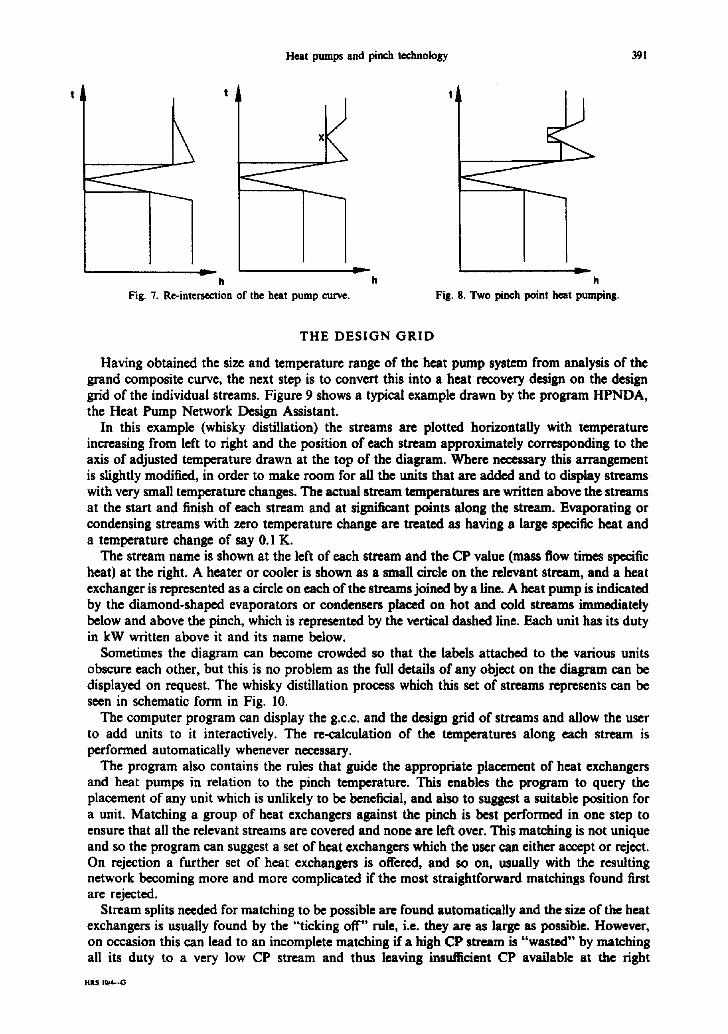
The restrictions on the size of heat pump occur when either the maximum temperature lift is reached or when the heat pump's minor image g.c.c, re-inter'~cts the process cta~e, Fig. 7. If this inter-~ction is with the end of the curve, as in the first example, then no further heat pumping is possible, as any further heating by the condenser prevents cooling of the high temperature streams, and any further cooling by the evaporator prevents heating of the low temperature streams.
If the intersection of the heat pump fine is with some intermediate portion of the g.c.c., as in the second example, then this point, X, becomes a new secondary pinch in the remaining problem. For further heat pumping to be carded out a heat pump is required across both the primary and secondary pinch, Fig. 8. For this to be economic the total temperature lift across both heat pumps must be less than 50 K. It is sometimes possible in these cases, if a unit operation is causing the secondary pinch, to adjust the operating parameters of the process so that it coincides with the primary pinch and one heat pump can be used for both pinches.
cokt c o n d o n m l
heat
I--L I I i - - ' - I I evapmem mmm
*) m.n~,Oe t.m pump,
f 3
,) ~ * e d on the g.c.c.
v
h
Fig. 6. Multistage heat pumps.
Heat pumps and pinch technology 391
h h Fig. 7. Re-intersection of the heat pump curve.
h Fig. 8. Two pinch point heat pumping.
THE DESIGN GRID
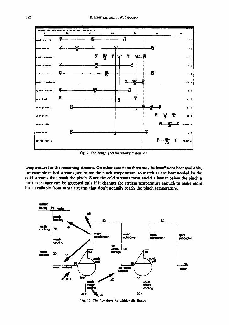
Having obtained the size and temperature range of the heat pump system from analysis of the grand composite curve, the next step is to convert this into a heat recovery design on the design grid of the individual streams. Figure 9 shows a typical example drawn by the program HPNDA, the Heat Pump Network Design Assistant.
In this example (whisky distillation) the streams are plotted horizontally with temperature increasing from left to right and the position of each stream approximately corresponding to the axis of adjusted temperature drawn at the top of the diagram. Where necessary this arrangement is slightly modified, in order to make room for all the units that are added and to display streams with very small temperature changes. The actual stream temperatures are written above the streams at the start and finish of each stream and at significant points along the stream. Evaporating or condensing streams with zero temperature change are treated as having a large specific heat and a temperature change of say 0.1 K.
The stream name is shown at the left of each stream and the CP value (mass flow times specific heat) at the right. A heater or cooler is shown as a small circle on the relevant stream, and a heat exchanger is represented as a circle on each of the streams joined by a line. A heat pump is indicated by the diamond-shaped evaporators or condensers placed on hot and cold streams immediately below and above the pinch, which is represented by the vertical dashed line. Each unit has its duty in kW written above it and its name below.
Sometimes the diagram can become crowded so that the labels attached to the various units obscure each other, but this is no problem as the full details of any object on the diagram can be displayed on request. The whisky distillation process which this set of streams represents can be seen in schematic form in Fig. 10.
The computer program can display the g.c.c, and the design grid of streams and allow the user to add units to it interactively. The re-calculation of the temperatures along each stream is performed automatically whenever necessary.
The program also contains the rules that guide the appropriate placement of heat exchangers and heat pumps in relation to the pinch temperature. This enables the program to query the placement of any unit which is unlikely to be beneficial, and also to suggest a suitable position for a unit. Matching a group of heat exchangers against the pinch is best performed in one step to ensure that all the relevant streams are covered and none are left over. This matching is not unique and so the program can suggest a set of heat exchangers which the user can either accept or reject. On rejection a further set of heat exchangers is offered, and so on, usually with the resulting network becoming more and more complicated if the most straightforward matchings found first are rejected.
Stream splits needed for matching to be possible are found automatically and the size of the heat exchangers is usually found by the "ticking off" rule, i.e. they are as large as possible. However, on occasion this can lead to an incomplete matching if a high CP stream is "wasted" by matching all its duty to a very low CP stream and thus leaving insufficient CP available at the right
HILS IO~b-G
392 R, BENSTEAD and F. W. SRA~.AN
V~htaky d i a t q 1 1 1 t l o n v4th t h r e e heat e a c b a n g o r e
mmsh coo] tng
wash e l i t e
va lh condonlor
wash euboea1
spar ta v a a t e
s p i r i t ¢on4hmeer
o p | r l t 8ubr.oo]
m a s h h e a t
r a s h p r e h e a t
~ 8 h e t t l t
u .ash 8 t | | t S
v i n e h e a t
| 2 g i |
2 0 (
8
P
B
5e J
ep I xt.~e
7~ (3
e.e
8 0 I
1L83
8 p t r t t ot1118
: i
tO8 t
i
,¢
Fig. 9. The dadgn grid- for whisky distillation.
.'TI
i
I 2 e I
17.5
|2.3
227.3
5.3
3.5
2~4.6
6 4
t7 .5
12.3
~ . 0
9 . 9
31,W~. 8
temperature for the remaining streams. On other occasions there may be ius~=nt heat available, for example in hot streams just below the pinch temperature, to match all the heat needed by the cold streams that reach the pinch. Since the cold streams must avoid a heater below the pinch a heat exchanger can be accepted only if it changes the stream temperature enough to make more heat available from other streams that don't actually reach the pinch temperature.
m~w? )_ waist
ue
20+ ~ 2o+
Fig. I0. The flowsheet for whisky distillation.
2O mm

Heat pumps and pinch technology 393
ADDING A HEAT PUMP
If a heat pump is to be considered the program displays the grand composite curve and invites the user to indicate the position at which the heat pump line should touch the curve. This determines temperature and load of either the condenser or the evaporator. The nodes of the grand composite curve correspond to the temperatures at the entry and exit of the streams. The user can therefore snap the evaporating or condensing temperature onto a node of the grand composite curve in order to align it exactly with the end of one of the streams. It is not usually possible to align both the evaporating and the condensing temperature with stream ends.
Figure 11 shows the grand composite curve for the whisky example. The left axis is the adjusted temperature and the bottom axis is the heat load. The pinch temperature is the point at which the grand composite curve reaches zero heat load, here 88°C.
Once the temperature of either the condenser or the evaporator is selected the program looks up which work fluids are possible for the heat pump, and if there are more than one it presents them as a menu for the user to select from. The heat pump cycle can then be calculated as described below and the results displayed on the diagram of the grand composite curve. This takes the form of a line showing the heat pump duties and temperatures together with the numeric values and the simple payback period for this case. The user can accept this size of heat pump or select a different size and consider the results for that new size. Figure 11 shows such a line for a heat pump with a condenser of 3114 kW and an evaporator of 2877 kW. The grand composite curve is intersected by the line representing the heat pump at the temperatures and duties of the evaporator and condenser. The slope of the central portion of the heat pump line depends on the heat pump efficiency and so will vary with the fluid selected and with the evaporating and condensing temperatures.
Once the heat pump size and temperature is accepted the program goes on to display the streams on the design grid with marks on each stream indicating the evaporating and condensing temperatures. The heat pump will transfer heat from hot streams below the pinch to cold streams above it, but it cannot affect the cold streams below the pinch. Therefore to avoid undesirable
~ t r a t i o n I - ~ q ~ y d t s t l l | s t 4 ~
|21
al
\
2A. ~.. ,~., s~ . B... Heat I o s d
Fig, I I. The grand composite curve with a heat pump line.
394 R. B~srro~ and F. W. StrAP.MAN
utilities, these cold streams, and similarly the hot streams above the pinch, must be matched by heat exchangers before the heat pump is installed, using a matching procedure similar to that when only heat exchangers are present. Any stream with a heat exchanger which has more heat available within the heat pump temperature range is given a parallel split in order to make that heat available as near the pinch temperature as possible. In this way the temperature lift of the heat pump can be reduced and the efficiency increased.
When this matching with heat exchangers is complete, evaporators and condensers can be installed on the remaining hot streams below the pinch and cold streams above it. The total duties of the condensers and evaporators then equal the values derived from the grand composite curve. At that stage all streams will be fully matched between the evaporating and condensing temperatures, and the pinch on the grand composite curve will have opened out to be the entire range from the evaporating temperature to the condensing temperature. The remaining streams can therefore be matched with heat exchangers in the usual way without being affected by the heat pump just as if they were being matched against the pinch. When no further heat exchangers can be added the remaining loads are satisfied with utility heaters and coolers, and it can be checked that the target energy consumptions have been achieved, though modified by the extra energy saving of the heat pump.
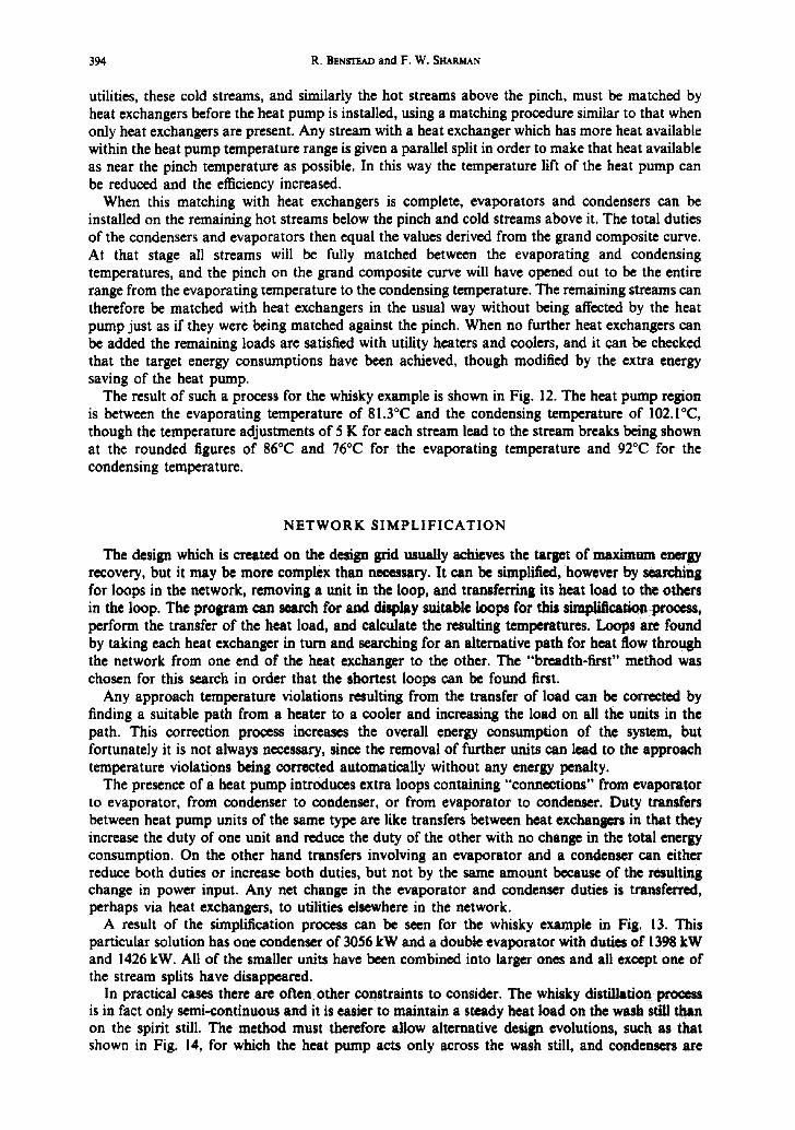
The result of such a process for the whisky example is shown in Fig. 12. The heat pump region is between the evaporating temperature of 81.3°C and the condensing temperature of 102.1°C, though the temperature adjustments of 5 K for each stream lead to the stream breaks being shown at the rounded figures of 86°C and 76°C for the evaporating temperature and 92°C for the condensing temperature.
NETWORK SIMPLIFICATION
The design which is created on the design grid usually achieves the target of maximum energy recovery, but it may be more complex than necessary. It can be simplified, however by searching for loops in the network, removing a unit in the loop, and transferring its heat load to the others in the loop. The program can search for and display suitable loops for this simplification process, perform the transfer of the heat load, and calculate the resulting temperatures. Loops are found by taking each heat exchanger in turn and searching for an alternative path for heat flow through the network from one end of the heat exchanger to the other. The "breadth-first" method was chosen for this search in order that the shortest loops can be found first.
Any approach temperature violations resulting from the transfer of load can be corrected by finding a suitable path from a heater to a cooler and increasing the load on all the units in the path. This correction process increases the overall energy consumption of the system, but fortunately it is not always necessary, since the removal of further units can lead to the approach temperature violations being corrected automatically without any energy penalty.
The presence of a heat pump introduces extra loops containing "connections" from evaporator to evaporator, from condenser to condenser, or from evaporator to condenser. Duty transfers between heat pump units of the same type are like transfers between heat exchangers in that they increase the duty of one unit and reduce the duty of the other with no change in the total energy consumption. On the other hand transfers involving an evaporator and a condenser can either reduce both duties or increase both duties, but not by the same amount because of the resulting change in power input. Any net change in the evaporator and condenser duties is transferred, perhaps via heat exchangers, to utifities elsewhere in the network.
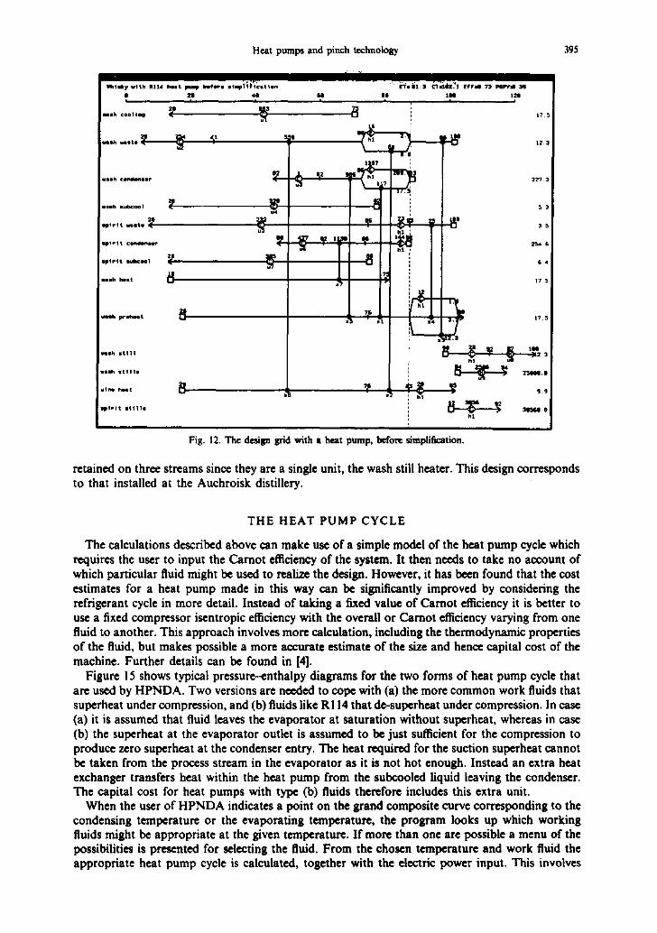
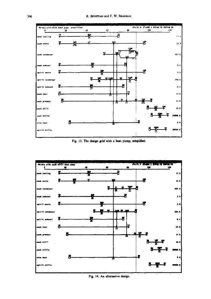
A result of the simplification process can be seen for the whisky example in Fig. 13. This particular solution has one condenser of 3056 kW and a double evaporator with duties of 1398 kW and 1426 kW. All of the smaller units have been combined into larger ones and all except one of the stream splits have disappeared.
In practical cases there are often other constraints to consider. The whisky distillation prooeu is in fact only semi-continuous and it is easier to maintain a steady heat load on the wash still than on the spirit still. The method must therefore allow alternative design evolutions, such as that shown in Fig. 14, for which the heat pump acts only across the wash still, and condensers are
Heat pumps and pinch technology 395
M t i ~ y v l t h R I I 4 ~ . t p i p t i t l e , s l I p i ~ ¢ t t i o n
i i i
v i o k c o ~ i e r
I I I h I1~1i)¢0(11
I p t r t t cond~m~Ir
sp t r~ t I I~Xool
mesh I~a~
se i
I l t l h I t t | l
v a I ~ I t t l l !
v t n l h i l t
1 9 i r i t I t I l l l
i I I | ~ .
l e I
"
s~ ~ q2 sl,.~ As
I
IMI 1 ~ i m
h t
L :L
O R
I ? . "
1 2 . 3
227 3
S
31
Z~t. I;
g 4
1?.5
1 7 . 5
9 9
h l
Fig. 12. The design grid with a heat pump, before simplification.
retained on three streams since they are a single unit, the wash still heater. This design corresponds to that installed at the Auchroisk distillery.
THE HEAT PUMP CYCLE
The calculations described above can make use of a simple model of the heat pump cycle which requires the user to input the Carnot efficiency of the system. It then needs to take no account of which particular fluid might be used to realize the design. However, it has been found that the cost estimates for a heat pump made in this way can be significantly improved by considering the refrigerant cycle in more detail. Instead of taking a fixed value of Carnot efficiency it is better to use a fixed compressor isentropic efficiency with the overall or Carnot efficiency varying from one fluid to another. This approach involves more calculation, including the thermodynamic properties of the fluid, but makes possible a more accurate estimate of the size and hence capital cost of the machine. Further details can be found in [4].
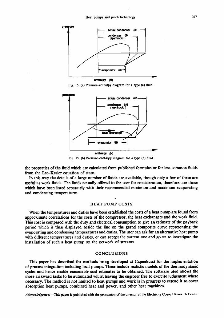
Figure 15 shows typical pressure-enthalpy diagrams for the two forms of heat pump cycle that are used by HPNDA. Two versions are needed to cope with (a) the more common work fluids that superheat under compression, and (b) fluids like R! 14 that de-superheat under compression. In case (a) it is assumed that fluid leaves the evaporator at saturation without superheat, whereas in case (b) the superheat at the evaporator outlet is assumed to be just sufficient for the compression to produce zero superheat at the condenser entry. The heat required for the suction superheat cannot be taken from the process stream in the evaporator as it is not hot enough. Instead an extra heat exchanger transfers heat within the heat pump from the subcooled fiquid leaving the condenser. The capital cost for heat pumps with type (b) fluids therefore includes this extra unit.
When the user of HPNDA indicates a point on the grand composite curve corresponding to the condensing temperature or the evaporating temperature, the program looks up which working fluids might be appropriate at the given temperature. If more than one are possible a menu of the possibilities is presented for selecting the fluid. From the chosen temperature and work fluid the appropriate heat pump cycle is calculated, together with the electric power input. This involves
396 R. B~NSTE~m and F. W. SXARMAN
~isk~ ,Ith e~X, h,st p,.,p, , ~ . " ' ' ' d !
mash c o o l i n g
wash waste
wash condenser
v t s h subcool
s p i r i t vests
spqr4t condenser
s p i r i t eubcool
mtsh heat
r ash p rehea t
r a s h s t i l l
~alh It111e
v i n e heat
s p i r t s s t i l l s
I
i
T
g___
I d ..,
8
f:'TsO2,$ ~ u l R . ! EFFsO,?3 PISI~4.sg 8@ 190 12g * s ,
- - - a :
'. ~ ,
n U ' l
!5 1
~s
Fig. 13. The d~i l ln ~ with a heat pump, s impl~ed.
h!
I75
227.3
5 ,3
3.5
254,6
6.4
17.~*
27,5
12.3
25000, 0
9 ,g
39560, |
! e e
H
~P glP q ~ u ,a
2;t1.3
s.s H
lip : ~ s.s S a
~ w i .-m m .-,,, ~ 2se.e
-- T L I ~ s,4
" 1 $?.S
i ]" ,d~" T * , .
1 : 1 , 3
~ IlmW,ID
8 T , . ,
i
Fill. 14. An alternative design.
sash c o o l t n 9
veoh v e s t s
r a s h condenser
~P tmOh ma l ted I
o p t r l t welts ~I
s p l r l t c4m41samw
w p l r t t md~oo l
sash Imet 8
vamh Ist l 11
r a s h e t (11o
mine hea t
o p t r 4 { s t i l l s
lull i
Heat pumps and pinch technology 397
pnm
S
actual condenser 8H
I/ "-evaporator 8H-~
Fig. 15. (a) Prcssure-enthalpy diagram for a type (a) fluid.
u M
condenser 8H
cor~lenur 8H
Fig. 15. (b) Pressure--enthalpy diagram for a type Co) fluid.
w
the properties of the fluid which are calculated from published formulas or for less common fluids from the Lee-Kesler equation of state.
In this way the details of a large number of fluids are available, though only a few of these are useful as work fluids. The fluids actually offered to the user for consideration, therefore, are those which have been listed separately with their recommended minimum and maximum evaporating and condensing temperatures.
H E A T P U M P C O S T S
When the temperatures and duties have been established the costs of a heat pump are found from approximate correlations for the costs of the compressor, the heat exchangers and the work fluid. This cost is compared with the duty and electrical consumption to give an estimate of the payback period which is then displayed beside the line on the grand composite curve representing the evaporating and condensing temperatures and duties. The user can ask for an alternative heat pump with different temperatures and duties, or can accept the current one and go on to investigate the installation of such a heat pump on the network of streams.
C O N C L U S I O N S
This paper has described the methods being developed at Capenhurst for the implementation of process integration including heat pumps. These include realistic models of the thermodynamic cycles and hence enable reasonable cost estimates to be obtained. The software used allows the more awkward tasks to be automated whilst leaving the engineer free to exercise judgement where necessary. The method is not limited to heat pumps and work is in progress to extend it to cover absorption heat pumps, combined heat and power, and other heat machines.
Acknowledgement--This paper is published with the permission of the director of the Electricity Council Research Centre.

398 R. BENS'r~ and F. W. SHXR~
R E F E R E N C E S
1. R. Benstead, The Optimization of Multistage Heat Pump Systems. Paper presented at I.I,R. Commission E2 meeting, Systems and Components for Large Heat Pumps, Trondheim, Norway, 1985.
2. E. Chalmers, D. L. Hodgett and A. A. Mitchell, A stream recompression heat pump for increasing energy efficiency in distillation, l. Chem. E. Symposium, Innovation in Process Energy Utilization, Bath, September, 1987.
3. B. Linnhoff (Ed.), User guide on process integration for the efficient use of energy. 1. Chem. E., 1982. 4. M. B. Bertinat, Fluids for high temperature heat pumps. Int. J. Refrig. 9, 43-50, (1986).