heat conduction through insulating supports in very low temperature equipment
TRANSCRIPT

Journal of Research of the National Bureau of Standards Vol. 57, No.6, December 1956 Research Paper 2726
Heat Conduction Through Insulating Supports In Very Low Temperature Equipment 1
R. P. Mikesell and R. B. Scott
An apparatus is described that is used to measure the heat conduction t hrough ins ulating supports of storage vessels for cryogenic liquids and presents the data obtained from the cond uct ion measurements. Two types of supports were tested: (1) multiple-contact supports in the form of stacks of thin meta llic p lates or spirally wound strips, and (2) nonmetallic spheres. The high t hermal resista nce of the multiple-contact supports arises from the numerous r elatively poor contacts between the individual plates. Some special treatments of the plates were tried, and two of these, perforating and dusting, Kere found to be effective. Pyrex-glass spheres were also found to be excellent insulators, but, of course, a re not as rugged as a stack of metal plates. Of t he un treated plates tested, t hose of stainless steel (0.0008 inch thick) were found to be the best insulators per unit length of stack. The heat conduction through these p lates, at a load pressure of 1,000 pounds per squ are inch , was found to be 2 percent of t he conduction by a solid sample of th e same metal having the same dimensions.
1. Introduction
The most effieient containers for stori ng and transporting low-temperature liquids, such as liquid oxygen , nitrogen, and hydrogen , are the vacuumjacketed type known as Dewar vessels. In the past, several types of heat insulators have been used to bridge the vacuum space and furn ish support for the inner container. For small laboratory- t~rp e Dewars, the design of in sulators is not a major problem, but when designing a vacuum-insulated con tainer of several hundred Ii ters or more, which must have ruggedness to withstand the shocks and vibration of transpor-tation by any type of carrier, t he problem of insulating supports becomes a serious one .
The recent devclopmenL of a large aluminum Dewar at the Bureau's Cyrogenic Engineering laboratory included the design of some new type insulating supports, which were of such a natUl'e that their insulating properties could not be computed from the th ermal conducLivit~r of the materials from which they ·were constructed. For this reason , an apparatus was constructed to measure the heat conduction through these suppor ts. Some of the supports were found to have such good insulating and structUTal properties that it is b elieved they will have an extended usefulness , and that information obtained from the tests will have general value in the design of Dewar equipment.
2. Experimental Details
2.1. Description of Apparatus
In order to simula te condiLions aCLually encount er ed in pracLice, the calorimeter for measuring the heat conduction was iLself a D ewn,r vessel. WiLh this apparatus it was possible to measure the total beat conduction of the specimen when it was subjected to loads ranging from approximately 30 pounds to approximaLely 1,050 pounds and under the following temperature conditions: (1) room temper-
1 ~L' hi s work was sponsored by the U. S. Atomic Energy Comm ission.
371
ature to liquid-nitrogen temperature (296° to 76° Ie), (2) liquid-nitrogen to liquid-hydrogen tempe~·at':lre (76° to 20° Ie), and (3) room temperature to hqUldhydrogen temperature (296° to 20° Ie). These temperatures are the boundary conditions enc~)Untered in liquid-hydrogen Dewars, which are prOVIded with a liqllid-nitrogen-cooled radiation shield between the liquid hydrogen and the room-temperature shell.
The apparatus (fig. ] ) \vas desigJl ed so that the calorimeter is a metal Dewar with the test specimen acting as a separating and insulating member. The specimen :is placed between Lhe bottom plaLe of the inn er con Lainrl", into which is pOllredliquid nitrogen or hydrogen , and the bottom plate of the outer container, which is at room temperaLure OT liquid nitrogen temperature. A 5-li( er Dewar containing liquid nitrogen surrounds the calorimeter when it is required Lo have the exterior wall of the calorim eter at liquid-nitrogen temperature.
The outside container is secured in a vertical position by means of the O -ring flange, which rests UDon a wall bracket not shown in the diagram. The O -ring seal is completed by a Lop flan ge, through th e center of which passes a tube (8- 18 stainless steel, H~-in. outside diameter, }i6-in . wall), ·which is connected to the inner container. The vacuum system , consisting of a cold trap, diffusion pump, n,nd forepump, is connected to the Oll ter container.
The central tube serves both as Lhe neck of Lhe calorimeter-Dewar and as the compression member for transmitting the load from the fulcrum point of the lever arm to the specimen. Thi verLicalload is the force resulting from a movable wei ght mounted on a lever arm. A metal bellows pennils the central Lube to move verticall)' throu gh guid es that also preven t horizon tal mo tion. The brass plate is soldered to the bellows, is sealeelLo the outer container by means of an O -ring and is secured in position by four screws. Th e unit consisting of the i.nner conL&iner or calorimeter, Lhe centTal tube, the bellows, and the top flange may be easily withdrawn from the outer co ntainer to enable one to change t.he test specimen .

In order to reduce heat radia tion from the side, the surfaces that face the insulating vacuum are covered with bright aluminum sheet. To intercept radia t ion from above, horizont al metal disks are placed along the central tube both inside and outside.
2.2. Test Specimens
The specimens measured in the t ests are described n tables 1 and 2 .
The round plates (A, fig. 2) 1 in . in diameter , are mounted between brass end plates of the same diameter. Nylon threads tied through small holes in the plates keep them in place. The r ectangular plates are mounted in the same manner , with the diagonal of each r ectangle approximately t he same length as the diameter of the circular end plates. The spheres (B, fig. 2) are held between two stainless-steel plates, each of which has three matching spherical depressions of somewhat larger diameter than that of the spheres (spheres ;li6-in. radius, depression %-in. radius). This assembly is also t ied together with threads to prevent dislodgmen t of the spheres durin g test .
LEVER ARM
FI LL AND BOIL 'OFF TUBE
TOP FLANGE """,,,,;om<,,", /' TO VACUUM
r--r~, PUMP
T A B LE 1. Nonmetallic sphe1'es
Specimen Dimensions Comments
Three Pyrex·glass· Eacb sphere, O.3i5· M ade (rom scmi polisb No. spheres. in . d iameter. 774 clear chem ical glass,
manu fact ured by the .T. R. K ilburn Glass Co., C hart·
LI QUID LEVEl INNER CON TAINER ley, Mass.
Three soda lime Average diameter of Manufactured by Hans L. spheres. spheres, 0.42 in. Landay, Boulder, Colo.
IJ.'hree ceramic Each sphere, 0.39· M ade from Coors type AB-2 spberes. diameter. ceramic" high- s t rength
alumina", manu factu red by the Coors Porcelain Co., Golden, Colo.
I a 3 I I!!I I
SCALE IN INCHES T hree Miearta Eacb sphere, 0.3;5· M anufact ured by Westing,
linen-impreg- in. diam eter. bouse Elect. Mfg. Corp. nated spheres.
BOTTOM PLATE
FIGURE 1. Cross section of the calorimetric apparatus .
T A BLE 2. M ultiple-contact specimens (metallic)
SpeCimen
Monel round plates : Clean plates .... _ .. __ ..... _._ ... _. ____ .. _ .. _. Greased plates . .. __ . __ ... _. _ ... _ ... __ .... __ .
Type 304 stainless·steel round plates: Clean plates ..... _ ..... __ ._. __ ....... _ .. __ ...
Type 302 stainless·steel round plates: Cleao plates .... _ .. __ .. _ .. ___ ... _ ... _ ...... _. Clean plates ...... _ .. __ ._._._ ... _._._._ .... .. Clean plates .... _ .. _. __ .. __ . _ ... _ ... _. ____ ._. Clean plates ......... __ ... _._ ... _ ... _ ... _. __ . D usted plates __ ..... _ ... __ ._ ... _ ... _ ..... _ ..
T ype 304 stainless·steel rectangular plates: Clean , plain p lates ........ _ ........ _ ..... _._ ....
Clean, perforated plates .. _._ ... _ ... _._._._ ..
A Item ate layered stack of plain and perforated plat es.
Dusted plain platos .. _. __ ._ ... _._. __ .... _ .. _ .. _.
Teflon layered stack of plain plates ._ ... ___ ._._ ..
Number of plates
Dimensions Comments
52 }1 ' d ' t 001- ' tb' k {GreaSed with Dow·Corning high·vacuum 52 -Ill. lame Of, . I-H]. 10 -ncss____ _____ _____ grease.
49 l·in. diameter, 0.0195·in . tbickness .. __ . ___ .. _ ..
~~~ )1.in. d iameter, 0.OOO8·io. tb ick ness ..... _._..... D usted witb a thin layer of manganese 148 d iox ide . 345
92 ~16 by % in ., O.OO4-in . tb ickness _____________ _ _ 107 ~16 by % io ., 0.004·in. tbickness. 18 %4·in .·
diameter boles comprise approximately 40% of total arca of a plate.
61 of eacb YI6 by % in., 0.004·in. tbickness. 18 %.-in.· T he boles of each plate were staggered witb diameter boles comprise approximately 40% respect to the holes of the adjacent plate. of total area of a plate.
llO YI6 by % in., 0.004·in . tb iekness ... _._._._ ..... Holes of adjacent perforated plates were staggered.
no YI6 by % in. , 0.004·io. thiekness .... _._._ .... _.. T be metal plates were sepa rated from each otber by Teflon fi lm 0.00025·in. thick.
372

1IIIIi~· - NYLON THREAD~.", 19'f';~-4'--4b1iJUl SPHERES-~~-v--~~
~ DIS KS
TY PE 304 STA INLESS ST EEL /
A 8 FIGURE 2. J1!Jelhod for rn01mting the specirnens.
2 .3. Experimental Procedure
.With. the. sp~cimen in place, .the calorimeter supplIed wlth hqmd hydrogen 01' mLl'ogen , the required lo ad applied, and an adequate vacuum (less than 10- 5 mm Hg) in the insulating space , the volume of gas ~vapol'~ted from the calorimetric liquid is determYled wlth. a wet test gas meLcl'. R eadings are contmu ed until a C~)].) st~nt rate of evaporation gives assurance that eqUlhbnum has been reached. Volume determinations are adjusted to standaJ'd conclit ions and corrected for t he partial pressure of waLe]' vapor in the meter. Several seLs of readinO's are made wiLh applied load on the specimen. b
The rate of heat flow through the specimen cannot be calculated directly from Lhe evaporaLion rate because (1) part of th~ evaporation of t he liquid during the measurements lS caused bv heat Lransfer other than through the sp ecimen , an'd (2) the relation between e,:apor~tion rat~ an~ heat conducted through the specnnen IS not qUIte Imear because some of the heat flowing dow~ the central tube is intercepted by the cold gas flowmg up the tube; thus less heat is c~mdu?ted d?wJ? the. tube when the rate of evaporatlOn of .the hqmd lS l~creased . Instead of trying to determme the magmtude of these incidental heat leaks, ~heir. effects were taken il'l;to account simply by cahbratmg the apparatus With a known heat inP1?t.. This was done by lifting the inner container until It no l(~mger made con~tact with the specimen and conductmg another sen es of measurements of the gas evo.lvecl. when knoV\:n values of electric power were .supplIed to .a h eater unmersed in the liquid in the lllner contalller. The amount of heat conducted through the specimen during a lest measurement IS assumed to b e the same as that supplied to the. heater to. pr~d~ce ~ giv?n rate of evaporation. Tlus assumptlOn IS Justlfi ecl If the conditions during the measure~en~s of he~t conduction with appl ied loads are mamtallled durmg the caJibra tion mea,surements.
3 . Data a nd Discussion
3 .1. Accuracy of the Data
The values of heaL condu clion obLained wilh Lhis apparatus are accUI'aLe in most cases Lo approximately 10 percent. The main causes of elTor \\'ere the following: (J) The flu ctuations in the mao' ni lud e of the. incidental. heat leaks, though small , did become Important 111 the measurement of the cond uction through the very good insulators, and (2) there wer.e s!Uall ,changes in heat conduction resulting from vanatlOns 111 the exact mann er of mounting or loading the specimen.
3 .2 . Untreated Stacked Plates
Six multiple contact specimens wer e tested between nitrogen (76 0 Ie) and room temperature' five o.f these were stacks of stainless-steel plates, an~l the SIxth was a stack of IVloncl plates . Two specimens were tested between liquid-hydrogen temperature (~ O O Ie) and liquid-ni trogen temperature (76 0 Ie) . Smce the sUI)port of a D ewar is in most cases loaded . 1 ' , warm, 1. e., t 1e load is applied when the suppor t is at room temp,erature, the data for each specimen, with the exceptlOn of the Monel stack , i presented for warm loadings. The Monel stack was loaded cold i. c. the load w~s applied when one end of Lhe speci~ men was at m trogen tcmpera tUI·e. I t was found tha ~ the conduct~on by a stack of plates (0.004 in. ) sub] ected to a hIgh pressure was approximately 30 percent greater when the stack was load cd warm than when it was loadcd cold.
The results on cle~n mul tiple-contact, metal suppo~·ts 2 arc shown m figures 3a, 3b, and 3c, whercm t~e heat Clll'l'ent pel' unit arca is ploUed as a functlOll of the preSSU1'e on Lhe specimen. The heat conduction through the plates increased with the prCSSU1'e for two reasons: (1) the area of conLaet surface was increased , and (2) the heat paths becam c sh.orter throu gh a givcn stack of plates. The cO~lductlOn \vas found to be proportional to someth~ng less than the first power of the pressure, there b emg a tendency for the curves to level off as increased pressure had less effect. Thus, the stac k of plates acted as a good insulator, even at the higher pressures.
The points below a pressm e of 300 psi were not especially reliable because the exact v alues of the lower pressmes, as well as the measU1'ed conduction rates, are somewhat in doub t.
Figure 4, on which these same curves are plottcd on l?g-log paper , s}~ows the conduction to be proportlOnal to approxImately the 0.67 power of the preSSU1'e for the ;nitl'ogen- Lo room-temperature range , and proportlOnal to approximately the 0.86 power for the hydrogen- t? nitrogen-temperature range. As the heat conductlOn by a stack of plates was found to be proportional to less than the first power of the l~ad , it is co~cluclcd that such a support should be . deSIgned for hIgh loading per unit area,
2 S.u Ch. an arrangement for usc as an F insu1aUng support is the subject of a patent a pplica tIOn for the A EC b y B. 1W.1BiIlTIin gham, E. n . Brown , R . B . Scott, a ne! P . C. Va nd er Arene!.
373

"I---+---t--:;;;;;J""""
• 10 I----!-"'=---+-::;,.,.""---l )(
3 "-
!;; "' :z:
PRESSURE. psi
FIGURE 3a. Heat conducted as a function of mechanical pTesSUTe of stacks of type 302 round stainless-steel plates, each plate 0.0008 in. thick.
A (fl.). 148 plates; C (0 ), 209 plates; F (0 ), 313 plates; H (e ), 315 platrs . Boundary temperatures for A, C, and Fare 76° and 296° K; forH, 20° and 76° K.
10 ,-----,------,r----.,
. ~ ,r---~~~-+--~ it
S :c
PRESSURE~ PSI
FIGURE 3b. Heat conducted through slacles of thick plates where the b01mdary temperatures are 76 0 and 296 0 K.
D (0), a stack of 52 round IVl onel plates, 0.017 in . t hick; E (fl.) , a stack of 49 type 304 round, sta inless-steel plates, 0.0195 in . thick. Curve I shows the cond uction that would occur through II stack of 0.0008in . plates t ho same height as the stack of 0.0195-in . plates. The conduction is ex trapolated from tho conduction by a stack of 313 plates, 0.0008 in . thick .
20
.S 15 "~
~ 10 --' "->-~ 5 :J:
o ~ o
./ -r'
/f /
/~
G
500 1000 1500 2000 2500
PRESSURE. ps i
FI GURE 3c. H eat conducted through a stack of 92 type 304 rectangular, stainless-steel plates, 0.004 in. thick.
The bouudary temperatures for B (0) are 76° and 296° K; for a (0),20° and 76° K .
i. e., the cross-sectional area should be made as small as is consistent with strength and other design considerations.
The concept of thermal resistance is introduced here as an aid in comparing and correlating data on different specimens. Thermal resistance is defined as the temperature difference divided by the
. )(
" .J ...
30.-----,---,---,-----,
0.5 1---+-d-'----f-7'''----+---t
0.2 r-- =7"'-t---r-------r------i H
0 . 1 L..--'---'--'-.................. L..---'------'-_'--"-' 200 500 1000 2000 5000
PRESSURE, psi
FIGURE 4. A log-log presentation of the data given in jiguTes 3a, 3b, and 3c, demonstrating that the heat CUTrent is approx1:mat ely proportional to the 0.67 power of the pressure in the upper temperature range (76 0 to 296 0 K ), and to the 0.86 power of the pressure in the lower temperature range (20 0
to 76 0 K ).
A (0) , 148 plates, 0.0008 in . thick; B (0) , 92 plate.s, 0.004 in . thick ; C (6), 209 plates, 0.0008 in . t hick; D (0), 52 plates, 0.017 in. t hick; E (fl.), 49 platrs, 0.0195 in. thick ; F (0), 313 plates, 0.0008 in . thick; G (0), 92 plates, 0.004 in . thick; H (0),3 15 plates, 0.0008 in . thick .
heat current (in analogy to its electrical equivalent). Thermal resistance is temperature dependent, but it is permissible to use 3,n average value for comparing two stacks under the same temperature difference. As there were a large number of stacked plates in these tests, it was reasonable to expect that the resistance would be proportional to the number of plates, i. e., that the end effects 'would be negligible.
Three specimens of the O.0008-in.-round stainlesssteel plates were tested, each with a different number of plates. In figme 5 it is shown that the thermal resistance of a stack of plates varies linearly with the number of plates in the stack. Thermal resistance of unit area per plate as a function of the thickness of each plate is shown in figure 6. For many design applications a certain volume may be available for the insulating member. Hence, consistent with strength and cost considerations, it is desirable to knO'lv what thickness the plates should have to provide adequate heat insulation. Thermal resistance of unit area pel' unit length of stack as a function of plate thickness is plotted in figure 7. The length of the stack was determined by multiplying the number of plates by the thickness of each plate; this calculated length was in close agreement with the length measured when the stack was subjected to a pressure of 1,000 psi. Points for the curves of figures 6 and 7 arc taken from the curves of figures 3a, 3b, and 3c for the
374

• ~ '" o
120r-----.------.-----.------,-----,
100~----+_----_+----~--~L-t_-----
• BO~----+_----_+--~~------t_-----
~ '§ ~ 60~----+_--.l~----_+------r_--~
'" u z ~ ~ 40~--~+_----~--~_t~~~r_--~ '" a:
~ '" :I:
O L-----~----·~----~------~--~ 100 200 300
NUMBER OF PLATES
FIGURE 5. Observed linear increase oj the thermal Tesislance with the number oj plates contained in a stack.
T be plate thickness is 0.0008 in .; the bou ndary temperatures are 76° and 296° K .
O.OOOS-in. stainless-steel round plates, the 0.0195-in. s tainless-steel rectangular plates, and the 0.004-in. stainless-steel round pla tes . It is seen that the 0.0195-in . stainless-steel round plates had a higher thermal resistance per plate than the o Llwrs, the explanation being that the thin plates ,,:ere pre~sed into b etLer contact with each other WIth a gIven applied pressure. However , for a given length of stack , the thin ph·,tes produced a greater LoLal th ermal resistance . This is shmvn by the dotted curve, I , figure 3b . No implication is in tende.d tha~ the slopes of approximately X and - }~ of the lwes of figures 6 and 7 hav e any significance ?ther than that of r epresen ting the observaLions. It lS probable that for different loads or plate thicknesses these would have other values.
The heat conduction through a stac k of plates was considerably less than the conduction by a solid member of' the same metal having the same dimensions, showing that th e difference in c~mduction was du c mainl:,,' to the total contact reSIstance of the spccimen. . .
The condu ction through a stack of 0.0008-m.-thlCk stainless-steel plates uncler a pressure of 1,000 psi was found to be approximaLely 2 perccn t of the condu ction by a solid mcmber; for the 0.0195-in. sta.inl ess steel round phtes at ] ,000 pSJ, S.5 percent ; for the 0.004-in.-lhick sLainless-sLeel rec tan gular plates at 1,000 psi, 4. 5 percenL ; an(~ for Lhe 0.017-in.thi ck Monel round plates a t 600 p SI , 6.5 pe rcent .
The O.OOOS-in. a nd the 0.004-in. pla les were Les ted between liquid-nitrogen and liquid-hydrogen temp eratures. T able 3 sliO"l'fs th e compar ison between these specimens. In the ease of bolh the 0.0008-in. and the 0.004-in . plates, t he specimen 'was loaded warm at the hi o-her pressures ' th e load ,vas reduced Lo the
b '. ] 1'J lower pressures after the specnnen was co d. Ie
375
5.0 ...----r----,------,------r-----,-----,
2.0 ~---+----j-----+_--_t--"""'f_--~
• ~
b; 1.0 I---_+----r_-----.Y"'----_t----g.----o
'" u • z. ~ i 0.5 1---+---::..,;tt.F-----+_7"q-::.il~t---~ iii L
l:!8. ~ ~ ~: 0.2 ~---+"""~i---:~::..><...+_---+---'---'.---~
'§
0.1 1--rt4-----I------+-----+----+------I
0.05 L...I. ........ ..u... __ '--.l.--'--'-.J...J .......... ....I..I. __ .l.-~_'_...J.....J
0.0005 0.00 1 0.002 0 .005 0.01 0.02 0.05
PLATE THICKNESS, In.
FH1UUE 6. A log- log presentation demonstrating that the heat j'esistance peT plate increases approximately as the square Toot oj the individual plate thickness.
'rhc boundary temperat urrs arc 760 and 2960 K.
• 0 .....
- '" 0 0
'" u • z •
500r-~.-----------.---_r----------.
200~~4---------~~--_+--------~
';:! ' ~ I 00 ~--~....,.----...::' ........ o---+_---+---=::!!""'"---en U
iii~ '" U a: c
>- • <l C
'" 0 :I:
50 1---~--------~~~_+~~-------
0.001 0.005 0.01 0 .05
PLATE TH ICK NESS, in.
F I GURE 7. A log-log presenlation demonstrating that the heal Tesistance per w~it length oj a slack val'i es ap7n'oximately as the inverse square j'oot oj the individtwl plate thickness .
rI'hc boundary temperatures arc 76° and 2960 K .
ratio of the h eat conducted between 296° and 76° Ie to that conducted beween 76° and 20° Ie is of interest. The conduct ion ratio of a solid member of the same type of metal and the same dimension between the two temp erature intervals would be 9 to 1. The greater ra tio in the case of th? stacked pla tes is an indication th at the th erm al ~'esl s tance of th e contacts increases as the temperature IS decreased .
T A RLE 3. Corrt parison oJ O.0008-in . and O.004-ir . plates
= CondLlction ratio
S pecimen (Cond llct ion at 7Go })rcssurc pla tes to 296° K + coll '
d uct ioll at 20° to 7Go K )
psi in . 754 0. 0008 15.5 to 1
1,346 . OOOS 13.3 to 1 1, 407 . 004 14.2 to I 2, 509 . 004 10.6 to I
'~
3.3. Specially Treated Stacked Plates
a. Dusted Pla tes
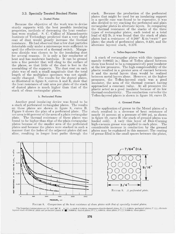
Because the objective of the work was to devise sturdy supports with the best possible insulating properties, methods of decreasing the heat conduction were studied. S. C. Collins of Massachusetts Institute of Technology predicted that a very slight coat of dust would greatly increase the thermal resistance. He had observed that a few dust particles detectable only under a microscope were sufficient to spoil the effectiveness of a thermal switch. Manganese dioxide was chosen to be the insulating dust for several reasons. It is only a fair conductor of heat and has moderate hardness. It can be ground into a fine powder that will cling to the surface of the plates, so that little of the dust is lost in the assembling of the supports. The dust coat on each plate was of such a small magnitude that the total length of the multiplate specimen was not significantly changed. The results for the dusted plates, as illustrated in figure 8, curves A and E , show that the heat resistance of unit area per plate of the stack of dusted plates is much higher than that of the stack of clean rectangular plates.
b . Perforated Pla tes
Another good insulating device was found to be a stack of perforated rectangular plates. The results on these plates are shown in figure 8, curve B . Figure 9 shows the plan of a perforated plate. The net area is 60 percen t of the area of a plain rec tan gular plate. The thermal resistance of these plates was found to be higher than that of the plain rectangular plates because of the smaller area of the perforated plates and because the plates were stacked in such a manner that the holes of the adjacent plates did not aline, resulting in longer heat paths through the
stack. Because the production of the perforated plates that might b e used for an insulating support in a specific case was found to be expensive, it was also decided to try stacking the perforated and plain rectangular plates in alternate layers. In comparing the thermal resistance of the stacks of the three types of rectangular plates, each tested at a total load of 422 Ib, it was found that the stack of plain plates had a r esistance of 0.260° K-in.2-watt- 1 per plate ; the stack of p erforated plates, 0.420, and the alternate layered stack, 0.370.
c. Teflon-Separated Plates
A stack of rectangular plates with thin (approximately 0.00025 in. ) films of Teflon placed between them was found to be a comparatively poor insulator at the low pressures. The high compressibility of the plastic resulted in a greater area of contact between it and the metal layers than would be realized between metal layers alone. However, at the higher pressures, the Teflon-layered stack was a good insulator, the area of the thermal contact having approached a constant value. At all pressures the plastic acted as a good insulator because of its low thermal conductivity. The conduction curve for the Teflon-layered plates is shown in figure 10, curve D.
d. Grea sed Plates
The application of grease to the Monel plates of a stack resulted in a decrease of heat resistance of nearly 16 percent at a pressure of 600 psi, as shown in figure 10, curve B (the stack of greased plates was loaded cold). A very thin layer of Dow-Corning high -vacuum grease was applied to each plate. The considerable increase in co nduction by the greased plates may be explai ned in this manner: The coating of grease filled in the small spaces between the plates,
,." rtr- --,- ---r-----,- - ---,----,------,
• ;;-~ 1.00
'f
w ~ ~
0.1 5
r ~ ~
~ 0 . ' 0
~
'" " z ~ 0. 25
in '" 0:
S J:
'00
FIGU RE 8.
F --0--
PRESSURE, psi
2000
1 9/16"
~----,l ..... 1.;---.- 3 /4 ',,-' ---'l~~1
F IGURE 9. A pe/jomted plate.
Comparison of the heat 1'esistance of clean plates with that oj specially treated plates.
'rhe boundary temperatures are 7G' and 296' K. A (f:,.) . a stack of O.004-in. manganese·dioxide-dusted plates; B (0 ). O.OO4·in. perforated pla tes; C (f:,. ). alternate layered stack ofO.OO4-in. plain and perforated plates; E (. ). O.OOO8·ill. dusted pla tes; D (0 ). O.OO4·in. clean plates; F ( 0). O.OOO8-in. clean plates.
376

2.0
~
~ . ~ I.' e·
'" ~ ~~ .. ~
1. 0 ~ :5 " ~ ~ :
~
~ . 0.'
'" " r z
\ Q~ ~ ~ kl.. -- t---o. ~
~
'00 1000 1600
PRESSURE, ps i
2000
.... z
2 .0
1.5
l:! 1.0 a:: ::> u
!;t !!! 0.5 ('t'
o o
/' ",-
500
./ ~
1000
LOAD, lb.
1500 2000
FIGUJlE 10. Com pw'ison of the heat resistance oj clean plates with that oj specially tl'eated plates.
FrrmRE 11 . H eat conducted as a function oj total load on a type 304 stainless-steel strip , 0.0021 in. thick, 1 in. wide, which is dusted with manganese dioxide and rolled into a tight coil.
'rhe boundary temperatures a re 76° a lld 296° K. A (e ), a stac k or O.OI7-in . clea ll Mon el plates; B (0), O.OI7-in . greased MOlle I plates; C (D), O.004-in . CIOH I1 plates; J) (1)), O.OO4-in. '['e(lon-se parated plates.
resulting in a more posiLiYe Lltermal contact. I t is seen , therefore, that caution should be taken when one assembles a s tack of plates, keeping each plate as clean as possible.
3.4. Application of Multiple-Contact Supports
A liquid- hydrogen Dewar, designed at the NBSAEC Cryogenic Engineering Laboratory, was constructed with multiple-contact supporting mcmbers. Each of these separating members was made by tightly rolling a strip of type 304 stainless steel into a coil, the s trip being 0.0021 in . Lhick, approximately 400 ft long and 1 ill_ widr . The iJmer diameter of the coil was approximately 2 in. and the ouLer diameter approximately 5 in . The coil was tested for conduction in an apparatus similar in operation to the original multiple-suppOI'L testing equipment. The results of the conducLion tests between ni trogen and room temperature, using a s trip dusted with manganese dioxide, are sholVn in figure 11 . It was not feasible to compute the heat conduction by a coil from the conduction by a stack of plates because it was not known how much heat flowed along the circumference of the coil nor how large was the effective cross-sectional area through which the heat flowed.
3.5. Nonmetallic Spheres
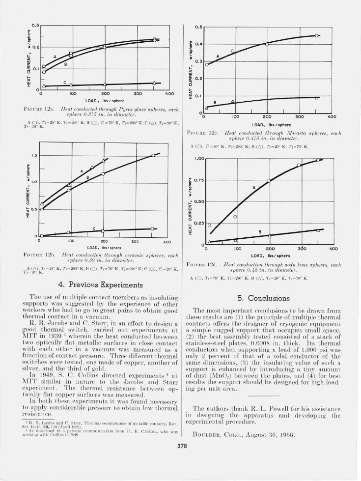
TIle results of tests on nonmetallic spheres are shown in figures 12a, 12b, 12c, and 12d, wherein the heat current per sphere is plotted as a function of the load per sphere . Each of the spheres in its socket made little more than point contact at no load . The conduction increased with increasing loads because the area of contact was in creased, but it tended to level off itt the higher loads as this area approach ed a constant value. The dependence of conduction on pressure also varied with t he type of material of the sphere, e. g. , if the material was soft, the sphere would flow slightly at the high er loads, resulting in a greater area of contact.
rrhe boundary te mperature'; arc 760 and 2000 K.
It is seen that of the four Lypes of spheres tested, ceramic was found to be the best conductor and Pyrex glass was found to be th e poorest conductor of heat. A lo ad has more effect on the flow of heat through the ceramic spheres because the contact resistance has proportionally more effect in the case of the better conductor. Although the conductivity of Micarta is less than that of Pyrex, the conduction through the Micarta spheres was found to be greater th an through tbe Pyrex spheres, possibly because of Lhe slight flow of Micarta at the higber loads.
There was a small errol' due to a comparatively small temperature drop across the stainless-steel plates thaL were used for support of the spheres. The conduction tbrough the spheres Wfl,S actuall:v greater than was measured.
In all cases, the conduction from 76° Lo 20 ° K is very much less than that from approximately 296° to 76 ° K. This is a consequence not only of the smaller temperature interval but also of the grea t decrease of the thermal conductivity of noncrystalline materials below 76° K.
Because the purpose of these measurements was to provide information about members that would be expected to have usefulness as insulating supports, some tests were conducted on the spheres to determine their crushing strength . The Pyrex-glass spheres failed at approximately 2,000 lb per sphere (two measurements). The ceramic spheres supported 10,000 lb each without failure.
The conduction data on the spheres should be considered in relation to their compressive strength . At first sight it appears that the higher strength of the ceramic spheres offsets their larger thermal conduction . This, of course, assumes that they will be used at high loads. If a support is designed for loads that would take the full advantage of the strength of the ceramic spheres, it would be necessary to provide hard bearings for the spheres to rest against , possibly of the same ceramic material. For average loads, the Pyrex spheres would be the most suitable.
377
... z w a:
0.3r--------,,--------.---------.---------,
~ 0.1 F """''------f-----------+---------+--------...., <.>
!;{ w :z:
c OL-__ -L ____ ~ __ ~ __ ~ ____ ~ __ ~ ____ ~ __ _J
o 100 200 300 400
LOA D. I bs / sphere
FIGUHE 12a. Heat conducted through P yrex glass spheres, each sphere 0.375 in. in diameter.
£ ~ "-
1.5 t---------t----------jr---------+----:~a=----l
• 1.0 r-------~r"7"~----+---------j.---------I ... z '" II: II: ::> <>
LOAD , lbs !sphe,.o
FIGUHE 12b. Heat conduction throu gh ceramic spheres, each sphere 0.39 in. in diam ete1·.
A (.6.) . '1',= 20° K , '1',=296° K ; B (0) , '1',=76° K , 7"2= 296' K ; C (0) , 7", = 20° K, 7"2= 76° K .
4 . Previous Experiments
The use of multiple contact members as insulating supports was su ggested by the experience of other worker s who had to go to great pains to obtain good thermal contact in a vacuum.
R. B . Jacobs and C. Starr, in an effort to design a good therma.l switch , carried out experiments at MIT in 1939 3 wherein the heat conducted be~ween two optically fiat metallic surfaces in close contact with each other in a vacuum was measured as a function of co ntact pressure. Thref' different thermal switches were tested, one made of copper, another of silver , and the third of gold .
In 1949 . S . C. Collins directed experiments 4 at 1!JIT similar in nature t o the Jacobs and Starr experiment. The thermal resistance between optica.lly fiat copper surfaces was measured.
I n both th ese experimen ts it was found necessary to apply considerable pressure to obtain low thermal resista n ce .
3 R. B. Jacobs and C. Sta rr. 'I'hcrmal conductancc of metallic contacts, Rc". Sci. l ns tr. 10, 140 (April 1939),
4 As d esprib('d in a p rh'ate commu nication from D . B . C lwlton . who was working with Collins in 1949.
0 .5
~ 0. 4 .c <>. .. "-• ..: z w
0. 3
~ 0.2 ::> <.>
!;{ ~ 0.1
y ~ C1'
B 1\
I~ 1 o o
I 100
.n. .----
I I 200 300 400
F IGURE 12c . Heat conducted through MicG1'la spheres, each sphere 0. 375 in. in diameter.
A (0) , 7",= 76' K , 7"2=296° K ; B (.6.), 7', = 20° K , '1'2= 76' K.
I .OO .------------,,---------,-----------r-----::;riii"---,
~ 0.75 ~------~--------_n~------_r--------~ .. .c <>. ., "~
..:0.50~------~~~------+---------t--------~ z '" a: Ir ::> <.> ... 0.25 ~--~--~f--------_4--------_+--------~ <t
'" :I:
O~--~--~~--~--~----~--~----~--~ o 100 200 400
LOAD, Ibs/ spher'e
F IGUR E 12d. H eat conduction through soda lime spheres, each sphere 0.42 in. in diameter.
5. Conclusions
The most important conclusions to be drawn from these results are (1 ) the principle of mul tiple thermal contacts offers the designer of cryogenic eq uipment a simple rugged support that occupies small space, (2) the best assembly tested consisted of a stack of stainless-steel plates, 0.0008 in. thick . Its thermal conduction when supporting a load of 1,000 psi was only 2 percent of that of a solid conductor of the same dimen sions, (3) the in sulating value of such a support is enhanced by in troducing a tiny amount of du st (Mn 02) between the plates, and (4) for best results the support should b e designed for high loading per unit area .
The au thors th ank R. L. Powell for his assistance in designing the apparatus and developing the experimental procedure.
BO ULDER, COLO. , August 30 , 1956 .
378