heat and cold resistant limit and basic switcheswl- t,...
TRANSCRIPT

1WL-_T, TZ
Heat and cold resistant limit and basic switches
WL-_T, TZThe limit switches WL-_T provide the ruggedness, reli-ability and the wide actuator range of the WL family and allow a direct usage in applications with temperatures from -40°C up to 120°C. For applications with even low-er or higher temperatures the TZ basic switch provides reliable operation from -65° up to 400°C for sub-assem-blies.• -40°C to 120°C in rugged WL limit switch housing
for direct usage
• -65°C to 400°C in TZ basic housing for sub-assemblies
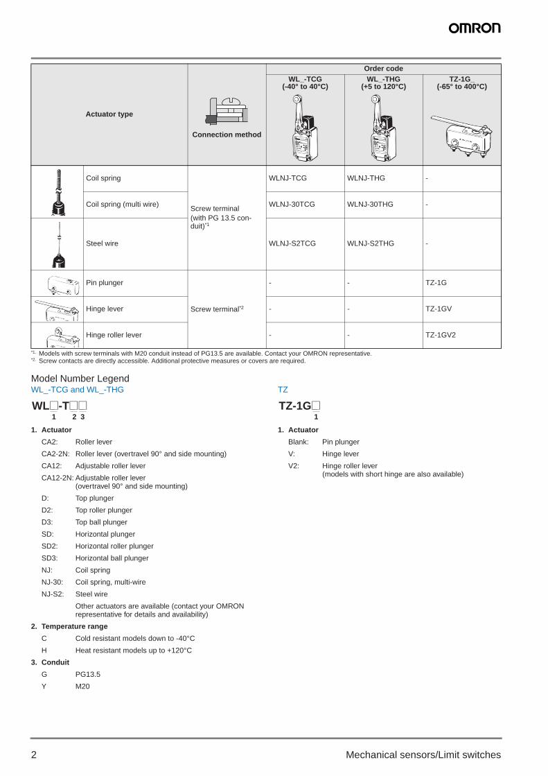
Ordering Information
Actuator type
Connection method
Order codeWL_-TCG
(-40° to 40°C)WL_-THG
(+5 to 120°C)TZ-1G_
(-65° to 400°C)
Roller lever(80° overtravel)
Screw terminal(with PG 13.5 con-duit)*1
WLCA2-TCG WLCA2-THG -
Roller lever (side mounting and 90° overtravel) WLCA2-2NTCG WLCA2-2NTHG -
Adjustable roller lever WLCA12-TCG WLCA12-THG -
Adjustable roller lever (side mounting and 90° overtravel) WLCA12-2NTCG WLCA12-2NTHG -
Top plunger WLD-TCG WLD-THG -
Top roller plunger WLD2-TCG WLD2-THG -
Top ball plunger WLD3-TCG WLD3-THG -
Horizontal plunger WLSD-TCG WLSD-THG -
Horizontal roller plunger WLSD2-TCG WLSD2-THG -
Horizontal ball plunger WLSD3-TCG WLSD3-THG -
C10E-EN-01+WL-_T_TZ+Datasheet.fm Seite 1 Montag, 8. August 2011 2:32 14
2 Mechanical sensors/Limit switches
Model Number LegendWL_-TCG and WL_-THG
1. Actuator
CA2: Roller lever
CA2-2N: Roller lever (overtravel 90° and side mounting)
CA12: Adjustable roller lever
CA12-2N: Adjustable roller lever (overtravel 90° and side mounting)
D: Top plunger
D2: Top roller plunger
D3: Top ball plunger
SD: Horizontal plunger
SD2: Horizontal roller plunger
SD3: Horizontal ball plunger
NJ: Coil spring
NJ-30: Coil spring, multi-wire
NJ-S2: Steel wire
Other actuators are available (contact your OMRON representative for details and availability)
2. Temperature range
C Cold resistant models down to -40°C
H Heat resistant models up to +120°C
3. Conduit
G PG13.5
Y M20
TZ
1. Actuator
Blank: Pin plunger
V: Hinge lever
V2: Hinge roller lever (models with short hinge are also available)
Coil spring
Screw terminal(with PG 13.5 con-duit)*1
WLNJ-TCG WLNJ-THG -
Coil spring (multi wire) WLNJ-30TCG WLNJ-30THG -
Steel wire WLNJ-S2TCG WLNJ-S2THG -
Pin plunger
Screw terminal*2
- - TZ-1G
Hinge lever - - TZ-1GV
Hinge roller lever - - TZ-1GV2
*1. Models with screw terminals with M20 conduit instead of PG13.5 are available. Contact your OMRON representative.*2. Screw contacts are directly accessible. Additional protective measures or covers are required.
Actuator type
Connection method
Order codeWL_-TCG
(-40° to 40°C)WL_-THG
(+5 to 120°C)TZ-1G_
(-65° to 400°C)
1 2 3WL@-T@@
1TZ-1G@
C10E-EN-01+WL-_T_TZ+Datasheet.fm Seite 2 Montag, 8. August 2011 2:32 14
3WL-_T, TZ
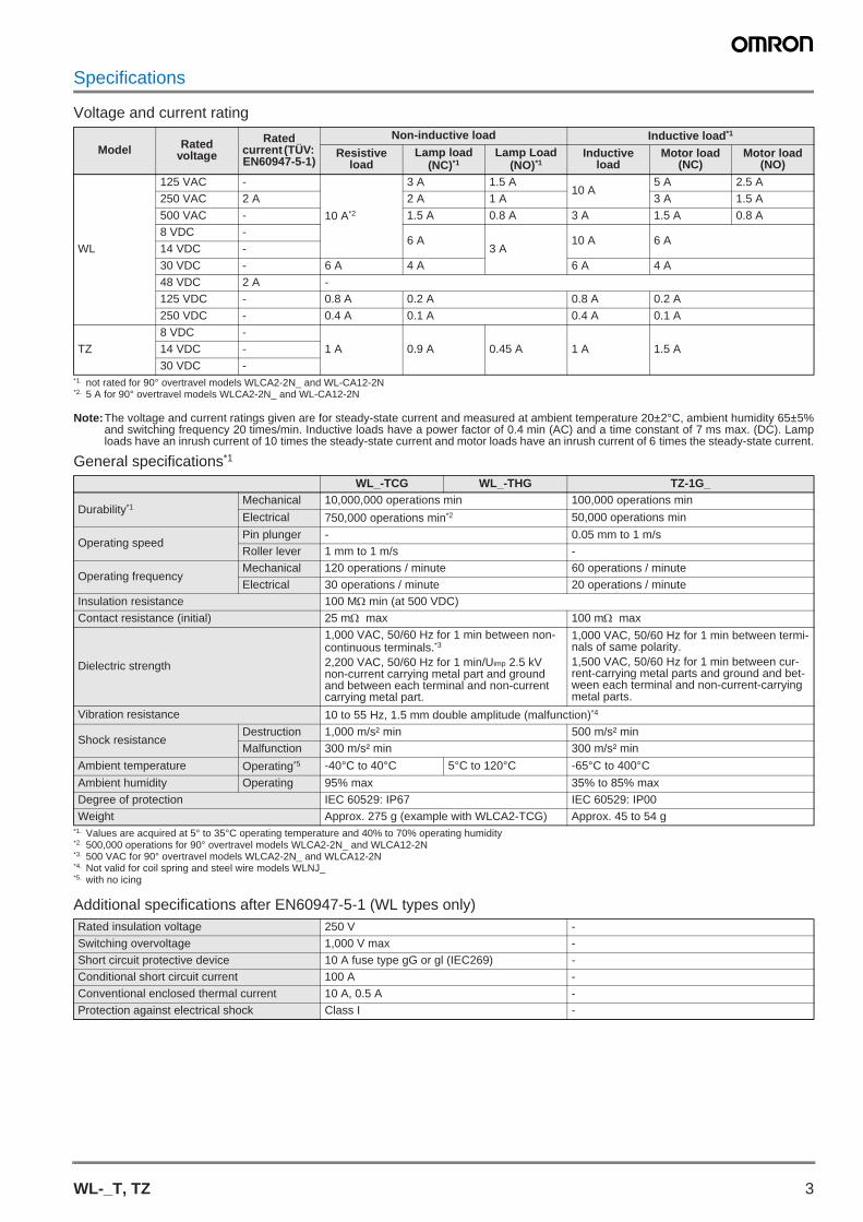
Specifications
Voltage and current rating
Note:The voltage and current ratings given are for steady-state current and measured at ambient temperature 20±2°C, ambient humidity 65±5%and switching frequency 20 times/min. Inductive loads have a power factor of 0.4 min (AC) and a time constant of 7 ms max. (DC). Lamploads have an inrush current of 10 times the steady-state current and motor loads have an inrush current of 6 times the steady-state current.
General specifications*1
Additional specifications after EN60947-5-1 (WL types only)
Model Rated voltage
Rated current (TÜV: EN60947-5-1)
Non-inductive load Inductive load*1
*1. not rated for 90° overtravel models WLCA2-2N_ and WL-CA12-2N
Resistive load
Lamp load (NC)*1
Lamp Load (NO)*1
Inductive load
Motor load (NC)
Motor load (NO)
WL
125 VAC -
10 A*2
*2. 5 A for 90° overtravel models WLCA2-2N_ and WL-CA12-2N
3 A 1.5 A10 A
5 A 2.5 A250 VAC 2 A 2 A 1 A 3 A 1.5 A500 VAC - 1.5 A 0.8 A 3 A 1.5 A 0.8 A8 VDC -
6 A3 A
10 A 6 A14 VDC -30 VDC - 6 A 4 A 6 A 4 A48 VDC 2 A -125 VDC - 0.8 A 0.2 A 0.8 A 0.2 A250 VDC - 0.4 A 0.1 A 0.4 A 0.1 A
TZ8 VDC -
1 A 0.9 A 0.45 A 1 A 1.5 A14 VDC -30 VDC -
WL_-TCG WL_-THG TZ-1G_
Durability*1
*1. Values are acquired at 5° to 35°C operating temperature and 40% to 70% operating humidity
Mechanical 10,000,000 operations min 100,000 operations min
Electrical 750,000 operations min*2
*2. 500,000 operations for 90° overtravel models WLCA2-2N_ and WLCA12-2N
50,000 operations min
Operating speedPin plunger - 0.05 mm to 1 m/sRoller lever 1 mm to 1 m/s -
Operating frequencyMechanical 120 operations / minute 60 operations / minuteElectrical 30 operations / minute 20 operations / minute
Insulation resistance 100 M min (at 500 VDC)Contact resistance (initial) 25 m max 100 m max
Dielectric strength
1,000 VAC, 50/60 Hz for 1 min between non-continuous terminals.*3
2,200 VAC, 50/60 Hz for 1 min/Uimp 2.5 kV non-current carrying metal part and ground and between each terminal and non-current carrying metal part.
*3. 500 VAC for 90° overtravel models WLCA2-2N_ and WLCA12-2N
1,000 VAC, 50/60 Hz for 1 min between termi-nals of same polarity.1,500 VAC, 50/60 Hz for 1 min between cur-rent-carrying metal parts and ground and bet-ween each terminal and non-current-carrying metal parts.
Vibration resistance 10 to 55 Hz, 1.5 mm double amplitude (malfunction)*4
*4. Not valid for coil spring and steel wire models WLNJ_
Shock resistanceDestruction 1,000 m/s² min 500 m/s² minMalfunction 300 m/s² min 300 m/s² min
Ambient temperature Operating*5
*5. with no icing
-40°C to 40°C 5°C to 120°C -65°C to 400°C
Ambient humidity Operating 95% max 35% to 85% maxDegree of protection IEC 60529: IP67 IEC 60529: IP00Weight Approx. 275 g (example with WLCA2-TCG) Approx. 45 to 54 g
Rated insulation voltage 250 V -Switching overvoltage 1,000 V max -Short circuit protective device 10 A fuse type gG or gl (IEC269) -Conditional short circuit current 100 A -Conventional enclosed thermal current 10 A, 0.5 A -Protection against electrical shock Class I -
C10E-EN-01+WL-_T_TZ+Datasheet.fm Seite 3 Montag, 8. August 2011 2:32 14

4 Mechanical sensors/Limit switches
Operating characteristicsValues for OF and RF are in N and values for PT, OT, MD and OP are in mm unless otherwise specified
Output circuit diagramsWL TZ
NomenclatureWL TZ
Actuator models
WL_- TZ-_C
A2
CA
12
CA
2-2N
CA
12-2
N
D D2
D3
SD
SD
2
SD
3
NJ*1
*1. Values are taken from top end of wire or spring
NJ-
30
NJ-
S2
1G 1GV
1GV
2
Operating for-ce (OF max) 13.34 9.61 26.67 40.03 1.47 0.28 4.9 0.98 1.27
Release force (RF min) 2.23 1.18 8.92 8.89 - 1.12 0.14 0.2
Pre-travel (PT max) 15±5° 20° 1.7 2.8 20±10 40
±20 0.4 3.5 2.6
Over travel (OT min) 30° 70° 6.4 5.6 4 6.4 5.6 4 - 0.13 4.6 3.5
Movement differential (MD max)
12° 10° 1 - 0.15 1.3 1
Operating po-sition (OP) - 34
±0.844±0.8
44.5±0.8
40.6±0.8
54.2±0.8
54.1±0.8 - 15.6
±0.618±1.2
28.6±1.2
4 (NO)
1 (NC)
3 (NO)
2 (NC)
(NO) 4
(NC) 1
3 (NO)
2 (NC)
Za
EN60947-5-1
NCNOCOM
Set Position Marker Plate Roller
Shaft Section Seal
Conduit Opening
Head
Bearing
Built-in Switch
Lever
Roller Lever SetscrewOperational Plunger
Cover Seal
Terminal Screws
Cover
Insulator
Cover Setscrew
Head-mounting Screws
Fixed contact
Movable springBracket
Ceramic terminal blockMovable contact
Fixed contact
Ceramic pushbutton
C10E-EN-01+WL-_T_TZ+Datasheet.fm Seite 4 Montag, 8. August 2011 2:32 14
5WL-_T, TZ
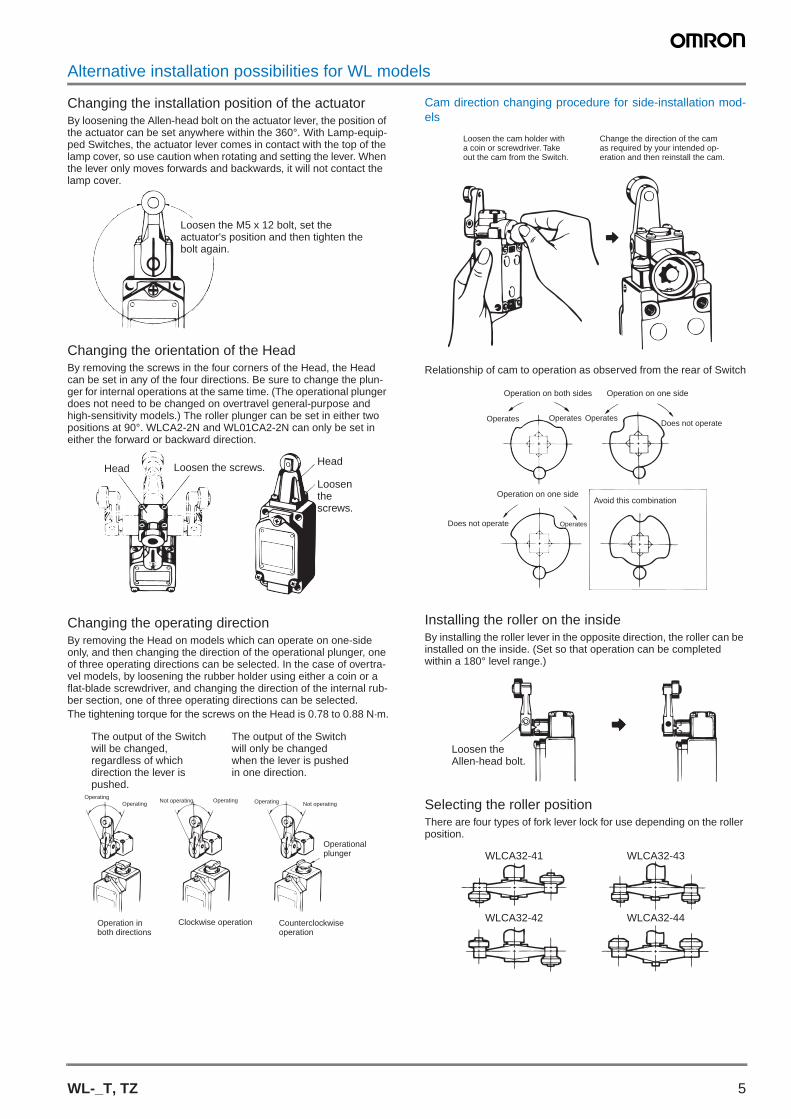
Alternative installation possibilities for WL models
Changing the installation position of the actuatorBy loosening the Allen-head bolt on the actuator lever, the position of the actuator can be set anywhere within the 360°. With Lamp-equip-ped Switches, the actuator lever comes in contact with the top of the lamp cover, so use caution when rotating and setting the lever. When the lever only moves forwards and backwards, it will not contact the lamp cover.
Changing the orientation of the HeadBy removing the screws in the four corners of the Head, the Head can be set in any of the four directions. Be sure to change the plun-ger for internal operations at the same time. (The operational plunger does not need to be changed on overtravel general-purpose and high-sensitivity models.) The roller plunger can be set in either two positions at 90°. WLCA2-2N and WL01CA2-2N can only be set in either the forward or backward direction.
Changing the operating directionBy removing the Head on models which can operate on one-side only, and then changing the direction of the operational plunger, one of three operating directions can be selected. In the case of overtra-vel models, by loosening the rubber holder using either a coin or a flat-blade screwdriver, and changing the direction of the internal rub-ber section, one of three operating directions can be selected.The tightening torque for the screws on the Head is 0.78 to 0.88 N·m.
Cam direction changing procedure for side-installation mod-els
Relationship of cam to operation as observed from the rear of Switch
Installing the roller on the insideBy installing the roller lever in the opposite direction, the roller can be installed on the inside. (Set so that operation can be completed within a 180° level range.)
Selecting the roller positionThere are four types of fork lever lock for use depending on the roller position.
Loosen the M5 x 12 bolt, set the actuator's position and then tighten the bolt again.
Loosen the screws.Head
Head
Loosen the screws.
OperatingNot operating
Clockwise operation
Not operatingOperatingOperating Operating
The output of the Switch will be changed, regardless of which direction the lever is pushed.
The output of the Switch will only be changed when the lever is pushed in one direction.
Operational plunger
Operation in both directions
Counterclockwise operation
Loosen the cam holder with a coin or screwdriver. Take out the cam from the Switch.
Change the direction of the cam as required by your intended op-eration and then reinstall the cam.
Operation on both sides Operation on one side
Operation on one sideAvoid this combination
Operates Operates Operates
Operates
Does not operate
Does not operate
Loosen the Allen-head bolt.
WLCA32-41
WLCA32-42
WLCA32-43
WLCA32-44
C10E-EN-01+WL-_T_TZ+Datasheet.fm Seite 5 Montag, 8. August 2011 2:32 14
6 Mechanical sensors/Limit switches
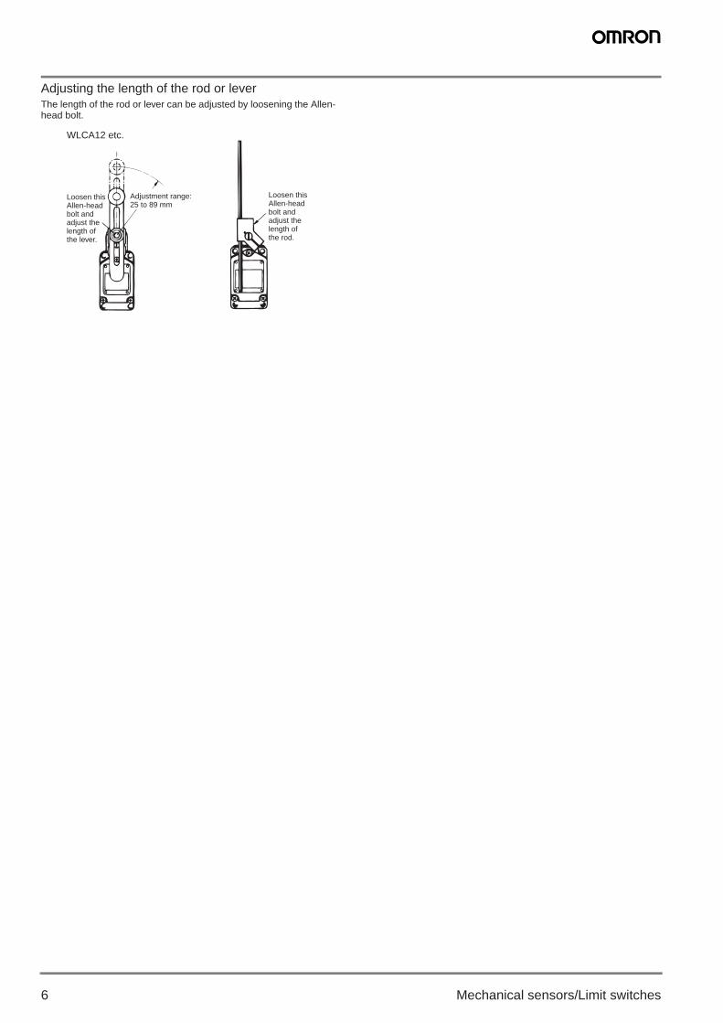
Adjusting the length of the rod or leverThe length of the rod or lever can be adjusted by loosening the Allen-head bolt.
WLCA12 etc.
Loosen this Allen-head bolt and adjust the length of the lever.
Adjustment range: 25 to 89 mm
Loosen this Allen-head bolt and adjust the length of the rod.
C10E-EN-01+WL-_T_TZ+Datasheet.fm Seite 6 Montag, 8. August 2011 2:32 14

7WL-_T, TZ
Dimensions
Note:All units are in millimeters unless otherwise indicated.
Roller LeverWLCA2
Note: Stainless sintered roller
WLCA2-2N
Note: Stainless sintered roller
Adjustable Roller LeverWLCA12
Note: Stainless sintered roller
WLCA12-2N
Note: Stainless sintered roller
Top PlungerWLD
Note: Stainless steel plunger
Top-roller PlungerWLD2
Note: Stainless sintered roller
17.5 dia. x 7 (see note)
Four, M3.5
60 max.
42 max.
M5 (length: 12) Allen-head bolt
oFour, 5.2+0.2 dia. holes
JIS B0202 G1/2 Effective thread: 4 threads min.
Four, M6Depth: 15 min.
38R
Three, M4 (lengh:13) Three, M4
(length: 13)
17.5 dia. (length: 7) (see note)
Four, M3
60 max.
42 max.
M5 (length: 12) Allen-head bolt
0Four, 5.2+0.2 dia. holes
0 Two, 5.2+0.2 dia.
JIS B0202 G1/2 Effective thread: 4 threads min.
Four, M6Depth: 15 min.
38R Two, M5 (length: 18)
17.5 dia. x 7 (see note)
Four, M3.5
67 max.
42 max.
Adjustable range: 25 to 89 M5 (length: 16)
Allen-head bolt
oFour, 5.2+0.2 dia. holes
JIS B0202 G1/2 Effective thread: 4 threads min.
Four, M6Depth: 15 min.
Three, M4 (length: 13)
42 max.
Four, M3
17.5 dia. (length: 7) (see note)
67 max.
Two, 5.2+0.2 dia.0
Adjustable range: 25 to 89 Two, M5
(length: 18)
M5 (length: 16) Allen-head bolt
JIS B0202 G1/2 Effective thread: 4 threads min.
Four, M6Depth: 15 min.
Three, M4 (length: 13)
Four, M3.5
1R (see note)
42 max.
9 dia.
0
Four, 5.2+0.2 dia. holes
JIS B0202 G1/2 Effective thread: 4 threads min.
Four, M6Depth: 15 min.
OP
Three, M4 (length: 13)
42 max.
Four, M3.5
17 dia. (length: 5) (see note)
0
Four, 5.2+0.2 dia. holes
JIS B0202 G1/2 Effective thread: 4 threads min.
OP
Four, M6Depth: 15 min.
Three, M4 (length: 13)
C10E-EN-01+WL-_T_TZ+Datasheet.fm Seite 7 Montag, 8. August 2011 2:32 14

8 Mechanical sensors/Limit switches
Top-ball PlungerWLD3
Note: Stainless steel ball
Horizontal PlungerWLSD
Note: 1 .Stainless steel plunger2 .Cosmetic nuts.
Horizontal-roller PlungerWLSD2
Note: 1 .Stainless sintered roller2 .Cosmetic nuts.3 .The WLSD21 model, which has the roller rotated by 90° is also avail-
able.
Horizontal-ball PlungerWLSD3
Note: 1 .Stainless steel ball2 .Cosmetic nuts.
Coil SpringWLNJ
Note: 1 .The coil spring may be operated from any direction except the axialdirection ().
2 .Stainless steel coil spring3 .Optimum operating range of the coil spring is within 1/3 of the entire
length from the top end.
Coli Spring (Multi-wire)WLNJ-30
Note: 1 .The coil spring may be operated from any direction except the axialdirection ().
2 .Piano wire coil3 .Optimum operating range of the coil spring is within 1/3 of the entire
length from the top end.
OP Four, M3.5
15.5 dia.1/2 dia. (see note)
42 max.
0
Four, 5.2+0.2 dia. holes
JIS B0202 G1/2 Effective thread: 4 threads min.
Four, M6Depth: 15 min.
Three, M4 (length: 13)
Four, M6Depth: 15 min.
Four, M3.5
1R (see note 1)
42 max.
25 dia. (see note 2.)
0
Four, 5.2+0.2 dia. holes
JIS B0202 G1/2 Effective thread: 4 threads min.
Three, M4 (length: 13)
Four, M3.5
42 max.
17 dia. (length: 5) (see note 1)
0
Four, 5.2+0.2 dia. holes
Three, M4 (length: 13)
25 dia. (see note 2.)
JIS B0202 G1/2 Effective thread: 4 threads min.
Four, M6Depth: 15 min.
Four, M3.5
42 max.
1/2 dia. (see note)
0
Four, 5.2+0.2 dia. holesThree, M4 (length: 13)
25 dia. (see note 2)
JIS B0202 G1/2 Effective thread: 4 threads min.
Four, M6Depth: 15 min.
(See note 3.)
(See note 2.)
42 max.
(See note 1.)
6.5 dia.
0
Four, 5.2+0.2 dia. holes
JIS B0202 G1/2 Effective thread: 4 threads min.
Four, M6Depth: 15 min.
Three, M4 (length: 13)
(See note 2.)(See note 1.)
(See note 3.)
4.8 dia.
0
Four, 5.2+0.2 dia. holesThree, M4 (length: 13)
JIS B0202 G1/2 Effective thread: 4 threads min.
Four, M6Depth: 15 min.
42 max.
C10E-EN-01+WL-_T_TZ+Datasheet.fm Seite 8 Montag, 8. August 2011 2:32 14
9WL-_T, TZ
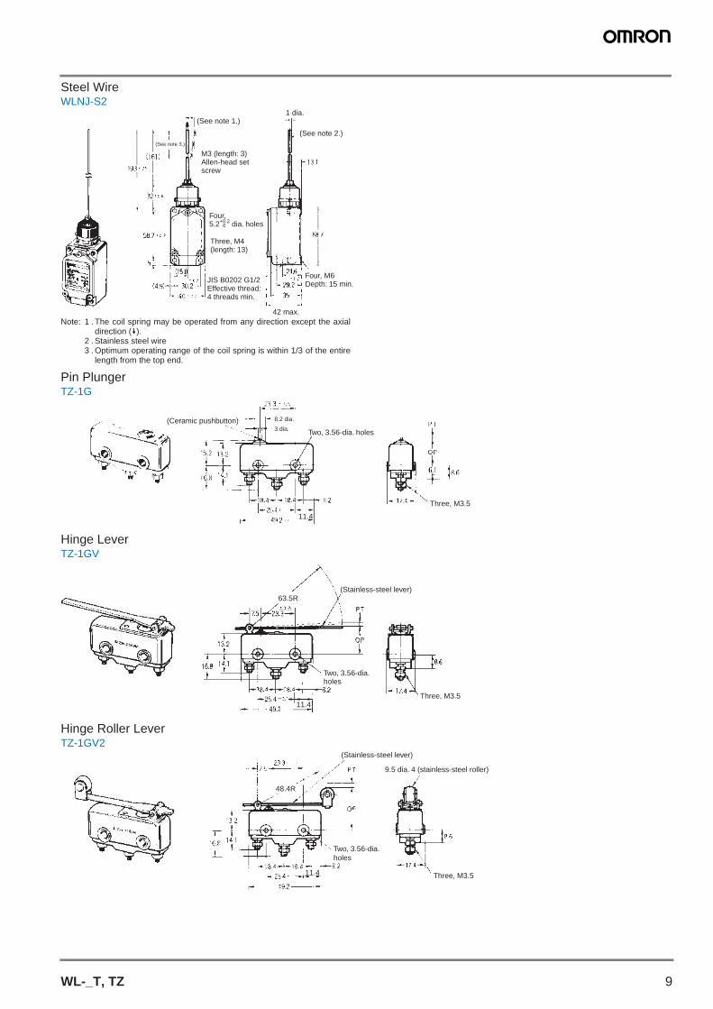
Steel WireWLNJ-S2
Note: 1 .The coil spring may be operated from any direction except the axialdirection ().
2 .Stainless steel wire3 .Optimum operating range of the coil spring is within 1/3 of the entire
length from the top end.
Pin PlungerTZ-1G
Hinge LeverTZ-1GV
Hinge Roller LeverTZ-1GV2
(See note 1.)
(See note 2.)(See note 3.)
42 max.
1 dia.
M3 (length: 3) Allen-head set screw
0
Four, 5.2+0.2 dia. holes
JIS B0202 G1/2 Effective thread: 4 threads min.
Four, M6Depth: 15 min.
Three, M4 (length: 13)
11.4
(Ceramic pushbutton)3 dia. Two, 3.56-dia. holes
Three, M3.5
8.2 dia.
11.4
63.5R
Three, M3.5
(Stainless-steel lever)
Two, 3.56-dia. holes
11.4
48.4R
(Stainless-steel lever)
9.5 dia. 4 (stainless-steel roller)
Three, M3.5
Two, 3.56-dia. holes
C10E-EN-01+WL-_T_TZ+Datasheet.fm Seite 9 Montag, 8. August 2011 2:32 14

10 Mechanical sensors/Limit switches
Precautions
WLCorrect UseWhen a rod or wired-type actuator is used, do not touch the top end of the actuator. Doing so may result in injury. Applicable models: WLHAL5 and WL01HAL5 Rod Spring Levers and WLNJ-S2 and WL01NJ-S2 Steel-wire Actuators.A short-circuit may cause damage to the Switch, so insert a circuit breaker fuse, of 1.5 to 2 times the rated current, in parallel with the Switch. In order to meet EN approval ratings, use a 10 A fuse that corresponds to IEC269, either a gI or gG for general-purpose types and spatter-prevention models only.When wiring terminal screws, use M4 round crimp terminals and tighten screws to the recommended torque. Wiring with broken wires, or the incorrect crimp terminals, or not tightening screws to the recommended torque can lead to short-circuits, leakage current, and fire.When performing internal wiring there is a chance of short-circuit, leakage current, or fire, so be sure to protect the inside of the Switch from splashes of oil or water, corrosive gases, and cutting powder.Using an inappropriate connector or assembling Switches incorrectly (assembly, tightening torque) can result in malfunction, leakage cur-rent, or fire, so be sure to read the instruction manual thoroughly beforehand.Even when the connector is assembled and set correctly, the end of the cable and the inside of the Switch may come in contact. This can lead to malfunction, leakage current, or fire, so be sure to protect the end of the cable from splashes of oil or water and corrosive gases.
Environmental Precautions
When the Switch is used in locations subject to splashes of water or oil, the material of the seal, which ensures the sealing properties of the Switch, may undergo changes in shape and quality. This is due to deterioration (including expansion and contraction), and may result in reduced performance, ineffective return, and ineffective sealing (lea-ding to ineffective contact, insulation, leakage current, and fire). Con-firm the possible effects of the operating environment on the Switch before use.
Built-in Switch
Do not remove or replace the built-in switch. If the position of the built-in switch moves, it can cause reduced performance, and if the insulation sheet moves (separator), the insulation may become inef-fective.
Tightening Torque
If screws are too loose they can lead to an early malfunction of the Switch, so ensure that all screws are tightened using the correct tor-que.
In particular, when changing the direction of the Head, make sure that all screws are tightened again to the correct torque. Do not allow foreign objects to fall into the Switch.
Installing the Switch
To install the Switch, make a mounting panel, as shown in the follo-wing diagram, and tighten screws using the correct torque.
No. Type TorqueA Head mounting screw 0.78 to 0.88 N·mB Cover mounting screw 1.18 to 1.37 N·mC Allen-head bolt (for securing the lever) 4.90 to 5.88 N·mD Terminal screw 0.59 to 0.78 N·mE Connector 1.77 to 2.16 N·mF Main Unit screws 4.90 to 5.88 N·m
Standard/Overtravel model Overtravel model (side installation)
A
F
C
D
B
E
Mounting holesFour, 5.2+0.2 dia. holes0
Mounting holesTwo, 5.2+0.2 dia. holes0
C10E-EN-01+WL-_T_TZ+Datasheet.fm Seite 10 Montag, 8. August 2011 2:32 14

11WL-_T, TZ
TZCorrect Use
Handling
The Switch has a ceramic casing. Do not drop the Switch from a height of 30 cm or more. Doing so will break the casing.
Mounting
Be sure to turn OFF the power supply to the Switch before mounting, dismounting, wiring, or working on the Switch for maintenance. Not doing so may result in an electric shock or the Switch may burn.Mount the switch with M3.5 stainless-steel screws with plane washer and spring washers securely.Use M3.5 stainless-steel mounting screws with plane washers or spring washers to securely mount the Switch. Tighten the screws to a torque of 0.69 to 0.98 N·m {7 to 10 kgf·cm}.Mounting Holes
Connect nickel-plated solderless terminals to the TZ. Each terminal must be secured on the TZ with M3.5 nut.Make sure that the ceramic case is free of metal powder or other impurities.
Operation
Do not modify the Actuator and change the operating position.Make sure that the switching speed is not extremely slow or do not use the Switch so that the pushbutton will be set to a position bet-ween the FP and OP.Make sure that the pin-type pushbutton and the switching stroke are on the same vertical line.Make sure that the switching frequency or speed is within the speci-fied range.• If the switching speed is extremely slow, the contact may not be
switched smoothly, which may result in a contact failure or contact welding.
• If the switching speed is extremely fast, switching shock may damage the Switch soon. If the switching frequency is too high, the contact may not catch up with the speed.
The rated permissible switching speed and frequency indicate the switching reliability of the Switch.The life of a Switch is determined at the specified switching speed. The life varies with the switching speed and frequency even when they are within the permissible ranges. In order to determine the life of a Switch model to be applied to a particular use, it is best to con-duct an appropriate durability test on some samples of the model under actual conditions.Make sure that the actuator travel does not exceed the permissible OT position. The operating stroke must be set to 70% to 100% of the rated OT.
25.4 ± 0.1
Two, 3.56-dia. mounting holes or M3.5 screw holes
C10E-EN-01+WL-_T_TZ+Datasheet.fm Seite 11 Montag, 8. August 2011 2:32 14
12 Mechanical sensors/Limit switches
WARRANTY
OMRON’s exclusive warranty is that the products are free from de-fects in materials and workmanship for a period of one year (or otherperiod if specified) from date of sale by OMRON.
OMRON MAKES NO WARRANTY OR REPRESENTATION, EX-PRESS OR IMPLIED, REGARDING NON-INFRINGEMENT, MER-CHANTABILITY, OR FITNESS FOR PARTICULAR PURPOSE OF THE PRODUCTS. ANY BUYER OR USER ACKNOWLEDGES THAT THE BUYER OR USER ALONE HAS DETERMINED THAT THE PRODUCTS WILL SUITABLY MEET THE REQUIREMENTS OF THEIR INTENDED USE. OMRON DISCLAIMS ALL OTHER WAR-RANTIES, EXPRESS OR IMPLIED.
LIMITATIONS OF LIABILITY
OMRON SHALL NOT BE RESPONSIBLE FOR SPECIAL, INDI-RECT, OR CONSEQUENTIAL DAMAGES, LOSS OF PROFITS OR COMMERCIAL LOSS IN ANY WAY CONNECTED WITH THE PRODUCTS, WHETHER SUCH CLAIM IS BASED ON CONTRACT, WARRANTY, NEGLIGENCE, OR STRICT LIABILITY.
In no event shall responsibility of OMRON for any act exceed the in-dividual price of the product on which liability is asserted.
IN NO EVENT SHALL OMRON BE RESPONSIBLE FOR WARRAN-TY, REPAIR, OR OTHER CLAIMS REGARDING THE PRODUCTS UNLESS OMRON’S ANALYSIS CONFIRMS THAT THE PROD-UCTS WERE PROPERLY HANDLED, STORED, INSTALLED, AND MAINTAINED AND NOT SUBJECT TO CONTAMINATION, ABUSE, MISUSE, OR INAPPROPRIATE MODIFICATION OR REPAIR.
SUITABILITY FOR USE
THE PRODUCTS CONTAINED IN THIS DOCUMENT ARE NOT SAFETY RATED. THEY ARE NOT DESIGNED OR RATED FOR EN-SURING SAFETY OF PERSONS, AND SHOULD NOT BE RELIED UPON AS A SAFETY COMPONENT OR PROTECTIVE DEVICE FOR SUCH PURPOSES. Please refer to separate catalogs for OM-RON's safety rated products.
OMRON shall not be responsible for conformity with any standards,codes, or regulations that apply to the combination of products in the
customer’s application or use of the product.
At the customer’s request, OMRON will provide applicable third partycertification documents identifying ratings and limitations of use thatapply to the products. This information by itself is not sufficient for acomplete determination of the suitability of the products in combina-tion with the end product, machine, system, or other application oruse.
The following are some examples of applications for which particularattention must be given. This is not intended to be an exhaustive listof all possible uses of the products, nor is it intended to imply that theuses listed may be suitable for the products:
• Outdoor use, uses involving potential chemical contamination orelectrical interference, or conditions or uses not described in thisdocument.
• Nuclear energy control systems, combustion systems, railroad sys-tems, aviation systems, medical equipment, amusement machines,vehicles, safety equipment, and installations subject to separate in-dustry or government regulations.
• Systems, machines, and equipment that could present a risk to lifeor property.
Please know and observe all prohibitions of use applicable to theproducts.
NEVER USE THE PRODUCTS FOR AN APPLICATION INVOLVINGSERIOUS RISK TO LIFE OR PROPERTY WITHOUT ENSURINGTHAT THE SYSTEM AS A WHOLE HAS BEEN DESIGNED TO ADDRESS THE RISKS, AND THAT THE OMRON PRODUCT ISPROPERLY RATED AND INSTALLED FOR THE INTENDED USEWITHIN THE OVERALL EQUIPMENT OR SYSTEM.
PERFORMANCE DATA
Performance data given in this document is provided as a guide forthe user in determining suitability and does not constitute a warranty.It may represent the result of OMRON’s test conditions, and the usersmust correlate it to actual application requirements. Actual perfor-mance is subject to the OMRON Warranty and Limitations of Liability.
CHANGE IN SPECIFICATIONS
Product specifications and accessories may be changed at any timebased on improvements and other reasons.
It is our practice to change model numbers when published ratings orfeatures are changed, or when significant construction changes aremade. However, some specifications of the product may be changedwithout any notice. When in doubt, special model numbers may be as-signed to fix or establish key specifications for your application onyour request. Please consult with your OMRON representative at anytime to confirm actual specifications of purchased products.
DIMENSIONS AND WEIGHTS
Dimensions and weights are nominal and are not to be used for man-ufacturing purposes, even when tolerances are shown.
ERRORS AND OMISSIONS
The information in this document has been carefully checked and isbelieved to be accurate; however, no responsibility is assumed forclerical, typographical, or proofreading errors, or omissions.
PROGRAMMABLE PRODUCTS
OMRON shall not be responsible for the user’s programming of a pro-grammable product, or any consequence thereof.
In the interest of product improvement, specifications are subject to change without notice.Cat. No. C10E-EN-01
OMRON EUROPE B.V.Wegalaan 67-69, NL-2132 JD, Hoofddorp, The NetherlandsPhone: +31 23 568 13 00Fax: +31 23 568 13 88www.industrial.omron.eu
C10E-EN-01+WL-_T_TZ+Datasheet.fm Seite 12 Montag, 8. August 2011 2:32 14