head gasket replacement and head stud install · head gasket replacement and head stud install by...
TRANSCRIPT
Head Gasket Replacement and Head Stud Install by Flopster843
21 Mar 2016
The 6.7L Cummins is known to have a weaker head gasket than previous 5.9L engines. This is primarily
due to the engine having a larger piston bore with the same crank spacing, resulting in less gasket
material between the cylinders and water jackets. The most common symptom of a head gasket failure
is excessive pressure in the cooling system. The coolant level of your overflow bottle will increase and
eventually it will spray coolant in your engine bay. If you see an increase in coolant level and spots of
dried coolant in your engine bay without your truck overheating, you've probably compromised the
head gasket.
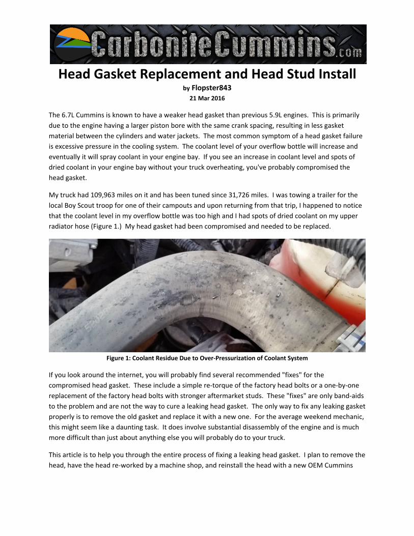
My truck had 109,963 miles on it and has been tuned since 31,726 miles. I was towing a trailer for the
local Boy Scout troop for one of their campouts and upon returning from that trip, I happened to notice
that the coolant level in my overflow bottle was too high and I had spots of dried coolant on my upper
radiator hose (Figure 1.) My head gasket had been compromised and needed to be replaced.
Figure 1: Coolant Residue Due to Over‐Pressurization of Coolant System
If you look around the internet, you will probably find several recommended "fixes" for the
compromised head gasket. These include a simple re‐torque of the factory head bolts or a one‐by‐one
replacement of the factory head bolts with stronger aftermarket studs. These "fixes" are only band‐aids
to the problem and are not the way to cure a leaking head gasket. The only way to fix any leaking gasket
properly is to remove the old gasket and replace it with a new one. For the average weekend mechanic,
this might seem like a daunting task. It does involve substantial disassembly of the engine and is much
more difficult than just about anything else you will probably do to your truck.
This article is to help you through the entire process of fixing a leaking head gasket. I plan to remove the
head, have the head re‐worked by a machine shop, and reinstall the head with a new OEM Cummins

head gasket and a set of ARP 2000 head studs. So why do all the extra stuff instead of simply putting in
a new gasket and calling it quits?
The cylinder head from Cummins has a tolerance of 0.012" end‐to‐end and 0.003" side‐to‐side. The
cylinder block has a tolerance of 0.003" end‐to‐end and 0.002" side‐to‐side. Put this together and you
have a total allowable clearance of 0.015" end‐to‐end and 0.005" side‐to‐side. For an engine, this is a
very large gap for a head gasket. In addition, nearly every head will warp a little after it has been heat‐
cycled several times from normal driving, which will increase the gap even further. Having the head
surfaced will take it to a 0.000" by 0.000" measurement after it has already been heat‐cycled, so it
should not warp after it's put back on. This takes our allowable tolerance down to a much lower level,
which will promote a significantly stronger seal between the block and cylinder head.
The stock cylinder head bolts are a torque‐to‐yield design. This means that they are tightened to a
specific measurement (66 ft lbs) and are rotated an additional 90 degrees. These head bolts are
designed to stretch as they are tightened to hold the head on. This design is used primarily for engine
assembly purposes because it's much easier to install bolts with a more lenient tolerance than better
fasteners that have a more stringent torque requirement. The ARP 2000 head studs I am going to use
are designed to accept a torque value of 125 ft lbs and have a minimum of 220,000 lbs clamping force.
They are much stronger than factory head bolts and will do a better job of securing the head. There are
other options for head studs that are stronger than the ARP 2000s, but they cost a lot more and I feel
that they aren't truly needed unless you are going for all out performance or competition use.
To prepare for this endeavor, I reviewed Andy Redmond's article in issue 72 of Turbo Diesel Register on
pages 100‐125. His article was on repairing an earlier 24‐valve engine and I will be working on the
newer 6.7L engine. While the procedures are similar, there are some differences between the two,
especially with the fuel system and injectors. I also purchased an OEM Cummins top end gasket kit
(Item #: 4955354) from Geno's Garage. Sadly, Geno's does not sell the ARP 2000 head studs that I
needed, so I ordered them and some ARP ultra‐torque lube from Rollin Smoke Diesel. I also thoroughly
reviewed the factory service manual for any technical specs that apply. Most of the following steps are
not in any mandatory sequence and can be adjusted as you see fit, any important information will be
highlighted with a NOTE.
REMOVAL
To start off, park the truck in a location where you will not mind it sitting for a week. Disconnect the
negative battery terminals from both of the batteries and drain the coolant. There is a valve on the
bottom driver's side of the radiator (Figure 2) to allow the coolant to drain. If you leave the radiator cap
on, it will drain your over flow tank as well, if you take the cap off it will only drain the radiator and the
engine. I removed about 4 gallons of coolant from the system into a clean bucket. Keep the coolant
clean so you can re‐use it in the engine when you are done.

Figure 2: Coolant Drain Valve on Radiator
Disconnect the two electrical connectors on the air intake, disconnect the Crank Case Vent (CCV) drain
tube from the valve cover, loosen the clamp that connects the intake to the front of the turbo, and pull
the entire assembly off as one piece (Figure 3.) To remove the lower air box, remove one nut holding
the front part of the air box to the radiator support and pull it straight up to dislodge it from the two
grommets that hold the back part to the battery box. I was successfully able to break one of the mounts
off my battery box while doing this.
Figure 3: Air Intake Assembly
On my truck, the EGR cooler and associated hardware have already been removed previously. If you still
have all of this stuff installed, you will need to add a few extra steps to remove this stuff. Check out my
"EGR Delete" article on CarboniteCummins.com to see the easiest way to pull this stuff off of the engine.
Starting from the passenger side, remove the two coolant hoses from the cylinder head (and EGR cooler
if you still have it.) Loosen the two bolts holding the cover plate on top of the thermostat housing and
pull the cover plate off. Disconnect the two electrical connectors for the exhaust pressure sensor and
the coolant temp sensor and then disconnect the exhaust pressure tube from the thermostat housing.

Disconnect the upper radiator hose from the radiator on the driver's side and then remove the three
bolts in the thermostat housing (Figure 4.) Remove the housing and hose as an assembly from the truck.
Figure 4: Thermostat Housing and Radiator Hose
On the driver's side, disconnect all the electrical connectors from the intake horn and the bolt on the
backside holding part of the wiring harness to the intake horn. Loosen the clamp holding the intercooler
pipe to the intake horn and then slide the boot off the horn. I left the intercooler tube installed in the
truck throughout the procedure. Remove the bolt securing the oil dipstick to the top of the intake horn
and remove the 6 bolts holding the horn to the head. Remove the intake horn from the vehicle (Figure
5.)
Figure 5: Air Intake Horn
Remove the CCV cover on top of the engine. You will need to remove the oil cap to remove the cover.
Pull upwards on the CCV filter to remove it from the vehicle (Figure 6.)

Figure 6: CCV Cover and Filter
Disconnect the two injector harness electrical connectors on the driver's side of the valve cover.
Disconnect the two oil drain lines from the valve cover. Loosen the 6 bolts holding the valve cover on
top of the engine. Gently lift up on the valve cover making sure that the valve cover gasket comes loose
from the cover and stays on the engine (Figure 7.) On a 6.7L, the valve cover gasket is the injector
harness. It must stay on the engine for now or you will damage it and have to replace the entire
assembly.
Figure 7: Valve Cover and Injector Harness
After the valve cover is removed, you can disconnect the two injector harness wires from each of the
injectors (Figure 8.) After all of the wires are removed from the injectors, you can lift the harness/gasket
assembly off the engine. Be very careful while handling this harness, it is important.

Figure 8: Injector Harness Removed
On the passenger side, a coolant line goes from the coolant standpipe in the front, wraps around the
bottom of the turbo, and comes up in the back for the heater core. This line must be removed to get
enough clearance to remove the exhaust manifold. About half way up the standpipe, right by the oil
filter housing is a short section of rubber hose. Slide the clamp back on that hose to pull it off the
standpipe. There is a bolt holding the first metal portion of the pipe to the engine block below the #3
exhaust manifold flange that you need to remove, and then disconnect the short rubber portion directly
in front of the turbo charger. Remove this metal pipe from the truck. Climb under the truck and remove
the bolt holding the rear half of the pipe to the engine block directly below the turbo where the oil pan
bolts to the block. Back on top; remove the nut from the lower #6 exhaust manifold flange holding the
rear portion of the pipe. Remove the coolant line to the top of the turbo by removing the banjo bolt.
The rear half of the pipe does not need to be removed from the truck, but it must be pushed out of the
way to gain access to the exhaust manifold.
Remove the tension from the fan belt and slide it off of the alternator pulley. Remove the top mount
bolt on the alternator and loosen the bottom one. Rotate the alternator away from the upper bracket
that is bolted to the head (Figure 9.) Remove the upper passenger side fan shroud mount that is
secured to the front of the head. Working your way around the front of the head, remove the mounting
bolts that are securing the two wiring harnesses to the front of the head. These bolts are a real pain to
access and are easily dropped. A ¼” ratchet and shallow socket works pretty good for this location.

Figure 9: Alternator and Fan Shroud Bracket
On the front portion of the exhaust manifold, remove the six nuts holding the heat shield to the
manifold. Disconnect the exhaust pressure line from the manifold and remove the line and heat shield
from the truck (Figure 10.)
Figure 10: Exhaust Heat Shield, Coolant Line, and Pressure Line
Remove all twelve exhaust manifold bolts. The back two flanges have anti‐tamper straps on them that
must be removed before the bolts can come out (Figure 11.) They just pull off the bolts, but are a major
pain to get loose.
The Cummins engine utilizes individual gaskets for each manifold connection; they will fall out when the
bolts are removed. These gaskets are not reusable and will need to be replaced when you put
everything back together, but it is important that you gather all of them to make sure they aren't caught
in your turbo or in any other important parts. The manifold will fall outwards about ¼ of an inch, which
gives you enough room to remove the head.

Figure 11: Exhaust Manifold Bolts and Anti‐Tamper Straps
NOTE: All fuel lines that you are about to work with are AFTER the fuel filter. Any contaminates that you
get in the lines from this point forward will go directly into your injectors. It is critical that you keep all
of these lines perfectly clean. I recommend washing your hands and cleaning up your work area before
continuing.
Remove the high pressure feed line that goes from the CP3 to the fuel rail. Place this line into a clean
zip‐lock bag and set it in a safe area. Then start removing the injector lines between the fuel rail and the
crossover tubes in the head (Figure 12.) Place each line in its own zip‐lock bag and label it for each
cylinder that it is removed from. You must reinstall the lines back in their correct location. After all six
injector lines are removed; disconnect the electrical connector from the rail pressure sensor on the back
of the fuel rail and the electrical connector from the intake air temp sensor. Remove all the bolts and
pull the fuel rail from the truck. Place the rail in a clean bag and store it with all the other fuel lines.
Remove the grid heater plate. Remove the two bolts holding the fuel filter housing to the head (no need
to remove the housing completely) and then remove the bolt behind the housing holding the wiring
harness to the head.
Figure 12: High Pressure Fuel Lines and Rail Removal

Prior to removing the rockers, it is recommended to rotate the engine until #1 cylinder is at TDC (top
dead center) to make re‐assembly much easier. On the side of the harmonic balancer, there will be a
small line with the letters "TDC" stamped into it. This line needs to be at the 12 o'clock position.
Utilizing the engine barring tool from Geno's, rotate the engine until that mark is where you need it.
There is a cover plate on the passenger side bell housing (Figure 13) that needs to be removed so the
tool can be inserted. It allows you to turn the engine over using a 1/2 inch ratchet. When the TDC mark
is at the 12 o'clock position, check both rockers on the #1 cylinder to see if they're loose enough to
wiggle a bit. If both of them are not loose, rotate the engine another 360 degrees and try again. We're
looking for the #1 cylinder to be at the top during the compression stroke when both valves are fully
closed. Remove the seven bolts holding the aluminum rocker box to the top of the head and pull it off
the engine.
Figure 13: TDC Mark, Barring Tool, Barring Tool Inserted, and Rocker Box
NOTE: It is critical to reinstall the rockers, cross heads, and pushrods in the same location that they were
removed. Be sure to place them in order, in a location where they will not be hit or moved so you can
reinstall them correctly later.
Starting with the #1 cylinder, remove the bolt holding the intake valve rocker to the head. Carefully pull
the rocker from the head. On the valve side of the rocker, there is a small black plastic cap (Figure 14)

holding a metal socket to the rocker. If this plastic cap is damaged the socket will fall off the rocker and
could fall into the engine. This plastic piece and socket are not replaceable, if it is damaged you must
purchase a new rocker. Repeat the process for the exhaust rocker. After both rockers are removed, you
can pull the crossheads off the valves and the rocker pedestal from the head. Place these items in order
just like the rockers. Continue for the other five cylinders.
Figure 14: Rockers and Plastic Cap
Once all the rockers, crossheads, and pedestals are removed, pull out the pushrods from the head, being
sure to keep them in their correct order. The first four cylinders come out easy, #5 and #6 must pass
through the cowl to come out. In the bottom of the cowl, there are two rubber plugs (Figure 15) that
you can remove to give you enough room to pull out the pushrods. I removed the entire plastic cowl
cover from the truck, but after everything was done, I believe they will come out without removing the
plastic cowl and only removing the two rubber plugs.
Figure 15: Rubber Cowl Plugs and Pushrods
Now it is time to remove the injectors. Start by pulling the fuel connecters from the head. These are
the lines inside the head that the high pressure fuel lines connected to. The connectors are held in with
a 24mm nut, but a 15/16 fits perfectly. Remove the nuts holding the connectors on and pull the

connectors out of the head. They're held in with an o‐ring that might be a bit of a pain to get out. DO
NOT grab the connector with a pair of pliers and try to pull it out. If you damage it in anyway, it must be
replaced. Instead, utilize one of the high pressure fuel lines to pull it out. Screw the line to the
connector and gently pull it outwards to dislodge it from the head (Figure 16.) As with the fuel lines,
place it in a clean zip‐lock bag and label it with the position that it was removed from.
Figure 16: Injector Fuel Connectors
Remove the fuel injectors by taking out the two bolts holding the injector clamp and removing the
clamp from the injector (Figure 17.) Be very careful when dealing with the injectors, the top side is
plastic and if you damage it, the injector must be replaced. In addition, the injector nozzle (the part that
sticks into the cylinder) is sensitive and can be damaged easily. The injector is sealed in the head with an
o‐ring on the body and a copper crush washer on the tip. Neither of these seals are reusable and should
be replaced when pulling the injectors. Gently lift up on the injector to unseat it from its location. A
small pry bar can be used to pull up the injector, but be extremely careful not to damage it in any way.
Put each injector in a zip‐lock bag and label it for the cylinder it was removed from.
Figure 17: Fuel Injectors

There is a fuel return line located on the back side of the head that must be removed. With everything
else taken off of the head, you can lay up there and reach your arms around the back side of the head to
remove the banjo bolt holding this line in place. There are two sealing washers that will fall off when
the bolt is removed. The Cummins gasket kit has new sealing washers for all fuel lines, so you don’t have
to save them. On the driver’s side rear of the head there is a thick metal bracket that is there to
“protect” the #6 high pressure fuel line (Figure 18.) Either remove the bracket from the head (2 bolts) or
pull up on the return line and tuck it behind the bracket. Either way is fine, but the bracket will catch
the fuel return line if you don’t take care of it. There is also part of a wiring harness with a push‐tab style
clamp holding it to the bracket. Remove this clamp to free up the wiring harness from the head.
Figure 18: Fuel Return on Back of Cylinder Head
At this point, you should have everything removed from the head. Work your way around the engine
ensuring that you have not forgotten anything. Once you are sure that you’ve got everything removed,
start removing the 26 head bolts. I like to loosen a head in reverse order of the torque sequence that is
required when putting it on. I don’t think it is required to go in order, but it’s one of those old
superstition things that I’ve always done with my grandpa.
NOTE: The head on a 6.7L Cummins weighs approximately 160 lbs. While it is possible to lift it up out of
the engine bay without a hoist, you risk injuring yourself or damaging something on the truck. I highly
recommend utilizing an engine hoist to remove the head.
Place a strap or a short piece of chain between the engine lift mounts on the head. I utilized a 2000 lb.
ratchet strap. Attach the engine hoist to the strap and lift directly upwards on the head (Figure 19.) The
head should “pop” loose from the block without much force. You’ll need to angle the front part of the
head upwards while lifting it to clear the radiator and get it out from under the cowl. When the head is
removed from the truck, don’t just set it down on the concrete. Set it on something like plywood to
keep from damaging it. Remove the lifting brackets, alternator bracket, and anything else that you didn’t
remove from it while it was in the truck. Load it up in the back of your significant other’s Subaru (she
was really happy about that) and take it to the machine shop.

Figure 19: Head Removed
I took the head down to Big State Grinding (BSG) in Wichita Falls, Texas. These guys specialize in
industrial equipment and diesel engines, but will do smaller stuff as well. I had them give the head a
complete inspection and rework anything necessary as well as perform a full surfacing to make it flat
again. The process started with a thorough cleaning and inspection of the head. There were no visible
defects and no cracks were detected. After the inspection, the valve seats were machined to ensure
that they have a perfect seal (Figure 20.)
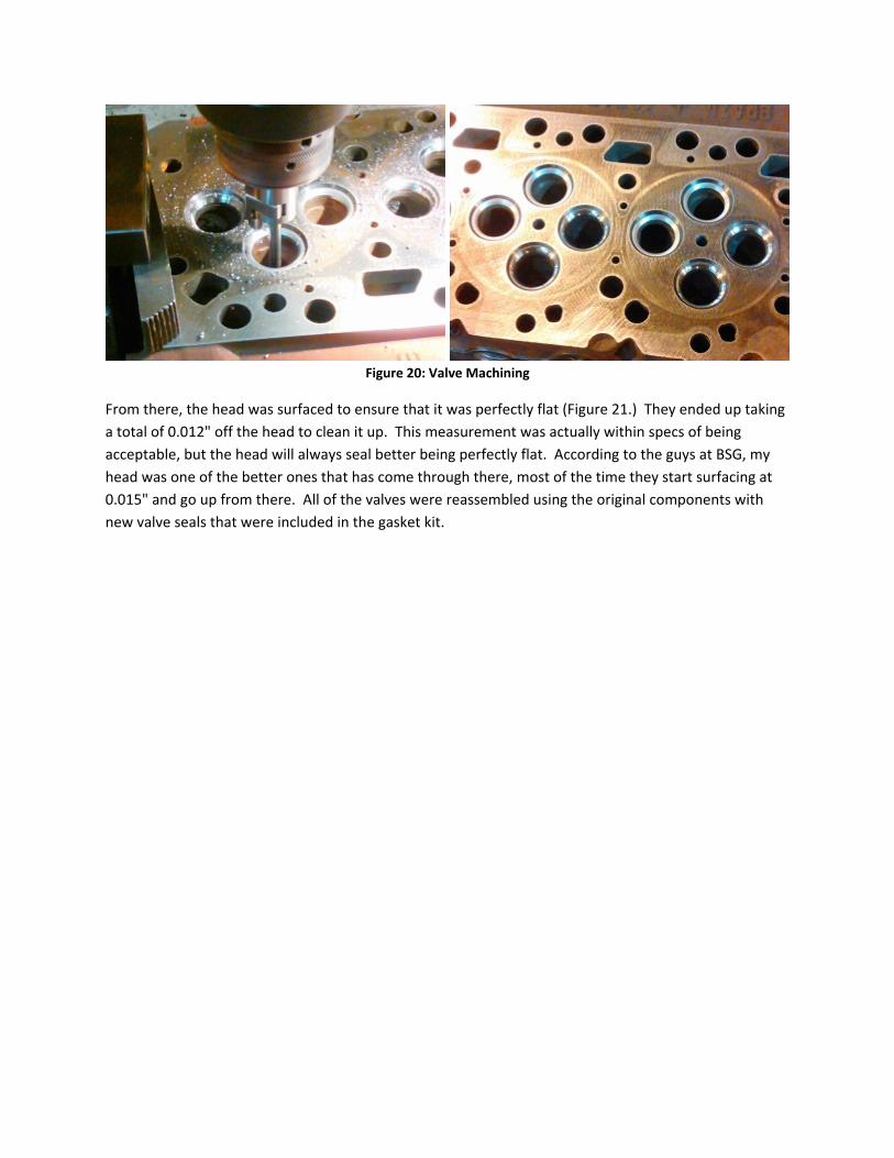
Figure 20: Valve Machining
From there, the head was surfaced to ensure that it was perfectly flat (Figure 21.) They ended up taking
a total of 0.012" off the head to clean it up. This measurement was actually within specs of being
acceptable, but the head will always seal better being perfectly flat. According to the guys at BSG, my
head was one of the better ones that has come through there, most of the time they start surfacing at
0.015" and go up from there. All of the valves were reassembled using the original components with
new valve seals that were included in the gasket kit.

Figure 21: Surfacing and Valve Assembly
Once the head was back together, it was pressure tested to ensure that there were no leaks. I dropped
the head off on Monday morning, and they gave it back to me on Thursday morning, which is a good
turn‐around time for major machine work.
With the head back at the house, it is time to prep for reassembly. Start with a thorough inspection of
the cylinder block and the pistons. There will be some carbon built up on top of the pistons, this is
normal. Do not worry about trying to remove it; it will come back as soon as the engine is started.
Inspect the walls of the cylinders and the pistons for any scratches or damage. If any damage is found,
now is the time to fix it. All of my pistons looked great and you could still see the cross‐hatching in the
cylinder walls (Figure 22.) The bottom of this engine is in great shape.
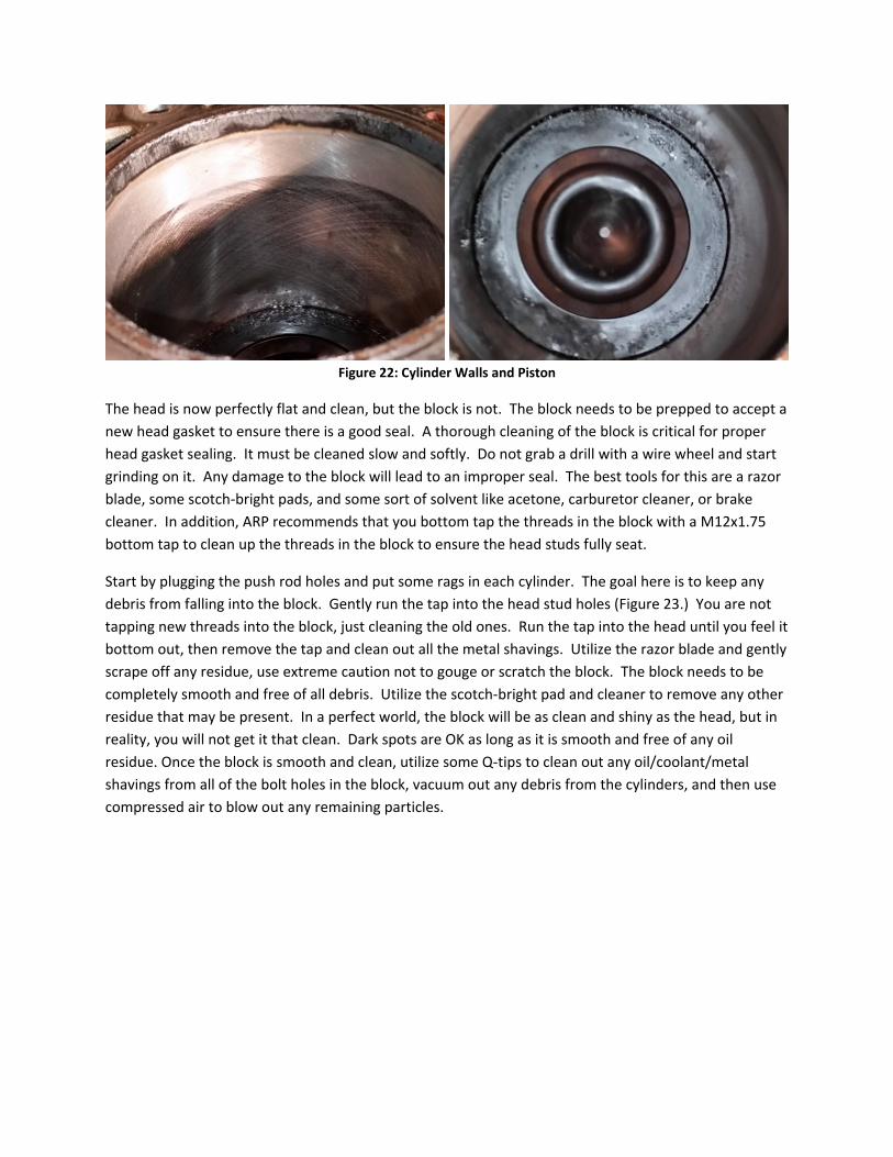
Figure 22: Cylinder Walls and Piston
The head is now perfectly flat and clean, but the block is not. The block needs to be prepped to accept a
new head gasket to ensure there is a good seal. A thorough cleaning of the block is critical for proper
head gasket sealing. It must be cleaned slow and softly. Do not grab a drill with a wire wheel and start
grinding on it. Any damage to the block will lead to an improper seal. The best tools for this are a razor
blade, some scotch‐bright pads, and some sort of solvent like acetone, carburetor cleaner, or brake
cleaner. In addition, ARP recommends that you bottom tap the threads in the block with a M12x1.75
bottom tap to clean up the threads in the block to ensure the head studs fully seat.
Start by plugging the push rod holes and put some rags in each cylinder. The goal here is to keep any
debris from falling into the block. Gently run the tap into the head stud holes (Figure 23.) You are not
tapping new threads into the block, just cleaning the old ones. Run the tap into the head until you feel it
bottom out, then remove the tap and clean out all the metal shavings. Utilize the razor blade and gently
scrape off any residue, use extreme caution not to gouge or scratch the block. The block needs to be
completely smooth and free of all debris. Utilize the scotch‐bright pad and cleaner to remove any other
residue that may be present. In a perfect world, the block will be as clean and shiny as the head, but in
reality, you will not get it that clean. Dark spots are OK as long as it is smooth and free of any oil
residue. Once the block is smooth and clean, utilize some Q‐tips to clean out any oil/coolant/metal
shavings from all of the bolt holes in the block, vacuum out any debris from the cylinders, and then use
compressed air to blow out any remaining particles.

Figure 23: Thread Tapping and Block Cleaned
Reassembly is straight forward, just put all the stuff back on that you took off earlier. Start by placing a
new OEM head gasket from the kit onto the block. The part number stamped into the gasket must be
facing up and the gasket must be aligned with the two alignment dowels sticking up out of the block
(Figure 24.)
Figure 24: Head Gasket
Reinstall the brackets on the head that were removed prior to it going to the machine shop. Attach a
chain or strap to the lifting brackets again (Figure 17) so you can lift it into position. When putting the
head back on, be sure not to hit it against anything. The bottom is perfect, and it needs to stay that
way. Also, be sure not to touch the head gasket at all with anything while you maneuver the head into
position. Get the head into position and slowly lower it onto the alignment dowels in the block. The
head should sit right down on the head gasket in its proper place.
With the head fully seated, insert the ARP head studs through the head and screw them down into the
block. The head studs must be inserted HAND TIGHT ONLY into the block (Figure 25.) If you utilize a
tool to tighten the head studs into the block, you run the risk of cracking the block when you torque the

nuts on the top. 6 studs are slightly longer than all of the other studs in the kit. These 6 studs must be
inserted in the head on the exhaust manifold side.
Figure 25: Head Studs Installed Hand Tight Into Engine
Lubricate the top and bottom of all 26 washers (included with head stud kit) with the ARP Ultra‐Torque
lube and put them on the head studs. Lubricate the threads of each stud and the threads in each nut
with the same lube. Screw the nuts onto each stud. Torque each nut down to the recommended specs
in the proper order (Figure 26.) ARP recommends three equal steps stopping at 125 ft lbs. I torqued
them in five steps, going 50‐75‐100‐115‐125 ft lbs. Torque all of them to 50 ft lbs in order, then all to 75
in order, then to 100, etc. After all 26 head studs are torqued to 125 ft lbs, in order, break the first head
stud loose 90 degrees and re‐torque to 125 ft lbs. Repeat for all 26 studs, doing one at a time. Repeat
this re‐torque procedure two more times, this will accommodate for stud stretch. You will notice that
you will break it 90 degrees, but you will actually tighten them 110 to 120 degrees in order to reach 125
ft lbs again, this is the stud stretching and the gasket seating. After all studs are done, wipe off any extra
Ultra‐Torque lube from the head studs.

Figure 26: Head Stud Torque Pattern
On a related note, be sure to use a good torque wrench that is properly calibrated for the head studs.
The cheap ones from the parts store or the one that has been in the bottom of your toolbox for 20 years
is not sufficient. I utilized a Snap‐On 1/2 inch drive TECH3FR250 torque wrench to put in these studs.
Install the exhaust manifold to the cylinder head with new gaskets from the kit. The easiest way to
install new exhaust gaskets is to install them upside down using the top manifold bolts (Figure 27.) In
other words, hold the bottom hole of the gasket in line with the top stud and then screw the stud in.
After the stud has been started a few threads, flip the gasket down between the manifold and the head
to line it up with the bottom bolt. The gaskets are universal and there is no up/down side. Note:
cylinders 1, 2, and 3 top/bottom and cylinder 6 bottom bolts are the ones that have the extra stud
sticking out of them for the heat shield nuts. Cylinders 4, 5 and the top of 6 are the regular bolts.
Starting from the center and working outwards, torque all bolts to 32 ft lbs.

Figure 27: Exhaust Gasket Installation
Slide the heat shield over the front of the exhaust manifold (Figure 10) and reinstall the exhaust back
pressure line. Install the six nuts holding the heat shield and the back pressure line to the manifold and
torque to 18 ft lbs. Reinstall the two halves of the metal coolant line under the manifold that runs
around the turbo, reconnect the coolant line to the top of the turbo, and bolt the back bracket to the
lower #6 exhaust manifold stud.
Rotate the alternator back into position and bolt it back to the bracket on the head (Figure 9). Reinstall
the fan belt on the front of the engine.
Reinstall the bolt behind the fuel filter holding the wiring harness to the head and bolt the fuel filter
housing to the head. Reach around the back of the head and reinstall the fuel line and banjo bolt with
new seals from the kit (Figure 18).
NOTE: The incorrect installation of the injectors into the head is the most common cause of a no‐start
condition after the truck is back together. Be sure to follow the injector installation instructions to the
letter to give you the best chance of having a successful repair.
Starting with the #6 injector, remove the rubber o‐ring from the body and the copper crush washer from
the tip. Be extremely careful not to damage anything and keep the entire assembly completely clean.
Coat the new o‐ring with oil and install it on the injector body (Figure 28.) Coat the new copper crush
washer with oil and install it on the injector tip. Make sure the injector stays perfectly clean. Clean out
the injector hole in the head and apply a light coat of engine oil on the walls of the hole. Gently install
the #6 injector in its location being sure to align the high‐pressure fuel fitting with the crossover tubes in
the head, and push down on it to seat it in position.

Figure 28: Fuel Injector with New O‐Ring and Copper Washer
Install the injector hold down bracket onto the injector. Alternate between the two bolts, tightening
them 90 degrees at a time, and torque them down to 44 in lbs. After they are torqued down to ensure
the injector is fully seated, loosen the bolts but do not remove them and do not touch the injector. Take
the #6 crossover tube, again making sure it is completely clean, and install it into the head from the
driver's side. There is a small alignment pin (Figure 16) on the crossover tube that will only allow it seat
if it’s properly lined up. Insert the tube into the head and rotate it by hand until you feel it fall into
position. Torque the retaining nut to 11 ft lbs. After the crossover tube is in, torque the injector back
down to 71 in lbs using the same alternating 90 degree turns as before. Then re‐torque the crossover
tube to 37 ft lbs (Figure 29.) Repeat all of these steps for the other five injectors.
Figure 29: Injector and Cross‐Over Tube Installation
Reinstall all of the push rods in the engine, they must be installed in the exact same location that they
were removed from. Make sure that they are fully seated in the tappets in the block. You will be able to
feel when they actually seat, if you just drop them in, they will fall too far into the head or not far
enough.
Install the cross heads on the #6 cylinder valves in the same location they came from.

Set the rocker pedestal into position (Figure 14.) Install the #6 exhaust rocker into position and hand
tighten the bolt. Do the same for the intake rocker. Repeat this process for the other five cylinders.
Do you remember earlier when we set the engine to TDC for the #1 cylinder? Here is where that extra
work comes in handy. With the #1 cylinder at TDC, you can adjust the valves for intake #1‐2‐4 and
exhaust #1‐3‐5. On these six rockers, you can torque the rocker bolt to 27 ft lbs. The reason for this is
that there is no spring pressure on these valves in this location, so you can get an accurate torque
reading. After the rockers are tight, adjust the valve lash on these rockers (Figure 30.) The specs are
0.010" intake and 0.026" exhaust.
Figure 30: Rocker Installation and Valve Adjustment
Rotate the engine over 360 degrees using the baring tool, realigning the TDC mark at the 12 o'clock
position. With the engine in this position, you can now torque the rockers and adjust the valve lash on
intake #3‐5‐6 and exhaust #2‐4‐6.
Install a new grid heater gasket on the head and set the grid heater in place. Position the high‐pressure
fuel rail and install the bolts to hold it in position, remember to keep it clean (Figure 31.) Starting with
the #6 cylinder, install the high‐pressure fuel line from the rail to the crossover tubes in the head.
Torque the nuts on this tube to 37 ft lbs, being sure to use a backup wrench on the crossover tube to
keep from over‐torquing it in the head. Repeat this process for the over five cylinders. Install the feed
line from the CP3 to the fuel rail and the pressure relief line using new sealing washers from the gasket
kit. Connect the electrical connector for the fuel rail pressure sensor on the back of the rail and the air
intake temp sensor in the grid heater plate. If you removed the plate on the back of the head that
protects the #6 fuel line, now is the time to reinstall it and the wiring harness that attaches to it.

Figure 31: Fuel Rail and High‐Pressure Lines
If you are installing ARP head studs into the truck, you will need to machine the rocker housing to clear
one of the studs (Figure 32). On the very back mounting bolt hole, you need to cut away some of the
material on the side to allow the head stud to fit. This is because the head studs stick up further than
the stock bolts. If you fail to machine this part, the spacer will not seat properly and it will leak oil from
the back of the engine. A Dremel tool is a good way to modify the aluminum rocker box. The rocker
housing seal is reusable and does not need to be replaced if it is not damaged. The gasket kit has a new
seal in it, and the part is already off the engine, so I replaced it anyway to be sure that it would not leak.
Reinstall the rocker housing on the engine and torque the seven bolts to 18 ft lbs.

Figure 32: Rocker Box Modification
Set the valve cover gasket/injector harness on top of the rocker housing and connect the wires back to
the fuel injectors (Figure 7.) Use extreme caution when connecting the wires to the injectors. The studs
are small and soft, if you break one, you must replace the injector. Torque these nuts to 11 in lbs.
Reinstall the bolts holding the wiring harness to the front of the head. These are very tiny and are very
difficult to get to, so they will be difficult to get back in place. Reinstall the fan shroud bracket (Figure 9)
on the passenger side to the front of the head. Rotate the alternator back into position and bolt it back
on. Reinstall the fan belt.
Reinstall the air intake horn (Figure 5) and connect all electrical connectors and the dipstick bracket to it.
Do not forget about the bolt in the back that holds the wiring harness.
Reinstall the thermostat housing and upper radiator hose (Figure 4.) Reconnect the electrical
connectors to the water temp sensor and exhaust backpressure sensor. Reconnect the exhaust pressure
tube to the thermostat housing and reinstall the cover plate.
NOTE: Before you reinstall the valve cover, there is an un‐written rule you should follow. The head was
completely removed, disassembled, cleaned, machined, and reinstalled. Currently there is absolutely no
oil on the rockers or around any of the valves and springs. This un‐written rule is to take a couple gallons
of engine oil and pour them over the top of the head to cover all of the valves and rockers with oil
before you start the engine and run them dry. Be sure to pour oil on ALL of the rockers, including the
ones in the very back. I had to use a funnel to direct the oil back there to cover the rockers and springs.
The way I deal with my oil might be a bit controversial, but I will tell you anyway. The engine oil that
was in the truck before the head gasket job had about 1400 miles on it, so it was still good oil. I promise
you, that there are contaminates inside the engine block from the maintenance performed. Any new oil
you put in the engine will be instantly contaminated with this debris. I drained two gallons of oil out of
the engine, and poured this used oil on top of the head to lubricate the valve train. By using a lot of oil,
it will fully cover the valve train, as well as wash any contaminates out of the push rod holes and away
from the camshaft. It will also wash off some of the ARP Ultra‐Lube that was used on the head studs.

This oil will be used for the first engine start after maintenance, and will be changed before the truck is
moved. This will theoretically pull most contaminates out of the engine with the old oil. New oil is put
in the engine and ran for 2 weeks while leaving the original filter in place. The oil is changed again with
a new filter and run for a full oil change interval. This will remove nearly all of any remaining
contaminates from the engine.
Reinstall the valve cover, the CCV filter, and the CCV filter cover plate (Figure 6.) Reconnect the CCV
drain lines, the injector harness connectors, and any remaining connectors or hoses that you have not
connected yet. It is a good idea to look over the engine thoroughly to make sure you did not forget to
connect anything. If you have any parts left over other than the air intake, you missed something.
Reinstall the lower air box, the air filter and the upper air intake (Figure 3.) Connect the intake tubing to
the turbo and the CCV line to the CCV filter on top of the valve cover. Reconnect the two electrical
connectors on the air intake tube.
Fill the engine with the coolant you removed earlier. As long as it is clean, it will work fine. Double and
triple check your work, looking for any loose components that were not connected, tightened, or slid
into place. Make sure all of your hose clamps are tight and look for leaks. Once you are sure that
everything looks satisfactory, reconnect the batteries.
The first start after a major job like this can sometimes be a little tricky; after all, the entire engine was
just taken apart. The first thing to do is turn the key to the on position but do not start the engine. This
lets the fuel pump prime up the fuel system. Wait about 10 seconds and turn the key back off. I like to
repeat this process three or four times to ensure there is as much fuel to the engine as the lift pump can
push. After you are satisfied, start cranking the engine. Since we had the entire fuel system apart, the
truck will need to crank enough to build sufficient rail pressure to fire the injectors. Do not crank the
engine for more than about 30 seconds max or you run the risk of damaging the starter. Crank for 30
seconds, and then let it sit for about 2 minutes to cool down. Repeat until it starts. If you did everything
correctly, the truck should start within the first two or three starter cycles. My truck started after about
25 seconds of cranking on the first cycle.
Do not be alarmed if the truck starts smoking, shaking, missing, sputtering, etc. when it first starts. All of
the air needs to be purged from the fuel system. If it does not straighten itself out within the first
minute or so of running, something probably is not correct. On my truck, it did not smoke, shake,
sputter, or anything else on the first start, just a long crank and it fired up like normal.
After the truck starts, no matter how tempting it is, do not rev the engine. Let it idle at normal speed
with the exhaust brake off. While it is idling, start checking around the engine for anything out of place.
Do a visual inspection for anything leaking under the truck and look around the engine bay for anything
leaking from the engine. From a distance, do a thorough visual inspection of the high‐pressure fuel
system fittings. Do not start rubbing your hand around the fuel lines to check for leaks. This system
runs at an extremely high pressure (about 5,000 psi at idle,) and even a small pin hole leak will inject
diesel fuel directly into any body part that you place by it. Just watch it for a while and look for anything
to appear wet close to any of the components.

You can rub your hand around the air intake system, specifically the intake horn and the intercooler
tube boots to feel for any air leaks. Keep watching while you let the truck idle itself up to operating
temperature. If you see anything out of place, immediately shut it down and correct the issues you
found. If nothing is out of place by the time the truck reaches operating temperature, go ahead and
shut it down. This is the first heat cycle on the new head gasket. Let it sit and cool down while you put
away all of your stuff.
I let my truck sit overnight to cool down completely. The next morning, the engine oil is changed before
the test drive. When you drive your truck around for the first week, you will need to be extremely easy
on it for the head gasket to properly seat. Low power, low boost, and no exhaust brake throughout a
week's worth of heat cycles.
After the first week of driving, I did a re‐torque on the head studs. The re‐torque is not required by ARP,
but is good insurance to make sure that everything is tight. To re‐torque the studs, the valve cover,
injector harness, rocker box, and all of the intake rockers must be removed to gain access to the head
studs. There is no need to remove the injectors, exhaust rockers, or the push rods. Re‐torque all studs
by breaking one stud loose 90 degrees, and re‐torque it to spec. Repeat for all 26 head studs. ARP's
torque spec is 125 ft lbs; however, it is a semi‐common practice to torque the studs to 135 ft lbs to
obtain more clamp load. If you choose to go up to 135 ft lbs, do so at your own risk. You run the chance
of breaking a head stud and causing some major issues for yourself. I went to 135 ft lbs on all of my
studs without incident. After the re‐torque, put everything back together and drive your truck as you
normally would. After one more week of driving (2 weeks total) on my new oil, the oil is changed again
with a new filter to ensure all contaminates are removed from the engine.
This process is a lot of work and you should expect the truck to be down for about a week for this entire
process. I did this entire procedure in my carport using basic hand tools. A typical shop will usually
charge $2,000 ‐ $3,000 to perform this maintenance on your truck, but by doing it yourself, you are able
to have the satisfaction of fixing it and you can save that money for some other upgrades in the future.