-head department
TRANSCRIPT

CONrD>Em'IAL
BEHAVIOB at A CAN:ILEVER P1A'l'B TO BAPm EDGE HF.Amil
by
lD1.t1a 1reder1ck Vosteen
Tbesia subldtted to the Graduate Faculty of the
Virg:1n1& .Polyteclmic Institute
in candidacy- tor the degree ot
MASml al OOJ:El'CE
in
Applied Mechanics
AP.PROVED:
'tiirector of G:rad.uate Studie& - Head of Department
Dean ot Engineering •
Ma-y 10, 1955
Blacksburg, Virg1ni&
CONJ'mmrIAL
&ale Mviaor

CONPIDEiflIAL
TAB18 a, COM'.E?fl'S
CHAPl'ER
I. n.
III.
I.:lE1l a, nammB AND TABIBS • • • • • • • • • • • • • • • • • Dl'Ba:RmIOlf • • • • • • • • • • • • • • • • • • • • • • • • DS'l PROCEDURB AND RESUI:m • • • • • • • • • • • • • • • • •
A. Deformat1ona • • • • • • • • • • • • • • • • • • • • •
B. Natural lrequenciea •••••••••••••••••
IV. CO:MPARISOJl_·oF~ THmBEI'ICIL•'.,CAmIJI.A'aOl~][ITlt':~AL
:RBSOI:rS •••••••••••••••••••••••••
A. Defo:mation • • • • • • • • • • • • • • • • • • • • •
B. Natural Frequency • • • • • • • • • • • • • • • • • •
V. CO?l:UJDDIJ REMARKS • • • • • • • • • • • • • • • • • • • • •
VI. ACIO'fOWlEDGEMElflS • • • • • • • • • • • • • • • • • • • • • • VII. .. • • • • • • • • • • • • • • • • • • • • • • •
VIII. vm •• • • • • • • • • • • • • • • • • • • • • • • • • • • IX. APPEBDIX • • • • • • • • • • • • • • • • • • • • • • • • • •
A. Temperature Distribution•••••.••.••••••
B. !l!hel'm&l streeaea •••••• • ••••••••••• •
C. Ettect of teD;perature Orad:lent on Detlectiona and
Natural Prequencies •• • •••••••••••• •
PAGE
' 5 8
14 17
21
21
21
26
27 28
29 ,0
32 )4

COlU'IDllfl'IAL
-' -I. LIS'! or rIOURES AND !l.'ABLIS
FIGUBE PAGE
1. Chordviae T~ture Diatribution 1n an ~cally
Heated Airfoil (ref. 11 tis• 11) •••
Sketch of Cantilever Plate 'feat Setup •
• • • • • • • • • • • • 7
• • • • • • • • • • • • 9
,. Instrumentation of 'fest Spec1men • • • • • • • • • • •
4. Measured Teu;,erature B1ator1ea tor an Ids• and the • • • • ll
:rd Line •••••••• • • • ••••••• • • • ••• l2
5. Measured Chord.wise Temperature Diatr1but1ona ot Bad1antq
Heated Plate •. • •• •. •·• • • • •. • •. • •• • • • • 13 6. Measured Tip-llotation Biatoriea for ~ed. ot
0 and :t4oo in•lb. • • • • • • • • • • . • • • • • • • • • • • • 15 7. !oreional Detomation ot :Plate lu'bJected to Rai'Pi4 Edge
Heating • • • • • • • • • • • • • • • • • • • • • • • • • • • 16
8. Measured frequency Jliatoriea tor the 1irat :Bending and
F:lrat Torsion MJde8 •••••• • •••••••••• • •. • 19
9. Caa;pariaon ot Measured and calculated Tip Rotationa tor
an A;ppl.ied ~rque o~ 4oo in•lb. • • • • • • • • • • • • • • • 22
10. C<D9&1'11on ot Measured and Calculated Frequency Changes
tor the First !onion Mode •• • • •••••••••• •. • 23
ll. Canpariaon of Measured and Calculated Frequency B1atorie1
tor the First ~ra1on Mode •••••••••••••• •. • 25
COlU'IDEiflIAL

COD'IDEB'.rIAL
- 4 -
PAGE
12. Dimenaiona and Coordinate System ot cantilever Plate • • • • • ,,
1:,. Comparison ot ~aau:red and Calculated Chordvise Temperature
D1atribut1ona at the !1JDe of ltlx:hma Edge Temperature • • • J5 14. Assumed Thermal stress Diatributiona in a cantilever Plate
Rapidly Heated Along the Longitud,nal Edges • • • • • • • • 37
TAELE
I. Comparison ot Interaction Relations • • • • • • • • • • • • • • 58 II. Relative Amplitude Coefficients • • . . . • • . . • . • • • • . 59
III. Deflection of Tip, x • a • • . . • • • • • • • • • • • • • • • 00
IV. Deflection of Edge, y • b. . • • • . • • • • • • • • . • • • • 00
COIFIDEDTIAL

CONFIDENTIAL -,-II. INTRODUCTION
Che of the structural problems produced by nonuniform heating is
a change in the effective stiffness of a structure caused by thermal
stresses. This stiffness-change phonomenon does not depend on a
change in the material properties but depends on the state ot stress
and may occur at stress levels well below those necessary to produce
buckling. .A change in stiffness may also result f'rom changes in the
material properties but these effects 118re found to be small in
comparison 1Vi th the effects of the thermal stresses. Laboratory
demonstrations performed at the 19$3 NACA annual inspection have shown
that the natural .t'requeney ot a simplified 'ldng structure can be
effectively re<bced by the nonuniform temperature distribution
associated with rapid heating.
The type or temperature distribution produced by the aerodynamic
heating of a thin missile wing is shown in figure 1. Thia figure
(given in ref. 1) ahOffll the variation in temperature across the chord
or a solid double-wedge airfoil immediately following a lg acceleration
to Mach number 4 at $0#000 feet. The temperatures on the surface and
at the midplane are ahawn. Stlch a temperature distribution produces
longitudinal compressive stresses near the leading and trailing edges
and tension in the central part or ~he wing. The effect of these
stresses is a reduction in the stiffness or the structure that may be
observed as an increased deformation under load or as a reduction in
CONFIDENTIAL

COMFIDENT'IAL
-6-
natural frequency. No quantitative data have been round, however,
which relate changes in frequency, and hence effective stiffness, to
temperature distribution. The project to be discussed in this paper
was devised to satisfy part ot this need.
CONFIDENTIAL

1,000
T, o F 500
0 25
-CONFIDENTIAL
• 1.
~SURFACE // MIDPLANE
50 PERCENT CHORD
75
Figure 1.- Chordwise temperature distribution in an aerodynamically heated airfoil (ref. 1, fig. 11).
cmrFIDENTIAL
100

CON1IDE?l:IAL
m. TES!' PRcx:EDt1RB AND m:stJIJl'S
In order to investigate some ot the ettecta ot nonuniform heating
experimentaJ.1¥, a test arrangement which resembled an aircraft Ying was
used. 'l'he arrangement (ahown 1n fig. 2) utilized a thin plate ot uni-.
tom thickness mounted as a cantilever. The specimen, made ot 2024
aluminum alloy sheet l/4-inch thick, wu.20 inches vide and 24 1nchea
long. lour 1nches of the length were clamped between two 4 X 4 X -,/8
structural steel angles thua forming a clamped root and lea.Ying a
20-inch square plate. A apec1men ot uniform thickness, rather than an
airtoil section, was used tor econ.any of construction and to simplify
the theoretical anal;yais.
A nonunif'orm temperature diatribution was produced by rapidly
heating the long1tnd1nal edges ot the plate by radiation frail 1ncandes•
cent carbon rods. The rods were heated to 1.ncandeacence by pusing an
8oo ampere current throusb. the rods vith a voltage drop of 55 volts
acroaa each rod. !be roda reached :incandiescence 1n about 5 seconds at
which time a shield between the rods and the plate vu removed. After
the desired heating time, the ehield was ae;a1n 1nterpoeed and the power
cut ott. The heated edges and l inch of the plate surface adJacent to
the edges were painted with black lacquer to increase heat absorption.
CONPIDEm'1AL


- 10 -
The temperature distribution over the llllrface of the plate vu obtained
tram 24 iron-constantan thermocouples which were arranged aa shown 1n
figure ,. AU thermocouples, except the two on the plate edges, were
peened into the surface of the plate. '?he tvo on the edges vere
installed about 3/64-inch fran the edge at the midplane of the plate.
The thermocouple• were connected to Consolidated !ype ,-114 recording
oscillographa and temperatures were recorded contimlously during the
test •.
The temperature distribution &lol'.lg the span of the plate was found
to be constant except tor & alight decrease toward the tip. The dis ..
tribution across the chord, however, varied greatly. In figure 4 the I
temperature 1n degrees 7ahrenhe1t ot an ed8e and the mid.chord line ia
plotted aga1nst time 1n seconds. Heat 11 applied to the plate for about
16 seconds. During this time, the edge temperature rises almost
linearly to :,15° Pat the peak of the heating cycle. When the heating
stops, the edge tem;perature dropa quickly and slovly level.a ott as the
plate cools. The variation 1n temperature acrosa the chord ia shown 1n
figure 5 tor a time 1n the heating cycle (lo seconds), at the time ot max1m'IJm eaee tEEJ;Perature (16.5 seconds), and during cooling (,o
These distributions abov that the teuv?erature rena1ne relatively low
over the center half' of the plate, but rises lhar,pl.y' near the heated
edges.
CONl':rJ>EllrIAL

·COHFIDENTIAL
20 10
I ~r~2 -~~17 1 I" ' 2,
I j__'._ '
6 I ,oL 1¼1 ' Bleck stripe
I 14[ '
I / Thermocouple 18 ' t I Wire strain gage
I '
I
0 0 0 0
Figure 3.- Instrumentation of test specimen.
CONFIDENTIAL

CO~FIDENTIAL
• 12.
300
200
T °F , MIDCH0RD
100
0 10 20 30 40 50 TIME, SEC
Figure 4.- ~asured temperature histories for an edge and the midchord line.
CONFIDENTIAL

CONFIDENTIAL
300
TIME, SEC 200 30
16.5 T °F 10 '
100
0 25
0
50 PERCENT CHORD
75 100
Figure 5.- M=asured chordwise temperature distributions of radiantly heated plate.
CCTJFIDEN'TIAL
CONFIDENTIAL
- 14 -
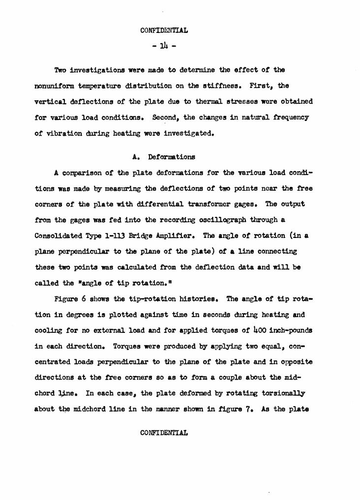
Two investigations were made to determine the effect or the
nonuniform temperature distribution on the stiffness. First, the
vert.ical defiections of the plate due to thermal atresses were obtained
for various load conditions. Second, the changes in natural frequency
of vibration during heating were investigated.
A. Deformations
A coi:tparison of the plate de.formations for the various load condi-
tions was made by measuring the denections or t,v0 points near the .free
corners or the plate with difterential trans.former gages. The output
from the gages was fed into the recording oscillegraph through a
Consolidated Type l-ll3 Bridge .Ampli.f'ier. The angle ot rotation (in a
plane perpendicular to the plane of the plate) of a line connecting
these two points was calculated .from the defiection data and will be
called the "angle of tip rotation."
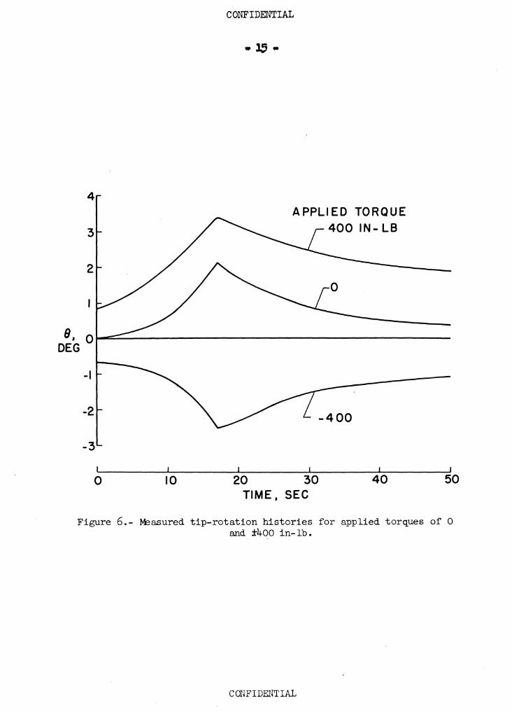
Figure 6 shows the tip-rotation histories. The angle of tip rota•
tion in degrees is plotted against time in seconds during heating and
cooling for no external load and for applied torques or 400 inch-pounds
in each direction. Torques were produced by applying two equal, con-
centrated loads perpendicular to the plane of the plate and in opposite
directions at the free corners so as to form a couple about the mid-
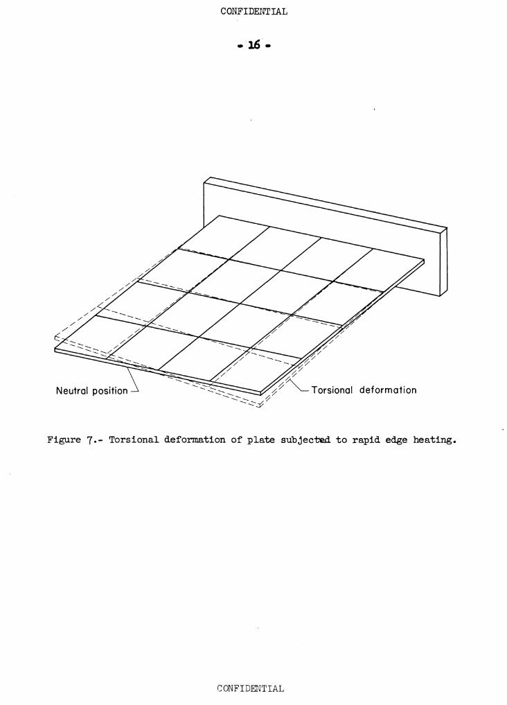
chord ],;ine. In each case., the plate deformed by rotating torsionally
about the midchord line in the manner shown in figure 7 • As the plate
CONFIDENTIAL
CONFIDENTIAL
.. 1.5 -
4 APPLIED TORQUE
3
2
8, Qi-=-------------------------DEG
-1
-2 -400
-3
0 10 20 30 40 50 TIME, SEC
Figure 6.- ~a.sured tip-rotation histories for applied torques of 0 and ±400 in- lb.
CONFIDENTIAL
CONFIDENTIAL
• 16.
Figure 7.- Torsional deformation of plate subjected to rapid edge heating.
CONFIDENTIAL

COHFIDENTiil,
- 17 •
cooled, the def'ol'll&tiona decreased and the plate returned to its
original poli tion. The .... t7Pe ad direction ot detormation wu
obtained regardlesa ot whether beat wu applied symmetrically, on
either edge, or eimutaneouaq to the upper surface ot the plate along
one edge and to the lower along the other edge, and connrael.7
because ot an initial cunature of the plate re•embling the torsional
deformation ahown in figure 1. lote that the plate underwent an
appreciable deformation without the application of an external load.
Thia 1• • thel'll&l buaklin, phenomenon ( rer. 2) which _,, be a > '
aignificant factor in the' control of 111.ssilea baring solid tina. Th•
deformation• which occurred when a constant torque wu
applied in the lame direction aa the initial twist 1ndicate1an approx-
imate of the deformation induced by the thermal atreaae1
on the initial static deflection. When a torque was applied in the
opposite direction, the plate twisted in the direction ot the applied
torque, but the maxilllUll twist le•••
B. Watural
It ia ditficult to detect the frequency ot a plate under
transient beating conditions because ot the time required to establieb
re•onance. For this the investigation limited to the tint
bending and first torsion mode1, inasmuch aa each or theae modes could
be excited by ,triking the i,late in the proper manner. The ti rat
banding mode ia euily produced by str:l.Jd.ng the plate at the midcbord
line near the tip. To excite the first, torsion mode, the plate n1 held
CONFIDENTIAL
• 18 •
with one band at the tip midchord and then struck at a tree corner. The
plate was then released.. Since the mid.chord line ia a node of the ti.rat
torsion mode, by holding the plate at th1a point tor an 1nat&nt a:f'ter it
bu been most bending vibrations are dam.Ped out and (as ~c
strain-gage records indicated) practical.1¥ pure torsion remains. lre·
quency meuurements were made~ recordillg the output traa a tvo
active-a:rm bridge made up traa tvo Baldv:ln SR-4 type EBDr•7D
(+50 to +250) wire atra:ln sages placed back to back on opposite aides
ot the plate in the position ab.own 1n figure ,. Varioua gage positions
were tried and the one ahown wu tound to give the best output for the
modes teated.
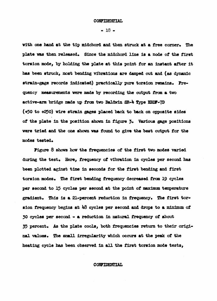
Pigu1"e 8 shows how the trequenciea of the tint two mod.ea varied
during the test. Here, frequency ot vibration 1n c1(!lea per second ha.a
been plotted aginst time 1n second.a tor the tint ben«Uns; and tirst
torsion modes. 1'he first '>ending frequency decreased. traa 19 cycles
per second to l5 cyclea per aecond at the point of maximum temperature
gradient. This is a 21-percent reduction in frequency. !he first tor•
aion frequency begins at 48 cycles per second and drops to a mimJnum of
,o cyclea per second .. a reduction in natural 1'.requency of about
,, percent. J,s the pl.ate cools, both frequencies return to their origi•
nal values. fhe small irregularity which occurs at the peak ot the
heating cycle has been observed 1n all the first tonsion mode tests,
COlU'JDD.rIAL

CONFIDENTIAL
• 19 •
60
40 FIRST TORSION
w, CPS
FIRST BENDING 20 r-----
0 10 20 30 40 50 TIME, SEC
Figure 8.- ~asured frequency histories for the first bending and first torsion modes.
CONFIDENTIAL

CONFIDENTIAL
- 20 -
but as yet its cause has not been determined.
In addition to the effects of thermal stresses, the behavior of
the plate may also be affected by changes in the material properties.
At 300° F the modulus of elasticity decreases about 7 percent (ref'. 3)
and the coefficient or thermal expansion increases about 6 percent
(ret. 4). No information has been fowid tor values or Poisson's ratio
or the shear modulus at elevated temperatures. Only a very small ·
portion or the plate reaches or exceeds JocP F during a teat, therefore,
the changes in material properties would have only a small er.feet on
the deformations and natural frequencies and the changes measured in
these test.a may be attributed to the induced thermal stresses.
CONFIDENTIAL

CONFIDENTIAL
• 21 •
IV. CCUPARISON OF THEORETICAL CALCULATIONS WITH EXPERnra-lTAL RESULTS
As a first approach to predicting the changes measured in these
tests, small-denection theory has been used. The analytical approach,
which is a combination of the energy methods used to solve buckling
and vibrational problems, is outlined in the Appendix.
A. Deformations
A comparison or the predicted and actual effect or the telllperature
gradient on the torsional stiffness ror the case ot no vibration is
ehown in figure 9. Here the tip rotation in degrees has been plotted
against the edge-to-center temperature difference AT in degrees
Fahrenheit tor an applied torque of 400 inch-pounds. Curves are sh:nm
. for the period ot heating (or increasing AT) and cooling (or decreasing
AT). The small-denection theory gives a reasonable approximation of
the reduction 1n stiffness about halfway to the buckling temperature
predicted by the theory. Above this point, however, the amall-defiection
theory indicates that the plate defiections W011ld increase mre rapidly
than actually occurs•
B. Natural Frequency
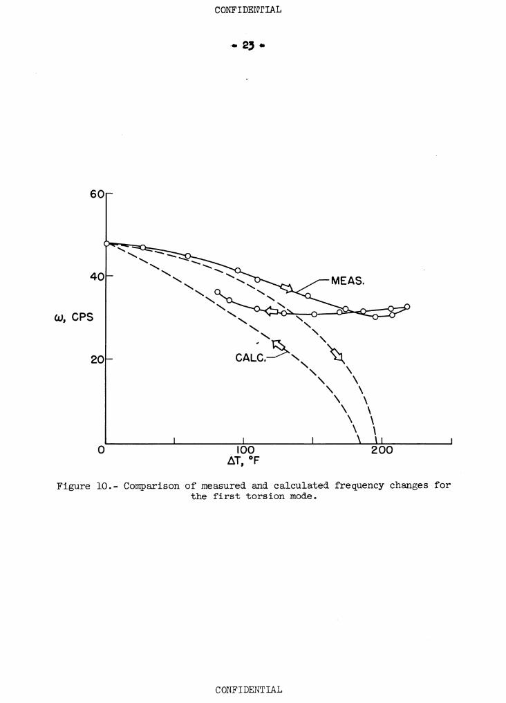
Figure 10 compares the results of the calculations with test
results when there are no external loads and the plate is vibrating in
the first torsion mode. In this figure the trequency in cycles per
second has been plotted against temperature difference between the edge
CONFIDENTIAL I

8, DEG
3
2
0
CONFIDENTIAL
- 22.
100 AT °F ,
200
Figure 9-- Comparison of measured and calculated tip rotations for an applied torque of 400 in-lb.
CONFIDENTIAL
60
40
w, CPS
20
0
CONFIDENrIAL
100 ~T °F '
\ \ \ \ \ \ \ 200
Figure 10.- Comparison of measured and calculated frequency changes for the first torsion mode.
CONFIDENTIAL

COlU'IDmIAL
• 24 •
and the midchord line for the perioda of 1ncreuing and decreasing at.
The amall-deflection theory again approximates the frequency- change
about~ to the critical buckling temperature. Above this value,
the theory ._ta. overestimate• the change. !h1a disagreement is
expected since the measured deflection of a corner 1• approximat~
equal to the plate thickness. ror de:f'lectiona of thia magnitude, the
amal.1-detlection theory 1a no longer valid.
Figure ll ahovs a s1•1 Jar aompar:1.aon ot measured and calculated
frequency- aa a function of time. 'the ratio of actual frequency to the
initial uniform-tqerature frequency 1a l)lotted ap1 nat time 1D
seconds. '.rhe calculated curve indicates that the theoretical critical•
buckling temperature differential 1• reached 1n about 15 seconds. '1'he
amall-detlection theory predicts that the plate vould bave lost all
its atittnesa at this point, but th1a is not the actual cue. Since
atittneas 1a proportional to the •f!U&N of the_ frequency-, the trequency-
decreue obta:1.ned. 1nd1catea that o~ about halt ot the atittneaa vu
loat u a result of the induced. thermal stresses. M the plate cools
and the temperature clitterence beccmes less than halt that required tor
buckling, the theory 1• again 1n fair agreement ¥1th the teat results.
C;OlCtl.D.UlIAI,

1.0
.5
0
" \ \ \ \ \
\ \ \ \ \ \
10
\ \ \ \ \ \ \ \ \ \
CONFIDENTIAL
20 30 40 50 TIME, SEC
Figure 11.- Comparison of measured and calculated frequency histories for the first torsion mode.
CONFIDENTIAL

Con:nmm'IAL
V • CO:1£WDI11J HEMABKS
!eata ot a cantilever plate have ahovn that the mi~la.ne atre.asea
imposed b)' a nommitorm teq,erature distribution can ettectiveq reduce
the atittnua ot the plate. Thia reduction 1n atittneaa 1a reflected
1D the increased deformation under the action ot a c0Z18tant applied
torque and also 1n the reduction ot the natural frequency ot vibration
ot the tint tvo mod.ea ot the plate. By using am&ll-detlection theor.v
and 'b7 employins energy methoda, the effect ot nonuniform heating on the
plate atittneaa was calculated.. t'he theor;y predicts the general ettecte
ot the thermal atresaes, but 1a 1nad.equate when the 4eformat1ona became
large. An extension ot the ~ia to account properly for large
deflections would be expected to give more satiatactor;y reaults near
the critical. t~ture.
COBl'II>El'fnAL

COBrIDENTIAL
- 27 -
'the author Wishes to expreaa h18 gratitude to the lf&tional
.Advisory Camnittee for Aeronautic• tor the use ot their equipnent and
personnel 1n carryiJ:JS out the teatins program.
Re a:Leo wiahea to thank Mr. R. R. Beldetltela ot the KACA tOr his
asaiatance and guidance throughout the program and eapeciallT 1n the
theoretical analyais, Mr. IC. B. Puller of the lUCA tor hie he1p 1n
conducting the tests, and Proteaaor B. J. Buffington end other members
of the Applied. Mecban1~• Statt ot Virginia ~echnic Institute tor
their uaistance 1n the preparation of this theaia.
(;C>lV'l.DmIAI,
CONFIDENT!AL
- 28 -
VII• REFERE?lCES
1. Kaye, Josephs The Transient Temperature Distribu.tion in a Wing Flying at Sliperaonic Speeds. Jour. Aero. Sci., Vol. 17, No. 12, Dec. 19$0, PP• 737-807, 81.6.
2. Gossard, M. L., Seide, P., and Roberts, w. M., Thermal fuckli.ng ot Plates. NACA TN 2771, 1952.
3. Flanican, A. E., Tedsen, L. F., and Ibrn, J. E. r Compressive Properties ot Aluminum Allo;y Sheet at Elevated Temperatures. Proc. Am. Soc. tor Testing Mat., Vol. 46, 1946, pp. 951-967.
4. Alcoa Aluminum and i ta Alloys. Aluminum Company or America, 1947.
,. Timoshenko, s., and Goodier, J. N. t Theory or Elasticity. Second Ed., McGraw-Hill Book Co., 1951, PP• 155, 16.9.
6. Heldentels, Richard R., and Roberts, William M. 1 Experimental and Theoretical Determination of Thermal Stresses in a Flat Plate. NACA TN 2769, 1952.
7 • Love, A. E. H. 1 A Treatise on the !.ilthematical Theory or El.astici ty, Fourth Ed., Dover Fllblications, 1944, P• 95.
8. Timoshenko, s., Theory of Elastic Stability. McGraw-Hill Book Co., Inc., 19.36, PP• .305-.32.3.
9. Timoshenko, s. 1 Vibration Problems in Engineering. Second Ed., D. Van Nostrand Co•, Inc., 19.37, P• 42.3.
10. Crout, P. D. r A Short Method tor Evaluating Determinants and Solrtng Systems ot Linear Equations with Real or Complex Coefficients. Am. Inst. Elec. Eng. Trana., Vol. 60, 1941, PP• 1235-1240.
CONFIDENrIAL

The vita has been removed from the scanned document
CONFIDENTIAL
- 30 -
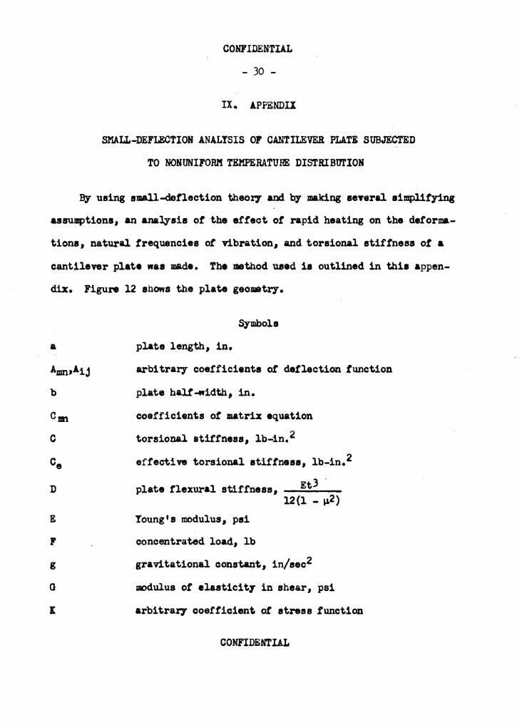
IX. APPENDIX
SHALL-DEFLECTIOH ANALYSIS or CANTILEVER PLATI SUBJECTED
TO NONUNIFORl'l TEMPERATURE DISTRIBUl'IOH
By using amall-defiection theory and by making 1eTeral aimplitying
&a8Ulllption1, an analysis ot the etteot ot rapid heating on the detorma-
tiona, natural tre4uencies ot vibration, and torsional atittness ot a
cantilever plate "a• made. The method used ia outlined in thia appen-
dix. Figure 12 shows the plate geo•trT•
a
C
D
E ., g
0
I
Symbol•
plate length, in.
arbitrary coefficients ot deflection function
plate halt-«idth, in.
coefficients ot matrix equation
torsional stiffness, lb-in.2
effective torsional atiffn•••• lb-in.2
plate tlexural stiffness, Et3 · 12(1 - ~2)
Young's modulus, psi
concentrated load, lb
gravitational constant, in/aec2
modulus ot elaaticit7 in shear, psi
arbitrary coetticient ot stress function
CONFIDENTIAL

p
t
T
Ua
utt
" X
'1
Yxy
8
CONFIDENTIAL
- 31 -
distributed load, psi
plate thiclmess, in.
temperature, °F
temperature or midchord, 0r difference in temperature between edge and midchord, 0 1
critical temperature difference, 0r potential energy or bending, in-lb
strain energy due to thermal expansion, in-lb
potential energy due to external load, in-lb
energy due to midplane stresses; in-lb
strain energy of midplane stresses, in-lb
kinetic energy ot vibration, in-lb
deflection, in.
longitudinal coordinate measured trom root, in.
transverse coordinate measured from. midchord line, in.
coefficient or thermal exparusion, in. in. - 0 ,
longitudinal strain, in./in.
tranaverse straU1, in./in.
shearing strain, in./in.
arbitrar;r exponent in temperature distribution
tip rotation,.-.deg
tip rotation ~hen AT• o, deg
CONFIDENTIAL

Pois.son•• ratio
CONFIDENTIAL
- 32 -
specific weight, lb/cuiin.
longitudinal direct stress, psi
transverse direct stress, psi
shear stress, psi
stress function
frequenc;r, cps
frequency when lt.T • o,. cpe
A. Temperature Distribution
The temperature ie asaUDBd to be constant through the thickness ot
the plate and along the spanJ the distribution across the chord ia
represented by- the simple power law
(1)
which involves the edge to midchord temperature difference AT and the
power t required to describe the measured chord.wise temperature dis-
tribution. The power , which varies during a test, determ.i.nes how
sharply the temperature rises near the edges or the plate. In order to
!ind how varied, a c~ ot the form given in equation (l) was
titted to the chordw:l.se temperature distribution measured at various
times during a test. At the at.art of heating is very large, but it
decreases to about 6 at the peak edge temperature, continues to drop as
CONFIDENTIAL

COOFIDENTIAL
. ''.
y
Figure 12.- Dimensions and coordinate system of cantilever plate.
CONFIDENTIAL

CONFIDENTIAL
- 31.i -
the plate cools, and reaches a value ot 2 at the end or the test (about
35 seconds after the peak temperature). The temperature distribution
given by equation (l} .tits the measured distribution rather well during
heating aa can be seen from figure 13, but becomes increasingly poor as
the plate cools.
B. Thermal Stresses
The plate is assumed to be in a state or plane stress and all
stresses are assumed to be in the elastic range or the material. The
assumption also baa been made that the material properties or the plate
do not change with temperature. Thermal stresses are given by the rela-
(2}
where i is the Airy stress function (see ref. !i) assumed to be given
by
(3)
This function satisfies the boundary" condition that the stresses
CONFIDENTIAL

300
200
T °F I
100
0 20
CONFIDENTIAL
40
-Cale.
0 Meas.
60 Percent chord
80 100
Figure 13.- Comparison of measured and calculated chordwise temperature distributions at the time of maximum edge temperature.
CONFIDENTIAL

CONFIDENTIAL
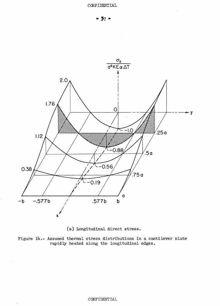
(equations 2) vanish on the free boundaries {x • a and 7 • !h). The
distribtuion of 11tress as gi'fen by equations (2) and (.3) has been
plotted in figure 14 in dimensionless form tor a square plate (a/b • 2). To evaluate the arbitrary- constant in the atress function
( equation (3)) the method of minimum complmnentar7 energy- is used. The
expression can be written simply as
(4)
where
The .first integral is the usual strain-energy- expression and the second
represents the strain energy due to thermal expansion of the plate.
Equations (S) and (6) have been used by' previous investigators (see,
for example, ret. 6) and will be shown to be valid since the derivative
ot the strain energy with respect to each of the stress components
gives the corresponding strain component (ref. 7).
CONFIDENTIAL
-b -.577b
I X
I I
CONFIDENTIAL
. ,., .
a6 KEaLff
• I I
I
.577b b
(a) Longitudinal direct stress.
------y
Figure 14.- Assumed thermal stress distributions in a cantilever plate rapidzy heated along the longitudinal edges.
CONFIDENTIAL

CONFIDENTIAL
<Ty
I X
(b) Transverse direct stress.
Figure 14.- Continued.
CO:NFIDElJTIAL

-b -.577b
I X
I I
CONFIDENTIAL
- '9 •
Txy
0
.577b
t I I
b a
(c) Shear stress.
.75o
Figure 14.- Concluded.
C ONFIDEN'l' IAL
-----y

CONFIDENTIAL
- 40 -
The stress-strain relations are
(a)
(b)
(o)
and the strain energ per unit volume as given by- equations (S) and (6)
is
The deri vati n or the strain energy with respect to ax is
Equation (e) may then be reduced. to
which is the longitudinal strain•• given by equation (a).
In a similar manner it 'l'Dlq be ahoffll that the derivative& ot the
strain enerry with respect to the other etress components give their
corresponding strain components. It may be concluded, therefore,
CONFIDENTIAL
(e)
(t)

CONFIDENTIAL
- 41 -
that the strain-energy expressions given in equations (5) and (6) are
By using equation (1) for temperature and equations (2) and (3) tor
the stresses, equation (S) may be rewritten as
where
2µ(Jx2 _ a2)(x2 _ a2)2(J,2 _ b2)(y2 _ b2)2 +
)2(1 + ~)x2.,2(x2 _ a2)2(y2 _ b2)2Jdx ey
and equation (6) becomes
where
Equation (4) can now be written
CONFIDENTIAL
(7)
(8)
(9)
(10)

which reduces to
CONFIDENTIAL
- 42 -
(11)
(12)
By evaluating th• expressions for f(x,;r} and g(x,y) from equations
(8) and (10) and substituting these quantities into equation {12), the
value ot IC is then determined. Thia value 11
(13)
when a/b • 2, equation (1.3) reduces to
K • 2.72 - 7 {~ + .3 ){~ + l) (14)
Since the value ot K is negatin, a positive value ot the stress
parametersahown in figure 14 actually indicatesa negative or (for ox
and a,-) co.mpresain stress.
CONFI.Dl!JJTIAL

CONFIDENTIAL
- 43 -
c. Effect ot Temperature Gradient on Deflections
and Natural Frequencies
To tind the effect of temperature gradient on the deflections and
natural freQuencies, another minimum-energy method is used. Deflections
are represented by the power series
(lS)
which satisfies the boundary conditions that the slope and deflection are
zero at the root, x • 0; • The undetermined coetficients ot. the deflec-
tion function may be evaluated by minim.izing the change in energy during
deflection with respect to each ot these coefficients. The Tariation in
the change in energy is expressed aa
(16)
where
t 1• f b I (aw)2 (aw)2 aw oaj Utt • 2 0 , -b Lax ai + Cly + 2-f~ ai aij dx (ld)
CONFIDENTIAL

CONFIDENTIAL
- 44 -
2n2yt Uy - g (19)
(20)
The first integral is the energy due to bending, the second is the
energy imposed by midplane thermal stresses (obtained from equations (2)
and (3)), the third is the kinetic energy ot vibration, and the fourth
is the energy resulting from any external loads applied perpendicular
to the plane or the plate. (See refs. 8 and 9.) By using equations (2)
and (3) tor stresses and equat,ion (14) tor deflections, equations (16),
(17), and (18) may be written
Ua • fa f b LL { ~m(m + 1)xm-1:,n-1]2 + 0 -b m-1 n•l r
2µ ~(m + l)rR-lyn-1] ~(n - l)(n - 2)rll+J.,n-3] +
2(1 - µ) ~(m + l)(n - l)""'7n-<]Ji1x d,y
CONFIDENTIAL
(21}

CONFIDENTIAL
- 45 -
Ui, • ½ t r= tJ,llaAT(x2 - a2)2()72 b2) ~mn(m + l)x"'r'-1]2 + 0 -b m•l n•l l [
WCEa.AT{Jx2 - a2)(,-2 - b2)2 f"mn<n - l):rl+lyn-2] 2 +
32.KEa.AT:xy(x2 - a2)(y2 -·b2) ~(m + l)i°yD-~
~mn(n - l)x"'+¾,n-2]}c1x d7 . (22)
(23)
It the external loading consists or a couple .formed by a:-.plying con-
centrated loads F at the free corners (x • a, y • tb), equation (19)
beCOJIIBS
or
(24)
When equations (21-24) incl. are minimized with respect to the arbitrary
coefficient A1j, and the indicated integrations are performed, the
following general equation is obtained.
CONFIDENTIAL

CONFIDENrnt
IL( l)(j - l)(j - 2) + 1(1 + l)(n - l)(n - 2) a•i+l~n+j-3 _ + 1 + l)(n + j - 3)
r: + 1)( 1 + l)(n + j • 2) ·· · L<• + 1 + S)(m + 1 + + 1 + l)(n + j + l)(n + j - l) +
(n - l)(j - 1)(1 + • + 2) (m + i + 5)(a + 1 + j)(n + 3 + 1)(n + 3 - i)(n + j - 3} -
(m + 1)( j - 1) + (1 + l)(n - 1) 7 (a+ 1 + S)(a + i + l)(j + n • l)(j + n - lU -
CORJ.l'IDE1ll'IAL

CONFIDENTIAL
- 47 -
Anal:ysia ot torsional. defiections.- The thermal buckling which
occurred when the longitudinal edges ot the cantilever plate were
heated resulted in torsional detormations which were similar to the
deformatiorus that took place when a constant torque waa applied to
the plate tip. It was also noted that of the tirat two modes ot
vibration, both ot which experienced a redu.ction in natural trequency-,
the first torsion mode underwent the largest change. There tore, the
remainder ot the analysis baa been restricted to torsional defonoations.
Six terms ot the defiection function which are antiaymmetrical in )"
have been used. The deflection ia then given as
(26)
If the TBluea ot m., n., 11 and j corresponding to the coeffi-
cients of equation (26) are substituted into equation (2S), a set ot
six simultaneous equations is obtained. A matrix ot the coefticienta
of the six equations ia symmetrical about the <iiagonal so that
For a square plate ! • 2 the matrix ia b
CONFIDENTIAL

where
COPFIDE1ll'IAL
168 -
Cu C21 en C!a. CS]. 061 Oi1 021 022 C32 Cu Cs2 C62 C27 . C31 C32 C3.3 Ch3 cs, C63 • C.37 C14 01,2 Ch:, CIJi c,h C6Ji Ch7 en CS2 cs, csi. 0ss C6S Cs7 061 062 C63 C6fi C6S 066 C67
Cu • (2.1111 + O.02O3181 • 0.0l6667'3)a2
021 • 012 • ( o.6o;SS + o.00l.088hl - o.002S000P.)ah
C31. • C13 • (2.SOOO + 0.01666?>. - O.Ol.3889,)al
CJa. • C14 • (o.6S833 + o.001190S>. • o.002083313)aS
CS]. • C1S • (2.8000. + 0.01.)ShSl • 0.01190Sp)a!,.
c61 • c16 • (0.10000 • o.00108Bhl - o.0017s;7p)a6
C22 • (o.eL226 + o.000)6281l - o.ooohL6L:,p)a6
C32 • C23 • (0.82SOO - o.0020833p)aS
c la • C2Ji • ( o. 78839 • o.000248o2>. - 0.00037202p )a '7
c,2 • C2s • (1.0333 - o.00072S62l - o.0017e;-,p)a6
062 • C26 • (o. 7S6h29 • o.OOOlS'l.17>. - o.00031.es9p)a8
C33 • ( 3.booo • o.01;235i - 0.01190513 )ah
COHP'IDENrllL
(27)

CONFIDENTIAL
CJi3 • c34 • (o.9;000 + o.OOOSLL22>. - o.00178S7p)a6
CS3 • C3; • (h.1667 + 0.0133331 - o.010L17,)aS
c63 • c36 • (l.OS83 • o.00071L29>. - ~.001;62Sp)a?
CIJi • (0.78S38 + o.00022676>. - 0.0003188813)a8
CS4 • ckS • (1.22; - o.001S62S~)a7
C6Ji • CJa6 • ( o. 79018 • 0.000178S7l. - . o.00027902~ )a9
c,s • (S.Lh76 + o.0123lb>. - o.0092S9,P)a6 c6; • cS6 • (1.4076 + 0.00032983>. - o.001)889P)a8
c66 • ( 0.82619 + o.00016h91>. - 0.0002L802)al0
Ci7 • -1'1
~7•-!?
CJi7 • -t c,7 • -.2,,
C67•-~
The temperature, trequeDC7, and load l., f3, and 'I are
defined aa
COIP'IDERrIAL
(28)

CONFIDENTIAL
• 50 •
(29)
,, .m D
(30)
Related values ot temperature, frequency, and defiection under load
are obtained by aolT.1.ng the matrix, equation (27). In this ana~ie,
the mtrix equation was aolTed by the Crout method because ot ita euit-
ability- tor use with automatic calculating machines. (See ref.. 10. )
When there ii no rlbration or external load, • and 1 are sero
am the solution of equation (27) gina the temperature difference necee-
AZ7 to produce thermal buckling. For a square pl.ate ( • 2) this
ditterence 18
When the value of I given by equation (lh) 11 used, equation ( 31)
becomes
Since the nexural stiffness D also contains the modulus B, the
critical temperature difference dapendl only on the plate geometry,
CONFIDENTIAL
(31)

CONFIDENl'IAL
the coefficient of thermal expansion, and Poiason'a ratio.
ror the case ot no heating or external load, AT and r are sero
and the frequency or the first u,raion mode 'flA7 be obtained. When
I.• 2 th1a wlue 1a b
(33)
The frequency ginm by this relationship ia alightl;r higher than that
obtained in the experiments. Thia is due largel;r to 1.nautticient
clamping ot the plate root. Por the purpose of comparing measui-ed and
calculated results, the theoretical plate was assumed to be slightl;r
longer than the actual plate ao that the measured and calculated
would be the at the start ot the
It no heat applied and the plate ii not vibrating, (AT and •
are sero) the angle of tip rotation resulting from a couple ot magnitude
2Fb procluced by applying a conoentrated load r at the tips (a, ! b)
of a square plate (? • 2) is
CONFIDENI'llL

CONFIDElfl'IAL
• 52 •
Approximate interaction 1guat1ons.• The defiection modes ot the
plate for vibration, thermal buckling, and applied
torques at the tip are all very 11:hd.lar. If these three modes are
assumed to be identical, the defiect1on can then be expresBed as a
function with only one arbitzoaey coefficient and simple interaction
equationa can be obtained direct~ by minimizing. equation-: -(16)--w:i.th
respect· to. tbe-, •inale: to~fficie.nt. If the defiection function ill
expressed 1n terma of the denaction ot the tree corner (x • a,
7 • b), equation (15) can be 'Wl"itten
(3S)
11h1ch reduces to
where •a b denotes the defiection ot the tree corner. FrOJI equation1 , (17) - (24), it can be seen that Va rill be proportional to (1ra,b)2,
and that Uy 1s proportional to AT(1ra,b>2, u.,. 1s proportional to
CO.tl'IDEHl'IAL

CONFIDENI'IAL
C•a,tJ2, and Ur, 1a proportional to W'a,b• Sime the angle ot tip
rotation e ( a1 previouaq detined) 1a proportional to wa, b• let
A simplitied energy equation can n,w be written as
It there ii no heating or external loac1
COBP'IDENrIAL
(37)
(38)
(39)

CONFIDENTIAL
It there is m rlbration or external load, equation (.38) becomes
and the critical bw:kl.ing-temperature ditterence 11
fl1m1larl.1', it there is n:, heating or vibration,. the angle ot tip
rotation tor a oonatant couple 1a
(4o)
(hl)
When there is no load and beat ill applied during rlbration, equation
(38) becomes
or, solving tor •• thi1 ma7 be written
•• ~· ' -:,r +AT~ -y v.., (42)
CONFIDENl'llL
CONP'IDENTIAL
... '' -- .
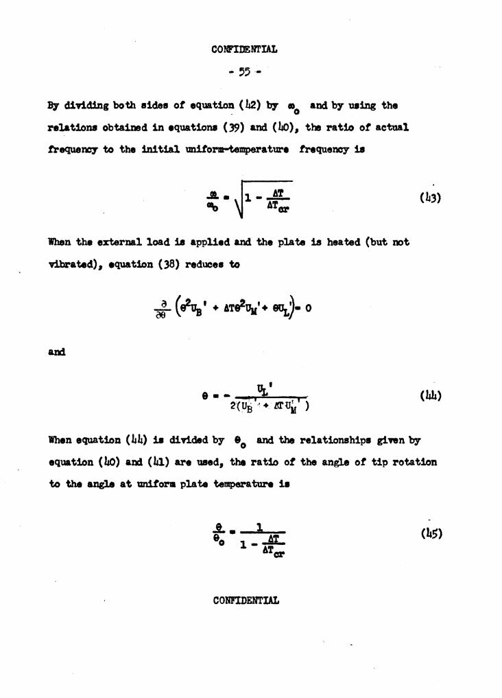
By d11'iding both aides ot equation (L2) b7 •o and b7 using the
relations obtained in equaticmll (39) and (Lo), the ratio ot actual
frequen07 to the initial uniform-temperature trequem.y 18
When the external load 18 applied and the plate is he& t.d (but not
T.l.brated), equation ( 38) reduce• t.o
(hh)
When equation (Lh) 18 divided by- 90 and the relationships g:f:nn b7 equation (l,o) and (bl) are wsed, the ratio of the angle of tip rotation
to the angle at uniform plate temperature ia
COBFIDfflIAL

CONFIDENTIAL
The trequenc,- ot vibration is proportional to the aq,Jare root ot
the torsional etittness C, and the angle ot twiat 1s inversely pro-
portional to the atittness. Hance, in tb.ia simple case, it 1a apparent
fr011 equations ( 43) and ( 4S) that
Ca All' --1-..a... C ATor
where C 1• the torsional etittness ot the unstressed plate am C8
1a the eftectiTe stiffness ot the plate when subjected to thermal
(h6)
It 18 ot interest to note that a relationship similar to equation
(L6) exists tor a 1imple beam subjected to an axial load. The ratio
ot the eftective nexural 1tittne111 ot the loaded beam to that of the
unloaded beam 1a
where F 1s the axial load (positive tor tension,. negative tor oom-
preesion) am Fer 1a the load neceHary to produce column buckling.
Comparison 2t interaction relatipns .- To obtain interaction
relations trom equation (27), nl.ues ot AT {and hence l.) were ;
CONFIDENTIAL
CONFIDENTIAL
- S7 -
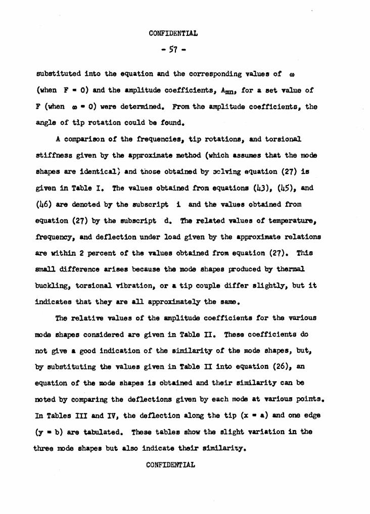
substituted into the equation and the corresponding values of (I)
(when F • 0) and the amplitude coefficients, Amn, for a set Yalue of
F (when (I)• 0) were determined. From the amplitude coefficients, the
angle of tip rotation could be found.
A compariaon of the frequencies, tip rotations, and torsional
stiffness given by the approximate method (which assumes that the mode
shapes are identical} and those obtained by 3Clving equation (27) is
given in Table I. The values obtained from equations (43), (45), and
(46) are denoted b7 the subscript 1 and the values obtained from
equation (27) b7 the subscript d. The related values of temperature,
.frequency, and defiection under load given by the approximate relations
are within 2 percent ot the values obtained from equation (27). This
small difference arises because the mode shapes produced by thermal.
buckling, torsional vibration, or a tip couple differ slightly, but it
indicates that they are all approximately the same.
The relative values of the amplitude coefficients tor the various
n.:>de shapes considered are given in Table II. These coefficients do
not give a good indication of the aimilarit7 of the J110de shapes, but,
by- substituting the values given in Table II into equation (26), an
equation of the mode shapes is obtained and their similarity can be
noted by comparing the deflections given by each mode at various points.
In Tables III and IV, the defiection along the tip (x • a) and one edge
(y • b) are tabulated. These tables show the slight variation in the
three mode shapes but also indicate their silllilari~y.
CONFIDOOIAL

COlU'IDD'l'IAL
- ,a -
TABII I
C<JIPABISOB fl m.rBRAC'.rIOB RELATIO!JS
frequency !ip Rotation Toraicmal Stittnesa M (;;)1 (;;)4 (!;)1 (~)4 (?)1 (;;): (~t -Mer
0 1.0000 1.0000 1.0000 1.0000 1.0000 1.0000 1.0000 •
.2 .8944 .9055 1.2500 1.198, .8000 .8199 .a:,4,
.4 .7746 .7855 1.6667 1.5247 .6ooo .6170 .6559
.6 .6,a5 .6364 2.5000 2.111, .4ooo .4050 .4606
.8 .4472 .4528 ,.0000 4.2409 .2000 .2050 .2358
1.0 0 0 - - 0 0 0
CORl'IDD'l'IAL

A12 /Jq2
A1i. /A1a
l.z;./A12
~4/A12
A?f2. /A12
A34/A12
COBPIDEN.rIA.L
- 59 -
UBIB II
RELATIVI AMPL1'l'UIS COEffICIENTS
t'herm&l Torsional buckJ:lng vibration
1.000 1.000
.008676 -.oorna -.02147 -.o6m. •• 001082 .0002115
-.ooo:,;6o .001410
.00003225 -.000006,12
COHFIDEN.rIAL
Applied tip couple
1.000
-.000192:,
-.o426:, .00002034 .~
-.00000(1jl.15

y
0 2 4 6 8
10
X
0 4 8
12 16 20
COll'IDD.l'IAL
- 60 -
DEl'Ia!!IOB at ~IP, x • a
ylt-
1'hemal Torsional buckling vibration
0 0 .2()CJ2 .2031 .i.162 .4052 .618; .6o61 .81.3(; .8046
1.000 1.000
UBIB rt
IJEFI&'!IOB 0, EDGE, y • b
!'hermal !oraional. buckl:tng vibration
0 0 .1296 .1,-,4 .3200 .3987 .6742 .6378 .8797 .8)05
1.000 1.000
Applied tip coiwle
0 .1995 .'992 .5991 .7994
1.000
Applied tip coup.le
0 •<11131 .2()(), .i.645 .7166
1.000
-lftel&tive denectiona based on v • 1 at the t.ree corner
CoNl'manAL
CO?U'IDEETIAL
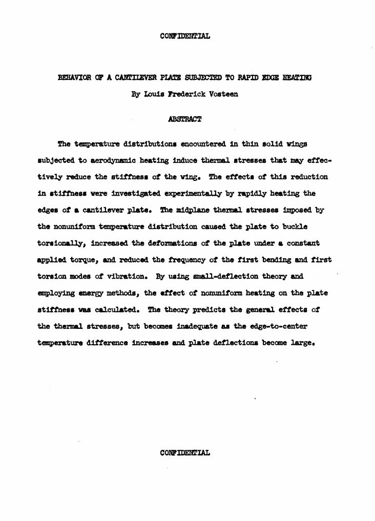
J3EHAVIOR a, A CAl'llIIEVER PLATI TO RAPID IDGB BEA!t'llll
By lDu1a Frederick Vosteen
The temperature distributions encountered 1n thin solid v1llgB
subjected to ae~c heating induce thermal atressea that 'l1J8;:{ ettec•
ti vely reduce the stift'neaa of the v:lng. The ettecta of this reduction
1n atift'neaa vere investigated experimentally by rapidly heating the
edgu ot a cantilever plate. The mi~Jane thermal atresaea im,poaed by
the nonunitom tenu,erature distribution caused the plate to buckle
tora:fonaJly-1 increased the de1'o:rmations of the plate under a constant
applied torque, and reduced the frequency of the first benc'l1ng and first
tora1on modes of vibration. By uaing small-deflection theory and
em.ploying energy methods, the effect of nonuniform heating on the plate
atittnesa vu calculated. The theory predicts the general ettecta of
the thenal stresses, but becanea inadequate u the edge-to-center
temperature ditterence increases and plate deflections becane large.
COHl'lllEl'llIAL