hdt-70 h.264 high definition multiband ......manual method of artificial respiration...
TRANSCRIPT

HDT-70_H.264
HIGH DEFINITION MULTIBAND - MULTIFUNCTION
TRANSMITTER
MANUAL V9.1

Accessories included in this manual:
SCDA HAP-60

3 HDT-70_H.264 High Definition Camera Transmitter MANUAL V9.1
Contents
Chapter 1: Introduction This first chapter provides a general description of the High Definition HDT-70_H.264 camera transmitter. Chapter 2: Technical features This second part offers the transmitter’s physical and environmental characteristics. Chapter 3: Transmitter operation and Menus This third part provides the user all the necessary information to control and operate the equipment properly. It is detailed the function of each button on the keyboard. It is also explained how the information is shown on the display, transmitter menus, alarms, etc. Chapter 4: GPS Application In this chapter, the use of the GPS incorporated system and some of its applications are shown. Chapter 5: Web Server and SNMP This chapter provides a detailed description of the Web Server tool. This feature allows controlling the HDT-70_H.264 transmitter through a website. Chapter 6: Equipment Installation This chapter indicates the available connections of the transmitter, their characteristics and the installation of the equipment. Chapter 7: Block Diagram This chapter provides a block diagram of the HDT-02 transmitter internal performance. Chapter 8: Up Converter This section provides the user all the necessary information to understand the general operation characteristics of the up-converter. Chapter 9: System Configurations In this chapter it is provided several antenna configuration options to transmit.

4 HDT-70_H.264 High Definition Camera Transmitter MANUAL V9.1
Index A: T-Box Index B: SCDA User’s Guide Index C: HAP User’s Guide Dear customer, We would like to thank you for selecting this equipment and welcome you to the SVP’s growing family of products. We are sure that the addition of this equipment will cause you a complete satisfaction in your existing installation. Please read these instructions carefully, and keep them in hand in case you have to refer to them.

5 HDT-70_H.264 High Definition Camera Transmitter MANUAL V9.1
About this manual This user’s guide provides indications and explanations about how to set up easily the HDT-70 transmitter for the most common use cases. This document is intended to help first time users:
- To find their way around the GUI.
- To understand the different possibilities of the HDT-70 transmitter.
- To configure the HDT-70 for their specific configurations. Symbols
The symbols that appear in this manual are:
An information message which indicates explanations for the proper operation of the equipment.
This symbol advises users that if they do not take, avoid or make specific actions, several damages could appear in the device.
In the places where this symbol appears it means that by pressing the Down button of the equipment the user can access to the next screen.
This symbol means that pressing the OK button in the options where this symbol appear, the user can access to the submenu related to that option or can change the value of the parameter.
<> These symbols mean that the parameter can be modified in the same screen with the right and left keys.

6 HDT-70_H.264 High Definition Camera Transmitter MANUAL V9.1
Important Notes The HDT-70_H.264 High Definition transmitter is completely
compatible with the DVB-T/T2/S2/S Standards, included in the European Standard ETSI EN300744 (DVB-T), ETSI EN300755 (DVB-T2), ETSI EN302307 (DVB-S2) and ETSI EN300421 (DVB-S).
1. The control unit has available a 70 MHz output connection through which it is possible to transmit the signal to the RF head via a triax cable in DVB-T2, DVB-T, DVB-S2 or DVB-S mode. Besides, this control unit has another optional output connector in which the signal is generated in the L band for DVB-S and DVB-S2.
2. This device has the ASI and IP (optional) output available when the input is ASI. Besides, it has also the ASI output available when the input is IP (optional).
3. It is important that when the transmitter is switched on, the selected RF output connection must have the suitable antenna or must be loaded.
4. The HDT-70 transmitter applies an MPEG-4 compression to either HDMI,
composite video or SDI input signals. An MPEG-1 layer 2 compression is applied to the corresponding 4 analogue audio channels, the 2 stereo SDI embedded, the HDMI embedded and the AES digital audio signals. The resulting multiplexed signal is transmitted using COFDM modulation system.
5. In 1080p Video Format, it can only be performed the Standard Delay, not the Low Delay, Super Low Delay or Ultra Low Delay.
6. If the RF output is set to DVB-T2 and the bandwidth selected is 1.7 MHz then, the device automatically disables the Audio2 and it sets the bitrate of the Audio1 to 128 kbps.
7. In case it is selected SDI input with 1080p format, the delay will be automatically Standard.
8. Equipment’s maximum output power for the DVB-T2/T is 3 W (selectable
from 0.3 to 3 W) and for the DVB-S2/S is from -20 to + 5 dBm. 9. Special care should be taken with SDI cables, quality and length, these
are very important, especially when HD-SDI or 3G-SDI signals are transmitted.

7 HDT-70_H.264 High Definition Camera Transmitter MANUAL V9.1
10.If any audio or data channel are not to be used in a transmission, they should be disabled, in order to assign that bitrate to the video and achieve a higher quality transmitted video signal.
11. Only authorized personnel should open the product and any repair or
warranty will be invalidated if the seals are broken.

8 HDT-70_H.264 High Definition Camera Transmitter MANUAL V9.1
First Aid in Case of Electric Shock DO NOT TOUCH THE VICTIM WITH YOUR BARE HANDS until the circuit is broken. SWITCH OFF. If this is not possible, PROTECT YOURSELF with DRY insulating material and pull the victim clear of the conductor. If breathing has stopped, indicated by unconsciousness, lack of respiratory movements and a ‘blue’ look to cheeks, lips, ears and nails, START RESUSCITATION AT ONCE.
EMERGENCY RESUSCITATION – THE EXPIRED AIR METHOD (Approved by the Royal Life Saving Society)
1. If possible, lie the victim on his back with his head slightly higher
than his feet. Clear the mouth and throat of any obvious obstruction.
2. Kneel on one side of the victim, level with his head. LIFT THE JAW AND TILT THE HEAD BACK AS FAR AS POSSIBLE (Figs. 1a and 1b)
3. One of the following may happen: a) Breathing may begin and consciousness
returns. b) Breathing may begin but consciousness NOT
return. Turn the victim on his side and ensure that the airway is kept clear.
c) Breathing may return but be NOISY which means that the airway is not fully clear. Try to clear the airway.
4. IF THERE NO SIGN OF BREATHING: a) Check that the head is still tilted back. b) Take a deep breath. c) Pinch the victim’s nose and blow firmly into his
mouth (Fig. 2). As you do, the chest will RISE. d) Turn your head away and take another breath,
watching for the chest to FALL (Fig. 3).
5. Start with four quick breaths and then continue with one breath every five seconds (i.e. 12 times a minute). This should be continued until the victim revives or a doctor certifies death.
6. As consciousness returns the victim will start to breathe on his own, and a ‘pink’ color replaces the ‘blue’ look: this is the time to stop resuscitation. Continue to hold his chin up and so keep the airway clear.
7. In the case of injuries to the mouth, it may be necessary to use mouth-to-nose resuscitation. Seal the victim’s mouth with your cheek and blow firmly into his nose, proceeding as above.

9 HDT-70_H.264 High Definition Camera Transmitter MANUAL V9.1
8. In the case of severe facial injuries it may be necessary to do a
manual method of artificial respiration (Silvester-Brosch or Holger Nielsen). Briefly, these methods apply compression to ribcage with the victim lying on his back (S-B) or face down (H.N.) with associated movement of his arms up and out. The cycle of movement should take about five seconds, i.e. the normal breathing phase.
9. Whatever the method, it is ESSENTIAL to commence resuscitation WITHOUT DELAY and to send for medical assistance immediately.
TREATMENT FOR BURNS
If the victim is also suffering from burns, then, without hindrance to resuscitation, observe the following:
a) DO NOT ATTEMP TO REMOVE CLOTHING ADHERING TO THE BURN.
b) If possible alleviate the pain from the burnt part by immersing in cold water.
c) If help as available or as soon as resuscitation is no longer required the wound should be covered with a DRY clean dressing.
d) Oil or grease in any form should not be applied.
e) If severely burnt, get the victim to hospital immediately.

10 HDT-70_H.264 High Definition Camera Transmitter MANUAL V9.1
Main Index
Chapter 1: Introduction ................................................................. 14
Chapter 2: Technical Features ....................................................... 19
Chapter 3: Transmitter Operation and Menus ................................ 23
3.1 Display .................................................................................. 23
3.1.1 Main Screen for the DVB-T2 ............................................... 26 3.1.2 Main Screen for the DVB-T ................................................. 28 3.1.3 Main Screen for the DVB-S2 ............................................... 30 3.1.4 Main Screen for the DVB-S ................................................. 32
3.2 Transmission Examples ........................................................... 34
3.3 LEDs ..................................................................................... 37
3.4 Front panel ............................................................................ 38
3.4.1 ON/OFF Button ................................................................. 38 3.4.2 OK Button ........................................................................ 39 3.4.3 Cross Button .................................................................... 39 3.4.4 Left and Right Button ........................................................ 39 3.4.5 Up and Down Button ......................................................... 40 3.4.6 TX Button ........................................................................ 40
3.5 Menus ................................................................................... 41
3.5.1 Menu Navigation ............................................................... 46 3.5.2 Menu Structure ................................................................. 47
3.5.2.1 Encoder Menu ............................................................. 48 3.5.2.1.1 SDI Input .............................................................. 52 3.5.2.1.2 HDMI (1/2)Input .................................................... 54 3.5.2.1.3 CVBS Input ........................................................... 56 3.5.2.1.4 ASI Input .............................................................. 58 3.5.2.1.5 IP Input ................................................................ 59 3.5.2.1.6 Generator Input ..................................................... 63 3.5.2.1.7 Audio1 Embedded .................................................. 65 3.5.2.1.8 Audio1 Analogue .................................................... 66 3.5.2.1.9 Audio1 AES-EBU .................................................... 67 3.5.2.1.10 Audio1 Tone.Gen ................................................. 68 3.5.2.1.11 Audio2 Embedded ...... ¡Error! Marcador no definido. 3.5.2.1.12 Audio2 Analogue ........ ¡Error! Marcador no definido. 3.5.2.1.13 Audio2 AES-EBU ........ ¡Error! Marcador no definido. 3.5.2.1.14 Audio2 Tone.Gen ....... ¡Error! Marcador no definido. 3.5.2.1.15 Data ................................................................... 69 3.5.2.1.16 Encoder Output ................................................... 73 3.5.2.1.17 TS Parameters ..................................................... 74 3.5.2.1.18 Scrambler ........................................................... 76 3.5.2.1.19 Remux (optional) ................................................. 78
3.5.2.2 RF Menu ..................................................................... 79

11 HDT-70_H.264 High Definition Camera Transmitter MANUAL V9.1
3.5.2.2.1 DVB-T2 ................................................................. 79 3.5.2.2.2 DVB-T2 Maximum Bitrates ...................................... 84 3.5.2.2.3 DVB-T .................................................................. 85 3.5.2.2.4 Autotracking (DVB-T2/T) (Under development) ......... 89 3.5.2.2.5 DVB-T Useful Bitrate .............................................. 93 3.5.2.2.6 DVB-S2 (Optional) ................................................. 95 3.5.2.2.7 Symbol Rate calculation ........................................ 100 3.5.2.2.8 DVB-S (Optional) ................................................. 101
3.5.2.3 IP Out (Optional) ....................................................... 105 3.5.2.4 Unit Menu ................................................................. 107
3.5.2.4.1 Profile ......................... ¡Error! Marcador no definido. 3.5.2.4.2 Profile Config ....................................................... 110 3.5.2.4.3 Alarms ................................................................ 119 3.5.2.4.4 Monitor ............................................................... 120 3.5.2.4.5 Remote............................................................... 120 3.5.2.4.6 Miscellaneous ...................................................... 123 3.5.2.4.7 Firmware ............................................................ 126
Chapter 4: GPS ............................................................................ 130
4.1 Introduction ......................................................................... 130
4.2 Main Screen ......................................................................... 130
4.3 GPS transmitter screen ......................................................... 131
4.4 Application example .............................................................. 132
Chapter 5: Web Server ................................................................. 134
5.1 Introduction ......................................................................... 134
5.2 Web Page Overview .............................................................. 137
5.2.1 ENCODER ....................................................................... 138 5.2.1.1 Video ....................................................................... 139 5.2.1.2 Audio ....................................................................... 139 5.2.1.3 Data ........................................................................ 140
5.2.1.3.1 RS-232 ............................................................... 140 5.2.1.3.2 GPS.................................................................... 141
5.2.1.4 TS Parameters .......................................................... 142 5.2.1.5 Output ..................................................................... 143
5.2.1.5.1 Scrambler ........................................................... 144 5.2.1.5.2 Remux ................................................................ 144
5.2.2 RF ................................................................................. 145 5.2.2.1 DVB-T ...................................................................... 146 5.2.2.2 DVB-T2 .................................................................... 148 5.2.2.3 DVB-S2 (Optional) ..................................................... 151 5.2.2.4 DVB-S (Optional) ....................................................... 153
5.2.3 TSoIP ............................................................................ 156 5.2.3.1 IP Output ................................................................. 157
5.2.4 UNIT ............................................................................. 158 5.2.4.1 LEDs Status (reading parameters) ............................... 159 5.2.4.2 Alarms (reading parameter) ........................................ 159 5.2.4.3 Monitor .................................................................... 160 5.2.4.4 Configuration ............................................................ 160

12 HDT-70_H.264 High Definition Camera Transmitter MANUAL V9.1
5.2.4.5 Miscellaneous ............................................................ 161 5.2.4.6 ODU T/T2 Unit .......................................................... 161
5.3 Web Page Setup Notes .......................................................... 163
5.4 SNMP .................................................................................. 163
5.4.1 SNMP commands ............................................................ 164 Chapter 6: Block Diagram ............................................................ 165
Chapter 7: Equipment Installation ............................................... 167
7.1 Introduction ......................................................................... 167
7.2 Connections ......................................................................... 167
7.2.1 Power supply .................................................................. 169 AC Power supply ..................................................................... 169
7.2.2 Intermediate frequency ................................................... 170 Intermediate frequency output IF .............................................. 170
7.2.3 L-Band Output (Optional) ................................................. 171 7.2.4 RF Output (Optional) ....................................................... 172 7.2.5 ASI ............................................................................... 172
ASI input ................................................................................ 172 ASI output .............................................................................. 173
7.2.6 CVBS/ SDI/ HDMI ........................................................... 174 7.2.7 Transport Stream over IP (Optional) .................................. 175
Transport Stream over IP Input and Output ................................ 175 7.2.8 Audio inputs ................................................................... 176 7.2.9 BUC .............................................................................. 177 7.2.10 Data/GPS input ............................................................ 178 7.2.11 USB connection ............................................................ 179 7.2.12 Ethernet ...................................................................... 179
7.3 Rack Unit Installation ............................................................ 180
7.4 Up-Converter and parabolic antenna installation ....................... 180
7.5 Antenna Installation .............................................................. 181
Chapter 8: Up Converter .............................................................. 182
8.1 Front Panel .......................................................................... 182
8.2 Display ................................................................................ 183
8.2.1 Main screen DVB-T/T2 ..................................................... 183 8.2.2 Main screen DVB-S/S2 ..................................................... 184
8.3 Alarms ................................................................................ 185
8.4 Mechanical Dimensions .......................................................... 186
8.5 Connections ......................................................................... 187
8.5.1 IF connector ................................................................... 187 8.5.2 Autotracking Antenna connector (under development) ......... 187
8.6 Block Driagram .................................................................... 189
Index A – T-Box ........................................................................... 191
A.1 Mechanical Drawing ............................................................... 191
Index C: SCDA User’s Guide ......................................................... 192

13 HDT-70_H.264 High Definition Camera Transmitter MANUAL V9.1
C.1 Description ............................................................................ 193
C.2 Technical Specifications ......................................................... 194
C.3 Configurations ....................................................................... 195
Index D: HAP-60 User’s Guide ..................................................... 197
D.1 Description ............................................................................ 198
D.2 Technical Specifications ........................................................ 199

14 HDT-70_H.264 High Definition Camera Transmitter MANUAL V9.1
Chapter 1: Introduction The new HDT-70 is a split box portable microwave transmitter, which consists of a control unit and a RF head connected by triax cable. The control unit has a 70 MHz output connection available through which it is possible to transmit the signal to the RF head via a triax cable in DVB-T2, DVB-T and optionally inDVB-S2 or DVB-S mode. Besides, this control unit has other optional output connectors, in one of them the signal is generated in the L band for DVB-S and DVB-S2 and in the other you have a multiband RF output. Its feature H.264 encodes for 3G, high definition (HD) and standard definition (SD) signals. Based on NEL encoding technology, the new HDT-70 offers the highest video quality with minimum latency, 33 ms. H.264 transmission is possible using 40% lower bitrate than conventional MPEG-2 systems. For added security, transmitted signal can be encrypted using BISS encryption. This new generation transmitter accepts 3G/HD/SD-SDI, HDMI and analogue video input signals. SDI embedded, HDMI embedded, AES audio and analogue inputs are available as standard. User or GPS data can be transmitted over the data channel. ASI input and Transport Stream over IP input make possible to use this transmitter as a modulator. Besides, the ASI output and the Transport Stream over IP output (optional) enables the user to use the transmitter as a standalone encoder. The HDT-70 transmitter performs DVB-T2, DVB-T and optionally DVB-S and DVB-S2 modulations. DVB-T enables compatibility with neatly all types of COFDM receivers. DVB-T2 modulation outperforms DVB-T modulation, and offers much higher data rate, which renders in a higher signal quality or much more robust signal than DVB-T, making possible longer and more difficult links. This transmitter also can perform DVB-S2 and DVB-S modulations. An L band optional output is available which enables the user to handle the transmitter control unit as satellite encoder & modulator unit.

15 HDT-70_H.264 High Definition Camera Transmitter MANUAL V9.1
Features Input video signals, composite video, 3G –SDI, HD-SDI, SD-SDI or HDMI are MPEG-4 encoded, together with 4 analogue audios, 2 stereo AES/EBU channels or 4 digital audios embedded on the SDI signal. The video formats can be 1080p (only in Standard Delay mode), 1080i, 720p, 576i or 480i. This transmitter also has a test pattern and test tone generator available. This device has a data channel available that allows transmitting user data or GPS data as well as a Transport Stream ASI input so it can be used as a repeater. The encoder uses a H.264/MPEG-4 Part 10 video compression that provides output bitrates from 1 Mbps to 216 Mbps and a MPEG-1 Layer II audio compression which supplies different audio bit rates (128, 192, 256 or 384 Kbps). Encoded signals can be encrypted using BISS-1 or BISS-E scrambling system. Encrypted signal will only be received by the receivers that have a valid descrambling key. Transmitter system operation is very easy. It has a display and a keyboard which make possible the configuration and monitorization of every parameter of the equipment. The equipment is fed with AC power supply from 90 to 240 V. Its excellent design, mechanical and electronic assembly make the HDT-70 a robust and reliable solution. DVB-T2 features Its maximum output power is 3 Watt. High quality components have been used to achieve the best output signal quality. The HDT-70 digital camera transmitter uses COFDM (Coded Orthogonal Frequency Division Multiplexing) modulation system (1K, 2K, 4K, 8K and 8K.ext) which provides superior signal robustness and a higher link performance. This technology provides operators with efficient means to overcome the challenges of NLOS propagation and mobile channels propagation. OFDM spread spectrum modulation system distributes the data over a large number of closely-spaced carriers, for example, 1.705 carriers in 2K mode. The data are divided into several parallel data streams, one for each carrier, so, each carrier transports a lower data rate and the symbol duration is longer. Each carrier is then modulated with a QPSK, 16QAM, 64QAM or 256QAM scheme with a constellation rotation.

16 HDT-70_H.264 High Definition Camera Transmitter MANUAL V9.1
An OFDM modulated signal, since uses a low symbol rate modulation scheme (i.e. where the symbols are relatively long compared to the channel time characteristics) suffer less from intersymbol interference caused by multipath propagation. As the duration of each symbol is long, it is feasible to insert a guard interval between the OFDM symbols, thus eliminating the intersymbol and co-channel interference. So, if one carrier’s information is lost, it would only be lost a small part of the whole information. Besides, in OFDM, the sub-carrier frequencies are chosen so that the sub-carriers are orthogonal to each other, meaning that cross-talk, interference, between the sub-channels is eliminated. The orthogonality allows high spectral efficiency. On the other hand, OFDM system is invariably used in conjunction with channel coding (forward error correction). The error correction code used in this equipment is Reed-Solomon coding, which is concatenated with LDPC, and there is an additional interleaving between the two layers of coding. Error correcting codes build redundancy into the transmitted data stream. This redundancy allows bits that are in error or even missing to be corrected in the receiver. The European ETSI EN 300755 standard defines the following LDPC coding rates: 1/2, 3/5, 2/3, 3/4, 4/5, 5/6. There is a compromise between the coding rate (signal robustness) and the transmitted bit rate. If the coding rate is higher the signal transmission is more robust (1/2 is the most robust) but the bit rate that the system is capable to transmit is lower. Used modulation scheme of each OFDM sub-carrier, QPSK, 16QAM, 64QAM and 256 QAM is also connected with signal robustness and transmitted bit rate. QPSK is the most robust and 256QAM is able to transport a higher bit rate. Besides, the system can define 7 guard intervals: 1/4, 19/128, 1/8, 19/256, 1/16, 1/32 and 1/128. The guard interval is used to reduce intersymbol interferences due to the multipath propagation. In addition, it also provides several bandwidths: 1.7, 5, 6, 7 and 8 MHz in case there are needed for different applications. To summarize, with all of these characteristics, the maximum bit rate achieved is 44.6 Mbps.

17 HDT-70_H.264 High Definition Camera Transmitter MANUAL V9.1
DVB-T features The RF stage of the HDT-70 transmitter is the same as the DVB-T2 one. The difference is found in the modulation part as it is commented bellow. The HDT-70 digital camera transmitter uses COFDM (Coded Orthogonal Frequency Division Multiplexing) modulation system (2K mode). The available modulations are QPSK, 16QAM or 64QAM where the most robust is the QPSK one and the one with the bigger bit rate is the 64QAM. The European ETSI EN 300744 standard defines the following convolutional coding rates: 1/2, 2/3, 3/4, 5/6, 7/8. Used modulation scheme of each OFDM sub-carrier, QPSK, 16QAM and 64QAM, is also connected with signal robustness and transmitted bit rate. QPSK is the most robust and 64QAM is able to transport a higher bit rate. Besides, the system can define 4 guard intervals: 1/4, 1/8, 1/16 and 1/32. In conclusion, with all of these characteristics, the maximum bit rate achieved is 31.67 Mbps. DVB-S2 features (optional) In case the HDT-70 transmitter is needed to be used as a satellite transmitter, it features an optional IF stage in the L band , that L band output that provides a 10 MHz reference oscillator. The HDT-70 digital camera transmitter uses single carrier or one modulation from the next available: QPSK, 8PSK, 16APSK or 32APSK where the most robust is the QPSK one and the one with the bigger bit rate is the 32APSK. In addition, the European ETSI EN 302307 standard defines the following LDPC coding rates: 1/4, 1/3, 2/5, 1/2, 3/5, 2/3, 3/4, 4/5, 5/6, 8/9, 9/10. In the modulation step it is also included a roll off factor (0.20, 0.25, 0.35) which is used to reduce intersymbol interference where the value that most reduces interference but with less bandwidth is 0.20. To sum up, with all of these characteristics, the maximum bit rate achieved is 31 Msym/s.

18 HDT-70_H.264 High Definition Camera Transmitter MANUAL V9.1
DVB-S features (optional) In case the HDT-70 transmitter is needed to be used as a satellite transmitter, it features an optional IF stage in the L band, that L band provides a 10 MHz reference oscillator. The HDT-70 digital camera transmitter uses QPSK modulation. In addition, the European ETSI EN 300421 standard defines the following Reed Solomon coding rates: 1/2, 2/3, 3/4, 5/6, 7/8.

19 HDT-70_H.264 High Definition Camera Transmitter MANUAL V9.1
Chapter 2: Technical Features RF Stage DVB-T2 and DVB-T (ODU unit) Available Frequency bands: 2 GHz (2.0GHz – 2.4GHz) 4 GHz (4.4GHz – 4.9GHz) 6 GHz (6.28GHz – 6.9GHz)
7 GHz (6.8GHz – 7.4GHz) 10 GHz (10.15GHz – 10.65GHz)
Output Power: 3 W in 2 GHz band (adjustable)
1 W in 4 GHz band (adjustable) 1 W in 6 GHz band (adjustable) 1 W in 7 GHz band (adjustable) 1 W in 10 GHz band (adjustable) Standard Bandwidth: 500 MHz Tuning step: 250 KHz The frequency of the output signal from the control unit is I.F. 70 MHz and, after going through the RF head, it is converted to RF. RF Auxiliary Output at control unit (Optional) Frequency range: 2.0 to 2.4 GHz IF Stage (70 MHz) DVB-T, DVB-T2, DVB-S and DVB-S2 Frequency: 70 MHz L Band Output (DVB-S2 and DVB-S) (Optional) Frequency range: 950 to 2.150 MHz (L band) Output Power Level: -50 to +5 dBm 10 MHz Ref. Oscillator: 0 dBm Frequency Tolerance: ± 1,0 ppm Frequency Stability: ± 0,30 ppm Operating Temperature Range:-40 to +85ºC Phase Noise: 10 Hz_____-100 dBc/Hz 100 Hz____-130 dBc/Hz 1 kHz_____-147 dBc/Hz 10 kHz____-156 dBc/Hz 100 kHz___-160 dBc/Hz 1 MHz_____-160 dBc/Hz

20 HDT-70_H.264 High Definition Camera Transmitter MANUAL V9.1
Video: Inputs: 3G-SDI SMPTE-425M-A(299M) HD-SDI SMPTE-292M(299M) SD-SDI SMPTE-259M(272M) HDMI (1.4a) Composite video (PAL/NTSC) Formats: 1080p (1920x1080) – 23.98/24/25/ 29.97/30/50/59.94/60 Hz (Standard Delay
– Limitation only for 59.94/60) 1080i (1920x1080) – 50/59.94/60 Hz 720p (1280x720) – 23,98/24/25/29.97/ 30/50/59.94/60 Hz 576i (720x576) – 50 Hz 480i (720x480) – 59.94 Hz Audio: Input: SDI embedded / HDMI embedded AES Digital / Analog Analog: 2 Stereo / 4 Mono Line, Micro Dynamic and Micro with Phantom SDI embedded: 1 Group (4 audio channels) AES/EBU: 2 Stereo channels Data Channels Data channel: User data or GPS Data rate: 1.200 to 57.600 bps ASI and IP Input and Output: ASI Transport Stream (EN50083-9) ASI over IP (SMPTE2022/CoP3) – FEC (optional) Test Signals Video: Bars with moving icon Audio: 4 Audio tones

21 HDT-70_H.264 High Definition Camera Transmitter MANUAL V9.1
Encoder Video compression: H.264/MPEG-4 Part 10
Profile: High 422, High, Main
Level: 3.0/3.1/3.2/4.0/4.1
Latency: Ultra Low delay: 33 ms
Audio compression: MPEG-1 Layer II
Audio bit rate: 128, 192, 256 or 384 Kbps
Output bit rate: 1 Mbps – 109 Mbps (DVB-S2) Encryption BISS: BISS-1 and BISS-E AES (Optional): AES-128 and AES-256 Remux: (Optional) Modulation DVB-T2: COFDM 1K, 2K, 4K, 8K and 8K.ext QPSK, 16 QAM, 64 QAM, 256 QAM Constellation rotation LDPC FEC: 1/2, 3/5, 2/3, 3/4, 4/5, 5/6 IG: 1/4, 19/128, 1/8, 19/256, 1/16, 1/32 1/128 Bandwidth: 1.7, 5, 6, 7, 8 MHz Max. bitrate: 44.6 Mbps Min. bitrate: 1 Mbps DVB-T: COFDM 2K mode QPSK, 16 QAM, 64 QAM FEC: 1/2, 2/3, 3/4, 5/6, 7/8 IG: 1/4, 1/8, 1/16, 1/32 Bandwidth: 5, 6, 7, 8 MHz Max. bitrate: 31.67 Mbps DVB-S2 (Optional): QPSK, 8PSK, 16APSK, 32APSK LDPC FEC: 1/4, 1/3, 2/5, 1/2, 3/5, 2/3, 3/4, 4/5, 5/6, 8/9, 9/10 Max. Symbol Rate: 25 Msymb/s Max. Bandwidth: 30MHz Max. Bitrate: 109 Mbps

22 HDT-70_H.264 High Definition Camera Transmitter MANUAL V9.1
DVB-S (Optional): QPSK Reed Solomon FEC: 1/2, 2/3, 3/4, 5/6, 7/8 Max. Symbol Rate 22.2 Msymb/s
Max. Bandwidth: 30MHz Max. Bitrate: 35.802 Mbps
Control & Monitorization Control Interfaces: Front panel & display Web Server interface SNMP Monitoring: Encoding, Modulation, Frequency and Output power, alarms and warnings Power Supply AC input: 90 to 240 V AC DC input: 24 V to 36 V DC Mechanical Control unit: Size: 1/2 RU, 240 mm (10 inches) depth Weight: 1.4 kg (3.09 Ib) RF head: Size: 333 x 79 x 185.5 mm Weight: 4.6 kg (10.14 lb) Consumption: RF Head – 60W / Control Unit – 40W Temperature range: -30 to 50ºC ODU Protection: IP66 Control unit and RF head connection: Triax cable with Lemo 3 Max. distance between control unit and IF head: 400 m (Triax cable 11mm)

23 HDT-70_H.264 High Definition Camera Transmitter MANUAL V9.1
Chapter 3: Transmitter Operation and Menus This third chapter provides the user all the necessary information to control, configure and operate the equipment properly. 3.1 Display To switch the equipment on and off, press ON/OFF button. When the equipment is turned on, the main screen of the HDT-70 transmitter is shown.
Figure 3.1 HDT-70 front panel/ Main screen explanation
7000,00MHz DVBT2 P:+10dBm R10% B8 Q16 3/5 1/8 14.60 GAEX 576/50i 420S
Frequency
Output Power
Modulation Scheme
Video Input Selection
Audio Input Selection
Reflected Power
Data Input Selection
FEC
Input Video Signal Format
Transmission Standard
Bandwidth
Bitrate
Latency
Guard Interval
Encoder Video Profile

24 HDT-70_H.264 High Definition Camera Transmitter MANUAL V9.1
These are the parameters displayed: Frequency (MHz). Transmission Standard (DVB-T2 and DVB-T)(Optional DVB-S/S2). Output power (dBm). Reflected Power (%). Bandwidth (MHz). Modulation Scheme. FEC. Guard Interval. Transmitted bitrate (Mbps). Video input selection
- Possibilities: SDI, HDMI1, HDMI2, CVBS, DVB-ASI Transport
Stream, IP or Generator. - Behaviour of the corresponding character: If the character is
static then it means presence of that signal. If the character is blinking then it means absence of that signal.
Audios status indication: If audio 1 or 2 is not darkened then it is enabled. On the other hand, if audio 1 or 2 is darkened then it is disabled.
Data status indication: If this field is not darkened then it means that data is enabled. On the other hand, if this value is darkened it means that data is disabled. Moreover, in case this field is static, its meaning is presence of the data whereas if this field is blinking, it means absence of the data.
Input video signal format. Encoder Video Profile (4.2.0 or 4.2.2) Latency (Standard delay, Low delay, Super Low Delay or Ultra Low
Delay) - Standard Delay (Lipsync < 10 ms) - Low delay (Lipsync < 10 ms) 3 frame - Super Low Delay (Lipsync < 10 ms) 2 frame - Ultra Low Delay (Lipsync = 20 ms) 1 frame

25 HDT-70_H.264 High Definition Camera Transmitter MANUAL V9.1
Next, the linkages between the input and the character displayed in the principal screen are shown:
Video
CVBS
C
HDMI
H
SDI
S
ASI
A
IP
I
Test Pattern
G
Audio
Embedded
E
AES/EBU
U
Analogue
A
Test Tone
G
Data
RS232
D
GPS
G
Table 3.1 Linkages between the input and the character displayed Next, the main screen for each output type (DVB-T2, DVB-T, DVB-S2 and DVB-S) is shown:
26 HDT-70_H.264 High Definition Camera Transmitter MANUAL V9.1
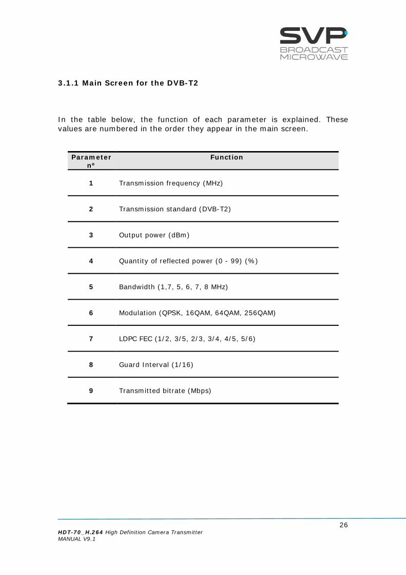
3.1.1 Main Screen for the DVB-T2 In the table below, the function of each parameter is explained. These values are numbered in the order they appear in the main screen.
Parameter nº
Function
1
Transmission frequency (MHz)
2
Transmission standard (DVB-T2)
3
Output power (dBm)
4
Quantity of reflected power (0 - 99) (%)
5
Bandwidth (1,7, 5, 6, 7, 8 MHz)
6
Modulation (QPSK, 16QAM, 64QAM, 256QAM)
7
LDPC FEC (1/2, 3/5, 2/3, 3/4, 4/5, 5/6)
8
Guard Interval (1/16)
9
Transmitted bitrate (Mbps)

27 HDT-70_H.264 High Definition Camera Transmitter MANUAL V9.1
10
Character 1: Video input selection (SDI, HDMI1, HDMI2, CVBS, DVB-
ASI Transport Stream or Generator) and (static -> presence / blinking -> absence)
Characters 2 (Audio 1) and 3 (Audio 2): Audio inputs selection ( Embedded, Analogue, AES/EBU,
Generator or None) and (Audio 1 and 2 not darkened -> enabled / darkened -> disabled)
Character 4: Data input selection (None, GPS, RS232) and (not
darkened -> enabled / darkened -> disabled) and (static -> presence / blinking -> absence)
11
Video Format (1080p, 1080i, 720p, 576i, 480i)
12
Video options Profile (MPEG-4 4:2:0 or MPEG-4 4:2:2) Delay (Standard (S), Low delay (L), Super Low delay (SL)
or Ultra Low delay (UL))
Table 3.2 Main screen for DVB-T2 standard
Figure 3.2 Main screen for DVB-T2 standard
2350,00MHz DVBT2 P:+10dBm R10% B8 Q16 3/5 1/8 14.6 GAEX 576/50i 420S
Frequency
Output Power
Modulation Scheme
Video Input Selection
Audio Inputs Selection
Data Input Selection
FEC
Input Video Signal Format
Transmission Standard
Bandwidth
Bitrate
Latency
Guard Interval
Encoder Video Profile
Reflected Power

28 HDT-70_H.264 High Definition Camera Transmitter MANUAL V9.1
3.1.2 Main Screen for the DVB-T In the table below, the function of each parameter is explained. These values are numbered in the order they appear in the main screen.
Parameter nº
Function
1
Transmission frequency (MHz)
2
Transmission standard (DVB-T)
3
Output power (dBm)
4
Quantity of reflected power (0 - 99) (%)
5
Bandwidth (5, 6, 7, 8 MHz)
6
Modulation (QPSK, 16QAM, 64QAM)
7
LDPC FEC (1/2, 2/3, 3/4, 5/6, 7/8)
8
Interval Guard (1/4, 1/8, 1/16, 1/32)
9
Transmitted bitrate (Mbps)

29 HDT-70_H.264 High Definition Camera Transmitter MANUAL V9.1
10
Character 1: Video input selection (SDI, HDMI1, HDMI2, CVBS, DVB-
ASI Transport Stream or Generator) and (static -> presence / blinking -> absence)
Characters 2 (Audio 1) and 3 (Audio 2): Audio inputs selection ( Embedded, Analogue, AES/EBU,
Generator or None) and (Audio 1 and 2 not darkened -> enabled / darkened -> disabled)
Character 4: Data input selection (None, GPS, RS232) and (not
darkened -> enabled / darkened -> disabled) and (static -> presence / blinking -> absence)
11
Video Format (1080p, 1080i, 720p, 576i, 480i)
12
Video options Profile (MPEG-4 4:2:0 or MPEG-4 4:2:2) Delay (Standard (S), Low delay (L), Super Low delay (SL)
or Ultra Low delay (UL))
Table 3.3 Main screen for DVB-T standard
Figure 3.3 Main screen for DVB-T standard
1250,00MHz DVBT P: +5dBm R--% B8 QPSK 3/4 1/16 8.7 HAuG 1080/50p 422L
Frequency
Output Power
Modulation Scheme
Video Input Selection
Audio Input Selection
Data Input Selection
FEC
Input Video Signal Format
Transmission Standard
Bandwidth
Bitrate
Latency
Guard Interval
Encoder Video Profile
Reflected Power

30 HDT-70_H.264 High Definition Camera Transmitter MANUAL V9.1
3.1.3 Main Screen for the DVB-S2
In the table below, the function of each parameter is explained. These values are numbered in the order they appear in the main screen.
Parameter nº
Function
1
Transmission frequency(MHz)
2
Transmission standard (DVB-S2)
3
Output power (dBm)
4
SR (Msymb) for L-Band or Quantity of reflected power (0 - 99) (%) for 2 GHz and 6-11 GHz.
5
Bandwidth
6
Modulation (QPSK, 8PSK, 16APSK, 32APSK)
7
LDPC FEC (1/4, 1/3, 2/5, 1/2, 3/5, 2/3, 3/4, 4/5, 5/6, 8/9, 9/10)
9
Transmitted bitrate (Mbps)

31 HDT-70_H.264 High Definition Camera Transmitter MANUAL V9.1
10
Character 1: Video input selection (SDI, HDMI1, HDMI2, CVBS, DVB-
ASI Transport Stream or Generator) and (static -> presence / blinking -> absence)
Characters 2 (Audio 1) and 3 (Audio 2): Audio inputs selection ( Embedded, Analogue, AES/EBU,
Generator or None) and (Audio 1 and 2 not darkened -> enabled / darkened -> disabled)
Character 4: Data input selection (None, GPS, RS232) and (not
darkened -> enabled / darkened -> disabled) and (static -> presence / blinking -> absence)
11
Video Format (1080p, 1080i, 720p, 576i, 480i
12
Video options Profile (MPEG-4 4:2:0 or MPEG-4 4:2:2) Delay (Standard (S), Low delay (L), Super Low delay (SL)
or Ultra Low delay (UL))
Table 3.4 Main screen for DVB-S2 standard
Figure 3.4 Main screen for DVB-S2 standard
2340,000MHz DVBS2 +0.0dbm SR12.400 B16 32APSK 8/9 53.300Mb GEAD 576/50i 420S
Frequency
Output Power
Modulation Scheme
Video Input Selection
Audio Inputs Selection
Data Input Selection Input Video Signal Format
Transmission Standard
Bandwidth
Bitrate
Latency
Encoder Video Profile
FEC
Symbol Rate

32 HDT-70_H.264 High Definition Camera Transmitter MANUAL V9.1
3.1.4 Main Screen for the DVB-S In the table below, the function of each parameter is explained. These values are numbered in the order they appear in the main screen.
Parameter nº
Function
1
Transmission frequency (MHz)
2
Transmission standard (DVB-S)
3
Output power (dBm)
4
SR (Msymb)
5
Bandwidth
6
Modulation (QPSK)
7
LDPC FEC (1/2, 2/3, 3/4, 5/6, 7/8)
9
Transmitted bitrate (Mbps)
10
Character 1: Video input selection (CVBS, HDMI, SDI, DVB-ASI
Transport Stream or Generator) and (static -> presence / blinking -> absence)
Characters 2 (Audio 1) and 3 (Audio 2): Audio inputs selection (Analog, Embedded or AES/EBU)
and (Audio 1 and 2 not darkened -> enabled / darkened -> disabled)
Character 4: Data input selection (None, GPS, RS232, RS485 or UDP)
and (not darkened -> enabled / darkened -> disabled) and (static -> presence / blinking -> absence)

33 HDT-70_H.264 High Definition Camera Transmitter MANUAL V9.1
11
Video Format (1080p, 1080i, 720p, 576i, 480i)
12
Video options Profile (MPEG-4 4:2:0 or MPEG-4 4:2:2) Delay (Standard (S), Low delay (L), Super Low delay (SL)
or Ultra Low delay (UL))
Table 3.5 Main screen for DVB-S standard
Figure 3.5 Main screen for DVB-S standard
1360,500MHz DVBS P:+3dBm SR08.000 B10 QPSK 7/8 12.901Mb SEx 1080/50i 420UL
Frequency
Output Power
Modulation Scheme
Video Input Selection
Audio Inputs Selection
Data Input Selection Input Video Signal Format
Transmission Standard
Bandwidth
Bitrate
Latency
Encoder Video Profile
FEC
Symbol Rate

34 HDT-70_H.264 High Definition Camera Transmitter MANUAL V9.1
3.2 Transmission Examples Next, some setup examples and the image that appears in the monitor screen are shown. Example 1 (DVB-T) Setup: Frequency: 1.250 MHz Transmission Standard: DVB-T Output power: +5 dBm FFT number of points: 2K Bandwidth: 8 MHz Modulation Scheme: QPSK FEC: 3/4 Guard Interval: 1/16 Transmitted bitrate: 8,7 Mbps Video input selection: HDMI Audio inputs selection: Audio1 analogue (enabled), Audio2 AES/EBU
(disabled) Data input selection: GPS Input video signal format: no signal format Encoder Video Profile: 4.2.2 Latency: Low Delay
Figure 3.6 HDT-70 Main screen. Example 1
The Audio2 status indication is darkened because it is not enabled. If it was enabled, then this field would not be darkened. When the data status field is enabled and blinks, this means that there is nothing connected to the data input. If it varies between a ‘G’ and a ‘g’ it means that the GPS antenna is connected and it is trying to find three localization satellites. If the ‘G’ does not vary, then it is connected to the satellites.
1250,00MHz DVBT P: +5dBm 2K B8 QPSK 3/4 1/16 8.7 HAUG 1080/50p 422L
darkened
blinking

35 HDT-70_H.264 High Definition Camera Transmitter MANUAL V9.1
Example 2 (DVB-S2) Setup: Frequency: 1.500,00 MHz (L band) Transmission Standard: DVB-S2 Output power: +0 dBm Symbol rate: 12,4 Msymb/s Bandwidth: 16 MHz Modulation Scheme: 32APSK FEC: 8/9 Transmitted BitRate: 53,3Mbps Video input selection: SDI Audio inputs selection: Audio1 embedded, Audio2 Analogue (both
enabled) Data input selection: RS232 Input video signal format: 1080/50i Padlock: BISS activated Encoder Video Profile: 4.2.2 Latency: Standard
Figure 3.7 HDT-70 Main screen. Example 2 The input selection is not blinking because the transmitter is receiving SDI (S) video signal. The Audio1 and Audio2 status indications are not darkened because both of them are enabled. Letter ‘E’ corresponds to embedded and letter ‘A’ to analogue. The data input has been selected to RS232 so letter ‘D’ appears in the data gap. Before the encoder profile a padlock appears when BISS encryption is activated.
1500,000MHz DVBS2 P: +0.0 SR12.400 B16 32APSK 8/9 53.300Mb SEAD 1080/50i 422S
padlock

36 HDT-70_H.264 High Definition Camera Transmitter MANUAL V9.1
Example 3 (DVB-S) Setup: Frequency: 1.360,5 MHz (L band) Transmission Standard: DVB-S Output power: +3,0 dBm Symbol rate: 8 Msymb/s Bandwidth: 10 MHz Modulation Scheme: QPSK FEC: 7/8 Transmitted BitRate: 12.901Mbps Video input selection: SDI Audio inputs selection: Audio1 embedded, Audio2 None Data input selection: UDP Input video signal format: 1080/50i Padlock: BISS activated Encoder Video Profile: 4.2.0 Latency: Ultra Low Delay
Figure 3.8 HDT-70 Main screen. Example 3
1360,500MHz DVBS P: +3.0 SR08.000 B10 QPSK 7/8 12.901Mb SEx 1080/50i 420UL

37 HDT-70_H.264 High Definition Camera Transmitter MANUAL V9.1
3.3 LEDs The HDT-70 transmitter has 5 LEDs on its front panel that show the information detailed below. The ON/OFF provides the following information:
• If the LED is off, the equipment is not being fed. • If the LED flickers in red, the equipment is being fed but it is turned
off. • The Led lights up in green when the equipment is turned on.
The RF LED provides the following information:
• If the LED is off, the equipment does not transmit RF signal. • The LED lights up in green when the equipment transmits RF signal,
RF stage is active. The ALARM LED provides the following information:
• The LED lights up in red when any alarm occurs. • The different alarms that can appear in the transmitter are:
• Voltage High. • Voltage Low. • Temperature High. • ASI Overflow: This alarm means that the input bitrate is higher
than the one that can be modulated due to the configured parameters (constellation, FEC, GI...).
• The different warnings that can appear in the transmitter are:
No SDI/HDMI/CVBS/ASI Input. No GPS. No KLV.
The REMOTE LED provides the following information:
• The LED lights up in blue when the user is connected remotely to the device (through the Web Server).
The STATUS LED provides the following information:
• The LED lights up when the encoder is working properly. •
Figure 3.9 HDT-70 LEDs
REMOTE
ALARM
STATUS
RF
ON/OFF

38 HDT-70_H.264 High Definition Camera Transmitter MANUAL V9.1
3.4 Front panel The HDT-70 transmitter is configured following a menus structure on the display. The front panel has 8 buttons to enter and exit the equipment’s control menus and submenus and to navigate through them. The function of each button is detailed in the following sections.
Figure 3.10 HDT-70 front panel
3.4.1 ON/OFF Button To switch the equipment on and off, press this button. When the equipment is turned on, it will display the main screen. If the power fails while the equipment is operating, it will restart automatically when the power returns, not being necessary to press the on/off button again.
Figure 3.11 ON/OFF button
Fan
Display Left Button
UP Button
Right Button
OK Button
Down Button
Cross Button
ON/OFF Button
LEDs
TX Button

39 HDT-70_H.264 High Definition Camera Transmitter MANUAL V9.1
3.4.2 OK Button This button is used to: Enter to submenus and change parameters. So as to access to a
submenu, OK button must be pressed. Moreover, in the fields where the enter symbol appears, by pressing the OK button the user can
change the values of the selected parameter. Besides, so as to save the introduced value, the OK button must be pressed.
In case of being in the main screen, pressing the OK button the user can access to the alarms screen where there are different alarms that are taking place. So as to return to the main screen, the cross button must be pressed.
Figure 3.12 OK button
3.4.3 Cross Button This button is used to: Enter from the equipment main screen to the setup menu and vice
versa. Exit equipment submenus. This button allows the user to access to the main screen from the alarms
screen.
Figure 3.13 Cross button
3.4.4 Left and Right Button These buttons are used to: Once the parameter to change has been selected, they are used to move
the cursor towards the digit immediately on the left or right and to select a parameter from different options.
OK
X

40 HDT-70_H.264 High Definition Camera Transmitter MANUAL V9.1
Figure 3.14 Left and Right buttons
3.4.5 Up and Down Button The up and down arrow buttons allow the navigation in the main menu
and the rest of submenus. Using this buttons, the user can enter to the submenu or change a parameter. Once selected, the OK button has to be pressed.
These buttons are also used to change, for example, the frequency and PID parameters values. Pressing up and down arrows the value of those parameters can be changed, increased or decreased respectively.
Figure 3.15 Up and Down buttons
3.4.6 TX Button By pressing TX button, RF output is enabled or disabled. To enable or disable the RF output just press TX button. It is important that before pressing this button, the selected RF output must be conveniently loaded and there is no reflected signal. After pressing this button, power gradually increases until arrive to the maximum power in 5 second. In case the device is switched off with the output is enabled, then, when it is switched on again it is necessary to push again TX button so as to enable this feature. However, if power supply fails when the output is enabled then, once power supply returns it is not necessary to push TX button because it will continue being enabled.
Figure 3.16 TX button
TX

41 HDT-70_H.264 High Definition Camera Transmitter MANUAL V9.1
3.5 Menus There is one menu in this transmitter that allows the user to change the transmitter’s parameters and configure them. To enter the menu of this equipment cross button must be pressed. In case it is wanted to return again to the principal screen from the menu, cross button must be pressed. Furthermore, in case of being in the submenus area, returning to the mainly screens is achieved by pressing the cross button as much times as it is needed. In the next page it is shown a scheme that specifies the different menu options available.

42 HDT-70_H.264 High Definition Camera Transmitter MANUAL V9.1
continued
HDT-70 MENU STRUCTURE
MAIN SCREEN Frequency, standard, power, FFT, bandwidth, modulation, FEC,GI, latency, output bitrate,
audio and video status, profile
Format
Encoder
Video
SDI HDMI 1 CVBS ASI IP GEN
L Type
Format Status Format
Delay
Profile
Delay
Profile Profile
Delay
Format
Bitrate
Profile
Delay
Analogue Embedded AES-EBU Tone.Gen None
Audio 1
Bitrate Bitrate Bitrate Bitrate
Frequency
Level
continued
Format Local IP
Protocol
Fec
Port
Out.Delay
TPpor IP
Status
IP.Adr
BitRate
PCR
Packet Size
GOP GOP GOP GOP
R Type
HDMI 2
Delay
Profile
Format
GOP
Level Level Level Level Level

43 HDT-70_H.264 High Definition Camera Transmitter MANUAL V9.1
continued
continued
continued
continued
Audio 2
Data
Analogue
Embedded AES-EBU Tone.Gen None None Ext. GPS RS232
Bitrate
L Type
Bitrate Bitrate Bitrate
Frequency
Level
BaudRate
Parity
Stop Bits
Encoder Output
Auto
Encoder
R Type
Int. GPS 4K board
GPS Info Antenna 5V
GPS Info Manual

44 HDT-70_H.264 High Definition Camera Transmitter MANUAL V9.1
Freq
Power
Bandwidth
LDPC Fec
Modulation
FFT Spectrum
ODU Select
Sort of output
Freq
LDPC FEC
SR
ODU Unit
Freq
Power
Modulation
FEC
GI
Bandwidth
RF
DVB-T2
DVB-T
DVB-S2
continued
continued
TS
Parameters
Video PID
Audio1 PID
PMT PID
PCR PID
Data PID
Program Nº
Network Name
Audio2 PID
TS id
Network id
Service Name
Scrambler
continued
Encoder
Spectrum
DVB-S
Freq
Power
FEC
SR
ODU Unit
Spectrum
ODU Select
Time Int.
ODU Select
Autotrack
Power
Modulation
Autotrack
Mode
ODU Unit
ODU Unit
ODU Select
Remux
None BISS-1 BISS-E Enable Disable Sort of output
KLV PID
AES-128 AES-256
Gen with no video
On OFF
Format
Audio
Delay

45 HDT-70_H.264 High Definition Camera Transmitter MANUAL V9.1
continued
Temperature
Voltage
Local IP
Mask
Gateway
Unit
Alarms
Monitor
Remote
Miscellaneous
Firmware
IP Out
DestinationIP&Port
Fec
Local IP
TP per IP
Protocol
MAC
Admin Pass
Rectore Admin Pass
User Pass
Rectore User Pass
Keyboard Lock
Night Mode
Dist Units Video Switch
Update Firmware
Current
Keyboard Beep
RTC-01 Config
RTC Sel
RTC-02 Config
T/T2 Carrier Activ Key
S/N
Activ Licenses
View
Config

46 HDT-70_H.264 High Definition Camera Transmitter MANUAL V9.1
3.5.1 Menu Navigation This section contains a detailed description of each parameter that can be configured in the HDT-70 transmitter via the MENU. To enter the MENU, press the cross button in case of being in the principal screen or in any submenu. To select a parameter or a submenu use the Up, Down arrows. Once selected, press the OK button to access to a submenu or to edit a parameter. To exit a submenu or a parameter press cross button. Figure means that to have access to the right image that button must be pushed. Symbols <> mean that the parameter can be modified in the same screen with the right and left keys. Symbol means that pushing the OK button allows entering to the options of the submenu. Different types of parameters are available:
- Eligible: When the user can choose between predetermined states. (They usually have the symbol <> near to them)
- Editable: When the user must enter a value in that option. (They usually have the symbol near them). So as to save the introduced value, the OK button must be pressed.
- Reading: When the value of that parameter is a monitored parameter that can’t be changed.
To change a parameter, for example, the transmitted frequency, press the OK button in the desired option and then with Up, Down buttons choose the value. Once the parameter is set, press the OK button so as to save the value. Next, the different menus and submenus with the options and eligible parameters are shown. Also, in each figure, example parameters are shown.

47 HDT-70_H.264 High Definition Camera Transmitter MANUAL V9.1
3.5.2 Menu Structure The following menu screen can be accessed by pressing the cross key from the monitoring menu.
Figure 3.17 Menu
Encoder – All the parameters related to the video, audio and data inputs are configured here. Besides, all video, audio, data encoding and multiplexing parameters are accessed here. RF – DVB-T2/T/S2/S transmission parameters are set in this section. Unit –Parameters related to the Web Server and other internal options of the HDT-70 transmitter are configured here, as well as other characteristics of the device. IP Out – All parameters related to the IP output are configured in this section.
MAIN MENU Encoder IP Out RF Unit

48 HDT-70_H.264 High Definition Camera Transmitter MANUAL V9.1
3.5.2.1 Encoder Menu By using the Up, Down arrow keys, select the Encoder option and press the OK key.
Figure 3.18 Encoder Menu
ENCODER Video: CVBS <> Audio1: Tone.Gen <> Audio2: AES-EBU <>
ENCODER Data: GPS <> KLV Metadata: Off > Encoder Output ENCODER
TS Parameters Scrambler: BISS-E Remux: Enable <
ENCODER Gen no video: On <

49 HDT-70_H.264 High Definition Camera Transmitter MANUAL V9.1
Line nº Function
1
Video: In this field, the video input must be chosen with the Right and Left buttons. Once the video input has been selected, press the OK button to configure the parameters related to it. The available options are: SDI HDMI 1 HDMI 2 CVBS ASI IP GEN
2
Audio 1: In this field, the sort of audio input through the channel number 1 can be chosen with right and left buttons. Once the audio 1 input has been selected, press the OK button so as to configure the parameters related to it. The available options are: Embedded Analogue AES-EBU Tone.Gen None

50 HDT-70_H.264 High Definition Camera Transmitter MANUAL V9.1
3
Audio 2: In this field, the sort of audio input through the channel number 2 can be chosen with right and left buttons. Once the audio 2 input has been selected, press the OK button so as to configure the parameters related to it. The available options are: Embedded Analogue AES-EBU Tone.Gen None
4
Data: In this field, the sort of data input can be selected. The available options are: None External GPS Internal GPS 4k Board RS-232
5
KLV Metadata: In this field, the KLV metadata can be enabled.
6
Encoder Output: In this field, the encoder output bitrate mode can be selected. The available options are: • Auto • Manual Bitrate (editable parameter) In the Manual Bitrate Mode, pressing the OK button, the output bitrate can be configured.
7
TS Parameters: This file consists on the configuration of the parameters of the Transport Stream. In this option, the different program identifiers are configured.

51 HDT-70_H.264 High Definition Camera Transmitter MANUAL V9.1
8
Scrambler: In this field, the encryption system can be chosen with right and left buttons. The available options are: None BISS-1 (Uses an unencrypted key for the BISS key) BISS-E (Uses an encrypted key) AES-128 (Optional) AES-256 (Optional)
9
Remux: In this field, the remux option can be enabled or disabled.
10
Generator with no video: In this field, you can configure if the video generator must be switched in absence of the video input signal or not. Once enabled, press OK to configure the related parameters.
Table 3.6 Encoder Menu options

52 HDT-70_H.264 High Definition Camera Transmitter MANUAL V9.1
3.5.2.1.1 SDI Input
Figure 3.19 SDI Input Menu
Line nº Function
1
Format (SDI): In this field, the format of the SDI input signal is displayed.
(reading parameter) The available options are: 1080p (1920x1080) – 23.98/24/25/29.97/30/50/59.94/60
Hz 1080i (1920x1080) – 50/59.94/60 Hz 720p (1280x720) – 23.98/24/25/29.97/30/50/59.94/60 Hz 576i (720x576) – 50 Hz 480i (720x480) – 59.94 Hz
2
Delay: In this field, the delay of the coding process is configured. So as to select the desired delay, press Right, Left arrows buttons. (eligible parameter) The available options are: Standard Super Low Delay (2 frames of delay) Ultra Low Delay (1 frame of delay)
ENCODER VIDEO SDI Format: 1080/50i Delay: SuperLD 2F <> Profile: 4.2.0 >
ENCODER VIDEO SDI GOP: Auto 12 > Level: 4.0 >

53 HDT-70_H.264 High Definition Camera Transmitter MANUAL V9.1
3
Profile: In this field, the codification profile can be configured. So as to select the wanted profile, press Right, Left arrows buttons. (eligible parameter) The available options are: 4.2.2 4.2.0
4
GOP: In this field, the Group Of Pictures parameter is displayed. It specifies the order in which intra and inter-frames are arranged. The available options are: • Auto • Manual (editable parameter)
5
Level (eligible parameter): In this field, the level of the H.264 encoder can be configured. The available options are: • 4.0 • 4.1 • 4.2 (only available in 1080p-50/59.94/60 Hz video formats)
Table 3.7 SDI Input menu options
In case HDMI video input is selected, it is necessary to specify the format (1080p, 1080i, 720p). If other video input (SDI, CVBS or ASI) is selected, then the transmitter automatically captures its format and the frame rate. If the video format is changed, the time detection of this new format is less than 15 seconds.
54 HDT-70_H.264 High Definition Camera Transmitter MANUAL V9.1
3.5.2.1.2 HDMI (1/2)Input
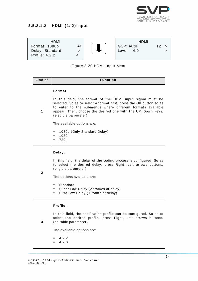
Figure 3.20 HDMI Input Menu
Line nº Function
1
Format: In this field, the format of the HDMI input signal must be selected. So as to select a format first, press the OK button so as to enter to the submenus where different formats available appear. Then, choose the desired one with the UP, Down keys. (elegible parameter) The available options are: 1080p (Only Standard Delay) 1080i 720p
2
Delay: In this field, the delay of the coding process is configured. So as to select the desired delay, press Right, Left arrows buttons. (eligible parameter) The options available are: Standard Super Low Delay (2 frames of delay) Ultra Low Delay (1 frame of delay)
3
Profile: In this field, the codification profile can be configured. So as to select the desired profile, press Right, Left arrows buttons. (editable parameter) The available options are: 4.2.2 4.2.0
HDMI Format: 1080p Delay: Standard > Profile: 4.2.2 <
HDMI GOP: Auto 12 > Level: 4.0 >

55 HDT-70_H.264 High Definition Camera Transmitter MANUAL V9.1
4
GOP: In this field, the Group Of Pictures parameter is displayed. It specifies the order in which intra and inter-frames are arranged. The available options are: • Auto • Manual (editable parameter)
5
Level (eligible parameter): In this field, the level of the H.264 encoder can be configured. The available options are: • 4.0 • 4.1 • 4.2 (only available in 1080p-50/59.94/60 Hz video formats)
Table 3.8 HDMI Input menu options

56 HDT-70_H.264 High Definition Camera Transmitter MANUAL V9.1
3.5.2.1.3 CVBS Input
Figure 3.21 CVBS Input Menu
Line nº Function
1
Format (CVBS): In this field, the format of the CVBS input signal is displayed. (reading parameter) The available options are: 480i 576i
2
Delay: In this field, the delay of the coding process is configured. So as to select the desired delay, press Right, Left arrows buttons. (eligible parameter) The available options are: Standard Super Low Delay (2 frames of delay) Ultra Low Delay (1 frame of delay)
3
Profile: In this field, the codification profile can be configured. So as to select the desired profile, press Right, Left arrows buttons. (eligible parameter) The available options are: 4.2.2 4.2.0
CVBS Format: 480i Delay: SuperLD 2F <> Profile: 4.2.0 >
CVBS GOP: Auto 12 > Level: 4.0 >

57 HDT-70_H.264 High Definition Camera Transmitter MANUAL V9.1
4
GOP: In this field, the Group Of Pictures parameter is displayed. It specifies the order in which intra and inter-frames are arranged. The available options are: • Auto • Manual (editable parameter)
5
Level (eligible parameter): In this field, the level of the H.264 encoder can be configured. The available options are: • 4.0 • 4.1 • 4.2 (only available in 1080p-50/59.94/60 Hz video formats)
Table 3.9 CVBS Input menu options

58 HDT-70_H.264 High Definition Camera Transmitter MANUAL V9.1
3.5.2.1.4 ASI Input When ASI input is selected, the signal is directly sent to the modulator. This input is also used for Remux. When Remux option is enabled, the second video which is going to be sent must be connected to the ASI input, but the selected video input must be SDI or HDMI or CVBS (according to the inserted video input for the first channel to be remuxed) but not ASI.
Figure 3.22 ASI Input Menu
Line nº Function
1
Status: In this field it is indicated if there is any ASI signal in the ASI input. In case there is an ASI signal, this field will display the word present. If there is no ASI signal then, no present will be displayed. (reading parameter) The available options are: Present No Present
2
Bitrate: In this field, the bitrate of the ASI input signal is shown. (reading parameter)
Table 3.10 ASI Input menu options
ASI INPUT Status: Present Bitrate: 18.0Mb

59 HDT-70_H.264 High Definition Camera Transmitter MANUAL V9.1
3.5.2.1.5 IP Input
Figure 3.23 IP Input Menu
IP INPUT Local IP IP.Adr: Unicast > Fec: Disable >
IP INPUT Port: 5600 Out. Delay: 128 ms TP per IP: 1
IP INPUT Status: ENABLE Protocol: UDP Packet Size: 188
IP INPUT BitRate: 0.00Mb PCR: No Present

60 HDT-70_H.264 High Definition Camera Transmitter MANUAL V9.1
Line nº Function
1
Local IP: So as to configure the network parameters, press the OK button. (editable parameters) The available options are: Local IP:
So as to establish the Local IP address, press the OK button and then, with the UP and Down buttons change the value. If the user wants to change from one character to another, press the Right, Left buttons. So as to save the introduced value, press the OK button. If this IP is the same as the IP for remote control (Webserver / SNMP), the device shows a warning message.
Mask: In this field the Subnet Mask address must be specified. So as to establish the Subnet Mask address, press the OK button and then, with the UP, Down buttons change the value. If the user wants to change from one character to another, press the Right, Left buttons. So as to save the introduced value, press the OK button.
Gateway: In this field the Gateway address must be specified. So as to establish the Gateway address, press the OK button and then, with the UP, Down buttons change the value. If the user wants to change from one character to another, press the Right, Left buttons. So as to save the introduced value, press the OK button.
MAC: The MAC Address of the transmitter is shown. (reading parameter)

61 HDT-70_H.264 High Definition Camera Transmitter MANUAL V9.1
2
IP.Adr: So as to select the short of address from which IP information is received, press Right, Left buttons. (eligible parameters) The available options are: Unicast:
In case it is wanted to receive the signal from any single IP address to this device, unicast option must be chosen.
Multicast: In case the signal is received from a multicast address, that multicast address must be configured in this field. So as to enter the multicast address, press the OK button so as to be able to configure the multicast address. (editable parameter)
3
Fec: So as to select if FEC is enabled or disabled in the received signal press Right, Left buttons. (eligible parameter) The available options are: Enable Col: Row: (The IP Forward Error Correction is
composed by a number of FEC columns and rows. In this field it is shown the number of FEC columns and rows of the received signal) (reading parameter)
Disable (The FEC is disabled)
4
Port: This field must be filled in with the port number of the decoder device through which is going to receive the signal. So as to edit this parameter, press the OK button and then, select the desired port with the Up, Down, or Right, Left buttons. So as to save the introduced value, press the OK button. (editable parameter)
5
Output Delay [1..9942]ms: This delay means the time passed between the Transport Stream is obtained in the decoder and the signal is taken out from the decoder. So as to edit this parameter, press the OK button and then, select the desired port with the Up, Down and Right, Left buttons. So as to save the value introduced press the OK button. (editable parameter)

62 HDT-70_H.264 High Definition Camera Transmitter MANUAL V9.1
6
TP per IP: This field displays the number of TS packets per IP packet. (reading parameter)
7
Status: This field displays the status of the IP input. (reading parameter)
8
Protocol: This field displays the protocol used for the communication. (reading parameter) The possible options are: UDP RTP
9
Packet Size: This field shows the size in bytes of the IP received packets. (reading parameter)
10
BitRate: This field displays the bitrate of the received signal. (reading parameter)
11
PCR: Program Clock Reference. To enable a decoder to present synchronized content, such as audio tracks matching the associated video, at least once each 100 ms a Program Clock Reference, or PCR is transmitted in the adaptation field of an MPEG-2 transport stream packet. The parameters displayed can be present or no present. (reading parameter)
Table 3.11 IP Input Select menu option

63 HDT-70_H.264 High Definition Camera Transmitter MANUAL V9.1
3.5.2.1.6 Generator Input
Figure 3.24 Generator Input Menu
Line nº Function
1
Format: In this field, the format of the generated video signal is configured. To select the desired format, press Right, Left arrows buttons. The available options are:
• 1080p (1920x1080) – 25 Hz • 1080p (1920x1080) – 30 Hz • 1080i (1920x1080) – 50 Hz • 1080i (1920x1080) – 59.94 Hz • 1080i (1920x1080) – 60 Hz • 720p (1280x720) – 25 Hz • 720p (1280x720) – 30 Hz • 720p (1280x720) – 50 Hz • 720p (1280x720) – 59.94 Hz • 720p (1280x720) – 60 Hz • 480i (720x480) – 59.94 Hz • 576i (720x576) – 50 Hz
2
Delay: In this field, the delay of the coding process is configured. So as to select the desired delay, press Right, Left arrows buttons. (eligible parameter) The available options are: Standard Super Low Delay (2 frames of delay) Ultra Low Delay (1 frame of delay)
GENERATOR Format: 576/50i > Delay: SuperLD 2F <> Profile: 4.2.0 >
GENERATOR GOP: Auto 12 > Level: 4.0 >

64 HDT-70_H.264 High Definition Camera Transmitter MANUAL V9.1
3
Profile: In this field, the codification profile can be configured. So as to select the desired profile, press Right, Left arrows buttons. (eligible parameter) The available options are: 4.2.2 4.2.0
4
GOP: In this field, the Group Of Pictures parameter is displayed. It specifies the order in which intra and inter-frames are arranged. The available options are: • Auto • Manual (editable parameter)
5
Level (eligible parameter): In this field, the level of the H.264 encoder can be configured. The available options are: • 4.0 • 4.1 • 4.2 (only available in 1080p-50/59.94/60 Hz video formats)
Table 3.12 Generator Input menu options

65 HDT-70_H.264 High Definition Camera Transmitter MANUAL V9.1
3.5.2.1.7 Audio Embedded
Figure 3.25 Audio Embedded Input Menu
Line nº Function
1
Bitrate: In this option the bitrate for the codification of the audio signal 1 can be selected. So as to select the desired bitrate, press Right, Left arrows buttons. (eligible parameter) The available options are: 128K 192K 256K 384K
Table 3.13 Audio Embedded Input menu options
If the video option selected is CVBS, ASI, IP or Test Pattern generator then, the option of audio embedded will be blinking because that configuration is not possible.
ENCODER AUDIO Bitrate:256K <>

66 HDT-70_H.264 High Definition Camera Transmitter MANUAL V9.1
3.5.2.1.8 Audio Analogue
Figure 3.26 Audio Analogue Input Menu
Line nº Function
1
Bitrate: In this option, the bitrate for the codification of the audio signal 1 can be selected. So as to select the desired bitrate, press Right, Left arrows buttons. (eligible parameter) The available options are: 128K 192K 256K 384K
2
L Type: In this field, the sort of signal of the audio 1 left channel introduced in the transmitter is selected. So as to choose the type of audio1, press Right, Left buttons. (eligible parameter) The available options are: Line Mic Dynamic Mic Phantom
3
R Type: In this field, the sort of signal of the audio 1 right channel introduced in the transmitter is selected. So as to choose the type of audio 1, press Right, Left buttons. (eligible parameter) The available options are: Line Mic Dynamic Mic Phantom
Table 3.14 Audio Analogue Input menu options
ENCODER AUDIO Bitrate: 256K <> L Type: Line > R Type: Line >

67 HDT-70_H.264 High Definition Camera Transmitter MANUAL V9.1
3.5.2.1.9 Audio AES-EBU
Figure 3.27 Audio AES-EBU Input Menu
Line nº Function
1
Bitrate: In this option the bitrate for the codification of the audio signal 1 can be selected. So as to select the desired bitrate, press Right, Left arrows buttons. (eligible parameter) The available options are: 128K 192K 256K 384K
Table 3.15 Audio AES-EBU Input menu options
ENCODER AUDIO Bitrate: 384K <

68 HDT-70_H.264 High Definition Camera Transmitter MANUAL V9.1
3.5.2.1.10 Audio Generator
Figure 3.28 Audio Generator Input Menu
Line nº Function
1
Bitrate: In this option, the bitrate for the codification of the audio signal 1 can be selected. So as to select the desired bitrate, press Right, Left arrows buttons. (eligible parameter) The available options are: 128K 192K 256K 384K
2
Frequency (Hz): In this field, the frequency of the generated tone is displayed. (reading parameter)
3
Level (dBFs): In this field the level in dBF of the generated tone is displayed. (reading parameter)
Table 3.16 Audio Generator Input menu options
ENCODER AUDIO Bitrate: 384K < Frequency: 1000Hz Level: 18dBFs

69 HDT-70_H.264 High Definition Camera Transmitter MANUAL V9.1
3.5.2.1.11 Data To select the desired sort of data, press Right, Left buttons (eligible parameter). The available options are:
• None • External GPS • Internal GPS • 4K Board • RS232
None This option is selected in case no data is sent to the transmitter.
Figure 3.33 None screen
External GPS Screen If External GPS option is selected and the GPS receiver is connected to the GPS input of the transmitter, then, by pressing the OK button, the user can access to the different parameters sent by the GPS. Below, the GPS screen and the meanings of the parameters related are explained. The GPS receiver speed must be set to 4800. To access the GPS screen, first go to the encoder option in the menu. Then, go to the Data option and select GPS with the Right, Left keys. Next, press the OK button to access the GPS screen. Below, there are shown the different parameters which appear on the GPS screen. The format of the GPS coordinates used is decimal minutes as shown in the next example:
N43º02.032’ W023º03.023’
Next are shown the different fields and their meanings.
ENCODER Data: None > Encoder Output TS Parameters

70 HDT-70_H.264 High Definition Camera Transmitter MANUAL V9.1
Figure 3.34 GPS screen
Next, the different meanings of each field are shown:
• Latitude of the transmitter: It specifies the latitude position of the
transmitter.
• Speed of the transmitter: It shows the speed of the transmitter in knot .
• Direction of the transmitter: The direction of the transmitter is shown in this field.
• Longitude of the transmitter: It specifies the longitude position of the transmitter.
• Height of the transmitter: The height of the transmitter from ground is specified in this value.
• Satellite Level: The level of each satellite signal received is shown in this field.
• Date: The updated date is shown.
Internal GPS Screen
If this option is selected, you can receive the GPS information from the internal GPS receiver using an external GPS antenna (which must be connected to the GPS Antenna Input). The antenna is fed directly from the transmitter at 5 V.

71 HDT-70_H.264 High Definition Camera Transmitter MANUAL V9.1
4K Board This option is selected in order to control the Lau-K HEVC encoder from HDT-02 transmitter. Once the communication has been stabilized, the menus of the encoder would change automatically. RS232
If it is wanted to send data to the transmitter through a RS232 connection, this option must be selected. It is also needed to configure the next parameters so as to achieve a successful communication.
Figure 3.35 RS232 screen
Data option
Parameters
1
BaudRate: Select the baudrate at which data user is received. (Baudrate options are: 1200, 2400, 4800, 9600, 14400, 19200, 38400, 57600) (eligible parameters)
2
Parity: Select the same parity as the parity of the received data user signal. (Parity options are None, Even, Odd) (eligible parameters)
ENCODER Data: RS232 < Encoder Output TS Parameters
OK
DATA INPUT RS232 BaudRate: 57600 < Parity: None > Stop Bits: 1 >

72 HDT-70_H.264 High Definition Camera Transmitter MANUAL V9.1
3
Stop Bits: Select the same number of stop bits as the received data user signal has. (Stop bit options are 1 or 2) (eligible parameter)
Table 3.21 RS232 Parameters
3.5.2.1.12 KLV Metadata
When this option is ON, the KLV Metadata embedded on the SDI signal is sent through the radio link. If KLV metadata is not embedded on SDI input, the HDT-02 Transmitter will show an alarm indicating that the KLV is not present.
Once that KLV is received at ground, using the TS over IP output of the receiver, KLV metadata can be monitored by a Mission Monitor program.
Figure 3.36: KLV Metadata option
ENCODER KLV Metadata: On < Encoder Output TS Parameters

73 HDT-70_H.264 High Definition Camera Transmitter MANUAL V9.1
3.5.2.1.13 Encoder Output
Figure 3.36 Encoder Output Menu
Line nº Function
1
BitRate: In this field, the output bitrate is shown. It case it is wanted to select between an automatic bitrate or configure manually the bitrate, press Right, Left buttons. If manual configuration is selected then, press the OK button so as to select the desired bitrate with the UP, Down keys. Press the OK button so as to save the introduced value. (eligible parameter) The available options are: Auto Manual (editable parameter)
Table 3.22 Encoder Output menu options
If the user selects the manual option, the first and second lines disappear on the main screen.
When the encoder output is in Manual, if you activate the RF, the encoder output changes to AUTO mode automatically.
ENCODER OUTPUT BitRate: 10.0Mb <

74 HDT-70_H.264 High Definition Camera Transmitter MANUAL V9.1
3.5.2.1.14 TS Parameters
Figure 3.37 Encoder TS Menu
Line nº Function
1
Service Name: Here the Service name must be entered. So as to change its value first, press the OK button and then, with the UP, Down arrows select the desired letter. With the Right, Left keys, the user can select the character of the word. Press the OK button so as to save the introduced value. (editable parameter)
2
Program Nº: Here the program number must be entered. So as to change its value first, press the OK button and then, with the UP, Down arrows select the desired number. Press the OK button so as to save the introduced value. (editable parameter)
3
Video PID: Here the video packet identifier must be entered. So as to change its value first, press the OK button and then, with the UP, Down arrows select the desired number. Press the OK button so as to save the introduced value. (editable parameter)
ENCODER TS Service Name Program Nº: 1 Video PID: 273
ENCODER TS Audio1 PID: 512 Audio2 PID: 513 Data PID: 2100
ENCODER TS PMT PID: 291 PCR PID: 256 KLV Metadata PID:70
ENCODER TS TS id: 7 Network id: 7 Network Name

75 HDT-70_H.264 High Definition Camera Transmitter MANUAL V9.1
4
Audio1 PID: Here the audio1 packet identifier must be entered. So as to change its value first, press the OK button and then, with the UP, Down arrows select the desired number. Press the OK button so as to save the introduced value. (editable parameter)
5
Audio2 PID: Here the audio2 packet identifier must be entered. So as to change its value first, press the OK button and then, with the UP, Down arrows select the desired number. Press the OK button so as to save the introduced value. (editable parameter)
6
Data PID: Here the data packet identifier must be entered. So as to change its value first, press the OK button and then, with the UP, Down arrows select the desired number. Press the OK button so as to save the introduced value. (editable parameter)
7
PMT PID: Here the program map tables packet identifier must be entered. So as to change its value first, press the OK button and then, with the UP, Down arrows select the desired number. Press the OK button so as to save the introduced value. (editable parameter)
8
PCR PID: Here the program clock reference packet identifier must be entered. So as to change its value first, press the OK button and then, with the UP, Down arrows select the desired number. Press the OK button so as to save the introduced value. (editable parameter)
9
KLV Metadata: Here the KLV Metadata packet identifier must be entered. To change its value, first press the OK button and then, with the UP, Down arrows select the desired number. Press the OK button to save the introduced value.

76 HDT-70_H.264 High Definition Camera Transmitter MANUAL V9.1
10
TS id: Here the Transport Stream identifier must be entered. So as to change its value first, press the OK button and then, with the UP, Down arrows select the desired number. Press the OK button so as to save the introduced value. (editable parameter)
11
Network id: Here the Network identifier must be entered. So as to change its value first, press the OK button and then, with the UP, Down arrows select the desired number. Press the OK button so as to save the introduced value. (editable parameter)
12
Network Name: Here the Network name must be entered. So as to change its value first, press the OK button and then, with the UP, Down arrows select the desired letter. With the Right, Left keys, the user can select the character of the word. Press the OK button so as to save the introduced value. (editable parameter)
Table 3.23 Encoder TS menu options
3.5.2.1.15 Scrambler In this option, you can choose de encryption mode.
Figure 3.38 Scrambler menu screen There are two options available. Press the Right and Left button to select the desired option:
• BISS-1 (Uses an unencrypted key for the BISS key) • BISS-E (Uses an encrypted key) • AES-128 • AES-256
ENCODER Scrambler: BISS-1 < Remux: Enable >

77 HDT-70_H.264 High Definition Camera Transmitter MANUAL V9.1
To introduce the key of the encryption, follow these steps:
1. Choose the correct encryption.
2. Press the OK button to introduce the key.
3. With Left and Right buttons select one field and with UP, Down buttons choose one value from 0 to 9 or A to F.
4. Press the OK button to set the key.

78 HDT-70_H.264 High Definition Camera Transmitter MANUAL V9.1
3.5.2.1.16 Remux (optional) Remux option allows the transmitter to send up to 8 services multiplexed in one TS. The TS must be introduced in the ASI input.
Figure 3.39 Remux menu screen Please, make sure that the TS parameters are different for each services. Then, the Encoder Output changes to manual bitrate when you enable Remux option. The modulator bitrate must be set to support the total bitrate; Manual bitrate + ASI input bitrate must be lower than the bitrate configured in the modulator.
Figure 4.1: Remux work diagram
ASI bitrate must be known.
You must configure it to have ASI input Bit rate plus NTT encoder Bit rate minor than modulator total Bit rate.
ENCODER Scrambler: BISS-1 < Remux: Enable >

79 HDT-70_H.264 High Definition Camera Transmitter MANUAL V9.1
3.5.2.2 RF Menu By using the Up, Down arrow keys, select the RF option and press the OK key.
Figure 3.41 RF Menu
3.5.2.2.1 DVB-T2
Figure 3.42 DVB-T2
DVB-T2 Sel: 1-6 GHz > F: 2.250,00 (CH 1) Power: High (30 dBm) <
DVB-T2 Mode: Fixed (1/8) > Bandwidth: 8 MHz < Modul: 256QAM <
DVB-T2 LDPC Fec: 3/5 <> FFT: 2K > Time Int: 100(100)
MODULATOR & RF DVB-T2 DVB-S2 DVB-T DVB-S
DVB-T2 Autotrack: None > ODU Unit

80 HDT-70_H.264 High Definition Camera Transmitter MANUAL V9.1
Line nº Function
1 ODU Select: In this option, the user can choose the type of the ODU unit. (elegible parameter) The available options are: 1-6 GHz 6-11 GHz PA-10 RF OUTPUT
2
Frequency: Select the frequency at which the signal is going to be transmitted. So as to establish the frequency value first, press the OK button and then, with the Up, Down arrows buttons select the desired value. So as to save the introduced value, press the OK button. (editable parameter)
3
Power: So as to establish the output power value first, press the OK button and then, with the right, left buttons select the desired option. (elegible parameter) The available options are: When ODU unit selected:
• Low (24dBm) • High (30 dBm)
When PA-10 selected
• Low • Mid • High
When RF OUTPUT Selected
• Editable from -5dBm to +20 dBm

81 HDT-70_H.264 High Definition Camera Transmitter MANUAL V9.1
4
Mode: Here the operation mode can be chosen. Use Right, Left buttons to select the desired value. The available options are:
• Fixed 1/8: The guard Interval is configured to 1/8 and the receiver automatically detects the operation mode working on Fixed mode (packet switching reception).
• Fixed 1/32: The guard Interval is configured to 1/32 and the receiver automatically detects the operation mode working on Fixed mode (packet switching reception).
• Mobile 1/16: The guard Interval is configured to 1/16 and the receiver automatically detects the operation mode working on Mobile mode (MRC Diversity reception).
5
Bandwidth:
Here the bandwidth of the transmitted signal can be chosen. Use Right, Left buttons to select the desired value.
The available options are:
• 1.7 MHz
• 5 MHz
• 6 MHz
• 7 MHz
• 8 MHz
6
Modulation: Here the constellation can be chosen. Use the Right, Left buttons to select the desired constellation. The available options are: • QPSK • 16QAM • 64QAM • 256QAM In the Mobile 1/16 guard interval mode, 16QAM can be only selected.

82 HDT-70_H.264 High Definition Camera Transmitter MANUAL V9.1
7
LDPC FEC:
Here the value of the Forward Error Correction can be chosen. Use the Right, Left buttons to select the desired value.
The available options are:
• 1/2
• 3/5
• 2/3
• 3/4
• 4/5
• 5/6
8
FFT Mode:
Here the number of FFT points can be chosen. Use Right, Left buttons to select the desired buttons.
The available options are:
• 2K
• 4K
9
Time Interleaving: This option indicates the number of interleaver blocks per interleaving frame. The user selects into how many interleaver blocks (TI_blocks) an interleaving frame is split. To configure this option, press the OK button and then select the desired value with the Up and Down buttons.
10
Autotracking: This field is explained in the 3.5.2.3.4 section. The available options are: None Sectorial Parabolic Omnidirectional

83 HDT-70_H.264 High Definition Camera Transmitter MANUAL V9.1
11
ODU Unit In this field, users can control ODU units: Alarms Temperature Voltage SN/RV Edit ODU channels
Table 3.25 DVB-T2 menu options

84 HDT-70_H.264 High Definition Camera Transmitter MANUAL V9.1
3.5.2.2.2 DVB-T2 Maximum Bitrates These maximum values are reached under the following conditions: 8-MHz channel, 8K mode, G.I.=1/128. Modulation Scheme Code Rate Bit Rate (Mbps)
QPSK
1/2 7.0 3/5 8.4 2/3 9.4 3/4 10.5 4/5 11.3 5/6 11.7
16 QAM
1/2 14.5 3/5 17.5 2/3 19.4 3/4 21.8 4/5 23.3 5/6 24.3
64 QAM
1/2 21.5 3/5 25.9 2/3 28.8 3/4 32.4 4/5 34.6 5/6 36.0
256 QAM
1/2 29.0 3/5 34.9 2/3 38.8 3/4 43.7 4/5 46.6 5/6 48.6
Table 3.26 DVB-T2 Maximum Bitrates

85 HDT-70_H.264 High Definition Camera Transmitter MANUAL V9.1
3.5.2.2.3 DVB-T
Figure 3.43 DVB-T Menu
Line nº Function
1
ODU Select: In this option, the user can choose the type of the ODU unit. The available options are: 1-6 GHz 6-11 GHz PA-10 RF OUTPUT
2
Frequency: Select the frequency at which the signal is going to be transmitted. So as to establish the frequency value first, press the OK button and then, with the Up, Down arrows buttons select the desired value. So as to save the introduced value, press the OK button. (editable parameter)
DVB-T Sel: 1-6 GHz > F: 1.040,50 (CH 1) Power: High (30dBm) >
DVB-T Bandwidth: 8 MHz < Modul: 64 QAM < FEC: 1/2 >
DVB-T GI: 1/4 < Spectrum: Normal > Autotrack: None >
DVB-T ODU Unit

86 HDT-70_H.264 High Definition Camera Transmitter MANUAL V9.1
3
Power: So as to establish the output power value first, press the OK button and then, with the right, left buttons select the desired option. (elegible parameter) The available options are: When ODU unit selected:
• Low (24dBm) • High (30 dBm)
When PA-10 selected
• Low • Mid • High
When RF OUTPUT Selected
• Editable from -5dBm to +20 dBm
4
Bandwidth: Here the bandwidth of the transmitted signal can be chosen. Use Right, Left buttons so as to select the desired value. (eligible parameter) The available options are: 5 MHz 6 MHz 7 MHz 8 MHz
5
Modulation: Here the constellation of the modulation can be chosen. Use Right, Left buttons so as to select the desired constellation. (eligible parameter) The available options are: QPSK 16QAM 64QAM

87 HDT-70_H.264 High Definition Camera Transmitter MANUAL V9.1
6
Fec: Here the value of the Forward Error Correction can be chosen. Use Right, Left buttons so as to select the desired value. (eligible parameter) The available parameters are: 1/2 2/3 3/4 5/6
7
GI: Here the Guard Interval value can be chosen. Use Right, Left buttons so as to select the desired value. (eligible parameter) The available options are: 1/4 1/8 1/16 1/32
8
Spectrum: Here the type of the spectrum is configured. Inverted spectrum is just another method to help preventing signal theft. Use Right, Left buttons so as to select the desired option. (eligible parameter) The available options are: Normal Invert
9
Autotracking: This field is explained in the next page. The available options are: None Sectorial Parabolic Omnidirectional

88 HDT-70_H.264 High Definition Camera Transmitter MANUAL V9.1
10
ODU Unit In this field, users can control ODU units: Alarms Temperature Voltage SN/RV Edit ODU channels
Table 3.27 DVB-T menu options

89 HDT-70_H.264 High Definition Camera Transmitter MANUAL V9.1
3.5.2.2.4 Autotracking (DVB-T2/T) In this option, the different parameters related to the autotracking can be controlled. On the one hand, the type of the antenna can be selected and on the other hand, the parameters of those options can be configured. With the right and left buttons choose the desired option, there are four options available:
None Sectorial Parabolic Omnidirectional
3.5.2.2.4.1 None If none option is selected, the autotracking option will be disabled.
Figure 3.44 Autotracking None option
3.5.2.2.4.2 Sectorial Press the right and left buttons to choose the sectorial option. Then press the OK button so as to enter to the submenu to modify and configure the different parameters related to this option:
Figure 3.45 Autotracking Sectorial option
DVB-T Bandwidth: 8 MHz < Spectrum: Normal > Autotracking: None >
DVB-T Bandwidth: 8 MHz < Spectrum: Normal > Autotracking: Sect <>
OK
AUTOTRACKING-SECT Manu Sect:1 > Receiver GPS Info Num Sect:4

90 HDT-70_H.264 High Definition Camera Transmitter MANUAL V9.1
Line nº Function
1
Type: So as to choose the desired type of sectorial antenna configuration, press the Right, Left keys. (eligible parameter) The available options are: Manual GPS
2
Receiver GPS Info: In this field, the GPS information of the receiver is shown. (editable parameter) Pressing the OK button, different parameters will be available to configure them: Latitude: In this option the user can enter the latitude of
the receiver. Longitude: In this option the user can enter the
longitude of the receiver. Altitude: In this option the altitude of the receiver can be
entered.
3
Number of sectors: In this field, the number of sectors of the autotracking can be configured. (editable parameter)
Table 3.28 Autotracking Sectorial options

91 HDT-70_H.264 High Definition Camera Transmitter MANUAL V9.1
3.5.2.2.4.3 Parabolic Press the right and left buttons to choose the parabolic option. Then press the OK button so as to enter to the submenu to modify and configure the different parameters related to this option:
Figure 3.46 Autotracking Parabolic option
Line nº Function
1
Type: So as to choose the desired type of sectorial antenna configuration, press the Right, Left keys. (eligible parameter) The available options are: Manual GPS Then, pressing the OK button, the azimuth and elevation position of the antenna in degrees can be configured. With the Up and Down buttons change the azimuth option and then press OK button to save the values. Moreover, to change the elevation option, press the right button and change the value with the Up and Down buttons. Finally press the OK button to save the value.
DVB-T Bandwidth: 8 MHz < Spectrum: Normal > Autotracking: Parab <>
OK
AUTOTRACKING-PARAB Manu H-180ºV -30º > Receiver GPS Info Polarization: VER >

92 HDT-70_H.264 High Definition Camera Transmitter MANUAL V9.1
2
Receiver GPS Info: In this field, the GPS information of the receiver is shown. (editable parameter) Pressing the OK button, different parameters will be available to configure them: Latitude: In this option the user can enter the latitude of
the receiver. Longitude: In this option the user can enter the
longitude of the receiver. Altitude: In this option the altitude of the receiver can be
entered.
3
Polarization: In this field, the polarization of the parabolic antenna can be configured. (elegible parameter) The available options are: Vertical Horizontal RHCP LHCP
Table 3.29 Autotracking Parabolic options

93 HDT-70_H.264 High Definition Camera Transmitter MANUAL V9.1
3.5.2.2.4.4 Omnidirectional Press the right and left buttons to choose the omnidirectional option.
Figure 3.47 Autotracking Omnidirectional option
3.5.2.2.5 DVB-T Useful Bitrate In this point, useful bitrates are given for the 4K mode in the following tables and cover the 8 MHz, 7 MHz and 6 MHz channels. In the following tables, the values in italics are approximate values for the given channel bandwidth.
Table 3.30 Useful bitrate (Mbit/s) for non-hierarchical systems in 8 MHz channels
DVB-T Bandwidth: 8 MHz < Spectrum: Normal > Autotracking: Omni <

94 HDT-70_H.264 High Definition Camera Transmitter MANUAL V9.1
Table 3.31 Useful bitrate (Mbit/s) for non-hierarchical systems in 7 MHz channels
Table 3.32 Useful bitrate (Mbit/s) for non-hierarchical systems in 6 MHz channels
Table 3.33 Useful bitrate (Mbit/s) for non-hierarchical systems in 5 MHz
channels

95 HDT-70_H.264 High Definition Camera Transmitter MANUAL V9.1
3.5.2.2.6 DVB-S2 (Optional)
Figure 3.48 DVB-S2 Menu
Line nº Function
1
ODU Select: In this option, the user can choose the type of the ODU unit. (elegible parameter) The available options are: 1-6 GHz 6-11 GHz L-Band (Optional Output)
2
Frequency: Select the frequency at which the signal is going to be transmitted. So as to establish the frequency value first, press the OK button and then, with the Up, Down arrows buttons select the desired value. So as to save the introduced value, press the OK button. (editable parameter)
DVB-S2 Sel: 1-6GHz > F: 2.300,00 (CH 1) Power: High (30 dBm) <
DVB-S2 Modul: QPSK > LDPC Fec: 3/4 <> SR: 12.400 B:14.88
DVB-S2 ODU Unit

96 HDT-70_H.264 High Definition Camera Transmitter MANUAL V9.1
3
Power: So as to establish the output power value first, press the OK button and then, with the right, left buttons select the desired option. (elegible parameter) The available options are: When ODU unit selected:
• Low (24dBm) • High (30 dBm)
When L-band selected, the possibilities are: Low Carrier (the output signal is a continuous wave and the
output power is adjusted to 10 dB less than what is configured in the power field)
Carrier (The RF output is carrier only (CW) without modulation. So as specify the output power, select it in the power option)
Modulator (The RF output carrier with modulation. So as specify the output power, select it in the field below)
4
Modulation: Here the constellation of the modulation can be chosen. Use Right and Left buttons so as to select the desired constellation. (eligible parameter) The available options are: QPSK 8PSK 16APSK 32APSK

97 HDT-70_H.264 High Definition Camera Transmitter MANUAL V9.1
5
LDPC Fec: Here the value of the Forward Error Correction can be chosen. Use Right and Left buttons so as to select the desired value. (eligible parameter) The available options are: 1/4 1/3 2/5 1/2 3/5 2/3 3/4 4/5 5/6 8/9 9/10
6
SR: In this field, the value of the symbol rate can be introduced. (editable parameter) BW: In this field, the value of the bandwidth of the transmitted signal is displayed. (reading parameter) This parameter is automatically adjusted according to the selected transport stream parameters.

98 HDT-70_H.264 High Definition Camera Transmitter MANUAL V9.1
7
ODU Unit In this field, users can control ODU units: Alarms Temperature Voltage SN/RV Edit ODU channels *In L-band appears BUC; BUC Buc is used in the transmission (uplink) of satellite signals. It converts a band of frequencies from a lower frequency to a higher frequency. The available options are:
None 12,80 GHz 13,05 GHz
Additionally, when L-Band is selected, the following parameters can be configured:
8
Roll Off: Here the value of the Roll Off factor can be chosen. Use Right and Left buttons so as to select the desired value. (eligible parameter) The available options are: 0,20 0,25 0,35
9
Pilots: In this field, selecting the ON option carrier pilots are transmitted. If OFF option is selected, then no carrier pilots are transmitted. So as to select an option, Right, Left keys must be pressed. (eligible parameter) The available options are: ON OFF

99 HDT-70_H.264 High Definition Camera Transmitter MANUAL V9.1
10
Spectrum: Here the type of the spectrum is configured. Inverted spectrum is just another method to help preventing signal theft. Use Right and Left buttons so as to select the desired option. (eligible parameter) The available options are: Normal Invert
11
10 MHz: This feature provides a reference signal of 10MHz to the satellite up-converter in case of being ON. (eligible parameter) The available options are: ON OFF
12
Antenna Gain: Select the gain of the transmitter antenna. Press the OK button to configure it and then the OK button again to save the introduced value.(editable parameter)
Table 3.34 DVB-S2 menu options

100 HDT-70_H.264 High Definition Camera Transmitter MANUAL V9.1
3.5.2.2.7 Symbol Rate calculation So as to calculate the symbol rate needed for a determined bandwidth, the next equation must be implemented:
Where: SR: Symbol Rate in Msymb/s BW: Bandwidth in MHz Next, it is shown a table as an example of the Symbol Rate values for a determined Bandwidth of 28 MHz.
Bandwidth (MHz) Roll-off Symbol Rate (Msymb/s)
28 0.20 23.33 28 0.25 22.4 28 0.35 20.74
Table 3.35 Symbol Rate calculation

101 HDT-70_H.264 High Definition Camera Transmitter MANUAL V9.1
3.5.2.2.8 DVB-S (Optional)
Figure 3.49 DVB-S Menu
Line nº Function
1
ODU Select: In this option, the user can choose the type of the ODU unit. (elegible parameter) The available options are: 1-6 GHz 6-11 GHz L-Band (Optional Output)
2
Frequency: Select the frequency at which the signal is going to be transmitted. So as to establish the frequency value first, press the OK button and then, with the Up, Down arrows buttons select the desired value. So as to save the introduced value, press the OK button. (editable parameter)
DVB-S Sel: 1-6 GHz > F: 2.300,00 (CH 1) Power: High (30 dBm) <
DVB-S FEC: 7/8 < SR:12.400 B:16..74 ODU Select
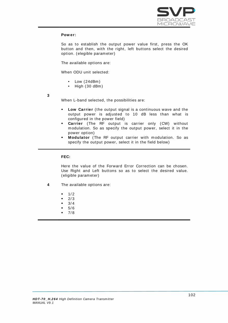
102 HDT-70_H.264 High Definition Camera Transmitter MANUAL V9.1
3
Power: So as to establish the output power value first, press the OK button and then, with the right, left buttons select the desired option. (elegible parameter) The available options are: When ODU unit selected:
• Low (24dBm) • High (30 dBm)
When L-band selected, the possibilities are: Low Carrier (the output signal is a continuous wave and the
output power is adjusted to 10 dB less than what is configured in the power field)
Carrier (The RF output is carrier only (CW) without modulation. So as specify the output power, select it in the power option)
Modulator (The RF output carrier with modulation. So as specify the output power, select it in the field below)
4
FEC: Here the value of the Forward Error Correction can be chosen. Use Right and Left buttons so as to select the desired value. (eligible parameter) The available options are: 1/2 2/3 3/4 5/6 7/8

103 HDT-70_H.264 High Definition Camera Transmitter MANUAL V9.1
5
SR: In this field, the value of the symbol rate can be introduced. (editable parameter) BW: In this field, the value of the bandwidth of the transmitted signal is displayed. (reading parameter) This parameter is automatically adjusted according to the selected transport stream parameters.
6
ODU Unit In this field, users can control ODU units: Alarms Temperature Voltage SN/RV Edit ODU channels *In L-band appears BUC; BUC Buc is used in the transmission (uplink) of satellite signals. It converts a band of frequencies from a lower frequency to a higher frequency. The available options are:
None 12,80 GHz 13,05 GHz

104 HDT-70_H.264 High Definition Camera Transmitter MANUAL V9.1
Additionally, when L-Band is selected, the following parameters can be configured:
7
Spectrum: Here the type of the spectrum is configured. Inverted spectrum is just another method to help preventing signal theft. Use Right and Left buttons so as to select the desired option. (eligible parameter) The available options are: Normal Invert
8
10 MHz: This feature provides a reference signal of 10MHz to the satellite up-converter in case of being ON. (eligible parameter) The available options are: ON OFF
9
Antenna Gain (dBi): Select the gain of the transmitter antenna. Press the OK button to configure it and then the OK button again to save the introduced value.(editable parameter)
Table 3.36 DVB-S menu options

105 HDT-70_H.264 High Definition Camera Transmitter MANUAL V9.1
3.5.2.3 Video over IP Out (Optional) By using the Up, Down arrow keys, select the IP Out option and press the OK key.
Figure 3.50 IP Out Menu
Line nº Function
1
Local IP: In this option it can be set the IP address, Mask, Gateway and MAC of the device in case it is wanted to control the device remotely. So as to change those parameters, press OK button and then, with the Up and Down keys select the desired option. LOC:
IP address of the device which is going to send the information. So as to change the IP address first press OK button and then, with the Up, Down keys select the desired number. So as to change from one character to another, press Right, Left keys. So as to save the value, press the OK button. (editable parameter)
MSK:
Subnet address of the device which is going to send the information. So as to change the Subnet Mask address first press OK button and then, with the Up, Down keys select the desired number. So as to change from one character to another, press Right, Left keys. So as to save the value, press the OK button. (editable parameter)
GAT:
Gateway address of the device which is going to send the information. So as to change the Gateway address first press OK button and then, with the Up, Down keys select the desired number. So as to change from one character to another, press Right, Left keys. So as to save the value, press the OK button. (editable parameter)
MAC ADDRESS
The MAC Address of the transmitter is shown. (reading parameter)
Video over IP Out Local IP DestinationIP&Port Fec: Disable >
Video over IP Out TP per IP: 7 (1..7) <> Protocol: UDP >

106 HDT-70_H.264 High Definition Camera Transmitter MANUAL V9.1
2
Destination IP & Port: In this option, the IP address and the port number of the device to which data is sent must be configured. In case it is wanted to send data to a multicast address just enter the desired multicast address. So as to change the IP address and the port number, first press the OK button and then, with the Up, Down keys select the desired number. So as to change from one character to another, press Right, Left keys. So as to save the value, press OK button. (editable parameter)
3
FEC: In this field, the Forward Error Correction can be enabled or disabled. In case it is enabled, the number of columns and rows can be configured pushing firstly the OK button and then, with the Up, Down arrows, the number of columns and rows wanted can be selected. If FEC option is enabled then, the only protocol which can be used is RTP. (eligible parameter)
4 TP per IP: In this field, the number of Transport Stream packets per IP (from 1 to 7) can be configured. So as to select the desired value, press the Right, Left buttons. (eligible parameter)
5
Protocol: The type of protocol used for the communication can be RTP or UDP. So as to select the desired protocol for the communication, use Right, Left buttons. (eligible parameter)
Table 3.37 IP Out menu options
When a parameter of the TS over IP menu options is changed, it takes 30 seconds to the device to be configured and work again.

107 HDT-70_H.264 High Definition Camera Transmitter MANUAL V9.1
3.5.2.4 Unit Menu By using the Up, Down arrow keys, select the Unit option and press OK key.
Figure 3.51 Unit Menu
3.5.2.4.1 RTC Selection
In the Profile option, use the Right and Left buttons to select with the Remote Control is going to be connected, RTC-01 or RTC-02, or disable it. Once you have selected the correct RTC model, press OK button to access to the profiles mode.
Figure 3.52 Unit Profile Menu • Disable:
The HDT-02 Transmitter works without the Profile option. • RTC-01:
Select this option if RTC-01 is used. • RTC-02:
Select this option when the RTC-02 is used.
UNIT Alarms Monitor Remote
UNIT Miscellaneous Firmware
UNIT RTC SEL: Disable > RTC-01 Config: RTC-02 Config:
UNIT RTC SEL: Disable > RTC-01 Config: RTC-02 Config:

108 HDT-70_H.264 High Definition Camera Transmitter MANUAL V9.1
3.5.2.4.1.1 RTC-01 Remote Control Screen When we enter in the RTC-01 profile, the profile selection screen will appear automatically:
Figure 3.53 Profile Selection This screen enables the user to choose one of the profiles that have been previously configured. If one of the profiles is selected, a line under the profile number will appear and the device will be ready to work in that configuration. To access the profile and see its configuration, the down button must be pressed for a short time. It is also possible to access to the main screen of a profile by pressing the up button for a short time. Alarms and warnings are displayed if you press OK button for a short time.
Figure 3.54: Profile selected
To exit profile mode and return to the Main menu click exit.
After entering the Main menu, the parameters can be configured from the Web Server.

109 HDT-70_H.264 High Definition Camera Transmitter MANUAL V9.1
3.5.2.4.1.2 RTC-02 Remote Control Screen When we enter in the RTC-02 profile, the channel selection screen will appear:
Figure 3.55: Profile Selection
This screen enables the user to choose one channel from the channel group that has been previously configured. If one of the channels is selected, a line under the channel number will appear and the device will be ready to work in that configuration. To access to the channel and see its configuration, the down button must be pressed for a short time. It is also possible to access to the main screen of a channel by pressing up button for a short time. Alarms and warnings are displayed if you press OK button for a short time. The output power configured on the RTC-02 is shown on the main screen of the channel selection.
Figure 4.2: Profile selected
To return to the Main menu and change the HDT-02 configuration, press Exit.
While the user is controlling the Transmitter via a Remote control, Web Server is not accessible

110 HDT-70_H.264 High Definition Camera Transmitter MANUAL V9.1
3.5.2.4.2 RTC-01 Config In this option, a profile can be configured. Select RTC-01 Config option and then by pressing the OK button, the available profiles will be displayed. There are seven profiles available and can be enabled or disabled.
Figure 3.56: Profile Config Menu
Select a profile and then press the OK button to configure the parameters related to it:
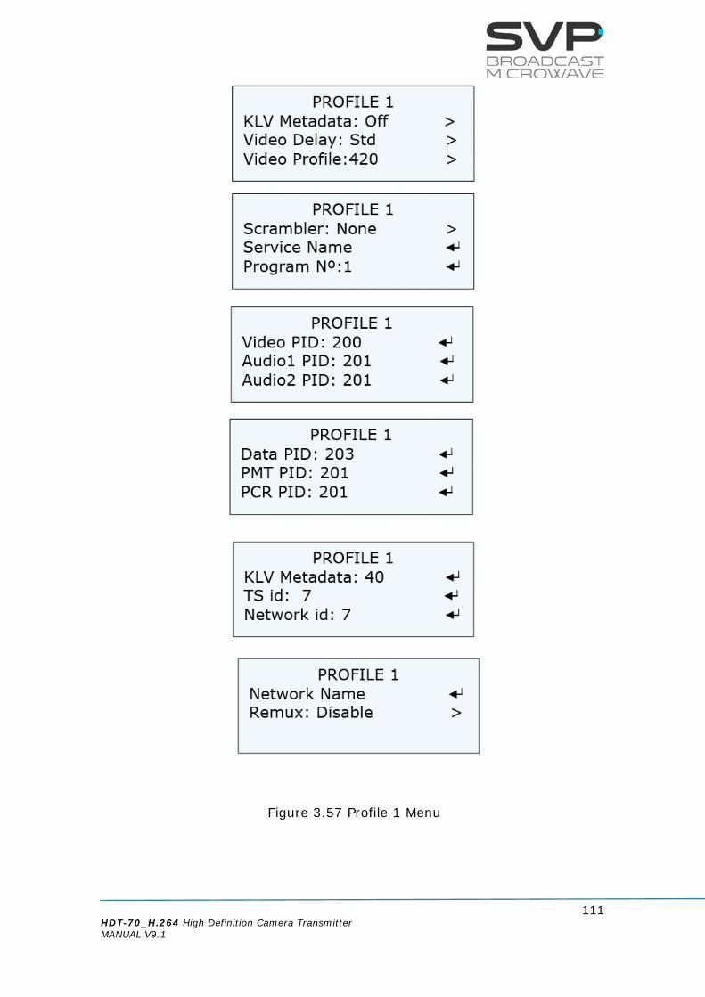
111 HDT-70_H.264 High Definition Camera Transmitter MANUAL V9.1
Figure 3.57 Profile 1 Menu

112 HDT-70_H.264 High Definition Camera Transmitter MANUAL V9.1
Line nº Function
1
System: Select the type of the transmission system with the Right and Left buttons. (eligible parameter) There are two options available:
• DVB-T2 • DVB-T
2
Frequency: Select the frequency at which the signal is going to be transmitted. Press the OK button and with Up, Down keys configure the desired value. (editable parameter)
3
Power: Select the desired power with the Right and Left buttons. (eligible parameter) There are three options available:
• High • Low
4
Bandwidth: Select the desired bandwidth with the Right and Left buttons. (eligible parameter) There are five options available:
• 1.7 MHz (Only DVB-T2) • 5 MHz • 6 MHz • 7 MHz • 8 MHz

113 HDT-70_H.264 High Definition Camera Transmitter MANUAL V9.1
5
Modulation: In this field, the modulation must be chosen with the Right and Left buttons. (eligible parameter)
The available options are: • QPSK • 16QAM • 64QAM • 256QAM (Only DVB-T2)
6
LDPC Fec: Select the desired FEC value with the Right and Left buttons. (eligible parameter)
The available options are:
• 1/2 • 3/5 • 2/3 • 3/4 • 4/5 • 5/6 • 7/8
7
FFT: Select the desired FFT value with the Right and Left buttons. (eligible parameter)
The available options are:
• 1K • 2K • 4K • 8K • 8K_ext

114 HDT-70_H.264 High Definition Camera Transmitter MANUAL V9.1
8
Guard Interval: Select the desired GI value with the Right and Left buttons. (eligible parameter)
The available options are:
• 1/4 • 19/128 • 1/8 • 19/256 • 1/16 • 1/32 • 1/128
9
Video Input:
In this field, the video input must be chosen with the Right and Left buttons. (eligible parameter)
The available options are:
• SDI • HDMI1 • HDMI2 • CVBS • ASI • IP • Generator
10
Audio1 Input: In this field, the sort of audio signal introduced in the audio 1 input can be chosen with right and left buttons. (eligible parameter)
The available options are:
• Embedded • Analogue • AES-EBU • Tone.Gen • None

115 HDT-70_H.264 High Definition Camera Transmitter MANUAL V9.1
11
Audio2 Input:
In this field, the sort of audio signal introduced in the audio 2 input can be chosen with right and left buttons. (eligible parameter) The available options are:
• Embedded • Analogue • AES-EBU • Tone.Gen • None
12
Data Input:
In this field, the data input must be chosen with the Right and Left buttons. (eligible parameter) The available options are:
• RS-232
• 4k Board
• Internal GPS with 5V
• External GPS
• None
13
KLV Metadata (eligible parameter):
In this field, the KLV metadata can be enabled or disabled.

116 HDT-70_H.264 High Definition Camera Transmitter MANUAL V9.1
14
Video Delay: In this field, the delay of the coding process is configured. So as to select the desired delay, press Right, Left arrows buttons. (eligible parameter)
The available options are:
• Standard • Super Low Delay (2 frames of delay) • Ultra Low Delay (1 frame of delay)
15
Video Profile: In this field, the codification profile can be configured. So as to select the desired profile, press Right, Left arrows buttons. (eligible parameter) The available options are:
• 4.2.0 • 4.2.2
16
Scrambler: Select the desired encryption with the Right and Left buttons. (eligible parameter) There are five options available:
• None • Biss • Biss-E • AES-128 (optional) • AES-256 (optional)
17
Service Name: Set the name of the service. (editable parameter)
18
Program Number: Here the program number must be entered. (editable parameter)

117 HDT-70_H.264 High Definition Camera Transmitter MANUAL V9.1
19
Video PID:
Here the video packet identifier must be entered. (editable parameter)
20
Audio 1 PID:
Here the audio 1 packet identifier must be entered. (editable parameter)
21
Audio 2 PID:
Here the audio 2 packet identifier must be entered. (editable parameter)
22
Data PID:
Here the data packet identifier must be entered. (editable parameter)
23 PMT PID:
Here the program map tables packet identifier must be entered. (editable parameter)
24 PCR PID:
Here the program clock reference packet identifier must be entered. (editable parameter)
25
KLV Metadata (editable parameter): Here the KLV Metadata packet identifier must be entered.
26
TS id:
In this field the Transport Stream identifier must be set. (editable parameter)
27
Network id:
In this option the network identifier must be specified. (editable parameter)

118 HDT-70_H.264 High Definition Camera Transmitter MANUAL V9.1
28
Network Name:
Specify the name of the network. (editable parameter)
29
Remux: You can enable or disable remux mode with Right and Left buttons.
Table 3.38 Profile menu options
3.5.2.4.3 RTC-02 Config Only the frequency and bandwidth are programmed. Other parameters are configured on the main menu of the transmitter. Select RTC-02 config option and then, by pressing the OK button, the channel list will be displayed. There are fourteen channels available, seven in group A and seven in group B. Also, they can be enabled or disabled.
Figure 3.58: CH Config Menu
If a channel is disabled, when the HDT is turned on it will not be selectable in the channel selection screen. Select a channel and then press the OK button to configure the parameters related to it:
Figure 3.59: Channel 1 menu

119 HDT-70_H.264 High Definition Camera Transmitter MANUAL V9.1
3.5.2.4.4 Alarms In this section, you can View and Configure the Alarms shown by the Transmitter. You can select view or configure an alarms by pressing Left and Right arrows. The alarm screen can be accessed by pressing the OK button from the main screen as well. To return to the main screen from the alarm screen, the Cross button must be pressed. The different alarms and warnings that configured in the transmitter are:
• High Voltage
• Low Voltage
• High Temperature
• Input Overflow: this alarm means that the input bit rate is higher than the one that can be modulated due to the parameters configured (constellation, FEC, GI...).
• ODU no present
• ODU frequency Range
• ODU PLL Unlock
• ODU Temperature High
• ODU Voltage Low
• ODU RF Reverse
• No SDI Input: Video source is not connected.
• No HDMI Input: Video source is not connected.
• No CVBS Input: Video source is not connected.
• No ASI Input: ASI source is not connected.
• No IP Input: IP source is not connected.
• No Audio 1 Input: Audio source is not connected.
• No Audio 2 Input: Audio source is not connected.
• No GPS: GPS source is not connected.
• RF Power
• ODU RF Low
• ODU RF Over
• PA No Forward
• PA Rev High
• No KLV
• PA Volt Low
• PA Temp High

120 HDT-70_H.264 High Definition Camera Transmitter MANUAL V9.1
3.5.2.4.5 Monitor
Figure 3.60 Unit Monitor Menu Temperature:
In this field, the internal temperature of the device is displayed. With the Right, Left keys, the user can select if the temperature is shown in ºC or in ºF. Also, the value which is between square brackets means the speed of the fans (values from 0 to 3) where 0 means that the fans are stopped and value 3 is the maximum speed. (Reading parameter)
Voltage: In this field, the voltage of the transmitter is shown. (Reading parameter)
3.5.2.4.6 Remote
Figure 3.61 Remote
UNIT MONITOR Temp: +37,1ºC (0) > Voltage: +11.6V
UNIT ETHERNET LOC 192.168.001.010 MSK 255.255.000.000 GAT 192.168.001.001
UNIT ETHERNET MAC: 70-B3-D5-1A-C0-00 Admin Pass: ******** Restore Admin Pas
UNIT ETHERNET User Pass: ******** Restores User Pas

121 HDT-70_H.264 High Definition Camera Transmitter MANUAL V9.1
Line nº Function
1
Local IP: In this option it can be set the IP address of the device in case it is wanted to control the device remotely. So as to change the IP address first press OK button and then, with the Up and Down keys select the desired number. So as to change from one character to another, press Right and Left keys. Press the OK button so as to save the introduced value. (editable parameter)
2
Subnet Mask: Here it can be written the Subnet Mask address of the device. So as to change the Subnet Mask address first press OK button and then, with the Up and Down keys select the desired number. So as to change from one character to another, press Right and Left keys. Press the OK button so as to save the introduced value. (editable parameter)
3
Gateway: In this option, the address of the Gateway must be written. So as to change the Gateway address first press OK button and then, with the Up and Down keys select the desired number. So as to change from one character to another, press Right and Left keys. Press the OK button so as to save the introduced value. (editable parameter)
4
MAC ADDRESS (Reading parameter) In this field, the MAC address of the device is shown.
5
Admin Pass: The administrator’s password is introduced. It can be set an own password which is a list of 8 digits. To set the password, press the OK button and then use the Up and Down buttons to establish the desired value, then press the Right and Left buttons to change other digits. Finally press OK button to save the introduced values.

122 HDT-70_H.264 High Definition Camera Transmitter MANUAL V9.1
6
Restore Admin Pass:
This option enables to restore the default administrator password (00000000).
7
User Pass: The user’s password is introduced. It can be set an own password which is a list of 8 digits. To set the password, press the OK button and then use the Up and Down buttons to establish the desired value, then press the Right and Left buttons to change other digits. Finally press the OK button to save the introduced values.
8
Restore User Pass: This option enables to restore the default user password (00000000).
Table 3.39 Unit Ethernet menu options

123 HDT-70_H.264 High Definition Camera Transmitter MANUAL V9.1
3.5.2.4.7 Miscellaneous
Figure 3.60 Miscellaneous Menu
Line nº Function
1
Keyboard Beep: In this field, the user can switch off the keyboard beeps.
2
Keyboard Lock:
If the On option is selected and then, the buttons of the equipment remain for 5 minutes without being pressed, a message will appear in the screen saying that the keyboard is locked. Pressing the cross button, the keyboard can be unlocked. If the Off option is selected there will be no messages in the screen. The available options are: On Off
UNIT MISCELLANEOUS Keyboard Beep: Off <
Keyboard Lock: Off < Night Mode: 0 >
UNIT MISCELLANEOUS Dist Units: Km > Video Switch: No > T/T2 Carrier: Off
UNIT MISCELLANEOUS Activ Key:******* > S/N: 660010911 Activ Licenses:

124 HDT-70_H.264 High Definition Camera Transmitter MANUAL V9.1
3
Night Mode: There are four possible states for the night mode. If night mode is in state 0, then the light in the screen will shine more than if it is in state 1. If the state is three then, the light in the screen will be the lowest of the four possible states. (eligible parameter) The available options are:
0 1 2 3
4
Dist Units: If miles is selected then, all the distances will be in miles and the same occurs if kilometers is selected. (eligible parameter) The available options are: Kilometers Miles
5
Video switch:
This option permits you to automatically switch the input signal source once the configured time for the signal source has ended. The configured video sources are switched in a looped sequence.
6
T/T2 Carrier:
The available options are:
• On: The carrier (without modulation) is shown for 1 minute.
• Off: The option is disabled.
7
Activation Key In this field, you can activate your license. You can set the activation key pressing up and down buttons. It must have 8 characters alphanumeric.

125 HDT-70_H.264 High Definition Camera Transmitter MANUAL V9.1
8
S/N: In this field the serial number of the device is shown (reading parameter).
9
Activ Licenses:
In this field you can enter the license code for the following optional features:
• AES
• KLV
• Remux
• Internal GPS
Once the code has been introduced, the licence is enabled on the unit.
You can use this menu to check which licenses are enabled on this unit.
For a new license code, please contact us.
Table 3.40 Unit Miscellaneous menu options
If the equipment asks about a license key but you don’t have it. Please contact SVP at the following email: [email protected]

126 HDT-70_H.264 High Definition Camera Transmitter MANUAL V9.1
3.5.2.4.8 Firmware
Figure 3.61 Firmware Menu
Line nº Function
1
Update Firmware: This field is the one for updating the version of the device. So as to update the equipment properly, follow the instructions below.
2
Rev: In this field it is shown the number of the version installed in the device. The characters which describe the number of the version are the one inside the red box shown in the figure above. The rest of the characters are important for the manufacturer but are not important for the user.
Table 3.41 Unit Firmware menu options

127 HDT-70_H.264 High Definition Camera Transmitter MANUAL V9.1
Next, the necessary steps so as to make a successful update are explained. 1) The latest firmware is allocated in the webpage of SVP Broadcast
Microwave. So as to access to the firmware file, first enter www.svpbm.com in your web browser.
2) Click on the Support tab.
Figure 3.62 Updating firmware step 2
3) Click on Firmware.
Figure 3.63 Updating firmware step 3

128 HDT-70_H.264 High Definition Camera Transmitter MANUAL V9.1
4) Go to TX_Firmware.
Figure 3.64 Updating firmware step 4
5) Press the Download button so as to download the file.
To verify the version of the transmitter, go to firmware field and then look at the Current Firmware to check the number of the version installed in the device (the first two digits).
Figure 3.65 Updating firmware step 5

129 HDT-70_H.264 High Definition Camera Transmitter MANUAL V9.1
6) Once the firmware file has been downloaded, save it in a USB device. In the USB device, the only file that can be allocated inside it is the firmware file of the device to be updated. 7) With the equipment completely power off (with no power
supply), insert the USB device in the USB connector, situated in the rear panel.
Before introducing the USB device, remove the power supply of the equipment. 8) Now, switch on the device.
9) Go to Unit menu. In case of being in the main screen, press cross
button so as to access to the menu. There, with the Up, Down buttons, select the Unit option.
10) Select Firmware by pressing the OK button.
11) Select Check USB Memory with the OK button.
12) Now, automatically the device updates the firmware. The screens which are shown below display the different steps that the device is making while the updating process. Don’t power off the device during the updating process.
You must remove the USB before start working with the new firmware.

130 HDT-70_H.264 High Definition Camera Transmitter MANUAL V9.1
Chapter 4: GPS 4.1 Introduction The HDT-70 transmitter has a GPS antenna input in order to give information to the device about the positioning data. Connecting the GPS antenna to this input, allows the transference of the information given. Once the information is kept inside the device, it can be sent to the HDR-70 receiver. If the signal arrives correctly to the receiver system, then the HDR-70 will have all the GPS data available and this receiver device will be able to calculate the direction, distance, positioning... of the transmitter. The HDR-70 receiver also includes another feature that consists on an output RS232 connection which allows watching throughout Google Maps application the position of the transmitter in real time. 4.2 Main Screen Next it is explained the value of the data field which appears in the main screen of the HDT-70 transmitter.
Figure 4.1 Main screen
The data status field indicates with a darkened X that it is disabled. When this parameter is enabled and blinks, this means that there is nothing connected to the data input. When this field alternates the value between ‘g’ and ‘G’, it means that it is trying to get the GPS satellites. If the ‘G’ does not vary, then it is connected to the satellites.
1250,00MHz DVBT P: +5dBm FFT8K B8 QPSK 3/4 1/16 8.7 HAuG -------- 422L

131 HDT-70_H.264 High Definition Camera Transmitter MANUAL V9.1
4.3 GPS transmitter screen So as to access to the GPS screen, go to the encoder option in the menu. Once inside this option, go to the Data field and choose GPS. Press OK button and then the GPS screen appears.
The format of the GPS coordinates used is decimal minutes as shown in the next example:
N43º02.032’
W023º03.023’
Next there are shown the different fields meanings.
Figure 4.2 GPS transmitter screen • Latitude of the transmitter: It specifies the latitude position of the
transmitter.
• Speed of the transmitter: It shows the speed of the transmitter in knot.
• Direction of the transmitter: The direction of the transmitter is shown in this field.
• Longitude of the transmitter: It specifies the longitude position of the transmitter.
• Height of the transmitter: The height of the transmitter from ground is specified in this value.
• Satellite Level: The level of each satellite signal received is shown in this field.
• Date: The updated date is shown.
#--º--.---´ ---k ---º #---º--.---´ -----mt Satellite Level --/--/-- --:--:--
Level of the satellite signals Time
Date
Height (meters)
Speed (knot) / Direction (degrees)
Longitude of the transmitter
Latitude of the transmitter

132 HDT-70_H.264 High Definition Camera Transmitter MANUAL V9.1
4.4 Application example Suppose the transmitter device is on a hill and constant positioning of the transmitter is wanted to be known. This is achievable with the next items: HDT-70_H.264 transmitter GPS antenna HDR-70 receiver
With the GPS antenna connected to the HDT-70_H.264 transmitter, positioning of the transmitter is achieved once the GPS system is connected to the necessary satellites. Next, this GPS data is sent to the HDR-70 receiver. When this signal arrives to the receiver, the HDR-70 shows in its screen some GPS value like: Transmitter positioning Transmitter direction Distance from receiver to transmitter
An example system is shown on the following page:
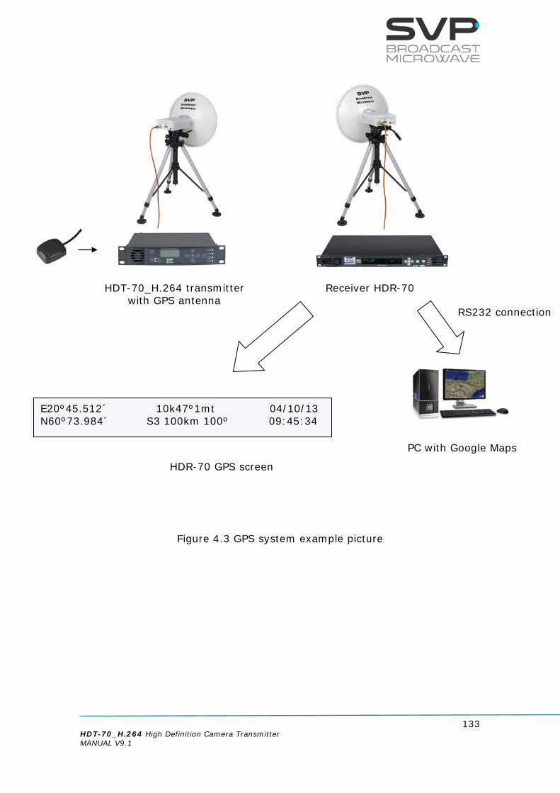
133 HDT-70_H.264 High Definition Camera Transmitter MANUAL V9.1
Figure 4.3 GPS system example picture
HDT-70_H.264 transmitter with GPS antenna
HDR-70 GPS screen
Receiver HDR-70
E20º45.512´ 10k47º1mt 04/10/13 N60º73.984´ S3 100km 100º 09:45:34
RS232 connection
PC with Google Maps

134 HDT-70_H.264 High Definition Camera Transmitter MANUAL V9.1
Chapter 5: Web Server 5.1 Introduction This equipment can be controlled by the use of a PC connected at the rear panel Ethernet connector. To enable the browser interface correctly, the IP address, Subnet Mask, Gateway, User Password and Administrator Password need to be set correctly on this unit. Next, the steps so as to setup network parameters are shown:
1. Go to Unit -> Remote
Figure 5.1 Remote
2. Select LOC option and set an IP address. So as to change the IP address first press the OK button and then, with the Up, Down keys select the desired number. So as to change from one character to another, press Right, Left keys. Press the OK button so as to save the introduced value.
Figure 5.2 Local IP
3. Select MSK option and set the Subnet Mask address. So as to change
the Subnet Mask address first press the OK button and then, with the Up, Down keys select the desired number. So as to change from one character to another, press Right, Left keys. Press the OK button so as to save the introduced value.
UNIT REMOTE LOC 192.168.001.010 MSK 255.255.000.000 GAT 192.168.001.001
UNIT Encoder IP.Out RF Unit
UNIT REMOTE LOC 192.168.001.010 MSK 255.255.000.000 GAT 192.168.001.001
UNIT Alarms(None) Monitor Remote

135 HDT-70_H.264 High Definition Camera Transmitter MANUAL V9.1
Figure 5.3 Subnet Mask
4. Select GAT option and set the Gateway address. So as to change the Gateway address first press OK button and then, with the Up, Down keys select the desired number. So as to change from one character to another, press Right, Left keys. Press the OK button so as to save the introduced value.
Figure 5.4 Gateway
5. Select Admin Pass option and set the administrator’s password. If it is wanted to access to the Webserver directly without setting any password, the Admin Pass must be set to 0 (00000000). However, if it is wanted to set an administrator’s password, it is necessary to introduce 8 digits. In this way, with this password, the administrator can access to the Webserver and make any configuration, modification or monitoring.
Figure 5.5 Admin Pass
6. Select Restore Admin Pass option to restore de default value of the administrator’s password.
UNIT REMOTE LOC 192.168.001.010 MSK 255.255.000.000 GAT 192.168.001.001
UNIT REMOTE LOC 192.168.001.010 MSK 255.255.000.000 GAT 192.168.001.001
UNIT REMOTE 70-B3-D5-1A-C0-00 Admin Pass: ******** Restore Admin Pas

136 HDT-70_H.264 High Definition Camera Transmitter MANUAL V9.1
Figure 5.6 Restore Admin Pass
7. Select User Pass option and set the user’s password. If it is wanted to access to the Webserver directly without setting any password, the User Pass must be set to 0 (00000000). However, if it is wanted to set a user’s password, it is necessary to introduce 8 digits. In this way, with this password, the user can access to the Webserver and make any monitoring.
Figure 5.7 User Pass
8. Select Restore User Pass option to restore de default value of the administrator’s password.
Figure 5.8 Restore User Pass Once the IP, Subnet Mask, Gateway, User Password and Admin Password are set and the laptop or PC is connected to the HDT-70_H.264, open the web browser and tip the IP given to the transmitter. Press enter button in your computer and then the main screen will appear.
UNIT REMOTE 70-B3-D5-1A-C0-00 Admin Pass: ******** Restore Admin Pas
UNIT REMOTE User Pass: ******** Restore User Pas
UNIT REMOTE User Pass: ******** Restore User Pas

137 HDT-70_H.264 High Definition Camera Transmitter MANUAL V9.1
5.2 Web Page Overview The main menu is set in the upper position of the screen. Once an option is chosen, it is possible to change a parameter or see the values of some options. In order to modify a parameter, introduce or select the new one and press enter button. Then the change will be set in the transmitter device. Next, several screens of the web server and their features are shown.

138 HDT-70_H.264 High Definition Camera Transmitter MANUAL V9.1
5.2.1 ENCODER
Figure 5.9 Web Server Encoder screen

139 HDT-70_H.264 High Definition Camera Transmitter MANUAL V9.1
5.2.1.1 Video Input:
Select the type of the video input. The video input options available are SDI, HDMI 1, HDMI 2, CVBS, ASI, IP and Test Pattern. In case IP input is selected, the parameters related to this input can be configured in the TSoIP screen. (eligible parameter)
Format:
Here the format of the video input signal is displayed. If there is no video input, then, the message ‘not detected’ is displayed. (reading parameter)
Bitrate:
In this field the bitrate of the input signal in Mbps is displayed. (reading parameter)
Delay: In this field, the delay of the coding process is configured. The available options are Standard Delay, Low Delay, Super Low Delay or Ultra Low Delay. (eligible parameter)
Profile: In this field, the codification profile can be configured. The available options are 4:2:0 and 4:2:2. (eligible parameter)
GOP Size:
In this field, the GOP size can be configured. The available options are auto or manual from 3 to 30.
5.2.1.2 Audio [A1] Input:
Select the type of signal introduced in the audio 1 input. The audio input options available are Embedded, Analogue, AES-EBU, Test Tone Generator and None. (eligible parameter)
[A1] Bitrate: Select the bitrate for the coding process of the audio 1 signal. The available options are 128, 192, 256 and 384 Kbps. (eligible parameter)

140 HDT-70_H.264 High Definition Camera Transmitter MANUAL V9.1
[A2] Input: Select the type of signal introduced in the audio 2 input. The audio input options available are Embedded, Analogue, AES-EBU, Test Tone Generator and None. (eligible parameter)
[A2] Bitrate: Select the bitrate for the coding process of the audio 2 signal. The available options are 128, 192, 256 and 384 Kbps. (eligible parameter)
• DID: Here you can choose the group, available options are gruop 1,2,3 or 4.
5.2.1.3 Data Input:
Select the type of data introduced to the device. The available options are None, GPS and RS232. (eligible parameter)
5.2.1.3.1 RS-232
Figure 5.10 Remote RS-232 screen
If it is wanted to send data to the transmitter through a RS232 connection, this option must be selected. It is also needed to configure the next parameters so as to achieve a successful communication: Baudrate:
Choose the baudrate of the RS-232 connection. The available options are 1200, 2400, 4800, 9600, 14400, 19200, 38400, 57600. (eligible parameter)
Parity: Select the parity for the RS-232 connection. The available options are None, ODD and Even. (eligible parameter)

141 HDT-70_H.264 High Definition Camera Transmitter MANUAL V9.1
Stop Bits: Establish the number of stop bits for the RS-232 connection. The available options are 1 and 2. (eligible parameter)
5.2.1.3.2 GPS
If GPS data is selected and the GPS antenna is connected to the device, then different parameters as shown in chapter 4 appear:
Figure 5.11 Remote GPS screen
The format of the GPS coordinates used is decimal minutes as shown in the next example:
N43º02.032’
W023º03.023’
Status: The status of the GPS input is displayed in this field. (reading parameter)
Latitude: It specifies the latitude position of the transmitter. (reading parameter)
Longitude: It specifies the longitude position of the transmitter. (reading parameter)
Altitude:
The height of the transmitter from ground in meters is specified in this value. (reading parameter)

142 HDT-70_H.264 High Definition Camera Transmitter MANUAL V9.1
Direction: The direction in degrees of the transmitter is shown in this field. (reading parameter)
Speed: The speed of the transmitter in km/h is shown in this field. (reading parameter)
5.2.1.4 TS Parameters Video PID:
Here the video packet identifier must be entered. (editable parameter)
Audio 1 PID: Here the audio 1 packet identifier must be entered. (editable parameter)
Audio 2 PID: Here the audio 2 packet identifier must be entered. (editable parameter)
Data PID: Here the data packet identifier must be entered. (editable parameter)
PMT PID: Here the program map tables packet identifier must be entered. (editable parameter)
PCR PID: Here the program clock reference packet identifier must be entered. (editable parameter)
Program Number: Here the program number must be entered. (editable parameter)

143 HDT-70_H.264 High Definition Camera Transmitter MANUAL V9.1
TS id:
In this field the Transport Stream identifier must be set. (editable parameter)
Network id: In this option the network identifier must be specified. (editable parameter)
Network Name: Specify the name of the network. (editable parameter)
Service Name: Set the name of the service. (editable parameter)
5.2.1.5 Output TS Bitrate Mode:
Bitrate mode can be automatic or manual. In case automatic mode is selected, the device configures automatically the video bitrate depending on the modulation, FEC, IG, BW used, so as to the video bitrate can be always the maximum allowed. SVP advises to use the automatic mode when the signal is transmitted through RF. Manual mode is useful when the device is used as an encoder so as to configure the desired output bitrate in the ASI output. (eligible parameter)
TS Bitrate: In case bitrate mode is manual, select the desired bitrate. (editable parameter)
When editable parameters are being set in the Web Server and new values are being introduced, the text remains in red colour until the enter button is pressed. When the enter button is pressed, the new values are saved and the text will appear in black colour. It is necessary to press the enter button to keep and save the new values on the screen.

144 HDT-70_H.264 High Definition Camera Transmitter MANUAL V9.1
5.2.1.5.1 Scrambler
If you want an encryption system, it can be chosen here. None: None encryption BISS-1:
Uses an encrypted key for the BISS key BISS-E:
Uses an encrypted key
AES-128
AES-256
5.2.1.5.2 Remux
• Mode:
Here you can enable or disable Remux mode, when de enable mode is selected, Transport Stream Bitrate mode is always manual.

145 HDT-70_H.264 High Definition Camera Transmitter MANUAL V9.1
5.2.2 RF
Figure 5.12 Remote RF screen (DVB-T)
System: In this field the transmission standard can be chosen. The available options are DVB-T2, DVB-T, DVB-S2 and DVB-S. (eligible parameter)
RF Status: Select ON in case of wanting to activate the RF transmission or press OFF button so as to deactivate it. (eligible parameter)

146 HDT-70_H.264 High Definition Camera Transmitter MANUAL V9.1
5.2.2.1 DVB-T ODU Select:
In this option, the user can choose the type of the ODU unit. (elegible parameter) The available options are: 1-6 GHz 6-11GHz PA 2.0-2.4 GHz (Optional output)
Frequency:
Introduce the frequency at which the signal is being transmitted. (editable parameter)
Power: In this field, the user can select the power at which the signal is being transmitted, the available options are high (30 dBm) and low (24 dBm).
Bandwidth: Enter the transmitted signal bandwidth. The available options are 5, 6, 7, 8 MHz. (eligible parameter)
Modulation: Select the constellation of the transmitted signal. The available options are QPSK, 16 QAM, 64 QAM. (eligible parameter)
FEC: Select the FEC value for the transmitted signal. The available options are 1/2, 2/3, 3/4, 5/6, 7/8. (eligible parameter)
GI:
Select the guard interval of the transmitted signal. The available options are 1/4, 1/8, 1/16, 1/32. (eligible parameter)

147 HDT-70_H.264 High Definition Camera Transmitter MANUAL V9.1
Spectrum
Here the type of the spectrum is configured. Inverted spectrum is just another method to help preventing signal theft. Use Right, Left buttons so as to select the desired option. (eligible parameter)
The available options are normal or invert.
TS Bitrate: The bitrate of the transmitted signal is displayed in this field. (reading parameter)
Antenna Type
In this option, the type of antenna needed is selected (elegible parameter): The available options are: None Sectorial Parabolic Omnidirectional
Polarization
In this option, the polarization of antenna is selected (elegible parameter): The available options are: Vertical Horizontal RHCP LHCP
When editable parameters are being set in the Web Server and new values are being introduced, the text remains in red colour until the enter button is pressed. When the enter button is pressed, the new values are saved and the text will appear in black colour. It is necessary to press the enter button to keep and save the new values on the screen.

148 HDT-70_H.264 High Definition Camera Transmitter MANUAL V9.1
5.2.2.2 DVB-T2
Figure 5.13 Remote RF screen (DVB-T2) ODU Select:
In this option, the user can choose the type of the ODU unit. (elegible parameter) The available options are: 1-6 GHz 6-11 GHz PA 2.0-2.4 GHz (Optional output) RF OUTPUT
Frequency:
Introduce the frequency at which the signal is being transmitted. (editable parameter)

149 HDT-70_H.264 High Definition Camera Transmitter MANUAL V9.1
Power:
In this field, the user can select the power at which the signal is being transmitted, the available options are high (30dBm) and low (24dBm).
ODU Direct The direct power transmitted is shown in the screen (dBm).
ODU Reverse The quantity of reflected power of the transmitted signal is displayed (%).
Bandwidth: Enter the transmitted signal bandwidth. The available options are 1.7, 5, 6, 7, 8 MHz. (eligible parameter)
Modulation: Select the constellation of the transmitted signal. The available options are QPSK, 16 QAM, 64 QAM, 256 QAM. (eligible parameter)
LDPC FEC: Select the FEC value for the transmitted signal. The available options are 1/2, 3/5, 2/3, 3/4, 4/5, 5/6. (eligible parameter)
Mode: Specify the FFT mode. The available options are 1K, 2K, 4K, 8K, 8K.ext. (eligible parameter)
GI: Select the guard interval of the transmitted signal. The available options are 1/4, 19/128, 1/8, 19/256, 1/16, 1/32, 1/128. (eligible parameter)
Pilot Pattern: This field indicates the scattered pilot pattern used for the data OFDM symbols. The available options are between PP1 and PP8. (reading parameter)
Time Interleaving: This option indicates the number of time interleaver blocks per interleaving frame. The user must select in how many time interleaver blocks (TI_blocks) an interleaving frame is split. Only the time interleaver mode 0 (TIME_IL_TYPE=0) is supported, so one interleaving frame always equates to exactly one OFDM frame.

150 HDT-70_H.264 High Definition Camera Transmitter MANUAL V9.1
To desactivate the time interleaver, this parameter must be set to 0. (editable parameter)
Bitrate: The bitrate of the transmitted signal is displayed in this field. (reading parameter)
Antenna Type In this option, the type of antenna needed is selected (elegible parameter):
The available options are: None Sectorial Parabolic Omnidirectional
Polarization
In this option, the polarization of antenna is selected (elegible parameter): The available options are: Vertical Horizontal RHCP LHCP
When editable parameters are being set in the Web Server and new values are being introduced, the text remains in red colour until the enter button is pressed. When the enter button is pressed, the new values are saved and the text will appear in black colour. It is necessary to press the enter button to keep and save the new values on the screen.

151 HDT-70_H.264 High Definition Camera Transmitter MANUAL V9.1
5.2.2.3 DVB-S2 (Optional)
Figure 5.14 Web Server RF screen (DVB-S2) ODU Select:
In this option, the user can choose the type of the ODU unit. (elegible parameter) The available options are: 1-6 GHz 6-11 GHz LBAND (Optional output)
Frequency:
Introduce the frequency at which the signal is being transmitted. (editable parameter)

152 HDT-70_H.264 High Definition Camera Transmitter MANUAL V9.1
Output Mode: Specify the transmission mode which can be no output. (eligible parameter) The available options are: Low Carrier Carrier Modulator
Power:
Specify the power at which the signal is being transmitted. (editable parameter)
ODU Direct The direct power transmitted is shown in the screen (dBm).
ODU Reverse
The quantity of reflected power of the transmitted signal is displayed (%).
Mod / FEC:
Introduce the constellation and LDPC FEC value of the transmitted signal. (Constellation options are: QPSK, 8PSK, 16 APSK, 32 APSK) (LDPC FEC options are: 1/4, 1/3, 2/5, 1/2, 3/5, 2/3, 3/4, 4/5, 5/6, 8/9, 9/10) (eligible parameter)
Symbol Rate:
In this field the value of the symbol rate of the transmitted signal can be selected. (From 2 to 45 Mbaud/s) (editable parameter)
Bandwidth: In this field, the value of the bandwidth of the transmitted signal is displayed. (reading parameter)
TS Bitrate:
In this field, the value of the bitrate of the transmitted signal is displayed. (reading parameter)
10 MHz:
10 MHz reference oscillator mode ON or OFF. This feature provides a reference signal to the satellite up-converter in case of being ON. (eligible parameter)

153 HDT-70_H.264 High Definition Camera Transmitter MANUAL V9.1
5.2.2.4 DVB-S (Optional)
Figure 5.15 Web Server MOD_RF screen (DVB-S) ODU Select:
In this option, the user can choose the type of the ODU unit. (elegible parameter) The available options are: 1-6 GHz 6-11 GHz LBAND (Optional output)
Frequency:
Introduce the frequency at which the signal is being transmitted. (editable parameter)
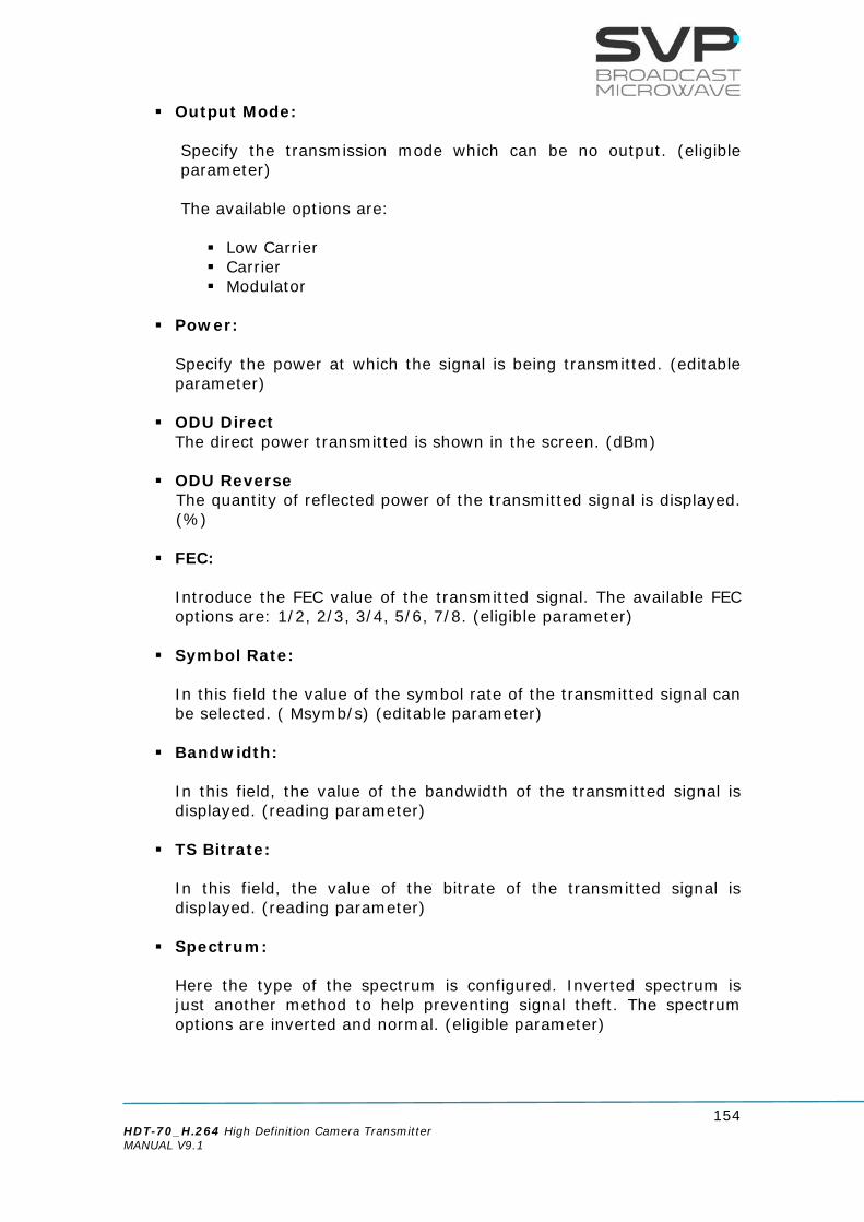
154 HDT-70_H.264 High Definition Camera Transmitter MANUAL V9.1
Output Mode: Specify the transmission mode which can be no output. (eligible parameter) The available options are: Low Carrier Carrier Modulator
Power:
Specify the power at which the signal is being transmitted. (editable parameter)
ODU Direct The direct power transmitted is shown in the screen. (dBm)
ODU Reverse
The quantity of reflected power of the transmitted signal is displayed. (%)
FEC:
Introduce the FEC value of the transmitted signal. The available FEC options are: 1/2, 2/3, 3/4, 5/6, 7/8. (eligible parameter)
Symbol Rate:
In this field the value of the symbol rate of the transmitted signal can be selected. ( Msymb/s) (editable parameter)
Bandwidth:
In this field, the value of the bandwidth of the transmitted signal is displayed. (reading parameter)
TS Bitrate:
In this field, the value of the bitrate of the transmitted signal is displayed. (reading parameter)
Spectrum:
Here the type of the spectrum is configured. Inverted spectrum is just another method to help preventing signal theft. The spectrum options are inverted and normal. (eligible parameter)

155 HDT-70_H.264 High Definition Camera Transmitter MANUAL V9.1
10 MHz:
10 MHz reference oscillator mode ON / OFF. This feature provides a reference signal to the satellite up-converter in case of being ON. (eligible parameter) When editable parameters are being set in the Web Server and new values are being introduced, the text remains in red colour until the enter button is pressed. When the enter button is pressed, the new values are saved and the text will appear in black colour. It is necessary to press the enter button to keep and save the new values on the screen.
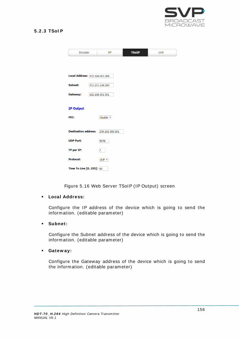
156 HDT-70_H.264 High Definition Camera Transmitter MANUAL V9.1
5.2.3 TSoIP
Figure 5.16 Web Server TSoIP (IP Output) screen
Local Address: Configure the IP address of the device which is going to send the information. (editable parameter)
Subnet: Configure the Subnet address of the device which is going to send the information. (editable parameter)
Gateway: Configure the Gateway address of the device which is going to send the information. (editable parameter)

157 HDT-70_H.264 High Definition Camera Transmitter MANUAL V9.1
5.2.3.1 IP Output FEC:
In this field the Forward Error Correction can be enabled or disabled. In case it is enabled, the number of columns and rows can be configured. If FEC option is enabled then, the only protocol which can be used is RTP. (eligible parameter)
Destination address: In this option, the IP of the device to which data is sent must be configured. In case it is wanted to send data to a multicast address just enter the desired multicast address. (editable parameter)
UDP Port: In this option, the port number of the device to which data is sent must be configured. (editable parameter)
TP per IP: In this field the number of Transport Stream packets per IP (from 1 to 7) can be configured. (editable parameter)
Protocol: In this field the type of protocol used for the communication is selected. The type of protocol used for the communication can be RTP or UDP. (eligible parameter)
Time To Live[0..255]: This field limits the lifetime of data. The Time to Live value (from 1 to 255) means the number of routers that a packet can reach until that packet is discarded. (editable parameter) When editable parameters are being set in the Web Server and new values are being introduced, the text remains in red colour until the enter button is pressed. When the enter button is pressed, the new values are saved and the text will appear in black colour. It is necessary to press the enter button to keep and save the new values on the screen.

158 HDT-70_H.264 High Definition Camera Transmitter MANUAL V9.1
5.2.4 UNIT
Figure 5.17 Web Server UNIT screen

159 HDT-70_H.264 High Definition Camera Transmitter MANUAL V9.1
5.2.4.1 LEDs Status (reading parameters)
ON/OFF:
o If the LED is off the equipment is not being fed. o The LED lights up in green when the equipment is turned on.
RF:
o If the LED is off the equipment does not transmit RF signal. o The LED lights up in green when the equipment transmits RF
signal, RF stage is active.
ALARM:
o The LED lights up in red when an alarm occurs. o The different alarms that can appear in the transmitter are:
Voltage Low (<22 dBm). Temperature High. ASI Overflow.
o The different warnings that can appear in the transmitter are: No Video Input. No GPS.
STATUS:
The LED lights up when a change in the configuration of the device is being processed.
5.2.4.2 Alarms
In this option, different alarms which are present in the device are shown. The different alarms that can appear in the transmitter are: - Voltage Low. - Temperature High. - ASI Overflow:
this alarm means that the input bitrate is higher than the one that can be modulated due to the parameters configured (constellation, FEC, GI...).
The different warnings that can appear in the transmitter are: - No Video Input. - No GPS.

160 HDT-70_H.264 High Definition Camera Transmitter MANUAL V9.1
5.2.4.3 Monitor Voltage:
In this field, the voltage of the transmitter is shown. (reading parameter)
Temperature:
In this field, the internal temperature of the device is displayed. (reading parameter)
5.2.4.4 Configuration
Standby Mode
In this option the user can turn on or turn off the device pressing On or Standby options. (elegible parameters)
Web&SNMP Address
In this option it can be set the IP address of the device in case it is wanted to control the device remotely. So as to change the IP address, introduce the desired number and then press enter button to save the introduced value. (editable parameter)
Web&SNMP Subnet
Here it can be written the Subnet Mask address of the device. So as to change the Subnet Mask address, introduce the desired value and then press enter button to save it. (editable parameter)
Web&SNMP Gateway
In this option, the address of the Gateway must be written. So as to change the Gateway address, introduce the desired value and then press enter button to save it. (editable parameter)
Web&SNMP MAC In this field, the MAC address of the device is shown
Admin Password
In this field, the administrator’s password is introduced. It can be set an own password which is a list of 8 digits. Then, to save the

161 HDT-70_H.264 High Definition Camera Transmitter MANUAL V9.1
introduced value, press Enter button. Moreover, there is the option to restore the default administrator password (00000000).
User Password In this field, the user’s password is introduced. It can be set an own password which is a list of 8 digits. Then, to save the introduced value, press Enter button. Moreover, there is the option to restore the default user password (00000000).
5.2.4.5 Miscellaneous
Night Mode:
If the night mode is OFF then, the light in the screen will shine more than if the night mode is ON. (eligible parameter)
S/N:
In this field, the serial number of the device is displayed. (reading parameter)
Firmware: In this field, the number of the version installed in the device is displayed. (reading parameter)
5.2.4.6 ODU T/T2 Unit Temperature
In this option, the temperature of the ODU is shown in the screen. (reading parameter)
Voltage
In this field, the voltage of the ODU is displayed in the screen. (reading parameter)
S/N
In this field the serial number of the ODU is shown (reading parameter).

162 HDT-70_H.264 High Definition Camera Transmitter MANUAL V9.1
Revision
In this field it is shown the number of the version installed in the ODU (reading parameter). When editable parameters are being set in the Web Server and new values are being introduced, the text remains in red colour until the enter button is pressed. When the enter button is pressed, the new values are saved and the text will appear in black colour. It is necessary to press the enter button to keep and save the new values on the screen.

163 HDT-70_H.264 High Definition Camera Transmitter MANUAL V9.1
5.3 Web Page Setup Notes In order for the data to be refreshed correctly, you may need to change some settings on your browser. Please follow these instructions carefully. For Google Chrome: 1. Make click in the Chrome menu situated in the toolbar of the browser. 2. Select tools. 3. Choose the option Delete navigation data… 4. Choose the option empty cache. 5. Make click in Delete navigation data. For Internet Explorer: 1. From the Tools menu, select Internet Options 2. In the General tab, click the Settings button in the Browsing History section. 3. Select 'Every time I visit the webpage' then click the OK button. 4. Click the OK button For Mozilla Firefox: 1. Open a new tab, in the address bar enter about:config 2. In the Filter box, enter disk 3. Set the value for 'browser.cache.disk.enable' to false (double click to change the setting). 4. Close the about:config tab. 5.4 SNMP Simple Network Management Protocol (SNMP) is an "Internet-standard protocol for managing devices on IP networks. SNMP exposes management data in the form of variables on the managed systems, which describe the system configuration. These variables can then be queried (and sometimes set) by managing applications. SNMP is an application-layer protocol and it runs over UDP at the transport level. SNMP is based on a manager / agent model as it is shown below:

164 HDT-70_H.264 High Definition Camera Transmitter MANUAL V9.1
Figure 5.18 SNMP management system
The SNMP agent used is MIB-II compliant. The SVP MIB (Management Information Database) provides a standard representation of the SNMP Agent’s available information and where it is stored. The MIB is defined according to the ASN.1.
5.4.1 SNMP commands SNMP use the next commands:
Operation Description Sender
Get
Readout the current value of specific objects in the MIB.
NMS
Get next
Readout the current value of the next object in the MIB.
NMS
Set
Change a value of a specific
object in the MIB.
NMS
Get response
Responds to a get, get next
or set request.
Agent
Trap
A trap is a mechanism to trigger the NMS that a
change in the device has occurred.
After receiving the trap the NMS still has to poll the
device to find out the details of the change.
Agent
Table 5.1 SNMP commands
Network Management Station SNMP agent

165 HDT-70_H.264 High Definition Camera Transmitter MANUAL V9.1
6 Chapter 6: Block Diagram In this chapter, the block diagram of the HDT-70 transmitter is explained. This diagram has several parts related to the HDT-70 internal performance which are shown in blocks with different inputs and outputs. In the first part, the video, audio 1 and audio 2 encoder outputs go to the multiplexer to obtain in this way one common output signal. Then, the signal passes through the scrambler which encrypts the signal at the transmitter to make the message unintelligible at a receiver not equipped with an appropriately set descrambling device. The ASI transport stream can be scrambled in Operational Mode 1 or Mode E, with a Session Word. This is an ultimate solution for reliable and interoperable protection of the communication. The user can choose between None, BISS- 1or BISS-E options for the encryption. As it is explained in the manual, if None option is selected the signal will not be encrypted. Once the signal has passed the BISS-1 / E block, it passes through the DVB-T/T2/S/S2 modulator. In this part, the signal is modulated according to the requirements needed and a digital signal is obtained. The next step is to go to the DAC converter to obtain an analogue signal. There are two DAC blocks. The first one provides a 70 MHz output connected via triax cable and the other one goes to the Quadrature Modulator which is a general technique of modulating employing a VCO & PLL system. Thanks to the VCO & PLL block, the system frequency can be configured, and then, in the output of the Quadrature Modulator block, the RF signal is obtained. The next block consists of a variable attenuator that controls the output power. Then a splitter is required, which distributes the signal to four different amplifier blocks. In this way there are four different outputs available for DVB-S/S2 L-Band and then DVB-T/T2 1-2,8 GHz, DVB-T/T2 2,8-4 GHz and DVB-T/T2 4-6,4 GHz connected to a switch . The 10 MHz oscillator is used for the synchronization of the BUC and it can be enabled or disabled. In the bottom of the diagram, there is a FPGA Controller, which is responsible for controlling all the system. This block controls the remote control (RTC), the power amplifier (PA), the temperature and the voltage. It also has an USB and Ethernet control connection.

166 HDT-70_H.264 High Definition Camera Transmitter MANUAL V9.1
Figure 6.1: HDT-70 Block Diagram

167 HDT-70_H.264 High Definition Camera Transmitter MANUAL V9.1
Chapter 7: Equipment Installation 7.1 Introduction This chapter provides important information for the transmitter system installation such as the connections available in the rear and front panel of the HDT-70 transmitter and their pinout, connectors needed and the accessories which are available with the transmitter device. 7.2 Connections Every connection of the HDT-70 camera transmitter is on the rear panel, except for the RF antenna connections that are on the front panel. All the Lemo part numbers and pinout refer to the connector that is fixed to the cable. The pinout of the cable connector is shown as if it is watched from the soldering side. All the input/output connections of the HDT-70 transmitter are shown in the figure below:
Figure 7.1 HDT-70 Connections
HDT-70 H.264
SDI (3G/SD/HD)
HDMI 1/HDMI 2
Ethernet
Audio 1 (L&R)
Audio 2 (L&R)
IF Output
Trasnport Stream over IP Out (Optional)
USB
DATA/GPS
ASI Out
AES/EBU
ASI In
Trasnport Stream over IP In
Power AC
L Band Output (Optional)
CVBS RF Output 2.0-2.4 GHz (Optional)

168 HDT-70_H.264 High Definition Camera Transmitter MANUAL V9.1
The following figures show the HDT-70 front and rear panel. The connections mentioned in the upper figure are shown below.
Figure 7.2 HDT-70 front panel
Figure 7.3 HDT-70 rear panel
Technical features of each connection are described on the following sections.

169 HDT-70_H.264 High Definition Camera Transmitter MANUAL V9.1
7.2.1 Power supply In this section technical features about the power supply connections and the connectors needed are described.
AC Power supply The transmitter equipment can be powered by an AC source between 90 and 240 V. The mains frequency should be between 50 and 60 Hz. The AC mains input uses a Neutrik MLC connector. A cable with the required connectors is supplied with the equipment. The AC power connector used in this equipment is designed to prevent accidental disconnection. To extract the connector, pull back the locking clip and rotate the connector, as indicated on the connector itself.
Power supply AC connection technical features
Item Features Connector label POWER A.C. Connector type MLC Neutrik Supply voltage 90-240 V. (50/60Hz)
Table 7.1 AC Power supply features
Pinout

170 HDT-70_H.264 High Definition Camera Transmitter MANUAL V9.1
Pin Description
1 L
2 GND
3 N
Table 7.2 AC Power supply connector pinout
Connector needed
7.2.2 Intermediate frequency In this section technical features about the output connections available and the connectors needed are described.
Intermediate frequency output IF The connection between the transmitter unit and the up-converter uses triax cable, whose maximum length depends on the type of triaxial cable used.
Intermediate frequency connection technical features
Item Features Connector label IF Connector type (equipment) Lemo 3 triax Part Number (equipment) Lemo EHP.3T Part Number (cable) Lemo FFA.3T Manufacturer Lemo Required cable Draka-Triflex 8 – Y HDTV
Table 7.5 IF output connections characteristics
NAC3FCA
NAC3MPA

171 HDT-70_H.264 High Definition Camera Transmitter MANUAL V9.1
Never connect transmitter control unit directly to the receiver control unit. The HENM-70 can be connected to a Block-Up-Converter connecting the IF Input of the BUC to the IF out (L-band) connector of the HENM-70, and the M&C connector of the BUC to the DATA GPS connector of the HENM-70, as shown in the figure below.
7.2.3 L-Band Output (Optional) The satellite up – converter is directly connected to the female BNC – type connector on the rear panel of the HDT-70.
L Band connection technical features
Item Features Connector label DVB-S2 L Band Connector type BNC female Impedance 50 Ω
Table 7.6 L Band output connections characteristics

172 HDT-70_H.264 High Definition Camera Transmitter MANUAL V9.1
7.2.4 RF Output (Optional)
There is an RF output for DVB-T and DVB-T2 in the control unit which frequency range goes from 2.0 GHz to 2.4 GHz.
RF connection technical features
Item Features Connector label RF OUTPUT
(2.0 to 2.4GHz) Connector type N female Impedance 50 Ω Output power Maximum: 10 W
Table 7.7 RF output connections characteristics
7.2.5 ASI
ASI input The HDT-70 transmitter has a DVB-ASI Transport Stream input, available on an insulated 75 Ω BNC connector.
ASI IN connection technical features
Item Features Connector label ASI-IN Connector type BNC Impedance 75 Ω Standard EN50083-9 Maximum Bitrate 216 Mbps
Table 7.8 DVB-ASI Transport Stream input connection features

173 HDT-70_H.264 High Definition Camera Transmitter MANUAL V9.1
ASI output
ASI output signal type uses 75Ω BNC connector. This connector is placed on transmitter rear panel. It is important that 75 Ω connectors are used. This is because the female output connector of the HDT-70 unit may be damaged because of an impedance mismatch.
ASI OUT connection technical features
Item Features Connector label ASI-OUT Connector type BNC female Impedance 75 Ω Standard EN50083-9 Maximum Bitrate 100 Mbit/s
Table 7.9 DVB-ASI Transport Stream output connection features

174 HDT-70_H.264 High Definition Camera Transmitter MANUAL V9.1
7.2.6 CVBS/ SDI/ HDMI The HDT-70_H.264 transmitter incorporates two HDMI inputs so as to allow that new devices can be connected. SD-SDI digital video input is compatible with SMPTE-259 Standard, HD-SDI digital video input signal type is SMPTE-292 compliant and 3G-SDI digital video input signal type is SMPTE-425M compliant.
CVBS connection technical features
Item Features Connector Label CVBS Connector type Female BNC Impedance 75 Ω
Table 7.10 CVBS signal connection features
SDI connection technical features
Item Features Connector Label SDI-IN Connector type BNC Impedance 75 Ω Input Level 800 mVpp nominal ±10% Standards SMPTE-259M and SMPTE-272M
SMPTE-292M and SMPTE-299M SMPTE-425M
Bitrate SD: 270 Mbit/s HD: 1485 Mbit/s 3G: 3 Gbit/s
Table 7.11 SDI input signal connection features
HDMI connection technical features
Item Features Connector Label HDMI Connector type Type A
Table 7.12 HDMI input signal connection features

175 HDT-70_H.264 High Definition Camera Transmitter MANUAL V9.1
7.2.7 Transport Stream over IP (Optional)
Transport Stream over IP Input and Output The HDT-70 transmitter has a connector that allows receiving and transporting video over IP. The connector is a UTP Cat 5e which is described in the EIA/TIA568B standard.
TS over IP connection technical features
Item Features Connector Label VIDEO over IP Connector type RJ-45
Table 7.13 Transport Stream over IP connection technical features
There is no recompression when the equipment sends the information through IP. At the level of ASI and IP, the device keeps the original coding generated in the transmitter. Transport Stream over IP gives some benefits like: • Ensured Quality of Service with highly reliable Video Gateways. • Built-in intelligent monitoring and redundancy solutions. • Simple and fast connection setup and teardown with T-VIPS Connect. • Allows broadcasters and network operators to simplify their day to day
operation. • Create revenue-generating professional Wide Area Networks for video
transport. Technical features are described below:
• IP encapsulation and 2D FEC encoding and decoding as defined in SMPTE
2022. • Persistent storage of configuration parameters. • Unicast and multicast IP addressing. It is not possible to configure the equipment as IP input and IP output at the same time.
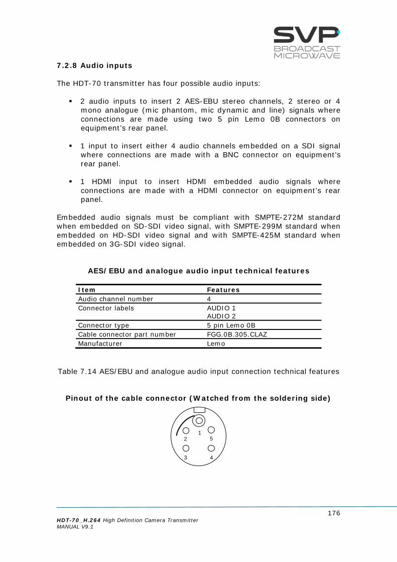
176 HDT-70_H.264 High Definition Camera Transmitter MANUAL V9.1
7.2.8 Audio inputs The HDT-70 transmitter has four possible audio inputs: 2 audio inputs to insert 2 AES-EBU stereo channels, 2 stereo or 4
mono analogue (mic phantom, mic dynamic and line) signals where connections are made using two 5 pin Lemo 0B connectors on equipment’s rear panel.
1 input to insert either 4 audio channels embedded on a SDI signal where connections are made with a BNC connector on equipment’s rear panel.
1 HDMI input to insert HDMI embedded audio signals where
connections are made with a HDMI connector on equipment’s rear panel.
Embedded audio signals must be compliant with SMPTE-272M standard when embedded on SD-SDI video signal, with SMPTE-299M standard when embedded on HD-SDI video signal and with SMPTE-425M standard when embedded on 3G-SDI video signal.
AES/EBU and analogue audio input technical features
Item Features Audio channel number 4 Connector labels AUDIO 1
AUDIO 2 Connector type 5 pin Lemo 0B Cable connector part number FGG.0B.305.CLAZ Manufacturer Lemo
Table 7.14 AES/EBU and analogue audio input connection technical features
Pinout of the cable connector (Watched from the soldering side)
2 5
3 4
1

177 HDT-70_H.264 High Definition Camera Transmitter MANUAL V9.1
Pin Description
1 A1L+ / AES1P
2 A1L- / AES1N
3 GND
4 A1R+
5 A1R-
Table 7.15 AES/EBU and analogue audio cable connector pinout
7.2.9 BUC The HDT-70 transmitter incorporates an input so as to control the BUC.
BUC & SSPA connection technical features Item Features Connector Label BUC & SSPA Connector type 7 pin Lemo 0B Cable connector part number FGG.0B.307.CLAZ Manufacturer Lemo
Table 7.16 BUC & SSPA connection features
Pinout of the cable connector (Watched from the soldering side)
Pin Description
1 GND
2 Remote TX (-)
3 Remote TX (+)
4 Not used
5 Not used
6 Remote RX (+)
7 Remote RX (-)
Table 7.17 BUC & SSPA cable connector pinout
7

178 HDT-70_H.264 High Definition Camera Transmitter MANUAL V9.1
In pins number 2, 3, 6 and 7, Remote means that a connection can be established between the HDT-02 transmitter and a BUC
7.2.10 Data/GPS input This input is mainly used in order to transfer GPS data or user data through connections made using 6 pin Lemo 0B connector on equipment’s rear panel. Thanks to this characteristic it is possible to obtain GPS coordinates in the HDR-70 receiver and to know the exact position of the transmitter and the distance between the receiver and the transmitter as well as other parameters.
Data/GPS connection technical features
Item Features Connector Label DATA/GPS Connector type 6 pin Lemo 0B Cable connector part number FGG.0B.306.CLAZ Manufacturer Lemo
Table 7.18 Data/GPS input connection technical features
Pinout of the cable connector (Watched from the soldering side)
Pin Description
1 Ground
2 DATA
3 NOT USED
4 +5Vd_GPS
5 PA_ON/OFF
6 PA_DIRECT
Table 7.19 Data/GPS cable connector pinout
1
3
2
4
5 6

179 HDT-70_H.264 High Definition Camera Transmitter MANUAL V9.1
7.2.11 USB connection Thanks to the USB connection, it is possible to update directly from an external USB device the firmware of the HDT-70 transmitter. The connector is type A.
USB connection technical features
Item Features Connector Label USB Connector type Type A
Table 7.20 USB connection technical features
7.2.12 Ethernet This connection allows the user to monitor and setup any parameter of the transmitter throughout Web Browser and SNMP through the network. This feature is implemented with the SNMP (Simple Network Management Protocol) and the connector used is a RJ-45.
Ethernet connection technical features
Item Features Connector Label Ethernet Connector type RJ-45
Table 7.21 Ethernet input connection technical features

180 HDT-70_H.264 High Definition Camera Transmitter MANUAL V9.1
7.3 Rack Unit Installation When the unit is installed the transmitter rack unit horizontally, guides should be used due to the weight of the equipment. Also, the transmitter has to be well chilled and therefore, some space must be left next to the sides of the HDT-70 transmitter for ventilation purposes. This is especially important when the rack unit is installed in a rack case. 7.4 Up-Converter and parabolic antenna installation The up-converter is installed next to the transmitter antenna. The form that the antenna is connected to the up-converter input is through mechanical hook. The up-converter is connected to the HDT-70 transmitter through a triax cable. For better performance high quality cables and connectors should be used. Do not connect wrongly down-converter to the transmitter. In this case, the down converter doesn’t switch on. The up-converter is powered by the transmitter by the IF output. So the IF output should be connected to one IF input of the HD diversity transmitter.
Figure 7.4 Up-Converter The power supply to the up-converter in the transmitter should be disabled when the up-converter is being installed.

181 HDT-70_H.264 High Definition Camera Transmitter MANUAL V9.1
7.5 Antenna Installation Parabolic antenna is connected to the up-converter through a mechanical hook as shown in figure 6.5
Figure 7.5 HDT-70 transmitter system installation

182 HDT-70_H.264 High Definition Camera Transmitter MANUAL V9.1
Chapter 8: Up Converter This chapter provides all the information needed about the HDT-70 transmitter up-converter. The up-converter provides 3Watt power in 2GHz band and 0,5Watt power in 7GHz and 10GHz bands. 8.1 Front Panel The figure below shows the front panel of the up-converter. Lemo connector for IF Autotracking Antenna connector (under development) Channel selector: with 15 preset channels (Editable) Status indicator LED Display
Figure 8.1 Front panel of the Up-Converter
The up-converter is a multi-frequency equipment. The reception frequency can be configured manually using the channel selector in the down-converter (one among 15 previously programmed frequencies) or remotely from the rack demodulator equipment. Frequency configuration can be done from the demodulator rack unit or from the up-converter channel selector. To configure the frequency manually, using the channel selector in the up-converter, the operator should look at the channel list at one side of the up-converter and move the channel selector to the desired channel. In this case, the frequency cannot be modified from the rack control unit.

183 HDT-70_H.264 High Definition Camera Transmitter MANUAL V9.1
To configure the reception frequency remotely, the channel selector has to be set in 0 position, slave mode. The up-converter has a Status Indicator LED. If the up-converter is working properly the LED lights in green. If the LED is Off:
The control unit has the up-converter power supply disabled There is a short circuit in the triax cable
When the PLL is unlocked the LED flashes green and red alternatively If the up-converter has any other alarm the LED lights in red. 8.2 Display
8.2.1 Main screen DVB-T/T2 Next, the main screen of the Up – Converter is shown.
Figure 8.2 Up Converter front panel/ Main screen DVB-T/T2 explanation The parameters displayed in the panel are: Frequency: transmitted frequency in MHz Power: Output power in Watts Transmission standard (DVB-T/T2) Bandwidth Transmitted bitrate Modulation scheme LDPC FEC (1/2, 3/5, 2/3, 3/4, 4/5, 5/6) Guard Interval (1/4, 19/128, 1/8,19/256, 1/16, 1/32, 1/128)
F:10.350,00MHz (MN00) Pwr:00dBm T2 8MHz 44.8Mbps 256QAM 5/6 1/16

184 HDT-70_H.264 High Definition Camera Transmitter MANUAL V9.1
8.2.2 Main screen DVB-S/S2 Next, the main screen of the Up – Converter is shown.
Figure 8.3 Up Converter front panel/ Main screen DVB-S/S2 explanation The parameters displayed in the panel are: Frequency: transmitted frequency in MHz Power: Output power in Watts Transmission standard (DVB-T/T2) Bandwidth Transmitted bitrate Modulation scheme(QPSK, 8PSK, 16APSK, 32APSK) LDPC FEC (1/4, 1/3, 2/5, 1/2, 3/5, 2/3, 3/4, 4/5, 5/6, 8/9, 9/10)
F:10.350,00MHz (MN00) Pwr:00dBm S2 8MHz 44.8Mbps 32APSK 9/10

185 HDT-70_H.264 High Definition Camera Transmitter MANUAL V9.1
8.3 Alarms Alarms and warnings detailed below can appear on the up-converter. Up-converter transmission power: when the transmission power is equal or lower than 50% of the configured transmission power, the equipment shows an alarm, the LED next to ALARM button lights red. When the power reaches 55% of the configured transmission power the alarm is cancelled. Reverse power: when the reverse power exceeds the 25% of the transmitted power, an alarm is triggered and the LED next to ALARM button lights red. Besides, the field corresponding to transmitted power blinks in both, main screen and line no.2 in the MONITOR STATUS menu. When the reverse power decreases below 23% of the transmitted signal power the alarm is cancelled. Up-converter temperature: if the temperature inside the up-converter reaches or exceeds 85ºC, an alarm is triggered and the red LED next to the ALARM button lights. When the temperature drops to 65ºC, the alarm is cancelled. Up-converter power supply: if the power supply voltage to the up-converter is below 18V or above 36V, an alarm is triggered and the red LED next to the ALARM button lights. The unit stops displaying the alarm when the power supply voltage is 18V or greater, but below 36V. Lock status of the up-converter: if the PLL of the up-converter is not locked in frequency, the equipment shows an alarm and the LED next to alarm button lights.

186 HDT-70_H.264 High Definition Camera Transmitter MANUAL V9.1
8.4 Mechanical Dimensions
Figure 8.4 Mechanical Dimensions
186 mm
80 mm
334 mm

187 HDT-70_H.264 High Definition Camera Transmitter MANUAL V9.1
8.5 Connections This section provides important information about the connectors of the Up Converter.
8.5.1 IF connector The connection between the transmitter unit and the up-converter uses triax cable, whose maximum length depends on the type of triax cable used.
Item Features Connector label IF Connector type (equipment) Lemo 3 triax Part Number (equipment) Lemo EHP.3T Part Number (cable) Lemo FFA.3T Manufacturer Lemo Required cable Draka – Triflex 8 – Y HDTV
Table 8.1 Intermediate frequency connector technical features
8.5.2 Autotracking Antenna connector (under development) This is a connector used for autotracking antenna.
Item Features Connector label Antenna Autotracking Connector type Bayonet 19 pin female Output DC
20 to 36V DC / 1 Amp (Internal fuse autoreseteable)
Output Voltage Control 10,5V at 300mA Part Number ITT Canon: JMS3116F14-19P
ABM: 9847 – AB056027
Table 8.2 Autotracking Antenna connector technical features

188 HDT-70_H.264 High Definition Camera Transmitter MANUAL V9.1
Pin Description
E Left (LHCP)
F Right (RHCP)
C Vertical (VER)
G Horizontal (HOR)
S+T GND
D OMNI Selection
A+B External fan
Table 8.3 Autotracking Antenna connector pinout

189 HDT-70_H.264 High Definition Camera Transmitter MANUAL V9.1
8.6 Block Driagram In this chapter, the block diagram of the up–converter is explained. This diagram has several parts related to the DC internal performance which
are shown in blocks with different inputs and outputs.

190 HDT-70_H.264 High Definition Camera Transmitter MANUAL V9.1
Figure 8.5: Up-converter block diagra

191 HDT-70_H.264 High Definition Camera Transmitter MANUAL V9.1
Index A – T-Box
The T-Box is a device which splits the signal to the two up-converters. Next, it is shown the mechanical drawing of the device. A.1 Mechanical Drawing
Figure A.1 T-Box mechanical drawing

192 HDT-70_H.264 High Definition Camera Transmitter MANUAL V9.1
Index B: SCDA User’s Guide
Important Notes
1. The SCDA duplexor has been designed to allow an easy and quick installation of two equipments.
2. The duplexor is rugged and durable enough for virtually any environment. 3. The high performance of this equipment is only guaranteed when using high quality cables and connectors. 4. Only authorized personnel should open the product and any repair or warranty will be invalidated if the seals are broken.
Figure B.1 SCDA Duplexor

193 HDT-70_H.264 High Definition Camera Transmitter MANUAL V9.1
B.1 Description
The SCDA Duplexor with double head bracket has been designed to allow an easy and quick installation of two equipments. Both equipments are installed near the antenna using just one tripod. With this duplexor it is possible to connect two transmitters, two receivers or one receiver and one transmitter. This device is available for the frequency range which is needed. The equipments can be up-converters or down-converters. This configuration makes possible for both equipments to share the same tripod and the same antenna. The bracket has two clasps, one for each equipment, to prevent an unwanted manipulation.

194 HDT-70_H.264 High Definition Camera Transmitter MANUAL V9.1
B.2 Technical Specifications Main Characteristics
Item Specifications Frequency bands Any frequency band Material Stainless Steel Weight 2 kg (4.4 Ib) Size Width: 300 mm (11.8 inches)
Height: 150 mm (5.9 inches) (without connectors) Depth: 22 mm (0.86 inches)
Table B.1 SCDA Main Characteristics
Figure B.1 SCDA Duplexor
Figure B.2 SCDA Duplexor

195 HDT-70_H.264 High Definition Camera Transmitter MANUAL V9.1
B.3 Configurations
Figure B.3 Tx + Tx Configuration
Figure B.4 Rx + Rx Configuration
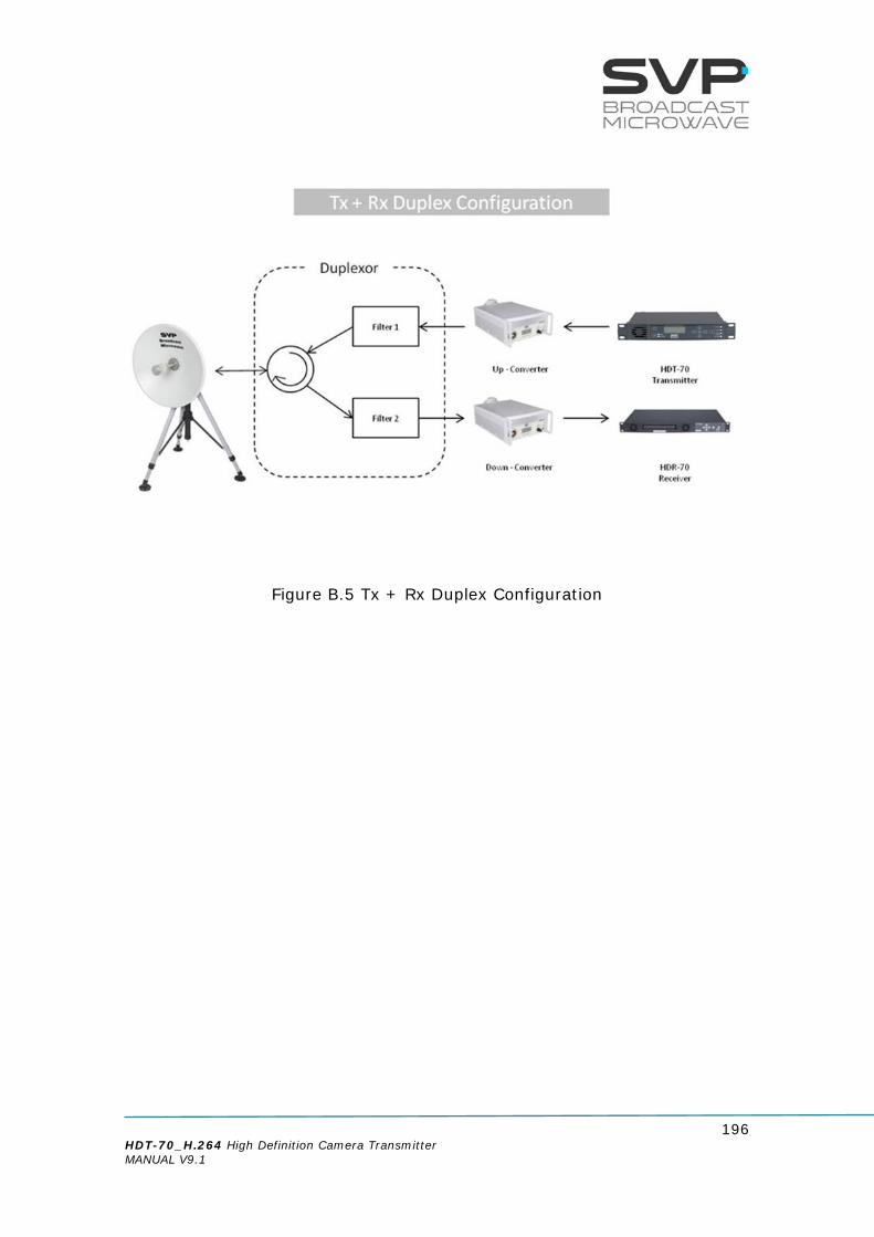
196 HDT-70_H.264 High Definition Camera Transmitter MANUAL V9.1
Figure B.5 Tx + Rx Duplex Configuration

197 HDT-70_H.264 High Definition Camera Transmitter MANUAL V9.1
9
10 Index C: HAP-60 User’s Guide
Important Notes
1. The HAP-60 parabolic antenna has been designed to be used in portable SVP links.
2. The antenna is rugged and durable enough for virtually any environment. 3. The high performance of this equipment is only guaranteed when using high quality cables and connectors. 4. Only authorized personnel should open the product and any repair or warranty will be invalidated if the seals are broken.
Figure C.1 HAP-60 Parabolic Antenna

198 HDT-70_H.264 High Definition Camera Transmitter MANUAL V9.1
C.1 Description
The HAP-60 parabolic antenna from SVP Broadcast Microwave is a single polarization antenna with a 60 cm diameter. This antenna works in the 2 GHz, 6GHz, 7 GHz and 10 GHz frequency bands. It has been especially designed to be used in portable SVP links. So it can be clamped to the RF head of SVP equipment. The reflector is made of aluminum and it has an external ring, which increases the robustness of the structure. The feeder has a quickset system and can be clamped to the antenna without screws. The HAP antenna offers the best performance and a long useful life is guaranteed. It can be used in the most adverse weather conditions.

199 HDT-70_H.264 High Definition Camera Transmitter MANUAL V9.1
C.2 Technical Specifications Main Characteristics
Item Specifications Frequency bands 2 GHz, 6GHz, 7 GHz and 10 GHz Bandwidth 500 MHz Gain Depends on the frequency Polarization Linear VSWR Typ: < 1.8 Connector N female Diameter 60 cm Weight 5 kg
Table C.1 HAP-60 Main Characteristics
Figure C.2 HAP-60 Parabolic Antenna

200 HDT-70_H.264 High Definition Camera Transmitter MANUAL V9.1
Glossary
AES/EBU
Audio Engineering Society/European
Broadcasting Union
ACPR
Adjacent Channel Power Ratio
APSK
Amplitude and phase-shift
keying or asymmetric phase-shift keying (APSK)
ASI
Asynchronous Serial Interface
BNC
Bayonet Neill-Concelman
BR
BitRate
CA-BISS
Conditional Access-BISS
COFDM
Coded Orthogonal Frequency Division Multiplexing
DC
Direct current
DVB-S2
Digital Video Broadcasting by Satellite – Second Generation
DVB-T
Digital Video Broadcasting – Terrestrial
DVB-T2
Digital Video Broadcasting – Terrestrial Second Generation
ETSI
European Telecommunications Standards Institute

201 HDT-70_H.264 High Definition Camera Transmitter MANUAL V9.1
EVM
Error Vector Magnitude
FEC
Forward Error Correction
FFT
Fast Fourier transform
GPS
Global Positioning System
HD
High Definition
HDMI
High-Definition Multimedia Interface
HDR
High Definition Receiver
HDT
High Definition Transmitter
IF
Intermediate Frequency
IG
Interval Guard
IP
Internet Protocol
LCD
Liquid Crystal Display
LED
Light-Emitting Diode
LD
Low Delay
MPEG
Moving Picture Experts Group
NLOS
Non Line of Sight

202 HDT-70_H.264 High Definition Camera Transmitter MANUAL V9.1
PAL
Phase Alternating Line
PID
Packet Identification
QAM
Quadrature Amplitude Modulation
QPSK
Quadrature Phase-Shift Keying
RF
RadioFrequency
RTC
Remote Control
SD
Standard Delay
SDI
Serial Digital Interface
SNMP
Simple Network Management
Protocol
TFT
Thin-Film Transistor
TS
Transport Stream
UDP
User Datagram Protocol
USB
Universal Serial Bus

203 HDT-70_H.264 High Definition Camera Transmitter MANUAL V9.1

204 HDT-70_H.264 High Definition Camera Transmitter MANUAL V9.1
Note

205 HDT-70_H.264 High Definition Camera Transmitter MANUAL V9.1
Final note SVP Broadcast Microwave S.L. is constantly striving to improve all of its products. Therefore, we ask you to understand that modifications may occur in designs, equipment and technology. Consequently, no responsibility can be derived from the information, illustrations or descriptions contained in this manual. The texts, illustrations and instructions in the manual are based on the existing situation when the manual is published. Reprinting, reproduction and translation, in part or in whole, is forbidden without written authorisation from SVP Broadcast Microwave S.L. SVP Broadcast Microwave reserves all rights regarding intellectual property rights. All rights reserved regarding modifications.

SVP Broadcast Microwave reserves the right to make changes to this manual and to the equipment without prior notice.
C/ Zubiaurre 7 bajo 48215 Iurreta Vizcaya – Spain
Tel: (+34) 94620 3722
[email protected] www.svpbm.com