hds series heavy duty plugs and receptacles · 2017-09-06 · 3. hds series electrical connectors....
TRANSCRIPT


HDS SeriesHeavy Duty Plugs and Receptacles
Product Overview . . . . . . . . . . . . . . . . . . . . . . . . . . . . . . . . . . . . . 3
Environmental highlights . . . . . . . . . . . . . . . . . . . . . . . . . . . . . . . . 4
Code Logic . . . . . . . . . . . . . . . . . . . . . . . . . . . . . . . . . . . . . . . . . . . 5
Rating Specifications . . . . . . . . . . . . . . . . . . . . . . . . . . . . . . . . . . . 6
Cable Mounted Plug with
Compression Nut . . . . . . . . . . . . . . . . . . . . . . . . . . . . . . . . 8
Mechanical Clamp Assemblies . . . . . . . . . . . . . . . . . . . . . 9
Basket Weave Grip . . . . . . . . . . . . . . . . . . . . . . . . . . . . . . . 10
NPT Threaded Entry . . . . . . . . . . . . . . . . . . . . . . . . . . . . . . 11
Metric Threaded Entry . . . . . . . . . . . . . . . . . . . . . . . . . . . . 12
Panel Mounted Plug . . . . . . . . . . . . . . . . . . . . . . . . . . . . . . 13
Cable Mounted Receptacle with
Compression Nut . . . . . . . . . . . . . . . . . . . . . . . . . . . . . . . . 14
Mechanical Clamp Assemblies . . . . . . . . . . . . . . . . . . . . . 15
Basket Weave Grip . . . . . . . . . . . . . . . . . . . . . . . . . . . . . . . 16
NPT Conduit Entry . . . . . . . . . . . . . . . . . . . . . . . . . . . . . . . 17
Metric Threaded Entry . . . . . . . . . . . . . . . . . . . . . . . . . . . . 18
Panel Mounted Receptacle . . . . . . . . . . . . . . . . . . . . . . . . . . . . . . 19
Receptacle Mounted to Conduit Fitting Box with
Straight Adapter . . . . . . . . . . . . . . . . . . . . . . . . . . . . . . . . . 20
Angle Adapter . . . . . . . . . . . . . . . . . . . . . . . . . . . . . . . . . . . 21
Cable Grip Accessory Components . . . . . . . . . . . . . . . . . . . . . . . 22
Connector Components . . . . . . . . . . . . . . . . . . . . . . . . . . . . . . . . 23 - 24
Cable Adapters . . . . . . . . . . . . . . . . . . . . . . . . . . . . . . . . . . . . . . . 25 - 26
Cable Grip Components . . . . . . . . . . . . . . . . . . . . . . . . . . . . . . . . 27
Standard / Jack / Clamp Nuts . . . . . . . . . . . . . . . . . . . . . . . . . . . . 28
Nuts Continued / Mechanical Clamp Assembly . . . . . . . . . . . . . . 29
Conduit Adapters: Internally & Externally Threaded . . . . . . . . . . . 30
Panel Board & Transition Adapters . . . . . . . . . . . . . . . . . . . . . . . . 31
Protective Covers . . . . . . . . . . . . . . . . . . . . . . . . . . . . . . . . . . . . . 32
Straight and Angled Adapter Covers . . . . . . . . . . . . . . . . . . . . . . 33
Conduit Back Boxes . . . . . . . . . . . . . . . . . . . . . . . . . . . . . . . . . . . 34
Thermocouple Contacts . . . . . . . . . . . . . . . . . . . . . . . . . . . . . . . . 35 - 36
AWG/MCM to Metric mm² wire and Contact Sizes . . . . . . . . . . . 37 - 38
Replacement Contact Part Numbers . . . . . . . . . . . . . . . . . . . . . . 39
Termination Data . . . . . . . . . . . . . . . . . . . . . . . . . . . . . . . . . . . . . . 40 - 41
Electrical Service Rating . . . . . . . . . . . . . . . . . . . . . . . . . . . . . . . . 42

3
HDS Series Electrical ConnectorsHeavy Duty Environmentally Sealed Plugs & Receptacles
Product Overview
The HDS Series connectors are heavy duty, environmentally sealed plug and receptacle that represent the latest in advancements in electrical connector technology . The design objectives in developing this product line were to exceed the environmental and performance characteristics of the relevant standards and specifications whilst giving design engineers the widest possible selection in the design of connector systems .
These rugged compact connectors provide the basis for a family of electrical connector products, including Explosion Proof and Flameproof designs, with uses in a multitude of applications; Ground support, cable networks, automation, process control systems, land based and offshore drilling systems and control, instrumentation systems .
Current and Voltage RatingsConnectors are designed to handle heavy loads given the low overalll size and in addition are capable of opening circuits under their full voltage and ampacity ratings .* HDS series control and instrumentation inserts carry higher than normal voltage ratings as a result of the one piece insert having increased creepage and clearance distances and higher dielectric strength in the components .
Ingress ProtectionDesign and materials enable connectors to meet IP68-8 Per EN:60529:1992 and 6P per NEMA 250 .
Solder, Crimp and Pressure TerminationContact termination is available in three styles, Solder, crimp and pressure termination depending on the insert configuration and application .
Compact Size and Low WeightConnectors are smaller and weigh less than an equivalent connector of the same service rating, resulting in less cumbersome cable assemblies and better utilization of mounting space .
Easily Accessible Wire TerminalsConductors are readily connected to inserts . housings are slipped over conductors or leads after termination . Cumbersome handling and seating of inserts with conductors attached is eliminated .
Single Piece InsertsA unique design of insert combining specially formulated silicones and plastics allow, higher and increased environmental sealing between adjacent and mating contacts allowing for increased voltage service .
Double Lead Thread CouplingThis strong and durable fast acting modified thread speeds up the insertion and extraction of the plug . Moreover the thread is easier to start and less susceptible to jamming .
Rugged ConstructionAll metal hardware is machined from tempered aluminium bar stock and treated with a Hard Anodic coating providing excellent corrosion resistance (salt Spray) and generally increases the durability of the connector assembly .
Systems IntegrationHDS series connectors form the basis of four connectors series, allowing for the integration of common pin and cable configurations in both hazardous and non-hazardous areas .
The HDS Series of connectors are available in single pin, multipin power and control and instrumentation configurations . Connector components are interchangeable, including the ability to accommodate male or female contacts in either style of hardware, allowing for even greater flexibility in the design process .
The performance and reliability designed into the HDS series connectors, combined with the latest production methods, lends itself to selection in the Oil Gas and Petrochimical markets for heavy duty environmentally sealed connectors . These connectors combine a level of performance and reliability unsurpassed in heavy duty circular connectors .

Cable Mounted Receptacle: HDS-CMR-M16 with mechanical Clamp
Additional certification information is available via ourwebsite at www .elecquip .com
HDS Series Electrical ConnectorsEnvironmental Features & Service Parameters
Service Parameters
Property Standard HDS Connectors
Operating TemperatureMIL-STD-1344Method 1003
-67°F to 225°F / -55°C to 125°C
Ingress ProtectionEN:60529:1992Degrees of protection provided by enclosure (IP Code)
Achieves IP 68-8Clause 5 .1, 5 .2, 13 .4, 14 .2 .7
Electrical ResistanceEN:50019:2000MIL-STD-1344
Clause 4 .3Method 3001
Thermal ShockMIL-STD-1344Method 1003 Test Condition AEN:60079-1:2007 (Clause 26 .8)
Meets MIL-STD-1344Method 1003Meets Clause 26 .8
Corrosion Resistance48 Hours Method 1001MIL-STD-1344No exposure of base material
Salt Spray: 336 DaysNo Exposure of Material
Chemical Resistance No Requirements Oil, Most Acids and Alkalis
Air Leakage 1 AtmosphereMeets MIL-STD-1344Method 1003
Shock ResistanceMIL-STD-202Method 207
Meets MIL-STD-202Method 207
VibrationMIL-STD-1344Method 2006
Meets MIL-STD-1344Method 2006
High-Impact ResistanceMIL-STD-202Method 207EN:50102
Meets MIL-STD-202Method 207Meets IK08 Joules
Frequency 50, 60 and 400Hz Per MIL-C-22992E
Hazardous Location Certifications
Class I, Div 2, GrABCD, T1-T6
Ex nA IIC, T1-T6
Class I Zone 2, Ex/AEx nA IIC, T1-T6
-40ºC ≤ Ta ≤ 40/50/65ºC

1 Shell StyleCM - Cable MountedPM - Panel Mounted
7 Grommet Selection Code(see table 1)
9 Number ofContacts
11 Composite InsertC - Composite Insert(Various Contact Sizes)Omit if all contacts are the same
13 Polarized ContactOmit if not polarizedP - Polarized contact
16 Insert OrientationOmit if normal .01, .02, .03, etc .
17 Special OptionsXX - Modification NumberT - Through Shell Conductivity
15 Contact TerminationR - PressureOmit for crimp
14 Contact GenderM - Male (pin)F - Female (socket)
8 Shell Size12, 16, C16, 20, C20, 24, C24, 28, C28
12 Grounded Contact to ShellG - GroundedOmit if not grounded
10 Contact Size in AWG
3 Cable GripOmit for Mechanical ClampK - Basket WeaveC - Gland Nut
5 Coupling NutOmit for StandardJ - Jacking Coupling NutG - Glove Nut
4 Cable AdapterL - Long AdapterM - Metric Conduit ThreadT - NPT ThreadE- Extra Long
6 Protective CoverOmit For Standard Cap And ChainA - Less CoverS - Spring Loaded Cover
Gro
mm
et S
elec
tion
Co
de
Cable Size
Cable Size
2 Connector GenderP - Plug (Through Shell Conductivity)
R - Recepticle (Through Shell Conductivity)
C M P K L J A 1 8 C 1 6 7 1 2 C G P R 0 2 X XMHDS SERIES 1 7 10 11 12 13 14 15 16 1782 43 5 6 9
Code Logic HDS Series
Table 1 Rubber Grommet Selection Table
Omit if No Gland or Grommet RequiredInches Millimeters Inches Millimeters
Min Max Min Max Min Max Min Max02 0 .062 0 .125 1 .6 3 .2 26 1 .500 1 .625 38 .1 41 .304 .0125 0 .250 3 .2 6 .4 28 1 .625 1 .750 41 .3 44 .406 0 .250 0 .375 6 .4 9 .5 30 1 .750 1 .875 44 .4 47 .608 0 .375 0 .500 9 .5 12 .7 31 1 .875 2 .937 47 .6 49 .210 0 .500 0 .625 12 .7 15 .9 32 1 .875 2 .000 47 .6 50 .812 0 .625 0 .750 15 .9 19 .1 34 2 .000 2 .125 50 .8 54 .014 0 .750 0 .875 19 .1 22 .2 36 2 .125 2 .250 54 .0 57 .115 0 .875 0 .937 22 .2 23 .8 38 2 .250 2 .375 57 .1 60 .316 0 .875 1 .000 22 .2 25 .4 39 2 .375 2 .437 60 .3 61 .918 0 .875 1 .125 25 .4 28 .6 40 2 .375 2 .500 60 .3 63 .520 1 .000 1 .250 28 .6 31 .8 42 2 .500 2 .625 63 .5 66 .722 1 .125 1 .375 31 .8 34 .9 44 2 .625 2 .750 66 .7 69 .923 1 .250 1 .437 34 .9 36 .5 46 2 .750 2 .875 69 .9 73 .024 1 .375 1 .500 36 .5 38 .1

6
Ampacity RatingsContact Size Selection and Connector Resistance Values
1 Contact sizes: assume equal wire size included as contact and wire combination . Differing wire sizes will exhibit different electrical performance results .
2 MS Specification (MIL-C-39029D) current ratings are in accordance with MIL-C-39029D
3 NEC Specifications assume a wire size selection that is in accordance NEC guidelines for temperature rise .
4 NEC circuit breaking capabilty: connectors and contacts that have demonstrated the ability to rupture current under full rated load in accordance with UL standard 1686 1977 and MIL-C-22992E . NEC circuit breaking for hazardous locations ( Class and Division system) Connectors and contacts have demonstrated the ability to disconnect under full rated load in accordance with UL standard 1977, 1919 and CSA C22 .2-159-M1987
5 IEC ampacity ratings: assume equal wire size, included as contact and wire combination . Differing wire sizes will exhibit different electrical performance results .
6 Contact Resistance when tested in accordance with MIL-1344 method 3004 .1 will not exceed the values listed in table 1 column 6
Note All ampacities shown are for individual contacts and must be derated to determine maximum total current to be carried by the connector . Use the tables and formulas detailed on pages: 6 and 7
Contact Sizes #AWG MCM ( mm² )
Ampacity Rating Non-Circuit Breaking
NEC Ampacity Rating
Non-Circuit Breaking
IEC Ampacity Rating
Non-Circuit Breaking
Contact Resistance Milliohms (mW)
MS NEC Crimp Term Solder Term
18 AWG (1 .0 mm² ) - 9 - 9 3 .00 2 .47
16 AWG (1 .3 mm² ) 13 16 10 16 2 .25 1 .75
12 AWG (3 .3 mm² ) 23 30 20 30 1 .29 0 .86
10 AWG (5 .2 mm² ) 33 40 30 40 0 .96 0 .64
8 AWG (7 .6 mm² ) 46 50 40 50 0 .75 0 .42
4 AWG (21 mm² ) 80 90 60 90 0 .41 0 .18
1/0 AWG (54 mm² ) 150 155 100 155 0 .23 0 .10
4/0 AWG (109 mm² ) 225 225 200 225 0 .16 0 .06
262 MCM (132 mm² ) - 599 - 599 0 .086 NA
313 MCM (159 mm² ) - 636 - 636 0 .090 NA
350 MCM (185 mm² ) - 325 - 325 0 .070 NA
373 MCM (189 mm² ) - 674 - 674 0 .070 NA
500 MCM (240 mm² ) - 750 - 750 0 .069 NA
535 MCM (273 mm² ) - 898 - 898 0 .032 NA
646 MCM (326 mm² ) - 1009 - 1009 0 .026 NA
777 MCM (394 mm² ) - 1135 - 1135 0 .020 NA
1111 MCM (562 mm² ) - 1303 - 1303 0 .017 NA
1
1 5
6
Note
2
3
4
2 3
4 5 6

7
Different ambient temperatures need to be taken into consideration when considering ampacity ratings, depending on application and the location in which the connectors are to be used . Accordingly it is important to rate the connector xxxx
Non Hazardous location ratings:The following standard may be used in calculating the total current carrying capacity of the connector
MIL-W-5088L Section 6.7 Wire current ratings:For a more conservative standard use the hazardous location derating formulas detailed on pages 42 and 43 .
Hazardous Locations:The following standards IEC derating per IEC60079-0 :2004 General requirements IEC 60079-1 :2004 Flameproof protection IEC 60079-7 :2003 Increased Safety protection
These standards require that equipment, when in an energized condition, does not exceed the rated surface temperature, in order not to ignite the hazardous atmosphere . These values are listed in table 3 . The Formulas detailed on pages x and x will be of assistance in determining the correct insert and allowable ampacity for the connector application and location .
Derating Charts - HDS Series Connectors
Table 2 IEC vs NEC Temperature Classification
Temp in C
Classification
IEC N . America
83 T6 T6
100 T5 T5
120 T4 T4A
135 T4 T4
150 T3 T3C
165 T3 T3B
180 T3 T3A
100 T3 T3
115 T2 T2D
130 T2 T2C
160 T2 T2B
180 T2 T2A
300 T2 T2
450 T1 T1
Table 3 Safe Equipment Operating Temperatures
Spontaneous Ignition Temp of the Gasses
(T)
Temperature Class of Equipment
T685°C
T5100°C
T4135°C
T3200°C
T2300°C
T1450°C
85 < T < 100
100 < T < 135
135 < T < 200
200 < T < 300
300 < T < 450
450 < T

8
Cable Mounted Plugwith Compression Nut
in. in.
Cable Size Select from cable grip accessory components Table 1, Page 5 and substitute symbol number for delta XX
Shell Size
Part Number with Standard Coupling Nut
Dimensions with Standard Cable AdapterPart Number with Jack Coupling Nut
A B C
in mm in mm in mm
12 HDS-CMPC-XX12 5-3/8 137 1-13/16 46 5-31/32 152 HDS-CMPCJ-XX12
16 HDS-CMPC-XX16 5-5/8 143 2-5/16 59 6-7/32 158 HDS-CMPCJ-XX16
20 HDS-CMPC-XX20 6-1/8 156 2-13/16 71 6-23/32 171 HDS-CMPCJ-XX20
C20 HDS-CMPC-XXC20 6-5/8 169 2-13/16 71 7-7/32 183 HDS-CMPCJ-XXC20
24 HDS-CMPC-XX24 6-5/8 169 3-5/16 84 7-7/32 183 HDS-CMPCJ-XX24
C24 HDS-CMPC-XXC24 7-1/8 181 3-5/16 84 7-23/32 196 HDS-CMPCJ-XXC24
28 HDS-CMPC-XX28 7-1/8 181 3-13/16 97 7-23/32 196 HDS-CMPCJ-XX28
C28 HDS-CMPC-XXC28 7-5/8 194 3-13/16 97 8-7/32 209 HDS-CMPCJ-XXC28
With Long Cable Adapter
12 HDS-CMPCL-XX12 7-5/8 194 1-13/16 46 8-7/32 209 HDS-CMPCLJ-XX12
16 HDS-CMPCL-XX16 7-7/8 200 2-5/16 59 8-15/32 215 HDS-CMPCLJ-XX16
20 HDS-CMPCL-XX20 8-3/8 213 2-13/16 71 8-31/32 228 HDS-CMPCLJ-XX20
C20 HDS-CMPCL-XXC20 8-7/8 225 2-13/16 71 9-15/32 241 HDS-CMPCLJ-XXC20
24 HDS-CMPCL-XX24 8-7/8 225 3-5/16 84 9-15/32 241 HDS-CMPCLJ-XX24
C24 HDS-CMPCL-XXC24 9-3/8 238 3-5/16 84 9-31/32 253 HDS-CMPCLJ-XXC24
28 HDS-CMPCL-XX28 9-1/8 232 3-13/16 97 9-23/32 247 HDS-CMPCLJ-XX28
C28 HDS-CMPCL-XXC28 9-5/8 245 3-13/16 97 10-7/32 260 HDS-CMPCLJ-XXC28

9
Cable Mounted Plugwith Mechanical Clamp Assembly
Cable Size Select from cable grip accessory components table and substitute symbol number for delta XX
in.
Shell Size
Part Number with Standard Coupling Nut
Dimensions with Standard Cable AdapterPart Number with Jack Coupling Nut
A B C D E
in mm in mm in mm in mm in mm
12 HDS-CMP-XX12 6-1/8 156 1-13/16 46 6-23/32 171 2-3/8 60 1-3/4 44 HDS-CMPCJ-XX12
16 HDS-CMP-XX16 6-7/16 164 2-5/16 59 7-1/32 179 3 76 2-1/4 57 HDS-CMPCJ-XX16
20 HDS-CMP-XX20 7 178 2-13/16 71 7-19/32 193 3-3/4 95 2-3/4 70 HDS-CMPCJ-XX20
C20 HDS-CMP-XXC20 7-1/2 190 2-13/16 71 8-3/32 206 3-3/4 95 2-3/4 70 HDS-CMPCJ-XXC20
24 HDS-CMP-XX24 7-9/16 192 3-5/16 84 8-5/32 207 4-1/2 114 3-1/4 83 HDS-CMPCJ-XX24
C24 HDS-CMP-XXC24 8-1/16 205 3-5/16 84 8-21/32 220 4-1/2 114 3-1/4 83 HDS-CMPCJ-XXC24
28 HDS-CMP-XX28 8-1/8 206 3-13/16 97 8-23/32 221 5-1/8 130 3-3/4 96 HDS-CMPCJ-XX28
C28 HDS-CMP-XXC28 8-5/8 219 3-13/16 97 9-7/32 234 5-1/8 130 3-3/4 96 HDS-CMPCJ-XXC28
With Long Cable Adapter
12 HDS-CMPL-XX12 8-3/8 213 1-13/16 46 8-31/32 229 2-3/8 60 1-3/4 44 HDS-CMPCLJ-XX12
16 HDS-CMPL-XX16 8-11/16 221 2-5/16 59 9-9/32 236 3 76 2-1/4 57 HDS-CMPCLJ-XX16
20 HDS-CMPL-XX20 9-1/4 235 2-13/16 71 9-27/32 250 3-3/4 95 2-3/4 70 HDS-CMPCLJ-XX20
C20 HDS-CMPL-XXC20 9-3/4 248 2-13/16 71 10-11/32 263 3-3/4 95 2-3/4 70 HDS-CMPCLJ-XXC20
24 HDS-CMPL-XX24 9-3/16 230 3-5/16 84 10-13/32 264 4-1/2 114 3-1/4 83 HDS-CMPCLJ-XX24
C24 HDS-CMPL-XXC24 10-1/16 262 3-5/16 84 10-29/32 277 4-1/2 114 3-1/4 83 HDS-CMPCLJ-XXC24
28 HDS-CMPL-XX28 10-1/8 257 3-13/16 97 10-23/32 272 5-1/8 130 3-3/4 95 HDS-CMPCLJ-XX28
C28 HDS-CMPL-XXC28 10-5/8 270 3-13/16 97 11-7/32 285 5-1/8 130 3-3/4 95 HDS-CMPCLJ-XXC28

10
Cable Mounted plugwith Basket Weave Grip
in.
Cable Size Select from cable grip accessory components table and substitute symbol number for delta XX
Shell Size
Part Number with Standard Coupling Nut
Dimensions with Standard Cable AdapterPart Number with Jack Coupling Nut
A B C
in mm in mm in mm
12 HDS-CMPK-XX12 5-3/8 137 6 152 1-3/4 45 HDS-CMPJK-XX12
16 HDS-CMPK-XX16 5-5/8 143 6-1/4 159 2-1/4 57 HDS-CMPJK-XX16
20 HDS-CMPK-XX20 6-1/8 156 6-3/4 172 2-3/4 70 HDS-CMPJK-XX20
C20 HDS-CMPK-XXC20 6-5/8 168 7-1/4 184 2-3/4 70 HDS-CMPJK-XXC20
24 HDS-CMPK-XX24 6-5/8 168 7-1/4 184 3-1/4 83 HDS-CMPJK-XX24
C24 HDS-CMPK-XXC24 7-1/8 181 7-3/4 197 3-1/4 83 HDS-CMPJK-XXC24
28 HDS-CMPK-XX28 7-1/8 181 7-3/4 197 3-3/4 95 HDS-CMPJK-XX28
C28 HDS-CMPK-XXC28 7-5/8 194 8-1/4 210 3-3/4 95 HDS-CMPJK-XXC28
With Long Cable Adapter
12 HDS-CMPKL-XX12 7-5/8 194 1-13/16 46 8-7/32 209 HDS-CMPKLJ-XX12
16 HDS-CMPKL-XX16 7-5/8 194 2-5/16 59 8-15/32 215 HDS-CMPKLJ-XX16
20 HDS-CMPKL-XX20 8-3/8 213 2-13/16 71 8-31/32 228 HDS-CMPKLJ-XX20
C20 HDS-CMPKL-XXC20 8-7/8 225 2-13/16 71 9-15/32 241 HDS-CMPKLJ-XXC20
24 HDS-CMPKL-XX24 8-7/8 225 3-5/16 84 9-15/32 241 HDS-CMPKLJ-XX24
C24 HDS-CMPKL-XXC24 9-3/8 238 3-5/16 84 9-31/32 253 HDS-CMPKLJ-XXC24
28 HDS-CMPKL-XX28 9-1/8 232 3-13/16 97 9-23/32 247 HDS-CMPKLJ-XX28
C28 HDS-CMPKL-XXC28 9-5/8 245 3-13/16 97 10-7/32 260 HDS-CMPKLJ-XXC28

11
Cable Mounted Plug 3/4" to 2-1/2" NPTwith NPT Threaded Entry
in.
Shell Size
NPT Size
Conduit
Part Number with
Standard Coupling Nut
Dimensions with Standard Cable Adapter
Part Number with
Jack Coupling NutA B C D
in mm in mm in mm in mm
12 3/4 HDS-CMPN-12 4-1/4 108 1-13/16 46 4-27/32 123 3/4 19 HDS-CMPJK-XX12
16 1-1/4 HDS-CMPN-16 4-3/8 111 2-5/16 59 4-31/32 126 1-1/4 32 HDS-CMPJK-XX16
20 1-1/2 HDS-CMPN-20 4-1/2 114 2-3/16 71 5-3/32 129 1-1/2 38 HDS-CMPJK-XX20
C20 1-1/2 HDS-CMPN-C20 5 127 2-3/16 71 5-19/32 142 1-1/2 38 HDS-CMPJK-XXC20
24 2 HDS-CMPN-24 4-5/8 117 3-5/16 84 5-7/32 132 2 51 HDS-CMPJK-XX24
C24 2 HDS-CMPN-C24 5-1/8 130 3-5/16 84 5-23/32 145 2 51 HDS-CMPJK-XXC24
28 2-1/2 HDS-CMPN-28 5-3/32 129 3-13/16 97 5-11/16 145 2-1/2 64 HDS-CMPJK-XX28
C28 2-1/2 HDS-CMPN-C28 5-19/32 142 3-13/16 97 6-3/16 157 2-1/2 64 HDS-CMPJK-XXC28

12
Cable Mounted Plug M20 to M63with Metric Threaded Entry
in.
Shell Size
Metric Thread for
Part Number with Standard Coupling Nut
Dimensions with Standard Cable Adapter
Part Number with Jack Coupling Nut
A B C D
in mm in mm in mm in mm
12 M20 HDS-CMPM-12 4-1/4 108.0 1-13/16 46.1 4-27/32 123.0 3/4 19.1 HDS-CMPMJ-12
16 M32 HDS-CMPM-16 4-3/8 111.1 2-5/16 58.7 4-31/32 126.2 1-3/4 31.8 HDS-CMPMJ-16
20 M40 HDS-CMPM-20 4-1/2 114.3 2-3/16 71.4 5-3/32 129.4 1-1/2 38.1 HDS-CMPMJ-20
C20 M40 HDS-CMPM-C20 5 127.0 2-3/16 71.4 5-19/32 142.1 1-1/2 38.1 HDS-CMPMJ-C20
24 M50 HDS-CMPM-24 4-5/8 117.5 3-5/16 84.1 5-7/32 131.6 2 50.8 HDS-CMPMJ-24
C24 M50 HDS-CMPM-C24 5-1/8 130.2 3-5/16 84.1 5-23/32 145.2 2 50.8 HDS-CMPMJ-C24
28 M63 HDS-CMPM-28 5-3/32 129.4 3-13/16 96.8 5-11/16 144.5 2-1/2 63.5 HDS-CMPMJ-28
C28 M63 HDS-CMPM-C28 5-19/32 142.1 3-13/16 96.8 6-3/16 157.2 2-1/2 63.5 HDS-CMPMJ-C28

13
Panel Mounted Plug
in.
Shell Size
Part Number with Standard Coupling Nut
Dimensions with Standard Cable Adapter
Part Number with Jack
Coupling NutA B C D E F
in mm in mm in mm in mm in mm in mm
12 HDS-PMP-12 2-3/8 60.3 1-13/16 46.0 2-31/32 75.4 1-17/64 32.1 1-5/8 41.3 3/16 4.8 HDS-PMPJ-12
16 HDS-PMP-16 2-13/32 61.1 2-5/16 58.7 3 76.2 1-11/16 42.9 2-1/8 54.0 7/32 5.6 HDS-PMPJ-16
20 HDS-PMP-20 2-7/16 61.9 2-13/16 71.4 3-1/32 77.0 2-3/32 53.2 2-5/8 66.7 9/32 7.1 HDS-PMPJ-20
C20 HDS-PMP-C20 2-15/16 74.6 2-13/16 71.4 3-17/32 89.7 2-3/32 53.2 2-5/8 66.7 9/32 7.1 HDS-PMPJ-C20
24 HDS-PMP-24 2-15/32 62.7 3-5/16 84.1 3-1/16 77.8 2-17/32 64.3 3-1/8 79.4 11/32 8.7 HDS-PMPJ-24
C24 HDS-PMP-C24 2-31/32 75.4 3-5/16 84.1 3-9/16 90.5 2-17/32 64.3 3-1/8 79.4 11/32 8.7 HDS-PMPJ-C24
28 HDS-PMP-28 2-15/32 62.7 3-13/16 96.8 3-1/16 77.8 3-1/32 77.0 3-3/4 95.3 11/32 8.7 HDS-PMPJ-28
C28 HDS-PMP-C28 2-31/32 75.4 3-13/16 96.8 3-9/16 90.5 3-1/32 77.0 3-3/4 95.3 11/32 8.7 HDS-PMPJ-C28

14
Cable Mounted Receptaclewith Compression Nut
in. (1.6mm) in. (1.6mm)
Cable Size Select from cable grip accessory components table and substitute symbol number for delta XX
Shell Size
Part Number with Inline Receptacle
Dimensions with Standard Cable Adapter
A B C D
in mm in mm in mm in mm
12 HDS-CMRC-XX12 5-3/8 137 6 152 1-3/4 45 1-61/64 50
16 HDS-CMRC-XX16 5-5/8 143 6-1/4 159 2-1/4 57 2-31/64 63
20 HDS-CMRC-XX20 6-1/8 156 6-3/4 172 2-3/4 70 3-1/32 77
C20 HDS-CMRC-XXC20 6-5/8 168 7-1/4 184 2-3/4 70 3-1/32 77
24 HDS-CMRC-XX24 6-5/8 168 7-1/4 184 3-1/4 83 3-9/16 90
C24 HDS-CMRC-XXC24 7-1/8 181 7-3/4 197 3-1/4 83 3-9/16 90
28 HDS-CMRC-XX28 7-1/8 181 7-3/4 197 3-3/4 95 4-1/16 103
C28 HDS-CMRC-XXC28 7-5/8 194 8-1/4 210 3-3/4 95 4-1/16 103
With Long Cable Adapter
12 HDS-CMRCL-XX12 7-5/8 194 8-1/4 210 1-3/4 45 1-61/64 50
16 HDS-CMRCL-XX16 7-7/8 200 8-1/2 216 2-1/4 57 2-31/64 63
20 HDS-CMRCL-XX20 8-3/8 213 9 289 2-3/4 70 3-1/32 77
C20 HDS-CMRCL-XXC20 8-7/8 226 9-1/2 241 2-3/4 70 3-1/32 77
24 HDS-CMRCL-XX24 8-7/8 226 9-1/2 241 3-1/4 83 3-9/16 90
C24 HDS-CMRCL-XXC24 9-3/8 238 10 254 3-1/4 83 3-9/16 90
28 HDS-CMRCL-XX28 9-1/8 238 9-3/4 248 3-3/4 95 4-1/16 103
C28 HDS-CMRCL-XXC28 9-5/8 245 10-1/4 260 3-3/4 95 4-1/16 103

15
Cable Mounted Receptaclewith Mechanical Clamp Assembly
in. (1.6mm)
Cable Size Select from cable grip accessory components table and substitute symbol number for delta XX
Shell Size
Part Number with Inline Receptacle
Dimensions with Standard Cable Adapter
A B C D E F
in mm in mm in mm in mm in mm in mm
12 HDS-CMR-XX12 6-1/8 156 6-3/4 172 1-3/4 45 1-61/64 50 1-3/4 45 2-3/8 60
16 HDS-CMR-XX16 6-7/16 164 7-1/16 179 2-1/4 57 2-31/64 63 2-1/4 57 3 76
20 HDS-CMR-XX20 7 178 7-5/8 194 2-3/4 70 3-1/32 77 2-3/4 70 3-3/4 95
C20 HDS-CMR-XXC20 7-1/2 191 8-1/8 206 2-3/4 70 3-1/32 77 2-3/4 70 3-3/4 95
24 HDS-CMR-XX24 7-9/16 192 8-3/16 208 3-1/4 83 3-9/16 91 3-1/4 83 4-1/2 108
C24 HDS-CMR-XXC24 8-1/16 205 8-11/16 221 3-1/4 83 3-9/16 91 3-1/4 83 4-1/2 108
28 HDS-CMR-XX28 8-1/8 206 8-3/4 222 3-3/4 95 4-1/16 103 3-3/4 95 5-1/8 130
C28 HDS-CMR-XXC28 8-5/8 219 9-1/4 235 3-3/4 95 4-1/16 103 3-3/4 95 5-1/8 130
With Long Cable Adapter
12 HDS-CMRL-XX12 8-3/8 213 9 229 1-3/4 45 1-61/64 50 1-3/4 45 2-3/8 60.3
16 HDS-CMRL-XX16 8-11/16 221 9-5/16 237 2-1/4 57 2-31/64 63 2-1/4 57 3 76
20 HDS-CMRL-XX20 9-1/4 235 9-7/8 251 2-3/4 70 3-1/32 77 2-3/4 70 3-3/4 95
C20 HDS-CMRL-XXC20 9-3/4 248 10-3/8 264 2-3/4 70 3-1/32 77 2-3/4 70 3-3/4 95
24 HDS-CMRL-XX24 9-13/16 249 10-7/16 265 3-1/4 83 3-9/16 91 3-1/4 83 4-1/2 108
C24 HDS-CMRL-XXC24 10-5/16 262 10-15/16 278 3-1/4 83 3-9/16 91 3-1/4 83 4-1/2 108
28 HDS-CMRL-XX28 10-1/8 257 10-1/8 273 3-3/4 95 4-1/16 103 3-3/4 95 5-1/8 130
C28 HDS-CMRL-XXC28 10-5/8 270 11-3/8 286 3-3/4 95 4-1/16 103 3-3/4 95 5-1/8 130

16
Cable Mounted Receptaclewith Basket Weave Grip
Cable Size Select from cable grip accessory components table and substitute symbol number for delta XX
Shell Size
Part Number with Inline Receptacle
Dimensions with Standard Cable Adapter
A B C D
in mm in mm in mm in mm
12 HDS-CMRKL-XX12 7-5/8 194 8-1/4 210 1-3/4 45 1-61/64 50
16 HDS-CMRKL-XX16 7-7/8 200 8-1/2 216 2-1/4 57 2-31/64 63
20 HDS-CMRKL-XX20 8-3/8 213 9 229 2-3/4 70 3-1/32 77
C20 HDS-CMRKL-XXC20 8-7/8 226 9-1/2 241 2-3/4 70 3-1/32 77
24 HDS-CMRKL-XX24 8-7/8 226 9-1/2 241 3-1/4 83 3-9/16 91
C24 HDS-CMRKL-XXC24 9-3/8 238 10 254 3-1/4 83 3-9/16 91
28 HDS-CMRKL-XX28 9-1/8 232 9-3/4 248 3-3/4 95 4-1/16 103
C28 HDS-CMRKL-XXC28 9-5/8 245 10-1/4 260 3-3/4 95 4-1/16 103
With Long Cable Adapter
12 HDS-CMRKL-XX12 7-5/8 194 8-1/4 210 1-3/4 45 1-61/64 50
16 HDS-CMRKL-XX16 7-7/8 200 8-1/2 216 2-1/4 57 2-31/64 63
20 HDS-CMRKL-XX20 8-3/8 213 9 229 2-3/4 70 3-1/32 77
C20 HDS-CMRKL-XXC20 8-7/8 226 9-1/2 241 2-3/4 70 3-1/32 77
24 HDS-CMRKL-XX24 8-7/8 226 9-1/2 241 3-1/4 83 3-9/16 90
C24 HDS-CMRKL-XXC24 9-3/8 238 10 254 3-1/4 83 3-9/16 90
28 HDS-CMRKL-XX28 9-1/8 232 9-3/4 248 3-3/4 95 4-1/16 103
C28 HDS-CMRKL-XXC28 9-5/8 245 10-1/4 260 3-3/4 95 4-1/16 103
in. in.

17
Cable Mounted Receptacle 3/4" to 2-1/2" NPTNPT Conduit Entry
in. in.
Dimensions with Standard Cable Adapter
Shell Size
NPT Size Conduit
Part Number Receptacle with Threaded Cover
Dimensions with Standard Cable Adapter
A B C D E
in mm in mm in mm in mm in mm
12 3/4 HDS-MRN-12 4-1/4 108 3/4 19 4-7/8 124 1-3/8 35 1-61/64 50
16 1-1/4 HDS-MRN-16 4-3/8 111 1-1/4 32 5 127 2-1/4 57 2-15/32 63
20 1-1/2 HDS-MRN-20 4-1/2 114 1-1/2 38 5-1/8 130 2-3/4 70 3-1/32 77
C20 1-1/2 HDS-MRN-C20 5 127 1-1/2 38 5-5/8 143 2-3/4 70 3-1/32 77
24 2 HDS-MRN-24 4-5/8 118 2 51 5-1/4 133 3-1/4 83 3-9/16 90
C24 2 HDS-MRN-C24 5-1/8 130 2 51 5-3/4 146 3-1/4 83 3-9/16 90
28 2-1/2 HDS-MRN-28 5-3/32 129 2-1/2 64 5-23/32 145 3-3/4 95 4-1/16 103
C28 2-1/2 HDS-MRN-C28 5-19/32 142 2-1/2 64 6-7/32 158 3-3/4 95 4-1/16 103

18
Cable Mounted Receptacle M20 to M63with Metric Threaded Entry
in. in.
Shell Size
Metric Thread for
Part Number with
Inline Receptacle
Dimensions with Standard Cable Adapter
A B C D E
in mm in mm in mm in mm in mm
12 M20 HDS-CMRM-12 4-1/4 108 3/4 19 4-7/8 124 1-3/8 35 1-61/64 50
16 M32 HDS-CMRM-16 4-3/8 111 1-1/4 32 5 127 2-1/4 57 2-15/32 63
20 M40 HDS-CMRM-20 4-1/2 114 1-1/2 38 5-1/8 130 2-3/4 70 3-1/32 77
C20 M50 HDS-CMRM-C20 5 127 1-1/2 38 5-5/8 143 2-3/4 70 3-1/31 77
24 M50 HDS-CMRM-24 4-5/8 118 2 51 5-1/4 133 3-1/4 83 3-9/16 90
C24 M50 HDS-CMRM-C24 5-1/8 130 2 51 5-3/4 146 3-1/4 83 3-9/16 90
28 M63 HDS-CMRM-28 5-3/32 129 2-1/2 64 5-23/32 145 3-3/4 95 4-1/16 103
C28 M63 HDS-CMRM-C28 5-19/32 142 2-1/2 64 6-7/32 158 3-3/4 95 4-1/16 103

19
Panel Mounted Receptacle
Dimensions with Standard Cable Adapter
Shell Size
Part Number Receptacle with Threaded Cover
Receptacle with Conduit Box
A B C D E
in mm in mm in mm in mm in mm
12 HDS-PMR-12 1-3/4 44.5 1-3/8 34.9 1-1/2 38.1 11/64 4.3 2-15/16 74.6
16 HDS-PMR-16 2-1/4 57.2 1-11/16 42.9 2 50.8 13/64 5.1 2-15/16 74.6
20 HDS-PMR-20 2-3/4 69.9 2-3/32 53.2 2-1/2 57.2 7/32 5.5 2-15/16 74.6
C20 HDS-PMR-C20 2-3/4 69.9 2-3/32 53.2 2-1/2 57.2 7/32 5.5 2-7/16 61.9
24 HDS-PMR-24 3-1/4 82.6 2-17/32 64.3 3 76.2 9/32 7.14 2-15/16 74.6
C24 HDS-PMR-C24 3-1/4 82.6 2-17/32 64.3 3 76.2 9/32 7.14 2-7/16 61.9
28 HDS-PMR-28 3-3/4 95.3 3-1/32 89.7 3-1/2 82.6 11/32 8.7 2-15/16 74.6
C28 HDS-PMR-C28 3-3/4 95.3 3-1/32 89.7 3-1/2 82.6 11/32 8.7 2-7/16 61.9

20
Receptacle Mounted to Conduit Fitting Box with Straight Adapter plate
Shell Size
Hub Size Part Number with Environmental Cover
Receptacle with Conduit Box
A B C D E F G H
in mm in mm in mm in mm in mm in mm in mm in mm in mm
123/41
2025
HDS-CFBA-12-*HDS-CFBA-12-*
5-1/45-1/4
133133
4-5/84-5/8
118118
4-3/164-3/16
106106
3-9/163-9/16
9191
2-3/82-3/8
6060
1-27/321-27/32
4747
11
2525
9/329/32
77
161
1-1/41-1/2
253236
HDS-CFBA-16-*HDS-CFBA-16-*HDS-CFBA-16-*
5-1/45-1/45-1/4
133133133
4-5/84-5/84-5/8
118118118
4-3/164-3/164-3/16
106106106
3-9/163-9/163-9/16
919191
2-3/82-3/82-3/8
606060
1-27/321-27/321-27/32
474747
111
252525
9/329/329/32
777
201-1/41-1/2
2
323651
HDS-CFBA-20-*HDS-CFBA-20-*HDS-CFBA-20-*
666
152152152
5-1/45-1/45-1/4
133133133
4-1/24-1/24-1/2
114114114
3-7/83-7/83-7/8
989898
3-3/43-3/43-3/4
959595
3-1/163-1/163-1/16
787878
1-7/321-7/321-7/32
313131
9/329/329/32
777
C201-1/41-1/2
2
323651
HDS-CFBA-C20-*HDS-CFBA-C20-*HDS-CFBA-C20-*
666
152152152
5-1/45-1/45-1/4
133133133
4-1/24-1/24-1/2
114114114
3-7/83-7/83-7/8
989898
3-3/43-3/43-3/4
959595
2-9/162-9/162-9/16
656565
1-7/321-7/321-7/32
313131
9/329/329/32
777
242-1/4
36476
HDS-CFBA-24-*HDS-CFBA-24-*
88
203203
6-3/46-3/4
171171
88
203203
77
178178
3-3/44-1/2
95114
2-11/322-11/32
6060
1-1/21-1/2
3838
7/167/16
1111
C242-1/4
36476
HDS-CFBA-C24-*HDS-CFBA-C24-*
88
203203
6-3/46-3/4
171171
88
203203
77
178178
3-3/44-1/2
95114
2-27/322-27/32
4747
1-1/21-1/2
3838
7/167/16
1111
282-1/4
36476
HDS-CFBA-28-*HDS-CFBA-28-*
88
203203
6-3/46-3/4
171171
88
203203
77
178178
3-3/44-1/2
95114
2-9/322-9/32
5858
1-1/21-1/2
3838
7/167/16
1111
C282-1/4
36476
HDS-CFBA-C28-*HDS-CFBA-C28-*
88
203203
6-3/46-3/4
171171
88
203203
77
178178
3-3/44-1/2
95114
2-25/322-25/32
7171
1-1/21-1/2
3838
7/167/16
1111

21
Receptacle Mounted to Conduit Fitting Box with Angle Adapter Plate 45°
Shell Size
Hub Size Part Number with Environmental Cover
Receptacle with Conduit Box
A B C D E F G H
in mm in mm in mm in mm in mm in mm in mm in mm in mm
123/41
2025
HDS-CFBB-12-*HDS-CFBB-12-*
5-1/45-1/4
133133
4-5/84-5/8
118118
4-3/164-3/16
106106
3-9/163-9/16
9191
2-3/82-3/8
6060
1-27/321-27/32
4747
11
2525
9/329/32
77
161
1-1/41-1/2
253236
HDS-CFBB-16-*HDS-CFBB-16-*HDS-CFBB-16-*
5-1/45-1/45-1/4
133133133
4-5/84-5/84-5/8
118118118
4-3/164-3/164-3/16
106106106
3-9/163-9/163-9/16
919191
2-3/82-3/82-3/8
606060
1-27/321-27/321-27/32
474747
111
252525
9/329/329/32
777
201-1/41-1/2
2
323651
HDS-CFBB-20-*HDS-CFBB-20-*HDS-CFBB-20-*
666
152152152
5-1/45-1/45-1/4
133133133
4-1/24-1/24-1/2
114114114
3-7/83-7/83-7/8
989898
3-3/43-3/43-3/4
959595
3-1/163-1/163-1/16
787878
1-7/321-7/321-7/32
313131
9/329/329/32
777
C201-1/41-1/2
2
323651
HDS-CFBB-C20-*HDS-CFBB-C20-*HDS-CFBB-C20-*
666
152152152
5-1/45-1/45-1/4
133133133
4-1/24-1/24-1/2
114114114
3-7/83-7/83-7/8
989898
3-3/43-3/43-3/4
959595
2-9/162-9/162-9/16
656565
1-7/321-7/321-7/32
313131
9/329/329/32
777
242-1/4
36476
HDS-CFBB-24-*HDS-CFBB-24-*
88
203203
6-3/46-3/4
171171
88
203203
77
178178
3-3/44-1/2
95114
2-11/322-11/32
6060
1-1/21-1/2
3838
7/167/16
1111
C242-1/4
36476
HDS-CFBB-C24-*HDS-CFBB-C24-*
88
203203
6-3/46-3/4
171171
88
203203
77
178178
3-3/44-1/2
95114
2-27/322-27/32
4747
1-1/21-1/2
3838
7/167/16
1111
282-1/4
36476
HDS-CFBB-28-*HDS-CFBB-28-*
88
203203
6-3/46-3/4
171171
88
203203
77
178178
3-3/44-1/2
95114
2-9/322-9/32
5858
1-1/21-1/2
3838
7/167/16
1111
C282-1/4
36476
HDS-CFBB-C28-*HDS-CFBB-C28-*
88
203203
6-3/46-3/4
171171
88
203203
77
178178
3-3/44-1/2
95114
2-25/322-25/32
7171
1-1/21-1/2
3838
7/167/16
1111

22
Cable Grip Accessory ComponentsBasket Weave Grips, Anti-friction Washers & Sealing Grommets
Shell Size
Cable Diameter Dimension ACable Diameter Code Number
GrommetsRubber Sealing
GrommetsPart No.
Gland Washers Stainless Steel
Part No.
Basket Weave Grips
Inches MM Stainless Steel Part No.
Nominal Length
Min Max Min Max Inches MM
12
.062 .125 1.6 3.2 01 HDS-6312-02HDS-8012-4
.125 .250 3.2 6.4 02 HDS-6312-04 HDS-5012-04 3 76.2
.250 .375 6.4 9.5 03 HDS-6312-06HDS-8012-08
HDS-5012-06 4 101.6
.375 .500 9.5 12.7 04 HDS-6312-08 HDS-5012-08 5 127
.500 .625 12.7 15.9 05 HDS-6312-10HDS-8012-12
HDS-5012-10 6 152.4
.625 .750 15.9 19.1 06 HDS-6312-12 HDS-5012-12 7 177.8
.750 .875 19.1 22.2 07 HDS-6312-14HDS-8012-15
HDS-5012-14 7-1/2 190.5
.875 .937 22.2 23.8 08 HDS-6312-15 HDS-5012-15 8 203.2
16
.250 .375 6.4 9.5 06 HDS-6316-06HDS-8016-08
HDS-5016-06 4 101.6
.375 .500 9.5 12.7 08 HDS-6316-08 HDS-5016-08 5 127
.500 .625 12.7 15.9 10 HDS-6316-10HDS-8016-12
HDS-5016-10 6 152.4
.625 .750 15.9 19.1 12 HDS-6316-12 HDS-5016-12 7 177.8
.750 .875 19.1 22.2 14 HDS-6316-14HDS-8016-16
HDS-5016-14 7-1/2 190.5
.875 1.000 22.2 25.4 16 HDS-6316-16 HDS-5016-16 8-1/2 215.9
1.000 1.125 25.4 28.6 18 HDS-6316-18HDS-8016-20
HDS-5016-18 9 228.6
1.125 1.250 28.6 31.8 20 HDS-6316-20 HDS-5016-20 10 254
1.250 1.375 31.8 34.9 22 HDS-6316-22HDS-8016-23 HDS-5016-23 10-1/2 266.9
1.375 1.437 34.9 36.5 23 HDS-6316-23
20or
C20
.500 .625 12.7 15.9 10 HDS-6320-10HDS-8020-12
HDS-5020-10 6 152.4
.625 .750 15.9 19.1 12 HDS-6320-12 HDS-5020-12 7 177.8
.750 .875 19.1 22.2 14 HDS-6320-14HDS-8020-16
HDS-5020-14 7-1/2 190.5
.875 1.000 22.2 25.4 16 HDS-6320-16 HDS-5020-16 8-1/2 215.9
1.000 1.125 25.4 28.6 18 HDS-6320-18HDS-8020-20
HDS-5020-18 9 228.6
1.125 1.250 28.6 31.8 20 HDS-6320-20 HDS-5020-20 10 254
1.250 1.375 31.8 34.9 22 HDS-6320-22HDS-8020-24 HDS-5020-24 11 279.4
1.375 1.500 34.9 38.1 24 HDS-6320-24
1.500 1.625 38.1 41.3 26 HDS-6320-26HDS-8020-28 HDS-5020-28 13 330.2
1.625 1.750 41.3 44.4 28 HDS-6320-28
1.750 1.875 44.4 47.6 30 HDS-6320-30HDS-8020-31 HDS-5020-31 14-1/2 368.3
1.875 1.937 47.6 49.2 31 HDS-6320-31
24or
C24
.750 .875 19.1 22.2 14 HDS-6324-14HDS-8024-16 HDS-5024-16 8-1/2 215.9
.875 1.000 22.2 25.4 16 HDS-6324-16
1.000 1.125 25.4 28.6 18 HDS-6324-18HDS-8024-20 HDS-5024-20 10 254
1.125 1.250 28.6 31.8 20 HDS-6324-20
1.250 1.375 31.8 34.9 22 HDS-6324-22HDS-8024-24 HDS-5024-24 11 279.4
1.375 1.500 34.9 38.1 24 HDS-6324-24
1.500 1.625 38.1 41.3 26 HDS-6324-26HDS-8024-28 HDS-5024-28 13 330.2
1.625 1.750 41.3 44.4 28 HDS-6324-28
1.750 1.875 44.4 47.6 30 HDS-6324-30HDS-8024-32 HDS-5024-32 15 381
1.875 2.000 47.6 50.8 32 HDS-6324-32
2.000 2.125 50.8 54.0 34 HDS-6324-34HDS-8024-36 HDS-5024-36 16 406.4
2.125 2.250 54.0 57.1 36 HDS-6324-36
2.250 2.375 57.1 60.3 38 HDS-6324-38HDS-8024-39 HDS-5024-39 17-1/2 444.5
2.375 2.500 60.3 63.5 39 HDS-6324-39
28or
C28
1.375 1.500 34.9 38.1 24 HDS-8028-24 HDS-8028-24 HDS-5028-24 11 279.4
1.500 1.625 38.1 41.3 26 HDS-8028-26HDS-8028-28 HDS-5028-28 13 330.2
1.625 1.750 41.3 44.4 28 HDS-8028-28
1.750 1.875 44.4 47.6 30 HDS-8028-30HDS-8028-32 HDS-5028-32 15 381
1.875 2.000 47.6 50.8 32 HDS-8028-32
2.000 2.125 50.8 54.0 34 HDS-8028-34HDS-8028-36 HDS-5028-36 16 406.4
2.125 2.250 54.0 57.1 36 HDS-8028-36
2.250 2.375 57.1 60.3 38 HDS-8028-38HDS-8028-40 HDS-5028-40 17-1/2 444.5
2.375 2.500 60.3 63.5 40 HDS-8028-40
2.500 2.625 63.5 66.7 42 HDS-8028-42
HDS-8028-46 HDS-5028-46 19 482.62.625 2.750 66.7 69.9 44 HDS-8028-44
2.750 2.875 69.9 73.0 46 HDS-8028-46

23
Tapered left hand thread
Safety wire holes
Modified acme thread
Tapered left hand thread
Connector ComponentsIncluding Spare Parts & Accessories
Male Straight Plug Shell
Shell Size Shell Size Shell Size
12 HDS-1312 2-1/64
16 HDS-1316 2-1/64
20 HDS-1320 2-1/64
C20 HDS-13C20 2-33/64
24 HDS-1324 2-1/64
C24 HDS-13C24 2-33/64
28 HDS-1328 2-1/64
C28 HDS-13C24 2-33/64
Female In-Line Receptacle Shell
Shell Size Shell SizeDimensions
A B C D E F
12 HDS-1512 1-3/4 1-61/64 1-1/2 1-3/32 1 2-1/64
16 HDS-1516 2-1/4 2-31/64 2 1-19/32 1 2-1/64
20 HDS-1520 2-3/4 3-1/32 2-1/2 2-3/32 1 2-1/64
C20 HDS-15C20 2-3/4 3-1/32 2-1/2 2-3/32 1-1/2 2-33/64
24 HDS-1524 3-1/4 3-9/16 3 2-19/32 1 2-1/64
C24 HDS-15C24 3-1/4 3-9/16 3 2-19/32 1-1/2 2-33/64
28 HDS-1528 3-3/4 4-1/16 3-1/2 3-3/32 1 2-1/64
C28 HDS-15C28 3-3/4 4-1/16 3-1/2 3-3/32 1-1/2 2-33/64

24
The table above gives the minimum mounting distance between center lines of any two receptacles for a mixture of receptacle sizes adddimesion a for each and divide by 2 .
Connector ComponentsReceptacle Shells
H Hole Dia
Max Panel thickness when back mounted using jack nut plugs**
lLeft hand tapered thread
1/16” gasket fits front or back of flange
Tapered left hand thread
Basic Barrel for Panel Mounting, Square Flange Receptacle
Shell Size Part NumberDimensions
A B C D E F G** H
12 HDS-1712 1-3/4 1-3/8 1-1/2 2-1/64 1-3/8 1 1/4 11/64
16 HDS-1716 2-1/4 1-11/16 2 2-1/64 1-7/8 1 1/4 13/64
20 HDS-1720 2-3/4 2-3/32 2-1/2 2-1/64 2-3/8 1 1/4 7/32
C20 HDS-17C20 2-3/4 2-3/32 2-1/2 2-33/64 2-3/8 1-1/2 3/4 7/32
24 HDS-1724 3-1/4 2-17/32 3 2-1/64 2-7/8 1 1/4 9/32
C24 HDS-17C24 3-1/4 2-17/32 3 2-33/64 2-7/8 1-1/2 3/4 9/32
28 HDS-1728 2-3/4 3-1/32 3-1/2 2-1/64 3-3/8 1 1/4 11/32
C28 HDS-17C28 2-3/4 3-1-32 3-1/2 2-33/64 3-3/8 1-1/2 3/4 11/32
Shell Size
Dimension "A"
12 3"
16 3-1/2"
20 / C20 4-1/4"
24 / C24 4-3/4"
28 / C28 5-1/4"
Drill Hole in panel 1/64” larger than Dimension “E” for front mounting or Dimension “C” for back mounting .** Maximum panel thickness may be increased by 1/8” when using Standard Coupling Plugs .
Mounting Dimension Recommendation In order to avoid interference between coupling nuts a certain distance should be maintained between receptacles when mounted on a panel . These recommended spacings ensure plugs are able to be connected and disconnected with out interference .

25
To order cable adapters complete with grommet, substitute the grommet code number for the ‡ sign (see page 26)
Cable Adapters Complete Rubber Grommet and Strain Relief Method
Cable Adapter with Rubber Grommet and Compression Nut
Shell Size
Standard Style Part Number
Long Style Part Number
Extra Long Style Part Number
12 HDS-2012-(D)-C HDS-2412-(D)-C HDS-2912-(D)-C
16 HDS-2016-(D)-C HDS-2416-(D)-C HDS-2916-(D)-C
20 / C20 HDS-2020-(D)-C HDS-2420-(D)-C HDS-2920-(D)-C
24 / C24 HDS-2024-(D)-C HDS-2424-(D)-C HDS-2924-(D)-C
28 / C28 HDS-2028-(D)-C HDS-2428-(D)-C HDS-2928-(D)-C
Cable Adapter with Rubber Grommet and Mechanical Clamp
Shell Size
Standard Style Part Number
Long Style Part Number
Extra Long Style Part Number
12 HDS-2012-(D)-M HDS-2412-(D)-M HDS-2912-(D)-M
16 HDS-2016-(D)-M HDS-2416-(D)-M HDS-2916-(D)-M
20 / C20 HDS-2020-(D)-M HDS-2420-(D)-M HDS-2920-(D)-M
24 / C24 HDS-2024-(D)-M HDS-2424-(D)-M HDS-2924-(D)-M
28 / C28 HDS-2028-(D)-M HDS-2428-(D)-M HDS-2928-(D)-M
Cable Adapter with Rubber Grommet and Basketweave Grip
Shell Size
Standard Style Part Number
Long Style Part Number
Extra Long Style Part Number
12 HDS-2012-(D)-K HDS-2412-(D)-K HDS-2912-(D)-K
16 HDS-2016-(D)-K HDS-2416-(D)-K HDS-2916-(D)-K
20 / C20 HDS-2020-(D)-K HDS-2420-(D)-K HDS-2920-(D)-K
24 / C24 HDS-2024-(D)-K HDS-2424-(D)-K HDS-2924-(D)-K
28 / C28 HDS-2028-(D)-K HDS-2428-(D)-K HDS-2928-(D)-K
Note: Cable adapters with potting ports and moling accessories are also available in all shell sizes - consult factory

26
See cable grip components page for basket weave grip lengths
Tapered left hand thread
Cable Adapters (Dimensions)Short, Long & Extra Long
Dimensions
Shell Size
A
B C D
Standard Style Long Style Extra Long Style
12 3-29/32 6-5/32 7-13/32 1-13/32 1-1/2 1-3/8
16 4-5/32 6-1/32 7-21/32 1-29/32 2 1-7/8
20 / C20 4-21/32 6-29/32 8-5/32 2-13/32 2-1/2 2-3/8
24 / C24 5-5/32 7-13/32 8-21/32 2-29/32 3 2-7/8
28 / C28 5-21/32 7-21/32 8-29/32 3-13/32 3-1/2 3-3/8

27
AB
13/16
AE
1/16
Cable Grip ComponentsRubber Grommets, Washers and Basketweave Grips
Grommets
Shell Size
Grommet Dimensions
A B
12See cable diameter
Column "A" for Cable
Range
1-7/32
16 1-23/32
20 / C20 2-7/32
24 / C24 2-23/32
28 / C28 3-5/32
Gland Washers
Shell Size
Washer Dimensions
A B
12See cable diameter
Column "A" for Cable
Range
1-1/4
16 1-3/4
20 / C20 2-1/4
24 / C24 2-3/4
28 / C28 3-1/4
Gland Washers
Gland Washers are not required when Grommets are used with Basket Weave Cable Grips .
Assembly Order
Rubber Grommet, followed by Gland Washer and finished with a Compression Nut .

28
Select when easy access to receptacles and panelboards is required . Potting adapters maybe specified when extreme environmental protection and or strain releif is required on which the basic barrel is mounted .
1 13/16 with potting sleeve
Standard/Jack Coupling Nuts &Insert Clamp Nuts
Insert Clamp Nuts
Shell Size
Without Potting Sleeve
+ Type 8200 Pot Sleeve
Dimensions
Part Number Part Number A B
12 HDS-7512 HDS-7512-P 1-11/32 1-3/32
16 HDS-7516 HDS-7516-P 1-27/32 1-9/32
20 / C20 HDS-7520 HDS-7520-P 2-11/32 2-3/32
24 / C24 HDS-7524 HDS-7524-P 2-27/32 2-9/32
28 / C28 HDS-7528 HDS-7528-P 3-11/32 3-3/32
Standard and Jack Coupling Nuts
Shell SizePart Number
(Standard)
Dimensions
A B
12 HDS-7012-S 47/64 1-13/16
16 HDS-7016-S 47/64 2-5/16
20 & CB20 HDS-7020-S 47/64 2-13/16
24 & CB24 HDS-7024-S 47/64 3-5/16
28 & CB28 HDS-7028-S 47/64 3-13/16
Shell SizePart Number
(Jack)
Dimensions
A B
12 HDS-7012-J 1-1/32 1-13/16
16 HDS-7016-J 1-1/32 2-5/16
20 & CB20 HDS-70C20 1-1/32 2-13/16
24 & CB24 HDS-70C24 1-1/32 3-5/16
28 & CB28 HDS-70C28 1-1/32 3-13/16

29
Select when easy access to receptacles and panelboards is required . Potting adapters maybe specified when extreme environmental protection and or strain releif is required on which the basic barrel is mounted .
A
Reversible clamps for complete cable range acceptance
Compression Nut, Mechanical Clamp Assembly &Safety Jam Nuts
To securely lock Coupling Nut or Threaded Dust Cap . Jam nut cannot be used on barrels with Hinged Spring Covers .
Modified acme thread
Use for compressing rubber grommet or rubber grommet and basketweve grommet combination
Mechanical Clamp Assembly
Shell Size Part NumberDimensions
A B C D
12 HDS-5312 2-3/8 1-3/4 7/8 2
16 HDS-5316 3 2-1/4 15/16 2-1/16
20 / C20 HDS-5320 3-3/4 2-3/4 1 2-1/8
24 / C24 HDS-5324 4-1/2 3-1/4 1-1/16 2-3/16
28 / C28 HDS-5328 5-1/8 3-3/4 1-1/8 2-1/4
Compression Nut
Shell Size Part NumberDimensions
A B
12 HDS-7312 1-1/32 1-9/32
16 HDS-7316 2 1-25/32
20 / C20 HDS-7320 2-1/2 2-9/32
24 / C24 HDS-7324 3 2-25/32
28 / C28 HDS-7328 3-1/2 3-9/32
Safety Jam Nuts
Shell Size
Part Number
Dimensions
A B
12 HDS-JN-16 1-3/4 1-61/64
16 HDS-JN-20 2-1/4 1-19/32
20 / C20 HDS-JN-24 2-3/4 2-3/32
24 / C24 HDS-JN-28 3-1/4 2-19/32

30
For use with all inserts other than those with pressure pad termination . Internal tapered pipe thread takes various types of threaded connectors .
E NPTthread
Conduit AdaptersInternally & Externally Threaded
Conduit Adapters for Tapered Conduit (Interally Threaded)
Shell Size Conduit Tap Size Part NumberDimensions
A B C D E
12 3/4 HDS-2812 2-5/8 1-13/32 1-1/2 1-3/8 3/4
16 1-1/4 HDS-2816 2-3/4 1-29/32 2 1-7/8 1-1/4
20 / C20 1-1/2 HDS-2820 2-7/8 2-13/32 2-1/2 2-3/8 1-1/2
24 / C24 2 HDS-2824 3 2-29/32 3 2-7/8 2
28 / C28 2-1/2 HDS-2828 3-15/32 3-13/32 3-1/2 3-3/8 2-1/2
Tapered left hand thread
Thread
Conduit Adapters for Tapered Conduit (Externally Threaded)
Thread SIze Shell SizeStandard Style
Part Number
Long Style
Part Number
Extra Long Style
Part Number
Dimensions
AB
Standard Large Extra Large
1-3/8 12 12 HDS-2012 HDS-2412 HDS-2912 3 5-1/4 6-1/2 1-3/8
1-7/8 12 16 HDS-2016 HDS-2416 HDS-2916 3-1/4 5-1/2 6-3/4 1-7/8
2-3/8 1220
C20HDS-2020 HDS-2420 HDS-2920 3-3/4 6 7-1/4 2-3/8
2-7/8 1224
C24HDS-2024 HDS-2424 HDS-2924 4-1/4 6-1/2 7-3/4 2-7/8
3-3/8 1228
C28HDS-2028 HDS-2428 HDS-2928 4-3/4 6-3/4 8 3-3/8

31
left hand tread tapered
AB
D
C
13/32
7/8
For plug and receptacle shells, when a completely external mounting is required .
Gasket furnished may be used for front panel mounting only .
D tapered left hand thread
J hole diameter
Transition adapters provide use for cable adapters on Shell Size larger than that of the basic barrel selected . These adapters are used when terminating shielded cables requiring an increase in diameter for additional wiring space .
Panel Board & Transition Adapters
Panelboard Adapters
Shell Size Part NumberDimensions
A B C D E F G H J
12 HDS-2112 1-5/8 1-1/4 1-1/8 1-3/32 3/32 9/16 3/4 1-3/8 3/16
16 HDS-2116 2-1/8 1-11/16 1-5/8 1-19/32 1/8 9/16 25/32 1-7/8 7/32
20 / C20 HDS-2120 2-5/8 2-3/32 2-1/8 2-3/32 5/32 9/16 13/16 2-3/8 9/32
24 / C24 HDS-2124 3-1/8 2-17/32 2-5/8 2-19/32 3/16 9/16 27/32 2-7/8 11/32
28 / C28 HDS-2128 3-3/4 3-1/32 3-1/8 2-3/32 9/32 29/64 27/32 3-3/8 11/32
Transition Adapters
Barrel Shell Size
Adapter Shell Size
Part Number
Dimensions
A B C D
12 16 HDS-TA-16 2 2-15/64 1-19/32 1-3/32
16 20 / C20 HDS-TA-20 2-1/2 2-49/64 2-3/32 1-19/32
20 / C20 24 / C24 HDS-TA-24 3 3-9/32 2-19/32 2-3/32
24 / C24 28 / C28 HDS-TA-28 3-1/2 3-15/16 3-3/32 2-19/32

32
Application of Eyelet to EnclosureEyelet Type: Attach eyelet to flange mounting screw or drill and tap hole in panel or enclosure
Components Protective Covers
Threaded Environmental Covers with Chain
Shell Size Part Number with Ring Part Number with EyeletDimensions
A B C D E
Threaded caps with chain for use with male plugs required to maintain ingress protection
12 HDS-5512 HDS-5512-E 1-1/2 1-1/2 1-1/4 11/64 -
16 HDS-5516 HDS-5516-E 2 1-3/4 13/64 -
20 HDS-5520 HDS-5520-E2-1/2
1-1/22-1/4 7/32 -
C20 HDS-55C20 HDS-55C20-E 2
24 HDS-5524 HDS-5524-E3
1-1/22-3/4 9/32 -
C24 HDS-55C24 HDS-55C24-E 2
28 HDS-5528 HDS-5528-E3-1/2
1-1/23-1/4 11/32 -
C28 HDS-55C28 HDS-55C28-E 2
Threaded caps with chain for sue with female receptacles required to maintain ingress protection
12 HDS-5612-R HDS-5612 - - 1-1/4 11/64 1-23/32
16 HDS-5616-R HDS-5616 - - 1-3/4 13/64 2-7/32
20HDS-5620-R HDS-5620 - - 2-1/4 7/32 2-23/32
C20
24HDS-5624-R HDS-5624 - - 2-3/4 9/32 3-7/32
C24
28HDS-5628-R HDS-5628 - - 3-1/4 11/32 3-23/32
C28

33
Straight and Angled Adapter Covers
Environmetal Sealing Protection: Adapter plate will maintain the folowing IP ratings when assembled with the mating conduit fitting boxes, enclosure or panelboards . All adapter covers are supplied drilled and tapped, complete with bolts screw and sealing washers, to suit shell size .
45 Degree Angle Adapter CoverAdapter Cover
DC
E
1/16
A
B
C
E
D1/16
A
B
Shell SizePart Number Dimensions (with Barrel)
Standard Deep A B C D E
12 - - 4-3/16 3-9/16 2-3/16 2-7/16 20-1/4
16 HDS-AP45-16 - 4-3/16 3-9/16 2-15/16 2-17/32 20-1/4
16 - HDS-AP45D-16 4-3/16 3-9/16 4-7/16 4-1/16 20-1/4
20 HDS-AP45-20 - 4-1/2 3-7/8 3-39/64 3 20-1/4
CB20 - - 4-1/2 3-7/8 3-39/64 3-3/8 20-1/4
20 - HDS-AP45D-20 4-1/2 3-7/8 5 4-1/2 20-1/4
CB20 - - 4-1/2 3-7/8 5 4-7/8 20-1/4
24 HDS-AP45-24 - 8 7 3-33/64 2-19/64 13-1/2
CB24 - - 8 7 3-33/64 2-21/32 13-1/2
24 - HDS-AP45D-24 8 7 5-3/4 4-9/16 13-1/2
CB24 - - 8 7 5-3/4 5 13-1/2
28 HDS-AP45-28 - 8 7 3-5/8 2-7/16 13-1/2
CB28 - - 8 7 3-5/8 2-3/4 13-1/2
28 - HDS-AP45D-28 8 7 5-3/4 4-9/16 13-1/2
CB28 - - 8 7 5-3/4 5 13-1/2
Adapter Covers - For HDS Receptacles
Style Shell Size Part NumberDimension (with Barrel)
A B C D E
S 12 HDS-AP90-12 4-3/16 3-9/16 1 1-27/32 20-1/4
T 16 HDS-AP90-16 4-3/16 3-9/16 1 1-27/32 20-1/4
R 20 & CB20 HDS-AP90-20 4-1/2 3-7/8 1-7/32 2-1/6 20-1/4
A 4-1/2 3-7/8 1-7/32 2-1/6 20-1/4
I 24 & CB24 HDS-AP90-24 8 7 1-1/2 2-9/16 13-1/2
G 8 7 1-1/2 2-27/32 13-1/2
H 26 & CB28 HDS-AP90-28 8 7 1-1/2 2-9/32 13-1/2
T 8 7 1-1/2 2-25/32 13-1/2

34
A
C
G
8" H B D
F
E
G
H
A
C
E
F
B D
Conduit Back Boxes
Conduit Fitting Bodies
Shell SizeNPT Entry
ThreadPart
Number
Dimensions
A¹ A² B C¹ C² D E F
12 or 16 3/4 HDS-CFB-16-75 5-1/4 5-1/4 25/64 4-5/8 4-5/8 4-3/16 2-3/8 9/32
12 or 16 1 HDS-CFB-16-1 5-1/4 5-1/4 25/64 4-5/8 4-5/8 4-3/16 2-3/8 9/32
12 or 16 1-1/4 HDS-CFB-16-125 5-1/4 5-1/4 39/64 4-5/8 4-5/8 4-3/16 2-3/8 9/32
12 or 16 1-1/2 HDS-CFB-16-150 5-1/4 5-1/4 39/64 4-5/8 4-5/8 4-3/16 2-5/8 9/32
20 or C20 1-1/4 HDS-CFB-20-125 6 6 9/16 5-1/4 5-1/4 4-1/2 3-3/4 9/32
20 or C20 1-1/2 HDS-CFB-20-150 6 6 9/16 5-1/4 5-1/4 4-1/2 3-3/4 9/32
20 or C20 2 HDS-CFB-20-2 6 6 5/8 5-1/4 5-1/4 4-1/2 3-3/4 9/32
24 or C24 2-1/2 HDS-CFB-24-25 3-3/4 7/16
3 HDS-CFB-28-3 4-1/2 7/16
Materials:Cast aluminum alloyPlated ferrors alloyIngress protection to IP 65 Nema
See Chart

35
Thermocouple ContactsDescription of Materials and Designations
Thermocouple Type Letter Designations
Type Nominal Temp Range Temp-EMF Relationship DataMaterial Identification
(Positive Material in Caps)
B 0 TO 1820C Refer to Table 11 Platinum - 30% Rhodium
E -270 to 1000C Refer to Table 12 Nickel - 10% Chromium
J -210 to 760C Refer to Table 13 Iron
K -270 to 1372C Refer to Table 14 Nickel - 10% Chromium
R -50 to 1768C Refer to Table 15 Platinum - 13% Rhodium
S -50 to 1768C Refer to Table 16 Platinum - 10% Rhodium
T -270 to 400C Refer to Table 17 Copper
Extension Grade Wire
ANSI TypeGrade or Generic
Trade NamesSIngle Conductors Magnetic
Conductor Color Code
Overall Color Code
EXChromel
ConstantanEPX ENX
NoNo
PurpleRed
Purple
JXIron
ConstantanJPXJNX
YesNo
WhiteRed
Black
KXChromelAlumel
KPXKNX
NoYes
YellowRed
Yellow
TXCopper
ConstantanTPXTNX
NoNo
BlueRed
Blue
RXCopper
Alloy #11RPXPNX
NoNo
BlackRed
Green
SXCopper
Alloy #11SPXSNX
NoNo
BlackRed
Green
BXCopper Copper
BPXBNX
NoNo
GrayRed
Gray
W325XAlloy 203 Alloy 225
W3FXW25NX
No Yes
OrangeRed
Orange with Black Tracer
WS26XAlloy 405 Alloy 426
WSPXW26NX
YesYes
OrangeRed
Orange

36
*Chromel and Alumel are registered trademarks of Hoskins Manufacturing Company . Thermocouple contacts may be used with all control and instrument configurations . Contacts are available seperately or maybe included with connector at the time of order .
Thermocouple ContactsTemperature Ratings & Part Numbers
Thermocouple Grade Wire
ANSI TypeGrade or Generic
Trade NamesSIngle Conductors Magnetic
Conductor Color Code
Overall Color Code
EChromel
ConstantanEP EN
NoNo
PurpleRed
Brown w/ Purple Tracer
JIron
ConstantanJPJN
YesNo
WhiteRed
Brown w/ White Tracer
KChromelAlumel
KPKN
NoYes
YellowRed
Brown w/ Yellow Tracer
TCopper
ConstantanTPTN
NoNo
BlueRed
Brown w/ Blue Tracer
Thermocouple Contact Part Numbers
Size Gender Part Number Color Code Thermocouple Material
#16 AWG (1 .3 mm²) Male / Female HDS-16M-1 / HDS-16F-1 Black Iron
#16 AWG (1 .3 mm²) Male / Female HDS-16M-C / HDS-16F-C Yellow Constantan
#16 AWG (1 .3 mm²) Male / Female HDS-16M-CH / HDS-16F-CH White Chromel
#16 AWG (1 .3 mm²) Male / Female HDS-16M-A / HDS-16F-A Green Alumel
#16 AWG (1 .3 mm²) Male / Female HDS-16M-CO / HDS-16F-CO Red Copper
Temperature Range of Thermocouple Materials
Material*
Temperature Range
C° Continuous C° Short Time
Electrolytic Copper & Constantan
190 to 350 to 600
Chromel & Constantan 0 to 900 to 1100
Iron & Constantan 0 to 1100 to 1100
Chromel & Alumel 0 to 1100 to 1350

37
Conductor Sizes Cross Reference AWG/MCM to mm² (metric)
*This cross reference is a "nearest equivalent", not an exact cross sectional area calculation, and represents the nearest standard metric equivalent . For an accurate conversion of AWG to Millimetre Squared use the following equation . This will yield an exact mathmatical eqivalent .
Cross-Reference of AWG and MCM to Metric mm² wire and Contact Sizes
AWG/MCM mm²
30awg 0 .05
28awg 0 .08
26awg 0 .14
24awg 0 .25
22awg 0 .34
21awg 0 .38
20awg 0 .5
18awg 1 .0
16awg 1 .3
14awg 2 .5
12awg 3 .3
10awg 5 .2
8awg 7 .6
6awg 16
4awg 21
2awg 35
AWG/MCM mm²
1/0awg 54
2/0awg 70
3/0awg 95
4/0awg 109
262 MCM 132
313 MCM 159
373 MCM 189
444 MCM 227
500 MCM 240
535 MCM 273
600 MCM 300
646 MCM 326
750 MCM 400
777 MCM 394
1111 MCM 562
Contact-Material and Plating Options
Contact Material and Plating
Designation Material and Finish
GN
Leaded commercial bronze bars uns No . C31400 -
Gold over nickle plating: Gold per mil-G-45204
Type II, .00005"/Nickle per QQ-N-290, .00005"
GS
Leaded commercial bronze bars uns No . C31400 -
Gold over silver plating: Gold per mil-G-45204
Type II, .00005"/Silver per QQ-S-365, .0001"
SLeaded commercial bronze bars uns No . C31400 -
Silver plating: per QQ-S-365 Type III, .0001"
38
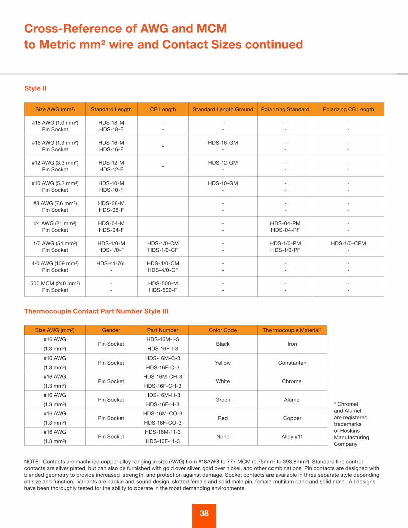
NOTE: Contacts are machined copper alloy ranging in size (AWG) from #18AWG to 777 MCM (0 .75mm² to 393 .8mm²) Standard line control contacts are silver plated, but can also be furnished with gold over silver, gold over nickel, and other combinations Pin contacts are designed with blended geometry to provide increased strength, and protection against damage . Socket contacts are available in three separate style depending on size and function . Variants are napkin and sound design, slotted female and solid male pin, female multilam band and solid male . All designs have been thoroughly tested for the ability to operate in the most demanding environments .
* Chromel and Alumel are registered trademarks of Hoskins Manufacturing Company
Cross-Reference of AWG and MCM to Metric mm² wire and Contact Sizes continued
Style II
Size AWG (mm²) Standard Length CB Length Standard Length Ground Polarizing Standard Polarizing CB Length
#18 AWG (1 .0 mm²) Pin Socket
HDS-18-MHDS-18-F
--
--
--
--
#16 AWG (1 .3 mm²)Pin Socket
HDS-16-MHDS-16-F
-HDS-16-GM
---
--
#12 AWG (3 .3 mm²)Pin Socket
HDS-12-MHDS-12-F
-HDS-12-GM
---
--
#10 AWG (5 .2 mm²)Pin Socket
HDS-10-MHDS-10-F
-HDS-10-GM
---
--
#8 AWG (7 .6 mm²)Pin Socket
HDS-08-MHDS-08-F
---
--
--
#4 AWG (21 mm²)Pin Socket
HDS-04-MHDS-04-F
---
HDS-04-PMHDS-04-PF
--
1/0 AWG (54 mm²)Pin Socket
HDS-1/0-MHDS-1/0-F
HDS-1/0-CMHDS-1/0-CF
--
HDS-1/0-PM HDS-1/0-PF
HDS-1/0-CPM -
4/0 AWG (109 mm²) Pin Socket
HDS-41-76L-
HDS-4/0-CM HDS-4/0-CF
--
--
--
500 MCM (240 mm²)Pin Socket
--
HDS-500-M HDS-500-F
--
--
--
Thermocouple Contact Part Number Style III
Size AWG (mm²) Gender Part Number Color Code Thermocouple Material*
#16 AWG
(1 .3 mm²)Pin Socket
HDS-16M-I-3
HDS-16F-I-3Black Iron
#16 AWG
(1 .3 mm²)Pin Socket
HDS-16M-C-3
HDS-16F-C-3Yellow Constantan
#16 AWG
(1 .3 mm²)Pin Socket
HDS-16M-CH-3
HDS-16F-CH-3White Chromel
#16 AWG
(1 .3 mm²)Pin Socket
HDS-16M-H-3
HDS-16F-H-3Green Alumel
#16 AWG
(1 .3 mm²)Pin Socket
HDS-16M-CO-3
HDS-16F-CO-3Red Copper
#16 AWG
(1 .3 mm²)Pin Socket
HDS-16M-11-3
HDS-16F-11-3None Alloy #11

39
NOTE: See page 41 for notes regarding this table
Replacement Contact Part Numbers
Replacement Contact Part Numbers
Size AWG (mm²) Gender Standard Length CB LengthStandard Length
Ground
Polarizing
Standard
Polarizing CB
Length
#18 AWG
(1 .0 mm²)Pin Socket
HDS-18-M
HDS-18-F
-
-
-
-
-
-
-
-
#16 AWG
(1 .3 mm²)Pin Socket
HDS-16-M
HDS-16-F-
-
HDS-16-GM
-
-
-
-
#12 AWG
(3 .3 mm²)Pin Socket
HDS-12-M
HDS-12-F-
-
HDS-12-GM
-
-
-
-
#10 AWG
(5 .2 mm²)Pin Socket
HDS-10-M
HDS-10-F-
-
HDS-10-GM
-
-
-
-
#8 AWG
(7 .6 mm²)Pin Socket
HDS-08-M
HDS-08-F-
-
-
-
-
-
-
#4 AWG
(21 mm²)Pin Socket
HDS-04-M
HDS-04-F-
-
-
HDS-04-PM
HDS-04-PF
-
-
1/0 AWG
(54 mm²)Pin Socket
HDS-1/0-M
HDS-1/0-F
HDS-1/0-CM
-
-
-
-
HDS-1/0-PF
HDS-1/0-CPM
-
4/0 AWG
(109 mm²)Pin Socket
HDS-4/0-M
HDS-4/0-F
HDS-4/0-CBM
HDS-4/0-CBF
-
-
-
-
-
-
262 MCM
(132 mm²)Pin Socket
-
-
HDS-262-CBM
HDS-262-CBF
-
-
-
-
-
-
313 MCM
(189 mm²)Pin Socket
-
-
HDS-313-CBM
HDS-313-CBF
-
-
-
-
-
-
444 MCM
(227 mm²)Pin Socket
-
-
HDS-444-CBM
HDS-444-CBF
-
-
-
-
-
-
500 MCM
(240 mm²)Pin Socket
-
-
HDS-500-CBM
HDS-500-CBF
-
-
-
-
-
-
535 MCM
(273 mm²)Pin Socket
-
-
HDS-535-CBM
HDS-535-CBF
-
-
-
-
-
-
646 MCM
(326 mm²)Pin Socket
-
-
HDS-646-CBM
HDS-646-CBF
-
-
-
-
-
-
777 MCM
(394 mm²)Pin Socket
-
-
HDS-777-CBM
HDS-777-CBF
-
-
-
-
-
-
1111 MCM
(562 mm²)Pin Socket
-
-
HDS-1111-CBM
HDS-1111-CBF
-
-
-
-
-
-

40
Termination Data
Solder and Crimp Wire Well Dimensions
Contact Size AWG (mm)
Solder and Crimp Wire Well Dimensions
Style I Solder Style II Solder Style III Crimp
Diameter Depth Diameter Depth Diameter Depth
#18 AWG (1 .0mm) .060" (1 .52) 13/64" (5 .15) .059" (1 .49) 3/8" (9 .52) .058" (1 .47) 3/8" (9 .52)
#16AWG (1 .3mm) .079" (2 .00) 13/64" (5 .15) .079" (2 .00) 1/2" (12 .70) 0 .79" (2 .0) 1/2" (12 .70)
#12AWG (3 .3mm) .117" (2 .97) 17/64" (6 .47) .113" (2 .87) 17/32" (6 .74) .113" (2 .87) 17/32" (6 .74)
#10AWG (5 .2mm) .142" (3 .61) 25/64" (9 .92) .142" (3 .60) 19/32" (15 .09) .142" (3 .60) 19/32" (15 .09)
#8AWG (7 .6mm) .210" (5 .33) 23/64" (9 .12) .189" (4 .80) 3/4" (19 .05) .189" (4 .80) 3/4" (19 .05)
#4AWG (21mm) .333" (8 .45) 37/64" (14 .63) .289" (7 .34) 53/64" (21 .03) .278" (7 .06) 53/64" (21 .03)
1/0 AWG (54mm) .470" (11 .94) 41/64" (16 .27) .445" (11 .30) 1-1/8" (28 .58) .455" (11 .56) 15/16" (23 .81)
4/0 AWG (109mm) .656" (16 .7) 57/64" (22 .62) - - - 15/16" (23 .81)
350 MCM (185mm) .798" (20 .27) 1-1/8" (28 .58) - - - -
500MCM (240mm) - 1 .00" (25 .40) 1-3/8" (34 .93) - -
Torque Values for Pressure Pad Termination
Contact/ Conductor Size Torque Required In/lbs (N•m) Retention Force lbs (N))
4/0 AWG (109mm²) 100 (11 .3)
4/0 450 (2001 .7)
3/0 350 (1556 .9)
2/0 300 (1334 .5)
1/0 AWG (54mm²) 50 (5 .7)
1/0 250 (1112 .0)
#1 200 (889 .7)
#2 180 (800 .7)
#4 AWG (21mm²) 20 (2 .3)#4 140 (662 .8)
#6 100 (444 .8)
#8 AWG (7 .6mm²) 25 (2 .8) #8 90 (400 .3)
#10 AWG (5 .2mm²) 15 (1 .7)
#10 80 (335 .9)
#12 70 (311 .4)
#14 60 (266 .9)

41
*Consult EEC if soldering or using with sizes other than those stated Recommended using IES Tool SP1 Crimp Tool with appropriate sized dies .
Termination Data (continued)
Torque Data for Pressure Contacts Continued
Contact Conductor Size
AWG (mm²)
Torque Required in/lbs
(N•m)Retention Force lbs (N)
#8 AWG
(7.6mm²)25 (2.8) #8 75 (333.6)
#10 AWG
(5.2mm²)15 (1.7)
#10 80 (335.9)
#12 70 (311.4)
#14 60 (266.9)
Crimp Termination Data
Contact Conductor Size
AWG (mm²)
Conductor Wire Size
Crimped AWG (mm²)
Crimp Retention
Minimum
Force lbs (N)
#18 AWG (0.75mm²) #18 (1.0mm²)
#20 (0.50mm²)
#22 (0.34mm²)
38 (169)
19 (84.5)
15 (66.7)
#16 AWG (1.5mm²) #16 (1.3mm²)
#18 (1.0mm²)
#20 (0.5mm²)
50 (222.4)
38 (169.0)
19 (84.5)
#12 AWG (4.0mm²) #12 (3.3mm²)
#14 (2.5mm²)
#16 (1.3mm²)
110 (489.3)
70 (311.4)
50 (222.4)
#10 AWG (6.0mm²) #10 (5.2mm²)
#12 (3.3mm²)
#14 (2.5mm²)
180* (800.7)
110 (489.3)
70 (311.4)
#8 AWG (10.0mm²) #8 to #10 225 (1000)
180 (800)
#4 AWG (25mm²) #4 to #6 400 (1779)
300 (1334)
1/0 AWG (50mm²) #2 (35) to 1/0 (54) 550 (2447)
700 (3114)
4/0 AWG (120mm²) 4/0 (109)
3/0 (95)
2/0 (70)
875 (3892)
825 (3670)
750 (3336)
262MCM (132mm²) 262MCM (132mm²) 550 (2445)*
313MCM (159mm²) 313MCM (159mm²) 600 (2670)*
373MCM (189mm²) 373MCM (189mm²) 650 (2593)*
444MCM (227mm²) 444MCM (227mm²) 2500 (1120)*
500MCM (240mm²) 500MCM (240mm²) 2500 (1120)
535MCM (273mm²) 535MCM (273mm²) 900 (4005)
646MCM (326mm²) 646MCM (326mm²) 950 (4228)
777MCM (394mm²) 777MCM (394mm²) 1000 (4450)
1111MCM (562mm²) 1111MCM (562mm²) 1000 (4450)
2000MCM (1120mm²) 2000MCM (1120mm²) 1000 (4450)

Electrical Service Ratings
Insert Arrangement Service Rating
Each insert plan form has a factory designated working voltage rating . The voltage allowable through the contacts, male and female, is limited by the dielectric separation between each contact and the nearest conductor (adjacent contacts and the connector shell) .
Electrical Service Voltage
Military Ratings MIL-C-5015 Specifications Non-Circuit Breaking
N.E.C. Raings IEC Service RatingsReq'd Minimum
Creepage Distance
Req'd Minimum Clearance or Thru
Air Spacing
DC (V) AC (V)Non-Circuit
Breaking DC (V)Circuit Breaking
AC (V)Non-Circuit
Breaking DC (V)Circuit Breaking
AC (V) in mm in mm
Instrument 250 200 - - 1000 1000 1/16 1.6 - -
A 700 500 250 240 1000 1000 1/8 3.18 1/16 1.6
D 1250 900 600 600 1250 1000 3/16 4.76 1/8 3.18
E 1750 1250 600 600 1750 1250 1/4 6.35 3/16 4.76
B 2450 1750 600 600 2450 1750 5/16 7.94 1/4 6.35
C 4200 3000 600 600 4200 3000 1 24.4 5/16 7.94
A letter in Table 1 represents voltage ratings, with their associated maximum values, both AC and DC . The insert plan from listings show the ratings for each individual insert .
Military Current Ratings according to MIL-C-39029The maximum current carrying capability of a contact pair is determined by the basic design of the contacts and also the ability of the insulation to withstand the temperature rises caused by an increase in current . The connector is temperature rated at 225ºC for continuous operation . The actual working temperature is a function of the ambient temperature and the summation of the heat dissipated by each individual contact . The maximum current rating for continuous supply is calculated from temperature of the insert
N.E.C. (National Electric Code) Non-Circuit Breaking Current RatingsThis table lists ratings that are based on test results of contacts and connectors . The temperature range must fall within the bands specified by Underwriters Laboratories Inc ., assuming wire sizes are in accordance with the National Electric Code . The results are based on single conductors - multiple conductors, the ambient and insert temperature must be taken into account and a reduction factor applied .
N.E.C. (National Electric Code) Circuit Breaking Current RatingsRatings are shown for the ability of different sizes of standard silver plated contacts to be engaged and disengaged under load .
42


©2015 Amphenol EEC, Inc.www.eecchicago.com