hds-nt press brake - lapis services...
TRANSCRIPT

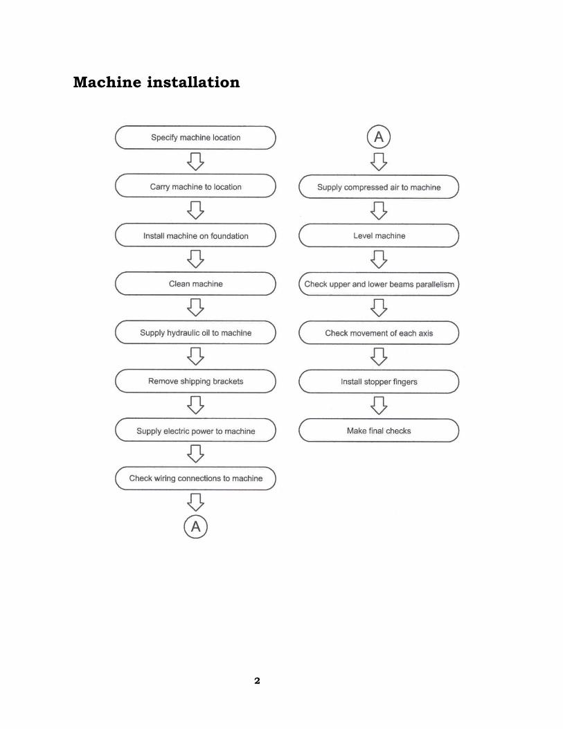
HDS-NT Press Brake Installation Guide
Summary...........................................................................................2
Environmental conditions ..............................................................2 Power supply.................................................................................2 Machine installation.......................................................................3
Location ............................................................................................4 Carrying ............................................................................................5
Using a crane ................................................................................5 Using rollers ..................................................................................6
Foundation........................................................................................7 Cleaning............................................................................................7 Supplying hydraulic oil ......................................................................8 Removing shipping brackets.............................................................9 Installing stopper fingers..................................................................12 Moving rear guard............................................................................13 Supplying electric power..................................................................14
Connecting power cable...............................................................15 Checking wiring connections........................................................16
Zero-returning ..................................................................................17 Leveling............................................................................................17 Paralleling upper and lower beams .................................................18 Checking movement of each axis....................................................19 Making final checks .........................................................................20

1
SUMMARY
Environmental conditions • The higher the humidity in the place where the machine is installed,
the lower the insulation performance of its electric parts becomes. This results in the premature degradation of the electric parts. Do not install the machine in such a humid place.
• Where the ambient temperature is not higher than 5°C {41°F}, keep the machine and hydraulic unit energized during the day's work.
• Install the machine in a place where it is not subjected to dust, dirt, and organic or corrosive gases.
• Keep the machine at least 10 m {33 ft} away from a welder or any other equipment that may produce electric noise and magnetic fields.
Power supply Power requirement: 200/220 V, AC, 3 phases, 50/60 Hz Power cable: Composed of four conductors (including grounding conductor) and thick enough to carry required power
Full load current Power cable and ground conductor
{in2} Model Power voltage
200 V 220 V 200/230V
8025 200/220 V 44 A 40 A 14 mm2 {0.022}
1030 200/220 V 56A 50.9� 22 mm2 {0.866}
1303 200/220 V 64A 58.2� 22 mm2 {0.866}
NOTICE
● Supply the machine from a power source independent of a welder or any other equipment that may produce line voltage variations.
2
Machine installation

3
LOCATION The place where the machine is to be installed must have an ample floor space. Refer to the machine dimensions given in the table below. Also take the following points into account: • There must be no pillars and other obstacles in the area where the
tools are mounted and removed. (At least 835 mm {32.9 in.} long tools must be able to be horizontally mounted and removed.)
• The ceiling must be at least 1000 mm {40 in.} from the top of the machine.
• There must be an additional space to place a tool storage case and an air compressor.
• There must be a work space where the worksheets can be easily moved in and out and where maintenance and part quality check can be smoothly performed. Especially, a work space of 1000 mm {40 in.} or more must be available at the rear of the machine, and an enough space must be available for the door of the electrical enclosure to be opened.
NOTICE
● Do not install the machine in a place where it is exposed to dust from such operations as sandblasting and to direct sunlight, rain or wind.
Unit: mm {in.} Model A B
8025 4675 {184.06} 2250 {88.58}
1030 5185 {204.13} 2250 {88.58}
1303 5250 {206.49} 2250 {88.58}
A
B

4
CARRYING WARNING
● Carrying the machine is very dangerous. Have a qualified contractor perform the carrying work.
Using a crane When lifting the machine, apply the wire rope sling to the hole at the top of the left and right frames, slowly lift and carry the machine to the location, and slowly lower the machine at the location. The wire rope sling must be strong enough to carry the mass of the machine. (For the mass of the machine, see the serial number plate attached to the machine.)
Lifting hole
5
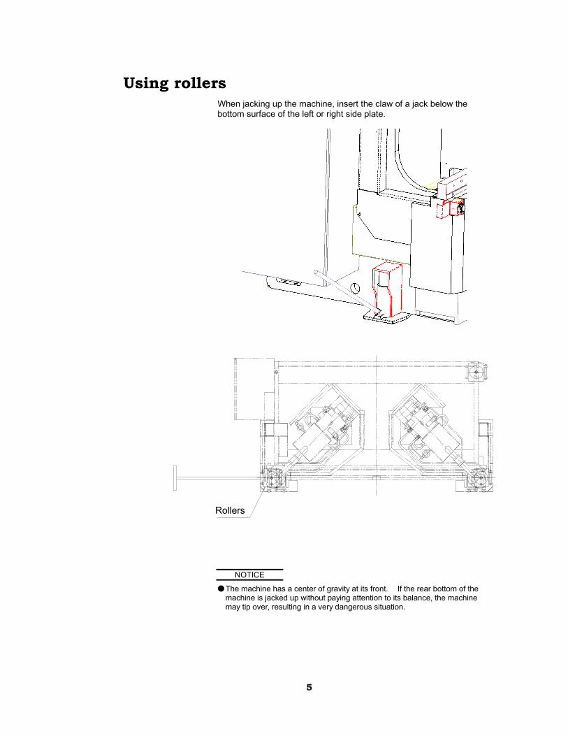
Using rollers When jacking up the machine, insert the claw of a jack below the bottom surface of the left or right side plate.
NOTICE
● The machine has a center of gravity at its front. If the rear bottom of the machine is jacked up without paying attention to its balance, the machine may tip over, resulting in a very dangerous situation.
Rollers

6
FOUNDATION To maintain bending accuracy, install the machine on a flat concrete floor that is strong enough to carry the weight of the machine and is not likely to subside.
Unit: mm {in.}
Model A B
8025 4675 {184.06} 2250 {88.58}
1030 5185 {204.13} 2250 {88.58}
1303 5250 {206.69} 2250 {88.58}
CLEANING After the machine is installed on the foundation, clean it. Particularly, remove all rust-preventive grease from the punch holders, the die holders, and the top surface of the lower beam, using cleaning oil.
NOTICE
● Do not use a solvent or scraper that removes the paint of the machine.
7
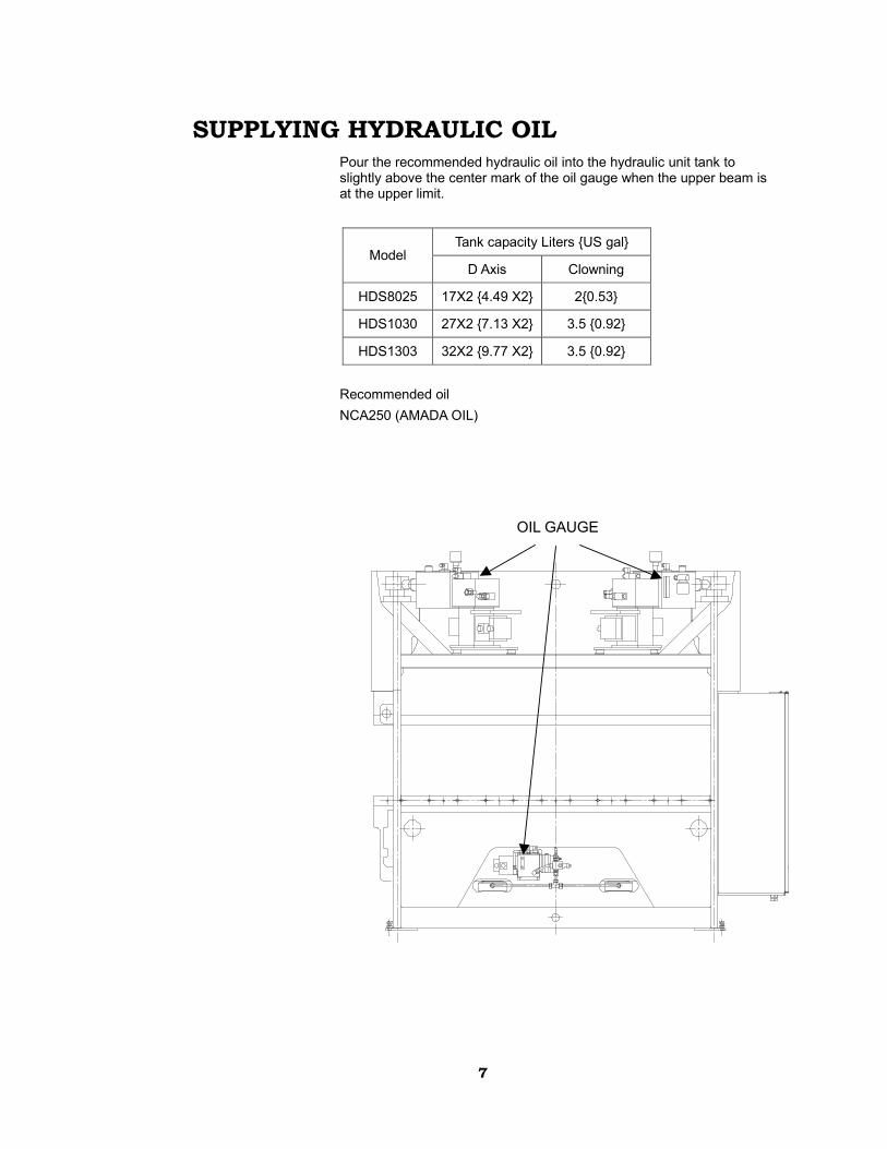
SUPPLYING HYDRAULIC OIL Pour the recommended hydraulic oil into the hydraulic unit tank to slightly above the center mark of the oil gauge when the upper beam is at the upper limit.
Tank capacity Liters {US gal} Model
D Axis Clowning
HDS8025 17X2 {4.49 X2} 2{0.53}
HDS1030 27X2 {7.13 X2} 3.5 {0.92}
HDS1303 32X2 {9.77 X2} 3.5 {0.92} Recommended oil NCA250 (AMADA OIL)
OIL GAUGE

8
REMOVING SHIPPING BRACKETS The shipping brackets securing the upper beam are positioned near the left and right upper guide rollers. Loosen the nut� and bolt� of each shipping bracket. Remove the bolts�, and remove the block�. Take care not to lose the removed shipping brackets.
�
�
��
9
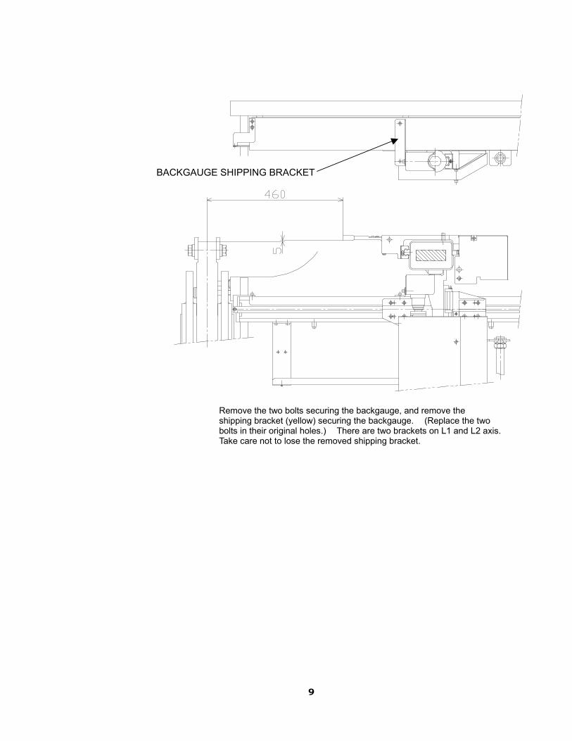
Remove the two bolts securing the backgauge, and remove the shipping bracket (yellow) securing the backgauge. (Replace the two bolts in their original holes.) There are two brackets on L1 and L2 axis. Take care not to lose the removed shipping bracket.
BACKGAUGE SHIPPING BRACKET

10
Remove the bolts securing the straightedge, and remove the shipping bracket (yellow). There are two brackets on Y1 and Y2 axis. Replace the two bolts in their original holes with collars. Take care not to lose the removed shipping bracket.
BOLT
COLLAR
STOPPER SHIPPING BRACKET
11
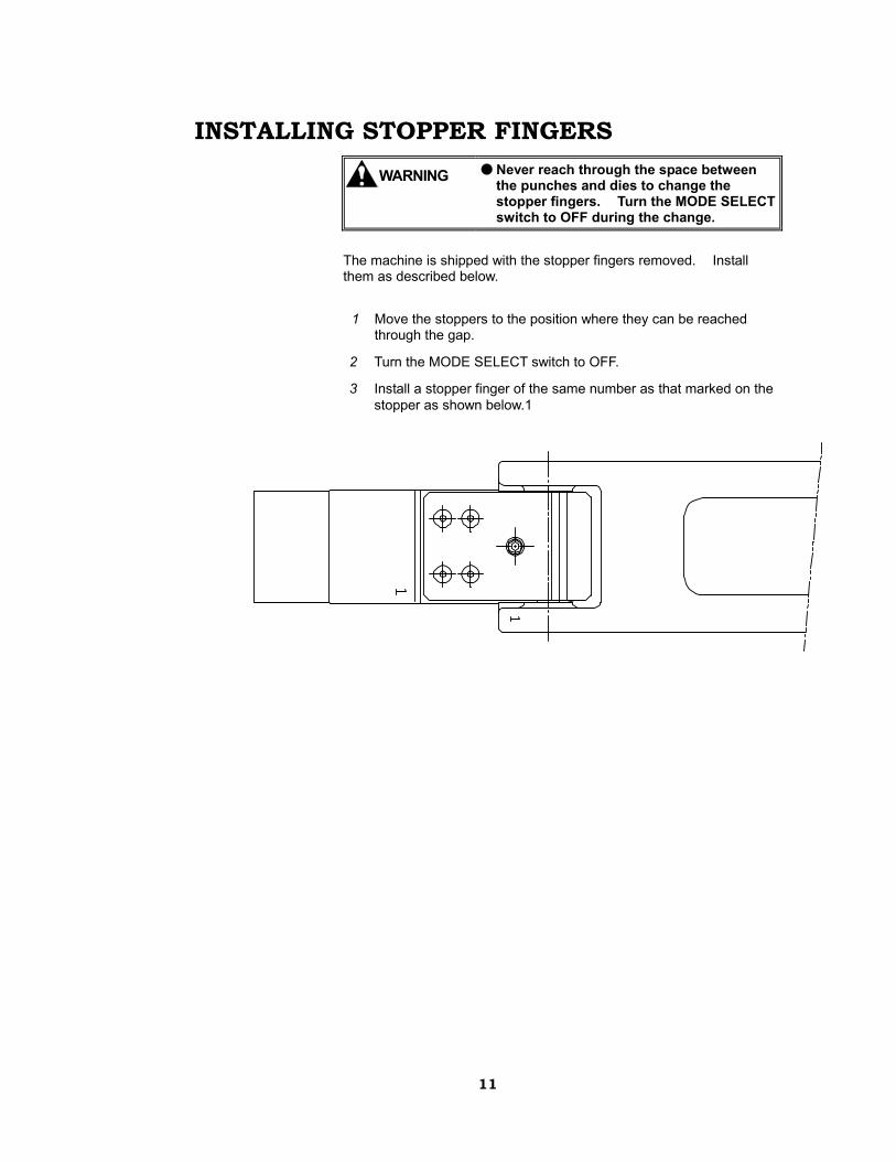
INSTALLING STOPPER FINGERS WARNING
● Never reach through the space between the punches and dies to change the stopper fingers. Turn the MODE SELECT switch to OFF during the change.
The machine is shipped with the stopper fingers removed. Install them as described below. 1 Move the stoppers to the position where they can be reached
through the gap.
2 Turn the MODE SELECT switch to OFF.
3 Install a stopper finger of the same number as that marked on the stopper as shown below.1�

12
MOVING REAR GUARD
�� Loosen the 6bolts securing inside of the flame.
�� Pull the rear guard to the end of the slots.
�� Tighten the 6bolts
BEFORE MOVING AFTER MOVING
��SLOTS

13
SUPPLYING ELECTRIC POWER WARNING
● Have a qualified electrician perform all electric work to prevent accidents and damage.
● Before making the electrical connections, be sure to turn off the shop circuit breaker.
● Be sure to connect the grounding conductor for safety.
● Use the shop circuit breaker and grounding conductor exclusively for the machine, and separate from those of other equipment such as welders, drills, sanders, and grinders.
NOTE
● The machine needs a 200/220 V and 3-phase power supply. ● Use the power cable and grounding conductor that suit the power to be
handled.
Connecting power cable Connect the power cable to the machine as described below. 1 Turn off the shop circuit breaker.
2 Open the door of the electrical enclosure at the left side of the machine.
3 Turn off the machine circuit breaker.
4 Run the power cable from the shop circuit breaker through the hole into the electrical enclosure.
5 Connect the power cable to the power input terminals L1, L2, and L3 in the electrical enclosure.
6 Connect the grounding conductor to the ground terminal PE.
NOTE
● Use a grounding conductor of at least the same size as that of the power cable conductors.

14
7 After the electric wiring connections are completed, check the voltage with a tester.
When the power supply parts are changed, check the voltage with a tester as described below.
(1) Turn off the shop circuit breaker.
(2) Change the machine to the following conditions: • Turn off the circuit breaker QF1. • Turn off the motor circuit breaker QM1. • Remove the fuse FU3. • Turn off the circuit protectors QF3 to QF5.
(3) Turn on the shop circuit breaker.
(4) Check the input voltage between the terminals L1 and L2, L2 and L3, and L1 and L3 at the lower terminal block.
(5) Check the input voltage between the terminals L1 and L2, L2 and L3, and L1 and L3 at the primary side (upper terminal block) of the circuit breaker QF1.
(6) Turn on the circuit breaker QF1.
(7) Check the input voltage between the terminals L11 and L21, L21 and L31, and L11 and L31 at the secondary side (lower terminal block) of the circuit breaker QF1.
(8) Check the output voltage at the secondary side of the transformer TC1.
(9) Check the input voltage between the terminals L11 and L21, L21 and L31, and L11 and L31 at the primary side (upper terminal block) of the motor circuit breaker QM1.
(10) Turn on the motor circuit breaker QM1.
(11) Check the input voltage between the terminals L12 and L22, L22 and L32, and L12 and L32 at the secondary side (lower terminal block) of the motor circuit breaker QM1.
(12) If the above voltage checks find no problems, turn off the circuit breaker QF1.
(13) Return the machine to the following conditions: • Replace the fuse FU3. • Turn on the circuit protectors QF3 to QF5.
8 Replace the cover of the electrical enclosure.

15
Checking wiring connections Check the wiring connections as described below. 1 Turn on the shop circuit breaker.
2 Turn on the machine circuit breaker, and check that the POWER light comes on.
3 Turn the POWER ON/OFF switch to ON. When the initial NC display is shown and a beep is heard, the hydraulic pump motor can be started.
4 Press the HYDRAULIC ON button. The hydraulic pump motor starts, and the HYDRAULIC ON button lights.

16
ZERO-RETURNING After the power of the machine is turned on, be sure to zero-return the machine. Unless the zero-return is performed, each axis cannot move. Zero-return the machine as described below. 1 Touch the SETUP button shown on the screen.
2 Press and hold the CLOSE foot pedal. Each axis zero-returns.
LEVELING Leveling left-to-right direction 1 Place a spirit level at the center of the lower beam.
2 Turn the leveling bolt behind the machine side plate to level the machine to 0.04 mm/1 m or less.
Leveling front-to-back direction 1 Clean the traveling surface of the lower guide roller behind the
upper beam of the machine.
2 Attach a square spirit level with a magnet to the traveling surface.
3 Turn the leveling bolt behind the machine side plate to level the machine to 0.02 mm/1 m or less.
4 When the leveling of the machine is completed, tighten the nut.
17
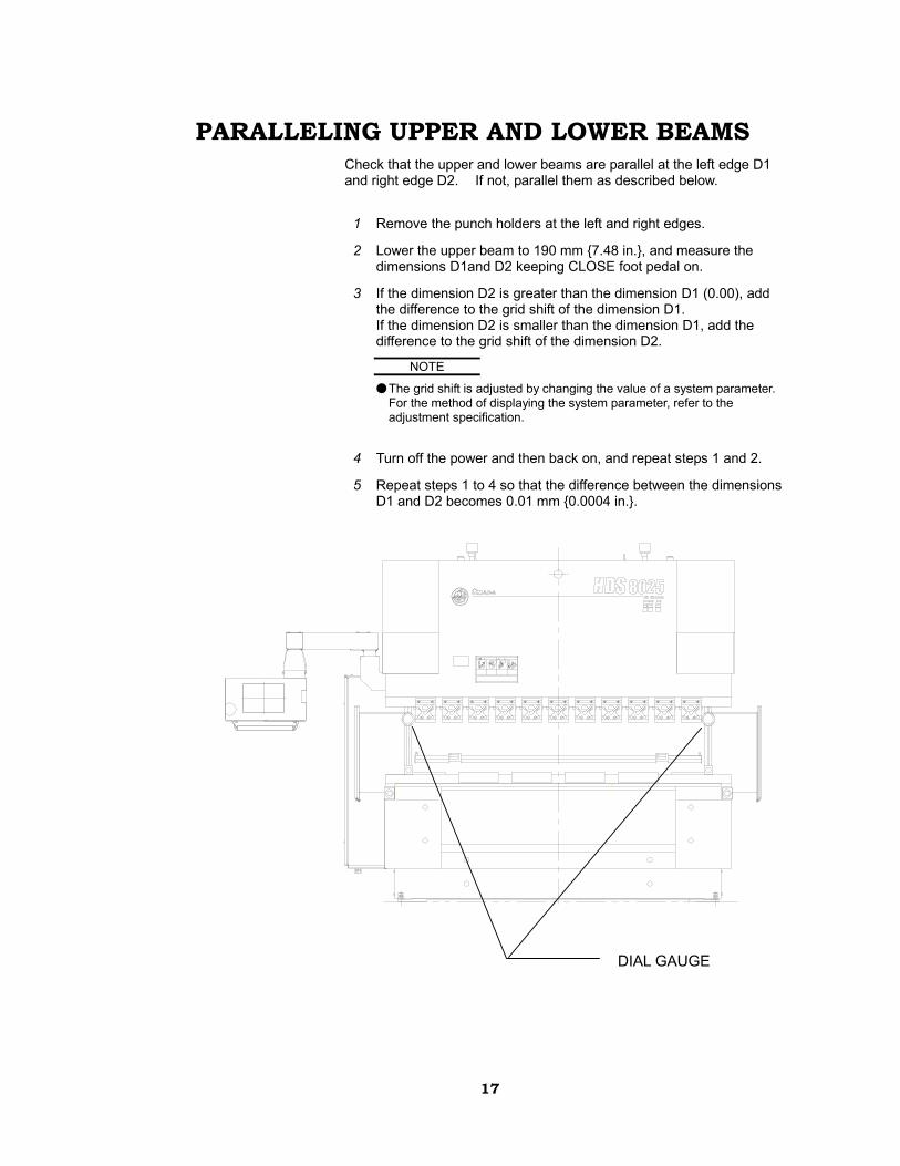
PARALLELING UPPER AND LOWER BEAMS Check that the upper and lower beams are parallel at the left edge D1 and right edge D2. If not, parallel them as described below. 1 Remove the punch holders at the left and right edges.
2 Lower the upper beam to 190 mm {7.48 in.}, and measure the dimensions D1and D2 keeping CLOSE foot pedal on.
3 If the dimension D2 is greater than the dimension D1 (0.00), add the difference to the grid shift of the dimension D1. If the dimension D2 is smaller than the dimension D1, add the difference to the grid shift of the dimension D2.
NOTE
● The grid shift is adjusted by changing the value of a system parameter. For the method of displaying the system parameter, refer to the adjustment specification.
4 Turn off the power and then back on, and repeat steps 1 and 2.
5 Repeat steps 1 to 4 so that the difference between the dimensions D1 and D2 becomes 0.01 mm {0.0004 in.}.
DIAL GAUGE
18
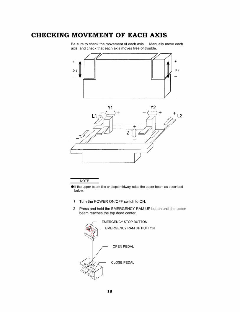
CHECKING MOVEMENT OF EACH AXIS Be sure to check the movement of each axis. Manually move each axis, and check that each axis moves free of trouble.
NOTE
● If the upper beam tilts or stops midway, raise the upper beam as described below.
1 Turn the POWER ON/OFF switch to ON.
2 Press and hold the EMERGENCY RAM UP button until the upper beam reaches the top dead center.
EMERGENCY STOP BUTTON
EMERGENCY RAM UP BUTTON
CLOSE PEDAL
OPEN PEDAL

19
MAKING FINAL CHECKS • Oil leakage and air removal Check for any oil leak. After tools are mounted, move down the
upper beam to apply pressure to the tools for a few seconds. This forces air out of the hydraulic unit. In case of existing air in the hydraulic circuit ram moves not smoothly and alarm[Error amount is too large in D-axis ]

20