hdl mne 2102 - modelsim walkthrough2
TRANSCRIPT
7/29/2019 HDL MNE 2102 - ModelSim Walkthrough2
http://slidepdf.com/reader/full/hdl-mne-2102-modelsim-walkthrough2 1/14
Hardware Description Languages – MNE 2102 1
Modelsim Walkthrough – Design of a Simple ALU
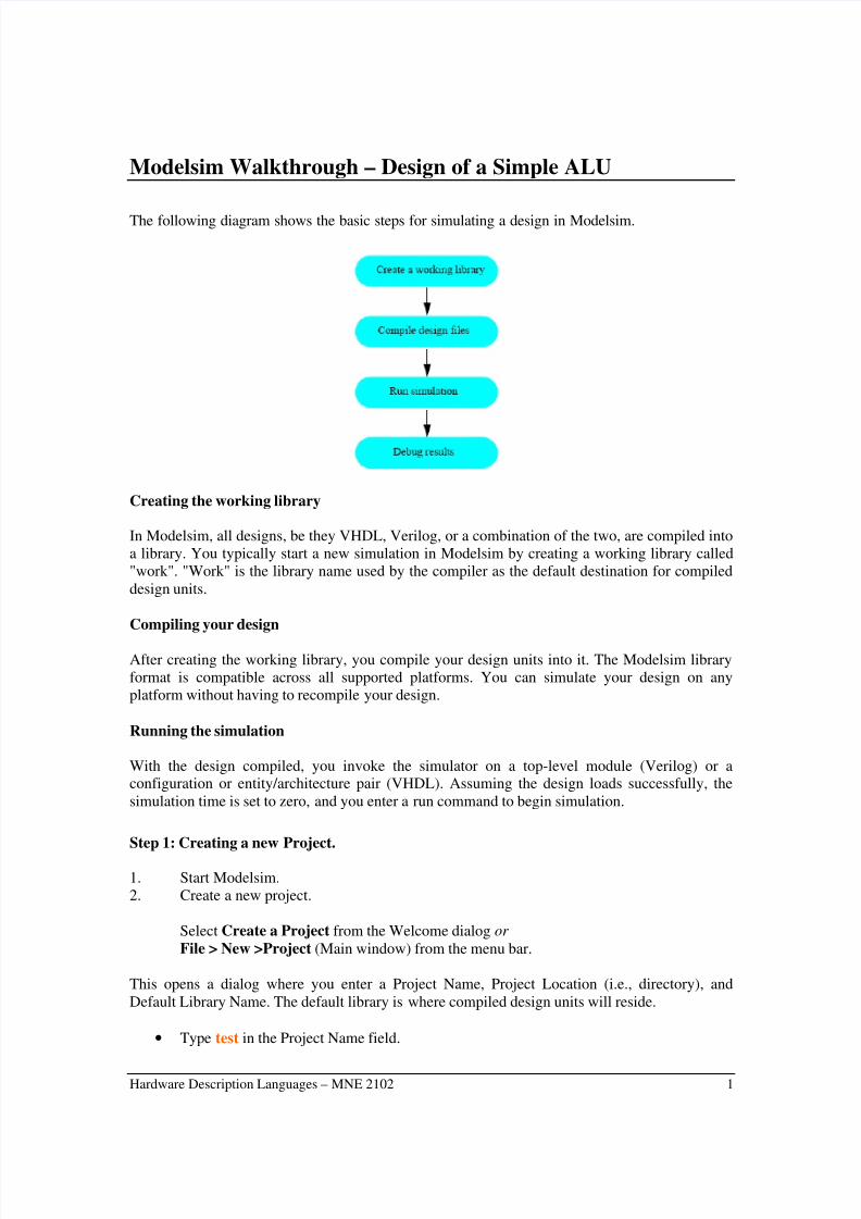
The following diagram shows the basic steps for simulating a design in Modelsim.
Creating the working library
In Modelsim, all designs, be they VHDL, Verilog, or a combination of the two, are compiled into
a library. You typically start a new simulation in Modelsim by creating a working library called
"work". "Work" is the library name used by the compiler as the default destination for compiled
design units.
Compiling your design
After creating the working library, you compile your design units into it. The Modelsim library
format is compatible across all supported platforms. You can simulate your design on any
platform without having to recompile your design.
Running the simulation
With the design compiled, you invoke the simulator on a top-level module (Verilog) or aconfiguration or entity/architecture pair (VHDL). Assuming the design loads successfully, the
simulation time is set to zero, and you enter a run command to begin simulation.
Step 1: Creating a new Project.
1. Start Modelsim.
2. Create a new project.
Select Create a Project from the Welcome dialog or
File > New >Project (Main window) from the menu bar.
This opens a dialog where you enter a Project Name, Project Location (i.e., directory), and
Default Library Name. The default library is where compiled design units will reside.
• Type test in the Project Name field.

7/29/2019 HDL MNE 2102 - ModelSim Walkthrough2
http://slidepdf.com/reader/full/hdl-mne-2102-modelsim-walkthrough2 2/14
Hardware Description Languages – MNE 2102 2
• Click Browse to select a directory where the project file will be stored.
• Leave the Default Library Name set to work .
• Click ok
Step 2: Adding items to the project
Once you click OK to accept the new project settings, you will see a blank Project tab in theworkspace area of the Main window and the Add items to the Project dialog will appear. From
this dialog you can create a new design file, add an existing file, add a folder for organizationpurposes, or create a simulation configuration.
Creating new files:
In this walkthrough you will need two files: one for the VHDL code of the ALU and another for
the test benches.

7/29/2019 HDL MNE 2102 - ModelSim Walkthrough2
http://slidepdf.com/reader/full/hdl-mne-2102-modelsim-walkthrough2 3/14
Hardware Description Languages – MNE 2102 3
• Click Create New File.
• Click Browse.
• Write the file name you wish to give to file e.g. alu.vhd• Click Open and then OK
• Repeat for any other files e.g. alu_tb.vhd and alu_tl.vhd
These two files are attached to this walk-through.
Adding existing files:
• Click Add Existing File.
• Click Browse.
• Open the examples directory in your ModelSim installation tree
• Select alu.vhd, alu_tb.vhd and alu_tl.vhd
• Click Open and then OK
You should now see two files listed in the Project tab of the Main window workspace. Question
mark icons (?) in the Status column mean the file hasn’t been compiled or the source file has
changed since the last successful compile. The other columns identify file type (e.g., Verilog orVHDL), compilation order, and modified date.
Changing compile order (VHDL)

7/29/2019 HDL MNE 2102 - ModelSim Walkthrough2
http://slidepdf.com/reader/full/hdl-mne-2102-modelsim-walkthrough2 4/14
Hardware Description Languages – MNE 2102 4
Compilation order is important in VHDL designs. Follow these steps to change compilation order
within a project.
• Select Compile > Compile Order.• Click the Auto Generate button.
ModelSim "determines" the compile order by making multiple passes over the files. It starts
compiling from the top; if a file fails to compile due to dependencies, it moves that file to the
bottom and then recompiles it after compiling the rest of the files. It continues in this manner until
all files compile successfully or until a file(s) can’t be compiled for reasons other than
dependency. Alternatively, you can select a file and use the Move Up and Move Down buttons toput the files in the correct order.
Step 3: Simulation Configurations
A Simulation Configuration associates a design unit(s) and its simulation options. For example,
say every time you load alu_tl.vhd you want to set the simulator resolution to nanoseconds (ns)and enable event order hazard checking. Ordinarily you would have to specify those options each
time you load the design. With a Simulation Configuration, you specify options for a design and
then save a "configuration" that associates the design and its options. The configuration is then
listed in the Project tab and you can double-click it to load alu.vhd along with its options.
Create a new Simulation Configuration:
• Select File > Add to Project > Simulation Configuration.
• Type alu in the Simulation Configuration Name field
• Select Top Level from the Place in Folder drop-down• Click the ’+’ icon next to the work library and select alu_tl.
• Click the Resolution drop-down and select ns
• Click Ok
The Project tab now shows a Simulation Configuration named alu.
7/29/2019 HDL MNE 2102 - ModelSim Walkthrough2
http://slidepdf.com/reader/full/hdl-mne-2102-modelsim-walkthrough2 5/14
Hardware Description Languages – MNE 2102 5
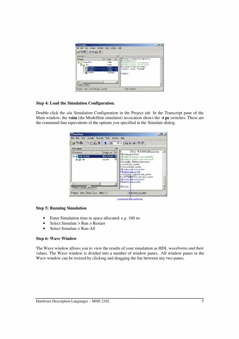
Step 4: Load the Simulation Configuration.
Double-click the alu Simulation Configuration in the Project tab. In the Transcript pane of the
Main window, the vsim (the ModelSim simulator) invocation shows the -t ps switches. These arethe command-line equivalents of the options you specified in the Simulate dialog.
Step 5: Running Simulation
• Enter Simulation time in space allocated: e.g. 160 ns
• Select Simulate > Run > Restart
• Select Simulate > Run-All
Step 6: Wave Window
The Wave window allows you to view the results of your simulation as HDL waveforms and their
values. The Wave window is divided into a number of window panes. All window panes in the
Wave window can be resized by clicking and dragging the bar between any two panes.

7/29/2019 HDL MNE 2102 - ModelSim Walkthrough2
http://slidepdf.com/reader/full/hdl-mne-2102-modelsim-walkthrough2 6/14
Hardware Description Languages – MNE 2102 6
Adding items to the Wave window
ModelSim offers several methods for adding items to the Wave window. In this exercise, you’lltry out different methods.
1. Add items using drag-and-drop.
You can drag an item to the Wave window from many other windows (e.g., Main, Signals, and
Variables).
• Drag an instance from the sim tab of the Main window to the Wave.
• Drag a signal from the Signals window to the Wave window.
• In the Wave window, select Edit > Select All and then Edit > Delete.
2. Add items using a command.
• Type add wave * at the VSIM> prompt. ModelSim adds all items from the current
region.
• Run the simulation for awhile so you can see waveforms.
Using cursors in the Wave window
Cursors mark simulation time in the Wave window. When ModelSim first draws the Wave
window, it places one cursor at time zero. Clicking anywhere in the waveform pane brings that
cursor to the mouse location. You can also add additional cursors; name, lock, and delete cursors;
use cursors to measure time interval; and use cursors to find transitions.
Working with a single cursor
• Position the cursor by clicking and dragging.
• Click the Select Mode icon on the Wave window toolbar.
• Click anywhere in the waveform pane. A cursor is inserted at the time where you clicked

7/29/2019 HDL MNE 2102 - ModelSim Walkthrough2
http://slidepdf.com/reader/full/hdl-mne-2102-modelsim-walkthrough2 7/14
Hardware Description Languages – MNE 2102 7
• Drag the cursor and observe the value pane. The signal values change as you move the
cursor. This is perhaps the easiest way to examine the value of a signal at a particular
time.
• d In the waveform pane, drag the cursor to the right of a transition with the mousepositioned over a waveform. The cursor "snaps" to the transition. Cursors "snap" to a
waveform edge if you click or drag a cursor to within ten pixels of a waveform edge. You
can set the snap distance in the Window Preferences dialog (select Tools > WindowPreferences).
• In the cursor pane, drag the cursor to the right of a transition. The cursor doesn’t snap to a
transition if you drag in the cursor pane.

7/29/2019 HDL MNE 2102 - ModelSim Walkthrough2
http://slidepdf.com/reader/full/hdl-mne-2102-modelsim-walkthrough2 8/14
Hardware Description Languages – MNE 2102 8
VHDL Code for clk, reset
-------------------------------------------------
-- Project : Simple Reset ---- Author : Owen Casha ---- Date : 10/10/2005 ---- Company : UOM ---- File : system.vhd ---- Design : Walkthrough ---------------------------------------------------library IEEE;use IEEE.std_logic_1164.all;use IEEE.std_logic_arith.all;use IEEE.std_logic_misc.all;use IEEE.std_logic_unsigned.all;
entity SYSTEM isport (
reset : out bit ;
clk : out bit );end SYSTEM;
architecture SYSTEM_arch of SYSTEM isbegin
SIGNAL reset : bit := '1';SIGNAL clk : bit;
CONSTANT clk_pd : time := 100 ns; --clock periodCONSTANT reset_pd : time := 200 ns; --reset period
BEGIN--------------------------------------------- clock generator-------------------------------------------clock_driver : PROCESS
BEGINclk <= '0';WAIT FOR clk_pd / 2;LOOP
clk <= '1', '0' AFTER clk_pd / 2;WAIT FOR clk_pd;
END LOOP;END PROCESS;
--------------------------------------------- reset driver-------------------------------------------reset <= '0' after reset_pd;
END SYSTEM_arch

7/29/2019 HDL MNE 2102 - ModelSim Walkthrough2
http://slidepdf.com/reader/full/hdl-mne-2102-modelsim-walkthrough2 9/14
Hardware Description Languages – MNE 2102 9
VHDL Code for ALU
-------------------------------------------------
-- Project : Simple Arithmetic Logic Unit ---- Author : Owen Casha ---- Date : 10/10/2005 ---- Company : UOM ---- File : alu.vhd ---- Design : Walkthrough ---------------------------------------------------library IEEE;use IEEE.std_logic_1164.all;use IEEE.std_logic_arith.all;use IEEE.std_logic_misc.all;use IEEE.std_logic_unsigned.all;
entity ALU isport ( Accumulator_in: in STD_LOGIC_VECTOR (7 downto 0);
Data_in : in STD_LOGIC_VECTOR (7 downto 0);Opcode_in : in STD_LOGIC_VECTOR (3 downto 0);Result_out : out STD_LOGIC_VECTOR (7 downto 0)
);end ALU;
architecture ALU_arch of ALU isbegin
Main: process(Accumulator_in,Opcode_in, Data_in)begin
case Opcode_in is
when "0000" => Result_out <= Data_in;-- result = Data_in
when "0001"=> Result_out <= Accumulator_in;-- result = accumulator_in
when "0010"=> Result_out <= "00000000";
-- result = accumulator_in + Data_inwhen "0011"=> Result_out <= "00000000";-- result = accumulator_in - Data_in
when "0100"=> Result_out <= Accumulator_in and Data_in;-- result = accumulator_in and Data_in
when "0101"=> Result_out <= Accumulator_in or Data_in;-- result = accumulator_in or Data_in
when "0110"=> Result_out <= Accumulator_in xor Data_in;-- result = accumulator_in xor Data_in
when "0111"=> Result_out <= not(accumulator_in);-- result = not(accumulator_in)
when "1000"=> Result_out <= not(accumulator_in);-- result = not(Data_in);
when "1001"=> Result_out <= "00000000";-- result = 0
when "1010"=> Result_out <= "00000000";-- result = 8 LSBs of ( accumulator_in * Data_in)
when "1011"=> Result_out <= "00000000";-- result = 8 MSBs of ( accumulator_in * Data_in)when "1100"=> Result_out <= accumulator_in nand Data_in;
-- result = accumulator_in nand Data_in when "1101"=> Result_out <= accumulator_in nor Data_in;
-- result = accumulator_in nor Data_inwhen "1110"=> Result_out <= accumulator_in xnor Data_in;
--result=accumulator_in xnor Data_inwhen "1111"=> Result_out <= "00000000";
--result=Accumulator_in+1when others => Result_out <="XXXXXXXX";end case;
end process Main;end ALU_arch;

7/29/2019 HDL MNE 2102 - ModelSim Walkthrough2
http://slidepdf.com/reader/full/hdl-mne-2102-modelsim-walkthrough2 10/14
Hardware Description Languages – MNE 2102 10
Test Bench for ALU
--------------------------------------------------- Project : Simple Arithmetic Logic Unit ---- Author : Owen Casha ---- Date : 10/10/2005 ---- Company : UOM ---- File : alu_tb.vhd ---- Design : Walkthrough ---------------------------------------------------
library IEEE;use IEEE.std_logic_1164.all;use IEEE.std_logic_arith.all;use IEEE.std_logic_misc.all;use IEEE.std_logic_unsigned.all;
entity alu_tb is
port (Accumulator_out: out std_logic_vector (8 downto 1);Data_out : out std_logic_vector (8 downto 1);Opcode_out : out std_logic_vector (4 downto 1));
end alu_tb;
architecture alu_tb_arch of alu_tb isbegin
operation_1: PROCESSbegin
wait for 0ns; Opcode_out <= "0000";wait for 10 ns; Opcode_out <= "0001";wait for 10 ns; Opcode_out <= "0010";wait for 10 ns; Opcode_out <= "0011";wait for 10 ns; Opcode_out <= "0100";
wait for 10 ns; Opcode_out <= "0101";wait for 10 ns; Opcode_out <= "0110";wait for 10 ns; Opcode_out <= "0111";wait for 10 ns; Opcode_out <= "1000";wait for 10 ns; Opcode_out <= "1001";wait for 10 ns; Opcode_out <= "1010";wait for 10 ns; Opcode_out <= "1011";wait for 10 ns; Opcode_out <= "1100";wait for 10 ns; Opcode_out <= "1101";wait for 10 ns; Opcode_out <= "1110";wait for 10 ns; Opcode_out <= "1111";wait;
end PROCESS operation_1;
operation_2: PROCESSbegin
wait for 0ns; Data_out <= "00000001";
wait;end PROCESS operation_2;
operation_3: PROCESSbegin
wait for 0ns; Accumulator_out <= "00001010";wait;end PROCESS operation_3;end alu_tb_arch;
7/29/2019 HDL MNE 2102 - ModelSim Walkthrough2
http://slidepdf.com/reader/full/hdl-mne-2102-modelsim-walkthrough2 11/14
Hardware Description Languages – MNE 2102 11
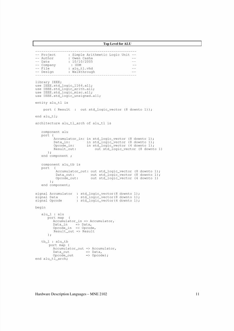
Top Level for ALU
--------------------------------------------------- Project : Simple Arithmetic Logic Unit --
-- Author : Owen Casha ---- Date : 10/10/2005 ---- Company : UOM ---- File : alu_tl.vhd ---- Design : Walkthrough ---------------------------------------------------
library IEEE;use IEEE.std_logic_1164.all;use IEEE.std_logic_arith.all;use IEEE.std_logic_misc.all;use IEEE.std_logic_unsigned.all;
entity alu_tl is
port ( Result : out std_logic_vector (8 downto 1));
end alu_tl;
architecture alu_tl_arch of alu_tl is
component aluport (
Accumulator_in: in std_logic_vector (8 downto 1);Data_in: in std_logic_vector (8 downto 1);Opcode_in: in std_logic_vector (4 downto 1);Result_out: out std_logic_vector (8 downto 1)
);end component ;
component alu_tb isport (
Accumulator_out: out std_logic_vector (8 downto 1);
Data_out: out std_logic_vector (8 downto 1);Opcode_out: out std_logic_vector (4 downto 1)
);end component;
signal Accumulator : std_logic_vector(8 downto 1);signal Data : std_logic_vector(8 downto 1);signal Opcode : std_logic_vector(4 downto 1);
begin
alu_1 : aluport map (
Accumulator_in => Accumulator,Data_in => Data,Opcode_in => Opcode,
Result_out => Result);
tb_1 : alu_tbport map (Accumulator_out => Accumulator,Data_out => Data,Opcode_out => Opcode);
end alu_tl_arch;

7/29/2019 HDL MNE 2102 - ModelSim Walkthrough2
http://slidepdf.com/reader/full/hdl-mne-2102-modelsim-walkthrough2 12/14
Hardware Description Languages – MNE 2102 12
VHDL Coding style
1. VHDL directory format
The following table is the recommended way to organize your project. Each project should be
placed in a separate directory.
Project directory Sub directories Description
title doc Place any documentation here
rtl Place vhdl files here
synth Place synthesis script here
testbench Place simulation test files here
work Work directory for modelsim
2. VHDL file name description
Project name File name Description
title entity_name.vhd One architecture and one entity
entity_name_arch.vhd One architecture
entity_name_ent.vhd One entity
entity_name_cfg.vhd One configuration
entity_name_pkg.vhd Package
entity_name_tb.vhd Test bench
Rule: A VHDL file and the entity it contains have the same name.
3. VHDL signal naming convention
Signal name Description
_in Input signal
_out Output signal
_io Inout signal
_reg Output Signal of a flipflop
_lat Output signal of a latch
_clk Clock signal
_rst reset_signal
_n Negative logic signal
_async Asynchronous signal
7/29/2019 HDL MNE 2102 - ModelSim Walkthrough2
http://slidepdf.com/reader/full/hdl-mne-2102-modelsim-walkthrough2 13/14
Hardware Description Languages – MNE 2102 13
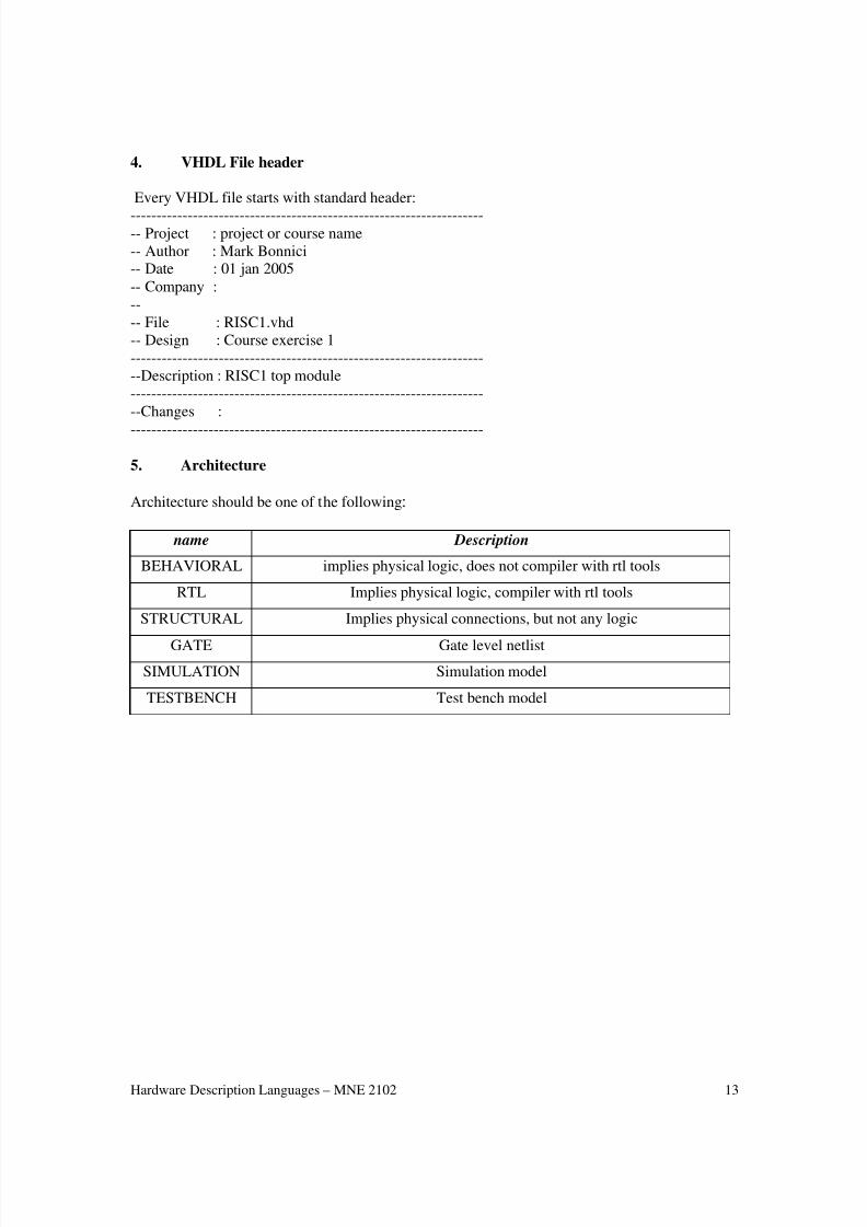
4. VHDL File header
Every VHDL file starts with standard header:
---------------------------------------------------------------------- Project : project or course name
-- Author : Mark Bonnici-- Date : 01 jan 2005
-- Company :
--
-- File : RISC1.vhd
-- Design : Course exercise 1
--------------------------------------------------------------------
--Description : RISC1 top module
--------------------------------------------------------------------
--Changes :
--------------------------------------------------------------------
5. Architecture
Architecture should be one of the following:
name Description
BEHAVIORAL implies physical logic, does not compiler with rtl tools
RTL Implies physical logic, compiler with rtl tools
STRUCTURAL Implies physical connections, but not any logic
GATE Gate level netlist
SIMULATION Simulation model
TESTBENCH Test bench model

7/29/2019 HDL MNE 2102 - ModelSim Walkthrough2
http://slidepdf.com/reader/full/hdl-mne-2102-modelsim-walkthrough2 14/14
Hardware Description Languages – MNE 2102 14
6. Code Appearance
I.1 -VHDL code must be indented. Use three spaces for indentation.
I.2 -The maximum length of lines is 80.I.3 - place each port on a different line.
I.4 -Use lower caseI.5 -Align the colons in the entity port.
I.6 -Add a short comment to each port
I.7 -Add other comments as necessary to make your code more readable and understandable.
Example--------------------------------------------------------------------
-- Project : project or course name
-- Author :
-- Date :
-- Company :
--
-- File : async_dff.vhd
-- Design : Course exercise 1
--------------------------------------------------------------------
--Description : asynchronous d type fliflop
--------------------------------------------------------------------
--Changes :
--------------------------------------------------------------------
--------------------------------------------------------------------
--entity of asynchronous d flpflop
--------------------------------------------------------------------
ENTITY async_dff is
PORT (async_rst : in std_logic; --asynchronous reset
clk : in std_logic; --system clock
d_in : in std_logic; --data input
q_reg_out : out std_logic; --data output
end async_dff;
--------------------------------------------------------------------
--architecture of asynchronous d flpflop
--------------------------------------------------------------------
architecture behav of async_dff is
begin
process (clk, async_rst) beginif (async_rst = '1') then
q_reg_out <= '0';
elsif (clk'event and clk = '1') then
q_reg_out <= d_in;
end if;
end process;
end behav;