hdb3 code
TRANSCRIPT

EEE358S Communications Engineering508 Page 1 April 7, 2023
EEE358SFundamentals of Communications Engineering
Pulse Code Modulation
Emmanuel O [email protected]
http://www.uct.ac.za/depts/staff/rebejide/Department of Electrical Engineering
University of Cape Town

EEE358S Communications Engineering508 Page 2 April 7, 2023
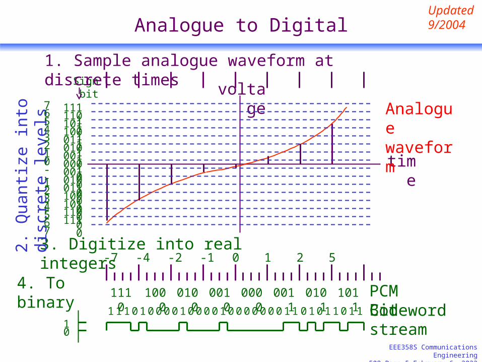
Analogue to Digital
After sampling, the analogue amplitude value of each sampled (PAM) signal is quantized into one of a number of L discrete levels. The result is a quantized PAM signal.
A codeword can then be used to designate each level at each sample time. This procedure is referred to as “Pulse Code Modulation”.
Low-pass Filter
Encoder; Pulse
modulateSampler Quantizer
Continuous-time message signal
PCM wave
Quantized PAM signal
Updated 9/2004

EEE358S Communications Engineering508 Page 3 April 7, 2023
Encoding
After quantization, a digit is assigned to each of the quantized signal levels in such a way that each level has a one-to-one correspondence with the set of real integers. This is called digitization of the waveform.
Each integer is then expressed as an x-bit binary number, called codeword, or PCM word.
The number of codewords, L , is related to x by: 2x = L
Updated 9/2004
Quantized PAM signal
A real integer
PCM codeword (bit stream)
digitization To binary

EEE358S Communications Engineering508 Page 4 April 7, 2023
Codeword
Quantization followed by digitization maps input amplitudes into PCM words.
A cell is the set of input amplitudes mapped to a codeword.
There are L integers, PCM words, or codewords to correspond to the L allowed output amplitudes of the quantizer.
Codebook is the set of all these L codewords.
Updated 9/2004
EEE358S Communications Engineering508 Page 5 April 7, 2023
Analogue to Digital
time
Analogue waveform
voltage
00000011010101111001101111011111
0010010001101000101011001110
01
1110 1000 0100 0010 0000 0011 0101 1011
Bit stream
Sign bit
1 1 1 0 1 0 0 0 0 1 0 0 0 0 101 0 0 0 0 0 0 0 1 1 0 1 0 1 1 1
PCM Codeword
3. Digitize into real integers
1. Sample analogue waveform at discrete times
2. Q
uant
ize
into
dis
cret
e le
vels
Updated 9/2004
01234567
-1-2-3-4-5-6-7
-7 -4 -2 -1 0 1 2 5
4. To binary

EEE358S Communications Engineering508 Page 6 April 7, 2023
Types of Encoding(to PCM Waveforms)
Unipolar
RZ
NRZ
Bipolar AMI
Biphase Polar
M
L
S
Updated 9/2004
Polar
Bipolar
Unipolar

EEE358S Communications Engineering508 Page 7 April 7, 2023
Encoder Attributes
RZ (return to zero), NRZ (non-return to zero) Unipolar, Polar, Bipolar L (level), M (mark), S (space) Biphase AMI (alternate mark inversion)
Updated 9/2004

EEE358S Communications Engineering508 Page 8 April 7, 2023
NRZ – Unipolar/Polar – L/M/S Coding
Unipolar
RZ
NRZ
Bipolar AMI
Biphase Polar
M
L
S
Updated 9/2004
Polar
Bipolar
Uniolar

EEE358S Communications Engineering508 Page 9 April 7, 2023
NRZ coding may be unipolar or polar
1 0 1 1 0 11 0 01
UnipolarNRZ-L
PolarNRZ-L

EEE358S Communications Engineering508 Page 10 April 7, 2023
NRZ-L Coding
NRZ-L (level):1 higher level; 0 lower level
Used in SONET XOR bit sequence, and in early magnetic tape recording
Long sequence of same bit causes difficulty in clock recovery; also in detecting the average DC level

EEE358S Communications Engineering508 Page 11 April 7, 2023
(Polar) NRZ Coding
1 0 1 1 0 11 0 01
NRZ-L
NRZ-M
NRZ-S

EEE358S Communications Engineering508 Page 12 April 7, 2023
NRZ – Unipolar/Polar – L/M/S Coding
NRZ-L (level):1 higher level; 0 lower level
NRZ-M (mark):1 (mark): change level0 (space): no change in level (clock recovery problem with
successive 0’s)used primarily in magnetic tape recording used in Synchronous data link control (SDLC)
NRZ-S (space):0 (space): change in level 1 (mark): no change level (clock recovery problem with
successive 1’s)
Updated 9/2004

EEE358S Communications Engineering508 Page 13 April 7, 2023
RZ – Bipolar/Unipolar Coding
Unipolar
RZ
NRZ
Bipolar AMI
Biphase Polar
M
L
S
Updated 9/2004
Polar
Bipolar
Unipolar

EEE358S Communications Engineering508 Page 14 April 7, 2023
RZ Coding may be unipolar or bipolar
1 0 1 1 0 11 0 01
UnipolarRZ
BipolarRZ
RZ-AMI
Include RZ-AMI here for completeness, defer discussion
Updated 9/2004

EEE358S Communications Engineering508 Page 15 April 7, 2023
RZ Coding may be unipolar or bipolar
Unipolar-RZ:1 is represented by positive for the first half of T and zero for
the second half.0 is represented by 0
Bipolar-RZ:1 is represented by positive for the first half of T and zero for
the second half.0 is represented by negative for the first half of T and zero for
the second half.
Used in baseband data transmission, magnetic recording. The transitions at T/2 may be used for synchronization.

EEE358S Communications Engineering508 Page 16 April 7, 2023
Biphase Coding
Unipolar
RZ
NRZ
Bipolar AMI
Biphase Polar
M
L
S
Updated 9/2004
Polar
Bipolar
Unipolar

EEE358S Communications Engineering508 Page 17 April 7, 2023
Biphase Coding
1 0 1 1 0 11 0 01
biphase-L
biphase-M
biphase-S

EEE358S Communications Engineering508 Page 18 April 7, 2023
Biphase Coding may be L, M, or S
Biphase-L (level) / Manchester:0 is represented by +ve for first half and –ve for 2nd half1 is represented by -ve for first half and +ve for 2nd half
used in digital logic circuits including IEEE 802.4 standard, Ethernet.
An alternate scheme adopted by some authors has the above coding for 0’s and 1’s in reversed manner.

EEE358S Communications Engineering508 Page 19 April 7, 2023
Biphase Coding may be L, M, or S
biphase-M (mark) / Differential Manchester:Always transition at beginning of bit1 (mark) is represented by second transition at T/20 (space) is represented by no second transition at T/2
Alternately: always transition at center1 is represented by additional transition at start of T.
biphase-S (space):Always transition at beginning of bit0 (space) is represented by second transition at T/21 (mark) is represented by no second transition at T/2

EEE358S Communications Engineering508 Page 20 April 7, 2023
AMI Coding
Unipolar
RZ
NRZ
Bipolar AMI
Biphase Polar
M
L
S
Updated 9/2004
Polar
Bipolar
Unipolar

EEE358S Communications Engineering508 Page 21 April 7, 2023
(Bipolar) AMI Coding may be NRZ or RZ
1 0 1 1 0 11 0 01
NRZ-AMI
RZ-AMI

EEE358S Communications Engineering508 Page 22 April 7, 2023
AMI Coding may be NRZ or RZ
AMI (Alternate Mark Inversion) coding: 0 is represented by 0
NRZ-AMI: The 1’s are alternately positive and negative. RZ-AMI: The 1’s are represented by equal amplitude
opposite polarity RZ pulses
Used in the signaling scheme in telephone systems.

EEE358S Communications Engineering508 Page 23 April 7, 2023
B8ZS coding
B8ZS (bipolar with eight-zero substitution) coding: With AMI coding, user data containing too many
successive 0’s are difficult to find bit boundaries. Bipolar violations are deliberately inserted if user data
contains a string of 8 or more consecutive zeros. A violation bit has the same polarity as that for the
previous non-zero bit. Is used in the T1 rate.

EEE358S Communications Engineering508 Page 24 April 7, 2023
B8ZS coding versus bipolar NRZ-AMI
0 0 0 0 0 10 0 01
NRZ-AMI
B8ZSV V

EEE358S Communications Engineering508 Page 25 April 7, 2023
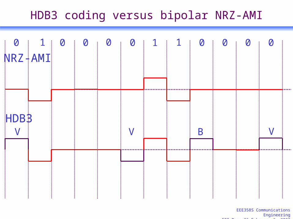
HDB3 coding
HDB3 (High density bipolar order 3) code modifies AMI to prevent long runs of 0’s by introducing violation (V) and balance (B) bits. It is used in E1.
4 0’s are replaced by 000V if the number of 1’s from the previous V is odd.Receiver turns back to 0 all V preceded by 000
4 0’s are replaced by B00V if the number of 1’s from the previous V is even.B is such at V is of opposite polarity to the previous V. Its
purpose is to prevent DC introduced by the V’sReceiver turns back to 0 all V preceded by 00, together the bit
(B) before the 00.
EEE358S Communications Engineering508 Page 26 April 7, 2023
HDB3 coding versus bipolar NRZ-AMI
0 0 1 1 01 0 0 00
NRZ-AMI
HDB3VB
0
V
0
V