hd integrated camera aw‑he42wp aw‑he42kp aw‑he42we · microsoft ® windows 8 pro 32/64-bit is...
TRANSCRIPT

ENGLISHDVQX1917ZA
CX0419RA0 -FJPrinted in China
Before operating this product, please read the instructions carefully and save this manual for future use.
ENGLISHExcerpted Version
Before installing and using this product, be sure to read “Read this first!” (pages 5, 28 to 34).This manual contains information excerpted from the Operating Instructions.For more information, please visit the Panasonic website (https://pro-av.panasonic.net/manual/en/index.html), and refer to the Operating Instructions.
FRANÇAISAvant d’installer et d’utiliser cet appareil, s’assurer de lire la section « Lire ces informations en premier ! » (pages 5, 35 à 39).Pour de plus amples informations, visiter le site Web de Panasonic (https://pro-av.panasonic.net/manual/en/index. html) et consulter le mode d’emploi et les instructions d’installation.
ESPAÑOLAntes de instalar y usar este producto, asegúrese de leer “Lea esto primero” (páginas 5, 40 a 44).Si desea obtener más información, visite el sitio web de Panasonic (https://pro-av.panasonic.net/manual/en/index.html) y consulte las instrucciones de funcionamiento y las instrucciones de instalación.
DEUTSCHBitte lesen Sie sorgfältig „Bitte lesen Sie zuerst diesen Hinweis!“ vor der Installation und Nutzung dieses Produkts. (Seiten 6, 45 bis 47).Weitere Informationen finden Sie auf der Panasonic-Webseite (https://pro-av.panasonic.net/manual/en/index. html), in der Bedienungsanleitung und in der Installationsanleitung.
ITALIANOPrima di installare e utilizzare il prodotto, assicurarsi di leggere “Leggere prima quanto segue!” (pagine 6, 48 a 50).Per maggiori informazioni, visitare il sito Web Panasonic (https://pro-av.panasonic.net/manual/en/index.html) e fare riferimento alle istruzioni per l’uso e alle istruzioni per l’installazione.
PУССКИЙ
Перед установкой и использованием данного изделия ознакомьтесь с информацией в разделе «Прочитайте нижеследующее до начала эксплуатации!» (стр. 6, 51 до 53).Для получения дополнительной информации посетите веб-сайт Panasonic (https://pro-av.panasonic.net/manual/en/index.html) и обратитесь к инструкции по эксплуатации и инструкции по установке.
PJ EJ
Operating InstructionsExcerpted Version
Installation Instructions provided
HD Integrated Camera
Model No. AW‑HE42WP Model No. AW‑HE42KP Model No. AW‑HE42WE Model No. AW‑HE42KE

2
българскиПосетете следния уебсайт относно информация за безопасността и важни уведомления за продукта.
Hrvatski Za sigurnosne informacije i važne obavijesti o proizvodu posjetite sljedeću internetsku stranicu.
Čeština Na následujícím webu najdete bezpečnostní informace a důležité poznámky k tomuto produktu.
Dansk Besøg følgende webside for sikkerhedsinformation og vigtige bemærkninger vedrørende produktet.
NederlandsGa naar de volgende website voor veiligheidsinformatie en belangrijke meldingen over het product.
Eesti Toodet puudutava ohutusteabe ja oluliste märkuste saamiseks külastage järgmist veebilehte.
SuomiKäy seuraavalla verkkosivulla saadaksesi turvallisuustietoja ja tärkeitä tietoja liittyen laitteeseen.
ΕλληνικάΓια πληροφορίες σχετικά με θέματα ασφάλειας και σημαντικές ειδοποιήσεις που αφορούν το προϊόν σας, επισκεφτείτε τον ιστότοπο που ακολουθεί.
MagyarA termékkel kapcsolatos biztonsági információkért és fontos értesítésekért látogasson el az alábbi weboldalra.
LatviešuLai iegūtu informāciju par drošību un skatītu svarīgus paziņojumus par šo produktu, apmeklējiet tālāk norādīto tīmekļa vietni.
LietuviųJei reikia saugos informacijos ir svarbių pranešimų apie gaminį, apsilankykite toliau nurodytoje svetainėje.
PolskiInformacje o bezpieczeństwie i ważne informacje o produkcie znajdują się w poniższej witrynie internetowej.
PortuguêsConsulte o seguinte website para as informações de segurança e importantes notificações sobre o produto.
RomânăVizitați următoarea pagină web pentru informaţii de securitate și notificări importante cu privire la produs.
SlovenskyPre bezpečnostné informácie a dôležité oznámenia súvisiace s produktom navštívte túto webovú stránku.
Slovenščina Za varnostne informacije in pomembna obvestila v zvezi z izdelkom obiščite naslednje spletno mesto.
Svenska Besök följande webbplats för säkerhetsinformation och viktiga meddelanden om produkten.
العربیة زر موقع الویب التالي لمعرفة أحدث معلومات السالمة واإلخطاراتالھامة بشأن المنتج.
https://pro-av.panasonic.net/manual/en/index.html

3
Trademarks and registered trademarks
● Microsoft®, Windows®, Windows® 7, Windows® 8, Windows® 8.1, Internet Explorer® and ActiveX® are either registered trademarks or trademarks of Microsoft Corporation in the United States and other countries.
● Intel® and Intel® CoreTM are trademarks or registered trademarks of Intel Corporation in the United States and other countries.
● Adobe® and Reader® are either registered trademarks or trademarks of Adobe Systems Incorporated in the United States and/or other countries.
● The terms HDMI and HDMI High-Definition Multimedia Interface, and the HDMI Logo are trademarks or registered trademarks of HDMI Licensing Administrator, Inc. in the United States and other countries.
● microSDXC Logo is a trademark of SD-3C, LLC. ● Apple, Mac, OS X, iPhone, iPod Touch, iPad, and Safari
are registered trademarks of Apple Inc., in the United States and other countries.
● AndroidTM is a trademark of Google LLC. ● Other names of companies and products contained
in these Operating Instructions may be trademarks or registered trademarks of their respective owners.
About copyright and licence
Distributing, copying, disassembling, reverse compiling, reverse engineering, and also exporting in violation of export laws of the software provided with the unit are expressly prohibited.
This product incorporates the following software:(1) the software developed independently by or for Panasonic
Corporation,(2) the software owned by third party and licensed to Panasonic
Corporation,(3) the software licensed under the GNU General Public License,
Version 2.0 (GPL V2.0),(4) the software licensed under the GNU LESSER General Public
License, Version 2.1 (LGPL V2.1), and/or(5) open source software other than the software licensed under the
GPL V2.0 and/or LGPL V2.1.
The software categorized as (3) - (5) are distributed in the hope that it will be useful, but WITHOUT ANY WARRANTY, without even the implied warranty of MERCHANTABILITY or FITNESS FOR A PARTICULAR PURPOSE. For details, refer to the license conditions that appear when the operation described in the Operating Instructions (PDF) → “Web screen configurations” → “Maintenance screen [Maintenance]” → “Product information tab [Product info.]” → “OSS license display” is performed.At least three (3) years from delivery of this product, Panasonic will give to any third party who contacts us at the contact information provided below, for a charge no more than our cost of physically performing source code distribution, a complete machine-readable copy of the corresponding source code covered under GPL V2.0 or LGPL V2.1, as well as the respective copyright notice thereof.Contact Information: [email protected]
The source code and the copyright notice are also available for free in our website below.https://panasonic.net/cns/oss/index.html
Abbreviations
The following abbreviations are used in this manual.
● Microsoft® Windows® 7 Professional SP1 32/64-bit is abbreviated to “Windows 7”.
● Microsoft® Windows® 8 Pro 32/64-bit is abbreviated to “Windows 8”.
● Microsoft® Windows® 8.1 Pro 32/64-bit is abbreviated to “Windows 8.1”.
● Windows® Internet Explorer® 8.0, Windows® Internet Explorer® 9.0, Windows® Internet Explorer® 10.0 and Windows® Internet Explorer® 11.0 are abbreviated to “Internet Explorer”.
For the purposes of this manual, the model numbers of the units are given as listed in the table below.
Model number of unit
Model number given in manual
AW-HE42WP, AW-HE42KP, AW-HE42WE, AW-HE42KE
AW-HE42
AW-HS50NAW-HS50
AW-HS50E
AW-RP50NAW-RP50
AW-RP50E
Illustrations and screen displays featured in the manual
● What is shown in the manual’s illustrations and screen displays may differ from how it is actually appears.
● The screenshots are used in accordance with the guidelines of Microsoft Corporation.

4
Contents
Installation Instructions
Operating Instructions
Read this first! (For AW-HE42WP, AW-HE42KP) 28
Read this first! (For AW-HE42WE, AW-HE42KE) 31
Lire ces informations en premier ! (Pour AW-HE42WP, AW-HE42KP) 35
Lire ces informations en premier ! (Pour AW-HE42WE, AW-HE42KE) 37
Lea esto primero (Para AW-HE42WP, AW-HE42KP) 40
Lea esto primero (Para AW-HE42WE, AW-HE42KE) 42
Bitte lesen Sie zuerst diesen Hinweis! (Für AW-HE42WE, AW-HE42KE) 45
Leggere prima quanto segue! (Per AW-HE42WE, AW-HE42KE) 48
Прочитайте нижеследующее до начала эксплуатации! (Для AW-HE42WE, AW-HE42KE) 51
Before use 54
Overview 54
Required personal computer environment 54
Disclaimer of warranty 55
Network security 55
Read this first! 5
Lire ces informations en premier ! 5
Lea esto primero 5
Bitte lesen Sie zuerst diesen Hinweis! 6
Leggere prima quanto segue! 6
Прочитайте нижеследующее до начала эксплуатации! 6
Installation precautions 7
How to install and connect the unit 9
When using the WV-Q105A (optional accessory) 13
Removing the camera 15
Stand-alone installation (when the mount bracket is going to be used) 16
Stand-alone installation (when the mount bracket is not going to be used) 18
When installing the unit on a desktop 18
When mounting the unit on a tripod 18
Connections 19
Connecting an NDI|HX compatible switcher 19
Connecting a controller (AW-RP50) (IP connection example) 20
System example 1 (connection with commercially available controller, RS-232C daisy-chain connection) 21
System example 2 (connection with commercially available controller, RS-422 connection) 22
System example 3 (serial control) 23
System example 4 (IP control) 24
System example 5 (infrared output connection) 25
System example 6 (IP image transmission, PoE+) 25
System example 7 (USB connection, Web camera) 26
Appearance 27
Characteristics 56
Accessories 58
Optional accessories 58
Operating precautions 59
Concerning the wireless remote control (optional accessory) 61
Parts and their functions 62
Camera unit 62
Wireless remote controller (optional accessory) 65
Setting the remote control IDs 67
Network settings [When using Windows] 68
Use the Easy IP Setup Software to establish the unit’s settings 68
Installing the plug-in viewer software 69
User authentication 70
Troubleshooting 71
Specifications 72
Index 73

5
Installation Instructions
indicates safety information.
WARNING:To prevent injury, this apparatus must be securely attached to the floor/wall in accordance with the installation instructions.
CAUTION:This camera intended for use only with the Mount Bracket enclosed with the unit and Panasonic Direct Ceiling Mount Bracket, WV-Q105A.Use with other apparatus is capable of resulting in instability causing possible injury.
WARNING:Installation should only be performed by qualified installation personnel.Improper installation may result in the entire apparatus falling down and causing injury.
Read this first!
ATTENTION:Cette caméra est conçue pour être utilisée uniquement avec la potence de fixation fournie avec l’appareil ou avec la potence de fixation directe au plafond Panasonic WV-Q105A.L’utilisation de tout autre dispositif risque de se traduire par une instabilité et être cause de blessures à des personnes.
Lire ces informations en premier !
Informations concernant la sécurité.
AVERTISSEMENT:Pour éviter tout risque de blessures, l’appareil doit être solidement fixé au plancher/mur conformément aux instructions d’installation.
AVERTISSEMENT:L’installation ne doit être effectuée que par du personnel d’installation qualifié.Une mauvaise installation peut avoir pour conséquence la chute de l’appareil et provoquer des blessures.
Lea esto primero
PRECAUCIÓN:Esta cámara ha sido diseñada para ser utilizada solamente con la ménsula de montaje suministrada con la unidad y con la ménsula de montaje directo en el techo de Panasonic modelo WV-Q105A.La utilización con otros aparatos puede causar inestabilidad y posibles lesiones.
indica información de seguridad.
ADVERTENCIA:Para evitar heridas, este aparato debe estar firmemente instalado al piso/pared de acuerdo con las instrucciones de instalación.
ADVERTENCIA:La instalación solamente debe llevarla a cabo personal cualificado.Una instalación incorrecta podría provocar la caída del dispositivo y causar lesiones.
ENGLISH
FRANÇAIS
ESPAÑOL

6
Installation Instructions
Bitte lesen Sie zuerst diesen Hinweis!
WARNUNG:Um Verletzungen zu verhüten, muss dieser Apparat gemäß der Installationsanleitung sicher am Boden bzw. an der Wand befestigt werden.
VORSICHT:Diese Kamera ist nur für den Einsatz mit der mitgelieferten Montagehalterung und der Panasonic Decken-Direktmontagehalterung WV-Q105A vorgesehen.Wird die Kamera mit anderen Apparaten verwendet, kann es zu Instabilität kommen, die Verletzungen verursachen kann.
WARNUNG:Die Installation darf nur durch qualifiziertes Personal ausgeführt werden.Fehlerhafte Installation kann zum Herunterfallen des Gerätes und zu Verletzungen führen.
ist die Sicherheitsinformation.
Leggere prima quanto segue!
PRECAUZIONE:La videocamera deve essere utilizzata esclusivamente con la staffa di montaggio in dotazione con l’unità e con la staffa per montaggio diretto a soffitto WV-Q105A.L’uso con altri apparecchi potrebbe causare instabilità ed eventuali infortuni.
sono le informazioni sulla sicurezza.
AVVISO:Per prevenire ferite, questo apparecchio deve essere montato saldamente al pavimento/muro in conformità alle istruzioni di installazione.
AVVISO:L’installazione deve essere realizzata unicamente da tecnici qualificati.Un’installazione incorretta può risultare nella caduta dell’apparecchio con conseguenti danni alle persone.
Прочитайте нижеследующее до начала эксплуатации!
ПРЕДОСТЕРЕЖЕНИЕ:Данная камера предназначена для использования только с монтажным кронштейном, поставляемым с устройством, и монтажным кронштейном Panasonic для непосредственного крепления к потолку WV-Q105A.Использование с другим аппаратом может привести к нарушению устойчивости и возможной травме.
Данный знак обозначает информацию, относящуюся к технике безопасности.
ОСТОРОЖНО:Во избежание повреждения данный прибор должен быть надежно закреплен на полу/стене в соответствии с инструкцией по установке.
ОСТОРОЖНО:Установка должна выполняться только квалифицированным специалистом по установке.Ненадлежащая установка может привести к падению всего аппарата и получению травмы.
DEUTSCH
ITALIANO
РУССКИЙ

7
Installation Instructions
Installation precautionsPanasonic does not accept any responsibility for accident or damage during installation if procedure in this manual is not followed.
To installation personnelRead the “Installation Instructions” thoroughly and then perform the operation correctly and safely.Also, always read the “Read this first!” (page 5) of this manual as they contain important information.After the installation, give the “Installation Instructions” to the customer to save for future use.
Ensure that the installation work complies with the technical standards governing electrical equipment.
The unit is for indoor use only.It cannot be used outdoors.Avoid installation in a location where the unit will be exposed to direct sunlight for extended periods or near a cooling or heating appliance.Otherwise, deformation, discoloration, malfunctioning and/or problems in operation may result. Operate the unit where it will not be splashed or sprayed by water.
Use the unit with an installation where the unit is suspended from an overhead surface or with a stand-alone installation.Do not use the unit on its side or tilted at an angle.
● Be absolutely sure to use the four bracket mounting screws (M4) for mounting the mount bracket. These are supplied with the unit. Do not use wood screws, nails, etc. In the case of a concrete ceiling, secure the unit using anchor bolts (for M4) or AY plug bolts (for M4). Recommended clamping torque M4: 1.47 N · m {15 kgf · cm}
● The withdrawal strength of the mounting location for each screw must be at least 196 N {20 kgf}.
● When mounting the unit on a ceiling made of plasterboard, for instance, if it is not strong enough to support its weight, either reinforce the ceiling adequately or use the WV-Q105A direct ceiling mount bracket, which is sold separately.
● When using a mount bracket which is sold separately, read the handling instructions.
● Do not hold the camera head while undertaking the installation work. Doing so may cause malfunctioning.
Correct IncorrectCorrect Incorrect
Desktop installation Hanging installation
Notes
AW-HE42main unit
Mounting conditions
Applicable mount bracket Mounting onto the ceiling
Mass Model No. Mass Mounting Recommended screws
No. of screws
Minimum withdrawal strength(per screw)
Approx. 1.5 kg [3.30 lb]
Direct mount(supplied
accessory)
Approx. 0.23 kg [0.51 lb]
Hanging/DesktopM4 screws (supplied
accessory)4
196 N {20 kgf} ● Ensure that the mounting strength can support a weight that is at least five times the total mass of the equipment, including the camera’s main unit.
WV-Q105A(optional
accessory)
Approx. 0.15 kg [0.33 lb]
For ceilingM4 screws
(supplied with the WV-Q105A)
4
Concerning the installation locationInstall the unit in a stable location which will not be susceptible to shaking. If the unit is installed in a location which is susceptible to shaking, this will cause the unit’s images to shake in turn.Install the unit after conferring in detail with your dealer.Install the unit on a ceiling that is strong enough (such as a concrete ceiling).If the unit is to be installed on a ceiling which is not strong enough, reinforce the ceiling sufficiently first.
Do not install or use the unit in the following kinds of locations.
● On walls (where the unit would be installed sideways) ● In locations (including places such as under the eaves of
a building) where the unit would be directly exposed to rain or water
● In locations such as kitchens where there are high concentrations of steam and grease
● In outdoor locations or hot places where the temperature will exceed 40 °C (104 °F)
● In cold locations where the temperature will drop below 0 °C (32 °F)
● In locations where the humidity will exceed 90 % ● In locations where chemicals are used such as near
swimming pools ● At sea, in coastal areas or in locations where corrosive
gases are emitted ● In locations where radiation, X-rays, or strong radio waves
or magnetic fields are generated ● In locations where the unit would be subject to a great
deal of vibration such as on board a vehicle or ship (the unit is not designed to be used in vehicles)
● In locations where the temperature is subject to sudden changes such as near the air outlet of an air conditioner or near a door which allows the outside air to come in
What to avoid to ensure that the unit will perform stably over a prolonged period
● Using the unit for a prolonged period in a location with high temperature and humidity levels will cause its parts to deteriorate and shorten its service life.
● Ensure that a cooling unit or heating unit will not blow any air directly toward the installation location.

8
Installation Instructions
Installation precautions (continued)
Be absolutely sure to use the specified brackets and screws to install the camera.
● Do not mount the unit by employing any methods other than those specified.
● Do not remodel the mounting bracket or mounting screws provided with the unit.
Before installation, always disconnect the power plugWhen installing, always use the supplied components.Do not disassemble or modify the wall mount adaptor.
Tightening up the mounting screws ● Tighten up the screws and bolts securely to the degree
that is appropriate for each of the materials used in the mounting location and structures.
● After tightening up the screws and bolts, check that there is no unsteadiness and that the parts have been tightened securely.
● Use the specified tools and tighten the screws firmly. ● Tighten up the screws using the specified torque driver.
Do not use electrical drivers or impact drivers.
When the unit is no longer going to be used, do not leave it lying around, but be absolutely sure to remove it properly.For details on how to remove the unit, refer to “Removing the camera” (page 15).
When installing, transferring or disposing of the unit, be absolutely sure to hold it by its pedestal area.Problems may result if the camera head is held or rotated.
Do not attach a filter, hood, extender or other parts to the unit.
Use the dedicated AC adaptor and power cable provided with the unit.Connect the AC adaptor and power cable to the power inlet securely.
Installing the AC adaptor ● Do not place the adaptor directly onto a ceiling panel or
other such surface. Extreme danger is posed when water has collected on the surface as a result of leaking rain, for instance. Secure the adaptor firmly to the bottom or other surface of a reinforcing member made of channel steel where dust and other foreign matter will not accumulate. (Refer to page 13.)
● Secure the adaptor firmly so that there will be no chance that it will fall off or fall down. Secure it using a strength which can withstand the mass of the AC adaptor.
Install the accessory AC adaptor near the main power outlet, and position it in such a way that its power plug can be plugged into and unplugged from the outlet easily.When connecting the AC adaptor to a power outlet on the ceiling or on any other surface where dust may collect, wipe off the dust on the power plug at periodic intervals as an anti-tracking measure.
Power switchThe unit does not have a power switch. The power turns on when its power plug is connected to a power outlet. When the power is turned on, the pan, tilt, zoom and focusing operations are performed. Before proceeding with maintenance, be absolutely sure to disconnect the power plug from the power outlet.
Connecting the power cableBe absolutely sure to connect the power cable of the AC adaptor through a circuit breaker using one of the following methods.
(1) Connect the power cable through a power control unit.(2) Connect the power cable to a circuit breaker in a
power distribution panel with a contact distance of 3.0 mm (1/8 inches) or more. Use a circuit breaker which is capable of shutting off all the poles of the main power supply with the exception of the protective ground conductor.
(3) Install the AC adaptor near the power outlet, and connect it through the power plug.
If there is a possibility of noise interferenceEither wire the cables so that the power cable (ceiling light cord) of AC 100 V* [AC 220 V**] or more, and the signal cable are placed at least 1 meter (3.3 ft) apart. Alternatively run each cable through its own metal conduit. (The metal conduits must be grounded.)
* : For AW-HE42WP, AW-HE42KP** : For AW-HE42WE, AW-HE42KE
Radio signal interferenceIf the unit is positioned near a TV or radio transmitting antenna or a strong electrical field or magnetic field (such as that generated by a motor, transformer or power lines), its images may be distorted and/or the images may be affected by noise.
When connecting the cables, ensure that the connector areas will not be subject to any load.Doing so may cause malfunctioning.
Allowing the generated heat to escapeThe unit allows the heat generated inside to escape from its surfaces.Do not install the unit in a location where it will be surrounded by walls or other surfaces and where heat will be trapped. In addition, the heat is dissipated to the bottom panel which will warm up over time: This is normal and not indicative of any trouble.
PoE+ power suppliesUse a PoE+ (IEEE802.3at compliant) compatible hub or power supply device.

9
Installation Instructions
How to install and connect the unitBe absolutely sure to read through the “Read this first!” (page 5) and “Installation precautions” (pages 7 to 8).
The procedure given here is for the kind of installation where the unit is suspended from an overhead surface, but the same steps are followed for a stand-alone installation.
If the ceiling panel is not strong enough to bear the unit’s weight, use the kind of mount bracket that is supported by anchor bolts between the concrete ceiling and ceiling panel. The unit supports the WV-Q105A direct ceiling mount bracket which is used solely for combination cameras. Use this bracket to install the unit. (See page 13.)In a case like this, the holes (ø 60 mm [ø 2-3/8 inches]) for installing the direct ceiling mount bracket on the ceiling must be drilled in the ceiling panel.It is also recommended that you provide an inspection space or opening for access purposes in the area near where the equipment is installed in order to facilitate installation and the wiring connections work.See page 58 for details of the accessories.
1 Check the mounting space. ● Refer to the illustration, and determine where the unit is to be installed and in which direction it should be mounted.
Factor in the unit mounting area and include space for the wires extending from its rear panel. ● The asterisk () in the illustration marks the position and dimensions of the hole for mounting the mount bracket.
66 (2-19/32)
130 (5-1/8)
() 83.5 (3-9/32)
156 (6-1/8)160 (6-5/16)
78 (3
-1/1
6)65
(2-9
/16)
80 (3
-5/3
2)77
(3-1
/32)
90 (3
-17/
32)
() 4
6 (1-1
3/16)
99 (3
-29/
32)
(Space for the wires from the rear panel)
290
(11-
7/16
) o
r m
ore
(Sp
ace
for
the
wir
es)
Hole for checking the positioning
The front panel of the unit on this side
Unit: mm (inch)
Mount bracket
Hook for mounting the drop-prevention wire
Unit mounting area
Through-hole for cable ø 40 (ø 1-9/16) [reference]
() Holes for mounting the mount bracket: ø 4.5 × 4
Hole for mounting the main unit mounting screw
Hole for installing the WV-Q105A direct ceiling mount bracket[ø 60 (ø 2-3/8)]
● Make connections for each cable within the ceiling beforehand, and pass the cables through a cable-routing hole in preparation for making connections for and installing the unit.
● For a power outlet which is used on the ceiling, be absolutely sure to take measures to deal with the tracking that may be caused by the accumulation of dust and other foreign matter.
Notes

10
Installation Instructions
How to install and connect the unit (continued)
2 Mount the mount bracket onto the installation surface. ● Use the bracket mounting screws [M4, bind-head: 10 mm (13/32 inches) long] supplied with the unit. ● For proper clamping torque, securely attach the screws using the specified tools.
Screw diameter Clamping torque
M4 1.47 N · m {15 kgf · cm}
Bracket mounting screws × 4 (supplied)(M4, bind-head)
● Use only the screws supplied with the unit. Do not use any other screws such as wood screws, nails, etc.
Note
3 Attach the drop-prevention wire. ● Pull out the drop-prevention wire from the bottom panel of the unit, and engage the end with the wire ring through the
hole of the mount bracket hook. ● Pull the drop-prevention wire, and check that it has been attached securely to the hook.
Pull out the drop-prevention wire, and engage it with the mount bracket hook.
End of hook
Drop-prevention wire
Holding spring
● Do not do this work while holding the camera head since doing so may result in malfunctioning of the unit. ● The drop-prevention wire is designed to be used for installation where the unit is suspended from an overhead
surface so do not subject it to the weight of units other than the unit.
Notes

11
Installation Instructions
How to install and connect the unit (continued)
4 Mount the unit. ● Align the position of the hole for checking the positioning with the status display lamp. ● Align the holes on the camera main unit used to insert the bottom panel with the protrusions on the mount bracket used
for inserting the camera, push the camera to the bracket firmly, and rotate the main unit by about 15 degrees in the direction of the arrow.
● Secure the unit to the mount bracket using the main unit mounting screw (M3) as supplied. ● Attach the mount bracket securely with the prescribed tool using the clamping torque below.
Be absolutely sure to verify that none of the screws are loose.
Screw diameter Clamping torque
M3 0.78 N · m {8 kgf · cm}
Main unit mounting screw (M3 screw)(with flat washer, spring washer)
Status display lamp
Approx. 15°
On the camera main unit: Holes (×3) used to insert the bottom panel
On the mount bracket: Protrusions (×3) used for inserting the camera
Hole for checking the positioning
● Do not do this work while holding the camera head since doing so may result in malfunctioning of the unit. ● Use only the screws supplied. Do not use any other screws. ● Check that the unit has been mounted securely with no tilting or wobbling. ● The unit must be secured without fail using the main unit mounting screw before any of the cables are connected.
Notes
5 Check the mounting.Check out the following points.
• The main unit mounting screw must be mounted securely.• The unit must not tilt, and it must be mounted exactly.• The unit must be securely installed. • The unit pedestal part must not rotate even when an attempt is made to turn it.

12
Installation Instructions
How to install and connect the unit (continued)
6 Connect the rear panel connectors.Anchor the AC adaptor cable in place using the cable clamp.
Cable clamp
Strap part
LAN cable
LAN cable(for RS-422)
RS-232C cable
HDMI cable
SDI cable
AC adaptor cable
Coaxial cable (for G/L IN)
●How to secure the AC adaptor cable
A Loosely secure the cable clamp.
B Fasten the cable clamp.
Loosely secure the cable clamp in the area shown above.
Take hold of the strap part, slide the cable clamp until it stops moving, and then secure it tightly.
● Always disconnect the power supply before connecting or disconnecting cables. Connecting or disconnecting cables while the power is turned on may result in malfunctions.
Note
The unit is in the standby condition when the AC adaptor is connected.The primary circuit is always “live” as long as the AC adaptor is connected to an electrical outlet.

13
Installation Instructions
How to install and connect the unit (continued)
■When using the WV-Q105A (optional accessory)It is recommended that you provide an inspection opening or other such space for access purposes in the area near where the equipment is installed in order to facilitate installation and the wiring connections work.Before mounting the mount bracket, check that the installation location is strong enough to withstand the total mass (approx. 2.0 kg [4.41 lb]) which will be exerted once the camera is mounted.When installing the unit on a ceiling, ensure that there is at least 100 mm (3-15/16 inches) of space above the ceiling panel in the place where the unit will be used.The unit can be installed on a ceiling panel with a thickness ranging from 5 mm (3/16 inches) to 40 mm (1-9/16 inches).The drop-prevention wire (supplied with the WV-Q105A) must be used when mounting the direct ceiling mount bracket.
Height above ceiling panel: At least 100 mm (3-15/16 inches) The anchor bolts must not protrude
beneath the ceiling panel.
Ceiling panel (plasterboard, etc.) with a thickness from 5 mm (3/16 inches) to 40 mm (1-9/16 inches)
Anchor bolts ● Withdrawal strength: 196 N {20 kgf} or more
ø 60 mm (2-3/8 inches)
Concrete ceiling
When installing the unit on a ceiling
1 Refer to the Operating Instructions of the WV-Q105A direct ceiling mount bracket, and attach the WV-Q105A as well as the drop-prevention wire angle and drop-prevention wire supplied with the WV-Q105A to the anchor bolts.
Mounting the anchor bolts and direct ceiling mount bracket ()This job is facilitated if the direct ceiling mount bracket is loosely secured to the ceiling panel in one place, and the direct ceiling mount bracket and anchor bolts are vertically aligned before the nuts are tightened up.
2 First, remove the screws which were loosely fastened in step 1, and then align the camera mount bracket of the AW-HE42 with the screw holes in the WV-Q105A direct ceiling mount bracket and mount it in place.
● Use the mounting screws (the M4-L60 Phillips head screws with adhesive) supplied with the WV-Q105A as the mounting screws.
● Fasten the AC adaptor securely to the bottom or other surface of the reinforcing member made of channel steel where dust and other foreign matter will not accumulate.
● Do not place the AC adaptor directly onto the ceiling panel or other such surface.
AW-HE42
Drop-prevention wire angle (Supplied with WV-Q105A) Anchor bolts
Space above the ceiling
Direct ceiling mount bracket WV-Q105A (optional accessory)
Drop-prevention wire (Supplied with WV-Q105A)
Plasterboard or other ceiling panel
Camera mount bracket (Supplied with AW-HE42)
Mounting screws × 4 (Supplied with WV-Q105A)
Channel steel
Secure the AC adaptor firmly to a member made of channel steel.
(Ceiling panel)
Inspection opening recommended• The installation and wiring connection
work is facilitated if an inspection opening is provided for access purposes.
(): Fasten here using the nut.
3 Install the AW-HE42 camera by following the procedure starting with step 3 on page 10.

14
Installation Instructions
How to install and connect the unit (continued)
When installing the unit on a wall (installation example)
1 Before proceeding, fashion an L-shaped mounting fixture, and attach the fixture securely to the wall where the unit will be installed.
IMPORTANT ● Before installing the unit, check that the surface of the wall where the unit will be installed is strong enough to
bear not only the total weight (approx. 2.0 kg [4.41 lb]) of the camera once it has been installed but also the weight of the L-shaped mounting fixture and its supports.
● Use supports that are strong enough to withstand the total weight of the camera once it has been installed and any vibration or other forces to secure the L-shaped mounting fixture. If the supports are not capable of bearing this weight and forces, the unit may become detached from the installation surface or it may fall off, possibly causing injury.
AW-HE42
L-shaped mounting fixture
Support
2 Refer to steps 1 to 3 in “When installing the unit on a ceiling” (page 13), and install the AW-HE42.

15
Installation Instructions
Removing the camera1 Turn off the circuit breaker and power.
2 Disconnect the cables.Disconnect the power cable, video cable, and control cable, etc.
3 Remove the main unit mounting screw used to secure the unit and mount bracket.
4 Push the unit (A). Turn it approximately 15 degrees away from the installed position (B), and remove it (C).
Main unit mounting screw (M3 screw)(with flat washer, spring washer)
Approx. 15°
● Do not do this work while holding the camera head since doing so may result in malfunctioning of the unit.
Note
5 Disengage the drop-prevention wire from the mount bracket.
16
Installation Instructions
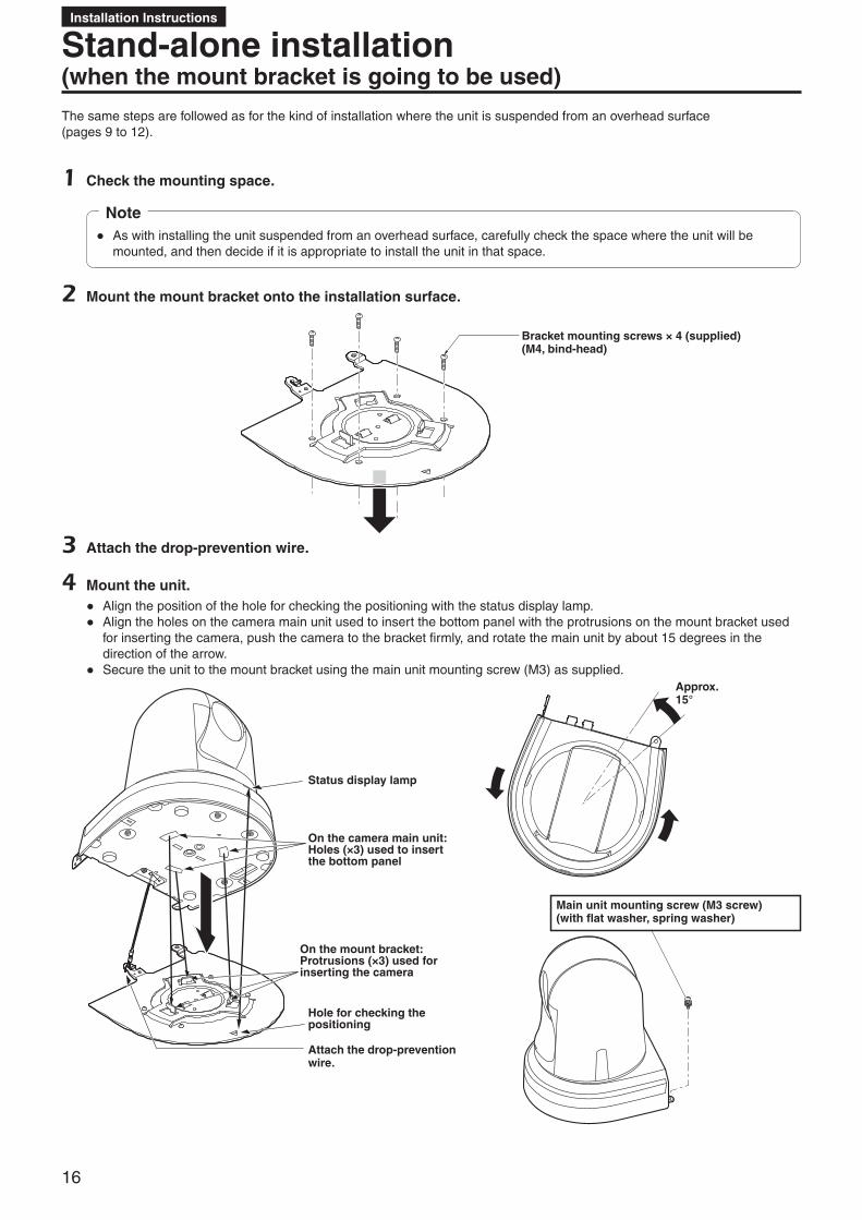
Stand-alone installation (when the mount bracket is going to be used)
The same steps are followed as for the kind of installation where the unit is suspended from an overhead surface (pages 9 to 12).
1 Check the mounting space.
● As with installing the unit suspended from an overhead surface, carefully check the space where the unit will be mounted, and then decide if it is appropriate to install the unit in that space.
Note
2 Mount the mount bracket onto the installation surface.
Bracket mounting screws × 4 (supplied)(M4, bind-head)
3 Attach the drop-prevention wire.
4 Mount the unit. ● Align the position of the hole for checking the positioning with the status display lamp. ● Align the holes on the camera main unit used to insert the bottom panel with the protrusions on the mount bracket used
for inserting the camera, push the camera to the bracket firmly, and rotate the main unit by about 15 degrees in the direction of the arrow.
● Secure the unit to the mount bracket using the main unit mounting screw (M3) as supplied.
Main unit mounting screw (M3 screw)(with flat washer, spring washer)
Status display lamp
On the camera main unit: Holes (×3) used to insert the bottom panel
On the mount bracket: Protrusions (×3) used for inserting the camera
Hole for checking the positioning
Attach the drop-prevention wire.
Approx. 15°

17
Installation Instructions
Stand-alone installation (when the mount bracket is going to be used) (continued)
5 Check the mounting.
6 Connect the rear panel connectors.
LAN cable
HDMI cable
SDI cable
AC adaptor cable
Cable clamp
Strap part
●How to secure the AC adaptor cable
A Loosely secure the cable clamp.
B Fasten the cable clamp.
Loosely secure the cable clamp in the area shown above.
Take hold of the strap part, slide the cable clamp until it stops moving, and then secure it tightly.
RS-232C cable
LAN cable(for RS-422)
Coaxial cable (for G/L IN)
● Always disconnect the power supply before connecting or disconnecting cables. Connecting or disconnecting cables while the power is turned on may result in malfunctions.
Note
The unit is in the standby condition when the AC adaptor is connected.The primary circuit is always “live” as long as the AC adaptor is connected to an electrical outlet.
Note for connecting with an HDMI cableWhen connecting with an HDMI cable using an HDMI-to-DVI converter, etc., be sure to connect the HDMI cable to the connector of the AW-HE42 last.Connecting the HDMI cable to the connector of the AW-HE42 first may result in malfunction.
2 1AW-HE42
HDMI cable
HDMI-to-DVI converter, etc.
Switcher
Monitor

18
Installation Instructions
Stand-alone installation (when the mount bracket is not going to be used)
■When installing the unit on a desktopPlace the unit flat on the surface.
● Install the unit in a stable location which will not be susceptible to shaking. If the unit is installed in a location which is susceptible to shaking, this will cause the unit’s images to shake in turn.
● Take care not to allow the unit to fall or otherwise be damaged during installation. ● When carrying the unit, do not hold it by its head. ● Do not take hold of the camera head or rotate it. Doing so may cause malfunctioning. ● Take care not to pull the connected cables. Doing so may cause the unit to fall and/or it may result in injury.
Notes
Ensure that the unit will not fall off.
Correct Incorrect
■When mounting the unit on a tripodAttach the tripod to the threaded holes for mounting the camera on the camera’s bottom panel.Place the tripod on a completely flat and level surface.Tighten the screws by hand to mount the tripod securely.Use screw for mounting tripod that satisfy the following standard.
Screw for mounting tripod1/4-20UNC, ISO1222 (6.35 mm)
4.5 mm to 6 mm(0.18 to 0.24 inches)
● Do not install the unit where people will be passing back and forth. ● When using the unit mounted on a tripod, do not put the tripod high above the floor level. ● Mount the unit securely so there is no looseness. Looseness may cause the unit to fall off and/or result in injuries. ● When the unit is going to be used for a prolonged period of time, take steps to ensure that the unit will not topple or fall
over and that it will not fall off or fall down. After using the unit, restore the installation location to its original state without delay.
Notes

19
Installation Instructions
Connections ■Connecting an NDI|HX compatible switcher
Supplied AC adaptor
AW-HE42 AW-HE42*
LAN cable
Switching hub
NDI|HX compatible switcher
Monitor Monitor
External DC power supply
*: The AC adaptor provided with the unit is not shown in the above figure.
Remote Camera ControllerAW-RP50

20
Installation Instructions
Connections (continued)
■Connecting a controller (AW-RP50) (IP connection example)
SIGNAL GND
TALLY/GPITO PAN/TILT HEAD
5 4 3 2 1
SV
POWERON
BOOT
NM
12V INLAN
Pan-tilt head / camera control signal
HDMI/SDI signal
AW-HE42
Remote Camera ControllerAW-RP50
Supplied AC adaptor
Supplied AC adaptor
LAN cable
Monitor
● The unit automatically detects the straight cable or crossover cable connected to the LAN connector.

21
Installation Instructions
Connections (continued)
■System example 1 (connection with commercially available controller, RS-232C daisy-chain connection)
RS-232C connector
RS-232C connector
Commercially available controller
AW-HE42*
Supplied AC adaptorSupplied AC adaptorSupplied AC adaptor
Up to 7
*: You can connect up to seven cameras to a single controller.
● Configure the service switches at the bottom of the unit. For details on the service switches, see “Service switch settings” (page 64).
SW1 Camera address setting (standard serial communication)
Set to AUTO or 1 to 7.(Set address numbers so that they do not duplicate each other.)
SW2
SW3
SW4Communication format
Enable standard serial communication (ON).
SW7Communication baud rate
Set to 9600 bps (OFF) or 38400 bps (ON) based on your commercially available controller.
SW8Communication connector
Set to RS-232C (ON).
● Configure the following items in the camera menu.1. Display [System] menu [Protocol] [Model Select].2. Select [SEVIHD1], [SBRC300], or [SBRCZ330] for the protocol type.

22
Installation Instructions
Connections (continued)
■System example 2 (connection with commercially available controller, RS-422 connection)
RS-422 communication connector
Commercially available controller
AW-HE42
Supplied AC adaptor
● Configure the service switches at the bottom of the unit. For details on the service switches, see “Service switch settings” (page 64).
SW1 Camera address setting (standard serial communication)
Set to AUTO or 1 to 7.(Set address numbers so that they do not duplicate each other.)
SW2
SW3
SW4Communication format
Enable standard serial communication (ON).
SW7Communication baud rate
Set to 9600 bps (OFF) or 38400 bps (ON) based on your commercially available controller.
SW8Communication connector
Set to RS-422 (OFF).
● Configure the following items in the camera menu.1. Display [System] menu [Protocol] [Model Select].2. Select [SEVIHD1], [SBRC300], or [SBRCZ330] for the protocol type.
● Daisy-chain connections are not possible for RS-422 connections.
Note

23
Installation Instructions
Connections (continued)
■System example 3 (serial control)
AW-HE42 AW-HE42*
Monitor 1 Monitor 2
Monitor Monitor
Pan-tilt head / camera control signal(LAN cable (straight cable))
System tally
External DC power supply
Remote Camera ControllerAW-RP50
Compact Live SwitcherAW-HS50
Supplied AC adaptor
RS-422 connector
*: The AC adaptor provided with the unit is not shown in the above figure.
Supplied AC adaptor
● Make sure the LAN cable connected to the RS-422 connector is a straight cable.

24
Installation Instructions
Connections (continued)
■System example 4 (IP control)
Supplied AC adaptor
AW-HE42 AW-HE42*
Switching hub
LAN cable
Compact Live Switcher AW-HS50
Monitor 1
Monitor 2
Monitor Monitor
LAN cable(straight cable)
Remote Camera Controller AW-RP50
*: The AC adaptor provided with the unit is not shown in the above figure.
Supplied AC adaptor
Supplied AC adaptor
Personal computer
IP video display
Wireless access point
Mobile terminal
IP video display
● The unit automatically detects the straight cable or crossover cable connected to the LAN connector.

25
Installation Instructions
Connections (continued)
■System example 5 (infrared output connection)You can point the infrared remote control of a commercially available controller toward the camera to operate it.
RS-232C cable(including infrared remote control signals)
RS-232C connector
RS-232C connector
Commercially available controller
AW-HE42
MonitorSupplied AC adaptor
Remote camera control signal
Infrared remote control supplied with commercially available controller
● Configure the service switches at the bottom of the unit. For details on the service switches, see “Service switch settings” (page 64).
SW6 Infrared output Set to ON.
■System example 6 (IP image transmission, PoE+)AW-HE42
IP decoder (commercially available)
Monitor
Monitor
PoE+ compatible switching hub
Personal computer
LAN cable
LAN cable

26
Installation Instructions
Connections (continued)
■System example 7 (USB connection, Web camera)
AW-HE42
USB cable(A-mini B type)
Communication software (optional accessory) Supplied AC
adaptor
Personal computer
Microphone
● Use a USB cable that is compatible with the USB 2.0 specification. Connect a mini B connector to the unit.
● The priority mode of the unit needs to be set to “USB”. For details, refer to the Operating Instructions (PDF) → “Web screen configurations” → “Basic screen [Basic]” → “Priority mode tab [Priority mode]”.
● Use communication software (optional accessory) that is compatible with the USB Video Class and USB Audio Class.
Note on grounding ● Ground the unit via the SIGNAL GND ground connector.
to ground connector on wall outlet, ground bar, etc.
Ground connector

27
Installation Instructions
AppearanceUnit: mm (inch)
99 (3-29/32)
77 (3-1/32)80 (3-5/32)166 (6-17/32)
183
(7-1
3/64
)
179 (7-3/64)
129
(5-5
/64)
48 (1
-57/
64)
3 (1
/8)160 (6-5/16)
R80(R3-5/32)
66 (2-19/32) 62 (2-7/16)

28
Operating Instructions
indicates safety information.
CAUTIONRISK OF ELECTRIC SHOCK
DO NOT OPEN
CAUTION: TO REDUCE THE RISK OF ELECTRIC SHOCK, DO NOT REMOVE COVER (OR BACK).
NO USER SERVICEABLE PARTS INSIDE.REFER TO SERVICING TO QUALIFIED SERVICE PERSONNEL.
The lightning flash with arrowhead symbol, within an equilateral triangle, is intended to alert the user to the presence of uninsulated “dangerous voltage” within the product’s enclosure that may be of sufficient magnitude to constitute a risk of electric shock to persons.
The exclamation point within an equilateral triangle is intended to alert the user to the presence of important operating and maintenance (servicing) instructions in the literature accompanying the appliance.
Read this first! (For AW-HE42WP, AW-HE42KP)
WARNING:Always keep memory cards (optional accessory) or accessories (mounting screws) out of the reach of babies and small children.
WARNING:• To reduce the risk of fire or electric shock, do not
expose this equipment to rain or moisture.• To reduce the risk of fire or electric shock, keep
this equipment away from all liquids. Use and store only in locations which are not exposed to the risk of dripping or splashing liquids, and do not place any liquid containers on top of the equipment.
CAUTION:To reduce the risk of fire or electric shock and annoying interference, use the recommended accessories only.
CAUTION:In order to maintain adequate ventilation, do not install or place this unit in a bookcase, built-in cabinet or any other confined space. To prevent risk of electric shock or fire hazard due to overheating, ensure that curtains and any other materials do not obstruct the ventilation.
CAUTION:The mains plug of the power supply cord shall remain readily operable.The AC receptacle (mains socket outlet) shall be installed near the equipment and shall be easily accessible. To completely disconnect this equipment from the AC mains, disconnect the power cord plug from the AC receptacle.
CAUTION:Check the installation at least once a year.An improper installation could cause the unit to fall off resulting in personal injury.
CAUTION:Do not pick up and move the unit while the tripod is attached.The fitting may break under the weight of the tripod, which may result in injury.
CAUTION:A coin type battery is installed inside of the unit.Do not expose the unit to excessive heat such as sunshine, fire or the like.
CAUTION:This apparatus can be operated at a voltage in the range of 100 – 240 V AC.Voltages other than 120 V are not intended for U.S.A. and Canada.Operation at a voltage other than 120 V AC may require the use of a different AC plug. Please contact either a local or foreign Panasonic authorized service center for assistance in selecting an alternate AC plug.
Conforms to UL STD 60065.Certified to CAN/CSA STD C22.2 No.60065.
ENGLISH

29
Operating Instructions
indicates safety information.
Supplier’s Declaration of ConformityModel Number: AW-HE42WP/AW-HE42KPTrade Name: PanasonicResponsible Party: Panasonic Corporation of North AmericaTwo Riverfront Plaza, Newark, NJ 07102Support contact: 1-800-524-1448
This device complies with part 15 of the FCC Rules.Operation is subject to the following two conditions:(1) This device may not cause harmful interference, and (2) this device must accept any interference received, including interference that may cause undesired operation.
FCC Note:This equipment has been tested and found to comply with the limits for a class A digital device, pursuant to Part 15 of the FCC Rules. These limits are designed to provide reasonable protection against harmful interference when the equipment is operated in a commercial environment. This equipment generates, uses, and can radiate radio frequency energy, and if not installed and used in accordance with the instruction manual, may cause harmful interference to radio communications. Operation of this equipment in a residential area is likely to cause harmful interference in which case the user will be required to correct the interference at his own expense.
Warning:To assure continued FCC emission limit compliance, the user must use only shielded interface cables when connecting to external units. Also, any unauthorized changes or modifications to this equipment could void the user’s authority to operate it.
Read this first! (For AW-HE42WP, AW-HE42KP) (continued)
IMPORTANT SAFETY INSTRUCTIONS 1) Read these instructions. 2) Keep these instructions. 3) Heed all warnings. 4) Follow all instructions. 5) Do not use this apparatus near water. 6) Clean only with dry cloth. 7) Do not block any ventilation openings. Install in accordance with the manufacturer’s instructions. 8) Do not install near any heat sources such as radiators, heat registers, stoves, or other apparatus (including amplifiers) that
produce heat. 9) Do not defeat the safety purpose of the polarized or grounding-type plug. A polarized plug has two blades with one wider
than the other. A grounding-type plug has two blades and a third grounding prong. The wide blade or the third prong are provided for your safety. If the provided plug does not fit into your outlet, consult an electrician for replacement of the obsolete outlet.
10) Protect the power cord from being walked on or pinched particularly at plugs, convenience receptacles, and the point where they exit from the apparatus.
11) Only use attachments/accessories specified by the manufacturer. 12) Use only with the cart, stand, tripod, bracket, or table specified by the manufacturer, or sold with the apparatus.
When a cart is used, use caution when moving the cart/apparatus combination to avoid injury from tip-over. 13) Unplug this apparatus during lightning storms or when unused for long periods of time. 14) Refer all servicing to qualified service personnel. Servicing is required when the apparatus has been damaged
in any way, such as power-supply cord or plug is damaged, liquid has been spilled or objects have fallen into the apparatus, the apparatus has been exposed to rain or moisture, does not operate normally, or has been dropped.
FCC NOTICE (USA)
NOTIFICATION (Canada)
CAN ICES-3 (A)/NMB-3(A)
ENGLISH

30
Operating Instructions
Read this first! (For AW-HE42WP, AW-HE42KP) (continued)
Information on Disposal in other Countries outside the European Union
EUThese symbols are only valid in the European Union.If you wish to discard the item(s), please contact your local authorities or dealer and ask for the correct method of disposal.
The symbols on this product (including the accessories) represent the following.
AC DC Class II equipment (The construction of the product is double-insulated.)
ENGLISH

31
Operating Instructions
indicates safety information.
WARNING:• To reduce the risk of fire or electric shock, do not
expose this equipment to rain or moisture.• To reduce the risk of fire or electric shock, keep
this equipment away from all liquids. Use and store only in locations which are not exposed to the risk of dripping or splashing liquids, and do not place any liquid containers on top of the equipment.
CAUTION:To reduce the risk of fire or electric shock and annoying interference, use the recommended accessories only.
CAUTION:In order to maintain adequate ventilation, do not install or place this unit in a bookcase, built-in cabinet or any other confined space. To prevent risk of electric shock or fire hazard due to overheating, ensure that curtains and any other materials do not obstruct the ventilation.
CAUTION:The mains plug of the power supply cord shall remain readily operable.The AC receptacle (mains socket outlet) shall be installed near the equipment and shall be easily accessible. To completely disconnect this equipment from the AC mains, disconnect the power cord plug from the AC receptacle.
CAUTION:Check the installation at least once a year.An improper installation could cause the unit to fall off resulting in personal injury.
CAUTION:Do not pick up and move the unit while the tripod is attached.The fitting may break under the weight of the tripod, which may result in injury.
Read this first! (For AW-HE42WE, AW-HE42KE)
CAUTION:Do not remove panel covers by unscrewing.To reduce the risk of electric shock, do not remove the covers. No user serviceable parts inside.Refer servicing to qualified service personnel.
WARNING:Always keep memory cards (optional accessory) or accessories (mounting screws) out of the reach of babies and small children.
WARNING:This equipment is compliant with Class A of CISPR 32. In a residential environment this equipment may cause radio interference.
AEEE Yönetmeliğine UygundurAEEE Complies with Directive of Turkey.
ENGLISH
CAUTION:A coin type battery is installed inside of the unit.Do not expose the unit to excessive heat such as sunshine, fire or the like.

32
Operating Instructions
EMC NOTICE FOR THE PURCHASER/USER OF THE APPARATUS
1. Pre-requisite conditions to achieving compliance with the above standards
<1> Peripheral equipment to be connected to the apparatus and special connecting cables • The purchaser/user is urged to use only equipment which has been recommended by us as peripheral equipment
to be connected to the apparatus. • The purchaser/user is urged to use only the connecting cables described below.
<2> For the connecting cables, use shielded cables which suit the intended purpose of the apparatus. • Video signal connecting cables
Use double shielded coaxial cables, which are designed for 75-ohm type high-frequency applications, for SDI (Serial Digital Interface). Coaxial cables, which are designed for 75-ohm type high-frequency applications, are recommended for analog video signals.
• Audio signal connecting cables If your apparatus supports AES/EBU serial digital audio signals, use cables designed for AES/EBU. Use shielded cables, which provide quality performance for high-frequency transmission applications, for analog audio signals.
• Other connecting cables Use double shielded cables, which provide quality performance for high-frequency applications, as connecting cables for IEEE1394 and USB.
• When connecting to the HDMI signal terminal, use multilayer shielded cables, which provide quality performance for high-frequency applications.
• If your apparatus is supplied with ferrite core(s), they must be attached on cable(s) following instructions in this manual.
2. Performance level The performance level of the apparatus is equivalent to or better than the performance level required by these standards.
However, the apparatus may be adversely affected by interference if it is being used in an EMC environment, such as an area where strong electromagnetic fields are generated (by the presence of signal transmission towers, cellular phones, etc.). In order to minimize the adverse effects of the interference on the apparatus in cases like this, it is recommended that the following steps be taken with the apparatus being affected and with its operating environment:
1. Place the apparatus at a distance from the source of the interference. 2. Change the direction of the apparatus. 3. Change the connection method used for the apparatus. 4. Connect the apparatus to another power outlet where the power is not shared by any other appliances.
Read this first! (For AW-HE42WE, AW-HE42KE) (continued) ENGLISH

33
Operating Instructions
indicates safety information.
For the AC mains plug of three pins
■Caution for AC mains leadFor your safety, please read the following text carefully.
This appliance is supplied with a moulded three pin mains plug for your safety and convenience.A 5-ampere fuse is fitted in this plug.Should the fuse need to be replaced please ensure that the replacement fuse has a rating of 5-ampere and that it is approved by ASTA or BSI to BS1362.Check for the ASTA mark or the BSI mark on the body of the fuse.
If the plug contains a removable fuse cover you must ensure that it is refitted when the fuse is replaced.
If you lose the fuse cover the plug must not be used until a replacement cover is obtained.A replacement fuse cover can be purchased from your local dealer.
Before useRemove the connector cover.
How to replace the fuseThe location of the fuse differ according to the type of AC mains plug (figures A and B).Confirm the AC mains plug fitted and follow the instructions below.Illustrations may differ from actual AC mains plug.
1. Open the fuse cover with a screwdriver.
Figure A Figure B
Fuse cover
2. Replace the fuse and close or attach the fuse cover.
Figure AFuse(5 ampere)
Figure BFuse(5 ampere)
Read this first! (For AW-HE42WE, AW-HE42KE) (continued) ENGLISH

34
Operating Instructions
Manufactured by: Panasonic Corporation, Osaka, JapanImporter’s name and address of pursuant to EU rules: Panasonic Marketing Europe GmbH Panasonic Testing Centre Winsbergring 15, 22525 Hamburg, Germany
Read this first! (For AW-HE42WE, AW-HE42KE) (continued) ENGLISH
EU
Disposal of Old Equipment and BatteriesOnly for European Union and countries with recycling systemsThese symbols on the products, packaging, and/or accompanying documents mean that used electrical and electronic products and batteries must not be mixed with general household waste.For proper treatment, recovery and recycling of old products and used batteries, please take them to applicable collection points in accordance with your national legislation.By disposing of them correctly, you will help to save valuable resources and prevent any potential negative effects on human health and the environment.For more information about collection and recycling, please contact your local municipality.Penalties may be applicable for incorrect disposal of this waste, in accordance with national legislation.
Note for the battery symbol (bottom symbol):This symbol might be used in combination with a chemical symbol. In this case it complies with the requirement set by the Directive for the chemical involved.
Back-up Battery (Lithium Battery) For the removal of the battery for disposal at the end of its service life, please consult your dealer.
The symbols on this product (including the accessories) represent the following.
AC DC Class II equipment (The construction of the product is double-insulated.)

35
Operating Instructions
Lire ces informations en premier ! (Pour AW-HE42WP, AW-HE42KP)
Informations concernant la sécurité.
AVERTISSEMENT:• Pour réduire les risques d’incendie ou de choc
électrique, évitez d’exposer cet appareil à la pluie ou à l’humidité.
• Pour réduire tout risque de feu ou de choc électrique, éloigner l’appareil des liquides — utiliser et ranger uniquement dans un endroitne risquant pas de recevoir des gouttes ou d’être aspergé de liquides, et ne pas mettre de récipient renfermant des liquides sur le dessus de l’appareil.
AVERTISSEMENT:Tenez toujours les cartes mémoire (accessoire en option) ou accessoires (vis de montage) hors de portée des bébés et jeunes enfants.
ATTENTION:Cet appareil peut être mis en service sur la tension d’une plage de 100 – 240 V C.A.Le réglage autre que à 120 V C.A. n’est pas prévu pour utilisation au Canada ou aux États-Unis d’Amérique.L’utilisation d’une tension de secteur autre que à 120 V C.A. peut exiger une fiche différente. Consulter un centre de service Panasonic authrisé local ou à l’etranger pour le choix de l’adaptateur approprié.
ATTENTIONRISQUE DE CHOC
ÉLECTRIQUENE PAS OUVRIR
ATTENTION: AFIN DE PRÉVENIR LE RISQUE DE CHOCS ÉLECTRIQUES,
NE DÉVISSEZ PAS LE COUVERCLE.AUCUNE PIÉCE N’EST RÉPARABLE PAR L’UTILISATEUR À
L’INTÉRIER DU COFFRET.TOUTE RÉPARATION DEVRAIT ÊTRE CONFIÉE À UN
PERSONNEL QUALIFIÉ.
Le symbole de l’éclair dans un triangle équilatéral indique la présence d’une tension suffisamment élevée pour engendrer un risque de chocs électriques.
Le point d’exclamation dans un triangle équilatéral indique que le manuel d’utilisation inclus avec l’appareil contient d’importantes recommandations quant au fonctionnement et à l’entretien de ce dernier.
ATTENTION:La fiche du cordon d’alimentation doit être facilement accessible.La prise de courant (prise secteur) doit être installée à proximité de l’appareil et facilement accessible. Pour déconnecter complètement cet appareil du secteur, débranchez la fiche du cordon d’alimentation de la prise de courant.
ATTENTION:Pour maintenir une bonne ventilation, ne pas installer ni placer l’appareil dans une étagère, un meuble encastré ni aucun endroit confiné.Pour éviter tout risque de choc électrique ou de feu dû à une surchauffe, vérifier qu’aucun rideau ni aucun autre matériau ne fait obstacle à la ventilation.
ATTENTION:Pour éviter tout risque d’incendie, de chocs électriques ou d’interférences, n’utiliser que les accessoires recommandés.
ATTENTION:Vérifiez l’installation au moins une fois par an.Une mauvaise installation peut provoquer la chute de l’appareil et engendrer des blessures.
ATTENTION:Ne pas soulever et déplacer l’appareil quand le trépied est en place.L’attache risque de se casser sous le poids du trépied, ce qui peut entraîner des blessures.
ATTENTION:Une pile de type bouton est installée à l’intérieur de l’appareil.Ne pas exposer l’appareil à une chaleur excessive tell que le rayonnement du soleil, le feu, ou des pareils.
Conforme à la norme CAN/CSA STD C22.2 No.60065.
FRANÇAIS

36
Operating Instructions
IMPORTANTES MISES EN GARDE 1) Lire ces instructions. 2) Conserver ces instructions. 3) Respecter ces instructions. 4) Suivre toutes les instructions. 5) Ne pas utiliser cet appareil près de l’eau. 6) Nettoyer avec un chiffon sec seulement. 7) Ne pas bloquer les ouvertures pour ventilation. Installer selon les directives du fabricant. 8) Éloigner l’appareil de toute source de chaleur telle que radiateurs et autres éléments de chauffage (incluant les
amplificateurs). 9) Ne pas tenter de contourner les mesures de sécurité des fiches polarisées ou de mise à la terre. Une fiche polarisée
possède une lame plus large que l’autre. Une fiche avec mise à la terre possède une troisième broche pour la mise à la terre. Si la fiche ne peut pas être branchée, communiquer avec un électricien pour faire changer la prise de courant.
10) Protéger le cordon secteur de manière qu’il ne soit pas piétiné ou écrasé par des objets. Faire particulièrement attention à ses extrémités de branchement, y compris sa fiche.
11) N’utiliser que les accessoires recommandés par le fabricant. 12) Ne placer l’appareil que dans une baie ou un support recommandé par le fabricant. Déplacer la baie ou le
support avec le plus grand soin afin d’en éviter le renversement. 13) Débrancher durant un orage ou lors de non-utilisation prolongée. 14) Confier toute réparation à un technicien qualifié. Faire réparer l’appareil si le cordon ou la fiche a été
endommagé, si l’appareil a été mouillé, si un objet est tombé sur l’appareil, s’il a été exposé à la pluie ou à de l’humidité, s’il ne fonctionne pas normalement ou s’il a été échappé.
Lire ces informations en premier ! (Pour AW-HE42WP, AW-HE42KP) (suite)
NOTIFICATION (Canada)
CAN ICES-3 (A)/NMB-3(A)
FRANÇAIS
Information sur la mise au rebut dans les pays n’appartenant pas à l’Union européenne
EUCes symboles ne sont valables que dans l’Union européenne.Si vous souhaitez vous débarrasser de ces éléments, contactez l’administration locale ou le revendeur et informez-vous de la bonne façon de procéder.
Les symboles présents sur ce produit (y compris sur les accessoires) signifient les choses suivantes.
CA CC Équipement de Classe II (Le produit a été fabriqué avec une double isolation.)

37
Operating Instructions
Informations concernant la sécurité.
AVERTISSEMENT:• Pour réduire les risques d’incendie ou de choc
électrique, évitez d’exposer cet appareil à la pluie ou à l’humidité.
• Pour réduire tout risque de feu ou de choc électrique, éloigner l’appareil des liquides — utiliser et ranger uniquement dans un endroitne risquant pas de recevoir des gouttes ou d’être aspergé de liquides, et ne pas mettre de récipient renfermant des liquides sur le dessus de l’appareil.
AVERTISSEMENT:Tenez toujours les cartes mémoire (accessoire en option) ou accessoires (vis de montage) hors de portée des bébés et jeunes enfants.
AVERTISSEMENT:Cet appareil est conforme à la Classe A de la norme CISPR32.Dans un environnement résidentiel, cet appareil peut provoquer des interférences radio.
ATTENTION:La fiche du cordon d’alimentation doit être facilement accessible.La prise de courant (prise secteur) doit être installée à proximité de l’appareil et facilement accessible. Pour déconnecter complètement cet appareil du secteur, débranchez la fiche du cordon d’alimentation de la prise de courant.
Lire ces informations en premier ! (Pour AW-HE42WE, AW-HE42KE)
ATTENTION:Pour maintenir une bonne ventilation, ne pas installer ni placer l’appareil dans une étagère, un meuble encastré ni aucun endroit confiné.Pour éviter tout risque de choc électrique ou de feu dû à une surchauffe, vérifier qu’aucun rideau ni aucun autre matériau ne fait obstacle à la ventilation.
ATTENTION:Pour éviter tout risque d’incendie, de chocs électriques ou d’interférences, n’utiliser que les accessoires recommandés.
ATTENTION:Vérifiez l’installation au moins une fois par an.Une mauvaise installation peut provoquer la chute de l’appareil et engendrer des blessures.
ATTENTION:Ne pas soulever et déplacer l’appareil quand le trépied est en place.L’attache risque de se casser sous le poids du trépied, ce qui peut entraîner des blessures.
ATTENTION:Une pile de type bouton est installée à l’intérieur de l’appareil.Ne pas exposer l’appareil à une chaleur excessive tell que le rayonnement du soleil, le feu, ou des pareils.
ATTENTION:Ne pas dévisser le couvercle.Pour réduire tout risque d’électrocution, ne pas retirer le couvercle. Il ne se trouve à l’intérieur aucune pièce qui puisse être réparée par l’utilisateur.Confier toute réparation à un personnel qualifié.
FRANÇAIS

38
Operating Instructions
NOTE D’INFORMATION SUR LA CEM POUR L’ACHETEUR/UTILISATEUR DE L’APPAREIL
1. Conditions requises pour obtenir la conformité aux normes ci-dessus
<1> Equipements périphériques à connecter à l’appareil et câbles de connexion spéciaux • L’acheteur/utilisateur est invité à utiliser uniquement des équipements recommandés par notre société comme
équipements périphériques à connecter à l’appareil. • L’acheteur/utilisateur est invité à n’utiliser que les câbles de connexion décrits ci-dessous.
<2> Pour les câbles de connexion, utilisez des câbles blindés appropriés à l’utilisation de l’appareil. • Câbles de connexion signal vidéo
Utilisez des câbles coaxiaux blindés, conçus pour des applications à haute fréquence du type 75 ohms, pour la SDI (Serial Digital Interface). Les câbles coaxiaux, conçus pour des applications à haute fréquence du type 75 ohms, sont conseillés pour les signaux vidéo analogiques.
• Câbles de connexion signal audio Si votre appareil prend en charge les signaux audio numériques série AES/EBU, utilisez des câbles conçus pour AES/EBU. Utilisez des câbles blindés, qui assure des performances de qualité pour les applications de transmission haute fréquence, pour les signaux audio analogiques.
• Autres câbles de connexion Utilisez des câbles à double blindage qui fournissent des performances élevées pour les applications hautes fréquences, comme par exemple les câbles de connexion pour IEEE1394 ou USB.
• Lorsque vous connectez un connecteur de signaux HDMI, utilisez des câbles blindés multicouches qui fournissent des performances élevées pour les applications hautes fréquences.
• Si votre appareil est fourni avec un ou plusieurs tore(s) magnétique(s), ils doivent être fixés sur le(s) câble(s) selon les instructions figurant dans la présent manuel.
2. Niveau de performance Le niveau de performance de l’appareil est équivalent ou supérieur au niveau de performance requis par les normes en
question. Cependant, l’appareil pourrait être affecté de façon négative par des interférences s’il est utilisé dans un environnement CEM, tel qu’une zone où de forts champs électromagnétiques sont générés (par la présence de pylônes de transmission, téléphones portables etc.). Pour réduire au minimum les effets négatifs des interférences sur l’appareil dans des cas de ce genre, il est conseillé d’adopter les mesures suivantes en ce qui concerne l’appareil concerné et son environnement de fonctionnement:
1. Placez l’appareil à une certaine distance de la sources des interférences. 2. Changez la direction de l’appareil. 3. Changez la méthode de connexion utilisée pour l’appareil. 4. Connectez l’appareil à une autre prise électrique sur laquelle l’alimentation n’est partagée par aucun autre
appareil.
Lire ces informations en premier ! (Pour AW-HE42WE, AW-HE42KE) (suite) FRANÇAIS

39
Operating Instructions
Lire ces informations en premier ! (Pour AW-HE42WE, AW-HE42KE) (suite)
Fabriqué par : Panasonic Corporation, Osaka, JaponNom et adresse de l’importateur en accord avec les règlements de l’Union Européenne : Panasonic Marketing Europe GmbH Panasonic Testing Centre Winsbergring 15, 22525 Hamburg, Allemagne
EU
L’élimination des équipements et des batteries usagésApplicable uniquement dans les pays membres de l’Union européenne et les pays disposant de systèmes de recyclage. Apposé sur le produit lui-même, sur son emballage, ou figurant dans la documentation qui l’accompagne, ce pictogramme indique que les piles, appareils électriques et électroniques usagés, doivent être séparées des ordures ménagères.Afin de permettre le traitement, la valorisation et le recyclage adéquats des piles et des appareils usagés, veuillez les porter à l’un des points de collecte prévus, conformément à la législation nationale en vigueur. En les éliminant conformément à la réglementation en vigueur, vous contribuez à éviter le gaspillage de ressources précieuses ainsi qu’à protéger la santé humaine et l’environnement.Pour de plus amples renseignements sur la collecte et le recyclage, veuillez vous renseigner auprès des collectivités locales. Le non-respect de la réglementation relative à l’élimination des déchets est passible d’une peine d’amende.
Note relative au pictogramme à apposer sur les piles (pictogramme du bas) :Si ce pictogramme est combiné avec un symbole chimique, il répond également aux exigences posées par la Directive relative au produit chimique concerné.
Batterie de secours (batterie au lithium)Pour l’enlèvement de la batterie en vue de son élimination à la fin de sa durée d’utilisation, veuillez consulter votre revendeur.
Les symboles présents sur ce produit (y compris sur les accessoires) signifient les choses suivantes.
CA CC Équipement de Classe II (Le produit a été fabriqué avec une double isolation.)
FRANÇAIS

40
Operating Instructions
ADVERTENCIA:• Para reducir el riesgo de producir un incendio o
recibir una descarga eléctrica, no exponga este equipo a la lluvia ni a la humedad.
• Para reducir el riesgo de incendio o sacudida eléctrica, mantenga este equipo alejado de todos los líquidos. Utilícelo y guárdelo solamente en lugares donde no corra el riesgo de que le caigan gotas o le salpiquen líquidos, y no coloque ningún recipiente de líquidos encima del equipo.
ADVERTENCIA: Mantenga siempre las tarjetas de memoria (accesorio opcional) o los accesorios (tornillos de montaje) fuera del alcance de los bebés o los niños pequeños.
PRECAUCIÓN:El enchufe del cable de la alimentación deberá poder conectarse y desconectarse fácilmente.La toma de CA (toma de la red) deberá estar cerca del equipo y a ella podrá accederse fácilmente. Para desconectar completamente el equipo de la red, desconecte el cable de alimentación de la toma de red.
PRECAUCIÓN:Para mantener unas buenas condiciones de ventilación, no instale ni ponga este aparato en una librería, mueble empotrado u otro espacio reducido. Para evitar el riesgo de que se produzcan sacudidas eléctricas o peligros de incendio debidos al recalentamiento, asegúrese de que las cortinas y otros materiales no obstruyan la ventilación.
PRECAUCIÓN:Compruebe la instalación al menos una vez al año.Una instalación incorrecta podría provocar la caída de la unidad, lo cual podría causar lesiones al usuario.
PRECAUCIÓN:Para reducir el riesgo de incendios, sacudidas eléctricas e interferencias molestas, utilice solamente los accesorios recomendados.
PRECAUCIÓN:Este aparato puede funcionar con una tensión de entre 100 – 240 V CA.Las tensiones diferentes de 120 V no son adecuadas para los EE.UU. y Canadá.El funcionamiento con una tensión diferente de 120 V CA puede requerir la utilización de una clavija de CA diferente. Póngase en contacto con un centro de servicio autorizado por Panasonic, bien sea local o del extranjero, para que le ayude en la selección de una clavija de CA alternativa.
indica información de seguridad.
AVISORIESGO DE DESCARGA
ELÉCTRICANO ABRIR
AVISO: PARA REDUCIR EL RIESGO DE SUFRIR UNA DESCARGA
ELÉCTRICA, NO RETIRE LA CUBIERTA (NI EL PANEL POSTERIOR).EN EL INTERIOR NO HAY PIEZAS QUE DEBA REPARAR EL
USUARIO.SOLICITE LAS REPARACIONES AL PERSONAL DE SERVICIO
CUALIFICADO.
El símbolo del rayo con punta de flecha, dentro de un triángulo equilátero, tiene la finalidad de avisar al usuario de la presencia de una “tensión peligrosa” sin aislar en el interior del producto que puede ser de suficiente magnitud como para constituir un riesgo de descarga eléctrica para las personas.
El signo de exclamación dentro de un triángulo equilátero tiene la finalidad de avisar al usuario de la presencia de instrucciones de funcionamiento y mantenimiento (servicio) importantes en el manual que acompaña al aparato.
PRECAUCIÓN:No agarre ni mueva la unidad estando ésta colocada en el trípode.El adaptador podría romperse debido al peso del trípode, lo que podría causarle lesiones.
PRECAUCIÓN:La unidad dispone de una pila de botón instalada.No exponga la unidad a calor excesivo, por ejemplo, a la luz solar, al fuego, etc.
Lea esto primero (Para AW-HE42WP, AW-HE42KP) ESPAÑOL
41
Operating Instructions
INSTRUCCIONES IMPORTANTES DE SEGURIDAD 1) Lea estas instrucciones. 2) Guarde estas instrucciones. 3) Tenga en cuenta todas las advertencias. 4) Siga todas las instrucciones. 5) No utilice este aparato cerca del agua. 6) Limpie únicamente con un paño seco. 7) No bloquee los orificios de ventilación. Instale de acuerdo con las instrucciones del fabricante. 8) No instale cerca de fuentes de calor como radiadores, calefactores, estufas u otros aparatos (incluyendo amplificadores)
que generen calor. 9) No anule la función de seguridad de la clavija polarizada o de puesta a tierra. Una clavija polarizada tiene dos patillas, una
más ancha que la otra. Una clavija de puesta a tierra tiene dos patillas normales y otra de puesta a tierra. La patilla ancha o la de puesta a tierra son para su seguridad. Si la clavija suministrada no encaja en su toma, consulte a un electricista para que sustituya la toma obsoleta.
10) Proteja el cable de alimentación de ser pisado o pellizcado, particularmente en las clavijas, tomas de corriente y el punto de salida del aparato.
11) Utilice únicamente acoples/accesorios especificados por el fabricante. 12) Utilice únicamente con un carrito, base, trípode, soporte o mesa especificados por el fabricante o vendidos
con el aparato. Si se utiliza un carrito, tenga cuidado cuando desplace el conjunto carrito/aparato para evitar que se vuelque y pueda producir lesiones.
13) Desenchufe el aparato durante tormentas eléctricas o cuando no se utilice durante un largo periodo de tiempo. 14) Cualquier servicio debe ser realizado por personal de servicio cualificado. El servicio es necesario cuando el aparato se
ha dañado de algún modo, por ejemplo, si se ha dañado el cable o la clavija de alimentación, si se ha derramado líquido o han caído objetos dentro del aparato, si el aparato ha estado expuesto a lluvia o humedad, si no funciona normalmente o si se ha caído.
Lea esto primero (Para AW-HE42WP, AW-HE42KP) (continuación) ESPAÑOL
Información sobre la eliminación en otros países no pertenecientes a la Unión Europea
EUEstos símbolos sólo son válidos dentro de la Unión Europea.Si desea desechar estos objetos, por favor contacte con sus autoridades locales o distribuidor y consulte por el método correcto de eliminación.
Los símbolos en este producto (incluidos los accesorios) representan lo siguiente.
CA CC Equipamiento de Clase II (Producto fabricado con aislamiento doble.)

42
Operating Instructions
PRECAUCIÓN:El enchufe del cable de la alimentación deberá poder conectarse y desconectarse fácilmente.La toma de CA (toma de la red) deberá estar cerca del equipo y a ella podrá accederse fácilmente. Para desconectar completamente el equipo de la red, desconecte el cable de alimentación de la toma de red.
PRECAUCIÓN:Para mantener unas buenas condiciones de ventilación, no instale ni ponga este aparato en una librería, mueble empotrado u otro espacio reducido. Para evitar el riesgo de que se produzcan sacudidas eléctricas o peligros de incendio debidos al recalentamiento, asegúrese de que las cortinas y otros materiales no obstruyan la ventilación.
PRECAUCIÓN:Para reducir el riesgo de incendios, sacudidas eléctricas e interferencias molestas, utilice solamente los accesorios recomendados.
PRECAUCIÓN:Compruebe la instalación al menos una vez al año.Una instalación incorrecta podría provocar la caída de la unidad, lo cual podría causar lesiones al usuario.
PRECAUCIÓN:No agarre ni mueva la unidad estando ésta colocada en el trípode.El adaptador podría romperse debido al peso del trípode, lo que podría causarle lesiones.
PRECAUCIÓN:La unidad dispone de una pila de botón instalada.No exponga la unidad a calor excesivo, por ejemplo, a la luz solar, al fuego, etc.
indica información de seguridad.
ADVERTENCIA:• Para reducir el riesgo de producir un incendio o
recibir una descarga eléctrica, no exponga este equipo a la lluvia ni a la humedad.
• Para reducir el riesgo de incendio o sacudida eléctrica, mantenga este equipo alejado de todos los líquidos. Utilícelo y guárdelo solamente en lugares donde no corra el riesgo de que le caigan gotas o le salpiquen líquidos, y no coloque ningún recipiente de líquidos encima del equipo.
PRECAUCIÓN:No quite la cubierta desatornillándola.No quite la tapa para evitar el riesgo de sacudidas eléctricas. Las piezas del interior no requieren mantenimiento por parte del usuario.Solicite las reparaciones al personal de servicio calificado.
ADVERTENCIA: Mantenga siempre las tarjetas de memoria (accesorio opcional) o los accesorios (tornillos de montaje) fuera del alcance de los bebés o los niños pequeños.
ADVERTENCIA:Este equipo es compatible con la Clase A de CISPR32.En un entorno residencial, este equipo puede causar interferencias de radio.
Lea esto primero (Para AW-HE42WE, AW-HE42KE) ESPAÑOL

43
Operating Instructions
AVISO SOBRE CEM PARA EL COMPRADOR/USUARIO DEL APARATO
1. Condiciones previas para conseguir la conformidad con las normas mencionadas
<1> Equipo periférico por conectar al aparato y cables de conexión especiales • Se recomienda que el comprador/usuario utilice solo equipos recomendados por nosotros como equipos
periféricos que se pueden conectar al aparato. • Se recomienda que el comprador/usuario utilice solo los cables de conexión descritos más abajo.
<2> Para los cables de conexión, utilizar cables apantallados que se ajusten al destino del aparato. • Cables de conexión de señales de vídeo
Utilizar cables coaxiales apantallados dobles, diseñados para aplicaciones de alta frecuencia del tipo de 75 ohm, para SDI (Interfaz digital en serie). Cables coaxiales, diseñados para aplicaciones de alta frecuencia del tipo de 75 ohm, están recomendados para señales de vídeo analógicas.
• Cables de conexión de señales de audio Si el aparato es compatible con las señales de audio digitales en serie AES/EBU, utilizar cables diseñados para AES/EBU. Utilizar cables apantallados, que proporcionan un rendimiento de calidad para aplicaciones de transmisión en alta frecuencia, para señales de audio analógicas.
• Otros cables de conexión Utilice cables blindados dobles, que proporcionan rendimiento de calidad para aplicaciones de alta frecuencia, como cables de conexión para IEEE1394 o USB.
• Al conectarse al terminal de señales HDMI, utilice cables blindados de varias capas, que proporcionan un rendimiento de calidad para aplicaciones de alta frecuencia.
• Si el aparato está equipado con núcleo(s) de ferrita, tiene que conectarse al cable(s) siguiendo las instrucciones contenidas en este manual.
2. Nivel de rendimiento El nivel de rendimiento del aparato es equivalente a o mejor respecto al nivel de rendimiento requerido por estas normas.
Sin embargo, el aparato puede quedar perjudicado por las interferencias si se está utilizando en un ambiente CEM, como una zona donde haya fuertes campos electromagnéticos (generados por la presencia de torres de transmisión de señales, teléfonos móviles, etc.). Para minimizar los efectos negativos de la interferencia en el aparato en casos como éste, se recomienda llevar a cabo las siguientes operaciones en el aparato afectado y en su ambiente de funcionamiento.
1. Colocar el aparato a cierta distancia de la fuente de la interferencia: 2. Cambiar de dirección el aparato. 3. Cambiar el método de conexión utilizado para el aparato. 4. Conectar el aparato a otra toma de corriente que no comparta su energía con otros dispositivos.
Lea esto primero (Para AW-HE42WE, AW-HE42KE) (continuación) ESPAÑOL

44
Operating Instructions
Lea esto primero (Para AW-HE42WE, AW-HE42KE) (continuación) ESPAÑOL
Fabricado por: Panasonic Corporation, Osaka, JapónNombre y dirección del importador conforme a las normas de la UE: Panasonic Marketing Europe GmbH Panasonic Testing Centre Winsbergring 15, 22525 Hamburg, Alemania
EU
Eliminación de Aparatos Viejos y de Pilas y Baterías Solamente para la Unión Europea y países con sistemas de reciclado.Estos símbolos en los productos, su embalaje o en los documentos que los acompañen significan que los productos eléctricos y electrónicos y pilas y baterías usadas no deben mezclarse con los residuos domésticos.Para el adecuado tratamiento, recuperación y reciclaje de los productos viejos y pilas y baterías usadas llévelos a los puntos de recogida de acuerdo con su legislación nacional. En España, los usuarios están obligados a entregar las pilas en los correspondientes puntos de recogida. En cualquier caso, la entrega por los usuarios será sin coste alguno para éstos.El coste de la gestión medioambiental de los residuos de pilas, acumuladores y baterías está incluido en el precio de venta.Si los elimina correctamente ayudará a preservar valuosos recursos y evitará potenciales efectos negativos sobre la salud de las personas y sobre el medio ambiente.Para más información sobre la recogida u reciclaje, por favor contacte con su ayuntamiento.Puede haber sanciones por una incorrecta eliminación de este residuo, de acuerdo con la legislación nacional.
Nota para el símbolo de pilas y baterías (símbolo debajo):Este símbolo puede usarse en combinación con el símbolo químico. En este caso, cumple con los requisitos de la Directiva del producto químico indicado.
Batería de Reserva (Batería de Litio)Consulte en su establecimiento para obtener información sobre la eliminación de la batería al final de su vida útil.
Los símbolos en este producto (incluidos los accesorios) representan lo siguiente.
CA CC Equipamiento de Clase II (Producto fabricado con aislamiento doble.)

45
Operating Instructions
Bitte lesen Sie zuerst diesen Hinweis! (Für AW-HE42WE, AW-HE42KE)
ist die Sicherheitsinformation.
WARNUNG:• Zur Reduzierung der Gefahr von Brand und
elektrischem Schlag dieses Gerät weder Nässe noch Feuchtigkeit aussetzen.
• Um Brand- oder Stromschlaggefahr zu reduzieren, muss dieses Gerät von allen Flüssigkeiten ferngehalten werden. Vermeiden sie Gebrauch und Lagerung des Gerätes an Orten, an denen die Gefahr besteht, dass es mit Flüssigkeiten betropft oder bespritzt wird, und stellen sie keine Flüssigkeitsbehälter auf das Gerät.
WARNUNG:Halten Sie Speicherkarten (optionales Zubehör) und Zubehörteile (Befestigungsschrauben) stets fern von Babys und Kleinkindern.
WARNUNG:Dieses Gerät ist mit der Klasse A von CISPR32 kompatibel.In einer Wohngegend kann dieses Gerät Funkstörungen verursachen.
VORSICHT:Ein unbehinderter Zugang zum Netzstecker des Netzkabels muss jederzeit gewährleistet sein.Die Steckdose (Netzsteckdose) sollte in der Nähe des Gerätes installiert werden und leicht zugänglich sein. Zur vollständigen Trennung dieses Gerätes vom Netz ziehen sie den Netzstecker aus der Steckdose.
VORSICHT:Um eine ausreichende Belüftung zu gewährleisten, dieses Gerät nicht in einem Bücherregal, Einbauschrank oder an einem anderen engen Platz aufstellen. Sicherstellen, dass die Ventilationsöffnungen im Gehäuse nicht durch Vorhänge oder andere Materialien blockiert werden; anderenfalls besteht die Gefahr von elektrischem Schlag oder Feuer aufgrund von Überhitzung.
VORSICHT:Nur das empfohlene Zubehör verwenden, um die Gefahr von Feuer und elektrischem Schlag sowie Störungen auszuschalten.
VORSICHT:Die Installation ist mindestens einmal jährlich zu überprüfen.Bei fehlerhafter Installation besteht Verletzungsgefahr durch Herunterfallen des Gerätes.
VORSICHT:Unterlassen Sie das Aufheben und Transportieren des Gerätes bei angebrachtem Stativ.Die Fassung kann unter dem Gewicht des Stativs brechen, was zu einer Verletzung führen kann.
VORSICHT:Im Inneren des Geräts befindet sich eine Knopfbatterie.Setzen Sie das Gerät keiner großen Hitze aus, wie beispielsweise direktem Sonnenlicht oder Feuer.
VORSICHT:Öffnen Sie nicht das Gerät durch Abschrauben von Gehäuseteilen.Zur Vermeidung von elektrischem Schlag darf das Gehäuse nicht geöffnet werden. Im Geräteinneren befinden sich keine Teile, die vom Benutzer gewartet werden können.Wartungs- und Reparaturarbeiten grundsätzlich autorisiertem Kundendienstpersonal überlassen.
DEUTSCH

46
Operating Instructions
Bitte lesen Sie zuerst diesen Hinweis! (Für AW-HE42WE, AW-HE42KE) (Fortsetzung)
EMV-HINWEIS FÜR DEN KÄUFER/ANWENDER DES GERÄTS
1. Erforderliche Bedingungen zur Einhaltung der oben genannten Standards
<1> An das Gerät angeschlossene Geräte und spezielle Verbindungskabel • Der Käufer/Anwender sollte nur Geräte verwenden, die von uns als Zusatzgeräte für den Anschluss an das Gerät
empfohlen wurden. • Der Käufer/Anwender sollte nur die unten aufgeführten Verbindungskabel verwenden.
<2> Für den Anschluss abgeschirmte Kabel verwenden, die dem Gerätezweck entsprechen. • Videokabel
Für SDI (Serial Digital Interface) doppelt abgeschirmte 75-Ohm HF-Koaxialkabel verwenden. Für analoge Videosignale werden 75-Ohm HF-Koaxialkabel empfohlen.
• Audiokabel Verwenden Sie Kabel für AES/EBU, wenn Ihr Gerät serielle digitale AES/EBU-Audiosignale unterstützt. Verwenden Sie für analoge Audiosignale abgeschirmte Kabel für hochwertige HF-Übertragungen.
• Weitere Kabel Verwenden Sie doppelt abgeschirmte Kabel, die bei Hochfrequenzanwendungen hohe Leistung garantieren, für IEEE1394- oder USB-Verbindungen.
• Verwenden Sie zur Verbindung mit dem HDMI-Signalanschluss mehrschichtig abgeschirmte Kabel, die bei Hochfrequenzanwendungen hohe Leistung garantieren.
• Wird Ihr Gerät mit Ferritkernen geliefert, müssen diese an den Kabeln befestigt werden, siehe Angaben in dieser Anleitung.
2. Leistungsniveau Das Leistungsniveau des Geräts entspricht oder übersteigt das von diesen Standards verlangte Leistungsniveau.
Das Gerät kann aber durch Nutzung in einer EMV-Umgebung, wie Bereichen mit starken elektromagnetischen Feldern (durch Sendemasten, Mobiltelefone etc.) störend beeinflusst werden. Um in diesen Situationen die störenden Einflüsse auf das Gerät zu minimieren wird empfohlen, folgende Schritte für betroffene Geräte und Betriebsumgebungen durchzuführen:
1. Positionieren Sie das Gerät von der Störquelle entfernt. 2. Ändern Sie die Geräterichtung. 3. Ändern Sie die Anschlussmethode des Geräts. 4. Schließen Sie das Gerät an eine andere Stromverbindung, die mit keinen weiteren Geräten geteilt wird.
DEUTSCH

47
Operating Instructions
Bitte lesen Sie zuerst diesen Hinweis! (Für AW-HE42WE, AW-HE42KE) (Fortsetzung)
Hergestellt von: Panasonic Corporation, Osaka, JapanName und Adresse des Importeurs gemäß EU-Bestimmungen: Panasonic Marketing Europe GmbH Panasonic Testing Centre Winsbergring 15, 22525 Hamburg, Deutschland
EU
Entsorgung von Altgeräten und BatterienNur für die Europäische Union und Länder mit RecyclingsystemenDieses Symbol, auf den Produkten, der Verpackung und/oder den Begleitdokumenten, bedeutet, dass gebrauchte elektrische und elektronische Produkte sowie Batterien nicht in den allgemeinen Hausmüll gegeben werden dürfen.Bitte führen Sie alte Produkte und verbrauchte Batterien zur Behandlung, Aufarbeitung bzw. zum Recycling gemäß den gesetzlichen Bestimmungen den zuständigen Sammelpunkten zu. Endnutzer sind in Deutschland gesetzlich zur Rückgabe von Altbatterien an einer geeigneten Annahmestelle verpflichtet. Batterien können im Handelsgeschäft unentgeltlich zurückgegeben werden.Indem Sie diese Produkte und Batterien ordnungsgemäß entsorgen, helfen Sie dabei, wertvolle Ressourcen zu schützen und eventuelle negative Auswirkungen auf die menschliche Gesundheit und die Umwelt zu vermeiden.Für mehr Informationen zu Sammlung und Recycling, wenden Sie sich bitte an Ihren örtlichen Abfallentsorgungsdienstleister. Gemäß Landesvorschriften können wegen nicht ordnungsgemäßer Entsorgung dieses Abfalls Strafgelder verhängt werden.
Hinweis für das Batteriesymbol (Symbol unten):Dieses Symbol kann in Kombination mit einem chemischen Symbol abgebildet sein. In diesem Fall erfolgt dieses auf Grund der Anforderungen derjenigen Richtlinien, die für die betreffende Chemikalie erlassen wurden.
Back-Up-Batterie (Lithium-Batterie)Zur Entfernung und Entsorgung der Batterie nach ihrem Lebenszyklus, fragen Sie bitte Ihren Händler.
Die Symbole an diesem Produkt (einschließlich Zubehör) haben die folgenden Bedeutungen.
Wechselstrom Gleichstrom Geräte der Klasse II (das Produkt wurde mit doppelter Isolierung konstruiert.)
DEUTSCH

48
Operating Instructions
Leggere prima quanto segue! (Per AW-HE42WE, AW-HE42KE)
sono le informazioni sulla sicurezza.
AVVISO:• Per ridurre il rischio d’incendio o di scosse, non
esporre questo prodotto alla pioggia o all’umidità.• Per ridurre il rischio d’incendio o di scosse
elettriche, tenere questo prodotto lontano da tutti i liquidi. Usarlo e conservarlo soltanto in luoghi che non siano esposti a gocciolamenti o spruzzi di liquidi, e non mettervi sopra recipienti di liquidi.
AVVISO:Conservare sempre schede di memoria (accessorio opzionale) o altri accessori (viti di montaggio) fuori dalla portata dei bambini.
AVVISO:Questa apparecchiatura è conforme alla Classe A della norma CISPR32.In ambienti residenziali questa apparecchiatura potrebbe causare interferenze radio.
PRECAUZIONE:La spina del cavo di alimentazione deve essere sempre a portata di mano.La presa c.a. (presa di rete) deve essere installata vicino all’apparecchio ed essere facilmente accessibile. Per scollegare completamente questo apparecchio dalla rete, scollegare la spina del cavo di alimentazione dalla presa c.a..
PRECAUZIONE:Per assicurare una buona ventilazione, non installare o sistemare questo apparecchio in uno scaffale, mobile incorporato od altro spazio chiuso. Per evitare i pericoli di scosse elettriche o d’incendio a causa di un surriscaldamento, accertarsi che tende od altro materiale non ostacolino la ventilazione.
PRECAUZIONE:Per ridurre i pericoli d’incendio o di scosse elettriche e di fastidiose interferenze, usare soltanto gli accessori raccomandati.
PRECAUZIONE:Controllare l’installazione almeno una volta all’anno.Un’installazione incorretta può risultare nella caduta dell’apparecchio con conseguenti danni alle persone.
PRECAUZIONE:Non sollevare o spostare l’unità quando è montata sul treppiede.Il supporto potrebbe rompersi a causa del peso del treppiede e causare infortuni.
PRECAUZIONE:All’interno dell’unità è presente una batteria di tipo moneta.Non esporre l’unità a temperature eccessive, luce solare diretta, fiamme libere, ecc.
PRECAUZIONE:Non togliere il coperchio svitandolo.Per ridurre i pericoli di scosse elettriche, non togliere il coperchio. All’interno non ci sono parti riparabili dall’utente.Per le riparazioni, rivolgersi a personale tecnico qualificato.
ITALIANO

49
Operating Instructions
Leggere prima quanto segue! (Per AW-HE42WE, AW-HE42KE) (continua)
AVVISO EMC PER L’ACQUIRENTE/UTENTE DELL’APPARATO
1. Prerequisiti essenziali per la conformità agli standard sopra menzionati
<1> Periferiche da collegare all’apparato e cavi di collegamento speciali • Si raccomanda all’acquirente/utente di collegare l’apparato esclusivamente con periferiche da noi approvate. • Si raccomanda all’acquirente/utente di utilizzare esclusivamente i cavi di collegamento descritti in basso.
<2> Per i cavi di collegamento, utilizzare cavi schermati idonei per l’utilizzo previsto per l’apparato. • Cavi di collegamento per segnali video
Utilizzare cavi coassiali con doppia schermatura, progettati per applicazioni in alta frequenza da 75-ohm, per SDI (interfaccia digitale seriale). Per i segnali video analogici sono consigliati cavi coassiali, progettati per applicazioni in alta frequenza da 75-ohm.
• Cavi di collegamento per segnali audio Se l’apparato dell’utente supporta i segnali audio digitali seriali AES/EBU, utilizzare i cavi progettati per segnali AES/EBU. Per i segnali audio analogici, utilizzare cavi schermati che garantiscono prestazioni di qualità per le applicazioni di trasmissione ad alta frequenza.
• Altri cavi di collegamento Utilizzare cavi con doppia schermatura, che garantiscono prestazioni di qualità per le applicazioni ad alta frequenza, come cavi di collegamento per IEEE1394 o USB.
• Per la connessione al terminale del segnale HDMI, utilizzare cavi con schermatura multistrato, che garantiscono prestazioni di qualità per le applicazioni ad alta frequenza.
• Se l’apparato dell’utente dispone di anima/e in ferrite, questa deve essere attaccata al cavo o ai cavi come indicato nelle istruzioni che seguono nel presente manuale.
2. Livello di prestazioni Il livello di prestazioni dell’apparato è equivalente o superiore al livello di prestazioni richiesto da questi standard.
Tuttavia, l’apparato potrebbe essere disturbato da interferenze esterne qualora venga utilizzato in un ambiente EMC, come nel caso di un’area con forti campi elettromagnetici (generati dalla presenza di torri per la trasmissione di segnali, telefoni cellulari, ecc.). In casi simili, al fine di minimizzare il disturbo di tali interferenze sull’apparato, si consiglia di intervenire sull’apparato e sul suo ambiente operativo adottando le misure indicate di seguito:
1. Posizionare l’apparato lontano dalla fonte dell’interferenza. 2. Cambiare la direzione dell’apparato. 3. Cambiare il metodo di collegamento utilizzato per l’apparato. 4. Collegare l’apparato a un’altra presa sul muro che non sia condivisa con altri apparecchi.
ITALIANO

50
Operating Instructions
Leggere prima quanto segue! (Per AW-HE42WE, AW-HE42KE) (continua) ITALIANO
Fabbricato da: Panasonic Corporation, Osaka, GiapponeNome e indirizzo dell'importatore in conformità con le normative UE: Panasonic Marketing Europe GmbH Panasonic Testing Centre Winsbergring 15, 22525 Hamburg, Germania
EU
Smaltimento di vecchie apparecchiature e batterie usateSolo per Unione Europea e Nazioni con sistemi di raccolta e smaltimentoQuesti simboli sui prodotti, sull’imballaggio e/o sulle documentazioni o manuali accompagnanti i prodotti indicano che i prodotti elettrici, elettronici e le batterie usate non devono essere buttati nei rifiuti domestici generici. Per un trattamento adeguato , recupero e riciclaggio di vecchi prodotti e batterie usate vi invitiamo a portarli negli appositi punti di raccolta secondo la legislazione vigente nel vostro paese. Con uno smaltimento corretto, contribuirete a salvare importanti risorse e ad evitare i potenziali effetti negativi sulla salute umana e sull’ambiente.Per ulteriori informazioni su raccolta e riciclaggio, vi invitiamo a contattare il vostro comune. Lo smaltimento non corretto di questi rifiuti potrebbe comportare sanzioni in accordo con la legislazione nazionale.
Note per il simbolo batterie (simbolo sotto):Questo simbolo può essere usato in combinazione con un simbolo chimico. In questo caso è conforme ai requisiti indicati dalla Direttiva per il prodotto chimico in questione.
Batteria di riserva (batteria al litio)Per la rimozione della batteria ai fini del suo smaltimento alla fine del ciclo vitale, consultare il proprio rivenditore.
I simboli su questo prodotto (compresi gli accessori) rappresentano quanto segue.
CA DC Apparecchiatura di classe II (il prodotto dispone di doppio isolamento.)

51
Operating Instructions
Прочитайте нижеследующее до начала эксплуатации! (Для AW-HE42WE, AW-HE42KE)
Данный знак обозначает информацию, относящуюся к технике безопасности.
ОСТОРОЖНО:• Для снижения риска возникновения пожара или
удара электрическим током не подвергайте данное оборудование воздействию дождя или влаги.
• Для снижения риска возникновения пожара или удара электрическим током держите данное оборудование подальше от любых жидкостей. Используйте и храните его только в местах, где оно не будет подвергаться риску попадания капель или брызг жидкости и не помещайте емкостей с жидкостью на оборудование.
ОСТОРОЖНО:Всегда держите карты памяти (дополнительная принадлежность) или принадлежности (крепежные винты) в месте, недоступном для младенцев и маленьких детей.
ОСТОРОЖНО:Это оборудование совместимо с классом A стандарта CISPR32.В жилых районах это оборудование может стать причиной радиопомех.
ПРЕДОСТЕРЕЖЕНИЕ:Сетевой штепсель шнура источника питания должен всегда оставаться в пределах досягаемости.Штепсельная розетка переменного тока (сетевая розетка) должна быть установлена возле оборудования и должна быть легкодоступной. Для полного отключения данного оборудования от розетки переменного тока отсоедините шнур питания от штепсельной розетки переменного тока.
ПРЕДОСТЕРЕЖЕНИЕ:Для обеспечения надлежащей вентиляции не устанавливайте и не размещайте данное устройство на книжном стеллаже, во встроенном шкафу или в другом закрытом пространстве. Для предотвращения риска поражения электрическим током или опасности возгорания вследствие перегрева убедитесь, что занавески или другие материалы не препятствуют вентиляции.
ПРЕДОСТЕРЕЖЕНИЕ:Для снижения риска возникновения пожара или удара электрическим током и возникновения помех используйте только рекомендуемые дополнительные принадлежности.
ПРЕДОСТЕРЕЖЕНИЕ:Проверяйте установку по крайней мере раз в год.Ненадлежащая установка может привести к падению устройства и получению травмы.
ПРЕДОСТЕРЕЖЕНИЕ:Не поднимайте и не передвигайте устройство при подсоединенном штативе.Приспособление под весом штатива может поломаться, что может привести к травме.
ПРЕДОСТЕРЕЖЕНИЕ:Внутри устройства установлена батарея в виде монеты.Не подвергайте устройство воздействию чрезмерных источников тепла, например солнечный свет, огонь и т.п.
ПРЕДОСТЕРЕЖЕНИЕ:Не отвинчивайте крышки панелей.Для снижения риска удара электрическим током не снимайте панели. Внутри устройства нет деталей, подлежащих обслуживанию пользователем.Обратитесь за сервисным обслуживанием к квалифицированному персоналу.
РУССКИЙ

52
Operating Instructions
Прочитайте нижеследующее до начала эксплуатации! (Для AW-HE42WE, AW-HE42KE) (продолжение)
ПРИМЕЧАНИЕ EMC ДЛЯ ПОКУПАТЕЛЯ/ПОЛЬЗОВАТЕЛЯ
1. Условия, которые необходимо соблюдать для достижения соответствия указанным стандартам <1> Периферийное оборудование, которое подключается к устройству, и специальные соединительные кабели • Настоятельно рекомендуется использовать только то оборудование, которое поставляется как периферийные
устройства для подключения к данному аппарату. • Используйте только соединительные кабели, представленные ниже. <2> В качестве соединительных кабелей используйте экранированные кабели, которые соответствуют задачам
подключения устройства. • Соединительные кабели для передачи видеосигнала
Для подключения SDI (Serial Digital Interface) следует использовать двойной экранированный коаксиальный кабель, предназначенный для высокочастотных приложений с сопротивлением 75 Ом, для SDI (Serial Digital Interface). Для передачи аналоговых видеосигналов рекомендуется использовать коаксиальный кабель, предназначенный для высокочастотных приложений с сопротивлением 75 Ом.
• Соединительные кабели для передачи аудиосигнала Если видеокамера принимает цифровые аудиосигналы AES/EBU, следует использовать кабели, предназначенные специально для AES/EBU. Для передачи аналоговых аудиосигналов используйте экранированные кабели, которые обеспечивают высокую производительность при работе с высокочастотными приложениями.
• Другие типы соединительных кабелей Следует использовать кабели с двойным экранированием, которые обеспечивают высокую производительность при работе с высокочастотными приложениями (например, соединительные кабели IEEE1394 или USB-кабели).
• Для подключения к разъему для вывода HDMI-сигналов следует использовать кабели с многослойным экранированием, которые обеспечивают высокую производительность при работе с высокочастотными приложениями.
• Если камера поставляется с ферритовыми сердечниками, следует подсоединить их к кабелям, как показано в инструкции.
2. Уровень производительности Уровень производительности данного устройства соответствует требованиям указанных стандартов или превосходит их.
При использовании устройства вблизи оборудования, которое является источником сильного электромагнитного излучения, могут возникать помехи (например, при использовании вблизи устройств передачи сигналов, мобильных телефонов и др.). Для минимизации подобного воздействия на устройство рекомендуется выполнить следующие действия с устройством и другими источниками электромагнитного излучения:
1. Переместите камеру на достаточно большое расстояние от других устройств. 2. Измените направление расположения камеры. 3. Измените метод подключения камеры. 4. Подключите камеру к другому источнику питания, который не используется никакими устройствами.
РУССКИЙ

53
Operating Instructions
Прочитайте нижеследующее до начала эксплуатации! (Для AW-HE42WE, AW-HE42KE) (продолжение)
Інформація для покупця
Виробник: Panasonic Corporation Панасонік КорпорейшнАдреса виробника: Kadoma, Osaka, Japan Кадома, Осака, ЯпоніяКраїна походження: China Китай
Імпортер: ТОВ "ПАНАСОНІК УКРАЇНА ЛТД"Адреса імпортера: провулок Охтирський, будинок 7, місто Київ, 03022, Україна
Примітки:Термін служби виробу 7 років
Дата виготовлення може бути визначена за допомогою комбінації літер та цифр серійного номера, розташованого на продукті.
Приклад: X X XXXXXXX
Рік: остання цифра року (7 – 2017, 8 – 2018,…0 – 2020)Місяць: А – Січень, В – Лютий… L – Грудень
Символы на данном изделии (включая дополнительные принадлежности) означают следующее:
Переменный ток Постоянный ток Оборудование класса II (Конструкция изделия с двойной изоляцией.)
РУССКИЙ

54
Operating Instructions
Before use ■Overview
● The unit is a full HD camera integrated with a pan-tilt head and featuring a 1/2.3-type MOS sensor and digital signal processor (DSP).
● In addition to its optical 20× zoom lens, the unit comes with a 12× digital zoom allowing you to capture high-quality images that overflow with ambience. With built-in image stabilization, Night mode function, and ND filter, it can record in a wide range of environments. Further, its i.Zoom function allows up to 30× zoom while maintaining HD quality.
● This product is compatible with NDI|HX technology of NewTek, Inc.
● The unit supports transmission of video to NewTek NDI|HX compatible software applications and hardware devices over a network.
● When a controller is connected, camera operations can be performed smoothly via IP control or serial control.
● The unit features a Night mode, making it possible to shoot even under very-low-brightness conditions by exposing subjects to infrared rays.
● When the unit is connected to a computer via an IP network, it can be operated via a web browser while viewing the camera images on the screen.
● Connection with a Panasonic camera controller is also possible via Panasonic’s proprietary serial communication format.
● The unit supports standard serial communication formats, allowing connection to commercially available controllers.
● The unit is available in two color variations (white or black) to suit your intended application and environment.
● Equipped with a codec engine, the unit can output Full HD images at up to 60 fps via a network.
● Changing the Priority Mode enables operation for various applications.
■Required personal computer environment
CPU When using 1080/60p [59.94Hz] and 1080/50p [50Hz]
Intel® CoreTM i7 3.4 GHz or higher recommended
Other than aboveIntel® CoreTM2 Duo 2.4 GHz or higher recommended
Memory For Windows:1 GB or more(2 GB or more for Microsoft® Windows® 8.1, Microsoft® Windows® 8, Microsoft® Windows® 7 64-bit edition)
For Mac:2 GB or more
Network function
10BASE-T or 100BASE-TX port × 1
Image display function
Resolution: 1024 × 768 pixels or moreColor generation: True Color 24-bit or more
Supported operating system andWeb browser
WindowsMicrosoft® Windows® 8.1 Pro 64-bit/32-bit *1 Windows® Internet Explorer® 11.0
Microsoft® Windows® 8 Pro 64-bit/32-bit *1 Windows® Internet Explorer® 10.0 *1
Microsoft® Windows® 7 Professional SP1 64-bit/32-bit *2 Windows® Internet Explorer® 8.0 / 9.0 / 10.0 / 11.0 *3
MacOS X v10.8 Safari 6.2
OS X v10.9 Safari 7.1
OS X v10.10 Safari 8.0
iPhone / iPad / iPod touchiOS 8.3Standard browser
AndroidAndroid OS 4.4Standard browser
Other Adobe® Reader® (for viewing the operating instructions available on the website)
*1: Use the desktop version of Internet Explorer. (Internet Explorer for Windows UI is not supported.)
*2: Windows® XP compatibility mode is not supported.*3: The 64-bit version of Internet Explorer® is not supported.

55
Operating Instructions
Before use (continued)
IMPORTANT ● Failure to provide the required personal computer
environment may slow down the delineation of the images on the screen, make it impossible for the web browser to work and cause other kinds of problems.
● Use the desktop version of Internet Explorer. (Internet Explorer for Windows UI is not supported.)
● For the most recent information on compatible operating systems and web browsers, visit the support desk at the following web site. https://pro-av.panasonic.net/
■Disclaimer of warrantyIN NO EVENT SHALL Panasonic Corporation BE LIABLE TO ANY PARTY OR ANY PERSON, EXCEPT FOR REPLACEMENT OR REASONABLE MAINTENANCE OF THE PRODUCT, FOR THE CASES, INCLUDING BUT NOT LIMITED TO BELOW:
A ANY DAMAGE AND LOSS, INCLUDING WITHOUT LIMITATION, DIRECT OR INDIRECT, SPECIAL, CONSEQUENTIAL OR EXEMPLARY, ARISING OUT OF OR RELATING TO THE PRODUCT;
B PERSONAL INJURY OR ANY DAMAGE CAUSED BY INAPPROPRIATE USE OR NEGLIGENT OPERATION OF THE USER;
C UNAUTHORIZED DISASSEMBLE, REPAIR OR MODIFICATION OF THE PRODUCT BY THE USER;
D INCONVENIENCE OR ANY LOSS ARISING WHEN IMAGES ARE NOT DISPLAYED, DUE TO ANY REASON OR CAUSE INCLUDING ANY FAILURE OR PROBLEM OF THE PRODUCT;
E ANY PROBLEM, CONSEQUENTIAL INCONVENIENCE, OR LOSS OR DAMAGE, ARISING OUT OF THE SYSTEM COMBINED BY THE DEVICES OF THIRD PARTY;
F ANY DEMANDS FOR COMPENSATION, CLAIMS, ETC. OCCASIONED BY THE INFRINGEMENT OF PRIVACY BY INDIVIDUALS OR ORGANIZATIONS WHOSE IMAGES WERE SHOT BY THE USER BECAUSE THESE IMAGES (INCLUDING THE RECORDINGS MADE) WERE MADE AVAILABLE BY THE USER BECAUSE IN THE PUBLIC DOMAIN FOR SOME REASON OR OTHER OR BECAUSE THE IMAGES ENDED UP BEING USED FOR PURPOSES OTHER THAN THE ONE DESCRIBED ABOVE;
G LOSS OF REGISTERED DATA CAUSED BY ANY FAILURE.
H Indemnity about recorded content Panasonic does not accept any responsibility for damages directly or indirectly due to any type of problems that result in loss of recording or edited content, and does not guarantee any content if recording or editing does not work properly. Likewise, the above also applies in a case where any type of repair is made to this unit.
■Network securityAs you will use the unit connected to a network, your attention is called to the following security risks.
A Leakage or theft of information through the unit
B Use of the unit for illegal operations by persons with malicious intent
C Interference with or stoppage of the unit by persons with malicious intent
It is your responsibility to take precautions such as those described below to protect yourself against the above network security risks.
● Use the unit in a network secured by a firewall, etc. ● If the unit is connected to a network that includes personal
computers, make sure that the system is not infected by computer viruses or other malicious entities (using a regularly updated antivirus program, anti-spyware program, etc.).
● Protect your network against unauthorized access by restricting users to those who log in with an authorized user name and password.
● After accessing the unit as an administrator, be sure to close all web browsers.
● Change the administrator password periodically. ● Restrict access to the unit by authenticating the users, for
example, to prevent setting information stored on the unit from leaking over the network.
● Do not install the camera in locations where the camera or the cables can be destroyed or damaged by persons with malicious intent.
● Avoid connections that use public lines.
Concerning user authorizationUser authentication on the unit can be performed via digest authentication or basic authentication. If basic authentication is used without using a dedicated line equipped with an authentication function, password leaks may occur.
Usage restrictionsUse of the same segment is recommended for the network in which the unit and the controller or personal computer are connected.If the equipment uses connections with different segments, events based on the settings inherent to the network equipment, for instance, may occur so check this thoroughly prior to operation.

56
Operating Instructions
CharacteristicsMultiple number of formats supported
● You can switch between the following formats via the camera menus or a web browser. Supported formats: 1080/59.94p, 1080/59.94i, 1080/29.97p, 1080/29.97PsF, 720/59.94p, 1080/50p, 1080/50i, 1080/25p, 1080/25PsF, 720/50p
1/2.3-type MOS sensor and high-performance 20× zoom lens featured
● A 1/2.3-type MOS sensor and DSP (digital signal processor) are incorporated. High-quality pictures are obtained by video processing in many different kinds of ways.
● In addition to its optical 20× zoom lens, the unit comes with a 12× digital zoom to achieve high-quality images that overflow with ambiance. Further, its i.Zoom function allows up to 30× zoom while maintaining HD quality.
● The unit is equipped with functions that allow clean and clear reproduction of images in a wide range of applications, such as high dynamic range (HDR) and dynamic range stretch (DRS) functions that compensate for overexposure and loss of dark detail and a digital noise reduction (DNR) function that allows you to shoot scenes clearly by minimizing image lag even in dark locations.
Easy operation of unit enabled by its integration with a high-performance pan-tilt head unit
● High-speed operations with maximum speed of 300°/s during preset, and 90°/s during manual
● Wide rotational angles with a panning range of ±175° and a tilting range from –30° to +90°
● Quiet operation with noise levels of NC35 (normal speed) and NC40 (during preset)
● Storage of up to 100 positions in the preset memory (The number of preset memories that can be used varies from one controller to another.)
Night mode incorporated ● Infrared shooting is supported.
The kind of shooting which is normally difficult under very-low-brightness conditions is now possible by exposing the subjects to infrared rays. (Black-and-white images are output in this case.)
● The iris will be fixed at open.
IP video output function featured ● The unit is equipped with image compression and IP
transmission LSI capabilities. IP video transmission in SD format is possible. In addition, output at up to 60 fps is possible for Full HD images.
● Employing the functions of this chip together with IP control opens the door to uses in a wide range of applications including the control of the camera from a remote location.
High degree of compatibility with Panasonic’s currently available controllers, enabling a flexible system to be put together
● A maximum of five units can be operated by serial control from one of Panasonic’s currently available controllers (AW-RP50).The unit can also be used together with the cameras and pan-tilt head unit systems currently available from Panasonic Corporation so that an existing system can be used to advantage to put together a system that is even more flexible.
● It may be necessary to upgrade the version of the controllers in order to support the unit. For details on upgrading, visit the support page on the following website. https://pro-av.panasonic.net/
● The maximum distances between the units and controller is 1000 meters (3280 ft). (when serial control is exercised) Use of an external device or some other means must be provided separately in order to extend the video signal connections.
Notes
Standard serial communication support ● Connect up to seven cameras to a commercially available
controller via RS-232C interface.
Integrated pan-tilt head unit, camera and lens to facilitate installation
● By designing the camera, lens and pan-tilt head as a single integrated unit, the time taken for the installation work has been drastically reduced.
Use of easy-to-operate wireless remote control (optional accessory) is possible
● A wireless remote control capable of operating up to four units can be used.It can easily be used to set the various functions or switch between them while viewing the menu screens.

57
Operating Instructions
Characteristics (continued)
Flexible camera layout enabled by simple connection and installation
● The unit features excellent connectivity and installability thanks to the IP control; a lightweight main unit, and the turn-lock mechanism, which enables the user to install it on his or her own (only when used indoors).
● Bear in mind that the unit is designed to be used indoors only: It cannot be used outdoors.
Note
Easy connections and settings courtesy of IP control ● Up to a hundred units can be operated by IP connection
from a Panasonic controller (AW-RP50).(The maximum length of the LAN cables is 100 meters [328 ft].)
● By automatically recognizing the IP addresses and changing their allocation, the previous restrictions on the connections between the cameras and controllers using serial interfaces and the time and trouble taken to establish the various settings can be significantly reduced, and by configuring a network, flexible camera control can be implemented anywhere with any of the cameras.
PoE+ *1 eliminates need for camera power configurations ● Configurations for camera’s power supply are not
necessary when the unit is connected to a network device that supports the PoE+ standard (IEEE802.3at compliant)*2.
● If the AC adaptor and a PoE+ power supply are connected simultaneously, the AC adaptor will have priority.
● Use a category 5e cable or higher when using a PoE+ power supply. The maximum length of the cable between the power supply unit and the unit is 100 meters (328 ft). Using a cable that is lower than category 5e may result in reduced power supply capabilities.
Notes
*1: Power over Ethernet Plus. Referred to as “PoE+” in this manual.
*2: For details on PoE+ power supply devices for which operation has been verified, consult your local dealer.
Equipped with a high dynamic range (HDR) imaging function
● This reduces overexposure and loss of dark detail in images with high light-dark contrast between the background and the subject.
Built-in ND filter ● Built-in ND filter with 4 positions (Through, 1/4, 1/16,
1/64). This makes it easy to select the most suitable shutter speed and aperture under varying levels of illumination. When “Full Auto” is selected as the setting for shooting mode (Scene), you can select ND filter auto selection function according to ambient light conditions.
Equipped with optical image stabilization (OIS) ● This function detects and compensates for camera shake
to reduce image blurring due to camera jitter. High-precision camera shake compensation is provided through an optical image stabilization with low image degradation.

58
Operating Instructions
AccessoriesCheck that the following accessories are present and accounted for.
● After removing the product from its container, dispose of the power cable cap and packing materials in an appropriate manner.
■ Mount bracket for installation surface (Hanging / Desktop) ............. 1
■ Main unit mounting screw (with flat washer, spring washer) M3 × 6 mm ............. 1
■ Drop-prevention wire ........... 1 (already attached to the unit)
■ Bracket mounting screws (bind-head) M4 × 10 mm ...... 4
■ AC adaptor ........................... 1 ■ Power cable for AW-HE42WP,
AW-HE42KP ................... 1for AW-HE42WE, AW-HE42KE .................... 3
● For U.K. and Saudi Arabia
● For Continental Europe, etc.
● For India only
● This product is equipped with 3 types of AC mains cable. Appropriate mains cable must be used in each local area, since the other type of mains cable is not suitable.
Optional accessories ● Wireless remote controller AW-RM50G
(Size “AA”, “R6” or “LR6” dry battery × 2, obtained separately) ● Direct ceiling mount bracket WV-Q105A

59
Operating Instructions
Operating precautionsShoot under the proper lighting conditions.To produce pictures with eye-pleasing colors, shoot under the proper lighting conditions.The pictures may not appear with their proper colors when shooting under fluorescent lights. Select the proper lighting as required.
To ensure a stable performance in the long termUsing the unit for prolonged periods in locations where the temperature and humidity levels are high will cause its parts to deteriorate, resulting in a reduction of its service life.(Recommended temperature: Max. 35 °C [95 °F])Ensure that a cooling unit or heating unit will not blow any air directly toward the installation location.
Image persistence on the MOS sensor color filtersIf parts of the MOS sensor are exposed continuously to spotlights or other bright lights, the color filters inside the MOS sensor will deteriorate, and the parts concerned may become discolored. The discoloration may be noticeable when the direction of fixed monitoring is changed.
Do not point the camera at strong lights.When parts of the MOS sensor are exposed to spotlights or other strong lights, blooming (a phenomenon where the edges of strong lights become blurred) may occur.
Bright subject
Blooming
Concerning the color reproduction of MOS sensorsDepending on the color tones of the subjects, the color reproduction may deteriorate: This is normal and not indicative of any trouble.
What happens with high-brightness subjectsFlare may occur if an extremely bright light source is pointed at the lens. In a case like this, change the angle or take some other remedial action.
When using the automatic functions ● If “Full Auto” has been selected as the setting for Scene
on the camera menu, for example, all the auto settings will be turned on, and manual operations will no longer be possible for some of the items.
● When using the ATW (auto tracking white adjustment) function under fluorescent lights, the white balance may vary.
● In some situations, it may be hard to focus at the auto setting. In cases like this, select the manual setting, and focus manually.
● The appropriate brightness may not be obtained when shooting bright objects using the auto settings for the gain and iris. In cases like this, set the shutter speed to manual, and adjust.
Zooming and focusingWhen the focus is set manually, out-of-focusing may occur during zooming.After zooming, if necessary, either adjust the focus or set the focus to auto.When using the focus at the manual setting, proceed with zooming after setting the focus position at the Tele end where the focusing accuracy is higher.(However, if the distance from the unit to the subject is less than 1.0 meter [3.28 ft], the subject may shift out of focus at the Wide end.)If zooming is performed to the Tele end after having adjusted the focus at the Wide end, out-of-focusing may occur.
Concerning the zoom position when the power is turned onWhen the unit is turned on, the zoom, focus, and iris return to their positions from before the unit entered standby mode. (This happens for the focus and iris when they were set manually.)The operation will be performed with the [Preset Scope] settings applied in such cases.However, this position may not be restored if, for instance, the power cable was disconnected during operation.
Operating temperature rangeAvoid using the unit in cold locations where the temperature drops below 0 °C (32 °F) or hot locations where the temperature rises above 40 °C (104 °F) since these temperatures downgrade the picture quality and adversely affect the internal parts.
Concerning the HDMI interface standardThe unit has been certified as HDMI-compatible, but on rare occasions images may not be displayed depending on the HDMI device which has been connected to the unit.

60
Operating Instructions
Operating precautions (continued)
Color barsColor bars are used to adjust the color phase, and the widths and positions of these bars may differ from other models.
Concerning IP video refresh speed and operations from the web screenThe IP video refresh speed may be reduced and operations from the web screen may be slower, depending on the network environment used, performance of the personal computer or the mobile terminal, subjects and access count.
H.264 patent pool licensingThis product is licensed based on the AVC Patent Portfolio License, and the license does not extend beyond uses by users, who engage in the acts described below, for their own personal and non-profit applications.(i) Recording of image information in compliance with the
AVC standard (hereafter, “AVC videos”)(ii) Playing of AVC videos recorded by consumers engaging
in personal activities or AVC videos acquired from licensed providers
For details, visit MPEG LA, LLC website (http://www.mpegla.com).
Concerning PoE+ power supplyThe unit complies with the IEEE802.3at standard. Use a PoE+ compatible Ethernet hub and injector when using a PoE+ power supply. For details on recommended Ethernet hubs and injectors, consult your local dealer.
Turn off the power before connecting or disconnecting the cables.Always disconnect the power supply before connecting or disconnecting cables.
Handle the unit carefully.Do not drop the unit or subject it to strong impact or vibration. Doing so may cause the unit to malfunction.
When the unit is not in useTurn off the unit’s power when it is not in use.When the unit is no longer going to be used, do not leave it lying around, but be absolutely sure to remove it properly.
Do not touch the optical system parts.The optical system parts are the very heart of the camera. Under no circumstances must they be touched.In the unlikely event that they have become dusty, remove the dust by using a camera blower or by wiping them gently with a lens cleaning paper.
Do not point the camera directly at the sun or a laser beam no matter whether it is turned on or not.Taking images of the sun, laser beams, or other brightly lit subjects for prolonged periods of time may damage the MOS sensor.
Personal computer usedIf the same image is displayed for a prolonged period on a PC monitor, the monitor may be damaged. Use of a screen saver is recommended.
Concerning the IP address settingDo not run the Easy IP Setup Software on a multiple number of personal computers for a single camera and set the IP address at the same time.Otherwise, you will be unable to complete the proper procedure and set the IP address correctly.
Do not allow foreign matter to make contact with the rotating parts.Otherwise, trouble may be caused.
Keep the unit away from water.Avoid all direct contact with water. Otherwise, problems may occur.
MaintenanceDisconnect the power supply before proceeding with maintenance.Otherwise, you may injure yourself.Wipe the surfaces using a soft dry cloth. Avoid all contact with benzine, paint thinners and other volatile substances, and avoid using these substances. Otherwise, the casing may become discolored.
Do not turn the camera head by hand.Turning the camera head by hand may cause the unit to malfunction.
Use the unit in an environment with minimal moisture and dust.Avoid using the unit in an environment with high concentration of moisture or dust since these conditions will damage the internal parts.
Disposal of the unitWhen the unit has reached the end of its service life and is to be disposed of, ask a qualified contractor to dispose of the unit properly in order to protect the environment.

61
Operating Instructions
Concerning the wireless remote control (optional accessory)The unit can be operated by remote control using a wireless remote control (model number: AW-RM50G) purchased separately.Check out the following points before using the wireless remote control.
● Point the wireless remote control at the unit’s wireless remote control signal light-sensing area (front panel or side panel), and operate it within a range of 10 meters (32.8 ft) from these areas.
Refer to <Layout of wireless remote control signal light-sensing areas> shown below.
<Layout of wireless remote control signal light-sensing areas>
45°45°
75°75°
Wireless remote control signal light-sensing area(side panel, 2 places)
Wireless remote control signal light-sensing area (front panel, 2 places)
● Top view
(Back)
(Front)
● The arrows in the figure below show the light-sensing directions in which the wireless remote control signals travel.
Note
● If the unit is installed near fluorescent lights, plasma monitors or other such products or if the unit is exposed to sunlight, the effects of the light may make it impossible for the unit to be operated using the wireless remote control.Be sure to follow the steps below for installation and use.• Take steps to ensure that the wireless remote control
signal light-sensing area will not be exposed to the light from fluorescent lights, plasma monitors or other such products or from the sun.
• Install the unit away from fluorescent lights, plasma monitors and other such products.
● For about 10 minutes even after the batteries have been removed from the wireless remote control, the selection of the operation to be performed (the [CAM1], [CAM2], [CAM3] or [CAM4] button which was pressed last) will remain stored in the memory. When a longer period of time elapses, however, the selection is reset to the status established when the [CAM1] button was pressed.

62
Operating Instructions
Parts and their functions ■Camera unit
<Rear panel>
<Bottom panel>
a Mount bracket for installation surface (supplied accessory)Mount this bracket onto the installation surface, and then attach the camera main unit to the bracket.
b Drop-prevention wirePull out the wire from the bottom panel of the camera main unit, and attach it to the hook of the mount bracket.
c Hole for securing the camera pedestalThis hole is provided in the bottom panel of the camera pedestal.
d Wireless remote control signal light-sensing areaLight sensors are located in four places; at the front of the camera pedestal and on either side.
e Status display lampThis lights in the following way depending on the status of the unit. Orange: When the standby status is established Green: When the power is on Red: When trouble has occurred in the unit Green and blinks twice: When a signal matched by the remote control
ID has been received from the wireless remote control (optional accessory) while the power is on
Orange and blinks twice: When a signal which is not matched by the
remote control ID has been received from the wireless remote control (optional accessory) while the power is on
f Camera headThis rotates in the horizontal direction.
g Lens unitThis rotates in the up and down direction.
h Tally lampThis comes on or goes off in response to the control from the controller but only when “On” has been selected as the tally lamp use setting.
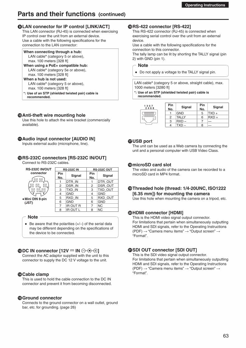
63
Operating Instructions
Parts and their functions (continued)
i LAN connector for IP control [LINK/ACT]This LAN connector (RJ-45) is connected when exercising IP control over the unit from an external device.Use a cable with the following specifications for the connection to the LAN connector:
When connecting through a hub: LAN cable* (category 5 or above),
max. 100 meters [328 ft]When using a PoE+ compatible hub: LAN cable* (category 5e or above),
max. 100 meters [328 ft]When a hub is not used: LAN cable* (category 5 or above),
max. 100 meters [328 ft]*: Use of an STP (shielded twisted pair) cable is
recommended.
j Anti-theft wire mounting holeUse this hole to attach the wire bracket (commercially available).
k Audio input connector [AUDIO IN]Inputs external audio (microphone, line).
l RS-232C connectors [RS-232C IN/OUT]Connect to RS-232C cables.
RS-232C IN/OUT connector
1 2
3 4 5
67
8
● Mini DIN 8-pin (JST)
RS-232C IN RS-232C OUTPin No.
SignalPin No.
Signal
1 DTR_IN 1 DTR_OUT2 DSR_IN 2 DSR_OUT3 TXD_IN 3 TXD_OUT4 GND 4 GND5 RXD_IN 5 RXD_OUT6 GND 6 GND7 IR OUT R 7 NC8 IR OUT L 8 NC
● Be aware that the polarities (+/−) of the serial data may be different depending on the specifications of the device to be connected.
Note
m DC IN connector [12V IN ]Connect the AC adaptor supplied with the unit to this connector to supply the DC 12 V voltage to the unit.
n Cable clampThis is used to hold the cable connection to the DC IN connector and prevent it from becoming disconnected.
o Ground connectorConnects to the ground connector on a wall outlet, ground bar, etc. for grounding. (page 26)
p RS-422 connector [RS-422]This RS-422 connector (RJ-45) is connected when exercising serial control over the unit from an external device. Use a cable with the following specifications for the connection to this connector.The tally lamp can be lit by shorting the TALLY signal (pin 2) with GND (pin 1).
● Do not apply a voltage to the TALLY signal pin.
Note
LAN cable* (category 5 or above, straight cable), max. 1000 meters [3280 ft]*: Use of an STP (shielded twisted pair) cable is
recommended.
1 3 5 72 4 6 8
Pin No.
SignalPin No.
Signal
1 GND 5 TXD +2 TALLY 6 RXD +3 RXD – 7 —4 TXD – 8 —
q USB portThe unit can be used as a Web camera by connecting the unit and a personal computer with USB Video Class.
r microSD card slotThe video and audio of the camera can be recorded to a microSD card in MP4 format.
s Threaded hole (thread: 1/4-20UNC, ISO1222 [6.35 mm]) for mounting the cameraUse this hole when mounting the camera on a tripod, etc.
t HDMI connector [HDMI]This is the HDMI video signal output connector. For limitations that pertain when simultaneously outputting HDMI and SDI signals, refer to the Operating Instructions (PDF) → “Camera menu items” → “Output screen” → “Format”.
u SDI OUT connector [SDI OUT]This is the SDI video signal output connector. For limitations that pertain when simultaneously outputting HDMI and SDI signals, refer to the Operating Instructions (PDF) → “Camera menu items” → “Output screen” → “Format”.

64
Operating Instructions
Parts and their functions (continued)
v G/L IN connector [G/L IN]This is the external sync signal input connector.This unit supports BBS (Black Burst Sync) and tri-level synchronization.External synchronization (genlock) can be applied to achieve phase alignment when multiple cameras are to be used or when the unit is to be used in combination with other devices.Supply to this connector the sync signals that correspond to the video signal format which has been set.
FormatExternal sync signal input format
BBS Tri-level sync
1080/59.94p1080/29.97p1080/59.94i1080/29.97PsF720/59.94p
480/59.94i480/59.94i480/59.94i480/59.94i480/59.94i
1080/59.94i—
1080/59.94i1080/59.94i720/59.94p
1080/50p1080/25p1080/50i1080/25PsF720/50p
576/50i576/50i576/50i576/50i576/50i
1080/50i—
1080/50i1080/50i720/50p
● External synchronization is performed using the SDI video signal. Synchronization is not possible using the HDMI video signal or the IP video signal. For horizontal phase adjustment, refer to the Operating Instructions (PDF) → “Camera menu items” → “Genlock screen”.
w Service switches
SW1
ON
OFF
SW2 SW3 SW4 SW5 SW6 SW7 SW8
Function OFF ONFactory setting
SW1 Camera address setting (standard serial communication)
See descriptions for SW1 to SW3
OFF
SW2 OFF
SW3 OFF
SW4 Communication format
Panasonic proprietary serial communication
Standard serial communication OFF
SW5 Always leave at OFF (used for factory adjustments) OFF
SW6 Infrared output Disable Enable OFF
SW7 Communication baud rate 9600 bps 38400 bps OFF
SW8 Communication connector RS-422 RS-232C OFF
● Perform switch settings before turning the unit on. ● Cameras whose camera address setting switches
are set to AUTO cannot coexist with cameras whose switches are set to 1 to 7.
● Manually setting multiple cameras to the same address will not allow you to control multiple cameras from a single controller simultaneously.
Notes
Service switch settings(1) SW1 to SW3: Camera address setting switches
Configure the camera address. Set this to AUTO under normal circumstances. When cameras are set to AUTO, addresses will be assigned to the cameras automatically in response operation from the controller in the order in which the cameras were connected. To manually configure the address, set the switches as follows.
Address AUTO 1 2 3 4 5 6 7SW1 OFF ON OFF ON OFF ON OFF ONSW2 OFF ON ON OFF OFF ON ON OFFSW3 OFF ON ON ON ON OFF OFF OFF
(2) SW4: Communication format selection switch Selects the communication format. When this is set to ON, standard serial communication is enabled. When this is set to OFF, Panasonic’s proprietary serial communication is enabled.
(3) SW5: Maintenance switch Fixed at OFF. Do not change this switch setting.
(4) SW6: Infrared output switch When this is set to ON, infrared output is enabled. The signal received via the remote control sensor is output from pins 7 and 8 of the RS-232C IN connector. Signal output is disabled when this is set to OFF.
(5) SW7: Communication baud rate switch When this is set to ON, the baud rate is 38400 bps. When this is set to OFF, the baud rate is 9600 bps.
(6) SW8: Communication connector switch When this is set to ON, RS-232C is enabled. When this is set to OFF, RS-422 is enabled.

65
Operating Instructions
Parts and their functions (continued)
■Wireless remote controller (optional accessory)
a ON/STANDBY buttonEach time this is pressed for 2 seconds, operation switches between turning on the unit’s power and establishing the standby status.
● When operation is transferred to the standby mode: The current pan-tilt position is stored in the memory (as a POWER ON preset), and the panning/tilting moves so that the camera points in the backward-facing direction.
● When operation is transferred to the POWER ON mode: Panning/tilting moves to the position which was stored in the memory (as a POWER ON preset) when operation was transferred to the standby mode.
Notes
b Signal transmission window
c MENU buttonEach time this is pressed for 2 seconds, operation switches between displaying the unit’s camera menu and exiting the camera menu.When it is pressed quickly (for less than 2 seconds) while a menu is displayed, the setting change is canceled.Furthermore, the pan and tilt movement range limits (limiters) are set and released by operating the MENU button, PRESET/LIMIT button and the pan-tilt buttons ([▲], [▼], [◄] and [►]).For details, refer to the Operating Instructions (PDF) → “Limiters”.
d CAM1 to CAM4 buttonsThese are used to select the units that are to be operated.Once a button has been selected, the unit corresponding to the selected button can be operated.
e SET buttonIf this button is pressed when one of the “Manual1 to 3” settings has been selected for “Scene” on the camera menu and the AWB A memory or AWB B memory has been selected by the white balance adjustment, the white balance is automatically adjusted and registered in the selected memory.
f MODE buttonThis is used to select the video signals which are output from the unit.Each time it is pressed, the signals are switched between the color bar signals and camera video signals.
● When the color bar is displayed, a test tone (1 kHz) is output according to the Audio setting in the camera menu. Be cautious of the volume on external devices.
Note
g GAIN buttons [OFF] [LOW] [HI] [AUTO]These are used to set the gain.The gain increase can be set in three steps using the [OFF], [LOW] and [HI] buttons.[OFF] is set to 0 dB, [LOW] is set to 9 dB, and [HI] is set to 18 dB.When the [AUTO] button is pressed, the AGC function is activated, and the gain is adjusted automatically depending on the light quantity.The maximum gain of the AGC function can be set using the camera menu.
h Preset memory call buttons [1] to [12]These are used to call the information on the unit’s directions and other settings, which have been registered in the unit’s preset memories No.1 to No.12, and reproduce those settings.Settings in preset memories No.13 and above cannot be called from the wireless remote control.

66
Operating Instructions
Parts and their functions (continued)
i PRESET/LIMIT buttonThis is used to register the settings in the preset memories or set or release the limiters.When a preset memory call button is pressed while the PRESET/LIMIT button is held down, the information on the unit’s current direction and other settings is registered in the call button.Preset memory call buttons [1] to [12] correspond to the unit’s No.1 to No.12 preset memories.Furthermore, the pan and tilt movement range limits (limiters) are set and released by operating the PRESET/LIMIT button, MENU button and the pan/tilt buttons ([▲], [▼], [◄] and [►]).For details, refer to the Operating Instructions (PDF) → “Limiters”.
j Pan-tilt buttons and menu operation buttons [▲] [▼] [◄] [►] [○](1) These are used to change the unit’s direction.
The unit is tilted in the up/down direction using the [▲] and [▼] buttons and panned in the left/right direction using the [◄] and [►] buttons.The [○] button does not work during tilting and panning.When the [▲] or [▼] and [◄] or [►] buttons are pressed at the same time, the unit moves diagonally.
(2) The buttons are used for menu operations when the unit displays the camera menus.Use the [▲], [▼], [◄] and [►] buttons to select the menu items.When a selected item has a sub-menu, the sub-menu will be displayed by pressing the [○] button.When the cursor is aligned with a particular item and the [○] button is pressed on the setting menu at the bottom hierarchical level, the setting of the selected item blinks.When the [○] button is pressed after the setting has been changed using the [▲], [▼], [◄] and [►] buttons, the setting stops blinking, and the new setting is entered.With a regular menu, the new setting is reflected immediately after it has been changed if the change was made from the setting in the blinking status, but there are some menus (Scene, Format and Initialize) where it is reflected only after the [○] button has been pressed, the blinking has stopped and the new setting has been entered.If the MENU button is pressed quickly (for less than 2 seconds) while the setting is in the blinking status, the change will be canceled, and the setting selected prior to the change will be restored.
k FOCUS buttons [F] [N]These are used to adjust the lens focus manually when the manual setting is established for the lens focus.The focus is adjusted in the far using the [F] button and in the near using the [N] button.
l A/FOCUS buttonThis is used when automatically adjusting the lens focus.
m M/FOCUS buttonThis is used when manually adjusting the lens focus.The FOCUS buttons ([F] and [N]) are used when performing the actual adjustment.
n OPT buttons [ON] [OFF]This is used to select the Day mode or Night mode.[ON]: Night mode[OFF]: Day mode (standard setting)
o HOME buttonWhen this is pressed for 2 seconds, the unit’s direction (panning or tilting) returns to the reference position.
p ZOOM buttons [T] [W]These are used to adjust the lens zoom.The zoom is adjusted in the wide-angle using the [W] button and in the telephoto using the [T] button.
q FAST buttonThis is used to change the movement speed at which the panning, tilting, zooming and focusing operations are performed to the high speed.When the button is tapped, the movement speed can be set to the normal high-speed operation. When the button is held down, it can be set to an even faster high-speed operation. Tap the button to return the movement speed to the normal high-speed operation.
● The operating speed for panning and tilting when the preset memory settings have been called can be changed using the Preset Speed item and Preset Speed Table item of the camera menu.
Note
r SLOW buttonThis is used to change the movement speed at which the panning, tilting, zooming and focusing operations are performed to the low speed.When the button is tapped, the movement speed can be set to the normal low-speed operation. When the button is held down, it can be set to an even slower low-speed operation. Tap the button to return the movement speed to the normal low-speed operation.
s A/IRIS buttonThis establishes the setting for adjusting the lens iris automatically in line with the light quantity.
t M/IRIS buttonThis establishes the setting for adjusting the lens iris manually.The IRIS + and IRIS – buttons are used when performing the actual adjustment.
u IRIS + buttonThis is used to adjust the lens iris in the opening direction.
v IRIS – buttonThis is used to adjust the lens iris in the closing direction.

67
Operating Instructions
Setting the remote control IDsThe wireless remote control (optional accessory) is capable of operating up to four units.IDs are used to set which units are selected when the [CAM1], [CAM2], [CAM3] and [CAM4] buttons on the wireless remote control have been pressed.
● When operating a multiple number of these units using wireless remote controls, set a different remote control ID for each control.
● When using one unit, set the remote control ID to “CAM1” unless the setting needs to be changed.
Setting procedureOperate the unit’s camera menu or the web screen to select a remote control ID ([CAM1] to [CAM4]). The camera’s [CAM1] to [CAM4] settings correspond to the [CAM1] to [CAM4] buttons on the wireless remote control.(The factory setting is “CAM1”.)For details, refer to the Operating Instructions (PDF) → “Camera menu items” → “Others 2/4 screen” → “IR ID”, or the Operating Instructions (PDF) → “Web screen configurations” → “Image screen [Image/Audio]” → “System settings tab [System]” → “Others” → “IR ID”.
[CAM1] to [CAM4] buttons

68
Operating Instructions
Network settings [When using Windows]
■Use the Easy IP Setup Software to establish the unit’s settings
The settings related to the unit’s network can be established using the Easy IP Setup Software supplied.You can obtain Easy IP Setup Software (EasyIPSetup.exe) by downloading it from the following website. https://pro-av.panasonic.net/
To establish the settings for a multiple number of units, the settings must be selected for each camera involved.If the settings cannot be established using the Easy IP Setup Software, select the settings separately for the unit and personal computer on the Network setup screen [Network] of the setting menu. (Operating Instructions (PDF) → “Web screen configurations” → “Network setup screen [Network]”)
● If, after the network settings have been established, another device in the same network has the same IP address, the network operations will not be performed properly. Set the IP address in such a way that it does not duplicate an existing IP address.
● Do not establish network settings from a multiple number of Easy IP Setup Software programs at the same time for a single camera. Similarly, do not perform the “Auto IP setting” operation of the remote camera controller (AW-RP50) at the same time. The IP address settings may no longer be recognized as a result.
● When you start the Easy IP Setup Software, you may be asked for the administrator account password.
● To enhance security, the Easy IP Setup Software is designed so that when around 20 or more minutes have passed after the power was turned on, the network settings of the target camera can no longer be configured. (Operating Instructions (PDF) → “Web screen configurations” → “Network setup screen [Network]” → “Network setup tab [Network]” → “Common (to IPv6/IPv4)” → “Easy IP Setup accommodate period”)
● The Easy IP Setup Software cannot be used from a different subnet via a router.
Notes
1 Start the Easy IP Setup Software.
2 Click the [Search] button.
3 Click the MAC address/IPv4 address of the camera to be set, and click the [Network Settings] button.
● When a DHCP server is being used, the IP address allocated to the unit can be checked by clicking the [Search] button of the Easy IP Setup Software.
● If the same IP address is used for any additional cameras, the numbers of the additional cameras will be displayed in the “IPv4 overlap” column of the cameras concerned.
● When the [Access Camera] button is clicked, the Live screen of the selected camera is displayed.
Notes

69
Operating Instructions
4 Input the network items, and click the [Save] button.
● When a DHCP server is being used, “DNS” of the Easy IP Setup Software can be set to “Auto”.
● After the [Save] button is clicked, it takes about 1 minute for the settings in the unit to be completed. If the AC adaptor or LAN cable is disconnected before the settings are completed, the settings will be canceled. In this case, repeat the steps to establish the settings.
● When a firewall (including software) has been introduced, enable access to all the UDP ports.
● When the Easy IP Setup Software is used for the first time, the [Program Compatibility Assistant] screen may appear after quitting the Easy IP Setup Software. Select [This program installed correctly] in the [Program Compatibility Assistant] screen.
Notes
■Installing the plug-in viewer software
To view IP images from the unit on a web browser, the “Network Camera View 4S” plug-in viewer software (ActiveX®) must be installed in your personal computer.
● When you display the Live screen [Live] on the personal computer for the first time, the installation screen for the plug-in viewer software (ActiveX) appears. Follow the instructions on the screen to perform installation.
● Depending on the operating environment of your computer, you may need to start Internet Explorer with an administrator account during installation. (Startup with an administrator account will not be required after installation is complete.)
● [Automatic installation of viewer software] is set to [On] at the time of purchase, allowing you to install directly from the unit. If a message appears in the web browser’s information bar, refer to the Operating Instructions (PDF) → “Troubleshooting” → “Web browser settings”.
● If the plug-in viewer software (ActiveX) installation screen continues to appear when switching screens, even after it is installed, restart the personal computer.
● To uninstall the plug-in viewer software, select [Control Panel] - [Programs] - [Uninstall a program] in Windows, and remove “Network Camera View 4S”.
● If installation of the plug-in viewer software fails, close Internet Explorer with while the above screen is displayed and then click [Next].
Notes
Network settings [When using Windows] (continued)

70
Operating Instructions
■User authenticationThe unit can be configured to allow access from the internet. To prevent infringement of privacy and personality rights, information leaks, and other issues concerning unauthorized access by third parties, we recommend enabling the user authentication function upon installation.We also recommend using DIGEST authentication when connecting to a device that supports DIGEST authentication.
• The AW-RP50 supports DIGEST authentication.
Preparation:1. Startup the web browser and display the “Live” page on
a PC.2. Click “Setup” button and then click “User mng.” button.The user authentication window will be displayed.
C
A
B
D
A Select “On” for “User auth.”* Set to “Off” by default.
Then click “Set” button.B (When using a device that supports DIGEST
authentication) Select “Digest” for “Authentication”. Then click “Set” button.
C Register a new user name and password* Select “1. Administrator” for the access level.
Then click “Set” button.D Delete the default user name.
Click the “Delete” button after selecting the user name to be deleted (“admin[1]”).
* Depending on the model used, the screens shown in the explanations may differ to the actual camera screens.
User name and password management • Use a combination of characters and numbers that is difficult to guess.Avoid using a string of the same characters, such as “11111”, birth dates, or telephone numbers.For details on valid characters and lengths, refer to the Operating Instructions (PDF) → “Web screen configurations” → “User management screen [User mng.]” → “User authentication settings tab [User auth.]”.
• Change user names and passwords periodically. • Make sure to manage the configured user names and passwords.
• Delete all user names that do not have an assigned user.
After changing the user name/passwordAlso change the user names and passwords registered to the following.Refer to the operating instructions provided with your camera for further information about the settings used for your camera.
• Remote camera controller (AW-RP50) • Browsers and applications on computers, tablets, and smartphones.
Network settings [When using Windows] (continued)

71
Operating Instructions
Troubleshooting ●Operation
Symptom Cause and remedial action Reference pages
No power
● Is the AC adaptor securely connected to the AC outlet? –––
● Is the power plug of the AC adaptor connected properly? –––
● Is the network cable for the PoE+ (IEEE802.3at compliant) compatible power supply device and the unit connected properly?
P.25
● Power may not be supplied if the total power limit is exceeded on power supply devices that allow connections to multiple PoE+ terminals. Refer to the operating instructions for the PoE+ power supply
device.
–––
The status display lamp flashes red continuously
● The PoE+ power supply conditions do not meet the specifications. Check the power supply device.
P.57
The status display lamp flashes red several times
● An error such as an attempt to perform a recording operation while an SD card is not inserted has occurred. Check the event log.
Operating Instructions (PDF) → “Web screen configurations” → “Maintenance screen [Maintenance]” → “System log tab [System log]”
Cannot operate(common to wireless remote control, controller)
● Is the power on? If the unit’s status display lamp is off or if it has lit up orange,
it means that the unit’s power is not being supplied.
Operating Instructions (PDF) → “How to turn the power on and off”
● Have the limiter functions been set?Operating Instructions (PDF) → “Limiters”
● Has the correct unit to be operated been selected?Operating Instructions (PDF) → “Selecting the units”
Cannot operate using the wireless remote control
● Have the remote control’s batteries run down or have the batteries been installed with their polarities reversed? If the status display lamp does not blink even when the
wireless remote control is operated near the wireless remote control signal light-sensing area, it means that the batteries have run down. Replace the batteries.
–––
● Has the IR ID setting been set correctly?
Operating Instructions (PDF) → “Camera menu items” → “Others 2/4 screen” → “IR ID”Operating Instructions (PDF) → “Web screen configurations” → “Image screen [Image/Audio]” → “System settings tab [System]” → “Others” → “IR ID”
● Is there a fluorescent light or plasma monitor near the unit and, if so, is the wireless remote control signal light-sensing area exposed to its light?
P.61
Cannot operate using the controller
● Is the unit connected to the controller properly? Refer to the Operating Instructions of the controller.
P.20 to 25
● Are all the cameras in the daisy-chain connection turned on? P.21
● It may be necessary to upgrade the version of the controller so that the controller will support the unit.
P.56
The unit turns in the opposite direction to the one operated
● Has the stand-alone (Desktop) installation setting been selected correctly?
Operating Instructions (PDF) → “Camera menu items” → “Others 1/4 screen” → “Install Position”Operating Instructions (PDF) → “Web screen configurations” → “Image screen [Image/Audio]” → “System settings tab [System]” → “Others” → “Install Position”
● The reversal setting may have been established at the controller if the unit is connected to the controller. Refer to the Operating Instructions of the controller.
–––

72
Operating Instructions
SpecificationsFor details on specifications, visit the Panasonic website (https://pro-av.panasonic.net/manual/en/index.html) and refer to the Operating Instructions.
Power requirements: DC 12 V (Supplied AC adaptor) DC 42 V to 57 V (PoE+ power supply)Current consumption: 1.3 A (Supplied AC adaptor) 0.5 A (PoE+ power supply)
indicates safety information.
■ GENERALAmbient operating temperature: 0 °C to 40 °C (32 °F to 104 °F)
Storage temperature: –20 °C to 50 °C (–4 °F to 122 °F)
Allowable humidity ranges: 20 % to 90 % (no condensation)
Mass: Approx. 1.5 kg (3.30 lb)
Dimensions (W × H × D): 160 mm × 186 mm × 179 mm
(6-5/16 inches × 7-41/128 inches × 7-3/64 inches) [excluding protrusions, direct ceiling mount bracket]
■ AC adaptor
Input: AC 100 V to 240 V, 1.2 A, 50/60 Hz
Output: DC 12 V, 3.0 A, 36 W
indicates safety information.
Mass: Approx. 220 g (0.485 lb)
Dimensions (W × H × D): 115 mm × 37 mm × 57 mm (4-17/32 inches × 1-59/128 inches ×
2-31/128 inches)
Inrush current, measured according to European standard EN55103-1, on initial switch-on: 4.5 A, after a supply interruption of 5 s: 16 A

73
Operating Instructions
A
AC adaptor (Supplied) ................................................ 58, 72AC adaptor cable ........................................................ 12, 17AW-HS50 .................................................................... 23, 24AW-RM50G ................................................................ 58, 61AW-RP50 ........................................................ 19, 20, 23, 24
B
Bracket mounting screws ..................................... 10, 16, 58
C
Cable clamp .......................................................... 12, 17, 63Coaxial cable .............................................................. 12, 17Commercially available controller ......................... 21, 22, 25Communication software .................................................. 26Compact Live Switcher ............................................... 23, 24
D
Direct ceiling mount bracket ............................... 7, 9, 13, 58Drop-prevention wire ................................ 10, 15, 16, 58, 62
E
Easy IP Setup Software .................................................... 68
H
HDMI cable ................................................................. 12, 17
I
IP address ........................................................................ 68IP decoder ........................................................................ 25
L
LAN cable ........................................... 12, 17, 19, 24, 25, 63
M
MAC address .................................................................... 68Main unit mounting screw ............................... 11, 15, 16, 58Microphone ....................................................................... 26Mount bracket ....................................... 9, 10, 13, 16, 58, 62
N
NDI|HX compatible switcher ............................................. 19
P
PoE+ ................................................................................. 57PoE+ compatible switching hub ....................................... 25Power cable ...................................................................... 58
R
Remote Camera Controller ............................. 19, 20, 23, 24RS-232C cable ........................................................... 12, 17
S
Screw for mounting tripod ................................................. 18SDI cable .................................................................... 12, 17
T
Tripod ............................................................................... 18
U
USB cable ......................................................................... 26
W
Wireless remote controller .............................. 58, 61, 65, 67WV-Q105A .......................................................... 7, 9, 13, 58
Index

74
Memo

75
Memo

Web Site: http://www.panasonic.com
©Panasonic Corporation 2019