hcruisera en 050117 m0058 date code label here …...frame 22 quick release lever & nut 2 front...
TRANSCRIPT

See back page for Customer Service InformationConsulte el reverso para Servicio de Información al ClienteVoir pages verso pour des renseignements le service à la clientèle
© Copyright Huffy Corporation 2017
Owner’s Manual for Cruiser Bicycles
Please read and fully understand this manual before operation.
Save this manual for future reference.
This manual contains important safety, assembly, operation and maintenance information.
HCruiserA EN 050117 m0058Date Code Label
HereEN

Owner’s Manual Index
Your Bike• Fitting the Rider to the Bicycle ..........................................................................................3• Warning and Safety Information ......................................................................................4• Owner’s Responsibility ........................................................................................................4• Rules of the Road ...................................................................................................................5
Bicycle Assembly• Parts Assembly View .............................................................................................................6• Parts Assembly List ................................................................................................................7• Introduction .............................................................................................................................8• Tools Needed ...........................................................................................................................8• Front Fender Installation .....................................................................................................9• Front Wheel Install ................................................................................................................10• Re-attach Front Brake Cable ...................................................................... 11• Mounted Wire Basket Assembly ......................................................................................12• Rear Fender Assembly .........................................................................................................13• Handlebar and Stem Installation ....................................................................................14• Testing Stem and Handlebar Tightness ........................................................................15• Seat Installation ................................................................................................................. 16-17• Testing Seat Clamp and Post Clamp Tightness ..........................................................17• Pedal Installation...................................................................................................................18• Reflector Installations ..........................................................................................................18• Accessories (various models) ........................................................................................ 19-20
Maintenance and Service• Repair and Service ................................................................................................................21• Tires ........................................................................................................................................22• Coaster Brake and Chain Adjustment ...........................................................................23• Rim Brake System: Setup and Adjustment .............................................................. 24-27• Brake Pad replacement .......................................................................................................27• Lubrication ..............................................................................................................................28• Lubrication Table...................................................................................................................28• Inspection of the Bearings ................................................................................................29
Warranty• Limited Warranty...................................................................................................................30
Owner’s Bicycle Identification Record .......................................................... 31

3
Your Bike
Your
Bik
e
3
1
2
Owner’s Bicycle Identifi cation RecordNOTE: This information is only available on the bicycle itself. It is not available from Huff y.
Each Huff y bicycle has a Recovery Code stamped into the frame. The Recovery Code can be found on the bottom of the crank housing as shown.
Write this number below to keep it for future reference.If the bicycle is stolen, give this number and a description of the bicycle to the police. This will help them fi nd the bicycle.
1
Recovery Code:
Purchase Date:
Model Name:
To determine the correct size of bicycle for the rider:
• Straddle the assembled bicycle with feet shoulder width apart and fl at on the ground.
• There must be at least 1 inch (2.5 cm) of clearance between the highest part of the top tube and the crotch of the rider with tires properly infl ated.
• The minimum leg-length for the rider is the highest part of the top tube plus one inch .
Fitting the Rider to the Bicycle
WARNING:ALWAYS WEAR YOUR
HELMET WHEN RIDING THIS PRODUCT!
• Helmet should sit level on your head and low on your forehead. Exposed forehead can result in serious injury.
• Adjust the strap sliders below the ear on both sides.• Buckle the chin strap. Adjust strap until it is snug.• No more than two fi ngers should fi t between the strap
and your chin.• A proper fi tting helmet should be comfortable and not
rock forward/backward or side to side.
Helmet Warning Information

4
Warning and Safety Information
The Owner’s Responsibility
WARNING: This bicycle is made to be ridden by one rider at a time for general transportation and recreational use. It is not made to withstand the abuse of stunting and jumping.
If the bicycle was purchased unassembled, it is the owner’s responsibility to follow all as-sembly and adjustment instructions exactly as written in this manual, and any “Special In-structions” supplied and to make sure all fasteners and components are securely tightened.
NOTE: Periodically check that all fasteners and components are securely tightened.
If the bicycle was purchased assembled, it is the owner’s responsibility, before riding the bicycle for the fi rst time, to make sure the bicycle has been assembled and adjusted ex-actly as written in this manual, and any “Special Instructions” supplied and to make sure all fasteners and components are securely tightened.
NOTE:If product is assembled, please proceed to sections: • Testing Stem, Handlebar• Seat Clamp tightness.
Meanings of Warnings:
This symbol is important. See the word “CAUTION” or “WARNING” which follows it.The word “CAUTION” is before mechanical instructions. If you do not obey these instruc-tions, mechanical damage or failure of a part of the bicycle can occur.The word “WARNING” is before personal safety instructions. If you do not obey these in-structions, injury to the rider or to others can occur.• CHOKING HAZARD. Small parts. Not for children under 3 years.• Adult assembly is required.• Handlebar hand grip or tube end plugs should be replaced if damaged as bare tubes have
been known to cause injury. All products with capped handlebar ends should be checked regularly to ensure that adequate protection for the ends of the handlebars are in place.
• Replacement forks must have the same rake and tube inner diameter as the original product.
• Do not add a motor to the product.• Do not tow or push the product.• Do not modify the product.• Replace worn or broken parts immediately.• If anything does not operate properly, discontinue use.
War
ning
and
Saf
ety

5
Rules of the Road
WARNING: Failure of the rider to obey the following “Rules of the Road” can result in injury to the rider or to others.• Obey all traffi c regulations, signs, and signals.• Always wear a bicycle helmet that meets safety standards, as well as local safety standards.• Ride on the correct side of the road, in a single fi le, and in a straight line.• If possible, avoid riding at night, dusk, dawn and any other time of poor visibility.• If you must ride at night or at time of poor visibility:
• Purchase, install, and use a headlight and taillight.• Headlights are required by all states for nighttime riding and taillights are required in
some states.• Battery-powered lights or fl ashing safety lights are also recommended.
• Refl ectors: For your own safety, do not ride the bicycle if the refl ectors are incorrectly installed, damaged, or missing. Make sure the front and rear refl ectors are vertical. Do not allow the visibility of the refl ectors to be blocked by clothing or other articles. Dirty refl ec-tors do not work well. Clean the refl ectors, as necessary, with soap and a damp cloth.• Make yourself more visible to motorists.
• Wear light-colored or refl ective clothing, such as a refl ective vest and refl ective bands for your arms and legs.
• Use refl ective tape on your helmet.• Do not let anything cover the refl ectors.
• Use extra caution in wet weather:• Ride slowly on damp surfaces because the tires will slide more easily.• Allow increased braking distance in wet weather.
• Avoid these hazards to prevent loss of control or damage to your wheels:• Be aware of drain grates, soft road edges, gravel or sand, pot holes or ruts, wet leaves, or
uneven paving.• Cross railroad tracks at a right angle to prevent the loss of control.• Avoid unsafe actions while riding.• Do not carry any passengers.• Do not carry any items or attach anything to your bicycle that could hinder your vision,
hearing, or control.• Do not ride with both hands off the handlebar.• Do not add a motor to the product.• Do not tow or push the product.• Do not modify the product.• Replace worn or broken parts immediately with original equipment.• If anything does not operate properly, discontinue use.
War
ning
and
Saf
ety

6 Part
s A
ssem
bly
View
22
29
623
2524
26
1
27
2812
14 13
910
5
14 13
19
19
1720
1533
36
34
21
18
16
2 3 4
3 4
3839
4037
35 78
30 31
32
11
41
42
Assembly
NO
TE: A
ll fe
atur
es, c
ompo
nent
s an
d ac
cess
orie
s ar
e no
t inc
lude
d on
all
mod
els.

7 Part
s A
ssem
bly
List
No.
Des
crip
tion
No.
Des
crip
tion
1Fr
ame
22Q
uick
Rel
ease
Lev
er &
Nut
2Fr
ont W
heel
Ass
embl
y23
Cran
k
3Ti
re (x
2)24
Cran
k Be
arin
gs
4Tu
be (x
2)25
Spro
cket
5Re
ar W
heel
Ass
embl
y26
Chai
n
6Fo
rk27
Peda
l Set
7Fr
ont F
ende
r28
Kick
stan
d
8Bo
lt, W
ashe
r, N
ut (t
op ta
b m
ount
)29
Chai
n G
uard
9Re
ar F
ende
rVa
riou
s M
odel
Opt
ions
:
10Bo
lt, W
ashe
r, N
ut (t
op ta
b m
ount
)30
Wire
Bas
ket K
it
11H
ead
Set B
earin
gs31
Wire
Bas
ket M
ount
ing
Har
dwar
e
12W
heel
Ret
aine
r (x2
)32
Rear
Rac
k Ad
just
able
Bar
and
Top
13A
xle
Nut
(x4)
33Le
ft H
and
Brak
e Le
ver (
If E
quip
ped)
14Fe
nder
Bra
ce B
olt (
x4)
34Ri
ght H
and
Brak
e Le
ver (
If E
quip
ped)
15H
andl
ebar
Ste
m35
Fron
t Lin
ear P
ull B
rake
(If E
quip
ped)
16H
andl
ebar
36Re
ar L
inea
r Pul
l Bra
ke (I
f Equ
ippe
d)
17G
rips
(x2)
37Ba
sket
(var
ious
mod
els)
18Fr
ont R
eflec
tor (
vario
us)
38Ba
g (v
ario
us m
odel
s)
19Re
ar R
eflec
tor (
vario
us)
39Cu
p H
olde
r (va
rious
mod
els)
20Se
at40
Bell
(var
ious
mod
els)
21Se
at P
ost
41Co
oler
Bag
(var
ious
mod
els)
42W
ater
Bot
tle/C
age
(var
ious
mod
els)

8
Intr
oduc
tion
Introduction to Assembly
Tools Needed (not included)
Small Adjustable Wrench(Jaws must open at least 9/16 inch.)
Open-end Wrenches
Flat-blade Screwdriver Phillips Screwdriver
Slip-Joint Pliers Metric Allen Wrenches
This Owner’s Manual is made for several diff erent bicycles: • Some illustrations may vary slightly from the actual product. • Follow instructions completely.• If the bicycle has any parts that are not described in this manual, look for separate “Special
Instructions” that are supplied with the bicycle.• Models may have diff erent accessory items such as bags, baskets, refl ectors, cup holders,
racks, etc.• All features, components and accessories are not included on all models.• Use the Index page to locate specifi c sections of this manual.• Please read through this entire manual before beginning assembly or maintenance.• If you are not confi dent with assembling this unit, refer to a local bike shop.
WARNING: Keep small parts away from children during assembly.
NOTE: All of the directions (right, left, front, rear, etc.) in this manual are as seen by the rider while seated on the bicycle.
Do not dispose of the carton and packaging until you complete the assembly of the bicycle. This can prevent accidentally discarding parts of the bicycle.
9
Ass
embl
y
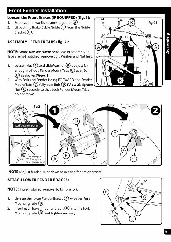
Front Fender Installation:Loosen the Front Brakes (IF EQUIPPED) (fi g. 1):1. Squeeze the two Brake arms together A.2. Lift out the Brake Cable Guide B from the Guide
Bracket C.
ASSEMBLY - FENDER TABS (fi g. 2):
NOTE: Some Tabs are Notched for easier assembly. If Tabs are not notched, remove Bolt, Washer and Nut fi rst.
1. Loosen Nut A and slide Washer B out just far enough to hook Fender Mount Tabs C over Bolt
D as shown (View. 1). 2. With Fork and Fender facing FORWARD and Fender
Mount Tabs C fully over Bolt D (View 2), tighten Nut A securely so that both Fender Mount Tabs do not move.
�g 01
CA A
B
BC
A
AB
D
D
CC
21fwd/delantera/avant
If equippedSi se equipa
Selon l'équipement
�g 2
NOTE: Adjust fender up or down as needed for tire clearance.
ATTACH LOWER FENDER BRACES:
NOTE: If pre-installed, remove Bolts from fork.
1. Line up the lower Fender Braces A with the Fork Mounting Tabs B.
2. Insert each lower mounting Bolt C into the Fork Mounting Tabs B and tighten securely.
H
JF
G

10
Ass
embl
y
Front Wheel Install:
1. If the Axle Nuts A are already attached to the front wheel axle, begin by removing them with an open end wrench or adjustable wrench.
2. Set the wheel into the front fork B. 3. Install wheel retainers C making sure
the tabs are in the fork D tab holes.4. Attach the front wheel with the Axle
Nuts A.5. With the wheel in the center of the
fork and tighten both nuts securely.
WARNING: • Do NOT use Axle Nuts without serrations to attach the front wheel.• Ensure wheel spins freely without contacting fork or fender.• Failure to obey these steps can allow the front wheel to loosen while riding. This can cause
injury to the rider or to others.
B
C
C
A
A
D

11
Ass
embl
y
Attach Lower Fender Braces:
1. Line up the Rear Fender Braces A with the Frame Mounting Tabs B.
2. Insert each lower mounting Bolt C into the Frame Mounting Tabs B and tighten securely. Make sure fender is centered over tire.
Tighten Top Fender Mount:
Note: Top Fender mount is loose to allow installation.
3. Tighten Bolt D and Nut E securely. Make sure fender is centered over tire.
Note: Ensure wheel spins freely without con-tacting frame or fender.
Rear Fender Assembly
C
BA
D E
Re-attach Front Brake Cable (If Equipped):
Re-attach Front Brake Cable:1. Squeeze the two Brake arms together
A.2. Insert the Brake Cable Guide B into the
cutout in the Guide Bracket C.3. Make sure the Brake Cable Guide B is
seated securely in the Guide Bracket C cutout.
WARNING: Check Front Brake Adjustment Before
Riding! See Maintenance > Brakes Section
CA A
B
BC

12
Ass
embl
y
Installation:
1. Attach Support Legs A to bottom of Basket B using Bracket C, 2 Screws D, 2 Washers E and 2 Nuts F. Tighten Securely.
2. Make sure top of Support Legs A set between Bracket C and Basket.
3. Install the front wheel into the fork as described in the owner’s manual. Ensure the wheel retainer clips are located in the holes in the fork.
4. Remove the front Axle Nuts G. With the retainer clips still on the fork, place the Support Legs A onto the Axle H on both sides.
5. Reinstall the Axle Nuts G hand tight.
6. Place Basket into position against upper Bracket I and attach with 2 Screws D, 2 Washers E and 2 Nuts F. Tighten Securely.
7. Realign the front wheel as needed and tighten Axle Nuts securely according to Torque Chart.
WARNING: • Failure to obey these steps can allow the front wheel to loosen while riding. This can
cause injury to the rider or to others.• Maximum basket weight is 4.5kg (10lbs).
B
I
D
E F
A
GFH
CB
E
A
Mounted Wire Basket Assembly (if equipped)

13
Ass
embl
y
Attach Lower Fender Braces:
1. Line up the Rear Fender Braces A with the Frame Mounting Tabs B.
2. Insert each lower mounting Bolt C into the Frame Mounting Tabs B and tighten securely. Make sure fender is centered over tire.
Tighten Top Fender Mount:
Note: Top Fender mount is loose to allow installation.
3. Tighten Bolt D and Nut E securely. Make sure fender is centered over tire.
Note: Ensure wheel spins freely without con-tacting frame or fender.
Rear Fender Assembly
C
BA
D E
NOTE: See Torque Chart for recommended torque.

14
Ass
embl
y
Handlebar and Stem Installation
NOTE: Remove plastic Cap C from the end of the Stem D. Loosen Stem Bolt E as needed.
1. Insert the Stem into the Fork Locknut B up to the top of the MIN-IN mark A.2. Tighten the Stem Bolt E just enough to hold it in position.3. If necessary, loosen the Handlebar Clamp Nut F and rotate Handlebar into a comfort-
able riding position.4. Tighten Handlebar Clamp Nut F just enough to hold it in position.5. Align the Stem with the front tire and tighten the Stem Bolt E securely (see Testing
Stem, next section)6. If necessary, re-adjust Handlebar and tighten Clamp Nut F securely.
D
C
E
G
GA
B
F
WARNINGS: • To prevent steering system damage and possible loss of control, the “MIN-IN” (minimum
insertion) mark A on the stem must be below the top of the Fork Locknut B. • The Front Brake G (if equipped) must be positioned in FRONT of the Fork. Ensure the Fork
is pointing FORWARD before proceeding.• Do not over tighten the stem bolt. Over tightening the stem bolt can damage the steering
system and cause loss of control.• If the handlebar clamp in not tight enough, the handlebar can slip in the stem. This can
cause damage to the handlebar or stem, and can cause loss of control.

15
Ass
embl
y
Testing Stem and Handlebar TightnessTO TEST THE TIGHTNESS OF THE STEM:
• Straddle the front wheel between your legs.• Try to turn the front wheel by turning the handlebar.• If the handlebar and stem turn without turning the front
wheel, realign the stem with the wheel and tighten the stem bolt(s) tighter than before (about 1/2 revolution only at a time).
• Do this test again, until the handlebar and stem do not turn without turning the front wheel.
TO TEST THE TIGHTNESS OF THE HANDLEBAR CLAMP:
• Hold the bicycle stationary and try to move the ends of the handlebar up and down.
CAUTION: Do not exceed 100 lbs (45 kg) downward force.
• If the handlebar moves, loosen the bolt(s) of the handlebar clamp.
• Put the handlebar in the correct position and tighten the bolt(s) of the handlebar clamp tighter than before.
• If the handlebar clamp has more than one bolt, tighten the bolts equally.• Do this test again, until the handlebar does not move in the handlebar clamp.

16
WARNING: To prevent the Seat A coming loose and possible loss of control, the “MIN-IN” (minimum insertion) mark B on the Seat Post must be below the top of the Seat Tube C.
SEAT AND SEAT POST SETUP:1. If needed, loosen Nuts on Seat
Clamp D and rotate Seat into rid-ing position.
2. Ensure the Seat Post E is fully through the TOP Seat Clamp D.
3. Tighten the Seat Clamp so the Seat does not move on the seat post.
4. If the Seat Clamp has a Nut on each side, tighten both nuts equally.
5. Point the Seat forward and put the Seat Post E into the Seat Tube C and proceed to next step.
TIGHTEN THE QUICK RELEASE LEVER:NOTE: The words “open” and “close” are on opposite sides of the quick release lever.
CAUTION: Operate the Quick Release Lever F by hand only. Do not use a hammer or any other tool to tighten the quick release lever.
1. Move the Quick Release Lever F to the “open” posi-tion so the word “open” is pointing away from the Seat Post Clamp G.
WARNING: You must use strong force to move the quick release lever to the “close” position. If you can easily move the lever to the “close” position, the clamping force is too light. If the clamping force of the Quick Release Lever is too light, the seat post can loosen while riding. This can cause injury to the rider or to others.
2. Open and close the Quick Release Lever with one hand while you turn the Adjusting Nut H with the other hand.
3. Tighten or loosen the adjusting nut by hand, so that you fi rst feel resistance to the quick release lever when it perpendicular to the bicycle frame.
4. Push the Quick Release Lever to the “close” position.5. When in the “close” position, make sure the Quick Release Lever lays against the Seat
Seat Installation
�g A
D
A
E
B
C
B
�g B
GC
H
E
F
Ass
embl
y

17
Ass
embl
y
Seat Installation - continued
Post Clamp G.6. The tightening torque of the Quick Release Lever should be tight enough so that the
seat does not move during normal operation.
Seat Bolt Mount (various models)
Some models have a Bolt I, Washer J and Nut K instead of a Quick Release Lever.
• If needed, loosen the nut enough to insert the Seat Post E.
• Point the seat forward and insert Seat Post to the Mini-mum Insertion marks B.
• Tighten Nut securely so it supports the rider without moving.
B
J
CKE
I
�g C
Testing Seat Clamp and Post Clamp Tightness
To test the tightness of the seat clamp and the post clamp:• Try to turn the seat side-to-side and to move the front of the seat up and down.
• If the seat moves in the Seat Clamp:• Loosen the Seat Clamp Nut.• Put the seat in the correct position and tighten the Seat Clamp tighter than before.• Do this test again, until the seat does not move in the Seat Clamp.
• If the Seat Post moves in the Seat Tube Clamp:• Loosen the Seat Clamp Lever.• Put the Seat Post in the correct position and tighten the Seat Clamp Nut tighter than
before.• If necessary, tighten or loosen Hand Nut so that Quick Release tightens securely.
• Do this test again, until the Seat Post does not move in the Seat Tube Clamp.

18
Ass
embl
y
Refl ector Installation (as equipped)Refl ector Installation:1. Position FRONT Refl ector A so it points
straight forward.2. Tighten Clamp Screw.3. Position Seat Post Refl ector (if equipped)
B so it points straight backwards.4. Tighten Clamp Screw.
NOTE: Do not over-tighten. This will damage the Clamp.
B A
Pedal Installation
CAUTION: There is a RIGHT pedal marked R and a LEFT pedal marked L.
NOTE: A Pedal Wrench is preferred for attaching Ped-als. A thin open-endwrench can also be used.
• The pedal marked R has right-hand threads. Tighten it in a clockwise direction.
• The pedal marked L has left-hand threads. Tighten it in a counterclockwise direction (anti-clockwise).
• Turn the right pedal marked R into the right side of the crank arm, and the left pedal marked L into the left side of the crank arm.
Tighten the pedals:• Make sure the threads of each pedal are fully into
the crank arm.
WARNING: Ensure pedals are secure in crank arms so they will not loosen. Periodically check tightness.
L
R

19
Accessories (various models)
A B
CD
INSULATED BAG INSTALL:1. Attach Bag A to
Handlebar by sliding the Back Brace B securely into the Bracket Slots C.
2. If needed, adjust Brackets C by loosening Screws D, and moving Brackets closer together or further apart so that Bag fi ts into the Brackets Slots.
3. Tighten Screws D Securely.
B A
LUGGAGE RACK ADJUSTMENT:1. Loosen Adjustment Knob A by turning
counter clockwise.2. Slide Adjustable Rack B into position 3. Tighten with Adjustment Knob A by turning
clockwise.
NOTE: Do not over-tighten. This will damage the Knob.
CUP HOLDER (VARIOUS):
NOTE: • Bracket may be pre-
installed and only need to be adjusted.
• Be careful not to scratch painted handlebars.
Installation:1. Attach Cup A to
Bracket B using two Screws C. Tighten securely.
2. Position Cup and Bracket level on Handlebar and attach Clamp Half B with Screw(s) D. Tighten securely.
NOTE: Slide Clamp halves slide together at Notch E and attach with one Screw.
A
A
C B DC
EB
D
D
Acc
esso
ries
20
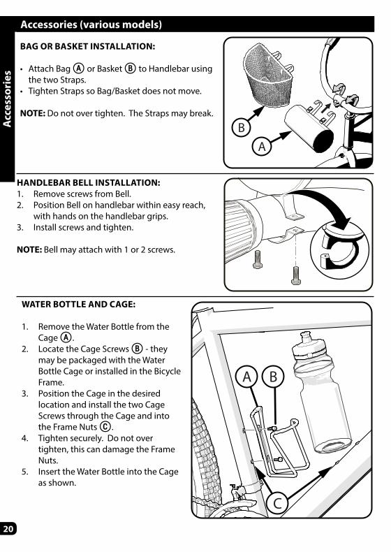
HANDLEBAR BELL INSTALLATION:1. Remove screws from Bell.2. Position Bell on handlebar within easy reach,
with hands on the handlebar grips.3. Install screws and tighten.
NOTE: Bell may attach with 1 or 2 screws.
BAG OR BASKET INSTALLATION:
• Attach Bag A or Basket B to Handlebar using the two Straps.
• Tighten Straps so Bag/Basket does not move.
NOTE: Do not over tighten. The Straps may break.
WATER BOTTLE AND CAGE:
1. Remove the Water Bottle from the Cage A.
2. Locate the Cage Screws B - they may be packaged with the Water Bottle Cage or installed in the Bicycle Frame.
3. Position the Cage in the desired location and install the two Cage Screws through the Cage and into the Frame Nuts C.
4. Tighten securely. Do not over tighten, this can damage the Frame Nuts.
5. Insert the Water Bottle into the Cage as shown.
Accessories (various models)
BA
A B
C
Acc
esso
ries
21
Maintenance and Service
Mai
nten
ance
Repair and Service
WARNING: • Inspect the product frequently. Failure to inspect the product and to make repairs or
adjustments, as necessary, can result in injury to the rider or to others. Make sure all parts are correctly assembled and adjusted as written in this manual and any “Special Instructions”.
• Immediately replace any damaged, missing, or badly worn parts with original equipment.
• Make sure all fasteners are correctly tightened as written in this manual and any “Special Instructions”. Parts that are not tight enough can be lost or operate poorly. Over tightened parts can be damaged. Make sure any replacement fasteners are the correct size and type.
NOTE: Have a bicycle service shop make any repairs or adjustments for which you do not have the correct tools or if the instructions in this manual or any “Special Instructions” are not suffi cient for you.

22
Tires
Maintenance:• Frequently check the tire infl ation pressure because all tires lose air slowly over time. For
extended storage, keep the weight of the off the tires.• Do not use unregulated air hoses to infl ate the tire/tubes. An unregulated hose can sud-
denly over infl ate tires and cause them to burst.• Replace worn tires.
WARNING: Do not ride or sit on the unit if a tire is under infl ated. This can dam-age the tire, inner tube and rim.
Infl ating the Tires:• Use a hand or a foot pump to infl ate the tires. • Service station meter-regulated air hoses are also acceptable. • The maximum infl ation pressure is shown on the tire sidewall. • If two infl ation pressures are on the tire sidewall, use the higher pressure for on-road riding
and the lower pressure for off -road riding. • The lower pressure will provide better tire traction and a more comfortable ride.
Before adding air to any tire, make sure the edge of the tire (the bead) is the same distance from the rim, all around the rim, on both sides of the tire. If the tire does not appear to be seated correctly, release air from the inner tube until you can push the bead of the tire into the rim where necessary. Add air slowly and stop frequently to check the tire seating and the pressure, until you reach the correct infl ation pressure.
Mai
nten
ance

23
Chain Adjustment
WARNING: • The chain must remain on the sprock-
ets. If the chain comes off the sprock-ets, the coaster brake will not operate.
• Do not attempt chain repairs. If there is a problem with the chain, have a bicycle service shop make any repairs.
Adjustment:The chain must be at the correct tightness. If too tight, the bicycle will be diffi cult to pedal. If too loose, the chain can come off the sprockets.When the chain C is at the correct tightness, you can rotate the crank freely and you can pull it no more than one-half inch A away from a straightedge B as shown.Adjust the tightness of the chain as follows:
• Loosen the axle nuts of the rear wheel.• Move the rear wheel forward or backward as necessary.
NOTE: Make sure the rear wheel is in the center of the bicycle frame.
• Hold the wheel in this position and tighten securely.
C
B A
Coaster BrakesThese models are equipped with a rear ‘coaster’ brake that is operated by rotating the crank backwards.
Operate the coaster brake as follows:• Push the pedals backward to move the
chain backward• The chain activates the coaster brake
mechanism that is inside the rear wheel hub
• As you push the pedals backward with increasing force, the braking action of the coaster brake increases.
Mai
nten
ance

24
Mai
nten
ance
Final Brake Adjustment Before Riding
Check tightness of the cantilever mounting Bolt A (fi g A):• Make sure each cantilever mounting Bolt is tightened securely.
Center brake shoes on rim:1. Turn the Adjustment Screw B on
the cantilever arm to move the arm in or out so each Brake Shoe C is the same distance from the rim.
2. Squeeze the brake lever two times.3. Do this step again, until both brake
shoes are the same distance from the rim.
A
C
B
�g A
• Infl ate Tires to recommended pressure on Tire side wall.
• Make sure Tire is centered in Fork.
• If Needed, Re-attach Front Brake Cable:• Squeeze the two Brake
arms together A.• Insert the Brake
Cable Guide B into the cutout in the Guide Bracket C.
• Make sure the Brake Cable Guide B is seated securely in the Guide Bracket C cutout.
B
B C
CA A
Linear Pull Brake System Adjustment - Before StartingIF EQUIPPED: The Following Sections Describe Final Brake System Adjustments Re-quired Before Riding.

25
Mai
nten
ance
NOTE: The front and rear break adjustments are the same.
WARNING: You must adjust the front and rear brakes before you ride the bicycle.
Step 1: Put the brake shoes B in the cor-rect position (fi g B):
1. Loosen the Screw A of each Brake Shoe B.
2. Adjust each Brake Shoe so it is fl at against the rim and aligned with the curve of the rim.
3. Make sure each Brake Shoe does not rub the tire.
4. If the surface of the Brake Shoe has arrows, make sure the arrows point toward the rear of the bicycle.
5. Hold each Brake Shoe in position and tighten the Screw.
Step 2: Test the tightness of each Brake Shoe:
1. Try to move each Brake Shoe out of position.2. If a Brake Shoe moves, do Step 1 again, but tighten the nut tighter than before.3. Do this test again, until each Brake Shoe does not move.
Step 3. Stretching the cable (fi g B):1. Hold both Brake Shoes against the rim.2. Loosen the cable clamp Screw C.3. Pull the Cable D tight and tighten the Screw.
WARNING: Do not over tighten the cable clamp Screw. Over tightening the cable clamp Screw may cut the cable and cause injury to the rider or to others.
4. Squeeze each brake lever fi rmly 20 times.5. Hold both Brake Shoes against the rim and loosen the cable clamp Screw.6. Pull the Cable tight and tighten the cable clamp Screw.
A
C
D
B
�g B
Linear Pull Brake System - Adjustment continued
26 continued >>
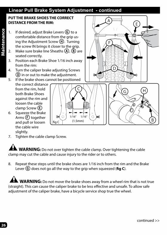
Linear Pull Brake System Adjustment - continuedPUT THE BRAKE SHOES THE CORRECT DISTANCE FROM THE RIM:
1. If desired, adjust Brake Levers G to a comfortable distance from the grip us-ing the Adjustment Screw H. Turning the screw IN brings it closer to the grip.
2. Make sure brake line Sheaths A, B are seated correctly.
3. Position each Brake Shoe 1/16 inch away from the rim:
4. Turn the caliper brake adjusting Screws D in or out to make the adjustment.
5. If the brake shoes cannot be positioned the correct distance from the rim, hold both Brake Shoes against the rim and loosen the cable clamp Screw E
6. Squeeze the Brake Arms F together and pull or loosen the cable wire slightly.
7. Tighten the cable clamp Screw.
WARNING: Do not over tighten the cable clamp. Over tightening the cable clamp may cut the cable and cause injury to the rider or to others.
8. Repeat these steps until the brake shoes are 1/16 inch from the rim and the Brake Lever G does not go all the way to the grip when squeezed (fi g C).
WARNING: Do not move the brake shoes away from a wheel rim that is not true (straight). This can cause the caliper brake to be less eff ective and unsafe. To allow safe adjustment of the caliper brake, have a bicycle service shop true the wheel.
A
F
D
B
G H
�g C
1/16” 1/16”
C
E
(1.5mm)
Mai
nten
ance

27
Linear Pull Brake System - continued
Linear Pull Brake Pad Replacement
B
A
C
D
1. If necessary, loosen brake cable Adjustment Bolt A.
2. Loosen and remove brake pad Bolt/Screws B.
3. Remove old Brake Shoe C.4. Install new Brake Shoe, mak-
ing sure it is pointing forward and lined up evenly with the Wheel Rim D.
5. Tighten brake pad Bolt/Screw and Adjustment Bolt according to Torque Chart.
WARNING: Replace Brake Pad with same model and type as original.
Test the tightness of the cable clamp (fi g C):
1. Squeeze each Brake Levers G with fi rm pressure.2. Make sure the cable does not move in the Cable Clamp E.3. If the cable moves in the cable clamp, adjust the brakes again but tighten the cable
clamp tighter than before.4. Do this test again, until the cable does not move in the cable clamp.Test the travel of each brake lever:
1. Squeeze each Brake Lever G with strong pressure2. If the brake lever touches the grip, adjust the brakes again.
WARNING: After you adjust the brakes again, if either brake lever touches the grip or does not work well, have a bicycle service shop repair or adjust the brakes.
Mai
nten
ance

28
Lubrication
Lubrication Table
What When How
Pedals every six months Put four drops of oil where the axles go into the pedals.
Chain every six months Put one drop of oil on each roller of the chain. Wipe all excess oil off the chain.
WARNING: • Do not over lubricate. If oil gets on the wheel rims or the brake shoes, it will reduce
brake performance and a longer distance to stop the bicycle will be necessary. Injury to the rider or to others can occur.
• The chain can throw excess oil onto the wheel rim. Wipe excess oil off the chain.• Keep all oil off the surfaces of the pedals where your feet rest.• Using soap and hot water, wash all oil off the wheel rims, the brake shoes, the pedals,
and the tires.• Rinse with clean water and dry completely before you ride the bicycle.• Using a light machine oil (20W), lubricate the bicycle according to the following table:
Mai
nten
ance

29
MaintenanceFrequently check the bearings of the bicycle. Have a bicycle service shop lubricate the bear-ings once a year or any time they do not pass the following tests:Head Tube BearingsThe fork should turn freely and smoothly at all times. With the front wheel off the ground, you should not be able to move the fork up, down, or side-to-side in the head tube.Crank BearingsThe crank should turn freely and smoothly at all times and the front sprockets should not be loose on the crank. You should not be able to move the pedal end of the crank from side-to-side.Wheel BearingsLift each end of the bicycle off the ground and slowly spin the raised wheel by hand. The bearings are correctly adjusted if:
• The wheel spins freely and easily.• The weight of the spoke reflector, when you put it toward the front or rear of the bicycle,
causes the wheel to spin back and forth several times.• There is no side-to-side movement at the wheel rim when you push it to the side with
light force.
Inspection of the Bearings
Mai
nten
ance

30
Limited WarrantyGeneral:
• Part or model specifi cations are subject to change without notice.
• This Limited Warranty is the only warranty for the product. There are no other express warranties.
• The only uses for this product are described in this manual.
• Warranty registration is not required. • The Limited Warranty extends only to the
original consumer and is not transferable to anyone else.
What does this Limited Warranty cover?This Limited Warranty covers all parts of the product except those indicated below as not warranted.
What must you do to keep the Limited Warranty in eff ect?This Limited Warranty is eff ective only if:
• Product is completely and correctly assembled.
• Product is used under normal conditions for its intended purpose (see the following section for excluded activities).
• Product receives all necessary maintenance and adjustments.
• Product is used for general transportation and recreational use only.
What is not covered by this Limited Warranty?This product is designed for recreational use only. This Limited Warranty does not cover normal wear and tear, normal maintenance items, or any damage, failure, or loss that is caused by improper assembly, maintenance, adjustment, storage, or use of the product.
This Limited Warranty will be void if the product is ever:
• Used in any competitive sport• Used for stunt riding, jumping, aerobatics or
similar activity• Modifi ed in any way• Modifi ed with the addition of a motor• Ridden by more than one person at a time• Rented, sold, or given away
• Used in a manner contrary to the instructions and warnings in this Owner’s Manual
Huff y will not be liable for incidental or consequential loss or damage due directly or indirectly from use of this product. Some States do not allow the exclusion or limitation of incidental or consequential damages, so the above limitation may not apply to you.
What will Huff y do?Huff y will replace, without charge to you, any part, or component found to be defective by Huff y.
How do you get service?Contact the Customer Service Department.• See included list for Customer Contact
information or visit www.huff ybikes.com/contact.
What rights do you have?This warranty gives you specifi c legal rights. You may also have other rights which vary from State to State.
War
rant
y
For how long does this Limited Warranty last?
• The frame is warranted for life except aluminum frames which are warranted for ten (10) years, from the date of purchase.
• The fork is warranted for life except for shock forks which are warranted one (1) year from date of purchase.
• All other components are warranted for six (6) months from the date of purchase.
War
rant
y

31
3
1
2
Owner’s Bicycle Identifi cation RecordNOTE: This information is only available on the bicycle itself. It is not available from Huff y.
Each Huff y bicycle has a Recovery Code stamped into the frame. The Recovery Code can be found on the bottom of the crank housing as shown.
Write this number below to keep it for future reference.If the bicycle is stolen, give this number and a description of the bicycle to the police. This will help them fi nd the bicycle.
1
Recovery Code:
Purchase Date:
Model Name:
To determine the correct size of bicycle for the rider:
• Straddle the assembled bicycle with feet shoulder width apart and fl at on the ground.
• There must be at least 1 inch (2.5 cm) of clearance between the highest part of the top tube and the crotch of the rider with tires properly infl ated.
• The minimum leg-length for the rider is the highest part of the top tube plus one inch .
Fitting the Rider to the Bicycle
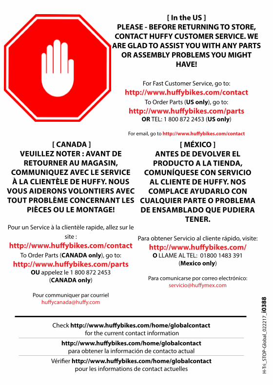
[ In the US ]PLEASE - BEFORE RETURNING TO STORE,
CONTACT HUFFY CUSTOMER SERVICE. WE ARE GLAD TO ASSIST YOU WITH ANY PARTS
OR ASSEMBLY PROBLEMS YOU MIGHT HAVE!
For Fast Customer Service, go to: http://www.huff ybikes.com/contact
To Order Parts (US only), go to: http://www.huff ybikes.com/parts
OR TEL: 1 800 872 2453 (US only)
For email, go to http://www.huff ybikes.com/contact
[ CANADA ]VEUILLEZ NOTER : AVANT DE
RETOURNER AU MAGASIN, COMMUNIQUEZ AVEC LE SERVICE À LA CLIENTÈLE DE HUFFY. NOUS
VOUS AIDERONS VOLONTIERS AVEC TOUT PROBLÈME CONCERNANT LES
PIÈCES OU LE MONTAGE!
Pour un Service à la clientèle rapide, allez sur le site :
http://www.huff ybikes.com/contactTo Order Parts (CANADA only), go to:
http://www.huff ybikes.com/partsOU appelez le 1 800 872 2453
(CANADA only)
Pour communiquer par courriel huff ycanada@huff y.com
[ MÉXICO ]ANTES DE DEVOLVER EL
PRODUCTO A LA TIENDA, COMUNÍQUESE CON SERVICIO
AL CLIENTE DE HUFFY. NOS COMPLACE AYUDARLO CON
CUALQUIER PARTE O PROBLEMA DE ENSAMBLADO QUE PUDIERA
TENER.
Para obtener Servicio al cliente rápido, visite: http://www.huff ybikes.com/
O LLAME AL TEL: 01800 1483 391 (Mexico only)
Para comunicarse por correo electrónico: servicio@huff ymex.com
H-T
ri_ST
OP-
Glo
bal_
0222
17_i
0388
Check http://www.huff ybikes.com/home/globalcontact for the current contact information
http://www.huff ybikes.com/home/globalcontact para obtener la información de contacto actual
Vérifi er http://www.huff ybikes.com/home/globalcontact pour les informations de contact actuelles