hbcu presentation: impact of rohs legislation on the high performance industry
TRANSCRIPT
Tuskegee University:
Collaborative Research with the Boeing Company
Legand Burge, Dean Heshmat Aglan, Associate Dean
College of Engineering
David Burdick The Boeing Company
Presented at BEYA 2015, Washington DC

The College of Engineering Enabling Education and Leadership; Exploration and Discovery; Engagement and Service; Technology and Application by Legand L. Burge, Jr., Dean
TM

Tuskegee University Overview Independent and state-related institution of higher
education The academic programs are organized into five
colleges and two schools The curricula for these colleges and schools currently
offer over 50 degrees including 39 Bachelor's, 13 Master's, 3 Doctor's of Philosophy: Materials Science and Engineering, Integrative Bio-Sciences, Interdisciplinary Pathobiology and the Doctor of Veterinary Medicine. Tuskegee enrolls more than 3,000 students and
employs approximately 900 faculty and support personnel. Physical facilities include more than 5,000 acres of
forestry and a campus on which sits more than 100 major buildings and structures.

College of Engineering (CE)
CE
AEROSPACE SCIENCE
ENGINEERING
MECHANICAL ENGINEERING
ELECTRICAL ENGINEERING
CHEMICAL ENGINEERING
WITH ENVIRONMENTAL
OPTION
MATERIALS SCIENCE &
ENGINEERING

Tuskegee University partner with prime Jacobs Engineering on ESSSA – Prime with NASA
NASA Mentor-Protégé Program Jacobs Engineering (ETSA) Current Kr for Products, Services, Consultancy – Dynetics;
Aerojet; Teledyne Brown; Boeing; Lockheed Martin; Raytheon Proposals with URS, L-3 Comm, SAIC $12.5M – Government Grants/Contracts (NSF, DoD, NSA,
CIA, DoEd, DoEnergy, USDA, FAA, DOT(FRA), NRC, Pending Proposals - $8M Career Fair, Fall 2015: Internships/Cooperative Ed Talent Acquisition – Fortune 500 Companies Benchmark Industries – Procter & Gamble; Ford Motor; 3M;
Boeing Co., Nucor Steel Co., Chevron; ExxonMobil; Boeing; Lockheed Martin; John Deere; Jacobs; Kellogg; Southern Company; Microsoft; Nucor
Overview - College of Engineering – Past Performance

Utilize current infrastructure for insert Veterans into undergraduate and graduate courses
Tuskegee University current partnership with consortium institution easy to add to ongoing courses and internship experiences particularly with prime from NASA, e.g., Jacobs Engineering in Huntsville, AL, Steins, MS, Orlando, FL, etc.
Undergrad programs provide ease to move into STEM areas Graduate programs focus on Systems Engineering (Navy) Utilize HBCU Engineering Deans (14) to utilize nation-wide
approach for Veterans, particularly for southeastern states Utilize Fortune 500 collaborations Utilize nation-wide Career Fair, online and for
Internships/Cooperative Ed for Vets GI Bill funding easy for Online/On-campus courses/programs Talent Acquisition – Fortune 500 Companies
Proposal Overview - College of Engineering
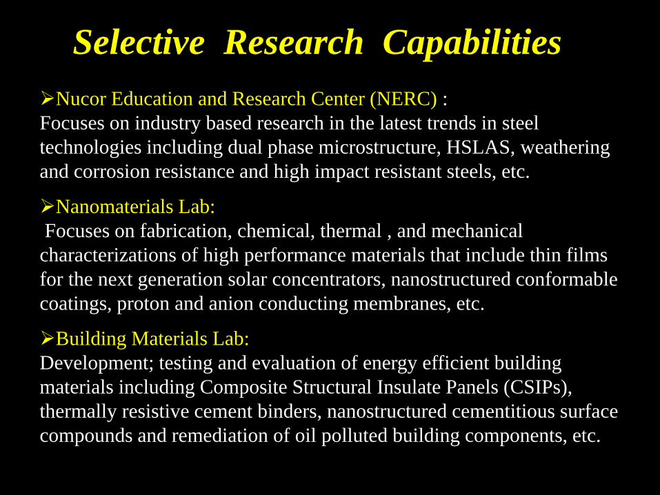
Selective Research Capabilities Nucor Education and Research Center (NERC) : Focuses on industry based research in the latest trends in steel technologies including dual phase microstructure, HSLAS, weathering and corrosion resistance and high impact resistant steels, etc.
Nanomaterials Lab: Focuses on fabrication, chemical, thermal , and mechanical characterizations of high performance materials that include thin films for the next generation solar concentrators, nanostructured conformable coatings, proton and anion conducting membranes, etc.
Building Materials Lab: Development; testing and evaluation of energy efficient building materials including Composite Structural Insulate Panels (CSIPs), thermally resistive cement binders, nanostructured cementitious surface compounds and remediation of oil polluted building components, etc.

NUCOR –Education and Research Center (NERC)
• The Center is comprised of three main components: • Educational • Research • Outreach
• The NERC pursues a balance between these components to provide engineering graduates with basic and applied knowledge of steels and their related technologies.

NERC Research
• Microstructure- properties relationship of structure steels • Processing- properties relationships of structure steels • Analysis of surface defects in hot and cold rolled steels • Accelerated corrosion studies on enameled and galvanized
steels • Microstructure – properties relationships of low carbon steels • Improvement of wear, strength and corrosion resistance of
carbon steels using nanocoatings.

Microstructural Analysis of Bainitic and Pearlitic Rail steels
0200400600800
1000120014001600
0 2 4 6 8 10 12 14
Stre
ss
MPa
Strain %
Pearlitic steel
Bainitic steel
Microstructure of rail steel dictates its overloading behavior. pearlitic
bainitic

Microstructural Gradient of Old and New Railheads
Fine grains due to head hardening. More ductile features
Elongated grains due to service shear and compressive loading.
Brittle-like features
New railhead Old railhead

Detection and Assessment of Low Cycle Fatigue Damage

Fatigue Crack Propagation Kinetics of Bainitic and Pearlitic Rail Steels
1.E-08
1.E-07
1.E-06
1.E-05
1.E-04
0 10 20 30 40 50 60 70Energy Release rate, J* (kJ/m2)
Cra
ck G
row
th r
ate,
da/
dN
(m/c
ycle
)
Bainitic Pearlitic
Fatigue crack propagation kinetics correlation with fracture surface morphology. (fast crack region)
bainitic
pearlitic

Rail Steel Repairs

Rail Steel after Welding
Slot weld Continuous weld
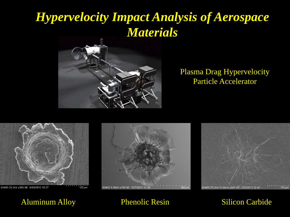
Hypervelocity Impact Analysis of Aerospace Materials
Phenolic Resin Aluminum Alloy Silicon Carbide
Plasma Drag Hypervelocity Particle Accelerator

Fracture and Fatigue Studies of Vanadium Alloys
Processing Orientation Fracture Toughness Relationship of Vanadium Alloys

Nanostructured Polymeric and Cementitious Materials

Well dispersed Acid treated MWCNTs
Dispersion of Nanoparticles

Mechanical Performance of Nanostructured MWCNT Tetrafunctional Epoxy Systems
020406080
100120140160180200
0 0.2 0.4 0.6 0.8 1 1.2Deflection, mm
Flex
ural
Stre
ss, M
Pa
nano
neat
MWCNT dispersed in epoxy matrix A considerable enhancement in the flexural strength has been achieved with MWCNT
reinforcement.

Thermal Conductivity of Aligned MWCNT
Number of
Stack Layers
Thermal
Resistance
( m2K/W)
Overall Stack
Assembly
Thickness (mm)
MWCNT/
Epoxy
Thickness (mm)
Thermal
Conductivity
(W/mK)
3 6.79E-3 8.59 2 178
2 6.29E-3 8.0 1.4 178
1 5.96E-3 7.1 0.4 178
.
Summary of thermal resistances and corresponding thicknesses of stacks

Fabrication of Thin Films
Neat Polyimide Film 0.5%MWCNT Polyimide Film

Fabrication
Woven Carbon/Phenolic Composites

Pulse Laser Degradation of Nanostructured Composites
0 5
10 15 20 25 30 35 40 45
0 0.5 1 1.5 2 2.5
Stre
ss, M
Pa
Strain, %
Neat Epoxy - 2 min 0.15% MWCNT/Epoxy - 2 min 2% NC/Epoxy - 2 min
Top view of the laser damaged area of the (a) neat epoxy, (b) 2% nanosilicate/epoxy and (c) 0.15% MWCNT/epoxy.
a b c
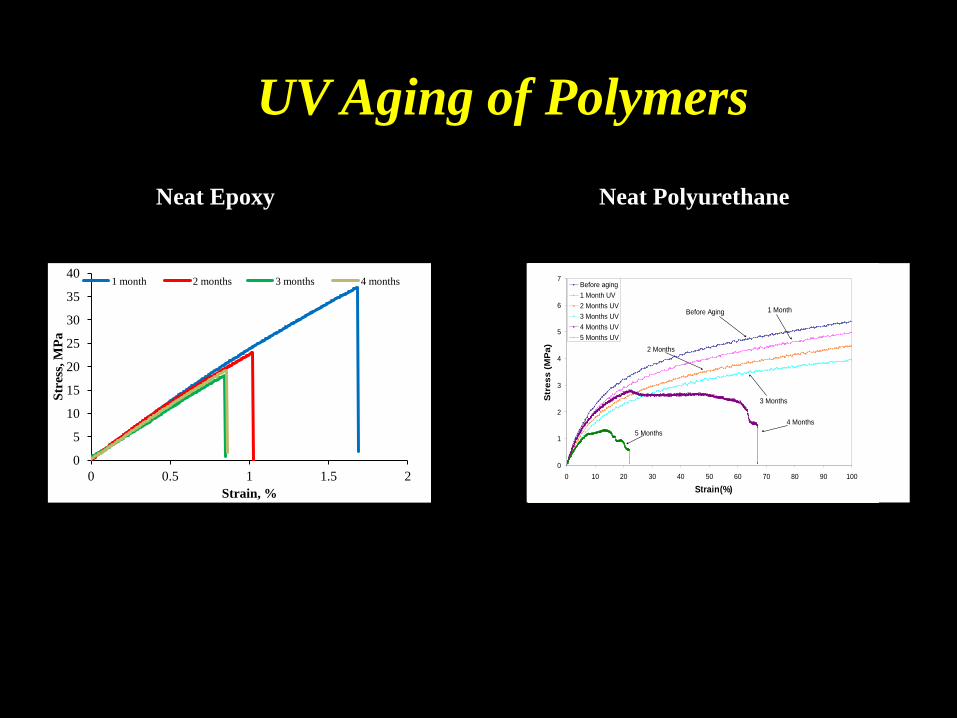
UV Aging of Polymers
0
5
10
15
20
25
30
35
40
0 0.5 1 1.5 2
Stre
ss, M
Pa
Strain, %
1 month 2 months 3 months 4 months
Neat Epoxy
0
1
2
3
4
5
6
7
0 10 20 30 40 50 60 70 80 90 100
Strain(%)
Str
ess
(MP
a)
Before aging1 Month UV2 Months UV3 Months UV4 Months UV5 Months UV
Before Aging 1 Month
2 Months
3 Months
4 Months5 Months
Neat Polyurethane

0
5000
10000
15000
20000
25000
30000
35000
-20000 0 20000 40000 60000 80000 100000 120000 140000
Imag
inar
y a
xis,
-Z (Ω
)
real axis, Z (Ω)
18%MPI 21% MPI 25% MPI 30% MPI
1.5 MHz
10 Hz
10 Hz 10 Hz
Proton Conductivity
Nanoparticle Proton Conductivity, (S/cm)
Membrane Nanostructured
Membrane Increase, %
Activated Silica 1.28×10⁻⁵ 1.44×10⁻⁵ 12.5
Fumed Silica 5.14×10⁻⁵ 1.44×10⁻⁴ 180
Liquid Silica 2.6×10⁻³ 1.4×10⁻² 400

Sand-Jet Edge Erosion of Coated Graphite Epoxy Composites
Uncoated Coated
Typical values of mass loading vary from 0.0001 g/cm2 (extremely light) to 1.0 g/cm2 (extremely heavy).
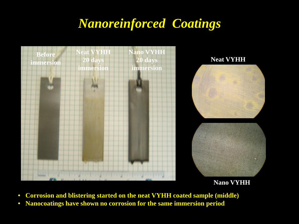
Nanoreinforced Coatings
Before immersion
Neat VYHH 20 days
immersion
Nano VYHH 20 days
immersion
• Corrosion and blistering started on the neat VYHH coated sample (middle) • Nanocoatings have shown no corrosion for the same immersion period
Neat VYHH
Nano VYHH

Effect of Nanosilicate Loading on the Mechanical performance of Cementitious Compounds
0
2
4
6
8
0 2 4 6 8 10
Indi
rect
Ten
sile
Stre
ngth
, MP
a
NS Replacement Ratio, %
Unactivated nanosilicate Activated nano silicate
AFM morphology of un-activated material AFM morphology of activated material
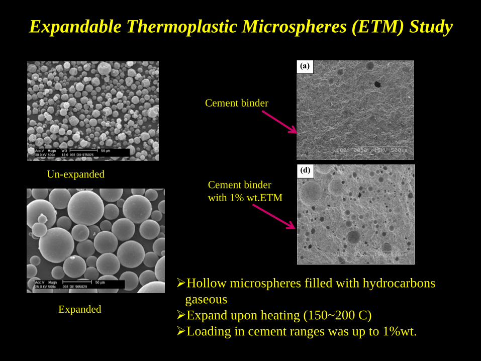
Expandable Thermoplastic Microspheres (ETM) Study
Hollow microspheres filled with hydrocarbons gaseous Expand upon heating (150~200 C) Loading in cement ranges was up to 1%wt.
Un-expanded
Expanded
Cement binder
Cement binder with 1% wt.ETM

Lab and Field Testing of Energy-Efficient Flood-Damage-
Resistant Residential Envelope Systems
Flooding for 3 days
Flooding for 21 days
Mold growth upon re-entry after flooding
Samples taken for mold identifications

A research effort to understand the growth mechanism of Tin Whiskers and methods of risk
mitigation
By
David Burdick, The Boeing Co. Heshmat Aglan, Tuskegee University

The Banned Substance
The European Union’s RoHS (Reduction of Hazardous Substances) legislation banned the use of four hazardous materials one of these materials was Lead. Lead is used in solder alloys

The Change
Lead is also used as a plating material for high performance electronic components
Component terminations are plated with Tin/Lead solder

The Problem
The replacement plating material is Tin and to our disadvantage Tin grows whiskers.

What are Tin Whiskers Tin Whiskers are electrically
conductive single crystalline tin structures that grow from pure tin-plated surfaces
They can and have caused short circuits in electronic circuits
They can break from the surface and interfere with the operation of mechanical or optical assemblies
They are a threat to the aerospace and defense industry
Tin whiskers (Courtesy of NASA)

What are Tin Whiskers
Tin Whiskers Up Close (Courtesy of DUART Productions)

Tin whisker growing from tin surfaces near electrical components
Tin whisker growing from the surface of tin connector guides.
(Acquired from nepp.nasa.gov)
How do they Cause Shorts

(Acquired from nepp.nasa.gov)
Shorts Cause Equipment Failures On-Orbit commercial (non-NASA) Satellite failures:
GALAXY VII (PanAmSat) Both primary and redundant SCP failed SOLIDARIDAD 1 (SatMex) Both primary and redundant SCP failed GALAXY IIIR (PanAmSat) Both primary and redundant SCP failed
Medical Equipment Failures:
Heart Pacemaker Recall Apnea Monitor Failures
Industrial Power Failures Dresden Nuclear Reactor - Tripped Channel B Duane Arnold Nuclear Reactor - Reactor Scram Duane Arnold Nuclear Reactor - Reactor Scram/Controlled Shutdown Dresden Nuclear Reactor - Reactor Scram Dominion Millstone - Reactor Trip
Military System Failures
Patriot Missile Phoenix Missile F-15 Radar

Tuskegee’s Research Project
Many scientists agree that compressive stress in the tin film is the fundamental driving force behind tin whisker growth.
Other factors proposed are oxidation, re-crystallization,
thermal mismatch between metallic surfaces, corrosion, impurities, inter-metallic compound growth and migration.
The students at Tuskegee University are attempting to determine the root cause of Tin Whisker growth and to find a way to mitigate the risks they cause to electronic circuits.

Observation of Tin Whisker Growth under Hygro-Thermal Exposure and 5% NaCl Water Immersion
funded by Boeing Co.
Whiskers protrusion seen at magnification 5KX
Thermotron Test Chamber (a) (b)
Coupons arrangement – (a) Thermotron and (b) Corrosion chambers
(a) (b)

The First Step in the Process
Tin plated brass coupons immersed in 5% NaCl solution.
Tuskegee is Growing Whiskers

Coupons Used in the Research at Tuskegee
Coupons removed from the NaCl Solution show signs of corrosion that may induce stresses. The next step is to check for
Tin Whiskers
(c)
(d) (e)

How do we find a Whisker
Optical Microscope (Olympus G5000) Scanning Electron Microscope (Hitachi S3400 N)
Optical Microscope Scanning Electron Microscope
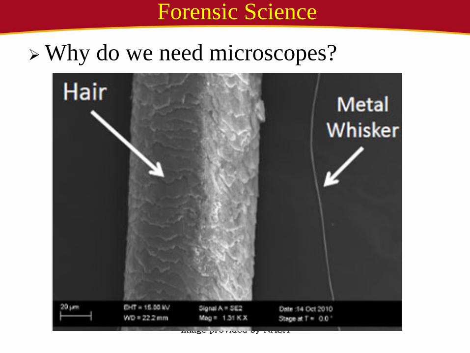
Forensic Science
Why do we need microscopes?
Image provided by NASA

How do we know we have found one? After optical observations of something that looks like a
protrusion growing out of the surface, we confirmed our suspicion by elemental analysis using X-ray diffraction (XRD)
In this test tin whisker growth was evident by the elemental tin peak (100% tin shown)
SEM Micrographs showing (a) whisker growth and (b) XRD analysis showing 100% tin peak

Whiskers Growing at Tuskegee Whiskers were found Growing from a Sample coupon
(a) (b) Figure 23: SEM micrograph showing long and bent whisker from scratched flat coupon after 5700 hour exposure to corrosive environment (aqueous NaCl); magnifications are 5000X (a) and 3000X (b)
(a) (b) Figure 24: SEM micrograph showing conjoined whiskers from scratched flat coupon after 7000 hours of exposure to corrosive environment (aqueous NaCl); magnification is 4000X.

Tin Whisker Growth - Factors
Intermetallic
Tin
Copper Substrate Courtesy of: A History of Tin Whisker Theory George T. Galyon IBM eSG Group
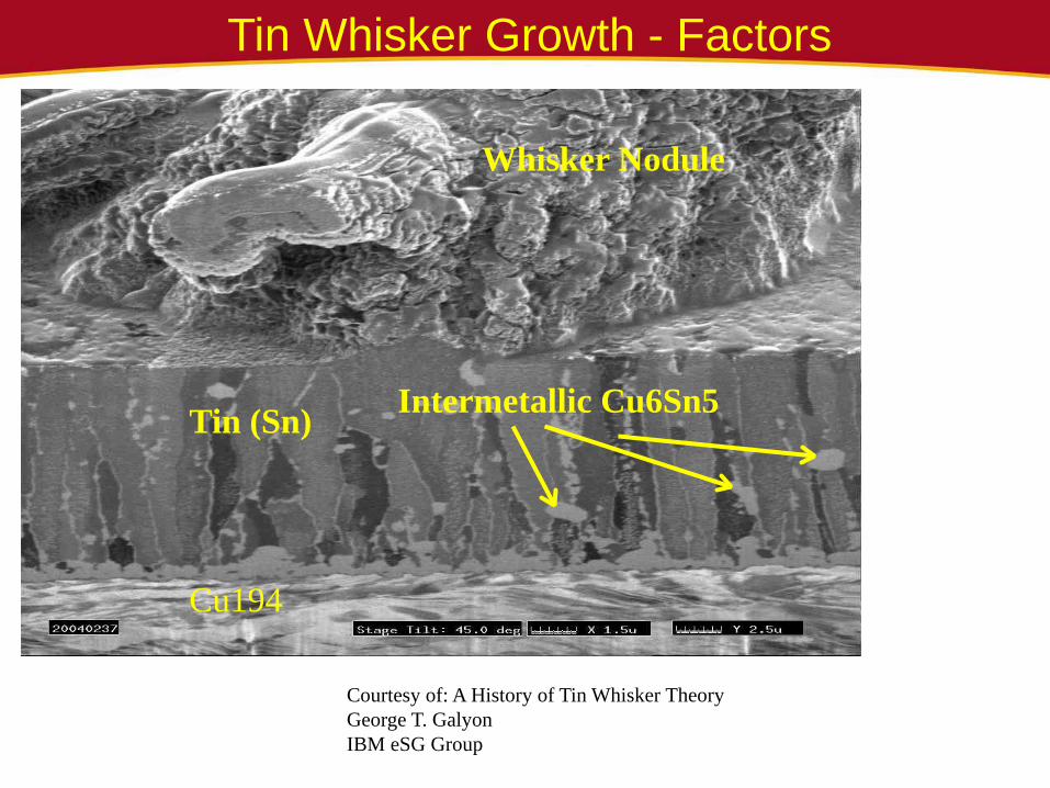
Tin Whisker Growth - Factors
Whisker Nodule
Intermetallic Cu6Sn5 Tin (Sn)
Cu194
Courtesy of: A History of Tin Whisker Theory George T. Galyon IBM eSG Group

Next Steps
Sectioning at the root
Whisker root analysis
Study the migration of binary compounds
Follow the trail