hazardous location el120 linear actuators
TRANSCRIPT
120 952.500.6200 | www.exlar.com
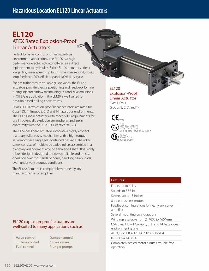
EL120 ATEX Rated Explosion-Proof Linear ActuatorsPerfect for valve control or other hazardous environment applications, the EL120 is a high performance electric actuator offered as a direct replacement to hydraulics. Exlar’s EL120 actuators offer a longer life, linear speeds up to 37 inches per second, closed loop feedback, 90% efficiency and 100% duty cycle.
For gas turbines with variable guide vanes, the EL120 actuators provide precise positioning and feedback for fine tuning injector airflow maintaining CO and NOx emissions. In Oil & Gas applications, the EL120 is well suited for position based drilling choke valves.
Exlar’s EL120 explosion-proof linear actuators are rated for Class I, Div 1, Groups B, C, D and T4 hazardous environments. The EL120 linear actuators also meet ATEX requirements for use in potentially explosive atmospheres and are in conformity with the EU ATEX Directive 94/9/EC.
The EL Series linear actuators integrate a highly efficient planetary roller screw mechanism with a high torque servomotor in a single self-contained package. The roller screw consists of multiple threaded rollers assembled in a planetary arrangement around a threaded shaft. This highly robust design is designed to provide reliable and precise operation over thousands of hours, handling heavy loads even under very arduous conditions.
The EL120 Actuator is compatable with nearly any manufactures’ servo amplifier.
Features
Forces to 4000 lbs
Speeds to 37.5 ips
Strokes up to 18 inches
8 pole brushless motorsFeedback configurations for nearly any servo amplifierSeveral mounting configurations
Windings available from 24 VDC to 460 VrmsCSA Class I, Div 1 Group B, C, D and T4 hazardous environment ratingATEX, Ex d II B +H2 T4 Gb IP66S, Type 4
IECEx CSA 14.0014Completely sealed motor assures trouble-free operation
Valve control Damper controlTurbine control Choke valvesFuel control Plunger pumps
EL120 explosion-proof actuators are well-suited to many applications such as:
Hazardous Location EL120 Linear Actuators
II 2GSIRA 10ATEX1037XIECEx CSA 14.0014Ex d II B +H2 T4 Gb IP66S, Type 4
0518
163694Class I, Div 1 Group B,C,D,T4
120 952.500.6200 | www.exlar.com
EL120 Explosion-Proof Linear ActuatorClass I, Div 1, Groups B, C, D, and T4
952.500.6200 | www.exlar.com 121
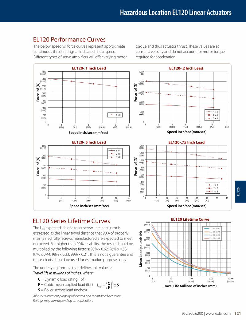
EL120 Performance CurvesThe below speed vs. force curves represent approximate continuous thrust ratings at indicated linear speed. Different types of servo amplifiers will offer varying motor
torque and thus actuator thrust. These values are at constant velocity and do not account for motor torque required for acceleration.
Speed inch/sec (mm/sec)
Forc
e lb
f (N
)
EL120-.1 Inch Lead3,500
(15569)
3000 (13345)
2,500 (11120)
2000 (8896)
1500 (6672)
1000 (4448)
500 (2224)
0
EL120-.1 Inch Lead
1 x 8
0 1 2 3 4 5 6 (25.4) (50.8) (76.2) (101.6) (127) (152.4)
Speed inch/sec (mm/sec)Fo
rce
lbf (
N)
EL120-.2 Inch Lead5,000
(XX)
4,000 (17793)
3,000 (13345)
2,000 (8896)
1,000 (4448)
0
EL120-.2 Inch Lead
1 x 82 x 83 x 8
0 2 4 6 8 10 12 (50.8) (101.6) (152.4) (203.2) (254) (304.8)
Speed inch/sec (mm/sec)
Forc
e lb
f (N
)
EL120-.5 Inch Lead2,500
(11120)
2000 (8896)
1500 (6672)
1000 (4448)
500 (2224)
0
EL120-.5 Inch Lead
1 x 82 x 83 x 8
0 5 10 15 20 25 30 (127) (254) (381) (508) (635) (762)
Hazardous Location EL120 Linear Actuators
Speed inch/sec (mm/sec)
Forc
e lb
f (N
)
EL120-.75 Inch Lead1,400
(6228)
1,200 (5338)
1,000 (4448)
800 (3559)
600 (2670)
400 (1779)
200 (890)
0
EL120-.75 Inch Lead
1 x 82 x 83 x 8
0 5 10 15 20 25 30 35 40 (127) (254) (381) (508) (635) (762)
EL12
0
The L10 expected life of a roller screw linear actuator is
expressed as the linear travel distance that 90% of properly maintained roller screws manufactured are expected to meet or exceed. For higher than 90% reliability, the result should be multiplied by the following factors: 95% x 0.62; 96% x 0.53; 97% x 0.44; 98% x 0.33; 99% x 0.21. This is not a guarantee and these charts should be used for estimation purposes only.
The underlying formula that defines this value is: Travel life in millions of inches, where:
C = Dynamic load rating (lbf ) F = Cubic mean applied load (lbf ) S = Roller screws lead (inches)
All curves represent properly lubricated and maintained actuators. Ratings may vary depending on application.
EL120 Series Lifetime CurvesEL120-xx01
EL120-xx02
EL120-xx05
EL120-xx08
6,000 (26689)
5,000 (22241)
4,000 (17793)
3,000 (13345)
2,000 (8896)
1,000 (4448)
500 (2224)
0
Travel Life Millions of inches (mm)
Mea
n L
oad
pou
nd
s (N
)
EL120 Lifetime Curve
1 10 100 1,000 10,000 (25.4) (254) (2,540) (25,400) (254,000)
L10
= ( C )3 x S
F
Hazardous Location EL120 Linear Actuators
122 952.500.6200 | www.exlar.com
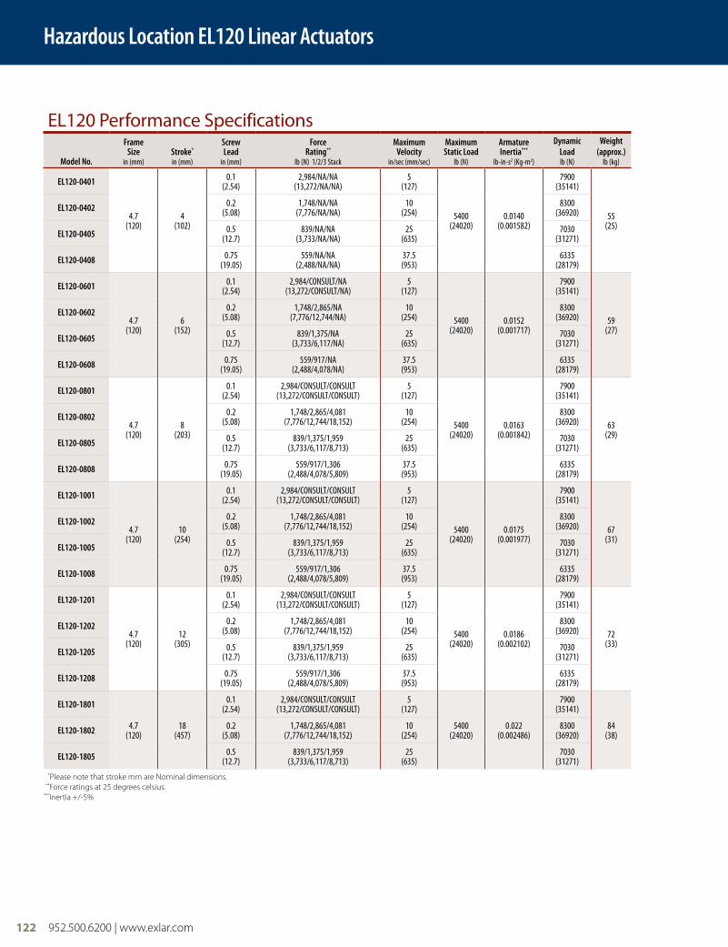
EL120 Performance Specifications
Model No.
FrameSize
in (mm)Stroke* in (mm)
ScrewLead
in (mm)
ForceRating**
lb (N) 1/2/3 Stack
MaximumVelocity
in/sec (mm/sec)
Maximum Static Load
lb (N)
Armature Inertia***
lb-in-s2 (Kg-m2)
Dynamic Loadlb (N)
Weight (approx.)
lb (kg)
EL120-0401
4.7 (120)
4 (102)
0.1 (2.54)
2,984/NA/NA (13,272/NA/NA)
5 (127)
5400 (24020)
0.0140 (0.001582)
7900 (35141)
55 (25)
EL120-0402 0.2 (5.08)
1,748/NA/NA (7,776/NA/NA)
10 (254)
8300 (36920)
EL120-0405 0.5 (12.7)
839/NA/NA (3,733/NA/NA)
25 (635)
7030 (31271)
EL120-0408 0.75 (19.05)
559/NA/NA (2,488/NA/NA)
37.5 (953)
6335 (28179)
EL120-0601
4.7 (120)
6 (152)
0.1 (2.54)
2,984/CONSULT/NA (13,272/CONSULT/NA)
5 (127)
5400 (24020)
0.0152 (0.001717)
7900 (35141)
59 (27)
EL120-0602 0.2 (5.08)
1,748/2,865/NA (7,776/12,744/NA)
10 (254)
8300 (36920)
EL120-0605 0.5 (12.7)
839/1,375/NA (3,733/6,117/NA)
25 (635)
7030 (31271)
EL120-0608 0.75 (19.05)
559/917/NA (2,488/4,078/NA)
37.5 (953)
6335 (28179)
EL120-0801
4.7 (120)
8 (203)
0.1 (2.54)
2,984/CONSULT/CONSULT (13,272/CONSULT/CONSULT)
5 (127)
5400 (24020)
0.0163 (0.001842)
7900 (35141)
63 (29)
EL120-0802 0.2 (5.08)
1,748/2,865/4,081 (7,776/12,744/18,152)
10 (254)
8300 (36920)
EL120-0805 0.5 (12.7)
839/1,375/1,959 (3,733/6,117/8,713)
25 (635)
7030 (31271)
EL120-0808 0.75 (19.05)
559/917/1,306 (2,488/4,078/5,809)
37.5 (953)
6335 (28179)
EL120-1001
4.7 (120)
10 (254)
0.1 (2.54)
2,984/CONSULT/CONSULT (13,272/CONSULT/CONSULT)
5 (127)
5400 (24020)
0.0175 (0.001977)
7900 (35141)
67 (31)
EL120-1002 0.2 (5.08)
1,748/2,865/4,081 (7,776/12,744/18,152)
10 (254)
8300 (36920)
EL120-1005 0.5 (12.7)
839/1,375/1,959 (3,733/6,117/8,713)
25 (635)
7030 (31271)
EL120-1008 0.75 (19.05)
559/917/1,306 (2,488/4,078/5,809)
37.5 (953)
6335 (28179)
EL120-1201
4.7 (120)
12 (305)
0.1 (2.54)
2,984/CONSULT/CONSULT (13,272/CONSULT/CONSULT)
5 (127)
5400 (24020)
0.0186 (0.002102)
7900 (35141)
72 (33)
EL120-1202 0.2 (5.08)
1,748/2,865/4,081 (7,776/12,744/18,152)
10 (254)
8300 (36920)
EL120-1205 0.5 (12.7)
839/1,375/1,959 (3,733/6,117/8,713)
25 (635)
7030 (31271)
EL120-1208 0.75 (19.05)
559/917/1,306 (2,488/4,078/5,809)
37.5 (953)
6335 (28179)
EL120-1801
4.7 (120)
18 (457)
0.1 (2.54)
2,984/CONSULT/CONSULT (13,272/CONSULT/CONSULT)
5 (127)
5400 (24020)
0.022 (0.002486)
7900 (35141)
84 (38)EL120-1802 0.2
(5.08)1,748/2,865/4,081
(7,776/12,744/18,152)10
(254)8300
(36920)
EL120-1805 0.5 (12.7)
839/1,375/1,959 (3,733/6,117/8,713)
25 (635)
7030 (31271)
*Please note that stroke mm are Nominal dimensions. **Force ratings at 25 degrees celsius.***Inertia +/-5%

FT80 Series Linear Actuators
952.500.6200 | www.exlar.com 123
Hazardous Location EL120 Linear Actuators
EL120 Electrical/Mechanical SpecificationsNominal Backlash in (mm) 0.004 (0.10)
Maximum Backlash (preloaded) in (mm) 0.0
Lead Accuracy in/ft (mm/300 mm) 0.001 (0.025)
Maximum Radial Load lb (N) 40 (179)
Environmental Rating Standard IP66S
Motor StatorAmbient Temperature
11825˚C
13825˚C
15825˚C
16825˚C
23825˚C
25825˚C
26825˚C
33825˚C
35825˚C
36825˚C
RMS SINUSOIDAL COMMUTATION DATA
Continuous Motor Torque lbf-in(N-m)
74.1 (8.37)
74.1 (8.37)
74.3 (8.39)
74.1 (8.37)
123.6 (13.96)
121.4 (13.72)
123.6 (13.96)
172.3 (19.46)
168.9 (19.09)
176.9 (19.98)
Peak Motor Torque lbf-in(N-m)
148.20 (16.74)
148.20 (16.74)
148.60 (16.79)
148.10 (16.74)
247.20 (27.93)
242.80 (27.43)
247.20 (27.93)
344.50 (38.93)
337.80 (38.17)
353.70 (39.96)
Torque Constant (Kt) lbf-in (N-m/A)
4.30(0.49)
8.70(1.00)
15.70(1.80)
17.30(2.00)
8.70(1.00)
15.80(1.80)
17.30(2.00)
8.50(1.00)
15.80(1.80)
17.50(2.00)
Continuous Current Rating Greased (IG) A 19.10 9.50 5.30 4.80 15.90 8.60 8.00 22.70 11.90 11.30
Peak Current Rating A 38.20 19.10 10.60 9.50 31.80 17.10 15.90 45.40 23.80 22.50
O-PEAK SINUSOIDAL COMMUTATION
Continuous Motor Torque lbf-in(N-m)
74.1(8.37)
74.1(8.37)
74.3(8.39)
74.1(8.37)
123.6(13.96)
121.4(13.72)
123.6(13.96)
172.3(19.46)
168.9(19.09)
176.9(19.98)
Peak Motor Torque lbf-in(N-m)
148.20(16.74)
148.20(16.74)
148.60(16.79)
148.10(16.74)
247.20(27.93)
242.80(27.43)
247.20(27.93)
344.50(38.93)
337.80(38.17)
353.70(39.96)
Torque Constant (Kt) lbf-in/A(N-m/A)
3.10(0.35)
6.10(0.70)
11.10(1.30)
12.30(1.40)
6.10(0.70)
11.20(1.30)
12.30(1.40)
6.00(0.70)
11.20(1.30)
12.40(1.40)
Continuous Current Rating Greased (IG) A 27.00 13.50 7.50 6.70 22.50 12.10 11.30 32.10 16.90 15.90
Peak Current Rating A 54.00 27.00 15.00 13.50 45.00 24.20 22.50 64.20 33.70 31.90
MOTOR DATA
Voltage Constant @ 25˚C (Ke) Vrms/Krpm 29.6(41.9)
59.2(83.8)
106.9(151.2)
118.5(167.6)
59.2(83.8)
108.2(153.0)
118.5(167.6)
58.0(82.0)
108.2(153.0)
119.8(169.4)
Pole Configuration 8 8 8 8 8 8 8 8 8 8
Resistance (L-L) Ohms 0.20 0.80 2.60 3.21 0.34 1.17 1.35 0.20 0.72 0.81
Inductance (L-L) mH 3.30 11.90 42.40 48.30 5.90 21.10 25.30 3.70 11.60 17.10
Brake Inertia lbf-in-sec2 (kg-cm2) 0.00146 (1.66)
Brake Current @24 VDC +/- 10% A 1.0
Brake Holding Torque - Dry lbf-in (Nm/A) 177 (20)
Brake Engage/Disengage Time ms 13/50
Mechanical Time Constant (tm) ms 0.79 0.79 0.79 0.79 0.60 0.63 0.60 0.54 0.56 0.51
Electrical Time Constant (te) ms 16.26 14.88 16.34 15.06 17.60 18.06 18.72 18.51 16.06 21.16
Friction Torque lbf-in (N-m) 1.43(0.16)
1.43(0.16)
1.43(0.16)
1.43(0.16)
1.81(0.20)
1.81(0.20)
1.81(0.20)
2.32(0.26)
2.32(0.26)
2.32(0.26)
Bus Voltage Vrms 115 230 400 460 230 400 460 230 400 460
Speed @ Bus Voltage rpm 3,000 3,000 3,000 3,000 3,000 3,000 3,000 3,000 3,000 3,000
Insulation Class 180(H)
Ambient Temperature Rating -29°C to 93°C
Insulation System Voltage Rating T4, 135° Maximum Allowable Surface Temperature
Test data derived using NEMA recommended aluminum heatsink 12" x 12" x 1/2"
EL12
0
124 952.500.6200 | www.exlar.com
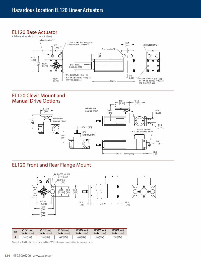
EL120 Base ActuatorAll dimensions shown in mm (inches)
EL120 Clevis Mount and Manual Drive Options
EL120 Front and Rear Flange Mount
Hazardous Location EL120 Linear Actuators
120.04.72
120.04.72
202.27.96
150.25.91
67.32.65
"N" = 4X M10x1.5 19 [.75]"H" = 4X 3/8-16 UNC 19 [.75]ON 90.00 [3.544]
2X 3/4-14 NPT Wire entry portsShown on Port Location "F"
Port Location "L"
Ø 65 mm h7[2.559 +0/-.001]
DIM "A"
7.6.30
67.92.68
120.04.72
Port Location "R"
220.08.66
180.07.09
140.005.512
120.04.72
90.03.54
80.003.150
4X Ø 16.5.65
4X Ø 8.000 ±0.025.315 ±.001
18.0.71 DIM "A"
18.0.71
Port Location "B"
"N" = 4X M10x1.5 19 [.75]"H" = 4X 3/8-16 UNC 19 [.75]ON 90.00 [3.544]
"G" = Ø 20mm H7"C" = Ø .750 IN +.002/-.001
R19.1.75
DIM "A" + 127.0 [5.00]48.31.90
31.81.25
63.52.50
206.28.12
194.37.65
178.17.01
HAND CRANKMANUAL DRIVE
165.36.51
HEX 19 [.75]
HEXMANUAL DRIVE
Ø 152.46.00
179.97.08
HANDWHEELMANUAL DRIVE
Dim 4" (102 mm) Stroke in (mm)
6" (152 mm) Stroke in (mm)
8" (203 mm) Stroke in (mm)
10" (254 mm) Stroke in (mm)
12" (305 mm) Stroke in (mm)
18" (457 mm) Stroke in (mm)
A 345 (13.6) 396 (15.6) 447 (17.6) 498 (19.6) 549 (21.6) 701 (27.6)
Note: Add 1.63 Inches (41.4 mm) to Dims “A” if ordering a brake without a manual drive.
952.500.6200 | www.exlar.com 125
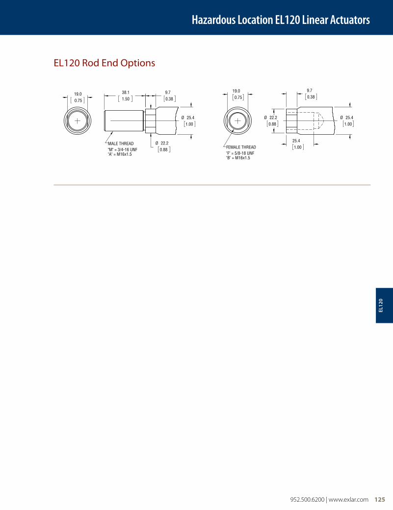
EL120 Rod End Options
Hazardous Location EL120 Linear ActuatorsEL120 ROD END OPTIONS
Dimensions shown in mm [ inches ]
38.11.50
Ø 22.20.88
Ø 25.41.00
9.70.38
MALE THREAD"M" = 3/4-16 UNF"A" = M16x1.5
19.00.75
9.70.38
Ø 22.20.88
Ø 25.41.00
25.41.00
19.00.75
FEMALE THREAD"F" = 5/8-18 UNF"B" = M16x1.5
EL12
0
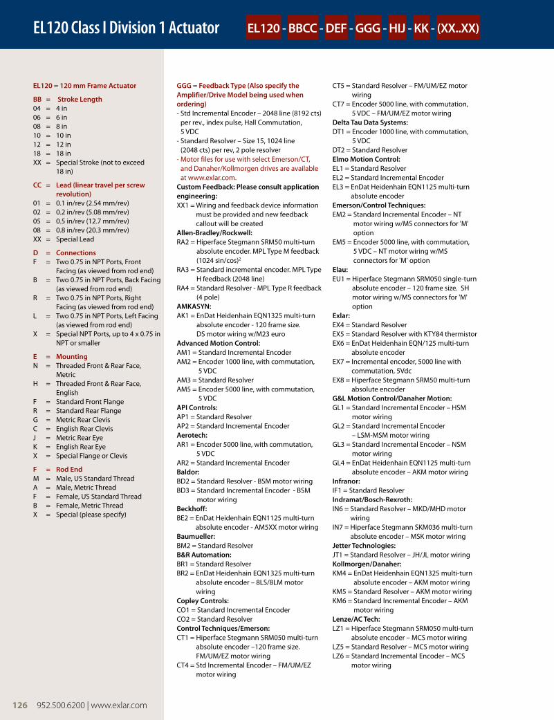
EL120 Class I Division 1 Actuator
EL120 = 120 mm Frame Actuator
BB = Stroke Length04 = 4 in06 = 6 in08 = 8 in10 = 10 in12 = 12 in18 = 18 inXX = Special Stroke (not to exceed
18 in)
CC = Lead (linear travel per screw revolution)
01 = 0.1 in/rev (2.54 mm/rev)02 = 0.2 in/rev (5.08 mm/rev)05 = 0.5 in/rev (12.7 mm/rev)08 = 0.8 in/rev (20.3 mm/rev)XX = Special Lead
D = ConnectionsF = Two 0.75 in NPT Ports, Front
Facing (as viewed from rod end)B = Two 0.75 in NPT Ports, Back Facing
(as viewed from rod end)R = Two 0.75 in NPT Ports, Right
Facing (as viewed from rod end)L = Two 0.75 in NPT Ports, Left Facing
(as viewed from rod end)X = Special NPT Ports, up to 4 x 0.75 in
NPT or smaller
E = MountingN = Threaded Front & Rear Face,
MetricH = Threaded Front & Rear Face,
EnglishF = Standard Front FlangeR = Standard Rear FlangeG = Metric Rear ClevisC = English Rear ClevisJ = Metric Rear EyeK = English Rear EyeX = Special Flange or Clevis
F = Rod EndM = Male, US Standard ThreadA = Male, Metric ThreadF = Female, US Standard ThreadB = Female, Metric ThreadX = Special (please specify)
GGG = Feedback Type (Also specify the Amplifier/Drive Model being used when ordering)- Std Incremental Encoder – 2048 line (8192 cts)
per rev., index pulse, Hall Commutation, 5 VDC
- Standard Resolver – Size 15, 1024 line (2048 cts) per rev, 2 pole resolver
- Motor files for use with select Emerson/CT, and Danaher/Kollmorgen drives are available at www.exlar.com.
Custom Feedback: Please consult application engineering:XX1 = Wiring and feedback device information
must be provided and new feedback callout will be created
Allen-Bradley/Rockwell: RA2 = Hiperface Stegmann SRM50 multi-turn
absolute encoder. MPL Type M feedback (1024 sin/cos)2
RA3 = Standard incremental encoder. MPL Type H feedback (2048 line)
RA4 = Standard Resolver - MPL Type R feedback (4 pole)
AMKASYN:AK1 = EnDat Heidenhain EQN1325 multi-turn
absolute encoder - 120 frame size. DS motor wiring w/M23 euro
Advanced Motion Control:AM1 = Standard Incremental Encoder AM2 = Encoder 1000 line, with commutation,
5 VDCAM3 = Standard ResolverAM5 = Encoder 5000 line, with commutation,
5 VDCAPI Controls:AP1 = Standard ResolverAP2 = Standard Incremental Encoder Aerotech:AR1 = Encoder 5000 line, with commutation,
5 VDCAR2 = Standard Incremental Encoder Baldor:BD2 = Standard Resolver - BSM motor wiringBD3 = Standard Incremental Encoder - BSM
motor wiringBeckhoff:BE2 = EnDat Heidenhain EQN1125 multi-turn
absolute encoder - AM5XX motor wiringBaumueller:BM2 = Standard ResolverB&R Automation:BR1 = Standard ResolverBR2 = EnDat Heidenhain EQN1325 multi-turn
absolute encoder – 8LS/8LM motor wiring
Copley Controls:CO1 = Standard Incremental EncoderCO2 = Standard ResolverControl Techniques/Emerson:CT1 = Hiperface Stegmann SRM050 multi-turn
absolute encoder –120 frame size. FM/UM/EZ motor wiring
CT4 = Std Incremental Encoder – FM/UM/EZ motor wiring
CT5 = Standard Resolver – FM/UM/EZ motor wiring
CT7 = Encoder 5000 line, with commutation, 5 VDC – FM/UM/EZ motor wiring
Delta Tau Data Systems:DT1 = Encoder 1000 line, with commutation,
5 VDCDT2 = Standard ResolverElmo Motion Control:EL1 = Standard ResolverEL2 = Standard Incremental EncoderEL3 = EnDat Heidenhain EQN1125 multi-turn
absolute encoderEmerson/Control Techniques:EM2 = Standard Incremental Encoder – NT
motor wiring w/MS connectors for 'M' option
EM5 = Encoder 5000 line, with commutation, 5 VDC – NT motor wiring w/MS connectors for 'M' option
Elau:EU1 = Hiperface Stegmann SRM050 single-turn
absolute encoder – 120 frame size. SH motor wiring w/MS connectors for 'M' option
Exlar:EX4 = Standard ResolverEX5 = Standard Resolver with KTY84 thermistorEX6 = EnDat Heidenhain EQN/125 multi-turn
absolute encoder EX7 = Incremental encoder, 5000 line with
commutation, 5Vdc EX8 = Hiperface Stegmann SRM50 multi-turn
absolute encoderG&L Motion Control/Danaher Motion:GL1 = Standard Incremental Encoder – HSM
motor wiringGL2 = Standard Incremental Encoder
– LSM-MSM motor wiringGL3 = Standard Incremental Encoder – NSM
motor wiringGL4 = EnDat Heidenhain EQN1125 multi-turn
absolute encoder – AKM motor wiringInfranor:IF1 = Standard ResolverIndramat/Bosch-Rexroth:IN6 = Standard Resolver – MKD/MHD motor
wiringIN7 = Hiperface Stegmann SKM036 multi-turn
absolute encoder – MSK motor wiringJetter Technologies:JT1 = Standard Resolver – JH/JL motor wiringKollmorgen/Danaher:KM4 = EnDat Heidenhain EQN1325 multi-turn
absolute encoder – AKM motor wiringKM5 = Standard Resolver – AKM motor wiringKM6 = Standard Incremental Encoder – AKM
motor wiringLenze/AC Tech: LZ1 = Hiperface Stegmann SRM050 multi-turn
absolute encoder – MCS motor wiringLZ5 = Standard Resolver – MCS motor wiringLZ6 = Standard Incremental Encoder – MCS
motor wiring
EL120 - BBCC - DEF - GGG - HIJ - KK - (XX..XX)
126 952.500.6200 | www.exlar.com

EL120 Class I Division 1 Actuator Ordering Information
Metronix:MX1 = Standard ResolverMX2 = Hiperface Stegmann SKM036 multi-turn
absolute encoderMX3 = EnDat Heidenhain EQN1125 multi-turn
absolute encoderMomentum:MN1 = Hiperface Stegmann SRM050 multi-turn
absolute encoder - MN motor wiringMN2 = EnDat Heidenhain EQN1325 multi-turn
absolute encoder - MN motor wiringMN3 = Std incremental encoder - MN motor
wiringMN4 = Std resolver - MN motor wiringMoog:MG1 = Standard ResolverOrmec:OR1 = Standard Resolver OR2 = Standard Incremental Encoder – G series
motor wiringParker Compumotor:PC6 = Standard Incremental Encoder – SMH
motor wiringPC7 = Standard Resolver – SMH motor wiringPC8 = Standard Incremental Encoder – MPP
series motor wiringPC9 = Hiperface Stegmann SRM050 multi-turn
absolute encoder – MPP motor wiringPC0 = Standard Resolver – MPP motor wiringPacific Scientific:PS2 = Standard Incremental EncoderPS3 = Standard Resolver – PMA motor wiringStober Drives:SB2 = Standard resolver ED/EK motor wiring SB3 = EnDat Heidenhain EQN1125 multi-turn
absolute encoder – ED/EK motor wiringSiemens:SM2 = Standard Resolver – 1FK7 motor wiringSM3 = EnDat Heidenhain EQN1325 multi-turn
absolute enc. 120 frame. 1FK7 motor wiring
SEW/Eurodrive:SW1 = Standard Resolver – CM motor wiringSW2 = Standard Incremental EncoderSW3 = Hiperface Stegmann SRM050 multi-turn
absolute encoder – CM motor wiring
H = Motor Stator1 = 1 stack motor2 = 2 stack motor3 = 3 stack motor
I = Rated Voltage1 = 115 Volt RMS 3 = 230 Volt RMS 5 = 400 Volt RMS 6 = 460 Volt RMS X = Special Voltage (voltage not to exceed 460
Volt RMS)
J = Motor Poles8 = 8 pole motor
KK = Rated Motor Speed at Rated Voltage01 - 45 Two digit number x 100 = rated RPM
(XX..XX) = Mechanical Option (Multiple options may apply, separated by "-"XL = Special lubrication, Mobilgrease 28 or other
(please specify)PF = Preloaded follower1
AR = External anti-rotate assemblyRB = Rear brakeHW = Handwheel Drive - StandardSD = Side Hex DriveCD = Crank DriveXT = Special Housing Option - See list below Non standard roller count Deep groove ball bearings Stainless steel main rodXH = Special Housing Option Special coating
##### = Part Number5 digit numeric part number unique to model configuration
Notes:1. The dynamic load rating of zero backlash, preloaded screws
is 63% of the dynamic load rating of the standard non-preloaded screws. The calculated travel life of a preloaded screw will be 25% of the same size and lead of a non-preloaded screw.
2. Not compatible with Kinetix 300 Drives.
952.500.6200 | www.exlar.com 127
EL12
0
FT60 Series Linear Actuators
128 952.500.6200 | www.exlar.com
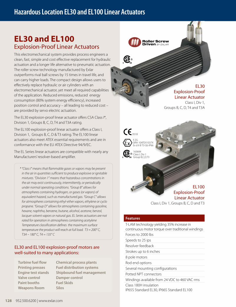
EL30 and EL100 Explosion-Proof Linear ActuatorsThis electromechanical system provides process engineers a clean, fast, simple and cost effective replacement for hydraulic actuation and a longer life alternative to pneumatic actuation. The roller screw technology manufactured by Exlar outperforms rival ball screws by 15 times in travel life, and can carry higher loads. The compact design allows users to effectively replace hydraulic or air cylinders with an electromechanical actuator, yet meet all required capabilities of the application. Reduced emissions, reduced energy consumption (80% system energy efficiency), increased position control and accuracy – all leading to reduced cost – are provided by servo electric actuation.
The EL30 explosion-proof linear actuator offers CSA Class I*, Division 1, Groups B, C, D, T4 and T3A rating.
The EL100 explosion-proof linear actuator offers a Class I, Division 1, Groups B, C, D & T3 rating. The EL100 linear actuators also meet ATEX essential requirements and are in conformance with the EU ATEX Directive 94/9/EC.
The EL Series linear actuators are compatible with nearly any Manufacturers’ resolver-based amplifier.
* “Class I” means that flammable gases or vapors may be present in the air in quantities sufficient to produce explosive or ignitable mixtures. “Division 1” means that hazardous concentrations in the air may exist continuously, intermittently, or periodically under normal operating conditions. “Group B” allows for atmospheres containing hydrogen, or gases (or vapors) of equivalent hazard, such as manufactured gas. “Group C” allows for atmospheres containing ethyl-ether vapors, ethylene or cyclo propane. “Group D” allows for atmospheres containing gasoline, hexane, naphtha, benzene, butane, alcohol, acetone, benzol, lacquer solvent vapors or natural gas. EL Series actuators are not rated for operation in atmospheres containing acetylene Temperature classification defines the maximum surface temperature the product will reach at full load. T3 = 200° C, T3A – 180° C, T4 = 135° C
Features
T-LAM technology yielding 35% increase in continuous motor torque over traditional windings Forces to 2000 lbs
Speeds to 25 ips
Resolver feedback
Strokes up to 6 inches
8 pole motors
Rod end options
Several mounting configurations
Potted NPT connectors
Windings available from 24 VDC to 460 VAC rmsClass 180H insulationIP65S Standard EL30, IP66S Standard EL100
Turbine fuel flow Chemical process plantsPrinting presses Fuel distribution systemsEngine test stands Shipbound fuel managementValve control Damper controlPaint booths Fuel SkidsWeapons Room Silos
EL30 and EL100 explosion-proof motors are well-suited to many applications:
Hazardous Location EL30 and EL100 Linear Actuators
EL30 Explosion-Proof Linear Actuator
Class I, Div 1, Groups B, C, D, T4 and T3A
EL100 Explosion-Proof Linear Actuator
Class I, Div 1, Groups B, C, D and T3
II 2GSIRA 10ATEX1037XEx d II B T3 Gb IP66
0518
163694Class I, Div 1 Group B,C,D,T3
128 952.500.6200 | www.exlar.com

FT80 Series Linear Actuators
952.500.6200 | www.exlar.com 129
EL Series Performance CurvesThe below speed vs. force curves represent approximate continuous thrust ratings at indicated linear speed. Different types of servo amplifiers will offer varying motor
torque and thus actuator thrust. These values are at constant velocity and do not account for motor torque required for acceleration.
Speed inch/sec (mm/sec)
Forc
e lb
f (N
)
EL30-.1 Inch Lead1000
(4448)900
(4003)800
(3559)700
(3114)600
(2669)500
(2224)400
(1779)300
(1334)200
(890)100
(445)0
1X82X8
0 1 2 3 4 5 6 (25.4) (50.8) (76.2) (101.6) (127) (152.4)
Speed inch/sec (mm/sec)Fo
rce
lbf (
N)
EL30-.2 Inch Lead1000
(4448)900
(4003)800
(3559)700
(3114)600
(2669)500
(2224)400
(1779)300
(1334)200
(890)100
(445)0
1X82X83X8
0 2 4 6 8 10 12 (50.8) (101.6) (152.4) (203.2) (254) (304.8)
Speed inch/sec (mm/sec)
Forc
e lb
f (N
)
EL30-.5 Inch Lead450
(2002)400
(1779)350
(1557)300
(1334)250
(1112)200
(890)150
(667)100
(445)50
(222)0
1X82X83X8
0 5 10 15 20 25 30 (127) (254) (381) (508) (635) (762)
Hazardous Location EL30 and EL100 Linear Actuators
Speed inch/sec (mm/sec)
EL100 Speed Force
inch (mm)sec
Forc
e lb
f (KN
)
800 2000 4000 (3.6) (8.9) (17.8)
600 1500 3000 (2.7) (6.7) 13.3)
400 1000 2000 (1.8) (4.4) (8.9)
200 500 1000 (0.9) (2.2) (4.4)
0 0 0
0 1.67 (42.4) 3.33 (84.6) 5.0 (127.0) 6.67 (169.4) 8.33 (211.6)
0 3.33 (84.6) 6.67 (169.4) 10.0 (254.0) 13.33 (338.6) 16.67 (423.4)
0 8.33 (211.6) 16.67 (423.4) 25.0 (635.0) 33.33 (846.6) 41.67 (1058.4)
0.5 0.2 0.1 (12.70) (5.08) (2.54)
Lead inch (mm) Max Speed Max Speed Max Speed -10 Stators -25 Stators -40 Stators
25˚C peak80˚C peak25˚C cont80˚C cont
Lead inch (mm)0.1 (2.54)0.2 (5.08)0.5 (12.70)
EL100 Speed Force
EL30
& 1
00
130 952.500.6200 | www.exlar.com
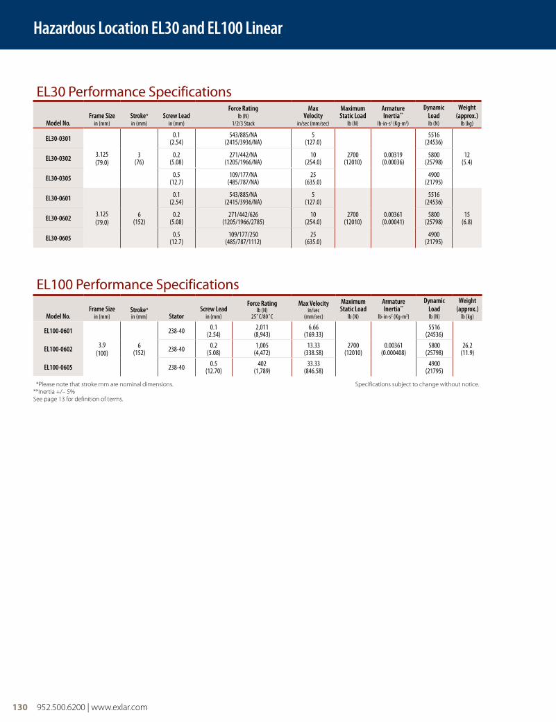
EL30 Performance Specifications
Model No.Frame Size
in (mm)Stroke*in (mm)
Screw Leadin (mm)
Force Ratinglb (N)
1/2/3 Stack
MaxVelocity
in/sec (mm/sec)
Maximum Static Load
lb (N)
Armature Inertia**
lb-in-s2 (Kg-m2)
Dynamic Loadlb (N)
Weight (approx.)
lb (kg)
EL30-0301
3.125(79.0)
3(76)
0.1(2.54)
543/885/NA(2415/3936/NA)
5 (127.0)
2700(12010)
0.00319(0.00036)
5516(24536)
12(5.4)EL30-0302 0.2
(5.08)271/442/NA
(1205/1966/NA)10
(254.0)5800
(25798)
EL30-0305 0.5(12.7)
109/177/NA(485/787/NA)
25 (635.0)
4900(21795)
EL30-0601
3.125(79.0)
6(152)
0.1(2.54)
543/885/NA(2415/3936/NA)
5 (127.0)
2700(12010)
0.00361(0.00041)
5516(24536)
15(6.8)EL30-0602 0.2
(5.08)271/442/626
(1205/1966/2785)10
(254.0)5800
(25798)
EL30-0605 0.5(12.7)
109/177/250(485/787/1112)
25 (635.0)
4900(21795)
Hazardous Location EL30 and EL100 Linear
EL100 Performance Specifications
Model No.Frame Size
in (mm)Stroke*in (mm) Stator
Screw Leadin (mm)
Force Ratinglb (N)
25˚C/80˚C
Max Velocityin/sec
(mm/sec)
Maximum Static Load
lb (N)
Armature Inertia**
lb-in-s2 (Kg-m2)
Dynamic Loadlb (N)
Weight (approx.)
lb (kg)
EL100-0601
3.9(100)
6(152)
238-40 0.1(2.54)
2,011(8,943)
6.66 (169.33)
2700(12010)
0.00361(0.000408)
5516(24536)
26.2(11.9)EL100-0602 238-40 0.2
(5.08)1,005
(4,472)13.33
(338.58)5800
(25798)
EL100-0605 238-40 0.5(12.70)
402(1,789)
33.33(846.58)
4900(21795)
*Please note that stroke mm are nominal dimensions. Specifications subject to change without notice. **Inertia +/– 5%See page 13 for definition of terms.

952.500.6200 | www.exlar.com 131
EL30 Mechanical/Electrical SpecificationsMaximum Backlash (not preloaded) in (mm) 0.004 (.10)
Maximum Backlash (preloaded) in (mm) 0.0
Lead Accuracy in/ft (mm/300 mm) 0.001 (.025)
Maximum Radial Load lb (N) 30 (134)
Environmental Rating: Standard IP65S
Motor Stator-T4 Ratings 1A8 1B8 118 138 158 168 2A8 2B8 218 238 258 268 318* 338* 358* 368*
RMS SINUSOIDAL COMMUTATION
Continuous Motor Torque**
(+/– 10% @ 80˚C)lbf-in(Nm)
10.8(1.22)
10.8(1.22)
11.1(1.25)
11.0(1.24)
10.7(1.21)
10.5(1.18)
17.4(1.97)
17.4(1.97)
17.7(2.00)
17.8(2.01)
17.5(1.98)
17.5(1.98)
25.2(2.84)
24.9(2.81)
23.6(2.66)
22.5(2.55)
Torque Constant (Kt)**
(+/– 10% @ 80˚C)lbf-in/
(Nm/A)1.1
(0.13)1.1
(0.13)4.4
(0.49)8.7
(0.99)15.5
(1.75)17.5
(1.97)1.1
(0.13)1.1
(0.13)4.4
(0.49)8.7
(0.99)15.5
(1.75)17.5
(1.97)4.4
(0.50)8.7
(0.98)15.6
(1.77)13.7
(1.54)
Continuous Current Rating** A 10.7 10.7 2.8 1.4 0.8 0.7 17.3 17.3 4.5 2.3 1.3 1.1 6.3 3.2 1.7 1.8
Peak Current Rating A 21.3 21.3 5.7 2.8 1.5 1.3 34.5 34.5 9.0 4.5 2.5 2.2 12.7 6.4 3.4 3.7
O-PK SMUSOIDAL COMMUTATION
Continuous Motor Torque**
(+/– 10% @ 80˚C)lbf-in(Nm)
10.8(1.22)
10.8(1.22)
11.1(1.25)
11.0(1.24)
10.7(1.21)
10.5(1.18)
17.4(1.97)
17.4(1.97)
17.7(2.00)
17.8(2.01)
17.5(1.98)
17.5(1.97)
25.2(2.84)
24.9(2.81)
23.6(2.66)
23.6(2.67)
Torque Constant (Kt)**
(+/– 10% @ 80˚C)lbf-in/A(Nm/A)
0.8(0.09)
0.8(0.09)
3.1(0.35)
6.2(0.70)
11.0(1.24)
12.4(1.40)
0.8(0.09)
0.8(0.09)
3.1(0.35)
6.2(0.70)
11.0(1.24)
12.4(1.40)
3.1(0.35)
6.1(0.69)
11.1(1.25)
17.5(1.98)
Continuous Current Rating A 15.1 15.1 4.0 2.0 1.1 0.9 24.4 24.4 6.4 3.2 1.8 1.6 9.0 4.5 2.4 1.5
Peak Current Rating A 30.2 30.2 8.0 4.0 2.2 1.9 48.8 48.8 12.8 6.4 3.6 3.2 17.9 9.1 4.8 3.0
MOTOR STATOR DATA
Voltage Constant (Ke)** Vrms/Krpm 7.7 7.7 29.8 59.7 105.8 119.3 7.7 7.7 29.8 59.7 105.8 119.3 30.3 59.2 106.8 119.8
(+/– 10% @ 25˚C) Vpk/Krpm 10.9 10.9 42.2 84.5 149.7 168.7 10.9 10.9 42.2 84.4 149.7 168.7 42.9 83.7 151.0 169.4
Pole Configuration 8 8 8 8 8 8 8 8 8 8 8 8 8 8 8 8
Resistance (L-L)(+/– 5% @ 80˚C) Ohms 0.19 0.19 2.7 10.8 36.3 47.9 0.08 0.08 1.1 4.4 14.1 18.0 0.65 2.6 9.3 11.6
Inductance (L-L)(+/– 5%) mH 0.51 0.51 7.7 30.7 96.8 123.0 0.24 0.24 3.7 14.7 46.2 58.7 2.5 9.5 30.9 38.8
Electrical Time Constant (te) ms 2.7 2.7 2.9 2.8 2.7 2.6 3.2 3.2 3.3 3.4 3.3 3.3 3.8 3.7 3.3 3.3
Friction Torque lbf-in (Nm) 1.46 (0.17) 1.60 (0.18) 1.80 (0.20)
Bus Voltage Vrms 24VDC 48VDC 115 230 400 460 24VDC 48VDC 115 230 400 460 115 230 400 460
Speed @ Bus Voltage rpm 1500 3000 3000 3000 3000 3000 1500 3000 3000 3000 3000 3000 3000 3000 3000 3000
Insulation Class 180 (H)
Temperature Class ˚C T4 = 135˚C
Connectors Potted NPT Connectors Only
For amplifiers using peak sinusoidal ratings, multiply RMS sinusoidal Kt by 0.707 and current by 1.414. Specifications subject to change without notice.Specifications reflect 80˚C test environment
*Not available with 3" stroke**For T3A Temperature Class multiply Kt & Ke ratings by 0.83; Continuous Current by 1.245; Continuous Torque by 1.095
Hazardous Location EL30 Linear
EL30
& 1
00
132 952.500.6200 | www.exlar.com
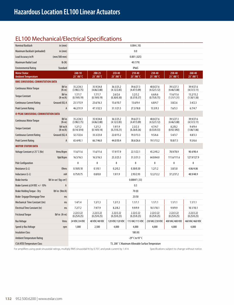
EL100 Mechanical/Electrical SpecificationsNominal Backlash in (mm) 0.004 (.10)
Maximum Backlash (preloaded) in (mm) 0.0
Lead Accuracy in/ft (mm/300 mm) 0.001 (.025)
Maximum Radial Load lb (N) 40 (179)
Environmental Rating Standard IP66S
Motor StatorAmbient Temperature
2A8-1025˚/80˚C
2B8-2525˚/80˚C
2C8-4025˚/80˚C
218-4025˚/80˚C
238-4025˚/80˚C
258-4025˚/80˚C
268-4025˚/80˚C
RMS SINUSOIDAL COMMUTATION DATA
Continuous Motor Torque lbf-in(N-m)
35.2/24.3(3.98/2.75)
35.9/24.8(4.06/2.80)
36.5/25.2(4.12/2.85)
39.6/27.3(4.47/3.09)
40.0/27.6(4.52/3.12)
39.5/27.3(4.46/3.08)
39.9/27.6(4.51/3.11)
Torque Constant lbf-in (N-m/A)
1.7/1.7(0.19/0.19)
1.7/1.7(0.19/0.19)
2.6/2.6(0.30/0.30)
3.2/3.2(0.37/0.37)
6.6/6.6(0.75/0.75)
11.6/11.6(1.31/1.31)
13.2/13.2(1.50/1.50)
Continuous Current Rating Greased (IG) A 23.1/15.9 23.6/16.3 15.6/10.7 13.6/9.4 6.8/4.7 3.8/2.6 3.4/2.3
Peak Current Rating A 46.2/31.9 47.1/32.5 31.1/21.5 27.3/18.8 13.5/9.3 7.6/5.3 6.7/4.7
O-PEAK SMUSOIDAL COMMUTATION DATA
Continuous Motor Torque lbf-in(N-m)
35.2/24.3(3.98/2.75)
35.9/24.8(4.06/2.80)
36.5/25.2(4.12/2.85)
39.6/27.3(4.47/3.09)
40.0/27.6(4.52/3.12)
39.5/27.3(4.46/3.08)
39.9/27.6(4.51/3.11)
Torque Constant lbf-in/A(N-m/A)
1.2/1.2(0.14/.014)
1.2/1.2(0.14/0.14)
1.9/1.9(0.21/0.21)
2.3/2.3(0.26/0.26)
4.7/4.7(0.53/0.53)
8.2/8.2(0.92/.092)
9.4/9.4(1.06/1.06)
Continuous Current Rating Greased (IG) A 32.7/22.6 33.3/23.0 22.0/15.2 19.3/13.3 9.5/6.6 5.4/3.7 4.8/3.3
Peak Current Rating A 65.4/45.1 66.7/46.0 44.0/30.4 38.6/26.6 19.1/13.2 10.8/7.5 9.5/6.6
MOTOR STATOR DATA
Voltage Constant @ 25˚C (Ke) Vrms/Krpm 11.6/11.6 11.6/11.6 17.9/17.9 22.1/22.1 45.2/45.2 78.9/78.9 90.4/90.4
Vpk/Krpm 16.5/16.5 16.5/16.5 25.3/25.3 31.3/31.3 64.0/64.0 111.6/111.6 127.9/127.9
Pole Configuration 8 8 8 8 8 8 8
Resistance (L-L) Ohms 0.10/0.10 0.1/0.1 0.2/0.2 0.30/0.30 1.2/1.2 3.8/3.8 4.86/4.86
Inductance (L-L) mH 0.75/0.75 0.8/0.8 1.9/1.9 2.93/2.93 12.2/12.2 37.2/37.2 48.9/48.9
Brake Inertia lbf-in-sec2 (kg-cm2) 0.00047 (.53)
Brake Current @24 VDC +/- 10% A 0.5
Brake Holding Torque - Dry lbf-in (Nm/A) 70 (8)
Brake Engage/Disengage Time ms 25/50
Mechanical Time Constant (tm) ms 1.4/1.4 1.3/1.3 1.3/1.3 1.1/1.1 1.1/1.1 1.1/1.1 1.1/1.1
Electrical Time Constant (te) ms 7.2/7.2 7.9/7.9 8.2/8.2 9.9/9.9 10.1/10.1 9.9/9.9 10.1/10.1
Frictional Torque lbf-in (N-m) 2.22/2.22(0.25/0.25)
2.22/2.22(0.25/0.25)
2.22/2.22(0.25/0.25)
2.22/2.22(0.25/0.25)
2.22/2.22(0.25/0.25)
2.22/2.22(0.25/0.25)
2.22/2.22(0.25/0.25)
Bus Voltage Vrms 24 VDC/24 VDC 48 VDC/48 VDC 120 VDC/120 VDC 115 VAC/115 VDC 230 VAC/230 VDC 400 VAC/400 VDC 460 VAC/460 VDC
Speed @ Bus Voltage rpm 1,000 2,500 4,000 4,000 4,000 4,000 4,000
Insulation Class 180 (H)
Ambient Temperature Rating -29° C to 93° C
CSA/ATEX Temperature Class T3, 200˚ C Maximum Allowable Surface Temperature For amplifiers using peak sinusoidal ratings, multiply RMS sinusoidal Kt by 0.707, and peak current by 1.414. Specifications subject to change without notice.
Hazardous Location EL100 Linear Actuators
FT80 Series Linear Actuators
952.500.6200 | www.exlar.com 133
Hazardous Location EL30 Linear Actuators
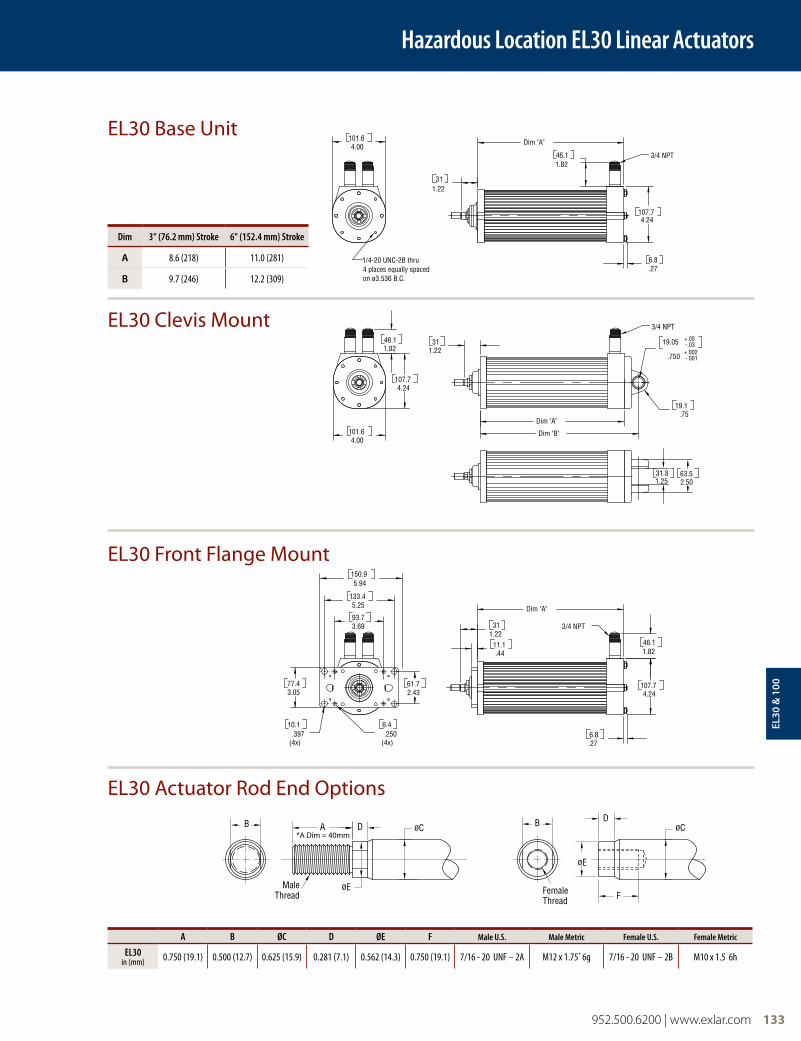
EL30 Base Unit
EL30 Clevis Mount
EL30 Front Flange Mount
EL30 Actuator Rod End Options
D
A
H
FG
øB
C
J K
E
AA
A
B
øA
C
D
F
E
D DE
øF
C
B
A
øG
HøJ
K
C CB
A
øE
øD
A
A
øC
øC
D
D
øE
øE
B
B
MaleThread
MaleThread
B
B
D
D
øE
øE
F
F
øC
øC
FemaleThread
FemaleThread
*A Dim = 40mm
A B ØC D ØE F Male U.S. Male Metric Female U.S. Female Metric
EL30in (mm) 0.750 (19.1) 0.500 (12.7) 0.625 (15.9) 0.281 (7.1) 0.562 (14.3) 0.750 (19.1) 7/16 - 20 UNF – 2A M12 x 1.75* 6g 7/16 - 20 UNF – 2B M10 x 1.5 6h
Dim 3" (76.2 mm) Stroke 6" (152.4 mm) Stroke
A 8.6 (218) 11.0 (281)
B 9.7 (246) 12.2 (309)
Dim "A"
Dim "B"
.750+.002-.001
19.05 +.05-.03
1.2231
.7519.1
1.2531.8
2.5063.5
1.8246.1
4.24107.7
4.00101.6
3/4 NPT
Dim "A"
1.2231
.4411.1
4.24107.7
.276.8
1.8246.1
5.94150.9
3.0577.4
2.4361.7
5.25133.4
3.6993.7
.250(4x)
6.4.397
(4x)
10.1
3/4 NPT
Dim "A"
4.24107.7
1.2231
.276.8
1.8246.1
4.00101.6
1/4-20 UNC-2B thru4 places equally spacedon ø3.536 B.C.
3/4 NPT
EL30
& 1
00

3.9099.1
3.9099.1
"M" = M8x1.25"H" = 5/16-24 UNF
Power and I/O(2x) 3/4 NPT
2.800 B.C.[71.1]
1.3233.5
"A"
1.9850.2
8.13206.4
8.80223.5
5.25133.4
6.80172.7
7.69195.3
2.9274.2
3.8096.4
4X .5213.1
4X .256.4
1.3233.5
.6315.9 "A"
"D"
.750 -.001+.002
1.9850.2
8.13206.4
8.80223.5
A D
E
C
MALE THREAD
E
D
F
CB B
FEMALE THREAD
1.2531.8
2.5063.5
"M" = M8x1.25"H" = 5/16-24 UNF
3.156 B.C.80.2
Hazardous Location EL100 Linear Actuators
134 952.500.6200 | www.exlar.com
EL100 Base Unit
EL100 Front Flange or Clevis Mount
EL100 Actuator Rod End Options
Dim No Brake Brake
A 11.9 (302.3) 14.2 (360.8)
A B ØC D ØE F Male "M" Inch Male "A" Metric Female "F" Inch Female "B" Metric
EL100in (mm) 1.250 (31.8) 0.625 (17.0) 0.787 (20.0) 0.281 (7.1) 0.725 (18.4) 1.000 (25.4) 1/2 - 20 UNF – 2A M16 x 1.5 6g 1/2 - 20 UNF – 2B M16 x 1.5 6h
Dim No Brake Brake
A 11.9 (302.3) 14.2 (360.8)
D 13.77 (349.9) 16.7 (408.2)
952.500.6200 | www.exlar.com 135
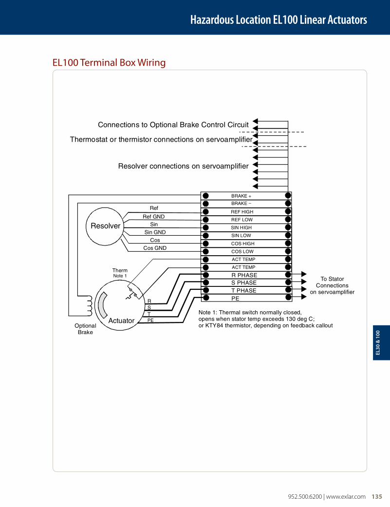
Hazardous Location EL100 Linear Actuators
EL100 Terminal Box Wiring
EL30
& 1
00
136 952.500.6200 | www.exlar.com
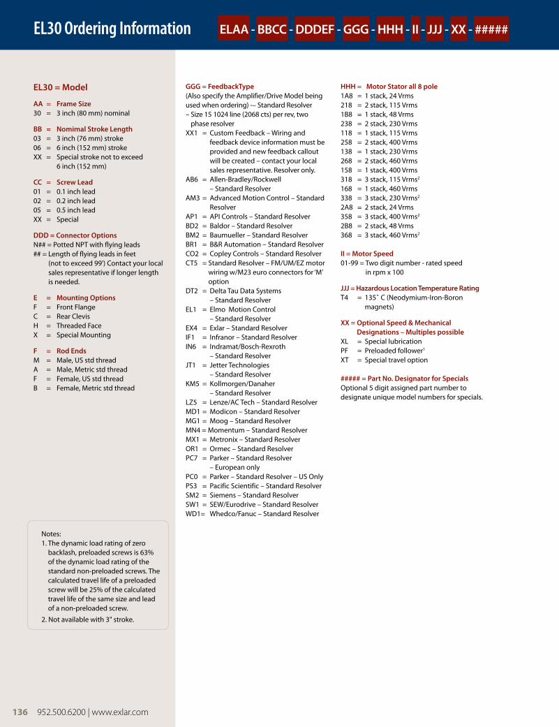
EL30 = Model
AA = Frame Size30 = 3 inch (80 mm) nominal
BB = Nomimal Stroke Length03 = 3 inch (76 mm) stroke06 = 6 inch (152 mm) strokeXX = Special stroke not to exceed
6 inch (152 mm)
CC = Screw Lead01 = 0.1 inch lead02 = 0.2 inch lead05 = 0.5 inch leadXX = Special
DDD = Connector OptionsN## = Potted NPT with flying leads## = Length of flying leads in feet
(not to exceed 99') Contact your local sales representative if longer length is needed.
E = Mounting OptionsF = Front FlangeC = Rear ClevisH = Threaded FaceX = Special Mounting
F = Rod EndsM = Male, US std threadA = Male, Metric std threadF = Female, US std threadB = Female, Metric std thread
Notes:1. The dynamic load rating of zero
backlash, preloaded screws is 63% of the dynamic load rating of the standard non-preloaded screws. The calculated travel life of a preloaded screw will be 25% of the calculated travel life of the same size and lead of a non-preloaded screw.
2. Not available with 3" stroke.
GGG = FeedbackType (Also specify the Amplifier/Drive Model being used when ordering) -– Standard Resolver – Size 15 1024 line (2068 cts) per rev, two
phase resolverXX1 = Custom Feedback – Wiring and
feedback device information must be provided and new feedback callout will be created – contact your local sales representative. Resolver only.
AB6 = Allen-Bradley/Rockwell – Standard Resolver
AM3 = Advanced Motion Control – Standard Resolver
AP1 = API Controls – Standard ResolverBD2 = Baldor – Standard Resolver BM2 = Baumueller – Standard ResolverBR1 = B&R Automation – Standard ResolverCO2 = Copley Controls – Standard ResolverCT5 = Standard Resolver – FM/UM/EZ motor
wiring w/M23 euro connectors for ‘M’ option
DT2 = Delta Tau Data Systems – Standard Resolver
EL1 = Elmo Motion Control – Standard Resolver
EX4 = Exlar – Standard ResolverIF1 = Infranor – Standard ResolverIN6 = Indramat/Bosch-Rexroth
– Standard ResolverJT1 = Jetter Technologies
– Standard ResolverKM5 = Kollmorgen/Danaher
– Standard ResolverLZ5 = Lenze/AC Tech – Standard ResolverMD1 = Modicon – Standard ResolverMG1 = Moog – Standard ResolverMN4 = Momentum – Standard ResolverMX1 = Metronix – Standard ResolverOR1 = Ormec – Standard ResolverPC7 = Parker – Standard Resolver
– European onlyPC0 = Parker – Standard Resolver – US OnlyPS3 = Pacific Scientific – Standard ResolverSM2 = Siemens – Standard ResolverSW1 = SEW/Eurodrive – Standard ResolverWD1= Whedco/Fanuc – Standard Resolver
HHH = Motor Stator all 8 pole1A8 = 1 stack, 24 Vrms218 = 2 stack, 115 Vrms1B8 = 1 stack, 48 Vrms238 = 2 stack, 230 Vrms118 = 1 stack, 115 Vrms258 = 2 stack, 400 Vrms138 = 1 stack, 230 Vrms268 = 2 stack, 460 Vrms158 = 1 stack, 400 Vrms318 = 3 stack, 115 Vrms2
168 = 1 stack, 460 Vrms338 = 3 stack, 230 Vrms2
2A8 = 2 stack, 24 Vrms358 = 3 stack, 400 Vrms2
2B8 = 2 stack, 48 Vrms368 = 3 stack, 460 Vrms2
II = Motor Speed01-99 = Two digit number - rated speed
in rpm x 100
JJJ = Hazardous Location Temperature RatingT4 = 135˚ C (Neodymium-Iron-Boron
magnets)
XX = Optional Speed & Mechanical Designations – Multiples possible
XL = Special lubricationPF = Preloaded follower1
XT = Special travel option
##### = Part No. Designator for Specials Optional 5 digit assigned part number to designate unique model numbers for specials.
ELAA - BBCC - DDDEF - GGG - HHH - II - JJJ - XX - #####EL30 Ordering Information
136 952.500.6200 | www.exlar.com
952.500.6200 | www.exlar.com 137
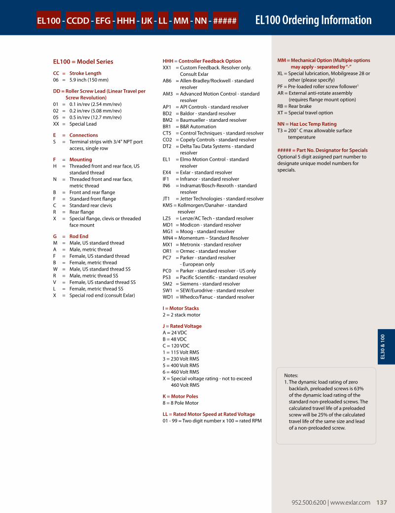
MM = Mechanical Option (Multiple options may apply - separated by “-”
XL = Special lubrication, Mobilgrease 28 or other (please specify)
PF = Pre-loaded roller screw follower1
AR = External anti-rotate assembly (requires flange mount option)
RB = Rear brakeXT = Special travel option
NN = Haz Loc Temp RatingT3 = 200˚ C max allowable surface
temperature
##### = Part No. Designator for Specials Optional 5 digit assigned part number to designate unique model numbers for specials.
EL100 = Model Series
CC = Stroke Length06 = 5.9 inch (150 mm)
DD = Roller Screw Lead (Linear Travel per Screw Revolution)
01 = 0.1 in/rev (2.54 mm/rev)02 = 0.2 in/rev (5.08 mm/rev)05 = 0.5 in/rev (12.7 mm/rev)XX = Special Lead
E = ConnectionsS = Terminal strips with 3/4" NPT port
access, single row
F = MountingH = Threaded front and rear face, US
standard threadN = Threaded front and rear face,
metric threadB = Front and rear flangeF = Standard front flangeC = Standard rear clevisR = Rear flangeX = Special flange, clevis or threaded
face mount
G = Rod EndM = Male, US standard threadA = Male, metric threadF = Female, US standard threadB = Female, metric threadW = Male, US standard thread SSR = Male, metric thread SSV = Female, US standard thread SSL = Female, metric thread SSX = Special rod end (consult Exlar)
HHH = Controller Feedback OptionXX1 = Custom Feedback. Resolver only.
Consult ExlarAB6 = Allen-Bradley/Rockwell - standard
resolverAM3 = Advanced Motion Control - standard
resolverAP1 = API Controls - standard resolverBD2 = Baldor - standard resolverBM2 = Baumueller - standard resolverBR1 = B&R AutomationCT5 = Control Techniques - standard resolverCO2 = Copely Controls - standard resolverDT2 = Delta Tau Data Systems - standard
resolverEL1 = Elmo Motion Control - standard
resolverEX4 = Exlar - standard resolverIF1 = Infranor - standard resolverIN6 = Indramat/Bosch-Rexroth - standard
resolverJT1 = Jetter Technologies - standard resolverKM5 = Kollmorgen/Danaher - standard
resolverLZ5 = Lenze/AC Tech - standard resolverMD1 = Modicon - standard resolverMG1 = Moog - standard resolverMN4 = Momentum – Standard Resolver MX1 = Metronix - standard resolverOR1 = Ormec - standard resolverPC7 = Parker - standard resolver
- European onlyPC0 = Parker - standard resolver - US only PS3 = Pacific Scientific - standard resolverSM2 = Siemens - standard resolverSW1 = SEW/Eurodrive - standard resolverWD1 = Whedco/Fanuc - standard resolver
I = Motor Stacks2 = 2 stack motor
J = Rated VoltageA = 24 VDCB = 48 VDCC = 120 VDC 1 = 115 Volt RMS3 = 230 Volt RMS5 = 400 Volt RMS6 = 460 Volt RMSX = Special voltage rating - not to exceed
460 Volt RMS
K = Motor Poles8 = 8 Pole Motor
LL = Rated Motor Speed at Rated Voltage 01 - 99 = Two digit number x 100 = rated RPM
EL100 - CCDD - EFG - HHH - IJK - LL - MM - NN - ##### EL100 Ordering Information
Notes:1. The dynamic load rating of zero
backlash, preloaded screws is 63% of the dynamic load rating of the standard non-preloaded screws. The calculated travel life of a preloaded screw will be 25% of the calculated travel life of the same size and lead of a non-preloaded screw.
952.500.6200 | www.exlar.com 137
EL30
& 1
00