having a distinct shear center -...
TRANSCRIPT

Annals of DAAAM for 2012 & Proceedings of the 23rd International DAAAM Symposium, Volume 23, No.1, ISSN 2304-1382
ISBN 978-3-901509-91-9, CDROM version, Ed. B. Katalinic, Published by DAAAM International, Vienna, Austria, EU, 2012
Make Harmony between Technology and Nature, and Your Mind will Fly Free as a Bird
Annals & Proceedings of DAAAM International 2012
IDEAS REGARDING THE MODELING OF THE BEHAVIOR OF THE SECTIONS
HAVING A DISTINCT SHEAR CENTER
OANTA, E[mil]; PANAIT, C[ornel]; SABAU, A[drian];
BARHALESCU, M[ihaela] L[uminita] & AXINTE, T[iberiu]
Abstract: One of the measures frequently undertaken to
minimize the cost of a structure is to use pre-engineered
members, such as I-shaped members. The designer must take
into consideration the behavior of such pre-engineered beams,
being aware about the applied elasticity phenomena which
might impose additional conditions regarding the numerical
model. The paper presents some interesting aspects regarding
the shear center issue, which may be applied in the concept and
the design of the structures. Beside the theoretical aspects,
there is presented a comparative study of two finite element
models. Some practical conclusions are drawn,together with
the identification of a new direction of study regarding the
automatic calculus of the structures.
Keywords:Shear center, applied elasticity, appropriate finite
element selection, practical solutions
1. INTRODUCTION
The cost minimization of the products is a basic
objective for all the engineering team involved in
concept, design, testing, manufacturing and maintenance.
If the final product is the design of a structure, several
aspects should be considered. The most popular design
instrument nowadays is the computer and many CAD /
CAE / CAM integrated applications offer many facilities
which could not be foreseen a few years ago. Other
solutions are given by the original software applications
which use the modern information technologies and the
according algorithms in order to create hybrid models
which include advanced analytical aspects, [2], [3], [4],
and [5]. Beside these facilities offered by the integrated
CAD / CAE / CAM applications, the structural analyst is
not replaced by these new intelligent applications, but
empowered with new instruments of investigation.
Accordingly, the analyst must possess a higher degree of
knowledge regarding the theoretical aspects, the effective
use of the software instruments and the practical
solutions to be designed.
As an example that theory and modern instruments
(such as FEM) must complete each other, we do consider
the shear center issue problem.
2. THEORETICAL BACKGROUND
Some of the notions employed to compute the
stresses in applied elasticity may be defined by taking
into account geometrical aspects (like the centroid, area,
second moment of area, aso) or combined, geometrical
and mechanical aspects (such as the shear center, the
neutral axis, aso).
The shear center is important because the twisting
effect of the beams under transverse forces is less known.
According to the technical literature, [1], the shear center
is defined as the “point on a line parallel to the axis of a
beam through which any transverse force must be applied
to avoid twisting of the section. A beam section will
rotate when the resultant of the internal shearing forces is
not collinear with the externally applied force. The shear
center may be determined by locating the line of action
of the resultant of the internal shear forces.” The shear
center is also designated as “flexural center” and it
should not be wrongfully mixed-up with the “center of
twist”that is the point about which the section rotates
when subjected to torsion.If the beam is subjected to pure
torsion, then the center of twist is the same with the shear
center. The shear center should also not be confused with
the elastic center which is that point of a beam in the
plane of the section lying midway between the flexural
center and the center of twist in that section. If the cross
section is homogeneous and symmetrical in both vertical
and horizontal directions, then shear center, center of
twist and elastic center are all located in the beam
centroid.
The calculus of the position of the shear center takes
into consideration the tangential stresses and uses the
equilibrium condition between the torque produced by
the tangential stresses and the torque produced by a
virtual (external) force. For a random shape of the cross-
section, the position of the shear center may be computed
using the general expression:
1
0 0
1S S
t
Y
C dsdstzrI
Y (1)
Let us consider the model of a C-shape beam
(channel) presented in figure 1. The horizontal rectangles
are the flanges of the section and the vertical, central
rectangle is the web of the section. We do consider that
the web and the flanges have the same thickness,
denotedby . The vertical distance between the
midpoints of the flanges is denoted h and the width of
the flanges is denoted by b . The according expression
employed to compute the position of the shear center is:
Y
CI
bhY
4
22 (2)
- 0489 -

In the next section we will survey the way how the
shear center twisting effect may be modeled using the
finite element method.
3. FINITE ELEMENT MODELS
The section presented in figure 1 was defined using
the Femap/NASTRAN software, using the beam element
type.
Fig. 1. Model of a C-shape beam
As it can be noticed, for each dimension of each
rectangle, values can be easily assigned.Moreover, the
user is allowed to select either „standard‟ or „NASTRAN‟
element types.
Figure 2 presents the results of the numerical model
which uses beam-type elements.
Fig. 2. Results of the finite element model which uses a beam element
As it can be noticed, there is no rotation of the
section, so the model does not take into consideration the
shear center effect. This is explained by the beam-
element theory which considers only the effects of the
bending, without shear effects.
The same loads are considered using Hex and Tet
elements and the results are in the figure above.
The next study is done using the NX software
application, which belongs to the same „family‟ of
software for engineering designed by Siemens, which
also includes Femap/NASTRAN.
The figure below presents the definition of the beam
geometry in NX and the results of the finite element
model which uses Tet elements.
Fig. 3. Results of the numerical models which use Hex and Tet types of finite elements in Femap/NASTRAN
- 0490 -

Fig. 4. Definition of the beam geometry in NX and results of the finite element model
As it can be noticed from the several finite element
models above, the results of the numerical model must be
in accord with the real behavior of the structure to be
studied.
The first model which uses beam-type elements does
not take into consideration the effect of the tangential
stresses in the upper and lower flanges of the C-shape
section. This is why the results present only the
deflection of the cantilever, which is appropriate for pure
bending only.
For large structures it is inappropriate to model the
beams using solid elements (Tet or Hex), so there may be
used other options.
First idea is to use beams with symmetrical cross-
section, which can be chosen from the catalogues of pre-
engineered members. The second option is to neglect the
effect of the tangential stresses for short beams which are
not used under large loads. The third option is to use a
self-compensation effect, by positioning in a symmetrical
way the members in the overall cross-section of the
beam. The two members of the section must be
connected one to the other at equal distances with
additional elements which are located at a certain short
distance one to the other. An additional condition is to
equally load the two components of the beam. An
example is given in figure 5.
5. CONCLUSION
Computer aided engineering software applications are
powerful instruments of design and analysis in
mechanical and structural engineering.
Regarding the limitations of a research study, several
effects may be taken into account, such as influence of
- 0491 -
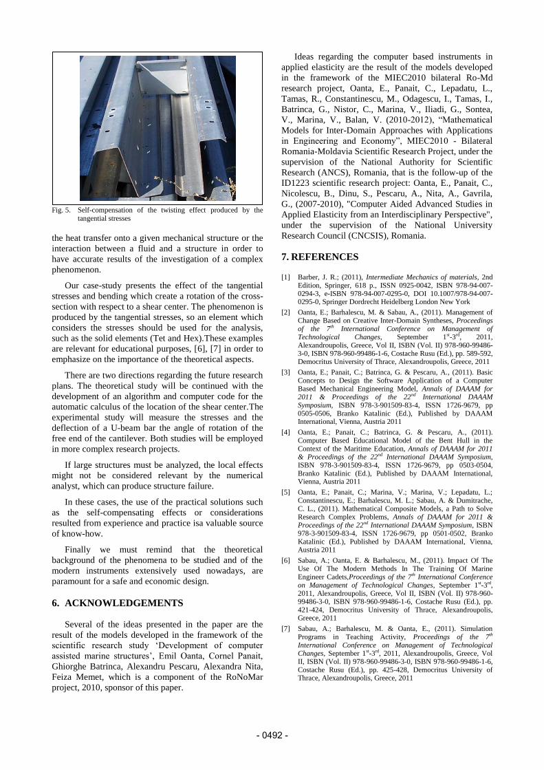
Fig. 5. Self-compensation of the twisting effect produced by the
tangential stresses
the heat transfer onto a given mechanical structure or the
interaction between a fluid and a structure in order to
have accurate results of the investigation of a complex
phenomenon.
Our case-study presents the effect of the tangential
stresses and bending which create a rotation of the cross-
section with respect to a shear center. The phenomenon is
produced by the tangential stresses, so an element which
considers the stresses should be used for the analysis,
such as the solid elements (Tet and Hex).These examples
are relevant for educational purposes, [6], [7] in order to
emphasize on the importance of the theoretical aspects.
There are two directions regarding the future research
plans. The theoretical study will be continued with the
development of an algorithm and computer code for the
automatic calculus of the location of the shear center.The
experimental study will measure the stresses and the
deflection of a U-beam bar the angle of rotation of the
free end of the cantilever. Both studies will be employed
in more complex research projects.
If large structures must be analyzed, the local effects
might not be considered relevant by the numerical
analyst, which can produce structure failure.
In these cases, the use of the practical solutions such
as the self-compensating effects or considerations
resulted from experience and practice isa valuable source
of know-how.
Finally we must remind that the theoretical
background of the phenomena to be studied and of the
modern instruments extensively used nowadays, are
paramount for a safe and economic design.
6. ACKNOWLEDGEMENTS
Several of the ideas presented in the paper are the
result of the models developed in the framework of the
scientific research study „Development of computer
assisted marine structures‟, Emil Oanta, Cornel Panait,
Ghiorghe Batrinca, Alexandru Pescaru, Alexandra Nita,
Feiza Memet, which is a component of the RoNoMar
project, 2010, sponsor of this paper.
Ideas regarding the computer based instruments in
applied elasticity are the result of the models developed
in the framework of the MIEC2010 bilateral Ro-Md
research project, Oanta, E., Panait, C., Lepadatu, L.,
Tamas, R., Constantinescu, M., Odagescu, I., Tamas, I.,
Batrinca, G., Nistor, C., Marina, V., Iliadi, G., Sontea,
V., Marina, V., Balan, V. (2010-2012), “Mathematical
Models for Inter-Domain Approaches with Applications
in Engineering and Economy”, MIEC2010 - Bilateral
Romania-Moldavia Scientific Research Project, under the
supervision of the National Authority for Scientific
Research (ANCS), Romania, that is the follow-up of the
ID1223 scientific research project: Oanta, E., Panait, C.,
Nicolescu, B., Dinu, S., Pescaru, A., Nita, A., Gavrila,
G., (2007-2010), "Computer Aided Advanced Studies in
Applied Elasticity from an Interdisciplinary Perspective",
under the supervision of the National University
Research Council (CNCSIS), Romania.
7. REFERENCES [1] Barber, J. R.; (2011), Intermediate Mechanics of materials, 2nd
Edition, Springer, 618 p., ISSN 0925-0042, ISBN 978-94-007-0294-3, e-ISBN 978-94-007-0295-0, DOI 10.1007/978-94-007-0295-0, Springer Dordrecht Heidelberg London New York
[2] Oanta, E.; Barhalescu, M. & Sabau, A., (2011). Management of Change Based on Creative Inter-Domain Syntheses, Proceedings of the 7th International Conference on Management of Technological Changes, September 1st-3rd, 2011, Alexandroupolis, Greece, Vol II, ISBN (Vol. II) 978-960-99486-3-0, ISBN 978-960-99486-1-6, Costache Rusu (Ed.), pp. 589-592, Democritus University of Thrace, Alexandroupolis, Greece, 2011
[3] Oanta, E.; Panait, C.; Batrinca, G. & Pescaru, A., (2011). Basic Concepts to Design the Software Application of a Computer Based Mechanical Engineering Model, Annals of DAAAM for 2011 & Proceedings of the 22nd International DAAAM Symposium, ISBN 978-3-901509-83-4, ISSN 1726-9679, pp 0505-0506, Branko Katalinic (Ed.), Published by DAAAM International, Vienna, Austria 2011
[4] Oanta, E.; Panait, C.; Batrinca, G. & Pescaru, A., (2011). Computer Based Educational Model of the Bent Hull in the Context of the Maritime Education, Annals of DAAAM for 2011 & Proceedings of the 22nd International DAAAM Symposium, ISBN 978-3-901509-83-4, ISSN 1726-9679, pp 0503-0504, Branko Katalinic (Ed.), Published by DAAAM International, Vienna, Austria 2011
[5] Oanta, E.; Panait, C.; Marina, V.; Marina, V.; Lepadatu, L.; Constantinescu, E.; Barhalescu, M. L.; Sabau, A. & Dumitrache, C. L., (2011). Mathematical Composite Models, a Path to Solve Research Complex Problems, Annals of DAAAM for 2011 & Proceedings of the 22nd International DAAAM Symposium, ISBN 978-3-901509-83-4, ISSN 1726-9679, pp 0501-0502, Branko Katalinic (Ed.), Published by DAAAM International, Vienna, Austria 2011
[6] Sabau, A.; Oanta, E. & Barhalescu, M., (2011). Impact Of The Use Of The Modern Methods In The Training Of Marine Engineer Cadets,Proceedings of the 7th International Conference on Management of Technological Changes, September 1st-3rd, 2011, Alexandroupolis, Greece, Vol II, ISBN (Vol. II) 978-960-99486-3-0, ISBN 978-960-99486-1-6, Costache Rusu (Ed.), pp. 421-424, Democritus University of Thrace, Alexandroupolis, Greece, 2011
[7] Sabau, A.; Barhalescu, M. & Oanta, E., (2011). Simulation Programs in Teaching Activity, Proceedings of the 7th International Conference on Management of Technological Changes, September 1st-3rd, 2011, Alexandroupolis, Greece, Vol II, ISBN (Vol. II) 978-960-99486-3-0, ISBN 978-960-99486-1-6, Costache Rusu (Ed.), pp. 425-428, Democritus University of Thrace, Alexandroupolis, Greece, 2011
- 0492 -