hassan shahzad, ncp _001.pdf · october 23, 2009 hassan shahzad, ncp 2. what is dcs ydcs stands for...
TRANSCRIPT

Hassan Shahzad, NCP

ContentsShort Introduction to DCS, JCOP Framework, PVSS and FSM.
PVSS Architecture and Concept.JCOP Framework concepts and tools.
CMS Endcap RPC DCS.
October 23, 2009 2Hassan Shahzad, NCP

What is DCSDCS stands for Detector Control System.In all large experiments a control system is required which controls and monitors the experimental hardware and takes necessary actions to avoid failure.At LHC, to control and monitor the installed detectors at experimental areas, an intelligent and powerful DCS is used to assure the reliable and safe operation of the electronics.
October 23, 2009 3Hassan Shahzad, NCP
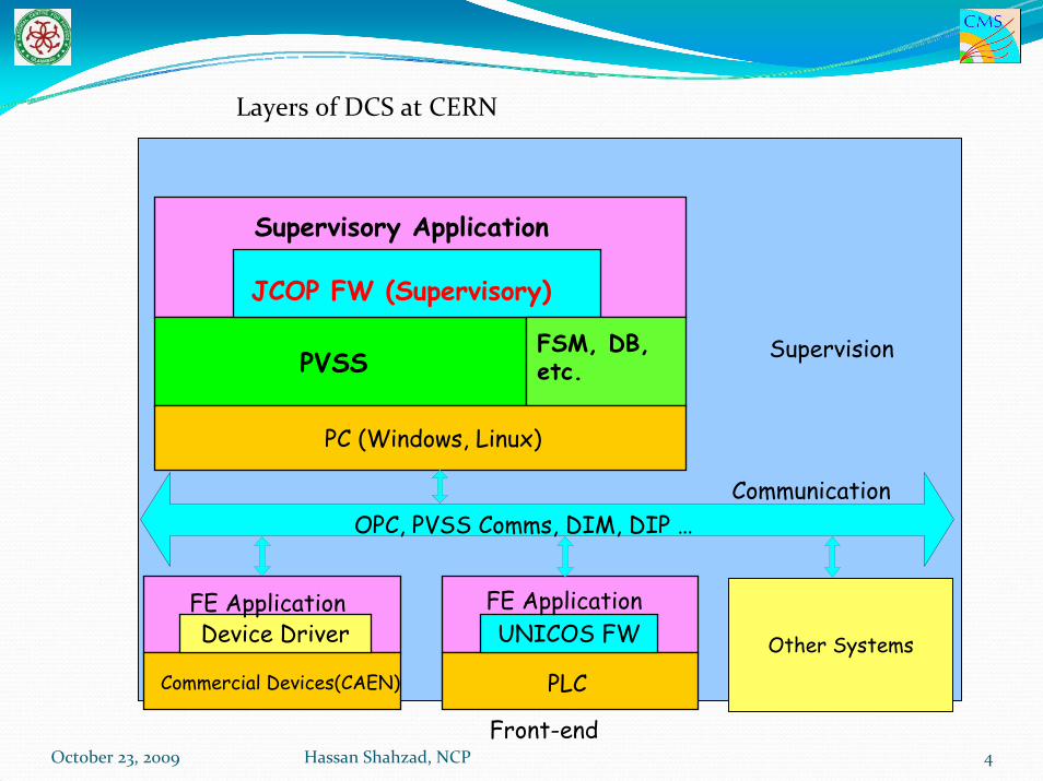
PVSS
JCOP FW (Supervisory)
Supervisory Application
FSM, DB, etc.
Supervision
Front-end
PLC
UNICOS FWFE Application
Communication
PC (Windows, Linux)
Other Systems
Commercial Devices(CAEN)
Device DriverFE Application
OPC, PVSS Comms, DIM, DIPOPC, PVSS Comms, DIM, DIP …
Layers of DCS at CERN
October 23, 2009 Hassan Shahzad, NCP 4

What is JCOP?
JCOP stands for “Joint COntrols Project”.Grouping of representatives from the 4 big Large Hadron Collider (LHC) experiments.Aims to reduce the overall manpower cost required to produce and run the experiment control systems.
October 23, 2009 5Hassan Shahzad, NCP

What is PVSS?The Supervisory Control And Data Acquisition (SCADA) system chosen by JCOP.
JCOP chose PVSS (Prozeßvisualisierungs‐ und Steuerungs‐system) as LHC control system software after extensive evaluation.It is a commercial product from ETM, Austria.Since then, PVSS has been widely adopted across CERN.
PVSS is a TOOL to build control systems, it is not a control system!
October 23, 2009 6Hassan Shahzad, NCP

October 23, 2009 7Hassan Shahzad, NCP
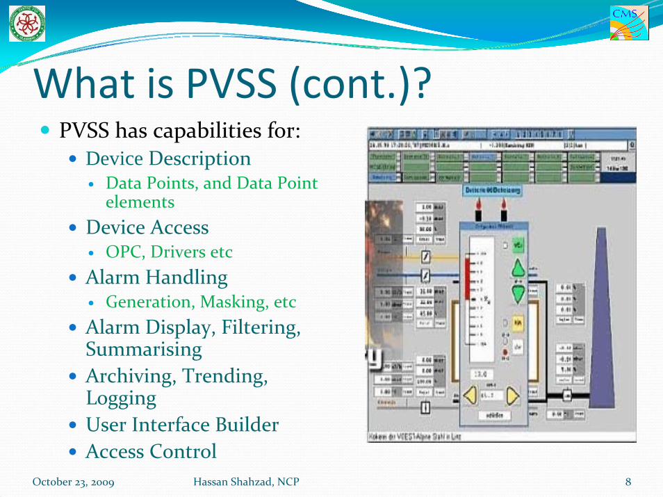
What is PVSS (cont.)?PVSS has capabilities for:
Device Description Data Points, and Data Point elements
Device AccessOPC, Drivers etc
Alarm HandlingGeneration, Masking, etc
Alarm Display, Filtering, SummarisingArchiving, Trending, LoggingUser Interface BuilderAccess Control
October 23, 2009 8Hassan Shahzad, NCP

Cont..The device data in the PVSS database is structured as, so called, Data Points (DP) of a pre‐defined Data Point Type (DPT). PVSS allows devices to be modeled using these DPTs/DPs. DPTs are similar to Classes in Object Oriented terminology. DPs are similar to Objects instantiated from a Class in Object Oriented terminology.
October 23, 2009 9Hassan Shahzad, NCP

What is PVSS not?PVSS II does not have tools specifically for:
Abstract behaviour modellingFinite State Machines
Automation & Error RecoveryExpert System
But…FSM (SMI++) does
October 23, 2009 10Hassan Shahzad, NCP
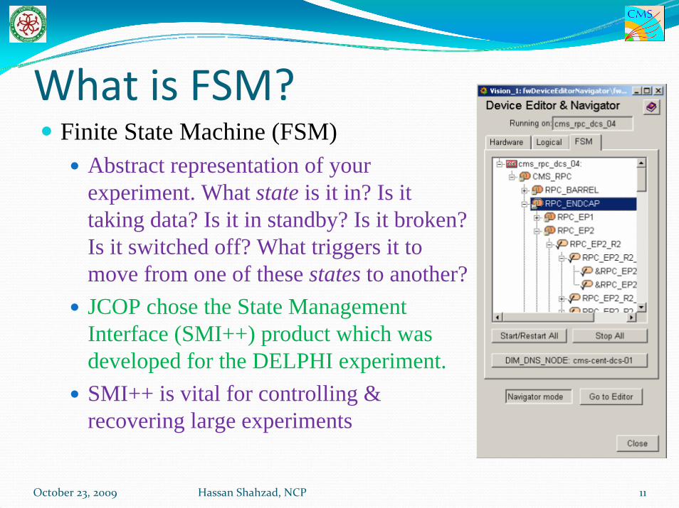
What is FSM?Finite State Machine (FSM)
Abstract representation of your experiment. What state is it in? Is it taking data? Is it in standby? Is it broken? Is it switched off? What triggers it to move from one of these states to another?JCOP chose the State Management Interface (SMI++) product which was developed for the DELPHI experiment. SMI++ is vital for controlling & recovering large experiments
October 23, 2009 11Hassan Shahzad, NCP

What is JCOP Framework?A layer of software components
These components are produced in collaboration.All these components can work together and make the job easy.It is very useful for large PVSS projects.
October 23, 2009 12Hassan Shahzad, NCP

Experiments using PVSSLHC Experiments
All LHC experiments have projectsHas been used for many years in test beams
Fixed Target ExperimentsCOMPASS
Helped in framework developmentNow in production
HARP, NA60, NA48/NA62 ...
October 23, 2009 13Hassan Shahzad, NCP
PVSS Architecture and Concept.
October 23, 2009 14Hassan Shahzad, NCP

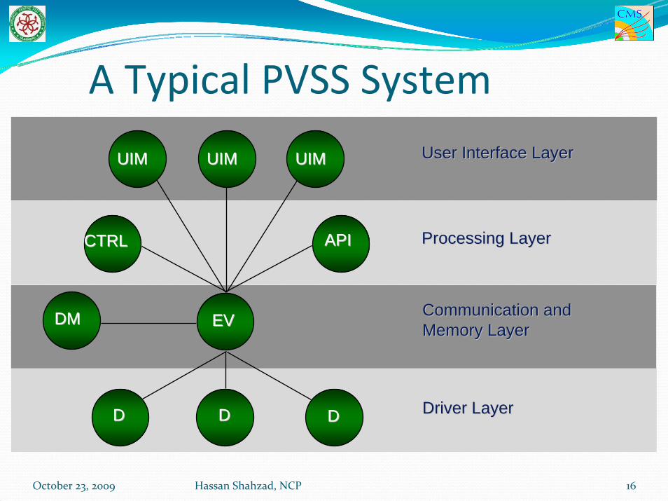
PVSS ArchitecturePVSS has a highly distributed architecture. A PVSS application is composed of several processes, in PVSS nomenclature: Managers. These Managers communicate via a PVSS-specific protocol over TCP/IP. Managers subscribe to data and this is then only sent on change by the Event Manager, which is the heart of the system.
October 23, 2009 15Hassan Shahzad, NCP
User Interface LayerUser Interface Layer
Processing LayerProcessing Layer
Driver LayerDriver Layer
CTRLCTRL APIAPI
EVEV
DD DDDD
UIMUIM UIMUIM UIMUIM
DMDM Communication and Communication and Memory LayerMemory Layer
A Typical PVSS System
October 23, 2009 16Hassan Shahzad, NCP

PVSS Managers OverviewThe Event Manager (EVM) – is responsible for all communications. It receives data from Drivers (D) and sends it to the Database Manager to be stored in the data base.
However, it maintains the “process image” in memory, i.e. the current value of all the data. It also ensures the distribution of data to all Managers which have subscribed to this data.
The DataBase Manager (DBM) – provides the interface to the (run-time) data base.
October 23, 2009 17Hassan Shahzad, NCP

Cont..User Interface Managers (UIM) – can get device data from the database, or send data to the database.Ctrl Managers (Ctrl) – provide for any data processing as “background” processes, by running a scripting language. This language is like “C” with extensions. API Managers (API) – Allow users to write their own programs in C++ using a PVSS API (Application Programming Interface) to access the data in the database. Drivers (D) – Provide the interface to the devices to be controlled. These can be PVSS provided drivers or user-made drivers.
October 23, 2009 18Hassan Shahzad, NCP

Types of PVSS SystemsA PVSS System is an application containing one data base manager and one event manager and any number of drivers, user interfaces, etc. PVSS Managers can run on Windows or Linux and they can all run in the same machine or be distributed across different machines (including mixed Windows and Linux environments). When the managers of one system run distributed across different machines this is called a PVSS Scattered System.
October 23, 2009 19Hassan Shahzad, NCP

Cont..
PVSS can provide control for very large applications, in which case one PVSS system would not be enough.In this case a PVSS Distributed System can be used. As shown in a figure, distributed system is built by adding a Distribution Manager (Dist) to each system and connecting them together. Hundreds of systems can be connected in this way.
October 23, 2009 20Hassan Shahzad, NCP

Distributed System
October 23, 2009 21Hassan Shahzad, NCP

22
Distributed System
EVEvent-
Manager
CTRLControl-Manager
DDriver
DBDatabase-Manager
REDURedundancy
Manager EVEvent-
Manager
CTRLControl-Manager
DDriver
DBDatabase-Manager
REDURedundancy
Manager
Server 1 Server 2
UIUserinterface
Runtime
Operator 1
UIUserinterface
Runtime
Operator 2
DISTDistribution
Manager
DISTDistribution
Manager
EVEvent-
Manager
CTRLControl-manager
DDriver
DBDatabase-Manager
Single Machine Station
DISTDistribution
Manager
UIUserinterface
Runtime
UIUserinterface
Runtime
Operator 2
EVEvent-
Manager
CTRLControl-Manager
DDriver
DBDatabase-Manager
Server
DISTDistribution
Manager
UIUserinterface
Runtime
Operator 1
Local Area Network TCP
System 1
System 2
System 3
October 23, 2009 Hassan Shahzad, NCP

Distributed System
Distribution Manager provides the interface between systemsEvent driven communication leads to low network loadOnly requested data is transferredIntegrated connection monitoringInterconnected 130 systems at CERN.
October 23, 2009 23Hassan Shahzad, NCP
JCOP Framework concepts and tools.
October 23, 2009 24Hassan Shahzad, NCP

Aims of the JCOP FrameworkReduce the development effort
Reuse of componentsHide complexity.Facilitate the integration.
Reduce resources for maintenance
Homogeneous control system.Easy operation and maintenance.
Provide a higher layer of abstraction
reduce knowledge of toolsinterface for non experts
Customize & Extend industrial componentsModular/ExtensibleAs simple as possibleDevelopment driven by the JCOP FW Working Group.
October 23, 2009 25Hassan Shahzad, NCP

What is it (not)?
October 23, 2009 26Hassan Shahzad, NCP

DCS Architecture
PVSS
JCOP FW (Supervisory)
Supervisory Application
FSM, DB, etc.
Supervision
Front-end
PLC
UNICOS FWFE Application
Communication
PC (Windows, Linux)
Other Systems
Commercial Devices(CAEN)
Device DriverFE Application
OPC, PVSS Comms, DIM, DIPOPC, PVSS Comms, DIM, DIP …
October 23, 2009 27Hassan Shahzad, NCP

Tools Provided by JCOP Framework
Device Editor and Navigator (DEN)Main user interface to the Framework.Configuring devices, users login.High level view of experimentIncludes FSMs
Fw Tree ViewProvides the Tree view of whole project.
fwGeneral:Exception handlingPanels to give messages to usersHelp system
One html file for every panel.For library routines the help text is within the code itself.
October 23, 2009 Hassan Shahzad, NCP 28

Cont..Fw Config Library
Hide complexity of PVSS configsOptimized functions for mass configurationExceptions are handled
Component Installation ToolTrending
Greatly simplifies PVSS trends.
Configuration DBFw definitions stored in Oracle.
Static definitions (DEN configuration)Recipes (Values, eg for “physics”/”comics”/”shutdown”states
October 23, 2009 29Hassan Shahzad, NCP

Cont..
Mass ConfigurationEasy configuration of many channels with alerts, settings etc.
Access controlHide complexity of PVSS access control!Defines privilege levels and role groups (operator, expert etc.)
October 23, 2009 30Hassan Shahzad, NCP

October 23, 2009 31Hassan Shahzad, NCP

Brief Introduction to CMS and RPCCMS (Compact Muon Solenoid) is one of the main experiment sight at LHC.RPCs are the dedicated detectors used for the first level muon trigger of CMS.Good performance of RPC is essential in assigning the muon to the right bunch crossing at the LHC.
The CMS Experiment
October 23, 2009 32Hassan Shahzad, NCP

RPC DCSThe RPC DCS has two sub‐systems: RPC Barrel and RPC Endcap.
RPC Barrel DCS is prepared by Italian Group.RPC Endcap DCS is prepared by NCP HEP Group in coordination with Barrel DCS group expert.
The Endcap RPC system of CMS detector comprises of 432 double gap chambers. The correct and safe operation of the RPC system requires a sophisticated and complex online Detector Control System (DCS), able to monitor and control the RPC hardware devices.
October 23, 2009 33Hassan Shahzad, NCP

RPC DCS The RPC DCS system has to assure the safe and correct operation of the sub‐detectors during the entire CMS life time (more than 10 years), detect abnormal and harmful situations and take protective and automatic actions to minimize consequential damages.
October 23, 2009 34Hassan Shahzad, NCP

RPC ENDCAP DCSThe RPC Endcap DCS is subdivided into several sub‐systems:
High Voltage (HV), Low Voltage (LV), Environmental Sensors(humidity and temperature ), Gas,Cooling systems.
NCP EHEP Group had designed and prepared the software applications for the control and monitoring of the HV, LV systems and environmental sensors. All information is monitored and shared through the Central DCS.Cooling and Gas systems are instead developed centrally by CMS DCS Group.
October 23, 2009 35Hassan Shahzad, NCP

The RPC Endcap Power system: high voltage and low voltageLarge part of the RPC Endcap power system is located close to the detector and in particular inside the racks placed on the balconies around the Endcap wheel.Every RPC chamber has been equipped with two independent HV channels (one per gap) and two LV channels.In addition four LV channels are needed to supply each Link Boards Box (LBB), aimed to collect data from each chamber, synchronize and send them to trigger and readout chain in control room.
October 23, 2009 36Hassan Shahzad, NCP
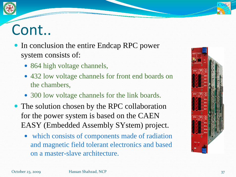
Cont..In conclusion the entire Endcap RPC power system consists of:
864 high voltage channels,432 low voltage channels for front end boards on the chambers,300 low voltage channels for the link boards.
The solution chosen by the RPC collaboration for the power system is based on the CAEN EASY (Embedded Assembly SYstem) project.
which consists of components made of radiation and magnetic field tolerant electronics and based on a master-slave architecture.
October 23, 2009 37Hassan Shahzad, NCP

Cont..The following CAEN Hardware is used for RPC Endcap Power System and was purchased by Govt. of Pakistan.CAEN Hardware Short Description Quantity
SY1527 HV Mainframe 1A3512N HV Board 42A3485 AC to DC Convertor for HV System 1A1676 Branch Controller for HV System 3
EASY3000 HV CRATE for housing boards 11A3000FB FAN Units for EASY Crates 11
SY1527 LV Mainframe 1A3009N LV Board 36A3486S AC to DC Convertor for LV System 6A1676 Branch Controller for LV System 4
EASY3000S LV CRATE for housing boards 12
October 23, 2009 38Hassan Shahzad, NCP
ENVIRONMENTAL SENSOR NETWOK
The performance of the Endcap RPC detector is strongly related to the temperature and humidity. In particular the noise rate and the dark current of the chamber depend on these two parameters.For this reason monitoring the gas temperature, the humidity and the temperature outside of the chamber is crucial.
October 23, 2009 39Hassan Shahzad, NCP

Cont..The environmental sensor network is composed of:
72 sensors to measure the outside temperature of the RPC.48 relative humidity sensors. 24 Water temperature sensors.
The temperature sensor is the D592BN, made by Analog devices.All above sensors are powered and read by the 8 CAEN ADC (A3801A) boards,
All ADC boards are placed in the balcony around the detector.
October 23, 2009 40Hassan Shahzad, NCP

RPC DCS Hardware Structure
All the RPC subsystems are handled and controlled by the RPC Supervisor, aimed to gather and summarize all the information and to present a simplified but coherent and general view to the end users.
Purchased by Pakistan
October 23, 2009 41Hassan Shahzad, NCP

RPC Endcap DCS SoftwareIn accordance with the CMS official guidelines, all Endcap RPC DCS applications have been developed using the commercial ETM SCADA (Supervisory Control And Data Acquisition) software, PVSS 3.6 and the standard Joint Control Project (JCOP) framework components .The DCS uses the finite state machine (FSM) approach and its follows the RPC subsystem structure (station, ring, chamber, Channel...).
October 23, 2009 42Hassan Shahzad, NCP

Cont..
Example of the Chamber Finite State Machine.
Structure of the hierarchy tree of the RPC DCS
October 23, 2009 43Hassan Shahzad, NCP

Cont…RPC DCS uses most of the functionalities provided by the PVSS + JCOP software as the final state machine, the GUI, the alarm handler and the ORACLE database interface.
October 23, 2009 44Hassan Shahzad, NCP

Commissioning of RE DCSThe NCP EHEP Group started work on DCS since Jan, 2008.The Provisional DCS version is released in August, 2008.
This was a temporary setup in building 40 office by using 3 ordinary desktop computer machines(as RE Supervisor, RE LV machine and RE HV machine). This setup is capable to control and monitor the HV system, LV system of three Endcap Discs.
i.e. 432 HV channels and 216 LV Channels.
October 23, 2009 45Hassan Shahzad, NCP

Commissioning of RE DCS
One User interface panel for example.October 23, 2009 46Hassan Shahzad, NCP

Provisional DCSProvisional DCS provides functionalities such as:
Easy user interface with hardware in form of tree view.Power On or Off the Disc/Ring/Single RPC via UI panel.Settings for Current and Voltage parameters for both HV and LV systems like voltage, current, trip time etc.Generate plots for HV Vs Current for each HV and LV channel of RPC separately.Maintains History for Current and Voltage to analyze in detail the behavior of the hardware.Generate Alarms in case of unusual situations like high current or high temperature of boards.Turn off the respective board/channel in case of bad situation to avoid the failure of hardware, etc..
October 23, 2009 47Hassan Shahzad, NCP

Global Settings for ring
October 23, 2009 48Hassan Shahzad, NCP

Provisional DCSFrom August 2008 till February 2009, the provisional DCS is used by CMS shifters on 24 hours basis.The provisional DCS helped a lot to shifters to monitor and analyze in detail the behavior of RPC Endcap HV and LV system.In the mean time several updates were implemented to improve the user interface and to make it more robust and secure.
Extensive work has been done on supervisor system to integrate the Barrel and Endcap in one project which is very complicated and requires continuous work and discussions of Barrel DCS expert with Endcap DCS expert.
October 23, 2009 49Hassan Shahzad, NCP

Final RPC DCSIn February 2009, the final RPC DCS version is released which has common supervisor for RPC Endcap and Barrel.
All RPC Endcap DCS computer machines are installed in CMS central DCS control room and are on CMS internal network.The RPC DCS has been also successfully integrated into the Central DCS and was able to publish its state and receive commands from it.
October 23, 2009 50Hassan Shahzad, NCP

Cont..Final DCS adds more functionalities in provisional DCS such as:
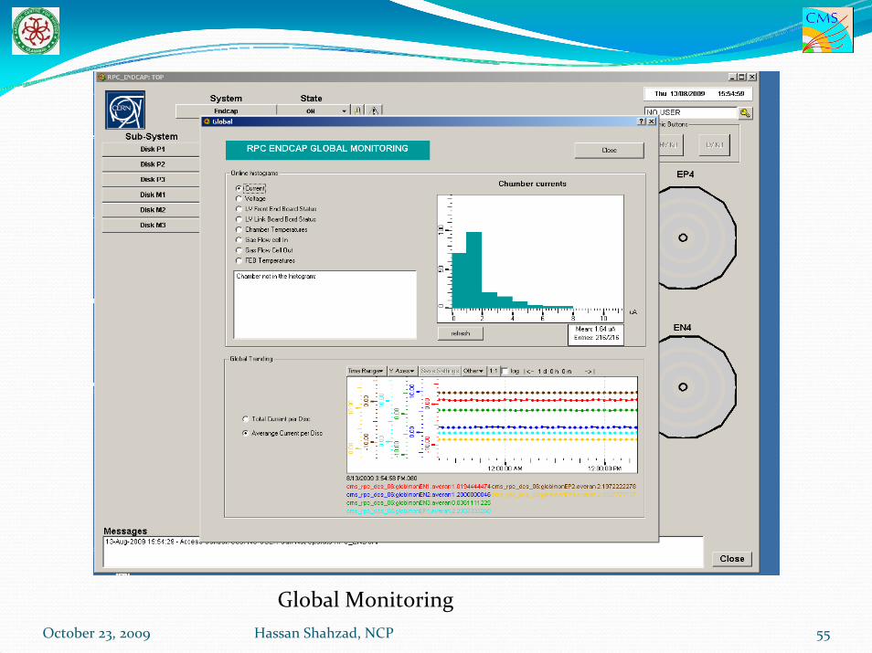
Provide control and monitoring of HV, LV, LBB temperature and humidity channels and sensors on disc level.Global monitoring of RPC Endcap six stations
Average and total temperature per disc.Average and total current per disc.
Provide HV Scan utility.
October 23, 2009 Hassan Shahzad, NCP 51
Cont..Integration of Gas system in RPC Endcap DCS.More user friendly.Addition of monitoring of online temperature of hardware like boards, power supplies etc.Addition of emergency shutdown capability of HV and LV of all stations.After a short debug phase, the system ran without problems for the entire test period. It was proved to be able to manage properly the interruptions occurred, due to power failures and communication problem with the power supply.
October 23, 2009 Hassan Shahzad, NCP 52
Cont..Final DCS is more robust and secure than provisional DCS and have more detailed information of the hardware.The DCS proved to be a reliable tool for the safe and correct operation of the detectors and trained shifter, were able to operate the detector in a easy and safe way. Some DCS UI panels are shown in next slides.
October 23, 2009 53Hassan Shahzad, NCP

October 23, 2009 54Hassan Shahzad, NCP
RPC Endcap DCS Overview
October 23, 2009 55Hassan Shahzad, NCP
Global Monitoring

October 23, 2009 Hassan Shahzad, NCP 56

Cont..
October 23, 2009 57Hassan Shahzad, NCP
HV Channels for disk

Cont..
October 23, 2009 58Hassan Shahzad, NCP
LBB Channels for disk

HV Setting for Disk LV Setting for Disk
October 23, 2009 59Hassan Shahzad, NCP

Cont..
October 23, 2009 60Hassan Shahzad, NCP
Global Monitoring for disk

Boards and AC to DC Convertor TemperatureHassan Shahzad, NCPOctober 23, 2009 61

October 23, 2009 62Hassan Shahzad, NCP
Temperature and Humidity for disk

Current plots at 9.2kV for selected RPCsOctober 23, 2009 63Hassan Shahzad, NCP

October 23, 2009 Hassan Shahzad, NCP 64
Temperature plots for one station

October 23, 2009 Hassan Shahzad, NCP 65
Water temperature sensors plots for one station

ConclusionThe design and development of the Endcap RPC detector control system is now finished and shifters are using it on 24 hours basis.The good results obtained during the 2008 and 2009 global runs and in August 2009 CRAFT operating whole RPC Endcap system, demonstrated that the RPC DCS was well designed and was able to run in a very stable and safe way for long period. In conclusion, the RPC DCS system, developed following the guidelines of the DCS central group was proved to be a reliable tool and it is ready to become fully operational for the Winter 2009 and whole 2010 when CMS will begin to take data.
October 23, 2009 66Hassan Shahzad, NCP

October 23, 2009 Hassan Shahzad, NCP 67