hartner reibahlen en 2017 lowres 2017
TRANSCRIPT

11
Precision Cutting Tools
REAMERSTR 300 HP - HIGH-PERFORMANCE REAMERSSOLID CARBIDE AND HSS-E MACHINE REAMERS | HAND REAMERS
EN
+ THE FULL PROGRAMME OF REAMERS

HSS HSS-E
TR 300 HP S
TR 300 HP D
A B
DIN206
DIN208
DIN212
DIN212-2
DIN212-3
~DIN8050
~DIN8051
WN
H7 +0,005+0,004+0,005
R L
HA Cyl MK
≠ EU
Hartner GmbH · P.O.Box 10 04 27 · D-72425 Albstadt · Phone +49 74 31 125-0 · Fax: +49 74 31 125-21 547 · www.hartner.de
Pictograms
Optimal diameters of pre-drilled holes
Tool material
Solid carbide Carbide-tipped
Type
Blind hole (S) Through hole (D)
Form
Hole type
Through hole Blind hole
Norm
to DIN
to Hartnerstandard
Tolerance on Ø
Cutting direction
right left
Shank form
Morse taper
Helix angle
straight-fluted left-hand helix
Flute spacing
unequal extremely unequal
Internal cooling
with IC without IC
ISO code
P Steel, high-alloyed steel
M Stainless steel
K Grey cast iron, spher. graphite iron/malleable cast iron
N Aluminium and other non-ferrous metals
S Special, super and titanium alloys
H Hardened steel and chilled cast iron
Recommended stock allowance, in mm up to Ø6 up to Ø10 up to Ø16 up to Ø25 up to Ø40 up to Ø40
all materials Ø 0.1-0.2 Ø 0.2 Ø 0.2-0.3 Ø 0.3 Ø 0.3-0.4 Ø 0.4-0.5
hardened steel Hup to 48 HRC Ø 0.1-0.2 Ø 0.2 Ø 0.2 Ø 0.2 Ø 0.3 Ø 0.3
up to 63 HRC Ø 0.1 Ø 0.1 Ø 0.1-0.2 Ø 0.2 Ø 0.2 Ø 0.2

Solid carbide reamers
HSS-E- machine reamers
page 4
page 11
page 19
Hand reamers page 32
Technical section page 36
TR 300 HPHigh-performance reamers

4
High-performance reamers
AlTiN nano
High-perform
ance reamers
Standard Form Shank form Diameter tolerance
Tool material
Surfacefinish Hole type d1 Order
no.
Discountgroup
Standardrange page
High-performance reamers
Hartner Standard TR 300 HP S HA H7 Solid
carbide 3.000 - 20.000 88400 166 5
Hartner Standard TR 300 HP S HA +0.005 Solid
carbide 2.970 - 12.030 88402 166 5
Hartner Standard TR 300 HP D HA H7 Solid
carbide 3.000 - 20.000 88401 166 8
Hartner Standard TR 300 HP D HA +0.005 Solid
carbide 2.970 - 12.030 88403 166 8

5
TR 300 HP S WN
HAEU
R H7 +0,005
P (N/mm²)
M
K
N
S
H (HRC)
d2
l 1
d1
l 4
l2
Hig
h-pe
rfor
man
ce re
amer
s
High-performance reamers
AlTiN nano
High-performance reamers
AlTiN nano
Solid carbide
Order no. 88400 88402
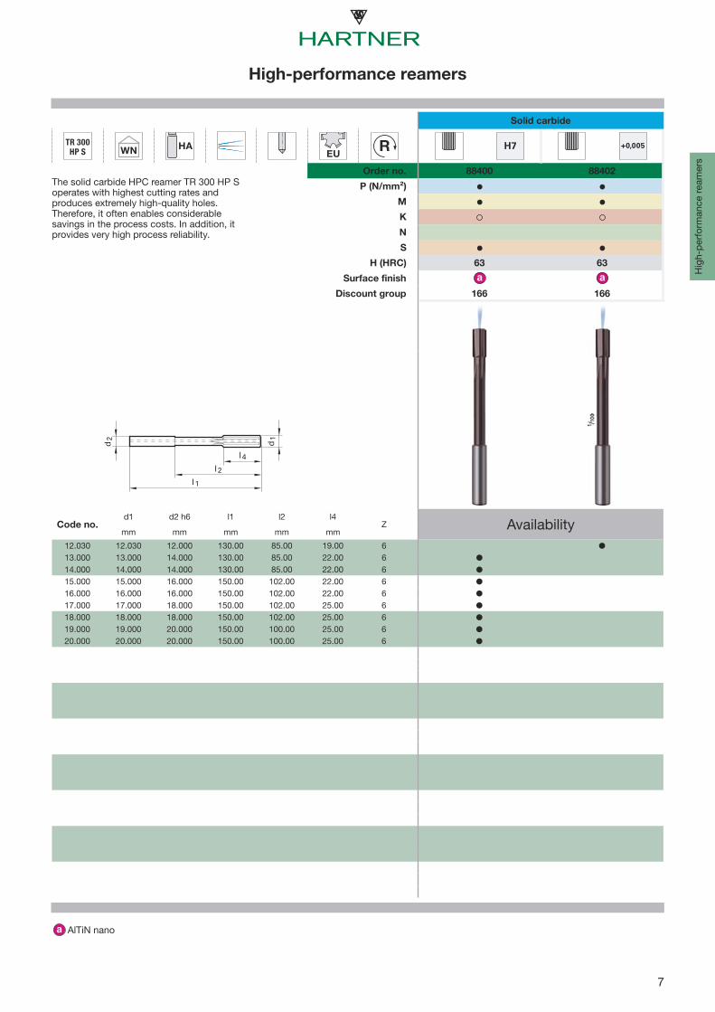
The solid carbide HPC reamer HR 500 Soperates with highest cutting rates andproduces extremely high-quality holes.Therefore, it often enables considerablesavings in the process costs. In addition, itprovides very high process reliability.
63 63
Surface finish
Discount group 166 166
Code no.d1 d2 h6 l1 l2 l4
Z Availabilitymm mm mm mm mm
2.970 2.970 4.000 68.00 40.00 12.00 42.980 2.980 4.000 68.00 40.00 12.00 42.990 2.990 4.000 68.00 40.00 12.00 43.000 3.000 4.000 68.00 40.00 12.00 43.010 3.010 4.000 68.00 40.00 12.00 43.020 3.020 4.000 68.00 40.00 12.00 43.030 3.030 4.000 68.00 40.00 12.00 43.500 3.500 4.000 68.00 40.00 12.00 43.970 3.970 4.000 68.00 40.00 12.00 43.980 3.980 4.000 68.00 40.00 12.00 43.990 3.990 4.000 68.00 40.00 12.00 44.000 4.000 4.000 68.00 40.00 12.00 44.010 4.010 4.000 68.00 40.00 12.00 44.020 4.020 4.000 68.00 40.00 12.00 44.030 4.030 4.000 68.00 40.00 12.00 44.500 4.500 6.000 76.00 40.00 12.00 44.970 4.970 6.000 76.00 40.00 12.00 44.980 4.980 6.000 76.00 40.00 12.00 44.990 4.990 6.000 76.00 40.00 12.00 45.000 5.000 6.000 76.00 40.00 12.00 45.010 5.010 6.000 76.00 40.00 12.00 45.020 5.020 6.000 76.00 40.00 12.00 45.030 5.030 6.000 76.00 40.00 12.00 45.500 5.500 6.000 76.00 40.00 12.00 45.970 5.970 6.000 76.00 40.00 12.00 45.980 5.980 6.000 76.00 40.00 12.00 45.990 5.990 6.000 76.00 40.00 12.00 46.000 6.000 6.000 76.00 40.00 12.00 46.010 6.010 6.000 76.00 40.00 12.00 46.020 6.020 6.000 76.00 40.00 12.00 4

6
TR 300 HP S WN
HAEU
R H7 +0,005
P (N/mm²)
M
K
N
S
H (HRC)
d2
l 1
d1
l 4
l2
High-performance reamers
AlTiN nano
High-perform
ance reamers
Solid carbide
Order no. 88400 88402
The solid carbide HPC reamer TR 300 HP Soperates with highest cutting rates andproduces extremely high-quality holes.Therefore, it often enables considerablesavings in the process costs. In addition, itprovides very high process reliability.
63 63
Surface finish
Discount group 166 166
Code no.d1 d2 h6 l1 l2 l4
Z Availabilitymm mm mm mm mm
6.030 6.030 6.000 76.00 40.00 12.00 46.500 6.500 8.000 101.00 65.00 16.00 67.000 7.000 8.000 101.00 65.00 16.00 67.500 7.500 8.000 101.00 65.00 16.00 67.970 7.970 8.000 101.00 65.00 16.00 67.980 7.980 8.000 101.00 65.00 16.00 67.990 7.990 8.000 101.00 65.00 16.00 68.000 8.000 8.000 101.00 65.00 16.00 68.010 8.010 8.000 101.00 65.00 16.00 68.020 8.020 8.000 101.00 65.00 16.00 68.030 8.030 8.000 101.00 65.00 16.00 68.500 8.500 10.000 101.00 61.00 19.00 69.000 9.000 10.000 101.00 61.00 19.00 69.500 9.500 10.000 101.00 61.00 19.00 69.970 9.970 10.000 101.00 61.00 19.00 69.980 9.980 10.000 101.00 61.00 19.00 69.990 9.990 10.000 101.00 61.00 19.00 6
10.000 10.000 10.000 101.00 61.00 19.00 610.010 10.010 10.000 101.00 61.00 19.00 610.020 10.020 10.000 101.00 61.00 19.00 610.030 10.030 10.000 101.00 61.00 19.00 610.500 10.500 12.000 130.00 85.00 19.00 611.000 11.000 12.000 130.00 85.00 19.00 611.500 11.500 12.000 130.00 85.00 19.00 611.970 11.970 12.000 130.00 85.00 19.00 611.980 11.980 12.000 130.00 85.00 19.00 611.990 11.990 12.000 130.00 85.00 19.00 612.000 12.000 12.000 130.00 85.00 19.00 612.010 12.010 12.000 130.00 85.00 19.00 612.020 12.020 12.000 130.00 85.00 19.00 6
7
TR 300 HP S WN
HAEU
R H7 +0,005
P (N/mm²)
M
K
N
S
H (HRC)
d2
l 1
d1
l 4
l2
Hig
h-pe
rfor
man
ce re
amer
s
High-performance reamers
AlTiN nano
Solid carbide
Order no. 88400 88402
The solid carbide HPC reamer TR 300 HP Soperates with highest cutting rates andproduces extremely high-quality holes.Therefore, it often enables considerablesavings in the process costs. In addition, itprovides very high process reliability.
63 63
Surface finish
Discount group 166 166
Code no.d1 d2 h6 l1 l2 l4
Z Availabilitymm mm mm mm mm
12.030 12.030 12.000 130.00 85.00 19.00 613.000 13.000 14.000 130.00 85.00 22.00 614.000 14.000 14.000 130.00 85.00 22.00 615.000 15.000 16.000 150.00 102.00 22.00 616.000 16.000 16.000 150.00 102.00 22.00 617.000 17.000 18.000 150.00 102.00 25.00 618.000 18.000 18.000 150.00 102.00 25.00 619.000 19.000 20.000 150.00 100.00 25.00 620.000 20.000 20.000 150.00 100.00 25.00 6

8
TR 300 HP D WN
HAEU
R H7 +0,005
P (N/mm²)
M
K
N
S
H (HRC)
d2
l 1
d1
l 4
l2
High-performance reamers
AlTiN nano
High-perform
ance reamers
Solid carbide
Order no. 88401 88403
The solid carbide HPC reamer TR 300 HP Doperates with highest cutting rates and produces extremely high-quality holes. Therefore, it often enables considerable savings in the process costs.In addition, it provides very high processreliability. The special coolant supply withflutes in the shank ensures optimal chipevacuation and reliable cooling. 63 63
Surface finish
Discount group 166 166
Code no.d1 d2 h6 l1 l2 l4
Z Availabilitymm mm mm mm mm
2.970 2.970 4.000 68.00 40.00 12.00 42.980 2.980 4.000 68.00 40.00 12.00 42.990 2.990 4.000 68.00 40.00 12.00 43.000 3.000 4.000 68.00 40.00 12.00 43.010 3.010 4.000 68.00 40.00 12.00 43.020 3.020 4.000 68.00 40.00 12.00 43.030 3.030 4.000 68.00 40.00 12.00 43.500 3.500 4.000 68.00 40.00 12.00 43.970 3.970 4.000 68.00 40.00 12.00 43.980 3.980 4.000 68.00 40.00 12.00 43.990 3.990 4.000 68.00 40.00 12.00 44.000 4.000 4.000 68.00 40.00 12.00 44.010 4.010 4.000 68.00 40.00 12.00 44.020 4.020 4.000 68.00 40.00 12.00 44.030 4.030 4.000 68.00 40.00 12.00 44.500 4.500 6.000 76.00 40.00 12.00 44.970 4.970 6.000 76.00 40.00 12.00 44.980 4.980 6.000 76.00 40.00 12.00 44.990 4.990 6.000 76.00 40.00 12.00 45.000 5.000 6.000 76.00 40.00 12.00 45.010 5.010 6.000 76.00 40.00 12.00 45.020 5.020 6.000 76.00 40.00 12.00 45.030 5.030 6.000 76.00 40.00 12.00 45.500 5.500 6.000 76.00 40.00 12.00 45.970 5.970 6.000 76.00 40.00 12.00 45.980 5.980 6.000 76.00 40.00 12.00 45.990 5.990 6.000 76.00 40.00 12.00 46.000 6.000 6.000 76.00 40.00 12.00 46.010 6.010 6.000 76.00 40.00 12.00 46.020 6.020 6.000 76.00 40.00 12.00 4

9
TR 300 HP D WN
HAEU
R H7 +0,005
P (N/mm²)
M
K
N
S
H (HRC)
d2
l 1
d1
l 4
l2
Hig
h-pe
rfor
man
ce re
amer
s
High-performance reamers
AlTiN nano
Solid carbide
Order no. 88401 88403
The solid carbide HPC reamer TR 300 HP Doperates with highest cutting rates and produces extremely high-quality holes. Therefore, it often enables considerable savings in the process costs.In addition, it provides very high processreliability. The special coolant supply withflutes in the shank ensures optimal chipevacuation and reliable cooling. 63 63
Surface finish
Discount group 166 166
Code no.d1 d2 h6 l1 l2 l4
Z Availabilitymm mm mm mm mm
6.030 6.030 6.000 76.00 40.00 12.00 46.500 6.500 8.000 101.00 65.00 16.00 67.000 7.000 8.000 101.00 65.00 16.00 67.500 7.500 8.000 101.00 65.00 16.00 67.970 7.970 8.000 101.00 65.00 16.00 67.980 7.980 8.000 101.00 65.00 16.00 67.990 7.990 8.000 101.00 65.00 16.00 68.000 8.000 8.000 101.00 65.00 16.00 68.010 8.010 8.000 101.00 65.00 16.00 68.020 8.020 8.000 101.00 65.00 16.00 68.030 8.030 8.000 101.00 65.00 16.00 68.500 8.500 10.000 101.00 61.00 19.00 69.000 9.000 10.000 101.00 61.00 19.00 69.500 9.500 10.000 101.00 61.00 19.00 69.970 9.970 10.000 101.00 61.00 19.00 69.980 9.980 10.000 101.00 61.00 19.00 69.990 9.990 10.000 101.00 61.00 19.00 6
10.000 10.000 10.000 101.00 61.00 19.00 610.010 10.010 10.000 101.00 61.00 19.00 610.020 10.020 10.000 101.00 61.00 19.00 610.030 10.030 10.000 101.00 61.00 19.00 610.500 10.500 12.000 130.00 85.00 19.00 611.000 11.000 12.000 130.00 85.00 19.00 611.500 11.500 12.000 130.00 85.00 19.00 611.970 11.970 12.000 130.00 85.00 19.00 611.980 11.980 12.000 130.00 85.00 19.00 611.990 11.990 12.000 130.00 85.00 19.00 612.000 12.000 12.000 130.00 85.00 19.00 612.010 12.010 12.000 130.00 85.00 19.00 612.020 12.020 12.000 130.00 85.00 19.00 6

10
TR 300 HP D WN
HAEU
R H7 +0,005
P (N/mm²)
M
K
N
S
H (HRC)
d2
l 1
d1
l 4
l2
High-performance reamers
AlTiN nano
High-perform
ance reamers
Solide carbide
Order no. 88401 88403
The solid carbide HPC reamer TR 300 HP Doperates with highest cutting rates and produces extremely high-quality holes. Therefore, it often enables considerable savings in the process costs.In addition, it provides very high processreliability. The special coolant supply withflutes in the shank ensures optimal chipevacuation and reliable cooling. 63 63
Surface finish
Discount group 166 166
Code no.d1 d2 h6 l1 l2 l4
Z Availabilitymm mm mm mm mm
12.030 12.030 12.000 130.00 85.00 19.00 613.000 13.000 14.000 130.00 85.00 22.00 614.000 14.000 14.000 130.00 85.00 22.00 615.000 15.000 16.000 150.00 102.00 22.00 616.000 16.000 16.000 150.00 102.00 22.00 617.000 17.000 18.000 150.00 102.00 25.00 618.000 18.000 18.000 150.00 102.00 25.00 619.000 19.000 20.000 150.00 100.00 25.00 620.000 20.000 20.000 150.00 100.00 25.00 6

11
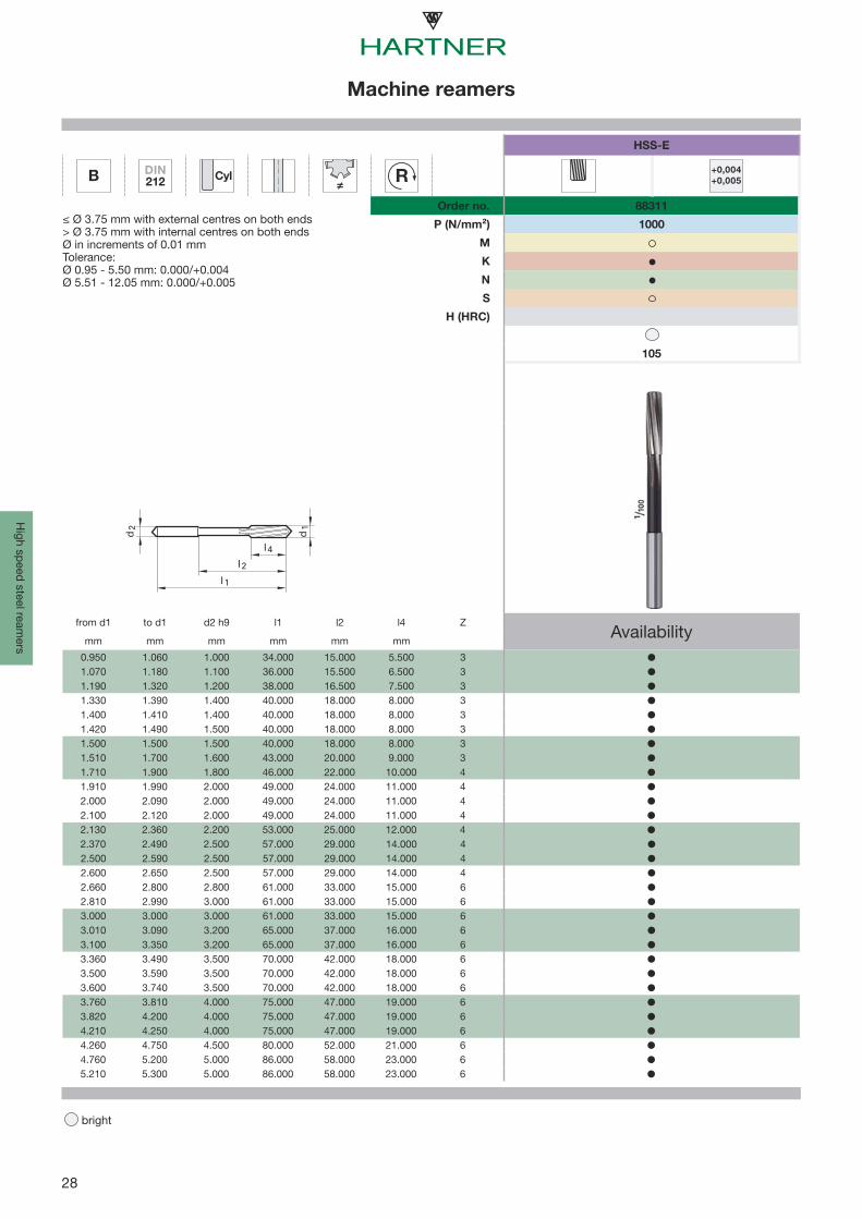
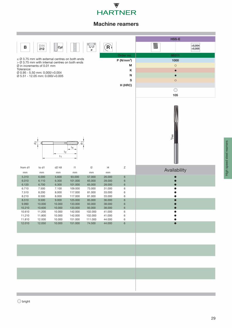
Machine reamers
bright
Mac
hine
ream
ers
Standard Form Shank form Diameter tolerance
Tool material
Surfacefinish Hole type d1 Order
no.
Discountgroup
Standardrange page
NC machine reamers
Hartner Standard B HA +0.004
+0.005Solid
carbide 0.980 - 12.050 88350 120 12
Hartner Standard B HA H7 Solid
carbide 3.000 - 12.000 88351 120 12
Machine reamers
~ DIN 8050 A cyl. H7 Carbide 5.000 - 20.000 88352 120 17
~ DIN 8050 B cyl. H7 Carbide 5.000 - 20.000 88353 120 17
~ DIN 8051 A MK H7 Carbide 5.000 - 40.000 88354 120 18
~ DIN 8051 B MK H7 Carbide 6.000 - 32.000 88355 120 18
12
B WNHA
EUR +0,004
+0,005 H7
P (N/mm²)
M
K
N
S
H (HRC)
d2
l 1
d1
l 4
l2
NC machine reamers
bright
Machine ream
ers
Solid carbide
Order no. 88350 88351
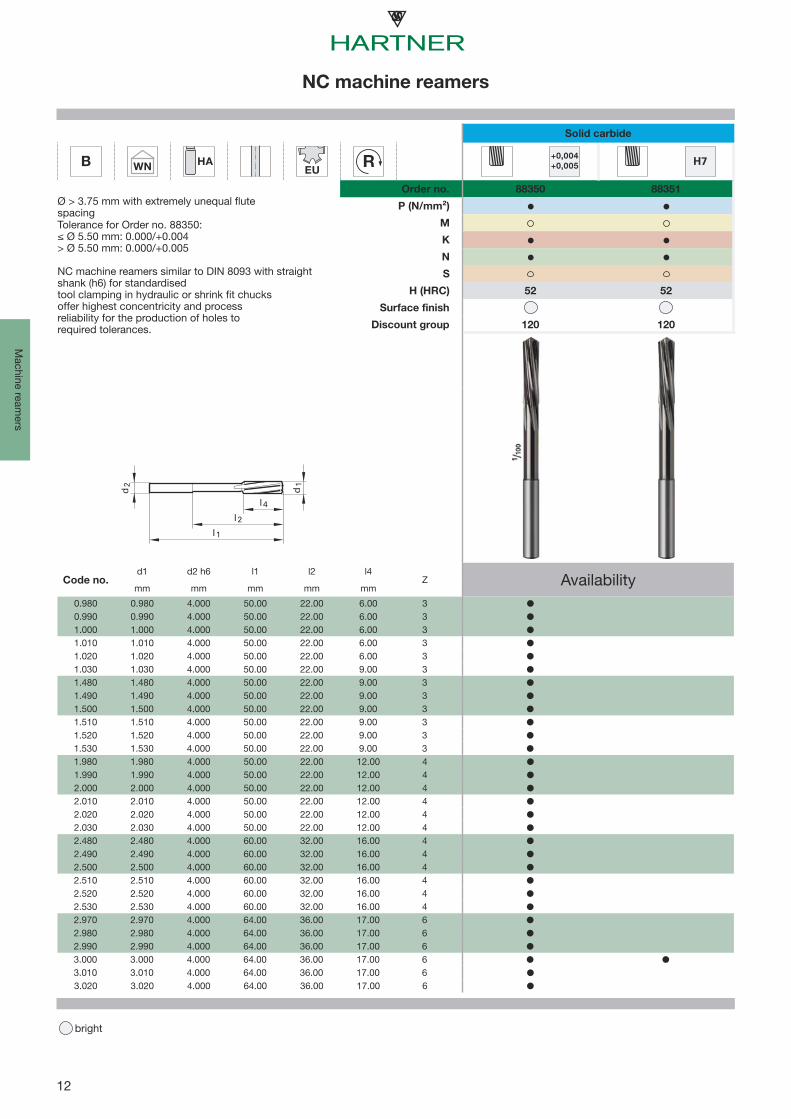
Ø > 3.75 mm with extremely unequal flutespacingTolerance for Order no. 88350:≤ Ø 5.50 mm: 0.000/+0.004> Ø 5.50 mm: 0.000/+0.005
NC machine reamers similar to DIN 8093 with straight shank (h6) for standardisedtool clamping in hydraulic or shrink fit chucksoffer highest concentricity and processreliability for the production of holes torequired tolerances.
52 52
Surface finish
Discount group 120 120
Code no.d1 d2 h6 l1 l2 l4
Z Availabilitymm mm mm mm mm
0.980 0.980 4.000 50.00 22.00 6.00 30.990 0.990 4.000 50.00 22.00 6.00 31.000 1.000 4.000 50.00 22.00 6.00 31.010 1.010 4.000 50.00 22.00 6.00 31.020 1.020 4.000 50.00 22.00 6.00 31.030 1.030 4.000 50.00 22.00 9.00 31.480 1.480 4.000 50.00 22.00 9.00 31.490 1.490 4.000 50.00 22.00 9.00 31.500 1.500 4.000 50.00 22.00 9.00 31.510 1.510 4.000 50.00 22.00 9.00 31.520 1.520 4.000 50.00 22.00 9.00 31.530 1.530 4.000 50.00 22.00 9.00 31.980 1.980 4.000 50.00 22.00 12.00 41.990 1.990 4.000 50.00 22.00 12.00 42.000 2.000 4.000 50.00 22.00 12.00 42.010 2.010 4.000 50.00 22.00 12.00 42.020 2.020 4.000 50.00 22.00 12.00 42.030 2.030 4.000 50.00 22.00 12.00 42.480 2.480 4.000 60.00 32.00 16.00 42.490 2.490 4.000 60.00 32.00 16.00 42.500 2.500 4.000 60.00 32.00 16.00 42.510 2.510 4.000 60.00 32.00 16.00 42.520 2.520 4.000 60.00 32.00 16.00 42.530 2.530 4.000 60.00 32.00 16.00 42.970 2.970 4.000 64.00 36.00 17.00 62.980 2.980 4.000 64.00 36.00 17.00 62.990 2.990 4.000 64.00 36.00 17.00 63.000 3.000 4.000 64.00 36.00 17.00 63.010 3.010 4.000 64.00 36.00 17.00 63.020 3.020 4.000 64.00 36.00 17.00 6

13
B WNHA
EUR +0,004
+0,005 H7
P (N/mm²)
M
K
N
S
H (HRC)
d2
l 1
d1
l 4
l2
NC machine reamers
bright
Mac
hine
ream
ers
Solid carbide
Order no. 88350 88351
Ø > 3.75 mm with extremely unequal flutespacingTolerance for Order no. 88350:≤ Ø 5.50 mm: 0.000/+0.004> Ø 5.50 mm: 0.000/+0.005
NC machine reamers similar to DIN 8093 with straight shank (h6) for standardisedtool clamping in hydraulic or shrink fit chucksoffer highest concentricity and processreliability for the production of holes torequired tolerances.
52 52
Surface finish
Discount group 120 120
Code no.d1 d2 h6 l1 l2 l4
Z Availabilitymm mm mm mm mm
3.030 3.030 4.000 64.00 36.00 17.00 63.100 3.100 4.000 68.00 40.00 18.00 63.200 3.200 4.000 68.00 40.00 18.00 63.300 3.300 4.000 68.00 40.00 18.00 63.400 3.400 4.000 74.00 46.00 20.00 63.500 3.500 4.000 74.00 46.00 20.00 63.600 3.600 4.000 74.00 46.00 20.00 63.700 3.700 4.000 74.00 46.00 20.00 63.800 3.800 4.000 77.00 45.00 21.00 63.970 3.970 4.000 77.00 45.00 21.00 63.980 3.980 4.000 77.00 45.00 21.00 63.990 3.990 4.000 77.00 45.00 21.00 64.000 4.000 4.000 77.00 45.00 21.00 64.010 4.010 4.000 77.00 45.00 21.00 64.020 4.020 4.000 77.00 45.00 21.00 64.030 4.030 4.000 77.00 45.00 21.00 64.100 4.100 6.000 82.00 50.00 23.00 64.200 4.200 6.000 82.00 50.00 23.00 64.300 4.300 6.000 82.00 50.00 23.00 64.400 4.400 6.000 82.00 50.00 23.00 64.500 4.500 6.000 82.00 50.00 23.00 64.600 4.600 6.000 82.00 50.00 23.00 64.700 4.700 6.000 82.00 50.00 23.00 64.800 4.800 6.000 93.00 59.00 26.00 64.900 4.900 6.000 93.00 59.00 26.00 64.970 4.970 6.000 93.00 59.00 26.00 64.980 4.980 6.000 93.00 59.00 26.00 64.990 4.990 6.000 93.00 59.00 26.00 65.000 5.000 6.000 93.00 59.00 26.00 65.010 5.010 6.000 93.00 59.00 26.00 6

14
B WNHA
EUR +0,004
+0,005 H7
P (N/mm²)
M
K
N
S
H (HRC)
d2
l 1
d1
l 4
l2
NC machine reamers
bright
Machine ream
ers
Solid carbide
Order no. 88350 88351
Ø > 3.75 mm with extremely unequal flutespacingTolerance for Order no. 88350:≤ Ø 5.50 mm: 0.000/+0.004> Ø 5.50 mm: 0.000/+0.005
NC machine reamers similar to DIN 8093 with straight shank (h6) for standardisedtool clamping in hydraulic or shrink fit chucksoffer highest concentricity and processreliability for the production of holes torequired tolerances.
52 52
Surface finish
Discount group 120 120
Code no.d1 d2 h6 l1 l2 l4
Z Availabilitymm mm mm mm mm
5.020 5.020 6.000 93.00 59.00 26.00 65.030 5.030 6.000 93.00 59.00 26.00 65.100 5.100 6.000 93.00 59.00 26.00 65.200 5.200 6.000 93.00 59.00 26.00 65.300 5.300 6.000 93.00 59.00 26.00 65.500 5.500 6.000 93.00 57.00 26.00 65.600 5.600 6.000 93.00 57.00 26.00 65.700 5.700 6.000 93.00 57.00 26.00 65.800 5.800 6.000 93.00 57.00 26.00 65.970 5.970 6.000 93.00 57.00 26.00 65.980 5.980 6.000 93.00 57.00 26.00 65.990 5.990 6.000 93.00 57.00 26.00 66.000 6.000 6.000 93.00 57.00 26.00 66.010 6.010 6.000 93.00 57.00 26.00 66.020 6.020 6.000 93.00 57.00 26.00 66.030 6.030 6.000 93.00 57.00 26.00 66.100 6.100 8.000 101.00 63.00 28.00 66.200 6.200 8.000 101.00 63.00 28.00 66.300 6.300 8.000 101.00 63.00 28.00 66.400 6.400 8.000 101.00 63.00 28.00 66.500 6.500 8.000 101.00 63.00 28.00 66.600 6.600 8.000 101.00 63.00 28.00 66.700 6.700 8.000 101.00 63.00 28.00 66.800 6.800 8.000 109.00 69.00 31.00 67.000 7.000 8.000 109.00 69.00 31.00 67.100 7.100 8.000 109.00 69.00 31.00 67.200 7.200 8.000 109.00 69.00 31.00 67.400 7.400 8.000 109.00 69.00 31.00 67.500 7.500 8.000 109.00 69.00 31.00 67.700 7.700 8.000 117.00 75.00 33.00 6

15
B WNHA
EUR +0,004
+0,005 H7
P (N/mm²)
M
K
N
S
H (HRC)
d2
l 1
d1
l 4
l2
NC machine reamers
bright
Mac
hine
ream
ers
Solid carbide
Order no. 88350 88351
Ø > 3.75 mm with extremely unequal flutespacingTolerance for Order no. 88350:≤ Ø 5.50 mm: 0.000/+0.004> Ø 5.50 mm: 0.000/+0.005
NC machine reamers similar to DIN 8093 with straight shank (h6) for standardisedtool clamping in hydraulic or shrink fit chucksoffer highest concentricity and processreliability for the production of holes torequired tolerances.
52 52
Surface finish
Discount group 120 120
Code no.d1 d2 h6 l1 l2 l4
Z Availabilitymm mm mm mm mm
7.800 7.800 8.000 117.00 75.00 33.00 67.900 7.900 8.000 117.00 75.00 33.00 67.970 7.970 8.000 117.00 75.00 33.00 67.980 7.980 8.000 117.00 75.00 33.00 67.990 7.990 8.000 117.00 75.00 33.00 68.000 8.000 8.000 117.00 75.00 33.00 68.010 8.010 8.000 117.00 75.00 33.00 68.020 8.020 8.000 117.00 75.00 33.00 68.030 8.030 8.000 117.00 75.00 33.00 68.040 8.040 8.000 117.00 75.00 33.00 68.100 8.100 10.000 117.00 75.00 33.00 68.200 8.200 10.000 117.00 75.00 33.00 68.300 8.300 10.000 117.00 75.00 33.00 68.400 8.400 10.000 117.00 75.00 33.00 68.500 8.500 10.000 117.00 75.00 33.00 68.600 8.600 10.000 117.00 75.00 33.00 68.700 8.700 10.000 125.00 81.00 36.00 68.800 8.800 10.000 125.00 81.00 36.00 68.900 8.900 10.000 125.00 81.00 36.00 69.000 9.000 10.000 125.00 81.00 36.00 69.100 9.100 10.000 125.00 81.00 36.00 69.300 9.300 10.000 125.00 81.00 36.00 69.500 9.500 10.000 125.00 81.00 36.00 69.600 9.600 10.000 125.00 81.00 36.00 69.700 9.700 10.000 133.00 87.00 38.00 69.800 9.800 10.000 133.00 87.00 38.00 69.900 9.900 10.000 133.00 87.00 38.00 69.970 9.970 10.000 133.00 87.00 38.00 69.980 9.980 10.000 133.00 87.00 38.00 69.990 9.990 10.000 133.00 87.00 38.00 6

16
B WNHA
EUR +0,004
+0,005 H7
P (N/mm²)
M
K
N
S
H (HRC)
d2
l 1
d1
l 4
l2
NC machine reamers
bright
Machine ream
ers
Solid carbide
Order no. 88350 88351
Ø > 3.75 mm with extremely unequal flutespacingTolerance for Order no. 88350:≤ Ø 5.50 mm: 0.000/+0.004> Ø 5.50 mm: 0.000/+0.005
NC machine reamers similar to DIN 8093 with straight shank (h6) for standardisedtool clamping in hydraulic or shrink fit chucksoffer highest concentricity and processreliability for the production of holes torequired tolerances.
52 52
Surface finish
Discount group 120 120
Code no.d1 d2 h6 l1 l2 l4
Z Availabilitymm mm mm mm mm
10.000 10.000 10.000 133.00 87.00 38.00 610.010 10.010 10.000 133.00 87.00 38.00 610.020 10.020 10.000 133.00 87.00 38.00 610.030 10.030 10.000 133.00 87.00 38.00 610.040 10.040 10.000 133.00 87.00 38.00 610.050 10.050 10.000 133.00 87.00 38.00 610.100 10.100 10.000 133.00 87.00 38.00 610.200 10.200 10.000 133.00 87.00 38.00 610.300 10.300 10.000 133.00 87.00 38.00 610.400 10.400 10.000 133.00 87.00 38.00 610.500 10.500 10.000 133.00 87.00 38.00 610.600 10.600 10.000 133.00 87.00 38.00 611.000 11.000 10.000 142.00 96.00 41.00 611.100 11.100 10.000 142.00 96.00 41.00 611.200 11.200 10.000 142.00 96.00 41.00 611.300 11.300 10.000 142.00 96.00 41.00 611.500 11.500 10.000 142.00 96.00 41.00 611.600 11.600 10.000 142.00 96.00 41.00 611.800 11.800 10.000 142.00 96.00 41.00 611.900 11.900 12.000 151.00 105.00 44.00 611.970 11.970 12.000 151.00 105.00 44.00 611.980 11.980 12.000 151.00 105.00 44.00 611.990 11.990 12.000 151.00 105.00 44.00 612.000 12.000 12.000 151.00 105.00 44.00 612.010 12.010 12.000 151.00 105.00 44.00 612.020 12.020 12.000 151.00 105.00 44.00 612.030 12.030 12.000 151.00 105.00 44.00 612.040 12.040 12.000 151.00 105.00 44.00 612.050 12.050 12.000 151.00 105.00 44.00 6

17
H7 ~DIN8050 Cyl
EUR
A
B
P (N/mm²)
M
K
N
S
H (HRC)
d2
l 1
d1
l 4
l2
Machine reamers
bright
Mac
hine
ream
ers
Carbide
Order no. 88352 88353
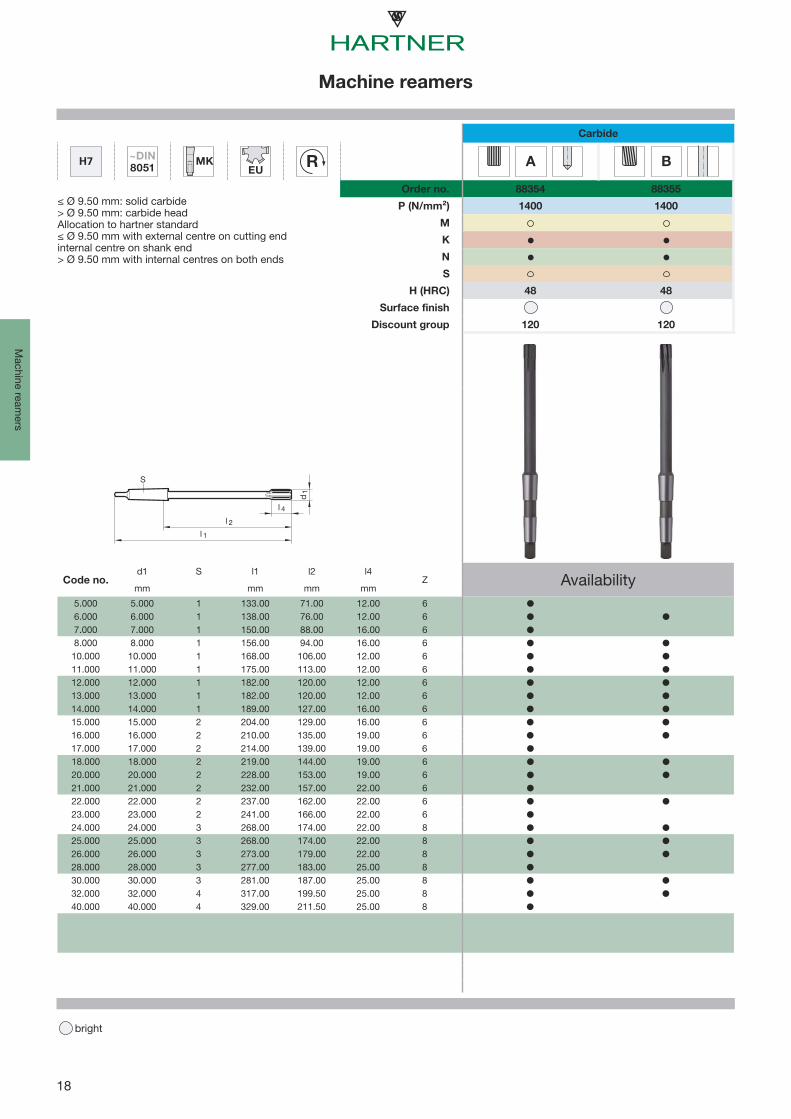
≤ Ø 9.50 mm: solid carbide> Ø 9.50 mm: carbide headAllocation to hartner standard≤ Ø 9.50 mm with ext. centres on both ends> Ø 9.50 mm with int. centres on both ends
1400 1400
48 48
Surface finish
Discount group 120 120
Code no.d1 d2 h6 l1 l2 l4
Z Availabilitymm mm mm mm mm
5.000 5.000 5.000 86.00 52.00 12.00 66.000 6.000 5.600 93.00 57.00 12.00 67.000 7.000 7.100 109.00 69.00 16.00 68.000 8.000 8.000 117.00 75.00 16.00 69.000 9.000 9.000 125.00 81.00 19.00 6
10.000 10.000 10.000 133.00 87.00 12.00 611.000 11.000 10.000 142.00 96.00 12.00 612.000 12.000 10.000 151.00 105.00 12.00 613.000 13.000 10.000 151.00 105.00 12.00 614.000 14.000 12.000 160.00 110.00 16.00 615.000 15.000 12.000 162.00 112.00 16.00 616.000 16.000 12.000 170.00 120.00 19.00 618.000 18.000 14.000 182.00 130.00 19.00 620.000 20.000 16.000 195.00 137.00 19.00 6
18
H7 ~DIN8051
MKEU
R
A
B
P (N/mm²)
M
K
N
S
H (HRC)
l 1
d1
l 4
l 2
S
Machine reamers
bright
Machine ream
ers
Carbide
Order no. 88354 88355
≤ Ø 9.50 mm: solid carbide> Ø 9.50 mm: carbide headAllocation to hartner standard≤ Ø 9.50 mm with external centre on cutting endinternal centre on shank end> Ø 9.50 mm with internal centres on both ends
1400 1400
48 48
Surface finish
Discount group 120 120
Code no.d1 S l1 l2 l4
Z Availabilitymm mm mm mm
5.000 5.000 1 133.00 71.00 12.00 66.000 6.000 1 138.00 76.00 12.00 67.000 7.000 1 150.00 88.00 16.00 68.000 8.000 1 156.00 94.00 16.00 6
10.000 10.000 1 168.00 106.00 12.00 611.000 11.000 1 175.00 113.00 12.00 612.000 12.000 1 182.00 120.00 12.00 613.000 13.000 1 182.00 120.00 12.00 614.000 14.000 1 189.00 127.00 16.00 615.000 15.000 2 204.00 129.00 16.00 616.000 16.000 2 210.00 135.00 19.00 617.000 17.000 2 214.00 139.00 19.00 618.000 18.000 2 219.00 144.00 19.00 620.000 20.000 2 228.00 153.00 19.00 621.000 21.000 2 232.00 157.00 22.00 622.000 22.000 2 237.00 162.00 22.00 623.000 23.000 2 241.00 166.00 22.00 624.000 24.000 3 268.00 174.00 22.00 825.000 25.000 3 268.00 174.00 22.00 826.000 26.000 3 273.00 179.00 22.00 828.000 28.000 3 277.00 183.00 25.00 830.000 30.000 3 281.00 187.00 25.00 832.000 32.000 4 317.00 199.50 25.00 840.000 40.000 4 329.00 211.50 25.00 8

19
High speed steel reamers
bright
Hig
h sp
eed
stee
l rea
mer
s
Standard Form Shank form Diameter tolerance
Tool material
Surfacefinish Hole type d1 Order
no.
Discountgroup
Standard range page
NC machine reamers
DIN 212-3 B HA +0,004+0,005 HSS-E 1.000 - 12.020 88300 105 20
DIN 212-3 B HA H7 HSS-E 1.500 - 20.000 88301 105 20
Machine reamers
DIN 212 A cyl. H7 HSS-E 1.000 - 5.500 88302 105 25
DIN 212 B cyl. H7 HSS-E 1.000 - 3.700 88304 105 25
DIN 212-2 A cyl. H7 HSS-E 4.000 - 20.000 88305 105 26
DIN 212-2 B cyl. H7 HSS-E 3.800 - 20.000 88306 105 26
DIN 212 B cyl. +0,004+0,005 HSS-E 0.950 - 12.050 88311 105 28
DIN 208 A MK H7 HSS-E 3.000 - 40.000 88307 105 30
DIN 208 B MK H7 HSS-E 3.000 - 50.000 88308 105 30

20
B DIN212-3 HA
≠ R +0,004+0,005 H7
P (N/mm²)
M
K
N
S
H (HRC)
d2
l 1
d1
l 4
l2
NC machine reamers
bright
High speed steel ream
ers
HSS-E
Order no. 88300 88301
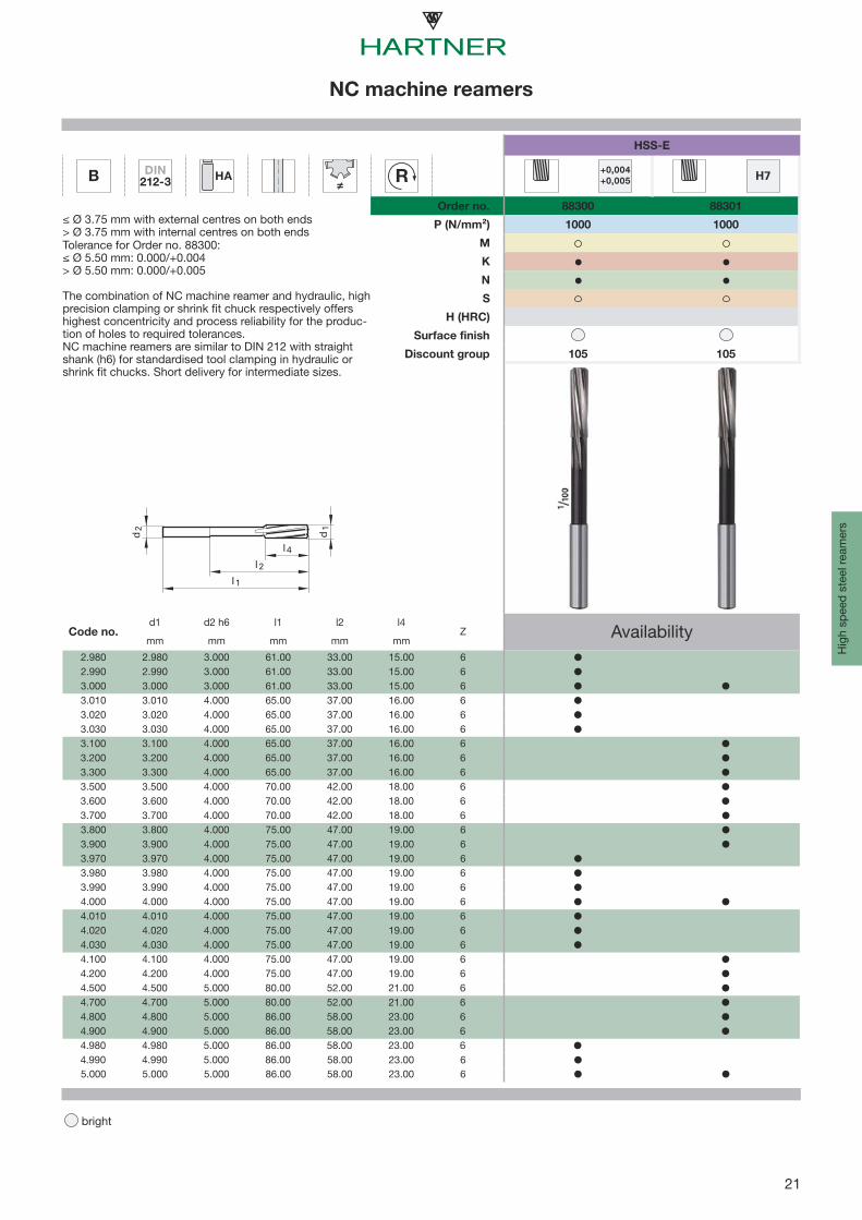
≤ Ø 3.75 mm with external centres on both ends> Ø 3.75 mm with internal centres on both endsTolerance for Order no. 88300:≤ Ø 5.50 mm: 0.000/+0.004> Ø 5.50 mm: 0.000/+0.005
The combination of NC machine reamer and hydraulic, high precision clamping or shrink fit chuck respectively offers highest concentricity and process reliability for the produc-tion of holes to required tolerances. NC machine reamers are similar to DIN 212 with straight shank (h6) for standardised tool clamping in hydraulic or shrink fit chucks. Short delivery for intermediate sizes.
1000 1000
Surface finish
Discount group 105 105
Code no.d1 d2 h6 l1 l2 l4
Z Availabilitymm mm mm mm mm
1.000 1.000 1.000 34.00 15.00 5.50 31.010 1.010 1.000 34.00 15.00 5.50 31.500 1.500 2.000 40.00 18.00 8.00 31.510 1.510 2.000 43.00 20.00 9.00 31.530 1.530 2.000 43.00 20.00 9.00 31.600 1.600 2.000 43.00 20.00 9.00 31.700 1.700 2.000 43.00 20.00 9.00 31.800 1.800 2.000 46.00 22.00 10.00 41.970 1.970 2.000 49.00 24.00 11.00 41.980 1.980 2.000 49.00 24.00 11.00 41.990 1.990 2.000 49.00 24.00 11.00 42.000 2.000 2.000 49.00 24.00 11.00 42.010 2.010 2.000 49.00 24.00 11.00 42.020 2.020 2.000 49.00 24.00 11.00 42.030 2.030 2.000 49.00 24.00 11.00 42.100 2.100 2.000 49.00 24.00 11.00 42.200 2.200 3.000 53.00 25.00 12.00 42.300 2.300 3.000 53.00 25.00 12.00 42.400 2.400 3.000 57.00 29.00 14.00 42.470 2.470 3.000 57.00 29.00 14.00 42.490 2.490 3.000 57.00 29.00 14.00 42.500 2.500 3.000 57.00 29.00 14.00 42.510 2.510 3.000 57.00 29.00 14.00 42.520 2.520 3.000 57.00 29.00 14.00 42.530 2.530 3.000 57.00 29.00 14.00 42.600 2.600 3.000 57.00 29.00 14.00 42.700 2.700 3.000 61.00 33.00 15.00 62.800 2.800 3.000 61.00 33.00 15.00 62.900 2.900 3.000 61.00 33.00 15.00 62.970 2.970 3.000 61.00 33.00 15.00 6
21
B DIN212-3 HA
≠ R +0,004+0,005 H7
P (N/mm²)
M
K
N
S
H (HRC)
d2
l 1
d1
l 4
l2
NC machine reamers
bright
Hig
h sp
eed
stee
l rea
mer
s
HSS-E
Order no. 88300 88301
≤ Ø 3.75 mm with external centres on both ends> Ø 3.75 mm with internal centres on both endsTolerance for Order no. 88300:≤ Ø 5.50 mm: 0.000/+0.004> Ø 5.50 mm: 0.000/+0.005
The combination of NC machine reamer and hydraulic, high precision clamping or shrink fit chuck respectively offers highest concentricity and process reliability for the produc-tion of holes to required tolerances. NC machine reamers are similar to DIN 212 with straight shank (h6) for standardised tool clamping in hydraulic or shrink fit chucks. Short delivery for intermediate sizes.
1000 1000
Surface finish
Discount group 105 105
Code no.d1 d2 h6 l1 l2 l4
Z Availabilitymm mm mm mm mm
2.980 2.980 3.000 61.00 33.00 15.00 62.990 2.990 3.000 61.00 33.00 15.00 63.000 3.000 3.000 61.00 33.00 15.00 63.010 3.010 4.000 65.00 37.00 16.00 63.020 3.020 4.000 65.00 37.00 16.00 63.030 3.030 4.000 65.00 37.00 16.00 63.100 3.100 4.000 65.00 37.00 16.00 63.200 3.200 4.000 65.00 37.00 16.00 63.300 3.300 4.000 65.00 37.00 16.00 63.500 3.500 4.000 70.00 42.00 18.00 63.600 3.600 4.000 70.00 42.00 18.00 63.700 3.700 4.000 70.00 42.00 18.00 63.800 3.800 4.000 75.00 47.00 19.00 63.900 3.900 4.000 75.00 47.00 19.00 63.970 3.970 4.000 75.00 47.00 19.00 63.980 3.980 4.000 75.00 47.00 19.00 63.990 3.990 4.000 75.00 47.00 19.00 64.000 4.000 4.000 75.00 47.00 19.00 64.010 4.010 4.000 75.00 47.00 19.00 64.020 4.020 4.000 75.00 47.00 19.00 64.030 4.030 4.000 75.00 47.00 19.00 64.100 4.100 4.000 75.00 47.00 19.00 64.200 4.200 4.000 75.00 47.00 19.00 64.500 4.500 5.000 80.00 52.00 21.00 64.700 4.700 5.000 80.00 52.00 21.00 64.800 4.800 5.000 86.00 58.00 23.00 64.900 4.900 5.000 86.00 58.00 23.00 64.980 4.980 5.000 86.00 58.00 23.00 64.990 4.990 5.000 86.00 58.00 23.00 65.000 5.000 5.000 86.00 58.00 23.00 6

22
B DIN212-3 HA
≠ R +0,004+0,005 H7
P (N/mm²)
M
K
N
S
H (HRC)
d2
l 1
d1
l 4
l2
NC machine reamers
bright
High speed steel ream
ers
HSS-E
Order no. 88300 88301
≤ Ø 3.75 mm with external centres on both ends> Ø 3.75 mm with internal centres on both endsTolerance for Order no. 88300:≤ Ø 5.50 mm: 0.000/+0.004> Ø 5.50 mm: 0.000/+0.005
The combination of NC machine reamer and hydraulic, high precision clamping or shrink fit chuck respectively offers highest concentricity and process reliability for the produc-tion of holes to required tolerances. NC machine reamers are similar to DIN 212 with straight shank (h6) for standardised tool clamping in hydraulic or shrink fit chucks. Short delivery for intermediate sizes.
1000 1000
Surface finish
Discount group 105 105
Code no.d1 d2 h6 l1 l2 l4
Z Availabilitymm mm mm mm mm
5.010 5.010 5.000 86.00 58.00 23.00 65.020 5.020 5.000 86.00 58.00 23.00 65.030 5.030 5.000 86.00 58.00 23.00 65.100 5.100 5.000 86.00 58.00 23.00 65.200 5.200 5.000 86.00 58.00 23.00 65.300 5.300 5.000 86.00 58.00 23.00 65.400 5.400 6.000 93.00 57.00 26.00 65.500 5.500 6.000 93.00 57.00 26.00 65.600 5.600 6.000 93.00 57.00 26.00 65.700 5.700 6.000 93.00 57.00 26.00 65.800 5.800 6.000 93.00 57.00 26.00 65.900 5.900 6.000 93.00 57.00 26.00 65.980 5.980 6.000 93.00 57.00 26.00 65.990 5.990 6.000 93.00 57.00 26.00 66.000 6.000 6.000 93.00 57.00 26.00 66.010 6.010 6.000 101.00 65.00 28.00 66.020 6.020 6.000 101.00 65.00 28.00 66.030 6.030 6.000 101.00 65.00 28.00 66.100 6.100 6.000 101.00 65.00 28.00 66.200 6.200 6.000 101.00 65.00 28.00 66.300 6.300 6.000 101.00 65.00 28.00 66.400 6.400 6.000 101.00 65.00 28.00 66.500 6.500 6.000 101.00 65.00 28.00 66.600 6.600 6.000 101.00 65.00 28.00 66.800 6.800 8.000 109.00 73.00 31.00 66.900 6.900 8.000 109.00 73.00 31.00 67.000 7.000 8.000 109.00 73.00 31.00 67.100 7.100 8.000 109.00 73.00 31.00 67.300 7.300 8.000 109.00 73.00 31.00 67.400 7.400 8.000 109.00 73.00 31.00 6

23
B DIN212-3 HA
≠ R +0,004+0,005 H7
P (N/mm²)
M
K
N
S
H (HRC)
d2
l 1
d1
l 4
l2
NC machine reamers
bright
Hig
h sp
eed
stee
l rea
mer
s
HSS-E
Order no. 88300 88301
≤ Ø 3.75 mm with external centres on both ends> Ø 3.75 mm with internal centres on both endsTolerance for Order no. 88300:≤ Ø 5.50 mm: 0.000/+0.004> Ø 5.50 mm: 0.000/+0.005
The combination of NC machine reamer and hydraulic, high precision clamping or shrink fit chuck respectively offers highest concentricity and process reliability for the produc-tion of holes to required tolerances. NC machine reamers are similar to DIN 212 with straight shank (h6) for standardised tool clamping in hydraulic or shrink fit chucks. Short delivery for intermediate sizes.
1000 1000
Surface finish
Discount group 105 105
Code no.d1 d2 h6 l1 l2 l4
Z Availabilitymm mm mm mm mm
7.500 7.500 8.000 109.00 73.00 31.00 67.600 7.600 8.000 117.00 81.00 33.00 67.700 7.700 8.000 117.00 81.00 33.00 67.800 7.800 8.000 117.00 81.00 33.00 67.900 7.900 8.000 117.00 81.00 33.00 67.970 7.970 8.000 117.00 81.00 33.00 67.980 7.980 8.000 117.00 81.00 33.00 67.990 7.990 8.000 117.00 81.00 33.00 68.000 8.000 8.000 117.00 81.00 33.00 68.010 8.010 8.000 117.00 81.00 33.00 68.020 8.020 8.000 117.00 81.00 33.00 68.030 8.030 8.000 117.00 81.00 33.00 68.100 8.100 8.000 117.00 81.00 33.00 68.200 8.200 8.000 117.00 81.00 33.00 68.300 8.300 8.000 117.00 81.00 33.00 68.500 8.500 8.000 117.00 81.00 33.00 68.600 8.600 10.000 125.00 85.00 36.00 68.700 8.700 10.000 125.00 85.00 36.00 68.800 8.800 10.000 125.00 85.00 36.00 69.000 9.000 10.000 125.00 85.00 36.00 69.010 9.010 10.000 125.00 85.00 36.00 69.100 9.100 10.000 125.00 85.00 36.00 69.200 9.200 10.000 125.00 85.00 36.00 69.300 9.300 10.000 125.00 85.00 36.00 69.500 9.500 10.000 125.00 85.00 36.00 69.700 9.700 10.000 133.00 93.00 38.00 69.970 9.970 10.000 133.00 93.00 38.00 69.980 9.980 10.000 133.00 93.00 38.00 69.990 9.990 10.000 133.00 93.00 38.00 610.000 10.000 10.000 133.00 93.00 38.00 6

24
B DIN212-3 HA
≠ R +0,004+0,005 H7
P (N/mm²)
M
K
N
S
H (HRC)
d2
l 1
d1
l 4
l2
NC machine reamers
bright
High speed steel ream
ers
HSS-E
Order no. 88300 88301
≤ Ø 3.75 mm with external centres on both ends> Ø 3.75 mm with internal centres on both endsTolerance for Order no. 88300:≤ Ø 5.50 mm: 0.000/+0.004> Ø 5.50 mm: 0.000/+0.005
The combination of NC machine reamer and hydraulic, high precision clamping or shrink fit chuck respectively offers highest concentricity and process reliability for the produc-tion of holes to required tolerances. NC machine reamers are similar to DIN 212 with straight shank (h6) for standardised tool clamping in hydraulic or shrink fit chucks. Short delivery for intermediate sizes.
1000 1000
Surface finish
Discount group 105 105
Code no.d1 d2 h6 l1 l2 l4
Z Availabilitymm mm mm mm mm
10.010 10.010 10.000 133.00 93.00 38.00 610.020 10.020 10.000 133.00 93.00 38.00 610.030 10.030 10.000 133.00 93.00 38.00 611.000 11.000 10.000 142.00 102.00 41.00 611.980 11.980 10.000 151.00 111.00 44.00 611.990 11.990 10.000 151.00 111.00 44.00 612.000 12.000 10.000 151.00 111.00 44.00 612.010 12.010 10.000 151.00 111.00 44.00 612.020 12.020 10.000 151.00 111.00 44.00 613.000 13.000 10.000 151.00 111.00 44.00 614.000 14.000 14.000 160.00 115.00 47.00 815.000 15.000 14.000 162.00 117.00 50.00 816.000 16.000 14.000 170.00 125.00 52.00 817.000 17.000 14.000 175.00 130.00 54.00 818.000 18.000 14.000 182.00 137.00 56.00 819.000 19.000 16.000 189.00 141.00 58.00 820.000 20.000 16.000 195.00 147.00 60.00 8

25
H7 DIN212 Cyl
≠ R
A
B
P (N/mm²)
M
K
N
S
H (HRC)
d2
l 1
d1
l 4
l2
Machine reamers
bright
Hig
h sp
eed
stee
l rea
mer
s
HSS-E
Order no. 88302 88304
≤ Ø 3.75 mm with external centres on bothends> Ø 3.75 mm with internal centres on bothends
1000 1000
Surface finish
Discount group 105 105
Code no.d1 d2 h6 l1 l2 l4
Z Availabilitymm mm mm mm mm
1.000 1.000 1.000 34.00 15.00 5.50 31.200 1.200 1.200 38.00 16.50 7.50 31.300 1.300 1.300 38.00 16.50 7.50 31.400 1.400 1.400 40.00 18.00 8.00 31.500 1.500 1.500 40.00 18.00 8.00 31.600 1.600 1.600 43.00 20.00 9.00 31.800 1.800 1.800 46.00 22.00 10.00 41.900 1.900 1.900 46.00 22.00 10.00 42.000 2.000 2.000 49.00 24.00 11.00 42.200 2.200 2.200 53.00 25.00 12.00 42.300 2.300 2.300 53.00 25.00 12.00 42.500 2.500 2.500 57.00 29.00 14.00 42.700 2.700 2.800 61.00 33.00 15.00 62.800 2.800 2.800 61.00 33.00 15.00 62.900 2.900 3.000 61.00 33.00 15.00 63.000 3.000 3.000 61.00 33.00 15.00 63.200 3.200 3.200 65.00 37.00 16.00 63.500 3.500 3.500 70.00 42.00 18.00 63.700 3.700 3.500 70.00 42.00 18.00 65.500 5.500 5.600 93.00 57.00 26.00 6

26
H7 DIN212-2 Cyl
≠ R
A
B
P (N/mm²)
M
K
N
S
H (HRC)
d2
l 1
d1
l 4
l2
Machine reamers
bright
High speed steel ream
ers
HSS-E
Order no. 88305 88306
≤ Ø 3.75 mm with external centres on bothends> Ø 3.75 mm with internal centres on bothends
1000 1000
Surface finish
Discount group 105 105
Code no.d1 d2 h6 l1 l2 l4
Z Availabilitymm mm mm mm mm
3.800 3.800 4.000 75.00 47.00 19.00 64.000 4.000 4.000 75.00 47.00 19.00 64.400 4.400 4.500 80.00 52.00 21.00 64.500 4.500 4.500 80.00 52.00 21.00 64.700 4.700 4.500 80.00 52.00 21.00 64.900 4.900 5.000 86.00 58.00 23.00 65.000 5.000 5.000 86.00 58.00 23.00 65.100 5.100 5.000 86.00 58.00 23.00 65.500 5.500 5.600 93.00 57.00 26.00 66.000 6.000 5.600 93.00 57.00 26.00 66.100 6.100 6.300 101.00 65.00 28.00 66.200 6.200 6.300 101.00 65.00 28.00 66.500 6.500 6.300 101.00 65.00 28.00 66.900 6.900 7.100 109.00 73.00 31.00 67.000 7.000 7.100 109.00 73.00 31.00 67.100 7.100 7.100 109.00 73.00 31.00 67.200 7.200 7.100 109.00 73.00 31.00 67.400 7.400 7.100 109.00 73.00 31.00 67.500 7.500 7.100 109.00 73.00 31.00 68.000 8.000 8.000 117.00 81.00 33.00 68.100 8.100 8.000 117.00 81.00 33.00 68.300 8.300 8.000 117.00 81.00 33.00 68.500 8.500 8.000 117.00 81.00 33.00 69.000 9.000 9.000 125.00 85.00 36.00 69.200 9.200 9.000 125.00 85.00 36.00 69.400 9.400 9.000 125.00 85.00 36.00 69.500 9.500 9.000 125.00 85.00 36.00 69.800 9.800 10.000 133.00 93.00 38.00 69.900 9.900 10.000 133.00 93.00 38.00 610.000 10.000 10.000 133.00 93.00 38.00 6

27
H7 DIN212-2 Cyl
≠ R
A
B
P (N/mm²)
M
K
N
S
H (HRC)
d2
l 1
d1
l 4
l2
Machine reamers
bright
Hig
h sp
eed
stee
l rea
mer
s
HSS-E
Order no. 88305 88306
≤ Ø 3.75 mm with external centres on bothends> Ø 3.75 mm with internal centres on bothends
1000 1000
Surface finish
Discount group 105 105
Code no.d1 d2 h6 l1 l2 l4
Z Availabilitymm mm mm mm mm
10.100 10.100 10.000 133.00 93.00 38.00 610.500 10.500 10.000 133.00 93.00 38.00 610.700 10.700 10.000 142.00 102.00 41.00 611.000 11.000 10.000 142.00 102.00 41.00 611.500 11.500 10.000 142.00 102.00 41.00 612.000 12.000 10.000 151.00 111.00 44.00 613.000 13.000 10.000 151.00 111.00 44.00 614.000 14.000 12.500 160.00 115.00 47.00 815.000 15.000 12.500 162.00 117.00 50.00 816.000 16.000 12.500 170.00 125.00 52.00 817.000 17.000 14.000 175.00 130.00 54.00 818.000 18.000 14.000 182.00 137.00 56.00 819.000 19.000 16.000 189.00 141.00 58.00 820.000 20.000 16.000 195.00 147.00 60.00 8
28
B DIN212 Cyl
≠ R +0,004+0,005
P (N/mm²)
M
K
N
S
H (HRC)
d2
l 1
d1
l 4
l2
Machine reamers
bright
High speed steel ream
ers
HSS-E
Order no. 88311
≤ Ø 3.75 mm with external centres on both ends> Ø 3.75 mm with internal centres on both endsØ in increments of 0.01 mmTolerance:Ø 0.95 - 5.50 mm: 0.000/+0.004Ø 5.51 - 12.05 mm: 0.000/+0.005
1000
105
from d1 to d1 d2 h9 l1 l2 l4 ZAvailability
mm mm mm mm mm mm
0.950 1.060 1.000 34.000 15.000 5.500 31.070 1.180 1.100 36.000 15.500 6.500 31.190 1.320 1.200 38.000 16.500 7.500 31.330 1.390 1.400 40.000 18.000 8.000 31.400 1.410 1.400 40.000 18.000 8.000 31.420 1.490 1.500 40.000 18.000 8.000 31.500 1.500 1.500 40.000 18.000 8.000 31.510 1.700 1.600 43.000 20.000 9.000 31.710 1.900 1.800 46.000 22.000 10.000 41.910 1.990 2.000 49.000 24.000 11.000 42.000 2.090 2.000 49.000 24.000 11.000 42.100 2.120 2.000 49.000 24.000 11.000 42.130 2.360 2.200 53.000 25.000 12.000 42.370 2.490 2.500 57.000 29.000 14.000 42.500 2.590 2.500 57.000 29.000 14.000 42.600 2.650 2.500 57.000 29.000 14.000 42.660 2.800 2.800 61.000 33.000 15.000 62.810 2.990 3.000 61.000 33.000 15.000 63.000 3.000 3.000 61.000 33.000 15.000 63.010 3.090 3.200 65.000 37.000 16.000 63.100 3.350 3.200 65.000 37.000 16.000 63.360 3.490 3.500 70.000 42.000 18.000 63.500 3.590 3.500 70.000 42.000 18.000 63.600 3.740 3.500 70.000 42.000 18.000 63.760 3.810 4.000 75.000 47.000 19.000 63.820 4.200 4.000 75.000 47.000 19.000 64.210 4.250 4.000 75.000 47.000 19.000 64.260 4.750 4.500 80.000 52.000 21.000 64.760 5.200 5.000 86.000 58.000 23.000 65.210 5.300 5.000 86.000 58.000 23.000 6
29
B DIN212 Cyl
≠ R +0,004+0,005
P (N/mm²)
M
K
N
S
H (HRC)
d2
l 1
d1
l 4
l2
Machine reamers
bright
Hig
h sp
eed
stee
l rea
mer
s
HSS-E
Order no. 88311
≤ Ø 3.75 mm with external centres on both ends> Ø 3.75 mm with internal centres on both endsØ in increments of 0.01 mmTolerance:Ø 0.95 - 5.50 mm: 0.000/+0.004Ø 5.51 - 12.05 mm: 0.000/+0.005
1000
105
from d1 to d1 d2 h9 l1 l2 l4 ZAvailability
mm mm mm mm mm mm
5.310 6.000 5.600 93.000 57.000 26.000 66.010 6.110 6.300 101.000 65.000 28.000 66.120 6.700 6.300 101.000 65.000 28.000 66.710 7.500 7.100 109.000 73.000 31.000 67.510 8.200 8.000 117.000 81.000 33.000 68.210 8.500 8.000 117.000 81.000 33.000 68.510 9.500 9.000 125.000 85.000 36.000 69.990 10.000 10.000 133.000 93.000 38.000 6
10.210 10.600 10.000 133.000 93.000 38.000 610.610 11.200 10.000 142.000 102.000 41.000 611.210 11.800 10.000 142.000 102.000 41.000 611.810 12.000 10.000 151.000 111.000 44.000 612.010 12.050 10.000 151.000 74.500 44.000 6

30
H7 DIN208 MK
≠ R
A
B
P (N/mm²)
M
K
N
S
H (HRC)
l 2
d1
l 4
l 1
S
Machine reamers
bright
High speed steel ream
ers
HSS-E
Order no. 88307 88308
Ø 3.00 mm with external centre on cuttingend, with internal centre on shank end> Ø 3.00 mm with internal centres on bothends≤ Ø 4.00 mm to hartner standard
1000 1000
Surface finish
Discount group 105 105
Code no.d1 S l1 l2 l4
Z Availabilitymm mm mm mm
3.000 3.000 1 115.00 53.00 15.00 64.000 4.000 1 125.00 63.00 19.00 65.000 5.000 1 133.00 71.00 23.00 65.100 5.100 1 133.00 71.00 23.00 65.500 5.500 1 138.00 76.00 26.00 66.000 6.000 1 138.00 76.00 26.00 66.100 6.100 1 144.00 82.00 28.00 66.200 6.200 1 144.00 82.00 28.00 66.500 6.500 1 144.00 82.00 28.00 67.000 7.000 1 150.00 88.00 31.00 67.500 7.500 1 150.00 88.00 31.00 68.000 8.000 1 156.00 94.00 33.00 68.500 8.500 1 156.00 94.00 33.00 69.000 9.000 1 162.00 100.00 36.00 69.500 9.500 1 162.00 100.00 36.00 69.800 9.800 1 168.00 106.00 38.00 6
10.000 10.000 1 168.00 106.00 38.00 610.100 10.100 1 168.00 106.00 38.00 611.000 11.000 1 175.00 113.00 41.00 612.000 12.000 1 182.00 120.00 44.00 613.000 13.000 1 182.00 120.00 44.00 614.000 14.000 1 189.00 127.00 47.00 815.000 15.000 2 204.00 129.00 50.00 815.700 15.700 2 210.00 135.00 52.00 816.000 16.000 2 210.00 135.00 52.00 817.000 17.000 2 214.00 139.00 54.00 818.000 18.000 2 219.00 144.00 56.00 819.000 19.000 2 223.00 148.00 58.00 819.500 19.500 2 228.00 153.00 60.00 820.000 20.000 2 228.00 153.00 60.00 8

31
H7 DIN208 MK
≠ R
A
B
P (N/mm²)
M
K
N
S
H (HRC)
l 2
d1
l 4
l 1
S
Machine reamers
bright
Hig
h sp
eed
stee
l rea
mer
s
HSS-E
Order no. 88307 88308
Ø 3.00 mm with external centre on cuttingend, with internal centre on shank end> Ø 3.00 mm with internal centres on bothends≤ Ø 4.00 mm to hartner standard
1000 1000
Surface finish
Discount group 105 105
Code no.d1 S l1 l2 l4
Z Availabilitymm mm mm mm
21.000 21.000 2 232.00 157.00 62.00 822.000 22.000 2 237.00 162.00 64.00 823.000 23.000 2 241.00 166.00 66.00 824.000 24.000 3 268.00 174.00 68.00 825.000 25.000 3 268.00 174.00 68.00 826.000 26.000 3 273.00 179.00 70.00 827.000 27.000 3 277.00 183.00 71.00 1028.000 28.000 3 277.00 183.00 71.00 1029.000 29.000 3 281.00 187.00 73.00 1030.000 30.000 3 281.00 187.00 73.00 1031.000 31.000 3 285.00 191.00 75.00 1032.000 32.000 4 317.00 199.50 77.00 1033.000 33.000 4 317.00 199.50 77.00 1034.000 34.000 4 321.00 203.50 78.00 1035.000 35.000 4 321.00 203.50 78.00 1036.000 36.000 4 325.00 207.50 79.00 1038.000 38.000 4 329.00 211.50 81.00 1040.000 40.000 4 329.00 211.50 81.00 1042.000 42.000 4 333.00 215.50 82.00 1244.000 44.000 4 336.00 218.50 83.00 1245.000 45.000 4 336.00 218.50 83.00 1246.000 46.000 4 340.00 222.50 84.00 1248.000 48.000 4 344.00 226.50 86.00 1250.000 50.000 4 344.00 226.50 86.00 12
32
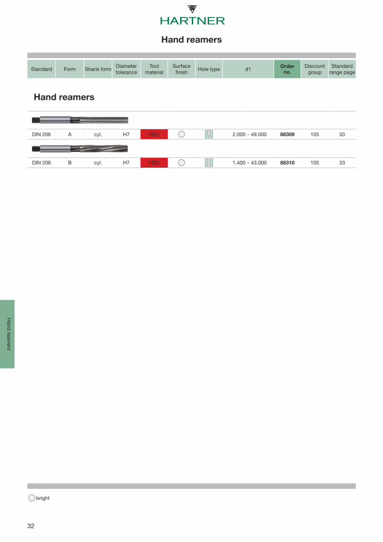
Hand reamers
bright
Hand ream
ers
Standard Form Shank form Diameter tolerance
Tool material
Surfacefinish Hole type d1 Order
no.
Discountgroup
Standard range page
Hand reamers
DIN 206 A cyl. H7 HSS 2.000 - 49.000 88309 105 33
DIN 206 B cyl. H7 HSS 1.400 - 43.000 88310 105 33

33
H7 DIN206 ~HA R
A
B
P (N/mm²)
M
K
N
S
H (HRC)
l 1
d 1
l 4
d 2
SW
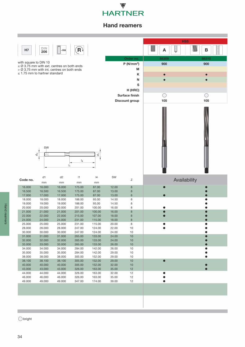
Hand reamers
bright
Han
d re
amer
s
HSS
Order no. 88309 88310
with square to DIN 10≤ Ø 3.75 mm with ext. centres on both ends> Ø 3.75 mm with int. centres on both ends≤ 1.75 mm to hartner standard
900 900
Surface finish
Discount group 105 105
Code no.d1 d2 l1 l4 SW
Z Availabilitymm mm mm mm
1.400 1.400 1.400 41.00 20.00 1.12 31.500 1.500 1.500 41.00 20.00 1.12 32.000 2.000 2.000 50.00 25.00 1.60 42.200 2.200 2.200 54.00 27.00 1.80 42.500 2.500 2.500 58.00 29.00 2.10 43.000 3.000 3.000 62.00 31.00 2.40 63.200 3.200 3.200 66.00 33.00 2.40 63.500 3.500 3.500 71.00 35.00 2.70 64.000 4.000 4.000 76.00 38.00 3.00 64.500 4.500 4.500 81.00 41.00 3.40 65.000 5.000 5.000 87.00 44.00 3.80 65.500 5.500 5.500 93.00 47.00 4.30 66.000 6.000 6.000 93.00 47.00 4.90 66.500 6.500 6.500 100.00 50.00 4.90 67.000 7.000 7.000 107.00 54.00 5.50 67.500 7.500 7.500 107.00 54.00 6.20 68.000 8.000 8.000 115.00 58.00 6.20 68.500 8.500 8.500 115.00 58.00 7.00 69.000 9.000 9.000 124.00 62.00 7.00 69.500 9.500 9.500 124.00 62.00 8.00 6
10.000 10.000 10.000 133.00 66.00 8.00 610.500 10.500 10.500 133.00 66.00 8.00 611.000 11.000 11.000 142.00 71.00 9.00 611.500 11.500 11.500 142.00 71.00 9.00 612.000 12.000 12.000 152.00 76.00 9.00 612.500 12.500 12.500 152.00 76.00 10.00 613.000 13.000 13.000 152.00 76.00 10.00 614.000 14.000 14.000 163.00 81.00 11.00 815.000 15.000 15.000 163.00 81.00 12.00 815.500 15.500 15.500 175.00 87.00 12.00 8
34
H7 DIN206 ~HA R
A
B
P (N/mm²)
M
K
N
S
H (HRC)
l 1
d 1
l 4
d 2
SW
Hand reamers
bright
Hand ream
ers
HSS
Order no. 88309 88310
with square to DIN 10≤ Ø 3.75 mm with ext. centres on both ends> Ø 3.75 mm with int. centres on both ends≤ 1.75 mm to hartner standard
900 900
Surface finish
Discount group 105 105
Code no.d1 d2 l1 l4 SW
Z Availabilitymm mm mm mm
16.000 16.000 16.000 175.00 87.00 12.00 816.500 16.500 16.500 175.00 87.00 13.00 817.000 17.000 17.000 175.00 87.00 13.00 818.000 18.000 18.000 188.00 93.00 14.50 819.000 19.000 19.000 188.00 93.00 14.50 820.000 20.000 20.000 201.00 100.00 16.00 821.000 21.000 21.000 201.00 100.00 16.00 822.000 22.000 22.000 215.00 107.00 18.00 824.000 24.000 24.000 231.00 115.00 18.00 825.000 25.000 25.000 231.00 115.00 20.00 828.000 28.000 28.000 247.00 124.00 22.00 1030.000 30.000 30.000 247.00 124.00 24.00 1031.000 31.000 31.000 265.00 133.00 24.00 1032.000 32.000 32.000 265.00 133.00 24.00 1033.000 33.000 33.000 265.00 133.00 26.00 1034.000 34.000 34.000 284.00 142.00 26.00 1035.000 35.000 35.000 284.00 142.00 29.00 1038.000 38.000 38.000 305.00 152.00 29.00 1038.100 38.100 38.100 305.00 152.00 29.00 1040.000 40.000 40.000 305.00 152.00 32.00 1043.000 43.000 43.000 326.00 163.00 35.00 1244.000 44.000 44.000 326.00 163.00 32.00 1246.000 46.000 46.000 326.00 163.00 35.00 1249.000 49.000 49.000 347.00 174.00 39.00 12

Our comprehensive TR 300 HP range includes reamers
for the machining of most materials. The perfect
combination of special geometries, tool material and
coatings provides optimal machining results for all
reaming operations.
Maximum performance for allmaterials
36
≤500≤1000≤850≤1000≤700≤850≤1000≤1000≤1400≤850≤1000≤1400≤1000≤1400≤850≤1400≤1400
≤350 HB≤900≤1100≤1500
≤48 HRC≤63 HRC
≤2000≤240 HB ≤350 HB ≤240 HB≤350 HB≤350 HB
≤850 ≤1400≤400≤650≤600≤600≤400≤500≤600≤600≤600 ≤850≤850≤1000≤150≤100
≤220 HB ≤300 HB
≤1000 ≤1400 ≤1000≤1000
R
Technical section
bright AlTiN nano
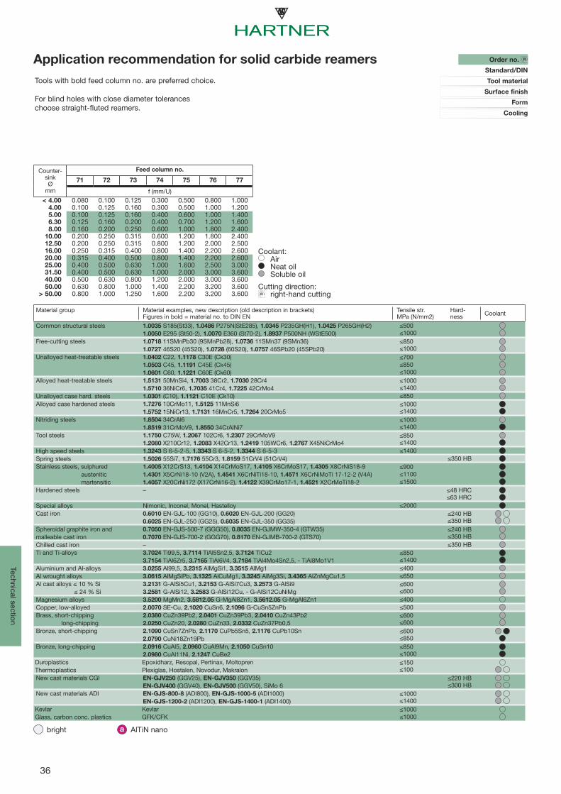
Material group Material examples, new description (old description in brackets)Figures in bold = material no. to DIN EN
Tensile str.MPa (N/mm2)
Hard-ness Coolant
Common structural steels 1.0035 S185(St33), 1.0486 P275N(StE285), 1.0345 P235GH(H1), 1.0425 P265GH(H2)1.0050 E295 (St50-2), 1.0070 E360 (St70-2), 1.8937 P500NH (WStE500)
Free-cutting steels 1.0718 11SMnPb30 (9SMnPb28), 1.0736 11SMn37 (9SMn36)1.0727 46S20 (45S20), 1.0728 (60S20), 1.0757 46SPb20 (45SPb20)
Unalloyed heat-treatable steels 1.0402 C22, 1.1178 C30E (Ck30)1.0503 C45, 1.1191 C45E (Ck45)1.0601 C60, 1.1221 C60E (Ck60)
Alloyed heat-treatable steels 1.5131 50MnSi4, 1.7003 38Cr2, 1.7030 28Cr41.5710 36NiCr6, 1.7035 41Cr4, 1.7225 42CrMo4
Unalloyed case hard. steels 1.0301 (C10), 1.1121 C10E (Ck10)Alloyed case hardened steels 1.7276 10CrMo11, 1.5125 11MnSi6
1.5752 15NiCr13, 1.7131 16MnCr5, 1.7264 20CrMo5Nitriding steels 1.8504 34CrAl6
1.8519 31CrMoV9, 1.8550 34CrAlNi7Tool steels 1.1750 C75W, 1.2067 102Cr6, 1.2307 29CrMoV9
1.2080 X210Cr12, 1.2083 X42Cr13, 1.2419 105WCr6, 1.2767 X45NiCrMo4High speed steels 1.3243 S 6-5-2-5, 1.3343 S 6-5-2, 1.3344 S 6-5-3Spring steels 1.5026 55Si7, 1.7176 55Cr3, 1.8159 51CrV4 (51CrV4)Stainless steels, sulphured 1.4005 X12CrS13, 1.4104 X14CrMoS17, 1.4105 X6CrMoS17, 1.4305 X8CrNiS18-9 austenitic 1.4301 X5CrNi18-10 (V2A), 1.4541 X6CrNiTi18-10, 1.4571 X6CrNiMoTi 17-12-2 (V4A) martensitic 1.4057 X20CrNi172 (X17CrNi16-2), 1.4122 X39CrMo17-1, 1.4521 X2CrMoTi18-2Hardened steels –
Special alloys Nimonic, Inconel, Monel, HastelloyCast iron 0.6010 EN-GJL-100 (GG10), 0.6020 EN-GJL-200 (GG20)
0.6025 EN-GJL-250 (GG25), 0.6035 EN-GJL-350 (GG35)Spheroidal graphite iron and 0.7050 EN-GJS-500-7 (GGG50), 0.8035 EN-GJMW-350-4 (GTW35)malleable cast iron 0.7070 EN-GJS-700-2 (GGG70), 0.8170 EN-GJMB-700-2 (GTS70)Chilled cast iron –Ti and Ti-alloys 3.7024 Ti99,5, 3.7114 TiAl5Sn2,5, 3.7124 TiCu2
3.7154 TiAl6Zr5, 3.7165 TiAl6V4, 3.7184 TiAl4Mo4Sn2,5, - TiAl8Mo1V1Aluminium and Al-alloys 3.0255 Al99,5, 3.2315 AlMgSi1, 3.3515 AlMg1Al wrought alloys 3.0615 AlMgSiPb, 3.1325 AlCuMg1, 3.3245 AlMg3Si, 3.4365 AlZnMgCu1,5Al cast alloys ≤ 10 % Si 3.2131 G-AlSi5Cu1, 3.2153 G-AlSi7Cu3, 3.2573 G-AlSi9 ≤ 24 % Si 3.2581 G-AlSi12, 3.2583 G-AlSi12Cu, - G-AlSi12CuNiMgMagnesium alloys 3.5200 MgMn2, 3.5812.05 G-MgAl8Zn1, 3.5612.05 G-MgAl6Zn1Copper, low-alloyed 2.0070 SE-Cu, 2.1020 CuSn6, 2.1096 G-CuSn5ZnPbBrass, short-chipping 2.0380 CuZn39Pb2, 2.0401 CuZn39Pb3, 2.0410 CuZn43Pb2 long-chipping 2.0250 CuZn20, 2.0280 CuZn33, 2.0332 CuZn37Pb0,5Bronze, short-chipping 2.1090 CuSn7ZnPb, 2.1170 CuPb5Sn5, 2.1176 CuPb10Sn
2.0790 CuNi18Zn19PbBronze, long-chipping 2.0916 CuAl5, 2.0960 CuAl9Mn, 2.1050 CuSn10
2.0980 CuAl11Ni, 2.1247 CuBe2Duroplastics Epoxidharz, Resopal, Pertinax, MoltoprenThermoplastics Plexiglas, Hostalen, Novodur, MakralonNew cast materials CGI EN-GJV250 (GGV25), EN-GJV350 (GGV35)
EN-GJV400 (GGV40), EN-GJV500 (GGV50), SiMo 6New cast materials ADI EN-GJS-800-8 (ADI800), EN-GJS-1000-5 (ADI1000)
EN-GJS-1200-2 (ADI1200), EN-GJS-1400-1 (ADI1400)Kevlar KevlarGlass, carbon conc. plastics GFK/CFK
Order no. R
Standard/DIN
Tool material
Surface finish
Form
Cooling
Coolant: Air Neat oil Soluble oil
Cutting direction: right-hand cutting
Application recommendation for solid carbide reamers
Counter-sinkØ
mm
Feed column no.
71 72 73 74 75 76 77
f (mm/U)< 4.00 0.080 0.100 0.125 0.300 0.500 0.800 1.000
4.00 0.100 0.125 0.160 0.300 0.500 1.000 1.2005.00 0.100 0.125 0.160 0.400 0.600 1.000 1.4006.30 0.125 0.160 0.200 0.400 0.700 1.200 1.6008.00 0.160 0.200 0.250 0.600 1.000 1.800 2.400
10.00 0.200 0.250 0.315 0.600 1.200 1.800 2.40012.50 0.200 0.250 0.315 0.800 1.200 2.000 2.50016.00 0.250 0.315 0.400 0.800 1.400 2.200 2.60020.00 0.315 0.400 0.500 0.800 1.400 2.200 2.60025.00 0.400 0.500 0.630 1.000 1.600 2.500 3.00031.50 0.400 0.500 0.630 1.000 2.000 3.000 3.60040.00 0.500 0.630 0.800 1.200 2.000 3.000 3.60050.00 0.630 0.800 1.000 1.400 2.200 3.200 3.600
> 50.00 0.800 1.000 1.250 1.600 2.200 3.200 3.600
Tools with bold feed column no. are preferred choice. For blind holes with close diameter toleranceschoose straight-fluted reamers.
37
Tech
nica
l sec
tion
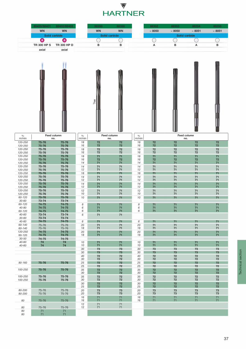
88400/88401 88402/88403 88350 88350 88352 88353 88354 88355
WN WN WN WN ~ 8050 ~ 8050 ~ 8051 ~ 8051
Solid carbide Solid carbide Solid carbide
TR 300 HP S TR 300 HP D B B A B A B
axial axial
vc m/min
Feed columnno.
vc m/min
Feed columnno.
vc m/min
Feed columnno.
120-250 75-76 75-76 18 72 72 18 72 72 72 72
120-250 75-76 75-76 16 72 72 16 72 72 72 72
120-250 75-76 75-76 18 72 72 18 72 72 72 72
120-250 75-76 75-76 16 72 72 16 72 72 72 72
120-250 75-76 75-76 18 71 71 18 71 71 71 71
120-250 75-76 75-76 16 72 72 16 72 72 72 72
120-250 75-76 75-76 14 71 71 14 71 71 71 71
120-250 75-76 75-76 14 71 71 14 71 71 71 71
120-250 75-76 75-76 12 71 71 12 71 71 71 71
120-250 75-76 75-76 18 71 71 18 71 71 71 71
120-250 75-76 75-76 14 71 71 14 71 71 71 71
120-250 75-76 75-76 12 71 71 12 71 71 71 71
120-250 75-76 75-76 14 71 71 14 71 71 71 71
120-250 75-76 75-76 12 71 71 12 71 71 71 71
120-250 75-76 75-76 12 71 71 12 71 71 71 71
120-250 75-76 75-76 10 71 71 10 71 71 71 71
60-120 75-76 75-76 10 71 71 10 71 71 71 71
30-60 73-74 73-74
60-120 74-75 74-75 8 71 71 8 71 71 71 71
40-80 74-75 74-75 6 71 71 6 71 71 71 71
60-120 74-75 74-75 6 71 71 6 71 71 71 71
40-60 73-74 73-74 6 71 71
30-60 73-74 73-74
40-60 74-75 74-75 6 71 71 6 71 71 71 71
60-140 75-76 75-76 20 71 71 20 71 71 71 71
60-140 75-76 75-76 18 71 71 18 71 71 71 71
120-250 74-75 74-75 20 71 71 20 71 71 71 71
60-120 74-75 74-75 18 71 71 18 71 71 71 71
30-50 74-75 74-7540-60 74 74 10 71 71 10 71 71 71 71
40-60 74 74 10 71 71 10 71 71 71 71
30 73 73 30 73 73 73 73
30 73 73 30 73 73 73 73
40 72 72 40 72 72 72 7230 72 72 30 72 72 72 72
80-160 75-76 75-76 25 72 72 25 72 72 72 72
25 72 72 25 72 72 72 72
100-250 75-76 75-76 35 72 72 35 72 72 72 7230 72 72 30 72 72 72 72
100-250 75-76 75-76 35 72 72 35 72 72 72 72
100-250 75-76 75-76 30 72 72 30 72 72 72 72
30 72 72 30 72 72 72 7225 72 72 25 72 72 72 72
80-200 75-76 75-76 20 73 73 20 73 73 73 73
80-200 75-76 75-76 20 73 73 20 73 73 73 73
16 71 71 16 71 71 71 7180 75-76 75-76 16 71 71 16 71 71 71 71
12 71 7180 75-76 75-76 12 71 7180 71 7180 71 71

38
≤500≤1000≤850≤1000≤700≤850≤1000≤1000≤1400≤850≤1000≤1400≤1000≤1400≤850≤1400≤1400
≤350 HB≤900≤1100≤1500
≤48 HRC≤63 HRC
≤2000≤240 HB ≤350 HB ≤240 HB≤350 HB≤350 HB
≤850 ≤1400≤400≤650≤600≤600≤400≤500≤600≤600≤600 ≤850≤850≤1000≤150≤100
≤220 HB ≤300 HB
≤1000 ≤1400 ≤1000≤1000
R
Technical section
bright AlTiN nano
Material group Material examples, new description (old description in brackets)Figures in bold = material no. to DIN EN
Tensile str.MPa (N/mm2)
Hard-ness Coolant
Common structural steels 1.0035 S185(St33), 1.0486 P275N(StE285), 1.0345 P235GH(H1), 1.0425 P265GH(H2)1.0050 E295 (St50-2), 1.0070 E360 (St70-2), 1.8937 P500NH (WStE500)
Free-cutting steels 1.0718 11SMnPb30 (9SMnPb28), 1.0736 11SMn37 (9SMn36)1.0727 46S20 (45S20), 1.0728 (60S20), 1.0757 46SPb20 (45SPb20)
Unalloyed heat-treatable steels 1.0402 C22, 1.1178 C30E (Ck30)1.0503 C45, 1.1191 C45E (Ck45)1.0601 C60, 1.1221 C60E (Ck60)
Alloyed heat-treatable steels 1.5131 50MnSi4, 1.7003 38Cr2, 1.7030 28Cr41.5710 36NiCr6, 1.7035 41Cr4, 1.7225 42CrMo4
Unalloyed case hard. steels 1.0301 (C10), 1.1121 C10E (Ck10)Alloyed case hardened steels 1.7276 10CrMo11, 1.5125 11MnSi6
1.5752 15NiCr13, 1.7131 16MnCr5, 1.7264 20CrMo5Nitriding steels 1.8504 34CrAl6
1.8519 31CrMoV9, 1.8550 34CrAlNi7Tool steels 1.1750 C75W, 1.2067 102Cr6, 1.2307 29CrMoV9
1.2080 X210Cr12, 1.2083 X42Cr13, 1.2419 105WCr6, 1.2767 X45NiCrMo4High speed steels 1.3243 S 6-5-2-5, 1.3343 S 6-5-2, 1.3344 S 6-5-3Spring steels 1.5026 55Si7, 1.7176 55Cr3, 1.8159 51CrV4 (51CrV4)Stainless steels, sulphured 1.4005 X12CrS13, 1.4104 X14CrMoS17, 1.4105 X6CrMoS17, 1.4305 X8CrNiS18-9 austenitic 1.4301 X5CrNi18-10 (V2A), 1.4541 X6CrNiTi18-10, 1.4571 X6CrNiMoTi 17-12-2 (V4A) martensitic 1.4057 X20CrNi172 (X17CrNi16-2), 1.4122 X39CrMo17-1, 1.4521 X2CrMoTi18-2Hardened steels –
Special alloys Nimonic, Inconel, Monel, HastelloyCast iron 0.6010 EN-GJL-100 (GG10), 0.6020 EN-GJL-200 (GG20)
0.6025 EN-GJL-250 (GG25), 0.6035 EN-GJL-350 (GG35)Spheroidal graphite iron and 0.7050 EN-GJS-500-7 (GGG50), 0.8035 EN-GJMW-350-4 (GTW35)malleable cast iron 0.7070 EN-GJS-700-2 (GGG70), 0.8170 EN-GJMB-700-2 (GTS70)Chilled cast iron –Ti and Ti-alloys 3.7024 Ti99,5, 3.7114 TiAl5Sn2,5, 3.7124 TiCu2
3.7154 TiAl6Zr5, 3.7165 TiAl6V4, 3.7184 TiAl4Mo4Sn2,5, - TiAl8Mo1V1Aluminium and Al-alloys 3.0255 Al99,5, 3.2315 AlMgSi1, 3.3515 AlMg1Al wrought alloys 3.0615 AlMgSiPb, 3.1325 AlCuMg1, 3.3245 AlMg3Si, 3.4365 AlZnMgCu1,5Al cast alloys ≤ 10 % Si 3.2131 G-AlSi5Cu1, 3.2153 G-AlSi7Cu3, 3.2573 G-AlSi9 ≤ 24 % Si 3.2581 G-AlSi12, 3.2583 G-AlSi12Cu, - G-AlSi12CuNiMgMagnesium alloys 3.5200 MgMn2, 3.5812.05 G-MgAl8Zn1, 3.5612.05 G-MgAl6Zn1Copper, low-alloyed 2.0070 SE-Cu, 2.1020 CuSn6, 2.1096 G-CuSn5ZnPbBrass, short-chipping 2.0380 CuZn39Pb2, 2.0401 CuZn39Pb3, 2.0410 CuZn43Pb2 long-chipping 2.0250 CuZn20, 2.0280 CuZn33, 2.0332 CuZn37Pb0,5Bronze, short-chipping 2.1090 CuSn7ZnPb, 2.1170 CuPb5Sn5, 2.1176 CuPb10Sn
2.0790 CuNi18Zn19PbBronze, long-chipping 2.0916 CuAl5, 2.0960 CuAl9Mn, 2.1050 CuSn10
2.0980 CuAl11Ni, 2.1247 CuBe2Duroplastics Epoxidharz, Resopal, Pertinax, MoltoprenThermoplastics Plexiglas, Hostalen, Novodur, MakralonNew cast materials CGI EN-GJV250 (GGV25), EN-GJV350 (GGV35)
EN-GJV400 (GGV40), EN-GJV500 (GGV50), SiMo 6New cast materials ADI EN-GJS-800-8 (ADI800), EN-GJS-1000-5 (ADI1000)
EN-GJS-1200-2 (ADI1200), EN-GJS-1400-1 (ADI1400)Kevlar KevlarGlass, carbon conc. plastics GFK/CFK
Order no. R
Standard/DIN
Tool material
Surface finish
Form
Coolant: Air Neat Oil Soluble oil
Cutting direction: right-hand cutting
Application recommendation for HSS-E reamers
Counter-sinkØ
mm
Feed column no.
71 72 73 74 75 76 77
f (mm/U)< 4.00 0.080 0.100 0.125 0.300 0.500 0.800 1.000
4.00 0.100 0.125 0.160 0.300 0.500 1.000 1.2005.00 0.100 0.125 0.160 0.400 0.600 1.000 1.4006.30 0.125 0.160 0.200 0.400 0.700 1.200 1.6008.00 0.160 0.200 0.250 0.600 1.000 1.800 2.400
10.00 0.200 0.250 0.315 0.600 1.200 1.800 2.40012.50 0.200 0.250 0.315 0.800 1.200 2.000 2.50016.00 0.250 0.315 0.400 0.800 1.400 2.200 2.60020.00 0.315 0.400 0.500 0.800 1.400 2.200 2.60025.00 0.400 0.500 0.630 1.000 1.600 2.500 3.00031.50 0.400 0.500 0.630 1.000 2.000 3.000 3.60040.00 0.500 0.630 0.800 1.200 2.000 3.000 3.60050.00 0.630 0.800 1.000 1.400 2.200 3.200 3.600
> 50.00 0.800 1.000 1.250 1.600 2.200 3.200 3.600
Tools with bold feed column no. are preferred choice. For blind holes with close diameter toleranceschoose straight-fluted reamers.
39
Tech
nica
l sec
tion
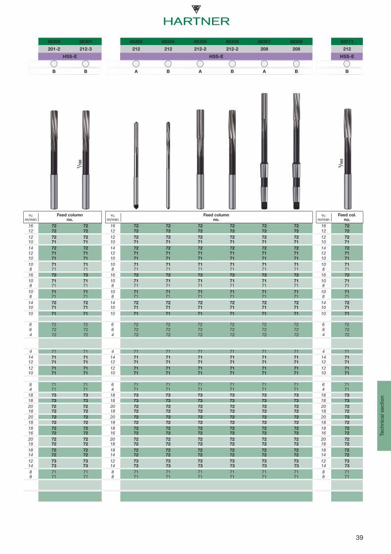
88300 88301 88302 88304 88305 88306 88307 88308 88311
201-2 212-3 212 212 212-2 212-2 208 208 212
HSS-E HSS-E HSS-E
B B A B A B A B B
vc m/min
Feed columnno.
vc m/min
Feed columnno.
vc m/min
Feed col.no.
16 72 72 16 72 72 72 72 72 72 16 72
12 72 72 12 72 72 72 72 72 72 12 72
12 72 72 12 72 72 72 72 72 72 12 7210 71 71 10 71 71 71 71 71 71 10 71
14 72 72 14 72 72 72 72 72 72 14 72
12 71 71 12 71 71 71 71 71 71 12 71
10 71 71 10 71 71 71 71 71 71 10 71
10 71 71 10 71 71 71 71 71 71 10 718 71 71 8 71 71 71 71 71 71 8 71
16 72 72 16 72 72 72 72 72 72 16 72
10 71 71 10 71 71 71 71 71 71 10 718 71 71 8 71 71 71 71 71 71 8 71
10 71 71 10 71 71 71 71 71 71 10 718 71 71 8 71 71 71 71 71 71 8 71
14 72 72 14 72 72 72 72 72 72 14 7210 71 71 10 71 71 71 71 71 71 10 71
10 71 71 10 71 71 71 71 71 71 10 71
6 72 72 6 72 72 72 72 72 72 6 726 72 72 6 72 72 72 72 72 72 6 724 72 72 4 72 72 72 72 72 72 4 72
4 71 71 4 71 71 71 71 71 71 4 7114 71 71 14 71 71 71 71 71 71 14 7112 71 71 12 71 71 71 71 71 71 12 71
12 71 71 12 71 71 71 71 71 71 12 7110 71 71 10 71 71 71 71 71 71 10 71
6 71 71 6 71 71 71 71 71 71 6 714 71 71 4 71 71 71 71 71 71 4 71
18 73 73 18 73 73 73 73 73 73 18 73
18 73 73 18 73 73 73 73 73 73 18 73
20 72 72 20 72 72 72 72 72 72 20 7218 72 72 18 72 72 72 72 72 72 18 72
20 72 72 20 72 72 72 72 72 72 20 72
18 72 72 18 72 72 72 72 72 72 18 72
18 72 72 18 72 72 72 72 72 72 18 7216 72 72 16 72 72 72 72 72 72 16 72
20 72 72 20 72 72 72 72 72 72 20 7218 72 72 18 72 72 72 72 72 72 18 72
18 72 72 18 72 72 72 72 72 72 18 7214 72 72 14 72 72 72 72 72 72 14 72
12 73 73 12 73 73 73 73 73 73 12 7314 73 73 14 73 73 73 73 73 73 14 73
8 71 71 8 71 71 71 71 71 71 8 718 71 71 8 71 71 71 71 71 71 8 71

40
0102030405060
60 100 120 160 200 250
7080
Technical section
Recommendations for the application of high-performance reamers TR 300 HP
TR 300 HP D Ø 20
TR 300 HP D Ø 14
TR 300 HP D Ø 10
Coolant pressure - cutting speedvalid for standard dimensions.Preconditions: sufficient capacity of coolant pump
Cutting speed (vc)
Coo
lant
pre
ssur
e (b
ar)
Coolant pressure
TR 300 HP S
(blind hole)

41
8
5 4 3
7 6
2 1
Reibmaß
Sollmaß
Reibmaß
Sollmaß
Sollmaß
Fehlmaß
Fluchtungs-versatz
Tech
nica
l sec
tion
• Cutting speed too low• Worn cutting edges • Crumbling on cutting edges• Build up on cutting edges• Position to pilot hole incorrect• Insufficient lubrication
• Pre-drilled hole misaligned• Concentricity bevel lead incorrect• Apply floating holder if necessary• If necessary pilot drill to correct
predrilled position
• Cutting speed too low• No/insufficient lubrication. Cutting edge build-up.• Tool damaged, i. e. broken cutting edge• Material has a tendancy to cause build up on cutting edges.• Concentricity bevel lead incorrect
• Tool knocks in spindle• Bevel lead incorrect• Axis shifting between tool and predrilled hole. Application of floating holders• Pre-machining inaccurate
• Position to pilot hole incorrect• Back taper incorrect • Circular lands too wide• Pre-drilled hole is too small• Bevel lead blunt/ground unevenly• Feed rate too high• Chip congestion – increase feed rate to produce shorter chips
• Feed too low• Cutting edge build-up• Grease content in coolant too low• Circular lands too small• Stock removal allowance insufficient• Tool incorrectly clamped in tool holder• Machine spindle not concentric
• Reamer blunt. Does not cut, scrapes• Cutting speed too low• Component is thin-walled, springs back• Insufficient stock removal allowance, tool seizes in hole• Hole is not round due to distortion
• Tool diameter too large• Cutting speed too high• Concentricity error of machine spindle• Bevel lead of tool too short/uneven• Cutting edge build up due to wrong cutting speeds or poor lubrication• Lubricating agent unsuitable, holes too large due to lubrication
Holes too large
Unsatisfactory surface finish
Reamer seizes and breaks
Conical hole malformation
Hole has chatter marks
Holes too small
Misalignment of hole
Feed scoring marks in hole
Adapted cutting speed, an appropriate feed rate and good cooling and lubricating agents should always be a top priority for reaming operations. A further point to be considered is that the reamer always follows the direction of the pre-drilled hole. An exception is the machine bottoming reamer or a very small reamer. Consequently reamers do not correct alignment errors of predrilled holes. Errors between the spindle axis and the axis of a pre-drilled hole can be adjusted with the aid of floating holders. The following fault finding chart will be found useful in tracing the cause of some common reaming problems.
Wording:Desired dim. Required finish dimension of bore hole, defined as max./min. dimension of tolerance zoneReaming dim. the finish dimension reached in fact„Bore hole" The reached bore hole after reaming
Troubleshooting
desired dimension
false dimension
desired dimension
reaming dimension
reaming dimension
misalignment
reaming dimension

42
A B C
9 11 8 9 10 11 8 9 10 11
0 3+295 +330 +154 +165 +180 +200 +74 +85 +100 +120+270 +270 +140 +140 +140 +140 +60 +60 +60 +60
3 6+300 +345 +158 +170 +188 +215 +88 +100 +118 +145+270 +270 +140 +140 +140 +140 +70 +70 +70 +70
6 10+316 +370 +172 +186 +208 +240 +102 +116 +138 +170+280 +280 +150 +150 +150 +150 +80 +80 +80 +80
10 18+333 +400 +177 +193 +220 +260 +122 +138 +165 +205+290 +290 +150 +150 +150 +150 +95 +95 +95 +95
18 30+352 +430 +193 +212 +244 +290 +143 +162 +194 +240+300 +300 +160 +160 +160 +160 +110 +110 +110 +110
30 40+372 +470 +209 +232 +270 +330 +159 +182 +220 +280+310 +310 +170 +170 +170 +170 +120 +120 +120 +120
40 50+382 +480 +219 +242 +280 +340 +169 +192 +230 +290+320 +320 +180 +180 +180 +180 +130 +130 +130 +130
50 65+414 +530 +236 +264 +310 +380 +186 +214 +260 +330+340 +340 +190 +190 +190 +190 +140 +140 +140 +140
65 80+434 +550 +246 +274 +320 +390 +196 +224 +270 +340+360 +360 +200 +200 +200 +200 +150 +150 +150 +150
80 100+467 +600 +274 +307 +360 +440 +224 +257 +310 +390+380 +380 +220 +220 +220 +220 +170 +170 +170 +170
100 120+497 +630 +294 +327 +380 +460 +234 +267 +320 +400+410 +410 +240 +240 +240 +240 +180 +180 +180 +180
D E F
8 9 10 11 12 7 8 9 6 7 8 9
0 3+34 +45 +60 +80 +120 +24 +28 +39 +12 16 +20 +31+20 +20 +20 +20 +20 +14 +14 +14 +6 +6 +6 +6
3 6+48 +60 +78 +105 +150 +32 +38 +50 +18 +22 +28 +40+30 +30 +30 +30 +30 +20 +20 +20 +10 +10 +10 +10
6 10+62 +76 +98 +130 +190 +40 +47 +61 +22 +28 +35 +49+40 +40 +40 +40 +40 +25 +25 +25 +13 +13 +13 +13
10 18+77 +93 +120 +160 +230 +50 +59 +75 +27 +34 +43 +59+50 +50 +50 +50 +50 +32 +32 +32 +16 +16 +16 +16
18 30+98 +117 +149 +195 +275 +61 +73 +92 +33 +41 +53 +72+65 +65 +65 +65 +65 +40 +40 +40 +20 +20 +20 +20
30 50+119 +142 +180 +240 +75 +89 +112 +41 +50 +64 +87
+80 +80 +80 +80 +50 +50 +50 +25 +25 +25 +25
50 80+146 +174 +220 +290 +90 +106 +134 +49 +60 +76 +104+100 +100 +100 +100 +60 +60 +60 +30 +30 +30 +30
80 120+174 +207 +260 +340 +107 +126 +159 +58 +71 +90 +123+120 +120 +120 +120 +72 +72 +72 +36 +36 +36 +36
120 180+148
+85
180 250+172+100
Technical section
Nominal diameterin mm
over to
Nominal diameter in mm
over to
The most common tolerance zones in μm

43
G H J
6 7 6 7 8 9 10 11 12 6 7 8
0 3+8 +12 +6 +10 +14 +25 +40 +60 +100 +2 +4 +6+2 +2 0 0 0 0 0 0 0 -4 -6 -8
3 6+12 +16 +8 +12 +18 +30 +48 +75 +120 +5 +6 +10+4 +4 0 0 0 0 0 0 0 -3 -6 -8
6 10+14 +20 +9 +15 +22 +36 +58 +90 +150 +5 +8 +12+5 +5 0 0 0 0 0 0 0 -4 -7 -10
10 18+17 +24 +11 +18 +27 +43 +70 +110 +180 +6 +10 +15+6 +6 0 0 0 0 0 0 0 -5 -8 -12
18 30+20 +28 +13 +21 +33 +52 +84 +130 +210 +8 +12 +20+7 +7 0 0 0 0 0 0 0 -5 -9 -13
30 50+25 +34 +16 +25 +39 +62 +100 +160 +250 +10 +14 +24+9 +9 0 0 0 0 0 0 0 -6 -11 -15
50 80+29 +40 +19 +30 +46 +74 +120 +190 +300 +13 +18 +28+10 +10 0 0 0 0 0 0 0 -6 -12 -18
80 120+34 +47 +22 +35 +54 +87 +140 +220 +350 +16 +22 +34+12 +12 0 0 0 0 0 0 0 -6 -13 -20
120 180+54 +25 +40 +63 +100 +160 +250 +18 +26 +41+14 0 0 0 0 0 0 -7 -14 -22
180 250+61 +29 +46 +72 +115 +185 +290 +22 +30 +47+15 0 0 0 0 0 0 -7 -16 -25
JS K M
6 7 8 9 6 7 8 6 7 8
0 3
3 6
6 10
10 18
18 30
30 50
50 80
80 120
120 180
180 250
+3 +5 +7 +12,5 0 0 0 -2 -2 -4-3 -5 -7 -12,5 -6 -10 -14 -8 -12 -18+4 +6 +9 +15 +2 +3 +5 -1 0 +2-4 -6 -9 -15 -6 -9 -13 -9 -12 -16
+4,5 +7,5 +11 +18 +2 +5 +6 -3 0 +1-4,5 -7,5 -11 -18 -7 -10 -16 -12 -215 -21+5,5 +9 +13,5 +21,5 +2 +6 +8 -4 0 +2-5,5 -9 -13,5 -21,5 -9 -12 -19 -15 -18 -25+6,5 +10,5 +16,5 +26 +2 +6 +10 -4 0 +4-6,5 -10,5 -16,5 -26 -11 -15 -23 -17 -21 -29
+8 +12,5 +19,5 +31 +3 +7 +12 -4 0 +5-8 -12,5 -19,5 -31 -13 -18 -27 -20 -25 -34
+9,5 +15 +23 +37 +4 +9 +14 -5 0 +5-9,5 -15 -23 -37 -15 -21 -32 -24 -30 -41+11 +17,5 +27 +43,5 +4 +10 +16 -6 0 +6-11 -17,5 -27 -43,5 -18 -25 -38 -28 -35 -48
+4 +12-21 -28+5 +13
-24 -33 Tech
nica
l sec
tion
Nominal diameter in mm
over to
Nominal diameter in mm
over to
The most common tolerance zones in μm

44
N P R
6 7 8 9 10 11 6 7 9 6 7
0 3-4 -4 -4 -4 -4 -4 -6 -6 -6 -10 -10
-10 -14 -8 -29 -44 -64 -12 -16 -31 -16 -20
3 6-5 -4 -2 0 0 0 -9 -8 -12 -12 -11
-13 -16 -20 -30 -48 -75 -17 -20 -42 -20 -23
6 10-7 -4 -3 0 0 0 -12 -9 -15 -16 -13
-16 -19 -25 -36 -58 -90 -21 -24 -51 -25 -28
10 18-9 -5 -3 0 0 0 -15 -11 -18 -20 -16
-20 -23 -30 -43 -70 -110 -26 -29 -61 -31 -34
18 30-11 -7 -3 0 0 0 -18 -14 -22 -24 -20-24 -28 -36 -52 -84 -130 -31 -35 -74 -37 -41
30 50-12 -8 -3 0 0 0 -21 -17 -26 -29 -25-28 -33 -42 -62 -100 -160 -37 -42 -88 -45 -50
50 65-14 -9 -4 0 0 0 -26 -21 -32 -35 -30-33 -39 -50 -74 -120 -190 -45 -51 -106 -54 -60
65 80-14 -9 -4 0 0 0 -26 -21 -32 -37 -32-33 -39 -50 -74 -120 -190 -45 -51 -106 -56 -62
80 100-16 -10 -4 0 0 0 -30 -24 -37 -44 -38-38 -45 -58 -87 -140 -220 -52 -59 -124 -66 -73
100 120-16 -10 -4 0 0 0 -30 -24 -47 -41-38 -45 -58 -87 -140 -220 -52 -59 -69 -76
S T U X Z
6 7 6 6 7 10 10 11 10 11
0 3-14 -14 -18 -18 -18 -18 -20 -20 -26 -26-20 -24 -24 -24 -28 -58 -60 -80 -66 -86
3 6-16 -15 -20 -20 -19 -23 -28 -28 -35 -35-24 -27 -28 -28 -31 -71 -76 -103 -83 -110
6 10-20 -17 -25 -25 -22 -28 -34 -34 -42 -42-29 -32 -34 -34 -37 -86 -92 -124 -100 -132
10 14-25 -21 -30 -30 -26 -33 -40 -40 -50 -50-36 -39 -41 -41 -44 -103 -110 -150 -120 -160
14 18-25 -21 -30 -30 -26 -33 -45 -45 -60 -60-36 -39 -41 -41 -44 -103 -115 -155 -130 -170
18 24-31 -27 -37 -37 -33 -41 -54 -54 -73 -73-44 -48 -50 -50 -54 -125 -138 -184 -157 -203
24 30-31 -27 -37 -44 -40 -48 -64 -64 -88 -88-44 -48 -50 -57 -61 -132 -148 -194 -172 -218
30 40-38 -34 -43 -55 -51 -60 -80 -80 -112 -112-54 -59 -59 -71 -76 -160 -180 -240 -212 -272
40 50-38 -34 -49 -65 -61 -70 -97 -97 -136 -136-54 -59 -65 -81 -86 -170 -197 -257 -236 -296
50 65-47 -42 -60 -81 -76 -87 -122 -122 -172 -172-66 -72 -79 -100 -106 -207 -242 -312 -292 -362
65 80-53 -48 -69 -96 -91 -102 -146 -146 -210 -210-72 -78 -88 -115 -121 -222 -266 -336 -330 -400
80 100-64 -58 -84 -117 -111 -124 -178 -178 -258 -258-86 -93 -106 -139 -146 -264 -318 -398 -398 -478
100 120-72 -66 -97 -137 -131 -144 -210 -210 -310 -310-94 -101 -119 -159 -166 -284 -350 -430 -450 -530
Technical section
The most common tolerance zones in μm
Nominal diameter in mm
over to
Nominal diameterin mm
over to

45
A9 A11 B8 B9 B10 B11 C8 C9 C10 C11
1 3+ 291 + 321 + 151 + 161 + 174 + 191 + 71 + 81 + 94 + 111+ 282 + 300 + 146 + 152 + 160 + 170 + 66 + 72 + 80 + 90
3 6+ 295 + 333 + 155 + 165 + 180 + 203 + 85 + 95 + 110 + 133
+ 284 + 306 + 148 + 154 + 163 + 176 + 78 + 84 + 93 + 106
6 10+ 310 + 356 + 168 + 180 + 199 + 226 + 98 + 110 + 129 + 156
+ 297 + 324 + 160 + 167 + 178 + 194 + 90 + 97 + 108 + 124
10 18+ 326 + 383 + 172 + 186 + 209 + 243 + 117 + 131 + 154 + 188
+ 310 + 344 + 162 + 170 + 184 + 204 + 107 + 115 + 129 + 149
18 30+ 344 + 410 + 188 + 204 + 231 + 270 + 138 + 154 + 181 + 220
+ 325 + 364 + 176 + 185 + 201 + 224 + 126 + 135 + 151 + 174
30 40+ 362 + 446 + 203 + 222 + 255 + 306 + 153 + 172 + 205 + 256
+ 340 + 390 + 189 + 200 + 220 + 250 + 139 + 150 + 170 + 200
40 50+ 372 + 456 + 213 + 232 + 265 + 316 + 163 + 182 + 215 + 266
+ 350 + 400 + 199 + 210 + 230 + 260 + 149 + 160 + 180 + 210
50 65+ 402 + 501 + 229 + 252 + 292 + 351 + 179 + 202 + 242 + 301
+ 376 + 434 + 212 + 226 + 250 + 284 + 162 + 176 + 200 + 234
65 80+ 422 + 521 + 239 + 262 + 302 + 361 + 189 + 212 + 252 + 311
+ 396 + 454 + 222 + 236 + 260 + 294 + 172 + 186 + 210 + 244
80 100+ 453 + 567 + 265 + 293 + 339 + 407 + 215 + 243 + 289 + 357
+ 422 + 490 + 246 + 262 + 290 + 330 + 196 + 212 + 240 + 280
100 120+ 483 + 597 + 285 + 313 + 359 + 427 + 225 + 253 + 299 + 367
+ 452 + 520 + 266 + 282 + 310 + 350 + 206 + 222 + 250 + 290
120 140+ 545 + 672 + 313 + 345 + 396 + 472 + 253 + 285 + 336 + 412
+ 510 + 584 + 290 + 310 + 340 + 384 + 230 + 250 + 280 + 324
140 160+ 605 + 732 + 333 + 365 + 416 + 492 + 263 + 295 + 346 + 422
+ 570 + 644 + 310 + 330 + 360 + 404 + 240 + 260 + 290 + 334
160 180+ 665 + 792 + 363 + 395 + 446 + 522 + 283 + 315 + 366 + 442
+ 630 + 704 + 340 + 360 + 390 + 434 + 260 + 280 + 310 + 354
D8 D9 D10 D11 E7 E8 E9 F6 F7 F8 F9 G6 G7
1 3+ 31 + 41 + 54 + 71 + 22 + 25 + 35 + 11 + 14 + 17 + 27 + 7 + 10+ 26 + 32 + 40 + 50 + 18 + 20 + 26 + 8 + 10 + 12 + 18 + 4 + 6
3 6+ 45 + 55 + 70 + 93 + 30 + 35 + 45 + 16 + 20 + 25 + 35 + 10 + 14
+ 38 + 44 + 53 + 66 + 25 + 28 + 34 + 13 + 15 + 18 + 24 + 7 + 9
6 10+ 58 + 70 + 89 + 116 + 37 + 43 + 55 + 20 + 25 + 31 + 43 + 12 + 17
+ 50 + 57 + 68 + 84 + 31 + 35 + 42 + 16 + 19 + 23 + 30 + 8 + 11
10 18+ 72 + 86 + 109 + 143 + 47 + 54 + 68 + 25 + 31 + 38 + 52 + 15 + 21
+ 62 + 70 + 84 + 104 + 40 + 44 + 52 + 21 + 24 + 28 + 36 + 11 + 14
18 30+ 93 + 109 + 136 + 175 + 57 + 68 + 84 + 31 + 37 + 48 + 64 + 18 + 24
+ 81 + 90 + 106 + 129 + 49 + 56 + 65 + 26 + 29 + 36 + 45 + 13 + 16
30 50+ 113 + 132 + 165 + 216 + 71 + 83 + 102 + 38 + 46 + 58 + 77 + 22 + 30
+ 99 + 110 + 130 + 160 + 62 + 69 + 80 + 32 + 37 + 44 + 55 + 16 + 21
50 80+ 139 + 162 + 202 + 261 + 85 + 99 + 122 + 46 + 55 + 69 + 92 + 26 + 35
+ 122 + 136 + 160 + 194 + 74 + 82 + 96 + 39 + 44 + 52 + 66 + 19 + 24
80 120+ 165 + 193 + 239 + 307 + 101 + 117 + 145 + 54 + 65 + 81 + 109 + 30 + 41
+ 146 + 162 + 190 + 230 + 88 + 98 + 114 + 46 + 52 + 62 + 78 + 22 + 28
120 180+ 198 + 230 + 281 + 357 + 119 + 138 + 170 + 64 + 77 + 96 + 128 + 35 + 48
+ 175 + 195 + 225 + 269 + 105 + 115 + 135 + 55 + 63 + 73 + 93 + 26 + 34
Tech
nica
l sec
tion
(tolerance zones A ... G)
DIN 1420
Nominal diameter in mm
over to
Permissible upper and lower tolerances on nominal reamer diameter d1 in μmfor hole tolerance zone
Nominal diameter in mm
over to
Permissible upper and lower tolerances on nominal reamer diameter d1 in μmfor hole tolerance zone
Manufacturing tolerances

46
H6 H7 H8 H9 H10 H11 H12 J6 J7 J8 JS6 JS7 JS8 JS9
>1…....3+ 5 + 8 +11 +21 + 34 + 51 + 85 + 1 + 2 + 3 + 2 + 3 + 4 + 8+ 2 + 4 + 6 +12 + 20 + 30 + 50 – 2 – 2 – 2 – 1 – 1 – 1 – 1
>3…....6+ 6 +10 +15 +25 + 40 + 63 +102 + 3 + 4 + 7 + 2 + 4 + 6 +10
+ 3 + 5 + 8 +14 + 23 + 36 + 60 0 – 1 0 – 1 – 1 – 1 – 1
>6…..10+ 7 +12 +18 +30 + 49 + 76 +127 + 3 + 5 + 8 + 3 + 5 + 7 +12
+ 3 + 6 +10 +17 + 28 + 44 + 74 – 1 – 1 0 – 1 – 1 – 1 – 1
>10…..18+ 9 +15 +22 +36 + 59 + 93 +153 + 4 + 7 +10 + 3 + 6 + 8 +15
+ 5 + 8 +12 +20 + 34 + 54 + 90 0 0 0 – 1 – 1 – 1 – 1
>18…..30+11 +17 +28 +44 + 71 +110 +178 + 6 + 8 +15 + 4 + 7 +11 +18
+ 6 + 9 +16 +25 + 41 + 64 +104 + 1 0 + 3 – 1 – 1 – 1 – 1
>30…..50+13 +21 +33 +52 + 85 +136 +212 + 7 +10 +18 + 5 + 8 +13 +21
+ 7 +12 +19 +30 + 50 + 80 +124 + 1 + 1 + 4 – 1 – 1 – 1 – 1
>50…..80+16 +25 +39 +62 +102 +161 +255 +10 +13 +21 + 6 +10 +16 +25
+ 9 +14 +22 +36 + 60 + 94 +150 + 3 + 2 + 4 – 1 – 1 – 1 – 1
>80…120+18 +29 +45 +73 +119 +187 +297 +12 +16 +25 + 7 +12 +18 +30
+10 +16 +26 +42 + 70 +110 +174 + 4 + 3 + 6 – 1 – 1 – 1 – 1
>120…180+21 +34 +53 +85 +136 +212 +340 +14 +20 +31 + 8 +14 +22 +35
+12 +20 +30 +50 + 80 +124 +200 + 5 + 6 + 8 – 1 0 – 1 0
K6 K7 K8 M6 M7 M8 N6 N7 N8 N9 N10 N11 P6 P7
1 3– 1 – 2 – 3 – 3 – 4 – 5 – 6 – 7 – 8 –10 – 13 – 7 – 8– 4 – 6 – 8 – 6 – 8 – 8 –10 –12 –17 –24 – 34 –10 –12
3 6 0 + 1 + 2 – 3 – 2 – 1 – 7 – 6 – 5 – 5 – 8 – 12 –11 –10
– 3 – 4 – 5 – 6 – 7 – 8 –10 –11 –12 –16 –25 – 39 –14 –15
6 10 0 + 2 + 2 – 5 – 3 – 3 – 9 – 7 – 7 – 6 – 9 – 14 –14 –12
– 4 – 4 – 6 – 9 – 9 –11 –13 –13 –15 –19 –30 – 46 –18 –18
10 18 0 + 3 + 3 – 6 – 3 – 3 –11 – 8 – 8 – 7 –11 – 17 –17 –14
– 4 – 4 – 7 –10 –10 –13 –15 –15 –18 –23 –36 – 56 –21 –21
18 30 0 + 2 + 5 – 6 – 4 – 1 –13 –11 – 8 – 8 –13 – 20 –20 –1
– 5 – 6 – 7 –11 –12 –13 –18 –19 –20 –27 –43 – 66 –25 –26
30 50 0 + 3 + 6 – 7 – 4 – 1 –15 –12 – 9 –10 –15 – 24 –24 –21
– 6 – 6 – 8 –13 –13 –15 –21 –21 –23 –32 –50 – 80 –30 –30
50 80+ 1 + 4 + 7 – 8 – 5 – 2 –17 –14 –11 –12 –18 – 29 –29 –26
– 6 – 7 –10 –15 –16 –19 –24 –25 –28 –38 –60 – 96 –36 –37
80 120 0 + 4 + 7 –10 – 6 – 3 –20 –16 –13 –14 –21 – 33 –34 –30
– 8 – 9 –12 –18 –19 –22 –28 –29 –32 –45 –70 –110 –42 –43
120 180 0 + 6 +10 –12 – 6 – 2 –24 –18 –14 –15 –24 – 38 –40 –43
– 9 – 8 –13 –21 –20 –25 –33 –32 –37 –50 –80 –126 –49 –48
Technical section
Manufacturing tolerances
(tolerance zones H ... P)
DIN 1420
Ourstandard
manufacturing accuracy
Nominal diameter in mm
over to
Permissible upper and lower tolerances on nominal reamer diameter d1 in μmfor hole tolerance zone
Nominal diameter in mm
over to
Permissible upper and lower tolerances on nominal reamer diameter d1 in μmfor hole tolerance zone

47
R6 R7 S6 S7 T6 U6 U7 U10 X10 X11 Z10 Z11
1 3– 11 – 12 – 15 – 16 – 19 – 20 – 32– 14 – 16 – 18 – 20 – 22 – 24 – 46
3 6– 14 – 13 – 18 – 17 – 22 – 21 – 31 – 43
– 17 – 18 – 21 – 22 – 25 – 26 – 48 – 60
6 10– 18 – 16 – 22 – 20 – 27 – 25 – 37 – 51
– 22 – 22 – 26 – 26 – 31 – 31 – 58 – 72
10 14– 22 – 19 – 27 – 24 – 32 – 29 – 44 – 61
– 26 – 26 – 31 – 31 – 36 – 36 – 69 – 86
14 18– 22 – 19 – 27 – 24 – 32 – 29 – 44 – 56 – 71
– 26 – 26 – 31 – 31 – 36 – 36 – 69 – 81 – 96
18 24– 26 – 24 – 33 – 31 – 39 – 37 – 67 – 86
– 31 – 32 – 38 – 39 – 44 – 45 – 97 –116
24 30– 26 – 24 – 33 – 31 – 39 – 46 – 44 – 77 –101 –108
– 31 – 32 – 38 – 39 – 44 – 51 – 52 –107 –131 –154
30 40– 32 – 29 – 41 – 38 – 46 – 58 – 55 – 95 –127 –136
– 38 – 38 – 47 – 47 – 52 – 64 – 64 –130 –162 –192
40 50– 32 – 29 – 41 – 38 – 52 – 68 – 65 – 85 –112 –151 –160
– 38 – 38 – 47 – 47 – 58 – 74 – 74 –120 –147 –186 –216
50 65– 38 – 35 – 50 – 47 – 63 – 84 – 81 –105 –140 –151 –190 –201
– 45 – 46 – 57 – 58 – 70 – 91 – 92 –147 –182 –218 –232 –268
65 80– 40 – 37 – 56 – 53 – 72 – 99 – 96 –120 –164 –175 –228 –239
– 47 – 48 – 63 – 64 – 79 –106 –107 –162 –206 –242 –270 –306
80 100– 48 – 44 – 68 – 64 – 88 –121 –117 –145 –199 –211 –279 –291
– 56 – 57 – 76 – 77 – 96 –129 –130 –194 –248 –288 –328 –368
100 120– 51 – 47 – 76 – 72 –101 –141 –137 –165 –231 –243 –331 –343
– 59 – 60 – 84 – 85 –109 –149 –150 –214 –280 –320 –380 –420
120 140– 60 – 54 – 89 – 83 –119 –167 –161 –194 –272 –286 –389 –403
– 69 – 68 – 98 – 97 –128 –176 –175 –250 –328 –374 –445 –491
140 160– 62 – 56 – 97 – 91 –131 –187 –181 –214 –304 –318 –439 –453
– 71 – 70 –106 –105 –140 –196 –195 –270 –360 –406 –495 –541
160 180– 65 – 59 –105 – 99 –143 –207 –201 –234 –334 –348 –489 –503
– 74 – 73 –114 –113 –152 –216 –215 –290 –390 –436 –545 –591
Tech
nica
l sec
tion
Manufacturing tolerances
Nominal diameter in mm
over to
Permissible upper and lower tolerances on nominal reamer diameter d1 in μmfor hole tolerance zone
(tolerance zones R ... Z)
DIN 1420

48
3300
μm
2100
1300
1100
900
700
500
300
150
100
50
0 01 0 1 2 3 4 5 6 7 8 9 10 11 12 13 14 15 16 17 18IT
3 4 5 6 7 8 9 10 11 12 13 14
2 3 4 6 10 14 25 40 60 100 140 250
2.5 4 5 8 12 18 30 48 75 120 180 300
2.5 4 6 9 15 22 36 58 90 150 220 360
3 5 8 11 18 27 43 70 110 180 270 430
4 6 9 13 21 33 52 84 130 210 330 520
4 7 11 16 25 39 62 100 160 250 390 620
5 8 13 19 30 46 74 120 190 300 460 740
6 10 15 22 35 54 87 140 220 350 540 870
0.6 1.5 2. 5 1 4 6 9 1321
33
52
84
130
210330
520
840
1300
2100
3300
Technical section
Basic ISO tolerances
Example: Basic ISO tolerances for a range of nominal sizes over 18 to 30 mm
fine valuesfor gauges
medium valuesfor common fits
coarse valuesfor coarse tolerances
(products of rolling mills)
DIN ISO 286-1
Range ofnominal size
mm
IT in μm
from 1 to 3
over 3 to 6
over 6 to 10
over 10 to 18
over 18 to 30
over 30 to 50
over 50 to 80
over 80 to 120

49
Tech
nica
l sec
tion
Manufacturing tolerances to DIN 1420
Example 1
nominal diameter d1 = 20.000 mmmaximum diameter of the hole = 20.021 mmhole tolerance (IT 7) = 0.021 mm15% of the hole tolerance (0.15 IT 7) = 0.0031 mm ≈ 0.004 mmmaximum reamer diameter:d1 max = 20.021 – 0.004 = 20.017 mm
manufacturing tolerance of reamer:35% of the hole tolerance (0.35 IT 7) = 0.0073 mm ≈ 0.008 mm
minimum reamer diameter:d1 min = d1 max – 0.35 IT 7 = 20.017 – 0.008 = 20.009 mm
Simplified calculation of the permissible maximum and minimum dimensions for reamers
Example: Hole tolerance zone Ø 20 H7/nom. dimension d1 of reamer 20 mm
General remarks for the determination of manufacturing
tolerances for reamers
The manufacturing tolerances to DIN 1420 are allocated tocertain tolerance zones of the holes to be reamed. Generallythey ensure the positioning of reamed holes within the relevanttolerance zone as well as the most economical use of thereamer.It must, however, be taken into account that the size of thereamed hole depends, in addition to the manufacturing toleranceof the reamer, on various other factors, such as angles of cutting edges; bevel lead of reamer; clamping of the workpiece; the tool holder; condition of the machine; the coolant and on the material of the workpiece. Therefore, from time to time other manufactu-ring tolerances than IT7 (H7) might prove more advantageous.However, in the interest of economic production and storage,it is recommended that non-standard manufacturing tolerancesare used only in exceptional cases.For determing the manufacturing tolerances the following well-proven basic rules were stipulated:
Determination of perm. max. and min. sizes of reamers
The largest permitted reamer diameter ranges at about 15% ofthe approximate hole tolerance (0.15 IT) below the permissiblemaximum diameter of the hole (see fig.), whereby the value0.15 IT will be rounded of to the next higher integer or halfμm-value, so that even μm values are derived for d1max. Thepermissible smallest reamer diameter d1min ranges at about35% of the approximate hole tolerance (0.35 IT) below thepermissible maximum diameter d1max (ex. 1).
Simplified determination of permissible max. and min.
reamer dimensions
In order to facilitate calculations, the table on page 47 indicatesthe upper and lower tolerance limits on the nominaldiameter d1 for the most common “H” tolerance zones. Withthe aid of these tolerance limits the permissible maximum andminimum reamer dimensions can be calculated.
Hole tolerance
Min. hole dimension 0 μm
hole
tole
ranc
e 20
H7
Zero line Ø 20.0
Max. holedimension +21 μm
Reamer manufacturing tolerance
15%
of
hole
tole
ranc
e
35%
of h
ole
tole
ranc
e
Min
. man
uf.
dim
ensi
on+9
μm
Max
. man
uf. d
imen
sion
+17
μm

50
P7P6N7N6
M7M6
K7K6
J7J6
H7
G7
h5
g6
h6j5
j6 k5 k6 m5 m6n5 n6
p6
0
0
Technical section
Designation
Hole
Clearancefit
Press fit
Shaft
Press fit
Transition fit
Transition fit
For the designation of reamers the ISO abbreviation for thetolerance zone of the hole is indicated after the nominaldiameter. Designation of a reamer with nominal diameterd1 = 20 mm, for hole tolerance H 7:
reamer 20 H 7 DIN ...(” ... “: for DIN no. indicationof appropriate reamer)
In special cases, reamers are ordered with maximum andminimum dimensions deviating from this standard, the ISOabbreviation for the hole tolerance zone must be replaced
by the upper and lower tolerance limit of the reamer in μm,e.g. for a reamer with a nominal diameter d1 = 20 mm, uppertolerance limit = + (p) 25 μm and lower tolerance limit= + (p) 15 μm: reamer 20 p 25 p 15 DIN ... The designation shows a ‘p’ instead of the plus and an ‘m’instead of the minus sign, because »+« and » – « cannot bewritten on all machines, particularly not on data processingmachines.
Designation to DIN 1420
Tolerance position

51
0,16 0,40 1,0 2,5 6,3 16 40 100 2500,25 0,63 1,6 4,0 10 25 63 160
40
25
16
10
6,3
4,0
2,5
1,5
1,0
0,630
0,400
0,250
0,160
0,100
0,063
0,040
0,025
0,016
N1
N2
N3
N4
N5
N6
N7
N8
N9
N10
N11
Ra
Rz
Ra
Rz
0.16 0.40 1.0 2.5 6.3 16 40 100 2500.25 0.63 1.6 4.0 10 25 63 160
40
25
16
10
6.3
4.0
2.5
1.5
1.0
0.630
0.400
0.250
0.160
0.100
0.063
0.040
0.025
0.016
N1
N2
N3
N4
N5
N6
N7
N8
N9
N10
N11
Ra
Rz
Ra
Rz
Tech
nica
l sec
tion
Upper limit of Ra forconversion ofRz to Ra
Dispersion-/scattering area
Upper limit of Rz for conversion of Ra to Rz
Ra-
valu
es in
μm
Rz-values in μm
Gra
de o
f rou
ghne
ss a
ccor
ding
to D
IN IS
O 1
302
Conversion ratio to DIN 47
example 2
example 1
Surface quality
Reading example 1 Ra in Rz
When comparing the average roughness index Ra = 0.4 μm tothe average roughness Rz we achieve a value of Rz = 1.6 μm.
Reading example 2 Rz in Ra
When comparing the average roughness Rz = 25 μm to theaverage roughness index Ra we achieve a value of Ra = 2 μm.
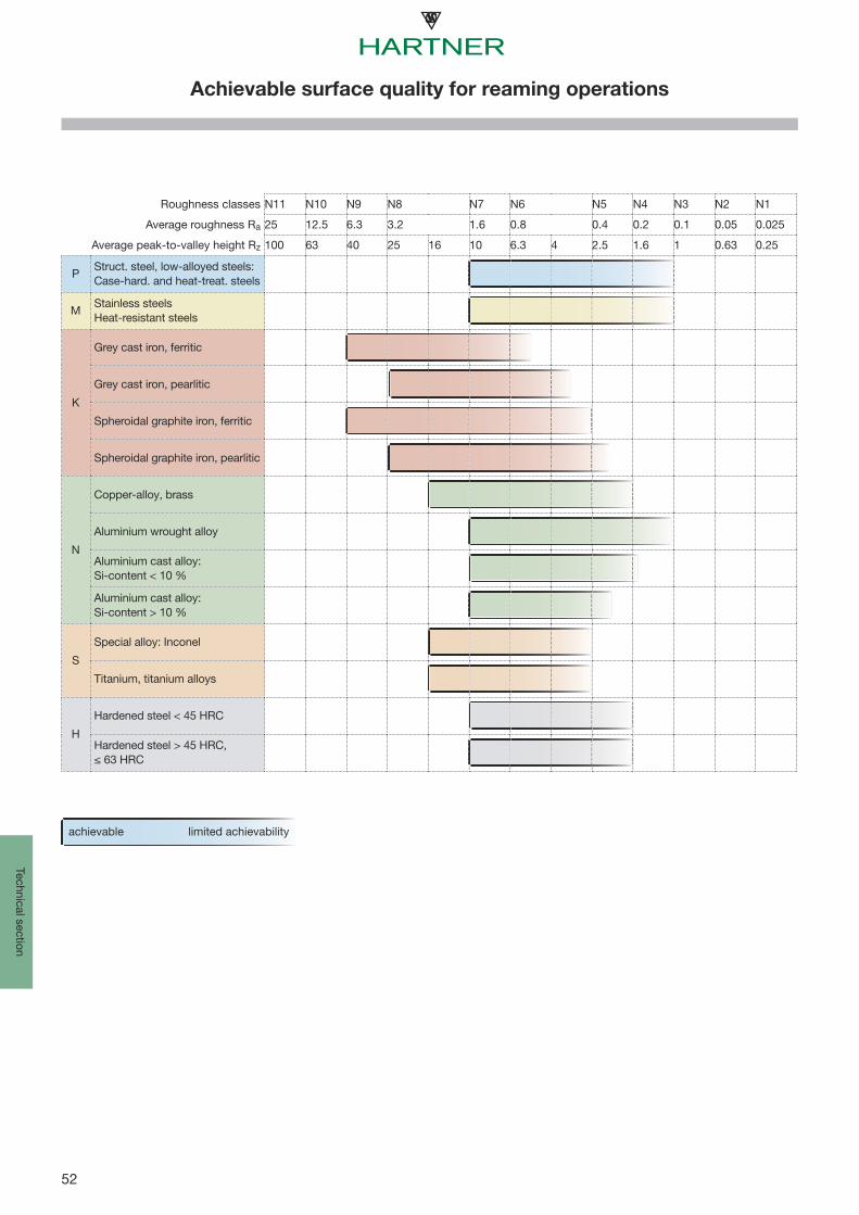
52
Technical section
Achievable surface quality for reaming operations
Roughness classes N11 N10 N9 N8 N7 N6 N5 N4 N3 N2 N1
Average roughness Ra 25 12.5 6.3 3.2 1.6 0.8 0.4 0.2 0.1 0.05 0.025
Average peak-to-valley height Rz 100 63 40 25 16 10 6.3 4 2.5 1.6 1 0.63 0.25
PStruct. steel, low-alloyed steels:Case-hard. and heat-treat. steels
MStainless steelsHeat-resistant steels
K
Grey cast iron, ferritic
Grey cast iron, pearlitic
Spheroidal graphite iron, ferritic
Spheroidal graphite iron, pearlitic
N
Copper-alloy, brass
Aluminium wrought alloy
Aluminium cast alloy:Si-content < 10 %
Aluminium cast alloy:Si-content > 10 %
S
Special alloy: Inconel
Titanium, titanium alloys
H
Hardened steel < 45 HRC
Hardened steel > 45 HRC,≤ 63 HRC
limited achievabilityachievable

53
240 71 75255 76 80270 81 85
285 86 90305 90 95320 95 100
335 100 105350 105 110370 109 115
385 114 120400 119 125415 124 130
430 128 135450 133 140465 138 145
480 143 150495 147 155510 152 160
530 157 165545 162 170560 166 175
575 171 180595 176 185610 181 190
625 185 195640 190 200660 195 205
675 199 210690 204 215705 209 220
720 214 225740 219 230755 223 235
770 228 240785 233 245800 22 238 250
820 23 242 255835 24 247 260860 25 255 268
870 26 258 272900 27 266 280920 28 273 287
940 29 278 293970 30 287 302995 31 295 310
1020 32 301 3171050 33 311 3271080 34 319 336
1110 35 328 3451140 36 337 3551170 37 346 3641200 38 354 3731230 39 363 3821260 40 372 392
1300 41 383 4031330 42 393 4131360 43 402 423
1400 44 413 4341440 45 424 4461480 46 435 458
1530 47 449 4731570 48 460 4841620 49 472 497
1680 50 488 5141730 51 501 5271790 52 517 544
1845 53 532 5601910 54 549 5781980 55 567 596
2050 56 584 6152140 57 607 6392180 58 622 655
59 67560 69861 720
62 74563 77364 800
65 82966 86467 900
68 940Te
chni
cal s
ectio
n
Hardness comparison
HRC
HB30
HV10
HRC
HB30
HV10
Tens. strength (N/mm2)
Tens. strength (N/mm2)

54
Technical section
Selection and application
Fig. 1
Fig. 2: taper hand reamer
Fig. 4: expanding hand reamer with blades
Fig. 3: adjustable hand reamer
core drilling reamingdrilling
Fig. 5: carbide-tipped machine reamer
The reamer is the most commonly used tool for theproduction of holes true to form and tolerance with highsurface quality. The latter meets the requirement of ‘finishing’or ‘fine finishing’ i.e. from approximately Ra 0.2 to 6.5 μmaccording to the scales laid down in DIN 4766. However,finishes to Ra = 0.5 μm can be regarded as satisfactory.Generally, the achievable tolerance ranks at IT 7. In specialcases IT 6 or even IT 5 are possible, provided that the reameris appropriately ground and all other operating conditionsmeet the high specifications.
In preparation for the reaming process, holes have to bepre-drilled and normally core drilled (fig. 1). Pre-drilled holesproduced with gun drills, are due to their highly compressedsurface, not particularly suitable for reaming. Moreover, holesproduced with gun drills show generally excellent toleranceson fit and surface qualities, so that additional fine finishing isusually not required. Should any further information on ourgun drills be needed, please do not hesitate to contact us.
Which reamer for which purpose?
With regard to their application we differentiate between:• hand reamers• machine reamers
Hand reamers
Hand reamers are turned in the hole by means of a tapwrench which is mounted on the square. The feeding actionis produced manually. Because of the low cutting ratesthese tools are made of HSS. To ensure a proper guidancein the hole the taper lead length of hand reamers is madeconsiderably longer than that of machine reamers. Handreamers are available for both cylindrical and tapered holes.
Machine reamers
Machine reamers are - as the name implies - exclusivelydesigned for use on machines and differ with regard to thetype of tool material. Due to the possibility of higher cuttingvalues, these tools are available in HSS-E, solid carbide orcarbide-tipped (fig. 5). The tool material should be selected inaccordance with the material to be machined.
Hand reamers to DIN 859 may be adjusted within theelasticity tolerance range of hardened HSS. This correspondsin practice to 1% of the diameter, i.e. for example 0.1 mmon a reamer with 10 mm diameter. In the fully expandedcondition these tools are not very resistant to breakage andmust therefore be protected against impact. They should bestored with the tension released. Expanding reamers can be adjusted over a much largerrange, even up to a few millimeters! For accuracy reasonssetting must be carried out with a ring gauge. A basic rule for reaming by hand: turn the tool only inthe cutting direction, i.e. never reverse the tool contraryto standard practice in thread cutting. Cutting edges willbecome immediately blunt if the reamer is turned back.
Carbide reamers offer the following advantages:
• Higher cutting speeds and feed rates.• Most economic machining of materials of over 1200 mm2 tensile strength.• The tool life is much higher than that of HSS-E reamers.
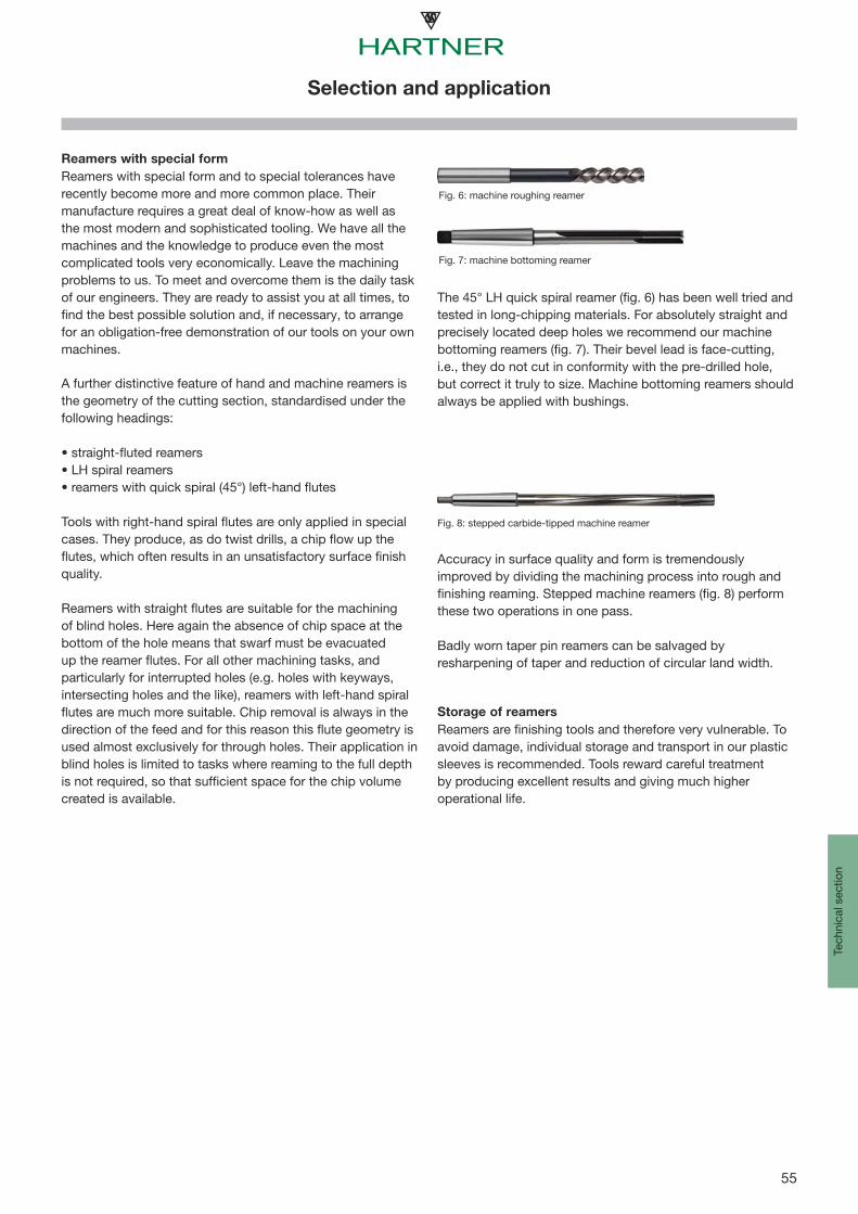
55
Tech
nica
l sec
tion
Selection and application
Fig. 7: machine bottoming reamer
Fig. 6: machine roughing reamer
Fig. 8: stepped carbide-tipped machine reamer
Reamers with special form
Reamers with special form and to special tolerances haverecently become more and more common place. Theirmanufacture requires a great deal of know-how as well asthe most modern and sophisticated tooling. We have all themachines and the knowledge to produce even the mostcomplicated tools very economically. Leave the machiningproblems to us. To meet and overcome them is the daily taskof our engineers. They are ready to assist you at all times, tofind the best possible solution and, if necessary, to arrangefor an obligation-free demonstration of our tools on your ownmachines.
A further distinctive feature of hand and machine reamers isthe geometry of the cutting section, standardised under thefollowing headings: • straight-fluted reamers• LH spiral reamers• reamers with quick spiral (45°) left-hand flutes Tools with right-hand spiral flutes are only applied in specialcases. They produce, as do twist drills, a chip flow up theflutes, which often results in an unsatisfactory surface finishquality. Reamers with straight flutes are suitable for the machiningof blind holes. Here again the absence of chip space at thebottom of the hole means that swarf must be evacuatedup the reamer flutes. For all other machining tasks, andparticularly for interrupted holes (e.g. holes with keyways,intersecting holes and the like), reamers with left-hand spiralflutes are much more suitable. Chip removal is always in thedirection of the feed and for this reason this flute geometry isused almost exclusively for through holes. Their application inblind holes is limited to tasks where reaming to the full depthis not required, so that sufficient space for the chip volumecreated is available.
The 45° LH quick spiral reamer (fig. 6) has been well tried andtested in long-chipping materials. For absolutely straight andprecisely located deep holes we recommend our machinebottoming reamers (fig. 7). Their bevel lead is face-cutting,i.e., they do not cut in conformity with the pre-drilled hole,but correct it truly to size. Machine bottoming reamers shouldalways be applied with bushings.
Accuracy in surface quality and form is tremendouslyimproved by dividing the machining process into rough andfinishing reaming. Stepped machine reamers (fig. 8) performthese two operations in one pass.
Badly worn taper pin reamers can be salvaged byresharpening of taper and reduction of circular land width.
Storage of reamers
Reamers are finishing tools and therefore very vulnerable. Toavoid damage, individual storage and transport in our plasticsleeves is recommended. Tools reward careful treatmentby producing excellent results and giving much higheroperational life.
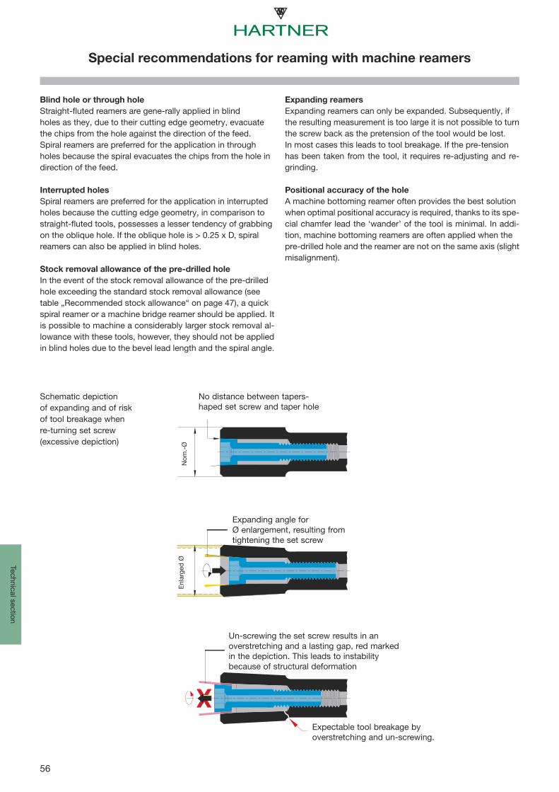
56
Technical section
Special recommendations for reaming with machine reamers
Schematic depictionof expanding and of riskof tool breakage whenre-turning set screw(excessive depiction)
No distance between tapers-haped set screw and taper hole
Expanding angle forØ enlargement, resulting fromtightening the set screw
Nom
.-Ø
Enl
arge
d Ø
Un-screwing the set screw results in anoverstretching and a lasting gap, red markedin the depiction. This leads to instabilitybecause of structural deformation
Expectable tool breakage byoverstretching and un-screwing.
Blind hole or through hole
Straight-fluted reamers are gene-rally applied in blindholes as they, due to their cutting edge geometry, evacuatethe chips from the hole against the direction of the feed.Spiral reamers are preferred for the application in throughholes because the spiral evacuates the chips from the hole indirection of the feed.
Interrupted holes
Spiral reamers are preferred for the application in interruptedholes because the cutting edge geometry, in comparison tostraight-fluted tools, possesses a lesser tendency of grabbingon the oblique hole. If the oblique hole is > 0.25 x D, spiralreamers can also be applied in blind holes.
Stock removal allowance of the pre-drilled hole
In the event of the stock removal allowance of the pre-drilledhole exceeding the standard stock removal allowance (seetable „Recommended stock allowance“ on page 47), a quickspiral reamer or a machine bridge reamer should be applied. Itis possible to machine a considerably larger stock removal al-lowance with these tools, however, they should not be appliedin blind holes due to the bevel lead length and the spiral angle.
Expanding reamers
Expanding reamers can only be expanded. Subsequently, ifthe resulting measurement is too large it is not possible to turnthe screw back as the pretension of the tool would be lost.In most cases this leads to tool breakage. If the pre-tensionhas been taken from the tool, it requires re-adjusting and re-grinding.
Positional accuracy of the hole
A machine bottoming reamer often provides the best solutionwhen optimal positional accuracy is required, thanks to its spe-cial chamfer lead the ‘wander’ of the tool is minimal. In addi-tion, machine bottoming reamers are often applied when thepre-drilled hole and the reamer are not on the same axis (slightmisalignment).
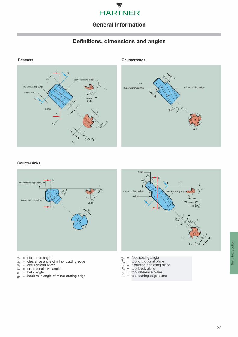
57
Pf
F
E
γ p
b α
γo
αo
C
D
χ r
γf
Pr
E-F (Pp)
C-D (Po)
Ps
αo
γ fbα
G
H
G-H
A
B
C
D
A-B
γ f
γp
α p
Po
Pr
bα
γo
αo
C-D (Pp)
Pf
Ps
C r
A
γp
γo
αoχ r
BA-B
o = p =
b = o = f = p =
r = Po = Pf = Pp = Pr = Ps =
Tech
nica
l sec
tion
Countersinks
CounterboresReamers
clearance angleclearance angle of minor cutting edgecircular land widthorthogonal rake anglehelix angleback rake angle of minor cutting edge
face setting angletool orthogonal planeassumed operating planetool back planetool reference planetool cutting edge plane
edge
bevel lead
major cutting edge
minor cutting edge
pilot
major cutting edge
major cutting edge
countersinking angle
pilot
major cutting edge minor cutting edge
edge
minor cutting edge
General Information
Definitions, dimensions and angles

58
Technical section
Notes

59
Tech
nica
l sec
tion
Notes

Precision Cutting Tools
FU500 | FN500UNIVERSELL & WIRTSCHAFTLICH
DE
16MnCr5
11SMn30+C
Sz37
GG
GGG
C45
VA
Aluminium
Kupfer
Bronze
Messing
Plexiglas
PVC
Makrolon
PE 1000
Precision Cutting Tools
KLEINSTBOHRERAUS HSS-E-PM UND VOLLHARTMETALL
DE
Precision Cutting Tools
TS-DRILLSVHM VORZUGSPROGRAMM
DE
Gewindewerkzeuge
Das neue Komplettprogramm zur universellen Gewindeherstellung
2014
Präzisionswerkzeuge
NEU
TF 100 MULTI-MILL
2014
NEU
Eintauchen mit bis zu 45°
Rampen, Bohren, Nuten,
Schruppen und Schlichten
Fräsen mit extremem
Zeitspanvolumen
Bohren ohne Pilotieren
bis 2xD möglich
Tiefl ochbohrer
Komplettprogramm
2014 Preisliste 42
Präzisionswerkzeuge
Precision Cutting Tools
FRÄSWERKZEUGEAUS VOLLHARTMETALL
DE
VHM-Fasfräser
mit Spitzenwinkel60°, 90° und 120°
2014
Präzisionswerkzeuge
NEU
Precision Cutting Tools
MULTIPLEXWECHSELPLATTEN-BOHRSYSTEM MIT INNENKÜHLUNG
DE
Precision Cutting Tools
MULTIPLEX HPCDAS WECHSELPLATTEN-BOHRSYSTEM
FÜR BOHRUNGEN BIS 10 X D
BIS DURCHMESSER 40,0 MM
DE
Präzisionswerkzeuge TM Werkzeug-
Ausgabesysteme
Individuelle Lösungen zur effi zienten Lagerung und Verwaltung von Werkzeugen
2013
www.hartner.de No
liabi
lity
can
be a
ccep
ted
for
prin
ting
erro
rs o
r te
chni
cal c
hang
es o
f any
kin
d.
Our
Con
ditio
ns o
f Sal
e an
d Te
rms
of P
aym
ent a
pply
. Ava
ilabl
e on
requ
est.
Hartner GmbH
P.O. Box 10 04 27, D-72425 AlbstadtTel. +49 74 31/1 25-0, Fax +49 74 31/1 25-21 547
Our programme:
FU 500/FN500
INOX Drills
Micro Precision Drills
TS-Drills
Gun Drills
Solid Carbide High Performance Milling Cutters
Chamfering Milling Cutters
Multiplex
Multiplex HPC
TM Vending Machines
Threading Tools
TF 100 Multi-Mill
148
863/
1622
-XI-
20
Prin
ted
in G
erm
any
2016