hart field device specification guide...hart® field device specification guide: hart® field device...
TRANSCRIPT

H A R T ® F i e l d D e v i c e S p e c i f i c a t i o nG u i d e :
H A R T ® F i e l d D e v i c e S p e c i f i c a t i o n f o rD a n i e l L i q u i d U l t r a s o n i c F l o w M e t e r s r e v i s i o n 2
DANIELTM MEASUREMENT AND CONTROL, INC.AN EMERSON PROCESS MANAGEMENT COMPANY
HOUSTON, TEXAS
Document 3-9000-755, rev. 2Initial release: 30 September 2007Current release: 20 December 2011
DanielTM Measurement and Control, Inc.11100 Brittmoore Park DriveHouston, TX 77041
HART is a registered Trademark of the HART Communication Foundation


Important Instructions
DanielTM Measurement and Control, Inc. (Daniel) designs, manufactures andtests its products to meet many national and international standards. Becausethese instruments are sophisticated technical products, you must properlyinstall, use and maintain them to ensure they continue to operate within theirnormal specifications. The following instructions must be adhered to andintegrated into your safety program when installing, using and maintainingDaniel products.
• Read all instructions prior to installing, operating and servicing the product. If this instruction manual is not the correct manual, call 1-713-827-6314 (24-hour response number for both Service and Sales Support) and the requested manual will be provided. Save this instruction manual for future reference.
• If you do not understand any of the instructions, contact your Daniel representative for clarification.
• Follow all warnings, cautions and instructions marked on and supplied with the product.
• Inform and educate your personnel in the proper installation, operation and maintenance of the product.
• Install your equipment as specified in the installation instructions of the appropriate instruction manual and per applicable local and national codes. Connect all products to the proper electrical and pressure sources.
• To ensure proper performance, use qualified personnel to install, operate, update, program and maintain the product.
• When replacement parts are required, ensure that qualified people use replacement parts specified by the manufacturer. Unauthorized parts and procedures can affect the product's performance and place the safe operation of your process at risk. Look-alike substitutions may result in fire, electrical hazards or improper operation.
• Ensure that all equipment doors are closed and protective covers are in place, except when maintenance is being performed by qualified persons, to prevent personal injury.
• ALWAYS READ AND FOLLOW THE DANIEL ULTRASONIC GAS FLOW METER REFERENCE, INSTALLATION, AND OPERATIONS MANUAL AND ALL PRODUCT WARNINGS AND INSTRUCTIONS.
• Use of this equipment for any purpose other than its intended purpose may result in property damage and/or serious personal injury or death.
• Before opening the flameproof enclosure in a flammable atmosphere, the electrical circuits must be interrupted.

This page is intentionally left blank.

DANIELTM MEASUREMENT AND CONTROL, INC.Daniel Liquid Ultrasonic Flow Meter Reference,
Installation, and Operations Manual
NOTICE
THE CONTENTS OF THIS PUBLICATION ARE PRESENTED FOR INFORMATIONAL PURPOSESONLY, AND WHILE EVERY EFFORT HAS BEEN MADE TO ENSURE THEIR ACCURACY, THEYARE NOT TO BE CONSTRUED AS WARRANTIES OR GUARANTEES, EXPRESSED OR IMPLIED,REGARDING THE PRODUCTS OR SERVICES DESCRIBED HEREIN OR THEIR USE ORAPPLICABILITY. ALL SALES ARE GOVERNED BY DANIEL'S TERMS AND CONDITIONS, WHICHARE AVAILABLE UPON REQUEST. WE RESERVE THE RIGHT TO MODIFY OR IMPROVE THEDESIGNS OR SPECIFICATIONS OF SUCH PRODUCTS AT ANY TIME.
DANIEL DOES NOT ASSUME RESPONSIBILITY FOR THE SELECTION, USE OR MAINTENANCEOF ANY PRODUCT. RESPONSIBILITY FOR PROPER SELECTION, USE AND MAINTENANCE OFANY DANIEL PRODUCT REMAINS SOLELY WITH THE PURCHASER AND END-USER.
TO THE BEST OF DANIEL'S KNOWLEDGE THE INFORMATION HEREIN IS COMPLETE ANDACCURATE. DANIEL MAKES NO WARRANTIES, EXPRESSED OR IMPLIED, INCLUDING THEIMPLIED WARRANTIES OF MERCHANTABILITY AND FITNESS FOR A PARTICULAR PURPOSEWITH RESPECT TO THIS MANUAL AND, IN NO EVENT, SHALL DANIEL BE LIABLE FOR ANYINCIDENTAL, PUNITIVE, SPECIAL OR CONSEQUENTIAL DAMAGES INCLUDING, BUT NOTLIMITED TO, LOSS OF PRODUCTION, LOSS OF PROFITS, LOSS OF REVENUE OR USE ANDCOSTS INCURRED INCLUDING WITHOUT LIMITATION FOR CAPITAL, FUEL AND POWER, ANDCLAIMS OF THIRD PARTIES.
PRODUCT NAMES USED HEREIN ARE FOR MANUFACTURER OR SUPPLIER IDENTIFICATIONONLY AND MAY BE TRADEMARKS/REGISTERED TRADEMARKS OF THESE COMPANIES.
DANIEL AND THE DANIEL LOGO ARE REGISTERED TRADEMARKS OF DANIEL INDUSTRIES,INC. THE EMERSON LOGO IS A TRADEMARK AND SERVICE MARK OF EMERSON ELECTRICCO.
.
COPYRIGHT © 2009 BY DANIEL MEASUREMENT AND CONTROL, INC., HOUSTON, TEXAS, U.S.A.
All rights reserved. No part of this work may be reproduced or copied in any form or by any means - graphic, electronic, or mechanical — without first receiving the written permission of
Daniel Measurement and Control, Inc. Houston, Texas, U.S.A.

WARRANTY
1. LIMITED WARRANTY: Subject to the limitations contained in Section 2 herein, Daniel Measurement& Control, Inc. ("Daniel") warrants that the licensed firmware embodied in the Goods will execute theprogramming instructions provided by Daniel, and that the Goods manufactured by Daniel will be freefrom defects in materials or workmanship under normal use and care and Services will be performed bytrained personnel using proper equipment and instrumentation for the particular Service provided. Theforegoing warranties will apply until the expiration of the applicable warranty period. Goods arewarranted for twelve (12) months from the date of initial installation or eighteen (18) months from thedate of shipment by Daniel, whichever period expires first. Consumables and Services are warrantedfor a period of 90 days from the date of shipment or completion of the Services. Products purchasedby Daniel from a third party for resale to Buyer ("Resale Products") shall carry only the warrantyextended by the original manufacturer. Buyer agrees that Daniel has no liability for Resale Productsbeyond making a reasonable commercial effort to arrange for procurement and shipping of the ResaleProducts. If Buyer discovers any warranty defects and notifies Daniel thereof in writing during theapplicable warranty period, Daniel shall, at its option, correct any errors that are found by Daniel in thefirmware or Services or repair or replace F.O.B. point of manufacture that portion of the Goods orfirmware found by Daniel to be defective, or refund the purchase price of the defective portion of theGoods/Services. All replacements or repairs necessitated by inadequate maintenance, normal wear andusage, unsuitable power sources or environmental conditions, accident, misuse, improper installation,modification, repair, use of unauthorized replacement parts, storage or handling, or any other cause notthe fault of Daniel are not covered by this limited warranty, and shall be at Buyer's expense. Danielshall not be obligated to pay any costs or charges incurred by Buyer or any other party except as maybe agreed upon in writing in advance by Daniel. All costs of dismantling, reinstallation and freight andthe time and expenses of Daniel's personnel and representatives for site travel and diagnosis under thiswarranty clause shall be borne by Buyer unless accepted in writing by Daniel. Goods repaired and partsreplaced by Daniel during the warranty period shall be in warranty for the remainder of the originalwarranty period or ninety (90) days, whichever is longer. This limited warranty is the only warrantymade by Daniel and can be amended only in a writing signed by Daniel. THE WARRANTIES ANDREMEDIES SET FORTH ABOVE ARE EXCLUSIVE. THERE ARE NO REPRESENTATIONS ORWARRANTIES OF ANY KIND, EXPRESS OR IMPLIED, AS TO MERCHANTABILITY, FITNESS FORPARTICULAR PURPOSE OR ANY OTHER MATTER WITH RESPECT TO ANY OF THE GOODS ORSERVICES. Buyer acknowledges and agrees that corrosion or erosion of materials is not covered by thiswarranty.
2. LIMITATION OF REMEDY AND LIABILITY: DANIEL SHALL NOT BE LIABLE FOR DAMAGESCAUSED BY DELAY IN PERFORMANCE. THE REMEDIES OF BUYER SET FORTH IN THIS AGREEMENTARE EXCLUSIVE. IN NO EVENT, REGARDLESS OF THE FORM OF THE CLAIM OR CAUSE OF ACTION(WHETHER BASED IN CONTRACT, INFRINGEMENT, NEGLIGENCE, STRICT LIABILITY, OTHER TORTOR OTHERWISE), SHALL DANIEL'S LIABILITY TO BUYER AND/OR ITS CUSTOMERS EXCEED THEPRICE TO BUYER OF THE SPECIFIC GOODS MANUFACTURED OR SERVICES PROVIDED BY DANIELGIVING RISE TO THE CLAIM OR CAUSE OF ACTION. BUYER AGREES THAT IN NO EVENT SHALLDANIEL'S LIABILITY TO BUYER AND/OR ITS CUSTOMERS EXTEND TO INCLUDE INCIDENTAL,CONSEQUENTIAL OR PUNITIVE DAMAGES. THE TERM "CONSEQUENTIAL DAMAGES" SHALLINCLUDE, BUT NOT BE LIMITED TO, LOSS OF ANTICIPATED PROFITS, REVENUE OR USE AND COSTSINCURRED INCLUDING WITHOUT LIMITATION FOR CAPITAL, FUEL AND POWER, AND CLAIMS OFBUYER'S CUSTOMERS.

TABLE OF CONTENTS iHART Field Device Specification: Daniel Liquid Ultrasonic Flow Meter
Table of Contents
INTRODUCTION
1. Introduction ......................................................................................... 1-1
1.1 Scope ..................................................................................... 1-1
1.2 Purpose................................................................................... 1-1
1.3 Who should use this document? ................................................. 1-2
1.4 Abbreviations and Definitions..................................................... 1-2
1.5 References .............................................................................. 1-3
DEVICE IDENTIFICATION
2. Introduction ......................................................................................... 2-1
2.1 Expansion Board with HART Identification ................................... 2-1
2.2 Physical Description.................................................................. 2-2
PRODUCT OVERVIEW
3. Introduction ......................................................................................... 3-1
3.1 Device Function, Purpose and Features ....................................... 3-1
3.2 Process Connections................................................................. 3-1
3.3 External Interfaces (electrical and non-electrical) ........................... 3-1
3.4 Other Required Equipment ......................................................... 3-2
PRODUCT INTERFACES
4. Introduction ......................................................................................... 4-1
4.1 Process Interface...................................................................... 4-1
4.2 Sensor Input Channels .............................................................. 4-1
DEVICE VARIABLES
5. Introduction ......................................................................................... 5-1
5.1 Device Variable 0 - Uncorrected Flow Rate .................................. 5-1
5.2 Device Variable 6 - Pressure....................................................... 5-2
5.3 Device Variable 7 - Temperature................................................. 5-3
December 2011 Table of Contents

ii TABLE OF CONTENTSHART Field Device Specification: Daniel Liquid Ultrasonic Flow Meter
HART DYNAMIC VARIABLES
6. Introduction......................................................................................... 6-1
6.1 Fixed Dynamic Variables ........................................................... 6-1
6.2 Dynamic Variables with Configurable Mapping ............................. 6-1
STATUS INFORMATION
7. Introduction......................................................................................... 7-1
7.1 Field Device Status................................................................... 7-2
7.2 Command 48 - Additional Device Status ..................................... 7-4
UNIVERSAL COMMANDS
8. Introduction......................................................................................... 8-1
8.1 HART® Universal Commands ..................................................... 8-1
COMMON-PRACTICE COMMANDS
9. Introduction......................................................................................... 9-1
9.1 Supported Common-Practice Commands ..................................... 9-1
9.2 Burst Mode.............................................................................. 9-2
9.3 Catch Device Variable............................................................... 9-2
DEVICE-SPECIFIC COMMANDS
10. Introduction........................................................................................10-1
10.1 Public, Device-Specific Commands ............................................10-1
10.2 Command 128 Write Analog Output Configuration ......................10-1
10.3 Command 129 Read Analog Output Configuration.......................10-4
10.4 Command 130 Write Frequency and Digital Output Configuration..10-4
10.5 Command 131 Read Frequency and Digital Output Configuration ..10-8
10.6 Command 132 Write Flow Pressure Configuration .......................10-8
10.7 Command 133 Read Flow Pressure Configuration......................10-12
10.8 Command 134 Write Flow Temperature Configuration ...............10-12
10.9 Command 135 Read Flow Temperature Configuration................10-15
10.10 Command 136 Write Device Units...........................................10-16
10.11 Command 137 Read Device Units ...........................................10-17
Table of Contents December 2011

TABLE OF CONTENTS iiiHART Field Device Specification: Daniel Liquid Ultrasonic Flow Meter
10.12 Command 138 Write Device Variable Range ........................... 10-18
10.13 Command 139 Read Device Variable Range ............................ 10-20
10.14 Command 140 Read Detailed Status ...................................... 10-21
10.15 Command 141 Acknowledge Alarm ........................................ 10-31
10.16 Command 142 Write Digital Input Configuration ....................... 10-34
10.17 Command 143 Read Digital Input Configuration........................ 10-35
10.18 Command 144 Perform Velocity Zero Calibration...................... 10-36
10.19 Command 145 Write Velocity Zero Calibration Control .............. 10-37Velocity Zero Flow Calibration Functional Requirements............. 10-39Possible HART Master Perspective.......................................... 10-43
10.20 Command 147 Read Miscellaneous Parameters ........................ 10-44
10.21 Command 153 Read Running Averages ................................... 10-44
10.22 Command 154 Read Baselines ............................................... 10-46
10.23 Command 155 Write Baselines............................................... 10-48
10.24 Command 159 Read Meter Chord Data ................................... 10-52
10.25 Command 160 Read Meter Flow Data..................................... 10-53
10.26 Command 161 Read Path Signal Amplitude Data...................... 10-54
10.27 Command 162 Read Noise Amplitudes.................................... 10-55
10.28 Command 163 Read Path SNR Data ....................................... 10-56
10.29 Command 164 Read Path Percent Good .................................. 10-57
10.30 Command 165 Read Path Gains ............................................. 10-58
10.31 Command 166 - Read Flow Analysis Configuration ................... 10-59
10.32 Command 167 Write Flow Analysis Configuration .................... 10-60
10.33 Command 168 Read General Meter Information........................ 10-62
10.34 Command 169 Read Flow Totals ............................................ 10-63
December 2011 Table of Contents

iv TABLE OF CONTENTSHART Field Device Specification: Daniel Liquid Ultrasonic Flow Meter
MEASUREMENT UNITS TABLES
11. Introduction........................................................................................11-1
11.1 Volume Units..........................................................................11-1
11.2 Time Units (Flow Rate).............................................................11-1
11.3 Volumetric Flow Rate Engineering Unit Codes .............................11-2
11.4 Pressure Units.........................................................................11-3
11.5 Temperature Unit Codes...........................................................11-3
11.6 Velocity Units .........................................................................11-3
11.7 Unit Conversion ......................................................................11-4
11.8 Decibel Units ..........................................................................11-5
11.9 Voltage Units..........................................................................11-5
11.10 Pressure and Temperature Tables ..............................................11-6Flow-Condition Pressure and Temperature ..................................11-6Live Pressure ..........................................................................11-7Live Temperature ....................................................................11-8
PERFORMANCE
12. Introduction........................................................................................12-1
12.1 Sampling Rates .......................................................................12-1
12.2 Power-Up ...............................................................................12-1
12.3 Device Reset ..........................................................................12-2Typical time to reset ................................................................12-2Maximum delay.......................................................................12-2Mode(s) effected .....................................................................12-2
12.4 Self Test ................................................................................12-2
12.5 Command Response Delay .......................................................12-3
12.6 Busy and Delayed-Response .....................................................12-3
12.7 Long Messages .......................................................................12-3
12.8 Non-Volatile Memory ...............................................................12-3
12.9 Operating Modes.....................................................................12-4
12.10 Write Protection ......................................................................12-4
12.11 Damping ................................................................................12-4
Table of Contents December 2011

TABLE OF CONTENTS vHART Field Device Specification: Daniel Liquid Ultrasonic Flow Meter
ANNEX A CAPABILITY CHECKLIST
A.1 Device Capability Checklist ....................................................................A-1
ANNEX B DEFAULT CONFIGURATION
B.1 Default Configuration ............................................................................ B-1
ANNEX C DEVICE VARIABLE CALCULATIONS
C.1 Introduction .........................................................................................C-1
C.2 Uncorrected Flow Rate..........................................................................C-2
C.3 Pressure ..............................................................................................C-2
C.4 Temperature ........................................................................................C-3Reynolds Number.................................................................................C-4
December 2011 Table of Contents

vi TABLE OF CONTENTSHART Field Device Specification: Daniel Liquid Ultrasonic Flow Meter
ANNEX D AMS™ DEVICE OPERATIONS
D.1 Overview ............................................................................................ D-1
D.2 Overview Menu.................................................................................... D-1Overview>Device Information.............................................................. D-2Overview>Alerts ................................................................................ D-2Overview>Zero Flow .......................................................................... D-2
D.3 Configure Menu ................................................................................... D-3Guided Setup ...................................................................................... D-3Manual Setup Menu............................................................................. D-3Alert Setup ......................................................................................... D-4Calibrate............................................................................................. D-4
D.4 Service Tools Menu .............................................................................. D-5Alerts ................................................................................................. D-5Variables............................................................................................. D-5Trends................................................................................................ D-5
ANNEX E 375 FIELD COMMUNICATOR MENU TREE
E.1 375 Fast Key Sequences........................................................................E-1
E.2 375 Field Communicator Menu Tree ........................................................E-4
ANNEX F REVISION HISTORY
F.1 Document Release.................................................................................F-1
F.2 Changes from Rev 1 to Rev 2 .................................................................F-1
F.3 Changes Rev 2 .....................................................................................F-4
F.4 Changes Rev 2 .....................................................................................F-5
Table of Contents December 2011

LIST OF FIGURES viiDaniel Liquid Ultrasonic Flow Meter
List of Figures
Figure 2-1 Expansion Board with HART .......................................................... 2-2
November 2010 List of Figures

viii LIST OF FIGURESHART Field Device Specification: Daniel Liquid Ultrasonic Flow Meter
This page is intentionally left blank.
List of Figures November 2010
LIST OF TABLES ixHART Field Device Specification: Daniel Liquid Ultrasonic Flow Meter
List of Tables
Table 2-1 Expansion Board with HART Field Device Identification Summary ....... 2-1
Table 4-1 Field Connection Board J16 - Port C ............................................... 4-4
Table 4-2 Analog Output Characteristics........................................................ 4-6
Table 4-3 Analog Output Trim ...................................................................... 4-7
Table 6-1 Dynamic Variables Configurable Mapping......................................... 6-1
Table 7-1 Device Status Byte Database Point Mapping .................................... 7-2
Table 7-2 Command 48 - Additional Device Status.......................................... 7-4
Table 8-1 HART® Universal Commands for Slave Implementation...................... 8-1
Table 9-1 HART® Common-Practice Commands .............................................. 9-1
Table 11-1 Volume Units ............................................................................. 11-1
Table 11-2 Time Units................................................................................. 11-1
Table 11-3 Flow Rate Units.......................................................................... 11-2
Table 11-4 Pressure Units............................................................................ 11-3
Table 11-5 Temperature Units ...................................................................... 11-3
Table 11-6 Velocity Units ............................................................................ 11-3
Table 11-7 Conversion Factors per Unit of Measurement ................................. 11-4
Table 11-8 Decibel Units ............................................................................. 11-5
Table 11-9 Voltage Units ............................................................................. 11-5
Table 11-10 Flow-Condition Pressure and Temperature Data Source ................... 11-6
Table 11-11 Data Points for Pressure Inputs .................................................... 11-7
Table 11-12 Data Points for Temperature Inputs............................................... 11-8
Table 12-1 Command Response Delay........................................................... 12-3
Table A-1 Capability Checklist ......................................................................A-1
Table B-1 Device Factory Settings Configuration............................................. B-1
Table E-1 375 Fast Key Sequences ............................................................... E-1
November 2010 List of Tables

x LIST OF TABLESHART Field Device Specification: Daniel Liquid Ultrasonic Flow Meter
This page is intentionally left blank.
List of Tables November 2010

INTRODUCTION 1-1HART Field Device Specification Guide: Daniel Liquid Ultrasonic Meters
1
INTRODUCTION
1. INTRODUCTION
This section defines the scope of the Daniel HART® Field Device Specification Guide: Daniel Liquid Ultrasonic Meters Functional Requirements Specification (FDS).
1.1 Scope
The Daniel Measurement and Control, Inc. Division of Emerson Process Management HART® Field Device Specification Guide: for Daniel Liquid Ultrasonic Flow Meters, revision 2, with the Expansion Board with HART, and firmware revision 1.70, complies with HART® Protocol Revision 5. This document specifies all the device specific features and documents the HART® Protocol implementation details (e.g., the Engineering Codes supported). The functionality of this Field Device is described sufficiently to allow its proper application in a process and its complete support in HART® capable Host Applications.
1.2 Purpose
This specification is designed to complement other documentation by providing a complete, unambiguous description of this field device from an Expansion Board with HART Communication perspective.(e.g., the 3-9000-750 Rev D or later) Daniel Liquid Ultrasonic Flow Meter Reference, Installation, and Operations Manual).
Daniel Division of Emerson Process Management products page:
http://www2.emersonprocess.com/en-US/brands/daniel/Flow/ultrasonics/Pages/Ultrasonic.aspx
To access the product manual, from the Daniel products page (above link), select the Daniel Model 3804 Liquid Ultrasonic Flow Meter link, click the Documentation tab, expand the Manuals & Guides tab, then select the manual.
November 2010 Introduction

1-2 INTRODUCTIONHART Field Device Specification Guide: Daniel Liquid Ultrasonic Meters
1.3 Who should use this document?
This specification is designed to be a technical reference for Expansion Board with HART capable Host Application Developers, System Integrators, and knowledgeable End Users. It also provides functional specifications (e.g., commands, enumerations and performance requirements) used during Field Device Development, maintenance and testing. This document assumes the reader is familiar with Expansion Board with HART Protocol requirements and terminology.
1.4 Abbreviations and Definitions
The following is a list of commonly used definitions used throughout this document:
ACRONYM DEFINITION
oC Degrees Celsius (alternatively, degrees Centigrade)
A/D Analog-to-Digital
ADC Analog to Digital Converter
API Application Program Interface
ATEX Atmospheres Explosives (French)
CPU Central Processing Unit
D/A Digital-to-Analog
DAC Digital to Analog Converter
DD Device Description (Expansion Board with HART)
EDDL Electronic Device Description Language (Expansion Board with HART)
FPGA Field-Programmable Gate Array
HART® Highway Addressable Remote Transducer
Hz Hertz
I/O Input(s)/Output(s)
LED Light-Emitting Diode
LUSM Liquid UltraSonic Meter
mA Milliamperes (also referred to as milliamps)
Rx Receive
Tx Transmit
Who should use this document? November 2010

INTRODUCTION 1-3HART Field Device Specification Guide: Daniel Liquid Ultrasonic Meters
1.5 References
The documents referenced within the text of this document are listed in the table below:
Title Document number, revision, date
American Petroleum Institute (API) Manual of Petroleum Measurement Standards (MPMS) Chapter 21 - Flow Measurement Using Electronic Metering Systems Section 2 - Electronic Liquid Volume Mea-surement and Section 5.8.
First Edition, June 1998
HART® SMART Communications Protocol Specification (also includes the specifications listed below in italics) HCF_SPEC 11, Rev. 5.10 (14-Dec-2000)
Field Device Specification Guide HCF_LIT-18, Rev 11.0 (18 April, 2001)
FSK Physical Layer Specification HCF_SPEC 54, Rev. 8.1 (24-Nov-1999)
Data Link Layer Specification HCF_SPEC 81, Rev. 7.1 (27-Nov-1996)
Command Summary Specification HCF_SPEC 99, Rev. 7.1 (15-Jan-1997)
Universal Command Specification HCF_SPEC 127, Rev. 5.2 (15-Jan-1997)
Common Practice Command Specification HCF_SPEC-151, Rev. 7.1 (15-Jan-1997)
Common Tables HCF_SPEC 183, Rev. 12.0 (11-Dec-2000)
Appendix 1 - Command Specific Response Code Definitions
HCF_SPEC 307, Rev. 4.1 (15-Jan-1997)
Daniel Liquid Ultrasonic Flow Meter Reference, Installation, and Operations Manual
P/N 3-9000-750 Rev. D (or later)http://www2.emersonprocess.com/en-US/brands/daniel/Flow/ultrasonics/Pages/Ultrasonic.aspx
November 2010 References

1-4 INTRODUCTIONHART Field Device Specification Guide: Daniel Liquid Ultrasonic Meters
This page is intentionally left blank.
References November 2010

DEVICE IDENTIFICATION 2-1HART Field Device Specification Guide: Daniel Liquid Ultrasonic Meters
2
DEVICE IDENTIFICATION
2. INTRODUCTION
This section details the Expansion Board with HART identification and physical description.
2.1 Expansion Board with HART Identification
The Expansion Board with HART Field Device Identification summary is shown in Table 2-1 below.
Table 2-1 Expansion Board with HART Field Device Identification Summary
Manufacturer Name: Daniel Measure-ment and Control, Inc.
Model Name(s): Expansion Board with HART
Manufacture ID Code: 13 (D Hex) Device TypeCode:
40 (28 Hex)
HART® Protocol Revision: 5 Device Revision: 2
Number of Device Variables: 3 (0, 6, 7)
Physical Layers Supported: Bell 202 FSK Note:HART®
HardwareRevision
3
Physical Device Category: Daniel Liquid Ultrasonic Flow Meter
November 2010 Introduction

2-2 DEVICE IDENTIFICATIONHART Field Device Specification Guide: Daniel Liquid Ultrasonic Meters
2.2 Physical Description
The Expansion Board with HART provides communication flexibility with Daniel Liquid Ultrasonic Flow Meters. The Expansion Board with HART provides communication with other field devices, and ultimately, communicates key diagnostic information through PlantWeb® architecture.
Figure 2-1 Expansion Board with HART
The Expansion Board with HART name plate is located on the bottom left corner of the board along with the DanielTM Measurement and Control, Inc., part numbers and revision level.
Expansion Boardwith HART Identification
Physical Description November 2010

PRODUCT OVERVIEW 3-1HART Field Device Specification Guide: Daniel Liquid Ultrasonic Meters
3
PRODUCT OVERVIEW
3. INTRODUCTION
This section specifies the purpose and application of the Expansion Board with HART.
3.1 Device Function, Purpose and Features
The Expansion Board with HART enables communication with other field devices, and ultimately, communicates key diagnostic information through the PlantWeb® architecture.
All analog inputs and outputs are isolated from each other and isolated from the system with a minimum isolation of 500 V.
3.2 Process Connections
The Expansion Board with HART is optionally used in place of the optional Expansion Board. Thus, the Expansion Board with HART connects to the Daniel Liquid Ultrasonic Meter CPU and Field Connection boards in the same manner as the optional Expansion Board and fits within the existing electronics housing.
3.3 External Interfaces (electrical and non-electrical)
Any pressure and/or temperature input read via the Expansion Board with HART is configured using a hand-held communicator (e.g., Emerson's 375 Field Communicator) and not via the meter such as for device address, device tag, limits, and units. The Expansion Board with HART is compliant with Asset Management Solutions (AMS™) software applications that provides operator interface between the Expansion Board with HART enabled field device and the remote PC.
HART® temperature and pressure features referenced in this section are currently unavailable.
November 2010 Introduction

3-2 PRODUCT OVERVIEWHART Field Device Specification Guide: Daniel Liquid Ultrasonic Meters
Additionally, pressure and/or temperature input read via HART® is not multi-dropped (due to API MPMS Chapter 21 requirement) (Future release).
The only device configuration handled by the meter is Burst Mode and preamble length if supported by the pressure and/or temperature transmitter (Future release).
3.4 Other Required Equipment
The Expansion Board with HART is backward compatible with the Daniel Expansion Board.
An RS-232C/RS-485 (half duplex) serial communication port for Modbus communication is provided as Port C.
Any programmable device on the Expansion Board with HART (such as a FPGA) is programmed via the CPU Board.
Other Required Equipment November 2010

PRODUCT INTERFACES 4-1HART Field Device Specification Guide: Daniel Liquid Ultrasonic Meters
4
PRODUCT INTERFACES
4. INTRODUCTION
This section discusses the Expansion Board with HART communications, electrical interface, and input and output requirements.
4.1 Process Interface
The Expansion Board with HART is capable of communicating with a flow computer or other interface devices via HART® and enables PlantWeb® connectivity. The HART® host (AMS or Emerson 375 Handheld Communicator, etc.) reads the pressure and temperature process variables.
The Expansion Board with HART provides an RS-232C/RS-485 Half-duplex serial communications port (Port C) connected via J16 on the Field Connection Board. The board also provides two independent analog input circuits and 16-bit, 4 -20mA analog output circuits.
LED status indicators show 24V power, 24V current limit, TX and RX serial communication port, and HART® slave communication via Analog Output 2.
4.2 Sensor Input Channels
The Expansion Board with HART provides two independent analog input circuits used either in conventional 4-20 mA service or as a digital HART® Master for pressure and/or temperature input. Full HART® functionality is provided so that any commercially available HART transmitter which meets the specifications of the HART® Communications Foundation can be connected to the DanielTM Liquid Ultrasonic Flow Meter.
HART® temperature and pressure features referenced in this section are currently unavailable.
NOVEMBER 2010 Introduction

4-2 PRODUCT INTERFACESHART Field Device Specification Guide: Daniel Liquid Ultrasonic Meters
The handles live pressure input (gage or absolute as specified by the user configuration data point InputPressureUnit) as indicated by the user-configurable data point PressureLiveInput (encoded as follows: Analog (0), or HART® (1)) when the EnablePressureInput is set to Live (1).
The Analog selection indicates input via sampled conventional 4-20 mA signal. The HART® selection indicates input via HART® communication with a transmitter.
The firmware handles live temperature input as indicated by the user-configurable data point TemperatureLiveInput (encoded as follows: Analog (0), or HART (1) when the EnableTemperatureInput is set to Live (1). The Analog selection indicates input via sampled conventional 4-20 mA signal. The HART® selection indicates input via HART® communication with a transmitter.
The Expansion Board with HART must be installed to select the HART® option for PressureLiveInput and/or TemperatureLiveInput.
Pressure and/or temperature inputs from conventional 4-20 mA input or HART® signal(s) is sampled at least once per second. Due to this requirement, the pressure and/or temperature HART® inputs only supports point-to-point mode (i.e., multi-dropping is not be supported).
For pressure and/or temperature inputs via HART®, the meter puts the HART® transmitter in Burst Mode (if it is available).
For pressure and/or temperature inputs via HART®, the meter attempts to set the HART® transmitter to a user-configurable preamble length (when that functionality is available). The preamble length configuration parameter defaults to the minimum (5) preamble length (20 maximum preamble length).
Live pressure values (from conventional 4-20 mA input or read digitally via HART®) are written to the LiveFlowPressure data point.
Live temperature values (from conventional 4-20 mA input or read digitally via HART®) is written to the LiveFlowTemperature data point.
When pressure and/or temperature is read via HART®, the corresponding status information is used to update the corresponding measurement's validity data point (i.e., PressureValidity and/or Tempera-tureValidity).
Sensor Input Channels November 2010

PRODUCT INTERFACES 4-3HART Field Device Specification Guide: Daniel Liquid Ultrasonic Meters
When pressure and/or temperature is read via HART®, the corresponding status information is external-world readable via one or more data points.
Regardless of the data source, pressure and/or temperature value(s) are averaged at least once every 5 seconds with the results written to the FlowPressure and FlowTemperature data points (respectively).
The user-configurable offset (zero) and gain calibration values (LiveFlow-PressureOffset, LiveFlowPressureGain, LiveFlowTemperatureOffset, and LiveFlowTemperatureGain) are applied to live conventional 4-20 mA inputs but are not applied to inputs read digitally via HART®.
The HART® slave supports the HART® Rev. 5 commands listed in Section 8 through Section 10.
For pressure and/or temperature inputs via HART®, if the primary variable units are not supported by the meter or not valid for the expected input (such as reading a pressure unit for the temperature input), then the input is considered invalid and the error is indicated via the PressIs-LiveDigitalUnitInvalid and/or TempIsLiveDigitalUnitInvalid data point(s).
The PressIsLiveDigitalUnitInvalid and TempIsLiveDigitalUnitInvalid error indicators shall be assigned to the Field I/O status group bits 14 and 15, respectively, with "Red" status levels.
A live HART® input is considered invalid if any of the following is detected:
• the transmitter device indicates a malfunction via the status byte bit 7
• the transmitter device indicates that the primary variable is out of its limits via the status byte bit 0
• the data unit is invalid
• the meter is unable to communicate with the transmitter device (such as not receiving a reply to HART® Command 1).
NOVEMBER 2010 Sensor Input Channels

4-4 PRODUCT INTERFACESHART Field Device Specification Guide: Daniel Liquid Ultrasonic Meters
4.2.1 Communication Port(s)
An RS-232C/RS-485 (half duplex) serial communication port for Modbus communication is provided as Port C on the Expansion Board with HART. The RS- 232C/RS-485 (Half Duplex) communication lines are connected via Field Connection Board connector J16 as indicated:
4.2.2 Expansion Board with HART Analog Inputs
The Expansion Board with HART provides two independent analog input circuits that can be used either in conventional 4-20 mA service or as a digital HART® Master for pressure and/or temperature input. Full HART functionality is provided so that any commercially available HART transmitter which meets the specifications of the HART® Communication Foundation can be connected to the DanielTM Liquid Ultrasonic Flow Meter. Conventional analog inputs are sampled using a 16 bit A/D converter.
Each analog input circuit resistance provides a minimum resistance of 230 ohms. This requirement is for communication with a HART field communicator device so that an external resistor is not necessary.
Analog Input 1 (AIN1), representing fluid temperature, is input via J12
(with pin 1 for AIN1+, pin 2 for AIN1-).
Table 4-1 Field Connection Board J16 - Port C
Pin RS 232CRS 485 Half Duplex
1 RX RX/TX+
2 TX RX/TX-
3 COM COM
HART® temperature and pressure features referenced in this section are currently unavailable.
Sensor Input Channels November 2010

PRODUCT INTERFACES 4-5HART Field Device Specification Guide: Daniel Liquid Ultrasonic Meters
Analog Input 2 (AIN2), representing fluid pressure (absolute or gage), is input via J12 (with pin 3 for AIN2+, pin 4 for AIN2 ).
Each analog input's current mode (sink or source) is configured via a switch. The two current mode configuration switches are numbered sequentially so that the AIN1 configuration switch is the lower numbered switch (i.e., if AIN1's switch is S12, then AIN2's switch is numbered S13).
4.2.3 Expansion Board with HART Analog Outputs
Two 16 bit, 4-20 mA analog outputs are provided on the Expansion Board with HART. The analog output(s) are capable of outputting 3.5 mA to 21 mA signal(s). Each analog output is capable or sourcing or sinking at least 21 mA.
The Expansion Board with HART has two analog output current modes (sink or source) configured via switches S14 and S15 (i.e., AOUT1's switch is S14 and AOUT2's switch is S15).
Analog output 1 (AOUT1), is output via J11 (where pin 1 is AOUT1+, pin 2 is AOUT1 ) and, if provided, the second analog output, AOUT2, is output via J10 (where pin 1 is AOUT2+, pin 2 is AOUT2 ). Each of the analog outputs are isolated from each other and from the system.
Analog output 2 (AO2) is user-configurable (via a configuration parameter) as either a conventional 4-20 mA output (like AO1) or as a HART® slave.
The firmware supports two independently-configurable analog outputs (AO1 and AO2).
For conventional operation, the analog outputs provide identical but separate configuration parameters including, but not limited to, the currently available AO1 configuration parameters (such as for content and scaling configuration). These new configuration parameters follow
NOVEMBER 2010 Sensor Input Channels

4-6 PRODUCT INTERFACESHART Field Device Specification Guide: Daniel Liquid Ultrasonic Meters
the same naming convention as the AO1-related configuration parameters (which retains their current names).
The HART® selectable output Primary Variable (via any serial, Ethernet, or HART® slave port) for Daniel Liquid Ultrasonic Flow Meters is:
• uncorrected volumetric flow rate
The Expansion Board with HART output Secondary through Quaternary Variables (via any serial, Ethernet, or HART® slave port) from among the choices available for the Primary Variable and additionally the following choices (if applicable):
• live pressure value
• live temperature value
The selectable units for each of the HART® Primary through Quaternary Variables (via any serial, Ethernet, or HART® slave port) are displayed from among the appropriate units currently supported by the Daniel Liquid Ultrasonic Flow Meter. For example, the volumetric flow rate unit of barrels per minute is only supported by the Daniel Liquid Ultrasonic Flow Meter; thus, barrels per minute are among the volumetric flow rate units selectable for the Daniel Liquid Ultrasonic Flow Meter but not available as a selection for the DanielTM Gas Ultrasonic Flow Meter.
Table 4-2 Analog Output Characteristics
Direction Values(percent of range)
Values (e.g., in mA)
Linear Over-RangeDown greater than -3.125% 3.5 mA
Up less than +106.25% 21 mA
Maximum Current +106.25% 21 mA
Multi-drop Current Draw 4 mA (Available in sink mode only)
Lift-Off Voltage 7 V @ full scale
Sensor Input Channels November 2010

PRODUCT INTERFACES 4-7HART Field Device Specification Guide: Daniel Liquid Ultrasonic Meters
The user-configuration outputs are listed below (via any serial, Ethernet, or HART® slave port):
• for each frequency output: maximum frequency, content, relationship to flow direction, B channel action upon error, A and B channel phase relationship, and output scaling
• for each digital output: content, and polarity
• for each analog output (conventional 4-20 mA operation): content, relationship to flow direction, and output scaling
The user is able to trim the analog outputs via the methods shown in the table below.
The user is able to zero the meter (i.e., perform zero-flow calibration) via any serial, Ethernet, or HART® slave port.
The HART® slave output supports configurable preamble length (5 to 20 preamble length).
The HART® slave supports the HART® Rev. 5 commands listed in Section 8, through Section 10.
The HART® slave does not support transfer functions.
Table 4-3 Analog Output Trim
Analog OutputTrim via HART® interface?
Trim via Serial or Ethernet interface?
1 (non HART®) No Yes
2 (HART®) Yes Yes
Configuration via the HART® slave port, requires Device-Specific Commands.
NOVEMBER 2010 Sensor Input Channels

4-8 PRODUCT INTERFACESHART Field Device Specification Guide: Daniel Liquid Ultrasonic Meters
Each analog output has individually configurable alarm selections. The selections includes:
• Very Low (3.5 mA)
• Low (4.0 mA), High (20 mA)
• Very High (20.5 mA)
• Hold Last Value
• None
The configuration is indicated by the corresponding AOXActionUponInvalidContent data point.
Each analog output is considered saturated if the "pre-trimmed" value is (strictly) outside the range [3.5, 20.5] mA. Note that a value less than 4 mA should only occur if the output is invalid and the invalid content is selected to be represented by a fixed 3.5 mA output. The database point AOXIsSaturated is used to indicate the saturation status.
For each analog output, after the saturation determination is made, then the DAC limits of [3.5, 21] mA is applied to the pre-trimmed value. The resulting value is written to the appropriate AOXOutput database point (so that the point's meaning is consistent with the pre-HART® firmware).
The analog output trim zero and gain values (stored in database points AOXCurrentTrimZero and AOXCurrentTrimGain, respectively) are always applied to the analog output's pre-trimmed, DAC-limited value (i.e., the value stored in the database point AOXOutput) as shown in Equation 4-1 (all values in milliamps except the dimensionless gain). The DAC limits ([3.5, 21] mA) is applied to the resultant trim value (AOXTRIM) and DAC-limited result is stored in the database point AOX-OutputTrimmed and output to the DAC.
Equation 4-1 AOXOutput Trim
AOXTRIM AOXCurrentTrimGain AOXOutput 4– 4 AOXCurrenTrimZero+ +=
Sensor Input Channels November 2010

DEVICE VARIABLES 5-1HART Field Device Specification Guide: Daniel Liquid Ultrasonic Meters
5
DEVICE VARIABLES
5. INTRODUCTION
The Expansion Board with HART does not use Device Family commands.
5.1 Device Variable 0 - Uncorrected Flow Rate
The flow-condition volumetric flow rate is the result of applying expansion correction and flow-profile correction to the raw volumetric flow rate derived as shown in Equation C-1 subject to the low-flow cut-off (see Annex C). If the resulting value is below the low-flow cut-off value, it is set to zero. The low-flow cut-off volumetric flow rate (CutRate) is the specified low-flow velocity threshold (ZeroCut) converted to a volumetric flow rate.
Device Variable
Number: 0 Name Uncorrected Flow Rate
Classification:66
Volumetric FlowUnit Codes
(see Table 11-1)
November 2010 Introduction

5-2 DEVICE VARIABLESHART Field Device Specification Guide: Daniel Liquid Ultrasonic Meters
5.2 Device Variable 6 - Pressure
When the Expansion Board with HART is used, the meter samples the input analog signal(s) and updates the corresponding data point (Live-FlowPresure) once per second regardless of the input selection (disabled, live, or fixed).
Every five seconds, the meter updates the “in-use” flow-condition pressure and temperature values (FlowPressure and AbsFlowPressure) depending upon the input selection, validity of the input data, and the selected data source upon alarm (see Table 11-4).
The flow-condition pressure is configurable (via the EnablePressureInput data point) to be:
• disabled (0)
• live (1) (4-20 mA input signal, requires the Option Board) or
• fixed (2)
If an input is live, then the values corresponding to the minimum and maximum input (4 and 20 mA, respectively) are specified via data points MinInputPressure and MaxInputPressure.
To configure the live pressure, plus associated alarms, configure the data points in Table 11-11.
Device Variable
Number: 6 Name Pressure
Classification:65
PressureUnit Codes
(see Table 11-4)
Device Variable 6 - Pressure November 2010

DEVICE VARIABLES 5-3HART Field Device Specification Guide: Daniel Liquid Ultrasonic Meters
5.3 Device Variable 7 - Temperature
When the Option Board is used, the meter samples the input analog signal(s) and updates the corresponding data point (LiveFlowTemperature) once per second regardless of the input selection (disabled, live, or fixed).
Every five seconds, the meter updates the “in-use” flow-condition pressure and temperature values (FlowTemperature) depending upon the input selection, validity of the input data, and the selected data source upon alarm according to Table 11-5.
The flow-condition temperature is configurable (via the EnableTemperature-Input data point) to be:
• disabled (0)
• live (1) (4-20 mA input signal, requires the Option Board) or
• fixed (2)
If an input is live, then the values corresponding to the minimum and maximum input (4 and 20 mA, respectively) are specified via data points MinInputTemperature and MaxInputTemperature.
To configure the live temperature, plus associated alarms, configure the data points in Table 11-12.
Device Variable
Number: 7 Name Pressure
Classification: 64 Unit Codes (see Table 11-5)
November 2010 Device Variable 7 - Temperature

5-4 DEVICE VARIABLESHART Field Device Specification Guide: Daniel Liquid Ultrasonic Meters
This page is intentionally left blank.
Device Variable 7 - Temperature November 2010

HART DYNAMIC VARIABLES 6-1HART Field Device Specification Guide: Daniel Liquid Ultrasonic Meters
6
HART DYNAMIC VARIABLES
6. INTRODUCTION
This section documents the HART® primary, secondary, tertiary, and quaternary variables.
6.1 Fixed Dynamic Variables
There are no fixed Dynamic Variables for this device.
6.2 Dynamic Variables with Configurable Mapping
The DanielTM Expansion Board with HART allows the following user-configurable Dynamic Variables to be mapped to the Device Variables:
The default primary Dynamic Variable is Uncorrected Flow Rate for all meters.
Table 6-1 Dynamic Variables Configurable Mapping
Dynamic Variable Device Variable Number Name
PV 0 • 0 Uncorrected Flow Rate• 6 Pressure• 7 Temperature
SV 0, 6, 7 • 0 Uncorrected Flow Rate• 6 Pressure• 7 Temperature
TV 0, 6, 7 • 0 Uncorrected Flow Rate• 6 Pressure• 7 Temperature
QV 0, 6, 7 • 0 Uncorrected Flow Rate• 6 Pressure• 7 Temperature
If Analog Output 2 is not configured to represent absolute flow, the current will go to zero when the actual flow is not in the configured flow direction. The primary variable always represents the measured value regardless of the configured flow direction.
November 2010 Introduction

6-2 HART DYNAMIC VARIABLESHART Field Device Specification Guide: Daniel Liquid Ultrasonic Meters
This page is intentionally left blank.
Dynamic Variables with Configurable Mapping November 2010

STATUS INFORMATION 7-1HART Field Device Specification Guide: Daniel Liquid Ultrasonic Meters
7
STATUS INFORMATION
7. INTRODUCTION
This section documents the Expansion Board with HART primary, secondary, tertiary, and quaternary variables.
The meter status information is derived from Boolean database points. For host display purposes, the status information is divided into three categories:
• Failed - indications that the meter is not working properly and has lost measurement
• Maintenance - indications that the meter requires operator intervention
• Advisory - indications that the meter has information but is still measuring flow and does not require operator intervention
The meter uses the following mechanisms for communicating the status information to the host system:
• the Device Status Byte sent with every slave response,
• the Read Additional Device Status Universal Command 48 (see Section 7.2)
• the device-specific command for reading detailed status information Command 140 (see Section 10.14).
Device-Specific Command 141 (see Section 10.15) is used to acknowledge status Boolean database points that require acknowledgement.
These groups are displayed on the AMS screen and communicated via Universal Command 48 (see Section 7.2) unless it is indicated via the device status byte.
The database point mapping for the Device Status Byte is shown in Table 7-1. Command 48 database point mapping is shown in Table 7-2. Note that for Command 48, only the first 16 bytes (numbered 0 through 15) shall be sent by the HART® Slave. Additional Device Status is communicated via Device Specific Command 140 (illustrated in the command definition in Section 10.14).
December 2011 Introduction

7-2 STATUS INFORMATIONHART Field Device Specification Guide: Daniel Liquid Ultrasonic Meters
DEVSTABIT
)
7 (ms
6
5
4
3
2
7.1 Field Device Status
Table 7-1 Device Status Byte Database Point Mapping
ICE TUS DEFINITION EXPLANATION RELATED DATABASE POINT(S
b) Device Malfunction - The device detected a serious error or failure that compro-mises device operation.
This is the logical OR’ing of the related database points.
• IsCommErrAcqBd• WatchDogReset• IsElecVoltOutOfRange• IsUnkAcqBdRev
Configuration Changed - An operation was performed that changed the device's configuration.
• DidCnfgChksumChg
Cold Start - A power failure or Device Reset has occurred.
For the Daniel Liquid Ultrasonic Meter platform, the term "cold start" is used to refer to the initial start of the board (when all non-volatile database points are initialized to their default values) whereas the term "warm start" is used to refer to a power failure. Thus, the HART® term "cold start" is equivalent to the Daniel Liquid Ultrasonic Meter platform term "warm start." Note that this bit is automatically reset by the first command that recognizes it (refer to HCF_SPEC 99 rev. 7.1, ver. A, section 3.3) although the database point is not reset.
• DidPowerFail
More Status Available - More status information is available via Command 48, Read Additional Status Information.
This bit is set whenever a Command 48 bit is active. Refer to Table 7-2 for the Command 48 bit map.
N/A
Loop Current Fixed - The Loop Current is being held at a fixed value and is not responding to process varia-tions.
This bit is set whenever the AO2 current output is fixed (whether via HART® Command 40 or via enabling the test mode). Thus, it is the logical OR‘ing of the related database points.
• IsAO2EnableTest• AO2IsFixed
Loop Current Saturated - The loop Current has reached its upper (or lower) endpoint limit and cannot increase (or decrease) any further.
• AO2IsSaturated
Field Device Status December 2011

STATUS INFORMATION 7-3HART Field Device Specification Guide: Daniel Liquid Ultrasonic Meters
1
0 (lsb
DEVSTABIT
)
Non-Primary Variable Out of Limits - A Device Variable not mapped to the PV is beyond its operating limits.
This bit is set whenever any Device Variable not mapped to the PV is out-of-limits. It is the logical OR’ing of the related out-of-limits database points. It uses the AO2Content database point to determine which Device Variable is mapped to the PV.
• IsMeterVelAboveMaxLmt• AvgSndVelIsOutOfLimits• FlowPressureIsOutOfLimits• FlowTemperatureIsOutOfLimits
) Primary Variable Out of Limits - The Primary Variable is beyond its operating limit.
This bit is set whenever the Device Variable mapped to the PV is out-of-limits. It uses the AO2Content database point to determine which Device Variable is mapped to the PV. Note that some Device Variables do not have limits and thus do not have associated out-of-limits database points.
• AO2Content
Table 7-1 Device Status Byte Database Point Mapping
ICE TUS DEFINITION EXPLANATION RELATED DATABASE POINT(S
December 2011 Field Device Status

7-4 STATUS INFORMATIONHART Field Device Specification Guide: Daniel Liquid Ultrasonic Meters
7.2 Command 48 - Additional Device Status
Request Data Bytes
Table 7-2 Command 48 - Additional Device Status
Byte Format Description
0 Bits Failed Status Byte 0
1 Bits Maintenance Status Byte 0
Bit Description Related Database Point(s)
7 (msb) Acquisition Mode Indicator • IsAcqMode
6 Meter cold-start indicator. • DidColdStart
5 Acquisition Mode Latched indicator
• IsAcqModeLatched
4 Number of operating chords below specified minimumlatched indicator
• IsTooFewOperChordsLatched
3 Number of operating chords below specified minimum
• IsTooFewOperChords
2 Acquisition board communi-cations error latched indicator
• IsCommErrAcqBdLatched
1
0 (lsb)
Bit Description Related Database Point(s)
7 (msb) Chord A is hard failed • IsHardFailedA
6 Chord B is hard failed • IsHardFailedB
5 Chord C is hard failed • IsHardFailedC
4 Chord D is hard failed • IsHardFailedD
3
2
1
0 (lsb)
Command 48 - Additional Device Status December 2011

STATUS INFORMATION 7-5HART Field Device Specification Guide: Daniel Liquid Ultrasonic Meters
2 Bits Maintenance Status Byte 1
3 Bits Maintenance Status Byte 2
Table 7-2 Command 48 - Additional Device Status
Byte Format Description
Bit Description Related Database Point(s)
7 (msb) Flow-condition pressure invalid indicator
• PressureInvalid
6 Flow-condition temperature invalid indicator
• TemperatureInvalid
5 • Reserved
4 Live digital pressure invalid unit indicator
• PressIsLiveDigitalUnitIn-valid
3 Live digital temperature invalid unit indicator.
• TempIsLiveDigitalUnitIn-valid
2 Live digital pressure latched indicator
• PressureInvalidLatched
1 Live digital temperature latched indicator
• TemperatureInvalidLatched
0(lsb)
Bit Description Related Database Point(s)
7 (msb) Clock invalid indicator • IsClkInvalid
6 • Reserved
5 • Reserved
4 Indicator that the meter should be warm-started
• IsWarmStartReq
3
2
1
0 (lsb)
December 2011 Command 48 - Additional Device Status

7-6 STATUS INFORMATIONHART Field Device Specification Guide: Daniel Liquid Ultrasonic Meters
4 Bits Advisory Status Byte 0
Table 7-2 Command 48 - Additional Device Status
Byte Format Description
Bit Description Related Database Point(s)
7 (msb)
Invalid measurement indicator - logical OR'ing of the related database points
• QFlowValidity (inverted)• Freq1DataValidity (inverted)• Freq2DataValidity (inverted)• AO1DataValidity (inverted)• AO2DataValidity (inverted)• HARTAO2SVValidity (inverted)• HARTAO2TVValidity (inverted)• HARTAO2QVValidity (inverted)• HARTAO2Slot0Validity (inverted)• HARTAO2Slot1Validity (inverted)• HARTAO2Slot2Validity (inverted)• HARTAO2Slot3Validity (inverted)
6 * HART Pressure Input Device Status - logical OR'ing of the related database points
* Future availability
• PressHARTIsCommErr• PressHARTIsDevMalfunction• PressHARTIsConfigChanged• PressHARTDidColdStart• PressHARTIsMoreStatusAvailable• PressHARTIsLoopCurrentFixed• PressHARTIsLoopCurrentSaturated• PressHARTIsNonPVOutOfLimits• PressHARTIsPVOutOfLimits
5 * HART Temperature Input Device Status - logical OR'ing of the related database points
* Future availability
• TempHARTIsCommErr• TempHARTIsDevMalfunction• TempHARTIsConfigChanged• TempHARTDidColdStart• TempHARTIsMoreStatusAvailable• TempHARTIsLoopCurrentFixed• TempHARTIsLoopCurrentSaturated• TempHARTIsNonPVOutOfLimits• TempHARTIsPVOutOfLimits
4 Power failure indicator • DidPowerFail
3 Latched alarm indicator • IsMeterVelAboveMaxLmtLatched
2
1
0 (lsb)
Command 48 - Additional Device Status December 2011

STATUS INFORMATION 7-7HART Field Device Specification Guide: Daniel Liquid Ultrasonic Meters
Byte Format Description
5 Bits Advisory Status Byte 1
6 Enum-8 Operating Mode #1 (set to 250 "Not Used")
7 Enum-8 Operating Mode #2 (set to 250 "Not Used")
8-10 Unsigned-24 Analog Output Saturated, Respectively LSB to MSB: AO1, AO2, … AO24
11-13 Unsigned-24 Analog Output Fixed, Respectively LSB to MSB: AO1, AO2, …, AO24
Bit Description Related Database Point(s)
7 (msb) One or more logs full indicator - logical OR'ing of the related database points
• IsHourlyLogFull• IsDailyLogFull• IsAuditLogFull• IsAlarmLogFull• IsSystemLogFull
6 • IsFreq1EnableTest
5 • IsFreq2EnableTest
4 AO1 fixed indicator - Logical OR'ing of the related database points
• IsAO1EnableTest• AO1IsFixed
3 • AO1IsSaturated
2 Reserved
1 Reserved
0 (lsb) • IsElecTempOutOfRange
December 2011 Command 48 - Additional Device Status

7-8 STATUS INFORMATIONHART Field Device Specification Guide: Daniel Liquid Ultrasonic Meters
14 Bits Advisory -- Advanced Diagnostic Alarms
15 Bits Advisory -- Advanced Diagnostic Alarms Latched
16-24 Bits, Unsigned-24 or Enum
Not used at this time and thus not sent.
Bit Description Related Database Point(s)
7 (msb) Reserved
6 Reserved
5 Reserved
4 Reserved
3 • IsReverseFlowDetected
2
1
0 (lsb)
Bit Description Related Database Point(s)
7 (msb) Reserved
6 Reserved
5 Reserved
4 Reserved
3 • IsReverseFlowDetectedLatched
2
1
0 (lsb)
Command 48 - Additional Device Status December 2011

UNIVERSAL COMMANDS 8-1HART Field Device Specification Guide: Daniel Liquid Ultrasonic Meters
Co
.
8
UNIVERSAL COMMANDS
8. INTRODUCTION
This section documents the HART® Universal Commands.
8.1 HART® Universal Commands
Table 8-1 HART® Universal Commands for Slave Implementation
mmand Function Description
0 Read Unique Identifier Returns identity information about the meter including: the Device Type, revision levels, and Device ID.
1 Read Primary Variable Returns the Primary Variable value along with its Unit Code.
2 Read Loop Current and Percent Of Range
Reads the Loop Current and its associated Percent of Range.
3 Read Dynamic Variables and Loop Current
Reads the Loop Current and up to four predefined Dynamic VariablesThe Dynamic Variables and associated units are defined via Commands 51 and 53.
6 Write Polling Address Used to set the meter's polling address and loop current mode.
11 Read Unique Identifier Associated With Tag
If the specified tag matches that of the meter, it responds with the Command 0 response.
12 Read Message Reads the Message contained within the meter.
13 Read Tag, Descriptor, Date Reads the Tag, Descriptor, and Date contained within the meter.
14 Read Primary Variable Transducer Information
Reads the Transducer (meter) Serial Number, Limits/Minimum SpanUnits Code, Upper Transducer Limit, Lower Transducer Limit, and Minimum Span for the Primary Variable transducer.
15 Read Device Information Reads the alarm selection code, transfer function code, range values units code upper range value, Primary Variable lower range value, damping value, write protect code, and private label distributor code.
16 Read Final Assembly Number
Reads the Final Assembly Number associated with the meter.
17 Write Message Write the Message into the meter.
18 Write Tag, Descriptor, Date Write the Tag, Descriptor, and Date Code into the meter.
19 Write Final Assembly Number
Write the Final Assembly Number into the meter.
November 2010 Introduction

8-2 UNIVERSAL COMMANDSHART Field Device Specification Guide: Daniel Liquid Ultrasonic Meters
This page is intentionally left blank.
HART® Universal Commands November 2010

COMMON-PRACTICE COMMANDS 9-1HART Field Device Specification Guide: Daniel Liquid Ultrasonic Meters
C
3
3
4
4
4
4
4
4
5
5
5
5
5
9
COMMON-PRACTICE COMMANDS
9. INTRODUCTION
This section documents the Expansion Board with HART additional device status optional Common-Practice Commands.
9.1 Supported Common-Practice Commands
The device features, functionality, and restrictions of the Common-Practice Commands are listed in the table below.
Table 9-1 HART® Common-Practice Commands
ommand Function Description
3 Read Device Variables Allows a Master to request the value of up to four Device Variables.
8 Reset Configuration Changed Flag
Resets the configuration changed indicator (Device Status Byte bit 6).
0 Enter/Exit Fixed Current Mode
Forces the Loop Current to the requested value.
2 Perform Device Reset Forces the meter to perform a warm start (equivalent to cycling the power off and then back on to the meter).
4 Write Primary Variable Units
Selects the units in which the Primary Variable and its range will bereturned.
5 Trim Loop Current Zero Trims the zero or lower endpoint value of the Loop Current exactly toits minimum. This trim is typically performed by adjusting the LoopCurrent to 4.00 mA and sending the measured value to the meter.
6 Trim Loop Current Gain Trims the gain or upper endpoint value of the Loop Current exactly to its maximum. This trim is typically performed by adjusting the Loop Current to 20.0 mA and sending the measured value to the meter.
8 Read Additional Device Status
Returns meter status information not included in the Response Codeor Device Status Byte.
0 Read Dynamic Variable Assignments
Reads the Device Variables assigned to the Primary, Secondary, Tertiary, and Quaternary Variables.
1 Write Dynamic Variable Assignments
Allows the user to assign Device Variables to the Primary, Second-ary, Tertiary, and Quaternary Variables
3 Write Device Variable Units
Selects the units in which the selected Device Variable will be returned.
4 Read Device Variable Information
Responds with the transducer serial number, the Limits, Damping Value (not applicable), and Minimum Span of the Device Variable along with the corresponding engineering units.
9 Write Number Of Response Preambles
Sets the number of asynchronous preamble bytes to be sent by the meter before the start of a response message.
November 2010 Introduction

9-2 COMMON-PRACTICE COMMANDSHART Field Device Specification Guide: Daniel Liquid Ultrasonic Meters
9.2 Burst Mode
This device does not support Burst Mode.
9.3 Catch Device Variable
This device does not support a Catch Device Variable.
Burst Mode November 2010
DEVICE-SPECIFIC COMMANDS 10-1HART Field Device Specification Guide: Daniel Liquid Ultrasonic Meters
10
DEVICE-SPECIFIC COMMANDS
10. INTRODUCTION
This section documents the Device-Specific Commands implemented for the Expansion Board with HART for Daniel Liquid Ultrasonic Flow Meters.
10.1 Public, Device-Specific Commands
This section lists the Expansion Board with HART Device-Specific Commands in each of the following subsections as defined by:
• command number and command name
• functional description
• command’s operation (i.e., read/write/command)
• request data (Byte stream position, data format and descriptions)
• response data (Byte stream position, data format and descriptions)
• Command-specific response codes
10.2 Command 128 Write Analog Output Configuration
This command is used to configure the meter's specified analog output. The meter provides two analog outputs: Analog Output 1 (AO1) and Analog Output 2 (AO2). Analog Output 1 supports only conventional 4-20 mA output whereas Analog Output 2 supports both conventional 4-20 mA output and HART® output. This command is primarily provided to allow configuration of Analog Output 1. It can be used to configure Analog Output 2 but the preferred method is to configure the output via the supported HART® Universal and Common commands.
December 2011 Introduction

10-2 DEVICE-SPECIFIC COMMANDSHART Field Device Specification Guide: Daniel Liquid Ultrasonic Meters
-
f
.
Request Data Bytes
Response Data Bytes
Byte Format Description Explanation
0 Unsigned-8 Analog output selector (0 for Analog Output 1, 1 for Analog Output 2)
Used to select which analog output to be configured
1 Unsigned-8 Device Variable assigned to the specified analog output
Used to set AOXContent. When this assignment is a configuration change, the remaining data bytes are ignored. However, for the response, the remaining data bytes should reflect the data for the newly assigned device variable.
2 Enum-8 Upper and Lower Range Values Units Code (see Section 11)
Specifies the units for the requested Upperand Lower Range Values. This units code isonly pertinent for interpreting this command’s data values and for the units othe response’s data values. It does not update any units-related data points.
3-6 Float Upper Range Value Used to set AOXFullScaleVolFlowRate
7-10 Float Lower Range Value Reserved
11 Enum-8 Flow direction to be represented by specified analog output
• 0=Reverse• 1=Forward• 2=Absolute
(indicates flow regardless of flow direction
12 Enum-8 Alarm Selection Code (see Section 11) 0=High (20mA), 1=Low (4mA), 239=Hold Last Value, 240=Very Low (3.5mA), 241=Very High (20.5mA), 251=None. Usedto set (new data point) AOXAction-UponInvalidContent (direct mapping)
Byte Format Description
0 Unsigned-8 Analog output selector
1 Unsigned-8 Device Variable assigned to the specified analog output
2 Enum-8 Upper and Lower Range Values Units Code (see Section 11) for the assigned Device Variable. If the device variable assigned is modified, then the configured HART default units code for the Device Variable is used.
3-6 Float Upper Range Value for the assigned Device Variable
7-10 Float Lower Range Value for the assigned Device Variable
11 Enum-8 Flow direction represented by specified analog output
12 Enum-8 Alarm Selection Code - 0=High (20mA), 1=Low (4mA), 239=Hold Last Value, 240=Very Low (3.5mA), 241=Very High (20.5mA), 251=None.
Command 128 Write Analog Output Configuration December 2011

DEVICE-SPECIFIC COMMANDS 10-3HART Field Device Specification Guide: Daniel Liquid Ultrasonic Meters
Command-Specific Response CodesCode Class Description Explanation
0 Success No Command-Specific Errors
1 Undefined
2 Error Invalid Selection Unit code, Flow direction or alarm code selection invalid.
3-4 Error Undefined
5 Error Too Few Data Bytes Received
6 Error Device-Specific Command Error Lower range value > Upper range value
7 Error In Write Protect Mode
8 Undefined
9 Error Lower Range Value Too High Lower Range Value was above the Upper Transducer Limit or some other physical device limitation is exceeded.
10 Error Lower Range Value Too Low Lower Range Value was below the Lower Transducer Limit or some other physical device limitation is exceeded.
11 Error Upper Range Value Too High Upper Range Value was above Upper Transducer Limit.
12 Error Upper Range Value Too Low Upper Range Value was below the Lower Transducer Limit.
13-14 Undefined
15 Error Invalid Analog Channel Code Number
The analog channel does not exist in this field device. (This is returned if the analog output number is neither 0 nor 1.)
16-27 Undefined
28 Error Invalid Device Variable Index The requested Device Variable does not exist in this field device or is not supported by the requested command or operation. (This is returned if an invalid Device Variable selection is requested.)
29-31 Undefined
32 Error Busy
33-127 Undefined
December 2011 Command 128 Write Analog Output Configuration
10-4 DEVICE-SPECIFIC COMMANDSHART Field Device Specification Guide: Daniel Liquid Ultrasonic Meters
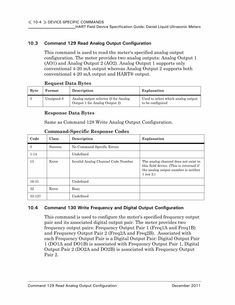
10.3 Command 129 Read Analog Output Configuration
This command is used to read the meter's specified analog output configuration. The meter provides two analog outputs: Analog Output 1 (AO1) and Analog Output 2 (AO2). Analog Output 1 supports only conventional 4-20 mA output whereas Analog Output 2 supports both conventional 4-20 mA output and HART® output.
Request Data Bytes
Response Data Bytes
Same as Command 128 Write Analog Output Configuration.
Command-Specific Response Codes
10.4 Command 130 Write Frequency and Digital Output Configuration
This command is used to configure the meter's specified frequency output pair and its associated digital output pair. The meter provides two frequency output pairs: Frequency Output Pair 1 (Freq1A and Freq1B) and Frequency Output Pair 2 (Freq2A and Freq2B). Associated with each Frequency Output Pair is a Digital Output Pair: Digital Output Pair 1 (DO1A and DO1B) is associated with Frequency Output Pair 1, Digital Output Pair 2 (DO2A and DO2B) is associated with Frequency Output Pair 2.
Byte Format Description Explanation
0 Unsigned-8 Analog output selector (0 for Analog Output 1 for Analog Output 2)
Used to select which analog output to be configured
Code Class Description Explanation
0 Success No Command-Specific Errors
1-14 Undefined
15 Error Invalid Analog Channel Code Number The analog channel does not exist in this field device. (This is returned if the analog output number is neither 1 nor 2.)
16-31 Undefined
32 Error Busy
33-127 Undefined
Command 129 Read Analog Output Configuration December 2011

DEVICE-SPECIFIC COMMANDS 10-5HART Field Device Specification Guide: Daniel Liquid Ultrasonic Meters
Request Data BytesByte Format Description Explanation
0 Unsigned-8 Frequency/Digital Output Pair selector (0 for Pair 1 or 1 for Pair 2)
Used to select which frequency/digital output pair to be configured
1 Unsigned-8 Device Variable assigned to the specified Frequency Output Pair
• 0=Uncorrected flow rate.
Used to set FreqXContent. When this assignment is a configuration change, the remaining data bytes are ignored. However, for the response, the remaining data bytes should reflect the data for the newly assigned device variable.
2 Enum-8 Upper and Lower Range Values Units Code (see Section 11.)
Specifies the units for the requested Device Variable and Upper and Lower Range Values. This units code is only pertinent for interpreting this command’s data values and for the units of the response’s data values. It does not update any units-related data points.
3-6 Float Upper Range Value Used to set FreqXFullScaleVolFlowRate. This value corresponds to the maximum frequency (set via FreqXMaxFrequency).
7-10 Float Lower Range Value Used to set AOXMinVel. Write is rejected if volumetric flow rate is selected as the device variable and the Lower Range Value is non-zero.
11-12 Enum-16 Maximum Frequency (Hertz) Allowed values are 1000 and 5000 Hz. Used to set FreqXMaxFrequency.
13 Enum-8 Flow direction to be represented by Frequency Output Pair
• 0=Reverse• 1=Forward• 2=Absolute (indicates flow regardless
of flow direction)• 3=Bidirectional (Phase A indicates forward direction flow, Phase B indicates reverse direction flow). Used to set FreqXDir.
14 Enum-8 Frequency B Phase zero-on-error configuration
0=don’t zero on error, 1=zero on errorUsed to set IsFreqXBZeroedOnErr.
15 Enum-8 Frequency B Phase relative to Frequency A Phase configuration
• 0=Lag when forward flow, lead when reverse flow
• 1=Lead when forward flow, lag when reverse flow
This configuration is ignored when Bidirec-tional flow direction is requested (see above). Used to set FreqXBPhase.
December 2011 Command 130 Write Frequency and Digital Output Configuration

10-6 DEVICE-SPECIFIC COMMANDSHART Field Device Specification Guide: Daniel Liquid Ultrasonic Meters
Response Data Bytes
16 Unsigned-8 Frequency feedback correction percentage
Values within [0, 100] percent. Used to set FreqXFeedbackCorrectionPcnt.
17 Enum-8 Selected Digital Output A inverted polarity configuration
• 0=Normal polarity• 1=Inverted polarityThis is used to set DOXAIsInvPolarity
18 Enum-8 Selected Digital Output A content selector
• 0=Corresponding Frequency Output Pair Validity
• 1=Flow DirectionThis is used to set DOXAContent data point but it is NOT a direct mapping.
19 Enum-8 Selected Digital Output B inverted polarity configuration selector
• 0=Normal polarity• 1=Inverted polarityThis is used to set DOXBIsInvPolarity
20 Enum-8 Selected Digital Output B content selector
• 0=Corresponding Frequency Output Pair Validity
• 1=Flow DirectionThis is used to DOXBContent data point but it is NOT a direct mapping.
Byte Format Description
0 Unsigned-8 Frequency/Digital Output Pair selector (0 for Pair 1 or 1 for Pair 2)
1 Unsigned-8 Device Variable assigned to the specified Frequency Output Pair
2 Enum-8 Upper and Lower Range Values Units Code (see Section 11.) for the assigned Device Variable. If the device variable assigned is modified, then the configured HART default units code for the Device Variable is used.
3-6 Float Upper Range Value for the assigned Device Variable
7-10 Float Lower Range Value for the assigned Device Variable
11-12 Enum-16 Maximum Frequency (Hertz)
13 Enum-8 Flow direction to be represented by Frequency Output Pair
14 Enum-8 Frequency B Phase zero-on-error configuration
15 Enum-8 Frequency B Phase relative to Frequency A Phase configuration
16 Unsigned-8 Frequency feedback correction percentage
17 Enum-8 Selected Digital Output A inverted polarity configuration
18 Enum-8 Selected Digital Output A content
19 Enum-8 Selected Digital Output B inverted polarity configuration
20 Enum-8 Selected Digital Output B content
Command 130 Write Frequency and Digital Output Configuration December 2011

DEVICE-SPECIFIC COMMANDS 10-7HART Field Device Specification Guide: Daniel Liquid Ultrasonic Meters
C
0
1
2
3
4
5
6
7
8
9
1
1
1
1
1
1
2
2
3
3
Command-Specific Response Codesode Class Description Explanation
Success No Command-Specific Errors
Undefined
Error Invalid Selection Requested maximum frequency, feedback percent-age invalid Frequency Phase B, Digital Output inverted polarity or Digital Output content invalid.
Error Passed Parameter Too Large
Error Passed Parameter Too Small
Error Too Few Data Bytes Received
Error Device-Specific Command Error
Error In Write Protect Mode
Undefined
Error Lower Range Value Too High Lower Range Value was above the Upper Trans-ducer Limit or some other physical device limita-tion is exceeded.
0 Error Lower Range Value Too Low Lower Range Value was below the Lower Trans-ducer Limit or some other physical device limita-tion is exceeded.
1 Error Upper Range Value Too High Upper Range Value was above Upper Transducer Limit.
2 Error Upper Range Value Too Low Upper Range Value was below the Lower Trans-ducer Limit.
3-14 Undefined
5 Error Invalid Frequency/Digital Output Pair Number
The frequency/digital output pair requested does not exist in this field device. (This is returned if the number is neither 0 nor 1.)
6-27 Undefined
8 Error Invalid Device Variable Index The requested Device Variable does not exist in this field device. (This is returned if an invalid Device Variable selection is requested.)
9-31 Undefined
2 Error Busy
3-127 Undefined
December 2011 Command 130 Write Frequency and Digital Output Configuration

10-8 DEVICE-SPECIFIC COMMANDSHART Field Device Specification Guide: Daniel Liquid Ultrasonic Meters
10.5 Command 131 Read Frequency and Digital Output Configuration
This command is used to read the meter's specified frequency output pair and its associated digital output pair configuration. The meter provides two frequency output pairs: Frequency Output Pair 1 (Freq1A and Freq1B) and Frequency Output Pair 2 (Freq2A and Freq2B). Associated with each Frequency Output Pair is a Digital Output Pair: Digital Output Pair 1 (DO1A and DO1B) is associated with Frequency Output Pair 1, Digital Output Pair 2 (DO2A and DO2B) is associated with Frequency Output Pair 2. The parameters are returned using the units code selection for the Device Variable represented by the specified frequency output pair.
Request Data Bytes
Response Data Bytes
Same as Command 130 Write Frequency and Digital Output Configuration.
Command-Specific Response Codes
10.6 Command 132 Write Flow Pressure Configuration
This command is used to configure the meter's flow-condition pressure. The input can be disabled, a conventional 4-20 mA input, a HART® input, or fixed at a specified value. For conventional 4-20 mA and HART® inputs, Analog Input 2 (AI2) is used for pressure.
Byte Format Description Explanation
0 Unsigned-8 Frequency/Digital Output Pair number (1 or 2)
Used to select which frequency/digital output pair to be configured
Code Class Description Explanation
0 Success No Command-Specific Errors
1-14 Undefined
15 Error Invalid Frequency/Digital Output Pair Number
The frequency/digital output pair does not exist in this field device. (This is returned if the number is neither 1 nor 2.)
16-31 Undefined
32 Error Busy
33-127 Undefined
Command 131 Read Frequency and Digital Output Configuration December 2011
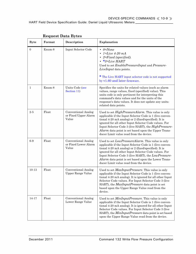
DEVICE-SPECIFIC COMMANDS 10-9HART Field Device Specification Guide: Daniel Liquid Ultrasonic Meters
Request Data BytesByte Format Description Explanation
0 Enum-8 Input Selector Code • 0=None• 1=Live 4-20 mA• 2=Fixed (specified).• *3=Live HART Used to set EnablePressureInput and Pressure-LiveInput data points.
* The Live HART input selector code is not supported by v1.60 and later firmware.
1 Enum-8 Units Code (see Section 11)
Specifies the units for related values (such as alarm values, range values, fixed (specified) value). This units code is only pertinent for interpreting this command's data values and for the units of the response's data values. It does not update any units-related data points.
2-5 Float Conventional Analog or Fixed Upper Alarm Value
Used to set HighPressureAlarm. This value is only applicable if the Input Selector Code is 1 (live conven-tional 4-20 mA analog) or 2 (fixed/specified). It is ignored for all other Input Selector Code values. For Input Selector Code 3 (live HART), the HighPressure-Alarm data point is set based upon the Upper Trans-ducer Limit value read from the device.
6-9 Float Conventional Analog or Fixed Lower Alarm Value
Used to set LowPressureAlarm. This value is only applicable if the Input Selector Code is 1 (live conven-tional 4-20 mA analog) or 2 (fixed/specified). It is ignored for all other Input Selector Code values. For Input Selector Code 3 (live HART), the LowPressure-Alarm data point is set based upon the Lower Trans-ducer Limit value read from the device.
10-13 Float Conventional Analog Upper Range Value
Used to set MaxInputPressure. This value is only applicable if the Input Selector Code is 1 (live conven-tional 4-20 mA analog). It is ignored for all other Input Selector Code values. For Input Selector Code 3 (live HART), the MaxInputPressure data point is set based upon the Upper Range Value read from the device.
14-17 Float Conventional Analog Lower Range Value
Used to set MinInputPressure. This value is only applicable if the Input Selector Code is 1 (live conven-tional 4-20 mA analog). It is ignored for all other Input Selector Code values. For Input Selector Code 3 (live HART), the MinInputPressure data point is set based upon the Upper Range Value read from the device.
December 2011 Command 132 Write Flow Pressure Configuration

10-10 DEVICE-SPECIFIC COMMANDSHART Field Device Specification Guide: Daniel Liquid Ultrasonic Meters
Response Data Bytes
18-21 Float Fixed Value Used to set SpecFlowPressure. This value is only applicable if the Input Selector Code is 2 (fixed/speci-fied). It is ignored for all other Input Selector Code values.
22 Enum-8 Pressure and Temper-ature Alarm Selection Code(see Section 11)
This selects the input action upon alarm and is appli-cable to both pressure and temperature inputs. Used to set FlowPOrTSrcUponAlarm although it is not a direct mapping:• 239 Hold Last Output Value set
FlowPOrTSrcUponAlarm to 0;• 242 Used Fixed Value set
FlowPOrTSrcUponAlarm to 1 (Fixed value).
23 Enum-8 Absolute pressure input type indicator
• 0=gage• 1=absoluteUsed to set InputPressureUnit.
24-27 Float Atmospheric Pressure Value
Required when the input pressure is gage. Used to set AtmosphericPress.
Byte Format Description
0 Enum-8 Input Selector Code
1 Enum-8 Units Code (see Section 11)
2-5 Float Conventional Analog or Fixed Upper Alarm Value
6-9 Float Conventional Analog or Fixed Lower Alarm Value
10-13 Float Conventional Analog Upper Range Value
14-17 Float Conventional Analog Lower Range Value
18-21 Float Fixed Value
22 Enum-8 Pressure and Temperature Alarm Selection Code (see Section 11)
23 Enum-8 Absolute pressure input type indicator (1=absolute, 0=gage)
24 - 27 Float Atmospheric Pressure Value
Byte Format Description Explanation
Command 132 Write Flow Pressure Configuration December 2011

DEVICE-SPECIFIC COMMANDS 10-11HART Field Device Specification Guide: Daniel Liquid Ultrasonic Meters
Command-Specific Response CodesCode Class Description Explanation
0 Success No Command-Specific Errors
1 Undefined
2 Error Invalid Selection Input selector code or alarm code selection invalid.
3-4 Undefined
5 Error Too Few Data Bytes Received
6 Error Device-Specific Command Error This is used to indicate an error when either (a) lower alarm value > upper alarm value, (b) lower range value > upper range value, or (c) a requested value is outside its sanity limits.
* Also used for unsupported selector code, e.g. Live HART is not supported v1.60 and later firmware.
7 Error In Write Protect Mode
8 Undefined
9 Error Lower Range Value Too High Lower Range Value was above the Upper Transducer Limit or some other physical device limitation is exceeded.
10 Error Lower Range Value Too Low Lower Range Value was below the Lower Transducer Limit or some other physical device limitation is exceeded
11 Error Upper Range Value Too High Upper Range Value was above Upper Transducer Limit.
12 Error Upper Range Value Too Low Upper Range Value was below the Lower Transducer Limit.
13-31 Undefined
32 Error Busy
33-127 Undefined
December 2011 Command 132 Write Flow Pressure Configuration

10-12 DEVICE-SPECIFIC COMMANDSHART Field Device Specification Guide: Daniel Liquid Ultrasonic Meters
10.7 Command 133 Read Flow Pressure Configuration
This command is used to read the meter's flow-condition pressure input configuration. The parameters are returned using the Pressure Device Variable configured units code.
Request Data Bytes
Response Data Bytes
Same as Command 132 Write Flow Pressure Configuration.
Command-Specific Response Codes
10.8 Command 134 Write Flow Temperature Configuration
This command is used to configure the meter's flow-condition temperature. The input can be disabled, a conventional 4-20 mA input, a HART® input, or fixed at a specified value. For conventional 4-20 mA and HART® inputs, Analog Input 1 (AI1) is used for temperature.
Request Data Bytes
Byte Format Description Explanation
None
Code Class Description Explanation
0 Success No Command-Specific Errors
1-31 Undefined
32 Error Busy
33-127 Undefined
Byte Format Description Explanation
0 Enum-8 Input Selector Code 0=None, 1=Live 4-20 mA, 3=Live HART, 2=Fixed (specified). Used to set EnableTemperatureInput and TemperatureLiveInput data points.
* The Live HART input selector code is not supported byv1.60 and later firmware.
1 Enum-8 Units Code (see Section 11) Specifies the units for related values (such as alarm values, range values, fixed (specified) value). This units code is only pertinent for interpreting this command's data values and for the units of the response's data values. It does not update any units-related data points.
Command 133 Read Flow Pressure Configuration December 2011

DEVICE-SPECIFIC COMMANDS 10-13HART Field Device Specification Guide: Daniel Liquid Ultrasonic Meters
2-5 Float Conventional Analog or Fixed Upper Alarm Value
Used to set HighTemperatureAlarm. This value is only applicable if the Input Selector Code is 1 (live conventional 4-20 mA analog) or 2 (fixed/specified). It is ignored for all other Input Selector Code values. For Input Selector Code 3 (live HART), the HighTemperature-Alarm data point is set based upon the Upper Transducer Limit value read from the device.
6-9 Float Conventional Analog or Fixed Lower Alarm Value
Used to set LowTemperatureAlarm. This value is only applicable if the Input Selector Code is 1 (live conventional 4-20 mA analog) or 2 (fixed/specified). It is ignored for all other Input Selector Code values. For Input Selector Code 3 (live HART), the LowTemperature-Alarm data point is set based upon the Lower Transducer Limit value read from the device.
10-13 Float Conventional Analog Upper Range Value
Used to set MaxInputTemperature. This value is only applicable if the Input Selector Code is 1 (live conventional 4-20 mA analog). It is ignored for all other Input Selector Code values. For Input Selector Code 3 (live HART), the MaxInputTempera-ture data point is set based upon the Upper Range Value read from the device.
14-17 Float Conventional Analog Lower Range Value
Used to set MinInputTemperature. This value is only applicable if the Input Selector Code is 1 (live conventional 4-20 mA analog). It is ignored for all other Input Selector Code values. For Input Selector Code 3 (live HART), the MinInputTemperature data point is set based upon the Upper Range Value read from the device.
18-21 Float Fixed Value Used to set SpecFlowTemperature. This value is only applicable if the Input Selector Code is 2 (fixed/specified). It is ignored for all other Input Selector Code values.
22 Enum-8 Pressure and Temperature Alarm Selection Code (see Section 11)
This selects the input action upon alarm and is applicable to both pressure and temperature inputs. Used to set FlowPOrTSrcUponAlarm although it is not a direct mapping:• 239 Hold Last Output Value set
FlowPOrTSrcUponAlarm to 0• 242 Used Fixed Value set
FlowPOrTSrcUponAlarm to 1 (Fixed value).
Byte Format Description Explanation
December 2011 Command 134 Write Flow Temperature Configuration

10-14 DEVICE-SPECIFIC COMMANDSHART Field Device Specification Guide: Daniel Liquid Ultrasonic Meters
Response Data Bytes
Command-Specific Response Codes
Byte Format Description
0 Enum-8 Input Selector Code
1 Enum-8 Units Code (see Section 11)
2-5 Float Conventional Analog or FixedUpper Alarm Value
6-9 Float Conventional Analog or FixedLower Alarm Value
10-13 Float Conventional Analog Upper Range Value
14-17 Float Conventional Analog Lower Range Value
18-21 Float Fixed Value
22 Enum-8 Pressure and Temperature Alarm
Code Class Description Explanation
0 Success No Command-Specific Errors
1 Undefined
2 Error Invalid Selection Input selector code or alarm code selection invalid.
3-4 Undefined
5 Error Too Few Data Bytes Received
6 Error Device-Specific Command Error This is used to indicate an error when either:• lower alarm value > upper alarm
value• lower range value > upper range
value or • a requested value is outside its sanity
limits.* Also used for unsupported selector code, e.g. Live HART is not supported v1.60 and later firmware.
7 Error In Write Protect Mode
8 Undefined
Command 134 Write Flow Temperature Configuration December 2011

DEVICE-SPECIFIC COMMANDS 10-15HART Field Device Specification Guide: Daniel Liquid Ultrasonic Meters
10.9 Command 135 Read Flow Temperature Configuration
This command is used to read the meter's flow-condition temperature input configuration. The parameters are returned using the Temperature Device Variable configured units code.
Request Data Bytes
Response Data Bytes
Same as Command 134 Write Flow Pressure-Specific Configuration.
Command-Specific Response Codes
9 Error Lower Range Value Too High Lower Range Value was above the Upper Transducer Limit or some other physical device limitation is exceeded.
10 Error Lower Range Value Too Low Lower Range Value was below the Lower Transducer Limit or some other physical device limitation is exceeded
11 Error Upper Range Value Too High Upper Range Value was above Upper Transducer Limit.
12 Error Upper Range Value Too Low Upper Range Value was below the Lower Transducer Limit.
13-31 Undefined
32 Error Busy
33-127 Undefined
Byte Format Description Explanation
None
Code Class Description Explanation
0 Success No Command-Specific Errors
1-31 Undefined
32 Error Busy
33-127 Undefined
Code Class Description Explanation
December 2011 Command 135 Read Flow Temperature Configuration

10-16 DEVICE-SPECIFIC COMMANDSHART Field Device Specification Guide: Daniel Liquid Ultrasonic Meters
10.10 Command 136 Write Device Units
This command is used to write the device's units. Note that the meter utilizes the Flow Rate Time Units Code to derive all flow rate units. For example, the Volumetric Flow Rate Units Code (used for the uncorrected volumetric flow rate device variable) is derived from the Volume Units Code and the Flow Rate Time Units Code: if the Volume Units Code is cubic meters and the Flow Rate Time Units Code is (per) hour, then the derived Volumetric Flow Rate Units Code is cubic meters per hour. The supported HART® Units Codes are listed in Section 11.
Request Data Bytes
Response Data Bytes
Byte Format Description
0 Enum-8 Volume Units Code (see Table 11-1)
1 Enum-8 Flow Rate Time Units Code (see Table 11-2)
2 Enum-8 Pressure Units Code (see Table 11-4)
3 Enum-8 Temperature Units Code (see Table 11-5)
4 Enum-8 Velocity Units Code (see Table 11-6)
Byte Format Description
0 Enum-8 Volume Units Code
1 Enum-8 Flow Rate Time Units Code
2 Enum-8 Pressure Units Code
3 Enum-8 Temperature Units Code
4 Enum-8 Velocity Units Code
Command 136 Write Device Units December 2011

DEVICE-SPECIFIC COMMANDS 10-17HART Field Device Specification Guide: Daniel Liquid Ultrasonic Meters
Command-Specific Response Codes
10.11 Command 137 Read Device Units
This command is used to read the device's units. The response message content is different between the gas and liquid meters as indicated below.
Request Data Bytes
Response Data Bytes
Same as for Command 136 Write Device Units (according to the meter type).
Command-Specific Response Codes
Code Class Description Explanation
0 Success No Command-Specific Errors
1 Undefined
2 Error Invalid Selection One or more of the units code selection(s) is/are invalid.
3-4 Undefined
5 Error Too Few Data Bytes Received
6 Undefined
7 Error In Write Protect Mode
8-31 Undefined
32 Error Busy
33-127 Undefined
Byte Format Description Explanation
None
Code Class Description Explanation
0 Success No Command-Specific Errors
1-31 Undefined
32 Error Busy
33-127 Undefined
December 2011 Command 137 Read Device Units

10-18 DEVICE-SPECIFIC COMMANDSHART Field Device Specification Guide: Daniel Liquid Ultrasonic Meters
10.12 Command 138 Write Device Variable Range
This command is used to write a specified device variable's upper and lower range values. This command is used to scale graphs, charts, etc. for displaying device variable values on host system (HART® Field Device Specification Guide: Daniel Liquid Ultrasonic Meters) screens.
Request Data Bytes
Response Data Bytes
Command-Specific Response Codes
Byte Format Description Explanation
0 Unsigned-8 Device Variable Selector
Specifies the device variable for which the range values are to be set. Note that the pressure and/or temperature device variable range values cannot be written if the value(s) is/are input live via HART since the range values are determined by reading the transmitter primary variable range.
1 Enum-8 Units Code (see Section 11)
Specifies the units for the specified range values. This units code is only pertinent for interpreting this command's data values and for the units of the response's data values. It does not update any units-related data points.
2-5 Float Upper Range Value
6-9 Float Lower Range Value
Byte Format Description
0 Unsigned-8 Device Variable Selector
1 Enum-8 Range Values Units Code (see Section 11)
2-5 Float Upper Range Value
6-9 Float Lower Range Value
Code Class Description Explanation
0 Success No Command-Specific Errors
1 Undefined
2 Error Invalid Selection Units code selection invalid.
3-4 Undefined
5 Error Too Few Data Bytes Received
Command 138 Write Device Variable Range December 2011

DEVICE-SPECIFIC COMMANDS 10-19HART Field Device Specification Guide: Daniel Liquid Ultrasonic Meters
6-8 Undefined
9 Error Lower Range Value Too High Lower Range Value was above the Upper Transducer Limit or some other physical device limitation is exceeded.
10 Error Lower Range Value Too Low Lower Range Value was below the Lower Transducer Limit or some other physical device limitation is exceeded.
11 Error Upper Range Value Too High Upper Range Value was above Upper Transducer Limit.
12 Error Upper Range Value Too Low Upper Range Value was below the Lower Transducer Limit.
13-27 Undefined
28 Error Invalid Device Variable Index The requested Device Variable does not exist in this field device or is not supported by the requested command or operation. (This is returned if an invalid Device Variable selection is requested.)
29-31 Undefined
32 Error Busy
33-127 Undefined
Code Class Description Explanation
December 2011 Command 138 Write Device Variable Range

10-20 DEVICE-SPECIFIC COMMANDSHART Field Device Specification Guide: Daniel Liquid Ultrasonic Meters
Command 139 Read Device Variable Range December 2011
10.13 Command 139 Read Device Variable Range
This command is used to read a specified device variable's upper and lower range values. This command is expected to be used to scale graphs, charts, etc. for displaying device variable values on host system () screens.
Request Data Bytes
Response Data Bytes
Same as for Command 138 Write Device Variable Range.
Command-Specific Response Codes
Byte Format Description Explanation
0 Unsigned-8 Device Variable Selector Specifies the device variable for which the range values are to be read.
Code Class Description Explanation
0 Success No Command-Specific Errors
1-4 Undefined
5 Error Too Few Data Bytes Received
6-27 Undefined
28 Error Invalid Device Variable Index The requested Device Variable does not exist in this field device or is not supported by the requested command or operation. (This is returned if an invalid Device Variable selection is requested.)
29-31 Undefined
32 Error Busy
33-127 Undefined

DEVICE-SPECIFIC COMMANDS 10-21HART Field Device Specification Guide: Daniel Liquid Ultrasonic Meters
By
0
1
10.14 Command 140 Read Detailed Status
This command is used to read detailed status information (i.e., status information that provides detail beyond that of the response status byte and Common Command 48 (Read Additional Device Status see Table 7-2). The purpose of having a separate device-specific command is to limit what is seen and logged by the AMS® Alert Monitor.
Request Data Bytes
Response Data Bytes
Byte Format Description Explanation
None
te Format Description
Bits Failed Detail Screen Status Byte 0
Bits Failed Detail Screen Status Byte 1 (for future use)
Bit DescriptionRelated Database Point(s)
7 (msb) • Reserved
6 Indicates communication error with Acquisition board.
• IsCommErrAcqBd
5 Indicates electronics voltage out-of-range. • IsElecVoltOutOfRange
4 Indicates memory error (acknowledged by writing to FALSE).
• Reserved
3 Indicates the watchdog performed a meter warm-start.
• WatchDogReset
2 Indicates unknown Acquisition Board revision - firmware upgrade is required.
• IsUnkAcqBdRev
1
0 (lsb)
December 2011 Command 140 Read Detailed Status

10-22 DEVICE-SPECIFIC COMMANDSHART Field Device Specification Guide: Daniel Liquid Ultrasonic Meters
2
3
By
Bits Maintenance Detail Screen Status Byte 0
Bits Maintenance Detail Screen Status Byte 1
te Format Description
Bit Description Related Database Point(s)
7 (msb) Noise energy exceeded maximum limit (chord A).
• DidExceedMaxNoiseA†
6 Signal-to-noise ratio below minimum threshold (chord A).
• IsSNRTooLowA†
5 Measurement quality check failed (chord A).
• DidTmDevChkFailA†
4 Acquisition mode sound speed out of (min, max) range (chord A).
• IsAcqSndSpdRangeErrA†
3 Delta time measurement error (chord A). • DidDltTmChkFailA†
2 Signal quality below minimum threshold (chord A).
• IsSigQltyBadA†
1 Sound speed out of range error (Measure-ment mode, chord A).
• IsMeasSndSpdRangeA†
0 (lsb)
Bit Description Related Database Point(s)
7 (msb) Chord A detection error. • IsDetectionErrA†
6 Signal discarded due to distortion (chord A). • IsSigDistortedA†
5
4
3
2
1
0 (lsb)
Command 140 Read Detailed Status December 2011

DEVICE-SPECIFIC COMMANDS 10-23HART Field Device Specification Guide: Daniel Liquid Ultrasonic Meters
4
5
By
Bits Maintenance Detail Screen Status Byte 2
Bits Maintenance Detail Screen Status Byte 3
te Format Description
Bit Description Related Database Point(s)
7 (msb) Noise energy exceeded maximum limit (chord B).
• DidExceedMaxNoiseB†
6 Signal-to-noise ratio below minimum threshold (chord B).
• IsSNRTooLowB†
5 Measurement quality check failed (chord B). • DidTmDevChkFailB†
4 Acquisition mode sound speed out of (min, max) range (chord B).
• IsAcqSndSpdRangeErrB†
3 Delta time measurement error (chord B).
• DidDltTmChkFailB†
2 Signal quality below minimum threshold (chord B).
• IsSigQltyBadB†
1 Sound speed out of range error (Measure-ment mode, chord B).
• IsMeasSndSpdRangeB†
0 (lsb)
Bit Description Related Database Point(s)
7 (msb) Chord B detection error. • IsDetectionErrB†
6 Signal discarded due to distortion (chord B). • IsSigDistortedB†
5
4
3
2
1
0 (lsb)
December 2011 Command 140 Read Detailed Status

10-24 DEVICE-SPECIFIC COMMANDSHART Field Device Specification Guide: Daniel Liquid Ultrasonic Meters
6
7
By
Command 140 Read Detailed Status December 2011
Bits Maintenance Detail Screen Status Byte 4
Bits Maintenance Detail Screen Status Byte 5
te Format Description
Bit Description Related Database Point(s)
7 (msb) Noise energy exceeded maximum limit (chord C).
• DidExceedMaxNoiseC†
6 Signal-to-noise ratio below minimum threshold (chord C).
• IsSNRTooLowC†
5 Measurement quality check failed (chord C).
• DidTmDevChkFailC†
4 Acquisition mode sound speed out of (min, max) range (chord C).
• IsAcqSndSpdRangeErrC†
3 Delta time measurement error (chord C).
• DidDltTmChkFailC†
2 Signal quality below minimum threshold (chord C).
• IsSigQltyBadC†
1 Sound speed out of range error (Mea-surement mode, chord C).
• IsMeasSndSpdRangeC†
0 (lsb)
Bit Description Related Database Point(s)
7 (msb) Chord C detection error. • IsDetectionErrC†
6 Signal discarded due to distortion (chord C).
• IsSigDistortedC†
5
4
3
2
1
0 (lsb)

DEVICE-SPECIFIC COMMANDS 10-25HART Field Device Specification Guide: Daniel Liquid Ultrasonic Meters
8
9
By
Bits Maintenance Detail Screen Status Byte 6
Bits Maintenance Detail Screen Status Byte 7
te Format Description
Bit Description Related Database Point(s)
7 (msb) Noise energy exceeded maximum limit (chord D).
• DidExceedMaxNoiseD†
6 Signal-to-noise ratio below minimum threshold (chord D)
• IsSNRTooLowD†
5 Measurement quality check failed (chord D).
• DidTmDevChkFailD†
4 Acquisition mode sound speed out of (min, max) range (chord D).
• IsAcqSndSpdRangeErrD†
3 Delta time measurement error (chord D).
• DidDltTmChkFailD†
2 Signal quality below minimum threshold (chord D).
• IsSigQltyBadD†
1 Sound speed out of range error (Mea-surement mode, chord D).
• IsMeasSndSpdRangeD†
0 (lsb) •
Bit Description Related Database Point(s)
7 (msb) Chord D detection error. • IsDetectionErrD†
6 Signal discarded due to distortion (chord D).
• IsSigDistortedD†
5
4
3
2
1
0 (lsb)
December 2011 Command 140 Read Detailed Status

10-26 DEVICE-SPECIFIC COMMANDSHART Field Device Specification Guide: Daniel Liquid Ultrasonic Meters
10
11
By
Bits Maintenance Detail Screen Status Byte 8
Bits Maintenance Detail Screen Status Byte 9
te Format Description
Bit Description Related Database Point(s)
7 (msb) Analog Output 2 test enable.
• IsAO2EnableTest
6 Analog Output 2 fixed current value (for trim).
• AO2IsFixed
5
4
3
2
1
0 (lsb)
Bit Description Related Database Point(s)
7 (msb) Reserved
6 Reserved
5 Reserved
4 Reserved
3
2
1
0 (lsb)
Command 140 Read Detailed Status December 2011

DEVICE-SPECIFIC COMMANDS 10-27HART Field Device Specification Guide: Daniel Liquid Ultrasonic Meters
12
By
Bits Advisory Detail Screen Status Byte 0
te Format Description
Bit Description Related Database Point(s)
7 (msb) Indicates Flow-condition volumetric flow rate validity.
• QFlowValidity (inverted)
6 Reserved
5 Reserved
4 Reserved
3 Reserved
2 Reserved
1
0 (lsb)
December 2011 Command 140 Read Detailed Status

10-28 DEVICE-SPECIFIC COMMANDSHART Field Device Specification Guide: Daniel Liquid Ultrasonic Meters
13
By
Bits Advisory Detail Screen Status Byte 1
te Format Description
Bit Description Related Database Point(s)
7 (msb) Indicates HART pressure trans-mitter device malfunction
• PressHARTIsDevMalfunction
6 Indicates HART pressure trans-mitter configuration changed.
• PressHARTIsConfigChanged
5 Indicates HART pressure trans-mitter cold started.
• PressHARTDidColdStart
4 Indicates HART pressure trans-mitter has more status available
• PressHARTIsMoreStatusAvailable
3 Indicates HART pressure trans-mitter loop current is fixed.
• PressHARTIsLoopCurrentFixed
2 Indicates HART pressure trans-mitter loop current is saturated.
• PressHARTIsLoopCurrentSatu-rated
1 Indicates HART pressure trans-mitter non-Primary Variable is out of limits.
• PressHARTIsNonPVOutOfLimits
0 (lsb) Indicates HART pressure trans-mitter Primary Variable is out of its limits
• PressHARTIsPVOutOfLimits
Command 140 Read Detailed Status December 2011

DEVICE-SPECIFIC COMMANDS 10-29HART Field Device Specification Guide: Daniel Liquid Ultrasonic Meters
14
15
By
Bits Advisory Detail Screen Status Byte 2
Bits Advisory Detail Screen Status Byte 3
te Format Description
Bit Description Related Database Point(s)
7 (msb) Temperature device malfunction • TempHARTIsDevMalfunction
6 Temperature config changed • TempHARTIsConfigChanged
5 Temperature cold started • TempHARTDidColdStart
4 Temperature more status • TempHARTIsMoreStatusAvailable
3 Temperature loop current fixed • TempHARTIsLoopCurrentFixed
2 Temperature loop current saturated
• TempHARTIsLoopCurrentSaturated
1 Temperature non-PV out of limits • TempHARTIsNonPVOutOfLimits
0 (lsb) Temperature PV out of limits • TempHARTIsPVOutOfLimits
Bit Description Related Database Point(s)
7 (msb) Indicates HART Pressure trans-mitter communication error.
• PressureHARTIsCommErr
6 Indicates HART Temperature transmitter communication error.
• TempHARTIsCommErr
5 Frequency 1 pair validityindicator.
• Freq2DataValidity (inverted)
4 Frequency 2 pair validityindicator.
• Freq1DataValidity (inverted)
3 Analog output 2 validity • AO2DataValidity (inverted)
2 Analog output 1 validity • AO1DataValidity (inverted)
1 Analog Output 1 test enable. • IsAO1EnableTest
0 (lsb) Indicates whether AO1 current is fixed or not.
• AO1IsFixed
December 2011 Command 140 Read Detailed Status

10-30 DEVICE-SPECIFIC COMMANDSHART Field Device Specification Guide: Daniel Liquid Ultrasonic Meters
16
17
† T whFAva as
By
)
)
)
d)
d)
d)
d)
Command 140 Read Detailed Status December 2011
Bits Advisory Detail Screen Status Byte 4
Bits Advisory Detail Screen Status Byte 5
hese database points are only indicated if the corresponding chord is hard failed (i.e., if IsHardFailedX is TRUEere X is the corresponding chord). Thus, if the corresponding chord is not hard failed (i.e., if IsHardFailedX is LSE), then the chord's related detail status bits shall all be zero regardless of the associated database point's
lue. For example, if IsHardFailedA is FALSE and DidExceedMaxNoiseA is TRUE, then byte 2 bit 0 is indicated 0 (as are all byte 2 bits) since the chord is not hard failed.
te Format Description
Bit Description Related Database Point(s)
7 (msb) Hourly log full indicator. • IsHourlyLogFull
6 Daily log full indicator. • IsDailyLogFull
5 Audit log full indicator. • IsAuditLogFull
4 Alarm log full indicator. • IsAlarmLogFull
3 System log full indicator. • IsSystemLogFull
2 HART (via AO2) Secondary Variable validity indicator.
• HARTAO2SVValidity (inverted
1 HART (via AO2) Tertiary Variable validity indicator.
• HARTAO2TVValidity (inverted
0 (lsb) HART (viaAO2) Quaternary Variable validity indicator.
• HARTAO2QVValidity(inverted
Bit Description Related Database Point(s)
7 (msb) Velocity above meter maximum velocity limit • IsMeterVelAboveMaxLmt
6 Reserved
5 Flow-condition pressure out-of-limits indica-tor.
• FlowPressureIsOutOfLimits
4 Flow-condition temperature out-of-limits indicator.
• FlowTemperatureIsOutOfLimits
3 HART Command 33 Slot 0 validity indicator. • HARTAO2Slot0Validity (inverte
2 HART Command 33 Slot 1 validity indicator. • HARTAO2Slot1Validity (inverte
1 HART Command 33 Slot 2 validity indicator. • HARTAO2Slot2Validity (inverte
0 (lsb) HART Command 33 Slot 3 validity indicator. • HARTAO2Slot3Validity (inverte

DEVICE-SPECIFIC COMMANDS 10-31HART Field Device Specification Guide: Daniel Liquid Ultrasonic Meters
Command-Specific Response Codes
10.15 Command 141 Acknowledge Alarm
This command is used to acknowledge (clear/reset) an acknowledgeable alarm. The request includes an enumeration to specify which alarm to acknowledge where the enumeration is as listed in the table below:
Code Class Description Explanation
0 Success No Command-Specific Errors
1-31 Undefined
32 Error Busy
33-127 Undefined
Enumeration Alarm
0 Reserved
1 Reserved
2 WatchDogReset
3 DidCnfgChksumChg
4 DidColdStart
5 DidPowerFail
6 Reserved
7 Reserved
8 Reserved
9 Reserved
10 Reserved
December 2011 Command 141 Acknowledge Alarm

10-32 DEVICE-SPECIFIC COMMANDSHART Field Device Specification Guide: Daniel Liquid Ultrasonic Meters
The acknowledgeable alarm DidCnfgChksumChg can also be acknowledged via Common Command 38. The DidPowerFail acknowl-edgeable alarm is automatically reset according to the HART Device Status requirements. The meter shall also reset any DidColdStart alarm when the DidPowerFail alarm is automatically reset. However, this "automatic reset" would only apply to HART (for the Field Device Status byte) and would not clear the database point(s). Acknowledging DidColdStart or DidPowerFail via this command shall clear the specified database point.
Enumeration Alarm
11 Reserved
12 IsReverseFlowDetectedLatched
13 Reserved
14 IsCommErrAcqBdLatched
15 IsMeterVelAboveMaxLmtLatched
16 TemperatureInvalidLatched
17 PressureInvalidLatched
18 IsAcqModeLatched
19 IsTooFewOperChordsLatched
20 Reserved
21 Reserved
Command 141 Acknowledge Alarm December 2011
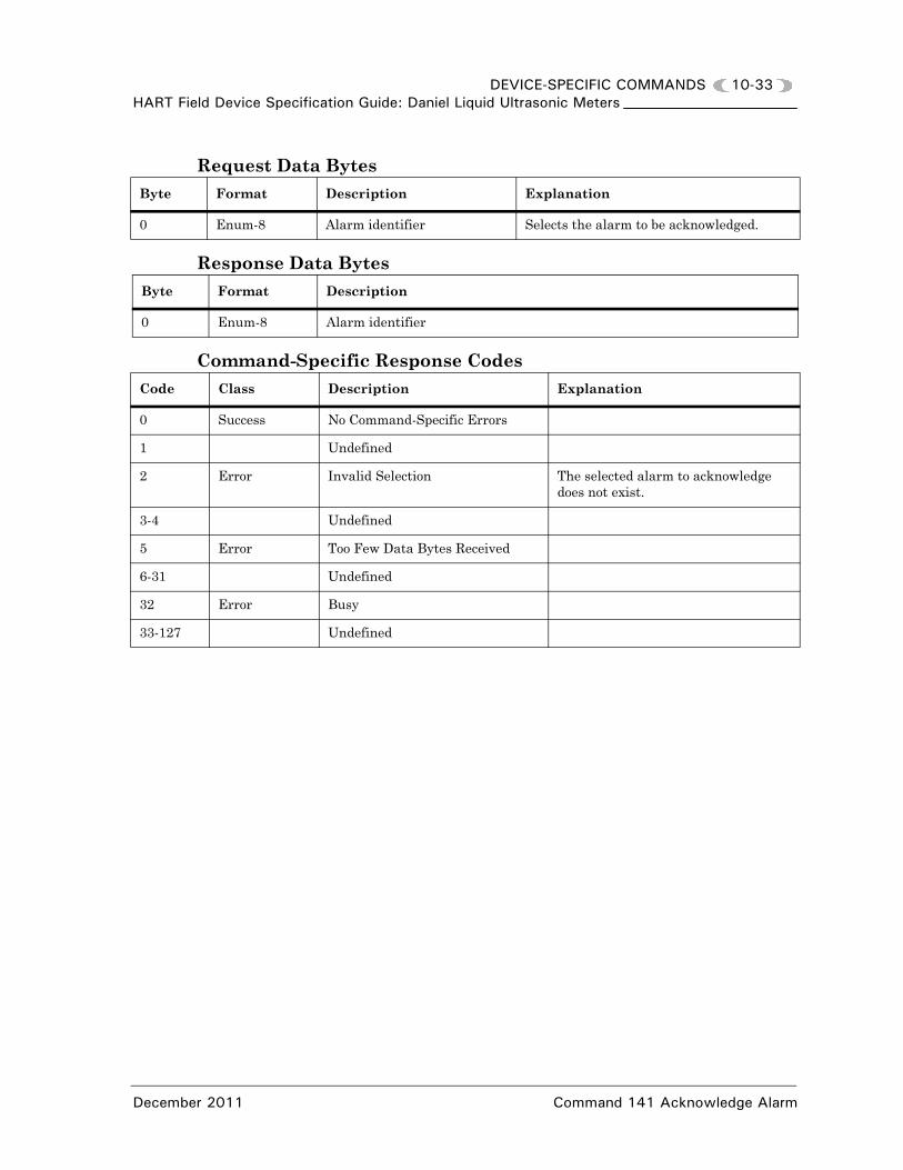
DEVICE-SPECIFIC COMMANDS 10-33HART Field Device Specification Guide: Daniel Liquid Ultrasonic Meters
Request Data Bytes
Response Data Bytes
Command-Specific Response Codes
Byte Format Description Explanation
0 Enum-8 Alarm identifier Selects the alarm to be acknowledged.
Byte Format Description
0 Enum-8 Alarm identifier
Code Class Description Explanation
0 Success No Command-Specific Errors
1 Undefined
2 Error Invalid Selection The selected alarm to acknowledge does not exist.
3-4 Undefined
5 Error Too Few Data Bytes Received
6-31 Undefined
32 Error Busy
33-127 Undefined
December 2011 Command 141 Acknowledge Alarm

10-34 DEVICE-SPECIFIC COMMANDSHART Field Device Specification Guide: Daniel Liquid Ultrasonic Meters
10.16 Command 142 Write Digital Input Configuration
This command is used to configure the meter's specified digital input configuration. The meter provides a single digital input that can be used to gate a calibration pass (such as for synchronizing the meter's calibration with prover switches).
Request Data Bytes
Response Data Bytes
Byte Format Description Explanation
0 Enum-8 Digital input selector • 0=general purpose• 1=used for calibration).
Used to set DI1IsInvPolarity.
1 Enum-8 General purpose polarity • 0=normal• 1=invertedApplicable when the digital input is used as a general purpose input. Specifies the digital input polarity for interpreting the input value. Used to set IsDI1UsedForCal.
2 Enum-8 Calibration input polarity • 0=active high• 1=active lowApplicable when the digital input is used for cal-ibration. Specifies the digital input polarity for starting/stopping calibration. Used to set IsDI1ForCalActiveLow.
3 Enum-8 Calibrating gating type • 0=edge gated• 1=state gatedApplicable when the digital input is used for cal-ibration. Specifies the digital input polarity for starting/stopping calibration. Used to set IsDI1ForCalStateGated.
Byte Format Description
0 Enum-8 Digital input usage selector (0=general purpose, 1=used for calibration)
1 Enum-8 (Bit 2) General purpose polarity (0=normal, 1=inverted)
2 Enum-8 (Bit 1) Calibration input polarity (0=active high, 1=active low)
3 Enum-8 (Least Significant Bit, Bit 0) Calibrating gating type (0=edge gated, 1=state gated)
Command 142 Write Digital Input Configuration December 2011

DEVICE-SPECIFIC COMMANDS 10-35HART Field Device Specification Guide: Daniel Liquid Ultrasonic Meters
Command-Specific Response Codes
10.17 Command 143 Read Digital Input Configuration
This command is used to read the meter's specified digital input configuration. The meter provides a single digital input that can be used to gate a calibration pass (such as for synchronizing the meter's calibration with prover switches).
Request Data Bytes
Response Data Bytes
Same as for Command 136 Write Digital Input Configuration.
Command-Specific Response Codes
Code Class Description Explanation
0 Success No Command-Specific Errors
1 Undefined
2 Error Invalid Selection Input usage selector, general purpose polarity, calibration input polarity or gating type selection invalid.
3-4 Undefined
5 Error Too Few Data Bytes Received
6 Undefined
7 Error In Write Protect Mode
8-31 Undefined
32 Error Busy
33-127 Undefined
Byte Format Description Explanation
None
Code Class Description Explanation
0 Success No Command-Specific Errors
1-31 Undefined
32 Error Busy
33-127 Undefined
December 2011 Command 143 Read Digital Input Configuration

10-36 DEVICE-SPECIFIC COMMANDSHART Field Device Specification Guide: Daniel Liquid Ultrasonic Meters
10.18 Command 144 Perform Velocity Zero Calibration
Commands 144 and 145 are used to perform velocity zero calibration on liquid ultrasonic flow meters. Two commands are used to achieve command-query separation (http://en.wikipedia.org/wiki/Command-Query Separation). This simplifies the acquisition of velocity zero calibration status in a HART® host edit display or when used in a DDL method. The engineering units for velocity are pre-configured in the device.
The command's request and response data bytes as well as the command-specific response codes are indicated below (with the functional requirements following associated Command 145):
Request Data Bytes
Response Data Bytes
Byte Format Description Explanation
None
Byte Format Description
0 Enum-8 Zero calibration process status. This should be included in the HART® Field Device Specification Guide: Daniel Liquid Ultrasonic Meters screen so that a DDL post-read method can use status change to 2 to accept/reject proposed zero cali-bration value.
1 Unsigned-8 Zero calibration duration in minutes (for initial/default value displayed for user) (ZeroFlowCalReqDuration)
2 Unsigned-8 Zero calibration progress % (zero when status is 0) updated every 5 seconds
3 Enum-8 Zero flow velocity Units Code (see Section 11)
4-7 Float Instantaneous zero flow velocity (DryCalVel) (included for display/charting purposes)
Code Description
0 Zero calibration process inactive
1 Zero calibration process in progress
2 Zero calibration process completed successfully
3 Zero calibration process failed due to chord failure during process
4 Zero calibration process failed due to too-large offset
5 Zero calibration process failed due to too-large estimated maximum deviation
Command 144 Perform Velocity Zero Calibration December 2011

DEVICE-SPECIFIC COMMANDS 10-37HART Field Device Specification Guide: Daniel Liquid Ultrasonic Meters
Command-Specific Response Codes
10.19 Command 145 Write Velocity Zero Calibration Control
This command is used to control the velocity zero calibration process on liquid ultrasonic flow meters.
The command's request and response data bytes as well as the command-specific response codes are indicated below (with the functional requirements following):
Request Data Bytes
8-11 Float Proposed zero calibration value ("zero flow velocity offset") (only relevant when the zero calibration process status is 2)
Code Class Description Explanation
0 Success No Command-Specific Errors
1-31 Undefined
32 Error Busy
33-127 Undefined
Byte Format Description Explanation
0 Enum-8 Zero calibration control Controls the meter's zero calibration process.
1 Unsigned-8 Zero calibration duration (minutes)
This byte is only relevant when the zero calibration control value is 1. This value specifies the zero calibration process duration in minutes within the range [2, 10]. The default is duration is 4 minutes. This sets the ZeroFlowCalReqDura-tion data point.
Code Description
0 Exit/abort zero cali-bration process
1 Start zero calibra-tion process
2 Accept proposed zero calibration value and exit process
December 2011 Command 145 Write Velocity Zero Calibration Control

10-38 DEVICE-SPECIFIC COMMANDSHART Field Device Specification Guide: Daniel Liquid Ultrasonic Meters
Response Data Bytes
Command-Specific Response Codes
Byte Format Description Explanation
0 Enum-8 Zero calibration control
1 Unsigned-8 Zero calibration duration (minutes) (ZeroFlowCalReqDuration)
Code Class Description Explanation
0 Success No Command-Specific Errors
1 Undefined
2 Error Invalid Selection The requested zero calibration control value is invalid (outside of its limits) or the specified duration is outside of its limits.
3-4 Undefined
5 Error Too Few Data Bytes Received
6 Error Device-Specific Command Error The requested zero calibration control value is inappropriate (such as attempting to accept a zero calibration value after a failed calibration or attempting to start a zero calibration while one is already in progress).
7 Error In Write Protect Mode
8-31 Undefined
32 Error Busy
33-127 Undefined
Code Description
0 Exit/abort zero calibration process
1 Start zero calibration process
2 Accept proposed zero calibration value and exit process
Command 145 Write Velocity Zero Calibration Control December 2011

DEVICE-SPECIFIC COMMANDS 10-39HART Field Device Specification Guide: Daniel Liquid Ultrasonic Meters
Velocity Zero Flow Calibration Functional Requirements
The functional requirements for performing zero flow calibration via the Series 100 Plus Board request and response messages listed above are as follows:
1. When the meter is not currently in the zero calibration process, it enters the zero calibration process upon receiving HART® Command 145 with the zero calibration control value of 1. Upon entering the zero calibration process, the zero calibration process status is set to 1 (in progress).
2. The zero calibration process duration (in minutes) is set according to the "Zero calibration duration" value received with the calibration start command (if valid).
3. While in the zero calibration process, once per second the meter reads the uncalibrated and dry-calibrated flow velocities (via the AvgWtdFlowVel and DryCalVel data points) and the meter's chord status values (via the IsFailedForBatchA…IsFailedForBatchD data points).
4. While in the zero calibration process, once per five seconds the meter updates the zero calibration progress which is a percentage of completion based upon the specified duration. A new data point (Zero-FlowCalProgress) is created for indicating the progress.
5. The meter exits any calibration process in progress if any chord failure is detected (via the IsFailedForBatchA…IsFailedForBatchD data points). In this case, the meter responds to a calibration status read request (via Command 144) with the zero calibration process status value of 3.
December 2011 Command 145 Write Velocity Zero Calibration Control

10-40 DEVICE-SPECIFIC COMMANDSHART Field Device Specification Guide: Daniel Liquid Ultrasonic Meters
6. While the meter is in the zero calibration process prior to the completion of the specified process duration, it responds to an exit/abort request (via Command 145 control value of 0). In this case, the meter changes the zero calibration process status value to 0 (inactive).
7. While the meter is in the zero calibration process prior to the completion of the specified process duration, it ignores requests to re-start the calibration (via Command 145 control value of 1) and responds with the Device-Specific Command Error Response Code.
8. While the meter is in the zero calibration process prior to the completion of the specified process duration, it responds to all calibration status read requests (via Command 144) with the zero calibration process status value of 1 (zero calibration in progress).
9. While the meter is in the zero calibration process prior to the completion of the specified process duration, it ignores requests to accept the proposed zero calibration value (via Command 145 control value of 2) and responds with the Device-Specific Command Error Response Code.
10.When the zero calibration process reaches the specified process duration, then the meter determines whether the calibration was successful or not as follows:
(a) If the absolute value of the proposed zero calibration value (calculated as shown below) is greater than 0.02 ft/sec, then the zero calibration failed. In this case, the meter responds to the next calibration process status read request (via Command 144) with a zero calibration process status value of 4.
The proposed zero calibration value is calculated as follows:
where
is the average of the average weighted flow velocity values (ft/sec)
ZeroCalibrationValue AvgWtdFlowVel–=
AvgWtdFlowVel
Command 145 Write Velocity Zero Calibration Control December 2011

DEVICE-SPECIFIC COMMANDS 10-41HART Field Device Specification Guide: Daniel Liquid Ultrasonic Meters
(b) If the dry-calibrated flow velocity Estimated Maximum Deviation (calculated as shown below) is greater than 0.002 ft/sec, then the zero calibration failed. In this case, the meter responds to the next calibration process status read request (via Command 144) with a zero calibration process status value of 5.
The dry-calibrated flow velocity Estimated Maximum Deviation is calculated as follows:
where
is the dry-calibrated flow velocity standard deviation during the process (ft/sec)
N is the number of dry-calibrated flow velocity values taken during the process
(c) Otherwise, the zero calibration completed successfully and the meter responds to the next calibration process status read request (via Command 144) with a zero calibration process status value of 2 and the proposed zero calibration value (in the HART®-configured velocity units).
11.When a zero calibration process ends unsuccessfully (i.e., with a status value of 3, 4, or 5), the meter ignores requests to accept the proposed zero calibration value (via Command 145 control value of 2). In this case, the meter responds with the Device-Specific Command Error Response Code.
12.When a zero calibration process ends unsuccessfully (i.e., with a status value of 3, 4, or 5), the meter continues to respond to zero calibration process status read requests (via Command 144) with the same status response until the calibration is exited/aborted (via Command 145 control value of 0) or re-started (via Command 145 control value of 1).
(a) In this case, the meter responds to the exit/abort command by setting the status value to 0 (inactive).
(b) In this case, the meter responds to the start command by setting the status value to 1 (in progress).
13.When the zero calibration process ends successfully, the meter continues to respond to zero calibration process status read requests
EstimatedMaximumDeviationDryCalVel 3DryCalVel
N------------------------=
DryCalVel
December 2011 Command 145 Write Velocity Zero Calibration Control

10-42 DEVICE-SPECIFIC COMMANDSHART Field Device Specification Guide: Daniel Liquid Ultrasonic Meters
(via Command 144) with the successful completion response (status value of 2) until any other following occurs:
(a) The proposed zero calibration value is accepted (via Command 145 control value of 2) - in this case the meter writes the proposed zero calibration value to the FwdA0 and RevA0 data points and set the status value to 0 (inactive).
(b) The proposed zero calibration value is rejected via exiting the process (via Command 145 control value of 0) - the meter discards the proposed zero calibration value and set the status value to 0 (in active).
(c) The proposed zero calibration value is rejected via re-starting the process (via Command 145 control value of 1) - the meter discards the proposed zero calibration value and re-start the process. In this case, the meter sets the status value to 1 (in progress).
14.When the meter is not in the zero calibration process, it responds to requests to exit/abort (via Command 145 control value of 0) with the Device-Specific Command Error Response Code.
15.When the meter is not in the zero calibration process, it responds to requests to accept the proposed zero calibration value (via Command 145 control value of 2) with the Device-Specific Command Error Response Code.
Command 145 Write Velocity Zero Calibration Control December 2011

DEVICE-SPECIFIC COMMANDS 10-43HART Field Device Specification Guide: Daniel Liquid Ultrasonic Meters
Possible HART Master Perspective
From the user a HART™ master’s perspective, the process for performing a zero calibration might be as follows (Note: there is more than one way to implement the process):
• Repeatedly issue Command 144 until the meter responds with a zero calibration process status value of 0 (inactive) or issue Command 145 with zero calibration control value of 0 (abort zero calibration process) to force a zero calibration process status value of 0 (inactive) not equal to 1 (i.e., no zero calibration already in progress). The meter is now ready to start a new zero calibration.
• Issue Command 145 with zero calibration control value of 1 (start zero calibration process) and a calibration duration. The meter will respond with response code 2 if the calibration duration is outside of its limits.
• Repeatedly issue Command 144 until the meter responds with a zero calibration process status value of either 2 (process completed successfully) or 3, 4, or 5 (process failed). If the zero calibration process completed successfully, then the zero calibration value is returned in the previously-configured velocity units.
• After the process completes successfully, issue Command 145 with zero calibration control value of 2 to accept the new zero calibration value (which writes the new value to the FwdA0 and RevA0 non-volatile data points) or 0 to abort the zero calibration process (which rejects the zero calibration result).
• If the process completes unsuccessfully, then issue Command 145 with zero calibration control value of 0 (abort zero calibration process) to exit the process or with zero calibration control value of 1 to re-start the process.
December 2011 Command 145 Write Velocity Zero Calibration Control

10-44 DEVICE-SPECIFIC COMMANDSHART Field Device Specification Guide: Daniel Liquid Ultrasonic Meters
10.20 Command 147 Read Miscellaneous Parameters
This command is used to read miscellaneous HART® parameters.
Request Data Bytes
Response Data Bytes
Command-Specific Response Codes
10.21 Command 153 Read Running Averages
This command reads the running average data. The running average reported is a snapshot capture from the latest register point update in the HART slave. Units for turbulence values are percentage. Cross Flow, Symmetry, and Profile do not have units. Swirl Angle is always in degrees. The unit codes for other values in the message can only be the units allowed for that type of variable. Unit code tables used by the meter are specified in Section 11.
Request Data Bytes
Response Data Bytes
Byte Format Description Explanation
None
Byte Format Description
0 Unsigned-8 Polling Address (the least-significant 4 bits of the short frame address)
1 Unsigned-8 Number of preamble bytes to be sent with the response message from the Slave to the Master
Code Class Description Explanation
0 Success No Command-Specific Errors
1-31 Undefined
32 Error Busy
33-127 Undefined
Byte Format Description Explanation
None
Byte Format Description Related Database Points
0-3 Float Reads the datapoint Running Average Flow Temperature. Used for forward and reverse baseline temperature.
• RunningAvgFlowTemperature
Command 147 Read Miscellaneous Parameters December 2011

DEVICE-SPECIFIC COMMANDS 10-45HART Field Device Specification Guide: Daniel Liquid Ultrasonic Meters
4-7 Float Reads the datapoint Average Flow Pressure. Used for forward and reverse baseline pressure.
• RunningAvgFlowPressure
8-11 Float Reads the datapoint Average Turbu-lence A. Used for forward and reverse baseline turbulence.
• RunningAvgTurbulenceA
12-15 Float Reads the datapoint Average Turbu-lence B. Used for forward and reverse baseline turbulence.
• RunningAvgTurbulenceB
16-19 Float Reads the datapoint Average Turbu-lence C. Used for forward and reverse baseline turbulence.
• RunningAvgTurbulenceC
20-23 Float Reads the datapoint Average Turbu-lence D. Used for forward and reverse baseline turbulence.
• RunningAvgTurbulenceD
24-27 Float Reads the datapoint Running Average Average Flow. Used for forward and reverse baseline average flow.
• RunningAvgAvgFlow
28-31 Float Reads the datapoint Average Cross Flow. Used for forward and reverse baseline cross flow.
• RunningAvgCrossFlow
32-35 Float Reads the datapoint Average Profile Factor. Used for forward and reverse baseline profile factors.
• RunningAvgProfileFactor
36-39 Float Reads the datapoint Average Swirl Angle. Used for forward and reverse baseline swirl angle.
• RunningAvgSwirlAngle
40-43 Float Reads the datapoint Average Symmetry. Used for forward and reverse baseline symmetry.
• RunningAvgSymmetry
44-47 Float Reads the datapoint Average Standard Deviation of Cross Flow.
• RunningAvgSDevCrossFlow
48-51 Float Reads the datapoint Average Standard Deviation of Profile Factor.
• RunningAvgSDevProfileFactor
52-55 Float Reads the datapoint Average Standard Deviation of Symmetry.
• RunningAvgSDevSymmetry
56 Enum-8 Reads the datapoint Running average validity.
• IsRunningAvgValid
Byte Format Description Related Database Points
December 2011 Command 153 Read Running Averages

10-46 DEVICE-SPECIFIC COMMANDSHART Field Device Specification Guide: Daniel Liquid Ultrasonic Meters
Command-Specific Response Codes
10.22 Command 154 Read Baselines
This command reads the forward or reverse baseline values depending upon the parameter passed in the command request. The turbulence, profile factor, symmetry, and cross flow units are percentages. Swirl Angle is always in degrees. If IsAnyBaselineAvail is FALSE, then this command responds with “command not implemented” error.
Request Data Bytes
Response Data Bytes
57 Enum-8 Sets the forward or reverse flow direc-tion.
FlowDirection• 0= Reverse• 1= Forward
58 Enum-8 Units Code for Temperature values Units for Average Flow Temperature. See Table 11-5.
59 Enum-8 Units Code for Pressure values Units for Average Flow Pressure. See Table 11-4.
60 Enum-8 Units Code for flow velocity Units code for Average Flow. See Table 11-6.
Code Class Description
0 Success No Command-Specific Errors
1-31 Undefined
32 Error Busy
33-127 Undefined
Byte Format Description Explanation
0 Enum-8 Forward / Reverse Selection • 0 = Reverse• 1 = Forward
Byte Format Description Related Database Points
0 Enum-8 Forward/Reverse selection
• 0 = Reverse• 1 = Forward
1-4 Float Reads the datapoint Profile Factor (direc-tion depends on request byte 0)
• FwdBaselineProfileFactor or RevBaselineProfileFactor
Byte Format Description Related Database Points
Command 154 Read Baselines December 2011

DEVICE-SPECIFIC COMMANDS 10-47HART Field Device Specification Guide: Daniel Liquid Ultrasonic Meters
5-8 Float Reads the datapoint Flow Pressure (direc-tion depends on request byte 0)
• FwdBaselineFlowPressure or RevBaselineFlowPressure
9-12 Float Reads the datapoint Turbulence A (direc-tion depends on request byte 0)
• FwdBaselineTurbulenceA or RevBaselineTurbulenceA
13-16 Float Reads the datapoint Turbulence B (direc-tion depends on request byte 0)
• FwdBaselineTurbulenceB or RevBaselineTurbulenceB
17-20 Float Reads the datapoint Turbulence C (direc-tion depends on request byte 0)
• FwdBaselineTurbulenceC or RevBaselineTurbulenceC
21-24 Float Reads the datapoint Turbulence D (direc-tion depends on request byte 0)
• FwdBaselineTurbulenceD or RevBaselineTurbulenceD
25-28 Float Reads the datapoint Average Flow (direc-tion depends on request byte 0)
• FwdBaselineAvgFlow or RevBaselineAvgFlow
29-32 Float Reads the datapoint Cross Flow (direction depends on request byte 0)
• FwdBaselineCrossFlow or RevBaselineCrossFlow
33-36 Float Reads the datapoint forward or reverse Swirl Angle (direction depends on request byte 0)
• FwdBaselineSwirlAngle or RevBaselineSwirlAngle
37-40 Float Reads the datapoint forward or reverse Symmetry (direction depends on request byte 0)
• FwdBaselineSymmetry or RevBaselineSymmetry
41-44 Float Reads the datapoint forward or reverse Temperature (direc-tion depends on request byte 0)
• FwdBaselineFlowTemperature or RevBaselineFlowTem-perature
Byte Format Description Related Database Points
December 2011 Command 154 Read Baselines

10-48 DEVICE-SPECIFIC COMMANDSHART Field Device Specification Guide: Daniel Liquid Ultrasonic Meters
Command-Specific Response Codes
10.23 Command 155 Write Baselines
Writes forward or reverse baseline values depending upon the first byte in command. Note: The date is set by meter if baseline set is successful and the baseline comment will be set to "Set by HART". The IsFwdBase-
lineNotSet and IsRevBaselineNotSet Booleans will be cleared if the baseline set was successful. This is to be done in the MarkIII by writing the Booleans for individual points, with the logic handling setting the global baseline not set Boolean. When the firmware is updated, and more datapoints are added, the baseline(s) will be handled correctly. The units for turbulence, profile factor, symmetry, and cross flow units are percentages. Swirl Angle is always in degrees. Turbulences must be between 0 and 100%. Profile factor and average flow must be greater than or equal to 0. If IsAnyBaselineAvail is FALSE, then this command responds with “command not implemented” error.
45 Unsigned-8 Reads the datapoint Baseline Not Set Boolean
• IsFwdBaselineNotSet or IsRevBaselineNotSet
46 Enum-8 Units Code for Flow Temperature
Units for Flow Temperature. See Table 11-5
47 Enum-8 Units Code for Flow Pressure
Units for Flow Pressure. See Table 11-4
48 Enum-8 Units Code for flow velocity
Units for Average Flow. See Table 11-1
Code Class Description Explanation
0 Success No Command-Specific Errors
1 Undefined
2 Error Invalid Selection Invalid value for Forward / Reverse Selection
3-31 Undefined
32 Error Busy
33-127 Undefined
Byte Format Description Related Database Points
Command 155 Write Baselines December 2011

DEVICE-SPECIFIC COMMANDS 10-49HART Field Device Specification Guide: Daniel Liquid Ultrasonic Meters
B
0
1
5
9
1
1
2
2
2
3
3
4
4
4
Request Data Bytesyte Format Description Explanation
Enum-8 Forward / Reverse Selection • 0 = Reverse• 1 = Forward
-4 Float Writes the datapoint FwdBaselinePro-fileFactor or RevBaselineProfileFactor (depends on request byte 0)
• FwdBaselineProfileFactor or RevBaselineProfileFactor
-8 Float Writes the datapoint FwdBaseline-FlowPressure or RevBaselineFlow-Pressure (depends on request byte 0)
• FwdBaselineFlowPressure or RevBaselineFlowPressure
-12 Float Writes the datapoint FwdBaselineTur-bulenceA or RevBaselineTurbulenceA (depends on request byte 0)
• FwdBaselineTurbulenceA or RevBaselineTurbulenceA
3-16 Float Writes the datapoint FwdBaselineTur-bulenceB or RevBaselineTurbulenceB (depends on request byte 0)
• FwdBaselineTurbulenceB or RevBaselineTurbulenceB
7-20 Float Writes the datapoint FwdBaselineTur-bulenceC or RevBaselineTurbulenceC (depends on request byte 0)
• FwdBaselineTurbulenceC or RevBaselineTurbulenceC
1-24 Float Writes the datapoint FwdBaselineTur-bulenceD or RevBaselineTurbulenceD (depends on request byte 0)
• FwdBaselineTurbulenceD or RevBaselineTurbulenceD
5-28 Float Writes the datapoint FwdBaselineAvg-Flow or RevBaselineAvgFlow (depends on request byte 0)
• FwdBaselineAvgFlow or RevBaselineAvgFlow
9-32 Float Writes the datapoint FwdBaseline-CrossFlow or RevBaselineCrossFlow (depends on request byte 0)
• FwdBaselineCrossFlow or RevBaselineCrossFlow
3-36 Float Writes the datapoint FwdBaseline-SwirlAngle or RevBaselineSwirlAngle (depends on request byte 0)
• FwdBaselineSwirlAngle or RevBaselineSwirlAngle
7-40 Float Writes the datapoint FwdBaseline-Symmetry or RevBaselineSymmetry (depends on request byte 0)
• FwdBaselineSymmetry or RevBaselineSymmetry
1-44 Float Writes the datapoint FwdBaseline-FlowTemperature or RevBaseline-FlowTemperature(depends on request byte 0)
• FwdBaselineFlowTemperature or RevBaselineFlowTemperature
5 Enum-8 Units Code for Flow Temperature Units for Flow Temperature. See Table 11-5.
6 Enum-8 Units Code for Flow Pressure Units for Flow Pressure. See Table 11-4
December 2011 Command 155 Write Baselines

10-50 DEVICE-SPECIFIC COMMANDSHART Field Device Specification Guide: Daniel Liquid Ultrasonic Meters
4
B
7 Enum-8 Units Code for flow velocity Units for Average Flow. See Table 11-6
yte Format Description Explanation
Command 155 Write Baselines December 2011

DEVICE-SPECIFIC COMMANDS 10-51HART Field Device Specification Guide: Daniel Liquid Ultrasonic Meters
Byt
0
1-4
5-8
9-12
13-1
17-2
21-2
25-2
29-3
33-3
37-4
41-4
45
46
47
Response Data Bytes e Format Description Related Database Points
Enum-8 Forward / Reverse Selection • 0 = Reverse• 1 = Forward
Float Writes the datapoint Forward or Reverse Baseline Profile Factor (depends on request byte 0)
• FwdBaselineProfileFactor or RevBaselineProfileFactor
Float Writes the datapoint Forward or Reverse Baseline Flow Pressure (depends on request byte 0)
• FwdBaselineFlowPressure or RevBaselineFlowPressure
Float Writes the datapoint Forward or Reverse Baseline Turbulence A (depends on request byte 0)
• FwdBaselineTurbulenceA or RevBaselineTurbulenceA
6 Float Writes the datapoint Forward or Reverse Baseline Turbulence B (depends on request byte 0)
• FwdBaselineTurbulenceB or RevBaselineTurbulenceB
0 Float Writes the datapoint Forward or Reverse Baseline Turbulence C (depends on request byte 0)
• FwdBaselineTurbulenceC or RevBaselineTurbulenceC
4 Float Writes the datapoint Forward or Reverse Baseline Turbulence D (depends on request byte 0)
• FwdBaselineTurbulenceD or RevBaselineTurbulenceD
8 Float Writes the datapoint Forward or Reverse Baseline Average Flow (depends on request byte 0)
• FwdBaselineAvgFlow or RevBaselineAvgFlow
2 Float Writes the datapoint Forward or Reverse Baseline Cross Flow (depends on request byte 0)
• FwdBaselineCrossFlow or RevBaselineCrossFlow
6 Float Writes the datapoint Forward or Reverse Baseline Swirl Angle (depends on request byte 0)
• FwdBaselineSwirlAngle or RevBaselineSwirlAngle
0 Float Writes the datapoint Forward or Reverse Baseline Symmetry (depends on request byte 0)
• FwdBaselineSymmetry or RevBaselineSymmetry
4 Float Writes the datapoint Forward or Reverse Baseline Flow Tempera-ture (depends on request byte 0)
• FwdBaselineFlowTemperature or RevBaselineFlowTemperature
Enum-8 Units Code for Flow Temperature Units for Flow Temperature. See Table 11-5
Enum-8 Units Code for Flow Pressure Units for Flow Pressure. See Table 11-4.
Enum-8 Units Code for Flow Velocity Units for Average Flow.See Table 11-6
December 2011 Command 155 Write Baselines

10-52 DEVICE-SPECIFIC COMMANDSHART Field Device Specification Guide: Daniel Liquid Ultrasonic Meters
Command-Specific Response Codes
10.24 Command 159 Read Meter Chord Data
This command will read meter flow related data (flow velocities, sound velocities and turbulence). The units code values for velocity are specified in Section 11. Turbulence units are always percentage.
Request Data Bytes
Response Data Bytes
Code Class Description Explanation
0 Success No Command-Specific Errors
1 Undefined
2 Error Invalid Selection Invalid value for Forward / Reverse Selection
3 Error Passed Parameter Too High A baseline value was too high
4 Error Passed Parameter Too Low A baseline value was too low
5 Error Too Few Bytes Received
6 Undefined
7 Error In Write Protect Mode
8-11 Undefined
12 Error Invalid Units Code One or more of the units codes are invalid
13-31 Undefined
32 Error Busy
33-127 Undefined
Byte Format Description Explanation
None
Byte Format Description Related Database Points
0-3 Float Flow Velocity Chord A • FlowVelA
4-7 Float Flow Velocity Chord B • FlowVelB
8-11 Float Flow Velocity Chord C • FlowVelC
12-15 Float Flow Velocity Chord D • FlowVelD
16-19 Float Sound Velocity Chord A • SndVelA
Command 159 Read Meter Chord Data December 2011

DEVICE-SPECIFIC COMMANDS 10-53HART Field Device Specification Guide: Daniel Liquid Ultrasonic Meters
Command-Specific Response Codes
10.25 Command 160 Read Meter Flow Data
This command reads flow related data (symmetry, cross flow, flow direction, profile factor, and swirl angle) along with sound velocity and the volume related to the reverse flow alarm. The units code for velocity and volume are defined in Section 11. Symmetry, Cross Flow, and Profile Factor are ratios and do not have units. Swirl Angle is always in degrees.
Request Data Bytes
Response Data Bytes
20-23 Float Sound Velocity Chord B • SndVelB
24-27 Float Sound Velocity Chord C • SndVelC
28-31 Float Sound Velocity Chord D • SndVelD
32-35 Float Turbulence Chord A • TurbulenceA
36-39 Float Turbulence Chord B • TurbulenceB
40-43 Float Turbulence Chord C • TurbulenceC
44-47 Float Turbulence Chord D • TurbulenceD
48 Enum-8 Units Code for velocity Units Code that applies to all velocity values in this message. See Table 11-6
Code Class Description
0 Success No Command-Specific Errors
1-31 Undefined
32 Error Busy
33-127 Undefined
Byte Format Description Explanation
None
Byte Format Description Related Database Points
0-3 Float Symmetry • Symmetry
4-7 Float Cross Flow • CrossFlow
8-11 Float Profile Factor • Profile Factor
12-15 Float Swirl Angle • SwirlAngle
Byte Format Description Related Database Points
December 2011 Command 160 Read Meter Flow Data

10-54 DEVICE-SPECIFIC COMMANDSHART Field Device Specification Guide: Daniel Liquid Ultrasonic Meters
Command-Specific Response Codes
10.26 Command 161 Read Path Signal Amplitude Data
This command reads the path Signal Amplitude data. Voltage units codes in Table 11-9.
Request Data Bytes
Response Data Bytes
16-19 Float Average Flow Velocity • AvgFlow
20-23 Float Average Sound Velocity • AvgSndVel
24-27 Float Reverse Flow Volume • ReverseFlowVol
28-31 Float Reserved
32-35 Float Reserved
36 Enum-8 Sets the flow direction FlowDirection• 0= Reverse• 1= Forward
37 Enum-8 Units code for velocity Units code that applies to all velocity values in this message.Table 11-6
38 Enum-8 Units code for volume Units code for volume values. Table 11-1.
Code Class Description
0 Success No Command-Specific Errors
1-31 Undefined
32 Error Busy
33-127 Undefined
Byte Format Description Explanation
None
Byte Format Description Related Database Points
0-3 Float Signal Amplitude A upstream • SignalAmplitudeA1
4-7 Float Signal Amplitude A downstream • SignalAmplitudeA2
8-11 Float Signal Amplitude B upstream • SignalAmplitudeB1
12-15 Float Signal Amplitude B downstream • SignalAmplitudeB2
16-19 Float Signal Amplitude C upstream • SignalAmplitudeC1
Byte Format Description Related Database Points
Command 161 Read Path Signal Amplitude Data December 2011

DEVICE-SPECIFIC COMMANDS 10-55HART Field Device Specification Guide: Daniel Liquid Ultrasonic Meters
Command-Specific Response Codes
10.27 Command 162 Read Noise Amplitudes
This command reads the path noise amplitudes. Units codes for voltage are specified in Table 11-9.
Request Data Bytes
Response Data Bytes
20-23 Float Signal Amplitude C downstream • SignalAmplitudeC2
24-27 Float Signal Amplitude D upstream • SignalAmplitudeD1
28-31 Float Signal Amplitude D downstream • SignalAmplitudeD2
32 Enum-8 Units for amplitude points A HART Units enum indicating the units for all the amplitude values in this message. See Table 11-9 voltage unit codes.
Code Class Description
0 Success No Command-Specific Errors
1-31 Undefined
32 Error Busy
33-127 Undefined
Byte Format Description Explanation
None
Byte Format Description Related Database Points
0-3 Float Noise Amplitude A upstream • NoiseAmplitudeA1
4-7 Float Noise Amplitude A downstream • NoiseAmplitudeA2
8-11 Float Noise Amplitude B upstream • NoiseAmplitudeB1
12-15 Float Noise Amplitude B downstream • NoiseAmplitudeB2
16-19 Float Noise Amplitude C upstream • NoiseAmplitudeC1
20-23 Float Noise Amplitude C downstream • NoiseAmplitudeC2
24-27 Float Noise Amplitude D upstream • NoiseAmplitudeD1
28-31 Float Noise Amplitude D downstream • NoiseAmplitudeD2
Byte Format Description Related Database Points
December 2011 Command 162 Read Noise Amplitudes

10-56 DEVICE-SPECIFIC COMMANDSHART Field Device Specification Guide: Daniel Liquid Ultrasonic Meters
Command-Specific Response Codes
10.28 Command 163 Read Path SNR Data
This command reads the SNR (signal-to-noise ratio) values for each path. SNR values are in decibels. Unit codes for decibels are specified in Table 11-8.
Request Data Bytes
Response Data Bytes
32 Enum-8 Units for amplitudes A HART Units enum indicating the units for all the amplitude values in this message. See Table 11-9 voltage unit codes.
Code Class Description
0 Success No Command-Specific Errors
1-31 Undefined
32 Error Busy
33-127 Undefined
Byte Format Description Explanation
None
Byte Format Description Related Database Points
0-3 Float Signal Noise Ratio A upstream • SNRA1
4-7 Float Signal Noise Ratio A downstream • SNRA2
8-11 Float Signal Noise Ratio B upstream • SNRB1
12-15 Float Signal Noise Ratio B downstream • SNRB2
16-19 Float Signal Noise Ratio C upstream • SNRC1
20-23 Float Signal Noise Ratio C downstream • SNRC2
24-27 Float Signal Noise Ratio D upstream • SNRD1
28-31 Float Signal Noise Ratio D downstream • SNRD2
32 Enum-8 Units HART Unit code for SNR ratio.See Table 11-8 decibel unit codes.
Byte Format Description Related Database Points
Command 163 Read Path SNR Data December 2011

DEVICE-SPECIFIC COMMANDS 10-57HART Field Device Specification Guide: Daniel Liquid Ultrasonic Meters
Command-Specific Response Codes
10.29 Command 164 Read Path Percent Good
This command reads the percentage of “good” batch firings for all paths for upstream and downstream flow directions. Units are fixed to percentage.
Request Data Bytes
Response Data Bytes
Command-Specific Response Codes
Code Class Description
0 Success No Command-Specific Errors
1-31 Undefined
32 Error Busy
33-127 Undefined
Byte Format Description Explanation
None
Byte Format Description Related Database Points
0-3 Float Percent Good Path A upstream • PctGoodA1
4-7 Float Percent Good Path A downstream • PctGoodA2
8-11 Float Percent Good Path B upstream • PctGoodB1
12-15 Float Percent Good Path B downstream • PctGoodB2
16-19 Float Percent Good Path C upstream • PctGoodC1
20-23 Float Percent Good Path C downstream • PctGoodC2
24-27 Float Percent Good Path D upstream • PctGoodD1
28-31 Float Percent Good Path D downstream • PctGoodD2
Code Class Description
0 Success No Command-Specific Errors
1-31 Undefined
32 Error Busy
33-127 Undefined
December 2011 Command 164 Read Path Percent Good

10-58 DEVICE-SPECIFIC COMMANDSHART Field Device Specification Guide: Daniel Liquid Ultrasonic Meters
10.30 Command 165 Read Path Gains
This command reads all path gain values. The decibel units code is a device specific units code see Table 11-8. Note: If the gains in the meter are currently in some other unit than decibels (such as hardware or software gain), the HART® slave must convert the values to decibels.
Request Data Bytes
Response Data Bytes
Command-Specific Response Codes
Byte Format Description Explanation
None
Byte Format Description
0-3 Float Gain when transducer A1 (upstream) is receiving a signal
• GainA1
4-7 Float Gain when transducer A2 (down-stream stream) is receiving a signal
• GainA2
8-11 Float Gain when transducer B1 (upstream) is receiving a signal
• GainB1
12-15 Float Gain when transducer B2 (down-stream stream) is receiving a signal
• GainB2
16-19 Float Gain when transducer C1 (upstream) is receiving a signal
• GainC1
20-23 Float Gain when transducer C2 (down-stream stream) is receiving a signal
• GainC2
24-27 Float Gain when transducer D1 (upstream) is receiving a signal
• GainD1
28-31 Float Gain when transducer D2 (down-stream stream) is receiving a signal
• GainD2
32 Enum-8 Units HART Units enum for all gain points read. Must be dB units.See Table 11-8.
Code Class Description
0 Success No Command-Specific Errors
1-31 Undefined
32 Error Busy
33-127 Undefined
Command 165 Read Path Gains December 2011

DEVICE-SPECIFIC COMMANDS 10-59HART Field Device Specification Guide: Daniel Liquid Ultrasonic Meters
10.31 Command 166 - Read Flow Analysis Configuration
This command reads flow analysis configuration data. See Table 11-6 for flow velocity units and Table 11-1 for volume units.
Request Data Bytes
Response Data Bytes
Command-Specific Response Codes
Byte Format Description Explanation
None
Byte Format Description Related Database Points
0-3 Float Reads the database point Flow Analysis Low Flow Limit
• FlowAnalysisLowFlowLmt
4-7 Float Reads the database point Flow Analysis High Flow Limit
• FlowAnalysisHighFlowLmt
8-11 Float Reads the database point Reverse Flow Volume Limit
• ReverseFlowVolLmt
12-15 Float Reads the database point Reverse Flow Detection Zero Cut. This value is a flow velocity and has the same units as the other flow velocity values in this message.
• ReverseFlowDetectionZeroCut
16 Enum-8 Reads the Units code enum for flow velocity
Units code for all flow velocity values in this message. See Table 11-6.
17 Enum-8 Reads the Units code for volume values Units code for ReverseFlowVolLmt.See Table 11-1
18 Enum-8 Enables reverse flow detection. Reads the database point Reverse Flow Detection Enabled
• IsReverseFlowDetectionEnabled
19 Enum-8 Are Baselines Available. If this database point is FALSE, the baselines are not available to be set in the meter (does not apply to this meter type). The DD can use this variable to disable the baseline menus.
• IsAnyBaselineAvail
Code Class Description
0 Success No Command-Specific Errors
1-31 Undefined
32 Error Busy
33-127 Undefined
December 2011 Command 166 - Read Flow Analysis Configuration

10-60 DEVICE-SPECIFIC COMMANDSHART Field Device Specification Guide: Daniel Liquid Ultrasonic Meters
10.32 Command 167 Write Flow Analysis Configuration
This command writes flow analysis related data. See Table 11-1 for flow volume units code and Table 11-6 velocity units codes.
Request Data Bytes
Response Data Bytes
Byte Format Description Explanation
0-3 Float Writes the database point Flow Analysis Low Flow Limit
• FlowAnalysisLowFlowLmt
4-7 Float Writes the database point Flow Analysis High Flow Limit
• FlowAnalysisHighFlowLmt
8-11 Float Writes the database point Reverse Flow Volume Limit
• ReverseFlowVolLmt
12-15 Float Writes the database point Reverse Flow Detection Zero Cut
• ReverseFlowDetectionZeroCut
16 Enum-8 Units code for flow velocity values
Units code for flow velocity values. This unit applies to all flow values including Reverse Flow Limit. This must be a units code that is valid for velocity. See Table 11-6.
17 Enum-8 Units code for volume values Units code for Reverse Flow Limit. This must be a valid units code for volume. See Table 11-1.
18 Enum-8 Enable for reverse flow detec-tion. Writes the point Reverse Flow Detection Enabled
• IsReverseFlowDetectionEnabled.
Byte Format Description Related Database Points
0-3 Float Flow Analysis Low Flow Limit - Lower flow velocity limit for per-forming flow analysis diagnostics
• FlowAnalysisLowFlowLmt
4-7 Float Upper flow velocity limit for per-forming flow analysis diagnostics
• FlowAnalysisHighFlowLmt
8-11 Float Reverse Flow Volume Limit • ReverseFlowVolumeLmt
12-15 Float Reverse Flow Detection Zero Cut • ReverseFlowDetectionZeroCut
16 Enum-8 Units code for flow velocity values
See Table 11-6 for velocity units.
17 Enum-8 Units code for volume See Table 11-1 for volume units.
18 Enum-8 Reverse Flow Detection Enabled • IsReverseFlowDetectionEnabled
Command 167 Write Flow Analysis Configuration December 2011
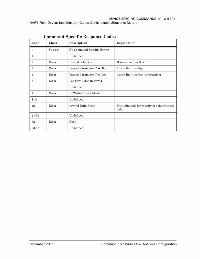
DEVICE-SPECIFIC COMMANDS 10-61HART Field Device Specification Guide: Daniel Liquid Ultrasonic Meters
Command-Specific Response CodesCode Class Description Explanation
0 Success No Command-Specific Errors
1 Undefined
2 Error Invalid Selection Boolean neither 0 or 1
3 Error Passed Parameter Too High Alarm limit too high
4 Error Passed Parameter Too Low Alarm limit too low (or negative)
5 Error Too Few Bytes Received
6 Undefined
7 Error In Write Protect Mode
8-31 Undefined
12 Error Invalid Units Code The units code for velocity or volume is not valid
13-31 Undefined
32 Error Busy
33-127 Undefined
December 2011 Command 167 Write Flow Analysis Configuration

10-62 DEVICE-SPECIFIC COMMANDSHART Field Device Specification Guide: Daniel Liquid Ultrasonic Meters
10.33 Command 168 Read General Meter Information
Reads the General meter information for use in the device information screen.
Request Data Bytes
Response Data Bytes
Command-Specific Response Codes
Byte Format Description Explanation
None
Byte Format Description Related Database Point
0-1 Unsigned Integer
Reads the database point Device Number
• DeviceNumber
2-7 Packed ASCII
Reads a PACKED ASCII string which is just the major version number and the minor version number followed by spaces padded out to 8 characters. This string will not be stored in nvram but shall be created from CPUBdSwIntVer by the HART Slave. The string will be in the format%d.%d (major.minor), numbers only
• FirmwareVersion
8-19 Packed ASCII
Reads the database point MeterSerialNumber converted to a PACKED ASCII 16 character string. If serial number is shorter than 16 char-acters, the number will be padded with spaces, if it is longer than 16 characters, the number will be truncated to 16 characters.
• MeterSerialNumber
Code Class Description
0 Success No Command-Specific Errors
1-31 Undefined
32 Error Busy
33-127 Undefined
Command 168 Read General Meter Information December 2011

DEVICE-SPECIFIC COMMANDS 10-63HART Field Device Specification Guide: Daniel Liquid Ultrasonic Meters
10.34 Command 169 Read Flow Totals
This command reads the flow totals. The flow totals will be sent as 4 byte integers rolling over at 999,999,999 so that same mechanism used in Modbus for flow totals can be used. See Table 11-1 for volume units code values.
Request Data Bytes
Response Data Bytes
Command-Specific Response Codes
Byte Format Description Explanation
None
Byte Format Description Related Database Points
0-3 Unsigned-32 Reads the database point Pos-VolFlow with a maximum limit of 999,999,999
• PosVolFlow
4-7 Unsigned-32 Reads the database point NegVolFlow with a maximum limit of 999,999,999.
• NegVolFlow
8-11 Unsigned-32 Reads the database point Pos-VolBase with a maximum limit of 999,999,999.
• PosVolBase
12-15 Unsigned-32 Reads the database point NegVolBase with a maximum limit of 999,999,999
• NegVolBase
16-19 Unsigned-32 Reserved
20 - 23 Unsigned-32 Reserved
24-27 Unsigned-32 Reserved
28-31 Unsigned-32 Reserved
32 Enum-8 Units code for volume Units code for all volume related values in this message. This must be a valid units code for volume values.See Table 11-1.
33 Enum-8 Reserved
34 Enum-8 Reserved
Code Class Description
0 Success No Command-Specific Errors
December 2011 Command 169 Read Flow Totals

10-64 DEVICE-SPECIFIC COMMANDSHART Field Device Specification Guide: Daniel Liquid Ultrasonic Meters
1-31 Undefined
32 Error Busy
33-127 Undefined
Code Class Description
Command 169 Read Flow Totals December 2011

DEVICE-SPECIFIC COMMANDS 10-65HART Field Device Specification Guide: Daniel Liquid Ultrasonic Meters
This page is intentionally left blank.
December 2011 Command 169 Read Flow Totals

10-66 DEVICE-SPECIFIC COMMANDSHART Field Device Specification Guide: Daniel Liquid Ultrasonic Meters
Command 169 Read Flow Totals December 2011

MEASUREMENT UNITS TABLES 11-1HART Field Device Specification Guide: Daniel Liquid Ultrasonic Meters
11
MEASUREMENT UNITS TABLES
11. INTRODUCTION
The units tables and conversion factors in this section are used for ultrasonic measurement.
11.1 Volume Units
* Shaded areas in the table indicate measurement is not applicable to Daniel Liquid Ultrasonic Meters.
11.2 Time Units (Flow Rate)
Table 11-1 Volume Units
Unit Code Description
40 Gallons
41 Liters
43 Cubic Meters
46 Barrels
*112 Cubic feet
Table 11-2 Time Units
Unit Code DescriptionMeter Type(L=liquid)
51 (Per) Second L
50 (Per) Minute L
52 (Per) Hour L
53 (Per) Day L
November 2010 Introduction

11-2 MEASUREMENT UNITS TABLESHART Field Device Specification Guide: Daniel Liquid Ultrasonic Meters
11.3 Volumetric Flow Rate Engineering Unit Codes
* Shaded areas in the table indicate measurement is not applicable to Daniel Liquid Ultrasonic Meters.
Table 11-3 Flow Rate Units
Unit Code DescriptionMeter Type(G=gas, L=liquid)
16 Gallons per minute L
17 Liters per minute L
19 Cubic meters per hour G, L
22 Gallons per second L
24 Liters per second L
*26 Cubic feet per second
*27 Cubic feet per day
28 Cubic meters per second G, L
29 Cubic meters per day G, L
*130 Cubic feet per hour G
131 Cubic feet per minute L
132 Barrels per second L
133 Barrels per minute L
134 Barrels per hour L
135 Barrels per day L
136 Gallons per hour L
138 Liters per hour L
235 Gallons per day L
246 Liters per day L
Volumetric Flow Rate Engineering Unit Codes November 2010

MEASUREMENT UNITS TABLES 11-3HART Field Device Specification Guide: Daniel Liquid Ultrasonic Meters
11.4 Pressure Units
11.5 Temperature Unit Codes
11.6 Velocity Units
Table 11-4 Pressure Units
Unit Code Description
6 Pounds per square inch
11 Pascals
12 Kilopascals
237 Megapascals
Table 11-5 Temperature Units
Unit Code Description
32 Degrees Celsius
33 Degrees Fahrenheit
35 Kelvin
Table 11-6 Velocity Units
Unit Code Description
20 Feet per second
21 Meters per second
November 2010 Pressure Units

11-4 MEASUREMENT UNITS TABLESHART Field Device Specification Guide: Daniel Liquid Ultrasonic Meters
11.7 Unit ConversionTable 11-7 Conversion Factors per Unit of Measurement
Conversion Factors Unit of Measurement
(°F-32)x(5/9)–>°C(°C+273.15)–>K
1 K/°C
5/9 °C/°F
10-6 MPa/Pa
0.006894757 MPa/psi
0.1 MPa/bar
0.101325 MPa/atm
0.000133322 MPa/mmHg
0.3048 m/ft
0.0254 m/in
103 dm3/m3
10-6 m3/cc (=m3/cm3)
(0.3048)3 m3/ft3
(0.0254)3 m3/in3
3600 s/h
86400 s/day
103 g/kg
0.45359237 kg/lbm
4.1868 kJ/kcal
1.05505585262 kJ/ BtuIT
10-3 Pa•s/cPoise
1.488 Pa•s/(lb/(ft•s))
Unit Conversion November 2010

MEASUREMENT UNITS TABLES 11-5HART Field Device Specification Guide: Daniel Liquid Ultrasonic Meters
11.8 Decibel Units
11.9 Voltage Units
Table 11-8 Decibel Units
Unit Code Description
247 Decibels (dB)
Table 11-9 Voltage Units
Unit Code Description
36 Millivolts
38 Volts
November 2010 Decibel Units

11-6 MEASUREMENT UNITS TABLESHART Field Device Specification Guide: Daniel Liquid Ultrasonic Meters
11.10 Pressure and Temperature Tables
Flow-Condition Pressure and Temperature
Table 11-10 Flow-Condition Pressure and Temperature Data Source
Input Type(EnablePressureInput or EnableTemperatureInput)
Data Validity(PressureValidity or TemperatureValidity)
Data Source Upon Alarm(FlowPOrTSrcUponAlarm)
“In-Use” Data Source(FlowPressure or FlowTemperature)
Disabled N/A N/A “In-Use” value unchanged
Live
Valid N/AAverage of live values(LiveFlowPressure or LiveFlowTemperature)
Invalid*
Last good value “In-Use” value unchanged
FixedFixed data point(SpecFlowPressure or SpecFlowTemperature)
Fixed
Valid N/AFixed data point(SpecFlowPressure or SpecFlowTemperature)
Invalid
Last good value “In-Use” value unchanged
FixedFixed data point(SpecFlowPressure or SpecFlowTemperature)
*Live input can be invalid due to (a) one or more live values is/are at or outside the alarm limits, or (b) the input is being calibrated.
Pressure and Temperature Tables November 2010

MEASUREMENT UNITS TABLES 11-7HART Field Device Specification Guide: Daniel Liquid Ultrasonic Meters
Live Pressure
Table 11-11 Data Points for Pressure Inputs
Daniel CUITM
Display NameData Points, Options and Guidelines
Is pressure gage or absolute? Data points affected:- InputPressureUnitOptions:• Gage (FALSE)• Absolute (TRUE)
Atmospheric pressure Data points affected:- AtmosphericPressOptions:• Enter a value (KPaa or psia) within the range [30.0, 108.40
KPaa]Guidelines:• This data point is only applicable when the input pressure
unit is specified as gage.
Live pressure,Min input
Data points affected:- MinInputPressureOptions:• Enter the pressure (KPag or psig if gage, KPaa or psia if
absolute) that corresponds to a 4 mA input signal. The pressure must be within the range [0, 280e3 KPag or KPaa].
Live pressure,Max input
Data points affected:- MaxInputPressureOptions:• Enter the pressure (KPag or psig if gage, KPaa or psia if
absolute) that corresponds to a 20 mA input signal. The pressure must be within the range [0, 280e3 KPag or KPaa].
Pressure alarm, Low limit
Data points affected:- LowPressureAlarmOptions:• Enter a value (KPag or psig if gage, KPaa or psia if absolute)
within the range [0, 280e3 KPag or KPaa]. An alarm is generated when the pressure is at or below this limit value.
Pressure alarm, High limit
Data points affected:- HighPressureAlarmOptions:• Enter a value (KPag or psig if gage, KPaa or psia if absolute)
within the range [0, 280e3 KPag or KPaa]. An alarm is generated when the pressure is at or above this limit value.
November 2010 Pressure and Temperature Tables

11-8 MEASUREMENT UNITS TABLESHART Field Device Specification Guide: Daniel Liquid Ultrasonic Meters
Live Temperature
Table 11-12 Data Points for Temperature Inputs
Daniel CUITM
Display NameData Points, Options and Guidelines
Live temperature,Min input
Data points affected:- MinInputTemperatureOptions:• Enter the temperature (°C or °F) that corresponds to a 4 mA input
signal. The temperature must be within the range [-273.15 °C, 200 °C].
Live temperature,Max input
Data points affected:- MaxInputTemperatureOptions:• Enter the temperature (°C or °F) that corresponds to a 20 mA input
signal. The temperature must be within the range [-273.15 °C, 200 °C].
Temperature alarm, Low limit
Data points affected:- LowTemperatureAlarmOptions:• Enter a value (°C or °F) within the range
[-130 °C, 200 °C]. An alarm is generated when the temperature is at or below this limit value.
Temperature alarm, High limit
Data points affected:- HighTemperatureAlarmOptions:• Enter a value (°C or °F) within the range
[-130 °C, 200 °C]. An alarm is generated when the temperature is at or above this limit value.
Pressure and Temperature Tables November 2010

PERFORMANCE 12-1HART Field Device Specification Guide: Daniel Liquid Ultrasonic Meters
12
PERFORMANCE
12. INTRODUCTION
This section discusses the Expansion Board with HART performance capabilities.
12.1 Sampling Rates
The typical update rate of each HART® device and dynamic variable is once per second.
Stack size and Filters are two operational conditions which cause variance in the update rate.
12.2 Power-Up
On power-up, when functioning correctly, the Expansion Board with HART green LED indicators show 3.3 volt and +24 volt power. A red LED for +24V current limit reached indicator.
A pair of TX active and RX active green LED indicators are provided for each serial communication port.
A pair of TX active and RX active green LED indicators are provided for the HART slave communication via Analog Output 2.
All LED indicators are located on the card edge that is visible when the meter electronics enclosure end cap is removed.
Primary temperature sensor • Live values = 1/sec• Calc. = on average of 5 sec
Internal (cold-junction) sensor sample 1 per second
PV digital value calculationSV digital value calculations
Depends on Configuration• Typical 1 per second• Can be as long as 1 per 5 seconds
Analog output update Depends on configuration• 250ms• Can be as long as 1 second
November 2010 Introduction

12-2 PERFORMANCEHART Field Device Specification Guide: Daniel Liquid Ultrasonic Meters
12.3 Device Reset
This section describes the effect of Device Reset (Command 42) and any other reset methods. The device must respond to Command 42 before executing the Device reset. Command 42 forces the meter to perform a warm start (equivalent to cycling the power to the meter off and then back on).
Typical time to reset
65 seconds
Maximum delay
79 seconds
Mode(s) effected
All modes are effected.
12.4 Self Test
Refer to Section 5.10 in the Daniel Liquid Ultrasonic Flow Meter Reference, Installation and Operations Manual (P/N 3-9000-750 for self test details.
http://www2.emersonprocess.com/en-US/brands/daniel/Flow/ultrasonics/Pages/Ultrasonic.aspx
To access the product manual, from the Daniel products page (above link), select the Daniel Model 3804 Liquid Ultrasonic Flow Meter link, click the Documentation tab, expand the Manuals & Guides tab, then select the manual.
Device Reset November 2010

PERFORMANCE 12-3HART Field Device Specification Guide: Daniel Liquid Ultrasonic Meters
12.5 Command Response Delay
Table 12-1 shows the minimum, typical, and maximum delays before the device responds to a HART command. (Timed from end of the stop bit of the Check Byte of the master request (STX), to the beginning of the start bit of the first preamble character of the response (ACK).
The response delay is not command specific, however, the write configuration commands generally require more time.
12.6 Busy and Delayed-Response
If the meter cannot respond within the prescribed time, the Busy Response code is returned.
12.7 Long Messages
Largest size of data field used for Commands 132 and 133 is 30 response bytes (including the two status bytes).
12.8 Non-Volatile Memory
Daniel Liquid Ultrasonic Flow Meters use Flash and NVRAM technology for non-volatile memory.
All configuration parameters are held in non-volatile memory until a “write command” is executed. Flash memory (the operating system kernel, the file system, and the firmware) is upgraded via MON2000TM. Refer to the Daniel Liquid Ultrasonic Flow Meter Reference, Installation, and Operations Manual (P/N 3-9000-750) Section 5.9, Upgrading the Meter Program for detailed instructions: http://www2.emersonprocess.com/en-US/brands/daniel/Flow/ultrasonics/Pages/Ultrasonic.aspx .
Table 12-1 Command Response Delay
Minimum 5 ms
Typical 15 ms
Maximum 80 ms
November 2010 Command Response Delay

12-4 PERFORMANCEHART Field Device Specification Guide: Daniel Liquid Ultrasonic Meters
12.9 Operating Modes
No alternative operating modes are available for this device.
12.10 Write Protection
Daniel Liquid Ultrasonic Flow Meters have a write protection hardware switch located on the CPU Board (switch S-2 Position 4 open or pushed away from the board to write-protect the meter configuration). Refer to the Daniel Liquid Ultrasonic Flow Meter Reference, Installation, and Operations Manual (P/N 3-9000-750) Figure 2-2 for switch details:
http://www2.emersonprocess.com/en-US/brands/daniel/Flow/ultrasonics/Pages/Ultrasonic.aspx
HART® Device-Specific Commands are rejected in write-protect mode (see Section 10 for a detailed list of applicable commands).
12.11 Damping
Damping time for Daniel Liquid Ultrasonic Meters is approximately 1.64 seconds affecting only the PV and the loop current signal.
Operating Modes November 2010

CAPABILITY CHECKLIST A-1HART Field Device Specification Guide: Daniel Liquid Ultrasonic Meters
A
ANNEX A CAPABILITY CHECKLIST
A.1 DEVICE CAPABILITY CHECKLIST
Below is a brief checklist of the device capabilities.
Table A-1 Capability Checklist
Manufacturer, Model, and RevisionDaniel Measurement and Control, Inc.HART® Field Device Specification Guide: Daniel Liquid Ultrasonic Meters Rev. 2
Device type Sensor
HART protocol revision Rev. 5.0
Number and type of process connections 2 - Pressure and Temperature
Number and type of host connections 2 - AMS™ and Emerson 375 Communicator
Number of Device Variables 3
Number of Dynamic Variables 4
Mappable Dynamic Variables 4
Number of Common-Practice Commands implemented 13
Number of Device-Specific commands 33
Bytes of additional device status 15 (Command 48)
Alternative operating modes N/A (HART® Rev 5)
Burst-Mode No
Capture Device Variable No
Write-protection Yes
November 2010 Device Capability Checklist

A-2 CAPABILITY CHECKLISTHART Field Device Specification Guide: Daniel Liquid Ultrasonic Meters
This page is intentionally left blank.
Device Capability Checklist November 2010

DEFAULT CONFIGURATION B-1HART Field Device Specification Guide: Daniel Liquid Ultrasonic Meters
B
ANNEX B DEFAULT CONFIGURATION
B.1 DEFAULT CONFIGURATION
This is a complete list of the default device configuration (parameter values, variable mapping, switch positions) which are factory set, unless user-specified when the device is ordered.
Table B-1 Device Factory Settings Configuration
Parameter Default value
Lower Range Value See Section 11 HART® Units Tables
Upper Range Value See Section 11 HART® Units Tables
PV Unit(s) Uncorrected Flow Rate
Sensor Type Pressure / Temperature
Number of Wires 3
Damping Time Constant ~1.64
Fault-indication LED Status Indicators
Write Protection Switch CPU board S2 position 4• Open (up position) write
protection on• Down (closed position) write
protection off
Number of Response Preambles • 5 minimum• 20 maximum
November 2010 Default Configuration

B-2 DEFAULT CONFIGURATIONHART Field Device Specification Guide: Daniel Liquid Ultrasonic Meters
This page is intentionally left blank.
Default Configuration November 2010

DEVICE VARIABLE CALCULATIONS C-1HART Field Device Specification Guide: Daniel Liquid Ultrasonic Meters
C
ANNEX C DEVICE VARIABLE CALCULATIONS
C.1 INTRODUCTION
This section consists of the calculations used by Daniel Liquid Ultrasonic Flow Meters for the device variables summarized in Section 5.
For HART® communications purposes, the Daniel Liquid Ultrasonic Meter applies the following calculations:
• Uncorrected Flow Rate
• Pressure
• Temperature
All Daniel Liquid Ultrasonic Flow Meter Calculations are discussed in Appendix B of the Daniel Series 3800 Liquid Ultrasonic Flow Meter Reference, Installation and Operations Manual (P/N 3-9000-750). To download this manual from the Daniel web site use the link below.
http://www2.emersonprocess.com/en-US/brands/daniel/Flow/ultrasonics/Pages/Ultrasonic.aspx
To access the product manual, from the Daniel products page (above link), select the Daniel Model 3804 Liquid Ultrasonic Flow Meter link, click the Documentation tab, expand the Manuals & Guides tab, then select the manual.
November 2010 Introduction

C-2 DEVICE VARIABLE CALCULATIONSHART Field Device Specification Guide: Daniel Liquid Ultrasonic Meters
C.2 UNCORRECTED FLOW RATE
Equation C-1 Flow-Condition Volumetric Flow Rate
where
C.3 PRESSURE
The flow-condition absolute flow pressure is calculated as shown in Equation C-2.
Equation C-2 Flow-Condition Absolute Pressure
where
= flow-condition volumetric flow rate (m3/h) (QFlow)
= “raw” volumetric flow rate (m3/h) (QMeter)= expansion correction factor due to pressure
(dimensionless) (ExpCorrPressure) = expansion correction factor due to
temperature (dimensionless) (ExpCorrTemperature)
= profile-effect correction factor (CorrectionFactor)
= flow-condition absolute pressure (MPaa) (AbsFlowPressure)
= flow-condition pressure (MPa if InputPressureUnit=FALSE, MPaa if InputPressureUnit=TRUE) (FlowPressure)
= (specified) atmospheric pressure (MPaa) (AtmosphericPress)
QFlow QRaw ExpCorrP ExpCorrT CorrFctr =
QFlow
QRaw
ExpCorrP
ExpCorrT
CorrFctr
Pabs f Pf PAtmosphere+= InputPressureUnit FALSE Gage =
Pabs f Pf= InputPressureUnit TRUE Absolute =
Pabs f
Pf
PAtmosphere
Uncorrected Flow Rate November 2010

DEVICE VARIABLE CALCULATIONS C-3HART Field Device Specification Guide: Daniel Liquid Ultrasonic Meters
C.4 TEMPERATURE
The meter is capable of correcting the raw volumetric flow rate for the effect of pipe expansion due to temperature changes. Note that for the temperature-effect expansion correction factor to be calculated, the correction must be enabled (via the EnableExpCorrTemp data point) and the flow-condition temperature must be available (i.e., the EnableTemperatureInput data point must be set to ‘Live’(1) or ‘Fixed’(2),see Section 4.1). The temperature-effect calculation is shown in Equation C-3. If the temperature-effect expansion correction factor is not calculated, it is set to 1.0.
Equation C-3 Temperature-Effect Expansion Correction
where
= expansion correction factor due to temperature (dimensionless) (ExpCorrTemperature)
= pipe linear expansion coefficient due to temperature (K-1) (LinearExpansionCoef)
= flow-condition temperature (K) (FlowTemperature)
= reference temperature for the pipe linear expansion coefficient (K) (RefTempLinearExpCoef)
ExpCorrT 1 3 Tf Tref– +=
ExpCorrT
Tf
Tref
November 2010 Temperature

C-4 DEVICE VARIABLE CALCULATIONSHART Field Device Specification Guide: Daniel Liquid Ultrasonic Meters
Reynolds Number
Reynolds Number is a dimensionless value that represents the nature of the liquid flow within the pipe. Reynolds Number is calculated as shown in Equation C-4.
Equation C-4 Reynolds Number
where
= Reynolds Number (dimensionless) (ReynoldsNumber)
= geometric constant, pi (dimensionless) (3.14159...)
= “raw” volumetric flow rate (m3/h) (QMeter)= fluid mass density at the flow condition
(specified via SpecRhoMixFlow) (kg/m3) (RhoMixFlow)
= pipe inside diameter (m) (PipeDiam)
= dynamic viscosity (Pa•s) (Viscosity)
Re4---
=QRaw Pf Tf,
Din --------------------------------
Re
QRaw
Pf Tf,
Din
Temperature November 2010

AMS™ DEVICE OPERATIONS D-1HART Field Device Specification Guide: Daniel Liquid Ultrasonic Meters
D
ANNEX D AMS™ DEVICE OPERATIONS
This section consists of the AMS™ Suite device operations used by HART® Field Device Specification Guide: Daniel Liquid Ultrasonic Meters. For detailed information refer to the AMS™: Intelligent Device Manager.
D.1 OVERVIEW
This section consists of the AMS™ Suite configuration and settings used by HART® Field Device Specification Guide: Daniel Liquid Ultrasonic Meters and assumes the device is connected, power is applied and the device is functioning correctly. Menu selections include Overview, Configure and Service Tools. Each of the menu choices are detailed in the following sections.
D.2 OVERVIEW MENU
The AMS™ Suite device Overview screen provides the user with a graphical view of the meter’s Status, the Primary Purpose Variable, and Shortcut buttons for Device Information, Analog Output 2 Trim and Display Meter K Factors. Other menu selections include Device Information and Alerts.
See Section E.2 375 Field Communicator Menu tree for fast key selections.
November 2010 Overview

D-2 AMS™ DEVICE OPERATIONSHART Field Device Specification Guide: Daniel Liquid Ultrasonic Meters
Overview>Device Information
The Device Information screen consists of the following:
• HART parameters• Device ID (CPU serial number)• Tag
• Device Parameters• Firmware revision• Meter serial number• Device model number• Write protect• DD revision, build number
Overview>Alerts
The Alerts screen consists of the following:
• Failed - Fix Now• Maintenance - Fix Soon• Advisory
Overview>Zero Flow
The Zero Flow screen consists of the following:
• Start Zero• Zero Calibration Velocity (m/s)• Zero Calibration Status• Zero Calibration Progress (%)
• Abort Zero• End Zero
Alerts are sorted in the three groups by severity and some alarms remain active “latched” until acknowledged.
Overview Menu November 2010
AMS™ DEVICE OPERATIONS D-3HART Field Device Specification Guide: Daniel Liquid Ultrasonic Meters
D.3 CONFIGURE MENU
Review or change the default configuration (factory set) for Daniel Gas Ultrasonic Meters using AMS™ Suite Configure menu.
The Configure menu includes:
• Guided Setup • Manual Setup• Alert Setup• Calibrate
Guided Setup
After installation, use these wizards to configure the HART parameter units, meter outputs, and baseline characteristics used to diagnose the meter health at a later time.
The Guided Setup screen consists of the following:
• Initial Setup• Setup Units• Setup Outputs• Setup Baseline
Manual Setup Menu
The Manual Setup screen consists of the following:
• Device Variables Mapping• Units• Analog Output 1 and Analog Output 2 (HART)• Frequency and Digital Outputs 1 and 2• Temperature• Pressure• Digital Input
November 2010 Configure Menu

D-4 AMS™ DEVICE OPERATIONSHART Field Device Specification Guide: Daniel Liquid Ultrasonic Meters
Alert Setup
The Alert Setup screen consists of the following:
• Flow Analysis Alerts• Detect Reverse Flow• Set Flow Range Limits
• Baseline Parameters (read-only values)• Setup Baseline (after initial installation)• Forward or Reverse Baseline Parameters
- Profile Factor- Swirl Angle- Symmetry- Cross-Flow- Turbulence A- Turbulence B- Turbulence C- Turbulence D- Average Flow Velocity- Temperature- Pressure
Calibrate
The Calibrate screen consists of the following:
• Analog Output 2 Trim• Zero Flow
Configure Menu November 2010

AMS™ DEVICE OPERATIONS D-5HART Field Device Specification Guide: Daniel Liquid Ultrasonic Meters
D.4 SERVICE TOOLS MENU
Review or change the default configuration (factory set) for HART® Field Device Specification Guide: Daniel Liquid Ultrasonic Meters using the AMS™ Suite Process variables.
The Service Tools screen consists of the following:
• Alerts• Variables• Trends
Alerts
See Section D.2.
Variables
The Variables screen consists of the following:
• Flow Data• Path Performance• Path Signal Quality• Flow Totals• All Variables
Trends
The Trends screen consists of the following:
• Primary Variable• Secondary Variable• Tertiary Variable• Quaternary Variable
November 2010 Service Tools Menu

D-6 AMS™ DEVICE OPERATIONSHART Field Device Specification Guide: Daniel Liquid Ultrasonic Meters
This page is intentionally left blank.
Service Tools Menu November 2010

375 FIELD COMMUNICATOR MENU TREE E-1HART Field Device Specification Guide: Daniel Liquid Ultrasonic Meters
E
ANNEX E 375 FIELD COMMUNICATOR MENU TREE
This section consists of the 375 Field Communicator Menu Tree diagrams and Fast Key Sequences (Table E-1) for Daniel Liquid Ultrasonic Flow Meters.
E.1 375 FAST KEY SEQUENCES
The Table below provides Fast Key Sequences for the most common Daniel Liquid Ultrasonic meter configuration parameters when using a 375 Field Communicator.
Table E-1 375 Fast Key Sequences
FUNCTION FAST KEY INPUT SEQUENCE
Analog Output 1 Content 2,1,3,1
Analog Output 1 Direction 2,1,3,2
Analog Output 1 Lower Range 2,1,3,3
Analog Output 1 Upper Range 2,1,3,4
Analog Output 1 Alarm Action 2,1,3,5
Analog Output 2 Content 2,1,4,1
Analog Output 2 Direction 2,1,4,2
Analog Output 2 Lower Range 2,1,4,3
Analog Output 2 Upper Range 2,1,4,4
Analog Output 2 Alarm Action 2,1,4,5
Start Analog Output Trim 3,4,1,1
Calibrate Zero Flow 3,4,2
Calibrate Zero Flow Velocity 3,4,2,1 (read only)
The Menu Tree diagrams and Fast Key sequences are only valid for Revision 1 of the HART® Field Device Specification Guide.
December 2011 375 Fast Key Sequences

E-2 375 FIELD COMMUNICATOR MENU TREEHART Field Device Specification Guide: Daniel Liquid Ultrasonic Meters
Calibrate Zero Flow Status 3,4,2,2 (read only)
Calibrate Zero Flow Progress 3,4,2,3 (read only)
Calibrate Start Zero Flow 3,4,2,4
Calibrate Abort Zero Flow 3,4,2,5
Calibrate End Zero Flow 3,4,2,6
Device Variable Mapping 2,1,1
Device Variable Mapping PV 2,1,1,1
Device Variable Mapping SV 2,1,1,2
Device Variable Mapping TV 2,1,1,3
Device Variable Mapping QV 2,1,1,4
Digital Input 2,1,9
Digital Input General Polarity 2,1,9,1
Digital Input Calibration Polarity 2,1,9,2
Digital Input Calibration Gating 2,1,9,3
Digital Output 1 2,1,5,2
Digital Output 1 CH A Content 2,1,5,2,1
Digital Output 1 CH A Polarity 2,1,5,2,2
Digital Output 1 CH B Content 2,1,5,2,3
Digital Output 1 CH B Polarity 2,1,5,2,4
Digital Output 2 2,1,6,2
Digital Output 2 CH A Content 2,1,6,2,1
Digital Output 2 CH A Polarity 2,1,6,2,2
Digital Output 2 CH B Content 2,1,6,2,3
Digital Output 2 CH B Polarity 2,1,6,2,4
(Flow) Pressure 2,1,8
(Flow) Pressure Source 2,1,8,1
(Flow) Pressure Fixed 2,1,8,2
(Flow) Pressure Alarm Selection 2,1,8,3
(Flow) Temperature 2,1,7
(Flow) Temperature Source 2,1,7,1
(Flow) Temperature Fixed 2,1,7,2
Table E-1 375 Fast Key Sequences
375 Fast Key Sequences December 2011

375 FIELD COMMUNICATOR MENU TREE E-3HART Field Device Specification Guide: Daniel Liquid Ultrasonic Meters
(Flow) Temperature Alarm Selection 2,1,7,3
Frequency & Digital 1 2,1,5
Frequency Output 1 2,1,5,1
Frequency Output 1 Content 2,1,5,1,1
Frequency Output 1 Direction 2,1,5,1,2
Frequency Output 1 B Zeroed on Error 2,1,5,1,3
Frequency Output 1 B Phase 2,1,5,1,4
Frequency Output 1 Max Frequency 2,1,5,1,5
Frequency Output 1 Lower Range 2,1,5,1,6
Frequency Output 1 Upper Range 2,1,5,1,7
Frequency Output 1 K-Factor 2,1,5,1,8
Frequency & Digital 2 2,1,6
Frequency Output 2 2,1,6,1
Frequency Output 2 Content 2,1,6,1,1
Frequency Output 2 Direction 2,1,6,1,2
Frequency Output 2 B Zeroed on Error 2,1,6,1,3
Frequency Output 2 B Phase 2,1,6,1,4
Frequency Output 2 Max Frequency 2,1,6,1,5
Frequency Output 2 Lower Range 2,1,6,1,6
Frequency Output 2 Upper Range 2,1,6,1,7
Frequency Output 2 K-Factor 2,1,6,1,8
Table E-1 375 Fast Key Sequences
December 2011 375 Fast Key Sequences

E-4 375 FIELD COMMUNICATOR MENU TREEHART Field Device Specification Guide: Daniel Liquid Ultrasonic Meters
E.2 375 FIELD COMMUNICATOR MENU TREE
The 375/475 Field Communicator provides real-time HART® communications with Daniel 3800 Series Liquid Ultrasonic Flow Meters.
The following figures show details of the 375 Handheld Communicator Menu Tree.
• Diagram Page 1 - Liquid USM Series Root Menu; Overview, Config-ure>Manual Setup
• Diagram Page 2 - Configure>Manual Setup (continued) and Alerts Setup
• Diagram Page 3 - Service Tools>Alerts and Variables
• Diagram Page 4 - Service Tools>Variables (continued), Service Tools>Trends, and Service Tools>Maintenance
375 Field Communicator Menu Tree December 2011

1. Overview2. Configure3. Service Tools
1. Device Status: Good, Failed, Maintenance, or Advisory2. Comm Status: Polled3. Uncorr Volume Rate Value UOM4. Display K-Factors5. Zero Calibration6. Device Information
Liquid USM Root MenuOverview Menu
Device Status Menu
1. Refresh Alerts2. No Active Alerts* 3. List F: <Alert Label>**4. List M: <Alert Label>***5. List A: <Alert Label>****
1. Identification2. Revisions3. Alarm Type and Security
Device Information 1. Tag Value2. Model Number Value3. Meter Serial Number Value4. CPU Serial Number Value5. Date Value6. Descriptor Value7. Message Value
Device Identification
1. Universal Value2. Field Device Value3. Hardware Value4. Software Value5. Firmware Value6. DD Value7. DD Build Value
Revisions
1. AO1 Alarm Action Value2. AO2 Alarm Action Value3. Write Protect Status Value
Alarm Type and Security
1. Alerts2. Variables3. Trends4. Maintenance
Service Tools
Configure Menu
1. Manual Setup2. Alert Setup
1. Device Variables Mapping2. Units3. Analog Output 14. Analog Output 2 (HART)5. Frequency & Digital output 16. Frequency & Digital output 27. Temperature8. Pressure9. Digital Input
Manual Setup
1. Primary Variable Value2. Secondary Variable Value3. Third Variable Value4. Fourth Variable Value
Device Variables Mapping
Units1. Volume Units Value2. Flow Rate Time Units Value3. Velocity Units Value4. Pressure Units Value5. Temperature Units Value
HART Parameters
1. Tag Value2. Date Value3. Descriptor Value4. Message Value5. Final Assembly Num Value6. Poll Address Value7. Response Preambles Value
Analog Output 1
1. Content Value2. Direction Value3. Lower Range Value UOM4. Upper Range Value UOM5. AO1 Alarm Action Value
Analog Output 2 (HART)1. Content (PV) Value2. Direction Value3. Lower Range Value UOM4. Upper Range Value UOM5. AO2 Alarm Action Value6. HART Parameters
See Sheet 2
See Sheet 3
Page 1 of 4
Note* Displayed when No Active Alert is present** Displayed when Active Alert with category ‘Failed’ is present*** Displayed when Active Alert with category ‘Maintenance’ is present****Displayed when Active Alert with category ‘Advisory’ is present
HART 375/475 Rev 1
1. Velocity Value UOM2. Status Value3. Progress Value %4. Start5. Abort6. End
Zero Calibration
Frequency & Digital Output 11. Frequency Output 12. Digital Output 1
Frequency & Digital Output 21. Frequency Output 22. Digital Output 2
Frequency Output 1 or Frequency Output 2
1. Content Value2. Direction Value3. B Phase Zeroed Value4. B Phase Value5. Maximum Frequency Value Hz6. Lower Range Value UOM7. Upper Range Value UOM8. Display K-Factors
Digital Output 1 or Digital Output 2
1. Channel A Content Value2. Channel A Polarity Value3. Channel B Content Value4. Channel B Content Value

Liquid USM Configure Menu (continued)
1. Overview2. Configure3. Service Tools
1. Manual Setup2. Alert Setup
1. Device Variables Mapping2. Units3. Analog Output 1 (HART)4. Analog Output 25. Frequency & Digital output 16. Frequency & Digital output 27. Temperature8. Pressure9. Digital Input
Manual Setup
Configure Menu
Temperature1. Temperature Source Value2. Fixed Temperature Value UOM3. Alarm Selection Value4. Lower Range Value UOM5. Upper Range Value UOM6. Low Limit Value UOM7. High Limit Value UOM
Pressure1. Pressure Source Value2. Fixed Pressure Value UOM3. Alarm Selection Value4. Lower Range Value UOM5. Upper Range Value UOM6. Low Limit Value UOM7. High Limit Value UOM8. Gage or Absolute Value9. Atmospheric Press Value UOM
Digital Input1. General Polarity Value2. Calibration Polarity Value3. Calibration Gating Value
Page 2 of 4
See Sheet 1
HART 375/475 Rev 1
1. Detect Reverse Flow2. Set Flow Range Limits
Flow Analysis Alerts
Alert Setup1. Flow Analysis Alerts
1. Detect Reverse Flow Value 2. Enable3. Configure
Detect Reverse Flow
Configure Reverse Flow Detection1. Rev Flow Zero Cutoff Value UOM2. Rev Flow Vol Limit Value UOM
1. Lower Velocity Lmt Value UOM2. Upper Velocity Lmt Value UOM
Set Flow Range Limits

1. Alerts2. Variables3. Trends4. Maintenance
Liquid USM Service Tools
Alerts
Variables1. Flow Data2. Path Information3. Flow Totals4. All Variables
1. Flow Velocity2. Sound Velocity3. Flow Values4. Flow Analysis
Flow Data
1. Flow Direction Value2. Avg Flow Velocity Value UOM3. Avg Sound Velocity Value UOM
Flow Values
Sound Velocity1
Flow Velocity1
Flow Analysis2
1. Profile Factor Value2. Swirl Angle Value deg3. Symmetry Value4. Cross-Flow Value5. Turbulence A Value %6. Turbulence B Value %7. Turbulence C Value %8. Turbulence D Value %
1. Performance2. Gain3. SNR4. Signal5. Noise
Path Information
1. Volume TotalsFlow Totals
1. Fwd Uncorrected Vol Value UOM2. Rev Uncorrected Vol Value UOM
Volume Totals
See Sheet 4
Page 3 of 4
1. Refresh Alerts2. No Active Alerts* 3. List F: <Alert Label>**4. List M: <Alert Label>***5. List A: <Alert Label>****
Note* Displayed when No Active Alert is present** Displayed when Active Alert with category ‘Failed’ is present*** Displayed when Active Alert with category ‘Maintenance’ is present****Displayed when Active Alert with category ‘Advisory’ is present
HART 375/475 Rev 1
Performance1
1. Performance A1 Value %2. Performance A2 Value %3. Performance B1 Value %4. Performance B2 Value %5. Performance C1 Value %6. Performance C2 Value %7. Performance D1 Value %8. Performance D2 Value %
Signal1
1. Signal A1 Value mV2. Signal A2 Value mV3. Signal B1 Value mV4. Signal B2 Value mV5. Signal C1 Value mV6. Signal C2 Value mV7. Signal D1 Value mV8. Signal D2 Value mV
Gain1
1. Gain A1 Value dB2. Gain A2 Value dB3. Gain B1 Value dB4. Gain B2 Value dB5. Gain C1 Value dB6. Gain C2 Value dB7. Gain D1 Value dB8. Gain D2 Value dB
Noise1
1. Noise A1 Value mV2. Noise A2 Value mV3. Noise B1 Value mV4. Noise B2 Value mV5. Noise C1 Value mV6. Noise C2 Value mV7. Noise D1 Value mV8. Noise D2 Value mV
SNR1
1. SNR A1 Value dB2. SNR A2 Value dB3. SNR B1 Value dB4. SNR B2 Value dB5. SNR C1 Value dB6. SNR C2 Value dB7. SNR D1 Value dB8. SNR D2 Value dB
1. Chord A Value UOM2. Chord B Value UOM3. Chord C Value UOM4. Chord D Value UOM
1. Chord A Value UOM2. Chord B Value UOM3. Chord C Value UOM4. Chord D Value UOM
1. All chord parameters are always displayed for Device Number=3804 and only Chords A & B are displayed for Device Number=3802
2. All chord parameters are always displayed for Device Number=3804 and only Chords A & B are displayed for Device Number=3802.
Profile Factor, Swirl Angle, Symmetry, Cross-Flow shall not be displayed for 3802 meters.

Page 4 of 4
Variables1. Flow Data2. Path Information3. Flow Totals4. All Variables
1. Alerts2. Variables3. Trends4. Maintenance
Liquid USM Service Tools>Variables (continued)Liquid USM Service Tools>Trends and Liquid USM Service Tools>Maintenance
Trends1. Primary Variable2. Secondary Variable3. Third Variable4. Fourth Variable
Primary Variable
Secondary Variable1. Uncorr Volume Rate2. Uncorr Volume Rate Value UOM3. Status: Good4. Upper Range Value UOM5. Lower Range Value UOM
Third Variable
Fourth Variable
1. Uncorr Volume Rate2. Uncorr Volume Rate Value UOM3. Status: Good4. Upper Range Value UOM5. Lower Range Value UOM
1. Pressure2. Pressure Value UOM3. Status: Good4. Upper Range Value UOM5. Lower Range Value UOM
1. Temperature2. Temperature Value UOM3. Status: Good4. Upper Range Value UOM5. Lower Range Value UOM
Maintenance1. Routine Maintenance2. Zero Calibration
All Variables1. Variable Summary2. Primary Variable3. Secondary Variable4. Third Variable5. Fourth Variable
Primary Variable1. Uncorr Volume Rate2. Uncorr Volume Rate Value UOM3. Status: Good
Secondary Variable*
Third Variable*1. Pressure2. Avg Flow Velocity Value UOM3. Status: Good
1. Temperature2. Avg Sound Velocity Value UOM3. Status: Good
Fourth Variable*
* NoteThe factory default value for all variables is Uncorr Flow Rate and must be set as the Primary Variable for Daniel 3800 Series Liquid Ultrasonic Meters. Secondary, Third and Fourth variable selections are:
PressureTemperature1. Uncorr Volume Rate
2. Uncorr Volume Rate Value UOM3. Status: Good
HART 375/475 Rev 1
Routine Maintenance1. Analog Output 2 Trim
Zero Calibration1. Velocity Value UOM2. Status Value3. Progress Value %4. Start5. Abort6. End

REVISION HISTORY F-1HART Field Device Specification Guide: Daniel Liquid Ultrasonic Meters
Pa
Tit
Ta
Lis
Lis
Se
Se
Se
Se
F
ANNEX F REVISION HISTORY
F.1 DOCUMENT RELEASE
This is this initial release of the Daniel HART® Field Device Specification Guide: Daniel Liquid Ultrasonic Meters.
F.2 CHANGES FROM REV 1 TO REV 2
ge/Section Description of Change
le Page • Revision level from 1 to 2• Date from 30 September 2007 to 29 May 2009
ble of Contents • Changed title from HART Option Board to Series 100 Plus Option Board in Sections 2.0, 4.1.2, 4.1.3 and 5
• Changed Section headings from level X.0 to X.1• Changed title from Section 8 Universal Commands
to add new section, Alert Resolutions• Changed remaining Section Numbers/Titles• Added Section 11.18 - 11.42 new commands for v1.70 of the Firmware• Changed titles in Annex D for Wave .5 requirements• Added Section F.2 to Annex F for revision history changes
t of Figures • Changed title from HART Option Board to HART® Option Board
t of Tables • Table 9-1 to 13-1 re-pagination of section titles after adding Alert Resolutions• Added Table 12-12 Decibel Units and 12-13 Voltage Units
ction 1 • Changed Section 1.0 to 1.1 and re-numbered remaining sections• Section 1.2 - Added link to Daniel Liquid Ultrasonic web page• Sec 1.4- changed title from HART Option Board to HART® Option Board• Section 1.5 - And added reference to HCF Field Device Specification Guide LIT-18
ction 2 • Changed Section 2.0 to 2.1 and re-numbered remaining sections• Changed HART Protocol Revision from 5.1 to 5• Changed Device Revision from 1 to 2• Changed Hardware revision from 1 to 3
ction 3 • Renamed Heading 3. from Product Overview to Introduction• Changed Section 3.0 to 3.1 and re-numbered remaining sections• Changed title from HART Option Board to HART® Option Board
ction 4 • Renamed Heading 4. from Product Interfaces to Introduction• Changed Section 4.0 to 4.1 and re-numbered remaining sections• Changed name from HART Option Board to HART® Option Board• Changed Section references from Section 8, 9 and 10 to Sections 9-11
November 2010 Document Release

F-2 REVISION HISTORYHART Field Device Specification Guide: Daniel Liquid Ultrasonic Meters
Pa
Se
Se-
Se
-
Se
Se
Se
ge/Section Description of Change
ction 5 • Renamed Heading 5. from Device Variables to Introduction• Changed Section 5.0 to 5.1 and re-numbered remaining sections• Changed title from HART Option Board to Series 100 Plus Option Board• Changed Table references from 11-1, 11-4, 11-5, 11-5, 11-9, 11-10 to 12-1, 12-4,
12-5, 12-11, 12-12
ction 6 • Changed Section 6.0 to 6.1 and re-numbered remaining sections• Changed title from HART® Option Board Dynamic-Variables to HART® Dynamic
Variables• Changed title from HART Option Board to Series 100 Plus Option Board
ction 7 • Changed Section 7.0 to 7.1 and re-numbered remaining sections• Re-pagination of section references from 10-13 to 11-13, 10-14 to 11-14• Added 8.0 Alert Resolutions reference• Added note: Status bit numbers from 0-13 to 0-15• Added missing datapoints to Table 7-1 (IsMeterVelAboveMaxLmt and
AvgSndVelIsOutOfLimits) Device Status Bit 1 and moved AO2Content to Device Status Bit 0
• Removed references to “Top Level screens and Detail screens in text and Table 7-1and 7-2 headings
• Added missing datapoints to Table 7-2 and Continuous Flow Analysis datapointsin Bytes/Bits 0-0,2-2, 2-1, 4-7, 5-1, 14-7, 14-6, 14-5, 14-4, 14-3, 15-7, 15-6, 15-5, 154, 15-3, 15-3
• Removed duplicate datapoint in table 7-2 Byte 4-0 (PressHARTIsLoopCurrentFixed)• Added Bytes 14 and 15 in Table 7-2
ction 8 • New section Alerts Resolutions
ction 9 • Changed Section 9.0 to 9.1 and re-numbered remaining sections• Re-pagination of section number was Section 8 Universal Commands• Table 9-1 added Command 6 Write polling address per FRS change 1.00 Draft AM
ction 10 • Changed Section 10.0 to 10.1 and re-numbered remaining sections• Re-pagination of section number was Section 9 Common-Practice Command• Changed title from HART Option Board to Expansion Board with HART
Changes from Rev 1 to Rev 2 November 2010

REVISION HISTORY F-3HART Field Device Specification Guide: Daniel Liquid Ultrasonic Meters
Pa
Se
Se
Se
An
An
An
An
An
An
ge/Section Description of Change
ction 11 • Changed Section 11.0 to 11.1 and re-numbered remaining sections• Re-pagination of section number was Section 10 Device-Specific Commands• Changed text from firmware v1.60 to v1.60 and later• Changed title from HART Option Board to HART® Option Board• Command 128 Request Data Bytes Byte 12 - added direct mapping
AOXActionUponInvalidContent data point• Command 128 Response Code 6 added Lower range value>Upper range value• Command 140 Byte 10 Bit 6 changed data point name from AO2TrimCurrent to
AO2Fixed• Changed Command 141 IsAnyKeyAboutToExpire and IsAnyKeyExpired to not
used and added Acknowledge latched alarm datapoints• Command 141 removed reference to external document• Changed Enum to Enum-8 throughout document• Changed reference to v1.60 of the the firmware to v1.60 and later• Added Commands 148-171 for Continuous Flow Analysis
ction 12 • Changed Section 12.0 to 12.1 and re-numbered remaining sections• Re-pagination of section was Section 11 Tables• Added Table 12-11 Decibel Units and Table 12-12 Voltage Units
ction 13 • Changed Section 13.0 to 13.1 and re-numbered remaining sections• Re-pagination of section was Section 12 Performance• Added link to Daniel website
nex A • Changed revision level from 1 to 2• Changed number of Device-Specific Commands from 17 to 33• Changed number of Additional-Status bytes from 6 to 15
nex B • Changed cross reference links to current pagination
nex C • Changed footer date from Sep 2007 to May 2009
nex D • Change to be compliant with Wave .5 formatting for AMS menu titles
nex E • Added Notice - Fast Key Sequences Menu Tree Diagrams valid for Revision 1
nex F • Added F-2 Updated manual revision history
November 2010 Changes from Rev 1 to Rev 2

F-4 REVISION HISTORYHART Field Device Specification Guide: Daniel Liquid Ultrasonic Meters
Pa
Tit
Ta f
Lis
Lis
Se
TaSe
An
An
Ba
F.3 CHANGES REV 2
Note: The manual revision does not increment because the firmware did not change.
ge/Section Description of Change
le Page • Revision level 2 (no change)• Date from 09 September 2010 to 22 November 2010• Added trademark to Daniel Measurement and Control
ble of Contents • Deleted Section 8 Alert Resolutions section (Tokenizer 8 can display the length othe text)
• Changed remaining Section Numbers/Titles
t of Figures • Changed pagination and date
t of Tables • Re-pagination of section titles after deleting Alert Resolutions
ctions • Delete Section 8 Alert Resolutions and repaginate remaining sections• Changed footer date in sections to November 2010
ble 11-11ction 12.8
• Changed Daniel CUI to Daniel MeterLinkTM
nex E • Updated Menu Tree information
nex F • Updated Revision history
ck Pages • Updated RMA form
Changes Rev 2 November 2010

REVISION HISTORY F-5HART Field Device Specification Guide: Daniel Liquid Ultrasonic Meters
F.4 CHANGES REV 2
Page/Section Description of Change
Title Page • Revision level 2 (no change)• Date from 22 November 2010 to 20 December 2011
Table of Contents • Updated TOC to add changes to Annex F• Changed footer date from November 2010 to December 2011
Sections • Section 7 Changed Table 7-1 removed Device Status Bit references to Is1BitMemoryError and IsCorePresent
• Section 10 Command 140 and 141 removed Device Status Bit references to Is1BitMemoryError and IsCorePresent shown as Reserved
• Changed footer dates to December 2011
Annex E •Updated Menu Tree information - changed Title on Sheets 1-5 to Gas USM from 3400 Series
• Changed name of file from 3400_Series_Menu_pages_1-5_Rev_1.pdf to Gas USM Menu_pages_1-5_Rev_1.pdf
• Changed footer date to December 2011
Annex F • Updated Revision history - added Section F.4• Changed footer date to December 2011
November 2010 Changes Rev 2
F-6 REVISION HISTORYHART Field Device Specification Guide: Daniel Liquid Ultrasonic Meters
This page is intentionally left blank.
Changes Rev 2 November 2010

DANIELTM MEASUREMENT AND CONTROL, INC.RETURNED MATERIAL AUTHORIZATION
REPAIR FORM FOR USED EQUIPMENTINCLUDING DECONTAMINATION/CLEANING STATEMENT
A Return Material Authorization (RMA) number must be obtained prior to returning any equipment for any reason. Download the RMA form on the Daniel Measurement and Control, Inc. Support Services web page by selecting the link below.
Select the link below to open the Microsoft Excel® RMA request form:
http://www2.emersonprocess.com/EN-US/BRANDS/DANIEL/SUPPORT-SERVICES/Pages/Support-Services.aspx
1. Return Material Authorization (RMA) Number_________________________________
2. Equipment to be returned:Model Number ___________________Serial Number__________________________
3. Reason for return: __________________________________________________________________________________________________________________________________________
Decontamination/Cleaning Fluids Process
A. List each substance in which the equipment was exposed. Attach additional documents if necessary.
CommonName
CAS# ifAvailable
Used for HazardousWaste (20 CFR 261)
EPA Waste Codeif used for hazardous waste
[ ] Yes [ ] No
[ ] Yes [ ] No
[ ] Yes [ ] No
[ ] Yes [ ] No
[ ] Yes [ ] No
[ ] Yes [ ] No
B. Circle any hazards and/or process fluid types that apply:
Infectious Radioactive Explosive Pryophoric Poison Gas
Cyanides Sulfides Corrosive Oxidizer Flammable Poison
Carcinogen Peroxide Reactive-Air Reactive-Water Reactive-Other (list):
Other Hazard Category (list):
C. Describe decontamination/cleaning process. Include MSDS description for substances used in decontamination and cleaning processes. Attach additional documents if necessary.

Shipping Requirements
Failure to comply with this procedure will result in the shipment being refused.
1. Write the RMA number on the shipping package.
2. Inside the package include one copy of this document and all required Material Safety Data Sheets (MSDS)
3. Outside of the package attach one copy of this document and all required Material Safety Data Sheets (MSDS).
THIS EQUIPMENT, BEING RETURNED "FOR REPAIR," HAS BEEN COMPLETELY DECONTAMINATED AND CLEANED. ALL FOREIGN SUBSTANCES HAVE BEEN DOCUMENTED ABOVE AND MSDS SHEETS ARE ATTACHED.
By_________________________________ _____________________________________(Signature) (Print name)
Title:_______________________________ Date:________________________________
Company:___________________________
Phone: ____________________________ Fax:_________________________________

This page is intentionally left blank.

The sales and service offices of DanielTM Measurement and Control are locatedthroughout the United States and in major countries overseas.
Please contact DanielTM Measurement Services at 11100 Brittmoore Park Drive,Houston, Texas 77041, or phone (713) 827-6314 for the location of the sales orservice office nearest you.
DanielTM Measurement Services offers both on-call and contract maintenanceservice designed to provide single-source responsibility for all DanielTM products.
DanielTM Measurement and Control, Inc., and DanielTM Measurement Services, Inc. Divisions of Emerson Process Management reserves the right to make changes to any of its products or services at any time without prior notification in order to improve that product or service and to supply the
best product or service possible.
http://www2.emersonprocess.com/en-us/brands/daniel/Pages/Daniel.aspx