harness basics and handling precaution for terminals & connectors prepared by: jayson bocalbos...
TRANSCRIPT

Harness Basics and Handling Precaution for Terminals &
Connectors
Prepared by: Jayson BocalbosQA/QC Supervisor
SL Electronics. Co., Ltd

SL Electronics. Co., Ltd
ObjectiveThis presentation will give the vital parts of a harness, it’s terminologies, definition and applications. Part of this presentation also describes some basic precautions for use of terminal and connector. Make use of this document when wire connection processing is conducted in wire harness process.

SL Electronics. Co., Ltd
Parts Terminologies and DefinitionsTerminals. are the conductors in a connector. When connectors mate, the terminals make contact to bridge the circuit. Although they appear simple, terminals are precisely designed and manufactured to optimize electrical and mechanical performance over the life of the connector. Terminals are also called contacts. They are identified as either male (left) or female (right).
Un-matedMated

SL Electronics. Co., Ltd
Pin Contacts. In addition to the spring clamp design on the previous slide, terminals include pin designs. Pins are also called leads or posts. Usually a spring contact, or cantilever, on the other connector slides over and presses against the pin.
SL Electronics. Co., Ltd
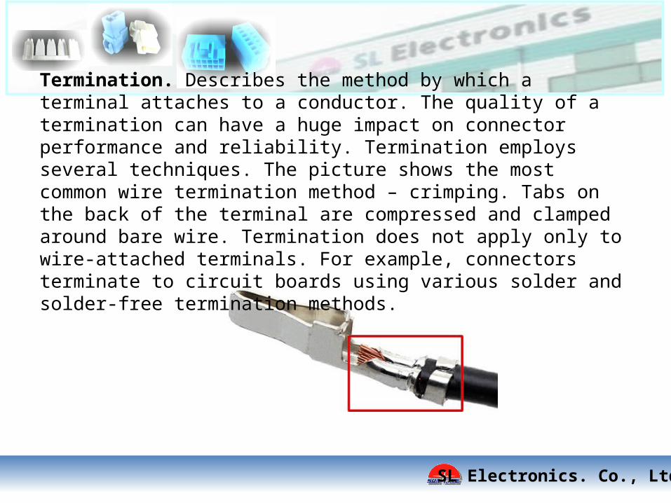
Termination. Describes the method by which a terminal attaches to a conductor. The quality of a termination can have a huge impact on connector performance and reliability. Termination employs several techniques. The picture shows the most common wire termination method – crimping. Tabs on the back of the terminal are compressed and clamped around bare wire. Termination does not apply only to wire-attached terminals. For example, connectors terminate to circuit boards using various solder and solder-free termination methods.
SL Electronics. Co., Ltd
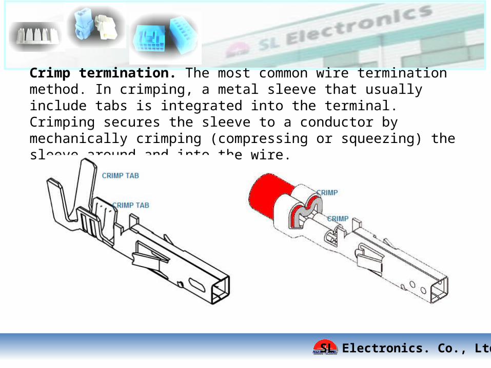
Crimp termination. The most common wire termination method. In crimping, a metal sleeve that usually include tabs is integrated into the terminal. Crimping secures the sleeve to a conductor by mechanically crimping (compressing or squeezing) the sleeve around and into the wire.

SL Electronics. Co., Ltd
Crimp termination. Terminals are often crimp in two places – the wire and on its insulator. The conductor crimp provides the electrical interface. Insulation is stripped off the wire before crimping. The insulation crimps add strengths called strain relief. Strain relief reduces the likelihood that the wire will pull out of the terminal under stress.
SL Electronics. Co., Ltd
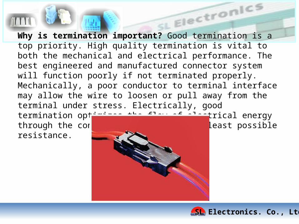
Why is termination important? Good termination is a top priority. High quality termination is vital to both the mechanical and electrical performance. The best engineered and manufactured connector system will function poorly if not terminated properly. Mechanically, a poor conductor to terminal interface may allow the wire to loosen or pull away from the terminal under stress. Electrically, good termination optimizes the flow of electrical energy through the conductor by offering the least possible resistance.

SL Electronics. Co., Ltd
Why is termination important? Consider the conductor that connects to a terminal. It offers so little electrical resistance that its resistance is considered to zero. A good termination should do the same. This is why an ideal termination is said to be “electrically invisible”. This means it offers no more resistance than the conductor to which it is attached. Most of the problems on a circuit occur at a connection points. Remember that a connector’s purpose is to bridge the gap in the circuit. The two key bridge points are the terminal contact interface and the termination. Good contact and good termination are both vital to a connector’s function.

SL Electronics. Co., Ltd
Housings. If terminals provide the electrical conductivity, housings offer the means to make those connections accurately and reliably. Housings support and protect the terminals. They provide the mechanical method for mating terminals securely. And they protect the terminals from contaminants. Housings also have an electrical function. They separate and align the terminals for ideal electrical performance. And they electrically insulate the terminals from each other, as well from external electrical interference.

SL Electronics. Co., Ltd
Housings Designs. There are far too many housing styles to show here. But several key features distinguish them. One obvious characteristic is how a connector protect its terminals. Terminals may be completely enclosed, or fully shrouded, in walled chambers or housing cavities. The contacts may be partially shrouded. Or they may be completely open, or unshrouded. Each design provides a different level of electrical and mechanical protection for the contacts. As a rule, more plastic provided better physical protection and electrical isolation.

SL Electronics. Co., Ltd
Housings Features – mating security. A second distinguishing housing feature determines how mated connectors stay mated. In some cases, friction between housings may be adequate. More often, connectors employ a locking mechanism to secure the interface against vibration and other stressors. Some applications are very stable and require minimal locking. But imagine the stress under the hood of a car or the mating security needed on an airplane electrical system or in medical life-support equipment. The locking feature provides that security.
SL Electronics. Co., Ltd
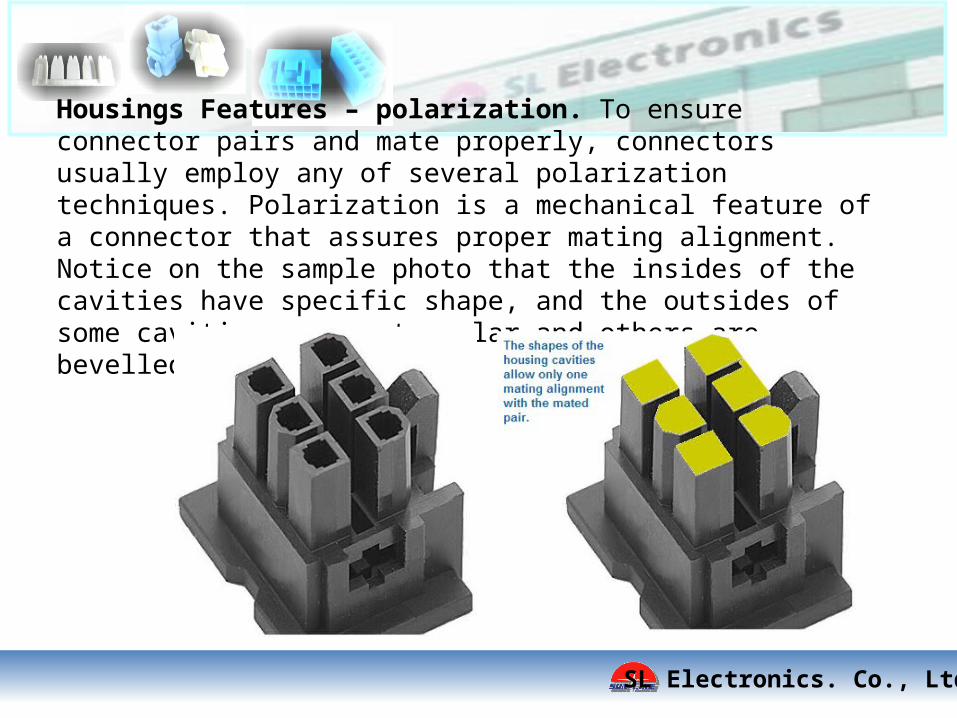
Housings Features – polarization. To ensure connector pairs and mate properly, connectors usually employ any of several polarization techniques. Polarization is a mechanical feature of a connector that assures proper mating alignment. Notice on the sample photo that the insides of the cavities have specific shape, and the outsides of some cavities are rectangular and others are bevelled.

SL Electronics. Co., Ltd
Connection – Wire-To-Board. Wire-to-board connectors interface a board mounted connector with a connector that is attached to wire or cable. They interconnect either a sub-assemblies (components) of an electrical device to a circuit board, or they connect two sub-assemblies. Most input/output connectors are of this type, but there are many other wire-to-board connections. The connections may be vertical from the board or at a right angle.

SL Electronics. Co., Ltd
Wire-To-Board Application. This flatbed scanner uses several wire-to-board connections to link components like the scanner, motor and power supply to the main board. Notice that they make both signal and power connections.
SL Electronics. Co., Ltd
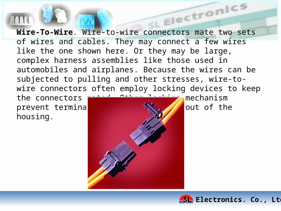
Wire-To-Wire. Wire-to-wire connectors mate two sets of wires and cables. They may connect a few wires like the one shown here. Or they may be large, complex harness assemblies like those used in automobiles and airplanes. Because the wires can be subjected to pulling and other stresses, wire-to-wire connectors often employ locking devices to keep the connectors mated. Other locking mechanism prevent terminals from being pulled out of the housing.

SL Electronics. Co., Ltd
Connector Applications. Harnesses are market and used in far too many applications. This market includes the many products we all use everyday to make our lives easier, more comfortable or more enjoyable. A few examples include digital cameras, portable media players, stereo equipment, televisions, DVD players, set-up boxes, microwave ovens, refrigerator, washing machines and room air-conditioners.

SL Electronics. Co., Ltd
Common Handling Precautions1. Terminal and Connector are designed to connect electricity and electrical signal, and not aimed to be used as structure or a part of structure premising that mechanical force loads to connection part (contact part).2. Terminal and connector are designed for wiring in electrical appliances or between electrical appliances.3. Do not expose the terminal and connector, processing process product and processing product (harness) to corrosive substance, corrosive gas, high temperature and high humidity and direct sunshine. It causes corrosion of contact and deterioration of insulation performance of housing, etc., so that it causes motion defect of appliances.

SL Electronics. Co., Ltd
4. Do not apply external load to terminal and connector, processing process product and processing product (harness). Deformation and breakage, etc., occur, and it causes performance defect of connector.

SL Electronics. Co., Ltd
5. When checking circuit of harness with terminal and connector, handling wire harness in assembly, due to tensile strength in applying load, joint part of contact contacting part and wire is damaged and causes contact defect. When handling and wiring wire harness, provision such as an appropriate slack to wire is required in order not to apply abnormal load to joint part of terminal and connector. See Example 1.

SL Electronics. Co., Ltd
6. When dis-connectable terminal and connector is mated and unmated in check of harness, hold wire in a bundle and operate it within 15⁰ which is an indicated angle (see Example 3 & 4). Disconnection operation beyond specified angle leads to expanding of mating part of contact , and causes of contact defect.

Thank You
SL Electronics. Co., Ltd