harmonisation fo wiring colour codesdownloads.rews.org.mt/files/474b2ce0-175c-4fa8-893b... ·...
TRANSCRIPT

HARMONISATION OF WIRING COLOUR CODES
Practical Guidelines

Acknowledgments: We are grateful to the IEE for their permission to reproduce sections of BS 7671 and The Electrician’s Guide to the Building Regulations.
Disclaimer:
These guidelines do not supersede the I.E.E. Regulations (BS 7671) and its subsequent amendments. The Malta Resources Authority does not assume any liability to any person for any loss or damage caused by way of error or omission whether this has occurred through negligence or any other cause.
Page 2 / 11 MRA/ENEL/05/1

INTRODUCTION In Malta the wiring of electrical installations is currently regulated by the Electricity Supply Regulations under the Enemalta Act. These regulations require compliance with the provisions of the I.E.E. Regulations which is also a UK standard BS 7671. In compliance with the existing regulations therefore the colour codes for cables used in Malta for the wiring of electrical installations are those listed in the IEE Regulations. A new European standard has been introduced where a new set of cable colour codes were adopted. This was an initiative driven by a request from the industry. Although the new colour codes were not introduced as mandatory a deadline of 2006 was set for all European countries to adopt the new standard. In the UK the new wiring colour codes will become mandatory as from 1st April 2006. Consequently an amendment has been made in the BS7671: 2001 for the adoption of the new colour codes. In Malta, so far, the new standard was adopted on voluntary basis. In virtue of the amendment of the BS 7671 the new colour codes will effectively become mandatory as from 1st April 2006.
Page 3 / 11 MRA/ENEL/05/1

SINGLE-PHASE INSTALLATIONS
In compliance with the new wiring colour codes the existing red and black phase and neutral conductors will be replaced by the colours of brown and blue according to Regulation 514-03-01 Amendment No 2:2004 to BS 7671:2001. When the neutral is identified by a colour, the blue colour must be used as per Regulation 514-
04-01 Amendment No 2:2004 to BS 7671:2001. In the case of protective conductors the bi-colour combination of green-and yellow will continue to be used as per Regulation 514-04-02 Amendment No 2:2004 to BS 7671:2001. This applies to single core wiring, live and neutral in electrical cables and wires in flexible leads for portable appliances.
NEW SINGLE PHASE INSTALLATIONS In new installations the circuits shall be wired in the colours of brown, blue, and green-and-yellow. Fig.1 shows how a typical distribution board (consumer unit) would look like wired according to the new colour codes.
Fig.1 Typical Single-Phase Distribution Board
MALTA RESOURCES AUTHORITY
BrownBlue
RedBlack
EarthEarth
Page 4 / 11 MRA/ENEL/05/1

EXTENSIONS, ALTERATIONS AND REPAIRS TO AN EXISTING SINGLE-PHASE INSTALLATION
An extension, alteration or repair to an existing single-phase installation should be wired in the colours of brown, blue, and green-and-yellow. No further marking is required at the interface if the extension, alteration or repair is compliant with Regulation 514-01-03 Amendment No 2:2004 to BS 7671:2001 and can thus be considered to be unambiguously marked provided that the existing cables are correctly identified by the colours of red for phase conductor and black for neutral conductor, and the new cables are correctly identified by the colours of brown for phase conductor and blue for neutral conductor.
Fig. 2 Alteration carried out in an installation wired with old colour codes If an extension, alteration or repair is made such that both the brown & blue and red & black cables are present a warning must be fixed near the distribution board or consumer unit according to Regulation 514-14-01. The following words should be used:
CAUTION !
This installation has wiring colours to two versions of BS 7671. Great care should be taken before undertaking extension,
alteration or repair that all conductors are correctly identified.
CAUTION !This installation has wiring colours to
two versions of BS 7671.Great care should be taken before
undertaking extension,alteration or repair that all conductors
are correctly identified.
MALTA RESOURCES AUTHORITY
Page 5 / 11 MRA/ENEL/05/1

THREE PHASE INSTALLATIONS
The existing colours of red, yellow and blue for the phase conductors and black for the neutral conductors are replaced by the colours of brown, black and grey for the phase conductors and blue for the neutral conductor as per Regulation 514-03-01 and 514-04-01. As for protective conductors remain green-and-yellow remain valid as per Regulation 514-04-02.
EarthEarthBlueBlack
BrownBlack
RedYellow
GreyBlue
WIRING OF NEW THREE PHASE INSTALLATIONS New three phase installations shall be wired in the colours brown, black and grey for the phase conductors and blue for the neutral conductors. The protective conductors will remain green-and yellow. Fig.3 shows a three phase distribution board wired according to the new wiring colour code.
MALTA RESOURCES AUTHORITY
Fig. 3 Three phase Distribution Board
Page 6 / 11 MRA/ENEL/05/1
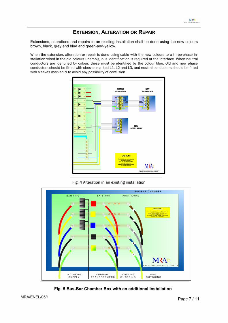
EXTENSION, ALTERATION OR REPAIR Extensions, alterations and repairs to an existing installation shall be done using the new colours brown, black, grey and blue and green-and-yellow. When the extension, alteration or repair is done using cable with the new colours to a three-phase in-stallation wired in the old colours unambiguous identification is required at the interface. When neutral conductors are identified by colour, these must be identified by the colour blue. Old and new phase conductors should be fitted with sleeves marked L1, L2 and L3, and neutral conductors should be fitted with sleeves marked N to avoid any possibility of confusion.
EXISTINGINSTALLATION
NEWINSTALLATION
NEWINSTALLATION
CAUTION !This installation has wiring colours to
two versions of BS 7671.Great care should be taken before
undertaking extension,alteration or repair that all conductors
are correctly identified.
MALTA RESOURCES AUTHORITY
N
L1
L3L2
N
L1
L3L2
N
L1
L3L2
N
L1
L3L2
Fig. 4 Alteration in an existing installation
L 1L 2
L 3N
B U S B A R C H A M B E R
IN C O M IN GS U P P L Y
A D D IT IO N A LE X IS T IN GE X IS T IN G
C U R R E N TT R A N S F O R M E R S
E X IS T IN GO U T G O IN G
N E WO U T G O IN G
E
C A U T IO N !T h is in s ta lla t io n h as w ir in g c o lo u rs t o
t w o ver s io n s o f B S 7 671 .G r eat c are s h o u ld b e t ake n b ef o re
u n d e r t ak in g ex te n s io n ,a lt er a t io n o r r ep a ir th a t a l l co n d u c to r s
ar e co r rec t ly id en t if ied .
M A L T A R E S O U R C E S AU T H O R IT Y
Fig. 5 Bus-Bar Chamber Box with an additional Installation
Page 7 / 11 MRA/ENEL/05/1

A permitted alternative arrangement when doing an extension is to use three single cores for the phase conductors with insulation of the same colour. Permitted colours for phase conductors are brown, black, red, orange, yellow, violet, grey, white, pink or turquoise. In a two-or three-phase power circuit the phase conductors may all be of one of the permitted colours but unambiguous identification must be provided at the terminations.
L 1
L 2
L 3
N
L 1
L 2
L 3
N
EXISTINGINSTALLATION
NEWINSTALLATION
MALTA RESOURCES AUTHORITY
Fig. 6 An Alternative arrangement for extensions
In a three-phase circuit phase identification can be achieved by using numbering or lettering. It is recommended that the old and new cables are marked at the interface using either L1, L2, L3 for phases and N for the neutral as shown in Fig.6. An acceptable alternative to fig.6 when using conductors with the same insulation colour is to mark the conductors brown, black, grey at their terminations to identify the phases. If an extension, alteration or repair is made to an installation such that both red, yellow, blue & black, and brown, black, grey & blue cores are present, a warning notice must be affixed at or near the appropriate distribution board having the following wording:
CAUTION ! This installation has wiring colours to two versions of BS 7671. Great care should be taken before undertaking extension, alteration or repair that all conductors are correctly identified.
Page 8 / 11 MRA/ENEL/05/1

In these guidelines reference has been made to the following amendments in Regulations 514 of BS 7671 Regulation 514-01-03
Except where there is no possibility of confusion, unambiguous marking shall be provided at the interface between conductors identified in accordance with these Regulations and conductors identified to previous versions of the Regulations. Appendix 7 gives guidance on how this can be achieved.
Regulation 514-03-01 Except where identification is not required by Regulation 514-06, cores of cables shall be identified by: (i) colour as required by Regulation 514-04 and/or (ii) lettering and/or numbering as required by Regulation 514-05.
Regulation 514-03-02
Every core of a cable shall be identifiable at its terminations and preferably throughout its length. Binding and sleeves for identification purposes shall comply with BS 3858 where appropriate.
Regulation 514-04-01 Where a circuit includes a neutral or mid-point conductor identified by colour, the colour used shall be blue.
Regulation 514-04-02 The bi-colour combination green-and-yellow shall be used exclusively for identification of a protective conductor and this combination shall not be used for any other purpose. Single core cables that are coloured green-and-yellow throughout their length shall only be used as a protective conductor and shall not be over-marked at their terminations, except as permitted by Regulation 514-04-03. In this combination one of the colours shall cover at least 30% and at most 70% of the surface being coloured, while the other colour shall cover the remainder of the surface. A bare conductor or busbar used as a protective conductor shall be identified, where necessary, by equal green-and-yellow stripes, each not less than 15 mm and not more than 100 mm wide, close together, either throughout the length of the conductor or in each compartment and unit and at each accessible position. If adhesive tape is used, it shall be bi-coloured.
Regulation 514-04-04 Other conductors shall be identified by colour in accordance with Table 51.
Regulation 514-05-01 The lettering or numbering system applies to identification of individual conductors and of conductors in a group. The identification shall be clearly legible and durable. All numerals shall be in strong contrast to the colour of the insulation. The identification shall be given in letters or Arabic numerals. In order to avoid confusion, unattached numerals 6 and 9 shall be underlined.
Regulation 514-06-01 Identification by colour or marking is not required for: (i) concentric conductors of cables; (ii) metal sheath or armour of cables when used as a protective conductor; (iii) bare conductors where permanent identification is not practicable; (iv) extraneous-conductive-parts used as a protective conductor; (v) exposed-conductive-parts used as a protective conductor.
Regulation 514-14-01 If wiring alterations or additions are made to an installation such that some of the wiring complies with Regulation 514-04 but there is also wiring to previous versions of these Regulations, a warning notice shall be affixed at or near the appropriate distribution board with the following wording: CAUTION This installation has wiring colours to two versions of BS 7671. Great care should be taken before undertaking extension, alteration or repair that all conductors are correctly identified.
Page 9/ 11 MRA/ENEL/05/1

New wiring codes -2005 Page 10 / 11

REFERENCES [1] www.i.e.e.org/cablecolours [2] BS 7671 : 2001,Requirements for Electrical Installations, IEE Wiring Regulations Sixteenth Edition Amendment No 2 : AMD 14905 March 2004 [3] New fixed wiring colours – A practical guide, www.niceic.org.uk [4] The IEE, Electrician’s guide to the building regulations – including Ap-proved Document P: Electrical Safety in Dwellings, Chapter 11
Page 11 / 11 MRA/ENEL/05/1