harmonics reduction using multilevel based shunt …2002/09/17 · harmonics reduction using...
TRANSCRIPT
Harmonics Reduction using Multilevel Based Shunt Active Filter with SMES
Deepika G1, Elakkiya M2, Mohamed Iqbal M3
1Assistant Professor, 2Assistant Professor, 3Assistant Professor (Sl.Grade) 1Department of EEE, 2Department of EEE, 3Department of EEE
1Mailam Engineering College, 2Sri Ramakrishna Institute of Technology, 3Sri Ramakrishna Institute of Technology
1Villupuram, 2Coimbatore, 2Coimbatore 1India, 2India, 2India
1 [email protected], [email protected], [email protected]
Abstract—Nowadays, the increase in the usage of nonlinear loads leads to harmonics and waveform distortion to the power system. Shunt active filters (SAF) is commonly a voltage source inverter with the dc link capacitor which is used to mitigate the harmonics and voltage sag. In this paper, diode clamped multilevel inverter based shunt active filter has been designed and it injects the compensating current into system at the point of common coupling. A fuzzy logic controller is established to adjust the energy storage of the dc voltage. The instantaneous reactive power (p-q) theory is used to generate the reference current computation of the shunt APF. Hysteresis Controllers is used to generate switching signals of the voltage source inverter. Super conducting magnetic energy storage coil is capable of storing electric energy in the magnetic field generated by dc current flowing through it. Therefore the combined SAF and SMES system can be a perfect device to compensate both harmonic current and voltage sag. The proposed system is simulated using MATLAB/SIMULINK power system toolbox. Simulation results show that the leading harmonics are reduced considerably.
Keywords- Fuzzy logic controller, Multilevel inverter, Nonlinear load, Shunt active filter, Superconducting Magnetic Energy Storage coil.
I. INTRODUCTION The power quality (PQ) problems in power utility distribution systems are not new, but only recently their
effects have gained public awareness. However the power electronics based equipment which include adjustable-speed motor drives, electronic power supplies, DC motor drives, battery chargers, electronic ballasts are responsible for the rise in PQ related problems. These nonlinear loads appear to be major sources of harmonic distortion in a power distribution system. Harmonic currents produced by nonlinear loads are injected back into power distribution systems through the point of common coupling (PCC).These harmonics are the origin of many problems and affect electrical equipment connected to the power supply. These harmonics induce malfunctions in sensitive equipment, Voltage stresses, increased heating in the conductors and harmonic voltage drop across the network impedance that affects power factor. Traditionally passive filters have been used to compensate harmonics and reactive power; but passive filters are large in size, aging and tuning problems exist and can resonate with the supply impedance.
Recently active power filters are designed for compensating the current-harmonics and reactive power simultaneously. The shunt APF based on Voltage Source Inverter (VSI) structure (a DC energy storage device in this case is capacitor) is an attractive solution to harmonic current problems. The shunt APF is designed to be connected in parallel with the nonlinear load. It detects the harmonic current of nonlinear load and injects into the system a compensating current, identical with the nonlinear load harmonic current but in opposite phase. Therefore, the net current drawn from the distribution network at the point of coupling of filter and the load will be a sinusoidal current of only fundamental frequency.
One of the important tasks in the shunt APF design is the maintenance of constant DC voltage across the capacitor connected to the inverter. This is necessary because there is energy loss due to conduction and switching power losses associated with the controllable switches of the inverter, which tend to reduce the value of voltage across the DC capacitor. Generally, PI controller is used to control the DC bus voltage. The PI controller based approach requires precise linear mathematical model which is difficult to obtain. Also, it fails to perform satisfactorily under parameter variations, non-linearity, and load disturbances. Recently, fuzzy logic controller has generated a great deal of Interest in various applications and has been introduced in the power electronics field. The advantages of fuzzy logic controllers over the conventional PI controller are that they do not need an accurate mathematical model; they can work with imprecise inputs, can handle nonlinearity, and may be more robust than the conventional PI controller. In the other hand, In APF design and control, p-q theory was often served as the basis for the calculation of compensation current. In this theory, the mains voltage was
ISSN (Print) : 2319-8613 ISSN (Online) : 0975-4024 Deepika G et al. / International Journal of Engineering and Technology (IJET)
DOI: 10.21817/ijet/2017/v9i2/170902270 Vol 9 No 2 Apr-May 2017 1001
assumed to be an ideal source in the calculation process. However, in most of time and most of industry power systems, mains voltage may be unbalanced and/or distorted; in this case the control using the p-q theory does not provide good performance.
This paper presents an analysis and simulation of a shunt APF topology that achieves simultaneously harmonic current damping and reactive power compensation under unbalanced mains voltages. To optimize the energy storage, a fuzzy logic controller is developed to adjust the energy storage of the dc voltage to its reference and to attenuate harmonic frequencies resulting from power fluctuations. For the reference current computation of the shunt APF, we used a new technique with p-q for the control of shunt APF. Hysteresis Controllers is used to generate switching signals of the voltage source inverter.
II. SHUNT ACTIVE FILTER STRATEGY
A. Shunt Active Filter Shunt APFs have been the topic of interest for researchers as it compensates for current harmonics more
effectively compared to traditional passive filters. It is barren of many drawbacks observed in passive filters such as, heavy weight, bulky size, harmonic resonance with power system impedance and ineffectiveness when harmonic content varies randomly. The APFs are designed to produce harmonics of equal magnitude and opposite phase as that present in load current. The filter generated harmonics are injected at the point of common coupling between the source and the load so as to cancel out the load current harmonics [3]. The switching loss occurring in two-level inverter based APF is not negligible, which in turn highly affects the performance of APF. Hence, an additional DC-link voltage regulator is required to maintain the DC-link capacitor voltage at a constant value. With the use of a multilevel inverter the switching losses are reduced by a large amount, as the switching occurs at fundamental frequency.
B. Diode-Clamped Multilevel Inverter An m-level diode-clamped multilevel inverter typically consists of (m – 1) capacitors and produces m levels
of the phase voltage. A three-phase five-level structure of a DCMLI is shown in Figure 1. Each of the three phases of the inverter shares a common dc bus, which has been subdivided by four capacitors into five level s. The numbering order of the switches is Sa1, Sa2, Sa3, Sa4, S’a1, S’a2, S’a3 and S’a4. The dc bus consists of four capacitors C1, C2, C3, and C4. For a dc bus voltage Vdc, the voltage across each capacitor is Vdc/4, and each device voltage stress is limited to one capacitor voltage level Vdc/4 through clamping diodes. An m-level inverter leg requires (m-1) capacitors, 2(m-1) switching devices and (m-1) (m-2) clamping diodes.
ISSN (Print) : 2319-8613 ISSN (Online) : 0975-4024 Deepika G et al. / International Journal of Engineering and Technology (IJET)
DOI: 10.21817/ijet/2017/v9i2/170902270 Vol 9 No 2 Apr-May 2017 1002

Fig 1.Diode-Clamped Multilevel Inverter
Table 1 shows the voltage levels and their corresponding switching states. State condition 1 means the switch is on, and 0 means the switch is off. Each phase has five complementary switch pairs such that turning on one of the switches of the pair require that the other complementary switch be turned off. The complementary switch pairs for phase are (Sa1, Sa’1), (Sa2, Sa’2), (Sa3, Sa’3), and (Sa4, Sa’4). Table I also shows that in a diode-clamped inverter, the switches that are on for a particular phase leg is always adjacent and in series [4]. Thus, if one of the complementary switch pairs is turned on, the other of the same pair must be off. Four switches are always turned on at the same time.
TABLE I
Diode-Clamped Voltage Levels and Their Switching State
Output Va0 Switching State
Sa1 Sa2 Sa3 Sa4 S’a1 S’a2 S’
a3 S’ a4
V5 = Vdc 1 1 1 1 0 0 0 0
V4 =3 Vdc/ 4 0 1 1 1 1 0 0 0
V3 = Vdc / 2 0 0 1 1 1 1 0 0
V2 = Vdc/4 0 0 0 1 1 1 1 0
V1 = 0 0 0 0 0 1 1 1 1
ISSN (Print) : 2319-8613 ISSN (Online) : 0975-4024 Deepika G et al. / International Journal of Engineering and Technology (IJET)
DOI: 10.21817/ijet/2017/v9i2/170902270 Vol 9 No 2 Apr-May 2017 1003

III. HYSTERESIS CURRENT CONTROL TECHNIQUE Hysteresis Current Control (HCC) technique is fundamentally an instantaneous feedback current control
method of PWM, where the actual current constantly tracks the command current within a hysteresis band. Basic working principle of the HCC technique is shown in Figure 2. Hysteresis band (HB) is the potential boundary of the compensating current [13]. This current departs between upper and lower hysteresis limits. For example in phase a, if If is equal or over than the upper hysteresis limit (If* + HB/2) then the comparator output is 0 (g1=0, g2=1). On the other hand, if Ifa is equal or less than the lower hysteresis limit (Ifa* - HB/2) then the comparator output is 1 (g1=0, g2=1).
Fig 2. Working Principle of the HCC Technique
IV. INSTANTANEOUS REACTIVE POWER THEORY
The p-q theory is based on transformation of a-b-c coordinate into α-β-0 coordinates and α-β-0 coordinates into a-b-c coordinates, popularly known as Clark transformation and inverse transformation respectively [7]. Simple block diagram of p-q theory is shown in Figure 3. Generated compensating current will be:
Icomp= Isource- Iload (1) Where,
Icomp = Compensating current Isource = Source current and Iload = Load Current
Fig 3. Basic Block Diagram of P-Q Theory
ISSN (Print) : 2319-8613 ISSN (Online) : 0975-4024 Deepika G et al. / International Journal of Engineering and Technology (IJET)
DOI: 10.21817/ijet/2017/v9i2/170902270 Vol 9 No 2 Apr-May 2017 1004

.In this method three phase source voltage and load current are converted into α-β-0 stationary reference frame = 1/√2 1/√2 1/√21 1/2 −1/20 √3/2 −√3/2 (2)
= 1/√2 1/√2 1/√21 1/2 −1/20 √3/2 −√3/2 (3)
From this transformed quantities, instantaneous real and reactive power of the load is calculated which
consists of average and oscillating component.
= 0 000 − (4)
For three phase three wire systems I0= 0, so source power P0 also becomes zero. So power equation becomes
as follows.
= − (5)
Instantaneous active and reactive power of load can be calculated as follows:
= − (6)
Instantaneous real and reactive power can be moldy into two components called oscillatory components and
average components. =
− 0 (7)
The oscillating component is extracted by high-pass filter and taking inverse of α-β transformation
compensating reference signals in terms of either currents or voltages are derived.
∗∗∗ = 1 0−1/2 √3/2−1/2 −√3/2 (8)
The reference currents in three-phase system (Ifa*, Ifb*and Ifc*) are calculated so as to compensate harmonic currents in the load. The switching pulses used in shunt active power filter control algorithm are created by comparing reference currents and actual line currents by hysteresis band current control algorithm.
V. FUZZY LOGIC CONTROLLER Fuzzy logic is a form of many -valued logic that deals with approximate, rather than fixed and exact
reasoning. Compared to traditional binary logic, fuzzy logic variables may have a truth value that ranges in degree between 0 and 1. Fuzzy logic has been extended to handle the concept of partial truth, where the truth value may range between completely false. Now-a-days, fuzzy logic controller is used in almost all sectors of industry power systems and science [5]. One of them is the harmonic current and reactive power compensation control.
A fuzzy inference process consists of the following steps: Step 1: Fuzzification of input variables Step 2: Application of fuzzy operator (AND, OR, NOT) in theIF (antecedent) part of the rule Step 3: Implication from the antecedent to the consequent (THEN part of the rules)
ISSN (Print) : 2319-8613 ISSN (Online) : 0975-4024 Deepika G et al. / International Journal of Engineering and Technology (IJET)
DOI: 10.21817/ijet/2017/v9i2/170902270 Vol 9 No 2 Apr-May 2017 1005
Step 4: Aggregation of the consequents across the rules Step 5: Defuzzification
The crisp inputs are converted to linguistic variables in fuzzification based on membership function (MF). A membership function can have different shapes.
A. DC Capacitor Voltage Control Among the various available powers filter controllers PI, PID, RST hysteresis and fuzzy logic controller. In
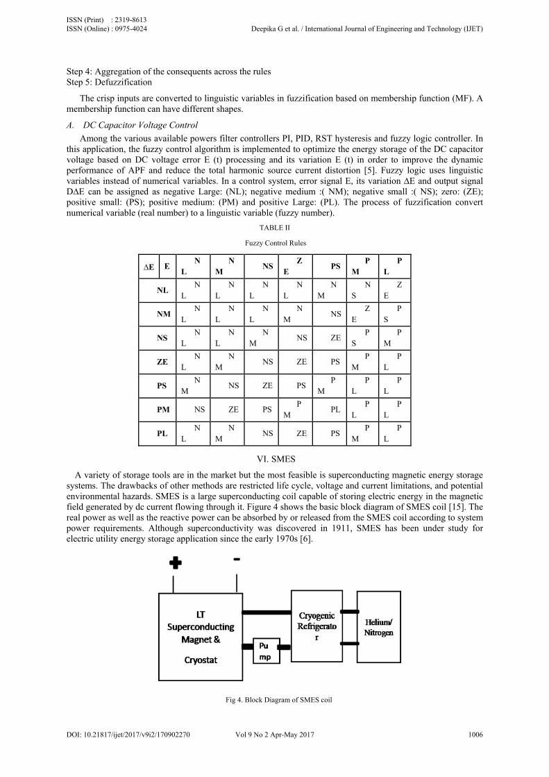
this application, the fuzzy control algorithm is implemented to optimize the energy storage of the DC capacitor voltage based on DC voltage error E (t) processing and its variation E (t) in order to improve the dynamic performance of APF and reduce the total harmonic source current distortion [5]. Fuzzy logic uses linguistic variables instead of numerical variables. In a control system, error signal E, its variation ∆E and output signal D∆E can be assigned as negative Large: (NL); negative medium :( NM); negative small :( NS); zero: (ZE); positive small: (PS); positive medium: (PM) and positive Large: (PL). The process of fuzzification convert numerical variable (real number) to a linguistic variable (fuzzy number).
TABLE II
Fuzzy Control Rules
∆E E N
L N
M NS
ZE
PS P
M P
L
NL N
L N
L N
L N
L N
M N
S Z
E
NM N
L N
L N
L N
M NS
ZE
PS
NS N
L N
L N
M NS ZE
PS
PM
ZE N
L N
M NS ZE PS
PM
PL
PS N
M NS ZE PS
PM
PL
PL
PM NS ZE PS P
M PL
PL
PL
PL N
L N
M NS ZE PS
PM
PL
VI. SMES
A variety of storage tools are in the market but the most feasible is superconducting magnetic energy storage systems. The drawbacks of other methods are restricted life cycle, voltage and current limitations, and potential environmental hazards. SMES is a large superconducting coil capable of storing electric energy in the magnetic field generated by dc current flowing through it. Figure 4 shows the basic block diagram of SMES coil [15]. The real power as well as the reactive power can be absorbed by or released from the SMES coil according to system power requirements. Although superconductivity was discovered in 1911, SMES has been under study for electric utility energy storage application since the early 1970s [6].
Fig 4. Block Diagram of SMES coil
ISSN (Print) : 2319-8613 ISSN (Online) : 0975-4024 Deepika G et al. / International Journal of Engineering and Technology (IJET)
DOI: 10.21817/ijet/2017/v9i2/170902270 Vol 9 No 2 Apr-May 2017 1006

A. Application of SMES in Power Systems It is the fast response that makes SMES able to provide benefit to many potential utility applications. The
applications of SMES are; • Energy storage range of SMES is up to 5000MWh with a high return efficiency (up to 95% for a large
unit) and a fast response time for dynamic change of energy flow. • SMES has the ability to damp out the low power oscillations and stabilize the system frequency. • SMES is useful in reducing dynamic voltage instability by supplying real and reactive power
simultaneously. • SMES can be used as a backup power supply for large industrial customers in case of loss of the utility
main power supply. • SMES unit can represent a terrific amount of spinning reserve capacity when in charge mode.
VII. PROPOSED SYSTEM This paper propose the control strategy for mitigating the harmonics and voltage sag problem in the power
systems using the combined co-ordination of multilevel based shunt active filter and SMES. The block diagram of the system is shown in Figure 5. Three phase source is given to the nonlinear load. The nonlinear load used here is the diode bridge rectifier with the resistance of 10Ω. The diode clamped multilevel inverter is used in this model.
Fig 5. Three Phase Shunt Active Power Filter.
VIII. SIMULATION RESULTS The proposed system considered in this paper is simulated using the MATLAB/Simulink Sim power system
toolbox. The simulation results are based on the presence of SMES coil. Figure 6 shows the three phase voltage source.
ISSN (Print) : 2319-8613 ISSN (Online) : 0975-4024 Deepika G et al. / International Journal of Engineering and Technology (IJET)
DOI: 10.21817/ijet/2017/v9i2/170902270 Vol 9 No 2 Apr-May 2017 1007

Fig 6. Three Phase Source Voltage
The nonlinear load considered in this paper is diode bridge rectifier with the resistor. Diodes are the source to produce this type of harmonic current as shown in Figure 7.
Fig 7. Three Phase Nonlinear Load Current
Fig 8. DC Capacitor Voltage
0 0.5 1 1.5 2 2.5 3 3.5 4
x 104
-400
-300
-200
-100
0
100
200
300
400
Time(secs)
Vol
tage
(V)
Source Voltage
0 0.5 1 1.5 2 2.5 3 3.5 4
x 104
-80
-60
-40
-20
0
20
40
60
80
Time(secs)
Cur
rent
(A)
Load Current
0 0.5 1 1.5 2 2.5 3 3.5 4
x 104
-500
0
500
1000
1500
2000
2500
Time(secs)
Vol
tage
(V)
DC Capacitor Voltage
ISSN (Print) : 2319-8613 ISSN (Online) : 0975-4024 Deepika G et al. / International Journal of Engineering and Technology (IJET)
DOI: 10.21817/ijet/2017/v9i2/170902270 Vol 9 No 2 Apr-May 2017 1008

The main aim is to maintain the dc link voltage as constant and load current as sinusoidal. This achieved through fuzzy logic controller unit; in this error value and change in error value of load current is measured and compared with each other. Based on this result control signal is generated from the filter circuit to the load. The Figure 8 shows the DC capacitor voltage. Vdc is kept constant as 1200V.
Fig 9. Three Phase Filter Current
Figure 9 shows the filter current waveform. This is due to the presence of 5 level diode clamped multilevel inverter. Three phases a, b, c are shown separately. This current is going to be injected at the point of common coupling. SMES is used as an additional energy source along with the capacitor. Figure 10 shows the compensated filter current. After some distortion, the source current is gradually compensated. Figure 11 shows the Harmonic Spectrum of Load Current, Source Current and DC Capacitor Voltage
ISSN (Print) : 2319-8613 ISSN (Online) : 0975-4024 Deepika G et al. / International Journal of Engineering and Technology (IJET)
DOI: 10.21817/ijet/2017/v9i2/170902270 Vol 9 No 2 Apr-May 2017 1009

Fig 10. Compensated Source Current
Fig 11. Harmonic Spectrum of (i) Load Current (ii) Source Current (iii) DC Capacitor Voltage
IX. CONCLUSION This paper has discussed the control and performance improvement of a shunt APF under distorted voltage
conditions, using a fuzzy logic controller for a five level shunt APF based on the optimization of the reference current generation and using a modified version of the p-q theory and HCPWM to generate switching signals. Simulation results have shown high performances in reducing harmonics. The use of the SAF leads to satisfactory improvements since it perfectly extracts the harmonic currents under distorted conditions. In addition, the results have demonstrated the major advantages of using SAF and fuzzy logic controller in filter control. The five-level APF provides numerous advantages such as improvement of supply current waveform, less harmonic distortion and possibilities to use it in high power applications. As a final conclusion, the source current total harmonic distortion (THD) after compensation by single inverter is 3.73% but by using two inverters it decreases to 1.67% which is agreed and less than the harmonic limit imposed by the IEEE-519 standard (3%), by using multilevel inverters with 5-Step diode clamped multi-level inverter the circuit is simulated by using MATLAB/ Simulink.
REFERENCES [1] Sushree Sangita Patnaik and Anup Kumar Panda, “Cascaded three-level inverter based shunt active filter for power conditioning
application,” in Annual IEEE India Conference 2013. [2] Izzeldin Idris Abdalla, K. S. Rama Rae and N. Perusal, “Cascaded multilevel inverter based shunt active power filter in four-wire
distribution system,” in IEEE 2011. [3] B.Geethalakshmi, M.Kavitha and K.Delhibabu, “Harmonic compensation using multilevel inverter based shunt active power filter,” in
IEEE 2010. [4] Xiaoming Yuan and Ivo Barbi, “Fundamentals of a new diode clamping multilevel inverter”, in IEEE Transactions on power
electronics, vol. 15, no. 4, July 2000. [5] Benazir Hajira A, Ramya M, Sathyapriya M, Anju R and Kumar P, “Fuzzy logic controller based 3-phase shunt active power filter for
current harmonic mitigation,”vol. 3, Issue 3, March 2014. [6] A.Arulkumar, Dr.N.RathinaPrabha and M.KalaRathi, “PI controller based shunt active power filter with cascaded multilevel inverter,”
vol. 3, Issue 3, March 2014.
0 0.5 1 1.5 2 2.5 3 3.5 4
x 104
-300
-200
-100
0
100
200
300
400
500
Time(secs)
Cur
rent
(A)
Compensated Source Current
(iii) (I) (ii)
ISSN (Print) : 2319-8613 ISSN (Online) : 0975-4024 Deepika G et al. / International Journal of Engineering and Technology (IJET)
DOI: 10.21817/ijet/2017/v9i2/170902270 Vol 9 No 2 Apr-May 2017 1010

[7] Bhim Sing, Kamal Al Haddad and Ambrish Chandra, “A Review of Active Filters for Power Quality Improvement”, IEEE Transaction on Industrial Electronics, vol.46, no.5, October 1999, pp.960-970.
[8] ParagKanjiya and VinodKhadkikar, “Optimal control of shunt active power filter to meet IEEE std.519 current harmonics constraints under non-ideal supply condition,” in IEEE Transactions on Industrial Electronics, 2013.
[9] PradeepAnjana, Vikaas Gupta and HarpalTiwari, “Reducing harmonics in micro grid distribution system using APF with PI controller”, in IEEE Transactions, 2014.
[10] Arpit Shah and Nirav Vaghela, “Shunt active power filter for power quality improvement in distribution systems,” in International Journal of Engineering Development and Research, 2005.
[11] Luis F.C. Monteria, Lucas F. Encarnacao and Mauricio aredes, “A novel selective control algorithm for the shunt active filter,” in International Power Electronics Conference, 2010.
[12] Nihau Kumara and Isa Awash, “Harmonic Compensation Using Shunt Active Power Filter in Power System Using Mat lab,” in International Journal of Scientific Engineering and Research, vol.1, nov.2013.
[13] S. Bus, L.Malesani, P.Mattavelli, “Comparison of Current Control Techniques for Active Filter Applications”, IEEE Transactions on Industrial Electronics,vol.45, no.5, pp.722-729, October 1998.
[14] Weijia Yuan, W. Xian, M. Ainslie, Z. Hong, Y. Yan, R. Pei, Y. Jiang and T.A. Coombs, “Design and test of a Superconducting Magnetic Energy Storage (SMES) Coil”, IEEE Transactions on Applied Superconductivity, vol.20 no.3, June 2010.
[15] Michael Steurer, Cesar A. Luongo, Paulo R. riberio and Steve Eckroad, “Interaction between a superconducting coil and the power electronics interface on a 100 MJ SMES system”, IEEE Transaction on Applied Superconductivity, vol.13, no. 2, June 2003.
[16] C. J. Hawley, S.A. Gower, “Design and Preliminary Results of a Prototype HTS SMES Device”, IEEE Transactions on Applied Superconductivity, vol. 15, no. 2, June 2005.
[17] Mohd. Hasan Ali, Bin Wu, and Roger A. Dougal, “ An Overview of SMES Applications in Power and Energy Systems”, in IEEE Transactions on Sustainable Energy, vol. 1, no.1, April 2010.
[18] V S R Varaprasad, D V S S Siva Sarma, “An Improved SVPWM based Shunt Active Power Filter for Compensation of Power System Harmonics”, IEEE 2014.
AUTHOR PROFILE Ms. G. Deepika has obtained her BE degree in Electrical and Electronics Engineering from Anna University, Tamilnadu in 2013. She received her ME degree in Power Systems Engineering from Anna University, Tamilnadu in 2015. At present she is working as Assistant Professor in EEE Department at Mailam Engineering College. Her research area includes power systems, power electronics and renewable energy.
Ms. M. Elakkiya has obtained her BE degree in Electrical and Electronics Engineering from Anna University, Tamilnadu in 2013. She received her ME degree in Power Systems Engineering from Anna University, Tamilnadu in 2015. At present she is working as Assistant Professor in EEE Department at Sri Ramakrishna Institute of Technology. Her research area includes power systems, Soft computing and renewable energy.
Dr. M. Mohamed Iqbal received his B.E. Electrical and Electronics Engineering degree from Madurai Kamaraj University, Madurai, Tamilnadu, India in 2002 and the M.E. Power Systems Engineering degree from Anna University, Chennai, Tamilnadu, India in 2006. And obtained his PhD in Renewable Energy systems under the Faculty of Electrical Engineering, Anna University, Chennai in 2016. He has more than 10 years of teaching experience. He has published 16 research papers in reputed Journals and Conferences both National and International levels. He is currently working as Assistant Professor (Senior Grade) in the Department of Electrical and Electronics Engineering, Sri Ramakrishna Institute of Technology, Coimbatore, Tamilnadu. He has guided more than 20 projects for post graduate and under graduate level students. His area of interest includes Renewable energy systems, Power system analysis, Power system operation and control, Electrical Machines and Soft computing techniques.
ISSN (Print) : 2319-8613 ISSN (Online) : 0975-4024 Deepika G et al. / International Journal of Engineering and Technology (IJET)
DOI: 10.21817/ijet/2017/v9i2/170902270 Vol 9 No 2 Apr-May 2017 1011