harley davidson quick-install pushrod …harley davidson quick-install pushrod installation...
TRANSCRIPT

HARLEY DAVIDSON QUICK-INSTALL PUSHROD
INSTALLATION INSTRUCTIONS
Included in kit: (figure 1)
2 ea. Intake Pushrods
2 ea. Exhaust Pushrods
4 ea. Bases
1 ea. Adjustment Fixture (to hold pushrod cover up while adjusting pushrod)
1 ea .5 ml tube 271 loctite
Figure 1
You will need (2) 7/16 open end wrenches of your own.
1. To make the job easier we recommend raising the bike up on a motorcycle floor jack for ease of
access as well as being able to rotate the rear wheel when adjusting the piston position in the
cylinders. We also recommend removal of the spark plugs to make engine rotation easier.
2. After securing and lifting the bike on the stand, remove the spark plugs and the pushrod tube
uppers so the lower portion of the tube can be raised exposing the pushrods that will be removed.

Place transmission into second gear and rotate rear tire until you see the front exhaust pushrod go
all the way down into the lifter block. If it begins to come back up, reverse rotate the tire in the
opposite direction until the pushrod (and lifter) are at the lowest point. Stuff a clean rag or
something into the hole of the lifter block so no debris can get into the exposed area during removal
of the old pushrods. Use a set of bolt cutters and cut the pushrod off above the lifter block and
remove the upper portion along with the pushrod tube. (fig 2) You now have access to the bottom
piece of the pushrod and can remove it as well.
Figure 2
3. Repeat step 2 for the remaining three pushrods.
4. Make sure the lifter is riding on the base circle of the cam (the lowest point on the lobe) before
beginning installation of the pushrod. One way to make sure is to watch and when the exhaust lifter
is just beginning to come up, the intake should be at the bottom and when the intake lifter comes up
and is going back down, the exhaust should be at the bottom.
5. Begin installation of your new pushrods by applying a couple drops of thread locker around the top
of the inside of the threads on the base. Make sure the threads are clean and dry on both the screw
and the base. Don’t use too much as it can get down in the bottom and plug the oil hole. Also, only
apply it when you are ready for installation and only to that particular one. It can begin to harden
before you’re ready to install the next one and so on.
6. Drop one base (with thread locker applied) into the lifter block and make sure it’s setting in the
pocket of the lifter. Again, make sure the exposed threads on the pushrods are clean and dry (no oil
or solvent present) and make sure you install the exhaust rods in the exhaust position and the intake
rods in the intake position. They are marked. Insert the pushrod into the pushrod tube then insert
the top portion of the pushrod up into the rocker box and feel for when it is seated in the rocker
arm. Swing the bottom portion of the pushrod into position and just set the threaded end into the
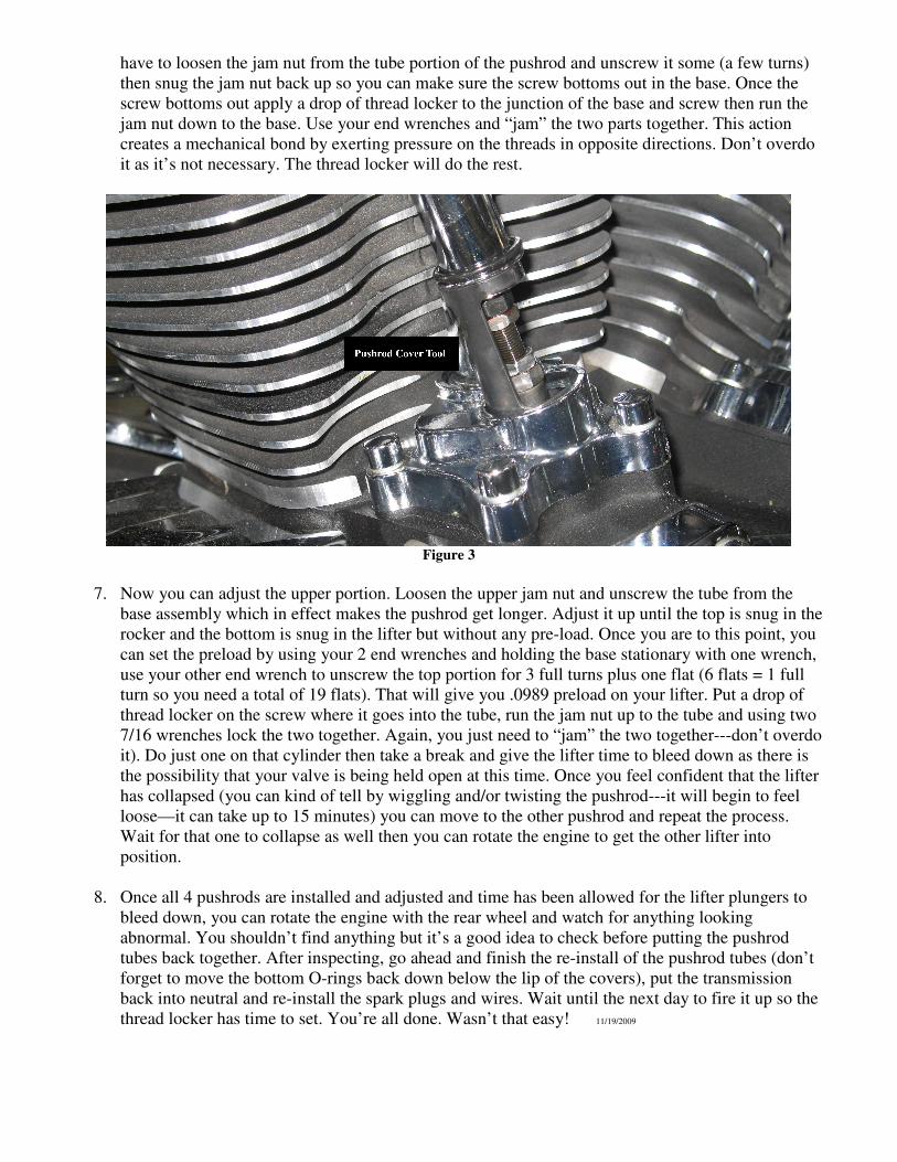
opening of the base. This next step will be easier if you use the fixture provided to hold the pushrod
cover up out of the way. (fig. 3) Move the bottom O-ring above the lip on the cover so it’s out of
the way. Using your fingers, get the screw started into the base and it can be faster to just keep
screwing the 2 parts together by hand. If it’s not easy for you that way, once you get the screw
started you can use your end wrenches and keep screwing the parts together that way. You may
have to loosen the jam nut from the tube portion of the pushrod and unscrew it some (a few turns)
then snug the jam nut back up so you can make sure the screw bottoms out in the base. Once the
screw bottoms out apply a drop of thread locker to the junction of the base and screw then run the
jam nut down to the base. Use your end wrenches and “jam” the two parts together. This action
creates a mechanical bond by exerting pressure on the threads in opposite directions. Don’t overdo
it as it’s not necessary. The thread locker will do the rest.
Figure 3
7. Now you can adjust the upper portion. Loosen the upper jam nut and unscrew the tube from the
base assembly which in effect makes the pushrod get longer. Adjust it up until the top is snug in the
rocker and the bottom is snug in the lifter but without any pre-load. Once you are to this point, you
can set the preload by using your 2 end wrenches and holding the base stationary with one wrench,
use your other end wrench to unscrew the top portion for 3 full turns plus one flat (6 flats = 1 full
turn so you need a total of 19 flats). That will give you .0989 preload on your lifter. Put a drop of
thread locker on the screw where it goes into the tube, run the jam nut up to the tube and using two
7/16 wrenches lock the two together. Again, you just need to “jam” the two together---don’t overdo
it). Do just one on that cylinder then take a break and give the lifter time to bleed down as there is
the possibility that your valve is being held open at this time. Once you feel confident that the lifter
has collapsed (you can kind of tell by wiggling and/or twisting the pushrod---it will begin to feel
loose—it can take up to 15 minutes) you can move to the other pushrod and repeat the process.
Wait for that one to collapse as well then you can rotate the engine to get the other lifter into
position.
8. Once all 4 pushrods are installed and adjusted and time has been allowed for the lifter plungers to
bleed down, you can rotate the engine with the rear wheel and watch for anything looking
abnormal. You shouldn’t find anything but it’s a good idea to check before putting the pushrod
tubes back together. After inspecting, go ahead and finish the re-install of the pushrod tubes (don’t
forget to move the bottom O-rings back down below the lip of the covers), put the transmission
back into neutral and re-install the spark plugs and wires. Wait until the next day to fire it up so the
thread locker has time to set. You’re all done. Wasn’t that easy! 11/19/2009