hardy rib installation guide - mid-michigan metal sales · hardy-rib was designed with strong...
TRANSCRIPT

.
Hardy-Rib Installation Manual
G3336 S Dort Hwy. Burton, MI 48529
midmichiganmetalsales.com . Toll-Free (800) 615-8416
“Nationwide supplier of quality metal roofing.”

Mid Michigan Metal Sales 800-615-8416
IMPORTANTNOTICE
This manual contains suggestions and guidelines on how to install Mid Michigan
Hardy Rib panels and trim details. The contents of this manual include the
guidelines that were in effect at the time this publication was originally printed. In
an effort to keep pace with the ever-changing code environment, Mid Michigan
Metal Sales retains the right to change specifications and/ or designs at any time
without incurring any obligations. To insure you have the latest information
available, please inquire or visit our web site. Application and design details are for
illustrative purposes only and may not be appropriate for all environmental
conditions and/or building designs. Projects should be engineered and installed to
conform to applicable building codes, regulations, and accepted industry practices.
*Disclaimer: This information is provided “as is” and is intended for entertainment purposes only. The author, publishers and marketers of this information disclaim any loss or liability, either directly or indirectly as a consequence of applying the information presented herein, or in regard to the use and application of said information. No guarantee is given, either expressed or implied, in regard to the merchantability, accuracy, or acceptability of the information.

Mid Michigan Metal Sales 800-615-8416
TABLE OF CONTENTS
1. Introduction - Design and Testing
2. Panel Installation
a. Installation Guide
b. Panel Squaring
3. Installation Sequence
4. Trim Assemblies
a. Fascia
b.
c.
Drip Edge
d.
Rake / Gable
e.
Preformed Valley
f.
g.
am
Transition/Pitch Break
Gambrel
h.
Hip
i.
Ridge
j.
Vented Ridge
k.
High Side Peak
l.
Side Wall
End Wall
5. Special Details
a. Valley Lapping and Cutting
b. Pipe Flashing
Mid Michigan Metal Sales 800-615-8416
Introduction
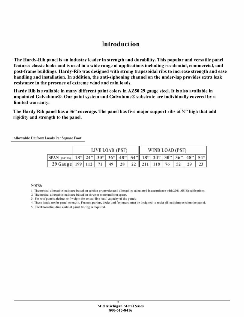
The Hardy-Rib panel is an industry leader in strength and durability. This popular and versatile panel features classic looks and is used in a wide range of applications including residential, commercial, and post-frame buildings. Hardy-Rib was designed with strong trapezoidal ribs to increase strength and ease handling and installation. In addition, the anti-siphoning channel on the under-lap provides extra leak resistance in the presence of extreme wind and rain loads.
Hardy Rib is available in many different paint colors in AZ50 29 gauge steel. It is also available in unpainted Galvalume®. Our paint system and Galvalume® substrate are individually covered by a limited warranty.
The Hardy Rib panel has a 36” coverage. The panel has five major support ribs at ¾” high that add rigidity and strength to the panel.
Allowable Uniform Loads Per Square Foot
LIVE LOAD (PSF) WIND LOAD (PSF)
SPAN (INCHES) 18” 24” 30” 36” 48” 54” 18” 24” 30” 36” 48” 54”
29 Gauge 199 112 71 49 28 22 211 118 76 52 29 23
NOTES:
1. Theoretical allowable loads are based on section properties and allowables calculated in accordance with 2001 AISI Specifications.
Theoretical allowable loads are based on three or more uniform spans.
3. For roof panels, deduct self weight for actual ‘live load’ capacity of the panel.
4. These loads are for panel strength. Frames, purlins, decks and fasteners must be designed to resist all loads imposed on the panel.
5. Check local building codes if panel testing is required.
2
Mid Michigan Metal Sales 800-615-8416
Panel Installation Guide
Storage If metal is not to be used immediately, store inside in a well ventilated, dry location. Condensation or other moisture can form
between the sheets during storage causing water stains or white rust which detract from the appearance of the product and
may affect the product’s useful life. Trapped moisture between sheets of painted metal can cause white rust to form
underneath the paint. This can cause the paint to flake off the panel immediately or several years later. To prevent white rust
and staining, break the shipping bands on the material. Store the material on end or on an incline of at least 8” with a
supporting board underneath to prevent sagging. Fan the sheets slightly at the bottom to allow for air circulation. Keep the
sheets off of the ground with an insulator such as wood. Any outdoor storage is at the customer’s own risk. If outdoor storage
cannot be avoided, protect the metal using a canvas cover or waterproof paper. Never cover the metal with plastic as this will
cause condensation to form.
Some Safety Precautions Always wear protective gloves when working with steel panels to avoid cuts from sharp edges. When cutting or drilling steel
panels, always wear safety glasses and sweep off any metal shavings immediately to prevent eye injury from flying metal
fragments. If you must walk on a metal roof, take great care. Metal panels can become slippery, so always wear shoes with
non-slip soles. Avoid working on metal roofs during wet conditions when the panels can become extremely slippery.
General Installation Information
Insure that the structure is square and true before beginning panel installation. If the structure is not square, the panels will
not properly seal at the sidelaps. Start the first panel square to eave by using the 3, 4, 5 Triangle Method. Green or damp
lumber is not recommended. Moisture released from the damp lumber may damage the metal panels. Nails installed in
green or damp lumber may back out. Remove any loose metal shavings left on the roof surface immediately to prevent
corrosion. After installing roof, remove any debris such as leaves or dirt to prevent moisture from getting trapped on panels.
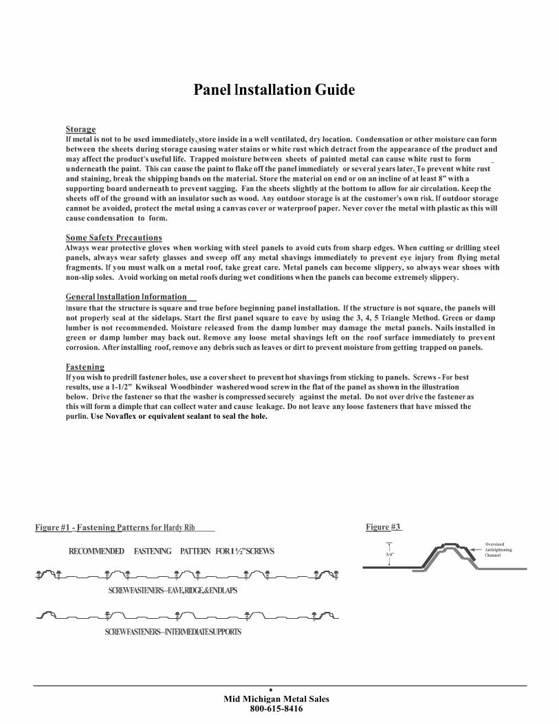
Fastening If you wish to predrill fastener holes, use a cover sheet to prevent hot shavings from sticking to panels. Screws - For best
results, use a 1-1/2” Kwikseal Woodbinder washered wood screw in the flat of the panel as shown in the illustration below. Drive the fastener so that the washer is compressed securely against the metal. Do not over drive the fastener as
this will form a dimple that can collect water and cause leakage. Do not leave any loose fasteners that have missed the
purlin. Use Novaflex or equivalent sealant to seal the hole.
Figure #1 - Fastening Patterns for Hardy Rib Figure #3
RECOMMENDED FASTENING PATTERN FOR1½”SCREWS 3/4”
Oversized
Antisiphoning
Channel
SCREWFASTENERS–EAVE,RIDGE,&ENDLAPS
SCREWFASTENERS–INTERMEDIATESUPPORTS

Mid Michigan Metal Sales 800-615-8416
Roofing Slopes of less than 2” on 12” are not recommended. For slopes of 2” on 12” or greater, end lap panels 6”. Side laps should faceaway from the prevailing wind. Lay the first sheet along the eave at the down-wind side of the roof, farthest away from the
direction of the prevailing winds (See Figure #4). Install sheets in the sequence shown in Figure #4.
Figure #4 Figure #5 - Installation Options
Prevaili
ng Winds
2”x4”s
4 2’ Spacing
2 Underlayment Underlayment
Install Metal Directly to Wood Frame
Install Metal on Solid Deck
Install Metal Over Existing Shingles
• Use Maximum 2’ Purlin Spacing • Lay Plywood Deck • Apply Synthetic
• Install Metal • Apply Synthetic Underlayment or other
*NOT RECOMMENDED FOR HEATED Underlayment or other Vapor Vapor Barrier Protection
5 3
1
SPACESUNLESSINSULATION ANDVAPOR Barrier Protection • Install Metal
Maximum Purlin Spacing for BARRIERPROTECTIONISUSED • Install Metal
Roof 2’ on Center
* Proper ventilation and vapor barrier protection recommended for heated spaces
Allow an overhang a minimum of 1” at the eave to provide for a drip edge. Use inside closure at eave to prevent water
infiltration, insect or bird infestation at openings. To protect against uplifting winds and to provide a finished appearance,
apply gable trim. Apply fasteners every 24”. Optionally apply butyl tape as shown in Figure #6 along the top of lap ribs. Do
not block the siphon channel with the tape. Also an option: apply a 1-1/2" lap stitch screw into the crown of the rib to securethe side lap. This is especially a good idea on roofs with a slope less than 4:12.
Figure #6 - Proper Application of Side Lap Butyl Tape
Allowable Uniform Loads Per Square Foot
LIVE LOAD (PSF) WIND LOAD (PSF)
SPAN (INCHES) 18” 24” 30” 36” 48” 54” 18” 24” 30” 36” 48” 54”
29 Gauge 199 112 71 49 28 22 211 118 76 52 29 23
NOTES:
1. Theoretical allowable loads are based on section properties and allowables calculated in accordance with 2001 AISI Specifications.
2. Theoretical allowable loads are based on three or more uniform spans.
3. For roof panels, deduct self weight for actual ‘live load’ capacity of the panel.
4. These loads are for panel strength. Frames, purlins, decks and fasteners must be designed to resist all loads imposed on the panel.
5. Check local building codes if panel testing is required.
Mid Michigan Metal Sales 800-615-8416
Rake
Rake
Roof S
lope
Roof S
lope
Rake
Rake
5
1
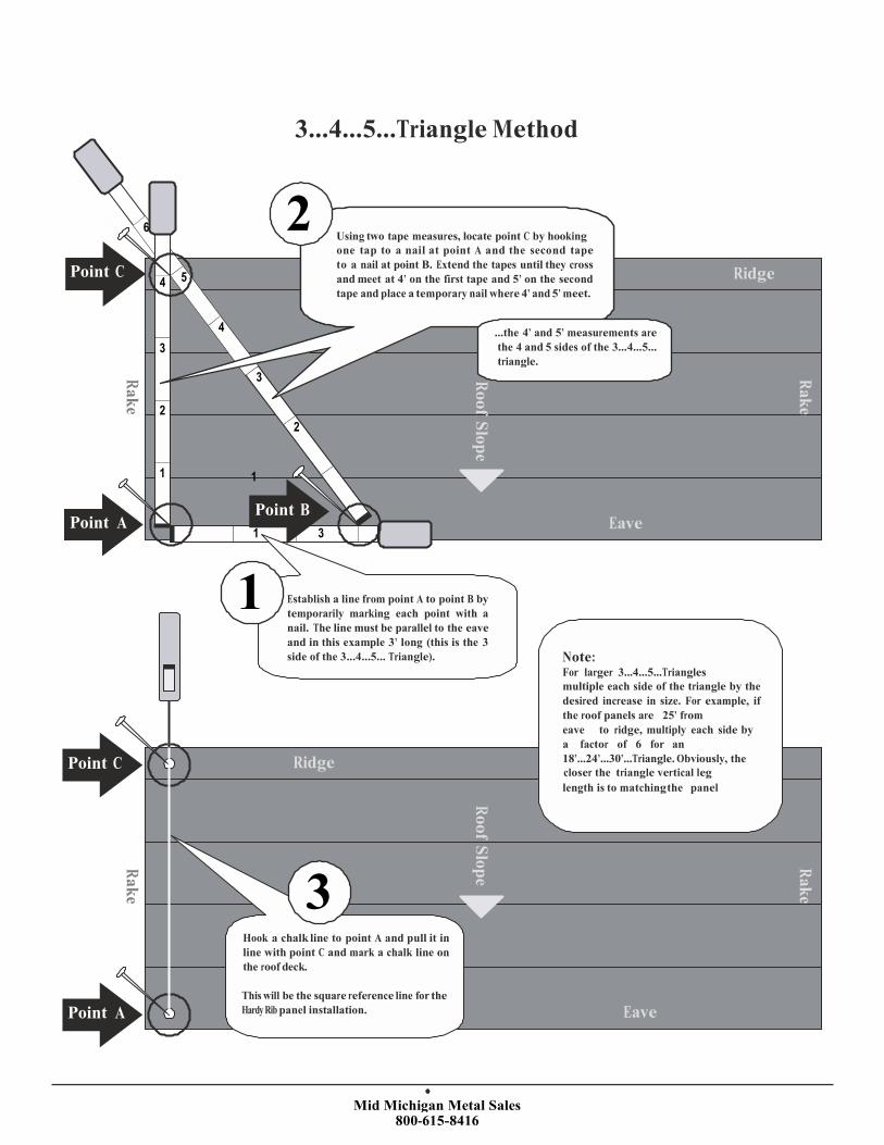
3...4...5...Triangle Method
6
Point C 4
4
3
2Using two tape measures, locate point C by hooking
one tap to a nail at point A and the second tape
to a nail at point B. Extend the tapes until they cross
and meet at 4’ on the first tape and 5’ on the second
tape and place a temporary nail where 4’ and 5’ meet.
...the 4’ and 5’ measurements are
the 4 and 5 sides of the 3...4...5...
triangle.
3
Ridge
2
2
1 1
Point A Point B
1 3 Eave
Point C
Establish a line from point A to point B by
temporarily marking each point with a
nail. The line must be parallel to the eave
and in this example 3’ long (this is the 3
side of the 3...4...5... Triangle).
Ridge
Note: For larger 3...4...5...Triangles
multiple each side of the triangle by the
desired increase in size. For example, if
the roof panels are 25’ from
eave to ridge, multiply each side by
a factor of 6 for an
18’...24’...30’...Triangle. Obviously, the closer the triangle vertical leg
length is to matching the panel
3 Hook a chalk line to point A and pull it in
line with point C and mark a chalk line on
the roof deck.
Point A This will be the square reference line for the
Hardy Rib panel installation. Eave
Mid Michigan Metal Sales 800-615-8416
Rake
Rake
Roof S
lope
Square Refe
rence Line
Rake
Rake
Ridge
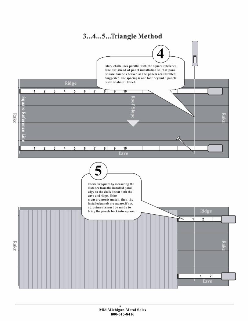
3...4...5...Triangle Method
4 Mark chalk lines parallel with the square reference
line out ahead of panel installation so that panel
square can be checked as the panels are installed.
Suggested line spacing is one foot beyond 3 panels
wide or about 10 feet.
1 2 3 4 5 6 7 8 9 10
1 2 3 4 5 6 7 8 9 10
Eave
5 Check for square by measuring the
distance from the installed panel
edge to the chalk line at both the
eave and ridge. If the
measurements match, then the
installed panels are square, if not,
adjustments must be made to
bring the panels back into square. Ridge
1 2
1 2
Eave

Mid Michigan Metal Sales 800-615-8416
Installation Sequence
The following is an example of a typical sequence for the installation of Hardy Rib panels and trims and is specific to the roof plan and conditions illustrated. The actual sequence may vary based on the specific roof plan and applicable conditions.
1. Moisture Barrier
Install the Moisture Barrier per the manufacturer’s recommendedprocedure.
2. Fascia Trim (optional)
Install the FasciaTrim along all eaves and rakes.
3. Drip Edge
Install the drip edge along all eaveslapping over the FasciaTrim.
4. Valley Trim
Install the Valley Trim over the Drip Edge working from the eave
to the valley peak.
5. Hardy Rib PanelsInstall the panels over the Eave and Valley Trims. Do not install panels where the Ridge Trim laps
under the panels.
6. Hip Trim
Install the Hip Trim over the panels.

Mid Michigan Metal Sales 800-615-8416
Installation Sequence
7. Ridge TrimInstall the Ridge Trim over the Hip Trim
intersection and valley peak.
10. Gable / Rake TrimInstall the Rake Trim over the panels along
all rake (gable) edges.
8. Transition TrimInstall theTransitionTrim over the low slope
panels and moisture barrier.
11. High Side Peak TrimInstall the High Side Peak Trim over the
panels.
9. Hardy Rib Panels Complete the
panel installation installing the high slop panels
over the Trim Transition and the other remaining
exposed locations.
12. Ridge CapInstall the Ridge Trim over the panels.
13. Side Wall TrimInstall the Side Wall Trim over the panels.
14. Side Wall Trim (Rear View)Install the Side Wall Trim over the panels.
15. End Wall TrimInstall the End Wall Trim over the panels.

Mid Michigan Metal Sales 800-615-8416
Fascia
Roof Substrate
Install the roof substrate according to local
building code requirements.
Moisture Barrier
Install moisture barrier according to the manufacture’s recommended
procedure and in compliance with local building code requirements.
Fascia Trim Install the Fascia trim and butt ends.
Trim Pancake Screw
Fasten trim with Pancake Screws 2’ apart
along the length of the trim.
Trim Wood Screw
Fasten trim withWood Screws spaced 2’
apart along the length of the trim.
1
2
3
4
5
Mid Michigan Metal Sales 800-615-8416
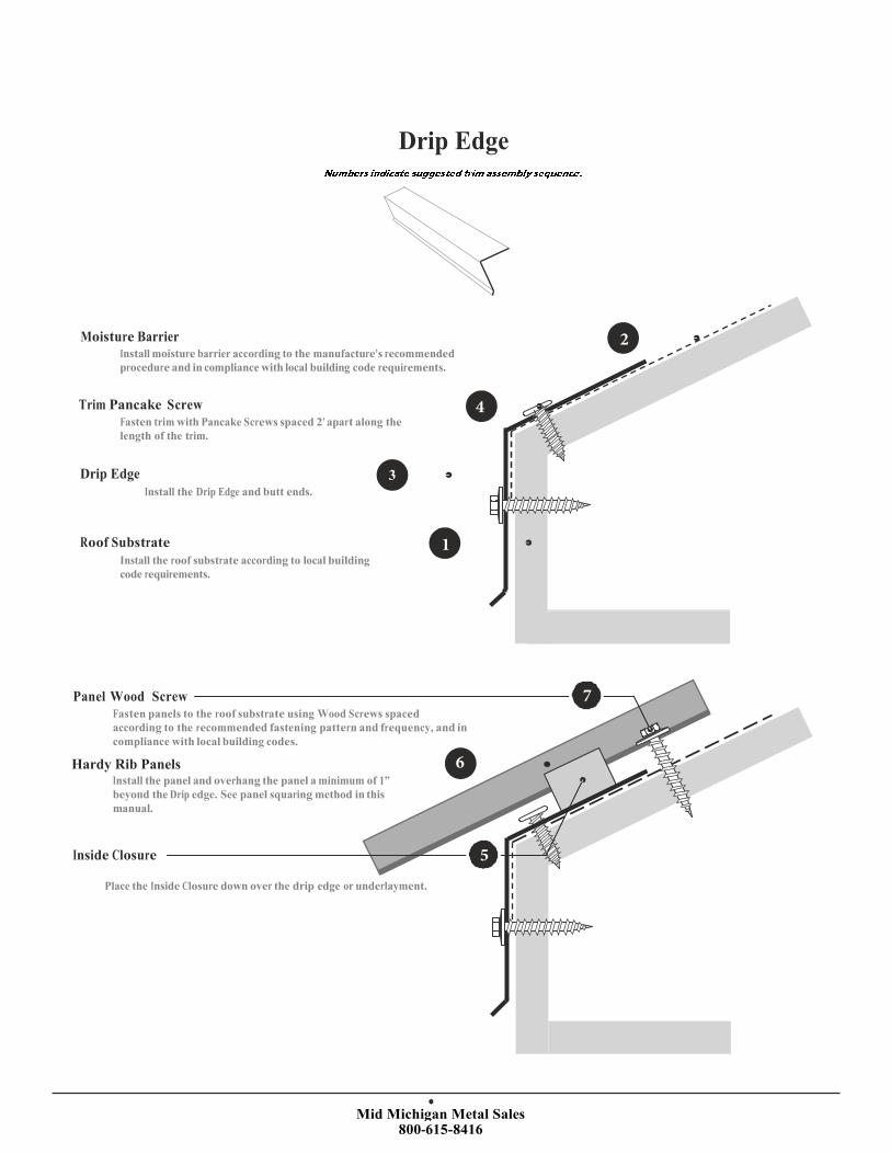
Drip Edge
Moisture Barrier Install moisture barrier according to the manufacture’s recommended
procedure and in compliance with local building code requirements.
Trim Pancake Screw
Fasten trim with Pancake Screws spaced 2’ apart along the
length of the trim.
Drip Edge 3 Install the Drip Edge and butt ends.
Roof Substrate
Install the roof substrate according to local building
code requirements.
Panel Wood Screw
Fasten panels to the roof substrate using Wood Screws spaced
according to the recommended fastening pattern and frequency, and in
compliance with local building codes.
Hardy Rib PanelsInstall the panel and overhang the panel a minimum of 1”
beyond the Drip edge. See panel squaring method in this
manual.
Inside Closure
Place the Inside Closure down over the drip edge or underlayment.
1
2
4
5
6
7
Mid Michigan Metal Sales 800-615-8416
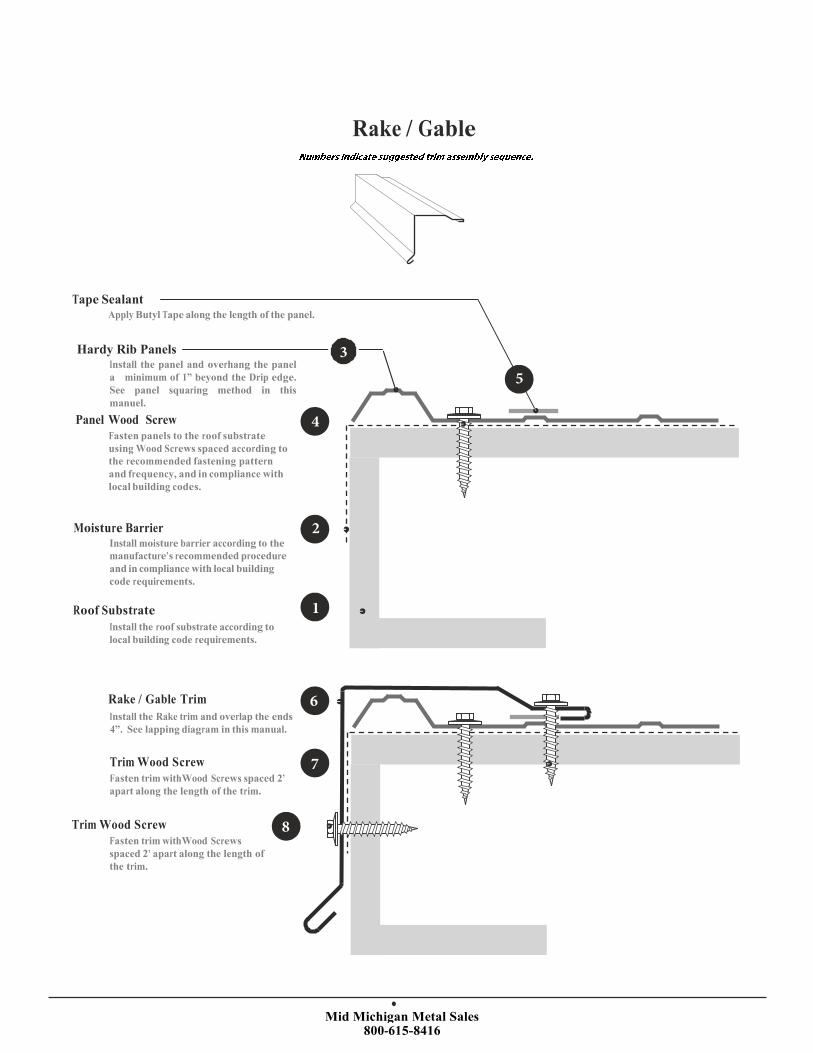
Tape Sealant Apply Butyl Tape along the length of the panel.
Rake / Gable
Hardy Rib PanelsInstall the panel and overhang the panel
a minimum of 1” beyond the Drip edge. See panel squaring method in this
manuel.Panel Wood Screw
Fasten panels to the roof substrate
using Wood Screws spaced according to
the recommended fastening pattern
and frequency, and in compliance with
local building codes.
Moisture Barrier Install moisture barrier according to the
manufacture’s recommended procedure
and in compliance with local building
code requirements.
Roof Substrate
Install the roof substrate according to
local building code requirements.
Rake / Gable Trim
Install the Rake trim and overlap the ends
4”. See lapping diagram in this manual.
Trim Wood Screw
Fasten trim withWood Screws spaced 2’
apart along the length of the trim.
Trim Wood Screw
Fasten trim withWood Screws
spaced 2’ apart along the length of
the trim.
1
2
3
4
5
6
7
8

Mid Michigan Metal Sales 800-615-8416
Preformed Valley
4
Roof Substrate
Install the roof
substrate according to local
building code requirements.
Moisture Barrier Install moisture barrier according to the
manufacture’s recommended procedure and in
compliance with local building code requirements.
Preformed Valley Trim
Install the Valley trim and overlap the ends 4”.
See lapping diagram in this manual.
Trim Pancake Screw Fasten trim with Pancake Screws spaced 2’ apart along the length
of the trim. See lapping diagram fastener pattern in this manual.
7
6
Hardy Rib PanelInstall the panel a minimum of 3” up from the
water diverter at the bottom of the Valley and minimum
of 3” down from the top of the Valley. See panel squaring method in this manual.
Expanding Closure Place Expanding Closure parallel to each side of the Valley
center water diverter. Closure should be up from the panel
end about 1”. See panel minimum set back above.
Panel Wood Screw Fasten panels to the roof substrate usingWood Screws spaced according to the recommended
fastening pattern and frequency, and in compliance with local building codes.
Notes:
1. See Valley Lapping - Page 25
2. See Valley Cutting - Page 26
1
2
3
5

Mid Michigan Metal Sales 800-615-8416
Transition / Pitch Break
Panel Wood Screw Fasten panels to the roof substrate using Wood Screws
spaced according to the recommended fastening pattern
and frequency, and in compliance with local building codes.
Hardy Rib PanelInstall the panel up 1” the transition bend. See panel
squaring method in this manual.
10
9
Inside Closure Place the Inside Closure over the top of the Transition.
The closure should be about 1” up from the panel end.
Transition Trim Place the Transition Flashing Trim
over the Outside Closure. 6
Trim Wood Screw Fasten trim with
Wood Screws
spaced 9” apartalong the length of
the trim, through the rib. See lapping
diagram.
3
1
Outside Closure Place the Outside Closure over panels.
4 Panel Wood Screw Fasten panels to the roof substrate using Wood Screws
spaced according to the recommended fastening pattern
and frequency, and in compliance with local building codes.
Hardy Rib PanelInstall the panel and overhang the panel a minimum of 1” beyond
the drip edge. See panel squaring method in this manual.
Moisture Barrier Install moisture barrier according to the manufacture’s recommended
procedure and in compliance with local building code requirements.
Roof Substrate Install the roof substrate according to local building code requirements.
8
57
2

Mid Michigan Metal Sales 800-615-8416
Gambrel
Hardy Rib PanelInstall the panel 1” beyond the transition bend. See panelsquaring method in this manual.
Panel Wood Screw Fasten panels to the roof substrate using Wood Screws
spaced according to the recommended fastening pattern and
frequency, and in compliance with local building codes.
Panel Wood Screw Fasten panels to the roof
substrate using Wood
Screws spaced according to
the recommended fastening
Inside Closure
Place the Inside Closure over
the top of the Gambrel up
about 1” from the panel end.
pattern and frequency, and
in compliance with local
building codes.
4 Gambrel Trim Place the Gambrel Flashing Trim
over the Outside Closure.
Trim Wood Screw Fasten trim withWood
Screws spaced 18” apart
along the length of the trim,
through the rib.
6 Outside Closure Place the Outside Closure over the
top of the panels.
Hardy Rib Panel 3
Install the panel and overhang
the panel a minimum of 1”
beyond the eave edge.
Moisture Barrier Install moisture barrier
according to the manufacturer’s
recommended procedure and in
compliance with local building
code requirements.
1 Roof Substrate Install the roof substrate according to local
building code requirements.
13
14
11
8
9
3
2

Mid Michigan Metal Sales 800-615-8416
Panel Wood Screw Fasten trim withWood Screws spaced 9” apart alongthe length of the trim, through the rib. See lapping
diagram fastener pattern in this manual.
Hip Trim Place the Hip Trim over the Expanding Closure
Expanding Closure Place Expanding closure parallel to
each side of the hip center line so that hip
fastener penetrates the center of the closure.
Closure should be up from the panel end
about 1”.
Hip
6
7
5
3
4
Panel Wood Screw
Fasten panels to the roof substrate using Wood Screws
spaced according to the recommended fastening pattern
and frequency, and in compliance with local building codes.
Hardy Rib PanelInstall the panel and overhang the panel a minimum of 1” beyond
the eave edge. See panel squaring method in this manual.
Moisture Barrier Install moisture barrier according to the manufacture’s
recommended procedure and in compliance with local
building code requirements.
Roof Substrate Install the roof substrate according to local
building code requirements.
1 2

Mid Michigan Metal Sales 800-615-8416
Trim Wood Screw Fasten trim withWood Screws spaced 9” apart along thelength of the trim, through the rib. See lapping diagram.
Ridge Trim Place the Ridge Trim over the Outside Closure.
Outside Closure Place the Outside Closure over the top
of the panel.
Ridge
7
5
6
3
4
Panel Wood Screw 2
Fasten panels to the roof substrate using Wood Screws
spaced according to the recommended fastening pattern
and frequency, and in compliance with local building codes.
Hardy Rib PanelInstall the panel and overhang the panel a minimum of 1” beyond
the eave edge. See panel squaring method in this manual.
Moisture Barrier Install moisture barrier according to the manufacture’s recommended
procedure and in compliance with local building code requirements.
Roof Substrate Install the roof substrate according to local building code requirements.
1

Mid Michigan Metal Sales 800-615-8416
Vented Ridge
Trim Wood Screw Fasten trim withWood Screws spaced 9” apart alongthe length of the trim, through the rib. See lapping
diagram fastener pattern in this manual.
Ridge Trim Place the Ridge Trim over the Profile Vent.
6
Vent Material Apply the Profile Vent ridge venting material over the
panels on each side.
5
7
3
Panel Wood Screw 2
Fasten panels to the roof substrate using Wood Screws
spaced according to the recommended fastening pattern
and frequency, and in compliance with local building codes.
Hardy Rib PanelInstall the panel and overhang the panel a minimum of 1” beyond
the drip edge. See panel squaring method in this manual.
Moisture Barrier Install moisture barrier according to the manufacture’s recommended
procedure and in compliance with local building code requirements.
Roof Substrate Install the roof substrate according to local building code requirements.
1
4

Mid Michigan Metal Sales 800-615-8416
High Side Peak
Trim Wood Screw Fasten trim with Wood Screws spaced 2’ apart
along the length of the trim. See lapping diagram.
High Side Peak Trim Place the High Side Peak Trim over the Outside Closure.
6
Trim Wood Screw Fasten trim withWood Screws spaced 9” apartalong the length of the trim, through the rib.
See lapping diagram.
8
Outside Closure
Place the Outside Closure over the
panels.
4
3
1 Panel Wood Screw
Fasten panels to the roof substrate using Wood
Screws spaced according to the recommended
fastening pattern and frequency, and in
compliance with local building codes.
Hardy Rib PanelInstall the panel and overhang the panel a minimum of 1”
beyond the drip edge. See panel squaring method in this
manual. Moisture Barrier
Install moisture barrier according to the manufacturer's
recommended procedure and in compliance with local
building code requirements.
Roof Substrate
Install the roof substrate according to
local building code requirements.
5
7
2
Mid Michigan Metal Sales 800-615-8416
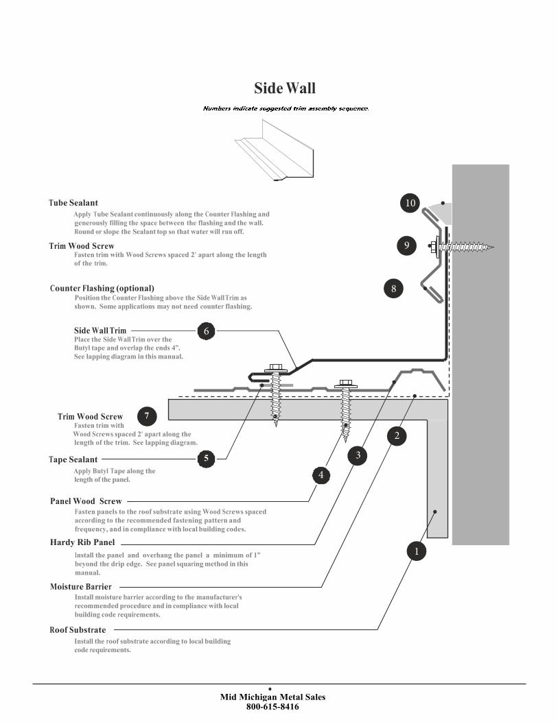
Side Wall
Tube Sealant
Apply Tube Sealant continuously along the Counter Flashing and
generously filling the space between the flashing and the wall.
Round or slope the Sealant top so that water will run off.
Trim Wood Screw Fasten trim with Wood Screws spaced 2’ apart along the length
of the trim.
Counter Flashing (optional) Position the Counter Flashing above the Side Wall Trim as
shown. Some applications may not need counter flashing.
Side Wall Trim Place the Side Wall Trim over the
Butyl tape and overlap the ends 4”.
See lapping diagram in this manual.
Trim Wood Screw 7 Fasten trim with
Wood Screws spaced 2’ apart along the
length of the trim. See lapping diagram.
Tape Sealant 5
Apply Butyl Tape along the
length of the panel.
Panel Wood Screw Fasten panels to the roof substrate using Wood Screws spaced
according to the recommended fastening pattern and
frequency, and in compliance with local building codes.
Hardy Rib PanelInstall the panel and overhang the panel a minimum of 1”
beyond the drip edge. See panel squaring method in this
manual.
Moisture Barrier Install moisture barrier according to the manufacturer's
recommended procedure and in compliance with local
building code requirements.
Roof Substrate
Install the roof substrate according to local building
code requirements.
10
9
8
6
4
3
2
1
Mid Michigan Metal Sales 800-615-8416
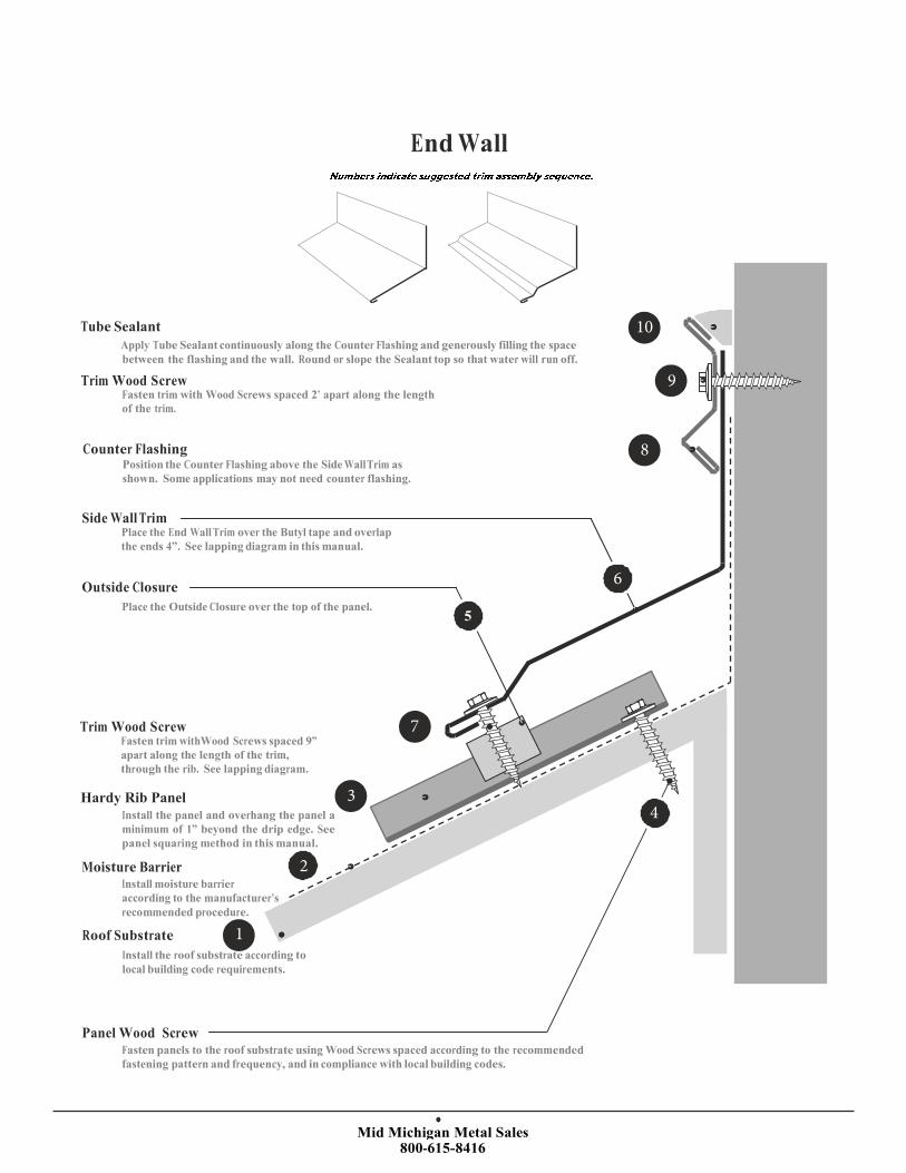
End Wall
Tube Sealant
Apply Tube Sealant continuously along the Counter Flashing and generously filling the space
between the flashing and the wall. Round or slope the Sealant top so that water will run off.
Trim Wood Screw Fasten trim with Wood Screws spaced 2’ apart along the length
of the trim.
Counter Flashing Position the Counter Flashing above the Side Wall Trim as
shown. Some applications may not need counter flashing.
Side Wall Trim Place the End Wall Trim over the Butyl tape and overlap
the ends 4”. See lapping diagram in this manual.
Outside Closure
Place the Outside Closure over the top of the panel. 5
Trim Wood Screw Fasten trim withWood Screws spaced 9”apart along the length of the trim,
through the rib. See lapping diagram.
Hardy Rib PanelInstall the panel and overhang the panel a
minimum of 1” beyond the drip edge. Seepanel squaring method in this manual.
Moisture Barrier Install moisture barrier
according to the manufacturer’s
recommended procedure.
Roof Substrate
Install the roof substrate according to
local building code requirements.
Panel Wood Screw Fasten panels to the roof substrate using Wood Screws spaced according to the recommended
fastening pattern and frequency, and in compliance with local building codes.
10
9
8
6
7
3
2
1
4
Mid Michigan Metal Sales 800-615-8416
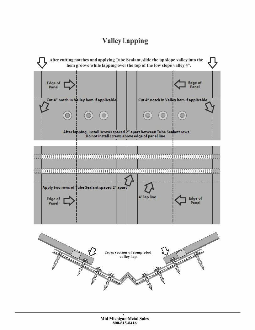
Valley Lapping
After cutting notches and applying Tube Sealant, slide the up slope valley into the
hem groove while lapping over the top of the low slope valley 4”.
Edge of Panel
Edge of Panel
Cut 4” notch in Valley hem if applicable Cut 4” notch in Valley hem if applicable
Apply two rows of Tube Sealant spaced 2” apart
Edge of Panel
4” lap line Edge of Panel
Cross section of completed valley Lap
After lapping, install screws spaced 2” apart between Tube Sealant rows. Do not install screws above edge of panel line.

Mid Michigan Metal Sales 800-615-8416
Valley Cutting
Valley starter cutting diagram with water diverter tabs.
Before folding tabs
2. Bend Line, bend left tab down 90º 3. Bend Line, bend right tab down 90º
1. Cut alone dashed lines
After folding tabs

Mid Michigan Metal Sales 800-615-8416
Pipe Flashing
Cut pipe flashing 15%
smaller than actual pipe.
Apply tube sealant to the
underside of the pipe flashing.
Slide pipe flashing
down over the pipe.
Press the pipe flashing into contours of panel configuration
and fasten to the Hardy Rib Panel with wood screws orstitch screws. Apply additional sealant around base if
desired.

Mid Michigan Metal SalesG3336 S Dort Hwy. Burton, MI. 48529 (800) 615-8416
Manufactures of High quality Metal Roofing and Siding Products