hardware user's manual versapump 3 syringe …firsttenangstroms.com/pdfdocs/versa3.pdf · 4.8...
TRANSCRIPT
HARDWARE USER'S MANUALfor the
VersaPump 3
SYRINGE DISPENSER MODULE
Kloehn Ltd.10000 Banburry Cross Drive
Las Vegas, NV 89144 U.S.A.
Telephone: (702) 243-7727Fax: (702) 243-6036
Part Number 23454Revision C for
V3 Firmware Version 3
Copyright (C) 2002, Kloehn Ltd., all rights reserved worldwide.

P/N 23454 Rev. C, 06-13-03i
TABLE OF CONTENTS
1.0 INTRODUCTION . . . . . . . . . . . . . . . . . . . . . . . . . . . . . . . . . . . . . . . . . . . . . . . . 11.1 GENERAL DESCRIPTION . . . . . . . . . . . . . . . . . . . . . . . . . . . . . . . . . . . 11.2 OPTIONS . . . . . . . . . . . . . . . . . . . . . . . . . . . . . . . . . . . . . . . . . . . . . . . . 1
2.0 CARD EDGE INTERFACE . . . . . . . . . . . . . . . . . . . . . . . . . . . . . . . . . . . . . . . . 42.1 INPUTS . . . . . . . . . . . . . . . . . . . . . . . . . . . . . . . . . . . . . . . . . . . . . . . . . . 4
2.1.1 Power Input . . . . . . . . . . . . . . . . . . . . . . . . . . . . . . . . . . . . . . . . . 42.1.1.1 Connection . . . . . . . . . . . . . . . . . . . . . . . . . . . . . . . 42.1.1.2 Low Voltage Warning . . . . . . . . . . . . . . . . . . . . . . . 42.1.1.3 Power Supply Capacity . . . . . . . . . . . . . . . . . . . . . . 42.1.1.4 Power Supply Selection . . . . . . . . . . . . . . . . . . . . . 62.1.1.5 Multiple-Unit Power Distribution . . . . . . . . . . . . . . . 6
2.1.2 Address Inputs . . . . . . . . . . . . . . . . . . . . . . . . . . . . . . . . . . . . . . . 62.1.3 Digital Voltmeter Input . . . . . . . . . . . . . . . . . . . . . . . . . . . . . . . . . 82.1.4 Reset Input . . . . . . . . . . . . . . . . . . . . . . . . . . . . . . . . . . . . . . . . . . 92.1.5 User Digital Inputs . . . . . . . . . . . . . . . . . . . . . . . . . . . . . . . . . . . . 9
2.2 OUTPUTS . . . . . . . . . . . . . . . . . . . . . . . . . . . . . . . . . . . . . . . . . . . . . . . . 92.2.1 Digital Outputs . . . . . . . . . . . . . . . . . . . . . . . . . . . . . . . . . . . . . . . 92.2.2 Error Outputs . . . . . . . . . . . . . . . . . . . . . . . . . . . . . . . . . . . . . . . 102.2.3 5Vdc Power Output . . . . . . . . . . . . . . . . . . . . . . . . . . . . . . . . . . 10
2.3 SERIAL I/O EXPANSION (SIO) . . . . . . . . . . . . . . . . . . . . . . . . . . . . . . 102.4 COMMUNICATIONS I/O . . . . . . . . . . . . . . . . . . . . . . . . . . . . . . . . . . . . 11
2.4.1 RS485 Communications I/O . . . . . . . . . . . . . . . . . . . . . . . . . . . . 112.4.2 RS232 Communications I/O . . . . . . . . . . . . . . . . . . . . . . . . . . . . 11
2.5 REAR PANEL SWITCHES . . . . . . . . . . . . . . . . . . . . . . . . . . . . . . . . . . 122.5.1 Com Setup Switch . . . . . . . . . . . . . . . . . . . . . . . . . . . . . . . . . . . 122.5.2 Address Switch . . . . . . . . . . . . . . . . . . . . . . . . . . . . . . . . . . . . . . 13
2.6 CONNECTOR KEY . . . . . . . . . . . . . . . . . . . . . . . . . . . . . . . . . . . . . . . . 13
3.0 GETTING STARTED . . . . . . . . . . . . . . . . . . . . . . . . . . . . . . . . . . . . . . . . . . . . 143.1 INSTALLING a VALVE . . . . . . . . . . . . . . . . . . . . . . . . . . . . . . . . . . . . . 143.2 INSTALLING a SYRINGE . . . . . . . . . . . . . . . . . . . . . . . . . . . . . . . . . . . 153.3 CONNECTING POWER and COMMUNICATIONS . . . . . . . . . . . . . . . 15
3.3.1 With the Starter Kit . . . . . . . . . . . . . . . . . . . . . . . . . . . . . . . . . . . 153.3.1.1 Card Edge Adapter Board . . . . . . . . . . . . . . . . . . . 153.3.1.2 Communications Cable . . . . . . . . . . . . . . . . . . . . . 153.3.1.3 Power Cables . . . . . . . . . . . . . . . . . . . . . . . . . . . . 16
3.3.2 Without the Starter Kit . . . . . . . . . . . . . . . . . . . . . . . . . . . . . . . . 183.4 SETTING the SWITCHES . . . . . . . . . . . . . . . . . . . . . . . . . . . . . . . . . . 19
3.4.1 Com Setup Switch . . . . . . . . . . . . . . . . . . . . . . . . . . . . . . . . . . . 193.4.2 Address Switch . . . . . . . . . . . . . . . . . . . . . . . . . . . . . . . . . . . . . . 20
3.5 SETTING UP COMMUNICATIONS . . . . . . . . . . . . . . . . . . . . . . . . . . . 203.5.1 Setting up HyperTerminal . . . . . . . . . . . . . . . . . . . . . . . . . . . . . . 203.5.2 Checking the Connection . . . . . . . . . . . . . . . . . . . . . . . . . . . . . . 21
3.6 SENDING COMMANDS . . . . . . . . . . . . . . . . . . . . . . . . . . . . . . . . . . . . 213.6.1 General Command Structure . . . . . . . . . . . . . . . . . . . . . . . . . . . 213.6.2 Command Addressing . . . . . . . . . . . . . . . . . . . . . . . . . . . . . . . . 223.6.3 Pump Replies . . . . . . . . . . . . . . . . . . . . . . . . . . . . . . . . . . . . . . . 223.6.4 Configuring the Pump . . . . . . . . . . . . . . . . . . . . . . . . . . . . . . . . . 233.6.5 Calibrating the Syringe . . . . . . . . . . . . . . . . . . . . . . . . . . . . . . . . 233.6.6 Sending Some Commands . . . . . . . . . . . . . . . . . . . . . . . . . . . . 24
P/N 23454 Rev. C, 06-13-03ii
4.0 COMMAND SET . . . . . . . . . . . . . . . . . . . . . . . . . . . . . . . . . . . . . . . . . . . . . . . 254.1 SYRINGE COMMANDS . . . . . . . . . . . . . . . . . . . . . . . . . . . . . . . . . . . . 25
4.1.1 Positioning Commands . . . . . . . . . . . . . . . . . . . . . . . . . . . . . . . . 254.1.2 Motion Variables . . . . . . . . . . . . . . . . . . . . . . . . . . . . . . . . . . . . . 274.1.3 Initialization . . . . . . . . . . . . . . . . . . . . . . . . . . . . . . . . . . . . . . . . . 284.1.4 Syringe Queries . . . . . . . . . . . . . . . . . . . . . . . . . . . . . . . . . . . . . 30
4.2 VALVE COMMANDS . . . . . . . . . . . . . . . . . . . . . . . . . . . . . . . . . . . . . . 304.2.1 Valve Type Setting . . . . . . . . . . . . . . . . . . . . . . . . . . . . . . . . . . . 304.2.2 Valve Position Commands . . . . . . . . . . . . . . . . . . . . . . . . . . . . . 314.2.3 Valve Queries . . . . . . . . . . . . . . . . . . . . . . . . . . . . . . . . . . . . . . . 32
4.3 I/O COMMANDS . . . . . . . . . . . . . . . . . . . . . . . . . . . . . . . . . . . . . . . . . . 324.3.1 Output Commands . . . . . . . . . . . . . . . . . . . . . . . . . . . . . . . . . . . 324.3.2 Input Query Commands . . . . . . . . . . . . . . . . . . . . . . . . . . . . . . . 334.3.3 Input Test and Jump Commands . . . . . . . . . . . . . . . . . . . . . . . . 34
4.4 USER PROGRAM COMMANDS . . . . . . . . . . . . . . . . . . . . . . . . . . . . . 354.4.1 Program Storage . . . . . . . . . . . . . . . . . . . . . . . . . . . . . . . . . . . . 354.4.2 Program Execution . . . . . . . . . . . . . . . . . . . . . . . . . . . . . . . . . . . 364.4.3 Program Control . . . . . . . . . . . . . . . . . . . . . . . . . . . . . . . . . . . . . 37
4.4.3.1 Jumps and Labels . . . . . . . . . . . . . . . . . . . . . . . . . 374.4.3.2 Repeat Loops . . . . . . . . . . . . . . . . . . . . . . . . . . . . 384.4.3.3 Time Delays . . . . . . . . . . . . . . . . . . . . . . . . . . . . . 39
4.5 VARIABLES . . . . . . . . . . . . . . . . . . . . . . . . . . . . . . . . . . . . . . . . . . . . . 394.5.1 General Variables . . . . . . . . . . . . . . . . . . . . . . . . . . . . . . . . . . . . 39
4.5.1.1 Setting a General Variable . . . . . . . . . . . . . . . . . . 394.5.1.2 Using a General Variable . . . . . . . . . . . . . . . . . . . 40
4.5.2 Indirect Variables . . . . . . . . . . . . . . . . . . . . . . . . . . . . . . . . . . . . 404.5.3 List of Commands Using Variables . . . . . . . . . . . . . . . . . . . . . . 41
4.6 CONFIGURATION COMMANDS . . . . . . . . . . . . . . . . . . . . . . . . . . . . . 424.7 QUERY COMMANDS . . . . . . . . . . . . . . . . . . . . . . . . . . . . . . . . . . . . . . 444.8 ERROR TRAPPING COMMANDS . . . . . . . . . . . . . . . . . . . . . . . . . . . . 47
4.8.1 Trap Declarations . . . . . . . . . . . . . . . . . . . . . . . . . . . . . . . . . . . . 474.8.2 Trap Exits . . . . . . . . . . . . . . . . . . . . . . . . . . . . . . . . . . . . . . . . . . 484.8.3 Error Trap Query . . . . . . . . . . . . . . . . . . . . . . . . . . . . . . . . . . . . 48
4.9 MISCELLANEOUS COMMANDS . . . . . . . . . . . . . . . . . . . . . . . . . . . . 494.9.1 Software Counters . . . . . . . . . . . . . . . . . . . . . . . . . . . . . . . . . . . 494.9.2 Flags . . . . . . . . . . . . . . . . . . . . . . . . . . . . . . . . . . . . . . . . . . . . . . 504.9.3 SET HOME Button Control . . . . . . . . . . . . . . . . . . . . . . . . . . . . . 504.9.4 External Syringe Motion Limit Input . . . . . . . . . . . . . . . . . . . . . . 514.9.5 Motor Power Control . . . . . . . . . . . . . . . . . . . . . . . . . . . . . . . . . . 524.9.6 Repeat Command String . . . . . . . . . . . . . . . . . . . . . . . . . . . . . . 52
5.0 STATUS & ERROR MESSAGES . . . . . . . . . . . . . . . . . . . . . . . . . . . . . . . . . . . 535.1 STATUS SUMMARY . . . . . . . . . . . . . . . . . . . . . . . . . . . . . . . . . . . . . . . 535.2 DETAILED EXPLANATIONS . . . . . . . . . . . . . . . . . . . . . . . . . . . . . . . . 54
6.0 COMMUNICATIONS . . . . . . . . . . . . . . . . . . . . . . . . . . . . . . . . . . . . . . . . . . . . 576.1 INDIVIDUAL DEVICE ADDRESSING . . . . . . . . . . . . . . . . . . . . . . . . . . 576.2 MULTIPLE DEVICE ADDRESSING . . . . . . . . . . . . . . . . . . . . . . . . . . . 57
6.2.1 Dual Device Mode . . . . . . . . . . . . . . . . . . . . . . . . . . . . . . . . . . . 576.2.2 Quad Device Mode . . . . . . . . . . . . . . . . . . . . . . . . . . . . . . . . . . . 576.2.3 Global Mode . . . . . . . . . . . . . . . . . . . . . . . . . . . . . . . . . . . . . . . . 58
6.3 COMMUNICATIONS PROTOCOLS . . . . . . . . . . . . . . . . . . . . . . . . . . . 586.3.1 DT Command Protocol . . . . . . . . . . . . . . . . . . . . . . . . . . . . . . . . 58
P/N 23454 Rev. C, 06-13-03iii
6.3.2 DT Response Protocol . . . . . . . . . . . . . . . . . . . . . . . . . . . . . . . . 596.3.3 OEM Command Protocol . . . . . . . . . . . . . . . . . . . . . . . . . . . . . . 596.3.4 OEM Response Protocol . . . . . . . . . . . . . . . . . . . . . . . . . . . . . . 60
6.4 COMMUNICATIONS SETTINGS . . . . . . . . . . . . . . . . . . . . . . . . . . . . . 616.5 CONNECTING MULTIPLE DEVICES . . . . . . . . . . . . . . . . . . . . . . . . . . 61
6.5.1 Bus Wiring . . . . . . . . . . . . . . . . . . . . . . . . . . . . . . . . . . . . . . . . . 616.5.2 Bus Terminations . . . . . . . . . . . . . . . . . . . . . . . . . . . . . . . . . . . . 62
6.6 COMMUNICATIONS CHECKS . . . . . . . . . . . . . . . . . . . . . . . . . . . . . . . 636.7 COMMUNICATIONS DRIVERS . . . . . . . . . . . . . . . . . . . . . . . . . . . . . . 64
7.0 PROGRAM MEMORY . . . . . . . . . . . . . . . . . . . . . . . . . . . . . . . . . . . . . . . . . . . 657.1 TEMPORARY MEMORY . . . . . . . . . . . . . . . . . . . . . . . . . . . . . . . . . . . 657.2 NONVOLATILE MEMORY . . . . . . . . . . . . . . . . . . . . . . . . . . . . . . . . . . 65
7.2.1 Saving and Erasing a Program . . . . . . . . . . . . . . . . . . . . . . . . . . 667.2.2 Listing a Program . . . . . . . . . . . . . . . . . . . . . . . . . . . . . . . . . . . . 667.2.3 Auto-Starting an NVM Program . . . . . . . . . . . . . . . . . . . . . . . . . 667.2.4 Externally Starting a Program . . . . . . . . . . . . . . . . . . . . . . . . . . . 67
8.0 PROGRAMMING TECHNIQUES . . . . . . . . . . . . . . . . . . . . . . . . . . . . . . . . . . . 688.1 CONTROLLER INTERFACE SOFTWARE . . . . . . . . . . . . . . . . . . . . . . 68
8.1.1 System Initialization . . . . . . . . . . . . . . . . . . . . . . . . . . . . . . . . . . 688.1.2 Sending Single Instructions . . . . . . . . . . . . . . . . . . . . . . . . . . . . 698.1.3 Using Stored Subroutines . . . . . . . . . . . . . . . . . . . . . . . . . . . . . . 698.1.4 Protecting the User . . . . . . . . . . . . . . . . . . . . . . . . . . . . . . . . . . . 70
8.2 PUMP PROGRAMMING TIPS . . . . . . . . . . . . . . . . . . . . . . . . . . . . . . . 708.2.1 Programming Very Slow Moves . . . . . . . . . . . . . . . . . . . . . . . . . 708.2.2 Programming Error Traps . . . . . . . . . . . . . . . . . . . . . . . . . . . . . . 718.2.3 Setting the Speeds . . . . . . . . . . . . . . . . . . . . . . . . . . . . . . . . . . . 728.2.4 Counting Program Cycles . . . . . . . . . . . . . . . . . . . . . . . . . . . . . . 758.2.5 Converting Volume to Steps . . . . . . . . . . . . . . . . . . . . . . . . . . . . 75
8.3 I/O INTERFACE PROGRAMMING . . . . . . . . . . . . . . . . . . . . . . . . . . . . 768.3.1 Waiting for an Input . . . . . . . . . . . . . . . . . . . . . . . . . . . . . . . . . . 768.3.2 Handshaking Between Pumps . . . . . . . . . . . . . . . . . . . . . . . . . . 768.3.3 Programming Continuous Flow . . . . . . . . . . . . . . . . . . . . . . . . . 788.3.4 The DVM as a Selector Switch . . . . . . . . . . . . . . . . . . . . . . . . . . 798.3.5 Position Snapshots . . . . . . . . . . . . . . . . . . . . . . . . . . . . . . . . . . . 808.3.6 Using the Expansion Port . . . . . . . . . . . . . . . . . . . . . . . . . . . . . . 808.3.7 Generating External Pulses . . . . . . . . . . . . . . . . . . . . . . . . . . . . 838.3.8 A Binary Input Selector . . . . . . . . . . . . . . . . . . . . . . . . . . . . . . . . 838.3.9 Driving External LEDs . . . . . . . . . . . . . . . . . . . . . . . . . . . . . . . . . 848.3.10 Wired-Or Error Signal . . . . . . . . . . . . . . . . . . . . . . . . . . . . . . . . 84
9.0 POWER . . . . . . . . . . . . . . . . . . . . . . . . . . . . . . . . . . . . . . . . . . . . . . . . . . . . . . 859.1 POWER SUPPLY SELECTION . . . . . . . . . . . . . . . . . . . . . . . . . . . . . . 85
9.1.1 Capacity Selection . . . . . . . . . . . . . . . . . . . . . . . . . . . . . . . . . . . 859.1.2 Type Selection . . . . . . . . . . . . . . . . . . . . . . . . . . . . . . . . . . . . . . 85
9.2 SYSTEM WIRING PRACTICES . . . . . . . . . . . . . . . . . . . . . . . . . . . . . . 869.3 LOW VOLTAGE CONDITION . . . . . . . . . . . . . . . . . . . . . . . . . . . . . . . . 869.4 POWER CONSERVATION FOR BATTERY APPLICATIONS . . . . . . . 87
10.0 MOUNTING & INSTALLATION . . . . . . . . . . . . . . . . . . . . . . . . . . . . . . . . . . . . 8810.1 MOUNTING a SINGLE PUMP . . . . . . . . . . . . . . . . . . . . . . . . . . . . . . . 8810.2 STACKING DEVICES VERTICALLY . . . . . . . . . . . . . . . . . . . . . . . . . . 8810.3 THERMAL CONSIDERATIONS . . . . . . . . . . . . . . . . . . . . . . . . . . . . . . 90
P/N 23454 Rev. C, 06-13-03iv
11.0 SPECIFICATIONS . . . . . . . . . . . . . . . . . . . . . . . . . . . . . . . . . . . . . . . . . . . . . . 9111.1 ENVIRONMENTAL . . . . . . . . . . . . . . . . . . . . . . . . . . . . . . . . . . . . . . . . 9111.2 PHYSICAL . . . . . . . . . . . . . . . . . . . . . . . . . . . . . . . . . . . . . . . . . . . . . . 9111.3 POWER . . . . . . . . . . . . . . . . . . . . . . . . . . . . . . . . . . . . . . . . . . . . . . . . 9111.4 SYRINGE AXIS . . . . . . . . . . . . . . . . . . . . . . . . . . . . . . . . . . . . . . . . . . . 91
11.4.1 Resolution . . . . . . . . . . . . . . . . . . . . . . . . . . . . . . . . . . . . 9111.4.2 Accuracy . . . . . . . . . . . . . . . . . . . . . . . . . . . . . . . . . . . . . 9111.4.3 Speed . . . . . . . . . . . . . . . . . . . . . . . . . . . . . . . . . . . . . . . 9211.4.4 Syringe Thrust and Pressure . . . . . . . . . . . . . . . . . . . . . . 92
11.5 VALVE AXIS . . . . . . . . . . . . . . . . . . . . . . . . . . . . . . . . . . . . . . . . . . . . . 9311.6 COMMUNICATIONS . . . . . . . . . . . . . . . . . . . . . . . . . . . . . . . . . . . . . . . 9311.7 I/O INTERFACE . . . . . . . . . . . . . . . . . . . . . . . . . . . . . . . . . . . . . . . . . . 93
11.7.1 Digital Outputs . . . . . . . . . . . . . . . . . . . . . . . . . . . . . . . . . 9311.7.2 Digital Inputs . . . . . . . . . . . . . . . . . . . . . . . . . . . . . . . . . . 9511.7.3 Digital Voltmeter Input . . . . . . . . . . . . . . . . . . . . . . . . . . . 9511.7.4 Serial I/O Expansion Port . . . . . . . . . . . . . . . . . . . . . . . . 95
11.8 USER PROGRAM MEMORY . . . . . . . . . . . . . . . . . . . . . . . . . . . . . . . . 97
APPENDIX A: COMMAND SET SUMMARY . . . . . . . . . . . . . . . . . . . . . . . . . . . . . 98A.1 COMMANDS . . . . . . . . . . . . . . . . . . . . . . . . . . . . . . . . . . . . . . . . . . . . . 98A.2 VARIABLES . . . . . . . . . . . . . . . . . . . . . . . . . . . . . . . . . . . . . . . . . . . . 103
APPENDIX B: STATUS and ERROR CODES SUMMARY . . . . . . . . . . . . . . . . . 106
APPENDIX C SAMPLE QBASIC COMMUNICATIONS PROGRAM . . . . . . . . . . 107
LIST OF FIGURES
Figure 1-1 VersaPump 3 shown with syringe and valve installed . . . . . . . . . . . . . . . 2Figure 1-2 Pump Nomenclature . . . . . . . . . . . . . . . . . . . . . . . . . . . . . . . . . . . . . . . . 3Figure 2-1 Syringe Drive Interfaces . . . . . . . . . . . . . . . . . . . . . . . . . . . . . . . . . . . . . 5Figure 2-2 Equivalent Circuits of the User Inputs . . . . . . . . . . . . . . . . . . . . . . . . . . . 8Figure 2-3 Com Setup Switch . . . . . . . . . . . . . . . . . . . . . . . . . . . . . . . . . . . . . . . . . 12Figure 2-4 Connector Key Slot . . . . . . . . . . . . . . . . . . . . . . . . . . . . . . . . . . . . . . . . 13Figure 3-1 Card Edge Adapter Board . . . . . . . . . . . . . . . . . . . . . . . . . . . . . . . . . . . 16Figure 3-4 Pump Connections With Card Edge Connector . . . . . . . . . . . . . . . . . . 18Figure 3-5 RS232 Communications Cable Wiring . . . . . . . . . . . . . . . . . . . . . . . . . 19Figure 4-1 Relative vs Absolute Positions . . . . . . . . . . . . . . . . . . . . . . . . . . . . . . . 26Figure 6-1 Multi-device Wiring Diagram . . . . . . . . . . . . . . . . . . . . . . . . . . . . . . . . . 62Figure 8-1 Normal Syringe Speed Profile . . . . . . . . . . . . . . . . . . . . . . . . . . . . . . . . 73Figure 8-2 Slow Acceleration or Short Move Speed Profile . . . . . . . . . . . . . . . . . . 73Figure 8-3 Handshake Operation . . . . . . . . . . . . . . . . . . . . . . . . . . . . . . . . . . . . . . 77Figure 8-4 Sample 8-bit Input Circuit for Expansion I/O . . . . . . . . . . . . . . . . . . . . . 82Figure 8-5 Binary Selection Tree Flow Chart . . . . . . . . . . . . . . . . . . . . . . . . . . . . . 83Figure 10-1 Mounting Dimensions for VersaPump 3 . . . . . . . . . . . . . . . . . . . . . . . . 89Figure 11-1 Serial Expansion I/O timing, 2-byte mode . . . . . . . . . . . . . . . . . . . . . . . 96Figure 11-2 Serial Expansion I/O timing, single-byte mode . . . . . . . . . . . . . . . . . . . 97
P/N 23454 Rev. C, 06-13-031
1.0 INTRODUCTION
1.1 GENERAL DESCRIPTION
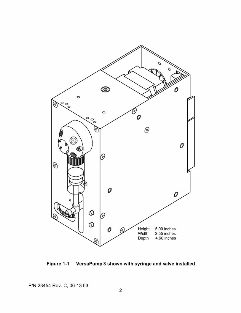
The Kloehn VersaPump 3 (V3) syringe pump shown in Figure 1-1 is aprogrammable, precision, liquid metering instrument with user-programmablememory and Input / Output (I/O). It offers 6000 or 12,000 step resolution for its 3cm stroke. Two to six port valves can be mounted, and syringes from 50 uL to 5 mLcan be used. The unit can accept individual commands or programs via its serialcommunications interfaces.
Two-way, serial communications between the V3 and a controlling host is done viaan RS485 or RS232 interface. Up to 15 addressable pumps or other devices canshare a single, standard, bidirectional RS485 communications bus, controlled froma single PC serial port at baud rates from 1200 to 38,400 baud. Two protocols, DTand OEM, are supported, both of which are fully compatible with the Cavroprotocols. The unit may be interrogated for status or operating parameter valuesat any time. Individual commands or groups of commands may be sent forimmediate or later execution by the pump.
Command strings, or programs, can be executed from RAM or may be stored intoand executed from the non-volatile memory (NVM). Up to 10 programs may bestored. A program in the NVM can be set to self-start when power is first appliedto the pump and immediately after a Reset input. Program retention in the NVM istypically greater than 15 years without batteries. Program looping and if-thenprogram flow control is supported.
Three external logic inputs and three logic outputs permit interfacing to a variety ofother devices. One input can be used to halt a dispense in progress. A built-indigital voltmeter (DVM) is included. For applications which require more I/O, anI/O expander card is available to provide 16 more inputs and 16 more outputs.
Many different program test-and-jump instructions allow the pump to respond toexternal events and conditions as well as internal program conditions. Externalinputs can be used to set internal programmed operating parameters. The I/O canbe used to operate a synchronized, two-pump, continuous flow application. Real-time, remotely-controlled and monitored I/O is supported simultaneously with otherpump operations.
The V3 interface is located on a single card edge connector at the rear of the pump.This permits simple wiring connections and the use of modular, plug-in mounting.
1.2 OPTIONS
The VersaPump 3 series can be ordered in 6000 or 12,000 step resolutions, withor without valves. A starter kit with all the things needed to begin using the pumpis also available from Kloehn Company. The kit includes cables, power supply,manuals, and software.
There are versions of the VersaPump3 which do not have any motor driver orcontrol electronics. These versions come with an interface board containing theelectromechanical interfaces and a convenient card edge connector.
P/N 23454 Rev. C, 06-13-032
Figure 1-1 VersaPump 3 shown with syringe and valve installed
P/N 23454 Rev. C, 06-13-033
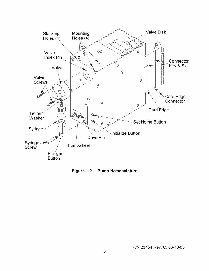
Figure 1-2 Pump Nomenclature
P/N 23454 Rev. C, 06-13-034
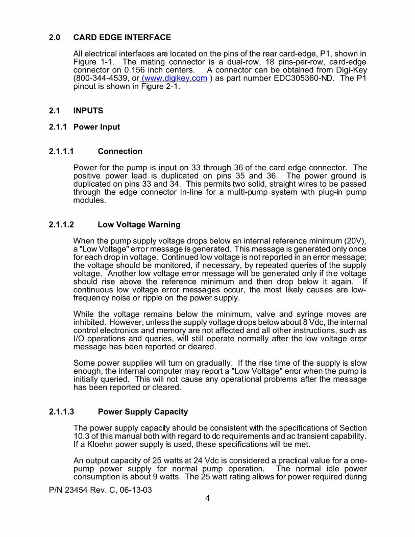
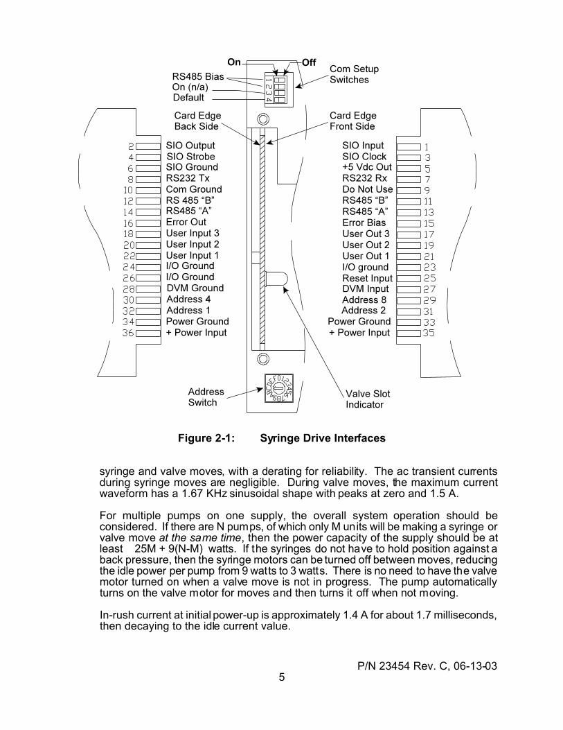
2.0 CARD EDGE INTERFACE
All electrical interfaces are located on the pins of the rear card-edge, P1, shown inFigure 1-1. The mating connector is a dual-row, 18 pins-per-row, card-edgeconnector on 0.156 inch centers. A connector can be obtained from Digi-Key(800-344-4539, or (www.digikey.com ) as part number EDC305360-ND. The P1pinout is shown in Figure 2-1.
2.1 INPUTS
2.1.1 Power Input
2.1.1.1 Connection
Power for the pump is input on 33 through 36 of the card edge connector. Thepositive power lead is duplicated on pins 35 and 36. The power ground isduplicated on pins 33 and 34. This permits two solid, straight wires to be passedthrough the edge connector in-line for a multi-pump system with plug-in pumpmodules.
2.1.1.2 Low Voltage Warning
When the pump supply voltage drops below an internal reference minimum (20V),a "Low Voltage" error message is generated. This message is generated only oncefor each drop in voltage. Continued low voltage is not reported in an error message;the voltage should be monitored, if necessary, by repeated queries of the supplyvoltage. Another low voltage error message will be generated only if the voltageshould rise above the reference minimum and then drop below it again. Ifcontinuous low voltage error messages occur, the most likely causes are low-frequency noise or ripple on the power supply.
While the voltage remains below the minimum, valve and syringe moves areinhibited. However, unless the supply voltage drops below about 8 Vdc, the internalcontrol electronics and memory are not affected and all other instructions, such asI/O operations and queries, will still operate normally after the low voltage errormessage has been reported or cleared.
Some power supplies will turn on gradually. If the rise time of the supply is slowenough, the internal computer may report a "Low Voltage" error when the pump isinitially queried. This will not cause any operational problems after the messagehas been reported or cleared.
2.1.1.3 Power Supply Capacity
The power supply capacity should be consistent with the specifications of Section10.3 of this manual both with regard to dc requirements and ac transient capability.If a Kloehn power supply is used, these specifications will be met.
An output capacity of 25 watts at 24 Vdc is considered a practical value for a one-pump power supply for normal pump operation. The normal idle powerconsumption is about 9 watts. The 25 watt rating allows for power required during
P/N 23454 Rev. C, 06-13-035
Figure 2-1: Syringe Drive Interfaces
syringe and valve moves, with a derating for reliability. The ac transient currentsduring syringe moves are negligible. During valve moves, the maximum currentwaveform has a 1.67 KHz sinusoidal shape with peaks at zero and 1.5 A.
For multiple pumps on one supply, the overall system operation should beconsidered. If there are N pumps, of which only M units will be making a syringe orvalve move at the same time, then the power capacity of the supply should be atleast 25M + 9(N-M) watts. If the syringes do not have to hold position against aback pressure, then the syringe motors can be turned off between moves, reducingthe idle power per pump from 9 watts to 3 watts. There is no need to have the valvemotor turned on when a valve move is not in progress. The pump automaticallyturns on the valve motor for moves and then turns it off when not moving.
In-rush current at initial power-up is approximately 1.4 A for about 1.7 milliseconds,then decaying to the idle current value.
P/N 23454 Rev. C, 06-13-036
2.1.1.4 Power Supply Selection
There are four classes of power supply: unregulated DC, linear regulator types,switching regulator types, and batteries. Each has different selectionconsiderations.
The unregulated supply is the cheapest and simplest. Due to its unregulatednature, it is not recommended.
The linear regulator supply usually has a protective current limiting. This limit valuemust be set to at least 1.5 A to allow for the start-up in-rush current.
A switching power supply is the preferred choice. It offers higher efficiency, lowerheat generation, and a well-filtered output. Note that some switching powersupplies have a minimum load current requirement. Since the pump can idle as lowas 50 milliamps, the supply should be rated for a minimum load current equal to theminimum total system idle current. A ballast resistor may be added across thesupply output to guarantee the minimum load requirement of the supply.
Battery operation from 24 V battery systems is feasible. The wide operating rangemakes this possible. In most cases, a standby battery voltage of 28 Vdc is seen inautomotive and aircraft systems. This is acceptable for normal operation. Mobilesystems should provide overvoltage clamping for transients exceeding 34 Vdc.
2.1.1.5 Multiple-Unit Power Distribution
In a system with multiple syringe drive modules, the power distribution wiring canaffect the system reliability. The best system wiring practice is to connect eachdrive module with an individual pair of power leads from the power supply to thatindividual module. This is called a "star" connection. The power leads for eachmodule should be twisted together along their length to reduce radiated fields.External filter capacitors are not required, as internal filters are included.
2.1.2 Address Inputs
The device address on the communications bus can be hard-wired into theconnector so a device can be inserted into an instrument without a need to set theaddress switch to a particular location. To use this feature, that address switchmust be in the “F” position. If the address switch is in any other position, a conflictwill result between a hard-wired address and the address indicated on the switch.
The address inputs have built-in pull up resistors and use positive logic. The defaultAddress input level is logic “1". A logic “0" is made by grounding an Address pin.The address is set as a 4-bit binary number by shorting those pins to ground whichshould have a zero value. The address weighting on the pins is as follows:
Address 8 = 8 Address 4 = 4 Address 2 = 2 Address 1 = 1
The address value is the sum of the pin weights which are not connected toground. See Table 2-1 for the pin connections corresponding to the equivalentaddress switch settings.
To wire an address onto the card edge connector, convert the address “1" through
P/N 23454 Rev. C, 06-13-037
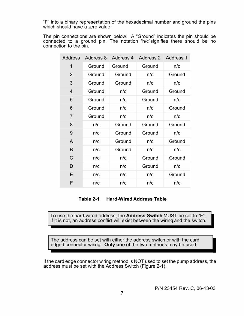
To use the hard-wired address, the Address Switch MUST be set to “F”. If it is not, an address conflict will exist between the wiring and the switch.
The address can be set with either the address switch or with the cardedged connector wiring. Only one of the two methods may be used.
“F” into a binary representation of the hexadecimal number and ground the pinswhich should have a zero value.
The pin connections are shown below. A “Ground” indicates the pin should beconnected to a ground pin. The notation “n/c”signifies there should be noconnection to the pin.
Address Address 8 Address 4 Address 2 Address 1
1 Ground Ground Ground n/c
2 Ground Ground n/c Ground
3 Ground Ground n/c n/c
4 Ground n/c Ground Ground
5 Ground n/c Ground n/c
6 Ground n/c n/c Ground
7 Ground n/c n/c n/c
8 n/c Ground Ground Ground
9 n/c Ground Ground n/c
A n/c Ground n/c Ground
B n/c Ground n/c n/c
C n/c n/c Ground Ground
D n/c n/c Ground n/c
E n/c n/c n/c Ground
F n/c n/c n/c n/c
Table 2-1 Hard-Wired Address Table
If the card edge connector wiring method is NOT used to set the pump address, theaddress must be set with the Address Switch (Figure 2-1).
P/N 23454 Rev. C, 06-13-038
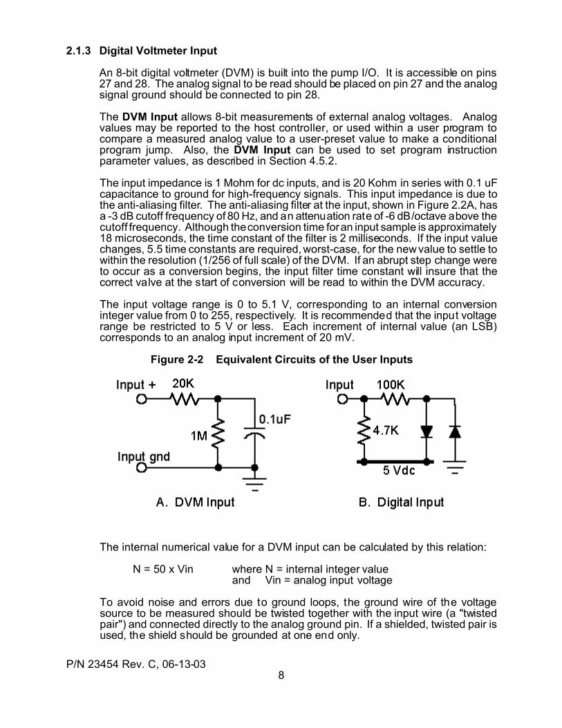
2.1.3 Digital Voltmeter Input
An 8-bit digital voltmeter (DVM) is built into the pump I/O. It is accessible on pins27 and 28. The analog signal to be read should be placed on pin 27 and the analogsignal ground should be connected to pin 28.
The DVM Input allows 8-bit measurements of external analog voltages. Analogvalues may be reported to the host controller, or used within a user program tocompare a measured analog value to a user-preset value to make a conditionalprogram jump. Also, the DVM Input can be used to set program instructionparameter values, as described in Section 4.5.2.
The input impedance is 1 Mohm for dc inputs, and is 20 Kohm in series with 0.1 uFcapacitance to ground for high-frequency signals. This input impedance is due tothe anti-aliasing filter. The anti-aliasing filter at the input, shown in Figure 2.2A, hasa -3 dB cutoff frequency of 80 Hz, and an attenuation rate of -6 dB/octave above thecutoff frequency. Although the conversion time for an input sample is approximately18 microseconds, the time constant of the filter is 2 milliseconds. If the input valuechanges, 5.5 time constants are required, worst-case, for the new value to settle towithin the resolution (1/256 of full scale) of the DVM. If an abrupt step change wereto occur as a conversion begins, the input filter time constant will insure that thecorrect valve at the start of conversion will be read to within the DVM accuracy.
The input voltage range is 0 to 5.1 V, corresponding to an internal conversioninteger value from 0 to 255, respectively. It is recommended that the input voltagerange be restricted to 5 V or less. Each increment of internal value (an LSB)corresponds to an analog input increment of 20 mV.
Figure 2-2 Equivalent Circuits of the User Inputs
The internal numerical value for a DVM input can be calculated by this relation:
N = 50 x Vin where N = internal integer valueand Vin = analog input voltage
To avoid noise and errors due to ground loops, the ground wire of the voltagesource to be measured should be twisted together with the input wire (a "twistedpair") and connected directly to the analog ground pin. If a shielded, twisted pair isused, the shield should be grounded at one end only.
P/N 23454 Rev. C, 06-13-039
Do NOT apply voltages greater than 30 Volts to a User Input.
2.1.4 Reset Input
A Reset Input is located on pin 25. When this pin is brought low (below 0.8Vdc),the processor resets. The reset condition remains active while the input is low.When the input is returned high, the processor begins a pump initialization cycleafter a 0.25 seconds delay. The Reset Input is referenced to a ground on one ofpins 23 to 26. Reset is also automatically generated internally when power is firstapplied. A reset causes the following actions:
(1) a checksum is computed on the firmware memory to verify its integrity(2) the syringe position value is set to zero (position is no longer valid)(3) the "position snapshot" values are reset to "-1"(4) any error messages are erased (cleared) and the Error Out is turned OFF(5) the valve moves to the "home", or port A position, if enabled(6) temporary memory (RAM) is cleared(7) the communications buffer is cleared(8) the pump address is read and saved(9) the Com Setup Switch status is read and saved(10) syringe speeds are set to the values saved in the non-volatile memory(11) the User Outputs are reset to OFF
2.1.5 User Digital Inputs
Three Digital Inputs are provided on pins 18, 20, and 22. Each of these inputscan be queried at any time, even during pump operation and while an internalprogram is executing. These inputs may also be used to control operation of thepump.
As shown in the equivalent input circuit in Figure 2-2B, each input has a 4.7K pull-up resistor and is protected for input voltages up to 30 Vdc. Inputs are compatiblewith CMOS and TTL logic operating from 5V supplies, with other pump's digitaloutputs, and with external switches. An "on" input is less than 1 V. An "off" inputis more than 3.5 V, or an open circuit. The internal resistance provides the biasrequired for external switches. External switches should make a connection toground when in the "on" condition.
2.2 OUTPUTS
2.2.1 Digital Outputs
Three digital outputs are provided on pins 17, 19, and 12. These outputs appeardirectly opposite the digital inputs described in Section 3.5. Each output consistsof an “HC” type CMOS output with a signal span of zero to 5 Vdc. The outputs maybe controlled under internal user program control or may be set by externalcommands from a controller.
The Digital Outputs are “active low”. An “on” condition outputs a low logic level.An “off” condition outputs a logic high level. This is compatibility with the digitalinput logic levels. The maximum safe output current is specified in Section 10.7.1.
P/N 23454 Rev. C, 06-13-0310
The Digital Outputs are “HC” type CMOS active outputs. Connect ONLY tologic inputs. Do NOT attempt to drive relays or solenoids.
2.2.2 Error Outputs
Pin 16 provides an Error Out suitable for driving logic or an LED indicator. Theoutput is active whenever an unreported error condition exists within the pump.When an error condition occurs, the Error Out on pin 16 is set to an “on” condition,which acts like a 5 ohm resistance to ground. In the absence of and error or afteran error has been reported to a controller via the communications I/O, the Error Outis an open-circuit.
The Error Bias output on pin 15 consists of a 330 ohm resistor connectedinternally to the +5 Vdc power. This output provides a current-limited output suitablefor direct drive of an LED indicator anode. To drive an external LED error indicator,connect pin 15 to the anode and pin 16 to the cathode.
If an LED is not used, the Error Out can be used to drive some other errorindicating device. The maximum output voltage in the “off” condition is 40 volts. Ifan external supply is used, a common ground connection should be taken from theI/O ground to the external supply ground. Since no internal protection is providedfor inductive loads, if relays or solenoids are driven, a clamp diode across the loadis required. For sending an error indication to a remote electronic equipment, theError Out pin can be used to drive the input of an opto-isolator.
The Error outputs of several devices may be tied together to make a single "wire-OR'ed" system error signal. This signal may be used to drive a LED or an input toa controller.
2.2.3 5Vdc Power Output
To power external I/O circuits, the card edge interface includes a +5 Vdc poweroutput on pin 5. This output is rated for loads up to 100 mAdc. Any of the Groundpins on the card edge may be used in conjunction with this pin.
2.3 SERIAL I/O EXPANSION (SIO)
The serial I/O (SIO) expansion port is independent of the serial communicationsport and is located on pins 1 through 6 of the edge connector. The SIO uses foursignals: SIO Input, SIO Output, SIO Clock, and SIO Strobe.
The SIO Input receives serial data as 8-bit bytes from an external circuit and theSIO Output sends data as 8-bit bytes from the pump. The SIO port acts as a“master” using the SIO Clock to synchronize the serial data transfers bit-by-bit. TheSIO Strobe acts as a synchronous, active-low enable signal for external devices.
Depending on the value of the SIO mode parameter “~S”, SIO operation willperform one-byte or two-byte data transfers.
P/N 23454 Rev. C, 06-13-0311
Do NOT have more than two RS485 bias networks switched “on”, regardlessof the number of devices on the bus. Use ONLY one network “on” at eachend of the overall RS485 bus wiring.
An RS485 bus with multiple devices must be wired directly from device-to-device, using “A”, “B”, and “Com Ground” pins.
2.4 COMMUNICATIONS I/O
The pump provides serial communications compatible with PC serial ports andRS485 I/O cards. There are to physical protocols, RS232 and RS485. There aretwo communications protocols, DT and OEM. See Section 6.4 for thecommunications physical protocol specifications and Section 6.3 for thecommunications protocols.
2.4.1 RS485 Communications I/O
The RS485 I/O is available on pins 11 through 14. There are two signals, RS485“A” and RS485 “B”. The "A" line is the "positive" line, and the "B" line is the"negative" line under idle bias conditions. To prevent common-mode voltageerrors, the communications should also use the Com Ground on pin 10 for anRS485 communication ground in addition to the "A" and "B" lines.
The “A” signal is duplicated on pins 13 and 14, while the “B” signal is duplicated onpins 11 and 12. This duplication permits a straight wire to pass straight througheach pair of the “A” and “B” lines to interconnect a series of devices.
The RS485 bus requires a proper bias and termination network for reliableoperation. The necessary network is included in the pump and is applied via theRS484 Bias toggles “1" and “2" on the Com Setup Switch shown in Figure 2-3.The first and last devices on an RS485 bus should have the network switched “on”.All other devices between the first and last devices should have the networkswitched “off”. A toggle is “on” when the button is positioned to the center of theswitch housing; a toggle is “off” when the button is positioned nearest the edge ofthe switch housing.
The com bus wiring should be a twisted pair for the “A” and “B” signals. The rateof twist should be approximately one to three turns per inch. The ground wire maybe a shield or a third wire twisted with the “A” and “B” wires.
2.4.2 RS232 Communications I/O
An RS232 communications option is available on the card edge connector. Thisprovides a communications I/O compatible with the serial ports found on PCs andcontrollers.
There are two lines: RS232 Rx on pin 7 and RS232 Tx on pin 8. The Tx pin sendsdata from the pump to a controller, and the Rx pin receives data from a controller
P/N 23454 Rev. C, 06-13-0312
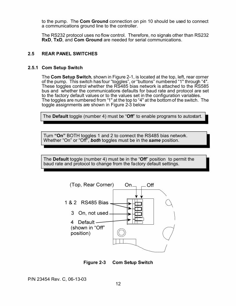
The Default toggle (number 4) must be “Off” to enable programs to autostart.
The Default toggle (number 4) must be in the “Off” position to permit thebaud rate and protocol to change from the factory default settings.
Turn “On” BOTH toggles 1 and 2 to connect the RS485 bias network. Whether “On” or “Off”, both toggles must be in the same position.
to the pump. The Com Ground connection on pin 10 should be used to connecta communications ground line to the controller.
The RS232 protocol uses no flow control. Therefore, no signals other than RS232RxD, TxD, and Com Ground are needed for serial communications.
2.5 REAR PANEL SWITCHES
2.5.1 Com Setup Switch
The Com Setup Switch, shown in Figure 2-1, is located at the top, left, rear cornerof the pump. This switch has four “toggles”, or “buttons” numbered “1" through “4".These toggles control whether the RS485 bias network is attached to the RS585bus and whether the communications defaults for baud rate and protocol are setto the factory default values or to the values set in the configuration variables. The toggles are numbered from “1" at the top to “4" at the bottom of the switch. Thetoggle assignments are shown in Figure 2-3 below
Figure 2-3 Com Setup Switch
P/N 23454 Rev. C, 06-13-0313
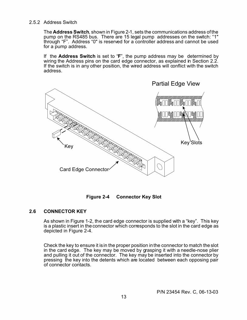
2.5.2 Address Switch
The Address Switch, shown in Figure 2-1, sets the communications address of thepump on the RS485 bus. There are 15 legal pump addresses on the switch: “1"through “F”. Address “0" is reserved for a controller address and cannot be usedfor a pump address.
If the Address Switch is set to “F”, the pump address may be determined bywiring the Address pins on the card edge connector, as explained in Section 2.2.If the switch is in any other position, the wired address will conflict with the switchaddress.
Figure 2-4 Connector Key Slot
2.6 CONNECTOR KEY
As shown in Figure 1-2, the card edge connector is supplied with a “key”. This keyis a plastic insert in the connector which corresponds to the slot in the card edge asdepicted in Figure 2-4.
Check the key to ensure it is in the proper position in the connector to match the slotin the card edge. The key may be moved by grasping it with a needle-nose plierand pulling it out of the connector. The key may be inserted into the connector bypressing the key into the detents which are located between each opposing pairof connector contacts.
P/N 23454 Rev. C, 06-13-0314
Note: The valve should be in the port A position when installing the valve.
Note: If the valve is rotated too far during installation, the valve may beinstalled with the ports 180 degrees out of position.
3.0 GETTING STARTED
This section describes the basic setup required to control a single VersaPump 3from a PC. Refer to Figure 1-2 for the assembly illustration. The following items arerequired for a basic bump installation:
Quantity Item (1) VersaPump 3 drive module (1) Valve (1) Syringe (1+) Teflon washer (one per port used + syringe) (1) Power supply (24 to 30 Vdc, 25 Watts) (1) Communications cable, PC-to-pump, Kloehn P/N 17734 (1) PC communications software (1) Card edge adapter board, Kloehn P/N 23352 or card edge connector,
Kloehn P/N 23277 or equivalent.
Getting started requires certain basic actions be taken, in order. These actions are:
(1) Install a valve.(2) Install a syringe.(3) Set the Com Setup and Address switches.(4) Connect power and communications.(5) Configure the pump.
Section 3 leads the first-time user through these steps using either the KloehnStarter Kit or user-supplied power and wiring. Advanced users can go directly toSection 4 to study the command set.
3.1 INSTALLING a VALVE
(1) Turn on the power to the pump and press the Initialize Button on the frontpanel of the pump. Wait for the initialize move to complete. The slot in thevalve drive shaft should be horizontal.
(2) Insert the valve into the faceplate so that the Valve Index Pin engages acorresponding hole in the valve and the valve drive motor shaft slot engagesthe blade in the back of the valve. It may be necessary to rotate the valveslightly to cause full engagement of both the index pin and the motor shaft.The valve should seat flush onto the pump faceplate.
(3) Install the two Valve Screws through the valve and into the faceplate.Tighten the screws firmly, but only finger tight. Over-tightening can damagethe valve.
P/N 23454 Rev. C, 06-13-0315
Note: The Teflon washer MUST be used to ensure the syringe fully seats. If the washer is not inserted, the syringe will not seat properly and will leak.
3.2 INSTALLING a SYRINGE
(1) Place a Teflon® washer into the syringe port on the valve. This port islocated at the bottom of the valve.
(2) Insert the syringe into the syringe port and tighten to a finger-tight tension.Do not over-tighten the syringe, as the hole in the washer will tend to clodflow into a smaller diameter over time.
3.3 CONNECTING POWER and COMMUNICATIONS
There are two methods for connecting the pump to power and a PC. One methoduses the Kloehn Starter Kit and the other method uses a Card edge connector withuser-supplied wiring. Section 3.3.1 describes the setup with the Starter Kit. Section3.3.2 describes the setup with the card edge connector. Use the section which isappropriate for the application.
3.3.1 With the Starter Kit
The Kloehn Starter Kit, P/N 23427, contains all the accessories needed to powerthe V3 pump and control it using a PC. The following items are included in the kit:
1. 24 Vdc Power Supply, P/N 17732, with power cables (Figure 3-3)2. RS232 Communications cable, P/N 17734 (Figure 3-2)3. Card Edge Adapter Board, P/N 23352 (Figure 3-1)4. Disk with software and manual, P/N 5. Installation instruction sheet
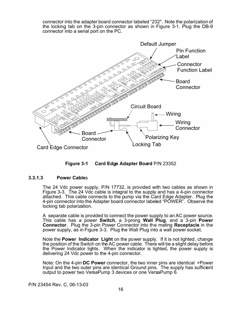
3.3.1.1 Card Edge Adapter Board
The Card Edge Adapter Board (Adapter P/N 23352), shown in Figure 3-1, convertsthe card edge connector on the rear of the pump to a set of 0.1-inch connectorscompatible with the 50300 series pump accessories, including the power supplycable and the communications cable. Inset the card edge connector on the boardonto the card edge of the pump. The .1-inch connectors should be located near thecenter of the rear of the pump.
When inserting a wiring connector into an Adapter board connector, ensure thePolarizing Key is oriented toward the Locking Tab, as shown in Figure 3-5, andthe pins are properly aligned with the connector.
3.3.1.2 Communications Cable
The Communications Cable (com cable) has a DB-9 connector on one end and athree-pin .1-inch connector on the other end, as shown in Figure 3-2. Plug the 3-pin
P/N 23454 Rev. C, 06-13-0316
connector into the adapter board connector labeled “232". Note the polarization ofthe locking tab on the 3-pin connector as shown in Figure 3-1. Plug the DB-9connector into a serial port on the PC.
Figure 3-1 Card Edge Adapter Board P/N 23352
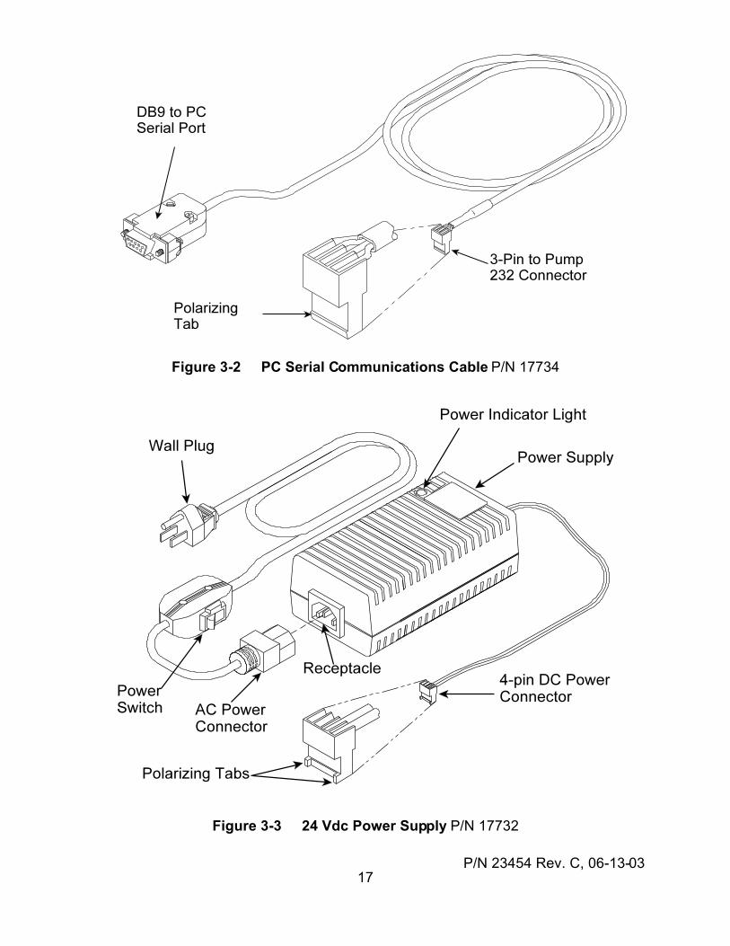
3.3.1.3 Power Cables
The 24 Vdc power supply, P/N 17732, is provided with two cables as shown inFigure 3-3. The 24 Vdc cable is integral to the supply and has a 4-pin connectorattached. This cable connects to the pump via the Card Edge Adapter. Plug the4-pin connector into the Adapter board connector labeled “POWER”. Observe thelocking tab polarization.
A separate cable is provided to connect the power supply to an AC power source.This cable has a power Switch, a 3-prong Wall Plug, and a 3-pin PowerConnector. Plug the 3-pin Power Connector into the mating Receptacle in thepower supply, as in Figure 3-3. Plug the Wall Plug into a wall power socket.
Note the Power Indicator Light on the power supply. If it is not lighted, changethe position of the Switch on the AC power cable. There will be a slight delay beforethe Power Indicator lights. When the indicator is lighted, the power supply isdelivering 24 Vdc power to the 4-pin connector.
Note: On the 4-pin DC Power connector, the two inner pins are identical +PowerInput and the two outer pins are identical Ground pins. The supply has sufficientoutput to power two VersaPump 3 devices or one VersaPump 6.
P/N 23454 Rev. C, 06-13-0317
Figure 3-2 PC Serial Communications Cable P/N 17734
Figure 3-3 24 Vdc Power Supply P/N 17732
P/N 23454 Rev. C, 06-13-0318
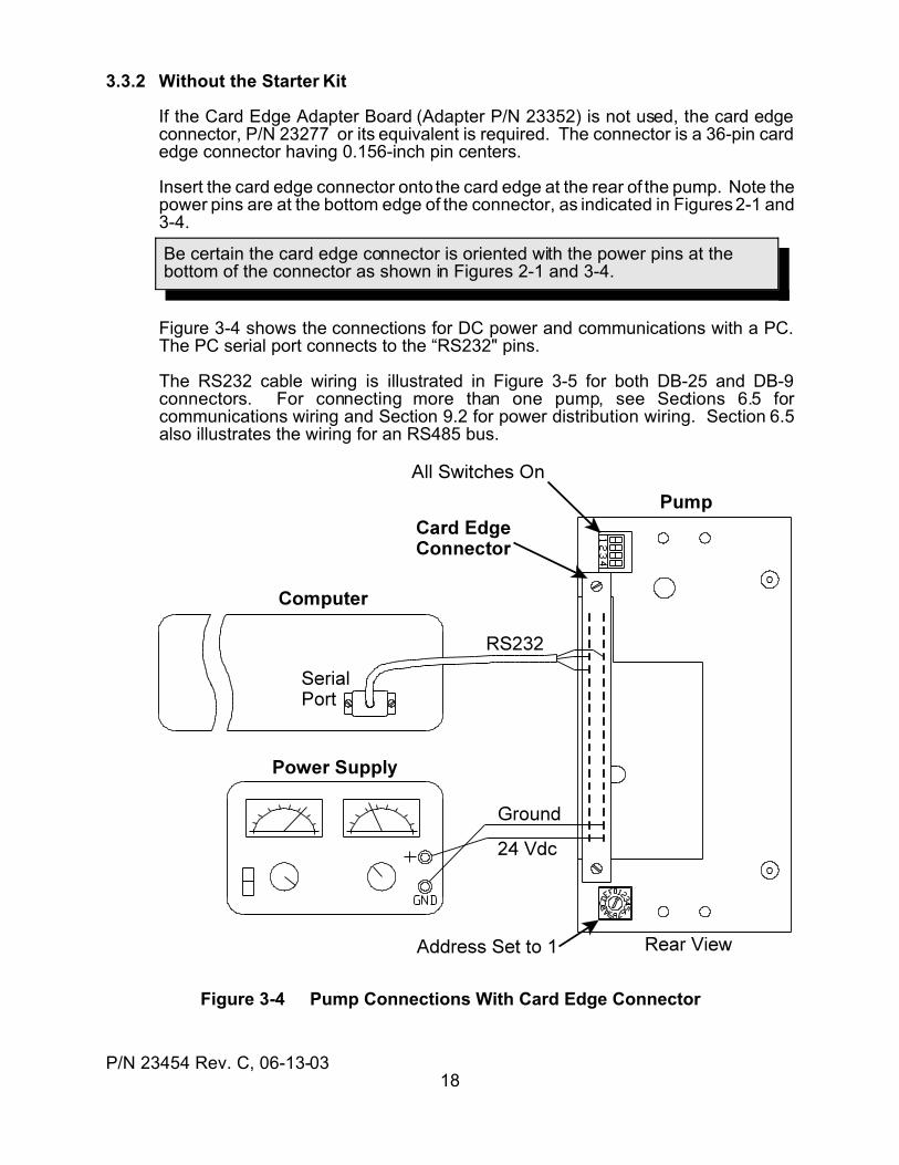
Be certain the card edge connector is oriented with the power pins at thebottom of the connector as shown in Figures 2-1 and 3-4.
3.3.2 Without the Starter Kit
If the Card Edge Adapter Board (Adapter P/N 23352) is not used, the card edgeconnector, P/N 23277 or its equivalent is required. The connector is a 36-pin cardedge connector having 0.156-inch pin centers.
Insert the card edge connector onto the card edge at the rear of the pump. Note thepower pins are at the bottom edge of the connector, as indicated in Figures 2-1 and3-4.
Figure 3-4 shows the connections for DC power and communications with a PC.The PC serial port connects to the “RS232" pins.
The RS232 cable wiring is illustrated in Figure 3-5 for both DB-25 and DB-9connectors. For connecting more than one pump, see Sections 6.5 forcommunications wiring and Section 9.2 for power distribution wiring. Section 6.5also illustrates the wiring for an RS485 bus.
Figure 3-4 Pump Connections With Card Edge Connector
P/N 23454 Rev. C, 06-13-0319
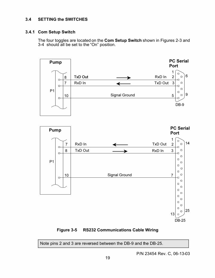
Note pins 2 and 3 are reversed between the DB-9 and the DB-25.
3.4 SETTING the SWITCHES
3.4.1 Com Setup Switch
The four toggles are located on the Com Setup Switch shown in Figures 2-3 and3-4 should all be set to the “On” position.
Figure 3-5 RS232 Communications Cable Wiring
P/N 23454 Rev. C, 06-13-0320
3.4.2 Address Switch
The Address Switch, shown in Figure 3-4, set the device address number. Usinga small screwdriver, set the switch to “1".
All communications with the pump begin with the address number. The addressmay be set with the Address Switch or by wiring on the Address pins of the cardedge connector. The card edge wiring method permits a wire harness to set anaddress when multiple pumps are used in an instrument. See Section 2.2 for theaddress wiring details.
3.5 SETTING UP COMMUNICATIONS
The HyperTerminal© program supplied with Windows® can be used to verifycommunications with the pump. If a communications program has been suppliedby Kloehn Co., follow the setup directions supplied with the software. Otherwise,use the HyperTerminal program as described in this section.
3.5.1 Setting up HyperTerminal
HyperTerminal allows the monitoring of all pump responses to commands, withoutthe filtering done by the WinPump program. The communications setup describedin this section assumes the default communications parameters of "DT" protocoland "9600" baud.
The following procedure will locate and configure the HyperTerminal program.
(1) Click on the Start button in the Windows environment screen.
(2) Go to Program --> Accessories --> Communication –>HyperTerminaland click on the HyperTerminal folder.
(3) When the HyperTerminal window opens, double-click on the Hypertrm.exeicon
(4) At the name prompt, type "Kloehn" and click on OK.
. (5) Go to Connect Using, select Direct to COM1, and click on OK. This willselect a serial port. If you are using another serial port, then select theappropriate "Direct to Com...".
(6) In the new window, make these entries:(a) Bits Per Second 9600(b) Data Bits 8(c) Parity None(d) Stop Bits 1(e) Flow Control None
(7) When the preceding entries are made, click on OK.
(8) Go to the top line terminal menu and select File.
P/N 23454 Rev. C, 06-13-0321
(9) Click on Properties.
(10) In the Properties window, click on the Settings tab.
(11) Click on the ASCII Setup button and place a check mark in the followingboxes:
T Send line ends with line feedsT Echo typed characters locallyT Append line feeds to incoming line endsT Wrap lines that exceed terminal width
(12) Click on OK and then again on the next OK.
(13) Go to the top line terminal menu and select File.
(14) Select Save As.
(15) Click on OK.
Steps 13 through 15 create an icon named "Kloehn" in the HyperTerminal Window. This icon can be dragged onto the desktop and used for direct access toa pre-set version of HyperTerminal. Each time the terminal program is required inthe future, the preceding setup steps need not be performed again. Just double-click on the new "Kloehn" icon.
3.5.2 Checking the Connection
When HyperTerminal or some other communications program has been set up forcommunications with the pump, verify the communications link is operational.
(1) Turn on power to the pump.
(2) After the pump has initialized, send the command: /1 <Enter>
(3) The pump should respond with “/0`”. If this response is seen, proceed to thenext section. If not, go to Section 6.6 for troubleshooting tips.
3.6 SENDING COMMANDS
3.6.1 General Command Structure
A command is an instruction to the pump to do one thing, such as move the syringeor turn the valve. Commands can combined, or concatenated” to form commandstrings. Command strings, also called programs, can perform complex tasksconsisting of many operations, including decision-making.
A command consists of ASCII characters and contain two parts: the commandand its argument. The command is a case-sensitive letter which represents aspecific type of action to perform. The argument follows the command letter anddetermines how the command will execute. For example, the command “D1200"tells the pump to dispense (“D”) 1200 steps.
P/N 23454 Rev. C, 06-13-0322
Commands which make decisions have two arguments. The first is a number whichworks the same way as for other commands. The second is a letter, whichdetermines what the outcome of the decision will be depending on thecircumstances. For example, the command “i2F” checks input (“i”) #2 for a lowlevel. If the level is low, the program goes to the label “F” (a label is a “placemarker” in a program). Other two-argument commands will be explained as theyare listed in Section 4.
3.6.2 Command Addressing
All commands and command strings must begin with a device address. Thedevice address determines which devices will respond to a particular commandstring. In this way, many devices can be connected together on a singlecommunications line without interfering with each other. The character whichsignifies an address is the forward slash, “/”. When the slash is seen by a pump,the pump reads the character which follows as an address to determine if thatpump should accept the command string. The individual device address is set viathe Address Switch or by the Address pin wiring on the card edge connector.
For example, if the Address Switch is set to “3", a command string which beginswith “/3" will be accepted by the pump. If the string were to begin with “/2", thepump would ignore the string.
Pumps may be addressed individually or in groups. The groups may be in pairs,groups of four, or all pumps on a single communications line. The details of pumpaddressing are given in Sections 6.1 and 6.2.
3.6.3 Pump Replies
When the pump receives a command string, it checks the string for correctness andsends a reply. The reply always begins with “/0", which is the address of the PC orcontrolling device. At least one character follows immediately after the “/0". Thischaracter is the status byte. The status byte informs the controller of the currentstatus of the communication and the pump.
There are two types of status: “ok” and “error”. There is a unique letter assigned toeach type of error the pump can recognize. For every error, the status letter maybe capitalized or small-case. If the status byte is capitalized, the pump is busydoing something. If the status byte is lower-case, the pump is not busy, and isready for another command. The “ok” status has two special characters to indicate“busy” or “ready”: the accent mark “`” indicates “ready”, and the ampersand “@”indicates “busy”. A typical response is “/0`” or “/0@”. Both these responsesindicate the pump and command string are ok.
Most command strings cannot be accepted until the previous command string iscompleted. The exception to this rule is queries. A query asks the pump to reportsomething, not to do something. A query can be asked any time and will beanswered when it is received, even if the pump is busy.
The commands are given and explained in Section 4. A command summary islisted in Appendix A. A complete listing and explanation of the status bytes is givenin Section 5 and is summarized in Appendix B.
P/N 23454 Rev. C, 06-13-0323
The zero position MUST be set ABOVE the INITIALIZE position by atleast some small distance or errors will result.
3.6.4 Configuring the Pump
Before the pump can be used, it must be configured. Configuring a pumpdetermines the way it will operate. The operating configuration is set byparameters stored in non-volatile memory (NVM). The NVM acts like a solid-state disk drive. The parameters determine such things as the type of valve, thecommunications baud rate, and other operating characteristics.
The parameters are set by the configuration commands. Each parameter isrepresented by a letter which may be upper-case or lower-case. The pumprecognizes a letter as a configuration command because the letter is preceded bya tilde “~”. Following the tilde and letter, a number sets the configuration.
For example, the configuration command “~V8" sets the valve type to 6-waydistribution. The “~” denotes a configuration command. The “V” denotes the valveparameter, and the “8" sets the valve to a six-way distribution. The valve parameteris the only parameter which MUST be set before the pump can be used.
Look up the valve parameter which corresponds to the valve type to be mounted tothe pump. The parameters are listed in Section 4.2.2. Then send the command
/1~Vn <Enter> (Substitute the number of the valve type in place of “n”.)<Enter> means to press the Enter key on the keyboard.
3.6.5 Calibrating the Syringe
The syringe zero position must be calibrated prior to the f irst use of the syringewhenever a new syringe, valve, or syringe washer is installed. This is a simpleprocedure using the buttons on the front panel.
(1) With the syringe and valve already mounted to the pump, press the lower ofthe two front panel buttons, the INITIALIZE button. This will cause thesyringe to move to a position a small distance below the top-of-stroke. Thisposition is internally fixed and is sometimes called the soft limit.
(2) When the INITIALIZE move completes, the syringe motor power will be Off.(Normally, when a move ends, the motor is left at half-power.) Rotate theThumbwheel at the lower left corner to move the syringe piston upward untilit barely contacts the top of the syringe. This will be the zero position, alsocalled Home. In some applications, the position may be slightly below thetop-of-stroke position if a small air gap is desired.
(3) Press the upper button, the SET HOME button. The syringe will movedownward to the INITIALIZE position and then return to the zero position.
When step (3) above executes, the location of the zero position is stored in NVM.This value will remain even after power is removed from the pump. The zeroposition will be remembered by the pump whenever the pump is powered up.
P/N 23454 Rev. C, 06-13-0324
Do NOT do the calibration procedure each time the pump is poweredup. Do the procedure ONLY when the syringe, valve, or syringe washer ischanged.
3.6.6 Sending Some Commands
All the basic setup procedures are now complete. This section introduces somebasic commands and illustrates the difference between individual commands andcommand strings. The notation <Enter> means to press the Enter key on thekeyboard. The “R” at the end of each command means “Run the command now.”
(1) Enter the command: /1W4R <Enter>
This initializes the syringe just as the INITIALIZE button did on the frontpanel.
(2) Enter the command: /1A6000R <Enter>
This causes the syringe to move to the position 6000 steps below the zeroposition. “A” means “go to the Absolute position”. This will be half-way downfor a 12000-step model or all the way down for a 6000-step model.
(3) Enter the command: /1o3R <Enter>
The valve will move clockwise (viewed from the front) to port “C”. The “o”denotes a valve move and the “3" corresponds to port “C” (1=A, 2=B, etc.).
(4) Enter the command: /1D4000R <Enter>
The syringe will move 2/3 the distance to the zero position (syringe at 6000moves upward by 4000 to position 2000).
The preceding sequence of single commands could have executed as a singlecommand string, as happens next.
Enter the command: /1W4A6000o3D4000R <Enter>
The same sequence of commands is executed as for the individual commands, butwithout any delays and as if a single, more complex command had executed. Thisis an example of a command string. Next, a query will be illustrated.
Enter the command: /1? <Enter> (Query the syringe position)
The reply should be: /0`2000 (the position is at 2000 absolute)
Since queries are executed when they are received, no Run command was needed.This is true for all queries and configuration commands. For other commands, thecommand or command string will execute when the “R” command is sent, either atthe end of the string or as the next command sent. For example,
/1A6000 <Enter> place the command in the pump. /1R <Enter> now run the command
P/N 23454 Rev. C, 06-13-0325
4.0 COMMAND SET
This section presents the commands supported in the VersaPump 3. The f irstcolumn lists the command syntax. The values in parenthesis ( ) indicate the rangeof values. The value in brackets [ ] is the factory default value. The notation “@n”signifies the argument may be an indirect variable. Indirect variables are explainedin Sections 8.1.4 and 8.3.7.
The non-volatile memory is limited to 10,000 writes. For this reason, useconfiguration commands only when a specific operating configuration must bechanged. A configuration setting is stored for the life of the pump or until changed.
4.1 SYRINGE COMMANDS
There are two syringe resolutions: 6000 steps and 12000 steps, depending on themodel of pump.
4.1.1 Positioning Commands
These commands cause the syringe to move to a commanded position along itsrange of motion. An absolute position is a specific point. A relative position is adistance offset from the current position. Absolute vs relative positions areillustrated in Figure 4-1.
It is highly recommended that the upper case form of the "An", "Bn", and "Cn"commands be used so that busy status can be ascertained. The lower case "an","bn", and "cn" do not reveal busy status upon query.
In each of the commands below, the "n" value is expressed in steps, where "0" isat top-of-stroke (0 volume).
An Go to Absolute position "n", with the BUSY status bit set to "busy".(n: 0...6000 steps or 0...12000 steps, @n) [n/a]
an Go to absolute position "n", with the BUSY status bit set to "ready".(n: 0...6000 steps or 0...12000 steps, @n) [n/a]
Dn Dispense "n" steps from the current position, with the BUSY status bit setto a "busy". The dispense direction is upward, towards the valve.(n: 0...6000 steps or 0...12000 steps, @n) [n/a]
dn dispense "n" steps from the current position, with the BUSY status set to l"ready". The dispense direction is upward, towards the valve.(n: 0...6000 steps or 0...12000 steps, @n) [n/a]
Pn Aspirate (“Pick up”) "n" steps from the current position, with the BUSY statusbit set to a logic "1". The aspirate direction is downward, away from thevalve. (n: 0...6000 steps or 0...12000 steps, @n) [n/a]
pn Aspirate (“pick up”) "n" steps from the current position, with the BUSYstatus bit cleared to a logic "0". The aspirate direction is downward, awayfrom the valve. (n: 0...6000 steps or 0...12000 steps, @n) [n/a]
P/N 23454 Rev. C, 06-13-0326
All moves to Zero or to the full-stroke positions should use an Absoluteposition command (e.g., “A0" or “A12000").
Use the capitalized version of the An, Pn, and Dn commands. Lower-caseversions will not report a “busy” status if the pump is queried while moving.
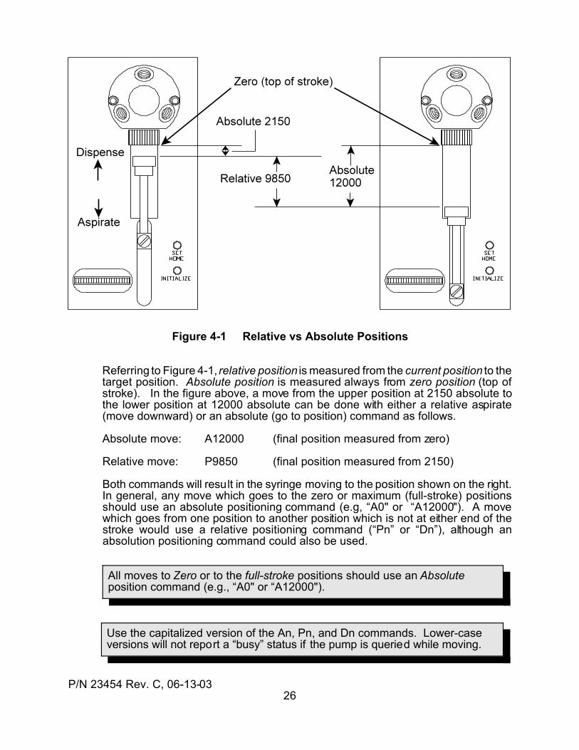
Figure 4-1 Relative vs Absolute Positions
Referring to Figure 4-1, relative position is measured from the current position to thetarget position. Absolute position is measured always from zero position (top ofstroke). In the figure above, a move from the upper position at 2150 absolute tothe lower position at 12000 absolute can be done with either a relative aspirate(move downward) or an absolute (go to position) command as follows.
Absolute move: A12000 (final position measured from zero)
Relative move: P9850 (final position measured from 2150)
Both commands will result in the syringe moving to the position shown on the right.In general, any move which goes to the zero or maximum (full-stroke) positionsshould use an absolute positioning command (e.g, “A0" or “A12000"). A movewhich goes from one position to another position which is not at either end of thestroke would use a relative positioning command (“Pn” or “Dn”), although anabsolution positioning command could also be used.
P/N 23454 Rev. C, 06-13-0327
hn Do a handshake dispense, using User Input #n and User Output #n forthe handshake signals. See Section 8.3.3 for details about programming ahandshake dispense application.(n: 1...3, @n) [n/a]
h-n Trigger a handshake dispense immediately, without an external inputstimulus.(n: 1...3, @n) [n/a]
The handshake dispense is a coordinated sequence between two pumps in whichone pump dispenses while the other pump aspirates. When one pump completesits dispense, the other pump begins its dispense. By summing the outputs of thetwo pumps, a continuous flow can be synthesized.
The coordination between the two pumps is done automatically by the pumps whentheir inputs and outputs are connected as explained in Section 8.3.3. The value of“n” in the handshake dispense commands determines which of the user inputs willbe used for the handshake coordination. For example, if the command is “h2", thenthe pump will use input #2 and output #2.
As each pump nears the end of its dispense, it provides an advance trigger signalto the other pump, which immediately begins its own dispense. The timing on thetrigger signal is automatically adjusted to compensate for different accelerationsettings.
4.1.2 Motion Variables
The syringe axis uses the following variables to determine the speeds,accelerations, and drive compensation moves. See Section 8.2.3 for tips on settingspeed and acceleration values.
During power up of the pump, default values in the operational memory are recalledfrom the NVM. The operational values can be set at any time a move is not inprogress. Top Speed is an exception, as it can be set “on-the-fly”.
Except as noted, all these commands require a “R” (Run) command to executeimmediately.
Cn Set the Stop speed to "n" steps per second (sps).(n: 40...8000, @n) [650]
cn Set the Stop speed to "n" steps per second (sps). (n: 40...8000, @n) [650]
Kn Set the number of syringe backlash steps to "n" steps. Backlashcompensates for mechanical slack in the drive system. Too little backlashcompensation will result in an error in the initial dispense movement followingan aspirate move.(n: 0...500, @n) [100]
Ln Set acceleration and deceleration slopes to "n", where the actualacceleration value in steps per second per second = n x 2500 sps/sec.(n: 1...20, @n) [7]
P/N 23454 Rev. C, 06-13-0328
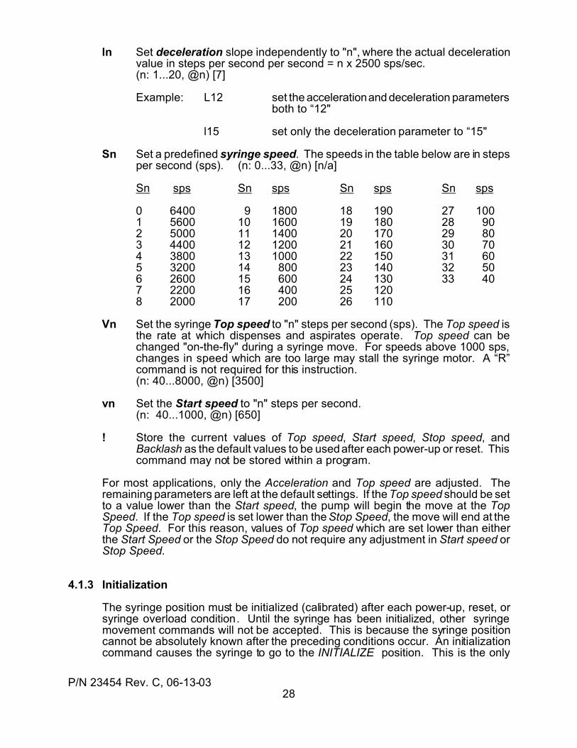
ln Set deceleration slope independently to "n", where the actual decelerationvalue in steps per second per second = n x 2500 sps/sec.(n: 1...20, @n) [7]
Example: L12 set the acceleration and deceleration parametersboth to “12"
l15 set only the deceleration parameter to “15"
Sn Set a predefined syringe speed. The speeds in the table below are in stepsper second (sps). (n: 0...33, @n) [n/a]
Sn sps Sn sps Sn sps Sn sps
0 6400 9 1800 18 190 27 1001 5600 10 1600 19 180 28 902 5000 11 1400 20 170 29 803 4400 12 1200 21 160 30 704 3800 13 1000 22 150 31 605 3200 14 800 23 140 32 506 2600 15 600 24 130 33 407 2200 16 400 25 1208 2000 17 200 26 110
Vn Set the syringe Top speed to "n" steps per second (sps). The Top speed isthe rate at which dispenses and aspirates operate. Top speed can bechanged "on-the-fly" during a syringe move. For speeds above 1000 sps,changes in speed which are too large may stall the syringe motor. A “R”command is not required for this instruction.(n: 40...8000, @n) [3500]
vn Set the Start speed to "n" steps per second.(n: 40...1000, @n) [650]
! Store the current values of Top speed, Start speed, Stop speed, andBacklash as the default values to be used after each power-up or reset. Thiscommand may not be stored within a program.
For most applications, only the Acceleration and Top speed are adjusted. Theremaining parameters are left at the default settings. If the Top speed should be setto a value lower than the Start speed, the pump will begin the move at the TopSpeed. If the Top speed is set lower than the Stop Speed, the move will end at theTop Speed. For this reason, values of Top speed which are set lower than eitherthe Start Speed or the Stop Speed do not require any adjustment in Start speed orStop Speed.
4.1.3 Initialization
The syringe position must be initialized (calibrated) after each power-up, reset, orsyringe overload condition. Until the syringe has been initialized, other syringemovement commands will not be accepted. This is because the syringe positioncannot be absolutely known after the preceding conditions occur. An initializationcommand causes the syringe to go to the INITIALIZE position. This is the only
P/N 23454 Rev. C, 06-13-0329
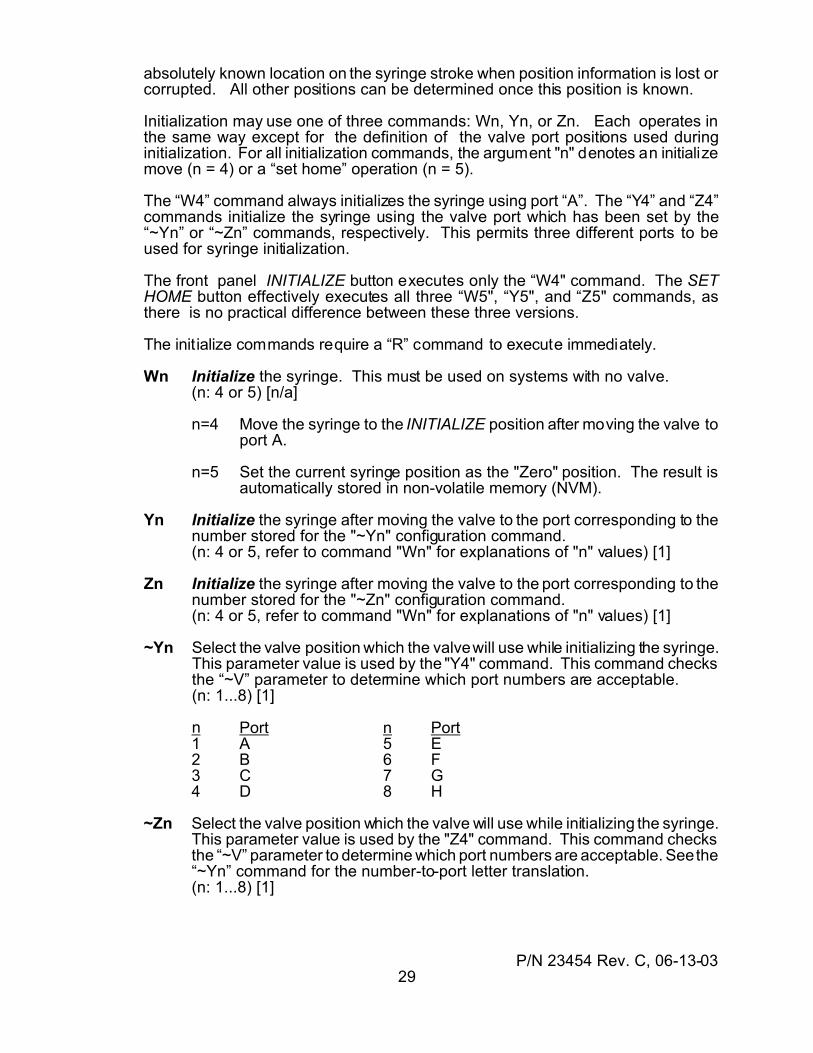
absolutely known location on the syringe stroke when position information is lost orcorrupted. All other positions can be determined once this position is known.
Initialization may use one of three commands: Wn, Yn, or Zn. Each operates inthe same way except for the definition of the valve port positions used duringinitialization. For all initialization commands, the argument "n" denotes an initializemove (n = 4) or a “set home” operation (n = 5).
The “W4” command always initializes the syringe using port “A”. The “Y4” and “Z4”commands initialize the syringe using the valve port which has been set by the“~Yn” or “~Zn” commands, respectively. This permits three different ports to beused for syringe initialization.
The front panel INITIALIZE button executes only the “W4" command. The SETHOME button effectively executes all three “W5", “Y5", and “Z5" commands, asthere is no practical difference between these three versions.
The initialize commands require a “R” command to execute immediately.
Wn Initialize the syringe. This must be used on systems with no valve.(n: 4 or 5) [n/a]
n=4 Move the syringe to the INITIALIZE position after moving the valve toport A.
n=5 Set the current syringe position as the "Zero" position. The result isautomatically stored in non-volatile memory (NVM).
Yn Initialize the syringe after moving the valve to the port corresponding to thenumber stored for the "~Yn" configuration command.(n: 4 or 5, refer to command "Wn" for explanations of "n" values) [1]
Zn Initialize the syringe after moving the valve to the port corresponding to thenumber stored for the "~Zn" configuration command.(n: 4 or 5, refer to command "Wn" for explanations of "n" values) [1]
~Yn Select the valve position which the valve will use while initializing the syringe.This parameter value is used by the "Y4" command. This command checksthe “~V” parameter to determine which port numbers are acceptable.(n: 1...8) [1]
n Port n Port1 A 5 E2 B 6 F3 C 7 G4 D 8 H
~Zn Select the valve position which the valve will use while initializing the syringe.This parameter value is used by the "Z4" command. This command checksthe “~V” parameter to determine which port numbers are acceptable. See the“~Yn” command for the number-to-port letter translation.(n: 1...8) [1]
P/N 23454 Rev. C, 06-13-0330
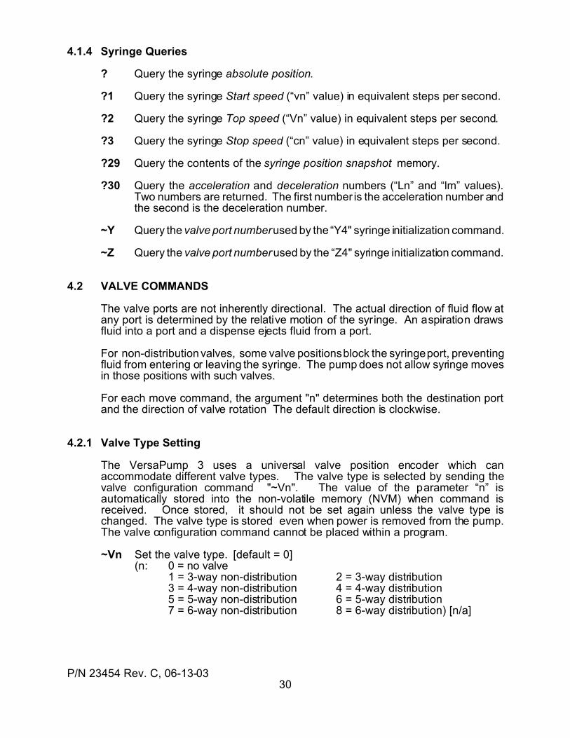
4.1.4 Syringe Queries
? Query the syringe absolute position.
?1 Query the syringe Start speed (“vn” value) in equivalent steps per second.
?2 Query the syringe Top speed (“Vn” value) in equivalent steps per second.
?3 Query the syringe Stop speed (“cn” value) in equivalent steps per second.
?29 Query the contents of the syringe position snapshot memory.
?30 Query the acceleration and deceleration numbers (“Ln” and “lm” values).Two numbers are returned. The first number is the acceleration number andthe second is the deceleration number.
~Y Query the valve port number used by the “Y4" syringe initialization command.
~Z Query the valve port number used by the “Z4" syringe initialization command.
4.2 VALVE COMMANDS
The valve ports are not inherently directional. The actual direction of fluid flow atany port is determined by the relative motion of the syringe. An aspiration drawsfluid into a port and a dispense ejects fluid from a port.
For non-distribution valves, some valve positions block the syringe port, preventingfluid from entering or leaving the syringe. The pump does not allow syringe movesin those positions with such valves.
For each move command, the argument "n" determines both the destination portand the direction of valve rotation The default direction is clockwise.
4.2.1 Valve Type Setting
The VersaPump 3 uses a universal valve position encoder which canaccommodate different valve types. The valve type is selected by sending thevalve configuration command "~Vn". The value of the parameter “n” isautomatically stored into the non-volatile memory (NVM) when command isreceived. Once stored, it should not be set again unless the valve type ischanged. The valve type is stored even when power is removed from the pump.The valve configuration command cannot be placed within a program.
~Vn Set the valve type. [default = 0] (n: 0 = no valve
1 = 3-way non-distribution 2 = 3-way distribution3 = 4-way non-distribution 4 = 4-way distribution5 = 5-way non-distribution 6 = 5-way distribution7 = 6-way non-distribution 8 = 6-way distribution) [n/a]
P/N 23454 Rev. C, 06-13-0331
Due to automatic valve move retries after a valve motor stall, the time for avalve move can vary significantly. Do NOT use timing loops in controllersoftware to assume a valve move has completed.
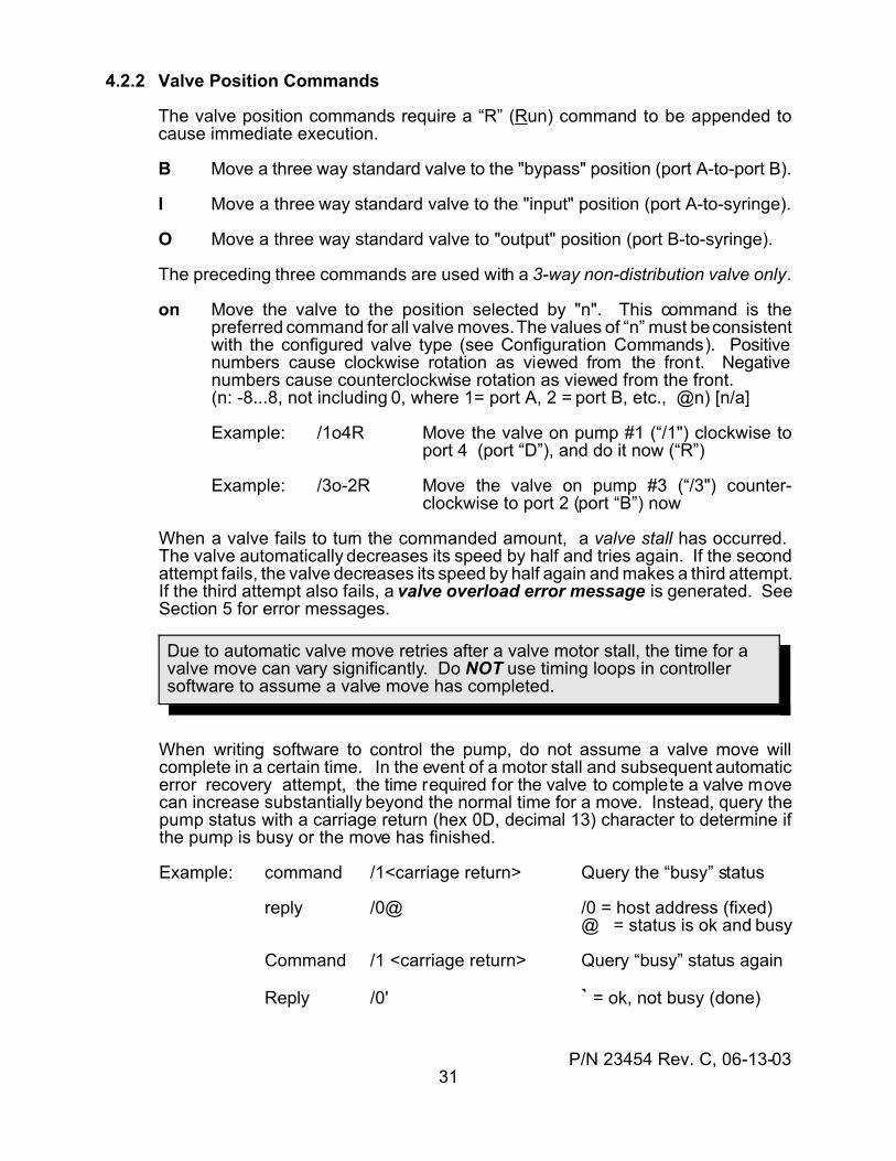
4.2.2 Valve Position Commands
The valve position commands require a “R” (Run) command to be appended tocause immediate execution.
B Move a three way standard valve to the "bypass" position (port A-to-port B).
I Move a three way standard valve to the "input" position (port A-to-syringe).
O Move a three way standard valve to "output" position (port B-to-syringe).
The preceding three commands are used with a 3-way non-distribution valve only.
on Move the valve to the position selected by "n". This command is thepreferred command for all valve moves. The values of “n” must be consistentwith the configured valve type (see Configuration Commands). Positivenumbers cause clockwise rotation as viewed from the front. Negativenumbers cause counterclockwise rotation as viewed from the front.(n: -8...8, not including 0, where 1= port A, 2 = port B, etc., @n) [n/a]
Example: /1o4R Move the valve on pump #1 (“/1") clockwise toport 4 (port “D”), and do it now (“R”)
Example: /3o-2R Move the valve on pump #3 (“/3") counter-clockwise to port 2 (port “B”) now
When a valve fails to turn the commanded amount, a valve stall has occurred. The valve automatically decreases its speed by half and tries again. If the secondattempt fails, the valve decreases its speed by half again and makes a third attempt.If the third attempt also fails, a valve overload error message is generated. SeeSection 5 for error messages.
When writing software to control the pump, do not assume a valve move willcomplete in a certain time. In the event of a motor stall and subsequent automaticerror recovery attempt, the time required for the valve to complete a valve movecan increase substantially beyond the normal time for a move. Instead, query thepump status with a carriage return (hex 0D, decimal 13) character to determine ifthe pump is busy or the move has finished.
Example: command /1<carriage return> Query the “busy” status
reply /0@ /0 = host address (fixed)@ = status is ok and busy
Command /1 <carriage return> Query “busy” status again
Reply /0' ` = ok, not busy (done)
P/N 23454 Rev. C, 06-13-0332
4.2.3 Valve Queries
Valve queries require no “R” command to execute. They are executed immediatelyafter they are received by the pump. These commands can not be embeddedwithin a program.
?8 Query the current valve position. Return the ASCII numerical value. (1= portA, 2 = port B, etc.)
$ Query the number of valve stalls. Send the result to the host as an ASCIInumber. The value of the returned number is the number of times a stall andsubsequent automatic error recovery occurred. "0" = no error. If the thirdattempt fails, a valve overload error is generated.
% Query the number of valve movements since the last power-up or Reset.Return an ASCII number.
~V Query the valve type setting. Return the value of the "~Vn" parameter. (SeeSection 4.2.1 for the values.)
4.3 I/O COMMANDS
4.3.1 Output Commands
These commands set a User Output logic level or send an output byte via the SerialExpansion I/O port. All these commands require a “R” command to executeimmediately.
sn Send a serial byte from the User Serial expansion Port, MSB first. The valueof the ASCII number "n" is the base 10 representation of the value of abinary byte. For transmitted bytes, positive logic applies ("1" = high logiclevel). In the 2-byte serial mode, "n" represents the second byte sent. Thefirst byte is the same as the first byte sent by a "sn,m" instruction. SeeSection 4.5 for an explanation of "@n" usage.(n: 0...255, @n) [n/a]
Example: s85 Send the decimal number “85" in binary format. Theserial I/O device will receive the binary number01010101 (= 85 in decimal - base 10 - format). A “1" isa high logic level and a “0" is a low logic level.
sn,m Send two bytes from the User Serial expansion Port, byte "m" first and thenbyte "n" second. Both bytes are sent MSB (most significant bit) first. Thevalues of "n" and "m" are expressed as the ASCII base 10 representation ofthe binary bytes. (n: 0...255, m: 0...255, @n) [n/a]
Example: s85, 129 Send the decimal numbers 85 and 129 as binarynumbers. The external serial I/O device willreceive the binary numbers 0101010110000001. A “1" is a high logic level and a “0" isa low logic level.
P/N 23454 Rev. C, 06-13-0333
Example: s@10, 35 Send two numbers. The first is the same firstnumber sent when this command was last used,and the second number is “35" (00100011). SeeSection 4.5 for an explanation of "@n" usage.
Un Turn the user parallel output "n" ON (low logic level) or turn on a serial I/Oport output bit.(n: 1...3 = parallel outputs 1...3
11...18 = serial byte 1, bit 1...8 of the serial expansion port21...28 = serial byte 2, bit 1...8 of the serial expansion port) [n/a]
Example: U2 Turn On (set to low logic level) user output #2
Example: U25 Turn On bit 5 in byte #2 of the serial expansion I/O
un Turn the user parallel output "n" OFF (open-circuited) or turn off a serial I/Oport output bit.(n: 1...3 = parallel outputs 1...3
11...18 = serial byte 1, bit 1...8 of the serial expansion port21...28 = serial byte 2, bit 1...8 of the serial expansion port) [n/a]
A special syntax is available for controlling the outputs while the pump is executingother commands or a program. This allows immediate, real-time control of theoutputs. The syntax is a variation of the preceding output commands. The syntaxis
U#n Turn ON (set low) an output immediately.
u#n Turn OFF (set high) an output immediately.
These commands use the same values for “n” as the Un and un commands.
4.3.2 Input Query Commands
Input query commands are sent from a host controller and request a status replyfrom the pump. These commands are executed when they are received by thepump and do not require a “R” command. These commands can not be embeddedin a program string.
?4 Query the "User Input 1" status. Send the value to the host as an ASCII "1"if "true" (low logic input level) or an ASCII "0" if "false" (high logic input level).
Example:command /5?4 Query User Input #1 status on pump #5
reply /0'1 /0 = host address (fixed assignment)‘ = status is “not busy” and “no errors”1 = input is “true” (low input logic level)
?5 Query the "User Input 2" status. Send the value to the host (see "?4").
?6 Query the "User Input 3" status. Send the value to the host (see "?4").
P/N 23454 Rev. C, 06-13-0334
?7 Query the analog input value at the Digital Voltmeter input. Send the valueto the host controller as an ASCII base 10 number. Voltage = number x 0.02volts.
Example:command /1?7 Query Digital Voltmeter input on pump #1
reply /0'157 /0 = host address (fixed assignment)‘ = status is “not busy” and “no errors”157 = 157 x .02 = 3.14 Volts
?10 Query the value of the first byte received from the Expansion I/O port input. An input byte is shifted in (MSB first), and the numerical value of the firstinput byte is reported in a base 10 ASCII format. The value uses a negativelogic convention (low level = 1, high level = 0). In 1-byte mode, this is theonly byte. In 2-byte mode, this is the first of two bytes.
Example: The inputs for the first byte are 11001001 (201 decimal)
sent /2?10 Query pump #2 Expansion input, byte #1
reply /0'201 /0 = host address (fixed assignment)‘ = status is “not busy” and “no errors”201 decimal = binary 11001001
?20 Query the value of the second byte received from the Expansion I/O portinput in 2-byte mode. Two input bytes are shifted in (MSB first), and thenumerical value of the second input byte is reported in a base 10 ASCIIformat. The value uses a negative logic convention (low level = 1, high level= 0). This instruction is not valid in 1-byte mode. See “?10" above for anexample.
?n Query the state of the Expansion I/O port input bit designated by "n". Aserial byte is input (MSB first), and the state of the designated bit is reportedas an ASCII "0" if the bit is "false" (high input logic level) or an ASCII "1" if"true" (low input logic level).(n: 1...3 = parallel outputs 1...3
11...18 bit 1...8 in Expansion input byte #121...28 bit 1...8 in Expansion input byte #2)
4.3.3 Input Test and Jump Commands
The value of an input can be checked and its status can be used to cause aprogram to change the path of the instructions to be executed. This is called aconditional jump. The general format is
If the input is “true”, then jump to the place marked by the program label
These commands are used to control the way a program executes, dependingupon the state of an input variable. The commands are intended to be embeddedwithin a program string and not to be executed alone. See Section 4.4.3 for moreinformation about program jumps and labels.
P/N 23454 Rev. C, 06-13-0335
inp If the input level is true (low input level), jump to label "p". This checks if auser input pin on the card edge connector is at a low level. There are threeuser inputs. If an I/O Expansion Board is used, the number of inputsincreases by 16, organized as two bytes of eight bits each.(n: 1...3 User input number 1...3
11...18 bit 1...8 in Expansion input byte #121...28 bit 1...8 in Expansion input byte #2
p: a...z, A...Z) [n/a]
Example: i18b Test bit #8 in Expansion byte #1. If it is at a low level, beginexecuting the instructions at program label “b”. If it is not at alow level, continue with the next instruction after this one.
i<np If the analog input (DVM) value is less than the number in the command,jump to label “p”. The input voltage range of 0 to 5V is converted into one of255 levels. The number “n” is the numerical value of the level. This can befound as n = 51 x input volts, truncated to an integer number.(n: 0...255, @n p: a...z, A...Z)
Example: i<126s Test the Digital Voltmeter input, and if thevoltage is less than 2.48 V, then go to programlabel “s”. (126 = integer part of 51 x 2.48.)
i>np If the analog input (DVM) value is greater than the number in the command,jump to label “p”. The input voltage range of 0 to 5V is converted into one of255 levels. The number “n” is the numerical value of the level. This can befound as n = 51 x input volts, truncated to an integer number.(n: 0...255, @n p: a...z, A...Z)
4.4 USER PROGRAM COMMANDS
Commands, command strings, and programs are executed in the pump RAM(temporary) memory. The pump can also store programs in non-volatile memory(NVM). The NVM acts like a solid-state disk drive. See Section 7 for details on thepump’s internal memory.
User program storage commands can load, save, run, or erase user programs inthe pump memory. Program execution commands are used to stop or startprograms. Program control commands determine the order of execution (flow) ofa program.
4.4.1 Program Storage
These commands control the storage, retrieval, and erasure of a user program inthe non-volatile user program memory (NVM). These command execute whenreceived and can not be placed within a program. A “R” command is not required.
En Store the current command string into non-volatile memory. Maximumprogram length is 170 characters.(n: 1...10) [n/a]
P/N 23454 Rev. C, 06-13-0336
The “T” command may cause the syringe to “loose steps” and generate a “Z”error if the “T” command is used to stop the syringe motion at a high speed.
en erase a stored command string in non-volatile memory.(n: 1...10) [n/a]
qn Return a copy of a program currently stored in the non-volatile programmemory (NVM).(n: 1...10) [n/a]
?9 Query the number of unused bytes (characters) in non-volatile programmemory. (390 maximum)
?19 Query which program numbers are currently used to store a program.Return a list of the numbers in use, separated by a space between numbers.
4.4.2 Program Execution
The non-volatile user-program memory and its "auto-start" capability are unique toKloehn pumps. The external "Stop" input function is also an added feature onKloehn pumps. Only the "H" command can be used within a program. Thesecommands do not require a “R” command for immediate execution.
~An Enable or disable autostart for a program in NVM. If “n” is not zero, beginexecuting the numbered program when power is applied or after a reset. If autostart is disabled, a stored program is started with the "r n" command.(n: 0 = disable, 1...10 = enable, @n) [0]
~A Query the autostart state. Return "0" if disabled, "1" if enabled.
H Halt the executing command string or program. This is used to createbreakpoints in program execution. The "H" command is for inclusion withina program string and cannot be used as a command sent externally to arunning program. A program stopped by an "H" command within theprogram may resume execution with the command following the "H"command if a "R" command is subsequently sent.
r n run stored program #n in the non-volatile program memory. (Externalcommand)(n: 1...10, @n) [n/a]
jn Do stored program #n and then continue with the present program.(n: 1...10, @n) [n/a]
R Run the command string in RAM. If the command string has been stoppedby an "H" command, resume execution.
T Terminate execution of current command string. An externally-sentcommand only, it is executed when received. A valve move in progress willgo to completion when a "T" is received. If the “T” command is used whilethe syringe is moving above about 2000 steps per second, the pump maygenerate a “Z” error when it passes up through the INITIALIZE point.
P/N 23454 Rev. C, 06-13-0337
4.4.3 Program Control
4.4.3.1 Jumps and Labels
A program jump provides a means to change the order of execution of programcommands. The point from which a jump occurs is a jump command. Programexecution is changed from the location of the jump command to the destinationlabel ("p") specified in the jump command.
A jump may be unconditional, which executes every time it is encountered, or it maybe conditional. Conditional jumps are “if...then” commands. The jump to a labelwill occur only if the specific test condition in the command is true. Remember“Do if True”. Jumps and labels are unique to Kloehn pumps.
:p Declare the program label "p" (case sensitive).(p: a...z, A...Z)
Jp Jump unconditionally to program label "p". This is the only unconditionaljump command.(p: a...z, A...Z)
fnp If the flag is set (=1), then clear it and jump to label “p”. This is useful tochange the way a program executes if the path has already been done oncebefore. The program will jump the first time this instruction is encountered,but not when it is encountered after the first time. A flag is a bit which canbe set (turned “on”), cleared (turned “off”) or tested (if...then). There areeight flags, numbered 1 through 8.(n: 1...8 p: a...z, A...Z)
f-np If the flag is clear (=0), jump to label “p”.(n: 1...8 p: a...z, A...Z)
inp If the input level is true (low input level), jump to label "p". This tests if a userinput pin on the card edge connector is at a high or a low level. There arethree user inputs. If an I/O Expansion Board is used, the number of inputsincreases by 16, organized as two bytes of eight bits each.(n: 1...3 User input number
11...18 bit 1...8 in Expansion input byte #121...28 bit 1...8 in Expansion input byte #2
p: a...z, A...Z)
i<np If the analog input (DVM) value is less than the number in the command,jump to label “p”. The input voltage range of 0 to 5V is converted into one of255 levels. The number “n” is the numerical value of the level. This can befound as n = 51 x input volts, truncated to an integer number.(n: 0...255, p: a...z, A...Z)
i>np If the analog input (DVM) value is greater than the number in the command,jump to label “p”. The input voltage range of 0 to 5V is converted into one of255 levels. The number “n” is the numerical value of the level. This can befound as n = 51 x input volts, truncated to an integer number.(n: 0...255, p: a...z, A...Z)
P/N 23454 Rev. C, 06-13-0338
k<np If the software counter is less than "n", jump to label "p". A softwarecounter is internal to the pump and can be set to a number, added to,subtracted from, and tested. It is useful for counting program events and forthe temporary storage of internal variables such as syringe or valveposition. See Section 4.9.1 for more information on software counters.
(n: 0...65535, @n p: a...z, A...Z)
k=np If the software counter is equal to "n", jump to label "p". (n: 0...65535, @n p: a...z, A...Z)
k>np If the software counter is greater than "n", go to label "p". (n: 0...65535, @n p: a...z, A...Z)
s<np If the Expansion I/O input byte has a value less than "n", jump to label "p".This reads in the value of the first I/O Expansion input byte and comparesthe numerical value of the byte against the number in the command.
(n: 0...255, p: a...z, A...Z)
s>np If the Expansion I/O input byte is greater than "n", go to label "p". (n: 0...255, @n p: a...z, A...Z)
y<np If the syringe position is less than "n", jump to label "p". This is useful inloops which repeatedly aspirate or dispense until some event occurs. Thistest can prevent the error which occurs if a move is commanded beyondzero or full-stroke.
(n: 0...6000 or 0...12000, @n p: a...z, A...Z)
y=np If the syringe position is equal to "n", jump to label "p". (n: 0...6000 or 0...12000, @n p: a...z, A...Z)
y>np If the syringe position is greater than "n", go to label "p". (n: 0...6000 or 0...12000, @n p: a...z, A...Z)
4.4.3.2 Repeat Loops
A program loop causes a group of commands to repeat. A loop may be constructedfrom a jump command and a label. Such a loop will repeat indefinitely unless aconditional jump is included within the loop to cause an exit from the loop. Therepeat command offers a better way when the number of repeats is known.
The repeat command causes a group of instructions to repeat a specific numberof times. The syntax is "g...Gn". The "g" command marks the beginning of thegroup of commands to be repeated, and the "Gn" command marks the end of thegroup. The value "n" denotes the number of times the loop is to be repeated.
g Mark the beginning of a group of commands to be repeated.
Gn Mark the end of a repeat string, to be repeated "n" times. (n: 0...30000) [n/a]
Example: go1P6000o3A0G10
g...G10 repeat the sequence of commands ten times
P/N 23454 Rev. C, 06-13-0339
o1 set the valve to port “A” (1 = A)P6000 aspirate 6000 stepso3 move the valve to port “C” (3 = C)A0 dispense all the contents of the syringe (go to zero)
“o1P6000o3A0", the command string between “g” and “G10", will berepeated ten times.
4.4.3.3 Time Delays
A time delay is a pause in a program. These are useful for timing events such asgenerating pulses, very slow syringe moves, and event synchronization.
Mn Delay (pause) "n" milliseconds. The "Mn" command will wait for "n"milliseconds before moving to the next command. 1000 milliseconds = 1second.(n: 1...60000) [n/a]
4.5 VARIABLES
A variable is command argument (command value) which permits a command touse a value which is determined at the time the command executes within aprogram, rather than being set to a fixed value when the program is written. Thispermits more general programs to be written and stored.
There are two types of variables: general and indirect. General variables are set bythe user and are declared before a program is run. Indirect variables use valuesobtained from hardware inputs or internal pump values. All variables use the syntax“@n”, where the @ symbol denotes a variable and the value of “n” denotes thesource of the variable.
4.5.1 General Variables
There are eight general variables, z1 through z8. There are two forms of syntaxused with the general-purpose variables: one to use the variable in a command andone to set the value of the variable.
4.5.1.1 Setting a General Variable
The value of a general variable is set with the syntax:
zn = m “z” denotes a general variable“n” is the variable identification number“m” is the value assigned to the variable
Example: z3=4500 The general variable is “z3" and the value 4500 isassigned to it. In the example of Section 4.5.1.2, thedispense would be 4500 steps, given this declaration.
P/N 23454 Rev. C, 06-13-0340
The value of a general variable may be declared at any time prior to the executionof the program using the variable. The value of the variable must be valid for thecommand in which it is used. If an invalid value is used, an error message results.
Example: z1=45z2=4500z5=12000r7 A typical run-time declaration for astored program
z1=45 Set general variable z1 = 45z2=4500 Set general variable z2 = 4500z5=12000 Set general variable z5 = 12000r7 “r7" means to run the stored program #7 in the non-
volatile memory using these variable settings.
The "zn" command executes as soon as the pump recognizes the command. The"zn" command cannot, therefore, be stored as part of a program. The values of all"zn" commands are stored into RAM, and are lost if the power is removed from thepump or if the pump is reset. The default value of all zn variables is zero after areset.
4.5.1.2 Using a General Variable
The syntax for a general variable is:
@1n where The @ symbol denotes a variable.The “1" denotes a general variableThe “n” denotes which general variable to use(n: 1...8)
The general variables and their argument values are:
Argument Variable Argument Variable @11 z1 @15 z5 @12 z2 @16 z6 @13 z3 @17 z7 @14 z4 @18 z8
Example: D@13 Dispense an amount equal to the value of the generalvariable “z3".
4.5.2 Indirect Variables
Indirect variables are determined by the value of an input or by some internalcondition. The variable syntax is “@n”, where “@” denotes a variable and “n”denotes the source of its value. The indirect variables are listed below.
@1 Numerical value of Expansion input byte #1, read as a two-digit packed BCDnumber (0...99)
@2 Numerical value of Expansion input byte #2 #1, read as a two-digit packedBCD number (0...99)
@3 Digital Voltmeter input (0...255)
P/N 23454 Rev. C, 06-13-0341
@4 Digital Voltmeter input (two-digit BCD, normalized to 0...99. Normallyused for external displays driven from theExpansion port.)
@5 Current Software Counter value (0...65535)
@6 Current valve position (1...number of ports for valve type)
@7 Current syringe position (steps, normally used in other commands)
@8 Current syringe position (two-digit BCD, normalized to percent of fullstroke, 0...99. Normally used for externaldisplays driven fro the Expansion port.)
@9 most recently-sent value of the byte #2 sent with the sn,m command
@10 most recently-sent value of the byte #1 sent with the sn,m command
4.5.3 List of Commands Using Variables
The commands listed in this section may use variables. The column labeled“Scaled” indicates if the variable is scaled for use with a particular command.Variables which are not scaled are used as the actual numeric value of a commandargument. Variables which are scaled are used to compute a proportional amountof the argument’s range. The proportion is
argument value = (variable value / maximum variable) x maximum argument
Example: o@3 Not scaled. Use the number as the value. If the number were“6", the command would be “o6".
Example: V@3 Scaled. The value used for the command will be proportionalto the maximum value of the number. In this case, if the valueof @3 were “127", the actual argument would be 3984. Thisis computed as follows:
Maximum V = 8000, maximum analog value (@3) = 255.
Value = (127 / 255) x 8000 (The value is to 8000 as127 is to 255.)
In the preceding example, the DVM input accepts a dc voltage from 0 to 5 Voltsand converts this voltage to a parameter value. A parameter value may be scaled.Thus, if a potentiometer is used to input a voltage, the potentiometer dial could becalibrated to read from 0 to 100 percent, and would then be applicable to any scaledparameter.
A given variable is not restricted to use by one command nor to one instance of acommand. However, the value of a variable must be compatible with all commandswhich use it. The following commands can use a variable in place of a fixed valuefor “n”. Variables can not be used for labels.
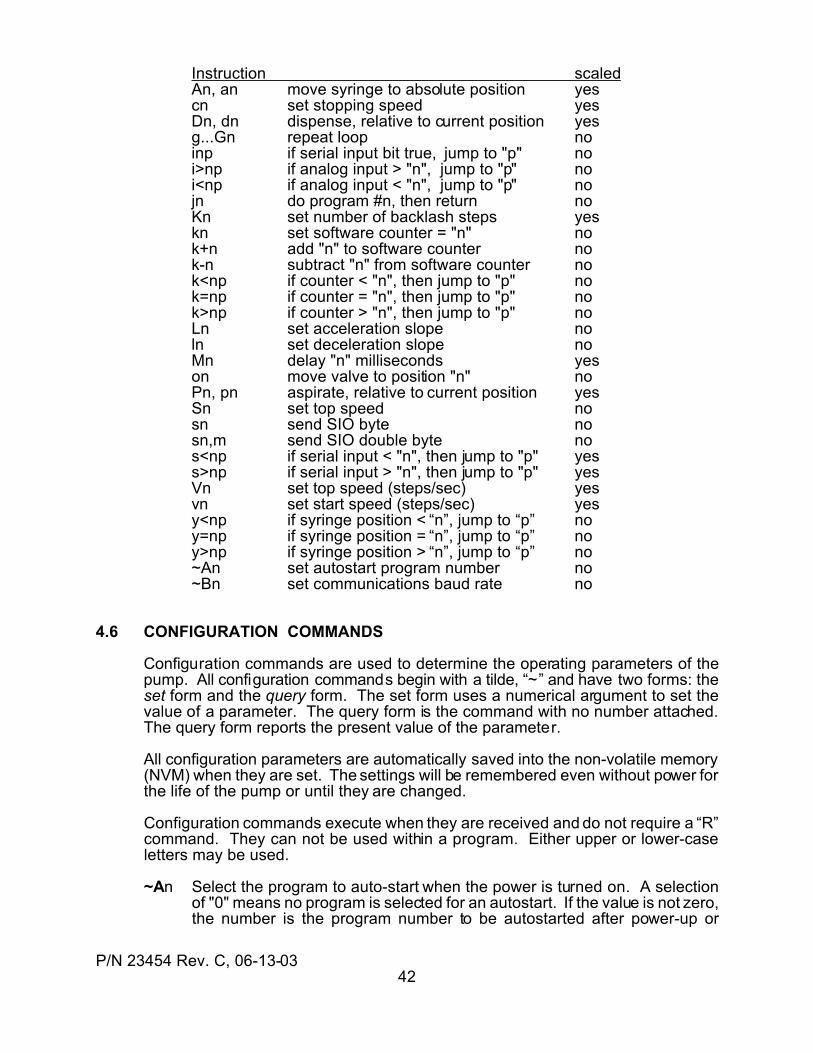
P/N 23454 Rev. C, 06-13-0342
Instruction scaledAn, an move syringe to absolute position yescn set stopping speed yesDn, dn dispense, relative to current position yesg...Gn repeat loop noinp if serial input bit true, jump to "p" noi>np if analog input > "n", jump to "p" noi<np if analog input < "n", jump to "p" nojn do program #n, then return noKn set number of backlash steps yeskn set software counter = "n" nok+n add "n" to software counter nok-n subtract "n" from software counter nok<np if counter < "n", then jump to "p" nok=np if counter = "n", then jump to "p" nok>np if counter > "n", then jump to "p" noLn set acceleration slope noln set deceleration slope noMn delay "n" milliseconds yeson move valve to position "n" noPn, pn aspirate, relative to current position yesSn set top speed nosn send SIO byte nosn,m send SIO double byte nos<np if serial input < "n", then jump to "p" yess>np if serial input > "n", then jump to "p" yesVn set top speed (steps/sec) yesvn set start speed (steps/sec) yesy<np if syringe position < “n”, jump to “p” noy=np if syringe position = “n”, jump to “p” noy>np if syringe position > “n”, jump to “p” no~An set autostart program number no~Bn set communications baud rate no
4.6 CONFIGURATION COMMANDS
Configuration commands are used to determine the operating parameters of thepump. All configuration commands begin with a tilde, “~” and have two forms: theset form and the query form. The set form uses a numerical argument to set thevalue of a parameter. The query form is the command with no number attached.The query form reports the present value of the parameter.
All configuration parameters are automatically saved into the non-volatile memory(NVM) when they are set. The settings will be remembered even without power forthe life of the pump or until they are changed.
Configuration commands execute when they are received and do not require a “R”command. They can not be used within a program. Either upper or lower-caseletters may be used.
~An Select the program to auto-start when the power is turned on. A selectionof "0" means no program is selected for an autostart. If the value is not zero,the number is the program number to be autostarted after power-up or
P/N 23454 Rev. C, 06-13-0343
Reset. If no parameter "n" is entered, the current value of "n" is returned.(n: 0...10, @) [0]
~Bn Select the communications baud rate. If no parameter “n” is entered, thecurrent value of "n" is returned.(n: 0...7) [3]
n Baud rate n Baud rate1 38,400 5 2,4002 19,200 6 1,2003 9,600 7 6004 4,800 8 300
~Hn Set the SET HOME button mode on the faceplate. If no parameter “n” isentered, the current value of "n" is returned. This parameter determines ifthe front panel SET HOME button is working or not working. This is usefulfor preventing users from resetting the Home position of the syringe.(n: 0 = the button operation is enabled.
1 = the button operation is disabled.) [0]
~in Enable or disable the valve power-up initialization mode. If no parameter “n”is entered, the current value of the parameter is returned. When power isfirst applied to a pump or immediately after a Reset, the valve normallyperforms a move to home (port “A”). In systems with several pumps, it maybe desired to inhibit this initialization move to prevent a large current demandon the power supply due to all pumps moving at the same time. If the power-up move is inhibited, the first valve move command or the first syringeinitialize command will cause the valve to perform an initialization move asthe first part of the command.(n: 0 = the move is enabled and will occur
1 = the move is inhibited and will not occur) [0]
~Ln Set User Input #3 operating mode. If "n" is omitted, the current value of theoperating mode will be returned. The default is 0. Regardless of theoperating mode, the syringe position snapshot feature is active (See “?29"in Section 4.7).
n Operating mode0 Normal The input is a normal logic input1 Limit A syringe dispense will stop when the input goes true
(low), and the input can still be read and tested like anormal logic input.
~Pn Select the communication protocol. If no parameter "n" is entered, thecurrent value of the parameter is returned.(n: 1=DT, 2=OEM) [1]
~Sn Select the Expansion I/O mode. This determines if one or two bytes will besent and received for each I/O operation. If the I/O Expander Board isused, the two-byte mode must be selected. If no parameter "n" is entered,the current value of the parameter is returned. The factory default is 1-byte.(n: 1=1-byte transfers, 2=2-byte transfers) [1]
P/N 23454 Rev. C, 06-13-0344
The simplest form of status query is a Carriage Return (hex code 0D). Thecommand “/address <carriage return >” returns only a single-character ASCIIstatus byte. Example: /1<Cr>
~Vn Set the valve type. If no "n" is entered, the current value of the parameteris returned. The factory default is “0" for units ordered without a valve drive.(n: 0...10) [1]
n Valve Type n Valve Type 0 no value 1 3 way non-distribution valve 2 3 way distribution valve 3 4 way non-distribution valve 4 4 way distribution valve 5 5 way non-distribution valve 6 5 way distribution valve 7 6 way non-distribution valve 8 6 way distribution valve 9 8 way non-distribution valve 10 8 way distribution valve
~Yn Select the valve position to which the valve will go just prior to moving thesyringe to the soft limit using the "Y4" command. The "~Vn" value ischecked for a valid entry before accepting the value of "n". This permits aport different from “A” to be used for the syringe initialization move.(n: 1...8) [1]
n Port n Port1 A 5 E2 B 6 F3 C 7 G4 D 8 H
~Zn Select the valve position to which the valve will go just prior to moving thesyringe to the soft limit using the "Z4" command. The "~Vn" value is checkedfor a valid entry before accepting the value of "n". This permits a portdifferent from “A” to be used for the syringe initialization move.(n: 1...8) [1]
n Port n Port1 A 5 E2 B 6 F3 C 7 G4 D 8 H
4.7 QUERY COMMANDS
Query commands are executed when they are received. They return a value orset of values to the query. A query command can be sent at any time, even if thepump is busy doing something else, and a reply will be sent.
All query commands are executed when they are received and can not be placedwithin a program. Query commands do not require a “R” command to executeimmediately.
Q Return the status byte. (See Section 5.0 for status replies.)
P/N 23454 Rev. C, 06-13-0345
q List the command string stored into non-volatile user program memory. Thisis used to view programs stored in non-volatile memory.
x? Report the last error that was trapped by an error trap instruction.
? Query the syringe absolute position. Return the value in steps from zeroposition (top-of-stroke).
?1 Query the syringe Start speed (vn) in steps per second.
?2 Query the syringe Top speed (Vn) in steps per second.
?3 Query the syringe Stop speed (cn) in steps per second.
?4 Query the status of the User Input #1. Return “1" (“true”) if low or “0" (“false”)if high.
?5 Query the status of the User Input #2. Return “1" (“true”) if low or “0"(“false”) if high.
?6 Query the status of the User Input #3. Return “1" (“true”) if low or “0"(“false”) if high.
?7 Query the voltage at the Digital Voltmeter input. Send the value to the hostcontroller as an ASCII base 10 number. Voltage = number x 0.02 volts.
?8 Query the valve position.
?9 Query the number of unused bytes (characters) in non-volatile programmemory. (170 maximum)
?10 Query the first byte value of the Expansion I/O port input. An input byte isinput (MSB first), and the numerical value of the input byte is reported in abase 10 ASCII format. The value uses a negative logic convention (low level= 1, high level = 0). In 1-byte mode, this is the only byte. In 2-byte mode,this is the first of two bytes.
?19 Query which program numbers are currently used to store a program.Return a list of the numbers in use, separated by a space between numbers.
?20 Query the numerical value of the second byte of the Expansion I/O portinput in 2-byte mode. Two input bytes are received (MSB first), and thenumerical value of the second input byte is reported in a base 10 ASCIIformat. The value uses a negative logic convention (low level = 1, high level= 0). This instruction is not valid in 1-byte mode.
?29 Query the contents of the syringe position snapshot memory. When theUser input #3 transitions from high to low, the current value of the syringeposition is stored in the snapshot memory. The last two consecutivesnapshots are saved and reported.
?30 Query the acceleration and deceleration values. Return the accelerationvalue first and the deceleration value second.
P/N 23454 Rev. C, 06-13-0346
?n Query the state of the Expansion I/O port input bit designated by "n". Aserial byte is input (MSB first), and the state of the designated bit is reportedas an ASCII "0" if the bit is "false" (high input logic level) or an ASCII "1" if"true" (low input logic level).n: 1...3 = parallel outputs 1...3
11...18 = serial byte 1, bit 1...8 of the serial expansion port21...28 = serial byte 2, bit 1...8 of the serial expansion port
F Report the communications buffer status.1 = command in buffer, 0 = buffer empty
& Report the firmware version. Return: Pxyy, where xyy is a three-digitnumber which denotes revision x.yy)
$ Query the number of valve stalls. Send the result to the host as an ASCIInumber. The value of the returned number is the number of times a stall andsubsequent automatic error recovery occurred. "0" = no error. If the thirdattempt fails, a valve overload error is generated.
% Report the number of valve movements since the last power-up or Reset.
* Report the supply voltage in decimal volts, rounded to the nearest 1/10 volt.The value is averaged over not less than 8 readings.
~A Query the NVM user program autostart state. Return "0" if disabled. Ifenabled, report the program number to autostart.
~B Query the communications baud rate. Return the baud number “n”.n Baud rate n Baud rate1 38,400 5 2,4002 19,200 6 1,2003 9,600 7 6004 4,800 8 300
~H Query the operating mode of the front panel SET HOME button.n: 0 = The button operation is enabled
1 = The button operation is disabled
~i Query the mode of the power-up (post Reset) valve initialize move.n: 0 = The move is enabled and will occur
1 = The move is inhibited and will not occur
~L Query the User Input #3 operating mode.n Operating mode0 Normal The input is a normal logic input (see Section 4.6)1 Limit A syringe dispense will stop when the input goes true
(low), and the input can be read and tested like anormal logic input.
~P Query the communications protocol. Communications protocols areexplained in Section 6.3. The default is the DT protocol.n: 1 = DT (data terminal)
2 = OEM
P/N 23454 Rev. C, 06-13-0347
~S Query the Expansion I/O operating mode.n: 1 = 1-byte transfers
2 = 2-byte transfers
~V Query the valve type setting. n Valve Type n Valve Type
0 no valve1 3 way non-distribution valve 2 3 way distribution valve3 4 way non-distribution valve 4 4 way distribution valve5 5 way non-distribution valve 6 5 way distribution valve7 6 way non-distribution valve 8 6 way distribution valve9 8 way non-distribution valve 10 8 way distribution valve
~Y Query the valve port to be used by the Yn initialization command.n Port n Port1 A 5 E2 B 6 F3 C 7 G4 D 8 H
~Z Query the valve port to be used by the Yn initialization command. See“~Yn” above for the returned values.
4.8 ERROR TRAPPING COMMANDS
Errors may occur during pump operation, in the structure of a user program, duringcommunications, or in the way a command is given. The pump recognizes theseerrors. Normally, an error causes a program or instruction to halt and generates anerror message to be reported in reply to the next received command. This normal response to an error can be redefined by a user program using a trap.
A trap is an instruction which directs the pump to go to a label in a program if aparticular error should occur. The commands following the label then determinewhat actions will be taken as a result of the error. An exit command marks the endof the error-handling command string (the “handler”) and determines what willhappen next.
A user error handler is thus made from three parts: the label which marks thebeginning of the handler, the commands which are the body of the handler, and theexit command which marks the end of the handler.
4.8.1 Trap Declarations
A trap instruction takes effect when it is declared in the program. It remains in effectas written unless it is changed afterwards. Thus error traps can be re-defined “on-the-fly” in a program. The syntax for an error trap is
xnp where “x” denotes an exception (trap) instruction“n” denotes the error number to be trapped“p” denotes the program label which starts the error handler routine
P/N 23454 Rev. C, 06-13-0348
Traps can provide graceful recovery or controlled exits from occasional errorconditions. A trap can NOT fix system problems or overcome seriousmechanical difficulties.
If the exit type “4" is used, some means must be used to prevent an “endlessloop”: error -> handler -> error -> handler...
If error #n should occur after a trap for error #n is set, the program will jump to thelabel “p”. By declaring the same trap with a different label, different error handlingroutines can be used for the same type of error in different parts of a program.
A trap will operate any number of times if the error occurs externally to the errorhandling routine. If the error recurs while executing the error handler (before theerror handler exit), the program will terminate with a standard error exit. In general,if an error persists in recurring, it can not be solved with a trap. The trap exists todeal with occasional errors, but cannot fix system errors external to the pump orserious pump mechanical failures.
4.8.2 Trap Exits
The last instruction of an error handler (exception program) MUST be a trap exitcommand. Trap exit commands mark the end of an error handler and specify whataction the program is to take when exiting the error handler.
The general syntax is
tn where “t” denotes a trap routine exit“n” specifies the action to be taken after exiting
(n: 1 = Return program execution to the instruction following the instruction which caused the error2 = Restart the program from the beginning3 = Perform a normal error exit with an error message4 = Retry the instruction which caused the error) [n/a]
4.8.3 Error Trap Query
The pump may be queried at any time to report the last error encountered by a trap.The syntax is
x? Report the last error that was trapped.
This command executes when received and does not require a “R” command. Thiscommand can not be placed within a program.
P/N 23454 Rev. C, 06-13-0349
4.9 MISCELLANEOUS COMMANDS
4.9.1 Software Counters
The pump contains eight software counters. A software counter is a register in theRAM which can hold a number and with which simple arithmetic and tests can bedone. These counters are useful for holding numbers for other uses, for countingprogram cycles, for tracking external events, or for offsetting numbers inputexternally.
The counters are organized as one active and eight exchangeable memorylocations. All operations are performed on the active counter. To use one of theother counter memories, that memory must be exchanged with the active counter.The value of the active counter will then be placed in the memory location and thecontents of the memory will be placed into the active counter.
The symbol for the counters is “k”. The counter instructions require a “R” commandto execute immediately. The test-and-jump instructions must be used within aprogram.
k Query the current value of the active counter
kn Set the active counter equal to the number “n”
k+n Add the number “n” to the active counter
k-n Subtract the number “n” from the active counter
k^n Exchange the contents of counter memory “n” with the active counter.
k<np If the active software counter is less than "n", jump to label "p". A softwarecounter is internal to the pump and can be set to a number, added to,subtracted from, and tested. It is useful for counting program events and forthe temporary storage of internal variables such as syringe or valveposition. See Section 4.9.1 for more information on software counters.
(n: 0...65535, @n p: a...z, A...Z)
k=np If the active software counter is equal to "n", jump to label "p". (n: 0...65535, @n p: a...z, A...Z)
k>np If the active software counter is greater than "n", go to label "p". (n: 0...65535, @n p: a...z, A...Z)
Example: memory 1 (#1) = 13, memory 3 (#3) = 45, active counter (ac) = 122Increment #3.
k^3 #1 = 13, #3 = 122, ac = 45k+1 #1 = 13, #3 = 122, ac = 46k^3 #1 = 13, #3 = 46, ac = 122
Example: Count cycles and jump when a limit is reached.k+1 Increment the active counterk>250A if the count exceeds 250, jump to program label “A”
P/N 23454 Rev. C, 06-13-0350
4.9.2 Flags
Flags are software switches which can be set (“turned on”), cleared (“turned off”),and tested. Flags are used to indicate the status of something or to change theway something is done after the first time.
There are six general-purpose flags (f1...f6) and three special-purpose flags (f7...f9).The flag instructions require a “R” command to execute immediately. The test-and-jump instructions must be used within a program.
fn+ set flag “n”(n: 1...9) [n/a]
fn- clear flag “n”(n: 1...9) [n/a]
fn? query the status of flag “n”. Return a “0" is cleared or a “1" if set.(n: 1...9) [n/a]
fnp test the status of flag “n”. If it is set, then clear it and jump to program label“p”. This is useful for altering the way something is done the first time thisinstruction is encountered. The first time will see the flag set and subsequenttimes will see it cleared.(n: 1...8) [n/a]
fn-p test the status of flag “n”. If it is clear, then jump to program label “p”. Thisis useful for altering the way something is done after the first time it isencountered.(n: 1...8) [n/a]
4.9.3 SET HOME Button Control
The SET HOME button on the front panel can be inhibited, thus preventing it frombeing inadvertently activated by a user. There are two ways this can be done, oneof which is a long-term control and one of which is intended to be dynamically set“on-the-fly”.
When the button is enabled, pressing the button will perform the “W5" commandfunction, which sets the current syringe position as the “zero”, or top-of-strokeposition and stores the result into non-volatile memory. This is an operation whichshould be done only when the valve, syringe, or washer has been changed or whenthe top-of-stroke position needs to be changed.
When the button is disabled, pressing the button has no effect. The two means ofcontrolling the activation of the SET HOME button are:
~Hn Set the SET HOME button mode. If no parameter “n” is entered, the currentvalue of "n" is returned. Use this as a long-term enable or inhibit. Thenumber times the SET HOME function can be done is limited to 10,000.(n: 0 = the button operation is enabled.
1 = the button operation is disabled.) [0]
P/N 23454 Rev. C, 06-13-0351
f9+ Inhibit the SET HOME button operation. This command operates in RAM(temporary memory) and is effective as long as power is applied. Use thiscommand to inhibit button operation “on-the-f ly”.
f9- Enable the SET HOME button operation. This command operates in RAM(temporary memory) and is effective as long as power is applied. Use thiscommand to enable button operation “on-the-fly”.
f9? Query the status of the button flag “f9". Report “1" is disabled or “0" ifenabled.
The ~Hn and f9 flag interact. If the ~H is set to inhibit, the button will be inhibitedregardless of the state of the f9 flag. On useful application of the flags is to set f9when the system initializes and clear it only when a technician enters an accesscode into a controller or activates a User Input to service the pump.
4.9.4 External Syringe Motion Limit Input
For applications in which a dispense must be terminated by some external eventor condition, the User Input #3 can be configured as an external limit input. Suchsituations may include dispensing to a fixed level, dispensing to a PH, or creatingan external safety stop button.
The normal operating mode for User Input #3 is a logic input. The "~Ln" pumpconfiguration command (see Section 4.6) can be used to set input #3 into the "limit"mode. In the limit mode, a true (low) input will halt a syringe move in the dispensedirection, but has no effect in the aspirate direction. The behavior of the externallimit input can be modified by the action of either flag #7 or flag #8. The syntax forflags is given in section 4.9.2.
Once stopped, the syringe cannot be moved further in the dispense directionunless the Limit input changes to an "off" (high) condition or unless the flag #7 isset. Moves in the aspirate direction can still be made at any time. If flag #7 is set,then a dispense may be initiated against an active limit input. When the move hasbegun, the flag is automatically cleared so that the next limit input transition fromhigh-to-low will cause the syringe to stop again. This is useful in applications wheresuccessive dispenses are to be made under the control of an external signal, suchas filling containers using a fill-until-signal.
For some applications, it is desired to stop a dispense after the second high-to-lowlimit input transition. This is accomplished by setting flag #8. Such a limit action isuseful for titrations where the transition is measured optically and a pair of pulsesis generated through the transition region. If this feature is used in conjunctionwith the "snapshot" feature, fully automatic titrations can be done.
Even in the "Limit" mode, the User Input #3 can still be used for the normal logicfunctions of reporting Input #3 status to a host and for "test-and-branch" decisionswithin a program.
P/N 23454 Rev. C, 06-13-0352
4.9.5 Motor Power Control
The syringe and valve motors can be turned “on” and “off” individually. The syringemotor normally idles at half-power to conserve energy and reduce idle motorheating. The syringe motor automatically goes to full power at the beginning of amove and returns to half-power after the move completes.
The valve motor is normally off. The valve motor automatically turns “on” at thebeginning of a valve move and turns “off” at the end of a valve move. There are norotary forces acting on a valve and the combination of the internal friction in a valveand the motor detent torque are sufficient to hold the valve in place between moves.
The individual motor powers can be controlled by the command
mn where “n” denotes the motor and action to take.n: 0 = turn off the syringe motor
1 = turn on the syringe motor2 = turn off the valve motor3 = turn on the valve motor
When a move takes place in either the syringe or valve motor, the normal motorpower operation for the move overrides the current state of the “mn” command.
Example:m0 turn off the syringe motor (motor is off)A1200 send the syringe to position “1200" (motor is on during
and after move)
4.9.6 Repeat Command String
An entire command string can be repeated in its entirety by sending the stringrepeat command. The syntax is:
X Repeat the last command string
This command can be used repeatedly and will repeat the same command stringeach time. This command does not work for queries and configuration commands.
Example:
o2A12000o-1A0R Move the valve to port B, fill the syringe, movethe valve to port A, empty the syringe.
X Do all of the above commands again in the sameway.
X Do all the commands listed above again.
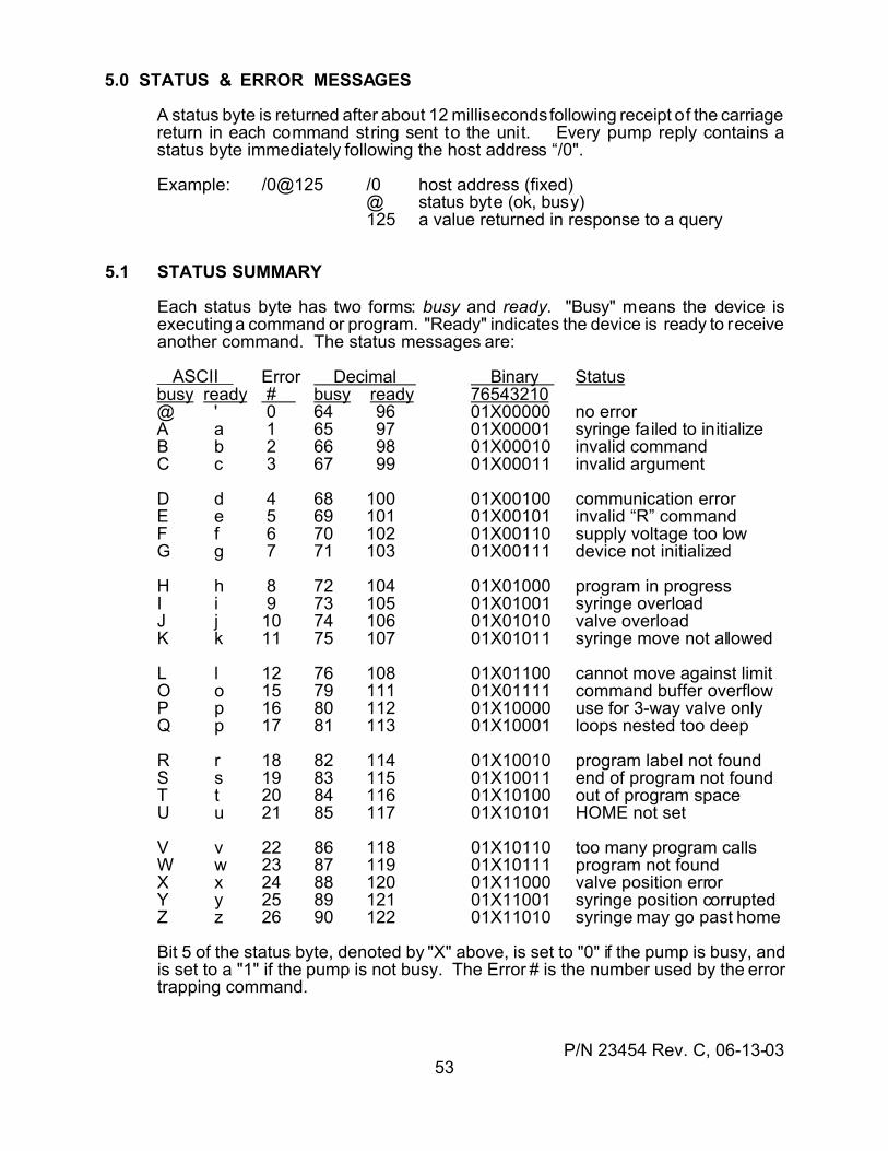
P/N 23454 Rev. C, 06-13-0353
5.0 STATUS & ERROR MESSAGES
A status byte is returned after about 12 milliseconds following receipt of the carriagereturn in each command string sent to the unit. Every pump reply contains astatus byte immediately following the host address “/0".
Example: /0@125 /0 host address (fixed)@ status byte (ok, busy)125 a value returned in response to a query
5.1 STATUS SUMMARY
Each status byte has two forms: busy and ready. "Busy" means the device isexecuting a command or program. "Ready" indicates the device is ready to receiveanother command. The status messages are:
ASCII Error Decimal Binary Statusbusy ready # busy ready 76543210@ ' 0 64 96 01X00000 no errorA a 1 65 97 01X00001 syringe failed to initializeB b 2 66 98 01X00010 invalid commandC c 3 67 99 01X00011 invalid argument
D d 4 68 100 01X00100 communication errorE e 5 69 101 01X00101 invalid “R” commandF f 6 70 102 01X00110 supply voltage too lowG g 7 71 103 01X00111 device not initialized
H h 8 72 104 01X01000 program in progressI i 9 73 105 01X01001 syringe overloadJ j 10 74 106 01X01010 valve overloadK k 11 75 107 01X01011 syringe move not allowed
L l 12 76 108 01X01100 cannot move against limitO o 15 79 111 01X01111 command buffer overflowP p 16 80 112 01X10000 use for 3-way valve onlyQ p 17 81 113 01X10001 loops nested too deep
R r 18 82 114 01X10010 program label not foundS s 19 83 115 01X10011 end of program not foundT t 20 84 116 01X10100 out of program spaceU u 21 85 117 01X10101 HOME not set
V v 22 86 118 01X10110 too many program callsW w 23 87 119 01X10111 program not foundX x 24 88 120 01X11000 valve position errorY y 25 89 121 01X11001 syringe position corruptedZ z 26 90 122 01X11010 syringe may go past home
Bit 5 of the status byte, denoted by "X" above, is set to "0" if the pump is busy, andis set to a "1" if the pump is not busy. The Error # is the number used by the errortrapping command.
P/N 23454 Rev. C, 06-13-0354
5.2 DETAILED EXPLANATIONS
@, ` The device is operating normally. No error condition has been detected.
A, a An attempt to initialize the syringe has failed. No syringe move commandother than an initialize command will be valid until initialization is complete.This error is usually the result of a syringe overload. Check the fluid pathsfor restrictions or obstructions. Check the valve ports for alignment. If areduced speed succeeds, try a shorter fluid path or larger diameter fluid path.
B, b A command just sent was not recognized as valid. A character was sentthat is not part of the command set. A typing error may have occurred. Forexample, "N1000" is not valid because "N" is not a legal command.
C, c The number sent with a command is not valid. The command itself wasvalid, but the value sent with it was out of the allowed range of values for thatcommand. For example, "A25000" has a value, "25000", which is not withinthe range of available values. This most frequently occurs when a series ofrelative dispenses is commanded, and the last dispense command exceedsthe volume remaining.
D, d The checksum or sequence number was incorrect (OEM protocol only).The message should be retransmitted with a new sequence number. Thesequence number is adjusted each time a command is repeated to preventa repeated command from being executed more than once. See Section6.6.3 for the checksum and sequence number definitions.
E, e A “R” (Run) command was sent with a command which does not require it.
F, f The device supply voltage was too low. The condition may be caused by alow power supply voltage or by voltage transients on the power supply wiringnear the pump.
G, g A move command was sent while the device was in an uninitialized state.The device must be initialized before a move command will be accepted.An initialized state results after a power-up, a reset, or a syringe overloaderror.
H, h A program or command is executing. A new command (other than queries,“Vn” and “T”) cannot be sent until the present command completes.
I, i The load on the syringe drive axis was too great. The syringe motor stalled.A stall does no damage to the drive system. There are several possibilities:(1) A fluid path was constricted or blocked. Check for kinks in tubing,
valve washers which may have a shrunken hole, other valves sticking,and other sources of constriction.
(2) The syringe velocity was too high. Back pressure increases with thesquare of velocity. Available thrust force also decreases with velocity.Reduce the syringe top speed ("Vn" or "Sn").
(3) The acceleration is too high. High acceleration places a powerdemand upon the syringe motor in addition to the friction and fluidback pressure demands. Decrease the acceleration value ("Ln").
(4) The flow path inside diameter is too small for the fluid flow rate. Alarger diameter, shorter path, or lower velocity may be required. The
P/N 23454 Rev. C, 06-13-0355
back pressure varies as nearly the fourth power of the diameter ofthe path and directly with the length
J, j The valve motor failed to complete a commanded move. Some possibilitiesare:(1) The valve is wearing out and needs replacement.(2) There is particle contamination in the valve. Particles may come from
another place and be transported into the valve or may result fromcrystal deposits in the valve.
(3) The chemistry results in swelling or softening of the valve materials,resulting in binding. Check chemical compatibility.
(4) The fluid or operating environment is too hot, resulting in swelling andbinding of the valve.
(5) There is a misalignment of the valve drive and the valve stem. Thistypically results in binding at one point in the valve rotation.
(6) A fitting is screwed in too tight, distorting the valve and causingbinding.
K, k A syringe move command was not allowed because the valve is in a bypassposition (syringe port blocked), or because the supply voltage was too low.
L, l The User Input #3 limit input is active. The syringe cannot dispense againstan active limit input.
O, o A command was sent while another was executing. The last commandwhich was sent was not executed and was discarded.
P, p An instruction was sent which applies only to a three-way non-distributionvalve only (O, I, B) with the valve type set to other than a three-way non-distribution.
Q, q There are too many loops within loops in the program.
R, r A program label called by a jump instruction was not found in the program.Remember that the labels are case-sensitive. A label may have beenchanged or deleted when editing a program.
S, s A program stored in the non-volatile memory (NVM) does not have therequired end-of-program indicator. The NVM may have been corrupted. Trysaving the program again into NVM.
T, t There is not enough program memory to hold the entire program.
U, u The HOME (zero) position has not been set. The syringe axis requirescalibration. See Sections 3.2 and 4.1.3.
V, v A called program has called another program. Only one program can becalled at the same time.
W, w The program called or commanded to execute cannot be found in memory.
X, x The valve position is not valid. This error occurs when the valve positioncode wheel sensor fails to see a slot after all valve motion has ceased.
P/N 23454 Rev. C, 06-13-0356
Some possible causes are:(1) The valve failed to complete the preceding move.(2) The valve position has been displaced since the last move completed.(3) Contamination has blocked one slot in the valve opto disk or a valve
sensor face is contaminated.
Y, y The current computed syringe location is in error. The position value isoutside the range of acceptable values. The syringe position memory haslikely been corrupted.
Z, z The syringe may try to go upwards past the Home (zero) position. Thismessage is generated whenever a check of the computed syringe positionexhibits an out-of-tolerance error. Syringe “crashes” are avoided by thismeans.
When the syringe position is calibrated, the distance from the INITIALIZEposition to the top-of-stroke (zero) is stored into NVM. Each time the syringepasses up through the INITIALIZE point, the computed position is comparedto the stored value. If the two values do not match within a given error band,the syringe is stopped and the error message is generated.
The two most common sources of this error are (1) having the Home positionset at the INITIALIZE point and (2), having “lost” (not counted) steps duringa move. Steps can be lost when the “T” command is used to stop a syringewhich is moving at speeds above about 2000 steps pers second or when asyringe overload occurs.
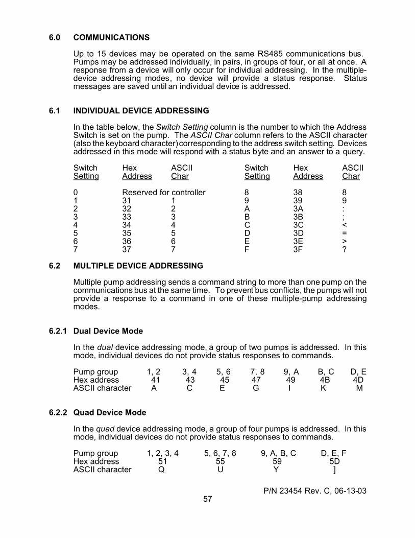
P/N 23454 Rev. C, 06-13-0357
6.0 COMMUNICATIONS
Up to 15 devices may be operated on the same RS485 communications bus. Pumps may be addressed individually, in pairs, in groups of four, or all at once. Aresponse from a device will only occur for individual addressing. In the multiple-device addressing modes, no device will provide a status response. Statusmessages are saved until an individual device is addressed.
6.1 INDIVIDUAL DEVICE ADDRESSING
In the table below, the Switch Setting column is the number to which the AddressSwitch is set on the pump. The ASCII Char column refers to the ASCII character(also the keyboard character) corresponding to the address switch setting. Devicesaddressed in this mode will respond with a status byte and an answer to a query.
Switch Hex ASCII Switch Hex ASCIISetting Address Char Setting Address Char
0 Reserved for controller 8 38 81 31 1 9 39 92 32 2 A 3A :3 33 3 B 3B ;4 34 4 C 3C <5 35 5 D 3D =6 36 6 E 3E >7 37 7 F 3F ?
6.2 MULTIPLE DEVICE ADDRESSING
Multiple pump addressing sends a command string to more than one pump on thecommunications bus at the same time. To prevent bus conflicts, the pumps will notprovide a response to a command in one of these multiple-pump addressingmodes.
6.2.1 Dual Device Mode
In the dual device addressing mode, a group of two pumps is addressed. In thismode, individual devices do not provide status responses to commands.
Pump group 1, 2 3, 4 5, 6 7, 8 9, A B, C D, EHex address 41 43 45 47 49 4B 4DASCII character A C E G I K M
6.2.2 Quad Device Mode
In the quad device addressing mode, a group of four pumps is addressed. In thismode, individual devices do not provide status responses to commands.
Pump group 1, 2, 3, 4 5, 6, 7, 8 9, A, B, C D, E, FHex address 51 55 59 5DASCII character Q U Y ]
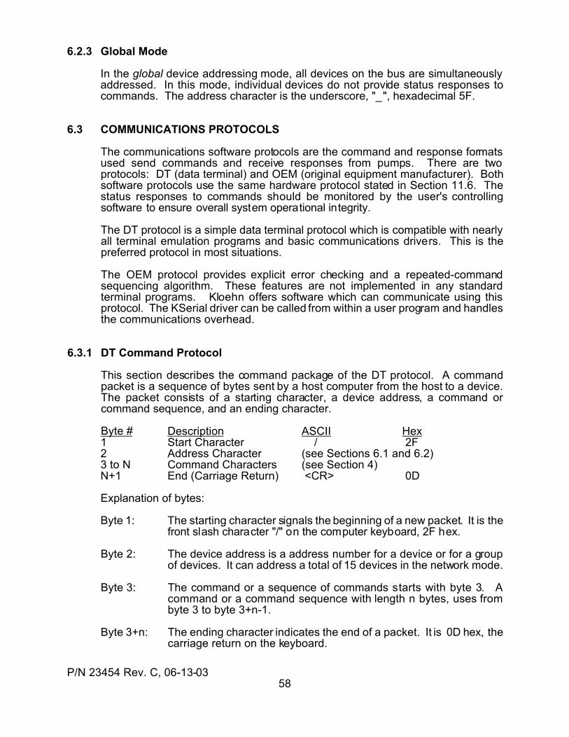
P/N 23454 Rev. C, 06-13-0358
6.2.3 Global Mode
In the global device addressing mode, all devices on the bus are simultaneouslyaddressed. In this mode, individual devices do not provide status responses tocommands. The address character is the underscore, "_", hexadecimal 5F.
6.3 COMMUNICATIONS PROTOCOLS
The communications software protocols are the command and response formatsused send commands and receive responses from pumps. There are twoprotocols: DT (data terminal) and OEM (original equipment manufacturer). Bothsoftware protocols use the same hardware protocol stated in Section 11.6. Thestatus responses to commands should be monitored by the user's controllingsoftware to ensure overall system operational integrity.
The DT protocol is a simple data terminal protocol which is compatible with nearlyall terminal emulation programs and basic communications drivers. This is thepreferred protocol in most situations.
The OEM protocol provides explicit error checking and a repeated-commandsequencing algorithm. These features are not implemented in any standardterminal programs. Kloehn offers software which can communicate using thisprotocol. The KSerial driver can be called from within a user program and handlesthe communications overhead.
6.3.1 DT Command Protocol
This section describes the command package of the DT protocol. A commandpacket is a sequence of bytes sent by a host computer from the host to a device.The packet consists of a starting character, a device address, a command orcommand sequence, and an ending character.
Byte # Description ASCII Hex1 Start Character / 2F2 Address Character (see Sections 6.1 and 6.2)3 to N Command Characters (see Section 4)N+1 End (Carriage Return) <CR> 0D
Explanation of bytes:
Byte 1: The starting character signals the beginning of a new packet. It is thefront slash character "/" on the computer keyboard, 2F hex.
Byte 2: The device address is a address number for a device or for a groupof devices. It can address a total of 15 devices in the network mode.
Byte 3: The command or a sequence of commands starts with byte 3. Acommand or a command sequence with length n bytes, uses frombyte 3 to byte 3+n-1.
Byte 3+n: The ending character indicates the end of a packet. It is 0D hex, thecarriage return on the keyboard.
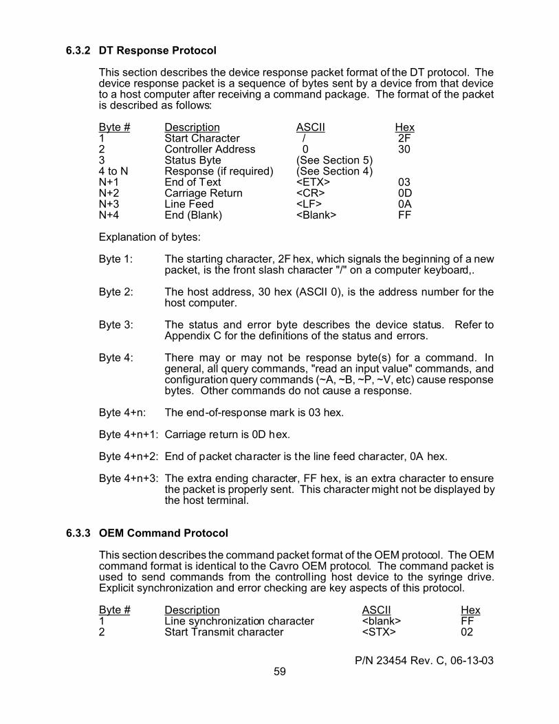
P/N 23454 Rev. C, 06-13-0359
6.3.2 DT Response Protocol
This section describes the device response packet format of the DT protocol. Thedevice response packet is a sequence of bytes sent by a device from that deviceto a host computer after receiving a command package. The format of the packetis described as follows:
Byte # Description ASCII Hex1 Start Character / 2F2 Controller Address 0 303 Status Byte (See Section 5)4 to N Response (if required) (See Section 4)N+1 End of Text <ETX> 03N+2 Carriage Return <CR> 0DN+3 Line Feed <LF> 0AN+4 End (Blank) <Blank> FF
Explanation of bytes:
Byte 1: The starting character, 2F hex, which signals the beginning of a newpacket, is the front slash character "/" on a computer keyboard,.
Byte 2: The host address, 30 hex (ASCII 0), is the address number for thehost computer.
Byte 3: The status and error byte describes the device status. Refer toAppendix C for the definitions of the status and errors.
Byte 4: There may or may not be response byte(s) for a command. Ingeneral, all query commands, "read an input value" commands, andconfiguration query commands (~A, ~B, ~P, ~V, etc) cause responsebytes. Other commands do not cause a response.
Byte 4+n: The end-of-response mark is 03 hex.
Byte 4+n+1: Carriage return is 0D hex.
Byte 4+n+2: End of packet character is the line feed character, 0A hex.
Byte 4+n+3: The extra ending character, FF hex, is an extra character to ensurethe packet is properly sent. This character might not be displayed bythe host terminal.
6.3.3 OEM Command Protocol
This section describes the command packet format of the OEM protocol. The OEMcommand format is identical to the Cavro OEM protocol. The command packet isused to send commands from the controlling host device to the syringe drive.Explicit synchronization and error checking are key aspects of this protocol.
Byte # Description ASCII Hex1 Line synchronization character <blank> FF2 Start Transmit character <STX> 02
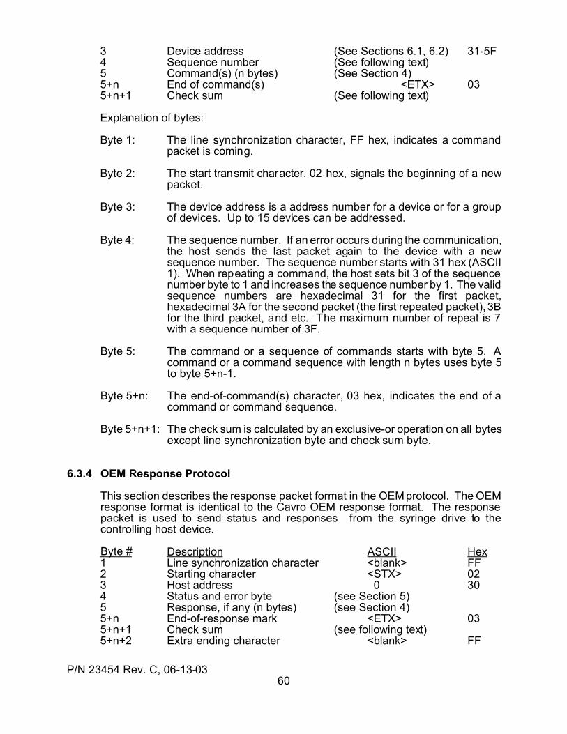
P/N 23454 Rev. C, 06-13-0360
3 Device address (See Sections 6.1, 6.2) 31-5F4 Sequence number (See following text)5 Command(s) (n bytes) (See Section 4)5+n End of command(s) <ETX> 035+n+1 Check sum (See following text)
Explanation of bytes:
Byte 1: The line synchronization character, FF hex, indicates a commandpacket is coming.
Byte 2: The start transmit character, 02 hex, signals the beginning of a newpacket.
Byte 3: The device address is a address number for a device or for a groupof devices. Up to 15 devices can be addressed.
Byte 4: The sequence number. If an error occurs during the communication,the host sends the last packet again to the device with a newsequence number. The sequence number starts with 31 hex (ASCII1). When repeating a command, the host sets bit 3 of the sequencenumber byte to 1 and increases the sequence number by 1. The validsequence numbers are hexadecimal 31 for the first packet,hexadecimal 3A for the second packet (the first repeated packet), 3Bfor the third packet, and etc. The maximum number of repeat is 7with a sequence number of 3F.
Byte 5: The command or a sequence of commands starts with byte 5. Acommand or a command sequence with length n bytes uses byte 5to byte 5+n-1.
Byte 5+n: The end-of-command(s) character, 03 hex, indicates the end of acommand or command sequence.
Byte 5+n+1: The check sum is calculated by an exclusive-or operation on all bytesexcept line synchronization byte and check sum byte.
6.3.4 OEM Response Protocol
This section describes the response packet format in the OEM protocol. The OEMresponse format is identical to the Cavro OEM response format. The responsepacket is used to send status and responses from the syringe drive to thecontrolling host device.
Byte # Description ASCII Hex1 Line synchronization character <blank> FF2 Starting character <STX> 023 Host address 0 304 Status and error byte (see Section 5)5 Response, if any (n bytes) (see Section 4)5+n End-of-response mark <ETX> 035+n+1 Check sum (see following text)5+n+2 Extra ending character <blank> FF
P/N 23454 Rev. C, 06-13-0361
Explanation of bytes:
Byte 1: The line synchronization, FF hex
Byte 2: The starting character, 02 hex, signals the beginning of a new packet.
Byte 3: The host address, 30 hex, is the address number for the hostcomputer.
Byte 4: The status and error byte describes the device status. Please referto Appendix C for the definitions of the status and errors.
Byte 5: There may or may not be response byte(s) for a command. Ingeneral, all query commands, read input commands, andconfiguration query commands (~A, ~B, ~P, ~V, etc) produceresponse bytes. Other commands do not produce a response.
Byte 5+n: The end-of-response mark, 03 hex, indicates the end of the responsebyte(s).
Byte 5+n+1: The check sum is calculated by an exclusive-or operation on all bytesexcept the line synchronization byte and the check sum byte.
Byte 5+n+2: The extra ending character, FF hex, is an extra character to ensurethe packet is properly sent. This character might not be displayed thehost terminal.
6.4 COMMUNICATIONS SETTINGS
There are four communications settings: address, bus termination, baud rate, andprotocol. Baud rate and protocol are set by the configuration commands “~Bn” and“~Pn” as explained in Section 4.6. The address is set via the Address Switch or thewiring on the card edge connector, as explained in Section 2.5.2 and Section 3.4.2.The bus termination setting is explained in Section 2.5.1 and Section 3.4.1.
6.5 CONNECTING MULTIPLE DEVICES
Up to 15 devices may be connected to the same RS485 communications bus. Thebus consists of three wires: "A", "B", and signal ground. The interface is normallydone via pins on P1, identified in Section 2.4.1. A proper bus structure consists ofthe bus wiring and terminations at each end of the bus.
6.5.1 Bus Wiring
The bus wiring should connect all RS485 "A" pins to one wire, all "B" pins to anotherwire, and all comm ground pins to a third wire. The connections begin at one deviceand proceed from that device to the next, one device after another. The threewires connecting one device to the next should be twisted together with a twist ratefrom one to three twists per inch. A wiring diagram is shown in Figure 6-1. Thewiring to connect a PC to the first drive unit is shown in Figure 3.5.
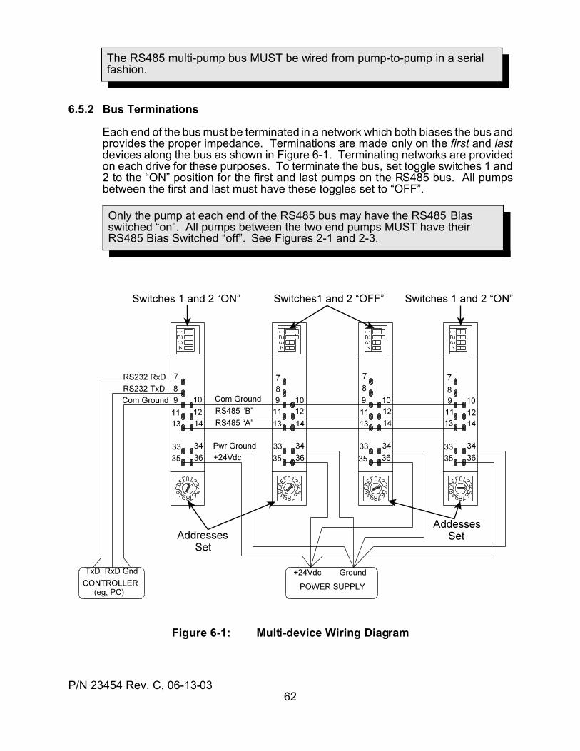
P/N 23454 Rev. C, 06-13-0362
The RS485 multi-pump bus MUST be wired from pump-to-pump in a serialfashion.
Only the pump at each end of the RS485 bus may have the RS485 Bias switched “on”. All pumps between the two end pumps MUST have theirRS485 Bias Switched “off”. See Figures 2-1 and 2-3.
6.5.2 Bus Terminations
Each end of the bus must be terminated in a network which both biases the bus andprovides the proper impedance. Terminations are made only on the first and lastdevices along the bus as shown in Figure 6-1. Terminating networks are providedon each drive for these purposes. To terminate the bus, set toggle switches 1 and2 to the “ON” position for the first and last pumps on the RS485 bus. All pumpsbetween the first and last must have these toggles set to “OFF”.
Figure 6-1: Multi-device Wiring Diagram
P/N 23454 Rev. C, 06-13-0363
6.6 COMMUNICATIONS CHECKS
This section presents some procedures for determining whether a device iscommunicating with a host controller. The checks are predicated upon the use ofsome form of terminal emulator program running on a PC. This is a type of programwhich sends ASCII characters typed on the keyboard to a serial port and displaysthe ASCII responses received. Before using such a program, determine thenumber to which the Address Switch, shown in Figure 3-3, is set. The AddressSwitch setting determines the value (from the tables in Sections 6.1 and 6.2) whichmust be substituted for the notation "<addr>". Each new command string mustbegin with a front slash ( / ) followed by the value of <addr>. Each command stringmust end with a carriage return (the "return" or "enter" key). See Section 4 for thecommand syntax, and Section 6.3.1 for the DT command protocol. Note that eachkey is sent when the key is pressed, so typed characters cannot be edited. Editingkeystrokes will be sent to the syringe drive and will result in syntax errors.
After the communications wiring is connected and the PC serial port cable hasbeen connected to the first device on the bus, turn on the pumps. When the power-up valve move is complete, send a Query of the module status as shown next. Ifneeded, see Section 3.3, Section 3.4, and Section 3.5 for communications setupinstructions.
type /1<enter> Query the status of pump #1/0' Response is "not busy, no errors”
If a response occurs, communications is operating properly. A valid response froma communicating module will always begin with "/0". This is the default address ofthe host controller. If there are no errors to be reported, the next character after the"/0" will be either an accent ( ' ) or a “@”. The accent signifies that the module is notbusy and is ready to accept any commands. The "@" signifies that the module isbusy and therefore only queries and the Terminate (T) command are acceptable.
Note: If the query is sent while the power-up initialization sequence is in progress,no response will be seen. The pump does not "listen" until the power-up sequenceis completed.
If an apostrophe ( ` ) or an "at sign" (@) is not returned, and a letter is returned inits place, then the module is reporting an internal error condition. The interpretationof such letter codes is given in Section 5.
If there is no response, then if the pump is not powered up, the communicationshardware connection is not properly made, or the communications program iseither not properly configured or not operating correctly. Check the items below:
(1) Insure that the communications connector is inserted properly into the RS-232 connector and NOT into the RS485 connector.
(2) Try another comm port selection in step (5) of the Terminal program setupprocedure (Section 3.5.1).
(3) Using a voltmeter, with the communications cable connected to the RS-232pins on P1, measure voltages from the "GND" pin to the "RXD IN" pin andthe "TXD OUT" pin. Each pin should measure -6 Vdc to -15Vdc. If they donot, the following errors may exist.
(a) "RXD IN" fails the check: the host PC port is not functioning, the
P/N 23454 Rev. C, 06-13-0364
communications cable is defective, or it is plugged in backwards.(b) "TXD OUT" fails the check: the RS-232 converter board or the
communications cable is defective, or the module is not powered on.
6.7 COMMUNICATIONS DRIVERS
A communications driver is a program, module, procedure, or function which canbe called by a program to send and receive ASCII strings to and from a pump. Ingeneral, drivers should be designed to "trap" (receive and recognize) the statuscodes returned by a syringe drive in response to a command.
Kloehn Company provides a driver called KSerial which operates from thecommand line and can be called from within a user’s program. KSerial handles allthe communications overhead with Kloehn pumps in both DT and OEM protocols.
Appendix C provides a sample QBasic program which emulates a terminal in theDT communications mode. This code can be updated to Visual Basic® code orused as a model for a simple, user-written DT protocol communications driver.
P/N 23454 Rev. C, 06-13-0365
7.0 PROGRAM MEMORY
The VersaPump 3 has the ability to store and execute command strings. Acommand string is a group of commands run together, without spaces, to form asingle line of legal ASCII characters. Such a string is also called a program. Forexample, the commands
I move valve to input positionA0 move syringe to fully-closed positionA3000 fill syringeM500 delay 500 millisecondsO move valve to output positionD1500 dispense half of syringe
can be placed into a single command string (program) as follows:
IA0A3000M500OD1500
In a command string, each new command will execute immediately after thepreceding command has completed. The command sequence will run in theminimum possible time without the need to query the drive to determine whether itis busy or ready for the next command. This can eliminate much communicationsoverhead. Such a program can be executed immediately or some time after theprogram is sent to the drive. It can be executed from temporary memory (RAM) orfrom non-volatile memory (NVM).
7.1 TEMPORARY MEMORY
When a command string is sent to the drive, the string is entered into temporarymemory (RAM). This memory retains its contents while power is applied to the driveunit. When power is removed, the contents of RAM are lost. After a commandstring is executed, it may be repeated by sending the "X" command.
To execute a program at the time it is sent, append a "R" (“Run”) command to thestring. If no "R" command is appended, the program will execute when asubsequent "R" command is sent. If another command is sent after the programstring and before the "R", or if the "R" is appended to another command, theoriginal program string will be overwritten by the last command string.
For example, the command "D1000R" will execute as soon as it is received by thedrive. The command "D1000" will be stored into RAM, but will not execute until aseparate, subsequent "R" is sent.
7.2 NONVOLATILE MEMORY
Non-volatile memory (NVM) will retain its contents even after power has beenremoved. The minimum retention time is about 15 years. Thus the NVM acts asif it were a "solid-state disk drive". Up to ten programs can be stored in the NVM.The maximum number of times a program string may be written into the NVM is10,000. After 10,000 writes, the integrity of a stored program cannot beguaranteed. There is no limit to the number of times a stored program can be reador executed.
P/N 23454 Rev. C, 06-13-0366
The maximum number of times a program string may be written into the NVMis 10,000. After this, the integrity of a stored program is not guaranteed.
The COMM DEFAULT toggle switch must be set to OFF for the Auto-Startfeature to function. The toggle in the ON condition will inhibit Auto-Start.
7.2.1 Saving and Erasing a Program
A program string is saved into the NVM by sending it to the RAM without a "R" runcommand appended, and then sending the "En" command as a separatecommand. When the “En” command is received, the string in RAM is transferredinto the NVM as stored as “program #n”. To erase a command string in NVM, eitheroverwrite it with another command string or send the "en" (erase) command.
Because of the limitation on writes, NVM should not be written every time anapplication is run. It should be used to store a command sequence or program ifthat program will be long-lived in the application. Short-term programs such asprograms which can change often, should be executed from RAM. Some programwhich vary in the numbers but not in structure can use general variables, asexplained in Section 4.5.
7.2.2 Listing a Program
A program saved into NVM can be queried with the "qn" (program query) command.When the "qn" command is received, the drive will respond by sending the completecommand string, if any, found in the NVM. The command string will be terminatedwith a period. If no command string is found, only the period will be returned afterthe status byte.
7.2.3 Auto-Starting an NVM Program
The VersaPump 3 has the ability to automatically begin executing a program storedin NVM when power is applied. This feature is known as "Autostart". This is usefulfor those applications which may require rapid and automatic pump initialization orin cases where a program sequence is controlled with User Inputs or Expansion I/O.
The Autostart feature is enabled by setting the "~An" parameter to "1" with the"~A1" command. The auto-start can be disabled by setting the "~An" parameter to"0" with the command "~A0". These commands require no "R" command.
When writing an Auto-Start program, remember that the syringe cannot becommanded to move until it has first been told to initialize to the soft limit with a"W4", a "Y4", or a "Z4" command. However, all commands other than a syringemove command can be executed before (or without) executing a "W4", "Y4", or"Z4". It is therefore recommended that one of these commands, followed by an"absolute position" move to zero position ("A0"), be included at the beginning of anAuto-Start program.

P/N 23454 Rev. C, 06-13-0367
7.2.4 Externally Starting a Program
The User inputs and the input test-and-jump instructions provide the means to“trigger” a program running in the pump. The program can be self-starting onpower-up (see Section 7.2.3 for details). The program would be programmed toread an input and wait for an active signal to continue program execution. Doinga series of identical dispenses using a probe and pushbutton (or foot switch) is acommon application of this technique. See Section 8.3.1 for programmingexamples of waiting for an input signal.
P/N 23454 Rev. C, 06-13-0368
Do NOT set the configuration values each time the system is powered-on.
8.0 PROGRAMMING TECHNIQUES
This section presents some application techniques for good system design. Somesections discuss means of using some of the pump’s special features, while somedeal with the best programming practices for host controller software development.
8.1 CONTROLLER INTERFACE SOFTWARE
This section discusses best practices when writing software to control the pump.These techniques represent years of practical experience in developingapplications.
8.1.1 System Initialization
When a pump is installed into a system, the pump may not have the configurationparameters set to the needed values (see Section 4.6 for configurationparameters). Such parameters include valve type, I/O operating modes, andinitialization parameters. The overall system reliability in the field is greatlyenhanced if the controller software can perform the setting of these parameters asneeded when a pump is installed.
The parameters are set in non-volatile memory (NVM) by the configurationcommands. The number of writes to NVM is limited. For this reason, theparameters should only be set when they are incorrect, and not each time thesystem is powered on.
A good system programming technique is to read the parameters at system power-on, compare the values to the desired values, and set only those parameters whichare not correct. The general form of such code would be
Query <parameter>if <parameter> is not the <desired value> then Set <parameter>
For example, if the valve type should be “6", the code might look like this in Basic:
OPEN "COM2: 9600, N, 8, 1, CS0, DS0, CD0, RS" FOR RANDOM AS #1PRINT #1, “/1~V”; CHR$(13) 'Query valve type (add <CR>)FOR n = 0 TO 1000: NEXT n 'Pause to receive entire replyIn$ = INPUT$(LOC(1), #1) 'get reply string from pumpIF MID$(In$, 4, 1) <> "6" THEN ‘If parameter not correct, then
PRINT #1, “/1~V6";CHR$(13) ‘set it to the correct valueEND IFCLOSE #1
Using this technique, factory installations and field replacements will always becorrectly configured. This technique can also be used to ensure any required userprograms are stored into the NVM. If an external text-based configuration file isused, servicing the system software becomes an easy matter.
P/N 23454 Rev. C, 06-13-0369
Commands might NOT execute in the same time if an error condition occurs. Do NOT use timing loops to determine when to send the next command.
8.1.2 Sending Single Instructions
A common error in application programming is to assume a given instruction orinstruction sequence will take a fixed length of time to execute. The next instructionis then sent after this fixed delay. This programming technique can lead to systemfailures.
The only valid way to determine if the pump is ready to accept another commandis to query its status. The simplest way to do this is to send just the address and acarriage return character (hex 0D or decimal 13). A typical query might be:
/1<Carriage Return>
Wait for the reply and check the status byte to see if the pump is ready or busy (seeSection 5.1 for the status codes). The queries should not be sent too fast.Checking at a rate of eight times per second or less is adequate for nearly allsystems. This also permits the controlling software to discover error conditionsmuch sooner than would otherwise occur.
Two situations are deserve special acknowledgment: valve moves and traps. If avalve motor stall occurs, the valve will automatically attempt a recovery (see Section4.2). The recover attempt can take up to several seconds. An error trap causes theprogram to go to a user program to handle the error (see Section 4.8). This canextend the time required for a program sequence to complete.
A second way to determine when the pump has completed a task or operationalcycle is to program the pump to set a User Output to ON when each instance of thetask is done. A controller can sample the controller input to which the pump outputis connected. This technique avoids the communications overhead.
In general, it is better to send commands as groups rather than individually, as eachcommand will execute immediately after the preceding command has finished,without any controller overhead. Periodic status queries are still a good idea.
8.1.3 Using Stored Subroutines
Many tasks are repetitive. These include priming cycles, wash cycles, and somefixed I/O routines. The essential nature of such command sequences is that theynever vary; they always execute exactly the same way. Such a routine is a goodcandidates for a stored program. By storing such a routine in the NVM, theoverhead of repeating it in a program or sending a long command string can beavoided. A program can “call” a stored program with the call command “jn”. A hostsoftware program can call the routine with the stored program “run” command “r n”.
Calling stored routines is a very efficient way to handle repetitive tasks. With theuse of general variables (see Section 4.5.1), even tasks which vary only in thenumbers, but not in the sequence of events, can be stored and called, with thenumbers set when the routine is called.
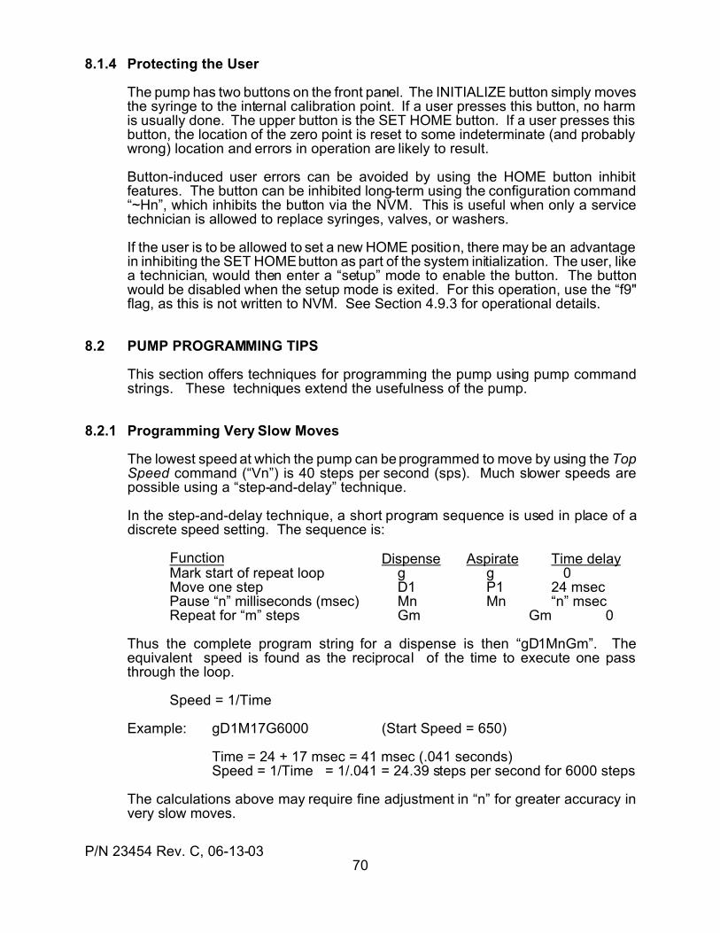
P/N 23454 Rev. C, 06-13-0370
8.1.4 Protecting the User
The pump has two buttons on the front panel. The INITIALIZE button simply movesthe syringe to the internal calibration point. If a user presses this button, no harmis usually done. The upper button is the SET HOME button. If a user presses thisbutton, the location of the zero point is reset to some indeterminate (and probablywrong) location and errors in operation are likely to result.
Button-induced user errors can be avoided by using the HOME button inhibitfeatures. The button can be inhibited long-term using the configuration command“~Hn”, which inhibits the button via the NVM. This is useful when only a servicetechnician is allowed to replace syringes, valves, or washers.
If the user is to be allowed to set a new HOME position, there may be an advantagein inhibiting the SET HOME button as part of the system initialization. The user, likea technician, would then enter a “setup” mode to enable the button. The buttonwould be disabled when the setup mode is exited. For this operation, use the “f9"flag, as this is not written to NVM. See Section 4.9.3 for operational details.
8.2 PUMP PROGRAMMING TIPS
This section offers techniques for programming the pump using pump commandstrings. These techniques extend the usefulness of the pump.
8.2.1 Programming Very Slow Moves
The lowest speed at which the pump can be programmed to move by using the TopSpeed command (“Vn”) is 40 steps per second (sps). Much slower speeds arepossible using a “step-and-delay” technique.
In the step-and-delay technique, a short program sequence is used in place of adiscrete speed setting. The sequence is:
Function Dispense Aspirate Time delayMark start of repeat loop g g 0Move one step D1 P1 24 msecPause “n” milliseconds (msec) Mn Mn “n” msecRepeat for “m” steps Gm Gm 0
Thus the complete program string for a dispense is then “gD1MnGm”. Theequivalent speed is found as the reciprocal of the time to execute one passthrough the loop.
Speed = 1/Time
Example: gD1M17G6000 (Start Speed = 650)
Time = 24 + 17 msec = 41 msec (.041 seconds)Speed = 1/Time = 1/.041 = 24.39 steps per second for 6000 steps
The calculations above may require fine adjustment in “n” for greater accuracy invery slow moves.
P/N 23454 Rev. C, 06-13-0371
Error trapping can NOT fix external mechanical or fluidic problems. Trappingis intended to provide graceful systems exits from error conditions.
8.2.2 Programming Error Traps
Errors can occur during operation of the pump. Errors can range from incorrectcommands to motor overloads. The pump can detect most error conditions (seeSection 5). For some systems, the robustness of the design can be enhanced byprogramming the pump to take corrective action automatically. This is calledtrapping and the part of the user program designed to handle the error is called theerror handler, or exception handler. The syntax to do this is given in Section 4.8.This section will provide an examples of error trapping.
Example: Trap a syringe overload error. Save the value of the syringe position,initialize the syringe to the input port, then return to the stall positionand continue the dispense. Note: this assumes the dispense wasintended to deliver all the contents of the syringe.
In the main user program, the trap is set by declaring:
x9V If a syringe overload (#9, see Section 5), occurs, go to label “V”.
At the end of the program, where error handlers are normally located, thehandler might be as follows:
:V label identifies start of handler (label used in trap instruction above)k@7 store current syringe position in Software Counter for later usek^1 exchange with counter memory #1k@6 save current valve port position in Software CounterY4 initialize syringe to reservoir port (~Yn set which port this is)o@5 move valve back to previous port positionk^1 place previous syringe position back in Software CounterA@5 move syringe back to stall positionA0 Complete dispenset1 Resume program execution with the next instruction
There are some limitations on error trapping. The error trapping feature is designedto provide a graceful recovery from errors, but it can not fix system errors. Any errorinduced by mechanical or fluidic problems cannot be fixed by a program. Suchthings must be fixed at the external root cause. In some cases, a syringe overloadmight be handled by reducing the syringe speed and trying again.
Example: Recover from a valve overload by initializing the valve and thenrepeating the valve move. An “error cycle counter” is included toprevent a run-away loop.
In main program, zero counter memory #2 and declare a trap:
k^2 exchange counter with counter memory #2 (preserve k value)k0 set current counter to zerok^2 restore current counter and place zero in counter memory #2x10p If a valve overload (error #10) occurs, go to program label “p”.
P/N 23454 Rev. C, 06-13-0372
If an error occurs while an error handler is executing, the program willperform a normal program error exit, regardless of the error handler.
At the end of the program, where error handlers are normally located, thehandler might be as follows:
:p label identifies start of handler (label used in trap instruction above)o1 initialize valve positionk^2 get counter #2k+1 increment error loop counterk>5q if more than 5 valve errors, go to label “q”k^2 if not, restore previous counter valuet4 try the valve move again:q label q means more than 5 valve errors (from k>5q)k^2 restore previous counter valueU3 signal terminal error (via User Output #3)t3 do a normal program error exit (stop program and make error
message.
In the preceding example, the “t4" exit retries the instruction which caused the error.If the initialize move works, but there are more than 5 retires without success, thehandler exits the program after setting an external “error” signal. If the initializemove fails, a program exit would occur. If an error occurs while in the error handlerroutine, a normal error exit takes place, superceding any user error handler.
Example: If any error occurs, set the User Output #2 low, set User Output #1high, save the current Digital Voltmeter input value, and then exit theprogram.
Set the error trap in the main program:
x*s if any error (*) occurs, go to program label “s”.
At the end of the program, where error handlers are normally located, thehandler might be as follows:
:s label marking start of error handlerU2 Set User Output #2 lowu1 Set User Output #1 highk@3 Save the current Digital Voltmeter input valuet3 Do a normal error exit
8.2.3 Setting the Speeds
For most applications, the factory default values for syringe accelerations andspeeds are adequate. Usually, only the Top Speed is changed for different syringerates. If the Top speed is set lower than the Start speed, the pump will begin amove at the Top Speed. If the Top speed is set lower than the Stop Speed, themove will end at the Top Speed. For this reason, values of Top speed which areset lower than either the Start Speed or the Stop Speed do not require anyadjustment in Start speed or Stop Speed.
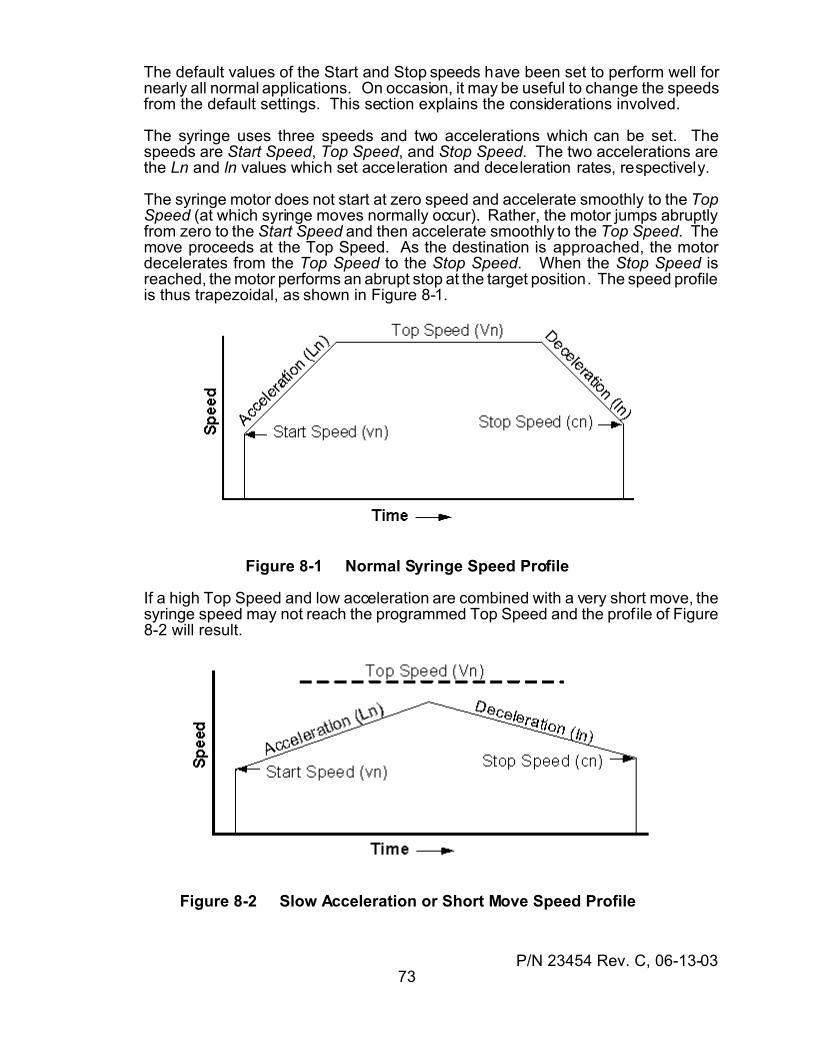
P/N 23454 Rev. C, 06-13-0373
The default values of the Start and Stop speeds have been set to perform well fornearly all normal applications. On occasion, it may be useful to change the speedsfrom the default settings. This section explains the considerations involved.
The syringe uses three speeds and two accelerations which can be set. Thespeeds are Start Speed, Top Speed, and Stop Speed. The two accelerations arethe Ln and ln values which set acceleration and deceleration rates, respectively.
The syringe motor does not start at zero speed and accelerate smoothly to the TopSpeed (at which syringe moves normally occur). Rather, the motor jumps abruptlyfrom zero to the Start Speed and then accelerate smoothly to the Top Speed. Themove proceeds at the Top Speed. As the destination is approached, the motordecelerates from the Top Speed to the Stop Speed. When the Stop Speed isreached, the motor performs an abrupt stop at the target position. The speed profileis thus trapezoidal, as shown in Figure 8-1.
Figure 8-1 Normal Syringe Speed Profile
If a high Top Speed and low acceleration are combined with a very short move, thesyringe speed may not reach the programmed Top Speed and the prof ile of Figure8-2 will result.
Figure 8-2 Slow Acceleration or Short Move Speed Profile
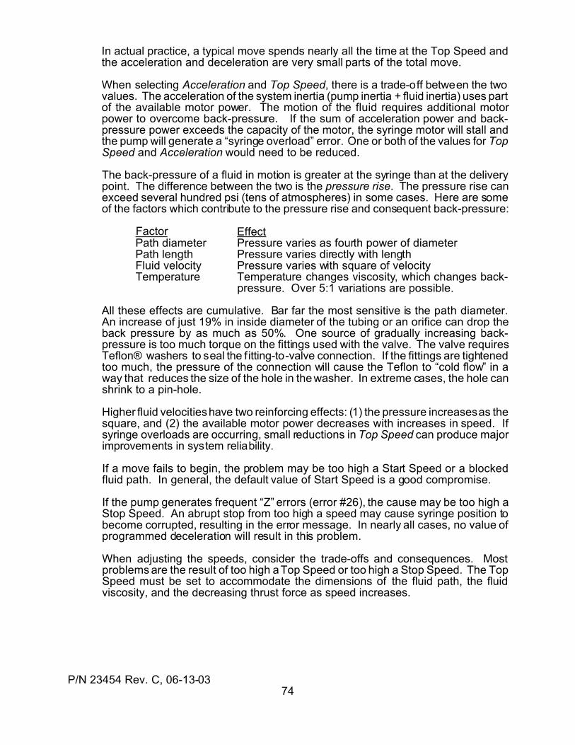
P/N 23454 Rev. C, 06-13-0374
In actual practice, a typical move spends nearly all the time at the Top Speed andthe acceleration and deceleration are very small parts of the total move.
When selecting Acceleration and Top Speed, there is a trade-off between the twovalues. The acceleration of the system inertia (pump inertia + fluid inertia) uses partof the available motor power. The motion of the fluid requires additional motorpower to overcome back-pressure. If the sum of acceleration power and back-pressure power exceeds the capacity of the motor, the syringe motor will stall andthe pump will generate a “syringe overload” error. One or both of the values for TopSpeed and Acceleration would need to be reduced.
The back-pressure of a fluid in motion is greater at the syringe than at the deliverypoint. The difference between the two is the pressure rise. The pressure rise canexceed several hundred psi (tens of atmospheres) in some cases. Here are someof the factors which contribute to the pressure rise and consequent back-pressure:
Factor EffectPath diameter Pressure varies as fourth power of diameterPath length Pressure varies directly with lengthFluid velocity Pressure varies with square of velocityTemperature Temperature changes viscosity, which changes back-
pressure. Over 5:1 variations are possible.
All these effects are cumulative. Bar far the most sensitive is the path diameter.An increase of just 19% in inside diameter of the tubing or an orifice can drop theback pressure by as much as 50%. One source of gradually increasing back-pressure is too much torque on the fittings used with the valve. The valve requiresTeflon® washers to seal the fitting-to-valve connection. If the fittings are tightenedtoo much, the pressure of the connection will cause the Teflon to “cold flow” in away that reduces the size of the hole in the washer. In extreme cases, the hole canshrink to a pin-hole.
Higher fluid velocities have two reinforcing effects: (1) the pressure increases as thesquare, and (2) the available motor power decreases with increases in speed. Ifsyringe overloads are occurring, small reductions in Top Speed can produce majorimprovements in system reliability.
If a move fails to begin, the problem may be too high a Start Speed or a blockedfluid path. In general, the default value of Start Speed is a good compromise.
If the pump generates frequent “Z” errors (error #26), the cause may be too high aStop Speed. An abrupt stop from too high a speed may cause syringe position tobecome corrupted, resulting in the error message. In nearly all cases, no value ofprogrammed deceleration will result in this problem.
When adjusting the speeds, consider the trade-offs and consequences. Mostproblems are the result of too high a Top Speed or too high a Stop Speed. The TopSpeed must be set to accommodate the dimensions of the fluid path, the fluidviscosity, and the decreasing thrust force as speed increases.
P/N 23454 Rev. C, 06-13-0375
8.2.4 Counting Program Cycles
The number of times a given event has occurred can be determined with theSoftware Counter (see Section 4.9.1). In the example below, the number of timesa programmed dispensing sequence has occurred is counted so a controller canquery the pump to determine the number of dispenses which have occurred sincethe program was initiated.
Example: Count the number of times a dispense has been made in anautomated dispensing cycle:
k0 set the counter to zero (start of dispense program)
:B mark start of f illing of syringeo-1 move valve to reservoir portA12000 fill syringe (12000-step model)o3 move valve to dispense port
:A mark start of dispense loopy<1500B if not enough left to dispense, refill (go to label :B)D1500 Dispense 12.5% of a syringe (12000-step model)k+1 increment the software counterJA do another dispense loop
In the example above, the program begins by setting the counter to zero. thesyringe is refilled each time the syringe position is too small to do another dispense.After each dispense, the counter is incremented by “1'. The counter can be queriedat any time to read how many dispenses have occurred. The complete programstring would be:
k0:Bo-1A12000o3:Ay<1500BD1500k+1JA
8.2.5 Converting Volume to Steps
The conversion of syringe volume to steps (syringe increments) can be easily doneusing a proportion.
steps required = desired volume total steps in full stroke total volume of full stroke
Example: Assume a total syringe volume of 5 mR (5000 µR), a desired volume of250 µR, and a 12,000 step model syringe drive. The required numberof steps can be found as
Set up proportion:
steps required = 250 µR 12,000 5000 µR
Solve for desired quantity
steps required = 12,000 ( 250 / 5000 ) = 600
P/N 23454 Rev. C, 06-13-0376
The preceding proportion can be used to find speeds also if the “steps required” isreplaced with “steps per second” and the “desired volume” is replaced with “volumeper second”.
8.3 I/O INTERFACE PROGRAMMING
User Inputs and User Outputs (I/O) can be used to preform a variety of interfacingtasks. In stand-alone operation, without a serial communications controller, the I/Ocan be used to trigger program operations and to indicate operational status. Inmultiple-pump operations, the I/O can be used to coordinate and synchronize theoperations of the pumps. One special case is the synthesis of continuos fluid flowusing two pumps. This section provides some interfacing techniques to aid in usingthe pump I/O.
8.3.1 Waiting for an Input
In many applications, it is desirable for a pump to wait for an external input signalto start an operation. Test-and-jump commands are used to sense the state of aninput signal at a User Input and control the program operation. There are two basicscenarios: wait for a high level and wait for a low level.
Example: Wait for a high input level:
:A program label “A”i2A if input #2 is low, go back to label “A”
When input #2 goes high, the “i2A” instruction will be “false” and the jumpback to label “A” will not be taken. The next instruction in line will beexecuted. It should be noted the inputs have internal pull-up resistors, so inthe absence of a signal connection, the default input level will be high.
Example: Wait for a low input level:
:r program label “r”i3T if the input #3 is low, go to label “T”Jr jump always to label “r”:T label “T”
While the input is high, the test for input #3 to be low will fail and the jump to“T” will not be taken. The next command, “Jr” is therefor executed. The “Jr”command send the program execution back to the “r” label and the test willbe repeated. When input #3 goes low, the jump to label “T” will be taken.Label “T” then leads to the next instruction in the program.
8.3.2 Handshaking Between Pumps
Handshaking between pumps uses the techniques in Section 8.3.1 to synchronizethe operations of two or more pumps. Each pump sends a signal to the otherpumps while monitoring the signals from the other pumps. Each pump thereforwaits for another pump to trigger its next operation. The example below illustratesthe nature of the bidirectional trigger signaling, called a handshake.
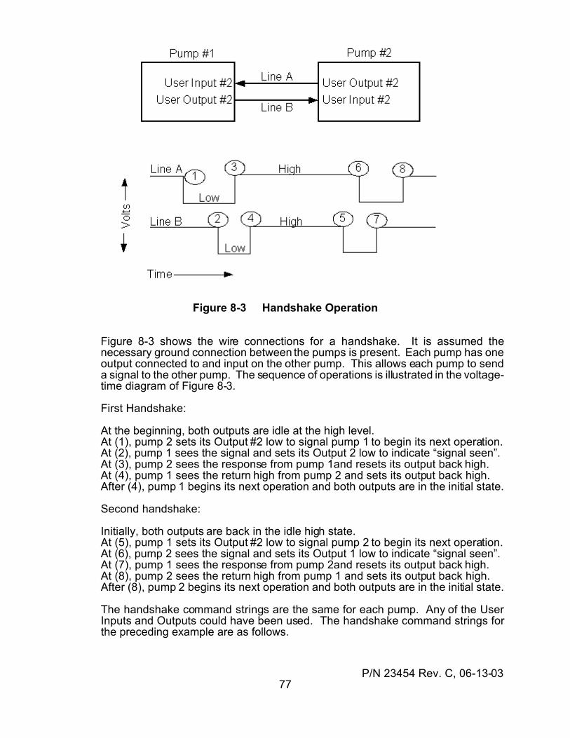
P/N 23454 Rev. C, 06-13-0377
Figure 8-3 Handshake Operation
Figure 8-3 shows the wire connections for a handshake. It is assumed thenecessary ground connection between the pumps is present. Each pump has oneoutput connected to and input on the other pump. This allows each pump to senda signal to the other pump. The sequence of operations is illustrated in the voltage-time diagram of Figure 8-3.
First Handshake:
At the beginning, both outputs are idle at the high level.At (1), pump 2 sets its Output #2 low to signal pump 1 to begin its next operation.At (2), pump 1 sees the signal and sets its Output 2 low to indicate “signal seen”.At (3), pump 2 sees the response from pump 1and resets its output back high.At (4), pump 1 sees the return high from pump 2 and sets its output back high.After (4), pump 1 begins its next operation and both outputs are in the initial state.
Second handshake:
Initially, both outputs are back in the idle high state.At (5), pump 1 sets its Output #2 low to signal pump 2 to begin its next operation.At (6), pump 2 sees the signal and sets its Output 1 low to indicate “signal seen”.At (7), pump 1 sees the response from pump 2and resets its output back high.At (8), pump 2 sees the return high from pump 1 and sets its output back high.After (8), pump 2 begins its next operation and both outputs are in the initial state.
The handshake command strings are the same for each pump. Any of the UserInputs and Outputs could have been used. The handshake command strings forthe preceding example are as follows.
P/N 23454 Rev. C, 06-13-0378
Starting a handshake:U2 set output #2 to signal “Go” to the other pump:A label “A”i2B if input is low, go to label “B”JA if not low, go to label “A”:B input is lowu2 set Output #2 high again to say “signal is seen”
Receiving a handshake::C label “C”i2D if input is low, go to label “D”JC if not low, go to label “C”:D input is lowu2 set Output #2 low to say “signal is seen”:E label “E”i2E if input is still low, check it againu2 input went high, so set out back to high
One special case of a handshake is the handshake dispense, described in Section8.3.3. This command provides an automatic handshake sequence.
8.3.3 Programming Continuous Flow
When a continuous fluid flow is required, the handshake dispense commands maybe used to synthesize the flow using two pumps. The resulting flow is continuous,with no gaps in delivery. The handshake connections and signal sequencesexplained in Section 8.3.2 are used, but the handshaking is an inherent part of theinstructions and does not require any programing.
The input ports of both pumps are connected with a “T” fitting so a single source lineis used. The output ports of both pumps are connected together with a “T”connection to sum the two outputs into a single delivery line.
As one pump is dispensing, the other pump is refilling. When pump A approachesthe end of its dispense, it signals pump “B” to begin to dispense. While pump B isdispensing, pump A refills itself. The handshake signals which tell each pump tobegin its dispense are generated by the dispensing pump just prior to finishing adispense. As one pump is finishing a dispense, the other begins and the fluid flowis thus continuous.
The syntax of the handshake dispense is hn (handshake dispense)
When this instruction is encountered, the pump begins testing User Input #n for alow level. When a low level is seen, a dispense begins. The dispense is alwaysfrom the current syringe position to zero (the full-dispense position). As thedispense nears the zero position, the User Output #n is set low just before thedispense ends. This is used as advance notice to the other pump to start its ownhandshake dispense. All these I/O operations are automatic.
To begin a handshake dispense without an external trigger signal, use the syntax“h-n”. This is useful to start a handshake dispense operation or to resume one thathas been stopped.
P/N 23454 Rev. C, 06-13-0379
The handshake sequences below assume the syringes are both filled and thevalves are both at the dispense port.
Initiating pump:V2000 Set the dispense speedh-n Begin the handshake dispense immediately:S Label “S”o-1 Move the valve to the input portV6000 Set the filling speedA12000 Fill the syringeo3 Move the valve to the dispense portV2000 Set the dispense speedhn Do a standard handshake dispenseJS go to label “S” for another cycle
Other pump::S Label “S”o-1 Move the valve to the input portV6000 Set the filling speedA12000 Fill the syringeo3 Move the valve to the dispense portV2000 Set the dispense speedhn Do a standard handshake dispenseJS go to label “S” for another cycle
Note the initiating pump differs only in the first two lines, which are needed to startthe overall process. Once begun, both pumps use the same handshake commandsequence. Special note should be taken of the speeds. The refill speed must befaster than the dispense speed by a difference which allows the refilling pump tomake two valve moves and refill the syringe before the dispensing pump completesits dispense.
8.3.4 The DVM as a Selector Switch
The Digital Voltmeter (DVM) input can be used as a selector switch. If repeatablevoltage levels can be applied to the DVM input, a series of tests can be made todetermine what the program should do next. These levels can be generated froma digital-to-analog converter or from a series of resistors soldered around a selectorswitch to form a tapped voltage divider. In the following command sequence, eachtest level is chosen to be half-way between the actual voltage levels, not at thevoltage levels. This is done for noise immunity.
Example: Assume six discrete voltage levels at 0, 1, 2, 3, 4, and 5 volts. Thetest thresholds would be at 0.5, 1.5, 2.5, 3.5, and 4.5 volts for a totalof five possible selections.
The actual test numbers are found as: number = volts x 51Selection 1: 0.5 volts = 25Selection 2: 1.5 volts = 76Select ion 3: 2.5 volts = 127Selection 4: 3.5 volts = 178Selection 5: 4.5 volts = 229
P/N 23454 Rev. C, 06-13-0380
The test sequence uses the numbers calculated above.:A label “A” marks start of test loopi>229B if selection is 5, go to label “B” (start of selection 5)i>229C if selection is 4, go to label “C” (start of selection 4)i>229D if selection is 3, go to label “D” (start of selection 3)i>229E if selection is 2, go to label “E” (start of selection 2)i>229F if selection is 1, go to label “F” (start of selection 1)JA if no selection, test loop again
The order of the tests is critical. If the order were reversed, all selections wouldsatisfy the test for selection 1. Each label “B” through “F” denotes the place in theprogram at which the commands for each different selection begins. The commandsequence of reach selection must end with a jump back to Label “A” (“JA”) so theselection process will continue when each selection is done.
8.3.5 Position Snapshots
When the precise location of the syringe at the time of an external event must beknown, the pump provides a means to record this. Such information is useful intitrations and other applications in which an external sensor detects an event whilethe syringe is in motion. Although the syringe position can be queried while thesyringe is in motion, the communications overhead prevents the exact syringeposition from being determined through on-the-fly position queries. The snapshotfeature overcomes these limitations and provides exact measurements.
The snapshot feature uses the User Input #3. Each time the User Input #3transitions from high-to-low, the current location of the syringe is stored in memory. The snapshot memory retains the positions for the two most recent inputtransitions. The syringe positions for these two points can be queried at any timewith the “?29" query. This feature is always available regardless of the input #3operating mode.
The snapshot feature is very useful for titrations using optical detection, where thedetector outputs a double pulse and the two positions at the time of the pulses mustbe known. It is also useful in any application in which the amount to be dispensedis unknown in advance and must ve determined on-the-fly during the process.
8.3.6 Using the Expansion Port
The V3 includes three digital inputs, three digital outputs, and a Digital Voltmeterinput as part of the standard unit. For those applications which need more I/O ordifferent I/O, an Expansion I/O port is also included. The Expansion I/O port is asynchronous serial port which can increase the I/O by either one byte (eight bits ofinput + eight bits of output) or two bytes (16 bits of input + 16 bits of output). Kloehnmakes an I/O Expander Board (P/N 50765) which implements the two-byteexpansion.
The 50765 I/O Expander Board is an example of the I/O increase possible with theExpansion port. The 50765 provides 16 extra inputs which can be operated as twobytes or bit-by-bit, and 16 extra outputs, each of which can switch up to 250milliamperes at up to 40 Vdc. These can be used to control solenoid valves, relays,indicator lights, or other motors.
P/N 23454 Rev. C, 06-13-0381
The Expansion I/O port consists of four signals and two power leads which provide+5 Vdc power for external circuits. The details of the signals are given in section11.7.4.
The Expansion I/O is managed by extensions of the basic I/O commands as listedin Section 4.3. The relevant commands are listed next, emphasizing the Expansionsyntax. The outputs are controlled by these commands, which may be included ina program:
sn Send a serial byte from the User Serial expansion Port, MSB first. The valueof the ASCII number "n" is the base 10 representation of the value of abinary byte. For transmitted bytes, positive logic applies ("1" = high logiclevel). In the 2-byte serial mode, "n" represents the second byte sent. Thefirst byte is the same as the first byte sent by a "sn,m" instruction. SeeSection 4.5 for an explanation of "@n" usage.(n: 0...255, @n) [n/a]
sn,m Send two bytes from the User Serial expansion Port, byte "m" first and thenbyte "n" second. Both bytes are sent MSB (most significant bit) first. Thevalues of "n" and "m" are expressed as the ASCII base 10 representation ofthe binary bytes. (n: 0...255, m: 0...255, @n) [n/a]
Un Turn the user parallel output "n" ON (low logic level) or turn on a serial I/Oport output bit.(n: 11...18 = serial byte 1, bit 1...8 of the serial expansion port
21...28 = serial byte 2, bit 1...8 of the serial expansion port) [n/a]
un Turn the user parallel output "n" OFF (open-circuited) or turn off a serial I/Oport output bit.(n: 11...18 = serial byte 1, bit 1...8 of the serial expansion port
21...28 = serial byte 2, bit 1...8 of the serial expansion port) [n/a]
The inputs are read by these commands, which are executed immediately uponreceipt and cannot be included in a program:
?10 Query the value of the first byte received from the Expansion I/O port input. An input byte is shifted in (MSB first), and the numerical value of the firstinput byte is reported in a base 10 ASCII format. The value uses a negativelogic convention (low level = 1, high level = 0). In 1-byte mode, this is theonly byte. In 2-byte mode, this is the first of two bytes.
?20 Query the value of the second byte received from the Expansion I/O portinput in 2-byte mode. Two input bytes are shifted in (MSB first), and thenumerical value of the second input byte is reported in a base 10 ASCIIformat. The value uses a negative logic convention (low level = 1, high level= 0). This instruction is not valid in 1-byte mode.
?n Query the state of the Expansion I/O port input bit designated by "n". Aserial byte is input (MSB first), and the state of the designated bit is reportedas an ASCII "0" if the bit is "false" (high input logic level) or an ASCII "1" if"true" (low input logic level).(n: 11...18 bit 1...8 in Expansion input byte #1
21...28 bit 1...8 in Expansion input byte #2)
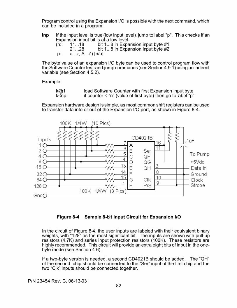
P/N 23454 Rev. C, 06-13-0382
Program control using the Expansion I/O is possible with the next command, whichcan be included in a program:
inp If the input level is true (low input level), jump to label "p". This checks if anExpansion input bit is at a low level.(n: 11...18 bit 1...8 in Expansion input byte #1
21...28 bit 1...8 in Expansion input byte #2 p: a...z, A...Z) [n/a]
The byte value of an expansion I/O byte can be used to control program flow withthe Software Counter test-and-jump commands (see Section 4.9.1) using an indirectvariable (see Section 4.5.2).
Example:
k@1 load Software Counter with first Expansion input bytek<np if counter < “n” (value of first byte) then go to label “p”
Expansion hardware design is simple, as most common shift registers can be usedto transfer data into or out of the Expansion I/O port, as shown in Figure 8-4.
Figure 8-4 Sample 8-bit Input Circuit for Expansion I/O
In the circuit of Figure 8-4, the user inputs are labeled with their equivalent binaryweights, with “128" as the most significant bit. The inputs are shown with pull-upresistors (4.7K) and series input protection resistors (100K). These resistors arehighly recommended. This circuit will provide an extra eight bits of input in the one-byte mode (see Section 4.6).
If a two-byte version is needed, a second CD4021B should be added. The “QH”of the second chip should be connected to the “Ser” input of the first chip and thetwo “Clk” inputs should be connected together.
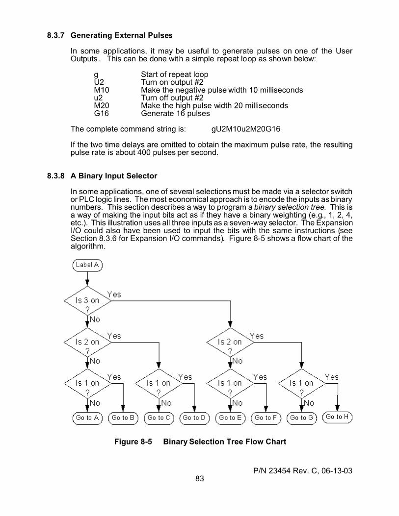
P/N 23454 Rev. C, 06-13-0383
8.3.7 Generating External Pulses
In some applications, it may be useful to generate pulses on one of the UserOutputs. This can be done with a simple repeat loop as shown below:
g Start of repeat loopU2 Turn on output #2M10 Make the negative pulse width 10 millisecondsu2 Turn off output #2M20 Make the high pulse width 20 millisecondsG16 Generate 16 pulses
The complete command string is: gU2M10u2M20G16
If the two time delays are omitted to obtain the maximum pulse rate, the resultingpulse rate is about 400 pulses per second.
8.3.8 A Binary Input Selector
In some applications, one of several selections must be made via a selector switchor PLC logic lines. The most economical approach is to encode the inputs as binarynumbers. This section describes a way to program a binary selection tree. This isa way of making the input bits act as if they have a binary weighting (e.g., 1, 2, 4,etc.). This illustration uses all three inputs as a seven-way selector. The ExpansionI/O could also have been used to input the bits with the same instructions (seeSection 8.3.6 for Expansion I/O commands). Figure 8-5 shows a flow chart of thealgorithm.
Figure 8-5 Binary Selection Tree Flow Chart
P/N 23454 Rev. C, 06-13-0384
The corresponding commands are:
:A label “A” marks start of selection treei3K Is 3 on? If yes, go to label “K”i2L Is 2 on? If yes, go to label “L”i1B Is 1 on? If yes, go to label “B” (selection = B)JA Go to label “A” (no selection):L label “L”i1D Is 1 on? If yes, go to label “D” (selection = D)JC Go to label “C” (selection = C):K label “K” (second half of binary tree)i2M Is 2 on? If yes, go to label “M”i1F Is 1 on? If yes, go to label “F” (selection = F)JE Go to label “E” (selection = E):M label “M”i1H Is 1 on? If yes, go to label “H” (selection = H)JC Go to label “G” (selection = G)
A three-way selection tree would use only the commands from “:A” through “JC”.Each of the labels “B” through “H” is the start of the command sequence whichcorresponds to the input selection. Each selection command sequence must endwith a “JA” (jump to label “A”) so the input selection procedure can continue whena process is done. Note the selection “A” goes back to the start of the selectiontree. This is done to provide a “no selection” position. If some other means ofinitiating the selection process (other than a “valid” selection) is used, then label “A”can be used for an eighth selection.
8.3.9 Driving External LEDs
External LED (light-emitting diode) indicators can be driven from the User Outputs.The diode anode should be connected to +5Vdc through a 470-ohm resistor.The LED cathode is connected to the output. When the output is turned “on”, theoutput level will go low and turn on the LED. The output level will still be low enoughto drive other external logic. A “super-bright” LED should be used.
An output could also drive the input to an opto-isolator. The internal opto-isolatorLED should be connected as described above. The drive current will be about eightmilliamps.
The Error Out output can also drive an LED. This output should be connected asdescribed above, or the anode of the LED can be connected to the Error Bias pin,which provides an internal resistor to +5Vdc.
8.3.10 Wired-Or Error Signal
The Error Out signal is an open-drain MOSFET. This permits all the Error Out pinsof several pumps to be wired directly together. This creates a single, compositeError Out signal for all pumps. This composite output can be wired to an LED, opto-isolator, other logic, or a relay (up to 160 mA). If any pump has an error, the outputwill be active.
P/N 23454 Rev. C, 06-13-0385
9.0 POWER
This section describes the low voltage condition detection, the selection of powersupplies, and good power distribution wiring practices.
9.1 POWER SUPPLY SELECTION
9.1.1 Capacity Selection
The power supply capacity should be consistent with the specifications of Section11.3 of this manual. If a Kloehn power supply is used, these specifications will bemet. One Kloehn P/N 17732 power supply has sufficient capacity to power twoVersaPump 3 devices.
An output capacity of 25 watts at 24 Vdc is considered a practical value for a one-pump power supply for normal pump operation. The normal idle powerconsumption is about 6 watts. The 25 watt rating allows for the maximum powerrequired during syringe and valve moves, with a small reserve for reliability.
For multiple pumps on one supply, the overall system operation should beconsidered. If there are N pumps, of which only M units will be making a syringe orvalve move at the same time, then the average power capacity of the supply shouldbe at least P = 25M + 6(N-M) watts. The pump automatically turns on the valvemotor for moves and then turns it off when not moving. See section 8.2 foradditional multiple-pump system wiring considerations.
At power-up, all the valve motors will make simultaneous valve calibration moves,demanding about 0.8 Adc each. To allow for the valve calibration moves, the powersupply should have a peak power capacity of P = 25N watts. The peak capacity isoften not specified directly. It can be calculated from the peak current specification(Ipk) as P = 24N(Ipk). If this results in an excessively large power rating for thenormal system operation, the power-up initialize inhibit parameter can be set toprevent the power up moves (see Section 4.6).
In-rush current at initial power-up is the idle current plus the current required tocharge the nominal 470 uF capacitance at each pump power input. For almost anypower supply, this current will be well within its capacity.
9.1.2 Type Selection
There are three general types of power supply: unregulated DC, linear regulatortypes, and switching regulator types. Each has different selection considerations.
The unregulated supply is the cheapest and simplest. Its output voltage willtypically vary about 5% to 20% from no-load to rated load. In addition, the outputwill vary in proportion to the input line voltage. Since the driver is specified for24Vdc ± 10%, it is not recommended for use with the V3 pumps.
The linear regulator supply usually has a current limiting feature which must be sethigh enough to handle any current transients generated by the syringe drive. If thecurrent limit is too low, erratic pump operation will result with no obvious cause.
P/N 23454 Rev. C, 06-13-0386
Such a condition can be detected by monitoring the power with a storageoscilloscope. Another possible consequence of low current limit is a too-slow powerrise at turn-on. Linear power supplies are inefficient, requiring larger power input,more space, and more weight than the switching power supplies.
A switching power supply is the preferred choice. It offers higher efficiency, lowerheat generation, and a well-filtered output. Some switching power supplies havea minimum load current requirement. Since the pump can idle as low as 60milliamps, the supply should be rated for a minimum load current equal to theminimum total system idle current. A ballast resistor may be added across thesupply output to guarantee the minimum load requirement of the supply.
9.2 SYSTEM WIRING PRACTICES
In a system with two or more syringe pumps, the power distribution wiring canaffect the system reliability. The best system wiring practice is to connect eachdrive module with an individual pair of power leads from the power supply to thatindividual module, as shown in Figure 6-1. The pair of leads for each moduleshould be twisted together along their length to reduce radiated fields. Route thetwisted pairs of power leads close to the chassis if a metal chassis is used formounting. This aids in reducing unwanted stray electromagnetic fields in the overallequipment design.
The use of an output filter in each line can reduce radiated and conducted EMI.The simplest filter consists of a series inductance of about 10 uH to 20 uH (ratedat 1.5 amps) inserted in-line with the positive power wire. Best results are usuallyobtained when the inductance is located nearest to the pump.
The J1 interface connector has two power input pins and two ground pins. Goodwiring practice uses both opposing pins for the positive lead and both opposingpins for the ground lead. The redundant connections assure a low impedance,reliable set of power connections.
If communications upsets occur during ESD testing when high-voltage arcs areinjected into either the controller or the syringe drive, insertion of a ferrite common-mode choke with good high-frequency impedance may eliminate the problem. Thepower and communications lines should be looped two or three times through aferrite toroid having an outside diameter of about one inch.
Syringe drives should not share the same power leads as large, noisy electricalloads such as motors and large solenoids. While the syringe design containsfiltering to reduce susceptibility to electrical noise conducted via the power supplywires, large current or voltage transients could be harmful to the pump.
9.3 LOW VOLTAGE CONDITION
If the pump supply voltage decreases below the internal reference minimum (20V),a "Low Voltage" error condition is generated. While the voltage remains below theminimum, valve and syringe moves are inhibited. For supply voltages down toabout 8 Vdc, the internal control electronics and memory are not affected and otherinstructions, such as I/O operations and queries, will still operate normally after thelow voltage error message has been reported or cleared.

P/N 23454 Rev. C, 06-13-0387
Some power supplies will turn on gradually. If the rise time of the supply is slowenough, the internal computer may generate a "Low Voltage" error when the pumppowers up. This will not cause any operational problems after the power hasstabilized and communications has been established. The error message will haveto be cleared before any other commands can be executed. The message can becleared by querying the pump status.
If low voltage errors persist when a voltmeter check of the power supply appears toshow a proper voltage, the problem may be transients on the power supply leads.Transients may be induced by wiring which passes close to other high-currentelectrical loads, by current-limiting operation of linear supplies, by transients passedthrough the power supply from the ac power source used by the supply, or by usinga wire size which is too small for the length.
9.4 POWER CONSERVATION FOR BATTERY APPLICATIONS
The V3 pump draws a current which depends upon the power supply voltage, theidle logic current, and the motor currents. The current consumption can beminimized in some applications through the pump programming.
The supply voltage is inversely proportional the current consumption. This isbecause the pump is a constant power device. As the voltage increases, thecurrent decreases so the product of the two will remain approximately constant.The capacity of a battery for portable operation is thus best estimated using a watt-hour rating (watt-hours = ampere-hours x volts).
The motor current is the sum of the valve motor and syringe motor demands. Thevalve motor draws current during a valve move, and automatically turns off when avalve ends. The valve motor automatically turns on at the start of a valve move.
The Syringe motor normally idles at half-power. When a syringe move begins, thesyringe switches to full-power operation for the duration of the move. When themove ends, the power automatically switches back to half-power. If the syringe isnot required to hold a significant back-pressure, the syringe motor can be turnedoff at the completion of each move, thereby reducing idle power to the logic idlepower alone. The logic idle power alone is typically about 2.4 Watts.
P/N 23454 Rev. C, 06-13-0388
10.0 MOUNTING & INSTALLATION
10.1 MOUNTING a SINGLE PUMP
The mounting dimensions of the VersaPump 3 are shown in Figure 10-1. The driveis usually base mounted using the holes in the bottom. The stacking holes on theback may also be used for mounting with a bracket.
It is recommended that the pump be mounted to a solid base. If the pump ismounted to an instrument panel, the panel should be reinforced to create a verystiff, rigid surface. If these precautions are not observed, any vibrations from theoperation of the drive may be coupled into the instrument face. The instrument facecan then act as a loudspeaker, amplifying all pump acoustics. Where possible, avibration isolation material may be used between the pump and the mountingsurface to improve acoustic isolation from the mounting structure. A material suchas Sorbothane (see www.sorbothane.com) is recommended. A gasket cut from amouse pad can serve in a breadboard as a convenient isolator. When selectingmaterials, remember that different materials are acoustically transparent at somefrequencies and acoustically opaque at other frequencies. Mechanically "lossy"materials are best.
An instrument enclosure to which the drive is mounted should have good electricalconductivity to the system chassis ground. This will reduce radiated emissionsfrom the equipment. A wire from the pump chassis to the equipment chassis willgenerally not provide a satisfactory system ground because it does not provide thehigh-frequency transient conductivity required. If possible, a metallic enclosure ora plastic enclosure with RF shielding is preferred.
The pump has been designed with a large operating ambient temperature margin.However, it is prudent to allow air venting for an enclosure to improve the systemreliability. In many applications, a cooling air inlet at the bottom of an enclosure anda hot air vent near the top can provide adequate ventilation. Only when operatingin ambient temperatures near the maximum would any kind of forced air cooingbecome desirable.
An alternate mounting technique uses the stacking holes on the rear panel of thepump to attach the pump to a mounting bracket. The bracket contains the threadednuts to capture the mounting screws. The PEM company (www.pemnet.com)carries a well-designed and varied selection of such nuts.
10.2 STACKING DEVICES VERTICALLY
The V3 pump has been designed to permit stacking two devices vertically. Thedevices can be two V3 pumps or one V3 pump and one electronically-controlledselector valve such as the Kloehn Intellect. In the latter case, an Intellect would bethe upper device and a pump would be the lower device. This arrangement alsooffers the advantage of the shortest possible distance between the pump andIntellect valves. This produces the lowest dead volume between valves, whileproviding 13 ports.
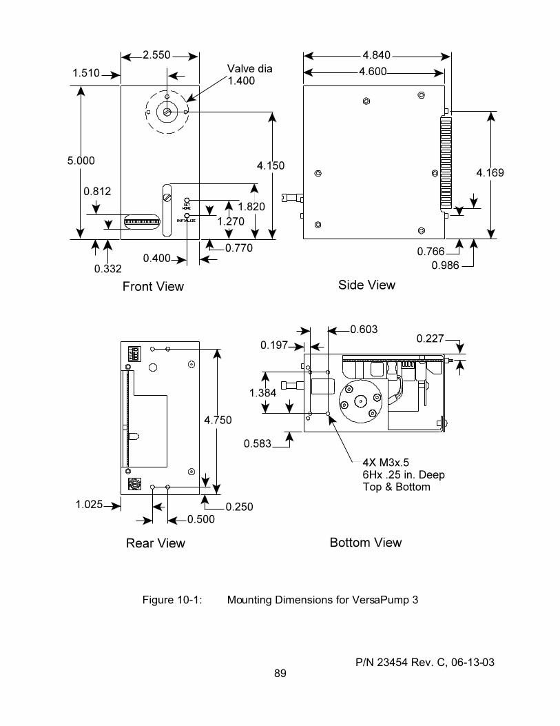
P/N 23454 Rev. C, 06-13-0389
Figure 10-1: Mounting Dimensions for VersaPump 3
P/N 23454 Rev. C, 06-13-0390
10.3 THERMAL CONSIDERATIONS
The Versa3 pumps are designed to operate throughout the specified operatingtemperature range with natural convection cooling. If the pumps are placed into anenclosed container or the mounting restricts cooling air flow, provision should bemade for adequate ventilation.
Adequate ventilation can be achieved by providing a path for cooling air to enter andheated air to exit the pump’s interior. Cooling air should be drawn from a pointbelow the heated air exhaust. If the pump is mounted in its own enclosure or in asmall enclosure, a fan may be required to provide adequate cooling.
A cooling fan of about 40mm x 40mm x 10mm with not less than an unloadedairflow of about 6 m3/hr (3.5 ft3/min) is recommended to blow air into the pumpinterior. A DC brushless motor type is recommended for reliability. The secondmodel V3 is available with this fan included within the pump as an option.
External fans should be mounted to blow air into the lower portion of the pump’srear opening. Some examples of recommended fan types are the PAPST models414F, 414, or 414H (www.papst.de/home.html), also available from Digi-Key aspart numbers 381-1070-ND or 381-1082-ND.
Do NOT disassemble a V3 pump to install an interior fan. Mount fansexternal to the pump or order a fan installed as a factory option.
P/N 23454 Rev. C, 06-13-0391
11.0 SPECIFICATIONS
11.1 ENVIRONMENTAL
TemperatureOperating -25 to 55 °C (-13 to 131 °F)Storage -25 to 85 °C (-13 to 185 °F)
Humidity 5 to 95% RH, non-condensingAltitude
Operating 10,000 feet pressure altitude, maximumNon-operating 40,000 feet pressure altitude, maximum
11.2 PHYSICAL
Height 5.00 inches 127 mmWidth 2.55 inches 64.77 mmDepth 4.60 inches 116.8 mmWeight 2.5 pounds 1.13 Kg
11.3 POWER
Voltage 20 to 30 Vdc, 24 Vdc nominalCurrent (at 24 Vdc)
Idle, syringe on 0.24 to 0.36 AdcIdle, syringe off 0.12 AdcValve move 0.8 Adc + 0.7 Apk @ 1.67 KHz (sine)Syringe move 0.5 AdcTurn-on surge 1.25 A peak, 6 msec
Power consumptionIdle, syringe off 3 Watts, max.Idle, syringe on 9 Watts, maxSyringe or valve moving 20 Watts, max.
11.4 SYRINGE AXIS
The syringe axis is designed to drive a syringe having a full-stroke length of 3cm.
11.4.1 Resolution
The syringe axis is available in two resolutions: 6000 steps and 12,000 steps forthe same 3 cm stroke length. The resolution is predicated on mechanicaldesign and is not electronically “inflated”. Which of the two resolutions isapplicable depends upon which model is purchased.
11.4.2 Accuracy
Accuracy is described by two parameters: accuracy and precision. For both, thevalue given is expressed as a percentage of the full stroke of the syringe.
P/N 23454 Rev. C, 06-13-0392
Accuracy measures how closely a dispensed amount of fluid corresponds to theideal programmed value. Precision describes the ability of the drive to deliverthe same quantity of fluid for the same size programmed dispenses.
By analogy, consider an archer shooting a group of arrows at a target. Precisionis a measure of how closely the arrows are spaced on the target, called the sizeof the group. Accuracy is a measure of how far the center of that group is fromthe center of the target. The values for the VersaPump 3 series of pumps are:
Accuracy 0.10% CV (typical, full-stroke), 0.21% maxPrecision 0.03% CV (typical, full-stroke), 0.06% max
Additional factors contributing to system accuracy are the total syringe size, anyair bubbles or gaps, and any elasticity in the fluid path. The syringe tolerance isa maximum ±1% of total volume. This error contribution is proportional to theamount dispensed as a fraction of syringe volume. Air bubbles, gaps, and tubingelasticity can contribute errors due to compressibility or expansion of theirvolumes. Such errors are proportional to the positive or negative fluid pressuresin the fluid path.
For small dispensed volumes, the accuracy of the volume can be sensitive to themeans by which the volume is removed from the probe of tubing tip. Anymeniscus can contribute several microliters of dispense error. To minimize theseerrors, submerge the tip into the destination fluid or "touch off" the tip against thecontainer.
11.4.3 Speed
Syringe speeds are measures in steps per second. The definition of a step isone increment of motion.
Range, normal 40 to 8000 steps per second5 minutes full-stroke to 1 seconds full-stroke
Range, extended < 1 step per minute> 200 minutes full stroke.
11.4.4 Syringe Thrust and Pressure
Syringe thrust is related to syringe fluid pressure by the relation
psi = 19.3 x (Thrust - Friction) / Volume
where “Volume” is total rated syringe volume in milliliters(cc),Thrust is drive force in pounds,Friction is the syringe piston friction force in pounds.
The 12000-step model has a typical maximum thrust of about 43 poundsindependent of the speed. For the 6000-step model, as the syringe speed isincreased, the available syringe thrust decreases, as shown in the next table.
Syringe friction is larger for the larger syringes. The largest is the 5 mL, with
P/N 23454 Rev. C, 06-13-0393
about three to five pounds of friction. The smallest syringes have about one tothree pounds of friction.
Speed (sps) Force (pounds)4500 or less 606000 407000 388000 33
11.5 VALVE AXIS
The valve axis controls a user-selected valve mounted to the faceplate of thepump. The valve axis is configurable for different types of valves Thus a singlemodel of the VersaPump 3 can accommodate any of the available valve typeswithout modification. This is a feature of all Kloehn syringe pumps. Distributionand non-distribution types are available with from two to six ports.
11.6 COMMUNICATIONS
The VersaPump 3 syringe drive has two serial communications protocols: OEMand DT. The two protocols are compatible with the corresponding Cavroprotocols. In each case, the pump acts as a slave device. It cannot initiatecommunications, but can only respond to commands from a controlling device. All communications are serial, half-duplex data transfers. The RS232 andRS485 interfaces are supported.For both standards, the communications parameters are:
Baud rate 1200, 2400, 4800, 9600, 19200, 38400 baudData bits 8Parity noneStop bits 1Flow control NonePhysical protocols RS485, RS232Logical protocols DT, OEM
All communications use ASCII characters for both commands and responses. All numbers are expressed as ASCII decimal numbers. The two protocols, DTand OEM, are explained in Section 6.3.
11.7 I/O INTERFACE
The following subsections describe the User Inputs/Outputs (User I/O) availableon the 50300 Syringe Drive Unit. There are 3 parallel digital outputs, 3 paralleldigital inputs, one digital voltmeter input, and a serial I/O expansion port foradding additional I/O externally.
11.7.1 Digital Outputs
There are three CMOS digital outputs. These are 5 volt “HC” outputs,compatible with 5V CMOS and TTL. The outputs can be controlled from within a

P/N 23454 Rev. C, 06-13-0394
program or by external command.
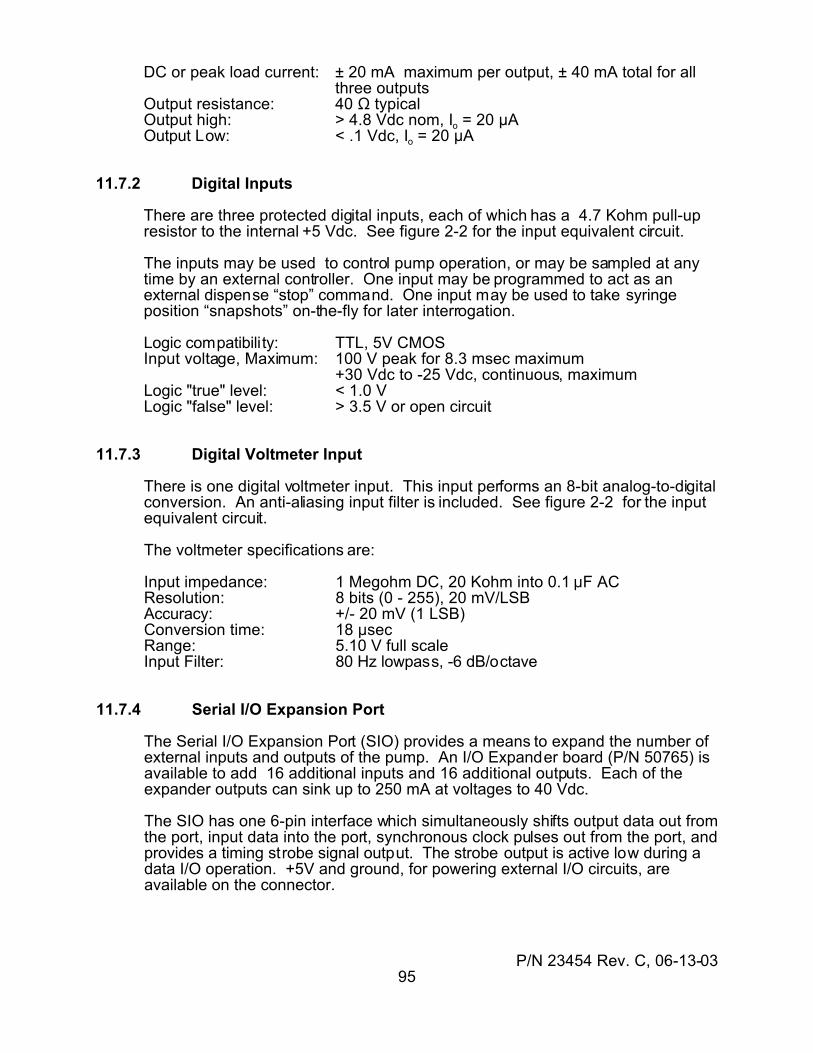
P/N 23454 Rev. C, 06-13-0395
DC or peak load current: ± 20 mA maximum per output, ± 40 mA total for allthree outputs
Output resistance: 40 S typicalOutput high: > 4.8 Vdc nom, Io = 20 µAOutput Low: < .1 Vdc, Io = 20 µA
11.7.2 Digital Inputs
There are three protected digital inputs, each of which has a 4.7 Kohm pull-upresistor to the internal +5 Vdc. See figure 2-2 for the input equivalent circuit.
The inputs may be used to control pump operation, or may be sampled at anytime by an external controller. One input may be programmed to act as anexternal dispense “stop” command. One input may be used to take syringeposition “snapshots” on-the-fly for later interrogation.
Logic compatibility: TTL, 5V CMOSInput voltage, Maximum: 100 V peak for 8.3 msec maximum
+30 Vdc to -25 Vdc, continuous, maximumLogic "true" level: < 1.0 VLogic "false" level: > 3.5 V or open circuit
11.7.3 Digital Voltmeter Input
There is one digital voltmeter input. This input performs an 8-bit analog-to-digitalconversion. An anti-aliasing input filter is included. See figure 2-2 for the inputequivalent circuit.
The voltmeter specifications are:
Input impedance: 1 Megohm DC, 20 Kohm into 0.1 :F ACResolution: 8 bits (0 - 255), 20 mV/LSBAccuracy: +/- 20 mV (1 LSB)Conversion time: 18 :secRange: 5.10 V full scaleInput Filter: 80 Hz lowpass, -6 dB/octave
11.7.4 Serial I/O Expansion Port
The Serial I/O Expansion Port (SIO) provides a means to expand the number ofexternal inputs and outputs of the pump. An I/O Expander board (P/N 50765) isavailable to add 16 additional inputs and 16 additional outputs. Each of theexpander outputs can sink up to 250 mA at voltages to 40 Vdc.
The SIO has one 6-pin interface which simultaneously shifts output data out fromthe port, input data into the port, synchronous clock pulses out from the port, andprovides a timing strobe signal output. The strobe output is active low during adata I/O operation. +5V and ground, for powering external I/O circuits, areavailable on the connector.
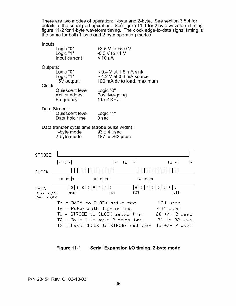
P/N 23454 Rev. C, 06-13-0396
There are two modes of operation: 1-byte and 2-byte. See section 3.5.4 fordetails of the serial port operation. See figure 11-1 for 2-byte waveform timingfigure 11-2 for 1-byte waveform timing. The clock edge-to-data signal timing isthe same for both 1-byte and 2-byte operating modes.
Inputs:Logic "0" +3.5 V to +5.0 VLogic "1" -0.3 V to +1 VInput current < 10 :A
Outputs:Logic "0" < 0.4 V at 1.6 mA sinkLogic "1" > 4.2 V at 0.8 mA source+5V output: 100 mA dc to load, maximum
Clock:Quiescent level Logic "0"Active edges Positive-goingFrequency 115.2 KHz
Data Strobe:Quiescent level Logic "1"Data hold time 0 sec
Data transfer cycle time (strobe pulse width):1-byte mode 93 ± 4 :sec2-byte mode 187 to 262 :sec
Figure 11-1 Serial Expansion I/O timing, 2-byte mode
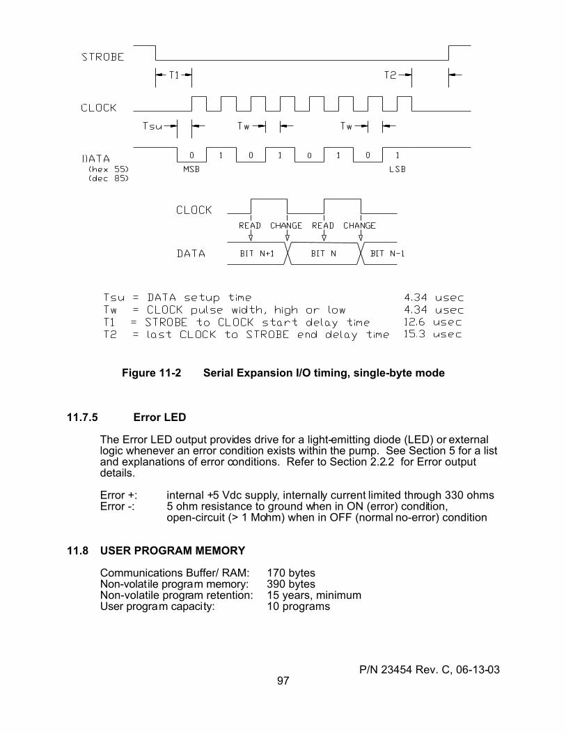
P/N 23454 Rev. C, 06-13-0397
Figure 11-2 Serial Expansion I/O timing, single-byte mode
11.7.5 Error LED
The Error LED output provides drive for a light-emitting diode (LED) or externallogic whenever an error condition exists within the pump. See Section 5 for a listand explanations of error conditions. Refer to Section 2.2.2 for Error outputdetails.
Error +: internal +5 Vdc supply, internally current limited through 330 ohmsError -: 5 ohm resistance to ground when in ON (error) condition,
open-circuit (> 1 Mohm) when in OFF (normal no-error) condition
11.8 USER PROGRAM MEMORY
Communications Buffer/ RAM: 170 bytesNon-volatile program memory: 390 bytesNon-volatile program retention: 15 years, minimumUser program capacity: 10 programs
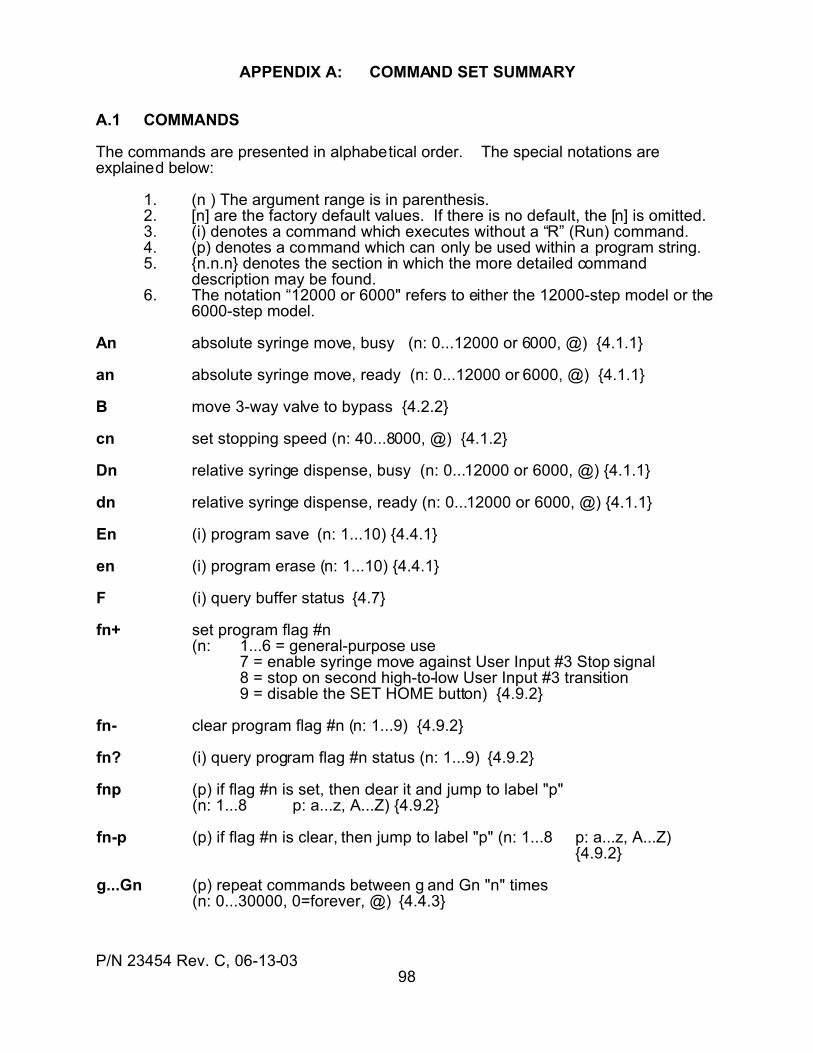
P/N 23454 Rev. C, 06-13-0398
APPENDIX A: COMMAND SET SUMMARY
A.1 COMMANDS
The commands are presented in alphabetical order. The special notations areexplained below:
1. (n ) The argument range is in parenthesis.2. [n] are the factory default values. If there is no default, the [n] is omitted.3. (i) denotes a command which executes without a “R” (Run) command.4. (p) denotes a command which can only be used within a program string.5. {n.n.n} denotes the section in which the more detailed command
description may be found.6. The notation “12000 or 6000" refers to either the 12000-step model or the
6000-step model.
An absolute syringe move, busy (n: 0...12000 or 6000, @) {4.1.1}
an absolute syringe move, ready (n: 0...12000 or 6000, @) {4.1.1}
B move 3-way valve to bypass {4.2.2}
cn set stopping speed (n: 40...8000, @) {4.1.2}
Dn relative syringe dispense, busy (n: 0...12000 or 6000, @) {4.1.1}
dn relative syringe dispense, ready (n: 0...12000 or 6000, @) {4.1.1}
En (i) program save (n: 1...10) {4.4.1}
en (i) program erase (n: 1...10) {4.4.1}
F (i) query buffer status {4.7}
fn+ set program flag #n(n: 1...6 = general-purpose use
7 = enable syringe move against User Input #3 Stop signal8 = stop on second high-to-low User Input #3 transition9 = disable the SET HOME button) {4.9.2}
fn- clear program flag #n (n: 1...9) {4.9.2}
fn? (i) query program flag #n status (n: 1...9) {4.9.2}
fnp (p) if flag #n is set, then clear it and jump to label "p"(n: 1...8 p: a...z, A...Z) {4.9.2}
fn-p (p) if flag #n is clear, then jump to label "p" (n: 1...8 p: a...z, A...Z){4.9.2}
g...Gn (p) repeat commands between g and Gn "n" times(n: 0...30000, 0=forever, @) {4.4.3}
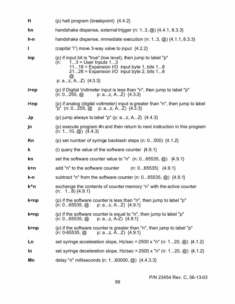
P/N 23454 Rev. C, 06-13-0399
H (p) halt program (breakpoint) {4.4.2}
hn handshake dispense, external trigger (n: 1..3, @) {4.4.1, 8.3.3}
h-n handshake dispense, immediate execution (n: 1..3, @) {4.1.1, 8.3.3}
I (capital “i”) move 3-way valve to input {4.2.2}
inp (p) if input bit is "true" (low level), then jump to label "p"(n: 1...3 = User Inputs 1...3 11...18 = Expansion I/O input byte 1, bits 1...8 21...28 = Expansion I/O input byte 2, bits 1...8
@ p: a...z, A...Z) {4.3.3}
i>np (p) if Digital Voltmeter input is less than "n", then jump to label "p"(n: 0...255, @ p: a...z, A...Z) {4.3.3}
i<np (p) if analog (digital voltmeter) input is greater than "n", then jump to label"p" (n: 0...255, @ p: a...z, A...Z) {4.3.3}
Jp (p) jump always to label "p" (p: a...z, A...Z) {4.4.3}
jn (p) execute program #n and then return to next instruction in this program(n: 1...10, @) {4.4.3}
Kn (p) set number of syringe backlash steps (n: 0...500) {4.1.2}
k (i) query the value of the software counter {4.9.1}
kn set the software counter value to "n" (n: 0...65535, @) {4.9.1}
k+n add "n" to the software counter (n: 0...65535) {4.9.1}
k-n subtract "n" from the software counter (n: 0...65535, @) {4.9.1}
k^n exchange the contents of counter memory “n” with the active counter(n: 1...8) {4.9.1}
k<np (p) if the software counter is less than "n", then jump to label "p"(n: 0...65535, @ p: a...z, A...Z) {4.9.1}
k=np (p) if the software counter is equal to "n", then jump to label "p"(n: 0...65535, @ p: a...z, A-Z) {4.9.1}
k>np (p) if the software counter is greater than "n", then jump to label "p"(n: 0-65535, @ p: a...z, A...Z) {4.9.1}
Ln set syringe acceleration slope, Hz/sec = 2500 x "n" (n: 1...20, @) {4.1.2}
ln set syringe deceleration slope, Hz/sec = 2500 x "n" (n: 1...20, @) {4.1.2}
Mn delay "n" milliseconds (n: 1...60000, @) {4.4.3.3}
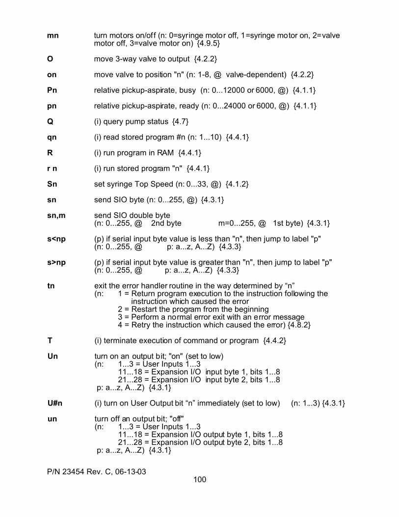
P/N 23454 Rev. C, 06-13-03100
mn turn motors on/off (n: 0=syringe motor off, 1=syringe motor on, 2=valvemotor off, 3=valve motor on) {4.9.5}
O move 3-way valve to output {4.2.2}
on move valve to position "n" (n: 1-8, @ valve-dependent) {4.2.2}
Pn relative pickup-aspirate, busy (n: 0...12000 or 6000, @) {4.1.1}
pn relative pickup-aspirate, ready (n: 0...24000 or 6000, @) {4.1.1}
Q (i) query pump status {4.7}
qn (i) read stored program #n (n: 1...10) {4.4.1}
R (i) run program in RAM {4.4.1}
r n (i) run stored program "n" {4.4.1}
Sn set syringe Top Speed (n: 0...33, @) {4.1.2}
sn send SIO byte (n: 0...255, @) {4.3.1}
sn,m send SIO double byte(n: 0...255, @ 2nd byte m=0...255, @ 1st byte) {4.3.1}
s<np (p) if serial input byte value is less than "n", then jump to label "p"(n: 0...255, @ p: a...z, A...Z) {4.3.3}
s>np (p) if serial input byte value is greater than "n", then jump to label "p"(n: 0...255, @ p: a...z, A...Z) {4.3.3}
tn exit the error handler routine in the way determined by “n”(n: 1 = Return program execution to the instruction following the
instruction which caused the error2 = Restart the program from the beginning3 = Perform a normal error exit with an error message4 = Retry the instruction which caused the error) {4.8.2}
T (i) terminate execution of command or program {4.4.2}
Un turn on an output bit; "on" (set to low)(n: 1...3 = User Inputs 1...3 11...18 = Expansion I/O input byte 1, bits 1...8 21...28 = Expansion I/O input byte 2, bits 1...8 p: a...z, A...Z) {4.3.1}
U#n (i) turn on User Output bit “n” immediately (set to low) (n: 1...3) {4.3.1}
un turn off an output bit; "off"(n: 1...3 = User Inputs 1...3 11...18 = Expansion I/O output byte 1, bits 1...8 21...28 = Expansion I/O output byte 2, bits 1...8 p: a...z, A...Z) {4.3.1}

P/N 23454 Rev. C, 06-13-03101
u#n (i) turn off User Output bit “n” immediately (set to high) (n: 1...3) {4.3.1}
Vn (i) set syringe Top Speed in steps/sec (n: 40...8000, @) {4.1.2}
vn set syringe Start Speed in steps/sec (n: 40...1000, @) {4.1.2}
Wn initialize syringe and valve (n: 4=move valve to port 1, then move syringe to "soft limit"; 5=save current syringe position as zero) {4.1.3}
X (i) repeat last command string; does not apply to queries {4.9.6}
x? query error number (see Section 5.1) last trapped {4.8.3}
y<np (o) if syringe position is less than “n”, then go to label “p”(n: 0...12000 or 6000 p=a...z, A...Z) {4.4.3}
y=np (o) if syringe position equals “n”, then go to label “p”(n: 0...12000 or 6000 p=a...z, A...Z) {4.4.3}
y>np (o) if syringe position greater than “n”, then go to label “p”(n: 0...12000 or 6000 p=a...z, A...Z) {4.4.3}
Yn initialize the syringe and select the port specified by the "~Y" parameter(n: 4...5, see "Wn") {4.1.3}
Zn initialize the syringe and select the port specified by the "~Z" parameter(n: 4...5, see "Wn") {4.1.3}
znp trap error #n and jump to a user error handler routine at program label “p”(n: 1...26 p: a...z, A...Z) {4.8.1}
? (i) query the syringe position {4.1.4}
?1 (i) query the syringe Start Speed {4.1.4}
?2 (i) query the syringe Top Speed {4.1.4}
?3 (i) query the syringe Stop Speed {4.1.4}
?4 (i) query the User Input 1 status, reply "1" if at low level {4.3.2}
?5 (i) query the User Input 2 status, reply "1" if at low level {4.3.2}
?6 (i) query the User Input 3 status, reply "1" if at low level {4.3.2}
?7 (i) query the User Analog Input voltage, volts = reply x 0.02 {4.3.2}
?8 (i) query the valve position (1=A, 2=B, etc.) {4.2.3}
?9 (i) query the number of unused bytes in NVM {4.4.1}
?10 (i) query the numerical value of the serial I/O input byte, or of byte 1 for a 2-byte mode {4.3.2}
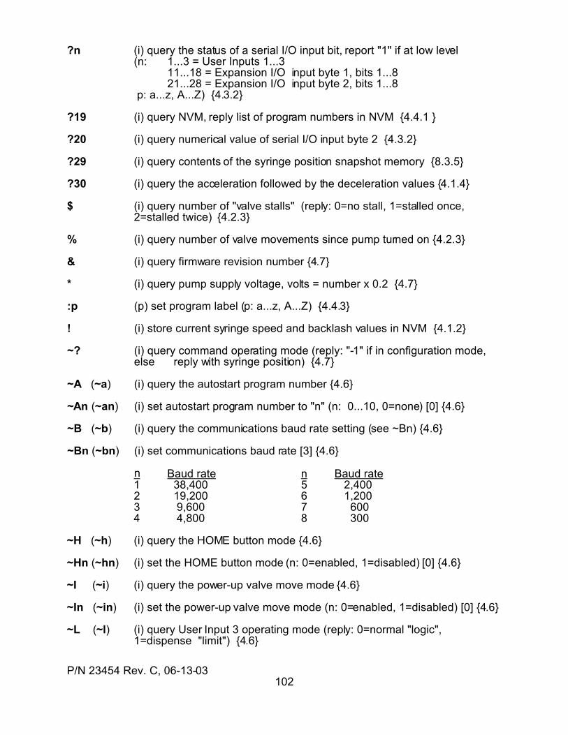
P/N 23454 Rev. C, 06-13-03102
?n (i) query the status of a serial I/O input bit, report "1" if at low level(n: 1...3 = User Inputs 1...3 11...18 = Expansion I/O input byte 1, bits 1...8 21...28 = Expansion I/O input byte 2, bits 1...8 p: a...z, A...Z) {4.3.2}
?19 (i) query NVM, reply list of program numbers in NVM {4.4.1 }
?20 (i) query numerical value of serial I/O input byte 2 {4.3.2}
?29 (i) query contents of the syringe position snapshot memory {8.3.5}
?30 (i) query the acceleration followed by the deceleration values {4.1.4}
$ (i) query number of "valve stalls" (reply: 0=no stall, 1=stalled once, 2=stalled twice) {4.2.3}
% (i) query number of valve movements since pump turned on {4.2.3}
& (i) query firmware revision number {4.7}
* (i) query pump supply voltage, volts = number x 0.2 {4.7}
:p (p) set program label (p: a...z, A...Z) {4.4.3}
! (i) store current syringe speed and backlash values in NVM {4.1.2}
~? (i) query command operating mode (reply: "-1" if in configuration mode,else reply with syringe position) {4.7}
~A (~a) (i) query the autostart program number {4.6}
~An (~an) (i) set autostart program number to "n" (n: 0...10, 0=none) [0] {4.6}
~B (~b) (i) query the communications baud rate setting (see ~Bn) {4.6}
~Bn (~bn) (i) set communications baud rate [3] {4.6}
n Baud rate n Baud rate1 38,400 5 2,4002 19,200 6 1,2003 9,600 7 6004 4,800 8 300
~H (~h) (i) query the HOME button mode {4.6}
~Hn (~hn) (i) set the HOME button mode (n: 0=enabled, 1=disabled) [0] {4.6}
~I (~i) (i) query the power-up valve move mode {4.6}
~In (~in) (i) set the power-up valve move mode (n: 0=enabled, 1=disabled) [0] {4.6}
~L (~l) (i) query User Input 3 operating mode (reply: 0=normal "logic", 1=dispense "limit") {4.6}
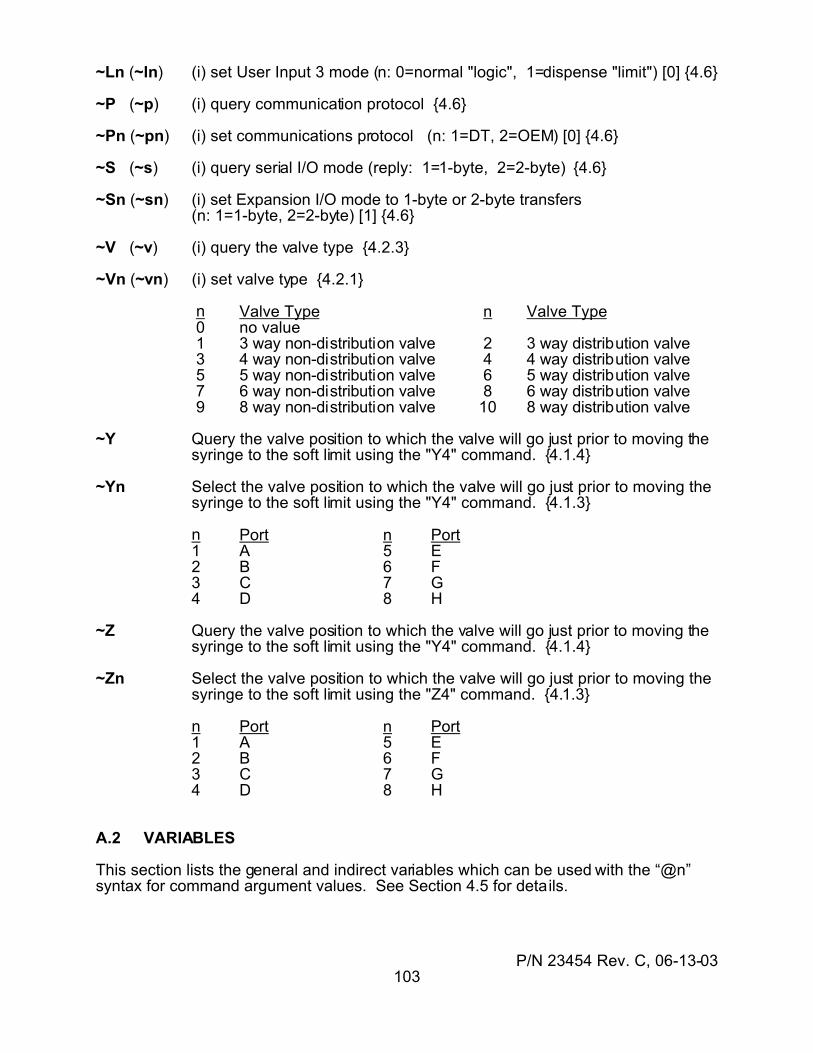
P/N 23454 Rev. C, 06-13-03103
~Ln (~ln) (i) set User Input 3 mode (n: 0=normal "logic", 1=dispense "limit") [0] {4.6}
~P (~p) (i) query communication protocol {4.6}
~Pn (~pn) (i) set communications protocol (n: 1=DT, 2=OEM) [0] {4.6}
~S (~s) (i) query serial I/O mode (reply: 1=1-byte, 2=2-byte) {4.6}
~Sn (~sn) (i) set Expansion I/O mode to 1-byte or 2-byte transfers(n: 1=1-byte, 2=2-byte) [1] {4.6}
~V (~v) (i) query the valve type {4.2.3}
~Vn (~vn) (i) set valve type {4.2.1}
n Valve Type n Valve Type 0 no value 1 3 way non-distribution valve 2 3 way distribution valve 3 4 way non-distribution valve 4 4 way distribution valve 5 5 way non-distribution valve 6 5 way distribution valve 7 6 way non-distribution valve 8 6 way distribution valve 9 8 way non-distribution valve 10 8 way distribution valve
~Y Query the valve position to which the valve will go just prior to moving thesyringe to the soft limit using the "Y4" command. {4.1.4}
~Yn Select the valve position to which the valve will go just prior to moving thesyringe to the soft limit using the "Y4" command. {4.1.3}
n Port n Port1 A 5 E2 B 6 F3 C 7 G4 D 8 H
~Z Query the valve position to which the valve will go just prior to moving thesyringe to the soft limit using the "Y4" command. {4.1.4}
~Zn Select the valve position to which the valve will go just prior to moving thesyringe to the soft limit using the "Z4" command. {4.1.3}
n Port n Port1 A 5 E2 B 6 F3 C 7 G4 D 8 H
A.2 VARIABLES
This section lists the general and indirect variables which can be used with the “@n”syntax for command argument values. See Section 4.5 for details.
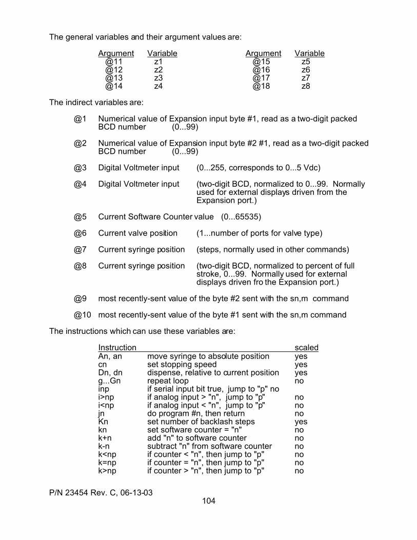
P/N 23454 Rev. C, 06-13-03104
The general variables and their argument values are:
Argument Variable Argument Variable @11 z1 @15 z5 @12 z2 @16 z6 @13 z3 @17 z7 @14 z4 @18 z8
The indirect variables are:
@1 Numerical value of Expansion input byte #1, read as a two-digit packedBCD number (0...99)
@2 Numerical value of Expansion input byte #2 #1, read as a two-digit packedBCD number (0...99)
@3 Digital Voltmeter input (0...255, corresponds to 0...5 Vdc)
@4 Digital Voltmeter input (two-digit BCD, normalized to 0...99. Normallyused for external displays driven from theExpansion port.)
@5 Current Software Counter value (0...65535)
@6 Current valve position (1...number of ports for valve type)
@7 Current syringe position (steps, normally used in other commands)
@8 Current syringe position (two-digit BCD, normalized to percent of fullstroke, 0...99. Normally used for externaldisplays driven fro the Expansion port.)
@9 most recently-sent value of the byte #2 sent with the sn,m command
@10 most recently-sent value of the byte #1 sent with the sn,m command
The instructions which can use these variables are:
Instruction scaledAn, an move syringe to absolute position yescn set stopping speed yesDn, dn dispense, relative to current position yesg...Gn repeat loop noinp if serial input bit true, jump to "p" noi>np if analog input > "n", jump to "p" noi<np if analog input < "n", jump to "p" nojn do program #n, then return noKn set number of backlash steps yeskn set software counter = "n" nok+n add "n" to software counter nok-n subtract "n" from software counter nok<np if counter < "n", then jump to "p" nok=np if counter = "n", then jump to "p" nok>np if counter > "n", then jump to "p" no
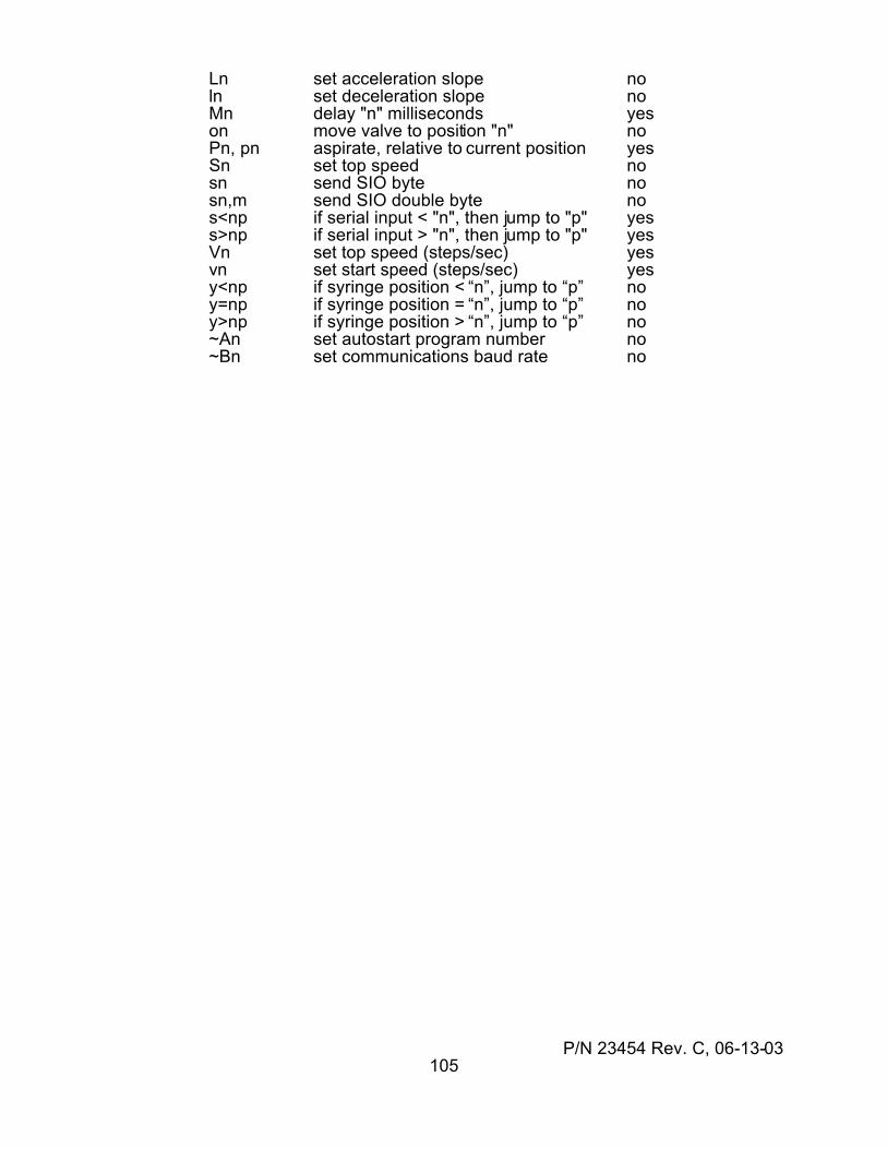
P/N 23454 Rev. C, 06-13-03105
Ln set acceleration slope noln set deceleration slope noMn delay "n" milliseconds yeson move valve to position "n" noPn, pn aspirate, relative to current position yesSn set top speed nosn send SIO byte nosn,m send SIO double byte nos<np if serial input < "n", then jump to "p" yess>np if serial input > "n", then jump to "p" yesVn set top speed (steps/sec) yesvn set start speed (steps/sec) yesy<np if syringe position < “n”, jump to “p” noy=np if syringe position = “n”, jump to “p” noy>np if syringe position > “n”, jump to “p” no~An set autostart program number no~Bn set communications baud rate no
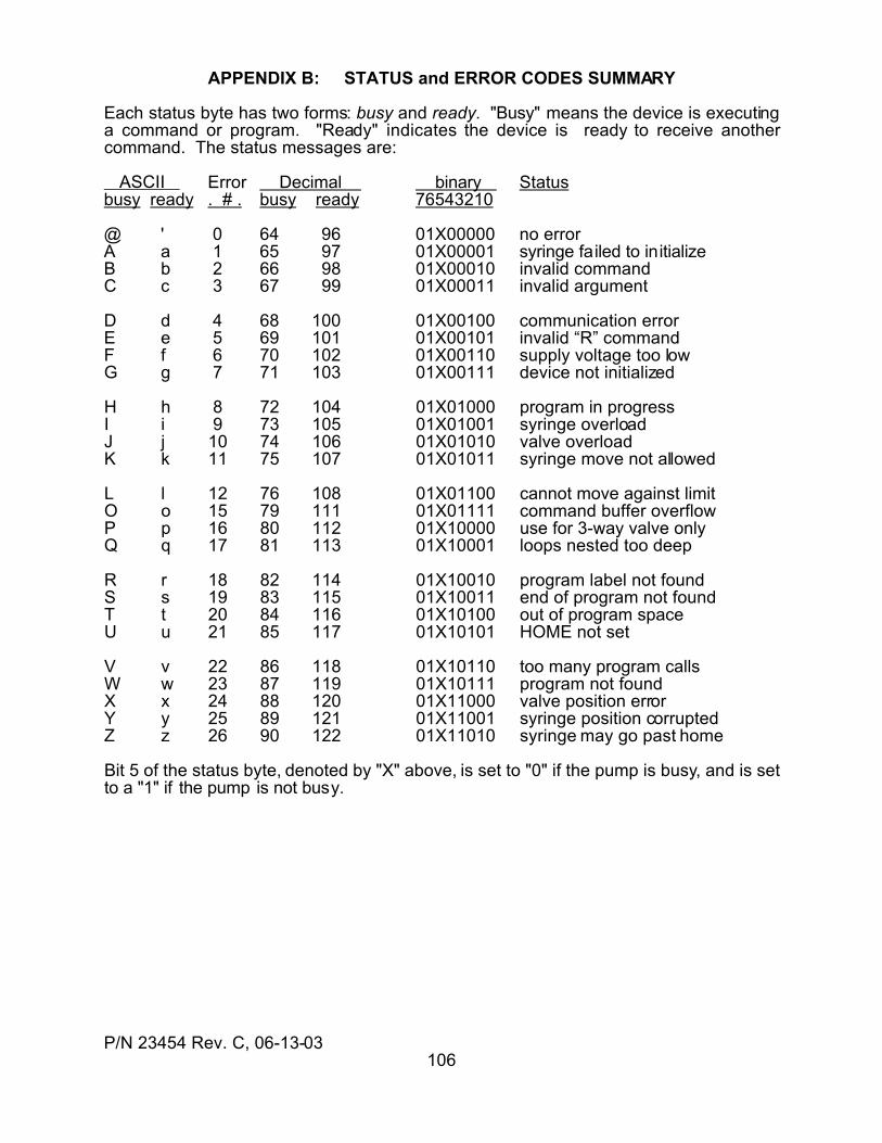
P/N 23454 Rev. C, 06-13-03106
APPENDIX B: STATUS and ERROR CODES SUMMARY
Each status byte has two forms: busy and ready. "Busy" means the device is executinga command or program. "Ready" indicates the device is ready to receive anothercommand. The status messages are:
ASCII Error Decimal binary Statusbusy ready . # . busy ready 76543210
@ ' 0 64 96 01X00000 no errorA a 1 65 97 01X00001 syringe failed to initializeB b 2 66 98 01X00010 invalid commandC c 3 67 99 01X00011 invalid argument
D d 4 68 100 01X00100 communication errorE e 5 69 101 01X00101 invalid “R” commandF f 6 70 102 01X00110 supply voltage too lowG g 7 71 103 01X00111 device not initialized
H h 8 72 104 01X01000 program in progressI i 9 73 105 01X01001 syringe overloadJ j 10 74 106 01X01010 valve overloadK k 11 75 107 01X01011 syringe move not allowed
L l 12 76 108 01X01100 cannot move against limitO o 15 79 111 01X01111 command buffer overflowP p 16 80 112 01X10000 use for 3-way valve onlyQ q 17 81 113 01X10001 loops nested too deep
R r 18 82 114 01X10010 program label not foundS s 19 83 115 01X10011 end of program not foundT t 20 84 116 01X10100 out of program spaceU u 21 85 117 01X10101 HOME not set
V v 22 86 118 01X10110 too many program callsW w 23 87 119 01X10111 program not foundX x 24 88 120 01X11000 valve position errorY y 25 89 121 01X11001 syringe position corruptedZ z 26 90 122 01X11010 syringe may go past home
Bit 5 of the status byte, denoted by "X" above, is set to "0" if the pump is busy, and is setto a "1" if the pump is not busy.
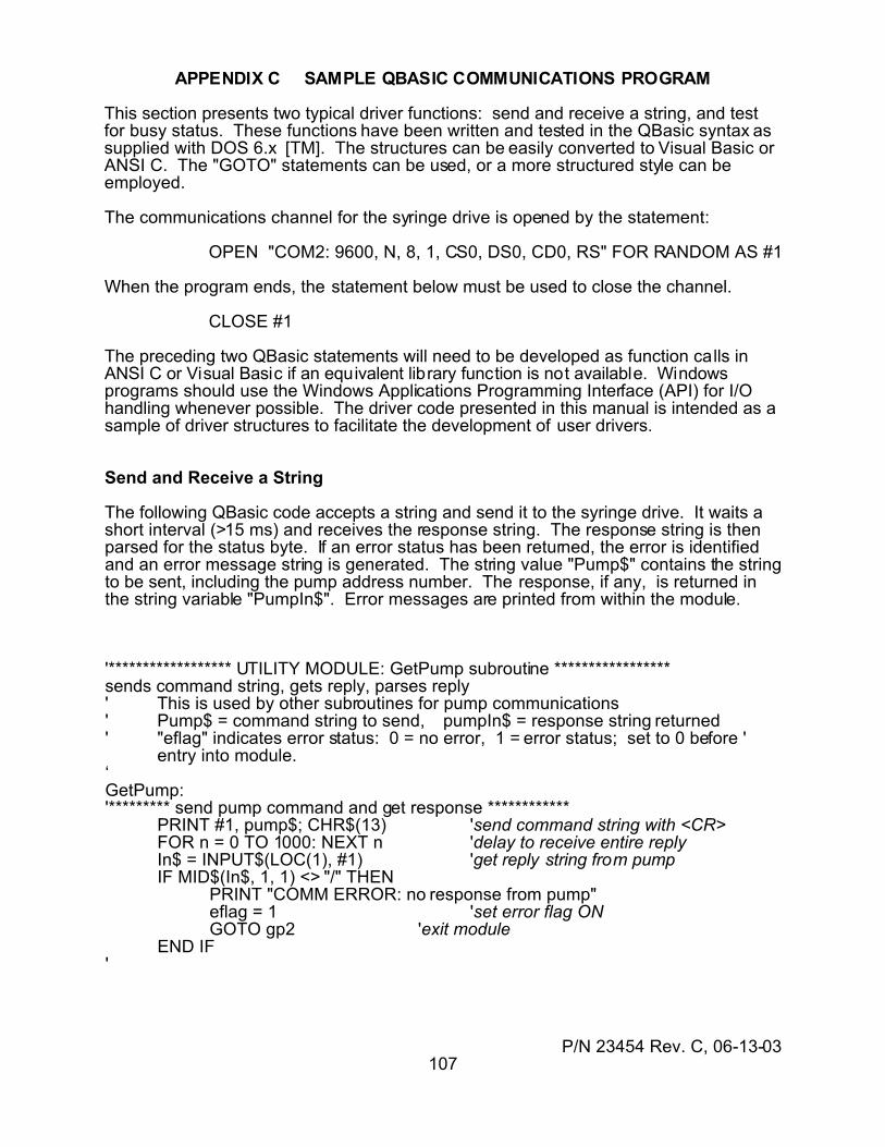
P/N 23454 Rev. C, 06-13-03107
APPENDIX C SAMPLE QBASIC COMMUNICATIONS PROGRAM
This section presents two typical driver functions: send and receive a string, and testfor busy status. These functions have been written and tested in the QBasic syntax assupplied with DOS 6.x [TM]. The structures can be easily converted to Visual Basic orANSI C. The "GOTO" statements can be used, or a more structured style can beemployed.
The communications channel for the syringe drive is opened by the statement:
OPEN "COM2: 9600, N, 8, 1, CS0, DS0, CD0, RS" FOR RANDOM AS #1
When the program ends, the statement below must be used to close the channel.
CLOSE #1
The preceding two QBasic statements will need to be developed as function calls inANSI C or Visual Basic if an equivalent library function is not available. Windowsprograms should use the Windows Applications Programming Interface (API) for I/Ohandling whenever possible. The driver code presented in this manual is intended as asample of driver structures to facilitate the development of user drivers.
Send and Receive a String
The following QBasic code accepts a string and send it to the syringe drive. It waits ashort interval (>15 ms) and receives the response string. The response string is thenparsed for the status byte. If an error status has been returned, the error is identifiedand an error message string is generated. The string value "Pump$" contains the stringto be sent, including the pump address number. The response, if any, is returned inthe string variable "PumpIn$". Error messages are printed from within the module.
'****************** UTILITY MODULE: GetPump subroutine *****************sends command string, gets reply, parses reply' This is used by other subroutines for pump communications' Pump$ = command string to send, pumpIn$ = response string returned' "eflag" indicates error status: 0 = no error, 1 = error status; set to 0 before '
entry into module.‘GetPump:'********* send pump command and get response ************
PRINT #1, pump$; CHR$(13) 'send command string with <CR>FOR n = 0 TO 1000: NEXT n 'delay to receive entire replyIn$ = INPUT$(LOC(1), #1) 'get reply string from pumpIF MID$(In$, 1, 1) <> "/" THEN
PRINT "COMM ERROR: no response from pump" eflag = 1 'set error flag ON GOTO gp2 'exit module
END IF'
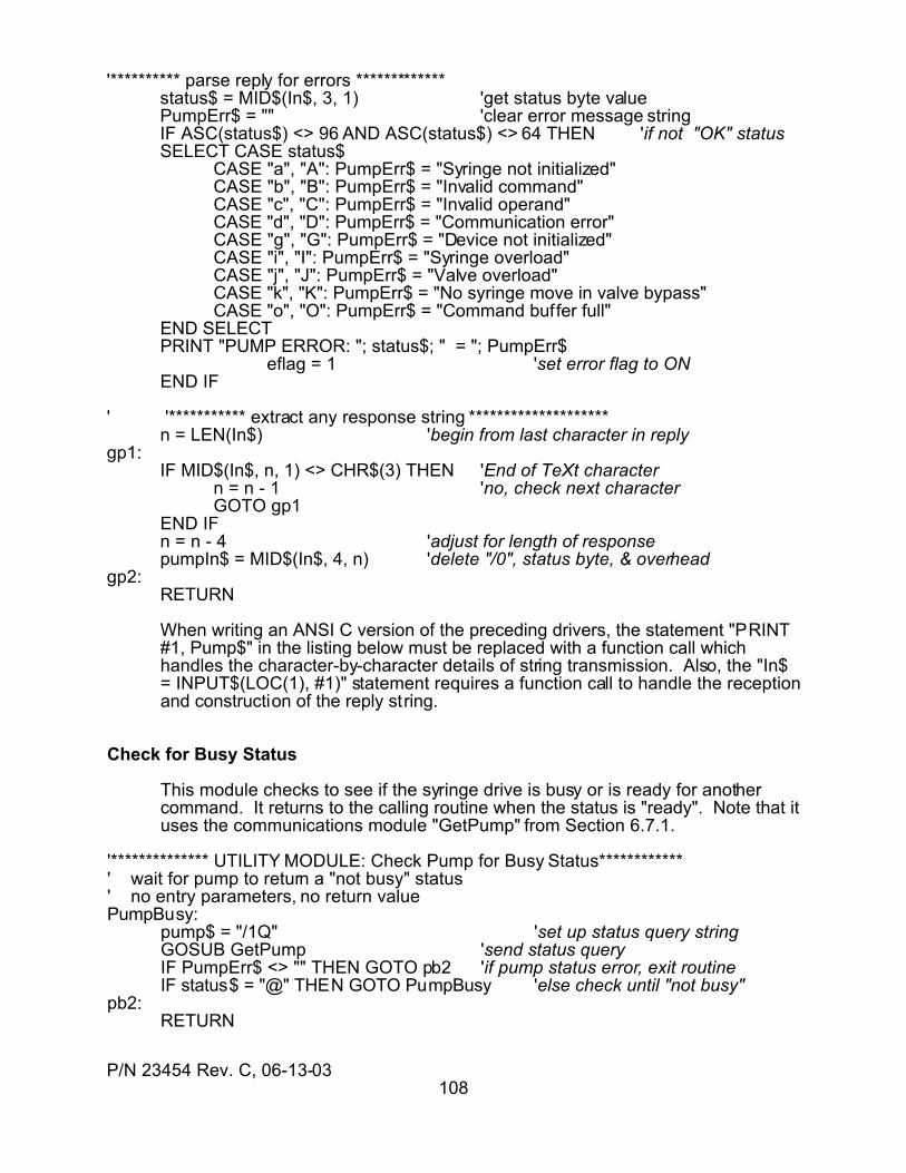
P/N 23454 Rev. C, 06-13-03108
'********** parse reply for errors *************status$ = MID$(In$, 3, 1) 'get status byte valuePumpErr$ = "" 'clear error message stringIF ASC(status$) <> 96 AND ASC(status$) <> 64 THEN 'if not "OK" statusSELECT CASE status$
CASE "a", "A": PumpErr$ = "Syringe not initialized"CASE "b", "B": PumpErr$ = "Invalid command"CASE "c", "C": PumpErr$ = "Invalid operand"CASE "d", "D": PumpErr$ = "Communication error"CASE "g", "G": PumpErr$ = "Device not initialized"CASE "i", "I": PumpErr$ = "Syringe overload"CASE "j", "J": PumpErr$ = "Valve overload"CASE "k", "K": PumpErr$ = "No syringe move in valve bypass"CASE "o", "O": PumpErr$ = "Command buffer full"
END SELECTPRINT "PUMP ERROR: "; status$; " = "; PumpErr$
eflag = 1 'set error flag to ONEND IF
' '*********** extract any response string ********************n = LEN(In$) 'begin from last character in reply
gp1:IF MID$(In$, n, 1) <> CHR$(3) THEN 'End of TeXt character
n = n - 1 'no, check next characterGOTO gp1
END IFn = n - 4 'adjust for length of responsepumpIn$ = MID$(In$, 4, n) 'delete "/0", status byte, & overhead
gp2:RETURN
When writing an ANSI C version of the preceding drivers, the statement "PRINT#1, Pump$" in the listing below must be replaced with a function call whichhandles the character-by-character details of string transmission. Also, the "In$= INPUT$(LOC(1), #1)" statement requires a function call to handle the receptionand construction of the reply string.
Check for Busy Status
This module checks to see if the syringe drive is busy or is ready for anothercommand. It returns to the calling routine when the status is "ready". Note that ituses the communications module "GetPump" from Section 6.7.1.
'************** UTILITY MODULE: Check Pump for Busy Status************' wait for pump to return a "not busy" status' no entry parameters, no return valuePumpBusy:
pump$ = "/1Q" 'set up status query stringGOSUB GetPump 'send status query
IF PumpErr$ <> "" THEN GOTO pb2 'if pump status error, exit routineIF status$ = "@" THEN GOTO PumpBusy 'else check until "not busy"
pb2:RETURN
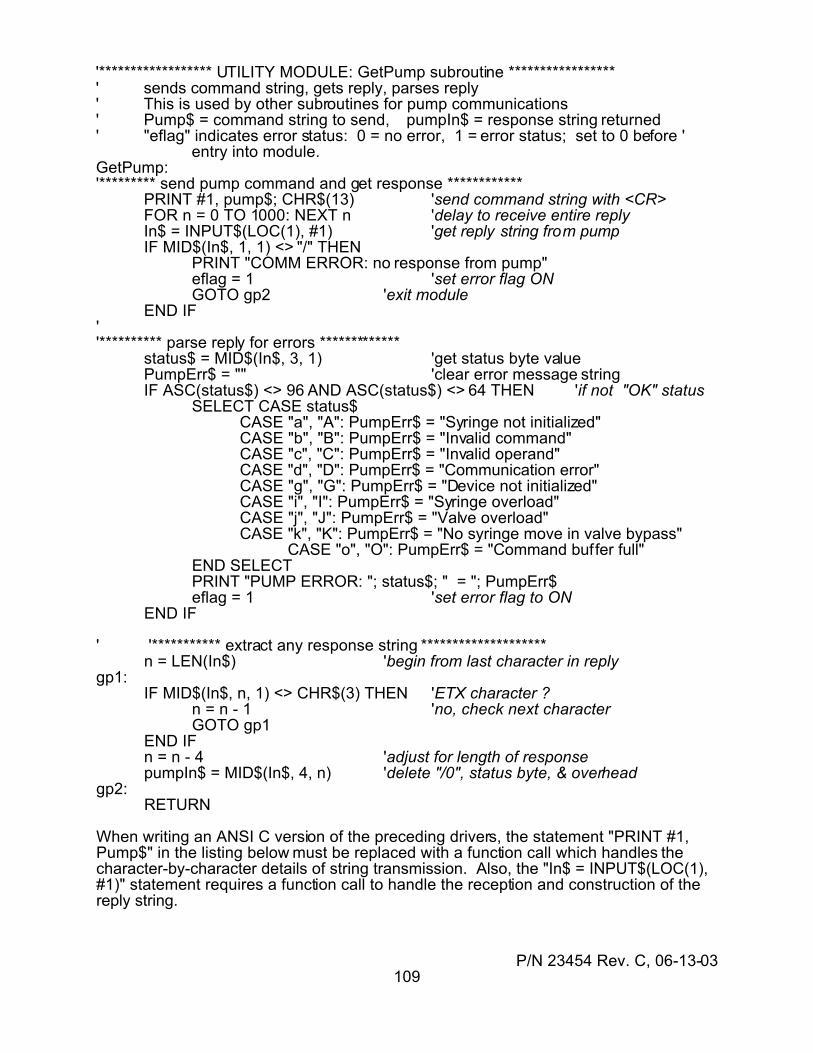
P/N 23454 Rev. C, 06-13-03109
'****************** UTILITY MODULE: GetPump subroutine *****************' sends command string, gets reply, parses reply' This is used by other subroutines for pump communications' Pump$ = command string to send, pumpIn$ = response string returned' "eflag" indicates error status: 0 = no error, 1 = error status; set to 0 before '
entry into module.GetPump:'********* send pump command and get response ************
PRINT #1, pump$; CHR$(13) 'send command string with <CR>FOR n = 0 TO 1000: NEXT n 'delay to receive entire replyIn$ = INPUT$(LOC(1), #1) 'get reply string from pumpIF MID$(In$, 1, 1) <> "/" THEN
PRINT "COMM ERROR: no response from pump"eflag = 1 'set error flag ONGOTO gp2 'exit module
END IF''********** parse reply for errors *************
status$ = MID$(In$, 3, 1) 'get status byte valuePumpErr$ = "" 'clear error message stringIF ASC(status$) <> 96 AND ASC(status$) <> 64 THEN 'if not "OK" status
SELECT CASE status$ CASE "a", "A": PumpErr$ = "Syringe not initialized" CASE "b", "B": PumpErr$ = "Invalid command" CASE "c", "C": PumpErr$ = "Invalid operand" CASE "d", "D": PumpErr$ = "Communication error" CASE "g", "G": PumpErr$ = "Device not initialized" CASE "i", "I": PumpErr$ = "Syringe overload" CASE "j", "J": PumpErr$ = "Valve overload" CASE "k", "K": PumpErr$ = "No syringe move in valve bypass" CASE "o", "O": PumpErr$ = "Command buffer full" END SELECT
PRINT "PUMP ERROR: "; status$; " = "; PumpErr$eflag = 1 'set error flag to ON
END IF
' '*********** extract any response string ********************n = LEN(In$) 'begin from last character in reply
gp1:IF MID$(In$, n, 1) <> CHR$(3) THEN 'ETX character ?
n = n - 1 'no, check next characterGOTO gp1
END IFn = n - 4 'adjust for length of responsepumpIn$ = MID$(In$, 4, n) 'delete "/0", status byte, & overhead
gp2:RETURN
When writing an ANSI C version of the preceding drivers, the statement "PRINT #1,Pump$" in the listing below must be replaced with a function call which handles thecharacter-by-character details of string transmission. Also, the "In$ = INPUT$(LOC(1),#1)" statement requires a function call to handle the reception and construction of thereply string.
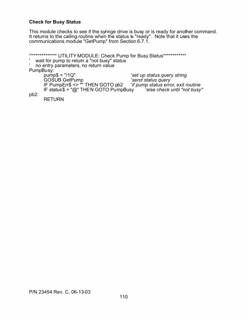
P/N 23454 Rev. C, 06-13-03110
Check for Busy Status
This module checks to see if the syringe drive is busy or is ready for another command. It returns to the calling routine when the status is "ready". Note that it uses thecommunications module "GetPump" from Section 6.7.1.
'************** UTILITY MODULE: Check Pump for Busy Status************' wait for pump to return a "not busy" status' no entry parameters, no return valuePumpBusy:
pump$ = "/1Q" 'set up status query stringGOSUB GetPump 'send status query
IF PumpErr$ <> "" THEN GOTO pb2 'if pump status error, exit routineIF status$ = "@" THEN GOTO PumpBusy 'else check until "not busy"
pb2:RETURN