hardware graduation project storing robot
DESCRIPTION
Hardware Graduation Project Storing Robot . Alaa Shaheen – Computer Dep. Mariam Imar – Electrical Dep. Supervised by: Dr. Samer Arandi Hardware Graduation Project 23 May 2012 . Overview. Brief Introduction. Project Characteristics. Mechanical design. Mathematical Background. - PowerPoint PPT PresentationTRANSCRIPT

Hardware Graduation Project
Storing Robot Alaa Shaheen – Computer Dep.
Mariam Imar – Electrical Dep.Supervised by: Dr. Samer Arandi
Hardware Graduation Project 23 May 2012
Brief Introduction. Project Characteristics. Mechanical design. Mathematical Background. Block Diagram. Actuators. Microcontroller. RFID Circuit. IR Range Sensor. Power Supply. Conclusion. Video Demo.
Overview
What is our project?
Storing Robot is a robotics arm with a mobile base that is mainly classify the objects based on a tag. Each object has a specific tag, and the robot included an RFID reader that reads it. Then the robot arm will move in specific degrees to reach the right shelf for each object .
We added some feeling – around IR range finder sensor that could know where the object is ,so it moves toward it. This added some dynamic moves to the robot.
We allow the robot to move in a pre-defined path that is already known to the robot.
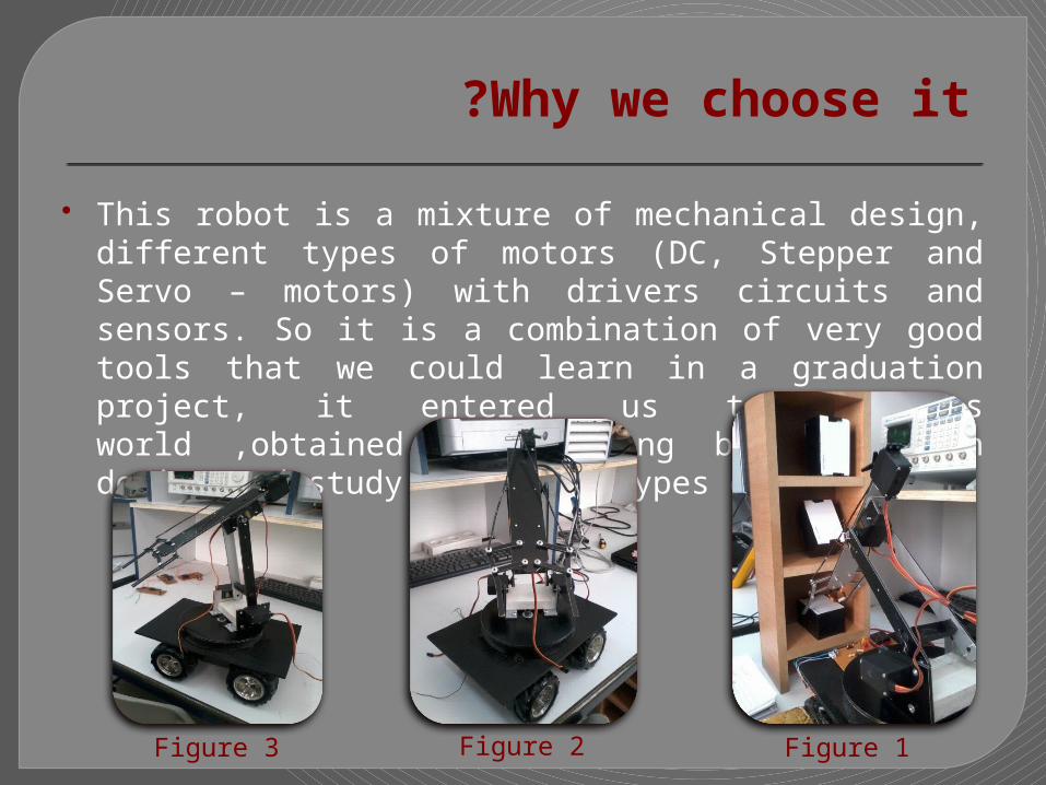
Why we choose it ? This robot is a mixture of mechanical design, different types of
motors (DC, Stepper and Servo – motors) with drivers circuits and sensors. So it is a combination of very good tools that we could learn in a graduation project, it entered us to robotics world ,obtained good strong background in design and study different types of motors .
Figure 1Figure 2Figure 3

Where can be used ? This type of robots are used in Industrial application. Usually it used
to move objects in production lines.
It used also in big inventories to do classifications. If an extra bar-code reader is added we could use it to classify
medicine in medical inventories on shelves.
Figure 4
Project Characteristics :
Storing Robot brings a sophisticated Articulated Robotic Arm to facilitate the Industrial/Research installations with object manipulation capabilities.
It has an robotic arm that rotate in five degree of freedom.
It has the ability to read different tags .
It can move from place to another (mobile robot).
It can see the environment around it.
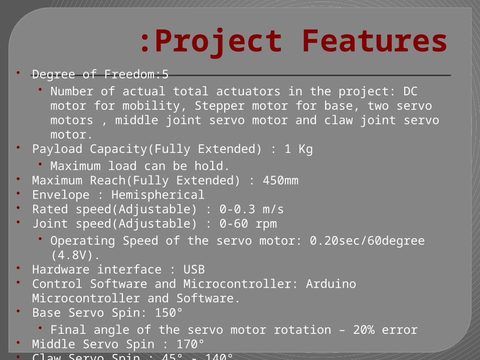
Project Features: Degree of Freedom:5
• Number of actual total actuators in the project: DC motor for mobility, Stepper motor for base, two servo motors , middle joint servo motor and claw joint servo motor.
Payload Capacity(Fully Extended) : 1 Kg• Maximum load can be hold.
Maximum Reach(Fully Extended) : 450mm Envelope : Hemispherical Rated speed(Adjustable) : 0-0.3 m/s Joint speed(Adjustable) : 0-60 rpm
• Operating Speed of the servo motor: 0.20sec/60degree (4.8V). Hardware interface : USB Control Software and Microcontroller: Arduino Microcontroller and Software. Base Servo Spin: 150°
• Final angle of the servo motor rotation – 20% error Middle Servo Spin : 170° Claw Servo Spin : 45° - 140° Gripper (Claw) Opening(Max) : 65mm
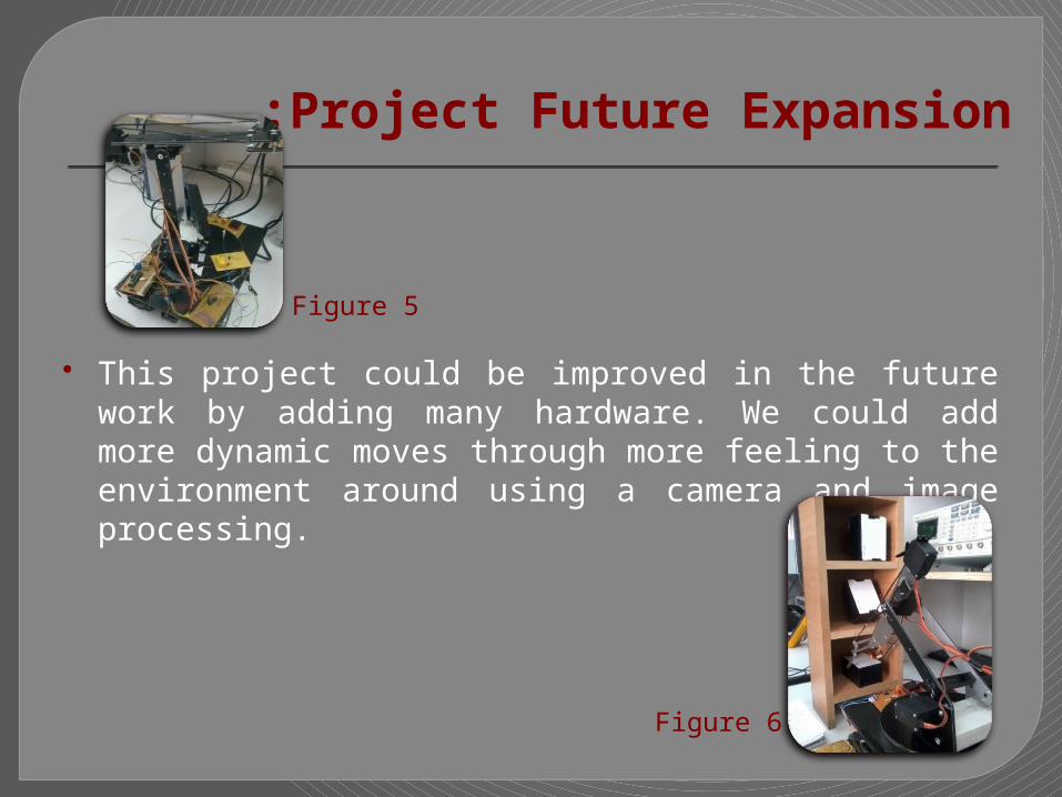
Project Future Expansion:
This project could be improved in the future work by adding many hardware. We could add more dynamic moves through more feeling to the environment around using a camera and image processing.
Figure 5
Figure 6
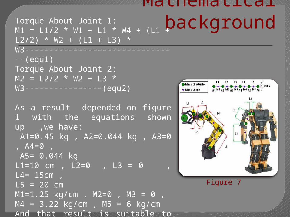
Mathematical backgroundTorque About Joint 1: M1 = L1/2 * W1 + L1 * W4 + (L1 + L2/2) * W2 + (L1 + L3) * W3--------------------------------(equ1)Torque About Joint 2: M2 = L2/2 * W2 + L3 * W3----------------(equ2)
As a result depended on figure 1 with the equations shown up ,we have: A1=0.45 kg , A2=0.044 kg , A3=0 , A4=0 , A5= 0.044 kgL1=10 cm , L2=0 , L3 = 0 , L4= 15cm , L5 = 20 cmM1=1.25 kg/cm , M2=0 , M3 = 0 , M4 = 3.22 kg/cm , M5 = 6 kg/cm And that result is suitable to servo motor that we had with torque = 5.2 – 6.5 kg/cm
Figure 7

Choosing suitable wheelsVelocity= circumference * rpm ----------------------------------------------------(equ3)Velocity = diameter * pi * rpm OR Velocity = 2 * radius * pi * rpm----------- (equ4)
We depended four wheels with 5 cm diameter for each .
Torque = Distance * Force ----------------------------------------------------------(equa5)Distance = Wheel Radius ----------------------------------------------------------- (equa6)Force = Torque / Wheel Radius ----------------------------------------------------(equa7)
Figure 5

Figure 6 : AutoCad Design
Material and design depended: :
ALUCOBOND aluminum shows excellent product properties such as extraordinary flatness, a large variety of colors and perfect formability.
It has been developed as a rigid and, at the same time, flexible fascia material for architecture.
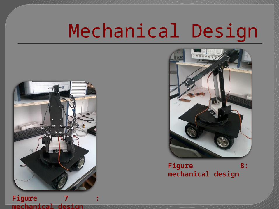
Mechanical Design
Figure 8: mechanical design
Figure 7 : mechanical design
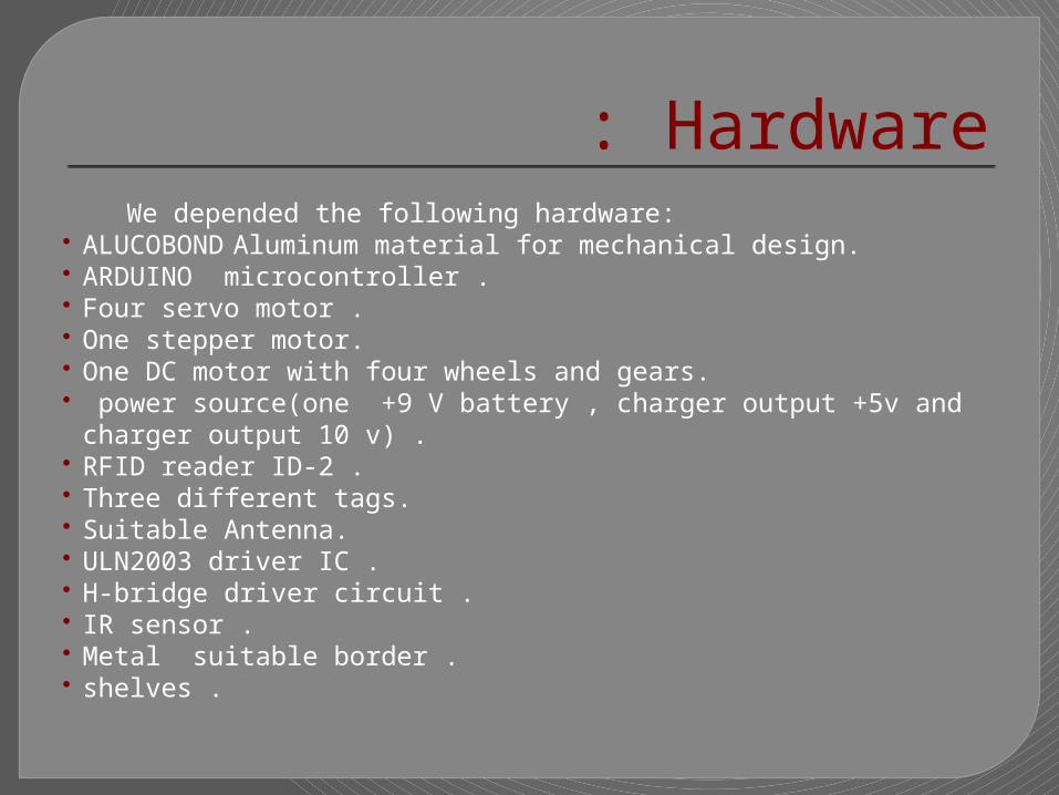
Hardware : We depended the following hardware: ALUCOBOND Aluminum material for mechanical design. ARDUINO microcontroller . Four servo motor . One stepper motor. One DC motor with four wheels and gears. power source(one +9 V battery , charger output +5v and charger output 10 v) . RFID reader ID-2 . Three different tags. Suitable Antenna. ULN2003 driver IC . H-bridge driver circuit . IR sensor . Metal suitable border . shelves .

Detect if there is an
object
Robotic Arm start
working
Storing Robot moving forward
Rotate the base to the
right
Returning to it’s initial position
Decide it correct shelf
Reach the object &
read the tag
Robotic Arm start moving
Storing Robot moving reverse
Put the object in it’s right place
Reach the shelves
Repeat action to the next object
No action
Y
N
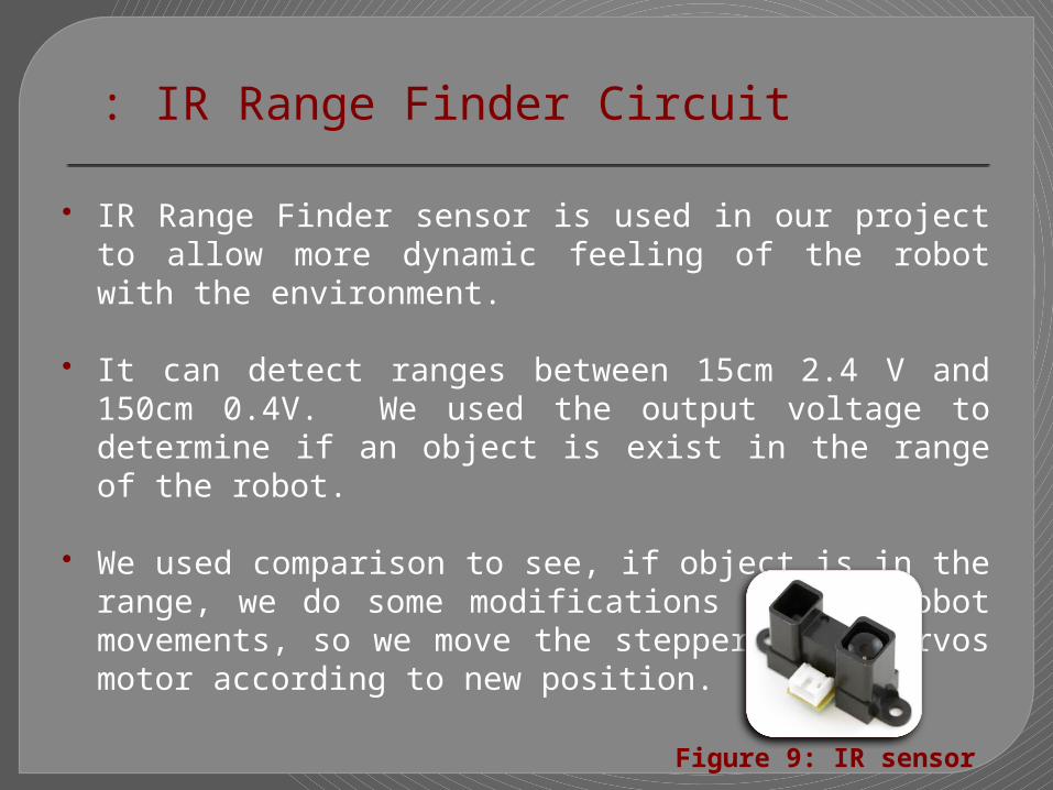
IR Range Finder Circuit : IR Range Finder sensor is used in our project to allow more dynamic
feeling of the robot with the environment.
It can detect ranges between 15cm 2.4 V and 150cm 0.4V. We used the output voltage to determine if an object is exist in the range of the robot.
We used comparison to see, if object is in the range, we do some modifications on the robot movements, so we move the stepper and servos motor according to new position.
Figure 9: IR sensor
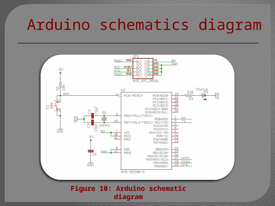
Arduino schematics diagram
Figure 10: Arduino schematic diagram

Built Arduino microcontroller
Figure 11: Built Arduino microcontroller

Servo Motor In general the Servo motors are better for the précised movements
and rotations, since it has an internal feedback and it can be controlled using sending the exact angle we want to go to. We used servo shown in figure 12 .
Figure 12: servo motor
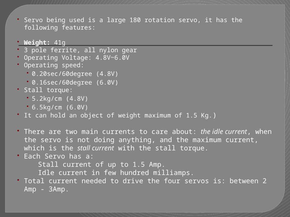
Servo being used is a large 180 rotation servo, it has the following features: Weight: 41g 3 pole ferrite, all nylon gear Operating Voltage: 4.8V~6.0V Operating speed:
• 0.20sec/60degree (4.8V)• 0.16sec/60degree (6.0V)
Stall torque:• 5.2kg/cm (4.8V)• 6.5kg/cm (6.0V)
It can hold an object of weight maximum of 1.5 Kg.)
There are two main currents to care about: the idle current, when the servo is not doing anything, and the maximum current, which is the stall current with the stall torque.
Each Servo has a: Stall current of up to 1.5 Amp. Idle current in few hundred milliamps. Total current needed to drive the four servos is: between 2 Amp - 3Amp.
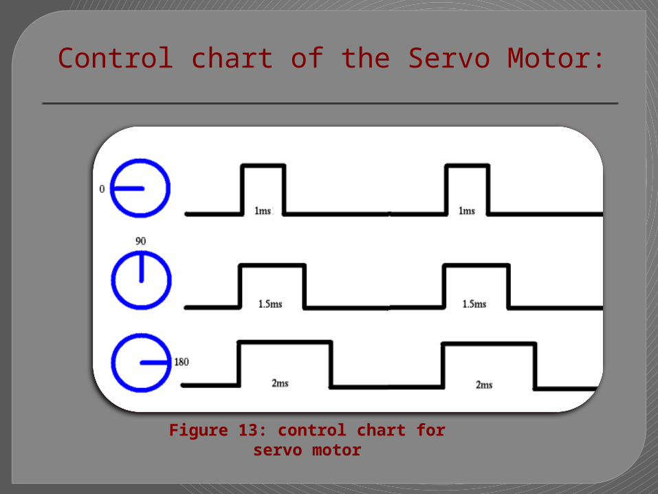
Control chart of the Servo Motor:
Figure 13: control chart for servo motor
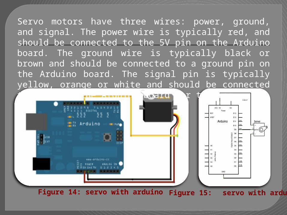
Servo motors have three wires: power, ground, and signal. The power wire is typically red, and should be connected to the 5V pin on the Arduino board. The ground wire is typically black or brown and should be connected to a ground pin on the Arduino board. The signal pin is typically yellow, orange or white and should be connected to pin 9 on the Arduino board for testing.
Figure 14: servo with arduino Figure 15: servo with arduino

RFID Concept and Characteristics :
We depend here RFID reader ID -2 sensor as a sensor that will read the tags and controlling the motors according to that reading .
The ID-2 is a smaller module requiring an external antenna. We hooked up an antenna, power the module, hold up a card, and we got a serial string output containing the unique ID of the card.
Features: 5V supply 125kHz read frequency EM4001 64-bit RFID tag compatible 9600bps TTL and RS232 output Magnetic stripe emulation output Dimensions: 19x21mm Range: locate tag up to 3 – 5 cm with strong Antenna.
Figure 15: RFID reader
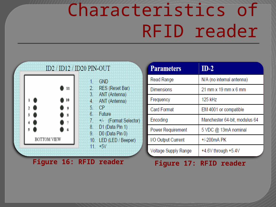
Characteristics of RFID reader
Figure 16: RFID reader Figure 17: RFID reader
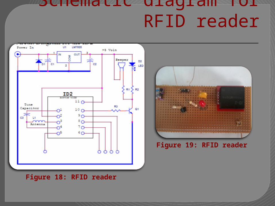
Schematic diagram for RFID reader
Figure 18: RFID reader
Figure 19: RFID reader

Choosing the right Antenna : The RFID reader antenna transmits a wave that has both
electrical and magnetic properties and is known as an electromagnetic wave.
Designing Coils Antennas for ID2: The recommended Inductance is 1.08mH (that 63 turns on a
120mm diameter ) to be used with an internal tuning capacitor of 1n5.
In general the bigger the antenna the better, provided the reader is generating enough field strength to excite the tag.
The ID-2 is relatively low power so a maximum coil size of 15x15cm is recommended if it is intended to read ISO cards .

Types of Tags used : Card tags each has a unique number.
Figure 19: Tags
Figure 20: Antenna
Stepper Motor
A stepper motor is a permanent magnet or variable reluctance dc motor that has the following performance characteristics:
Rotation in both directions. Precision angular incremental changes. Repetition of accurate motion or velocity profiles. Holding torque at zero speed. Capability for digital control.

A Unipolar stepper as in figure 21 is a motor that has one winding with center tap per phase. Each section of windings is switched on for each direction of magnetic field. Since in this arrangement a magnetic pole can be reversed without switching the direction of current.
Operating voltage: up to 12 V. Maximum current : up to 1A.
Figure 21: stepper motor

Driving circuit used: ULN2003A, which has the following features:
high-voltage high-current Darlington transistor arrays. Each consists of seven NPN Darlington pairs that feature high-
voltage outputs with common-cathode clamp diodes for switching inductive loads.
500-mA-Rated Collector Current (Single Output) .
High-Voltage Outputs: 50 V .
Output Clamp Diodes .
Inputs Compatible With Various Types of Logic .
ULN2003A Driving IC
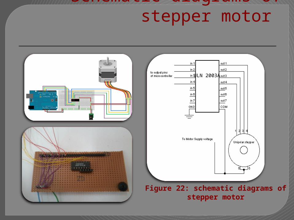
Schematic diagrams of stepper motor
ULN 2003A
Figure 22: schematic diagrams of stepper motor
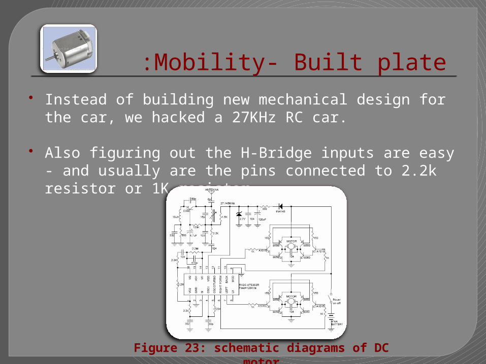
Mobility- Built plate: Instead of building new mechanical design for the car, we hacked a
27KHz RC car. Also figuring out the H-Bridge inputs are easy - and usually are the
pins connected to 2.2k resistor or 1K resistor.
Figure 23: schematic diagrams of DC motor
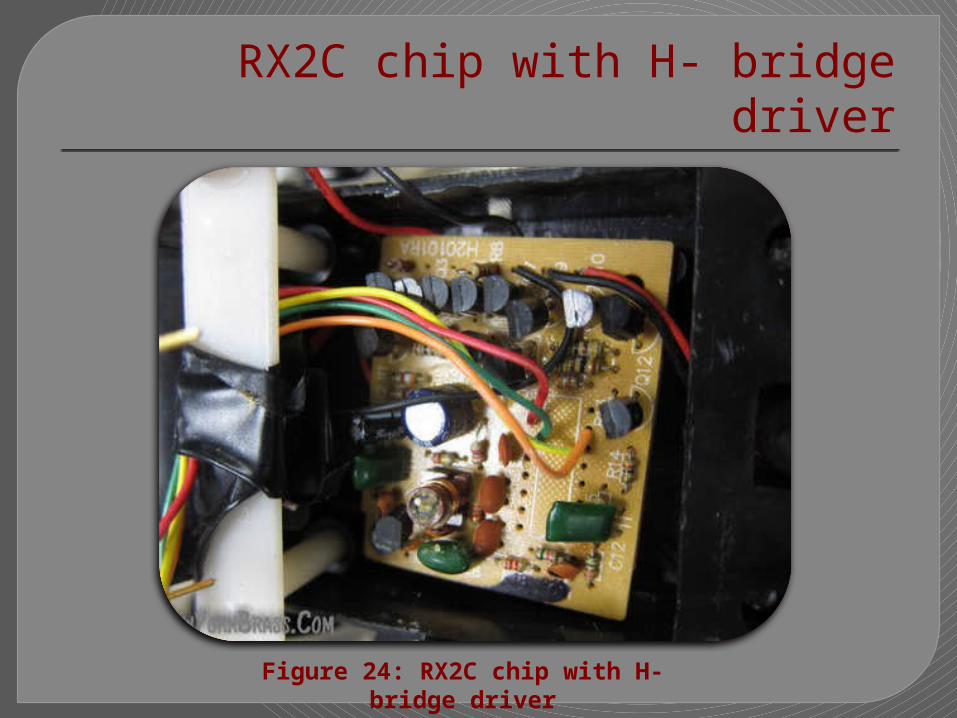
RX2C chip with H- bridge driver
Figure 24: RX2C chip with H- bridge driver
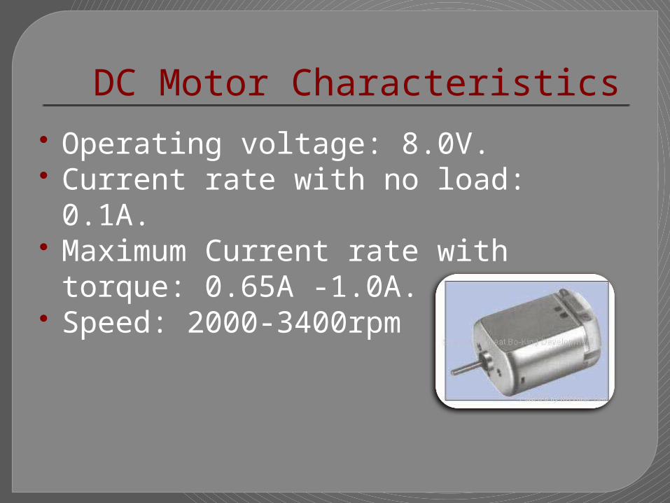
Operating voltage: 8.0V. Current rate with no load: 0.1A. Maximum Current rate with torque: 0.65A -
1.0A. Speed: 2000-3400rpm
DC Motor Characteristics

Shelves and Car Path : We made a simulation for the shelves we will use to put objects on
and a path that the car will use to move within it.
Figure 25: car path
Figure 26: shelves
Power Supply This is used to power the whole system i.e. the: Control Unit, RFID
Sensing Unit ,IR range finder sensor , the Servo Motors ,the Stepper Motors and DC moving plate .
We isolated the actuators from the control units. So we used for the RFID-Sensor, the MC and IR sensors +5Volt , we built voltage regulator with +9 V to step down to +5 V and used it.
A charger of +12V to power the stepper motor , another +5V with
3A current to power the 4 servos together .
An independent recharging battery of about +8V is powered the DC motors in the moving car plate.
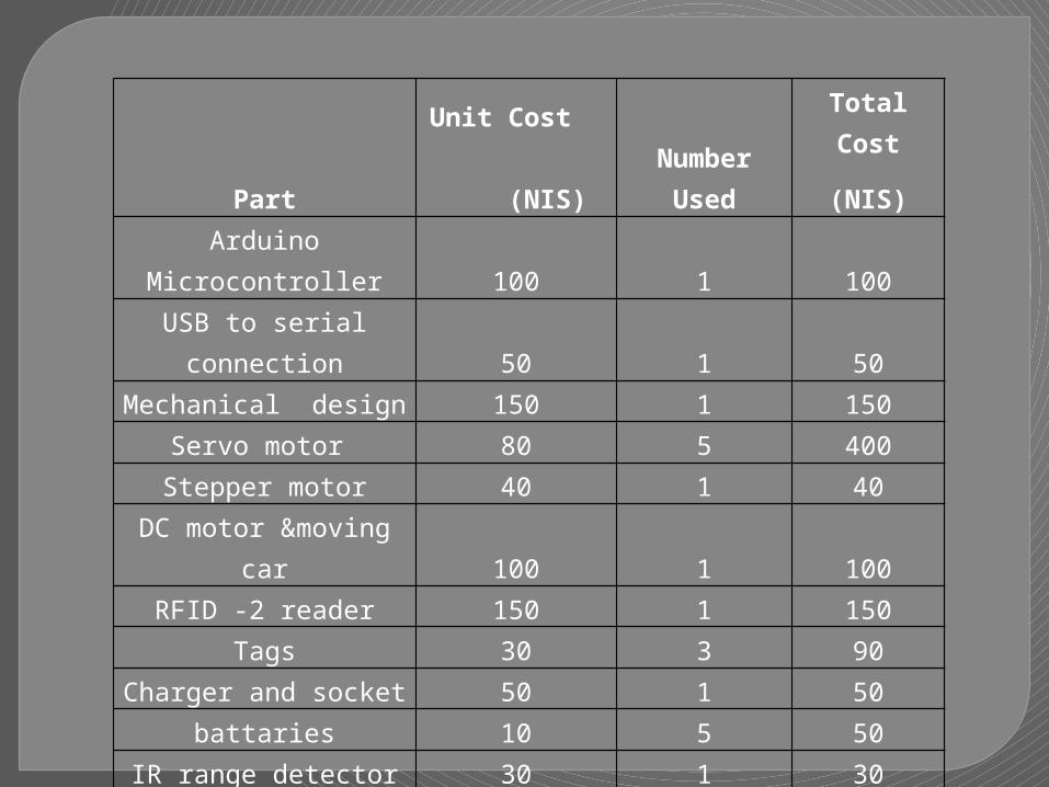
PartUnit Cost
(NIS) Number Used
Total Cost
(NIS)Arduino Microcontroller 100 1 100USB to serial connection 50 1 50
Mechanical design 150 1 150Servo motor 80 5 400
Stepper motor 40 1 40DC motor &moving car 100 1 100
RFID -2 reader 150 1 150Tags 30 3 90
Charger and socket 50 1 50battaries 10 5 50
IR range detector 30 1 30Drivers and other
electronics 70 1 70Shelves & car path 50 1 50
boards Depend on the length 20Total Parts Cost 1350 NIS

Problems and Solutions: Controlling Arm through the computer:
We wrote a code to control Arm from computer to determining appropriate angles for each shelf.
RFID reading tag: Reading tags need many steps: study format of the tag, the
written code should consider check header, checksum, data of the tag , convert it to hexadecimal and output it through serial.

First Integration of the arm: When integrate servo movements with RFID read tag,
additional delays needs to be added to ensure enough time to have tag available on serial buffer.
RFID reader – range up to 5cm!! Frequency is 125KHz, low power and low range reading
tag. If the range of frequency and power higher, the range of reading will be more useful to detect existence of object.
Problems and Solutions 2:

Conclusion: In that project we have interfaced the robot that has different types
of motors with Arduino microcontroller and other different sensor to achieve it function in correct form.
From our work, we deduced that our STORING ROBOT can be much intelligent and are therefore able to classify objects and rearrange stores alone in correct functional way.
That ‘s why it is important in industries , big stores and factories because the overall objective of industrial engineering is productivity and functionality and our STORING ROBOT achieve it.
Meanwhile, intelligent Control for motors and sensors with
Intelligent Microcontroller (Arduino)to perform tasks with minimum supervision and interaction with a human operator.
References:
www.societyofrobots.com www.robotshop.com www.instructable.com www.arduino.com www.sparkfun.com

Video Demo Time

THE END
THANK’S