hardware development on fpga using vhdlapachepersonal.miun.se/~bentho/ec/download/f1b.pdf · ports...
TRANSCRIPT

Hardware development on
FPGA using VHDL
Benny Thörnberg
Associate Professor in Electronics
2
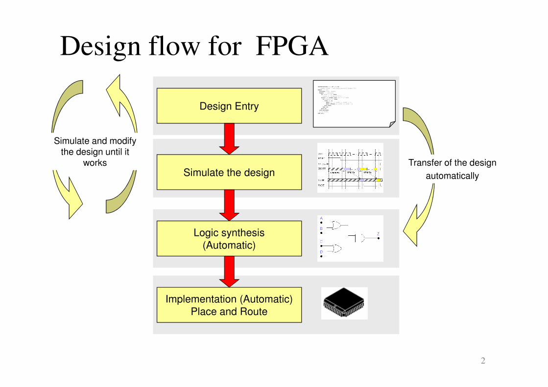
Implementation (Automatic)
Place and Route
Logic synthesis
(Automatic)
Simulate the design
Design flow for FPGAarchitecture rtl of fsm is
signal count : std_logic_vector(2 downto 0);
begin -- rtl
process (clk, reset)
begin -- process
if reset = '0' then
count <= (others=>'0');
elsif clk'event and clk = '1' then
if enable='1' then
case up is
when '1' => count <= count + 1;
when others => count <= count -1;
end case;
end if;
end if;
end process;
q <= count;
end rtl;
Design Entry
Simulate and modifythe design until it
works Transfer of the design
automatically

3
VHDL
Synthesis tool
Design Tool I
Design
Entry
Test BenchGeneratetest data
Analyzy response
VHDL simulator
Waveforms
TechnologyData for the gates
e.g delay,
power consumption
DirectiveE.g. clock
frequency
Gate netlist
Data from component-
vendor
Specified
by the designer
4
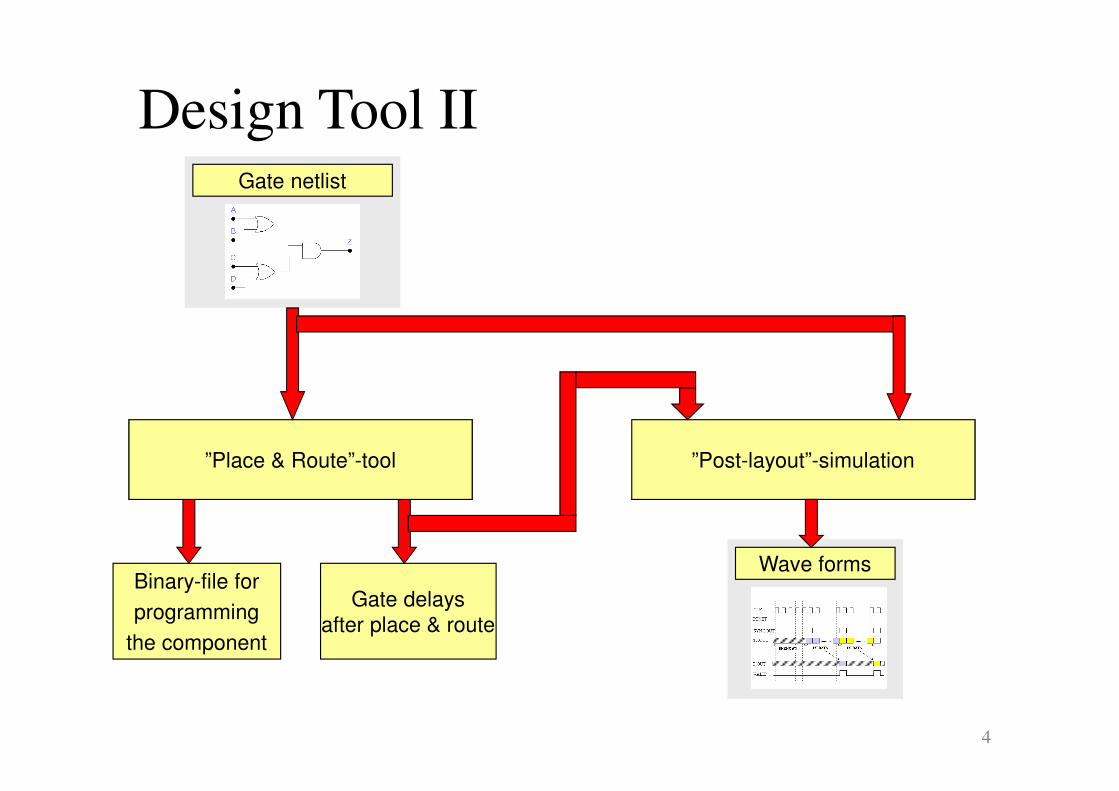
”Post-layout”-simulation
Design Tool IIGate netlist
Binary-file for
programming
the component
Gate delays
after place & route
”Place & Route”-tool
Wave forms

5
Component model
� Model for describing components
� External interface
� Internal function
A
B
C
X
Y
Ports: external connections
to the component
The component’s
- Behaviour or
- Structure
VHDL-komponent
Function: a number ofparallel processes
6
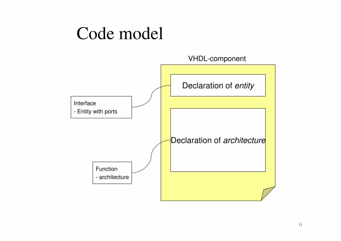
VHDL-component
Code model
Function
- architecture
Interface
- Entity with ports
Declaration of entity
Declaration of architecture
7
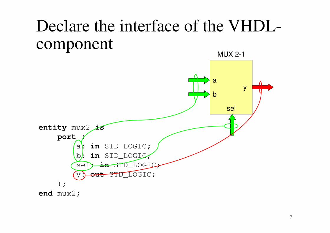
Declare the interface of the VHDL-component
entity mux2 is
port (
a: in STD_LOGIC;
b: in STD_LOGIC;
sel: in STD_LOGIC;
y: out STD_LOGIC;
);
end mux2;
MUX 2-1
y
sel
a
b
8
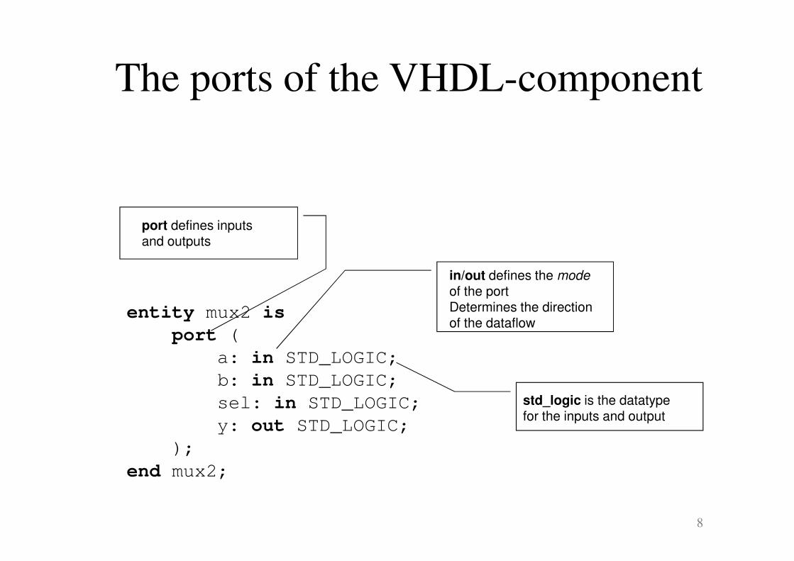
The ports of the VHDL-component
entity mux2 is
port (
a: in STD_LOGIC;
b: in STD_LOGIC;
sel: in STD_LOGIC;
y: out STD_LOGIC;
);
end mux2;
port defines inputsand outputs
in/out defines the mode
of the portDetermines the direction of the dataflow
std_logic is the datatype for the inputs and output
9
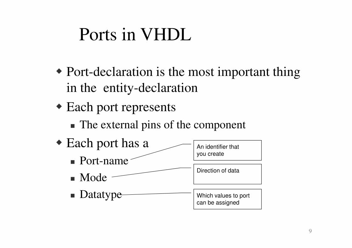
Ports in VHDL
� Port-declaration is the most important thing
in the entity-declaration
� Each port represents
� The external pins of the component
� Each port has a
� Port-name
� Mode
� Datatype
An identifier that you create
Direction of data
Which values to portcan be assigned

10
The modes of the port
IN
OUT
BUFFER
INOUT
The signal goes only in to the component and the value isdriven by another component.
The input signal is used on the right side in the assignment:
z <= a OR inport
The signal goes out from the component.
It is not possible to read the value of the output.
Is used on the left side in the assignment:outport <= a OR b
The signal goes out from the component.
It is possible to read the value of the output.
Can be used on both sides in the assignment:
buffer_port <= a OR b;
z <= buffer_port OR c;
The signal can go in both directions, either in or out
-The value of the signal can be read by the component
-The signal can be driven by other components
-Can be used in both sides in an assignment
11
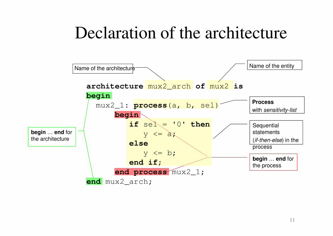
begin … end forthe architecture
begin … end forthe process
Sequential statements
(if-then-else) in the process
Process
with sensitivity-list
Name of the entityName of the architecture
Declaration of the architecture
architecture mux2_arch of mux2 is
begin
mux2_1: process(a, b, sel)
begin
if sel = '0' then
y <= a;
else
y <= b;
end if;
end process mux2_1;
end mux2_arch;

12
Structure of the architecture
architecture name_arch of name is
begin
end name_arch;
Declaration of signals
Parallella satser
Process 1
Parallel statements
Process 2
Parallel statementsProcesses and parallell statements are executed in parallel
Inside a process the execution is
sequential
Signals are used for communication between components and parallel statements.
Signals can only be declared at architecture-level (not in processes)

13
Parallel processes
Example of parallel and sequential statements
ENTITY ename IS
Ports( a, b, c: IN bit;
y, z, w: OUT bit;
Deklarationer -- no variables allowed
END ename
ARCHITECTURE first OF ename IS
Deklarationer -- no variables,
but signals are OK
BEGIN
y <= a AND b;
PROCESS (a,b,c)
Deklarationer -- no signals,
but variables are OK
VARIABLE v: bit;
BEGIN
v := (a OR b);
v := v AND c;
w <= a XOR v;
END PROCESS;
z <= c XOR b;
END first;
Statements in proce-sses are sequential
14
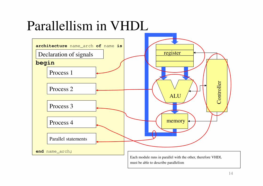
Parallellism in VHDL
architecture name_arch of name is
begin
end name_arch;
Declaration of signals
Process 1
Process 2
Process 3
Process 4
Parallel statements
ALU
memory
register
Contr
oll
er
Each module runs in parallel with the other, therefore VHDL
must be able to describe parallelism

15
Stimuli to the circuit
(input data)
Response from the
circuit (output data)
Simulating VHDL code
010 … 11
011 … 00
011 … 10
000 … 01
110 … 11
111 … 11
VHDL simulator
VHDL description
of the function
For each in-vector an out-vector is generated

16
Simulating sequential events
� Simulation time
� The modeled time the circuit has been simulated
(not the real simulator execution-time)
� Delta-delay
� Used in the simulator internally to queue events
� If a delta delay is added to the simulation, the
simulation time is still un-changed.

17
� Example: What is the response at output C ?
1
&
&
1
IN: 1→0 CA
B
Suppose that these gates have
no internal delays
Sim. time delta event
IN: 1 → 0
Inv a new value for A is calculated
10 ns
A: 0 → 1
Nand , And calculate new values
20 ns
B: 1 → 0
C: 0 → 1
And calculates a new value for C
30 ns
C: 1 → 0
No more events
40 ns
A new value will be assigned
to C at zero simulation time
since the gates have no delays.
Delta delays are used for
serialization of events within
the same simulation time
Simulating sequential events

18
Simulation cycle for the VHDL simulator
Start simulation
Update signals Execute processes
simulationTerminate simulation
response
stimuli
Drive signal values that
have been scheduled to
current simulation time
Schedule changes of signals
in future simulation time
Only processes sensitive to inputs
that have changed will be activated
No new events makes
the simulation stop

19
Signal assignment in processes
PROCESS (a,b,c)
VARIABLE v: bit;
BEGIN
s <= (a AND b);
v := (a OR b);
v := v AND c;
w <= a XOR v;
s <= v OR c;
END PROCESS;
This signal assignment will
have no effect on value of
signal s
The change of value of signal
s never happens within the
process, scheduled changes
happens after process has
finished and at next delta
cycle
Thus, signals can never be used to temporarily hold data dependencies between statements
within a process. Variables should in that case be used.