hardware description(v300r010c03 01)
DESCRIPTION
Huawei Soft SwitchTRANSCRIPT

U-SYS SoftX3000 SoftSwitch SystemV300R010C03
Hardware Description
Issue 01
Date 2010-03-25
HUAWEI TECHNOLOGIES CO., LTD.


Copyright © Huawei Technologies Co., Ltd. 2010. All rights reserved.No part of this document may be reproduced or transmitted in any form or by any means without prior writtenconsent of Huawei Technologies Co., Ltd. Trademarks and Permissions
and other Huawei trademarks are trademarks of Huawei Technologies Co., Ltd.All other trademarks and trade names mentioned in this document are the property of their respective holders. NoticeThe purchased products, services and features are stipulated by the contract made between Huawei and thecustomer. All or part of the products, services and features described in this document may not be within thepurchase scope or the usage scope. Unless otherwise specified in the contract, all statements, information,and recommendations in this document are provided "AS IS" without warranties, guarantees or representationsof any kind, either express or implied.
The information in this document is subject to change without notice. Every effort has been made in thepreparation of this document to ensure accuracy of the contents, but all statements, information, andrecommendations in this document do not constitute the warranty of any kind, express or implied.
Huawei Technologies Co., Ltd.Address: Huawei Industrial Base
Bantian, LonggangShenzhen 518129People's Republic of China
Website: http://www.huawei.com
Email: [email protected]
Issue 01 (2010-03-25) Huawei Proprietary and ConfidentialCopyright © Huawei Technologies Co., Ltd.
i

About This Document
Related VersionsThe following table lists the product versions related to this document.
Product Name Version
SoftX3000 V300R010C03
Intended AudienceThis document describes the hardware structure of the SoftX3000, including the cabinet,subrack, board and cable.
This document is intended for:l Engineering specialists
l Operation and maintenance engineers
l Mobile network system engineers
Change HistoryUpdates between document issues are cumulative. Therefore, the latest document issue containsall updates made in previous issues.
Changes in Issue 01 (2010-03-25)First commercial release.
U-SYS SoftX3000 SoftSwitch SystemHardware Description About This Document
Issue 01 (2010-03-25) Huawei Proprietary and ConfidentialCopyright © Huawei Technologies Co., Ltd.
iii


Contents
About This Document...................................................................................................................iii
1 Overview......................................................................................................................................1-11.1 Hardware Structure.........................................................................................................................................1-21.2 Overview of the OSTA Platform....................................................................................................................1-2
2 Cabinet.........................................................................................................................................2-12.1 N68-22E Cabinet.............................................................................................................................................2-22.2 Classification of Cabinets................................................................................................................................2-6
2.2.1 Integrated Configuration Cabinet...........................................................................................................2-62.2.2 Service Processing Cabinet..................................................................................................................2-112.2.3 MRS Cabinet........................................................................................................................................2-132.2.4 Special Cabinets...................................................................................................................................2-16
2.3 Power Supply System....................................................................................................................................2-242.3.1 Power Input Module.............................................................................................................................2-242.3.2 Power Distribution Module..................................................................................................................2-25
3 Subrack.........................................................................................................................................3-13.1 Overview of the Subrack.................................................................................................................................3-23.2 Basic Subrack 0...............................................................................................................................................3-43.3 Basic Subrack 1...............................................................................................................................................3-53.4 Expansion Subrack..........................................................................................................................................3-63.5 Media Resource Subrack.................................................................................................................................3-83.6 Fan Box...........................................................................................................................................................3-93.7 Board Allocation in a Subrack......................................................................................................................3-103.8 Numbering of Subracks.................................................................................................................................3-10
4 Boards...........................................................................................................................................4-14.1 Overview of the Boards...................................................................................................................................4-2
4.1.1 Classification of Boards.........................................................................................................................4-24.1.2 Classification of Boards.........................................................................................................................4-34.1.3 Mechanical Structure of Boards.............................................................................................................4-44.1.4 Working Modes of Boards.....................................................................................................................4-54.1.5 Switching Modes of Boards...................................................................................................................4-74.1.6 Differences Between Series Boards.......................................................................................................4-7
4.2 Front Boards....................................................................................................................................................4-9
U-SYS SoftX3000 SoftSwitch SystemHardware Description Contents
Issue 01 (2010-03-25) Huawei Proprietary and ConfidentialCopyright © Huawei Technologies Co., Ltd.
v

4.2.1 SMUI....................................................................................................................................................4-104.2.2 BSGI.....................................................................................................................................................4-124.2.3 FCCU...................................................................................................................................................4-154.2.4 CDBI....................................................................................................................................................4-194.2.5 IFMI.....................................................................................................................................................4-214.2.6 MRCA..................................................................................................................................................4-264.2.7 MSGI....................................................................................................................................................4-284.2.8 ALUI....................................................................................................................................................4-314.2.9 UPWR..................................................................................................................................................4-344.2.10 UACU.................................................................................................................................................4-36
4.3 Back Boards..................................................................................................................................................4-404.3.1 SIUI......................................................................................................................................................4-404.3.2 HSCI.....................................................................................................................................................4-434.3.3 MRIA...................................................................................................................................................4-454.3.4 BFII......................................................................................................................................................4-47
5 Servers..........................................................................................................................................5-15.1 BAM and iGWB (IBM X3650 Server)...........................................................................................................5-25.2 BAM and iGWB (DELL 2950 Server)...........................................................................................................5-45.3 BAM and iGWB (HP 380G5 Server)............................................................................................................. 5-75.4 BAM and iGWB (HP ProLiant DL380 G6 Server)......................................................................................5-10
6 Internal Components of Cabinet.............................................................................................6-16.1 Service Processing Subrack............................................................................................................................ 6-26.2 PDB.................................................................................................................................................................6-26.3 Air Deflector................................................................................................................................................... 6-96.4 Air Defense Frame........................................................................................................................................6-106.5 Cable Trough.................................................................................................................................................6-116.6 KVMS...........................................................................................................................................................6-126.7 Ethernet Switch.............................................................................................................................................6-14
7 Peripherals...................................................................................................................................7-17.1 EWS................................................................................................................................................................ 7-27.2 LMT................................................................................................................................................................ 7-27.3 N6X Support and Accessories.........................................................................................................................7-37.4 Universal Alarm Box...................................................................................................................................... 7-5
8 Cables...........................................................................................................................................8-18.1 Power Cable and PGND Cable....................................................................................................................... 8-2
8.1.1 Input Power Cable and PGND Cable for the Cabinet............................................................................8-28.1.2 Power Cable and PGND Cable for the Subrack.....................................................................................8-48.1.3 Power Cable and PGND Cable for the KVMS......................................................................................8-58.1.4 Power Cable and PGND Cable for the LAN Switch............................................................................. 8-68.1.5 Power Cable and PGND Cable for the BAM or iGWB (IBM x3650 Server).......................................8-78.1.6 Power Cable and PGND Cable for the BAM or iGWB (DELL 2950 Server).......................................8-8
ContentsU-SYS SoftX3000 SoftSwitch System
Hardware Description
vi Huawei Proprietary and ConfidentialCopyright © Huawei Technologies Co., Ltd.
Issue 01 (2010-03-25)
8.1.7 Power Cable and PGND Cable for the BAM or iGWB (HP 380G5 Server).........................................8-98.1.8 Power Cable and PGND Cable for the MRS.......................................................................................8-108.1.9 Other PGND Cables.............................................................................................................................8-11
8.2 Internal Signal Cable.....................................................................................................................................8-118.2.1 Straight Through Cable........................................................................................................................8-128.2.2 Serial Port Cable Between iGWBs (HP 380G5 Server)......................................................................8-148.2.3 Serial Port Cable Between the iGWBs (IBM Server)..........................................................................8-158.2.4 Serial Port Cable Between the iGWBs (DELL 2950 Server)..............................................................8-178.2.5 Server/Switcher Cable..........................................................................................................................8-188.2.6 Serial Port Cable for Monitoring the PDB...........................................................................................8-19
9 Labels............................................................................................................................................9-19.1 Label Materials and Features..........................................................................................................................9-29.2 Label Types and Structures.............................................................................................................................9-2
U-SYS SoftX3000 SoftSwitch SystemHardware Description Contents
Issue 01 (2010-03-25) Huawei Proprietary and ConfidentialCopyright © Huawei Technologies Co., Ltd.
vii


Figures
Figure 1-1 Hardware structure of the SoftX3000.................................................................................................1-2Figure 1-2 Appearance of the OSTA subrack .....................................................................................................1-3Figure 1-3 Overall structure of OSTA subrack ...................................................................................................1-4Figure 2-1 Appearance of the N68E-22 cabinet...................................................................................................2-3Figure 2-2 Architecture of the N68E-22 cabinet..................................................................................................2-4Figure 2-3 Full configuration of the integrated configuration cabinet (single-BAM mode)............................... 2-7Figure 2-4 Full configuration of the integrated configuration cabinet (dual-BAM mode)..................................2-8Figure 2-5 Full configuration of the integrated configuration cabinet (single-BAM mode, BAM and iGWB co-installed)................................................................................................................................................................2-9Figure 2-6 Full configuration of the integrated configuration cabinet (dual-BAM, BAMs and iGWB co-installed).............................................................................................................................................................................2-10Figure 2-7 Full configuration of the service processing cabinet........................................................................2-12Figure 2-8 Configuration of the MRS cabinet adopting MRS6000C................................................................2-14Figure 2-9 Configuration of the MRS cabinet adopting MRS6100...................................................................2-16Figure 2-10 Configuration of the SoftX3000 and SG7000 cabinet (China)......................................................2-18Figure 2-11 Configuration of the SoftX3000 and SG7000 cabinet (outside China, IBM X343 server)............2-20Figure 2-12 Configuration of the SoftX3000 and UMG8900 cabinet (China)..................................................2-22Figure 2-13 Configuration of the SoftX3000 and UMG8900 cabinet (outside China, IBM X343 server).......2-23Figure 2-14 Power input module........................................................................................................................2-24Figure 2-15 Electrical connections of the integraged configuration cabinet......................................................2-25Figure 2-16 Electrical connections of the service processing cabinet................................................................2-26Figure 3-1 Appearance of the subrack..................................................................................................................3-2Figure 3-2 Structure of the subrack......................................................................................................................3-3Figure 3-3 Inserting a front board and a back board into the backplane..............................................................3-3Figure 3-4 Board allocation in basic subrack 0....................................................................................................3-5Figure 3-5 Board allocation in basic subrack 1....................................................................................................3-6Figure 3-6 Board allocation in the expansion subrack.........................................................................................3-7Figure 3-7 Board allocation in a media resource subrack....................................................................................3-8Figure 3-8 Front view of the fan box................................................................................................................... 3-9Figure 3-9 Board allocation in a subrack...........................................................................................................3-10Figure 4-1 Front board and back board................................................................................................................4-3Figure 4-2 Mechanical structure of a board......................................................................................................... 4-5Figure 4-3 Labels on the FCCU boards of 750C and 750B serials......................................................................4-8Figure 4-4 Front panel of the SMUI...................................................................................................................4-11
U-SYS SoftX3000 SoftSwitch SystemHardware Description Figures
Issue 01 (2010-03-25) Huawei Proprietary and ConfidentialCopyright © Huawei Technologies Co., Ltd.
ix
Figure 4-5 Protocol stack processed by the BSGI..............................................................................................4-13Figure 4-6 Front panel of the BSGI....................................................................................................................4-14Figure 4-7 Protocol stack processed by the FCCU............................................................................................4-16Figure 4-8 Front panel of the FCCU..................................................................................................................4-17Figure 4-9 Front panel of the CDBI...................................................................................................................4-20Figure 4-10 Front panel of the IFMI..................................................................................................................4-22Figure 4-11 IFMIs of the 750C series and the 750B series................................................................................4-26Figure 4-12 Front panel of the MRCA...............................................................................................................4-27Figure 4-13 Protocol stack processed by the MSGI...........................................................................................4-29Figure 4-14 Front panel of the MSGI.................................................................................................................4-30Figure 4-15 Front panel of the ALUI.................................................................................................................4-32Figure 4-16 Front panel of the UPWR...............................................................................................................4-35Figure 4-17 Protocol stack processed by the UACU ........................................................................................4-37Figure 4-18 Front panel of the UACU...............................................................................................................4-38Figure 4-19 Front panel of the SIUI...................................................................................................................4-41Figure 4-20 Front panel of the HSCI..................................................................................................................4-44Figure 4-21 Front panel of the MRIA................................................................................................................4-46Figure 4-22 Front panel of the BFII...................................................................................................................4-47Figure 4-23 Indicators on the BFII (with two network ports)............................................................................4-48Figure 4-24 Differences between dual-network-port BFII and single-network-port BFII.................................4-50Figure 5-1 Front view of the BAM and the iGWB..............................................................................................5-2Figure 5-2 Rear view of the BAM and the iGWB...............................................................................................5-3Figure 5-3 Components and the indicators on the front panel.............................................................................5-5Figure 5-4 Components and the indicators on the rear panel...............................................................................5-6Figure 5-5 Front view of the BAM and the iGWB..............................................................................................5-8Figure 5-6 Rear view of the BAM and the iGWB ..............................................................................................5-8Figure 5-7 Indicators on the front panel of the BAM and the iGWB ..................................................................5-9Figure 5-8 Front view of the BAM or iGWB server..........................................................................................5-10Figure 5-9 Rear view of the BAM or iGWB server...........................................................................................5-11Figure 5-10 Indicators and button on the front panel of the BAM or iGWB server..........................................5-11Figure 5-11 Indicators and button on the rear panel of the BAM or iGWB server............................................5-12Figure 6-1 Appearance of the PDB......................................................................................................................6-2Figure 6-2 Structure of the PDB...........................................................................................................................6-3Figure 6-3 Appearance of the front panel of the PDB..........................................................................................6-3Figure 6-4 Appearance of the monitoring panel of the PDB................................................................................6-4Figure 6-5 Appearance of the real panel of the PDB...........................................................................................6-5Figure 6-6 Communication interface board of the PDB......................................................................................6-6Figure 6-7 Architecture of the PDB.....................................................................................................................6-8Figure 6-8 Appearance of the air deflector.........................................................................................................6-10Figure 6-9 Appearance of the air defense subrack.............................................................................................6-11Figure 6-10 Appearance and architecture of the cable trough for the N68E-22 cabinet....................................6-11Figure 6-11 Appearance of the folded KVMS...................................................................................................6-12
FiguresU-SYS SoftX3000 SoftSwitch System
Hardware Description
x Huawei Proprietary and ConfidentialCopyright © Huawei Technologies Co., Ltd.
Issue 01 (2010-03-25)
Figure 6-12 Appearance of the unfolded KVMS...............................................................................................6-13Figure 6-13 Rear view of the KVMS.................................................................................................................6-13Figure 6-14 Front view of the S3928P-EI..........................................................................................................6-15Figure 6-15 Front view of the S3528G..............................................................................................................6-15Figure 6-16 Front view of the S3328TP-EI-24S................................................................................................6-16Figure 6-17 Rear view of the S3928P-EI...........................................................................................................6-17Figure 6-18 Rear view of the S3528G................................................................................................................6-17Figure 7-1 Appearance of an N6X support.......................................................................................................... 7-4Figure 7-2 Appearance of a front holder..............................................................................................................7-5Figure 7-3 Appearance of a slide rail...................................................................................................................7-5Figure 7-4 Appearance of the universal alarm box..............................................................................................7-6Figure 8-1 Cord end terminal...............................................................................................................................8-3Figure 8-2 OT terminal.........................................................................................................................................8-3Figure 8-3 Appearance of a power cable for the subrack.....................................................................................8-5Figure 8-4 Appearance of a KVMS power cable.................................................................................................8-5Figure 8-5 Appearance of a KVMS PGND cable................................................................................................8-6Figure 8-6 Power cable for the LAN Switch........................................................................................................8-7Figure 8-7 Appearance of the power cable and PGND cables for the IBM x3650 server...................................8-8Figure 8-8 Appearance of the power cable and PGND cables for the DELL 2950 server.................................. 8-9Figure 8-9 Appearance of the power cables and PGND cables for the HP 380G5 server.................................8-10Figure 8-10 Appearance of the power cable for the MRS..................................................................................8-10Figure 8-11 Appearance of a straight through cable..........................................................................................8-13Figure 8-12 Appearance of the serial port cable connecting two iGWBs..........................................................8-14Figure 8-13 Appearance of the serial port cable connecting two iGWBs..........................................................8-16Figure 8-14 Appearance of the serial port cable connecting two iGWBs (DELL 2950 server)........................8-17Figure 8-15 Appearance of the keyboard and mouse signal cables...................................................................8-19Figure 8-16 Appearance of a display signal cable..............................................................................................8-19Figure 8-17 Appearance of a serial port cable for monitoring the PDB............................................................8-20Figure 9-1 Signal cable label paper......................................................................................................................9-2Figure 9-2 Power cable label paper......................................................................................................................9-3
U-SYS SoftX3000 SoftSwitch SystemHardware Description Figures
Issue 01 (2010-03-25) Huawei Proprietary and ConfidentialCopyright © Huawei Technologies Co., Ltd.
xi

Tables
Table 2-1 Technical specifications of the N68E-22 cabinet.................................................................................2-5Table 2-2 Mappings between the cabinet components and the switches...........................................................2-27Table 3-1 Technical specifications of the subrack...............................................................................................3-4Table 3-2 Mapping between the DIP switch setting on the SIUI and the subrack number................................3-11Table 4-1 Attributes of the SoftX3000 boards.....................................................................................................4-4Table 4-2 Boards and their working modes and positions...................................................................................4-6Table 4-3 Work modes of 750C boards................................................................................................................4-7Table 4-4 Difference between 750C boards and 750B boards in hardware configuration..................................4-9Table 4-5 Mapping between the BFII with dual-network port or single-network port and the IFMI of 750C or 750Bserials.....................................................................................................................................................................4-9Table 4-6 Indicators on the front panel of the SMUI.........................................................................................4-11Table 4-7 Technical specifications of the SMUI................................................................................................4-12Table 4-8 Indicators on the front panel of the BSGI..........................................................................................4-14Table 4-9 Technical specifications of the BSGI.................................................................................................4-15Table 4-10 Indicators on the front panel of the FCCU.......................................................................................4-17Table 4-11 Technical specifications of the FCCU.............................................................................................4-18Table 4-12 Indicators on the front panel of the CDBI........................................................................................4-20Table 4-13 Technical specifications of the CDBI..............................................................................................4-21Table 4-14 Indicators on the front panel of the IFMI.........................................................................................4-22Table 4-15 Technical specifications of the IFMI...............................................................................................4-23Table 4-16 Indicators on the front panel of the IFMI (750C)............................................................................4-24Table 4-17 Indicators on the front panel of the MRCA.....................................................................................4-27Table 4-18 Technical specifications of the MRCA............................................................................................4-28Table 4-19 Indicators on the front panel of the MSGI.......................................................................................4-30Table 4-20 Technical specifications of the MSGI..............................................................................................4-31Table 4-21 Indicators on the front panel of the ALUI........................................................................................4-32Table 4-22 Technical specifications of the ALUI..............................................................................................4-34Table 4-23 Indicators on the front panel of the UPWR......................................................................................4-35Table 4-24 Technical specifications of the UPWR............................................................................................4-36Table 4-25 Indicators on the front panel of the UACU .....................................................................................4-38Table 4-26 Technical specifications of the UACU ............................................................................................4-39Table 4-27 Indicators on the front panel of the SIUI.........................................................................................4-41Table 4-28 Subrack number and DIP switch setting..........................................................................................4-42Table 4-29 Technical specifications of the SIUI................................................................................................4-42
U-SYS SoftX3000 SoftSwitch SystemHardware Description Tables
Issue 01 (2010-03-25) Huawei Proprietary and ConfidentialCopyright © Huawei Technologies Co., Ltd.
xiii

Table 4-30 Indicators on the front panel of the HSCI........................................................................................4-44Table 4-31 Technical specifications of the HSCI...............................................................................................4-45Table 4-32 Technical specifications of the MRIA............................................................................................. 4-46Table 4-33 Technical specifications of the BFII................................................................................................4-48Table 4-34 Technical specifications...................................................................................................................4-49Table 4-35 Network ports of the BFII of the 750C series and the 750B series..................................................4-51Table 5-1 Front panel control switches and status indicators of the iGWB and the BAM..................................5-2Table 5-2 Hardware configuration of the BAM and the iGWB...........................................................................5-4Table 5-3 LED indicators, buttons, and connectors on the front panel................................................................5-5Table 5-4 Hardware configuration of the BAM and the iGWB...........................................................................5-7Table 5-5 Hardware configuration of the BAM and the iGWB...........................................................................5-9Table 5-6 Hardware configuration of the BAM and iGWB servers...................................................................5-12Table 6-1 Monitoring indicators of the PDB........................................................................................................6-4Table 6-2 Communication interfaces of the PDB................................................................................................6-6Table 6-3 Relationship between the components in the N68E-22 cabinet and the switches on the PDB............6-7Table 6-4 Technical specifications of the PDB....................................................................................................6-9Table 6-5 Technical specifications of the KVMS..............................................................................................6-14Table 6-6 Functions of the interfaces on the S3328TP-EI-24S..........................................................................6-16Table 6-7 Description of indicators on the front panel of the S3928P-EI..........................................................6-17Table 6-8 Description of indicators on the front panel of the S3528G.............................................................. 6-21Table 6-9 Indicators on the S3328TP-EI-24S.................................................................................................... 6-22Table 6-10 Technical specifications of the S3928P-EI......................................................................................6-23Table 6-11 Technical specifications of the S3528G...........................................................................................6-24Table 6-12 Technical specifications of the S3328TP-EI-24S............................................................................6-24Table 7-1 Hardware requirements of the EWS (DELL PowerEdge 800)............................................................7-2Table 7-2 Height of the N6X series supports.......................................................................................................7-4Table 8-1 Technical specifications of the input power cable and PGND cable for a cabinet..............................8-4Table 8-2 Technical specifications of the power cable and PGND cable for the subrack...................................8-5Table 8-3 Technical specifications of the power cable and PGND cable for the KVMS....................................8-6Table 8-4 Technical specifications of the power cable and PGND cable for the LAN Switch...........................8-7Table 8-5 Technical specifications of the power cable and PGND cable............................................................8-8Table 8-6 Classification and function of the straight through cable...................................................................8-12Table 8-7 Pinout at both ends of a straight through cable..................................................................................8-13Table 8-8 Technical specifications of the straight through cable.......................................................................8-14Table 8-9 Pinout at both ends of a serial port cable........................................................................................... 8-15Table 8-10 Technical specifications of the serial port cable between the iGWBs.............................................8-15Table 8-11 Pinout at both ends of a serial port cable......................................................................................... 8-16Table 8-12 Technical specifications of the serial port cable between the iGWBs.............................................8-16Table 8-13 Pinout at both ends of a serial port cable......................................................................................... 8-18Table 8-14 Technical specifications of the serial port cable between the iGWBs (DELL 2950 server)........... 8-18Table 8-15 Pinout at both ends of a serial port cable for monitoring the PDB..................................................8-20
TablesU-SYS SoftX3000 SoftSwitch System
Hardware Description
xiv Huawei Proprietary and ConfidentialCopyright © Huawei Technologies Co., Ltd.
Issue 01 (2010-03-25)
1 Overview
About This Chapter
This section describes the overall hardware structure and OSTA platform of the SoftX3000.
1.1 Hardware StructureThis section describes the hardware structure of the SoftX3000.
1.2 Overview of the OSTA PlatformThis section describes the structures of the open standard telecom architecture (OSTA) platformand the service subracks of the SoftX3000.
U-SYS SoftX3000 SoftSwitch SystemHardware Description 1 Overview
Issue 01 (2010-03-25) Huawei Proprietary and ConfidentialCopyright © Huawei Technologies Co., Ltd.
1-1

1.1 Hardware StructureThis section describes the hardware structure of the SoftX3000.
The SoftX3000 system consists of subracks, LAN Switches, backend administration module(BAM), and integrated gateway billing (iGWB). Subracks are the host of the SoftX3000 systemand are responsible for service processing and resource management. The BAM and iGWB arethe servers of the SoftX3000 system and are responsible for OAM and bill management. LANSwitches connect the subracks to the BAM and iGWB and enable the subracks to communicatewith the BAM and iGWB.
Figure 1-1 shows the hardware structure of the SoftX3000.
Figure 1-1 Hardware structure of the SoftX3000
FE: 100 Mbit/s fast Ethernet interface 3 x FE: 3 FE cables WS: WorkstationMAN: Metropolitan area network NMS: Network management system -
1.2 Overview of the OSTA PlatformThis section describes the structures of the open standard telecom architecture (OSTA) platformand the service subracks of the SoftX3000.
1 OverviewU-SYS SoftX3000 SoftSwitch System
Hardware Description
1-2 Huawei Proprietary and ConfidentialCopyright © Huawei Technologies Co., Ltd.
Issue 01 (2010-03-25)
The SoftX3000 adopts the OSTA platform as its hardware platform. The OSTA platform usesthe shared resource bus and Ethernet bus as the buses of the backplane. It features goodversatility, high reliability, and support for switching and transmitting length-variable data ofthe softswitch .
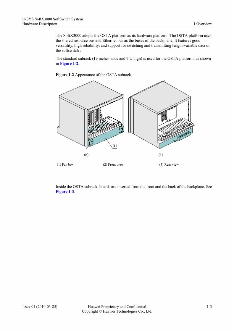
The standard subrack (19 inches wide and 9 U high) is used for the OSTA platform, as shownin Figure 1-2.
Figure 1-2 Appearance of the OSTA subrack
(1) Fan box (2) Front view (3) Rear view
Inside the OSTA subrack, boards are inserted from the front and the back of the backplane. SeeFigure 1-3.
U-SYS SoftX3000 SoftSwitch SystemHardware Description 1 Overview
Issue 01 (2010-03-25) Huawei Proprietary and ConfidentialCopyright © Huawei Technologies Co., Ltd.
1-3

Figure 1-3 Overall structure of OSTA subrack
(1) Power boards (2) Interface boards (3) Ethernet communication boards
(4) Back boards (5) Backplane (6) Front boards
(7) Service boards (8) System management boards (9) Alarm board
In the OSTA subrack, the front boards include:l Service boards
l System management boards
l Alarm board
l Power boards
The back boards include:l Interface boards
l Ethernet communication boards
l Power boards
Because of such a distribution, the OSTA subrack has the following features:l Different function design for front boards and back boards
l Simplification of board functions
l Low complexity of hardware
l High reliability
l Adaptable subrack
l Flexible configuration
All OSTA subracks of the SoftX3000 share the same hardware structure. Each subrack isdesigned with 21 standard slots. The following boards are always configured in fixed positions:
1 OverviewU-SYS SoftX3000 SoftSwitch System
Hardware Description
1-4 Huawei Proprietary and ConfidentialCopyright © Huawei Technologies Co., Ltd.
Issue 01 (2010-03-25)
l System management boards
l Ethernet communication boards
l Alarm board
l Power boards (occupying two slots)
These boards occupy nine slots in total. The remaining 12 slots are used for service boards andinterface boards.
U-SYS SoftX3000 SoftSwitch SystemHardware Description 1 Overview
Issue 01 (2010-03-25) Huawei Proprietary and ConfidentialCopyright © Huawei Technologies Co., Ltd.
1-5


2 Cabinet
About This Chapter
This section describes the cabinet of the SoftX3000.
2.1 N68-22E CabinetThis section describes the functions, appearance, architecture, and technical parameters of theN68E-22 cabinet.
2.2 Classification of CabinetsThis section describes the integrated configuration cabinet and service processing cabinet of theSoftX3000.
2.3 Power Supply SystemThe power supply system powers the entire SoftX3000 and requires high reliability. The powersupply system adopts dual-circuit backup and point-specific monitoring solutions. The powersupply system consists of the power input module and power distribution module.
U-SYS SoftX3000 SoftSwitch SystemHardware Description 2 Cabinet
Issue 01 (2010-03-25) Huawei Proprietary and ConfidentialCopyright © Huawei Technologies Co., Ltd.
2-1
2.1 N68-22E CabinetThis section describes the functions, appearance, architecture, and technical parameters of theN68E-22 cabinet.
FunctionsThe N68E-22 cabinet houses the internal components of the SoftX3000 and allowsinterconnection between these components. It can protect its components against pollution anddamage.
AppearanceThe N68E-22 cabinet is 2200 mm (height) x 600 mm (width) x 800 mm (depth). Figure 2-1shows the appearance of the N68E-22 cabinet.
2 CabinetU-SYS SoftX3000 SoftSwitch System
Hardware Description
2-2 Huawei Proprietary and ConfidentialCopyright © Huawei Technologies Co., Ltd.
Issue 01 (2010-03-25)
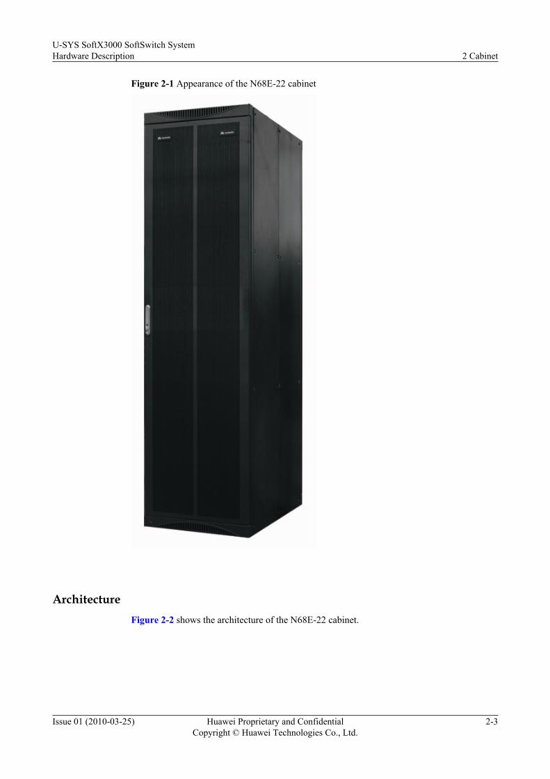
Figure 2-1 Appearance of the N68E-22 cabinet
ArchitectureFigure 2-2 shows the architecture of the N68E-22 cabinet.
U-SYS SoftX3000 SoftSwitch SystemHardware Description 2 Cabinet
Issue 01 (2010-03-25) Huawei Proprietary and ConfidentialCopyright © Huawei Technologies Co., Ltd.
2-3

Figure 2-2 Architecture of the N68E-22 cabinet
1 Front door 2 Rear door 3 Side panels
The front and rear doors of the N68E-22 cabinet are single-leaf doors. The single-leaf designmakes the cabinet easy to install and operate. The side panels are installed in the exterior screwfixing mode, thus making the installation easy.
2 CabinetU-SYS SoftX3000 SoftSwitch System
Hardware Description
2-4 Huawei Proprietary and ConfidentialCopyright © Huawei Technologies Co., Ltd.
Issue 01 (2010-03-25)

The front mount angle in the cabinet is used to fasten the internal components of the cabinet.There are grounding points on the rear mount angle in the cabinet. The grounding points areused for grounding internal components and interconnecting grounding cables between cabinets.
The wire bushings on the side posts, the cable strips and the cabling rack at the rear of the cabinetare used for the layout and bundling of internal cables of the cabinet.
The N68E-22 cabinet can be installed on the cement floor or ESD-preventive floor.
When the N68E-22 cabinet is installed on the ESD-preventive floor, the N6X series supportsare used. For details, see the Installing Supports.
Technical ParametersTable 2-1 lists the technical specifications of the N68E-22 cabinet.
Table 2-1 Technical specifications of the N68E-22 cabinet
Item Specification
DesignIt conforms to IEC 297. The modular design eases expansion andmaintenance.
Dimensions 2200 mm (height) x 600 mm (width) x 800 mm (depth).
Capacity The height of available space of a cabinet is 46 U (1 U = 44.45 mm). Onecabinet can accommodate up to four service processing subracks.
Weight 100 kg when vacant, and 365 kg when fully configured.
Cabling mode The cable-through holes are located at both the top and bottom of thecabinet, supporting overhead cabling and underfloor cabling.
Heat dissipation The front and rear doors and the bottom plate have minute air vents. Thecabinet is quipped with air deflectors and the service processing subracksare equipped with fans. The cabinet adopts front-in, back-out and bottom-to-top ventilation mode to enable excellent heat dissipation.
Installationmode
The N68E-22 cabinet can be installed on the cement floor or the ESD-preventive floor. When the N68E-22 cabinet is installed on the ESD-preventive floor, the N6X series supports and guide rails are used.
Protection EMC is fully considered when the cabinet is designed. All interfaces havegood performance of electromagnetic shielding.
The front and rear doors and the bottom plate have minute air vents andare equipped with air filters inside. This can help prevent dust.
Material The N68E-22 cabinet is assembled with electrolytic zinc-coated cold-rolled steel sheet and screws. The fire-proof materials conform to the ULstandards.
Color The cabinet surface is Huawei purple-gray.
U-SYS SoftX3000 SoftSwitch SystemHardware Description 2 Cabinet
Issue 01 (2010-03-25) Huawei Proprietary and ConfidentialCopyright © Huawei Technologies Co., Ltd.
2-5

2.2 Classification of CabinetsThis section describes the integrated configuration cabinet and service processing cabinet of theSoftX3000.
Based on the actual configuration of the cabinet components in a cabinet, the SoftX3000 cabinetsare classified into the integrated configuration cabinet and service processing cabinet.
The MRS cabinet is required when a separate media resource server (MRS) is configured in theSoftX3000.
2.2.1 Integrated Configuration CabinetThis section describes the integrated configuration cabinets.
2.2.2 Service Processing CabinetThis section describes the service processing cabinets.
2.2.3 MRS CabinetThis section describes the MRS cabinets.
2.2.4 Special CabinetsThis section describes the special cabinets.
2.2.1 Integrated Configuration CabinetThis section describes the integrated configuration cabinets.
Functions
The integrated configuration cabinet is mandatory. It houses the following components: iGWB,BAM, LAN Switch, KVMS, and service subracks. There are three types of service subracks:basic subracks, expansion subracks, and media resource subracks.
The integrated configuration cabinet provides the following functions:
l Processing basic services
l Providing external interfaces, such as the IP interface
l Managing communication between the host and the BAM
l Storing call detail records
l Providing MRS features when a media resource subrack is configured
Configuration of the Integrated Configuration Cabinet (N68E-22)
The configuration of an integrated configuration cabinet varies with the countries or areas.
When the SoftX3000 is used in China, the BAM and the iGWB use DELL 2950 servers. Whenthe SoftX3000 is used outside China, the BAM and the iGWB use IBM X3650 or DELL 2950(in the Asian-Pacific countries where the direct sales of DELL servers is available) servers andthe core LAN Switches use Ethernet switches. In addition, two Ethernet switches functioningas the NET Switches are installed in the integrated configuration cabinet. Figure 2-3 and , Figure2-4 shows the full configuration of the integrated configuration cabinet.
2 CabinetU-SYS SoftX3000 SoftSwitch System
Hardware Description
2-6 Huawei Proprietary and ConfidentialCopyright © Huawei Technologies Co., Ltd.
Issue 01 (2010-03-25)
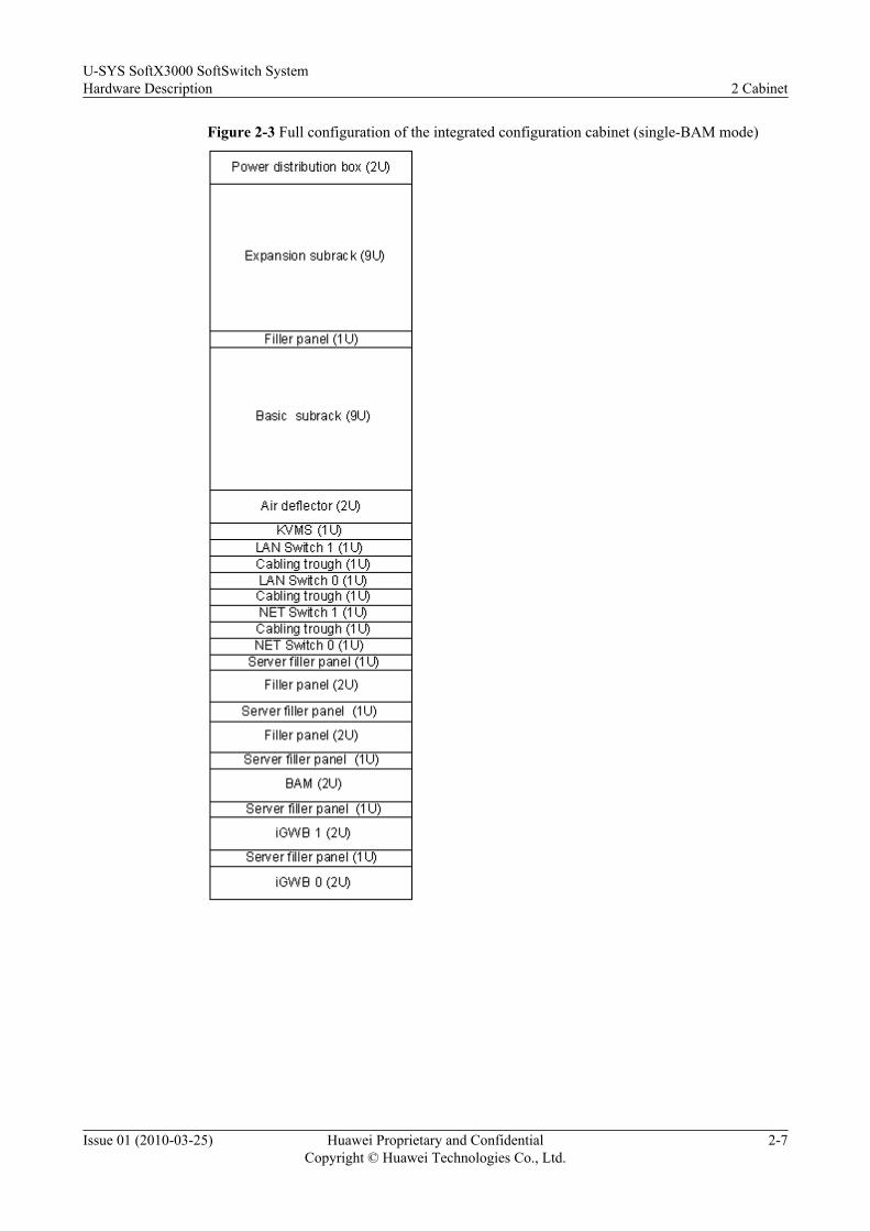
Figure 2-3 Full configuration of the integrated configuration cabinet (single-BAM mode)
U-SYS SoftX3000 SoftSwitch SystemHardware Description 2 Cabinet
Issue 01 (2010-03-25) Huawei Proprietary and ConfidentialCopyright © Huawei Technologies Co., Ltd.
2-7

Figure 2-4 Full configuration of the integrated configuration cabinet (dual-BAM mode)
When the BAM and the iGWB of the SoftX3000 are installed on the same server, Figure 2-5,Figure 2-6 show the full configuration of the integrated configuration cabinet.
2 CabinetU-SYS SoftX3000 SoftSwitch System
Hardware Description
2-8 Huawei Proprietary and ConfidentialCopyright © Huawei Technologies Co., Ltd.
Issue 01 (2010-03-25)

Figure 2-5 Full configuration of the integrated configuration cabinet (single-BAM mode, BAMand iGWB co-installed)
U-SYS SoftX3000 SoftSwitch SystemHardware Description 2 Cabinet
Issue 01 (2010-03-25) Huawei Proprietary and ConfidentialCopyright © Huawei Technologies Co., Ltd.
2-9
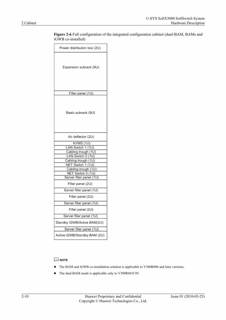
Figure 2-6 Full configuration of the integrated configuration cabinet (dual-BAM, BAMs andiGWB co-installed)
NOTE
l The BAM and iGWB co-installation solution is applicable to V300R006 and later versions.
l The dual-BAM mode is applicable only to V300R601C05.
2 CabinetU-SYS SoftX3000 SoftSwitch System
Hardware Description
2-10 Huawei Proprietary and ConfidentialCopyright © Huawei Technologies Co., Ltd.
Issue 01 (2010-03-25)

Configuration GuidanceConfigure the integrated configuration cabinet as follows:
l In an integrated configuration cabinet, the iGWB, BAM, hard disk array (when the iGWBuses the IBM X343 server), LAN Switch 0, LAN Switch 1, KVMS, air deflector, basicsubrack and power distribution box must be configured. Other components are optional.
l NET Switch 1 and NET Switch 0 are optional. They work with the IFMIs in the basicsubrack to support IP networking for the SoftX3000.
l If the SoftX3000 uses a separate MRS, you must configure an expansion subrack at thenear top of the integrated configuration cabinet. Otherwise, configure a media resourcesubrack or MRS6100.
Configuration NotesNote the following:
l If neither an expansion subrack nor a media resource subrack is configured, cover theposition at the top of the integrated configuration cabinet with a standard filler panel.
l The media resource subrack can be configured with only the MRCA and MRIA.
2.2.2 Service Processing CabinetThis section describes the service processing cabinets.
FunctionsA service processing cabinet provides all the features of the integrated configuration cabinetexcept the host-BAM communication and bill storage features. The system capacity determinesthe number of service processing cabinets (up to four).
Configuration of the Service Processing CabinetFigure 2-7 shows the full configuration of the service processing cabinet and the details ofsubrack position. All subracks are configured in bottom-to-top sequence.
U-SYS SoftX3000 SoftSwitch SystemHardware Description 2 Cabinet
Issue 01 (2010-03-25) Huawei Proprietary and ConfidentialCopyright © Huawei Technologies Co., Ltd.
2-11

Figure 2-7 Full configuration of the service processing cabinet
NOTE
When there are more than 100,000 subscribers or equivalent, you need to use a separate MRS. In this case,configure three service processing cabinets, and replace the media resource subracks with expansionsubracks.
Configuration GuidanceConfigure the service processing cabinet as follows:
l When the MRS is not separately configured in the SoftX3000, configure a media resourcesubrack in the service processing cabinet (with MRCAs and MRIAs).
l When the MRS is configured separately in the SoftX3000, you need not configure a mediaresource subrack in the service processing cabinet. Three service processing cabinets canmeet the requirements of system full configuration.
l When there is more than one service processing cabinet, configure a basic subrack, as shownin Figure 2-7.
2 CabinetU-SYS SoftX3000 SoftSwitch System
Hardware Description
2-12 Huawei Proprietary and ConfidentialCopyright © Huawei Technologies Co., Ltd.
Issue 01 (2010-03-25)
RemarksWhen less then four subracks are configured in a service processing cabinet, all vacant subrackpositions must be covered with filler panels.
2.2.3 MRS CabinetThis section describes the MRS cabinets.
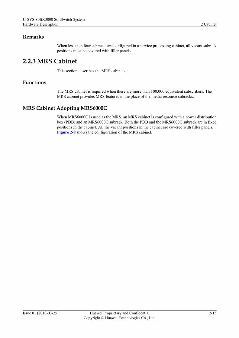
FunctionsThe MRS cabinet is required when there are more than 100,000 equivalent subscribers. TheMRS cabinet provides MRS features in the place of the media resource subracks.
MRS Cabinet Adopting MRS6000CWhen MRS6000C is used as the MRS, an MRS cabinet is configured with a power distributionbox (PDB) and an MRS6000C subrack. Both the PDB and the MRS6000C subrack are in fixedpositions in the cabinet. All the vacant positions in the cabinet are covered with filler panels.Figure 2-8 shows the configuration of the MRS cabinet.
U-SYS SoftX3000 SoftSwitch SystemHardware Description 2 Cabinet
Issue 01 (2010-03-25) Huawei Proprietary and ConfidentialCopyright © Huawei Technologies Co., Ltd.
2-13

Figure 2-8 Configuration of the MRS cabinet adopting MRS6000C
2 CabinetU-SYS SoftX3000 SoftSwitch System
Hardware Description
2-14 Huawei Proprietary and ConfidentialCopyright © Huawei Technologies Co., Ltd.
Issue 01 (2010-03-25)

MRS Cabinet Adopting MRS6100When MRS6100 is used as the MRS, an MRS cabinet is configured with a power distributionbox (PDB) and an MRS6100 subrack. Both the PDB and the MRS6100 subrack are in fixedpositions in the cabinet. All the vacant positions in the cabinet are covered with filler panels.Figure 2-9 shows the configuration of the MRS cabinet.
U-SYS SoftX3000 SoftSwitch SystemHardware Description 2 Cabinet
Issue 01 (2010-03-25) Huawei Proprietary and ConfidentialCopyright © Huawei Technologies Co., Ltd.
2-15
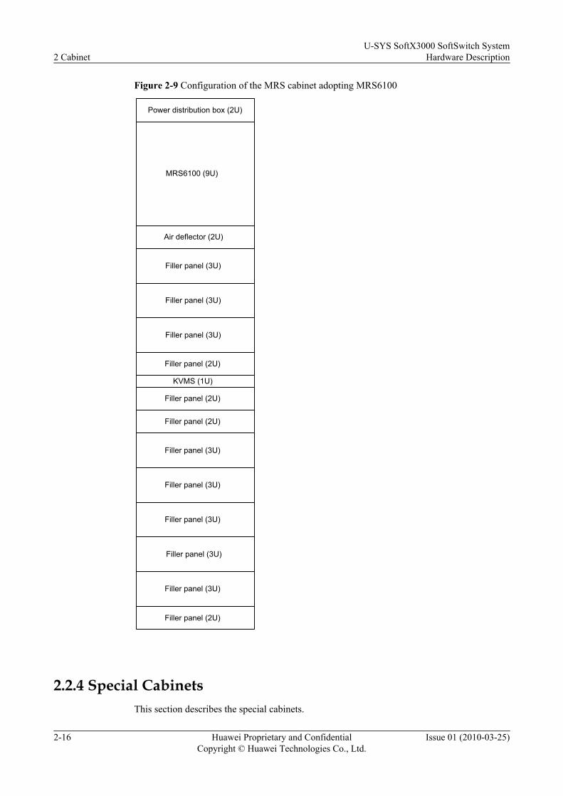
Figure 2-9 Configuration of the MRS cabinet adopting MRS6100
Power distribution box (2U)
Air deflector (2U)
Filler panel (2U)
Filler panel (3U)
Filler panel (3U)
Filler panel (3U)
MRS6100 (9U)
KVMS (1U)
Filler panel (3U)
Filler panel (3U)
Filler panel (3U)
Filler panel (3U)
Filler panel (3U)
Filler panel (2U)
Filler panel (2U)
Filler panel (2U)
2.2.4 Special CabinetsThis section describes the special cabinets.
2 CabinetU-SYS SoftX3000 SoftSwitch System
Hardware Description
2-16 Huawei Proprietary and ConfidentialCopyright © Huawei Technologies Co., Ltd.
Issue 01 (2010-03-25)
SoftX3000 and SG7000 CabinetThe configuration of the SoftX3000 and SG7000 cabinet may vary with the countries and areas.
l When the SoftX3000 and SG7000 cabinet is used in China, the BAM and the iGWB useHP or C4210 servers. The BAM is not configured with a hard disk array, and the iGWB isconfigured with a built-in hard disk array. Figure 2-10 shows the configuration of thecabinet.
U-SYS SoftX3000 SoftSwitch SystemHardware Description 2 Cabinet
Issue 01 (2010-03-25) Huawei Proprietary and ConfidentialCopyright © Huawei Technologies Co., Ltd.
2-17
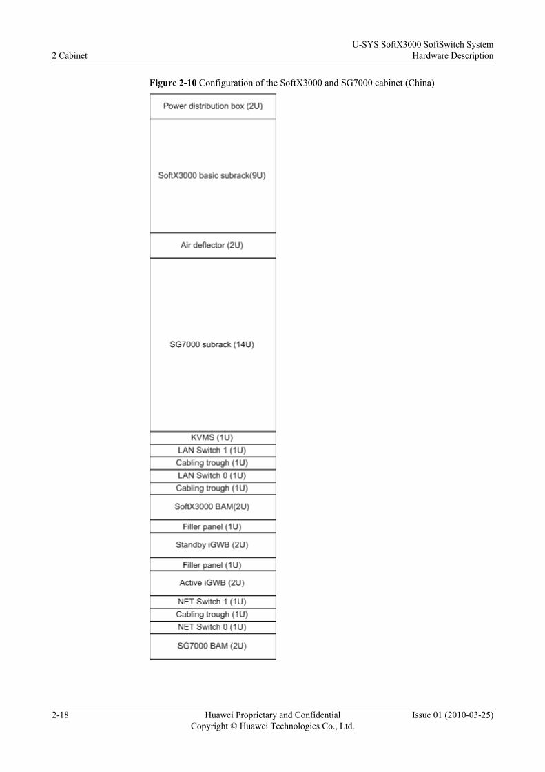
Figure 2-10 Configuration of the SoftX3000 and SG7000 cabinet (China)
2 CabinetU-SYS SoftX3000 SoftSwitch System
Hardware Description
2-18 Huawei Proprietary and ConfidentialCopyright © Huawei Technologies Co., Ltd.
Issue 01 (2010-03-25)
l When the SoftX3000 and SG7000 cabinet is used outside China, the configuration of the
cabinet is as shown in Figure 2-11.
U-SYS SoftX3000 SoftSwitch SystemHardware Description 2 Cabinet
Issue 01 (2010-03-25) Huawei Proprietary and ConfidentialCopyright © Huawei Technologies Co., Ltd.
2-19

Figure 2-11 Configuration of the SoftX3000 and SG7000 cabinet (outside China, IBMX343 server)
Power distribution box (2U)
Air deflector (2U)
SoftX3000 basic subrack (9U)
SG7000 subrack (14U)
KVMS (1U)LAN Switch 1 (1U)Cabling trough (1U)LAN Switch 0 (1U)Cabling trough (1U)
Hard disk array (3U)
SoftX3000 BAM(2U)
Standby iGWB (2U)
Active iGWB (2U)
NET Switch 1 (1U)Cabling trough (1U)NET Switch 0 (1U)
SG7000 BAM (2U)
2 CabinetU-SYS SoftX3000 SoftSwitch System
Hardware Description
2-20 Huawei Proprietary and ConfidentialCopyright © Huawei Technologies Co., Ltd.
Issue 01 (2010-03-25)
SoftX3000 and UMG8900 Cabinet—VIG8920 CabinetThe configuration of the SoftX3000 and UMG8900 cabinet may vary with the countries andareas.
l When the SoftX3000 and UMG8900 cabinet is used in China, the BAM and the iGWB useHP or C4210 servers. The BAM is not configured with a hard disk array, and the iGWB isconfigured with a built-in hard disk array. Figure 2-12 shows the configuration of thecabinet.
U-SYS SoftX3000 SoftSwitch SystemHardware Description 2 Cabinet
Issue 01 (2010-03-25) Huawei Proprietary and ConfidentialCopyright © Huawei Technologies Co., Ltd.
2-21

Figure 2-12 Configuration of the SoftX3000 and UMG8900 cabinet (China)
l When the SoftX3000 and UMG8900 cabinet is used outside China, the configuration ofthe cabinet is as shown in Figure 2-13.
2 CabinetU-SYS SoftX3000 SoftSwitch System
Hardware Description
2-22 Huawei Proprietary and ConfidentialCopyright © Huawei Technologies Co., Ltd.
Issue 01 (2010-03-25)
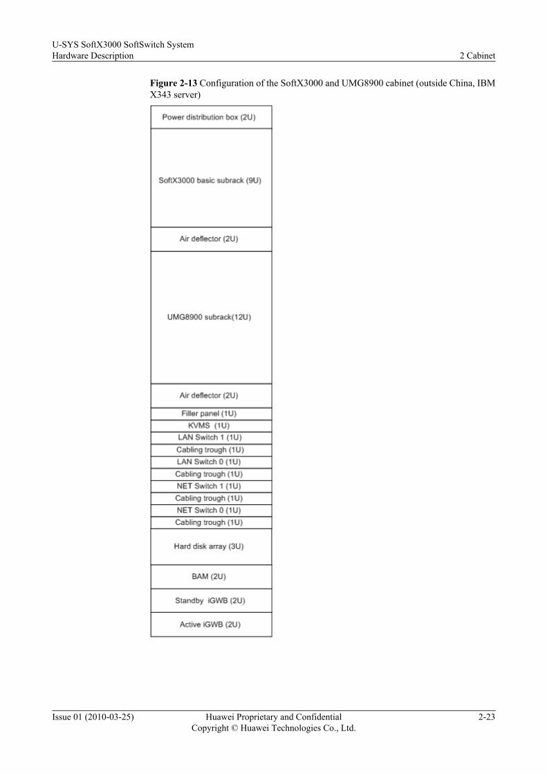
Figure 2-13 Configuration of the SoftX3000 and UMG8900 cabinet (outside China, IBMX343 server)
U-SYS SoftX3000 SoftSwitch SystemHardware Description 2 Cabinet
Issue 01 (2010-03-25) Huawei Proprietary and ConfidentialCopyright © Huawei Technologies Co., Ltd.
2-23
2.3 Power Supply SystemThe power supply system powers the entire SoftX3000 and requires high reliability. The powersupply system adopts dual-circuit backup and point-specific monitoring solutions. The powersupply system consists of the power input module and power distribution module.
2.3.1 Power Input ModuleThe power input module refers to the part from the PDF to the SoftX3000 cabinet.
2.3.2 Power Distribution ModuleThe power distribution module distributes power from the PDF to all internal components ofthe SoftX3000 cabinets.
2.3.1 Power Input ModuleThe power input module refers to the part from the PDF to the SoftX3000 cabinet.
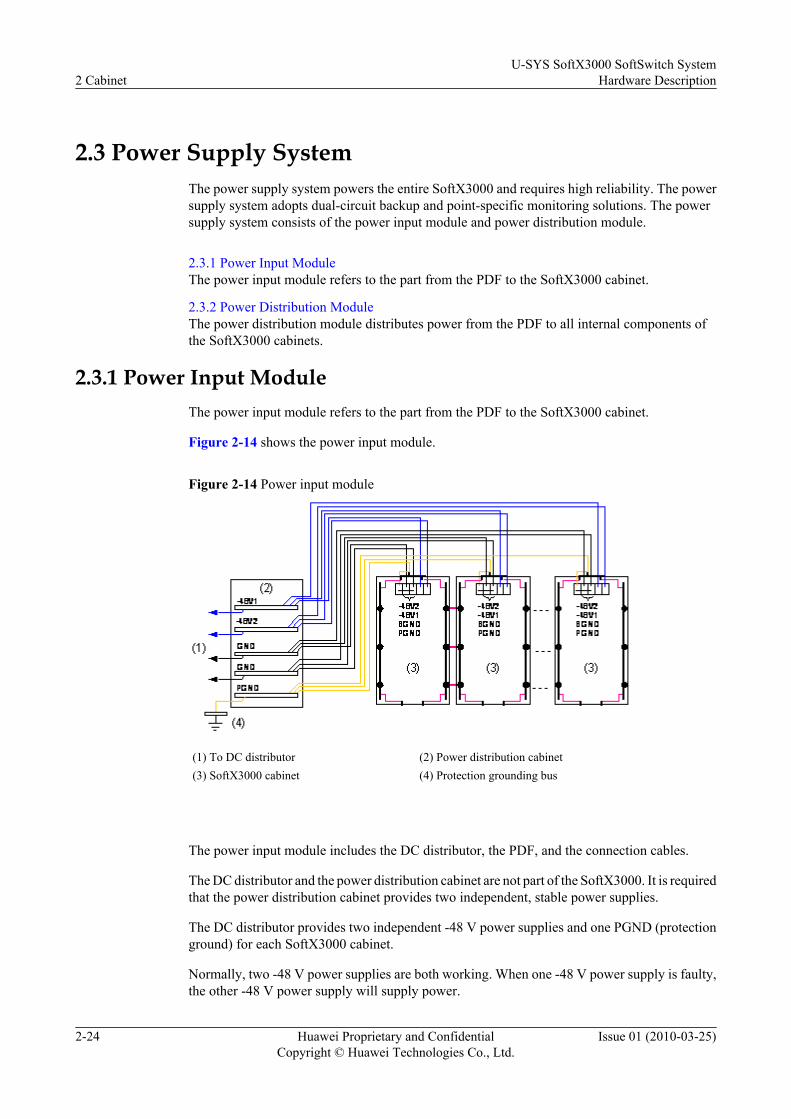
Figure 2-14 shows the power input module.
Figure 2-14 Power input module
(1) To DC distributor (2) Power distribution cabinet(3) SoftX3000 cabinet (4) Protection grounding bus
The power input module includes the DC distributor, the PDF, and the connection cables.
The DC distributor and the power distribution cabinet are not part of the SoftX3000. It is requiredthat the power distribution cabinet provides two independent, stable power supplies.
The DC distributor provides two independent -48 V power supplies and one PGND (protectionground) for each SoftX3000 cabinet.
Normally, two -48 V power supplies are both working. When one -48 V power supply is faulty,the other -48 V power supply will supply power.
2 CabinetU-SYS SoftX3000 SoftSwitch System
Hardware Description
2-24 Huawei Proprietary and ConfidentialCopyright © Huawei Technologies Co., Ltd.
Issue 01 (2010-03-25)

2.3.2 Power Distribution ModuleThe power distribution module distributes power from the PDF to all internal components ofthe SoftX3000 cabinets.
The SoftX3000 consists of integrated configuration cabinets and service processing cabinets.Different cabinets are equipped with different components. Their electrical connections varyfrom cabinet to cabinet, as shown in Figure 2-15 and Figure 2-16.
Figure 2-15 Electrical connections of the integraged configuration cabinet
U-SYS SoftX3000 SoftSwitch SystemHardware Description 2 Cabinet
Issue 01 (2010-03-25) Huawei Proprietary and ConfidentialCopyright © Huawei Technologies Co., Ltd.
2-25

Figure 2-16 Electrical connections of the service processing cabinet
CAUTIONTable 2-2 lists the mappings between the cabinet components and the switches. Actual mappingsbetween cabinet components and switches differ. The mappings between the cabinet componentsand the switches in this table are used for example purposes only.
2 CabinetU-SYS SoftX3000 SoftSwitch System
Hardware Description
2-26 Huawei Proprietary and ConfidentialCopyright © Huawei Technologies Co., Ltd.
Issue 01 (2010-03-25)
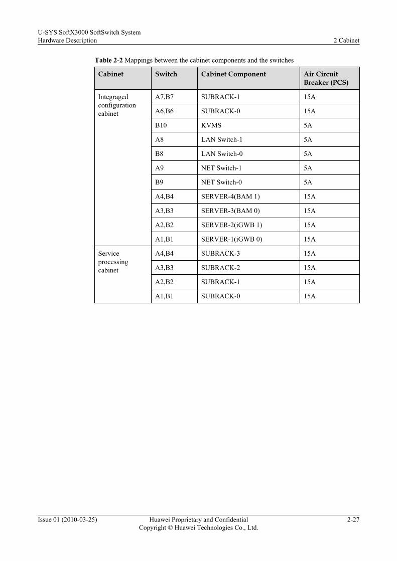
Table 2-2 Mappings between the cabinet components and the switches
Cabinet Switch Cabinet Component Air CircuitBreaker (PCS)
Integragedconfigurationcabinet
A7,B7 SUBRACK-1 15A
A6,B6 SUBRACK-0 15A
B10 KVMS 5A
A8 LAN Switch-1 5A
B8 LAN Switch-0 5A
A9 NET Switch-1 5A
B9 NET Switch-0 5A
A4,B4 SERVER-4(BAM 1) 15A
A3,B3 SERVER-3(BAM 0) 15A
A2,B2 SERVER-2(iGWB 1) 15A
A1,B1 SERVER-1(iGWB 0) 15A
Serviceprocessingcabinet
A4,B4 SUBRACK-3 15A
A3,B3 SUBRACK-2 15A
A2,B2 SUBRACK-1 15A
A1,B1 SUBRACK-0 15A
U-SYS SoftX3000 SoftSwitch SystemHardware Description 2 Cabinet
Issue 01 (2010-03-25) Huawei Proprietary and ConfidentialCopyright © Huawei Technologies Co., Ltd.
2-27

3 Subrack
About This Chapter
The service processing subrack (hereinafter referred to as the subrack) is the service processingcenter of the SoftX3000. Boards in a subrack are connected through the same backplane to forman independent working unit. Based on different board configurations, subracks are categorizedinto the basic subrack and the expansion subrack.
The SoftX3000 adopts the open standards telecom architecture (OSTA) platform as its hardwareplatform.
3.1 Overview of the SubrackThis section describes the appearance and technical specifications of the SoftX3000 subrack.
3.2 Basic Subrack 0This section describes the basic subrack 0.
3.3 Basic Subrack 1This section describes the basic subrack 1.
3.4 Expansion SubrackThis section describes the expansion subrack.
3.5 Media Resource SubrackThis section describes the media resource subrack.
3.6 Fan BoxA fan box is installed at the bottom of each subrack for heat dissipation. The fan box is 2 U high.This section describes the functions, appearance and technical specifications of the fan box.
3.7 Board Allocation in a SubrackThis section describes how boards are allocated in a subrack.
3.8 Numbering of SubracksThis section describes the numbering of subracks.
U-SYS SoftX3000 SoftSwitch SystemHardware Description 3 Subrack
Issue 01 (2010-03-25) Huawei Proprietary and ConfidentialCopyright © Huawei Technologies Co., Ltd.
3-1
3.1 Overview of the SubrackThis section describes the appearance and technical specifications of the SoftX3000 subrack.
FunctionsThe subrack is the service processing center of the SoftX3000. Boards in a subrack are connectedthrough the same backplane to form an independent working unit.
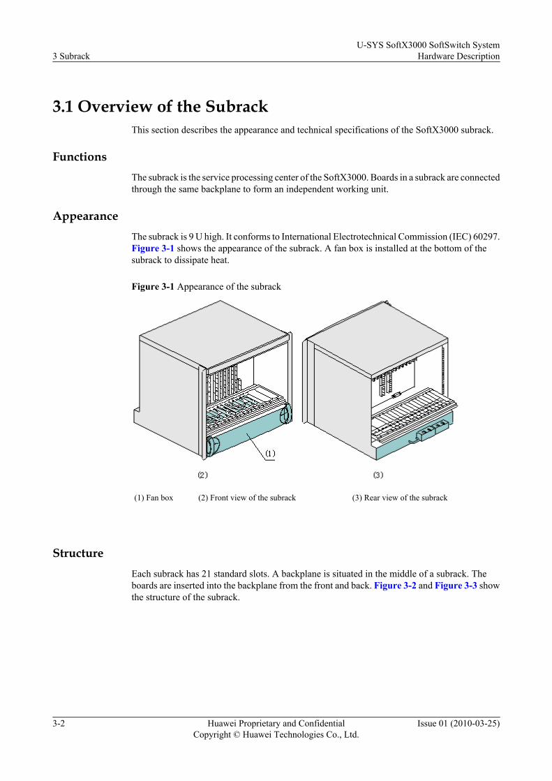
AppearanceThe subrack is 9 U high. It conforms to International Electrotechnical Commission (IEC) 60297.Figure 3-1 shows the appearance of the subrack. A fan box is installed at the bottom of thesubrack to dissipate heat.
Figure 3-1 Appearance of the subrack
(1) Fan box (2) Front view of the subrack (3) Rear view of the subrack
StructureEach subrack has 21 standard slots. A backplane is situated in the middle of a subrack. Theboards are inserted into the backplane from the front and back. Figure 3-2 and Figure 3-3 showthe structure of the subrack.
3 SubrackU-SYS SoftX3000 SoftSwitch System
Hardware Description
3-2 Huawei Proprietary and ConfidentialCopyright © Huawei Technologies Co., Ltd.
Issue 01 (2010-03-25)

Figure 3-2 Structure of the subrack
1 Back boards 2 Backplane 3 Front boards
Figure 3-3 Inserting a front board and a back board into the backplane
1 Back board 2 Backplane 3 Front board
Technical specificationsTable 3-1 lists the technical specifications of the subrack.
U-SYS SoftX3000 SoftSwitch SystemHardware Description 3 Subrack
Issue 01 (2010-03-25) Huawei Proprietary and ConfidentialCopyright © Huawei Technologies Co., Ltd.
3-3
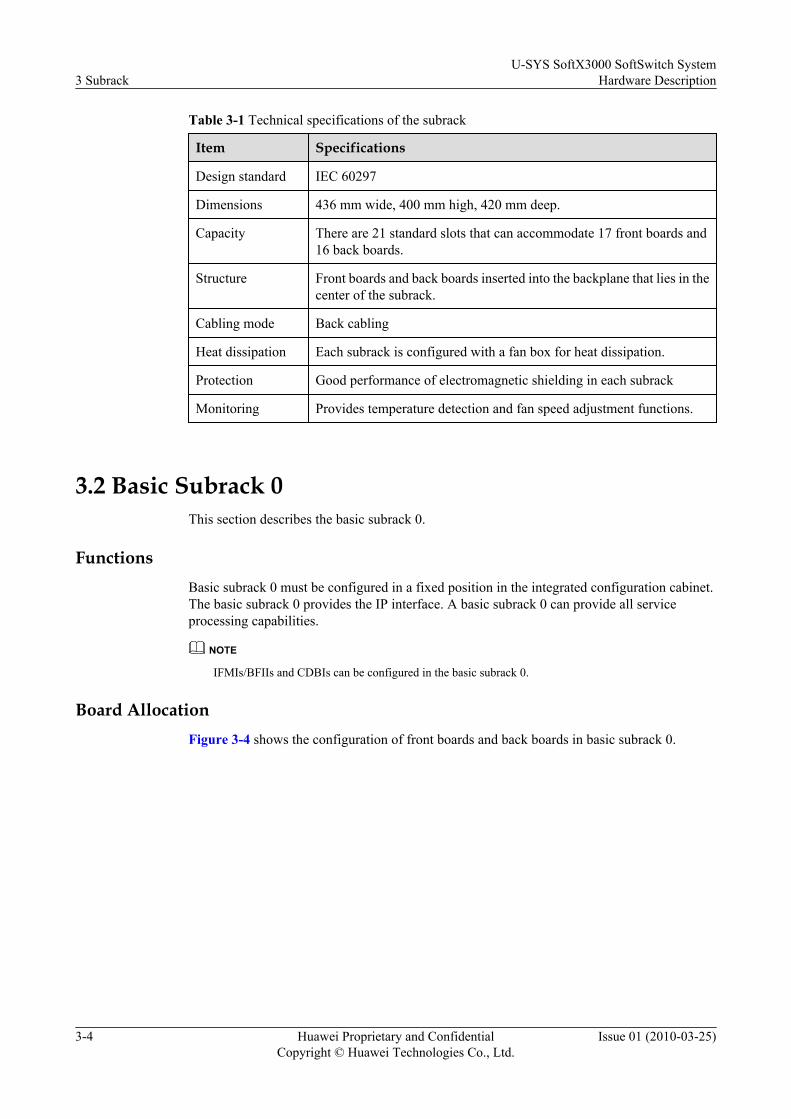
Table 3-1 Technical specifications of the subrack
Item Specifications
Design standard IEC 60297
Dimensions 436 mm wide, 400 mm high, 420 mm deep.
Capacity There are 21 standard slots that can accommodate 17 front boards and16 back boards.
Structure Front boards and back boards inserted into the backplane that lies in thecenter of the subrack.
Cabling mode Back cabling
Heat dissipation Each subrack is configured with a fan box for heat dissipation.
Protection Good performance of electromagnetic shielding in each subrack
Monitoring Provides temperature detection and fan speed adjustment functions.
3.2 Basic Subrack 0This section describes the basic subrack 0.
FunctionsBasic subrack 0 must be configured in a fixed position in the integrated configuration cabinet.The basic subrack 0 provides the IP interface. A basic subrack 0 can provide all serviceprocessing capabilities.
NOTE
IFMIs/BFIIs and CDBIs can be configured in the basic subrack 0.
Board AllocationFigure 3-4 shows the configuration of front boards and back boards in basic subrack 0.
3 SubrackU-SYS SoftX3000 SoftSwitch System
Hardware Description
3-4 Huawei Proprietary and ConfidentialCopyright © Huawei Technologies Co., Ltd.
Issue 01 (2010-03-25)

Figure 3-4 Board allocation in basic subrack 0
Configuration Guidancel The SMUIs, SIUIs, HSCIs, ALUI and UPWRs are mandatory and are configured in fixed
positions in basic subrack 0. The SMUIs occupy the front slots 6 and 8. The HSCIs occupythe back slots 7 and 9. The ALUI occupy the front slot 16. The UPWRs occupy slots 17and 18, and 19 and 20.
l The IFMIs and BFIIs in the left half of the subrack, and the CDBIs in the right half of thesubrack are mandatory. It is recommended to configure the IFMIs fixedly into slots 0 and1, and CDBIs fixedly into slots 10 and 11 for future expansion.
l The following boards are also configured in basic subrack 0:– Fixed calling control units (FCCU)
– Broadband signaling gateway boards (BSGI)
– Multimedia signaling gateway units (MSGI)
l The FCCU/BSGI/MSGI compatible slots are front slots 2 - 5 and 12 - 15. Configure theFCCU from left to right and BSGIs/MSGIs from right to left.
l Cover all vacant slots with filler panels.
3.3 Basic Subrack 1This section describes the basic subrack 1.
Functions
Basic subrack 1 must be configured when the number of equivalent subscribers is greater than500,000. The basic subrack 1 provides external IP interface, and can provide all serviceprocessing functions. For each increase of 500,000 equivalent subscribers, add a pair of IFMIs
U-SYS SoftX3000 SoftSwitch SystemHardware Description 3 Subrack
Issue 01 (2010-03-25) Huawei Proprietary and ConfidentialCopyright © Huawei Technologies Co., Ltd.
3-5

in basic subrack 1. When the number of equivalent subscribers is greater than 1,000,000, add apair of CDBIs in the basic subrack 1.
NOTE
l Up to four pairs of IFMIs and two pairs of CDBIs can be configured in the SoftX3000. Therefore, onlyone basic subrack 0 and one basic subrack 1 are required for the whole system.
l The IP Forward Modules (IFMIs)/Back insert FE Interface Units (BFIIs) and Central Database Boards(CDBIs) can be configured in the basic subrack 1. The IFMIs/BFIIs provide IP interfaces.
Board AllocationFigure 3-5 shows the allocation of front boards and back boards in basic subrack 1.
Figure 3-5 Board allocation in basic subrack 1
Configuration Guidancel When there are more than two IFMIs or two CDBIs, basic subrack 1 must be configured.
l The SMUIs, SIUIs, HSCIs, ALUI and UPWRs are mandatory. The SMUIs are configuredfixedly in the front slots 6 and 8, HSCIs in the back slots 7 and 9, ALUI in the front slot16, and UPWRs in the front slots 17, 18 and 19, 20, and the mapping back slots.
l In slots 2 - 5, IFMIs are preferred; in slots 12 - 15, CDBIs are preferred. The front slots leftvacant, after inserting IFMIs and CDBIs, can be used for FCCUs, BSGIs and MSGIs
l It is recommended to configure FCCUs from left to right and BSGIs/MSGIs from right toleft.
l Cover all vacant slots with filler panels.
3.4 Expansion SubrackThis section describes the expansion subrack.
3 SubrackU-SYS SoftX3000 SoftSwitch System
Hardware Description
3-6 Huawei Proprietary and ConfidentialCopyright © Huawei Technologies Co., Ltd.
Issue 01 (2010-03-25)
FunctionsThe expansion subrack is optional and can be configured as the service processing subrack basedon the subscriber capacity. The expansion subracks can provide the service processing functionsonly in cooperation with the basic subrack 0.
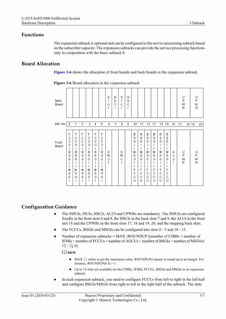
Board AllocationFigure 3-6 shows the allocation of front boards and back boards in the expansion subrack.
Figure 3-6 Board allocation in the expansion subrack
Configuration Guidancel The SMUIs, SIUIs, HSCIs, ALUI and UPWRs are mandatory. The SMUIs are configured
fixedly in the front slots 6 and 8, the HSCIs in the back slots 7 and 9, the ALUI in the frontslot 16 and the UPWRs in the front slots 17, 18 and 19, 20, and the mapping back slots.
l The FCCUs, BSGIs and MSGIs can be configured into slots 0 - 5 and 10 - 15.
l Number of expansion subracks = MAX {ROUNDUP [(number of CDBIs + number ofIFMIs + number of FCCUs + number of AGCUs + number of BSGIs + number of MSGIs)/12 - 1], 0}
NOTE
l MAX { } refers to get the maximum value. ROUNDUP() means to round up to an integer. Forinstance, ROUNDUP(0.4) = 1.
l Up to 12 slots are available for the CDBIs, IFMIs, FCCUs, BSGIs and MSGIs in an expansionsubrack.
l In each expansion subrack, you need to configure FCCUs from left to right in the left halfand configure BSGIs/MSGIs from right to left in the right half of the subrack. The slots
U-SYS SoftX3000 SoftSwitch SystemHardware Description 3 Subrack
Issue 01 (2010-03-25) Huawei Proprietary and ConfidentialCopyright © Huawei Technologies Co., Ltd.
3-7
left vacant, after configuring the FCCUs (BSGIs/MSGIs) in the left (right) half, can be usedfor BSGIs/MSGIs (FCCUs).
l Cover all vacant slots with filler panels.
3.5 Media Resource SubrackThis section describes the media resource subrack.
Functions
When the capacity of equivalent subscribers is less than 100,000, a media resource subrack isconfigured to provide resource media streams to implement the MRS functions.
Board Allocation
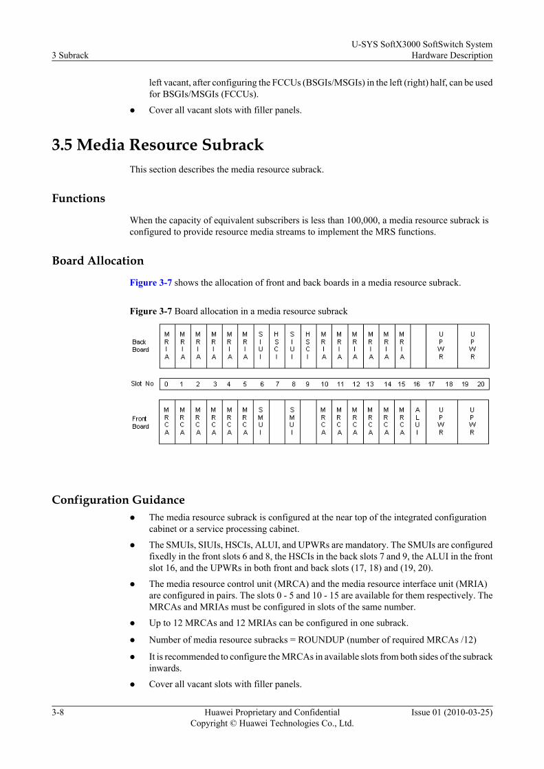
Figure 3-7 shows the allocation of front and back boards in a media resource subrack.
Figure 3-7 Board allocation in a media resource subrack
Configuration Guidancel The media resource subrack is configured at the near top of the integrated configuration
cabinet or a service processing cabinet.
l The SMUIs, SIUIs, HSCIs, ALUI, and UPWRs are mandatory. The SMUIs are configuredfixedly in the front slots 6 and 8, the HSCIs in the back slots 7 and 9, the ALUI in the frontslot 16, and the UPWRs in both front and back slots (17, 18) and (19, 20).
l The media resource control unit (MRCA) and the media resource interface unit (MRIA)are configured in pairs. The slots 0 - 5 and 10 - 15 are available for them respectively. TheMRCAs and MRIAs must be configured in slots of the same number.
l Up to 12 MRCAs and 12 MRIAs can be configured in one subrack.
l Number of media resource subracks = ROUNDUP (number of required MRCAs /12)
l It is recommended to configure the MRCAs in available slots from both sides of the subrackinwards.
l Cover all vacant slots with filler panels.
3 SubrackU-SYS SoftX3000 SoftSwitch System
Hardware Description
3-8 Huawei Proprietary and ConfidentialCopyright © Huawei Technologies Co., Ltd.
Issue 01 (2010-03-25)

3.6 Fan BoxA fan box is installed at the bottom of each subrack for heat dissipation. The fan box is 2 U high.This section describes the functions, appearance and technical specifications of the fan box.
NOTE
The fan box is made of plastic and sheet metal. Each fan box accommodates a monitor board and six fans.The diameter of each fan is 120 mm, and the thickness is 32 mm.
Functions
The fan box has the following features:
l The temperature detection and speed adjustment techniques are used in the fans. Therotation speed of the fans can be adjusted to half speed or full speed to ensure normal heatdissipation and reliable running of the subrack.
l The fans are hot-swappable.
l The running state of the fans can be known by observing the indicators.
l The fan box can be maintained through a remote network management terminal.
Appearance
Figure 3-8 shows the front view of the fan box.
Figure 3-8 Front view of the fan box
(1) Captive screw (2) Fan state indicator
If the state indicator turns green and flashes at a frequency of 0.5 Hz, it indicates that all the fansare working normally. Otherwise, the fans might be working abnormally, the communicationmonitor board might be faulty, or the power supply for the fan box might have failed.
Technical Specifications
The technical specifications of a fan box are as follows:
l Input voltage: - 40 V to - 58 V
l Maximum power consumption of a fan box: 90 W
l Communication rate through RS485: 9.6 kbit/s
U-SYS SoftX3000 SoftSwitch SystemHardware Description 3 Subrack
Issue 01 (2010-03-25) Huawei Proprietary and ConfidentialCopyright © Huawei Technologies Co., Ltd.
3-9
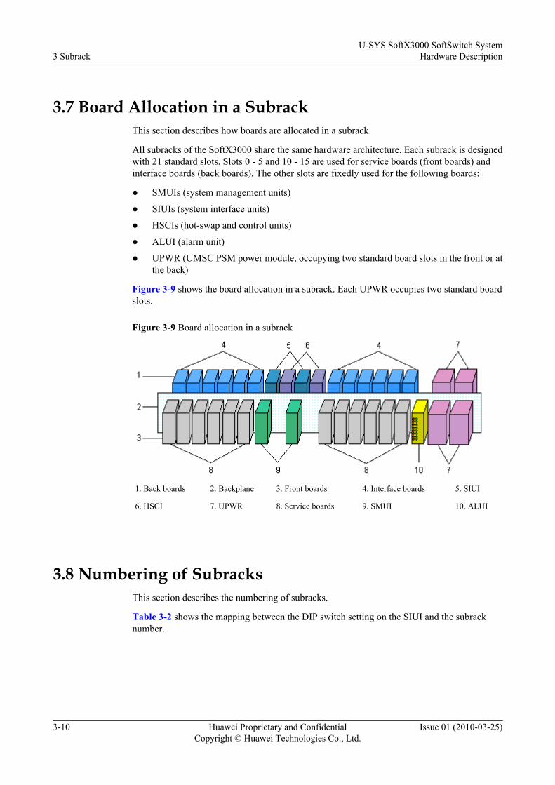
3.7 Board Allocation in a SubrackThis section describes how boards are allocated in a subrack.
All subracks of the SoftX3000 share the same hardware architecture. Each subrack is designedwith 21 standard slots. Slots 0 - 5 and 10 - 15 are used for service boards (front boards) andinterface boards (back boards). The other slots are fixedly used for the following boards:
l SMUIs (system management units)
l SIUIs (system interface units)
l HSCIs (hot-swap and control units)
l ALUI (alarm unit)
l UPWR (UMSC PSM power module, occupying two standard board slots in the front or atthe back)
Figure 3-9 shows the board allocation in a subrack. Each UPWR occupies two standard boardslots.
Figure 3-9 Board allocation in a subrack
1. Back boards 2. Backplane 3. Front boards 4. Interface boards 5. SIUI
6. HSCI 7. UPWR 8. Service boards 9. SMUI 10. ALUI
3.8 Numbering of SubracksThis section describes the numbering of subracks.
Table 3-2 shows the mapping between the DIP switch setting on the SIUI and the subracknumber.
3 SubrackU-SYS SoftX3000 SoftSwitch System
Hardware Description
3-10 Huawei Proprietary and ConfidentialCopyright © Huawei Technologies Co., Ltd.
Issue 01 (2010-03-25)

Table 3-2 Mapping between the DIP switch setting on the SIUI and the subrack number
DIPSwitch BitSubrackNo. 8 7 6 5 4 3 2 1
0 on on on on on on on on
1 on on on on on on on off
2 on on on on on on off on
3 on on on on on on off off
4 on on on on on off on on
5 on on on on on off on off
6 on on on on on off off on
7 on on on on on off off off
8 on on on on off on on on
9 on on on on off on on off
10 on on on on off on off on
11 on on on on off on off off
12 on on on on off off on on
13 on on on on off off on off
14 on on on on off off off on
15 on on on on off off off off
16 on on on off on on on on
17 on on on off on on on off
U-SYS SoftX3000 SoftSwitch SystemHardware Description 3 Subrack
Issue 01 (2010-03-25) Huawei Proprietary and ConfidentialCopyright © Huawei Technologies Co., Ltd.
3-11

4 Boards
About This Chapter
This section describes the functions and technical specifications of the front boards and backboards of the SoftX3000.
4.1 Overview of the BoardsThis section describes the classification of SoftX3000 boards.
4.2 Front BoardsThis section describes the functions, indicators, DIP switches and jumpers, and technicalspecifications of the front boards of the SoftX3000.
4.3 Back BoardsThis section describes the functions, indicators, DIP switches and jumpers, and technicalspecifications of the back boards of the SoftX3000.
U-SYS SoftX3000 SoftSwitch SystemHardware Description 4 Boards
Issue 01 (2010-03-25) Huawei Proprietary and ConfidentialCopyright © Huawei Technologies Co., Ltd.
4-1

4.1 Overview of the BoardsThis section describes the classification of SoftX3000 boards.
750C boardsand 750B boards differ in their hardware versions. Any board of 750C or 750Bserials can function as the FCCU, IFMI, BSGI, MSGI, or CDBI after being installed withcorresponding hardware or software.
The SoftX3000 of V300R601C03 and later versions support both 750C and 750B boards. TheSoftX3000 of V300R003, V300R005, V300R006, V300R601C01, and V300R601C02 versionssupport only 750B boards.
NOTE
For details about 750B boards, see 4 Boards. For details about differences between 750C boards and 750Bboards, see 4.1.6 Differences Between Series Boards.
4.1.1 Classification of BoardsThis section describes the classification of boards.
4.1.2 Classification of BoardsThis section describes the classification of boards.
4.1.3 Mechanical Structure of BoardsFor the SoftX3000, the mechanical structures of all boards are basically the same, whichfacilitates board removal and insertion.
4.1.4 Working Modes of BoardsBoards have three working modes: independent working mode, load-sharing working mode, andactive/standby working mode. Boards working in different modes are replaced in differentprocedures.
4.1.5 Switching Modes of BoardsThis section describes the automatic switchover and manual switchover of boards.
4.1.6 Differences Between Series BoardsThis section describes the differences between 750C boards and 750B boards.
4.1.1 Classification of BoardsThis section describes the classification of boards.
FunctionsA board is the basic functional unit of the system. Boards co-work with each other to achievethe established functions.
Both the front boards and back boards of the SoftX3000 are inserted into the backplane in themiddle of a subrack.
The functions of the boards are as follows:
l Front boards: They are the service processing boards and management control boards.
l Back boards: They are the protocol processing boards and interface boards.
l Backplane: It provides a communication channel for other boards.
4 BoardsU-SYS SoftX3000 SoftSwitch System
Hardware Description
4-2 Huawei Proprietary and ConfidentialCopyright © Huawei Technologies Co., Ltd.
Issue 01 (2010-03-25)
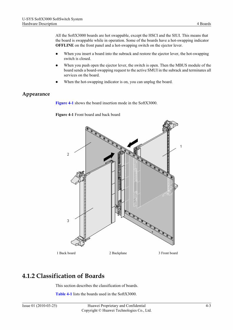
All the SoftX3000 boards are hot swappable, except the HSCI and the SIUI. This means thatthe board is swappable while in operation. Some of the boards have a hot-swapping indicatorOFFLINE on the front panel and a hot-swapping switch on the ejector lever.
l When you insert a board into the subrack and restore the ejector lever, the hot-swappingswitch is closed.
l When you push open the ejector lever, the switch is open. Then the MBUS module of theboard sends a board-swapping request to the active SMUI in the subrack and terminates allservices on the board.
l When the hot-swapping indicator is on, you can unplug the board.
AppearanceFigure 4-1 shows the board insertion mode in the SoftX3000.
Figure 4-1 Front board and back board
1 Back board 2 Backplane 3 Front board
4.1.2 Classification of BoardsThis section describes the classification of boards.
Table 4-1 lists the boards used in the SoftX3000.
U-SYS SoftX3000 SoftSwitch SystemHardware Description 4 Boards
Issue 01 (2010-03-25) Huawei Proprietary and ConfidentialCopyright © Huawei Technologies Co., Ltd.
4-3

Table 4-1 Attributes of the SoftX3000 boards
Board Subrack Board Type CorrespondingFront or Back Board
FCCU Basic subrack andexpansion subrack
Front board None
IFMI Basic subrack Front board Used in pairs
BFII Basic subrack Back board
SMUI Basic subrack andexpansion subrack
Front board Used in pairs
SMUI Basic subrack andexpansion subrack
Back board
MRCA Media resourcesubrack
Front board Used in pairs
MRIA Media resourcesubrack
Back board
BSGI Basic subrack andexpansion subrack
Front board None
MSGI Basic subrack andexpansion subrack
Front board None
CDBI Basic subrack Front board None
ALUI Basic subrack andexpansion subrack
Front board None
UPWR Basic subrack andexpansion subrack
Front board and backboard
None
HSCI Basic subrack andexpansion subrack
Back board None
4.1.3 Mechanical Structure of BoardsFor the SoftX3000, the mechanical structures of all boards are basically the same, whichfacilitates board removal and insertion.
In the SoftX3000, all boards consist of a circuit card, connector, upper ejector lever, lower ejectorlever, fastening screws, locks, and positioning pins, as shown in Figure 4-2.
4 BoardsU-SYS SoftX3000 SoftSwitch System
Hardware Description
4-4 Huawei Proprietary and ConfidentialCopyright © Huawei Technologies Co., Ltd.
Issue 01 (2010-03-25)

Figure 4-2 Mechanical structure of a board
(1) Positioning pin (2) Fastening screw (3) Upper ejector lever (4) Locking key (5) EMC shielding bar
(6) Faceplate (7) Circuit card (8) Shielding bar (9) Lower ejectorlever
(10) Connector
4.1.4 Working Modes of BoardsBoards have three working modes: independent working mode, load-sharing working mode, andactive/standby working mode. Boards working in different modes are replaced in differentprocedures.
Active/Standby Working ModeIf two boards work in the active-standby mode, the active board carries the service load and thestandby board backs up the data of the active board periodically. When the active board is faulty,the standby board takes over the load from the active board.
Before replacing a board, ensure that it is in the standby.
Load-Sharing ModeThe load-sharing mode is also called the resources pool mode. In this mode, a group of boardsof the same type are configured in a functional subrack and share the same tasks.
Normally, each board in the group shares 1/n (n >= 2; "n" refers to the number of boards in thegroup) of service load in their group. If you replace one board in a group, the system will transferthe service load taken by this board to other boards in the group. In case of heavy traffic, otherboards in this group may be overloaded, resulting in traffic congestion. Therefore, you mustreplace boards when the traffic is light, for example, at 2:00 a.m.
U-SYS SoftX3000 SoftSwitch SystemHardware Description 4 Boards
Issue 01 (2010-03-25) Huawei Proprietary and ConfidentialCopyright © Huawei Technologies Co., Ltd.
4-5
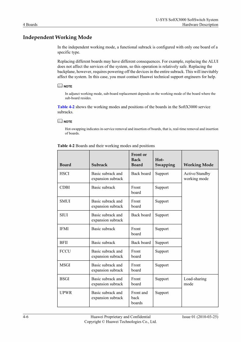
Independent Working Mode
In the independent working mode, a functional subrack is configured with only one board of aspecific type.
Replacing different boards may have different consequences. For example, replacing the ALUIdoes not affect the services of the system, so this operation is relatively safe. Replacing thebackplane, however, requires powering off the devices in the entire subrack. This will inevitablyaffect the system. In this case, you must contact Huawei technical support engineers for help.
NOTE
In adjunct working mode, sub-board replacement depends on the working mode of the board where thesub-board resides.
Table 4-2 shows the working modes and positions of the boards in the SoftX3000 servicesubracks.
NOTE
Hot-swapping indicates in-service removal and insertion of boards, that is, real-time removal and insertionof boards.
Table 4-2 Boards and their working modes and positions
Board Subrack
Front orBackBoard
Hot-Swapping Working Mode
HSCI Basic subrack andexpansion subrack
Back board Support Active/Standbyworking mode
CDBI Basic subrack Frontboard
Support
SMUI Basic subrack andexpansion subrack
Frontboard
Support
SIUI Basic subrack andexpansion subrack
Back board Support
IFMI Basic subrack Frontboard
Support
BFII Basic subrack Back board Support
FCCU Basic subrack andexpansion subrack
Frontboard
Support
MSGI Basic subrack andexpansion subrack
Frontboard
Support
BSGI Basic subrack andexpansion subrack
Frontboard
Support Load-sharingmode
UPWR Basic subrack andexpansion subrack
Front andbackboards
Support
4 BoardsU-SYS SoftX3000 SoftSwitch System
Hardware Description
4-6 Huawei Proprietary and ConfidentialCopyright © Huawei Technologies Co., Ltd.
Issue 01 (2010-03-25)
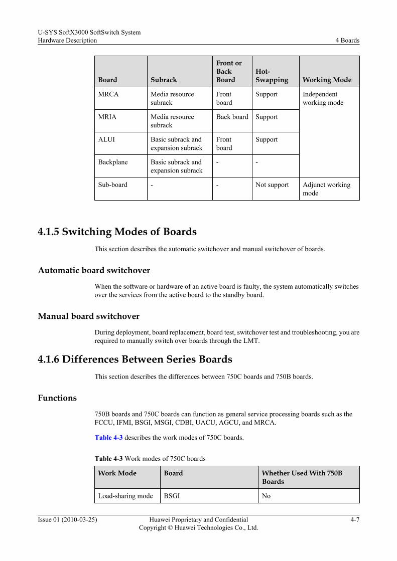
Board Subrack
Front orBackBoard
Hot-Swapping Working Mode
MRCA Media resourcesubrack
Frontboard
Support Independentworking mode
MRIA Media resourcesubrack
Back board Support
ALUI Basic subrack andexpansion subrack
Frontboard
Support
Backplane Basic subrack andexpansion subrack
- -
Sub-board - - Not support Adjunct workingmode
4.1.5 Switching Modes of BoardsThis section describes the automatic switchover and manual switchover of boards.
Automatic board switchover
When the software or hardware of an active board is faulty, the system automatically switchesover the services from the active board to the standby board.
Manual board switchover
During deployment, board replacement, board test, switchover test and troubleshooting, you arerequired to manually switch over boards through the LMT.
4.1.6 Differences Between Series BoardsThis section describes the differences between 750C boards and 750B boards.
Functions
750B boards and 750C boards can function as general service processing boards such as theFCCU, IFMI, BSGI, MSGI, CDBI, UACU, AGCU, and MRCA.
Table 4-3 describes the work modes of 750C boards.
Table 4-3 Work modes of 750C boards
Work Mode Board Whether Used With 750BBoards
Load-sharing mode BSGI No
U-SYS SoftX3000 SoftSwitch SystemHardware Description 4 Boards
Issue 01 (2010-03-25) Huawei Proprietary and ConfidentialCopyright © Huawei Technologies Co., Ltd.
4-7

Work Mode Board Whether Used With 750BBoards
Active/Standbymode
CDBI, FCCU, MSGI, or IFMI No
Appearance
The label of the 750C board has a lower case c, whereas the label of the 750B board does not.Figure 4-3 shows the labels on the FCCU boards of 750C and 750B serials.
Figure 4-3 Labels on the FCCU boards of 750C and 750B serials
NOTE
You can also run DSP BRD to query the board type.
Hardware Configuration
Table 4-4 shows the differences between 750C boards and 750B boards in hardwareconfiguration.
4 BoardsU-SYS SoftX3000 SoftSwitch System
Hardware Description
4-8 Huawei Proprietary and ConfidentialCopyright © Huawei Technologies Co., Ltd.
Issue 01 (2010-03-25)

Table 4-4 Difference between 750C boards and 750B boards in hardware configuration
Hardware 750C 750B
CPU 750 GX (dominant frequency: 1GHz)
750 (dominant frequency: 500 MHz)
Dominantmemory
1 GB 512 MB
Flash memory 32 MB 16 MB
Powerconsumption
14 W 11 W
Mapping Between the BFII with Dual-Network Port or Single-Network Port andthe IFMI of 750C or 750B Serials
Table 4-5 shows the mapping between the BFII with dual-network port or single-network portand the IFMI of 750C or 750B serials.
Table 4-5 Mapping between the BFII with dual-network port or single-network port and theIFMI of 750C or 750B serials
Back Board Front Board WhetherRequires an FESubboard
Network Port of theBFII to Which NetworkCable Is Connected
BFII (with dualnetwork ports)
IFMI (750B) Yes 10/100BT1
IFMI (750C) No 10/100BT2
BFII (with singlenetwork port)
IFMI (750B) Yes 10/100BT
IFMI (750C) The BFII and IFMI of 750C serials cannot beinserted in pairs.
4.2 Front BoardsThis section describes the functions, indicators, DIP switches and jumpers, and technicalspecifications of the front boards of the SoftX3000.
4.2.1 SMUIThis section describes the SMUI.
4.2.2 BSGIThis section describes the BSGI.
4.2.3 FCCUThis section describes the FCCU.
4.2.4 CDBI
U-SYS SoftX3000 SoftSwitch SystemHardware Description 4 Boards
Issue 01 (2010-03-25) Huawei Proprietary and ConfidentialCopyright © Huawei Technologies Co., Ltd.
4-9

This section describes the CDBI.
4.2.5 IFMIThis section describes the IFMI.
4.2.6 MRCAThis section describes the MRCA.
4.2.7 MSGIThis section describes the MSGI.
4.2.8 ALUIThis section describes the ALUI.
4.2.9 UPWRThis section describes the UPWR.
4.2.10 UACUThis section describes the functions of the UACU board and provides related information aboutthe board.
4.2.1 SMUIThis section describes the SMUI.
FunctionsThe SMUI is the main control board of the subrack. The board implements the followingfunctions:
l Managing the configuration and status of the shared resource bus.
l Managing all the boards in the subrack and reporting their status to the BAM through theserial port bus and shared resource bus, and controlling the indicators on the front panel ofthe ALUI.
l Loading and managing the system programs and data.
The SMUI is a front board installed in slots 6 and 8 in the basic subrack and expansion subrack.Its corresponding back board is the SIUI.
The SMUIs work in 1+1 backup mode.
IndicatorsFigure 4-4 shows the front panel of the SMUI.
4 BoardsU-SYS SoftX3000 SoftSwitch System
Hardware Description
4-10 Huawei Proprietary and ConfidentialCopyright © Huawei Technologies Co., Ltd.
Issue 01 (2010-03-25)
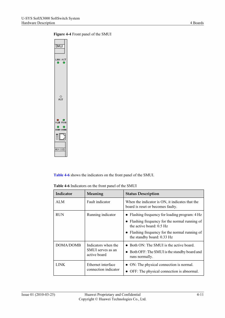
Figure 4-4 Front panel of the SMUI
Table 4-6 shows the indicators on the front panel of the SMUI.
Table 4-6 Indicators on the front panel of the SMUI
Indicator Meaning Status Description
ALM Fault indicator When the indicator is ON, it indicates that theboard is reset or becomes faulty.
RUN Running indicator l Flashing frequency for loading program: 4 Hz
l Flashing frequency for the normal running ofthe active board: 0.5 Hz
l Flashing frequency for the normal running ofthe standby board: 0.33 Hz
DOMA/DOMB Indicators when theSMUI serves as anactive board
l Both ON: The SMUI is the active board.
l Both OFF: The SMUI is the standby board andruns normally.
LINK Ethernet interfaceconnection indicator
l ON: The physical connection is normal.
l OFF: The physical connection is abnormal.
U-SYS SoftX3000 SoftSwitch SystemHardware Description 4 Boards
Issue 01 (2010-03-25) Huawei Proprietary and ConfidentialCopyright © Huawei Technologies Co., Ltd.
4-11
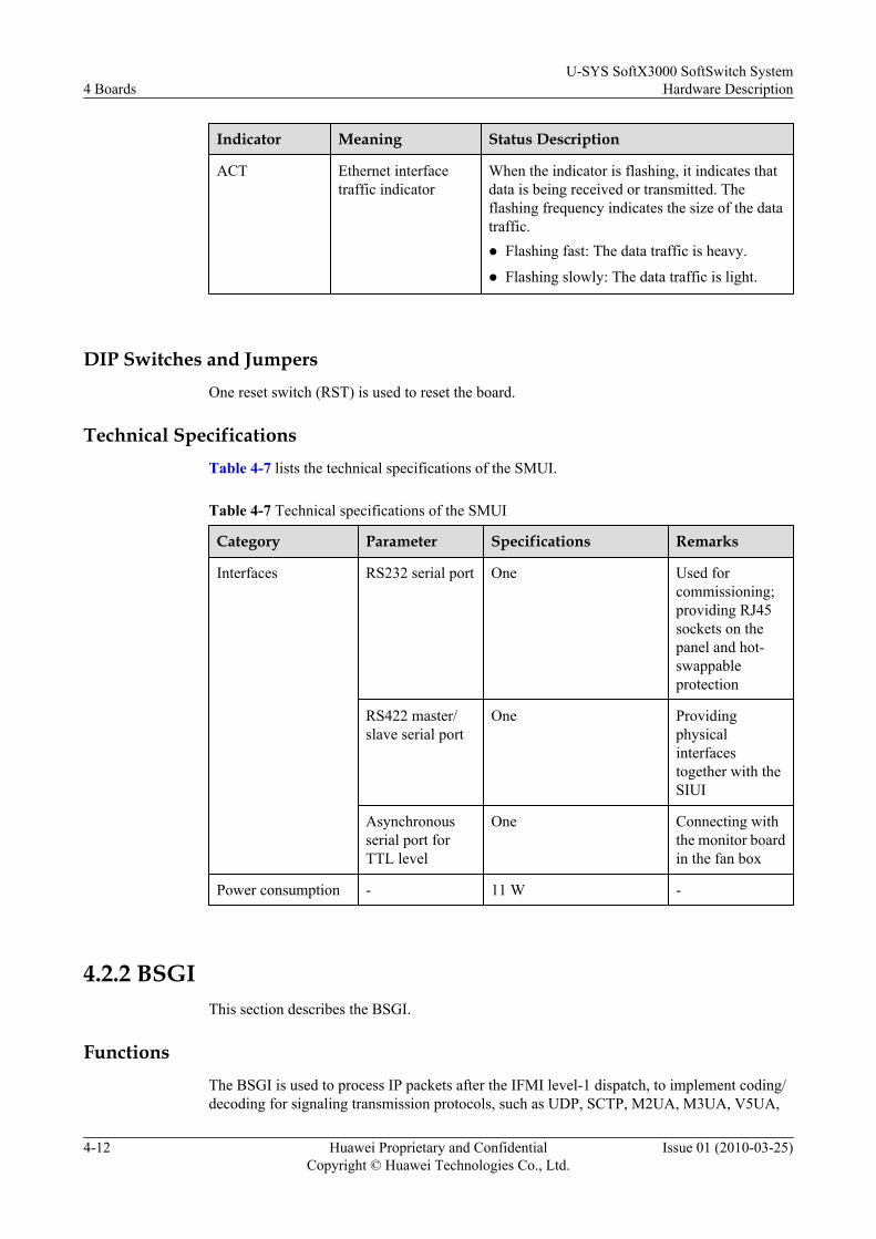
Indicator Meaning Status Description
ACT Ethernet interfacetraffic indicator
When the indicator is flashing, it indicates thatdata is being received or transmitted. Theflashing frequency indicates the size of the datatraffic.l Flashing fast: The data traffic is heavy.
l Flashing slowly: The data traffic is light.
DIP Switches and JumpersOne reset switch (RST) is used to reset the board.
Technical SpecificationsTable 4-7 lists the technical specifications of the SMUI.
Table 4-7 Technical specifications of the SMUI
Category Parameter Specifications Remarks
Interfaces RS232 serial port One Used forcommissioning;providing RJ45sockets on thepanel and hot-swappableprotection
RS422 master/slave serial port
One Providingphysicalinterfacestogether with theSIUI
Asynchronousserial port forTTL level
One Connecting withthe monitor boardin the fan box
Power consumption - 11 W -
4.2.2 BSGIThis section describes the BSGI.
FunctionsThe BSGI is used to process IP packets after the IFMI level-1 dispatch, to implement coding/decoding for signaling transmission protocols, such as UDP, SCTP, M2UA, M3UA, V5UA,
4 BoardsU-SYS SoftX3000 SoftSwitch System
Hardware Description
4-12 Huawei Proprietary and ConfidentialCopyright © Huawei Technologies Co., Ltd.
Issue 01 (2010-03-25)

IUA, MGCP and H.248, and to dispatch messages to corresponding service processing units fortransaction layer/service layer processing.
Figure 4-5 shows the protocol stack processed by the BSGI.
Figure 4-5 Protocol stack processed by the BSGI
The alarms generated by the BSGI are reported to the SMUI through the shared resource bus.
The BSGI is a front board that can be installed in a front slot except slot 6, 8, 16, 17, 18, 19, or20.
The BSGI works in the load sharing mode.
IndicatorsFigure 4-6 shows the front panel of the BSGI.
U-SYS SoftX3000 SoftSwitch SystemHardware Description 4 Boards
Issue 01 (2010-03-25) Huawei Proprietary and ConfidentialCopyright © Huawei Technologies Co., Ltd.
4-13
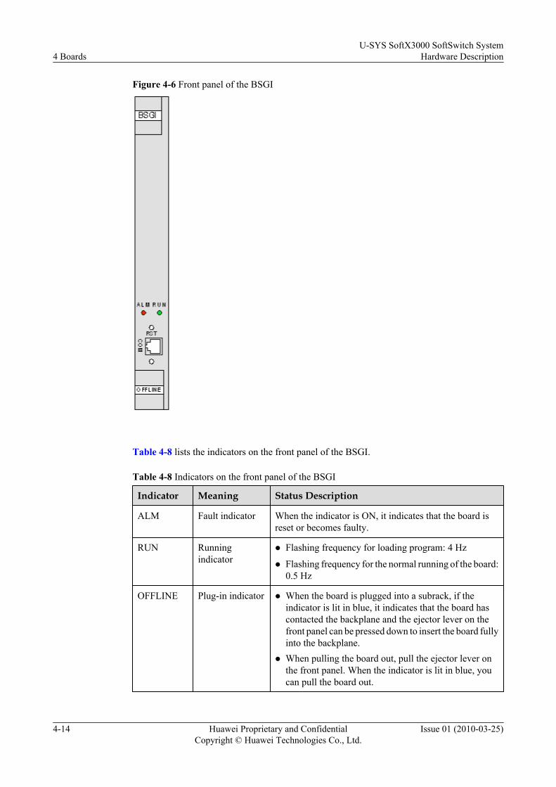
Figure 4-6 Front panel of the BSGI
Table 4-8 lists the indicators on the front panel of the BSGI.
Table 4-8 Indicators on the front panel of the BSGI
Indicator Meaning Status Description
ALM Fault indicator When the indicator is ON, it indicates that the board isreset or becomes faulty.
RUN Runningindicator
l Flashing frequency for loading program: 4 Hz
l Flashing frequency for the normal running of the board:0.5 Hz
OFFLINE Plug-in indicator l When the board is plugged into a subrack, if theindicator is lit in blue, it indicates that the board hascontacted the backplane and the ejector lever on thefront panel can be pressed down to insert the board fullyinto the backplane.
l When pulling the board out, pull the ejector lever onthe front panel. When the indicator is lit in blue, youcan pull the board out.
4 BoardsU-SYS SoftX3000 SoftSwitch System
Hardware Description
4-14 Huawei Proprietary and ConfidentialCopyright © Huawei Technologies Co., Ltd.
Issue 01 (2010-03-25)

DIP Switches and JumpersOne reset switch (RST) is used to reset the board.
Technical SpecificationsTable 4-9 lists the technical specifications of the BSGI.
Table 4-9 Technical specifications of the BSGI
Category ParameterSpecifications Remarks
Function H.248 1800 packetsper second
-
MGCP 1500 packetsper second
-
M2UA 5000 packetsper second
-
M3UA 5000 packetsper second
-
V5UA 5000 packetsper second
-
IUA 5000 packetsper second
-
Interface RS232 serial port One Used for commissioning; providingRJ45 sockets on the panel and hot-swappable protection
Powerconsumption
- 11 W -
4.2.3 FCCUThis section describes the FCCU.
FunctionsThe FCCU is responsible for call control and protocol processing of the MTP3, ISUP, INAP,MGCP, H.248, H.323, SIP, R2 and DSS1. The FCCU also forwards the M3UA, IUA and V5UAmessages.
Figure 4-7 shows the protocol stack processed by the FCCU.
U-SYS SoftX3000 SoftSwitch SystemHardware Description 4 Boards
Issue 01 (2010-03-25) Huawei Proprietary and ConfidentialCopyright © Huawei Technologies Co., Ltd.
4-15
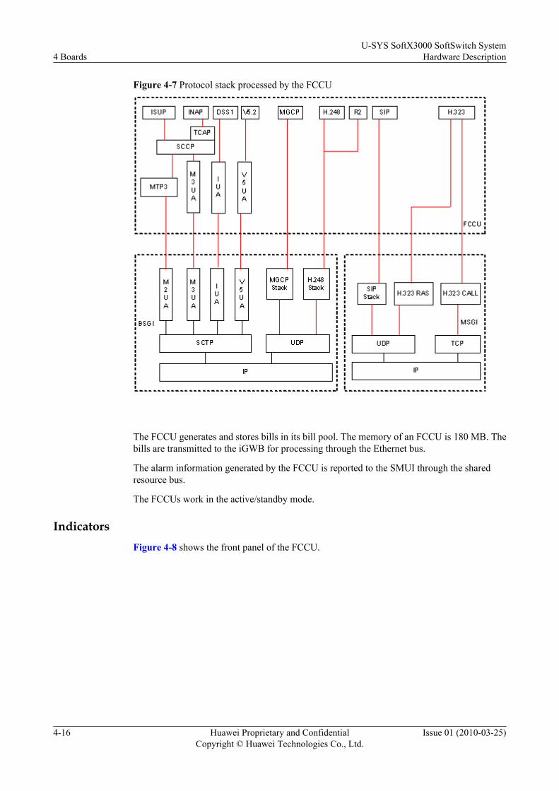
Figure 4-7 Protocol stack processed by the FCCU
The FCCU generates and stores bills in its bill pool. The memory of an FCCU is 180 MB. Thebills are transmitted to the iGWB for processing through the Ethernet bus.
The alarm information generated by the FCCU is reported to the SMUI through the sharedresource bus.
The FCCUs work in the active/standby mode.
IndicatorsFigure 4-8 shows the front panel of the FCCU.
4 BoardsU-SYS SoftX3000 SoftSwitch System
Hardware Description
4-16 Huawei Proprietary and ConfidentialCopyright © Huawei Technologies Co., Ltd.
Issue 01 (2010-03-25)
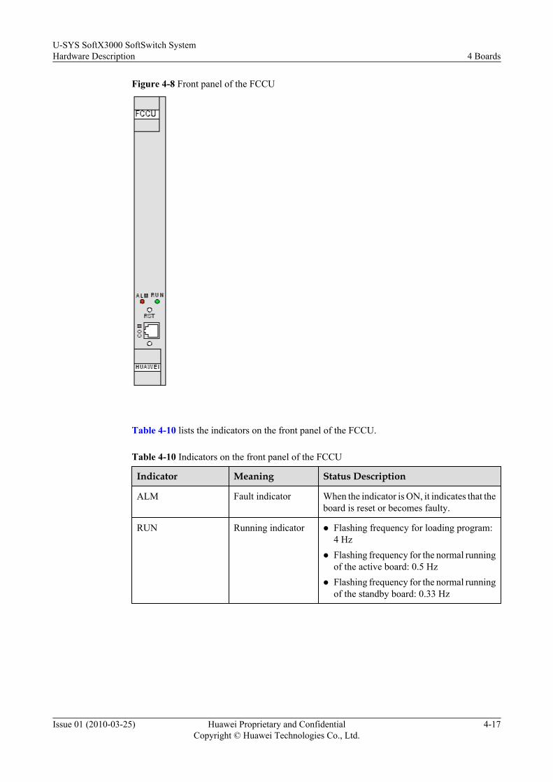
Figure 4-8 Front panel of the FCCU
Table 4-10 lists the indicators on the front panel of the FCCU.
Table 4-10 Indicators on the front panel of the FCCU
Indicator Meaning Status Description
ALM Fault indicator When the indicator is ON, it indicates that theboard is reset or becomes faulty.
RUN Running indicator l Flashing frequency for loading program:4 Hz
l Flashing frequency for the normal runningof the active board: 0.5 Hz
l Flashing frequency for the normal runningof the standby board: 0.33 Hz
U-SYS SoftX3000 SoftSwitch SystemHardware Description 4 Boards
Issue 01 (2010-03-25) Huawei Proprietary and ConfidentialCopyright © Huawei Technologies Co., Ltd.
4-17

Indicator Meaning Status Description
OFFLINE Plug-in indicator l When the board is plugged into a subrack,if the indicator is lit in blue, it indicatesthat the board has contacted the backplaneand the ejector lever on the front panel canbe pressed down to insert the board fullyinto the backplane.
l When pulling the board out, pull theejector lever on the front panel. When theindicator is lit in blue, you can pull theboard out.
l When the indicator is OFF, the board doescompletely contact the backplane.
DIP Switches and JumpersOne reset switch (RST) is used to reset the board.
NOTE
During routine maintenance, run RST BRD at the local maintenance terminal to reset a specified board.Do not use this RST switch to manually reset a board.
Technical SpecificationsTable 4-11 lists the technical specifications of the FCCU.
Table 4-11 Technical specifications of the FCCU
Category Parameter Specifications Remarks
Function Call processingcapability
SIP and H.323terminals: 500 kBHCA/pair
SIP: SessionInitiation Protocol;MGCP: MediaGateway ControlProtocol; BHCA:busy hour callattempt
MGCP and H.248terminals: 300 kBHCA/pair
Maximum numberof trunks
9,000/pair POTS: plain oldtelephone service
4 BoardsU-SYS SoftX3000 SoftSwitch System
Hardware Description
4-18 Huawei Proprietary and ConfidentialCopyright © Huawei Technologies Co., Ltd.
Issue 01 (2010-03-25)
Category Parameter Specifications Remarks
Maximum numberof subscribers
750B boards:POTS subscribers:50,000/pairV5 subscribers: 50,000/pairSIP subscribers: 50,000/pairH.323 subscribers:25,000/pair750C boards:POTS subscribers:65,000/pairV5 subscribers: 65,000/pairSIP subscribers: 65,000/pairH.323 subscribers:25,000/pair
Maximum numberof IP supermarkets
90/pair -
Interface RS232 serial port 1 Used forcommissioning;providing RJ45sockets on the panel;provided with hot-swappableprotection.
Powerconsumption
- 11 W -
4.2.4 CDBIThis section describes the CDBI.
FunctionsThe CDBIs are front boards in basic subrack 0 and basic subrack 1. As the database of theequipment, the CDBI stores all data for call location, gateway resources management andoutgoing trunk circuit selection.
The alarms generated by the CDBI are reported to the SMUI through the Ethernet bus.
The CDBI can be installed in any front slot except slot 6, 8, 16, 17, 18, 19, or 20 in the basicsubrack. The CDBIs work in the 1+1 backup mode. In the system, a maximum of two pairs ofCDBIs can be configured.
U-SYS SoftX3000 SoftSwitch SystemHardware Description 4 Boards
Issue 01 (2010-03-25) Huawei Proprietary and ConfidentialCopyright © Huawei Technologies Co., Ltd.
4-19

IndicatorsFigure 4-9 shows the front panel of the CDBI.
Figure 4-9 Front panel of the CDBI
Table 4-12 lists the indicators on the front panel of the CDBI.
Table 4-12 Indicators on the front panel of the CDBI
Indicator Meaning Status Description
ALM Fault indicator When the indicator is ON, it indicates that the board isreset or becomes faulty.
RUN Runningindicator
l Flashing frequency for loading program: 4 Hz
l Flashing frequency for the normal running of the activeboard: 0.5 Hz
l Flashing frequency for the normal running of thestandby board: 0.33 Hz
4 BoardsU-SYS SoftX3000 SoftSwitch System
Hardware Description
4-20 Huawei Proprietary and ConfidentialCopyright © Huawei Technologies Co., Ltd.
Issue 01 (2010-03-25)
Indicator Meaning Status Description
OFFLINE Plug-inindicator
l When the board is plugged into a subrack, if theindicator is lit in blue, it indicates that the board hascontacted the backplane and the ejector lever on thefront panel can be pressed down to insert the board fullyinto the backplane.
l When pulling the board out, pull the ejector lever onthe front panel. When the indicator is lit in blue, youcan pull the board out.
l When the indicator is OFF, the board does completelycontact the backplane.
DIP Switches and JumpersOne reset switch (RST) is used to reset the board.
Technical SpecificationsTable 4-13 lists the technical specifications of the CDBI.
Table 4-13 Technical specifications of the CDBI
Category Parameter Specifications Remarks
Function Subscriber locating 9000 times per second -
Gateway resourcemanagement
5500 times per second -
Outgoing trunk circuitselection of local office
6300 times per second -
Tandem call circuitselection
4300 times per second -
Interface RS232 serial port 1 -
Powerconsumption
- 11 W -
4.2.5 IFMIThis section describes the IFMI.
FunctionsThe IFMI receives and transmits IP packets. It processes media access control (MAC) layermessages and distributes IP messages.
The alarms generated by the IFMI are reported to the SMUI through the shared resource bus.
U-SYS SoftX3000 SoftSwitch SystemHardware Description 4 Boards
Issue 01 (2010-03-25) Huawei Proprietary and ConfidentialCopyright © Huawei Technologies Co., Ltd.
4-21
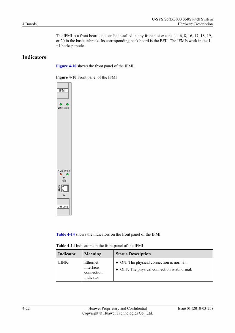
The IFMI is a front board and can be installed in any front slot except slot 6, 8, 16, 17, 18, 19,or 20 in the basic subrack. Its corresponding back board is the BFII. The IFMIs work in the 1+1 backup mode.
IndicatorsFigure 4-10 shows the front panel of the IFMI.
Figure 4-10 Front panel of the IFMI
Table 4-14 shows the indicators on the front panel of the IFMI.
Table 4-14 Indicators on the front panel of the IFMI
Indicator Meaning Status Description
LINK Ethernetinterfaceconnectionindicator
l ON: The physical connection is normal.
l OFF: The physical connection is abnormal.
4 BoardsU-SYS SoftX3000 SoftSwitch System
Hardware Description
4-22 Huawei Proprietary and ConfidentialCopyright © Huawei Technologies Co., Ltd.
Issue 01 (2010-03-25)
Indicator Meaning Status Description
ACT Ethernetinterface trafficindicator
When the indicator is flashing, it indicates that data isbeing received or transmitted. The flashing frequencyindicates the size of the data traffic.l Flashing fast: The data traffic is heavy.
l Flashing slowly: The data traffic is light.
ALM Fault indicator When the indicator is ON, it indicates that the board is resetor becomes faulty.
RUN Runningindicator
l Flashing frequency for loading program: 4 Hz
l Flashing frequency for the normal running of the activeboard: 0.5 Hz
l Flashing frequency for the normal running of thestandby board: 0.33 Hz
OFFLINE Plug-inindicator
l When the board is plugged into a subrack, if theindicator is lit in blue, it indicates that the board hascontacted the backplane and the ejector lever on thefront panel can be pressed down to insert the board fullyinto the backplane.
l When pulling the board out, pull the ejector lever on thefront panel. When the indicator is lit in blue, you canpull the board out.
DIP Switches and Jumpers
One reset switch (RST) is used to reset the board.
Technical Specifications
Table 4-15 lists the technical specifications of the IFMI.
Table 4-15 Technical specifications of the IFMI
Category Parameter Specifications Remarks
Function IP packetforwardingcapability per board
20,000 packets per secondboth uplink and downlink
A packet is 100bytes long.
Interface RS232 serial port 1 Used forcommissioning;providing RJ45sockets on thepanel and hot-swappableprotection
U-SYS SoftX3000 SoftSwitch SystemHardware Description 4 Boards
Issue 01 (2010-03-25) Huawei Proprietary and ConfidentialCopyright © Huawei Technologies Co., Ltd.
4-23
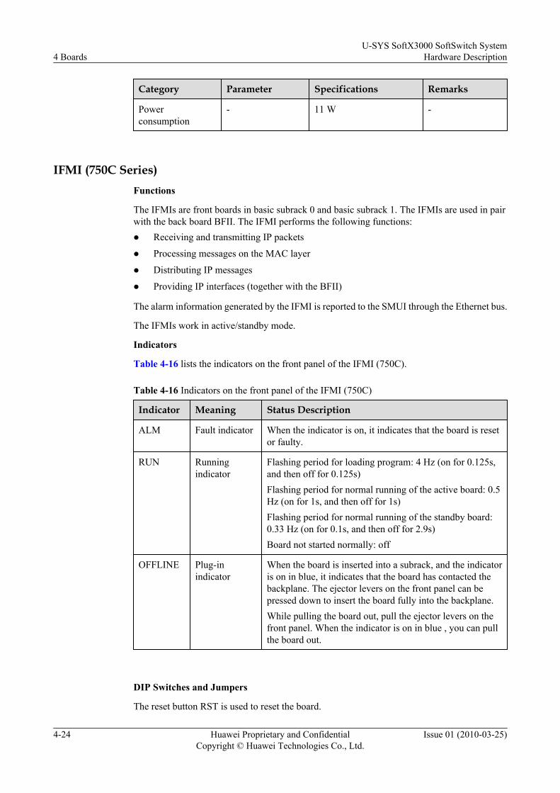
Category Parameter Specifications Remarks
Powerconsumption
- 11 W -
IFMI (750C Series)Functions
The IFMIs are front boards in basic subrack 0 and basic subrack 1. The IFMIs are used in pairwith the back board BFII. The IFMI performs the following functions:l Receiving and transmitting IP packets
l Processing messages on the MAC layer
l Distributing IP messages
l Providing IP interfaces (together with the BFII)
The alarm information generated by the IFMI is reported to the SMUI through the Ethernet bus.
The IFMIs work in active/standby mode.
Indicators
Table 4-16 lists the indicators on the front panel of the IFMI (750C).
Table 4-16 Indicators on the front panel of the IFMI (750C)
Indicator Meaning Status Description
ALM Fault indicator When the indicator is on, it indicates that the board is resetor faulty.
RUN Runningindicator
Flashing period for loading program: 4 Hz (on for 0.125s,and then off for 0.125s)Flashing period for normal running of the active board: 0.5Hz (on for 1s, and then off for 1s)Flashing period for normal running of the standby board:0.33 Hz (on for 0.1s, and then off for 2.9s)Board not started normally: off
OFFLINE Plug-inindicator
When the board is inserted into a subrack, and the indicatoris on in blue, it indicates that the board has contacted thebackplane. The ejector levers on the front panel can bepressed down to insert the board fully into the backplane.While pulling the board out, pull the ejector levers on thefront panel. When the indicator is on in blue , you can pullthe board out.
DIP Switches and Jumpers
The reset button RST is used to reset the board.
4 BoardsU-SYS SoftX3000 SoftSwitch System
Hardware Description
4-24 Huawei Proprietary and ConfidentialCopyright © Huawei Technologies Co., Ltd.
Issue 01 (2010-03-25)

Technical Specifications
Category Parameter Specification Remarks
Function IP packetforwardingcapability perboard
20,000 packetsper second, uplinkand downlink
A packet is 100 bytes long.
Interface RS232 serial port 1 Used for commissioning;providing RJ45 sockets on thepanel and hot-swappableprotection.
Powerconsumption
- 14 W None.
Heatdissipation
- 30 J None.
Differences Between IFMI of 750C Series and IFMI of 750B SeriesFigure 4-11 shows the IFMIs of the 750C series and the 750B series.
U-SYS SoftX3000 SoftSwitch SystemHardware Description 4 Boards
Issue 01 (2010-03-25) Huawei Proprietary and ConfidentialCopyright © Huawei Technologies Co., Ltd.
4-25
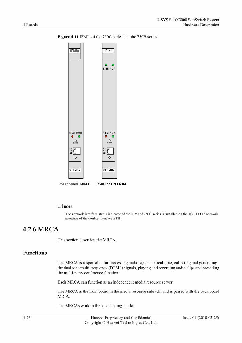
Figure 4-11 IFMIs of the 750C series and the 750B series
NOTE
The network interface status indicator of the IFMI of 750C series is installed on the 10/100BT2 networkinterface of the double-interface BFII.
4.2.6 MRCAThis section describes the MRCA.
Functions
The MRCA is responsible for processing audio signals in real time, collecting and generatingthe dual tone multi frequency (DTMF) signals, playing and recording audio clips and providingthe multi-party conference function.
Each MRCA can function as an independent media resource server.
The MRCA is the front board in the media resource subrack, and is paired with the back boardMRIA.
The MRCAs work in the load sharing mode.
4 BoardsU-SYS SoftX3000 SoftSwitch System
Hardware Description
4-26 Huawei Proprietary and ConfidentialCopyright © Huawei Technologies Co., Ltd.
Issue 01 (2010-03-25)
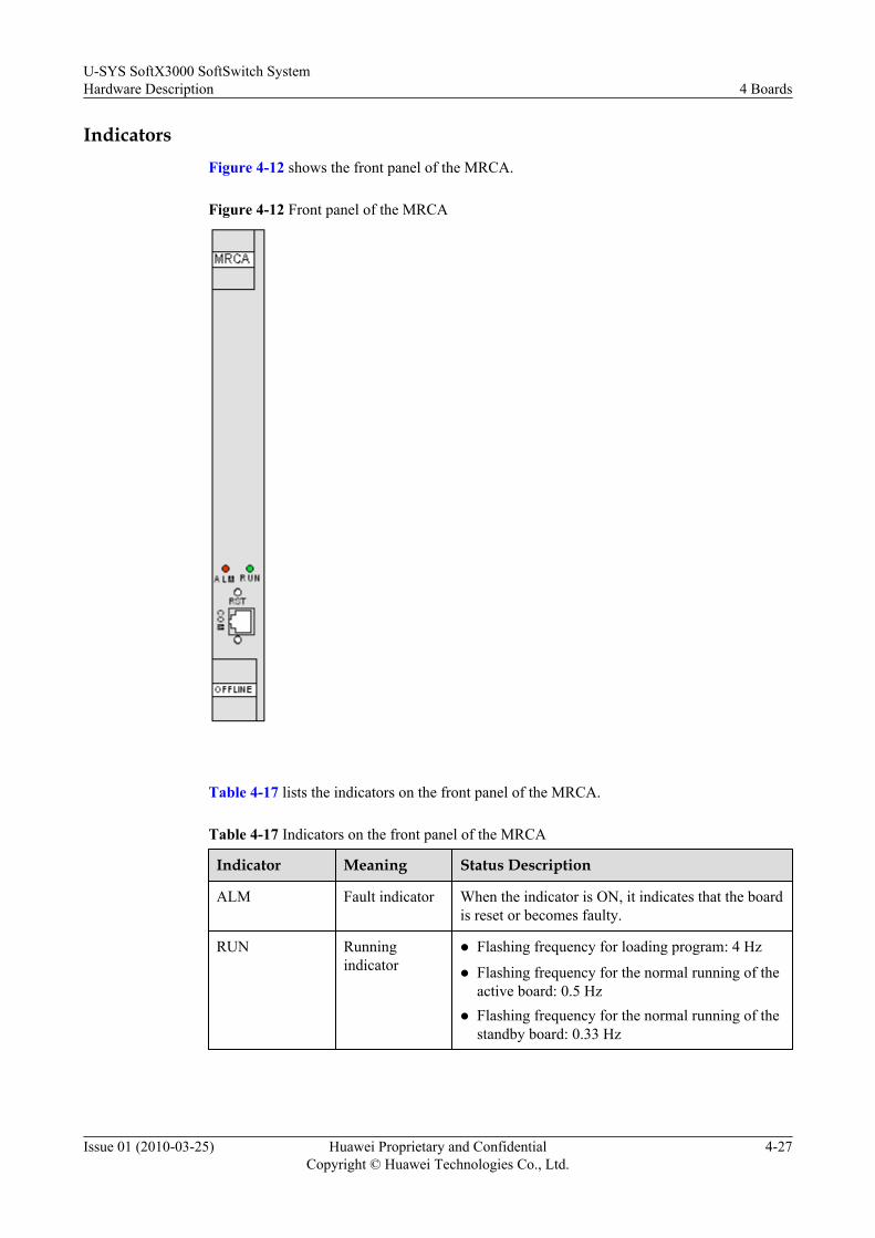
IndicatorsFigure 4-12 shows the front panel of the MRCA.
Figure 4-12 Front panel of the MRCA
Table 4-17 lists the indicators on the front panel of the MRCA.
Table 4-17 Indicators on the front panel of the MRCA
Indicator Meaning Status Description
ALM Fault indicator When the indicator is ON, it indicates that the boardis reset or becomes faulty.
RUN Runningindicator
l Flashing frequency for loading program: 4 Hz
l Flashing frequency for the normal running of theactive board: 0.5 Hz
l Flashing frequency for the normal running of thestandby board: 0.33 Hz
U-SYS SoftX3000 SoftSwitch SystemHardware Description 4 Boards
Issue 01 (2010-03-25) Huawei Proprietary and ConfidentialCopyright © Huawei Technologies Co., Ltd.
4-27
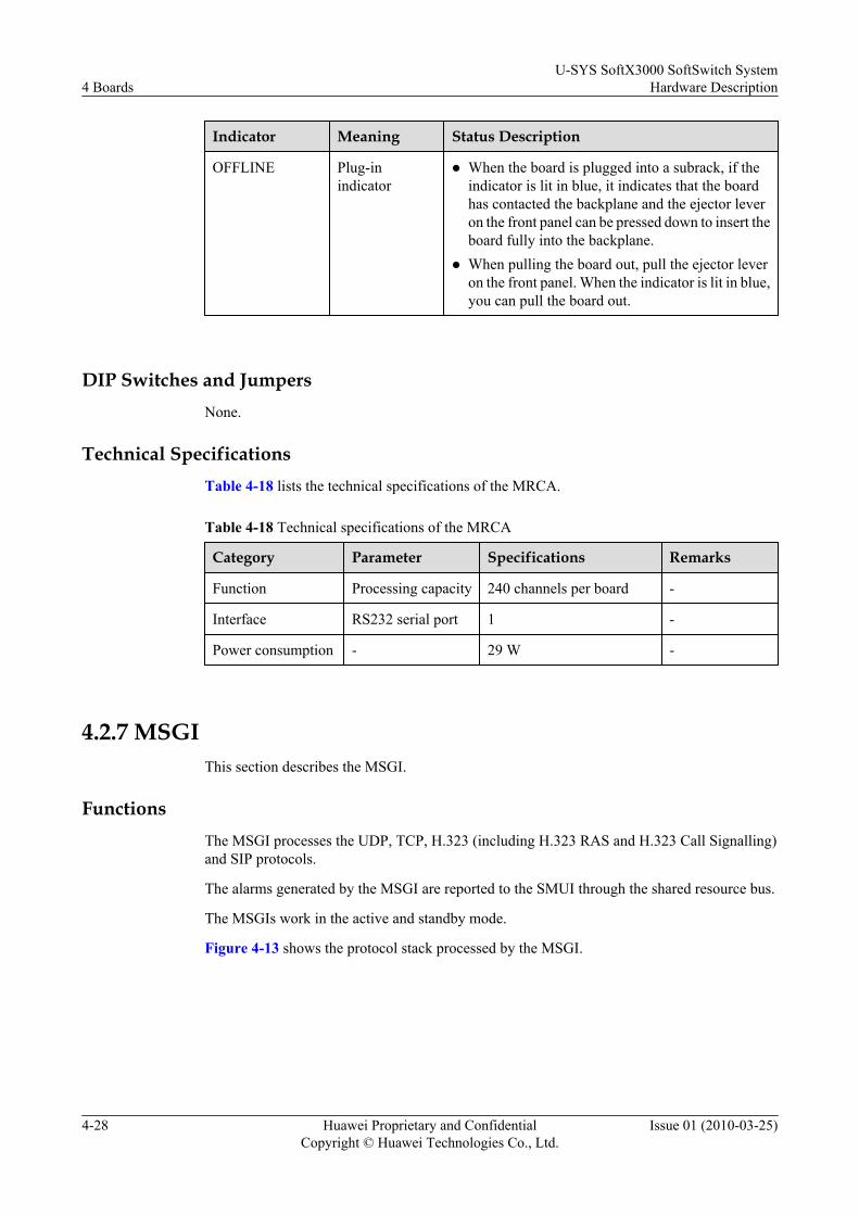
Indicator Meaning Status Description
OFFLINE Plug-inindicator
l When the board is plugged into a subrack, if theindicator is lit in blue, it indicates that the boardhas contacted the backplane and the ejector leveron the front panel can be pressed down to insert theboard fully into the backplane.
l When pulling the board out, pull the ejector leveron the front panel. When the indicator is lit in blue,you can pull the board out.
DIP Switches and JumpersNone.
Technical SpecificationsTable 4-18 lists the technical specifications of the MRCA.
Table 4-18 Technical specifications of the MRCA
Category Parameter Specifications Remarks
Function Processing capacity 240 channels per board -
Interface RS232 serial port 1 -
Power consumption - 29 W -
4.2.7 MSGIThis section describes the MSGI.
FunctionsThe MSGI processes the UDP, TCP, H.323 (including H.323 RAS and H.323 Call Signalling)and SIP protocols.
The alarms generated by the MSGI are reported to the SMUI through the shared resource bus.
The MSGIs work in the active and standby mode.
Figure 4-13 shows the protocol stack processed by the MSGI.
4 BoardsU-SYS SoftX3000 SoftSwitch System
Hardware Description
4-28 Huawei Proprietary and ConfidentialCopyright © Huawei Technologies Co., Ltd.
Issue 01 (2010-03-25)

Figure 4-13 Protocol stack processed by the MSGI
IndicatorsFigure 4-14 shows the front panel of the MSGI.
U-SYS SoftX3000 SoftSwitch SystemHardware Description 4 Boards
Issue 01 (2010-03-25) Huawei Proprietary and ConfidentialCopyright © Huawei Technologies Co., Ltd.
4-29
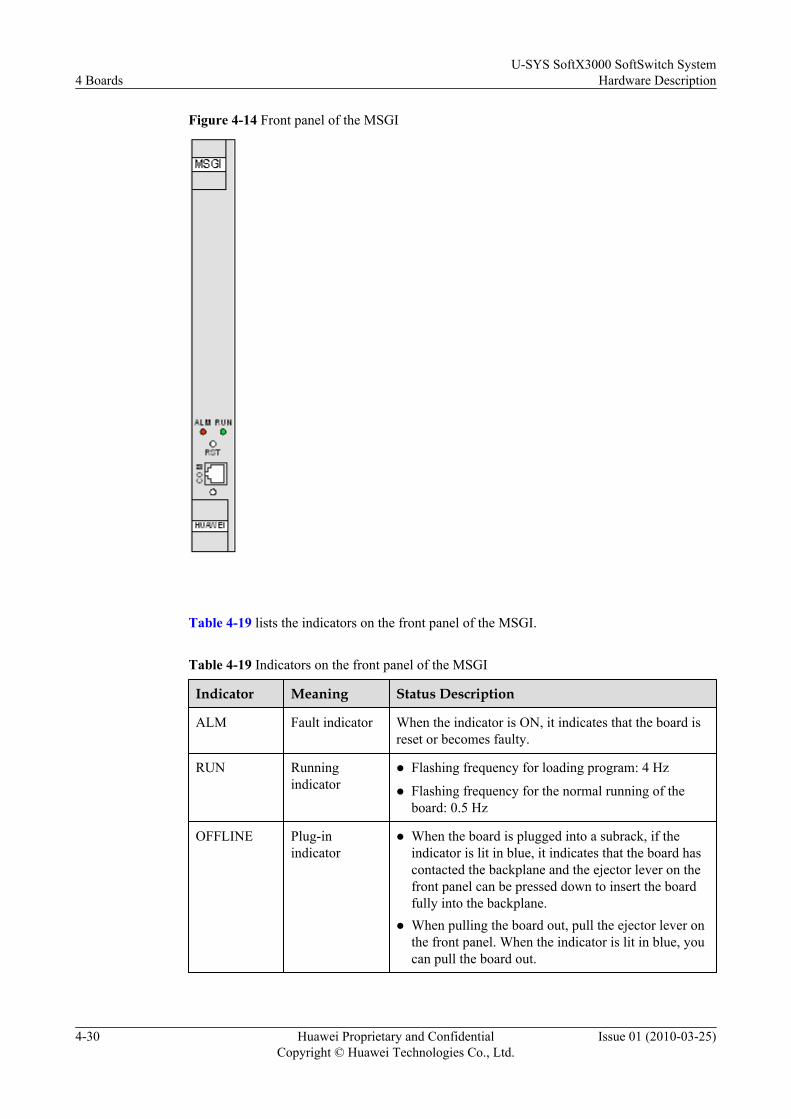
Figure 4-14 Front panel of the MSGI
Table 4-19 lists the indicators on the front panel of the MSGI.
Table 4-19 Indicators on the front panel of the MSGI
Indicator Meaning Status Description
ALM Fault indicator When the indicator is ON, it indicates that the board isreset or becomes faulty.
RUN Runningindicator
l Flashing frequency for loading program: 4 Hz
l Flashing frequency for the normal running of theboard: 0.5 Hz
OFFLINE Plug-inindicator
l When the board is plugged into a subrack, if theindicator is lit in blue, it indicates that the board hascontacted the backplane and the ejector lever on thefront panel can be pressed down to insert the boardfully into the backplane.
l When pulling the board out, pull the ejector lever onthe front panel. When the indicator is lit in blue, youcan pull the board out.
4 BoardsU-SYS SoftX3000 SoftSwitch System
Hardware Description
4-30 Huawei Proprietary and ConfidentialCopyright © Huawei Technologies Co., Ltd.
Issue 01 (2010-03-25)
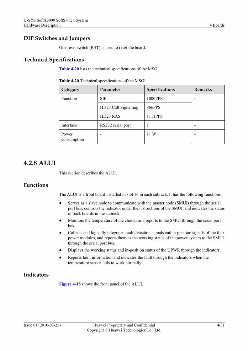
DIP Switches and JumpersOne reset switch (RST) is used to reset the board.
Technical SpecificationsTable 4-20 lists the technical specifications of the MSGI.
Table 4-20 Technical specifications of the MSGI
Category Parameter Specifications Remarks
Function SIP 1000PPS -
H.323 Call Signalling 866PPS
H.323 RAS 1111PPS
Interface RS232 serial port 1 -
Powerconsumption
- 11 W -
4.2.8 ALUIThis section describes the ALUI.
FunctionsThe ALUI is a front board installed in slot 16 in each subrack. It has the following functions:
l Serves as a slave node to communicate with the master node (SMUI) through the serialport bus, controls the indicator under the instructions of the SMUI, and indicates the statusof back boards in the subrack.
l Monitors the temperature of the chassis and reports to the SMUI through the serial portbus.
l Collects and logically integrates fault detection signals and in-position signals of the fourpower modules, and reports them as the working status of the power system to the SMUIthrough the serial port bus.
l Displays the working status and in-position status of the UPWR through the indicators.
l Reports fault information and indicates the fault through the indicators when thetemperature sensor fails to work normally.
IndicatorsFigure 4-15 shows the front panel of the ALUI.
U-SYS SoftX3000 SoftSwitch SystemHardware Description 4 Boards
Issue 01 (2010-03-25) Huawei Proprietary and ConfidentialCopyright © Huawei Technologies Co., Ltd.
4-31

Figure 4-15 Front panel of the ALUI
The ALUI consists of the CPU main processing module, logic control module and the powermodule. Table 4-21 lists the indicators on the front panel of ALUI.
Table 4-21 Indicators on the front panel of the ALUI
Indicator Meaning Status Description
Red Green Off
RUN Board runningindicator
Thecommunicationwith the SMUI isabnormal.
The board isrunningnormally.
The board isfaulty.
00 Back board 0status indicator
The board isfaulty.
The board isrunningnormally.
The board is outof position.
01 Back board 1status indicator
The board isfaulty.
The board isrunningnormally.
The board is outof position.
4 BoardsU-SYS SoftX3000 SoftSwitch System
Hardware Description
4-32 Huawei Proprietary and ConfidentialCopyright © Huawei Technologies Co., Ltd.
Issue 01 (2010-03-25)
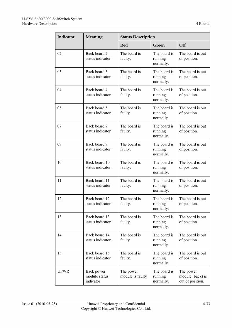
Indicator Meaning Status Description
Red Green Off
02 Back board 2status indicator
The board isfaulty.
The board isrunningnormally.
The board is outof position.
03 Back board 3status indicator
The board isfaulty.
The board isrunningnormally.
The board is outof position.
04 Back board 4status indicator
The board isfaulty.
The board isrunningnormally.
The board is outof position.
05 Back board 5status indicator
The board isfaulty.
The board isrunningnormally.
The board is outof position.
07 Back board 7status indicator
The board isfaulty.
The board isrunningnormally.
The board is outof position.
09 Back board 9status indicator
The board isfaulty.
The board isrunningnormally.
The board is outof position.
10 Back board 10status indicator
The board isfaulty.
The board isrunningnormally.
The board is outof position.
11 Back board 11status indicator
The board isfaulty.
The board isrunningnormally.
The board is outof position.
12 Back board 12status indicator
The board isfaulty.
The board isrunningnormally.
The board is outof position.
13 Back board 13status indicator
The board isfaulty.
The board isrunningnormally.
The board is outof position.
14 Back board 14status indicator
The board isfaulty.
The board isrunningnormally.
The board is outof position.
15 Back board 15status indicator
The board isfaulty.
The board isrunningnormally.
The board is outof position.
UPWR Back powermodule statusindicator
The powermodule is faulty
The board isrunningnormally.
The powermodule (back) isout of position.
U-SYS SoftX3000 SoftSwitch SystemHardware Description 4 Boards
Issue 01 (2010-03-25) Huawei Proprietary and ConfidentialCopyright © Huawei Technologies Co., Ltd.
4-33

Indicator Meaning Status Description
Red Green Off
UPWR Back powermodule statusindicator
The powermodule is faulty
The board isrunningnormally.
The powermodule (back) isout of position.
DIP Switches and Jumpers
One reset switch (RST) is used to reset the board.
Technical Specifications
Table 4-22 lists the technical specifications of the ALUI.
Table 4-22 Technical specifications of the ALUI
Category Parameter Specifications Remarks
Interface(COM)
RS232serial port
1 When J5 and J7 are configured with short-connecting modules, the front-out serialport is used as an RS422 serial port toconnect with the SMUI.When J6 and J7 are configured with short-connecting modules, the front-out serialport is used as a standard RS232 serialport that is led out from the front panel.
Powerconsumption
- 2 W -
4.2.9 UPWRThis section describes the UPWR.
FunctionsNOTE
By default, a subrack houses three UPWRs, which work in 2+1 backup mode. Two UPWRs are front boardsinstalled in slots 17 and 18, and slots 19 and 20. The other UPWR is a back board installed in slots 19 and 20.In this case, back slots 17 and 18 are covered with filler panels.
The UPWR can be a front board or a back board. It provides power supply to all the other boardsin the subrack. Each UPWR occupies two slots—slots 17 and 18 in the front or 19 and 20 at theback. It has the following functions:
l Providing +3.3 V, +5 V, +12 V, - 12 V DC power output.
l Supplying power for each board in the subrack.
4 BoardsU-SYS SoftX3000 SoftSwitch System
Hardware Description
4-34 Huawei Proprietary and ConfidentialCopyright © Huawei Technologies Co., Ltd.
Issue 01 (2010-03-25)
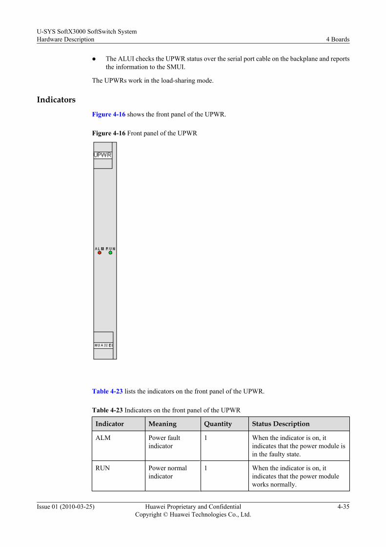
l The ALUI checks the UPWR status over the serial port cable on the backplane and reportsthe information to the SMUI.
The UPWRs work in the load-sharing mode.
IndicatorsFigure 4-16 shows the front panel of the UPWR.
Figure 4-16 Front panel of the UPWR
Table 4-23 lists the indicators on the front panel of the UPWR.
Table 4-23 Indicators on the front panel of the UPWR
Indicator Meaning Quantity Status Description
ALM Power faultindicator
1 When the indicator is on, itindicates that the power module isin the faulty state.
RUN Power normalindicator
1 When the indicator is on, itindicates that the power moduleworks normally.
U-SYS SoftX3000 SoftSwitch SystemHardware Description 4 Boards
Issue 01 (2010-03-25) Huawei Proprietary and ConfidentialCopyright © Huawei Technologies Co., Ltd.
4-35

DIP Switches and JumpersNone.
Technical SpecificationsTable 4-24 lists the technical specifications of the UPWR.
Table 4-24 Technical specifications of the UPWR
Category Parameter Specifications Remarks
Voltage Input voltage - 36 V to - 76 V -
Output voltage +3.3 V, +5 V, +12 V,and - 12 V
The correspondingoutput currents are50 A, 40 A, 8 A, and4 A respectively.
Interface Indication interface forpower output failure andin-position power unit
1 -
Powerconsumption
- 20 W -
4.2.10 UACUThis section describes the functions of the UACU board and provides related information aboutthe board.
FunctionsThe universal access control unit (UACU) is responsible for call control and processing of theH.248 and MGCP protocols.
Figure 4-17 shows the protocol stack processed by the UACU.
4 BoardsU-SYS SoftX3000 SoftSwitch System
Hardware Description
4-36 Huawei Proprietary and ConfidentialCopyright © Huawei Technologies Co., Ltd.
Issue 01 (2010-03-25)
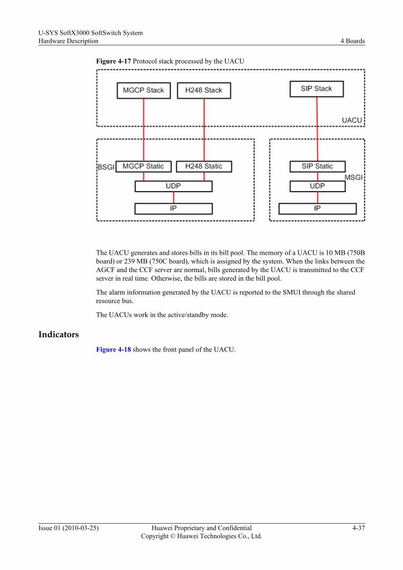
Figure 4-17 Protocol stack processed by the UACU
The UACU generates and stores bills in its bill pool. The memory of a UACU is 10 MB (750Bboard) or 239 MB (750C board), which is assigned by the system. When the links between theAGCF and the CCF server are normal, bills generated by the UACU is transmitted to the CCFserver in real time. Otherwise, the bills are stored in the bill pool.
The alarm information generated by the UACU is reported to the SMUI through the sharedresource bus.
The UACUs work in the active/standby mode.
IndicatorsFigure 4-18 shows the front panel of the UACU.
U-SYS SoftX3000 SoftSwitch SystemHardware Description 4 Boards
Issue 01 (2010-03-25) Huawei Proprietary and ConfidentialCopyright © Huawei Technologies Co., Ltd.
4-37

Figure 4-18 Front panel of the UACU
Table 4-25 lists the indicators on the front panel of the UACU.
Table 4-25 Indicators on the front panel of the UACU
Indicator Meaning Status Description
ALM Fault indicator When the indicator is ON, it indicates that the board is resetor becomes faulty.
RUN Runningindicator
l Flashing frequency for loading program: 4 Hz
l Flashing frequency for the normal running of the activeboard: 0.5 Hz
l Flashing frequency for the normal running of thestandby board: 0.33 Hz
4 BoardsU-SYS SoftX3000 SoftSwitch System
Hardware Description
4-38 Huawei Proprietary and ConfidentialCopyright © Huawei Technologies Co., Ltd.
Issue 01 (2010-03-25)

Indicator Meaning Status Description
OFFLINE Plug-inindicator
l When the board is plugged into a subrack, if theindicator is lit in blue, it indicates that the board hascontacted the backplane and the ejector lever on thefront panel can be pressed down to insert the board fullyinto the backplane.
l When pulling the board out, pull the ejector lever on thefront panel. When the indicator is lit in blue, you canpull the board out.
l When the indicator is OFF, it indicates that the boarddoes not completely contact the backplane.
DIP Switches and JumpersOne reset switch (RST) is used to reset the board.
NOTE
During routine maintenance, run RST BRD on the LMT to reset a specified board, so that the BAM recordsthe reset cause of the board. Do not use this RST switch to manually reset a board.
Technical SpecificationsTable 4-26 lists the technical specifications of the UACU.
Table 4-26 Technical specifications of the UACU
Category Parameter Specifications Remarks
Function Calling processingcapability
750B:38caps/pair750C:65caps/pair
Caps stands for Call Attemptper Second.
Maximum numberof subscribers
750B:POTS: 50000/pair750C:POTS: 65000/pair
POTS stands for the Plan OldTelephone Service.
Interface RS232 serial port One Used for commissioning;providing RJ45 sockets on thepanel; provided withhotswappable protection.
Powerconsumption
- 16 W -
U-SYS SoftX3000 SoftSwitch SystemHardware Description 4 Boards
Issue 01 (2010-03-25) Huawei Proprietary and ConfidentialCopyright © Huawei Technologies Co., Ltd.
4-39
4.3 Back BoardsThis section describes the functions, indicators, DIP switches and jumpers, and technicalspecifications of the back boards of the SoftX3000.
4.3.1 SIUIThis section describes the SIUI.
4.3.2 HSCIThis section describes the HSCI.
4.3.3 MRIAThis section describes the MRIA.
4.3.4 BFIIThis section describes the BFII.
4.3.1 SIUIThis section describes the SIUI.
FunctionsThe SIUI is the back interface board of the SMUI. It is installed in back slot 6 and 8 in eachsubrack. It has the following functions:
l Provides Ethernet interfaces to the SMUI. Each SIUI is configured to the correspondingSMUI.
l Implements level conversion for asynchronous serial port signals from the SMUI, andprovides two physical interfaces to this synchronous serial port.
l Identifies subrack ID through the setting of the DIP switches.
The SIUI work in the 1+1 backup mode.
IndicatorsFigure 4-19 shows the front panel of the SIUI.
4 BoardsU-SYS SoftX3000 SoftSwitch System
Hardware Description
4-40 Huawei Proprietary and ConfidentialCopyright © Huawei Technologies Co., Ltd.
Issue 01 (2010-03-25)
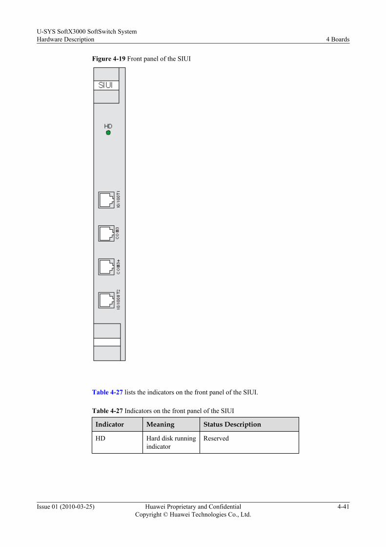
Figure 4-19 Front panel of the SIUI
Table 4-27 lists the indicators on the front panel of the SIUI.
Table 4-27 Indicators on the front panel of the SIUI
Indicator Meaning Status Description
HD Hard disk runningindicator
Reserved
U-SYS SoftX3000 SoftSwitch SystemHardware Description 4 Boards
Issue 01 (2010-03-25) Huawei Proprietary and ConfidentialCopyright © Huawei Technologies Co., Ltd.
4-41

DIP Switches and JumpersThe SIUI provides an 8-bit DIP switch (S3) for setting the subrack number of the subrack. Table4-28 lists the settings of the DIP switch.
Table 4-28 Subrack number and DIP switch setting
Subrack No. Switch Bit
8 7 6 5 4 3 2 1
0 ON ON ON ON ON ON ON ON
1 ON ON ON ON ON ON ON OFF
2 ON ON ON ON ON ON OFF ON
3 ON ON ON ON ON ON OFF OFF
4 ON ON ON ON ON OFF ON ON
5 ON ON ON ON ON OFF ON OFF
6 ON ON ON ON ON OFF OFF ON
7 ON ON ON ON ON OFF OFF OFF
8 ON ON ON ON OFF ON ON ON
9 ON ON ON ON OFF ON ON OFF
Technical SpecificationsTable 4-29 lists the technical specifications of the SIUI.
Table 4-29 Technical specifications of the SIUI
Category Parameter Specifications Remarks
Interface 10/100 Mbit/sEthernetinterface
2 Connected to the HSCIs inslots 7 and 9.
RS485interface
2 Implements RS485 levelconversion for theasynchronous serial portsignals from the systemboards and provides twophysical interfaces for theasynchronous serial portto connect with the powerdistribution monitoringsystem.
4 BoardsU-SYS SoftX3000 SoftSwitch System
Hardware Description
4-42 Huawei Proprietary and ConfidentialCopyright © Huawei Technologies Co., Ltd.
Issue 01 (2010-03-25)
Category Parameter Specifications Remarks
Powerconsumption
- - -
4.3.2 HSCIThis section describes the HSCI.
FunctionsThe HSCI is a back board. One pair of HSCIs is installed in the back slots 7 and 9 in each subrack.The HSCI is used to:
l Bridges the left and right Ethernet buses to ensure that the SMUIs in slots 6 and 8 canmanage the front boards (except ALUI and UPWR) of the subrack.
l Ensures the switching of Ethernet buses in the subrack.
l Conducts board hot swap control.
l Conducts board power-on control.
l Provides two pairs of heartbeat detection interfaces for the SMUI/HSCI.
l Provides a 10/100 Mbit/s compatible Ethernet connection between the active SMUI andthe standby SMUI.
l Provides six external FE ports.
The HSCIs work in 1+1 backup mode.
IndicatorsFigure 4-20 shows the front panel of the HSCI.
U-SYS SoftX3000 SoftSwitch SystemHardware Description 4 Boards
Issue 01 (2010-03-25) Huawei Proprietary and ConfidentialCopyright © Huawei Technologies Co., Ltd.
4-43
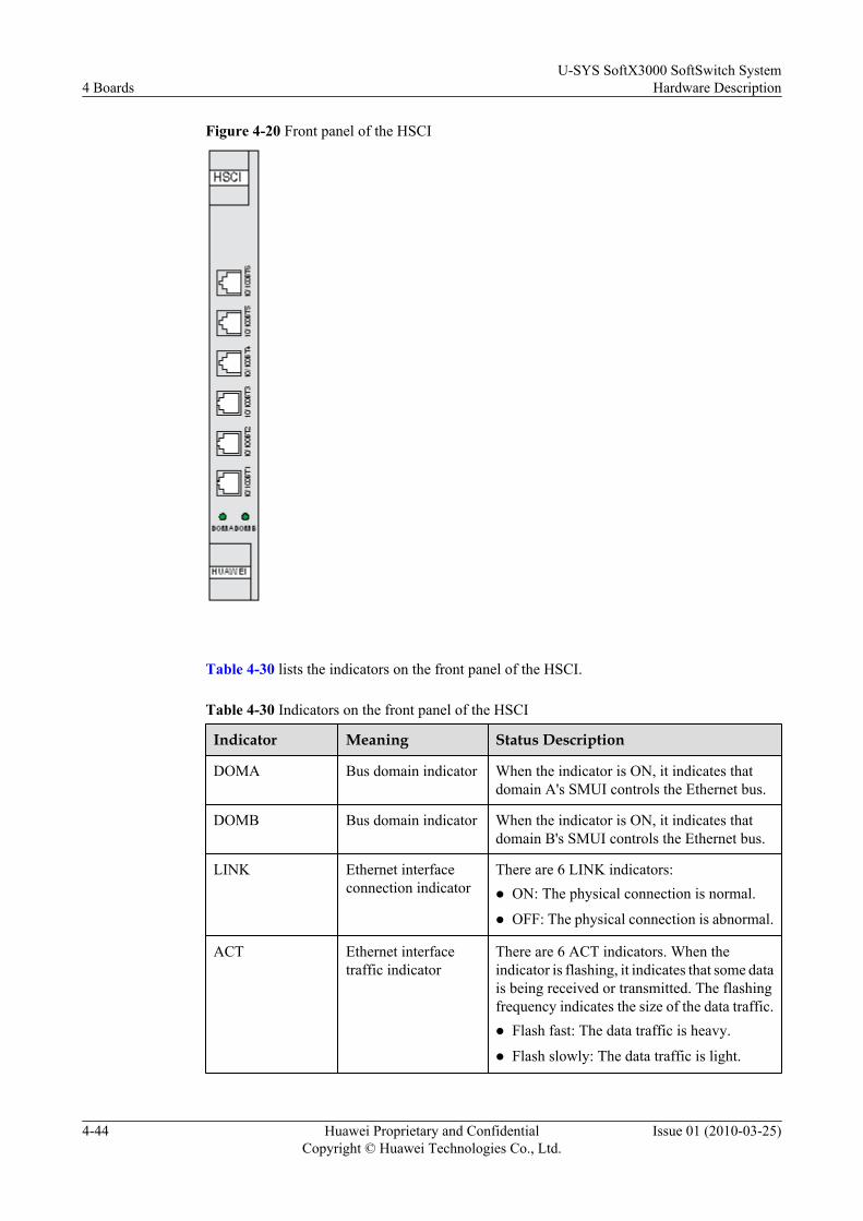
Figure 4-20 Front panel of the HSCI
Table 4-30 lists the indicators on the front panel of the HSCI.
Table 4-30 Indicators on the front panel of the HSCI
Indicator Meaning Status Description
DOMA Bus domain indicator When the indicator is ON, it indicates thatdomain A's SMUI controls the Ethernet bus.
DOMB Bus domain indicator When the indicator is ON, it indicates thatdomain B's SMUI controls the Ethernet bus.
LINK Ethernet interfaceconnection indicator
There are 6 LINK indicators:l ON: The physical connection is normal.
l OFF: The physical connection is abnormal.
ACT Ethernet interfacetraffic indicator
There are 6 ACT indicators. When theindicator is flashing, it indicates that some datais being received or transmitted. The flashingfrequency indicates the size of the data traffic.l Flash fast: The data traffic is heavy.
l Flash slowly: The data traffic is light.
4 BoardsU-SYS SoftX3000 SoftSwitch System
Hardware Description
4-44 Huawei Proprietary and ConfidentialCopyright © Huawei Technologies Co., Ltd.
Issue 01 (2010-03-25)
DIP Switches and JumpersNone.
Technical SpecificationsTable 4-31 lists the technical specifications of the HSCI.
Table 4-31 Technical specifications of the HSCI
Category Parameter Specifications Remarks
Interface 10/100 Mbit/sEthernet interface
6 Provided from the front panel
Powerconsumption
- 13 W -
4.3.3 MRIAThis section describes the MRIA.
FunctionsThe MRIA is the back board of the MRCA. It is used to provide 10/100 Mbit/s interface for theexternal media streams.
IndicatorsFigure 4-21 shows the front panel of the MRIA.
U-SYS SoftX3000 SoftSwitch SystemHardware Description 4 Boards
Issue 01 (2010-03-25) Huawei Proprietary and ConfidentialCopyright © Huawei Technologies Co., Ltd.
4-45

Figure 4-21 Front panel of the MRIA
NOTEThere are two groups of interfaces on the MRIA, and each group has three interfaces:
l The upper interface is the serial port for commissioning.
l The middle one is the 10/100 Mbit/s network interface for media stream transmission.
l The lower one is reserved for future use.
Technical SpecificationsTable 4-32 lists the technical specifications of the MRIA.
Table 4-32 Technical specifications of the MRIA
Category Parameter Specifications Remarks
Function 10/100-Mbit/s Ethernetinterface
2 Used to transfermedia streams.
Interface RS232 serial port 2 -
Powerconsumption
- 2 W -
4 BoardsU-SYS SoftX3000 SoftSwitch System
Hardware Description
4-46 Huawei Proprietary and ConfidentialCopyright © Huawei Technologies Co., Ltd.
Issue 01 (2010-03-25)
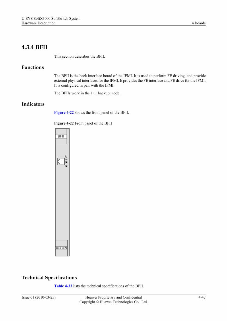
4.3.4 BFIIThis section describes the BFII.
FunctionsThe BFII is the back interface board of the IFMI. It is used to perform FE driving, and provideexternal physical interfaces for the IFMI. It provides the FE interface and FE drive for the IFMI.It is configured in pair with the IFMI.
The BFIIs work in the 1+1 backup mode.
IndicatorsFigure 4-22 shows the front panel of the BFII.
Figure 4-22 Front panel of the BFII
Technical SpecificationsTable 4-33 lists the technical specifications of the BFII.
U-SYS SoftX3000 SoftSwitch SystemHardware Description 4 Boards
Issue 01 (2010-03-25) Huawei Proprietary and ConfidentialCopyright © Huawei Technologies Co., Ltd.
4-47

Table 4-33 Technical specifications of the BFII
Category Parameter Specifications Remarks
Interface 10/100 Mbit/sEthernet interface
1 -
Powerconsumption
- - -
BFII (With Two Network Ports)Functions
The BFII (with two network ports) is the back board of the IFMI. It is used to perform FE drivingand provide external physical interfaces for the IFMI. It is configured in pair with the IFMI.
The BFIIs work in active/standby mode.
Indicators
Figure 4-23 shows the indicators on the BFII (with two network ports).
Figure 4-23 Indicators on the BFII (with two network ports)
4 BoardsU-SYS SoftX3000 SoftSwitch System
Hardware Description
4-48 Huawei Proprietary and ConfidentialCopyright © Huawei Technologies Co., Ltd.
Issue 01 (2010-03-25)
Switches and Jumpers
None.
Technical Specifications
Table 4-34 lists the technical specifications of the BFII.
Table 4-34 Technical specifications
Item ParameterSpecifications Remarks
Interface 10/100 Mbit/s Ethernetinterface
2 -
Powerconsumption
- - -
Heat dissipation - 4 J -
Differences Between Dual-Network-Port BFII and Single-Network-Port BFIIAppearance
The dual-network-port BFII has two network ports on the panel, whereas the single-network-port BFII has only one network port on the panel, as shown in Figure 4-24.
U-SYS SoftX3000 SoftSwitch SystemHardware Description 4 Boards
Issue 01 (2010-03-25) Huawei Proprietary and ConfidentialCopyright © Huawei Technologies Co., Ltd.
4-49

Figure 4-24 Differences between dual-network-port BFII and single-network-port BFII
NOTE
l There is no indicator on the BFIIc that indicates the 10/100BT1 status. 10/100BT1 is for the FEsubboard of the IFMI of the 750B series. When the indicator on the IFMI is on in green, the link isnormal.
l There are two indicators on the BFIIc that indicate the 10/100BT2 status. 10/100BT2 is for the IFMIcof the 750C series. When one indicator is on in green and the other is on in yellow, as shown in Figure4-24, the link is normal.
Network Ports of the BFII of the 750C Series and the 750B Series
Table 4-35 shows the network ports of the BFII of the 750C series and the 750B series.
4 BoardsU-SYS SoftX3000 SoftSwitch System
Hardware Description
4-50 Huawei Proprietary and ConfidentialCopyright © Huawei Technologies Co., Ltd.
Issue 01 (2010-03-25)

Table 4-35 Network ports of the BFII of the 750C series and the 750B series
Board Interface Quantity
Remarks
BFII (dualnetwork ports)
10/100Mbit/s Ethernetinterface
2 Either 10/100BT1 or 10/100BT2 canbe used. The configuration principleis as follows:l 10/100BT1 is for the FE subboard
of the IFMI of the 750B series.l 10/100BT2 is for the IFMI of the
750C series. (The IFMI of 750Cseries can be used without the FEsubboard.)
BFII (singlenetwork port)
10/100Mbit/s Ethernetinterface
1 10/100BT is for the FE subboard ofthe IFMI of the 750B series.
U-SYS SoftX3000 SoftSwitch SystemHardware Description 4 Boards
Issue 01 (2010-03-25) Huawei Proprietary and ConfidentialCopyright © Huawei Technologies Co., Ltd.
4-51


5 Servers
About This Chapter
This section describes the functions, appearance, and technical specifications of servers ofdifferent types.
5.1 BAM and iGWB (IBM X3650 Server)This section describes the BAM and iGWB (IBM X3650 server).
5.2 BAM and iGWB (DELL 2950 Server)This section describes the BAM and iGWB (DELL 2950 server).
5.3 BAM and iGWB (HP 380G5 Server)This section describes the BAM and iGWB (HP 380G5 server).
5.4 BAM and iGWB (HP ProLiant DL380 G6 Server)This section describes the BAM and iGWB (HP ProLiant DL380 G6 Server).
U-SYS SoftX3000 SoftSwitch SystemHardware Description 5 Servers
Issue 01 (2010-03-25) Huawei Proprietary and ConfidentialCopyright © Huawei Technologies Co., Ltd.
5-1

5.1 BAM and iGWB (IBM X3650 Server)This section describes the BAM and iGWB (IBM X3650 server).
Functions
The BAM is the server of the O&M system. It bridges the WSs and the SoftX3000. The BAMforwards the O&M commands from local and remote WSs to the SoftX3000, and sends theresponses from the SoftX3000 to the WSs. The BAM also stores and transfers the alarm andtraffic measurement data.
The iGWB is an intermediate billing device between the SoftX3000 and the billing center. Itreceives, pre-processes and stores bills at a speed of 1700 CDRs per second. In addition, theiGWB provides billing interfaces.
The iGWB server works in the active/standby mode.
The BAM and the iGWB are installed in fixed positions in the integrated configuration cabinet.Both adopt the IBM X3650 server.
Appearancel Front View of the BAM and the iGWB
Figure 5-1 shows the front view of the BAM and the iGWB. Table 5-1 lists the front panelcontrol switches and status indicators of the BAM and the iGWB.
Figure 5-1 Front view of the BAM and the iGWB
Table 5-1 Front panel control switches and status indicators of the iGWB and the BAM
Item
Name Description
A/I Rack releaseslide lock
Press the slide lock to disassemble a server from the rack.
B Operatorinformationpanel
The panel shows the information about controls andindicators.
5 ServersU-SYS SoftX3000 SoftSwitch System
Hardware Description
5-2 Huawei Proprietary and ConfidentialCopyright © Huawei Technologies Co., Ltd.
Issue 01 (2010-03-25)
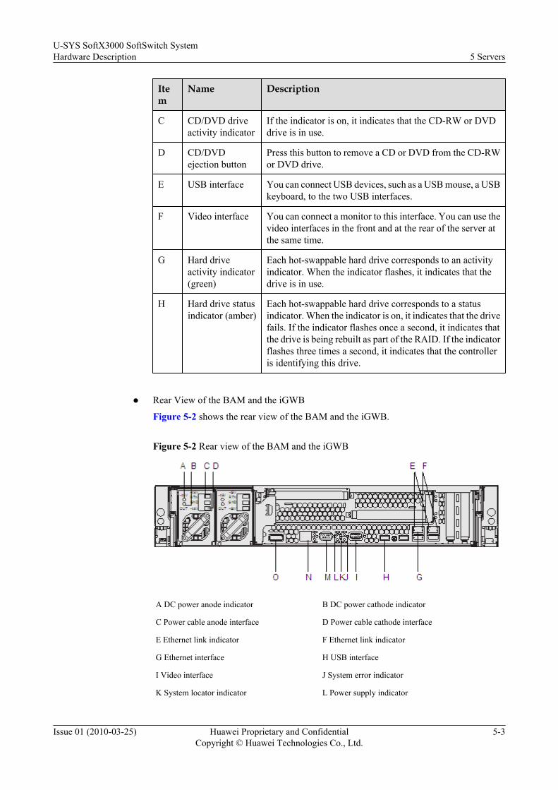
Item
Name Description
C CD/DVD driveactivity indicator
If the indicator is on, it indicates that the CD-RW or DVDdrive is in use.
D CD/DVDejection button
Press this button to remove a CD or DVD from the CD-RWor DVD drive.
E USB interface You can connect USB devices, such as a USB mouse, a USBkeyboard, to the two USB interfaces.
F Video interface You can connect a monitor to this interface. You can use thevideo interfaces in the front and at the rear of the server atthe same time.
G Hard driveactivity indicator(green)
Each hot-swappable hard drive corresponds to an activityindicator. When the indicator flashes, it indicates that thedrive is in use.
H Hard drive statusindicator (amber)
Each hot-swappable hard drive corresponds to a statusindicator. When the indicator is on, it indicates that the drivefails. If the indicator flashes once a second, it indicates thatthe drive is being rebuilt as part of the RAID. If the indicatorflashes three times a second, it indicates that the controlleris identifying this drive.
l Rear View of the BAM and the iGWB
Figure 5-2 shows the rear view of the BAM and the iGWB.
Figure 5-2 Rear view of the BAM and the iGWB
A DC power anode indicator B DC power cathode indicator
C Power cable anode interface D Power cable cathode interface
E Ethernet link indicator F Ethernet link indicator
G Ethernet interface H USB interface
I Video interface J System error indicator
K System locator indicator L Power supply indicator
U-SYS SoftX3000 SoftSwitch SystemHardware Description 5 Servers
Issue 01 (2010-03-25) Huawei Proprietary and ConfidentialCopyright © Huawei Technologies Co., Ltd.
5-3

M Serial port N Ethernet interface for system management
O Serial Attached SCSI (SAS) interface -
Technical Specifications
The rated power consumption of the IBM X3650 server is 220 W. Table 5-2 shows its hardwareconfiguration.
Table 5-2 Hardware configuration of the BAM and the iGWB
Item BAM iGWB Co-Installed BAM and iGWB
CPU One Intel Xeon DP 1.6 GHz or higher processor
Hard disk Two 146 GBhard disks(RAID 1)
438 GB harddisks (RAID5+hotspare)
Two 300 GB hard disks (RAID 1)
Memory One 2 GBmemory chip
One 2 GBmemory chip
One 4 GB memory chip
Networkadapter
Two 1000 Mbit/s integrated network adaptersTwo 1000 Mbit/s PCI network adapters
NOTE
The hardware configuration of the BAM and the iGWB may be updated. The preceding configuration isfor reference only.
5.2 BAM and iGWB (DELL 2950 Server)This section describes the BAM and iGWB (DELL 2950 server).
Functions
The BAM is the server of the O&M system. It bridges the WSs and the SoftX3000. The BAMforwards the O&M commands from local and remote WSs to the SoftX3000, and sends theresponses from the SoftX3000 to the WSs. The BAM also stores and transfers the alarm andtraffic measurement data.
The iGWB is an intermediate billing device between the SoftX3000 and the billing center. Itreceives, pre-processes and stores bills at a speed of 1700 CDRs per second. In addition, theiGWB provides billing interfaces.
The iGWB server works in the active/standby mode.
The BAM and the iGWB are installed in fixed positions in the integrated configuration cabinet.Both adopt the DELL 2950 server.
5 ServersU-SYS SoftX3000 SoftSwitch System
Hardware Description
5-4 Huawei Proprietary and ConfidentialCopyright © Huawei Technologies Co., Ltd.
Issue 01 (2010-03-25)
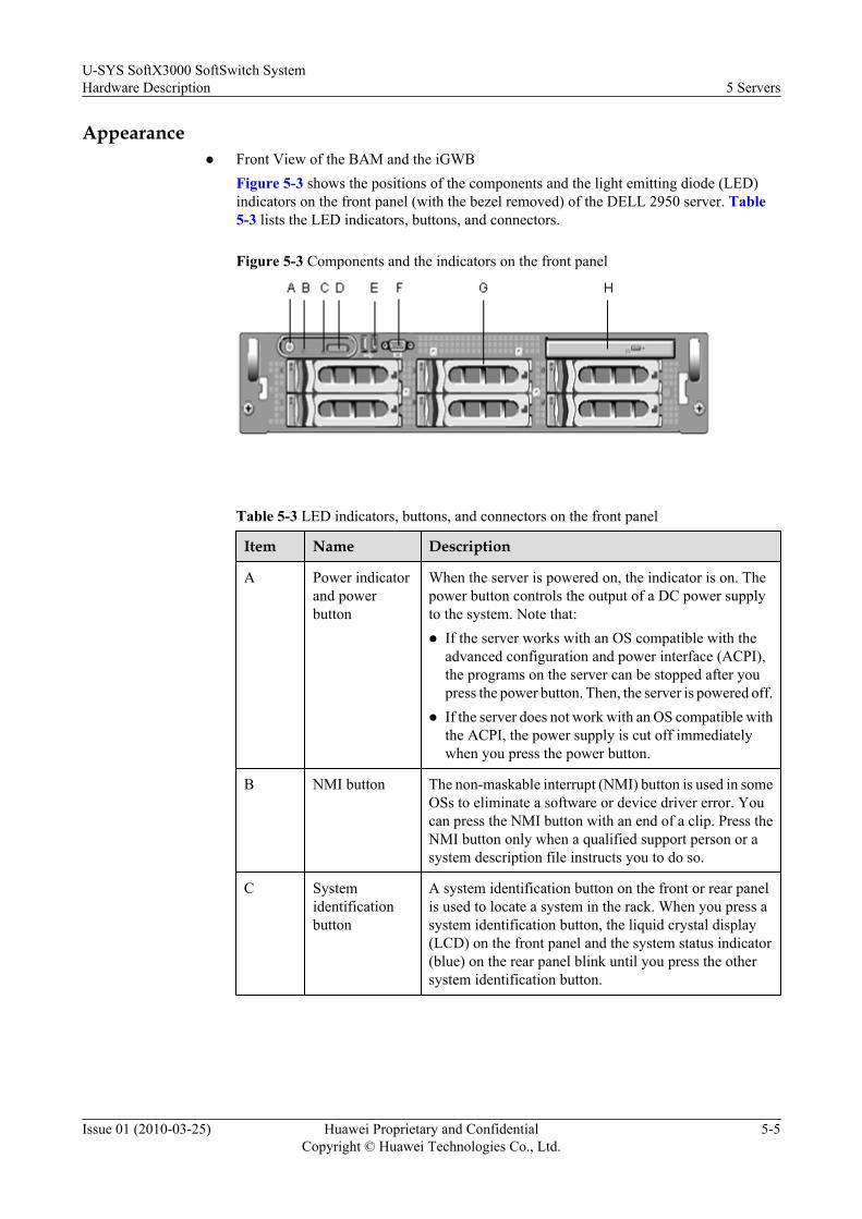
Appearancel Front View of the BAM and the iGWB
Figure 5-3 shows the positions of the components and the light emitting diode (LED)indicators on the front panel (with the bezel removed) of the DELL 2950 server. Table5-3 lists the LED indicators, buttons, and connectors.
Figure 5-3 Components and the indicators on the front panel
Table 5-3 LED indicators, buttons, and connectors on the front panel
Item Name Description
A Power indicatorand powerbutton
When the server is powered on, the indicator is on. Thepower button controls the output of a DC power supplyto the system. Note that:l If the server works with an OS compatible with the
advanced configuration and power interface (ACPI),the programs on the server can be stopped after youpress the power button. Then, the server is powered off.
l If the server does not work with an OS compatible withthe ACPI, the power supply is cut off immediatelywhen you press the power button.
B NMI button The non-maskable interrupt (NMI) button is used in someOSs to eliminate a software or device driver error. Youcan press the NMI button with an end of a clip. Press theNMI button only when a qualified support person or asystem description file instructs you to do so.
C Systemidentificationbutton
A system identification button on the front or rear panelis used to locate a system in the rack. When you press asystem identification button, the liquid crystal display(LCD) on the front panel and the system status indicator(blue) on the rear panel blink until you press the othersystem identification button.
U-SYS SoftX3000 SoftSwitch SystemHardware Description 5 Servers
Issue 01 (2010-03-25) Huawei Proprietary and ConfidentialCopyright © Huawei Technologies Co., Ltd.
5-5

Item Name Description
D LCD panel The system ID, status information, and system errormessages are displayed on the LCD panel. When theserver is normal, the LCD is on. The system managementsoftware and the system identification buttons on the frontand rear panels can make the LCD flash in blue to identifya specific system. When the server is faulty, the LCD ison in amber. In addition, the error code and the errordescription are displayed on the LCD panel. Note that ifthe server is connected to an AC power supply and anerror is detected, the LCD is on in amber irrespective ofwhether the server is powered on.
E USB connector The USB connector is used to connect a USB 2.0compatible device to the server.
F Video connector The video connector is used to connect a monitor to theserver.
G Hard disk drive Six 3.5-inch hot-swappable hard disk drives.
H CD-ROM drive(optional)
One DVD-ROM drive.
l Rear View of the BAM and the iGWB
Figure 5-4 shows the rear view of the BAM and the iGWB.
Figure 5-4 Components and the indicators on the rear panel
A Central PCI liftout plate (slot 1) B Left PCI liftout plate (slot 2)
C Right PCI liftout plate (slot 3) D Power device (2)
E System identification button F System status indicator
G System status indicator connector H NIC2 connector
I NIC1 connector J USB connector (2)
K USB connector (2) L Video connector
M Serial connector N Remote access controller (optional)
5 ServersU-SYS SoftX3000 SoftSwitch System
Hardware Description
5-6 Huawei Proprietary and ConfidentialCopyright © Huawei Technologies Co., Ltd.
Issue 01 (2010-03-25)
Technical Specifications
The rated power consumption of the DELL 2950 server is 220 W. Table 5-4 shows the hardwareconfiguration of the DELL 2950 server.
Table 5-4 Hardware configuration of the BAM and the iGWB
Item BAM iGWB Co-Installed BAM and iGWB
CPU One Intel Xeon DP 1.6 GHz or higher processor
Hard disk Two 146 GBhard disks(RAID 1)
Five 146 GB harddisks (RAID5+hotspare)
Two 300 GB hard disks (RAID1)
Memory One 2 GBmemory chip
One 2 GB memorychip
One 4 GB memory chip
Network adapter Two 1000 Mbit/s integrated network adaptersTwo 1000 Mbit/s PCI network adapters
NOTE
The hardware of the BAM and iGWB may be upgraded. The preceding configuration is for reference only.
5.3 BAM and iGWB (HP 380G5 Server)This section describes the BAM and iGWB (HP 380G5 server).
Functions
The BAM is the server of the O&M system. It bridges the WSs and the SoftX3000. The BAMforwards the O&M commands from local and remote WSs to the SoftX3000, and sends theresponses from the SoftX3000 to the WSs. The BAM also stores and transfers the alarm andtraffic measurement data.
The iGWB is an intermediate billing device between the SoftX3000 and the billing center. Itreceives, pre-processes and stores bills at a speed of 1700 CDRs per second. In addition, theiGWB provides billing interfaces.
The iGWB server works in the active/standby mode.
The BAM and the iGWB are installed in fixed positions in the integrated configuration cabinet.Both adopt the HP 380G5 server.
Appearancel Front View of the BAM and the iGWB
Figure 5-5 shows the front view of the BAM and the iGWB.
U-SYS SoftX3000 SoftSwitch SystemHardware Description 5 Servers
Issue 01 (2010-03-25) Huawei Proprietary and ConfidentialCopyright © Huawei Technologies Co., Ltd.
5-7

Figure 5-5 Front view of the BAM and the iGWB
A: CD-ROM drive B: Video interface6: USB interface D: Hard disk slots (for eight hard disks)
l Rear View of the BAM and the iGWB
Figure 5-6 shows the rear view of the BAM and the iGWB.
Figure 5-6 Rear view of the BAM and the iGWB
A: T-10/T-15 screwdriver B: NIC0 connectorC: NIC1 connector D: Filler panelE: NIC5 connector F: NIC4 connectorG: Power module (2) (configured) H: Power cable connectorI: Power module (1) (configured) J: iLO2 portK: Video connector L: USB connector (two)M: Serial connector N: Mouse connectorO: Keyboard connector P: Card bracket (1)Q: NIC2 connector R: NIC3 connectorP: Card bracket (2) T: Card bracket (3)U: Card bracket (4) V: Card bracket (5)
Indicators
Figure 5-7 shows the indicators on the front panel of the BAM and the iGWB.
5 ServersU-SYS SoftX3000 SoftSwitch System
Hardware Description
5-8 Huawei Proprietary and ConfidentialCopyright © Huawei Technologies Co., Ltd.
Issue 01 (2010-03-25)

Figure 5-7 Indicators on the front panel of the BAM and the iGWB
A: UID indicator/button B: Internal status indicatorC: External status indicator D: NIC1 connection indicatorE: NIC2 connection indicator F: Power button/indicator
Technical Specifications
The rated power consumption of the HP 380G5 server is 220 W. Table 5-5 shows the hardwareconfiguration of the HP 380G5 server.
Table 5-5 Hardware configuration of the BAM and the iGWB
Item BAM iGWB Co-installed BAM and iGWB
CPU One Intel Xeon Quad-Core E5405 2.0 GHz or higher processors
Hard disk Two 146 GBhard disks(RAID 1)
Five 146 GB harddisks (RAID 5 +hotspare)
Five 146 GB hard disks (RAID5 + hotspare)
Memory One 2 GBmemory chip
One 2 GB memorychip
One 4 GB memory chip
Network adapter Two 1000 Mbit/s integrated network adaptersTwo 1000 Mbit/s PCI network adapters
NOTE
The hardware of the BAM and iGWB may be upgraded. The preceding configuration is for reference only.
U-SYS SoftX3000 SoftSwitch SystemHardware Description 5 Servers
Issue 01 (2010-03-25) Huawei Proprietary and ConfidentialCopyright © Huawei Technologies Co., Ltd.
5-9
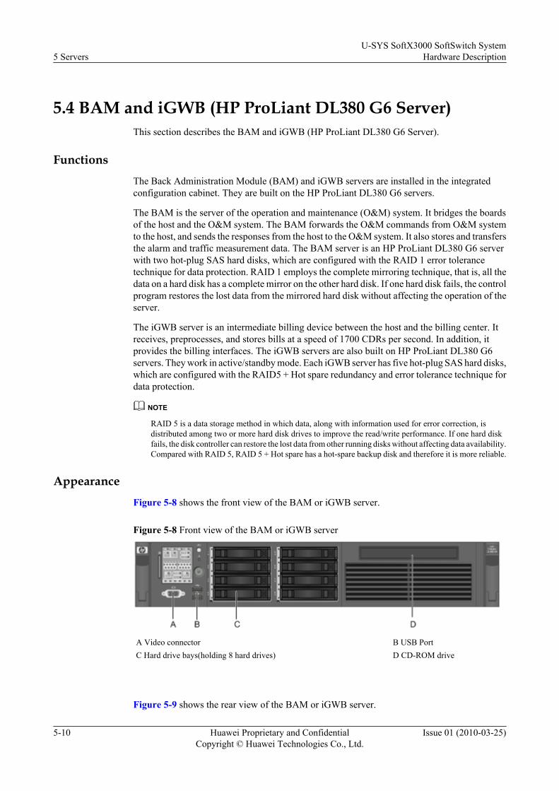
5.4 BAM and iGWB (HP ProLiant DL380 G6 Server)This section describes the BAM and iGWB (HP ProLiant DL380 G6 Server).
FunctionsThe Back Administration Module (BAM) and iGWB servers are installed in the integratedconfiguration cabinet. They are built on the HP ProLiant DL380 G6 servers.
The BAM is the server of the operation and maintenance (O&M) system. It bridges the boardsof the host and the O&M system. The BAM forwards the O&M commands from O&M systemto the host, and sends the responses from the host to the O&M system. It also stores and transfersthe alarm and traffic measurement data. The BAM server is an HP ProLiant DL380 G6 serverwith two hot-plug SAS hard disks, which are configured with the RAID 1 error tolerancetechnique for data protection. RAID 1 employs the complete mirroring technique, that is, all thedata on a hard disk has a complete mirror on the other hard disk. If one hard disk fails, the controlprogram restores the lost data from the mirrored hard disk without affecting the operation of theserver.
The iGWB server is an intermediate billing device between the host and the billing center. Itreceives, preprocesses, and stores bills at a speed of 1700 CDRs per second. In addition, itprovides the billing interfaces. The iGWB servers are also built on HP ProLiant DL380 G6servers. They work in active/standby mode. Each iGWB server has five hot-plug SAS hard disks,which are configured with the RAID5 + Hot spare redundancy and error tolerance technique fordata protection.
NOTE
RAID 5 is a data storage method in which data, along with information used for error correction, isdistributed among two or more hard disk drives to improve the read/write performance. If one hard diskfails, the disk controller can restore the lost data from other running disks without affecting data availability.Compared with RAID 5, RAID 5 + Hot spare has a hot-spare backup disk and therefore it is more reliable.
AppearanceFigure 5-8 shows the front view of the BAM or iGWB server.
Figure 5-8 Front view of the BAM or iGWB server
A Video connector B USB PortC Hard drive bays(holding 8 hard drives) D CD-ROM drive
Figure 5-9 shows the rear view of the BAM or iGWB server.
5 ServersU-SYS SoftX3000 SoftSwitch System
Hardware Description
5-10 Huawei Proprietary and ConfidentialCopyright © Huawei Technologies Co., Ltd.
Issue 01 (2010-03-25)
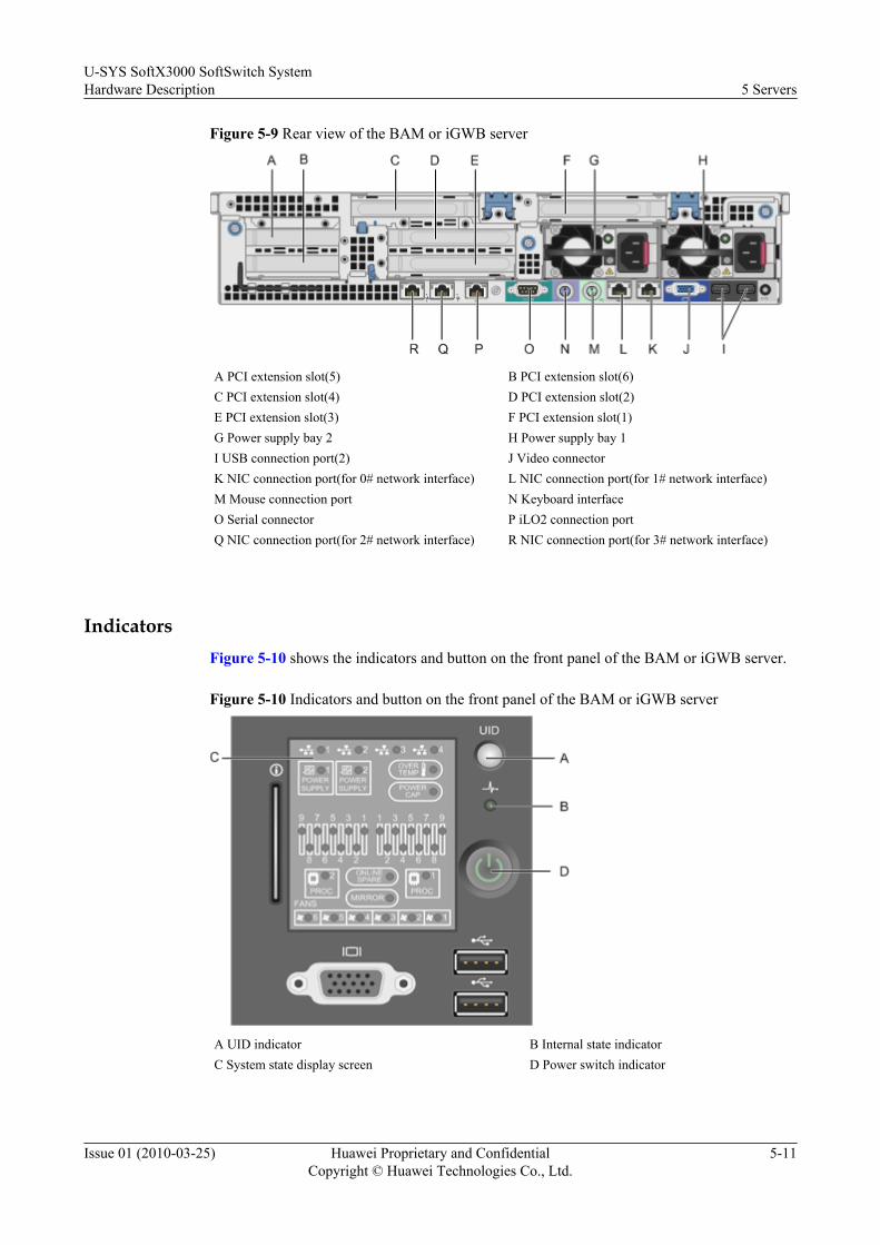
Figure 5-9 Rear view of the BAM or iGWB server
A PCI extension slot(5) B PCI extension slot(6)C PCI extension slot(4) D PCI extension slot(2)E PCI extension slot(3) F PCI extension slot(1)G Power supply bay 2 H Power supply bay 1I USB connection port(2) J Video connectorK NIC connection port(for 0# network interface) L NIC connection port(for 1# network interface)M Mouse connection port N Keyboard interfaceO Serial connector P iLO2 connection portQ NIC connection port(for 2# network interface) R NIC connection port(for 3# network interface)
IndicatorsFigure 5-10 shows the indicators and button on the front panel of the BAM or iGWB server.
Figure 5-10 Indicators and button on the front panel of the BAM or iGWB server
A UID indicator B Internal state indicatorC System state display screen D Power switch indicator
U-SYS SoftX3000 SoftSwitch SystemHardware Description 5 Servers
Issue 01 (2010-03-25) Huawei Proprietary and ConfidentialCopyright © Huawei Technologies Co., Ltd.
5-11
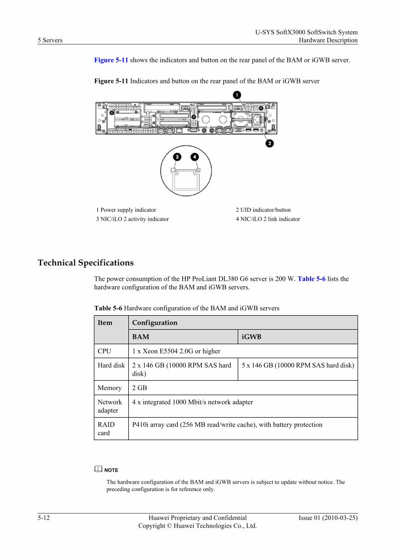
Figure 5-11 shows the indicators and button on the rear panel of the BAM or iGWB server.
Figure 5-11 Indicators and button on the rear panel of the BAM or iGWB server
1 Power supply indicator 2 UID indicator/button3 NIC/iLO 2 activity indicator 4 NIC/iLO 2 link indicator
Technical Specifications
The power consumption of the HP ProLiant DL380 G6 server is 200 W. Table 5-6 lists thehardware configuration of the BAM and iGWB servers.
Table 5-6 Hardware configuration of the BAM and iGWB servers
Item Configuration
BAM iGWB
CPU 1 x Xeon E5504 2.0G or higher
Hard disk 2 x 146 GB (10000 RPM SAS harddisk)
5 x 146 GB (10000 RPM SAS hard disk)
Memory 2 GB
Networkadapter
4 x integrated 1000 Mbit/s network adapter
RAIDcard
P410i array card (256 MB read/write cache), with battery protection
NOTE
The hardware configuration of the BAM and iGWB servers is subject to update without notice. Thepreceding configuration is for reference only.
5 ServersU-SYS SoftX3000 SoftSwitch System
Hardware Description
5-12 Huawei Proprietary and ConfidentialCopyright © Huawei Technologies Co., Ltd.
Issue 01 (2010-03-25)
6 Internal Components of Cabinet
About This Chapter
This section describes the functions of the service processing subrack, PDB, air deflector, airdefense frame, cable trough, KVMS, and Ethernet switch.
6.1 Service Processing SubrackThis section describes the service processing subrack.
6.2 PDBThis section describes the PDB.
6.3 Air DeflectorThis section describes the air deflector.
6.4 Air Defense FrameThis section describes the air defense frame.
6.5 Cable TroughThis section describes the cable trough.
6.6 KVMSThis section describes the KVMS.
6.7 Ethernet SwitchThis section describes the Ethernet switch.
U-SYS SoftX3000 SoftSwitch SystemHardware Description 6 Internal Components of Cabinet
Issue 01 (2010-03-25) Huawei Proprietary and ConfidentialCopyright © Huawei Technologies Co., Ltd.
6-1
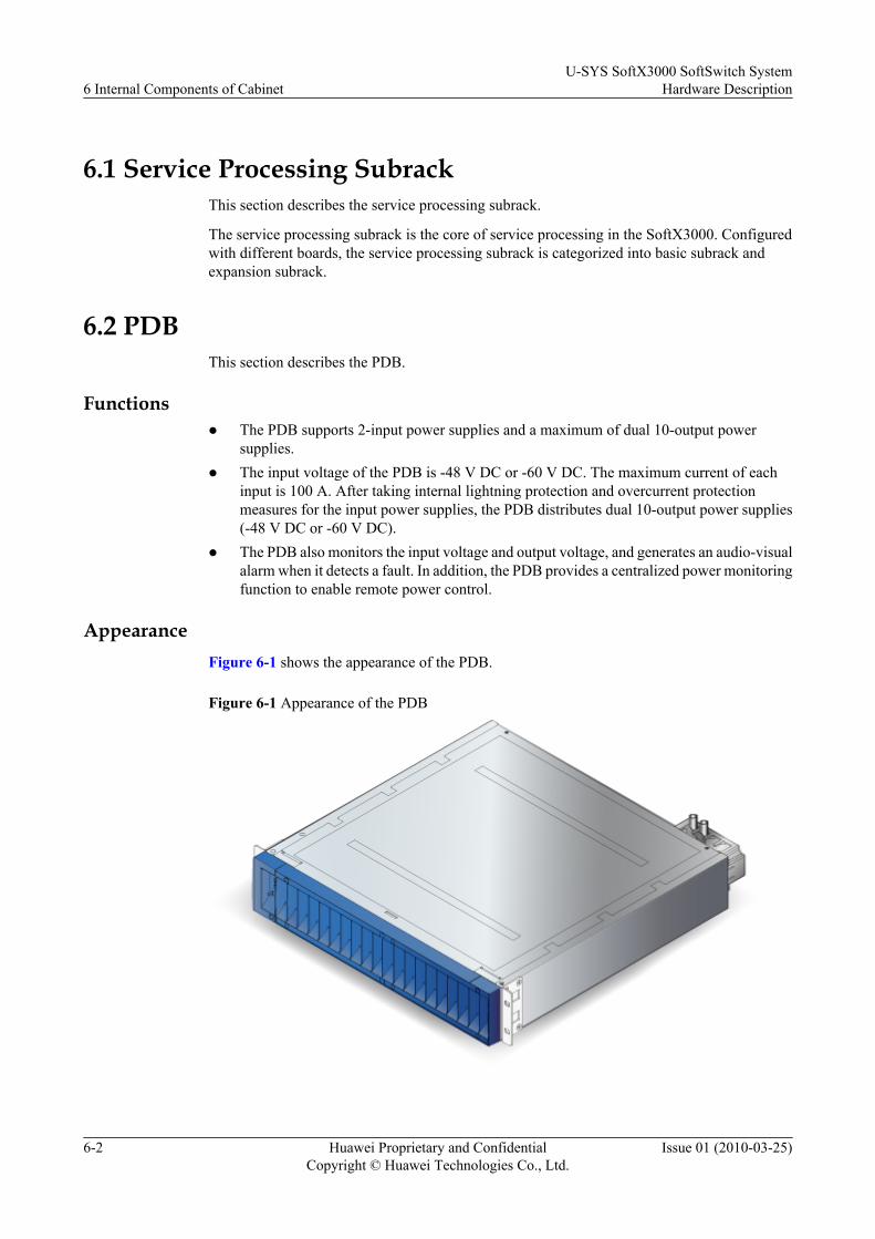
6.1 Service Processing SubrackThis section describes the service processing subrack.
The service processing subrack is the core of service processing in the SoftX3000. Configuredwith different boards, the service processing subrack is categorized into basic subrack andexpansion subrack.
6.2 PDBThis section describes the PDB.
Functionsl The PDB supports 2-input power supplies and a maximum of dual 10-output power
supplies.l The input voltage of the PDB is -48 V DC or -60 V DC. The maximum current of each
input is 100 A. After taking internal lightning protection and overcurrent protectionmeasures for the input power supplies, the PDB distributes dual 10-output power supplies(-48 V DC or -60 V DC).
l The PDB also monitors the input voltage and output voltage, and generates an audio-visualalarm when it detects a fault. In addition, the PDB provides a centralized power monitoringfunction to enable remote power control.
AppearanceFigure 6-1 shows the appearance of the PDB.
Figure 6-1 Appearance of the PDB
6 Internal Components of CabinetU-SYS SoftX3000 SoftSwitch System
Hardware Description
6-2 Huawei Proprietary and ConfidentialCopyright © Huawei Technologies Co., Ltd.
Issue 01 (2010-03-25)

Figure 6-2 shows the structure of the PDB.
Figure 6-2 Structure of the PDB
1. Monitoring panel 2. Signal connection board 3. Interface board 4. DC power lightning protection board
l Front panel
Figure 6-3 shows the appearance of the front panel of the PDB.
Figure 6-3 Appearance of the front panel of the PDB
1: Running indicator (RUN) 2: Air circuit breaker 3: Alarm indicator (ALM) 4: Buzzer switch (MUTE)
The monitoring panel is on the left of the PDB front panel. If the buzzer switch is set toON (|), the buzzer emits a sound when the PDB generates an alarm. If the buzzer switch is
U-SYS SoftX3000 SoftSwitch SystemHardware Description 6 Internal Components of Cabinet
Issue 01 (2010-03-25) Huawei Proprietary and ConfidentialCopyright © Huawei Technologies Co., Ltd.
6-3

set to OFF (O), the buzzer is mute even when the PDB generates an alarm. When the PDBis switched on, the RUN and ALM indicators are lit at the same time, the buzzer emits asound, and the monitoring board starts the self-test. After the self-test is successful, theRUN and ALM indicators turn off at the same time and the buzzer stops buzzingautomatically. Figure 6-4 shows the appearance of the monitoring panel of the PDB.
Figure 6-4 Appearance of the monitoring panel of the PDB
Table 6-1 describes the monitoring indicators of the PDB.
Table 6-1 Monitoring indicators of the PDB
Indicator Mark Color Status Description
Runningindicator(RUN)
RUN Green Blinking at 0.5 Hz (on forone second and off for onesecond)
It indicates that the PDBis working properly.
Blinking at 4 Hz (on for125 milliseconds and offfor 125 milliseconds)
It indicates that thecommunication betweenthe PDB and the controlboard is abnormal.
Off It indicates that the PDBdoes not have a powersupply, or the indicator isfaulty.
6 Internal Components of CabinetU-SYS SoftX3000 SoftSwitch System
Hardware Description
6-4 Huawei Proprietary and ConfidentialCopyright © Huawei Technologies Co., Ltd.
Issue 01 (2010-03-25)

Indicator Mark Color Status Description
Alarmindicator(ALM)
ALM Red On It indicates that the PDBis faulty.
Off It indicates that the PDBis operating properly.
l Rear panel
Figure 6-5 shows the appearance of the rear panel of the PDB.
Figure 6-5 Appearance of the real panel of the PDB
1: Input terminal 2: Output terminal 3: DB15 serial port
4 RJ45 serial port 5 External Boolean signal interface 6: Two-hole grounding screw
InterfacesThe monitoring unit of the PDB monitors the status of the six power inputs and generates analarm when it detects a fault, and monitors the status of the 20 power output switches andgenerates an alarm when it detects a fault. It supports automatic switchover of serial ports in thecase of a communication failure, thus ensuring normal communication between the serial portsand the monitoring unit. It also provides two RS485 (or two RS232) serial ports for transmittingmonitoring information about the PDB. Figure 6-6 shows the communication interface boardof the PDB.
U-SYS SoftX3000 SoftSwitch SystemHardware Description 6 Internal Components of Cabinet
Issue 01 (2010-03-25) Huawei Proprietary and ConfidentialCopyright © Huawei Technologies Co., Ltd.
6-5
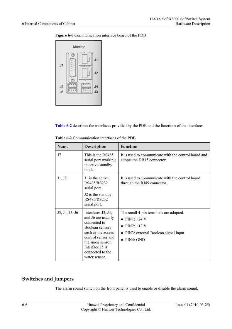
Figure 6-6 Communication interface board of the PDB
Table 6-2 describes the interfaces provided by the PDB and the functions of the interfaces.
Table 6-2 Communication interfaces of the PDB
Name Description Function
J7 This is the RS485serial port workingin active/standbymode.
It is used to communicate with the control board andadopts the DB15 connector.
J1, J2 J1 is the activeRS485/RS232serial port.J2 is the standbyRS485/RS232serial port.
It is used to communicate with the control boardthrough the RJ45 connector.
J3, J4, J5, J6 Interfaces J3, J4,and J6 are usuallyconnected toBoolean sensorssuch as the accesscontrol sensor andthe smog sensor.Interface J5 isconnected to thewater sensor.
The small 4-pin terminals are adopted.l PIN1: +24 V
l PIN2: +12 V
l PIN3: external Boolean signal input
l PIN4: GND
Switches and Jumpers
The alarm sound switch on the front panel is used to enable or disable the alarm sound.
6 Internal Components of CabinetU-SYS SoftX3000 SoftSwitch System
Hardware Description
6-6 Huawei Proprietary and ConfidentialCopyright © Huawei Technologies Co., Ltd.
Issue 01 (2010-03-25)

l When the alarm sound switch is set to ON, the buzzers on the PDB will beep when the PDBis faulty.
l When the alarm sound switch is set to OFF, the buzzers on the PDB will not beep whenthe PDB is faulty.
NOTEThe relationship between the cabinet components and the switches on the PDB listed in Table 6-3 is forreference. The relationship may vary with the delivered equipment. For details, refer to the labels on thePDB of the delivered equipment.
Table 6-3 lists the use of the twenty power outputs of the PDB for the components in the cabinet.
Table 6-3 Relationship between the components in the N68E-22 cabinet and the switches onthe PDB
Cabinet Type Switch Component
Integrated configurationcabinet
A7,B7 SUBRACK-1 (expansion subrack1)
A6,B6 SUBRACK-0 (basic subrack 0)
B10 KVMS
A8 LAN Switch 1
B8 LAN Switch 0
A9 NET Switch 1
B9 NET Switch 0
A3,B3 SERVER-3 (BAM)
A2,B2 SERVER-2 (iGWB 1)
A1,B1 SERVER-1 (iGWB 0)
Service processingcabinet
A4,B4 SUBRACK-3 (expansion subrack5)
A3,B3 SUBRACK-2 (expansion subrack4)
A2,B2 SUBRACK-1 (expansion subrack3)
A1,B1 SUBRACK-0 (expansion subrack2)
ArchitectureThe PDB consists of a monitor unit, a lightning protection unit and a power output unit, as shownin Figure 6-7.
U-SYS SoftX3000 SoftSwitch SystemHardware Description 6 Internal Components of Cabinet
Issue 01 (2010-03-25) Huawei Proprietary and ConfidentialCopyright © Huawei Technologies Co., Ltd.
6-7
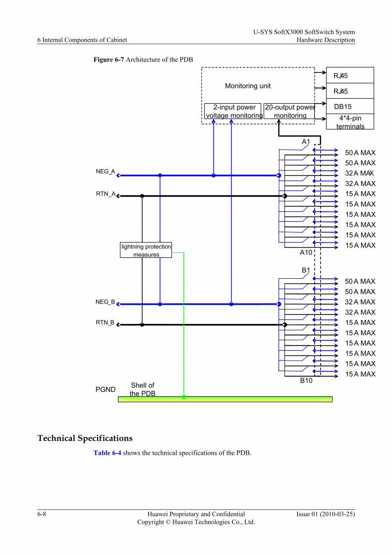
Figure 6-7 Architecture of the PDB
PGND Shell of the PDB
B10
A1
A10
B1
RTN_B
NEG_B
NEG_A
RTN_A
50 A MAX50 A MAX
2-input power voltage monitoring
32A MAX32 A MAX15 A MAX15 A MAX15 A MAX15 A MAX15 A MAX15 A MAX
Monitoring unit
20-output power monitoring
RJ45
RJ45
DB154*4-pin
terminals
lightning protection measures
50 A MAX50 A MAX
32 A MAX32 A MAX15 A MAX15 A MAX15 A MAX15 A MAX15 A MAX15 A MAX
Technical SpecificationsTable 6-4 shows the technical specifications of the PDB.
6 Internal Components of CabinetU-SYS SoftX3000 SoftSwitch System
Hardware Description
6-8 Huawei Proprietary and ConfidentialCopyright © Huawei Technologies Co., Ltd.
Issue 01 (2010-03-25)
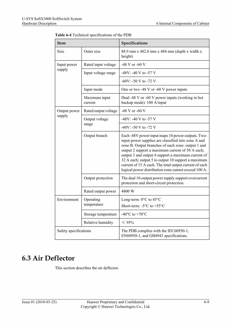
Table 6-4 Technical specifications of the PDB
Item Specifications
Size Outer size 88.9 mm x 482.6 mm x 484 mm (depth x width xheight)
Input powersupply
Rated input voltage -48 V or -60 V
Input voltage range -48V: -40 V to -57 V
-60V: -50 V to -72 V
Input mode One or two -48 V or -60 V power inputs
Maximum inputcurrent
Dual -48 V or -60 V power inputs (working in hotbackup mode): 100 A/input
Output powersupply
Rated output voltage -48 V or -60 V
Output voltagerange
-48V: -40 V to -57 V
-60V: -50 V to -72 V
Output branch Each -48V power input maps 10 power outputs. Two-input power supplies are classified into zone A andzone B. Output branches of each zone: output 1 andoutput 2 support a maximum current of 50 A each;output 3 and output 4 support a maximum current of32 A each; output 5 to output 10 support a maximumcurrent of 15 A each. The total output current of eachlogical power distribution zone cannot exceed 100 A.
Output protection The dual 10-output power supply support overcurrentprotection and short-circuit protection.
Rated output power 4800 W
Environment Operatingtemperature
Long-term: 0°C to 45°CShort-term: -5°C to +55°C
Storage temperature -40°C to +70°C
Relative humidity ≤ 95%
Safety specifications The PDB complies with the IEC60950-1,EN60950-1, and GB4943 specifications.
6.3 Air DeflectorThis section describes the air deflector.
U-SYS SoftX3000 SoftSwitch SystemHardware Description 6 Internal Components of Cabinet
Issue 01 (2010-03-25) Huawei Proprietary and ConfidentialCopyright © Huawei Technologies Co., Ltd.
6-9

FunctionsAn air deflector is used to smooth and divert the direction of air and separate heat dissipationchannels of subracks. In this way, air can be taken in from the front and exhausted through therear. The pressure consumption of the air can also be minimized through an air deflector.
Appearance of the Air DeflectorAn air deflector is 2 U high and 373.3 mm deep. There are a number of ventilation holes on itsplastic front panel, as shown in Figure 6-8.
Figure 6-8 Appearance of the air deflector
6.4 Air Defense FrameThis section describes the air defense frame.
FunctionsAn air defense subrack connects the air channels between two expansion subracks in the serviceprocessing cabinet. It enhances efficiency and reliability of heat dissipation.
Appearance of the Air Defense SubrackAn air defense subrack is 2 U high. There are a number of ventilation holes on its plastic frontpanel, as shown in Figure 6-9.
6 Internal Components of CabinetU-SYS SoftX3000 SoftSwitch System
Hardware Description
6-10 Huawei Proprietary and ConfidentialCopyright © Huawei Technologies Co., Ltd.
Issue 01 (2010-03-25)

Figure 6-9 Appearance of the air defense subrack
6.5 Cable TroughThis section describes the cable trough.
Functions
The cable trough can be used to route the network cables of the front panel of the LAN switchto the rear of the cabinet.
Appearance
The cable trough is used with LAN Switches. It connects the Ethernet cables from the front panelof the LAN Switch to the rear of the cabinet.
Figure 6-10 shows the appearance and architecture of the cable trough for the N68E-22 cabinet.
Figure 6-10 Appearance and architecture of the cable trough for the N68E-22 cabinet
U-SYS SoftX3000 SoftSwitch SystemHardware Description 6 Internal Components of Cabinet
Issue 01 (2010-03-25) Huawei Proprietary and ConfidentialCopyright © Huawei Technologies Co., Ltd.
6-11

6.6 KVMSThis section describes the KVMS.
FunctionsThe KVMS is an integration of the keyboard, video, mouse and switch. It is installed in theintegrated configuration cabinet. It provides eight groups of interfaces. Each group has onekeyboard interface, one mouse interface and one LCD interface. A separate computer connectedto any one group of interfaces can be used as the input and output device of the BAM and theiGWB.
The KVMS controller controls the connection between the KVMS and the servers. You canoperate the buttons or switches on the KVMS panel to conduct display switching, set channelflag and set protection password.
Appearance of the KVMSThe KVMS is 1 U high. Figure 6-11 shows the appearance of the folded KVMS.
Figure 6-11 Appearance of the folded KVMS
Figure 6-12 shows the appearance of the unfolded KVMS.
6 Internal Components of CabinetU-SYS SoftX3000 SoftSwitch System
Hardware Description
6-12 Huawei Proprietary and ConfidentialCopyright © Huawei Technologies Co., Ltd.
Issue 01 (2010-03-25)

Figure 6-12 Appearance of the unfolded KVMS
InterfacesThe KVMS provides eight groups of interfaces on the rear panel. Each group has one keyboardinterface, one mouse interface and one LCD interface. The KVMS also provides a power inputterminal and a protection grounding connection terminal on the rear panel. show in Figure6-13.
Figure 6-13 Rear view of the KVMS
Technical SpecificationsTable 6-5 lists the technical specifications of the KVMS.
U-SYS SoftX3000 SoftSwitch SystemHardware Description 6 Internal Components of Cabinet
Issue 01 (2010-03-25) Huawei Proprietary and ConfidentialCopyright © Huawei Technologies Co., Ltd.
6-13

Table 6-5 Technical specifications of the KVMS
Category Item Specifications
Mechanicalspecifications
Dimensions 445mm (width) x 42mm (height) x 423mm(depth)
Model and size ofLCD
15.1" TFT LCD
Interface type Monitor interface HD-DB-15 male
Keyboard and mouseinterfaces
PS/2
Electricalperformance
Input - 48 V, 2 A
Output - 12 V, 5 A
Performancespecifications
Scan interval 3, 8, 15, and 30 seconds
Length of signal cable 30 m at maximum
Display resolution 1024 x 768, at 85 Hz of refresh rate
Keyboard repeat rate(typing speed)
10, 15, 20 or 30 characters per second
Environmentrequirements
Working temperature 0°C to 50°C
Storage temperature - 20°C to +60°C
6.7 Ethernet SwitchThis section describes the Ethernet switch.
FunctionsIn an integrated configuration cabinet, Ethernet switches connect subracks with servers, achievedual planes for inter-component communication channels, and provide inter-componentcommunication and active/standby configuration functions.
NOTE
l For details about the features and operation guide of the Quidway S3928P-EI Ethernet Switch, refer to theQuidway S3900-EI Series Ethernet Switches Operation Manual.
l For details about the features and operation guide of the Quidway S3528G Ethernet switche, refer to theQuidway S3500 Series Ethernet Switches Operation Manual
Appearancel Front view
– Front View of the Quidway S3928P-EI Ethernet SwitchThe Quidway S3928P-EI Ethernet Switch (hereinafter referred to as the S3928P-EI)can serve as the LAN Switch to connect subracks with servers and achieve dual planes
6 Internal Components of CabinetU-SYS SoftX3000 SoftSwitch System
Hardware Description
6-14 Huawei Proprietary and ConfidentialCopyright © Huawei Technologies Co., Ltd.
Issue 01 (2010-03-25)

for inter-component communication. It can also serve as the NET LAN Switch toachieve dual-plane networking and connect to the IP signaling network.
On the front panel of the S3928P-EI, there are 24 fixed 10Base-T/100Base-TX adaptiveEthernet ports, four 1000Base-X SFP ports and a Console port. Figure 6-14 shows thefront view of the S3928P-EI.
Figure 6-14 Front view of the S3928P-EI
1 100M Ethernet ports status indicator 2 1000Base-X SFP port status indicator
3 DC power indicator 4 Power indicator
5 Ethernet port mode switch indicator 6 Mode switch button
7 7-segment digital indicator 8 Console port
– Front View of the Quidway S3528G Ethernet Switch
On the front panel of the Quidway S3528G Ethernet Switch (hereinafter referred to asthe S3528G), there is a power indicator (PWR), 24 fixed 10Base-T/100Base-TXEthernet ports and a Console port. Figure 6-15 shows the front view of the S3528G.
Figure 6-15 Front view of the S3528G
1. Power indicator 2. GBIC port status indicator 3. Mode switch button
4. Mode switch status indicator 5. 100M Ethernet ports and indicator 6. GBIC port and indicator
7. Console port - -
– Front view of the S3328TP-EI-24S
On the front panel of the S3328TP-EI-24S Ethernet Switch, there are grounding screws,DC power input module, power switch, 24 100Base-TX Ethernet interfaces, four opticalinterfaces, and one Console port, as shown in Figure 6-16.
U-SYS SoftX3000 SoftSwitch SystemHardware Description 6 Internal Components of Cabinet
Issue 01 (2010-03-25) Huawei Proprietary and ConfidentialCopyright © Huawei Technologies Co., Ltd.
6-15
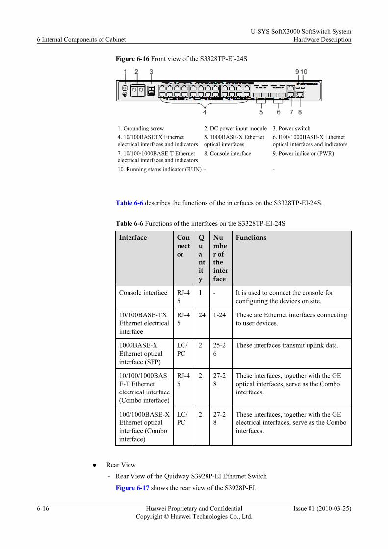
Figure 6-16 Front view of the S3328TP-EI-24S
1. Grounding screw 2. DC power input module 3. Power switch4. 10/100BASETX Ethernetelectrical interfaces and indicators
5. 1000BASE-X Ethernetoptical interfaces
6. l100/1000BASE-X Ethernetoptical interfaces and indicators
7. 10/100/1000BASE-T Ethernetelectrical interfaces and indicators
8. Console interface 9. Power indicator (PWR)
10. Running status indicator (RUN) - -
Table 6-6 describes the functions of the interfaces on the S3328TP-EI-24S.
Table 6-6 Functions of the interfaces on the S3328TP-EI-24S
Interface Connector
Quantity
Number oftheinterface
Functions
Console interface RJ-45
1 - It is used to connect the console forconfiguring the devices on site.
10/100BASE-TXEthernet electricalinterface
RJ-45
24 1-24 These are Ethernet interfaces connectingto user devices.
1000BASE-XEthernet opticalinterface (SFP)
LC/PC
2 25-26
These interfaces transmit uplink data.
10/100/1000BASE-T Ethernetelectrical interface(Combo interface)
RJ-45
2 27-28
These interfaces, together with the GEoptical interfaces, serve as the Combointerfaces.
100/1000BASE-XEthernet opticalinterface (Combointerface)
LC/PC
2 27-28
These interfaces, together with the GEelectrical interfaces, serve as the Combointerfaces.
l Rear View
– Rear View of the Quidway S3928P-EI Ethernet Switch
Figure 6-17 shows the rear view of the S3928P-EI.
6 Internal Components of CabinetU-SYS SoftX3000 SoftSwitch System
Hardware Description
6-16 Huawei Proprietary and ConfidentialCopyright © Huawei Technologies Co., Ltd.
Issue 01 (2010-03-25)
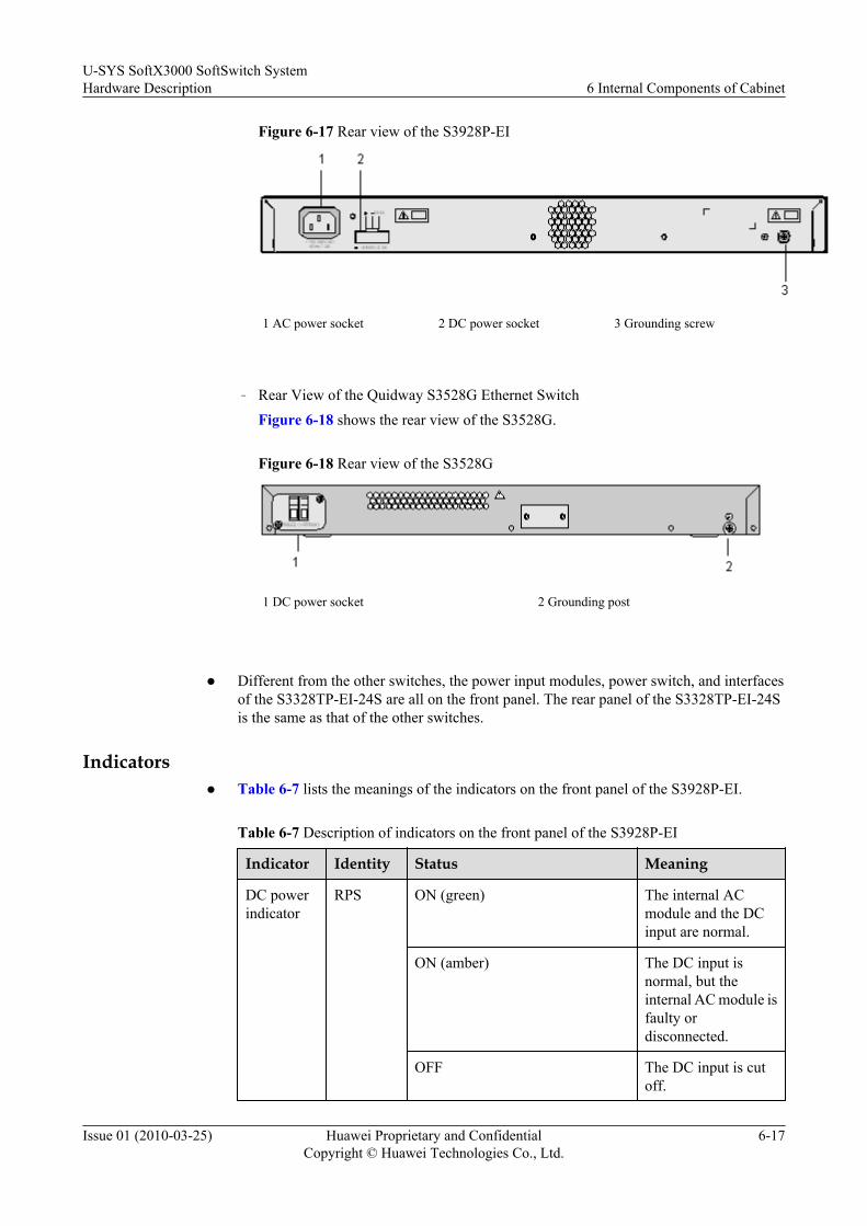
Figure 6-17 Rear view of the S3928P-EI
1 AC power socket 2 DC power socket 3 Grounding screw
– Rear View of the Quidway S3528G Ethernet Switch
Figure 6-18 shows the rear view of the S3528G.
Figure 6-18 Rear view of the S3528G
1 DC power socket 2 Grounding post
l Different from the other switches, the power input modules, power switch, and interfaces
of the S3328TP-EI-24S are all on the front panel. The rear panel of the S3328TP-EI-24Sis the same as that of the other switches.
Indicatorsl Table 6-7 lists the meanings of the indicators on the front panel of the S3928P-EI.
Table 6-7 Description of indicators on the front panel of the S3928P-EI
Indicator Identity Status Meaning
DC powerindicator
RPS ON (green) The internal ACmodule and the DCinput are normal.
ON (amber) The DC input isnormal, but theinternal AC module isfaulty ordisconnected.
OFF The DC input is cutoff.
U-SYS SoftX3000 SoftSwitch SystemHardware Description 6 Internal Components of Cabinet
Issue 01 (2010-03-25) Huawei Proprietary and ConfidentialCopyright © Huawei Technologies Co., Ltd.
6-17
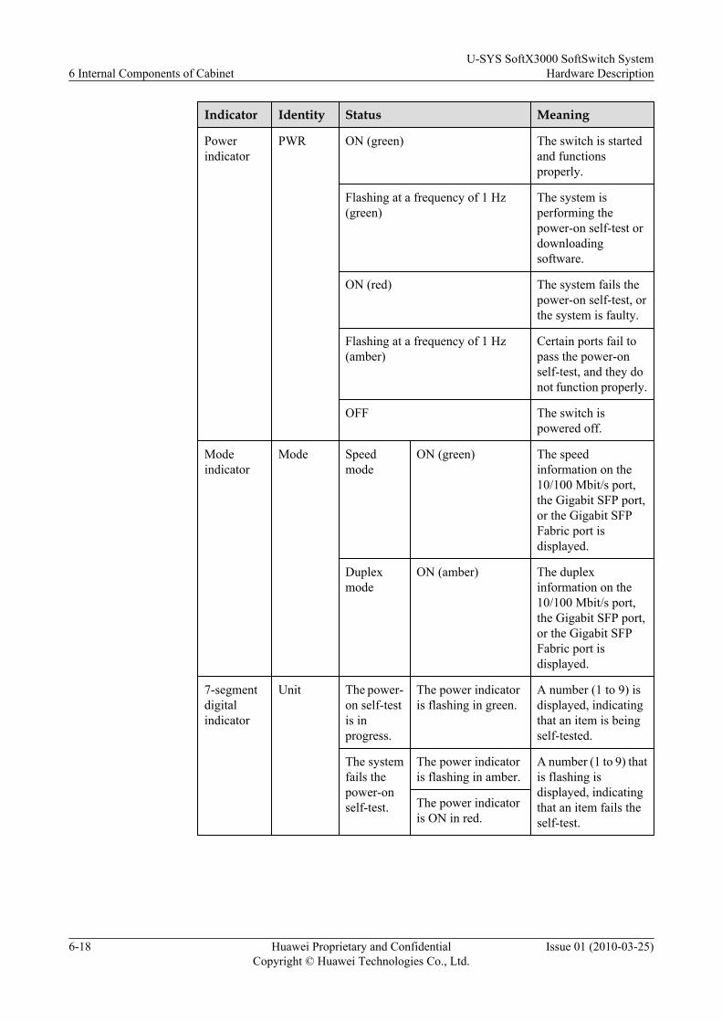
Indicator Identity Status Meaning
Powerindicator
PWR ON (green) The switch is startedand functionsproperly.
Flashing at a frequency of 1 Hz(green)
The system isperforming thepower-on self-test ordownloadingsoftware.
ON (red) The system fails thepower-on self-test, orthe system is faulty.
Flashing at a frequency of 1 Hz(amber)
Certain ports fail topass the power-onself-test, and they donot function properly.
OFF The switch ispowered off.
Modeindicator
Mode Speedmode
ON (green) The speedinformation on the10/100 Mbit/s port,the Gigabit SFP port,or the Gigabit SFPFabric port isdisplayed.
Duplexmode
ON (amber) The duplexinformation on the10/100 Mbit/s port,the Gigabit SFP port,or the Gigabit SFPFabric port isdisplayed.
7-segmentdigitalindicator
Unit The power-on self-testis inprogress.
The power indicatoris flashing in green.
A number (1 to 9) isdisplayed, indicatingthat an item is beingself-tested.
The systemfails thepower-onself-test.
The power indicatoris flashing in amber.
A number (1 to 9) thatis flashing isdisplayed, indicatingthat an item fails theself-test.
The power indicatoris ON in red.
6 Internal Components of CabinetU-SYS SoftX3000 SoftSwitch System
Hardware Description
6-18 Huawei Proprietary and ConfidentialCopyright © Huawei Technologies Co., Ltd.
Issue 01 (2010-03-25)

Indicator Identity Status Meaning
The systemis loadingsoftware.
The power indicatoris flashing in green.
When the system isloading software, thepointer movesclockwise along therectangle of thedigital number.
The fan isfaulty.
The power indicatoris ON in red.
The letter "F" isdisplayed.
Unit id The mode switchbutton is not presseddown.
The unit ID of theFabric port isdisplayed. If theFabric port worksindependently, thenumber "1" isdisplayed.
10Base-T/100Base-TX portindicator
- Speedmode
Green ON A 100 Mbit/sconnection is set upover the port.
Flashing The port is sending orreceiving data.
Amber ON A 10 Mbit/sconnection is set upover the port.
Flashing The port is sending orreceiving data.
Flashing at afrequency of 3 Hz(amber)
The port fails thepower-on self-test.
OFF The port isdisconnected.
Duplexmode
Green ON The port works in thefull duplex mode.
Flashing The port is sending orreceiving data.
Amber ON The port works in thehalf duplex mode.
Flashing The port is sending orreceiving data.
Flashing at afrequency of 3 Hz(amber)
The port fails thepower-on self-test.
U-SYS SoftX3000 SoftSwitch SystemHardware Description 6 Internal Components of Cabinet
Issue 01 (2010-03-25) Huawei Proprietary and ConfidentialCopyright © Huawei Technologies Co., Ltd.
6-19
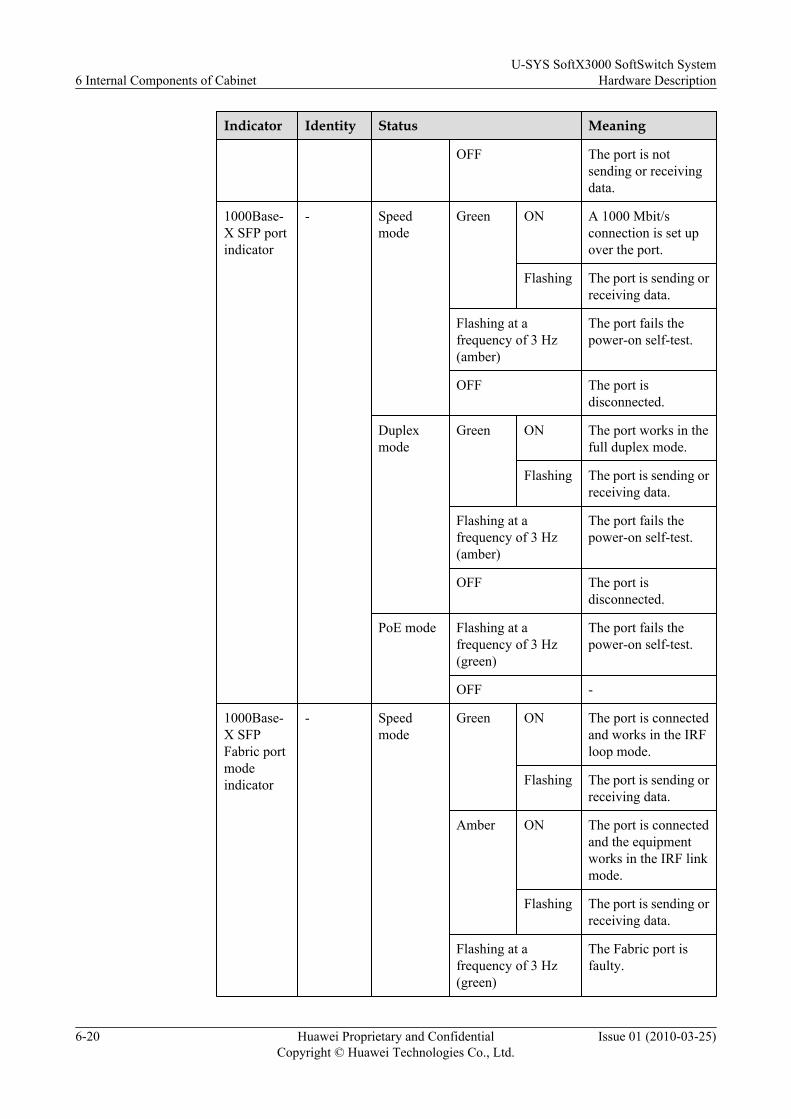
Indicator Identity Status Meaning
OFF The port is notsending or receivingdata.
1000Base-X SFP portindicator
- Speedmode
Green ON A 1000 Mbit/sconnection is set upover the port.
Flashing The port is sending orreceiving data.
Flashing at afrequency of 3 Hz(amber)
The port fails thepower-on self-test.
OFF The port isdisconnected.
Duplexmode
Green ON The port works in thefull duplex mode.
Flashing The port is sending orreceiving data.
Flashing at afrequency of 3 Hz(amber)
The port fails thepower-on self-test.
OFF The port isdisconnected.
PoE mode Flashing at afrequency of 3 Hz(green)
The port fails thepower-on self-test.
OFF -
1000Base-X SFPFabric portmodeindicator
- Speedmode
Green ON The port is connectedand works in the IRFloop mode.
Flashing The port is sending orreceiving data.
Amber ON The port is connectedand the equipmentworks in the IRF linkmode.
Flashing The port is sending orreceiving data.
Flashing at afrequency of 3 Hz(green)
The Fabric port isfaulty.
6 Internal Components of CabinetU-SYS SoftX3000 SoftSwitch System
Hardware Description
6-20 Huawei Proprietary and ConfidentialCopyright © Huawei Technologies Co., Ltd.
Issue 01 (2010-03-25)
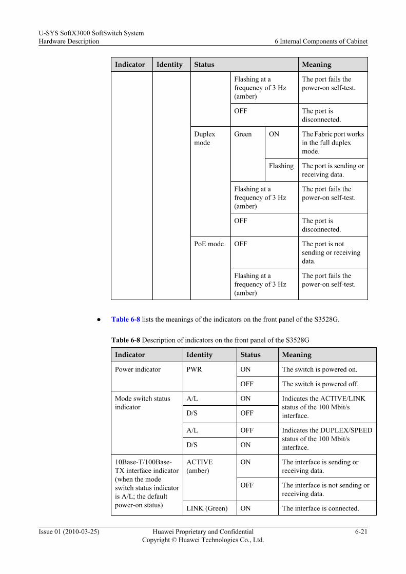
Indicator Identity Status Meaning
Flashing at afrequency of 3 Hz(amber)
The port fails thepower-on self-test.
OFF The port isdisconnected.
Duplexmode
Green ON The Fabric port worksin the full duplexmode.
Flashing The port is sending orreceiving data.
Flashing at afrequency of 3 Hz(amber)
The port fails thepower-on self-test.
OFF The port isdisconnected.
PoE mode OFF The port is notsending or receivingdata.
Flashing at afrequency of 3 Hz(amber)
The port fails thepower-on self-test.
l Table 6-8 lists the meanings of the indicators on the front panel of the S3528G.
Table 6-8 Description of indicators on the front panel of the S3528G
Indicator Identity Status Meaning
Power indicator PWR ON The switch is powered on.
OFF The switch is powered off.
Mode switch statusindicator
A/L ON Indicates the ACTIVE/LINKstatus of the 100 Mbit/sinterface.D/S OFF
A/L OFF Indicates the DUPLEX/SPEEDstatus of the 100 Mbit/sinterface.D/S ON
10Base-T/100Base-TX interface indicator(when the modeswitch status indicatoris A/L; the defaultpower-on status)
ACTIVE(amber)
ON The interface is sending orreceiving data.
OFF The interface is not sending orreceiving data.
LINK (Green) ON The interface is connected.
U-SYS SoftX3000 SoftSwitch SystemHardware Description 6 Internal Components of Cabinet
Issue 01 (2010-03-25) Huawei Proprietary and ConfidentialCopyright © Huawei Technologies Co., Ltd.
6-21

Indicator Identity Status Meaning
OFF The interface is disconnected.
10Base-T/100Base-TX interface indicator(when the modeswitch status indicatoris D/S)
DUPLEX(amber)
ON The interface works in the fullduplex mode.
OFF The interface works in the halfduplex mode.
SPEED (Green) ON The interface speed is 100 Mbit/s.
OFF The interface speed is 10 Mbit/s.
GBIC interface statusindicator
ACTIVE(amber)
ON The interface is sending orreceiving data.
OFF The interface is not sending orreceiving data.
LINK (Green) ON The interface is connected.
OFF The interface is disconnected.
l Table 6-9 describes the indicators on the S3328TP-EI-24S.
Table 6-9 Indicators on the S3328TP-EI-24S
Indicator Identity Status and Meaning
Power indicator PWR On: The LAN Switch ispowered on.Off: The LAN switch ispowered off.
10/100BASE-TX Ethernetelectrical interface
- On (green): The interface isconnected.Off (green): The interface isnot connected.On (amber): The interfaceis sending or receiving data.Off (amber): The interfaceis not sending or receivingdata.
6 Internal Components of CabinetU-SYS SoftX3000 SoftSwitch System
Hardware Description
6-22 Huawei Proprietary and ConfidentialCopyright © Huawei Technologies Co., Ltd.
Issue 01 (2010-03-25)

Indicator Identity Status and Meaning
1000BASE-X Ethernetoptical interface
LNK/ACT On: The interface isconnected properly.Off: The interface isconnected improperly or isnot connected.Blinking: The interface issending or receiving data.
Technical Specifications
Table 6-10, Table 6-11, and Table 6-12 list the technical specifications of the S3928P, S3528G,and S3328TP-EI-24S.
Table 6-10 Technical specifications of the S3928P-EI
Item Specifications
Dimensions 440 mm (length) x 260 mm (width) x 43.6 mm (height)
Weight 3.5 kg
Fixed port Twenty-four 10/100-Mbit/s Ethernet electrical ports and four GigabitSFP ports
Managementport
One Console port
Power supplysystem
AC power input:l Rated voltage range: 100 V AC to 240 V AC; 50Hz/60Hz
l Maximum voltage range: 90 V AC to 264 V AC; 50Hz/60Hz
DC power input:l Rated voltage range: - 48 V DC to - 60 V DC
l Maximum voltage range: - 36 V DC to - 72 V DC
PoE remotepower supply
Not supported
Maximumpowerconsumption
10 W
Operatingtemperature
0°C to 45°C
Relativeambienthumidity (nodewprecipitation)
10% to 90%
U-SYS SoftX3000 SoftSwitch SystemHardware Description 6 Internal Components of Cabinet
Issue 01 (2010-03-25) Huawei Proprietary and ConfidentialCopyright © Huawei Technologies Co., Ltd.
6-23

Table 6-11 Technical specifications of the S3528G
Item Specifications
Dimensions 436.2 mm (width) x 42 mm (height) x 240 mm (depth)(excluding the plastic panel)
Weight ≤ 5kg
Switching capacity ofbackplane
32 Gbit/s
Switching capacity of port 12.8 Gbit/s
Management port One Console port
Service port Fixed port Twenty-four 10/100Mbit/s Ethernet electrical ports(RJ-45 connector) and four GBIC ports
Optionalmodule
None
Port type 10/100BASE-TX1000BASE-GBIC
Input voltage Rated voltage: - 48 to - 60 V DCMaximum tolerance: - 36 to - 72 V DC
Supporting redundant power input
Power consumption (fullload)
10 W
Operating temperature 0°C to 45°C
Relative ambient humidity(no dew precipitation)
10% to 90%
Table 6-12 Technical specifications of the S3328TP-EI-24S
Category
Item Value
Physicalparameters
Dimensions (withoutmount angles)
442.0 mm x 220.0 mm x 43.6 mm (width x depth x height)
Number of fans Three
6 Internal Components of CabinetU-SYS SoftX3000 SoftSwitch System
Hardware Description
6-24 Huawei Proprietary and ConfidentialCopyright © Huawei Technologies Co., Ltd.
Issue 01 (2010-03-25)
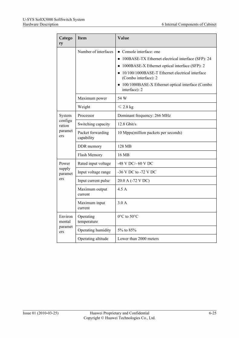
Category
Item Value
Number of interfaces l Console interface: one
l 100BASE-TX Ethernet electrical interface (SFP): 24
l 1000BASE-X Ethernet optical interface (SFP): 2
l 10/100/1000BASE-T Ethernet electrical interface(Combo interface): 2
l 100/1000BASE-X Ethernet optical interface (Combointerface): 2
Maximum power 54 W
Weight ≤ 2.8 kg
Systemconfigurationparameters
Processor Dominant frequency: 266 MHz
Switching capacity 12.8 Gbit/s
Packet forwardingcapability
10 Mpps(million packets per seconds)
DDR memory 128 MB
Flash Memory 16 MB
Powersupplyparameters
Rated input voltage -48 V DC/- 60 V DC
Input voltage range -36 V DC to -72 V DC
Input current pulse 20.0 A (-72 V DC)
Maximum outputcurrent
4.5 A
Maximum inputcurrent
3.0 A
Environmentalparameters
Operatingtemperature
0°C to 50°C
Operating humidity 5% to 85%
Operating altitude Lower than 2000 meters
U-SYS SoftX3000 SoftSwitch SystemHardware Description 6 Internal Components of Cabinet
Issue 01 (2010-03-25) Huawei Proprietary and ConfidentialCopyright © Huawei Technologies Co., Ltd.
6-25


7 Peripherals
About This Chapter
This section describes the peripherals of the SoftX3000, the N800 series supports andaccessories, and the universal alarm box. The peripherals of the SoftX3000 consist of anemergency workstation (EWS) and several local maintenance terminals (LMTs). The peripheralsuse the desktop equipment and are not installed in cabinets.
7.1 EWSThis section describes the EWS.
7.2 LMTThis section describes the LMT.
7.3 N6X Support and AccessoriesThis section describes the N6X support and its accessories.
7.4 Universal Alarm BoxThis section describes the universal alarm box.
U-SYS SoftX3000 SoftSwitch SystemHardware Description 7 Peripherals
Issue 01 (2010-03-25) Huawei Proprietary and ConfidentialCopyright © Huawei Technologies Co., Ltd.
7-1
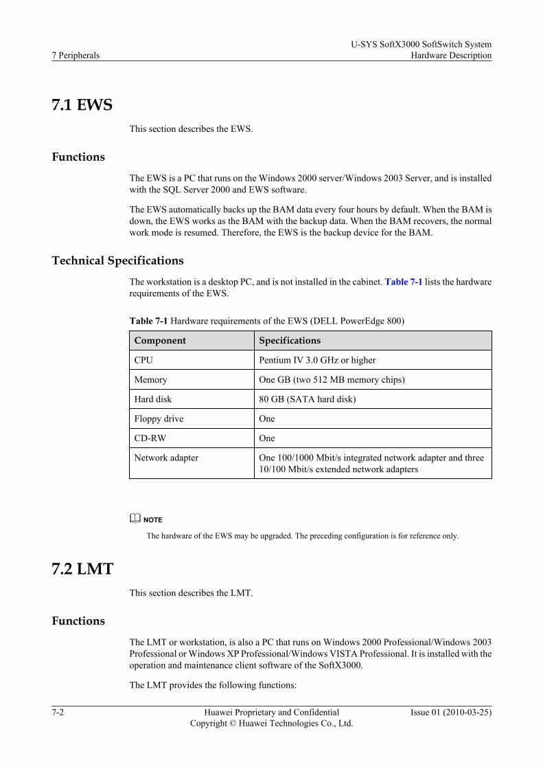
7.1 EWSThis section describes the EWS.
Functions
The EWS is a PC that runs on the Windows 2000 server/Windows 2003 Server, and is installedwith the SQL Server 2000 and EWS software.
The EWS automatically backs up the BAM data every four hours by default. When the BAM isdown, the EWS works as the BAM with the backup data. When the BAM recovers, the normalwork mode is resumed. Therefore, the EWS is the backup device for the BAM.
Technical Specifications
The workstation is a desktop PC, and is not installed in the cabinet. Table 7-1 lists the hardwarerequirements of the EWS.
Table 7-1 Hardware requirements of the EWS (DELL PowerEdge 800)
Component Specifications
CPU Pentium IV 3.0 GHz or higher
Memory One GB (two 512 MB memory chips)
Hard disk 80 GB (SATA hard disk)
Floppy drive One
CD-RW One
Network adapter One 100/1000 Mbit/s integrated network adapter and three10/100 Mbit/s extended network adapters
NOTE
The hardware of the EWS may be upgraded. The preceding configuration is for reference only.
7.2 LMTThis section describes the LMT.
Functions
The LMT or workstation, is also a PC that runs on Windows 2000 Professional/Windows 2003Professional or Windows XP Professional/Windows VISTA Professional. It is installed with theoperation and maintenance client software of the SoftX3000.
The LMT provides the following functions:
7 PeripheralsU-SYS SoftX3000 SoftSwitch System
Hardware Description
7-2 Huawei Proprietary and ConfidentialCopyright © Huawei Technologies Co., Ltd.
Issue 01 (2010-03-25)
l Device management
l Data configuration
l Host status query
l Device maintenance
AppearanceThe LMT is a PC. Different LMTs have different appearance.
7.3 N6X Support and AccessoriesThis section describes the N6X support and its accessories.
FunctionsA support is used to lift a cabinet so that the underside of the cabinet is flush with the surface ofthe ESD-preventive floor in the equipment room. The support is made of welded steel sheets.With the insulation plates attached underneath the support and the insulation washers placedover expansion bolts, the support enables the cabinet to be insulated before the whole set ofequipment is grounded.
Appearancel N6X Support
When the N68E-22 cabinet is installed on the ESD-preventive floor, the N6X seriessupports are used. Figure 7-1 shows the appearance of an N6X support.
U-SYS SoftX3000 SoftSwitch SystemHardware Description 7 Peripherals
Issue 01 (2010-03-25) Huawei Proprietary and ConfidentialCopyright © Huawei Technologies Co., Ltd.
7-3

Figure 7-1 Appearance of an N6X support
1 Connection holes for the sliderail
2 Connection holes for the frontholder
3 Height mark for the ESD-preventive floor
4 Height-locking bolt 5 Installation hole -
The N6X series supports are classified into two types. The height of one type is adjustableand that of the other type is fixed. Table 7-2 lists the height of each type of the support.
Table 7-2 Height of the N6X series supports
Type Applicable ESD-Preventive Floor Height
Support withadjustable height
Adjustable range: 296 mm - 465 mm.The height can be adjusted by moving the support components.
Support withfixed height
The support with fixed height is customized for the floor height. Itis applicable to floors that are extremely high or low. The lowestfloor height is 100 mm.
NOTE
The floor height is the distance between the surface of the ESD-preventive floor and the cement floorof the equipment room.
l Front HoldersOne cabinet uses two front holders. The front holders are used to support the antistatic floorat the front of and behind the cabinet. Figure 7-2 shows the appearance of a front holder.
7 PeripheralsU-SYS SoftX3000 SoftSwitch System
Hardware Description
7-4 Huawei Proprietary and ConfidentialCopyright © Huawei Technologies Co., Ltd.
Issue 01 (2010-03-25)

Figure 7-2 Appearance of a front holder
1 Connection holes for the support
l Slide Rails
One cabinet uses two slide rails. The slide rails are used to connect the cabinet and thesupport, move the equipment, and adjust the equipment positions. In addition, the slide railscan level the cabinet, reinforce the connection, and prevent vibration. Figure 7-3 showsthe appearance of a slide rail.
Figure 7-3 Appearance of a slide rail
1 Connection holes for the rack 2 Connection holes for the support
Technical SpecificationsNone.
7.4 Universal Alarm BoxThis section describes the universal alarm box.
FunctionsThe universal alarm box is used to receive alarm information and provide audio and visualalarms.
U-SYS SoftX3000 SoftSwitch SystemHardware Description 7 Peripherals
Issue 01 (2010-03-25) Huawei Proprietary and ConfidentialCopyright © Huawei Technologies Co., Ltd.
7-5

The universal alarm box is designed with the chassis architecture of advanced techniques andoptimal layout. The design of the universal alarm box fully considers operability, maintainabilityand security. The alarm box is usually installed on the wall of the room for monitoringmaintenance.
AppearanceFigure 7-4 shows the appearance of the universal alarm box.
Figure 7-4 Appearance of the universal alarm box
The alarm box is usually installed on the wall of the room for monitoring maintenance. For thedetailed installation procedure and cable connections, refer to the Universal Alarm Box UserManual delivered with the alarm box.
7 PeripheralsU-SYS SoftX3000 SoftSwitch System
Hardware Description
7-6 Huawei Proprietary and ConfidentialCopyright © Huawei Technologies Co., Ltd.
Issue 01 (2010-03-25)

8 Cables
About This Chapter
This section describes the usage, appearance, cross-sectional area and connection of the cables.
The cables used in the SoftX3000 are:
8.1 Power Cable and PGND CableThis section describes the power cable and PGND cable for the SoftX3000.
8.2 Internal Signal CableThis section describes the internal signal cables of the SoftX3000, including the straight throughcable, FE signal cable, serial port cable between the iGWBs, data cable between the iGWB andthe hard disk array, server/switcher cable and serial port cable for monitoring the PDB.
U-SYS SoftX3000 SoftSwitch SystemHardware Description 8 Cables
Issue 01 (2010-03-25) Huawei Proprietary and ConfidentialCopyright © Huawei Technologies Co., Ltd.
8-1
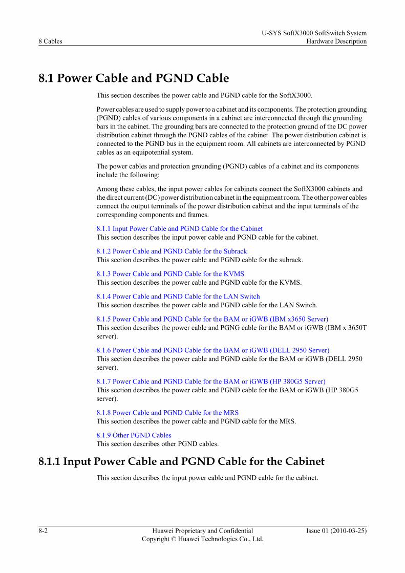
8.1 Power Cable and PGND CableThis section describes the power cable and PGND cable for the SoftX3000.
Power cables are used to supply power to a cabinet and its components. The protection grounding(PGND) cables of various components in a cabinet are interconnected through the groundingbars in the cabinet. The grounding bars are connected to the protection ground of the DC powerdistribution cabinet through the PGND cables of the cabinet. The power distribution cabinet isconnected to the PGND bus in the equipment room. All cabinets are interconnected by PGNDcables as an equipotential system.
The power cables and protection grounding (PGND) cables of a cabinet and its componentsinclude the following:
Among these cables, the input power cables for cabinets connect the SoftX3000 cabinets andthe direct current (DC) power distribution cabinet in the equipment room. The other power cablesconnect the output terminals of the power distribution cabinet and the input terminals of thecorresponding components and frames.
8.1.1 Input Power Cable and PGND Cable for the CabinetThis section describes the input power cable and PGND cable for the cabinet.
8.1.2 Power Cable and PGND Cable for the SubrackThis section describes the power cable and PGND cable for the subrack.
8.1.3 Power Cable and PGND Cable for the KVMSThis section describes the power cable and PGND cable for the KVMS.
8.1.4 Power Cable and PGND Cable for the LAN SwitchThis section describes the power cable and PGND cable for the LAN Switch.
8.1.5 Power Cable and PGND Cable for the BAM or iGWB (IBM x3650 Server)This section describes the power cable and PGNG cable for the BAM or iGWB (IBM x 3650Tserver).
8.1.6 Power Cable and PGND Cable for the BAM or iGWB (DELL 2950 Server)This section describes the power cable and PGND cable for the BAM or iGWB (DELL 2950server).
8.1.7 Power Cable and PGND Cable for the BAM or iGWB (HP 380G5 Server)This section describes the power cable and PGND cable for the BAM or iGWB (HP 380G5server).
8.1.8 Power Cable and PGND Cable for the MRSThis section describes the power cable and PGND cable for the MRS.
8.1.9 Other PGND CablesThis section describes other PGND cables.
8.1.1 Input Power Cable and PGND Cable for the CabinetThis section describes the input power cable and PGND cable for the cabinet.
8 CablesU-SYS SoftX3000 SoftSwitch System
Hardware Description
8-2 Huawei Proprietary and ConfidentialCopyright © Huawei Technologies Co., Ltd.
Issue 01 (2010-03-25)

Functions
The input power cables of each SoftX3000 cabinet are two -48 V cables (blue) and two RTN(BGND in earlier equipment) cables (black), equipped with one PGND cable (olivine). Table8-1 lists the cross-sectional area of these cables.
The power cable connects the DC PDB to the power input terminal of the cabinet and suppliespower to the cabinet. The PGND cable provides protection for the cabinet.
Appearance
The end of a power cable connected to the input terminal of the PDB is a cord end terminal, asshown in Figure 8-1, and often the other end is an OT terminal, as shown in Figure 8-2. Thetwo ends of a PGND cable use OT terminals. OT terminals should be connected after thecompletion of cabling on site. See appendix D of the Assembling Cable Connectors for theconnection method.
Figure 8-1 Cord end terminal
Figure 8-2 OT terminal
Technical Specifications
Table 8-1 lists the technical specifications of the input power cable and PGND cable for acabinet.
U-SYS SoftX3000 SoftSwitch SystemHardware Description 8 Cables
Issue 01 (2010-03-25) Huawei Proprietary and ConfidentialCopyright © Huawei Technologies Co., Ltd.
8-3

Table 8-1 Technical specifications of the input power cable and PGND cable for a cabinet
Item - 48 V Power Cable RTN (BGND) PGND Cable
Color Blue Black Olivine
Conductorsection
25mm2 25mm2 25mm2
DC resistanceof the internalconductor
0.780 ohm 0.780 ohm 0.780 ohm
Maximumcurrent capacity
110.0 A 110.0 A 110.0 A
Workingtemperature
- 10°C to +70°C - 10°C to +70°C - 10°C to +70°C
NOTE
If the cross-sectional area of the existing cables does not meet the design requirement, you can connecttwo or more cables in parallel for use. For example, if 240mm2 power cables are required but only120mm2 power cables are available, you can connect two 120mm2 power cables as one cable.
8.1.2 Power Cable and PGND Cable for the SubrackThis section describes the power cable and PGND cable for the subrack.
FunctionsEach subrack has one input power cable when single power supply is adopted, and has two inputpower cables when dual power supply is adopted. The power cables that are connected tosubracks in different locations have different lengths.
The power cable connects the power output terminal of the PDB to the power input terminal ofthe subrack and supplies power to the subrack. The PGND cable provides protection for thesubrack.
Cable AppearanceThe powder cable is a UL1015 cable with a cross-sectional area of 10 American Wire Gauge(AWG, about 5.3 mm2). The end connecting to a PDB has two cord end terminals (X2, X4), andthe other end connecting to a subrack has two OT terminals (X1, X3). The blue cable is - 48 Vcable, and the black one is RNT (BGND in earlier equipment) cable.
Each subrack is equipped with two olivine 10-AWG PGND cables, with both ends using OTterminals for connecting the two grounding terminals of a subrack to the grounding bars at bothsides of a cabinet. Figure 8-3 shows the appearance of a power cable for the subrack.
8 CablesU-SYS SoftX3000 SoftSwitch System
Hardware Description
8-4 Huawei Proprietary and ConfidentialCopyright © Huawei Technologies Co., Ltd.
Issue 01 (2010-03-25)

Figure 8-3 Appearance of a power cable for the subrack
Technical SpecificationsTable 8-2 lists the technical specifications of the power cable and PGND cable for the subrack.
Table 8-2 Technical specifications of the power cable and PGND cable for the subrack.
Item - 48 V Power Cable RTN (BGND) PGND Cable
Color Blue Black Olivine
Wire gauge 10 AWG 10 AWG 10 AWG
Maximumvoltage
600.0 V 600.0 V 600.0 V
Workingtemperature
- 10°C to +105°C - 10°C to +105°C - 10°C to +105°C
8.1.3 Power Cable and PGND Cable for the KVMSThis section describes the power cable and PGND cable for the KVMS.
FunctionsThe power cable connects the power output terminal of the PDB to the power input terminal ofthe KVMS and supplies power to the KVMS. The PGND cable provides protection for theKVMS.
AppearanceThe power cables for a KVMS are made of 16-AWG UL1015 wires (with the cross-sectionalarea about 1.3 mm2). The end connected to a PDB has two cord end terminals and the other endconnected to the KVMS has two OT terminals. The blue cable is - 48 V cable, and the black oneis RTN (BGND in earlier equipment) cable. Figure 8-4 shows the appearance of a power cablefor the KVMS.
Figure 8-4 Appearance of a KVMS power cable
U-SYS SoftX3000 SoftSwitch SystemHardware Description 8 Cables
Issue 01 (2010-03-25) Huawei Proprietary and ConfidentialCopyright © Huawei Technologies Co., Ltd.
8-5
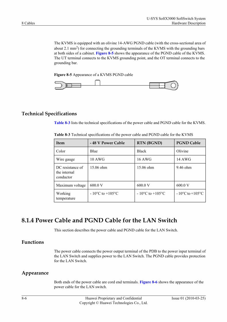
The KVMS is equipped with an olivine 14-AWG PGND cable (with the cross-sectional area ofabout 2.1 mm2) for connecting the grounding terminals of the KVMS with the grounding barsat both sides of a cabinet. Figure 8-5 shows the appearance of the PGND cable of the KVMS.The UT terminal connects to the KVMS grounding point, and the OT terminal connects to thegrounding bar.
Figure 8-5 Appearance of a KVMS PGND cable
Technical Specifications
Table 8-3 lists the technical specifications of the power cable and PGND cable for the KVMS.
Table 8-3 Technical specifications of the power cable and PGND cable for the KVMS
Item - 48 V Power Cable RTN (BGND) PGND Cable
Color Blue Black Olivine
Wire gauge 10 AWG 16 AWG 14 AWG
DC resistance ofthe internalconductor
15.06 ohm 15.06 ohm 9.46 ohm
Maximum voltage 600.0 V 600.0 V 600.0 V
Workingtemperature
- 10°C to +105°C - 10°C to +105°C - 10°C to +105°C
8.1.4 Power Cable and PGND Cable for the LAN SwitchThis section describes the power cable and PGND cable for the LAN Switch.
Functions
The power cable connects the power output terminal of the PDB to the power input terminal ofthe LAN Switch and supplies power to the LAN Switch. The PGND cable provides protectionfor the LAN Switch.
Appearance
Both ends of the power cable are cord end terminals. Figure 8-6 shows the appearance of thepower cable for the LAN switch.
8 CablesU-SYS SoftX3000 SoftSwitch System
Hardware Description
8-6 Huawei Proprietary and ConfidentialCopyright © Huawei Technologies Co., Ltd.
Issue 01 (2010-03-25)

Figure 8-6 Power cable for the LAN Switch
Both ends of the PGND cable are OT terminals. One end is connected to the grounding terminalon the rear panel of a LAN Switch and the other end is grounded locally.
Technical SpecificationsTable 8-4 lists the technical specifications of the power cable and PGND cable for the LANSwitch.
Table 8-4 Technical specifications of the power cable and PGND cable for the LAN Switch
Item - 48 V Power Cable RTN (BGND) PGND Cable
Color Blue Black Olivine
Wire gauge 10 AWG 16 AWG 14 AWG
DC resistance ofthe internalconductor
15.06 Ω 15.06 Ω 9.46 Ω
Maximum voltage 600.0 V 600.0 V 600.0 V
Workingtemperature
- 10°C to +105°C - 10°C to +105°C - 10°C to +105°C
8.1.5 Power Cable and PGND Cable for the BAM or iGWB (IBMx3650 Server)
This section describes the power cable and PGNG cable for the BAM or iGWB (IBM x 3650Tserver).
FunctionsThe power cables connect power output terminals of the PDB to power input terminals of theiGWB/BAM servers for the power supply. The PGND cables provide protection grounding forthe iGWB/BAM servers.
AppearanceThe power input terminals of the IBM X3650 server are located on the leftmost of the rear ofthe server. The two input terminals provide dual power supplies. The power cables and grounding
U-SYS SoftX3000 SoftSwitch SystemHardware Description 8 Cables
Issue 01 (2010-03-25) Huawei Proprietary and ConfidentialCopyright © Huawei Technologies Co., Ltd.
8-7

cables for the iGWB and the BAM are 16-AWG UL1015 wires, with a cross-sectional area ofabout 1.3 mm2, as shown in Figure 8-7. The end connected to a PDB and the power input endare cord end terminals. The grounding cable connects the server by cord end terminal andconnects the grounding bar by OT terminal. The blue cable is -48 V cable, and the black one isRTN cable.
Figure 8-7 Appearance of the power cable and PGND cables for the IBM x3650 server
Technical SpecificationsTable 8-5 shows the technical specifications of the power cable and PGND cable.
Table 8-5 Technical specifications of the power cable and PGND cable
Item -48 V Powercable
RTN(BGND) PGND
Color Blue Black Yellow and green
Gauge 16 AWG 16 AWG -
Conductorimpedance
15.06 ohm 15.06 ohm -
Voltageresistancelevel
600.0 V 600.0 V 600.0 V
Operatingtemperature
-10°C to +105°C -10°C to +105°C -10°C to +105°C
8.1.6 Power Cable and PGND Cable for the BAM or iGWB (DELL2950 Server)
This section describes the power cable and PGND cable for the BAM or iGWB (DELL 2950server).
8 CablesU-SYS SoftX3000 SoftSwitch System
Hardware Description
8-8 Huawei Proprietary and ConfidentialCopyright © Huawei Technologies Co., Ltd.
Issue 01 (2010-03-25)
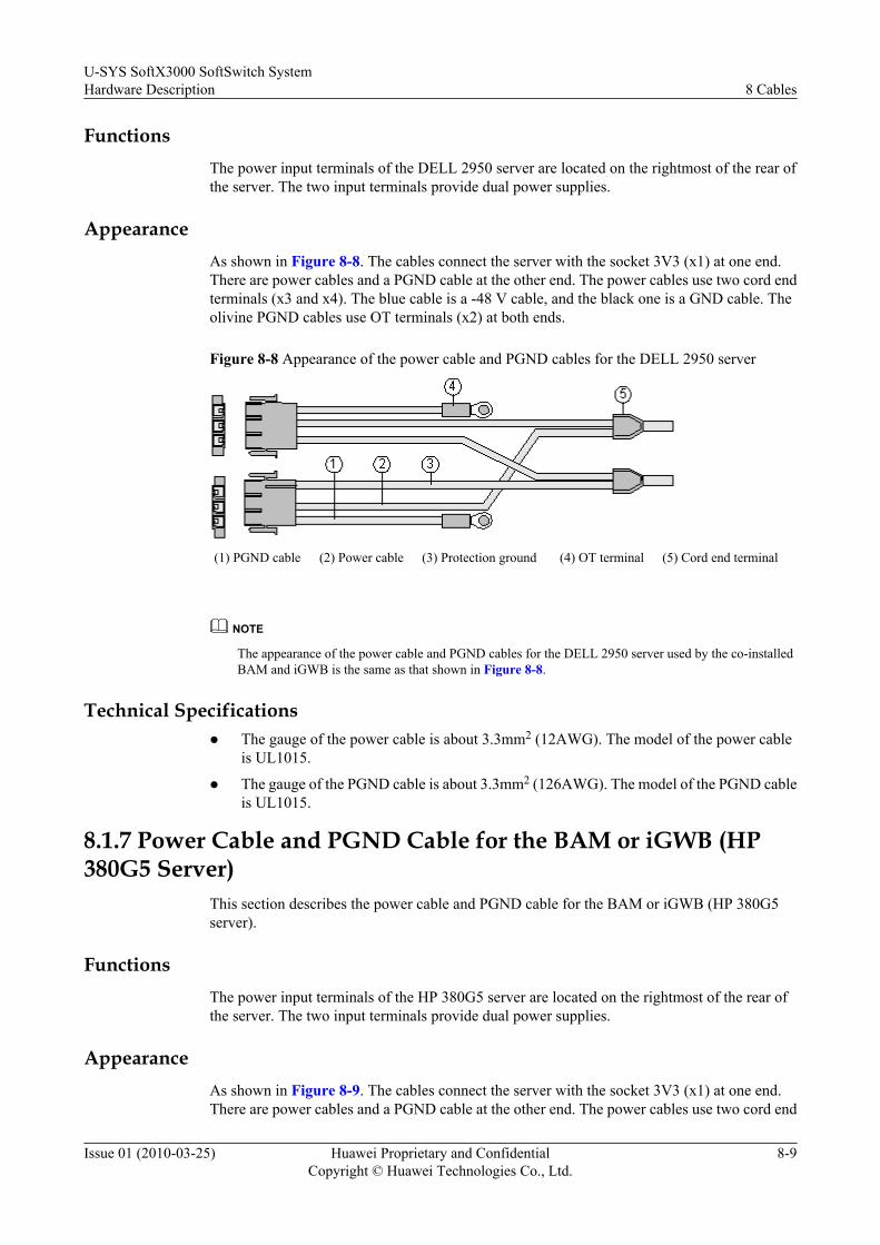
FunctionsThe power input terminals of the DELL 2950 server are located on the rightmost of the rear ofthe server. The two input terminals provide dual power supplies.
AppearanceAs shown in Figure 8-8. The cables connect the server with the socket 3V3 (x1) at one end.There are power cables and a PGND cable at the other end. The power cables use two cord endterminals (x3 and x4). The blue cable is a -48 V cable, and the black one is a GND cable. Theolivine PGND cables use OT terminals (x2) at both ends.
Figure 8-8 Appearance of the power cable and PGND cables for the DELL 2950 server
(1) PGND cable (2) Power cable (3) Protection ground (4) OT terminal (5) Cord end terminal
NOTE
The appearance of the power cable and PGND cables for the DELL 2950 server used by the co-installedBAM and iGWB is the same as that shown in Figure 8-8.
Technical Specificationsl The gauge of the power cable is about 3.3mm2 (12AWG). The model of the power cable
is UL1015.
l The gauge of the PGND cable is about 3.3mm2 (126AWG). The model of the PGND cableis UL1015.
8.1.7 Power Cable and PGND Cable for the BAM or iGWB (HP380G5 Server)
This section describes the power cable and PGND cable for the BAM or iGWB (HP 380G5server).
FunctionsThe power input terminals of the HP 380G5 server are located on the rightmost of the rear ofthe server. The two input terminals provide dual power supplies.
AppearanceAs shown in Figure 8-9. The cables connect the server with the socket 3V3 (x1) at one end.There are power cables and a PGND cable at the other end. The power cables use two cord end
U-SYS SoftX3000 SoftSwitch SystemHardware Description 8 Cables
Issue 01 (2010-03-25) Huawei Proprietary and ConfidentialCopyright © Huawei Technologies Co., Ltd.
8-9
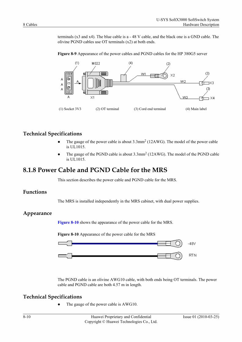
terminals (x3 and x4). The blue cable is a - 48 V cable, and the black one is a GND cable. Theolivine PGND cables use OT terminals (x2) at both ends.
Figure 8-9 Appearance of the power cables and PGND cables for the HP 380G5 server
(1) Socket 3V3 (2) OT terminal (3) Cord end terminal (4) Main label
Technical Specificationsl The gauge of the power cable is about 3.3mm2 (12AWG). The model of the power cable
is UL1015.
l The gauge of the PGND cable is about 3.3mm2 (12AWG). The model of the PGND cableis UL1015.
8.1.8 Power Cable and PGND Cable for the MRSThis section describes the power cable and PGND cable for the MRS.
FunctionsThe MRS is installed independently in the MRS cabinet, with dual power supplies.
AppearanceFigure 8-10 shows the appearance of the power cable for the MRS.
Figure 8-10 Appearance of the power cable for the MRS
The PGND cable is an olivine AWG10 cable, with both ends being OT terminals. The powercable and PGND cable are both 4.57 m in length.
Technical Specificationsl The gauge of the power cable is AWG10.
8 CablesU-SYS SoftX3000 SoftSwitch System
Hardware Description
8-10 Huawei Proprietary and ConfidentialCopyright © Huawei Technologies Co., Ltd.
Issue 01 (2010-03-25)

l The gauge of the PGND cable is AWG10. The PGND cable is in yellow and green.
8.1.9 Other PGND CablesThis section describes other PGND cables.
PGND Cables Between CabinetsThe PGND cables between adjacent cabinets are interconnected on the upper, middle, and lowerpoints of a grounding bar. The PGND cable is a UL1015 cable with the cross-sectional area of10 AWG. It has OT terminals at both ends and is 300 mm in length.
PGND Cables for Cabinet DoorsThe PGND cables for doors are used to connect the grounding terminals on the base of a cabinet,to the front doors, rear doors, and side panels of the cabinet. The PGND cable is UL1015 cablewith the cross-sectional area of 10 AWG and OT terminals at both ends, with one such cableconfigured for each door. The PGND cables for the front and rear doors are 300 mm long, andthose for the side panels are 250 mm long.
PGND Cables for the PDBs (Connected Before Delivery)The PGND cable for a PDB is used to connect the grounding terminal of the PDB and thegrounding bar of a cabinet. The PGND cable is a UL1015 cable with the cross-sectional area of10 AWG. It has OT terminals at both ends and is 250 mm in length.
PGND Cables from the Grounding Bar to the Cabinet Body (Connected BeforeDelivery)
This PGND cable is used to connect the grounding terminal at the top, the bottom, and thegrounding bar of the cabinet. The PGND cable is a ZRA VV cable with the cross-sectional areaof 10 mm2. It has OT terminals at both ends and is 300 mm in length.
8.2 Internal Signal CableThis section describes the internal signal cables of the SoftX3000, including the straight throughcable, FE signal cable, serial port cable between the iGWBs, data cable between the iGWB andthe hard disk array, server/switcher cable and serial port cable for monitoring the PDB.
The internal signal cables are:
8.2.1 Straight Through CableThis section describes the straight through cable.
8.2.2 Serial Port Cable Between iGWBs (HP 380G5 Server)This section describes the serial port cable between the iGWBs (HP 380G5 server).
8.2.3 Serial Port Cable Between the iGWBs (IBM Server)This section describes the serial port cable between the iGWBs (IBM server).
8.2.4 Serial Port Cable Between the iGWBs (DELL 2950 Server)This section describes the serial port cable between the iGWBs (DELL 2950 Server).
8.2.5 Server/Switcher Cable
U-SYS SoftX3000 SoftSwitch SystemHardware Description 8 Cables
Issue 01 (2010-03-25) Huawei Proprietary and ConfidentialCopyright © Huawei Technologies Co., Ltd.
8-11
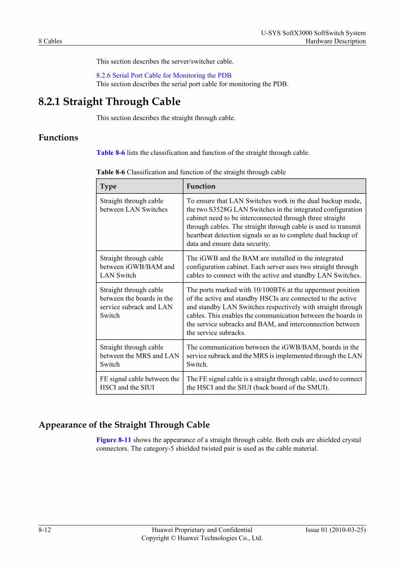
This section describes the server/switcher cable.
8.2.6 Serial Port Cable for Monitoring the PDBThis section describes the serial port cable for monitoring the PDB.
8.2.1 Straight Through CableThis section describes the straight through cable.
FunctionsTable 8-6 lists the classification and function of the straight through cable.
Table 8-6 Classification and function of the straight through cable
Type Function
Straight through cablebetween LAN Switches
To ensure that LAN Switches work in the dual backup mode,the two S3528G LAN Switches in the integrated configurationcabinet need to be interconnected through three straightthrough cables. The straight through cable is used to transmitheartbeat detection signals so as to complete dual backup ofdata and ensure data security.
Straight through cablebetween iGWB/BAM andLAN Switch
The iGWB and the BAM are installed in the integratedconfiguration cabinet. Each server uses two straight throughcables to connect with the active and standby LAN Switches.
Straight through cablebetween the boards in theservice subrack and LANSwitch
The ports marked with 10/100BT6 at the uppermost positionof the active and standby HSCIs are connected to the activeand standby LAN Switches respectively with straight throughcables. This enables the communication between the boards inthe service subracks and BAM, and interconnection betweenthe service subracks.
Straight through cablebetween the MRS and LANSwitch
The communication between the iGWB/BAM, boards in theservice subrack and the MRS is implemented through the LANSwitch.
FE signal cable between theHSCI and the SIUI
The FE signal cable is a straight through cable, used to connectthe HSCI and the SIUI (back board of the SMUI).
Appearance of the Straight Through CableFigure 8-11 shows the appearance of a straight through cable. Both ends are shielded crystalconnectors. The category-5 shielded twisted pair is used as the cable material.
8 CablesU-SYS SoftX3000 SoftSwitch System
Hardware Description
8-12 Huawei Proprietary and ConfidentialCopyright © Huawei Technologies Co., Ltd.
Issue 01 (2010-03-25)
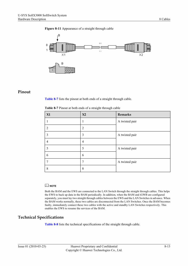
Figure 8-11 Appearance of a straight through cable
PinoutTable 8-7 lists the pinout at both ends of a straight through cable.
Table 8-7 Pinout at both ends of a straight through cable
X1 X2 Remarks
1 1 A twisted pair
2 2
3 3 A twisted pair
4 4
5 5 A twisted pair
6 6
7 7 A twisted pair
8 8
NOTE
Both the BAM and the EWS are connected to the LAN Switch through the straight through cables. This helpsthe EWS to back up data in the BAM periodically. In addition, when the BAM and iGWB are configuredseparately, you must lay two straight through cables between the EWS and the LAN Switches in advance. Whenthe BAM works normally, these two cables are disconnected from the LAN Switches. Once the BAM becomesfaulty, immediately connect these two cables with the active and standby LAN Switches respectively. Thisenables the EWS to resume the services of the BAM.
Technical SpecificationsTable 8-8 lists the technical specifications of the straight through cable.
U-SYS SoftX3000 SoftSwitch SystemHardware Description 8 Cables
Issue 01 (2010-03-25) Huawei Proprietary and ConfidentialCopyright © Huawei Technologies Co., Ltd.
8-13

Table 8-8 Technical specifications of the straight through cable
Item Specifications
Characteristic impedance 100.0 ohm
Core diameter of the internal conductor 0.510 mm
Wire gauge of the internal conductor 24 AWG
Working temperature - 15°C to +75°C
Frequency range 0 MHz - 100 MHz
Frequency attenuation 6.5 dB/10 MHz, 22 dB/100 MHz
8.2.2 Serial Port Cable Between iGWBs (HP 380G5 Server)This section describes the serial port cable between the iGWBs (HP 380G5 server).
FunctionsTo ensure the dual backup of the iGWBs, it is required to connect the two iGWBs in the integratedconfiguration cabinet through a serial port cable. The cable forms the second heartbeat signalpath between the active and standby iGWBs.
NOTE
The active and standby iGWBs connect to the bill console or NMS device through the hub. The externalnetwork cable connected to the hub serves as the first heartbeat signal path between the active and standbyiGWBs.
AppearanceThe serial port cable is a four-core round shielded cable, with a cross-sectional area of 26 AWGand DB9 sockets at both ends. Figure 8-12 shows the appearance of the serial port cable.
Figure 8-12 Appearance of the serial port cable connecting two iGWBs
(1) Main label
PinoutTable 8-9 lists the pinout at both ends of a serial port cable.
8 CablesU-SYS SoftX3000 SoftSwitch System
Hardware Description
8-14 Huawei Proprietary and ConfidentialCopyright © Huawei Technologies Co., Ltd.
Issue 01 (2010-03-25)

Table 8-9 Pinout at both ends of a serial port cable
X1 X2 Color
2 3 Red
3 2 Yellow
5 5 Black
Technical Specifications
Table 8-10 lists the technical specifications of the serial port cable between the iGWBs.
Table 8-10 Technical specifications of the serial port cable between the iGWBs
Item Specifications
Core diameter of the internal conductor 0.480 mm
Color Black
Breakdown voltage 1000.0 V
DC resistance of the internal conductor 148.96 ohm
Working temperature -15°C to +80°C
8.2.3 Serial Port Cable Between the iGWBs (IBM Server)This section describes the serial port cable between the iGWBs (IBM server).
Functions
To ensure the dual backup of the iGWBs, it is required to connect the two iGWBs in the integratedconfiguration cabinet through a serial port cable. The cable forms the second heartbeat signalpath between the active and standby iGWBs.
NOTE
The active and standby iGWBs connect to the bill console or NMS device through the hub. The externalnetwork cable connected to the hub serves as the first heartbeat signal path between the active and standbyiGWBs.
Appearance
The serial port cable is an enhanced C5 eight-core shielded twisted-pair cable, with a cross-sectional area of 24 AWG and RJ45 crystal connectors at both ends. Figure 8-13 shows theappearance of the serial port cable.
U-SYS SoftX3000 SoftSwitch SystemHardware Description 8 Cables
Issue 01 (2010-03-25) Huawei Proprietary and ConfidentialCopyright © Huawei Technologies Co., Ltd.
8-15
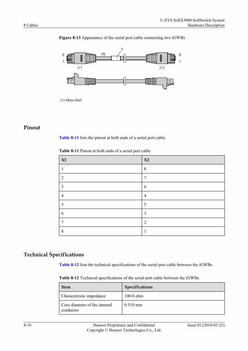
Figure 8-13 Appearance of the serial port cable connecting two iGWBs
(1) Main label
Pinout
Table 8-11 lists the pinout at both ends of a serial port cable.
Table 8-11 Pinout at both ends of a serial port cable
X1 X2
1 8
2 7
3 6
4 4
5 5
6 3
7 2
8 1
Technical Specifications
Table 8-12 lists the technical specifications of the serial port cable between the iGWBs.
Table 8-12 Technical specifications of the serial port cable between the iGWBs
Item Specifications
Characteristic impedance 100.0 ohm
Core diameter of the internalconductor
0.510 mm
8 CablesU-SYS SoftX3000 SoftSwitch System
Hardware Description
8-16 Huawei Proprietary and ConfidentialCopyright © Huawei Technologies Co., Ltd.
Issue 01 (2010-03-25)
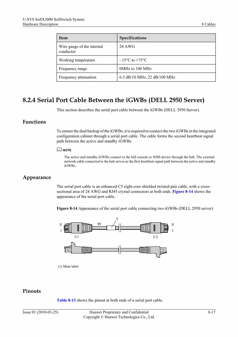
Item Specifications
Wire gauge of the internalconductor
24 AWG
Working temperature - 15°C to +75°C
Frequency range 0MHz to 100 MHz
Frequency attenuation 6.5 dB/10 MHz, 22 dB/100 MHz
8.2.4 Serial Port Cable Between the iGWBs (DELL 2950 Server)This section describes the serial port cable between the iGWBs (DELL 2950 Server).
FunctionsTo ensure the dual backup of the iGWBs, it is required to connect the two iGWBs in the integratedconfiguration cabinet through a serial port cable. The cable forms the second heartbeat signalpath between the active and standby iGWBs.
NOTE
The active and standby iGWBs connect to the bill console or NMS device through the hub. The externalnetwork cable connected to the hub serves as the first heartbeat signal path between the active and standbyiGWBs.
AppearanceThe serial port cable is an enhanced C5 eight-core shielded twisted-pair cable, with a cross-sectional area of 24 AWG and RJ45 crystal connectors at both ends. Figure 8-14 shows theappearance of the serial port cable.
Figure 8-14 Appearance of the serial port cable connecting two iGWBs (DELL 2950 server)
(1) Main label
PinoutsTable 8-13 shows the pinout at both ends of a serial port cable.
U-SYS SoftX3000 SoftSwitch SystemHardware Description 8 Cables
Issue 01 (2010-03-25) Huawei Proprietary and ConfidentialCopyright © Huawei Technologies Co., Ltd.
8-17
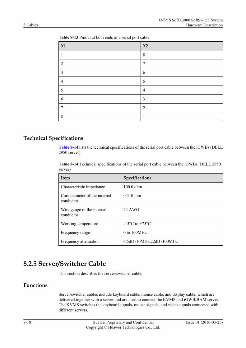
Table 8-13 Pinout at both ends of a serial port cable
X1 X2
1 8
2 7
3 6
4 5
5 4
6 3
7 2
8 1
Technical SpecificationsTable 8-14 lists the technical specifications of the serial port cable between the iGWBs (DELL2950 server).
Table 8-14 Technical specifications of the serial port cable between the iGWBs (DELL 2950server)
Item Specifications
Characteristic impedance 100.0 ohm
Core diameter of the internalconductor
0.510 mm
Wire gauge of the internalconductor
24 AWG
Working temperature -15°C to +75°C
Frequency range 0 to 100MHz
Frequency attenuation 6.5dB /10MHz,22dB /100MHz
8.2.5 Server/Switcher CableThis section describes the server/switcher cable.
FunctionsServer/switcher cables include keyboard cable, mouse cable, and display cable, which aredelivered together with a server and are used to connect the KVMS and iGWB/BAM server.The KVMS switches the keyboard signals, mouse signals, and video signals connected withdifferent servers.
8 CablesU-SYS SoftX3000 SoftSwitch System
Hardware Description
8-18 Huawei Proprietary and ConfidentialCopyright © Huawei Technologies Co., Ltd.
Issue 01 (2010-03-25)
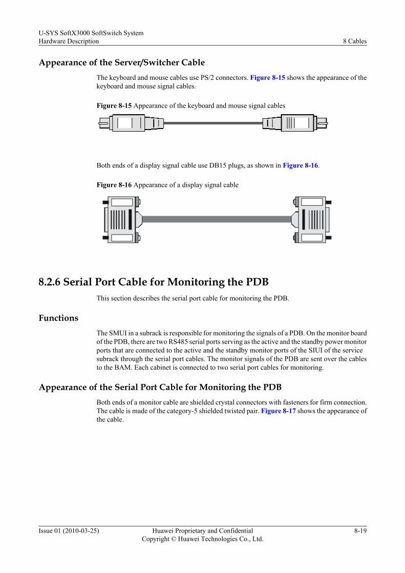
Appearance of the Server/Switcher CableThe keyboard and mouse cables use PS/2 connectors. Figure 8-15 shows the appearance of thekeyboard and mouse signal cables.
Figure 8-15 Appearance of the keyboard and mouse signal cables
Both ends of a display signal cable use DB15 plugs, as shown in Figure 8-16.
Figure 8-16 Appearance of a display signal cable
8.2.6 Serial Port Cable for Monitoring the PDBThis section describes the serial port cable for monitoring the PDB.
FunctionsThe SMUI in a subrack is responsible for monitoring the signals of a PDB. On the monitor boardof the PDB, there are two RS485 serial ports serving as the active and the standby power monitorports that are connected to the active and the standby monitor ports of the SIUI of the servicesubrack through the serial port cables. The monitor signals of the PDB are sent over the cablesto the BAM. Each cabinet is connected to two serial port cables for monitoring.
Appearance of the Serial Port Cable for Monitoring the PDBBoth ends of a monitor cable are shielded crystal connectors with fasteners for firm connection.The cable is made of the category-5 shielded twisted pair. Figure 8-17 shows the appearance ofthe cable.
U-SYS SoftX3000 SoftSwitch SystemHardware Description 8 Cables
Issue 01 (2010-03-25) Huawei Proprietary and ConfidentialCopyright © Huawei Technologies Co., Ltd.
8-19
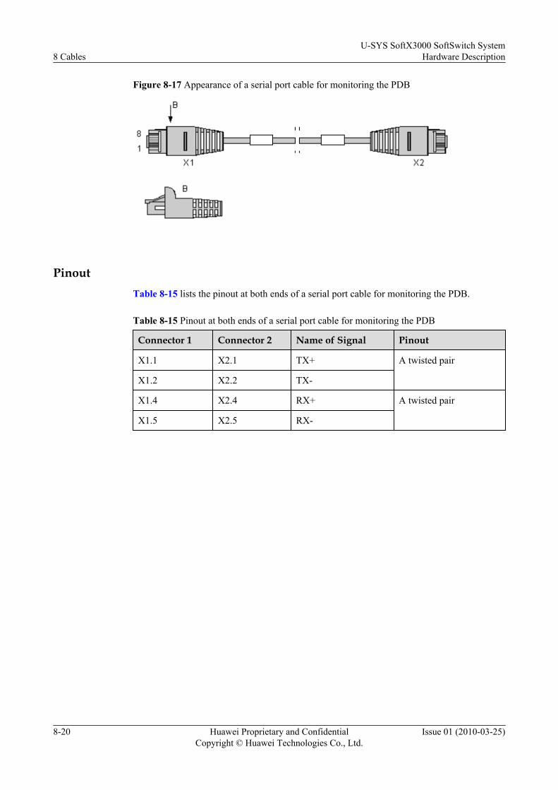
Figure 8-17 Appearance of a serial port cable for monitoring the PDB
PinoutTable 8-15 lists the pinout at both ends of a serial port cable for monitoring the PDB.
Table 8-15 Pinout at both ends of a serial port cable for monitoring the PDB
Connector 1 Connector 2 Name of Signal Pinout
X1.1 X2.1 TX+ A twisted pair
X1.2 X2.2 TX-
X1.4 X2.4 RX+ A twisted pair
X1.5 X2.5 RX-
8 CablesU-SYS SoftX3000 SoftSwitch System
Hardware Description
8-20 Huawei Proprietary and ConfidentialCopyright © Huawei Technologies Co., Ltd.
Issue 01 (2010-03-25)

9 Labels
About This Chapter
This section describes labels based on their features, types, and structures.
9.1 Label Materials and FeaturesThis section describes materials and features of labels.
9.2 Label Types and StructuresThis section describes types and structures of labels.
U-SYS SoftX3000 SoftSwitch SystemHardware Description 9 Labels
Issue 01 (2010-03-25) Huawei Proprietary and ConfidentialCopyright © Huawei Technologies Co., Ltd.
9-1

9.1 Label Materials and FeaturesThis section describes materials and features of labels.
The labels feature the following:
l They are 0.09 mm thick.
l Their color is white.
l They use polyester (PET) as materials, certificated by Underwriter LaboratoriesIncorporation (UL) and the Canadian Standards Association (CSA).
l They are applicable to the temperature from - 29°C to +149°C.
l They can be used for laser printing and written by oil markers.
9.2 Label Types and StructuresThis section describes types and structures of labels.
Engineering labels fall into signal cable labels and power cable labels.
Signal Cable LabelsSignal cable labels are in the flap-type structure of fixed size (unit: mm), as shown in Figure9-1.
Figure 9-1 Signal cable label paper
(1) Dividing line (2) Cut dotted line
9 LabelsU-SYS SoftX3000 SoftSwitch System
Hardware Description
9-2 Huawei Proprietary and ConfidentialCopyright © Huawei Technologies Co., Ltd.
Issue 01 (2010-03-25)
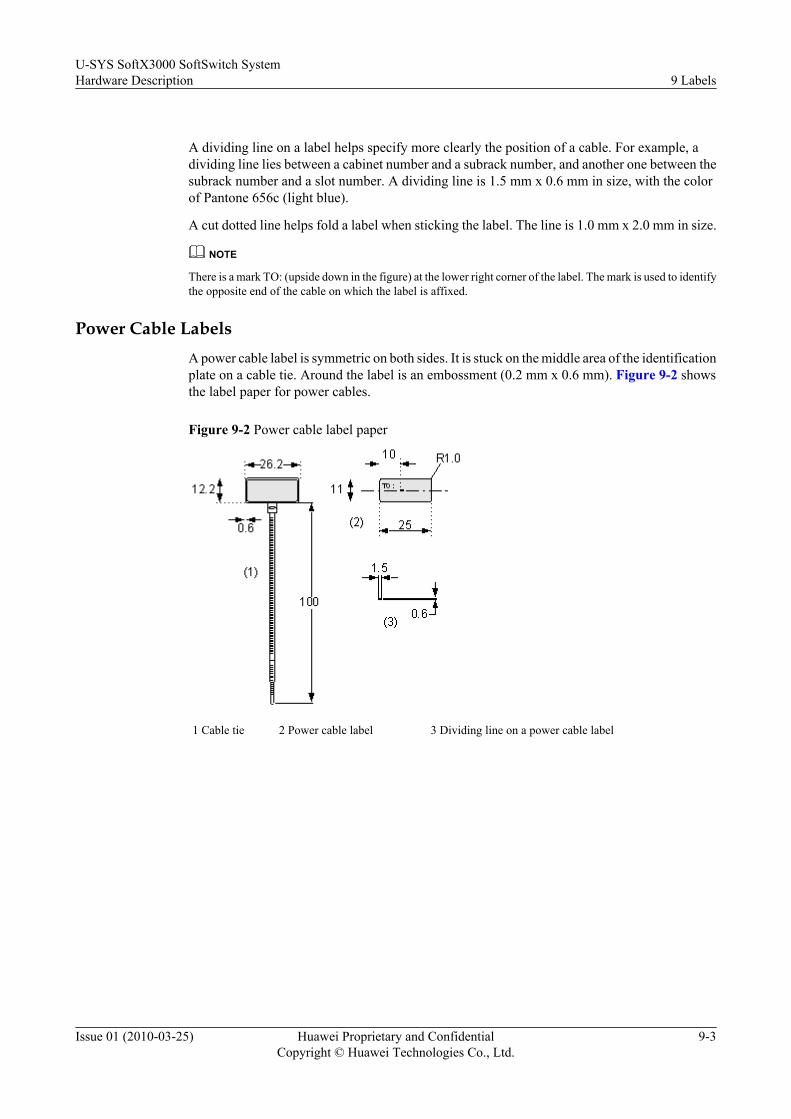
A dividing line on a label helps specify more clearly the position of a cable. For example, adividing line lies between a cabinet number and a subrack number, and another one between thesubrack number and a slot number. A dividing line is 1.5 mm x 0.6 mm in size, with the colorof Pantone 656c (light blue).
A cut dotted line helps fold a label when sticking the label. The line is 1.0 mm x 2.0 mm in size.
NOTE
There is a mark TO: (upside down in the figure) at the lower right corner of the label. The mark is used to identifythe opposite end of the cable on which the label is affixed.
Power Cable LabelsA power cable label is symmetric on both sides. It is stuck on the middle area of the identificationplate on a cable tie. Around the label is an embossment (0.2 mm x 0.6 mm). Figure 9-2 showsthe label paper for power cables.
Figure 9-2 Power cable label paper
1 Cable tie 2 Power cable label 3 Dividing line on a power cable label
U-SYS SoftX3000 SoftSwitch SystemHardware Description 9 Labels
Issue 01 (2010-03-25) Huawei Proprietary and ConfidentialCopyright © Huawei Technologies Co., Ltd.
9-3