hardware description - huawei 7800&6800&5800 series switches hardware description issue 08...
TRANSCRIPT
CloudEngine 7800&6800&5800 Series Switches
Hardware Description
Issue 08
Date 2014-04-21
HUAWEI TECHNOLOGIES CO., LTD.
Copyright © Huawei Technologies Co., Ltd. 2014. All rights reserved.
No part of this document may be reproduced or transmitted in any form or by any means without prior writtenconsent of Huawei Technologies Co., Ltd. Trademarks and Permissions
and other Huawei trademarks are trademarks of Huawei Technologies Co., Ltd.All other trademarks and trade names mentioned in this document are the property of their respective holders. NoticeThe purchased products, services and features are stipulated by the contract made between Huawei and thecustomer. All or part of the products, services and features described in this document may not be within thepurchase scope or the usage scope. Unless otherwise specified in the contract, all statements, information,and recommendations in this document are provided "AS IS" without warranties, guarantees or representationsof any kind, either express or implied.
The information in this document is subject to change without notice. Every effort has been made in thepreparation of this document to ensure accuracy of the contents, but all statements, information, andrecommendations in this document do not constitute a warranty of any kind, express or implied.
Huawei Technologies Co., Ltd.Address: Huawei Industrial Base
Bantian, LonggangShenzhen 518129People's Republic of China
Website: http://enterprise.huawei.com
Issue 08 (2014-04-21) Huawei Proprietary and ConfidentialCopyright © Huawei Technologies Co., Ltd.
i
About This Document
Intended AudienceThis document describes hardware components of the CE7800&6800&5800 series switches,including the chassis, power modules, fan modules, cables, and optical modules. You can finduseful information about CE7800&6800&5800 series switches hardware components from thisdocument.
This document is intended for:
l Network planning engineersl Hardware installation engineersl Commissioning engineersl On-site maintenance engineersl System maintenance engineers
Symbol ConventionsThe symbols that may be found in this document are defined as follows.
Symbol Description
Indicates an imminently hazardous situationwhich, if not avoided, will result in death orserious injury.
Indicates a potentially hazardous situationwhich, if not avoided, could result in death orserious injury.
Indicates a potentially hazardous situationwhich, if not avoided, may result in minor ormoderate injury.
CloudEngine 7800&6800&5800 Series SwitchesHardware Description About This Document
Issue 08 (2014-04-21) Huawei Proprietary and ConfidentialCopyright © Huawei Technologies Co., Ltd.
ii
Symbol Description
Indicates a potentially hazardous situationwhich, if not avoided, could result inequipment damage, data loss, performancedeterioration, or unanticipated results.NOTICE is used to address practices notrelated to personal injury.
NOTE Calls attention to important information, bestpractices and tips.NOTE is used to address information notrelated to personal injury, equipment damage,and environment deterioration.
Command ConventionsThe command conventions that may be found in this document are defined as follows.
Convention Description
Boldface The keywords of a command line are in boldface.
Italic Command arguments are in italics.
[ ] Items (keywords or arguments) in brackets [ ] are optional.
{ x | y | ... } Optional items are grouped in braces and separated byvertical bars. One item is selected.
[ x | y | ... ] Optional items are grouped in brackets and separated byvertical bars. One item is selected or no item is selected.
{ x | y | ... }* Optional items are grouped in braces and separated byvertical bars. A minimum of one item or a maximum of allitems can be selected.
[ x | y | ... ]* Optional items are grouped in brackets and separated byvertical bars. Several items or no item can be selected.
&<1-n> The parameter before the & sign can be repeated 1 to n times.
# A line starting with the # sign is comments.
Change HistoryChanges between document issues are cumulative. The latest document issue contains all thechanges made in earlier issues.
CloudEngine 7800&6800&5800 Series SwitchesHardware Description About This Document
Issue 08 (2014-04-21) Huawei Proprietary and ConfidentialCopyright © Huawei Technologies Co., Ltd.
iii
Issue 08 (2014-04-21)
This version has the following updates:
The following information is added:
l CE7850-32Q-EI
l CE6810-48S4Q-EI
Issue 07 (2013-12-31)
This version has the following updates:
The following information is added:
l CE5850-48T4S2Q-HI
Issue 06 (2013-12-01)
This version has the following updates:
The following information is modified:
l 2.5 Specifications
Issue 05 (2013-11-20)
This version has the following updates:
The following information is modified:
l 2.5 Specifications
Issue 04 (2013-10-15)
This version has the following updates:
The following information is modified:
l 3 Power Module
Issue 03 (2013-08-01)
This version has the following updates:
The following information is added:
l 3.3 350 W DC Power Module
l 3.4 600 W AC Power Module
l 4.2 FAN-40SB Series Fan Modules
l 5.2 DC Power Cable
The following information is modified:
l 2 Chassis
l 6 Optical Module
CloudEngine 7800&6800&5800 Series SwitchesHardware Description About This Document
Issue 08 (2014-04-21) Huawei Proprietary and ConfidentialCopyright © Huawei Technologies Co., Ltd.
iv
Issue 02 (2013-04-20)This version has the following updates:
The following information is modified:l 2.3 Indicators
Issue 01 (2013-03-15)Initial commercial release.
CloudEngine 7800&6800&5800 Series SwitchesHardware Description About This Document
Issue 08 (2014-04-21) Huawei Proprietary and ConfidentialCopyright © Huawei Technologies Co., Ltd.
v
Contents
About This Document.....................................................................................................................ii
1 Version Support for Components..............................................................................................11.1 Components Available in V100R001C00......................................................................................................................21.2 Components Available in V100R002C00......................................................................................................................31.3 Components Available in V100R003C00......................................................................................................................4
2 Chassis.............................................................................................................................................72.1 Version Mapping............................................................................................................................................................82.2 Appearance and Structure...............................................................................................................................................82.3 Indicators......................................................................................................................................................................232.4 Ports..............................................................................................................................................................................372.5 Specifications................................................................................................................................................................40
3 Power Module..............................................................................................................................473.1 150 W AC Power Module............................................................................................................................................483.2 350 W AC Power Module............................................................................................................................................523.3 350 W DC Power Module............................................................................................................................................563.4 600 W AC Power Module............................................................................................................................................60
4 Fan Module...................................................................................................................................654.1 FAN-40EA Series Fan Modules...................................................................................................................................664.2 FAN-40SB Series Fan Modules...................................................................................................................................694.3 FAN-40HA Series Fan Modules..................................................................................................................................73
5 Cables.............................................................................................................................................775.1 AC Power Cable...........................................................................................................................................................785.2 DC Power Cable...........................................................................................................................................................795.3 Ground Cable................................................................................................................................................................805.4 Console Cable...............................................................................................................................................................825.5 Network Cable..............................................................................................................................................................835.6 Optical Fiber.................................................................................................................................................................885.7 AOC Cable...................................................................................................................................................................955.8 Copper Cable................................................................................................................................................................96
6 Optical Module..........................................................................................................................100
CloudEngine 7800&6800&5800 Series SwitchesHardware Description Contents
Issue 08 (2014-04-21) Huawei Proprietary and ConfidentialCopyright © Huawei Technologies Co., Ltd.
vi
6.1 Concepts.....................................................................................................................................................................1016.2 SFP/SFP+ Modules.....................................................................................................................................................1036.3 QSFP+ Modules.........................................................................................................................................................111
CloudEngine 7800&6800&5800 Series SwitchesHardware Description Contents
Issue 08 (2014-04-21) Huawei Proprietary and ConfidentialCopyright © Huawei Technologies Co., Ltd.
vii
1 Version Support for Components
About This Chapter
NOTE
The availability of device models and modules described in this document will be specified in productchange notices (PCNs). For details, contact the product manager of Huawei local office.
The versions mentioned in this document refer to the software versions released for theCE7800&6800&5800 series switches.
1.1 Components Available in V100R001C00
1.2 Components Available in V100R002C00
1.3 Components Available in V100R003C00
CloudEngine 7800&6800&5800 Series SwitchesHardware Description 1 Version Support for Components
Issue 08 (2014-04-21) Huawei Proprietary and ConfidentialCopyright © Huawei Technologies Co., Ltd.
1
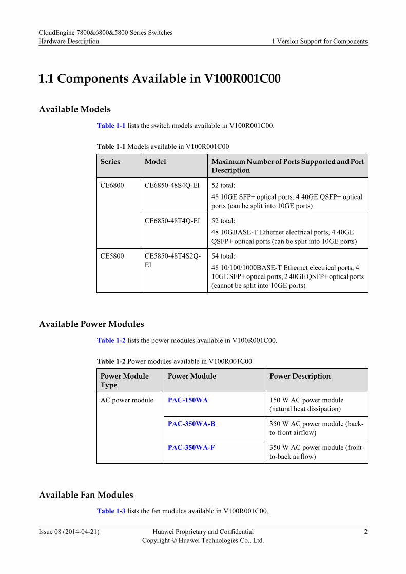
1.1 Components Available in V100R001C00
Available Models
Table 1-1 lists the switch models available in V100R001C00.
Table 1-1 Models available in V100R001C00
Series Model Maximum Number of Ports Supported and PortDescription
CE6800 CE6850-48S4Q-EI 52 total:48 10GE SFP+ optical ports, 4 40GE QSFP+ opticalports (can be split into 10GE ports)
CE6850-48T4Q-EI 52 total:48 10GBASE-T Ethernet electrical ports, 4 40GEQSFP+ optical ports (can be split into 10GE ports)
CE5800 CE5850-48T4S2Q-EI
54 total:48 10/100/1000BASE-T Ethernet electrical ports, 410GE SFP+ optical ports, 2 40GE QSFP+ optical ports(cannot be split into 10GE ports)
Available Power Modules
Table 1-2 lists the power modules available in V100R001C00.
Table 1-2 Power modules available in V100R001C00
Power ModuleType
Power Module Power Description
AC power module PAC-150WA 150 W AC power module(natural heat dissipation)
PAC-350WA-B 350 W AC power module (back-to-front airflow)
PAC-350WA-F 350 W AC power module (front-to-back airflow)
Available Fan Modules
Table 1-3 lists the fan modules available in V100R001C00.
CloudEngine 7800&6800&5800 Series SwitchesHardware Description 1 Version Support for Components
Issue 08 (2014-04-21) Huawei Proprietary and ConfidentialCopyright © Huawei Technologies Co., Ltd.
2
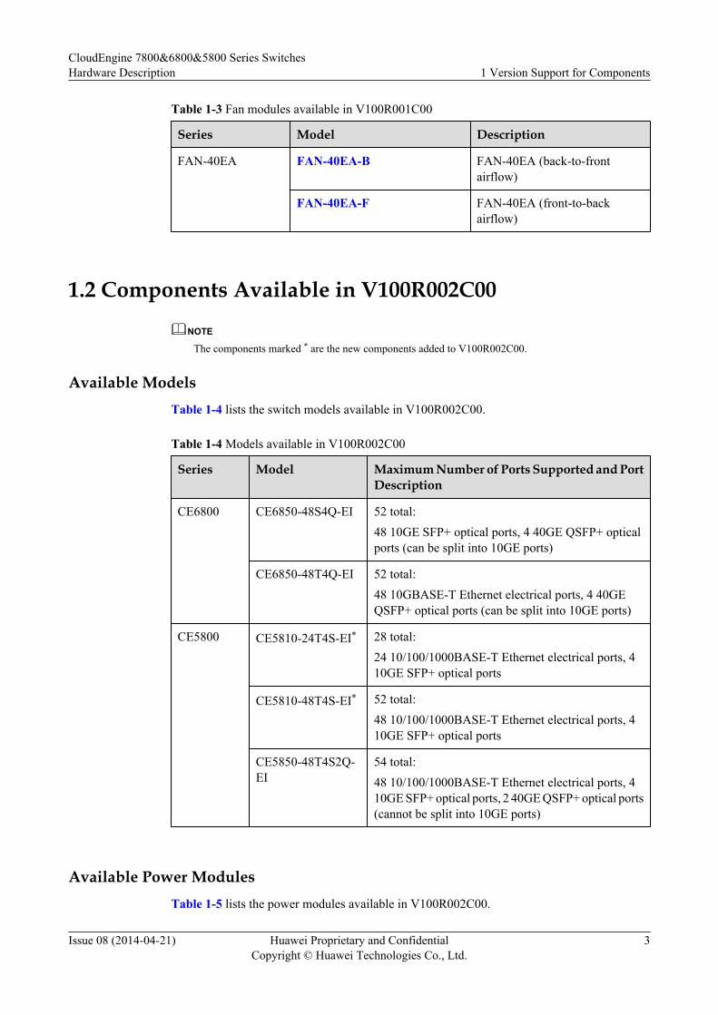
Table 1-3 Fan modules available in V100R001C00
Series Model Description
FAN-40EA FAN-40EA-B FAN-40EA (back-to-frontairflow)
FAN-40EA-F FAN-40EA (front-to-backairflow)
1.2 Components Available in V100R002C00
NOTE
The components marked * are the new components added to V100R002C00.
Available ModelsTable 1-4 lists the switch models available in V100R002C00.
Table 1-4 Models available in V100R002C00
Series Model Maximum Number of Ports Supported and PortDescription
CE6800 CE6850-48S4Q-EI 52 total:48 10GE SFP+ optical ports, 4 40GE QSFP+ opticalports (can be split into 10GE ports)
CE6850-48T4Q-EI 52 total:48 10GBASE-T Ethernet electrical ports, 4 40GEQSFP+ optical ports (can be split into 10GE ports)
CE5800 CE5810-24T4S-EI* 28 total:24 10/100/1000BASE-T Ethernet electrical ports, 410GE SFP+ optical ports
CE5810-48T4S-EI* 52 total:48 10/100/1000BASE-T Ethernet electrical ports, 410GE SFP+ optical ports
CE5850-48T4S2Q-EI
54 total:48 10/100/1000BASE-T Ethernet electrical ports, 410GE SFP+ optical ports, 2 40GE QSFP+ optical ports(cannot be split into 10GE ports)
Available Power ModulesTable 1-5 lists the power modules available in V100R002C00.
CloudEngine 7800&6800&5800 Series SwitchesHardware Description 1 Version Support for Components
Issue 08 (2014-04-21) Huawei Proprietary and ConfidentialCopyright © Huawei Technologies Co., Ltd.
3
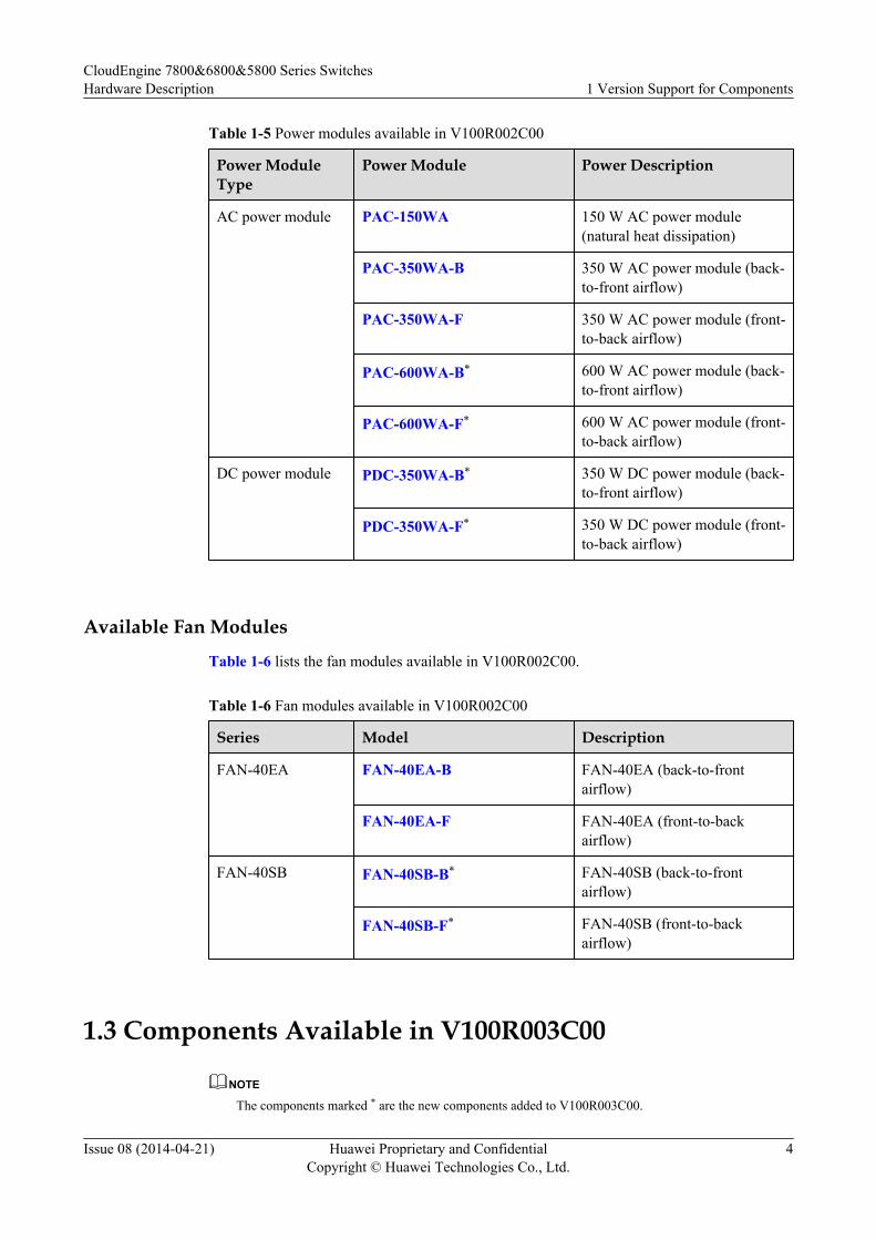
Table 1-5 Power modules available in V100R002C00
Power ModuleType
Power Module Power Description
AC power module PAC-150WA 150 W AC power module(natural heat dissipation)
PAC-350WA-B 350 W AC power module (back-to-front airflow)
PAC-350WA-F 350 W AC power module (front-to-back airflow)
PAC-600WA-B* 600 W AC power module (back-to-front airflow)
PAC-600WA-F* 600 W AC power module (front-to-back airflow)
DC power module PDC-350WA-B* 350 W DC power module (back-to-front airflow)
PDC-350WA-F* 350 W DC power module (front-to-back airflow)
Available Fan Modules
Table 1-6 lists the fan modules available in V100R002C00.
Table 1-6 Fan modules available in V100R002C00
Series Model Description
FAN-40EA FAN-40EA-B FAN-40EA (back-to-frontairflow)
FAN-40EA-F FAN-40EA (front-to-backairflow)
FAN-40SB FAN-40SB-B* FAN-40SB (back-to-frontairflow)
FAN-40SB-F* FAN-40SB (front-to-backairflow)
1.3 Components Available in V100R003C00
NOTE
The components marked * are the new components added to V100R003C00.
CloudEngine 7800&6800&5800 Series SwitchesHardware Description 1 Version Support for Components
Issue 08 (2014-04-21) Huawei Proprietary and ConfidentialCopyright © Huawei Technologies Co., Ltd.
4
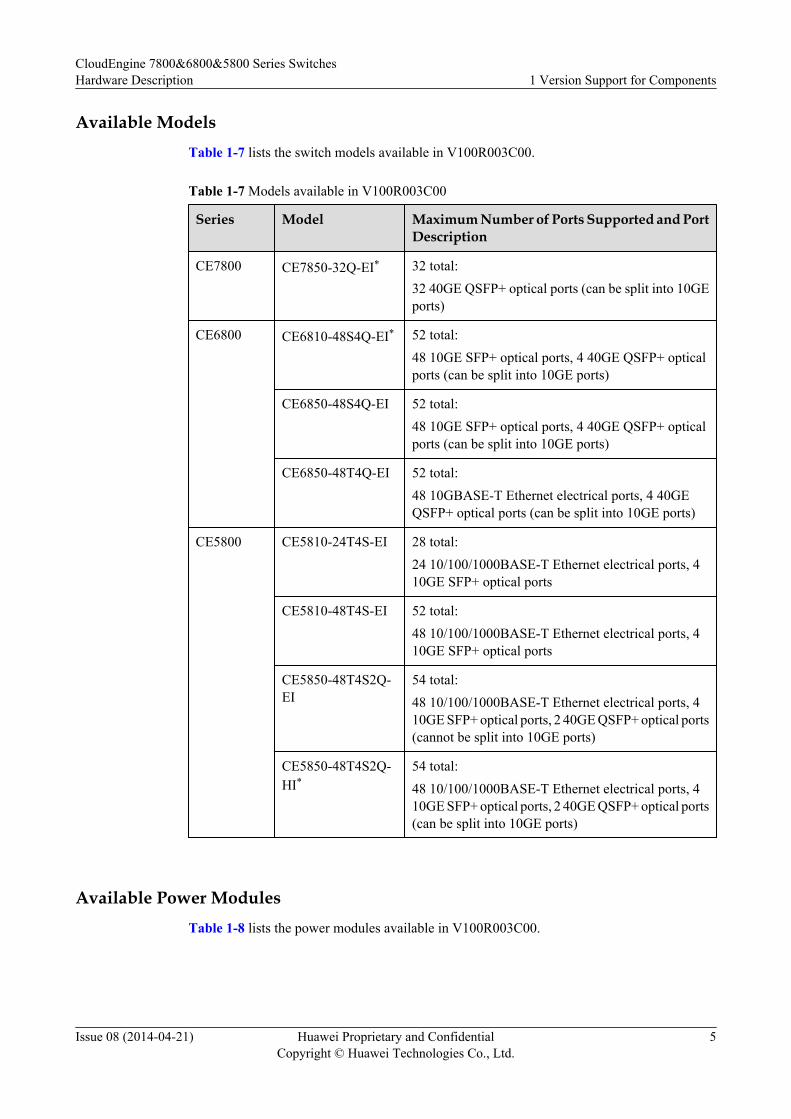
Available ModelsTable 1-7 lists the switch models available in V100R003C00.
Table 1-7 Models available in V100R003C00
Series Model Maximum Number of Ports Supported and PortDescription
CE7800 CE7850-32Q-EI* 32 total:32 40GE QSFP+ optical ports (can be split into 10GEports)
CE6800 CE6810-48S4Q-EI* 52 total:48 10GE SFP+ optical ports, 4 40GE QSFP+ opticalports (can be split into 10GE ports)
CE6850-48S4Q-EI 52 total:48 10GE SFP+ optical ports, 4 40GE QSFP+ opticalports (can be split into 10GE ports)
CE6850-48T4Q-EI 52 total:48 10GBASE-T Ethernet electrical ports, 4 40GEQSFP+ optical ports (can be split into 10GE ports)
CE5800 CE5810-24T4S-EI 28 total:24 10/100/1000BASE-T Ethernet electrical ports, 410GE SFP+ optical ports
CE5810-48T4S-EI 52 total:48 10/100/1000BASE-T Ethernet electrical ports, 410GE SFP+ optical ports
CE5850-48T4S2Q-EI
54 total:48 10/100/1000BASE-T Ethernet electrical ports, 410GE SFP+ optical ports, 2 40GE QSFP+ optical ports(cannot be split into 10GE ports)
CE5850-48T4S2Q-HI*
54 total:48 10/100/1000BASE-T Ethernet electrical ports, 410GE SFP+ optical ports, 2 40GE QSFP+ optical ports(can be split into 10GE ports)
Available Power ModulesTable 1-8 lists the power modules available in V100R003C00.
CloudEngine 7800&6800&5800 Series SwitchesHardware Description 1 Version Support for Components
Issue 08 (2014-04-21) Huawei Proprietary and ConfidentialCopyright © Huawei Technologies Co., Ltd.
5
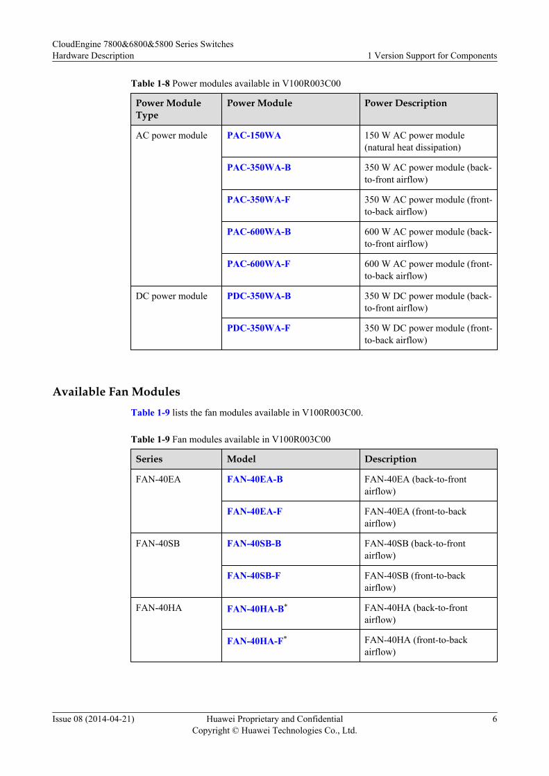
Table 1-8 Power modules available in V100R003C00
Power ModuleType
Power Module Power Description
AC power module PAC-150WA 150 W AC power module(natural heat dissipation)
PAC-350WA-B 350 W AC power module (back-to-front airflow)
PAC-350WA-F 350 W AC power module (front-to-back airflow)
PAC-600WA-B 600 W AC power module (back-to-front airflow)
PAC-600WA-F 600 W AC power module (front-to-back airflow)
DC power module PDC-350WA-B 350 W DC power module (back-to-front airflow)
PDC-350WA-F 350 W DC power module (front-to-back airflow)
Available Fan ModulesTable 1-9 lists the fan modules available in V100R003C00.
Table 1-9 Fan modules available in V100R003C00
Series Model Description
FAN-40EA FAN-40EA-B FAN-40EA (back-to-frontairflow)
FAN-40EA-F FAN-40EA (front-to-backairflow)
FAN-40SB FAN-40SB-B FAN-40SB (back-to-frontairflow)
FAN-40SB-F FAN-40SB (front-to-backairflow)
FAN-40HA FAN-40HA-B* FAN-40HA (back-to-frontairflow)
FAN-40HA-F* FAN-40HA (front-to-backairflow)
CloudEngine 7800&6800&5800 Series SwitchesHardware Description 1 Version Support for Components
Issue 08 (2014-04-21) Huawei Proprietary and ConfidentialCopyright © Huawei Technologies Co., Ltd.
6
2 Chassis
About This Chapter
2.1 Version Mapping
2.2 Appearance and Structure
2.3 Indicators
2.4 Ports
2.5 Specifications
CloudEngine 7800&6800&5800 Series SwitchesHardware Description 2 Chassis
Issue 08 (2014-04-21) Huawei Proprietary and ConfidentialCopyright © Huawei Technologies Co., Ltd.
7
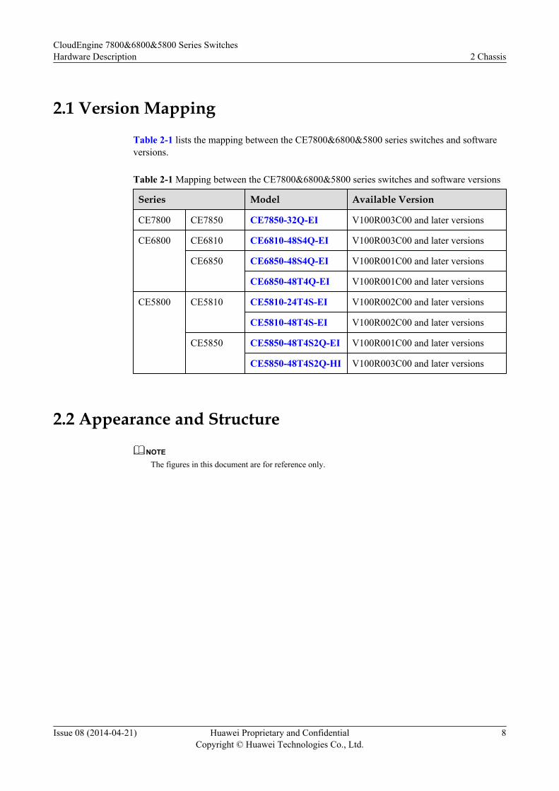
2.1 Version Mapping
Table 2-1 lists the mapping between the CE7800&6800&5800 series switches and softwareversions.
Table 2-1 Mapping between the CE7800&6800&5800 series switches and software versions
Series Model Available Version
CE7800 CE7850 CE7850-32Q-EI V100R003C00 and later versions
CE6800 CE6810 CE6810-48S4Q-EI V100R003C00 and later versions
CE6850 CE6850-48S4Q-EI V100R001C00 and later versions
CE6850-48T4Q-EI V100R001C00 and later versions
CE5800 CE5810 CE5810-24T4S-EI V100R002C00 and later versions
CE5810-48T4S-EI V100R002C00 and later versions
CE5850 CE5850-48T4S2Q-EI V100R001C00 and later versions
CE5850-48T4S2Q-HI V100R003C00 and later versions
2.2 Appearance and Structure
NOTE
The figures in this document are for reference only.
CloudEngine 7800&6800&5800 Series SwitchesHardware Description 2 Chassis
Issue 08 (2014-04-21) Huawei Proprietary and ConfidentialCopyright © Huawei Technologies Co., Ltd.
8
CE7850-32Q-EI
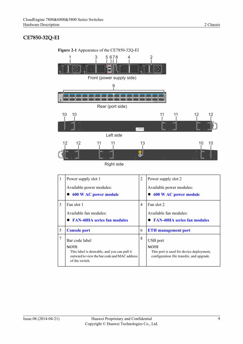
Figure 2-1 Appearance of the CE7850-32Q-EI
1 2 3 4 5 6 7 8 9 10 11 12 13 14 15 16 17 18 19 20 21 22 23 24 25 26 27 28 29 30 31 32SYSMSTSTATSPEEDSTACK
MODE/IDCE7850-32Q-EI
432140GEBreakout
CONSOLE
ETH
SYS
MST
ACT
L/A
ID
PWR1 FAN1 FAN2 PWR2
CE7850-32Q-EISTATUS STATUS STATUSSTATUS
9
1 23 45 67 8
1010 1111 1212
12 12 13 1010
Front (power supply side)
Rear (port side)
Left side
Right side
11 11
1 Power supply slot 1
Available power modules:l 600 W AC power module
2 Power supply slot 2
Available power modules:l 600 W AC power module
3 Fan slot 1
Available fan modules:l FAN-40HA series fan modules
4 Fan slot 2
Available fan modules:l FAN-40HA series fan modules
5 Console port 6 ETH management port
7 Bar code labelNOTE
This label is drawable, and you can pull itoutward to view the bar code and MAC addressof the switch.
8 USB portNOTE
This port is used for device deployment,configuration file transfer, and upgrade.
CloudEngine 7800&6800&5800 Series SwitchesHardware Description 2 Chassis
Issue 08 (2014-04-21) Huawei Proprietary and ConfidentialCopyright © Huawei Technologies Co., Ltd.
9
9 Thirty-two 40GE QSFP+ Ethernetoptical portsNOTE
A 40GE QSFP+ port can be split into four10GE ports.
Applicable modules and cables:l 40GE optical modulel 1m, 3m, 5m QSFP+ copper cables
(QSFP+ to 4*SFP+)l 1m, 3m, 5m QSFP+ copper cables
(QSFP+ to QSFP+)
10 Three port-side mounting holes formounting brackets
11 Four middle mounting holes for mountingbrackets
12 Four power-supply-side mounting holesfor mounting brackets
13 Ground screw - -
CE6810-48S4Q-EI
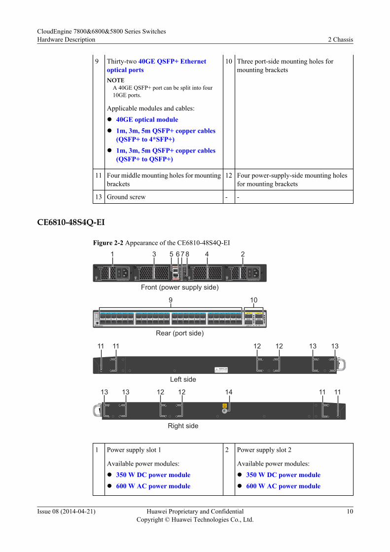
Figure 2-2 Appearance of the CE6810-48S4Q-EI
1 2 3 413 14 15 16 17 18 19 20 21 22 23 24 25 26 27 28 29 30 31 32 33 34 35 36 37 38 39 40 41 42 43 44 45 46 47 481 2 3 4 5 6 7 8 9 10 11 12SYSMSTSTATSPEEDSTACK
MODE/IDCE6810-48S4Q-EI 432140GE
Breakout
CONSOLE
ETH
SYS
MST
ACT
L/A
ID
PWR1 FAN1 FAN2 PWR2
CE6810-48S4Q-EISTATUS STATUS STATUSSTATUS
9
1 23 45 67 8
1111 1212 1313
13 13 14 1111
Front (power supply side)
Rear (port side)
Left side
Right side
12 12
10
1 Power supply slot 1
Available power modules:l 350 W DC power modulel 600 W AC power module
2 Power supply slot 2
Available power modules:l 350 W DC power modulel 600 W AC power module
CloudEngine 7800&6800&5800 Series SwitchesHardware Description 2 Chassis
Issue 08 (2014-04-21) Huawei Proprietary and ConfidentialCopyright © Huawei Technologies Co., Ltd.
10
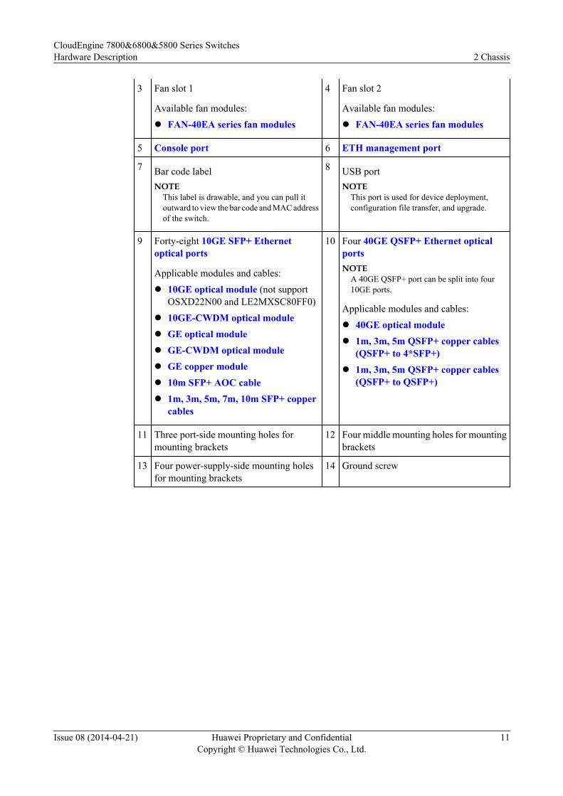
3 Fan slot 1
Available fan modules:l FAN-40EA series fan modules
4 Fan slot 2
Available fan modules:l FAN-40EA series fan modules
5 Console port 6 ETH management port
7 Bar code labelNOTE
This label is drawable, and you can pull itoutward to view the bar code and MAC addressof the switch.
8 USB portNOTE
This port is used for device deployment,configuration file transfer, and upgrade.
9 Forty-eight 10GE SFP+ Ethernetoptical ports
Applicable modules and cables:l 10GE optical module (not support
OSXD22N00 and LE2MXSC80FF0)l 10GE-CWDM optical modulel GE optical modulel GE-CWDM optical modulel GE copper modulel 10m SFP+ AOC cablel 1m, 3m, 5m, 7m, 10m SFP+ copper
cables
10 Four 40GE QSFP+ Ethernet opticalportsNOTE
A 40GE QSFP+ port can be split into four10GE ports.
Applicable modules and cables:l 40GE optical modulel 1m, 3m, 5m QSFP+ copper cables
(QSFP+ to 4*SFP+)l 1m, 3m, 5m QSFP+ copper cables
(QSFP+ to QSFP+)
11 Three port-side mounting holes formounting brackets
12 Four middle mounting holes for mountingbrackets
13 Four power-supply-side mounting holesfor mounting brackets
14 Ground screw
CloudEngine 7800&6800&5800 Series SwitchesHardware Description 2 Chassis
Issue 08 (2014-04-21) Huawei Proprietary and ConfidentialCopyright © Huawei Technologies Co., Ltd.
11
CE6850-48S4Q-EI
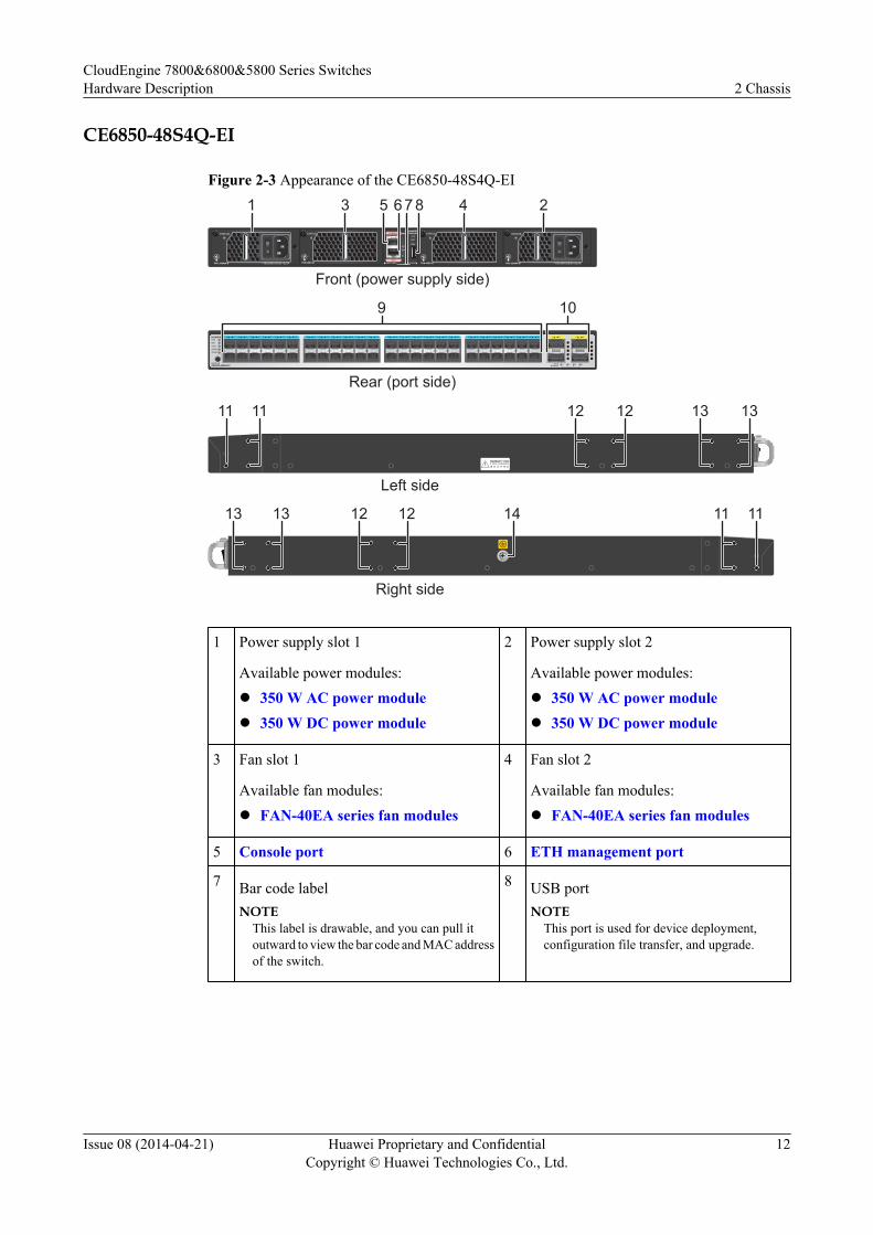
Figure 2-3 Appearance of the CE6850-48S4Q-EI
1 2 3 413 14 15 16 17 18 19 20 21 22 23 24 25 26 27 28 29 30 31 32 33 34 35 36 37 38 39 40 41 42 43 44 45 46 47 481 2 3 4 5 6 7 8 9 10 11 12SYSMSTSTATSPEEDSTACK
MODE/IDCE6850-48S4Q-EI 432140GE
Breakout
CONSOLE
ETH
SYS
MST
ACT
L/A
ID
PWR1 FAN1 FAN2 PWR2
CE6850-48S4Q-EISTATUS STATUS STATUSSTATUS
9
1 23 45 67 8
1111 1212 1313
13 13 14 1111
Front (power supply side)
Rear (port side)
Left side
Right side
12 12
10
1 Power supply slot 1
Available power modules:l 350 W AC power modulel 350 W DC power module
2 Power supply slot 2
Available power modules:l 350 W AC power modulel 350 W DC power module
3 Fan slot 1
Available fan modules:l FAN-40EA series fan modules
4 Fan slot 2
Available fan modules:l FAN-40EA series fan modules
5 Console port 6 ETH management port
7 Bar code labelNOTE
This label is drawable, and you can pull itoutward to view the bar code and MAC addressof the switch.
8 USB portNOTE
This port is used for device deployment,configuration file transfer, and upgrade.
CloudEngine 7800&6800&5800 Series SwitchesHardware Description 2 Chassis
Issue 08 (2014-04-21) Huawei Proprietary and ConfidentialCopyright © Huawei Technologies Co., Ltd.
12
9 Forty-eight 10GE SFP+ Ethernetoptical ports
Applicable modules and cables:l 10GE optical modulel 10GE-CWDM optical modulel GE optical modulel GE-CWDM optical modulel GE copper modulel 10m SFP+ AOC cablel 1m, 3m, 5m, 7m, 10m SFP+ copper
cables
10 Four 40GE QSFP+ Ethernet opticalportsNOTE
A 40GE QSFP+ port can be split into four10GE ports.
Applicable modules and cables:l 40GE optical modulel 1m, 3m, 5m QSFP+ copper cables
(QSFP+ to 4*SFP+)l 1m, 3m, 5m QSFP+ copper cables
(QSFP+ to QSFP+)
11 Three port-side mounting holes formounting brackets
12 Four middle mounting holes for mountingbrackets
13 Four power-supply-side mounting holesfor mounting brackets
14 Ground screw
CE6850-48T4Q-EI
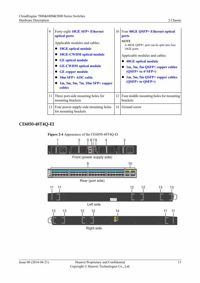
Figure 2-4 Appearance of the CE6850-48T4Q-EI
SYSMSTSTATSPEEDSTACK
MODE/IDCE6850-48T4Q-EI
13 14 15 16 17 18 19 20 21 22 23 24 25 26 27 28 29 30 31 32 33 34 35 36 37 38 39 40 41 42 43 44 45 46 47 481 2 3 4 5 6 7 8 9 10 11 12 1 2 3 4
432140GEBreakout
CONSOLE
ETH
SYS
MST
ACT
L/A
ID
PWR1 FAN1 FAN2 PWR2
CE6850-48T4Q-EISTATUS STATUSSTATUS STATUS
9
1 23 45 67 8
1111 1212 1313
13 13 14 1111
Front (power supply side)
Rear (port side)
Left side
Right side
12 12
10
CloudEngine 7800&6800&5800 Series SwitchesHardware Description 2 Chassis
Issue 08 (2014-04-21) Huawei Proprietary and ConfidentialCopyright © Huawei Technologies Co., Ltd.
13
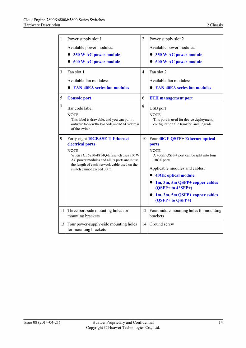
1 Power supply slot 1
Available power modules:l 350 W AC power modulel 600 W AC power module
2 Power supply slot 2
Available power modules:l 350 W AC power modulel 600 W AC power module
3 Fan slot 1
Available fan modules:l FAN-40EA series fan modules
4 Fan slot 2
Available fan modules:l FAN-40EA series fan modules
5 Console port 6 ETH management port
7 Bar code labelNOTE
This label is drawable, and you can pull itoutward to view the bar code and MAC addressof the switch.
8 USB portNOTE
This port is used for device deployment,configuration file transfer, and upgrade.
9 Forty-eight 10GBASE-T Ethernetelectrical portsNOTE
When a CE6850-48T4Q-EI switch uses 350 WAC power modules and all its ports are in use,the length of each network cable used on theswitch cannot exceed 30 m.
10 Four 40GE QSFP+ Ethernet opticalportsNOTE
A 40GE QSFP+ port can be split into four10GE ports.
Applicable modules and cables:l 40GE optical modulel 1m, 3m, 5m QSFP+ copper cables
(QSFP+ to 4*SFP+)l 1m, 3m, 5m QSFP+ copper cables
(QSFP+ to QSFP+)
11 Three port-side mounting holes formounting brackets
12 Four middle mounting holes for mountingbrackets
13 Four power-supply-side mounting holesfor mounting brackets
14 Ground screw
CloudEngine 7800&6800&5800 Series SwitchesHardware Description 2 Chassis
Issue 08 (2014-04-21) Huawei Proprietary and ConfidentialCopyright © Huawei Technologies Co., Ltd.
14
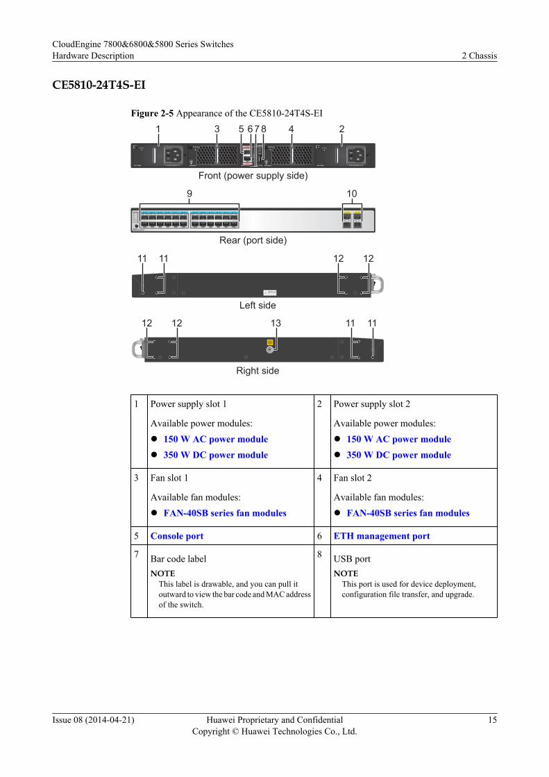
CE5810-24T4S-EI
Figure 2-5 Appearance of the CE5810-24T4S-EI
1 2 3 4 5 6 7 8 9 10 11 12 13 14 15 16 17 18 19 20 21 22 23 24 1 2 3 4SYSMSTSTATSPEEDSTACK
MODE/IDCE5810-24T4S-EI
9 10
CONSOLE
ETH
SYS
MST
ACT
L/A
ID
PWR1 FAN1 FAN2 PWR2
CE5810-24T4S-EI
PAC-150WA ~100-240V;50/60Hz,2.5A
STATUS
PAC-150WA ~100-240V;50/60Hz,2.5A
STATUSSTATUS STATUS
1 23 45 67 8
1111 1212
12 12 13 1111
Front (power supply side)
Rear (port side)
Left side
Right side
1 Power supply slot 1
Available power modules:l 150 W AC power modulel 350 W DC power module
2 Power supply slot 2
Available power modules:l 150 W AC power modulel 350 W DC power module
3 Fan slot 1
Available fan modules:l FAN-40SB series fan modules
4 Fan slot 2
Available fan modules:l FAN-40SB series fan modules
5 Console port 6 ETH management port
7 Bar code labelNOTE
This label is drawable, and you can pull itoutward to view the bar code and MAC addressof the switch.
8 USB portNOTE
This port is used for device deployment,configuration file transfer, and upgrade.
CloudEngine 7800&6800&5800 Series SwitchesHardware Description 2 Chassis
Issue 08 (2014-04-21) Huawei Proprietary and ConfidentialCopyright © Huawei Technologies Co., Ltd.
15
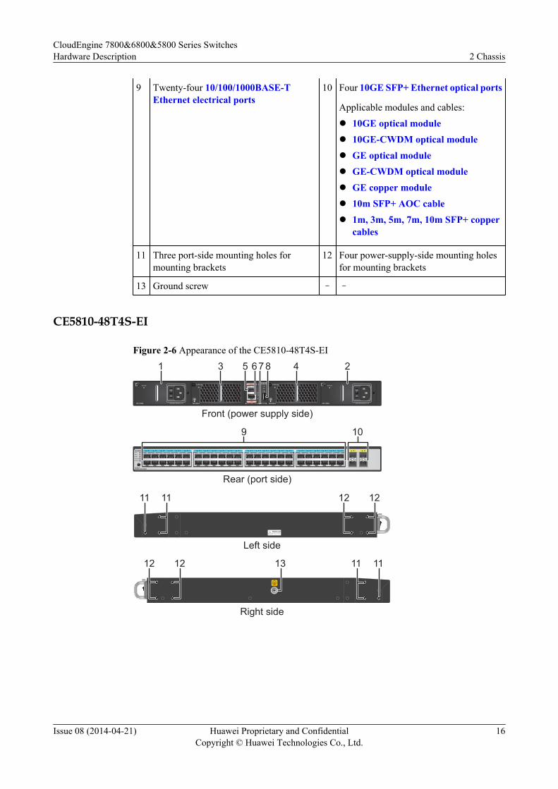
9 Twenty-four 10/100/1000BASE-TEthernet electrical ports
10 Four 10GE SFP+ Ethernet optical ports
Applicable modules and cables:l 10GE optical modulel 10GE-CWDM optical modulel GE optical modulel GE-CWDM optical modulel GE copper modulel 10m SFP+ AOC cablel 1m, 3m, 5m, 7m, 10m SFP+ copper
cables
11 Three port-side mounting holes formounting brackets
12 Four power-supply-side mounting holesfor mounting brackets
13 Ground screw – –
CE5810-48T4S-EI
Figure 2-6 Appearance of the CE5810-48T4S-EI
1 2 3 4 5 6 7 8 9 10 11 12 13 14 15 16 17 18 19 20 21 22 23 24 25 26 27 28 29 30 31 32 33 34 35 36 37 38 39 40 41 42 43 44 45 46 47 48SYSMSTSTATSPEEDSTACK
MODE/IDCE5810-48T4S-EI
1 2 3 4
CONSOLE
ETH
SYS
MST
ACT
L/A
ID
PWR1 FAN1 FAN2 PWR2
CE5810-48T4S-EI
PAC-150WA ~100-240V;50/60Hz,2.5A
STATUS
PAC-150WA ~100-240V;50/60Hz,2.5A
STATUSSTATUS STATUS
9 10
1 23 45 67 8
1111 1212
12 12 13 1111
Front (power supply side)
Rear (port side)
Left side
Right side
CloudEngine 7800&6800&5800 Series SwitchesHardware Description 2 Chassis
Issue 08 (2014-04-21) Huawei Proprietary and ConfidentialCopyright © Huawei Technologies Co., Ltd.
16
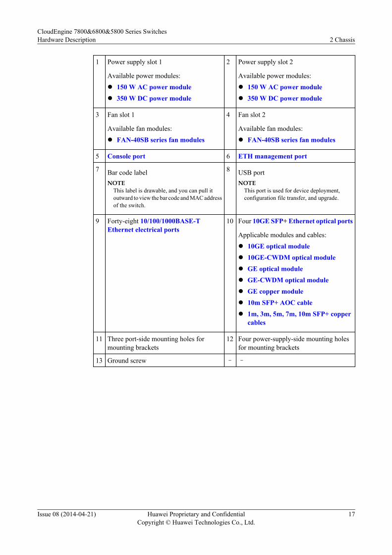
1 Power supply slot 1
Available power modules:l 150 W AC power modulel 350 W DC power module
2 Power supply slot 2
Available power modules:l 150 W AC power modulel 350 W DC power module
3 Fan slot 1
Available fan modules:l FAN-40SB series fan modules
4 Fan slot 2
Available fan modules:l FAN-40SB series fan modules
5 Console port 6 ETH management port
7 Bar code labelNOTE
This label is drawable, and you can pull itoutward to view the bar code and MAC addressof the switch.
8 USB portNOTE
This port is used for device deployment,configuration file transfer, and upgrade.
9 Forty-eight 10/100/1000BASE-TEthernet electrical ports
10 Four 10GE SFP+ Ethernet optical ports
Applicable modules and cables:l 10GE optical modulel 10GE-CWDM optical modulel GE optical modulel GE-CWDM optical modulel GE copper modulel 10m SFP+ AOC cablel 1m, 3m, 5m, 7m, 10m SFP+ copper
cables
11 Three port-side mounting holes formounting brackets
12 Four power-supply-side mounting holesfor mounting brackets
13 Ground screw – –
CloudEngine 7800&6800&5800 Series SwitchesHardware Description 2 Chassis
Issue 08 (2014-04-21) Huawei Proprietary and ConfidentialCopyright © Huawei Technologies Co., Ltd.
17
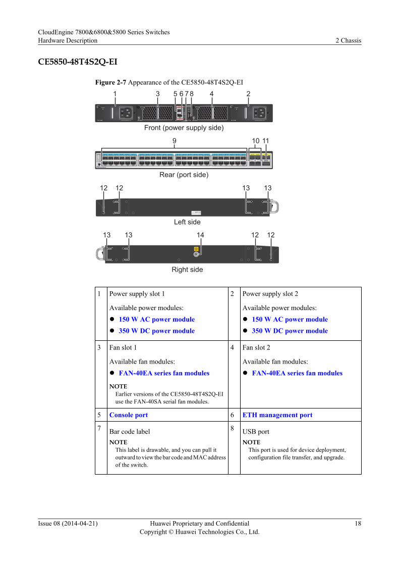
CE5850-48T4S2Q-EI
Figure 2-7 Appearance of the CE5850-48T4S2Q-EI
1 2 3 4 5 6 7 8 9 10 11 12 13 14 15 16 17 18 19 20 21 22 23 24 25 26 27 28 29 30 31 32 33 34 35 36 37 38 39 40 41 42 43 44 45 46 47 48 1 2 3 4 1 2SYSMSTSTATSPEEDSTACK
MODE/IDCE5850-48T4S2Q-EI
CONSOLE
ETH
SYS
MST
ACT
L/A
ID
PWR1 FAN1 FAN2 PWR2
CE5850-48T4S2Q-EI
PAC-150WA ~100-240V;50/60Hz,2.5A
STATUS
PAC-150WA ~100-240V;50/60Hz,2.5A
STATUSSTATUSSTATUS
9 10 11
1 23 45 6 7 8
1212 1313
13 13 14 1212
Front (power supply side)
Rear (port side)
Left side
Right side
1 Power supply slot 1
Available power modules:l 150 W AC power modulel 350 W DC power module
2 Power supply slot 2
Available power modules:l 150 W AC power modulel 350 W DC power module
3 Fan slot 1
Available fan modules:l FAN-40EA series fan modules
NOTEEarlier versions of the CE5850-48T4S2Q-EIuse the FAN-40SA serial fan modules.
4 Fan slot 2
Available fan modules:l FAN-40EA series fan modules
5 Console port 6 ETH management port
7 Bar code labelNOTE
This label is drawable, and you can pull itoutward to view the bar code and MAC addressof the switch.
8 USB portNOTE
This port is used for device deployment,configuration file transfer, and upgrade.
CloudEngine 7800&6800&5800 Series SwitchesHardware Description 2 Chassis
Issue 08 (2014-04-21) Huawei Proprietary and ConfidentialCopyright © Huawei Technologies Co., Ltd.
18
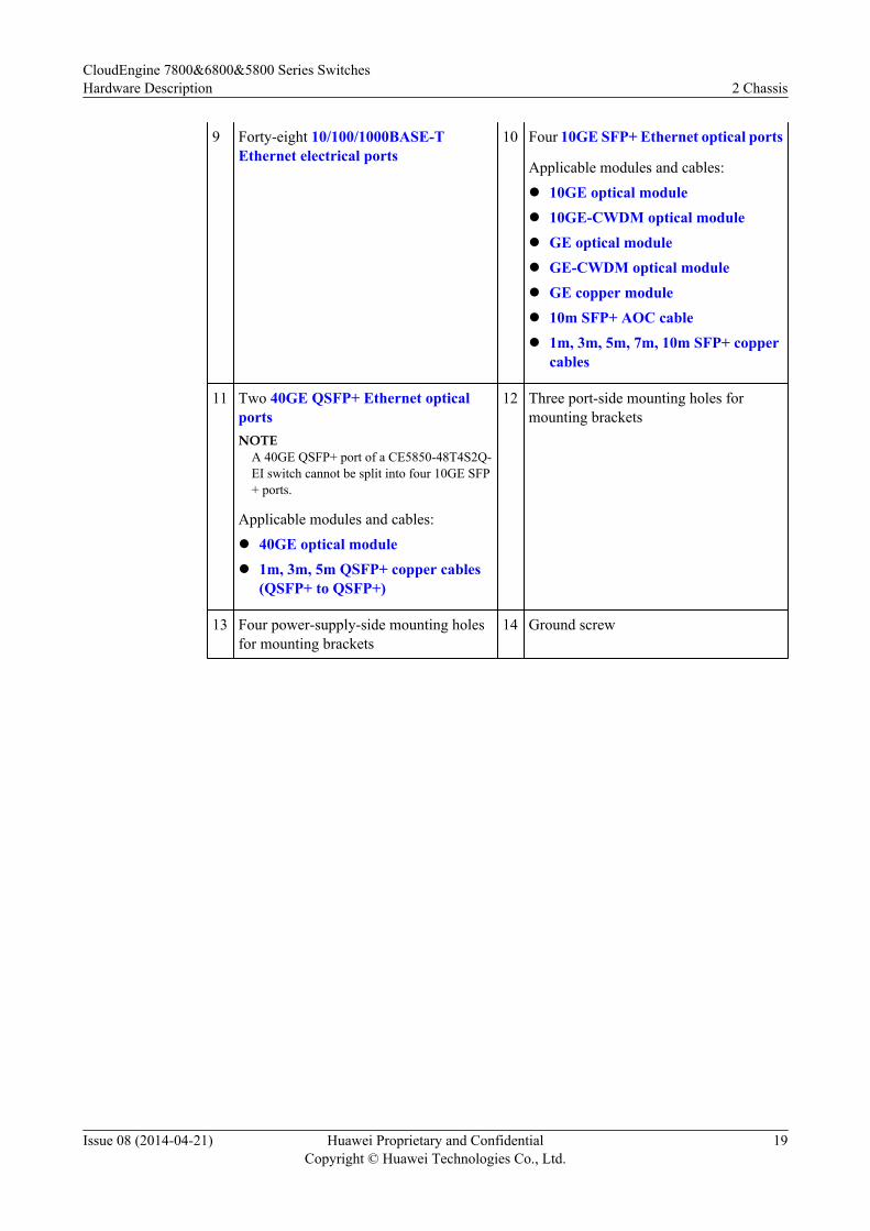
9 Forty-eight 10/100/1000BASE-TEthernet electrical ports
10 Four 10GE SFP+ Ethernet optical ports
Applicable modules and cables:l 10GE optical modulel 10GE-CWDM optical modulel GE optical modulel GE-CWDM optical modulel GE copper modulel 10m SFP+ AOC cablel 1m, 3m, 5m, 7m, 10m SFP+ copper
cables
11 Two 40GE QSFP+ Ethernet opticalportsNOTE
A 40GE QSFP+ port of a CE5850-48T4S2Q-EI switch cannot be split into four 10GE SFP+ ports.
Applicable modules and cables:l 40GE optical modulel 1m, 3m, 5m QSFP+ copper cables
(QSFP+ to QSFP+)
12 Three port-side mounting holes formounting brackets
13 Four power-supply-side mounting holesfor mounting brackets
14 Ground screw
CloudEngine 7800&6800&5800 Series SwitchesHardware Description 2 Chassis
Issue 08 (2014-04-21) Huawei Proprietary and ConfidentialCopyright © Huawei Technologies Co., Ltd.
19
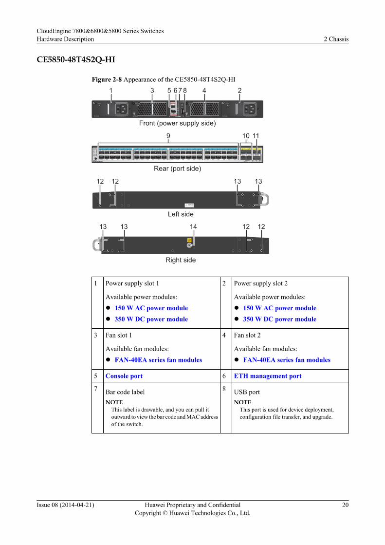
CE5850-48T4S2Q-HI
Figure 2-8 Appearance of the CE5850-48T4S2Q-HI
CONSOLE
ETH
SYS
MST
ACT
L/A
ID
PWR1 FAN1 FAN2 PWR2
CE5850-48T4S2Q-HI
PAC-150WA ~100-240V;50/60Hz,2.5A
STATUSSTATUS
PAC-150WA ~100-240V;50/60Hz,2.5A
STATUSSTATUS
1 2 3 4 5 6 7 8 9 10 11 12 13 14 15 16 17 18 19 20 21 22 23 24 25 26 27 28 29 30 31 32 33 34 35 36 37 38 39 40 41 42 43 44 45 46 47 48 1 2 3 4SYSMSTSTATSPEEDSTACK
MODE/IDCE5850-48T4S2Q-HI
140GEBreakout
2 3 4
1 2
9 10 11
1 23 45 67 8
1212 1313
13 13 14 1212
Front (power supply side)
Rear (port side)
Left side
Right side
1 Power supply slot 1
Available power modules:l 150 W AC power modulel 350 W DC power module
2 Power supply slot 2
Available power modules:l 150 W AC power modulel 350 W DC power module
3 Fan slot 1
Available fan modules:l FAN-40EA series fan modules
4 Fan slot 2
Available fan modules:l FAN-40EA series fan modules
5 Console port 6 ETH management port
7 Bar code labelNOTE
This label is drawable, and you can pull itoutward to view the bar code and MAC addressof the switch.
8 USB portNOTE
This port is used for device deployment,configuration file transfer, and upgrade.
CloudEngine 7800&6800&5800 Series SwitchesHardware Description 2 Chassis
Issue 08 (2014-04-21) Huawei Proprietary and ConfidentialCopyright © Huawei Technologies Co., Ltd.
20
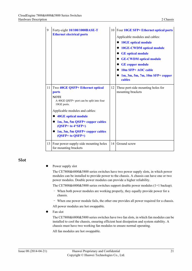
9 Forty-eight 10/100/1000BASE-TEthernet electrical ports
10 Four 10GE SFP+ Ethernet optical ports
Applicable modules and cables:l 10GE optical modulel 10GE-CWDM optical modulel GE optical modulel GE-CWDM optical modulel GE copper modulel 10m SFP+ AOC cablel 1m, 3m, 5m, 7m, 10m SFP+ copper
cables
11 Two 40GE QSFP+ Ethernet opticalportsNOTE
A 40GE QSFP+ port can be split into four10GE ports.
Applicable modules and cables:l 40GE optical modulel 1m, 3m, 5m QSFP+ copper cables
(QSFP+ to 4*SFP+)l 1m, 3m, 5m QSFP+ copper cables
(QSFP+ to QSFP+)
12 Three port-side mounting holes formounting brackets
13 Four power-supply-side mounting holesfor mounting brackets
14 Ground screw
Slotl Power supply slot
The CE7800&6800&5800 series switches have two power supply slots, in which powermodules can be installed to provide power to the chassis. A chassis can have one or twopower modules. Double power modules can provide a higher reliability.The CE7800&6800&5800 series switches support double power modules (1+1 backup).
– When both power modules are working properly, they equally provide power for achassis.
– When one power module fails, the other one provides all power required for a chassis.All power modules are hot swappable.
l Fan slotThe CE7800&6800&5800 series switches have two fan slots, in which fan modules can beinstalled to cool the chassis, ensuring efficient heat dissipation and system stability. Achassis must have two working fan modules to ensure normal operating.All fan modules are hot swappable.
CloudEngine 7800&6800&5800 Series SwitchesHardware Description 2 Chassis
Issue 08 (2014-04-21) Huawei Proprietary and ConfidentialCopyright © Huawei Technologies Co., Ltd.
21
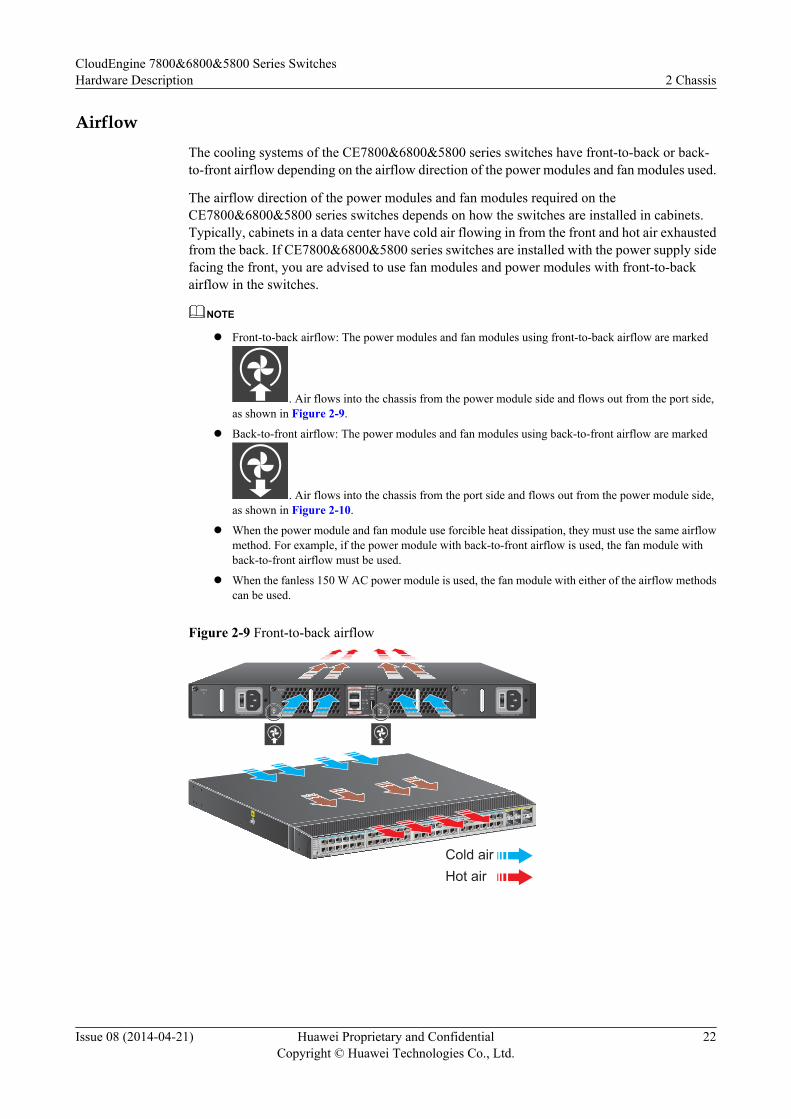
AirflowThe cooling systems of the CE7800&6800&5800 series switches have front-to-back or back-to-front airflow depending on the airflow direction of the power modules and fan modules used.
The airflow direction of the power modules and fan modules required on theCE7800&6800&5800 series switches depends on how the switches are installed in cabinets.Typically, cabinets in a data center have cold air flowing in from the front and hot air exhaustedfrom the back. If CE7800&6800&5800 series switches are installed with the power supply sidefacing the front, you are advised to use fan modules and power modules with front-to-backairflow in the switches.
NOTE
l Front-to-back airflow: The power modules and fan modules using front-to-back airflow are marked
. Air flows into the chassis from the power module side and flows out from the port side,as shown in Figure 2-9.
l Back-to-front airflow: The power modules and fan modules using back-to-front airflow are marked
. Air flows into the chassis from the port side and flows out from the power module side,as shown in Figure 2-10.
l When the power module and fan module use forcible heat dissipation, they must use the same airflowmethod. For example, if the power module with back-to-front airflow is used, the fan module withback-to-front airflow must be used.
l When the fanless 150 W AC power module is used, the fan module with either of the airflow methodscan be used.
Figure 2-9 Front-to-back airflow
1 2 3 4 5 6 7 8 9 10 11 1213 14 15 16 17 18 19 20 21 22 23 24
25 26 27 28 29 30 31 32 33 34 35 3637 38 39 40 41 42 43 44 45 46 47 48
1 2
1 2
3 4
Cold airHot air
PAC-150WA ~100-240V;50/60Hz,2.5A
STATUS
PAC-150WA ~100-240V;50/60Hz,2.5A
STATUSSTATUS
FAN-40EA-F
STATUS
FAN-40EA-F
CONSOLE
ETH
SYS
MST
ACT
L/A
ID
PWR1 FAN1 FAN2 PWR2
CE5850-48T4S2Q-EI
CloudEngine 7800&6800&5800 Series SwitchesHardware Description 2 Chassis
Issue 08 (2014-04-21) Huawei Proprietary and ConfidentialCopyright © Huawei Technologies Co., Ltd.
22
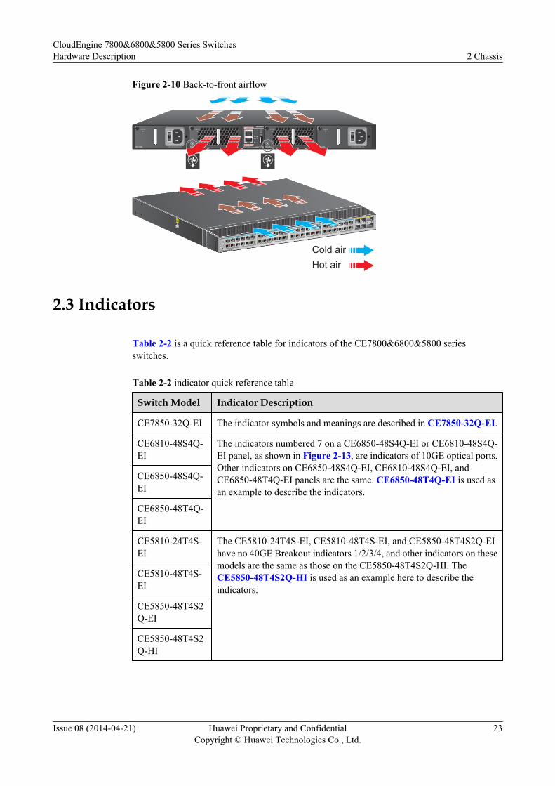
Figure 2-10 Back-to-front airflow
1 2 3 4 5 6 7 8 9 10 11 1213 14 15 16 17 18 19 20 21 22 23 24
25 26 27 28 29 30 31 32 33 34 35 3637 38 39 40 41 42 43 44 45 46 47 48
1 2
1 2
3 4
SYS
MST
STAT
SPEED
STACK
MODE/ID
CE5850-48T4S2Q-EI Cold airHot air
STATUS
FAN-40EA-B
STATUS
FAN-40EA-B
CONSOLE
ETH
SYS
MST
ACT
L/A
ID
PWR1 FAN1 FAN2 PWR2
CE5850-48T4S2Q-EI
PAC-150WA ~100-240V;50/60Hz,2.5A
STATUS
PAC-150WA ~100-240V;50/60Hz,2.5A
STATUS
2.3 Indicators
Table 2-2 is a quick reference table for indicators of the CE7800&6800&5800 seriesswitches.
Table 2-2 indicator quick reference table
Switch Model Indicator Description
CE7850-32Q-EI The indicator symbols and meanings are described in CE7850-32Q-EI.
CE6810-48S4Q-EI
The indicators numbered 7 on a CE6850-48S4Q-EI or CE6810-48S4Q-EI panel, as shown in Figure 2-13, are indicators of 10GE optical ports.Other indicators on CE6850-48S4Q-EI, CE6810-48S4Q-EI, andCE6850-48T4Q-EI panels are the same. CE6850-48T4Q-EI is used asan example to describe the indicators.
CE6850-48S4Q-EI
CE6850-48T4Q-EI
CE5810-24T4S-EI
The CE5810-24T4S-EI, CE5810-48T4S-EI, and CE5850-48T4S2Q-EIhave no 40GE Breakout indicators 1/2/3/4, and other indicators on thesemodels are the same as those on the CE5850-48T4S2Q-HI. TheCE5850-48T4S2Q-HI is used as an example here to describe theindicators.
CE5810-48T4S-EI
CE5850-48T4S2Q-EI
CE5850-48T4S2Q-HI
CloudEngine 7800&6800&5800 Series SwitchesHardware Description 2 Chassis
Issue 08 (2014-04-21) Huawei Proprietary and ConfidentialCopyright © Huawei Technologies Co., Ltd.
23
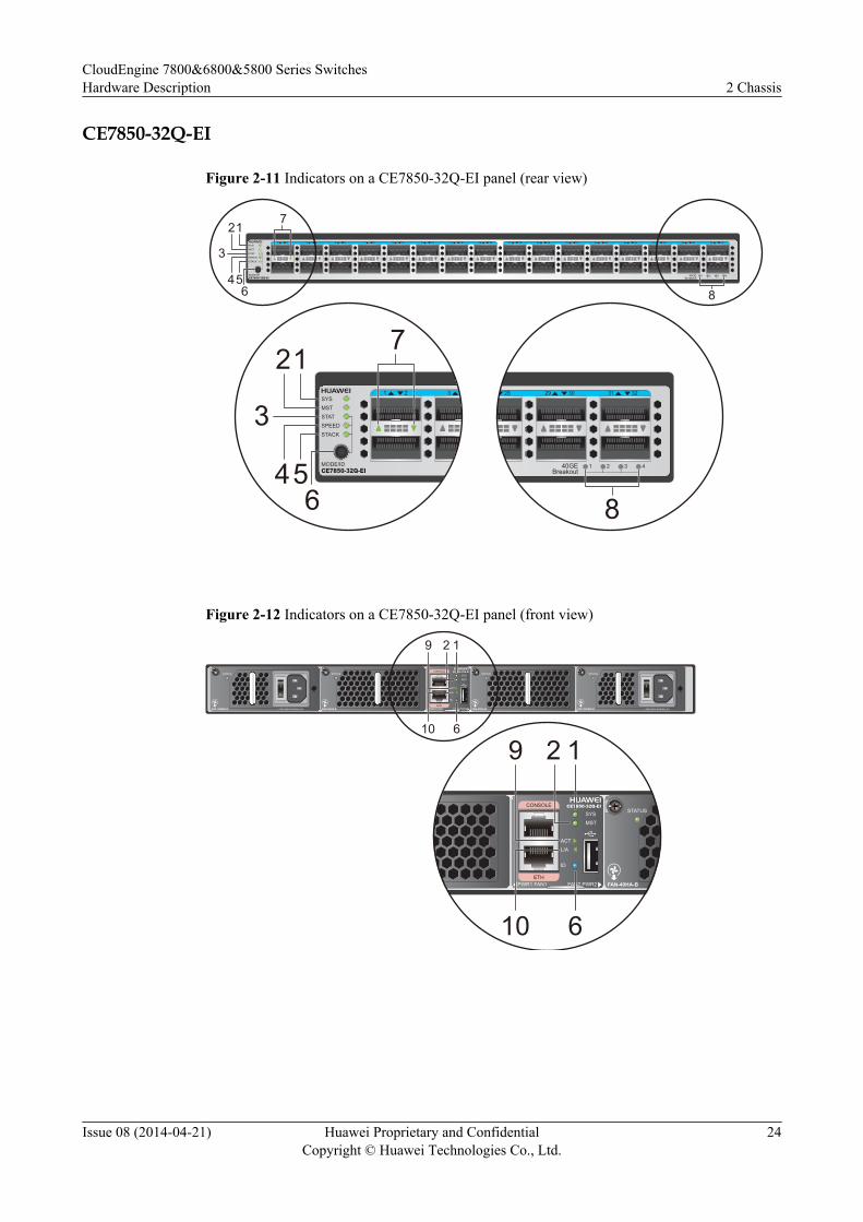
CE7850-32Q-EI
Figure 2-11 Indicators on a CE7850-32Q-EI panel (rear view)
1 2 3 4 5 6 7 8 9 10 11 12 13 14 15 16 17 18 19 20 21 22 23 24 25 26 27 28 29 30 31 32SYSMSTSTATSPEEDSTACK
MODE/IDCE7850-32Q-EI
432140GEBreakout
12
3
456 8
7
1 2 3SYSMSTSTATSPEEDSTACK
MODE/IDCE7850-32Q-EI
12
3
456
728 29 30 31 32
432140GEBreakout
8
Figure 2-12 Indicators on a CE7850-32Q-EI panel (front view)
STATUS
FAN-40HA-B
STATUS
FAN-40HA-B PAC-350WA-B ~100-240V;50/60Hz,5A
STATUS
PAC-350WA-B ~100-240V;50/60Hz,5A
STATUSCONSOLE
ETH
SYS
MST
ACT
L/A
ID
PWR1 FAN1 FAN2 PWR2
CE7850-32Q-EI
9 2 1
610
STATUS
FAN-40HA-B
CONSOLE
ETH
SYS
MST
ACT
L/A
ID
PWR1 FAN1 FAN2 PWR2
CE7850-32Q-EI
9 2 1
610
CloudEngine 7800&6800&5800 Series SwitchesHardware Description 2 Chassis
Issue 08 (2014-04-21) Huawei Proprietary and ConfidentialCopyright © Huawei Technologies Co., Ltd.
24
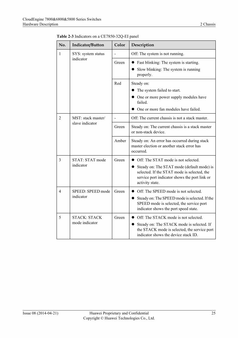
Table 2-3 Indicators on a CE7850-32Q-EI panel
No. Indicator/Button Color Description
1 SYS: system statusindicator
- Off: The system is not running.
Green l Fast blinking: The system is starting.l Slow blinking: The system is running
properly.
Red Steady on:l The system failed to start.l One or more power supply modules have
failed.l One or more fan modules have failed.
2 MST: stack master/slave indicator
- Off: The current chassis is not a stack master.
Green Steady on: The current chassis is a stack masteror non-stack device.
Amber Steady on: An error has occurred during stackmaster election or another stack error hasoccurred.
3 STAT: STAT modeindicator
Green l Off: The STAT mode is not selected.l Steady on: The STAT mode (default mode) is
selected. If the STAT mode is selected, theservice port indicator shows the port link oractivity state.
4 SPEED: SPEED modeindicator
Green l Off: The SPEED mode is not selected.l Steady on: The SPEED mode is selected. If the
SPEED mode is selected, the service portindicator shows the port speed state.
5 STACK: STACKmode indicator
Green l Off: The STACK mode is not selected.l Steady on: The STACK mode is selected. If
the STACK mode is selected, the service portindicator shows the device stack ID.
CloudEngine 7800&6800&5800 Series SwitchesHardware Description 2 Chassis
Issue 08 (2014-04-21) Huawei Proprietary and ConfidentialCopyright © Huawei Technologies Co., Ltd.
25
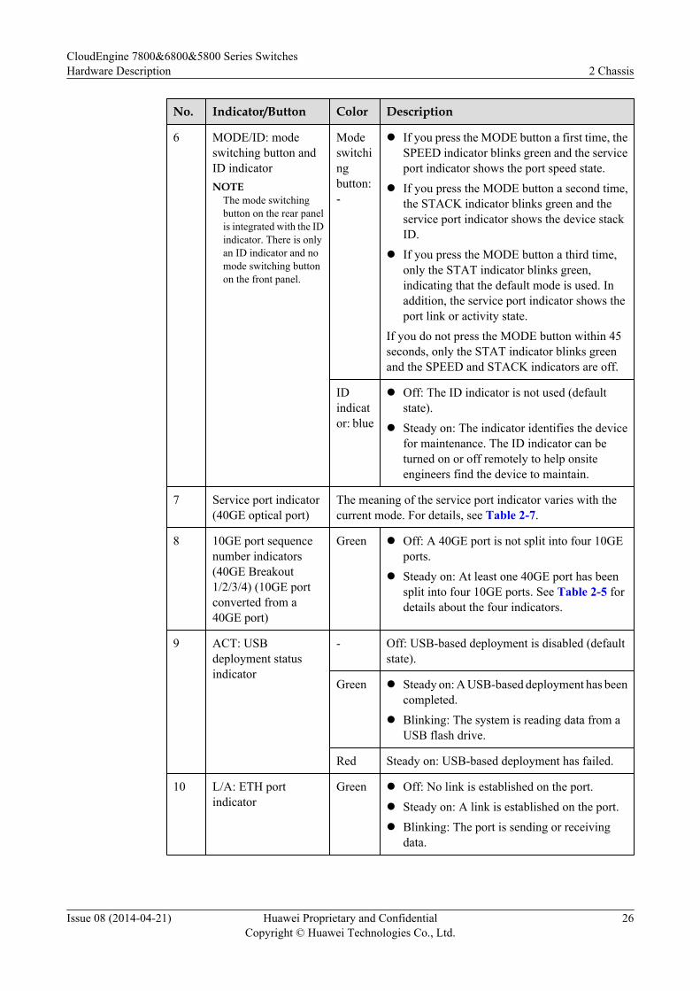
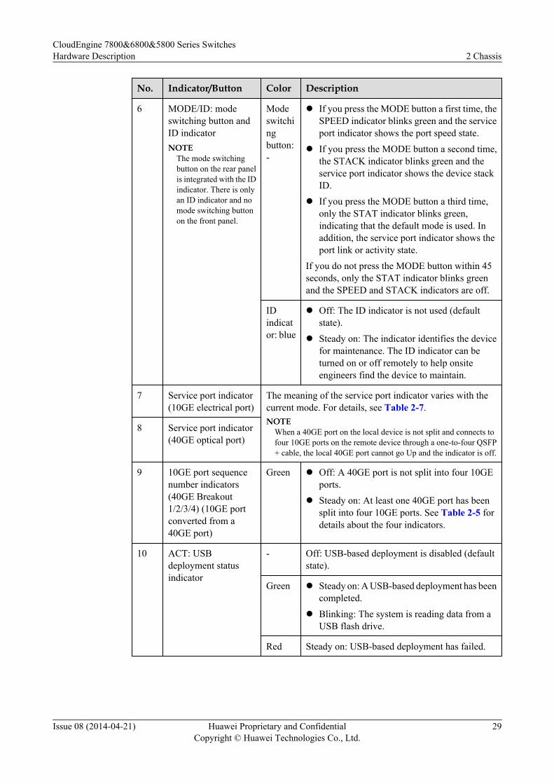
No. Indicator/Button Color Description
6 MODE/ID: modeswitching button andID indicatorNOTE
The mode switchingbutton on the rear panelis integrated with the IDindicator. There is onlyan ID indicator and nomode switching buttonon the front panel.
Modeswitchingbutton:-
l If you press the MODE button a first time, theSPEED indicator blinks green and the serviceport indicator shows the port speed state.
l If you press the MODE button a second time,the STACK indicator blinks green and theservice port indicator shows the device stackID.
l If you press the MODE button a third time,only the STAT indicator blinks green,indicating that the default mode is used. Inaddition, the service port indicator shows theport link or activity state.
If you do not press the MODE button within 45seconds, only the STAT indicator blinks greenand the SPEED and STACK indicators are off.
IDindicator: blue
l Off: The ID indicator is not used (defaultstate).
l Steady on: The indicator identifies the devicefor maintenance. The ID indicator can beturned on or off remotely to help onsiteengineers find the device to maintain.
7 Service port indicator(40GE optical port)
The meaning of the service port indicator varies with thecurrent mode. For details, see Table 2-7.
8 10GE port sequencenumber indicators(40GE Breakout1/2/3/4) (10GE portconverted from a40GE port)
Green l Off: A 40GE port is not split into four 10GEports.
l Steady on: At least one 40GE port has beensplit into four 10GE ports. See Table 2-5 fordetails about the four indicators.
9 ACT: USBdeployment statusindicator
- Off: USB-based deployment is disabled (defaultstate).
Green l Steady on: A USB-based deployment has beencompleted.
l Blinking: The system is reading data from aUSB flash drive.
Red Steady on: USB-based deployment has failed.
10 L/A: ETH portindicator
Green l Off: No link is established on the port.l Steady on: A link is established on the port.l Blinking: The port is sending or receiving
data.
CloudEngine 7800&6800&5800 Series SwitchesHardware Description 2 Chassis
Issue 08 (2014-04-21) Huawei Proprietary and ConfidentialCopyright © Huawei Technologies Co., Ltd.
26
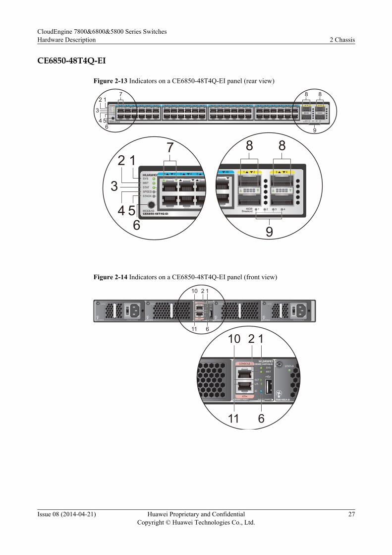
CE6850-48T4Q-EI
Figure 2-13 Indicators on a CE6850-48T4Q-EI panel (rear view)
SYSMSTSTATSPEEDSTACK
MODE/IDCE6850-48T4Q-EI
13 14 15 16 17 18 19 20 21 22 23 24 25 26 27 28 29 30 31 32 33 34 35 36 37 38 39 40 41 42 43 44 45 46 47 481 2 3 4 5 6 7 8 9 10 11 12 1 2 3 4
432140DEBreakout
7 8 8
9
12
3
4 56
SYSMSTSTATSPEEDSTACK
MODE/IDCE6850-48T4Q-EI
1 2 3 4 5
72 1
3
4 56
48 1 2 3 4
432140DEBreakout
8 8
9
Figure 2-14 Indicators on a CE6850-48T4Q-EI panel (front view)
STATUS
FAN-40EA-B
STATUS
FAN-40EA-B PAC-350WA-B ~100-240V;50/60Hz,5A
STATUS
PAC-350WA-B ~100-240V;50/60Hz,5A
STATUSCONSOLE
ETH
SYS
MST
ACT
L/A
ID
PWR1 FAN1 FAN2 PWR2
CE6850-48T4Q-EI
10 2 1
611
STATUS
FAN-40EA-B
CONSOLE
ETH
SYS
MST
ACT
L/A
ID
PWR1 FAN1 FAN2 PWR2
CE6850-48T4Q-EI
10 2 1
611
CloudEngine 7800&6800&5800 Series SwitchesHardware Description 2 Chassis
Issue 08 (2014-04-21) Huawei Proprietary and ConfidentialCopyright © Huawei Technologies Co., Ltd.
27
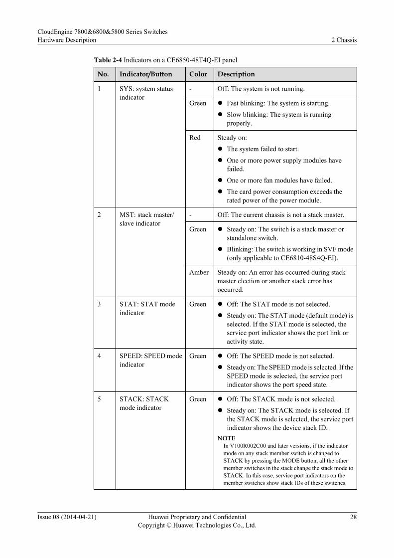
Table 2-4 Indicators on a CE6850-48T4Q-EI panel
No. Indicator/Button Color Description
1 SYS: system statusindicator
- Off: The system is not running.
Green l Fast blinking: The system is starting.l Slow blinking: The system is running
properly.
Red Steady on:l The system failed to start.l One or more power supply modules have
failed.l One or more fan modules have failed.l The card power consumption exceeds the
rated power of the power module.
2 MST: stack master/slave indicator
- Off: The current chassis is not a stack master.
Green l Steady on: The switch is a stack master orstandalone switch.
l Blinking: The switch is working in SVF mode(only applicable to CE6810-48S4Q-EI).
Amber Steady on: An error has occurred during stackmaster election or another stack error hasoccurred.
3 STAT: STAT modeindicator
Green l Off: The STAT mode is not selected.l Steady on: The STAT mode (default mode) is
selected. If the STAT mode is selected, theservice port indicator shows the port link oractivity state.
4 SPEED: SPEED modeindicator
Green l Off: The SPEED mode is not selected.l Steady on: The SPEED mode is selected. If the
SPEED mode is selected, the service portindicator shows the port speed state.
5 STACK: STACKmode indicator
Green l Off: The STACK mode is not selected.l Steady on: The STACK mode is selected. If
the STACK mode is selected, the service portindicator shows the device stack ID.
NOTEIn V100R002C00 and later versions, if the indicatormode on any stack member switch is changed toSTACK by pressing the MODE button, all the othermember switches in the stack change the stack mode toSTACK. In this case, service port indicators on themember switches show stack IDs of these switches.
CloudEngine 7800&6800&5800 Series SwitchesHardware Description 2 Chassis
Issue 08 (2014-04-21) Huawei Proprietary and ConfidentialCopyright © Huawei Technologies Co., Ltd.
28
No. Indicator/Button Color Description
6 MODE/ID: modeswitching button andID indicatorNOTE
The mode switchingbutton on the rear panelis integrated with the IDindicator. There is onlyan ID indicator and nomode switching buttonon the front panel.
Modeswitchingbutton:-
l If you press the MODE button a first time, theSPEED indicator blinks green and the serviceport indicator shows the port speed state.
l If you press the MODE button a second time,the STACK indicator blinks green and theservice port indicator shows the device stackID.
l If you press the MODE button a third time,only the STAT indicator blinks green,indicating that the default mode is used. Inaddition, the service port indicator shows theport link or activity state.
If you do not press the MODE button within 45seconds, only the STAT indicator blinks greenand the SPEED and STACK indicators are off.
IDindicator: blue
l Off: The ID indicator is not used (defaultstate).
l Steady on: The indicator identifies the devicefor maintenance. The ID indicator can beturned on or off remotely to help onsiteengineers find the device to maintain.
7 Service port indicator(10GE electrical port)
The meaning of the service port indicator varies with thecurrent mode. For details, see Table 2-7.NOTE
When a 40GE port on the local device is not split and connects tofour 10GE ports on the remote device through a one-to-four QSFP+ cable, the local 40GE port cannot go Up and the indicator is off.
8 Service port indicator(40GE optical port)
9 10GE port sequencenumber indicators(40GE Breakout1/2/3/4) (10GE portconverted from a40GE port)
Green l Off: A 40GE port is not split into four 10GEports.
l Steady on: At least one 40GE port has beensplit into four 10GE ports. See Table 2-5 fordetails about the four indicators.
10 ACT: USBdeployment statusindicator
- Off: USB-based deployment is disabled (defaultstate).
Green l Steady on: A USB-based deployment has beencompleted.
l Blinking: The system is reading data from aUSB flash drive.
Red Steady on: USB-based deployment has failed.
CloudEngine 7800&6800&5800 Series SwitchesHardware Description 2 Chassis
Issue 08 (2014-04-21) Huawei Proprietary and ConfidentialCopyright © Huawei Technologies Co., Ltd.
29
No. Indicator/Button Color Description
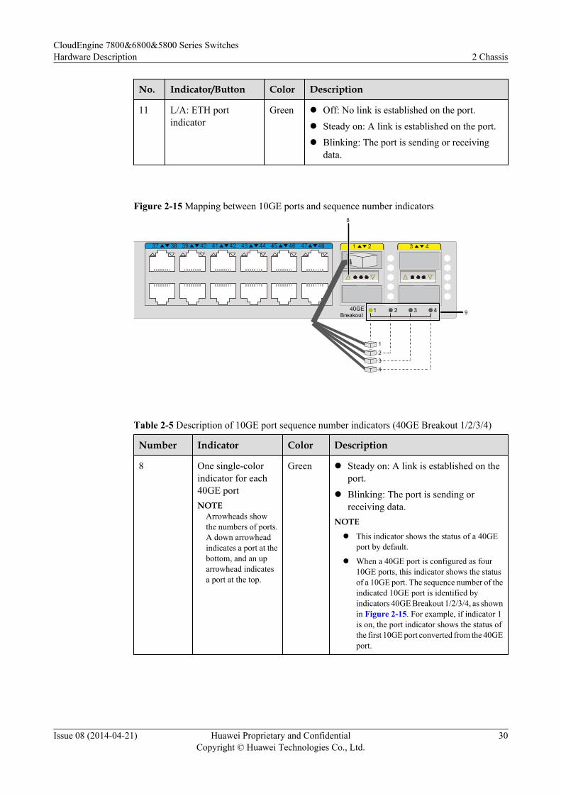
11 L/A: ETH portindicator
Green l Off: No link is established on the port.l Steady on: A link is established on the port.l Blinking: The port is sending or receiving
data.
Figure 2-15 Mapping between 10GE ports and sequence number indicators
1
8
9
234
Table 2-5 Description of 10GE port sequence number indicators (40GE Breakout 1/2/3/4)
Number Indicator Color Description
8 One single-colorindicator for each40GE portNOTE
Arrowheads showthe numbers of ports.A down arrowheadindicates a port at thebottom, and an uparrowhead indicatesa port at the top.
Green l Steady on: A link is established on theport.
l Blinking: The port is sending orreceiving data.
NOTE
l This indicator shows the status of a 40GEport by default.
l When a 40GE port is configured as four10GE ports, this indicator shows the statusof a 10GE port. The sequence number of theindicated 10GE port is identified byindicators 40GE Breakout 1/2/3/4, as shownin Figure 2-15. For example, if indicator 1is on, the port indicator shows the status ofthe first 10GE port converted from the 40GEport.
CloudEngine 7800&6800&5800 Series SwitchesHardware Description 2 Chassis
Issue 08 (2014-04-21) Huawei Proprietary and ConfidentialCopyright © Huawei Technologies Co., Ltd.
30
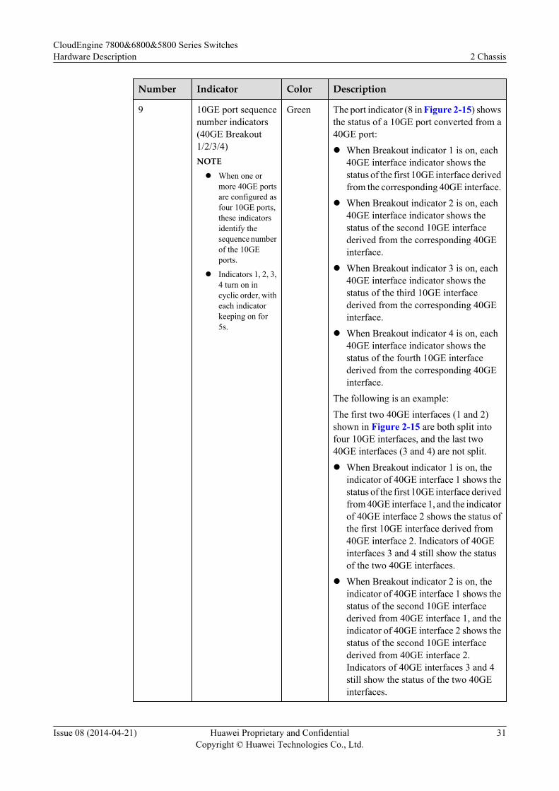
Number Indicator Color Description
9 10GE port sequencenumber indicators(40GE Breakout1/2/3/4)NOTE
l When one ormore 40GE portsare configured asfour 10GE ports,these indicatorsidentify thesequence numberof the 10GEports.
l Indicators 1, 2, 3,4 turn on incyclic order, witheach indicatorkeeping on for5s.
Green The port indicator (8 in Figure 2-15) showsthe status of a 10GE port converted from a40GE port:l When Breakout indicator 1 is on, each
40GE interface indicator shows thestatus of the first 10GE interface derivedfrom the corresponding 40GE interface.
l When Breakout indicator 2 is on, each40GE interface indicator shows thestatus of the second 10GE interfacederived from the corresponding 40GEinterface.
l When Breakout indicator 3 is on, each40GE interface indicator shows thestatus of the third 10GE interfacederived from the corresponding 40GEinterface.
l When Breakout indicator 4 is on, each40GE interface indicator shows thestatus of the fourth 10GE interfacederived from the corresponding 40GEinterface.
The following is an example:The first two 40GE interfaces (1 and 2)shown in Figure 2-15 are both split intofour 10GE interfaces, and the last two40GE interfaces (3 and 4) are not split.l When Breakout indicator 1 is on, the
indicator of 40GE interface 1 shows thestatus of the first 10GE interface derivedfrom 40GE interface 1, and the indicatorof 40GE interface 2 shows the status ofthe first 10GE interface derived from40GE interface 2. Indicators of 40GEinterfaces 3 and 4 still show the statusof the two 40GE interfaces.
l When Breakout indicator 2 is on, theindicator of 40GE interface 1 shows thestatus of the second 10GE interfacederived from 40GE interface 1, and theindicator of 40GE interface 2 shows thestatus of the second 10GE interfacederived from 40GE interface 2.Indicators of 40GE interfaces 3 and 4still show the status of the two 40GEinterfaces.
CloudEngine 7800&6800&5800 Series SwitchesHardware Description 2 Chassis
Issue 08 (2014-04-21) Huawei Proprietary and ConfidentialCopyright © Huawei Technologies Co., Ltd.
31
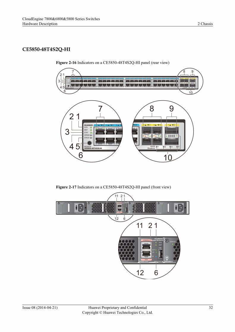
CE5850-48T4S2Q-HI
Figure 2-16 Indicators on a CE5850-48T4S2Q-HI panel (rear view)
1 2 3 4 5 6 7 8 9 10 11 12 13 14 15 16 17 18 19 20 21 22 23 24 25 26 27 28 29 30 31 32 33 34 35 36 37 38 39 40 41 42 43 44 45 46 47 48 1 2 3 4 1 2SYSMSTSTATSPEEDSTACK
MODE/IDCE5850-48T4S2Q-HI
140GEBreakout
2 3 4
7 8
10
912
3
4 56
1 2 3 4 5SYSMSTSTATSPEEDSTACK
MODE/IDCE5850-48T4S2Q-HI
712
3
4 56
48 1 2 3 4 1 2
8
10
9
140GEBreakout
2 3 4
Figure 2-17 Indicators on a CE5850-48T4S2Q-HI panel (front view)
PAC-150WA ~100-240V;50/60Hz,2.5A
STATUS STATUS
FAN-40EA-F PAC-150WA
STATUS
~100-240V;50/60Hz,2.5A
STATUS
FAN-40EA-F
CONSOLE
ETH
SYS
MST
ACT
L/A
ID
PWR1 FAN1 FAN2 PWR2
CE5850-48T4S2Q-HI
11 2 1
612
STATUS
FAN-40EA-F
CONSOLE
ETH
SYS
MST
ACT
L/A
ID
PWR1 FAN1 FAN2 PWR2
CE5850-48T4S2Q-HI
11 2 1
612
CloudEngine 7800&6800&5800 Series SwitchesHardware Description 2 Chassis
Issue 08 (2014-04-21) Huawei Proprietary and ConfidentialCopyright © Huawei Technologies Co., Ltd.
32
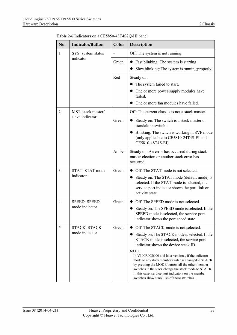
Table 2-6 Indicators on a CE5850-48T4S2Q-HI panel
No. Indicator/Button Color Description
1 SYS: system statusindicator
- Off: The system is not running.
Green l Fast blinking: The system is starting.l Slow blinking: The system is running properly.
Red Steady on:l The system failed to start.l One or more power supply modules have
failed.l One or more fan modules have failed.
2 MST: stack master/slave indicator
- Off: The current chassis is not a stack master.
Green l Steady on: The switch is a stack master orstandalone switch.
l Blinking: The switch is working in SVF mode(only applicable to CE5810-24T4S-EI andCE5810-48T4S-EI).
Amber Steady on: An error has occurred during stackmaster election or another stack error hasoccurred.
3 STAT: STAT modeindicator
Green l Off: The STAT mode is not selected.l Steady on: The STAT mode (default mode) is
selected. If the STAT mode is selected, theservice port indicator shows the port link oractivity state.
4 SPEED: SPEEDmode indicator
Green l Off: The SPEED mode is not selected.l Steady on: The SPEED mode is selected. If the
SPEED mode is selected, the service portindicator shows the port speed state.
5 STACK: STACKmode indicator
Green l Off: The STACK mode is not selected.l Steady on: The STACK mode is selected. If the
STACK mode is selected, the service portindicator shows the device stack ID.
NOTEIn V100R002C00 and later versions, if the indicatormode on any stack member switch is changed to STACKby pressing the MODE button, all the other memberswitches in the stack change the stack mode to STACK.In this case, service port indicators on the memberswitches show stack IDs of these switches.
CloudEngine 7800&6800&5800 Series SwitchesHardware Description 2 Chassis
Issue 08 (2014-04-21) Huawei Proprietary and ConfidentialCopyright © Huawei Technologies Co., Ltd.
33
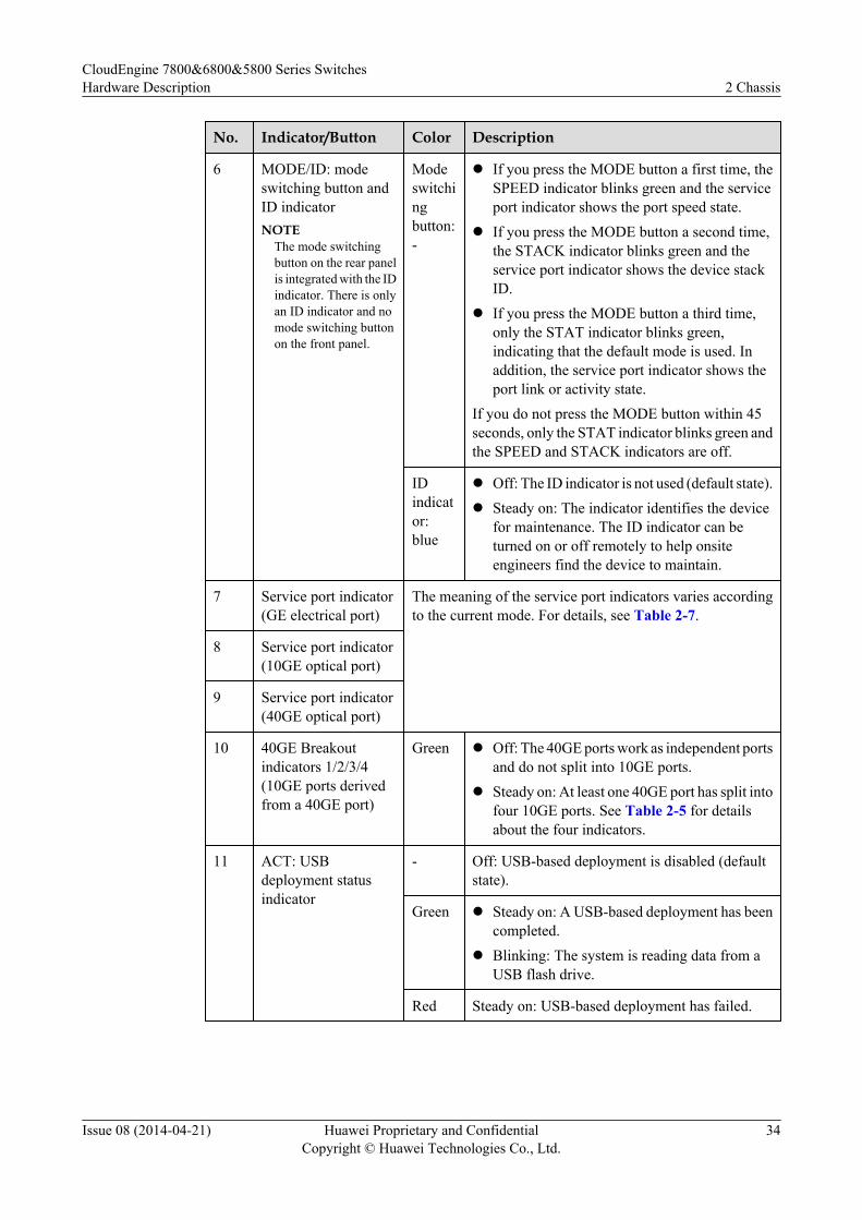
No. Indicator/Button Color Description
6 MODE/ID: modeswitching button andID indicatorNOTE
The mode switchingbutton on the rear panelis integrated with the IDindicator. There is onlyan ID indicator and nomode switching buttonon the front panel.
Modeswitchingbutton:-
l If you press the MODE button a first time, theSPEED indicator blinks green and the serviceport indicator shows the port speed state.
l If you press the MODE button a second time,the STACK indicator blinks green and theservice port indicator shows the device stackID.
l If you press the MODE button a third time,only the STAT indicator blinks green,indicating that the default mode is used. Inaddition, the service port indicator shows theport link or activity state.
If you do not press the MODE button within 45seconds, only the STAT indicator blinks green andthe SPEED and STACK indicators are off.
IDindicator:blue
l Off: The ID indicator is not used (default state).l Steady on: The indicator identifies the device
for maintenance. The ID indicator can beturned on or off remotely to help onsiteengineers find the device to maintain.
7 Service port indicator(GE electrical port)
The meaning of the service port indicators varies accordingto the current mode. For details, see Table 2-7.
8 Service port indicator(10GE optical port)
9 Service port indicator(40GE optical port)
10 40GE Breakoutindicators 1/2/3/4(10GE ports derivedfrom a 40GE port)
Green l Off: The 40GE ports work as independent portsand do not split into 10GE ports.
l Steady on: At least one 40GE port has split intofour 10GE ports. See Table 2-5 for detailsabout the four indicators.
11 ACT: USBdeployment statusindicator
- Off: USB-based deployment is disabled (defaultstate).
Green l Steady on: A USB-based deployment has beencompleted.
l Blinking: The system is reading data from aUSB flash drive.
Red Steady on: USB-based deployment has failed.
CloudEngine 7800&6800&5800 Series SwitchesHardware Description 2 Chassis
Issue 08 (2014-04-21) Huawei Proprietary and ConfidentialCopyright © Huawei Technologies Co., Ltd.
34
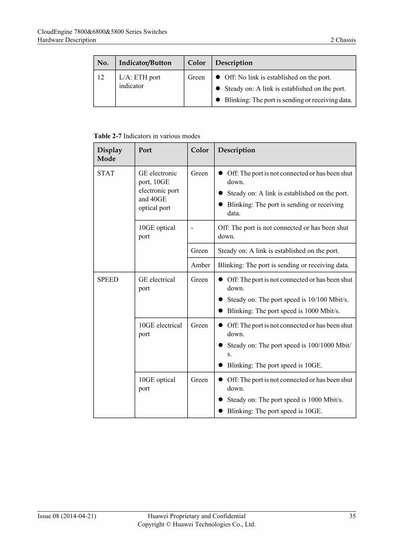
No. Indicator/Button Color Description
12 L/A: ETH portindicator
Green l Off: No link is established on the port.l Steady on: A link is established on the port.l Blinking: The port is sending or receiving data.
Table 2-7 Indicators in various modes
DisplayMode
Port Color Description
STAT GE electronicport, 10GEelectronic portand 40GEoptical port
Green l Off: The port is not connected or has been shutdown.
l Steady on: A link is established on the port.l Blinking: The port is sending or receiving
data.
10GE opticalport
- Off: The port is not connected or has been shutdown.
Green Steady on: A link is established on the port.
Amber Blinking: The port is sending or receiving data.
SPEED GE electricalport
Green l Off: The port is not connected or has been shutdown.
l Steady on: The port speed is 10/100 Mbit/s.l Blinking: The port speed is 1000 Mbit/s.
10GE electricalport
Green l Off: The port is not connected or has been shutdown.
l Steady on: The port speed is 100/1000 Mbit/s.
l Blinking: The port speed is 10GE.
10GE opticalport
Green l Off: The port is not connected or has been shutdown.
l Steady on: The port speed is 1000 Mbit/s.l Blinking: The port speed is 10GE.
CloudEngine 7800&6800&5800 Series SwitchesHardware Description 2 Chassis
Issue 08 (2014-04-21) Huawei Proprietary and ConfidentialCopyright © Huawei Technologies Co., Ltd.
35
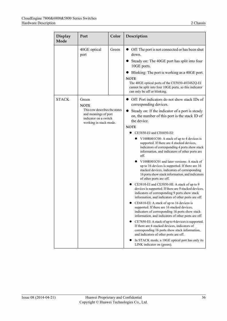
DisplayMode
Port Color Description
40GE opticalport
Green l Off: The port is not connected or has been shutdown.
l Steady on: The 40GE port has split into four10GE ports.
l Blinking: The port is working as a 40GE port.NOTE
The 40GE optical ports of the CE5850-48T4S2Q-EIcannot be split into four 10GE ports, so this indicatorcan only be off or blinking.
STACK GreenNOTE
This row describes the statesand meanings of portindicator on a switchworking in stack mode.
l Off: Port indicators do not show stack IDs ofcorresponding devices.
l Steady on: If the indicator of a port is steadyon, the number of this port is the stack ID ofthe device.
NOTE
l CE5850-EI and CE6850-EI:
l V100R001C00: A stack of up to 4 devices issupported. If there are 4 stacked devices,indicators of corresponding 4 ports show stackinformation, and indicators of other ports areoff.
l V100R001C01 and later versions: A stack ofup to 16 devices is supported. If there are 16stacked devices, indicators of corresponding16 ports show stack information, and indicatorsof other ports are off.
l CE5810-EI and CE5850-HI: A stack of up to 9devices is supported. If there are 9 stacked devices,indicators of corresponding 9 ports show stackinformation, and indicators of other ports are off.
l CE6810-EI: A stack of up to 16 devices issupported. If there are 16 stacked devices,indicators of corresponding 16 ports show stackinformation, and indicators of other ports are off.
l CE7850-EI: A stack of up to 4 devices is supported.If there are 4 stacked devices, indicators ofcorresponding 16 ports show stack information,and indicators of other ports are off.
l In STACK mode, a 10GE optical port has only itsLINK indicator on (green).
CloudEngine 7800&6800&5800 Series SwitchesHardware Description 2 Chassis
Issue 08 (2014-04-21) Huawei Proprietary and ConfidentialCopyright © Huawei Technologies Co., Ltd.
36
DisplayMode
Port Color Description
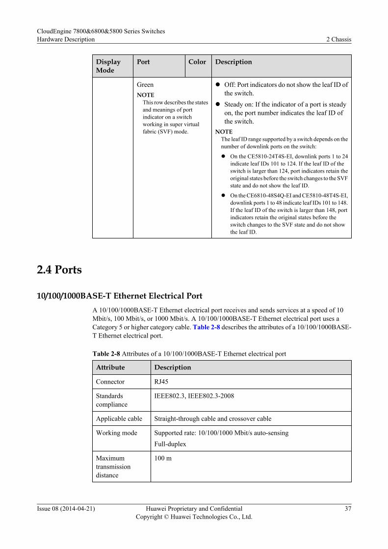
GreenNOTE
This row describes the statesand meanings of portindicator on a switchworking in super virtualfabric (SVF) mode.
l Off: Port indicators do not show the leaf ID ofthe switch.
l Steady on: If the indicator of a port is steadyon, the port number indicates the leaf ID ofthe switch.
NOTEThe leaf ID range supported by a switch depends on thenumber of downlink ports on the switch:
l On the CE5810-24T4S-EI, downlink ports 1 to 24indicate leaf IDs 101 to 124. If the leaf ID of theswitch is larger than 124, port indicators retain theoriginal states before the switch changes to the SVFstate and do not show the leaf ID.
l On the CE6810-48S4Q-EI and CE5810-48T4S-EI,downlink ports 1 to 48 indicate leaf IDs 101 to 148.If the leaf ID of the switch is larger than 148, portindicators retain the original states before theswitch changes to the SVF state and do not showthe leaf ID.
2.4 Ports
10/100/1000BASE-T Ethernet Electrical PortA 10/100/1000BASE-T Ethernet electrical port receives and sends services at a speed of 10Mbit/s, 100 Mbit/s, or 1000 Mbit/s. A 10/100/1000BASE-T Ethernet electrical port uses aCategory 5 or higher category cable. Table 2-8 describes the attributes of a 10/100/1000BASE-T Ethernet electrical port.
Table 2-8 Attributes of a 10/100/1000BASE-T Ethernet electrical port
Attribute Description
Connector RJ45
Standardscompliance
IEEE802.3, IEEE802.3-2008
Applicable cable Straight-through cable and crossover cable
Working mode Supported rate: 10/100/1000 Mbit/s auto-sensingFull-duplex
Maximumtransmissiondistance
100 m
CloudEngine 7800&6800&5800 Series SwitchesHardware Description 2 Chassis
Issue 08 (2014-04-21) Huawei Proprietary and ConfidentialCopyright © Huawei Technologies Co., Ltd.
37
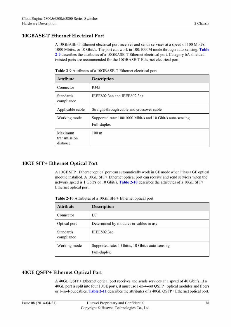
10GBASE-T Ethernet Electrical PortA 10GBASE-T Ethernet electrical port receives and sends services at a speed of 100 Mbit/s,1000 Mbit/s, or 10 Gbit/s. The port can work in 100/1000M mode through auto-sensing. Table2-9 describes the attributes of a 10GBASE-T Ethernet electrical port. Category 6A shieldedtwisted paris are recommended for the 10GBASE-T Ethernet electrical port.
Table 2-9 Attributes of a 10GBASE-T Ethernet electrical port
Attribute Description
Connector RJ45
Standardscompliance
IEEE802.3an and IEEE802.3az
Applicable cable Straight-through cable and crossover cable
Working mode Supported rate: 100/1000 Mbit/s and 10 Gbit/s auto-sensingFull-duplex
Maximumtransmissiondistance
100 m
10GE SFP+ Ethernet Optical PortA 10GE SFP+ Ethernet optical port can automatically work in GE mode when it has a GE opticalmodule installed. A 10GE SFP+ Ethernet optical port can receive and send services when thenetwork speed is 1 Gbit/s or 10 Gbit/s. Table 2-10 describes the attributes of a 10GE SFP+Ethernet optical port.
Table 2-10 Attributes of a 10GE SFP+ Ethernet optical port
Attribute Description
Connector LC
Optical port Determined by modules or cables in use
Standardscompliance
IEEE802.3ae
Working mode Supported rate: 1 Gbit/s, 10 Gbit/s auto-sensingFull-duplex
40GE QSFP+ Ethernet Optical PortA 40GE QSFP+ Ethernet optical port receives and sends services at a speed of 40 Gbit/s. If a40GE port is split into four 10GE ports, it must use 1-in-4-out QSFP+ optical modules and fibersor 1-in-4-out cables. Table 2-11 describes the attributes of a 40GE QSFP+ Ethernet optical port.
CloudEngine 7800&6800&5800 Series SwitchesHardware Description 2 Chassis
Issue 08 (2014-04-21) Huawei Proprietary and ConfidentialCopyright © Huawei Technologies Co., Ltd.
38
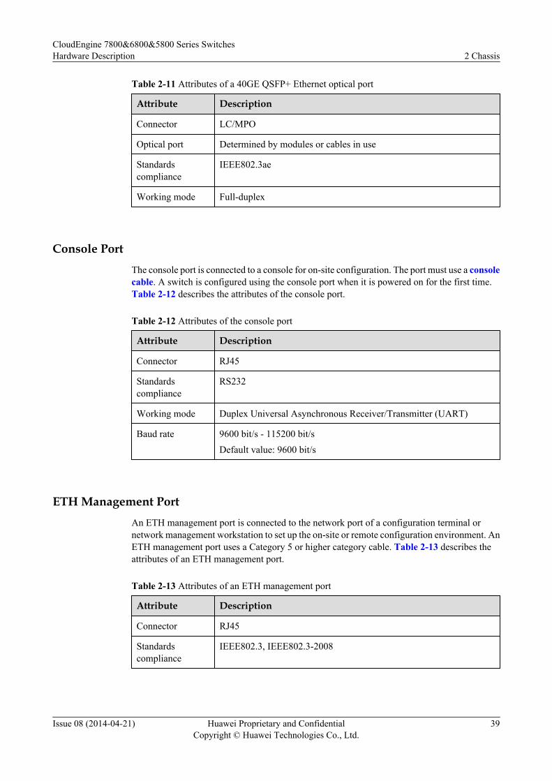
Table 2-11 Attributes of a 40GE QSFP+ Ethernet optical port
Attribute Description
Connector LC/MPO
Optical port Determined by modules or cables in use
Standardscompliance
IEEE802.3ae
Working mode Full-duplex
Console PortThe console port is connected to a console for on-site configuration. The port must use a consolecable. A switch is configured using the console port when it is powered on for the first time.Table 2-12 describes the attributes of the console port.
Table 2-12 Attributes of the console port
Attribute Description
Connector RJ45
Standardscompliance
RS232
Working mode Duplex Universal Asynchronous Receiver/Transmitter (UART)
Baud rate 9600 bit/s - 115200 bit/sDefault value: 9600 bit/s
ETH Management PortAn ETH management port is connected to the network port of a configuration terminal ornetwork management workstation to set up the on-site or remote configuration environment. AnETH management port uses a Category 5 or higher category cable. Table 2-13 describes theattributes of an ETH management port.
Table 2-13 Attributes of an ETH management port
Attribute Description
Connector RJ45
Standardscompliance
IEEE802.3, IEEE802.3-2008
CloudEngine 7800&6800&5800 Series SwitchesHardware Description 2 Chassis
Issue 08 (2014-04-21) Huawei Proprietary and ConfidentialCopyright © Huawei Technologies Co., Ltd.
39

Attribute Description
Working mode Supported rate: 10/100/1000 Mbit/s auto-sensingFull-duplex
Maximumtransmissiondistance
100 m
2.5 Specifications
Table 2-14 lists the specifications of CE7800&6800&5800 series switches.
CloudEngine 7800&6800&5800 Series SwitchesHardware Description 2 Chassis
Issue 08 (2014-04-21) Huawei Proprietary and ConfidentialCopyright © Huawei Technologies Co., Ltd.
40
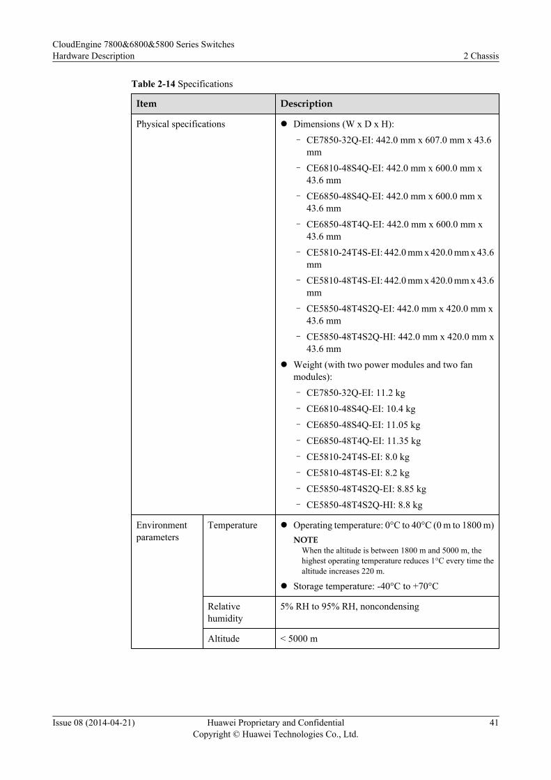
Table 2-14 Specifications
Item Description
Physical specifications l Dimensions (W x D x H):
– CE7850-32Q-EI: 442.0 mm x 607.0 mm x 43.6mm
– CE6810-48S4Q-EI: 442.0 mm x 600.0 mm x43.6 mm
– CE6850-48S4Q-EI: 442.0 mm x 600.0 mm x43.6 mm
– CE6850-48T4Q-EI: 442.0 mm x 600.0 mm x43.6 mm
– CE5810-24T4S-EI: 442.0 mm x 420.0 mm x 43.6mm
– CE5810-48T4S-EI: 442.0 mm x 420.0 mm x 43.6mm
– CE5850-48T4S2Q-EI: 442.0 mm x 420.0 mm x43.6 mm
– CE5850-48T4S2Q-HI: 442.0 mm x 420.0 mm x43.6 mm
l Weight (with two power modules and two fanmodules):
– CE7850-32Q-EI: 11.2 kg
– CE6810-48S4Q-EI: 10.4 kg
– CE6850-48S4Q-EI: 11.05 kg
– CE6850-48T4Q-EI: 11.35 kg
– CE5810-24T4S-EI: 8.0 kg
– CE5810-48T4S-EI: 8.2 kg
– CE5850-48T4S2Q-EI: 8.85 kg
– CE5850-48T4S2Q-HI: 8.8 kg
Environmentparameters
Temperature l Operating temperature: 0°C to 40°C (0 m to 1800 m)NOTE
When the altitude is between 1800 m and 5000 m, thehighest operating temperature reduces 1°C every time thealtitude increases 220 m.
l Storage temperature: -40°C to +70°C
Relativehumidity
5% RH to 95% RH, noncondensing
Altitude < 5000 m
CloudEngine 7800&6800&5800 Series SwitchesHardware Description 2 Chassis
Issue 08 (2014-04-21) Huawei Proprietary and ConfidentialCopyright © Huawei Technologies Co., Ltd.
41
Item Description
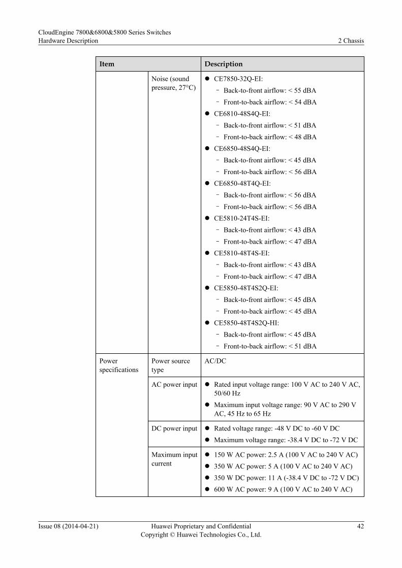
Noise (soundpressure, 27°C)
l CE7850-32Q-EI:
– Back-to-front airflow: < 55 dBA
– Front-to-back airflow: < 54 dBAl CE6810-48S4Q-EI:
– Back-to-front airflow: < 51 dBA
– Front-to-back airflow: < 48 dBAl CE6850-48S4Q-EI:
– Back-to-front airflow: < 45 dBA
– Front-to-back airflow: < 56 dBAl CE6850-48T4Q-EI:
– Back-to-front airflow: < 56 dBA
– Front-to-back airflow: < 56 dBAl CE5810-24T4S-EI:
– Back-to-front airflow: < 43 dBA
– Front-to-back airflow: < 47 dBAl CE5810-48T4S-EI:
– Back-to-front airflow: < 43 dBA
– Front-to-back airflow: < 47 dBAl CE5850-48T4S2Q-EI:
– Back-to-front airflow: < 45 dBA
– Front-to-back airflow: < 45 dBAl CE5850-48T4S2Q-HI:
– Back-to-front airflow: < 45 dBA
– Front-to-back airflow: < 51 dBA
Powerspecifications
Power sourcetype
AC/DC
AC power input l Rated input voltage range: 100 V AC to 240 V AC,50/60 Hz
l Maximum input voltage range: 90 V AC to 290 VAC, 45 Hz to 65 Hz
DC power input l Rated voltage range: -48 V DC to -60 V DCl Maximum voltage range: -38.4 V DC to -72 V DC
Maximum inputcurrent
l 150 W AC power: 2.5 A (100 V AC to 240 V AC)l 350 W AC power: 5 A (100 V AC to 240 V AC)l 350 W DC power: 11 A (-38.4 V DC to -72 V DC)l 600 W AC power: 9 A (100 V AC to 240 V AC)
CloudEngine 7800&6800&5800 Series SwitchesHardware Description 2 Chassis
Issue 08 (2014-04-21) Huawei Proprietary and ConfidentialCopyright © Huawei Technologies Co., Ltd.
42
Item Description
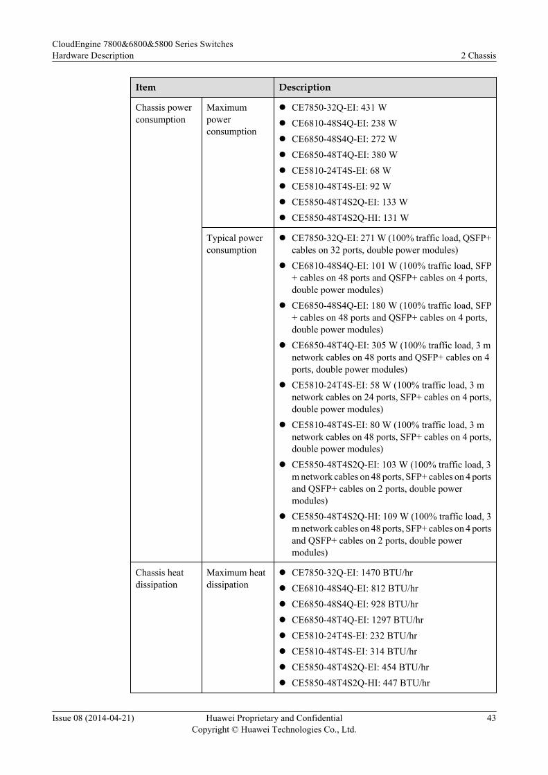
Chassis powerconsumption
Maximumpowerconsumption
l CE7850-32Q-EI: 431 Wl CE6810-48S4Q-EI: 238 Wl CE6850-48S4Q-EI: 272 Wl CE6850-48T4Q-EI: 380 Wl CE5810-24T4S-EI: 68 Wl CE5810-48T4S-EI: 92 Wl CE5850-48T4S2Q-EI: 133 Wl CE5850-48T4S2Q-HI: 131 W
Typical powerconsumption
l CE7850-32Q-EI: 271 W (100% traffic load, QSFP+cables on 32 ports, double power modules)
l CE6810-48S4Q-EI: 101 W (100% traffic load, SFP+ cables on 48 ports and QSFP+ cables on 4 ports,double power modules)
l CE6850-48S4Q-EI: 180 W (100% traffic load, SFP+ cables on 48 ports and QSFP+ cables on 4 ports,double power modules)
l CE6850-48T4Q-EI: 305 W (100% traffic load, 3 mnetwork cables on 48 ports and QSFP+ cables on 4ports, double power modules)
l CE5810-24T4S-EI: 58 W (100% traffic load, 3 mnetwork cables on 24 ports, SFP+ cables on 4 ports,double power modules)
l CE5810-48T4S-EI: 80 W (100% traffic load, 3 mnetwork cables on 48 ports, SFP+ cables on 4 ports,double power modules)
l CE5850-48T4S2Q-EI: 103 W (100% traffic load, 3m network cables on 48 ports, SFP+ cables on 4 portsand QSFP+ cables on 2 ports, double powermodules)
l CE5850-48T4S2Q-HI: 109 W (100% traffic load, 3m network cables on 48 ports, SFP+ cables on 4 portsand QSFP+ cables on 2 ports, double powermodules)
Chassis heatdissipation
Maximum heatdissipation
l CE7850-32Q-EI: 1470 BTU/hrl CE6810-48S4Q-EI: 812 BTU/hrl CE6850-48S4Q-EI: 928 BTU/hrl CE6850-48T4Q-EI: 1297 BTU/hrl CE5810-24T4S-EI: 232 BTU/hrl CE5810-48T4S-EI: 314 BTU/hrl CE5850-48T4S2Q-EI: 454 BTU/hrl CE5850-48T4S2Q-HI: 447 BTU/hr
CloudEngine 7800&6800&5800 Series SwitchesHardware Description 2 Chassis
Issue 08 (2014-04-21) Huawei Proprietary and ConfidentialCopyright © Huawei Technologies Co., Ltd.
43
Item Description
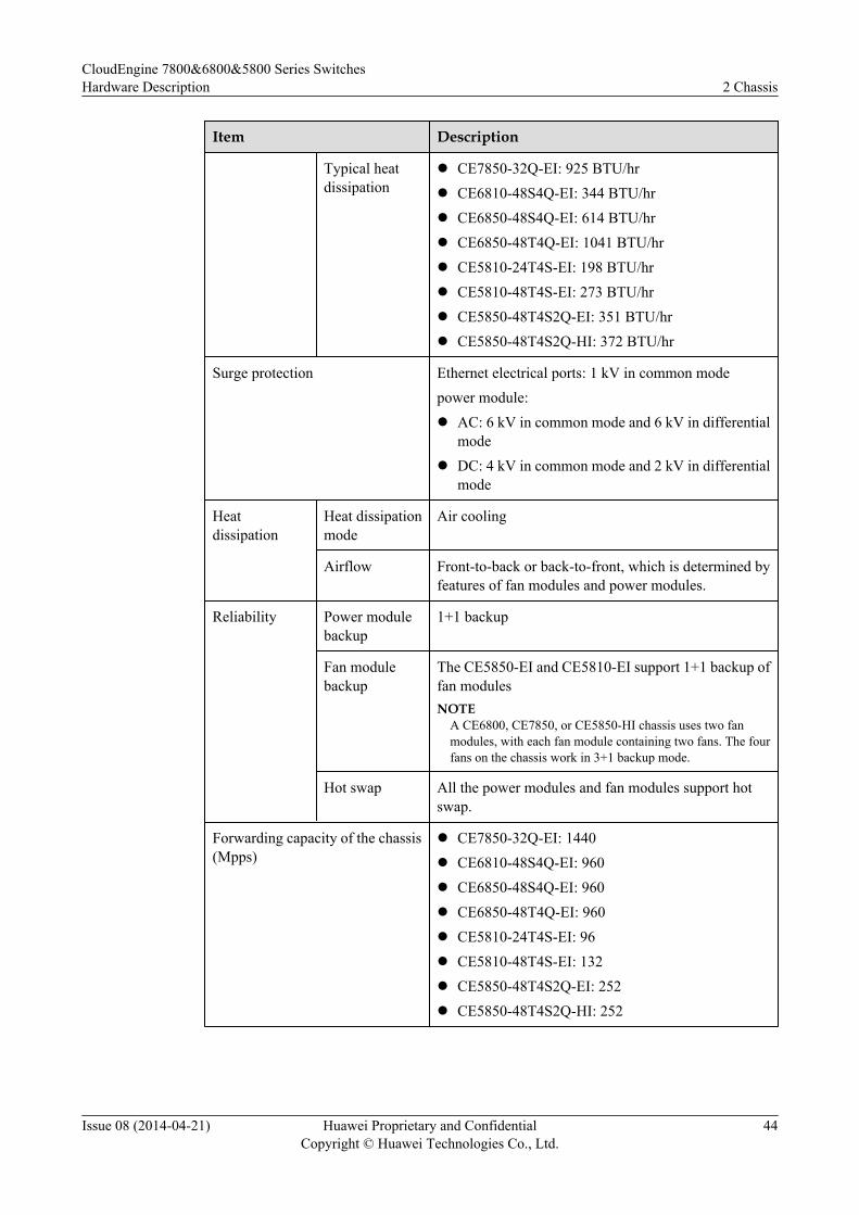
Typical heatdissipation
l CE7850-32Q-EI: 925 BTU/hrl CE6810-48S4Q-EI: 344 BTU/hrl CE6850-48S4Q-EI: 614 BTU/hrl CE6850-48T4Q-EI: 1041 BTU/hrl CE5810-24T4S-EI: 198 BTU/hrl CE5810-48T4S-EI: 273 BTU/hrl CE5850-48T4S2Q-EI: 351 BTU/hrl CE5850-48T4S2Q-HI: 372 BTU/hr
Surge protection Ethernet electrical ports: 1 kV in common modepower module:l AC: 6 kV in common mode and 6 kV in differential
model DC: 4 kV in common mode and 2 kV in differential
mode
Heatdissipation
Heat dissipationmode
Air cooling
Airflow Front-to-back or back-to-front, which is determined byfeatures of fan modules and power modules.
Reliability Power modulebackup
1+1 backup
Fan modulebackup
The CE5850-EI and CE5810-EI support 1+1 backup offan modulesNOTE
A CE6800, CE7850, or CE5850-HI chassis uses two fanmodules, with each fan module containing two fans. The fourfans on the chassis work in 3+1 backup mode.
Hot swap All the power modules and fan modules support hotswap.
Forwarding capacity of the chassis(Mpps)
l CE7850-32Q-EI: 1440l CE6810-48S4Q-EI: 960l CE6850-48S4Q-EI: 960l CE6850-48T4Q-EI: 960l CE5810-24T4S-EI: 96l CE5810-48T4S-EI: 132l CE5850-48T4S2Q-EI: 252l CE5850-48T4S2Q-HI: 252
CloudEngine 7800&6800&5800 Series SwitchesHardware Description 2 Chassis
Issue 08 (2014-04-21) Huawei Proprietary and ConfidentialCopyright © Huawei Technologies Co., Ltd.
44
Item Description
Stack Service portsupporting thestack function
l CE7850-32Q-EI: 40GE optical portsl CE6810-48S4Q-EI: 10GE optical ports and 40GE
optical portsl CE6850-48S4Q-EI: 10GE optical ports and 40GE
optical portsl CE6850-48T4Q-EI: 10GE electrical ports
(V100R002 and later versions) and 40GE opticalports
l CE5810-24T4S-EI: 10GE optical portsl CE5810-48T4S-EI: 10GE optical portsl CE5850-48T4S2Q-EI: 10GE and 40GE optical
portsl CE5850-48T4S2Q-HI: 10GE and 40GE optical
portsNOTE
Downlink GE electrical ports cannot be used as stack ports.
Maximum stackbandwidth(unidirectional)
l CE7850-32Q-EI: 640 Gbit/s (16x40GE, a maximumof sixteen physical ports on a logical stack port)
l CE6810-48S4Q-EI: 160 Gbit/s (4x40GE or16x10GE, a maximum of sixteen physical ports ona logical stack port)
l CE6850-48S4Q-EI: 160 Gbit/s (4x40GE or16x10GE, a maximum of sixteen physical ports ona logical stack port)
l CE6850-48T4Q-EI: 160 Gbit/s (4x40GE or16x10GE, a maximum of sixteen physical ports ona logical stack port)
l CE5810-24T4S-EI: 40 Gbit/s (4x10GE, a maximumof four physical ports on a logical stack port)
l CE5810-48T4S-EI: 40 Gbit/s (4x10GE, a maximumof two physical ports on a logical stack port)
l CE5850-48T4S2Q-EI: 80 Gbit/s (4x10GE or2x40GE, a maximum of four physical ports on alogical stack port)
l CE5850-48T4S2Q-HI: 80 Gbit/s (4x10GE or2x40GE, a maximum of four physical ports on alogical stack port)
NOTEA 10GE port and a 40GE port cannot belong to the same logicalstack port.
CloudEngine 7800&6800&5800 Series SwitchesHardware Description 2 Chassis
Issue 08 (2014-04-21) Huawei Proprietary and ConfidentialCopyright © Huawei Technologies Co., Ltd.
45
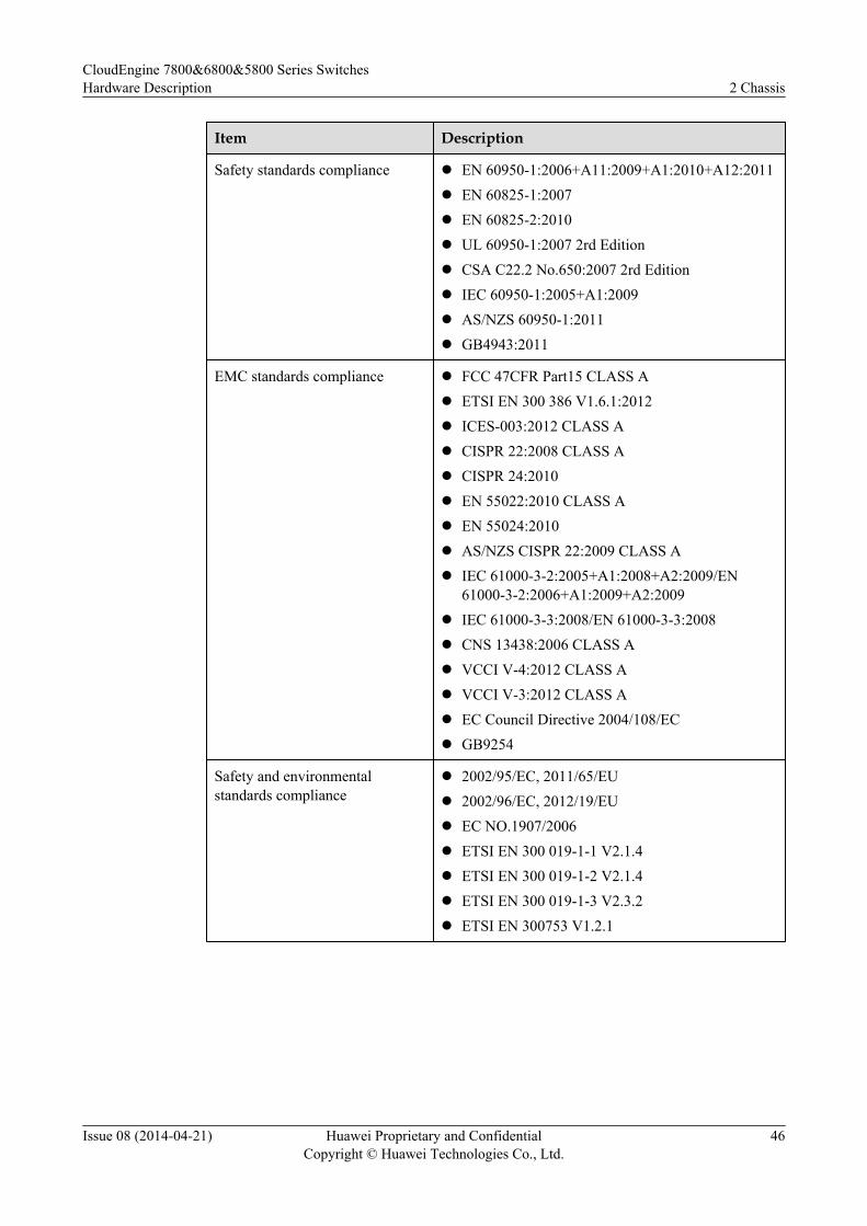
Item Description
Safety standards compliance l EN 60950-1:2006+A11:2009+A1:2010+A12:2011l EN 60825-1:2007l EN 60825-2:2010l UL 60950-1:2007 2rd Editionl CSA C22.2 No.650:2007 2rd Editionl IEC 60950-1:2005+A1:2009l AS/NZS 60950-1:2011l GB4943:2011
EMC standards compliance l FCC 47CFR Part15 CLASS Al ETSI EN 300 386 V1.6.1:2012l ICES-003:2012 CLASS Al CISPR 22:2008 CLASS Al CISPR 24:2010l EN 55022:2010 CLASS Al EN 55024:2010l AS/NZS CISPR 22:2009 CLASS Al IEC 61000-3-2:2005+A1:2008+A2:2009/EN
61000-3-2:2006+A1:2009+A2:2009l IEC 61000-3-3:2008/EN 61000-3-3:2008l CNS 13438:2006 CLASS Al VCCI V-4:2012 CLASS Al VCCI V-3:2012 CLASS Al EC Council Directive 2004/108/ECl GB9254
Safety and environmentalstandards compliance
l 2002/95/EC, 2011/65/EUl 2002/96/EC, 2012/19/EUl EC NO.1907/2006l ETSI EN 300 019-1-1 V2.1.4l ETSI EN 300 019-1-2 V2.1.4l ETSI EN 300 019-1-3 V2.3.2l ETSI EN 300753 V1.2.1
CloudEngine 7800&6800&5800 Series SwitchesHardware Description 2 Chassis
Issue 08 (2014-04-21) Huawei Proprietary and ConfidentialCopyright © Huawei Technologies Co., Ltd.
46
3 Power Module
About This Chapter
NOTICEl Power modules in a chassis must have the same power and same heat dissipation method.l AC and DC power modules cannot be used together on a switch.l When two power modules work in 1+1 backup mode, you can hot swap one of them.l When only one power module is installed in a chassis, install a filler panel on the empty
power supply slot.l Before powering off a switch, turn off all its power modules.
3.1 150 W AC Power Module
3.2 350 W AC Power Module
3.3 350 W DC Power Module
3.4 600 W AC Power Module
CloudEngine 7800&6800&5800 Series SwitchesHardware Description 3 Power Module
Issue 08 (2014-04-21) Huawei Proprietary and ConfidentialCopyright © Huawei Technologies Co., Ltd.
47
3.1 150 W AC Power Module
Version Mapping150 W AC power module is available only in one model: PAC-150WA. This model has no fansand uses natural heat dissipation.
Table 3-1 describes the mapping between device models and the 150 W AC power module.
Table 3-1 Mapping between device models and the 150 W AC power module
Device Model PAC-150WA
CE5810-24T4S-EICE5810-48T4S-EI
SupportedNOTE
This power module is supported in V100R002C00version and later versions.
CE5850-48T4S2Q-EI SupportedNOTE
This power module is supported in V100R001C00version and later versions.
CE5850-48T4S2Q-HI SupportedNOTE
This power module is supported in V100R003C00version and later versions.
CE6850-48S4Q-EICE6850-48T4Q-EICE6810-48S4Q-EICE7850-32Q-EI
Not supported
AppearanceFigure 3-1 shows the appearance of a 150 W AC power module.
CloudEngine 7800&6800&5800 Series SwitchesHardware Description 3 Power Module
Issue 08 (2014-04-21) Huawei Proprietary and ConfidentialCopyright © Huawei Technologies Co., Ltd.
48
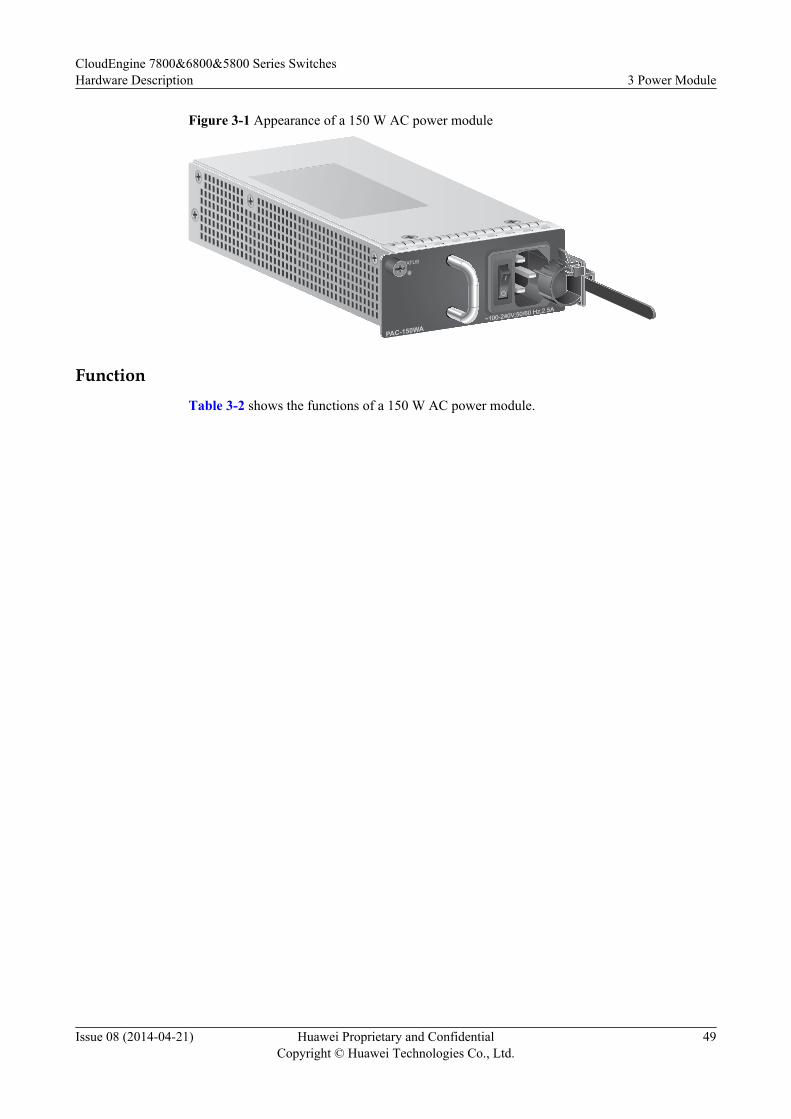
Figure 3-1 Appearance of a 150 W AC power module
PAC-150WA
STATUS
~100-240V;50/60 Hz;2.5A
FunctionTable 3-2 shows the functions of a 150 W AC power module.
CloudEngine 7800&6800&5800 Series SwitchesHardware Description 3 Power Module
Issue 08 (2014-04-21) Huawei Proprietary and ConfidentialCopyright © Huawei Technologies Co., Ltd.
49
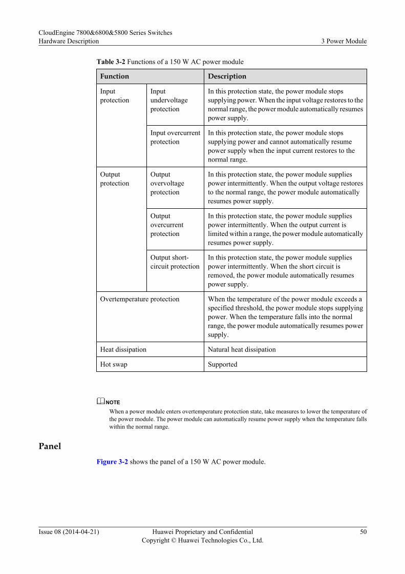
Table 3-2 Functions of a 150 W AC power module
Function Description
Inputprotection
Inputundervoltageprotection
In this protection state, the power module stopssupplying power. When the input voltage restores to thenormal range, the power module automatically resumespower supply.
Input overcurrentprotection
In this protection state, the power module stopssupplying power and cannot automatically resumepower supply when the input current restores to thenormal range.
Outputprotection
Outputovervoltageprotection
In this protection state, the power module suppliespower intermittently. When the output voltage restoresto the normal range, the power module automaticallyresumes power supply.
Outputovercurrentprotection
In this protection state, the power module suppliespower intermittently. When the output current islimited within a range, the power module automaticallyresumes power supply.
Output short-circuit protection
In this protection state, the power module suppliespower intermittently. When the short circuit isremoved, the power module automatically resumespower supply.
Overtemperature protection When the temperature of the power module exceeds aspecified threshold, the power module stops supplyingpower. When the temperature falls into the normalrange, the power module automatically resumes powersupply.
Heat dissipation Natural heat dissipation
Hot swap Supported
NOTE
When a power module enters overtemperature protection state, take measures to lower the temperature ofthe power module. The power module can automatically resume power supply when the temperature fallswithin the normal range.
PanelFigure 3-2 shows the panel of a 150 W AC power module.
CloudEngine 7800&6800&5800 Series SwitchesHardware Description 3 Power Module
Issue 08 (2014-04-21) Huawei Proprietary and ConfidentialCopyright © Huawei Technologies Co., Ltd.
50
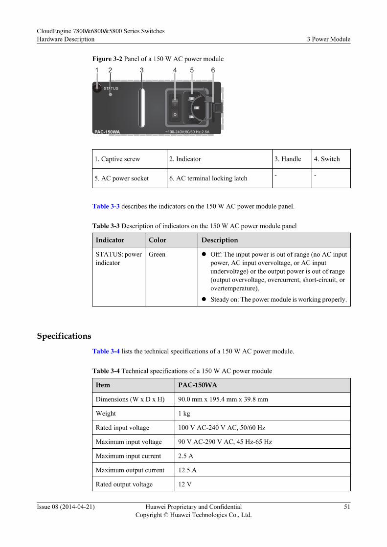
Figure 3-2 Panel of a 150 W AC power module
~100-240V;50/60 Hz;2.5A
STATUS
PAC-150WA
21 3 4 5 6
1. Captive screw 2. Indicator 3. Handle 4. Switch
5. AC power socket 6. AC terminal locking latch - -
Table 3-3 describes the indicators on the 150 W AC power module panel.
Table 3-3 Description of indicators on the 150 W AC power module panel
Indicator Color Description
STATUS: powerindicator
Green l Off: The input power is out of range (no AC inputpower, AC input overvoltage, or AC inputundervoltage) or the output power is out of range(output overvoltage, overcurrent, short-circuit, orovertemperature).
l Steady on: The power module is working properly.
Specifications
Table 3-4 lists the technical specifications of a 150 W AC power module.
Table 3-4 Technical specifications of a 150 W AC power module
Item PAC-150WA
Dimensions (W x D x H) 90.0 mm x 195.4 mm x 39.8 mm
Weight 1 kg
Rated input voltage 100 V AC-240 V AC, 50/60 Hz
Maximum input voltage 90 V AC-290 V AC, 45 Hz-65 Hz
Maximum input current 2.5 A
Maximum output current 12.5 A
Rated output voltage 12 V
CloudEngine 7800&6800&5800 Series SwitchesHardware Description 3 Power Module
Issue 08 (2014-04-21) Huawei Proprietary and ConfidentialCopyright © Huawei Technologies Co., Ltd.
51
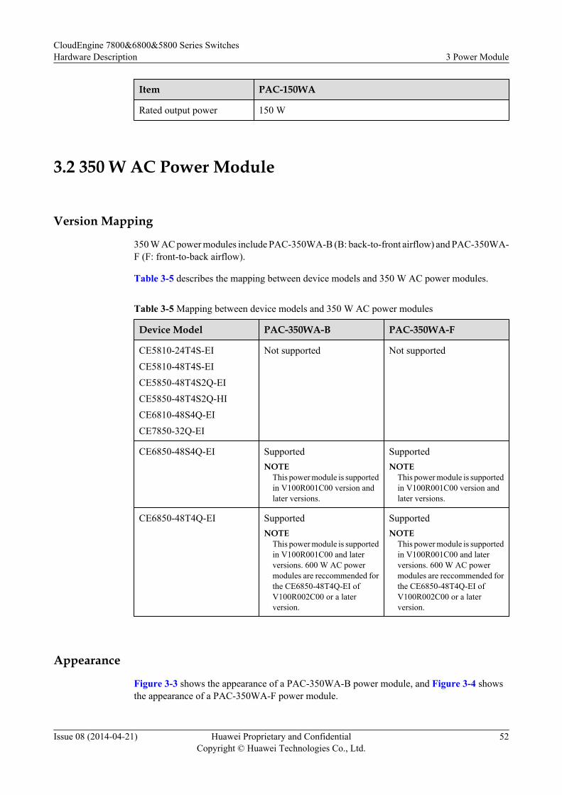
Item PAC-150WA
Rated output power 150 W
3.2 350 W AC Power Module
Version Mapping
350 W AC power modules include PAC-350WA-B (B: back-to-front airflow) and PAC-350WA-F (F: front-to-back airflow).
Table 3-5 describes the mapping between device models and 350 W AC power modules.
Table 3-5 Mapping between device models and 350 W AC power modules
Device Model PAC-350WA-B PAC-350WA-F
CE5810-24T4S-EICE5810-48T4S-EICE5850-48T4S2Q-EICE5850-48T4S2Q-HICE6810-48S4Q-EICE7850-32Q-EI
Not supported Not supported
CE6850-48S4Q-EI SupportedNOTE
This power module is supportedin V100R001C00 version andlater versions.
SupportedNOTE
This power module is supportedin V100R001C00 version andlater versions.
CE6850-48T4Q-EI SupportedNOTE
This power module is supportedin V100R001C00 and laterversions. 600 W AC powermodules are reccommended forthe CE6850-48T4Q-EI ofV100R002C00 or a laterversion.
SupportedNOTE
This power module is supportedin V100R001C00 and laterversions. 600 W AC powermodules are reccommended forthe CE6850-48T4Q-EI ofV100R002C00 or a laterversion.
Appearance
Figure 3-3 shows the appearance of a PAC-350WA-B power module, and Figure 3-4 showsthe appearance of a PAC-350WA-F power module.
CloudEngine 7800&6800&5800 Series SwitchesHardware Description 3 Power Module
Issue 08 (2014-04-21) Huawei Proprietary and ConfidentialCopyright © Huawei Technologies Co., Ltd.
52
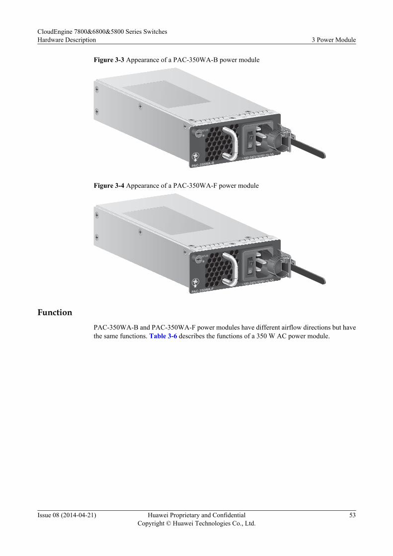
Figure 3-3 Appearance of a PAC-350WA-B power module
PAC-350WA-B
STATUS
~100-240V;50/60 Hz;5A
Figure 3-4 Appearance of a PAC-350WA-F power module
STATUS
~100-240V;50/60 Hz;5A
PAC-350WA-F
FunctionPAC-350WA-B and PAC-350WA-F power modules have different airflow directions but havethe same functions. Table 3-6 describes the functions of a 350 W AC power module.
CloudEngine 7800&6800&5800 Series SwitchesHardware Description 3 Power Module
Issue 08 (2014-04-21) Huawei Proprietary and ConfidentialCopyright © Huawei Technologies Co., Ltd.
53
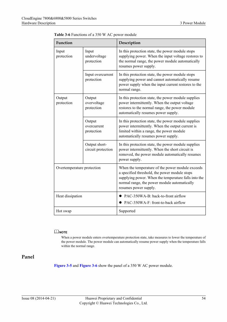
Table 3-6 Functions of a 350 W AC power module
Function Description
Inputprotection
Inputundervoltageprotection
In this protection state, the power module stopssupplying power. When the input voltage restores tothe normal range, the power module automaticallyresumes power supply.
Input overcurrentprotection
In this protection state, the power module stopssupplying power and cannot automatically resumepower supply when the input current restores to thenormal range.
Outputprotection
Outputovervoltageprotection
In this protection state, the power module suppliespower intermittently. When the output voltagerestores to the normal range, the power moduleautomatically resumes power supply.
Outputovercurrentprotection
In this protection state, the power module suppliespower intermittently. When the output current islimited within a range, the power moduleautomatically resumes power supply.
Output short-circuit protection
In this protection state, the power module suppliespower intermittently. When the short circuit isremoved, the power module automatically resumespower supply.
Overtemperature protection When the temperature of the power module exceedsa specified threshold, the power module stopssupplying power. When the temperature falls into thenormal range, the power module automaticallyresumes power supply.
Heat dissipation l PAC-350WA-B: back-to-front airflowl PAC-350WA-F: front-to-back airflow
Hot swap Supported
NOTE
When a power module enters overtemperature protection state, take measures to lower the temperature ofthe power module. The power module can automatically resume power supply when the temperature fallswithin the normal range.
PanelFigure 3-5 and Figure 3-6 show the panel of a 350 W AC power module.
CloudEngine 7800&6800&5800 Series SwitchesHardware Description 3 Power Module
Issue 08 (2014-04-21) Huawei Proprietary and ConfidentialCopyright © Huawei Technologies Co., Ltd.
54
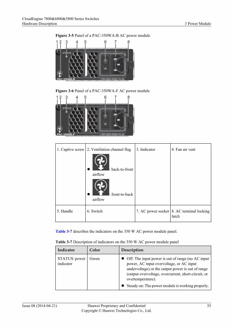
Figure 3-5 Panel of a PAC-350WA-B AC power module
~100-240V;50/60 Hz;5A
STATUS
PAC-350WA-B
21 3 4 5 6 7 8
Figure 3-6 Panel of a PAC-350WA-F AC power module
~100-240V;50/60 Hz;5A
STATUS
PAC-350WA-F
21 3 4 5 6 7 8
1. Captive screw 2. Ventilation channel flag
l : back-to-frontairflow
l : front-to-backairflow
3. Indicator 4. Fan air vent
5. Handle 6. Switch 7. AC power socket 8. AC terminal lockinglatch
Table 3-7 describes the indicators on the 350 W AC power module panel.
Table 3-7 Description of indicators on the 350 W AC power module panel
Indicator Color Description
STATUS: powerindicator
Green l Off: The input power is out of range (no AC inputpower, AC input overvoltage, or AC inputundervoltage) or the output power is out of range(output overvoltage, overcurrent, short-circuit, orovertemperature).
l Steady on: The power module is working properly.
CloudEngine 7800&6800&5800 Series SwitchesHardware Description 3 Power Module
Issue 08 (2014-04-21) Huawei Proprietary and ConfidentialCopyright © Huawei Technologies Co., Ltd.
55
Specifications
Table 3-8 lists the technical specifications of the 350 W AC power modules.
Table 3-8 Technical specifications of 350 W AC power modules
Item PAC-350WA-B PAC-350WA-F
Dimensions (width x depth x height) 90.0 mm x 195.4 mm x 39.8 mm
Weight 0.92 kg
Rated input voltage 100 V AC-240 V AC, 50/60 Hz
Maximum input voltage 90 V AC-290 V AC, 45 Hz-65 Hz
Maximum input current 5 A
Maximum output current 29.17 A
Rated output voltage 12 V
Rated output power 350 W
3.3 350 W DC Power Module
Version Mapping
350 W DC power modules include PDC-350WA-B (B: back-to-front airflow) and PDC-350WA-F (F: front-to-back airflow).
Table 3-9 describes the mapping between device models and 350 W DC power modules.
Table 3-9 Mapping between device models and 350 W DC power modules
Device Model PDC-350WA-B PDC-350WA-F
CE5810-24T4S-EICE5810-48T4S-EICE5850-48T4S2Q-EICE6850-48S4Q-EI
SupportedNOTE
This power module is supportedin V100R002C00 version andlater versions.
SupportedNOTE
This power module is supportedin V100R002C00 version andlater versions.
CE6850-48T4Q-EICE7850-32Q-EI
Not supported Not supported
CE5850-48T4S2Q-HICE6810-48S4Q-EI
SupportedNOTE
This power module is supportedin V100R003C00 version andlater versions.
SupportedNOTE
This power module is supportedin V100R003C00 version andlater versions.
CloudEngine 7800&6800&5800 Series SwitchesHardware Description 3 Power Module
Issue 08 (2014-04-21) Huawei Proprietary and ConfidentialCopyright © Huawei Technologies Co., Ltd.
56
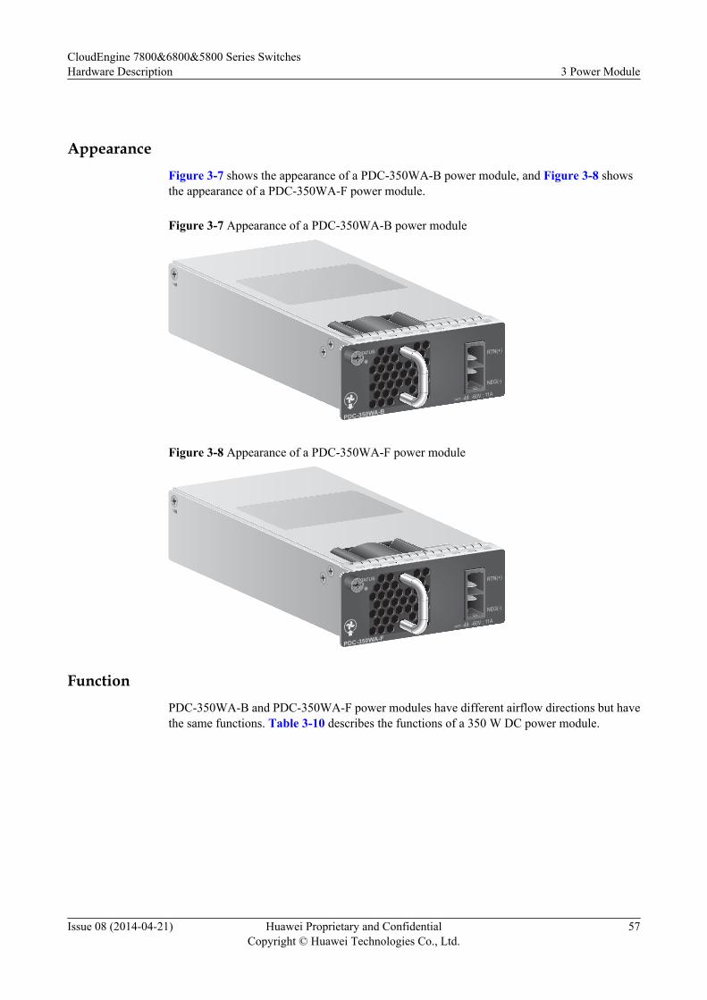
AppearanceFigure 3-7 shows the appearance of a PDC-350WA-B power module, and Figure 3-8 showsthe appearance of a PDC-350WA-F power module.
Figure 3-7 Appearance of a PDC-350WA-B power module
PDC-350WA-B
-48 -60V ; 11A
RTN(+)
NEG(-)
STATUS
Figure 3-8 Appearance of a PDC-350WA-F power module
-48 -60V ; 11A
RTN(+)
NEG(-)
STATUS
PDC-350WA-F
FunctionPDC-350WA-B and PDC-350WA-F power modules have different airflow directions but havethe same functions. Table 3-10 describes the functions of a 350 W DC power module.
CloudEngine 7800&6800&5800 Series SwitchesHardware Description 3 Power Module
Issue 08 (2014-04-21) Huawei Proprietary and ConfidentialCopyright © Huawei Technologies Co., Ltd.
57
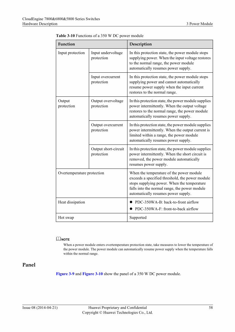
Table 3-10 Functions of a 350 W DC power module
Function Description
Input protection Input undervoltageprotection
In this protection state, the power module stopssupplying power. When the input voltage restoresto the normal range, the power moduleautomatically resumes power supply.
Input overcurrentprotection
In this protection state, the power module stopssupplying power and cannot automaticallyresume power supply when the input currentrestores to the normal range.
Outputprotection
Output overvoltageprotection
In this protection state, the power module suppliespower intermittently. When the output voltagerestores to the normal range, the power moduleautomatically resumes power supply.
Output overcurrentprotection
In this protection state, the power module suppliespower intermittently. When the output current islimited within a range, the power moduleautomatically resumes power supply.
Output short-circuitprotection
In this protection state, the power module suppliespower intermittently. When the short circuit isremoved, the power module automaticallyresumes power supply.
Overtemperature protection When the temperature of the power moduleexceeds a specified threshold, the power modulestops supplying power. When the temperaturefalls into the normal range, the power moduleautomatically resumes power supply.
Heat dissipation l PDC-350WA-B: back-to-front airflowl PDC-350WA-F: front-to-back airflow
Hot swap Supported
NOTE
When a power module enters overtemperature protection state, take measures to lower the temperature ofthe power module. The power module can automatically resume power supply when the temperature fallswithin the normal range.
PanelFigure 3-9 and Figure 3-10 show the panel of a 350 W DC power module.
CloudEngine 7800&6800&5800 Series SwitchesHardware Description 3 Power Module
Issue 08 (2014-04-21) Huawei Proprietary and ConfidentialCopyright © Huawei Technologies Co., Ltd.
58
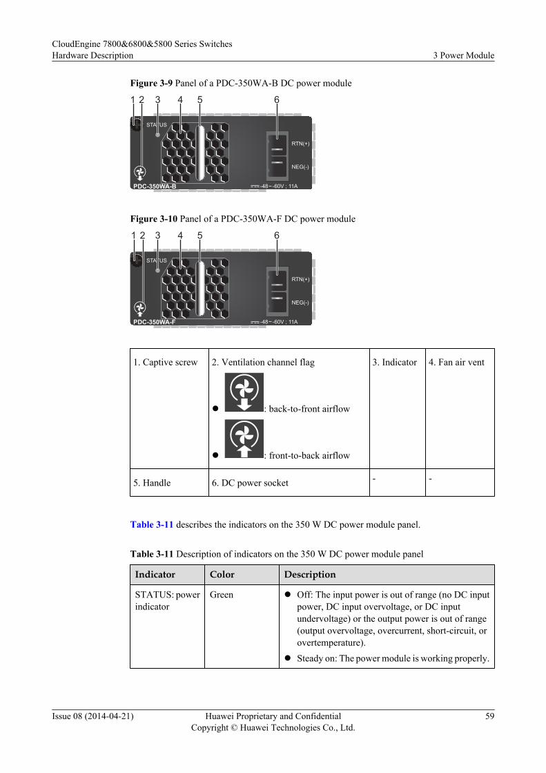
Figure 3-9 Panel of a PDC-350WA-B DC power module
-48 -60V ; 11A
RTN(+)
NEG(-)
STATUS
PDC-350WA-B
2 31 4 5 6
Figure 3-10 Panel of a PDC-350WA-F DC power module
-48 -60V ; 11A
RTN(+)
NEG(-)
STATUS
PDC-350WA-F
2 3 4 5 61
1. Captive screw 2. Ventilation channel flag
l : back-to-front airflow
l : front-to-back airflow
3. Indicator 4. Fan air vent
5. Handle 6. DC power socket - -
Table 3-11 describes the indicators on the 350 W DC power module panel.
Table 3-11 Description of indicators on the 350 W DC power module panel
Indicator Color Description
STATUS: powerindicator
Green l Off: The input power is out of range (no DC inputpower, DC input overvoltage, or DC inputundervoltage) or the output power is out of range(output overvoltage, overcurrent, short-circuit, orovertemperature).
l Steady on: The power module is working properly.
CloudEngine 7800&6800&5800 Series SwitchesHardware Description 3 Power Module
Issue 08 (2014-04-21) Huawei Proprietary and ConfidentialCopyright © Huawei Technologies Co., Ltd.
59
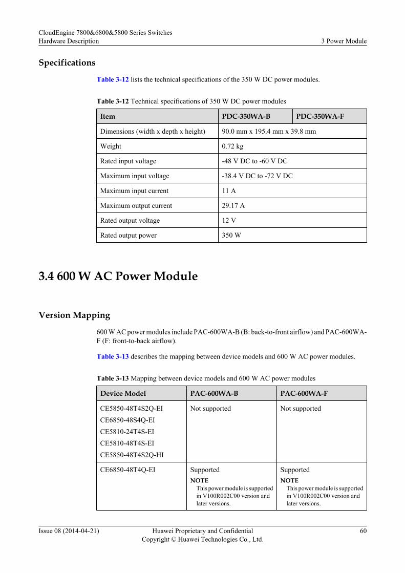
Specifications
Table 3-12 lists the technical specifications of the 350 W DC power modules.
Table 3-12 Technical specifications of 350 W DC power modules
Item PDC-350WA-B PDC-350WA-F
Dimensions (width x depth x height) 90.0 mm x 195.4 mm x 39.8 mm
Weight 0.72 kg
Rated input voltage -48 V DC to -60 V DC
Maximum input voltage -38.4 V DC to -72 V DC
Maximum input current 11 A
Maximum output current 29.17 A
Rated output voltage 12 V
Rated output power 350 W
3.4 600 W AC Power Module
Version Mapping
600 W AC power modules include PAC-600WA-B (B: back-to-front airflow) and PAC-600WA-F (F: front-to-back airflow).
Table 3-13 describes the mapping between device models and 600 W AC power modules.
Table 3-13 Mapping between device models and 600 W AC power modules
Device Model PAC-600WA-B PAC-600WA-F
CE5850-48T4S2Q-EICE6850-48S4Q-EICE5810-24T4S-EICE5810-48T4S-EICE5850-48T4S2Q-HI
Not supported Not supported
CE6850-48T4Q-EI SupportedNOTE
This power module is supportedin V100R002C00 version andlater versions.
SupportedNOTE
This power module is supportedin V100R002C00 version andlater versions.
CloudEngine 7800&6800&5800 Series SwitchesHardware Description 3 Power Module
Issue 08 (2014-04-21) Huawei Proprietary and ConfidentialCopyright © Huawei Technologies Co., Ltd.
60

Device Model PAC-600WA-B PAC-600WA-F
CE6810-48S4Q-EICE7850-32Q-EI
SupportedNOTE
This power module is supportedin V100R003C00 version andlater versions.
SupportedNOTE
This power module is supportedin V100R003C00 version andlater versions.
AppearanceFigure 3-11 shows the appearance of a PAC-600WA-B power module, and Figure 3-12 showsthe appearance of a PAC-600WA-F power module.
Figure 3-11 Appearance of a PAC-600WA-B power module
PAC-600WA-B
STATUS
~100-240V;50/60 Hz;9A
Figure 3-12 Appearance of a PAC-600WA-F power module
STATUS
~100-240V;50/60 Hz;9A
PAC-600WA-F
FunctionPAC-600WA-B and PAC-600WA-F power modules have different airflow directions but havethe same functions. Table 3-14 describes the functions of a 600 W AC power module.
CloudEngine 7800&6800&5800 Series SwitchesHardware Description 3 Power Module
Issue 08 (2014-04-21) Huawei Proprietary and ConfidentialCopyright © Huawei Technologies Co., Ltd.
61
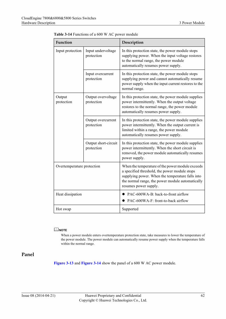
Table 3-14 Functions of a 600 W AC power module
Function Description
Input protection Input undervoltageprotection
In this protection state, the power module stopssupplying power. When the input voltage restoresto the normal range, the power moduleautomatically resumes power supply.
Input overcurrentprotection
In this protection state, the power module stopssupplying power and cannot automatically resumepower supply when the input current restores to thenormal range.
Outputprotection
Output overvoltageprotection
In this protection state, the power module suppliespower intermittently. When the output voltagerestores to the normal range, the power moduleautomatically resumes power supply.
Output overcurrentprotection
In this protection state, the power module suppliespower intermittently. When the output current islimited within a range, the power moduleautomatically resumes power supply.
Output short-circuitprotection
In this protection state, the power module suppliespower intermittently. When the short circuit isremoved, the power module automatically resumespower supply.
Overtemperature protection When the temperature of the power module exceedsa specified threshold, the power module stopssupplying power. When the temperature falls intothe normal range, the power module automaticallyresumes power supply.
Heat dissipation l PAC-600WA-B: back-to-front airflowl PAC-600WA-F: front-to-back airflow
Hot swap Supported
NOTE
When a power module enters overtemperature protection state, take measures to lower the temperature ofthe power module. The power module can automatically resume power supply when the temperature fallswithin the normal range.
PanelFigure 3-13 and Figure 3-14 show the panel of a 600 W AC power module.
CloudEngine 7800&6800&5800 Series SwitchesHardware Description 3 Power Module
Issue 08 (2014-04-21) Huawei Proprietary and ConfidentialCopyright © Huawei Technologies Co., Ltd.
62

Figure 3-13 Panel of a PAC-600WA-B AC power module
~100-240V;50/60 Hz;9A
STATUS
PAC-600WA-B
21 3 4 5 6 7 8
Figure 3-14 Panel of a PAC-600WA-F AC power module
~100-240V;50/60 Hz;9A
STATUS
PAC-600WA-F
2 3 4 5 6 7 81
1. Captive screw 2. Ventilation channel flag
l : back-to-frontairflow
l : front-to-backairflow
3. Indicator 4. Fan air vent
5. Handle 6. Switch 7. AC power socket 8. AC terminal lockinglatch
Table 3-15 describes the indicators on the 600 W AC power module panel.
Table 3-15 Description of indicators on the 600 W AC power module panel
Indicator Color Description
STATUS: powerindicator
Green l Off: The input power is out of range (no AC inputpower, AC input overvoltage, or AC inputundervoltage) or the output power is out of range(output overvoltage, overcurrent, short-circuit, orovertemperature).
l Steady on: The power module is working properly.
CloudEngine 7800&6800&5800 Series SwitchesHardware Description 3 Power Module
Issue 08 (2014-04-21) Huawei Proprietary and ConfidentialCopyright © Huawei Technologies Co., Ltd.
63
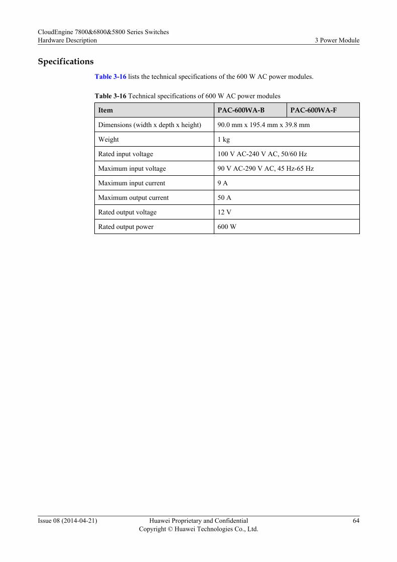
SpecificationsTable 3-16 lists the technical specifications of the 600 W AC power modules.
Table 3-16 Technical specifications of 600 W AC power modules
Item PAC-600WA-B PAC-600WA-F
Dimensions (width x depth x height) 90.0 mm x 195.4 mm x 39.8 mm
Weight 1 kg
Rated input voltage 100 V AC-240 V AC, 50/60 Hz
Maximum input voltage 90 V AC-290 V AC, 45 Hz-65 Hz
Maximum input current 9 A
Maximum output current 50 A
Rated output voltage 12 V
Rated output power 600 W
CloudEngine 7800&6800&5800 Series SwitchesHardware Description 3 Power Module
Issue 08 (2014-04-21) Huawei Proprietary and ConfidentialCopyright © Huawei Technologies Co., Ltd.
64
4 Fan Module
About This Chapter
NOTICEl A chassis must use fan modules with the same airflow direction.l A chassis must use fan modules of the same series.l A chassis can work properly only when two fan modules are running. If one of fan modules
is removed from the chassis, reinstall it into the chassis within 3 minutes.
4.1 FAN-40EA Series Fan Modules
4.2 FAN-40SB Series Fan Modules
4.3 FAN-40HA Series Fan Modules
CloudEngine 7800&6800&5800 Series SwitchesHardware Description 4 Fan Module
Issue 08 (2014-04-21) Huawei Proprietary and ConfidentialCopyright © Huawei Technologies Co., Ltd.
65
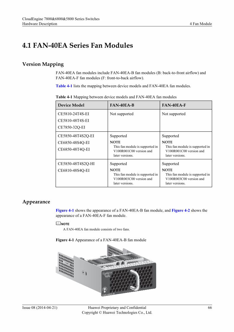
4.1 FAN-40EA Series Fan Modules
Version MappingFAN-40EA fan modules include FAN-40EA-B fan modules (B: back-to-front airflow) andFAN-40EA-F fan modules (F: front-to-back airflow).
Table 4-1 lists the mapping between device models and FAN-40EA fan modules.
Table 4-1 Mapping between device models and FAN-40EA fan modules
Device Model FAN-40EA-B FAN-40EA-F
CE5810-24T4S-EICE5810-48T4S-EICE7850-32Q-EI
Not supported Not supported
CE5850-48T4S2Q-EICE6850-48S4Q-EICE6850-48T4Q-EI
SupportedNOTE
This fan module is supported inV100R001C00 version andlater versions.
SupportedNOTE
This fan module is supported inV100R001C00 version andlater versions.
CE5850-48T4S2Q-HICE6810-48S4Q-EI
SupportedNOTE
This fan module is supported inV100R003C00 version andlater versions.
SupportedNOTE
This fan module is supported inV100R003C00 version andlater versions.
AppearanceFigure 4-1 shows the appearance of a FAN-40EA-B fan module, and Figure 4-2 shows theappearance of a FAN-40EA-F fan module.
NOTE
A FAN-40EA fan module consists of two fans.
Figure 4-1 Appearance of a FAN-40EA-B fan module
STATUS
FAN-40EA-B
CloudEngine 7800&6800&5800 Series SwitchesHardware Description 4 Fan Module
Issue 08 (2014-04-21) Huawei Proprietary and ConfidentialCopyright © Huawei Technologies Co., Ltd.
66
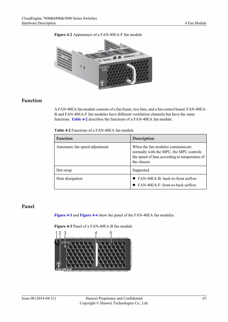
Figure 4-2 Appearance of a FAN-40EA-F fan module
STATUS
FAN-40EA-F
FunctionA FAN-40EA fan module consists of a fan frame, two fans, and a fan control board. FAN-40EA-B and FAN-40EA-F fan modules have different ventilation channels but have the samefunctions. Table 4-2 describes the functions of a FAN-40EA fan module.
Table 4-2 Functions of a FAN-40EA fan module
Function Description
Automatic fan speed adjustment When the fan modules communicatenormally with the MPU, the MPU controlsthe speed of fans according to temperature ofthe chassis.
Hot swap Supported
Heat dissipation l FAN-40EA-B: back-to-front airflowl FAN-40EA-F: front-to-back airflow
PanelFigure 4-3 and Figure 4-4 show the panel of the FAN-40EA fan modules.
Figure 4-3 Panel of a FAN-40EA-B fan module
STATUS
FAN-40EA-B
2 31 4 5
CloudEngine 7800&6800&5800 Series SwitchesHardware Description 4 Fan Module
Issue 08 (2014-04-21) Huawei Proprietary and ConfidentialCopyright © Huawei Technologies Co., Ltd.
67
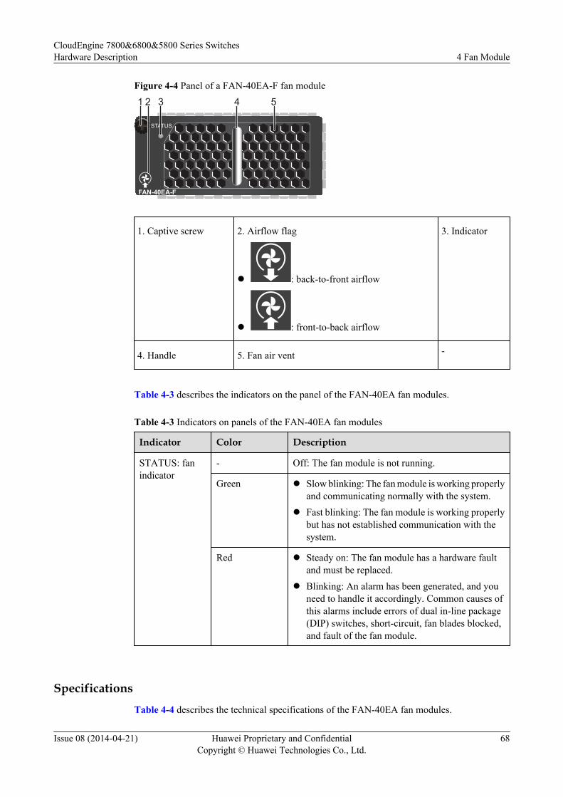
Figure 4-4 Panel of a FAN-40EA-F fan module
STATUS
FAN-40EA-F
2 3 4 51
1. Captive screw 2. Airflow flag
l : back-to-front airflow
l : front-to-back airflow
3. Indicator
4. Handle 5. Fan air vent -
Table 4-3 describes the indicators on the panel of the FAN-40EA fan modules.
Table 4-3 Indicators on panels of the FAN-40EA fan modules
Indicator Color Description
STATUS: fanindicator
- Off: The fan module is not running.
Green l Slow blinking: The fan module is working properlyand communicating normally with the system.
l Fast blinking: The fan module is working properlybut has not established communication with thesystem.
Red l Steady on: The fan module has a hardware faultand must be replaced.
l Blinking: An alarm has been generated, and youneed to handle it accordingly. Common causes ofthis alarms include errors of dual in-line package(DIP) switches, short-circuit, fan blades blocked,and fault of the fan module.
SpecificationsTable 4-4 describes the technical specifications of the FAN-40EA fan modules.
CloudEngine 7800&6800&5800 Series SwitchesHardware Description 4 Fan Module
Issue 08 (2014-04-21) Huawei Proprietary and ConfidentialCopyright © Huawei Technologies Co., Ltd.
68
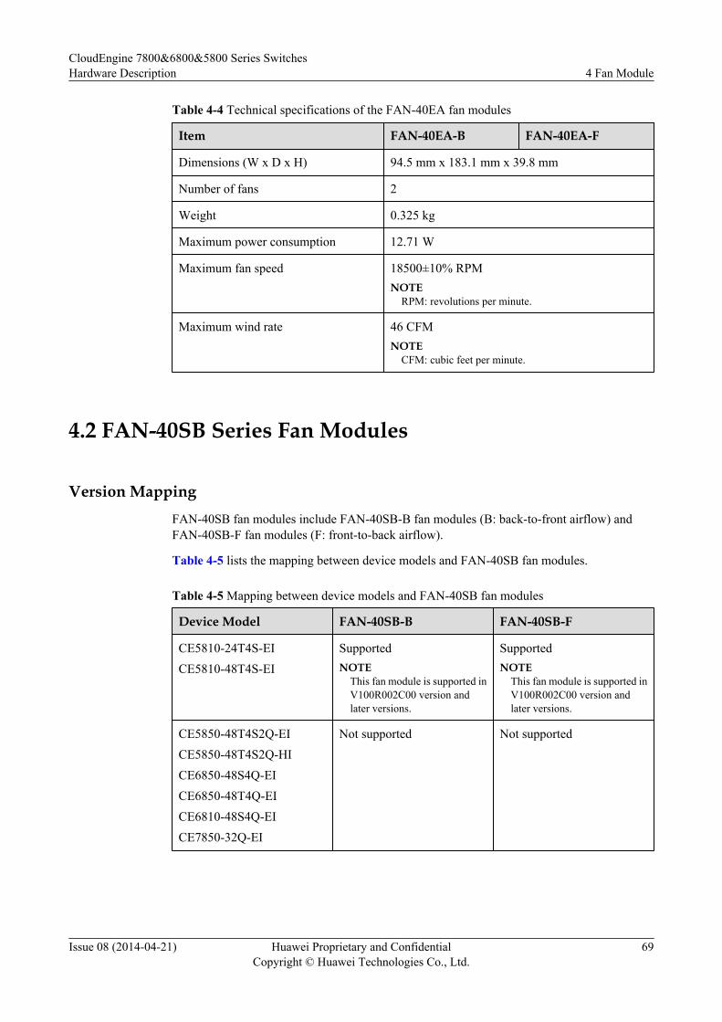
Table 4-4 Technical specifications of the FAN-40EA fan modules
Item FAN-40EA-B FAN-40EA-F
Dimensions (W x D x H) 94.5 mm x 183.1 mm x 39.8 mm
Number of fans 2
Weight 0.325 kg
Maximum power consumption 12.71 W
Maximum fan speed 18500±10% RPMNOTE
RPM: revolutions per minute.
Maximum wind rate 46 CFMNOTE
CFM: cubic feet per minute.
4.2 FAN-40SB Series Fan Modules
Version MappingFAN-40SB fan modules include FAN-40SB-B fan modules (B: back-to-front airflow) andFAN-40SB-F fan modules (F: front-to-back airflow).
Table 4-5 lists the mapping between device models and FAN-40SB fan modules.
Table 4-5 Mapping between device models and FAN-40SB fan modules
Device Model FAN-40SB-B FAN-40SB-F
CE5810-24T4S-EICE5810-48T4S-EI
SupportedNOTE
This fan module is supported inV100R002C00 version andlater versions.
SupportedNOTE
This fan module is supported inV100R002C00 version andlater versions.
CE5850-48T4S2Q-EICE5850-48T4S2Q-HICE6850-48S4Q-EICE6850-48T4Q-EICE6810-48S4Q-EICE7850-32Q-EI
Not supported Not supported
CloudEngine 7800&6800&5800 Series SwitchesHardware Description 4 Fan Module
Issue 08 (2014-04-21) Huawei Proprietary and ConfidentialCopyright © Huawei Technologies Co., Ltd.
69
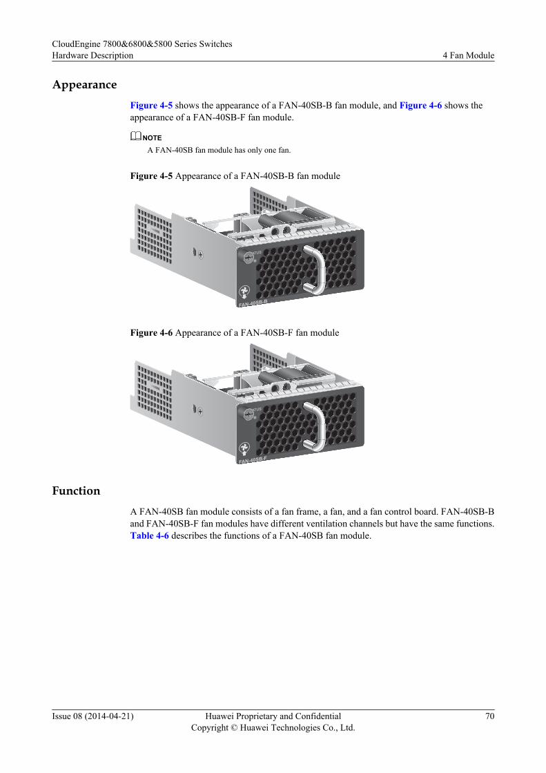
AppearanceFigure 4-5 shows the appearance of a FAN-40SB-B fan module, and Figure 4-6 shows theappearance of a FAN-40SB-F fan module.
NOTE
A FAN-40SB fan module has only one fan.
Figure 4-5 Appearance of a FAN-40SB-B fan module
STATUS
FAN-40SB-B
Figure 4-6 Appearance of a FAN-40SB-F fan module
STATUS
FAN-40SB-F
FunctionA FAN-40SB fan module consists of a fan frame, a fan, and a fan control board. FAN-40SB-Band FAN-40SB-F fan modules have different ventilation channels but have the same functions.Table 4-6 describes the functions of a FAN-40SB fan module.
CloudEngine 7800&6800&5800 Series SwitchesHardware Description 4 Fan Module
Issue 08 (2014-04-21) Huawei Proprietary and ConfidentialCopyright © Huawei Technologies Co., Ltd.
70
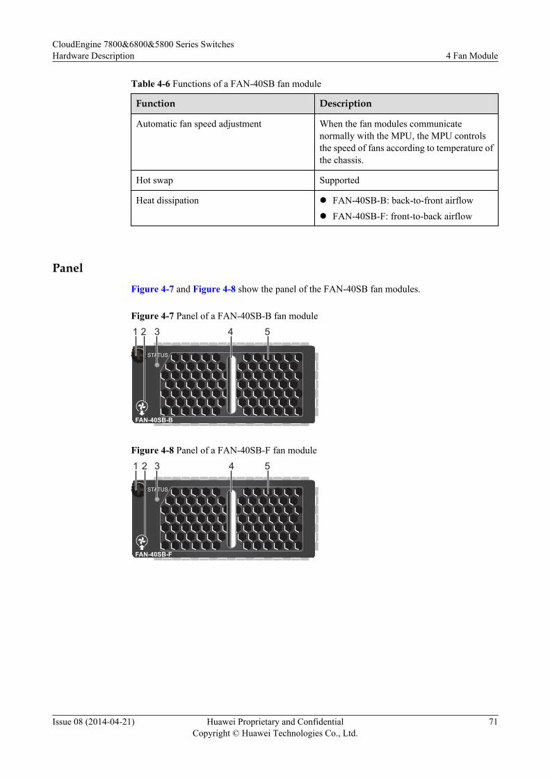
Table 4-6 Functions of a FAN-40SB fan module
Function Description
Automatic fan speed adjustment When the fan modules communicatenormally with the MPU, the MPU controlsthe speed of fans according to temperature ofthe chassis.
Hot swap Supported
Heat dissipation l FAN-40SB-B: back-to-front airflowl FAN-40SB-F: front-to-back airflow
PanelFigure 4-7 and Figure 4-8 show the panel of the FAN-40SB fan modules.
Figure 4-7 Panel of a FAN-40SB-B fan module
STATUS
FAN-40SB-B
2 31 4 5
Figure 4-8 Panel of a FAN-40SB-F fan module
STATUS
FAN-40SB-F
2 3 4 51
CloudEngine 7800&6800&5800 Series SwitchesHardware Description 4 Fan Module
Issue 08 (2014-04-21) Huawei Proprietary and ConfidentialCopyright © Huawei Technologies Co., Ltd.
71
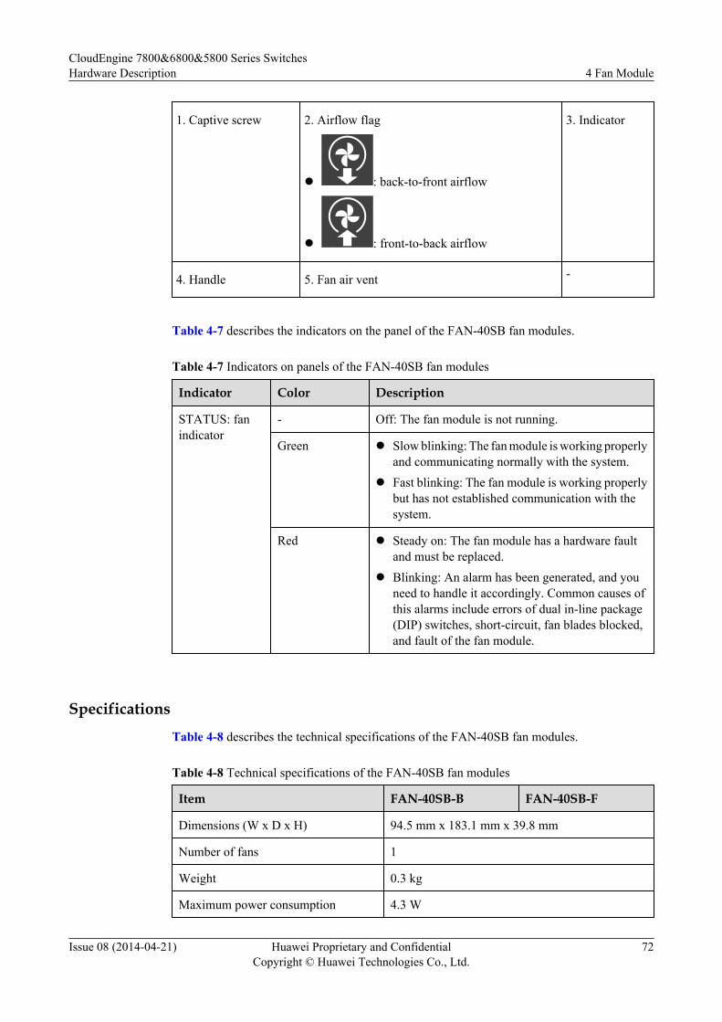
1. Captive screw 2. Airflow flag
l : back-to-front airflow
l : front-to-back airflow
3. Indicator
4. Handle 5. Fan air vent -
Table 4-7 describes the indicators on the panel of the FAN-40SB fan modules.
Table 4-7 Indicators on panels of the FAN-40SB fan modules
Indicator Color Description
STATUS: fanindicator
- Off: The fan module is not running.
Green l Slow blinking: The fan module is working properlyand communicating normally with the system.
l Fast blinking: The fan module is working properlybut has not established communication with thesystem.
Red l Steady on: The fan module has a hardware faultand must be replaced.
l Blinking: An alarm has been generated, and youneed to handle it accordingly. Common causes ofthis alarms include errors of dual in-line package(DIP) switches, short-circuit, fan blades blocked,and fault of the fan module.
Specifications
Table 4-8 describes the technical specifications of the FAN-40SB fan modules.
Table 4-8 Technical specifications of the FAN-40SB fan modules
Item FAN-40SB-B FAN-40SB-F
Dimensions (W x D x H) 94.5 mm x 183.1 mm x 39.8 mm
Number of fans 1
Weight 0.3 kg
Maximum power consumption 4.3 W
CloudEngine 7800&6800&5800 Series SwitchesHardware Description 4 Fan Module
Issue 08 (2014-04-21) Huawei Proprietary and ConfidentialCopyright © Huawei Technologies Co., Ltd.
72
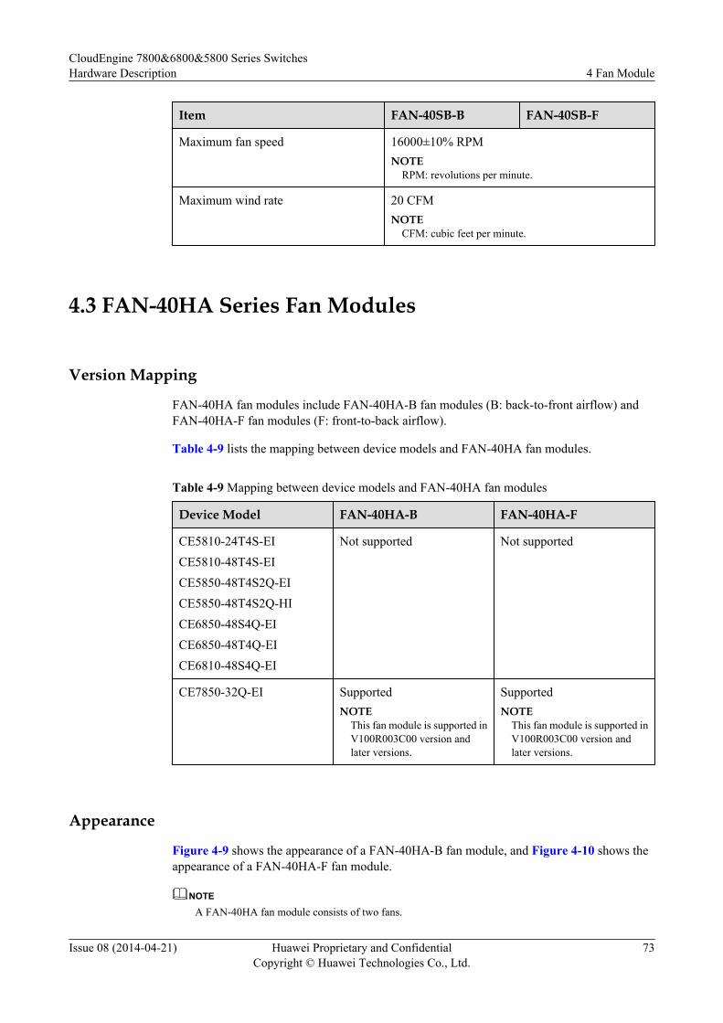
Item FAN-40SB-B FAN-40SB-F
Maximum fan speed 16000±10% RPMNOTE
RPM: revolutions per minute.
Maximum wind rate 20 CFMNOTE
CFM: cubic feet per minute.
4.3 FAN-40HA Series Fan Modules
Version Mapping
FAN-40HA fan modules include FAN-40HA-B fan modules (B: back-to-front airflow) andFAN-40HA-F fan modules (F: front-to-back airflow).
Table 4-9 lists the mapping between device models and FAN-40HA fan modules.
Table 4-9 Mapping between device models and FAN-40HA fan modules
Device Model FAN-40HA-B FAN-40HA-F
CE5810-24T4S-EICE5810-48T4S-EICE5850-48T4S2Q-EICE5850-48T4S2Q-HICE6850-48S4Q-EICE6850-48T4Q-EICE6810-48S4Q-EI
Not supported Not supported
CE7850-32Q-EI SupportedNOTE
This fan module is supported inV100R003C00 version andlater versions.
SupportedNOTE
This fan module is supported inV100R003C00 version andlater versions.
Appearance
Figure 4-9 shows the appearance of a FAN-40HA-B fan module, and Figure 4-10 shows theappearance of a FAN-40HA-F fan module.
NOTE
A FAN-40HA fan module consists of two fans.
CloudEngine 7800&6800&5800 Series SwitchesHardware Description 4 Fan Module
Issue 08 (2014-04-21) Huawei Proprietary and ConfidentialCopyright © Huawei Technologies Co., Ltd.
73
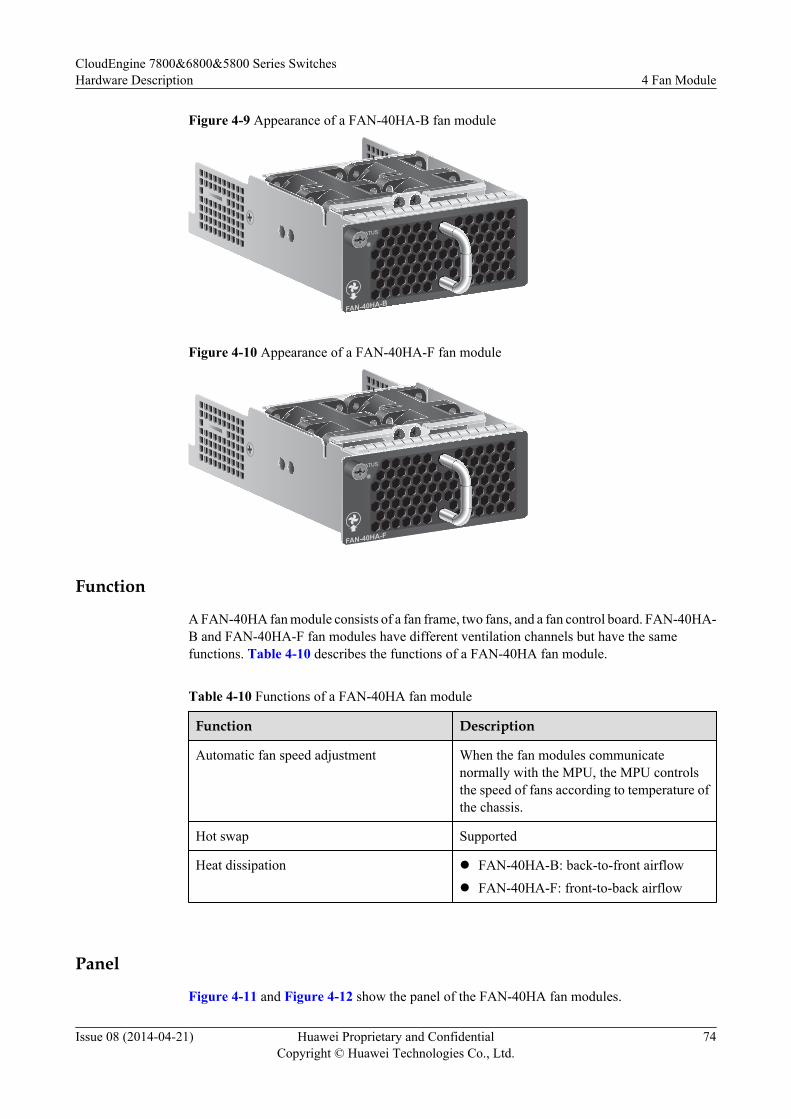
Figure 4-9 Appearance of a FAN-40HA-B fan module
STATUS
FAN-40HA-B
Figure 4-10 Appearance of a FAN-40HA-F fan module
STATUS
FAN-40HA-F
Function
A FAN-40HA fan module consists of a fan frame, two fans, and a fan control board. FAN-40HA-B and FAN-40HA-F fan modules have different ventilation channels but have the samefunctions. Table 4-10 describes the functions of a FAN-40HA fan module.
Table 4-10 Functions of a FAN-40HA fan module
Function Description
Automatic fan speed adjustment When the fan modules communicatenormally with the MPU, the MPU controlsthe speed of fans according to temperature ofthe chassis.
Hot swap Supported
Heat dissipation l FAN-40HA-B: back-to-front airflowl FAN-40HA-F: front-to-back airflow
Panel
Figure 4-11 and Figure 4-12 show the panel of the FAN-40HA fan modules.
CloudEngine 7800&6800&5800 Series SwitchesHardware Description 4 Fan Module
Issue 08 (2014-04-21) Huawei Proprietary and ConfidentialCopyright © Huawei Technologies Co., Ltd.
74
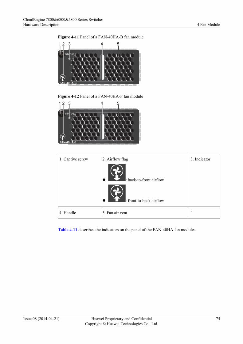
Figure 4-11 Panel of a FAN-40HA-B fan module
STATUS
FAN-40HA-B
2 31 4 5
Figure 4-12 Panel of a FAN-40HA-F fan module
STATUS
FAN-40HA-F
2 31 4 5
1. Captive screw 2. Airflow flag
l : back-to-front airflow
l : front-to-back airflow
3. Indicator
4. Handle 5. Fan air vent -
Table 4-11 describes the indicators on the panel of the FAN-40HA fan modules.
CloudEngine 7800&6800&5800 Series SwitchesHardware Description 4 Fan Module
Issue 08 (2014-04-21) Huawei Proprietary and ConfidentialCopyright © Huawei Technologies Co., Ltd.
75
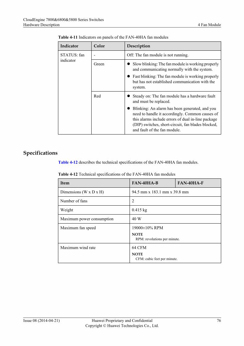
Table 4-11 Indicators on panels of the FAN-40HA fan modules
Indicator Color Description
STATUS: fanindicator
- Off: The fan module is not running.
Green l Slow blinking: The fan module is working properlyand communicating normally with the system.
l Fast blinking: The fan module is working properlybut has not established communication with thesystem.
Red l Steady on: The fan module has a hardware faultand must be replaced.
l Blinking: An alarm has been generated, and youneed to handle it accordingly. Common causes ofthis alarms include errors of dual in-line package(DIP) switches, short-circuit, fan blades blocked,and fault of the fan module.
SpecificationsTable 4-12 describes the technical specifications of the FAN-40HA fan modules.
Table 4-12 Technical specifications of the FAN-40HA fan modules
Item FAN-40HA-B FAN-40HA-F
Dimensions (W x D x H) 94.5 mm x 183.1 mm x 39.8 mm
Number of fans 2
Weight 0.415 kg
Maximum power consumption 40 W
Maximum fan speed 19000±10% RPMNOTE
RPM: revolutions per minute.
Maximum wind rate 64 CFMNOTE
CFM: cubic feet per minute.
CloudEngine 7800&6800&5800 Series SwitchesHardware Description 4 Fan Module
Issue 08 (2014-04-21) Huawei Proprietary and ConfidentialCopyright © Huawei Technologies Co., Ltd.
76
5 Cables
About This Chapter
5.1 AC Power Cable
5.2 DC Power Cable
5.3 Ground Cable
5.4 Console Cable
5.5 Network Cable
5.6 Optical Fiber
5.7 AOC Cable
5.8 Copper Cable
CloudEngine 7800&6800&5800 Series SwitchesHardware Description 5 Cables
Issue 08 (2014-04-21) Huawei Proprietary and ConfidentialCopyright © Huawei Technologies Co., Ltd.
77
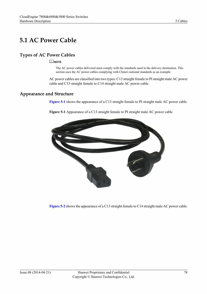
5.1 AC Power Cable
Types of AC Power CablesNOTE
The AC power cables delivered must comply with the standards used in the delivery destination. Thissection uses the AC power cables complying with China's national standards as an example.
AC power cables are classified into two types: C13 straight female to PI straight male AC powercable and C13 straight female to C14 straight male AC power cable.
Appearance and StructureFigure 5-1 shows the appearance of a C13 straight female to PI straight male AC power cable.
Figure 5-1 Appearance of a C13 straight female to PI straight male AC power cable
Figure 5-2 shows the appearance of a C13 straight female to C14 straight male AC power cable.
CloudEngine 7800&6800&5800 Series SwitchesHardware Description 5 Cables
Issue 08 (2014-04-21) Huawei Proprietary and ConfidentialCopyright © Huawei Technologies Co., Ltd.
78
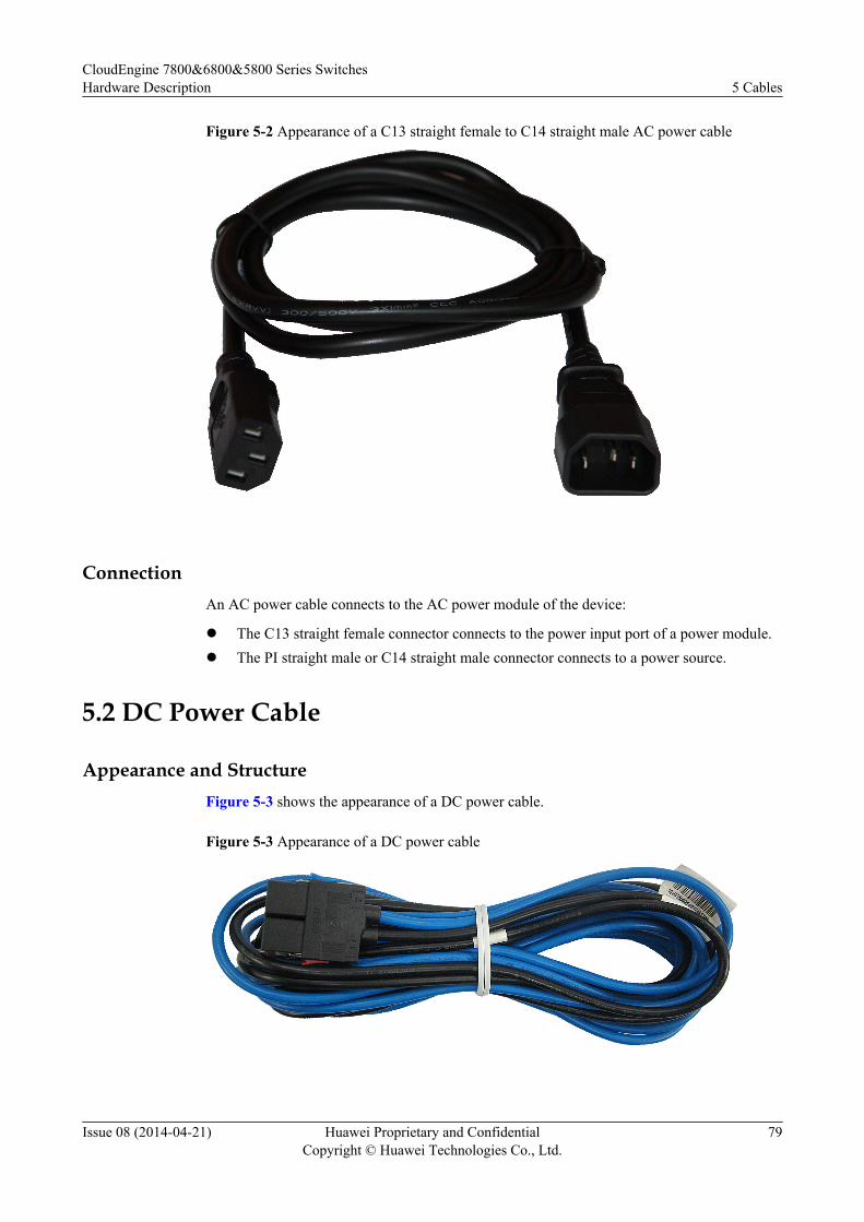
Figure 5-2 Appearance of a C13 straight female to C14 straight male AC power cable
ConnectionAn AC power cable connects to the AC power module of the device:
l The C13 straight female connector connects to the power input port of a power module.l The PI straight male or C14 straight male connector connects to a power source.
5.2 DC Power Cable
Appearance and StructureFigure 5-3 shows the appearance of a DC power cable.
Figure 5-3 Appearance of a DC power cable
CloudEngine 7800&6800&5800 Series SwitchesHardware Description 5 Cables
Issue 08 (2014-04-21) Huawei Proprietary and ConfidentialCopyright © Huawei Technologies Co., Ltd.
79
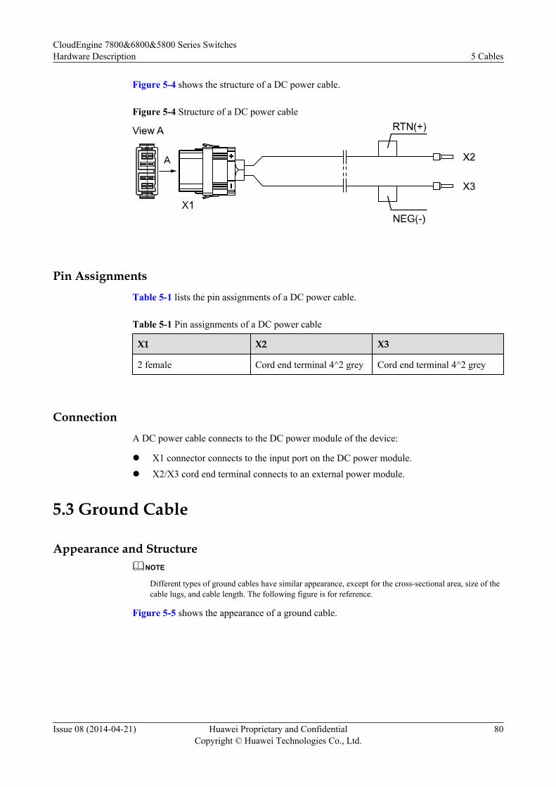
Figure 5-4 shows the structure of a DC power cable.
Figure 5-4 Structure of a DC power cable
Pin AssignmentsTable 5-1 lists the pin assignments of a DC power cable.
Table 5-1 Pin assignments of a DC power cable
X1 X2 X3
2 female Cord end terminal 4^2 grey Cord end terminal 4^2 grey
ConnectionA DC power cable connects to the DC power module of the device:
l X1 connector connects to the input port on the DC power module.l X2/X3 cord end terminal connects to an external power module.
5.3 Ground Cable
Appearance and StructureNOTE
Different types of ground cables have similar appearance, except for the cross-sectional area, size of thecable lugs, and cable length. The following figure is for reference.
Figure 5-5 shows the appearance of a ground cable.
CloudEngine 7800&6800&5800 Series SwitchesHardware Description 5 Cables
Issue 08 (2014-04-21) Huawei Proprietary and ConfidentialCopyright © Huawei Technologies Co., Ltd.
80

Figure 5-5 Appearance of a ground cable
Figure 5-6 shows the structure of a ground cable.
Figure 5-6 Structure of a ground cable
Pin AssignmentsTable 5-2 lists the pin assignments of a ground cable.
Table 5-2 Pin assignments of a ground cable
X1 X2 Wire Color
OT6-4 OT6-6 Green-yellow
ConnectionA ground cable grounds a device to protect it from lightning and electromagnetic interference.A ground cable is connected to a chassis in the following way:
CloudEngine 7800&6800&5800 Series SwitchesHardware Description 5 Cables
Issue 08 (2014-04-21) Huawei Proprietary and ConfidentialCopyright © Huawei Technologies Co., Ltd.
81
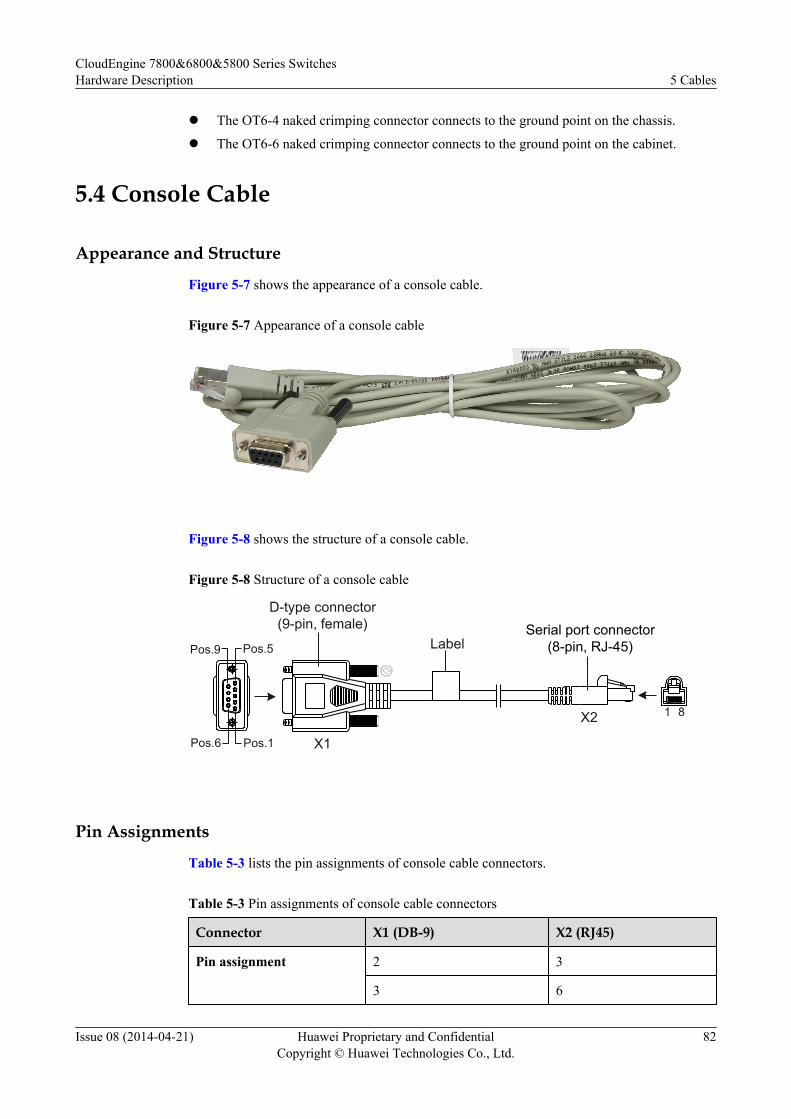
l The OT6-4 naked crimping connector connects to the ground point on the chassis.
l The OT6-6 naked crimping connector connects to the ground point on the cabinet.
5.4 Console Cable
Appearance and Structure
Figure 5-7 shows the appearance of a console cable.
Figure 5-7 Appearance of a console cable
Figure 5-8 shows the structure of a console cable.
Figure 5-8 Structure of a console cable
X1Pos.1
Pos.9
Pos.6
Pos.5
X2 1 8
Serial port connector(8-pin, RJ-45)
D-type connector(9-pin, female)
Label
Pin Assignments
Table 5-3 lists the pin assignments of console cable connectors.
Table 5-3 Pin assignments of console cable connectors
Connector X1 (DB-9) X2 (RJ45)
Pin assignment 2 3
3 6
CloudEngine 7800&6800&5800 Series SwitchesHardware Description 5 Cables
Issue 08 (2014-04-21) Huawei Proprietary and ConfidentialCopyright © Huawei Technologies Co., Ltd.
82
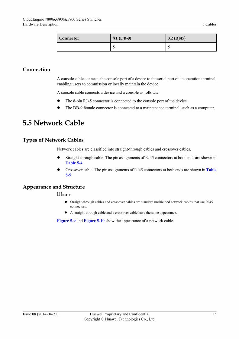
Connector X1 (DB-9) X2 (RJ45)
5 5
ConnectionA console cable connects the console port of a device to the serial port of an operation terminal,enabling users to commission or locally maintain the device.
A console cable connects a device and a console as follows:
l The 8-pin RJ45 connector is connected to the console port of the device.l The DB-9 female connector is connected to a maintenance terminal, such as a computer.
5.5 Network Cable
Types of Network CablesNetwork cables are classified into straight-through cables and crossover cables.
l Straight-through cable: The pin assignments of RJ45 connectors at both ends are shown inTable 5-4.
l Crossover cable: The pin assignments of RJ45 connectors at both ends are shown in Table5-5.
Appearance and StructureNOTE
l Straight-through cables and crossover cables are standard unshielded network cables that use RJ45connectors.
l A straight-through cable and a crossover cable have the same appearance.
Figure 5-9 and Figure 5-10 show the appearance of a network cable.
CloudEngine 7800&6800&5800 Series SwitchesHardware Description 5 Cables
Issue 08 (2014-04-21) Huawei Proprietary and ConfidentialCopyright © Huawei Technologies Co., Ltd.
83
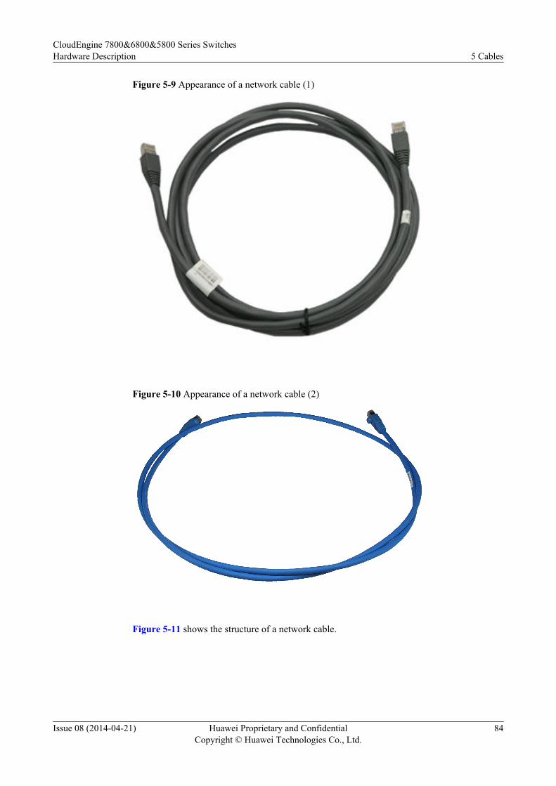
Figure 5-9 Appearance of a network cable (1)
Figure 5-10 Appearance of a network cable (2)
Figure 5-11 shows the structure of a network cable.
CloudEngine 7800&6800&5800 Series SwitchesHardware Description 5 Cables
Issue 08 (2014-04-21) Huawei Proprietary and ConfidentialCopyright © Huawei Technologies Co., Ltd.
84
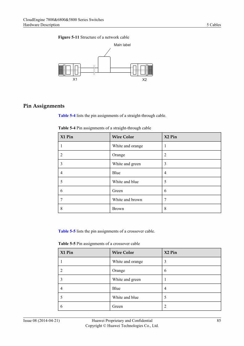
Figure 5-11 Structure of a network cable
Pin Assignments
Table 5-4 lists the pin assignments of a straight-through cable.
Table 5-4 Pin assignments of a straight-through cable
X1 Pin Wire Color X2 Pin
1 White and orange 1
2 Orange 2
3 White and green 3
4 Blue 4
5 White and blue 5
6 Green 6
7 White and brown 7
8 Brown 8
Table 5-5 lists the pin assignments of a crossover cable.
Table 5-5 Pin assignments of a crossover cable
X1 Pin Wire Color X2 Pin
1 White and orange 3
2 Orange 6
3 White and green 1
4 Blue 4
5 White and blue 5
6 Green 2
CloudEngine 7800&6800&5800 Series SwitchesHardware Description 5 Cables
Issue 08 (2014-04-21) Huawei Proprietary and ConfidentialCopyright © Huawei Technologies Co., Ltd.
85
X1 Pin Wire Color X2 Pin
7 White and brown 7
8 Brown 8
NOTE
To achieve the best electrical transmission performance, ensure that the wires connected to pins 1 and 2 and topins 3 and 6 are twisted pairs.
ConnectionNetwork cables connect network devices to each other to enable the devices to communicate orto allow local maintenance and remote access.
l A straight-through cable connects a terminal (such as a PC or switch) to a network device.l A crossover cable connects two terminals (such as PCs and switches).
Supported Cabling Types for 10GBASE-TTable 5-6 describes the supported cabling types for a 10GBASE-T Ethernet electrical port.
Table 5-6 Supported cabling types for 10GBASE-T
Item Category 7STP
Category6A STP
Category6A UTP
Category 6STP
Category 6UTP
CableDescription
Category 7shieldedtwisted pair(STP)
Category 6Ashieldedtwisted pair
Category 6Aunshieldedtwisted pair(UTP)
Category 6shieldedtwisted pair
Category 6unshieldedtwisted pair
Type Class F Class Ea Class Ea Class E Class E
Maximumtransmissiondistance
100 m 100 m 100 m 100 m 37 m - 55 mNOTE
Category 6unshieldedcables maybe limitedby aliencrosstalkbeyond 37–meterchannels.
CloudEngine 7800&6800&5800 Series SwitchesHardware Description 5 Cables
Issue 08 (2014-04-21) Huawei Proprietary and ConfidentialCopyright © Huawei Technologies Co., Ltd.
86
Item Category 7STP
Category6A STP
Category6A UTP
Category 6STP
Category 6UTP
Cablingsystembandwidth
600 MHzNOTE
The cablingsystemexceeds therequirements for IEEE10GBASE-Tperformance.
500 MHzNOTE
The cabling system exceeds therequirements for IEEE10GBASE-T performance.
250 MHzNOTE
Category 6 is specified only to250 MHz. The cabling systemmust be certified to 500 MHzaccording to TSB-155 to helpensure 10GBASE-Tcompliance.
NOTE
l In a new built equipment room, Category 6A shielded twisted pairs or Category 7 twisted pairs arerecommended. These cables can avoid alien crosstalk while having no special installation requirements.In addition, they can be used with other types of cables.
l If Category 6 shielded or unshielded twisted pairs are used in an equipment room and the cablingsystems can meet requirements of TSB-155, follow these rules route these cables:
l Separate these cables with other types of cables. If they must be routed in the same cable troughwith other types of cables, separated them from other cables using a metal plate.
l Separate cables as much as possible at the outlet and keep the cables parallel with each other. Mostalien crosstalk appears within 20 m away from the outlet. To reduce alien crosstalk, do not bundlecables in the first 5 m to 20 m.
l If cables need to be bundled, bundle cables with cable ties placed every 150 mm to 300 mm. SeeTable 5-7. Bundle cables loosely, as shown in Figure 5-12.
l You are advised to add no more than 12 cables in a bundle. A bundle cannot have more than 24cables.
l Replace Category 6 connectors with Category 6A connectors.
Table 5-7 Intervals between cable ties
Diameter of a Network CableBundle (mm)
Interval Between Cable Ties (mm)
< 10 150
10-30 200
> 30 300
CloudEngine 7800&6800&5800 Series SwitchesHardware Description 5 Cables
Issue 08 (2014-04-21) Huawei Proprietary and ConfidentialCopyright © Huawei Technologies Co., Ltd.
87
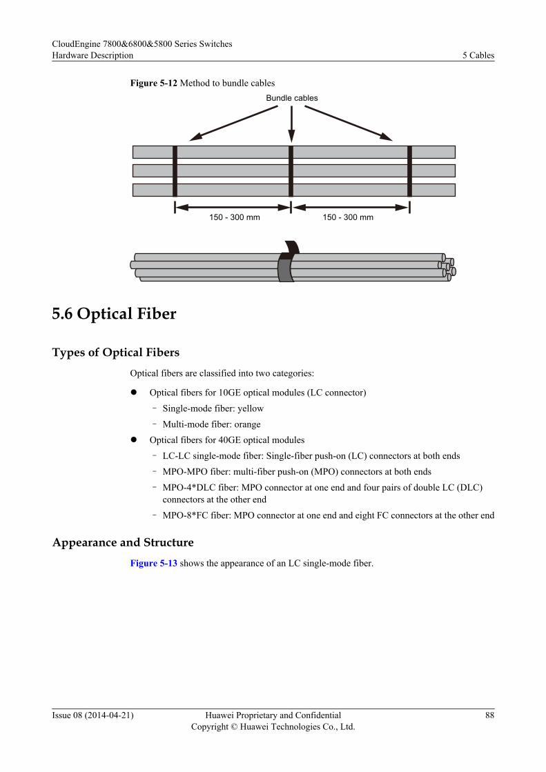
Figure 5-12 Method to bundle cables
150 - 300 mm
Bundle cables
150 - 300 mm
5.6 Optical Fiber
Types of Optical FibersOptical fibers are classified into two categories:
l Optical fibers for 10GE optical modules (LC connector)
– Single-mode fiber: yellow
– Multi-mode fiber: orangel Optical fibers for 40GE optical modules
– LC-LC single-mode fiber: Single-fiber push-on (LC) connectors at both ends
– MPO-MPO fiber: multi-fiber push-on (MPO) connectors at both ends
– MPO-4*DLC fiber: MPO connector at one end and four pairs of double LC (DLC)connectors at the other end
– MPO-8*FC fiber: MPO connector at one end and eight FC connectors at the other end
Appearance and StructureFigure 5-13 shows the appearance of an LC single-mode fiber.
CloudEngine 7800&6800&5800 Series SwitchesHardware Description 5 Cables
Issue 08 (2014-04-21) Huawei Proprietary and ConfidentialCopyright © Huawei Technologies Co., Ltd.
88
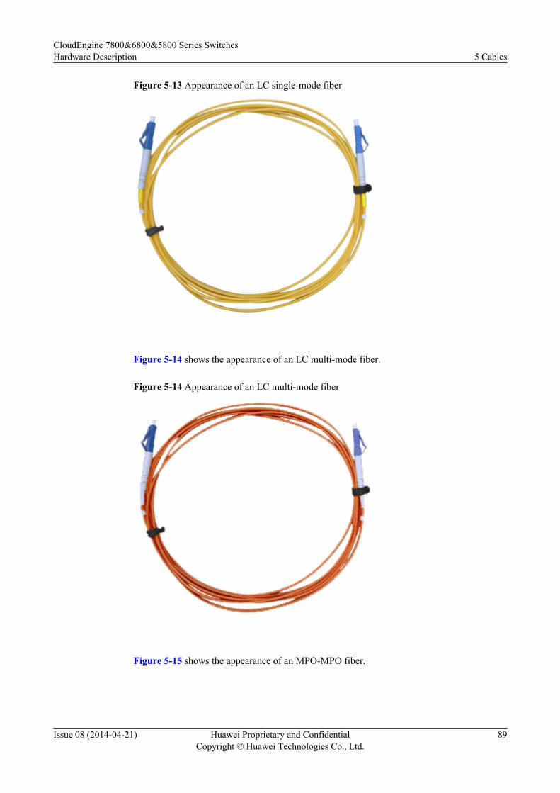
Figure 5-13 Appearance of an LC single-mode fiber
Figure 5-14 shows the appearance of an LC multi-mode fiber.
Figure 5-14 Appearance of an LC multi-mode fiber
Figure 5-15 shows the appearance of an MPO-MPO fiber.
CloudEngine 7800&6800&5800 Series SwitchesHardware Description 5 Cables
Issue 08 (2014-04-21) Huawei Proprietary and ConfidentialCopyright © Huawei Technologies Co., Ltd.
89
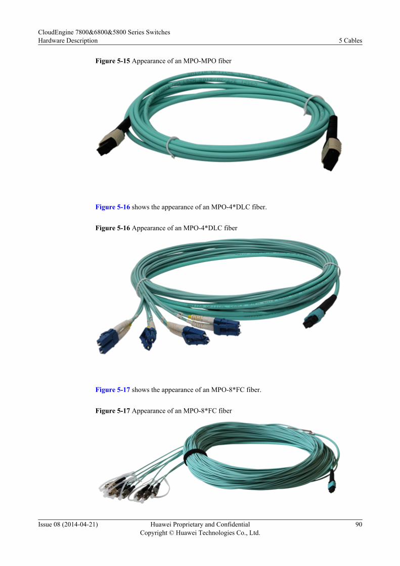
Figure 5-15 Appearance of an MPO-MPO fiber
Figure 5-16 shows the appearance of an MPO-4*DLC fiber.
Figure 5-16 Appearance of an MPO-4*DLC fiber
Figure 5-17 shows the appearance of an MPO-8*FC fiber.
Figure 5-17 Appearance of an MPO-8*FC fiber
CloudEngine 7800&6800&5800 Series SwitchesHardware Description 5 Cables
Issue 08 (2014-04-21) Huawei Proprietary and ConfidentialCopyright © Huawei Technologies Co., Ltd.
90
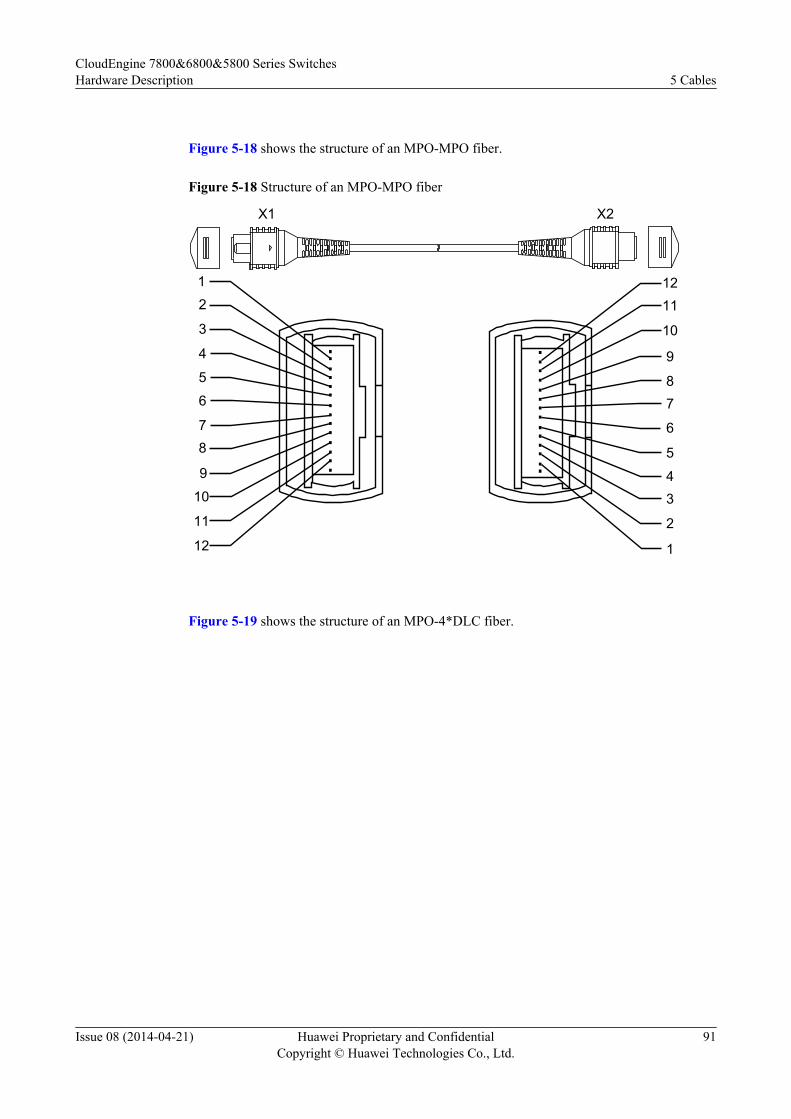
Figure 5-18 shows the structure of an MPO-MPO fiber.
Figure 5-18 Structure of an MPO-MPO fiber
X2X1
12
3
4
5
6
78
9
10
11
12
1211
10
9
87
6
5
43
2
1
Figure 5-19 shows the structure of an MPO-4*DLC fiber.
CloudEngine 7800&6800&5800 Series SwitchesHardware Description 5 Cables
Issue 08 (2014-04-21) Huawei Proprietary and ConfidentialCopyright © Huawei Technologies Co., Ltd.
91
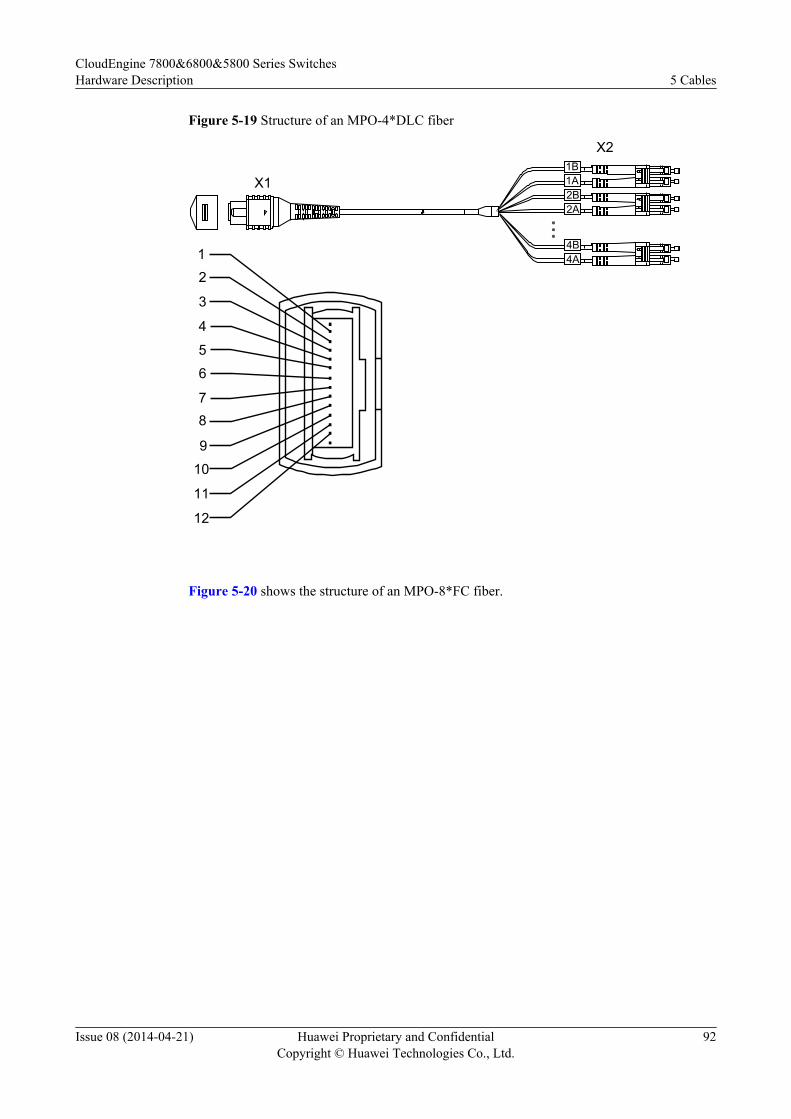
Figure 5-19 Structure of an MPO-4*DLC fiber
X2
X1
12
3
4
5
6
78
9
10
11
12
1B1A2B2A
4B4A
Figure 5-20 shows the structure of an MPO-8*FC fiber.
CloudEngine 7800&6800&5800 Series SwitchesHardware Description 5 Cables
Issue 08 (2014-04-21) Huawei Proprietary and ConfidentialCopyright © Huawei Technologies Co., Ltd.
92
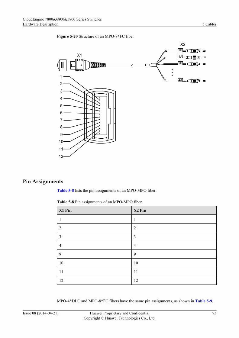
Figure 5-20 Structure of an MPO-8*FC fiber
X2
X1
12
3
4
5
6
78
9
10
11
12
1B
1A
2B
4A
Pin AssignmentsTable 5-8 lists the pin assignments of an MPO-MPO fiber.
Table 5-8 Pin assignments of an MPO-MPO fiber
X1 Pin X2 Pin
1 1
2 2
3 3
4 4
9 9
10 10
11 11
12 12
MPO-4*DLC and MPO-8*FC fibers have the same pin assignments, as shown in Table 5-9.
CloudEngine 7800&6800&5800 Series SwitchesHardware Description 5 Cables
Issue 08 (2014-04-21) Huawei Proprietary and ConfidentialCopyright © Huawei Technologies Co., Ltd.
93

Table 5-9 Pin assignments of MPO-4*DLC and MPO-8*FC fibers
X1 Pin X2 Pin
1 1B
2 2B
3 3B
4 4B
9 4A
10 3A
11 2A
12 1A
ConnectionTable 5-10 describes usage scenarios of optical fibers and fiber connections in these scenarios.
NOTE
Table 5-10 only describes connections of two ends of each fiber. In most cases, two devices are not directlyconnected by one fiber, and there are optical distribution frames (ODFs) between them.
Table 5-10 Fiber usage scenarios and connections
Fiber Connection
LC-LC fiber l Scenario 1: used for connection between twoCE7800&6800&5800 series switches for stacking or serviceaggregation.
l Scenario 2: used for connection between 10GE or 40GE ports ofCE7800&6800&5800 series switches and CE12800.
Each end connects to a 10GE port using an SFP+ optical module.Each end connects to a 40GE port using an QSFP+ optical module.
MPO-MPO fiber l Scenario 1: used for connection between twoCE7800&6800&5800 series switches for stacking or serviceaggregation.
l Scenario 2: used for connection between 40GE ports ofCE7800&6800&5800 series switches and CE12800.
Each end connects to a 40GE port using a QSFP+ optical module.
CloudEngine 7800&6800&5800 Series SwitchesHardware Description 5 Cables
Issue 08 (2014-04-21) Huawei Proprietary and ConfidentialCopyright © Huawei Technologies Co., Ltd.
94
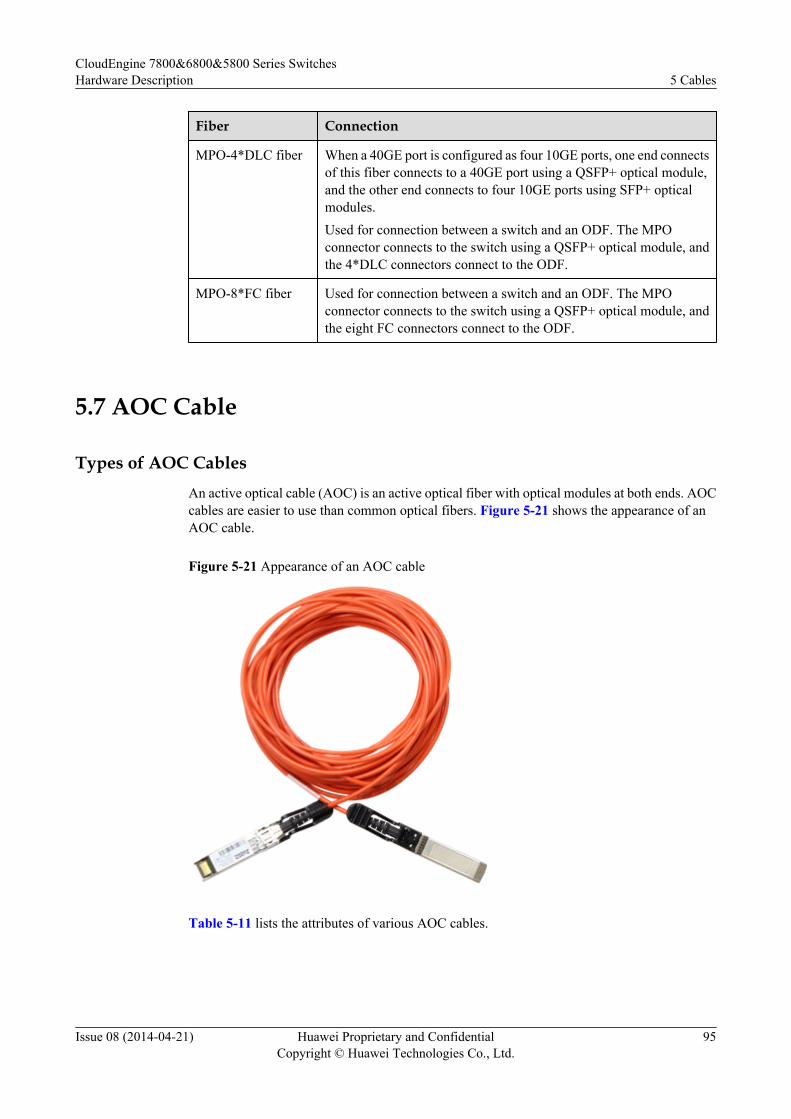
Fiber Connection
MPO-4*DLC fiber When a 40GE port is configured as four 10GE ports, one end connectsof this fiber connects to a 40GE port using a QSFP+ optical module,and the other end connects to four 10GE ports using SFP+ opticalmodules.Used for connection between a switch and an ODF. The MPOconnector connects to the switch using a QSFP+ optical module, andthe 4*DLC connectors connect to the ODF.
MPO-8*FC fiber Used for connection between a switch and an ODF. The MPOconnector connects to the switch using a QSFP+ optical module, andthe eight FC connectors connect to the ODF.
5.7 AOC Cable
Types of AOC CablesAn active optical cable (AOC) is an active optical fiber with optical modules at both ends. AOCcables are easier to use than common optical fibers. Figure 5-21 shows the appearance of anAOC cable.
Figure 5-21 Appearance of an AOC cable
Table 5-11 lists the attributes of various AOC cables.
CloudEngine 7800&6800&5800 Series SwitchesHardware Description 5 Cables
Issue 08 (2014-04-21) Huawei Proprietary and ConfidentialCopyright © Huawei Technologies Co., Ltd.
95
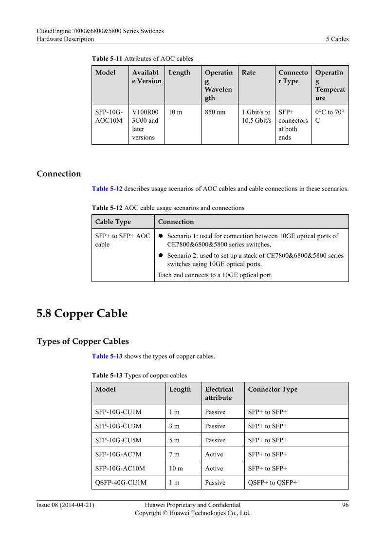
Table 5-11 Attributes of AOC cables
Model Available Version
Length OperatingWavelength
Rate Connector Type
OperatingTemperature
SFP-10G-AOC10M
V100R003C00 andlaterversions
10 m 850 nm 1 Gbit/s to10.5 Gbit/s
SFP+connectorsat bothends
0°C to 70°C
Connection
Table 5-12 describes usage scenarios of AOC cables and cable connections in these scenarios.
Table 5-12 AOC cable usage scenarios and connections
Cable Type Connection
SFP+ to SFP+ AOCcable
l Scenario 1: used for connection between 10GE optical ports ofCE7800&6800&5800 series switches.
l Scenario 2: used to set up a stack of CE7800&6800&5800 seriesswitches using 10GE optical ports.
Each end connects to a 10GE optical port.
5.8 Copper Cable
Types of Copper Cables
Table 5-13 shows the types of copper cables.
Table 5-13 Types of copper cables
Model Length Electricalattribute
Connector Type
SFP-10G-CU1M 1 m Passive SFP+ to SFP+
SFP-10G-CU3M 3 m Passive SFP+ to SFP+
SFP-10G-CU5M 5 m Passive SFP+ to SFP+
SFP-10G-AC7M 7 m Active SFP+ to SFP+
SFP-10G-AC10M 10 m Active SFP+ to SFP+
QSFP-40G-CU1M 1 m Passive QSFP+ to QSFP+
CloudEngine 7800&6800&5800 Series SwitchesHardware Description 5 Cables
Issue 08 (2014-04-21) Huawei Proprietary and ConfidentialCopyright © Huawei Technologies Co., Ltd.
96
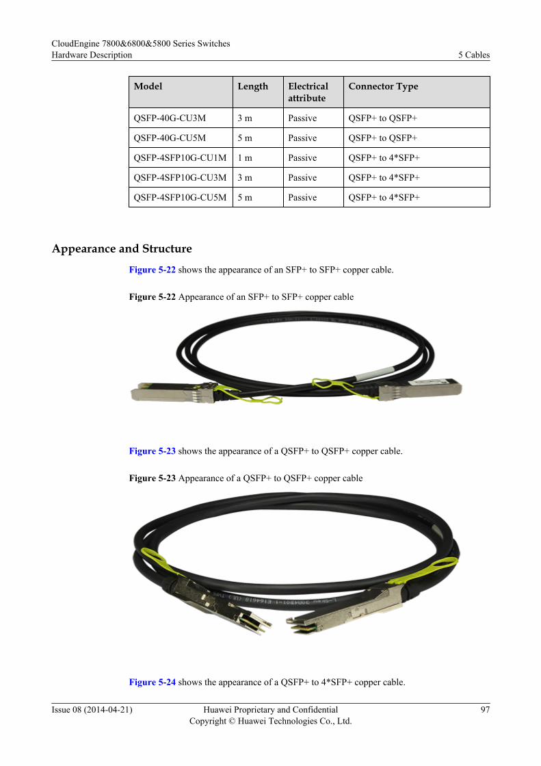
Model Length Electricalattribute
Connector Type
QSFP-40G-CU3M 3 m Passive QSFP+ to QSFP+
QSFP-40G-CU5M 5 m Passive QSFP+ to QSFP+
QSFP-4SFP10G-CU1M 1 m Passive QSFP+ to 4*SFP+
QSFP-4SFP10G-CU3M 3 m Passive QSFP+ to 4*SFP+
QSFP-4SFP10G-CU5M 5 m Passive QSFP+ to 4*SFP+
Appearance and Structure
Figure 5-22 shows the appearance of an SFP+ to SFP+ copper cable.
Figure 5-22 Appearance of an SFP+ to SFP+ copper cable
Figure 5-23 shows the appearance of a QSFP+ to QSFP+ copper cable.
Figure 5-23 Appearance of a QSFP+ to QSFP+ copper cable
Figure 5-24 shows the appearance of a QSFP+ to 4*SFP+ copper cable.
CloudEngine 7800&6800&5800 Series SwitchesHardware Description 5 Cables
Issue 08 (2014-04-21) Huawei Proprietary and ConfidentialCopyright © Huawei Technologies Co., Ltd.
97
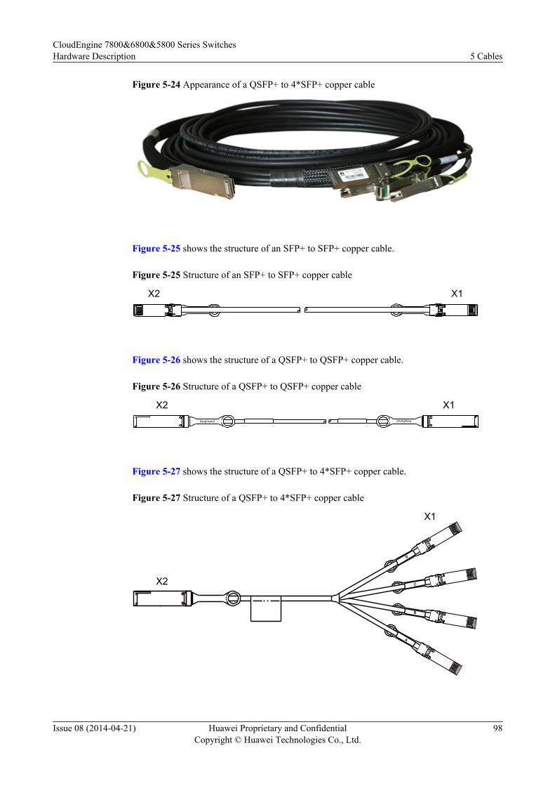
Figure 5-24 Appearance of a QSFP+ to 4*SFP+ copper cable
Figure 5-25 shows the structure of an SFP+ to SFP+ copper cable.
Figure 5-25 Structure of an SFP+ to SFP+ copper cable
X1X2
Figure 5-26 shows the structure of a QSFP+ to QSFP+ copper cable.
Figure 5-26 Structure of a QSFP+ to QSFP+ copper cable
X1X2Amphenol
Amphenol
Figure 5-27 shows the structure of a QSFP+ to 4*SFP+ copper cable.
Figure 5-27 Structure of a QSFP+ to 4*SFP+ copper cable
X1
X2
A
B
D
C
CloudEngine 7800&6800&5800 Series SwitchesHardware Description 5 Cables
Issue 08 (2014-04-21) Huawei Proprietary and ConfidentialCopyright © Huawei Technologies Co., Ltd.
98
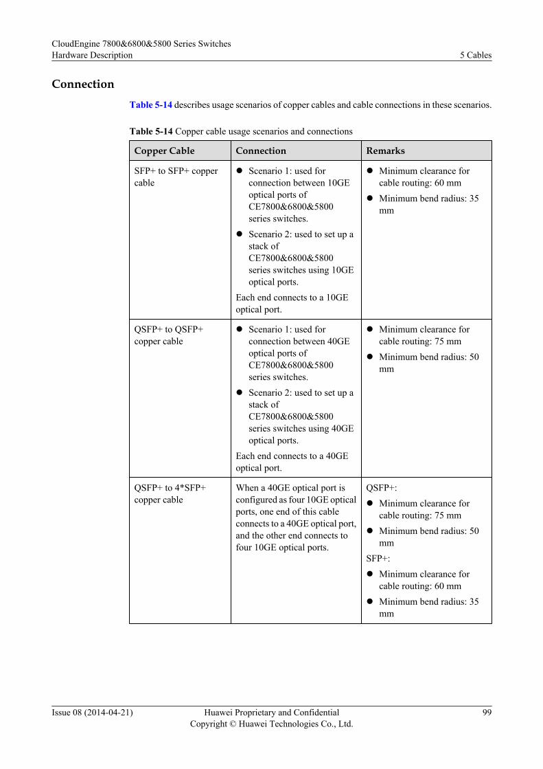
ConnectionTable 5-14 describes usage scenarios of copper cables and cable connections in these scenarios.
Table 5-14 Copper cable usage scenarios and connections
Copper Cable Connection Remarks
SFP+ to SFP+ coppercable
l Scenario 1: used forconnection between 10GEoptical ports ofCE7800&6800&5800series switches.
l Scenario 2: used to set up astack ofCE7800&6800&5800series switches using 10GEoptical ports.
Each end connects to a 10GEoptical port.
l Minimum clearance forcable routing: 60 mm
l Minimum bend radius: 35mm
QSFP+ to QSFP+copper cable
l Scenario 1: used forconnection between 40GEoptical ports ofCE7800&6800&5800series switches.
l Scenario 2: used to set up astack ofCE7800&6800&5800series switches using 40GEoptical ports.
Each end connects to a 40GEoptical port.
l Minimum clearance forcable routing: 75 mm
l Minimum bend radius: 50mm
QSFP+ to 4*SFP+copper cable
When a 40GE optical port isconfigured as four 10GE opticalports, one end of this cableconnects to a 40GE optical port,and the other end connects tofour 10GE optical ports.
QSFP+:l Minimum clearance for
cable routing: 75 mml Minimum bend radius: 50
mmSFP+:l Minimum clearance for
cable routing: 60 mml Minimum bend radius: 35
mm
CloudEngine 7800&6800&5800 Series SwitchesHardware Description 5 Cables
Issue 08 (2014-04-21) Huawei Proprietary and ConfidentialCopyright © Huawei Technologies Co., Ltd.
99
6 Optical Module
About This Chapter
NOTE
l In this document, optical modules are classified based on encapsulation types, and optical modules ofeach encapsulation type are classified based on interface rates.
l The actual optical modules depend on the delivered ones. The appearance of optical modules in thisdocument is for reference only.
l Use optical modules certified for Huawei switches. Non-certified optical modules cannot ensuretransmission reliability and may affect service stability on the switch. Huawei is not responsible forany problem caused by non-certified optical modules and will not fix such problems.
l All the optical modules listed in the documentation are Huawei certified optical modules.
6.1 Concepts
6.2 SFP/SFP+ Modules
6.3 QSFP+ Modules
CloudEngine 7800&6800&5800 Series SwitchesHardware Description 6 Optical Module
Issue 08 (2014-04-21) Huawei Proprietary and ConfidentialCopyright © Huawei Technologies Co., Ltd.
100
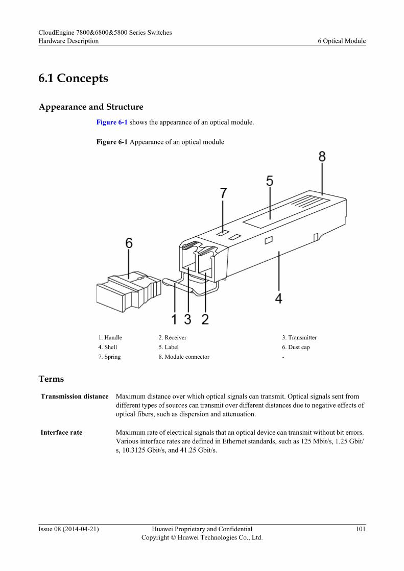
6.1 Concepts
Appearance and StructureFigure 6-1 shows the appearance of an optical module.
Figure 6-1 Appearance of an optical module
1. Handle 2. Receiver 3. Transmitter4. Shell 5. Label 6. Dust cap7. Spring 8. Module connector -
Terms
Transmission distance Maximum distance over which optical signals can transmit. Optical signals sent fromdifferent types of sources can transmit over different distances due to negative effects ofoptical fibers, such as dispersion and attenuation.
Interface rate Maximum rate of electrical signals that an optical device can transmit without bit errors.Various interface rates are defined in Ethernet standards, such as 125 Mbit/s, 1.25 Gbit/s, 10.3125 Gbit/s, and 41.25 Gbit/s.
CloudEngine 7800&6800&5800 Series SwitchesHardware Description 6 Optical Module
Issue 08 (2014-04-21) Huawei Proprietary and ConfidentialCopyright © Huawei Technologies Co., Ltd.
101
Encapsulation type Appearance type of an optical module. Encapsulation types of optical modules includeSFP, eSFP, SFP+, XFP, QSFP+, CXP, and CFP.
l SFP: small form-factor pluggable.l eSFP: enhanced small form-factor pluggable. An eSFP module is an SFP module
that supports monitoring of voltage, temperature, bias current, transmit opticalpower, and receive optical power. Because all the SFP optical modules supportthese monitoring functions, eSFP is also called SFP.
l SFP+: small form-factor pluggable plus, SFP with a higher rate. SFP+ modules aremore sensitive to electromagnetic interference (EMI) because they have a higherrate. To reduce EMI, SFP+ modules have more springs than SFP modules.
l XFP: 10GE optical module. X is the Roman numeral 10.l QSFP+: Quad SFP+, four-channel SFP+.
Center wavelength Wavelength measured at the midpoint of the half-amplitude line in the transmit spectrum.
Fiber mode Mode of fibers defining based on core diameters and features of optical fibers. Opticalfibers are classified into single-mode fibers and multi-mode fibers. Generally, multi-mode fibers have large core diameters and severe dispersion, so they transmit opticalsignals over short distances when working with multi-mode optical modules. Single-mode fibers have small dispersion and can transmit optical signals over long distanceswhen working with single-mode optical modules.
Modal bandwidth Bandwidth measured at a point with transmit power several dB lower than that of thepoint with the peak center wavelength. Modal bandwidth reflects spectrumcharacteristics of an optical module.
Fiber diameter Diameter of the core of a fiber. According to international standards for optical fibers,the diameter of a multi-mode fiber is 62.5 um or 50 um, and the diameter of a single-mode fiber is 9 um.
Fiber class Optical signals with different wavelengths have their best working windows in differentoptical fibers. To help efficiently adjust wavelengths or dispersion features of opticalfibers and change their refractive indexes, the following classes are defined: multi-modefiber (G.651), common single-mode fiber (G.652), shifted dispersion fiber (G.653), andnon-zero shifted dispersion fiber (G.655). Multi-mode fiber (G.651) and common single-mode fiber (G.652) are commonly used fiber classes.
Connector type Type of the interface on an optical module to accommodate a fiber. Commonly usedconnector types are LC (applicable to all the SFP, SFP+, and XFP modules) and MPO(applicable to some of QSFP+ and CXP modules).
Transmit optical power Output optical power of an optical module when it is working properly.
Maximum receiversensitivity
Minimum average input optical power that the receiver of an optical module can receivewithin a range of bit error rate (BER = 10-12).
CloudEngine 7800&6800&5800 Series SwitchesHardware Description 6 Optical Module
Issue 08 (2014-04-21) Huawei Proprietary and ConfidentialCopyright © Huawei Technologies Co., Ltd.
102

Overload optical power Maximum average input optical power that the receiver of an optical module can receivewithin a range of bit error rate (BER = 10-12).
Extinction ratio Minimum ratio of the average optical power with signals transmitted against the averageoptical power without signals transmitted in complete modulation mode. The extinctionratio indicates the capability of an optical module to identify signal 0 and signal 1.
6.2 SFP/SFP+ Modules
AppearanceFigure 6-2 shows an SFP/SFP+ module.
Figure 6-2 Appearance of an SFP/SFP+ module
Figure 6-3 shows a GE copper module.
CloudEngine 7800&6800&5800 Series SwitchesHardware Description 6 Optical Module
Issue 08 (2014-04-21) Huawei Proprietary and ConfidentialCopyright © Huawei Technologies Co., Ltd.
103
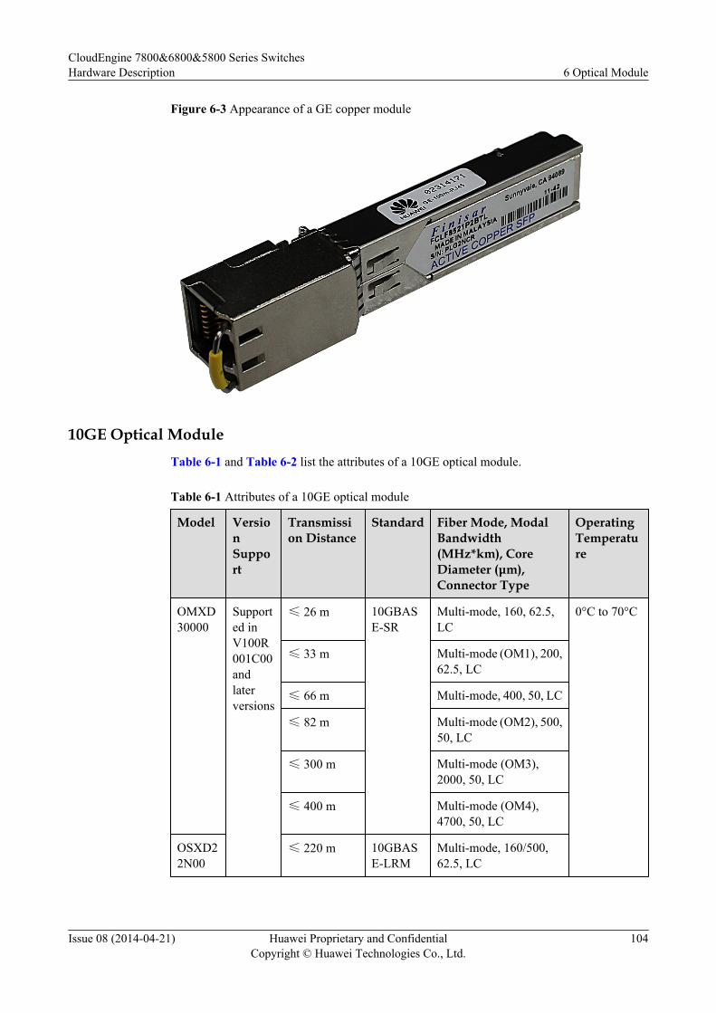
Figure 6-3 Appearance of a GE copper module
10GE Optical ModuleTable 6-1 and Table 6-2 list the attributes of a 10GE optical module.
Table 6-1 Attributes of a 10GE optical module
Model VersionSupport
Transmission Distance
Standard Fiber Mode, ModalBandwidth(MHz*km), CoreDiameter (μm),Connector Type
OperatingTemperature
OMXD30000
Supported inV100R001C00andlaterversions
≤ 26 m 10GBASE-SR
Multi-mode, 160, 62.5,LC
0°C to 70°C
≤ 33 m Multi-mode (OM1), 200,62.5, LC
≤ 66 m Multi-mode, 400, 50, LC
≤ 82 m Multi-mode (OM2), 500,50, LC
≤ 300 m Multi-mode (OM3),2000, 50, LC
≤ 400 m Multi-mode (OM4),4700, 50, LC
OSXD22N00
≤ 220 m 10GBASE-LRM
Multi-mode, 160/500,62.5, LC
CloudEngine 7800&6800&5800 Series SwitchesHardware Description 6 Optical Module
Issue 08 (2014-04-21) Huawei Proprietary and ConfidentialCopyright © Huawei Technologies Co., Ltd.
104
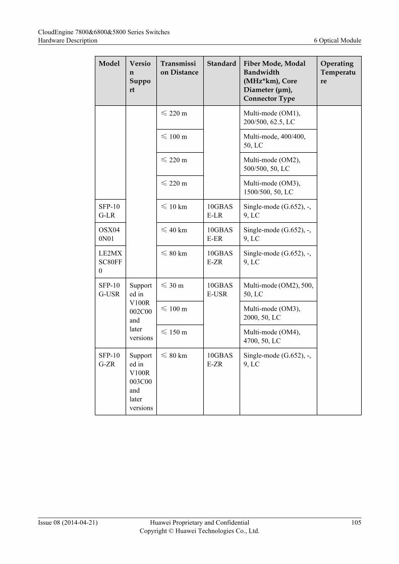
Model VersionSupport
Transmission Distance
Standard Fiber Mode, ModalBandwidth(MHz*km), CoreDiameter (μm),Connector Type
OperatingTemperature
≤ 220 m Multi-mode (OM1),200/500, 62.5, LC
≤ 100 m Multi-mode, 400/400,50, LC
≤ 220 m Multi-mode (OM2),500/500, 50, LC
≤ 220 m Multi-mode (OM3),1500/500, 50, LC
SFP-10G-LR
≤ 10 km 10GBASE-LR
Single-mode (G.652), -,9, LC
OSX040N01
≤ 40 km 10GBASE-ER
Single-mode (G.652), -,9, LC
LE2MXSC80FF0
≤ 80 km 10GBASE-ZR
Single-mode (G.652), -,9, LC
SFP-10G-USR
Supported inV100R002C00andlaterversions
≤ 30 m 10GBASE-USR
Multi-mode (OM2), 500,50, LC
≤ 100 m Multi-mode (OM3),2000, 50, LC
≤ 150 m Multi-mode (OM4),4700, 50, LC
SFP-10G-ZR
Supported inV100R003C00andlaterversions
≤ 80 km 10GBASE-ZR
Single-mode (G.652), -,9, LC
CloudEngine 7800&6800&5800 Series SwitchesHardware Description 6 Optical Module
Issue 08 (2014-04-21) Huawei Proprietary and ConfidentialCopyright © Huawei Technologies Co., Ltd.
105

Table 6-2 Optical parameters of a 10GE optical module
Model OperatingWavelength(nm)
TransmitOpticalPower(dBm)
ReceiverSensitivity(dBm)
OverloadOpticalPower (dBm)
ExtinctionRatio (dB)
OMXD30000
850 -7.3 to -1 ≤ -11.1 -1 ≥ 3
OSXD22N00
1310 -6.5 to +0.5 ≤ -6.5 1.5 ≥ 3.5
SFP-10G-LR
1310 -8.2 to +0.5 ≤ -12.6 0.5 ≥ 3.5
OSX040N01
1550 -4.7 to +4 ≤ -14.1 -1 ≥ 3
LE2MXSC80FF0
1550 0 to 4 ≤ -24 -7 ≥ 9
SFP-10G-USR
850 -7.3 to -1 ≤ -10.7 0.5 ≥ 3
SFP-10G-ZR
1550 0 to 4 ≤ -24 -7 ≥ 9
10GE CWDM Optical Module
Table 6-3 lists the attributes of a 10GE coarse wavelength division multiplexing (CWDM)optical module.
Table 6-3 Attributes of a 10GE CWDM optical module
OperatingWavelength(nm),Model
1471, SFP-10G-ZCW1471
1491, SFP-10G-ZCW1491
1511, SFP-10G-ZCW1511
1531, SFP-10G-ZCW1531
1551, SFP-10G-ZCW1551
1571, SFP-10G-ZCW1571
1591, SFP-10G-ZCW1591
1611, SFP-10G-ZCW1611
VersionSupport
Supported in V100R003C00 and later versions
AttributesandParameters
Encapsulation type: SFP+
Transmission distance: ≤ 70 km
Fiber mode, connector type: single-mode, LC
CloudEngine 7800&6800&5800 Series SwitchesHardware Description 6 Optical Module
Issue 08 (2014-04-21) Huawei Proprietary and ConfidentialCopyright © Huawei Technologies Co., Ltd.
106
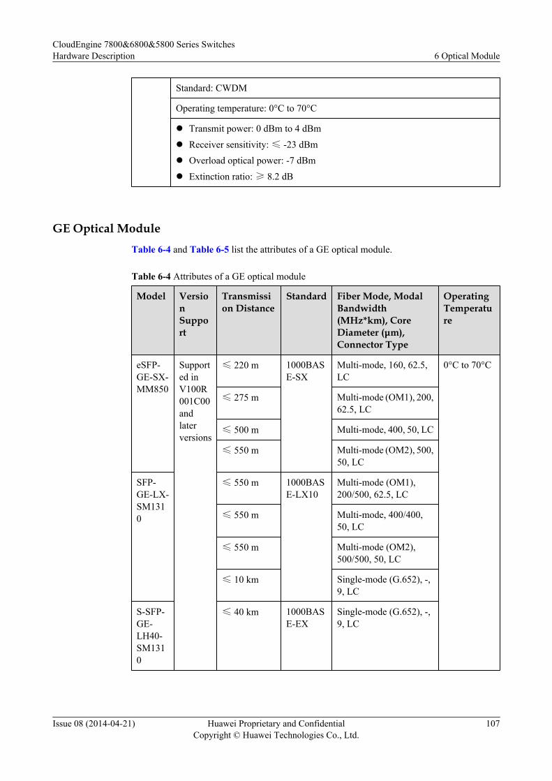
Standard: CWDM
Operating temperature: 0°C to 70°C
l Transmit power: 0 dBm to 4 dBm
l Receiver sensitivity: ≤ -23 dBml Overload optical power: -7 dBm
l Extinction ratio: ≥ 8.2 dB
GE Optical ModuleTable 6-4 and Table 6-5 list the attributes of a GE optical module.
Table 6-4 Attributes of a GE optical module
Model VersionSupport
Transmission Distance
Standard Fiber Mode, ModalBandwidth(MHz*km), CoreDiameter (μm),Connector Type
OperatingTemperature
eSFP-GE-SX-MM850
Supported inV100R001C00andlaterversions
≤ 220 m 1000BASE-SX
Multi-mode, 160, 62.5,LC
0°C to 70°C
≤ 275 m Multi-mode (OM1), 200,62.5, LC
≤ 500 m Multi-mode, 400, 50, LC
≤ 550 m Multi-mode (OM2), 500,50, LC
SFP-GE-LX-SM1310
≤ 550 m 1000BASE-LX10
Multi-mode (OM1),200/500, 62.5, LC
≤ 550 m Multi-mode, 400/400,50, LC
≤ 550 m Multi-mode (OM2),500/500, 50, LC
≤ 10 km Single-mode (G.652), -,9, LC
S-SFP-GE-LH40-SM1310
≤ 40 km 1000BASE-EX
Single-mode (G.652), -,9, LC
CloudEngine 7800&6800&5800 Series SwitchesHardware Description 6 Optical Module
Issue 08 (2014-04-21) Huawei Proprietary and ConfidentialCopyright © Huawei Technologies Co., Ltd.
107
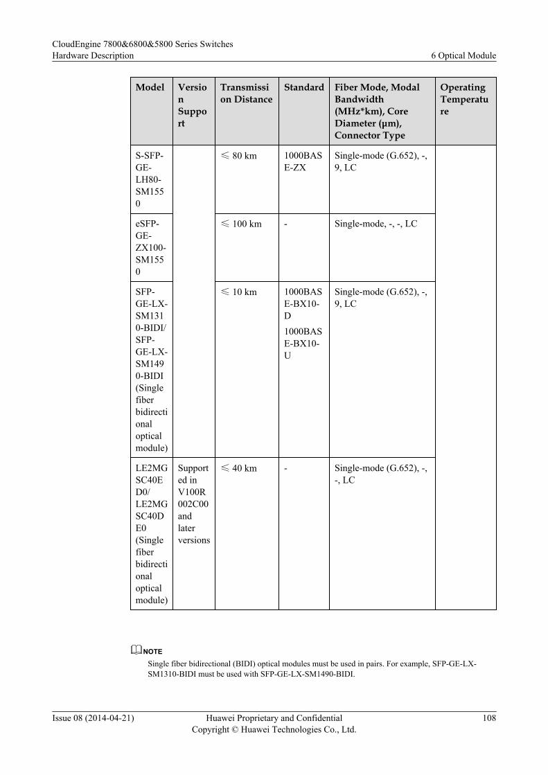
Model VersionSupport
Transmission Distance
Standard Fiber Mode, ModalBandwidth(MHz*km), CoreDiameter (μm),Connector Type
OperatingTemperature
S-SFP-GE-LH80-SM1550
≤ 80 km 1000BASE-ZX
Single-mode (G.652), -,9, LC
eSFP-GE-ZX100-SM1550
≤ 100 km - Single-mode, -, -, LC
SFP-GE-LX-SM1310-BIDI/SFP-GE-LX-SM1490-BIDI(Singlefiberbidirectionalopticalmodule)
≤ 10 km 1000BASE-BX10-D1000BASE-BX10-U
Single-mode (G.652), -,9, LC
LE2MGSC40ED0/LE2MGSC40DE0(Singlefiberbidirectionalopticalmodule)
Supported inV100R002C00andlaterversions
≤ 40 km - Single-mode (G.652), -,-, LC
NOTE
Single fiber bidirectional (BIDI) optical modules must be used in pairs. For example, SFP-GE-LX-SM1310-BIDI must be used with SFP-GE-LX-SM1490-BIDI.
CloudEngine 7800&6800&5800 Series SwitchesHardware Description 6 Optical Module
Issue 08 (2014-04-21) Huawei Proprietary and ConfidentialCopyright © Huawei Technologies Co., Ltd.
108
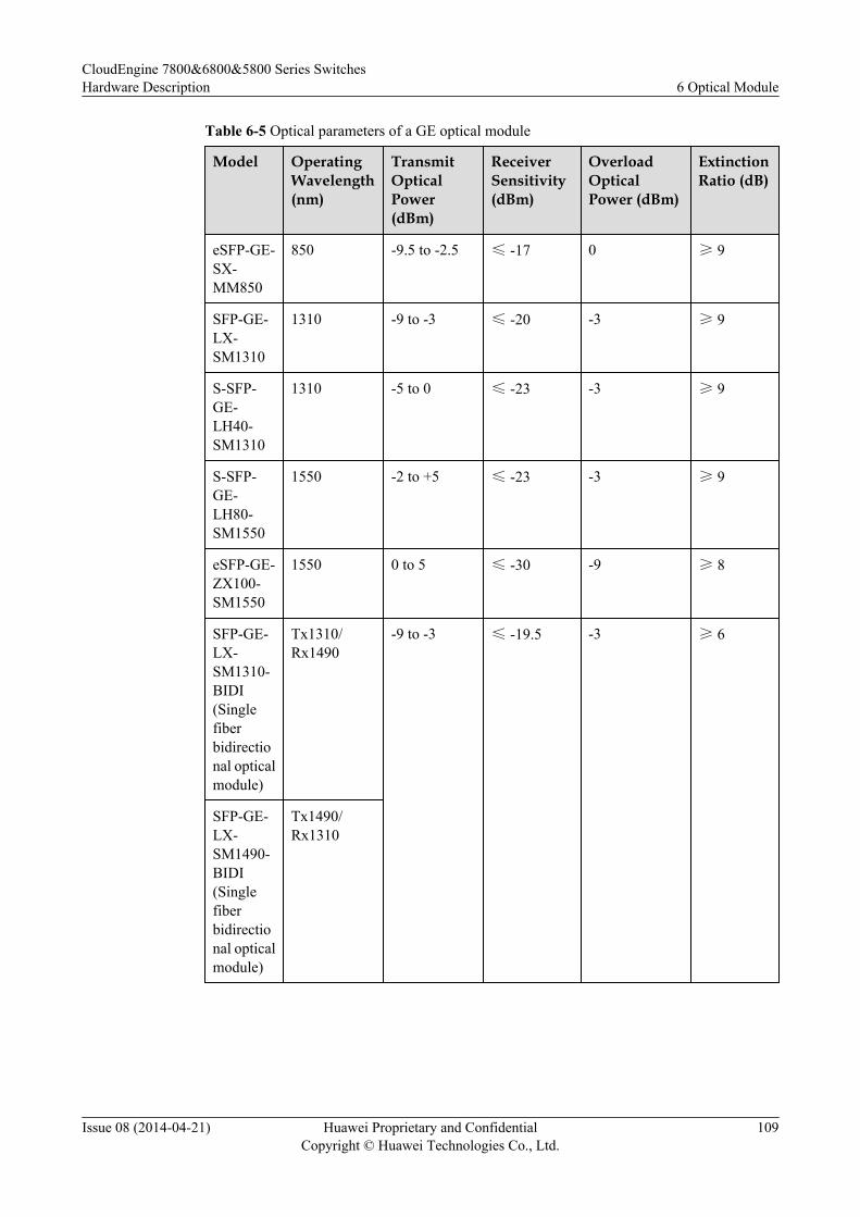
Table 6-5 Optical parameters of a GE optical module
Model OperatingWavelength(nm)
TransmitOpticalPower(dBm)
ReceiverSensitivity(dBm)
OverloadOpticalPower (dBm)
ExtinctionRatio (dB)
eSFP-GE-SX-MM850
850 -9.5 to -2.5 ≤ -17 0 ≥ 9
SFP-GE-LX-SM1310
1310 -9 to -3 ≤ -20 -3 ≥ 9
S-SFP-GE-LH40-SM1310
1310 -5 to 0 ≤ -23 -3 ≥ 9
S-SFP-GE-LH80-SM1550
1550 -2 to +5 ≤ -23 -3 ≥ 9
eSFP-GE-ZX100-SM1550
1550 0 to 5 ≤ -30 -9 ≥ 8
SFP-GE-LX-SM1310-BIDI(Singlefiberbidirectional opticalmodule)
Tx1310/Rx1490
-9 to -3 ≤ -19.5 -3 ≥ 6
SFP-GE-LX-SM1490-BIDI(Singlefiberbidirectional opticalmodule)
Tx1490/Rx1310
CloudEngine 7800&6800&5800 Series SwitchesHardware Description 6 Optical Module
Issue 08 (2014-04-21) Huawei Proprietary and ConfidentialCopyright © Huawei Technologies Co., Ltd.
109
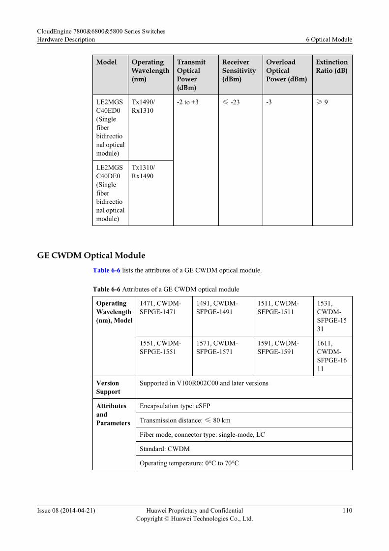
Model OperatingWavelength(nm)
TransmitOpticalPower(dBm)
ReceiverSensitivity(dBm)
OverloadOpticalPower (dBm)
ExtinctionRatio (dB)
LE2MGSC40ED0(Singlefiberbidirectional opticalmodule)
Tx1490/Rx1310
-2 to +3 ≤ -23 -3 ≥ 9
LE2MGSC40DE0(Singlefiberbidirectional opticalmodule)
Tx1310/Rx1490
GE CWDM Optical ModuleTable 6-6 lists the attributes of a GE CWDM optical module.
Table 6-6 Attributes of a GE CWDM optical module
OperatingWavelength(nm), Model
1471, CWDM-SFPGE-1471
1491, CWDM-SFPGE-1491
1511, CWDM-SFPGE-1511
1531,CWDM-SFPGE-1531
1551, CWDM-SFPGE-1551
1571, CWDM-SFPGE-1571
1591, CWDM-SFPGE-1591
1611,CWDM-SFPGE-1611
VersionSupport
Supported in V100R002C00 and later versions
AttributesandParameters
Encapsulation type: eSFP
Transmission distance: ≤ 80 km
Fiber mode, connector type: single-mode, LC
Standard: CWDM
Operating temperature: 0°C to 70°C
CloudEngine 7800&6800&5800 Series SwitchesHardware Description 6 Optical Module
Issue 08 (2014-04-21) Huawei Proprietary and ConfidentialCopyright © Huawei Technologies Co., Ltd.
110
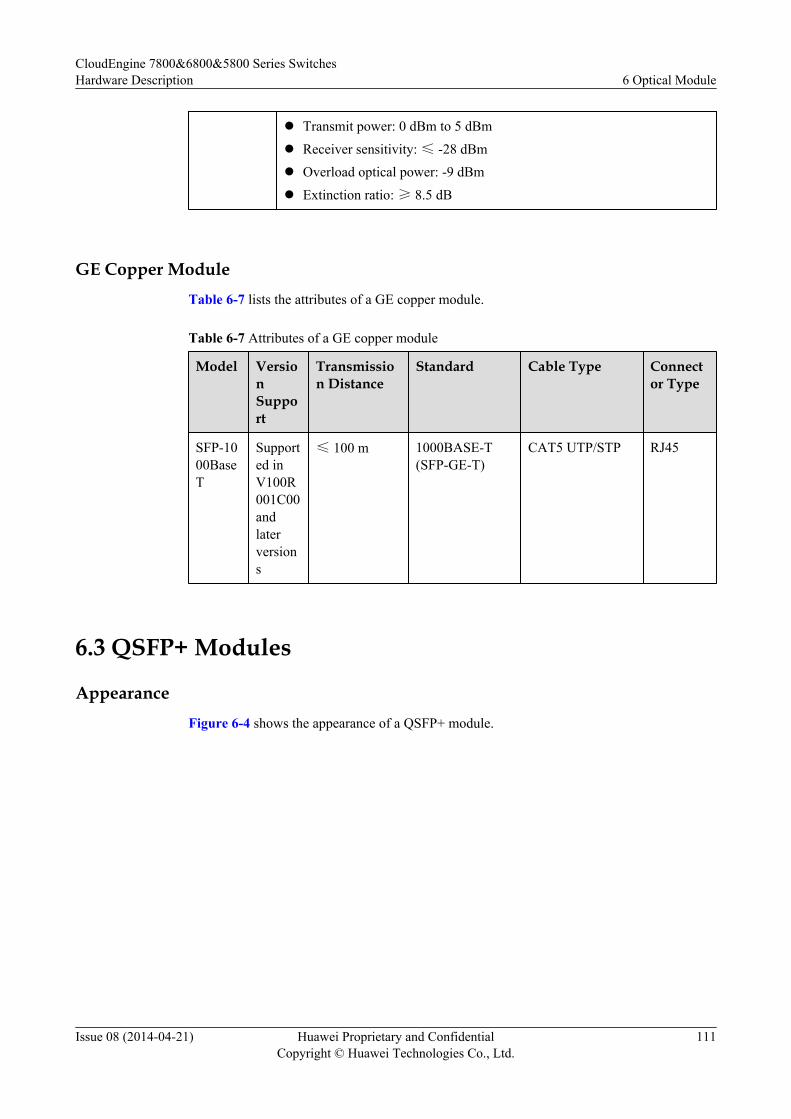
l Transmit power: 0 dBm to 5 dBm
l Receiver sensitivity: ≤ -28 dBml Overload optical power: -9 dBm
l Extinction ratio: ≥ 8.5 dB
GE Copper ModuleTable 6-7 lists the attributes of a GE copper module.
Table 6-7 Attributes of a GE copper module
Model VersionSupport
Transmission Distance
Standard Cable Type Connector Type
SFP-1000BaseT
Supported inV100R001C00andlaterversions
≤ 100 m 1000BASE-T(SFP-GE-T)
CAT5 UTP/STP RJ45
6.3 QSFP+ Modules
AppearanceFigure 6-4 shows the appearance of a QSFP+ module.
CloudEngine 7800&6800&5800 Series SwitchesHardware Description 6 Optical Module
Issue 08 (2014-04-21) Huawei Proprietary and ConfidentialCopyright © Huawei Technologies Co., Ltd.
111
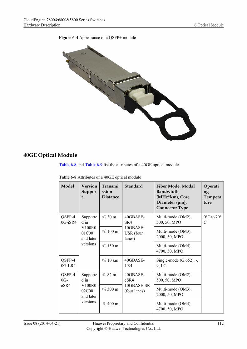
Figure 6-4 Appearance of a QSFP+ module
40GE Optical Module
Table 6-8 and Table 6-9 list the attributes of a 40GE optical module.
Table 6-8 Attributes of a 40GE optical module
Model VersionSupport
TransmissionDistance
Standard Fiber Mode, ModalBandwidth(MHz*km), CoreDiameter (μm),Connector Type
OperatingTemperature
QSFP-40G-iSR4
Supported inV100R001C00and laterversions
≤ 30 m 40GBASE-SR410GBASE-USR (fourlanes)
Multi-mode (OM2),500, 50, MPO
0°C to 70°C
≤ 100 m Multi-mode (OM3),2000, 50, MPO
≤ 150 m Multi-mode (OM4),4700, 50, MPO
QSFP-40G-LR4
≤ 10 km 40GBASE-LR4
Single-mode (G.652), -,9, LC
QSFP-40G-eSR4
Supported inV100R002C00and laterversions
≤ 82 m 40GBASE-eSR410GBASE-SR(four lanes)
Multi-mode (OM2),500, 50, MPO
≤ 300 m Multi-mode (OM3),2000, 50, MPO
≤ 400 m Multi-mode (OM4),4700, 50, MPO
CloudEngine 7800&6800&5800 Series SwitchesHardware Description 6 Optical Module
Issue 08 (2014-04-21) Huawei Proprietary and ConfidentialCopyright © Huawei Technologies Co., Ltd.
112
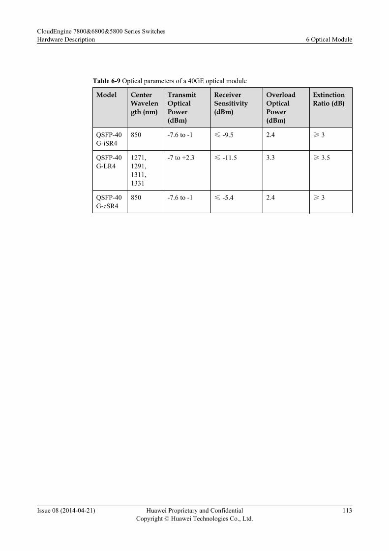
Table 6-9 Optical parameters of a 40GE optical module
Model CenterWavelength (nm)
TransmitOpticalPower(dBm)
ReceiverSensitivity(dBm)
OverloadOpticalPower(dBm)
ExtinctionRatio (dB)
QSFP-40G-iSR4
850 -7.6 to -1 ≤ -9.5 2.4 ≥ 3
QSFP-40G-LR4
1271,1291,1311,1331
-7 to +2.3 ≤ -11.5 3.3 ≥ 3.5
QSFP-40G-eSR4
850 -7.6 to -1 ≤ -5.4 2.4 ≥ 3
CloudEngine 7800&6800&5800 Series SwitchesHardware Description 6 Optical Module
Issue 08 (2014-04-21) Huawei Proprietary and ConfidentialCopyright © Huawei Technologies Co., Ltd.
113