hard-copy $- crv e microfiche · 2. analysis and theory of thin plastic replication 12 2.1 plastic...
TRANSCRIPT
Final Report
4REPLICA OPTICS
Prepared forCommanding Officer
Frankford ArsenalPhiladelphia, Pennsylvania 19137
Contract DA-04-495-AMC-376(A)
EOS Report 4821-Final 26 Februaiy 1965
COPY U _iOF ___
HARD-COPY $- - crV
E MICROFICHE $. /,7
IELCTO-OTIALSYSTEMS, N-g2A Subsldiory of Xerox Corpoaflon
300 N. Halstead Street, Pasadena. California
This document contains [ A2 1965blank pages that werenot filmed
DDC-IRA E
1' 7 _
yt
17
Final Report
REPLICA OPTICS
Prepared for
Commanding officer
Frankford ArsenalPhiladelphia, Pennsylvania 19137
Contract DA-04-495-AMC-3/6(A)
EOS Report 4821-Final 26 February 1965
Written in collaboration withH. Meyer
R. Bauer
R. Furlong
R. Frank
Prepared byD. E. Stewart
Approved by
Charles W. Stephens, MalagerOPTICS DIVISION
ELECTRO-OPTICAL SYSTEMS, INC. - PASADENA, CALIFORNIA

Now
ABSTRACT
This report covers the period of 14 February through 12 September
1964, and is submitted in accordance with the terms of the subject
contract. The scope of the program was redirected from the replica-
tion of a irototype production lot of corner prisms to the replication
of concave spherical mirrors having a diameter of 4 inches. The re-
vised objectives of this 6-month program were to procure necessary
masters, fabricate, and test approximately 24 replical spheres, continue
adhesives and coatings investigation, investigate advanred preform and
master techniqu s, and analyze and specify production processes.
These objectives were achieved. An analysis of the replication
process was updated, production processes specified, 4 mesters received
or fabricated, 7 submasters made, preforms procured, adhesives and
coatings investigated, fixtures improved, 39 replicas plus 3 replicas
by submastering made and analyed, and the environmental and nprical
tests described.
4821-Final

MU
CONTENTS
1. INTRODUCTION
1.1 Objectives and Accomplishments of
Contract DA-04-495-ORD-3332 4
1.2 Objectives of Contract DA-04-495-AMC-51(A) 4
1.3 Objectives of Contract DA-04-495-AMC-376(A) 4
1.3.1 Basic Program 4
1.3.2 Investigation of Advanced Preform
Techniques 5
1.3.3 Investigation of Advanced MasterTechniques 5
1.4 Program Summary 6
1.4.1 Production Processes 6
1.4.2 Masters 6
1.4.3 Preforms 6
1.4.4 Adhesives 7
1.4.5 Coatings 7
1.4.6 Fixtures 7
1.4.7 Replicas 7
1.4,8 Optical and Environmental Testing 7
1.5 Conclusions 8
1.5.1 Production Process 8
1.5.2 Masters 8
1.5.3 Preforms 8
1.5.4 Adhesives 8
1.5.5 Coatings 9
1.5.6 Fixtures 9
1.5.7 Replicas 9
1.5.8 Optical and Environmental 9
1.6 Recommendations 9
REFERENCES - SECTION 1 11
4821-Final iii
CONTENTS (contd)
2. ANALYSIS AND THEORY OF THIN PLASTIC REPLICATION 12
2.1 Plastic Layer Thickiiess 12
2.2 Plastic Strain 13
2.3 Preform Rigidity 13
3. REPLICATION PROCESS DISCRIPTION 141
4. MASTERS 17
4.1 Master Procurement 17
4.1.1 Fused Siica Corner Prisms 17
4.1.2 Metal Corner Prisms 17
4.1.3 Spherical Masters 18
4.2 Submasters 18
4.2.1 Replica Corner Prisms 18
4.2.2 Spherical Submasters 18
4.3 Master Life 21
4.3.1 Corner Prism Ma;ters 21
4.3.2 Spherical Masters 22
5. PREFORM 23
5.1 Hollow Corner Prism Preforms 23
5.2 Spherical Prefo.:ms 23
6. PLASTIC RESINS 27
6.1 Systems 27
6.1.1 Epoxies 27
6.1.2 Regilient and Flexibillzed Epoxies 27
601.3 Polyurethanes 29
6.2 Shelf Life 33
REFERENCES - SECTION 6 34
7. COATINGS 35
7.1 Release Coatings 35
7.2 Mirror Coating Adhesion 35
7.2.1 Predeposition of Mirror Coatings 36 ""
7.2.2 Post Baking 36
7.2.3 Adhesion Promoters 37
7.3 Recommendations 37
4821-Final iv
y-P
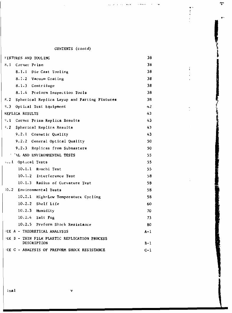
CONTENTS (contd)
FIXTURES AND TOOLING 38
8.1 Corner Prism 38
8.1.1 Die Cast Tooling 38
8.1.2 Vacuum Coating 38
8.1.3 Centrifuge 38
8.1.4 Preform Inspection Tools 38
8.2 Spherical Replica Layup and Parting Fixtures 38
1.3 Optical Test Equipment ,€2
REPLICA RESULTS 43
9.1. Corner Prism Replica Results 43
1.2 Spherical Replica Results 43
9.2.1 Cosmetic Quality 43
9.2.2 General Optical Quality 50
9.2.3 Replicas from Submasters 50
"kL AND ENVIRONMENTAL TESTS 55
.I Opt.iLcal Tests 55
10.1.1 Ronchi Test 55
10.1.2 Interference Test 58
10.1.3 Radius of Curvature Test 58
10.2 Environmental Tests 58
10.2.1 High-Low Temperaturc Cycling 58
10.2.2 Shelf Life 60
10.2.3 Humidity 70
10.2.4 Salt Fog 73
10.2.5 Preform Shock Resistance 80
AIX A - THEORETICAL ANALYSIS A-I
)IX B - THIN FILM PLASTIC REPLICATION PROCESSDESCRIPTION B-1
;IX C - ANALYSIS OF PREFORM SHOCK RESISTANCE C-i
inal v

ILLUSTRATIONS
Pa ge
Corner prism master, waster assembly,preform and replica 2
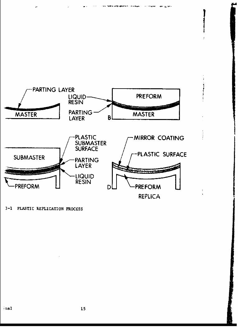
Plastic replication process 15
Replication process flow diagram 16
8.4 inch radius of curvature sphericaltest plate. 175 lines/inch Ronchi screen 19
Die cast preforms 24
Preform alternates 26
Die cast preform tooling 39
Lab-jack layup fixture 40
Cylindrical layup and parting fixture 40
Modified arbor press, step number one 41
Earlv model replica parting fixture 41
Spherical replicas with lightened aluminumpreforms 46
Typical Ronchigram of 4 inch aperture 8.4 inchradius of curvature spherical replica viewedwith a 175 lines/inch grating screen 51
Replica from submaster number one175 lines/Inch Ronchi screen 53
Replica from submaster number two175 lines/inch Ronchi screen 53
Ronchi test apparatus 56
Ronchigram test schematic 57
Replica 4, before shock test 61
Replica 10, before shock test 62
Replica 10, after shock test 62
Replica 10, after first environmental test 63
,| vii

ILLUSTRATIONS (c ontd)
F i ure
10-7 Rej., ca 10, after second environmentil test 63
10-8 Replica 14, before shock test 64
10-9 Replica 14, after shock test 64
10-10 Replica 14, after first environmental teot 65
10-li Rep1ic a 14, after second environmaental test 65
lu-12 Replico 17, before shocl test 66
10-13 Replica 17, after shock test 66
10-14 Replica 17, after first environmental test 67
10-15 Replica 17, after second environmental test 67 -
10 16 Replica 18, before shock test 68
10-17 Replica 18, after shock test 68
C-18 R~plica 18, after first environmental test 69
10- .9 Replica 18, after second environmental test 69
10-20 Hinnldity test on flat plastic replica mirrors 72
10-21 Salt spray apparatus 76
10-22 Schematic of ?-alt spray apparatus 77
A-I Allowable adhesive surface thickness varia ionvs cure temperature A-7
A-2 Rim-sp'iere:4rhaboid vs crcncsv iaeur
for various f/nos A-9
A-' Elastic modules vs temperature for an epoxy resin A-17
-4 Preform bending due to resin skin stress -
t), ical case A-20
5-! epliicatio process flow diagram B-2
B-2 iMudifie.d arbor press. step number one B-13
B-3 Modilied arbor press, step number two B-15
B-4 Modified arbor press, step nwnber three B-15
1-5 Modified arbor piess, step number four B-16
B-,6 Modifie-d arbor press, step number five B-16
C-1 Schematic of mirror enviyonment C-2
4821-Fina I Viii
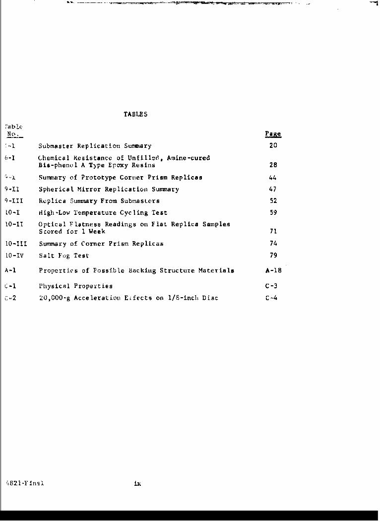
TABLES
No.e
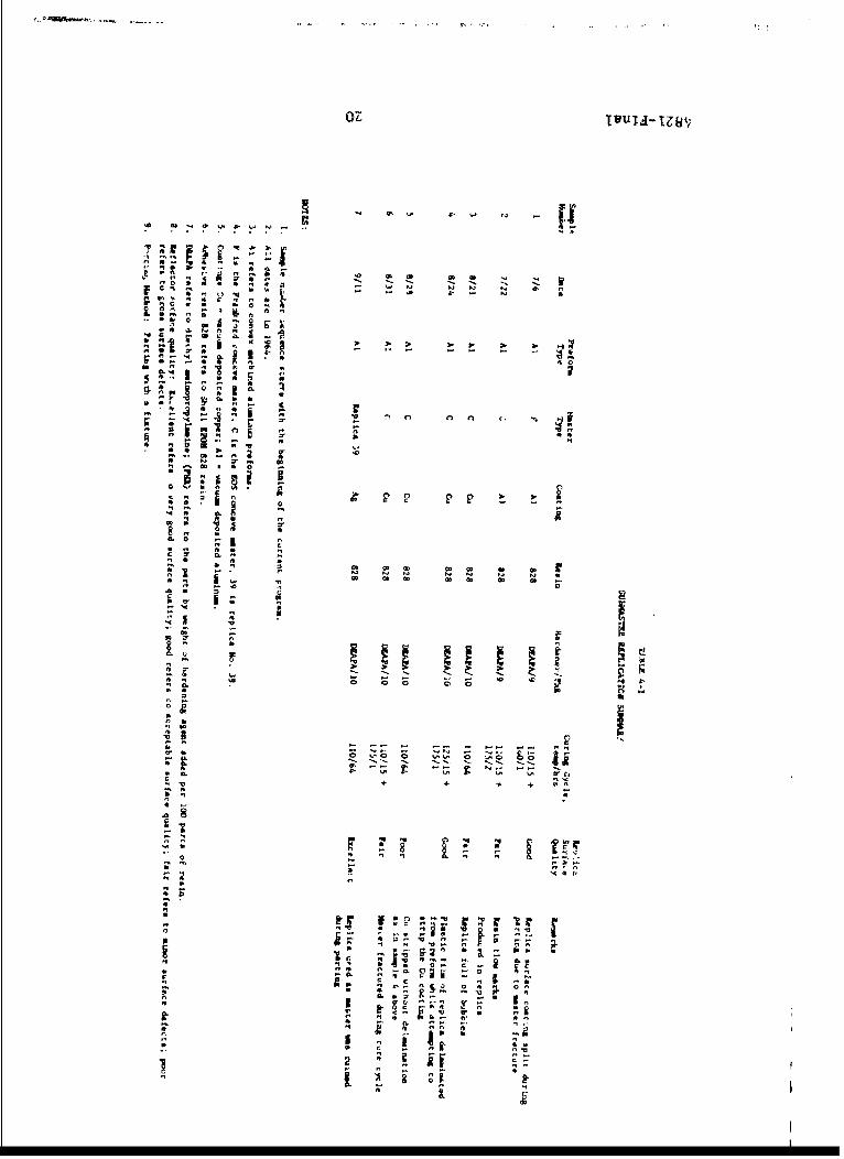
I Submaster Replication Summary 20
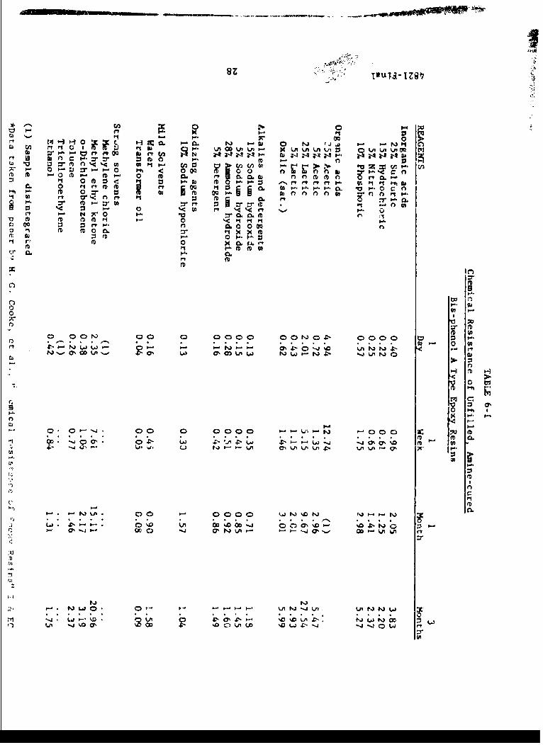
6-I Chemical Resistance of Unfilled, Amine-curedBis-phenol A Type Epoxy Resins 28
111 Summry of Prototype Corner Prism Replicas 44
9-li Spherical Mirror Replication Summary 47
q-III Replica Summary From SubmasLers 52
[0-I High-Low Temperature Cycling Test 59
10-I Optical Flatness Readings on Flat Replica SamplesScored for 1 Week 71
10-Ill Summary of Corner Prism Replicas 74
10-IV Salt Fog Test 79
A-i Properties of Possible Backiug Structure Materials A-18
C-I Physical Properties C-3
c,-2 20,000-g Acceleration ElIfects on 1/S-inch Dtac C-4
". 821-F nsl ix
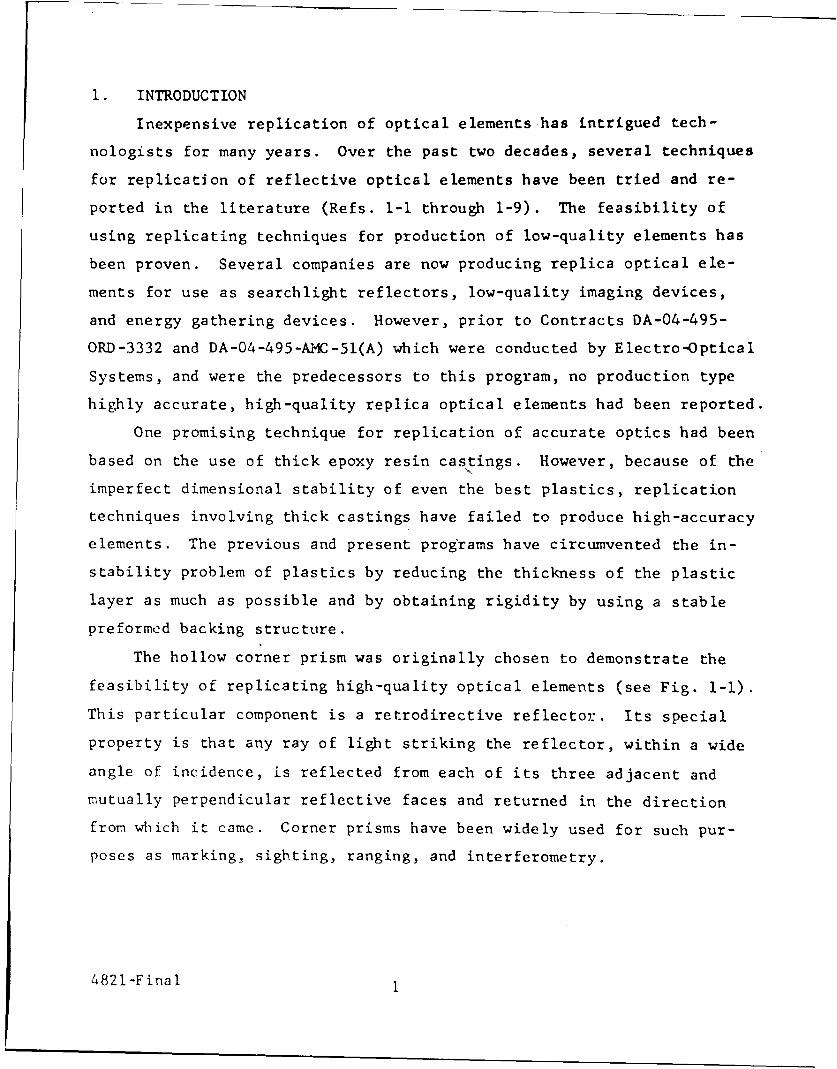
1. INTRODUCTION
Inexpensive replication of optical elements has intrigued tech-
nologists for many years. Over the past two decades, several techniques
for replication of reflective optical elements have been tried and re-
ported in the literature (Refs. 1-1 through 1-9). The feasibility of
using replicating techniques for production of low-quality elements has
been proven. Several companies are now producing replica optical ele-
ments for use as searchlight reflectors, low-quality imaging devices,
and energy gathering devices. However, prior to Contracts DA-04-495-
ORD-3332 and DA-04-495-AMC-51(A) which were conducted by Electro-Optical
Systems, and were the predecessors to this program, no production type
highly accurate, high-quality replica optical elements had been reported.
One promising technique for replication of accurate optics had been
based on the use of thick epoxy resin castings. However, because of the
imperfect dimensional stability of even the best plastics, replication
techniques involving thick castings have failed to produce high-accuracy
elements. The previous and present programs have circumvented the in-
stability problem of plastics by reducing the thickness of the plastic
layer as much as possible and by obtaining rigidity by using a stable
preformed backing structure.
The hollow corner prism was originally chosen to demonstrate the
feasibility of replicating high-quality optical elements (see Fig. 1-I).
This particular component is a retrodirective reflector. Its special
property is that any ray of light striking the reflector, within a wide
angle of incidence, is reflected from each of its three adjacent and
mutually perpendicular reflective faces and returned in the direction
from which it came. Corner prisms have been widely used for such pur-
poses as marking, sighting, ranging, and interferometry.
4821-Firial 1

FIG. 1-1 CORNER PRISM MASTER, MASTER ASSEMBLY,PREFORM AND REPLICA
4821-Final 2

I
In practice, these retrodirective reflectors usually are made in
the form of tetrahedral glass prisms. Three of the four faces are
,utually perpendicular and function as mirrors by virtue of total in-
ternal reflection. The fourth face is a window through which the light
lays enter and leave the prism. These prisms are made by grinding andP~olishing and are quite expensive because of the precise tolerances
iecessary for proper functioning. The replication of the prism provides
, good example for demonstrating replicating techniques. A replica
prism is the inverse of the glass prism and consists, therefore, ofthree mutually perpendicular front surfacp flat mirrors.
At the halfway Foint in this prigram, the program scope was re-
lirected to permit the fabricaticn of 4-inch diameter concave spherical
replica mirrors rather than retrodirective corner prisms. This re-
iirection was initiated to proluce deliverable hardware to be used in
nvironmelital shock analysis. Also, a replica sphere was a closer
pproximation to the current fire-control optical needs than the hollow
orner prism. Otherwise, the basic program goals remained tle same.
Replication has many possible advantages over conventional grinding
,nd polishing techniques. These advantages include:
1. Feasibility of fabricating difficult shapes easily
2. Lower production costs
3. Improved ruggedness
4. Lower weight
5. Improved thermal properties
The latter three advantages result from the possibility of using
,aterials in the replication process which are structurally and/or
Thermally superior to glass, even though these materials may not be
uitable for grinding and polishing. These advantages and the labora-
ory developments of the previous contracts provided incentive to
;evelop replication techniques further.
821-Final 3 I

1.1 Obiectives and Accomplishments of Contract DA-04-495-ORD-3332
The objectives of the initial contract were to improve the
art of optical replication and to demonstrate this improvement by the
laboratory fabrication of hollow corner reflectors having an accuracy
and durability comparable to glass prisms. These objectives were ac-
comp lished.
1.2 Objectives of Contract DA-04-495-AMC-51(A)
The objective of this program was to take_ the corner prism
replication process from the laboratory to a state of pilot production
readiness.
The feasibility of producing hollow replica corner prisms of
the angular accuracy specified for M-1 and M-2 corner reflectors was
demonstrated using low cost, mass-produced preforms. Other detailed
inforration relative to optical replica production was also obtained.
1.3 Objectives of Contract DA-04-495-AMC-376(A)
The basic objective of this program was originally to take
the repliation process as applied to corner prisms, from the state of
pilot prcduction readiness to the state of full production readiness.
However, the objectives were later revised to determine whether replica
mirrors could lthstand th: high shocd loads imposed on another re-
flectiv optical Plement now under study. The following tasks outline
the scop Af the revised program work.
1.3.1 Basic Program
1. Procurement of necessary masters.
2. Intensive fabrication of production prototype replica optics.
A total of approximately 24 4-inch diameter spherical or
aspherical units were to be produced. Units were to be
fabricated from at least two preforms each from at least
five of the following types of materials:
4821-Final 4

a. Aluminum Ib. Steel
r. Magnesium
d. Titanium
e. Beryllium
f. Nickel
g. Invar
h. Stainless steel
i. Reinforced plastic
3. Continuation of adhesives investigation at a reduced level.
4. Continuation of coatings investigation at a reduced level.
5. Anal-rsis and specification of production processes.
6. Optical and environmental testing of replicas.
1.3.2 Investigation of Advanced Preform Techniques
This supplementary study was to provide data on pre-
fabrication techniques that offered advantages but required further
opment in order to achieve a low unit cost or suitable accuracy.
ies arc:
1. Electroforming
2. Plasma spraying
3. Eloxed die and investment cast
of work included:
1. Design and fabrication of tooling or mandrels
2. Fabrication of preforms
3. Fabrication and testing of replicas using these preforms
1.3.3 Investigation of Advanced Master Techniques
This supplementary study involved metal masters and
,a masters. Items of work included:
1. Fabrication of plane replicas from plane meLal masters or
replica masters in order to provide basic data for masters
2. Design and fabrication of masters
3. Fabrication of replicas using these masters
inal 5
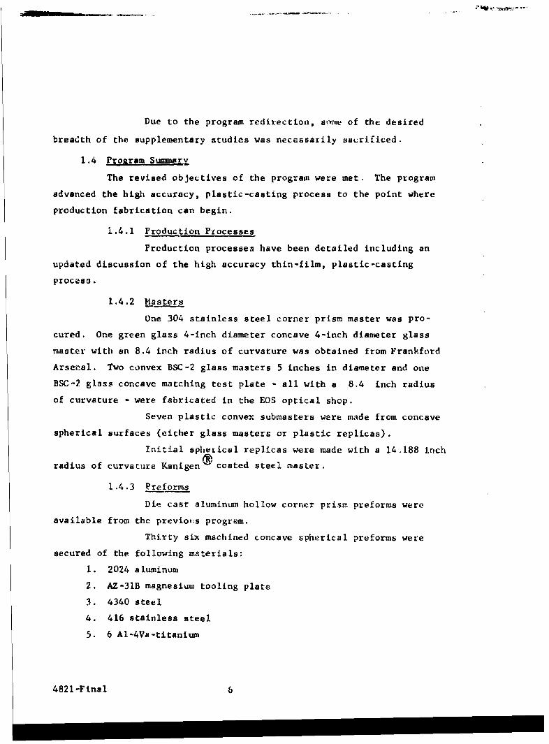
Due to the program redirection, some of the desired
breadth of the supplementary studies was necessarily sacrificed.
1.4 Proaram Summarv
The revised objectives of the program were met. The program
advanced the high accuracy, plastic-casting process to the point where
production fabrication can begin.
1.4.1 Production Processes
Production processes have been detailed including an
updated discussion of the high accuracy thin-film, plastic-casting
process.
1.4.2 Masters
One 304 stainless steel corner prism master was pro-
cured. One green glass 4-inch diameter concave 4-inch diameter glass
master with an 8.4 inch radius of curvature was obtained from Frankford
Arsenal. Two convex BSC-2 glass masters 5 inches in diameter and one
BSC-2 glass concave matching test plate - all with a 8.4 inch radius
of curvature - were fabricated in the EOS optical shop.
Seven plastic convex submasters were made from concave
spherical surfaces (either glass masters or plastic replicas).
Initial spheiical replicas were made with a 14,188 inch
radius of curvature Kanigen coated steel master,
1.4.3 Preforms
Die cast aluminmn hollow corner prism preforms were
available from the previous program.
Thirty six machined concave spherical preforms were
secured of the following materials:
1. 2024 aluminum
2. AZ-31B magnesium tooling plate
3. 4340 steel
4. 416 stainless steel
5. 6 Al-4Va-titanium
4821-Final 6
1.4.4 Adhesives
Investigations were made of epoxies, resilient. and
lexibilized epoxies, and polyurethanes.
1.4.5 Coatings
Vacuum deposited release coatings used included
tuminum, copper, gold, and silver.
Aluminum and gold reflective coatings have been used
conjunction with silicon monoxide protective layers and chromium
dhesion promoting coatings.
1.4.6 Fixtures
The hollow corner prism preform tooling was reworked.
acuum coating fixtures were also revised to facilitate corner prism
oating.
Improved fixtures for layup, aligLunent and curing,
nd parting of spherical replicas were designed and fabricated. Also
combination knife-edge, single-wire Foucalt and Ronchi tester was
,signed tu test and photographically document the spherical replicas.
1.4.7 Replicas
Ten replica coiner prisms an d39 spherical- replic a s
re produced. Except for minor cosmetic defects, the spherical
sters were not degraded.
1.4.8 Optical and EnvironmLntal Testing
Five spherical replicas were shock tested between
8,500 and 20,400 g's. No gross distortion r-,sulted. Minor or im-
,rceptibie optical distortion occurred. This test indicated the
tivantages of metal-backed replica optics relative to ground at,d
ofished glass.
The Ronchigrams of all spherical replicas were
hotographically recorded.
2-F innl I7

Salt spray and humidity test. , during the program and
since the end of the technical effort, indicate that plastic replicas
can withstand standard salt spray arnd humidity tests.
High and low temperature cycling and limited shelf
life tests zevealed no optical or mechanical degradation.
1.5 Conclusions
Th.s programa has improved the productior. capability uf rep-
lica optics in many areas.
1.5.1 Productiou Process
1. A relatively simple proccss is -'vafable for producing rep-
lica optics.
2. The equipmenL required for plartic replication i., readily
available. Th4 personnel experienr' necessary for econom-
ical production may be difficulL to acquirc: by those organ-
izstions with no p-evious reiication experiencc.
1.5,2 Masters
1. Glass masters --an bf- used at P small cost per replica. Yor
aspherics, plartic subimast':',as are reccniiiended aid appe.nr
economically feasible.
.. .Mete . a. er -. o._ . .. rLe hgI,,'y . duz,.1-I ... . .. canno~t ak_.t'A C....v th'I
surfcce finish of gkass ma,,.Lerso
1.5.3 Prei.orms
I. Spheiial prefo i*.is can bf! machlned from var-ious c',it.non ri:-als
an6 meet te 6hock environment resistance: requireerts.
2. kedu.edi i-refcorm co'srs car, be achieved using cast pretk rms.
1.,.4 Ahe eive.
i. The EPON 829 and DEA7-A reslii systLi, %iAi satisfactorily
produce high-qual! Ly "epicas.
2, ile.iblc epoxie6 ind polyurethane rc.iJns offer higher mar
resiszarce and durab-.lity fcy subm&esterz and -;owe re-lica
envI vonments.
4821-Finai 8
1.5,5 Coatings
1. Post coating baking improves the adhesion of vacuum-deposited
layers on plastic. Also an initial chromium coating enhances
adhesion.
2. Chromium and silicon monoxide coatings enhance the replica
resistance Lu humidity and salt spray.
1.5.6 Fixtures
Cosmetic voids and many mast;er attrition difficulties
,-an be eliminated with accurate fixtuc,;s and tooling.
2.5.7 Replic3s
The teplication process has developed to the point
where consistent surface accuracies and cosmetic qualities can now be
attained.
1.5.8 Op ical and Environmentil
1. Spherical replica mirrors of high quality and accuracy for
energy focusing applications can be made easily. Aspherics
should present no difficulties by uzing the same techniqtws
em-loye&.I in the fabrication of spherical repltcas during
this :orm
2. Limited envirot-wental t:.sts indizate that the replicas
should withstand standard fire control temperature
cycling, shock, humidity, and salc spray tnvironmental
tests.
I .i Reco ,. -ndat ion.,s
Bastd on this ptograi., several reconnendations for the future
divelopinent of th,_ prcr:ess are indicated.
I. The thin-film high accuracy casting replication technique
should be des'gned into a current reflective optic system
,-r component: requiyerncnt.
,821-Fin-.l 9

2. Extensive field use and storage of replica elements Lhould
be t itiated for an aCcurate evaluation of replica optics.
Only by a production test of this process can the true
economics of high accuracy replication be demonsurated.
3. Additional vacuwn coating development would improve the
abra ion and environmental resistance of replicas and
submasters.
4. Detailed analysis of replica corner prism pr,.forns made
sirce the program ended indicates that additional work
or. modifying preform fabrication toolinv will improve
replica accuracy appreciably.
. 52l-F inal 10

REFERENC ES
SECTION I
1-1 G. Hass and J- R. Jeaness, Jr., "NeLhod for FabricatingPataboloidal Mirrors," Journal of the Optical Society ofAmerica, 48, 86 (195&e'
1-2 J. H. Saxton and D. E. Kline, "Optical Characteristics and
Physical Properties of Filled Epoxy Mirrors," Journal ofthe Optical Socicty of America, 50, 1103 (1960)
1-3 D. E. Kline and J. H. Saxton, "Radiation, Mois'ire, andTemperature Effezts in Filled Epoxy Replica Flat Mirrors,"
Journal of the Optical Society of America, 51, 447 (1961)
1-4 Singer Maufacturing Company, "Investigation of Plastic
Replica Mirror Optical Components," Contract DA-19-020-ORD-5237
1-5 B. Goldberg, Journal of the Optical Society of America, 38,409 (1948)
1-6 G. Hlass and W. W. Erbe, "Method for Producing Replica Mirrorswith High Quality Surfaces," Journal of the Optical Societyof America, 44, 669 (1954)
1-7 A. P. Bradford, W. W. Erbe, and G. Hass, "Two-Step Methodfor Producing Replica Mirrors with Epoxy Resins," Journal
of the Optical Society of America, 49, 990 (1959)
1-8 U.S. Patent 2,444,532, J. H. Richardson, July 6, 1948
1-9 U.S. Patent 2,464,738, J. U. White, et al., March 15, 1949
4821-Final 11

2. ,NALY6IS ANO TEORY OF THIN PLASTIC REPLICATION
All repli'ation processes that do not involve post replication
finli !ing to impil-ve specularity, employ a polished master or submaster
cntu. which tha replica optical surfac_ i6 fourue by casting, molding, de-
position, etc. .ill cui.cently used methods involve processes that can
and ncrmallv' Jo irvlve strain which tends to distort the replica
efter it is parted from the master or submaster. In the thin-film
plastic r4plication process discussed in this report, the plastic
straii-e are minimiied by %:e following factors:
1. Minirilzing t.v plastic layer thickness.
2. Miut.mizitg the 1.astic strain for a given thickness by
usig the op:Imwn plastic properties.
3. Employin. a preform with high rigidity.
The anblysis Liv:a in Appendix A describes the effects of the
above iactors in the replication of flat, spherical, and paraboloidal.
mir-. rs. The .:Dnclusions are described below.
Thc prefurm rigidity is directly proportional to the plastic
thickness. Tvvically a 0.0005 to 0.004 inch thickness is desirable.
1he plastic thickness uniformity, which is a function of the
preform accuracy and surface finish, should be typically between
0.0005 to 0.002 inch maximum to achieve 1/40 (wavelength) accuracy
. ,461k. The exact maximum depends on many factors including:
X . Cure uhrinkage
2. Cure tempersure
3. Paistic thermal expansion coefflicicinc
4. Preform thernal expansion coefficient
5. Environmental temperatures
4821-Final 12

2.2 Plastic Strain
Plastic strain or shrinkage depends on the properties of the
it system used. Generally low temperature curing epoxies are most
rable. Fillers are not desirable since they degrade the surface
ularity.
2.3 Preform Rigidity
Preform rigidity is determined by the plastic strain, thick-
and modulus of elasticity. High rigidity is achieved by using
k sections of high modulus materials. For maximum rigidity-to-
ht ratios, structures of beryllium, aluminum, glass, and magnesium
desirable. Also honeycomb and ribbed construction will give high
dity-to-weight ratios. Typically, a diameter to thickness ratio
'een 6 to 8 is adequate for optics up to 6 inches in diameter.
-a I
-Final 13

I
3. REPLICATION PROCESS DESCRIlPION
Many optical elements can be generated and checked easily
as eitner a concave or convex surface. Concave paraboloids and
convex or solid corner prisms are relatively easy to make. Since
a convex paraboloid and a concave or hollow corner prism are dif-
ficult to make, the most economical production of replica concave par-
aboloids and external reflecting prisms would probably require a
double replication process as shown schematically in Fig. 3-1.
The process flow diagram is shown in Fig. 3-2. Each major
process item is given a unit .umber. Each process task is indi-
cated by a decin,.l. Fcc !onvenience, the process description is
described in Appendix B, where the process items and tasks are
discussed by their respective numLars.
4821-Fna l 14
PARTING LAYER
PL RSTICIRROTN
SUMASTER PARTING MSELAYER
LIQUILRESIN
3-1~~~PLSI PLSTCRELIATOAPOCS
LIQUID

14
I,
Is
ofo
'0
~Z
.2 LJ LP.n .o_r.
48 21 -Fina1 16
I I II I II I I I I
4. MASTERS
The master is a critical element in the replication process slnce
replication economics and accuracies are highly dependent on master cost,
design, materials, and attrition. Master requirements and considerations
applicable to the fabrication of hollow replica corner prisms and spher-
ical replicas are also adaptable to other types of replica optical ele-
ments.
4.1 Master Procurement
4.1.1 Fused Silica Corner Prisms
Five fused silica trihedral replica masters were orig-
inally ordered, four with a cumulative trihedral angular error of less
than 4 seconds each and one with a cumulative trihedral angular error
of 2 seconds. The order for these prisms was cancelled at no cost when
the program was redirected.
Fused silica masters should produce more accurate rep-
licas than BSC-2 type glass masters since the thermal distortion and
coefficient of expansion of silica masters is low compared with BSC-2.
Other properties of fused silica such as high hardness, chemical purity
and high softening temperature enhance its superiority as a master mate-
rial. Experience with fused silica on another replication program con-
firms these assumptions.
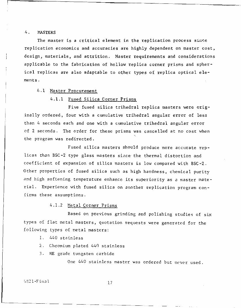
4.1.2 Metal Corner Prisms
Based on previous grinding and polishing studies of six
types of flat metal masters, quotation requests were generated for the
following types of metal masters:
1. 440 stainless
2. Chromium plated 440 stainless
3. HE grade tungsten carbide
One 440 stainless master was ordered but never used.
'4.82-Fina i17
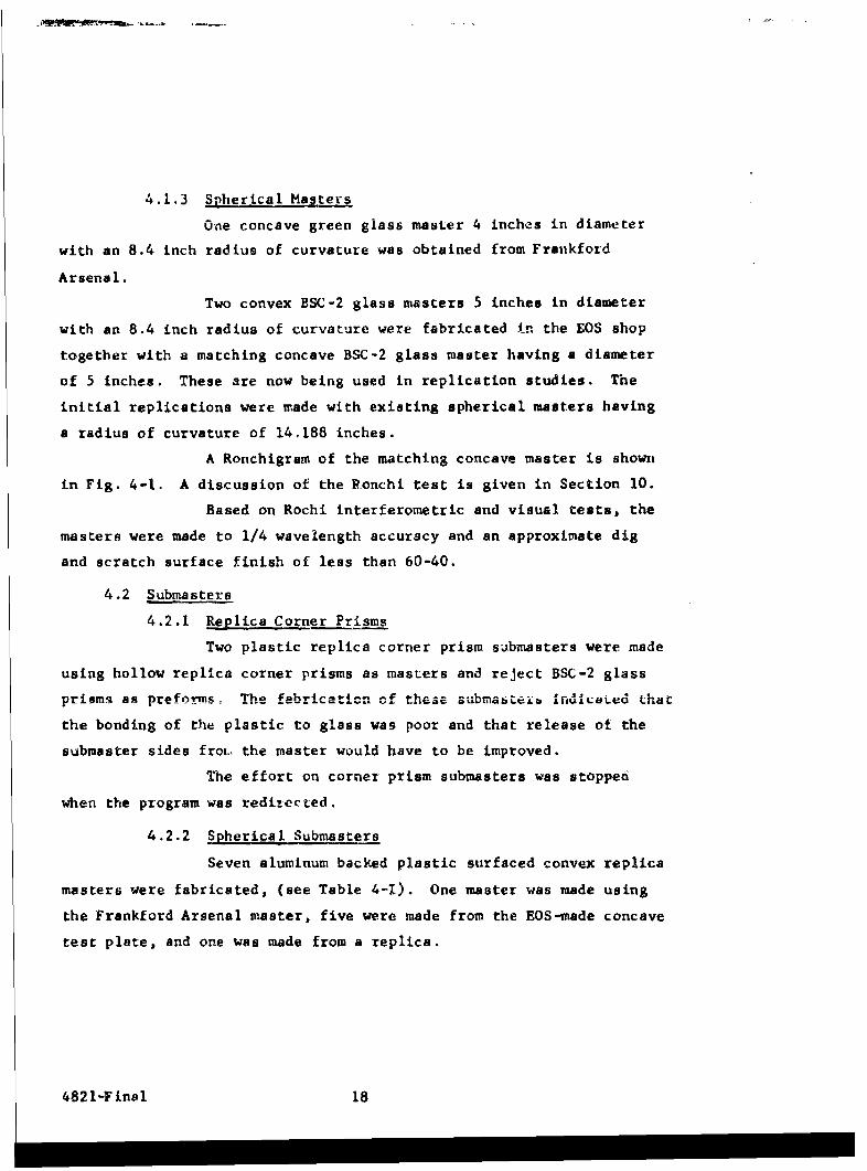
4.1.3 Spherical Masters
One concave green glass master 4 inches in diameter
with an 8.4 inch radius of curvature was obtained from Frankford
Arsenal.
Two convex BSC-2 glass masters 5 inches in diameter
with an 8.4 inch radius of curvature were fabricated in the EOS shop
together with a matching concave BSC-2 glass master having a diameter
of 5 inches. These are now being used in replication studies. The
initial replications were made with existing spherical masters having
a radius of curvature of 14.188 inches.
A Ronchigram of the matching concave master is shown
in Fig. 4-1. A discussion of the Ponchi test is given in Section 10.
Based on Rochi interferometric and visual tests, the
masters were made to 1/4 wavelength accuracy and an approximate dig
and scratch surface finish of less than 60-40.
4.2 Submasters
4.2.1 Replica Corner Prisms
Two plastic replica corner prism submasters were made
using hollow replica corner prisms as masters and reject BSC-2 glass
prisms as preform, The fabricatin of these submiatei InradiaLed that
the bonding of the plastic to glass was poor and that release of the
submaster sides frot.. the master would have to be improved.
The effort on corner prism submasters was stopped
when the program was redizected.
4.2.2 Spherical Submasters
Seven aluminum backed plastic surfaced convex replica
masters were fabricated, (see Table 4-I). One master was made using
the Frankford Arsenal master, five were made from the EOS-made concave
test plate, and one was made from a replica.
4821-Final 18

FRS Aa
FIG. 4 17 8.4 1 ICH R IS CATRE
Note: Over half the errorshown is due to the testerbeam splitter E
A-Final 19
hUh- TCH~;
-J 0~tp -
C 0-. e t~ *~ L,~ N - It
-~ ~Z zN 0'
a. *~ N N N
.40 - - -
F' ~ : ~0.~43UlJF ~ I
o a' - 7
F. r-I U fl C) 0 0 (. HI
E 0
'0
a 1 22 22 ~* S. IN -
'~ ho Aa p VbO 2- fl S S N0 7 Q. NN S S S- 0 N 0 0' 0 0 0 0 0 0 r* I - - r N N N) N N t.i A) B'* N I~' *~ 0 0 0 0 0 0 0-c 0.0 -go. I;
'~ N 34- r
0 7 N -
8" 0 ~.c ct t N- . y~ ~'y Iv I. 5 -~
* 7 .e - - - .- -* N
0 0 0 0 0 5 A
U'fl S
43 - - - - - C
o ~.'0 C 'p'j. C ;~0 bo 5~- - -'. - ~- -~ ~- -. - - - C A
* a. t -; ~ -~ j N.' -- -'S. 7Cj
N .4 + + + + ~0N
S -as
- N - ~ .4a z' ~- . S ~ a
o N Np S -N
SS X0~n.'.y -. w-
W~ INE &~ rKi S
N - £N~ 0. C .0
Ui ~N IS ~ NS S ~4SJ *'.~r ~23, N 4. B'.~ Br
N I
I2 ~ii['a 21 t

Theimal stresses caused by waxing the Frankferd master
to a backing plate f.rior to paiting caused the master to fracture cleartly
acros1, the diameter. Aside irom the hairline Lrack, the -uriaze accu-
racy of toe sLbmastcr vas good,
Rcchigcams oi replicas made frow, this submaster arc
shown and discuss.ed i,, SCctiOn 9.
1he Fr.nkford master was the sarne diameter as the
desired finish d replica which made submastering difficult. Ideally,
the iubmaEiter should !.ie between 1/4 and 112 inch smaller than the
waster and the repiica should be between 1/4 to 1/2 inch smaller than
the submaster. This site difference reduces mounting and alAgnment
problems.
Most of the subm;sters were made with improper tooling.
Many of the cosmetic difficulties encountered on the first - ix sub-
masters were due to lack of catrol in jcining the miaster and preform.
More sophistic-ted toolirg improved the submaster sutfac-e quality
appreciably as demonstrated by th" number 7 ubtnasLer. ThiL L-oling
is discussed in Section 8. Inprovcemeit itn the miaser life, should
occur with further tooling refinements. One of the ma-ei reasons why
,.:b ei e .i) ieit subu-istez fabric:ation has izor j.mj,-ved :-ore iz that
only limited time has been spent, on this phae ol. the replica process.
4.3 Master Life
4.3.1 Corner Prism Masters
Insufficient data is available to predict the expeLted
master life of a corner prism master. On another progravr, silica flat
masters have been replicated over 70 times. In the re2plication f
corner prisms, master life is highly dependent on master alignment.
Previous master alignu. ent had been on a matiual-
gravity basis using the fluid plastic as a viscous lubrifant. While
expedient in prior deveioptrent, this approach may have aiccounted for
son- of the master degradation reported. Aligrment. is particularly
4821-Final 21
60 0 E E E E E I I
importnl in covne, prisrm replication or any other sharp edged, reql.ca
optic Vnich is not a surface o1 revolution since stiiall MiCalinmenza
can cause prefozai and mastei. contact. The improved alignment fiyturcs
used ii the final spherical replicationc would probably in rease corner
prism msater lift concidezably. Fxperlence indicates that metal masters
will give lcng master life.
4,3.2 S!herical Masters
Experience of the life of convex spherical masters has
been quite good. One of the LOS masters was replicated 28 times with
no detectable change h*. fiure an,! only minor surface damage. Surface
dymage conisted of several scratches and pits and two small edge zracks.
Most surface daweage occurred during cleaning Procedures and in ha. mIling.
Both the Kaniben arnd BSC-2 6 irnch diameter 14.188 inch radius of cur-
vature masters initially used were used in a totas of over 20 ".eplit-ations
each without loss of figure. The BSC-2 glass master had a hairliae
crack before it was used on this prograr.. This crack was the po~nt of
fracture when the master broke. Ma&ters held it. storage at a|pproxiiately
740F and 50 percent humidity for perioda up to iour =ntha showed nr
observable attrition.
4821-Final 22
5. PREFORM
In the replication process, the preform is a major factor in deter-
mining the stability, environmental "esistance, angular accuracy, re-
flective surface finish, and cost of the finished replica optic. There-
fore, the successful adaptation -le art of replication to production
optics depends on the selection of optimum preform fabrication methods
amenable to low cost automatic rroduction techniques.
5.1 Hollow Corner Prism Preforms
The preforms used in the replication of hollow replica corner
prisms were made on the previous contract (DA-04-495-AMC-51(A)) of die
cast aluminum alloy number 380. These are shown in Fig. 5-1. Detailed
analysis of the accuracy of replica prisms indicated that these preforms
had angular errors of about 60 seconds which limited the ultimate obtain-
able accuracy. Also the faces of each preform were about 0.001 inch
concave due to the contraction of the preform upon cooling immediately
after die casting.
The angularity difficulties were probably attributable to
errors in the die fabrication. These errors were considerably reduced
when the die mold was repaired early in the program. However, the die
was never run since the program was redirected to make spherical rep-
licas.
Improved tooling was developed to gage the flatness and angular
accuracies of the preforms.
5.2 Spherical Preforms
Thirty six machined spherical preforms were made from the
following materials:
1. 2024 aluminum (16 total)
2. 4340 steel (4 total)
:8 2 L-F ina 1 23

JL
FIG. 5-1 DIE CAST PREFORMS
4821-Final 24

3. 416 stainless steel (4 total)
4. AZ31B magnesium tooling plate (8 total)
5. 6A1-4Va-titanium (4 total)
Three of the four various alternate preform constructions
are shown in Fig. 5-2. The fourth alternate design is similar to
alternate A except it has no lightening holes counterbored in the
preform back. For future reference, this alternate shall be de-
signated as alternate D. The initial preforms used a 14.188 inch
radius preform instead of the 8.4 inch preform. These various
alternates in preform design were chosen to determine the effect of
the structural design on the shock resistance.
The number of spherical replicas required on the revised
program did not warrant the fabrication of casting or molding tooling.
Aluminum and magnesium preforms were initially lap ground
to a 3F finish. The purpose of the lap grinding was to increase the
accuracy of the preform, reduce surface~roughness, and provide a
surface which would yield greater adhesion of the epoxy film. Sub-
sequent experience indicated that the lap grinding was unnecessary.
In fact, it was demonstrated that replica surfaces were superior
when the preforms were not ground. The reason for the surface im-
provement is not well understood. However, it is felt that the rough
surface allows air entrapment and bubbles result as the air expands
during the curing cycle.
Preforms of poor replicas were reused. These preforms offered
a variety of surfaces for layup. Where previously deposited epoxy was
mcchanicilly removed, the preform often had numerous scratches too deep
to remove readily by lap grinding. Layup on these surfaces gave good
results except in the case where epoxy films were one thousandth of an
inch thick or less. In these cases, the defects in the preform surface
telegraphed through the epoxy film.
Several layups were made directly on previously deposited
tpnxv. The resultant replicas had good surfaces, but they were often
, I tlam inat ed.
.S2 L-Fa l 25

L4 .375 -. YAK
.50t.01I0PHOF 1 1 MA HOLES) 2 .
-. 0021
4.00 12
4.0 +,01
- a(REF) A 1 1/2 DIA.. 70 DEPT, SHO0WN
NOTES.ib7
4821-Fn~l12
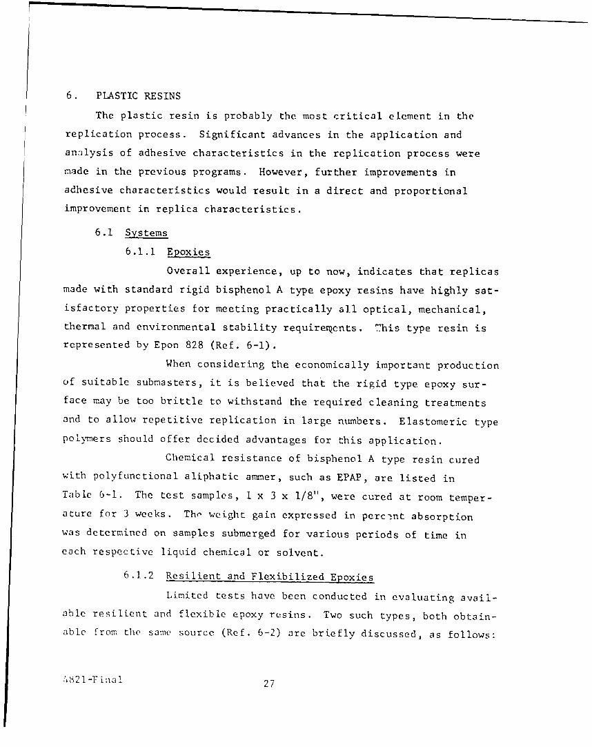
6. PLASTIC RESINS
The plastic resin is probably the most critical element in the
replication process. Significant advances in the application and
analysis of adhesive characteristics in the replication process were
made in the previous programs. However, further improvements in
adhesive characteristics would result in a direct and proportional
improvement in replica characteristics.
6.1 Systems
6.1.1 Epoxies
Overall experience, up to now, indicates that replicas
made with standard rigid bisphenol A type epoxy resins have highly sat-
isfactory properties for meeting practically all optical, mechanical,
thermal and environmental stability requiremcnts. This type resin is
represented by Epon 828 (Ref. 6-1).
When considering the economically important production
of suitable submasters, it is believed that the rigid type epoxy sur-
face may be too brittle to withstand the required cleaning treatments
and to allow repetitive replication in large numbers. Elastomeric type
polymers should offer decided advantages for this application.
Chemical resistance of bisphenol A type resin cured
with polyfunctional aliphatic ammer, such as EPAP, are listed in
Table 6-1. The test samples, 1 x 3 x 1/8", were cured at room temper-
ature for 3 weeks. Tho weight gain expressed in perc-!nt absorption
was determined on samples submerged for various periods of time in
each respective liquid chemical or solvent.
6.1.2 Resilient and Flexibilized Epoxies
Limited tests have been conducted in evaluating avail-
able resilient and flexible epoxy resins. Two such types, both obtain-
able from the same source (Ref. 6-2) are briefly discussed, as follows:
'421 -F inal 27
m -3 0Ft PI. 0. 1 16 AO 0AL lu A 00
rt lb n c * * b0 m n 1w V- 0~J~~ b4r m 0%4 P-- c n0(Aw0--P 0 -O0 u 00 0 0 0) t-o o 0 ~ .P1 00m oI M i..D 0L rt CL.f.' § m n n
pi 0 m1F 0 e 5 0 1..l 'IN " " W . ". " : "0 0 = a 03 m oo I't-lb Cf nl0 00 M flnl1r .
:t 030 r P 1 m r t W .ta ~m ;v 0r PI."~ V CL m t
m ED m 00. 0 94P1'piS00 p r I- MC 0000 0
0i m1 0 " x xlb? 0. P.. 0 .
(D 0 0 . . -
00~
0 00") 0 0000 )0 P4 4, 0 0 0 tvW
rD~ co c
raa0 'm
0:.. - j :
En0 ~ ~ 0 0 0 ~ .# J t ' 0
PO1'C LnL ,0%
vi -4 (Y a.)Wn~. -N~n.00 0 00 ~ '3FA

6.1.2.1 Epotut 37-134
Epotuf 37-134 cures to a polymer of relatively
high resiliency. The literature discloses that this property makes pos-
sible practically stress-free coatings. Formulation and cure cycle
suggested by the manufacturer are:
Resin: Epotuf 37-134 100 parts by weight
Hardener: Triethylenotetramine 10 parts by weight
Cure at room temperature (77°F) 24 hours
Post cure at 150°F 2 hours
Potlife at room temperature 4 - 6 hours
Initial tests showed that the suggested harde-
ner is not compatible with the resin when centrifuging for removal of
entrained air. However, it was found that this could be corrected by
allowing the hand-mixed compound to stand for approximately 1 hour prior
to centrifuging. The cured resin coating is extremely tough and re-
si I ient.
6.1.2.2 Epotuf 37-151
Epotuf 37-151 cures to a flexible polymer.
It is not useable in this application except as a flexibilizer in com-
bination with standard rigid type epoxy resins, such as Epotuf 37-140.
The suggested hardener is aminoethylpiperazine.
Various evaluation tests were conducted,
using different ratios of Epotuf 37-151 to 37-140 and varying curing
cycles. The suggested hardener was also found to be incompatible with
the resins, when centrifuging. This difficulty could not be solved.
The results of these preliminary studies were
not sufficiently promising to continue this investigation.
6.1.3 Polyurethanes
Polyurethane elastomers are definitely considered as
potentially superior materials for submasters. Various formulations
82 1-F tna 1 29
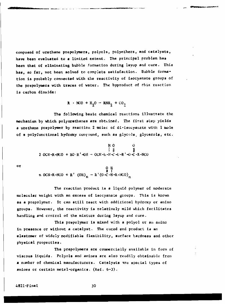
composed of urethane prepolymers, polyols, polyethers, and catalysts,
have been evaluated to a limited extent. The principal problem has
been that of eliminating bubble formation during layup and cure. This
has, so far, not been solved to complete satisfaction. Bubble forma-
tion is probably connected with the reactivity of isocyanate groups of
the prepolymers with traces of water. The byproduct of rhis reaction
is carbon dioxide:
R - NCO + I 20 -. RNH2 + Co
The following basic chemical react:ions illustrate the
mechanism by which polyurethanes are obt4.ined. The first step yields
a urethane prepolymer by reaction 2 mole. of di.isozyanate With 1 mole
of a polyfunctional hydroxy comr.ound, such as glycols, glycerols, etc.
HO0 0
2 OCN-R-NCO + HO-R'-OH - 0CN-hIC-C--R'-O-C.-R-NCU
or0II
n OCN-R-NCO + R' (OH) n - R'(O-C-N-R-N4CO) n
The reaction product is a liquid polymer of moderate
molecular weight with an excess of isocyana~e groups. This is known
as a prepolymer. It can still react with additional hydroxy or amino
groups. However, the reactivity is relatively mild which facilitates
handling and control of the mixture during layup and cure.
This prepolymer is mixed with a polyol or an amino
in presence or without a catalyst. The cured end product is an
elastomer of widely modifiable flexibility, surface hardness and other
physical properties.
The prepolymers are commercially available in form of
viscous liquids. Polyols and amines are also reodily obtainable from
a number of chemical manufacturers. Catalysts Ire special types of
amines or certain metal-organics. (Ref. 6-3).
4821-Final 30
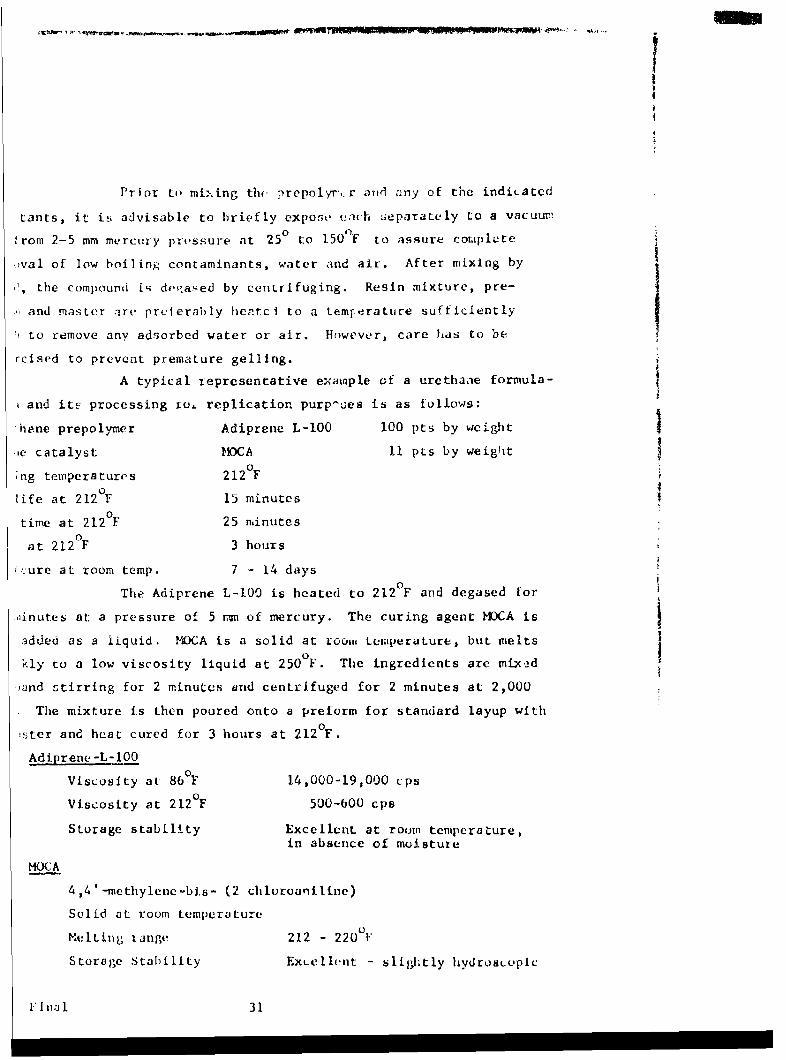
Prior ta ml..ing thte prepolyr',r an(d ;any of the indicated
tants, it is advisable to briefly expose ,eich separately to a vacuum
from 2-5 mm mercury pri.ssure at 25° to 150'F to assure cotuplete
;.val of low boiling contaminants, water and air. After mixing by
, the compound ii dv( ased by centrifuging. Resin mixture, pre-
and master are preferably hentci to a temr-erature sufficiently
to remove any adsorbed water or air. However, care has to be
rcised to prevent premature gelling.
A typical representative example of a urethane formula-
and its processing io, replication purp-oes is as follows:
'hene prepolymer Adiprene L-l00 100 pts by weight
le catalyst MCA 11 pts by weig'it
;ng temperatures 212°Fi 2
life at 212 F 15 minutes
time at 212 F 25 minutes
at 212°F 3 hours
'cure at room temp. 7 - 14 days0
The Adiprene L-lO is heated to 212 F and degased for
Ainutes at a pressure of 5 m of mercury. The curing agent MDCA is
added as a liquid. MOCA is a solid at room teumperature, but melts0Ikly to a low viscosity liquid at 250 F. The ingredients are mixed
'jand stirring for 2 minutes and centrifuged for 2 minutes at 2,000
The mixture is then poured onto a preform for standard layup with
,ster and heat cured for 3 hours at 212 0 F.
Adiprene-L-l0O
Viscosity at 86°F 14,000-19,000 cps
Viscosity at 212°F 500-600 cps
Storage stability Excellent at room tentperature,in absence of moisture
MOCA
4,4'-methylnec-b.s- (2 chloroaniline)
Solid at room temperature
Melting iange 212 - 220OF
Storage Stability ExLCllnt - slightly hydroscopic
FIl 31

Properties of Cured Polyurethane Elastomer
Modulus at 300 percent, psi 2,100
Tensile strength, psi 4,500
Elongation break, percent 440
Hardness, Shore A 90
Brittleness test, -80OF No break
Adiprene L-100 elastomers have good oil and solvent
resistance. Aromatic and polar solvents cause moderate tc severe
swelling:
Percent Volume Increase., 14 days at 1580F
Immersion in:
ASTM #1 Oil -5
ASTM #3 Oil 18
SAE #10 Oil 4
Isooctane 14
n-Hexane (750F) 17
Acetone (75°F) 74
Amyl acetate 94
Carbon tetrachloride 120
Toluene 124
Benzene 134
Methyl ethyl ketone 348
Percent Volume Increase. 40 days at 750F
Immersion in:
20 percent Hydrochloric acid 8
50 percent Sulfuric acid dissolved, 4 days
20 percent Acetic acid 12
50 percent Sodium hydroxide i
20 percent Nitric acid dissolved
100 percent Ammonium hydroxide 2
4821-Final 32

The urethane prepolymers are compatible with liquid
epoxy resins (Shell Epon 828) in all proportions and function, there-
fore, as excellent flexibilizers for them. Addition of Adiprene L-IO0
reduces the brittle point and increases impact strength and mar resis-
tance of the cured resin. Variations in ratio of Adiprene L-100 to
epoxy resin produce elastomers having a range of hardness from 65
Shore A to 85 Shore D. These compositions have a smooth glasslike
surface of very low friction.
Experimental studies have been, so far, conducted with
the above mixtures of Adiprene L-100 and MOCA. In addition, 5 resin
formulations, suggested by the Baker Oil Company, have also been in-
vestigated. These make use of polyols in place of amines. Other
materials and formulations will be tested which will be supplied by
Naugotuck Chemical Co., and Monsanto Chemical Company.
As a result of this experimentation, it was found
that these same urethane prepolymers, admtxxed and cured with amines
or polyols, are excellent adhesives. Their peel strength is far
superior to that of epoxy resin adhesives and of various unidentified
commercial adhesives recommended for this purpose. High environmental
stability (+165°F to -70°F; 100 percent R.H.) was also established.
6.2 Shelf Life
The shelf life of bisphenol A type epoxy resins at room tem-
perature is excellent (> 1 year). This is also true for the hardener
DEAPA. However, DEAPA is hygroscopic and should, therefore, be pro-
tected in storage against contact with moisture. Potlife of the resin-
hardener mixture at room temperature is between 2-4 hours, when using
DEAPA up to 10 parts per HPR.
!821-Finll 33
#It3# D 1Wt,2bPUC'i' p. - - . . . ... ..-- . ..i , q '' w* ) .... , . .... -~ .f l/t. .-- ,
REFERENCES
Section 6
6-I Shell Chemical Co., 10642 S Downey Street, Downey, California
E. V. Roberts & Associates, Inc., 3813 Hoke Avenue Culver City,California
6-2 Reichhold Chemical Co., 237 S. Motor Avenue, Azua, California
6-3 Irethaneprepolynrs:
DuPont, Elastomer Chemical Department, Wi.lmington 98, Delaware(Tradename-: Ad iprene)
Baker Castor Oil Co., Bayonne, New Jersey, (Tradename: PolycineU-56 and U-63)
Naugatuck Chemical Co., Naugatuck, Conneticut, (Tridename:Vibrathane)
Polyols and Polyether
Baker Castor Oil Cc., Bayonne, New JerseyUnion Cacbide Chemicals Division, 270 Pnrv' ,-enue,New York City, New YorkDow Chemical Co., Midland, Michgt..'i
Caltal= 1 ai. A&IW Une andU CUwatl ;rgaa1 ~Qlc6t.UDuPont Elastomer Chemical DepL., Wilmington, Delaware
Naugatuck Chemical Co., Naugatuck, CorinecticuL
M & T Cheuiacal& Co., Rawway, New Jeracy
I-oudry Pruceso Corporation, 1528 Walnut Street,Philad'lphi6n 2, Pennuylvania
4821-Final 34
7. COATINGS
The coating problems associated with replica optics are comparable
with those of conventional optics with one exception; the use of a re-
lease coating. References 1-1 through 1-9 cover the range of release
coatings applicable to replica optics. Since the actual coating process
is described ii. the Replica Process Description, only the experimental
results and conclusions are given here.
7.1 Release Coatings
Soft metal release coatings have been used with good success
as master release coatings. In order of preference they are:
1. Copper
2. Silver
3. Gold
4. Aluminum
On another program, soft copper release layers were used over
80 times on a master before fracture occurred.
It is possible that some of the previous master attrition
attributable to poor release coatings may have been due either to
increasing master roughness or to the gradual diffusion of the re-
lease coating metal into the glass. Roughness and diffused metal
would help promote a stronger bond at the release coating-glass inter-
face.
Release coatings on metal masters are not as critical as on
glass due to the lower water absorption of metal and the passive surface
of most metal surfaces, which tends to act as a natural release layer
by itself.
7.2 Mirror Coating Adhesion
Scveral successful methods of improving mirror coating ad-
hesion have been investigated.
4821-Final 35

7.2.1 Predeposition of Mirror Coatings
Reflective vacuum coatings applied to the master and
transferred during replication have higher adhesion than post repli-
cation deposited coatings. The post replication coatings applied to
the replica do not wet the cured plastic whereas the plastic monomer,
prior to curing, wets the prereplication vacuum coatings. This wet-
ting promotes a strong adhesive bind. These adhesive differences can
be more accurately explained by comparing the relative surface-free
energies of the vacuum coatings and liquid plastic monomer and the
cured plastic and condensing vacuum coatings, respectively.
The plastic resin polymer has a much lower surface-
free energy than condensing metal. In adhesion studies liquid
materials with high surface-free energy do not adhere well to solid
materials of low surface-free energy. Therefore, it is not surpris-
ing that metal-mirror films have only marginal adhesion when deposited
over cured plastic resin. On the other hand, the plastic resin
prepolymer has a very low surface-free energy with respect to mirror
coatings predeposited on the master; this relationship promotes good
adhesion. Therefore, mirror coatings, which are transferred from
the master to the replica surface, have a much higher adhesion than
postdeposited coatings. This adhesion approximates the tensile
strength of the epoxy and has been repeatedly demonstrated. However,
metal coatings alone are insufficient to withstand the humidity and
salt spray requirements specified for military optics. The epoxy
resin system used in the fabrication of most of the replicas is
slightly affected by moisture, and requires a moisture barrier.
7.2.2 Post Baking
Post baking of vacuum deposited aluminum films is a
standard method of improving the adhesion of aluminum to glass. The
same technique applies to aluminum over plastic. Post baking is
easily accomplished by baking the coated replica for 2 hours at
175 0F. Post baked aluminum coated replicas will easily pass the
standard tape test for vacuum coatings.
4821-Final 36
7.2.3 Adhesion Promoters
Vacuum deposited adhesion promoters will greatly im-
prove the adhesion of the mirror coatings to the plastic resin. Ex-
cellent results have been achieved using an initial vacuum layer of
chromium followed by successive layers of silicon monoxide, aluminum,
and silicon monoxide. Of the coating systems used and investigated
on this program, this combination gave the best results on adhesion,
humidity, and salt spray tests.
7.3 Recommendations
Despite the theoretical reasons for predepositing mirror
coatings, on the basis of the current state-of-the art post coating
is recommended for applying vacuum mirror coatings to plastic rep-
licas. This recommendation is based primarily on the -inability to
predeposit silicon monoxide coatings, which are necessary in most
applications to give improved abrasion resistance.
Future coating work should be -onsidered in the following
areas:
1. Depositing silicon monoxide over gold
2. Depositing improved abrasion resistant coatings for sub-
master to increase submaster life
3. Additional environmental tests
4821-Final 37
8. FIXTURES AND TOOLING
8.1 Corner Prism
8.1.1 Die Cast Tooling
The prism punch and ejector pins of the die cast
preform tooling, Fig. 8-1, were reworked to correct defects, This
tooling was not used after rework due to the program reduction.
8.1.2 Vacuum Coating
Modifications were made to an 18 inch vacuum coating
system to facilitate prism master rotation and multiple coating evap-
orstion. The program redirection e] 'nated the need for theqe fix-
tures.
8.1.3 Centrifuge
Adapter plates for the centrifuge were made to facil-
itate master cleaning. This tooling was also used with the spherical
masters.
b.i.4 Preform Inspection Tools
A simple sphereometer gage was made to test the
preform face flatness. Also, an angle gage was fabricated to check
the perpendicularity between faces. The gages uue a mechanical
indicator readable to 0.00005 inch.
8.2 Spherical Replica Layup and Parting Fixtures
Initial layups were made by hand. Replicas produced with
this method had a considerable number of resin ,,)ids due to bubbles
being introduced into the resin during the layup. Layup fixtures
(see Figs. 8-2, 8-3 and 8-4) were fabricated to aid in master coat-
ing, lowering into preforms, holding during curing, and parting.
Greater ccatrol of these fixtures, particularly the arbor press,
4821-Final 38
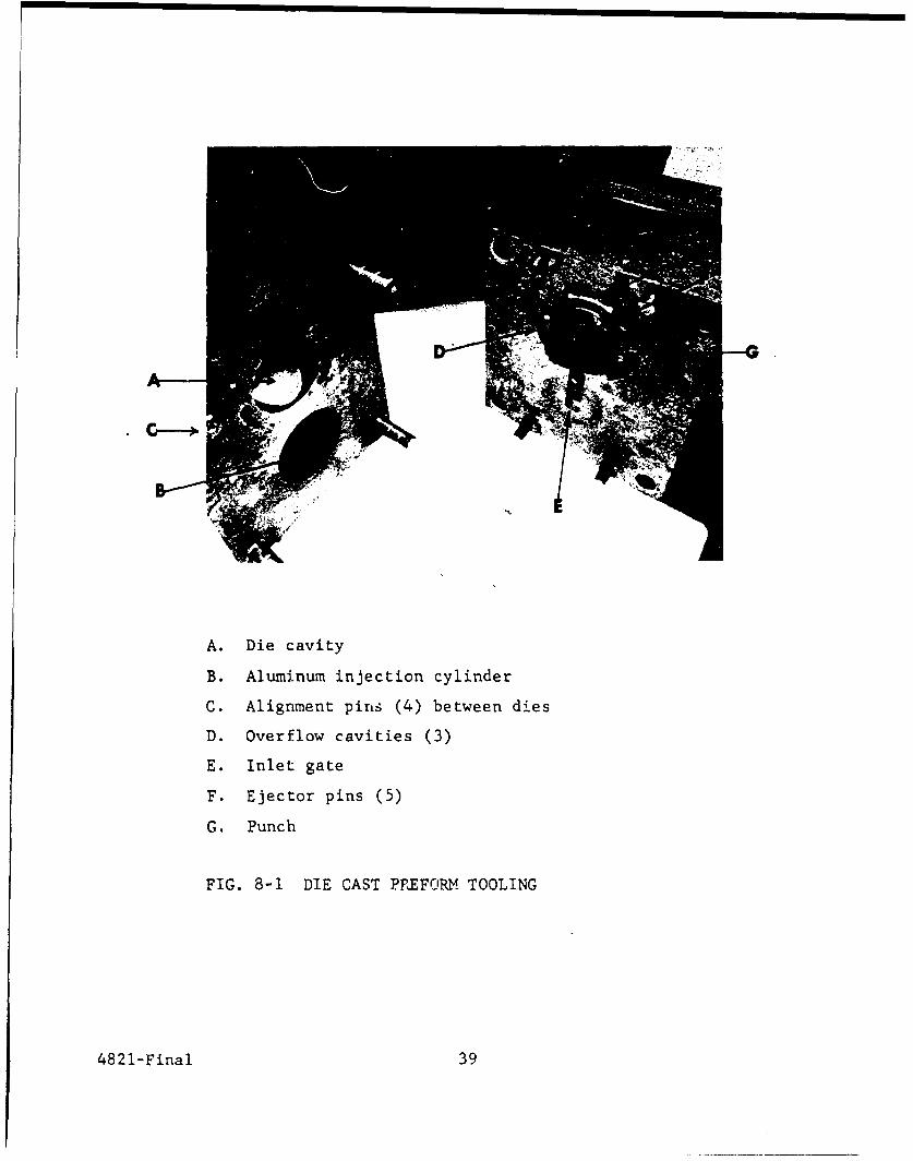
A. Die cavity
B. Aluminum injection cylinder
C. Alignment pine (4) between dies
D. Overflow cavities (3)
E. Inlet gate
F. Ejector pins (5)
G. Punch
FIG. 8-1 DIE CAST PEFORM TOOLING
4821-Final 39

FIG. 8-2 7AB-JACK LAYUP FIXTURE
FIG. 8-3 CYLINDRICAL LAYU)?P AND PARTING FIXTURE
4820

FIG. 8-4 MODIFIED ARBOR PRESS, STEP NUMBER ONE
FIG. 8-5 EARLY MODEL REPLICA PARTING FIXTURE
4821-Final 41
in the process of mating the master and preform has resulted In a
significant drop in the occurrences of resin voids.
Problems of handling the master have been greatly reduced
with the arbor press tooling. The master holding fixture w3s designed
so that it mounts easily on the centrifuge, in the vacuum chamber,
and on the arbor press without changing fixtures. Alignment during
layup is achieved with indexing pins that are fixed to the base
plate and engage the master holding fixtures. These indexing pina also
serve to maintain alignment during the cure cycle.
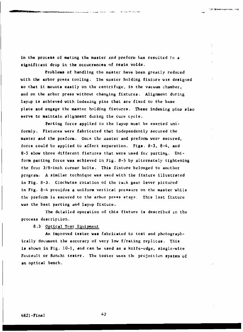
Parting force applied to the layup must be exerted uni-
formly. Fixtures were fabricated that independently secured the
master and the preform. Once the "ster and preform were' secured,
force could be applied to affect separation. Figs. 8-3, 8-4, and
8-5 show three different fixtures that were used foc parting. Uni-
form parting force was achieved in Fig. 8-5 by alternately tightening
the four 3/8-inch corner bolts. This fixture belonged to another
program. A similar technique was used with the fixture illustrated
in Fig. 8-3. Clockwise rotation of the rack gear lever pictured
in Fig. 8-4 provides a uniform vertical pressure on the master while
the preform is secured to the arbor nreas atage. This !ast fixture
was the beat parting and layup fixture.
The dtailed operation of this fixture is described in the
process description.
8.3 Optical Test Eguipment
An improved tester was fabricated to test and photograph-
ically dotument the accuracy of very low f/rating replicas. This
is shown in Fig. 10-1, and can be used as a knife-edge, single-wire
Foucault or Ronchi tester. The tester ubes tht projection system of
an optical bench.
4821-Final 42

9. REPLICA RESULTS
Since the replication process details are discussed elsewhere,
this section deals primarily with replica results except where the
process details illustrate a specific point relative to processing.
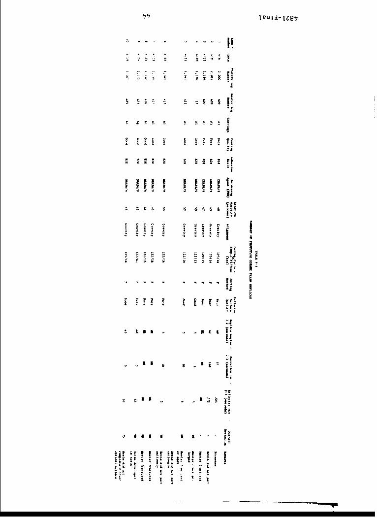
9.1 Corner Prism Replica Results
Prototype replicas are summarized in Table 9-1. These are
not representative prototype production replicas because they served
as training exercises for new program personnel. The masters used
had been internally fractured in prior work and, with the exception
of masters 417 and 422, were not within specification prior to rep-
licaticn. The masters are summarized in the final report of Con-
tract DA-04-495-AMC-51A, which was the previous prugram. Replicas
4 and 6 were within the required 45 sec collimated light specifi-
cation.
The vacuum aluminum coatings were post-deposited over
plastic. However, the aluminum adhesion was poor. This problem
initiated some of the coating adhesion studies, described in Section
7.
These initial corner prism replica results have indicated
the necessity for jetter alignment and preform inspection. Tooling
to accomplish the preform inspection was described previously. The
alignment fixture now used with the spherical replicas can also
be used with corner prisms with some modifications.
9.2 Spherical Replica Results
Figure 9-1 shows a typical spherical replica produced on
this program. Table 9-Il is a summary of spherical mirror replication.
9.2.1 Cosmetic Quality
The major difficulties in fabricating high quality
replicas appear to be cosmetic. These are due largely to resin voids
4821-Final 43
~q •
~I!
[i
* S S S S *..
C~ 0 Ci C
i l o g o I I.'a - 'S - is *
[j
i [. .&& :
9. REPLICA RESULTS
Since the replication process details are discussed elsewhere,
this section deals primarily with replica results except wh:re tLhe
process details illustrate a specific point relative to processing.
9.1 Corner Prism Replica Results
Prototype replicas are summarized in Table 9-1. These are
not representative prototype production replicas because they served
as training exercises for new program personnel. The mastcrs used
had been internally fractured in prior work and, with the exception
of masters 417 and 422, were not within specification prior to rep-
lication. rhe masters arc buntnarized in the final report of Con-
t-act DA-04-495-AMC-51A, which wais the previous program. Replicas
4 and 6 were within the required 45 sec collimated light specifi-
cation.
The vacuum aluminum coatings were post-deposited over
plastic. However, the aluminum adhesion was poor. This problem
initiated some of the coating adhesion studies, described in Section
7.
These initial corner nrism rk plica r.stIts have indirated
the necessity for better alig'iment and preform inspectiuii. Tooling
to accomplish the preform irspection was described previously. The
alignment fixture now used with the spherical replicas can also
be used with corner prisms with some modifications.
9.2 Spherical Replica Results
Figure 9-1 shows a typical spherical replica produced on
this program. Table 9-11 is a surmiary of spherical mirror replication.
9.2.1 Cosmetic Quality
The. major difficulties in fabricating high quaiity
replihas appear to be cosmetic. Thi-se are due largely to resin voids
4821-Final 43

+ I .
0~ 0j : 00 > v;c 0o C<- I' C j Vo of rl -
'I IrT ~ - -~. I., pid M rt( ri ? a) rt rtH
0 (V -( Q.( rD M - a' m- (V(n 3 n tv ri A :1 " = Li- - (nT0 000 " 0 Ha 3 M, (I r)1 M =r Mf) H-aCt 0
0- (V C00 = c ( 0 a)- c ) 6 ::
:3 ' 9T rtr r ) 1 L
'U 0 co 0. -l rto QV :3-Dr- "U =r C0 H.~ OD (V 00 0 " Ca)( D) pi 0 . 0 m~ (V N' 0 ID m
OOH- r)r (H- Wo 0- r- r- (D w -'- 9V 0 . (0.~~~~r ::J 0 ftO0 C o ~ 0 ~ a l
W0o 1V( D) M =VO 0k D 0 H ( H 0 0C3,~r M"CJ (D 0i0 0 F% Li (n (V ri ft
0. aU b C(V 00 < "1 c.~ I) el (nCtnr( "-~ a) c- 0D "h r- m ( o V r. m 0tr0- 0 mV 0D " . (V 0 H. C10 (VCH,
=1 CL m0 tt En H~ 0~ H- 0C)OJ( 0 00 :3 0 0 FA m- 00r-
'1(V iD Cr tr 0'- cn0 03' < 0Pi~~ r? 0 0 (V(DrT~-i 0 .- U (V 0- (t 0 r(-.M w * 0 (V W.0.H-CJI,-.W 0 ' 1 0* 0
cn r C) c-o (Z ft rA Qc :r, O fl m. U
::F-0 (cu OQ ( 0D 0 ~ m, a 0 >0 0)(D .3 - V C t Hi 00 a) CL to . 00
W0P4 0, W3 :jp 0(Dr- 0 (D ( 0 n #1 0 0 cnO' e- 3 00 :
00 =- r) H IC rLm - 0 D) 00 (D ( ) ( ' c -m C _Oe- wiV (V (V rT 0a' CV Hi (Vi0.( o 31 H. 00( W.0(M. U 0t- m " 0 CL( - F
V. t< (DU W 0mr? V r00 F3 Ct -r)i (D0
11(~ - f 0 0j w- H' n
H.. ar 0) 003 0r ( I0M 7'rt r tt M a- Hi 0 9 pi( (D I-%-
(I < 3 S 0 m0 lb r-H 0I0 W ' "C 0 ci 0 foiZ) riO L) a) :-3 U)C3 a-
S0 r?~ H- 9D H- n- 0am Oc0j !A M -< I rnpn -Uc C" " " ,E
r- M V C: M0 C
U H- 0 .
C 0 n m C
03 0d 0 W."0.cW,~~ Hnm9 0C03 - ft00
0r (A (VP-c
00
FIG. 9-1 SPHERICAL REPLICAS WITH LI.GHTENEDALUMINUM PREFORMS
4821-Final 46
co wA C. olJ 0 a 0. f 0 01 10 0
0 0 0 0 0' 0 0 0 0 0 0 "o LA L
IO n
p 0 v Q o p ~ 0 0 0 01
a c IC C C C C C 0 C C C C o
+ +
r 0 0. 0. 0cc 0 a, 0. C
* 0 0 0 0 0 0 0o 0 0 mNJ N NJ J N NJ ) N NJ J NJ NJ J NJ NJ NJ J f
0 0 0 0 00 0 0 0 0 0 0 0 0
fa
IrI

6'; IVUTA~1l8t, U-- ~ ~ I!- ~ 'Ce ~-'0'~t £ - - .' I
a' ~ -
a ' * IiC. ~ '~'~ a s- 0£~ I ~ ft--I aft ''Ce - - ~ hft* - - 42'* ft. ft.
5 c;~ .:x --
o . .,..,. 2:b A 0 250,' -~-; ~-aIt *
0 0 ft *!: ~0 - ~.
5-;. 3'":~ :i#i~. k~-, S
0 IHO V
;:~ ~ 1 2 2 rft i
ci I& *- C - 0 0 0 0 o
- 5 5 0 £a Ig g g - *1 0 0 0 0 0 -
ft I pI- * - I I'4 5 t- C - - - II
000 RE
- pa2 11*1 3 0 ft 'ft U0 0 0 0* r A A A A SU- S - ft ft
1C Ca 2S
ft - 28a Ii
o ft t'tC -
OS
I ~ ~~ -C
0
S "4
4 A A A ~ A
2 3 ~ a ~- s a iiI, -
V. Ag
- '10- .,:~ gr w r[a II
b
1 II
from bubbles caused by alignment, pretrrm surface preparation, anld
adhesive properties.
With new Looling dU ung~ruu pJtCt)Lmb, he last
five replicas were void free.
Another major pteblen besides bubbles, was the for-
mation of a circular scum or flow lines on the plastic surface dur-
ing layup. This is caused by an ititerruption in the layup process
occurring before the master apd the preform have fully joined. The
new arbor press alignment fixture eliminated this problem. Fig.
9-2 shows a Ronchigram of a typical spherical replica.
9.2.2 General Optical Qu.Ility
Preform errors were calculated by three dtf[erent
methods:
1. Comparing the master and replica interff:rometrically
2. Comparing center and rim radii of curvature with a pro-
jection microscope and optical beach
3. Calculating from Ronchigram data
These calculations were made on a spot check basis.
Interferometric tests indicate that some replicas approach and equal
k wave accuracy. Radii ot curvature calculations showed that. the
replicas deviate by less than 4 seconds of surface error. Ronchi-
gram calculations give a maximum surface error for a typical replica
as 10 secs of arc. However, at least half of this error i due to
the test apparatus.
Optical tests are described in Section 10. This
spherical accuracy is about an order of magnitude greater than that
needed for the paraboloid in the system requiring the high 20,OO g
shock resistance.
9.2.3 Replicas from Submasters
Table 9-I1 surmlarizes the results of replicas made
from plastic submasters. The Ronchigrams shown in Figs. 9-3 and
9-4 Indicate that little accuracy has been sacrificed in the double
4821-Final 50
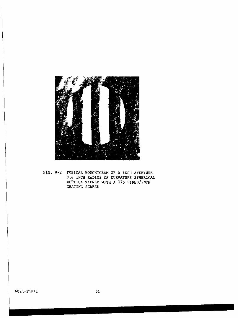
FIG. 9-2 TYPICAL RONCHIGRAM OF 4 INCH AVERIARE8.4 INCHI RADIUS OF CURVATURE SPHERICALREPLICA VIEWED WITH A 175 LINES/INCHGRA;TING SCREEN
4821-Final 51

.4 - F!-~ 0< '~
i~fift~ CC 0 * - * N A - - ~-.C -. 2 "N ft if - ifI NJ if~A ~ £ NJ N~ A
'' :~ ~- ?' ~N .. if, -.- - '. ~-. C'Ss 0 tin , -
ft'sft. ft. > '4I " - -
I IV (A C C' Coft 'S
2 i
ft . C 0.
no I 0
C () "-- ifN ~ 0
O c
N C
NJ NJ tI ft* 3 e z *N E
0 N
*~''1 H,
C - -o a S1Z 3
N C
LA
in a oa -- - -- £1ft V ft '-."'if L0 C V'O Do
3 -if '4- -S ~'
t 4 :3CftN 0.
* ftft 0N
'ft CVinft ft ft0 - *MV- ft Vt 0.O ft A N- fteq t *',
-nfl- 2o if. C.
if' 0C
- ~'~0 tOft ft - I
A ft ~IC- is Cif 2 C ft ft- C - a. -ft ft C -N N ft C
C 0~ if if' -* 0' 0 0 -I 'g
gI'
'U ft
ft

FIG. 9-3 REPLICA FROM SUBMASTER NUMBER ONE
175 LINES/INCHI ONCHI SCREEN
482 1-Final 53

replication process. The line in Fig. 9-3 is the replica of the
maste .. q,. b. %_e' Jagged .... i. n fig. 7-4 . .. Caused by i"LW II1drI
on the plastic during layup. The last replica made from a sub-
master was far superior to the first two in surface quality and
accuracy.
4821-Final 54

10. OPTICAL AND ENVIRONMENTAL TESTS
10.1 Optical Tests
The corner prism replicas were tested by the collimation tests
described in the previous program. The spherical ieplicas were tested
by Ronchi, inter-erence, and radius of curvature measurements.
10.1.1 Ronchi Test
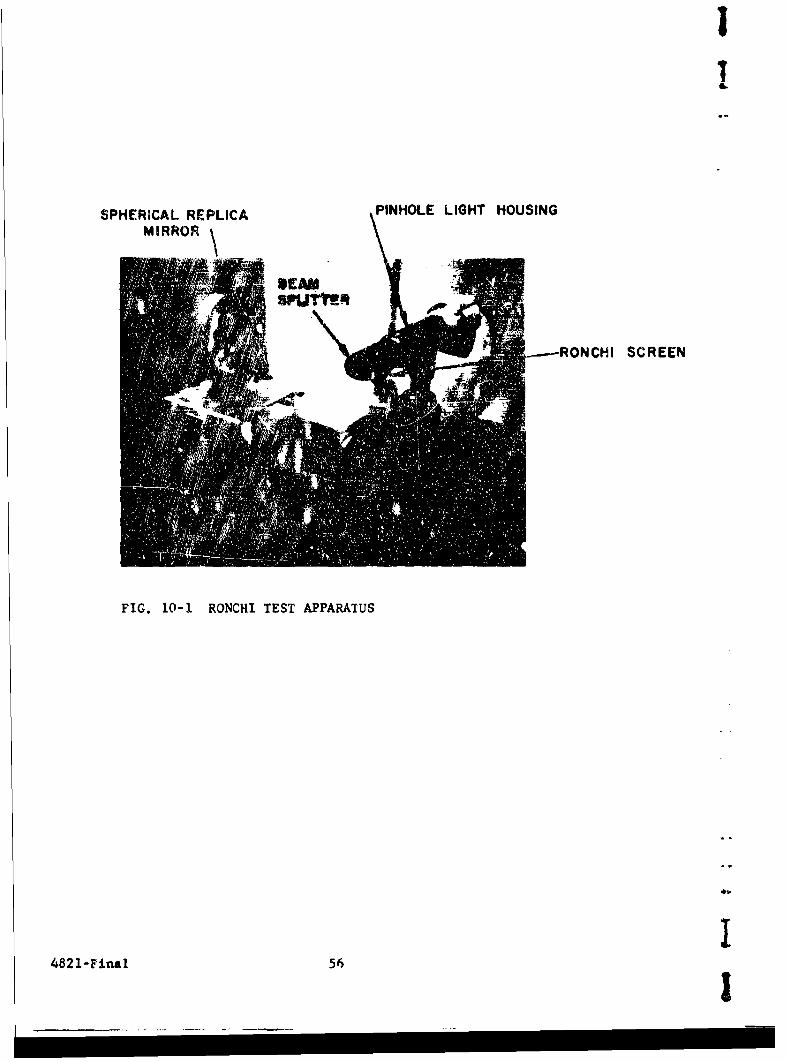
The Ronchi test apparatus is shown in Fig. 10-i. The
schematic drawing of this apparatus with a camera box for taking Ronchi-
grams is shown in Fig. 10-2. The Ronchi test is extensively used as a
simple method of determining sphericity, though it can be used with a
known reference to roughly check production aspherical elements. Bas-
ically the Ronchi test requires a pinhole light source as small or
smaller than the Ronchi grating screen separations projected from the
same effective radius of curvature at which the screen is located. The
projected "image" of the grating screen, as viewed by the eye or on
photographic film, is a function of the geometry of the optic under
test. A perfect sphere will produce perfectly straight lines. This
test can be used to quantitatively calculate the surface errors of the
replica element if the scaling factors, radius of curvature, and mea-
sured Ronchigram image deviation are known.
Ronchigrams were made of all replicas fabricated using
a i75 lines per inch grating screen. The maximum surface error as cal-
culated from the Ronchigrams is in the range of ten seconds. However,
at least half of this error is due to inaccuracy in the beam splitter
used in the Ronchi tester. Mirrors of this f/ratio miist be tested with
a light source that is on axis and has a wide field of view. This
necessitates the use of a thin beam splitter for mininum distortion.
A flat and parallel beam splitter of the thickness required is diffi-
cult tc fabricate and mount.
4821-Final 55
SPHERICAL REPLICA PINHOLE LIGHT HOUSINGMIRROR
RONCHI SCREEN
FIG. 10-1 RONCHI TEST APPARATUS
482 1-Final 56
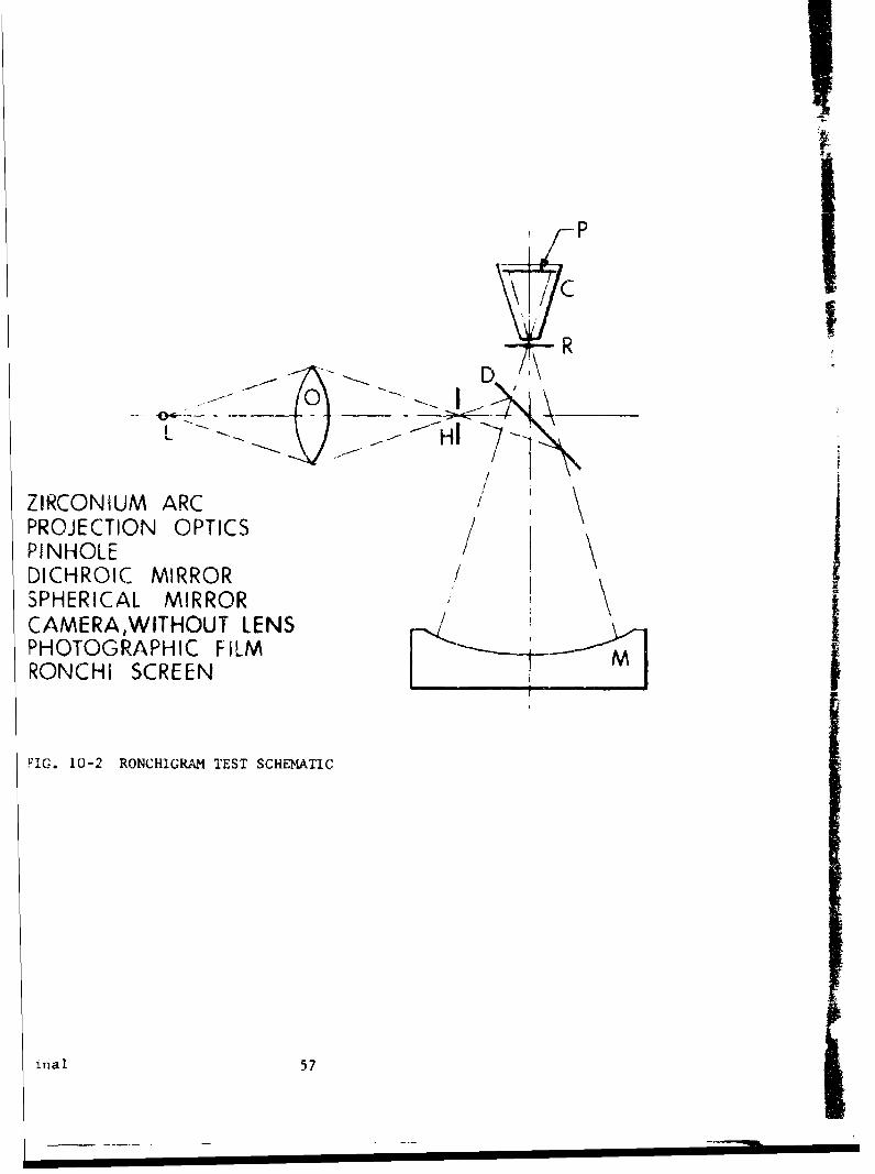
P
ZIRCONIUM ARC 'PROJECTION OPTICSPINHOLE IDICHROIC MIRROR
SPHERICAL MIRROR \CAMERA,WITHOUT LENS /iPHOTOGRAPHIC FILMRONCHI SCREEN
FIG. 10-2 RONCHIGRAM TEST SCHEMATIC
ina1 57
A). _fng fnr t he -- 3Map!4 e th Fln h i grmisC Os'U
throughout this report indicate a high degree of development in the
state of the art of peecislon replication.
10.1.2 Interference Test
The interference test involveb the use of the glass
master placed in near optical contact with the replica, plus a mono-
chromatic mercury light source. The vaLiatiuu in NewLn rings between
the master and replica is an indication of the replica accuracy. Since
this test tends to abrade the replica, most optical testing was done by
taking Ronchigram pictures.
10.1.3 Radius of Curvature Test
Before the Ronchi tester was completed, the radius of
curvature of the replicas was checked at two or more zones. The varia-
tion in curvature is a function of the spherical Lccuracy. The replicas
checked ":anged from a 0.010-inch variation in curvature when replication
started to less than a 0.001-inch variation after the fo,.rth replication.
Though fairly accurate, this test only measured the
curvature at discrete points and was limited by the lens btnch vernieL
scale.
10.2 Environmental Tests
A number of tests were ccsnducted with1 flat, spherical and
corner prism replicas of different surfa.,e coatings and fabrication
date to evaluate their resistance to various environmental conditions.
Most of the results obtained indicate satisfactory performance. Ad-
ditional tests are needed to confirm and extend these data.
10.2.1 High-Low Temperature Cycling
Table 10-I lists the results of a tesr series wherein
12 flat plastic replicas from another program, with and without metallic
vacuum coating, were exposed in a test chamcber to 12 consecutive tem-
perature cycles of between -70°F and +1650F for a period of 72 hours.
The temperature rise and fall between the maxima and minima was kept
4821-Final 58

6 ~ I"U1A- Il9'
r, wa a' lb-
ka. ID flt
MI n- n -- c
rtwD ibD I... l.b.
OD )k 041
o 00A)(
ODD
00 .9 . - --. D I -
OD 00
00 00 I-00
OD 9
OD t'-N)(
0040- - - (D
LD I I..
t'0 -_n l- -
OD00 0 1
'00
OD NP.-
U1<
w OD

intentionally at the steepest pcssible gradient (Ij hours). The
samples, thus, had approximately 1 hours to reach equilibrium at
maximum and minimum temperatures.
Similar tests were made with spherical and corner re-
flector replicas, vacuum coated with gold next to tht plastic surface,
followed by a SiO top coating.
The combined tests included, therefore, pyrex glass
as well as aluminum die cast preforms.
None of ultbv samples showed any evidence of optical
or mtchanical de-radation contributable to the test conditions
Four spherical replica mirrors were tested for 24
hours to the storage temperature extremes of +165 0 F to -450 F. The
temperature was cycled once during 24 hours. Repli'as selected for
testing represented four different preform materials:
1. Aluminum
2. Magnesium
3. 4340 Steel
4. 416 Steel
Thf chamber dehumidifier did not work properly during
these tests and resulted in ice formation at the low temperature re-
gion. This test did not produce any significant damage to the exposed
re plicas.o Surfac -e chavacdetsLLis remained unchariged except for minor
oxidation of the steel preforms. In all cases the optical character-
istics remained unchanged.
The above four replicas were tested for an additional
24 hours at the storage temperature extremes of +170 to -75'F. The
resul',, of this test were identical to those of the previous test;
surface and optical characteristics remaied unaltered, Additional
cxidation was observed on the steel preforms. Figures 10-3 through
10-19 swagarize the temprature cycling and shock tests.
10.2.2 Shelf Life
A systematic shelf life study has not ben consistently
carried on throughout th,: entire span of this work; ht'wvv, r, spot checks
4821-Final 60

FIG. 10-3 REPLICA 4, BEFORE SHOCK TEST
482 1-Final 61
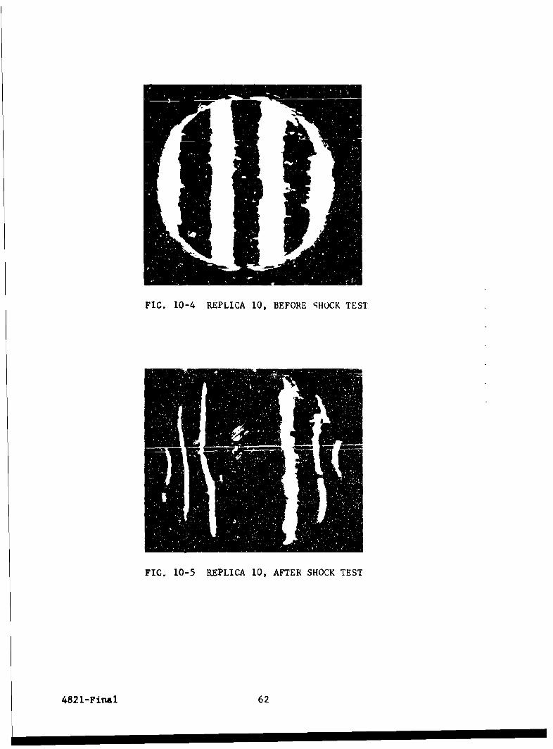
FIG. 10-4 REPLICA 10, BEFORE ';HOCK TEST
FIG. 10-5 REPLICA 10, AFT~ER SHOCK TEST
4821-Final 62
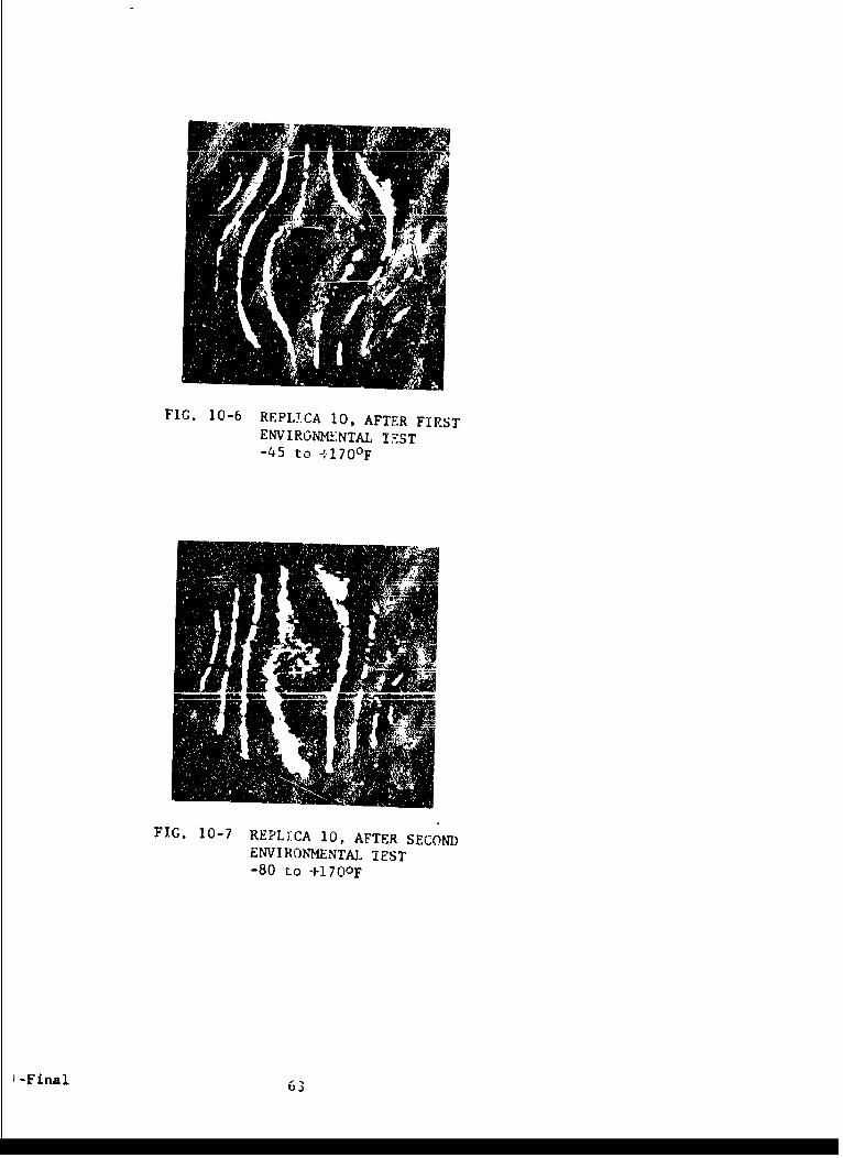
FIG. 10-b REPLI.CA 10, AFTER FIRSTENIRGNM!LNTAL TEST-45 to +170 0 F
FIG. 10-7 REPLICA 10, AFTER SECONDENVIRONJMENTAL~ TEST-80 Lo +170 0 F
-Final 63

FIG. 10-8 REPLICA 14, BEFORE SHOCK TEST
FIG. 10-9 REPLICA 14, AFTER SHOCK TEST
4821-Final 64
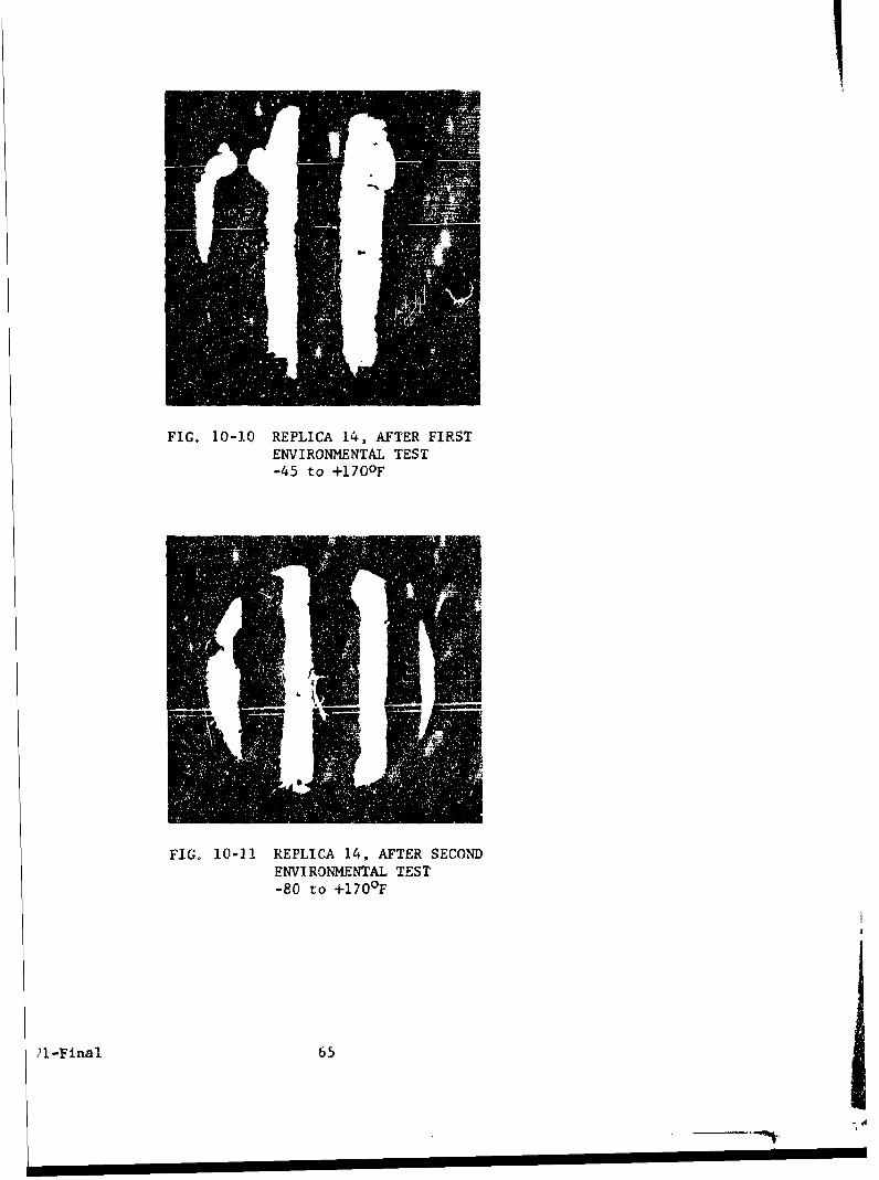
FIG. 10-10 REPLICA 14, AFTER FIRSTENVIRONMENTAL TEST-45 to +170°F
FIGo 10-11 REPLICA 14, AFTER SECONDENVIRONMENTAL TEST-80 to +l170F
21l-Final 65
i'
-. ",,
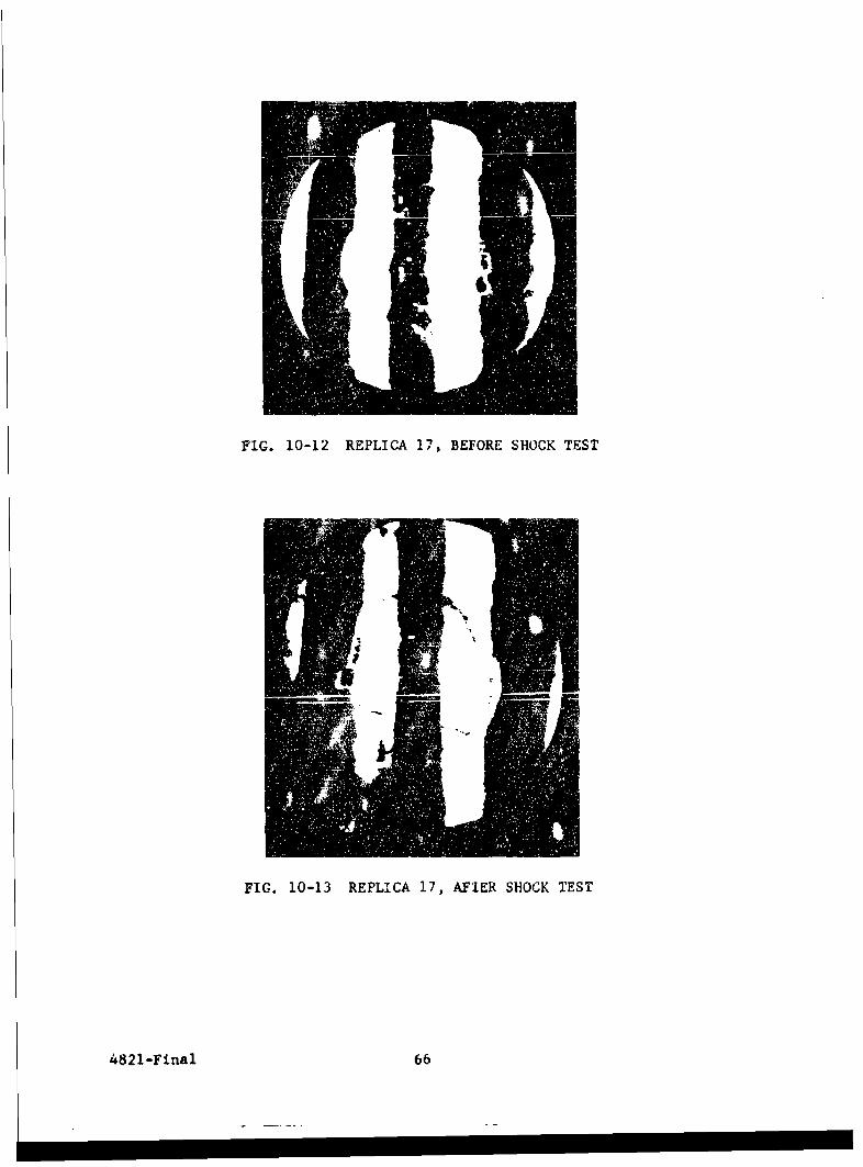
FIG. 10-12 REPLICA 17, BEFORE SHOCK TEST
FIG. 10-13 REPLICA 17, AFIER SHOCK TEST
4821-Final 66
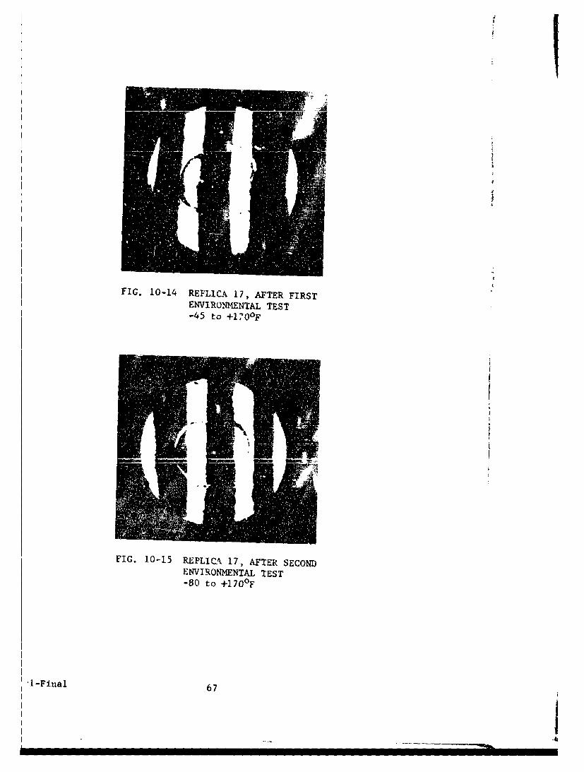
FIG. 10-14 REPLICA 17, AFTER FIRSTENVIRONMENTAL TEST-45 to +1170 0F
FIG. 10-15 REPLIO-k 17, AFTER SECONDENVIRONMENTAL TEST-80 to +170 0F
-1-Final 67
------I-

FIG. 10-16 REPLICA 18, BEFORE SHOCK TEST
FIG. 10-17 REPLICA 18, AFTER SHOCK TEST
4821-Final 68
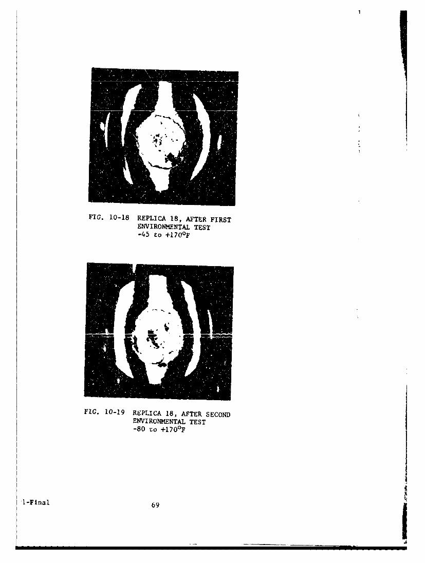
FIG. 10-18 REPLICA 18, AFTER FIRSTENVIRONMENTAL TEST-45 to +170OF
FIG. 10-19 REPLICA 18, AFTER SECONDENVIRONMENTAL TEST-80 to 4-170 0 F
I-Final 69
showed no evidence of degradation. To the contrary, optical quality
in some replicas had improved. The most plausible explanation of this
observance is that gradual stress relief occurred with a corresponding
improvement in optical accuracy.
In another program quantitative optical flatness was
conducted daily on flat replicas over a 1 week period to observe con-
sistency of readings. The results are listed in Table 10-II. It is
quite evident that the flatness readings improved considerably with
time on the replicas that showed inferior readings on date of fabri-
cation.
10.2.3 Humidity
Considerable difficulties were encountered when test-
ing plastic replicas with plain aluminum mirror coatings at high rel-
ative humidity. Partial or total loss of specular reflectance resulted
when the test samples were stored for even less than 12 hours in an
atmosphere of 100 percent relative humidity at a temperature of 1350F.
The test arrangement consf..ced of a desiccator in
which the samples were arranged face down. The bottnm of the desiccator
was filled with distilled water to 1 inch height. The desiccator with
tne samples was placed in an oven.
The cause of this adverse effect wrs found to be water
vapor and bulk penetrating the interface between resin and metallic
iayer which in these tests consisted rolely of vacuum coated aluminum.
This resulted in lifting and destruczion of the mirror finish, as shown
in Fig. 10-20.
Further studies led to a complete elimination of these
difficulties through the use of adhesion promoters and protective coat-
ings. This permitted exposure of plastic replica mirrors to a moisture
saturated atmosphere at 135°F frev 72 hours without any visual change in
reflectance or degradation of cther optical or mechanical properties.
This test included evaluation of SiO and of chromium
(vacuum coatings) as moisture t'arriers and adhesion promoting coatings
4821-Final 70
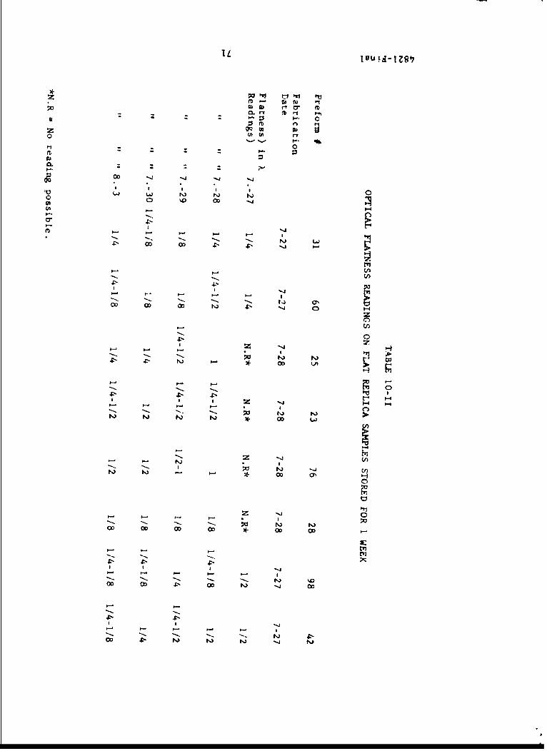
YU- IA- I o
M r'o E
z 00 c
OD - -4
0 c
0 00l
co OD 03 -- N) C
-1
-5 t-
4:-
-5 044:- ->
- *00 OD OD coOD O
5- 5-35
OD5 5o o c
4:55 4- t 1-OD N14 -
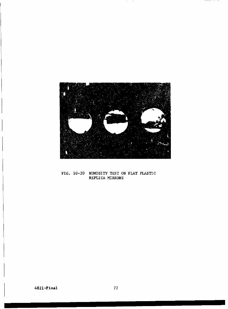
FIG. 10-20 HUMIDITY TEST ON FLAT PLASTICREPLICA MIRRORS
4821-Final 72
between the replica plastic surface and an aluminum vacuum coating.
In addition, SiO waa also evaluated as a protective top coating for
the aluminum mirror coating. The results of this, consisting of
3 samples, are shown in Table 10-III. The orange peel observed in
Sample 3 may possibly be caused by the relatively large difference
in Lhermal expansion coefficient between chromium, aluminum, and
epoxy resin. Expressed in units of in/in OF x 10- 6 , these coeffi-
cients are:
Chromium 4.0
Epoxy resin, unfilled 25-36
Aluminum 13-15
Additional samples made since the program ended have
been free from the orange peel associated with the third sample. An
explanation for this is presently not available.
10.2.4 Salt Fog
The salt log test was conducted to determine the
resistance of materials and fabricates (replicas) to the eftects of
a salt atmosphere. To accelerate this test, the samples are exposed
to moisture and salt concentrations considerably greater than encoun-
tered in normal service.
10.2.4.1 Operating Conditions
The test is performed at a temperature of
95 (+2, -3)0F. A 5 (± 1)7 sodium chloride solution is atomized into
the test chamber under the following conditions:
1. Nozzle pressure between 12-18 ps:.
2. Atomizer orifice between 0.02-0.03 inch in diameter.
3. Atomizer delivery rate is regulated so that a collecting
receptacle, placed at any point in the test chamber will
collect from 0.5 - 3.0 cc of solution for each 80 square
centimeters of horizontal collecting area.
4. Collected salt solution shall have a specific gravity of
from 1.023 to 1.037 and a pH ran,-e of 6.5 - 7.2.
4821-Final 73
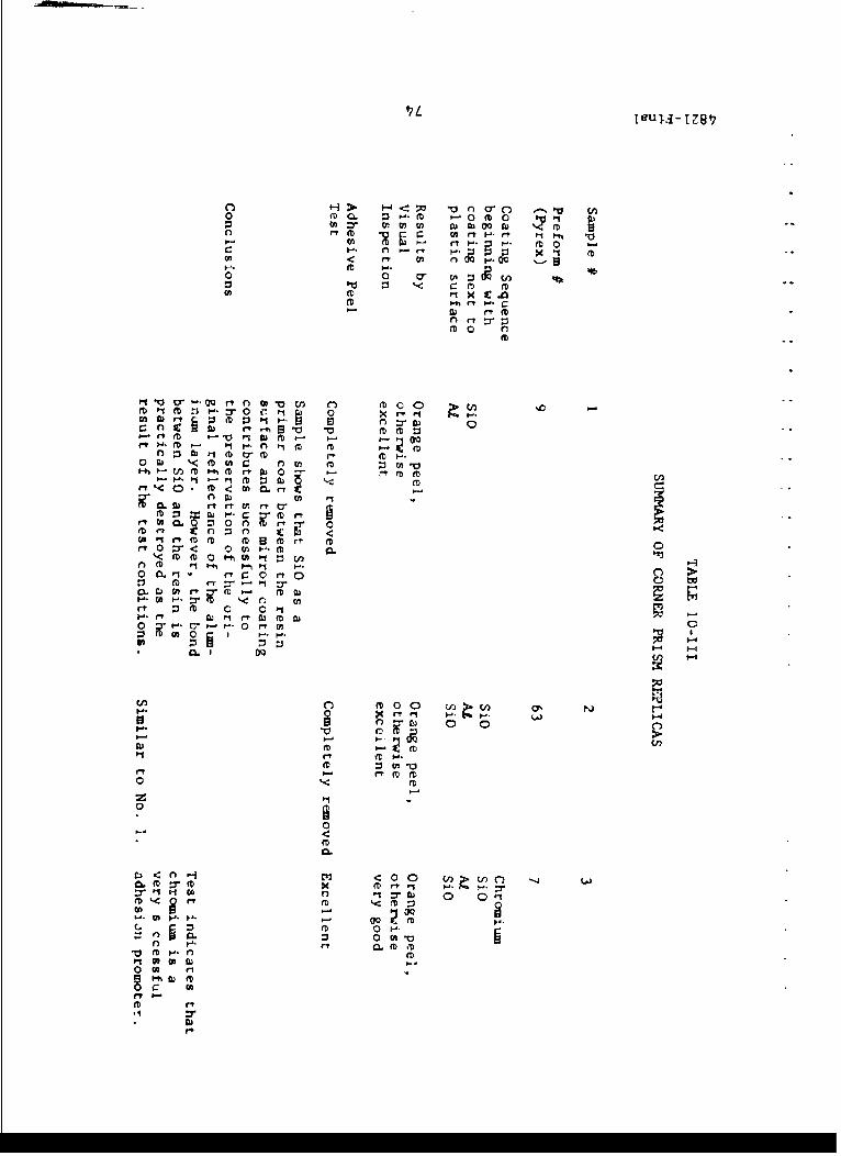
M (ArtH- p
H. 0 (D 0 -
0 0 (n
cft : tf(D
M~~ ~ ~ pt M 1 :
o.. rtM 0 11 F. 00
m j~ 0 m rb En
CLfi I-M~ A) t~l flr ftcn c4 :- Cfl w - . rP rD mr
rt. 02 0
m ftft 0 H 0 r l
0. On f i Q f
rtmf 0 0 V)
0 .
0n fte. 00 n
ft
0 a, ft
.1.

5. Compressed air entering the chamber shall be at a temperature
of at least 350F and have a relative htmidity of at least
85 percent.
6. The chamber must be properly vented to prevent pressure
buildup and allow uniform distribution of the salt fog.
10.2.4.2 Aparatus
A small salt fog chamber ,jith nece.6sary ac-
cessoi.es was devised and assembled, using available laboratory glass-
ware and c her items (Fig. 10-21). A schematic illustration of this
test equipment is shown in Fig. 10-22. The letters used refer to the
following parts:
A I - 12 x 12" bell jar
B 2 - 4 liter pyrex filter flasks
C I - Pyrex atomizer
D 2 - thermometers (mercury)
E 2 - thermostatically controlled hot plates
F 1 - pressure regulator
C 2 - # 11.5 rubber stoppers
H 1 airstone
S 1- dryi-, tube
J glass wool
K I - 1 -14" diameter perforated masonite sheet (1/8" thick)
L I - adjustable pinet clamp
M I - glass "T"
0 i pressure indicator
P insulation material
R drain
S I - sink
T test samples
U samplIe support
V salt soluton
W distilled water
4821-Final 75

FIG. 10-21 SALT SPRAY APPARATUS
4821-Final 76

0 D D
A
w / f.
13 H I N T T
FEE TEXT FOR NOMiENCLATURE) Mi
G. 10-22 5 -MATIC OF, SALT SPRAY APPARATUS
I -Final 77
4

10.2.4.3 Operation
The hot plates are turned on and adjusted to
maintain the salt solution and the water at a temperature of 1600 F.
The cc-qpLessed air is turned on and the pressure adjusted to 12 psi.
Air leaving the bubble chamber was measured at 105°F with a relative
humidity of 86 percent. Heat loss in the plastic tubing is approx-
imately 100 F. Therefore, the air entering the chamber meets the op-
erational requirements of 95 (+2, -3)°F. Constant temperature within
the bell jar was maintained by insulating it with styrofoam and asbestos
cloth. Trial chamber operation was carried out for 24 hours prior to
the test run to adjust the delivery rai.e of the salt solution and the
chamber operational temperature.
Tabh; 10-IV summarizes ,he resistance of
6 different reflective repli-a samples to 48 hourr salt fog exposure.
10.2.4.4 Discussion of Results
I. Glass preforms were unaffected by the salt fog.
2. Aluminum and steel pteforms were severely corroded by the
salt fog.
3. Unprotected aluminum surfaces were completely destroyed by
exposure to salt fog.
4. Cold reflective surfaces, w ith and without SiO protective
top coating were c -rosion-resistnt Hmtever, opia a.'
cosmetic quality was degraded due to blistering and blooming
effects caused by preform corrosion; assumedly through pin-
holes in the gold.
5. The chromium-primed samples of reflective aluminum coating-
withstood exposure to salt fog well except for some edge and
pinhole attack.
6. Only the chrordlum-primed samples passed a pressure sensitive,
tape-peel test.
7. Metal preforms, sensitive to currosion, have to be protected.
8. Research on salt spray resistance since the program ended has
improved the adhesior' and corrosion resistanct of gold-coated
replicas.
4821-Final 78

PI t03
o~r ftft f
0 ~~ ~ 0 ~ -~r
0 al1 rD
0 < r 0 E'<0
o 00 0 0
ox ff f
W~f cu 0 b( IEr' ,-'. in. m. Hr0) m 0 rt 0t
:0 0 0 r01 CL- ? <Im- L D !

A conservative analysis of the preform shock resistance,
based on the minimumn thickness of the preform shown in alternate A,
Fig. 5-2, is given in Appendix C. The analysis indicates that all the
materials chosen should withstand the shock environment if the assump-
tions made are correct, In addivion, since the preforms are tapered
rather than of constant thickness, the edge stress may be as much as
1/4 to 1/5 the values calculated in the analysis. Forthcoming experi-
mental shoi'k tube tests should determine the validity of tho' analysis.
Replicas 4, 10, 14, 17, and 18 were tested at Frank-
ford A:se.sl at shock levels of 20,130, 20,190, 20,400, 19,070, and
18,560g respectively. These replicas are shown in Figs. 10-3, -4, -8,
-12, -16 before shock testing and Figs. 10-5, -9, -13, and -17 after
shcck testing. Riplica No. 4 was left at Fran!'ford Arsenal for further
shock and environmental ',t;:ting. There was no visual failure of the
plastic Furfzces afrLr shock tests. However, on two of the four replicas
tested at FOS some preform distortion resulted.
On replica No. 10 the visual distortion was in the form
cf orange peel aligned in the same direction as the aluminum preform
inclusions. The Ronchigram in Fig. 10-5 indicates the orange peEl and
the general degree of preform distortion. The preform distortion is
probably due to several causes:
1. Thin preform section at the rep ica center.
2. The nonuniform lightening holes in the rear of the preform;
alternate A design.
3. The alloy used probably did not have maximum yield strength.
Replica No. 14 survived the shock test with no degra-
dation in the optical accuracy or plastic surface. This replica had
a magnesium preform which was about 5/8 inch thick at the center and
had no rear lightening holes; alternate C design. Its greater re-
sistance to tf,- shock envronment can be attributed to:
1. Thickness
2. Lack of irregularity
4821-4inal 80
3. High dampening of magnesium
Replica No. 17 was made with the same preform con-
liguration as replica No. 14 but ot 4340 steel. It showed no distor-
tion either.
Replica No. 18 was made of 416 stainless steel and
lad only the concave lightening of the preform back; alternate D de-
.ign. This replica also distorted slightly to a regular elliptical
shape.
Several conclusions can be tentatively drawn from
this small shock test sample:
1. The replica plastic surfaces will easily survive the 20,OOOg
shock level of the Frankford Arsenal shock test.
2. For the same weight magnesium preforms may offer greater
shock resistanct than aluminum.
3. The distortion even when present is small.
621-Final 81

APPENDIX A
THEORETICAL ANALYSIS
A theoreLical analysis of the replica system has been made to
:ttermine tolerable ranges of important variables and to provide a
!oundation and guide for the experimental program. This section
.immarizes the analyses and derivations. The basis of the analysis
s the interaction between the adhesive layer and the preform. Among
he topics which have been considered are:
1. The allowable variation in adhesive layer thickness
as a fuiiction of adhesive shrinkage characteristics
(this places a requirement on preform surface
accuracy).
2. Effect of adhesive shrinkage on bending.
A.1 Variables, Assumptions, and Nomenclature
Among the variables involved in the analysis are:
Plastic Adhesive
Modulus of elasticity
Cure shrinkage
Thermal expansion coefficient
Cure temperature
Adhesive value
Thickness
Heat transfer coefficient
Homogenei ty
Poisson's ratio
Backing Structures or Preforms
huolus of elasticity
Thermal expansion coefficient
I-Final A-1
Thickness
Surface finish
Dimensional tokerances
Shape
Homogeneity
Heat trarsfer coefficient
Poisson's ratio
For analysis purposes, the following assumptions were
made:
1. Adhesive and backing structure are each homo-
geneous with uniform physical characte-istics
2. Temperature is uniform throughout structure
3. Adhesive strength is sufficient to transfer
all stresses without failure.
The following nomenclature was used in the analysis and derivation:
s Stress (lb/in 2 )
t, Strain (in/in)
E Modutus of elasticity (lb/in 2)
Y Deflection (in)
t Thickness (it)
( )p Denotes preform
( )r Denotes adhesive layer
( )c Denotes curing effects
( )t Denotes thermal effects
kt Coefficient of thermal expansion (in/in (OF)
T AmbienL temperature (OF)
T 0 Datum temperature (OF)
1) Poisson's ratio
( )x Denotes x axis
( )y Denotes y axis
( )z Denotes z axis
4821-Final A-2

ti
T Resin cure temperature (OF)
R Radius of curvature (in.)
r p Radius of preform disc (in)
A.2 Effects of Resin Shrinkage Acting Normal to Plane of
Re lica Surface
Consider the ideal case of an adhesive-preform laminate with
nit length and width. The thickness is (tr + tp).
Y
I- - -rtrrt
he adhesive thickness is negligible compared with the preform thickness.
he object is to determine the maximum allowable variation in adhesive
,hickness, 't , which will still 6ive adequate surface accuracy (e.g.,
.4 ) in spite of curing sttain, cr' and temperature strain, Etr
'ther assumptioit are:
1. Strains perpendicular to the plane of the
reflecting surface are due only to curing
and temperature strains.
2. Bending of the backing structure does not
relieve adhesive skin stresses.
3. Backing structure is rigid, perpendicular
to replica face.
4. Physical properties of adhesive and preform
are uniform throughoot.
5. Assume typical adhesive physical properties on
tnt basi- of Epon(R) 828 adhesive using Z curing
I-Final A-3

* -' = .-- .-. _-9 4 - ---. _. lud4 oIUM I" - -- dV.
agent, 20 phr unfilled, with cures of 2 hr at
1750F and 2 hr at 300 0 F.
6. Resin layer is cured at 70°F (this value is
used for example calculation purposes only.
Actually, this temperature range would be too
low to cure Epon 828 with the Z curing agent.)
7. Operating temperature range is -40°F to +1250V
The details of the analysis are given below.
A.2.l Analysis of Adhesive Shrinkage Normal to
Replica Surface
The case to be analyzed is that of an adhesive-preform
laminate of unit length and width and of thickness (tr + tp ). It is
assumed that tr r< tp,. The object is to determine maximum allowable
adhesive thickness variation which will still give adequate surface
accuracy (e.g., 114 Q), Strains induced by cure ohrinkage and temper-
ature change will be considered.
Resin properties are assumed to be uniform throughout.
The properties of Epon 828 cured with "'" are assumed to be typical for
rigid epoxy adhesives. The linear coefficient of thermal expansion fur
Epon 828 is approximately
k -tr -k ktr z 2.83 x in/inOF
The linear shrinkage for Epon 828 due to curing is assuied to be
L'cr - Ecrx " 5cry crz *-4 x 10' 3 in/in
The minus sign is used for mathematical convenience. Poisson's ratio
for Epon 828 is assumed to be
u - 0.25
Because the properties of the preform are assumed to be uniform through-
out, the linear coefficients of thermal expansion are
k -k -k "ktp tpx tpy rpz
4821-Final A-4

r this analysis, the maximum permissible surface deviation will be
sumed to be one quarter wavelength of mercury light, where
114 X - 5.37 x 10- 6 in.
total normal shrinkage, Ly, is a function of the adhesive cure
rtfnkdge, tcr; ambient temperature, T; cure temperature, To; linear
. fficients of thermal expansicn, ktp and k tr; and Poisson's ratio
r the adhesive, ur- Then
tcr + f (k , k , o r T) + f (k tr r , T) (1)
r ) (f5 + , ) + (T - T) -k o (k - kt) - i3 (k - kcry r crx crz 0 try r tpx trx r rpz tr;
(T -T ) k (k - k )o (k kc 0 Ltry r tpx trx r tpz trz)
r practical purpose- ktp '- ktr' and as a first approximation, kp - 0.
v-efore, with the elimination of k, and the cancellation of the Ttp U
r:i, the above equatiou for Ly reduces to:
ty acr (1 + 2 ,) ) + (T - T ) [k (1 + 2 0)o (2)y cry r c .-tryr
itially we (an assume a room temperature cure,
T - T - 700F.C 0
ithough Epon 828-Z does not cure at 700 F, adhesives with similar
,'sical properties are available which will cure at this temperature.)
,m the above equation the absolute value of ty, , is a maxiinurM0T - -40 F, the bottom of the operating range. The absolute value of
shrinkage times the maximum variation in resin thickness gives the
imuln surface variation of a surface which was optically perfect
ore curing. It has been assumed that the maximum surface deviation,
-must be equal to or less than 1/4 .. Then
SyI t r) max - (tr)mi- 114 h (3)
(t r ) tw - (t r -i t r(4)
A--
-Ftnia1 A-5
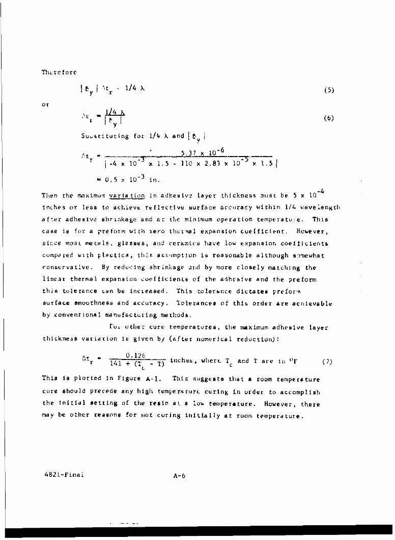
1/4 X (5)
oyr
r (6)
Sutstituting for 1/4 X and 1, i
a 5,37 106r -4 x -1 X- 1. 5 - 110 x 2, 83 x 10 Y 1.5 I
- 0.5 x 10 - 3 in.
Then the rrximum varia tion ir adhesivo layer thickness must. be 5 x i0- 4
inches or le6a to achieve refIectIve urface accuracy within 1/ wave length
after adhesive shriakage and ac the minimum operation temptratu-e. This
case is for a preform with zero thtnal expansion coefficient, However,
sin-e mos t me La i s, 8lasses, and ceramic have low expa rsior. coefticientb
compared with phistlcA, th2F, acs.imption is reasonable although s:)nlewhat
ronse-vative. By redu-cing shrinkage ittd by more closely matching the
linear thermal expansion coefficienis of the adhesive and the preform
this tolerance Ldn be incieased. This tolerance dictates prefox-n
surface smoothness and accuracy. Tolerances of thih order are acrievsble
by conventional manufacturing niethod&.
rou uther cure temperatures, the nmaximum adhesive layer
thickness variation ib given by (after numerical reduction):
nt r = - 0.126 inchea, where T and T are ini 'F (7)r 141 + (T( - T) c
This is plotted In Figure A-i. This suggests that a room temperature
cure should precede any hiah temperrur curing in order to accomplish
the Initial setting of the resin at. a low temperature. However, there
may be other reasons for tiot curJng initially at room temperaLure.
4821-Finai A-6
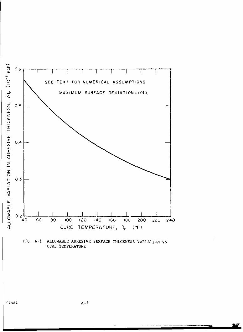
0 06
0 SEE TEXT FOR NUMERICAL ASSUMPTIONS
MAXIMUM SURFACE DEVIATION=I/4),
V) 0.5,
z
u
Xu-
LUJ
>
04
03
uj
I
<
o Z
0
-J ILfl I1l l[
o 40 30 80 100 120 140 160 180 200 220 240
CURE TEMPERATURE, Tc (-F)
FIG. A-i ALLOWABLE ADHESIVE SURFACE THICKNESS VARIATION VSCURE TEMPERATURE
IInal A-7
.... . ..... . RAW L,'

The above analysis applies to both flat and spherical
replicas and preforms. However, aspheric replicas are of greater poten-
tial interest. Consider the fabrication of a concave paraDoloidal.
FoL lowebL preform costs, it is desirable to fabricate
paraboloidal replicas using spherical preforms with a radius of curva-
ture equivalent to that of the vertex sphere of the paraboloid, or
R - 2f where R is the spherical radius of curvature and f the paraboloid
focal length. The difference between the sphere y - R ]F 2S and thex2 R2
parabola y 7 , dy is then given by Rfx
dy R-R (8)
2 112by expanding (I in a series this then reduces approximately to
4
dy - (9)64f 3
since f/no - 2p- dy Is also: given by2x'
dy so 1 (1 0 )
512 (f/no)
A plot of dy versus replica diameter, D, whete D - 2x is given in Fig-
ure A-2 for parabolas of various f/numbers. Using the 5 x 10.4 inch
plastic thiclness variation criteria developed above this figuze indi-
cates that a 4 inch diameter f/2.0 parabola can be replicated Lu 1/4 >,
accuracy with respect to the paraboloidal master.
Four inch ciameter parabolas having an f/nu less than /2.0 or f/2.0
parabolas having a diameter greater than 4 inches cannot be teplicated
to 1/4 ) accuracy with respeLt to the paraboloidal master curve, using
4821-Final A-8
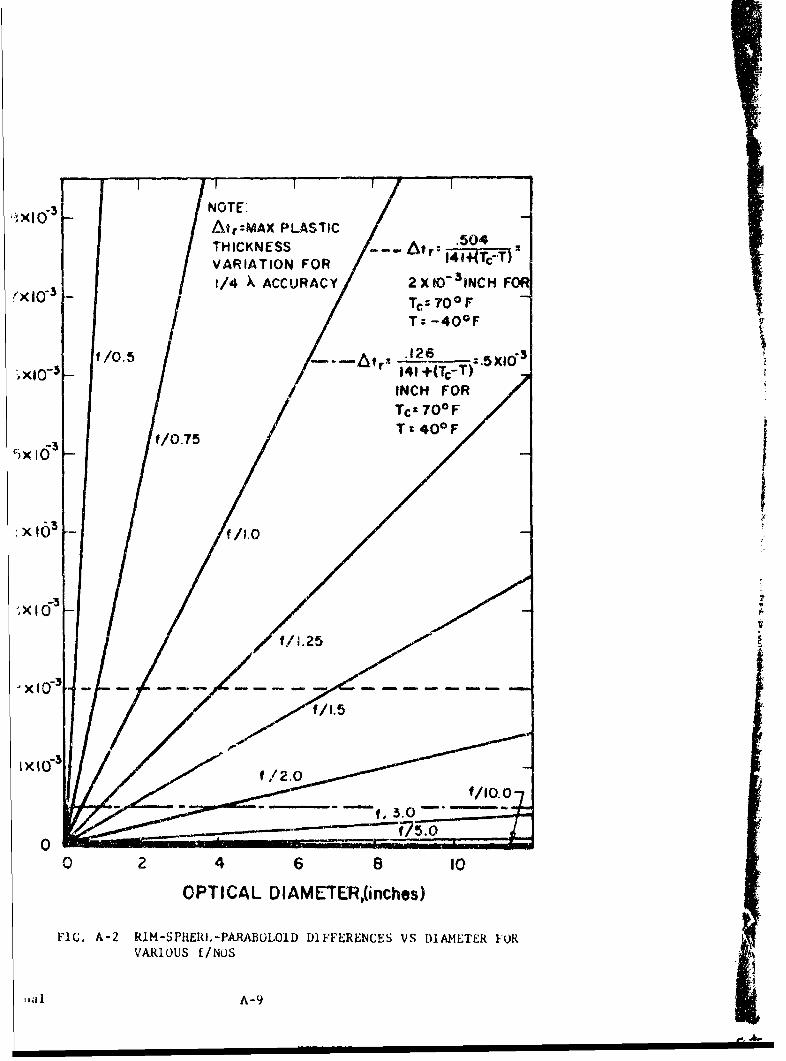
NOTE. /01Atr:MAX. PLASTIC .THICKNESS -- _Atr':I4_- "
VARIATION FOR 141 Tc7T
1/4 X ACCURACY 2X IO-SNCH FOR"'X10-3 Tc-700 F
T: -40 0 F
If /0.5o.26-5141 +(TCT)
INCH FORTcz 70*F
'~~xIO3 f/.7 T 400 F
f /0.7
,x13 f /1.0
x( 1- -0 - - - - -
0
0 2 4 6 a 10
OPTICAL DIAMETER,(inches)
FIG. A-2 RIM-SPHtERIL-PARABOLOID DIFFERENCES VS DIAMETER 1ORVARIOUS /NUS
1l111 A-9

a spherical prefo m,. Howe;vcr, greater plasLic Lhickness variations
are allowable if the paraboloidal focal length is allowed .o vary
slightly. Let the best fit parabola be given by
2
y- (11)4C'
The coordinates for the replica after replication are given by
I
- x+ (12)4f y
where
6 -6 x 10- 3 _ 4.24 x 10- 5 (T - T) (13)
4-A- (14)
64f3
Therefore, the difference between the best fit parabola and the actual
coordinates, dy', is given by
2 2dy ' -x x -X (1.5)
4f 4f y
Thi-, fo-,I reduULe Lu
2
dyt x - (16)4f
2 y
Assuming that the best fit parabaloid intersects the original paraba-
loid at the rim and vertex the difference in focal length can be
determined by the following equation at the riti where x -xo
2 2df 4!Z . where x - rim radius (17)
X 2 161 0
4821-final A-10

Combining Eqs. 16 and 17 yields
6 2
dy' =+--- (x2x2 x4) (18)
64f3 0
Differentiating with respect to x and setting the resultant = 0 to
find the x at which maximum dy' occurs yields the relationship
xXdy'max 0 (19)
Substituting Eq. 19 into Eq. 18 yields a total deviation of 1/4 that
calculated for the deviation from the paraboloidal master curve. This
means that the plastic thickness variation can be increased four times
or
t' 0.504 inches where T and T are in OFr 141 + ( ' -T) cc(20)
as plotted in Figure A-2 this variation criteria indicates that a 4-
inch diameter parabaloid having an f/number of f/1.25 can be fabricated
from a spherical preform and still maintain quarter wavelength accuracy
from a best fit resultant parabaloid.
Another shrinkage phenomenon also affects the replica-
tion accuracy. This phenomena is the curling of the preform due to
plastic cure shrinkage. This will be discussed extensively in Section
A.2.2, but for the purpose of this discussion, a total deviation of 1/4
-,avelength (sagitta) will be assumed from the desired parabaloid. For
a flat or large f/number mirror i.e. , when the mirror slope - 0 preform
rigidity is a function of x2 the total deflection due to curling is
: I-en by the formula
2x
Y 2(21)2 4
X
... i-F i A-11
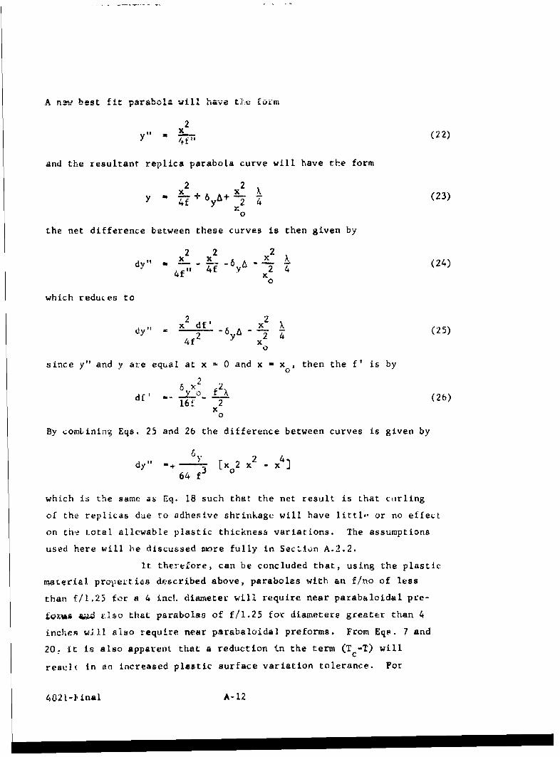
..n.w best fit parabola will have t".e fozm
2y ,, (22)
and the resultant replica parabola curve will have the form
2 2x x 2 xy 22S + 64 (23)
x0
the net difference between these curves is then given by
2 2 2dy" - - 2 -6 X (24)
4 f" 4f Y 2 4
0
which reduces to
dy x df' x (25)4f x2 4
since y" and y are equal at x - 0 and x - x, then the f' is by2o
6 x 2fdf' -- 0 (26)
16f 2x0
By combining Eqs. 25 and 26 the difference between curves is given by
dy" [x 2 x2 - x4
64 f3
which is the same as Eq. 18 such that the net result is that curling
of the replicas due to adhesive shrinkage will have littl,- or no effect
on the total allcwable plastic thickness variations. The assumptions
used here will be discussed more fully in SecLiun A.2.2.
It therefore, can be concluded that, using the plastic
material prope-ties described above, parabolas with an f/no of less
than f/1.25 for a 4 inch diameter will require near parabaloidal pre-
L€jAs 44 '.lso that parabolas of f/1.25 for diameters greater than 4
inches will also require near parabaloidal preforms. From Eqs. 7 and
20, it is also apparent that a reduction in the term (T -T) willc
restIt in an increased plastic surface variation tolerance. For
4021-1inal A-12
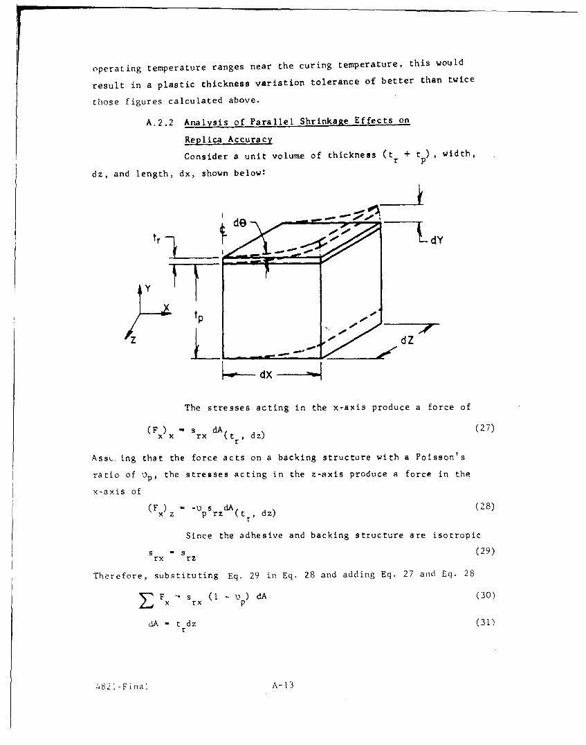
operating temperature ranges near the curing temperature, this would
result in a plastic thickness variation tolerance of better than twice
those figures calculated above.
A.2.2 Analysis of Parallel Shrinkage Effects on
Replica Accuracy
Consider a unit volume of thickness (t + tp ), width,
dz, and length, dx, shown below:
tp
Z dZ
The stresses acting in the x-axis produce a force of
(F) - s rx dA dz) (27)x x ( tr ,dz
Assu. ing that the force acts on a backing structure with a Poisson's
ratio of )p, the stresses acting in the z-axis produce a force in the
x-axis of
x z - p srz (t dz)
Since the adhesive and backing structure are isotropic
s s r (29)rx rz
Therefore, substituting Eq. 29 in Eq. 28 and adding Eq. 27 and Eq. 28
E F - sx (1 - o ) dA (30)
dA - t dz (31)r
4821 -F ina [ A- 13
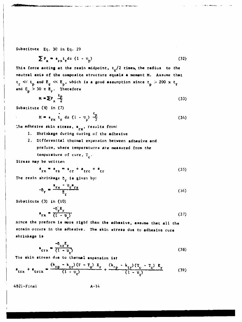
Substitute Eq. 30 in Eq. 29
IF f arxtrdz (1 - o ) (32)
This force acting at the resin midpoint, t r/2 time, the radius to the
neutral axis of the composite structure equals a moment M. Assume that
tr << tp and Er << EP, which is & good assumption since tp > 200 x tr
and C. > 30 x E.r Thereforepr
M =mF t (33)x 2
Substitute (6) in (7)
M - a ; dz (1 - u ) (34)
rxr p 2
'he adhesive skin stress, ,rx, results from:
1. Shrinkage during curing of the adhesive
2. Differential thermal expansion between adhesive and
preform, where temperatures are measured from the
temperature of cure, Tc
Stress may be written
rx rz cr +atrc +tr (35)
The resin shrinkage tr is given by:
a - Usrx
r rz
Substitute (3) in (10)
-8' Erx Z ar (7
Since the preform is more rigid than the adhesive, assume that all the
strain occurs in the adhesive. The skin stress due to adhesive cure
shrinkage is
" cr rsCrx "(I - 1) r (38)
The skin stress due to thermal expansion ist
(ktp ktr)CT - T)( o) Er (kfp - ktr)(T - Tc) Er (39)trx trcxr ' 0 - U r)
4821-Final A-14
I II II II IIM

(A positive sign indicates a tensile stress.) Combining Eq. 38 and 39
gives [ cr + (k tp - ktd(T - Tc)I Er (40)
5rx - (1
From Ref. 7, the siope at the free end of the volume element
above (neglecting t t and r) is
wx .(41)@x " Ip
pWhere I is the section modulus. Therefore,
-(42)
E Ip
The section modulus for the unit volume (neglecting t) is
3dz
t1 12 P (43)
12
Subgtituting Eq. 34 and Eq. 43 into Eq. 42 givest
t dz -P (I - ) dx
derxr 2 p (44)
x E dzt P P
12
Integrating Eq. 44 gives
6 s t xrx r p (45)
E tp p
The deflection dY is given by
dY - tan e dx (46)
But tan e - 8 for small angles. Then
dY - pdx (47)
4821-F'nal A-15
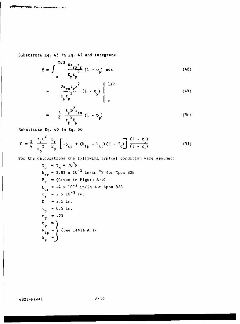
Substitute Eq. 45 in Eq. 47 and integrate
D/2y.f 69 rtpE tr2 (I - D ) xdx (48)
Et2 p0 p p
3s t xL/2rx r (1 - 1) p) (49)
E tpp 0
t 23 r rx3 2 (1 -u) (50)
p p
Substitute Eq. 40 in Eq. 50
3 It ) D 2 - 0 pY 4 t2 Ep L 5 cr + (ktp ktr)(T - Tc ) ( r) (51)
For the calculations the following typical condition were asLuumed:
T T - 700 Fc 0
k tr 2.83 x 10- 5 in/ii 0F for Epon 628
E r (Given in Figur- A-3)
bcr .4 x 10-3 in/in ior Epon 828
t *, x~ XU-3 inl.r
D -2.5 in.t 0.5 in.
- .25r
pk tp (See Table A-KI
Ep
4821-Final A-b

EPON 828 RESIN
CURING AGENT Z, 20PHR
NO FILLER
CURED 2HOURS AT 1750F
2 HOURS AT 300OF
50 IF ... T _ T _ _ _ _
MANUFACTURER'S DATA
EXTRAPOLATED
4.5
COM PRESSIV E
4.0 --
3.5
*5.00 20 40 60 80 100 120 140 160 180 200 220
TEMPERATURE, T ',F)
FIG. A-3 EL/STIC MODULES VS TF21PERATURE FOR AV EPOXY RESIN
inal A-I?
TABLE A- I
PROPERTIES OF POSSIBLE BACKING STRUCTURE MATERLALS
Material E k tp
Borosilicate Clavs 10 x 106 1.8 x 10⁻⁶ .10
Pyrex Glass 10 x 10 .8x 10 - 6 .10
Aluminum 10 x 106 12.8 V lo-6 .36
Beryllium 44 x 10 6 6.4 x 10"6 .10
Beryllium-copper 19 x 106 14.5 x 10⁻⁶ .25
Steel 30 x IO6 5.6 x 10 - 6 .30
Invar 21.5 x 106 b x 1o-6 .25
Molybdenum 51.4 x 10⁶ 2.9 x lo 6 .25
Tungsten 51.7 x 10 6 ? ; 10 "6 .25
4821 -Fi nal A-18
I
The defiecc ivn, Y, of the preform is shown in Figure
A-4 as a furLion of temperature for the various materials. If the
cure tempvrture, T,,, is some value other than T - 70 0 F, the deflec-
tion at any temperature T can be approximately found by substituting
T' for T on Figure A-4.
where T' T - (T - T )c U
Then when
T > T , Y vs T curves are displaced to the right by (Tc - T ) of
and whenTc < T , Y vs T curves are displaced to the left by (T o - Tc ) °F.
This technique is approximate because Young's modulus for the adhesive,
E is not a constant, but is a function of T.r
Analysis of simple preforms indicates that deflection
for a given diameter can be minimized by either:
Increasing: t , E , Vp p p
orDecreasing: tr' or' ,C) Er' V , (ktr " k t )
Therefore, from an analysis standpoint, the problem is basically ore
of proper prclorm material selection, adhesive selection, and preform
tolerances (to reduce t .
It appears from the above analysis that the effe':L of
ldhesive layer thickness variation is more important than preform
bending induced by adhesive skin stress.
Next consider the deflection of a spherical replicc
assuming the stress in Eq. 39, calculated for a flat replica
a 0R t E I dRS-j . W - -_e 1) (572 2K
30t w-P..
12 (53)
4821-Final A-19
I I I I II II Ii mm
' I l I I I ' V TITI I 1STORAGE RANGE
SERVICE RANGE
I~ BOROSILICATE GLASSI PYREX
12 1 ALUMINUM
2 4BERYLLIUM11 - BERYLLIUM- COPPER
I STEEL
0 to0 iNVAR
u ) MOLYBDENUM9 TUNGSTEN
8 INOT " -
SEE TEXT FORI COIT!ONS
7 .
5 7
FLG .- .RFR .......TURSN KNSTES- YIALCS
0
4821-Final A-20
I 1
22Rt s (Il-v )
dR o r rx p (54)
E t2
Pp
Assuming the conditions above with a T of -40°F and an aluminum preform
s = 2.86 x 10+ 3 lb/in2
rx
dR = 2.06 x 10- 5 R 2
0 2r
as a first approximation the Sagitta s 2R (55)0
2d
ASagitta r (56)2R 2
0
1.03 x 10 r2 variation from the surfacebetween the spherical master
This means that any spherical replica wilk remain spherical after
replication. The maximum radius change will then be 2 x 10- 5 R2 and
-5 20the maximum Sagitta difference I x 10 r .
Next consider the effect of plastic stress on parabo-
loidal replica surface accuracy assuming that the plastic stress can
be represented by the stress for a flat as in Eq. 40 above.
For a parabola
R 1
dR = If d (dRcr) (57)
R0
24 s t (1 - ) Rl
dR rx4s 2 RdR (58)E t Rpp 0
12 s t (1 - v ) 2
E t 2 (R 2 - R 2 (59)E t2 0
P P
2 2Assume a paraboloid y = - + (60)
4f 4f (60)
4821-Final A-21
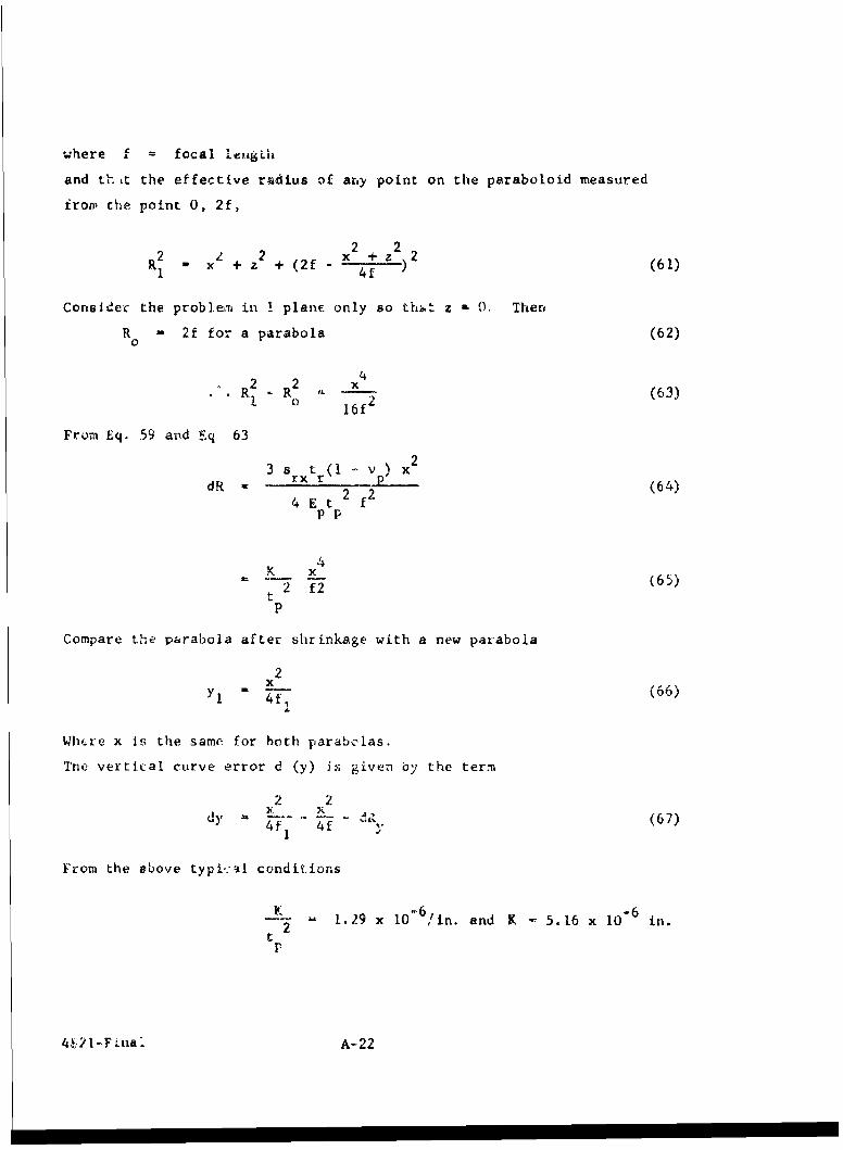
•", LL I focgL.. ..
and t lit the effective radius of any point on the paraboloid measured
from che point 0, 2f,
2 2)R - x + z + (2 f 4z)2 (61)
1 4
Considec the prob]em in 1 plane only so thi z 0, Ther
R 0,,,2f for a parabola (62)0
2 2 x (63)R R 02(3R!. o 62
From Eq. 59 aiid Eq 63
3 s t (1 v v[)
dR rx r P (64)4 E t 2 f
2
pp
x42 2(65)
t
p
Compare the parabola after shrinkage with a new parabola
2Yl M 4 (66)
Wire x is the same for both parabolas.
The vertical curve error d (y) is given by the term
2 2C!, a K - - - I
4f 4f d. (67)
From the above typic:al conditions
--2 -1,29 x 10" 6 /In. and K 5.16 x I0-6 in.2
t
4 -?1-F lna -- A -22
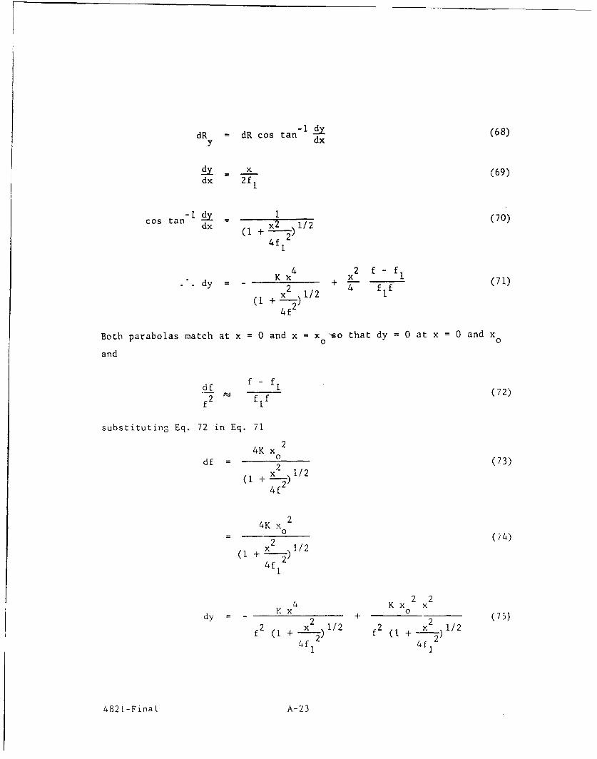
dR = dR cos tan - 1 (68)y dx
dy = x (69)dx 2fI
cos tan - I = 1 (70)dx (1 + x ) 1/2
4f 1
4 2 f f
dy = - x + 2L (71)(I + x2_) 1/2 4 fIf
4f
Both parabolas match at x = 0 and x = x so that dy =0 at x =0 and x
and
df f- f (72)f2 fIf
substituting Eq. 72 in Eq. 71
4K x
df = (73)2+ x__) 1/2
4f
4K x
2x
( 74 )
( + -- )
4f 2
2 2x 4 Kx x
dy x + 2 (75)f2 ( 2 + x2)i/2 f2 (1 + x 12)i/2
4f1 4f12
4821-FinaL A-23
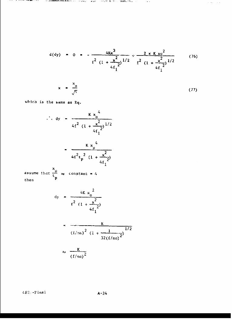
d(dy) - - 4Kx3 2 x K xo2-2 + (76)f 2 (1 +-- 21/2 C2 (I + x 1/2
4f 1 2 4f2
x0x (77)
which is the same as Eq.
Kxdy -
24f2 (1 + x )1/24f (
4
Kx4
0
22242tp2 (1 +
xassume tlt..t -t constant -4t
then P
4K x
dy - 22
f 2 ( 1 + - '2
K
2 1 1/2
32(f//no)
K
(f/no)"
4 82 - inaI A-24
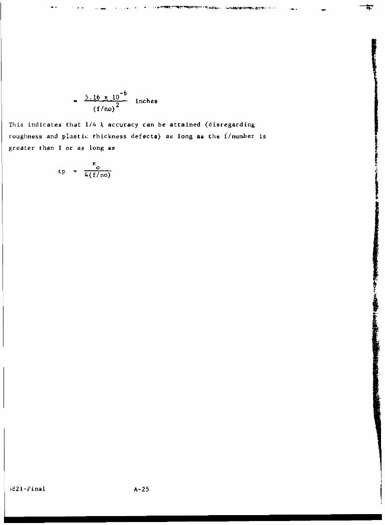
-615. 16 x 10- 6inches
(f/no) 2
This indicates that 1/4 X accuracy can be attained (disregarding
roughness and plastic thickness defects) as long as the f/number is
greater than I or as long as
x0
tp = 4(f/no)
I
p
S
' 82 l-?inal A-25
APPENDIX B
THIN FILM PLASTIC REPLICATION PROCESS DESCRIPTION
The purpose of this appendix is to outline the process details for
the fabrication of thin film plastic replicas. The scope includes the
basic equipment and materials required, operational procedures, some
precautionary measures and other related details. For continuity, the
Process Flow Diagram, Fig. B-l, is used as the process outline. The
format of this appendix is to use the Flow Diagram step numbers as
section and subsection numbers for reference between the text and flow
diagram.
B.1 MASTER
The surface quality and accuracy of the finished replica is limited
by the initial master quality and accuracy plus the wearing characteris-
tics of the master in production. Therefore the master specifications
defined for procurement must be explicit and well engineered.
B.I.1 Procurement
The angular accuracy and the surface quality of the master
should be better than the specifications of the desired replica. A
factor of two is the recommendation at this time. Many replica ele-
ments may require an even greater margin for error, particularly if
the desired replica approaches astronomical tolerances.
Where accuracy and surface quality requirements are high,
master materials should be chosen from the following list tabulated in
descending order of preference:
1. Quartz or fused silica
2. BSC-2
4821-Final B-I
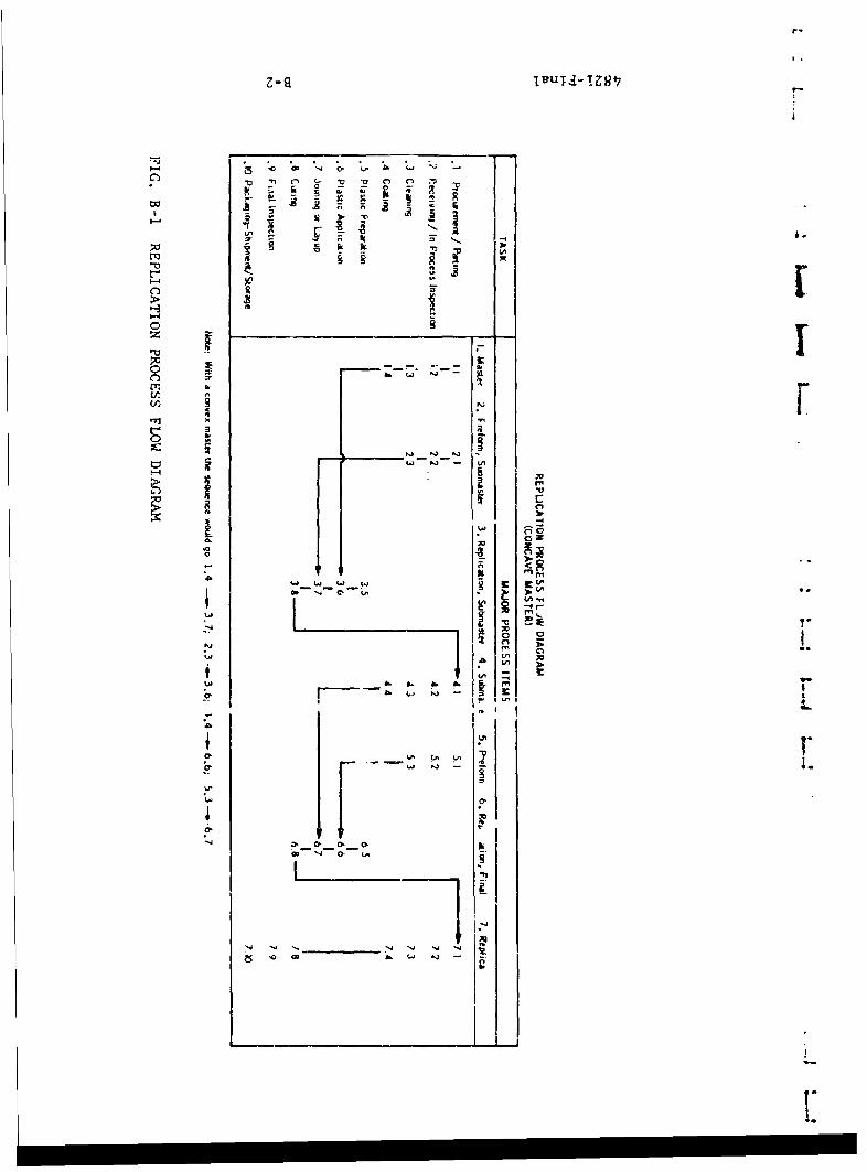
C-9-
> ' ~ L _____________________
"- rn
!Q. rn C.,,~- -
Lm M
-:

APPENDIX B
THIN FILM ?ASTIC REILICATION PROCESS DESCRIPTION
The pirpose of this appendix is to outline the process details for
the fabrication of thin film plastic replicas. The scope includes the
basic equipment and materials required, operational procedures, some
precautionary measures and other related details. For continuity, th,
Process Flow Diagram, Fig. B-l, is used as the process outline. The,
format of this appendix is to use the Flow Diagram step numbers as
section and subsection numbers for referenLe between the tcxt and flow
diagrarm.
B.1 MASTER
The surface quality and accuracy of the finished replica is limited
by the initial master quality and accuracy plus the wearing characteris-
tics of the master in production. Therefore the master specifications
defined for procurement must be explicit and well engineered.
B L.lI L LULI IVI|'kL
The angular accuracy and the surface quality of the master
should be better than th( specifications ( f the desired replica. A
factor of two is the recoinmenct.vn at this time. Maniy replica eh4-
ments may req,'.Ire an even greatcr margin for error, particularly if
the desired replica approa ihes istroaomical tolerances.
Where accuracy a'-] surtaoco quality rcquirem.ents are high,
master materials should be chosen fron the following list tabulated in
descending order of preference:
1. Quartz or fused silica
2. BSC-2
4821-Final B-1
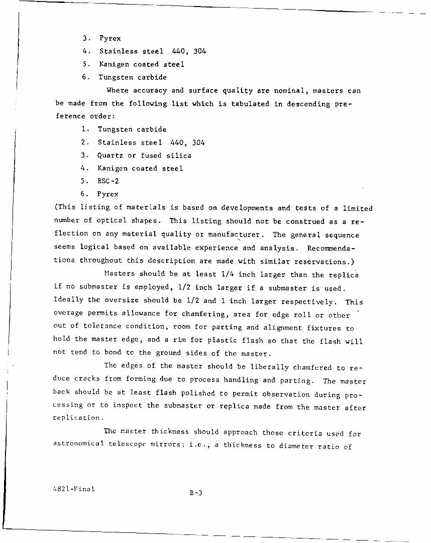
3. Pyrex
4. Stainless steel 440, 304
5. Kanigen coated steel
6. Tungsten carbide
Where accuracy and surface quality are nominal, masters can
be made from the following list which is tabulated in descending pre-
ference order:
1. Tungsten carbide
2. Stainless steel 440, 304
3. Quartz or fused silica
4. Kanigen coated steel
5. BSC-2
6. Pyrex
(This listing of materials is based on developments and tests of a limited
number of optical shapes. This listing should not be construed as a re-
flection on any material quality or manufacturer. The general sequence
seems logical based on available experience and analysis. Recommenda-
tions throughout this description are made with similar reservations.)
Masters should be at least 1/4 inch larger than the replica
if no submaster is employed, 1/2 inch larger if a submaster is used.
Ideally the oversize should be 1/2 and I inch larger respectively. This
overage permits allowance for chamfering, area for edge roll or other
out of tolerance condition, room for parting and alignment fixtures to
hold the master edge, and a rim for plastic flash so that the flash will
not tend to bond to the ground sides of the master.
The edges of the master should be liberally chamfered to re-
duce cracks from forming due to process handling and parting. The master
back should be at least flash polished to permit observation during pro-
cessing or to inspect the submaster or replica made from the master after
replication.
The master thickness should approach those criteria used forastronomical telescope mirrors; i.e., a thickness to diameter ratio of
4821-Final B-3
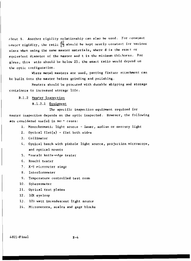
,bout 6. Another rigidity relationship can also be used. For constant
d2c:iaster rigidity, Lhe ratic j7 should be kept nearly constant for various
sizes when using the same master materials, where d is the exact or
equivalent diameter of the master and t is the minimum thickness. For
glass, this atio should be below 25; the exact ratio would depend on
the optic configuration.
Where metal masters are used, parting fixture attachment can
be built into the master before grinding and polishing.
Masters should be procured with durable shipping and storage
containers to increased storage life.
B.I.2 Master Inspection
B.1.2.1 Equipment
The specific inspection equipment required for
master inspection depends on the optic inspected. However, the following
are considered useful in mo! I cases:
1. Monochromatic light source - laser, sodium or mercury light
2. Optical flat(s) - flat both sides
3. Collimator
4. Optical bench with pinhole light source, projection microscope,
and optical mounts
5. 'roucalt knife-edge tester
6. Ronchi teaster
7. X-Y nicreorcter stage
8, Interferometer
9. Temperature controlled test room
10. Sphereometer
11. Optical test plates
12. lX eyeloop
13. 100 watt incandescent light source
14. Micrometers, scales and gage blocks
4821-Final. B-4

B.l.2.2 Optical Tests
The optical tests used to check the surface accuracy
will vary. Whatever the surface geometry, the surface quality should be
rigidly inspected for out of tolerance digs, pits, and scratches.
Surface defects replicate very well. Also any de-
fects act as nucleii for master attrition and, therefore, tend
to shorten
master life particularly with masters made from glass type materials.
Since surface defects are particularly important to
the results and economics of the replication process, optical or mechani-
cal tests that require physical or near-physical contact should be avoided
where possible.
B.l.3 Master Cleaning
The cosmetic quality of the finished replica, as well as the
master life, depend strongly on the master cleaning process.
B.1.3.1 Eqjuipment
The master cleaning equipment desirable but not
necessarily required includes:
1. Winfield type dust-free air bench
2. Centrifige or spin table with dust-free hot air source
B.1.3.2 Materials
I. Anionic detergent
2. Trichlorethylene
3. Precipitated calcium carbonate
b Hydrochloric acid
5. Nitric acid
6. Isopropyl alcohol
7. Acetone
8. Cotton swabs
9. Clc an, lint-free linen cloth
4821-Final B-5
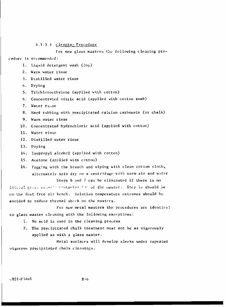
B.I.3.3 Cleanin, Procedure
For new glass masters tlie following cleaning pro-
cedture is recommended:
1. Liquid detergent wash (Joy)
2. Warm water rinse
3. Distilled water rinse
4. Drying
5. Trichleroethylene (applied with cotton)
6. Concentrated nitric acid (applied 4ith cotton swab)
7. Water rise
8. Hard rubbing with precipitated calcium carbonate (or chalk)
9. Warm water rinse
10. Concentrated hydrochloric acid (applied with cotton)
11. Water rinse
12. Distilled water rinse
13. Drying
14. Isopropyl alcohol (applied with cotton)
15. Acetone (applied with cotton)
16. Foggtng with the breath and wiping with clean cotton cloth,
alternately spin dry on a centrifuge with warm air and water
Steps 6 and 7 can be eliminated if there is no
1, ' I'nt a,,i,. . uf the ,aster . Step 1u shuuld be
on the dust free air bench. Solution temperature extremes should be
avoided to reduce thermal sheck on the masters.
For new metal masters the procedures are identical
to glass master cleaning with the following exceptions:
1. No acid is used in the cleaning process
2. The precipitated chalk treatment must not be as vigorously
applied as with a glass master.
Metal surfaces will develop sleeks under repeated
vigorous precipitated chalk cleanings.
,821-Final B-6
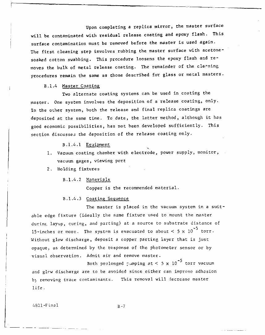
Upon completing a replica mirror, the master surface
will be contaminated with residual release coating and epoxy flash. This
surface contamination must be removed before the master is used again.
The first cleaning step involves rubbing the master surface with acetone-
soaked cotton swabbing. This procedure loosens the epoxy flash and re-
moves the bulk of metal release coating. The remainder of the clepning
procedures remain the same as those described for glass or metal masters.
B.I.4 Master Coating
Two alternate coating systems can be used in coating the
master. One system involves the deposition of a release coating, only.
In the other system, both the release and final replica coatings are
deposited at the same time. To date, the latter method, although it has
good economic possibilities, has not been developed sufficiently. This
section discusses the deposition of the release coating only.
B.1.4.1 Equipment
1. Vacuum coating chamber with electrode, power supply, monitor,
vacuum gages, viewing port
2. Holding fixtures
B.1.4.2 Materials
Copper is the recommended material.
B.I.4.3 Coating Sequence
The master is placed in the vacuum system in a suit-
able edge fixture (ideally the same fixture used to mount the master
during, layup, curing, and parting) at a source to substrate distance of-5
15-inches or more. The system is evacuated to about < 5 x 10 torr.
Without glow discharge, deposit a copper parting layer that is just
opaque, as determined by the response of the photometer sensor or by
visual observation. Admit air and remove master.-5
Both prolonged -mping at < 5 x 10 torr vacuum
and glcw discharge are to be avoided since either can improve adhesion
b) removing trace contaminants. This removal will decrease master
life.
4821-Fina 1 B-7

B.2 PREFORM, SUBMASTER
The effect of the preform oni the submastcr replication pr,,cess is
as important as that ot the master and plastic resin. Therefore, the
prefoim al 3 must be well engineered.
B.2.1 Procurement
The submaster preform should be between 1/4 and i/2 inch
larger in size than the finished replica and 1/4 and 1/2 inch smalle:
in size than the initial master. Preform thickness should be deter-
mined by the preform size or diameter.
The effective preform diametet-to-thickness ratio should
be at least a ratio of 6 for aluminum or glass materials, considering
process stresses only. When considering the preform resistance tod2
external forces, the ratio of should be kept constant, equal to or
less than 25 for glass or alumintun. Therefore, the rigidity design
criteria for both the master and submaster preform are the same %,hen
considering the strtctural resistance to external forces.
Preform surfac finish sh)uld either be 16 rn,s or better or lap
pr -otndj fn q JTF firlsh J, ln -- -4t4,, ^fr plsi SUiIac . ra,
cally any high modulus of elasticity material which can be groinded or
drilled is acceptable as a preform material.
Dimensional tolerances on the critical surface sl ould be
within ±0.001 inch to achieve maximum replication accuracies.
When mace than 100 to 500 preforms are procured, a casting
or molding process should be considered. Special optical shapes may
bh econonical in even smaller production units.
Preforms subject to corrosion should be given an organic or
inorganic strippable protective coating fer storage.
4321-Final B-8
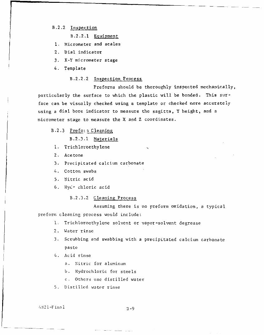
B.2.2 Inspection
B.2.2.1 Equipment
1. Micrometer and scales
2. Dial indicator
3. X-Y micrometer stage
4. Template
B.2.2.2 Inspection Process
Preforms should be thoroughly inspected mechanically,
particularly the surface to which the plastic will be bonded. This sur-
face can be visually checked using a template or checked more accurately
using a dial bore indicator to measure the sagitta, Y height, and a
micrometer stage to measure the X and Z coordinates.
B.2.3 Prefoin Cleaning
B.2.3.1 Materials
1. Trichloroethylene
2. Acetone
3. Precipitated calcium carbonate
4. Cotton swabs
5. Nitric acid
6. Hy6> chloric acid
B.2.3.2 Cleaning Process
Assuming there is no preform oxidation, a typical
preform cleaning process would include:
1. Trichloroethylene solvent or vapor-solvent degrease
2. Water rinse
3. Scrubbing and swabbing with a precipitated calcium carbonate
paste
4. Acid rinse
a. Nitric for aluminum
b. Hydrochloric for steels
c. Others use distilled water
5. Distilled water rinse
'82 -Fina if9

t. Rinse with triple dituilled acetone
7. .ir dry
If theyc are any "water breaks" (characteristic
of grease and dirt spots) after tha final distilled waler rinse, repeat
the cleaning procedure. 1,c ri,,1move gross uxidation, refer to standard
metal cleaning procedures.
4821-Final
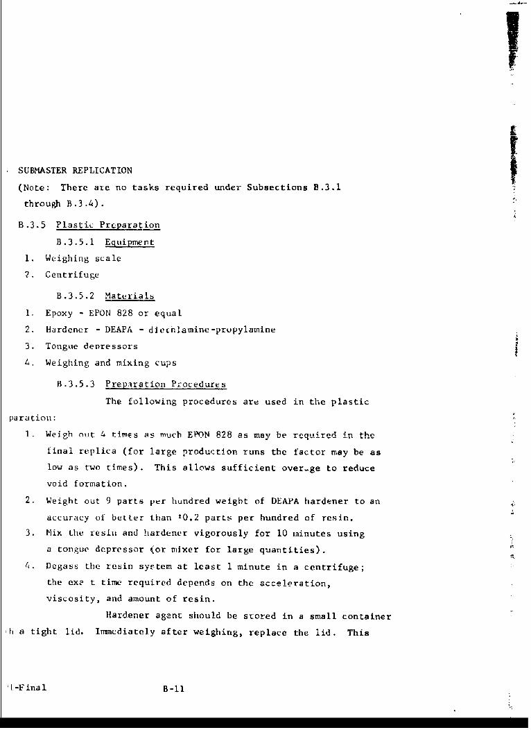
SUBMASTER REPLICATION
(Note: There ate no tasks required under Subsections B.3.1
through B.3.4).
B.3.5 Plastic Preparation
B.3.5.1 Equipment
1. Weighing scale
2. Centrifuge
B.3.5.2 Materials
1. Epoxy - EPON 828 or equal
2. Hardener - DEAPA - diechlamine-propylainine
3. Tongue denressors
4. Weighing and mixing cups
B.3.5.3 Preparation Procedures
The following procedures are used in the plastic
paration:
1. Weigh out 4 times as mucb EPON 828 -s may bp reitiirPd in the
final replica (for large production runs the factor may be as
low as two times). This allows sufficient over-ge to reduce
void formation.
2. Weight out 9 parts per hundred weight of DEAPA hardener to an
accuracy of better than ±0.2 parts per hundred of resin.
3. Mix the resin and hardener vigorously for 10 minutes using
a tongue depressor (or mixer for large quantities).
4. Degass the resin system at least 1 minute in a centrifuge;
the exp t time required depends on the acceleration,
viscosity, and amount of resin.
Hardener agent should be stored in a small container
ih a tight lid, Imnediately after weighing, replace the lid. This
1.-Final B-I
hardener is particularly hydroscopic and has an effective full
strength shelflife of much less than one year when exposed to air
during normal fabrication use.
Care sbould be taken to avoid contacting the
resin or hardener as either or both can cause skin irritation.
Resin should be used at least 30 minutes after
mixing to avoid high viscosity flow problems caused by the curing
plastic.
Laboratory humidity between 45 and 60 percent
is recommended
B.3.6 Master Preparation
1. Place epoxy in master (if master is convex, place epoxy
in concave submaster preform).
2. Pour degassed epoxy preheated to 120 to 130°F into the
center of the flat or concave master.
3. Avoid the formation of bubbles in the plastic during the
pouring by pouring slowly and steadily. Interrupted
pouring will entrap voids.
Preheating the resin-hardener mixture decreases
its viscosity and enhances spreading and wetting of the preform.
Goond we ttingv isc rosscbl, the pr incip coIvntr ibut-- tacoti,
free of surface flaws. It allows displacement of air adsorbed onto
small aspherities of the preform surface. Preheating of the moster
(and of the preform) with extreme care to desorb moisture and air
is also recommended. This should be done at a temperature of from
215-225 F for i to 2 hours. Thermal shock should be avoided.
For some optical shapes, additional centrif-
uging of the plastic in the preform may be helpful.
B.3.7 Layup-Placement of Submaster Preform on Master
B.3.7.1 Equipment
Figure B-2 depicts the modified arbor press align-
ment, curing and parting fixture shown with a convex master mounted in
4821-Final B-12

FIG* 2B-2 MOIFIED ADD^T R3S TP£uiiE(u1
921 -Final B-1.31

its holding fixture to the side and a concave preform held in place in
the reservoir base. The press is leveled by adjusting legs with the
aid of a bubble level. The rack gear arm was remachined to better than
normal alignment tolerances. Other optical configurations could he
similarly adapted to this modified type of fixture.
B.3.7.2 Layup
Figure B-3 shows the alignment assembly position
during the plastic pouring operation. The convex master is shown in
its adapter, attached to the rack gear bar. (With the replication of
a concave master, the upper element is a convex preform.)
Slowly lower the top assembly onto the bottom
assembly as shown in Fig. B-4. Lowering must be slow and continuous
to avoid bubbles and scum on the resin surface. Alignment pins permit
fine alignment adjustment in the final stages of joining the master
and submaster preform.
Figure B-5 shows the convex holding fixture un-
screwed and detached from the rack gear holder adapter. Figure B-6
shows the master-submaster alignment assembly detached from the modified
arbor press base plate. This is now ready for curing.
B.3.3 Curing
B.3.8.1 EQuipment
Forced draft, horizontal air-flow electric oven
capable of maintaining a preselected constant temperature + 0.5°C
over a range of +38 C to +260 C.
B.3.8.2 Process
The master-submaster assembly is cured at ll0°F
for a 15 hour preliminary cure followed by a post cure of 1 hour at
175 0F. The lower preliminary temperature followed by a relatively high
post cure temperature gives adequate curing without inducing excessive
shrinkage. The high temperature post cure has the advantage of ac-
centuating the tendency of self-parting due to the differential thermal
expansion rates when a glass master and metal preform are employed.
4821-I-inal B-14
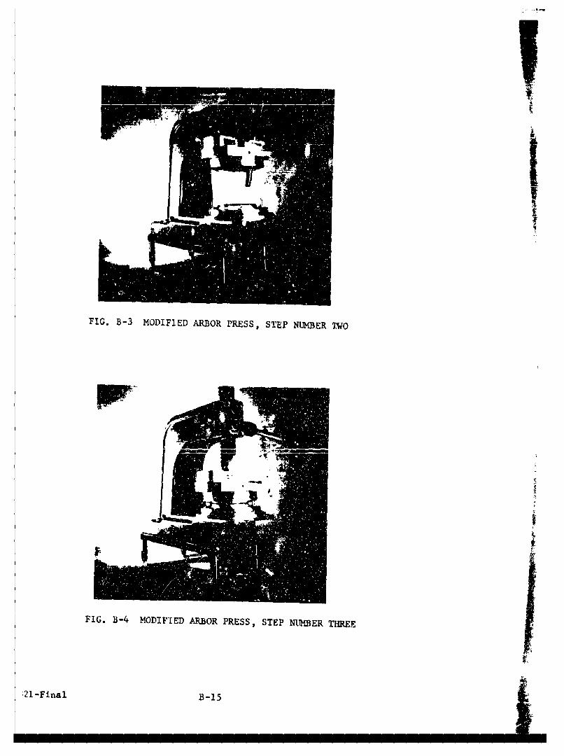
IFI
FIG. B-4 MODIFIE~D ARBOR PRESS, STEP NUBER THRE
21-Final B-15

FIG. B-5 MODIFIED ARBOR PRESS, STEP IU-BER FOUR
FIG. B-6 MODIFIED ARBOR PRESS, STLEP NUMBER FIVE
4821 -Final B-16
nimum vibration and a level oven shelf are important in producing a
gh accuracy replica with good cosmetic qualities.
21-Final B-17

B.4 SUBMASTER
B.4.1 Submaster Parting
Parting is initiated inunedlately after completion of the
post curing cycle. While still hot, the layup is secured in the part-
ing fixture. Slow cooling is allowed to take place. The metal preform
will shrink more rapidly than the glass master due to differences in
the thermal expansion coefficients. The forces generated by this dif-
ferential rate of shrinkage augments the force applied by the parting
fixture. Complete parting can therefore be affected with only a small
external force.
If parting does not occur on the initial attemp.t the apparatus
is allowed to cool for another 15 minutes. Gtntle pressure is again
exerted ol the parting fixture. Parting usually occurs by this time.
If partit.g does not occur another alternate period of cooling followed
by pressure is repeated until parting is achieved. Oil occasion it may
be necesbary to slowly reheat the layup and reapply the preceding tech-
nique before parting takes place. The application of great force rarely
has been needed to achieve partiiB.
B.4.2 Inspection
Submaster inspection is normally visual to determine whether
there are gross figure defect- or unacceptable surface finish. Where
more accurate optical testing is required, equipment and test methods
discussed in Subsection B.1-2 can be employed.
B.4.3 Cleaning
B.4.3.1 .Iaterials
Solution', to strip alumintu, copper, and silver.
4821-Final P-18

___ I
B.4.3.2 Procedurc
The replica submaster surface is flood4. with the
propriate stripping agent. Rinsing with tap water and distilled
ter follows as soon as the metal has buen completely dissolved. Ab-
lute alcohol is then poured over the replica surface and the replica
allowed to air dry.
If the submaster has been previously used in repli-
:tion, rcsin flash may have to be removed from ouLsilde iLe critical
,tical surface oy gentle swabbing with cotton and detergent or carefuL
obing with a razor blade.
B.4.4 Submaster Coating
B .4.4 . I EIipment
See Subsection B.1.4.
B.4.4.2 Materials
1. Copper
1. Chromium
3. Silicon monoxide
4. Oxygen
B.4.4.3 Procedure
1. Mount the stripped replica submaster in a vacuum coater at
least 15 inches from the sources.-5
2. Reduce the chamber pressure to less than 5 x 10 torr.
3. Throttle the pumps and bleed bottled oxygen into the system
until a glol' discharge hevel of 3,000 volts at 150 milliamperes
is reached from a shielded aluminum cathode. The glow dis-
charge must be carefully controlled to prcvent excessive heat-
ing. Excessive heat will cause orange peel in the plastic
film.
4. Using a photometer response, filtered by a Wratten No. 74
filter (peak transmission at 538 millimicrons) and a shutter
between the source and submaster, deposit a 30-40 percent
reflective film.
21-Final B-19 L

5. Follow irmmediately with a rapid deposition of silicon mon-
oxide as a protective film.
b. Deposit a barely opaque copper film onto the silicon mon:xide.
7. Admit air and remove submaster.
B.5 PREFORM
Details for the replica preform are the same as the submastcr
preform.
B.5.1 Procurement
Same as Subsection B.2.1 except size should be 1/4 to 1/2
inch smaller.
B.5.2 Inspection
Same as Subsection B.2.2
B.5.3 Cleaning
Same as Sub ection B.2.3.
B.6 REPLICATION
Details for replication are the same as for submaster replication.
B.6.1 to B.6.4 (not applicable)
B.6.5 Plastic Preparation
Same as Subsection B.3.5
B.6.b Placement of Epoxy
Same as Subsection B.3.6 except the plastic resin is placed
either in a concave preform or submaster wheeas in Subsection 1.3.6
the plastic resin is placed in a concave master or submaster preform;
the shape in each section depends on the original master shape. Note
that the tooling size may have tc he smaller to accommodate the smnlcr
preform.
B.6 , Layup - Joining Replica Submaster with Prefo-in
Same as Subsection B.3.7
4821-I £nal B-20
B.6.8 Cure
Same as Subsection B.3.8
REPLICA
B.7.1 Replica Parting
Same as Section B.4.
B.7.2 .Inspec tion
Basically the same as Subsection B.1.2. Surface accuracy,
ish tequirements, and standards will be different, howcver. Reason-
le specifications will have to be defined, based primarily on system
.tirements rather than aesthetic considerations.
B.7.3 Cleaning
Same as Subsection B.4.1
B.7.4 Coatnq
(See Subsections B.1.4 and 13.4.4 for equipment aud maturials)
I. Mount the stripped replica in a vacuurr, coecr it least 15
inches from the sources.
2. Reduce chamber pressure to at least 5 x 10' tort.
3. Throttle the pumps and bleed bottled oxyge n into the system
until a glow discharge level of 3.000 volts at 150 milllampcres
is reached from a shielded aluminum cathode. The glow dis-
charge must be carefully controlled tc prevent excessive heat-
ing. Excessive heat will cause orange peel in the plastic
film.
4. Using a photometer response filtered by e Wratten No. 74
filter, deposit a 30-40 precent reflective film.
5. Follow immediately with a rapid deposition of (269 milli-
microns) of silicon monoxide as determined by the reflectance
kfailing first to a minimum at _ and then rising to a maximum
k 4
at 1 •
6. Rapidly deposit aluminum to maximnm reflectance as measured
by the photomIter.
BLeed oxygen into the system to maintain a pressure of-5
5 to 7 x 10 torr while slowly depositing a - thickness
of siLicon monoxide.
8. Wait 15 minutes.
9. Admit air and remove replica.
B.7.5, B.7.6 and B.7.7 - There are no applicable task sections
for the ieplica item.
B.7.8 Peplica Cure
Equipment iequired is discussed in Subsection B.3.7. Post
cure the coated replica two hours at a temperature of 175 F to improve
coating adhesion:.
B.7.9 iin;,l Inspection
The replica should again be checked to speo i ications by
techniquCs and equ.ipment described in Subsections B.1.2 and B.7.2 and
accepted or rejected by quality control.
B.7 .10 Pac-a_ ingShiUUn_ and crl!.,
Package the finished replica in L dust a nia aisture-proof
container with sufficient rigidity and pacLing to avoicd damage during
shipment oi storage.
'4821-liual B.22

APPENDIX C
ANALYSIS OF PREFORM SHOCK RESISTANCE
1. MIRROR SHOCK STRESS
Assumptions
1. Replica mirror is mounted with the concave reflective face
pointing in the direction of projectile travel
2. Edges are fixed
3. Strained configuration is constant and maximum during the
20,O00-g constant acceleration period
- Load is uniformly distributed over the entire mirror
5. A flat disc is a good model for the mirror.
These assumptions are diagrammatically shown in Fig. C-I.
The axir l restraining force, F, is related to the axial strain, x, and
spring constant, K, by
F = Kx (1)
wh reK 16 i E 2 L3
K- 3 (92 -!_ _2 (Reference C-1) (2)
where E = *cung's Modulus (see Table C-l) (3)
I-
Poissons ratio (see Table C-i)
r disc ridius
t = disc thickness.
Also, F can i-e equated to the disc weight
F = mX': (4)
r. = mass n r t (5)
p = mass density
= acceleraLio.
4821-Final C-I
PROJECTILE
rkm2O,OOOg ~ - I
FIED EDGEOF MIRRORDISC
4b. I xf (F)
F1G- C-1 SCHFMATIC OF MIRROR ENVIRONMENT
4821-Final C-2
The maximum stress from Reference 1, amaximum' is given by
C = 3 F ( i )°max 8 It 2 (6)
By substitution
3 (1 + l) P r X
max 8 It (7)
TABLE C-1
PHYSICAL PROPERTIES
Material E Pg Uelastic
limit
ib/in2 in3 ib/in 2 (assumed)
Aluminum 10 x 106 0.100 50 x 103 1/32024-T3
63Beryllium 44 x 10 0.070 50 x 103 lif
Magnesium 6.5 x 10⁶ 0.066 25 x 103 1/3AZ31B
Steel 4340 30 x 106 0.280' 200 x 103 1/3
416 30 x 106 0.280 100 x 103 1/3
Titanium 15 x 106 0.170 130 x 103 1/36 Al-4Va
And
X 3 p r 4 _ R - 1)16 E 2 t2 (8)
For the case in question
r = 2 inches
t = .125 inches
= 20,000 g
A comparison of displacements, x, maximum stress C maximum , and
ratio of maximum stress to celastic limit' is shown in Table C-2.
4821 -Final C-3
TABLE C-2
20,000-g ACCELERATION EFFECIS ON 1/8-INCH DISC
Material Deflection C 2ax Cm /elasitinches Win 2elaxtic
Aluminum 2024-T3 0.034 32 x 103 0.64
Beryllium 0.010 17 x 103 0.34
Magnesium 0.035 21 x 103 0.84
Steel 4340 0.032 90 x 103 0.45
416 0.032 90 x 103 0.90
Titaniumi 0.039 54 x W03 0.426AI-4Va
From this analysis, all the materials could withstand the shock.
Since ;maximum varies with l/t, increasing preform thickness will de-
crease the stress and make the shock resistance even greater.
4821-Final C-4
REFERENCE
Appendix C
Roirk, R. J. , "Formulas for Stress and Strain," McGraw-HillBook company, 1954
-Final C-5Eot3
-. E8t At,71.' AAQ123).KI' LIECTVO-OPTICAL SYSTEMS. INC. 300 N. HALSTEAD 51., PASADENA. CALIFORNIA ~14d.SQ2'
A S vb d - , of '. O. Cwrpo o'o'STRANSMITTAL OF CONTRACT REPORT
Date .26 February 1965
TO: Los Angeles Procurement District
Unitcd States Army55 South Gr-and AvenuePasadena, California 91109
Attn: A. Anthony Scarpa, Contracting Officer/
UPON APPROVALReference (Contract No.) DA-04-495-AMC-376(A)
Rehport No. and Type 4821-Final Date of Issue 26 February 1965
Short Title Replica Optics Covers Period 12 February 1964-31 August 1964
Classification U +:: -: E OS Classified Doc. Nc,
I rd mi tted herewith are thte rquir.d c pies o, the reprt dIsr:b,.d .ibo..Vi: and labor repurts, il required, are :-' uded ani distrituted asi ,- ,,w. ShouId add: t inal itiflr:na;t ion bt, de- ted, p lcas,. Ji .. t '-.,, : rI
the udersigned.
Very truly yours,
ELECTRO-OPTICAL SYSTEMS, INC.
.ihard N. Strong, ManagerT/ D I S T.4T (" .rTrnAd i i t a i nT-- h. Fu,7 l-1 r Co.'tr Trans.>n.trac L Administration r e't Rpr Pa jor
Rport Rep, Reprt P ae Form
d - S Izz -__iiC r s

DISTRIBUTION LIST FOR FINAL REPORT
Contract DA 04-495-AMC-376(A)
'.mmanding Officer Commanding Generalirankford Arsenal U. S. Army Test & Evaluation CommandPhiladelphia, Pa. 19137 ATTN: D&PS\'TN: SMIFA-5500, M. Oulton 5 Aberdeen Proving Ground, Md.
',mmanding Officer Commanding General'rankford Arsenal U. S. Army Munitions CommandPiiladelphia, Pa. 19137 ATTN: AMSMU-K',TTN: SMUFA-6230, J. Shean 1 Dover, N. J. 07801
:,mmanding Officer Commanding OfficerFrankford Arsenal U. S. Army Research Office - DurhamP:'iladelphia, Pa. 19137 Box CM, Duke StationrTTN: SMUFA-8600, H. Fitzgerald 1 Durham, N. C.
::,'nimanding Officer Defense Documentation Center7rankford Arsenal Arlington Hall StationPhiiladelphia, Pa. 19137 ATTN: TiPDR\TTN: 0270, Library I Arlington 12, Va.
Crmanding Officer Commanding General?rankford Arsenal U. S. Army Munitions CommandPhi lade lph ia , Pa. 19137 ATTN: AMSMU-MATTN: SMUFA-1540, R. Cook Picatinny Arsenal
Dover, N. J.Commanding GeneralJ. S. Army Material Command Commanding GeneralATTN: AMCRD-DE-MO Engineering Research & Development LaboratoriesWashingron 25, D. C. 1 ATTN: SMOFB-ER
Ft. Belvoir, Va.C(>mmandin, GeneralV. S. Arriv Material CommandATTN: AMCRD-RS-CMashin ton 25, D. C.
/' "C