hangar 37, rand airport, germiston, jhb - 011 8245395 mfix manual.pdf · mfi x - instructional...
TRANSCRIPT
MFI X - Instructional ManualVersion 08.05
ww g
w. otech.co.za
HANGAR 37, RAND AIRPORT, GERMISTON, JHB - 011 8245395
All Specifications Subject to Change without Notification Manual Version 08.05 2008/5/15
Index:
Introduction 1Before You Begin 1Basic Tools Required 2Basic Components Required 3Hardware Installation 3ECU Plug Pinout 16 Pin 4ECU Plug Pinout 14 Pin 5ECU Power Supply 6Outputs According to Modes 7
Outputs Mode 0 8Outputs Mode 1 9Outputs Mode 5 10
Signal Input Gotech MFI X 11Connecting the input signal 12
Rotor Phasing 13TDC signal input 14
Connecting the TDC signal input 14Throttle Position Sensor Input 15Water Temperature Sensor Input 16Air Temperature Sensor Input 16Lambda Sensor 17
Lambda Sensor Installation 17Closed Loop Lambda Control 17
Launch Control 18Activating the launch control 18
Timing And Fuel Pots 19
Fuel Management SystemFuel Management System
THE FUEL MANAGEMENT SPECIALISTSTHE FUEL MANAGEMENT SPECIALISTS
Page 1
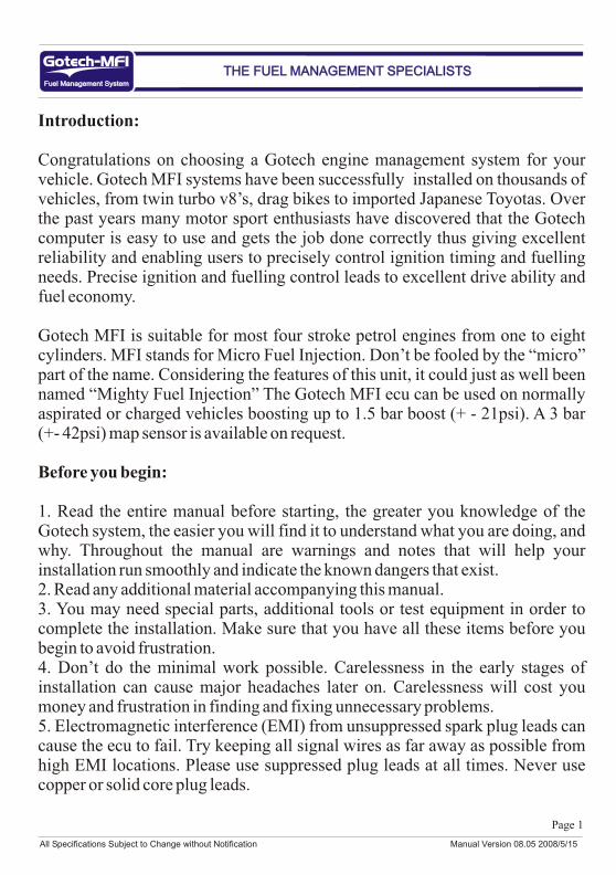
Introduction:
Congratulations on choosing a Gotech engine management system for your vehicle. Gotech MFI systems have been successfully installed on thousands of vehicles, from twin turbo v8’s, drag bikes to imported Japanese Toyotas. Over the past years many motor sport enthusiasts have discovered that the Gotech computer is easy to use and gets the job done correctly thus giving excellent reliability and enabling users to precisely control ignition timing and fuelling needs. Precise ignition and fuelling control leads to excellent drive ability and fuel economy.
Gotech MFI is suitable for most four stroke petrol engines from one to eight cylinders. MFI stands for Micro Fuel Injection. Don’t be fooled by the “micro” part of the name. Considering the features of this unit, it could just as well been named “Mighty Fuel Injection” The Gotech MFI ecu can be used on normally aspirated or charged vehicles boosting up to 1.5 bar boost (+ - 21psi). A 3 bar (+- 42psi) map sensor is available on request.
Before you begin:
1. Read the entire manual before starting, the greater you knowledge of the Gotech system, the easier you will find it to understand what you are doing, and why. Throughout the manual are warnings and notes that will help your installation run smoothly and indicate the known dangers that exist.2. Read any additional material accompanying this manual.3. You may need special parts, additional tools or test equipment in order to complete the installation. Make sure that you have all these items before you begin to avoid frustration.4. Don’t do the minimal work possible. Carelessness in the early stages of installation can cause major headaches later on. Carelessness will cost you money and frustration in finding and fixing unnecessary problems.5. Electromagnetic interference (EMI) from unsuppressed spark plug leads can cause the ecu to fail. Try keeping all signal wires as far away as possible from high EMI locations. Please use suppressed plug leads at all times. Never use copper or solid core plug leads.
Fuel Management SystemFuel Management System
THE FUEL MANAGEMENT SPECIALISTSTHE FUEL MANAGEMENT SPECIALISTS
All Specifications Subject to Change without Notification Manual Version 08.05 2008/5/15

Page 2
Before you begin continued:
6. In hot climates or with charged vehicles you might have to employ heat shielding to prevent heat soak to electrical and fuel parts. 7. We recommend you having your vehicle dynoed by professionals with the proper equipment.
Basic Tools Required For Wiring Installation:
Some basic tools are required for the Gotech wiring installation, these tools include:1. Side cutter2. Wire stripper3. Insulating tape4. Soldering iron5. Solder
Using heat shrink helps tidy up and insulate all the joints. A neat wiring harness makes fault finding easier and compliments the vehicle. Please use the Gotech wiring colour codes as far as possible.
Fuel Management SystemFuel Management System
THE FUEL MANAGEMENT SPECIALISTSTHE FUEL MANAGEMENT SPECIALISTS
WARNING - Before starting the Gotech installation:1. Avoid open sparks, flames or operation of electrical devices near flammable substances.2. Always disconnect the battery when doing electrical work on your vehicle.3. Do not charge the battery with a 24 volt truck charger or reverse the polarity of the battery or any charging unit.4. Do not charge the battery with the engine running as this could expose the ecu to an unregulated power supply that could destroy the ecu and other electrical equipment.5. All fuel system components and wiring should be mounted away from heat sources, shielded if necessary and well vented.6. Make sure that there are no leaks in the fuel system and that all connections are secure.7. Disconnect the Gotech ecu when doing any arc welding on the vehicle by unplugging the ecu from the main wiring harness.8. The engine should be earthed properly.
All Specifications Subject to Change without Notification Manual Version 08.05 2008/5/15
Page 3
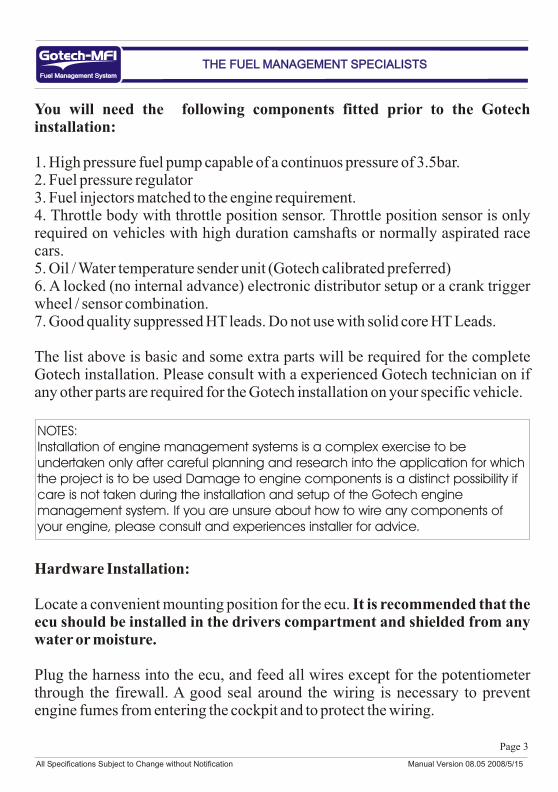
You will need the following components fitted prior to the Gotech installation:
1. High pressure fuel pump capable of a continuos pressure of 3.5bar.2. Fuel pressure regulator3. Fuel injectors matched to the engine requirement.4. Throttle body with throttle position sensor. Throttle position sensor is only required on vehicles with high duration camshafts or normally aspirated race cars.5. Oil / Water temperature sender unit (Gotech calibrated preferred)6. A locked (no internal advance) electronic distributor setup or a crank trigger wheel / sensor combination.7. Good quality suppressed HT leads. Do not use with solid core HT Leads.
The list above is basic and some extra parts will be required for the complete Gotech installation. Please consult with a experienced Gotech technician on if any other parts are required for the Gotech installation on your specific vehicle.
Hardware Installation:
Locate a convenient mounting position for the ecu. It is recommended that the ecu should be installed in the drivers compartment and shielded from any water or moisture.
Plug the harness into the ecu, and feed all wires except for the potentiometer through the firewall. A good seal around the wiring is necessary to prevent engine fumes from entering the cockpit and to protect the wiring.
Fuel Management SystemFuel Management System
THE FUEL MANAGEMENT SPECIALISTSTHE FUEL MANAGEMENT SPECIALISTS
NOTES:Installation of engine management systems is a complex exercise to be undertaken only after careful planning and research into the application for which the project is to be used Damage to engine components is a distinct possibility if care is not taken during the installation and setup of the Gotech engine management system. If you are unsure about how to wire any components of your engine, please consult and experiences installer for advice.
All Specifications Subject to Change without Notification Manual Version 08.05 2008/5/15

Page 4
Plug Pinouts Gotech MFI X:
Plug Pin Out References - 16 Pin Plug - MFI X
1. Ground 12 V - Brown 1.5 mm2.3.4.5.6.7. Positive12v Red 1.5 mm8. Positive12v Black 1.5 mm9. Ground 12 V - Brown 1.5 mm10. Ground 12 V - Brown 1.5 mm11. Ignition Phase 1 Black/White 1.5mm12 Ignition Phase 2 Red/White 1.5 mm13. Injector Phase 1 Brown/Orange 1.5mm14. Injector Phase 2 Brown/Red 1.5 mm15. Positive12v Red 1.5 mm16. Positive12v Black 1.5 mm
Fuel Management SystemFuel Management System
THE FUEL MANAGEMENT SPECIALISTSTHE FUEL MANAGEMENT SPECIALISTS
12345678
910111213141516
Retaining Clip
WARNING:Incorrect wiring connections will cause severe damage to the ecu and the vehicle. When routing the wiring harness try to keep is as far away as possible from HT leads and high heat sources like the turbo charger or exhaust headers. Always use good insulation tape and solder the wires properly. Always disconnect the car’s battery before working on the wiring. Avoid open sparks, flames or operation of electrical devices near flammable substances. Disconnect the Gotech ecu when doing any arc welding on the vehicle by unplugging the ecu from the main wiring harness.
FIG 1.16 PIN MALE PLUG ON THE ECU
All Specifications Subject to Change without Notification Manual Version 08.05 2008/5/15

Page 5
Plug Pinouts Gotech MFI X Continued:
Plug Pin Out References - 14 Pin Plug - MFI X
1. 3v+ Orange 0.5mm2. Ground To Sensors Brown/White 0.5mm3. Ground To Sensors Brown/White 0.5mm4. External Map Sensor input5. Ignition Pot Green 0.5mm6. Throttle position sensor input Blue/Yellow 0.5mm7. Water Temperature Blue/Orange 0.5mm8. 3v+ Orange 0.5mm9. RPM input Red, Shielded10. TDC input Red,Shielded211. Launch control Green/White 1mm12. Fuel Pot Yellow 0.5mm13. Lambda Black/Green 1.5mm14. Air Temp Blue 0.5mm
Fuel Management SystemFuel Management System
THE FUEL MANAGEMENT SPECIALISTSTHE FUEL MANAGEMENT SPECIALISTS
All Specifications Subject to Change without Notification Manual Version 08.05 2008/5/15
1234567
891011121314
Retaining Clip
WARNING:Incorrect wiring connections will cause severe damage to the ecu and the vehicle. Avoid jump starting the vehicle. Before attempting to start the vehicle, read the entire manual and setup the Ecu’s main configuration first. Please refer to page 7for the modes and outputs available. The two brown wires MUST be earthed straight onto the battery negative, do not earth them onto the body. The two black wires must be connected to a relay that is fed straight from the battery positive.

Page 6
Gotech ECU Power Supply:
The Gotech ecu requires a stable power and earth feed to function properly. It is recommended to fit a high quality 4 pin relay with a inline fuse on the 12v + input of the Gotech ecu. The Brown wire (16 Pin Plug, Pin 1) should be connected straight onto the battery negative terminal. Do not earth on the chassis.
Connecting the ECU Power Supply:
The ignition 12v + wire should give power to the relay pin 85 when the ignition is turned on and while the engine is cranking.
Fuel Management SystemFuel Management System
THE FUEL MANAGEMENT SPECIALISTSTHE FUEL MANAGEMENT SPECIALISTS
Brown (16 Pin plug, Pin 1)
Inline Fuse30AMPor more
12v Permanent power to pin 30 on relay as shown above
85
86
30
87Earth On Battery Negative
Ignition 12v +
Permanent 12v +
Black (16 Pin plug, Pin 16)
4 Pin Relay
Inline Fuse30AMPor more
WARNING:Do not reverse the polarity on the Gotech ecu. Reverse polarity will cause severe damage to the Gotech ecu and other electrical parts. Always earth the Gotech ECU directly to the battery. Do not earth the ecu onto the chassis.
All Specifications Subject to Change without Notification Manual Version 08.05 2008/5/15
Page 7
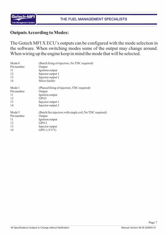
Outputs According to Modes:
The Gotech MFI X ECU’s outputs can be configured with the mode selection in the software. When switching modes some of the output may change around. When wiring up the engine keep in mind the mode that will be selected.
Mode 0 (Batch firing of injectors, No TDC required)Pin number Output11 Ignition output12 Injector output 113 Injector output 214 Micro fueller
Mode 1 (Phased firing of injectors, TDC required)Pin number Output11 Ignition output12 GPO213 Injector output 114 Injector output 2
Mode 5 (Batch fire injectors with single coil, No TDC required)Pin number Output11 Ignition output12 GPO 213 Injector output14 GPO 1 (VVT)
Fuel Management SystemFuel Management System
THE FUEL MANAGEMENT SPECIALISTSTHE FUEL MANAGEMENT SPECIALISTS
All Specifications Subject to Change without Notification Manual Version 08.05 2008/5/15

Page 8
Outputs Mode 0: (Batch Fire of injectors, No TDC required)
Ignition output:
Injector Output:
Micro Fueller:
Fuel Management SystemFuel Management System
THE FUEL MANAGEMENT SPECIALISTSTHE FUEL MANAGEMENT SPECIALISTS
+
_
Ignition 12v+
Black / White (16 Pin plug, Pin 11)
Single Coil
1234
Red (Relay, Pin 87)
Red (Relay, Pin 87)
Brown/Orange (16 Pin Plug, Pin 13)
Red/White (16 Pin Plug, Pin 12)
1234
Red (Relay, Pin 87)
Brown/Red (16 Pin Plug, Pin 14)
All Specifications Subject to Change without Notification Manual Version 08.05 2008/5/15
Page 9
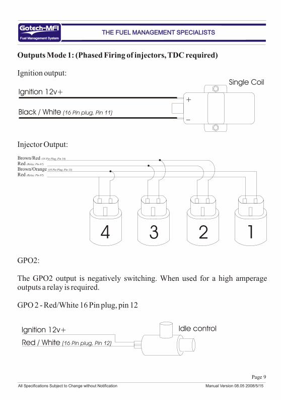
Outputs Mode 1: (Phased Firing of injectors, TDC required)
Ignition output:
Injector Output:
GPO2:
The GPO2 output is negatively switching. When used for a high amperage outputs a relay is required.
GPO 2 - Red/White 16 Pin plug, pin 12
Fuel Management SystemFuel Management System
THE FUEL MANAGEMENT SPECIALISTSTHE FUEL MANAGEMENT SPECIALISTS
+
_
Ignition 12v+
Black / White (16 Pin plug, Pin 11)
Single Coil
1234
Red (Relay, Pin 87)
Red (Relay, Pin 87)
Brown/Orange (16 Pin Plug, Pin 13)
Brown/Red (16 Pin Plug, Pin 14)
Ignition 12v+
Red / White (16 Pin plug, Pin 12)
Idle control
All Specifications Subject to Change without Notification Manual Version 08.05 2008/5/15
Page 10
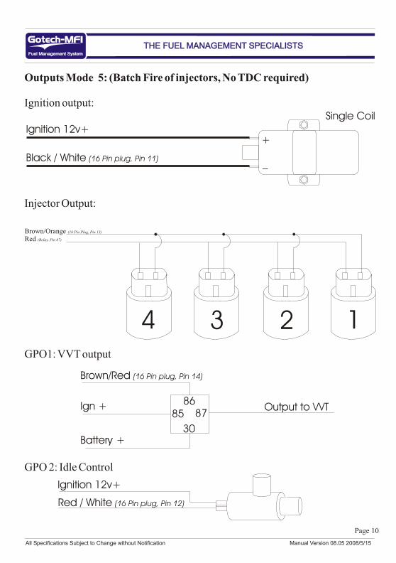
Outputs Mode 5: (Batch Fire of injectors, No TDC required)
Ignition output:
Injector Output:
GPO1: VVT output
GPO 2: Idle Control
Fuel Management SystemFuel Management System
THE FUEL MANAGEMENT SPECIALISTSTHE FUEL MANAGEMENT SPECIALISTS
+
_
Ignition 12v+
Black / White (16 Pin plug, Pin 11)
Single Coil
1234
Red (Relay, Pin 87)
Brown/Orange (16 Pin Plug, Pin 13)
8586
87
30
Brown/Red (16 Pin plug, Pin 14)
Ign +
Battery +
Output to VVT
Ignition 12v+
Red / White (16 Pin plug, Pin 12)
All Specifications Subject to Change without Notification Manual Version 08.05 2008/5/15
Page 11
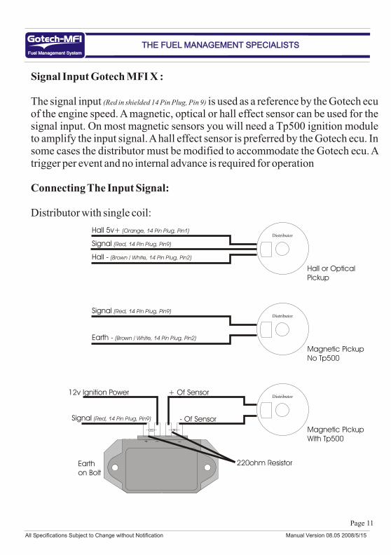
Signal Input Gotech MFI X :
The signal input (Red in shielded 14 Pin Plug, Pin 9) is used as a reference by the Gotech ecu of the engine speed. A magnetic, optical or hall effect sensor can be used for the signal input. On most magnetic sensors you will need a Tp500 ignition module to amplify the input signal. A hall effect sensor is preferred by the Gotech ecu. In some cases the distributor must be modified to accommodate the Gotech ecu. A trigger per event and no internal advance is required for operation
Connecting The Input Signal:
Distributor with single coil:
Fuel Management SystemFuel Management System
THE FUEL MANAGEMENT SPECIALISTSTHE FUEL MANAGEMENT SPECIALISTS
Hall 5v+ (Orange, 14 Pin Plug, Pin1)Distributor
Signal (Red, 14 Pin Plug, Pin9)
Hall - (Brown / White, 14 Pin Plug, Pin2)
Hall or OpticalPickup
Distributor
Magnetic PickupNo Tp500
+ Of SensorDistributor
Magnetic PickupWith Tp5004 3 2 1
- Of Sensor
12v Ignition Power
Earthon Bolt
220ohm Resistor
Signal (Red, 14 Pin Plug, Pin9)
Earth - (Brown / White, 14 Pin Plug, Pin2)
Signal (Red, 14 Pin Plug, Pin9)
All Specifications Subject to Change without Notification Manual Version 08.05 2008/5/15
Page 12
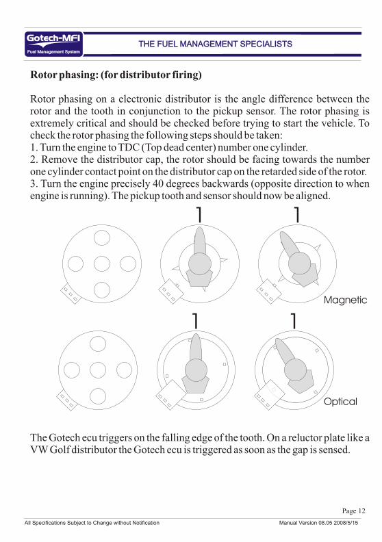
Rotor phasing: (for distributor firing)
Rotor phasing on a electronic distributor is the angle difference between the rotor and the tooth in conjunction to the pickup sensor. The rotor phasing is extremely critical and should be checked before trying to start the vehicle. To check the rotor phasing the following steps should be taken:1. Turn the engine to TDC (Top dead center) number one cylinder.2. Remove the distributor cap, the rotor should be facing towards the number one cylinder contact point on the distributor cap on the retarded side of the rotor.3. Turn the engine precisely 40 degrees backwards (opposite direction to when engine is running). The pickup tooth and sensor should now be aligned.
The Gotech ecu triggers on the falling edge of the tooth. On a reluctor plate like a VW Golf distributor the Gotech ecu is triggered as soon as the gap is sensed.
Fuel Management SystemFuel Management System
THE FUEL MANAGEMENT SPECIALISTSTHE FUEL MANAGEMENT SPECIALISTS
1 1
1 1Magnetic
Optical
All Specifications Subject to Change without Notification Manual Version 08.05 2008/5/15

Page 13
Top Dead Center (TDC) Signal Input Gotech MFI X:
The TDC signal input (Red Shielded2, 14 Pin Plug, Pin 10) is used by the Gotech ecu as a reference for TDC on the engine. A magnetic, optical or hall effect sensor can be used for the signal input. On some magnetic sensors you will need a Tp500 ignition module to amplify the input signal. The recommended TDC sensor is a hall effect sensor.
The TDC input signal is required in the following instances:1. Single coil, phased fire injectors, TDC required (Mode 1)
Do not connect the TDC input signal in the following instances:1. Single coil, batch fire injectors (Mode 0)2. Single coil batch fire injectors (Mode 5)
Connecting The TDC Input Signal:
Fuel Management SystemFuel Management System
THE FUEL MANAGEMENT SPECIALISTSTHE FUEL MANAGEMENT SPECIALISTS
Distributor
Hall or OpticalPickup
+ Of SensorDistributor
Magnetic PickupWith Tp5004 3 2 1
- Of Sensor
12v Ignition Power
Earthon Bolt
220ohm Resistor
Hall 5v+ (Orange, 14 Pin Plug, Pin1)
Signal (Red, 14 Pin Plug, Pin10)
Hall - (Brown / White, 14 Pin Plug, Pin2)
Signal (Red, 14 Pin Plug, Pin10)
All Specifications Subject to Change without Notification Manual Version 08.05 2008/5/15

Page 14
Top Dead Center (TDC) Signal Input Gotech MFI X Continued:
To check the rotor and TDC phasing the following should be done: (The simulated distributor turns clockwise in normal operation)
1. Turn the engine to TDC (Top dead center) number one cylinder.2. Remove the distributor cap, the rotor should be facing towards the number one cylinder contact point on the distributor cap on the retarded side of the rotor.3. Turn the engine precisely 40 degrees backwards (opposite direction to when engine is running). The RPM pickup tooth and sensor should now be aligned.4. Turn the engine another 10 degrees backwards (opposite direction to when engine is running). The total degrees backwards should be approx 50 degrees. The TDC pickup tooth and sensor should now be aligned.
Fuel Management SystemFuel Management System
THE FUEL MANAGEMENT SPECIALISTSTHE FUEL MANAGEMENT SPECIALISTS
Magnetic Pickup
RPM Pickup
TDC Pickup1
The TDC tooth is shown as squareand the RPM teeth is shown as sharp.The teeth is only drawn sharp and squareto make the images more explanatory. It is recommended to keep the teethsquare if possible. The Gotech ecutriggers on the falling edge.
11
1
Signal (Red, 14 Pin Plug, Pin10)
Earth (Brown / White, 14 Pin Plug, Pin2)
All Specifications Subject to Change without Notification Manual Version 08.05 2008/5/15

Page 15
Throttle position Sensor:
Most modern fuel injected vehicles are fitted with a TPS (Throttle position sensor). The ecu uses the TPS as a reference to how far the throttle is opened. A TPS is not a critical element of the input sensors and can be substituted with the built in map sensor. If the vehicle is equipped with high duration camshafts then a TPS is required. On turbo or super charged vehicles using forced induction it is recommended to run the map sensor as primary input. (Mode 0 in TPS map mix on
the f5 configuration screen). A TPS is basically a variable resistor as shown in fig 1.1. TPS connection on Gotech harness:
Blue / Yellow (14 Pin Plug, Pin 6) - SignalOrange (14 Pin Plug, Pin 1) - PositiveBrown / White (14 Pin Plug, Pin 2)- Negative
Determining the pinouts of a tps:
Take a multimeter and switch it to measure ohmage. On a three pin tps when measuring between positive and negative the ohmage will stay the same when opening the throttle. Between positive and signal the ohmage will go less when opening the throttle. Between negative and signal the ohmage will increase when opening the throttle.
Popular engine’s TPS pinouts:
Fuel Management SystemFuel Management System
THE FUEL MANAGEMENT SPECIALISTSTHE FUEL MANAGEMENT SPECIALISTS
Toyota 4agePin 1 - PositivePin 2 - SignalPin 4 - Negative
1234
VW Golf 3 PinPin 1 - NegativePin 2 - SignalPin 3 - Positive
VW Golf mp9Pin 4 - NegativePin 5 - SignalPin 7 - Positive
+
-S
Fig 1.1
All Specifications Subject to Change without Notification Manual Version 08.05 2008/5/15

Page 16
Water Temperature:
The Gotech ecu uses the water temperature sensor as a reference to see how hot the engine is for cold starting purposes. On air cooled engines the temperature sensor can be mounted to sense oil temperature. Most oem water temperature sensors can be used with the Gotech ecu, but it is recommended to use the Gotech temp sender unit as seen in fig 1.2 (Available from Gotech). A temp sender unit cannot be shared by the gauge and the Gotech ECU. Connecting both the gauge and Gotech on a single sender unit will damage the ecu.
Water Temperature Sensor Connection:Blue / Orange (14 Pin Plug, Pin 7) - SignalBrown / White (14 Pin Plug, Pin 2) - Negative
Air Temperature:
The air temperature sensor is supplied with the Gotech wiring harness as seen below. This sensor gives the ecu an indication of the outside air temperature and then enriches the fuel mixtures accordingly. The air temperature sensor should be fitted on the vehicle so that it does not receive hot air from the engine compartment (Ambient air temperature) . A threaded air temperature sensor is available on request. A temp sender unit cannot be shared by the gauge and the Gotech ECU. Connecting both the gauge and Gotech on a single sender unit will damage the ecu.
Air Temperature Sensor Connection:Blue (14 Pin Plug, Pin 14) - SignalBrown / White (14 Pin Plug, Pin 2) - Negative
Fuel Management SystemFuel Management System
THE FUEL MANAGEMENT SPECIALISTSTHE FUEL MANAGEMENT SPECIALISTS
Fig 1.2
M10 x 1Thread
All Specifications Subject to Change without Notification Manual Version 08.05 2008/5/15
Page 17
Lambda Sensor:
When setting up the ecu a Lambda sensor should be used, but it is not required for everyday driving. The Lambda sensor must be mounted in the exhaust pipe near the exhaust header or extractor, usually after the collector. The sensor uses the exhaust gas to detect if the engine is running lean or rich.
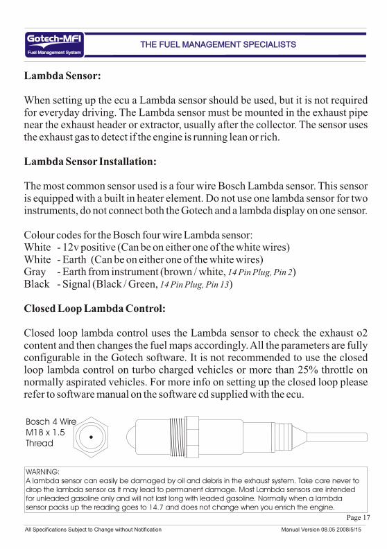
Lambda Sensor Installation:
The most common sensor used is a four wire Bosch Lambda sensor. This sensor is equipped with a built in heater element. Do not use one lambda sensor for two instruments, do not connect both the Gotech and a lambda display on one sensor.
Colour codes for the Bosch four wire Lambda sensor:White - 12v positive (Can be on either one of the white wires)White - Earth (Can be on either one of the white wires)Gray - Earth from instrument (brown / white, 14 Pin Plug, Pin 2)Black - Signal (Black / Green, 14 Pin Plug, Pin 13)
Closed Loop Lambda Control:
Closed loop lambda control uses the Lambda sensor to check the exhaust o2 content and then changes the fuel maps accordingly. All the parameters are fully configurable in the Gotech software. It is not recommended to use the closed loop lambda control on turbo charged vehicles or more than 25% throttle on normally aspirated vehicles. For more info on setting up the closed loop please refer to software manual on the software cd supplied with the ecu.
Fuel Management SystemFuel Management System
THE FUEL MANAGEMENT SPECIALISTSTHE FUEL MANAGEMENT SPECIALISTS
WARNING:A lambda sensor can easily be damaged by oil and debris in the exhaust system. Take care never to drop the lambda sensor as it may lead to permanent damage. Most Lambda sensors are intended for unleaded gasoline only and will not last long with leaded gasoline. Normally when a lambda sensor packs up the reading goes to 14.7 and does not change when you enrich the engine.
Bosch 4 WireM18 x 1.5Thread
All Specifications Subject to Change without Notification Manual Version 08.05 2008/5/15

Page 18
Launch Control:
The launch control feature is available on Gotech MFI X.
When the launch control is activated the ignition timing is retarded (amount
configurable) and the soft and hard launch rpm limit is used (rpm configurable). With your foot flat on the throttle the engine will limit on the launch rpm limit. As soon as you pull away you release the button and the timing will be advanced again to the original ignition map after a couple of ms (time configurable) and the rpm limit will go back to the standard value. With the launch control activated on a turbo vehicle you will notice that the engine will start to boost when the launch rpm limit is reached. This will help to bring down the turbo lag on a vehicle with a big turbo setup. Setting up the launch control may take a while and you will need to spend a couple of hours at the race track to perfect your settings and win that extra couple of tenths at the end of the 1/4 mile.
Activating The Launch Control:
Connect the green / white (14 Pin Plug, Pin 11) wire and the orange to activate the launch control. We recommend fitting a on/of switch in your vehicle with a push button on the steering.
Fuel Management SystemFuel Management System
THE FUEL MANAGEMENT SPECIALISTSTHE FUEL MANAGEMENT SPECIALISTS
WARNING:The launch control function should only be used by advanced users. By setting the launch control values incorrectly you can seriously damage your vehicle’s engine and the Gotech ecu. This function is intended for track use only.
On / Off Switch
Push button switch
Orange (14 Pin Plug, Pin 1)
Green / White (14 Pin Plug, Pin 11)
All Specifications Subject to Change without Notification Manual Version 08.05 2008/5/15
Page 19
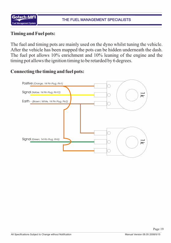
Timing and Fuel pots:
The fuel and timing pots are mainly used on the dyno whilst tuning the vehicle. After the vehicle has been mapped the pots can be hidden underneath the dash. The fuel pot allows 10% enrichment and 10% leaning of the engine and the timing pot allows the ignition timing to be retarded by 6 degrees.
Connecting the timing and fuel pots:
Fuel Management SystemFuel Management System
THE FUEL MANAGEMENT SPECIALISTSTHE FUEL MANAGEMENT SPECIALISTS
1k
1k
Positive (Orange, 14 Pin Plug, Pin1)
Signal (Yellow, 14 Pin Plug, Pin12)
Earth - (Brown / White, 14 Pin Plug, Pin2)
Signal (Green, 14 Pin Plug, Pin5)
All Specifications Subject to Change without Notification Manual Version 08.05 2008/5/15