hands-on modules for teaching physical concepts to 7 and 8
TRANSCRIPT

Hands-on Modules for Teaching Physical Concepts to 7th and 8th Grade Students: Module 4: The Physics of Collisions
Authors: Dorottya B. Noble1,2, Ian Linsmeier1,3, Daniel Seara1,4, Joshua Young10, Nadia Abascal2, Douglas B. Noble5, Corey S. O’Hern1,4,6,7,8, and Lynne Regan1,2,8,9
Affiliations: 1Integrated Graduate Program in Physical and Engineering Biology, 2Department of Molecular Biophysics and Biochemistry, 3Department of Biomedical Engineering, 4Department of Physics, 5Office of Environmental Health and Safety, 6Department of Mechanical Engineering and Materials Science, 7Department of Applied Physics, 8Graduate Program in Computational Biology and Bioinformatics, 9Department of Chemistry, Yale University, New Haven, CT 06520, USA; 10Hopkins School, New Haven, CT 06515, USA
Keywords: collisions, air track, momentum, hands-on, elastic, inelastic
Abstract: This physics education module encourages middle school students (ages 12-14) to think about collisions and conservation of momentum. We present a detailed description of the construction of a low-cost, custom-built air track and carts. We describe how this apparatus can be used by students to study conservation of momentum for different types of collisions. The module also includes ideas for how the instructor can relate the concepts described in the module to real-life examples that are relevant to middle school students.
1) Introduction and Learning Objectives
This module introduces students to one of the most fundamental concepts in physics: conservation of momentum “p”. Students analyze collisions on a low-cost, custom-built air track. Three classes of collisions are investigated: elastic collisions, inelastic collisions, and imperfectly inelastic collisions. Students will learn what momentum is and how to take measurements that will then be used to calculate it.
2) Preparation prior to offering the module
Prior to offering this module, one or more air tracks must be built. We list the 3D printed and laser cut components in Table S2 and also include the files for each component. If a 3D printer is not available, we recommend outsourcing the 3D printing, for example through shapeways.com. If a laser cutter is not available, the components can be made out of wood. A minimum of three students is needed to conduct the experiments for each air track.
Air track fabrication
With the 3D printed and laser cut components in hand (see Table S2), the air-track can be built.
Creating air holes in air track body: To evenly space the holes in the air track body, we recommend creating a drilling template (see Figure 1). The template can be created either from a clear acrylic sheet, using a CO2 laser cutter, or from a piece of wood, drilling through-holes using a 1 mm drill bit.
Affix the drilling template to the left-most section of the air track body using c-clamps. Attach the template such that the side of the template with the through-holes is aligned with the top edge of

the air track. Drill a hole in the air track body through each of the through-holes in the template using a 1 mm drill bit. Note that the drill bits are delicate, and thus we recommend obtaining more than one in case they break. Once holes have been drilled along the entire length of the template, unclamp the template and shift it down the length of the air track body. To ensure proper spacing, align the three leftmost holes of the template with the three rightmost holes that have already been made. Clear out any burrs on the interior of the square tube that may remain as a result of drilling, using a file, to ensure smooth airflow. Preparing end caps: Laser-cut the 8 by 8 cm end caps for the air track body, from the acrylic sheet. One end cap should include a hole in the center that matches the dimensions of the shop vacuum’s tapered hose to connect it to the air track. The end caps can be 3D printed, if needed.
Preparing air track base: An adjustable base for the air track is used to level the air track. Laser cut two, 20.25 cm by 3.80 cm rectangular bases from the Delrin sheet, with four through-holes also laser cut. Two should be cut in the center of the bases, approximately 2 cm apart, to the diameter of the screws (approximately 4 mm) used to attach the base to the U-channel. Drill two matching holes 23 cm from each end of the U-channel. Attach the two bases to the U-channel using nuts and bolts that fit the dimensions of the matching through holes, and then tighten the bolt to affix the bases to the U-channel. The other two holes, each approximately 1.25 cm from the end of the base, should be laser cut to the diameter of the larger hex bolts (approximately 8 mm) and tapped. Screw the larger hex-bolts, used to adjust the height of the air track, into the tapped holes (see Figure 2D and 2E). Use Velcro to attach a level to the U-channel, above each of the air track bases along one side of the air track (Figure 2D and 2E). The two bases can also be made from wood in the absence of a laser cutter, using a saw. Use two wood screws to attach the base to the U-channel in the middle, and drill and tap the holes at the ends of the base for the hex bolts.
Gluing air track components: Use a caulk gun to deliver silicone sealant to glue the components (allowing it to cure overnight). First, glue the end caps onto the hollow air track body containing the drilled air holes (Figure 2F and 2G). Next, glue the air track supports (Figure 2B) along length of the U-channel air track base (Figure 2A) and glue the air track body to the supports in the U-channel. Finally, glue the bumpers at the flanking ends of the air track (see Figures 1 and 2A). Creating magnet inserts for air track carts: Take the 3D printed cylinder and screw the magnet into the hole in the middle of the cylinder. Inspecting the carts: If the surface is rough, tape it with masking tape to create a smooth surface to minimize problems with airflow. Leveling the air track The air track must be leveled to ensure that only forces introduced during an experiment act on the carts. Use the level attached to the U-channel and place others on the base itself and adjust by twisting the bolts on the air track base. Marking distances along the air track body Velocity is determined by measuring the time it takes a cart to travel a known distance. Distances on the air track should to be marked by cutting 2-3 mm wide and 4-5 cm long pieces of masking tape and sticking them vertically to the air track body, at defined distances (see Figure 2A). 3) Lesson Plan

Introduction to the experimental system and collisions: The instructor should introduce the motivation behind this module. Collisions are among the most visible and useful demonstrations of the physical concepts of energy and momentum. One can witness collisions in daily life by watching a baseball game, for example. When a baseball player strikes a ball with a bat, a collision occurs. If the same baseball player swings their bat in the same way, one can predict that a baseball will go further than a softball. This is because a softball is heavier or–more precisely–has more mass “m”. In Major League Baseball, players must use wooden bats. Bats made of cork, a substance that is lighter and has less mass than wood, are illegal. To meet a fastball and hit it, one can swing a lighter cork bat much faster than a heavier wooden bat. When a player swings a bat, the bat is given a velocity (speed in a particular direction) “v”. The mass “m” and velocity “v” of an object can be used to calculate an important quantity for analyzing collisions: momentum “p”. Momentum is calculated using Eq. 1. The momentum gives a measure of how hard it is to stop an object that is moving. For example, a mosquito moving with a given velocity in a particular direction is much easier to stop than an elephant moving with the same velocity in the same direction, due to the difference in their masses, “m”.
𝑝 = 𝑚𝑣 (1) The instructor should tell the students that they will collide two carts on the air track, multiple times, film the collisions, and calculate the velocity and the momentum of the carts before and after the collision. All calculations should use the International Systems of Units (SI Units). Part 1. Perfectly Elastic Collisions. (~1.5 hours) Obtaining masses of the carts involved in the collision: To model perfectly elastic collisions, students will use carts with magnets attached to either side (Figure 3A). Although the collision will happen along only one end of each cart, magnet inserts should be added to both baskets of each cart for proper weight distribution. Place the magnet insert inside each basket of both carts and weigh each cart using a balance. Record the mass “m” of each cart in kilograms. The two carts should be within a couple grams of each other, otherwise the difference in masses will complicate accounting for the momentum in the collision. Colliding the carts: For this experiment, a moving “cart 1” will strike a stationary “cart 2”. Place cart 1 approximately 5-10 cm from the end of the air track before the first distance marker and cart 2 approximately half-way along the air track, between the second and third distance markers (see Figure 2A). Turn on the air track. One student should hold cart 2 in place (to ensure that it does not move due to airflow) while another student pushes cart 1, holding it along the top of one of the baskets. Just before cart 1 is about to collide with cart 2, let go of cart 2. After the collision, cart 1 should be stationary and cart 2 should be moving. Students should carry out a few collisions to get a feel for how hard to push cart 1 and when to let go of cart 2. An “ideal” push would cause cart 1 to collide into cart 2 fast enough to push cart 2 all the way to the end of the air track but not so fast that cart 2 hits the air track bumper hard. We have found that slight wobbling of the carts may occur, but this will not affect the experiment significantly. Calculating velocities: Students must calculate the velocities of the carts before and after the collision by dividing the distance traveled (d) on the air track by the time (t) it took to travel that distance (Eq. 2). To calculate the velocities of the carts, film the collision using a smart phone. Upload the video to the cloud photo service Google Drive (a Google account is required). To slow down the video for more accurate timing, start playing it, then click on video settings (the gear

icon), select “speed”, and click on “0.25.” Loop the video by right clicking anywhere on the video and selecting the “loop” option, which eliminates the need to continuously restart the video. To obtain the velocity (v) of cart 1 before the collision, time how long it takes the cart to go from distance marker 1 to distance marker 2. To increase the accuracy and decrease systematic error, we recommend obtaining at least 10 measurements, with multiple people timing. The instructor should remind students to multiply the measured times by the speed at which the video is played back (0.25) to obtain the true times. We recommend averaging the measured times and using that value in the velocity calculation. To calculate the velocity, in units of “m/s”, use Eq. 2. The velocity of cart 2 after the collision is determined by measuring the time it takes the cart to travel the distance between distance markers 3 and 4.
𝑣 = &' (2)
Calculating momentum: Students should use equations 3 and 4 to calculate the momentum of the system before and after the collision, respectively. In equations 5 and 6, “pi” is initial momentum, “pf” is final momentum, “m1” is the mass of cart 1, “m2” is the mass of cart 2, “𝑣() ” is the initial velocity of cart 1, “𝑣*) ” is the initial velocity of cart 2, “𝑣(
+” is the final velocity of cart 1, and “𝑣*
+” is the final velocity of cart 2.
𝑝) = 𝑝() + 𝑝*) = 𝑚(𝑣() + 𝑚*𝑣*) (3)
𝑝+ = 𝑝(+ + 𝑝*
+ = 𝑚(𝑣(+ +𝑚*𝑣*
+ (4) Calculating the relative deviation between the initial and final momentum: Students should use Eq. 5 to compare the initial and final momentum. The vertical brackets indicate the absolute value.
𝑟𝑒𝑙𝑎𝑡𝑖𝑣𝑒%𝑑𝑒𝑣𝑖𝑎𝑡𝑖𝑜𝑛 = 100 ∗ |;<=;>|;<
(5) Discussion and calculations for perfectly elastic collisions: Typical data and the relative deviation in the initial and final momentum can be found in Table 1. The instructor should explain to the students that perfectly elastic collisions are the “bounciest” type of collisions. The experiment in Part 1 seeks to model a perfectly elastic collision using the nearly frictionless surface of the air track. As with all collisions, the momentum along the path of the air track is conserved (pi= pf). We found a relative deviation of 5-15% for momentum conservation in our experiments. Extremely accurate testing of the conservation of momentum is difficult. The instructor should lead a discussion of the possible reasons why the measurements of the model perfectly elastic collisions on the air track did not appear to precisely conserve momentum. Topics to consider include: 1) The air track, although relatively low friction, is not a completely frictionless surface due to non-uniform air flow or imperfections along the base of the carts; 2) The air track is not perfectly level; 3) The velocities of the carts were not measured with high precision; and 4) Cart 2 may have been released with a nonzero velocity. The instructor can prompt the students by

asking: 1) How do you know the air track is level? 2) Are the surfaces of the experimental setup perfectly smooth? 3) Do you think the airflow around the air track is uniform? 4) Are the masses of the carts the same? 5) Did cart 1 stop after the collision or did it keep moving? Table 1. Perfectly elastic collisions. Values with an asterisk (*) show the average ± standard deviation of at least ten independent measurements of each collision (by replaying the video footage). Trial 1 Trial 2 Trial 3 Time (initial) cart 1* (s)
1.07 ± 0.02 1.01 ± 0.02 0.84 ± 0.02
Time (final) cart 2* (s)
1.19 ± 0.02 1.07 ± 0.02 0.93 ±0.03
m1 (kg) 0.3637 0.3637 0.3622 m2 (kg) 0.3616 0.3616 0.3633 v1
i (m/s) 0.285 0.302 0.363 v2
f (m/s) 0.256 0.285 0.328 pi (kg m/s) 0.104 0.110 0.131 pf (kg m/s) 0.093 0.103 0.119 % deviation in momentum
10.6% 6.2% 9.4%
Part 2. Perfectly Inelastic Collisions. (~1.5 hours) An example of a perfectly inelastic collision is catching a baseball. Upon impact, the baseball and the catcher’s hand will move together at a much slower velocity than the one with which the ball was flying. We will now study this type of collision using the air track. The experiment: Two carts, without any inserts, will be used in this experiment. Students should tape two pieces of Velcro on the bases of the carts, as shown in Figure 3B. After weighing each cart, the students will collide the carts as in Part 1, and measure the velocities before and after the collision. However, unlike in Part 1, in these collisions, the two carts will stick to each other and move together following the collision. Therefore, the final momentum can be calculated using Eq. 6. Eq. 3 is still used to calculate the initial momentum. Typically, for these collisions, cart 1 will have to be pushed harder than it was pushed in Part 1.
𝑝+ = 𝑝(+ + 𝑝*
+ = (𝑚( +𝑚*)𝑣+ (6) Discussion and calculations for perfectly inelastic collisions: In this experiment, once again, momentum should be conserved. Students should use Eqs. 3, 5, and 6 to determine the relative deviation in the initial and final momentum of the system. Typical data and calculated values for this experiment can be found in Table 2. We find deviations of 10-15%, which may result from the same sources as discussed in Part 1. In addition, the Velcro may cause repeated small collisions between the carts. Table 2. Perfectly inelastic collisions. Values with an asterisk (*) show the average ± standard deviation of at least ten independent measurements using the same video footage.

Trial 1 Trial 2 Trial 3 Time (initial) cart 1* (s)
0.38 ± 0.02 0.34 ± 0.02 0.42 ± 0.01
Time (final) cart 2* (s)
0.89 ± 0.02 0.76 ± 0.02 0.95 ±0.02
m1 (kg) 0.2765 0.2765 0.2765 m2 (kg) 0.2778 0.2778 0.2778 m1 + m2 (kg) 0.5543 0.5543 0.5543 v1
i (m/s) 0.802 0.896 0.726 v2
f (m/s) 0.342 0.401 0.321 pi (kg m/s) 0.222 0.248 0.201 pf (kg m/s) 0.190 0.222 0.178 % deviation in momentum
14.4% 10.3% 11.4%
Part 3. Imperfectly Inelastic Collisions. (~1.5 hours) An example of an imperfectly inelastic collision might be playing tee-ball with a soft ball and a padded bat, both of which can deform during the collision and absorb some of the momentum. To study these types of collisions, students will stuff various materials inside the cart baskets, to mimic the soft parts of the bat and ball. The experiment: The baskets facing each other on the two carts (and only those) should be filled with various materials. We recommend testing cotton pads, aluminum foil, Saran wrap, pieces of paper, and tissue paper. After filling the baskets, the carts should be weighed. Next, the students should collide the carts as in Part 1. In these collisions, both carts will continue to move after the collision, although cart 1 at a much slower rate. To determine the velocity after the collision of cart 1, it may be necessary to remove cart 2 from the air track once it touches the air track bumper to avoid the two carts colliding once again near the end of the track but before cart 1 reaches distance marker 4. For this collision, the final momentum can be calculated using equation 9.
𝑝+ = 𝑝(+ + 𝑝*
+ = 𝑚(𝑣(+ +𝑚*𝑣*
+ (7) Discussion and calculations for imperfectly inelastic collisions: Students should use equations 3, 5 and 7 to determine the initial and final momentum and relative deviation between the initial and final momentum of the system. Typical data and calculated values are given in Table 3. For materials that are able to absorb some of the momentum of the collision, the relative deviations in momentum will be significantly higher than those in Parts 1 and 2 (see Table 3). It is important that the students understand that even though these simple measurements indicate a deviation in the initial and final momentum, the total momentum will be conserved if we consider additional factors, such as the change of momentum of the cotton pads and motion of the carts in the vertical direction. Table 3. Imperfectly inelastic collisions using four cotton pads inside each basket. Values with an asterisk (*) show the average ± standard deviation of at least ten independent measurements using the same video footage. For calculations, the average time measurements were used. Trial 1 Trial 2 Trial 3
Time (initial) cart 1* (s)
0.46 ± 0.02 0.34 ± 0.02 0.33 ± 0.02
Time (final) cart 1* (s)
3.16 ± 0.06 4.24 ± 0.04 1.65 ± 0.03
Time (final) cart 2* (s)
0.76 ± 0.01 0.62 ± 0.02 0.52 ± 0.02
m1 (kg) 0.2809 0.2809 0.2809 m2 (kg) 0.2793 0.2793 0.2793 v1
i (m/s) 0.663 0.871 0.924 v1
f (m/s) 0.096 0.072 0.185 v2
f (m/s) 0.401 0.492 0.586 pi (kg m/s) 0.186 0.245 0.259 pf (kg m/s) 0.139 0.158 0.216 % deviation in momentum
25.3% 35.6% 16.9%
4) Safety Considerations During the air track fabrication process, only experienced personnel should operate the laser cutter. Proper personal protective equipment, including safety glasses, should be worn during the fabrication process. Anyone using a power drill should have basic knowledge of using the tool and take appropriate safety precautions, such as avoiding entanglement hazards.
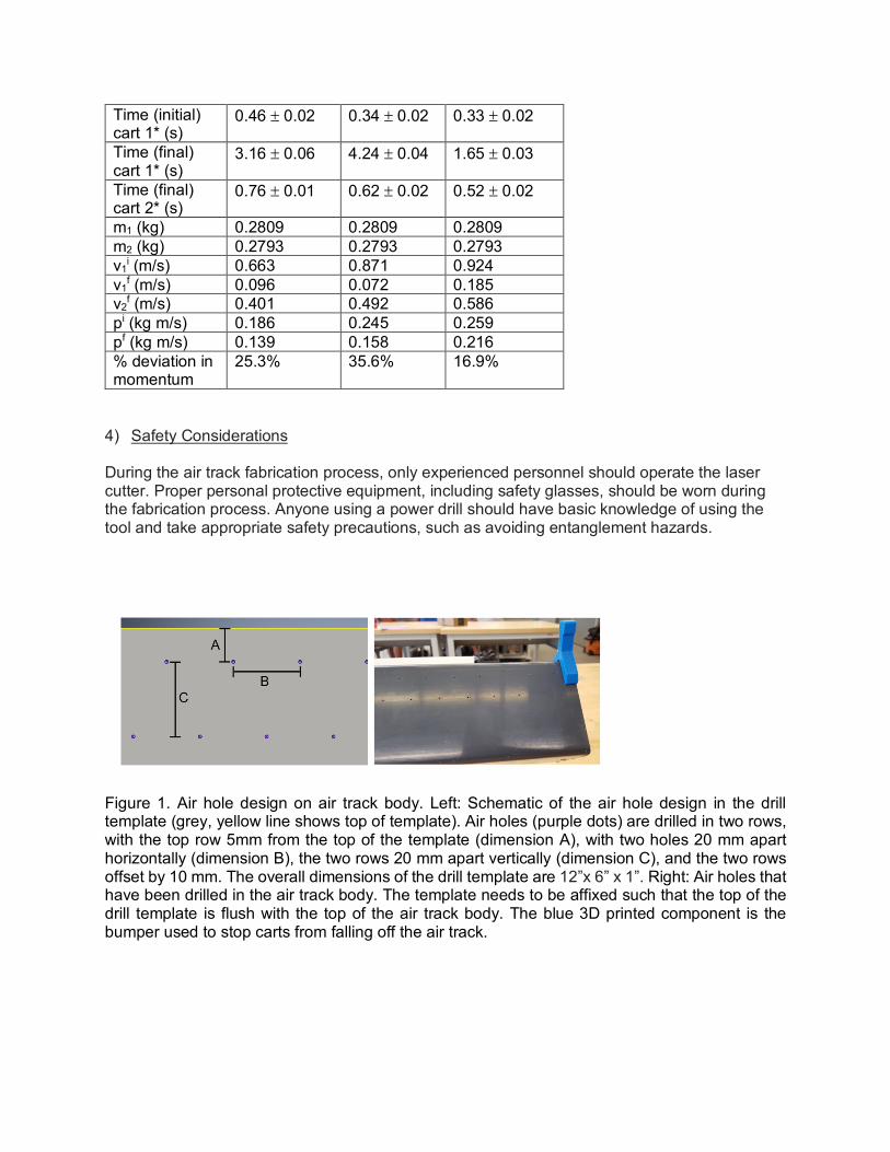
Figure 1. Air hole design on air track body. Left: Schematic of the air hole design in the drill template (grey, yellow line shows top of template). Air holes (purple dots) are drilled in two rows, with the top row 5mm from the top of the template (dimension A), with two holes 20 mm apart horizontally (dimension B), the two rows 20 mm apart vertically (dimension C), and the two rows offset by 10 mm. The overall dimensions of the drill template are 12”x 6” x 1”. Right: Air holes that have been drilled in the air track body. The template needs to be affixed such that the top of the drill template is flush with the top of the air track body. The blue 3D printed component is the bumper used to stop carts from falling off the air track.

Figure 2. Components of the air track. (A) The air track shown with two carts, labeled cart 1 and cart 2, each equipped with a magnet insert inside each basket. The white lines, labeled “dm 1-4” are the distance markers used to time the carts, with 41 cm between dm 1 and the end of the cart, and 30.4 cm between dm 1 and dm 2, dm 2 and dm3, and dm3 and dm 4. The distances between dm 1 and dm 2, and dm 3 and dm 4 will be used to calculate the velocities of the carts. The shop vacuum (green box) provides air for the air track. Adjustable air track bases (purple boxes) level the air track. The air track bumpers (red boxes) ensure that the carts stop at the ends of the track. Inside the U-channel air track base are four air track body supports (locations shown by cyan boxes) to stabilize the air track. (B) Air track body support. (C) Magnet insert shown with surface housing the magnet. (D) Close-up of the air track base, showing the two hex-bolts along the ends that are adjustable to control the height of the air track, the two screws that attach the stabilizer to the U-channel, and a level. (E) The bottom of the air track, showing the two screws attaching the base to the U-channel, and the two hex-bolts at the end of the base, used to adjust the air track. (F) The end of the air track with the solid end cap. (G) The end of the air track with the end cap containing the hole to accommodate the hose of the shop vacuum.
Figure 3. Image of carts (A) with magnet inserts for perfectly elastic collisions, (B) perfectly inelastic collisions, and (C) imperfectly elastic collisions.

Acknowledgements: The authors are grateful for support from the Raymond and Beverly Sackler Institute for Biological, Physical and Engineering Sciences at Yale University, NIH National Institute of Biomedical Imaging and Bioengineering Grant No. T32EB019941, NSF Grant Nos. DBI-1458609 and DBI-1755494, and NIH National Cancer Institute Grant No. U54CA209992. The authors thank Pathfinder Hopkins School, including Director Michael Van Leesten and Jennifer Lane for their longstanding collaboration. The authors also thank Larry Wilen and Yale’s Center for Engineering Innovation and Design for use of the space and equipment (laser cutter and 3D printers), and for providing advice and guidance during the design and fabrication of the module.

Table S1. List of components, supplies, equipment and tools needed to fabricate an air track. All items include a description, supplier, and costs. Ideally, one would have access to an engineering design center that can provide the equipment and tools. Name of Item Description Supplier Cost Assembly components and supplies Chemical-Resistant Type I PVC Rectangular Tube, 3" Square, .078" Wall Thickness, 5' Length
Air track body McMaster-Carr $51.70
Polypropylene U-Shaped Channel, 2-1/2" Base, 2-1/4" Legs x 3/16" Wall Thick, 5’ length
Air track base McMaster-Carr $61.40
Optically Clear Cast Acrylic Sheet - 5/16" Thick, 12" x 24"
Drilling Template, air track base stabilizers, air track end caps; drilling template can be reused indefinitely; enough end caps for 6 tracks
McMaster-Carr $27.03
3M Super Silicone Sealant - Number 8663, 10.3-oz. Cartridge
Silicone adhesive McMaster-Carr $16.35
Duck Brand 394693 General Purpose Masking Tape, 0.94-Inch by 60-Yard, Single Roll, Beige
To mark distance markers. Use a color that contrasts the body of the air track.
Amazon $4.99
Yardstick, product number 1908A15 Used to make measurements and to knock off burrs inside the air track body resulting from drilling the air holes
McMaster-Carr $3.91
“Master Magnetics RB45CX10 Round Base Magnet Fastener with 0.190" Center Hole Chrome Plate, 1.425" Diameter, 0.283" Thick, 16 Pounds, Silver (Pack of 10)”
Magnets for perfectly elastic collisions
Amazon $13.00

“Vkey 500pcs (250 Pair Sets) 3/4 Diameter Sticky Back Coins Hook & Loop Self Adhesive Dots Tapes White-Delivery By FBA”
Velcro dots to attach level and for use in perfectly inelastic collisions
Amazon $9.29
Part No. 2958A25 Order 2, Drill Bit - 1.0mm, 34mm Overall Length, 10.0mm Drill Depth, 118 Degree Point
McMaster-Carr $ 1.55 each
Shop-Vac 2.5-Gallon 2.5-Peak HP Shop Vacuum
Air source; airflow: 58 CFM; 2.5 gallons; 2.5 peak HP
Shopvac.com $44.99
“Standard Level By GFNT Four Pack For Use with RV, Tripod, Phonograph, Turntable”
To ensure that the air track is level
Amazon $9.99
“SEOH Weight Weights Slotted Set of 10” Weights for carts Amazon $19.95 Equipment and tools “Yost Tools F136 36" F-Clamp”
Used to affix the drilling template to the air track body, 2 are needed
Amazon $12.99 each
Century Drill and Tool 95107 Coarse Plug Hand Tap, 3/8 - 16
Tap with thread for adjustable bolts to tap the holes in the air track base
Amazon $5.75
Hanson 12002 T-Handle Tap Wrenches T-handle for tap Amazon $5.99 “BLACK+DECKER BDEDMT Matrix AC Drill/Driver”
Used to drill air holes
Amazon $31.53
“Dremel 220-01 Rotary Tool Workstation Drill Press Work Station with Wrench”
Optional – but recommended if making the air hole drilling template out of wood
Amazon $64.69
Newborn 930-GTD Drip-Free Smooth Hex Rod Cradle Caulking Gun with Gator Trigger Comfort Grip, 1/10 Gallon Cartridge, 10:1 Thrust Ratio
To use with silicone sealant
Amazon $9.61
Carbon dioxide laser cutter If not available at school, make parts out of wood
Not applicable Not applicable

“Ohaus ABSCL Compact Scale, 2000g x 1g”
Needs to be able to weigh 100s of grams to the nearest gram or tenth of a gram
Amazon $74.00
Smart phone To film and time collisions
Ideally, 1-2 students per group will have a smart phone
Not applicable
“STANLEY 68-012M All-In-One 6-Way Screwdriver”
screwdriver Amazon $5.44
Table S2. 3D printed components needed to build one air track. “.stl” files are used for 3D printing and “.cdr” files are used for laser cutting. Item Number of
items File name Use
Air track body supports
4 Air Track Body Support.stl
Stabilize the air track body placing inside the u-channel
Air track bumpers
2 Air Track Bumpers.stl
To prevent carts from gliding off the ends of the track
Air track carts 2 Air Track Cart.stl
Carts used in collisions, also capable of holding various materials to be used as a “crumple zone”
Solid end cap 1 Solid End Cap.cdr
To seal one of the air track body
End cap with air hole
1 End Cap with Center Hole.cdr
To seal the end of the air track body while accommodating the air source hose snugly
Magnet attachment for air track carts
4 Magnet Attachments.stl
To attach magnets to air track carts, used in perfectly elastic collisions
Air hole template
1 Drilling Air Hole Template.cdr
Template used to drill the air holes in the air track body