handout-2 - site investigations
TRANSCRIPT

10
CHAPTER 3
PLANNING A SUBSURFACE INVESTIGATION ANDLABORATORY TESTING PROGRAM
3.1 INTRODUCTION
To evaluate soil and rock properties required for geotechnical design related to transportationprojects, subsurface investigation and laboratory testing programs are developed and executed. Thedata collection efforts associated with these activities should occur early in the project; failure toconduct an appropriately scoped investigation and laboratory-testing program will result in potentialdata gaps and/or the need to re-mobilize to the site for supplementary testing. Data gaps can causesignificant delays in the project and can potentially lead to either an overconservative and costlydesign or an unconservative and unsafe design. It is, therefore, imperative that the subsurface andlaboratory testing programs be carefully planned to ensure that the information collected in the fieldand the laboratory will be sufficient to develop soil and rock properties for design and construction.
This chapter will present general guidelines related to the development of subsurface investigationand laboratory testing programs for the evaluation of soil and rock properties. Since the selection ofsampling and testing methods will be driven by the scope of the project and geologic conditions,critical project related issues must be understood prior to field and laboratory planning activities.For heterogeneous deposits and special materials (i.e., colluvium, organic soils, etc.) greater effortwill be required during the planning stage of the investigation to assess the applicability of specifictools and sampling devices.
3.2 PLANNING THE SUBSURFACE INVESTIGATION AND LABORATORYTESTING PROGRAM
3.2.1 General
Planning subsurface investigation and laboratory testing programs requires the engineer to be awareof parameters and properties needed for design and construction, as well as to understand thegeologic conditions and site access restrictions. Specific steps include: (1) identify data needs; (2)gather and analyze existing information; (3) develop a preliminary site model; (4) develop andconduct a site investigation; and (5) develop and conduct a laboratory-testing program. Specificplanning steps are addressed in the following sections.
3.2.2 Identify Data Needs
The first step of an investigation and testing program requires that the engineer understand theproject requirements and the site conditions and/or restrictions. The ultimate goal of this phase is to

11
identify geotechnical data needs for the project and potential methods available to assess theseneeds. During this phase it is necessary to:
identify design and constructability requirements (e.g., provide a grade separation, transferloads from bridge superstructure, provide for a dry excavation);
identify performance criteria (e.g., limiting settlements, right of way restrictions, proximityof adjacent structures) and schedule constraints;
identify areas of concern on site and potential variability of local geology;
develop likely sequence and phases of construction;
identify engineering analyses to be performed (e.g., bearing capacity, settlement);
identify engineering properties and parameters required for these analyses;
evaluate methods to obtain parameters and assess the validity of such methods for thematerial type and construction methods; and
evaluate number of tests/samples needed and appropriate locations for them.
As an aid to assist in the planning of site investigation and laboratory testing, table 1 provides asummary of the information needs and testing considerations for various geotechnical applications.A discussion of specific field and laboratory test methods is provided in chapter 4.
3.2.3 Gather and Analyze Existing Information
Before any equipment is mobilized to the site, existing data for the site, both regionally and locally,should be evaluated as a logical first step in the investigation. This is an important and inexpensivestep that is often overlooked. There are many readily available data sources that can be used toidentify major geologic processes that have affected the site, site history, geologic constraints, man-made features, and access issues. The planning step can be extremely cost effective and productive.Existing data will provide information which can reduce the scope of the subsurface investigation,help guide the location of testing and sampling points, and reduce the amount of time in the field dueto unexpected problems. For example, historical aerial photographs can be used to identify an areawhere fill had been placed, where a landslide scarp exists, or major geologic structures such asfaults, bedding planes, and continuous joint sets. A list of potential information sources along withthe type of information available is presented in table 2.


17
Of the information sources listed in table 2, utility maps, existing subsurface investigation reports inthe area, geologic reports/maps, and soil surveys often provide extremely valuable information.Although historic reports may provide useful data, the information they contain should be used withcaution. The data should be scrutinized as to its reliability by evaluating the consistency of theinformation and the overall quality of the report. Review of construction or performance monitoringrecords will provide helpful information regarding subsurface conditions and variability. On someprojects, it may be worthwhile to develop a geologic summary report that provides information onregional and local geology, hydrogeology, and unstable areas (e.g., karstic areas, fault zones, etc.).
3.2.4 Conduct Site Visit
After review of the available data and prior to mobilizing investigation equipment to the project site,a site visit should be performed. During the site visit, the engineer should carefully observe allrelevant physical features of the area and record detailed notes. These observations should include:
utility locations (overhead and underground);
access issues (e.g., location, width, and condition of all potential access roads; trees; powerlines; buildings; right-of-way);
conditions of nearby structures (record location, type, and depth of existing structures andfoundations);
geologic constraints (e.g., rivers, streams, bluffs, outcrops);
topographic conditions (e.g., ditches, hills, valleys);
soil/rock type (e.g., clay, sand, rock outcrops, conditions when wet);
surface conditions (e.g., desiccated surface, lack of vegetation, debris, ponded water,deposits of colluvium or talus, evidence of rock/soil slope failures);
geomorphic controls (e.g., landslides, floodplains, karst, erosional/depositional conditions);
flood levels/drainage issues;
zonation of rock mass with information on location, orientation, and type of boundarybetween zones of relatively uniform geology;
adjacent property use; and
potential borrow source areas (if applicable).
If possible, the engineer should meet with local landowners to obtain information on springs, historiclandslides, old mine workings, etc. and to obtain permission for gaining access to private property.

18
Potential drilling locations should be noted for subsequent subsurface investigation. A topographicmap of the project site should be prepared prior to the site visit and the map should be used by theengineer during the site visit. The previously referenced observations should be noted on thetopographic map and a preliminary layout of the subsurface investigations borings/soundings shouldbe marked. Temporary field stakes can often be established for these locations during the site visit.Additional information can be gained by driving along roads in the general site area and observingroadcuts and rock outcrops. In hilly areas, roadcuts provide some of the most accessible and usefulmeans of obtaining subsurface information prior to the use of intrusive investigation methods. Seepsalong the face of a roadcut may provide an idea of the relative proximity of the water table to theground surface and the structure of the subsurface geologic units.
Information gathered during a site reconnaissance visit will aid in the selection of a drill rig, samplertype, boring/sampling locations, personnel safety needs, and potential problems which may precludeconstruction of certain geotechnical design elements. The site visit also allows the engineer to makean initial estimate of subsurface conditions, as well as an estimation of the time needed to completethe field investigation and testing program. Conducting the site visit after collecting and interpretingexisting data allows for an efficient data collection effort. Figure 2 provides a checklist ofinformation items that should be collected during the site reconnaissance stage of a project.Checklists and/or field reconnaissance forms are useful while conducting site visits to ensure thatpertinent data are not forgotten or overlooked. A copy of the field reconnaissance report should beprovided to the drill crew prior to drilling.
3.2.5 Develop Preliminary Site Model
A preliminary site model should be developed using the information obtained from existing data andthe site visit. The preliminary model should consist of the soil and rock stratigraphy, potential siterestrictions, and anticipated groundwater levels. The model should be divided into zones of interest(i.e., geotechnical units) based on the necessary design parameters and objectives. This model willobviously change as results of the detailed investigation are collected.
While developing the preliminary site model, particular attention should be given to the possibilityof encountering heterogeneities. In many geologic settings, these include boulders and significantvariations in bedrock surface elevation, which may affect the design and investigation. If bouldersare suspected at a site, unexpected �top of rock� elevations should be questioned and it may benecessary to drill several feet into �rock� in order to resolve this issue. In addition, soils containinglarge amounts of gravel or boulders may cause damage to intrusive in situ testing equipment or limitthe feasibility of these test methods.
Based on the information gathered thus far in the planning phase, it may be possible to eliminate orfavor specific designs. For example, the preliminary site model may indicate that extensive boulderand gravel deposits are present at the site, which could eliminate the possibility of a driven piledesign. Alternatively, the preliminary site model might show subsurface conditions to beparticularly favorable to a proposed design.

20
3.2.6 Developing a Site Investigation Program
For many projects and for many site conditions, the most difficult and crucial part of the planningphase involves the decisions regarding sampling/investigation method, boring locations, number ofsamples, number and types of laboratory tests, and the number of confirmatory samples. At thisstage, the types of potential sampling/investigation methods should have been identified andassessed. During the site visit, it is often possible to eliminate certain techniques. Specific tools forsampling and testing are discussed in chapter 4 and include:
Undisturbed sampling: Thin walled tubes, block samples, rock core
Disturbed sampling: SPT, augering, non-core rock drilling
Non-intrusive: Geophysical and remote sensing methods
In-situ soil and rock testing: CPT, flat-plate dilatometer test (DMT), vane shear test (VST),pressuremeter, borehole dilatometer, in situ direct shear test, etc.
Many engineers underestimate the importance in selecting an appropriate investigation technique(s)and sampling method(s), since in-house SPT capabilities are a presumptive �one size fits all�investigation/sampling approach (e.g., SPT sampling at 1.5-m intervals in borings on 60-m spacing).Experience has shown the short-falls of this approach and the benefit of a focused site-specificstrategy. For example, in cases where extensive laboratory tests are not needed but it is necessary togather large amounts of data concerning stratigraphy and subsurface material variability, intrusivenon-sampling methods such as the CPT and DMT could be considered. The CPT method is quickand allows for stratigraphic mapping over a site area much more quickly and economically than theuse of other intrusive methods. Additionally, data from the CPT can be input into stress history andstrength correlations to obtain specific design parameters. When the penetrometer is fit with a porepressure transducer (CPTu), detailed stress history and strength correlations for clays can beevaluated, estimates of groundwater elevation can be predicted, and flow characteristics can beassessed. The DMT can provide stratigraphic information similar to that from the CPT, but theDMT data are better suited for assessment of modulus values for settlement calculations.
The number of borings and their locations in a site area will depend on the proposed structure,design parameters, access issues, geologic constraints, and expected stratigraphy and heterogeneity.Some minimum guidelines for boring spacing are provided in table 3. This table was developedbased on a number of FHWA documents including Drilled Shafts: Construction Procedures andDesign Methods (FHWA-IF-99-025), Design and Construction of Driven Pile Foundations (FHWA-HI-97-013), and Advanced Technologies for Soil Slope Stability (FHWA-SA-94-005). This tableshould be used only as a first step in estimating the minimum number of borings for a particulardesign, as actual boring spacings will be dependent upon the project type and geologic environment.In areas underlain by heterogeneous soil deposits and/or rock formations, it will probably benecessary to exceed the minimum guidelines from table 3 to capture variations in soil and/or rocktype and to assess consistency across the site area. For situations where large-diameter rock-

21
socketed shafts will be used or where drilled shafts are being installed in karstic formations, it maybe necessary to advance a boring at the location of each shaft. In a laterally homogeneous area,drilling or advancing a large number of borings may be redundant, since each sample tested wouldexhibit similar strength and compressibility properties. In all cases, it is necessary to understandhow the design and construction of the geotechnical feature will affect the soil and/or rock mass inorder to optimize the investigation.
The engineer or geologist should plot the proposed boring locations on a site topographic map priorto initiation of drilling. They should review the notes taken during the site visit considering accessrestrictions and not arbitrarily or randomly select boring locations. Alternate boring locations shouldbe considered and a contingency plan (e.g., move a maximum of 15 m from a boring location ifunable to drill at a particular location) should be discussed in case a boring needs to be relocated dueto access restrictions or unexpected geologic conditions. Field personnel unfamiliar with theobjectives and rational behind the planning of the site investigation should maintain contact with theoffice during field activities and discuss issues such as the relocation of a boring. Arbitrary orrandom boring selection will increase the chances of boring relocation, confusion, and wasted timein the field. Final boring locations should be surveyed and recorded as part of the permanent projectrecord.
The guidelines for depth interval selection should also be developed in recognition of specificsite/project conditions and design property/parameter requirements. For preliminary screening,disturbed samples might be taken continuously in the upper 3 m, at 1.5 m intervals up to 30 m, andpossibly every 3 m at depths greater than 30 m. For characterization and assessment of designproperties in fine-grained soils, a minimum of one undisturbed sample should be taken for eachstratum, with additional samples taken at 3 to 6 m intervals with depth. Undisturbed samples maynot need to be taken in each boring if the deposit is relatively homogeneous with closely spacedborings. These are general minimum guidelines and intervals may need to be increased dependingupon the project requirements and site geologic conditions. The sampling interval may need to beincreased when soil/rock conditions change frequently with depth; however, these changes need tobe considered in the context of the design. Therefore, ongoing communication with theoffice/design engineer is absolutely essential. Once the site stratigraphy has been established, it maynot be necessary to sample every time there is a change in stratigraphy if the changes have no impacton design. For example, it may not be necessary to sample alternating layers of coarse graineddeposits where settlement is of concern, and for designs concerned with bearing capacity, althoughsamples below the anticipated extent of the area influenced by the load may be reduced, samplesshould be obtained in case the type of foundation changes between preliminary and final design.
The sampling interval will vary between individual projects and regional geologies. If soils areanticipated to be difficult to sample or trim in the lab due to defects, etc., the frequency of samplecollection should be higher than average to offset the number of samples that may be unusable in thelab for performance property evaluation (e.g., shear strength). When borings are widely spaced, itmay be appropriate to collect undisturbed samples in each boring. For closely spaced borings or indeposits of lateral uniformity, undisturbed samples may only be needed in select borings. If a thinclay seam is encountered during drilling and not sampled, the boring may need to be offset and re-drilled to obtain a sample.

22
It is often quite helpful to combine in situ soundings using CPT, CPTu, DMT, or pressuremeter withconventional disturbed/undisturbed sampling. For example, by performing CPT or CPTu soundingsprior to conventional drilling and sampling, it may be possible to target representative and/or criticalareas where samples can be later obtained. This combination may reduce some of the potentialdrilling redundancy in heterogeneous environments. The use of geophysical methods can be used toprovide useful information on ground in-between boring locations.
For investigations for rock slopes and foundations, it is important to consider structural geology, inaddition to information obtained as part of a rock-coring program. For example, the orientation andcharacteristics of a clay-filled discontinuity is critical information that will be used to judge whethera rock slope will be stable or unstable or whether a structural foundation will undergo minor orsignificant settlement. However, a detailed structural geologic assessment may provide enoughinformation to significantly limit the scope of a rock-coring program. For example, drilling andcoring may not be required where applied loads are significantly less than the bearing capacity of therock, where there is no possibility of sliding instability in a rock slope, or where there are extensiverock outcrops from which information can be obtained to confidently establish the subsurfaceconditions for design and constructability assessments (Wyllie, 1999).
As the reader can see from this discussion, it is difficult and really unnecessary to establish aprescriptive drilling, sampling, and testing protocol that is applicable to all sites. The engineer ismost effective when: (1) applying these conventional guidelines with site and/or project-specificrequirements/constraints; and (2) recognizing the advantages and limitations of sampling equipmentand in-situ testing methods.
3.2.7 Developing a Laboratory Testing Program
The final planning step includes the development of a laboratory-testing program. Prior to planningthe laboratory-testing program, it is again necessary to review the design needs of the project.Specifying unnecessary laboratory tests will add time and cost to the project and consume samples.Table 1 lists laboratory tests that may be applicable to specific designs. One can see from this tablethat moisture content, Atterberg limits, grain size distribution, and unit weight tests arerecommended for most design applications in soils. As will be discussed in chapter 5, index testsare not specifically used in the design but are invaluable in establishing general conditions andassessing inherent material variabilities. Although this table provides useful guidelines, additionaltests may be required or tests may be eliminated depending on individual site conditions.
Once a list of necessary tests has been developed and the field program has been executed, theengineer should review field notes, borings, and design plans to identify �critical areas�. Criticalareas correspond to borings/locations where the results of the laboratory tests could result in asignificant change in the proposed design. Samples from these critical areas should be identified forperformance testing. As will be discussed in chapter 5, performance tests provide design-specificparameters. For example, if unexpected clay deposits were discovered in the area of a proposedfooting, 1-D consolidation testing would be required to assess potential settlements. If the testresults show that settlements may be excessive under the proposed design, the footing may have tobe moved, redesigned, or deep foundation support considered. Similarly, if the same footing was

23
proposed for use on a rock slope, the presence of an unfavorably oriented clay-filled discontinuitywould likely make it necessary to obtain an undisturbed rock core sample for direct shear testing ofthe clay-filled discontinuity. The engineer should also consider the site area in context of therequired design parameters and the samples available for laboratory analysis. It is necessary toselect samples for laboratory analysis that will accurately characterize the site. In heterogenousareas, many samples may be required to obtain comprehensive parameters; in homogeneous areas,few samples may be required.
A laboratory-testing program should be performed on representative and critical specimens fromgeologic layers across the site. To assess the locations where tests should be performed, it is usefulto evaluate sample location maps and geologic cross sections. By evaluating a sample location map,it will be easy to quickly identify the locations of disturbed and undisturbed samples that may beused in the laboratory testing program. The generation of detailed subsurface cross sections (seesection 5.2), including stratigraphy, in-situ testing results, and laboratory index test results, ifavailable, will be useful when identifying representative samples for laboratory performance testing.


26
CHAPTER 4
TOOLS AND TECHNIQUES FORMEASURING SOIL AND ROCK PARAMETERS
4.1 INTRODUCTION
The purpose of this section is to provide information on various in-situ and laboratory testingmethods that are currently used to establish site-specific soil and rock properties for design andconstruction. The execution of a conventional subsurface exploration and testing program usuallyincludes rotary drilling, Standard Penetration Testing (SPT), disturbed and undisturbed samplerecovery, and laboratory testing. Although procedures for these commonly performed activities arecodified in AASHTO and ASTM standards and are well known to most geo-professionals, importanttesting details are sometimes overlooked that can result in marginal data quality. This section wasprepared to help identify the importance of selecting and conducting the appropriate field andlaboratory testing method.
In-situ testing methods are becoming increasingly used on transportation projects, however testingprocedures and testing limitations are not as well understood as more conventional methods ofsubsurface exploration and testing. In this section, procedures for various in-situ and laboratorytesting methods are presented as they relate to obtaining high-quality data for evaluation ofengineering properties. Information on equipment calibration, measured test parameters, qualitycontrol, and the appropriate range of ground conditions that are appropriate for each test is alsopresented.
In-situ tests discussed in this section include: (1) SPT; (2) CPT; (3) piezocone penetration testing(CPTu); (4) seismic piezocone testing (SCPTu); (5) DMT; (6) pressuremeter testing (PMT); and (7)vane shear testing (VST). Many state DOTs perform these tests directly using agency-ownedequipment. In many cases however, the agency may directly contract to an outside contractor forthese services or they may be contracted for as part of an overall project development package.Several technical reports and manuals are available that describe these methods. A brief list of thesereferences is provided in table 4. Those agencies that perform or contract for these testing servicesare encouraged to obtain the references identified in table 4.

27
Table 4. Reference publications on in-situ testing.
Test MethodAASHTO/
ASTM Designation Reference
SPT AASHTO T206
ASTM D 1586
U.S. Department of Transportation, Federal Highway Administration,(1997) Subsurface Investigations, Training Course in Geotechnical andFoundation Engineering, FHWA HI-97-021
CPT, CPTu,SCPTu
ASTM D 3341, D5778 U.S. Department of Transportation, Federal Highway Administration,(1988) Guidelines for Using the CPT, CPTu, and Marchetti DMT forGeotechnical Design, FHWA-SA-87-023-024.
Lunne, T., Robertson, P.K., and Powell, J.J.M. (1997) Cone PenetrationTesting in Geotechnical Practice, E & F Spon, 312 pp.
DMT Suggested ASTMMethod
Schmertmann, 1986
U.S. Department of Transportation, Federal Highway Administration(1992) The Flat Dilatometer Test, FHWA-SA-91-044.
Marchetti, S., and Crapps, D.K. (1981) Flat Dilatometer Manual, InternalReport of GPE, Inc. (Gainesville, FL), available at http://www.gpe.org.
PMT ASTM D 4719 U.S. Department of Transportation, Federal Highway Administration,(1989) The Pressuremeter Test for Highway Applications, FHWA-IP-89-008.
Clarke, B.G. (1995) Pressuremeters in Geotechnical Design, BlackieAcademic & Professional, 364 pp.
VST ASTM D 2573 American Society of Testing and Materials, (1988) Vane Shear StrengthTesting in Soils: Field and Laboratory Studies, ASTM STP 1014, 378pp.
The remainder of this section is devoted to describing the specific tools and techniques used to drill,sample and test soil and rock materials. In addition, summary information on the use of geophysicalmethods as a supplement to drilling, sampling, in-situ testing, and laboratory testing of soil and rockis presented.
4.2 BORING METHODS
Geotechnical borings are a critical component of any subsurface exploration program. They areperformed to satisfy several objectives including those listed below.
identification of the subsurface distribution of materials with distinctive properties,including the presence and geometry of distinct layers;
determination of data on the characteristics of each layer by retrieving samples for use inevaluating engineering properties;

28
acquisition of groundwater data; and
provide access for introduction of in-situ testing tools.
There are many types of equipment used in current practice for advancing a soil or rock boring.Typical types of soil borings are listed in table 5(a), rock coring methods in table 5(b), and otherexploratory techniques in table 5(c). Detailed information on soil and rock boring procedures arebeyond the scope of this document, but can be found in AASHTO (1988), FHWA HI-97-021 (1997),and ASTM D 4700. A brief description of typical soil boring methods is provided below (Day,1999).
Discontinuous Auger boring: An auger is an apparatus with a helical shaft that can bemanually or mechanically advanced to bore a hole into soil. Auger drilling is shown infigure 3. The practice of advancing a borehole with a mechanical auger consists of rotatingthe auger while at the same time applying a downward pressure on the auger to penetratesoil and possibly weak or weathered rock. The augers may be continuous, where the lengthof the helix is along the entire length of the shaft, or discontinuous when the auger is at thebottom of the drill stem. There are basically two types of discontinuous augers:discontinuous flight augers and bucket augers. Commonly-available discontinuous flightaugers have diameters ranging from 0.05 to 1.2 m and bucket augers have diameters rangingfrom 0.3 to 2.4 m. For discontinuous flight auger borings, the auger is periodically removedfrom the hole and the soil lodged in the grooves of the flight auger is removed. When usinga bucket auger, the soil in the bucket is periodically removed. A casing is generally not usedfor discontinuous flight and bucket auger borings. Therefore, these methods are notrecommended for boreholes deeper than 10 m where the hole may cave-in during theexcavation of loose or soft soils, or when the boring is below the groundwater table. In firmstiff clays, discontinuous auger borings can be performed to depths in excess of 10 m.
Continuous flight auger. As the name implies, continuous flight augers have the augerflights continuous along the entire length of the auger. There are two types of continuousflight augers: solid stem and hollow stem. For both of these type augers the drill cuttingsare returned to the ground surface via the auger flights. The solid stem auger must beremoved from the borehole to allow access to the hole for sampling or testing. Because theauger must be periodically removed from the borehole, a solid stem auger is not appropriatein sands and soft soils, or in soil deposits exhibiting high groundwater. A hollow-stem flightauger has a circular hollow core that allows for sampling through the center of the auger.The hollow-stem auger acts like a casing and allows for sampling in loose or soft soils orwhen the excavation is below the groundwater table. A plug is necessary when advancinghollow stem augers to prevent cuttings from migrating through the hollow stem. The plug isremoved to permit SPT sampling. In loose sands and soft clays extending below the watertable, drilling fluids are often used (and maintained) in order to minimize and mitigatedisturbance effects.

29
Figure 3. Large diameter auger boring.
Wash-type borings. Wash-type borings use circulating drilling fluid (e.g., water or mud), toremove cuttings from the borehole. Cuttings are created by the chopping, twisting, andjetting action of the drill bit that breaks the soil or rock into small fragments. If bentonite orpolymeric drilling muds cannot be used to maintain an open borehole, casings are often usedto prevent cave-in of the borehole. The use of casing will require a significant amount ofadditional time and effort but will result in a protected borehole. When drilling mud is usedduring subsurface boring, it will be difficult to classify the soil using auger cuttings. Also,the outside of samples may become contaminated with drilling mud.
The previously described methods are typically used for soil exploration, while the followingmethods are primarily used in rock exploration.
Rotary coring. This type of boring equipment is most commonly used for rock explorationwhen an intact core of the rock is desired. This technique uses power rotation of the drillingbit as circulating fluid removes cuttings from the hole. The drilling bits are specificallydesigned to core rock, and inner/outer tubes or casings are used to capture the intact core.Table 5(b) lists various types of rotary coring techniques for rock, although many of thesetechniques are applicable in stiff soil.
Percussion drilling. This type of drilling equipment is often used to penetrate hard rock forsubsurface exploration or for the purpose of drilling wells. The drill bit works much like a

30
jackhammer, rising and falling to break up and crush the rock material. Air is commonlyused to clean the cuttings to the ground surface. Table 5(c) includes a description on use ofthe percussion drilling techniques.
Table 5(a). Boring methods (modified after Day, 1999).
Method Procedure Applications Limitations / Remarks
Auger boring(ASTM D 1452)
Dry hole drilled with hand orpower auger; samplesrecovered from auger flights
In soil and soft rock; toidentify geologic units andwater content above watertable
Soil and rock stratificationdestroyed; sample mixed withwater below the water table
Hollow-stemauger boring
Hole advanced by hollow-stemauger; soil sampled belowauger as in auger boring above
Typically used in soils thatwould require casing tomaintain an open hole forsampling
Sample limited by larger gravel;maintaining hydrostatic balancein hole below water table isdifficult
Wash-type boring Light chopping and strongjetting of soil; cuttings removedby circulating fluid anddischarged into settling tub
Soft to stiff cohesivematerials and fine to coarsegranular soils
Coarse material tends to settleto bottom of hole; Should not beused in boreholes above watertable where undisturbedsamples are desired.
Becker HammerPenetration Test(BPT)
Hole advanced using doubleacting diesel hammer to drive a168 mm double-walled casinginto the ground.
Typically used in soils withgravel and cobbles; Casingis driven open-ended ifsampling of materials isdesired
Skin friction of casing difficultto account for; unsure as to therepeatability of test
Bucket Augerboring
A 600 to 1200-mm diameterdrilling bucket with cuttingteeth is rotated and advanced.At the completion of eachadvancement, the bucket isretrieved from the boring andsoil is emptied on the ground.
Most soils above watertable; can dig harder soilsthan above types and canpenetrate soils with cobblesand boulders if equippedwith a rock bucket
Not applicable in running sands;used for obtaining largevolumes of disturbed samplesand where it is necessary toenter a boring to makeobservations
31
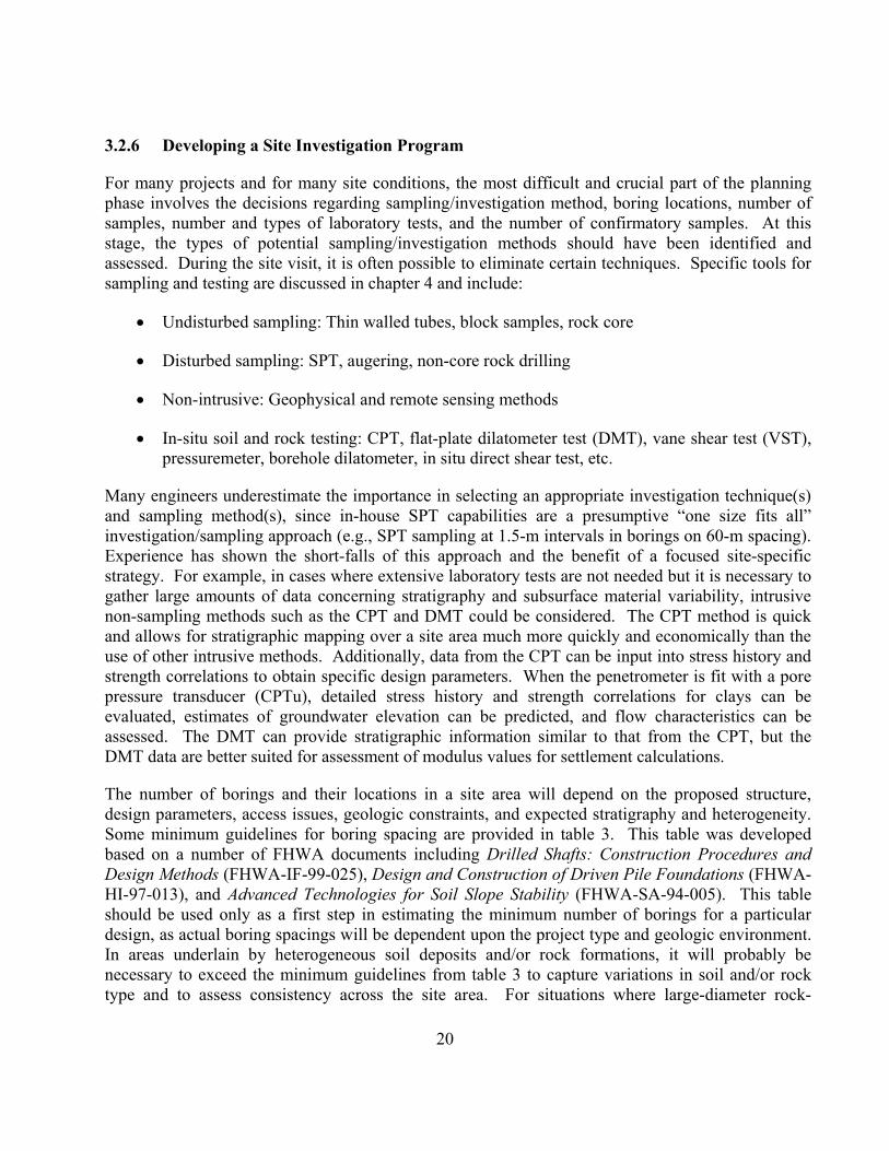
Table 5(b). Rock core drilling methods (modified after Day, 1999)(1).
Method Procedure Type of sample Applications Limitations / Remarks
Rotary coring ofrock (ASTM D2113; AASHTO T225)
Outer tube with diamond(or tungsten carbide) biton lower end rotated tocut annular hole in rock;core protected bystationary inner tube;cuttings flushed upwardby drill fluid
Rock cylinder 22to 100 mm wideand as long as 3m, depending onrock soundness.Standard coringsize is 54 mmdiameter.
To obtain continuouscore in sound rock(percent of corerecovered depends onfractures, rockvariability, equipment,and driller skill)
Core lost in fracture orvariable rock; blockageprevents drilling inbadly fractured rock;dip of bedding and jointevident but not strike
Rotary coring ofrock, wire line
Same as ASTM D 2113,but core and stationaryinner tube retrieved fromouter core barrel bylifting device or�overshot� suspended onthin cable (wire line)through special large-diameter drill rods andouter core barrel
Rock cylinder 28to 85 mm wideand 1.5 to 3 mlong
To recover core betterin fractured rock whichhas less tendency forcaving during coreremoval; to obtainmuch faster cycle ofcore recovery andresumption of drillingin deep holes
Core lost in fracture orvariable rock; blockageprevents drilling inbadly fractured rock;dip of bedding and jointevident but not strike
Rotary coring ofswelling clay, softrock
Similar to rotary coringof rock; swelling coreretained by third innerplastic liner
Soil cylinder 28.5to 53.2 mm wideand 600 to 1500mm long encasedin plastic tube
In soils and soft rocksthat swell ordisintegrate rapidly inair (protected by plastictube)
Sample smaller;equipment morecomplex than other soilsampling techniques
Note: (1) See section 4.3.3 for additional discussion on types of core barrels (i.e., single-, double-,or triple-tube).

32
Table 5(c). Other exploratory techniques (modified after Day, 1999).
Method Procedure Type of sample Applications Limitations / Remarks
Boreholecamera
Inside of core hole viewedby circular photograph orscan
No sample, but avisualrepresentation ofthe material
To examinestratification, fractures,and cavities in holewalls
Best above water tableor when hole can bestabilized by clear water
Pits andTrenches
Pit or trench excavated toexpose soils and rocks
Chunks cut fromwalls of trench; sizenot limited
To determine structureof complex formations;to obtain samples ofthin critical seams suchas failure surface
Moving excavationequipment to site,stabilizing excavationwalls, and controllinggroundwater may bedifficult; useful inobtaining depth toshallow rock and forobtaining undisturbedsamples on pit/trenchsidewalls; pits need tobe backfilled
Rotary orcable toolwell drill
Toothed cutter rotated orchisel bit pounded andchurned
Pulverized To penetrate boulders,coarse gravel; toidentify hardness fromdrilling rates
Identification of soils orrocks difficult
PercussiveMethod(jackhammer orair track)
Impact drill used; cuttingsremoved by compressed air
Rock dust To locate rock, softseams, or cavities insound rock
Drill becomes pluggedby wet soil
4.3 SAMPLING METHODS
4.3.1 Disturbed Sampling of Soil
Disturbed sampling provides a means to evaluate stratigraphy by visual examination and to obtainsoil specimens for laboratory index testing. Disturbed samples are usually collected using split-barrel samplers (figure 4; AASHTO T206, ASTM D 1586), although several other techniques areavailable for disturbed sample collection in boreholes (see table 6(a) and 6(b)). Shallow disturbedsamples can also be obtained using hand augers and test pits. Direct push methods, such asGeoProbe sampling, can be used to obtain continuous disturbed samples but have similar limitationsin sampling depth as solid stem and bucket augers (i.e., less than 10 m unless in firm to stiff clays).Discrete direct push samples can be obtained at depth using free-floating or retractable pistonsamplers. Samples obtained via disturbed sampling methods can often be used for index propertytesting in the laboratory but explicitly should not be used to prepare specimens for consolidation andstrength (i.e. performance) tests.

33
Figure 4. Split barrel sampler.
Table 6(a). Common samplers to collect disturbed soil samples (modified after NAVFAC, 1982).
Sampler TypicalDimensions
Soils that Give BestResults
Method ofPenetration
Cause ofLow
Recovery
Remarks
Split Barrel Standard is50 mmoutsidediameter(OD) and 35mm insidediameter(ID);
All soils finer than gravelsize particles that allowsampler to be driven;gravels invalidate drivedata;A soil retainer may berequired in granular soils.
64 kg (140 lb)hammer driven
Gravel mayblocksampler
A SPT is performed usinga standard penetrometerand hammer (see text);samples are extremelydisturbed
Continuoushelical-flight auger
Diametersrange 76 to406 mm;penetrationsto depthsexceeding15 m
Most soils above watertable; will not penetratehard soils or thosecontaining cobbles orboulders
Rotation Hard soils,cobbles,boulders
Method of determiningsoil profile, bag samplescan be obtained; log andsample depths mustaccount for lag timebetween penetration of bitand arrival of sample atsurface, to minimizeerrors in estimated sampledepths

34
Table 6(b). Specialty samplers to collect disturbed soil samples (modified after NAVFAC, 1982).
Sampler TypicalDimensions
Soils that Give BestResults
Method ofPenetration
Cause ofLow
Recovery
Remarks
Disc auger Up to 1070 mmdiameter;usually hasmaximumpenetrationdepth of 8 m
Most soils abovewater table; will notpenetrate hard soilsor those containingcobbles or boulders
Rotation Hard soils,cobbles,boulders
Method of determining soilprofile, bag samples can beobtained; log and sampledepths must account for lagtime between penetration ofbit and arrival of sample atsurface, to minimize errorsin estimated sample depths
Bucketauger
Up to 1220 mmdiametercommon; largersizes available;with extensions,depth over 24 mare possible
Most soils abovewater table; canpenetrate harder soilsthan above types andcan penetrate soilswith cobbles andboulders if equippedwith a rock bucket
Rotation Soil too hardto penetrate
Several bucket typesavailable, including thosewith ripper teeth andchopping tools; progress isslow when extensions areused
Test boringof largesamples,LargePenetrationTest (LPT)
50- to 75-mmID and 63- to89- mm ODsamplers(examples,Conversesampler,CaliforniaSampler)
In sandy to gravellysoils
Up to 160kg (350 lb)hammerdriven
Large gravel,cobbles, andboulders mayblock sampler
Sample is intact but verydisturbed; A resistance canbe recorded duringpenetration, but is notequivalent to the SPT N-value and is more variabledue to no standardequipment and methods
4.3.2 Undisturbed Sampling of Soil
4.3.2.1 General
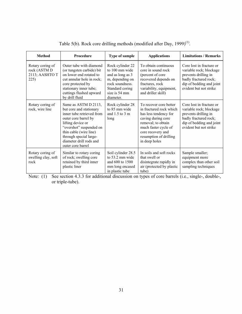
Undisturbed soil samples are required for performing laboratory strength and consolidation testingon generally cohesive soils ranging from soft to stiff consistency. High-quality samples for suchtesting are particularly important for approach embankments and for structural foundations and wallsystems that may stress compressible strata. In reality, it is impossible to collect truly undisturbedsamples since changes in the state of stress in the sample will occur upon sampling. The goal ofhigh-quality undisturbed sampling is to minimize the potential for: (1) alteration of the soil structure;(2) changes in moisture content or void ratio; and (3) changes in chemical composition of the soil.Due to cost and ease of use, the thin-walled Shelby tube (figure 5) is the most common equipmentfor obtaining relatively undisturbed samples of soils. Depending upon cohesive soil type (e.g.,stiffness and whether significant granular material is in the soil matrix), alternative samplingequipment may be used to obtain nominally undisturbed soil samples including: (1) stationary piston(figure 6); (2) hydraulic piston; (3) Denison (figure 7); and (4) pitcher samplers (figure 8). Summaryinformation on these samplers is provided in table 7 and detailed procedures for these samplingtechniques are provided in FHWA HI-97-021. Although not common for typical transportation-

35
related projects, a variety of special samplers are available to obtain samples of soil and soft rockssuch as the retractable plug, Sherbrooke, and Laval samplers.
When dealing with relatively shallow soils that are very stiff, brittle, partially cemented, or containcoarse gravel or stones, the best method to obtain large relatively undisturbed samples is by blocksampling. Block sampling involves isolating a soil column, encasing it in paraffin wax, andcovering it with an open-ended box or tube (usually about 30-cm square). The bottom is cut, sealedand covered, and the sample is transported to the laboratory. This technique is difficult to implementfor deep deposits of materials.
Figure 5. Thin walled (Shelby) tube for sampling (with end caps).
36
Figure 6. Stationary piston sampler.

37
Figure 7. Denison Sampler.

38
Figure 8. Pitcher sampler.

39
4.3.2.2 Overview of Thin-Walled Tube Sampling
The importance of appropriate sampling practice cannot be overemphasized. Poor samplingpractices, exposure to extreme temperatures, and careless handling of samples will result inmisleading test results that may result in uneconomical or unsafe designs. Issues related to goodpractice for undisturbed sampling are provided in this section.
Geometry of a Thin-Walled Tube: The inside clearance ratio (ICR) and the area ratio (AR)are parameters that are used to evaluate the disturbance potential for different types of soilsamplers. These parameters are defined as follows:
2
22
i
io
DDDAR (Equation 1)
e
ei
DDDICR (Equation 2)
where De = diameter at the sampler cutting tip, Di = inside diameter of the sampling tube, and Do =outside diameter of the sampling tube. For a sample to be considered undisturbed, the ICR shouldbe approximately 1 percent and the AR should be 10 percent or less. Using a tube with this ICRvalue minimizes the friction buildup between the soil sample and the sampler during theadvancement of the sampler. Using a tube with an AR value less than 10 percent enables thesampler to cut into the soil with minimal displacement of the soil. Thin-walled tubes (e.g., Shelbytubes) are typically manufactured to meet these specifications, but a thicker walled tube with an ICRof zero is commonly used in the Gulf states (i.e., Texas, Louisiana) to sample very stiffoverconsolidated clays. The use of the thicker walled tube minimizes buckling of the sampler in thestiff deposits, and the ICR of zero minimizes sample expansion within the tube. Additionalinformation on suitable geometry for thin-walled tubes is provided in ASTM D 1587.
Sample Tube Inspection and Storage: Tubes received from the manufacturer should beinspected to assure that no damage has occurred to the ends of the tubes. Plastic end caps,which will later be used to facilitate securing of the sample, should be placed on the ends ofthe tube at this time.
Cleaning Borehole Prior to Sampling: Depending upon the methods used, drilling andsampling procedures will cause some disturbance in the vicinity of the advancing face of aborehole. This is especially the case if a sample is overdriven, if casing is advanced aheadof the borehole, or during continuous sampling operations. It is recommended that aborehole be advanced and cleaned to two to three diameters below the bottom of theprevious sample to minimize disturbance. Additionally, after advancement of the borehole,caving may occur at the bottom of the hole. Thus, the bottom of the borehole should becleaned out thoroughly before advancing the sampling device. Improper cleaning will leadto severe disturbance of the upper material (accumulated settled material), and possibly

40
disturbance of the entire sample. Cleaning is usually performed by washing materials out ofthe hole. It should be ensured that the jet holes are not directed downward, for this willerode soft or granular materials to an unknown depth. All settled material should beremoved to the edge of the casing. In deep or wide borings, special cleaning augers may beused to decrease time for cleaning and produce a cleaner hole.
Tube Advancement and Retrieval: Tubes should be advanced without rotation in a smoothand relatively rapid manner. The length of the sampler advancement should be limited to610 mm for a 762-mm long tube to minimize friction along the wall of the sampler andallow for loose material in the hole. The amount of recovery should be compared to theadvanced length of the sampler to assess whether material has been lost, the sample hasswelled, or some caved material has been collected at the top of the tube. The possiblepresence of caved material should be noted at the top of the tube so that no laboratorymoisture content or performance tests are performed on that material. After advancing tothe target depth, the drill rod should be rotated one full turn to shear off the bottom of thesample. A waiting period of 5 to 15 minutes is recommended for tubes in soft soils topermit the sample to reach equilibrium inside the tube and prevent the sample from fallingout the bottom of the tube during retrieval. This waiting period may be reduced for stiffersoils.
Preparation for Shipment: Upon removal of the sample from the borehole, the ends shouldbe capped using the plastic end caps and the tube should be labeled. The label should bewritten directly on the tube with a permanent marking pen, and include: (1) tubeidentification number; (2) sample depth; (3) top and bottom of sample; (4) length ofrecovery; (5) sampling date; (6) job name and/or number; and (7) sample description. Tubesamples that are intended for laboratory performance testing (i.e., strength, consolidation,hydraulic conductivity) should never be extruded from the tube in the field and stored inalternative containers. Samples should only be extruded in the laboratory under controlledconditions. After the sample is collected, seal the upper end of the tube with nonshrinkingwax. After the upper wax has dried, remove at least 25 mm of material from the lower endof the tube and seal the bottom of the tube with nonshrinking wax. The use of relatively lowtemperature wax will minimize shrinkage and potential moisture migration within thesample. The space between the wax seal and the top of the tube should be filled withsawdust or moist sand. The tube should be kept vertical, with the top of the sample in theupright position. If the sample needs to be inverted for purposes such as sealing, care shouldbe taken to ensure the sample does not slide within the tube.
Shipment: Sample tubes need to be packed in accordance with guidelines provided in ASTMD 4220, or in an equivalent sample box. Tubes should be isolated from other sample tubes,and fit snugly in the case to protect against vibration or shock. The cushioning materialbetween the samples should be at least 25 mm thick, and the cushioning on the containerfloor should be at least 50 mm thick. The samples should not be exposed to extreme heat orcold. If possible, the engineer should deliver the samples to the lab or use an overlandfreight service to ship samples. Typical handling practices of air freight services will lead toadditional disturbance of the sample. The use of a chain of custody form for sampletraceability records is encouraged.

41
Table 7. Nominally undisturbed soil samplers (modified after NAVFAC, 1982).Sampler Typical
DimensionsSoils that Give
Best ResultsMethod of
PenetrationCause of
Disturbance or LowRecovery
Remarks
Shelby tube(ASTM D 1587;AASHTO T 207)
76 mm OD and 73mm ID mostcommon; availablefrom 50 to 127 mmOD; 760-mmsampler lengthstandard
Cohesive fine-grained or softsoils; gravellyand very stiffsoils will crimptube
Pressing withrelativelyrapid, smoothstroke; can becarefullyhammer drivenbut this willinduceadditionaldisturbance
Erratic pressureapplied duringsampling,hammering, gravelparticles, crimping oftube edge, impropersoil types forsampler, pressingtube greater than 80%of tube length
Simplest device forundisturbed samples;boring should be cleanbefore sampler islowered; little waste areain sampler; not suitablefor hard, dense orgravelly soils
Stationary piston 76 mm OD mostcommon; availablefrom 50 to 127 mmOD; 760-mmsampler lengthstandard
Soft to mediumclays and finesilts; not forsandy soils
Pressing withcontinuous,steady stroke
Erratic pressureduring sampling,allowing piston rod tomove during press,improper soil typesfor sampler
Piston at end of samplerprevents entry of fluidand contaminatingmaterial requires heavydrill rig with hydraulicdrill head; samplesgenerally less disturbedcompared with Shelbytube; not suitable forhard, dense, or gravellysoil
Hydraulic piston(Osterberg)
76 mm OD is mostcommon; availablefrom 50 to 101 mmOD; 910-mmsampler lengthstandard
Silts and clays,some sandysoils
Hydraulic orcompressed airpressure
Inadequate clampingof drill rods, erraticpressure
Needs only standard drillrods; requires adequatehydraulic or air capacityto activate sampler;samples generally lessdisturbed compared withShelby tube; not suitablefor hard, dense, orgravelly soil
Denison 89 to 177 mm OD,producing samples60 to 160 mm;610-mm samplerlength standard
Stiff to hardclay, silt, andsands withsomecementation,soft rock
Rotation andhydraulicpressure
Improper operationof sampler; poordrilling procedures
Inner tube face projectsbeyond outer tube, whichrotates; amount ofprojection can beadjusted; generally takesgood samples; notsuitable for loose sandsand soft clays
Pitcher sampler 105 mm OD; uses76-mm diameterShelby tubes;sample length 610mm
Same asDenison
Same asDenison
Same as Denison Differs from Denison inthat inner tube projectionis spring controlled; oftenineffective incohesionless soils
Foil Sampler Continuoussamples 50 mmwide and as longas 20 m
Fine grainedsoils includingsoft sensitiveclays, silts, andvarved clays
Pushed into theground withsteady stroke;Pauses occur toadd segmentsto samplebarrel
Samplers should notbe used in soilscontaining fragmentsor shells
Samples surrounded bythin strips of stainlesssteel, stored above cutter,to prevent contact of soilwith tube as it is forcedinto soil

42
4.3.3 Rock Coring
When considering equipment for rock coring, the dimensions, type of core barrel, type of coring bit,and drilling fluid are important variables. The minimum depth of rock coring should be determinedbased on the local geology of the site and type of structure to be constructed. Coring should also beperformed to a depth that assures that refusal was not encountered on a boulder.
Four different types of core barrels are described in ASTM D 2113 including: (1) Single Tube(figure 9(a)); (2) Rigid Double Tube (figure 9(b)); (3) Swivel Double Tube (figure 9(c)); and (4)Triple Tube. A brief description of issues related to rock coring is provided subsequently.Additional information on drilling rigs, methods of circulating drill cuttings (i.e., fluid or air), holediameters, and casings are provided in ASTM D 2113.
Since the double core barrel isolates the rock from the drilling fluid stream to yield better recovery, itis the minimum standard of core barrel that should be used in practice when an intact core isrequired. The inner tube of a swivel-type core barrel does not rotate during drilling, resulting in lessdisturbance and better recovery in weak and fractured rock. Rigid type double tube core barrelsshould not be used where core recovery is a concern. Triple tube swivel-type core barrels willproduce better recovery and less core breakage than a double tube barrel.
Conventional drilling and wireline techniques are applicable for rock coring. Wireline techniquesare generally preferred by drillers for deep cores since the production rates are higher and themethod facilitates deeper sampling. Wireline drilling can be used for any project, but is typicallyused for coring at depths greater than 25 m.
The standard size rock core is NX 54 mm (2 1/8 in.) diameter. Generally larger core sizes will leadto less mechanical breakage and yield greater recovery, but the associated cost for drilling will bemuch higher. Since the size of the core will affect the percent recovery, this should be clearlyrecorded on the log. Additionally, the core length can increase recovery in fractured and weatheredrock zones. In these zones a core length of 1.5 meters is recommended, and core lengths should notbe greater than 3 m under any conditions because of the potential to damage the long cores.
The coring bit is manufactured in accordance with one of the following designs: (1) diamond; (2)carbide insert; or (3) sawtooth. Bit selection will be based on the anticipated rock formation as wellas the expected drilling fluid. Diamond bits are applicable in all rock types, and permit higher ratesof coring when compared to other bits. Carbide insert bits are cheaper than diamond bits and can beused in soft to medium-hard rock. While sawtooth bits are the cheapest of the three, they have nosalvage value, lead to slower coring, and are typically only used in soft rock.

43
Figure 9. Single and double tube rock core barrels (after FHWA-HI-97-021, 1997).
Observations of drilling conditions and measurements of core properties taken in the field should berecorded on the boring log. These include: (1) size, type, and design of the core barrel; (2) length ofeach core run, core recovery, and rock quality designation (RQD); (3) engineer or geologists
(c)

44
description of the formation; (4) structural descriptions including dip of strata, dip of jointing,presence of fissures, presence of fractures, and any other pertinent information; (5) depth, thickness,and apparent nature of joint filling; and (6) notations concerning drilling time and character. Coresin a split core barrel should be photographed immediately upon removal from the borehole. Corerecovery and RQD are parameters often used in shear strength evaluations for rock masses. Theseparameters are defined in section 6.2.2.
4.4 STANDARD PENETRATION TEST (SPT)
4.4.1 General
The most commonly used in-situ test in the world is the Standard Penetration test (SPT) (AASHTOT206, ASTM D 1586). The SPT is a simple and rugged test suitable for most soil types exceptgravel and is usually performed using a conventional geotechnical drill rig (see figure 10). SPTs arerecommended for essentially all subsurface investigations since a disturbed sample can be obtainedfor baseline soil property interpretation. Many engineers have experience using SPT resistance fordesign purposes, even though the standard accepted correlations are often based on limitedlaboratory reference tests. Additionally, variability associated with hammer types used (i.e., donut,safety, automatic) and specific testing errors result in relatively poor correlations for evaluatingperformance properties for design, especially for cohesive soils. The test does provide a rough indexof the relative strength and compressibility of the soil in the vicinity of the test.
Figure 10. SPT performed at the back of a drill rig.

45
4.4.2 Procedures
Standard Penetration Test procedures consist of repeatedly dropping a 63.5-kg hammer from aheight of 760 mm to drive a split-spoon (i.e., split-barrel) sampler three successive 150-mm longincrements. The number of blows required to drive the sampler is recorded for each 150-mmincrement. The initial 150-mm increment is considered a seating drive. The blows required for thesecond and third 150-mm increments are totaled to provide blows/300 mm. This total is referred toas the as the SPT resistance or �N-value�. Blow counts taken for each 150-mm interval should berecorded, even for the seating increment. Additionally, the total recovery of soil during the 450-mmdrive should be recorded. Depending upon sampler geometry, resistance for a fourth 150-mmincrement is sometimes recorded. Due to sampler side friction, the values for the fourth 150-mmincrement should not be used in the calculation of N-values, but may provide additional insight intosoil stratigraphy.
Since the SPT is highly dependent upon the equipment and operator performing the test, it is oftendifficult to obtain repeatable results. The main factors affecting the SPT results are summarized intable 8. The SPT should not be relied on in soils containing coarse gravel, cobbles, or boulders,because the sampler can become obstructed, resulting in high and unconservative N values. The testshould not be relied on for cohesionless silts because dynamic effects at the sampler tip can lead toerroneous strength and compressibility evaluations. The test also has little meaning in soft andsensitive clays (Kulhawy and Mayne, 1990).
When performing an SPT and recording information on the field log, the following items are of note:(1) N is always recorded as an integer; (2) a test is ended and noted as �refusal� if 50 blows over a25-mm increment has been recorded. At this point, the blows per 25 mm (or in.) is recorded (i.e.,100/50 mm or 50/ 25 mm); and (3) if the N-value is less than one, then the engineer or geologistshould record that the penetration occurred due to the weight of the hammer (WOH) or the weight ofrods (WOR).
4.4.3 Parameters Measured
The measured N-value is the number of blows required to drive the split spoon sampler a distance of300 mm. The efficiency of the system can be obtained by comparing the kinetic energy, KE, (i.e.,KE=½mv2), with the potential energy, PE, of the system, (i.e., PE=mgh). The energy ratio (ER) isdefined as KE/PE. For routine engineering practice in the United States, correlations for engineeringproperties are based on SPT N values measured based on a system which is 60 percent efficient, i.e.,ER=60 percent. The N values corresponding to 60 percent efficiency are termed N60. Numerouscorrection factors to the measured N-value are necessary because of energy inefficiencies andprocedural variation in practice. When all factors are applied to the field recorded N-value (Nmeas),the corrected value is calculated as:
N60= NmeasCECBCSCR (Equation 3)
where correction factors are presented in table 9 and include the effects of energy (CE), boreholediameter (CB), sampling method (CS), and rod length (CR). As can be noted from table 9, values of

46
the correction term for energy, i.e., CE, vary over a relatively wide range. For this reason, accurateestimates of CE are more important than estimates of the other correction factors. More accurateestimates of CE should be evaluated by directly measuring the energy ratio (ER) of a particular SPTsetup according to procedures in ASTM D 4633. Commercially available equipment can be used toperform this calibration. Hammer systems used for standard penetration testing should beperiodically calibrated using the procedures outlined in ASTM D 4633.
Table 8. Factors affecting the SPT and SPT results (after Kulhawy and Mayne, 1990).
Cause Effects Influence on SPTN Value
Inadequate cleaning of hole SPT is not made in original in-situ soil,and therefore soil may become trappedin sampler and may be compressed assampler is driven, reducing recovery
Increases
Failure to maintain adequate head ofwater in borehole
Bottom of borehole may become quick Decreases
Careless measure of drop Hammer energy varies (generallyvariations cluster on low side)
Increases
Hammer weight inaccurate Hammer energy varies (driller suppliesweight; variations of 5 � 7 percentcommon)
Increases ordecreases
Hammer strikes drill rod collareccentrically
Hammer energy reduced Increases
Lack of hammer free fall because ofungreased sheaves, new stiff rope onweight, more than two turns on cathead,incomplete release of rope each drop
Hammer energy reduced Increases
Sampler driven above bottom of casing Sampler driven in disturbed, artificiallydensified soil
Increases greatly
Careless blow count Inaccurate results Increases ordecreases
Use of non-standard sampler Correlations with standard samplerinvalid
Increases ordecreases
Coarse gravel or cobbles in soil Sampler becomes clogged or impeded Increases
Use of bent drill rods Inhibited transfer of energy of sampler Increases

47
Table 9. Corrections to the SPT (after Skempton, 1986).
Factor Equipment Variable Term Correction
EnergyRatio
Donut HammerSafety HammerAutomatic Hammer
CE = ER/60 0.5 to 1.0(1)
0.7 to 1.2(1)
0.8 to 1.5(1)
BoreholeDiameter
65 to 115 mm150 mm200 mm
CB 1.01.051.15
Samplingmethod
Standard samplerNon-standard sampler
CS 1.01.1 to 1.3
Rod Length 3 to 4 m4 to 6 m6 to 10 m10 to >30 m
CR 0.750.850.951.0
1 Values presented are for guidance only. Actual ER values should be measured per ASTM D 4633
Since N-values of similar materials increase with increasing effective overburden stress, thecorrected blowcount (N60) is often normalized to 1-atmosphere (or about 100 kPa) effectiveoverburden stress using overburden normalization schemes. The normalized corrected blowcount isreferred to as (N1)60, and is equal to:
(N1)60=CN N60 (Equation 4)
where CN is the stress normalization parameter calculated as:
CN = (Pa/ vo )n (Equation 5)
where Pa is atmospheric pressure in the same units as vo , and n is a stress exponent typically equalto 1 in clays (e.g., Olsen, 1997; Mayne & Kemper, 1988) and 0.5 to 0.6 in sands (e.g., Seed et al.,1983; Liao & Whitman, 1986; Olsen, 1997). Figure 11 illustrates a correlation for CN that is usedfor sands. There exist several soil specific correlations for CN, as reported in the literature. CN mayvary slightly from the general values identified previously, depending upon the specific correlation.

48
0
0.5
1
1.5
2
2.5
0 50 100 150 200 250 300VERTICAL EFFECTIVE STRESS (kPa)
Sand (n=0.5)
Figure 11. Stress normalization parameter, CN, for sands.
4.5 CONE PENETRATION TESTS (CPT / CPTU / SCPTU)
4.5.1 General
The cone penetration test (CPT) involves the hydraulic push of an instrumented steel probe atconstant rate to obtain continuous vertical profiles of stress, pressures, and/or other measurements.No borehole, cuttings, or spoil are produced by this test. Testing is conducted in accordance withASTM D 5778. The cone penetration test can be conducted without the use of a pore pressuremeasurement (i.e., CPT) or can be conducted using a device to measure penetration pore pressureusing a piezocone (i.e., CPTu). Some equipment includes the ability to measure the propagation ofshear waves using a seismic piezocone; this test designated as SCPTu. Details concerning conepenetration tests are summarized in table 10. Additionally, other in-situ tests that will be discussedsubsequently are presented in this table.

49
Table 10. In-situ testing methods used in soil.
Method Procedure ApplicableSoil Types
Applicable SoilProperties
Limitations / Remarks
Electric ConePenetrometer(CPT)
A cylindrical probe ishydraulically pushedvertically through the soilmeasuring the resistance at theconical tip of the probe andalong the steel shaft;measurements typicallyrecorded at 2 to 5 cm intervals
Silts, sands,clays, andpeat
Estimation of soiltype and detailedstratigraphySand: , Dr, ho
Clay: su, p
No soil sample is obtained;The probe may becomedamaged if testing in gravellysoils is attempted; Test resultsnot particularly good forestimating deformationcharacteristics
PiezoconePenetrometer(CPTu)
Same as CPT; additionally,penetration porewaterpressures are measured usinga transducer and porous filterelement
Silts, sands,clays, andpeat
Same as CPT,with additionally:Sand: uo / watertable elevationClay: p , ch, khOCR
If the filter element and portsare not completely saturated,the pore pressure response maybe misleading; Compressionand wear of a mid-face (u1)element will effect readings;Test results not particularlygood for estimatingdeformation characteristics
SeismicCPTu(SCPTu)
Same as CPTu; additionally,shear waves generated at thesurface are recorded by ageophone at 1-m intervalsthroughout the profile forcalculation of shear wavevelocity
Silts, sands,clays, andpeat
Same as CPTu,with additionally:Vs, Gmax, Emax,
tot, eo
First arrival times should beused for calculation of shearwave velocity; If firstcrossover times are used, theerror in shear wave velocitywill increase with depth
Flat PlateDilatometer(DMT)
A flat plate is hydraulicallypushed or driven through thesoil to a desired depth; atapproximately 20 to 30 cmintervals, the pressure requiredto expand a thin membrane isrecorded; Two to threemeasurements are typicallyrecorded at each depth.
Silts, sands,clays, andpeat
Estimation of soiltype andstratigraphyTotal unit weightSand: , E, Dr, mv
Clays: p , Ko, su,mv, E, ch, kh
Membranes may becomedeformed if overinflated;Deformed membranes will notprovide accurate readings;Leaks in tubing or connectionswill lead to high readings;Good test for estimatingdeformation characteristics atsmall strains
Pre-boredPressuremeter(PMT)
A borehole is drilled and thebottom is carefully preparedfor insertion of the equipment;The pressure required toexpand the cylindricalmembrane to a certain volumeor radial strain is recorded
Clays, silts,and peat;marginalresponse insome sandsand gravels
E, G, mv, su Preparation of the boreholemost important step to obtaingood results; Good test forcalculation of lateraldeformation characteristics
FullDisplacementPressuremeter(PMT)
A cylindrical probe with apressuremeter attached behinda conical tip is hydraulicallypushed through the soil andpaused at select intervals fortesting; The pressure requiredto expand the cylindricalmembrane to a certain volumeor radial strain is recorded
Clays, silts,and peat insands
E, G, mv, su Disturbance duringadvancement of the probe willlead to stiffer initial modulusand mask liftoff pressure (po);Good test for calculation oflateral deformationcharacteristics

Table 10. In-situ testing methods (continued).
50
Method Procedure ApplicableSoil Types
Applicable SoilProperties
Limitations / Remarks
Vane ShearTest (VST)
A 4 blade vane is slowlyrotated while the torquerequired to rotate the vane isrecorded for calculation ofpeak undrained shear strength;The vane is rapidly rotated for10 turns, and the torquerequired to fail the soil isrecorded for calculation ofremolded undrained shearstrength
Clays,Some siltsand peats ifundrainedconditionscan beassumed;not for usein granularsoils
su, St, p Disturbance may occur in softsensitive clays, reducingmeasured shear strength;Partial drainage may occur infissured clays and siltymaterials, leading to errors incalculated strength; Rodfriction needs to be accountedfor in calculation of strength;Vane diameter and torquewrench capacity need to beproperly sized for adequatemeasurements in various claydeposits
Symbols used in table 10.: effective stress friction angle
Dr: relative densityho : in-situ horizontal effective stress
su: undrained shear strengthp : preconsolidation stress
ch: horizontal coefficient of consolidationkh: horizontal hydraulic conductivityOCR: overconsolidation ratioVs: shear wave velocity
Gmax: small-strain shear modulusG: shear modulusEmax: small-strain Young�s modulusE: Young�s modulus
tot: total densityeo: in-situ void ratiomv: volumetric compressibility coefficientKo: coefficient of at-rest earth pressureSt: sensitivity
4.5.2 Equipment
Equipment necessary for performing a cone penetration test includes a penetrometer, cone rod ordrill rod, electrical cable, a data acquisition system, and hydraulic actuator attached to equipmentexhibiting sufficient reaction mass to advance the penetrometer. This can be a conventional drillingrig or, more commonly, a dedicated CPT truck commonly weighing 20 to 25 tons.
A standard cone penetrometer is a 35.7-mm diameter cylindrical probe with a 60o apex at the tip, 10-cm2 projected tip area, and a 150-cm2 sleeve surface area. More robust penetrometers are availablewith a 44-mm diameter body, a 15-cm2 projected tip area, and 200- to 225-cm2 sleeve surface area.A 15-cm2 penetrometer will generally provide the same response as a 10-cm2 probe. The size of acone is identified by the projected tip area, e.g. a 10-cm2 cone or a 15-cm2 cone. Figure 12 shows anumber of different cone penetrometers and piezocones. Standard cone rod is typically 1 m inlength with a 35.7 mm outer diameter and a 22 mm inner diameter. Alternatively, the penetrometercan be pushed with standard AW or EW drill rod.
A cone cable will run through the hollow cone/drill rods and attach to a data acquisition system atthe ground surface. The data acquisition system will generally consist of an analog signalconditioner, an analog to digital (A-D) converter, and computer processor. Current data acquisition

51
systems are attached to one or two computer monitors so the operator and engineer can observe datarecorded during the sounding in real time. Real time monitoring allows for decisions to be made inthe field with respect to the sounding. This is helpful if auxiliary tests, such as a pore pressuredissipation tests, are to be performed in certain soil layers, or if the test is to be terminated once acertain layer is encountered. Printers can be attached to the computer processor to obtain a real-timeprintout of the data during the test. Printed data are a good backup in case an unforeseen incidentcauses the computer to crash and lose the data. Data are typically recorded every 2 to 5 cm ofvertical penetration.
For a piezocone penetration test (CPTu), the penetration porewater pressures are monitored using atransducer and porous filter element. The filter element position can be located at the mid-face onthe cone (u1) or behind the cone tip at the shoulder (u2), with the latter required for the correction oftip resistance. Filter elements consist of high-density polypropylene, ceramic, or sintered metal.The high-density polypropylene filters wear easily in sands and may clog in clays. Sincepolypropylene filters are inexpensive and disposable, they should generally be replaced after eachtest. Ceramic and sintered metal can be re-used many times, but should be switched frequently andcleaned to prevent clogging. Filter compression and wear may influence u1 results, and the positionof the u1 filter may vary between cone manufacturers. The u2 position is more standardized and isrequired for tip correction. It is not as affected by filter compression as the u1 location. In mostcases it is recommended to specify the u2, but on critical projects where detailed stratigraphy and orstress history are desired it may be advantageous to have the subcontractor bring additional tips withu1 filter locations. This allows for flexibility in testing, if it is necessary to switch filter location inthe middle of the program due to encountered soil conditions. A u1 element is recommended forprofiling in stiff fissured geomaterials where u2 0.
For the seismic piezocone test, a geophone is located approximately 500 mm uphole from the conetip. The geophone detects shear waves generated at the ground surface at intervals of approximately1-meter, corresponding to successive rod additions.

52
Figure 12. Cone and piezocone penetrometers (note the quarter for scale).
4.5.3 Procedures
Test procedures for the CPT consist of hydraulically pushing the cone at a rate of 2 cm/s inaccordance with ASTM D 5778 using either a standard drill rig or specialized cone truck (see figure13). The advance of the probe requires the successive addition of rods at approximately 1 m or 1.5m intervals. Readings of tip resistance (qc), sleeve friction (fs), inclination (i), and pore pressure (um)are taken at least at every 5-cm (i.e., 2.5-sec interval). For the seismic cone test, shear wave arrivaltimes (ts) are typically recorded at rod breaks corresponding to 1-m or 1.5-m intervals in the strata.
Careful saturation of the porous filter and transducer ports is paramount for piezocone testing. Poorsaturation will lead to a compressible measurement system, and thus the full magnitude of thepenetration pore pressure response will not be recorded. If water or water mixtures are used as thesaturation fluid, a fluid filled membrane should be wrapped around the element to maintainsaturation until the probe enters the ground. Glycerin and silicon oil are typically viscous enough toprevent desaturation of the element before penetration into the ground.

53
Typically a pause in penetration will occur to add new rods. This is referenced as the rod break.The depth at each rod break should be recorded and compared to the expected depth. Inconsistentdepths typically result from: (1) multiple readings at a pause in penetration due to decompression ofthe rod string; or (2) double recording of an interval due to the depth sensor being activated duringretraction of the pushing head. The extra readings typically will show significantly reduced tipresistance and sleeve friction values due to decoupling of the cone from the soil matrix. Thesereadings should be deleted from the CPT record and the depth of the sounding should be corrected.
For the seismic piezocone (SCPTu), downhole shear wave velocity tests are performed at each 1-mrod break. A special instrumented hammer is used to trigger a surface source rich in shear waves(e.g., typically a horizontal steel beam). The steel beam is coupled to the ground under a hydraulicoutrigger of a cone truck or drill rig, or under the tire of a support vehicle. The horizontal distancebetween the source beam and cone rod should be minimized (typically < 1.5 m) to ensure a relativelyvertically-propagating shear wave. A horizontal geophone located within the penetrometer serves asa receiver for the signal, which is displayed on the screen of an oscilloscope. First arrival times forshear waves are recorded with respect to depth, to provide interpretations of shear wave velocity ofthe overlying soil material.
Figure 13. Cone penetration testing from cone truck.

54
4.5.4 Parameters Measured
Electric and electronic penetrometers have standard readings of tip resistance (qc) and sleeve friction(fs), as shown in figure 14(a). Piezocone penetrometers measure penetration porewater pressuresusing filters located at the shoulder (u2; figure 14(b)) or the midface (u1; figure 14(c)). A horizontalgeophone in the seismic piezocone (figure 14(d)) can be used to record mechanically induced shearwaves from the surface, leading to determination of shear wave arrival time (ts) and shear wavevelocity (Vs).
Figure 14. Measurement locations on cone penetrometers:a. Electric Cone Penetrometer, CPT; b. Piezocone Penetrometer (filter behind tip), CPTu2;
c. Piezocone Penetrometer (mid-face filter) CPTu1; d. Seismic Piezocone, SCPTu2.
The cone tip resistance (qc) is the measured axial force over the projected tip area. It is a point stressrelated to the bearing capacity of the soil. In sands, the tip resistance is primarily controlled by theeffective stress friction angle ( ), relative density (Dr), and effective horizontal stress-state ( ho ).For intact clays, the tip resistance is primarily controlled by the undrained shear strength (su) andpreconsolidation stress ( p ). Particularly in clays and silts, the measured qc must be corrected forporewater pressures acting on the cone tip geometry, thus obtaining the corrected tip stress, qt(Lunne, et al., 1997):
qt = qc + (1-an)u2 (Equation 6)
where an is the net area ratio determined from laboratory calibration and u2 is the shoulderpenetration porewater pressure. The net area ratio is approximated as the ratio of the unequal endareas of the cone (see figure 15). The net area ratio (an) is penetrometer-specific and is obtained byisotropic pressurization of the cone in a triaxial cell. It is best to use penetrometers with an an > 0.80
a. b. c. d.

55
to minimize the necessary correction, although many 15 cm2 cones have an 0.75. Contractspecifications should always request the an calibration curves and clear indication that qc readingshave been adjusted to provide the proper qt values. A general rule of thumb is that qt > 5 MPa insands, while qt < 2 MPa in soft to medium clays and silts. It should be noted that the tip resistance inoverconsolidated clays can occasionally be larger than 5 MPa.
Figure 15. Illustration of unequal end areas of CPT (after Kulhawy and Mayne, 1990).
The sleeve friction (fs) is a shear stress determined as load acting over the cylindrical surface area ofa smooth sleeve. This value is often expressed as the Friction Ratio (FR) given as fs / qt x 100,which is indicative of soil type (Lunne et al., 1997). Often, FR is less than one percent in cleansands and greater than four percent in clays and silts of low to medium sensitivity. In highlysensitive clays, FR may be approximately one percent or less.
The penetration porewater pressures are monitored using a transducer and porous filter element.These readings represent the fluid pressures between the soil particles during penetration. At theshoulder position, the pressures are near hydrostatic in sands (u2 uo) whilst considerably higherthan hydrostatic (u2 > uo) in soft to firm to stiff intact clays. Using values for total stress, vo, and

56
hydrostatic pore pressure, uo, the pore pressure parameter, Bq = (u2 - uo) / (qt - vo), is used as ameans to normalize CPTu data for the purpose of soil classification and undrained shear strengthestimation (see chapter 5 for discussion on the use of Bq for soil classification). At the mid-facelocation (u1), penetration porewater pressures are always positive, while at the u2 locationmeasurements range from positive in intact (i.e., non fissured) materials to as low as negative oneatmosphere (-100 kPa) in fissured clays and dense silts. The parameter resulting from a CPT, CPTu,and SCPTu are combined to provide several useful index and performance parameters. Details ofthese parameters are provided in chapter 5.
4.6 FLAT DILATOMETER TEST (DMT)
4.6.1 General
The flat plate dilatometer (DMT) involves pushing an instrumented steel blade into the subsurfacesoils and periodically stopping the penetration to obtain specific pressure measurements at theselected depth. No borehole cuttings or spoil are generally produced by this test, although it ispossible to advance a conventional soil boring and then perform the DMT downhole within theborehole.
4.6.2 Equipment
The flat plate dilatometer system consists of a high strength steel blade, tubing, pressure gaugereadout unit, and a nitrogen gas tank. The tapered steel blade is approximately 240-mm long, 95-mm wide, 15-mm thick, with an 18o wedge tip. A 60-mm diameter inflatable steel membrane existson the face of the blade. The DMT tubing contains a wire, which is connected to an audible alarmwithin the control panel. The alarm notifies the operator to take specific pressure readings (i.e., theA, B, and C pressures, discussed subsequently). Figure 16 shows a flat plate dilatometer blade andthe associated equipment.
4.6.3 Procedures
While there is no ASTM standard for the flat plate dilatometer (DMT), a suggested method has beenoutlined in Schmertmann (1986). Since the DMT operates using a pressure-based system, allconnections should be sufficiently tightened with a wrench to eliminate leaks.

57
Figure 16. Flat plate dilatometer test equipment.
The blade is pushed into the ground at 20 mm/sec utilizing a similar truck and hydraulic system asdescribed for the cone penetration test. Discrete tests are performed typically at 200-mm intervals.For each test, a 60-mm diameter flexible circular membrane on the face of the blade is inflated withnitrogen pressure to provide the A- and B-readings corresponding to the deformation, , of thecircular membrane. Specifically the A-reading: (A) is the lift-off pressure where =0; and the B-reading (B) is the expansion pressure where =1.1 mm. A third reading may be recorded duringdeflation of the membrane and is noted as the closing pressure, or the C-reading.
The test should start within 15 seconds of reaching the desired depth, the A-reading should be takenwithin 15-30 seconds after beginning the test, and the B-reading should be taken within the next 15-30 seconds. After the B-reading is attained, the system is vented to prevent overexpansion of themembrane. The C-reading is recorded when the membrane is flush with the face of the blade duringslow venting of the gas pressure. After deflation of the membrane, the blade is pushed to the nexttest depth and the inflation cycle is repeated.
LowReadingGauge Pressure
Increase
VentPressure
Relief(C-Reading)
HighReadingGauge
Regulator
Dilatometer Blade
NitrogenTank

58
4.6.4 Parameters Measured
The A- and B- readings need to be corrected for membrane stiffness effects to obtain the liftoffpressure, po, and expansion pressure, p1. Correction of the readings has been presented bySchmertmann (1986):
po = 1.05(A + A -zm) -0.05(B - B - zm) (Equation 7)
p1 = B - B - zm (Equation 8)
where A and B (reported as positive absolute values) are the calibration factors for appliedsuction and expansion of the membrane in air, respectively, and zm is the gage offset zero reading.For a new gage, zm is often zero.
The two dilatometer pressures, po and p1, are combined with the hydrostatic water pressure, uo, toprovide three index parameters developed by Marchetti (1980). Hydrostatic water pressure shouldbe evaluated based on available pore pressure information. The material index, ID, is related to thesoil classification and is presented as:
ID = (p1 - po) / (po - uo) (Equation 9)
The dilatometer modulus, ED, is related to the compressibility of the soil. The equation for thisparameter is based on elastic theory and is presented as:
ED = 34.7 (p1 - po) (Equation 10)
The horizontal stress index, KD, is related to the in-situ horizontal stress-state of the soil. The indexKD will always be greater than Ko due to disturbance caused during insertion of the blade. Thisparameter is presented as:
KD = (po - uo) / vo' (Equation 11)
A soil classification and consistency scheme has been developed utilizing the material index, ID, andDilatometer Modulus, ED, and is presented in Schmertmann (1986). Other useful correlations toengineering properties are presented in chapter 5.
4.7 PRESSUREMETER TEST (PMT)
4.7.1 General
The pressuremeter test (PMT) involves inflating a cylindrical probe against the sidewalls of a boring.In general, the instrument is placed in a pre-bored hole prior to expansion, although it is possible toself-bore the instrument to the test location. The pressuremeter can be used to obtain specificstrength and deformation properties of the subsurface soils.

59
4.7.2 Equipment
Pressuremeter equipment consists of an expandable cylindrical probe, inner rubber membrane,pressure lines, and an outer slotted tube or Chinese lantern. The pressuremeter probe may consist ofeither one cell or three cells that are hydraulically or pneumatically expanded to obtain a pressureversus volume curve or pressure versus radial strain curve. The inner rubber membrane is expandedat a specific test depth, and the outer slotted tube or Chinese screen expands with the membrane.The slotted tube or screen protects the membrane from punctures induced by gravel or other sharpobjects.
Developments in pressuremeter testing include the self-boring pressuremeter, full displacementpressuremeter, and the cone pressuremeter. These devices do not require the independentpreparation of a borehole. The latter two are thus a potentially higher production test. The self-boring pressuremeter is primarily used for research. Unfortunately, the probe penetration during afull displacement test leads to a highly disturbed zone of soil, which complicates interpretation of thefield data. These instruments have not yet been extensively used on DOT projects.
Pressuremeter dimensions have not been standardized, which may lead to error when attempting tocompare test data from different probes. Commonly, a 76-mm diameter probe is used and a thinwalled Shelby tube can be conveniently pushed and extracted prior to the PMT. Typical probediameters for Menard type (i.e., pre-bored) pressuremeters are presented in ASTM D 4719, and it isrecommended that the length to diameter (L:D) ratio be at least 6.5L:1D to minimize end effects (seefigure 17). For the full displacement and cone pressuremeters, the diameter is typically that of a 15cm2 cone (43.7 cm) and the suggested length to diameter ratio is 10L:1D.
4.7.3 Procedures
The most important aspect of the pressuremeter test (ASTM D 4719) is the preparation of theborehole. The sidewalls of the borehole should be smooth, consistent, and of the appropriateuniform diameter. The borehole should not be less than 1.03D, or greater than 1.2D, where D is theinitial diameter of the pressuremeter.
The PMT proceeds by incrementally increasing the inflation pressure while monitoring the radialdeformation or volume. A loading increment should be selected to yield accurate results withoutproducing an excessively long test. Seven to ten load increments of 25 to 200 kPa are typically used,depending upon the anticipated soil conditions. Loading increments are generally applied attypically one to three minute intervals. Operator judgment and experience are typically used indeciding when it is appropriate to increase or decrease the load. In general, the load versusdeformation response is monitored and when the response stabilizes under a given load, the nextload increment is applied.
It is good practice to perform the PMT using a phase of monotonic loading, a phase including adrained creep test, and at least one unload-reload cycle. The purpose of the creep test is to assess thetime-dependent deformation behavior of the material. In a creep test, a constant pressure ismaintained in the pressuremeter and the corresponding time-dependent deformation is recorded.

60
Depending on the soil type and the magnitude of the staged load, the creep testing stage may takeseveral minutes to as long as an hour. In general, this test should be conducted for approximately 5to 10 minutes for a clayey soil, for 3 to 5 minutes for silty soils, and for 2 to 3 minutes for sandysoils. Within these time periods, the displacement of the membrane is anticipated to have generallystabilized. Soft soils at a high load ratio will require the longest time to complete.
The purpose of unload-reload cycle is primarily to assess the elastic behavior of the material. Sincethe initial loading includes disturbance effects as well as both recoverable and irrecoverabledeformations, an evaluation of the �elastic� modulus based on the initial pressuremeter response willlikely underestimate the actual small-strain deformations of the material during loading under thefield-applied stress. In general, it is recommended to include approximately two unload steps andthree to four reload steps for each unload-reload cycle. To avoid inducing plastic deformationsduring the unloading cycle, it is recommended that no more than 80 percent of the applied pressurebe removed before the reload cycle is initiated. In addition, care must be taken to release thepressure slowly during the unload cycle to allow the pressure in the pressuremeter membrane toequilibrate with the gage pressure when the pressure and deformation readings are recorded. If notconducted carefully, the membrane will appear to move outward when the pressure is decreased,because the pressure in the membrane will actually be higher than the gage pressure. If time permits(i.e., an unload�reload cycle may take nearly as long to complete as a monotonic-loading onlypressuremeter test), it is recommended to run more than one unload-reload test. Finally, it isdesirable to conduct one of the unload-reload cycles prior to achieving the yield pressure, pf.
A typical pressuremeter curve for pre-bored Menard type pressuremeter is shown on figure 18. Thisshows a monotonic loading stage, followed by an unload-reload cycle, a creep stage, a secondunload-reload cycle and a final monotonic load increase.
4.7.4 Parameters Measured
The following characteristic pressures on the pressuremeter curve are shown on figure 18:
po � the pressure at which recompression of the disturbed soil is complete and expansioninto undisturbed soil is started.
pf � an inflection point known as the creep or yield pressure where the soil changes frompseudo elastic to plastic where shear is initiated.
Creep test � prior to performing an unload reload test, a creep test should be performed.This allows deformation to continue at a constant pressure until strain rates of 0.1%/min arerecorded.
pu � the minimum pressure during unloading, in the unload � reload cycle.
pr � the yield point during the reloading portion of an unload � reload cycle whererecompression ends and the soil reinitiates plastic shearing.

61
Figure 17. Pre-bored pressuremeter equipment.
pL � the limit pressure where the curve becomes asymptotic on a pressure versus volumecurve. The value of pL is taken as the extrapolated pressure when the volume is equal to2 Vo, where Vo is the initial volume of the pressuremeter.
Figure 18. Typical curves and characteristic pressures for pre-bored Menard pressuremeter.
pL is thepressurecorrespondingto
V = Vo
or when
V = 2Vo
Volume
p o
p f
p L
CreepTest
pu
p r
PseudoElastic Plastic
Unload-reload cycle

62
The pseudo-elastic modulus from pressuremeter tests is calculated by one of two methods,depending upon whether the data are plotted on an applied stress versus probe volume curve or anapplied stress versus probe radius curve. The equation to calculate the pressuremeter elasticmodulus from an applied stress versus probe volume curve is (ASTM D 4719):
VPVVE mP 012 (Equation 12)
where is the Poisson ratio (usually taken as 0.33), Vo is the initial volume of the probe, Vm is theaverage volume of the probe over the stress range of consideration (i.e., (Vfinal Vinitial)/2 for a givenstress increment), and P / V is the slope of the linear portion of the stress versus probe volumecurve (between po and pf or between pu and pr). If the slope is taken as the unload-reload portion ofthe curve, this should be noted as Eu-r.
The equation to calculate the pressuremeter elastic modulus from an applied stress versus proberadius curve is (ASTM D 4719):
RdPRRE mPP 1 (Equation 13)
where is the Poisson ratio (usually taken as 0.33), RP is the uninflated radius of the probe, Rm isthe increase in radius of the probe to where Ep is measured, and P / d R is the slope of the linearportion of the applied stress versus radius curve between po and pf or pu and pr.
4.8 VANE SHEAR TEST (VST)
4.8.1 General
The vane shear test (VST) involves the use of a simple rotated blade to evaluate the undrained shearstrength in soft to stiff clays and silts. The use of the VST should be limited to soils in which slow(6o / min) rotation of the blade will lead to undrained shearing.
4.8.2 Equipment
Equipment necessary for a VST includes a four-sided vane with a height to diameter (H/D) ratio of2, rods, and a torque-measuring device. Additional equipment may include a rod sheath, protectionshoe, or slip coupling to account for rod friction, and a gear drive to provide a constant rate ofrotation.
The standard vane has a diameter (D) of 65 mm, a height (H) of 130 mm, and a vane edge thickness(t) of 2 mm. However, vane sizes range from a diameter of 38 to 92 mm, a height of 76 to 184 mm,a blade thickness between 1.6 and 3.2 mm, and are attached to a 12.7-mm diameter rod. The roddiameter may need to be increased in stiff materials to prevent yielding of the rod during rotation.The vane may be rectangular, double-tapered, or single-tapered (i.e., tapered at the bottom of the

63
vane). Using a tapered vane will facilitate placement of the vane in stiffer materials. A typical vaneand a summary of the geometric parameters used to identify a vane are provided in figure 19.
Vane size selection is a function of the anticipated strength of the soil and accuracy of the torquewrench. Larger vanes are typically used in soft soils and smaller vanes used in stiffer soils. While alarge vane will provide better resolution than a smaller vane, it may cause more disturbance duringinsertion, be more difficult to rotate and thus lead to additional disturbance, or result in loads thatoverstress the capacity of the torque wrench. A number of different sized vanes, as well as torquewrenches with varying capacity, should be brought to the field to accommodate potentially variableconditions.
Figure 19. (a) Rectangular vane; and (b) Parameters used to define vane dimensions.
4.8.3 Procedures
Procedures for the vane shear test are outlined in ASTM D 2573. Depending upon what type ofvane shear device is used, there is the potential for friction to develop along the rod. The torque-

64
measuring equipment can record this friction. This rod friction needs to be minimized andaccounted for in the calculation of shear strength. Typical methods to account for rod frictioninclude: (1) rods protected within a sheath; or (2) measurement of rod friction with a slip coupling.If the vane test is performed below the bottom of a borehole, the depth to the top of the vane fromthe bottom of the borehole should be equal to about 4 borehole diameters to minimize disturbanceeffects.
The VST should be started within 5 minutes of insertion, and the vane should be rotated at 6o perminute. This usually results in a time to failure between 2 and 5 minutes and is usually fast enoughto assure undrained conditions, but time to failure may be up to 10 to 15 minutes in very soft clays.Readings of torque at 30 second to 1-minute intervals are recommended to provide an assessment ofthe soil response. Additionally, systems are currently available which record the applied torque withtime or angle of rotation. Systems that use a gear drive to rotate the vane can eliminate some of thepotential operator error, but limit the flexibility necessary to test extremely soft soils.
4.8.4 Parameters Measured
Three parameters can be obtained from the vane shear test: (1) undrained shear strength (su,VST); (2)remolded undrained shear strength (sr,VST); and (3) sensitivity (St,VST). It should be noted that thesubscript VST is added to each parameter to note that the parameter was obtained using vane sheartest data. The undrained shear strength, remolded shear strength, and sensitivity will differdepending upon the mode of shear, as well as the strain level and degree of remolding.
During rotation, the torque (T) is measured and the maximum torque (Tmax) is used to calculate theundrained shear strength based on the vane geometry. Prior to calculation of undrained shearstrength (su,VST), the torque associated with rod friction (Trod) must be subtracted from the measuredtorque (Tnet = Tmax � Trod). Best practice involves using a sheath (or a slip coupling) to eliminate rodfriction, and thus Tnet would equal Tmax. The undrained shear strength for a standard rectangularvane (H/D = 2) is expressed as:
3, 76
DTs net
VSTu (Equation 14)
where D is the diameter of the vane (see figure 19). For the general case of rectangular or taperedvanes, the following equation is used to calculate undrained shear strength:
HiD
iDD
Ts
BT
netVSTu
6coscos
122
, (Equation 15)
where D is the diameter of the vane, H is the height of the vane, iB is the angle of taper at the bottom,and iT is the angle of taper at the top. These parameters are graphically displayed in figure 19(b).
The remolded strength is achieved in the same manner as the peak strength, except the torquereading is taken during rotation of the vane following 10 rapid turns. The torque associated with rod

65
friction should be recorded prior to the remolded test, and then subtracted from the maximum torquerecorded for calculations of sr,VST. The sensitivity of the soil from vane shear tests is expressed as:
VSTr
VSTuVSTt s
sS
,
,, (Equation 16)
4.9 USE OF DRILL RIGS TO PERFORM IN-SITU TESTS
When using a drill rig to perform in-situ tests such as the CPT, DMT, and PMT, it will be necessaryto carefully pass wires, cables, and tubing through the drill rod and couplings. The inside diameterof the coupling will typically be the limiting diameter. The ends of cables will typically be thelargest diameter of the cable or tubing system and should therefore be smaller than the diameter ofthe drill rod couplings. Typically, AW drill rod is used when CPTs are performed from drill rigs.Wires, cables, and tubing will need to exit through a coupling at the ground surface. The topcoupling should have a slot in the side to enable cables and tubing to pass through without beingpinched or cut.
It is important to ensure that the adapter for the in-situ testing device be appropriately attached to thedrill rod. Threads for the CPT and DMT are usually proprietary and manufacturers of CPT andDMT equipment do not typically have drill rod adapters readily available. For this reason, it is bestpractice to have a drilling equipment supplier weld the CPT or DMT adapter to the appropriate drillrod coupling.
Casing may be needed to support the borehole above the zone of testing for the VST and PMT tests.Typical casing sizes are provided in FHWA HI-97-021 (1997). Appropriate casing sizes anddiameters will be a function of the probe diameter and are outlined in ASTM D 2573 for the VSTand ASTM D 4719 for the PMT.
If non-standard equipment is used to advance the probe, such as a drill rig or GeoProbe truck, thetime for advancement of each rod should be recorded for CPT and DMT tests. A CPT contractormay be able to use the data acquisition system to record time of penetration along with depth, tipresistance, sleeve friction, and penetration pore pressure. It should be specified that thesubcontractor provide time information along with depth information, if their system is capable ofrecording time. The penetration should be maintained relatively constant, at a rate of 20 + 5 mm/secfor the CPT and DMT. Any pauses in penetration should be noted on a log.
4.10. IN-SITU TESTING IN ROCK
4.10.1 General
In-situ testing to evaluate rock mass deformation modulus and shear strength is sometimes requiredfor the design of foundations for major structures such as dams and bridges, however, such testing isnot performed for structural foundations or slopes associated with typical highway applications.Circumstances where in-situ rock testing may be carried out for highway projects include

66
foundations comprising closely fractured and weak rock that could compress, resulting in settlementof the structure, or continuous, low strength discontinuities on which sliding could take place. Theneed for in-situ testing would arise when it is not possible to obtain undisturbed samples, orsufficiently large samples, for laboratory testing. This section provides an overview of specific in-situ testing methods that may be used for rock (see table 11) and is based largely on informationpresented in Wyllie (1999).
Three methods of in-situ deformation modulus and shear strength testing are described in thissection. These include: (1) borehole dilatometer; (2) borehole jack; and (3) in-situ direct shear test.
Table 11. In-situ testing methods used in rock.
Method Procedure RockProperties
Limitations / Remarks
BoreholeDilatometer
The dilatometer is lowered tothe test elevation and theflexible rubber membrane isexpanded exerting a uniformpressure on the sidewalls ofthe borehole.
Modulus offractured rockmass
Poisson�s ratio of rock must beassumed; test only affects asmall area of the rock mass butseveral tests over the depth ofinfluence can be performed
Borehole Jack Jacks exert a unidirectionalpressure to the walls of aborehole by means of twoopposed curved steel platens
Modulus offractured rockmass
Measured modulus value mustbe corrected to account forstiffness of steel platens; testmethod can be used to providean estimate of anisotropy
Plate Load Test Load is applied to a steel plateor concrete foundation using asystem of hydraulic jacks anda reaction frame anchored tothe foundation rock
Modulus offractured rockmass
Loaded area is limited so maynot be effectively testing rockmass if joints are widelyspaced; modulus valuescorrected for plate geometry,effect of rock breakage, rockanisotropy, and steel platemodulus
In-situ Direct ShearTest
Testing is typically performedin an adit where reaction forthe shear load is provided byan adit wall. Normal loadapplied via a jack system thatuses the adit roof for reaction
Peak and residualshear strength ofdiscontinuity ordiscontinuityinfilling
Need to isolate a block of rockabove the discontinuity surfacewithout disturbing the infilling
4.10.2 Borehole Dilatometer
The borehole dilatometer is similar to the pressuremeter used in soil. At each testing depth, auniform radial pressure is exerted on the walls of the drill hole by means of a flexible rubber sleeve.As with the pressuremeter, the volumetric expansion of the borehole can be measured by theinflation medium (generally oil or water) as the pressure is raised, or by electronic transducers thatmeasure radial displacement of the inside of the sleeve. For the latter type, the measurement devicesare generally arranged at right angles that further enables the anisotropy of the rock to be evaluated.The expansion volume of the borehole can be measured with a calibrated hand-operated screwpump. Alternatively, the volumetric expansion can be measured directly in the probe.

67
Because of the generally stiff character of most rock (even fractured rock), the hydraulic systemshould be relatively stiff and the system should be calibrated prior to and after testing. Figure 20shows typical pressure-dilation graphs for a calibration test carried out in a material of knownmodulus; this figure also shows the result of a test carried out in rock. A complete test usuallyconsists of three loading and unloading cycles, with dilation and pressure readings being taken onboth the loading and unloading cycles.
Figure 20. Typical pressure-dilation graphs for a borehole dilatometer (after ISRM, 1987).
4.10.3 Borehole Jack
As an alternative to the flexible dilatometer and in rock that may be too stiff for the dilatometer, theborehole jack (ASTM D4971) can be used to measure rock mass deformability in a drill hole. Thejack exerts a directional pressure by means of semi-cylindrical steel loading platens, with thedeformation being measured with linear variable differential transformers (LVDTs) built into thejack. Calculation of the modulus is carried out in a similar manner to that of the dilatometer, exceptthat allowance must be made for the more complicated boundary conditions (i.e., pressure is notexerted uniformly in the borehole) and the relative stiffness of the steel platens compared to the in-situ rock mass.
4.10.4 In-situ Direct Shear Testing
In-situ direct shear testing is typically not performed due to the expense associated with the testsetup. This test may be appropriate, however, for critical cases in which the shear strength of anundisturbed, potentially sensitive, infilling is required for design analyses. In cases where theinfilling is displaced, it is likely that laboratory direct shear tests carried to residual conditions onrecompacted infilling material would be sufficient. Figure 21 shows a schematic illustration of an

68
in-situ direct shear test performed in an adit. Testing can be conducted on a rock surface usingcables anchored into the rock adjacent to the test site to supply the reaction for loading in thedirection normal to the shear load.
Legend:
1. Rock anchor2. Hand-placed concrete3. Wide flange steel beam4. Hardwood5. Steel plates6. 30 ton jack7. Dial gauge8. Steel rollers9. Reinforced concrete pad10. Bearing plate11. Styrofoam12. 50 ton jack13. Steel ball
Figure 21. Typical setup for an in-situ direct shear test in an adit (after Saint Simon et al., 1979).
4.11 GEOPHYSICAL TESTING
Geophysical testing is often used as part of the initial site exploration phase of a project and/or toprovide supplementary information collected by widely-spaced observations (i.e., borings, test pits,outcrops etc.). Geophysical testing can be used for establishing stratification of subsurfacematerials, the profile of the top of bedrock, depth to groundwater, limits of types of soil deposits,rippability of hard soil and rock, and the presence of voids, buried pipes, and depths of existingfoundations. Data from geophysical testing should always be correlated with information fromdirect methods of exploration.
Geophysical testing offers some notable advantages and some disadvantages that should beconsidered before the technique is recommended for a specific application. The advantages aresummarized as follows:
Many geophysical tests are non-invasive and thus offer significant benefits in cases whereconventional drilling, testing, and sampling are difficult (e.g., deposits of gravel, talusdeposits) or where potentially contaminated soils may occur in the subsurface.

69
In general, geophysical testing covers a relatively large area, thus providing the opportunityto characterize large areas with few tests. It is particularly well-suited to projects that havelarge longitudinal extent compared to lateral extent (such as for new highway construction).
Geophysical measurement assesses the characteristics of soil and rock at very small strains,typically on the order of 0.001 percent thus providing information on truly elastic properties.
For the purpose of obtaining information on the subsurface, geophysical methods arerelatively inexpensive when considering cost relative to the relatively large areas over whichinformation can be obtained.
Some of the general disadvantages of geophysical methods include:
Most methods work best for situations in which there is a large difference in stiffnessbetween adjacent subsurface units.
It is difficult to develop good stratigraphic profiling if the general stratigraphy consists ofhard material over soft material
Results are generally interpreted qualitatively and therefore useful results can only beobtained by an experienced engineer or geologist familiar with the particular testing method.
Specialized equipment is required (compared to more conventional subsurface explorationtools).
There are a number of different geophysical in-situ tests that can be used for stratigraphicinformation and in the determination of engineering properties. Table 12 provides a summary of thevarious geophysical methods that are currently available in U.S. practice. Additional information onthe procedures used for these methods is provided in AASHTO (1988), FHWA-HI-97-021 (1997),and Campanella (1994). Additional general discussion regarding the major headings in table 12 ispresented, with particular emphasis on the potential application to highway engineering.
Seismic Methods: These methods are becoming increasingly popular for highway andgeneral geotechnical engineering practice, as they have the potential to provide quantitativedata regarding the shear wave velocity of the subsurface materials. The shear wave velocityis directly related to small-strain material stiffness, which in turn, is often correlated tostrength and soil/rock type. As such, these techniques are often used for assessing thevertical stiffness profile in a soil deposit and for assessing the interface between soil androck.
Electrical Methods: These methods are usually used when attempting to locate voids orlocally distinct materials. With regards to highway applications, these procedures may beapplicable for assessing the potential for karst activity along a potential transmissioncorridor, or for locating specific underground drums and/or voids. The techniques providequalitative information only and are usually part of a two- or three-phased investigationprogram.


73
Gravity and Magnetic Methods: These methods are similar to the previously describedelectrical methods, except that they rely on the correlations between the influence of voidsand subsurface anomalies and differences in the earth�s micro-gravitational field and/or themagnetic fields, rather than the changes in the electrical fields.
Near-surface Nuclear Methods: These techniques have been used for several years in the fieldof soil construction. Through careful calibration, it is possible to reliably assess themoisture content and density of compacted soils. These techniques have gained widespreadadoption as reliable quantitative techniques
Borehole Methods: Downhole geophysical techniques have been recognized as providingreliable indications of a wide range of soil properties. The downhole/crosshole techniqueshave proven to provide reliable measure of shear wave velocity. As reported previously,this parameter is directly related to small-strain stiffness and is correlated to strength andsoil type. The downhole logging techniques have seen little use in highway construction,but they have been the mainstay for deep geologic characterization in oil exploration anddeep geologic characterization. The principal advantage is the ability to obtain severaldifferent geophysical tests/ indicators by �stringing� these tools together in a deep boring.
With specific regards to highway construction, the authors have identified a few typical exampleswhere geophysical testing could be used to compliment conventional exploration.
Highly Variable Subsurface Conditions: In several geologic settings, the subsurface conditionsalong a transportation corridor may be expected to be variable. This variability could befrom underlying karst development above limestone, alluvial deposits, including buriedterrace gravels, across a wide floodplain, buried boulders in a talus slope. For these cases,conventional exploration techniques may be very difficult and if �refusal� is encountered atone depth, there is a strong likelihood that different materials underlie the region. In thesecases, a preliminary subsurface characterization profile using geophysical testing couldprove advantageous in designing future focused investigations.
Regional Studies: Along a transmission corridor it may be necessary to assess the depth to (andthrough) rippable rock. Alternative alignments may or may not be possible, but the costimplications may be significant. Therefore, it is important to obtain a profile related torock/soil stiffness. Geophysical testing is a logical consideration for this application, as aprecursor to invasive investigation.
Settlement Sensitive Structures: The prior two examples related to cases where the geophysicaltesting served as the front�end of a multi-phase project. In the case where a settlement-sensitive structure is to be founded on deposits of sands, the in situ modulus of the sanddeposit is critical. After assessing the characteristics of the site, it may be helpful toquantify the deformation modulus via geophysical testing at the specific foundation site.
These examples demonstrate that geophysical testing has a potentially important role in thesubsurface characterization of soils and rocks. Like the other �tools� described in this document, theparticular selection of the appropriate technology is very much a function of the site conditions and

74
the goals of the characterization program. In this document, focus is placed on geophysical testingtechniques that can be used to measure soil shear wave velocity, Vs, such as seismic refraction,SASW, and seismic cone penetrometer. The relevance and evaluation of this parameter for staticdeformation analysis of various geotechnical structures is provided in chapter 5.
4.12 LABORATORY SOIL TESTING
4.12.1 Introduction
Laboratory testing of soil samples recovered during subsurface explorations is the most commontechnique to obtain engineering properties necessary for design. A laboratory-testing programconsists of index tests to obtain general information on material consistency and performance tests tomeasure specific properties (e.g., shear strength, compressibility, hydraulic conductivity) for designand constructability assessments. This section provides information on common laboratory testmethods for soil including testing equipment, general procedures related to each test, and parametersmeasured by the tests. A discussion of the interpretation of these tests to obtain properties isprovided in chapter 5.
Laboratory soil testing will be required for most projects and it is therefore necessary toappropriately select the types and quantities of laboratory tests to be performed. A careful review ofall data obtained during the field investigation is essential to developing an appropriately scopedlaboratory-testing program. In some cases, owners may wish to hire external testing laboratories toperform select tests. It is necessary that testing requests be clear and sufficiently detailed. Unlessspecialized testing is required, the owner should require that all testing be performed in accordancewith appropriate specification for laboratory testing such as those codified in AASHTO and ASTM.Table 13 provides a listing of commonly-performed laboratory tests. Tables 14 and 15 provide asummary of typical soil index and performance tests, respectively. Additional information on thesetests is provided in subsequent sections.
4.12.2 Quality Assurance for Laboratory Testing
4.12.2.1 Sample Tracking
Whether the laboratory testing is performed in-house or is subcontracted, samples will likely beassigned a laboratory identification number that differs from the identification number assigned inthe field. A list should be prepared which matches the laboratory identification number with thefield identification number. This list can also be used to provide tracking information to ensure thateach sample arrived at the lab. When requesting laboratory testing, both the field identificationnumber and the laboratory identification number should be used on the request form. A spreadsheetor database program is useful to manage sample identification data.