handling & installation - belding tank · handling or installation, which results in damage or...
TRANSCRIPT

Last Updated 02-06-2017
Phone: (616) 794-1130 Toll Free: (800) 253-4252 Fax: (616) 794-3666 E-Mail: [email protected] Website: www.beldingtank.com
HANDLING & INSTALLATION
INSTRUCTION MANUAL

200 N. Gooding Street – P.O. Box 160 – Belding, MI 48809-0160 Phone: (616) 794-1130 Toll Free: (800) 253-4252 Fax: (616) 794-3666
E-Mail: [email protected] Website: www.beldingtank.com
“Quality Is Our Standard…Customer Service Is Our Specialty”
HANDLING AND INSTALLATION INSTRUCTIONS
Page 1
TABLE OF CONTENTS
ABOVE GROUND STORAGE TANKS Page 2 INSPECTION Page 2 INHERENT CHARACTERISTICS Page 2 HANDLING
General Page 3 Handling Skidded Tanks Page 3 Lifting / Handling Lugs Page 3
FLAT or SLOPED BOTTOM TANKS Page 4 Tank Bottom Support Pad Page 5 Bottom Buffer Pad Page 5 Side Bottom Flange Pad Cut Out Page 6
Hold Down Lugs Standard Lugs Page 7 Anchor Dogs / Load Ledge Page 8 DISHED or CONE BOTTOM TANKS Page 9
Leg Supported or Sidewall Lug Supported Page 10 HORIZONTAL TANKS Page 11 INSTALLATION Fitting Connections Page 12 Water Fill Test Page 12 Tanks For Food Application Page 12
200 N. Gooding Street – P.O. Box 160 – Belding, MI 48809-0160 Phone: (616) 794-1130 Toll Free: (800) 253-4252 Fax: (616) 794-3666
E-Mail: [email protected] Website: www.beldingtank.com
“Quality Is Our Standard…Customer Service Is Our Specialty”
HANDLING AND INSTALLATION INSTRUCTIONS
Page 2
ABOVE GROUND STORAGE TANKS The following handling and installation instructions are intended to help customers install tanks properly and efficiently. Handling and installation instructions are only recommendations. They do not relieve the purchaser from full responsibility for proper inspection, handling and installation. Improper handling or installation, which results in damage or tank failure, is the sole responsibility of the purchaser. Failure by the customer to comply with the handling or installation instructions will void the tank warranty. Unknown situations or conditions are also the burden of the purchaser. The presence of BELDING TANK TECHNOLOGIES personnel or an authorized representative at the installation site does not relieve the purchaser of their responsibilities.
INSPECTION At the time of delivery the customer shall be responsible for inspecting the tank for damage during transit. Both the inside and the outside of the tank must be inspected. All manhole bolts should be removed to allow for proper inspection. For your convenience, we have installed a minimum number of bolts in the manhole(s). See BELDING TANK TECHNOLOGIES Operation & Maintenance Instructions for proper sequence and torque settings for manhole bolting. If damage has occurred it should be noted on the delivery receipt prior to signing acceptance, whether it be a BELDING TANK TECHNOLOGIES truck or common carrier. In the case of a common carrier, claim should be immediately filed by the customer with the delivering carrier. If delivery is made by a BELDING TANK TECHNOLOGIES truck, the factory should be immediately contacted prior to unloading or acceptance. The customer accepts all future responsibility for a damaged tank if the procedures set forth are not followed. Minor damage can be repaired at the delivery site.
INHERENT CHARACTERISTICS In the manufacturing process, resin / gel coat may adhere to the steel lugs. This interface between steel and resin / gel coat does not bond, which allows for separation between the two dissimilar materials. This separation is cosmetic in nature ONLY, and in no way affects the structural integrity or operation of the tank For minor cracks in the insulation case, an exterior expandable caulk may be used. None of the inherent characteristics are considered damage.
200 N. Gooding Street – P.O. Box 160 – Belding, MI 48809-0160 Phone: (616) 794-1130 Toll Free: (800) 253-4252 Fax: (616) 794-3666
E-Mail: [email protected] Website: www.beldingtank.com
“Quality Is Our Standard…Customer Service Is Our Specialty”
HANDLING AND INSTALLATION INSTRUCTIONS
Page 3
GENERAL BELDING TANK TECHNOLOGIES tanks are designed to withstand normal handling. Note the following handling precautions.
1. NEVER roll or slide a tank. Lift the tank using a crane or other approved method. 2. Operators of hoist equipment should follow proper rigging procedures at all times.
NEVER allow tank to swing out of control. 3. Do not drop or allow hard impact from tools, spreader bars, etc. 4. Avoid the use of equipment inside the tank that could scratch or damage the inner
corrosion barrier 5. NEVER use cables or chains around tank. 6. NEVER lift tank by using fittings. Use designated lifting lugs. 7. If tanks are being stored prior to installation, be sure to lay on padded surface and tie
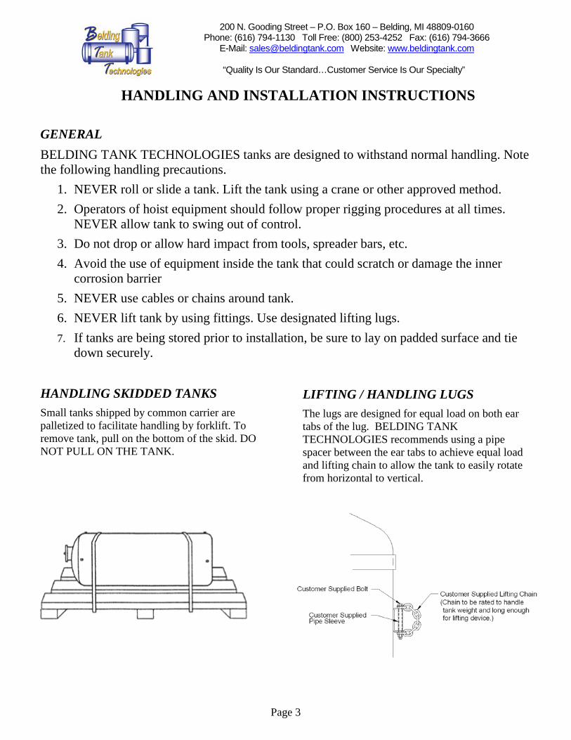
down securely. HANDLING SKIDDED TANKS Small tanks shipped by common carrier are palletized to facilitate handling by forklift. To remove tank, pull on the bottom of the skid. DO NOT PULL ON THE TANK.
LIFTING / HANDLING LUGS The lugs are designed for equal load on both ear tabs of the lug. BELDING TANK TECHNOLOGIES recommends using a pipe spacer between the ear tabs to achieve equal load and lifting chain to allow the tank to easily rotate from horizontal to vertical.

200 N. Gooding Street – P.O. Box 160 – Belding, MI 48809-0160 Phone: (616) 794-1130 Toll Free: (800) 253-4252 Fax: (616) 794-3666
E-Mail: [email protected] Website: www.beldingtank.com
“Quality Is Our Standard…Customer Service Is Our Specialty”
HANDLING AND INSTALLATION INSTRUCTIONS
Page 4
FLAT OR SLOPED BOTTOM TANKS
Larger tanks shipped by BELDING TANK TECHNOLOGIES truck and special built trailers, require a spreader bar and tail hook lines attached to the appropriate lifting lugs to unload tanks. Use a guide line to keep the load under control. Use a spreader bar and lines attached to appropriate lifting lugs to hoist the tank to an upright position and place the tank on its foundation. Control the tank with guide lines to ensure the tank is gently set on its base.

200 N. Gooding Street – P.O. Box 160 – Belding, MI 48809-0160 Phone: (616) 794-1130 Toll Free: (800) 253-4252 Fax: (616) 794-3666
E-Mail: [email protected] Website: www.beldingtank.com
“Quality Is Our Standard…Customer Service Is Our Specialty”
HANDLING AND INSTALLATION INSTRUCTIONS
Page 5
TANK BOTTOM SUPPORT PAD BELDING TANK flat bottom and slope bottom tanks require continuous bottom support. The most common support pad is a concrete slab. However, any other support structure with sufficient strength to support the combined weight of the tank and its contents without deflection, plus a reasonable factor of safety, is acceptable. Design for bearing strength of support pad is the responsibility of the purchaser. The support pad must exceed tank diameter by 6" minimum, and be flat within +/- 1/16". INSTALLATION NOTE: Support pad must be clean and free of all foreign objects prior to settling tank in place.
TANK BOTTOM BUFFER PAD Liquid grout such as concrete, epoxy, etc., MUST NOT be used under standard flat bottoms. BELDING TANK recommends a buffer pad between the tank support and tank bottom: flexible elastomer or a minimum of two layers of 30 pound roofing felt. When applying the roofing felt, be sure there are no overlaps or wrinkles causing ridges under the bottom. It is the responsibility of the purchaser to see that tanks are properly installed. Any deviation from the above outlined procedure must be approved by BELDING TANK TECHNOLOGIES or it will void your warranty.
200 N. Gooding Street – P.O. Box 160 – Belding, MI 48809-0160 Phone: (616) 794-1130 Toll Free: (800) 253-4252 Fax: (616) 794-3666
E-Mail: [email protected] Website: www.beldingtank.com
“Quality Is Our Standard…Customer Service Is Our Specialty”
HANDLING AND INSTALLATION INSTRUCTIONS
Page 6
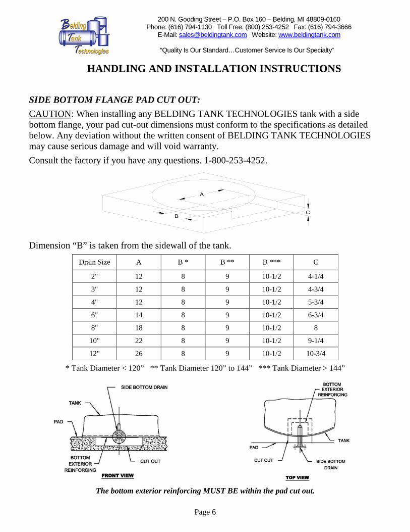
SIDE BOTTOM FLANGE PAD CUT OUT: CAUTION: When installing any BELDING TANK TECHNOLOGIES tank with a side bottom flange, your pad cut-out dimensions must conform to the specifications as detailed below. Any deviation without the written consent of BELDING TANK TECHNOLOGIES may cause serious damage and will void warranty. Consult the factory if you have any questions. 1-800-253-4252. Dimension “B” is taken from the sidewall of the tank.
Drain Size A B * B ** B *** C
2" 12 8 9 10-1/2 4-1/4
3" 12 8 9 10-1/2 4-3/4
4" 12 8 9 10-1/2 5-3/4
6" 14 8 9 10-1/2 6-3/4
8" 18 8 9 10-1/2 8
10" 22 8 9 10-1/2 9-1/4
12" 26 8 9 10-1/2 10-3/4
* Tank Diameter < 120” ** Tank Diameter 120” to 144” *** Tank Diameter > 144”
The bottom exterior reinforcing MUST BE within the pad cut out.
A
BC

200 N. Gooding Street – P.O. Box 160 – Belding, MI 48809-0160 Phone: (616) 794-1130 Toll Free: (800) 253-4252 Fax: (616) 794-3666
E-Mail: [email protected] Website: www.beldingtank.com
“Quality Is Our Standard…Customer Service Is Our Specialty”
HANDLING AND INSTALLATION INSTRUCTIONS
Page 7
HOLD DOWN LUGS - Standard The required hold down lugs are supplied as standard equipment on all BELDING TANK TECHNOLOGIES tanks. Anchor bolts and hold down hardware are supplied by the customer. Preferred Method of Anchor Installation:
Expansion anchor or resin capsule anchor.
Belding Tank recommends the use of two nuts on the top of the lug. When the tank is EMPTY, hand tighten the first nut onto the top of the lug. Hand tighten the second “JAM” top nut onto the bottom nut. Then, using two wrenches lock the bottom nut
onto the top nut. Do not adjust after the tank is filled. Do not over tighten hold down lugs.
INSTALLATION NOTE: Do not locate or pre-set anchor holes/bolts in the tank pad before receipt of tank. BELDING TANK will not be responsible for pre-set anchor holes/bolts.
Customer SuppliedAnchoring System
Customer SuppliedPipe Sleeve

200 N. Gooding Street – P.O. Box 160 – Belding, MI 48809-0160 Phone: (616) 794-1130 Toll Free: (800) 253-4252 Fax: (616) 794-3666
E-Mail: [email protected] Website: www.beldingtank.com
“Quality Is Our Standard…Customer Service Is Our Specialty”
HANDLING AND INSTALLATION INSTRUCTIONS
Page 8
HOLD DOWN LUGS – Anchor “DOG” / Load Ledge
1. Position & set Anchors -- See Tank Drawing for position. 2. Minimum height of anchors above tank base = height of “DOG” + top plate + height of
(2) nuts + ½” minimum. 3. Position anchor “DOGS” over anchor bolts; locate dog ledge ¼” away from sidewall
and on top of load ledge & level “DOGS”; -- shim if needed. 4. When tank is empty fill anchor “DOG” box with non-shrink grout. 5. Put cover plate over anchor “DOG” box and hand- tighten bottom nut. 6. Hand tighten second “JAM” top nut onto the bottom nut. 7. Lock bottom nut onto the top nut. Do not adjust after tank is filled.
TO SUIT LG.
1/2 CLEARANCESHIM PER INSTRUCTIONS ABOVE.
CUSTOMER SUPPLIEDANCHOR BOLTS
HAND TIGHTEN, LOCK WITHJAM NUT PER INSTRUCTIONSABOVE.
ISO VIEW
TANK LOAD LEDGE
DOG LEDGE
1/4 CLEARANCE

200 N. Gooding Street – P.O. Box 160 – Belding, MI 48809-0160 Phone: (616) 794-1130 Toll Free: (800) 253-4252 Fax: (616) 794-3666
E-Mail: [email protected] Website: www.beldingtank.com
“Quality Is Our Standard…Customer Service Is Our Specialty”
HANDLING AND INSTALLATION INSTRUCTIONS
Page 9
DISHED OR CONE BOTTOM TANKS
NOTE: When up righting a tank with legs, DO NOT pivot tank on legs. Lift the entire tank. Rotate to a vertical position. Set straight down on all legs.
Proper
Improper
CAUTION: If a fork truck is being used to offload the tank, the forks MUST NOT come in direct contact with the fiberglass tank.

200 N. Gooding Street – P.O. Box 160 – Belding, MI 48809-0160 Phone: (616) 794-1130 Toll Free: (800) 253-4252 Fax: (616) 794-3666
E-Mail: [email protected] Website: www.beldingtank.com
“Quality Is Our Standard…Customer Service Is Our Specialty”
HANDLING AND INSTALLATION INSTRUCTIONS
Page 10
LEG SUPPORTED / SIDEWALL LUG SUPPORTED TANKS The pad surface must be smooth and level. Consideration must be given to the concentrated nature (4-12 points) of the loading, the magnitude of which could require footings beneath each leg / lug to spread the load over a larger area. The design of footings is the responsibility of the purchaser. The tank is designed to rely upon firm even support at each of its legs / lugs. In order to allow for uneven pads, floors, and legs / lugs, the floor pads on each leg or base plates on each lug may require shims to insure uniform support. Once uniformly supported, the floor plates / base plates are to be anchored. Consult factory if you have any questions. (1-800-253-4252)

200 N. Gooding Street – P.O. Box 160 – Belding, MI 48809-0160 Phone: (616) 794-1130 Toll Free: (800) 253-4252 Fax: (616) 794-3666
E-Mail: [email protected] Website: www.beldingtank.com
“Quality Is Our Standard…Customer Service Is Our Specialty”
HANDLING AND INSTALLATION INSTRUCTIONS
Page 11
HORIZONTAL TANKS
Proper
HORIZONTAL TANK INSTALLATION Installation of horizontal tanks is much the same as the dished bottom. Tanks are supplied with the required number of steel support saddles. These saddles are to be placed under the designated support rings. The saddles should be centered on the support ring and through the centerline of the tank. Caution must be taken to insure that the tank support rings are in contact with the bottom of the saddles. The tank is designed to rely upon firm even support at each of its saddles. In order to allow for uneven pads and floors, the saddles may require shims to insure uniform support. Once uniformly supported, the saddles are to be anchored. Caution: Modification of saddles in any way voids your warranty.
150°SADDLE
CONTACTAREA
200 N. Gooding Street – P.O. Box 160 – Belding, MI 48809-0160 Phone: (616) 794-1130 Toll Free: (800) 253-4252 Fax: (616) 794-3666
E-Mail: [email protected] Website: www.beldingtank.com
“Quality Is Our Standard…Customer Service Is Our Specialty”
HANDLING AND INSTALLATION INSTRUCTIONS
Page 12
FITTING CONNECTIONS Fiberglass tanks will move due to hydrostatic pressure and temperature fluctuations. Because of this movement, Belding Tank strongly recommends the use of flexible pipe connections. The flexible connection should be attached to the tank fitting. If rigid piping is used and results in damage to the tank and/or fitting, your warranty will be void. CAUTION: METALLIC FITTINGS MUST NOT BE USED ON FRP NIPPLES OR COUPLINGS. BELDING TANK recommends that you do NOT use raised face flanges. If raised face flanges must be used, a flange spacer MUST BE USED when bolting FRP flanges to raised face flanges. Use only full face gaskets. Do NOT over torque the flange bolts. WATER FILL TESTING BELDING TANK recommends that each tank be water filled (hydro tested) for a minimum 2 hour period at atmospheric pressure, after the tank is installed and prior to use. TANKS FOR FOOD APPLICATION See BELDING TANK TECHNOLOGIES Operation & Maintenance Instructions for tanks requiring FDA approval.