handling inspection maintenance g, - electrical part … · wemco c insulating oil and wemco-ci oil...
TRANSCRIPT
1.8. 45-063-100
.HANDLING • INSPECTION • MAINTENANCE
g, I N S T R U C T I 0 N S
I"'"'
WEMCO® C
and
WEMCO CI
INSOLATING OILS
P.D.S. 2772 and P.D.S. 9855
for
Electrical Apparatus
WESTINGHOUSE ELECTRIC CORPORATION SHARON PLANT
SHARON, PA.
SUPERSEDES I . B . 44-820-1 B
• TRAFFORD PLANT
TRAFFORD, PA.
OCTOBER, 1961 www . El
ectric
alPar
tMan
uals
. com

2
TABLE OF CONTENTS
PART ONE RECEIVING, STORING AND HANDLING Pages 4-5
Shipment . . . . . . . . . . . . . . . . . . . . . . . . . . . . . . . . . . . . . . . . . . . . . . . . . . . . . . . . . . . 4
Storing . . . . . . . . . . . . . . . . . . . . . . . . . . . . . . . . . . . . . . . . . . . . . . . . . . . . . . . . . . . . . . . . . 4
Fire Protection . . . . . . . . . . . . . . . . . . . . . . . . . . . . . . . . . . . . . . . . . . . . . . . . . . . . . . . . . . 4
Handling . . . . . . . . . . . . . . . . . . . . . . . . . . . . . . . . . . . . . . . . . . . . . . . . . . . . . . . . . . . . . . . 4
Filling Drums . . . . . . . . . . . . . . . . . . . . . . . . . . . . . . . . . . . . . . . . . . . . . . . . . . . . . . . 5
Refilling Drums . . . . . . . . . . . . . . . . . . . . . . . . . . . . . . . . . . . . . . . . . . . . . . . . . . . . . 5
OIL CBABACTEBISTICS,.
PART TWO SAMPLING AND INSPECTION Pages 6-11
Characteristics of Insulating Oil . . . . . . . . . . . . . . . . . . . . . . . . . . . . . . . . . . . . . . . . . . 6
Causes of Deterioration of Oil . . . . . . . . . . . . . . . . . . . . . . . . . . . . . . . . . . . . . . . . . . . . 6
Transformers . . . . . . . . . . . . . . . . . . . . . . . . . . . . . . . . . . . . . . . . . . . . . . . . . . . . . . . 6
Circuit Breakers . . . . . . . . . . . . . . . . . . . . . . . . . . . . . . . . . . . . . . . . . . . . . . . . . . . . . 7
Sampling Oil from Shipping Containers . . . . . . . . . . . . . . . . . . . . . . . . . . . . . . . . . . 8
Sampling Oil from Apparatus . . . . . . . . . . . . . . . . . . . . . . . . . . . . . . . . . . . . . . . . . . . . 9
Periodic Inspection . . . . . . . . . . . . . . . . . . . . . . . . . . . . . . . . . . . . . . . . . . . . . . . . . . . . . . 1 0
Checking Oil Level . . . . . . . . . . . . . . . . . . . . . . . . . . . . . . . . . . . . . . . . . . . . . . . . . . 10
Checking Dielectric Strength . . . . . . . . . . . . . . . . . . . . . . . . . . . . . . . . . . . . . . . . . 10
Checking for Carbonization ..... . ... : . . . . . . . . . . . . . . . . . . . . . . . . . . . . . . . . 10
Checking for Sludge . . . . . . . . . . . . . . . . . . . . . . . . . . . . . . . . . . . . . . . . . . . . . . . . . 11
Westinghouse Oil Testing Service . . . . . . . . . . . . . . . . . . . . . . . . . . . . . . . . . . . . . . . . 11
PART THREE PURIFICATION AND RECONDITIONING Page 12
Purity of Oil . . . . . . . . . . . . . . . . . . . . . . . . . . . . . . . . . . . . . . . . . . . . . . . . . . . . . . . . . . . . 12
Reconditioning . . . . . . . . . . . . . . . . . . . . . . . . . . . . . . . . . . . . . . . . . . . . . . . . . . . . . . . . . . 12
PART FOUR TESTING METHODS Pages 13-17
Dielectric Strength Test . . . . . . . . . . . . . . . . . . . . . . . . . . . . . . . . . . . . . . . . . . . . . . . . . . 13
Steam Emulsion Test . . . . . . . . . . . . . . . . . . . . . . . . . . . . . . . . . . . . . . . . . . . . . . . . . . . . IS
Neutralization Test . . . . . . . . . . . . . . . . . . . . . . . . . . . . . . . . . . . . . . . . . . . . . . . . . . . . . . 16
PART FIVE
RECONDITIONING AND
APPARATUS FOB RECONDITIONING Pages 18-21
Blotter Filter Press . . . . . . . . . . . . . . . . . . . . . . . . . . . . . . . . . . . . . . . . . . . . . . . . . . . . . . . 19
Electric Drying Oven . . . . . . . . . . . . . . . . . . . . . . . . . . . . . . . . . . . . . . . . . . . . . . . . . . . . 21
Centrifuge . . . . . . . . . . . . . . . . . . . . . . . . . . . . . . . . . . . . . . . . . . . . . . . . . . . . . . . . . . . . . . 21
www . El
ectric
alPar
tMan
uals
. com

I.B. 45-063-100 INSULATING OIL
WEMCO® C INSULATING OIL P. D. S. 2772
WEMCO CI-INBIBITED INSULATING OIL--P.D.S. 9855
Wemco C insulating oil and Wemco-CI oil are developments of the Westinghouse Electric Corporation in cooperation with oil refin�rs. They have
been proven suitable for use in all Westinghouse oil-insulated apparatus. In order to insure the proper performance of the apparatus, only Westinghouse approved oils should be used.
This publication gives the instructions for handling, inspection and maintenance which experience has shown are important in obtaining the best
service from the insulating oil.
3 www . El
ectric
alPar
tMan
uals
. com
PART THREE
PURIFICATION AND RECONDITIONING PURITY OF OIL
Wemco C oil is clear and nearly water-white in colm. It is free from water, acid, alkali, and deleterious sulfur compounds.
The oil is carefully refined so as to have a high resistance to emulsion; that is, the water is not held in suspension but quickly separates out. This is particularly essential in circuit-breaker service
time arid the catalytic action of exposed metals in the apparatus to which it is subjected. High temperature over a short period of time cr somewhat lower temperature over a long period of time affect the characteristics of the oil, particularly in the development of organic acidity and sludge.
Heat in the presence of oxygen affects the unsaturated hydrocarbons, at first through formation of organic acids and later by precipitation in the
TESTING METHODS------------------------------------------------
CAUTION: Care must be taken if glass baHery
jars are used, as direct heating by flame or electric
hot point may cause breakage. Use of steam in
this case insures against breakage.
The temperature of the emulsifying bath shall be
the steaming operation is approximate} y 12 to 15 cc
greater than the actual volume due to displacement caused by steam, thermometer and steam delivery tube.
Seoaration. ThP. 5'ltP.rrm rl,:>liv<>nr tn ho c:hnll ha
www . El
ectric
alPar
tMan
uals
. com

e
PRINTED IN U.S.A. (REV. 10·111) www . El
ectric
alPar
tMan
uals
. com

Instructions for
WEMCO® C and WEMCO C1
Insulating Oils
Westinghouse Electric Corporation
Power Transformer Division, Sharon, Pa. LB. 45-063-100B Effective May, 1 969 Supersedes LB. 45-063-lOOA May, 1964 www .
Elec
tricalP
artM
anua
ls . c
om

2
TABLE OF CONTENTS
PART ONE RECEIVING, STORING AND HANDLING Pages 4-5
Shipment . . . . . . . . . . . . . . . . . . . . . . . . . . . . . . . . . . . . . . . . . . . . . . . . . . . . . . . . . . . 4 Storing .... , . . . . . . . . . . . . . . . . . . . . . . . . . . . . . . . . . . . . . . . . . . . . . . . . . . . . . . . . . . . . 4 Fire Protection . . . . . . . . . . . . . . . . . . . . . . . . . . . . . . . . . . . . . . . . . . . . . . . . . . . . . . . . . . 4 Handling . . . . . . . . . . . . . . . . . . . . . . . . . . . . . . . . . . . . . . . . . . . . . . . . . . . . . . . . . . . . . . . 4
Filling Drums . . . . . . . . . . . . . . . . . . . . . . . . . . . . . . . . . . . . . . . . . . . . . . . . . . . . . . . 5 Refilling Drums . . . . . . . . . . . . . . . . . . . . . . . . . . . . . . . . . . . . . . . . . . . . . . . . . . . . . 5
OIL CHARACTERISTICS.
PART TWO SAMPLING AND INSPECTION Pages 6-1 1
Characteristics of Insulating Oil . . . . . . . . . . . . . . .. . . . . . . . . . . . . . . . . . . . . . . . . . . . 6 Causes of Deterioration of Oil . . . . . . . . . . . . . . . . . . . . . . . . . . . . . . . . . . . . . . . . . . . . 6
Transformers . . . . . . . . . . . . . . . . . . . . . . . . . . . . . . . . . . . . . . . . . . . . . . . . . . . . . . . 6 Circuit Breakers . . . . . . . . . . . . . . . . . . . . . . . . . . . . . . . . . . . . . . . . . . . . . . . . . . . . . 7
Sampling Oil from Shipping Containers . . . . . . . . . . . . . . . . . . . . . . . . . . . . . . . . . . 8
Sampling Oil from Apparatus . . . . . . . . . . . . . . . . . . . . . . . . . . . . . . . . . . . . . . . . . . . . 9 Periodic Inspection . . . . . . . . . . . . . . . . . . . . . . . . . . . . . . . . . . . . . . . . . . . . . . . . . . . . . . 10
Checking Oil Level . . . . . . . . . . . . . . . . . . . . . . . . . . . . . . . . . . . . . . . . . . . . . . . . . . 1 0
Checking Dielectric Strength . . . . . . . . . . . . . . . . . . . . . . . . . . . . . . . . . . . . . . . . . 10
Checking for Carbonization . . . . . . . . . . . . . . . . . . . . . . . . . . . . . . . . . . . . . . . . . . 10
Checking for Sludge . . . . . . . . . . . . . . . . . . . . . . . . . . . . . . . . . . . . . . . . . . . . . . . . . II
Westinghouse Oil Testing Service . . . . . . . . . . . . . . . . . . . . . . . . . . . . . . . . . . . . . . . . 11
PART THREE PURIFICATION AND RECONDITIONING Page 1 2
Purity of Oil . . . . . . . . . . . . . . . . . . . . . . . . . . . . . . . . . . . . . . . . . . . . . . . . . . . . . . . . . . . . 12
Reconditioning . . . . . . . . . . . . . . . . . . . . . . . . . . . . . . . . . . . . . . . . . . . . . . . . . . . . . . . . . . 1 2
PART FOUR TESTING METHODS Pages 13-17 Dielectric Strength Test . . . . . . . . . . . . . . . . . . . . . . . . . . . . . . . . . . . . . . . . . . . . . . . . . . 13
Neutralization Test . . . . . . . . . . . . . . . . . . . . . . . . . . . . . . . . . . . . . . . . . . . . . . . . . . . . . . IS
PART FIVE
RECONDITIONING AND
APPARATUS FOR RECONDITIONING Pages 1 6-19
Blotter Filter Press . . . . . . . . . . . . . . . . . . . . . . . . . . . . . . . . . . . . . . . . . . . . . . . . . . . . . . . 17 Electric Drying Oven . . . . . . . . . . . . . . . . . . . . . . . . . . . . . . . . . . . . . . . . . . . . . . . . . . . . 19 Centrifuge . . . . . . . . . . . . . . . . . . . . . . . . . . . . . . . . . . . . . . . . . . . . . . . . . . . . . . . . . . . . . . 19
www . El
ectric
alPar
tMan
uals
. com

WEMCO® C INSULATING OIL P. D. S. 55822AG
WEMCO CI--INHIBITED INSULATING OIL--P.D.S. 55822AV
Wemco C insulating oil and Wemco-CI oil are developments of the Westinghouse Electric Corporation in cooperation with oil refinE!rs. They have been proven suitable for use in all Westinghouse oil-insulated apparatus. In order to insure the proper performance of the apparatus, only Westinghouse approved oils should be used.
This publication gives the instructions for handling. inspection and maintenance which experience has shown are important in obtaining the best service from the insulating oil.
3 www . El
ectric
alPar
tMan
uals
. com
4
PART ONE
RECEIVING, STORING AND HANDLING SHIPMENT
Wemco C and Wemco CI oils are shipped in tank cars, drums or cans. Modern tank cars are usually equipped with breathers which bar the admission of moisture and are otherwise well gasketed to protect the oil from moisture. These precautions are necessary because the volume of the oil changes with temperature variations.
When shipped in drums, the drums are provided with screw bungs having gaskets to prevent admission of water.
When shipped in cans, the cans are hermetically sealed immediately after filling and should not be opened until the oil is needed.
STORING
Drums. As soon as a drum of oil has been unloaded, the bung should be examined for damage or leaks.
It is very desirable that oil in drums be stored in a closed room. Outdoor storage of oil is always hazardous to the oil and should be avoided if at all possible. Re g a r dl e s s of storage location all drummed oil should be stored with the bungs down so that the bungs are under positive oil pressure. Do not open the drums until the oil is actually needed. Partially emptied drums must be tightly
resealed and stored the same as new drums.
Cans. One and five-gallon cans of oil must not be exposed to the weather. Seals should be kept intact until the oil is actually needed. It is not necessary to make dielectric tests on oil in sealed cans.
Screw caps are provided on the cans to use when the oil is only partially removed after the hermetic seal has been broken. By replacing the screw caps, contamination by moisture and dirt will be retarded but the oil must be tested before using.
Storage Tank. The storage tank should be mounted on piers so that it will not touch the ground, and will be accessible to all points for inspection for leakage.
In larger storage systems, it is desirable to provide equipment to supply dry air for breathing purposes. This is often accomplished by the use of
a breather making use of silica gel or aluminum oxide as the drying medium.
The tank should preferably have a convex bottom, allowing the installation of a drain cock at the lowest point for removing any free water or dirt which might settle out. When a cylindrical tank is installed with its axis horizontal, one end should be a little lower than the other, with c drain cock at the lowest point, and the oil supply pipe should enter at the opposite end of the tank. The oil may enter and leave the tank by the same pipe, but this should be at some distance from the bottom to prevent stirring up any settlings when the tank is being filled. It is desirable that the pipe be provided with a swing joint and float, so that it will automatically move with the change in oil level and remain near the surface of the oil.
FIRE PROTECTION
IMPORTANT: While Wemco C or Wemco CI oil will not take fire unless brought to a high tempera
ture (320c Fl. it should be remembered that under
abnormal conditions such a temperature can be
reached. so that proper precaution against fire should be taken. The best way to extinguish burning oil is to smother the flames so that the supply
of fresh air is cut off. Chemical fire extinguishers are effective. but water should not be used unless it is applied by a special atomizing spray nozzle.
HANDLING
SAMPLE AND DIELECTRIC TEST ALL OIL BEFORE PLACING IT IN APPARATUS.
Before putting the oil into equipment see that the tank is free from moisture and foreign material. The presence of impurities, particularly moisture, in the oil or apparatus may lower its dielectric strength to an unusable value. If the oil is supplied in more than one container, each container must be sampled and tested.
Although the drums and tank cars are thoroughly washed and dried at the refinery before filling, a certain amount of scale is sometimes loosened from the inside in transit. Therefore, it is recommended that all the oil be passed through a filter press to remove any moisture or solid contaminats which may be present. www .
Elec
tricalP
artM
anua
ls . c
om
RECEIVING, STORING AND HANDLING·-----------------------------------
The preparation and filling of outdoor apparatus should preferably be done on a clear, dry day; if this is not practicable, protection against moisture must be provided.
All vessels used for transferring the oil should be carefully inspected to see that they are absolutely dry and free from dirt.
Whenever possible it is recommended that all equipment should be allowed to stand for at least eight hours between filling and energizing the ap· paratus to allow gas bubbles to escape from the oil. This is especially important when filling under vacuum is impossible.
IMPORT ANT: Always use a metal or oil proof
hose when handling the oil. A hose made of nat
ural rubber must not be used. Oil may easily be
come contaminated from the sulfur in the natural
rubber, and should not be allowed to come in
contact with it.
When is is necessary to fill equipment with oil, it is essential that the oil be allowed to come to the same temperature as the apparatus. This may require eight hours, or even longer, under extreme temperature conditions. Otherwise, condensation of moisture may lower the dielectric strength of the oil to an unusable value. Cold oil in drums should never be brought into a warmer area and transferred to equipment until it has reached the some temperature as the apparatus.
FILLING DRUMS
The practice of filling drums with oil is undesirable and should be avoided whenever possible, for unless the utmost precautions are taken, the oil is likely to become contaminated.
If it is necessary to fill drums for storage. use only those drums which are in good condition and which have been used previously for transformer oil. A good practice is to reserve drums for this purpose by sealing them immediately after being emptied to exclude dirt and water. Before reusing each drum should be carefully examined to be sure it is clean and free of water.
A new washer should be used with the bung each time the drum is refilled, to insure a tight seal. These washers may be obtained from the oil refineries and it is recommended that a supply be kept on hand. Natural rubber composition washers should never be used as they would be attacked by the oil.
Cleaning Contaminated Drums. The cleaning of drums which have contained used insulating oil requires great care in order to insure a thoroughly clean drum. It is preferable to return such drums to the refinery where adequate cleaning facilities are available, rather than to attempt to clean them. If it is necessary to clean such drums, the following procedure is recommended:
Rinse the drum thoroughly with Stoddard solvent or other suitable solvent, using about one gallon each time, until the solvent shows no discoloration after using. Allow it to drain, then pump out the last traces of solvent with a vacuum pump, using a brass pipe flattened at the lower end to explore the corners of the drum.
CAUTION: Do not use a steel pipe because of
the danger of a spark igniting the vapor.
Heat the drum with bunghole down, in a ventilated oven at a temperature of at least 88oC ( 1 90"F) for sixteen hours. Screw the bung on tightly before removing drum from the oven. Use a new washer with the bung to insure a tight seal. A simple oven for this purpose may be made from sheet metal and heated with steam or an electric heater.
CAUTION: An open flame must always be kept
away from the oven to prevent igniting inflam
mable gases.
REFILLING DRUMS
CAUTION: STATIC ELECTRICITY-Pumping and
filtering of oil under certain circumstances may
cause electrical charges to be built up in the oil to
such an extent that electrical breakdown of the
gas above the oil is possible. When a filter press
is used to filter the oil in the equipment, precau
tionary measures should be taken to prevent an
explosion caused by the possible static discharqe of the electrical charge which could be built up
in the equipment. If this electrical discharge takes
place in an explosive gas mixture. the result could
be a damaging explosion.
This static charge is variable and depends upon
a number of variable factors. Since some of these
factors are beyond the range of control. it may be
best to surmise that they will always be present.
Thus there will always be the possibility of this static discharge.
A thorough purging with the use of nitrogen. of
the accumulated gases fanned in any electrical
equipment should be made before filtering the oil
This will offset any possible reaction between the
static discharge and the accumulated gases.
5 www . El
ectric
alPar
tMan
uals
. com

PART TWO
OIL CHARACTERISTICS,
SAMPLING AND INSPECTION CHARACTERISTICS OF INSULATING OIL
Wemco "C" insulating oil is a refined mineral oil obtained from the fractional distillation of crude petroleum. It contains no moisture, inorganic acid, alkali, free sulfur, asphalt, tar, vegetable, or animal oils. It is used as an insulating and heo:t transfer medium and is intended principally for use in tanks of oil insulated circuit breakers, switches and transformers. In circuit breakers and other apparatus subject to arcing, the cooling and deionizing characteristics of the oil become important in extinguishing the arc.
Wemco "CI" inhibited insulatinq oil has a minimum of 0.15 percent by weight of Di-Tertiary-ButylParacresol, (D.B.P.C.) added to Wemco "C" insulating oil to provide additional oxidation resistance for use in distribution transformers that may be subject to breathing of air and where it is difficult to maintain tight seo:ls.
ADVANTAGES OF WEMCO "C" OIL
I. High dielectric strength.
2. Low viscosity-provides for good heat transfer.
3. Freedom from inorganic acids, alkalis, and corrosive sulfur-prevents injury to insulation and materials of construction.
4. Good resistance to emulsification. In case of moisture contamination it quickly settles to the bottom of the tank.
5. Freedom from sludging under normal operating conditions over long periods of time-accomplished by proper selection of crudes and refining methods.
6. Because of its low viscosity it is more able to dissipate the arcing products in circuit breakers, tap changers, and other arcing contact apparatus.
7. Low pour point allows use under low temperature conditions.
a. The higher than average flash point allows higher operating temperatures with freedom from fire hazard.
PHYSICAL PROPERTIES AND
TEST PROCEDURE
I. Color-nearly water white-0.5 max.-ASTM Dl500
6
2. Reaction-Neutral
3. Neutralization Number-Mg. KOH per g. oil -0.03 max. ASTM D974
4. Precipitation Number-zero
5. Free or Corrosive Sulfur-- non-corrosiveASTM Dl275
6. Steam Emulsion-35 sec. max.-ASTM 1 935
7. Flash Point-293°F 045°C) Min.-ASTM D92
a. Pour Point-Minus 50°F (minus 45.0°C) Max.ASTM D97
9. Viscosity-Saybolt Universal-lOOoF (37.8°C) Max.-62 sec.-ASTM D88
10. Moisture Content-35 ppm. Max. ASTM D l533
11. Specific Gravity GOOF ( l5.5°C)- .898 Max. ASTM D l298
12. Specific Heat-0.488 Approx.
13. Inorganic Chlorides or Sulfates - None ASTM D878
14. Coefficient of Expansion 32oF (OoC}-.000725
15. Coefficient of Expansion 212'F ( lOOOC).000755
16. In terfacial Tension dynes/em. - 40 Min. ASTM D971
17. Dielectric Constant 2.2
1a. Dielectric Strength-3D KV Min.-ASTM D877
19. Weight per gallon-7.5 lbs.
20. Power Factor-60 cycle 25oC-Max . . 05 %ASTM D924
21. Inhibitor (D.B.P.C.) (PDS 9855} (Wemco CI
only) Min. 0.15% ASTM Dl473
CAUSES OF DETERIORATION OF OIL
Transformers. Deterioration of oil is a problem to which much thought and research has been devoted. Westinghouse Sealedaire, Inertaire, Thermosiphon, and expansion tank transformers are
www . El
ectric
alPar
tMan
uals
. com

SAMPLING AND INSPECTION _______ ______ _ ____ ___ _
the results of this research in methods of preventing deterioration.
Generally speaking, however. the p r i n c i p a l causes of deterioration of insulating oils are:
l . Presence of moisture.
2. Oxidation.
3. Excessive temperature.
Condensation from moist air due to breathing of the transformer, especially when the transformer is not continuously in service, may injure oil. (The moist air drawn into the transformer condenses moisture on the surface of the oil and inside of the tank.) The oil may also be contaminated with water through leakage such as from leaky cooling coils or covers.
Sludge is an oxidation product. the amount formed in a given oil being dependent upon the temperature and the time of exposure of the oil to the air. In the refining process for our transformer oil, the components of the oil which are most readily oxidized to form sludge are removed so as to provide an insulating oil which will not sludge under normal operating temperatures.
Note: Excessive temperatures may cause sludging of any transformer oil regardless of how well it is refined.
Transformer oil which has begun to sludge will continue to do so even after it has been reconditioned by means of the centrifuge or filter press, as these methods of reconditionmg do not remove the deterioration products which are in process of formation but have not yet been precipitated as sludge.
Reconditioning by means of fuller's earth and vacuum dehydration will remove many of the deterioration products, and if stabilized
'by the addi
tion of an oil inhibitor, further sludging can be prevented for long periods of time.
Another effect of oxygen is to gradually produce organic or "fatty" acids in oil in service. These should not be confused with the mineral acids such as sulphuric acid used in refining, as in small amounts the former do not have a deteriorating effect upon insulation.
Circuit Breakers. The principal causes of deterioration of insulating oil in circuit breakers or other arc producing apparatus, are:
l. Presence of water.
2. Carbonization of the oil (caused by operation of the circuit breaker).
FIG. l. Drum Thief.
The arcing of the oil in circuit breakers produces small amounts of water, acids, and carbon due to oil decomposition. These acids may in extreme cases form metal soap on plated hardware but this in no way harms the apparatus. Water may also result from the entrance of moist air into the tank. Some of the carbon is deposited on the contact components and at the bottom of the tank while the remainder continues in suspension in the oil.
Carbonization takes place not only when the circuit breaker opens heavy short circuits, but also whenever an arc is formed, even during such light service as the opening of the charging current of the line, and this latter service, repeated, may eventually produce enough carbon to be a source of trouble.
7 www . El
ectric
alPar
tMan
uals
. com

SAMPLING AND INSPECTION _____________________ _
8"
FIG. 2. Tank Car Thie£.
The carbon may reduce the dielectric strength of the oil, lower the surface resistance of the insula
tion if water is present, and also may lower the resistance to emulsification. The carbon alone may
not be detected by the dielectric test, particularly if the oil is free from moisture.
In cold weather, a larger amount of carbon is formed than in warm weather because of the increased viscosity of the oil at low temperatures. Also the carbon is not as readily dispersed through the oil.
SAMPLING OIL FROM SHIPPING CONTAINERS
The dielectric strength of oil is affected by the most minute traces of certain impurities, particularly water. It is important that the greatest care
be taken in obtaining the samples and in handling
them to avoid contamination. There have been low dielectric test results reported from the field which,
upon investigation, have been found to have been largely a matter of carelessness in handling. The following instructions, based on the specifications
of the American Society for Testing Materials, must be followed to assure accurate results:
Sample Bottle. The sample container shall be made of amber glass, of at least 16 oz. capacity,
8
and shall be cleaned and dried. The glass bottle is
preferable to a metal container as it may be examined to see if it is clean. It also allows visual inspection of the oil before testing, particularly as regards free water and solid impurities. However. any samples to be tested for color power factor or sludge-forming characteristics must be kept in the dark, as light produces changes in these properties. This is not necessary for any other tests.
The clean, dry bottle shall be thoroughly rinsed with Stoddard solvent or other suitable solvent
which has previously withstood a dielectric test of at least 25 kv in a standard test cup, and shall be allowed to drain. It is preferable to heat the bottle and cap to a temperature of lOOoC (212oF) for one hour after thoroughly draining. The bottle shall then be tightly capped and the neck of the bottle dipped in melted paraffin.
IMPORTANT: Glass jars having rubber gaskets
or stoppers must not be used. Oil may easily be
come contaminated from the sulfur in natural
rubber.
Thieves for Sampling. A convenient and simple thief (See Fig. l ) for use with 55 gal. drums may be made of metal as follows:
Length 36 in., diameter 1% in. with cone shaped caps over the ends and openings at the ends % in. in diameter. Three legs equally spaced around the thief at the bottom, and long enough to hold the opening 1/a in. from the bottom of the container being sampled, aid in securing a good representative sample. Two rings soldered to the opposite sides of the tube at the outer end will be found convenient for holding the thief by slipping two fingers through them and leaving the thumb free to close the opening. In an emergency a piece of glass tubing 36 in. long may be used. For the tank cars, a thief employing a trap at the bottom may be used. (See Fig 2.)
The thief shall be suitable for reaching the bottom of the container and the sample shall be taken with the thief not more than about 1/R in. from the bottom.
Thieves should be cleaned before and after use by rinsing with Stoddard solvent or other suitable solvent; be sure that no lint or other fibrous material remains on them. When not in use they should be kept in a hot. dry cabinet or compartment at a temperature not less than 37.8"C (100°F), and shall be stored in a vertical position in a rack having a suitable drainage receptacle at the base.
Samples shall not be drawn from containers indoors until the oil is at least as warm as the www .
Elec
tricalP
artM
anua
ls . c
om
SAMPLING AND INSPECTION ____________________ _
surrounding air. Cold oil may condense enough moisture on the surface from a humid atmosphere to seriously affect its insulating properties. Sampling oil from containers out of doors is undesirable, due to the possibility of condensation of moisture, and should be avoided whenever possible. (Samples should never be taken in the rain.)
Procedure. The drums to be sampled shall be assembled in line, with bungs up. and numbered. The bungs shall be unsealed and removed and laid with the oily side up beside the bungholes. The unstoppered sampling receptacle can be placed on the opposite side of the bungholes. The top hole of the thief shall be closed with the thumb, the thief quickly thrust to the bottom of the container and the thumb removed. When the thief is filled, the thumb shall be replaced, the thief quickly withdrawn and the contents allowed to flow into the sampling receptacle. The lower holes shall not be closed with the fingers of the other hand. The free hand shall not be used to guide the stream of oil except by touching the thief, and this only when necessary. The oil shall not be allowed to flow over the hand or fing.ars before it flows into the sampling receptacle.
When the sampling receptacle is filled, it shall be closed quickly and the bung replaced in the container and tightened. The sampling receptacle shall be taken under cover to the testing laboratory as quickly as feasible.
After using, thoroughly clean all thieves and sampling receptacles as outlined above.
The tank cars of oil shall be sampled by introducing the thief through the manhole on top of the car, the cover of which shall be removed carefully so as not to contaminate the oil with dirt The
shall be taken as near as possible to the bottom of the tank car. This shall not be done while rain or snow is falling.
When separate samples are being taken from a consignment or part of a consignment, care should be exercised to prevent contaminating the samples. A separate thief shall be used for each sample or the thief previously used shall be well drained and then thoroughly washed with oil from the next container to be sampled; the oil thus used for washing should be thrown away before the next sample is taken. (Enough thieves shall be provided to insure thorough drainage of each thief after rinsing with oil to be sampled before using it to withdraw the actual sample.) For obtaining only a few samples, two thieves are sufficient, but for obtaining a large number of samples (for example, sam-
piing a carload of drummed oil) six or more thieves are desirable.
When one average sample of a consignment or batch is being taken, the same thief may be used throughout the sampling operation, and it is not necessary to rinse the thief with oil before taking any of the portions that go to make up the total average sample.
Quantity of Sample. It is recommended that one 16 oz. bottle of oil be taken as a sample for dielectric tests, and a one quart sample be taken when complete physical and chemical tests are to be made. At least one sample should be taken from a tank car of oil. One sample may be taken from each drum, or if desired, a composite sample may be made from oil from five drums, provided all of the drums are airtight When the bung is first loosened, a hissing sound should be heard, which indicates that the drum has been airtight. If the test of the composite sample is not satisfactory, a sample from each of the drums represented should be tested.
When drums have been stored exposed to the weather, a sample from each drum shall be tested. The sample of oil should be examined for free water, and if any is noted, the drum of oil should be put through a blotter filter press and resampled for dielectric strength.
If the sample is being taken from a tank car, and water appears, follow the same procedure.
SAMPLING OIL FROM APPARATUS
When taking samples of oil from apparatus in in which a thief cannot be used, use the sampling valve and follow the procedure outlined above a s f ar a s practicable.
Care should be taken to procure a sample which fairly represents the oil at the bottom of the tank. A sufficient amount of oil should therefore be
drawn off before the sample is taken, to insure that the sample: will not be that which was stored in the sampling pipe. For this reason, the valve and the drain pipe should be sufficiently small to be emptied with convenience and yet sufficiently large to give an even flow of oil and avoid clogging by sediment. A 1/4 in. pipe and valve is recommended. This, of course, may be separate from the drainage pipe and valve or it may be connected to the drainage valve by means of a suitable reducer.
It is of utmost importance that the sample of insulating oil represents the actual condition of the oil in the apparatus. Every precaution should be
9 www . El
ectric
alPar
tMan
uals
. com

SAMPLING AND INSPECTION----------------------
taken to keep the sample and container free from
foreign impurities or moisture.
If the apparatus is installed outdoors, care should
be taken to prevent contamination of the sample by rain, snow, etc.
A glass bottle is recommended as a sampling
receptacle, so that any water present may readily be seen.
If the sample contains free water it is not suitable for dielectric test and the sample and bottle should be discarded. A second sample should be taken after at least two quarts of oil have been withdrawn. If free water still exists in the sample, the oil in the apparatus should be put through a blotter
filter press and resampled for dielectric strength.
In order to make sure that the dielectric strength
is up to its proper value, the insulating oil in any piece of apparatus should be tested before its initial operation, and at regt�lar intervals thereafter.
PERIODIC INSPECTION
Oil may deteriorate in service even under what seems to be the most favorable conditions. The more handling an i n s u l a t i ng oil receives, the
greater the opportunity for contamination unless
adequate precautions are taken.
IMPORTANT: It is essential to provide for peri
odic inspection and test and to purify the oil when
ever necessary in order to maintain it in good
condition.
Regular inspection and tests of insulating oils by electric utilities and other large users have proven the necessity of this proctice. Where these inspections and tests have been systematically followed it has been found that failure of the apparatus due to the fact the oil had become contaminated with moisture and sediment, has been reduced to a minmum and has resulted in greater economy of op
erotion. In view of the importance of the subiect,
it is, therefore, recommended that all companies, in the interest of good service, adopt some system of
oil inspection and test.
The frequency of inspecting and testing depends
upon the service to which the oil is subjected, and
the construction of and the materials used in the apparatus.
Even though field experience has shown that it
is not necessary to frequently examine the oil in
Inertaire or Sealedaire transformers, such oils
should be inspected to insura that the Inertaire
10
equipment is being maintained and the tanks are tight.
The oil in circuit breakers and transformers
which are operated under extreme! y heavy loads requires more frequent inspection than that in nor
mal or light service.
It is recommended that operators prepare a
schedule for inspection based on the operating conditions. Reference to the station log, together with the record of dielectric tests of the oil, should determine the frequency of inspection and test.
The period between successive inspections should not be longer than six months or until experience indicates that the time between tests can be extended. If the dielectric strength of the oil drops below 22 KV in the standard dielectric test the oil should be blotter pressed. In the event that the dielectric strength is not readily restored to 26 KV or above, other tests should be made to determine
if the oil should be reconditioned or replaced.
Checking Oil Level. It is essential that the proper oil level be maintained. Low oil level may
cause breakdown of insulation or flashover of bushing in any apparatus, or malfunctioning of circuit breakers mechanically or electrically.
Checking Dielectric Strength. The oil should be tested regularly for dielectric strength and purified when the tests show need of it. The testing should be systematized and complete records kept. It is particularly important in a circuit breaker to check the dielectric strength after exposure to near rating short-circuit operations.
Checking for Carbonization. The presence of carbon in circuit breaker oil may introduce a hazard. due to the tendency of the carbon to lower the dielectric strength of the oil. and also to deposit on insulating surfaces. thereby reducing the insulation resistance.
Visual inspection of the oil samples should be
made and, if any appreciable amount of carbon is
present, the :)il should be reconditioned even
though the dielectric test is good.
IMPORT ANT: Certain washing compounds have
been used by some operating companies to assist
in separating the carbon from the oil. Investigation
in the Westinghouse laboratories has shown that
these compounds leave the oil in poor condition.
Customers are warned against using any form of
chemical treatment that has not been investigated
and recommended by Westinghouse Electric Cor
poration. www . El
ectric
alPar
tMan
uals
. com

SAMPLING AND INSPECTION ______________________ _
Checking for Sludge. Transformers should be regularly examined for evidence of sludge. A visual inspection will indicate its presence. Appreciable amounts of sludge may clog the oil ducts and interfere with heat transfer. It is desirable that such oil be reconditioned or replaced immediately. If the oil is to be returned to service, oil inhibitor should be added to extend the life of the oil. Oil which has once sludged, will, after being reconditioned, sludge more quickly than the first time unless the inhibitor is added.
WESTINGHOUSE OIL TESTING SERVICE
Many users of transformers and large oil circuit breakers do not have the necessary facilities for testing insulating oil. In order that these users may be able to make the periodic tests recommended, Westinghouse Electric Corporation has established an oil testing service to provide a careful test by experienced engineers, and a prompt report of test results.
Two special 16 oz. sample bottles per mailing container (Westinghouse Sampling Set Style # 1608 629) as well as necessary packing and printed matter, may be obtained by contacting the nearest Westinghouse office.
After drcwing the sample of oil, the customer should seal the bottle with care, and mail it to the Westinghouse Electric Corp., Plant Laboratory, Sharon, Pa. The details of this transaction have been simplified by the inclusion in the Sampling Set of an instruction sheet and a printed return label. The instructions cover the taking of the sample and its proper preparation for maillng, and the label carries an envelope for enclosing customer's order covering the testing work. (Also see details given in Price List 45-825).
If customer desires to use his own bottles, he should be sure to obtain Form 24670 from the Westinghouse Office. Lack of this farm will cause much delay in various accounting procedures in· valved. and thereby delay the test. Samples should
be taken in accordance with ASTM D-117. Note that the bottles and containers involved will not be returned to the customer.
When samples of oil are received for testing they are sent to the engineering testing laboratory and tested for dielectric strength in accordance with methods described in ASTM D-117.
As soon as the test has been made, a report giving the average is sent by mail directly to the person in the customer's organization who has been designated on the order to receive it.
In addition to dielectric tests, Westinghouse is also prepared to make a physical and chemical examination. (The customer should plainly indicate the type of service desired.)
This service consists of an examination of the oil by a competent oil chemist. Recommendations will be made as to the suitability of the oil for continued use, whether it would be desirable and economical to clean it, and in a general way, the preferred method of cleaning. In submitting samples for this service, the history of the oil represented should be given as completely as possible. Samples should be not less than one pint.
Other tests available include a complete Physical and Chemical Examination; a power factor test; and the establishment of a Power Factor Curve from 25 C to l 00' C.
The Physical and Chemical Examination encompasses tests of acid and base numbers, color, interfacial tension test, pour point, specific gravity, and viscosity.
A combination is offered of the dielectric test, the acid and base number test, the interfacial tension test, and the power factor test. This combination covers those tests most often requested for general purposes.
(For further details on available tests, refer to the nearest Westinghouse Office.)
1 1 www . El
ectric
alPar
tMan
uals
. com
PART THREE
PURIFICATION AND RECONDITIONING PURITY OF OIL
Wemco C oil is clear and nearly water-white in col01. It is free from water, acid, alkali, and deleterious sulfur compounds.
The oil is carefully refined so as to have a high resistance to emulsion; that is, the water is not held in suspension but quickly separates out. This is particularly essential in circuit-breaker service since this apparatus cannot be tightly closed like a transformer and some moisture may be introduced into the oil. Wemco C oil has been designed with this particular property in mind and precipitates
water and carbon promptly. However, certain impurities develop while the oil is in service and these impurities must be removed to insure safe operation of the apparatus. The source and kind of impurities developed in the oil depend upon the type of apparatus in which it is used.
In circuit-breaker service, each time the circuit
is opened some carbon is formed in the oil, even when only a small charging current is being interrupted. The resistance to emulsion of the oil is also both by a change in the oil and by the presence of carbon in the oil. Oil which has been subjected to arc action in the circuit breaker tends to slowly form organic acids, which further tend to lower its resistance to emulsion. The major
portiorr of the carbon slowly precipitates to the bottom of the tank, but the more finely divided carbon has a tendency to remain suspended in the oiL and lower the dielectric strength. Both carbon and moisture are attracted to the insulating surfaces of the bushings by the electrostatic field, and when so deposited, lower the insulation resistance of the terminals from line to ground.
Oil in transformers is generally subjected to heat, oxidation and sometimes to moisture. Heat in the presence of oxygen produces a gradual physical and chemical change in oil and the extent of this change will depend upon the amount of heat,
12
time arid the catalytic action of exposed metals in the apparatus to which it is subjected. High temp&rature over a short period of time or somewhat lower temperature over a long period of time affect the characteristics of the oil. particularly in the development of organic acidity and sludge.
Heat in the presence of oxygen affects the unsaturated hydrocarbons, at first through formation of organic acids and later by precipitation in the form ordinarily called sludge.
RECONDITIONING
The reconditioning of oil used in circuit breakers and transformers consists principally of the removal of water, carbon and sludge and the restoration of resistance to emulsification, thereby putting the oil in the best condition to separate out any water which may later be introduced.
The four types of equipment in general use for simple reconditioning of oil in transformers and circuit breakers are: the centrifuge, the blotter filter press, the combination centrifuge and filter press and the combination fullers earth and vacuum dehydration process. (See Part Five.)
IMPORTANT: In generaL when small quantities
of oil have been contaminated with fire extinguish
ing agents, it is preferable to replace the oil rather
than to attempt to reclaim it.
Insulating oil which has been contaminated with
carbon tetrachloride or soda sulfuric acid cannot
be reclaimed. (It would have to be refined.)
When large quantities of oil have been contaminated with other fire extinguishing agents, the reclaiming of the oil will depend upon the kind and degree of contamination. There may be factors other than the fire extinguishing agent (for instance, high temperatures cracking the oil, carbonized insulation, etc.) which should be considered. Any question should be referred to 'the nearest Westinghouse Office.
www . El
ectric
alPar
tMan
uals
. com

PART FOUR
TESTING METHODS Instructions tor all tests listed correspond in
general to the recommendations of the American Society tor Testing Materials.
DIELECTRIC STRENGTH TEST
Apparatus. The transformer and the source of supply of energy shall not be less than Vz kva, and
the frequency shall not exceed 100 cycles per second. Regulation shall be so controlled that the high tension testing voltage taken from the secondary of the testing transformer can be raised gradually without opening either primary or secondary circuit. The rate of rise shall approximate 3000 volts per second. The voltage may be measured by any approved method which gives root-meansquare values.
Some protection is desirable to prevent excessive flow of current when breakdown of the oil takes place. This protection preferably should be in the primary or low voltage side of the testing hansformer. It is not especially important for transformers of 5 kva or less, as the current is limited by the regulation of the transformer.
The test cup for holding the sample of oil shall be made of a material having a suitable dielectric
FIG. 3. Oil or Fluid Test Cup for Dielectric Test.
strength. It must be insoluble in and unattacked by mineral oil and gasoline, and nonabsorbent as far as moisture, mineral oil and gasoline are concerned.
'The electrodes in the test cup between which the sample is tested shall be circular discs of polished brass or copper, I in. in diameter, with square edges. The electrodes shall be mounted in the test cup with their axes horizontal and coincident, with a gap of 0.100 in. between their adjacent faces, and with tops of electrodes about 11/4 in. below the top of the cup. (A suitable test cup shown in Fig. 3, and portable testing outfits in Figs. 4 and 5.)
Procedure. The spacing of electrodes shall be checked with a standard round gauge having a diameter of 0.100 in., and the electrodes then locked in position.
The electrodes and the test cup shall be wiped clean with dry, calendered tissue paper or with a clean, dry chamois skin and thoroughly rinsed with Stoddard solvent or other suitable solvent until they are entirely free from fibres.
The test cup shall be filled with dry benzine, and voltage applied with uniform increase at the rate of approximately 3000 volts (rms) per second until breakdown occurs. If the dielectric strength is not less than 25 kv, the cup shall be considered in suitable condition for testing the oil. If a lower test value is obtained the cup shall be cleaned with solvent and the test repeated.
Note: Evaporation of solvent from the electrodes may chill them sufficiently to cause moisture to condense on their surface. for this reason, after the final rinsing with solvent, the test cup should be immediately filled with the oil which is being tested, and the test made at once, or the electrodes should be thoroughly dried before using.
The temperature of the test cup and of the oil when tested shall be the same as that of the room, which should be between 20 and 30 C (68 and 86F). Testing at lower temperatures is likely to give variable results which may be misleading.
The sample in the container shall be agitated with a swirling motion to avoid introducing air, so as to mix the oil thoroughly before filling the test cup. This is even more important with used oil than with new oil as the impurities may settle to
13 www . El
ectric
alPar
tMan
uals
. com

TESTING METHODS-------------------------------------------------
FIG. 4. Portable Oil Testing Set V2 Kva. 35,000 Volts.
the bottom and the test may be misleading.
The cup shall be filled with oil to a height of no less than 0.79 in. (20 mm) above the top of the electrodes.
The oil shall be gently agitated by rocking the cup and allowing it to stand in the cup for three minutes before testing. This will allow air bubbles to escape.
Voltages shall be applied and increased uniformly at a rate of approximately 3000 volts (rms) per second until breakdown occurs as indicated by a continuous discharge across the gap. (Occasional momentary discharges which do not result in a permanent arc may occur; these should be disregarded.)
Provision shall be made for opening the circuit as promptly as possible after breakdown has occurred in order to prevent unnecessary carbonization of the oil.
TESTS
a. Except as specified in (b) one breakdown test shall be made on each of five fillings of the test cup. If the average deviation from the mean exceeds 10 percent or if any individual test deviates more than 25 percent from the average, additional tests shall be made. The dielectric strength shall be determined by averaging the first five tests that conform to the allowable variations.
14
b. When oil is tested in considerable quantity, '"'"'-so that the time required for testing is excessive and when it is merely desired to determine whether the breakdown safely exceeds the limit specified, or in those cases where the amount of oil available for test may be very limited, one breakdown test shall be made on each of two fillings of the test cup. If neither breakdown is below the specified value, the oil may be considered satisfactory and no further tests shall be required. If either of the breakdowns is less than the specified value, a breakdown shall be made on each of three addi-tional fillings and test results analyzed in accord-ance with (a).
Report. The report shall include the volts (rms value) at each puncture, the average voltage for each of the two or five fillings, grand average voltage, and the approximate temperature of the oil at the time of the test.
FIG. 5. Portable Truck Type Oil and Insulation
Testing Set. 5 Kva. 30.000/60.000 Volts. www . El
ectric
alPar
tMan
uals
. com

TESTING METHODS ________________________________________________ ___
NEUTRALIZATION TEST
The Neutralization Number is the weight in milligrams of potassium hydroxide required to neutralize the acid in one gram of oil. The Neutralization Number of new Wemco C oil is 0.03 maximum.
Solutions Required.
a. Standard Potassium Hydroxide Solution (alcoholic, 0 . 1 Nl �add 6 g. of c.p. solid KOH to 1 liter of c.p. anhydrous lsopropyl alcohol. Boil, add 2 g. of c.p. Ba (OHlc and boil again. Cool. filter and store in a chemically resistant bottle protected by a gumd tube containing soda lime and soda asbestos (Ascarite). Standardize against pure potassium acid phthalate using phenolphthalien as an indicator.
b. Titration Solvent-Add 500 mi. of c.p. benzene and 5 mi. of water to 495 ml. of c.p. anhydrous isopropyl alcohol.
c. Alpha-Naphtholbenzein Indicator Solution Prepare a solution containing 1 0 g. of alpha-naphtholbenzein per liter of c.p. anhydrous isopropyl. alcohol.
Procedure. Into a 250 ml. Erlenmeyer flask introduce 40 g. of Wemco C oil weighed to nearest 0.1 gram. Add 1 00 mi. of the titration solvent and 3 ml. of the indicator solution. Titrate immediately at a temperature below 30°C. Consider the end point definite if the color change to green persists
for IS seconds. A blank shall be determined on the solvent.
Calcula1ions. The neutralization number or mg
KOH per g. of Wemco C oil (A-B) (N) x 56· 1
A ml. KOH solution required for sample. B ml. KOH solution required for blank.
N = normality of KOH solution. W = grams of sample used.
1 5 www . El
ectric
alPar
tMan
uals
. com

PART FIV E
RECONDITIONING APPARATUS FOR RECONDITIONING
RECONDITIONING
In order that oil in circuit breakers and transformers performs its function, certain essential properties must be maintained. Various types of equipment are available to assist the operator in the maintenance of insulating oil.
The first step is to classify oils in service based upon an evaluation of their properties.
GROUP I-This group contains oils which m e in satisfactory condition for continued service.
GROUP 11-This group contains oils which are low in diel ectric strength or contain insoluble contaminants and requires only minor reconditioning by blotter press and or centrifuge to restore them to condition for continued service.
GROUP III- This group contains oils in poor condition which should be reclaimed or scrapped depending upon economic considerations.
GROUP IV- This group contains oils in such poor condition that it is advisable to dispose of them.
Many tests are available which can be applied to transformer oils in order to classify them into the four groups described. It is recommended that the latest revisions of standards as described by the American Society for Testing Materials (ASTM) be used.
APPARATUS FOR RECONDITIONING There are several types of reconditioning ap
paratus available, the relative advantages of each of which are as follows:
I. The centrifuge, connected as a separator, may be used where there are large quantities of water present in the oil , without waiting for it to settle out, and connected as. a clarifier, for removing small quantities of water. It will remove sludge and coarse carbon particles but not all finely divid ed carbon.
2. The filter press is suitable for reconditioning oil containing small quantities of water and will remove finely divided carbon and sludge. It will not materially reduce organic acidity or improve
1 6
the resistance to emulsification except as this is caused by the presence of carbon.
3. The combination centrifuge and filter press, pass)ng the oil first through the centrifuge, may be used advantageously in the removal of large quantities of carbon and water. It unites the exceptional qualities of the centrifuge with the excellent characteristics of the blotter press. This flexibility of operation makes it very desirable as standard equipment in the reconditioning of insulating oil for the removal of large quantities of carbon from the oil. However, the clogging of the pores of the filter reduces the output of this combination.
CAUTION: STATIC ELECTRICITY-In the opera
tion of a filter press it is necessary that the problem
of static electricity be recognized and areas and
tanks vented as much as possible. (See caution
note on Static Electricity-Part I page 5.)
4. A fuller's earth filter is the method most frequently used for oils in Group III. In general, reclaiming is done by one of two methods, percolation through the fuller's earth, or by contact at an elevated temperature with finely divided material. The excellent absorbent properties of the fuller's earth will remove acids and ether contaminants.
5. A vacuum dehydrator is an efficient means of reducing the water content of insulating oils and is frequently used in conjunction with a fuller's earth filter. Here the oil is exposed to a high vacuum and heat for a short interval of time.
The final criterion of the effectiveness of any method of reconditioning is the quality of the reconditioned oil. The dielectric strength of the reconditioned oil should be at least 26 KV to provide some margin over the lowest limit of 22 KV.
Oils which have been reconditioned by a fuller's earth process should have properties closely approaching those of new oil. It is recommended that to extend the life of reconditioned oils that at least 0.? percent by weight of inhibitor, Di-Tertiary-ButylParacaesol, (D.B.P.C.), be added to the oil.
www . El
ectric
alPar
tMan
uals
. com

APPARATUS FOR RECONDITIONING ____________________________________ __
BLOTTER FILTER PRESS
The blotter filter press (see 8) is probably most widely used for the reconditioning of insulating oils which have become unfit for use due to the presence of carbon or other foreign matter. It is essentially a number of sets of filter papers in parallel, each set containing several thicknesses. The oil is pumped through the filter paper which absorbs the water and strains out the sediment.
Note: Cleaning devices intended for recondition
ing of insula ting oii should never be used for other types of work, due to the danger of contaminating the oil.
Capacity. The capacity of these machines, with oil pressure and filtering area fixed, depends on the viscosity of the oil and its freedom from dirt. With fuirly clean oil at ordinary room temperature, the capacity of the machines will vary from normal to about 15 per cent above normal, depending on the viscosity (which varies with the temperature). It has been found that the best results are obtained when the oil temperature is about 50 ' C. The average working pressure of these machines is less than 40 lbs. per square inch and the pressure relief valve is set at the factory t o by-pass the full flow at 60 to 70 lbs. per square inch.
Apparatus. There are two standard sizes of Westinghouse filter presses: B-10 and A-30. The letter designates the size of filter paper; the number indicates the relative capacity in gallons per minute.
The complete outfit consists of filter press, motor, strainer, pump, gas trap, pressure gauge. drip pan, casters and piping. The piping is arranged so the suction line can be t<:isted for leaks under pressure.
The strainer can be cleaned by unscrewing a plug. The pumps are of the positive pressure type and are directly connected to the motor through flexible couplings.
The filter press proper is made up of a series of cast iron plates and frames assembled alternately, with the filter papers between them. By means of a screw and cast-iron end block, the plates, frames and papers are forced tightly together. Except for a machined rim which serves as a joint to prevent the escape of oil, the plates are cast with small pyramids on both surfaces.
The plates and frames have holes in two corners and supporting lugs at the sides. The plates have handles cast on the top edge. When the plates and
FIG. 7. Filter Press Frame with Blotters in Place.
frames are assembled with the filtN papers between, the holes form the inlet and outlet. The frames have the holes in the upper corner connected by small ducts to the middle of the frame. The plates have ducts leading from the surface of the plate to the hole in the lower corner. (See Fig. 7.)
The oil enters under pressure at the top corner through the inlet formed by the holes in the frames, plates, and filter papers, flows into the frames through the same ducts, and completely fills the chamber formed by the frame and two sets of filter paper. As there are no outlet ducts in the frame, the oil is forced through the paper and flows along the grooves betwen the rows of pyramids and out through the ducts provided at the lower corner of the plates. The dry filter paper takes up the moisture and removes the sediment from the oil.
Operation. The filter press is made ready for operation by placing a set of five sheets of filter paper, that have been thoroughly dried in an electric oven, between each filter plate and frame. The holes in the filter paper must line up with the holes in the plates and frames. The sediment is strained out by the first layer of paper and the moisture is taken up by the capillary action of the paper.
Oil which has only a very small quantity of moisture may be sati sfactorily reclaimed by the filter press, but when a large quantity of water is to be removed, the centrifuge or combination centrifuge and filter press is preferred, and is also more eccnomical.
1 7 www . El
ectric
alPar
tMan
uals
. com

APPARATUS FOR RECONDITIONING-------------------------------------
If any moisture remains, it indicates that the filter pape.rs are saturated with moisture and should be renewed. No rule can be given as to how often the papers must be changed, as this depends entirely on the condition of the oil. The usual procedure is to run the machine for about half an hour (if the oil is not in very bad condition) and then shut down; remove one sheet from the inlet side of each set and put in a new sheet on the outlet side of each set. (The frame is the inlet side and the plate is the outlet side.) Frequent dielectric tests should be made during this procedure as wet oil may necessitate recharging the filter press with a full set of papers before the five sheets have been removed in succession.
The quickest method of filtering a quantity of oil is to pump all the oil through the filter and into another tank which is clean and dry. If care is taken to change the filter papers before they become saturated, the oil will be clean and dry. If a second tank for holding the oil is not available, or if it is desired to filter the oil of a transformer while it is in service, the oil may be pumped from the bottom of the tank through the filter and returned to the top of the same tank under the surface of the oil to prevent aeration. This operation should be continued until the oil in the tank shows a sufficiently high dielectric strength.
When a large quantity of oil is to be filtered, time may be saved by using two filter presses, one of which may be operated while the other is being recharged.
The filter press is not intended to remove large amounts of free water from the oil. Obviously the changing of filter papers necessary for obtaining dry oil would so reduce the capacity as to make this method of reconditioning impractical. In such cases, the water may be removed by a centrifuge, or should be allowed to settle out and be drawn off from the bottom of the container before passing the oil through a filter press.
With badly fouled oil, it may be necessary to pass the oil through the filter press several times to take out the more finely divided carbon which is not caught on the filter papers, especially when they are new. The efficiency of the filter press for removing carbon increases as the pores of the filter papers become partly clogged. This produces a material slowing-down in the rate of flow through the filter papers.
Filtering through filter papers does not materially reduce organic acidity or improve resistance
18
FIG. B. B-1 0 Filter Press with Top and Side Panel
Removed. (Explosion-Proof Model).
to emulsification except as the latter is affected by the presence of carbon, although the dielectric strength may be restored to a satisfactory value.
The capacity of the filter press is much reduced when operating at low temperatures.
When the oil has to be filtered at low temperatures an additional pump in the pipe line is desirable.
Oil in transformers contaminated by only a small amount of moisture may be reconditioned by drawing the oil from the bottom of the tank, passing it through the filter press or centrifuge and pumping it back into the top of the transformer, preferably at a point below the surface of the oil. The oil should be put through the system until a sample drawn from the bottom of the transformer gives satisfactory dielectric values.
Pumping the oil from a circuit-breaker tank to the purifying outfit and directly back to the tank is not desirable, as the clean oil is again contaminated by the carbonized oil remaining in the tank. Also, i t is then impossible to clean the carbon deposit from the surfaces inside the tank. Do not filter oil from a circuit-breaker while the breaker is in service on an energized line.
Filter Paper. The filter paper used is a special grade of blotting paper about .025 in. thick; it contains no coloring matter or chemicals which might inju.re the oil. Five sheets cut to the proper size, www .
Elec
tricalP
artM
anua
ls . c
om

APPARATUS FOR RECONDITIONING __________________ _
FIG. 9. Electric Drying Oven.
12% in. square for the A sizes and 7% in. square for the B sizes, and with holes punched to correspond with the holes in the plates and frames, are between each plate and the adjacent frames.
To obtain the best results in reconditioning oil, the paper must be perfectly dry when first placed in the press. Filter paper always takes up moisture if exposed to the air for any length of time and for this reason care must be used in handling. The standard paper is carried in packages containing one ream carefully wrapped in waxed paper and covered with heavy wrapping paper.
ELECTRIC DRYING OVEN
The importance of the drying oven cannot be over-emphasized since the effectiveness of the whole filtering process is dependent on the dryness of the paper. For satisfactory results, the dried filter paper should either be inserted in the filter press and used immediately, or kept in dry transformer oil until it is transferred to the filter press. No filter paper can be effectively dried after it has once become saturated with oil. Therfore, care should be taken to insure that the paper is t hor-
oughly dried when placed in the filter.
The oven can be used on 1 10/220/440 DC or single phase AC, 1 000 watts. The normal capacity of 7 inch or 12 inch paper is I 80 sheets.
The paper is suspended from two rods with the sheets separated from each other, thus permitting thorough circulation of heated air. The rods can be rearranged for hanging either 12 inch or 7 inch filter paper.
Normally, the filter paper should be dried 6 to 1 2 hours, depending upon condition of the paper and spacing of the sheets in the oven.
The cabinet is constructed of fabricated sheet steel and insulated with 114 inch asbestos board. (See Figure 9)
The air vents are designed to provide cross ventilation so that dry heated air replaces moisture laden air.
Oil can be dried rapidly and thoroughly if the filter paper is carefully prepared, transferred to the press without reabsorbing moisture, and replaced when its effectiveness is exhausted. If good results are not obtained, it is probably because the paper was not sufficiently dry when placed in the press, due either to improper drying or careless handling.
CENTRIFUGE
The centrifuge is the most convenient equipment known for removing water from oil. It also removes solid material other than finely divided carbon. The temperature of the oil should be maintained at 48.9 to 5 1 .7 C ( 1 20 to 1 25 F) in order to insure removal of all the water at full capacity of the machine. A higher temperature gives no advantage, and if excessive, will permit the oil to carry more moisture through in solution. (A 6 kw heater will raise the oil about 1 5.6 C (60 F) per 1 00 gallons per hour.) The centrifuge equipment may be arranged to act as a separator, discharging the oil and water by different outlets, or as a clarifier, discharging the oil but retaining the water and other impurities in the bowl * .
* For further details, see manufacturer's information.
1 9 www . El
ectric
alPar
tMan
uals
. com

"
www . El
ectric
alPar
tMan
uals
. com

I nstructi ons for H and l ing
l ne rteen® I nsu lating Flu id
P.D.S. 54201 CM
a nd
I nsta l l ation and Maintenance
of lnerteen Transformers
Westi n g h o use E l ectr ic Corpo rat i on POWER TRANSFO R M E R D I V I S I O N , SHARON, P E N NSY LVA N I A • MUNC I E , I N D I A N A
DISTR I BUTI O N T RANSFO R M E R D I VISION, SOUTH BOSTON , V I R G I N IA
LB. 4 5 - 0 6 3 - 9 9C E ffective A ugust, 1 97 1 S u p ersedes L B . 4 5 - 0 6 3 · 99 B , S e p te m b er 1 9 6 8 www . El
ectric
alPar
tMan
uals
. com

CONTENTS
Page
P A R T O N E I N ERTEEN INSULAT I NG FLUI D . . . . . . . . . . . . . . . . . . . . . . . 3
Characterist ics . . . . . . . . . . . . . . . . . . . . . . . . . . . . . . . . . . . . . . . . . . . . . . . . . . . . . 3
Environmenta l Considerat ions . . . . . . . . . . . . . . . . . . . . . . . . . . . . . . . . . . . . . . . . . . 3
Hand ling . . . . . . . . . . . . . . . . . . . . . . . . . . . . . . . . . . . . . . . . . . . . . . . . . . . . . . . . . . 4
Sampling a n d I nspection . . . . . . . . . . . . . . . . . . . . . . . . . . . . . . . . . . . . . . . . . . . . . . 5
Testing Me thods . . . . . . . . . . . . . . . . . . . . . . . . . . . . . . . . . . . . . . . . . . . . . . . . . . . . 6
Recondit ioning . . . . . . . . . . . . . . . . . . . . . . . . . . . . . . . . . . . . . . . . . . . . . . . . . . . . . 8
Disposal . . . . . . . . . . . . . . . . . . . . . . . . . . . . . . . . . . . . . . . . . . . . . . . . . . . . . . . . . 9
P A RT TWO - I N ST A LLATION AND M A INTENA NCE OF
I N ERTEEN T RANSFO R M E RS . . . . . . . . . . . . . . . . . . . . . . . . . . . 1 0
I n stallat i o n . . . . . . . . . . . . . . . . . . . . . . . . . . . . . . . . . . . . . . . . . . . . . . . . . . . . . . . . 1 0
I nspection . . . . . . . . . . . . . . . . . . . . . . . . . . . . . . . . . . . . . . . . . . . . . . . . . . . . . . . . . 1 0
Accessories a n d Fi tt ings . . . . . . . . . . . . . . . . . . . . . . . . . . . . . . . . . . . . . . . . . . . . . . I I
F i nish . . . . . . . . . . . . . . . . . . . . . . . . . . . . . . . . . . . . . . . . . . . . . . . . . . . . . . . . . . . . 1 2
Fil l ing . . . . . . . . . . . . . . . . . . . . . . . . . . . . . . . . . . . . . . . . . . . . . . . . . . . . . . . . . . . . 1 2
Fill ing Under V a cuum . . . . . . . . . . . . . . . . . . . . . . . . . . . . . . . . . . . . . . . . . . . . 1 2
Placing i n Service . . . . . . . . . . . . . . . . . . . . . . . . . . . . . . . . . . . . . . . . . . . . . . . . . . . 1 3 Pressure Testing . . . . . . . . . . . . . . . . . . . . . . . . . . . . . . . . . . . . . . . . . . . . . . . . 1 3
High A l t i tude . . . . . . . . . . . . . . . . . . . . . . . . . . . . . . . . . . . . . . . . . . . . . . . . . 1 3
G roundin g Transformer Tank . . . . . . . . . . . . . . . . . . . . . . . . . . . . . . . . . . . . . . 1 3 Grounding Low Voltage Winding . . . . . . . . . . . . . . . . . . . . . . . . . . . . . . . . . . . 1 3
Making Connections . . . . . . . . . . . . . . . . . . . . . . . . . . . . . . . . . . . . . . . . . . . . . . . . . 1 3
Voltage Application . . . . . . . . . . . . . . . . . . . . . . . . . . . . . . . . . . . . . . . . . . . . 1 4
I nspection . . . . . . . . . . . . . . . . . . . . . . . . . . . . . . . . . . . . . . . . . . . . . . . . . . . . . . . . . 1 4
www . El
ectric
alPar
tMan
uals
. com

Part I - lnerteen® I nsulat ing F lu id
CHARACTERISTICS
lnerteen is a highly pure , synthetic noninflammable and non-explosive insulating and cooling liquid . Chemically stable and n early water white in color, Inerteen is not affected by reaction with other materials regularly used in the manufacture of I nerteen apparatus. It is nonoxidizing and non-corrosive at temperature considerably above those normally obtained in I nerteen apparatus. Inerteen will not sludge under any operating condition. Water is the main enemy of I nerteen and keeping it dry will insure long service life.
The dielectric strength of I nerteen will compare favorably with that of insulating oil when tested under the same conditions. Quality samples of I nerteen tested under lab ora tory conditions may show a dielectric strength in excess of 40KV. Care must be exercised in handling and testing lnerteen. l nerteen must be kept in clean, sealed containers to prevent loss by evaporation or contamination by moisture or dirt.
l nerteen exerts a strong solvent action on most varnishes, gums, and paints. Such materials are not used in the construction of Inerteen apparatus. No materials should be used in I nerteen apparatus except those approved b y the Westinghouse Electric Corporation.
lnerteen has an irritating effect upon the skin. I f i t i s necessary to handle it, see the precautions under " Handling". It should be remembered that mineral oil is completely miscible with Inerteen ; in fact, it is impossible to separate mineral oil and l nertcen .
SPECIFIC CHARACTERISTICS OF INERTEEN
As outlined in "Method of Testing Askarels A.S .T.M . D90 L" the specific characteristics of I nerteen are :
3
I . Burn point : None
2. Chemical stabili ty : No generation of free chlorides under normal opera ti ng conditions.
3. Color: (Maximum) I 00 A.P.H.
4. Condition : Clear
5. Dielectric constant :
At 1 000 hertz 77° F ( 2 5 ° C), 5 . 7 to 5 .9 At 1 000 hertz 2 1 2° F ( 1 00°C), 4.8 to 5 .0
6. Dielectric strength : (Minimum) 77° F (25°C)
At point of shipment, 3 5 KV At point of receipt, 30KV
7 . Electrical Resistivity : (Minimum)
500 x 1 09 ohms/ cm3 ( 2 1 2° F ( I 00° C) at 500 volts DC)
8 . Power factor:
At 60 hertz, 7 7° F (25°C) 2% At 60 hertz, 2 1 2° F ( l 00° C) 25%
9. Fixed chlorine content : (M inimum) 42 percent
1 0. Free chlorides : Less than 0 . 1 0 ppm
I I . Neutralization number: Less than 0.0 1 4 mg
of KOH/gram
1 2 . Pour Point : (Maximum) plus 7° F (minus l 4°C)
1 3 . Refractive index :
At 77° F (25°C) , 1 . 624 to 1 .626
1 4. Specific gravity :
At 60° F/6t1' F ( 1 5 .5° C/ 1 5 .5 ° C) , 1 . 38 1 to 1 .392
1 5 . Density : 1 1 .5 pounds per gallon
1 6 . Viscosity : At 1 00° F (37 .8°C) , 82-92 seconds
1 7 . Moisture : ( Maximum) 3 5 ppm
ENVIRONMENTAL CONSIDERATIONS
Inerteen is a synthetic insulating fluid made by the chlorination of a relatively common chemical , biphenyl. The chlorination i s necessary to impart nonflammable properties to the I nerteen. The resu lting polychlorinated biphenyls (PCB's) arc relatively insoluble in water but soluble in fat,
www . El
ectric
alPar
tMan
uals
. com
4
and extremely persistent in the environment I t has been shown b y several laboratories that measurable amounts of the PCB's, particularly those with more than 50% chlorination, are present in our general environment and are a threat to certain species of wildlife. While Inerteen is generally regz.rded as being non-toxic to humans, very high standards of control in the overall program against pollution must be exercised.
Electrical apparatus (such as transformers and capacitors) u sing I nerteen are normally sealed to prevent escape of I nerteen into the environment. However, a carefully planned program of waste disposal must be followed at every step of the equipment life. This includes manu facture , repair and final disposition of the fluid and the I nerteen contaminated parts. To date the only accep table destruction of the PCB's is by incineration at 2 25 0° C or higher under carefully controlled conditior.s. At this temperature I nerteen will breakdown into HC 1 , C02 and water vapor. An alkaline scrubber is necessary to neutralize the HC 1 anJ the final p roducts released to the atmosphere are C02 and steam. To be sure that the lnerteen and Inerteen contaminated materials do not contaminate the environment they must be incinerated in approved equipment.
HANDLING
1 . Safety Precautions
Breathing. The odor of Inerteen is noticeable at concentrations below the M aximu m A cceptable Concentration. Concentrations which exceed this may cause irritation of the eyes, nose , throat and upper respiratory tract Much higher concen trations could cause internal reactions.
Swallowing. I nerteen is highly toxic if taken internally. Swallowing of an ounce or two could cause severe irri tation of the digestive tract and serious internal reactions.
Skin Irritation. Although l nerteen is only a moderate skin irritant when contact i s for
short duration , it can be absorbed through the skin. Repeated contact over prolonged periods may result in severe dermatitis which may persist for many months after removal from exposure.
Protective Equipment. When necessary , under emergency conditions, to enter a space containing very high concentrations of I nerteen fumes or vapor, either an approved gas mask or self-con tained breathing equipment, should be worn . F or lower, but still significant concentrations, cartridge type chemical respirator should be worn. If the odor of I nerteen is noticed while wearing respiratory equipment, the wearer should go immediately in to fresh air.
Neoprene coated aprons and neoprene coated gloves may be used where necessary to protect the skin. Hand cream designed to protect against oils and petroleum solvents, ( such as Ply 9 Gel made by Milburn Co. of Detroit) may be of some value where the use of gloves is not practicaL
When handling I nerteen, wash hands often with warm soapy water and in case of spillage on to clothing, remove the clothing as soon as possible. The clothing must then be laundered prior to use.
2. Storage
I nerteen is shipped in tank cars, drums or cans. I nerteen in drums or cans should be stored in a covered area and when stored out-of-doors the bungs should be down to prevent collection of water around the bung. A storage tank should be mounted on piers above the ground anci accessible to all points for inspection for leakage. There should be a curb on the ground around the tank to contain any spillage or leakage.
I t is desirable , if possible , to keep lnerteen in storage at a temperature slightly above ambient to prevent moistu re condensation.
www . El
ectric
alPar
tMan
uals
. com
SAMPLING AN D INSPECTION
Sampling. Each container of Inerteen must be sampled and tested prior to being added to a transformer and then should be added only if the d ielectric strength is 30KV or above.
It is desirable that periodic inspect ion of Inerteen apparatus be made and that samples of I nerteen be taken from each compartment and tested . I nitially a sample should be taken after about 3 months of operation and then, where opera ting conditions permit, at intervals of 6 months to I year. Accurate records should be maintained and if die lectric strength drops below 22KV it should be reconditioned .
I f facil i ties are not available for testing Inerteen, see "Westinghouse l nerteen Testing Service" below.
Westinghouse Inerteen Testing Service. Many users of Inerteen do not have the necessary facilities for testing. I n order that these users may be able to make the periodic tests recommended, Westinghouse Electric Corpora tion has established an Inerteen testing serv ice to provide careful tests by experienced engineer, and provide a prompt report on the test results.
Two special 1 6 oz. sample bot tles per m a i l i n g c o n t a i n e r W e s t i n g h o u se S#24B 1 743602, as well as necessary packing and printed matter, may be obtained by contacting the nearest Westinghouse Office . (The bot tle and the container will not be returned to the customer.)
A fter drawing the sample of lnerteen, the customer should seal the b ottle and mail i t to the Westinghouse Electric Corporation, M aterials Engin eering Laboratory, Sharon, Pa. 1 6 1 46. To simplify these details, an instruction and order sheet and a printed re turn label have been included in the carton container. The instructions cover the taking of the sample and its proper preparation for mailing. The order sheet must be sent to the nearest Westinghouse office.
5
In addition to dielectric tests, Westinghouse is also prepared to make a physical and chemical examination if so requested. (The customer should plainly indica te the type of service desired.)
The physical and chemical examination consists of an examination of the l nerteen by a competent chemist. Recommendations will be made as to the suitabil i ty of the Inerteen for continued use , whether it would be desirable and economical to clean it, and in a general way , the preferred method of cleaning. In submitting samples for this service, the history of the Inerteen represented should be given as comple tely as possible . (For details refer to the nearest Westinghouse Office).
SAMPLING INERTEEN
The dielectric strength of l nerteen is affe cted by the most minute traces of certain impurities, particularly water. It is important that the greatest care be taken in obtaining the samples and in handling them to avoid contamination. There have been low dielectric test results reported from the field which, upon investigation, have been found to be largely a matter of poor sampling. All sampling and testing equipment used for handling Inerteen and servicing l nerteen should be used for no other purpose . Care must be used in taking samples of Inerteen and sealing them prior to testing. It is desirable that samples of Inerteen be removed from any container on clear days only , and when the temperature of the Inerteen is at least as high as the temperature of the s u rrounding air.
Use only tin containers with screwed metal caps or glass bottles with lnerteen resistant lids to hold I nerteen samples. If i t becomes necessary to use o ther than factory sampling containers, they should be rinsed with clean naptha, washed with detergent and water, and rinsed thoroughly in hot water, and then dried at approximately 1 1 0°C for four hours with neck down in circulating air oven. If the containers are not used immediately after cleaning, they should be sealed tightly and stored in a dry , clean place . An aluminum foil l iner should be put in the lid . www .
Elec
tricalP
artM
anua
ls . c
om

6
Provision is made on a ll l nerteen transformers to obtain a top sample of the Inerteen, however on a transformer that is in operation, a sample may be taken from either the top or bottom since any moisture presen t will be mixed in, due to circulation of l nerteen. In sampling , allow at least one quart of I nertccn to run out to flush the sampling connection before collecting the sample. This flush material must be collected in a suitable container for d isposit ion as per the section on "Inerteen Disposal" page 6. The Inerteen should be put into the sample containers immediately and the caps screwed on tightly. The label for each container should be marked clearly with the serial number of the transformer or compartment from which the l nerteen was taken.
Before taking samples from a storage tank, the Inerteen should be allowed to sett le for approximately twelve hours so that i f there is any moisture present. it. having a lower specific gravity , will rise to the top where the sample is to be t aken. A clean sneak-thief should be used to obtain the samples. Essen tially , the same precautions to prevent moisture and dirt contamination should be used as outlined above.
I t is recommended that one 1 6 oz. bottle of l ncrtccn be taken a s a sample for testing. A t least one sample should be taken from a tank car of lnerteen. One sa mple may be taken from each drum, or if desired , a composite sample may b e made from I nerteen from five d rums, p rovided all of the drums are a irtight. When the bung is first loosened, a hissing sound should be heard, which indicates that the drum has been airtight When the composite type of testing is used and a sample is found to be unsatisfactory , a sample from each of the dmms represented must be tested.
When drums have been stored exposed to the weather, a sample from each drum must be tested to determine if it is suit able for use .
DISPOSITION OF SAMPLE & CONTAIN ER. All samples must be collected in sealed, labelled containers for disposit ion as described in section on "I nerteen D isposal" page 6 . All solvent rinses of test containers must be handled in a like manner.
All containers, rags, and other solid materials involved in testing must be collected for proper d isposit ion.
TESTIN G M ETHODS
Instruction for all tests listed correspond in general to the recommendations of the American Society for Testing M aterials.
1 . Dielectric Strength Test
The testing transformer and the source of supply of energy shal l not be less than 1 / 2 KVA, and the frequency shall not exceed 1 00 Hertz per second. Regulation shall be so con trolled that the high tension testing voltage taken from the secondary of the testing transformer can be raised gradually without opening either primary or secondary circuit The rate of rise shall approximate 3000 volts per second. The voltage may be measured by an approved method which gives root-meansquare values.
Some protection is desirable to prevent excessive tlow of current when breakdown of the lnerteen takes place. This protection preferably should be in the primary or low voltage side of the testing transformer. l t is not especially important for transformers of 5 KV A or less, as the current is limited by the i mpedance of the t ransformer .
The standard test cup for holding the sample of I nerteen shall be made of a material having a suitable d ielectric strength . I t must be insoluble in and unat tacked by l nerteen or benzine and nonabsorbent as far as moisture, Inerteen, or gasoline are concerned.
The electrodes in the test cup between which the sample is tested shal l be circular discs of polished brass or copper, I in. in d iameter, with square (90° ) edges. The electrodes shall be moun te d in the test cup with their axes horizontal and coincident, with a gap of 0. 1 00 in . be tween their adjacent faces, and with tops of electrodes about l - 1 /4 in . below the top of the www .
Elec
tricalP
artM
anua
ls . c
om

cup. (A suitable test cup is shown in Fig. I , and portable testing outfits in Fig. 2.)
a . Procedure
The spacing of electrodes shall be checked with a standard round gauge having a diameter of 0. 1 00 in. , and the electrodes then locked in position.
The electrodes and the test cup shall be wiped clean with dry, calendered tissue paper or with a clean, dry chamois skin and thoroughly rinsed with Inerteen-free, dry benzine until they are entirely free from fibers.
The test cup shall be filled with dry benzine, and voltage applied with uniform increase at the rate of approximately 3000 volts (rms) per second until breakdown occurs. I f the dielectric strength is not less than 25KV, the cup shall be considered in suitable condition for testing the Inerteen. I f a lower test value is obtained the cup shall be cleaned with benzine and the test repeated.
The temperature of the test cup and of the Inerteen when tested shall be the same as
7
Voltages shall be applied and increased uniformly at a rate of approximately 3000 volts (rms) per second until breakdown occurs as indicated by a continuous discharge across
that of the room, which should be between Fig. 1. Fluid Test Cup for Dielectric Test
68° F and 86° F. ( 20° C and 3 0° C ) Testing at lower temperatures is likely to give variable results which may be misleading.
The sample in the container shall be agitated with a swirling motion (to avoid introducing air) so as to mix the Inerteen thoroughly before filling the test cup. This is even more important with used Inerteen than with new Inerteen as the impurities may be precipitated and the test may be misleading.
The cup shall be filled with Inerteen to a height of no less than 0.79 in. (20 mm) above the top of the electrodes.
The Inerteen shall be gently agitated by rocking the cup and allowing it to stand in the
cup for three minutes before the first and one minute before each succeeding puncture. This will allow air bubbles to escape. Fig. 2. Portable Oil Testing Set, 1/2 KVA, 35,000 Volts www .
Elec
tricalP
artM
anua
ls . c
om

8
the gap. (Occasional momentary discharges which do not result in a permanent arc may occur; these shoul d be disregarded).
b . Number of Tests
I. Except as specified in ( I I ) one breakd own test shall be made on each of five fillings of the test cup. I f the average deviation from the mean exceeds I 0 percent or if any individual test deviates mo re than percent from the average , additional tests shall be made. The dielectric strength shall be determined b y averaging the first five tests that conform to the allowable variations.
II. Whe n l nerteen is tested in considerable quan tity , so that the time required for testing is excessive and when it is me rely desired to determine whether the breakdown safely exceeds the limit specified, or in those cases where the amount of I nerteen available for test may be very limited , one breakdown test shall be made on each of two fillings of the test cup. I f neither breakdown i s below this value, the Inerteen may be considered satisfactory and no further tests shall be required. I f either o f the breakdowns i s less than the specified value a breakdown shall be made on each of three additional fi llings and test results analyzed in accordance with (I) .
c. Report
The report shall include the volts (rms value) at each breakdown and the average of the two or five breakdowns and the temperature of the I nerteen at the time of the test.
2. Neutralization Test
The Neutrali zation number is the number of milligrams of potassium hydroxide required to neutralize the acid in one gram of Inerteen.
Solutions Required
a. Standard Potassium Hydroxide Solution (alcoholic, O. I N ) - add 6 g. of c.p. solid KOH
to I liter of c.p. anhydrous isopropyl alcohol. Boil , add 2 g. of c.p. Ba (OH) 2 and boil again. Cool, filter and store in a chemically resistant bottle protected by a guard tube containing soda lime and soda asbestos (Ascarite). Standardize against pure potassium acid phthalate using phenolphthalein as an indicator.
b. Titration Solvent - - Add 5 00 ml. of c.p. benzene and 5 ml. of water to 495 ml. of c.p. anhydrous isopropyl alcohol.
Procedure. Into a 250 ml. Erlenmeyer flask in troduce 40 g. of Inerteen weighed accurately. Add I 00 mi. of the titration solvent and 3 mi. of the indicator solution. Titrate immediately at a temperature below 3 0° C. Consider the end point definite if the color change to green persists for 1 5 seconds. A blank shall be determined on the solvent.
Calculations. The neutralization number or mg.
KOH per g. of I nerteen (A-B (N) X 5 6. 1 ------w---····--
A = ml. KOH solution required for sample . B ml. KOH solution required for blank. N = normality of KOH solution. W = grams of sample used.
RECONDITIONING
Reconditioning wil l be necessary to remove water, foreign material and hydrogen chloride which may be present and contaminating Inerteen. The b lotter fil ter press, cartridge filter and the Inerteen conditioner will remove water and dirt which may be present. Various models of each of these types of apparatus are available. The I nerteen conditioner is the most effective for removing moisture , dirt, and other contaminating materials. It basically consists of a clay container, a clay filter, pump, attendant valves, gauges and fittings.
Water cannot be effectively removed from either clay or fil ter material once they have become saturated with I nerteen therefore care www .
Elec
tricalP
artM
anua
ls . c
om

should be taken to see that these materials are thoroughly dry prior to use. Any equipment used for conditioning l nerteen should first be thoroughly cleaned with benzine or naphtha to remove al l traces of material foreign to l nerteen. I f at all possib le, separate equipment should be used for filtering Inerteen only .
Hydrogen chloride, caused by arcing, may be eliminated by vigorously bubbling dry nitrogen through Inerteen. This should be done as quickly as possible fol lowing the failure to prevent the attack of HC I on the cellulose insulation. The nitrogen should be passed in through the drain valve at the bottom and allowed to escape through a vent at the top. The nitrogen shou ld be discharged through a pressure regulator attached to a stand pipe above the level of the Inerteen in the transformer to prevent the I nerteen from flowing into the regulator. The nitrogen should be bubbled through the I nerteen at a rate of one to three cubic feet per minute for a period of 4 to 6 hours. This may require two to eight cylinders (220 cu. ft. each) depending on the size of the apparatus.
DISPOSAL
Inerteen Liquid. Col lect all scrap Inerteen liquid in a suitable metal container which can be satisfactorily sealed. Once the l nerteen is collected it may be returned in sealed drums or tank cars to Monsanto or other certified disposal company. Ship prepaid to :
Monsanto Company W. G. Krummrich Plant Sauget, I llinois Attention : Supervisor Dept. , 246
A charge will be made for a l l returned Inerteen.
Solvent-Rinses Contaminated with Inerteen. Solvent rinses or other liquids contaminated with l nerteen should also be collected in sealed drums or tank cars and sent either to Monsanto or other certified disposal company.
Solids Contaminated with Inerteen. All solids materials contaminated with Inerteen must b e stored in impervious containers until disposal.
9
This includes all glass, metals, papers, insulation , clay rags, filter cartridges, etc.
These materials may be incinerated if suitable arrangements can be made for it to be done at a temperature sufficient t o breakdown the I nerteen. Or they may be purged by cleaning with a proper fluid and the resultant fluid then may be incinerated using an approved procedure and temperature.
The following disposition is recommended for various materials.
Material Disposi tion
Absorbing clay , filter paper, cartridges sawdust and rags I ncinerate
Coils Solvent clean or incinerate
Cores Solvent clean
Tanks & Frames Solvent clean
Copper or Aluminum
Insulation
Solvent clean
Incinerate i
Incineration. Incineration, whether of liquids or contaminated solid materials, must be d one at a temperature of at least 2 2 5 0° C and the stack must be equipped with a suitable scrubber to remove HC l .
Oeaning Contaminated Drums. The cleaning of drums which have contained used l nerteen requires great care in order to insure a thoroughly clean drum.
It is preferable to return such drums to the supplier where adequate cleaning facilities are available, rather than to attempt to clean them.
If it is necessary to clean such drums, the following procedure is recommended :
Rinse the drum thoroughly with gasoline or petroleum distillate, using about one gallon each time , until the solvent shows no discoloration after using. Allow it to drain, then pump out the last traces of solvent with a vacuum pump, using a brass pipe flattened at www .
Elec
tricalP
artM
anua
ls . c
om

10
the lower end to explore the corners of the drum. Collect all solvent rinse material for disposition as described above.
CAUT ION: Do not use a steel pipe because of the danger of a spark igniting the gasoline or petroleum d isti l late vapor.
Next, heat the drum with b unghole down in a ventilated oven at a tem perature of at least 88° C . ( 1 90° F) for sixteen hours. (A simple oven for this purpose may be made from sheet metal and heated with steam or an electric heater.) B low out the d rum with dry nitrogen or
Part I I - I nsta l l at i on and Ma i ntenance
of l nertee n Transfo rmers
INSTALLATION
For convenience in handling, all transformers are equipped with lugs or eyes for lifting and moving the complete assembly filled with Inerteen by use of a crane . Additional means are provided for the heavier parts such as covers, core and coils, radiators and terminal chambers. Jacking lugs are also supplied on either the base or corners of the tank . A transformer should only be lifted or moved by j acks placed against these lugs and not against the cooling tubes, radiator valves, or other fittings.
An indoor installation requires that the room in which the transformers are placed must be well ven tilated so that the heated air can readily escape and be replaced by cooler air from the outside. If the room is poorly ventilated, this exchange of air takes place too slowly and the temperature of the air in the room may become excessively high. At any given load the temperature rise of a self-cooled transformer will be a fixed n umber of degrees above the temperature of
dry air to remove any lingering explosive vapors. Screw the bung on tightly before removing the d rum from the oven. Use a new washer with the bung to insure a tight seal.
CAUT ION: Open flames must always be kept away from the oven to prevent igniting inflammable gases which might be rema ining i n dru m when p laced in the oven.
The practice of refilling drums with Inerteen is undesirable and should be avoided whenever possible, for unless the u tmost precautions are taken, the Inerteen is likely to become contaminated .
the surrounding air. The temperature of the transformer is the sum of this rise and the air temperature ; therefore, care must be taken to provide a room sufficiently ventilated to permit operation of transformers at a reasonable temperature. Area of the air inlets should be such that the ambient temperature never exceeds 40° C ( 1 04° F) with an average over twenty-four hours not exceeding 30° C (86° F); 5 0 to 60 square feet per I 000 kva of transformer capacity has been satisfactory. Outlet openings with the same total area should be provided.
Self-cooled transformers should always be well separated from one another and from adjacent walls, partitions, etc., in order to permit free air circulation about the cases. This separation should not be less than 24 to 3 6 inches depending on the size of the units.
INSPECTION
All Inerteen transformers are carefully inspected and tested at the factory and they are in good www .
Elec
tricalP
artM
anua
ls . c
om

condition when shipped ; but it is desirable to inspect each transformer thoroughly before placing it in service.
When a transformer is shipped comple te and filled with lnerteen , this inspection should include a check of the I nerteen level, the t ightening or adjustment of any parts that may have become loose or out of p lace, and determining the extent to which moisture may have entered the transformer. The latter can best be determined from the dielectric strength of the I nerteen. Inerteen used for filling transformers should have a dielectric strength of 30KV or higher. When it tests less than this the Inerteen should be fil tered. If the dielectric strength is very low or if there is any other evidence of moisture, it is necessary to dry the transformer.
Inerteen transformers should be dried by the short circuit method with the transformer immersed in the I nerteen and with the tank sealed tightly. During the drying out operation , the Inerteen should be circulated through a filter press or preferably through an I nerteen conditioner. A fi l ter press will remove dirt and most of the moisture, but t he conditioner will remove these and other contaminat ing materials as well.
The desired load current should be obtained by short circuiting one winding and impressing the proper impedance voltage on the other winding. The full load impedance may usually be found on the instruction plate for the transformers; if the impedance of the transformer is not known, it should be requested from the Westinghouse Electri c Corporation, Sharon, Pennsylvania, by identifying the t ransformer with its serial number.
If the transformer is at or lower than room temperature at the start of the drying process, circulation of 1 25 to 1 50% of fu ll load current will hasten the heating, and a higher top I nerteen temperature can be obtained more quickly by blanketing the coolers when tubular coolers are used or by shutting off the radiator valves when radiators are used . The cover should be lagged to prevent condensation.
1 1
The loading should be carefully watched and when the top Inerteen reaches a temperature of 60° C, the load should be reduced to obtain an approximately constant top I nerteen temperature based on the following table :
Short Circuit Amperes Maximum Temperature in Percent of Load of the Top lnerteen
50% 85°C 75% 80°C 85% 75°C
While the windings of the transformer heat up, do not permit the temperature of the top I nerteen to exceed the value specified for a given percentage of load. This precaution is necessary because the windings will heat up more quickly and operate a t a higher temperature than the Inerteen. If the windings are allowed to reach too high a temperature, the insulation wil l be damaged. The drying of a transformer should be continued until the dielectric strength of samples of Inerteen taken from the transformer test at 30KV or higher.
The cover should be kept tightly sealed during the temperature run , and until the transformer has cooled down to room temperature to prevent condensation . This also prevents the release of hot I nerteen vapors which are quite objectionable , particularly if the ventilation is poor.
CAUTION : It is not safe to attempt the dry ing out of transformers u nless co nstant attention is given to the job.
ACCESSORIES AND FITTINGS
Bushings, fittings, and accessories when boxed and shipped separately should be mounted as shown on the outline drawing. Proper installation www .
Elec
tricalP
artM
anua
ls . c
om

1 2
instructions when necessary are included in the instruction leaflets for component parts. Care must be exercised when these components are fitted to eliminate the accidental introduction of moisture in any form inside the transformer. Where blind flanges are removed before fittings are mounted, the level of the I nerteen must be lowered below the openings that will be made.
FINISH
Any portion of the paint film damaged during shipment or installation must be repaired as quickly as possible.
To do this, clean the damaged portion by means of a scraper or sandpaper, wipe thoroughly with a solvent dampened cloth, apply Westinghouse primer paint and allow it to dry for at least 24 hours, then apply a coat of Westinghouse finish paint.
FILLING
When putting new apparatus into service, see that the apparatus tank is free from moisture and foreign material.
IMPORTANT: Extreme precautions must be taken to i nsure the absolute dryness and cleanl iness of the apparatus before f i l l ing it with I nerteen, and to prevent the entrance of water and d irt during the transfer of the lnerteen to the apparatus.
The preparation and fill ing of outdoor apparatus should preferably be done on a c lear, dry day ; i f this is not possible, protection against moisture must be provided .
Al l vessels used for transferring the I nerteen should be carefully inspected to see that they are absolutely d ry and free from contamination. Use only all-metal hose or p ipe when filling, since the lining of most other types of hose may be soluble
in I nerteen and wil l contaminate i t in a short time . All joints should be tight; where practical, fil l through the drain valve to keep aeration to a minimum and vent the top of the tank to allow the air to escape. Be sure that valves and pipe connections between the main tank and any Inerteen filled compartments are open for free circulation of gas and liquid . Otherwise , trapped air or gas may cause the I nerteen level in some parts of the transformer to be below the safe operating level .
I f it is necessary to fil l a transformer out-ofdoors, particularly on a damp day, care should be taken to prevent the entrance of moisture. In order to avoid condensation the temperature inside the unit should be kept several d egrees above the outside air temperature.
The tank and compartments, if any, should be filled at ambient temperature to the point on the gauges marked "25° Liquid Level ." I f the ambient varies greatly from 2 5 ° C (77° F) when fil led , the Inerteen level should be checked when the average fluid temperature is 2 5 ° C ; sufficient I nertecn should be added to or drained from the tank to bring the level to the proper height. The transformer should never be operated or left standing, even out of service without the I ncrteen level being indicated on the gauge.
Filling Under Vacuum. Entrapped air is a potential source of trouble in all liquid filled t ransformers. Therefore, it is desirable to fil l all Inertcen transformers under a full vacuum. This is done for the transformers shipped from the factory and should be done where practicable when transformers are fil led in the field , providing the transformer cases have been so designed. I f the cases have not been designed for full vacuum and it is imperative to get the maximum winding impulse strength immed iately , the transformers should be fil led with I nertcen under full vacuum by placing them in an auxiliary vacuum tank.
Where purchaser docs not have an es tablished technique for vacuum fil ling, the fol lowing procedures may be used whether vacuum is applied www .
Elec
tricalP
artM
anua
ls . c
om

directly to the transformer or the complete transformer is placed in an auxiliary vacu um tan k .
I . Apply a n d maintain continuously a vacuum of at least 28 inches of mercury for at least one-half hour to u nits rated 2 5KV and below, or for four hours to units above 2 5 KV .
2 . While retaining the vacuum, slowly fil l with I nerteen t o the normal 2 5 ° C level or with approximately 90% of the required amount where it is impossible to gauge properly.
3. Maintain the specified vacu um for at least one-half hour after filling.
4. Adjust I nerteen to normal level and seal the transformer tank. Do not reopen until the temperature at the top of the fluid is equal to or higher than the ambient temperature in order to avoid condensation on the surface of the I nerteen .
I n those cases where the transformers are not filled under vacuum, full voltage should not be applied t o the w indings for at least 24 hours after the I nerteen has been put into the case . This time is necessary to allow the air bubbles to escape.
P LACING IN SERVICE
Pressure Testing . All lnertecn transformers are p ressure-tested at the factory and shipped free of leaks. After installations and before voltage is applied , it is desirable to pressure-test each transformer, especially if any fittings or covers have been removed and replaced during installation. Compressed dry nitrogen or dry air may be used for the purpose . It is recommended that the space above the lnerteen be blown out with dry nitrogen, then close all vents and apply a pressuretest of five p ounds per square inch for a period o f six to eight hours. The test pressure can best b e limi ted by the use o f a pressure regu lator attached to the nitrogen cylinder. A check for leaks of j oints above the I nerteen level may be m ade by painting them with a solution of soap and glycerin and watching for gas bubbles. At the conclusion of the test the internal pressure should
1 3
be returned to normal b y momentarily venting the gas space .
High Altitude. Where transformers are to be used at a high altitude (more than 3 000 feet above sea level) a fit ting above the liquid level should be opened to equalize the internal and external pressures at a temperature of approximately 2 5 ° C before p!acing the transformer i n service.
Grounding Transformer Tank. Regardless of the type of foundation or floor on which a transformer is to rest, the tank should be definitely and permanently grounded to eliminate the possibility of obtaining static shocks or being injured by accidental grounding of a winding to the case . A ground pad or lug is always provided near the bottom of the tank for the purpose of connecting the grounded lead .
CAUTION: A good low-resistance ground is necessary for adequate protection - a poor ground may be worse than none at a l l .
Grounding Low Voltage Winding. Every e ffort is made in insulating transformers to guard against any chance of breakdown between high voltage and low voltage windings : however, in order to be absolutely safe , it is advisable that low voltage circuits with which persons may come in contact be grounded . The maximum voltage that can be obtained to ground is then limited to the normal voltage that exists be tween the grounded point and the lin e ; this is true even though the high voltage and low voltage windings become connected electrically .
In grounding the winding, the neutral point should be u sed i f it is available. When transformers operate on single phase circuits with the midd le point of the low voltage, the m aximum voltage that can exist between any part of the low voltage circuit and ground is one-half of the low voltages.
MAKING CONN ECTIONS
A diagram, usu ally on the metal instruction plate attached to the side of the case , shows the proper www .
Elec
tricalP
artM
anua
ls . c
om

14
power terminal connections to be m ade for various voltages. Care should be taken to see that all connections and only those shown are properly made, for a wrong connection may cause severe damage.
Some installations require an auxiliary source of power or control leads to be wired to terminals at the transformer; a wiring d iagram, either a separate drawing or included as part of the out line drawing, shows the connections to be made.
Voltage Application. When voltage is first applied to the transformer, it should, if possib le , be brought up slowly to its ful l value so that any wrong connection or other trouble may be disclosed before damage can result. After full voltage has been applied successfully, the transformer should be operated w ithout load for a few hours. It should be kept under close observation during this time and also during the first few hours while loaded.
INSPECTION
I t is desirable that periodic inspections of Inerteen apparatus be made and that samples of Inerteen be taken from each and from all compartme nts of any apparatus and tested after a short period of service . See section on Sampling and I nspection.
Any increase in operating temperature at normal load should be investigated and if the cause cannot be determined, the transformer
should be taken out of service and given a thorough inspection.
Any symptoms, such as unusual nmses, high or low I nerteen levels, operation of relief device , etc. , should be investigated at once.
Transformers which have been subjected t o unusually severe operating conditions, such a s overloads, frequent short circuits, o r special u nits should be inspected at least once a year. This can usually be done adequately by lowering the Inerteen level and inspecting with a light through the manhole . Before this inspection is made, the Inerteen should be allowed to cool to reduce the amount of Inerteen fumes given off which are quite objectionable and should not be inhaled.
During periodic inspection, all accessories should be inspected to see if they are operating properly.
CAUT ION : Never enter a vau lt or any other confined area in which a transformer rel ief device has been known to operate or in which a transformer has fai led, u nti l the area has been thoroughly venti lated. Then enter cautiously, with another person in attendance. The pungent, somewhat irr itating fumes of hydrogen chloride are easily detected and can serve as a gu ide in entering the enclosure.
www . El
ectric
alPar
tMan
uals
. com

Memorandum
www . El
ectric
alPar
tMan
uals
. com

@ Westi nghouse
TH E LEADE R OF TH E TRANSFOR M ER I N D USTRY .,.,,
www . El
ectric
alPar
tMan
uals
. com

I nstructions for Hand l ing
l ne rteen® I nsu lat ing Flu id
P.D.S. 54201 CM
and
I nsta l lation and Mainte nance
of l nerteen Transformers
Westinghouse E l ectr ic Corporat i o n POW E R TRANS FO R M E R D I V I S I O N , SHARON, P E N NSY LVAN I A • MUNCI E , I N DI A NA DISTRI BUTION TRANSFO R M E R D I VISION, SOUTH BOSTO N, VI RG I N I A
L B . 4 5 - 0 6 3 - 9 9 C E ffec tive A u g u s t , 1 9 7 1 S u p ersedes l . B . 4 5 - 0 6 3 - 9 9 B , S ep te m b e r 1 9 6 8 www . El
ectric
alPar
tMan
uals
. com
CONTEN TS
Page
PART ONE - I N E RTEEN I NSULATING F LLi l D . . . . . . . . . . . . . . . . . . . . . . 3
Chara c terist ics . . . . . . . . . . . . . . . . . . . . . . . . . . . . . . . . . . . . . . . . . . . . . . . . . . . . . . 3 Enviro n me n ta l Considera tions . . . . . . . . . . . . . . . . . . . . . . . . . . . . . . . . . . . . . . . . 3 Handl ing . . . . . . . . . . . . . . . . . . . . . . . . . . . . . . . . . . . . . . . . . . . . . . . . . . . . . . . . . 4 Sampling a n d I nspect ion . . . . . . . . . . . . . . . . . . . . . . . . . . . . . . . . . . . . . . . . . . . . . 5
Testing M ethods . . . . . . . . . . . . . . . . . . . . . . . . . . . . . . . . . . . . . . . . . . . . . . . . . . . . 6
Recond it ioning . . . . . . . . . . . . . . . . . . . . . . . . . . . . . . . . . . . . . . . . . . . . . . . . . . . . . 8
Disposal . . . . . . . . . . . . . . . . . . . . . . . . . . . . . . . . . . . . . . . . . . . . . . . . . . . . . . . . . . 9
PART TWO - l N ST A LLA TION A N D MAI NTENANCE OF
I NERTEEN TRANSFORMERS . . . . . . . . . . . . . . . . . . . . . . . . . .
I nstal lat ion . . . . . . . . . . . . . . . . . . . . . . . . . . . . . . . . . . . . . . . . . . . . . . . . . . . . . . . .
I n spection . . . . . . . . . . . . . . . . . . . . . . . . . . . . . . . . . . . . . . . . . . . . . . . . . . . . . . . .
Acce ssorie s a n d F i t t i ngs . . . . . . . . . . . . . . . . . . . . . . . . . . . . . . . . . . . . . . . . . . . . .
F i n ish . . . . . . . . . . . . . . . . . . . . . . . . . . . . . . . . . . . . . . . . . . . . . . . . . . . . . . . . . . . .
Fil l ing . . . . . . . . . . . . . . . . . . . . . . . . . . . . . . . . . . . . . . . . . . . . . . . . . . . . . . . . . .
Fil l ing U nd e r V a cu u m . . . . . . . . . . . . . . . . . . . . . . . . . . . . . . . . . . . . . . . . . . . .
Placing in Service . . . . . . . . . . . . . . . . . . . . . . . . . . . . . . . . . . . . . . . . . . . . . . . . .
P ressure Testing . . . . . . . . . . . . . . . . . . . . . . . . . . . . . . . . . . . . . . . . . . . . . . . . .
H igh A l ti t u de . . . . . . . . . . . . . . . . . . . . . . . . . . . . . . . . . . . . . . . . . . . . . . . . .
Gro u n d in g Tra n sformer Tank . . . . . . . . . . . . . . . . . . . . . . . . . . . . . . . . . . . . . .
G rounding Low Vol tage Winding . . . . . . . . . . . . . . . . . . . . . . . . . . . . . . . . . . .
M ak ing Connections . . . . . . . . . . . . . . . . . . . . . . . . . . . . . . . . . . . . . . . . . . . . . . . .
V o l t age Applicat ion . . . . . . . . . . . . . . . . . . . . . . . . . . . . . . . . . . . . . . . . . . . . .
I nspection . . . . . . . . . . . . . . . . . . . . . . . . . . . . . . . . . . . . . . . . . . . . . . . . . . . . . . . .
1 0
1 0 1 0 I I
1 2 1 2 1 2 1 3
1 3 1 3 1 3 1 3 1 3 1 4 1 4
,..-4:\lJfl-�,
www . El
ectric
alPar
tMan
uals
. com

Part I - l nerteen® I nsu lati ng F lu id
CHARACTERISTICS
Inerteen is a highly pure , synthetic noninflammable and non-explosive insulating and cooling liquid . Chemically stable and nearly water white in color, I nerteen is not affected by reaction with other materials regularly used in the manufacture of lnerteen apparatus. It is nonoxidizing and non-corrosive at temperature considerably above those normally obtained in I nerteen apparatus. Inerteen will not sludge under any operating condition . Water is the main enemy of Inerteen and keeping it dry will insure long service life .
The dielectric strength of l nerteen will compare favorably with that of insulating oil when tested under the same conditions. Quality samples of I nerteen tested under laboratory conditions may show a dielectric strength in excess of 40KV. Care must be exercised in handling and testing lnerteen. l nerteen must be kept in clean, sealed containers to prevent loss by evaporation or contamination by moisture or dirt.
l nerteen exerts a strong solvent action on most varnishes, gums, and paints. Such materials are not used in the construction of Inerteen apparatus. No materials should be used in Inerteen apparatus except those approved by the Westinghouse Electric Corporation.
Inertcen has an irritating effect upon the skin. I f it is necessary to handle i t , see the precautions under "Handling". l t should be remembered that mineral oil is completely m iscible with I nerteen ; in fact, it is impossible to separate mineral oil and Inerteen .
SPECIFIC CHARACTERISTICS O F INERTEEN
As outlined in "Method of Testing Askarels A.S .T.M. D90 1 ," the specific characteristics of lnerteen are :
3
1 . Burn point : None
2. Chemical stability : No generation of free chlorides under normal operating conditions.
3. Color: (Maximum) 1 00 A.P.H.
4. Condition : Clear
5 . Dielectric constan t : At 1 000 hertz 77° F ( 2 5 ° C) , 5 .7 to 5 .9 At 1 000 hertz 2 l 2° F ( l 00° C), 4.8 to 5 . 0
6 . Dielectric strength : (Minimum) 7 r F ( 2 5 ° C) At point of shipment, 3 5 KV At point of receipt , 3 0KV
7. Electrical Resistivity : (M inimum) 5 00 x 1 09 ohms/cm3 (2 l 2° F ( l 00° C) at 5 00 volts DC)
8. Power factor: A t 60 hertz, 77° F (25° C) 2% At 60 hertz, 2 l 2° F ( l 00° C) 2 5 %
9 . Fixed chlorine con tent : (Minimum) 4 2 percent
1 0. Free chlorides : Less than 0 . 1 0 ppm
1 1 . Neutralization number: Less than 0.0 1 4 mg of KOH/gram
1 2 . Pour Poin t : (Maximum) plus 7° F (minus l 4° C)
1 3 . Refractive index : At 77° F (25° C), 1 . 624 to 1 .626
1 4. Specific gravity : A t 60° F/600 F ( l 5 . 5° C/ l 5 . 5 ° C) , 1 . 3 8 1 t o
1 .3 9 2 1 5 . Density : 1 1 . 5 pounds per gallon 1 6. Viscosity :
At 1 00° F ( 3 7 . 8 ° C ) , 8 2-92 seconds 1 7 . Moisture : (Maximum) 3 5 ppm
ENVIRONMENTAL CON SID ERA TIONS
I nerteen is a synthetic insula ting fluid made by the chlorination of a relatively common chemical, biphenyl. The chlorination is necessary to impart nonflammable properties to the l nerteen. The resulting polychlorinated biphenyls (PCB' s) arc relatively insoluble in water but soluble in fat ,
www . El
ectric
alPar
tMan
uals
. com

4
and ex tremely persistent in the environment. I t has been shown by several laboratories that measurable amounts of the PCB's, particularly those with more than 50% chlorination, are present in our general environment and are a threat to certain species of wildlife. While I nerteen is generally regzrded as being non-toxic to humans, very high standards of control in the overall program against pollution must be exercised.
Electrical apparatus ( such as transformers and capacitors) using I nerteen are normally sealed to prevent escape of I nerteen into the environment. However, a carefully planned program of waste disposal must be followed at every step of the equipment life. This includes manufacture, repair and final disposition of the fluid and the I nerteen contaminated parts. To date the only acceptable destruction of the PCB's is by incineration at 22 50° C or higher under carefully controlled conditior.s. At this temperature I nerteen will breakdown into HC 1 , C02 and water vapor. An alkaline scrubber is necessary to neutralize the HC 1 anJ the final products released to the atmosphere are C02 and steam. To be sure that the I nerteen and Inerteen contaminated materials do not contaminate the environment they must be incinerated in approved equipmen t.
HAND LIN G
1 . Safety Precautions
Breathing. The odor of I nerteen is noticeable at concentrations below the M aximum Acceptable Concentration. Concentrations which exceed this may cause irritation of the eyes, nose, throat and upper respiratory tract. Much higher concentrations could cause internal reactions.
Swallowing. l nerteen is highly toxic i f taken internally . S wallowing of an ounce or two could cause severe irritation of the digestive tract and serious internal reactions.
Skin Irritation. A lthough I nerteen is only a mo derate skin irritant when contact is for
short duration, i t can be absorbed through the skin. Repeated contact over prolonged periods may result in severe dermatitis which may persist for many months after removal from exposure .
Protective Equipment. When necessary , under emergency conditions, to enter a space containing very high concentrations of I nerteen fumes or vapor, either an approved gas mask or self-con tained breathing equipment, should be worn. For lower, but still significant concentrations, cartridge type chemical respirator should be worn . I f the odor of I nerteen is noticed while wearing respiratory equipment, the wearer should go immediately into fresh air.
Neoprene coated aprons and neoprene coated gloves may be used where necessary to protect the skin . Hand cream designed to protect against oils and petroleum solvents, (such as Ply 9 Gel made by M ilburn Co. of Detroit ) may be of some value where the use of gloves is not practical.
When handling I nerteen, wash hands often with warm soapy water and in case of spillage onto clothing, remove the clothing as soon as possible. The clothing must then be laundered prior to use .
2. Storage
I nerteen is shipped in tank cars, drums or cans. I nerteen in drums or cans should be stored in a covered area and when stored out-of-doors the bungs should be down to prevent collection of water around the bung. A storage tank should be mounted on piers above the ground anci accessible to all points for inspection for leakage. There should be a curb on the ground around the tank to contain any spillage or leakage.
I t is desirable, if possible, to keep I nerteen in storage at a temperature slightly above ambient to prevent moisture condensation. www .
Elec
tricalP
artM
anua
ls . c
om

SAMPLING AND INSPECTION
Sampling. Each container of I nerteen must be sampled and tested prior to being added to a transformer and then should be added only if the dielectric strength is 30KY or above .
I t is desirable that periodic inspection of Inerteen apparatus be made and that samples of I nerteen be taken from each compartment and tested. Initially a sample should be taken after about 3 months of operation and then, where operating cond itions permit , at intervals of 6 months to 1 year. Accurate records should be main tained and if dielec tric strength drops below 22KV it should be reconditioned.
If facilities are not available for testing Inerteen, see "Westinghouse Inerteen Testing Service" below.
Westinghouse Inerteen Testing Service. Many users of Inerteen do not have the necessary facilities for testing. In order that these users may be able to make the periodic tests recommended, Westinghouse E lectric Corporation has established an l nerteen testing service to provide careful tests by experienced engineer, and provide a prompt report on the test results.
Two special 1 6 oz. sample bottles per m a i l i n g c o n t a i n e r W e s t i n g h o u se S#24B 1 743602, as well as necessary packing and printed matter, may be obtained by contacting the nearest Westinghouse Office. (The bottle and the container will not be returned to the customer.)
After drawing the sample of I nerteen , the customer should seal the bottle and mail it to the Westinghouse E lectric Corporat ion, Materials Engineering Laboratory, Sharon, Pa. 1 6 1 46 . To simplify these details, an instruction and order sheet and a printed re turn label have been included in the carton container. The instructions cover the taking of the sample and its proper preparation for mailing. The order sheet must be sent to the nearest Westinghouse office.
5
In addition to dielec tric tests, Westinghouse is also prepared to make a physical and chemical examination if so requested. (The customer should plainly indicate the type o f service desired.)
The physical and chemical examination consists o f an examination of the Inerteen by a competent chemist. Recommendations will be made as to the suitability of the lnerteen for continued use, whether it wou ld be desirable and economical to clean i t , and in a general way , the preferred method of cleaning. I n submitting samples for this service , the history of the I nerteen represen ted should be given as completely as possible. (For details refer to the nearest Westinghouse Office).
SAMPLING INERTEEN
The dielectric strength of lnerteen is affected by the most minute traces of certain impurities, particularly water. It is important that the greatest care be taken in obtaining the samples and in handling them to avoid contamination. There have been low dielectric test results reported from the field which, upon investigation, have been found to be largely a matter of poor sampling. All sampling and testing equipment used for handling Inerteen and servicing Inerteen should be used for no other purpose. Care must be used in taking samples of Inerteen and sealing them prior to testing. It i s desirable that samples of lnerteen be removed from any container on clear days only , and when the temperature of the Inerteen is at least as high as the temperature of the s u rrounding air.
Use only tin containers with screwed metal caps or glass bot tles with I nerteen resistant lids to hold Inerteen samples. I f it becomes necessary to use other than factory sampling containers , they should be rinsed with clean naptha, washed w ith detergent and water, and rinsed thoroughly in hot water, and then dried at approximately l l 0° C for four hours with neck down in c irculating air oven. I f the containers are not used immediately after cleaning, they should be sealed tightly and stored in a dry , clean place. An aluminum foil liner should be put in the lid. www .
Elec
tricalP
artM
anua
ls . c
om

6
Provision i s made on al l Inerteen transformers to obtain a top sample of the lnerteen, however on a transformer that is in operation , a sample may be taken from e ither the top or bottom since any moisture present will be mixed in, due to circulation of I nerteen. In sampling, allow at least one quart of I nerteen to run out to flush the sampling connection before collecting the sample . This flush material must be collected in a suitable container for d isposition as per the section on "Inerteen Disposal " page 6. The l nerteen should be put in to the sample containers immediately and the caps screwed on tightly. The label for each container should be marked clearly with the serial number of the transformer or compartment from which the Inerteen was taken.
Before taking samples from a storage tank, the lnerteen should be allowed to settle for approximately twelve hours so that if there is any moisture present, it, having a lower specific gravity , will rise to the top where the sample is to be taken. A clean sneak-thief should be used to obtain the samples. Essentially, the same precautions to prevent moisture and dirt contamination should be used as outlined above.
I t is recommended that one 1 6 oz. bottle of lnerteen be taken as a sample for testing. At least one sample should be taken from a tank car of lncrteen. One sample may be taken from each drum, or if desired , a composite sample may be made from lnerteen from five drums, provided all of the drums are airtight . When the bung is first loosened, a hissing sound should be heard , which indicates that the drum has been airtight . When the composite type of testing is used and a sample is found to be unsatisfactory, a sample from each of the drums represented must be tested.
When drums have been stored exposed to the weather, a sample from each drum must be tested to determine if i t is suitable for use .
DISPOSITION OF SAMPLE & CONTAINER. All samples must be collected in sealed, labelled containers for disposition as described in section on " Incrteen Disposal" page 6 . All solven t rinses of test containers must be handled in a l ike manner.
Al l containers , rags, and other solid materials involved in testing must be collected for proper d isposition.
TESTING METHODS
Instru ction for all tests listed correspond in general to the recommendations of the American Society for Testing Materials.
1 . Dielectric Strength Test
The testing transformer and the source of supply of energy shall not be less than l /2 KVA, and the frequency shal l not exceed I 00 Hertz per second. Regulation shall be so controlled tha t the high tension test ing voltage taken from the secondary of the testing transformer can be raised gradually without opening either primary or secondary circuit. The rate of rise shall approximate 3000 volts per second . The voltage may be measured by an approved method which gives root-meansquare values.
Some protection is desirable to prevent excessive flow of current when breakdown of the I nerteen takes place. This protection preferably should be in the primary or low voltage side of the testing transformer. I t is not especially important for transformers of 5 KV A or less , as the current is limited by the impedance of the transformer.
The standard test cup for holding the sample of Inerteen shall be made of a material having a suitable dielectric strength. I t must be insoluble in and unattacked by I nerteen or benzine and nonabsorbent as far as moisture, Inerteen , or gasoline are concerned .
The electrodes in the test cup between which the sample is tested shall be circular discs of polished brass or copper, 1 in. in diameter, with square (90° ) edges. The electrodes shall be mounted in the test cup with their axes horizontal and coincident, with a gap of 0. 1 00 in. between their adjacent faces, and with tops of electrodes about 1 - 1 /4 in . below the top of the www .
Elec
tricalP
artM
anua
ls . c
om
cup. (A suitable test cup is shown in Fig. I , and portable testing outfits in Fig. 2.)
a. Procedure
The spacing of electrodes shall be checked with a standard round gauge having a diameter of 0. 1 00 in ., and the electrodes then locked in position.
The electrodes and the test cup shall be wiped clean with dry, calendered tissue paper or with a clean, dry chamois skin and thoroughly rinsed with I nerteen-free, dry benzine until they are entirely free from fibers.
The test cup shall be filled with dry benzine, and voltage applied with uniform increase at the rate of approximately 3 000 volts (rms) per second until breakdown occurs. If the dielectric strength is not less than 25KV, the cup shall be considered in suitable condition for testing the lnerteen. I f a lower test value is obtained the cup shall be cleaned with benzine and the test repeated.
The temperature of the test cup and of the Inerteen when tested shall be the same as
7
Voltages shall be applied and increased uniformly at a rate of approximately 3000 volts (rms) per second until breakdown occurs as indicated by a continuous discharge across
that of the room, which should be between Fig. 1. Fluid Test Cup for Dielectric Test
68° F and 86° F. (20° C and 3 0° C) Testing at lower temperatures is likely to give variable results which may be misleading.
The sample in the container shall be agitated with a swirling motion (to avoid introducing air) so as to mix the Inerteen thoroughly before filling the test cup. This is even more important with used I nerteen than with new Inerteen as the impurities may be precipitated and the test may be misleading.
The cup shall be filled with lnerteen to a height of no less than 0.79 in. (20 mm) above the top of the electrodes.
The Inerteen shall be gently agitated by rocking the cup and allowing it to stand in the
cup for three minutes before the first and one minute before each succeeding puncture. This will allow air bubbles to escape. Fig. 2. Portable Oil Testing Set, 1/2 K VA, 35, 000 Volts www .
Elec
tricalP
artM
anua
ls . c
om

8
the gap. (Occasional momentary discharges which do not re sult in a permanent arc may occur; these should be disregarded) .
b. Number of Tests
I. E xcept as specified in (II) one breakdown test shall be made on each of five fillings of the test cup. If the average d eviation from the mean exceeds 1 0 percent or if any individ ual test deviates more than 25 percent from the average, additional tests shall be made. The dielectric strength shall be determined by averaging the first five tests that conform to the allowable variations.
II. When l ne rteen is tested in considerable quantity, so that the time required for testing is excessive and when it is merely desired to determine whether the bre akdown safely exceeds the limit specified, or in those cases where the amount of Inerteen available for test may be very limited, one breakdown test shall be made on each of two fil lings of the test cup. If neither breakdown i s below this value, the Inerteen may be considered satisfactory and no further tests shall be required . I f either o f the breakdowns is less than the specified value a breakdown shall be made on each of three additional fil l ings and test results analyzed in accordance with (1) .
c. Report
The report shall include the volts (rms value) at each breakdown and the average of the two or five bre akdowns and the temperature of the Inerteen at the time of the test.
2. Neutralization Test
The Neutralization number is the number of milligrams of potassium hydroxide required to neutralize the acid in one gram of Inerteen.
Solutions Required
a. Standard Potassium Hydroxide Solution (alcoholic, O. I N ) add 6 g. of c.p. solid KOH
to 1 liter of c.p. anhydrous isopropyl alcohol. Boil, add 2 g. of c.p. Ba (OH) 2 and boil again. Cool, fi l ter and store in a chemically resistant bottle protected by a guard tube containing soda lime and soda asbestos (Ascarite). Standardize against pure potassium acid phthalate using phenolphthalein as an indicator.
b. Titration Solvent Add 5 00 ml . of c.p. benzene and 5 mi. of water to 495 ml. of c.p . anhydrous isopropyl alcohol.
Procedure. Into a 2 5 0 ml. Erlenmeyer flask introduce 40 g. of Inerteen weighed accurately . Add 1 00 mi. of the titration solvent and 3 mi. of the indicator solution. Titrate imme diately at a temperature below 30° C. Consider the end point definite if the color change to green persists for 1 5 seconds. A blank shall be determined on the solvent.
Calculations. The neutralization number or mg.
KOH per g. of Inerteen (A-B (N) X 5 6. 1 _____ w _____ _
A ml. KOH solution required for sample. B ml. KOH solution required for blank. N = normality of KOH solution. W grams of sample used.
RECONDITIONING
Reconditioning will be necessary to remove water, foreign material and hydrogen chloride which may be present and contaminating Inerteen. The blotter filter press, cartridge filter and the Inerteen conditioner will remove water and dirt which may be present. Various models of each of these types of apparatus are available . The Inerteen conditioner is the most effective for removing moisture , dirt, and other contaminating materials. It basically consists of a clay container, a clay filter, pump, attendant valves, gauges and fittings.
Water cannot be effectively removed from either clay or filter material once they have become saturated with Inerteen therefore care www .
Elec
tricalP
artM
anua
ls . c
om

should be taken to see that these materials are thoroughly dry prior to use. Any equipment used for conditioning I nerteen should first be thoroughly cleaned with benzine or naphtha to remove all traces of material foreign to Inerteen. I f at all possible, separate equipment should be used for fil tering I nerteen only .
Hydrogen chloride, caused by arcing, may be eliminated by vigorously bubbling dry nitrogen through I nerteen. This should be done as quickly as possible following the failure to prevent the attack of HC l on the celJulose insulation. The n itrogen should be passed in through the drain valve at the bottom and allowed to escape through a vent at the top. The nitrogen should be discharged through a pressure regulator a ttached to a stand pipe above the level of the I nerteen in the transformer to prevent the I nerteen from flowing into the regulator. The n itrogen should be bubbled through the Inerteen at a rate of one to three cubic feet per minute for a period of 4 to 6 hours. This may require two to eight cylinders (220 cu. ft. each) depending on the size of the apparatus.
DISPOSAL
Inerteen Liquid . Collect all scrap Inerteen liquid in a suitable metal container which can be satisfactorily sealed. Once the Inerteen i s collected it may be returned in sealed drums or tank cars to Monsanto or other certified d isposal company. Ship prepaid to:
Monsanto Company W. G. Krummrich Plant Sauget, I llinois Attention : Supervisor Dept. , 246
A charge will be made for al l returned Inerteen.
Solvent-Rinses Contaminated with Inerteen . Solvent rinses or other liquids contaminated with I nerteen should also be collected in sealed drums or tank cars and sent either to Monsanto or o ther certified d isposal company.
Solids Contaminated with Inerteen. All solids materials contaminated with I nerteen must be stored in impervious containers until disposal.
9
This includes all glass, metals, papers, insu lation , clay rags, filter cartridges, etc.
These materials may be incinerated i f suitable arrangements can be made for it to be done at a temperature sufficient to breakdown the I nerteen. Or they may be purged by cleaning with a proper flu id and the resultant fluid then may be incinerated using an approved procedure and temperature.
The following d isposition is recommended for various materials .
Ma teria l Disposition
Absorbing clay, filter paper, cartridges sawdust and rags Incinerate
Coils Solvent clean or incinerate
Cores Solvent clean
Tanks & Frames Solvent clean
Copper or Aluminum
I nsulation
Solvent clean
I ncinerate I
Incineration. Incineration, whether of liquids or contaminated solid materials, must be done at a temperature of at least 2250°C and the stack must be equipped with a suitable scrubber to remove HC l .
Cleaning Con taminated Drums. The cleaning of drums which have contained used I nerteen requires great care in order to insure a thoroughly clean drum.
I t is preferable to return such drums to the supplier where adequate cleaning facilities are available , rather than to attempt to clean them.
I f it is necessary to clean such drums, the following procedure is recommended :
Rinse the d rum thoroughly with gasoline or petroleum distillate, using about one gallon each time , until the solvent shows no d iscoloration after using. A llow it to drain, then pump out the last traces of solvent with a vacuum pump, using a brass pipe flattened at www .
Elec
tricalP
artM
anua
ls . c
om

10
the lower end to e xplore the corners of the d rum. Collect all solvent rinse material for disposition as described above.
CAUTI O N : Do not use a steel pipe because of the danger of a spark igniting the gaso line or petroleum d isti llate vapor.
Next, heat the drum with bunghole down in a ventilated oven at a temperature of at least 88° C. ( 1 90° F) for sixteen hours. (A simple oven for this pu rpose may be made from sheet metal and heated with steam or an electric heater. ) Blow out the d rum with dry n itrogen or
Part I I - I nstal la t ion and Ma intenance of lnerteen Transfo rmers
INSTALLATION
For convenience in handling, all transformers are equipped with lugs or eyes fur lifting and moving the complete assembly fiiied with I nerteen by u se of a crane. Additional means are provided for the heavier parts such as covers, core and coils, radiators and terminal chambers. Jacking lugs are also supplied on either the base or corners of the tank . A transformer should only be lifted or moved by jacks placed against t hese lugs and not against the cooling tubes, radiator valves, or other fit t ings.
An indoor installation requires that the room in which the transformers are placed must be well ventilated so that the heated air can readily escape and be replaced by cooler air from the outside. If the room is poorly ventilated, this exchange of air takes place too slowly and the temperature of the air in the room may b ecome excessively high. At any given load the temperature rise of a self-cooled transformer will be a fixed number o f degrees above the temperature o f
dry air to remove any lingering e xplosive vapors. Screw the b ung on tightly before removing the drum from the oven . Use a new washer with the bung to insure a tight seal.
CAUT ION: Open flames must always be kept away from the oven to prevent ign iting inflammable gases which m ight be remaining in drum when placed in the oven.
The practice of refilling d rums with lnerteen is undesirable and should be avoided whenever possible, for u nless the utmost precau tions are taken, the lnerteen is likely to become contamin ated .
the surrounding air. The temperature of the transformer is the sum of this rise and the air temperature ; therefore, care must be taken to provide a room sufficiently ventilated to permit operation of tran sformers at a reasonable temperature. Area of the air inlets should be such that the ambient temperature never exceeds 40° C ( l 04° F) with an average over twenty-four hours not exceeding 30° C ( 8 6° F); 5 0 to 60 square fee t per l 000 kva o f transformer capacity has been satisfactory. Outlet openings with the same total area should be provided.
Self-cooled transformers should always be well separated from one another and from adjacen t walls, partitions, etc., in order to permit free air circulation about the cases. This separation should not be less than 24 to 36 inches depending on the size of the units.
INSPECTION
All I nerteen transformers are carefully inspec ted and tested at the factory and they are in good www .
Elec
tricalP
artM
anua
ls . c
om

condition when shipped; but it is desirable to inspect each transformer thoroughly b e fore placing it in service .
When a transformer is shipped complete and filled with Inerteen , this inspection should include a check of the Inerteen level, the tightening or adjustment of any parts that may have become loose or out of place , and determining the extent to which moisture may have entered the transformer. The latter can best be determined from the dielectric strength of the I nerteen. I nerteen used for filling transformers should have a d ielectric strength o f 3 0KV or higher. When it tests less than this the I nerteen should be fil tered. I f the dielectric strength is very low or if there is any other evidence of moisture, it is necessary to dry the transformer.
I nerteen t ransformers should be d ried by the short circuit method with the transformer immersed in the I nerteen and with the tank sealed tightly. During the drying out operation , the lnerteen should be circulated through a filter press or preferably through an I nerteen conditioner. A filter press will remove d irt and most of the moisture, but the cond itioner will remove these and other contaminating materials as well.
The desired load current should be obtained by short circuiting one winding and impressing the proper impedance voltage on the other winding. The full load impedance may u sually b e found on the instruction plate for the transformers; if the impedance of the transformer is not known, it should be requested from the Westinghouse Electric Corporation, Sharon, Pennsylvania, by identifying the transformer with its serial number.
If the transformer is at or lower than room temperature at the start of the drying process, circu lation of 1 25 to 1 5 0% of full load current will hasten the heating, and a higher top I nerteen temperature can be obtained more quickly by blanketing the coolers when tubular coolers are used or by shutting off the radiator valves when radiators are use d . The cover should be lagged to prevent condensation.
1 1
The loading should b e carefully watched and when the top Inerteen reaches a temperature of 60° C, the load should be reduced to obtain an approximately constant top Inerteen temperature based on the following table :
Short Circuit Amperes Maximum Temperature in Percent of Load of the Top Inerteen
5 0% 8 5 ° C 7 5 % 80°C 8 5 % 7 5 ° C
While the windings o f the transformer heat up, do not permit the temperature of the top I nerteen to exceed the value specified for a given percentage of load. This precaution is necessary because the windings will heat up more quickly and operate at a higher temperature than the I nerteen. If the windings are allowed to reach too high a temperature, the insulation wil l be damaged. The drying of a transformer should b e continued until the dielectric strength of samples of I nerteen taken from the transformer test at 30KV or higher.
The cover should be kept tightly sealed during the temp erature run , and until the transformer has cooled down to room temperature to prevent condensation. This also prevents the release of hot I nerteen vapors which are quite objectionable , particularly if the ventilation is poor.
CAUTION : It is not safe to attempt the dry ing out of transformers unless constant attention is given to the job.
ACCESSORIES AND FITTINGS
Bushings, fittings, and accessories when boxed and shipped separately should b e mounted as shown on the ou tline d rawing. Proper installation www .
Elec
tricalP
artM
anua
ls . c
om

1 2
instructions when necessary are included i n the instruction leaflets for component parts. Care must be exercised when these components are fitted to eliminate the accidental introduction of moisture in any form inside the transformer. Where blind flanges are removed before fittings are mounted, the level of the lnerteen m ust be lowered below the openings that will be m ade.
FINISH
Any portion of the p aint film damaged during shipmen t or installation must be repaired as quickly as possible.
To do this, clean the damaged portion by means of a scraper or sandpaper, wipe thoroughly with a solvent dampened cloth, apply Westinghouse primer paint and allow it to dry for at least 24 hours, then apply a coat of Westinghouse finish paint .
FILLING
When putting new apparatus into service , see that the apparatus tank is free from moisture and foreign material.
I MPO RTANT : Extreme precautions mu st be taken to insu re the absolute dryness and cleanl iness of the apparatus before f i l l ing it w ith I nerteen, and to prevent the entrance of water and d irt during the transfer of the I nerteen to the apparatus.
The preparation and filling of outdoor apparatus should preferably be done on a c lear, dry day ; if this is not possible , protection against moisture must be provided .
All vessels used for transferring the Inerteen should be carefully inspected to see that they are absolutely dry and free from contamination. Use only all-metal hose or p ipe when filling, since the lining of most o ther types of hose may be soluble
in Inerteen and w ill contaminate it in a short time . All joints should be tight ; where practical, fill through the drain valve to keep aeration to a minimum and ven t the top of the tank to allow the air to escape. Be sure that valves and pipe connections between the main tank and any l nerteen filled compartments are open for free circulation of gas and liquid . Otherwise, trapped air or gas may cause the I nerteen level in some parts of the transformer to be below the safe operating level.
If it is necessary to fill a transformer out-ofdoors, p articularly on a damp day, care should b e taken to p reven t the entrance of moisture . I n order to avoid condensation the temperature inside the u nit should be kept several d egrees above the outside air temperature .
The tank and compartments, i f any, should b e filled at ambient temperature to the point on the gauges marked "25° Liquid Level ." If the ambient varies greatly from 2 5 ° C (77° F) when filled, the I nerteen level should be checked when the average fluid temperature is 2 5 ° C ; sufficient Inerteen should be added to or drained from the tank to b ring the level to the proper height . The transformer should never be operated or left standing, even out of service w ithout the I nerteen level being indicated on the gauge .
Filling Under Vacuum. Entrapped air is a potential source of trouble in all liquid filled transformers. Therefore, it is desirable to fill all Inerteen transformers under a full vacuum. This is done for the transformers shipped from the factory and should be done where practicable when transformers are filled in the field, p roviding the transformer cases have been so designed. I f the cases have not been designed for full vacuum and it is imperative to get the maximum winding impulse strength immediately , the transformers should b e filled w ith I nerteen u nder full vacuum by p lacing them in an auxiliary vacuum tank.
Where purchaser d oes not have an established technique for vacuum filling, the following p rocedures may be used whether vacuum i s applied www .
Elec
tricalP
artM
anua
ls . c
om
directly to the transformer or the complete transformer is placed in an auxiliary vacuum tank.
1 . Apply and maintain continuously a vacuum of at least 28 inches of mercury for at least one-half hour to units rated 2 5KV and below, or for four hours to units above 2 5 KV .
2 . While retaining the vacuum, slowly fill with lnerteen to the normal 25° C level or with approximately 90% of the required amount where it is impossible to gauge properly .
3. M aintain the specified vacuum for at least one-half hour after filling.
4. Adjust I nerteen to normal level and seal the transformer tank. Do not reopen until the temperature at the top of the fluid is equal to or higher than the amb ient temperature in order to avoid condensation on the surface of the lnerteen.
In those cases where the transformers are not fil led under vacuum, full voltage should not be applied to the w indings for at least 24 hours after the Inerteen has been put into the case . This time is necessary to allow the air bubbles to escape.
PLACING IN SERVICE
Pressure Testing. All 1 nertcen transformers are pressure-tested at the factory and shipped free of leaks. After installations and before voltage is applied , it is desirable to pressure-test each transformer, especially if any fittings or covers have been removed and replaced during installation. Compressed dry nitrogen or dry air may be used for the purpose . I t is recommended that the space above the l nerteen be blown out with dry nitrogen, then close all vents and apply a pressuretest of five pounds per square inch for a period of six to eight hours. The test pressure can best be l imi ted by the usc of a pressure regulator attached to the nitrogen cylinder. A check for leaks of joints above the l nerteen level may be made by painting them with a solution of soap and glycerin and watching for gas bubbles . At the conclusion of the test the internal pressure should
1 3
be returned to normal by momentarily venting the gas space.
High Altitude. Where transformers are to be used at a high altitude (more than 3000 feet above sea level) a fitting above the liquid level should be opened to equalize the internal and external pressures at a temperature of approximately 25° C before p!acing the transformer in service.
Grounding Transformer Tank. Regardless of the type of foundation or floor on which a transformer is to rest, the tank should be definitely and permanently grounded to eliminate the possibili ty of obtaining static shocks or being inj ured by accidental grounding of a winding to the case . A ground pad or lug is always provided near the bottom of the tank for the purpose of connecting the grounded lead .
CAUT I O N : A good low-resistance ground is necessary for adequate protection - a poor ground may be worse than none at a l l .
Grounding Low Voltage Winding. Every effort is made in insulating transformers to guard against any chance of breakdown between high voltage and low voltage wind ings ; however. in order to be absolutely safe, it is advisable that low voltage circuits with which persons may come in contact be grounded . The maximum voltage that can be obtained to ground is then l imited to the normal voltage that exists between the grounded point and the line ; this is true even though the high voltage and low voltage windings become connected electrically .
I n grounding the winding, the neutral poin t should be used i f it is available. When transformers operate on single phase circuits with the middle point of the low voltage, the maximum voltage that can exist between any part of the low voltage circuit and ground is one-half of the low voltages.
MAKING CON N ECTIONS
A diagram, usually on the metal instruction plate attached to the side of the case , shows the proper www .
Elec
tricalP
artM
anua
ls . c
om
1 4
power terminal connections to be m ade for various voltages. Care should be taken to see that all connections and only those shown are properly made, for a wrong connection may cause severe damage.
Some installations require an auxiliary source of power or control leads to be wired to terminals at the transformer; a wiring diagram, either a separate drawing or included as part of the outline drawing, shows the connections to be made.
Voltage Application. When voltage is first applied to the transformer, it should, if possible , be bro ught up slowly to its full value so that any wrong connection or other trouble may be disclosed before damage can result. After full voltage has been applied successfu lly, the transforme r should be operated without load for a few hours. I t should be kep t under close observation during this time and also d uring the first few hours while loaded.
INSPECTION
I t is desirable that periodic inspections of I nerteen apparatus be made and that samples of Inerteen be taken from each and from all compartme nts of any apparatus and tested after a short period o f service. See section on Sampling and I nspection.
Any increase in operating temperature at normal load should be investigated and if the cause cannot be determined, the transformer
should be taken out of service and given a thorough inspection.
Any symptoms, such as unusual noises, high or low lnerteen levels, operation o f relief device, etc., should be investigated at once.
Transformers which have been subjected t o unusually severe operating conditions, such as overloads, frequent short circuits, or special units should b e inspected at least once a year. This can usually b e done adequately by lowering the Inerteen level and inspecting with a light through the manhole. Before this inspection is made, the lnerteen should be allowed to cool to reduce the amount o f I nerteen fumes given off which are quite objectionable and should not be inhaled.
During periodic inspection, all accessories should be inspected to see if they are operating properly .
CAUTION : Never enter a vault o r any other confined area in which a transformer relief device has been known to operate or in which a transformer has fai led, u ntil the area has been thoroughly ventilated. Then enter cautiously, w ith another person in attendance. The pungent, somewhat irritating fumes of hydrogen chloride are easi ly detected and can serve as a guide in entering the enclosure.
�·.
www . El
ectric
alPar
tMan
uals
. com

Memorandum
www . El
ectric
alPar
tMan
uals
. com

·�.
® Westi nghouse
TH E LEADER O F TH E TRAN SFOR M E R I N D U STRY �,
www . El
ectric
alPar
tMan
uals
. com

I nstru cti ons fo r
WEMCO C and WEM CO C1
I nsu lati ng O i ls
Westi nghouse El ectric Corporation
Power Transformer Division, Sharon, Pa. I.B. 45-063-1008 Effective May, 1969 Supersedes LB. 45-063-lOO A May, 1964 www .
Elec
tricalP
artM
anua
ls . c
om
2
TABLE OF CONTENTS
PART ONE RECEIVING, STORING AND HANDLING Pages 4-5
Shipment . . . . . . . . . . . . . . . . . . . . . . . . . . . . . . . . . . . . . . . . . . . . . . . . . . . . . . . . . . . 4 Storing . . . . , . . . . . . . . . . . . . . . . . . . . . . . . . . . . . . . . . . . . . . . . . . . . . . . . . . . . . . . . . . . . 4 Fire Protection . . . . . . . . . . . . . . . . . . . . . . . . . . . . . . . . . . . . . . . . . . . . . . . . . . . . . . . . . . 4 Handling . . . . . . . . . . . . . . . . . . . . . . . . . . . . . . . . . . . . . . . . . . . . . . . . . . . . . . . . . . . . . . . 4
Filling Drums . . . . . . . . . . . . . . . . . . . . . . . . . . . . . . . . . . . . . . . . . . . . . . . . . . . . . . . 5
Refilling Drums . . . . . . . . . . . . . . . . . . . . . . . . . . . . . . . . . . . . . . . . . . . . . . . . . . . . . 5
PART TWO
OIL CHARACTERISTICS,
SAMPLING AND INSPECTION Pages 6-1 1
Characteristics of Insulating Oil . . . . . . . . . . . . . . .. . . . . . . . . . . . . . . . . . . . . . . . . . . . 6 Causes of Deterioration of Oil . . . . . . . . . . . . . . . . . . . . . . . . . . . . . . . . . . . . . . . . . . . . 6
Transformers . . . . . . . . . . . . . . . . . . . . . . . . . . . . . . . . . . . . . . . . . . . . . . . . . . . . . . . 6 Circuit Breakers . . . . . . . . . . . . . . . . . . . . . . . . . . . . . . . . . . . . . . . . . . . . . . . . . . . . . 7
Sampling Oil from Shipping Containers . . . . . . . . . . . . . . . . . . . . . . . . . . . . . . . . . . 8
Sampling Oil from Apparatus . . . . . . . . . . . . . . . . . . . . . . . . . . . . . . . . . . . . . . . . . . . . 9
Periodic Inspection . . . . . . . . . . . . . . . . . . . . . . . . . . . . . . . . . . . . . . . . . . . . . . . . . . . . . . 1 0
Checking Oil Level . . . . . . . . . . . . . . . . . . . . . . . . . . . . . . . . . . . . . . . . . . . . . . . . . . 1 0
Checking Dielectric Strength . . . . . . . . . . . . . . . . . . . . . . . . . . . . . . . . . . . . . . . . . 1 0
Checking for Carbonization . . . . . . . . . . . . . . . . . . . . . . . . . . . . . . . . . . . . . . . . . . 1 0
Checking for Sludge . . . . . . . . . . . . . . . . . . . . . . . . . . . . . . . . . . . . . . . . . . . . . . . . . 1 1
Westinghouse Oil Testing Service . . . . . . . . . . . . . . . . . . . . . . . . . . . . . . . . . . . . . . . . 1 1
PART THREE PURIFICATION AND RECONDITIONING Page 1 2
Purity o f Oil . . . . . . . . . . . . . . . . . . . . . . . . . . . . . . . . . . . . . . . . . . . . . . . . . . . . . . . . . . . . 1 2
Reconditioning . . . . . . . . . . . . . . . . . . . . . . . . . . . . . . . . . . . . . . . . . . . . . . . . . . . . . . . . . . 1 2
PART FOUR TESTING METHODS Pages 13-17 Dielectric Strength Test . . . . . . . . . . . . . . . . . . . . . . . . . . . . . . . . . . . . . . . . . . . . . . . . . . 1 3
Neutralization Test . . . . . . . . . . . . . . . . . . . . . . . . . . . . . . . . . . . . . . . . . . . . . . . . . . . . . . 1 5
PART FIVE
RECONDITIONING AND
APPARATUS FOR RECONDITIONING Pages 1 6-19
Blotter Filter Press . . . . . . . . . . . . . . . . . . . . . . . . . . . . . . . . . . . . . . . . . . . . . . . . . . . . . . . 17
Electric Drying Oven . . . . . . . . . . . . . . . . . . . . . . . . . . . . . . . . . . . . . . . . . . . . . . . . . . . . 1 9
Centrifuge . . . . . . . . . . . . . . . . . . . . . . . . . . . . . . . . . . . . . . . . . . . . . . . . . . . . . . . . . . . . . . 1 9
-�
www . El
ectric
alPar
tMan
uals
. com

WEMCO® C INSULATING OIL P. D. S. 55822AG
WEMCO CI--INHIBITED INSULATING OIL--P.D.S. 55822AV
Wemco C insulating oil and Wemco-CI oil are developments of the Westinghouse Electric Corporation in cooperation with oil refin�rs. They have been proven suitable for use in all Westinghouse oil-insulated apparatus. In order to insure the proper performance of the apparatus, only Westinghouse approved oils should be used.
This publication gives the instructions for handling, inspection and maintenance which experience has shown are important in obtaining the best service from the insulating oil.
3 www . El
ectric
alPar
tMan
uals
. com
4
PART ONE
RECEIVING, STORING AND HANDLING SHIPMENT
Wemco C and Wemco CI oils are shipped in tank cars, drums or cans. Modern tank cars are usually equipped with breathers which bar the admission of moisture and are otherwise well gasketed to protect the oil from moisture. These precautions are necessary because the volume of the oil changes with temperature variations.
When shipped in drums, the drums are provided with screw bungs having gaskets to prevent admission of water.
When shipped in cans, the cans are hermetically sealed immediately after filling and should not be opened until the oil is needed.
STORING
Drums. As soon as a drum of oil has been unloaded, the bung should be examined for damage or leaks.
It is very desirable that oil in drums be stored in a closed room. Outdoor storage of oil is always hazardous to the oil and should be avoided if at all possible. Regard I e s s of storage location all drummed oil should be stored with the bungs down so that the bungs are under positive oil pressure. Do not open the drums until the oil is actually needed. Partially emptied drums must be tightly resealed and stored the same as new drums.
Cans. One and five-gallon cans of oil must not be exposed to the weather. Seals should be kept intact until the oil is actually needed. It is not necessary to make dielectric tests on oil in sealed cans.
Screw caps are provided on the cans to use when the oil is only partially removed after the hermetic seal has been broken. By replacing the screw caps, contamination by moisture and dirt will be retarded but the oil must be tested before using.
Storage Tank. The storage tank should be mounted on piers so that it will not touch the ground, and will be accessible to all points for inspection for leakage.
In larger storage systems, it is desirable to provide equipment to supply dry air for breathing purposes. This is often accomplished by the use of
a breather making use of silica gel or aluminum oxide as the drying medium.
The tank should preferably have a convex bottom, allowing the installation of a drain cock at the lowest point for removing any free water or dirt which might settle out. When a cylindrical tank is installed with its axis horizontal, one end should be a little lower than the other, with a drain cock at the lowest point, and the oil supply pipe should enter at the opposite end of the tank. The oil may enter and leave the tank by the same pipe, but this should be at some distance from the bottom to prevent stirring up any settlings when the tank is being filled. It is desirable that the pipe be provided with a swing j oint and float, so that it will automatically move with the change in oil level and rEimain near the surface of the oil.
FIRE PROTECTION
IMPORTANT: While Wemco C or Wemco CI oil
will not take fire unless brought to a high tempera
ture (320 F), it should be remembered that under abnormal conditions such a temperature can be
reached, so that proper precaution against fire
should be taken. The best way to extinguish burning oil is to smother the flames so that the supply of fresh air is cut off. Chemical fire extinguishers are effective, but water should not be used unless it is applied by a special atomizing spray nozzle.
HANDLING
SAMPLE AND DIELECTRIC TEST ALL OIL BEFORE PLACING IT IN APPARATUS.
Before putting the oil into equipment see that the tank is free from moisture and foreign materiaL The presence of impurities, particularly moisture, in the oil or apparatus may lower its dielectric strength to an unusable value. If the oil is supplied in more than one container, each container must be sampled and tested.
Although the drums and tank cars are thoroughly washed and dried at the refinery before filling, a certain amount of scale is sometimes loosened from the inside in transit. Therefore, it is recommended that all the oil be passed through a filter press to remove any moisture or solid contaminats which may be present.
www . El
ectric
alPar
tMan
uals
. com
RECEIVING, STORING AND HANDLING------------------------------------
The preparation and filling of outdoor apparatus should preferably be done on a clear, dry day; if this is not practicable, protection against moisture must be provided.
All vessels used for transferring the oil should be carefully inspected to see that they are absolutely dry and free from dirt.
Whenever possible it is recommended that all equipment should be allowed to stand for at least eight hours between filling and energizing the apparatus to allow gas bubbles to escape from the oil. This is especially important when filling under vacuum is impossible.
IMPORT ANT: Always use a metal or oil proof
hose when hwulling the oil. A hose made of nat
ural rubber must not be used. Oil may easily be
come contaminated from the sulfur in the natural
rubber, and should not be allowed to come in
contact with it.
When is is necessary to fill equipment with oil. it is essential that the oil be allowed to come to the same temperature as the apparatus. This may require eight hours, or even longer, under extreme temperature conditions. Otherwise, condensation of moisture may lower the dielectric strength of the oil to an unusable value. Cold oil in drums should nEver be brought into a warmer area and transferred to equipment until it has reached the same temperature as the apparatus.
FILLING DRUMS The practice of filling drums with oil is undesir
able and should be avoided whenever possible, for unless the utmost precautions ure taken, the oil
is likely to become contaminated.
If it is necessary to fill drums for storage, use only those drums which are in good condition and which have been used previously for transformer oil. A good practice is to reserve drums for this purpose by sealing them immediately after being emptied to exclude dirt and water. Before reusing each drum should be carefully examined to be sure it is clean and free of water.
A new washer should be used with the bung each time the drum is refilled, to insure a tight seal. These washers may be obtained from the oil refineries and it is recommended that a supply be kept on hand. Natural rubber composition washers should never be used as they would be attacked by the oil.
Cleaning Contaminated Drums. The cleaning of drums which have contained used insulating oil requires great care in order to insure a thoroughly clean drum. It is preferable to return such drums to the refinery where adequate cleaning facilities are available, rather than to attempt to clean them. If it is necessary to clean such drums, the following procedure is recommended:
Rinse the drum thoroughly with Stoddard solvent or other suitable solvent, using about one gallon each time, until the solvent shows no discoloration after using. Allow it to drain, then pump out the last traces of solvent with a vacuum pump, using a brass pipe flattened at the lower end to explore the corners of the drum.
CAUTION: Do not use a steel pipe because of
the danger of a spark igniting the vapor.
Heat the drum with bunghole down, in a ventilated oven at a temperature of at least 88 a C ( l 90°F) for sixteen hours. Screw the bung on tightly before removing drum from the oven. Use a new washer with the bung to insure a tight seal. A simple oven for this purpose may be made from sheet metal and heated with steam or an electric heater.
CAUTION: An open flwne must always be kept
away from the oven to prevent igniting inflwn
mable gases.
REFILLING DRUMS CAUTION: STATIC ELECTRICITY-Pumping and
filtering of oil under certain circumstances may
cause electrical charges to be built up in the oil to
such an extent that electrical breakdown of the
gas above the oil is possible. When a filter press
is used to filter the oil in the equipment. precau
tionary measures should be taken to prevent an
explosion caused by the possible static discharge
of the electrical charge which could be built up
in the equipment. If this electrical discharge takes
place in an explosive gas mixture, the result could
be a damaging explosion.
This static charge is variable and depends upon
a number of variable factors. Since some of these
factors are beyond the range of control. it may be
best to surmise that they will always be present.
Thus there will always be the possibility of this
static discharge.
A thorough purging with the use of nitrogen, of
the accumulated gases formed in any electrical
equipment should be made before filtering the oil.
This will offset any possible reaction between the
static discharge and the accumulated gases.
5 www . El
ectric
alPar
tMan
uals
. com

PART TWO
OIL CHARACTERISTICS,
SAMPLING AND INSPECTION CHARACTERISTICS OF INSULATING OIL
Wemco "C" insulating oil is a refined mineral oil obtained from the fractional distillation of crude petroleum. It contains no moisture, inorganic acid, alkali, free sulfur, asphalt, tar, vegetable, or animal oils. It is used as an insulating and heat transfer medium and is intended principally for use in tanks of oil insulated circuit breakers, switches and transformers. In circuit breakers and other apparatus subject to arcing, the cooling and deionizing characteristics of the oil become important in extinguishing the arc.
Wemco "CI" inhibited insulatinq oil has a minimum of 0 . 1 5 percent by weight of Di-Tertiary-ButylParacresol. (D.B.P.C.) added to Wemco "C" insulating oil to provide additional oxidation resistance for use in distribution transformers that may be subject to breathing of air and where it is difficult to maintain tight seals.
ADVANTAGES OF WEMCO "C" OIL I. High dielectric strength.
2. Low viscosity-provides for good heat transfer.
3. Freedom from inorganic acids, alkalis, and corrosive sulfur-prevents injury to insulation and materials of construction.
4. Good resistance to emulsification. In case of moisture contamination it quickly settles to the bottom of the tank.
S. Freedom from sludging under normal operating conditions over long periods of time-accomplished by proper selection of crudes and refining methods.
6. Because of its low viscosity it is more able to dissipate the arcing products in circuit breakers, tap changers, and other arcing contact apparatus.
7. Low pour point allows use under low temperature conditions.
8. The higher than average flash point allows higher operating temperatures with freedom from fire hazard.
PHYSICAL PROPERTIES AND TEST PROCEDURE
I. Color-nearly water white-0.5 max.-ASTM
D l 500
6
2. Reaction-Neutral
3. Neutralization Number-Mg. KOH per g. oil -0.03 max. ASTM D974
4. Precipitation Number-zero
5. Free or Corrosive Sulfur- non-corrosive ASTM D l 275
6. Steam Emulsion-35 sec. max.-ASTM 1 935
7. Flash Point-293 °F ( l 45°C) Min.-ASTM D92
8. Pour Point-Minus 50 ° F (minus 45.0 °C) Max.ASTM D97
9. Viscosity-Saybolt Universal-l OO o F (37.8°C) Max.-62 sec.-ASTM D88
1 0. Moisture Content-35 ppm. Max. ASTM D l 533
I I . Specific Gravity - 60°F ( l 5S C) - .898 Max. ASTM D l 298
1 2. Specific Heat-0 .488 Approx.
1 3. Inorganic Chlorides or Sulfates - None -ASTM D878
1 4. Coefficient of Expansion 32oF (Oo C)-.000725
1 5. Coefficient of Expansion 2 1 2' F ( l00 ° C) .000755
1 6. I n t e r f a c i a l Tension dynes/em. - 40 Min. ASTM D97 1
1 7. Dielectric Constant-2.2
1 8. Dielectric Strength-3D KV Min.-ASTM D877
1 9. Weight per gallon-7.5 lbs.
20. Power Factor-60 cycle 25oC-Max . . 05 %ASTM D924
2 1 . Inhibitor (D.B.P.C.) (PDS 9855) (Wemco CI
only) Min. 0. 1 5 % ASTM D l 473
CAUSES OF DETERIORATION OF OIL
Transformer:>. Deterioration of oil is a problem to which much thought and research has been devoted. Westinghouse Sealedaire, Inertaire, Thermosiphon, and expansion tank transformers are
www . El
ectric
alPar
tMan
uals
. com
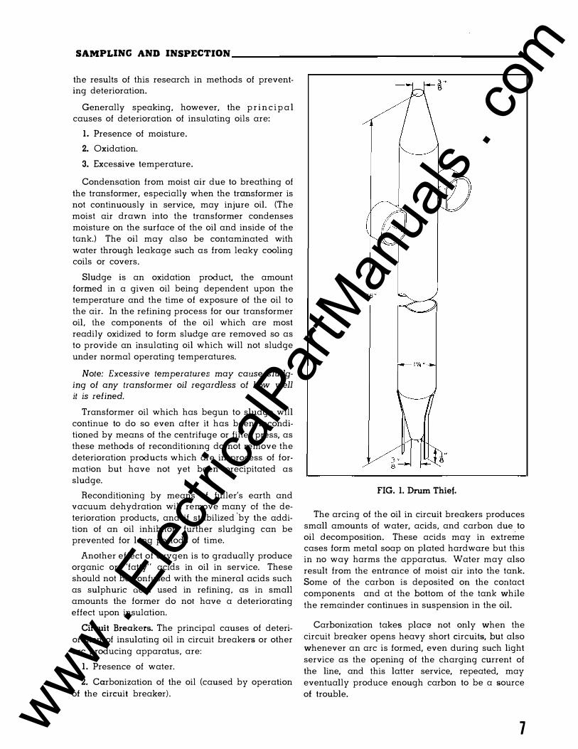
SAMPLING AND INSPECTION ______________________ _
the results of this research in methods of preventing deterioration.
Generally speaking, however, the p r i n c i p a l causes of deterioration of insulating oils are:
I. Presence of moisture.
2. Oxidation.
3. Excessive temperature.
Condensation from moist air due to breathing of the transformer, especially when the transformer is not continuously in service, may injure oil. (The moist air drawn into the transformer condenses moisture on the surface of the oil and inside of the tank.) The oil may also be contaminated with water through leakage such as from leaky cooling coils or covers.
Sludge is an oxidation product, the amount formed in a given oil being dependent upon the temperature and the time of exposure of the oil to the air. In the refining process for our transformer oil. the components of the oil which are most readily oxidized to form sludge are removed so as to provide an insulating oil which will not sludge under normal operating temperatures.
Note: Excessive temperatures may cause sludging of any transformer oil regardless of how well it is refined.
Transformer oil which has begun to sludge will continue to do so even after it has been reconditioned by means of the centrifuge or filter press, as these methods of reconditioning do not remove the deterioration products which are in process of formation but have not yet been precipitated as sludge.
Reconditioning by means of fuller's earth and vacuum dehydration will remove many of the deterioration products, and if stabilized
'by the addi
tion of an oil inhibitor, further sludging can be prevented for long periods of time.
Another effect of oxygen is to gradually produce organic or "fatty" acids in oil in service. These should not be confused with the mineral acids such as sulphuric acid used in refining, as in small amounts the former do not have a deteriorating effect upon insulation.
Circuit Breakers. The principal causes of deterioration of insulating oil in circuit breakers or other arc producing apparatus, are:
I. Presence of water.
2. Carbonization of the oil (caused by operation of the circuit breaker) .
FIG. I. Drum Thief.
The arcing of the oil in circuit breakers produces small amounts of water, acids, and carbon due to oil decomposition. These acids may in extreme cases form metal soap on plated hardware but this in no way harms the apparatus. Water may also result from the entrance of moist air into the tank. Some of the carbon is deposited on the con tact components and at the bottom of the tank while the remainder continues in suspension in the oil.
Carbonization takes place not only when the circuit breaker opens heavy short circuits, but also whenever an arc is formed, even during such light service as the opening of the charging current of the line, and this latter service, repeated, may eventually produce enough carbon to be a source of trouble.
7 www . El
ectric
alPar
tMan
uals
. com
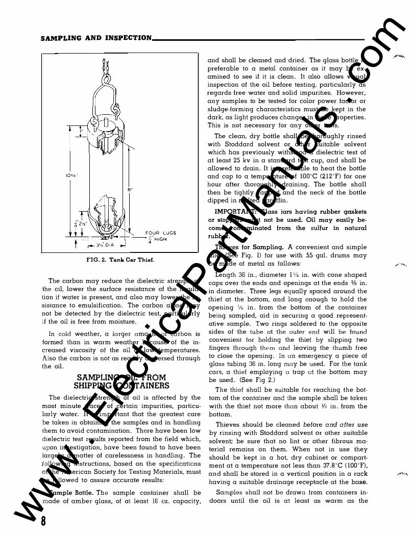
SAMPLING AND INSPECTION ______________________ _
B"
FOUR LUGS ---L--:::==t===�!W"-��-- f HIGH
FIG. 2. Tank Car Thief.
The carbon may reduce the dielectric strength of the oil, lower the surface resistance of the insulation if water is present, and also may lower the resistance to emulsification. The carbon alone may not be detected by the dielectric test, particularly if the oil is free from moisture.
In cold weather, a larger amount of carbon is formed than in warm weather because of the increased viscosity of the oil at low temperatures. Also the carbon is not as readily dispersed through the oil.
SAMPLING OIL FROM SHIPPING CONTAINERS
The dielectric strength of oil is affected by the most minute traces of certain impurities, particularly water. It is important that the greatest care be taken in obtaining the samples and in handling them to avoid contamination. There have been low dielectric test results reported from the field which, upon investigation, have been found to have been largely a matter of carelessness in handling. The following instructions, based on the specifications of the American Society for Testing Materials, must be followed to assure accurate results:
Sample Bottle. The sample container shall be made of amber glass, of at least 16 oz. capacity,
8
and shall be cleaned and dried. The glass bottle is preferable to a metal container as it may be examined to see if it is clean. It also allows visual inspection of the oil before testing, particularly as regards free water and solid impurities. However, any samples to be tested for color power factor or sludge-forming characteristics must be kept in the dark. as light produces changes in these properties. This is not necessary for any other tests.
The clean, dry bottle shall be thoroughly rinsed with Stoddard solvent or other suitable solvent which has previously withstood a dielectric test of at least 25 kv in a standard test cup, and shall be allowed to drain. It is preferable to heat the bottle and cap to a temperature of lOO'C (2 12 'F) for one hour after thoroughly draining. The bottle shall then be tightly capped and the neck of the bottle dipped in melted paraffin.
IMPORT ANT: Glass jars having rubber gaskets
or stoppers must not be used. Oil may easily be
come contaminated from the sulfur in natural
rubber.
Thieves for Sampling. A convenient and simple thief (See Fig. l) for use with 55 gal. drums may be made of metal as follows:
Length 36 in . . diameter 1 1/4 in. with cone shaped caps over the ends and openings at the ends 3fa in. in diameter. Three legs equally spaced around the thief at the bottom, and long enough to hold the opening 1/e in. from the bottom of the container being sampled, aid in securing a good representative sample. Two rings soldered to the opposite sides of the tube at the outer end will be found convenient for holding the thief by slipping two fingers through them and leaving the thumb free to close the opening. In an emergency a piece of glass tubing 36 in. long may be used. For the tank cars, a thief employing a trap ut the bottom may be used. (See Fig 2. )
The thief shall be suitable for reaching the bottom of the container and the sample shall be taken with the thief not more than about 1/s in. from the bottom.
Thieves should be cleaned before and after use by rinsing with Stoddard solvent or other suitable solvent; be sure that no lint or other fibrous material remains on them. When not in use they should be kept in a hot, dry cabinet or compartment at a temperature not less than 37.8 'C ( lOO 'F), and shall be stored in a vertical position in a rack having a suitable drainage receptacle at the base.
Samples shall not be drawn from containers indoors until the oil is at least as warm as the www .
Elec
tricalP
artM
anua
ls . c
om

SAMPLING AND INSPECTION---------------------
surrounding air. Cold oil may condense enough moisture on the surface from a humid atmosphere to seriously affect its insulating properties. Sampling oil from containers out of doors is undesirable, due to the possibility of condensation of moisture, and should be avoided whenever possible. (Samples should never be taken in the rain.)
Procedure. The drums to be sampled shall be assembled in li ne, with bungs up, and numbered. The bungs shall be unsealed and removed and laid with the oily side up beside the bungholes. The unstoppered sampling receptacle can be placed on the opposite side of the bungholes. The top hole of the thief shall be closed with the thumb, the thief quickly thrust to the bottom of the container and the thumb removed. When the thief is filled, the thumb shall be replaced, the thief quickly withdrawn and the contents allowed to flow into the sampling receptacle. The lower holes shall not be closed with the fingers of the other hand. The free hand shall not be used to guide the stream of oil except by touching the thief. and this only when necessary. The oil shall not be allowed to flow over the hand or fing8rs before it flows into the sampling receptacle.
When the sampling receptacle is filled, it shall be closed quickly and the bung replaced in the container and tightened. The sampling receptacle shall be taken under cover to the testing laboratory as quickly as feasible.
After using, thoroughly clean all thieves and sampling receptacle5 as outlined above.
The tank cars of oil shall be sampled by introducing the thief through the manhole on top of the car, the cover of which shall be removed carefully so as not to contaminate the oil with dirt. The sample shall be taken as near as possible to the bottom of the tank car. This shall not be done while rain or snow is falling.
When separate samples are being taken from a consignment or part of a consignment. care should be exercised to prevent contaminating the samples. A separate thief shall be used for each sample or the thief previously used shall be well dr ained and then thoroughly washed with oil from the next con· tainer to be sampled; the oil thus used for washing should be thrown away before the next sample is taken. (Enough thieves shall be provided to insure thorough drainage of each thief after rinsing with oil to be sampled before using it to withdraw the actual sample.) For obtaining only a few samples, two thieves are sufficient, but for obtaining a large number of samples (for example, sam-
piing a carload of drummed oil) six or more thieves are desirable.
When one average sample of a consignment or batch is being taken, the same thief may be used throughout the sampling operation, and it is not necessary to rinse the thief with oil before taking any of the portions that go to make up the total average sample.
Quantity of Sample. It is recommended that one
16 oz. bottle of oil be taken as a sample for dielectric tests, and a one quart sample be taken when complete physical and chemical tests are to be made. At least one sample should be taken from a tank car of oil. One sample may be taken from each drum, or if desired, a composite sample may be made from oil from five drums, provided all of the drums are airtight. When the bung is first loosened, a hissing sound should be heard, which indicates that the drum has been airtight. If the test of the composite sample is not satisfactory, a sample from each of the drums represented should be tested.
When drums have been stored exposed to the weather, a sample from each drum shall be tested. The sample of oil should be examined for free water, and if any is noted, the drum of oil should be put through a blotter filter press and resampled for dielectric strength.
If the sample is being taken from a tank car, and water appears, follow the same procedure.
SAMPLING OIL FROM APPARATUS
When taking samples of oil from apparatus in in which a thief cannot be used, use the sampling valve and follow the procedure outlined above as far as practicable.
Care should be taken to procure a sample which fairly represents the oil at the bottom of the tank. A sufficient amount of oil should therefore be drawn off before the sample is taken, to insure that the sampla will not be that which was stored in the sampling pipe. For this reason, the valve and the drain pipe should be sufficiently small to be emptied with convenience and yet sufficiently large to give an even flow of oil and avoid clogging by sediment. A V4 in. pipe and valve is recommended. This, of course, may be separate from the drainage pipe and valve or it may be connected to the drainage valve by means of a suitable reducer.
It is of utmost importance that the sample of insulating oil represents the actual condition of the oil in the apparatus. Every precaution should be
9 www . El
ectric
alPar
tMan
uals
. com

SAMPLING AND INSPECTION----------------------
taken to keep the sample and container free from
foreign impurities or moisture.
If the apparatus is installed outdoors, care should be t aken to prevent contamination of the sample by rain, snow, etc.
A glass bottle is recommended as a sampling
receptacle, so that any water present may readily be seen.
If the sample contains free water it is not suitable for dielectric test and the sample and bottle should be discarded. A second sample should be taken after at least two quarts of oil have been with
drawn. If free water sti ll exists in the sample, the oil in the apparatus should be put through a blotter
filter press and resampled for dielectric strength.
In order to make sure that the dielectric strength is up to its proper value, the insulating oil in any piece of apparatus should be tested before its ini
tial operation, and at regdar intervals thereafter.
PERIODIC INSPECTION
Oil may deteriorate in service even under what seems to be the most favorable conditions. The more handling an i n s u l a t i n g oil receives, the greater the opportunity for contamination unless adequate precautions are taken.
IMPORT ANT: It is essential to provide for peri
odic inspection and test. and to purify the oil when
ever necessary in order to maintain it in good
condition.
Regular inspection and tests of insulating oils by electric utilities and other large users have proven the necessity of this pr�ctice. Where these inspec
tions and tests have been systematically followed it has been found that failure of the apparatus due to the fact the oil had become contaminated with moisture and sediment, has been reduced to a minmum and has resulted in greater economy of operation. In view of the importance of the subiect,
it is, therefore, recommended that all companies, in
the interest of good service, adopt some system of oil inspection and test.
The frequency of inspecting and testing depends
upon the service to which the oil is subjected, and the construction of and the materials used in the apparatus.
Even though field experience has shown that it
is not necessary to frequently examine the oil in Inertaire or Sealedaire transformers, such oils should be inspected to insure that the Inertaire
10
equipment i s being maintained and the tanks are tight.
The oil in circuit breakers and transformers which are operated under extremely heavy loads
requires more frequent inspection than that in normal or light service.
It is recommended that operators prepare a
schedule for inspection based on the operating conditions. Reference to the station log, together with the record of dielectric tests of the oil, should determine the frequency of inspection and test . The period between successive inspections should not be longer than six months or until experience indicates that the time between tests can be extended. If the dielectric strength of the oil drops below 22 KV in the standard dielectric test the oil should be blotter pressed. In the event that the dielectric strength is not readily restored to 26 KV or above, other tests should be made to determine i f the oil should be reconditioned or replaced.
Checking Oil Level. It is essential that the
proper oil level be maintained. Low oil level may cause breakdown of insulation or flashover of bushing in any apparatus, or malfunctioning of circuit breakers mechanically or electrically.
Checking Dielectric Strength. The oil should be
tested regularly for dielectric strength and purified when the tests show need of iL The testing should
be systematized and complete records kept. It is particularly important in a circuit breaker to check the dielectric strength after exposure to near rating short-circuit operations.
Checking for Carbonization. The presence of carbon in circuit breaker oil may introduce a hazard, due to the tendency of the carbon to lower the dielectric strength of the oil. and also to deposit on insulating surfaces, thereby reducing the insulation resistance.
Visual inspect1on of the oil samples should b e made and, i f a n y appreciable amount of carbon i s
present, the ::>il should be reconditioned even
though the dielectric test is good.
IMPORTANT: Certain washing compounds have
been used by some operating companies to assist
in separating the carbon from the oil. Investigation
in the Westinghouse laboratories has shown that
these compounds leave the oil in poor condition.
Customers are warned against using any form of
chemical treatment that has not been investigated
and recommended by Westinghouse Electric Cor
poration. www . El
ectric
alPar
tMan
uals
. com

SAMPLING AND INSPECTION ______________________ _
Checking for Sludge. Transformers should be regularly examined for evidence of sludge. A visual inspection will indicate its presence. Appreciable amounts of sludge may clog the oil ducts and interfere with heat transfer. It is desirable that such oil be reconditioned or replaced immediately. If the oil is to be returned to service, oil inhibitor should be added to extend the life of the oil. Oil which has once sludged, wilL after being reconditioned, sludge more quickly than the first time unless the inhibitor is added.
WESTINGHOUSE OIL TESTING SERVICE
Many users of transformers and large oil circuit breakers do not have the necessary facilities for testing insulating oil. In order that these users may be able to make the periodic tests recommended, Westinghouse Electric Corporation has established an oil testing service to provide a careful test by experienced engineers, and a prompt report of test results.
Two special 16 oz. sample bottles per mailing container (Westinghouse Sampling Set Style # 1 608 629) as well as necessary packing and printed matter. may be obtained by contacting the nearest Westinghouse office.
After druwing the sample of oil, the customer should seal the bottle with care, and mail it t o the Westinghouse Electric Corp . . Plant Laboratory, Sharon, Pa. The details of this transaction have been simplified by the inclusion in the Sampling Set of an instruction sheet and a printed return label. The instructions cover the taking of the sample and its proper preparation for mailing, and the label carries an envelope for enclosing customer's order covering the testing work. (Also see details given in Price List 45-825).
If customer desires to use his own bottles, he should be sure to obtain Form 2 4670 from the Westinghouse Office. Lack of this form will cause much delay in various accounting procedures involved, and thereby delay the test. Samples should
be taken in accordance with ASTM D-117. Note that the bottles and containers involved will not be returned to the customer.
When samples of oil are received for testing they are sent to the engineering testing laboratory and tested for dielectric strength in accordance with methods described in ASTM D- 1 1 7.
As soon as the test has been made, a report giving the average is sent by mail directly to the person in the customer's organization who has been designated on the order to receive it.
In addition to dielectric tests, Westinghouse is also prepared to make a physical and chemical examination. (The customer should plainly indicate the type of service desired.)
This service consists of an examination of the oil by a competent oil chemist. Recommendations will be made as to the suitability of the oil for continued use, whether it would be desirable and economical to clean it, and in a general way, the preferred method of cleaning. In submitting samples for this service, the history of the oil represented should be given as completely as possible. Samples should be not less than one pint.
Other tests available include a complete Physical and Chemical Examination; a power factor test; and the establishment of a Power Factor Curve from 25 'C to l OO'C.
The Physical and Chemical Examination encompasses tests of acid and base numbers, color, interfacial tension test, pour point, specific gravity, and viscosity.
A combination is offered of the dielectric test, the acid and base number test. the interfacial tension test. and the power factor test. This combination covers those tests most often requested for general purposes.
(For further details on available tests, refer to the nearest Westinghouse Office.)
1 1 www . El
ectric
alPar
tMan
uals
. com
PART THREE
PURIFICATION AND RECONDITIONING PURITY OF OIL
Wemco C oil is clear and nearly water-white in colm. It is free from water, acid, alkali, and deleterious sulfur compounds.
The oil is carefully refined so as to have a high resistance to emulsion; that is, the water is not held in suspension but quickly separates out. This is particularly essential in circuit-breaker service since this apparatus cannot be tightly closed like a transformer and some moisture may be introduced into the oiL Wemco C oil has been designed with this particular property in mind and precipitates
water and carbon promptly. However, certain impurities develop while the oil is in service and these impurities must be removed to insure safe operation of the apparatus. The source and kind of impurities developed in the oil depend upon the type of apparatus in which it is used.
In circuit-breaker service, each time the circuit
is opened some carbon is formed in the oil, even when only a small charging current is being interrupted. The resistance to emulsion of the oil is also lessened, both by a change in the oil and by the presence of carbon in the oiL Oil which has been subjected to arc action in the circuit breaker tends to slowly form organic acids, which further tend to lower its resistance to emulsion. The major
portion of the carbon slowly precipitates to the bottom of the tank. but the more finely divided carbon has a tendenc y to remain suspended in the oil. and lower the dielectric strength. Both carbon and moisture are attracted to the insulating surfaces of the bushings by the electrostatic field, and when so deposited, lower the insulation resistance of the terminals from line to ground.
Oil in transformers is generally subjected to heat. oxidation and sometimes t o moisture. Heat in
1he presence of oxygen produces a gradual physical and chemical change in oil and the extent of this change will depend upon the amount of heat,
12
time arid the catalytic action of exposed metals in the apparatus to which it is subjected. High temperature over a short period of time or somewhat lower temperature over a long period of time affect the characteristics of the oil, particularly in the development of organic acidity and sludge.
Heat in the presence of oxygen affects the unsaturated hydrocarbons, at first through formation of organic acids and later by precipitation in the form ordinarily called sludge.
RECONDITIONING
The reconditioning of oil used in circuit breakers and transformers consists principally of the removal of water, carbon and sludge and the restoration of resistance to emulsification, thereby putting the oil in the best condition to separate out any water which may later be introduced.
The four types of equipment in general use for simple reconditioning of oil in transformers and circuit breakers are: the centrifuge, the blotter filter press, the combination centrifuge and filter press and the combination fullers earth and vacuum dehydration process. (See Part Five.)
IMPORTANT: In general. when small quantities
of oil have been contaminated with fire extinguish
ing agents, it is preferable to replace the oil rather
than to attempt to reclaim it.
Insula1ing oil which has been contarnina1ed wi1h
carbon tetrachloride or soda sulfuric acid cannot
be reclaimed. (It would have to be refined.)
When large quantities of oil have been contaminated with other fire extinguishing agents, the reclaiming of the oil will depend upon the kind and degree of contamination. There may be factors other than the fire extinguishing agent (for instance, high temperatures cracking the oil, carbonized insulation, etc.) which should be considered. Any questi on should be referred to ' the nearest
Westinghouse Office.
www . El
ectric
alPar
tMan
uals
. com

PART FOUR
TESTING METHODS Instructions for all tests listed correspond in
general to the recommendations of the American Society for Testing Materials.
DIELECTRIC STRENGTH TEST
Apparatus. The transformer and the source of supply of energy shall not be less than 112 kva, and the frequency shall not exceed 100 cycles per second. Regulation shall be so controlled that the high tension testing voltage taken from the secondary of the testing transformer can be raised gradually without opening either primary or secondary circuit. The rate of rise shall approximate 3000 volts per second. The voltage may be measured by any approved method which gives root-meansquare values.
Some protection is desirable to prevent excessive flow of current when breakdown of the oil takes place. This protection preferably should be in the primary or low voltage side of the testing hansformer. It is not especially important for transformers of 5 kva or less, as the current is limited by the regulation of the transformer.
The test cup for holding the sample of oil shall be made of a material having a suitable dielectric
FIG. 3. Oil or Fluid Test Cup for Dielectric Test.
strength. It must be insoluble in and unattacked by mineral oil and gasoline, and nonabsorbent as far as moisture, mineral oil and gasoline are concerned.
·The electrodes in the test cup between which the sample is tested shall be circular discs of polished brass or copper, I in. in diameter, with square edges. The electrodes shall be mounted in the test cup with their axes horizontal and coincident, with a gap of 0. 100 in. between their adjacent faces, and with tops of electrodes about 1 114 in. below the top of the cup. (A suitable test cup shown in Fig. 3, and portable testing outfits in Figs. 4 and 5.)
Procedure. The spacing of electrodes shall be checked with a standard round gauge having a diameter of 0. 100 in., and the electrodes then locked in position.
The electrodes and the test cup shall be wiped dean with dry, calendered tissue paper or with a clean, dry chamois skin and thoroughly rinsed with Stoddard solvent or other suitable solvent until they are entirely free from fibres.
The test cup shall be filled with dry benzine, and voltage applied with uniform increase at the rate of approximately 3000 volts (rms) per second until breakdown occurs. If the dielectric strength is not less than 25 kv, the cup shall be considered in suitable condition for testing the oiL If a lower test value is obtained the cup shall be cleaned with solvent and the test repeated.
Note: Evaporation of solvent from the electrodes may chill them suilicien tly to cause moisture to
condense on their surface. For this reason, after the final rinsing with solvent, the test cup should be immediately filled with the oil which is being tested. and the test made at once, or the electrodes should be thoroughly dried before using.
The temperature of the test cup and of the oil when tested shall be the same as that of the room, which should be between 20 and 30 C (68 and 86F). Testing at lower temperatures is likely to give variable results which may be misleading.
The sample in the container shall be agitated with a swirling m otion to avoid introducing air, so as to mix the oil thoroughly before filling the test cup. This is even more important with used oil than with new oil as the impurities may settle to
13 www . El
ectric
alPar
tMan
uals
. com
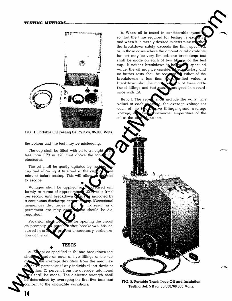
TESTING METHODS---------------------------------------------------
FIG. 4. Portable Oil Testing Set Y2 Kva. 35.000 Volts.
the bottom and the test may be misleading .
The cup shall be filled with oil to a height of no less than 0.79 in. (20 mm) above the top of the electrodes.
The oil shall be gently agitated by rocking the cup and allowing it to stand in the cup for three minutes before testing. This will allow air bubbles to escape.
Voltages shall be applied and increased uniformly at a rate of approximately 3000 volts (rms) per second until breakdown occurs as indicated by a continuous discharge across the gap. (Occasional momentary discharges which do not result in a permanent arc may occur; these should be disregarded.)
Provision shall be made for opening the circuit as promptly as possible after breakdown has occurred in order to prevent unnecessary carbonization of the oil.
TESTS
a. Except as specified in (b) one breakdown test shall be made on each of five fillings of the test cup. If the average deviation from the mean exceeds 1 0 percent or if any individual test deviates more than 25 percent from the average, additional tests shall be made. The dielectric strength shall be determined by averaging the first five tests that conform to the allowable variations.
14
b. When oil is tested i n considerable quantity, so that the time required for testing is excessive and when it is merely desired to determine whether the breakdown safely exceeds the limit specified, or in those cases where the amount of oil available for test may be very limited, one breakdown test shall be made on each of two fillings of the test cup. If neither breakdown is below the specified value, the oil may be considered satisfactory and no further tests shall be required. If either of the breakdowns is less than the specified value, a breakdown shall be made on each of three addit ional fillings and test results analyzed in accordance with (a).
Report. The report shall include the volts (rms value) at each puncture, the average voltage for each of the two or five fillings, grand average voltage, and the approximate temperature of the oil at the lime of the test.
FIG. 5. Portable Truck Type Oil and Insulation
Testing Set, 5 Kva, 30.000/60.000 Volts. www . El
ectric
alPar
tMan
uals
. com
TESTlNG METHODS ________________________________________________ ___
NEUTRALIZATION TEST
The Neutralization Number i s the weight in milligrams of potassium hydroxide required to neutralize the acid in one gram of oil. The Neutralization Number of new Wemco C oil is 0.03 maximum.
Solutions Required.
a. Standard Potassium Hydroxide Solution (alcoholic, 0.1 N)-add 6 g. of c.p. solid KOH to l liter of c.p. anhydrous isopropyl alcohol. Boil, add 2 g. of c.p. Ba (OH)" and boil again. Cool, filter and store in a chemically resistant bottle protected by a guard tube containing soda lime and soda asbestos (Ascarite). Standardize against pure potassium acid phthalate using phenolphthalien as an indicator.
b. Titration Solvent--Add 500 ml. of c.p. benzene and 5 mi. of water to 495 ml. of c.p. anhydrous isopropyl alcohol.
c. Alpha-Naphtholbenzein Indicator Solution Prepare a solution containing 1 0 g. of alpha-naphtholbenzein per liter of c.p. anhydrous isopropyl. alcohol.
Procedure. Into a 250 mi. Erlenmeyer flask introduce 40 g. of Wemco C oil weighed to nearest 0.1 gram. Add 1 00 mi. of the titration solvent and 3 ml. of the indicator solution. Titrate immediately at a temperature below 30°C. Consider the end point definite if the color change to green persists
for 1 5 seconds. A blank shall be determined on the solvent.
Calcula1ions. The neutralization number or mg
KOH per g. of Wemco C oil (A-B) (N) X 56. 1
A = ml. KOH solution required for sample. B ml. KOH solution required for blank.
N = normality of KOH solution. W grams of sample used.
1 5 www . El
ectric
alPar
tMan
uals
. com
PART FIVE
RECONDITIONING APPARATUS FOR RECONDITIONING
RECONDITIONING
In order that oil in circuit breakers and transformers performs its function, certain essential properties must be maintained. Various types of equipment are available to assist the operator in the maintenance of insulating oil.
The first step is to classify oils in service based upon an evaluation of their properties.
GROUP I-This group contains oils which m e i n satisfactory condition for continued service.
GROUP II- This group contains oils which are low in dielectric strength or contain insoluble contaminants and requires only minor reconditioning by blotter press and or centrifuge to restore them to condition for continued service.
GROUP III- This group contains oils in poor condition which should be reclaimed or scrapped depending upon economic considerations.
GROUP IV- This group contains oils in such poor condition that it is advisable to dispose of them.
Many tests are available which can be applied to transformer oils in order to classify them into the four groups described. It is recommended that the latest revisions of standards as described by the American Society for Testing Materials (ASTM) be used.
APPARATUS FOR RECONDITIONING
There are several types of reconditioning ap
paratus available, the relative advantages of each
of which are as follows:
I . The centrifuge, connected as a separator, may
be used where there are large quantities of water
present in the oil , without waiting for it to settle
out, and connected as a clarifier, for removing
small quantities of water. It will remove sludge
and coarse carbon particles but not all finely
divided carbon.
2. The filter press is suitable for reconditioning
oil containing small quantities of water and will
remove finely divided carbon and sludge. It will
not materially reduce organic acidity or improve
16
the resistance t o emulsification except a s this is caused by the presence of carbon.
3. The combination centrifuge and filter press, passing the oil first through the centrifuge, may be used advantageously in the removal of large quan· tities of carbon and water. It unites the exceptional qualities of the centrifuge with the excellent characteristics of the blotter press. This flexibility of operation makes it very desirable as standard equipment in the reconditioning of insulating oil for the removal of large quantities of carbon from the oil. However, the clogging of the pores of the filter reduces the output of this combination.
CAUTION: STATIC ELECTRICITY-In the opera· tion of a filter press it is necessary that the problem of static electricity be recognized and areas and tanks vented as much as possible. (See caution
note on Static Electricity-Part I page 5.)
4. A fuller's earth filter is the method most frequently used for oils in Group III. In general, reclaiming is done by one of two methods, percolation through the fuller's earth, or by contact at an elevated temperature with finely divided material. The excellent absorbent properties of the fuller's earth will remove acids and other contaminants.
5. A vacuum dehydrator is an efficient means of reducing the water content of insulating oils and is frequently used in conjunction with a fuller's earth filter. Here the oil is exposed to a high vacuum and heat for a short interval of time.
The final criterion of the effectiveness of any method of reconditioning is the quality of the reconditioned oil. The dielectric strength of the reconditioned oil should be at least 26 KV to provide some margin over the lowest limit of 22 KV.
Oils which have been reconditioned by a fuller's earth process should have properties closely approaching those of new oil. It is recommended that to extend the life of reconditioned oils that at least 0.? percent by weight of inhibitor, Di-Tertiary-ButylParacaesol. (D.B.P.C.), be added to the oil.
www . El
ectric
alPar
tMan
uals
. com
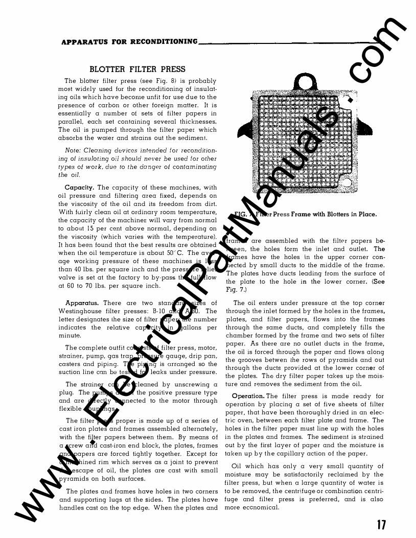
APPARATUS FOR RECONDITIONING ____________________________________ __
BLOTTER FILTER PRESS
The blotter filter press {see Fig. 8) is probably most widely used for the reconditioning of insulating oils which have become unfit for use due to the presence of carbon or other foreign matter. It is essentially a number of sets of filter papers in parallel. each set containing several thicknesses. The oil is pumped through the filter paper which absorbs the water and strains out the sediment.
Note: Cleaning devices in tended for recondition
ing of insula ting oil should never be used for o ther types of work, due to the da nger of contaminating the oil.
Capacity. The capacity of these machines, with oil pressure and filtering area fixed, depends on the viscosity of the oil and its freedom from dirt. With fuirly clean oil at ordinary room temperature, the capacity of the machines will vary from normal to about 1 5 per cent above normal, depending on the viscosity {which varies with the temperature). It has been found that the best results are obtained when the oil temperature is about SO ' C. The average working pressure of these machines is less than 40 lbs. per square inch and the pressure relief valve is set at the factory to by-pass the full flow at 60 to 70 lbs. per square inch.
Apparatus. There are two standard sizes of Westinghouse filter presses: B- 10 and A-30. The letter designates the size of filter paper; the number indicates the relative capacity in gallons per minute.
The complete outfit consists of filter press, motor, strainer, pump, gas trap, pressure gauge, drip pan, casters and piping. The piping is arranged so the suction line can be testt?d for leaks under pressure.
The strainer can be cleaned by unscrewing a plug. The pumps are of the positive pressure type and are directly connected to the motor through flexible couplings.
The filter press proper is made up of a series of cast iron plates and frames assembled alternately, with the filter papers between them. By means of a screw and cast-iron end block, the plates, frames and papers are forced tightly together. Except for a machined rim which serves as a j oint to prevent the escape of oil, the plates are cast with small pyramids on both surfaces.
The plates and frames have holes in two corners and supporting lugs at the sides. The plates have handles cast on the top edge. When the plates and
FIG. 7. Filter Press Frame with Blotters in Place.
frames are assembled with the filter papers between, the holes form the inlet and outlet. The frames have the holes in the upper corner connected by small ducts to the middle of the frame. The plates have ducts leading from the surface of the plate to the hole in the lower corner. {See Fig. 7.)
The oil enters under pressure at the top corner through the i nlet formed by the holes in the frames, plates, and filter papers, flows into the frames through the same ducts, and completely fills the chamber formed by the frame and two sets of filter paper. As there are no outlet duels in the frame, the oil is forced through the paper and flows along the grooves betwen the rows of pyramids and out through the ducts provided at the lower corner of the plates. The dry filter paper takes up the moisture and removes the sediment from the oil.
Operation. The filter press is made ready for operation by placing a set of five sheets of filter paper, that have been thoroughly dried in an electric oven, between each filter plate and frame. The holes in the filter paper must line up with the holes in the plates and frames. The sediment is strained out by the first layer of paper and the moisture is taken up by the capillary action of the paper.
Oil which has only a very small quantity of moisture may be satisfactorily reclaimed by the filter press, but when a large quantity of water is to be removed, the centr!fuge or combination centrifuge and filter press is preferred, and is also more economical.
1 7 www . El
ectric
alPar
tMan
uals
. com

APPARATUS FOR RECONDITIONING------------------
If any moisture remains, it indicates that the filter papers are saturated with moisture and should be renewed. No rule can be given as to how often the papers must be changed, as this depends entirely on the condition of the oil. The usual procedure is to run the machine for about half an hour (if the oil is not in very bad condition) and then shut down; remove one sheet from the inlet side of each set and put in a new sheet on the outlet side of each set. (The frame is the inlet side and the plate is the outlet side.) Frequent dielectric tests should be made during this procedure as wet oil may necessitate recharging the filter press with a full set of papers before the five sheets have been removed in succession.
The quickest method of filtering a quantity of oil is to pump all the oil through the filter and into another tank which is clean and dry. If care is taken to change the filter papers before they become saturated, the oil will be clean and dry. If a second tank for holding the oil is not available, or if it is desired to filter the oil of a transformer while it is in service, the oil may be pumped from the bottom of the tank through the filter and returned to the top of the same tank under the surface of the oil to prevent aeration. This operation should be continued until the oil in the tank shows a sufficiently high dielectric strength.
When a large quantity of oil is to be filtered, time may be saved by using two filter presses, one of which may be operated while the other is being recharged.
The filter press is not intended to remove large amounts of free water from the oiL Obviously the changing of filter papers necessary for obtaining dry oil would so reduce the capacity as to make this method of reconditioning impractical. In such cases, the water may be removed by a centrifuge, or should be allowed to settle out and be drawn off from the bottom of the container before passing the oil through a filter press.
With badly fouled oil, it may be necessary to pass the oil through the filter press several times to take out the more finely divided carbon which is not caught on the filter papers, especially when they are new. The efficiency of the filter press for removing carbon increases as the pores of the filter papers become partly clogged. This produces a material slowing-down in the rate of flow through the filter papers.
Filtering through filter papers does not materially reduce organic acidity or improve resistance
18
'' -«::::. · . · 0
FIG. 8. B- 10 Filter Press with Top and Side Panel
Removed. (Explosion-Proof Model).
to emulsification except as the latter is affected by the presence of carbon, although the dielectric strength may be restored to a satisfactory value.
The capacity of the filter press is much reduced when operating at low temperatures.
When the oil has to be filtered at low temperatures an additional pump in the pipe line is desirable .
Oil in transformers contaminated by only a small amount of moisture may be reconditioned by drawing the oil from the bottom of the tank, passing it through the filter press or centrifuge and pumping it back into the top of the transformer, preferably at a point below the surface of the oil. The oil should be put through the system until a sample drawn from the bottom of the transformer gives satisfactory dielectric values.
Pumping the oil from a circuit-breaker tank to the purifying outfit and directly back to the tank is not desirable, as the clean oil is again contaminated by the carbonized oil remaining in the tank. Also, it is then impossible to clean the carbon deposit from the surfaces inside the tank. Do not filter oil from a circuit-brooker while the brooker is in service on an energized line.
Filter Paper. The filter paper used is a special grade of blotting paper about .025 in. thick; it contains no coloring matter or chemicals which might injure the oil. Five sheets cut to the proper size, www .
Elec
tricalP
artM
anua
ls . c
om

APPARATUS FOR RECONDITIONING ___________________ _
FIG. 9. Electric Drying Oven.
1 2 % in. square for the A sizes and 73/:. in. square for the B sizes, and with holes punched to correspond with the holes in the plates and frames, are between each plate and the adjacent frames.
To obtain the best results in reconditioning oil, the paper must be perfectly dry when first placed in the press. Filter paper always takes up moisture if exposed to the air for any length of time and for this reason care must be used in handling. The standard paper is carried in packages containing one ream carefully wrapped in waxed paper and covered with h8avy wrapping paper.
ELECTRIC DRYING OVEN
The importance of the drying oven cannot be over-emphasized since the effectiveness of the whole filtering process is dependent on the dryness of the paper. For satisfactory results, the dried filter paper should either be inserted in the filter press and used immediately, or kept in dry transformer oil until it is transferred to the filter press. No filter paper can be effectively dried after it has once become saturated with oil. Therfore, care should be taken to insure that the paper is thor-
oughly dried when placed in the filter.
The oven can be used on 1 1 0/220/440 DC or single phase AC, 1 000 watts. The normal capacity of 7 inch or 12 inch paper is 1 80 sheets.
The paper is suspended from two rods with the sheets separated from each other, thus permitting thorough circulation of heated air. The rods can be rearranged for hanging either 12 inch or 7 inch filter paper.
Normally, the filter paper should be dried 6 to 1 2
hours, depending upon condition o f the paper and spacing of the sheets in the oven.
The cabinet is constructed of fabricated sheet steel and insulated with lf4 inch asbestos board. (See Figure 9)
The air vents are designed to provide cross ventilation so that dry heated air replaces moisture laden air.
Oil can be dried rapidly and thoroughly if the filter paper is carefully prepared, transferred to the press without reabsorbing moisture, and replaced when its effectiveness is exhausted. If good results are not obtained, it is probably because the paper was not sufficiently dry when placed in the press, due either to improper drying or careless handling.
CENTRIFUGE
The centrifuge is the most convenient equipment known for removing water from oil. It also removes solid material other than finely divided carbon. The temperature of the oil should be maintained at 48.9 to 5 1 .7 C ( 1 20 to 1 25 F) in order to insure removal of all the water at full capacity of the machine. A higher temperature gives no advantage, and if excessive, will permit the oil to carry more moisture through in solution. (A 6 kw heater will raise the oil about 1 5.6 C (60 F) per 1 00 gallons per hour.) The centrifuge equipment may be arranged to act as a separator, discharging the oil and water by different outlets, or as a clarifier, discharging the oil but retaining the water and other impurities in the bowl* .
*For further details, see manufacturer's information.
1 9 www . El
ectric
alPar
tMan
uals
. com

www . El
ectric
alPar
tMan
uals
. com